volume 2-part diii-book 1 of 6
DESCRIPTION
specTRANSCRIPT

7/18/2019 Volume 2-Part DIII-Book 1 of 6
http://slidepdf.com/reader/full/volume-2-part-diii-book-1-of-6 1/342

7/18/2019 Volume 2-Part DIII-Book 1 of 6
http://slidepdf.com/reader/full/volume-2-part-diii-book-1-of-6 2/342

7/18/2019 Volume 2-Part DIII-Book 1 of 6
http://slidepdf.com/reader/full/volume-2-part-diii-book-1-of-6 3/342
Tender Documents for
AIRCRAFTS MAINTENANCE HANGARS
Volume 2 Exhibit “D”: Special Specifications
PART D-III - Book 1 of 6Buildings & Related Utilities Specifications
S09063-01D – February 2011

7/18/2019 Volume 2-Part DIII-Book 1 of 6
http://slidepdf.com/reader/full/volume-2-part-diii-book-1-of-6 4/342
SAUDIA AEROSPACE ENGINEERING INDUSTRIES
AIRCRAFTS MAINTENANCE HANGARS
VOLUME 2 EXHIBIT “D”: SPECIAL SPECIFICATIONS
PART D-III - BOOK 1 OF 6
BUILDINGS & RELATED UTILITIES SPECIFICATIONS
TABLE OF CONTENTS

7/18/2019 Volume 2-Part DIII-Book 1 of 6
http://slidepdf.com/reader/full/volume-2-part-diii-book-1-of-6 5/342
Saudia Aerospace Engineering Industries
Aircrafts Maintenance Hangars
TABLE OF CONTENTS TC/B1 - Page 1 of 1S09063-01D-PD-TOC-PM-01 REV 1
TABLE OF CONTENTS
DIVISION 03 - CONCRETE
033000 CAST-IN-PLACE CONCRETE
033300 ARCHITECTURAL CONCRETE
033816 UNBONDED POST-TENSIONED CONCRETE
034500 PRECAST ARCHITECTURAL CONCRETE
DIVISION 04 - MASONRY
042200 CONCRETE UNIT MASONRY
044200 STONE CLADDING
DIVISION 05 - METALS
051200 STRUCTURAL STEEL FRAMING
052100 STEEL JOIST FRAMING
053100 STEEL DECKING
055000 METAL FABRICATIONS
055100 METAL STAIRS055213 PIPE AND TUBE RAILINGS
055300 METAL GRATINGS
057000 DECORATIVE METAL
057113 FABRICATED METAL SPIRAL STAIRS
DIVISION 06 - WOOD, PLASTICS, AND COMPOSITES
061053 MISCELLANEOUS ROUGH CARPENTRY
061600 SHEATHING
064023 INTERIOR ARCHITECTURAL WOODWORK
067413 FIBERGLASS REINFORCED GRATINGS
DIVISION 07 - THERMAL AND MOISTURE PROTECTION
071326 SELF-ADHERING SHEET WATERPROOFING071900 WATER REPELLENTS
072100 THERMAL INSULATION
072726 FLUID-APPLIED MEMBRANE AIR BARRIERS
074113 METAL ROOF PANELS
074213 METAL WALL PANELS
074216 INSULATED-CORE METAL WALL PANELS
075423 THERMOPLASTIC POLYOLEFIN (TPO) ROOFING
076200 SHEET METAL FLASHING AND TRIM
077129 MANUFACTURED ROOF EXPANSION JOINTS
077200 ROOF ACCESSORIES
078100 APPLIED FIREPROOFING
078123 INTUMESCENT MASTIC FIREPROOFING
078413 PENETRATION FIRESTOPPING
078446 FIRE-RESISTIVE JOINT SYSTEMS
079200 JOINT SEALANTS
Initial Date
PM Confirmed
7/18/2019 Volume 2-Part DIII-Book 1 of 6
http://slidepdf.com/reader/full/volume-2-part-diii-book-1-of-6 6/342
Saudia Aerospace Engineering Industries
Aircrafts Maintenance Hangars
S09063-01D-PD-SPC-AR-01 REV 1 033000 - Page 1 of 18
SECTION 033000 - CAST-IN-PLACE CONCRETE
PART 1 - GENERAL
1.01 RELATED DOCUMENTS:
A. Drawings and general provisions of the Contract, including General and SupplementaryConditions and DIVISION 01 Specification Sections, apply to this Section.
1.02 SUMMARY:A. Section includes cast-in-place concrete, including formwork, reinforcement, concrete
materials, mixture design, placement procedures, and finishes, for the following:
1. Footings.2. Foundation walls.
3. Slabs-on-grade.4. Suspended slabs.5. Concrete toppings.6. Building frame members.
7.
Building walls.B. Related Sections:1. DIVISION 03 Section "Architectural Concrete" for general building applications of
specially finished formed concrete.2. DIVISION 03 Section "Concrete Topping" for emery- and iron-aggregate concrete
floor toppings.
3. DIVISION 31 Section "Earth Moving" for drainage fill under slabs-on-grade.4. DIVISION 32 Section "Concrete Paving" for concrete pavement and walks.
5. DIVISION 32 Section "Decorative Concrete Paving" for decorative concrete pavement and walks.
1.03 DEFINITIONS:
A.
Cementitious Materials: Portland cement alone or in combination with one or more of thefollowing: blended hydraulic cement, fly ash and other pozzolans, ground granulated blast-
furnace slag, and silica fume; subject to compliance with requirements.
1.04 ACTION SUBMITTALS:A. Product Data: For each type of product indicated.B. Design Mixtures: For each concrete mixture. Submit alternate design mixtures when
characteristics of materials, Project conditions, weather, test results, or other circumstances
warrant adjustments.1. Indicate amounts of mixing water to be withheld for later addition at Project site.
C. Steel Reinforcement Shop Drawings: Placing drawings that detail fabrication, bending,and placement. Include bar sizes, lengths, material, grade, bar schedules, stirrup spacing,
bent bar diagrams, bar arrangement, splices and laps, mechanical connections, tie spacing,hoop spacing, and supports for concrete reinforcement.
D. Formwork Shop Drawings: Prepared by or under the supervision of a qualified professional engineer detailing fabrication, assembly, and support of formwork.1. Shoring and Reshoring: Indicate proposed schedule and sequence of stripping
formwork, shoring removal, and reshoring installation and removal.E. Construction Joint Layout: Indicate proposed construction joints required to construct the
structure.1. Location of construction joints is subject to approval of the Architect.
1.05 INFORMATIONAL SUBMITTALS:A. Welding certificates.

7/18/2019 Volume 2-Part DIII-Book 1 of 6
http://slidepdf.com/reader/full/volume-2-part-diii-book-1-of-6 7/342
Saudia Aerospace Engineering Industries
Aircrafts Maintenance Hangars
S09063-01D-PD-SPC-AR-01 REV 1 033000 - Page 2 of 18
B. Material Certificates: For each of the following, signed by manufacturers:1. Cementitious materials.2. Admixtures.
3. Form materials and form-release agents.4. Steel reinforcement and accessories.
5.
Waterstops.6.
Curing compounds.7. Floor and slab treatments.8. Bonding agents.9. Adhesives.
10. Vapor retarders.11. Semi-rigid joint filler.12. Joint-filler strips.
C. Material Test Reports: For the following, from a qualified testing agency, indicatingcompliance with requirements:1. Aggregates. Include service record data indicating absence of deleterious expansion
of concrete due to alkali aggregate reactivity.
D.
Floor surface flatness and levelness measurements indicating compliance with specifiedtolerances.
E. Field quality-control reports.
1.06 QUALITY ASSURANCE:A. Installer Qualifications: A qualified installer who employs on Project personnel qualified
as ACI-certified Flatwork Technician and Finisher and a supervisor who is an ACI-certified Concrete Flatwork Technician.
B. Manufacturer Qualifications: A firm experienced in manufacturing ready-mixed concrete products and that complies with ASTM C94/C94M requirements for production facilitiesand equipment.1. Manufacturer certified according to NRMCA's "Certification of Ready Mixed
Concrete Production Facilities."C. Testing Agency Qualifications: An independent agency, acceptable to authorities having
jurisdiction, qualified according to ASTM C1077 and ASTM E329 for testing indicated.1. Personnel conducting field tests shall be qualified as ACI Concrete Field Testing
Technician, Grade 1, according to ACI CP-1 or an equivalent certification program.2. Personnel performing laboratory tests shall be ACI-certified Concrete Strength
Testing Technician and Concrete Laboratory Testing Technician - Grade I. TestingAgency laboratory supervisor shall be an ACI-certified Concrete Laboratory TestingTechnician - Grade II.
D. Source Limitations: Obtain each type or class of cementitious material of the same brandfrom the same manufacturer's plant, obtain aggregate from single source, and obtainadmixtures from single source from single manufacturer.
E.
Welding Qualifications: Qualify procedures and personnel according toAWS D1.4/D 1.4M, "Structural Welding Code - Reinforcing Steel."
F. ACI Publications: Comply with the following unless modified by requirements in theContract Documents:1. ACI 301, "Specifications for Structural Concrete," Sections 1 through 5 and
Section 7, "Lightweight Concrete."2. ACI 117, "Specifications for Tolerances for Concrete Construction and Materials."
G. Concrete Testing Service: Engage a qualified independent testing agency to performmaterial evaluation tests and to design concrete mixtures.
1.07 DELIVERY, STORAGE, AND HANDLING:A. Steel Reinforcement: Deliver, store, and handle steel reinforcement to prevent bending and
damage.

7/18/2019 Volume 2-Part DIII-Book 1 of 6
http://slidepdf.com/reader/full/volume-2-part-diii-book-1-of-6 8/342
Saudia Aerospace Engineering Industries
Aircrafts Maintenance Hangars
S09063-01D-PD-SPC-AR-01 REV 1 033000 - Page 3 of 18
B. Waterstops: Store waterstops under cover to protect from moisture, sunlight, dirt, oil, andother contaminants.
PART 2 - PRODUCTS
2.01 FORM-FACING MATERIALS:A.
Smooth-Formed Finished Concrete: Form-facing panels that will provide continuous, true,and smooth concrete surfaces. Furnish in largest practicable sizes to minimize number of joints.1. Plywood, metal, or other approved panel materials.
2. Exterior-grade plywood panels, suitable for concrete forms, complying withDOC PS 1, and as follows:
a. High-density overlay, Class 1 or better. b. Medium-density overlay, Class 1 or better; mill-release agent treated and edge
sealed.c. Structural 1, B-B or better; mill oiled and edge sealed.d. B-B (Concrete Form), Class 1 or better; mill oiled and edge sealed.
B.
Rough-Formed Finished Concrete: Plywood, lumber, metal, or another approved material.Provide lumber dressed on at least two edges and one side for tight fit.C. Forms for Cylindrical Columns, Pedestals, and Supports: Metal, glass-fiber-reinforced
plastic, paper, or fiber tubes that will produce surfaces with gradual or abrupt irregularitiesnot exceeding specified formwork surface class. Provide units with sufficient wallthickness to resist plastic concrete loads without detrimental deformation.
D. Pan-Type Forms: Glass-fiber-reinforced plastic or formed steel, stiffened to resist plastic
concrete loads without detrimental deformation.E. Chamfer Strips: Wood, metal, PVC, or rubber strips, 19 by 19 mm, minimum.F. Form-Release Agent: Commercially formulated form-release agent that will not bond
with, stain, or adversely affect concrete surfaces and will not impair subsequent treatmentsof concrete surfaces.
1.
Formulate form-release agent with rust inhibitor for steel form-facing materials.G. Form Ties: Factory-fabricated, removable or snap-off metal or glass-fiber-reinforced
plastic form ties designed to resist lateral pressure of fresh concrete on forms and to prevent spalling of concrete on removal.1. Furnish units that will leave no corrodible metal closer than 25 mm to the plane of
exposed concrete surface.2. Furnish ties that, when removed, will leave holes no larger than 25 mm in diameter in
concrete surface.3. Furnish ties with integral water-barrier plates to walls indicated to receive
dampproofing or waterproofing.
2.02 STEEL REINFORCEMENT:
A.
Reinforcing Bars: ASTM A615/A615M, Grade 60, deformed.B. Low-Alloy-Steel Reinforcing Bars: ASTM A706/A706M, deformed.
C. Galvanized Reinforcing Bars: ASTM A615/A615M, Grade 60 (Grade 420)ASTM A706/A706M, deformed bars, ASTM A767/A767M, Class I zinc coated afterfabrication and bending.
D. Epoxy-Coated Reinforcing Bars: ASTM A615/A615M, Grade 60 (Grade 420)ASTM A706/A706M, deformed bars, ASTM A775/A775M or ASTM A934/A934M,
epoxy coated, with less than 2% damaged coating in each 300-mm bar length.E. Plain-Steel Wire: ASTM A82/A82M, as drawn.
F. Epoxy-Coated Wire: ASTM A884/A884M, Class A, Type 1 coated, as-drawn, plain-steelwire, with less than 2% damaged coating in each 300-mm wire length.
G. Plain-Steel Welded Wire Reinforcement: ASTM A185/A185M, plain, fabricated from as-drawn steel wire into flat sheets.

7/18/2019 Volume 2-Part DIII-Book 1 of 6
http://slidepdf.com/reader/full/volume-2-part-diii-book-1-of-6 9/342
Saudia Aerospace Engineering Industries
Aircrafts Maintenance Hangars
S09063-01D-PD-SPC-AR-01 REV 1 033000 - Page 4 of 18
2.03 REINFORCEMENT ACCESSORIES:A. Joint Dowel Bars: ASTM A615/A615M, Grade 60, plain-steel bars, cut true to length with
ends square and free of burrs.
B. Bar Supports: Bolsters, chairs, spacers, and other devices for spacing, supporting, andfastening reinforcing bars and welded wire reinforcement in place. Manufacture bar
supports from steel wire, plastic, or precast concrete according to CRSI's "Manual ofStandard Practice," of greater compressive strength than concrete and as follows:1. For concrete surfaces exposed to view where legs of wire bar supports contact forms,
use CRSI Class 1 plastic-protected steel wire or CRSI Class 2 stainless-steel barsupports.
2.04 CONCRETE MATERIALS:A. Cementitious Material: Use the following cementitious materials, of the same type, brand,
and source, throughout Project:1. Portland Cement: ASTM C150, Type I/II, Type V, gray.
a. Fly Ash: ASTM C618, Class F.2. Blended Hydraulic Cement: ASTM C595, Type IP, portland-pozzolan cement.
B.
Silica Fume: ASTM C1240, amorphous silica.C. Normal-Weight Aggregates: ASTM C33, coarse aggregate or better, graded. Provide
aggregates from a single source with documented service record data of at least 10 years'satisfactory service in similar applications and service conditions using similar aggregatesand cementitious materials.1. Maximum Coarse-Aggregate Size: 38 mm nominal.
2. Fine Aggregate: Free of materials with deleterious reactivity to alkali in cement.D. Lightweight Aggregate: ASTM C330, 19-mm nominal maximum aggregate size.E. Water: ASTM C94/C94M.
2.05 ADMIXTURES:A. Air-Entraining Admixture: ASTM C260.
1.
Color: As selected by Architect from manufacturer's full range.
2.06 WATERSTOPS:A. Flexible Rubber Waterstops: CE CRD-C 513, with factory-installed metal eyelets, for
embedding in concrete to prevent passage of fluids through joints. Factory fabricatecorners, intersections, and directional changes.1. Manufacturers: Subject to compliance with requirements, available manufacturers
offering products that may be incorporated into the Work include, but are not limitedto, the following:a. Greenstreak. b. Williams Products, Inc.
2. Profile: Dumbbell with center bulb.
3.
Dimensions: 225 mm by 10 mm thick, as required.B. Chemically Resistant Flexible Waterstops: Thermoplastic elastomer rubber waterstops, for
embedding in concrete to prevent passage of fluids through joints; resistant to oils,solvents, and chemicals. Factory fabricate corners, intersections, and directional changes.1. Products: Subject to compliance with requirements, available products that may be
incorporated into the Work include, but are not limited to, the following:a. JP Specialties, Inc.; Earth Shield TPE-Rubber.
b. Vinylex Corp.; PetroStop.c. WESTEC Barrier Technologies, Inc.; 600 Series TPE-R.
2. Profile: Dumbbell with center bulb.3. Dimensions: As required.
C. Self-Expanding Butyl Strip Waterstops: Manufactured rectangular or trapezoidal strip, butyl rubber with sodium bentonite or other hydrophilic polymers, for adhesive bonding toconcrete, 19 by 25 mm.

7/18/2019 Volume 2-Part DIII-Book 1 of 6
http://slidepdf.com/reader/full/volume-2-part-diii-book-1-of-6 10/342
Saudia Aerospace Engineering Industries
Aircrafts Maintenance Hangars
S09063-01D-PD-SPC-AR-01 REV 1 033000 - Page 5 of 18
1. Products: Subject to compliance with requirements, available products that may beincorporated into the Work include, but are not limited to, the following:a. Carlisle Coatings & Waterproofing, Inc.; MiraSTOP.
b. CETCO; Volclay Waterstop-RX.c. Concrete Sealants Inc.; Conseal CS-231.
d.
Greenstreak; Swellstop.e.
Henry Company, Sealants DIVISION; Hydro-Flex.f. JP Specialties, Inc.; Earth Shield Type 20.
2.07 VAPOR RETARDERS:A. Sheet Vapor Retarder: ASTM E1745, Class A. Include manufacturer's recommended
adhesive or pressure-sensitive tape.1. Products: Subject to compliance with requirements, available products that may be
incorporated into the Work include, but are not limited to, the following:a. Carlisle Coatings & Waterproofing, Inc.; Blackline 400. b. Fortifiber Building Systems Group; Moistop Ultra 15.c. Grace Construction Products, W. R. Grace & Co.; Florprufe 120.
d.
Insulation Solutions, Inc.; Viper VaporCheck 16.e. Meadows, W. R., Inc.; Perminator 15 mil.f. Raven Industries Inc.; Vapor Block 15.g. Reef Industries, Inc.; Griffolyn 15 mil Green.h. Stego Industries, LLC; Stego Wrap 15 mil Class A.
B. Sheet Vapor Retarder: ASTM E1745, Class B. Include manufacturer's recommended
adhesive or pressure-sensitive tape.1. Products: Subject to compliance with requirements, available products that may be
incorporated into the Work include, but are not limited to, the following:a. Fortifiber Building Systems Group; Moistop Ultra 6. b. Raven Industries Inc.; Griffolyn 10 mil Green.c. Stego Industries, LLC; Stego Wrap, 10 mil Class A.
C.
Sheet Vapor Retarder: ASTM E1745, Class C. Include manufacturer's recommendedadhesive or pressure-sensitive joint tape.1. Products: Subject to compliance with requirements, available products that may be
incorporated into the Work include, but are not limited to, the following:a. Fortifiber Building Systems Group; Moistop Plus. b. Raven Industries Inc.; Vapor Block 6.c. Reef Industries, Inc.; Griffolyn Type-85.d. Stego Industries, LLC; Stego Wrap, 10 mil Class C.
D. Sheet Vapor Retarder: Polyethylene sheet, ASTM D4397, not less than 0.25 mm thick.E. Bituminous Vapor Retarder: 2.8-mm-thick, semiflexible, 7-ply sheet membrane consisting
of reinforced core and carrier sheet with fortified asphalt layers, protective weathercoating,and removable plastic release liner. Furnish manufacturer's accessories including bonding
asphalt, pointing mastics, and self-adhering joint tape.1. Products: Subject to compliance with requirements, available products that may be
incorporated into the Work include, but are not limited to, the following:a. Meadows, W. R., Inc.; Premoulded Membrane Vapor Seal.
2. Water-Vapor Permeance: 0.00 ng/Pa x s x sq. m; ASTM E154.3. Tensile Strength: 24.5 kN/m; ASTM E154.4. Puncture Resistance: 400N; ASTM E154.
F. Granular Fill: Clean mixture of crushed stone or crushed or uncrushed gravel;ASTM D448, Size 57, with 100% passing a 37.5-mm sieve and 0 to 5% passing a 2.36-mm
sieve.G. Fine-Graded Granular Material: Clean mixture of crushed stone, crushed gravel, and
manufactured or natural sand; ASTM D448, Size 10, with 100% passing a 9.5-mm sieve,10 to 30% passing a 0.15-mm sieve, and at least 5% passing 0.075-mm sieve; complyingwith deleterious substance limits of ASTM C33 for fine aggregates.

7/18/2019 Volume 2-Part DIII-Book 1 of 6
http://slidepdf.com/reader/full/volume-2-part-diii-book-1-of-6 11/342
Saudia Aerospace Engineering Industries
Aircrafts Maintenance Hangars
S09063-01D-PD-SPC-AR-01 REV 1 033000 - Page 6 of 18
2.08 CONCRETE MIXTURES, GENERAL:A. Prepare design mixtures for each type and strength of concrete, proportioned on the basis
of laboratory trial mixture or field test data, or both, according to ACI 301.
1. Use a qualified independent testing agency for preparing and reporting proposedmixture designs based on laboratory trial mixtures.
B.
Limit water-soluble, chloride-ion content in hardened concrete to 0.30% by weight ofcement.C. Admixtures: Use admixtures according to manufacturer's written instructions.
1. Use water-reducing, high-range water-reducing, or plasticizing admixture in concrete,as required, for placement and workability.
2. Use water-reducing and retarding admixture when required by high temperatures, lowhumidity, or other adverse placement conditions.
3. Use water-reducing admixture in pumped concrete, concrete for heavy-use industrialslabs and parking structure slabs, concrete required to be watertight, and concretewith a water-cementitious materials ratio below 0.50.
4. Use corrosion-inhibiting admixture in concrete mixtures where indicated.D. Color Pigment: Add color pigment to concrete mixture according to manufacturer's written
instructions and to result in hardened concrete color consistent with approved ArchitecturalSpecifications.
2.09 CONCRETE MIXTURES FOR BUILDING ELEMENTS:A. Footings: Proportion normal-weight concrete mixture as follows:
1. Minimum Compressive Strength: 24.1 MPa at 28 days.
2. Maximum Water-Cementitious Materials Ratio: 0.40.3. Slump Limit: 100 mm for concrete with verified slump of 50 to 100 mm before
adding high-range water-reducing admixture or plasticizing admixture, plus or minus25 mm.
4. Air Content: 5.5%, plus or minus 1.5% at point of delivery for 38-mm nominalmaximum aggregate size.
B.
Foundation Walls: Proportion normal-weight concrete mixture as follows:1. Minimum Compressive Strength: 34.5 MPa at 28 days.2. Maximum Water-Cementitious Materials Ratio: 0.40.3. Slump Limit: 100 mm for concrete with verified slump of 50 to 100 mm before
adding high-range water-reducing admixture or plasticizing admixture, plus or minus25 mm.
4. Air Content: 5.5%, plus or minus 1.5% at point of delivery for 38-mm nominalmaximum aggregate size.
C. Slabs-on-Grade: Proportion normal-weight concrete mixture as follows:1. Minimum Compressive Strength: 34.5 MPa at 28 days.2. Minimum Cementitious Materials Content: 279 kg/cu. m.3. Slump Limit: 100 mm, plus or minus 25 mm.
4.
Air Content: 5.5%, plus or minus 1.5% at point of delivery for 38-mm nominalmaximum aggregate size.
5. Air Content: Do not allow air content of trowel-finished floors to exceed 3%.D. Suspended Slabs: Proportion normal-weight concrete mixture as follows:
1. Minimum Compressive Strength: 34.5 MPa at 28 days.2. Minimum Cementitious Materials Content: 279 kg/cu. m.3. Slump Limit: 125 mm, plus or minus 25 mm.
4. Air Content: 5.5%, plus or minus 1.5% at point of delivery for 38-mm nominalmaximum aggregate size.
5. Air Content: Do not allow air content of trowel-finished floors to exceed 3%.E. Concrete Toppings: Proportion normal-weight concrete mixture as follows:
1. Minimum Compressive Strength: 20.7 MPa at 28 days.2.
Minimum Cementitious Materials Content: 279 kg/cu. m.3. Slump Limit: 125 mm, plus or minus 25 mm.

7/18/2019 Volume 2-Part DIII-Book 1 of 6
http://slidepdf.com/reader/full/volume-2-part-diii-book-1-of-6 12/342
Saudia Aerospace Engineering Industries
Aircrafts Maintenance Hangars
S09063-01D-PD-SPC-AR-01 REV 1 033000 - Page 7 of 18
4. Air Content: 5.5%, plus or minus 1.5% at point of delivery for 38-mm nominalmaximum aggregate size.
5. Air Content: Do not allow air content of trowel-finished toppings to exceed 3%.
F. Building Frame Members: Proportion normal-weight concrete mixture as follows:1. Minimum Compressive Strength: 34.5 MPa at 28 days.
2.
Maximum Water-Cementitious Materials Ratio: 0.40.3.
Slump Limit: 100 mm for concrete with verified slump of 50 to 100 mm beforeadding high-range water-reducing admixture or plasticizing admixture, plus or minus25 mm.
4. Air Content: 5.5%, plus or minus 1.5% at point of delivery for 38-mm nominal
maximum aggregate size.G. Building Walls: Proportion normal-weight concrete mixture as follows:
1. Minimum Compressive Strength: 34.5 MPa at 28 days.2. Maximum Water-Cementitious Materials Ratio: 0.40.3. Slump Limit: 100 mm for concrete with verified slump of 50 to 100 mm before
adding high-range water-reducing admixture or plasticizing admixture, plus or minus25 mm.
4.
Air Content: 5.5%, plus or minus 1.5% at point of delivery for 38-mm nominalmaximum aggregate size.
2.10 FABRICATING REINFORCEMENT:A. Fabricate steel reinforcement according to CRSI's "Manual of Standard Practice."
2.11 CONCRETE MIXING:
A. Ready-Mixed Concrete: Measure, batch, mix, and deliver concrete according toASTM C94/C94M, and furnish batch ticket information.1. When air temperature is between 30 and 32ºC, reduce mixing and delivery time from
1-1/2 hours to 75 minutes; when air temperature is above 32ºC, reduce mixing anddelivery time to 60 minutes.
B.
Project-Site Mixing: Measure, batch, and mix concrete materials and concrete according toASTM C94/C94M. Mix concrete materials in appropriate drum-type batch machine mixer.1. For mixer capacity of 0.76 cu. m or smaller, continue mixing at least 1-1/2 minutes,
but not more than 5 minutes after ingredients are in mixer, before any part of batch isreleased.
2. For mixer capacity larger than 0.76 cu. m, increase mixing time by 15 seconds foreach additional 0.76 cu. m.
3. Provide batch ticket for each batch discharged and used in the Work, indicatingProject identification name and number, date, mixture type, mixture time, quantity,and amount of water added. Record approximate location of final deposit instructure.
PART 3 - EXECUTION
3.01 FORMWORK:
A. Design, erect, shore, brace, and maintain formwork, according to ACI 301, to supportvertical, lateral, static, and dynamic loads, and construction loads that might be applied,until structure can support such loads.
B. Construct formwork so concrete members and structures are of size, shape, alignment,elevation, and position indicated, within tolerance limits of ACI 117.
C. Limit concrete surface irregularities, designated by ACI 347 as abrupt or gradual, asfollows:1. Class A, 3.2 mm for smooth-formed finished surfaces.2. Class C, 13 mm for rough-formed finished surfaces.
D.
Construct forms tight enough to prevent loss of concrete mortar.

7/18/2019 Volume 2-Part DIII-Book 1 of 6
http://slidepdf.com/reader/full/volume-2-part-diii-book-1-of-6 13/342
Saudia Aerospace Engineering Industries
Aircrafts Maintenance Hangars
S09063-01D-PD-SPC-AR-01 REV 1 033000 - Page 8 of 18
E. Fabricate forms for easy removal without hammering or prying against concrete surfaces.Provide crush or wrecking plates where stripping may damage cast concrete surfaces.Provide top forms for inclined surfaces steeper than 1.5 horizontal to 1 vertical.
1. Install keyways, reglets, recesses, and the like, for easy removal.2. Do not use rust-stained steel form-facing material.
F.
Set edge forms, bulkheads, and intermediate screed strips for slabs to achieve requiredelevations and slopes in finished concrete surfaces. Provide and secure units to supportscreed strips; use strike-off templates or compacting-type screeds.
G. Provide temporary openings for cleanouts and inspection ports where interior area offormwork is inaccessible. Close openings with panels tightly fitted to forms and securely
braced to prevent loss of concrete mortar. Locate temporary openings in forms atinconspicuous locations.
H. Chamfer exterior corners and edges of concrete exposed to view.I. Form openings, chases, offsets, sinkages, keyways, reglets, blocking, screeds, and
bulkheads required in the Work. Determine sizes and locations from trades providing suchitems.
J. Clean forms and adjacent surfaces to receive concrete. Remove chips, wood, sawdust, dirt,
and other debris just before placing concrete.K. Retighten forms and bracing before placing concrete, as required, to prevent mortar leaks
and maintain proper alignment.L. Coat contact surfaces of forms with form-release agent, according to manufacturer's written
instructions, before placing reinforcement.
3.02 EMBEDDED ITEMS:A. Place and secure anchorage devices and other embedded items required for adjoining work
that is attached to or supported by cast-in-place concrete. Use setting drawings, templates,diagrams, instructions, and directions furnished with items to be embedded.1. Install anchor rods, accurately located, to elevations required and complying with
tolerances in Section 7.5 of AISC's "Code of Standard Practice for Steel Buildings
and Bridges."2. Install reglets to receive waterproofing and to receive through-wall flashings in outer
face of concrete frame at exterior walls, where flashing is shown at lintels, shelfangles, and other conditions.
3. Install dovetail anchor slots in concrete structures as indicated.
3.03 REMOVING AND REUSING FORMS:A. General: Formwork for sides of beams, walls, columns, and similar parts of the Work that
does not support weight of concrete may be removed after cumulatively curing at not lessthan 10ºC for 24 hours after placing concrete. Concrete has to be hard enough to not bedamaged by form-removal operations and curing and protection operations need to bemaintained.
1.
Leave formwork for beam soffits, joists, slabs, and other structural elements thatsupports weight of concrete in place until concrete has achieved at least 70% of its28-day design compressive strength.
2. Remove forms only if shores have been arranged to permit removal of forms withoutloosening or disturbing shores.
B. Clean and repair surfaces of forms to be reused in the Work. Split, frayed, delaminated, or
otherwise damaged form-facing material will not be acceptable for exposed surfaces.Apply new form-release agent.
C. When forms are reused, clean surfaces, remove fins and laitance, and tighten to close joints. Align and secure joints to avoid offsets. Do not use patched forms for exposedconcrete surfaces unless approved by Architect.

7/18/2019 Volume 2-Part DIII-Book 1 of 6
http://slidepdf.com/reader/full/volume-2-part-diii-book-1-of-6 14/342
Saudia Aerospace Engineering Industries
Aircrafts Maintenance Hangars
S09063-01D-PD-SPC-AR-01 REV 1 033000 - Page 9 of 18
3.04 SHORES AND RESHORES:A. Comply with ACI 318 (ACI 318M) and ACI 301 for design, installation, and removal of
shoring and reshoring.
1. Do not remove shoring or reshoring until measurement of slab tolerances is complete.B. In multistory construction, extend shoring or reshoring over a sufficient number of stories
to distribute loads in such a manner that no floor or member will be excessively loaded orwill induce tensile stress in concrete members without sufficient steel reinforcement.C. Plan sequence of removal of shores and reshore to avoid damage to concrete. Locate and
provide adequate reshoring to support construction without excessive stress or deflection.
3.05 VAPOR RETARDERS:
A. Sheet Vapor Retarders: Place, protect, and repair sheet vapor retarder according toASTM E1643 and manufacturer's written instructions.1. Lap joints 150 mm and seal with manufacturer's recommended tape.
B. Bituminous Vapor Retarders: Place, protect, and repair bituminous vapor retarderaccording to manufacturer's written instructions.
C. Granular Course: Cover vapor retarder with granular fill, moisten, and compact with
mechanical equipment to elevation tolerances of plus 0 mm or minus 19 mm.1. Place and compact a 13-mm-thick layer of fine-graded granular material over
granular fill.
3.06 STEEL REINFORCEMENT:A. General: Comply with CRSI's "Manual of Standard Practice" for placing reinforcement.
1. Do not cut or puncture vapor retarder. Repair damage and reseal vapor retarder
before placing concrete.B. Clean reinforcement of loose rust and mill scale, earth, ice, and other foreign materials that
would reduce bond to concrete.C. Accurately position, support, and secure reinforcement against displacement. Locate and
support reinforcement with bar supports to maintain minimum concrete cover. Do not tack
weld crossing reinforcing bars.1. Weld reinforcing bars according to AWS D1.4/D 1.4M, where indicated.
D. Set wire ties with ends directed into concrete, not toward exposed concrete surfaces.E. Install welded wire reinforcement in longest practicable lengths on bar supports spaced to
minimize sagging. Lap edges and ends of adjoining sheets at least one mesh spacing.Offset laps of adjoining sheet widths to prevent continuous laps in either direction. Laceoverlaps with wire.
3.07 JOINTS:A. General: Construct joints true to line with faces perpendicular to surface plane of concrete.B. Construction Joints: Install so strength and appearance of concrete are not impaired, at
locations indicated or as approved by Architect.
1.
Place joints perpendicular to main reinforcement. Continue reinforcement acrossconstruction joints unless otherwise indicated. Do not continue reinforcement
through sides of strip placements of floors and slabs.2. Form keyed joints as indicated. Embed keys at least 38 mm into concrete.3. Locate joints for beams, slabs, joists, and girders in the middle third of spans. Offset
joints in girders a minimum distance of twice the beam width from a beam-girderintersection.
4. Locate horizontal joints in walls and columns at underside of floors, slabs, beams,and girders and at the top of footings or floor slabs.
5. Space vertical joints in walls as indicated. Locate joints beside piers integral withwalls, near corners, and in concealed locations where possible.
6. Use a bonding agent at locations where fresh concrete is placed against hardened or partially hardened concrete surfaces.

7/18/2019 Volume 2-Part DIII-Book 1 of 6
http://slidepdf.com/reader/full/volume-2-part-diii-book-1-of-6 15/342
Saudia Aerospace Engineering Industries
Aircrafts Maintenance Hangars
S09063-01D-PD-SPC-AR-01 REV 1 033000 - Page 10 of 18
7. Use epoxy-bonding adhesive at locations where fresh concrete is placed againsthardened or partially hardened concrete surfaces.
C. Contraction Joints in Slabs-on-Grade: Form weakened-plane contraction joints, sectioning
concrete into areas as indicated. Construct contraction joints for a depth equal to at leastone-fourth of concrete thickness as follows:
1.
Grooved Joints: Form contraction joints after initial floating by grooving andfinishing each edge of joint to a radius of 3.2 mm. Repeat grooving of contraction joints after applying surface finishes. Eliminate groover tool marks on concretesurfaces.
2. Sawed Joints: Form contraction joints with power saws equipped with shatterproof
abrasive or diamond-rimmed blades. Cut 3.2-mm-wide joints into concrete whencutting action will not tear, abrade, or otherwise damage surface and before concretedevelops random contraction cracks.
D. Isolation Joints in Slabs-on-Grade: After removing formwork, install joint-filler strips atslab junctions with vertical surfaces, such as column pedestals, foundation walls, grade beams, and other locations, as indicated.1. Extend joint-filler strips full width and depth of joint, terminating flush with finished
concrete surface unless otherwise indicated.2. Terminate full-width joint-filler strips not less than 13 mm or more than 25 mm
below finished concrete surface where joint sealants, specified in DIVISION 07Section "Joint Sealants," are indicated.
3. Install joint-filler strips in lengths as long as practicable. Where more than one lengthis required, lace or clip sections together.
E. Doweled Joints: Install dowel bars and support assemblies at joints where indicated.Lubricate or asphalt coat one-half of dowel length to prevent concrete bonding to one sideof joint.
3.08 WATERSTOPS:A. Self-Expanding Strip Waterstops: Install in construction joints and at other locations
indicated, according to manufacturer's written instructions, adhesive bonding, mechanicallyfastening, and firmly pressing into place. Install in longest lengths practicable.
3.09 CONCRETE PLACEMENT:A. Before placing concrete, verify that installation of formwork, reinforcement, and embedded
items is complete and that required inspections have been performed.B. Before test sampling and placing concrete, water may be added at Project site, subject to
limitations of ACI 301.1. Do not add water to concrete after adding high-range water-reducing admixtures to
mixture.C. Deposit concrete continuously in one layer or in horizontal layers of such thickness that no
new concrete will be placed on concrete that has hardened enough to cause seams or planes
of weakness. If a section cannot be placed continuously, provide construction joints asindicated. Deposit concrete to avoid segregation.1. Deposit concrete in horizontal layers of depth to not exceed formwork design
pressures and in a manner to avoid inclined construction joints.2. Consolidate placed concrete with mechanical vibrating equipment according to
ACI 301.
3. Do not use vibrators to transport concrete inside forms. Insert and withdraw vibratorsvertically at uniformly spaced locations to rapidly penetrate placed layer and at least
150 mm into preceding layer. Do not insert vibrators into lower layers of concretethat have begun to lose plasticity. At each insertion, limit duration of vibration totime necessary to consolidate concrete and complete embedment of reinforcementand other embedded items without causing mixture constituents to segregate.
D.
Deposit and consolidate concrete for floors and slabs in a continuous operation, within
limits of construction joints, until placement of a panel or section is complete.

7/18/2019 Volume 2-Part DIII-Book 1 of 6
http://slidepdf.com/reader/full/volume-2-part-diii-book-1-of-6 16/342
Saudia Aerospace Engineering Industries
Aircrafts Maintenance Hangars
S09063-01D-PD-SPC-AR-01 REV 1 033000 - Page 11 of 18
1. Consolidate concrete during placement operations so concrete is thoroughly workedaround reinforcement and other embedded items and into corners.
2. Maintain reinforcement in position on chairs during concrete placement.
3. Screed slab surfaces with a straightedge and strike off to correct elevations.4. Slope surfaces uniformly to drains where required.
5.
Begin initial floating using bull floats or darbies to form a uniform and open-texturedsurface plane, before excess bleedwater appears on the surface. Do not furtherdisturb slab surfaces before starting finishing operations.
E. Cold-Weather Placement: Comply with ACI 306.1 and as follows. Protect concrete workfrom physical damage or reduced strength that could be caused by frost, freezing actions,
or low temperatures.1. When average high and low temperature is expected to fall below 4.4ºC for three
successive days, maintain delivered concrete mixture temperature within thetemperature range required by ACI 301.
2. Do not use frozen materials or materials containing ice or snow. Do not placeconcrete on frozen subgrade or on subgrade containing frozen materials.
3. Do not use calcium chloride, salt, or other materials containing antifreeze agents or
chemical accelerators unless otherwise specified and approved in mixture designs.F. Hot-Weather Placement: Comply with ACI 301 and as follows:
1. Maintain concrete temperature below 32ºC at time of placement. Chilled mixingwater or chopped ice may be used to control temperature, provided water equivalentof ice is calculated to total amount of mixing water. Using liquid nitrogen to coolconcrete is Contractor's option.
2. Fog-spray forms, steel reinforcement, and subgrade just before placing concrete.Keep subgrade uniformly moist without standing water, soft spots, or dry areas.
3.10 FINISHING FORMED SURFACES:A. Rough-Formed Finish: As-cast concrete texture imparted by form-facing material with tie
holes and defects repaired and patched. Remove fins and other projections that exceed
specified limits on formed-surface irregularities.1. Apply to concrete surfaces not exposed to public view.
B. Smooth-Formed Finish: As-cast concrete texture imparted by form-facing material,arranged in an orderly and symmetrical manner with a minimum of seams. Repair and patch tie holes and defects. Remove fins and other projections that exceed specified limitson formed-surface irregularities.1. Apply to concrete surfaces exposed to public view, to receive a rubbed finish, or to be
covered with a coating or covering material applied directly to concrete.C. Rubbed Finish: Apply the following to smooth-formed finished as-cast concrete where
indicated:1. Smooth-Rubbed Finish: Not later than one day after form removal, moisten concrete
surfaces and rub with carborundum brick or another abrasive until producing a
uniform color and texture. Do not apply cement grout other than that created by therubbing process.
2. Grout-Cleaned Finish: Wet concrete surfaces and apply grout of a consistency ofthick paint to coat surfaces and fill small holes. Mix one part portland cement to oneand one-half parts fine sand with a 1:1 mixture of bonding admixture and water. Addwhite portland cement in amounts determined by trial patches so color of dry groutwill match adjacent surfaces. Scrub grout into voids and remove excess grout. When
grout whitens, rub surface with clean burlap and keep surface damp by fog spray forat least 36 hours.
3. Cork-Floated Finish: Wet concrete surfaces and apply a stiff grout. Mix one part portland cement and one part fine sand with a 1:1 mixture of bonding agent andwater. Add white portland cement in amounts determined by trial patches so color ofdry grout will match adjacent surfaces. Compress grout into voids by grindingsurface. In a swirling motion, finish surface with a cork float.

7/18/2019 Volume 2-Part DIII-Book 1 of 6
http://slidepdf.com/reader/full/volume-2-part-diii-book-1-of-6 17/342
Saudia Aerospace Engineering Industries
Aircrafts Maintenance Hangars
S09063-01D-PD-SPC-AR-01 REV 1 033000 - Page 12 of 18
D. Related Unformed Surfaces: At tops of walls, horizontal offsets, and similar unformedsurfaces adjacent to formed surfaces, strike off smooth and finish with a texture matchingadjacent formed surfaces. Continue final surface treatment of formed surfaces uniformly
across adjacent unformed surfaces unless otherwise indicated.
3.11 FINISHING FLOORS AND SLABS:
A.
General: Comply with ACI 302.1R recommendations for screeding, restraightening, andfinishing operations for concrete surfaces. Do not wet concrete surfaces.
B. Scratch Finish: While still plastic, texture concrete surface that has been screeded and bull-
floated or darbied. Use stiff brushes, brooms, or rakes to produce a profile amplitude of6 mm in one direction.
1. Apply scratch finish to surfaces indicated and to receive concrete floor toppings toreceive mortar setting beds for bonded cementitious floor finishes.
C. Float Finish: Consolidate surface with power-driven floats or by hand floating if area issmall or inaccessible to power driven floats. Restraighten, cut down high spots, and filllow spots. Repeat float passes and restraightening until surface is left with a uniform,smooth, granular texture.
1.
Apply float finish to surfaces indicated, to receive trowel finish and to be coveredwith fluid-applied or sheet waterproofing, built-up or membrane roofing, or sand-bedterrazzo.
D. Trowel Finish: After applying float finish, apply first troweling and consolidate concrete by hand or power-driven trowel. Continue troweling passes and restraighten until surfaceis free of trowel marks and uniform in texture and appearance. Grind smooth any surface
defects that would telegraph through applied coatings or floor coverings.1. Apply a trowel finish to surfaces exposed to view or to be covered with resilient
flooring, carpet, ceramic or quarry tile set over a cleavage membrane, paint, oranother thin-film-finish coating system.
2. Finish surfaces to the following tolerances, according to ASTM E1155(ASTM E1155M), for a randomly trafficked floor surface:
a.
Specified overall values of flatness, F(F) 25; and of levelness, F(L) 20; withminimum local values of flatness, F(F) 17; and of levelness, F(L) 15.
b. Specified overall values of flatness, F(F) 35; and of levelness, F(L) 25; withminimum local values of flatness, F(F) 24; and of levelness, F(L) 17; for slabs-on-grade.
c. Specified overall values of flatness, F(F) 30; and of levelness, F(L) 20; withminimum local values of flatness, F(F) 24; and of levelness, F(L) 15; forsuspended slabs.
d. Specified overall values of flatness, F(F) 45; and of levelness, F(L) 35; withminimum local values of flatness, F(F) 30; and of levelness, F(L) 24.
3. Finish and measure surface so gap at any point between concrete surface and anunleveled, freestanding, 3.05-m-long straightedge resting on two high spots and
placed anywhere on the surface does not exceed 4.8 mm.E. Trowel and Fine-Broom Finish: Apply a first trowel finish to surfaces indicated or where
ceramic or quarry tile is to be installed by either thickset or thin-set method. Whileconcrete is still plastic, slightly scarify surface with a fine broom.1. Comply with flatness and levelness tolerances for trowel-finished floor surfaces.
F. Broom Finish: Apply a broom finish to exterior concrete platforms, steps, ramps, andelsewhere as indicated.
1. Immediately after float finishing, slightly roughen trafficked surface by broomingwith fiber-bristle broom perpendicular to main traffic route. Coordinate required
final finish with Architect before application.G. Slip-Resistive Finish: Before final floating, apply slip-resistive aluminum granule finish
where indicated and to concrete stair treads, platforms, and ramps. Apply according tomanufacturer's written instructions and as follows:

7/18/2019 Volume 2-Part DIII-Book 1 of 6
http://slidepdf.com/reader/full/volume-2-part-diii-book-1-of-6 18/342
Saudia Aerospace Engineering Industries
Aircrafts Maintenance Hangars
S09063-01D-PD-SPC-AR-01 REV 1 033000 - Page 13 of 18
1. Uniformly spread 12 kg/10 sq. m of dampened slip-resistive aggregate over surface inone or two applications. Tamp aggregate flush with surface, but do not force belowsurface.
2. After broadcasting and tamping, apply float finish.3. After curing, lightly work surface with a steel wire brush or an abrasive stone and
water to expose slip-resistive aluminum granules.H.
Dry-Shake Floor Hardener Finish: After initial floating, apply dry-shake floor hardener tosurfaces according to manufacturer's written instructions and as follows:1. Uniformly apply dry-shake floor hardener at a rate of 49 kg/10 sq. m unless greater
amount is recommended by manufacturer.
2. Uniformly distribute approximately two-thirds of dry-shake floor hardener oversurface by hand or with mechanical spreader, and embed by power floating. Follow power floating with a second dry-shake floor hardener application, uniformlydistributing remainder of material, and embed by power floating.
3. After final floating, apply a trowel finish. Cure concrete with curing compoundrecommended by dry-shake floor hardener manufacturer and apply immediately afterfinal finishing.
3.12 MISCELLANEOUS CONCRETE ITEMS:A. Filling In: Fill in holes and openings left in concrete structures after work of other trades is
in place unless otherwise indicated. Mix, place, and cure concrete, as specified, to blendwith in-place construction. Provide other miscellaneous concrete filling indicated orrequired to complete the Work.
B. Curbs: Provide monolithic finish to interior curbs by stripping forms while concrete is stillgreen and by steel-troweling surfaces to a hard, dense finish with corners, intersections, andterminations slightly rounded.
C. Equipment Bases and Foundations: Provide machine and equipment bases and foundationsas shown on Drawings. Set anchor bolts for machines and equipment at correct elevations,complying with diagrams or templates from manufacturer furnishing machines and
equipment.D. Steel Pan Stairs: Provide concrete fill for steel pan stair treads, landings, and associated
items. Cast-in inserts and accessories as shown on Drawings. Screed, tamp, and trowelfinish concrete surfaces.
3.13 CONCRETE PROTECTING AND CURING:A. General: Protect freshly placed concrete from premature drying and excessive cold or hot
temperatures. Comply with ACI 306.1 for cold-weather protection and ACI 301 for hot-weather protection during curing.
B. Evaporation Retarder: Apply evaporation retarder to unformed concrete surfaces if hot,dry, or windy conditions cause moisture loss approaching 1 kg/sq. m x h before and duringfinishing operations. Apply according to manufacturer's written instructions after placing,
screeding, and bull floating or darbying concrete, but before float finishing.C. Formed Surfaces: Cure formed concrete surfaces, including underside of beams, supported
slabs, and other similar surfaces. If forms remain during curing period, moist cure after
loosening forms. If removing forms before end of curing period, continue curing for theremainder of the curing period.
D. Unformed Surfaces: Begin curing immediately after finishing concrete. Cure unformed
surfaces, including floors and slabs, concrete floor toppings, and other surfaces.E. Cure concrete according to ACI 308.1, by one or a combination of the following methods:
1. Moisture Curing: Keep surfaces continuously moist for not less than seven days withthe following materials:a. Water. b. Continuous water-fog spray.c.
Absorptive cover, water saturated, and kept continuously wet. Cover concrete
surfaces and edges with 300-mm lap over adjacent absorptive covers.

7/18/2019 Volume 2-Part DIII-Book 1 of 6
http://slidepdf.com/reader/full/volume-2-part-diii-book-1-of-6 19/342
Saudia Aerospace Engineering Industries
Aircrafts Maintenance Hangars
S09063-01D-PD-SPC-AR-01 REV 1 033000 - Page 14 of 18
2. Moisture-Retaining-Cover Curing: Cover concrete surfaces with moisture-retainingcover for curing concrete, placed in widest practicable width, with sides and endslapped at least 300 mm, and sealed by waterproof tape or adhesive. Cure for not less
than seven days. Immediately repair any holes or tears during curing period usingcover material and waterproof tape.
a.
Moisture cure or use moisture-retaining covers to cure concrete surfaces toreceive floor coverings. b. Moisture cure or use moisture-retaining covers to cure concrete surfaces to
receive penetrating liquid floor treatments.c. Cure concrete surfaces to receive floor coverings with either a moisture-
retaining cover or a curing compound that the manufacturer certifies will notinterfere with bonding of floor covering used on Project.
3. Curing Compound: Apply uniformly in continuous operation by power spray orroller according to manufacturer's written instructions. Recoat areas subjected toheavy rainfall within three hours after initial application. Maintain continuity ofcoating and repair damage during curing period.a. Removal: After curing period has elapsed, remove curing compound without
damaging concrete surfaces by method recommended by curing compoundmanufacturer unless manufacturer certifies curing compound will not interferewith bonding of floor covering used on Project.
4. Curing and Sealing Compound: Apply uniformly to floors and slabs indicated in acontinuous operation by power spray or roller according to manufacturer's writteninstructions. Recoat areas subjected to heavy rainfall within three hours after initialapplication. Repeat process 24 hours later and apply a second coat. Maintaincontinuity of coating and repair damage during curing period.
3.14 LIQUID FLOOR TREATMENTS:A. Penetrating Liquid Floor Treatment: Prepare, apply, and finish penetrating liquid floor
treatment according to manufacturer's written instructions.
1.
Remove curing compounds, sealers, oil, dirt, laitance, and other contaminants andcomplete surface repairs.
2. Do not apply to concrete that is less than 28 days' old.3. Apply liquid until surface is saturated, scrubbing into surface until a gel forms; rewet;
and repeat brooming or scrubbing. Rinse with water; remove excess material untilsurface is dry. Apply a second coat in a similar manner if surface is rough or porous.
B. Polished Concrete Floor Treatment: Apply polished concrete finish system to cured and prepared slabs to match accepted mockup.1. Machine grind floor surfaces to receive polished finishes level and smooth and to
depth required to reveal aggregate to match approved mockup.2. Apply penetrating liquid floor treatment for polished concrete in polishing sequence
and according to manufacturer's written instructions, allowing recommended drying
time between successive coats.3. Continue polishing with progressively finer grit diamond polishing pads to gloss level
to match approved mockup.4. Control and dispose of waste products produced by grinding and polishing
operations.5. Neutralize and clean polished floor surfaces.
C. Sealing Coat: Uniformly apply a continuous sealing coat of curing and sealing compound
to hardened concrete by power spray or roller according to manufacturer's writteninstructions.
3.15 JOINT FILLING:A. Prepare, clean, and install joint filler according to manufacturer's written instructions.
1.
Defer joint filling until concrete has aged at least one month. Do not fill joints until
construction traffic has permanently ceased.

7/18/2019 Volume 2-Part DIII-Book 1 of 6
http://slidepdf.com/reader/full/volume-2-part-diii-book-1-of-6 20/342
Saudia Aerospace Engineering Industries
Aircrafts Maintenance Hangars
S09063-01D-PD-SPC-AR-01 REV 1 033000 - Page 15 of 18
B. Remove dirt, debris, saw cuttings, curing compounds, and sealers from joints; leave contactfaces of joint clean and dry.
C. Install semi-rigid joint filler full depth in saw-cut joints and at least 50 mm deep in formed
joints. Overfill joint and trim joint filler flush with top of joint after hardening.
3.16 CONCRETE SURFACE REPAIRS:
A.
Defective Concrete: Repair and patch defective areas when approved by Architect.Remove and replace concrete that cannot be repaired and patched to Architect's approval.
B. Patching Mortar: Mix dry-pack patching mortar, consisting of one part portland cement to
two and one-half parts fine aggregate passing a 1.18-mm sieve, using only enough waterfor handling and placing.
C. Repairing Formed Surfaces: Surface defects include color and texture irregularities,cracks, spalls, air bubbles, honeycombs, rock pockets, fins and other projections on thesurface, and stains and other discolorations that cannot be removed by cleaning.1. Immediately after form removal, cut out honeycombs, rock pockets, and voids more
than 13 mm in any dimension to solid concrete. Limit cut depth to 19 mm. Makeedges of cuts perpendicular to concrete surface. Clean, dampen with water, and
brush-coat holes and voids with bonding agent. Fill and compact with patchingmortar before bonding agent has dried. Fill form-tie voids with patching mortar orcone plugs secured in place with bonding agent.
2. Repair defects on surfaces exposed to view by blending white portland cement andstandard portland cement so that, when dry, patching mortar will match surroundingcolor. Patch a test area at inconspicuous locations to verify mixture and color match
before proceeding with patching. Compact mortar in place and strike off slightlyhigher than surrounding surface.
3. Repair defects on concealed formed surfaces that affect concrete's durability andstructural performance as determined by Architect.
D. Repairing Unformed Surfaces: Test unformed surfaces, such as floors and slabs, for finishand verify surface tolerances specified for each surface. Correct low and high areas. Test
surfaces sloped to drain for trueness of slope and smoothness; use a sloped template.1. Repair finished surfaces containing defects. Surface defects include spalls, popouts,
honeycombs, rock pockets, crazing and cracks in excess of 0.25 mm wide or that penetrate to reinforcement or completely through unreinforced sections regardless ofwidth, and other objectionable conditions.
2. After concrete has cured at least 14 days, correct high areas by grinding.3. Correct localized low areas during or immediately after completing surface finishing
operations by cutting out low areas and replacing with patching mortar. Finishrepaired areas to blend into adjacent concrete.
4. Correct other low areas scheduled to receive floor coverings with a repairunderlayment. Prepare, mix, and apply repair underlayment and primer according tomanufacturer's written instructions to produce a smooth, uniform, plane, and level
surface. Feather edges to match adjacent floor elevations.5. Correct other low areas scheduled to remain exposed with a repair topping. Cut out
low areas to ensure a minimum repair topping depth of 6 mm to match adjacent floorelevations. Prepare, mix, and apply repair topping and primer according tomanufacturer's written instructions to produce a smooth, uniform, plane, and levelsurface.
6. Repair defective areas, except random cracks and single holes 25 mm or less in
diameter, by cutting out and replacing with fresh concrete. Remove defective areaswith clean, square cuts and expose steel reinforcement with at least a 19-mm
clearance all around. Dampen concrete surfaces in contact with patching concreteand apply bonding agent. Mix patching concrete of same materials and mixture asoriginal concrete except without coarse aggregate. Place, compact, and finish to blend with adjacent finished concrete. Cure in same manner as adjacent concrete.

7/18/2019 Volume 2-Part DIII-Book 1 of 6
http://slidepdf.com/reader/full/volume-2-part-diii-book-1-of-6 21/342
Saudia Aerospace Engineering Industries
Aircrafts Maintenance Hangars
S09063-01D-PD-SPC-AR-01 REV 1 033000 - Page 16 of 18
7. Repair random cracks and single holes 25 mm or less in diameter with patchingmortar. Groove top of cracks and cut out holes to sound concrete and clean off dust,dirt, and loose particles. Dampen cleaned concrete surfaces and apply bonding agent.
Place patching mortar before bonding agent has dried. Compact patching mortar andfinish to match adjacent concrete. Keep patched area continuously moist for at least
72 hours.E.
Perform structural repairs of concrete, subject to Architect's approval, using epoxyadhesive and patching mortar.
F. Repair materials and installation not specified above may be used, subject to Architect'sapproval.
3.17 FIELD QUALITY CONTROL:A. Testing and Inspecting: Owner will engage a special inspector and qualified testing and
inspecting agency to perform field tests and inspections and prepare test reports.B. Testing and Inspecting: Engage a qualified testing and inspecting agency to perform tests
and inspections and to submit reports.C. Inspections:
1.
Steel reinforcement placement.2. Steel reinforcement welding.3. Headed bolts and studs.4. Verification of use of required design mixture.5. Concrete placement, including conveying and depositing.6. Curing procedures and maintenance of curing temperature.
7. Verification of concrete strength before removal of shores and forms from beams andslabs.
D. Concrete Tests: Testing of composite samples of fresh concrete obtained according toASTM C172 shall be performed according to the following requirements:1. Testing Frequency: Obtain one composite sample for each day's pour of each
concrete mixture exceeding 4 cu. m, but less than 19 cu. m, plus one set for each
additional 38 cu. m or fraction thereof.2. Testing Frequency: Obtain at least one composite sample for each 76 cu. m or
fraction thereof of each concrete mixture placed each day.a. When frequency of testing will provide fewer than five compressive-strength
tests for each concrete mixture, testing shall be conducted from at least fiverandomly selected batches or from each batch if fewer than five are used.
3. Slump: ASTM C143/C143M; one test at point of placement for each compositesample, but not less than one test for each day's pour of each concrete mixture.Perform additional tests when concrete consistency appears to change.
4. Air Content: ASTM C231, pressure method, for normal-weight concrete;ASTM C173/C173M, volumetric method, for structural lightweight concrete; one testfor each composite sample, but not less than one test for each day's pour of each
concrete mixture.5. Concrete Temperature: ASTM C1064/C1064M; one test hourly when air
temperature is 4.4ºC and below and when 27ºC and above, and one test for eachcomposite sample.
6. Unit Weight: ASTM C567, fresh unit weight of structural lightweight concrete; onetest for each composite sample, but not less than one test for each day's pour of eachconcrete mixture.
7. Compression Test Specimens: ASTM C31/C31M.a. Cast and laboratory cure two sets of two standard cylinder specimens for each
composite sample. b. Cast and field cure two sets of two standard cylinder specimens for each
composite sample.8.
Compressive-Strength Tests: ASTM C39/C39M; test one set of two laboratory-curedspecimens at 7 days and one set of two specimens at 28 days.
7/18/2019 Volume 2-Part DIII-Book 1 of 6
http://slidepdf.com/reader/full/volume-2-part-diii-book-1-of-6 22/342
Saudia Aerospace Engineering Industries
Aircrafts Maintenance Hangars
S09063-01D-PD-SPC-AR-01 REV 1 033000 - Page 17 of 18
a. Test one set of two field-cured specimens at 7 days and one set of twospecimens at 28 days.
b. A compressive-strength test shall be the average compressive strength from a set
of two specimens obtained from same composite sample and tested at ageindicated.
9.
When strength of field-cured cylinders is less than 85% of companion laboratory-cured cylinders, Contractor shall evaluate operations and provide corrective procedures for protecting and curing in-place concrete.
10. Strength of each concrete mixture will be satisfactory if every average of any threeconsecutive compressive-strength tests equals or exceeds specified compressive
strength and no compressive-strength test value falls below specified compressivestrength by more than 3.4 MPa.
11. Test results shall be reported in writing to Architect, concrete manufacturer, andContractor within 48 hours of testing. Reports of compressive-strength tests shallcontain Project identification name and number, date of concrete placement, name ofconcrete testing and inspecting agency, location of concrete batch in Work, designcompressive strength at 28 days, concrete mixture proportions and materials,
compressive breaking strength, and type of break for both 7- and 28-day tests.12. Nondestructive Testing: Impact hammer, sonoscope, or other nondestructive device
may be permitted by Architect but will not be used as sole basis for approval orrejection of concrete.
13. Additional Tests: Testing and inspecting agency shall make additional tests ofconcrete when test results indicate that slump, air entrainment, compressive strengths,or other requirements have not been met, as directed by Architect. Testing andinspecting agency may conduct tests to determine adequacy of concrete by coredcylinders complying with ASTM C42/C42M or by other methods as directed byArchitect.
14. Additional testing and inspecting, at Contractor's expense, will be performed todetermine compliance of replaced or additional work with specified requirements.
15.
Correct deficiencies in the Work that test reports and inspections indicate do notcomply with the Contract Documents.
E. Measure floor and slab flatness and levelness according to ASTM E1155M within 24 hoursof finishing.
3.18 PROTECTION OF LIQUID FLOOR TREATMENTS:A. Protect liquid floor treatment from damage and wear during the remainder of construction
period. Use protective methods and materials, including temporary covering,recommended in writing by liquid floor treatments installer.
END OF SECTION 033000

7/18/2019 Volume 2-Part DIII-Book 1 of 6
http://slidepdf.com/reader/full/volume-2-part-diii-book-1-of-6 23/342
Saudia Aerospace Engineering Industries
Aircrafts Maintenance Hangars
S09063-01D-PD-SPC-AR-01 REV 1 033000 - Page 18 of 18
THIS PAGE INTENTIONALLY LEFT BLANK

7/18/2019 Volume 2-Part DIII-Book 1 of 6
http://slidepdf.com/reader/full/volume-2-part-diii-book-1-of-6 24/342
Saudia Aerospace Engineering Industries
Aircrafts Maintenance Hangars
S09063-01D-PD-SPC-AR-01 REV 1 033300 - Page 1 of 11
SECTION 033300 - ARCHITECTURAL CONCRETE
PART 1 - GENERAL
1.01 RELATED DOCUMENTS:A. Drawings and general provisions of the Contract, including General and Supplementary
Conditions and DIVISION 01 Specification Sections, apply to this Section.
1.02 SUMMARY:
A. Section includes cast-in-place architectural concrete including form facings, reinforcementaccessories, concrete materials, concrete mixture design, placement procedures, andfinishes.
B. Related Requirements:1. SECTION 079200 - JOINT SEALANTS for elastomeric joint sealants in contraction
and other joints in cast-in-place architectural concrete.
2.
SECTION 321313 - CONCRETE PAVING for concrete pavement and flatworkfinishes.
3. SECTION 321316 - DECORATIVE CONCRETE PAVING for surface-imprintedconcrete pavement and finishes.
1.03 REFERENCES:A. American Architectural Manufacturers Association:
1. AAMA 800-2007 - Specification 810.1, Expanded Cellular Glazing Tape.B. American Association of State Highway and Transportation Officials:
1. AASHTO M 182-2005 - Specification for Burlap Cloth Made from Jute or Kenaf andCotton Mats.
C. American Concrete Institute:
1.
ACI 117-2006 - Specifications for Tolerances for Concrete Construction andMaterials.
2. ACI 301-2005 - Specification for Structural Concrete.3. ACI 303.1-1997 - Specification for Cast-in-Place Architectural Concrete.4. ACI 306.1-1990 (Reapproved 2002) - Specification for Cold Weather Concreting.5. ACI 308.1-1998 - Specification for Curing Concrete.6. ACI 347-2004 - Guide to Formwork for Concrete.7. ACI CP-01-2008 - Technician Workbook for ACI Certification of Concrete Field
Testing Technician - Grade 1.D. ASTM International:
1. ASTM C33-07 - Specification for Concrete Aggregates.2. ASTM C94/C94M-07 - Specification for Ready-Mixed Concrete.3.
ASTM C144-04 - Specification for Aggregate for Masonry Mortar.4. ASTM C150-07 - Specification for Portland Cement.5. ASTM C171-06 - Specification for Sheet Materials for Curing Concrete.6. ASTM C260-06 - Specification for Air-Entraining Admixtures for Concrete.7. ASTM C309-07 - Specification for Liquid Membrane-Forming Compounds for
Curing Concrete.8. ASTM C494/C494M-08 - Specification for Chemical Admixtures for Concrete.9. ASTM C595-08 - Specification for Blended Hydraulic Cements.10. ASTM C618-08 - Specification for Coal Fly Ash and Raw or Calcined Natural
Pozzolan for Use in Concrete.11. ASTM C881/C881M-02 - Specification for Epoxy-Resin-Base Bonding Systems for
Concrete.12. ASTM C920-05 - Specification for Elastomeric Joint Sealants.

7/18/2019 Volume 2-Part DIII-Book 1 of 6
http://slidepdf.com/reader/full/volume-2-part-diii-book-1-of-6 25/342
Saudia Aerospace Engineering Industries
Aircrafts Maintenance Hangars
S09063-01D-PD-SPC-AR-01 REV 1 033300 - Page 2 of 11
13. ASTM C979-05 - Specification for Pigments for Integrally Colored Concrete.14. ASTM C989-06 - Specification for Ground Granulated Blast-Furnace Slag for Use in
Concrete and Mortars.15. ASTM C1017/C1017M-07 - Specification for Chemical Admixtures for Use in
Producing Flowing Concrete.16.
ASTM C1059/C1059M-99 (Reapproved 2008) - Specification for Latex Agents forBonding Fresh to Hardened Concrete.
17. ASTM C1077-07a - Practice for Laboratories Testing Concrete and ConcreteAggregates for Use in Construction and Criteria for Laboratory Evaluation.
18. ASTM C1240-05 - Specification for Silica Fume Used in Cementitious Mixtures.19. ASTM E329-07a - Specification for Agencies Engaged in Construction Inspection
and/or Testing.20. ASTM E548-94 - Guide for General Criteria Used for Evaluating Laboratory
Competence.E. Concrete Reinforcing Steel Institute:
1. Manual of Standard Practice. 27th ed. 2001.
F.
National Ready Mixed Concrete Association:1. NRMCA Quality Control Manual - Section 3, Certification of Ready Mixed ConcreteProduction Facilities. 2007.
G. U.S. Department of Commerce, National Institute of Standards and Technology:1. DOC PS 1-2007: Voluntary Product Standard for Structural Plywood.
1.04 DEFINITIONS:A. Cast-in-Place Architectural Concrete: Formed concrete that is exposed to view on surfaces
of completed structure or building and that requires special concrete materials, formwork, placement, or finishes to obtain specified architectural appearance.
B. Cementitious Materials: Portland cement alone or in combination with one or more of thefollowing: blended hydraulic cement, fly ash and other pozzolans, ground granulated blast-
furnace slag, and silica fume; subject to compliance with requirements.C. Design Reference Sample: Sample designated by Architect in the Contract Documents that
reflects acceptable surface quality and appearance of cast-in-place architectural concrete.D. Reveal: Projection of coarse aggregate from matrix or mortar after completion of exposure
operations.
1.05 PREINSTALLATION MEETINGS:A. Preinstallation Conference: Conduct conference at Project site.
1. Before submitting design mixtures, review concrete design mixture and examine
procedures for ensuring quality of concrete materials. Require representatives of eachentity directly concerned with cast-in-place architectural concrete to attend, includingthe following:
a.
Contractor's superintendent. b. Independent testing agency responsible for concrete design mixtures.
c. Ready-mix concrete manufacturer.d. Cast-in-place architectural concrete subcontractor.
2. Review concrete finishes and finishing, hot-weather concreting procedures, curing procedures, construction joints, forms and form-removal limitations, reinforcementaccessory installation, concrete repair procedures, and protection of cast-in-placearchitectural concrete.
1.06 ACTION SUBMITTALS:
A. Product Data: For each type of product.B. Design Mixtures: For each concrete mixture. Submit alternate design mixtures when
characteristics of materials, Project conditions, weather, test results, or other circumstanceswarrant adjustments.

7/18/2019 Volume 2-Part DIII-Book 1 of 6
http://slidepdf.com/reader/full/volume-2-part-diii-book-1-of-6 26/342
Saudia Aerospace Engineering Industries
Aircrafts Maintenance Hangars
S09063-01D-PD-SPC-AR-01 REV 1 033300 - Page 3 of 11
1. Indicate amounts of mixing water to be withheld for later addition at Project site.C. Formwork Shop Drawings: Show formwork construction including form-facing joints,
rustications, construction and contraction joints, form joint-sealant details, form tielocations and patterns, inserts and embedments, cutouts, cleanout panels, and other itemsthat visually affect cast-in-place architectural concrete.
D.
Placement Schedule: Submit concrete placement schedule before start of placementoperations. Include locations of all joints including construction joints.
E. Samples: For each of the following materials:1. Form-facing panel.2. Form ties.3. Form liners.4. Coarse- and fine-aggregate gradations.5. Chamfers and rustications.
F. Samples for Verification: Architectural concrete Samples, cast vertically, approximately450 by 450 by 50 mm, of finishes, colors, and textures to match design reference sample.Include Sample sets showing the full range of variations expected in these characteristics.
1.07 INFORMATIONAL SUBMITTALS:A. Qualification Data: For testing agency.B. Material Certificates: For each of the following:
1. Cementitious materials.
2. Admixtures.3. Form materials and form-release agents.4. Repair materials.
C. Material Test Reports: For the following, by a qualified testing agency:1. Aggregates. Include service record data indicating absence of deleterious expansion
of concrete due to alkali-aggregate reactivity.
1.08
QUALITY ASSURANCE:A. Manufacturer Qualifications: A firm experienced in manufacturing ready-mixed concrete
products and that complies with ASTM C94/C94M requirements for production facilitiesand equipment.
1. Manufacturer certified according to NRMCA's "NRMCA Quality Control Manual -Section 3, Certification of Ready Mixed Concrete Production Facilities."
B. Testing Agency Qualifications: Qualified according to ASTM C1077 and ASTM E329 fortesting indicated, as documented according to ASTM E548.1. Personnel conducting field tests shall be qualified as ACI Concrete Field Testing
Technician, Grade 1, according to ACI CP-01 or an equivalent certification program.2. Personnel performing laboratory tests shall be an ACI-certified Concrete Strength
Testing Technician and Concrete Laboratory Testing Technician - Grade I. Testing
Agency laboratory supervisor shall be an ACI-certified Concrete Laboratory TestingTechnician - Grade II.
C. Source Limitations for Cast-in-Place Architectural Concrete: Obtain each color, size, type,and variety of concrete material and concrete mixture from single manufacturer with
resources to provide cast-in-place architectural concrete of consistent quality in appearanceand physical properties.
D. ACI Publications: Comply with the following unless modified by requirements in theContract Documents:1. ACI 301, "Specification for Structural Concrete," Sections 1 through 5 and Section 6,
"Architectural Concrete."2. ACI 303.1, "Specification for Cast-in-Place Architectural Concrete."
E. Concrete Testing Service: Engage a qualified independent testing agency to performmaterial evaluation tests and to design concrete mixtures.

7/18/2019 Volume 2-Part DIII-Book 1 of 6
http://slidepdf.com/reader/full/volume-2-part-diii-book-1-of-6 27/342
Saudia Aerospace Engineering Industries
Aircrafts Maintenance Hangars
S09063-01D-PD-SPC-AR-01 REV 1 033300 - Page 4 of 11
F. Field Sample Panels: After approval of verification sample and before casting architecturalconcrete, produce field sample panels to demonstrate the approved range of selectionsmade under Sample submittals. Produce a minimum of three sets of full-scale panels, castvertically, approximately 1200 by 1200 by 150 mm minimum, to demonstrate the expectedrange of finish, color, and texture variations.1.
Locate panels as indicated or, if not indicated, as directed by Architect.2. Demonstrate methods of curing, aggregate exposure, sealers, and coatings, as
applicable.3. In presence of Architect, damage part of an exposed-face surface for each finish,
color, and texture, and demonstrate materials and techniques proposed for repair of tieholes and surface blemishes to match adjacent undamaged surfaces.
4. Maintain field sample panels during construction in an undisturbed condition as astandard for judging the completed Work.
5. Demolish and remove field sample panels when directed.G. Mockups: Before casting architectural concrete, build mockups to verify selections made
under Sample submittals and to demonstrate typical joints, surface finish, texture,
tolerances, and standard of workmanship. Build mockups to comply with the followingrequirements, using materials indicated for the completed Work:1. Build mockups in the location and of the size indicated or, if not indicated, as directed
by Architect.2. Demonstrate curing, cleaning, and protecting of cast-in-place architectural concrete,
finishes, and contraction joints, as applicable.3. In presence of Architect, damage part of the exposed-face surface for each finish,
color, and texture, and demonstrate materials and techniques proposed for repair of tieholes and surface blemishes to match adjacent undamaged surfaces.
4. Obtain Architect's approval of mockups before casting architectural concrete.5. Subject to compliance with requirements, approved mockups may become part of the
completed Work if undisturbed at time of Substantial Completion.
PART 2 - PRODUCTS
2.01 FORM-FACING MATERIALS:
A. General: Comply with SECTION 033000 - CAST-IN-PLACE CONCRETE for formworkand other form-facing material requirements.
B. Form-Facing Panels for As-Cast Finishes: Steel, glass-fiber-reinforced plastic, or otherapproved nonabsorptive panel materials that will provide continuous, true, and smootharchitectural concrete surfaces. Furnish in largest practicable sizes to minimize number of
joints.C. Forms for Cylindrical Columns, Pedestals, and Supports: Metal, glass-fiber-reinforced
plastic, paper, or fiber tubes that will provide surfaces with gradual or abrupt irregularities
not exceeding specified formwork surface class. Provide units with sufficient wallthickness to resist plastic concrete loads without detrimental deformation.
D. Pan-Type Forms: Glass-fiber-reinforced plastic or formed steel, stiffened to resist plasticconcrete loads without detrimental deformation.
E. Form Liners: Units of face design, texture, arrangement, and configuration as indicated tomatch design reference sample. Furnish with manufacturer's recommended liquid-releaseagent that will not bond with, stain, or adversely affect concrete surfaces and will notimpair subsequent surface treatments of concrete.
F. Rustication Strips: Metal, rigid plastic, or dressed wood with sides beveled and back
kerfed; nonstaining; in longest practicable lengths.G. Chamfer Strips: Metal, rigid plastic, elastomeric rubber, or dressed wood, 19 by 19 mm,
minimum; nonstaining; in longest practicable lengths.H.
Form Joint Tape: Compressible foam tape; pressure sensitive; AAMA 800,"Specification 810.1, Expanded Cellular Glazing Tape"; minimum 6 mm thick.

7/18/2019 Volume 2-Part DIII-Book 1 of 6
http://slidepdf.com/reader/full/volume-2-part-diii-book-1-of-6 28/342
Saudia Aerospace Engineering Industries
Aircrafts Maintenance Hangars
S09063-01D-PD-SPC-AR-01 REV 1 033300 - Page 5 of 11
I. Form Joint Sealant: Elastomeric sealant complying with ASTM C920, Type M or Type S,Grade NS, that adheres to form joint substrates.
J. Sealer: Penetrating, clear, polyurethane wood form sealer formulated to reduce absorptionof bleed water and prevent migration of set-retarding chemicals from wood.
K. Form-Release Agent: Commercially formulated, colorless form-release agent that will not bond with, stain, or adversely affect architectural concrete surfaces and will not impairsubsequent treatments of those surfaces.1. Formulate form-release agent with rust inhibitor for steel form-facing materials.
L. Surface Retarder: Chemical liquid set retarder, for application on form-facing materials,capable of temporarily delaying final hardening of newly placed concrete surface to depthof reveal specified.
M. Form Ties: Factory-fabricated, glass-fiber-reinforced plastic or removable ties designed toresist lateral pressure of fresh concrete on forms and to prevent spalling of concrete onremoval.1. Furnish ties with tapered tie cone spreaders that, when removed, will leave holes
25 mm in diameter on concrete surface.
2.
Furnish ties with integral water-barrier plates to walls indicated to receivedampproofing or waterproofing.
2.02 STEEL REINFORCEMENT AND ACCESSORIES:A. General: Comply with SECTION 033000 - CAST-IN-PLACE CONCRETE for steel
reinforcement and other requirements for reinforcement accessories.B. Bar Supports: Bolsters, chairs, spacers, and other devices for spacing, supporting, and
fastening reinforcing bars and welded-wire fabric in place; manufacture according toCRSI's "Manual of Standard Practice."1. Where legs of wire bar supports contact forms, use CRSI Class 1, gray, plastic-
protected or CRSI Class 2, stainless-steel bar supports.
2.03
CONCRETE MATERIALS:A. Cementitious Material: Use the following cementitious materials, of the same type, brand,
and source, throughout Project:1. Portland Cement: ASTM C150, Type I/II.
B. Normal-Weight Aggregates: ASTM C33, Class 5S coarse aggregate or better, graded.Provide aggregates from single source with documented service record data of at least10 years' satisfactory service in similar applications and service conditions using similaraggregates and cementitious materials.1. Maximum Coarse-Aggregate Size: 13 mm.
2. Gradation: Uniformly graded.C. Normal-Weight Fine Aggregate: ASTM C33 or ASTM C144, manufactured or natural
sand, from same source for entire Project.
D.
Water: Potable, complying with ASTM C94/C94M except free of wash water from mixerwashout operations.
2.04 ADMIXTURES:A. Air-Entraining Admixture: ASTM C260.
B. Chemical Admixtures: Provide admixtures certified by manufacturer to be compatiblewith other admixtures and that will not contribute water-soluble chloride ions exceedingthose permitted in hardened concrete. Do not use calcium chloride or admixturescontaining calcium chloride.1. Water-Reducing Admixture: ASTM C494/C494M, Type A.
2. Retarding Admixture: ASTM C494/C494M, Type B.3. Water-Reducing and Retarding Admixture: ASTM C494/C494M, Type D.
4.
High-Range, Water-Reducing Admixture: ASTM C494/C494M, Type F.

7/18/2019 Volume 2-Part DIII-Book 1 of 6
http://slidepdf.com/reader/full/volume-2-part-diii-book-1-of-6 29/342
Saudia Aerospace Engineering Industries
Aircrafts Maintenance Hangars
S09063-01D-PD-SPC-AR-01 REV 1 033300 - Page 6 of 11
5. High-Range, Water-Reducing and Retarding Admixture: ASTM C494/C494M,Type G.
6. Plasticizing and Retarding Admixture: ASTM C1017/C1017M, Type II.C. Color Pigment: ASTM C979, synthetic mineral-oxide pigments or colored water-reducing
admixtures; color stable, free of carbon black, nonfading, and resistant to lime and otheralkalis.1. Color: As selected by Architect from manufacturer's full range.
2.05 CURING MATERIALS:
A. Absorptive Cover: AASHTO M 182, Class 2, burlap cloth made from jute or kenaf,weighing approximately 305 g/sq. m when dry.
B. Moisture-Retaining Cover: ASTM C171, polyethylene film or white burlap-polyethylenesheet.
C. Waterborne, Membrane-Forming Curing Compound: ASTM C309, Type 1, Class B.
1. For integrally colored concrete, curing compound shall be pigmented type approved by color pigment manufacturer.
2.
For concrete indicated to be sealed, curing compound shall be compatible with sealer.
2.06 REPAIR MATERIALS:A. Bonding Agent: ASTM C1059/C1059M, Type II, nonredispersible, acrylic emulsion or
styrene butadiene.B. Epoxy Bonding Adhesive: ASTM C881/C881M, two-component epoxy resin, capable of
humid curing and bonding to damp surfaces, of class suitable for application temperatureand of grade to suit requirements.1. Types IV and V, load bearing, for bonding hardened or freshly mixed concrete to
hardened concrete.
2.07 CONCRETE MIXTURES, GENERAL:
A.
Prepare design mixtures for each type and strength of cast-in-place architectural concrete proportioned on basis of laboratory trial mixture or field test data, or both, according toACI 301.1. Use a qualified independent testing agency for preparing and reporting proposed
design mixtures based on laboratory trial mixtures.
B. Proportion concrete mixtures as follows:1. Compressive Strength (28 Days): 34.5 MPa.2. Maximum Water-Cementitious Materials Ratio: 0.46.3. Slump Limit: 75 mm for concrete with verified slump of 50 to 100 mm before adding
high-range water-reducing admixture or plasticizing admixture, plus or minus 25 mm.
4. Air Content: 5-1/2%, plus or minus 1.5% at point of delivery for 38-mm nominalmaximum aggregate size.
5.
Air Content: 6%, plus or minus 1.5% at point of delivery for 25-mm nominalmaximum aggregate size.
C. Limit water-soluble, chloride-ion content in hardened concrete to 0.06% by weight of
cement.D. Admixtures: Use admixtures according to manufacturer's written instructions.
E. Color Pigment: Add color pigment to concrete mixture according to manufacturer's writteninstructions and to result in hardened concrete color consistent with approved mockup.
2.08 CONCRETE MIXING:
A. Ready-Mixed Architectural Concrete: Measure, batch, mix, and deliver concreteaccording to ASTM C94/C94M and furnish batch ticket information.
1. Clean equipment used to mix and deliver cast-in-place architectural concrete to
prevent contamination from other concrete.
7/18/2019 Volume 2-Part DIII-Book 1 of 6
http://slidepdf.com/reader/full/volume-2-part-diii-book-1-of-6 30/342
Saudia Aerospace Engineering Industries
Aircrafts Maintenance Hangars
S09063-01D-PD-SPC-AR-01 REV 1 033300 - Page 7 of 11
2. When air temperature is between 30 and 32ºC, reduce mixing and delivery time from1-1/2 hours to 75 minutes; when air temperature is above 32ºC, reduce mixing anddelivery time to 60 minutes.
PART 3 - EXECUTION
3.01 FORMWORK:A. General: Comply with SECTION 033000 - CAST-IN-PLACE CONCRETE for formwork,
embedded items, and shoring and reshoring.B. Limit deflection of form-facing panels to not exceed ACI 303.1 requirements.
C. In addition to ACI 303.1 limits on form-facing panel deflection, limit cast-in-placearchitectural concrete surface irregularities, designated by ACI 347 as abrupt or gradual, asfollows:1. Class A, 3.2 mm.
D. Fabricate forms to result in cast-in-place architectural concrete that complies with ACI 117,
"Specifications for Tolerances for Concrete Construction and Materials."
E.
Fabricate forms for easy removal without hammering or prying against concrete surfaces.Provide crush or wrecking plates where stripping may damage cast-in-place surfaces.Provide top forms for inclined surfaces steeper than 1.5 horizontal to 1 vertical. Kerf woodrustications, keyways, reglets, recesses, and the like, for easy removal.1. Seal form joints and penetrations at form ties with form joint tape or form joint
sealant to prevent cement paste leakage.
2. Do not use rust-stained steel form-facing material.F. Provide temporary openings for cleanouts and inspection ports where interior area of
formwork is inaccessible. Close openings with panels tightly fitted to forms and securely braced to prevent loss of concrete mortar. Locate temporary openings in forms atinconspicuous locations.
G. Chamfer exterior corners and edges of cast-in-place architectural concrete.
H.
Coat contact surfaces of wood rustications and chamfer strips with sealer before placingreinforcement, anchoring devices, and embedded items.
I. Form openings, chases, offsets, sinkages, keyways, reglets, blocking, screeds, and bulkheads required in the Work. Determine sizes and locations from trades providing such
items.J. Clean forms and adjacent surfaces to receive concrete. Remove chips, wood, sawdust, dirt,
and other debris just before placing concrete.K. Retighten forms and bracing before placing concrete, as required, to prevent mortar leaks
and maintain proper alignment.
L. Coat contact surfaces of forms with form-release agent, according to manufacturer's writteninstructions, before placing reinforcement.
M. Coat contact surfaces of forms with surface retarder, according to manufacturer's written
instructions, before placing reinforcement. N. Place form liners accurately to provide finished surface texture indicated. Provide solid
backing and attach securely to prevent deflection and maintain stability of liners duringconcreting. Prevent form liners from sagging and stretching in hot weather. Seal joints of
form liners and form liner accessories to prevent mortar leaks. Coat form liner with form-release agent.
3.02 REINFORCEMENT AND INSERTS:A. General: Comply with SECTION 033000 - CAST-IN-PLACE CONCRETE for fabricating
and installing steel reinforcement. Securely fasten steel reinforcement and wire ties against
shifting during concrete placement.B. Set wire ties with ends directed into concrete, not toward exposed concrete surfaces.

7/18/2019 Volume 2-Part DIII-Book 1 of 6
http://slidepdf.com/reader/full/volume-2-part-diii-book-1-of-6 31/342
Saudia Aerospace Engineering Industries
Aircrafts Maintenance Hangars
S09063-01D-PD-SPC-AR-01 REV 1 033300 - Page 8 of 11
3.03 REMOVING AND REUSING FORMS:A. Formwork for sides of beams, walls, columns, and similar parts of the Work that does not
support weight of concrete may be removed after cumulatively curing at not less than 10ºCfor 24 hours after placing concrete if concrete is hard enough to not be damaged by form-removal operations and curing and protection operations are maintained.1.
Schedule form removal to maintain surface appearance that matches approvedmockups.
2. Cut off and grind glass-fiber-reinforced plastic form ties flush with surface ofconcrete.
B. Leave formwork for beam soffits, joists, slabs, and other structural elements that supportweight of concrete in place until concrete has achieved 28-day design compressivestrength. Remove forms only if shores have been arranged to permit removal of formswithout loosening or disturbing shores.
C. Clean and repair surfaces of forms to be reused in the Work. Do not use split, frayed,delaminated, or otherwise damaged form-facing material. Apply new form-release agent.
D. When forms are reused, clean surfaces, remove fins and laitance, and tighten to close
joints. Align and secure joints to avoid offsets. Do not use patched forms for cast-in-placearchitectural concrete surfaces.
3.04 JOINTS:A. Construction Joints: Install construction joints true to line with faces perpendicular to
surface plane of cast-in-place architectural concrete so strength and appearance of concreteare not impaired, at locations indicated or as approved by Architect.1. Place joints perpendicular to main reinforcement. Continue reinforcement across
construction joints unless otherwise indicated.2. Form keyed joints as indicated. Embed keys at least 38 mm into concrete. Align
construction joint within rustications attached to form-facing material.3. Locate joints for beams, slabs, joists, and girders in the middle third of spans. Offset
joints in girders a minimum distance of twice the beam width from a beam-girderintersection.
4. Locate horizontal joints in walls and columns at underside of floors, slabs, beams, andgirders and at the top of footings or floor slabs.
5. Space vertical joints in walls as indicated. Locate joints beside piers integral withwalls, near corners, and in concealed locations where possible.
6. Use bonding agent at locations where fresh concrete is placed against hardened or partially hardened concrete surfaces.
B. Contraction Joints: Form weakened-plane contraction joints true to line with faces perpendicular to surface plane of cast-in-place architectural concrete so strength andappearance of concrete are not impaired, at locations indicated or as approved by Architect.
3.05
CONCRETE PLACEMENT:A. Before placing concrete, verify that installation of formwork, form-release agent,
reinforcement, and embedded items is complete and that required inspections have been performed.
B. Do not add water to concrete during delivery, at Project site, or during placement unlessapproved by Architect.1. Do not add water to concrete after adding high-range water-reducing admixtures to
mixture.C. Deposit concrete continuously between construction joints. Deposit concrete to avoid
segregation.1. Deposit concrete in horizontal layers of depth to not exceed formwork design
pressures and in a manner to avoid inclined construction joints.2.
Consolidate placed concrete with mechanical vibrating equipment according toACI 303.1.

7/18/2019 Volume 2-Part DIII-Book 1 of 6
http://slidepdf.com/reader/full/volume-2-part-diii-book-1-of-6 32/342
Saudia Aerospace Engineering Industries
Aircrafts Maintenance Hangars
S09063-01D-PD-SPC-AR-01 REV 1 033300 - Page 9 of 11
3. Do not use vibrators to transport concrete inside forms. Insert and withdraw vibratorsvertically at uniformly spaced locations to rapidly penetrate placed layer and at least150 mm into preceding layer. Do not insert vibrators into lower layers of concretethat have begun to lose plasticity. Do not permit vibrators to contact forms.
D. Hot-Weather Placement: Comply with ACI 301 and as follows:1.
Maintain concrete temperature below 32ºC at time of placement. Chilled mixingwater or chopped ice may be used to control temperature, provided water equivalentof ice is calculated to total amount of mixing water. Using liquid nitrogen to coolconcrete is Contractor's option.
2. Fog-spray forms, steel reinforcement, and subgrade just before placing concrete.Keep subgrade uniformly moist without standing water, soft spots, or dry areas.
3.06 FINISHES, GENERAL:A. Architectural Concrete Finish: Match Architect's design reference sample, identified and
described as indicated, to satisfaction of Architect.B. Related Unformed Surfaces: At tops of walls, horizontal offsets, and similar unformed
surfaces adjacent to formed surfaces, strike off smooth and finish with a texture matchingadjacent formed surfaces.1. Continue final surface treatment of formed surfaces uniformly across adjacent
unformed surfaces unless otherwise indicated.C. Maintain uniformity of special finishes over construction joints unless otherwise indicated.
3.07 AS-CAST FORMED FINISHES:A. Smooth-Formed Finish: As-cast concrete texture imparted by form-facing material,
arranged in an orderly and symmetrical manner with a minimum of seams. Remove finsand other projections exceeding specified limits on formed-surface irregularities. Repairand patch tie holes and defects.
B. Rubbed Finish: Apply the following to smooth-form-finished as-cast concrete where
indicated:1. Smooth-Rubbed Finish: Not later than one day after form removal, moisten concrete
surfaces and rub with carborundum brick or another abrasive until producing auniform color and texture. Do not apply cement grout other than that created by the
rubbing process.2. Grout-Cleaned Finish: Wet concrete surfaces and apply grout of a consistency of
thick paint to coat surfaces and fill small holes. Mix one part portland cement to oneand one-half parts fine sand with a 1:1 mixture of bonding admixture and water. Addwhite portland cement in amounts determined by trial patches so color of dry grout
will match surrounding concrete. Scrub grout into voids and remove excess grout.When grout whitens, rub surface with clean burlap and keep surface damp by fogspray for at least 36 hours.
3.
Cork-Floated Finish: Wet concrete surfaces and apply a stiff grout. Mix one part portland cement and one part fine sand with a 1:1 mixture of bonding agent and
water. Add white portland cement in amounts determined by trial patches so color ofdry grout will match surrounding concrete. Compress grout into voids by grinding
surface. In a swirling motion, finish surface with a cork float.C. Form-Liner Finish: Produce a textured surface free of pockets, streaks, and honeycombs,
and of uniform appearance, color, and texture.
3.08 EXPOSED-AGGREGATE FINISHES:A. Scrubbed Finish: After concrete has achieved a compressive strength of from 6.9 to
10.3 MPa, apply scrubbed finish. Wet concrete surfaces thoroughly and scrub with stifffiber or wire brushes, using water freely, until top mortar surface is removed and aggregate
is uniformly exposed. Rinse scrubbed surfaces with clean water. Maintain continuity of
7/18/2019 Volume 2-Part DIII-Book 1 of 6
http://slidepdf.com/reader/full/volume-2-part-diii-book-1-of-6 33/342
Saudia Aerospace Engineering Industries
Aircrafts Maintenance Hangars
S09063-01D-PD-SPC-AR-01 REV 1 033300 - Page 10 of 11
finish on each surface or area of Work. Remove only enough concrete mortar fromsurfaces to match design reference sample or mockup.
B. High-Pressure Water-Jet Finish: Perform high-pressure water jetting on concrete that hasachieved a minimum compressive strength of 31 MPa. Coordinate with formwork removalto ensure that surfaces to be high-pressure water-jet finished are treated at same age foruniform results.1. Surface Continuity: Perform high-pressure water-jet finishing in as continuous an
operation as possible, maintaining continuity of finish on each surface or area ofWork. Maintain required patterns or variances in reveal projection to match designreference sample or mockup.
C. Abrasive-Blast Finish: Perform abrasive blasting after compressive strength of concreteexceeds 13.8 MPa. Coordinate with formwork removal to ensure that surfaces to beabrasive blasted are treated at same age for uniform results.1. Surface Continuity: Perform abrasive-blast finishing in as continuous an operation as
possible, maintaining continuity of finish on each surface or area of Work. Maintainrequired patterns or variances in depths of blast to match design reference sample or
mockup.2. Abrasive Blasting: Abrasive blast corners and edges of patterns carefully, using backup boards, to maintain uniform corner or edge line. Determine type of nozzle,nozzle pressure, and blasting techniques required to match design reference sample ormockup.
3. Depth of Cut: Use an abrasive grit of proper type and gradation to expose aggregateand surrounding matrix surfaces to match design reference sample or mockup, asfollows:a. Brush: Remove cement matrix to dull surface sheen and expose face of fine
aggregate; with no significant reveal. b. Light: Expose fine aggregate with occasional exposure of coarse aggregate and
uniform color; with maximum reveal of 1.5 mm.
c.
Medium: Generally expose coarse aggregate; with slight reveal, a maximum of6 mm.
d. Heavy: Expose and reveal coarse aggregate to a maximum projection ofone-third its diameter; with reveal range of 6 to 13 mm.
D. Bushhammer Finish: Allow concrete to cure at least 14 days before starting bushhammersurface finish operations.1. Surface Continuity: Perform bushhammer finishing in as continuous an operation as
possible, maintaining continuity of finish on each surface or area of Work. Maintainrequired patterns or variances of cut as shown on Drawings or to match designreference sample or mockup.
2. Surface Cut: Maintain required depth of cut and general aggregate exposure. Use power tool with hammer attachments for large, flat surfaces, and use hand hammers
for small areas, at corners and edges, and for restricted locations where power toolscannot reach.
3. Remove impressions of formwork and form facings with exception of tie holes.
3.09 CONCRETE PROTECTING AND CURING:A. General: Protect freshly placed concrete from premature drying and excessive cold or hot
temperatures. Comply with ACI 306.1 for cold-weather protection and with ACI 301 forhot-weather protection during curing.
B. Begin curing cast-in-place architectural concrete immediately after removing forms fromconcrete. Cure according to ACI 308.1, by one or a combination of the following methodsthat will not mottle, discolor, or stain concrete:1. Moisture Curing: Keep exposed surfaces of cast-in-place architectural concrete
continuously moist for no fewer than seven days with the following materials:a. Water.

7/18/2019 Volume 2-Part DIII-Book 1 of 6
http://slidepdf.com/reader/full/volume-2-part-diii-book-1-of-6 34/342
Saudia Aerospace Engineering Industries
Aircrafts Maintenance Hangars
S09063-01D-PD-SPC-AR-01 REV 1 033300 - Page 11 of 11
b. Continuous water-fog spray.c. Absorptive cover, water saturated and kept continuously wet. Cover concrete
surfaces and edges with 300-mm lap over adjacent absorptive covers.2. Moisture-Retaining-Cover Curing: Cover concrete surfaces with moisture-retaining
cover for curing concrete, placed in widest practicable width, with sides and endslapped at least 300 mm, and sealed by waterproof tape or adhesive. Cure for no fewerthan seven days. Immediately repair any holes or tears during curing period; usecover material and waterproof tape.
3. Curing Compound: Mist concrete surfaces with water. Apply curing compounduniformly in continuous operation by power spray or roller according tomanufacturer's written instructions. Recoat areas subjected to heavy rainfall withinthree hours after initial application. Maintain continuity of coating and repair damageduring curing period.
3.10 FIELD QUALITY CONTROL:A. General: Comply with field quality-control requirements in SECTION 033000 -
CAST-IN-PLACE CONCRETE.
3.11 REPAIRS, PROTECTION, AND CLEANING:A. Repair and cure damaged finished surfaces of cast-in-place architectural concrete when
approved by Architect. Match repairs to color, texture, and uniformity of surroundingsurfaces and to repairs on approved mockups.
1. Remove and replace cast-in-place architectural concrete that cannot be repaired andcured to Architect's approval.
B. Protect corners, edges, and surfaces of cast-in-place architectural concrete from damage;use guards and barricades.
C. Protect cast-in-place architectural concrete from staining, laitance, and contamination
during remainder of construction period.
D.
Clean cast-in-place architectural concrete surfaces after finish treatment to remove stains,markings, dust, and debris.
E. Wash and rinse surfaces according to concrete finish applicator's written instructions.Protect other Work from staining or damage due to cleaning operations.
1. Do not use cleaning materials or processes that could change the appearance ofcast-in-place architectural concrete finishes.
END OF SECTION 033300

7/18/2019 Volume 2-Part DIII-Book 1 of 6
http://slidepdf.com/reader/full/volume-2-part-diii-book-1-of-6 35/342
Saudia Aerospace Engineering Industries
Aircrafts Maintenance Hangars
S09063-01D-PD-SPC-AR-01 REV 1 033816 - Page 1 of 10
SECTION 033816 - UNBONDED POST-TENSIONED CONCRETE
PART 1 - GENERAL
1.01 RELATED DOCUMENTS:
A. Drawings and general provisions of the Contract, including General and SupplementaryConditions and DIVISION 01 Specification Sections, apply to this Section.
1.02 SUMMARY:A. Section Includes:
1. Post-tensioning reinforcement and accessories including prestressing tendons, pocket
formers, support bars, bar chairs, and slab bolsters.2. Post-tensioning operations including stressing, recording tendon elongations and gage
pressures, and finishing tendons.
1.03 DEFINITIONS:A. Strand Tail: Excess strand length extending past the anchorage device.
B.
Stressing Pocket: Void formed by pocket former at stressing-end anchorage to providerequired cover over wedges and strand tail.
C. Wedge Cavity: Cone-shaped hole in anchorage device designed to hold the wedges thatanchor the strand.
1.04 COORDINATION:
A. Attachments and Penetrations:1. Attach permanent construction such as curtain-wall systems, handrails, fire-protection
equipment, lights, and security devices to the post-tensioned slab using embeddedanchors.
2. Drilled anchors, power-driven fasteners, and core drilling for sleeves or other penetrations are not allowed unless authorized in writing by Architect.
3.
Form penetrations within 460 mm of an anchorage with ASTM A53/A53M,Schedule 40 steel pipe.
1.05 ACTION SUBMITTALS:
A. Product Data: For the following:1. Post-tensioning coating.2. Tendon sheathing.3. Anchorage devices.4. Tendon couplers.
5. Bar and tendon supports.6. Pocket formers.7. Sheathing repair tape.
8.
Stressing-pocket patching material.9. Encapsulation system.
B. Shop Drawings: Include the following, prepared by or under the supervision of a qualified professional engineer, detailing tendon layout and installation procedures:1. Installation drawings including plans, elevations, sections, and details.2. Numbers, arrangement, and designation of post-tensioning tendons.3. Tendon profiles and method of tendon support including chair heights and locations.
Show tendon profiles at sufficient scale to clearly indicate all support points, withtheir associated heights.
4. Tendon anchorage details including bundled tendon flaring.5. Tendon clearances around slab openings and penetrations.6. Construction joint locations, pour sequence, locations of anchorages and blockouts
required for stressing.

7/18/2019 Volume 2-Part DIII-Book 1 of 6
http://slidepdf.com/reader/full/volume-2-part-diii-book-1-of-6 36/342
Saudia Aerospace Engineering Industries
Aircrafts Maintenance Hangars
S09063-01D-PD-SPC-AR-01 REV 1 033816 - Page 2 of 10
7. Stressing procedures and jacking force to result in final effective forces used indetermining number of tendons required.
8. Calculated elongations for each tendon.
9. Details for horizontal curvature around openings and at anchorages.10. Details for corners and other locations where tendon layouts may conflict with one
another or nonprestressed reinforcing steel.11.
Locations of nonprestressed reinforcement required for installing post-tensioningtendons including, but not limited to, the following:a. Support bars. b. Backup bars and hairpins at anchorages.
c. Hairpins at locations of horizontal curvature.d. Supplemental reinforcement at blockouts.
C. Samples: For the following products:1. Each anchorage device assembly with a minimum of 610 mm of coated, sheathed
strand.2. Each coupler assembly with a minimum of 610 mm of coated, sheathed strand.3. Components of the encapsulation system, unassembled and clearly identified.
D.
Delegated-Design Submittal: For post-tensioning system.1. Sealed design calculations prepared by a qualified structural engineer indicating
method of elongation calculation including values used for friction coefficients,anchorage seating loss, elastic shortening, creep, relaxation, and shrinkage.
1.06 INFORMATIONAL SUBMITTALS:
A. Qualification Data: For testing agency. Include resume of individual supervisinginstallation and stressing of post-tensioning tendons.
B. Product Certificates:1. For each type of anchorage device and coupler.2. For each type of encapsulation system.
C. Mill Test Reports: Certified mill test reports for prestressing strand used on Project
indicating that strand is low relaxation and including the following:1. Coil numbers or identification.2. Breaking load.3. Load at 1% extension.4. Elongation at failure.5. Modulus of elasticity.6. Diameter and net area of strand.
D. Field quality-control reports.E. Procedures Statement: Procedures for cutting excess strand tail and patching stressing
pocket.F. Stressing Jack Calibration: Calibration certificates for jacks and gages to be used on
Project. Calibrate each jack-and-gage set as a pair.
G.
Stressing Records: Submit the same day as stressing operations.
1.07 QUALITY ASSURANCE:
A. Manufacturer Qualifications: Fabricating plant certified by PTI according to proceduresset forth in PTI's "Manual for Certification of Plants Producing Unbonded Single StrandTendons."
B. Installer Qualifications: A qualified installer whose full-time Project superintendent hassuccessfully completed PTI's Level 1 - Field Fundamentals course or has equivalent
verifiable experience and knowledge acceptable to Architect.1. Superintendent must receive training from post-tensioning supplier in the operation of
stressing equipment to be used on Project.C. Testing Agency Qualifications: Qualified according to ASTM E329 for testing indicated.
1.
Testing Agency Inspector: Personnel performing field inspections and measuring
elongations shall have successfully completed PTI's Level 1 - Field Fundamentals

7/18/2019 Volume 2-Part DIII-Book 1 of 6
http://slidepdf.com/reader/full/volume-2-part-diii-book-1-of-6 37/342
Saudia Aerospace Engineering Industries
Aircrafts Maintenance Hangars
S09063-01D-PD-SPC-AR-01 REV 1 033816 - Page 3 of 10
course or shall have equivalent verifiable experience and knowledge acceptable toArchitect.
1.08 DELIVERY, STORAGE, AND HANDLING:
A. Deliver, store, and handle post-tensioning materials according to PTI's "Field ProceduresManual for Unbonded Single Strand Tendons."
B.
Immediately remove damaged components from Project site.
PART 2 - PRODUCTS
2.01 MANUFACTURERS:
A. Source Limitations: Obtain post-tensioning materials and equipment from single source.1. Stressing jacks not provided by post-tensioning supplier must be calibrated and
approved for use on Project by post-tensioning supplier.
2.02 PERFORMANCE REQUIREMENTS:A. Delegated Design: Engage a qualified professional engineer, as defined in DIVISION 01
Section "Quality Requirements", to design post-tensioned reinforcement.B.
Structural Performance: Design cast-in-place, post-tensioned concrete reinforcement as
indicated in this Section. Show final effective forces, tendon profiles, and nonprestressedreinforcement on design installation drawings.
C. Design structure to withstand the loads indicated according to governing codes, withinlimits and under conditions indicated.
D. Average Precompression:
1. Minimum Average Slab Precompression: 0.86 MPa.2. Maximum Average Slab Precompression: 3.4 MPa.
3. Minimum Average Precompression in T-, L-, and Rectangular-Beam Cross Sections:1.4 MPa.
4. Minimum Precompression in Slab Section Not Included in T- or L-Beam Section:
0.7 MPa.5. Maximum Precompression in Transfer Girders: 6.9 MPa. Specify stage-stressing
sequence to avoid overstress.E. Comply with ACI 318M requirements unless more stringent requirements are indicated.
1. Limits on stresses at transfer of prestress and under service load.2. Minimum bonded reinforcement.3. Concrete cover over reinforcement.
F. Fire Resistance: Design members such that thickness and concrete cover overreinforcement comply with fire-resistance requirements of authorities having jurisdiction.
G. Fire Resistance: Design members such that thickness and concrete cover overreinforcement comply with the following fire-resistance requirements:1. Slabs: Two hours.
2.
Beam: Two hours.H. Deflection Limits Including Creep and Shrinkage Effects:
1. Total Dead Load: L/600.
2. Total Dead Plus Live Load: L/360.I. Closure Strips: Locate closure strips at midspan and adjust tendon forces and profiles
accordingly. Calculate moments in spans with closure strips assuming a continuous slab.Provide only nonprestressed reinforcement within closure strips. Design reinforcement inclosure strip to carry ultimate moment at midspan.
2.03 PRESTRESSING TENDONS:A. ACI Publications: Comply with ACI 423.6, "Specification for Unbonded Single Strand
Tendons," unless otherwise indicated in the Contract Documents.
B.
Prestressing Strand: ASTM A416/A416M, Grade 270 (Grade 1860), uncoated, seven-wire,low-relaxation strand.

7/18/2019 Volume 2-Part DIII-Book 1 of 6
http://slidepdf.com/reader/full/volume-2-part-diii-book-1-of-6 38/342
Saudia Aerospace Engineering Industries
Aircrafts Maintenance Hangars
S09063-01D-PD-SPC-AR-01 REV 1 033816 - Page 4 of 10
C. Post-Tensioning Coating: Compound with friction-reducing, moisture-displacing, andcorrosion-inhibiting properties; chemically stable and nonreactive with prestressing steel,nonprestressed reinforcement, sheathing material, and concrete.
1. Minimum Coating Weight: 1.14 kg for 12.7-mm- and1.36 kg for 15.2-mm- diameterstrand per 30 m of strand.
2.
Completely fill annular space between strand and sheathing over entire tendon lengthwith post-tensioning coating.D. Tendon Sheathing:
1. Minimum Thickness: 1.25 mm for polyethylene or polypropylene with a minimumdensity of 0.9 g/cu. cm.
2. Continuous over length of tendon to provide watertight encapsulation of strand and between anchorages to prevent intrusion of cement paste or loss of coating for a non-encapsulated system.
E. Anchorage Device and Coupler Assembly: Assembly of strand, wedges, and anchoragedevice or coupler complying with static and fatigue testing requirements and capable ofdeveloping 95% of actual breaking strength of strand.1. Anchorage Bearing Stresses: Comply with ACI 423.6 for stresses at transfer load and
service load.2. Fixed-End Anchorage Device Assemblies: Plant fabricated with wedges seated at a
load of not less than 80% and not more than 85% of breaking strength of strand.F. Encapsulation System: Watertight encapsulation of prestressing strand consisting of the
following:1. Wedge-Cavity Caps: Attached to anchorages with a positive mechanical connection
and completely filled with post-tensioning coating.a. Caps for Fixed- and Stressing-End Anchorage Devices: Designed to provide
watertight encapsulation of wedge cavity. Sized to allow required extension ofstrand past the wedges.(1) Attach cap for fixed-end anchorage device in fabricating plant.
b. Caps at Intermediate Anchorages: Open to allow passage of strand.
2.
Sleeves: Attached to anchorage device with positive mechanical connection;overlapped a minimum of 100 mm with sheathing and completely filled with post-tensioning coating.
2.04 NONPRESTRESSED STEEL BARS:A. Support Bars, Reinforcing Bars, Hairpins:
1. Steel: ASTM A615/A615M, Grade 60 (Grade 420), deformed.2. Low-Alloy Steel: ASTM A706/A706M, deformed.3. Galvanized Steel: ASTM A615/A615M, Grade 60 (Grade 420)
ASTM A706/A706M, deformed bars, ASTM A767/A767M, Class I zinc coated afterfabrication and bending.a. Zinc Repair Material: ASTM A780, zinc-based solder, paint containing zinc
dust, or sprayed zinc.4. Epoxy-Coated Steel: ASTM A615/A615M, Grade 60 (Grade 420)
ASTM A706/A706M, deformed bars, ASTM A775/A775M epoxy coated with lessthan 2% damaged coating in each 300-mm bar length.a. Epoxy Repair Coating: Liquid, two-part, epoxy repair coating; compatible with
epoxy coating on bars and complying with ASTM A775/A755M. Repairdamaged areas according to ASTM D3963/D3963M.
B. Supports: Bolsters, chairs, spacers, and other devices for spacing, supporting, andfastening tendons and tendon support bars in place. Manufacture bar supports, according
to CRSI's "Manual of Standard Practice," from steel wire, plastic, or precast concrete ofgreater compressive strength than concrete, and as follows:1. For uncoated bars, use CRSI Class 1 plastic-protected or CRSI Class 2 stainless-steel
bar supports.

7/18/2019 Volume 2-Part DIII-Book 1 of 6
http://slidepdf.com/reader/full/volume-2-part-diii-book-1-of-6 39/342
Saudia Aerospace Engineering Industries
Aircrafts Maintenance Hangars
S09063-01D-PD-SPC-AR-01 REV 1 033816 - Page 5 of 10
2. For epoxy-coated bars, use CRSI Class 1A epoxy-coated or other dielectric-polymer-coated-wire bar supports.
3. For zinc-coated bars, use galvanized-wire or dielectric-polymer-coated-wire bar
supports.
2.05 ACCESSORIES:
A.
Pocket Formers: Capable of completely sealing wedge cavity; sized to provide therequired cover over the anchorage and allow access for cutting strand tail.
B. Anchorage Fasteners: Galvanized-steel nails, wires, and screws used to attach anchorage
devices to formwork.C. Sheathing Repair Tape: Elastic, self-adhesive, moisture-proof tape with minimum width of
50 mm, in contrasting color to tendon sheathing; nonreactive with sheathing, coating, or prestressing steel.1. Products: Subject to compliance with requirements, available products that may be
incorporated into the Work include, but are not limited to, the following:a. Adhesive Tape Products, Ltd.; PWT-20. b. Covalence Adhesives; Polyken 826.
c.
3M; Tape 226.
2.06 'PATCHING MATERIAL:A. One-component, polymer-modified, premixed patching material containing selected silica
aggregates and portland cement, suitable for vertical and overhead applications. Do notuse material containing chlorides or other chemicals known to be deleterious to prestressing steel or material that is reactive with prestressing steel, anchorage device
material, or concrete.1. Products: Subject to compliance with requirements, available products that may be
incorporated into the Work include, but are not limited to, the following:a. BASF Construction Chemicals, LLC - Building Systems; Emaco R350 CI. b. Euclid Chemical Company (The); Verticoat Supreme.
c.
Fox Industries, Inc.; FX-228.d. Kaufman Products, Inc.; Patchwell Kit V/O.e. Sika Corporation, Inc.; [SikaMonoTop 611] [SikaMonoTop 615].
PART 3 - 'EXECUTION
3.01 FORMWORK:A. Provide formwork for post-tensioned elements as specified in DIVISION 03 Section "Cast-
in-Place Concrete." Design formwork to support load redistribution that may occur duringstressing operation. Ensure that formwork does not restrain elastic shortening, camber, ordeflection resulting from application of prestressing force.
B. Do not remove forms supporting post-tensioned elements until tendons have been fully
stressed and elongations have been approved by Architect.C. Do not place concrete in supported floors until tendons on supporting floors have been
stressed and elongations have been approved by Architect.
3.02 NONPRESTRESSED STEEL REINFORCEMENT PLACEMENT:A. Placement of nonprestressed steel reinforcement is specified in DIVISION 03 Section
"Cast-in-Place Concrete." Coordinate placement of nonprestressed steel reinforcementwith installation of post-tensioning tendons.
3.03 TENDON INSTALLATION:A. Install tendons according to installation drawings and procedures stated in PTI's "Field
Procedures Manual for Unbonded Single Strand Tendons."
1.
Tolerances: Comply with tolerances in ACI 423.6 for beams and slabs.

7/18/2019 Volume 2-Part DIII-Book 1 of 6
http://slidepdf.com/reader/full/volume-2-part-diii-book-1-of-6 40/342
Saudia Aerospace Engineering Industries
Aircrafts Maintenance Hangars
S09063-01D-PD-SPC-AR-01 REV 1 033816 - Page 6 of 10
B. Tendon Supports: Provide continuous slab bolsters or bars supported on individual highchairs spaced at a maximum of 1070 mm o.c. to ensure tendons remain in their designated positions during construction operations and concrete placement.
1. Support tendons as required to provide profiles shown on installation drawings.Position supports at high and low points and at intervals not exceeding 1220 mm.
Ensure that tendon profiles between high and low points are smooth parabolic curves.2.
Attach tendons to supporting chairs and reinforcement without damaging tendonsheathing.
3. Support slab tendons independent of beam reinforcement.C. Maintain tendon profile within maximum allowable deviations from design profile as
follows:1. 6.3 mm for member depth less than or equal to 200 mm.2. 9.5 mm for member depth greater than 200 mm and less than or equal to 610 mm.3. 13 mm for member depth greater than 610 mm.
D. Maintain minimum radius of curvature of 480-strand diameters for lateral deviations toavoid openings, ducts, and embedded items. Maintain a minimum of 50 mm of separation between tendons at locations of curvature.
E.
Limit tendon bundles to five tendons. Do not twist or entwine tendons within a bundle.Maintain a minimum distance of 300 mm between center of adjacent bundles.
F. If tendon locations conflict with nonprestressed reinforcement or embedded items, tendon placement governs. Obtain Architect's approval before relocating tendons or tendonanchorages that interfere with one another.
G. Deviations in horizontal spacing and location of slab tendons are permitted when requiredto avoid openings and inserts.
H. Installation of Anchorage Devices:1. Place anchorage devices at locations shown on approved installation drawings.2. Do not switch fixed- and stressing-end anchorage locations.3. Attach pocket formers, intermediate anchorage devices, and stressing-end anchorage
devices securely to bulkhead forms. Install stressing-end and intermediate anchorage
devices perpendicular to tendon axis.4. Install tendons straight, without vertical or horizontal curvature, for a minimum of
300 mm behind stressing-end and intermediate anchorages.5. Embed intermediate anchorage devices at construction joints in first concrete placed
at joint.6. Minimum splice length in reinforcing bars at anchorages is 600 mm. Stagger splices
a minimum of 1500 mm.7. Place fixed-end anchorage devices in formwork at locations shown on installation
drawings. Support anchorages firmly to avoid movement during concrete placement.8. Remove loose caps on fixed-end anchorages, refill with post-tensioning coating, and
re-attach caps to achieve a watertight enclosure.I. Maintain minimum concrete cover as follows:
1.
From Exterior Edge of Concrete to Wedge Cavity: 50 mm.2. From Exterior Edge of Concrete to Strand Tail: 19 mm.3. From Exterior Edge of Concrete to Wedge-Cavity Cap: 25 mm.4. Top, Bottom, and Edge Cover for Anchorage Devices: 38 mm.
J. Maintain minimum clearance of 150 mm between tendons and openings.K. Prior to concrete placement, mark tendon locations on formwork with spray paint.
L. Do not install sleeves within 914 mm of anchorages after tendon layout has been inspected.M. Do not install conduit, pipe, or embeds requiring movement of tendons after tendon layout
has been inspected. N. Do not use couplers unless location has been approved by Architect.
3.04 SHEATHING INSPECTION AND REPAIR:A.
Inspect sheathing for damage after installing tendons. Repair damaged areas by restoring post-tensioning coating and repairing or replacing tendon sheathing.

7/18/2019 Volume 2-Part DIII-Book 1 of 6
http://slidepdf.com/reader/full/volume-2-part-diii-book-1-of-6 41/342
Saudia Aerospace Engineering Industries
Aircrafts Maintenance Hangars
S09063-01D-PD-SPC-AR-01 REV 1 033816 - Page 7 of 10
1. Ensure that sheathing is watertight and there are no air voids.2. Follow tape repair procedures in PTI's "Field Procedures Manual for Unbonded
Single Strand Tendons."
B. Maximum length of exposed strand behind anchorages is as follows:1. Fixed End: 300 mm.
2.
Intermediate and Stressing End: 25 mm.a.
Cover exposed strand with sheathing repair tape to prevent contact withconcrete.
C. Immediately remove and replace tendons that have damaged strand.
3.05 CONCRETE PLACEMENT:
A. Do not place concrete until placement of tendons and nonprestressed-steel reinforcementhas been inspected by testing agency.
B. Provide Architect and testing agency a minimum of 48 hours' notice before concrete placement.
C. Place concrete as specified in DIVISION 03 Section "Cast-in-Place Concrete." Ensurecompaction of concrete around anchorages.
D.
Ensure that position of tendon and nonprestressed-steel reinforcement does not changeduring concrete placement. Reposition tendons and nonprestressed-steel reinforcementmoved during concrete placement to original location.
E. Ensure that method of concrete placement does not damage tendon sheathing. Do notsupport pump lines, chutes, or other concrete-placing equipment on tendons.
3.06 TENDON STRESSING:
A. Calibrate stressing jacks and gages at start of project and at least every six monthsthereafter. Keep copies of calibration certificates for each jack-and-gage pair on Projectsite that are available for inspection. Exercise care in handling stressing equipment toensure that proper calibration is maintained.
B. Stress tendons only under supervision of a qualified post-tensioning superintendent.
C.
Do not begin stressing operations until concrete strength has reached 20.7 MPa as indicated by compression tests of field-cured cylinders.
D. Complete stressing within 96 hours of concrete placement.E. If concrete has not reached required strength, obtain Architect's approval to partially stress
tendons and delay final stressing until concrete has reached required strength.F. Stage stress transfer girders according to schedule shown on the Contract Drawings.G. If detensioning and restressing of tendon is required, discard wedges used in original
stressing and provide new wedges.H. Mark and measure elongations according to PTI's "Field Procedures Manual for Unbonded
Single Strand Tendons." Measure elongations to closest 3.2 mm.I. Submit stressing records within one day of completion of stressing. If discrepancies
between measured and calculated elongations exceed plus or minus 7%, resolve these
discrepancies to satisfaction of Architect.J. Prestressing will be considered acceptable if gage pressures shown on stressing record
correspond to required stressing force and calculated and measured elongations agree
within 7%.K. If measured elongations deviate from calculated elongations by more than 7%, additional
testing, restressing, strengthening, or replacing of affected elements may be required.
L. Stressing Records: Testing agency shall record the following information during stressingoperations:
1. Name of Project.2. Date of approved installation drawings used for installation and stressing.3. Floor number and concrete placement area.4. Date of stressing operation.5.
Weather conditions including temperature and rainfall.
6. Name and signature of inspector.

7/18/2019 Volume 2-Part DIII-Book 1 of 6
http://slidepdf.com/reader/full/volume-2-part-diii-book-1-of-6 42/342
Saudia Aerospace Engineering Industries
Aircrafts Maintenance Hangars
S09063-01D-PD-SPC-AR-01 REV 1 033816 - Page 8 of 10
7. Name of individual in charge of stressing operation.8. Serial or identification numbers of jack and gage.9. Date of jack-and-gage calibration certificates.
10. Gage pressure to achieve required stressing force per supplied calibration chart.11. Tendon identification mark.
12.
Calculated tendon elongation.13.
Actual tendon elongation.14. Actual gage pressure.
3.07 TENDON FINISHING:A. Do not cut strand tails or cover anchorages until stressing records have been reviewed and
approved by Architect.B. Cut strand tails as soon as possible after approval of elongations.C. Cut strand tail between 13 and 19 mm from wedges. Do not damage tendon or concrete
during removal of strand tail. Acceptable methods of cutting strand tail include thefollowing:1. Oxyacetylene flame.
2.
Abrasive wheel.3. Hydraulic shears.4. Plasma cutting.
D. Install caps and sleeves on intermediate anchorages within one day of stressing.E. Cut strand tails and install caps on stressing-end anchorages within one day of Architect's
acceptance of elongations.
F. Patch stressing pockets within one day of cutting strand tail. Clean inside surface of pocketto remove laitance or post-tensioning coating before installing patch material. Finish patchmaterial flush with adjacent concrete.
3.08 FIELD QUALITY CONTROL:A. Testing Agency: Engage a qualified testing agency to perform tests and inspections.
1.
Before concrete placement, testing agency will inspect the following for compliancewith post-tensioning installation drawings and the Contract Documents:a. Location and number of tendons. b. Tendon profiles and cover.c. Installation of backup bars, hairpins, and other nonprestressed reinforcement
shown on post-tensioning installation drawings.d. Installation of pocket formers and anchorage devices.e. Repair of damaged sheathing.f. Connections between sheathing and anchorage devices.
2. Testing agency will record tendon elongations during stressing.3. Testing agency will immediately report deviations from the Contract Documents to
Architect.
B.
Prepare test and inspection reports.
3.09 PROTECTION:A. Do not expose tendons to electric ground currents, welding sparks, or temperatures that
would degrade components.B. Protect exposed components within one workday of their exposure during installation.C. Prevent water from entering tendons during installation and stressing.
D. Provide weather protection to stressing-end anchorages if strand tails are not cut within 10days of stressing the tendons.

7/18/2019 Volume 2-Part DIII-Book 1 of 6
http://slidepdf.com/reader/full/volume-2-part-diii-book-1-of-6 43/342
Saudia Aerospace Engineering Industries
Aircrafts Maintenance Hangars
S09063-01D-PD-SPC-AR-01 REV 1 033816 - Page 9 of 10
3.10 REPAIRS:A. Submit repair procedure to Architect for evaluation and approval.B. Do not proceed with repairs requiring removal of concrete unless authorized in writing by
Architect.
END OF SECTION 033816

7/18/2019 Volume 2-Part DIII-Book 1 of 6
http://slidepdf.com/reader/full/volume-2-part-diii-book-1-of-6 44/342
Saudia Aerospace Engineering Industries
Aircrafts Maintenance Hangars
S09063-01D-PD-SPC-AR-01 REV 1 033816 - Page 10 of 10
THIS PAGE INTENTIONALLY LEFT BLANK

7/18/2019 Volume 2-Part DIII-Book 1 of 6
http://slidepdf.com/reader/full/volume-2-part-diii-book-1-of-6 45/342
Saudia Aerospace Engineering Industries
Aircrafts Maintenance Hangars
S09063-01D-PD-SPC-AR-01 REV 1 034500 - Page 1 of 18
SECTION 034500 - PRECAST ARCHITECTURAL CONCRETE
PART 1 - GENERAL
1.01
RELATED DOCUMENTS:A. Drawings and general provisions of the Contract, including General and Supplementary
Conditions and DIVISION 01 Specification Sections, apply to this Section.
1.02 SUMMARY:
A. This Section includes the following:1. Architectural precast concrete cladding units.2. Insulated, architectural precast concrete units.3. Stone-faced, architectural precast concrete units.
B. Related Sections include the following:
1. DIVISION 03 Section "Cast-In-Place Concrete" for installing connection anchors inconcrete.
2.
DIVISION 05 Section "Structural Steel Framing" for furnishing and installingconnections attached to structural-steel framing.
3. DIVISION 05 Section "Metal Fabrications" for kickers and other miscellaneous steelshapes.
1.03 REFERENCES:
A. American Association of State Highway and Transportation Officials:1. AASHTO M 251-96 - Specification for Plain and Laminated Elastomeric Bridge
Bearings.
2. AASHTO Load and Resistance Factor Design (LFRD) Bridge Specifications. 2003.B. ACI International:
1.
ACI 211.1-91 (Reapproved 1997) - Practice for Selecting Proportions for Normal,Heavyweight, and Mass Concrete.2. ACI 211.2-98 - Practice for Selecting Proportions for Structural Lightweight
Concrete.3. ACI 216.1/TMS 0216.1-97 - Standard Method for Determining Fire Resistance of
Concrete and Masonry Construction Assemblies.4. ACI 305R-99 - Hot Weather Concreting.5. ACI 306.1-90 (Reapproved 1998) - Specification for Cold Weather Concreting.6. ACI 318M-02 - Building Code Requirements for Structural Concrete.
C. American National Standards Institute:
1. ANSI A108.10-1999 - Specifications for Installation of Grout in Tilework.2. ANSI A118.6-1999 - Specifications for Ceramic Tile Grouts.
D.
American Society of Civil Engineers:1. ASCE 7-02 - Minimum Design Loads for Buildings and Other Structures.
E. American Welding Society:
1. AWS C5.4-93 - Recommended Practices for Stud Welding.2. AWS D1.1/D1.1M-02 - Structural Welding Code - Steel.
3. AWS D1.4-98 - Structural Welding Code - Reinforcing Steel.F. Architectural Precast Association:
1. Plant Certification Program for Production of Architectural Precast Concrete ProductsManual 1993.
G. ASTM International:
1. ASTM A27/A27M-03 - Specification for Steel Castings, Carbon, for GeneralApplication.
2.
ASTM A36/A36M-03a - Specification for Carbon Structural Steel.3. ASTM A47/A47M-99 - Specification for Ferritic Malleable Iron Castings.

7/18/2019 Volume 2-Part DIII-Book 1 of 6
http://slidepdf.com/reader/full/volume-2-part-diii-book-1-of-6 46/342
Saudia Aerospace Engineering Industries
Aircrafts Maintenance Hangars
S09063-01D-PD-SPC-AR-01 REV 1 034500 - Page 2 of 18
4. ASTM A108-03 - Specification for Steel Bar, Carbon and Alloy, Cold-Finished.5. ASTM A123/A123M-02 - Specification for Zinc (Hot-Dip Galvanized) Coatings on
Iron and Steel Products.6. ASTM A153/A153M-03 - Specification for Zinc Coating (Hot-Dip) on Iron and Steel
Hardware.7.
ASTM A184/A184M-01 - Specification for Fabricated Deformed Steel Bar Mats forConcrete Reinforcement.
8. ASTM A185-02 - Specification for Steel Welded Wire Reinforcement, Plain, forConcrete.
9. ASTM A276-03 - Specification for Stainless Steel Bars and Shapes.10. ASTM A283/A283M-03 - Specification for Low and Intermediate Tensile Strength
Carbon Steel Plates.11. ASTM A307-03 - Specification for Carbon Steel Bolts and Studs, 60 000 PSI Tensile
Strength.12. ASTM A325M-04 - Specification for Structural Bolts, Steel Heat Treated 830 MPa
Minimum Tensile Strength (Metric).
13.
ASTM A416/A416M-02 - Specification for Steel Strand, Uncoated Seven-Wire forPrestressed Concrete.14. ASTM A496-02 - Specification for Steel Wire, Deformed, for Concrete
Reinforcement.15. ASTM A497/A497M-02 - Specification for Steel Welded Wire Reinforcement,
Deformed, for Concrete.16. ASTM A500-03 - Specification for Cold-Formed Welded and Seamless Carbon Steel
Structural Tubing in Rounds and Shapes.17. ASTM A563M-03 - Specification for Carbon and Alloy Steel Nuts (Metric).18. ASTM A572/A572M-03 - Specification for High-Strength Low-Alloy Columbium-
Vanadium Structural Steel.19. ASTM A615/A615M-04 - Specification for Deformed and Plain Billet-Steel Bars for
Concrete Reinforcement.20. ASTM A666-03 - Specification for Annealed or Cold-Worked Austenitic Stainless
Steel Sheet, Strip, Plate, and Flat Bar.21. ASTM A675/A675M-03 - Specification for Steel Bars, Carbon, Hot-Wrought,
Special Quality, Mechanical Properties.22. ASTM A706/A706M-04 - Specification for Low-Alloy Steel Deformed and Plain
Bars for Concrete Reinforcement.23. ASTM A767/A767M-00b - Specification for Zinc-Coated (Galvanized) Steel Bars for
Concrete Reinforcement.24. ASTM A775/A775M-01 - Specification for Epoxy-Coated Reinforcing Steel Bars.25. ASTM A780-01 - Practice for Repair of Damaged and Uncoated Areas of Hot-Dip
Galvanized Coatings.
26.
ASTM A884/A884M-02 - Specification for Epoxy-Coated Steel Wire and WeldedWire Fabric for Reinforcement.
27. ASTM A934/A934M-03 - Specification for Epoxy-Coated Prefabricated SteelReinforcing Bars.
28. ASTM B633-98 - Specification for Electrodeposited Coatings of Zinc on Iron andSteel.
29. ASTM C33-03 - Specification for Concrete Aggregates.30. ASTM C42/C42M-03 - Test Method for Obtaining and Testing Drilled Cores and
Sawed Beams of Concrete Products.31. ASTM C144-03 - Specification for Aggregate for Masonry Mortar.32. ASTM C150-02a - Specification for Portland Cement.33. ASTM C260-01 - Specification for Air-Entraining Admixtures for Concrete.34.
ASTM C330-04 - Specification for Lightweight Aggregates for Structural Concrete.35. ASTM C404-03 - Specification for Aggregates for Masonry Grout.
7/18/2019 Volume 2-Part DIII-Book 1 of 6
http://slidepdf.com/reader/full/volume-2-part-diii-book-1-of-6 47/342
Saudia Aerospace Engineering Industries
Aircrafts Maintenance Hangars
S09063-01D-PD-SPC-AR-01 REV 1 034500 - Page 3 of 18
36. ASTM C494/C494M-99a - Specification for Chemical Admixtures for Concrete.37. ASTM C567-00 - Test Method for Determining Density of Structural Lightweight
Concrete.38. ASTM C578-03b - Specification for Rigid, Cellular Polystyrene Thermal Insulation.39. ASTM C591-01 - Specification for Unfaced Preformed Rigid Cellular
Polyisocyanurate Thermal Insulation.40. ASTM C618-03 - Specification for Coal Fly Ash and Raw or Calcined Natural
Pozzolan for Use as a Mineral Admixture in Concrete.41. ASTM C881/C881M-02 - Specification for Epoxy-Resin-Base Bonding Systems for
Concrete.42. ASTM C920-02 - Specification for Elastomeric Joint Sealants.43. ASTM C979-99 - Specification for Pigments for Integrally Colored Concrete.44. ASTM C989-04 - Specification for Ground Granulated Blast-Furnace Slag for Use in
Concrete and Mortars.45. ASTM C1017/C1017M-03 - Specification for Chemical Admixtures for Use in
Producing Flowing Concrete.
46.
ASTM C1077-03a - Practice for Laboratories Testing Concrete and ConcreteAggregates for Use in Construction and Criteria for Laboratory Evaluation.47. ASTM C1107-02 - Specification for Packaged Dry, Hydraulic-Cement Grout
(Nonshrink).48. ASTM C1218/C1218M-99 - Test Method for Water-Soluble Chloride in Mortar and
Concrete.49. ASTM C1240-03 - Specification for Use of Silica Fume for Use as a Mineral
Admixture in Hydraulic-Cement Concrete, Mortar, and Grout.50. ASTM D412-98a (Reapproved 2002) - Test Methods for Vulcanized Rubber and
Thermoplastic Elastomers - Tension.51. ASTM D1743-01 - Test Method for Determining Corrosion Preventive Properties of
Lubricating Greases.
52.
ASTM D2240-03 - Test Method for Rubber Property-Durometer Hardness.53. ASTM D4397-02 - Specification for Polyethylene Sheeting for Construction,
Industrial, and Agricultural Applications.54. ASTM E165-02 - Test Method for Liquid Penetrant Examination.55. ASTM E329-03 - Specification for Agencies Engaged in the Testing and/or
Inspection of Materials Used in Construction.56. ASTM E488-96 (Reapproved 2003) - Test Methods for Strength of Anchors in
Concrete and Masonry Elements.57. ASTM E709-01 - Guide for Magnetic Particle Examination.58. ASTM F436M-03 - Specification for Hardened Steel Washers (Metric).59. ASTM F568M-02 - Specification for Carbon and Alloy Steel Externally Threaded
Metric Fasteners.
60.
ASTM F593-02 - Specification for Stainless Steel Bolts, Hex Cap Screws, and Studs.61. ASTM F844-00 - Specification for Washers, Steel, Plain (Flat), Unhardened for
General Use.H. Department of Defense:
1. DOD-P-21035A (SH): Paint, High Zinc Dust Content, Galvanizing Repair.2. MIL-C-882E: Cloth, Duck, Cotton or Cotton-Polyester Blend, Synthetic Rubber,
Impregnated, and Laminated, Oil Resistant.I. Master Painters Institute:
1. MPI 79: Alkyd Anti-Corrosive Metal Primer.J. Precast/Prestressed Concrete Institute:
1. PCI MNL 117-04: Manual for Quality Control for Plants and Production ofArchitectural Precast Concrete Products.
2.
PCI MNL 120-99: PCI Design Handbook - Precast and Prestressed Concrete.3. PCI MNL 124-89: Design for Fire Resistance of Precast Prestressed Concrete.

7/18/2019 Volume 2-Part DIII-Book 1 of 6
http://slidepdf.com/reader/full/volume-2-part-diii-book-1-of-6 48/342
Saudia Aerospace Engineering Industries
Aircrafts Maintenance Hangars
S09063-01D-PD-SPC-AR-01 REV 1 034500 - Page 4 of 18
4. PCI TR-6-03: Interim Guidelines for the Use of Self-Consolidating Concrete inPrecast/Prestressed Concrete Institute Member Plants.
K. Architectural Precast Concrete - Color and Texture Selection Guide. 2003.L. SSPC: The Society for Protective Coatings:
1. SSPC-PA 1 2000: Paint Application Specification No. 1: Shop, Field, andMaintenance Painting of Steel.
2. SSPC-Paint 20 2002: Paint Specification No. 20: Zinc-Rich Primers (Type I,Inorganic, and Type II, Organic).
3. SSPC-Paint 25 1997 (Revised 2000): Paint Specification No. 25: Zinc Oxide,Alkyd, Linseed Oil Primer for Use Over Hand Cleaned Steel Type I and Type II.
4. SSPC-SP 3 1982 (Revised 2000): Surface Preparation Specification No. 3: PowerTool Cleaning.
1.04 DEFINITION:
A. Design Reference Sample: Sample of approved architectural precast concrete color, finishand texture, preapproved by Architect.
1.05 PERFORMANCE REQUIREMENTS:A. Structural Performance: Provide architectural precast concrete units and connections
capable of withstanding the following design loads within limits and under conditionsindicated:1. Loads: As indicated.2. Thermal Movements: Provide for in-plane thermal movements resulting from annual
ambient temperature changes of 67ºC.3. Fire-Resistance Rating: Select material and minimum thicknesses to provide -hour
fire rating as indicated on Drawings.4. Window Washing System: Design precast units supporting window washing system
indicated to resist pull-out and horizontal shear forces transmitted from window
washing equipment.5. Vehicular Impact Loads: Design spandrel beams acting as vehicular barriers for
passenger cars to resist a single 26.7-kN service load and 44.5-kN ultimate loadapplied horizontally in any direction to the spandrel beam, with anchorages orattachments capable of transferring this load to the structure. Design spandrel beamsassuming the load to act at a height of 460 mm above the floor or ramp surface on anarea not to exceed 0.93 sq. m.
1.06 ACTION SUBMITTALS:A. Product Data: For each type of product indicated.
B. Design Mixtures: For each precast concrete mixture. Include compressive strength andwater-absorption tests.
C.
Shop Drawings: Detail fabrication and installation of architectural precast concrete units.Indicate locations, plans, elevations, dimensions, shapes, and cross sections of each unit.Indicate joints, reveals, and extent and location of each surface finish. Indicate details at
building corners.1. Indicate separate face and backup mixture locations and thicknesses.2. Indicate welded connections by AWS standard symbols. Detail loose and cast-in
hardware and connections.3. Indicate locations, tolerances, and details of anchorage devices to be embedded in or
attached to structure or other construction.4. Indicate locations, extent, and treatment of dry joints if two-stage casting is proposed.5. Include plans and elevations showing unit location and sequence of erection for
special conditions.
6.
Indicate location of each architectural precast concrete unit by same identificationmark placed on panel.

7/18/2019 Volume 2-Part DIII-Book 1 of 6
http://slidepdf.com/reader/full/volume-2-part-diii-book-1-of-6 49/342
Saudia Aerospace Engineering Industries
Aircrafts Maintenance Hangars
S09063-01D-PD-SPC-AR-01 REV 1 034500 - Page 5 of 18
7. Indicate relationship of architectural precast concrete units to adjacent materials.8. Indicate locations and details of units, including corner units and special shapes, and
joint treatment.9. Indicate locations and details of stone facings, anchors, and joint widths.10. Design Modifications: If design modifications are proposed to meet performance
requirements and field conditions, submit design calculations and Shop Drawings.Do not adversely affect the appearance, durability, or strength of units whenmodifying details or materials and maintain the general design concept.
11. Comprehensive engineering analysis signed and sealed by the qualified professionalengineer responsible for its preparation. Show governing panel types, connections,and types of reinforcement, including special reinforcement. Indicate location, type,magnitude, and direction of loads imposed on the building structural frame fromarchitectural precast concrete.
D. Samples: For each type of finish indicated on exposed surfaces of architectural precastconcrete units, in sets of 3, illustrating full range of finish, color, and texture variationsexpected; approximately 300 by 300 by 50 mm.
1.
When other faces of precast concrete unit are exposed, include Samples illustratingworkmanship, color, and texture of backup concrete as well as facing concrete.
1.07 INFORMATIONAL SUBMITTALS:A. Qualification Data: For testing agency.B. Welding certificates.C. Material Certificates: For the following items, signed by manufacturers:
1. Cementitious materials.2. Reinforcing materials and prestressing tendons.3. Admixtures.4. Bearing pads.5. Structural-steel shapes and hollow structural sections.
6.
Stone anchors.D. Material Test Reports: For aggregates.E. Source quality-control test reports.F. Field quality-control test and special inspection reports.
1.08 QUALITY ASSURANCE:A. Installer Qualifications: A precast concrete erector qualified and designated by PCI's
Certificate of Compliance to erect Category A (Architectural Systems) for non-load- bearing members.
B. Installer Qualifications: A precast concrete erector who has retained a "PCI-Certified FieldAuditor" to conduct a field audit of a project in same category as this Project beforeerection of precast concrete and who can produce an Erectors' Post-Audit Declaration.
C.
Fabricator Qualifications: A firm that assumes responsibility for engineering architectural precast concrete units to comply with performance requirements. This responsibility
includes preparation of Shop Drawings and comprehensive engineering analysis by aqualified professional engineer.
D. Testing Agency Qualifications: An independent testing agency, acceptable to authoritieshaving jurisdiction, qualified according to ASTM C1077 and ASTM E329 for testingindicated.
E. Design Standards: Comply with ACI 318M and design recommendations ofPCI MNL 120, "PCI Design Handbook - Precast and Prestressed Concrete," applicable totypes of architectural precast concrete units indicated.
F. Quality-Control Standard: For manufacturing procedures and testing requirements,quality-control recommendations, and dimensional tolerances for types of units required,comply with PCI MNL 117, "Manual for Quality Control for Plants and Production ofArchitectural Precast Concrete Products."

7/18/2019 Volume 2-Part DIII-Book 1 of 6
http://slidepdf.com/reader/full/volume-2-part-diii-book-1-of-6 50/342
Saudia Aerospace Engineering Industries
Aircrafts Maintenance Hangars
S09063-01D-PD-SPC-AR-01 REV 1 034500 - Page 6 of 18
G. Welding: Qualify procedures and personnel according to AWS D1.1/D.1.1M, "StructuralWelding Code - Steel"; and AWS D1.4, "Structural Welding Code - Reinforcing Steel."
H. Calculated Fire-Test-Response Characteristics: Where indicated, provide architectural precast concrete units whose fire resistance has been calculated according toACI 216.1/TMS 0216.1, "Standard Method for Determining Fire Resistance of Concreteand Masonry Construction Assemblies," PCI MNL 124, "Design for Fire Resistance ofPrecast Prestressed Concrete," and is acceptable to authorities having jurisdiction.
I. Sample Panels: After sample approval and before fabricating architectural precast concreteunits, produce a minimum of 2 sample panels approximately1.5 sq. m in area for review byArchitect. Incorporate full-scale details of architectural features, finishes, textures, andtransitions in sample panels.1. Locate panels where indicated or, if not indicated, as directed by Architect.2. Damage part of an exposed-face surface for each finish, color, and texture, and
demonstrate adequacy of repair techniques proposed for repair of surface blemishes.3. After acceptance of repair technique, maintain one sample panel at manufacturer's
plant and one at Project site in an undisturbed condition as a standard for judging the
completed Work.4. Demolish and remove sample panels when directed.J. Range Samples: After sample panel approval and before fabricating architectural precast
concrete units, produce a minimum of 3 sets of samples, approximately 1.5 sq. m in area,representing anticipated range of each color and texture on Project's units. Following rangesample, maintain one set of samples at Project site and remaining sample sets atmanufacturer's plant as color and texture approval reference.
K. Mockups: After sample panel and range sample approval but before production ofarchitectural precast concrete units, construct full-sized mockups to verify selections madeunder sample submittals and to demonstrate aesthetic effects and set quality standards formaterials and execution.1. Build mockup as indicated on Drawings including aluminum framing, glass, sealants,
and architectural precast concrete complete with anchors, connections, flashings, and joint fillers.
2. Approved mockups may become part of the completed Work if undamaged at time ofSubstantial Completion.
3. Approval of mockups does not constitute approval of deviations from the ContractDocuments unless such deviations are specifically approved by Architect in writing.
L. Preconstruction Testing Mockup: Provide a full-size mockup of architectural precastconcrete indicated on Drawings for preconstruction testing. Refer to DIVISION 01 for preconstruction testing requirements.1. Build preconstruction testing mockup as indicated on Drawings including aluminum
framing, glass, sealants, and architectural precast concrete complete with anchors,connections, flashings, and joint fillers.
2.
Build preconstruction testing mockup at testing agency facility.M. Preinstallation Conference: Conduct conference at Project site to comply with
requirements in DIVISION 01 Section "Project Management and Coordination."
1.09 DELIVERY, STORAGE, AND HANDLING:A. Deliver architectural precast concrete units in such quantities and at such times to limit
unloading units temporarily on the ground.B. Support units during shipment on nonstaining shock-absorbing material.C. Store units with adequate dunnage and bracing and protect units to prevent contact with
soil, to prevent staining, and to prevent cracking, distortion, warping or other physicaldamage.
D. Place stored units so identification marks are clearly visible, and units can be inspected.E.
Handle and transport units in a position consistent with their shape and design in order toavoid excessive stresses which would cause cracking or damage.

7/18/2019 Volume 2-Part DIII-Book 1 of 6
http://slidepdf.com/reader/full/volume-2-part-diii-book-1-of-6 51/342
Saudia Aerospace Engineering Industries
Aircrafts Maintenance Hangars
S09063-01D-PD-SPC-AR-01 REV 1 034500 - Page 7 of 18
F. Lift and support units only at designated points shown on Shop Drawings.
1.10 SEQUENCING:A. Furnish loose connection hardware and anchorage items to be embedded in or attached to
other construction without delaying the Work. Provide locations, setting diagrams,templates, instructions, and directions, as required, for installation.
PART 2 - PRODUCTS
2.01 MOLD MATERIALS:A. Molds: Rigid, dimensionally stable, non-absorptive material, warp and buckle free, that
will provide continuous and true precast concrete surfaces within fabrication tolerancesindicated; nonreactive with concrete and suitable for producing required finishes.1. Mold-Release Agent: Commercially produced liquid-release agent that will not bond
with, stain or adversely affect precast concrete surfaces and will not impairsubsequent surface or joint treatments of precast concrete.
B.
Form Liners: Units of face design, texture, arrangement, and configuration indicated.Furnish with manufacturer's recommended liquid-release agent that will not bond with,stain, or adversely affect precast concrete surfaces and will not impair subsequent surfaceor joint treatments of precast concrete.
C. Surface Retarder: Chemical set retarder, capable of temporarily delaying final hardening
of newly placed concrete mixture to depth of reveal specified.
2.02 REINFORCING MATERIALS:A. Reinforcing Bars: ASTM A615/A615M, Grade 420, deformed.B. Low-Alloy-Steel Reinforcing Bars: ASTM A706/A706M, deformed.C. Galvanized Reinforcing Bars: ASTM A615/A615M, Grade 420, deformed bars,
ASTM A767/A767M, Class II zinc coated, hot-dip galvanized, and chromate wash treated
after fabrication and bending.D. Epoxy-Coated Reinforcing Bars: ASTM A615/A615M, Grade 420, deformed bars,
ASTM A775/A775M or ASTM A934/A934M epoxy coated.E. Steel Bar Mats: ASTM A184/A184M, fabricated from ASTM A615/A615M, Grade 420,
deformed bars, assembled with clips.F. Plain-Steel Welded Wire Reinforcement: ASTM A185, fabricated from galvanized steel
wire into flat sheets.G. Deformed-Steel Welded Wire Reinforcement: ASTM A497/A497M, flat sheet.H. Epoxy-Coated-Steel Wire: ASTM A884/A884M, Class A coated, plain, flat sheet, Type 1
bendable coating.I. Supports: Suspend reinforcement from back of mold or use bolsters, chairs, spacers, and
other devices for spacing, supporting, and fastening reinforcing bars and welded wire
reinforcement in place according to PCI MNL 117.
2.03 PRESTRESSING TENDONS:
A. Prestressing Strand: ASTM A416/A416M, Grade 1860, uncoated, 7-wire, low-relaxationstrand.
1. Coat unbonded post-tensioning strand with corrosion inhibitor passing ASTM D1743and sheath with polypropylene tendon sheathing. Include anchorage devices andcoupler assemblies.
2.04 CONCRETE MATERIALS:A. Portland Cement: ASTM C150, Type I or Type III, gray, unless otherwise indicated.
1. For surfaces exposed to view in finished structure, mix gray with white cement, of
same type, brand, and mill source.B. Supplementary Cementitious Materials:

7/18/2019 Volume 2-Part DIII-Book 1 of 6
http://slidepdf.com/reader/full/volume-2-part-diii-book-1-of-6 52/342
Saudia Aerospace Engineering Industries
Aircrafts Maintenance Hangars
S09063-01D-PD-SPC-AR-01 REV 1 034500 - Page 8 of 18
1. Fly Ash: ASTM C618, Class C or F, with maximum loss on ignition of 3%.2. Metakaolin Admixture: ASTM C618, Class N.3. Silica Fume Admixture: ASTM C1240, with optional chemical and physical
requirement.4. Ground Granulated Blast-Furnace Slag: ASTM C989, Grade 100 or 120.
C.
Normal-Weight Aggregates: Except as modified by PCI MNL 117, ASTM C33, withcoarse aggregates complying with Class 5S. Stockpile fine and coarse aggregates for eachtype of exposed finish from a single source (pit or quarry) for Project.1. Face-Mixture-Coarse Aggregates: Selected, hard, and durable; free of material that
reacts with cement or causes staining; to match selected finish sample.a. Gradation: Uniformly graded.
2. Face-Mixture-Fine Aggregates: Selected, natural or manufactured sand of samematerial as coarse aggregate, unless otherwise approved by Architect.
D. Lightweight Aggregates: Except as modified by PCI MNL 117, ASTM C330, withabsorption less than 11%.
E. Coloring Admixture: ASTM C979, synthetic or natural mineral-oxide pigments or colored
water-reducing admixtures, temperature stable, and nonfading.F. Water: Potable; free from deleterious material that may affect color stability, setting, orstrength of concrete and complying with chemical limits of PCI MNL 117.
G. Air-Entraining Admixture: ASTM C260, certified by manufacturer to be compatible withother required admixtures.
H. Chemical Admixtures: Certified by manufacturer to be compatible with other admixturesand to not contain calcium chloride, or more than 0.15% chloride ions or other salts byweight of admixture.1. Water-Reducing Admixtures: ASTM C494/C494M, Type A.2. Retarding Admixture: ASTM C494/C494M, Type B.3. Water-Reducing and Retarding Admixture: ASTM C494/C494M, Type D.4. Water-Reducing and Accelerating Admixture: ASTM C494/C494M, Type E.
5.
High-Range, Water-Reducing Admixture: ASTM C494/C494M, Type F.6. High-Range, Water-Reducing and Retarding Admixture: ASTM C494/C494M,
Type G.7. Plasticizing and Retarding Admixture: ASTM C1017/C1017 M.
2.05 STEEL CONNECTION MATERIALS:A. Carbon-Steel Shapes and Plates: ASTM A36/A36M.B. Carbon-Steel-Headed Studs: ASTM A108, AISI 1018 through AISI 1020, cold finished,
AWS D1.1/D1.1M, Type A or B, with arc shields and with minimum mechanical properties of PCI MNL 117, Table 3.2.3.
C. Carbon-Steel Plate: ASTM A283/A283M.D. Malleable Iron Castings: ASTM A47/A47M.
E.
Carbon-Steel Castings: ASTM A27/A27M, Grade 415-205.F. High-Strength, Low-Alloy Structural Steel: ASTM A572/A572M.G. Carbon-Steel Structural Tubing: ASTM A500, Grade B.H. Wrought Carbon-Steel Bars: ASTM A675/A675M, Grade 450.I. Deformed-Steel Wire or Bar Anchors: ASTM A496 or ASTM A706/A706M.J. Carbon-Steel Bolts and Studs: ASTM F568M, Property Class 4.6; carbon-steel, hex-head
bolts and studs; carbon-steel nuts, ASTM A563M; and flat, unhardened steel washers,ASTM F844.
K. High-Strength Bolts and Nuts: ASTM A325M, Type 1, heavy hex steel structural bolts;heavy hex carbon-steel nuts, ASTM A563M; and hardened carbon-steel washers,ASTM F436M.
L. Zinc-Coated Finish: For exterior steel items, and items indicated for galvanizing, applyzinc coating by hot-dip process according to ASTM A123/A123M orASTM A153/A153M.

7/18/2019 Volume 2-Part DIII-Book 1 of 6
http://slidepdf.com/reader/full/volume-2-part-diii-book-1-of-6 53/342
Saudia Aerospace Engineering Industries
Aircrafts Maintenance Hangars
S09063-01D-PD-SPC-AR-01 REV 1 034500 - Page 9 of 18
1. For steel shapes, plates, and tubing to be galvanized, limit silicon content of steel toless than 0.03% or to between 0.15 and 0.25% or limit sum of silicon and 2.5 times phosphorous content to 0.09%.
2. Galvanizing Repair Paint: High-zinc-dust-content paint with dry film containing notless than 94% zinc dust by weight, and complying with DOD-P-21035A or SSPC-Paint 20.
M. Shop-Primed Finish: Prepare surfaces of nongalvanized steel items, except those surfacesto be embedded in concrete, according to requirements in SSPC-SP 3 and shop-applySSPC-Paint 25 according to SSPC-PA 1.
N. Welding Electrodes: Comply with AWS standards.
2.06 STAINLESS-STEEL CONNECTION MATERIALS:A. Stainless-Steel Plate: ASTM A666, Type 304, of grade suitable for application.B. Stainless-Steel Bolts and Studs: ASTM F593, Alloy 304 or 316, hex-head bolts and studs;
stainless-steel nuts; and flat, stainless-steel washers.1. Lubricate threaded parts of stainless-steel bolts with an antiseize thread lubricant
during assembly.C. Stainless-Steel-Headed Studs: ASTM A276, with minimum mechanical properties ofPCI MNL 117, Table 3.2.3.
2.07 BEARING PADS:A. Provide one of the following bearing pads for architectural precast concrete units as
recommended by precast fabricator for application:1. Elastomeric Pads: AASHTO M 251, plain, vulcanized, 100% polychloroprene
(neoprene) elastomer, molded to size or cut from a molded sheet, Type A durometerhardness of 50 to 70, ASTM D2240, minimum tensile strength 15.5 MPa,ASTM D412.
2. Random-Oriented, Fiber-Reinforced Elastomeric Pads: Preformed, randomly
oriented synthetic fibers set in elastomer. Type A durometer hardness of 70 to 90,ASTM D2240; capable of supporting a compressive stress of 20.7 MPa with nocracking, splitting, or delaminating in the internal portions of pad. Test one specimenfor every 200 pads used in Project.
3. Cotton-Duck-Fabric-Reinforced Elastomeric Pads: Preformed, horizontally layeredcotton-duck fabric bonded to an elastomer; Type A durometer hardness of 80 to 100,ASTM D2240; complying with AASHTO's "AASHTO Load and Resistance FactorDesign (LRFD) Bridge Design Specifications," DIVISION II, SECTION 18.10.2, orwith MIL-C-882E.
4. Frictionless Pads: Tetrafluoroethylene (Teflon), glass-fiber reinforced, bonded tostainless or mild-steel plate, of type required for in-service stress.
5. High-Density Plastic: Multimonomer, nonleaching, plastic strip.
2.08 ACCESSORIES:A. Reglets: Specified in DIVISION 07 Section "Sheet Metal Flashing And Trim."
B. Reglets: Stainless steel, Type 302 or 304, felt or fiber filled, or with face opening of slotscovered.
C. Precast Accessories: Provide clips, hangers, plastic or steel shims, and other accessoriesrequired to install architectural precast concrete units.
2.09 GROUT MATERIALS:
A. Sand-Cement Grout: Portland cement, ASTM C150, Type I, and clean, natural sand,ASTM C144 or ASTM C404. Mix at ratio of 1 part cement to 2-1/2 parts sand, by volume,with minimum water required for placement and hydration.
B.
Nonmetallic, Nonshrink Grout: Premixed, nonmetallic, noncorrosive, nonstaining groutcontaining selected silica sands, portland cement, shrinkage-compensating agents,

7/18/2019 Volume 2-Part DIII-Book 1 of 6
http://slidepdf.com/reader/full/volume-2-part-diii-book-1-of-6 54/342
Saudia Aerospace Engineering Industries
Aircrafts Maintenance Hangars
S09063-01D-PD-SPC-AR-01 REV 1 034500 - Page 10 of 18
plasticizing and water-reducing agents, complying with ASTM C1107, Grade A fordrypack and Grades B and C for flowable grout and of consistency suitable for applicationwithin a 30-minute working time.
C. Epoxy-Resin Grout: Two-component, mineral-filled epoxy resin; ASTM C881/C881M, oftype, grade, and class to suit requirements.
2.10 STONE MATERIALS AND ACCESSORIES:A. Stone facing for architectural precast concrete is specified in DIVISION 04 Section
"Exterior Stone Cladding."B. Anchors: Stainless steel, ASTM A666, Type 316, of temper and diameter required to
support loads without exceeding allowable design stresses.1. Fit each anchor leg with neoprene grommet collar of width at least twice the diameter
and of length at least five times the diameter of anchor.C. Sealant Filler: ASTM C920, low-modulus, multicomponent, nonsag urethane sealant
complying with requirements in DIVISION 07 Section "Joint Sealants" and that isnonstaining to stone substrate.
D.
Epoxy Filler: ASTM C881/C881M, 100% solids, sand-filled nonshrinking, nonstaining oftype, class, and grade to suit application.1. Elastomeric Anchor Sleeve: 13 mm long, Type A durometer hardness of 60,
ASTM D2240.E. Bond Breaker: Preformed, compressible, resilient, nonstaining, nonwaxing, closed-cell
polyethylene foam pad, nonabsorbent to liquid and gas, 3.2 mm thick.
2.11 INSULATED PANEL ACCESSORIES:A. Polyisocyanurate Board Insulation: ASTM C591, Type I, 29 kg/cu. m unfaced, with R-
value of 22 and thickness of required to achieve R-Value.B. Wythe Connectors: Stainless-steel pin connectors manufactured to connect wythes of
precast concrete panels.
2.12 CONCRETE MIXTURES:A. Prepare design mixtures for each type of precast concrete required.
1. Limit use of fly ash and silica fume to 20% of portland cement by weight; limitmetakaolin and silica fume to 10% of portland cement by weight.
B. Design mixtures may be prepared by a qualified independent testing agency or by qualified precast plant personnel at architectural precast concrete fabricator's option.
C. Limit water-soluble chloride ions to maximum percentage by weight of cement permitted by ACI 318M or PCI MNL 117 when tested according to ASTM C1218/C1218M.
D. Normal-Weight Concrete Mixtures: Proportion face and backup mixtures or full-depth
mixtures, at fabricator's option by either laboratory trial batch or field test data methodsaccording to ACI 211.1, with materials to be used on Project, to provide normal-weight
concrete with the following properties:1. Compressive Strength (28 Days): 34.5 MPa minimum.2. Maximum Water-Cementitious Materials Ratio: 0.45.
E. Water Absorption: 6% by weight or 14% by volume, tested according to PCI MNL 117.F. Lightweight Concrete Backup Mixtures: Proportion mixtures by either laboratory trial
batch or field test data methods according to ACI 211.2, with materials to be used onProject, to provide lightweight concrete with the following properties:1. Compressive Strength (28 Days): 34.5 MPa.2. Unit Weight: Calculated equilibrium unit weight of 1842 kg/cu. m, plus or minus 48
kg/cu. m, according to ASTM C567.G. Add air-entraining admixture at manufacturer's prescribed rate to result in concrete at point
of placement having an air content complying with PCI MNL 117.
H.
When included in design mixtures, add other admixtures to concrete mixtures according tomanufacturer's written instructions.

7/18/2019 Volume 2-Part DIII-Book 1 of 6
http://slidepdf.com/reader/full/volume-2-part-diii-book-1-of-6 55/342
Saudia Aerospace Engineering Industries
Aircrafts Maintenance Hangars
S09063-01D-PD-SPC-AR-01 REV 1 034500 - Page 11 of 18
2.13 MOLD FABRICATION:A. Molds: Accurately construct molds, mortar tight, of sufficient strength to withstand
pressures due to concrete-placement operations and temperature changes and for prestressing and detensioning operations. Coat contact surfaces of molds with releaseagent before reinforcement is placed. Avoid contamination of reinforcement and prestressing tendons by release agent.1. Place form liners accurately to provide finished surface texture indicated. Provide
solid backing and supports to maintain stability of liners during concrete placement.Coat form liner with form-release agent.
B. Maintain molds to provide completed architectural precast concrete units of shapes, lines,and dimensions indicated, within fabrication tolerances specified.1. Form joints are not permitted on faces exposed to view in the finished work.2. Edge and Corner Treatment: Uniformly chamfered.
2.14 STONE FACINGS:A. Accurately position stone facings to comply with requirements and in locations indicated
on Shop Drawings. Install anchors, supports, and other attachments indicated or necessaryto secure stone in place. Keep concrete reinforcement a minimum of 19 mm from the backsurface of stone. Use continuous spacers to obtain uniform joints of widths indicated andwith edges and faces aligned according to established relationships and indicatedtolerances.1. Stone to Precast Anchorages: Provide anchors in numbers, types and locations
required to satisfy specified performance criteria, but not less than 2 anchors per stoneunit of less than 0.19 sq. m in area and 4 anchors per unit of less than 1.1 sq. m inarea; for units larger than 1.1 sq. m in area, provide anchors spaced not more than600 mm o.c. horizontally and vertically. Locate anchors a minimum of 150 mm fromstone edge.
B. Fill anchor holes with epoxy filler and install anchors with elastomeric anchor sleeve at
back surface of stone.1. Install polyethylene sheet to prevent bond between back of stone facing and concrete
substrate and to ensure no passage of precast matrix to stone surface.2. Install 3-mm polyethylene-foam bond breaker to prevent bond between back of stone
facing and concrete substrate and to ensure no passage of precast matrix to stonesurface. Maintain minimum projection requirements of stone anchors into concretesubstrate.
2.15 FABRICATION:
A. Cast-in Anchors, Inserts, Plates, Angles, and Other Anchorage Hardware: Fabricateanchorage hardware with sufficient anchorage and embedment to comply with designrequirements. Accurately position for attachment of loose hardware, and secure in place
during precasting operations. Locate anchorage hardware where it does not affect positionof main reinforcement or concrete placement.
1. Weld-headed studs and deformed bar anchors used for anchorage according toAWS D1.1/D1.1M and AWS C5.4, "Recommended Practices for Stud Welding."
B. Furnish loose hardware items including steel plates, clip angles, seat angles, anchors,dowels, cramps, hangers, and other hardware shapes for securing architectural precastconcrete units to supporting and adjacent construction.
C. Cast-in reglets, slots, holes, and other accessories in architectural precast concrete units asindicated on the Contract Drawings.
D. Cast-in openings larger than 250 mm in any dimension. Do not drill or cut openings or prestressing strand without Architect's approval.
E. Reinforcement: Comply with recommendations in PCI MNL 117 for fabricating, placing,and supporting reinforcement.
7/18/2019 Volume 2-Part DIII-Book 1 of 6
http://slidepdf.com/reader/full/volume-2-part-diii-book-1-of-6 56/342
Saudia Aerospace Engineering Industries
Aircrafts Maintenance Hangars
S09063-01D-PD-SPC-AR-01 REV 1 034500 - Page 12 of 18
1. Clean reinforcement of loose rust and mill scale, earth, and other materials thatreduce or destroy the bond with concrete. When damage to epoxy-coated reinforcingexceeds limits specified in ASTM A775/A775M, repair with patching materialcompatible with coating material and epoxy coat bar ends after cutting.
2. Accurately position, support, and secure reinforcement against displacement duringconcrete-placement and consolidation operations. Completely conceal supportdevices to prevent exposure on finished surfaces.
3. Place reinforcement to maintain at least 19-mm minimum coverage. Arrange, space,and securely tie bars and bar supports to hold reinforcement in position while placingconcrete. Direct wire tie ends away from finished, exposed concrete surfaces.
4. Place reinforcing steel and prestressing strand to maintain at least 19-mm minimumconcrete cover. Increase cover requirements for reinforcing steel to 38 mm whenunits are exposed to corrosive environment or severe exposure conditions. Arrange,space, and securely tie bars and bar supports to hold reinforcement in position while placing concrete. Direct wire tie ends away from finished, exposed concrete surfaces.
5. Install welded wire fabric in lengths as long as practicable. Lap adjoining pieces at
least one full mesh spacing and wire tie laps, where required by design. Offset laps ofadjoining widths to prevent continuous laps in either direction.F. Reinforce architectural precast concrete units to resist handling, transportation, and erection
stresses.G. Prestress tendons for architectural precast concrete units by either pretensioning or post-
tensioning methods. Comply with PCI MNL 117.1. Delay detensioning or post-tensioning of precast, prestressed architectural concrete
units until concrete has reached its indicated minimum design release compressivestrength as established by test cylinders cured under same conditions as concrete.
2. Detension pretensioned tendons either by gradually releasing tensioning jacks or byheat- cutting tendons, using a sequence and pattern to prevent shock or unbalancedloading.
3.
If concrete has been heat cured, detension while concrete is still warm and moist toavoid dimensional changes that may cause cracking or undesirable stresses.
4. Protect strand ends and anchorages with bituminous, zinc-rich, or epoxy paint toavoid corrosion and possible rust spots.
H. Comply with requirements in PCI MNL 117 and requirements in this Section formeasuring, mixing, transporting, and placing concrete. After concrete batching, noadditional water may be added.
I. Place face mixture to a minimum thickness after consolidation of the greater of 25 mm or1.5 times the maximum aggregate size, but not less than the minimum reinforcing coverspecified.
J. Place concrete in a continuous operation to prevent seams or planes of weakness fromforming in precast concrete units.
1.
Place backup concrete mixture to ensure bond with face-mixture concrete.K. Thoroughly consolidate placed concrete by internal and external vibration without
dislocating or damaging reinforcement and built-in items, and minimize pour lines,honeycombing, or entrapped air on surfaces. Use equipment and procedures complyingwith PCI MNL 117.1. Place self-consolidating concrete without vibration according to PCI TR-6, "Interim
Guidelines for the Use of Self-Consolidating Concrete in Precast/PrestressedConcrete Institute Member Plants."
L. Comply with PCI MNL 117 for hot- and cold-weather concrete placement.M. Identify pickup points of architectural precast concrete units and orientation in structure
with permanent markings, complying with markings indicated on Shop Drawings. Imprintor permanently mark casting date on each architectural precast concrete unit on a surfacethat will not show in finished structure.

7/18/2019 Volume 2-Part DIII-Book 1 of 6
http://slidepdf.com/reader/full/volume-2-part-diii-book-1-of-6 57/342
Saudia Aerospace Engineering Industries
Aircrafts Maintenance Hangars
S09063-01D-PD-SPC-AR-01 REV 1 034500 - Page 13 of 18
N. Cure concrete, according to requirements in PCI MNL 117, by moisture retention withoutheat or by accelerated heat curing using low-pressure live steam or radiant heat andmoisture. Cure units until compressive strength is high enough to ensure that strippingdoes not have an effect on performance or appearance of final product.
O. Discard and replace architectural precast concrete units that do not comply withrequirements, including structural, manufacturing tolerance, and appearance, unless repairsmeet requirements in PCI MNL 117 and Architect's approval.
2.16 INSULATED PANEL CASTING:A. Cast and screed supported wythe over mold.B. Place insulation boards abutting edges and ends of adjacent boards. Insert wythe
connectors through insulation, and consolidate concrete around connectors according toconnector manufacturer's written instructions.
C. Cast and screed top wythe to meet required finish.
2.17 FABRICATION TOLERANCES:
A.
Fabricate architectural precast concrete units straight and true to size and shape withexposed edges and corners precise and true so each finished panel complies withPCI MNL 117 product tolerances as well as position tolerances for cast-in items.
B. Fabricate architectural precast concrete units straight and true to size and shape withexposed edges and corners precise and true so each finished panel complies with thefollowing product tolerances:1. Overall Height and Width of Units, Measured at the Face Exposed to View: As
follows:a. 3 m or under, plus or minus 3 mm. b. 3 to 6 m, plus 3 mm, minus 5 mm.c. 6 to 12 m, plus or minus 6 mm.d. Each additional 3 m, plus or minus 1.5 mm.
2.
Overall Height and Width of Units, Measured at the Face Not Exposed to View: Asfollows:a. 3 m or under, plus or minus 6 mm. b. 3 to 6 m, plus 6 mm, minus 10 mm.c. 6 to 12 m, plus or minus 10 mm.d. Each additional 3 m, plus or minus 3 mm.
3. Total Thickness or Flange Thickness: Plus 6 mm, minus 3 mm.4. Rib Thickness: Plus or minus 3 mm.5. Rib to Edge of Flange: Plus or minus 3 mm.
6. Distance between Ribs: Plus or minus 3 mm.7. Variation from Square or Designated Skew (Difference in Length of the Two
Diagonal Measurements): Plus or minus 3 mm per 1830 mm or 13 mm total,
whichever is greater.8. Length and Width of Block-outs and Openings within One Unit: Plus or minus
6 mm.9. Location and Dimension of Block-outs Hidden from View and Used for HVAC and
Utility Penetrations: Plus or minus 19 mm.10. Dimensions of Haunches: Plus or minus 6 mm.11. Haunch Bearing Surface Deviation from Specified Plane: Plus or minus 3 mm.12. Difference in Relative Position of Adjacent Haunch Bearing Surfaces from Specified
Relative Position: Plus or minus 6 mm.13. Bowing: Plus or minus L/360, maximum 25 mm.14. Local Smoothness: 6 mm per 3 m.15. Warping: 1.5 mm per 300 mm of distance from nearest adjacent corner.16.
Tipping and Flushness of Plates: Plus or minus 6 mm.17. Dimensions of Architectural Features and Rustications: Plus or minus 3 mm.

7/18/2019 Volume 2-Part DIII-Book 1 of 6
http://slidepdf.com/reader/full/volume-2-part-diii-book-1-of-6 58/342
Saudia Aerospace Engineering Industries
Aircrafts Maintenance Hangars
S09063-01D-PD-SPC-AR-01 REV 1 034500 - Page 14 of 18
C. Position Tolerances: For cast-in items measured from datum line location, as indicated onShop Drawings.1. Weld Plates: Plus or minus 25 mm.2. Inserts: Plus or minus 13 mm.3. Handling Devices: Plus or minus 75 mm.4.
Reinforcing Steel and Welded Wire Fabric: Plus or minus 6 mm where position hasstructural implications or affects concrete cover; otherwise, plus or minus 13 mm.
5. Reinforcing Steel Extending out of Member: Plus or minus 13 mm of plandimensions.
6. Tendons: Plus or minus 6 mm, vertical; plus or minus 25 mm, horizontal.7. Location of Rustication Joints: Plus or minus 3 mm.8. Location of Opening within Panel: Plus or minus 6 mm.9. Location of Flashing Reglets: Plus or minus 6 mm.10. Location of Flashing Reglets at Edge of Panel: Plus or minus 3 mm.11. Reglets for Glazing Gaskets: Plus or minus 3 mm.12. Electrical Outlets, Hose Bibs: Plus or minus 13 mm.
13.
Location of Bearing Surface from End of Member: Plus or minus 6 mm.14. Allowable Rotation of Plate, Channel Inserts, and Electrical Boxes: 2-degree rotationor 6 mm maximum over the full dimension of unit.
15. Position of Sleeve: Plus or minus 13 mm.16. Location of Window Washer Track or Buttons: Plus or minus 3 mm.
D. Stone Veneer-Faced Architectural Precast Concrete Units:1. Variation in Cross-Sectional Dimensions: For thickness of walls from dimensions
indicated: Plus or minus 6 mm.2. Variation in Joint Width: 3 mm in 900 mm or a quarter of nominal joint width,
whichever is less.3. Variation in Plane between Adjacent Stone Units (Lipping): 1.5 mm difference
between planes of adjacent units.
2.18 FINISHES:A. Panel faces shall be free of joint marks, grain, and other obvious defects. Corners,
including false joints shall be uniform, straight, and sharp. Finish exposed-face surfaces ofarchitectural precast concrete units to match approved mockups and as follows:1. PCI's "Architectural Precast Concrete - Color and Texture Selection Guide," of plate
numbers indicated.2. As-Cast Surface Finish: Provide surfaces free of pockets, sand streaks, and
honeycombs.3. Textured-Surface Finish: Impart by form liners or inserts to provide surfaces free of
pockets, streaks, and honeycombs, with uniform color and texture.4. Bushhammer Finish: Use power or hand tools to remove matrix and fracture coarse
aggregates.5. Exposed-Aggregate Finish: Use chemical retarding agents applied to concrete forms
and washing and brushing procedures to expose aggregate and surrounding matrixsurfaces after form removal.
6. Abrasive-Blast Finish: Use abrasive grit, equipment, application techniques, andcleaning procedures to expose aggregate and surrounding matrix surfaces.
7. Acid-Etched Finish: Use acid and hot-water solution, equipment, applicationtechniques, and cleaning procedures to expose aggregate and surrounding matrixsurfaces. Protect hardware, connections, and insulation from acid attach.
8. Honed Finish: Use continuous mechanical abrasion with fine grit, followed by fillingand rubbing procedures.
9. Polished Finish: Use continuous mechanical abrasion with fine grit, followed byfilling and rubbing procedures.
7/18/2019 Volume 2-Part DIII-Book 1 of 6
http://slidepdf.com/reader/full/volume-2-part-diii-book-1-of-6 59/342
Saudia Aerospace Engineering Industries
Aircrafts Maintenance Hangars
S09063-01D-PD-SPC-AR-01 REV 1 034500 - Page 15 of 18
10. Sand-Embedment Finish: Use selected stones placed in a sand bed in bottom ofmold, with sand removed after curing.
B. Finish exposed top, bottom and back surfaces of architectural precast concrete units bysmooth, steel-trowel finish.
C. Finish unexposed surfaces of architectural precast concrete units by float finish.
2.19 SOURCE QUALITY CONTROL:A. Quality-Control Testing: Test and inspect precast concrete according to PCI MNL 117
requirements. If using self-consolidating concrete, also test and inspect according toPCI TR-6, "Interim Guidelines for the Use of Self-Consolidating Concrete inPrecast/Prestressed Concrete Institute Member Plants."
B. Owner will employ an independent testing agency to evaluate architectural precast concretefabricator's quality-control and testing methods.1. Allow Owner's testing agency access to material storage areas, concrete production
equipment, concrete placement, and curing facilities. Cooperate with Owner's testingagency and provide samples of materials and concrete mixtures as may be requested
for additional testing and evaluation.C. Strength of precast concrete units will be considered deficient if units fail to comply withACI 318M requirements for concrete strength.
D. Testing: If there is evidence that strength of precast concrete units may be deficient or maynot comply with ACI 318M requirements, precaster will employ an independent testingagency to obtain, prepare, and test cores drilled from hardened concrete to determinecompressive strength according to ASTM C42/C42M.1. A minimum of three representative cores will be taken from units of suspect strength,
from locations directed by Architect.2. Cores will be tested in an air-dry condition.3. Strength of concrete for each series of 3 cores will be considered satisfactory if
average compressive strength is equal to at least 85% of 28-day design compressive
strength and no single core is less than 75% of 28-day design compressive strength.4. Test results will be made in writing on same day that tests are performed, with copies
to Architect, Contractor, and precast concrete fabricator. Test reports will include thefollowing:a. Project identification name and number. b. Date when tests were performed.c. Name of precast concrete fabricator.d. Name of concrete testing agency.e. Identification letter, name, and type of precast concrete unit(s) represented by
core tests; design compressive strength; type of break; compressive strength at breaks, corrected for length-diameter ratio; and direction of applied load to corein relation to horizontal plane of concrete as placed.
E.
Patching: If core test results are satisfactory and precast concrete units comply withrequirements, clean and dampen core holes and solidly fill with precast concrete mixturethat has no coarse aggregate, and finish to match adjacent precast concrete surfaces.
PART 3 - EXECUTION
3.01 EXAMINATION:A. Examine supporting structural frame or foundation and conditions for compliance with
requirements for installation tolerances, true and level bearing surfaces, and otherconditions affecting performance.
B. Proceed with installation only after unsatisfactory conditions have been corrected.C. Do not install precast concrete units until supporting cast-in-place building structural
framing has attained minimum allowable design compressive strength or supporting steelor other structure is complete.

7/18/2019 Volume 2-Part DIII-Book 1 of 6
http://slidepdf.com/reader/full/volume-2-part-diii-book-1-of-6 60/342
Saudia Aerospace Engineering Industries
Aircrafts Maintenance Hangars
S09063-01D-PD-SPC-AR-01 REV 1 034500 - Page 16 of 18
3.02 INSTALLATION:A. Install clips, hangers, bearing pads, and other accessories required for connecting
architectural precast concrete units to supporting members and backup materials.B. Erect architectural precast concrete level, plumb, and square within specified allowable
tolerances. Provide temporary supports and bracing as required to maintain position,stability, and alignment as units are being permanently connected.1. Install temporary steel or plastic spacing shims or bearing pads as precast concrete
units are being erected. Tack weld steel shims to each other to prevent shims fromseparating.
2. Maintain horizontal and vertical joint alignment and uniform joint width as erection progresses.
3. Remove projecting lifting devices and grout fill voids within recessed lifting devicesflush with surface of adjacent precast surfaces when recess is exposed.
4. Unless otherwise indicated, maintain uniform joint widths of 19 mm.C. Connect architectural precast concrete units in position by bolting, welding, grouting, or as
otherwise indicated on Shop Drawings. Remove temporary shims, wedges, and spacers as
soon as practical after connecting and grouting are completed.1. Do not permit connections to disrupt continuity of roof flashing.D. Welding: Comply with applicable AWS D1.1/D1.1M and AWS D1.4 for welding, welding
electrodes, appearance, quality of welds, and methods used in correcting welding work.1. Protect architectural precast concrete units and bearing pads from damage by field
welding or cutting operations, and provide noncombustible shields as required.2. Welds not specified shall be continuous fillet welds, using no less than the minimum
fillet as specified by AWS.3. Clean weld-affected metal surfaces with chipping hammer followed by brushing, and
apply a minimum 0.1-mm- thick coat of galvanized repair paint to galvanizedsurfaces according to ASTM A780.
4. Clean weld-affected metal surfaces with chipping hammer followed by brushing, and
reprime damaged painted surfaces.5. Remove, reweld, or repair incomplete and defective welds.
E. At bolted connections, use lock washers, tack welding, or other approved means to preventloosening of nuts after final adjustment.1. Where slotted connections are used, verify bolt position and tightness. For sliding
connections, properly secure bolt but allow bolt to move within connection slot. Forfriction connections, apply specified bolt torque and check 25% of bolts at random bycalibrated torque wrench.
F. Grouting Connections: Grout connections where required or indicated. Retain grout in place until hard enough to support itself. Pack spaces with stiff grout material, tampinguntil voids are completely filled. Place grout to finish smooth, level, and plumb withadjacent concrete surfaces. Keep grouted joints damp for not less than 24 hours after initial
set. Promptly remove grout material from exposed surfaces before it affects finishes orhardens.
3.03 ERECTION TOLERANCES:A. Erect architectural precast concrete units level, plumb, square, true, and in alignment
without exceeding the noncumulative erection tolerances of PCI MNL 117, Appendix I.B. Erect architectural precast concrete units level, plumb, square, and true, without exceeding
the following noncumulative erection tolerances:1. Plan Location from Building Grid Datum: Plus or minus 13 mm.2. Plan Location from Centerline of Steel: Plus or minus 13 mm.3. Top Elevation from Nominal Top Elevation: As follows:
a. Exposed Individual Panel: Plus or minus 6 mm. b.
Non-Exposed Individual Panel: Plus or minus 13 mm.c. Exposed Panel Relative to Adjacent Panel: 6 mm.

7/18/2019 Volume 2-Part DIII-Book 1 of 6
http://slidepdf.com/reader/full/volume-2-part-diii-book-1-of-6 61/342
Saudia Aerospace Engineering Industries
Aircrafts Maintenance Hangars
S09063-01D-PD-SPC-AR-01 REV 1 034500 - Page 17 of 18
d. Non-Exposed Panel Relative to Adjacent Panel: 13 mm.4. Support Elevation from Nominal Support Elevation: As follows:
a. Maximum Low: 13 mm. b. Maximum High: 6 mm.
5. Maximum Plumb Variation over the Lesser of Height of Structure or 30 m: 25 mm.6.
Plumb in Any 3 m of Element Height: 6 mm.7. Maximum Jog in Alignment of Matching Edges: 6 mm.8. Joint Width (Governs over Joint Taper): Plus or minus 6 mm.9. Maximum Joint Taper: 10 mm.10. Joint Taper in 3 m: 6 mm.11. Maximum Jog in Alignment of Matching Faces: 6 mm.12. Differential Bowing or Camber, as Erected, between Adjacent Members of Same
Design: 6 mm.13. Opening Height between Spandrels: Plus or minus 6 mm.
3.04 FIELD QUALITY CONTROL:
A.
Special Inspections: Owner will engage a qualified special inspector to perform thefollowing special inspections and prepare reports:1. Erection of precast concrete members.
B. Testing Agency: Owner will engage a qualified testing agency to perform tests andinspections and prepare test reports.
C. Field welds will be subject to visual inspections and nondestructive testing according toASTM E165 or ASTM E709. High-strength bolted connections will be subject toinspections.
D. Testing agency will report test results promptly and in writing to Contractor and Architect.E. Repair or remove and replace work where tests and inspections indicate that it does not
comply with specified requirements.F. Additional testing and inspecting, at Contractor's expense, will be performed to determine
compliance of replaced or additional work with specified requirements.
3.05 REPAIRS:A. Repair architectural precast concrete units if permitted by Architect. The Architect
reserves the right to reject repaired units that do not comply with requirements.B. Mix patching materials and repair units so cured patches blend with color, texture, and
uniformity of adjacent exposed surfaces and show no apparent line of demarcation betweenoriginal and repaired work, when viewed in typical daylight illumination from a distance of6 m.
C. Prepare and repair damaged galvanized coatings with galvanizing repair paint according toASTM A780.
D. Wire brush, clean, and paint damaged prime-painted components with same type of shop
primer.E. Remove and replace damaged architectural precast concrete units when repairs do not
comply with requirements.
3.06 CLEANING:A. Clean surfaces of precast concrete units exposed to view.B. Clean mortar, plaster, fireproofing, weld slag, and other deleterious material from concrete
surfaces and adjacent materials immediately.C. Clean exposed surfaces of precast concrete units after erection and completion of joint
treatment to remove weld marks, other markings, dirt, and stains.1. Perform cleaning procedures, if necessary, according to precast concrete fabricator's
recommendations. Clean soiled precast concrete surfaces with detergent and water,
using stiff fiber brushes and sponges, and rinse with clean water. Protect other workfrom staining or damage due to cleaning operations.

7/18/2019 Volume 2-Part DIII-Book 1 of 6
http://slidepdf.com/reader/full/volume-2-part-diii-book-1-of-6 62/342
Saudia Aerospace Engineering Industries
Aircrafts Maintenance Hangars
S09063-01D-PD-SPC-AR-01 REV 1 034500 - Page 18 of 18
2. Do not use cleaning materials or processes that could change the appearance ofexposed concrete finishes or damage adjacent materials.
END OF SECTION 034500

7/18/2019 Volume 2-Part DIII-Book 1 of 6
http://slidepdf.com/reader/full/volume-2-part-diii-book-1-of-6 63/342
Saudia Aerospace Engineering Industries
Aircrafts Maintenance Hangars
S09063-01D-PD-SPC-AR-01 REV 1 042200 - Page 1 of 15
SECTION 042200 - CONCRETE UNIT MASONRY
PART 1 - GENERAL
1.01
RELATED DOCUMENTS:A. Drawings and general provisions of the Contract, including General and Supplementary
Conditions and DIVISION 01 Specification Sections, apply to this Section.
1.02 SUMMARY:
A. Section Includes:1. Concrete masonry units.2. Pre-faced concrete masonry units.3. Mortar and grout.4. Steel reinforcing bars.
5. Masonry joint reinforcement.6. Ties and anchors.
7.
Embedded flashing.8. Miscellaneous masonry accessories.
B. Related Sections:1. DIVISION 03 Section "Cast-in-Place Concrete" for dovetail slots for masonry
anchors.
2. DIVISION 05 Section "Structural Steel Framing" for installing anchor sections ofadjustable masonry anchors for connecting to structural-steel frame.
3. DIVISION 07 Section "Water Repellents" for water repellents applied to concreteunit masonry.
4. DIVISION 07 Section "Sheet Metal Flashing and Trim" for sheet metal flashing and
for furnishing manufactured reglets installed in masonry joints.
5.
DIVISION 32 Section "Unit Paving" for exterior concrete unit masonry paving.
1.03 REFERENCES:A. American Concrete Institute:
1. ACI 315-1999: Details and Detailing of Concrete Reinforcement American Concrete
Institute, Structural Engineering Institute of the American Society of Civil Engineers,and The Masonry Society.
2. ACI 530.1/ASCE 6/TMS 602-2005: Specification for Masonry Structures.B. ASTM International:
1. ASTM A36/A36M-05 - Specification for Carbon Structural Steel.
2. ASTM A82/A82M-05 - Specification for Steel Wire, Plain, for ConcreteReinforcement.
3.
ASTM A153/A153M-05 - Specification for Zinc Coating (Hot-Dip) on Iron and SteelHardware.
4. ASTM A240/A240M-07 - Specification for Chromium and Chromium-Nickel
Stainless Steel Plate, Sheet, and Strip for Pressure Vessels and for GeneralApplications.
5. ASTM A276-06 - Specification for Stainless Steel Bars and Shapes.6. ASTM A307-04 - Specification for Carbon Steel Bolts and Studs, 60 000 PSI Tensile
Strength.7. ASTM A563M-06 - Specification for Carbon and Alloy Steel Nuts (Metric).8. ASTM A580/A580M-06 - Specification for Stainless Steel Wire.
9. ASTM A615/A615M-07 - Specification for Deformed and Plain Billet-Steel Bars forConcrete Reinforcement.
10.
ASTM A641/A641M-03 - Specification for Zinc-Coated (Galvanized) Carbon SteelWire.

7/18/2019 Volume 2-Part DIII-Book 1 of 6
http://slidepdf.com/reader/full/volume-2-part-diii-book-1-of-6 64/342
Saudia Aerospace Engineering Industries
Aircrafts Maintenance Hangars
S09063-01D-PD-SPC-AR-01 REV 1 042200 - Page 2 of 15
11. ASTM A653/A653M-06a - Specification for Steel.12. ASTM A666-03 - Specification for Annealed or Cold-Worked Austenitic Stainless
Steel Sheet, Strip, Plate, and Flat Bar.13. ASTM A951/A951M-06 - Specification for Steel Wire for Masonry Joint
Reinforcement.14.
ASTM A996/A996M-06a - Specification for Rail-Steel and Axle-Steel DeformedBars for Concrete Reinforcement.
15. ASTM A1008/A1008M-07 - Specification for Steel, Sheet, Cold-Rolled, Carbon,Structural, High- Strength Low-Alloy, High-Strength Low-Alloy with ImprovedFormability, Solution Hardened, and Bake Hardenable.
16. ASTM B32-04 - Specification for Solder Metal.17. ASTM B633-07 - Specification for Electrodeposited Coatings of Zinc on Iron and
Steel.18. ASTM C90-06b - Specification for Loadbearing Concrete Masonry Units.19. ASTM C91-05 - Specification for Masonry Cement.20. ASTM C109/C109M-05 - Test Method for Compressive Strength of Hydraulic
Cement Mortars (Using 50-mm Cube Specimens).21. ASTM C140-06 - Test Methods for Sampling and Testing Concrete Masonry Unitsand Related Units.
22. ASTM C143/C143M-05a - Test Method for Slump of Hydraulic Cement Concrete.23. ASTM C144-04 - Specification for Aggregate for Masonry Mortar.24. ASTM C150-07 - Specification for Portland Cement.25. ASTM C207-06 - Specification for Hydrated Lime for Masonry Purposes.26. ASTM C270-07 - Specification for Mortar for Unit Masonry.27. ASTM C404-06 - Specification for Aggregates for Masonry Grout.28. ASTM C476-02 - Specification for Grout for Masonry.29. ASTM C494/C494M-05a - Specification for Chemical Admixtures for Concrete.30. ASTM C549-06 - Specification for Perlite Loose Fill Insulation.
31.
ASTM C578-07 - Specification for Rigid, Cellular Polystyrene Thermal Insulation.32. ASTM C744-05 - Specification for Prefaced Concrete and Calcium Silicate Masonry
Units.33. ASTM C780-06a - Test Method for Preconstruction and Construction Evaluation of
Mortars for Plain and Reinforced Unit Masonry.34. ASTM C920-05 - Specification for Elastomeric Joint Sealants.35. ASTM C1019-05 - Test Method for Sampling and Testing Grout.36. ASTM C1093-06 - Practice for Accreditation of Testing Agencies for Unit Masonry.37. ASTM C1314-03b - Test Method for Compressive Strength of Masonry Prisms.38. ASTM C1329-05 - Specification for Mortar Cement.39. ASTM C1506-03 - Test Method for Water Retention of Hydraulic Cement-Based
Mortars and Plasters.
40.
ASTM C1623-06 - Specification for Manufactured Concrete Masonry Lintels41. ASTM D226-06 - Specification for Asphalt-Saturated Organic Felt Used in Roofing
and Waterproofing.42. ASTM D1056-07 - Specification for Flexible Cellular Materials - Sponge or
Expanded Rubber.43. ASTM D2000-06a - Classification System for Rubber Products in Automotive
Applications.44. ASTM D2287-96 (Reapproved 2001) - Specification for Nonrigid Vinyl Chloride
Polymer and Copolymer Molding and Extrusion Compounds.45. ASTM D4637-04 - Specification for EPDM Sheet Used in Single-Ply Roof
Membrane.46. ASTM E119-07 - Test Methods for Fire Tests of Building Construction and
Materials.

7/18/2019 Volume 2-Part DIII-Book 1 of 6
http://slidepdf.com/reader/full/volume-2-part-diii-book-1-of-6 65/342
Saudia Aerospace Engineering Industries
Aircrafts Maintenance Hangars
S09063-01D-PD-SPC-AR-01 REV 1 042200 - Page 3 of 15
47. ASTM E488-96 (Reapproved 2003) - Test Methods for Strength of Anchors inConcrete and Masonry Elements.
48. ASTM E514-06 - Test Method for Water Penetration and Leakage Through Masonry.49. ASTM F568M-04 - Specification for Carbon and Alloy Steel Externally Threaded
Metric Fasteners.50.
ASTM F593-02 - Specification for Stainless Steel Bolts, Hex Cap Screws, and Studs.51. ASTM F738M-02 - Specification for Stainless Steel Metric Bolts, Screws, and Studs.52. ASTM F836M-02 - Specification for Style 1 Stainless Steel Metric Nuts.53. ASTM F1941M-05 - Specification for Electrodeposited Coatings on Threaded
Fasteners (Metric).C. International Code Council:
1. International Building Code. 2006.D. National Concrete Masonry Association:
1. NCMA TEK 8-2A (1998): Removal of Stains from Concrete Masonry Walls.E. Sheet Metal and Air Conditioning Contractors' National Association:
1. Architectural Sheet Metal Manual. 2003.
1.04 DEFINITIONS:A. CMU(s): Concrete masonry unit(s).B. Reinforced Masonry: Masonry containing reinforcing steel in grouted cells.
1.05 PERFORMANCE REQUIREMENTS:
A. Provide structural unit masonry that develops indicated net-area compressive strengths at28 days.1. Determine net-area compressive strength of masonry by testing masonry prisms
according to ASTM C1314.
1.06 PRECONSTRUCTION TESTING:
A.
Preconstruction Testing Service: Owner will engage a qualified independent testingagency to perform preconstruction testing indicated below. Retesting of materials that failto comply with specified requirements shall be done at Contractor's expense.1. Concrete Masonry Unit Test: For each type of unit required, according to ASTM
C140 for compressive strength.
2. Mortar Test (Property Specification): For each mix required, according toASTM C109/C109M for compressive strength, ASTM C1506 for water retention,and ASTM C91 for air content.
3. Mortar Test (Property Specification): For each mix required, according toASTM C780 for compressive strength.
4. Grout Test (Compressive Strength): For each mix required, according toASTM C1019.
1.07 ACTION SUBMITTALS:
A. Product Data: For each type of product indicated.B. Shop Drawings: For the following:
1. Masonry Units: Show sizes, profiles, coursing, and locations of special shapes.2. Reinforcing Steel: Detail bending and placement of unit masonry reinforcing bars.
Comply with ACI 315, "Details and Detailing of Concrete Reinforcement." Showelevations of reinforced walls.
3. Fabricated Flashing: Detail corner units, end-dam units, and other special
applications.C. Samples for Initial Selection:
1. Pre-faced CMUs.
2.
Colored mortar.3. Weep holes/vents.

7/18/2019 Volume 2-Part DIII-Book 1 of 6
http://slidepdf.com/reader/full/volume-2-part-diii-book-1-of-6 66/342
Saudia Aerospace Engineering Industries
Aircrafts Maintenance Hangars
S09063-01D-PD-SPC-AR-01 REV 1 042200 - Page 4 of 15
D. Samples for Verification: For each type and color of the following:1. Exposed CMUs.2. Pre-faced CMUs.3. Accessories embedded in masonry.
1.08
INFORMATIONAL SUBMITTALS:A. List of Materials Used in Constructing Mockups: List generic product names together with
manufacturers, manufacturers' product names, model numbers, lot numbers, batchnumbers, source of supply, and other information as required to identify materials used.
Include mix proportions for mortar and grout and source of aggregates.1. Submittal is for information only. Neither receipt of list nor approval of mockup
constitutes approval of deviations from the Contract Documents unless suchdeviations are specifically brought to the attention of Architect and approved inwriting.
B. Qualification Data: For testing agency.C. Material Certificates: For each type and size of the following:
1.
Masonry units.a. Include material test reports substantiating compliance with requirements. b. For masonry units used in structural masonry, include data and calculations
establishing average net-area compressive strength of units.2. Cementitious materials. Include brand, type, and name of manufacturer.
3. Preblended, dry mortar mixes. Include description of type and proportions ofingredients.
4. Grout mixes. Include description of type and proportions of ingredients.5. Reinforcing bars.6. Joint reinforcement.
7. Anchors, ties, and metal accessories.D. Mix Designs: For each type of mortar and grout. Include description of type and
proportions of ingredients.1. Include test reports for mortar mixes required to comply with property specification.
Test according to ASTM C109/C109M for compressive strength, ASTM C1506 forwater retention, and ASTM C91 for air content.
2. Include test reports, according to ASTM C1019, for grout mixes required to complywith compressive strength requirement.
E. Statement of Compressive Strength of Masonry: For each combination of masonry unittype and mortar type, provide statement of average net-area compressive strength ofmasonry units, mortar type, and resulting net-area compressive strength of masonrydetermined according to Tables 1 and 2 in ACI 530.1/ASCE 6/TMS 602.
F. Hot-Weather Procedures: Detailed description of methods, materials, and equipment to beused to comply with requirements.
1.09 QUALITY ASSURANCE:
A. Testing Agency Qualifications: Qualified according to ASTM C1093 for testing indicated.B. Source Limitations for Masonry Units: Obtain exposed masonry units of a uniform texture
and color, or a uniform blend within the ranges accepted for these characteristics, fromsingle source from single manufacturer for each product required.
C. Source Limitations for Mortar Materials: Obtain mortar ingredients of a uniform quality,including color for exposed masonry, from single manufacturer for each cementitiouscomponent and from single source or producer for each aggregate.
D. Masonry Standard: Comply with ACI 530.1/ASCE 6/TMS 602 unless modified byrequirements in the Contract Documents.
E. Sample Panels: Build sample panels to verify selections made under sample submittals andto demonstrate aesthetic effects. Comply with requirements in DIVISION 01 Section"Quality Requirements" for mockups.

7/18/2019 Volume 2-Part DIII-Book 1 of 6
http://slidepdf.com/reader/full/volume-2-part-diii-book-1-of-6 67/342
Saudia Aerospace Engineering Industries
Aircrafts Maintenance Hangars
S09063-01D-PD-SPC-AR-01 REV 1 042200 - Page 5 of 15
1. Build sample panels for each type of exposed unit masonry construction in sizesapproximately 1500 mm long by 1200 mm high by full thickness.
2. Where masonry is to match existing, erect panels adjacent and parallel to existingsurface.
3. Protect approved sample panels from the elements with weather-resistant membrane.4.
Approval of sample panels is for color, texture, and blending of masonry units;relationship of mortar and sealant colors to masonry unit colors; tooling of joints;aesthetic qualities of workmanship; and other material and construction qualitiesspecifically approved by Architect in writing.a. Approval of sample panels does not constitute approval of deviations from the
Contract Documents contained in sample panels unless such deviations arespecifically approved by Architect in writing.
F. Preinstallation Conference: Conduct conference at Project site to comply withrequirements in DIVISION 01 Section "Project Management and Coordination."
1.10 DELIVERY, STORAGE, AND HANDLING:
A.
Store masonry units on elevated platforms in a dry location. If units are not stored in anenclosed location, cover tops and sides of stacks with waterproof sheeting, securely tied. Ifunits become wet, do not install until they are dry.
B. Store cementitious materials on elevated platforms, under cover, and in a dry location. Donot use cementitious materials that have become damp.
C. Store aggregates where grading and other required characteristics can be maintained andcontamination avoided.
D. Deliver preblended, dry mortar mix in moisture-resistant containers designed for use withdispensing silos. Store preblended, dry mortar mix in delivery containers on elevated platforms, under cover, and in a dry location or in covered weatherproof dispensing silos.
E. Store masonry accessories, including metal items, to prevent corrosion and accumulation ofdirt and oil.
1.11 PROJECT CONDITIONS:A. Protection of Masonry: During construction, cover tops of walls, projections, and sills with
waterproof sheeting at end of each day's work. Cover partially completed masonry when
construction is not in progress.1. Extend cover a minimum of 600 mm down both sides of walls and hold cover
securely in place.B. Do not apply uniform floor or roof loads for at least 12 hours and concentrated loads for at
least three days after building masonry walls or columns.
C. Stain Prevention: Prevent grout, mortar, and soil from staining the face of masonry to beleft exposed or painted. Immediately remove grout, mortar, and soil that come in contactwith such masonry.
1.
Protect base of walls from rain-splashed mud and from mortar splatter by spreadingcoverings on ground and over wall surface.
2. Protect sills, ledges, and projections from mortar droppings.3. Protect surfaces of window and door frames, as well as similar products with painted
and integral finishes, from mortar droppings.4. Turn scaffold boards near the wall on edge at the end of each day to prevent rain from
splashing mortar and dirt onto completed masonry.D. Hot-Weather Requirements: Comply with hot-weather construction requirements
contained in ACI 530.1/ASCE 6/TMS 602.

7/18/2019 Volume 2-Part DIII-Book 1 of 6
http://slidepdf.com/reader/full/volume-2-part-diii-book-1-of-6 68/342
Saudia Aerospace Engineering Industries
Aircrafts Maintenance Hangars
S09063-01D-PD-SPC-AR-01 REV 1 042200 - Page 6 of 15
PART 2 - PRODUCTS
2.01 MASONRY UNITS, GENERAL:A. Defective Units: Referenced masonry unit standards may allow a certain percentage of
units to contain chips, cracks, or other defects exceeding limits stated in the standard. Donot use units where such defects will be exposed in the completed Work.
B. Fire-Resistance Ratings: Where indicated, provide units that comply with requirements forfire-resistance ratings indicated as determined by testing according to ASTM E119, byequivalent masonry thickness, or by other means, as acceptable to authorities having
jurisdiction.
2.02 CONCRETE MASONRY UNITS:A. Shapes: Provide shapes indicated and as follows, with exposed surfaces matching exposed
faces of adjacent units unless otherwise indicated.1. Provide special shapes for lintels, corners, jambs, sashes, movement joints, headers,
bonding, and other special conditions.
2.
Provide bullnose-edged units for outside corners that are exposed to view at the finishcondition unless otherwise indicated.B. CMUs: ASTM C90.
1. Unit Compressive Strength: Provide units with minimum average net-areacompressive strength of 21.0 MPa.
2. Density Classification: Normal weight unless otherwise indicated.
3. Size (Width): Manufactured to dimensions 9.5 mm less than nominal dimensions.4. Exposed Faces: Provide color and texture matching the range represented by
Architect's sample.5. Faces to Receive Plaster: Where units are indicated to receive a direct application of
plaster, provide textured-face units made with gap-graded aggregates.
C. Pre-faced CMUs: Lightweight hollow concrete units complying with ASTM C90, with
manufacturer's standard smooth resinous facing complying with ASTM C744.1. Unit Compressive Strength: Provide units with minimum average net-area
compressive strength of 21.0 MPa.2. Size: Manufactured to dimensions specified in "CMUs" Paragraph, but with pre-
faced surfaces having 1.5-mm- wide returns of facing to create 6.5-mm- wide mortar joints with modular coursing.
3. Colors and Patterns: As selected by Architect from manufacturer's full range.
2.03 CONCRETE AND MASONRY LINTELS:A. General: Provide one of the following:
B. Concrete Lintels: ASTM C1623, matching CMUs in color, texture, and densityclassification; and with reinforcing bars indicated. Provide lintels with net-area
compressive strength not less than CMUs.C. Masonry Lintels: Prefabricated or built-in-place masonry lintels made from bond beam
CMUs with reinforcing bars placed as indicated and filled with coarse grout. Cure precast
lintels before handling and installing. Temporarily support built-in-place lintels untilcured.
2.04 MORTAR AND GROUT MATERIALS:A. Portland Cement: ASTM C150, Type I or II, except Type III may be used for cold-weather
construction. Provide natural color or white cement as required to produce mortar color
indicated.B. Hydrated Lime: ASTM C207, Type S.
C. Portland Cement-Lime Mix: Packaged blend of portland cement and hydrated lime
containing no other ingredients.D. Aggregate for Mortar: ASTM C144.

7/18/2019 Volume 2-Part DIII-Book 1 of 6
http://slidepdf.com/reader/full/volume-2-part-diii-book-1-of-6 69/342
Saudia Aerospace Engineering Industries
Aircrafts Maintenance Hangars
S09063-01D-PD-SPC-AR-01 REV 1 042200 - Page 7 of 15
1. For mortar that is exposed to view, use washed aggregate consisting of natural sandor crushed stone.
2. For joints less than 6 mm thick, use aggregate graded with 100% passing the1.18-mm sieve.
E. Aggregate for Grout: ASTM C404.F.
Water: Potable.
2.05 REINFORCEMENT:A. Uncoated Steel Reinforcing Bars: ASTM A615/A615M or ASTM A996/A996M,
Grade 420.B. Masonry Joint Reinforcement, General: ASTM A951/A951M.
1. Interior Walls: Hot-dip galvanized, carbon steel.2. Exterior Walls: Hot-dip galvanized, carbon steel.3. Wire Size for Side Rods: 4.76-mmdiameter.
4. Wire Size for Cross Rods: 4.76-mm diameter.5. Wire Size for Veneer Ties: 4.76-mm diameter.
6.
Spacing of Cross Rods, Tabs, and Cross Ties: Not more than 407 mm o.c.7. Provide in lengths of not less than 3 m, with prefabricated corner and tee units.C. Masonry Joint Reinforcement for Single-Wythe Masonry: Either ladder or truss type with
single pair of side rods.
2.06 TIES AND ANCHORS:
A. Materials: Provide ties and anchors specified in this article that are made from materialsthat comply with the following unless otherwise indicated.1. Hot-Dip Galvanized, Carbon-Steel Wire: ASTM A82/A82M; with
ASTM A153/A153M, Class B-2 coating.2. Stainless-Steel Wire: ASTM A580/A580M, Type 304.
3. Steel Sheet, Galvanized after Fabrication: ASTM A1008/A1008M, Commercial
Steel, with ASTM A153/A153M, Class B coating.4. Stainless-Steel Sheet: ASTM A666, Type 304.5. Steel Plates, Shapes, and Bars: ASTM A36/A36M.6. Stainless-Steel Bars: ASTM A276 or ASTM A666, Type 304.
B. Adjustable Anchors for Connecting to Structural Steel Framing: Provide anchors thatallow vertical or horizontal adjustment but resist tension and compression forces perpendicular to plane of wall.1. Anchor Section for Welding to Steel Frame: Crimped 6.35-mm- diameter, hot-dip
galvanized steel wire.
2. Tie Section: Triangular-shaped wire tie, sized to extend within 25 mm of masonryface, made from 6.35-mm- diameter, hot-dip galvanized steel wire.
C. Adjustable Anchors for Connecting to Concrete: Provide anchors that allow vertical or
horizontal adjustment but resist tension and compression forces perpendicular to plane ofwall.
1. Connector Section: Dovetail tabs for inserting into dovetail slots in concrete andattached to tie section; formed from 2.66-mm- thick, steel sheet, galvanized after
fabrication.2. Tie Section: Triangular-shaped wire tie, sized to extend within 25 mm of masonry
face, made from 6.35-mm- diameter, hot-dip galvanized steel wire.3. Corrugated Metal Ties: Metal strips not less than 22 mm wide with corrugations
having a wavelength of 7.6 to 12.7 mm and an amplitude of 1.5 to 2.5 mm made from
2.66-mm- thick, steel sheet, galvanized after fabrication with dovetail tabs forinserting into dovetail slots in concrete and sized to extend to within 25 mm ofmasonry face.

7/18/2019 Volume 2-Part DIII-Book 1 of 6
http://slidepdf.com/reader/full/volume-2-part-diii-book-1-of-6 70/342
Saudia Aerospace Engineering Industries
Aircrafts Maintenance Hangars
S09063-01D-PD-SPC-AR-01 REV 1 042200 - Page 8 of 15
D. Partition Top anchors: 2.66-mm- thick metal plate with 9.5-mm- diameter metal rod152 mm long welded to plate and with closed-end plastic tube fitted over rod that allowsrod to move in and out of tube. Fabricate from steel, hot-dip galvanized after fabrication.
E. Rigid Anchors: Fabricate from steel bars 38 mm wide by 6.35 mm thick by 610 mm long,with ends turned up 51 mm or with cross pins unless otherwise indicated.1.
Corrosion Protection: Hot-dip galvanized to comply with ASTM A153/A153M.
2.07 MISCELLANEOUS ANCHORS:A. Unit Type Inserts in Concrete: Cast-iron or malleable-iron wedge-type inserts.
B. Dovetail Slots in Concrete: Furnish dovetail slots with filler strips, of slot size indicated,fabricated from 0.86-mm, galvanized steel sheet.
C. Anchor Bolts: Headed or L-shaped steel bolts complying with ASTM F568M, PropertyClass 4.6; with ASTM A63M hex nuts and, where indicated, flat washers; hot-dipgalvanized to comply with ASTM A53/A53M, Class C; of dimensions indicated.
2.08 EMBEDDED FLASHING MATERIALS:
A.
Metal Flashing: Provide metal flashing complying with DIVISION 07 Section "SheetMetal Flashing and Trim" and as follows:1. Stainless Steel: ASTM A240/A240M, Type 304, 0.40 mm thick.2. Fabricate continuous flashings in sections 2400 mm long minimum, but not
exceeding 3.7 m. Provide splice plates at joints of formed, smooth metal flashing.3. Fabricate through-wall metal flashing embedded in masonry from stainless steel ,
with ribs at 76-mm intervals along length of flashing to provide an integral mortar bond.a. Products: Subject to compliance with requirements, available products that may
be incorporated into the Work include, but are not limited to, the following:(1) Cheney Flashing Company; Cheney Flashing (Dovetail) or Cheney 3-Way
Flashing (Sawtooth).
(2)
Keystone Flashing Company, Inc.; Keystone 3-Way Interlocking ThruwallFlashing.
(3) Sandell Manufacturing Co., Inc.; Mechanically Keyed Flashing.4. Fabricate through-wall flashing with drip edge unless otherwise indicated. Fabricate
by extending flashing 13 mm out from wall, with outer edge bent down 30degrees and hemmed.
5. Fabricate through-wall flashing with sealant stop unless otherwise indicated.Fabricate by bending metal back on itself 19 mm at exterior face of wall and downinto joint 6 mm to form a stop for retaining sealant backer rod.
6. Metal Drip Edge: Fabricate from stainless steel. Extend at least 76 mm into wall and13 mm out from wall, with outer edge bent down 30 degrees and hemmed.
7. Metal Sealant Stop: Fabricate from stainless steel. Extend at least 76 mm into wall
and out to exterior face of wall. At exterior face of wall, bend metal back on itself for19 mm and down into joint 6 mm to form a stop for retaining sealant backer rod.
8. Metal Expansion-Joint Strips: Fabricate from stainless steel to shapes indicated.B. Flexible Flashing: Use the following unless otherwise indicated:
1. EPDM Flashing: Sheet flashing product made from ethylene-propylene-dieneterpolymer, complying with ASTM D4637, 1.0 mm thick.
C. Application: Unless otherwise indicated, use the following:1. Where flashing is indicated to receive counterflashing, use metal flashing.2. Where flashing is indicated to be turned down at or beyond the wall face, use metal
flashing.3. Where flashing is partly exposed and is indicated to terminate at the wall face, use
metal flashing with a drip edge or flexible flashing with a metal drip edge.4.
Where flashing is fully concealed, use metal flashing or flexible flashing.
7/18/2019 Volume 2-Part DIII-Book 1 of 6
http://slidepdf.com/reader/full/volume-2-part-diii-book-1-of-6 71/342
Saudia Aerospace Engineering Industries
Aircrafts Maintenance Hangars
S09063-01D-PD-SPC-AR-01 REV 1 042200 - Page 9 of 15
D. Single-Wythe CMU Flashing System: System of CMU cell flashing pans and interlockingCMU web covers made from high-density polyethylene incorporating chemical stabilizersthat prevent UV degradation. Cell flashing pans have integral weep spouts that aredesigned to be built into mortar bed joints and weep collected moisture to the exterior ofCMU walls and that extend into the cell to prevent clogging with mortar.1.
Products: Subject to compliance with requirements, available products that may beincorporated into the Work include, but are not limited to, the following:a. Mortar Net USA, Ltd.; Blok-Flash.
E. Solder and Sealants for Sheet Metal Flashings: As specified in DIVISION 07 Section"Sheet Metal Flashing and Trim."1. Solder for Stainless Steel: ASTM B32, Grade Sn60, with acid flux of type
recommended by stainless-steel sheet manufacturer.2. Solder for Copper: ASTM B32, Grade Sn50, 50% tin and 50% lead.3. Elastomeric Sealant: ASTM C920, chemically curing silicone sealant; of type, grade,
class, and use classifications required to seal joints in sheet metal flashing and trimand remain watertight.
F.
Adhesives, Primers, and Seam Tapes for Flashings: Flashing manufacturer's standard products or products recommended by flashing manufacturer for bonding flashing sheets toeach other and to substrates.
2.09 MISCELLANEOUS MASONRY ACCESSORIES
A. Compressible Filler: Premolded filler strips complying with ASTM D1056, Grade 2A1;compressible up to 35%; of width and thickness indicated; formulated from neoprene.
B. Preformed Control-Joint Gaskets: Made from styrene-butadiene-rubber compound,complying with ASTM D2000, Designation M2AA-805 and designed to fit standard sash block and to maintain lateral stability in masonry wall; size and configuration as indicated.
C. Bond-Breaker Strips: Asphalt-saturated, organic roofing felt complying with ASTM D226,Type I (No. 15 asphalt felt).
D.
Reinforcing Bar Positioners: Wire units designed to fit into mortar bed joints spanningmasonry unit cells and hold reinforcing bars in center of cells. Units are formed from3.77-mm steel wire, hot-dip galvanized after fabrication. Provide units designed fornumber of bars indicated.
2.10 MORTAR AND GROUT MIXES:A. General: Do not use admixtures, including pigments, air-entraining agents, accelerators,
retarders, water-repellent agents, antifreeze compounds, or other admixtures unlessotherwise indicated.
1. Do not use calcium chloride in mortar or grout.2. Use portland cement-lime mortar unless otherwise indicated.
B. Preblended, Dry Mortar Mix: Furnish dry mortar ingredients in form of a preblended mix.
Measure quantities by weight to ensure accurate proportions, and thoroughly blendingredients before delivering to Project site.
C. Mortar for Unit Masonry: Comply with ASTM C270, Proportion Specification. Providethe following types of mortar for applications stated unless another type is indicated or
needed to provide required compressive strength of masonry.1. For masonry below grade or in contact with earth, use Type S.2. For reinforced masonry, use Type S.3. For mortar parge coats, use Type N.4. For exterior, above-grade, load-bearing and non-load-bearing walls and parapet walls;
for interior load-bearing walls; for interior non-load-bearing partitions; and for otherapplications where another type is not indicated, use Type N.
5. For interior non-load-bearing partitions, Type O may be used instead of Type N.D.
Grout for Unit Masonry: Comply with ASTM C476.

7/18/2019 Volume 2-Part DIII-Book 1 of 6
http://slidepdf.com/reader/full/volume-2-part-diii-book-1-of-6 72/342
Saudia Aerospace Engineering Industries
Aircrafts Maintenance Hangars
S09063-01D-PD-SPC-AR-01 REV 1 042200 - Page 10 of 15
1. Use grout of type indicated or, if not otherwise indicated, of type (fine or coarse) thatwill comply with Table 1.15.1 in ACI 530.1/ASCE 6/TMS 602 for dimensions ofgrout spaces and pour height.
2. Proportion grout in accordance with ASTM C476, Table 1 or paragraph 4.2.2 forspecified 28-day compressive strength indicated, but not less than 14 MPa.
3.
Provide grout with a slump of 203 to 279 mm as measured according toASTM C143/C143M.
PART 3 - EXECUTION
3.01 EXAMINATION:A. Examine conditions, with Installer present, for compliance with requirements for
installation tolerances and other conditions affecting performance of the Work.1. For the record, prepare written report, endorsed by Installer, listing conditions
detrimental to performance of work.
2. Verify that foundations are within tolerances specified.
3.
Verify that reinforcing dowels are properly placed.B. Before installation, examine rough-in and built-in construction for piping systems to verifyactual locations of piping connections.
C. Proceed with installation only after unsatisfactory conditions have been corrected.
3.02 INSTALLATION, GENERAL:A. Build chases and recesses to accommodate items specified in this and other Sections.
B. Leave openings for equipment to be installed before completing masonry. After installingequipment, complete masonry to match the construction immediately adjacent to opening.
C. Use full-size units without cutting if possible. If cutting is required to provide a continuous
pattern or to fit adjoining construction, cut units with motor-driven saws; provide clean,sharp, unchipped edges. Allow units to dry before laying unless wetting of units is
specified. Install cut units with cut surfaces and, where possible, cut edges concealed.
3.03 TOLERANCES:A. Dimensions and Locations of Elements:
1. For dimensions in cross section or elevation do not vary by more than plus 12 mm orminus 6 mm.
2. For location of elements in plan do not vary from that indicated by more than plus orminus 12 mm.
3. For location of elements in elevation do not vary from that indicated by more than
plus or minus 6 mm in a story height or 12 mm total.B. Lines and Levels:
1. For bed joints and top surfaces of bearing walls do not vary from level by more than
6 mm in 3 m, or 12 mm maximum.2. For conspicuous horizontal lines, such as lintels, sills, parapets, and reveals, do not
vary from level by more than 3 mm in 3 m, 6 mm in 6 m, or 12 mm maximum.3. For vertical lines and surfaces do not vary from plumb by more than 6 mm in 3 m,
9 mm in 6 m, or 12 mm maximum.4. For conspicuous vertical lines, such as external corners, door jambs, reveals, and
expansion and control joints, do not vary from plumb by more than 3 mm in 3 m,6 mm in 6 m, or 12 mm maximum.
5. For lines and surfaces do not vary from straight by more than 6 mm in 3 m, 9 mm in
6 m, or 12 mm maximum.6. For vertical alignment of exposed head joints, do not vary from plumb by more than
6 mm in 3 m, or 12 mm maximum.
C.
Joints:

7/18/2019 Volume 2-Part DIII-Book 1 of 6
http://slidepdf.com/reader/full/volume-2-part-diii-book-1-of-6 73/342
Saudia Aerospace Engineering Industries
Aircrafts Maintenance Hangars
S09063-01D-PD-SPC-AR-01 REV 1 042200 - Page 11 of 15
1. For bed joints, do not vary from thickness indicated by more than plus or minus3 mm, with a maximum thickness limited to 12 mm.
2. For exposed bed joints, do not vary from bed-joint thickness of adjacent courses bymore than 3 mm.
3. For head and collar joints, do not vary from thickness indicated by more than plus9 mm or minus 6 mm.
4. For exposed head joints, do not vary from thickness indicated by more than plus orminus 3 mm.
3.04 LAYING MASONRY WALLS:A. Lay out walls in advance for accurate spacing of surface bond patterns with uniform joint
thicknesses and for accurate location of openings, movement-type joints, returns, andoffsets. Avoid using less-than-half-size units, particularly at corners, jambs, and, where possible, at other locations.
B. Bond Pattern for Exposed Masonry: Unless otherwise indicated, lay exposed masonry inrunning bond or bond pattern indicated on Drawings; do not use units with less than
nominal 100-mm horizontal face dimensions at corners or jambs.C. Lay concealed masonry with all units in a wythe in running bond or bonded by lapping notless than 100-mm. Bond and interlock each course of each wythe at corners. Do not useunits with less than nominal 100-mm horizontal face dimensions at corners or jambs.
D. Stopping and Resuming Work: Stop work by racking back units in each course from those
in course below; do not tooth. When resuming work, clean masonry surfaces that are toreceive mortar before laying fresh masonry.
E. Built-in Work: As construction progresses, build in items specified in this and otherSections. Fill in solidly with masonry around built-in items.
F. Fill space between steel frames and masonry solidly with mortar unless otherwise
indicated.G. Where built-in items are to be embedded in cores of hollow masonry units, place a layer of
metal lath, wire mesh, or plastic mesh in the joint below and rod mortar or grout into core.H. Fill cores in hollow CMUs with grout 600 mm under bearing plates, beams, lintels, posts,
and similar items unless otherwise indicated.I. Build non-load-bearing interior partitions full height of story to underside of solid floor or
roof structure above unless otherwise indicated.1. Install compressible filler in joint between top of partition and underside of structure
above.2. Fasten partition top anchors to structure above and build into top of partition. Grout
cells of CMUs solidly around plastic tubes of anchors and push tubes down into groutto provide 13-mm clearance between end of anchor rod and end of tube. Spaceanchors 1200 mm o.c. unless otherwise indicated.
3. At fire-rated partitions, treat joint between top of partition and underside of structure
above to comply with DIVISION 07 Section "Fire-Resistive Joint Systems."
3.05 MORTAR BEDDING AND JOINTING:A. Lay hollow CMUs as follows:
1. With face shells fully bedded in mortar and with head joints of depth equal to bed joints.
2. With webs fully bedded in mortar in all courses of piers, columns, and pilasters.3. With webs fully bedded in mortar in grouted masonry, including starting course on
footings.
4. With entire units, including areas under cells, fully bedded in mortar at starting courseon footings where cells are not grouted.
B. Lay solid masonry units with completely filled bed and head joints; butter ends withsufficient mortar to fill head joints and shove into place. Do not deeply furrow bed jointsor slush head joints.

7/18/2019 Volume 2-Part DIII-Book 1 of 6
http://slidepdf.com/reader/full/volume-2-part-diii-book-1-of-6 74/342
Saudia Aerospace Engineering Industries
Aircrafts Maintenance Hangars
S09063-01D-PD-SPC-AR-01 REV 1 042200 - Page 12 of 15
C. Set cast-stone trim units in full bed of mortar with full vertical joints. Fill dowel, anchor,and similar holes.1. Clean soiled surfaces with fiber brush and soap powder and rinse thoroughly with
clear water.2. Allow cleaned surfaces to dry before setting.3.
Wet joint surfaces thoroughly before applying mortar.D. Tool exposed joints slightly concave when thumbprint hard, using a jointer larger than joint
thickness unless otherwise indicated.E. Cut joints flush for masonry walls to receive plaster or other direct-applied finishes (other
than paint) unless otherwise indicated.
3.06 MASONRY JOINT REINFORCEMENT:A. General: Install entire length of longitudinal side rods in mortar with a minimum cover of
16 mm on exterior side of walls, 13 mm elsewhere. Lap reinforcement a minimum of
150 mm.1. Space reinforcement not more than 406 mm o.c.
2.
Space reinforcement not more than 203 mm o.c. in foundation walls and parapetwalls.3. Provide reinforcement not more than 203 mm above and below wall openings and
extending 305 mm beyond openings in addition to continuous reinforcement.B. Interrupt joint reinforcement at control and expansion joints unless otherwise indicated.
C. Provide continuity at wall intersections by using prefabricated T-shaped units.D. Provide continuity at corners by using prefabricated L-shaped units.E. Cut and bend reinforcing units as directed by manufacturer for continuity at corners,
returns, offsets, column fireproofing, pipe enclosures, and other special conditions.
3.07 ANCHORING MASONRY TO STRUCTURAL STEEL AND CONCRETE:
A. Anchor masonry to structural steel and concrete where masonry abuts or faces structural
steel or concrete to comply with the following:1. Provide an open space not less than 25 mm wide between masonry and structural
steel or concrete unless otherwise indicated. Keep open space free of mortar andother rigid materials.
2. Anchor masonry with anchors embedded in masonry joints and attached to structure.3. Space anchors as indicated, but not more than 610 mm o.c. vertically and 915 mm
o.c. horizontally.
3.08 CONTROL AND EXPANSION JOINTS:A. General: Install control and expansion joint materials in unit masonry as masonry
progresses. Do not allow materials to span control and expansion joints without provisionto allow for in-plane wall or partition movement.
B.
Form control joints in concrete masonry as follows:1. Fit bond-breaker strips into hollow contour in ends of CMUs on one side of control
joint. Fill resultant core with grout and rake out joints in exposed faces for
application of sealant.2. Install preformed control-joint gaskets designed to fit standard sash block.
3. Install interlocking units designed for control joints. Install bond-breaker strips at joint. Keep head joints free and clear of mortar or rake out joint for application ofsealant.
4. Install temporary foam-plastic filler in head joints and remove filler when unitmasonry is complete for application of sealant.

7/18/2019 Volume 2-Part DIII-Book 1 of 6
http://slidepdf.com/reader/full/volume-2-part-diii-book-1-of-6 75/342
Saudia Aerospace Engineering Industries
Aircrafts Maintenance Hangars
S09063-01D-PD-SPC-AR-01 REV 1 042200 - Page 13 of 15
3.09 LINTELS:A. Provide concrete or masonry lintels where shown and where openings of more than 305
mm for brick-size units and 610 mm for block-size units are shown without structural steelor other supporting lintels.
B. Provide minimum bearing of 200 mm at each jamb unless otherwise indicated.
3.10 FLASHING:A. General: Install embedded flashing in masonry at lintels, ledges, other obstructions to
downward flow of water in wall, and where indicated.
B. Install flashing as follows unless otherwise indicated:1. Prepare masonry surfaces so they are smooth and free from projections that could
puncture flashing. Where flashing is within mortar joint, place through-wall flashingon sloping bed of mortar and cover with mortar. Before covering with mortar, seal penetrations in flashing with adhesive, sealant, or tape as recommended by flashing
manufacturer.2. At lintels, extend flashing a minimum of 150 mm into masonry at each end. At heads
and sills, extend flashing 150 mm at ends and turn up not less than 50 mm to formend dams.3. Interlock end joints of ribbed sheet metal flashing by overlapping ribs not less than
38 mm or as recommended by flashing manufacturer, and seal lap with elastomericsealant complying with requirements in DIVISION 07 Section "Joint Sealants" for
application indicated.4. Install metal drip edges and sealant stops with ribbed sheet metal flashing by
interlocking hemmed edges to form hooked seam. Seal seam with elastomeric sealantcomplying with requirements in DIVISION 07 Section "Joint Sealants" forapplication indicated.
5. Install metal drip edges beneath flexible flashing at exterior face of wall. Stopflexible flashing 13 mm back from outside face of wall and adhere flexible flashing to
top of metal drip edge.C. Install single-wythe CMU flashing system in bed joints of CMU walls where indicated to
comply with manufacturer's written instructions. Install CMU cell pans with upturnededges located below face shells and webs of CMUs above and with weep spouts alignedwith face of wall. Install CMU web covers so that they cover upturned edges of CMU cell pans at CMU webs and extend from face shell to face shell.
D. Install reglets and nailers for flashing and other related construction where they are shownto be built into masonry.
3.11 REINFORCED UNIT MASONRY INSTALLATION:A. Temporary Formwork and Shores: Construct formwork and shores as needed to support
reinforced masonry elements during construction.
1.
Construct formwork to provide shape, line, and dimensions of completed masonry asindicated. Make forms sufficiently tight to prevent leakage of mortar and grout.
Brace, tie, and support forms to maintain position and shape during construction andcuring of reinforced masonry.
2. Do not remove forms and shores until reinforced masonry members have hardenedsufficiently to carry their own weight and other loads that may be placed on themduring construction.
B. Placing Reinforcement: Comply with requirements in ACI 530.1/ASCE 6/TMS 602.C. Grouting: Do not place grout until entire height of masonry to be grouted has attained
enough strength to resist grout pressure.1. Comply with requirements in ACI 530.1/ASCE 6/TMS 602 for cleanouts and for
grout placement, including minimum grout space and maximum pour height.2.
Limit height of vertical grout pours to not more than 1520 mm.

7/18/2019 Volume 2-Part DIII-Book 1 of 6
http://slidepdf.com/reader/full/volume-2-part-diii-book-1-of-6 76/342
Saudia Aerospace Engineering Industries
Aircrafts Maintenance Hangars
S09063-01D-PD-SPC-AR-01 REV 1 042200 - Page 14 of 15
3.12 FIELD QUALITY CONTROL:A. Testing and Inspecting: Owner will engage special inspectors to perform tests and
inspections and prepare reports. Allow inspectors access to scaffolding and work areas, asneeded to perform tests and inspections. Retesting of materials that fail to meet specifiedrequirements shall be done at Contractor's expense.
B.
Inspections: Level 1 special inspections according to the "International Building Code."1. Begin masonry construction only after inspectors have verified proportions of site-
prepared mortar.2. Place grout only after inspectors have verified compliance of grout spaces and of
grades, sizes, and locations of reinforcement.3. Place grout only after inspectors have verified proportions of site-prepared grout.
C. Testing Prior to Construction: One set of tests.D. Testing Frequency: One set of tests for each 464 sq. m of wall area or portion thereof.E. Concrete Masonry Unit Test: For each type of unit provided, according to ASTM C140 for
compressive strength.F. Mortar Aggregate Ratio Test (Proportion Specification): For each mix provided, according
to ASTM C780.G. Mortar Test (Property Specification): For each mix provided, according to ASTM C780.Test mortar for mortar air content and compressive strength.
H. Grout Test (Compressive Strength): For each mix provided, according to ASTM C1019.
3.13 PARGING:A. Parge exterior faces of below-grade masonry walls, where indicated, in 2 uniform coats to a
total thickness of 19 mm. Dampen wall before applying first coat and scarify first coat toensure full bond to subsequent coat.
B. Use a steel-trowel finish to produce a smooth, flat, dense surface with a maximum surface
variation of 3 mm per 300 mm. Form a wash at top of parging and a cove at bottom.C. Damp-cure parging for at least 24 hours and protect parging until cured.
3.14 REPAIRING, POINTING, AND CLEANING:A. Remove and replace masonry units that are loose, chipped, broken, stained, or otherwise
damaged or that do not match adjoining units. Install new units to match adjoining units;
install in fresh mortar, pointed to eliminate evidence of replacement.B. Pointing: During the tooling of joints, enlarge voids and holes, except weep holes, and
completely fill with mortar. Point up joints, including corners, openings, and adjacentconstruction, to provide a neat, uniform appearance. Prepare joints for sealant application,where indicated.
C. In-Progress Cleaning: Clean unit masonry as work progresses by dry brushing to removemortar fins and smears before tooling joints.
D. Final Cleaning: After mortar is thoroughly set and cured, clean exposed masonry as
follows:1. Remove large mortar particles by hand with wooden paddles and nonmetallic scrape
hoes or chisels.2. Test cleaning methods on sample wall panel; leave one-half of panel uncleaned for
comparison purposes. Obtain Architect's approval of sample cleaning before proceeding with cleaning of masonry.
3. Clean concrete masonry by cleaning method indicated in NCMA TEK 8-2Aapplicable to type of stain on exposed surfaces.
3.15 MASONRY WASTE DISPOSAL:
A. Salvageable Materials: Unless otherwise indicated, excess masonry materials areContractor's property. At completion of unit masonry work, remove from Project site.

7/18/2019 Volume 2-Part DIII-Book 1 of 6
http://slidepdf.com/reader/full/volume-2-part-diii-book-1-of-6 77/342
Saudia Aerospace Engineering Industries
Aircrafts Maintenance Hangars
S09063-01D-PD-SPC-AR-01 REV 1 042200 - Page 15 of 15
B. Waste Disposal as Fill Material: Dispose of clean masonry waste, including excess or soil-contaminated sand, waste mortar, and broken masonry units, by crushing and mixing withfill material as fill is placed.1. Crush masonry waste to less than 100 mm in each dimension.2. Mix masonry waste with at least two parts of specified fill material for each part of
masonry waste. Fill material is specified in DIVISION 31 Section "Earth Moving."3. Do not dispose of masonry waste as fill within 450 mm of finished grade.
C. Excess Masonry Waste: Remove excess clean masonry waste that cannot be used as fill, asdescribed above, and other masonry waste, and legally dispose of off Owner's property.
END OF SECTION 042200

7/18/2019 Volume 2-Part DIII-Book 1 of 6
http://slidepdf.com/reader/full/volume-2-part-diii-book-1-of-6 78/342
Saudia Aerospace Engineering Industries
Aircrafts Maintenance Hangars
S09063-01D-PD-SPC-AR-01 REV 1 044200 - Page 1 of 25
SECTION 044200 – STONE CLADDING
PART 1 - GENERAL
1.01 RELATED DOCUMENTS:
A.
Owner Drawings and general provisions of the Contract, including General andSupplementary Conditions and DIVISION 01 Specification Sections, apply to this Section.
1.02 SUMMARY:A. This Section includes the following types of dimension stone:
1. Panels set with individual anchors.2. Panels mechanically anchored to concrete soffits.3. Trim units, including bands copings sills jambs and soffits.4. Units with artistic treatment.
B. Related Sections include the following:1. DIVISION 03 Section "Cast In-Place Concrete" for installing inserts in concrete for
anchoring dimension stone cladding.2.
DIVISION 07 Section "Joint Sealants" for sealing joints in dimension stone claddingsystem with elastomeric sealants.
3. DIVISION 09 Section "Stone Flooring" for dimension stone used as paving andflooring.
4. DIVISION 32 Section "Unit Paving."5. Allowances: Furnish preconstruction and quality-control testing under the Inspection
and Testing Allowance as specified in DIVISION 01 Section "Allowances."
1.03 REFERENCES:A. Comply with references as listed with in this section except as otherwise specified.B. ACI International/American Society of Civil Engineers/The Masonry Society:
1.
ACI 530.1/ASCE 6/TMS 602-2002: Specification for Masonry Structures.C. The Aluminum Association, Inc.:1. AA ADM-1-2000: The Aluminum Design Manual.
D. American Institute of Steel Construction:1. AISC 303-2005: Code of Standard Practice for Steel Buildings and Bridges (available
at www.aisc.org).2. AISC 360-2005: Specifications for Structural Steel Buildings (available at
www.aisc.org).E. American Iron and Steel Institute:
1. North American Specification for the Design of Cold-Formed Steel StructuralMembers. 2001.
F. American Society of Civil Engineers:
1.
ASCE 8-2002: Specification for the Design of Cold-Formed Stainless Steel StructuralMembers.
G. American Society of Civil Engineers/Structural Engineering Institute:1. ASCE/SEI 7-2005: Minimum Design Loads for Buildings and Other Structures.
H. American Welding Society:1. AWS D1.1/D1.1M-2006: Structural Welding Code – Steel.2. AWS D1.2/D1.2M-2003: Structural Welding Code – Aluminum.3. AWS D1.3-1998: Structural Welding Code - Sheet Steel.
I. American Society for Testing and Material (ASTM):1. A36/A36M - Specification for Carbon Structural Steel.2. A123/A123M - Zinc (Hot-Dip Galvanized) Coatings on Iron and Steel Products.3. A307 - Carbon Steel Bolts and Studs, 60,000 psi Tensile Strength.
4.
A500/A500M - Specification for Cold-Formed Welded and Seamless Carbon SteelStructural Tubing in Rounds and Shapes.

7/18/2019 Volume 2-Part DIII-Book 1 of 6
http://slidepdf.com/reader/full/volume-2-part-diii-book-1-of-6 79/342
Saudia Aerospace Engineering Industries
Aircrafts Maintenance Hangars
S09063-01D-PD-SPC-AR-01 REV 1 044200 - Page 2 of 25
5. A513 - Specification for Electric-Resistance-Welded Carbon and Alloy SteelMechanical Tubing.
6. A563 /A563M - Specification for Carbons and Alloy Steel Nuts.7. A653/A653M - Steel Sheet, Zinc-Coated (Galvanized) or Zinc-Iron Alloy-Coated
(Galvannealed) by the Hot-Dip Process.
8.
A780 - Practice for Repair of Damaged and Uncoated Areas of Hot-Dip GalvanizedCoatings.
9. A1008/A1008M - Specification for Steel, Sheet, Cold-Rolled, Carbon, Structural,High-Strength Low-Alloy, High-Strength Low-Alloy with Improved Formability,Solution Hardened, and Bake Hardenable.
10. C97 - Test Methods for Absorption and Bulk Specific Gravity of Dimension Stone.11. C99 - Test Method for Modulus of Rupture of Dimension Stone.12. C119 - Terminology Relating to Dimension Stone.13. C144 - Aggregate For Masonry Mortar.14. C150 - Portland Cement.15. C170 - Test Method for Compressive Strength of Dimension Stone.
16.
C207 - Specification for Hydrated Lime for Masonry Purposes.17. C241 - Test Method for Abrasion Resistance of Stone Subject to Foot Traffic.18. C270 - Specification for Mortar for Unit Masonry.19. C503 - Specification for Marble Dimension Stone (Exterior).20. C568 - Specification for Limestone Dimension Stone.21. C615 - Specification for Granite Dimension Stone.
22. C880 - Test Method for Flexural Strength of Dimension Stone.23. C1201 - Test Method for Structural Performance of Exterior Dimension Stone
Cladding Systems by Uniform Static Air Pressure Difference.24. C1242 - Guide for Selection, Design, and Installation of Dimension Stone Anchoring
Systems.
25. C1248-06 Standard Test Method for Staining of Porous Substrate by Joint Sealants.
26.
1353 - Standard Test Method Using the Taber Abraser for Abrasion Resistance ofDimension Stone Subject to Foot Traffic.
27. C1354 - Test Method for Strength of Individual Stone Anchorages in DimensionStone.
28. C1526 - Specification for Serpentine Dimension Stone.29. C1527 - Specification for Travertine Dimension Stone.30. C1528 – Standard Guide for Selection of Dimension Stone for Exterior Use.31. E72 - Test Methods of Conducting Strength Tests of Panels for Building
Construction.
32. E283 - Test Method for Determining the Rate of Air Leakage through Exterior.Windows, Curtain Walls, and Doors under Specified Pressure Differences across theSpecimen.
33.
E329 - Specification for Agencies Engaged in Construction Inspection and/orTesting.
34. E331 - Test Method for Water Penetration of Exterior Windows, Skylights, Doors,and Curtain Walls, by Uniform Static Air Pressure Difference.
35. F436 - Specification for Hardened Steel Washers.J. Aluminum Association (AA):
1. ADM-1 - The Aluminum Design Manual.K. American Iron and Steel Institute (AISI):
1. North American Specification for the Design of Cold-Formed Steel Structural
Members.L. Indiana Limestone Institute (ILI):
1. Indiana Limestone Handbook.

7/18/2019 Volume 2-Part DIII-Book 1 of 6
http://slidepdf.com/reader/full/volume-2-part-diii-book-1-of-6 80/342
Saudia Aerospace Engineering Industries
Aircrafts Maintenance Hangars
S09063-01D-PD-SPC-AR-01 REV 1 044200 - Page 3 of 25
M. Marble Institute of America (MIA):1. Dimensional Stone--Design Manual IV.
N. National Building Granite Quarries Association (NBGQA):1. Specifications for Architectural Granite.
O. American Concrete Institute(ACI):
1.
530/530.1R - Building Code Requirements and Specifications for Masonry Structuresand Related Commentaries.
P. American Society of Civil Engineers (ASCE:)1. 6 - Building Code Requirements for Masonry Structures, Specifications for Masonry
Structures and Related Commentaries.
2. 7 - Minimum Design Loads for Buildings and Other Structures.3. 8 - Specification for the Design of Cold-Formed Stainless Steel Structural members.
Q. The Mineral, Metals & Materials Society (TMS):1. 602 - Specification for masonry structures.
R. The Society for Protective Coatings (SSPC):1. PA 1 - "Paint Application Specification No. 1.
2.
SP 6/NACE No. 3 -, "Commercial Blast Cleaning.3. Paint 20 - Zinc-Rich Coating (Type 1 - Inorganic, and Type II - Organic.4. Paint 29 - Zinc Dust Sacrificial Primer, Performance-Based.
S. American Institute of Steel Construction (AISC):1. Specification for Structural Steel Buildings - Allowable Stress Design and Plastic
Design.
T. Code of Federal Regulations (CFR):1. 40 CFR 59, subpart D.2001: Natural Volatile Organic Compound Emission
Standards for Architectural Coatings.2. 28 CFR Part 36: ADA Standards for Accessible Design; 4.5 Ground and Floor
Surfaces.
1.04
ALLOWANCES:A. Preconstruction and quality-control testing is part of testing and inspecting allowance
1.05 DEFINITIONS:A. Definitions contained in ASTM C119 apply to this Section.B. Dimension Stone Cladding Exterior System: An exterior wall covering system consisting
of dimension stone panels and trim together with 316L stainless anchors and fixings, , fluidapplied water/vapor barrier on structure, rigid insulation, mortar, adhesives, and sealantsused to secure the stone to building structure and to produce a finished and completeweather-resistant covering.1. Color code 316L Stainless Steel anchors and fixings to clearly distinguish from 304
Stainless Steel anchors and fixings. Color selection for coding to be approved by
Owner.2. Rigid insulation and fluid applied water/vapor barrier on structure.
C. Dimension Stone Cladding Interior System: An interior wall covering system consisting ofdimension stone panels and trim together with 304 stainless anchors and fixings, fluidapplied water/vapor barrier on structure, mortar, adhesives, and sealants used to secure thestone to building structure and to produce a finished and complete covering.1. Color code 304 Stainless Steel anchors and fixings to clearly distinguish from 316L
Stainless Steel anchors and fixings. Color selection for coding to be approved byOwner.
2. Fluid applied water/vapor barrier on structure. Verify that a vapor barrier is requiredon the structure for interior stone work
1.06
PREINSTALLATION MEETINGS:A. Preinstallation Conference: Conduct conference at Project site.

7/18/2019 Volume 2-Part DIII-Book 1 of 6
http://slidepdf.com/reader/full/volume-2-part-diii-book-1-of-6 81/342
Saudia Aerospace Engineering Industries
Aircrafts Maintenance Hangars
S09063-01D-PD-SPC-AR-01 REV 1 044200 - Page 4 of 25
1.07 ACTION SUBMITTALS:A. Submit as specified in DIVISION 01.B. Product Data: For each variety of stone, stone accessory, and other manufactured products
indicated.C. Submit laboratory test reports for stone and anchors in stone.
D.
Submit reports for quality control tests of stone.E. Submit stain test report for sealants and adhesives in contact with stone.F. Submit structural calculations prepared in compliance with referenced documents and this
Section. Calculations shall be legible and shall incorporate sufficient cross references toShop Drawings to make calculations readily understandable and reviewable. Test reports
are not an acceptable substitute for calculations. Calculations shall include:1. Table of contents.2. Calculation of design loads.3. Analysis of anchors.4. Analysis of stress in stone.5. Seal and signature of professional engineer licensed in the nation where the project is
located.G. The Tender Bid shall proceed on the basis of the different stones specified in this Section.H. Shop Drawings: Show fabrication and installation details for dimension stone cladding
system, including dimensions and profiles of stone units.1. Show locations and details of joints both within dimension stone cladding system and
between dimension stone cladding system, calligraphy, street names, pattern stone
and other construction.2. Include details of mortar joints, sealant joints and mortar joints pointed with sealant.3. Show locations and details of anchors and backup structure.4. Include large-scale shaded elevations and details of decorative surfaces and
inscriptions.
5. For installed products indicated to comply with design loads, include structural
analysis data signed and sealed by the qualified professional engineer responsible fortheir preparation.
I. Post Contract Stone Samples for Verification: Sets for each color, grade, finish, and varietyof stone required; not less than 500 mm square.
1. Sets for each type of stone shall consist of samples, exhibiting extremes of the fullrange of color and other visual characteristics expected and will establish the standard by which stone will be judged.
2. Sets for each type of stone shall consist of samples demonstrating the face texture,tone, cracks, shakes, frissures, styolites, veins, smudges, inclusions and impurities.
J. Post contract Specific Stone Detail Samples for the types as follows:1. A single stone panel with Artistic Treatment.2. Mortar and sealant joints for all EW Types specified.
K.
Post contract Colored Pointing Mortar Samples for Verification: For each color required,showing the full range of exposed color and texture expected in the completed Work.
L. Sealant Samples for Verification: For each type and color of joint sealant requiredincluding stone dusted surface.
M. Welding certificates. N. Qualification Data: For Installer, fabricator, professional engineer and testing agency.O. Material Test Reports: From a qualified independent testing agency, as follows:
1. Stone Test Reports: For each stone variety proposed for use on Project, provide testdata indicating compliance with required physical properties, other than abrasion
resistance, according to referenced ASTM standards. Base reports on testing donewithin previous five years.
2. For metal components, indicate chemical and physical properties of metal.3.
Sealant Stain, Compatibility, and Adhesion Test Report: From sealant manufacturercomplying with requirements in DIVISION 07 Section "Joint Sealants" and

7/18/2019 Volume 2-Part DIII-Book 1 of 6
http://slidepdf.com/reader/full/volume-2-part-diii-book-1-of-6 82/342
Saudia Aerospace Engineering Industries
Aircrafts Maintenance Hangars
S09063-01D-PD-SPC-AR-01 REV 1 044200 - Page 5 of 25
indicating that sealants will not stain or damage stone. Include interpretation of testresults and recommendations for primers and substrate preparation needed foradhesion.
4. Preconstruction Sealant Field Test Report: From Installer, complying withrequirements in DIVISION 07 Section "Joint Sealants.
P.
Samples for Initial Selection: For joint materials involving color selection.Q. Stone Samples for Verification: Sets for each variety, color, and finish of stone
required; not less than 300 mm square.R. Sets shall consist of at least five Samples, exhibiting extremes of the full range of color
and other visual characteristics expected and will establish the standard by which stone
will be judged.S. Colored Pointing Mortar Samples for Verification: For each color required. Make
Samples using same sand and mortar ingredients to be used on Project.T. Sealant Samples for Verification: For each type and color of joint sealant required.U. Delegated-Design Submittal: For dimension stone cladding assembly.
1.08
INFORMATIONAL SUBMITTALSA.
Qualification Data: For Installer, fabricator, professional engineer and testing agency.B. Welding certificates.C. Material Test Reports:
1. Stone Test Reports: For each stone variety proposed for use on Project, by a qualifiedtesting agency, indicating compliance with required physical properties, other thanabrasion resistance, according to referenced ASTM standards. Base reports on testingdone within previous five years.
2. For metal components, by a qualified testing agency, indicating chemical and physical properties of metal.
3. Sealant Compatibility and Adhesion Test Report: From sealant manufacturercomplying with requirements in Section 079200 "Joint Sealants" and indicating that
sealants will not stain or damage stone. Include interpretation of test results andrecommendations for primers and substrate preparation needed for adhesion.
D. Preconstruction test reports.E. Source quality-control reports.
1.09 MAINTENANCE MATERIAL SUBMITTALSA. Furnish extra materials for stones located in high traffic areas or for stone in areas
subject to potential damage by people, equipment, or vehicles including interior stonecladding, exterior stone cladding, and stone paving. Furnish extra materials for stonesdescribed below that match products installed and that are packaged with protectivecovering for storage and identified with labels describing contents.
B. Dimension Stone Units: Furnish 1% unfinished stone panels 2000-mm by 2000-mm by
160-mm for each finish and variety of stone specified. Furnish 1% unfinished stone panels 2000-mm by 2000-mm by 60-mm for each finish and variety of stone specified.
1.10 PERFORMANCE REQUIREMENTS:A. General: Design stone anchors and anchoring systems according to ASTM C1242.B. Ultimate strength of stone anchors (including metal anchor and stone in vicinity of metal
anchor) shall be determined by test. Average values shall be reduced by design factors toobtain allowable loads or stresses at design pressures. Results of specified quality controltests may result in a reduction of initial allowable load or stress. Anchor capacity asdetermined by test shall be compared to capacity as determined by allowable stress analysisof metal anchor; the lesser value shall govern.
C. Structural Performance: Provide dimension stone cladding system capable of withstanding
the effects of gravity loads and the following loads and stresses within limits and underconditions indicated:

7/18/2019 Volume 2-Part DIII-Book 1 of 6
http://slidepdf.com/reader/full/volume-2-part-diii-book-1-of-6 83/342
Saudia Aerospace Engineering Industries
Aircrafts Maintenance Hangars
S09063-01D-PD-SPC-AR-01 REV 1 044200 - Page 6 of 25
1. Wind Loads: Determine loads based on the following minimum design wind pressures:a. Uniform pressure as indicated on Structural Drawings.
2. Equipment Loads: Allow for loads due to window cleaning and maintenanceequipment.
3.
Periodic Maintenance-Equipment Loads.D. Seismic Performance: Provide dimension stone cladding system capable of withstanding
the effects of earthquake motions determined according to ASCE 7.1. Seismic Design Criteria: As indicated on Drawings.
E. Thermal Movements: Provide dimension stone cladding system that allows for thermal
movements resulting from the following maximum change (range) in ambient and surfacetemperatures by preventing displacement of stone, opening of joints, overstressing ofcomponents, failure of joint sealants, failure of connections, and other detrimental effects.Base engineering calculation on surface temperatures of materials due to both solar heatgain and nighttime-sky heat loss.1. Temperature Change (Range): 48
oC, ambient; 82
oC, material surfaces.
F.
Horizontal Building Movement (Interstory Drift): Allow for maximum horizontal buildingmovement equal to quotient resulting from dividing floor-to-floor height at any floor by400.
G. Shrinkage and Creep: Allow for progressive vertical shortening of building frame equal to3 mm in 3 m.
H. Stone and Anchor Design Criteria/Design Factors for Stone:
1. Design dimension stone cladding system to withstand loads indicated withoutexceeding allowable working stress of stone determined by dividing stone's averageultimate strength, as established by testing, by the following safety factors:a. Minimum ratio of flexural strength to allowable flexural stress in stone is the
design factor and is related to the spread of data within each subgroup of
flexural specimens, with and without freeze/thaw preconditioning. Within each
subgroup, compute the average flexural strength for all specimens tested, andexpress the high and low values as percentages of the average.(1) If within all subgroups high and low values deviate 10 percent or less
from average, design factor is:
(a) 3.0 for Granite.(b) 4.0 for Marble and Travertine.(c) 5.0 for Limestone.
(2) If within one or more subgroups high and/or low value deviates morethan 10 percent but not more than 20 percent from average, design factor
is:(a) 4.0 for Granite.(b) 5.0 for Marble and Travertine.
(c)
6.0 for Limestone.(3) If within one or more subgroups high and/or low value deviates more
than 20 percent from average, design factor is:(a) 6.0 for Granite.
(b) 7.0 for Marble and Travertine.(c) 8.0 for Limestone.
b. Minimum ratio of stone ultimate strength at its anchors to allowable load orstress is the design factor and is related to the spread of data within each groupof anchor test specimens. Within each group, compute average strength for all
specimens tested, and express high and low values as percentages of theaverage. Refer to Tests for Stone Properties.(1) If within a group high and low values deviate 10 percent or less from
average, design factor is:(a) 4.5 for Granite.
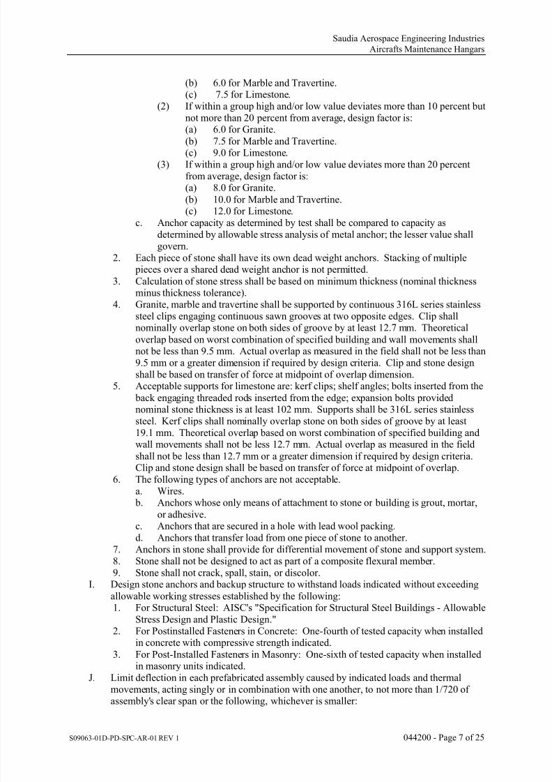
7/18/2019 Volume 2-Part DIII-Book 1 of 6
http://slidepdf.com/reader/full/volume-2-part-diii-book-1-of-6 84/342
Saudia Aerospace Engineering Industries
Aircrafts Maintenance Hangars
S09063-01D-PD-SPC-AR-01 REV 1 044200 - Page 7 of 25
(b) 6.0 for Marble and Travertine.(c) 7.5 for Limestone.
(2) If within a group high and/or low value deviates more than 10 percent butnot more than 20 percent from average, design factor is:(a) 6.0 for Granite.
(b)
7.5 for Marble and Travertine.(c) 9.0 for Limestone.
(3) If within a group high and/or low value deviates more than 20 percentfrom average, design factor is:(a) 8.0 for Granite.
(b) 10.0 for Marble and Travertine.(c) 12.0 for Limestone.
c. Anchor capacity as determined by test shall be compared to capacity asdetermined by allowable stress analysis of metal anchor; the lesser value shallgovern.
2. Each piece of stone shall have its own dead weight anchors. Stacking of multiple
pieces over a shared dead weight anchor is not permitted.3. Calculation of stone stress shall be based on minimum thickness (nominal thicknessminus thickness tolerance).
4. Granite, marble and travertine shall be supported by continuous 316L series stainlesssteel clips engaging continuous sawn grooves at two opposite edges. Clip shallnominally overlap stone on both sides of groove by at least 12.7 mm. Theoretical
overlap based on worst combination of specified building and wall movements shallnot be less than 9.5 mm. Actual overlap as measured in the field shall not be less than9.5 mm or a greater dimension if required by design criteria. Clip and stone designshall be based on transfer of force at midpoint of overlap dimension.
5. Acceptable supports for limestone are: kerf clips; shelf angles; bolts inserted from the
back engaging threaded rods inserted from the edge; expansion bolts provided
nominal stone thickness is at least 102 mm. Supports shall be 316L series stainlesssteel. Kerf clips shall nominally overlap stone on both sides of groove by at least19.1 mm. Theoretical overlap based on worst combination of specified building andwall movements shall not be less 12.7 mm. Actual overlap as measured in the field
shall not be less than 12.7 mm or a greater dimension if required by design criteria.Clip and stone design shall be based on transfer of force at midpoint of overlap.
6. The following types of anchors are not acceptable.a. Wires. b. Anchors whose only means of attachment to stone or building is grout, mortar,
or adhesive.c. Anchors that are secured in a hole with lead wool packing.d. Anchors that transfer load from one piece of stone to another.
7.
Anchors in stone shall provide for differential movement of stone and support system.8. Stone shall not be designed to act as part of a composite flexural member.9. Stone shall not crack, spall, stain, or discolor.
I. Design stone anchors and backup structure to withstand loads indicated without exceeding
allowable working stresses established by the following:1. For Structural Steel: AISC's "Specification for Structural Steel Buildings - Allowable
Stress Design and Plastic Design."2. For Postinstalled Fasteners in Concrete: One-fourth of tested capacity when installed
in concrete with compressive strength indicated.
3. For Post-Installed Fasteners in Masonry: One-sixth of tested capacity when installedin masonry units indicated.
J. Limit deflection in each prefabricated assembly caused by indicated loads and thermalmovements, acting singly or in combination with one another, to not more than 1/720 ofassembly's clear span or the following, whichever is smaller:

7/18/2019 Volume 2-Part DIII-Book 1 of 6
http://slidepdf.com/reader/full/volume-2-part-diii-book-1-of-6 85/342
Saudia Aerospace Engineering Industries
Aircrafts Maintenance Hangars
S09063-01D-PD-SPC-AR-01 REV 1 044200 - Page 8 of 25
1. 1.5 mm, measured in plane of wall.2. 6 mm, measured perpendicular to wall.
K. Provisions for Fabrication and Erection Tolerances: Allow for fabrication and erectiontolerances of building's structural system. Concrete fabrication and erection tolerances arespecified in DIVISION 03 Section "Concrete." Structural-steel fabrication and erection
tolerances are specified in DIVISION 05 Section "Structural Steel Framing."L. Provision for Deflection of Building Structure: Allow for the following:
1. Deflection due to Weight of Dimension Stone Cladding System: Allow for 6-mmvertical deflection in 6-m span of structural members supporting dimension stonecladding system.
2. Live Load Deflection: Allow for 6-mm vertical deflection, in 6-m span of structuralmembers supporting dimension stone cladding system, due to live loads imposed on building's structural frame after stone installation.
M. Leakage Resistance, Water and Air: Provide dimension stone cladding system thatcomplies with the following:1. Air Infiltration: Not more than 0.02 L/s per sq. m of wall area, as measured by testing
prototype per ASTM E283 at a differential pressure of 75 Pa.2. Water Penetration: No uncontrolled water penetration beyond plane of back ofdimension stone cladding system that is not contained or drained back to exterior, asmeasured by testing prototype per ASTM E331 at a differential pressure of 20% of positive design wind load, but not less than 479 Pa).
N. Control of Metal Corrosion and Staining of Stones and Stone Joint Materials:
1. Prevent galvanic and other forms of corrosion as well as staining by isolating metalsand other materials from direct contact with incompatible materials. Use materialsthat do not stain exposed surfaces of stone and joint materials.
2. Use materials that do not stain exposed surfaces of stone and joint materials.3. Select stone materials to avoid sources of stain and discoloration, including the
natural presence of iron oxide content.. Advise as to existing buildings with at least
five years of similar exposure, that have used the proposed stone types, to provideevidence of freedom of the stone from stain and/or discoloration
O. Durability:1. The performance criteria shall be satisfied for the full design life of the works, as
stated in the Specification.2. Atmospheric Considerations:
a. The Contractor shall give due regard to the environment and documentationshall be provided to show that the materials and finishes have been selected to be suitable for the coastal/ urban/ environment. The corrosive category of the
exterior atmosphere around the building shall be taken in accordance with BSEN ISO 12944, BS EN ISO 14713, BS EN 10169 and any other associatedstandards.
b.
In marine/ coastal or other aggressive environments (category C5), aluminumcomponents that are not visible, but exposed to the external environment such as(but not limited to) pressure plates, clips, fixings, secondary rainscreen rails/fixings, panels, sheet materials, etc. shall be protected with a suitable finish such
as a fluoropolymer coating.P. Demountability:
1. Panels shall be individually and independently removable.2. Removal of panels shall not affect the safety of the system.
Q. General Appearance and resistance to degradation:
1. The Contractor shall ensure that in completing the design for the system, that thematerials and methods chosen maintain the general visual and functionalrequirements for the designed life as stated above. Particular attention should begiven to ensuring that the stone surface does not degrade in the marine climate of thesite.

7/18/2019 Volume 2-Part DIII-Book 1 of 6
http://slidepdf.com/reader/full/volume-2-part-diii-book-1-of-6 86/342
Saudia Aerospace Engineering Industries
Aircrafts Maintenance Hangars
S09063-01D-PD-SPC-AR-01 REV 1 044200 - Page 9 of 25
R. Static Coefficient of Friction: For stone installed on walkway surfaces, provide productswith the following values as determined by testing identical products per ASTM C1028:1. Level Surfaces: Minimum 0.6.2. Step Treads: Minimum 0.8.3. Ramp Surfaces: Minimum 0.8.
1.11 QUALITY ASSURANCE:A. Installer Qualifications: A firm or individual experienced in installing dimension stone
cladding systems similar in material, design, and extent to that indicated for this Project,whose work has a record of successful in-service performance.
B. Fabricator Qualifications: Shop that employs skilled workers who custom-fabricatedimension stone cladding systems similar to that required for this Project and whose products have a record of successful in-service performance.1. Fabricator's responsibilities include fabricating dimension stone cladding and
providing professional engineering services needed to assume engineeringresponsibility.
2.
Engineering Responsibility: Comprehensive engineering analysis by a qualified professional engineer.C. Testing Agency Qualifications: An independent agency qualified according to ASTM E329
for testing indicated.D. Source Limitations for Mortar Materials: Obtain mortar ingredients of uniform quality for
each cementitious component from a single manufacturer and each aggregate from onesource or producer.
E. Source Limitations for Other Materials: Obtain each type of stone accessory, sealant, andother material from a single manufacturer for each product.
F. Source Limitations for Stone: Obtain each variety of stone, regardless of finish, from asingle quarry, whether specified in this Section or in another Section of the Specifications,with resources to provide materials of consistent quality in appearance and physical
properties.1. Quarry Assessment: Quarry evaluation, in situ material variability and characteristics,
production facility inspection and quality system assessment shall be carried out byan independent qualified geologist/ stone consultant experienced in the use of naturalstone for external and internal façades, ceilings, soffits, flooring and paving.
2. Representative approval testing blocks (3 No.) shall be selected by a qualifiedgeologist/ stone consultant working for an independent ASTM accredited testinglaboratory. Testing shall be performed at an independent ASTM accredited testinglaboratory. The material selected for testing shall match the agreed project referencecontrol samples.
3. The testing laboratory or supplier shall be engaged to select testing samples at thequarry.
4.
For stone types that include same list of varieties and sources, provide same varietyfrom same source for each.
5. Make quarried blocks available for examination by Owner for appearancecharacteristics.
G. Preconstruction Stone Testing:
1. Perform preconstruction tests as required by this Section.2. Contractor will engage a qualified independent testing agency to perform
preconstruction testing indicated below. Payment for these services will be madeContractor from the Inspection and Testing Allowance, as authorized by ChangeOrders.
3. Retesting of materials that fail to meet specified requirements shall be done atContractor's expense.
4.
Furnish test specimens that are representative of materials proposed for incorporationinto the Work.
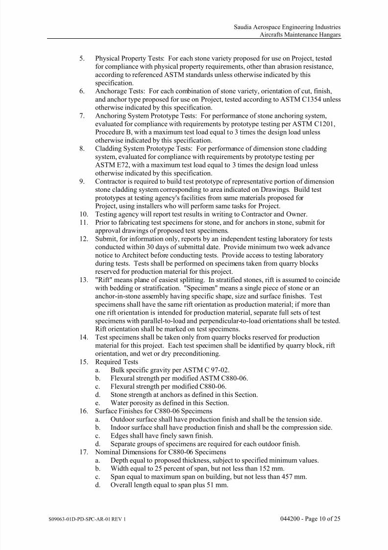
7/18/2019 Volume 2-Part DIII-Book 1 of 6
http://slidepdf.com/reader/full/volume-2-part-diii-book-1-of-6 87/342
Saudia Aerospace Engineering Industries
Aircrafts Maintenance Hangars
S09063-01D-PD-SPC-AR-01 REV 1 044200 - Page 10 of 25
5. Physical Property Tests: For each stone variety proposed for use on Project, testedfor compliance with physical property requirements, other than abrasion resistance,according to referenced ASTM standards unless otherwise indicated by thisspecification.
6. Anchorage Tests: For each combination of stone variety, orientation of cut, finish,
and anchor type proposed for use on Project, tested according to ASTM C1354 unlessotherwise indicated by this specification.
7. Anchoring System Prototype Tests: For performance of stone anchoring system,evaluated for compliance with requirements by prototype testing per ASTM C1201,Procedure B, with a maximum test load equal to 3 times the design load unless
otherwise indicated by this specification.8. Cladding System Prototype Tests: For performance of dimension stone cladding
system, evaluated for compliance with requirements by prototype testing perASTM E72, with a maximum test load equal to 3 times the design load unlessotherwise indicated by this specification.
9. Contractor is required to build test prototype of representative portion of dimension
stone cladding system corresponding to area indicated on Drawings. Build test prototypes at testing agency's facilities from same materials proposed forProject, using installers who will perform same tasks for Project.
10. Testing agency will report test results in writing to Contractor and Owner.11. Prior to fabricating test specimens for stone, and for anchors in stone, submit for
approval drawings of proposed test specimens.
12. Submit, for information only, reports by an independent testing laboratory for testsconducted within 30 days of submittal date. Provide minimum two week advancenotice to Architect before conducting tests. Provide access to testing laboratoryduring tests. Tests shall be performed on specimens taken from quarry blocksreserved for production material for this project.
13. "Rift" means plane of easiest splitting. In stratified stones, rift is assumed to coincide
with bedding or stratification. "Specimen" means a single piece of stone or ananchor-in-stone assembly having specific shape, size and surface finishes. Testspecimens shall have the same rift orientation as production material; if more thanone rift orientation is intended for production material, separate full sets of test
specimens with parallel-to-load and perpendicular-to-load orientations shall be tested.Rift orientation shall be marked on test specimens.
14. Test specimens shall be taken only from quarry blocks reserved for productionmaterial for this project. Each test specimen shall be identified by quarry block, riftorientation, and wet or dry preconditioning.
15. Required Testsa. Bulk specific gravity per ASTM C 97-02. b. Flexural strength per modified ASTM C880-06.
c.
Flexural strength per modified C880-06.d. Stone strength at anchors as defined in this Section.e. Water porosity as defined in this Section.
16. Surface Finishes for C880-06 Specimens
a. Outdoor surface shall have production finish and shall be the tension side. b. Indoor surface shall have production finish and shall be the compression side.c. Edges shall have finely sawn finish.d. Separate groups of specimens are required for each outdoor finish.
17. Nominal Dimensions for C880-06 Specimens
a. Depth equal to proposed thickness, subject to specified minimum values. b. Width equal to 25 percent of span, but not less than 152 mm.c. Span equal to maximum span on building, but not less than 457 mm.d.
Overall length equal to span plus 51 mm.

7/18/2019 Volume 2-Part DIII-Book 1 of 6
http://slidepdf.com/reader/full/volume-2-part-diii-book-1-of-6 88/342
Saudia Aerospace Engineering Industries
Aircrafts Maintenance Hangars
S09063-01D-PD-SPC-AR-01 REV 1 044200 - Page 11 of 25
18. Results shall be reported for all specimens tested. No result shall be disregarded incomputing average values.
19. For each type of stone and finsh proposed for use, perform flexural tests on at least 10specimens each representing at least 5 different quarry blocks shall be tested perC880-06. Separate sets of 10 or more specimens are required for each outdoor finish
for C880-06 tests. Each group of 10 or more specimens shall consist of 2 subgroupsof 5 or more specimens, representing all possible combinations of quarry block andwet or dry conditioning. Specimens shall be identified by quarry block and wet ordry conditioning.Flexural strength determined by test shall be used to compute allowable stress and
shall be smallest of average values computed for each subgroup of 5 or morespecimens tested per C880-06, or smallest of average values computed for eachsubgroup of 5 or more specimens tested per C880-06.Smallest average value of flexural strength shall be reduced by the design factor toobtain allowable stress at design pressures. Results of specified quality control testsmay result in a reduction of initial allowable stress. In the absence of specified test
data, assumed allowable stress for preliminary design shall not exceed 72 MPa forgranite, 1.10 MPa for marble and travertine, and 0.917 MPa for limestone. Finaldesign shall be based on specified preconstruction test results, not assumed values..Final design shall be based on specified preconstruction test results, not assumedvalues.
20. For each type of proposed stone anchor, perform flexural test at least 10 specimens, 2
from each of 5 different quarry blocks. Test at least 5 specimens, each from adifferent block, with inward load, and at least 5 specimens with outward load. Wheretests with inward load may not yield useful information, Contractor may submit forapproval a request that such tests be waived. Crosshead movement shall not exceed0.635 mm per minute. Wet or dry condition of stone shall correspond to weaker
condition as determined by flexural tests. Orientation of rift plane shall correspond to
orientation on building. Stone thicknesses shall be minimum (nominal thicknessminus tolerance) for anchor test specimens. Specimens for continuous kerf anchorsshall have same nominal dimensions as C880-06 specimens, with short edgesfabricated to receive anchors; symmetric load lines shall be one stone thickness
inboard from nearest edge of clips. Result shall be interpreted as stress at bottom ofkerf cut with transfer of force at midpoint of clip/stone overlap. Results shall bereported for all specimens tested. No result shall be disregarded. Strength of stone atan anchor used to compute allowable values shall be the average value for each groupof 5 or more specimens. Prior to fabricating anchor test specimens, submit for
approval drawings of proposed test specimens. Refer to this Section for restrictionsin the use of adhesives with test specimens.
21. For each proposed stone type and finish, perform water porosity test. A minimum of
three specimens is required, each having correct outdoor finish, indoor finish andthickness. Each specimen shall be taken from a different quarry block. Minimumspecimen size is 30.5 by 30.5 cm. Place specimens in horizontal position, outdoorsurface facing upward, such that indoor surface is clearly visible and is not in contact
with any other surface, other than small supports. Air temperature shall be 18 to 29degrees C. Seal to outdoor surface a circular or square sleeve having internal crosssectional area of at least 181 square cm. Sleeve shall be at least 51 mm from stoneedges. Fill sleeve with cold water to a depth of 254 +/- 6 mm. Maintain testconditions for 7 days. Record times at which: dampness is first visible on indoor
surface; water droplets are first visible on indoor surface; dripping of water fromindoor surface begins. If dripping occurs, once during each 24 hour period collectwater for one hour and record volume collected. Formation of water droplets onindoor surface (with or without dripping) constitutes failure. All specimens must pass.

7/18/2019 Volume 2-Part DIII-Book 1 of 6
http://slidepdf.com/reader/full/volume-2-part-diii-book-1-of-6 89/342
Saudia Aerospace Engineering Industries
Aircrafts Maintenance Hangars
S09063-01D-PD-SPC-AR-01 REV 1 044200 - Page 12 of 25
22. Provide double set of test specimens. One set consists of:a. C880-06; total of 10 specimens, 2 specimens taken from each of 5 quarry
blocks. b. Separate sets of 10 or more specimens are required for each outdoor finish for
C880-06 tests.
c.
If production material has more than one rift orientation, separate sets of 10 ormore specimens are required for each of rift orientations parallel and perpendicular to load, for each outdoor finish for C880-06 specimens.
d. Each anchor type in stone; 10 specimens, 2 from each of 5 quarry blocks.e. Water porosity test; 3 specimens for each outdoor finish; each specimen from a
different quarry block.f. C97-02 (density); total of 6 specimens, 3 specimens taken from each of 2 quarry
blocks.g. Test specimens shall be taken only from quarry blocks reserved for production
material for this project. Each test specimen shall be identified by quarry block,rift orientation, and wet or dry preconditioning.
H.
Production Quality Control Testing:1. General:a. Once production of stone for the project commences, the stone shall be tested at
a ASTM accredited test laboratory acceptable to the Owner. to demonstratecompliance with the Specification.
b. Unless otherwise agreed, all test samples for the production testing shall be
selected by an independent qualified geologist/ stone consultant.2. Visual Inspection:
a. The rough edge of each block shall be sawn off exposing a fresh face. The faceshall be visually inspected by an independent qualified geologist/ stoneconsultant for any visible defects, changes in structure or texture, and general
conformance to the aesthetic criteria defined by the Owner. and illustrated in
agreed project reference samples.3. A sufficient test area shall be taken from the slab to prepare all of the proposed tests
in the project bedding orientation.4. Type and frequency of testing shall be agreed in lieu of the preliminary testing results
to maintain a true representation of the material reserved for the project.I. Preconstruction Sealant Compatibility and Adhesion Testing: Submit to joint-sealant
manufacturers, for compatibility and adhesion testing according to sealant manufacturer'sstandard testing methods and DIVISION 07 Section "Joint Sealants," samples of materialsthat will contact or affect joint sealants.
J. Preconstruction Field Testing of Sealants: Before installing joint sealants, field test theiradhesion to joint substrates per requirements specified in DIVISION 07 Section "JointSealants."
K.
Particular Interfaces:1. Complete the Detailed Design of all interfaces with adjoining trades prior to
commencement of manufacture.2. Ensure that all interfaces are fully coordinated prior to commencement.
L. Welding: Qualify procedures and personnel according to AWS D1.1/D1.1M, "StructuralWelding Code--Steel."
M. Prototypes: Build prototypes to verify selections made under sample submittals and todemonstrate aesthetic effects and set quality standards for materials and execution.1. Build prototype of typical wall area as shown on Drawings.
2. Build prototypes of typical exterior wall with dimension stone cladding.a. Show typical components, attachments to building structure, and methods of
installation. b.
Include window opening with stone as indicated on plans.

7/18/2019 Volume 2-Part DIII-Book 1 of 6
http://slidepdf.com/reader/full/volume-2-part-diii-book-1-of-6 90/342
Saudia Aerospace Engineering Industries
Aircrafts Maintenance Hangars
S09063-01D-PD-SPC-AR-01 REV 1 044200 - Page 13 of 25
c. Include sealant-filled joint complying with requirements in DIVISION 07Section "Joint Sealants."
d. If sealant primers, sealants, resin-adhesives, water repellents, and othercompounds are required in the finished stonework, build prototype and applycompounds in sufficient time to allow for final test for staining or other
deleterious effects from such applications.3. Obtain Owner acceptance of prototype before start of stonework. Replace
unsatisfactory work, until acceptable. Retain during construction as a standard for judging completed stonework.
4. Approval of prototypes does not constitute approval of deviations from the Contract
Documents contained in prototypes unless such deviations are specifically approved by Owner in writing.
5. Approved prototypes may become part of the completed Work if undisturbed at timeof Substantial Completion.
N. Quality Benchmark:1. First completed façade and/ or structural bay of façade of each type of stone,
including surface finish as specified, and as agreed with the Owner.
1.12 DELIVERY, STORAGE, AND HANDLING:A. Store and handle stone and related materials to prevent deterioration or damage due to
moisture, temperature changes, contaminants, corrosion, breaking, chipping, and othercauses.1. Lift stone with wide-belt slings; do not use wire rope or ropes that might cause
staining. Move stone, if required, using dollies with cushioned wood supports.2. Store stone on wood skids or pallets with nonstaining, waterproof covers. Arrange to
distribute weight evenly and to prevent damage to stone. Ventilate under covers to prevent condensation.
B. Mark stone units, on surface that will be concealed after installation, with designations used
on Shop Drawings to identify individual stone units. Orient markings on vertical panels sothat they are right side up when units are installed.
C. Deliver sealants to Project site in original unopened containers labeled with manufacturer'sname, product name and designation, color, expiration period, pot life, curing time, andmixing instructions for multicomponent materials.
D. Store cementitious materials on elevated platforms, under cover, and in a dry location. Donot use cementitious materials that have become damp.
E. Store aggregates in locations where grading and other required characteristics can bemaintained and where contamination can be avoided.
1.13 PROJECT CONDITIONS:A. Protect dimension stone cladding during erection as follows:
1.
Cover tops of dimension stone cladding installation with nonstaining, waterproofsheeting at end of each day's work. Cover partially completed structures when workis not in progress. Extend cover a minimum of 600 mm down both sides and holdsecurely in place.
2. Prevent staining of stone from mortar, grout, sealants, and other sources.Immediately remove such materials without damaging stone.
3. Protect base of walls from rain-splashed mud and mortar splatter by coverings spreadon ground and over wall surface.
4. Protect sills, ledges, and projections from mortar and sealant droppings.B. Hot-Weather Requirements: Comply with hot-weather construction and protection
requirements for masonry contained in ACI 530/530.1R /ASCE 6/TMS 602.C. Environmental Limitations for Sealants: Do not install sealants when ambient and substrate
temperatures are outside limits permitted by sealant manufacturer or when joint substratesare wet.

7/18/2019 Volume 2-Part DIII-Book 1 of 6
http://slidepdf.com/reader/full/volume-2-part-diii-book-1-of-6 91/342
Saudia Aerospace Engineering Industries
Aircrafts Maintenance Hangars
S09063-01D-PD-SPC-AR-01 REV 1 044200 - Page 14 of 25
D. Stone cladding installed across structural movement joints shall be designed to even out anydifferences in relation to adjacent joints.
E. The extent of stone profiles shall fit within the dimensional confines as indicated on theDrawings.
F. External wall build up including insulation and backing wall shall achieve the thermal
resistance performance identified within this Section.G. Waterproofing membrane shall be lapped, sealed and flashed. Vapor control layers shall be
incorporated as required.
1.14 COORDINATION:A. Complete the Detailed Design of all interfaces with adjoining trades prior to
commencement of manufacture.B. Ensure that all interfaces are fully coordinated prior to commencement.C. Coordinate installation of inserts that are to be embedded in concrete or masonry, flashing
reglets, and similar items to be used by dimension stone cladding Installer for anchoring,supporting, and flashing of dimension stone cladding system. Furnish setting drawings,
templates, and directions for installing such items and deliver to Project site in time forinstallation.D. Time delivery and installation of dimension stone cladding to avoid extended on-site
storage and to coordinate with work adjacent to dimension stone cladding.
1.15 WARRANTYA. Provide written warranty agreeing to repair or replace defective materials and workmanship
during warranty period. Defective materials and workmanship include, but are not limitedto:1. Abnormal deterioration, aging or weathering of stone fixings, insulation, stone
cladding, mortar or sealant joints.2. Structural failure of stone fixings or stone.
3.
Sealant (including structural silicone) loss of adhesion, loss of cohesion, cracking ordiscoloration.
4. Disengagement of gaskets, weatherstrips, trim or other components.5. Deterioration or discoloration of stone, mortar or joint sealant.6. Collapse or deterioration of thermal insulation.7. Cracking or spalling of stone.8. Staining of stone by sealant, primer, adhesive or other material in contact with stone
or within stone.B. Warranty does not include damage caused by vandalism, or natural conditions exceeding
the performance requirements. Warranty and its enforcement shall not deprive Owner ofother action, right or remedy.
C. Warranty period for entire system shall be 15 years from date of substantial completion.
System warranty includes materials and labor.D. Certain materials are required to have special warranties. Special warranties shall not limit
or reduce requirements of system warranty. Special warranties may originate, in part or inwhole, with manufacturers or fabricators and pass through Contractor to Owner.Warranties as written or interpreted by manufacturers or fabricators shall not limit orreduce special warranty requirements of this Section.
PART 2 - PRODUCTS
2.01 GRANITE:A. Granite: Comply with ASTM C615, Architectural Grade, and the National Building
Granite Quarries Association, Inc., for color and finish qualities.
B.
Description: Uniform grained stone.C. Basis-of-Design Variety and Source: Subject to compliance with requirements.

7/18/2019 Volume 2-Part DIII-Book 1 of 6
http://slidepdf.com/reader/full/volume-2-part-diii-book-1-of-6 92/342
Saudia Aerospace Engineering Industries
Aircrafts Maintenance Hangars
S09063-01D-PD-SPC-AR-01 REV 1 044200 - Page 15 of 25
D. Cut: As selected by Architect.1. Orientation of Veining: As indicated.
E. Cut stone from one block or contiguous, matched blocks in which natural markings occur.F. Match Architect's samples for color, finish, and other stone characteristics relating to
aesthetic effects.
G.
Thickness: As indicated.
2.02 LIMESTONE:A. Limestone: Comply with ASTM C 568, Category II (high density), with minimum
compressive strength of 55MPa per ASTM C170 and maximum absorption of 3% perASTM C97 average flexural strength of 7.8 KPA (based on the specified minimum of tenflexural tests for the stone, five dry and 5 wet, with no individual stone test result less than4.8 KPA and the stone shall be a durability Class A stone with weight loss of less than 1% based on a salt crystallization test per BS EN 12370.
B. Description: Limestone type as selected byArchitect.C. Basis-of-Design Variety and Source: Subject to compliance with requirements.
D.
Cut: Uniform grained stone.1.
Orientation of Veining: As indicated.E. Cut stone from one block or contiguous, matched blocks in which natural markings occur.F. Match Architect's samples for color, finish, and other stone characteristics relating to
aesthetic effects.G. Thickness: As indicated.
2.03 MARBLE:A. Marble: Comply with ASTM C503, Classification II Dolomite.B. Description: Uniform, fine- to medium-grained, stone with only slight veining.C. Basis-of-Design Variety and Source: Subject to compliance with requirements.D. Cut: As selected by Architect..
1.
Orientation of Veining: As indicated.E. Cut stone from one block or contiguous, matched blocks in which natural markings occur.F. Match Architect’s samples for color, finish, and other stone characteristics relating to
aesthetic effects.G. Thickness: As indicated.
2.04 STONE JOINT BONDING AGENTA. Stone bonding agent to be selected by stone supplier/fabricatior that best matches the stone
being supplied.B. Stone bonding agent strength and durability should be equal to, or greater than, the
performance of the stone that is being used.C. Stone bonding agent shall be nonstaining, UV Resistant and not fade or discolor over time.
D.
Provide mechanical reinforcement (stainless steel clip angle with bolt connection) at backside of stone panel in addition to bonding material. Mechanical reinforcement shall meetstructure requirement.
2.05 SEALANTSA. Sealant manufacturer complying with requirements in DIVISION 07 Section "Joint
Sealants" and indicating that sealants will not stain or damage stone.
2.06 STONE TYPE GENERAL:A. General Requirements:
1. Clad elements:
a. Finished front face and a finished reveal to one side only.

7/18/2019 Volume 2-Part DIII-Book 1 of 6
http://slidepdf.com/reader/full/volume-2-part-diii-book-1-of-6 93/342
Saudia Aerospace Engineering Industries
Aircrafts Maintenance Hangars
S09063-01D-PD-SPC-AR-01 REV 1 044200 - Page 16 of 25
2. The pieces will be made for reviewing different combinations and should be mountedon a base with equipment to interchange options for the Inner, Outer layers andStringcourse. The substructure and fixing brackets are to the contractor’s design.
3. Exterior joint size should be not less than a 10 mm (±2mm) flush sealant joints(unless otherwise noted) to match color of final stone selected. Stone dust shall be
applied on the uncured surface of sealant joint to match color of final stone selected.Provide control joint required to comply with all specified building movements,where mortar joints are used. Coordinate with Owner for final control joint location.Stone jointing should be sealant struck flush with the finished face of stone, color tomatch stonework. The sealant should be installed using a compressible, closed cell,
non-gassing backing rod.4. Where combinations of stones are required on the same piece, the stones should be
used in an equal quantity and evenly spread across the face of the piece in a randommanner. The random distribution of stones shall ensure that any given stone typeshall not be adjacent to the same type three times in a row (either horizontally,vertically or diagonally).
B.
Interior Stone Joint:1. Interior joint should be 5 mm mortar joint to match color of final stone selected.2. Provide control joints horizontally and vertically. Coordinate control joint location
with Architect.3. Control joint shall match mortar joint color.4. Interior ceiling joint should be 10 mm (±2 mm) sealant joint to match color of final
stone selected.5. Interior Marble Joints: 6 mm mortar joint.
2.07 MORTAR MATERIALS:A. Mortar joints shall meet the relevant standards and be compatible with the final stone
selected. Joint color shall be customized to match final stones selected. Final finish shall
be as accepted by the Owner following sample submittals.B. Portland Cement: ASTM C150, Type I, Type II, or Type III. Provide natural color or
white cement as required to produce mortar color indicated.1. Low-Alkali Cement: Portland cement for use with limestone shall contain not more
than 0.60 percent total alkali when tested according to ASTM C114.
C. Hydrated Lime: ASTM C207.D. Portland Cement-Lime Mix: Packaged blend of portland cement complying with
ASTM C150, Type I or Type III, and hydrated lime complying with ASTM C207.E. Colored Portland Cement-Lime Mix: Packaged blend of portland cement complying with
ASTM C150, Type I or Type III; hydrated lime complying with ASTM C207; and mortar
pigments. Use a mix of formulation required to produce color indicated or, if not indicated,as selected from manufacturer's standard formulations. Pigments shall not exceed 10% of
portland cement by weight.1. Basis-of-Design Products: Subject to compliance with requirements, provide one of
the following:a. Essroc Italcementi Group
F. Aggregate: ASTM C144; except for joints narrower than 6 mm and pointing mortar, use
aggregate graded with 100% passing 1.18-mm sieve.1. White Aggregates: Natural white sand or ground white stone.2. Colored Aggregates: Natural-colored sand or ground marble, granite, or other
durable stone; of color necessary to produce required mortar color.a. Basis-of-Design Products: Subject to compliance with requirements, provide
one of the following available products that may be incorporated into the Workinclude, but are not limited to, the following:
(1)
Essroc Italcementi Group

7/18/2019 Volume 2-Part DIII-Book 1 of 6
http://slidepdf.com/reader/full/volume-2-part-diii-book-1-of-6 94/342
Saudia Aerospace Engineering Industries
Aircrafts Maintenance Hangars
S09063-01D-PD-SPC-AR-01 REV 1 044200 - Page 17 of 25
G. Mortar Pigments: Natural and synthetic iron oxides, compounded for use in mortar mixes.Use only pigments with a record of satisfactory performance in mortar and containing nocarbon black.1. Basis-of-Design Products: Subject to compliance with requirements, provide one of
the following:
a.
Essroc Italcementi GroupH. Water: Potable.
2.08 ANCHORS AND FASTENERS:A. Fabricate anchors, including shelf angles, from stainless steel, ASTM A666, Type 316 L for
exterior fixings and Type 304 for interior fixings, temper as required to support loadsimposed without exceeding allowable design stresses. Fabricate dowels and pins foranchors from stainless steel, ASTM A276, Type 316L for exterior fixings and Type 304 forinterior fixings.
B. Postinstalled Anchor Bolts for Concrete and Masonry: Chemical anchors, torque-controlledexpansion anchors or undercut anchors made from stainless-steel components complying
with ASTM F738M and ASTM F836M, Alloy Group A1 or A4 for bolts and nuts;ASTM A666 or ASTM A276, Type 316L, for anchors, with capability to sustain, withoutfailure, a load equal to 4 times the loads imposed, for concrete, or 6 times the load imposed,for masonry, as determined by testing per ASTM E488, conducted by a qualifiedindependent testing agency.
C. Threaded Fasteners: Heavy hexagon structural bolts, heavy hexagon nuts, and hardenedwashers.1. For stainless steel, use annealed stainless-steel bolts, nuts, and washers;
ASTM F738M for bolts; and ASTM F836M for nuts, Alloy Group A4.D. Weld Plates for Installation in Concrete: Comply with DIVISION 05 Section "Metal
Fabrications."
2.09
STONE ANCHORING SYSTEM:A. Metal-Stone Anchoring System: Provide manufacturer's standard integrated system that
combines metal clips, angles, fittings, fasteners, and stone anchors and that is engineeredexpressly for mechanically installing dimension stone cladding and that complies with thefollowing requirements:
B. Clips, Angles, Fittings and Fasteners: System manufacturer's standard components ofdesign, size, and material required to securely attach stone to building structure, by methodindicated or selected. Fabricate components in contact with stone from same materialspecified for anchors.
C. Stone Anchors: Shapes and sizes standard with system manufacturer, complying with"Anchors and Fasteners" Article.
2.10
STONE ACCESSORIES:A. Setting Shims: Strips of vulcanized neoprene, Type A Shore durometer hardness of 50 to
70, nonstaining to stone, of thickness needed to prevent point loading of stone on anchorsand of depths to suit anchors without intruding into required depths of pointing materials.
B. Setting Buttons: Resilient plastic buttons, nonstaining to stone, sized to suit jointthicknesses and bed depths of stone units without intruding into required depths of pointingmaterials.
C. Concealed Sheet Metal Flashing: Fabricate from zinc-tin alloy-coated stainless steel inthicknesses indicated, but not less than 0.4 mm thick. Comply with requirements specifiedin DIVISION 07 Section "Sheet Metal Flashing and Trim."
D. Weep and Vent Tubes: Rectangular, cellular, polypropylene or clear butyrate extrusion, 9 by 38 mm and of length required to extend from exterior face of stone to cavity behind.

7/18/2019 Volume 2-Part DIII-Book 1 of 6
http://slidepdf.com/reader/full/volume-2-part-diii-book-1-of-6 95/342
Saudia Aerospace Engineering Industries
Aircrafts Maintenance Hangars
S09063-01D-PD-SPC-AR-01 REV 1 044200 - Page 18 of 25
E. Wicking Material: Absorbent rope, made from UV-resistant synthetic fiber, 16 to 10 mm indiameter, in length required to produce 50-mm exposure on exterior and 450 mm in cavity between wythes.
F. Cementitious Dampproofing for Limestone: Provide cementitious formulations that arerecommended by ILI and that are nonstaining to stone, compatible with joint sealants, and
noncorrosive to anchors and attachments. Dampproofing shall be applied on backs, beds,and joints of all stones used at grade. Dampproof all adjacent concrete surfaces on whichlimestone will rest, including concrete or cmu haunches and ledges, as well as supportangles.1. Dampproof unexposed surfaces of stone to at least 1220-mm above grade.
2. Dampproof joints only to within 25-mm of finished surfaces when using bituminousor asphaltic solutions.
3. Stones extending below grade shall be dampproofed as above, and in addition shall bedampproofed to the level of grade on their face surfaces which are covered.
4. Cementitious coatings must be allowed to cure before treated stone is set. Due caremust be exercised in handling all dampproofed stone to avoid chipping or off-setting.
G.
Expansion and Control Joints:1. Joints shall be adequate to allow for thermal and structural differential movement.Filler material for these joints shall be nonstaining and compatible with the sealingcompound.
2. Location of control joints shall be 7.5 meter by 7.5 meter maximum and coordinatedwith Owner.
H. Joint Sealant:1. Sealant manufacturer complying with requirements in DIVISION 07 Section "Joint
Sealants" and indicating that sealants will not stain or damage stone.2. Primer, when required, shall be nonstaining and nonacidic, and shall be used as
recommended by manufacturer of primer in writing to Owner, having been tested
before for staining and durability on samples of actual surfaces to be primed. If
primers are required, they should be applied to the confines of joint surfaces afterstone is installed into the wall. In some instances it may be advisable to apply primerto the stone before the stone is installed into the wall. Application procedures should be as recommended by manufacturer of the primer, in writing, to the Owner.
3. Backup materials and preformed joint fillers shall be nonstaining, compatible withsealant and primer, and of a resilient nature, such as closed cell resilient foam asspecified in DIVISION 07 Section "Joint Sealants", sponge rubber, or of a supportingtype, such as closed cell rigid foam, cork or non-impregnated fiberboard. Materialsimpregnated with oil, bitumen or similar materials shall not be used. Size and shape
shall be as indicated by joint detail in Drawings. Sealant shall not adhere to backupmaterial and shall be as recommended by sealant manufacturer in writing to Owner.
4. Bond breakers, when required, shall be (polyethylene tape)-(other) as recommended
by manufacturer of sealant in writing to Owner.5. Solvents, cleaning agents and other accessory materials shall be nonstaining to and
shall be recommended by sealant manufacturer in writing to the Owner.I. Clear Sealer:
1. Sealant, when required, shall be non-staining and non-acidic, and shall be used asrecommended by the dimension stone supplier and manufacturer of sealant in writingto Owner, having been tested before for staining and durability on samples of actualsurfaces to be sealed. (If sealants are required, they should be applied to the confinesof joint surfaces after stone is installed into the wall. In some instances it may be
advisable to apply sealant to the stone before the stone is installed into the wall.Application procedures should be as recommended by manufacturer of the sealant, inwriting, to the Owner.

7/18/2019 Volume 2-Part DIII-Book 1 of 6
http://slidepdf.com/reader/full/volume-2-part-diii-book-1-of-6 96/342
Saudia Aerospace Engineering Industries
Aircrafts Maintenance Hangars
S09063-01D-PD-SPC-AR-01 REV 1 044200 - Page 19 of 25
2. This is an OPTIONAL treatment to be applied onto front face, and all edges of eachstone and should be costed as an option only and does not form part of the "Basis ofDesign". Further review is required upon presentation of prototype panels.
3. Stone/s selected shall meet and/or aim to exceed the performance criteria identified inthis specification. Sealant shall not be applied to compensate for the performance of
the stone; sealant shall only be applied to the stone in addition to meeting the performance criteria of the stone itself.
4. Final finish shall be as accepted by Owner.5. Sealant shall be to Contractor’s selection, a Basis-of-Design product is 500
EuroSealer SS by Eurobuild Construction Chemicals and Coatings.
J. Sealant for Filling Kerfs: Same sealant used for joints in dimension stone.1. Products: Subject to compliance with requirements, provide one of the following:
a. Tremco, Sealant/Waterproofing Division; Spectrem 2.K. Install mortar dropping collection device for masonry / stone cavity walls that keeps weep
hole vents open and flashing free of mortar droppings and debris by catching and permanently suspending droppings above the level of the top of the weep hole vents, by
preventing mortar from forming a continuous barrier against proper water flow to theweeps and by providing routes through the body of the product itself for waterto flow tothe flashing and weeps.
2.11 STONE FABRICATION:A. General: Fabricate stone units in sizes and shapes required to comply with requirements
indicated, including details on Drawings and Shop Drawings.1. For granite, comply with recommendations in NBGQA's "Specifications for
Architectural Granite."2. For limestone, comply with recommendations in ILI's "Indiana Limestone
Handbook."3. For marble, comply with recommendations in MIA's "Dimensional Stone--Design
Manual IV."B. Control depth of stone and back check to maintain minimum clearance of 25 mm between
backs of stone units and surfaces or projections of structural members, thermal insulationwithin the wall cavity, fireproofing (if any), backup walls, and other work behind stone.
C. Dress joints (bed and vertical) straight and at right angle to face, unless otherwise indicated.
Shape beds to fit supports.D. Cut and drill sinkages and holes in stone for anchors, fasteners, supports, and lifting devices
as indicated or needed to set stone securely in place.E. Form splayed vertical returns and heads to windows, stone shall be integral to the adjacent
cladding.
F. Finish exposed faces and edges of stone, except sawed reveals, to comply withrequirements indicated for finish and to match approved samples and prototypes.
G.
Form "L" shaped corners in plan, unless otherwise indicated; provide for cramp anchoragein top and bottom bed joints of corner pieces.
H. Cut or drill holes for surface or recessed lighting and power cable routes to soffit lightingwhere indicated on the Drawings.
I. Quirk-miter corners, unless otherwise indicated; provide for cramp anchorage in top and
bottom bed joints of corner pieces.J. Cut stone to produce uniform joints 10mm (±2mm) wide as required in locations indicated.
1. Matching Areas of Wall Paneling: Fabricate from one block or continuous blocks,where shown or delineated as a continuous area of sequenced matched veining.
K. Contiguous Work: Provide chases, reveals, reglets, openings, and similar features as
required to accommodate contiguous work.L. Fabricate molded work, including washes and drips, to produce stone shapes with a uniform
profile throughout entire unit length, with precisely formed arris slightly eased to preventsnipping, and with matching profile at joints between units.

7/18/2019 Volume 2-Part DIII-Book 1 of 6
http://slidepdf.com/reader/full/volume-2-part-diii-book-1-of-6 97/342
Saudia Aerospace Engineering Industries
Aircrafts Maintenance Hangars
S09063-01D-PD-SPC-AR-01 REV 1 044200 - Page 20 of 25
1. Produce moldings and molded edges with machines that use abrasive shaping wheelsmade to reverse contour of molding shape.
M. Stone Surface Finish: Refer to Visual and Operational Requirements. N. Clean backs of stone to remove rust stains, iron particles, and stone dust.O. Inspect finished stone units at fabrication plant for compliance with requirements for
appearance, material, and fabrication. Replace defective units.1. Grade and mark stone for overall uniform appearance when assembled in place.
Natural variations in appearance are acceptable if installed stone units match range ofcolors and other appearance characteristics represented in approved samples and prototypes.
P. CE Marking of Stone.1. The following information shall be supplied either on the packaging or on the
delivery note:a. The petrographical name of the stone. b. The commercial name of the stone.c. The name and address of the supplier.
d.
The name and location of the quarry.e. Reference to ASTM.f. The declared value or marking designation classes.g. Other information, e.g. surface chemical treatments.h. Other information as required by ASTM including:
(1) Breaking strength.
(2) Abrasion.
2.12 MORTAR MIXES:A. General: Comply with referenced standards and with manufacturers' written instructions
for mix proportions, mixing equipment, mixer speeds, mixing containers, mixing time, andother procedures needed to produce mortar of uniform quality and with optimum
performance characteristics.1. Do not use admixtures, including pigments, air-entraining agents, accelerators,
retarders, water-repellent agents, antifreeze compounds, or other admixtures, unlessotherwise indicated. Do not use calcium chloride.
2. Combine and thoroughly mix cementitious materials, water, and aggregates in a
mechanical batch mixer, unless otherwise indicated. Discard mortar when it hasreached initial set.
B. Portland Cement-Lime Setting Mortar: Comply with ASTM C270, ProportionSpecification, for types of mortar indicated below:1. Set granite with Type S mortar.
2. Set limestone with Type N mortar.3. Set marble with Type S mortar.
C.
Pointing Mortar: Comply with ASTM C270, Proportion Specification, for types of mortarindicated. Provide pointing mortar mixed to match Owner ’s sample and complying withthe following:1. Pigmented Pointing Mortar: Select and proportion pigments with other ingredients to
produce color required. Do not exceed pigment-to-cement ratio of 1:10, by weight.
2. Packaged Portland Cement-Lime Mix Mortar: Use portland cement-lime mix ofselected color.
3. Colored-Aggregate Pointing Mortar: Produce color required by combining coloredaggregates with portland cement of selected color.
4. Point granite with Type N mortar.
5. Point limestone with Type N mortar.6. Point marble with Type N mortar.

7/18/2019 Volume 2-Part DIII-Book 1 of 6
http://slidepdf.com/reader/full/volume-2-part-diii-book-1-of-6 98/342
Saudia Aerospace Engineering Industries
Aircrafts Maintenance Hangars
S09063-01D-PD-SPC-AR-01 REV 1 044200 - Page 21 of 25
2.13 SOURCE QUALITY CONTROL:A. Source Quality-Control Testing Service: Contractor will employ an independent testing
agency to perform source quality-control testing indicated below. Payment for theseservices will be made by Contractor from the Inspection and Testing Allowance, asauthorized by Change Orders.
B.
Source Quality-Control Testing Service: Engage a qualified independent testing agency to perform source quality-control testing indicated below.1. Retesting of materials that fail to meet specified requirements shall be done at
Contractor's expense.2. Furnish test specimens selected by testing agency from same blocks as actual
materials proposed for incorporation into the Work.3. Flexural Strength Tests: ASTM C880, performed on specimens of same thickness,
orientation of cut, and finish as installed stone. One set of test specimens is requiredto be tested for every 500 sq. m, but not fewer than 2 sets for each stone variety.a. If within all subgroups high and low values deviate 10 percent or less from
average, design factor is 3.0 for granite, 4.0 for marble and travertine, and 5.0
for limestone. b. If within one or more subgroups high and/or low value deviates more than 10 percent but not more than 20 percent from average, design factor is 4.0 forgranite, 5.0 for marble and travertine, and 6.0 for limestone.
c. If within one or more subgroups high and/or low value deviates more than 20 percent from average, design factor is 6.0 for granite, 7.0 for marble and
travertine, and 8.0 for limestone.C. Testing agency will report test results in writing to Owner and Contractor.D. Fabrication Tolerances:
1. Generally:a. The works shall be free from vents, cracks, fissures, discoloration, or other
defects that may adversely affect strength, durability or appearance.
2.
Sizes Generally:a. Panels shall be cut accurately to size. They shall hold out square at the back, i.e.
without corners broken away whereby the strength of the fixings system may beimpaired.
3. Permissible Deviations:a. The length and height face dimensions shall not vary from those specified by
more than ± 1.5mm in 1200mm. b. The thickness of each unit shall not vary from that specified by more than
+3mm or +10%, whichever is the more onerous. Thicknesses behind fixing
mortise positions shall be consistent.c. On the front surface of the stone the permissible tolerance from stone to stone
shall be ±2mm.
d.
Units, other than where required to be shaped, shall be square at all faces so thatany deviations in length or height dimensions are uniform and shall achieveuniform joint widths. The edges shall also be square.
4. System Production:
a. All load bearing and restraint fixings, including all jointing between units andadjacent elements as detailed, shall be designed and provided.
b. A range of samples to be inspected by the Owner for selection shall be arranged.c. All stone materials shall match the color and finish of a previously agreed
sample.
PART 3 - EXECUTION
3.01
EXAMINATION:
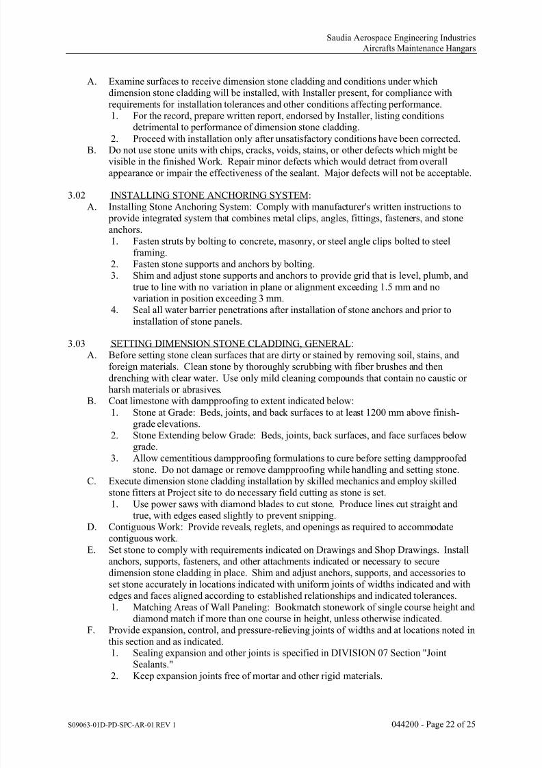
7/18/2019 Volume 2-Part DIII-Book 1 of 6
http://slidepdf.com/reader/full/volume-2-part-diii-book-1-of-6 99/342
Saudia Aerospace Engineering Industries
Aircrafts Maintenance Hangars
S09063-01D-PD-SPC-AR-01 REV 1 044200 - Page 22 of 25
A. Examine surfaces to receive dimension stone cladding and conditions under whichdimension stone cladding will be installed, with Installer present, for compliance withrequirements for installation tolerances and other conditions affecting performance.1. For the record, prepare written report, endorsed by Installer, listing conditions
detrimental to performance of dimension stone cladding.
2.
Proceed with installation only after unsatisfactory conditions have been corrected.B. Do not use stone units with chips, cracks, voids, stains, or other defects which might be
visible in the finished Work. Repair minor defects which would detract from overallappearance or impair the effectiveness of the sealant. Major defects will not be acceptable.
3.02 INSTALLING STONE ANCHORING SYSTEM:A. Installing Stone Anchoring System: Comply with manufacturer's written instructions to
provide integrated system that combines metal clips, angles, fittings, fasteners, and stoneanchors.1. Fasten struts by bolting to concrete, masonry, or steel angle clips bolted to steel
framing.
2.
Fasten stone supports and anchors by bolting.3.
Shim and adjust stone supports and anchors to provide grid that is level, plumb, andtrue to line with no variation in plane or alignment exceeding 1.5 mm and novariation in position exceeding 3 mm.
4. Seal all water barrier penetrations after installation of stone anchors and prior toinstallation of stone panels.
3.03 SETTING DIMENSION STONE CLADDING, GENERAL:A. Before setting stone clean surfaces that are dirty or stained by removing soil, stains, and
foreign materials. Clean stone by thoroughly scrubbing with fiber brushes and thendrenching with clear water. Use only mild cleaning compounds that contain no caustic orharsh materials or abrasives.
B.
Coat limestone with dampproofing to extent indicated below:1. Stone at Grade: Beds, joints, and back surfaces to at least 1200 mm above finish-
grade elevations.2. Stone Extending below Grade: Beds, joints, back surfaces, and face surfaces below
grade.3. Allow cementitious dampproofing formulations to cure before setting dampproofed
stone. Do not damage or remove dampproofing while handling and setting stone.C. Execute dimension stone cladding installation by skilled mechanics and employ skilled
stone fitters at Project site to do necessary field cutting as stone is set.1. Use power saws with diamond blades to cut stone. Produce lines cut straight and
true, with edges eased slightly to prevent snipping.D. Contiguous Work: Provide reveals, reglets, and openings as required to accommodate
contiguous work.E. Set stone to comply with requirements indicated on Drawings and Shop Drawings. Install
anchors, supports, fasteners, and other attachments indicated or necessary to securedimension stone cladding in place. Shim and adjust anchors, supports, and accessories toset stone accurately in locations indicated with uniform joints of widths indicated and withedges and faces aligned according to established relationships and indicated tolerances.1. Matching Areas of Wall Paneling: Bookmatch stonework of single course height and
diamond match if more than one course in height, unless otherwise indicated.F. Provide expansion, control, and pressure-relieving joints of widths and at locations noted in
this section and as indicated.1. Sealing expansion and other joints is specified in DIVISION 07 Section "Joint
Sealants."
2.
Keep expansion joints free of mortar and other rigid materials.

7/18/2019 Volume 2-Part DIII-Book 1 of 6
http://slidepdf.com/reader/full/volume-2-part-diii-book-1-of-6 100/342
Saudia Aerospace Engineering Industries
Aircrafts Maintenance Hangars
S09063-01D-PD-SPC-AR-01 REV 1 044200 - Page 23 of 25
G. Install concealed flashing at continuous shelf angles, lintels, ledges, and similar obstructionsto downward flow of water to divert water to building exterior. Seal all flashing splices andend dams, and seal underside of flashing to sub-strate below, to provide a complete andwater-tight flashing installation.
H. Keep cavities open where unfilled space is indicated between back of stone units and
backup wall; do not fill cavities with mortar or grout.1. Place weep holes in joints where moisture may accumulate, including base of cavity
walls, above shelf angles, and flashing. Locate weep holes at intervals not exceeding600 mm. Use weep and vent tubes or wicking material.
2. Place vents in cavity walls at tops of cavities, below shelf angles and flashing, and at
intervals not exceeding 6 m vertically. Locate vents in joints at intervals notexceeding 1500 mm horizontally. Use weep and vent tubes.
3.04 SETTING MECHANICALLY ANCHORED DIMENSION STONE CLADDING:A. Attach anchors securely to stone and to backup surfaces. Comply with recommendations in
ASTM C1242.
B.
Seal all water barrier penetrations after installation of stone anchors and prior to installationof stone panels.C. Fixings to withstand all imposed dead and live loads, including wind and suction pressures
appropriate to the degree of exposure and height above ground level.D. Fixings shall allow for three-way adjustment to allow for proper fit within pre-cut mortises
in the stone and to the substrate.E. Provide compressible filler in ends of dowel holes and bottoms of kerfs to prevent end
bearing of dowels and anchor tabs on stone. Fill remainder of anchor holes and kerfs withsealant indicated for filling kerfs.
F. Set stone supported on clips or continuous angles on resilient setting shims. Use material ofthickness required to maintain uniform joint widths and to prevent point loading of stone onanchors. Hold shims back from face of stone a distance at least equal to width of joint.
3.05 JOINT-SEALANT INSTALLATION:A. Prepare joints and apply sealants of type and at locations indicated to comply with
applicable requirements in DIVISION 07 Section "Joint Sealants."
3.06 SETTING DIMENSION STONE CLADDING WITH MORTAR:A. Set stone in full bed of mortar with head joints filled, unless otherwise indicated.B. Embed ends of sills in mortar; leave remainder of joint open until final pointing.C. Rake out joints for pointing with mortar to depths of not less than 12mm. Rake joints to
uniform depths with square bottoms and clean sides.D. Prepare stone-joint surfaces for pointing with mortar by removing dust and mortar
particles. Where setting mortar was removed to depths greater than surrounding areas,
apply first layer of pointing mortar in layers not more than 2 mm until a uniform depth isformed.
E. Point stone joints by placing pointing mortar in layers not more than 9mm (±2mm).Compact each layer thoroughly and allow to become thumbprint hard before applying nextlayer.
F. Tool joints with a round jointer having a diameter 3mm larger than width of joint, when pointing mortar is thumbprint hard.
G. Rake out mortar from sealant-pointed joints to depths of not less than 12 mm nor less thanthat required for sealant and sealant backing. Rake joints to uniform depths with square bottoms and clean sides.
3.07 INSTALLATION TOLERANCES:
A.
Level Across Joints:

7/18/2019 Volume 2-Part DIII-Book 1 of 6
http://slidepdf.com/reader/full/volume-2-part-diii-book-1-of-6 101/342
Saudia Aerospace Engineering Industries
Aircrafts Maintenance Hangars
S09063-01D-PD-SPC-AR-01 REV 1 044200 - Page 24 of 25
1. The maximum deviation between surfaces either side of a joint, including movement joints shall be:a. 1mm for joints less than 6mm wide (±0.5mm). b. 2mm for joints 6mm or greater in width (± 0.5mm).
B. Installation Tolerances:
1.
The works shall be installed to achieve the following:a. Vertical tolerance: ±1mm over 2000mm from its notional setting-out position. b. Horizontal tolerance: ±1mm over 2000mm from its notional setting-out position.c. Flatness: The variation in gap under a straightedge placed anywhere on the
surface shall be not more than the following:
(1) 2.5mm under a 3m straightedge.(2) 1mm under a 1m straightedge.
d. Straight lines and flat planes in all directions.2. The installation shall accommodate all required tolerances including differences
between actual Site dimensions and dimensions indicated on the Drawings.3. Account shall be taken of the installation tolerance requirements such that repetitive
units are accurately located, relative to each other.4. The maximum offset in plane, level or section of the works from design datum shall be ±2mm.
5. The maximum offset in plane, level or section between any two adjacent sectionsshall be ±1mm.
6. Joints shall be located to within ±2mm of their design location.
7. The works shall be flat, flush and true at abutments with adjacent surfaces.8. The works shall be installed such that finished surfaces shall be installed to achieve
the design tolerances, providing a flush, true and flat interface with adjacent finishes,free from steps, slopes or flaws.
9. Bay divisions and movement joints shall be accommodated in the design and
coordinated with joints and other elements as indicated on the Drawings.
10.
Cut-outs for interfacing works shall comply with the dimensions indicated on theDrawings ±1mm.
11. At the time of completion, the visual requirements of the works are such that withinany planning grid section the allowable tolerances are achieved.
12. On-Site Dimensions:a. All dimensions to be checked on Site. b. The final design shall accommodate all specified tolerances and differences
between actual Site dimensions and dimensions shown on the Shop Drawings.C. Setting Out:
1. Finishes shall be set out on a grid as indicated on the Shop Drawings and as accepted by the Owner.
2. Joints shall be true to line, continuous and without steps.
3.
Joints shall be parallel to the main axes of the space or other specified features.4. Cuts shall be kept to the minimum, as large as possible and in unobtrusive locations.5. Where positions of movement joints are not specified they shall be agreed with the
Owner prior to installation.
3.08 FIELD QUALITY CONTROL:A. Field Quality-Control Water Leakage Test: Test dimension stone cladding system.
Perform field hose tests for resistance to water leakage. Test areas shall be as selected by the Owner. Each test area shall be one bay wide by two floors high, or 37 m2,whichever is greater. There shall be no unacceptable water leakage as defined in this
Section. Provide powered scaffold, hose, water supply and manpower to perform atleast two successful tests, plus any unsuccessful tests. Water testing shall be conducted
early in construction schedule. Construction sequence shall include provisions for

7/18/2019 Volume 2-Part DIII-Book 1 of 6
http://slidepdf.com/reader/full/volume-2-part-diii-book-1-of-6 102/342
Saudia Aerospace Engineering Industries
Aircrafts Maintenance Hangars
S09063-01D-PD-SPC-AR-01 REV 1 044200 - Page 25 of 25
timely completion of test areas. Remedial measures shall maintain standards of qualityand durability and are subject to approval.
B. Conduct test with Monarch Type B-25 #6.030 brass nozzle and 19 mm diameter hose.Water pressure to nozzle shall be in the range 206.8Kpa to 241 Kpa. Working upwardfrom bottom of test area, direct water at 2 m long segments of seals, joints and
perimeters, moving slowly back and forth on each segment for minimum of 5 minutes.Sustained spraying at one point while the nozzle remains stationary is acceptable. Tip ofnozzle shall be 300 mm from specimen exterior surface. Nozzle shall generally be perpendicular to specimen surface, but shall be tilted to any angle that maximizesexposure of a given joint to water flow rate and kinetic energy. Continuously check for
leakage on indoor side. If necessary to pinpoint leak sources, perform additional testing.Repeated testing of joints is acceptable. The use of masking to pinpoint leaks isacceptable.
C. Check completed areas below test area, and report any leaks that occur. A test thatresults in leakage at a completed area below a designated test area is a failure.
D. Submit, for information only, reports in writing to Owner and Contractor containing
dates of tests, elevation drawings of test areas with locations relative to grid lines(including any lower areas where leaks occur), and location of each leak. (The reportrequirement may be waived if tests are observed and reported by a member of the designteam.)
E. Notify Owner and Contractor seven days in advance of dates and times when testingwill be done.
3.09 ADJUSTING AND CLEANING:A. Remove and replace broken, chipped, stained, or otherwise damaged stone, defective joints,
and dimension stone cladding that does not match approved samples and prototypes.Damaged stone may be repaired if Owner ’s approves methods and results.
B. Replace in a manner that results in dimension stone cladding's matching approved samples
and prototypes, complying with other requirements, and showing no evidence ofreplacement.
C. In-Progress Cleaning: Clean dimension stone cladding as work progresses. Remove mortarfins and smears before tooling joints. Remove excess sealant and smears as sealant isinstalled.
D. Final Cleaning: Clean dimension stone cladding no fewer than six days after completion of pointing and sealing, using clean water and stiff-bristle fiber brushes. Do not use wire brushes, acid-type cleaning agents, cleaning agents containing caustic compounds orabrasives, or other materials or methods that could damage stone.
E. Provide final protection and maintain conditions, in a manner acceptable to Fabricator and
Installer, which ensures stonework being without damage, discolorations, or deteriorationduring subsequent construction and until time of Substantial Completion.
END OF SECTION 044200

7/18/2019 Volume 2-Part DIII-Book 1 of 6
http://slidepdf.com/reader/full/volume-2-part-diii-book-1-of-6 103/342
Saudia Aerospace Engineering Industries
Aircrafts Maintenance Hangars
S09063-01D-PD-SPC-AR-01 REV 1 051200 - Page 1 of 10
SECTION 051200 - STRUCTURAL STEEL FRAMING
PART 1 - GENERAL
1.01 RELATED DOCUMENTS:
A. Drawings and general provisions of the Contract, including General and SupplementaryConditions and DIVISION 01 Specification Sections, apply to this Section.
1.02 SUMMARY:A. Section Includes:
1. Structural steel.
2. Prefabricated building columns.3. Grout.
B. Related Sections:1. DIVISION 01 Section "Quality Requirements" for independent testing agency
procedures and administrative requirements.2. DIVISION 05 Section "Architecturally Exposed Structural Steel Framing" for
additional requirements for architecturally exposed structural steel.3. DIVISION 05 Section "Steel Decking" for field installation of shear connectorsthrough deck.
4. DIVISION 05 Section "Metal Fabrications" for steel lintels and shelf angles notattached to structural-steel frame, miscellaneous steel fabrications and other metalitems not defined as structural steel.
5. DIVISION 05 Section "Metal Stairs."6. DIVISION 09 painting Sections and DIVISION 09 Section "High-Performance
Coatings" for surface-preparation and priming requirements.7. DIVISION 13 Section "Metal Building Systems" for structural steel.
1.03 DEFINITIONS:
A.
Structural Steel: Elements of structural-steel frame, as classified by AISC 303, "Code ofStandard Practice for Steel Buildings and Bridges."
B. Seismic-Load-Resisting System: Elements of structural-steel frame designated as "SLRS"or along grid lines designated as "SLRS" on Drawings, including columns, beams, and braces and their connections.
C. Heavy Sections: Rolled and built-up sections as follows:1. Shapes included in ASTM A6/A6M with flanges thicker than 38 mm.2. Welded built-up members with plates thicker than 50 mm.3. Column base plates thicker than 50 mm.
D. Protected Zone: Structural members or portions of structural members indicated as"Protected Zone" on Drawings. Connections of structural and nonstructural elements to protected zones are limited.
E.
Demand Critical Welds: Those welds, the failure of which would result in significantdegradation of the strength and stiffness of the Seismic-Load-Resisting System and whichare indicated as "Demand Critical" or "Seismic Critical" on Drawings.
1.04 PERFORMANCE REQUIREMENTS:A. Connections: Provide details of simple shear connections required by the Contract
Documents to be selected or completed by structural-steel fabricator, includingcomprehensive engineering analysis by a qualified professional engineer, to withstandloads indicated and comply with other information and restrictions indicated.
1. Select and complete connections using schematic details indicated and AISC 360.2. Use LRFD or ASD.
B. Moment Connections: Type FR, fully restrained.
C.
Construction: Combined system of braced frame and shear walls.

7/18/2019 Volume 2-Part DIII-Book 1 of 6
http://slidepdf.com/reader/full/volume-2-part-diii-book-1-of-6 104/342
Saudia Aerospace Engineering Industries
Aircrafts Maintenance Hangars
S09063-01D-PD-SPC-AR-01 REV 1 051200 - Page 2 of 10
1.05 ACTION SUBMITTALS:A. Product Data: For each type of product indicated.B. Shop Drawings: Show fabrication of structural-steel components.
1. Include details of cuts, connections, splices, camber, holes, and other pertinent data.2. Include embedment drawings.
3.
Indicate welds by standard AWS symbols, distinguishing between shop and fieldwelds, and show size, length, and type of each weld. Show backing bars that are to be removed and supplemental fillet welds where backing bars are to remain.
4. Indicate type, size, and length of bolts, distinguishing between shop and field bolts.Identify pretensioned and slip-critical high-strength bolted connections.
5. Identify members and connections of the seismic-load-resisting system.6. Indicate locations and dimensions of protected zones.7. Identify demand critical welds.8. For structural-steel connections indicated to comply with design loads, include
structural analysis data signed and sealed by the qualified professional engineerresponsible for their preparation.
C. Welding Procedure Specifications (WPSs) and Procedure Qualification Records (PQRs):
Provide according to AWS D1.1/D1.1M, "Structural Welding Code - Steel," for eachwelded joint whether prequalified or qualified by testing, including the following:1. Power source (constant current or constant voltage).2. Electrode manufacturer and trade name, for demand critical welds.
1.06 INFORMATIONAL SUBMITTALS:A. Qualification Data: For qualified testing agency.B. Welding certificates.C. Paint Compatibility Certificates: From manufacturers of topcoats applied over shop
primers, certifying that shop primers are compatible with topcoats.D. Mill test reports for structural steel, including chemical and physical properties.E. Product Test Reports: For the following:
1.
Bolts, nuts, and washers including mechanical properties and chemical analysis.2. Direct-tension indicators.3. Tension-control, high-strength bolt-nut-washer assemblies.4. Shear stud connectors.5. Shop primers.6. Nonshrink grout.
F. Source quality-control reports.
1.07 QUALITY ASSURANCE:A. Fabricator Qualifications: A qualified fabricator that participates in the AISC Quality
Certification Program and is designated an AISC-Certified Plant, Category STD.B. Installer Qualifications: A qualified installer who participates in the AISC Quality
Certification Program and is designated an AISC-Certified Erector, Category ACSE.C. Shop-Painting Applicators: Qualified according to AISC's Sophisticated Paint
Endorsement or SSPC-QP 3, "Standard Procedure for Evaluating Qualifications of Shop
Painting Applicators."D. Welding Qualifications: Qualify procedures and personnel according to
AWS D1.1/D1.1M, "Structural Welding Code - Steel."
1. Welders and welding operators performing work on bottom-flange, demand-criticalwelds shall pass the supplemental welder qualification testing, as required by
AWS D1.8. FCAW-S and FCAW-G shall be considered separate processes forwelding personnel qualification.
E. Comply with applicable provisions of the following specifications and documents:1. AISC 303.2.
AISC 341 and AISC 341s1.
3. AISC 360.

7/18/2019 Volume 2-Part DIII-Book 1 of 6
http://slidepdf.com/reader/full/volume-2-part-diii-book-1-of-6 105/342
Saudia Aerospace Engineering Industries
Aircrafts Maintenance Hangars
S09063-01D-PD-SPC-AR-01 REV 1 051200 - Page 3 of 10
4. RCSC's "Specification for Structural Joints Using ASTM A325 or A490 Bolts."F. Pre-installation Conference: Conduct conference at Project Site.
1.08 DELIVERY, STORAGE, AND HANDLING:
A. Store materials to permit easy access for inspection and identification. Keep steel membersoff ground and spaced by using pallets, dunnage, or other supports and spacers. Protect
steel members and packaged materials from corrosion and deterioration.1. Do not store materials on structure in a manner that might cause distortion, damage,
or overload to members or supporting structures. Repair or replace damaged
materials or structures as directed.B. Store fasteners in a protected place in sealed containers with manufacturer's labels intact.
1. Fasteners may be repackaged provided Owner's testing and inspecting agencyobserves repackaging and seals containers.
2. Clean and relubricate bolts and nuts that become dry or rusty before use.3. Comply with manufacturers' written recommendations for cleaning and lubricating
ASTM F1852 fasteners and for retesting fasteners after lubrication.
1.09
COORDINATION:A. Coordinate selection of shop primers with topcoats to be applied over them. Comply with paint and coating manufacturers' recommendations to ensure that shop primers andtopcoats are compatible with one another.
B. Coordinate installation of anchorage items to be embedded in or attached to otherconstruction without delaying the Work. Provide setting diagrams, sheet metal templates,instructions, and directions for installation.
PART 2 - PRODUCTS
2.01 STRUCTURAL-STEEL MATERIALS:A. W-Shapes: ASTM A992/A992M, Grade 50 (345), ASTM A529/A529M, Grade 50 (345),
and ASTM A913/A913M, Grade 50 (345).B. Channels, Angles, M, S-Shapes: ASTM A36/A36M.C. Plate and Bar: ASTM A36/A36M, ASTM A572/A572M, Grade 50 (345), where required.D. Corrosion-Resisting Structural-Steel Shapes, Plates, and Bars: ASTM A588/A588M,
Grade 50 (345).E. Cold-Formed Hollow Structural Sections: ASTM A500, Grade B or C, structural tubing.F. Corrosion-Resisting Cold-Formed Hollow Structural Sections: ASTM A847/A847M,
structural tubing.G. Steel Pipe: ASTM A53/A53M, Type E or S, Grade B.
1. Weight Class: Standard.2. Finish: Black except where indicated to be galvanized.
H. Welding Electrodes: Comply with AWS requirements.
2.02 BOLTS, CONNECTORS, AND ANCHORS:A. High-Strength Bolts, Nuts, and Washers: ASTM A325/A325M, Type 1, heavy-hex steel
structural bolts; ASTM A563, Grade C, (ASTM A563M, Class 8S) heavy-hex carbon-steelnuts; and ASTM F436 (ASTM F436M), Type 1, hardened carbon-steel washers; all with plain finish.1. Direct-Tension Indicators: ASTM F959, Type 325 (ASTM F959M, Type 8.8),
compressible-washer type with plain finish.B. High-Strength Bolts, Nuts, and Washers: ASTM A490 (ASTM A490M), Type 1, heavy-
hex steel structural bolts or tension-control, bolt-nut-washer assemblies with splined ends;ASTM A563, Grade DH, (ASTM A563M, Class 10S) heavy-hex carbon-steel nuts; andASTM F436 (ASTM F436M), Type 1, hardened carbon-steel washers with plain finish.
1.
Direct-Tension Indicators: ASTM F959, Type 490 (ASTM F959M, Type 10.9),compressible-washer type with plain finish.

7/18/2019 Volume 2-Part DIII-Book 1 of 6
http://slidepdf.com/reader/full/volume-2-part-diii-book-1-of-6 106/342
Saudia Aerospace Engineering Industries
Aircrafts Maintenance Hangars
S09063-01D-PD-SPC-AR-01 REV 1 051200 - Page 4 of 10
C. Tension-Control, High-Strength Bolt-Nut-Washer Assemblies: ASTM F1852, Type 1,heavy-hex head assemblies consisting of steel structural bolts with splined ends, heavy-hexcarbon-steel nuts, and hardened carbon-steel washers.
1. Finish: TBD.D. Shear Connectors: ASTM A108, Grades 1015 through 1020, headed-stud type, cold-
finished carbon steel; AWS D1.1/D1.1M, Type B.E.
Unheaded Anchor Rods: ASTM F1554, Grade 36, ASTM F1554, Grade 55, weldable,ASTM A354, ASTM A449, ASTM A572/A572M, Grade 50 (345), andASTM A36/A36M.1. Configuration: Straight or Hooked.
2. Nuts: ASTM A563 (ASTM A563M) heavy-hex carbon steel.3. Plate Washers: ASTM A36/A36M carbon steel.4. Washers: ASTM F 436 (ASTM F 436M), Type 1, hardened carbon steel.5. Finish: Hot-dip zinc coating, ASTM A153/A153M, Class C.
F. Headed Anchor Rods: ASTM F1554, Grade 36, ASTM F1554, Grade 55, weldable,ASTM A354, and ASTM A449, straight.1. Nuts: ASTM A563 (ASTM A563M) [heavy-]hex carbon steel.
2.
Plate Washers: ASTM A36/A36M carbon steel.3. Washers: ASTM F436 (ASTM F436M), Type 1, hardened carbon steel.4. Finish: Hot-dip zinc coating, ASTM A53/A53M, Class C.
G. Threaded Rods: ASTM A36/A36M.1. Nuts: ASTM A563 (ASTM A563M) heavy-hex carbon steel.2. Washers: ASTM A36/A36M carbon steel.3. Finish: Hot-dip zinc coating, ASTM A153/A153M, Class C.
2.03 PRIMER:A. Low-Emitting Materials: Paints and coatings shall comply with the testing and product
requirements of the California Department of Health Services' "Standard Practice for theTesting of Volatile Organic Emissions from Various Sources Using Small-Scale
Environmental Chambers."B. Primer: Comply with DIVISION 09 painting Sections.C. Primer: SSPC-Paint 25, Type I, zinc oxide, alkyd, linseed oil primer.D. Primer: SSPC-Paint 25 BCS, Type I, zinc oxide, alkyd, linseed oil primer.E. Primer: SSPC-Paint 23, latex primer.F. Primer: Fabricator's standard lead- and chromate-free, nonasphaltic, rust-inhibiting primer
complying with MPI#79 and compatible with topcoat.G. Galvanizing Repair Paint: MPI#18, MPI#19, or SSPC-Paint 20.
2.04 GROUT:A. Metallic, Shrinkage-Resistant Grout: ASTM C1107, factory-packaged, metallic aggregate
grout, mixed with water to consistency suitable for application and a 30-minute working
time.B. Nonmetallic, Shrinkage-Resistant Grout: ASTM C1107, factory-packaged, nonmetallic
aggregate grout, noncorrosive and nonstaining, mixed with water to consistency suitable
for application and a 30-minute working time.
2.05 FABRICATION:A. Structural Steel: Fabricate and assemble in shop to greatest extent possible. Fabricate
according to AISC's "Code of Standard Practice for Steel Buildings and Bridges" andAISC 360.
1. Camber structural-steel members where indicated.2. Fabricate beams with rolling camber up.3. Identify high-strength structural steel according to ASTM A6/A6M and maintain
markings until structural steel has been erected.4. Mark and match-mark materials for field assembly.
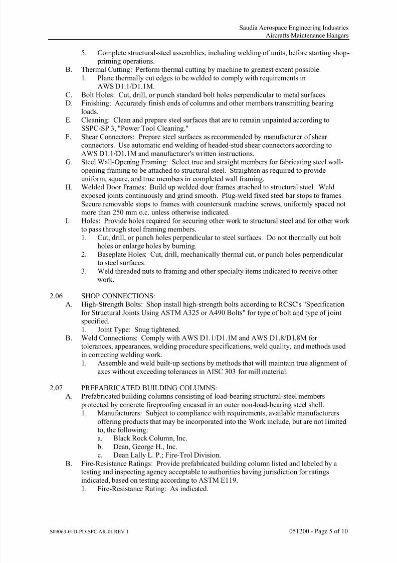
7/18/2019 Volume 2-Part DIII-Book 1 of 6
http://slidepdf.com/reader/full/volume-2-part-diii-book-1-of-6 107/342
Saudia Aerospace Engineering Industries
Aircrafts Maintenance Hangars
S09063-01D-PD-SPC-AR-01 REV 1 051200 - Page 5 of 10
5. Complete structural-steel assemblies, including welding of units, before starting shop- priming operations.
B. Thermal Cutting: Perform thermal cutting by machine to greatest extent possible.
1. Plane thermally cut edges to be welded to comply with requirements inAWS D1.1/D1.1M.
C.
Bolt Holes: Cut, drill, or punch standard bolt holes perpendicular to metal surfaces.D.
Finishing: Accurately finish ends of columns and other members transmitting bearingloads.
E. Cleaning: Clean and prepare steel surfaces that are to remain unpainted according toSSPC-SP 3, "Power Tool Cleaning."
F. Shear Connectors: Prepare steel surfaces as recommended by manufacturer of shearconnectors. Use automatic end welding of headed-stud shear connectors according toAWS D1.1/D1.1M and manufacturer's written instructions.
G. Steel Wall-Opening Framing: Select true and straight members for fabricating steel wall-opening framing to be attached to structural steel. Straighten as required to provideuniform, square, and true members in completed wall framing.
H. Welded Door Frames: Build up welded door frames attached to structural steel. Weld
exposed joints continuously and grind smooth. Plug-weld fixed steel bar stops to frames.Secure removable stops to frames with countersunk machine screws, uniformly spaced notmore than 250 mm o.c. unless otherwise indicated.
I. Holes: Provide holes required for securing other work to structural steel and for other workto pass through steel framing members.1. Cut, drill, or punch holes perpendicular to steel surfaces. Do not thermally cut bolt
holes or enlarge holes by burning.2. Baseplate Holes: Cut, drill, mechanically thermal cut, or punch holes perpendicular
to steel surfaces.3. Weld threaded nuts to framing and other specialty items indicated to receive other
work.
2.06
SHOP CONNECTIONS:A. High-Strength Bolts: Shop install high-strength bolts according to RCSC's "Specification
for Structural Joints Using ASTM A325 or A490 Bolts" for type of bolt and type of jointspecified.1. Joint Type: Snug tightened.
B. Weld Connections: Comply with AWS D1.1/D1.1M and AWS D1.8/D1.8M fortolerances, appearances, welding procedure specifications, weld quality, and methods usedin correcting welding work.1. Assemble and weld built-up sections by methods that will maintain true alignment of
axes without exceeding tolerances in AISC 303 for mill material.
2.07 PREFABRICATED BUILDING COLUMNS:
A.
Prefabricated building columns consisting of load-bearing structural-steel members protected by concrete fireproofing encased in an outer non-load-bearing steel shell.1. Manufacturers: Subject to compliance with requirements, available manufacturers
offering products that may be incorporated into the Work include, but are not limitedto, the following:a. Black Rock Column, Inc.
b. Dean, George H., Inc.c. Dean Lally L. P.; Fire-Trol Division.
B. Fire-Resistance Ratings: Provide prefabricated building column listed and labeled by atesting and inspecting agency acceptable to authorities having jurisdiction for ratingsindicated, based on testing according to ASTM E119.1. Fire-Resistance Rating: As indicated.

7/18/2019 Volume 2-Part DIII-Book 1 of 6
http://slidepdf.com/reader/full/volume-2-part-diii-book-1-of-6 108/342
Saudia Aerospace Engineering Industries
Aircrafts Maintenance Hangars
S09063-01D-PD-SPC-AR-01 REV 1 051200 - Page 6 of 10
2.08 SHOP PRIMING:A. Shop prime steel surfaces except the following:
1. Surfaces embedded in concrete or mortar. Extend priming of partially embedded
members to a depth of 50 mm.2. Surfaces to be field welded.
3.
Surfaces to be high-strength bolted with slip-critical connections.4.
Surfaces to receive sprayed fire-resistive materials (applied fireproofing).5. Galvanized surfaces.
B. Surface Preparation: Clean surfaces to be painted. Remove loose rust and mill scale andspatter, slag, or flux deposits. Prepare surfaces according to the following specifications
and standards:1. SSPC-SP 2, "Hand Tool Cleaning."2. SSPC-SP 3, "Power Tool Cleaning."3. SSPC-SP 7/NACE No. 4, "Brush-Off Blast Cleaning."4. SSPC-SP 11, "Power Tool Cleaning to Bare Metal."5. SSPC-SP 14/NACE No. 8, "Industrial Blast Cleaning."6. SSPC-SP 6/NACE No. 3, "Commercial Blast Cleaning."
7.
SSPC-SP 10/NACE No. 2, "Near-White Blast Cleaning."8. SSPC-SP 5/NACE No. 1, "White Metal Blast Cleaning."9. SSPC-SP 8, "Pickling."
C. Priming: Immediately after surface preparation, apply primer according to manufacturer'swritten instructions and at rate recommended by SSPC to provide a minimum dry filmthickness of 0.038 mm. Use priming methods that result in full coverage of joints, corners,edges, and exposed surfaces.1. Stripe paint corners, crevices, bolts, welds, and sharp edges.2. Apply two coats of shop paint to surfaces that are inaccessible after assembly or
erection. Change color of second coat to distinguish it from first.D. Painting: Prepare steel and apply a one-coat, nonasphaltic primer complying with SSPC-
PS Guide 7.00, "Painting System Guide 7.00: Guide for Selecting One-Coat Shop Painting
Systems," to provide a dry film thickness of not less than 0.038 mm.
2.09 GALVANIZING:A. Hot-Dip Galvanized Finish: Apply zinc coating by the hot-dip process to structural steel
according to ASTM A123/A123M.1. Fill vent and drain holes that will be exposed in the finished Work unless they will
function as weep holes, by plugging with zinc solder and filing off smooth.2. Galvanize lintels, shelf angles, and welded door frames attached to structural-steel
frame and located in exterior walls.
2.10 SOURCE QUALITY CONTROL:A. Testing Agency: Owner will engage an independent testing and inspecting agency to
perform shop tests and inspections and prepare test reports.1. Provide testing agency with access to places where structural-steel work is being
fabricated or produced to perform tests and inspections.
B. Correct deficiencies in Work that test reports and inspections indicate does not complywith the Contract Documents.
C. Bolted Connections: Shop-bolted connections will be tested and inspected according to
RCSC's "Specification for Structural Joints Using ASTM A325 or A490 Bolts."D. Welded Connections: In addition to visual inspection, shop-welded connections will be
tested and inspected according to AWS D1.1/D1.1M and the following inspection procedures, at testing agency's option:1. Liquid Penetrant Inspection: ASTM E165.2. Magnetic Particle Inspection: ASTM E709; performed on root pass and on finished
weld. Cracks or zones of incomplete fusion or penetration will not be accepted.
3. Ultrasonic Inspection: ASTM E164.

7/18/2019 Volume 2-Part DIII-Book 1 of 6
http://slidepdf.com/reader/full/volume-2-part-diii-book-1-of-6 109/342
Saudia Aerospace Engineering Industries
Aircrafts Maintenance Hangars
S09063-01D-PD-SPC-AR-01 REV 1 051200 - Page 7 of 10
4. Radiographic Inspection: ASTM E94.E. In addition to visual inspection, shop-welded shear connectors will be tested and inspected
according to requirements in AWS D1.1/D1.1M for stud welding and as follows:
1. Bend tests will be performed if visual inspections reveal either a less-than-continuous360-degree flash or welding repairs to any shear connector.
2.
Tests will be conducted on additional shear connectors if weld fracture occurs onshear connectors already tested, according to requirements in AWS D1.1/D1.1M.
PART 3 - EXECUTION
3.01 EXAMINATION:A. Verify, with steel Erector present, elevations of concrete- and masonry-bearing surfaces
and locations of anchor rods, bearing plates, and other embedments for compliance withrequirements.1. Prepare a certified survey of bearing surfaces, anchor rods, bearing plates, and other
embedments showing dimensions, locations, angles, and elevations.B. Proceed with installation only after unsatisfactory conditions have been corrected.
3.02 PREPARATION:A. Provide temporary shores, guys, braces, and other supports during erection to keep
structural steel secure, plumb, and in alignment against temporary construction loads andloads equal in intensity to design loads. Remove temporary supports when permanentstructural steel, connections, and bracing are in place unless otherwise indicated.
1. Do not remove temporary shoring supporting composite deck construction until cast-in-place concrete has attained its design compressive strength.
3.03 ERECTION:A. Set structural steel accurately in locations and to elevations indicated and according to
AISC 303 and AISC 360.
B.
Base Bearing and Leveling Plates: Clean concrete- and masonry-bearing surfaces of bond-reducing materials, and roughen surfaces prior to setting plates. Clean bottom surface of plates.1. Set plates for structural members on wedges, shims, or setting nuts as required.2. Weld plate washers to top of baseplate.3. Snug-tighten anchor rods after supported members have been positioned and
plumbed. Do not remove wedges or shims but, if protruding, cut off flush with edgeof plate before packing with grout.
4. Promptly pack grout solidly between bearing surfaces and plates so no voids remain. Neatly finish exposed surfaces; protect grout and allow to cure. Comply withmanufacturer's written installation instructions for shrinkage-resistant grouts.
C. Maintain erection tolerances of structural steel within AISC's "Code of Standard Practice
for Steel Buildings and Bridges."D. Align and adjust various members that form part of complete frame or structure before
permanently fastening. Before assembly, clean bearing surfaces and other surfaces that
will be in permanent contact with members. Perform necessary adjustments to compensatefor discrepancies in elevations and alignment.1. Level and plumb individual members of structure.2. Make allowances for difference between temperature at time of erection and mean
temperature when structure is completed and in service.
E. Splice members only where indicated.F. Do not use thermal cutting during erection.G. Do not enlarge unfair holes in members by burning or using drift pins. Ream holes that
must be enlarged to admit bolts.

7/18/2019 Volume 2-Part DIII-Book 1 of 6
http://slidepdf.com/reader/full/volume-2-part-diii-book-1-of-6 110/342
Saudia Aerospace Engineering Industries
Aircrafts Maintenance Hangars
S09063-01D-PD-SPC-AR-01 REV 1 051200 - Page 8 of 10
H. Shear Connectors: Prepare steel surfaces as recommended by manufacturer of shearconnectors. Use automatic end welding of headed-stud shear connectors according toAWS D1.1/D1.1M and manufacturer's written instructions.
3.04 FIELD CONNECTIONS:A. High-Strength Bolts: Install high-strength bolts according to RCSC's "Specification for
Structural Joints Using ASTM A325 or A490 Bolts" for type of bolt and type of jointspecified.1. Joint Type: Snug tightened, Pretensioned, or Slip critical.
B. Weld Connections: Comply with AWS D1.1/D1.1M and AWS D1.8/D1.8M fortolerances, appearances, welding procedure specifications, weld quality, and methods used
in correcting welding work.1. Comply with AISC 303 and AISC 360 for bearing, alignment, adequacy of temporary
connections, and removal of paint on surfaces adjacent to field welds.2. Remove backing bars or runoff tabs where indicated, back gouge, and grind steel
smooth.3. Assemble and weld built-up sections by methods that will maintain true alignment of
axes without exceeding tolerances in AISC's "Code of Standard Practice for SteelBuildings and Bridges" for mill material.
3.05 PREFABRICATED BUILDING COLUMNS:A. Install prefabricated building columns to comply with AISC 360, manufacturer's written
recommendations, and requirements of testing and inspecting agency that apply to the fire-resistance rating indicated.
3.06 FIELD QUALITY CONTROL:A. Testing Agency: Owner will engage a qualified independent testing and inspecting agency
to inspect field welds and high-strength bolted connections.B. Bolted Connections: Bolted connections will be tested and inspected according to RCSC's
"Specification for Structural Joints Using ASTM A325 or A490 Bolts."C. Welded Connections: Field welds will be visually inspected according to
AWS D1.1/D1.1M.1. In addition to visual inspection, field welds will be tested and inspected according to
AWS D1.1/D1.1M and the following inspection procedures, at testing agency'soption:a. Liquid Penetrant Inspection: ASTM E165. b. Magnetic Particle Inspection: ASTM E709; performed on root pass and on
finished weld. Cracks or zones of incomplete fusion or penetration will not beaccepted.
c. Ultrasonic Inspection: ASTM E164.d. Radiographic Inspection: ASTM E94.
D.
In addition to visual inspection, test and inspect field-welded shear connectors according torequirements in AWS D1.1/D1.1M for stud welding and as follows:
1. Perform bend tests if visual inspections reveal either a less-than-continuous360-degree flash or welding repairs to any shear connector.
2. Conduct tests on additional shear connectors if weld fracture occurs on shearconnectors already tested, according to requirements in AWS D1.1/D1.1M.
E. Correct deficiencies in Work that test reports and inspections indicate does not comply
with the Contract Documents.
3.07 REPAIRS AND PROTECTION:A. Galvanized Surfaces: Clean areas where galvanizing is damaged or missing and repair
galvanizing to comply with ASTM A780.

7/18/2019 Volume 2-Part DIII-Book 1 of 6
http://slidepdf.com/reader/full/volume-2-part-diii-book-1-of-6 111/342
Saudia Aerospace Engineering Industries
Aircrafts Maintenance Hangars
S09063-01D-PD-SPC-AR-01 REV 1 051200 - Page 9 of 10
B. Touchup Painting: Immediately after erection, clean exposed areas where primer isdamaged or missing and paint with the same material as used for shop painting to complywith SSPC-PA 1 for touching up shop-painted surfaces.
1. Clean and prepare surfaces by SSPC-SP 2 hand-tool cleaning or SSPC-SP 3 power-tool cleaning.
C.
Touchup Painting: Cleaning and touchup painting are specified in DIVISION 09 paintingSections.
END OF SECTION 051200

7/18/2019 Volume 2-Part DIII-Book 1 of 6
http://slidepdf.com/reader/full/volume-2-part-diii-book-1-of-6 112/342
Saudia Aerospace Engineering Industries
Aircrafts Maintenance Hangars
S09063-01D-PD-SPC-AR-01 REV 1 051200 - Page 10 of 10
THIS PAGE INTENTIONALLY LEFT BLANK

7/18/2019 Volume 2-Part DIII-Book 1 of 6
http://slidepdf.com/reader/full/volume-2-part-diii-book-1-of-6 113/342
Saudia Aerospace Engineering Industries
Aircrafts Maintenance Hangars
S09063-01D-PD-SPC-AR-01 REV 1 052100 - Page 1 of 6
SECTION 052100 - STEEL JOIST FRAMING
PART 1 - GENERAL
1.01 RELATED DOCUMENTS:
A. Drawings and general provisions of the Contract, including General and SupplementaryConditions and DIVISION 01 Specification Sections, apply to this Section.
1.02 SUMMARY:A. Section Includes:
1. K-series steel joists.
2. KCS-type K-series steel joists.3. K-series steel joist substitutes.
4. LH- and DLH-series long-span steel joists.5. Joist girders.6. Joist accessories.
B. Related Requirements:
1.
DIVISION 03 Section "Cast-in-Place Concrete" for installing bearing plates inconcrete.2. DIVISION 04 Section "Unit Masonry" for installing bearing plates in unit masonry.3. DIVISION 05 Section "Structural Steel Framing" for field-welded shear connectors.
1.03 DEFINITIONS:A. SJI's "Specifications": Steel Joist Institute's "Standard Specifications, Load Tables and
Weight Tables for Steel Joists and Joist Girders."B. Special Joists: Steel joists or joist girders requiring modification by manufacturer to
support non-uniform, unequal, or special loading conditions that invalidate load tables inSJI's "Specifications."
1.04
ACTION SUBMITTALS:A. Product Data: For each type of joist, accessory, and product.B. Shop Drawings:
1. Include layout, designation, number, type, location, and spacing of joists.2. Include joining and anchorage details, bracing, bridging, and joist accessories; splice
and connection locations and details; and attachments to other construction.3. Indicate locations and details of bearing plates to be embedded in other construction.
1.05 INFORMATIONAL SUBMITTALS:
A. Qualification Data: For professional engineer.B. Welding certificates.C. Manufacturer certificates.
D.
Mill Certificates: For each type of bolt.E. Comprehensive engineering analysis of special joists signed and sealed by the qualified
professional engineer responsible for its preparation.
1.06 QUALITY ASSURANCE:A. Manufacturer Qualifications: A manufacturer certified by SJI to manufacture joists
complying with applicable standard specifications and load tables in SJI's "Specifications"and "Standard Specifications for Composite Steel Joists, CJ-Series" in "StandardSpecifications for Composite Steel Joists, Weight Tables and Bridging Tables, Code ofStandard Practice."1. Manufacturer's responsibilities include providing professional engineering services
for designing special joists to comply with performance requirements.
B.
Welding Qualifications: Qualify field-welding procedures and personnel according toAWS D1.1/D1.1M, "Structural Welding Code - Steel."

7/18/2019 Volume 2-Part DIII-Book 1 of 6
http://slidepdf.com/reader/full/volume-2-part-diii-book-1-of-6 114/342
Saudia Aerospace Engineering Industries
Aircrafts Maintenance Hangars
S09063-01D-PD-SPC-AR-01 REV 1 052100 - Page 2 of 6
1.07 DELIVERY, STORAGE, AND HANDLING:A. Deliver, store, and handle joists as recommended in SJI's "Specifications" and "Standard
Specifications for Composite Steel Joists, CJ-Series" in "Standard Specifications for
Composite Steel Joists, Weight Tables and Bridging Tables, Code of Standard Practice."B. Protect joists from corrosion, deformation, and other damage during delivery, storage, and
handling.
1.08 SEQUENCING:A. Deliver steel bearing plates to be built into cast-in-place concrete construction.
PART 2 - PRODUCTS
2.01 K-SERIES STEEL JOISTS:
A. Manufacture steel joists of type indicated according to "Standard Specifications for OpenWeb Steel Joists, K-Series" in SJI's "Specifications," with steel-angle top- and bottom-chord members, underslung ends, and parallel top chord.1. Joist Type: K-series steel joists and KCS-type K-series steel joists.
B.
Steel Joist Substitutes: Manufacture according to "Standard Specifications for Open WebSteel Joists, K-Series" in SJI's "Specifications," with steel-angle or -channel members.C. Provide holes in chord members for connecting and securing other construction to joists.D. Top-Chord Extensions: Extend top chords of joists with SJI's Type S top-chord extensions
where indicated, complying with SJI's "Specifications."E. Extended Ends: Extend bearing ends of joists with SJI's Type R extended ends where
indicated, complying with SJI's "Specifications."F. Camber joists according to SJI's "Specifications."G. Equip bearing ends of joists with manufacturer's standard beveled ends or sloped shoes if
joist slope exceeds 7 mm per 305 mm.
2.02 LONG-SPAN STEEL JOISTS:
A.
Manufacture steel joists according to "Standard Specifications for Longspan Steel Joists,LH-Series and Deep Longspan Steel Joists, DLH-Series" in SJI's "Specifications," withsteel-angle top- and bottom-chord members; of joist type and end and top-chordarrangements as indicated.1. Joist Type: LH-series steel joists and DLH-series steel joists.
B. Provide holes in chord members for connecting and securing other construction to joists.C. Camber long-span steel joists according to SJI's "Specifications."D. Equip bearing ends of joists with manufacturer's standard beveled ends or sloped shoes if
joist slope exceeds 7 mm per 305 mm.
2.03 JOIST GIRDERS:A. Manufacture joist girders according to "Standard Specifications for Joist Girders" in SJI's
"Specifications," with steel-angle top- and bottom-chord members; with end and top-chordarrangements as indicated.
B. Provide holes in chord members for connecting and securing other construction to joistgirders.
C. Camber joist girders according to SJI's "Specifications."D. Equip bearing ends of joists with manufacturer's standard beveled ends or sloped shoes if
joist slope exceeds 7 mm per 305 mm.
2.04 PRIMERS:A. Low-Emitting Materials: Paints and coatings shall comply with the testing and product
requirements of the California Department of Health Services' "Standard Practice for theTesting of Volatile Organic Emissions from Various Sources Using Small-Scale
Environmental Chambers."
7/18/2019 Volume 2-Part DIII-Book 1 of 6
http://slidepdf.com/reader/full/volume-2-part-diii-book-1-of-6 115/342
Saudia Aerospace Engineering Industries
Aircrafts Maintenance Hangars
S09063-01D-PD-SPC-AR-01 REV 1 052100 - Page 3 of 6
B. Primer: SSPC-Paint 15, or manufacturer's standard shop primer complying with performance requirements in SSPC-Paint 15.
C. Primer: Provide shop primer that complies with DIVISION 09 painting Sections.
2.05 JOIST ACCESSORIES:A. Bridging: Provide bridging anchors and number of rows of horizontal or diagonal bridging
of material, size, and type required by SJI's "Specifications" and "Standard Specificationsfor Composite Steel Joists, CJ-Series" in "Standard Specifications for Composite SteelJoists, Weight Tables and Bridging Tables, Code of Standard Practice" for type of joist,
chord size, spacing, and span. Furnish additional erection bridging if required for stability.B. Bridging: Schematically indicated. Detail and fabricate according to SJI's "Specifications"
and "Standard Specifications for Composite Steel Joists, CJ-Series" in "StandardSpecifications for Composite Steel Joists, Weight Tables and Bridging Tables, Code ofStandard Practice." Furnish additional erection bridging if required for stability.
C. Bridging: Fabricate as indicated and according to SJI's "Specifications" and "StandardSpecifications for Composite Steel Joists, CJ-Series" in "Standard Specifications forComposite Steel Joists, Weight Tables and Bridging Tables, Code of Standard Practice."
Furnish additional erection bridging if required for stability.D. Fabricate steel bearing plates from ASTM A36/A36M steel with integral anchorages of
sizes and thicknesses indicated. Hot-dip zinc coat according to ASTM A123/A123M.E. Steel bearing plates with integral anchorages are specified in DIVISION 05 Section "Metal
Fabrications."F. Furnish ceiling extensions, either extended bottom-chord elements or a separate extension
unit of enough strength to support ceiling construction. Extend ends to within 13 mm offinished wall surface unless otherwise indicated.
G. Carbon-Steel Bolts and Threaded Fasteners: ASTM A307, Grade A (ASTM F568M,Property Class 4.6), carbon-steel, hex-head bolts and threaded fasteners; carbon-steel nuts;and flat, unhardened steel washers.1. Finish: Hot-dip zinc coating, ASTM A153/A153M, Class C.
H.
High-Strength Bolts, Nuts, and Washers: ASTM A325 (ASTM A325M), Type 1, heavyhex steel structural bolts; ASTM A563 (ASTM A563M) heavy hex carbon-steel nuts; andASTM F436 (ASTM F436M) hardened carbon-steel washers.1. Finish: Hot-dip zinc coating, ASTM A153/A153M, Class C.
I. Welding Electrodes: Comply with AWS standards.J. Galvanizing Repair Paint: MPI#18, MPI#19, or SSPC-Paint 20.K. Furnish miscellaneous accessories including splice plates and bolts required by joist
manufacturer to complete joist assembly.
2.06 CLEANING AND SHOP PAINTING:A. Clean and remove loose scale, heavy rust, and other foreign materials from fabricated joists
and accessories by hand-tool cleaning, SSPC-SP 2 or power-tool cleaning, SSPC-SP 3.
B.
Do not prime paint joists and accessories to receive sprayed fire-resistive materials.C. Apply one coat of shop primer to joists and joist accessories to be primed to provide a
continuous, dry paint film not less than 0.025 mm thick.
D. Shop priming of joists and joist accessories is specified in DIVISION 09 painting Sections.
PART 3 - EXECUTION
3.01 EXAMINATION:
A. Examine supporting substrates, embedded bearing plates, and abutting structural framingfor compliance with requirements for installation tolerances and other conditions affecting performance.
B. Proceed with installation only after unsatisfactory conditions have been corrected.

7/18/2019 Volume 2-Part DIII-Book 1 of 6
http://slidepdf.com/reader/full/volume-2-part-diii-book-1-of-6 116/342
Saudia Aerospace Engineering Industries
Aircrafts Maintenance Hangars
S09063-01D-PD-SPC-AR-01 REV 1 052100 - Page 4 of 6
3.02 INSTALLATION:A. Do not install joists until supporting construction is in place and secured.B. Install joists and accessories plumb, square, and true to line; securely fasten to supporting
construction according to SJI's "Specifications," and "Standard Specifications forComposite Steel Joists, CJ-Series" in "Standard Specifications for Composite Steel Joists,
Weight Tables and Bridging Tables, Code of Standard Practice," joist manufacturer'swritten recommendations, and requirements in this Section.1. Before installation, splice joists delivered to Project site in more than one piece.2. Space, adjust, and align joists accurately in location before permanently fastening.3. Install temporary bracing and erection bridging, connections, and anchors to ensure
that joists are stabilized during construction.4. Delay rigidly connecting bottom-chord extensions to columns or supports until dead
loads are applied.C. Field weld joists to supporting steel bearing plates and framework. Coordinate welding
sequence and procedure with placement of joists. Comply with AWS requirements and procedures for welding, appearance and quality of welds, and methods used in correctingwelding work.
D.
Bolt joists to supporting steel framework using carbon-steel bolts.E. Bolt joists to supporting steel framework using high-strength structural bolts. Comply with
Research Council on Structural Connection's "Specification for Structural Joints UsingASTM A325 or ASTM A490 Bolts" for high-strength structural bolt installation andtightening requirements.
F. Install and connect bridging concurrently with joist erection, before construction loads areapplied. Anchor ends of bridging lines at top and bottom chords if terminating at walls or beams.
3.03 FIELD QUALITY CONTROL:A. Testing Agency: Owner will engage a qualified independent testing and inspecting agency
to inspect field welds and bolted connections and to perform field tests and inspections and
prepare test and inspection reports.B. Visually inspect field welds according to AWS D1.1/D1.1M.
1. In addition to visual inspection, test field welds according to AWS D1.1/D1.1M andthe following procedures, as applicable:a. Liquid Penetrant Inspection: ASTM E165. b. Magnetic Particle Inspection: ASTM E709.c. Ultrasonic Testing: ASTM E164.d. Radiographic Testing: ASTM E94.
C. Visually inspect bolted connections.D. Correct deficiencies in Work that test and inspection reports have indicated are not in
compliance with specified requirements.E. Perform additional testing to determine compliance of corrected Work with specified
requirements.
3.04 PROTECTION:
A. Repair damaged galvanized coatings on galvanized items with galvanized repair paintaccording to ASTM A780 and manufacturer's written instructions.
B. Touchup Painting: After installation, promptly clean, prepare, and prime or reprime field
connections, rust spots, and abraded surfaces of prime-painted joists, bearing plates,abutting structural steel, and accessories.
1. Clean and prepare surfaces by hand-tool cleaning according to SSPC-SP 2, or power-tool cleaning according to SSPC-SP 3.
2. Apply a compatible primer of same type as primer used on adjacent surfaces.C. Touchup Painting: Cleaning and touchup painting are specified in DIVISION 09 painting
Sections.

7/18/2019 Volume 2-Part DIII-Book 1 of 6
http://slidepdf.com/reader/full/volume-2-part-diii-book-1-of-6 117/342
Saudia Aerospace Engineering Industries
Aircrafts Maintenance Hangars
S09063-01D-PD-SPC-AR-01 REV 1 052100 - Page 5 of 6
D. Provide final protection and maintain conditions, in a manner acceptable to manufacturerand Installer, that ensure that joists and accessories are without damage or deterioration attime of Substantial Completion.
END OF SECTION 052100

7/18/2019 Volume 2-Part DIII-Book 1 of 6
http://slidepdf.com/reader/full/volume-2-part-diii-book-1-of-6 118/342
Saudia Aerospace Engineering Industries
Aircrafts Maintenance Hangars
S09063-01D-PD-SPC-AR-01 REV 1 052100 - Page 6 of 6
THIS PAGE INTENTIONALLY LEFT BLANK

7/18/2019 Volume 2-Part DIII-Book 1 of 6
http://slidepdf.com/reader/full/volume-2-part-diii-book-1-of-6 119/342
Saudia Aerospace Engineering Industries
Aircrafts Maintenance Hangars
S09063-01D-PD-SPC-AR-01 REV 1 053100 - Page 1 of 6
SECTION 053100 - STEEL DECKING
PART 1 - GENERAL
1.01 RELATED DOCUMENTS:A.
Drawings and general provisions of the Contract, including General and SupplementaryConditions and DIVISION 01 Specification Sections, apply to this Section.
1.02 SUMMARY:A. Section Includes:
1. Roof deck.B. Related Requirements:
1. DIVISION 03 Section "Cast-in-Place Concrete" for normal-weight and lightweightstructural concrete fill over steel deck.
2. DIVISION 03 Section "Lightweight Insulating Concrete" for lightweight insulatingconcrete fill over steel deck.
3.
DIVISION 05 Section "Structural Steel Framing" for shop- and field-welded shearconnectors.4. DIVISION 05 Section "Metal Fabrications" for framing deck openings with
miscellaneous steel shapes.5. DIVISION 09 painting Sections for repair painting of primed deck and finish painting
of deck.
1.03 ACTION SUBMITTALS:A. Product Data: For each type of deck, accessory, and product indicated.B. Shop Drawings:
1. Include layout and types of deck panels, anchorage details, reinforcing channels, pans, cut deck openings, special jointing, accessories, and attachments to other
construction.
1.04 INFORMATIONAL SUBMITTALS:A. Welding certificates.B. Product Certificates: For each type of steel deck.C. Product Test Reports: Based on evaluation of comprehensive tests performed by a
qualified testing agency, indicating that each of the following complies with requirements:1. Power-actuated mechanical fasteners.2. Acoustical roof deck.
D. Evaluation Reports: For steel deck.E. Field quality-control reports.
1.05
QUALITY ASSURANCE:A. Testing Agency Qualifications: Qualified according to ASTM E329 for testing indicated.B. Welding Qualifications: Qualify procedures and personnel according to AWS D1.3,
"Structural Welding Code - Sheet Steel."C. Electrical Raceway Units: Provide UL-labeled cellular floor-deck units complying with
UL 209 and listed in UL's "Electrical Construction Equipment Directory" for use withstandard header ducts and outlets for electrical distribution systems.
D. FM Global Listing: Provide steel roof deck evaluated by FM Global and listed in its"Approval Guide, Building Materials" for Class 1 fire rating and Class 1-90 windstormratings.
1.06 DELIVERY, STORAGE, AND HANDLING:
A.
Protect steel deck from corrosion, deformation, and other damage during delivery, storage,and handling.

7/18/2019 Volume 2-Part DIII-Book 1 of 6
http://slidepdf.com/reader/full/volume-2-part-diii-book-1-of-6 120/342
Saudia Aerospace Engineering Industries
Aircrafts Maintenance Hangars
S09063-01D-PD-SPC-AR-01 REV 1 053100 - Page 2 of 6
B. Stack steel deck on platforms or pallets and slope to provide drainage. Protect with a
waterproof covering and ventilate to avoid condensation.1. Protect and ventilate acoustical cellular roof deck with factory-installed insulation to
maintain insulation free of moisture.
PART 2 - PRODUCTS
2.01 PERFORMANCE REQUIREMENTS:A. AISI Specifications: Comply with calculated structural characteristics of steel deck
according to AISI's "North American Specification for the Design of Cold-Formed SteelStructural Members."
B. Fire-Resistance Ratings: Comply with ASTM E119; testing by a qualified testing agency.Identify products with appropriate markings of applicable testing agency.1. Indicate design designations from UL's "Fire Resistance Directory" or from the
listings of another qualified testing agency.
2.02 ROOF DECK:
A.
Manufacturers: Subject to compliance with requirements, available manufacturers offering products that may be incorporated into the Work include, but are not limited to, thefollowing:1. ASC Profiles, Inc.; a Blue Scope Steel company.
2. Canam United States; Canam Group Inc.3. CMC Joist & Deck.4. Consolidated Systems, Inc.; Metal Dek Group.5. Cordeck.6. DACS, Inc.
7. Epic Metals Corporation.8. Marlyn Steel Decks, Inc.9. New Millennium Building Systems, LLC.
10.
Nucor Corp.; Vulcraft Group.11. Roof Deck, Inc.
12. Valley Joist; Subsidiary of EBSCO Industries, Inc.13. Verco Manufacturing Co.14. Wheeling Corrugating Company; Div. of Wheeling-Pittsburgh Steel Corporation.
B. Roof Deck: Fabricate panels, without top-flange stiffening grooves, to comply with "SDISpecifications and Commentary for Steel Roof Deck," in SDI Publication No. 31, and withthe following:1. Galvanized and Shop-Primed Steel Sheet: ASTM A653/A653M, Structural Steel
(SS), Grade 40 (275), G60 (Z180) zinc coating; cleaned, pretreated, and primed withmanufacturer's standard baked-on, rust-inhibitive primer.a. Color: Manufacturer's standard.
2.
Alloy-Coated Steel Sheet: ASTM A 792/A792M, Structural Steel (SS), Grade 33(230) minimum, AZ50 (AZ150) aluminum-zinc-alloy coating.
3. Deck Profile: As indicated Type WR, wide rib.4. Profile Depth: As indicated.5. Span Condition: Triple span or more.6. Side Laps: Overlapped or interlocking seam at Contractor's option.
2.03 COMPOSITE FLOOR DECK:
A. Manufacturers: Subject to compliance with requirements, available manufacturers offering products that may be incorporated into the Work include, but are not limited to, thefollowing:1. ASC Profiles, Inc.; a Blue Scope Steel company.2.
Canam United States; Canam Group Inc.3. CMC Joist & Deck.

7/18/2019 Volume 2-Part DIII-Book 1 of 6
http://slidepdf.com/reader/full/volume-2-part-diii-book-1-of-6 121/342
Saudia Aerospace Engineering Industries
Aircrafts Maintenance Hangars
S09063-01D-PD-SPC-AR-01 REV 1 053100 - Page 3 of 6
4. Consolidated Systems, Inc.; Metal Dek Group.
5. Cordeck.6. DACS, Inc.
7. Epic Metals Corporation.8. Marlyn Steel Decks, Inc.
9.
New Millennium Building Systems, LLC.10.
Nucor Corp.; Vulcraft Group.11. Roof Deck, Inc.
12. Verco Manufacturing Co.13. Wheeling Corrugating Company; Div. of Wheeling-Pittsburgh Steel Corporation.
B. Composite Floor Deck: Fabricate panels, with integrally embossed or raised pattern ribsand interlocking side laps, to comply with "SDI Specifications and Commentary forComposite Steel Floor Deck," in SDI Publication No. 31, with the minimum section
properties indicated, and with the following:1. Galvanized and Shop-Primed Steel Sheet: ASTM A653/A653M, Structural Steel
(SS), Grade 33 (230), G60 (Z180) zinc coating; with unpainted top surface andcleaned and pretreated bottom surface primed with manufacturer's standard gray
baked-on, rust-inhibitive primer.2. Profile Depth: As indicated.3. Span Condition: Triple span or more.
2.04 ACCESSORIES:A. General: Provide manufacturer's standard accessory materials for deck that comply with
requirements indicated.
B. Mechanical Fasteners: Corrosion-resistant, low-velocity, power-actuated or pneumaticallydriven carbon-steel fasteners; or self-drilling, self-threading screws.
C. Side-Lap Fasteners: Corrosion-resistant, hexagonal washer head; self-drilling, carbon-steelscrews, No. 10 (4.8-mm) minimum diameter.
D. Flexible Closure Strips: Vulcanized, closed-cell, synthetic rubber.
E.
Miscellaneous Sheet Metal Deck Accessories: Steel sheet, minimum yield strength of230 MPa, not less than 0.91-mm design uncoated thickness, of same material and finish as
deck; of profile indicated or required for application.F. Pour Stops and Girder Fillers: Steel sheet, minimum yield strength of 230 MPa, of same
material and finish as deck, and of thickness and profile recommended by SDI Publication No. 31 for overhang and slab depth.
G. Column Closures, End Closures, Z-Closures, and Cover Plates: Steel sheet, of same
material, finish, and thickness as deck unless otherwise indicated.H. Piercing Hanger Tabs: Piercing steel sheet hanger attachment devices for use with floor
deck.I. Weld Washers: Uncoated steel sheet, shaped to fit deck rib, 1.90 mm thick, with factory-
punched hole of 9.5-mm minimum diameter.
J.
Flat Sump Plates: Single-piece steel sheet, 1.90 mm thick, of same material and finish asdeck. For drains, cut holes in the field.
K. Recessed Sump Pans: Single-piece steel sheet, 1.90 mm thick, of same material and finishas deck, with 76-mm- wide flanges and sloped recessed pans of 38-mm minimum depth.For drains, cut holes in the field.
L. Galvanizing Repair Paint: ASTM A780.M. Repair Paint: Manufacturer's standard rust-inhibitive primer of same color as primer.
PART 3 - EXECUTION
3.01 EXAMINATION:A. Examine supporting frame and field conditions for compliance with requirements for
installation tolerances and other conditions affecting performance.B. Proceed with installation only after unsatisfactory conditions have been corrected.

7/18/2019 Volume 2-Part DIII-Book 1 of 6
http://slidepdf.com/reader/full/volume-2-part-diii-book-1-of-6 122/342
Saudia Aerospace Engineering Industries
Aircrafts Maintenance Hangars
S09063-01D-PD-SPC-AR-01 REV 1 053100 - Page 4 of 6
3.02 INSTALLATION, GENERAL:
A. Install deck panels and accessories according to applicable specifications and commentaryin SDI Publication No. 31, manufacturer's written instructions, and requirements in this
Section.B. Install temporary shoring before placing deck panels if required to meet deflection
limitations.C.
Locate deck bundles to prevent overloading of supporting members.D. Place deck panels on supporting frame and adjust to final position with ends accurately
aligned and bearing on supporting frame before being permanently fastened. Do notstretch or contract side-lap interlocks.1. Align cellular deck panels over full length of cell runs and align cells at ends of
abutting panels.E. Place deck panels flat and square and fasten to supporting frame without warp or
deflection.F. Cut and neatly fit deck panels and accessories around openings and other work projecting
through or adjacent to deck.G. Provide additional reinforcement and closure pieces at openings as required for strength,
continuity of deck, and support of other work.H. Comply with AWS requirements and procedures for manual shielded metal arc welding,
appearance and quality of welds, and methods used for correcting welding work.
I. Mechanical fasteners may be used in lieu of welding to fasten deck. Locate mechanicalfasteners and install according to deck manufacturer's written instructions.
3.03 ROOF-DECK INSTALLATION:
A. Fasten roof-deck panels to steel supporting members by arc spot (puddle) welds of thesurface diameter indicated or arc seam welds with an equal perimeter that is not less than
38 mm long, and as follows:1. Weld Diameter: 19 mm, nominal.2. Weld Spacing: Weld edge and interior ribs of deck units with a minimum of two
welds per deck unit at each support. Space welds 305 mm apart in the field of roofand 150 mm apart in roof corners and perimeter, based on roof-area definitions in
FMG Loss Prevention Data Sheet 1-28.3. Weld Washers: Install weld washers at each weld location.
B. Side-Lap and Perimeter Edge Fastening: Fasten side laps and perimeter edges of panels between supports, at intervals not exceeding the lesser of 1/2 of the span or 457 mm, and asfollows:
1. Mechanically fasten with self-drilling, No. 10 (4.8-mm-) diameter or larger, carbon-steel screws.
2. Mechanically clinch or button punch.3. Fasten with a minimum of 38-mm-long welds.
C. End Bearing: Install deck ends over supporting frame with a minimum end bearing of
38 mm, with end joints as follows:1. End Joints: Lapped (51 mm) minimum or butted at Contractor's option.
D. Roof Sump Pans and Sump Plates: Install over openings provided in roof deck andmechanically fasten flanges to top of deck. Space mechanical fasteners not more than 305mm apart with at least one fastener at each corner.1. Install reinforcing channels or zees in ribs to span between supports and weld or
mechanically fasten.
E. Miscellaneous Roof-Deck Accessories: Install ridge and valley plates, finish strips, endclosures, and reinforcing channels according to deck manufacturer's written instructions.Weld or mechanically fasten to substrate to provide a complete deck installation.1. Weld cover plates at changes in direction of roof-deck panels unless otherwise
indicated.

7/18/2019 Volume 2-Part DIII-Book 1 of 6
http://slidepdf.com/reader/full/volume-2-part-diii-book-1-of-6 123/342
Saudia Aerospace Engineering Industries
Aircrafts Maintenance Hangars
S09063-01D-PD-SPC-AR-01 REV 1 053100 - Page 5 of 6
F. Flexible Closure Strips: Install flexible closure strips over partitions, walls, and where
indicated. Install with adhesive according to manufacturer's written instructions to ensurecomplete closure.
3.04 FLOOR-DECK INSTALLATION:A. Fasten floor-deck panels to steel supporting members by arc spot (puddle) welds of the
surface diameter indicated and as follows:1. Weld Diameter: 19 mm, nominal.2. Weld Spacing: Weld edge ribs of panels at each support. Space additional welds an
average of 305 mm apart, but not more than 457 mm apart.3. Weld Spacing: Space and locate welds as indicated.4. Weld Washers: Install weld washers at each weld location.
B. Side-Lap and Perimeter Edge Fastening: Fasten side laps and perimeter edges of panels between supports, at intervals not exceeding the lesser of half of the span or 914 mm, and
as follows:1. Mechanically fasten with self-drilling, No. 10 (4.8-mm-) diameter or larger, carbon-
steel screws.
2.
Mechanically clinch or button punch.3. Fasten with a minimum of 38-mm-long welds.
C. End Bearing: Install deck ends over supporting frame with a minimum end bearing of38 mm, with end joints as follows:
1. End Joints: Lapped or butted at Contractor's option.D. Pour Stops and Girder Fillers: Weld steel sheet pour stops and girder fillers to supporting
structure according to SDI recommendations unless otherwise indicated.
E. Floor-Deck Closures: Weld steel sheet column closures, cell closures, and Z-closures todeck, according to SDI recommendations, to provide tight-fitting closures at open ends of
ribs and sides of deck.F. Electrified Cellular Floor Deck: Install cellular floor system with deck assembled from
units indicated.
1.
Coordinate layout and installation of trench headers, preset inserts, duct fittings, andother components specified in DIVISION 26 Section "Underfloor Raceways for
Electrical Systems" with installation of electrified cellular metal floor deck.G. Install piercing hanger tabs at 355 mm apart in both directions, within 228 mm of walls at
ends, and not more than 305 mm from walls at sides unless otherwise indicated.
3.05 FIELD QUALITY CONTROL:A. Testing Agency: Engage a qualified testing agency to perform tests and inspections.
B. Field welds will be subject to inspection.C. Testing agency will report inspection results promptly and in writing to Contractor and
Architect.D. Remove and replace work that does not comply with specified requirements.
E.
Additional inspecting, at Contractor's expense, will be performed to determine complianceof corrected work with specified requirements.
3.06 PROTECTION:A. Galvanizing Repairs: Prepare and repair damaged galvanized coatings on both surfaces of
deck with galvanized repair paint according to ASTM A780 and manufacturer's writteninstructions.
B. Repair Painting: Wire brush and clean rust spots, welds, and abraded areas on bothsurfaces of prime-painted deck immediately after installation, and apply repair paint.1. Apply repair paint, of same color as adjacent shop-primed deck, to bottom surfaces of
deck exposed to view.2. Wire brushing, cleaning, and repair painting of bottom deck surfaces are included in
DIVISION 09 .

7/18/2019 Volume 2-Part DIII-Book 1 of 6
http://slidepdf.com/reader/full/volume-2-part-diii-book-1-of-6 124/342
Saudia Aerospace Engineering Industries
Aircrafts Maintenance Hangars
S09063-01D-PD-SPC-AR-01 REV 1 053100 - Page 6 of 6
C. Repair Painting: Wire brushing, cleaning, and repair painting of rust spots, welds, and
abraded areas of both deck surfaces are included in DIVISION 09.D. Provide final protection and maintain conditions to ensure that steel deck is without
damage or deterioration at time of Substantial Completion.
END OF SECTION 053100

7/18/2019 Volume 2-Part DIII-Book 1 of 6
http://slidepdf.com/reader/full/volume-2-part-diii-book-1-of-6 125/342
Saudia Aerospace Engineering Industries
Aircrafts Maintenance Hangars
S09063-01D-PD-SPC-AR-01 REV 1 055000 - Page 1 of 13
SECTION 055000 - METAL FABRICATIONS
PART 1 - GENERAL
1.01 RELATED DOCUMENTS:A.
Drawings and general provisions of the Contract, including General and SupplementaryConditions and DIVISION 01 Specification Sections, apply to this Section.
1.02 SUMMARY:A. Section Includes:
1. Steel framing and supports for ceiling-hung toilet compartments.2. Steel framing and supports for operable partitions.3. Steel framing and supports for overhead doors and grilles.4. Steel framing and supports for countertops.5. Steel framing and supports for mechanical and electrical equipment.6. Steel framing and supports for applications where framing and supports are not
specified in other Sections.7.
Steel framing and supports for window-washing equipment including mounting brackets and anchorages.
8. Elevator machine beams, hoist beams, and divider beams.9. Steel shapes for supporting elevator door sills.10. Prefabricated building columns.11. Shelf angles.12. Metal ladders.13. Ladder safety cages.14. Alternating tread devices.15. Metal ships' ladders and pipe crossovers.16. Metal floor plate and supports.
17.
Structural-steel door frames.18. Miscellaneous steel trim including steel angle corner guards, steel edgings and
loading-dock edge angles.
19. Metal bollards.20. Downspout guards.21. Abrasive metal nosings,treads and thresholds.22. Metal downspout boots.23. Loose bearing and leveling plates for applications where they are not specified in
other Sections.B. Products furnished, but not installed, under this Section:
1. Loose steel lintels.2. Anchor bolts, steel pipe sleeves, slotted-channel inserts, and wedge-type inserts
indicated to be cast into concrete or built into unit masonry.3. Steel weld plates and angles for casting into concrete for applications where they are
not specified in other Sections.C. Related Sections:
1. DIVISION 03 Section "Cast-in-Place Concrete" for installing anchor bolts, steel pipesleeves, slotted-channel inserts, wedge-type inserts, and other items cast intoconcrete.
2. DIVISION 04 Section "Unit Masonry" for installing loose lintels, anchor bolts, and
other items built into unit masonry.3. DIVISION 05 Section "Structural Steel Framing."4. DIVISION 05 Section "Metal Stairs."5. DIVISION 05 Section "Pipe and Tube Railings."6.
DIVISION 05 Section "Metal Gratings."7. DIVISION 05 Section "Decorative Metal."

7/18/2019 Volume 2-Part DIII-Book 1 of 6
http://slidepdf.com/reader/full/volume-2-part-diii-book-1-of-6 126/342
Saudia Aerospace Engineering Industries
Aircrafts Maintenance Hangars
S09063-01D-PD-SPC-AR-01 REV 1 055000 - Page 2 of 13
8. DIVISION 12 Section "Site Furnishings"DIVISION 32 Section "Plants" for tree
grates.
1.03 ACTION SUBMITTALS:
A. Product Data: For the following:1. Nonslip aggregates and nonslip-aggregate surface finishes.2.
Prefabricated building columns.3. Metal nosings and treads.4. Paint products.
5. Grout.B. Shop Drawings: Show fabrication and installation details for metal fabrications.
1. Include plans, elevations, sections, and details of metal fabrications and theirconnections. Show anchorage and accessory items.
C. Samples for Verification: For each type and finish of extruded nosing and tread.
D. Delegated-Design Submittal: For installed products indicated to comply with performancerequirements and design criteria, including analysis data signed and sealed by the qualified
professional engineer responsible for their preparation.
1.04 INFORMATIONAL SUBMITTALS:A. Qualification Data: For qualified professional engineer.
B. Mill Certificates: Signed by manufacturers of stainless-steel certifying that productsfurnished comply with requirements.
C. Welding certificates.D. Paint Compatibility Certificates: From manufacturers of topcoats applied over shop
primers certifying that shop primers are compatible with topcoats.
1.05 QUALITY ASSURANCE:A. Welding Qualifications: Qualify procedures and personnel according to
AWS D1.1/D1.1M, "Structural Welding Code - Steel."
B.
Welding Qualifications: Qualify procedures and personnel according to the following:1. AWS D1.1/D1.1M, "Structural Welding Code - Steel."
2. AWS D1.2/D1.2M, "Structural Welding Code - Aluminum."3. AWS D1.6, "Structural Welding Code - Stainless Steel."
1.06 PROJECT CONDITIONS:A. Field Measurements: Verify actual locations of walls and other construction contiguous
with metal fabrications by field measurements before fabrication.
1.07 COORDINATION:A. Coordinate selection of shop primers with topcoats to be applied over them. Comply with
paint and coating manufacturers' written recommendations to ensure that shop primers and
topcoats are compatible with one another.B. Coordinate installation of anchorages and steel weld plates and angles for casting into
concrete. Furnish setting drawings, templates, and directions for installing anchorages,including sleeves, concrete inserts, anchor bolts, and items with integral anchors, that are to be embedded in concrete or masonry. Deliver such items to Project site in time forinstallation.
PART 2 - PRODUCTS
2.01 METALS, GENERAL:A. Metal Surfaces, General: Provide materials with smooth, flat surfaces unless otherwise
indicated. For metal fabrications exposed to view in the completed Work, provide
materials without seam marks, roller marks, rolled trade names, or blemishes.

7/18/2019 Volume 2-Part DIII-Book 1 of 6
http://slidepdf.com/reader/full/volume-2-part-diii-book-1-of-6 127/342
Saudia Aerospace Engineering Industries
Aircrafts Maintenance Hangars
S09063-01D-PD-SPC-AR-01 REV 1 055000 - Page 3 of 13
2.02 FERROUS METALS:
A. Recycled Content of Steel Products: Postconsumer recycled content plus one-half of preconsumer recycled content not less than25%.
B. Steel Plates, Shapes, and Bars: ASTM A36/A36M.C. Stainless-Steel Sheet, Strip, and Plate: ASTM A240/A240M or ASTM A666, Type 316L.
D.
Stainless-Steel Bars and Shapes: ASTM A276, Type 316L.E.
Rolled-Steel Floor Plate: ASTMA786/A786M, rolled from plate complying withASTM A36/A36M or ASTM A283/A283M, Grade C or D.
F. Rolled-Stainless-Steel Floor Plate: ASTM A793.G. Abrasive-Surface Floor Plate: Steel plate with abrasive granules rolled into surfaceorwith
abrasive material metallically bonded to steel.1. Products: Subject to compliance with requirements, provide one of the
followingavailable products that may be incorporated into the Work include, but are
not limited to, the following:a. IKG Industries, a division of Harsco Corporation; Mebac. b. SlipNOT Metal Safety Flooring, a W. S. Molnar company; SlipNOT.c. <Insert manufacturer's name; product name or designation>.
H.
Steel Tubing: ASTM A500, cold-formed steel tubing.I. Steel Pipe: ASTM A53/A53M, standard weight (Schedule 40) unless otherwise indicated.J. Slotted Channel Framing: Cold-formed metal box channels (struts) complying with
MFMA-4.1. Size of Channels: 41 by 41 mm or as otherwise indicated.2. Material: Galvanized steel, ASTM A653/A653M, commercial steel, Type B with
G90 (Z275) coating; 2.8-mm nominal thickness.3. Material: Cold-rolled steel, ASTM A1008/A1008M, commercial steel, Type B2.5-
mm minimum thickness; coated with rust-inhibitive, baked-on, acrylic enamel.K. Cast Iron: Either gray iron, ASTM A48/A48M, or malleable iron, ASTM A47/A47M,
unless otherwise indicated.
2.03
NONFERROUS METALS:A. Aluminum Plate and Sheet: ASTM B209 (ASTM B209M), Alloy 6061-T6.
B. Aluminum Extrusions: ASTM B221 (ASTM B221M), Alloy 6063-T6.C. Aluminum-Alloy Rolled Tread Plate: ASTM B632/B632M, Alloy 6061-T6.D. Aluminum Castings: ASTM B26/B26M, Alloy 443.0-F.E. Bronze Plate, Sheet, Strip, and Bars: ASTM B36/B36M, Alloy UNS No. C28000 (muntz
metal, 60% copper).
F. Bronze Extrusions: ASTM B455, Alloy UNS No. C38500 (extruded architectural bronze).G. Bronze Castings: ASTM B584, Alloy UNS No. C83600 (leaded red brass) or No. C84400
(leaded semired brass).H. Nickel Silver Extrusions: ASTM B151/B151M, Alloy UNS No. C74500.I. Nickel Silver Castings: ASTM B584, Alloy UNS No. C97600 (20% leaded nickel bronze).
2.04 FASTENERS:A. General: Unless otherwise indicated, provide Type 316 stainless-steel fasteners for exterior
use and zinc-plated fasteners with coating complying with ASTM B633 or ASTM F1941(ASTM F1941M), Class Fe/Zn 5, at exterior walls. Select fasteners for type, grade, andclass required.
1. Provide stainless-steel fasteners for fastening aluminum.2. Provide stainless-steel fasteners for fastening stainless steel.
3. Provide stainless-steel fasteners for fastening nickel silver.4. Provide bronze fasteners for fastening bronze.
B. Steel Bolts and Nuts: Regular hexagon-head bolts, ASTM A307, Grade A (ASTM F568M,
Property Class 4.6); with hex nuts, ASTM A563 (ASTM A563M); and, where indicated,flat washers.

7/18/2019 Volume 2-Part DIII-Book 1 of 6
http://slidepdf.com/reader/full/volume-2-part-diii-book-1-of-6 128/342
Saudia Aerospace Engineering Industries
Aircrafts Maintenance Hangars
S09063-01D-PD-SPC-AR-01 REV 1 055000 - Page 4 of 13
C. Steel Bolts and Nuts: Regular hexagon-head bolts, ASTM A325, Type 3 (ASTM A325M,
Type 3); with hex nuts, ASTM A563, Grade C3 (ASTM A563M, Class 8S3); and, whereindicated, flat washers.
D. Stainless-Steel Bolts and Nuts: Regular hexagon-head annealed stainless-steel bolts,ASTM F593 (ASTM F738M); with hex nuts, ASTM F594 (ASTM F836M); and, where
indicated, flat washers; Alloy [Group 1 (A1)] [Group 2 (A4)].E.
Anchor Bolts: ASTM F1554, Grade 36, of dimensions indicated; with nuts, ASTM A563;and, where indicated, flat washers.
1. Hot-dip galvanize or provide mechanically deposited, zinc coating where item beingfastened is indicated to be galvanized.
F. Eyebolts: ASTM A489.G. Machine Screws: ASME 18.6.3 (ASME B18.6.7M).H. Lag Screws: ASME B18.2.1 (ASME B18.2.3.8M).
I. Plain Washers: Round, ASME B18.22.1 (ASME B18.22M).J. Lock Washers: Helical, spring type, ASME B18.21.1 (ASME B18.21.2M).K. Anchors, General: Anchors capable of sustaining, without failure, a load equal to six times
the load imposed when installed in unit masonry and four times the load imposed when
installed in concrete, as determined by testing according to ASTM E488, conducted by aqualified independent testing agency.
L. Cast-in-Place Anchors in Concrete: Either threaded type or wedge type unless otherwise
indicated; galvanized ferrous castings, either ASTMA47/A47M malleable iron orASTM A27/A27M cast steel. Provide bolts, washers, and shims as needed, all hot-dipgalvanized per ASTM F2329.
M. Post-Installed Anchors: Torque-controlled expansion anchors or chemical anchors.1. Material for Interior Locations: Carbon-steel components zinc plated to comply with
ASTM B633 or ASTM F1941 (ASTM F1941M), Class Fe/Zn 5, unless otherwiseindicated.
2. Material for Exterior Locations and Where Stainless Steel is Indicated: Alloy
Group 2 (A4) stainless-steel bolts, ASTM F738M, and nuts, ASTM F836M.
N.
Slotted-Channel Inserts: Cold-formed, hot-dip galvanized-steel box channels (struts)complying with MFMA-4, 41 by 22 mm by length indicated with anchor straps or studs notless than 75 mm long at not more than 200 mm o.c. Provide with temporary filler and tee-
head bolts, complete with washers and nuts, all zinc-plated to comply with ASTM B633,Class Fe/Zn 5, as needed for fastening to inserts.
2.05 MISCELLANEOUS MATERIALS:
A. Welding Rods and Bare Electrodes: Select according to AWS specifications for metalalloy welded.
B. Low-Emitting Materials: Paints and coatings shall comply with the testing and productrequirements of the California Department of Health Services' "Standard Practice for theTesting of Volatile Organic Emissions from Various Sources Using Small-Scale
Environmental Chambers."C. Shop Primers: Provide primers that comply with DIVISION 09 painting Sections.D. Universal Shop Primer: Fast-curing, lead- and chromate-free, universal modified-alkyd
primer complying with MPI#79 and compatible with topcoat.1. Use primer containing pigments that make it easily distinguishable from zinc-rich
primer.E. Epoxy Zinc-Rich Primer: Complying with MPI#20 and compatible with topcoat.
1. Products: Subject to compliance with requirements, provide one of the followingavailable products that may be incorporated into the Work include, but are not limitedto, the following:a. Krylon b. PPG
c.
Tuff Coat

7/18/2019 Volume 2-Part DIII-Book 1 of 6
http://slidepdf.com/reader/full/volume-2-part-diii-book-1-of-6 129/342
Saudia Aerospace Engineering Industries
Aircrafts Maintenance Hangars
S09063-01D-PD-SPC-AR-01 REV 1 055000 - Page 5 of 13
F. Galvanizing Repair Paint: High-zinc-dust-content paint complying with SSPC-Paint 20
and compatible with paints specified to be used over it.G. Bituminous Paint: Cold-applied asphalt emulsion complying with ASTM D1187.
H. Nonshrink, Metallic Grout: Factory-packaged, ferrous-aggregate grout complying withASTM C1107, specifically recommended by manufacturer for heavy-duty loading
applications.I.
Nonshrink, Nonmetallic Grout: Factory-packaged, nonstaining, noncorrosive, nongaseousgrout complying with ASTM C1107. Provide grout specifically recommended by
manufacturer for interior and exterior applications.J. Concrete: Comply with requirements in DIVISION 03 Section "Cast-in-Place Concrete"
for normal-weight, air-entrained, concrete with a minimum 28-day compressive strength of20 MPa.
2.06 FABRICATION, GENERAL:
A. Shop Assembly: Preassemble items in the shop to greatest extent possible. Disassembleunits only as necessary for shipping and handling limitations. Use connections that
maintain structural value of joined pieces. Clearly mark units for reassembly and
coordinated installation.B. Cut, drill, and punch metals cleanly and accurately. Remove burrs and ease edges to a
radius of approximately 1 mm unless otherwise indicated. Remove sharp or rough areas onexposed surfaces.
C. Form bent-metal corners to smallest radius possible without causing grain separation orotherwise impairing work.
D. Form exposed work with accurate angles and surfaces and straight edges.
E. Weld corners and seams continuously to comply with the following:1. Use materials and methods that minimize distortion and develop strength and
corrosion resistance of base metals.2. Obtain fusion without undercut or overlap.3. Remove welding flux immediately.
4.
At exposed connections, finish exposed welds and surfaces smooth and blended so noroughness shows after finishing[ and contour of welded surface matches that of
adjacent surface].F. Form exposed connections with hairline joints, flush and smooth, using concealed fasteners
or welds where possible. Where exposed fasteners are required, use Phillips flat-head(countersunk) fasteners unless otherwise indicated. Locate joints where least conspicuous.
G. Fabricate seams and other connections that will be exposed to weather in a manner to
exclude water. Provide weep holes where water may accumulate.H. Cut, reinforce, drill, and tap metal fabrications as indicated to receive finish hardware,
screws, and similar items.I. Provide for anchorage of type indicated; coordinate with supporting structure. Space
anchoring devices to secure metal fabrications rigidly in place and to support indicated
loads.1. Where units are indicated to be cast into concrete or built into masonry, equip with
integrally welded steel strap anchors, 3.2 by 38 mm, with a minimum 150-mmembedment and 50-mm hook, not less than 200 mm from ends and corners of unitsand 600 mm o.c., unless otherwise indicated.
2.07 MISCELLANEOUS FRAMING AND SUPPORTS:A. General: Provide steel framing and supports not specified in other Sections as needed to
complete the Work.B. Fabricate units from steel shapes, plates, and bars of welded construction unless otherwise
indicated. Fabricate to sizes, shapes, and profiles indicated and as necessary to receive
adjacent construction.1.
Fabricate units from slotted channel framing where indicated.
2. Furnish inserts for units installed after concrete is placed.

7/18/2019 Volume 2-Part DIII-Book 1 of 6
http://slidepdf.com/reader/full/volume-2-part-diii-book-1-of-6 130/342
Saudia Aerospace Engineering Industries
Aircrafts Maintenance Hangars
S09063-01D-PD-SPC-AR-01 REV 1 055000 - Page 6 of 13
C. Fabricate supports for operable partitions from continuous steel beams of sizes
recommended by partition manufacturer with attached bearing plates, anchors, and bracesas recommended by partition manufacturer. Drill or punch bottom flanges of beams to
receive partition track hanger rods; locate holes where indicated on operable partition ShopDrawings.
D.
Fabricate steel girders for wood frame construction from continuous steel shapes of sizesindicated.1. Provide bearing plates welded to beams where indicated.
2. Drill or punch girders and plates for field-bolted connections where indicated.3. Where wood nailers are attached to girders with bolts or lag screws, drill or punch
holes at 600 mm o.c.E. Fabricate steel pipe columns for supporting wood frame construction from steel pipe with
steel baseplates and top plates as indicated. Drill or punch baseplates and top plates for
anchor and connection bolts and weld to pipe with fillet welds all around. Make welds thesame size as pipe wall thickness unless otherwise indicated.1. Unless otherwise indicated, fabricate from Schedule 40 steel pipe.2. Unless otherwise indicated, provide 12.7-mm baseplates with four 16-mm anchor
bolts and 6.4-mm top plates.F. Galvanize miscellaneous framing and supports where indicated.G. Prime miscellaneous framing and supports with zinc-rich primer or primer specified in
DIVISION 09 where indicated.
2.08 PREFABRICATED BUILDING COLUMNS:A. Manufacturers: Subject to compliance with requirements, [provide products by one of the
following] [available manufacturers offering products that may be incorporated into theWork include, but are not limited to, the following]:
1. Black Rock Column, Inc.2. Dean, George H., Inc.3. Fire-Trol Division; Dean Lally L. P.
B.
General: Provide prefabricated building columns consisting of load-bearing structural-steelmembers protected by concrete fireproofing encased in an outer non-load-bearing steel
shell. Fabricate connections to comply with details shown or as needed to suit type ofstructure indicated.
C. Fire-Resistance Ratings: Provide prefabricated building columns listed and labeled by atesting and inspecting agency acceptable to authorities having jurisdiction for ratingsindicated, based on testing according to ASTM E119.
1. Fire-Resistance Rating: As indicated.
2.09 SHELF ANGLES:A. Fabricate shelf angles from steel angles of sizes indicated and for attachment to concrete
framing. Provide horizontally slotted holes to receive 19-mm bolts, spaced not more than
150 mm from ends and 600 mm o.c., unless otherwise indicated.1. Provide mitered and welded units at corners.2. Provide open joints in shelf angles at expansion and control joints. Make open joint
approximately 50 mm larger than expansion or control joint.B. For cavity walls, provide vertical channel brackets to support angles from backup masonry
and concrete.
C. Galvanize shelf angles located in exterior walls.D. Prime shelf angles located in exterior walls with zinc-rich primer or primer specified in
DIVISION 09.E. Furnish wedge-type concrete inserts, complete with fasteners, to attach shelf angles to cast-
in-place concrete.
2.10
METAL LADDERS:A. General:

7/18/2019 Volume 2-Part DIII-Book 1 of 6
http://slidepdf.com/reader/full/volume-2-part-diii-book-1-of-6 131/342
Saudia Aerospace Engineering Industries
Aircrafts Maintenance Hangars
S09063-01D-PD-SPC-AR-01 REV 1 055000 - Page 7 of 13
1. Comply with ANSI A14.3 unless otherwise indicated.
2. For elevator pit ladders, comply with ASME A17.1.B. Steel Ladders:
1. Space siderails 457 mm apart unless otherwise indicated.2. Space siderails of elevator pit ladders 300 mm apart.
3.
Siderails: Continuous, 12.7-by-64-mmsteel flat bars, with eased edges.4.
Rungs: 25-mm- diameter steel bars.5. Fit rungs in centerline of siderails; plug-weld and grind smooth on outer rail faces.
6. Provide nonslip surfaces on top of each rung, either by coating rung with aluminum-oxide granules set in epoxy-resin adhesive or by using a type of manufactured rungfilled with aluminum-oxide grout.
7. Provide nonslip surfaces on top of each rung by coating with abrasive materialmetallically bonded to rung.
a. Products: Subject to compliance with requirements, provide one of thefollowing available products that may be incorporated into the Work include, but are not limited to, the following:
(1)
IKG Industries, a division of Harsco Corporation; Mebac.(2) SlipNOT Metal Safety Flooring, a W. S. Molnar company; SlipNOT.
8. Provide platforms as indicated fabricated from welded or pressure-locked steel bargrating, supported by steel angles. Limit openings in gratings to no more than 19 mm
in least dimension.9. Support each ladder at top and bottom and not more than 1500 mm o.c. with welded
or bolted steel brackets.
10. Galvanize exterior ladders, including brackets and fasteners.11. Prime exterior ladders, including brackets and fasteners, with zinc-rich primer.
C. Aluminum Ladders:1. Manufacturers: Subject to compliance with requirements, provide products by one of
the following available manufacturers offering products that may be incorporated into
the Work include, but are not limited to, the following:a. ACL Industries, Inc.
b. Alco-Lite Industrial Products.c. Halliday Products.d. O'Keeffe's Inc.e. Precision Ladders, LLC.f. Royalite Manufacturing, Inc.
g. Thompson Fabricating, LLC.2. Space siderails 457 mm apart unless otherwise indicated.3. Siderails: Continuous extruded-aluminum channels or tubes, not less than 64 mm
deep, 19 mm wide, and 3.2 mm thick.4. Rungs: Extruded-aluminum tubes, not less than 19 mm deep and not less than 3.2
mm thick, with ribbed tread surfaces.5. Fit rungs in centerline of siderails; fasten by welding or with stainless-steel fasteners
or brackets and aluminum rivets.6. Provide platforms as indicated fabricated from pressure-locked aluminum bar grating
or extruded-aluminum plank grating, supported by extruded-aluminum framing.Limit openings in gratings to no more than 19 mm in least dimension.
7. Support each ladder at top and bottom and not more than 1500 mm o.c. with welded
or bolted aluminum brackets.8. Provide minimum 1830-mm- high, hinged security door with padlock hasp at foot of
ladder to prevent unauthorized ladder use.
2.11 LADDER SAFETY CAGES:A.
General:

7/18/2019 Volume 2-Part DIII-Book 1 of 6
http://slidepdf.com/reader/full/volume-2-part-diii-book-1-of-6 132/342
Saudia Aerospace Engineering Industries
Aircrafts Maintenance Hangars
S09063-01D-PD-SPC-AR-01 REV 1 055000 - Page 8 of 13
1. Fabricate ladder safety cages to comply with ANSI A14.3. Assemble by welding or
with stainless-steel fasteners.2. Provide primary hoops at tops and bottoms of cages and spaced not more than 6 m
o.c. Provide secondary intermediate hoops spaced not more than 1200 mm o.c. between primary hoops.
3.
Fasten assembled safety cage to ladder rails and adjacent construction by welding orwith stainless-steel fasteners unless otherwise indicated.B. Steel Ladder Safety Cages:
1. Primary Hoops: 6.4-by-100-mm flat bar hoops.2. Secondary Intermediate Hoops: 6.4-by-50-mm flat bar hoops.3. Vertical Bars: 4.8-by-38-mm flat bars secured to each hoop.4. Galvanize ladder safety cages, including brackets and fasteners.5. Prime ladder safety cages, including brackets and fasteners, with zinc-rich primer.
C. Aluminum Ladder Safety Cages:1. Primary Hoops: 6.4-by-100-mm flat bar hoops.2. Secondary Intermediate Hoops: 6.4-by-50-mm flat bar hoops.3. Vertical Bars: 6.4-by-50-mm flat bars secured to each hoop.
2.12 ALTERNATING TREAD DEVICES:
A. Alternating Tread Devices: Fabricate alternating tread devices to comply with ICC'sInternational Building Code. Fabricate of open-type construction with channel or plate
stringers and pipe and tube railings unless otherwise indicated. Provide brackets andfittings for installation.1. Manufacturers: Subject to compliance with requirements, provide products by one of
the following available manufacturers offering products that may be incorporated intothe Work include, but are not limited to, the following:
a. Lapeyre Stair Inc. b. Schmidt Structural Products; a subsidiary of Penco Products, Inc.
2. Fabricate from steelor aluminum and assemble by welding or with stainless-steel
fasteners.3. Comply with applicable railing requirements in DIVISION 05 Section "Pipe and
Tube Railings."B. Galvanize exterior steel alternating tread devices, including treads, railings, brackets, and
fasteners.C. Prime exterior steel alternating tread devices, including treads, railings, brackets, and
fasteners, with zinc-rich primer.
2.13 METAL SHIPS' LADDERS AND PIPE CROSSOVERS:A. Provide metal [ships' ladders] [and] [pipe crossovers] where indicated. Fabricate of open-
type construction with channel or plate stringers and pipe and tube railings unlessotherwise indicated. Provide brackets and fittings for installation.
1.
Fabricate ships' ladders and pipe crossovers , including railings from steel oraluminum.
2. Fabricate treads and platforms from welded or pressure-locked steel bar grating, pressure-locked aluminum bar grating or extruded-aluminum plank grating. Limitopenings in gratings to no more than 19 mm in least dimension.
3. Fabricate treads and platformsfrom rolled-steel floor plate, rolled-aluminum-alloy
tread plate, abrasive-surface floor plate].4. Comply with applicable railing requirements in DIVISION 05 Section "Pipe and
Tube Railings."B. Galvanize exterior steel ships' ladders and pipe crossovers, including treads, railings,
brackets, and fasteners.
C. Prime exterior steel ships' laddersandpipe crossovers, including treads, railings, brackets,and fasteners, with zinc-rich primer.

7/18/2019 Volume 2-Part DIII-Book 1 of 6
http://slidepdf.com/reader/full/volume-2-part-diii-book-1-of-6 133/342
Saudia Aerospace Engineering Industries
Aircrafts Maintenance Hangars
S09063-01D-PD-SPC-AR-01 REV 1 055000 - Page 9 of 13
2.14 METAL FLOOR PLATE:
A. Fabricate from rolled-steel floorplate of thickness indicated below:1. Thickness: As indicated.
B. Provide grating sections where indicated fabricated from welded or pressure-locked steel bar grating. Limit openings in gratings to no more than 25 mm in least dimension.
C.
Provide steel angle supports as indicated.D.
Include steel angle stiffeners, and fixed and removable sections as indicated.E. Provide flush stainless-steel bar drop handles for lifting removable sections, one at each
end of each section.
2.15 STRUCTURAL-STEEL DOOR FRAMES:A. Fabricate structural-steel door frames from steel shapes, plates, and bars of size and to
dimensions indicated, fully welded together, with 16-by-38-mm steel channel stops, unlessotherwise indicated. Plug-weld built-up members and continuously weld exposed joints.
Secure removable stops to frame with countersunk machine screws, uniformly spaced atnot more than 250 mm o.c. Reinforce frames and drill and tap as necessary to accept finish
hardware.
1.
Provide with integrally welded steel strap anchors for securing door frames intoadjoining concrete or masonry.
B. Extend bottom of frames to floor elevation indicated with steel angle clips welded toframes for anchoring frame to floor with expansion shields and bolts.
C. D. Prime exterior ]steel frames with zinc-rich primer.
2.16 MISCELLANEOUS STEEL TRIM:
A. Unless otherwise indicated, fabricate units from steel shapes, plates, and bars of profilesshown with continuously welded joints and smooth exposed edges. Miter corners and useconcealed field splices where possible.
B. Provide cutouts, fittings, and anchorages as needed to coordinate assembly and installation
with other work.1. Provide with integrally welded steel strap anchors for embedding in concrete or
masonry construction.
C. Prime exterior miscellaneous steel trim with zinc-rich primer.] [primer specified inDIVISION 09 Section "High-Performance Coatings."]
2.17 METAL BOLLARDS:A. Fabricate metal bollards from Schedule 40 steel pipe.
1. Cap bollards with 6.4-mm- thick steel plate.2. Where bollards are indicated to receive controls for door operators, provide necessary
cutouts for controls and holes for wire.3. Where bollards are indicated to receive light fixtures, provide necessary cutouts for
fixtures and holes for wire.B. Fabricate bollards with 9.5-mm- thick steel baseplates for bolting to concrete slab. Drill
baseplates at all four corners for 19-mm anchor bolts.1. Where bollards are to be anchored to sloping concrete slabs, angle baseplates for
plumb alignment of bollards.C. Fabricate sleeves for bollard anchorage from steel tubing with 6.4-mm- thick steel plate
welded to bottom of sleeve. Make sleeves not less than 200 mm deep and 19 mm larger
than OD of bollard.D. Fabricate internal sleeves for removable bollards from Schedule 40 steel pipe or 6.4-mm
wall-thickness steel tubing with an OD approximately 1.5 mm less than ID of bollards.Match drill sleeve and bollard for 19 mm steel machine bolt.
E. Galvanize metal bollards .
7/18/2019 Volume 2-Part DIII-Book 1 of 6
http://slidepdf.com/reader/full/volume-2-part-diii-book-1-of-6 134/342
Saudia Aerospace Engineering Industries
Aircrafts Maintenance Hangars
S09063-01D-PD-SPC-AR-01 REV 1 055000 - Page 10 of 13
2.18 PIPE DOWNSPOUT GUARDS:
A. Fabricate downspout guards from 9.5-mm- thick by 300-mm- wide steel plate, bent to fitflat against the wall or column at both ends and to fit around pipe with 50-mm clearance
between pipe and pipe guard. Drill each end for two 19-mm anchor bolts.B. Galvanize downspout guards.
2.19
ABRASIVE METAL NOSINGS, TREADS AND THRESHOLDS:A. Cast-Metal Units: Cast aluminum, with an integral-abrasive, as-cast finish consisting of
aluminum oxide, silicon carbide, or a combination of both. Fabricate units in lengths
necessary to accurately fit openings or conditions.1. Manufacturers: Subject to compliance with requirements, provide products by one of
the followingavailable manufacturers offering products that may be incorporated intothe Work include, but are not limited to, the following:a. American Safety Tread Co., Inc.
b. Balco Inc.c. Barry Pattern & Foundry Co., Inc.
d. Granite State Casting Co.
e.
Safe-T-Metal Company, Inc.f. Wooster Products Inc.
2. Nosings: Cross-hatched units, 100 mm wide with 25-mm lip, for casting intoconcrete steps.
3. Nosings: Cross-hatched units, 38 by 38 mm, for casting into concrete curbs.4. Treads: Cross-hatched units, full depth of tread with 19-by-19-mm nosing, for
application over bent plate treads or existing stairs.
5. Thresholds: Fluted-saddle-type units, 125 mm wide by 12 mm high, with taperededges.
6. Thresholds: Fluted-interlocking- (hook-strip-) type units, 125 mm wide by 16 mmhigh, with tapered edge.
7. Thresholds: Plain-stepped- (stop-) type units, 125 mm wide by 12 mm high, with 12-
mm step.B. Extruded Units: Aluminum, with abrasive filler consisting of aluminum oxide, silicon
carbide, or a combination of both, in an epoxy-resin binder. Fabricate units in lengthsnecessary to accurately fit openings or conditions.1. Manufacturers: Subject to compliance with requirements, [provide products by one
of the following] [available manufacturers offering products that may be incorporatedinto the Work include, but are not limited to, the following]:
a. ACL Industries, Inc. b. American Safety Tread Co., Inc.c. Amstep Products.d. Armstrong Products, Inc.e. Balco Inc.
f.
Granite State Casting Co.g. Wooster Products Inc.
2. Provide ribbed units, with abrasive filler strips projecting 1.5 mm above aluminumextrusion.
3. Provide solid-abrasive-type units without ribs.4. Nosings: Square-back units, 48 mm wide, for casting into concrete steps.5. Nosings: Beveled-back units, 75 mm wide with 35-mm lip, for surface mounting on
existing stairs.6. Nosings: Two-piece units, 75 mm wide, with subchannel for casting into concrete
steps.7. Treads: Beveled-back units, full depth of tread with 35-mm lip, for application over
existing stairs.
C.
Provide anchors for embedding units in concrete, either integral or applied to units, asstandard with manufacturer.
7/18/2019 Volume 2-Part DIII-Book 1 of 6
http://slidepdf.com/reader/full/volume-2-part-diii-book-1-of-6 135/342
Saudia Aerospace Engineering Industries
Aircrafts Maintenance Hangars
S09063-01D-PD-SPC-AR-01 REV 1 055000 - Page 11 of 13
D. Drill for mechanical anchors and countersink. Locate holes not more than 100 mm from
ends and not more than 300 mm o.c., evenly spaced between ends, unless otherwiseindicated. Provide closer spacing if recommended by manufacturer.
1. Provide two rows of holes for units more than 125 mm wide, with two holes alignedat ends and intermediate holes staggered.
E.
Apply bituminous paint to concealed surfaces of cast-metal units.F.
Apply clear lacquer to concealed surfaces of extruded units.
2.20 METAL DOWNSPOUT BOOTS:
A. Provide downspout boots made from [cast iron] [cast aluminum] in heights indicated withinlets of size and shape to suit downspouts. Provide units with flanges and holes forcountersunk anchor bolts.1. Outlet: As indicated.
B. Prime cast iron downspout boots with zinc-rich primer.
2.21 LOOSE BEARING AND LEVELING PLATES:A. Provide loose bearing and leveling plates for steel items bearing on masonry or concrete
construction. Drill plates to receive anchor bolts and for grouting.B. Galvanize plates. Paint safety Yellow.
2.22 LOOSE STEEL LINTELS:
A. Fabricate loose steel lintels from steel angles and shapes of size indicated for openings andrecesses in masonry walls and partitions at locations indicated. Fabricate in single lengthsfor each opening unless otherwise indicated. Weld adjoining members together to form asingle unit where indicated.
B. Size loose lintels to provide bearing length at each side of openings equal to 1/12 of clear
span but not less than 200 mm unless otherwise indicated.C. Galvanize loose steel lintels.
2.23
STEEL WELD PLATES AND ANGLES:A. Provide steel weld plates and angles not specified in other Sections, for items supported
from concrete construction as needed to complete the Work. Provide each unit with no
fewer than two integrally welded steel strap anchors for embedding in concrete.
2.24 FINISHES, GENERAL:A. Comply with NAAMM's "Metal Finishes Manual for Architectural and Metal Products" for
recommendations for applying and designating finishes.B. Finish metal fabrications after assembly.C. Finish exposed surfaces to remove tool and die marks and stretch lines, and to blend into
surrounding surface.
2.25
STEEL AND IRON FINISHES:A. Galvanizing: Hot-dip galvanize items as indicated to comply with ASTM A153/A153M
for steel and iron hardware and with ASTM A123/A123M for other steel and iron products.1. Do not quench or apply post galvanizing treatments that might interfere with paint
adhesion.
2.26 ALUMINUM FINISHES:A. Finish designations prefixed by AA comply with the system established by the Aluminum
Association for designating aluminum finishes.B. As-Fabricated Finish: AA-M10 (Mechanical Finish: as fabricated, unspecified).C. Class I, Clear Anodic Finish: AA-M12C22A41 (Mechanical Finish: nonspecular as
fabricated; Chemical Finish: etched, medium matte; Anodic Coating: Architectural
Class I, clear coating 0.018 mm or thicker) complying with AAMA 611.

7/18/2019 Volume 2-Part DIII-Book 1 of 6
http://slidepdf.com/reader/full/volume-2-part-diii-book-1-of-6 136/342
Saudia Aerospace Engineering Industries
Aircrafts Maintenance Hangars
S09063-01D-PD-SPC-AR-01 REV 1 055000 - Page 12 of 13
PART 3 - EXECUTION
3.01 INSTALLATION, GENERAL:A. Cutting, Fitting, and Placement: Perform cutting, drilling, and fitting required for installing
metal fabrications. Set metal fabrications accurately in location, alignment, and elevation;with edges and surfaces level, plumb, true, and free of rack; and measured from establishedlines and levels.
B. Fit exposed connections accurately together to form hairline joints. Weld connections thatare not to be left as exposed joints but cannot be shop welded because of shipping size
limitations. Do not weld, cut, or abrade surfaces of exterior units that have been hot-dipgalvanized after fabrication and are for bolted or screwed field connections.
C. Field Welding: Comply with the following requirements:1. Use materials and methods that minimize distortion and develop strength and
corrosion resistance of base metals.
2. Obtain fusion without undercut or overlap.3. Remove welding flux immediately.
4. At exposed connections, finish exposed welds and surfaces smooth and blended so no
roughness shows after finishing and contour of welded surface matches that ofadjacent surface.
D. Fastening to In-Place Construction: Provide anchorage devices and fasteners where metalfabrications are required to be fastened to in-place construction. Provide threaded fasteners
for use with concrete and masonry inserts, toggle bolts, through bolts, lag screws, woodscrews, and other connectors.
E. Provide temporary bracing or anchors in formwork for items that are to be built into
concrete, masonry, or similar construction.F. Corrosion Protection: Coat concealed surfaces of aluminum that will come into contact
with grout, concrete, masonry, wood, or dissimilar metals with the following:1. Cast Aluminum: Heavy coat of bituminous paint.2. Extruded Aluminum: Two coats of clear lacquer.
3.02 INSTALLING MISCELLANEOUS FRAMING AND SUPPORTS:A. General: Install framing and supports to comply with requirements of items being
supported, including manufacturers' written instructions and requirements indicated onShop Drawings.
B. Anchor supports for operable partitions securely to and rigidly brace from buildingstructure.
C. Support steel girders on solid grouted masonry, concrete, or steel pipe columns. Secure
girders with anchor bolts embedded in grouted masonry or concrete or with bolts throughtop plates of pipe columns.1. Where grout space under bearing plates is indicated for girders supported on concrete
or masonry, install as specified in "Installing Bearing and Leveling Plates" Article.
D.
Install pipe columns on concrete footings with grouted baseplates. Position and groutcolumn baseplates as specified in "Installing Bearing and Leveling Plates" Article.1. Grout baseplates of columns supporting steel girders after girders are installed and
leveled.
3.03 INSTALLING PREFABRICATED BUILDING COLUMNS:A. Install prefabricated building columns to comply with AISC's "Specification for Structural
Steel Buildings" and with requirements applicable to listing and labeling for fire-resistancerating indicated.
3.04 INSTALLING METAL BOLLARDS:A. Fill metal-capped bollards solidly with concrete and allow concrete to cure seven days
before installing.1. Do not fill removable bollards with concrete.

7/18/2019 Volume 2-Part DIII-Book 1 of 6
http://slidepdf.com/reader/full/volume-2-part-diii-book-1-of-6 137/342
Saudia Aerospace Engineering Industries
Aircrafts Maintenance Hangars
S09063-01D-PD-SPC-AR-01 REV 1 055000 - Page 13 of 13
B. Anchor bollards to existing construction with expansion anchors or anchor bolts. Provide
four 19-mm bolts at each bollard unless otherwise indicated.1. Embed anchor bolts at least 100 mm in concrete.
C. Anchor bollards in place with concrete footings. Center and align bollards in holes 75 mmabove bottom of excavation. Place concrete and vibrate or tamp for consolidation. Support
and brace bollards in position until concrete has cured.D.
Fill bollards solidly with concrete, mounding top surface to shed water.1. Do not fill removable bollards with concrete.
3.05 INSTALLING PIPE GUARDS:A. Provide pipe guards at exposed vertical pipes in parking garage where not protected by
curbs or other barriers. Install by bolting to wall or column with expansion anchors.Provide four 19-mm bolts at each pipe guard. Mount pipe guards with top edge 660 mmabove driving surface.
3.06 INSTALLING NOSINGS, TREADS, AND THRESHOLDS:A. Center nosings on tread widths unless otherwise indicated.
B.
For nosings embedded in concrete steps or curbs, align nosings flush with riser faces andlevel with tread surfaces.C. Seal thresholds exposed to exterior with elastomeric sealant complying with DIVISION 07
Section "Joint Sealants" to provide a watertight installation.
3.07 INSTALLING CAST-IRON WHEEL GUARDS:A. Anchor wheel guards to concrete or masonry construction to comply with manufacturer's
written instructions. Fill cores solidly with concrete.
3.08 INSTALLING BEARING AND LEVELING PLATES:A. Clean concrete and masonry bearing surfaces of bond-reducing materials, and roughen to
improve bond to surfaces. Clean bottom surface of plates.
B.
Set bearing and leveling plates on wedges, shims, or leveling nuts. After bearing membershave been positioned and plumbed, tighten anchor bolts. Do not remove wedges or shims but, if protruding, cut off flush with edge of bearing plate before packing with grout.
1. Use nonshrink grout, either metallic or nonmetallic, in concealed locations where notexposed to moisture; use nonshrink, nonmetallic grout in exposed locations unlessotherwise indicated.
2. Pack grout solidly between bearing surfaces and plates to ensure that no voids remain.
3.09 ADJUSTING AND CLEANING:A. Touchup Painting: Immediately after erection, clean field welds, bolted connections, and
abraded areas. Paint uncoated and abraded areas with the same material as used for shop painting to comply with SSPC-PA 1 for touching up shop-painted surfaces.
1.
Apply by brush or spray to provide a minimum 0.05-mm dry film thickness.B. Touchup Painting: Cleaning and touchup painting of field welds, bolted connections, and
abraded areas of shop paint are specified in DIVISION 09 painting Sections.C. Galvanized Surfaces: Clean field welds, bolted connections, and abraded areas and repair
galvanizing to comply with ASTM A780.
END OF SECTION 055000

7/18/2019 Volume 2-Part DIII-Book 1 of 6
http://slidepdf.com/reader/full/volume-2-part-diii-book-1-of-6 138/342
Saudia Aerospace Engineering Industries
Aircrafts Maintenance Hangars
S09063-01D-PD-SPC-AR-01 REV 1 055100 - Page 1 of 10
SECTION 055100 - METAL STAIRS
PART 1 - GENERAL
1.01 RELATED DOCUMENTS:A. Drawings and general provisions of the Contract, including General and Supplementary
Conditions and DIVISION 01 Specification Sections, apply to this Section.
1.02 SUMMARY:A. Section Includes:
1. Preassembled steel stairs with concrete-filled treads.2. Industrial-type stairs with steel grating treads.3. Ornamental steel-framed stairs.4. Steel tube railings attached to metal stairs.5. Railing gates at the level of exit discharge.
B. Related Sections:
1. DIVISION 03 Section "Cast-in-Place Concrete" for concrete fill for stair treads and
platforms.2. DIVISION 05 Section "Metal Fabrications" for metal treads and nosings installed atlocations other than in metal stairs.
3. DIVISION 05 Section "Pipe and Tube Railings" for pipe and tube railings not
attached to metal stairs.4. DIVISION 05 Section "Fabricated Metal Spiral Stairs."5. DIVISION 09 Section "Non-Structural Metal Framing" for metal backing for
anchoring railings.
1.03 REFERENCES:A. American Society of Civil Engineers/Structural Engineering Institute:
1. ASCE/SEI 7-2005 - Minimum Design Loads for Buildings and Other Structures.
B.
American Welding Society:1. AWS D1.1/D1.1M-2006 - Structural Welding Code - Steel.2. AWS D1.3-1998 - Structural Welding Code - Sheet Steel.
C. ASME International:1. ASME B18.2.3.8M-1981 (Reaffirmed 2005) - Metric Hex Lag Screws.2. ASME B18.6.3-2003 - Machine Screws and Machine Screw Nuts.3. ASME B18.6.7M-1999 - Metric Machine Screws.4. ASME B18.21.2M-1999 (Reaffirmed 2005) - Lock Washers (Metric Series).5. ASME B18.22M-1981 (Reaffirmed 2005) - Metric Plain Washers.
D. ASTM International:1. ASTM A36/A36M-05 - Specification for Carbon Structural Steel.2. ASTM A47/A47M-99 (Reapproved 2004) - Specification for Ferritic Malleable Iron
Castings.3. ASTM A48/A48M-03 - Specification for Gray Iron Castings.4. ASTM A82/A82M-05a - Specification for Steel Wire, Plain, for Concrete
Reinforcement.5. ASTM A123/A123M-02 - Specification for Zinc (Hot-Dip Galvanized) Coatings on
Iron and Steel Products.6. ASTM A153/A153M-05 - Specification for Zinc Coating (Hot-Dip) on Iron and Steel
Hardware.
7. ASTM A185/A185M-06 - Specification for Steel Welded Wire Reinforcement, Plain,for Concrete.
8. ASTM A283/A283M-03 - Specification for Low and Intermediate Tensile StrengthCarbon Steel Plates.
9.
ASTM A307-04 - Specification for Carbon Steel Bolts and Studs, 60 000 PSI TensileStrength.

7/18/2019 Volume 2-Part DIII-Book 1 of 6
http://slidepdf.com/reader/full/volume-2-part-diii-book-1-of-6 139/342
Saudia Aerospace Engineering Industries
Aircrafts Maintenance Hangars
S09063-01D-PD-SPC-AR-01 REV 1 055100 - Page 2 of 10
10. ASTM A500-03a - Specification for Cold-Formed Welded and Seamless Carbon
Steel Structural Tubing in Rounds and Shapes.11. ASTM A510M-06 - Specification for General Requirements for Wire Rods and
Coarse Round Wire, Carbon Steel (Metric).12. ASTM A513-06a - Specification for Electric-Resistance-Welded Carbon and Alloy
Steel Mechanical Tubing.13.
ASTM A563M-06 - Specification for Carbon and Alloy Steel Nuts (Metric).14. ASTM A653/A653M-06 - Specification for Steel Sheet, Zinc-Coated (Galvanized) or
Zinc-Iron Alloy-Coated (Galvannealed) by the Hot-Dip Process.15. ASTM A780-01 - Practice for Repair of Damaged and Uncoated Areas of Hot-Dip
Galvanized Coatings.16. ASTM A786/A786M-05 - Specification for Hot-Rolled Carbon, Low-Alloy, High-
Strength Low-Alloy, and Alloy Steel Floor Plates.
17. ASTM A1008/A1008M-06a - Specification for Steel, Sheet, Cold-Rolled, Carbon,Structural, High-Strength Low-Alloy and High-Strength Low-Alloy with ImprovedFormability.
18. ASTM A1011/A1011M-06b - Specification for Steel, Sheet and Strip, Hot-Rolled,
Carbon, Structural, High-Strength Low-Alloy, High-Strength Low-Alloy withImproved Formability, and Ultra-High Strength.
19. ASTM A1018/A1018M-06 - Specification for Steel, Sheet and Strip, Heavy-
Thickness Coils, Hot-Rolled, Carbon, Commercial, Drawing, Structural, High-Strength Low-Alloy, High-Strength Low-Alloy with Improved Formability, andUltra-High Strength Steel.
20. ASTM B26/B26M-05 - Specification for Aluminum-Alloy Sand Castings.21. ASTM B221-05a - Specification for Aluminum and Aluminum-Alloy Extruded Bars,
Rods, Wire, Profiles, and Tubes.22. ASTM B221M-05a - Specification for Aluminum and Aluminum-Alloy Extruded
Bars, Rods, Wire, Profiles, and Tubes (Metric).
23. ASTM B455-05 - Specification for Copper-Zinc-Lead Alloy (Leaded-Brass)
Extruded Shapes.24. ASTM B584-06a - Specification for Copper Alloy Sand Castings for General
Applications.
25. ASTM B633-98 - Specification for Electrodeposited Coatings of Zinc on Iron andSteel.
26. ASTM C1107-05 - Specification for Packaged Dry, Hydraulic-Cement Grout
(Nonshrink).27. ASTM D1187-97 (Reapproved 2002) - Specification for Asphalt-Base Emulsions for
Use as Protective Coatings for Metal.28. ASTM E488-96 (Reapproved 2003) - Test Methods for Strength of Anchors in
Concrete and Masonry Elements.
29. ASTM E894-88 (Reapproved 2004) - Test Method for Anchorage of Permanent
Metal Railing Systems and Rails for Buildings.30. ASTM E935-00 (Reapproved 2006) - Test Methods for Performance of Permanent
Metal Railing Systems and Rails for Buildings.31. ASTM F568M-04 - Specification for Carbon and Alloy Steel Externally Threaded
Metric Fasteners.32. ASTM F593-02 - Specification for Stainless Steel Bolts, Hex Cap Screws, and Studs.
33. ASTM F594-02 - Specification for Stainless Steel Nuts.34. ASTM F738M-02 - Specification for Stainless Steel Metric Bolts, Screws, and Studs.35. ASTM F836M-02 - Specification for Style 1 Stainless Steel Metric Nuts.36. ASTM F1267-06 - Specification for Metal, Expanded, Steel.37. ASTM F1554-04 - Specification for Anchor Bolts, Steel, 36, 55, and 105-ksi Yield
Strength.38.
ASTM F1941-00 (Reapproved 2006) - Specification for Electrodeposited Coatings onThreaded Fasteners (Unified Inch Screw Threads [UN/UNR]).

7/18/2019 Volume 2-Part DIII-Book 1 of 6
http://slidepdf.com/reader/full/volume-2-part-diii-book-1-of-6 140/342
Saudia Aerospace Engineering Industries
Aircrafts Maintenance Hangars
S09063-01D-PD-SPC-AR-01 REV 1 055100 - Page 3 of 10
39. ASTM F1941M-05 - Specification for Electrodeposited Coatings on Threaded
Fasteners (Metric).E. Master Painters Institute:
1. MPI#20-2002 - Epoxy Zinc-Rich Primer.2. MPI#79-2004 - Alkyd Anti-Corrosive Metal Primer.
F.
National Association of Architectural Metal Manufacturers:1.
NAAMM AMP 510-1992 - Metal Stairs Manual.2. NAAMM MBG 531-2000 - Metal Bar Grating Manual.
3. Metal Finishes Manual for Architectural and Metal Products. 1988.G. National Ornamental & Miscellaneous Metals Association:
1. Voluntary Joint Finish Standards. 1994.H. SSPC - The Society for Protective Coatings:
1. SSPC-PA 1 2000 (Revised 2004) - Paint Application Specification No. 1: Shop,
Field, and Maintenance Painting of Steel.2. SSPC-Paint 20 2002 (Revised 2004) - Paint Specification No. 20: Zinc-Rich Primers
(Type I, "Inorganic," and Type II, "Organic").3. SSPC-SP 3 1982 (Revised 2004) - Surface Preparation Specification No. 3: Power
Tool Cleaning.4. SSPC-SP 6/NACE No. 3 2000 (Revised 2004) - Joint Surface Preparation Standard
SSPCSP 6/NACE No. 3: Commercial Blast Cleaning.
1.04 PERFORMANCE REQUIREMENTS:A. Delegated Design: Design metal stairs, including comprehensive engineering analysis by a
qualified professional engineer, using performance requirements and design criteria
indicated.B. Structural Performance of Stairs: Metal stairs shall withstand the effects of gravity loads
and the following loads and stresses within limits and under conditions indicated.1. Uniform Load: 4.79 kN/sq. m.2. Concentrated Load: 1.33 kN applied on an area of 2580 sq. mm.
3.
Uniform and concentrated loads need not be assumed to act concurrently.4. Stair Framing: Capable of withstanding stresses resulting from railing loads in
addition to loads specified above.5. Limit deflection of treads, platforms, and framing members to L/360 or 6.4 mm,
whichever is less.C. Structural Performance of Railings: Railings shall withstand the effects of gravity loads
and the following loads and stresses within limits and under conditions indicated.
1. Handrails and Top Rails of Guards:a. Uniform load of 0.73 kN/m applied in any direction. b. Concentrated load of 0.89 kN applied in any direction.c. Uniform and concentrated loads need not be assumed to act concurrently.
2. Infill of Guards:
a.
Concentrated load of 0.22 kN applied horizontally on an area of 0.093 sq. m. b. Infill load and other loads need not be assumed to act concurrently.
D. Seismic Performance: Metal stairs shall withstand the effects of earthquake motionsdetermined according to ASCE/SEI 7.1. Component Importance Factor is 1.5.
1.05 ACTION SUBMITTALS:A. Product Data: For metal stairs and the following:
1. Prefilled metal-pan stair treads.2. Abrasive nosings.3. Grating treads.
4. Paint products.5.
Grout.
B. Shop Drawings: Include plans, elevations, sections, details, and attachments to other work.

7/18/2019 Volume 2-Part DIII-Book 1 of 6
http://slidepdf.com/reader/full/volume-2-part-diii-book-1-of-6 141/342
Saudia Aerospace Engineering Industries
Aircrafts Maintenance Hangars
S09063-01D-PD-SPC-AR-01 REV 1 055100 - Page 4 of 10
C. Samples for Initial Selection: For products involving selection of color, texture, or design.
D. Samples for Verification: For the following products, in manufacturer's standard sizes:1. Grating treads.
2. Abrasive nosings.E. Delegated-Design Submittal: For installed products indicated to comply with performance
requirements and design criteria, including analysis data signed and sealed by the qualified professional engineer responsible for their preparation.
1.06 INFORMATIONAL SUBMITTALS:
A. Qualification Data: For qualified professional engineer.B. Welding certificates.C. Paint Compatibility Certificates: From manufacturers of topcoats applied over shop
primers certifying that shop primers are compatible with topcoats.D. Product Test Reports: Based on evaluation of comprehensive tests performed by a
qualified testing agency, for stairs and railings.1. Test railings according ASTM E894 and ASTM E935.
1.07
QUALITY ASSURANCE:A. Installer Qualifications: Fabricator of products.B. NAAMM Stair Standard: Comply with "Recommended Voluntary Minimum Standards
for Fixed Metal Stairs" in NAAMM AMP 510, "Metal Stairs Manual," for class of stairdesignated, unless more stringent requirements are indicated.1. Preassembled Stairs: Commercial class.2. Industrial-Type Stairs: Industrial class.3. Ornamental Stairs: Architectural class.
C. Welding Qualifications: Qualify procedures and personnel according toAWS D1.1/D1.1M, "Structural Welding Code - Steel."
D. Welding Qualifications: Qualify procedures and personnel according to the following:1. AWS D1.1/D1.1M, "Structural Welding Code - Steel."
2.
AWS D1.3, "Structural Welding Code - Sheet Steel."
1.08 COORDINATION:A. Coordinate selection of shop primers with topcoats to be applied over them. Comply with
paint and coating manufacturers' written recommendations to ensure that shop primers andtopcoats are compatible with one another.
B. Coordinate installation of anchorages for metal stairs. Furnish setting drawings, templates,and directions for installing anchorages, including sleeves, concrete inserts, anchor bolts,and items with integral anchors, that are to be embedded in concrete or masonry. Deliversuch items to Project site in time for installation.
C. Coordinate locations of hanger rods and struts with other work so that they will notencroach on required stair width and will be within the fire-resistance-rated stair enclosure.
PART 2 - PRODUCTS
2.01 METALS, GENERAL:A. Metal Surfaces, General: Provide materials with smooth, flat surfaces unless otherwise
indicated. For components exposed to view in the completed Work, provide materialswithout seam marks, roller marks, rolled trade names, or blemishes.
2.02 FERROUS METALS:A. Steel Plates, Shapes, and Bars: ASTM A36/A36M.B. Steel Tubing: ASTM A500 (cold formed) or ASTM A513.C. Rolled-Steel Floor Plate: ASTM A786/A786M, rolled from plate complying with
ASTM A36/A36M or ASTM A283/A283M, Grade C or D.

7/18/2019 Volume 2-Part DIII-Book 1 of 6
http://slidepdf.com/reader/full/volume-2-part-diii-book-1-of-6 142/342
Saudia Aerospace Engineering Industries
Aircrafts Maintenance Hangars
S09063-01D-PD-SPC-AR-01 REV 1 055100 - Page 5 of 10
D. Steel Bars for Grating Treads: ASTM A36/A36M or steel strip, ASTM A1011/A1011M or
ASTMA 1018/A1018M.E. Wire Rod for Grating Crossbars: ASTM A510M.
F. Cast Iron: Either gray iron, ASTM A48/A48M, or malleable iron, ASTM A47/A47M,unless otherwise indicated.
G.
Galvanized-Steel Sheet: ASTM A653/A653M, Z275 coating, either commercial steel,Type B, or structural steel, Grade 230, unless another grade is required by design loads.H. Perforated Metal: Galvanized-steel sheet, ASTM A653/A653M, Z275 coating, commercial
steel Type B, 1.63 mm thick, with 6.4-mm holes 9.5 mm o.c. in staggered rows.I. Woven-Wire Mesh: Intermediate-crimp, diamond pattern, 50-mm woven-wire mesh, made
from 3.5-mm nominal diameter wire complying with ASTM A510M.
2.03 NONFERROUS METALS:A. Aluminum Extrusions: ASTM B221M, Alloy 6063-T6.
B. Aluminum Castings: ASTM B26/B26M, Alloy 443.0-F.C. Bronze Extrusions: ASTM B455, Alloy UNS No. C38500 (extruded architectural bronze).
D. Bronze Castings: ASTM B584, Alloy UNS No. C83600 (leaded red brass) or No. C84400
(leaded semired brass).E. Nickel Silver Castings: ASTM B584, Alloy UNS No. C97600 (20% leaded nickel bronze).
2.04 ABRASIVE NOSINGS:A. Cast-Metal Units: Cast nickel silver, or material as selected by Architect, with an integral
abrasive, as-cast finish consisting of aluminum oxide, silicon carbide, or a combination of both. Fabricate units in lengths necessary to accurately fit openings or conditions.1. Manufacturers: Subject to compliance with requirements, available manufacturers
offering products that may be incorporated into the Work include, but are not limitedto, the following:a. American Safety Tread Co., Inc. b. Balco Inc.
c.
Barry Pattern & Foundry Co., Inc.d. Granite State Casting Co.e. Safe-T-Metal Company, Inc.
f. Wooster Products Inc.2. Configuration: Cross-hatched units, 3 inches (75 mm) wide without lip.3. Configuration: Cross-hatched angle-shaped units, same depth as bar-grating treads
and 25 to 38 mm wide.B. Provide anchors for embedding units in concrete, either integral or applied to units, as
standard with manufacturer.C. Apply bituminous paint to concealed surfaces of cast-metal units set into concrete.D. Apply clear lacquer to concealed surfaces of extruded units set into concrete.
2.05
FASTENERS:A. General: Provide zinc-plated fasteners with coating complying with ASTM B633 or
ASTM F1941M, Class Fe/Zn 12 for exterior use, and Class Fe/Zn 5 where built intoexterior walls. Select fasteners for type, grade, and class required.
B. Bolts and Nuts: Regular hexagon-head bolts, ASTM F568M, Property Class 4.6; with hexnuts, ASTM A563M; and, where indicated, flat washers.
C. Anchor Bolts: ASTM F1554, Grade 36, of dimensions indicated; with nuts,
ASTM A563M; and, where indicated, flat washers.1. Provide mechanically deposited or hot-dip, zinc-coated anchor bolts for exterior
stairs,stairs indicated to be galvanized and stairs indicated to be shop primed withzinc-rich primer.
D. Machine Screws: ASME B18.6.7M.
E.
Lag Screws: ASME B18.2.3.8M.F. Plain Washers: Round, ASME B18.22M.

7/18/2019 Volume 2-Part DIII-Book 1 of 6
http://slidepdf.com/reader/full/volume-2-part-diii-book-1-of-6 143/342
Saudia Aerospace Engineering Industries
Aircrafts Maintenance Hangars
S09063-01D-PD-SPC-AR-01 REV 1 055100 - Page 6 of 10
G. Lock Washers: Helical, spring type, ASME B18.21.2M.
H. Post-Installed Anchors: Torque-controlled expansion anchors or chemical anchors capableof sustaining, without failure, a load equal to six times the load imposed when installed in
unit masonry and four times the load imposed when installed in concrete, as determined bytesting according to ASTM E488, conducted by a qualified independent testing agency.
1.
Material for Interior Locations: Carbon-steel components zinc plated to comply withASTM B633 or ASTM F1941M, Class Fe/Zn 5, unless otherwise indicated.2. Material for Exterior Locations and Where Stainless Steel is Indicated: Alloy Group
A1 stainless-steel bolts, ASTM F738M, and nuts, ASTM F836M.
2.06 MISCELLANEOUS MATERIALS:A. Welding Rods and Bare Electrodes: Select according to AWS specifications for metal
alloy welded.B. Shop Primers: Provide primers that comply with DIVISION 09 painting Sections and
DIVISION 09 Section "High-Performance Coatings."C. Galvanizing Repair Paint: High-zinc-dust-content paint complying with SSPC-Paint 20
and compatible with paints specified to be used over it.
D.
Nonshrink, Nonmetallic Grout: Factory-packaged, nonstaining, noncorrosive, nongaseousgrout complying with ASTM C1107. Provide grout specifically recommended by
manufacturer for interior and exterior applications.E. Concrete Materials and Properties: Comply with requirements in DIVISION 03 Section
"Cast-in-Place Concrete" for normal-weight, air-entrained, ready-mix concrete with aminimum 28-day compressive strength of 3000 psi (20 MPa) unless otherwise indicated.
F. Welded Wire Fabric: ASTM A185/A185M, 152 by 152 mm, W1.4 by W1.4, unless
otherwise indicated.
2.07 FABRICATION, GENERAL:A. Provide complete stair assemblies, including metal framing, hangers, struts, railings, clips,
brackets, bearing plates, and other components necessary to support and anchor stairs and
platforms on supporting structure.1. Join components by welding unless otherwise indicated.2. Use connections that maintain structural value of joined pieces.
3. Fabricate treads and platforms of exterior stairs so finished walking surfaces slope todrain.
B. Preassembled Stairs: Assemble stairs in shop to greatest extent possible. Disassembleunits only as necessary for shipping and handling limitations. Clearly mark units forreassembly and coordinated installation.
C. Cut, drill, and punch metals cleanly and accurately. Remove burrs and ease edges to aradius of approximately 1 mm unless otherwise indicated. Remove sharp or rough areas onexposed surfaces.
D. Form bent-metal corners to smallest radius possible without causing grain separation or
otherwise impairing work.E. Form exposed work with accurate angles and surfaces and straight edges.F. Weld connections to comply with the following:
1. Use materials and methods that minimize distortion and develop strength andcorrosion resistance of base metals.
2. Obtain fusion without undercut or overlap.
3. Remove welding flux immediately.4. Weld exposed corners and seams continuously unless otherwise indicated.
5. At exposed connections, finish exposed welds to comply with NOMMA's "VoluntaryJoint Finish Standards" for Type 2 welds: completely sanded joint, someundercutting and pinholes okay.
G. Form exposed connections with hairline joints, flush and smooth, using concealed fastenerswhere possible. Where exposed fasteners are required, use Phillips flat-head (countersunk)
screws or bolts unless otherwise indicated. Locate joints where least conspicuous.

7/18/2019 Volume 2-Part DIII-Book 1 of 6
http://slidepdf.com/reader/full/volume-2-part-diii-book-1-of-6 144/342
Saudia Aerospace Engineering Industries
Aircrafts Maintenance Hangars
S09063-01D-PD-SPC-AR-01 REV 1 055100 - Page 7 of 10
H. Fabricate joints that will be exposed to weather in a manner to exclude water. Provide
weep holes where water may accumulate.
2.08 STEEL-FRAMED STAIRS:
A. Manufacturers: Subject to compliance with requirements, available manufacturersoffering products that may be incorporated into the Work include, but are not limited to,the following:1. Alfab, Inc.2. American Stair, Inc.
3. Sharon Companies Ltd. (The).B. Stair Framing:
1. Fabricate stringers of steel plates or channels.a. Provide closures for exposed ends of channel stringers.
2. Construct platforms of steel plate or channel headers and miscellaneous framing
members as needed to comply with performance requirements.3. Weld=stringers to headers; weld framing members to stringers and headers. If using
bolts, fabricate and join so bolts are not exposed on finished surfaces.
4.
Where stairs are enclosed by gypsum board shaft-wall assemblies, provide hangerrods or struts to support landings from floor construction above or below. Locate
hanger rods and struts where they will not encroach on required stair width and will be within the fire-resistance-rated stair enclosure.
5. Where masonry walls support metal stairs, provide temporary supporting strutsdesigned for erecting steel stair components before installing masonry.
C. Metal-Pan Stairs: Form risers, subtread pans, and subplatforms to configurations shown
from steel sheet of thickness needed to comply with performance requirements but not lessthan 1.7 mm.
1. Steel Sheet: Galvanized-steel sheet.2. Directly weld metal pans to stringers; locate welds on top of subtreads where they
will be concealed by concrete fill. Do not weld risers to stringers.
3.
Attach risers and subtreads to stringers with brackets made of steel angles or bars.Weld brackets to stringers and attach metal pans to brackets by welding, riveting, or
bolting.4. Shape metal pans to include nosing integral with riser.5. Attach abrasive nosings to risers.6. At Contractor's option, provide stair assemblies with metal-pan subtreads filled with
reinforced concrete during fabrication.
7. Provide subplatforms of configuration indicated or, if not indicated, the same assubtreads. Weld subplatforms to platform framing.a. Smooth Soffit Construction: Construct subplatforms with flat metal under
surfaces to produce smooth soffits.D. Metal Bar-Grating Stairs: Form treads and platforms to configurations shown from metal
bar grating; fabricate to comply with NAAMM MBG 531, "Metal Bar Grating Manual."1. Fabricate treads and platforms from welded or pressure-locked steel grating with
32-by-5-mm bearing bars at 24 mm o.c. and crossbars at 100 mm o.c.2. Fabricate treads and platforms from welded or pressure-locked steel grating with
openings in gratings no more than19 mm in least dimension.3. Surface: Plain.4. Finish: Galvanized.
5. Fabricate grating treads with rolled-steel floor plate cast abrasive nosing and withsteel angle or steel plate carrier at each end for stringer connections. Secure treads tostringers with bolts.
6. Fabricate grating platforms with nosing matching that on grating treads. Providetoeplates at open-sided edges of grating platforms. Weld grating to platform framing.

7/18/2019 Volume 2-Part DIII-Book 1 of 6
http://slidepdf.com/reader/full/volume-2-part-diii-book-1-of-6 145/342
Saudia Aerospace Engineering Industries
Aircrafts Maintenance Hangars
S09063-01D-PD-SPC-AR-01 REV 1 055100 - Page 8 of 10
2.09 STAIR RAILINGS:
A. Comply with applicable requirements in DIVISION 05 Section "Pipe and Tube Railings ."B. Steel Tube Railings: Fabricate railings to comply with requirements indicated for design,
dimensions, details, finish, and member sizes, including wall thickness of tube, postspacings, and anchorage, but not less than that needed to withstand indicated loads.
1.
Rails and Posts: 41-mm- diameter top and bottom rails and 38-mm- square posts.2.
Picket Infill: 13-mm- square pickets spaced less than 100 mm clear.3. Expanded-Metal Infill: Expanded-metal panels edged with U-shaped channels made
from steel sheet not less than 1.1 mm thick. Orient expanded metal with longdimension of diamonds parallel to top rail.
4. Perforated-Metal Infill: Perforated-metal panels edged with U-shaped channels madefrom metal sheet, of same metal as perforated metal and not less than 1.1 mm thick.Orient perforated metal with pattern as indicated on Drawings.
5. Mesh Infill: Woven wire mesh crimped into 25-by-13-by-3-mm steel channel frames.Orient wire mesh with wires perpendicular and parallel to top rail.
6. Intermediate Rails Infill: 41-mm- diameter intermediate rails spaced less than305 mm clear.
7.
Gates: Form gates from steel tube of same size and shape as top rails, with infill tomatch guards. Provide with hinges for fastening to wall and overlapping stop withrubber bumper to prevent gate from opening in direction opposite egress.
C. Welded Connections: Fabricate railings with welded connections. Cope components atconnections to provide close fit, or use fittings designed for this purpose. Weld all aroundat connections, including at fittings.
1. Finish welds to comply with NOMMA's "Voluntary Joint Finish Standards" forType 1 welds: no evidence of a welded joint.
D. Form changes in direction of railings as follows:1. As detailed.2. By bending.
E. Form simple and compound curves by bending members in jigs to produce uniform
curvature for each repetitive configuration required; maintain cross section of memberthroughout entire bend without buckling, twisting, cracking, or otherwise deformingexposed surfaces of components.
F. Close exposed ends of railing members with prefabricated end fittings.G. Provide wall returns at ends of wall-mounted handrails unless otherwise indicated. Close
ends of returns unless clearance between end of rail and wall is 6 mm or less.
H. Brackets, Flanges, Fittings, and Anchors: Provide wall brackets, end closures, flanges,miscellaneous fittings, and anchors for interconnecting components and for attaching to
other work. Furnish inserts and other anchorage devices for connecting to concrete ormasonry work.1. Connect posts to stair framing by direct welding unless otherwise indicated.
2. For galvanized railings, provide galvanized fittings, brackets, fasteners, sleeves, and
other ferrous-metal components.3. For nongalvanized railings, provide nongalvanized ferrous-metal fittings, brackets,
fasteners, and sleeves, except galvanize anchors embedded in exterior masonry andconcrete construction.
2.10 FINISHES:A. Comply with NAAMM's "Metal Finishes Manual for Architectural and Metal Products" for
recommendations for applying and designating finishes.B. Finish metal stairs after assembly.C. Galvanizing: Hot-dip galvanize items as indicated to comply with ASTM A153/A153M
for steel and iron hardware and with ASTM A123/A123M for other steel and iron products.1. Do not quench or apply post galvanizing treatments that might interfere with paint
adhesion.

7/18/2019 Volume 2-Part DIII-Book 1 of 6
http://slidepdf.com/reader/full/volume-2-part-diii-book-1-of-6 146/342
Saudia Aerospace Engineering Industries
Aircrafts Maintenance Hangars
S09063-01D-PD-SPC-AR-01 REV 1 055100 - Page 9 of 10
2. Fill vent and drain holes that will be exposed in finished Work, unless indicated to
remain as weep holes, by plugging with zinc solder and filing off smooth.D. Preparation for Shop Priming: Prepare uncoated ferrous-metal surfaces to comply with
minimum requirements indicated below for SSPC surface preparation specifications andenvironmental exposure conditions of installed products:
1.
Exterior Stairs: SSPC-SP 6/NACE No. 3, "Commercial Blast Cleaning."2.
Interior Stairs: SSPC-SP 6/NACE No. 3, "Commercial Blast Cleaning."3. Interior Stairs: SSPC-SP 3, "Power Tool Cleaning."
E. Apply shop primer to uncoated surfaces of metal stair components, except those withgalvanized finishes and those to be embedded in concrete or masonry unless otherwiseindicated. Comply with SSPC-PA 1, "Paint Application Specification No. 1: Shop, Field,and Maintenance Painting of Steel," for shop painting.1. Stripe paint corners, crevices, bolts, welds, and sharp edges.
PART 3 - EXECUTION
3.01 INSTALLATION, GENERAL:
A.
Fastening to In-Place Construction: Provide anchorage devices and fasteners wherenecessary for securing metal stairs to in-place construction. Include threaded fasteners forconcrete and masonry inserts, through-bolts, lag bolts, and other connectors.
B. Cutting, Fitting, and Placement: Perform cutting, drilling, and fitting required for installingmetal stairs. Set units accurately in location, alignment, and elevation, measured fromestablished lines and levels and free of rack.
C. Install metal stairs by welding stair framing to steel structure or to weld plates cast intoconcrete unless otherwise indicated.
D. Provide temporary bracing or anchors in formwork for items that are to be built intoconcrete, masonry, or similar construction.
E. Fit exposed connections accurately together to form hairline joints. Weld connections thatare not to be left as exposed joints but cannot be shop welded because of shipping size
limitations. Do not weld, cut, or abrade surfaces of exterior units that have been hot-dipgalvanized after fabrication and are for bolted or screwed field connections.
F. Field Welding: Comply with requirements for welding in "Fabrication, General" Article.
G. Place and finish concrete fill for treads and platforms to comply with DIVISION 03Section "Cast-in-Place Concrete."1. Install abrasive nosings with anchors fully embedded in concrete. Center nosings on
tread width.H. Install precast concrete treads with adhesive supplied by manufacturer.
3.02 INSTALLING METAL STAIRS WITH GROUTED BASEPLATES:A. Clean concrete and masonry bearing surfaces of bond-reducing materials, and roughen to
improve bond to surfaces. Clean bottom surface of baseplates.
B.
Set steel stair baseplates on wedges, shims, or leveling nuts. After stairs have been positioned and aligned, tighten anchor bolts. Do not remove wedges or shims but, if protruding, cut off flush with edge of bearing plate before packing with grout.1. Use nonmetallic, nonshrink grout unless otherwise indicated.2. Pack grout solidly between bearing surfaces and plates to ensure that no voids remain.
3.03 INSTALLING RAILINGS:A. Adjust railing systems before anchoring to ensure matching alignment at abutting joints.
Space posts at spacing indicated or, if not indicated, as required by design loads. Plumb posts in each direction. Secure posts and rail ends to building construction as follows:1. Anchor posts to steel by welding directly to steel supporting members.2. Anchor handrail ends to concrete and masonry with steel round flanges welded to rail
ends and anchored with postinstalled anchors and bolts.

7/18/2019 Volume 2-Part DIII-Book 1 of 6
http://slidepdf.com/reader/full/volume-2-part-diii-book-1-of-6 147/342
Saudia Aerospace Engineering Industries
Aircrafts Maintenance Hangars
S09063-01D-PD-SPC-AR-01 REV 1 055100 - Page 10 of 10
B. Attach handrails to wall with wall brackets. Use type of bracket with flange tapped for
concealed anchorage to threaded hanger bolt. Provide bracket with 38-mm clearance frominside face of handrail and finished wall surface. Locate brackets as indicated or, if not
indicated, at spacing required to support structural loads. Secure wall brackets to buildingconstruction as required to comply with performance requirements, or as follows:
1.
For concrete and solid masonry anchorage, use drilled-in expansion shields andhanger or lag bolts.2. For hollow masonry anchorage, use toggle bolts.
3. For steel-framed partitions, use self-tapping screws fastened to steel framing or toconcealed steel reinforcements.
3.04 ADJUSTING AND CLEANING:A. Touchup Painting: Immediately after erection, clean field welds, bolted connections, and
abraded areas of shop paint, and paint exposed areas with same material as used for shop
painting to comply with SSPC-PA 1 for touching up shop-painted surfaces.1. Apply by brush or spray to provide a minimum 0.05-mm dry film thickness.
B. Galvanized Surfaces: Clean field welds, bolted connections, and abraded areas and repair
galvanizing to comply with ASTM A780.
END OF SECTION 055100

7/18/2019 Volume 2-Part DIII-Book 1 of 6
http://slidepdf.com/reader/full/volume-2-part-diii-book-1-of-6 148/342
Saudia Aerospace Engineering Industries
Aircrafts Maintenance Hangars
S09063-01D-PD-SPC-AR-01 REV 1 055213 - Page 1 of 13
SECTION 055213 - PIPE AND TUBE RAILINGS
PART 1 - GENERAL
1.01
RELATED DOCUMENTS:A. Drawings and general provisions of the Contract, including General and Supplementary
Conditions and DIVISION 01 Specification Sections, apply to this Section.
1.02 SUMMARY:A. Section Includes:
1. Steel pipe and tube railings.
2. Aluminum pipe and tube railings.3. Stainless-steel pipe and tube railings.
B. Related Sections:1. DIVISION 05 Section "Decorative Metal" for ornamental railings fabricated from
pipes and tubes.2.
DIVISION 09 Section "Non-Structural Metal Framing" for metal backing foranchoring railings.
3. DIVISION 09 Section "Access Flooring" for railings included with access flooring.
1.03 REFERENCES:A. American Architectural Manufacturers Association:
1. AAMA 611-1998: Voluntary Standards for Anodized Architectural Aluminum.2. AAMA 2604-2005: Voluntary Specification, Performance Requirements and Test
Procedures for High Performing Organic Coatings on Aluminum Extrusions andPanels.
3. AAMA 2605-2005: Voluntary Specification, Performance Requirements and Test
Procedures for Superior Performing Organic Coatings on Aluminum Extrusions andPanels.B. American Welding Society:
1. AWS D1.1/D1.1M-2006: Structural Welding Code - Steel.2. AWS D1.2/D1.2M-2003: Structural Welding Code - Aluminum.3. AWS D1.6-99: Structural Welding Code - Stainless Steel.
C. ASTM International:1. ASTM A36/A36M-05: Specification for Carbon Structural Steel.2. ASTM A47/A47M-99 (Reapproved 2004): Specification for Ferritic Malleable Iron
Castings.
3. ASTM A48/A48M-03: Specification for Gray Iron Castings.4. ASTM A53/A53M-05: Specification for Pipe, Steel, Black and Hot-Dipped, Zinc-
Coated, Welded and Seamless.5. ASTM A123/A123M-02: Specification for Zinc (Hot-Dip Galvanized) Coatings on
Iron and Steel Products.6. ASTM A153/A153M-05: Specification for Zinc Coating (Hot-Dip) on Iron and Steel
Hardware.
7. ASTM A240/A240M-06: Specification for Chromium and Chromium-NickelStainless Steel Plate, Sheet, and Strip for Pressure Vessels and for General
Applications.8. ASTM A312/A312M-01a: Specification for Seamless, Welded, and Heavily Cold
Worked Austenitic Stainless Steel Pipes.
9. ASTM A500-03a: Specification for Cold-Formed Welded and Seamless CarbonSteel Structural Tubing in Rounds and Shapes.
10.
ASTM A510M-06: Specification for General Requirements for Wire Rods andCoarse Round Wire, Carbon Steel (Metric).

7/18/2019 Volume 2-Part DIII-Book 1 of 6
http://slidepdf.com/reader/full/volume-2-part-diii-book-1-of-6 149/342
Saudia Aerospace Engineering Industries
Aircrafts Maintenance Hangars
S09063-01D-PD-SPC-AR-01 REV 1 055213 - Page 2 of 13
11. ASTM A513-06a: Specification for Electric-Resistance-Welded Carbon and AlloySteel Mechanical Tubing.
12. ASTM A554-03: Specification for Welded Stainless Steel Mechanical Tubing13. ASTM A580/A580M-06: Specification for Stainless Steel Wire.14. ASTM A653/A653M-06: Specification for Steel Sheet, Zinc-Coated (Galvanized) or
Zinc-Iron .Alloy-Coated (Galvannealed) by the Hot-Dip Process15. ASTM A666-03: Specification for Annealed or Cold-Worked Austenitic Stainless
Steel Sheet, Strip, Plate, and Flat Bar.16. ASTM A743/A743M-06: Specification for Castings, Iron-Chromium, Iron-
Chromium-Nickel, Corrosion-Resistant, for General Application.17. ASTM A780-01: Practice for Repair of Damaged and Uncoated Areas of Hot-Dip
Galvanized Coatings.18. ASTM A1008/A1008M-06a: Specification for Steel, Sheet, Cold-Rolled, Carbon,
Structural, High-Strength Low-Alloy and High-Strength Low-Alloy with ImprovedFormability.
19. ASTM A1011/A1011M-06b: Specification for Steel, Sheet and Strip, Hot-Rolled,
Carbon, Structural, High-Strength Low-Alloy, High-Strength Low-Alloy withImproved Formability, Solution Hardened, and Bake Hardenable.
20. ASTM B26/B 26M-05: Specification for Aluminum-Alloy Sand Castings.21. ASTM B209M-04: Specification for Aluminum and Aluminum-Alloy Sheet and
Plate (Metric).22. ASTM B210M-05: Specification for Aluminum and Aluminum-Alloy Drawn
Seamless Tubes (Metric).
23. ASTM B211M-03: Specification for Aluminum and Aluminum-Alloy Bar, Rod, andWire (Metric).
24. ASTM B221M-05a: Specification for Aluminum and Aluminum-Alloy ExtrudedBars, Rods, Wire, Profiles, and Tubes (Metric).
25. ASTM B247M-02a: Specification for Aluminum and Aluminum-Alloy Die
Forgings, Hand Forgings, and Rolled Ring Forgings (Metric).26. ASTM B429/B 429M-06: Specification for Aluminum-Alloy Extruded Structural
Pipe and Tube.27. ASTM B633-98: Specification for Electrodeposited Coatings of Zinc on Iron and
Steel.28. ASTM C1107-05: Specification for Packaged Dry, Hydraulic-Cement Grout
(Nonshrink).
29. ASTM D1187-97 (Reapproved 2002): Specification for Asphalt-Base Emulsions forUse as Protective Coatings for Metal.
30. ASTM E488-96 (Reapproved 2003): Test Methods for Strength of Anchors inConcrete and Masonry Elements.
31. ASTM E894-88 (Reapproved 2004): Test Method for Anchorage of Permanent
Metal Railing Systems and Rails for Buildings.32. ASTM E935-00 (Reapproved 2006): Test Methods for Performance of Permanent
Metal Railing Systems and Rails for Buildings.33. ASTM F593-02: Specification for Stainless Steel Bolts, Hex Cap Screws, and Studs.34. ASTM F594-02: Specification for Stainless Steel Nuts.35. ASTM F738M-02: Specification for Stainless Steel Metric Bolts, Screws, and Studs.36. ASTM F836M-02a: Specification for Style 1 Stainless Steel Metric Nuts.37. ASTM F1267-06: Specification for Metal, Expanded, Steel.38. ASTM F1941-00 (Reapproved 2006): Specification for Electrodeposited Coatings on
Threaded.39. Fasteners Unified Inch Screw Threads (UN/UNR).40. ASTM F1941M-05: Specification for Electrodeposited Coatings on Threaded
Fasteners (Metric).

7/18/2019 Volume 2-Part DIII-Book 1 of 6
http://slidepdf.com/reader/full/volume-2-part-diii-book-1-of-6 150/342
Saudia Aerospace Engineering Industries
Aircrafts Maintenance Hangars
S09063-01D-PD-SPC-AR-01 REV 1 055213 - Page 3 of 13
41. ASTM F2329-05: Specification for Zinc Coating, Hot-Dip, Requirements forApplication to Carbon and Alloy Steel Bolts, Screws, Washers, Nuts, and SpecialThreaded Fasteners.
D. Master Painters Institute:1. MPI#20-2002: Epoxy Zinc-Rich Primer.2.
MPI#25-2002: Etching Cleaner.3. MPI#26-2003: Cementitious Galvanized Metal Primer.4. MPI#72-2006: Polyurethane, Two-Component Pigmented, Gloss.5. MPI#77-2002: Epoxy Cold Cured, Gloss.6. MPI#79-2004: Alkyd Anti-Corrosive Metal Primer.7. MPI#80-2000: Vinyl Wash Primer.8. MPI#134-2006: Waterborne Galvanized Primer.
E. National Association of Architectural Metal Manufacturers:1. Metal Finishes Manual for Architectural and Metal Products. 1988.
F. SSPC: The Society for Protective Coatings:1. SSPC-PA 1 2000 (Revised 2004): Paint Application Specification No. 1: Shop,
Field, and Maintenance Painting of Steel.2. SSPC-Paint 20 2002 (Revised 2004): Paint Specification No. 20: Zinc-Rich Primers
(Type I, "Inorganic," and Type II, "Organic").3. SSPC-Paint 29 2002: Paint Specification No. 29: Zinc Dust Sacrificial Primer,
Performance-Based.4. SSPC-SP 3 1982 (Revised 2004): Surface Preparation Specification No. 3: Power
Tool Cleaning.
5. SSPC-SP 6/NACE No. 3 2000 (Revised 2004): Joint Surface Preparation StandardSSPCSP 6/NACE No. 3: Commercial Blast Cleaning.
1.04 PERFORMANCE REQUIREMENTS:A. Delegated Design: Design railings, including comprehensive engineering analysis by a
qualified professional engineer, using performance requirements and design criteriaindicated.
B. General: In engineering railings to withstand structural loads indicated, determine
allowable design working stresses of railing materials based on the following:1. Steel: 72% of minimum yield strength.2. Aluminum: The lesser of minimum yield strength divided by 1.65 or minimum
ultimate tensile strength divided by 1.95.3. Stainless Steel: 60% of minimum yield strength.
C. Structural Performance: Railings shall withstand the effects of gravity loads and thefollowing loads and stresses within limits and under conditions indicated:1. Handrails and Top Rails of Guards:
a. Uniform load of 0.73 kN/m applied in any direction.
b.
Concentrated load of 0.89 kN applied in any direction.c. Uniform and concentrated loads need not be assumed to act concurrently.
2. Infill of Guards:a. Concentrated load of 0.22 kN applied horizontally on an area of 0.093 sq. m. b. Infill load and other loads need not be assumed to act concurrently.
D. Thermal Movements: Allow for thermal movements from ambient and surfacetemperature changes acting on exterior metal fabrications by preventing buckling, openingof joints, overstressing of components, failure of connections, and other detrimental effects.1. Temperature Change: 67ºC, ambient; 100ºC, material surfaces.
E. Control of Corrosion: Prevent galvanic action and other forms of corrosion by insulatingmetals and other materials from direct contact with incompatible materials.
1.05
ACTION SUBMITTALS:A. Product Data: For the following:

7/18/2019 Volume 2-Part DIII-Book 1 of 6
http://slidepdf.com/reader/full/volume-2-part-diii-book-1-of-6 151/342
Saudia Aerospace Engineering Industries
Aircrafts Maintenance Hangars
S09063-01D-PD-SPC-AR-01 REV 1 055213 - Page 4 of 13
1. Manufacturer's product lines of mechanically connected railings.2. Railing brackets.3. Grout, anchoring cement, and paint products.
B. Shop Drawings: Include plans, elevations, sections, details, and attachments to other work.C. Samples for Initial Selection: For products involving selection of color, texture, or
design, including mechanical finishes on stainless steel.D. Samples for Verification: For each type of exposed finish required.
1. Sections of each distinctly different linear railing member, including handrails, toprails, posts, and balusters.
2. Fittings and brackets.3. Assembled Sample of railing system, made from full-size components, including top
rail, post, handrail, and infill. Sample need not be full height.a. Show method of finishing and connecting members at intersections.
E. Delegated-Design Submittal: For installed products indicated to comply with performancerequirements and design criteria, including analysis data signed and sealed by the qualified professional engineer responsible for their preparation.
1.06 INFORMATIONAL SUBMITTALS:A. Qualification Data: For qualified professional engineerB. Mill Certificates: Signed by manufacturers of stainless-steel products certifying that
products furnished comply with requirements.C. Welding certificates.D. Paint Compatibility Certificates: From manufacturers of topcoats applied over shop
primers certifying that shop primers are compatible with topcoats.
E. Product Test Reports: Based on evaluation of comprehensive tests performed by aqualified testing agency, according to ASTM E894 and ASTM E935.
1.07 QUALITY ASSURANCE:
A.
Source Limitations: Obtain each type of railing from single source from singlemanufacturer.
B. Welding Qualifications: Qualify procedures and personnel according toAWS D1.1/D1.1M, "Structural Welding Code - Steel."
C. Welding Qualifications: Qualify procedures and personnel according to the following:1. AWS D1.1/D1.1M, "Structural Welding Code - Steel."2. AWS D1.2/D1.2M, "Structural Welding Code - Aluminum."
3. AWS D1.6, "Structural Welding Code - Stainless Steel."
1.08 PROJECT CONDITIONS:
A. Field Measurements: Verify actual locations of walls and other construction contiguouswith metal fabrications by field measurements before fabrication.
1.09 COORDINATION AND SCHEDULING:A. Coordinate selection of shop primers with topcoats to be applied over them. Comply with
paint and coating manufacturers' written recommendations to ensure that shop primers and
topcoats are compatible with one another.B. Coordinate installation of anchorages for railings. Furnish setting drawings, templates, and
directions for installing anchorages, including sleeves, concrete inserts, anchor bolts, anditems with integral anchors, that are to be embedded in concrete or masonry. Deliver suchitems to Project site in time for installation.
C. Schedule installation so wall attachments are made only to completed walls. Do notsupport railings temporarily by any means that do not satisfy structural performance
requirements.
7/18/2019 Volume 2-Part DIII-Book 1 of 6
http://slidepdf.com/reader/full/volume-2-part-diii-book-1-of-6 152/342
Saudia Aerospace Engineering Industries
Aircrafts Maintenance Hangars
S09063-01D-PD-SPC-AR-01 REV 1 055213 - Page 5 of 13
PART 2 - PRODUCTS
2.01 MANUFACTURERS:A. Manufacturers: Subject to compliance with requirements, available manufacturers offering
products that may be incorporated into the Work include, but are not limited to, thefollowing:1. Steel Pipe and Tube Railings:
a. Pisor Industries, Inc. b. Wagner, R & B, Inc.; a division of the Wagner Companies.
2. Aluminum Pipe and Tube Railings:a. ATR Technologies, Inc. b. Blum, Julius & Co., Inc.
c. Braun, J. G., Company; a division of the Wagner Companies.d. CraneVeyor Corp.e. Hollaender Manufacturing Company.f. Kee Industrial Products, Inc.
g.
Moultrie Manufacturing Company.h. Pisor Industries, Inc.i. Sterling Dula Architectural Products, Inc.; Div. of Kane Manufacturing. j. Superior Aluminum Products, Inc.k. Thompson Fabricating, LLC.l. Tri Tech, Inc.m. Tubular Specialties Manufacturing, Inc.n. Tuttle Railing Systems; Div. of Tuttle Aluminum & Bronze, Inc.
o. Wagner, R & B, Inc.; a division of the Wagner Companies.3. Stainless-Steel Pipe and Tube Railings:
a. Blum, Julius & Co., Inc. b. Paragon Aquatics; Division of Pentair, Inc.
c.
Pisor Industries, Inc.d. Stainless Fabricators, Inc.e. Sterling Dula Architectural Products, Inc.; Div. of Kane Manufacturing.
f. Tri Tech, Inc.g. Tubular Specialties Manufacturing, Inc.h. Tuttle Railing Systems; Div. of Tuttle Aluminum & Bronze, Inc.i. Wagner, R & B, Inc.; a division of the Wagner Companies.
2.02 METALS, GENERAL:
A. Metal Surfaces, General: Provide materials with smooth surfaces, without seam marks,roller marks, rolled trade names, stains, discolorations, or blemishes.
B. Brackets, Flanges, and Anchors: Cast or formed metal of same type of material and finish
as supported rails unless otherwise indicated.
2.03 STEEL AND IRON:A. Tubing: ASTM A500 (cold formed) or ASTM A513.B. Pipe: ASTM A53/A53M, Type F or Type S, Grade A, Standard Weight (Schedule 40),
unless another grade and weight are required by structural loads.C. Plates, Shapes, and Bars: ASTM A36/A36M.D. Cast Iron: Either gray iron, ASTM A48/A48M, or malleable iron, ASTM A47/A47M,
unless otherwise indicated.E. Expanded Metal: ASTM F1267, Type I (expanded), Class 1 (uncoated).
1. Style Designation: 1-1/2 number 10.F. Perforated Metal: Galvanized-steel sheet, ASTM A653/A653M, Z275 coating, commercial
steel Type B, 1.63 mm thick, with 6.4-mm holes 9.5 mm o.c. in staggered rows.

7/18/2019 Volume 2-Part DIII-Book 1 of 6
http://slidepdf.com/reader/full/volume-2-part-diii-book-1-of-6 153/342
Saudia Aerospace Engineering Industries
Aircrafts Maintenance Hangars
S09063-01D-PD-SPC-AR-01 REV 1 055213 - Page 6 of 13
G. Woven-Wire Mesh: Intermediate-crimp, diamond pattern, 50-mm woven-wire mesh, madefrom 3.5-mm nominal diameter wire complying with ASTM A510M.
2.04 ALUMINUM:A. Aluminum, General: Provide alloy and temper recommended by aluminum producer and
finisher for type of use and finish indicated, and with not less than the strength anddurability properties of alloy and temper designated below for each aluminum formrequired.
B. Extruded Bars and Tubing: ASTM B221M, Alloy 6063-T5/T52.C. Extruded Structural Pipe and Round Tubing: ASTM B429/B429M, Alloy 6063-T6.
1. Provide Standard Weight (Schedule 40) pipe, unless otherwise indicated.D. Drawn Seamless Tubing: ASTM B210M, Alloy 6063-T832.
E. Plate and Sheet: ASTM B209M, Alloy 6061-T6.F. Die and Hand Forgings: ASTM B247M, Alloy 6061-T6.G. Castings: ASTM B26/B26M, Alloy A356.0-T6.H. Perforated Metal: Aluminum sheet, ASTM B209M, Alloy 6061-T6, 1.60 mm thick, with
6.4-mm holes 9.5 mm o.c. in staggered rows.I. Woven-Wire Mesh: Intermediate-crimp, diamond pattern, 50-mm woven-wire mesh, madefrom 4.1-mm nominal diameter wire complying with ASTM B211M, Alloy 6061-T94.
2.05 STAINLESS STEEL:A. Tubing: ASTM A554, Grade MT 304.B. Pipe: ASTM A312/A312M, Grade TP 304.C. Castings: ASTM A743/A743M, Grade CF 8 or CF 20.D. Plate and Sheet: ASTM A240/A240M or ASTM A666, Type 304.
E. Expanded Metal: ASTM F1267, Type I (expanded), Class 3 (corrosion-resistant steel),made from stainless-steel sheet, ASTM A240/A240M or ASTM A666, Type 304.1. Style Designation: 1-1/2 number 10.
F.
Perforated Metal: Stainless-steel sheet, ASTM A240/A240M or ASTM A666, Type 304,1.59 mm thick, with 6.4-mm holes 9.5 mm o.c. in staggered rows.
G. Woven-Wire Mesh: Intermediate-crimp, diamond pattern, 50-mm woven-wire mesh, madefrom 3.5-mm nominal diameter wire complying with ASTM A580/A580M, Type 304.
2.06 FASTENERS:A. General: Provide the following:
1. Ungalvanized-Steel Railings: Plated steel fasteners complying with ASTM B633 or
ASTM F1941M, Class Fe/Zn 5 for zinc coating.2. Hot-Dip Galvanized Railings: Type 304 stainless-steel or hot-dip zinc-coated steel
fasteners complying with ASTM A153/A153M or ASTM F2329 for zinc coating.3. Aluminum Railings: Type 304 stainless-steel fasteners.
4.
Stainless-Steel Railings: Type 304 stainless-steel fasteners.B. Fasteners for Anchoring Railings to Other Construction: Select fasteners of type, grade,
and class required to produce connections suitable for anchoring railings to other types ofconstruction indicated and capable of withstanding design loads.
C. Fasteners for Interconnecting Railing Components:
1. Provide concealed fasteners for interconnecting railing components and for attachingthem to other work, unless otherwise indicated.
2. Provide concealed fasteners for interconnecting railing components and for attachingthem to other work, unless exposed fasteners are unavoidable or are the standardfastening method for railings indicated.
3. Provide square or hex socket flat-head machine screws for exposed fasteners unlessotherwise indicated.
D.
Post-Installed Anchors: Torque-controlled expansion anchors or chemical anchors capableof sustaining, without failure, a load equal to six times the load imposed when installed in

7/18/2019 Volume 2-Part DIII-Book 1 of 6
http://slidepdf.com/reader/full/volume-2-part-diii-book-1-of-6 154/342
Saudia Aerospace Engineering Industries
Aircrafts Maintenance Hangars
S09063-01D-PD-SPC-AR-01 REV 1 055213 - Page 7 of 13
unit masonry and four times the load imposed when installed in concrete, as determined bytesting according to ASTM E488, conducted by a qualified independent testing agency.1. Material for Interior Locations: Carbon-steel components zinc-plated to comply with
ASTM B633 or ASTM F1941M, Class Fe/Zn 5, unless otherwise indicated.2. Material for Exterior Locations and Where Stainless Steel is Indicated: Alloy
Group 1 A1 stainless-steel bolts, ASTM F738M, and nuts, ASTM F836M.
2.07 MISCELLANEOUS MATERIALS:A. Welding Rods and Bare Electrodes: Select according to AWS specifications for metal
alloy welded.1. For aluminum and stainless-steel railings, provide type and alloy as recommended by
producer of metal to be welded and as required for color match, strength, and
compatibility in fabricated items.B. Low-Emitting Materials: Paints and coatings shall comply with the testing and product
requirements of the California Department of Health Services' "Standard Practice for theTesting of Volatile Organic Emissions from Various Sources Using Small-Scale
Environmental Chambers."C. Etching Cleaner for Galvanized Metal: Complying with MPI#25.D. Galvanizing Repair Paint: High-zinc-dust-content paint complying with SSPC-Paint 20
and compatible with paints specified to be used over it.E. Shop Primers: Provide primers that comply with DIVISION 09 painting Sections.F. Universal Shop Primer: Fast-curing, lead- and chromate-free, universal modified-alkyd
primer complying with MPI#79 and compatible with topcoat.1. Use primer containing pigments that make it easily distinguishable from zinc-rich
primer.G. Epoxy Zinc-Rich Primer: Complying with MPI#20 and compatible with topcoat.
H. Shop Primer for Galvanized Steel: Vinyl wash primer complying with MPI#80I. Intermediate Coats and Topcoats: Provide products that comply with DIVISION 09
painting Sections.J. Epoxy Intermediate Coat: Complying with MPI #77 and compatible with primer and
topcoat.
K. Polyurethane Topcoat: Complying with MPI #72 and compatible with undercoat.L. Bituminous Paint: Cold-applied asphalt emulsion complying with ASTM D1187.M. Nonshrink, Nonmetallic Grout: Factory-packaged, nonstaining, noncorrosive, nongaseous
grout complying with ASTM C1107. Provide grout specifically recommended bymanufacturer for interior and exterior applications.
N. Anchoring Cement: Factory-packaged, nonshrink, nonstaining, hydraulic-controlledexpansion cement formulation for mixing with water at Project site to create pourableanchoring, patching, and grouting compound.1. Water-Resistant Product: [At exterior locations] [and] [where indicated] provide
formulation that is resistant to erosion from water exposure without needing protection by a sealer or waterproof coating and that is recommended bymanufacturer for exterior use.
2.08 FABRICATION:A. General: Fabricate railings to comply with requirements indicated for design, dimensions,
member sizes and spacing, details, finish, and anchorage, but not less than that required tosupport structural loads.
B. Assemble railings in the shop to greatest extent possible to minimize field splicing andassembly. Disassemble units only as necessary for shipping and handling limitations.Clearly mark units for reassembly and coordinated installation. Use connections thatmaintain structural value of joined pieces.
7/18/2019 Volume 2-Part DIII-Book 1 of 6
http://slidepdf.com/reader/full/volume-2-part-diii-book-1-of-6 155/342
Saudia Aerospace Engineering Industries
Aircrafts Maintenance Hangars
S09063-01D-PD-SPC-AR-01 REV 1 055213 - Page 8 of 13
C. Cut, drill, and punch metals cleanly and accurately. Remove burrs and ease edges to aradius of approximately 1 mm unless otherwise indicated. Remove sharp or rough areas onexposed surfaces.
D. Form work true to line and level with accurate angles and surfaces.E. Fabricate connections that will be exposed to weather in a manner to exclude water.
Provide weep holes where water may accumulate.F. Cut, reinforce, drill, and tap as indicated to receive finish hardware, screws, and similar
items.G. Connections: Fabricate railings with welded connections unless otherwise indicated.H. Welded Connections: Cope components at connections to provide close fit, or use fittings
designed for this purpose. Weld all around at connections, including at fittings.1. Use materials and methods that minimize distortion and develop strength and
corrosion resistance of base metals.2. Obtain fusion without undercut or overlap.3. Remove flux immediately.4. At exposed connections, finish exposed surfaces smooth and blended so no roughness
shows after finishing and welded surface matches contours of adjoining surfaces.I. Welded Connections for Aluminum Pipe: Fabricate railings to interconnect members with
concealed internal welds that eliminate surface grinding, using manufacturer's standardsystem of sleeve and socket fittings.
J. Nonwelded Connections: Connect members with concealed mechanical fasteners andfittings. Fabricate members and fittings to produce flush, smooth, rigid, hairline joints.1. Fabricate splice joints for field connection using an epoxy structural adhesive if this is
manufacturer's standard splicing method.K. Form changes in direction as follows:
1. As detailed.L. Bend members in jigs to produce uniform curvature for each configuration required;
maintain cross section of member throughout entire bend without buckling, twisting,
cracking, or otherwise deforming exposed surfaces of components.M. Close exposed ends of railing members with prefabricated end fittings.
N. Provide wall returns at ends of wall-mounted handrails unless otherwise indicated. Closeends of returns unless clearance between end of rail and wall is 6 mm or less.
O. Brackets, Flanges, Fittings, and Anchors: Provide wall brackets, flanges, miscellaneousfittings, and anchors to interconnect railing members to other work unless otherwiseindicated.
1. At brackets and fittings fastened to plaster or gypsum board partitions, provide crush-resistant fillers, or other means to transfer loads through wall finishes to structuralsupports and prevent bracket or fitting rotation and crushing of substrate.
P. Provide inserts and other anchorage devices for connecting railings to concrete or masonrywork. Fabricate anchorage devices capable of withstanding loads imposed by railings.
Coordinate anchorage devices with supporting structure.Q. For railing posts set in concrete, provide stainless-steel sleeves not less than 150 mm long
with inside dimensions not less than 13 mm greater than outside dimensions of post, withmetal plate forming bottom closure.
R. For removable railing posts, fabricate slip-fit sockets from steel or stainless-steel tube asindicated or pipe whose ID is sized for a close fit with posts; limit movement of postwithout lateral load, measured at top, to not more than one-fortieth of post height. Providesocket covers designed and fabricated to resist being dislodged.1. Provide chain with eye, snap hook, and staple across gaps formed by removable
railing sections at locations indicated. Fabricate from same metal as railings.S. Expanded-Metal Infill Panels: Fabricate infill panels from expanded metal made from
same metal as railings in which they are installed.1.
Edge panels with U-shaped channels made from metal sheet, of same metal asexpanded metal and not less than 1.1 mm thick.

7/18/2019 Volume 2-Part DIII-Book 1 of 6
http://slidepdf.com/reader/full/volume-2-part-diii-book-1-of-6 156/342
Saudia Aerospace Engineering Industries
Aircrafts Maintenance Hangars
S09063-01D-PD-SPC-AR-01 REV 1 055213 - Page 9 of 13
2. Orient expanded metal with long dimension of diamonds parallel to top rail or asindicated on Drawings.
T. Perforated-Metal Infill Panels: Fabricate infill panels from perforated metal made fromsame metal as railings in which they are installed.1. Edge panels with U-shaped channels made from metal sheet, of same metal as
perforated metal and not less than 1.1 mm thick.2. Orient perforated metal with pattern parallel to top rail or as indicated on Drawings.
U. Woven-Wire Mesh Infill Panels: Fabricate infill panels from woven-wire mesh crimpedinto 25-by-13-by-3-mm metal channel frames. Make wire mesh and frames from samemetal as railings in which they are installed.1. Orient wire mesh with wires perpendicular and parallel to top rail or as indicated on
Drawings.V. Toe Boards: Where required, provide toe boards at railings around openings and at edge of
open-sided floors and platforms. Fabricate to dimensions and details indicated.
2.09 FINISHES, GENERAL:
A.
Comply with NAAMM's "Metal Finishes Manual for Architectural and Metal Products" forrecommendations for applying and designating finishes.B. Protect mechanical finishes on exposed surfaces from damage by applying a strippable,
temporary protective covering before shipping.C. Appearance of Finished Work: Variations in appearance of abutting or adjacent pieces are
acceptable if they are within one-half of the range of approved Samples. Noticeablevariations in the same piece are not acceptable. Variations in appearance of othercomponents are acceptable if they are within the range of approved Samples and are
assembled or installed to minimize contrast.D. Provide exposed fasteners with finish matching appearance, including color and texture, of
railings.
2.10
STEEL AND IRON FINISHES:A. Galvanized Railings:
1. Hot-dip galvanize exterior steel and iron railings, including hardware, afterfabrication.
2. Hot-dip galvanize indicated steel and iron railings, including hardware, afterfabrication.
3. Comply with ASTM A123/A123M for hot-dip galvanized railings.
4. Comply with ASTM A153/A153M for hot-dip galvanized hardware.5. Do not quench or apply post galvanizing treatments that might interfere with paint
adhesion.6. Fill vent and drain holes that will be exposed in the finished Work, unless indicated to
remain as weep holes, by plugging with zinc solder and filing off smooth.
B.
For galvanized railings, provide hot-dip galvanized fittings, brackets, fasteners, sleeves,and other ferrous components.
C. Preparing Galvanized Railings for Shop Priming: After galvanizing, thoroughly cleanrailings of grease, dirt, oil, flux, and other foreign matter, and treat with etching cleaner.
D. For nongalvanized steel railings, provide nongalvanized ferrous-metal fittings, brackets,fasteners, and sleeves, except galvanize anchors to be embedded in exterior concrete ormasonry.
E. Preparation for Shop Priming: Prepare uncoated ferrous-metal surfaces to comply withSSPC-SP 6/NACE No. 3, "Commercial Blast Cleaning" requirements indicated below:1. Exterior Railings: SSPC-SP 6/NACE No. 3, "Commercial Blast Cleaning."2. Railings Indicated to Receive Zinc-Rich Primer: SSPC-SP 6/NACE No. 3,
"Commercial Blast Cleaning."3.
Railings Indicated to Receive Primers Specified in DIVISION 09 Section "High-Performance Coatings": SSPC-SP 6/NACE No. 3, "Commercial Blast Cleaning."

7/18/2019 Volume 2-Part DIII-Book 1 of 6
http://slidepdf.com/reader/full/volume-2-part-diii-book-1-of-6 157/342
Saudia Aerospace Engineering Industries
Aircrafts Maintenance Hangars
S09063-01D-PD-SPC-AR-01 REV 1 055213 - Page 10 of 13
4. Other Railings: SSPC-SP 3, "Power Tool Cleaning."F. Primer Application: Apply shop primer to prepared surfaces of railings unless otherwise
indicated. Comply with requirements in SSPC-PA 1, "Paint Application Specification No. 1: Shop, Field, and Maintenance Painting of Steel," for shop painting. Primer neednot be applied to surfaces to be embedded in concrete or masonry.1.
Shop prime uncoated railings with universal shop primer unless primers specified inDIVISION 09 Section "High-Performance Coatings" are indicated.
2. Do not apply primer to galvanized surfaces.G. Shop-Painted Finish: Comply with DIVISION 09 Section "High-Performance Coatings."
1. Color: As selected by Architect from manufacturer's full range.H. High-Performance Coating: Apply epoxy intermediate and polyurethane topcoats to
prime-coated surfaces. Comply with coating manufacturer's written instructions and withrequirements in SSPC-PA 1, "Paint Application Specification No. 1: Shop, Field, andMaintenance Painting of Steel," for shop painting. Apply at spreading rates recommended by coating manufacturer.1. Color: As selected by Architect from manufacturer's full range.
2.11 ALUMINUM FINISHES:A. Mechanical Finish: AA-M12 (Mechanical Finish: nonspecular as fabricated).B. Clear Anodic Finish: AAMA 611, AA-M12C22A41, Class I, 0.018 mm or thicker.C. Color Anodic Finish: AAMA 611, AA-M12C22A42/A44, Class I, 0.018 mm or thicker.
1. Color: As selected by Architect from full range of industry colors and color densities.D. Baked-Enamel or Powder-Coat Finish: AAMA 2603 except with a minimum dry film
thickness of 0.04 mm. Comply with coating manufacturer's written instructions for
cleaning, conversion coating, and applying and baking finish.1. Color and Gloss: As selected by Architect from manufacturer's full range.
E. High-Performance Organic Finish: Three-coat fluoropolymer finish complying withAAMA 2605 and containing not less than 70% PVDF resin by weight in both color coat
and clear topcoat. Prepare, pretreat, and apply coating to exposed metal surfaces to complywith coating and resin manufacturers' written instructions.1. Color and Gloss: As selected by Architect from manufacturer's full range.
2.12 STAINLESS-STEEL FINISHES:A. Remove tool and die marks and stretch lines, or blend into finish.B. Grind and polish surfaces to produce uniform, directionally textured, polished finish
indicated, free of cross scratches. Run grain with long dimension of each piece.C. Directional Satin Finish: No. 4.
PART 3 - EXECUTION
3.01
EXAMINATION:A. Examine plaster and gypsum board assemblies, where reinforced to receive anchors, to
verify that locations of concealed reinforcements have been clearly marked for Installer.Locate reinforcements and mark locations if not already done.
3.02 INSTALLATION, GENERAL:A. Fit exposed connections together to form tight, hairline joints.
B. Perform cutting, drilling, and fitting required for installing railings. Set railings accuratelyin location, alignment, and elevation; measured from established lines and levels and freeof rack.
1. Do not weld, cut, or abrade surfaces of railing components that have been coated orfinished after fabrication and that are intended for field connection by mechanical or
other means without further cutting or fitting.2. Set posts plumb within a tolerance of 2 mm in 1 m.

7/18/2019 Volume 2-Part DIII-Book 1 of 6
http://slidepdf.com/reader/full/volume-2-part-diii-book-1-of-6 158/342
Saudia Aerospace Engineering Industries
Aircrafts Maintenance Hangars
S09063-01D-PD-SPC-AR-01 REV 1 055213 - Page 11 of 13
3. Align rails so variations from level for horizontal members and variations from parallel with rake of steps and ramps for sloping members do not exceed 5 mm in 3m.
C. Corrosion Protection: Coat concealed surfaces of aluminum that will be in contact withgrout, concrete, masonry, wood, or dissimilar metals, with a heavy coat of bituminous paint.
D. Adjust railings before anchoring to ensure matching alignment at abutting joints.E. Fastening to In-Place Construction: Use anchorage devices and fasteners where necessary
for securing railings and for properly transferring loads to in-place construction.
3.03 RAILING CONNECTIONS:A. Nonwelded Connections: Use mechanical or adhesive joints for permanently connecting
railing components. Seal recessed holes of exposed locking screws using plastic cementfiller colored to match finish of railings.
B. Welded Connections: Use fully welded joints for permanently connecting railingcomponents. Comply with requirements for welded connections in "Fabrication" Article
whether welding is performed in the shop or in the field.C. Expansion Joints: Install expansion joints at locations indicated but not farther apart thanrequired to accommodate thermal movement. Provide slip-joint internal sleeve extending50 mm beyond joint on either side, fasten internal sleeve securely to one side, and locate joint within 150 mm of post.
3.04 ANCHORING POSTS:A. Use metal sleeves preset and anchored into concrete for installing posts. After posts have
been inserted into sleeves, fill annular space between post and sleeve with nonshrink,
nonmetallic grout or anchoring cement, mixed and placed to comply with anchoringmaterial manufacturer's written instructions.
B. Form or core-drill holes not less than 125 mm deep and 20 mm larger than OD of post for
installing posts in concrete. Clean holes of loose material, insert posts, and fill annularspace between post and concrete with nonshrink, nonmetallic grout or anchoring cement,
mixed and placed to comply with anchoring material manufacturer's written instructions.C. Cover anchorage joint with flange of same metal as post, attached to post with set screws.
D. Leave anchorage joint exposed with anchoring material flush with adjacent surface.E. Anchor posts to metal surfaces with oval flanges, angle type, or floor type as required by
conditions, connected to posts and to metal supporting members as follows:
1. For aluminum pipe railings, attach posts using fittings designed and engineered forthis purpose.
2. For stainless-steel pipe railings, weld flanges to post and bolt to supporting surfaces.3. For steel pipe railings, weld flanges to post and bolt to metal supporting surfaces.
F. Install removable railing sections, where indicated, in slip-fit metal sockets cast in
concrete.
3.05 ATTACHING RAILINGS:A. Anchor railing ends at walls with round flanges anchored to wall construction and welded
to railing ends or connected to railing ends using nonwelded connections.
B. Anchor railing ends to metal surfaces with flanges bolted to metal surfaces and welded torailing ends or connected to railing ends using nonwelded connections.
C. Attach railings to wall with wall brackets, except where end flanges are used. Provide brackets with 38-mm clearance from inside face of handrail and finished wall surface.Locate brackets as indicated or, if not indicated, at spacing required to support structural
loads.1. Use type of bracket with flange tapped for concealed anchorage to threaded hanger
bolt.
7/18/2019 Volume 2-Part DIII-Book 1 of 6
http://slidepdf.com/reader/full/volume-2-part-diii-book-1-of-6 159/342
Saudia Aerospace Engineering Industries
Aircrafts Maintenance Hangars
S09063-01D-PD-SPC-AR-01 REV 1 055213 - Page 12 of 13
2. Locate brackets as indicated or, if not indicated, at spacing required to supportstructural loads.
D. Secure wall brackets and railing end flanges to building construction as follows:1. For concrete and solid masonry anchorage, use drilled-in expansion shields and
hanger or lag bolts.2.
For hollow masonry anchorage, use toggle bolts.3. For steel-framed partitions, use self-tapping screws fastened to steel framing or to
concealed steel reinforcements.4. For steel-framed partitions, use toggle bolts installed through flanges of steel framing
or through concealed steel reinforcements.
3.06 ADJUSTING AND CLEANING:
A. Clean aluminum and stainless steel by washing thoroughly with clean water and soap andrinsing with clean water.
B. Touchup Painting: Immediately after erection, clean field welds, bolted connections, andabraded areas of shop paint, and paint exposed areas with the same material as used for
shop painting to comply with SSPC-PA 1 for touching up shop-painted surfaces.1. Apply by brush or spray to provide a minimum 0.05-mm dry film thickness.C. Touchup Painting: Cleaning and touchup painting of field welds, bolted connections, and
abraded areas of shop paint are specified in DIVISION 09 painting Sections.D. Galvanized Surfaces: Clean field welds, bolted connections, and abraded areas and repair
galvanizing to comply with ASTM A780.
3.07 PROTECTION:A. Protect finishes of railings from damage during construction period with temporary
protective coverings approved by railing manufacturer. Remove protective coverings attime of Substantial Completion.
END OF SECTION 055213

7/18/2019 Volume 2-Part DIII-Book 1 of 6
http://slidepdf.com/reader/full/volume-2-part-diii-book-1-of-6 160/342
Saudia Aerospace Engineering Industries
Aircrafts Maintenance Hangars
S09063-01D-PD-SPC-AR-01 REV 1 055213 - Page 13 of 13
THIS PAGE INTENTIONALLY LEFT BLANK

7/18/2019 Volume 2-Part DIII-Book 1 of 6
http://slidepdf.com/reader/full/volume-2-part-diii-book-1-of-6 161/342
Saudia Aerospace Engineering Industries
Aircrafts Maintenance Hangars
S09063-01D-PD-SPC-AR-01 REV 1 055300 - Page 1 of 8
SECTION 055300 - METAL GRATINGS
PART 1 - GENERAL
1.01 RELATED DOCUMENTS:A.
Drawings and general provisions of the Contract, including General and SupplementaryConditions and DIVISION 01 Specification Sections, apply to this Section.
1.02 SUMMARY:A. Section Includes:
1. Metal bar gratings.2. Glass-fiber-reinforced plastic gratings.3. Metal frames and supports for gratings.
B. Related Sections:1. DIVISION 05 Section "Structural Steel Framing" for structural-steel framing system
components.
2.
DIVISION 05 Section "Metal Stairs" for grating treads and landings of steel-framedstairs.3. DIVISION 05 Section "Pipe and Tube Railings" for metal pipe and tube handrails
and railings.
1.03 REFERENCES:A. American Society of Civil Engineers/Structural Engineering Institute:
1. ASCE/SEI 7-2005 - Minimum Design Loads for Buildings and Other Structures.B. American Welding Society:
1. AWS D1.1/D1.1M-2006 - Structural Welding Code - Steel.2. AWS D1.3-1998 - Structural Welding Code - Sheet Steel.
C. ASME International:
1.
ASME B18.21.2M-1999 (Reaffirmed 2005) - Lock Washers (Metric Series).2. ASME B18.22M-1981 (Reaffirmed 2005) - Metric Plain Washers.
D. ASTM International:1. ASTM A36/A36M-05 - Specification for Carbon Structural Steel.
2. ASTM A123/A123M-02 - Specification for Zinc (Hot-Dip Galvanized) Coatings onIron and Steel Products.
3. ASTM A153/A153M-05 - Specification for Zinc Coating (Hot-Dip) on Iron and SteelHardware.
4.
5. ASTM A307-04 - Specification for Carbon Steel Bolts and Studs, 60,000 PSI TensileStrength.
6. ASTM A510M-03 - Specification for General Requirements for Wire Rods and
Coarse Round Wire, Carbon Steel [Metric].7. ASTM A563M-06 Specification for Carbon and Alloy Steel Nuts [Metric].8. ASTM A653/A653M-06 - Specification for Steel Sheet, Zinc-Coated (Galvanized) or
Zinc-Iron Alloy-Coated (Galvannealed) by the Hot-Dip Process.
9. ASTM A666-03 - Specification for Annealed or Cold-Worked Austenitic StainlessSteel Sheet, Strip, Plate, and Flat Bar.
10. ASTM A780-01 - Practice for Repair of Damaged and Uncoated Areas of Hot-DipGalvanized Coatings.
11. ASTM A1011/A1011M-06b - Specification for Steel, Sheet and Strip, Hot-Rolled,Carbon, Structural, High-Strength Low-Alloy, High-Strength Low-Alloy withImproved Formability, and Ultra-High Strength.
12. ASTM A1018/A1018M-06 - Specification for Steel, Sheet and Strip, Heavy-
Thickness Coils, Hot-Rolled, Carbon, Commercial, Drawing, Structural, High-

7/18/2019 Volume 2-Part DIII-Book 1 of 6
http://slidepdf.com/reader/full/volume-2-part-diii-book-1-of-6 162/342
Saudia Aerospace Engineering Industries
Aircrafts Maintenance Hangars
S09063-01D-PD-SPC-AR-01 REV 1 055300 - Page 2 of 8
Strength Low-Alloy, High-Strength Low-Alloy with Improved Formability, andUltra-High Strength Steel.
13. ASTM B633-98 - Specification for Electrodeposited Coatings of Zinc on Iron andSteel.
14. ASTM D1187-97 (Reapproved 2002) - Specification for Asphalt-Base Emulsions forUse as Protective Coatings for Metal.
15. ASTM E84-06 - Test Method for Surface Burning Characteristics of BuildingMaterials.
16. ASTM E488-96 (Reapproved 2003) - Test Method for Strength of Anchors inConcrete and Masonry Elements.
17. ASTM F568M-04 - Specification for Carbon and Alloy Steel Externally ThreadedMetric Fasteners.
18. 19. ASTM F738M-02 - Specification for Stainless Steel Metric Bolts, Screws, and Studs.20. ASTM F836M-02 - Specification for Style 1 Stainless Steel Metric Nuts.21. ASTM F1267-06 - Specification for Metal, Expanded, Steel.
22.
ASTM F1554-04 - Specification for Anchor Bolts, Steel, 36, 55, and 105-ksi YieldStrength.
23. ASTM F1941M-05 - Specification for Electrodeposited Coatings on ThreadedFasteners [Metric].
E. Master Painters Institute:1. MPI#20-2002 - Epoxy Zinc-Rich Primer.2. MPI#79-2004 - Alkyd Anti-Corrosive Metal Primer.
F. National Association of Architectural Metal Manufacturers:1. NAAMM MBG 531-2000 - Metal Bar Grating Manual.
2. NAAMM MBG 532-2000 - Heavy-Duty Metal Bar Grating Manual.3. Metal Finishes Manual for Architectural and Metal Products. 1988.
G. SSPC - The Society for Protective Coatings:
1.
SSPC-PA 1 2000 (Revised 2004) - Paint Application Specification No. 1 - Shop,Field, and Maintenance Painting of Steel.
2. SSPC-Paint 20 2002 (Revised 2004) - Paint Specification No. 20 - Zinc-Rich Primers(Type I, "Inorganic," and Type II, "Organic").
3. SSPC-SP 6/NACE No. 3 2000 (Revised 2004) - Joint Surface Preparation StandardSSPC-SP 6/NACE No. 3 - Commercial Blast Cleaning.
4. SSPC-SP 7/NACE No. 4 2000 (Revised 2004) - Joint Surface Preparation Standard
SSPC-SP 7/NACE No. 4 - Brush-off Blast Cleaning.
1.04 PERFORMANCE REQUIREMENTS:A. Delegated Design: Design gratings, including comprehensive engineering analysis by a
qualified professional engineer, using performance requirements and design criteria
indicated.B. Structural Performance: Gratings shall withstand the effects of gravity loads and the
following loads and stresses within limits and under conditions indicated.1. Floors: Uniform load of 6.00 kN/sq. m or concentrated load of 8.90 kN, whichever
produces the greater stress.2. Floors: Uniform load of 11.97 kN/sq. m or concentrated load of 13.40 kN,
whichever produces the greater stress.3. Walkways and Elevated Platforms Other Than Exits: Uniform load of 2.87
kN/sq. m.4. Walkways and Elevated Platforms Used as Exits: Uniform load of 4.79 kN/sq. m.5. Sidewalks and Vehicular Driveways, Subject to Trucking: Uniform load of 11.97
kN/sq. m or concentrated load of 35.60 kN, whichever produces the greater stress.6.
Limit deflection to L/360 or 6.4 mm, whichever is less.

7/18/2019 Volume 2-Part DIII-Book 1 of 6
http://slidepdf.com/reader/full/volume-2-part-diii-book-1-of-6 163/342
Saudia Aerospace Engineering Industries
Aircrafts Maintenance Hangars
S09063-01D-PD-SPC-AR-01 REV 1 055300 - Page 3 of 8
1.05 ACTION SUBMITTALS:A. Product Data: For the following:
1. Formed-metal plank gratings.2. Glass-fiber-reinforced plastic gratings.3. Clips and anchorage devices for gratings.4.
Paint products.B. Shop Drawings: Include plans, sections, details, and attachments to other work.C. Delegated-Design Submittal: For installed products indicated to comply with performance
requirements and design criteria, including analysis data signed and sealed by the qualified professional engineer responsible for their preparation.
1.06 INFORMATIONAL SUBMITTALS:
A. Qualification Data: For qualified professional engineer.B. Mill Certificates: Signed by manufacturers of stainless-steel sheet certifying that products
furnished comply with requirements.C. Welding certificates.
D.
Paint Compatibility Certificates: From manufacturers of topcoats applied over shop primers certifying that shop primers are compatible with topcoats.
1.07 QUALITY ASSURANCE:A. Metal Bar Grating Standards: Comply with NAAMM MBG 531, "Metal Bar Grating
Manual" and NAAMM MBG 532, "Heavy-Duty Metal Bar Grating Manual."B. Welding Qualifications: Qualify procedures and personnel according to
AWS D1.1/D1.1M, "Structural Welding Code - Steel."C. Welding Qualifications: Qualify procedures and personnel according to the following:
1. AWS D1.1/D1.1M, "Structural Welding Code - Steel."2. AWS D1.3, "Structural Welding Code - Sheet Steel."
1.08
PROJECT CONDITIONS:A. Field Measurements: Verify actual locations of walls and other construction contiguous
with gratings by field measurements before fabrication.
1.09 COORDINATION:A. Coordinate selection of shop primers with topcoats to be applied over them. Comply with
paint and coating manufacturers' written recommendations to ensure that shop primers andtopcoats are compatible with one another.
B. Coordinate installation of anchorages for gratings, grating frames, and supports. Furnish
setting drawings, templates, and directions for installing anchorages, including sleeves,concrete inserts, anchor bolts, and items with integral anchors, that are to be embedded in
concrete or masonry. Deliver such items to Project site in time for installation.
PART 2 - PRODUCTS
2.01 FERROUS METALS:
A. Recycled Content of Steel Products: Postconsumer recycled content plus one-half of preconsumer recycled content not less than 25 %.
B. Steel Plates, Shapes, and Bars: ASTM A36/A36M.C. Steel Bars for Bar Gratings: ASTM A36/A36M or steel strip, ASTM A1011/A1011M or
ASTM A1018/A1018M.D. Wire Rod for Bar Grating Crossbars: ASTM A510M.E. Uncoated Steel Sheet: ASTM A1011/A1011M, structural steel, Grade 205.
F. Galvanized-Steel Sheet: ASTM A653/A653M, structural quality, Grade 230, with Z275
coating.

7/18/2019 Volume 2-Part DIII-Book 1 of 6
http://slidepdf.com/reader/full/volume-2-part-diii-book-1-of-6 164/342
Saudia Aerospace Engineering Industries
Aircrafts Maintenance Hangars
S09063-01D-PD-SPC-AR-01 REV 1 055300 - Page 4 of 8
2.02 FASTENERS:A. General: Unless otherwise indicated, provide [Type 304] [Type 316] stainless-steel
fasteners for exterior use and zinc-plated fasteners with coating complying withASTM B633 or ASTM F1941M, Class Fe/Zn 5, at exterior walls. Select fasteners fortype, grade, and class required.
B.
Steel Bolts and Nuts: Regular hexagon-head bolts, ASTM F568M, Property Class 4.6;with hex nuts, ASTM A563M; and, where indicated, flat washers.
C. Stainless-Steel Bolts and Nuts: Regular hexagon-head annealed stainless-steel bolts, nuts,and, where indicated, flat washers; ASTM F738M for bolts and ASTM F836M for nuts,Alloy Group A1 .
D. Anchor Bolts: ASTM F1554, Grade 36, of dimensions indicated; with nuts,ASTM A563M; and, where indicated, flat washers.1. Hot-dip galvanize or provide mechanically deposited, zinc coating where item being
fastened is indicated to be galvanized.E. Plain Washers: Round, ASME B18.22M.F. Lock Washers: Helical, spring type, ASME B18.21.2M.
G.
Post-Installed Anchors: Torque-controlled expansion anchors or chemical anchors capableof sustaining, without failure, a load equal to six times the load imposed when installed in
unit masonry and four times the load imposed when installed in concrete, as determined bytesting according to ASTM E488, conducted by a qualified independent testing agency.1. Material for Interior Locations: Carbon-steel components zinc plated to comply with
ASTM B633 or ASTM F1941M, Class Fe/Zn 5, unless otherwise indicated.2. Material for Exterior Locations and Where Stainless Steel is Indicated: Alloy Group
A1 stainless-steel bolts, ASTM F738M, and nuts, ASTM F836M.
2.03 MISCELLANEOUS MATERIALS:
A. Welding Rods and Bare Electrodes: Select according to AWS specifications for metalalloy that is welded.
B.
Shop Primers: Provide primers that comply with DIVISION 09 painting Sections.C. Universal Shop Primer: Fast-curing, lead- and chromate-free, universal modified-alkyd
primer complying with MPI#79 and compatible with topcoat.
1. Use primer containing pigments that make it easily distinguishable from zinc-rich primer.
D. Galvanizing Repair Paint: High-zinc-dust-content paint complying with SSPC-Paint 20and compatible with paints specified to be used over it.
E. Bituminous Paint: Cold-applied asphalt emulsion complying with ASTM D1187.
2.04 FABRICATION:A. Shop Assembly: Fabricate grating sections in shop to greatest extent possible to minimize
field splicing and assembly. Disassemble units only as necessary for shipping and
handling limitations. Use connections that maintain structural value of joined pieces.Clearly mark units for reassembly and coordinated installation.
B. Cut, drill, and punch material cleanly and accurately. Remove burrs and ease edges to aradius of approximately 1 mm unless otherwise indicated. Remove sharp or rough areas
on exposed surfaces.C. Form from materials of size, thickness, and shapes indicated, but not less than that needed
to support indicated loads.D. Fit exposed connections accurately together to form hairline joints.E. Welding: Comply with AWS recommendations and the following:
1. Use materials and methods that minimize distortion and develop strength andcorrosion resistance of base metals.
2. Obtain fusion without undercut or overlap.3.
Remove welding flux immediately.

7/18/2019 Volume 2-Part DIII-Book 1 of 6
http://slidepdf.com/reader/full/volume-2-part-diii-book-1-of-6 165/342
Saudia Aerospace Engineering Industries
Aircrafts Maintenance Hangars
S09063-01D-PD-SPC-AR-01 REV 1 055300 - Page 5 of 8
F. Provide for anchorage of type indicated; coordinate with supporting structure. Fabricateand space the anchoring devices to secure gratings, frames, and supports rigidly in placeand to support indicated loads.1. Fabricate toeplates to fit grating units and weld to units in shop unless otherwise
indicated.2.
Toeplate Height: 100 mm unless otherwise indicated.
2.05 METAL BAR GRATINGS:A. Manufacturers: Subject to compliance with requirements, provide products by one of the
following available manufacturers offering products that may be incorporated into theWork include, but are not limited to, the following:1. Alabama Metal Industries Corporation; a Gibraltar Industries company.
2. All American Grating.3. BarnettBates Corporation.4. Borden Metal Products (Canada) Limited.5. Fisher & Ludlow; Division of Harris Steel Limited.
6.
Grating Pacific, Inc.7. Grupo Metelmex, S.A. de C.V.8. IKG Industries; a division of Harsco Corporation.9. Marwas Steel Co.; Laurel Steel Products Division.10. Ohio Gratings, Inc.11. Seidelhuber Metal Products; Division of Brodhead Steel Products.12. Or approved equal.
B. Welded Steel Grating:
1. Bearing Bar Spacing: 11 or 13 mm o.c.2. Bearing Bar Depth: As required to comply with structural performance requirements.
3. Bearing Bar Thickness: As required to comply with structural performancerequirements.
4.
Crossbar Spacing: 51 mm o.c.5. Grating Mark: As indicated.6. Traffic Surface: As indicated.
7. Steel Finish: Shop primed .C. Removable Grating Sections: Fabricate with banding bars attached by welding to entire
perimeter of each section. Include anchors and fasteners of type indicated or, if notindicated, as recommended by manufacturer for attaching to supports.1. Provide no fewer than four weld lugs for each heavy-duty grating section, with each
lug shop welded to two bearing bars.2. Provide no fewer than four weld lugs for each grating section composed of
rectangular bearing bars 4.8 mm or less in thickness and spaced less than 24 mmo.c., with each lug shop welded to three or more bearing bars. Interrupt intermediate
bearing bars as necessary for fasteners securing grating to supports.3. Furnish threaded bolts with nuts and washers for securing grating to supports.4. Furnish galvanized malleable-iron flange clamp with galvanized bolt for securing
grating to supports. Furnish as a system designed to be installed from above grating by one person.a. Products: Subject to compliance with requirements, provide one of the
following available products that may be incorporated into the Work include, but are not limited to, the following:(1) Kee Industrial Products, Inc.; Grating Clip.(2) Lindapter North America, Inc.; Grate-Fast.(3) Or approved equal.
D. Fabricate cutouts in grating sections for penetrations indicated. Arrange cutouts to permitgrating removal without disturbing items penetrating gratings.

7/18/2019 Volume 2-Part DIII-Book 1 of 6
http://slidepdf.com/reader/full/volume-2-part-diii-book-1-of-6 166/342
Saudia Aerospace Engineering Industries
Aircrafts Maintenance Hangars
S09063-01D-PD-SPC-AR-01 REV 1 055300 - Page 6 of 8
1. Edge-band openings in grating that interrupt four or more bearing bars with bars ofsame size and material as bearing bars.
E. Do not notch bearing bars at supports to maintain elevation.
2.06 GLASS-FIBER-REINFORCED PLASTIC GRATINGS:A.
Manufacturers: Subject to compliance with requirements, provide products by one of thefollowing available manufacturers offering products that may be incorporated into theWork include, but are not limited to, the following:1. American Grating, LLC.2. Creative Pultrusions, Inc.3. Enduro Systems Inc.; Composite Products Division.4. Fibergrate Composite Structures Inc.
5. Fisher & Ludlow; Division of Harris Steel Limited.6. Grating Pacific, Inc.7. Seasafe, Inc.; a Gibraltar Industries company.8. Strongwell Corporation.
9.
Or approved equal.B. Pultruded Glass-Fiber-Reinforced Gratings: Bar gratings assembled from componentsmade by simultaneously pulling glass fibers and extruding thermosetting plastic resinthrough a heated die under pressure to produce a product without voids and with a highglass-fiber content.1. Configuration: As required to comply with structural performance requirements.2. Resin Type: Polyester.
a. Flame-Spread Index: 25 or less when tested according to ASTM E84.
3. Color: Manufacturer's standard.4. Traffic Surface: As indicated.
C. Fabricate cutouts in grating sections for penetrations indicated. Arrange cutouts to permitgrating removal without disturbing items penetrating gratings.
2.07 GRATING FRAMES AND SUPPORTS:
A. Frames and Supports for Metal Gratings: Fabricate from metal shapes, plates, and bars ofwelded construction to sizes, shapes, and profiles indicated and as necessary to receive
gratings. Miter and weld connections for perimeter angle frames. Cut, drill, and tap unitsto receive hardware and similar items.1. Unless otherwise indicated, fabricate from same basic metal as gratings.
2. Equip units indicated to be cast into concrete or built into masonry with integrallywelded anchors. Unless otherwise indicated, space anchors 600 mm o.c. and provide
minimum anchor units in the form of steel straps 32 mm wide by 6 mm thick by200 mm long.
B. Frames and Supports for Glass-Fiber-Reinforced Plastic Gratings: Fabricate from glass-
fiber-reinforced plastic shapes of sizes, shapes, and profiles indicated and as necessary toreceive gratings. Miter connections for perimeter angle frames. Cut, drill, and tap units toreceive hardware and similar items.1. Unless otherwise indicated, use shapes made from same resin as gratings.
2. Equip units indicated to be cast into concrete or built into masonry with integralanchors.
C. Galvanize steel frames and supports in the following locations:1. Exterior.2. Interior, where indicated.
2.08 STEEL FINISHES:A. Comply with NAAMM's "Metal Finishes Manual for Architectural and Metal Products" for
recommendations for applying and designating finishes.B. Finish gratings, frames, and supports after assembly.

7/18/2019 Volume 2-Part DIII-Book 1 of 6
http://slidepdf.com/reader/full/volume-2-part-diii-book-1-of-6 167/342
Saudia Aerospace Engineering Industries
Aircrafts Maintenance Hangars
S09063-01D-PD-SPC-AR-01 REV 1 055300 - Page 7 of 8
C. Galvanizing: Hot-dip galvanize items as indicated to comply with ASTM A153/A153Mfor steel and iron hardware and with ASTM A123/A123M for other steel and iron products.1. Do not quench or apply post galvanizing treatments that might interfere with paint
adhesion.D. Shop prime gratings, frames and supports not indicated to be galvanized unless otherwise
indicated.E. Preparation for Shop Priming: Prepare surfaces to comply with requirements indicated
below:1. Exterior Items: SSPC-SP 6/NACE No. 3, "Commercial Blast Cleaning."2. Items Indicated to Receive Zinc-Rich Primer: SSPC-SP 6/NACE No. 3,
"Commercial Blast Cleaning."3. Items Indicated to Receive Primers Specified in DIVISION 09 Section "High-
Performance Coatings": SSPC-SP 6/NACE No. 3, "Commercial Blast Cleaning."4. Other Items: SSPC-SP 7/NACE No. 4, "Brush-off Blast Cleaning."
F. Shop Priming: Apply shop primer to comply with SSPC-PA 1, "Paint ApplicationSpecification No. 1: Shop, Field, and Maintenance Painting of Steel," for shop painting.
PART 3 - EXECUTION
3.01 INSTALLATION, GENERAL:A. Fastening to In-Place Construction: Provide anchorage devices and fasteners where
necessary for securing gratings to in-place construction. Include threaded fasteners forconcrete and masonry inserts, through-bolts, lag bolts, and other connectors.
B. Cutting, Fitting, and Placement: Perform cutting, drilling, and fitting required for installinggratings. Set units accurately in location, alignment, and elevation; measured from
established lines and levels and free of rack.C. Provide temporary bracing or anchors in formwork for items that are to be built into
concrete or masonry.
D.
Fit exposed connections accurately together to form hairline joints.1. Weld connections that are not to be left as exposed joints but cannot be shop welded
because of shipping size limitations. Do not weld, cut, or abrade the surfaces ofexterior units that have been hot-dip galvanized after fabrication and are for bolted or
screwed field connections.E. Field Welding: Comply with the following requirements:
1. Use materials and methods that minimize distortion and develop strength and
corrosion resistance of base metals.2. Obtain fusion without undercut or overlap.
3. Remove welding flux immediately.
3.02 INSTALLING METAL BAR GRATINGS:
A.
General: Install gratings to comply with recommendations of referenced metal bar gratingstandards that apply to grating types and bar sizes indicated, including installationclearances and standard anchoring details.
B. Attach removable units to supporting members with type and size of clips and fastenersindicated or, if not indicated, as recommended by grating manufacturer for type of
installation conditions shown.C. Attach nonremovable units to supporting members by welding where both materials are
same; otherwise, fasten by bolting as indicated above.
3.03 INSTALLING GLASS-FIBER-REINFORCED PLASTIC GRATINGS:A. Comply with manufacturer's written instructions for installing gratings. Use manufacturer's
standard stainless-steel anchor clips and hold-down devices for bolted connections.

7/18/2019 Volume 2-Part DIII-Book 1 of 6
http://slidepdf.com/reader/full/volume-2-part-diii-book-1-of-6 168/342
Saudia Aerospace Engineering Industries
Aircrafts Maintenance Hangars
S09063-01D-PD-SPC-AR-01 REV 1 055300 - Page 8 of 8
3.04 ADJUSTING AND CLEANING:A. Touchup Painting: Immediately after erection, clean field welds, bolted connections, and
abraded areas of shop paint, and paint exposed areas with same material as used for shop painting to comply with SSPC-PA 1 requirements for touching up shop-painted surfaces.1. Apply by brush or spray to provide a minimum 0.05-mm dry film thickness.
B.
Touchup Painting: Cleaning and touchup painting of field welds, bolted connections, andabraded areas of shop paint are specified in DIVISION 09 painting Sections.
C. Galvanized Surfaces: Clean field welds, bolted connections, and abraded areas and repairgalvanizing to comply with ASTM A780.
END OF SECTION 055300

7/18/2019 Volume 2-Part DIII-Book 1 of 6
http://slidepdf.com/reader/full/volume-2-part-diii-book-1-of-6 169/342
Saudia Aerospace Engineering Industries
Aircrafts Maintenance Hangars
S09063-01D-PD-SPC-AR-01 REV 1 057000 - Page 1 of 13
SECTION 057000 - DECORATIVE METAL
PART 1 - GENERAL
1.01 RELATED DOCUMENTS:A.
Drawings and general provisions of the Contract, including General and SupplementaryConditions and DIVISION 01 Specification Sections, apply to this Section.
1.02 SUMMARY:A. Section Includes:
1. Decorative window security bars.2. Decorative mechanical grilles and frames.3. Decorative-metal-clad, hollow-metal doors and frames.4. Custom door pulls.5. Combination hall push-button stations.6. Metal reveals at wood paneling.
B.
Related Sections:1.
DIVISION 05 Section "Metal Fabrications" for non-decorative metal fabrications.
1.03 REFERENCES:A. American Architectural Manufacturers Association:
1. AAMA 611-1998 - Voluntary Standards for Anodized Architectural Aluminum.2. AAMA 2603-2002 - Voluntary Specification, Performance Requirements and Test
Procedures for Pigmented Organic Coatings on Aluminum Extrusions and Panels.3. AAMA 2604-2005 - Voluntary Specification, Performance Requirements and Test
Procedures for High Performing Organic Coatings on Aluminum Extrusions andPanels.
4. AAMA 2605-2005 - Voluntary Specification, Performance Requirements and Test
Procedures for Superior Performing Organic Coatings on Aluminum Extrusions andPanels.
B. American Welding Society:1. AWS D1.1/D1.1M-2006 - Structural Welding Code - Steel.
2. AWS D1.2/D1.2M-2003 - Structural Welding Code - Aluminum.3. AWS D1.3-1998 - Structural Welding Code - Sheet Steel.4. AWS D1.6-1999 - Structural Welding Code - Stainless Steel.
C. ASTM International:1. ASTM A29/A29M-05 - Specification for Steel Bars, Carbon and Alloy, Hot-
Wrought, General Requirements for.2. ASTM A36/A36M-05 - Specification for Carbon Structural Steel.
3. ASTM A47/A47M-99 (Reapproved 2004) - Specification for Ferritic Malleable Iron
Castings.4. ASTM A48/A48M-03 - Specification for Gray Iron Castings.5. ASTM A123/A123M-02 - Specification for Zinc (Hot-Dip Galvanized) Coatings on
Iron and Steel Products.
6. ASTM A153/A153M-05 - Specification for Zinc Coating (Hot-Dip) on Iron and SteelHardware.
7. ASTM A276-06 - Specification for Stainless Steel Bars and Shapes.8. ASTM A312/A312M-06 - Specification for Seamless, Welded, and Heavily Cold
Worked Austenitic Stainless Steel Pipes.9. ASTM A492-95 (Reapproved 2004): Specification for Stainless Steel Rope Wire.10. ASTM A500-03a - Specification for Cold-Formed Welded and Seamless Carbon
Steel Structural Tubing in Rounds and Shapes.
11.
ASTM A513-06b - Specification for Electric-Resistance-Welded Carbon and AlloySteel Mechanical Tubing.

7/18/2019 Volume 2-Part DIII-Book 1 of 6
http://slidepdf.com/reader/full/volume-2-part-diii-book-1-of-6 170/342
Saudia Aerospace Engineering Industries
Aircrafts Maintenance Hangars
S09063-01D-PD-SPC-AR-01 REV 1 057000 - Page 2 of 13
12. ASTM A554-03 - Specification for Welded Stainless Steel Mechanical Tubing.13. ASTM A666-03 - Specification for Annealed or Cold-Worked Austenitic Stainless
Steel Sheet, Strip, Plate, and Flat Bar.14. ASTM A743/A743M-06 - Specification for Castings, Iron-Chromium, Iron-
Chromium-Nickel, Corrosion-Resistant, for General Application.15.
ASTM A780-01 (Reapproved 2006) - Practice for Repair of Damaged and UncoatedAreas of Hot-Dip Galvanized Coatings.
16. ASTM A1008/A1008M-07 - Specification for Steel, Sheet, Cold-Rolled, Carbon,Structural, High-Strength Low-Alloy, High-Strength Low-Alloy with ImprovedFormability, Solution Hardened, and Bake Hardenable.
17. ASTM B26/B26M-05 - Specification for Aluminum-Alloy Sand Castings.18. ASTM B36/B36M-06 - Specification for Brass Plate, Sheet, Strip, and Rolled Bar.19. ASTM B43-98 (Reapproved 2004) - Specification for Seamless Red Brass Pipe,
Standard Sizes.20. ASTM B62-02 - Specification for Composition Bronze or Ounce Metal Castings.21. ASTM B75M-99 (Reapproved 2005) - Specification for Seamless Copper Tube
(Metric).22. ASTM B135M-00 (Reapproved 2006) - Specification for Seamless Brass Tube
(Metric).23. ASTM B152/B152M-06a - Specification for Copper Sheet, Strip, Plate, and Rolled
Bar.24. ASTM B209M-06 - Specification for Aluminum and Aluminum-Alloy Sheet and
Plate (Metric).
25. ASTM B210M-05 - Specification for Aluminum and Aluminum-Alloy DrawnSeamless Tubes (Metric).
26. ASTM B221M-06 - Specification for Aluminum and Aluminum-Alloy ExtrudedBars, Rods, Wire, Profiles, and Tubes (Metric).
27. ASTM B247M-02a - Specification for Aluminum and Aluminum-Alloy Die
Forgings, Hand Forgings, and Rolled Ring Forgings (Metric).28. ASTM B249/B249M-06 - Specification for General Requirements for Wrought
Copper and Copper-Alloy Rod, Bar, Shapes and Forgings.29. ASTM B265-06b - Specification for Titanium and Titanium Alloy Strip, Sheet, and
Plate.30. ASTM B348-06a - Specification for Titanium and Titanium Alloy Bars and Billets.31. ASTM B429/B429M-06 - Specification for Aluminum-Alloy Extruded Structural
Pipe and Tube.32. ASTM B455-05 - Specification for Copper-Zinc-Lead Alloy (Leaded Brass)
Extruded Shapes.33. ASTM B483/B483M-03 - Specification for Aluminum and Aluminum-Alloy Drawn
Tubes for General Purpose Applications.
34.
ASTM B584-06a - Specification for Copper Alloy Sand Castings for GeneralApplications.
35. ASTM B633-07 - Specification for Electrodeposited Coatings of Zinc on Iron andSteel.
36. ASTM B824-04 - Specification for General Requirements for Copper Alloy Castings.37. ASTM D1187-97 (Reapproved 2002) - Specification for Asphalt-Base Emulsions for
Use as Protective Coatings for Metal.38. ASTM E488-96 (Reapproved 2003) - Test Method for Strength of Anchors in
Concrete and Masonry Elements.39. ASTM F593-02 - Specification for Stainless Steel Bolts, Hex Cap Screws, and Studs.40. ASTM F594-02 - Specification for Stainless Steel Nuts.41. ASTM F738M-02 - Specification for Stainless Steel Metric Bolts, Screws, and Studs.42.
ASTM F836M-02 - Specification for Style 1 Stainless Steel Metric Nuts.

7/18/2019 Volume 2-Part DIII-Book 1 of 6
http://slidepdf.com/reader/full/volume-2-part-diii-book-1-of-6 171/342
Saudia Aerospace Engineering Industries
Aircrafts Maintenance Hangars
S09063-01D-PD-SPC-AR-01 REV 1 057000 - Page 3 of 13
43. ASTM F1941M-05 - Specification for Electrodeposited Coatings on ThreadedFasteners (Metric).
D. Master Painters Institute:1. MPI#20-2002 - Epoxy Zinc-Rich Primer.2. MPI#25-2002 - Etching Cleaner.3.
MPI#26-2003 - Cementitious Galvanized Metal Primer.4. MPI#72-2006 - Polyurethane, Two-Component Pigmented, Gloss.5. MPI#77-2002 - Epoxy Cold Cured, Gloss.6. MPI#79-2004 - Alkyd Anti-Corrosive Metal Primer.7. MPI#80-2000 - Vinyl Wash Primer.8. MPI#134-2006 - Waterborne Galvanized Primer.
E. National Association of Architectural Metal Manufacturers:1. Metal Finishes Manual for Architectural and Metal Products. 1988.
F. National Ornamental & Miscellaneous Metals Association (1535 Pennsylvania Ave.,McDonough, GA 30253; 888-516-8585).1. Voluntary Joint Finish Standards. 1994.
G.
SSPC: The Society for Protective Coatings:1. SSPC-PA 1 2000 (Revised 2004): Paint Application Specification No. 1 - Shop,
Field, and Maintenance Painting of Steel.2. SSPC-Paint 20 2002 (Revised 2004): Paint Specification No. 20 - Zinc-Rich Primers
(Type I, "Inorganic," and Type II, "Organic").3. SSPC-SP 6/NACE No. 3 2000 (Revised 2004) - Joint Surface Preparation Standard
SSPC-SP 6/NACE No. 3 - Commercial Blast Cleaning.
4. SSPC-SP 7/NACE No. 4 2004 - Joint Surface Preparation Standard SSPC- SP7/NACE No. 4 - Brush-off Blast Cleaning.
1.04 ACTION SUBMITTALS:A. Product Data: For each type of product indicated, including finishing materials.
B.
Shop Drawings: Show fabrication and installation details for decorative metal.1. Include plans, elevations, component details, and attachments to other work.2. Indicate materials and profiles of each decorative metal member, fittings, joinery,
finishes, fasteners, anchorages, and accessory items.C. Patterns, Models, or Plaster Castings: Made from proposed patterns for each design of
custom casting required.D. Samples for Initial Selection: For products involving selection of color, texture, or
design including mechanical finishes.
E. Samples for Verification: For each type of exposed finish required.1. Sections of linear shapes.2. Full-size Samples of castings and forgings.
a. For custom castings, submit finished Samples showing ability to reproduce
detail, cast-metal color, and quality of finish. Samples may be of similar previous work.
3. Samples of welded and brazed joints showing quality of workmanship and colormatching of materials.
1.05 INFORMATIONAL SUBMITTALS:A. Qualification Data: For qualified fabricator, organic-coating applicator, anodic finisher,
and powder-coating applicator.B. Welding certificates.
1.06 QUALITY ASSURANCE:A. Fabricator Qualifications: A firm experienced in producing decorative metal similar to that
indicated for this Project and with a record of successful in-service performance, as well assufficient production capacity to produce required units.

7/18/2019 Volume 2-Part DIII-Book 1 of 6
http://slidepdf.com/reader/full/volume-2-part-diii-book-1-of-6 172/342
Saudia Aerospace Engineering Industries
Aircrafts Maintenance Hangars
S09063-01D-PD-SPC-AR-01 REV 1 057000 - Page 4 of 13
B. Installer Qualifications: Fabricator of products.C. Organic-Coating Applicator Qualifications: A firm experienced in successfully applying
organic coatings, of type indicated, to aluminum extrusions and employing competentcontrol personnel to conduct continuing, effective quality-control program to ensurecompliance with requirements.
D.
Anodic Finisher Qualifications: A firm experienced in successfully applying anodicfinishes of type indicated and employing competent control personnel to conductcontinuing, effective quality-control program to ensure compliance with requirements.
E. Powder-Coating Applicator Qualifications: A firm experienced in successfully applying powder coatings of type indicated and employing competent control personnel to conductcontinuing, effective quality-control program to ensure compliance with requirements.
F. Welding Qualifications: Qualify procedures and personnel according to the following:1. AWS D1.1/D1.1M, "Structural Welding Code - Steel."2. AWS D1.2/D1.2M, "Structural Welding Code - Aluminum."3. AWS D1.3, "Structural Welding Code - Sheet Steel."4. AWS D1.6, "Structural Welding Code - Stainless Steel."
G.
Mockups: Build mockups as required by Architect to verify selections made under samplesubmittals and to demonstrate aesthetic effects and set quality standards for fabrication and
installation.1. Approved mockups may become part of the completed Work if undisturbed at time of
Substantial Completion.H. Preinstallation Conference: Conduct conference at Project site.
1.07 DELIVERY, STORAGE, AND HANDLING:
A. Store decorative metal in a well-ventilated area, away from uncured concrete and masonry,and protected from weather, moisture, soiling, abrasion, extreme temperatures, and
humidity.B. Deliver and store cast-metal products in wooden crates surrounded by sufficient packing
material to ensure that products will not be cracked or otherwise damaged.
1.08 PROJECT CONDITIONS:A. Field Measurements: Verify actual locations of walls and other construction contiguous
with decorative metal by field measurements before fabrication and indicate measurementson Shop Drawings.
1.09 COORDINATION:
A. Coordinate installation of anchorages for decorative metal items. Furnish setting drawings,templates, and directions for installing anchorages, including sleeves, concrete inserts,
anchor bolts, and items with integral anchors, that are to be embedded in concrete ormasonry. Deliver such items to Project site in time for installation.
PART 2 - PRODUCTS
2.01 DECORATIVE METAL FABRICATORS:A. Fabricators: Subject to compliance with requirements.
2.02 METALS, GENERAL:A. Metal Surfaces, General: Provide materials with smooth, flat surfaces unless otherwise
indicated. Provide materials without seam marks, roller marks, rolled trade names, stains,discolorations, or blemishes.
2.03 ALUMINUM:

7/18/2019 Volume 2-Part DIII-Book 1 of 6
http://slidepdf.com/reader/full/volume-2-part-diii-book-1-of-6 173/342
Saudia Aerospace Engineering Industries
Aircrafts Maintenance Hangars
S09063-01D-PD-SPC-AR-01 REV 1 057000 - Page 5 of 13
A. Aluminum, General: Provide alloy and temper recommended by aluminum producer andfinisher for type of use and finish indicated, and with strength and durability properties foreach aluminum form required not less than that of alloy and temper designated below.
B. Extruded Bars and Shapes: ASTM B221M, Alloy 6063-T5/T52.C. Extruded Structural Pipe and Round Tubing: ASTM B429/B429M, Alloy 6063-T6.D.
Drawn Seamless Tubing: ASTM B210M or ASTM B483/B483M, Alloy 6063-T832.E. Plate and Sheet: ASTM B209M, Alloy 5005-H32.F. Die and Hand Forgings: ASTM B247M, Alloy 6061-T6.G. Castings: ASTM B26/B26M, Alloy A356.0-T6.
2.04 COPPER ALLOYS:A. Copper and Copper Alloys, General: Provide alloys indicated and temper to suit
application and forming methods but with strength and stiffness not less than H01 (quarter-hard) for plate, sheet, strip, and bars and H55 (light-drawn) for tube and pipe.
B. Extruded Shapes, Bronze: ASTM B455, Alloy UNS No. C38500 (architectural bronze).C. Extruded Shapes, Brass: ASTM B249/B249M, Alloy UNS No. C36000 (free-cutting
brass).D. Extruded Shapes, Nickel Silver: ASTM B249/B249M, Alloy UNS No. C79600.E. Seamless Pipe, Bronze: ASTM B43, Alloy UNS No. C23000 (red brass, 85% copper).F. Seamless Tube, Bronze: ASTM B135M, Alloy UNS No. C23000 (red brass, 85% copper).G. Seamless Tube, Brass: ASTM B135M, Alloy UNS No. C26000 (cartridge brass, 70%
copper).H. Seamless Tube, Copper: ASTM B75M, Alloy UNS No. C12200 (phosphorous deoxidized,
high residual phosphorous copper).
I. Castings, Bronze: ASTM B62, Alloy UNS No. C83600 (85-5-5-5 or No. 1 compositioncommercial red brass) or ASTM B584, Alloy UNS No. C86500 (No. 1 manganese bronze).
J. Castings, Brass: ASTM B584, Alloy UNS No. C85200 (high-copper yellow brass).K. Castings, Copper: ASTM B824, with a minimum of 99.9% copper.
L.
Castings, Nickel Silver: ASTM B584, Alloy UNS No. C97300 (12% leaded nickel silver).M. Plate, Sheet, Strip, and Bars; Bronze: ASTM B36/B36M, Alloy UNS No. C28000 (muntz
metal, 60% copper).
N. Plate, Sheet, Strip, and Bars; Brass: ASTM B36/B36M, Alloy UNS No. C26000 (cartridge brass, 70% copper).
O. Plate, Sheet, Strip, and Bars; Copper: ASTM B152/B152M, Alloy UNS No. C11000(electrolytic tough pitch copper) or UNS No. C12200 (phosphorous deoxidized, high-residual phosphorous copper).
2.05 STAINLESS STEEL:A. Tubing: ASTM A554, Grade MT 316L.B. Pipe: ASTM A312/A312M, Grade TP 316L.
C.
Castings: ASTM A743/A743M, Grade CF 8M or CF 3M.D. Sheet, Strip, Plate, and Flat Bar: ASTM A666, Type 316L.E. Bars and Shapes: ASTM A276, Type 316L.F. Wire Rope and Fittings:
1. Wire Rope: wire rope made from wire complying with ASTM A492, Type 316.2. Wire-Rope Fittings: Connectors of types indicated, fabricated from stainless steel,
and with capability to sustain, without failure, a load equal to minimum breakingstrength of wire rope with which they are used.
2.06 STEEL AND IRON:
A. Tubing: ASTM A500 (cold formed) or ASTM A513, Type 5 (mandrel drawn).B. Bars: Hot-rolled, carbon steel complying with ASTM A29/A29M, Grade 1010.
C.
Plates, Shapes, and Bars: ASTM A36/A36M.

7/18/2019 Volume 2-Part DIII-Book 1 of 6
http://slidepdf.com/reader/full/volume-2-part-diii-book-1-of-6 174/342
Saudia Aerospace Engineering Industries
Aircrafts Maintenance Hangars
S09063-01D-PD-SPC-AR-01 REV 1 057000 - Page 6 of 13
D. Cast Iron: Either gray iron, ASTM A48/A48M, or malleable iron, ASTM A47/A47Munless otherwise indicated.
E. Steel Sheet, Cold Rolled: ASTM A1008/A1008M, either commercial steel or structuralsteel, exposed.
2.07
FASTENERS:A. Fastener Materials: Unless otherwise indicated, provide the following:
1. Aluminum Items: Type 316 stainless-steel fasteners.2. Copper-Alloy (Bronze) Items: Silicon bronze (Alloy 651 or Alloy 655) fasteners
where concealed, muntz metal (Alloy 280) fasteners where exposed.3. Copper-Alloy (Brass) Items: Silicon bronze (Alloy 651 or Alloy 655)
fasteners where concealed, brass (Alloy 260 or 360) fasteners where exposed.
4. Stainless-Steel Items: Type 316 stainless-steel fasteners.5. Uncoated-Steel Items: Plated steel fasteners complying with ASTM B633,
Class Fe/Zn 25 for electrodeposited zinc coating where concealed, Type 304stainless-steel fasteners where exposed.
6.
Galvanized-Steel Items: Plated steel fasteners complying with ASTM B633,Class Fe/Zn 25 for electrodeposited zinc coating.7. Dissimilar Metals: Type 316 stainless-steel fasteners.
B. Fasteners for Anchoring to Other Construction: Unless otherwise indicated, selectfasteners of type, grade, and class required to produce connections suitable for anchoringindicated items to other types of construction indicated.
C. Provide concealed fasteners for interconnecting components and for attaching decorativemetal items to other work unless otherwise indicated.
1. Provide square or hex socket flat-head machine screws for exposed fasteners unlessotherwise indicated.
D. Anchors, General: Anchors capable of sustaining, without failure, a load equal to six timesthe load imposed when installed in unit masonry and four times the load imposed when
installed in concrete, as determined by testing according to ASTM E488, conducted by aqualified independent testing agency.
E. Post-Installed Anchors: Torque-controlled expansion type or chemical type.
1. Material for Interior Locations: Carbon-steel components zinc plated to comply withASTM B633 or ASTM F1941M, Class Fe/Zn 5 unless otherwise indicated.
2. Material for Exterior Locations and Where Stainless Steel Is Indicated: AlloyGroup 1 (A1) stainless-steel bolts, ASTM F738M, and nuts, ASTM F836M.
2.08 MISCELLANEOUS MATERIALS:
A. Welding Rods and Bare Electrodes: Select according to AWS specifications for metalalloy welded.1. For aluminum, provide type and alloy as recommended by producer of metal to be
welded and as required for color match, strength, and compatibility in fabricateditems.
B. Brazing Rods: For copper alloys, provide type and alloy as recommended by producer ofmetal to be brazed and as required for color match, strength, and compatibility in fabricated
items.C. Etching Cleaner for Galvanized Metal: Complying with MPI#25.D. Galvanizing Repair Paint: High-zinc-dust-content paint complying with SSPC-Paint 20
and compatible with paints specified to be used over it.E. Lacquer for Copper Alloys: Clear, acrylic lacquer specially developed for coating copper-
alloy products.F. Shop Primers: Provide primers that comply with DIVISION 09 Section "High-
Performance Coatings."G.
Universal Shop Primer for Ferrous Metal: Fast-curing, lead- and chromate-free, universalmodified-alkyd primer complying with MPI#79 and compatible with topcoat.

7/18/2019 Volume 2-Part DIII-Book 1 of 6
http://slidepdf.com/reader/full/volume-2-part-diii-book-1-of-6 175/342
Saudia Aerospace Engineering Industries
Aircrafts Maintenance Hangars
S09063-01D-PD-SPC-AR-01 REV 1 057000 - Page 7 of 13
1. Use primer containing pigments that make it easily distinguishable from zinc-rich primer.
H. Epoxy Zinc-Rich Primer: Complying with MPI#20 and compatible with topcoat.I. Shop Primer for Galvanized Steel: Vinyl wash primer complying with MPI#80, and/or
water-based galvanized metal primer complying with MPI#134.J.
Intermediate Coats and Topcoats for Steel: Provide products that comply withDIVISION 09 painting Sections and DIVISION 09 Section "High-Performance Coatings."
K. Epoxy Intermediate Coat for Steel: Complying with MPI#77 and compatible with primerand topcoat.
L. Polyurethane Topcoat for Steel: Complying with MPI#72 and compatible with undercoat.M. Bituminous Paint: Cold-applied asphalt emulsion complying with ASTM D1187.
2.09 FABRICATION, GENERAL:A. Assemble items in the shop to greatest extent possible to minimize field splicing and
assembly. Disassemble units only as necessary for shipping and handling limitations.Clearly mark units for reassembly and coordinated installation. Use connections that
maintain structural value of joined pieces.B. Make up wire-rope assemblies in the shop to field-measured dimensions with fittingsmachine swaged. Minimize amount of turnbuckle take-up used for dimensional adjustmentso maximum amount is available for tensioning wire ropes. Tag wire-rope assemblies andfittings to identify installation locations and orientations for coordinated installation.
C. Form decorative metal to required shapes and sizes, true to line and level with true curvesand accurate angles and surfaces. Finish exposed surfaces to smooth, sharp, well-definedlines and arris.
D. Form bent-metal corners to smallest radius possible without causing grain separation orotherwise impairing the Work.
E. Form simple and compound curves in bars, pipe, tubing, and extruded shapes by bendingmembers in jigs to produce uniform curvature for each configuration required; maintain
cross section of member throughout entire bend without buckling, twisting, cracking, orotherwise deforming exposed surfaces.
F. Cut, drill, and punch metals cleanly and accurately. Remove burrs and ease edges to a
radius of approximately 1 mm unless otherwise indicated. Remove sharp or rough areas onexposed surfaces.
G. Mill joints to a tight, hairline fit. Cope or miter corner joints. Fabricate connections thatwill be exposed to weather in a manner to exclude water.
H. Provide weep holes where water may accumulate. Locate weep holes in inconspicuous
locations.I. Provide necessary rebates, lugs, and brackets to assemble units and to attach to other work.
Cut, reinforce, drill, and tap as needed to receive finish hardware, screws, and similar itemsunless otherwise indicated.
J.
Comply with AWS for recommended practices in shop welding and brazing. Weld and braze behind finished surfaces without distorting or discoloring exposed side. Cleanexposed welded and brazed joints of flux, and dress exposed and contact surfaces.1. Where welding and brazing cannot be concealed behind finished surfaces, finish
joints to comply with NOMMA's "Voluntary Joint Finish Standards" for Type 1Welds: No evidence of a welded joint.
K. Provide castings that are sound and free of warp, cracks, blowholes, or other defects thatimpair strength or appearance. Grind, wire brush, sandblast, and buff castings to removeseams, gate marks, casting flash, and other casting marks.
2.10 DECORATIVE WINDOW SECURITY BARS:A. General: Fabricate decorative window grilles to designs indicated from steel bars and
shapes of sizes and profiles indicated. Form steel bars by bending, forging, coping,mitering, and welding.

7/18/2019 Volume 2-Part DIII-Book 1 of 6
http://slidepdf.com/reader/full/volume-2-part-diii-book-1-of-6 176/342
Saudia Aerospace Engineering Industries
Aircrafts Maintenance Hangars
S09063-01D-PD-SPC-AR-01 REV 1 057000 - Page 8 of 13
B. Welding: Interconnect grille members with full-length, full-penetration welds unlessotherwise indicated. Use welding method that is appropriate for metal and finish indicatedand that develops full strength of members joined. Finish exposed welds and surfacessmooth, flush, and blended to match adjoining surfaces.1. Brackets, Fittings, and Anchors: Provide wall brackets, fittings, and anchors to
connect decorative window grilles to other work unless otherwise indicated.2. Furnish inserts and other anchorage devices to connect decorative window grilles to
concrete and masonry work. Coordinate anchorage devices with supporting structure.C. Fabricate anchorage devices that are capable of withstanding loads indicated.
2.11 DECORATIVE MECHANICAL GRILLES:A. Manufacturers: Subject to compliance with requirements, available manufacturers
offering products that may be incorporated into the Work include, but are not limited to,the following:1. Architectural Grille; Division of Giumenta Corporation.2. Beaux-Artes.
3.
Harrington & King Perforating Company, Inc.4. Reggio Register Company, Inc.5. Register & Grille Mfg. Co., Inc.
B. Fabricate decorative grilles from perforated metal sheet or plate of thickness, size, and pattern indicated. Form perforations by punching, cutting, or drilling to produce openingsof sizes and shapes indicated. Roll, press, and grind perforated metal to flatten and toremove burrs and deformations.
C. Fabricate grille frames from extruded metal of profiles, and to sizes and shapes indicated.
Miter frame members at corners and connect with concealed splice plates to back offrames.
D. Drill and countersink frames for mounting screws at 100 mm from corners and at 400 mmor less o.c. Provide units with oval-head self-tapping machine screws.
2.12 DECORATIVE-METAL-CLAD DOORS AND FRAMES:
A. Manufacturers: Subject to compliance with requirements, available manufacturers offering products that may be incorporated into the Work include, but are not limited to, the
following:1. Dawson Metal Co., Inc.2. InKan Limited.
3. Krieger Specialty Products Company.B. Laminate sheets to outside face of hollow-metal doors and frames at locations and to
comply with details indicated. Use adhesive recommended by metal fabricator that willfully bond metal to metal and that will prevent telegraphing and oil canning.1. Hollow-metal doors and frames are specified in DIVISION 08 Section "Hollow Metal
Doors and Frames."
2.13 CUSTOM DOOR PULLS:A. Fabricate custom door pulls from bar stock of profile indicated, fabricated to shapes
indicated. Form curves by bending to produce uniform curvature of radii indicated;
maintain profile of member throughout entire bend without buckling, twisting, or otherwisedeforming exposed surfaces. Where radii of bends are too small to avoid buckling, grind bars after bending to restore original profile. Drill and tap door pulls to receive through bolts for attachment to doors.
B. Fabricate backing plates for custom door pulls from sheet. Cut to shape indicated and
bevel edges at a 45-degree angle for one-half thickness of metal. Drill and countersinkholes where indicated for screws and bolts.
C.
Provide units with oval-head through bolts for mounting pulls and with oval-head woodscrews for mounting backing plates.

7/18/2019 Volume 2-Part DIII-Book 1 of 6
http://slidepdf.com/reader/full/volume-2-part-diii-book-1-of-6 177/342
Saudia Aerospace Engineering Industries
Aircrafts Maintenance Hangars
S09063-01D-PD-SPC-AR-01 REV 1 057000 - Page 9 of 13
2.14 COMBINATION HALL PUSH-BUTTON STATIONS:A. Fabricate units to comply with details indicated. Coordinate with requirements in
DIVISION14 Section "Electric Traction Elevators" to provide integrated, closely fittedassemblies.1. Fabricate faceplates from sheet with edges beveled at a 45-degree angle for one-half
thickness of metal.2. Provide units with rectangular, split-bowl trash receptacle, designed for recess
mounting in nominal wall depth. Fabricate recessed cabinets, top rings, and split bowls of same metal as face of units; fabricate removable receptacles of drawnaluminum.
3. Provide units with emergency pictorial signs and text, complying with requirementsof authorities having jurisdiction, indicating that in fire emergency, elevators shouldnot be used and that stairways should be used instead. Engrave pictorial sign and textinto front surface of faceplates with engraving painted red.
4. Provide cutouts in faceplates of units for push buttons of elevator hall push-buttonstation, card reader, and elevator key switches. Coordinate locations and sizes of
cutouts so additional faceplate is not required and so faces of push buttons are flushwith fronts of faceplates and key switches project beyond faceplate only by depth of
bezel.
2.15 METAL REVEALS:A. Fabricate metal reveals for wood paneling from channels. Drill for mounting screws 150
mm from ends of channels and not more than 600 mm o.c. Locate mounting screws atsame heights for all channels. Provide hex-socket, wafer-head screws for mounting
reveals.
2.16 FINISHES, GENERAL:A. Comply with NAAMM's "Metal Finishes Manual for Architectural and Metal Products" for
recommendations for applying and designating finishes.B. Protect mechanical finishes on exposed surfaces from damage by applying a strippable,
temporary protective covering before shipping.
2.17 ALUMINUM FINISHES:A. Finish designations prefixed by AA comply with the system established by the Aluminum
Association for designating aluminum finishes.B. Clear Anodic Finish: AAMA 611, AA-M12C22A41, Class I, 0.018 mm or thicker.
C. Color Anodic Finish: AAMA 611, AA-M12C22A42/A44, Class I, 0.018 mm- or thicker.1. Color: As selected by Architect from full range of industry colors and color densities.
D. Baked-Enamel or Powder-Coat Finish: AAMA 2603 except with a minimum dry filmthickness. Comply with coating manufacturer's written instructions for cleaning,
conversion coating, and applying and baking finish.1. Color and Gloss: As selected by Architect from manufacturer's full range.
E. Siliconized Polyester Finish: Epoxy primer and silicone-modified, polyester-enameltopcoat; with a dry film thickness of not less than 0.005 mm for primer and 0.02 mm fortopcoat.
1. Color and Gloss: As selected by Architect from manufacturer's full range.F. High-Performance Organic Finish: Three -coat fluoropolymer finish complying with
AAMA 2605 and containing not less than 70% PVDF resin by weight in both color coatand clear topcoat. Prepare, pretreat, and apply coating to exposed metal surfaces to complywith coating and resin manufacturers' written instructions.
1. Color and Gloss: As selected by Architect from manufacturer's full range.
2.18
COPPER-ALLOY FINISHES:

7/18/2019 Volume 2-Part DIII-Book 1 of 6
http://slidepdf.com/reader/full/volume-2-part-diii-book-1-of-6 178/342
Saudia Aerospace Engineering Industries
Aircrafts Maintenance Hangars
S09063-01D-PD-SPC-AR-01 REV 1 057000 - Page 10 of 13
A. Finish designations for copper alloys comply with the system established for designatingcopper-alloy finish systems defined in NAAMM's "Metal Finishes Manual forArchitectural and Metal Products."
B. Buffed Finish: M21 (Mechanical Finish: buffed, smooth specular).C. Hand-Rubbed Finish: M31-M34 (Mechanical Finish: directionally textured, fine satin;
Mechanical Finish: directionally textured, hand rubbed).D. Medium-Satin Finish: M32 (Mechanical Finish: directionally textured, medium satin).E. Fine-Matte Finish: M42 (Mechanical Finish: nondirectional finish, fine matte).F. Buffed Finish, Lacquered: M21-O6x (Mechanical Finish: buffed, smooth specular;
Coating: clear organic, air drying, as specified below):1. Clear, Organic Coating: Lacquer specified for copper alloys, applied by air spray in
two coats per manufacturer's written instructions, with interim drying, to a totalthickness of 0.025 mm.
G. Hand-Rubbed Finish, Lacquered: M31-M34-O6x (Mechanical Finish: directionallytextured, fine satin; Mechanical Finish: directionally textured, hand rubbed; Coating: clearorganic, air drying, as specified below):
1.
Clear, Organic Coating: Lacquer specified for copper alloys, applied by air spray intwo coats per manufacturer's written instructions, with interim drying, to a total
thickness of 0.025 mm.H. Medium-Satin Finish, Lacquered: M32-O6x (Mechanical Finish: directionally textured,
medium satin; Coating: clear organic, air drying, as specified below):1. Clear, Organic Coating: Lacquer specified for copper alloys, applied by air spray in
two coats per manufacturer's written instructions, with interim drying, to a total
thickness of 0.025 mm.I. Fine-Matte Finish, Lacquered: M42-O6x (Mechanical Finish: nondirectional finish, fine
matte; Coating: clear organic, air drying, as specified below):1. Clear, Organic Coating: Lacquer specified for copper alloys, applied by air spray in
two coats per manufacturer's written instructions, with interim drying, to a total
thickness of 0.025 mm.J. Statuary Conversion Coating over Satin Finish: M31-C55 (Mechanical Finish:
directionally textured, fine satin; Chemical Finish: conversion coating, sulfide), with colormatching Architect's sample.
K. Patina Conversion Coating: M36-C12-C52 (Mechanical Finish: directionally textured,uniform; Chemical Finish: nonetched cleaned, degreased; Chemical Finish: conversioncoating, ammonium sulfate), with color matching Architect's sample.
L. Statuary Conversion Coating, Bright Relieved and Lacquered: M12-C55-M2x-O6x(Mechanical Finish: matte finish, as cast; Chemical Finish: conversion coating, sulfide;Mechanical Finish: buffed, as specified; Coating: clear, organic, air drying, as specified below), with color matching Architect's sample:1. Clear, Organic Coating: Lacquer specified for copper alloys, applied by air spray in
two coats per manufacturer's written instructions, with interim drying, to a totalthickness of 0.025 mm.
M. Blackened, Bright Relieved, and Lacquered: M33-O60-M2x-O6x (Mechanical Finish:directionally textured, coarse satin; Coating: black, air drying; Mechanical Finish: buffed,as specified; Coating: clear, organic, air drying, as specified below), with blackening and buffing matching Architect's sample:1. Clear, Organic Coating: Lacquer specified for copper alloys, applied by air spray in
two coats per manufacturer's written instructions, with interim drying, to a totalthickness of 0.025 mm.
2.19 STAINLESS-STEEL FINISHES:A. Surface Preparation: Remove tool and die marks and stretch lines, or blend into finish.B.
Polished Finishes: Grind and polish surfaces to produce uniform finish, free of crossscratches.

7/18/2019 Volume 2-Part DIII-Book 1 of 6
http://slidepdf.com/reader/full/volume-2-part-diii-book-1-of-6 179/342
Saudia Aerospace Engineering Industries
Aircrafts Maintenance Hangars
S09063-01D-PD-SPC-AR-01 REV 1 057000 - Page 11 of 13
1. Run grain of directional finishes with long dimension of each piece.C. Directional Satin Finish: No. 4.D. When polishing is completed, passivate and rinse surfaces. Remove embedded foreign
matter and leave surfaces chemically clean.E. Colored, Oxide-Film Finish: Clear, oxide interference film produced by degreasing and
then immersing in a mixture of chromic and sulfuric acids.1. Product: Subject to compliance with requirements, provide INCO colored stainless-
steel finish as developed and licensed by International Nickel Co., Ltd.2. Color: As selected by Architect from finisher's full range.
2.20 STEEL AND IRON FINISHES:A. Galvanizing: Hot-dip galvanize products made from rolled, pressed, and forged steel
shapes, castings, plates, bars, and strips indicated to be galvanized to comply withASTM A123/A123M.1. Hot-dip galvanize steel and iron hardware indicated to be galvanized to comply with
ASTM A153/A153M.
2.
Do not quench or apply post-galvanizing treatments that might interfere with paintadhesion.3. Fill vent and drain holes that will be exposed in finished Work, unless indicated to
remain as weep holes, by plugging with zinc solder and filing off smooth.B. Preparing Galvanized Items for Shop Priming: After galvanizing, thoroughly clean
decorative metal of grease, dirt, oil, flux, and other foreign matter, and treat with etchingcleaner.
C. Preparing Nongalvanized Items for Shop Priming: Prepare uncoated ferrous-metal surfaces
to comply with requirements indicated below:1. Exteriors (SSPC Zone 1B): SSPC-SP 6/NACE No. 3, "Commercial Blast Cleaning."
2. Interiors (SSPC Zone 1A): SSPC-SP 7/NACE No. 4, "Brush-off Blast Cleaning."D. Primer Application: Apply shop primer to prepared surfaces of items unless otherwise
indicated. Comply with requirements in SSPC-PA 1, "Paint Application Specification No. 1: Shop, Field, and Maintenance Painting of Steel," for shop painting. Primer neednot be applied to surfaces to be embedded in concrete or masonry.
1. Shop prime uncoated ferrous-metal surfaces with universal shop primer unless primers specified in DIVISION 09 Section "High-Performance Coatings" areindicated.
2. Do not apply primer to galvanized surfaces.E. Shop-Painted Finish: Comply with DIVISION 09 Section "High-Performance Coatings."
1. Color: As selected by Architect from manufacturer's full range.F. High-Performance Coating: Apply epoxy intermediate and polyurethane topcoats to
prime-coated surfaces. Comply with coating manufacturer's written instructions and withrequirements in SSPC-PA 1, "Paint Application Specification No. 1: Shop, Field, and
Maintenance Painting of Steel," for shop painting. Apply at spreading rates recommended by coating manufacturer.1. Color: As selected by Architect from manufacturer's full range.
G. Powder-Coat Finish: Prepare, treat, and coat nongalvanized ferrous metal to comply withresin manufacturer's written instructions and as follows:1. Prepare uncoated ferrous-metal surfaces to comply with SSPC-SP 6/NACE No. 3,
"Commercial Blast Cleaning."2. Treat prepared metal with iron-phosphate pretreatment, rinse, and seal surfaces.3. Apply thermosetting polyester or acrylic urethane powder coating with cured-film
thickness not less than 0.04 mm.4. Color: As selected by Architect from manufacturer's full range.
H. Powder-Coat Finish: Prepare, treat, and coat galvanized metal to comply with resinmanufacturer's written instructions and as follows:

7/18/2019 Volume 2-Part DIII-Book 1 of 6
http://slidepdf.com/reader/full/volume-2-part-diii-book-1-of-6 180/342
Saudia Aerospace Engineering Industries
Aircrafts Maintenance Hangars
S09063-01D-PD-SPC-AR-01 REV 1 057000 - Page 12 of 13
1. Prepare galvanized metal by thoroughly removing grease, dirt, oil, flux, and otherforeign matter.
2. Treat prepared metal with zinc-phosphate pretreatment, rinse, and seal surfaces.3. Apply thermosetting polyester or acrylic urethane powder coating with cured-film
thickness not less than 0.04 mm.4.
Color: As selected by Architect from manufacturer's full range.
PART 3 - EXECUTION
3.01 EXAMINATION:A. Examine substrates and conditions, with Installer present, for compliance with
requirements for installation tolerances and other conditions affecting performance ofdecorative metal.
B. Proceed with installation only after unsatisfactory conditions have been corrected.
3.02 INSTALLATION, GENERAL:
A.
Provide anchorage devices and fasteners where needed to secure decorative metal to in- place construction.B. Perform cutting, drilling, and fitting required to install decorative metal. Set products
accurately in location, alignment, and elevation, measured from established lines andlevels. Provide temporary bracing or anchors in formwork for items to be built intoconcrete, masonry, or similar construction.
C. Fit exposed connections accurately together to form tight, hairline joints or, whereindicated, uniform reveals and spaces for sealants and joint fillers. Where cutting, welding,and grinding are required for proper shop fitting and jointing of decorative metal, restorefinishes to eliminate evidence of such corrective work.
D. Do not cut or abrade finishes that cannot be completely restored in the field. Return itemswith such finishes to the shop for required alterations, followed by complete refinishing, or
provide new units as required.E. Install concealed gaskets, joint fillers, insulation, and flashings as work progresses.F. Restore protective coverings that have been damaged during shipment or installation.
Remove protective coverings only when there is no possibility of damage from other workyet to be performed at same location.1. Retain protective coverings intact; remove coverings simultaneously from similarly
finished items to preclude nonuniform oxidation and discoloration.G. Field Welding: Comply with applicable AWS specification for procedures of manual
shielded metal arc welding and requirements for welding and for finishing weldedconnections in "Fabrication, General" Article. Weld connections that are not to be left as
exposed joints but cannot be shop welded because of shipping size limitations.H. Field Brazing: Comply with requirements for brazing and for finishing brazed connections
in "Fabrication, General" Article. Braze connections that are not to be left as exposed joints but cannot be shop brazed because of shipping size limitations.
I. Corrosion Protection: Coat concealed surfaces of aluminum that will be in contact withgrout, concrete, masonry, wood, or dissimilar metals, with a heavy coat of bituminous paint.
3.03 INSTALLING DECORATIVE WINDOW SECURITY BARS:A. Fasten security bar frames to concrete and masonry walls with cast-in-place or postinstalled
anchors. Peen exposed threads of anchors to prevent removal of security bars.
3.04 INSTALLING DECORATIVE MECHANICAL GRILLES:A. Mount decorative grilles at heights and in positions indicated, adjusting ductwork to be
centered on grilles if any.1. Secure to framing and blocking with specified fasteners.

7/18/2019 Volume 2-Part DIII-Book 1 of 6
http://slidepdf.com/reader/full/volume-2-part-diii-book-1-of-6 181/342
Saudia Aerospace Engineering Industries
Aircrafts Maintenance Hangars
S09063-01D-PD-SPC-AR-01 REV 1 057000 - Page 13 of 13
2. On marble, brick, and other solid surfaces, secure with wood screws in lead plugs.
3.05 INSTALLING DECORATIVE-METAL-CLAD, HOLLOW-METAL DOORS ANDFRAMES:
A. Install doors and frames to comply with requirements specified in DIVISION 08 Section"Hollow Metal Doors and Frames."
3.06 INSTALLING CUSTOM DOOR PULLS:A. Install door pulls at heights and locations shown. Install with backing plates on both sides
of doors. Fasten backing plates to doors with oval-head [wood] [self-tapping metal] screwsand secure pulls through doors and backing plates with oval-head machine screws.
3.07 INSTALLING COMBINATION HALL PUSH-BUTTON STATIONS:A. Coordinate installation of combination hall push-button stations with installation of related
elevator signal equipment components specified in DIVISION 14 Section "HydraulicElevators." Secure units in place with faceplate overlapping surrounding wall finish and
drawn into contact with surrounding wall finish at entire perimeter of faceplate.
3.08 INSTALLING METAL REVEALS AT WOOD PANELING:A. Install metal reveals between wood panels as paneling is installed. Secure to wood grounds
with specified screws.
3.09 CLEANING AND PROTECTION:A. Unless otherwise indicated, clean metals by washing thoroughly with clean water and soap,
rinsing with clean water, and drying with soft cloths.B. Clean copper alloys according to metal finisher's written instructions in a manner that
leaves an undamaged and uniform finish matching approved Sample.C. Touchup Painting: Immediately after erection, clean field welds, bolted connections, and
abraded areas of shop paint, and paint exposed areas with same material as used for shop painting to comply with SSPC-PA 1 for touching up shop-painted surfaces.1. Apply by brush or spray to provide a minimum 0.05-mm dry film thickness.
D. Touchup Painting: Cleaning and touchup painting of field welds, bolted connections, andabraded areas of shop paint are specified in DIVISION 09 painting Sections andDIVISION 09 Section "High-Performance Coatings."
E. Galvanized Surfaces: Clean field welds, bolted connections, and abraded areas and repairgalvanizing to comply with ASTM A780.
F. Protect finishes of decorative metal from damage during construction period withtemporary protective coverings approved by decorative metal fabricator. Remove
protective covering at time of Substantial Completion.G. Restore finishes damaged during installation and construction period so no evidence
remains of correction work. Return items that cannot be refinished in the field to the shop;make required alterations and refinish entire unit, or provide new units.
END OF SECTION 057000

7/18/2019 Volume 2-Part DIII-Book 1 of 6
http://slidepdf.com/reader/full/volume-2-part-diii-book-1-of-6 182/342
Saudia Aerospace Engineering Industries
Aircrafts Maintenance Hangars
S09063-01D-PD-SPC-AR-01 REV 1 057113 - Page 1 of 4
SECTION 057113 - FABRICATED METAL SPIRAL STAIRS
PART 1 - GENERAL
1.01 RELATED DOCUMENTS:
A.
Drawings and general provisions of the Contract, including General and SupplementaryConditions and DIVISION 01 Specification Sections, apply to this Section.
1.02 SUMMARY:
A. Section includes fabricated spiral stairs with steel central-supporting columns and radiatingtreads.
1.03 REFERENCES:A. American Welding Society:
1. AWS D1.1/D1.1M-2004 - Structural Welding Code - Steel.
B. ASTM International:1. ASTM A36/A36M-05 - Specification for Carbon Structural Steel.
2.
ASTM A53/A53M-05 - Specification for Pipe, Steel, Black and Hot-Dipped, Zinc-Coated, Welded and Seamless.
3. ASTM A283/A283M-03 - Specification for Low and Intermediate Tensile StrengthCarbon Steel Plates.
4. ASTM A500-03a - Specification for Cold-Formed Welded and Seamless Carbon
Steel Structural Tubing in Rounds and Shapes.5. ASTM A513-00 - Specification for Electric-Resistance-Welded Carbon and Alloy
Steel Mechanical Tubing.6. ASTM A786/A786M-00b - Specification for Hot-Rolled Carbon, Low-Alloy, High-
Strength Low-Alloy, and Alloy Steel Floor Plates.
7. ASTM A1011/A1011M-05a - Specification for Steel, Sheet and Strip, Hot-Rolled,
Carbon, Structural, High-Strength Low-Alloy and High-Strength Low-Alloy withImproved Formability.
C. Master Painters Institute:1. MPI#79-2000 - Alkyd Anti-Corrosive Metal Primer.
D. National Association of Architectural Metal Manufacturers:1. Metal Finishes Manual for Architectural and Metal Products. 1988.
E. National Ornamental & Miscellaneous Metals Association (1535 Pennsylvania Ave.,McDonough, GA 30253; 888-516-8585):1. NOMMA Guideline 1-1994: Joint Finishes.
F. SSPC: The Society for Protective Coatings:1. SSPC-PA 1 2000 (Revised 2004) - Paint Application Specification No. 1: Shop,
Field, and Maintenance Painting of Steel.
2.
SSPC-SP 7/NACE No. 4 2000 (Revised 2004) - Joint Surface Preparation StandardSSPCSP 7/NACE No. 4: Brush-off Blast Cleaning.
G. Structural Engineering Institute/American Society of Civil Engineers:1. SEI/ASCE 7-2002 - Minimum Design Loads for Buildings and Other Structures.
1.04 PERFORMANCE REQUIREMENTS:A. Delegated Design: Design fabricated spiral stairs, including comprehensive engineering
analysis by a qualified professional engineer, using performance requirements and designcriteria indicated.
B. Structural Performance of Stairs: Fabricated spiral stairs shall withstand the effects of
gravity loads and the following loads and stresses within limits and under conditionsindicated according to SEI/ASCE 7:
1.
Uniform Load: 4.79 kN/sq. m.2. Concentrated Load: 1.33 kN applied on an area of 2580 sq. mm.

7/18/2019 Volume 2-Part DIII-Book 1 of 6
http://slidepdf.com/reader/full/volume-2-part-diii-book-1-of-6 183/342
Saudia Aerospace Engineering Industries
Aircrafts Maintenance Hangars
S09063-01D-PD-SPC-AR-01 REV 1 057113 - Page 2 of 4
3. Uniform and concentrated loads need not be assumed to act concurrently.4. Railing Loads: Stairs shall withstand stresses resulting from railing loads in addition
to loads specified above.C. Structural Performance of Railings: Railings shall withstand the effects of gravity loads
and the following loads and stresses within limits and under conditions indicated accordingto SEI/ASCE 7:1. Handrails:
a. Uniform load of 0.73 kN/m applied in any direction. b. Concentrated load of 0.89 kN applied in any direction.c. Uniform and concentrated loads need not be assumed to act concurrently.
2. Top Rails of Guards:a. Uniform load of 0.73 kN/m applied in any direction. b. Concentrated load of 0.89 kN applied in any direction.c. Uniform and concentrated loads need not be assumed to act concurrently.
3. Infill of Guards:a. Concentrated load of 0.89 kN applied horizontally on an area of 0.093 sq. m.
b.
Uniform load of 1.2 kN/sq. m applied horizontally.c. Infill load and other loads need not be assumed to act concurrently.
1.05 ACTION SUBMITTALS:A. Product Data: For each type of product indicated. Include construction details, material
descriptions, dimensions of individual components and profiles, and finishes forcomponents.
B. Shop Drawings: For fabricated spiral stairs. Include plans, elevations, sections, details,and attachments to other work.1. Provide templates for anchors, bolts, and other anchorage devices specified for
installation under other Sections.C. Delegated-Design Submittal: For fabricated spiral stairs indicated to comply with
performance requirements and design criteria, including analysis data signed and sealed bythe qualified professional engineer responsible for their preparation.
1.06 INFORMATIONAL SUBMITTALS:
A. Welding certificates.
1.07 QUALITY ASSURANCE:A. Welding Qualifications: Qualify procedures and personnel according to
AWS D1.1/D1.1M, "Structural Welding Code - Steel."
1.08 COORDINATION:
A. Coordinate installation of anchorages for fabricated spiral stairs. Furnish setting drawings,
templates, and directions for installing anchorages, including sleeves, concrete inserts,anchor bolts, and items with integral anchors, that are to be embedded in concrete or
masonry. Deliver such items to Project site in time for installation.
PART 2 - PRODUCTS
2.01 MANUFACTURERS:A. Manufacturers: Subject to compliance with requirements, provide products by one of the
following:1. Duvinage Corporation.2. Iron Shop (The).
3. Pisor Industries, Inc.
4.
Salter Industries.5. Spiral Stairs of America.

7/18/2019 Volume 2-Part DIII-Book 1 of 6
http://slidepdf.com/reader/full/volume-2-part-diii-book-1-of-6 184/342
Saudia Aerospace Engineering Industries
Aircrafts Maintenance Hangars
S09063-01D-PD-SPC-AR-01 REV 1 057113 - Page 3 of 4
6. Stairways Inc.
2.02 MATERIALS:A. Metal Surfaces, General: Provide materials with smooth surfaces, without seam marks,
roller marks, rolled trade names, stains, discolorations, or blemishes.B.
Brackets, Flanges, and Anchors: Same metal and finish as supported item unless otherwiseindicated.
C. Steel Plates, Shapes, and Bars: ASTM A36/A36M.D. Rolled-Steel Floor Plate: ASTM A786/A786M, rolled from plate complying with
ASTM A36/A36M or ASTM A283/A283M, Grade C or Grade D.E. Steel Pipe Columns: ASTM A53/A53M, Schedule 40. Provide Schedule 80 for columns
larger than NPS 4 (DN 100) and where required to support loads.F. Steel Pipe Railings: ASTM A53/A53M, Schedule 40.G. Steel Tubing: Either cold-formed steel tubing complying with ASTM A500 or mandrel-
drawn mechanical tubing complying with ASTM A513, Type 5.
2.03
MISCELLANEOUS MATERIALS:A. Fasteners: For connecting stair components and for anchoring stairs to other construction,select fasteners of the type, grade, and class required to produce connections capable ofwithstanding design loadings.1. For steel and cast iron, use plated steel fasteners complying with ASTM B633,
Class Fe/Zn 25 for electrodeposited zinc coating.
B. Shop Primers: Provide primers that comply with DIVISION 09 Section "InteriorPainting."
2.04 FABRICATION:
A. Assemble spiral stairs in the shop to greatest extent possible to minimize field splicing andassembly. Disassemble units only as necessary for shipping and handling limitations.
Clearly mark units for reassembly and coordinated installation. Use connections thatmaintain structural value of joined pieces.
B. Cut, drill, and punch metals cleanly and accurately. Remove burrs and ease edges to aradius of approximately 1 mm unless otherwise indicated. Remove sharp or rough areas onexposed surfaces.
C. Form work true to line and level with accurate angles and surfaces.D. Fabricate connections that will be exposed to weather in a manner to exclude water.
Provide weep holes where water may accumulate.E. Cut, reinforce, drill, and tap as needed to receive hardware, screws, and similar items.F. Welded Connections: Cope components at connections to provide close fit, or use fittings
designed for this purpose. Weld all around at connections, including at fittings.1. Use materials and methods that minimize distortion and develop strength and
corrosion resistance of base metals.2. Obtain fusion without undercut or overlap.3. Remove flux immediately.
4. Provide Type 2 welds according to NOMMA Guideline 1, "Joint Finishes."5. At exposed connections, finish exposed surfaces smooth and blended so no roughness
shows after finishing and, except for fillet welds, welded surface matches contours ofadjoining surfaces.
G. Form exposed connections with hairline joints, flush and smooth, using concealed fastenerswhere possible. Where exposed fasteners are required, use Phillips flat-head (countersunk)screws or bolts unless otherwise indicated. Locate joints where least conspicuous.
H. Fabricate center column from steel pipe welded to baseplate for anchorage to floorstructure. Brace column at upper floors by means of landings attached to column and floor
structure unless otherwise indicated. Provide cap for column if top is exposed.

7/18/2019 Volume 2-Part DIII-Book 1 of 6
http://slidepdf.com/reader/full/volume-2-part-diii-book-1-of-6 185/342
Saudia Aerospace Engineering Industries
Aircrafts Maintenance Hangars
S09063-01D-PD-SPC-AR-01 REV 1 057113 - Page 4 of 4
I. Provide formed steel-plate treads and platforms welded to hubs or center column and asfollows:1. Straight flanges and welded-on legs.2. Rolled-steel, floor-plate wearing surfaces.
J. Railings: Provide railing system indicated, uniformly bent to spiral shape, and continuingat top to form guardrail around floor opening.1. Space balusters less than 102 mm, clear.2. Fabricate top rail from 32- to 51-mm-steel pipe or round tubing.3. Fabricate balusters from 22-mm- steel pipe or round tubing.
2.05 STEEL AND IRON FINISHES:A. Preparation for Shop Priming: Prepare uncoated ferrous-metal surfaces to comply with
minimum requirements indicated below for SSPC's surface-preparation specifications andenvironmental exposure conditions of installed stairs:
1. Interiors (SSPC Zone 1A): SSPC-SP 7/NACE No. 4, "Brush-off Blast Cleaning."B. Apply shop primer to prepared surfaces of handrails and railing components unless
otherwise indicated. Comply with requirements in SSPC-PA 1, "Paint ApplicationSpecification No. 1: Shop, Field, and Maintenance Painting of Steel," for shop painting.
PART 3 - EXECUTION
3.01 INSTALLATION:A. Fastening to In-Place Construction: Provide anchorage devices and fasteners where needed
for securing fabricated spiral stairs to in-place construction; include threaded fasteners forconcrete and masonry inserts, through bolts, lag bolts, wood screws, and other connectorsas required.
B. Assemble fabricated spiral stair components to comply with manufacturer's writteninstructions, with each component aligned and in correct relation to each other, securely
anchored to the supporting column and adjacent structure.C. Do not cut, alter, or drill stair components in the field that do not fit properly. Return
components that do not fit to manufacturer for adjustment.D. Install fabricated spiral stairs accurately in location, alignment, and elevation; level and
plumb; and according to manufacturer's written instructions.
E. Install fabricated spiral stairs by welding to steel structure or to weld plates cast intoconcrete unless otherwise indicated.
F. Field Welding:1. Use materials and methods that minimize distortion and develop strength and
corrosion resistance of base metals.
2. Obtain fusion without undercut or overlap.3. Remove welding flux immediately.
4.
At exposed connections, finish exposed welds and surfaces smooth and blended so noroughness shows after finishing and welded surface matches contours of adjoiningsurfaces.
3.02 CLEANING AND PROTECTION:A. Touchup Painting: Immediately after erection, clean field welds, bolted connections, and
abraded areas of shop paint and paint exposed areas with same material.1. Paint repaired areas with same material used for shop painting.
END OF SECTION 057113

7/18/2019 Volume 2-Part DIII-Book 1 of 6
http://slidepdf.com/reader/full/volume-2-part-diii-book-1-of-6 186/342
Saudia Aerospace Engineering Industries
Aircrafts Maintenance Hangars
S09063-01D-PD-SPC-AR-01 REV 1 061053 - Page 1 of 8
SECTION 061053 - MISCELLANEOUS ROUGH CARPENTRY
PART 1 - GENERAL
1.01
RELATED DOCUMENTS:A. Drawings and general provisions of the Contract, including General and Supplementary
Conditions and DIVISION 01 Specification Sections, apply to this Section.
1.02 SUMMARY:
A. Section Includes:1. Framing with dimension lumber.2. Rooftop equipment bases and support curbs.3. Wood blocking, cants, and nailers.
B. Related Requirements:
1. DIVISION 06 Section "Sheathing."2. DIVISION 06 finish carpentry Sections for nonstructural carpentry items exposed to
view and not specified in another Section.3. DIVISION 31 Section "Termite Control" for site application of borate treatment to
wood framing.
1.03 REFERENCES:A. American Forest & Paper Association:
1. WCD 1-2001- Details for Conventional Wood Frame Construction. (Available inPDF at www.awc.org).
B. American Wood Protection Association:1. AWPA M4-2001 - Care of Preservative-Treated Wood Products.
C. AWPA U1-2007 - Use Category System: User Specification for Treated Wood.
D.
ASME International:1. ASME B18.2.1-1996 - Square and Hex Bolts and Screws (Inch Series).2. ASME B18.2.3.8M-1981 (Revised 1999) - Metric Hex Lag Screws.3. ASME B18.6.1-1981 (Revised 1997) - Wood Screws (Inch Series).
E. ASTM International:
1. ASTM A153/A153M-05 - Specification for Zinc-Coating (Hot-Dip) of Iron and SteelHardware.
2. ASTM A307-07b - Specification for Carbon Steel Bolts and Studs, 60 000 PSITensile Strength.
3. ASTM A563M-07 - Specification for Carbon and Alloy Steel Nuts (Metric).
4. ASTM A653/A653M-07 - Specification for Steel Sheet, Zinc-Coated (Galvanized) orZinc-Iron Alloy-Coated (Galvannealed) by the Hot-Dip Process.
5.
ASTM A666-03 - Specification for Annealed or Cold-Worked Austenitic StainlessSteel Sheet, Strip, Plate, and Flat Bar.
6. ASTM B633-07 - Specification for Electrodeposited Coatings of Zinc on Iron and
Steel.7. ASTM C954-07 - Specification for Steel Drill Screws for the Application of Gypsum
Panel Products or Metal Plaster Bases to Steel Studs from 0.84 mm to 2.84 mm inThickness.
8. ASTM C1002-07 - Specification for Steel Self-Piercing Tapping Screws for theApplication of Gypsum Panel Products or Metal Plaster Bases to Wood Studs or SteelStuds.
9. ASTM D2898-07 - Practice for Accelerated Weathering of Fire-Retardant-TreatedWood for Fire Testing.
10.
ASTM D 3201-08 - Test Method for Hygroscopic Properties of Fire-Retardant Woodand Wood-Based Products.

7/18/2019 Volume 2-Part DIII-Book 1 of 6
http://slidepdf.com/reader/full/volume-2-part-diii-book-1-of-6 187/342
Saudia Aerospace Engineering Industries
Aircrafts Maintenance Hangars
S09063-01D-PD-SPC-AR-01 REV 1 061053 - Page 2 of 8
11. ASTM D3498-03 - Specification for Adhesives for Field-Gluing Plywood to LumberFraming for Floor Systems.
12. ASTM D5664-02 - Test Method for Evaluating the Effects of Fire-RetardantTreatments and Elevated Temperatures on Strength Properties of Fire-RetardantTreated Lumber.
13.
ASTM D6841-03 - Practice for Calculating Design Value Treatment AdjustmentFactors for Fire-Retardant-Treated Lumber.
14. ASTM E84-08a - Test Method for Surface-Burning Characteristics of BuildingMaterials
15. ASTM E488-96 (Reapproved 2003) - Test Methods for Strength of Anchors inConcrete and Masonry Elements.
16. ASTM F568M-07 - Specification for Carbon and Alloy Steel Externally ThreadedMetric Fasteners.
17. ASTM F593-02 - Specification for Stainless Steel Bolts, Hex Cap Screws, and Studs.18. ASTM F594-02 - Specification for Stainless Steel Nuts.19. ASTM F738M-02 - Specification for Stainless Steel Metric Bolts, Screws, and Studs.
20.
ASTM F836M-02 - Specification for Style 1 Stainless Steel Metric Nuts.21. ASTM F1667-05 - Specification for Driven Fasteners: Nails, Spikes, and Staples.F. Code of Federal Regulations:
1. 40 CFR - Protection of Environment, Chapter I - Environmental Protection Agency,Part 59 - "National Volatile Organic Compound Emission Standards for Consumerand Commercial Products," Subpart D - "National Volatile Organic CompoundEmission Standards for Architectural Coatings." 2007.
G. ICC Evaluation Service, Inc.:1. NES NER-272-2004: Power Driven Staples and Nails for Use in All Types of
Building Construction.H. International Code Council, Inc.:
1. International Building Code. 2006.
I.
National Lumber Grades Authority:1. Standard Grading Rules for Canadian Lumber. 2003.
J. Northeastern Lumber Manufacturers' Association:1. Standard Grading Rules for Northeastern Lumber. 2003. (Available in PDF at
www.nelma.org).K. The Southern Pine Inspection Bureau:
1. Standard Grading Rules for Southern Pine Lumber. 2002.L. U.S. Department of Commerce, National Institute of Standards and Technology:
1. DOC PS 1-1995: U.S. Product Standard for Construction and Industrial Plywood.2. DOC PS 20-1994: American Softwood Lumber Standard.
M. West Coast Lumber Inspection Bureau:1. Standard No. 17-1996: Grading Rules for West Coast Lumber.
N.
Western Wood Products Association:1. Western Lumber Grading Rules. 1998.
1.04 DEFINITIONS:A. Dimension Lumber: Lumber of 38 mm actual or greater but less than 114 mm actual in
least dimension.B. Lumber grading agencies, and the abbreviations used to reference them, include the
following:1. NeLMA: Northeastern Lumber Manufacturers' Association.2. NHLA: National Hardwood Lumber Association.3. NLGA: National Lumber Grades Employer.4. SPIB: The Southern Pine Inspection Bureau.5.
WCLIB: West Coast Lumber Inspection Bureau.6. WWPA: Western Wood Products Association.

7/18/2019 Volume 2-Part DIII-Book 1 of 6
http://slidepdf.com/reader/full/volume-2-part-diii-book-1-of-6 188/342
Saudia Aerospace Engineering Industries
Aircrafts Maintenance Hangars
S09063-01D-PD-SPC-AR-01 REV 1 061053 - Page 3 of 8
1.05 ACTION SUBMITTALS:A. Product Data: For each type of process and factory-fabricated product. Indicate
component materials and dimensions and include construction and application details.1. Include data for wood-preservative treatment from chemical treatment manufacturer
and certification by treating plant that treated materials comply with requirements.Indicate type of preservative used and net amount of preservative retained.
2. Include data for fire-retardant treatment from chemical treatment manufacturer andcertification by treating plant that treated materials comply with requirements.Include physical properties of treated materials based on testing by a qualifiedindependent testing agency.
3. For fire-retardant treatments, include physical properties of treated lumber both before and after exposure to elevated temperatures, based on testing by a qualifiedindependent testing agency according to ASTM D5664.
4. For products receiving a waterborne treatment, include statement that moisturecontent of treated materials was reduced to levels specified before shipment to Projectsite.
5.
Include copies of warranties from chemical treatment manufacturers for each type oftreatment.
1.06 INFORMATIONAL SUBMITTALS:A. Evaluation Reports: For the following, from ICC-ES:
1. Preservative-treated wood.2. Fire-retardant-treated wood.3. Power-driven fasteners.4. Powder-actuated fasteners.5. Expansion anchors.
6. Metal framing anchors.
1.07
QUALITY ASSURANCE:A. Testing Agency Qualifications: For testing agency providing classification marking for
fire-retardant treated material, an inspection agency acceptable to authorities having jurisdiction that periodically performs inspections to verify that the material bearing the
classification marking is representative of the material tested.
1.08 DELIVERY, STORAGE, AND HANDLING:A. Stack lumber flat with spacers beneath and between each bundle to provide air circulation.
Protect lumber from weather by covering with waterproof sheeting, securely anchored.Provide for air circulation around stacks and under coverings.
PART 2 - PRODUCTS
2.01 WOOD PRODUCTS, GENERAL:A. Lumber: DOC PS 20 and applicable rules of grading agencies indicated. If no grading
agency is indicated, provide lumber that complies with the applicable rules of any rules-writing agency certified by the ALSC Board of Review. Provide lumber graded by an
agency certified by the ALSC Board of Review to inspect and grade lumber under the rulesindicated.1. Factory mark each piece of lumber with grade stamp of grading agency.2. For exposed lumber indicated to receive a stained or natural finish, mark grade stamp
on end or back of each piece or omit grade stamp and provide certificates of grade
compliance issued by grading agency.3. Where nominal sizes are indicated, provide actual sizes required by DOC PS 20 for
moisture content specified. Where actual sizes are indicated, they are minimumdressed sizes for dry lumber.

7/18/2019 Volume 2-Part DIII-Book 1 of 6
http://slidepdf.com/reader/full/volume-2-part-diii-book-1-of-6 189/342
Saudia Aerospace Engineering Industries
Aircrafts Maintenance Hangars
S09063-01D-PD-SPC-AR-01 REV 1 061053 - Page 4 of 8
4. Provide dressed lumber, S4S, unless otherwise indicated.B. Maximum Moisture Content of Lumber: 19% unless otherwise indicated.
2.02 WOOD-PRESERVATIVE-TREATED MATERIALS:
A. Preservative Treatment by Pressure Process: AWPA U1; Use Category UC2 for interiorconstruction not in contact with the ground. Use Category UC3b for exterior constructionnot in contact with the ground, and use Category UC4a for items in contact with theground.1. Preservative Chemicals: Acceptable to authorities having jurisdiction and containing
no arsenic or chromium. Do not use inorganic boron (SBX) for sill plates.2. For exposed items indicated to receive a stained or natural finish, use chemical
formulations that do not require incising, contain colorants, bleed through, orotherwise adversely affect finishes.
B. Kiln-dry lumber after treatment to a maximum moisture content of 19%. Do not use
material that is warped or does not comply with requirements for untreated material.C. Mark lumber with treatment quality mark of an inspection agency approved by the ALSC
Board of Review.1. For exposed lumber indicated to receive a stained or natural finish, mark end or backof each piece or omit marking and provide certificates of treatment compliance issued by inspection agency.
D. Application: Treat all miscellaneous carpentry unless otherwise indicated.
2.03 FIRE-RETARDANT-TREATED MATERIALS:A. General: Where fire-retardant-treated materials are indicated, use materials complying
with requirements in this article, that are acceptable to authorities having jurisdiction, andwith fire-test-response characteristics specified as determined by testing identical products per test method indicated by a qualified testing agency.
B. Fire-Retardant-Treated Lumber and Plywood by Pressure Process: Products with a flame
spread index of 25 or less when tested according to ASTM E84, and with no evidence ofsignificant progressive combustion when the test is extended an additional 20 minutes, andwith the flame front not extending more than 3.2 m beyond the centerline of the burners atany time during the test.
1. Use treatment that does not promote corrosion of metal fasteners.2. Exterior Type: Treated materials shall comply with requirements specified above for
fire-retardant-treated lumber and plywood by pressure process after being subjectedto accelerated weathering according to ASTM D2898. Use for exterior locations andwhere indicated.
3. Interior Type A: Treated materials shall have a moisture content of 28% or less whentested according to ASTM D3201 at 92% relative humidity. Use where exterior typeis not indicated.
4.
Design Value Adjustment Factors: Treated lumber shall be tested accordingASTM D5664, and design value adjustment factors shall be calculated according to
ASTM D6841.C. Kiln-dry lumber after treatment to a maximum moisture content of 19%.
D. Identify fire-retardant-treated wood with appropriate classification marking of testing andinspecting agency acceptable to authorities having jurisdiction.1. For exposed lumber indicated to receive a stained or natural finish, mark end or back
of each piece or omit marking and provide certificates of treatment compliance issued by inspection agency.
E. For exposed items indicated to receive a stained or natural finish, use chemicalformulations that do not bleed through, contain colorants, or otherwise adversely affectfinishes.
F.
Application: Treat all miscellaneous carpentry unless otherwise indicated.

7/18/2019 Volume 2-Part DIII-Book 1 of 6
http://slidepdf.com/reader/full/volume-2-part-diii-book-1-of-6 190/342
Saudia Aerospace Engineering Industries
Aircrafts Maintenance Hangars
S09063-01D-PD-SPC-AR-01 REV 1 061053 - Page 5 of 8
2.04 DIMENSION LUMBER FRAMING:A. Non-Load-Bearing Interior Partitions: Construction or No. 2 grade and any of the
following species:1. Hem-fir (north); NLGA.2. Mixed southern pine; SPIB.3.
Spruce-pine-fir; NLGA.4. Hem-fir; WCLIB or WWPA.5. Spruce-pine-fir (south); NeLMA, WCLIB, or WWPA.6. Northern species; NLGA.7. Eastern softwoods; NeLMA.8. Western woods; WCLIB or WWPA.
B. Other Framing: Construction or No. 2 grade and any of the following species:1. Hem-fir (north); NLGA.2. Southern pine; SPIB.3. Douglas fir-larch; WCLIB or WWPA.4. Mixed southern pine; SPIB.
5.
Spruce-pine-fir; NLGA.6. Douglas fir-south; WWPA.7. Hem-fir; WCLIB or WWPA.8. Douglas fir-larch (north); NLGA.9. Spruce-pine-fir (south); NeLMA, WCLIB, or WWPA.
2.05 MISCELLANEOUS LUMBER:A. General: Provide miscellaneous lumber indicated and lumber for support or attachment of
other construction, including the following:1. Blocking.
2. Nailers.3. Rooftop equipment bases and support curbs.
4.
Cants.B. For items of dimension lumber size, provide Construction or No. 2 grade lumber and any
of the following species:1. Hem-fir (north); NLGA.2. Mixed southern pine; SPIB.3. Spruce-pine-fir; NLGA.4. Hem-fir; WCLIB or WWPA.5. Spruce-pine-fir (south); NeLMA, WCLIB, or WWPA.6. Western woods; WCLIB or WWPA.7. Northern species; NLGA.8. Eastern softwoods; NeLMA.
C. For concealed boards, provide lumber with 19% maximum moisture content and any of the
following species and grades:1. Mixed southern pine, No. 2 grade; SPIB.2. Hem-fir or hem-fir (north), Construction or No. 2 Common grade; NLGA, WCLIB,
or WWPA.3. Spruce-pine-fir (south) or spruce-pine-fir, Construction or No. 2 Common grade;
NeLMA, NLGA, WCLIB, or WWPA.4. Eastern softwoods, No. 2 Common grade; NELMA.5. Northern species, No. 2 Common grade; NLGA.6. Western woods, Construction or No. 2 Common grade; WCLIB or WWPA.
D. For blocking not used for attachment of other construction, Utility, Stud, or No. 3 gradelumber of any species may be used provided that it is cut and selected to eliminate defectsthat will interfere with its attachment and purpose.
E.
For blocking and nailers used for attachment of other construction, select and cut lumber toeliminate knots and other defects that will interfere with attachment of other work.

7/18/2019 Volume 2-Part DIII-Book 1 of 6
http://slidepdf.com/reader/full/volume-2-part-diii-book-1-of-6 191/342
Saudia Aerospace Engineering Industries
Aircrafts Maintenance Hangars
S09063-01D-PD-SPC-AR-01 REV 1 061053 - Page 6 of 8
2.06 PLYWOOD BACKING PANELS:A. Equipment Backing Panels: DOC PS 1, Exterior, AC, fire-retardant treated where
required, in thickness indicated or, if not indicated, not less than 19-mm nominal thickness.
2.07 FASTENERS:A.
General: Provide fasteners of size and type indicated that comply with requirementsspecified in this article for material and manufacture.1. Where carpentry is exposed to weather, in ground contact, pressure-preservative
treated, or in area of high relative humidity, provide fasteners with hot-dip zinc
coating complying with ASTM A153/A153M.B. Nails, Brads, and Staples: ASTM F1667.C. Power-Driven Fasteners: NES NER-272.D. Wood Screws: ASME B18.6.1.E. Screws for Fastening to Metal Framing: ASTM C954, length as recommended by screw
manufacturer for material being fastened.F. Lag Bolts: ASME B18.2.3.8M.
G.
Bolts: Steel bolts complying with ASTM F568M, Property Class 4.6; with ASTM A563Mhex nuts and, where indicated, flat washers.H. Expansion Anchors: Anchor bolt and sleeve assembly of material indicated below with
capability to sustain, without failure, a load equal to 6 times the load imposed wheninstalled in unit masonry assemblies and equal to 4 times the load imposed when installed
in concrete as determined by testing per ASTM E488 conducted by a qualified independenttesting and inspecting agency.1. Material: Carbon-steel components, zinc plated to comply with ASTM B633,
Class Fe/Zn 5.2. Material: Stainless steel with bolts and nuts complying with ASTM F738M and
ASTM F836M, Grade A1 or A4.
2.08
METAL FRAMING ANCHORS:A. Manufacturers: Subject to compliance with requirements, available manufacturers offering
products that may be incorporated into the Work include, but are not limited to, thefollowing:
1. Cleveland Steel Specialty Co.2. KC Metals Products, Inc.3. Phoenix Metal Products, Inc.4. Simpson Strong-Tie Co., Inc.5. USP Structural Connectors.
B. Galvanized-Steel Sheet: Hot-dip, zinc-coated steel sheet complying withASTM A653/A653M, Z180 coating designation.1. Use for interior locations unless otherwise indicated.
C.
Hot-Dip Heavy-Galvanized Steel Sheet: ASTM A653/A653M; Structural Steel (SS), high-strength low-alloy steel Type A (HSLAS Type A), or high-strength low-alloy steel Type B
(HSLAS Type B); Z550 coating designation; and not less than 0.9 mm thick.1. Use for wood-preservative-treated lumber and where indicated.
D. Stainless-Steel Sheet: ASTM A666, Type 304.1. Use for exterior locations and where indicated.
2.09 MISCELLANEOUS MATERIALS:A. Adhesives for Gluing to Concrete or Masonry: Formulation complying with ASTM D3498
that is approved for use indicated by adhesive manufacturer.
1. Adhesives shall have a VOC content of 70 g/L or less when calculated according to40 CFR 59, Subpart D (EPA Method 24).

7/18/2019 Volume 2-Part DIII-Book 1 of 6
http://slidepdf.com/reader/full/volume-2-part-diii-book-1-of-6 192/342
Saudia Aerospace Engineering Industries
Aircrafts Maintenance Hangars
S09063-01D-PD-SPC-AR-01 REV 1 061053 - Page 7 of 8
PART 3 - EXECUTION
3.01 INSTALLATION, GENERAL:A. Set carpentry to required levels and lines, with members plumb, true to line, cut, and fitted.
Fit carpentry to other construction; scribe and cope as needed for accurate fit. Locatenailers, blocking, and similar supports to comply with requirements for attaching otherconstruction.
B. Where wood-preservative-treated lumber is installed adjacent to metal decking, installcontinuous flexible flashing separator between wood and metal decking.
C. Framing Standard: Comply with AF&PA's WCD 1, "Details for Conventional WoodFrame Construction," unless otherwise indicated.
D. Install plywood backing panels by fastening to studs; coordinate locations with utilitiesrequiring backing panels. Install fire-retardant treated plywood backing panels withclassification marking of testing agency exposed to view.
E. Metal Framing Anchors: Install metal framing anchors to comply with manufacturer'swritten instructions. Install fasteners through each fastener hole.
F.
Do not splice structural members between supports unless otherwise indicated.G. Provide blocking and framing as indicated and as required to support facing materials,fixtures, specialty items, and trim.1. Provide metal clips for fastening gypsum board or lath at corners and intersections
where framing or blocking does not provide a surface for fastening edges of panels.
Space clips not more than 406 mm o.c.H. Provide fire blocking in furred spaces, stud spaces, and other concealed cavities as
indicated and as follows:1. Fire block furred spaces of walls, at each floor level, at ceiling, and at not more than
2438 mm o.c. with solid wood blocking or noncombustible materials accurately fitted
to close furred spaces.2. Fire block concealed spaces of wood-framed walls and partitions at each floor level,
at ceiling line of top story, and at not more than 2438 mm o.c. Where fire blocking isnot inherent in framing system used, provide closely fitted solid wood blocks of samewidth as framing members and 38-mm actual thickness.
3. Fire block concealed spaces between floor sleepers with same material as sleepers tolimit concealed spaces to not more than 9.3 sq. m and to solidly fill space below partitions.
4. Fire block concealed spaces behind combustible cornices and exterior trim at notmore than 6 m o.c.
I. Sort and select lumber so that natural characteristics will not interfere with installation orwith fastening other materials to lumber. Do not use materials with defects that interferewith function of member or pieces that are too small to use with minimum number of jointsor optimum joint arrangement.
J.
Comply with AWPA M4 for applying field treatment to cut surfaces of preservative-treatedlumber.1. Use inorganic boron for items that are continuously protected from liquid water.
2. Use copper naphthenate for items not continuously protected from liquid water.K. Securely attach carpentry work to substrate by anchoring and fastening as indicated,
complying with the following:1. NES NER-272 for power-driven fasteners.2. Table 2304.9.1, "Fastening Schedule," in ICC's International Building Code.
L. Use steel common nails unless otherwise indicated. Select fasteners of size that will notfully penetrate members where opposite side will be exposed to view or will receive finishmaterials. Make tight connections between members. Install fasteners without splittingwood. Drive nails snug but do not countersink nail heads unless otherwise indicated.
7/18/2019 Volume 2-Part DIII-Book 1 of 6
http://slidepdf.com/reader/full/volume-2-part-diii-book-1-of-6 193/342
Saudia Aerospace Engineering Industries
Aircrafts Maintenance Hangars
S09063-01D-PD-SPC-AR-01 REV 1 061053 - Page 8 of 8
3.02 WOOD BLOCKING, AND NAILER INSTALLATION:A. Install where indicated and where required for screeding or attaching other work. Form to
shapes indicated and cut as required for true line and level of attached work. Coordinatelocations with other work involved.
B. Attach items to substrates to support applied loading. Recess bolts and nuts flush withsurfaces unless otherwise indicated.
3.03 PROTECTION:A. Protect wood that has been treated with inorganic boron (SBX) from weather. If, despite
protection, inorganic boron-treated wood becomes wet, apply EPA-registered boratetreatment. Apply borate solution by spraying to comply with EPA-registered label.
B. Protect miscellaneous rough carpentry from weather. If, despite protection, miscellaneousrough carpentry becomes wet, apply EPA-registered borate treatment. Apply boratesolution by spraying to comply with EPA-registered label.
END OF SECTION 061053

7/18/2019 Volume 2-Part DIII-Book 1 of 6
http://slidepdf.com/reader/full/volume-2-part-diii-book-1-of-6 194/342
Saudia Aerospace Engineering Industries
Aircrafts Maintenance Hangars
S09063-01D-PD-SPC-AR-01 REV 1 061600 - Page 1 of 5
SECTION 061600 - SHEATHING
PART 1 - GENERAL
1.01
RELATED DOCUMENTS:A. Drawings and general provisions of the Contract, including General and Supplementary
Conditions and DIVISION 01 Specification Sections, apply to this Section.
1.02 SUMMARY:
A. Section Includes:1. Wall sheathing.2. Roof sheathing.3. Subflooring.
B. Related Requirements:
1. DIVISION 06 Section " Miscellaneous Rough Carpentry" for plywood backing panels.
1.03 REFERENCES:A. American Wood Protection Association:
1. AWPA U1-2007 - Use Category System: User Specification for Treated Wood.
B. APA - The Engineered Wood Association:1. APA AFG-01-1984 - Adhesives for Field-Gluing Plywood to Wood Framing.
2. APA Form No. E30-2007 - Engineered Wood Construction Guide.C. ASME International:
1. ASME B18.6.1-81 (Revised 1997) - Wood Screws (Inch Series).D. ASTM International:
1. ASTM A153/A153M-05 - Specification for Zinc-Coating (Hot-Dip) of Iron and Steel
Hardware.2. ASTM B117-07a - Practice for Operating Salt Spray (Fog) Apparatus.3. ASTM D2898-07 - Practice for Accelerated Weathering of Fire-Retardant-Treated
Wood for Fire Testing.4. ASTM D3201-08 - Test Method for Hygroscopic Properties of Fire-Retardant Wood
and Wood-Based Products.5. ASTM D3498-03 - Specification for Adhesives for Field-Gluing Plywood to Lumber
Framing for Floor Systems.6. ASTM D5516-03 - Test Method for Evaluating the Flexural Properties of Fire-
Retardant Treated Softwood Plywood Exposed to Elevated Temperatures.
7. ASTM D6305-02 - Practice for Calculating Bending Strength Design AdjustmentFactors for Fire-Retardant-Treated Plywood Roof Sheathing.
8.
ASTM E84-08a - Test Method for Surface-Burning Characteristics of BuildingMaterials.
9. ASTM E119-08a - Test Methods for Fire Tests of Building Construction and
Materials.10. ASTM F1667-05 - Specification for Driven Fasteners - Nails, Spikes, and Staples.
E. Code of Federal Regulations:1. 40 CFR 59, Subpart D-2002 - National Volatile Organic Compound Emission
Standards for Architectural Coatings.F. ICC Evaluation Service, Inc.:
1. NES NER-272-2004 - Power Driven Staples and Nails for Use in All Types of
Building Construction.G. International Code Council:
1.
International Building Code. 2006.H. Underwriters Laboratories Inc.:
7/18/2019 Volume 2-Part DIII-Book 1 of 6
http://slidepdf.com/reader/full/volume-2-part-diii-book-1-of-6 195/342
Saudia Aerospace Engineering Industries
Aircrafts Maintenance Hangars
S09063-01D-PD-SPC-AR-01 REV 1 061600 - Page 2 of 5
1. Fire Resistance Directory. Published annually.I. U.S. Department of Commerce, National Institute of Standards and Technology:
1. DOC PS 1-1995: U.S. Product Standard for Construction and Industrial Plywood.2. DOC PS 2-1992: Performance Standard for Wood-Based Structural-Use Panels.
1.04
ACTION SUBMITTALS:A. Product Data: For each type of process and factory-fabricated product. Indicate
component materials and dimensions and include construction and application details.1. Include data for wood-preservative treatment from chemical treatment manufacturer
and certification by treating plant that treated plywood complies with requirements.Indicate type of preservative used and net amount of preservative retained.
2. Include data for fire-retardant treatment from chemical treatment manufacturer andcertification by treating plant that treated plywood complies with requirements.Include physical properties of treated materials.
3. For fire-retardant treatments, include physical properties of treated plywood both before and after exposure to elevated temperatures, based on testing by a qualified
independent testing agency according to ASTM D5516.4. For products receiving a waterborne treatment, include statement that moisturecontent of treated materials was reduced to levels specified before shipment to Projectsite.
5. Include copies of warranties from chemical treatment manufacturers for each type of
treatment.
1.05 INFORMATIONAL SUBMITTALS:A. Evaluation Reports: For following products, from ICC-ES:
1. Preservative-treated plywood.2. Fire-retardant-treated plywood.
1.06
QUALITY ASSURANCE:A. Testing Agency Qualifications: For testing agency providing classification marking for
fire-retardant-treated material, an inspection agency acceptable to authorities having jurisdiction that periodically performs inspections to verify that the material bearing theclassification marking is representative of the material tested.
1.07 DELIVERY, STORAGE, AND HANDLING:A. Stack panels flat with spacers beneath and between each bundle to provide air circulation.
Protect sheathing from weather by covering with waterproof sheeting, securely anchored.
Provide for air circulation around stacks and under coverings.
PART 2 - PRODUCTS
2.01 PERFORMANCE REQUIREMENTS:A. Fire-Test-Response Characteristics: For assemblies with fire-resistance ratings, provide
materials and construction identical to those of assemblies tested for fire resistance per
ASTM E119 by a testing and inspecting agency acceptable to authorities having jurisdiction.
2.02 WOOD PANEL PRODUCTS:A. Plywood: Either DOC PS 1 or DOC PS 2 unless otherwise indicated.B. Thickness: As needed to comply with requirements specified, but not less than thickness
indicated.C. Factory mark panels to indicate compliance with applicable standard.

7/18/2019 Volume 2-Part DIII-Book 1 of 6
http://slidepdf.com/reader/full/volume-2-part-diii-book-1-of-6 196/342
Saudia Aerospace Engineering Industries
Aircrafts Maintenance Hangars
S09063-01D-PD-SPC-AR-01 REV 1 061600 - Page 3 of 5
2.03 PRESERVATIVE-TREATED PLYWOOD:A. Preservative Treatment by Pressure Process: AWPA U1; Use Category UC2 for interior
construction not in contact with the ground. Use Category UC3b for exterior constructionnot in contact with the ground, and use Category UC4a for items in contact with theground.1.
Preservative Chemicals: Acceptable to authorities having jurisdiction and containingno arsenic or chromium.
B. Mark plywood with appropriate classification marking of an inspection agency acceptableto authorities having jurisdiction.
C. Application: Treat all plywood unless otherwise indicated.
2.04 FIRE-RETARDANT-TREATED PLYWOOD:A. General: Where fire-retardant-treated materials are indicated, use materials complying
with requirements in this article that are acceptable to authorities having jurisdiction and
with fire-test-response characteristics specified as determined by testing identical products per test method indicated by a qualified testing agency.
B.
Fire-Retardant-Treated Plywood by Pressure Process: Products with a flame-spread indexof 25 or less when tested according to ASTM E84, and with no evidence of significant progressive combustion when the test is extended an additional 20 minutes, and with theflame front not extending more than 3.2 m beyond the centerline of the burners at any timeduring the test.
1. Use treatment that does not promote corrosion of metal fasteners.2. Exterior Type: Treated materials shall comply with requirements specified above for
fire-retardant-treated plywood by pressure process after being subjected toaccelerated weathering according to ASTM D2898. Use for exterior locations andwhere indicated.
3. Interior Type A: Treated materials shall have a moisture content of 28% or less whentested according to ASTM D3201 at 92% relative humidity. Use where exterior type
is not indicated.4. Design Value Adjustment Factors: Treated lumber plywood shall be tested according
ASTM D5516 and design value adjustment factors shall be calculated according toASTM D6305. Span ratings after treatment shall be not less than span ratingsspecified. For roof sheathing and where high-temperature fire-retardant treatment isindicated, span ratings for temperatures up to 76ºC shall be not less than span ratingsspecified.
C. Kiln-dry material after treatment to a maximum moisture content of 15%. Do not usematerial that is warped or does not comply with requirements for untreated material.
D. Identify fire-retardant-treated plywood with appropriate classification marking of qualifiedtesting agency.
E. Application: Treat all plywood unless otherwise indicated.
2.05 WALL SHEATHING:
A. Plywood Wall Sheathing: Exterior, Structural I sheathing.1. Span Rating: Not less than 16/0.
2. Nominal Thickness: Not less than 13 mm.
2.06 ROOF SHEATHING:A. Plywood Roof Sheathing: Exterior, Structural I sheathing.
1. Span Rating: Not less than 16/0.2. Nominal Thickness: Not less than 13 mm.
2.07 SUBFLOORING :
A.
Plywood Subflooring: Exterior, Structural I single-floor panels or sheathing.1. Span Rating: Not less than 16 o.c.
7/18/2019 Volume 2-Part DIII-Book 1 of 6
http://slidepdf.com/reader/full/volume-2-part-diii-book-1-of-6 197/342
Saudia Aerospace Engineering Industries
Aircrafts Maintenance Hangars
S09063-01D-PD-SPC-AR-01 REV 1 061600 - Page 4 of 5
2. Nominal Thickness: Not less than 18.3 mm.
2.08 FASTENERS:A. General: Provide fasteners of size and type indicated that comply with requirements
specified in this article for material and manufacture.1.
For roof and wall sheathing, provide fasteners with hot-dip zinc coating complyingwith ASTM A153/A153M .
B. Nails, Brads, and Staples: ASTM F1667.C. Power-Driven Fasteners: NES NER-272.
D. Wood Screws: ASME B18.6.1.E. Screws for Fastening Wood Structural Panels to Cold-Formed Metal Framing:
ASTM C954, except with wafer heads and reamer wings, length as recommended by screwmanufacturer for material being fastened.1. For wall and roof sheathing panels, provide screws with organic-polymer or other
corrosion-protective coating having a salt-spray resistance of more than 800 hoursaccording to ASTM B117.
2.09 MISCELLANEOUS MATERIALS:A. Adhesives for Field Gluing Panels to Framing: Formulation complying with ASTM D3498
that is approved for use with type of construction panel indicated by manufacturers of bothadhesives and panels.
PART 3 - EXECUTION
3.01 INSTALLATION, GENERAL:A. Do not use materials with defects that impair quality of sheathing or pieces that are too
small to use with minimum number of joints or optimum joint arrangement. Arrange joints
so that pieces do not span between fewer than three support members.
B.
Cut panels at penetrations, edges, and other obstructions of work; fit tightly againstabutting construction unless otherwise indicated.
C. Securely attach to substrate by fastening as indicated, complying with the following:1. NES NER-272 for power-driven fasteners.
2. Table 2304.9.1, "Fastening Schedule," in ICC's "International Building Code."D. Use common wire nails unless otherwise indicated. Select fasteners of size that will not
fully penetrate members where opposite side will be exposed to view or will receive finishmaterials. Make tight connections. Install fasteners without splitting wood.
E. Coordinate sheathing installation with flashing and joint-sealant installation so these
materials are installed in sequence and manner that prevent exterior moisture from passingthrough completed assembly.
F. Do not bridge building expansion joints; cut and space edges of panels to match spacing of
structural support elements.G. Coordinate sheathing installation with installation of materials installed over sheathing so
sheathing is not exposed to precipitation or left exposed at end of the workday when rain isforecast.
3.02 WOOD STRUCTURAL PANEL INSTALLATION:A. General: Comply with applicable recommendations in APA Form No. E30, "Engineered
Wood Construction Guide," for types of structural-use panels and applications indicated.B. Fastening Methods: Fasten panels as indicated below:
1. Subflooring:
a. Glue and nail to wood framing. b. Screw to cold-formed metal framing.
c.
Space panels 3 mm apart at edges and ends.
7/18/2019 Volume 2-Part DIII-Book 1 of 6
http://slidepdf.com/reader/full/volume-2-part-diii-book-1-of-6 198/342
Saudia Aerospace Engineering Industries
Aircrafts Maintenance Hangars
S09063-01D-PD-SPC-AR-01 REV 1 061600 - Page 5 of 5
2. Wall and Roof Sheathing:a. Nail to wood framing. Apply a continuous bead of glue to framing members at
edges of wall sheathing panels. b. Screw to cold-formed metal framing.c. Space panels 3 mm apart at edges and ends.
END OF SECTION 061600

7/18/2019 Volume 2-Part DIII-Book 1 of 6
http://slidepdf.com/reader/full/volume-2-part-diii-book-1-of-6 199/342
Saudia Aerospace Engineering Industries
Aircrafts Maintenance Hangars
S09063-01D-PD-SPC-AR-01 REV 1 064023 - Page 1 of 13
SECTION 064023 - INTERIOR ARCHITECTURAL WOODWORK
PART 1 - GENERAL
1.01 RELATED DOCUMENTS:A.
Drawings and general provisions of the Contract, including General and SupplementaryConditions and DIVISION 01 Specification Sections, apply to this Section.
1.02 SUMMARY:A. This Section includes the following:
1. Interior standing and running trim.2. Interior frames and jambs.3. Flush wood paneling.4. Interior ornamental work.5. Wood cabinets.6. Plastic-laminate cabinets.
7.
Wood countertops.8.
Solid-surfacing-material countertops.9. Closet and utility shelving.10. Shop finishing of interior woodwork.
B. Related Sections include the following:1. DIVISION 06 Section "Miscellaneous Rough Carpentry" for wood furring, blocking,
shims, and hanging strips required for installing woodwork and concealed withinother construction before woodwork installation.
1.03 REFERENCES:A. American Hardboard Association:
1. AHA A135.4-95 - Basic Hardboard.
B.
American National Standards Institute:1. ANSI A208.1-1999 - Particleboard.2. ANSI A208.2-2002 - Medium Density Fiberboard (MDF) for Interior Applications.
C. American Wood-Preservers' Association:
1. AWPA C20-99 - Structural Lumber - Fire-Retardant Treatment by PressureProcesses.
2. AWPA C27-99 - Plywood - Fire-Retardant Treatment by Pressure Processes.D. Architectural Woodwork Institute:
1. Architectural Woodwork Quality Standards. 8th ed. Version 1.0. 2003.
E. ASTM International:1. ASTM C1036-01 - Specification for Flat Glass.
2. ASTM C1048-97b - Specification for Heat-Treated Flat Glass - Kind HS, Kind FT
Coated and Uncoated Glass.3. ASTM C1503-01 - Specification for Silvered Flat Glass Mirror.4. ASTM D523-89 (Reapproved 1999) - Test Method for Specular Gloss.5. ASTM D2559-00 - Specification for Adhesives for Structural Laminated Wood
Products for Use Under Exterior (Wet Use) Exposure Conditions.6. ASTM D5456-01a - Specification for Evaluation of Structural Composite Lumber
Products.7. ASTM E84-01 - Test Method for Surface Burning Characteristics of Building
Materials.F. Builders Hardware Manufacturers Association:
1. BHMA A156.9-2003 - Cabinet Hardware.
2. BHMA A156.11-1999 - Cabinet Locks.
3.
BHMA A156.18-2000 - Materials and Finishes.

7/18/2019 Volume 2-Part DIII-Book 1 of 6
http://slidepdf.com/reader/full/volume-2-part-diii-book-1-of-6 200/342
Saudia Aerospace Engineering Industries
Aircrafts Maintenance Hangars
S09063-01D-PD-SPC-AR-01 REV 1 064023 - Page 2 of 13
G. Code of Federal Regulations:1. 40 CFR, Part 59, Subpart D-2001 - National Volatile Organic Compound Emission
Standards for Architectural Coatings.H. Glass Association of North America:
1. Glazing Manual. 1997.I.
Hardwood Plywood & Veneer Association:1. HPVA HP-1-2000 - Hardwood and Decorative Plywood.
J. International Solid Surface Fabricators Association:1. ISSFA-2-01 - Classification and Standards Publication of Solid Surfacing Material.
K. Laminating Materials Association:1. LMA EDG-1-1992 - Voluntary Product Standard and Typical Physical Properties of
Edgebanding Materials.2. LMA SAT-1-1998 - Voluntary Product Standard and Typical Physical Properties of
Saturated Paper Overlays.L. National Electrical Manufacturers Association:
1. NEMA LD 3-00 (Revised 2002) - High Pressure Decorative Laminates.
M.
NFPA:1. NFPA 252-99 - Fire Tests of Door Assemblies.
N. U.S. Department of Commerce, National Institute of Standards and Technology:1. DOC PS 1-95 - U.S. Product Standard for Construction and Industrial Plywood.
O. Woodwork Institute (formerly Woodwork Institute of California):1. Manual of Millwork. 2003.
1.04 DEFINITIONS:
A. Interior architectural woodwork includes wood furring, blocking, shims, and hanging stripsfor installing woodwork items unless concealed within other construction before
woodwork installation.
1.05
ACTION SUBMITTALS:A. Product Data: For each type of product indicated, including cabinet hardware and
accessories, handrail brackets, and finishing materials and processes.B. Product Data: For panel products, high-pressure decorative laminate, adhesive for bonding
plastic laminate, solid-surfacing material, fire-retardant-treated materials, cabinet hardwareand accessories, handrail brackets, and finishing materials and processes.
C. Shop Drawings: Show location of each item, dimensioned plans and elevations, large-scale
details, attachment devices, and other components.1. Show locations and sizes of furring, blocking, and hanging strips, including
concealed blocking and reinforcement specified in other Sections.2. Show locations and sizes of cutouts and holes for plumbing fixtures, faucets, soap
dispensers, and other items installed in architectural woodwork.
3.
Show veneer leaves with dimensions, grain direction, exposed face, and identificationnumbers indicating the flitch and sequence within the flitch for each leaf.
D. Samples for Initial Selection:1. Shop-applied transparent finishes.
2. Shop-applied opaque finishes.3. Plastic laminates.4. PVC edge material.5. Thermoset decorative panels.6. Solid-surfacing materials.
E. Samples for Verification:1. Lumber with or for transparent finish, not less than 125 mm wide by 600 mm long,
for each species and cut, finished on 1 side and 1 edge.2.
Veneer leaves representative of and selected from flitches to be used for transparent-finished woodwork.

7/18/2019 Volume 2-Part DIII-Book 1 of 6
http://slidepdf.com/reader/full/volume-2-part-diii-book-1-of-6 201/342
Saudia Aerospace Engineering Industries
Aircrafts Maintenance Hangars
S09063-01D-PD-SPC-AR-01 REV 1 064023 - Page 3 of 13
3. Veneer-faced panel products with or for transparent finish, 300 by 600 mm, for eachspecies and cut. Include at least one face-veneer seam and finish as specified.
4. Lumber and panel products with shop-applied opaque finish, 300 sq. cm for lumberand 200 by 250 mm for panels, for each finish system and color, with 1/2 of exposedsurface finished.
5.
Plastic laminates, 200 by 250 mm, for each type, color, pattern, and surface finish,with 1 sample applied to core material and specified edge material applied to 1 edge.
6. Thermoset decorative-panels, 200 by 250 mm, for each type, color, pattern, andsurface finish, with edge banding on 1 edge.
7. Solid-surfacing materials, 150 mm square.8. Corner pieces as follows:
a. Cabinet-front frame joints between stiles and rails, as well as exposed end pieces, 450 mm high by 450 mm wide by 150 mm deep.
b. Miter joints for standing trim.9. Exposed cabinet hardware and accessories, one unit for each type and finish.
1.06
INFORMATIONAL SUBMITTALS:A. Qualification Data: For fabricator.B. Product Certificates: For each type of product, signed by product manufacturer.C. Woodwork Quality Standard Compliance Certificates: AWI Quality Certification Program
certificates.
1.07 QUALITY ASSURANCE:A. Fabricator Qualifications: Shop that employs skilled workers who custom-fabricate
products similar to those required for this Project and whose products have a record of
successful in-service performance. Shop is a certified participant in AWI's QualityCertification Program.
B. Installer Qualifications: Certified participant in AWI's Quality Certification Program.
C.
Source Limitations: Engage a qualified woodworking firm to assume undividedresponsibility for production of interior architectural woodwork with sequence-matched
wood veneers and wood doors with face veneers that are sequence matched withwoodwork and transparent-finished wood doors that are required to be of same species as
woodwork.D. Quality Standard: Unless otherwise indicated, comply with AWI's "Architectural
Woodwork Quality Standards" for grades of interior architectural woodwork indicated for
construction, finishes, installation, and other requirements.1. Provide AWI Quality Certification Program labels and certificates indicating that
woodwork, including installation, complies with requirements of grades specified.E. Fire-Test-Response Characteristics: Where fire-retardant materials or products are
indicated, provide materials and products with specified fire-test-response characteristics as
determined by testing identical products per test method indicated by UL, ITS, or anothertesting and inspecting agency acceptable to authorities having jurisdiction. Identify withappropriate markings of applicable testing and inspecting agency in the form of separable paper label or, where required by authorities having jurisdiction, imprint on surfaces of
materials that will be concealed from view after installation.F. Mockups: Build mockups to verify selections made under sample submittals and to
demonstrate aesthetic effects and set quality standards for materials and execution.1. Approved mockups may become part of the completed Work if undisturbed at time of
Substantial Completion.G. Preinstallation Conference: Conduct conference at Project site to comply with
requirements in DIVISION 01 Section "Project Management and Coordination."

7/18/2019 Volume 2-Part DIII-Book 1 of 6
http://slidepdf.com/reader/full/volume-2-part-diii-book-1-of-6 202/342
Saudia Aerospace Engineering Industries
Aircrafts Maintenance Hangars
S09063-01D-PD-SPC-AR-01 REV 1 064023 - Page 4 of 13
1.08 DELIVERY, STORAGE, AND HANDLING:A. Do not deliver woodwork until painting and similar operations that could damage
woodwork have been completed in installation areas. If woodwork must be stored in otherthan installation areas, store only in areas where environmental conditions comply withrequirements specified in "Project Conditions" Article.
1.09 PROJECT CONDITIONS:A. Environmental Limitations: Do not deliver or install woodwork until building is enclosed,
wet work is complete, and HVAC system is operating and maintaining temperature andrelative humidity at occupancy levels during the remainder of the construction period.
B. Environmental Limitations: Do not deliver or install woodwork until building is enclosed,wet work is complete, and HVAC system is operating and maintaining temperature
between 6 and 32ºC and relative humidity between 43 and 70% during the remainder of theconstruction period.
C. Field Measurements: Where woodwork is indicated to fit to other construction, verifydimensions of other construction by field measurements before fabrication, and indicate
measurements on Shop Drawings. Coordinate fabrication schedule with construction progress to avoid delaying the Work.1. Locate concealed framing, blocking, and reinforcements that support woodwork by
field measurements before being enclosed, and indicate measurements on ShopDrawings.
1.10 COORDINATION:A. Coordinate sizes and locations of framing, blocking, furring, reinforcements, and other
related units of Work specified in other Sections to ensure that interior architectural
woodwork can be supported and installed as indicated.B. Hardware Coordination: Distribute copies of approved hardware schedule specified in
DIVISION 08 Section "Door Hardware (Scheduled by Describing Products)" to fabricator
of architectural woodwork; coordinate Shop Drawings and fabrication with hardwarerequirements.
PART 2 - PRODUCTS
2.01 MATERIALS:A. General: Provide materials that comply with requirements of AWI's quality standard for
each type of woodwork and quality grade specified, unless otherwise indicated.B. Wood Species and Cut for Transparent Finish: As selected by Architect.
C. Wood Species for Opaque Finish: Eastern white pine, sugar pine, or western white pine.1. Hardboard: AHA A135.4.
2. Medium-Density Fiberboard: ANSI A208.2, Grade MD, made with binder
containing no urea formaldehyde.3. Particleboard: ANSI A208.1, Grade M-2, made with binder containing no urea
formaldehyde.4. Softwood Plywood: DOC PS 1, Medium Density Overlay.
5. Veneer-Faced Panel Products (Hardwood Plywood): HPVA HP-1, made withadhesive containing no urea formaldehyde.
D. Thermoset Decorative Panels: Particleboard or medium-density fiberboard finished withthermally fused, melamine-impregnated decorative paper complying with LMA SAT-1.1. Provide PVC or polyester edge banding complying with LMA EDG-1 on components
with exposed or semiexposed edges.E. High-Pressure Decorative Laminate: NEMA LD 3, grades as indicated or, if not indicated,
as required by woodwork quality standard.

7/18/2019 Volume 2-Part DIII-Book 1 of 6
http://slidepdf.com/reader/full/volume-2-part-diii-book-1-of-6 203/342
Saudia Aerospace Engineering Industries
Aircrafts Maintenance Hangars
S09063-01D-PD-SPC-AR-01 REV 1 064023 - Page 5 of 13
1. Available Manufacturers: Subject to compliance with requirements, manufacturersoffering high-pressure decorative laminates that may be incorporated into the Workinclude, but are not limited to, the following:a. Abet Laminati, Inc. b. Arborite; Division of ITW Canada, Inc.c.
Formica Corporation.d. Lamin-Art, Inc.e. Nevamar Company, LLC; Decorative Products Div.f. Panolam Industries International Incorporated.g. Westinghouse Electric Corp.; Specialty Products Div.h. Wilsonart International; Div. of Premark International, Inc.
F. Chemical-Resistant, High-Pressure Decorative Laminate: NEMA LD 3, Grade HGP, andas follows:1. Laminate has the following ratings when tested with indicated reagents according to
NEMA LD 3, Test Procedure 3.9.5:a. Nitric Acid (30%): Moderate effect.
b.
Sulfuric Acid (77%): Moderate effect.c. Hydrochloric Acid (37%): Moderate effect.
d. Phosphoric Acid (75%): No effect.e. Acetic Acid (98%): No effect.f. Formaldehyde: No effect.g. Ethyl Acetate: No effect.h. Ethyl Ether: No effect.
i. Phenol (85%): Moderate effect. j. Benzene: No effect.
k. Xylene: No effect.l. Butyl Alcohol: No effect.m. Furfural: No effect.
n.
Methyl Ethyl Ketone: No effect.o. Sodium Hydroxide (25%): No effect.
p. Sodium Sulfide (15%): No effect.q. Ammonium Hydroxide (28%): No effect.r. Zinc Chloride: No effect.s. Gentian Violet: No effect.t. Methyl Red: No effect.
2. Available Products: Subject to compliance with requirements, products that may beincorporated into the Work include, but are not limited to, the following:a. Formica Corporation; Lab Grade 840 Black. b. Panolam Industries International Incorporated; Pionite Chemguard.c. Wilsonart International, Div. of Premark International, Inc.; Chemsurf.
d.
G. Solid-Surfacing Material: Homogeneous solid sheets of filled plastic resin complying withISSFA-2.1. Available Manufacturers: Subject to compliance with requirements, manufacturers
offering products that may be incorporated into the Work include, but are not limitedto, the following:a. ABA Industries. b. Avonite, Inc.c. E. I. du Pont de Nemours and Company.d. Formica Corporation.e. LG Chemical, Ltd.f. Meganite Inc.; a Division of the Pyrochem Group.g.
Nevamar Company, LLC; Decorative Products Div.h. Samsung; Cheil Industries Inc.
7/18/2019 Volume 2-Part DIII-Book 1 of 6
http://slidepdf.com/reader/full/volume-2-part-diii-book-1-of-6 204/342
Saudia Aerospace Engineering Industries
Aircrafts Maintenance Hangars
S09063-01D-PD-SPC-AR-01 REV 1 064023 - Page 6 of 13
i. Swan Corporation (The). j. Transolid, Inc.k. Wilsonart International; Div. of Premark International, Inc.
2. Type: Standard type [or Veneer type made from material complying withrequirements for Standard type, as indicated], unless Special Purpose type isindicated.
3. Colors and Patterns: [As indicated by manufacturer's designations] [MatchArchitect's samples] [As selected by Architect from manufacturer's full range].
H. Float Glass for Cabinet Doors: ASTM C1036, Type I, Class 1 (clear) or as selected byArchitect from manufactures full range, Quality-Q3, 6.0 mm thick.1. Tint Color: As selected by Architect from manufactures full range.
I. Tempered Float Glass for Cabinet Doors: ASTM C1048, Kind FT, Condition A, Type I,Class, Quality-Q3, 6 mm thick, unless otherwise indicated.1. Tint Color: As selected by Architect from manufactures full range.2. Tint Color: As selected by Architect from manufactures full range.
2.02
FIRE-RETARDANT-TREATED MATERIALS:A. General: Where fire-retardant-treated materials are indicated, use materials complyingwith requirements in this Article, that are acceptable to authorities having jurisdiction, andwith fire-test-response characteristics specified.1. Do not use treated materials that do not comply with requirements of referenced
woodworking standard or that are warped, discolored, or otherwise defective.2. Use fire-retardant-treatment formulations that do not bleed through or otherwise
adversely affect finishes. Do not use colorants to distinguish treated materials from
untreated materials.3. Identify fire-retardant-treated materials with appropriate classification marking of
UL, U.S. Testing, Timber Products Inspection, or another testing and inspectingagency acceptable to authorities having jurisdiction.
B.
Fire-Retardant-Treated Lumber and Plywood by Pressure Process: Comply with performance requirements of AWPA C20 (lumber) and AWPA C27 (plywood). Use thefollowing treatment type:
1. Exterior Type: Organic-resin-based formulation thermally set in wood by kilndrying.
2. Mill lumber before treatment and implement special procedures during treatment anddrying processes that prevent lumber from warping and developing discolorationsfrom drying sticks or other causes, marring, and other defects affecting appearance of
treated woodwork.3. Kiln-dry materials before and after treatment to levels required for untreated
materials.
2.03
CABINET HARDWARE AND ACCESSORIES:A. General: Provide cabinet hardware and accessory materials associated with architectural
cabinets, except for items specified in DIVISION 08 Section "Door Hardware (Scheduled by Describing Products)."
B. Butt Hinges: 70-mm, 5-knuckle steel hinges made from 2.4-mm- thick metal, and asfollows:
C. Frameless Concealed Hinges (European Type): BHMA A156.9, B01602, 100 degrees ofopening, self-closing.
D. Wire Pulls: Back mounted, solid metal, 100 mm long, 8 mm in diameter.E. Catches: Magnetic catches, BHMA A156.9, B03141.F. Adjustable Shelf Standards and Supports: BHMA A156.9, B04071; with shelf rests,
B04081.G.
Shelf Rests: BHMA A156.9, B04013; metal.H. Drawer Slides: BHMA A156.9, B05091.

7/18/2019 Volume 2-Part DIII-Book 1 of 6
http://slidepdf.com/reader/full/volume-2-part-diii-book-1-of-6 205/342
Saudia Aerospace Engineering Industries
Aircrafts Maintenance Hangars
S09063-01D-PD-SPC-AR-01 REV 1 064023 - Page 7 of 13
1. Heavy Duty (Grade 1HD-100 and Grade 1HD-200): Side mounted; full-extensiontype; zinc-plated steel ball-bearing slides.
2. Box Drawer Slides: Grade 1HD-100; for drawers not more than 150 mm high and600 mm wide.
3. File Drawer Slides: Grade 1HD-100; for drawers more than 150 mm high or 600 mmwide.
4. Pencil Drawer Slides: Grade 1; for drawers not more than 75 mm high and 600 mmwide.
5. Keyboard Slides: Grade 1HD-100; for computer keyboard shelves.6. Trash Bin Slides: Grade 1HD-100; for trash bins not more than 500 mm high and
400 mm wide.I. Aluminum Slides for Sliding Glass Doors: BHMA A156.9, B07063.J. Door Locks: BHMA A156.11, E07121.K. Drawer Locks: BHMA A156.11, E07041.L. Grommets for Cable Passage through Countertops: 32-mm OD, black, molded-plastic
grommets and matching plastic caps with slot for wire passage.
M.
Exposed Hardware Finishes: For exposed hardware, provide finish that complies withBHMA A156.18 for BHMA finish number indicated.
1. Satin Stainless Steel: BHMA 630 or finish as selected by Architect frommanufacturer's full range.
N. For concealed hardware, provide manufacturer's standard finish that complies with productclass requirements in BHMA A156.9.
2.04 MISCELLANEOUS MATERIALS:
A. Furring, Blocking, Shims, and Hanging Strips: Softwood or hardwood lumber, kiln driedto less than 15% moisture content.
B. Anchors: Select material, type, size, and finish required for each substrate for secureanchorage. Provide nonferrous-metal or hot-dip galvanized anchors and inserts on inside
face of exterior walls and elsewhere as required for corrosion resistance. Provide toothed-steel or lead expansion sleeves for drilled-in-place anchors.
C. Handrail Brackets: Cast from stainless steel with wall flange drilled and tapped for
concealed hanger bolt and with support arm for screwing to underside of rail. Sized to provide 38-mm clearance between handrail and wall.
D. Handrail/Bumper Rail Brackets: Pairs of extruded-aluminum channels; one for fasteningto back of rail and one for fastening to face of wall. They are then assembled inoverlapping fashion and fastened together top and bottom with self-tapping screws. Sized
to provide 38-mm clearance between handrail and wall.E. Adhesives, General: Adhesives shall not contain urea formaldehyde.F. VOC Limits for Installation Adhesives: Installation adhesives shall comply with the
following limits for VOC content when calculated according to 40 CFR 59, Subpart D
(EPA Method 24):1. Wood Glues: 30 g/L.2. Multipurpose Construction Adhesives: 70 g/L.3. Contact Adhesive: 250 g/L.
G. Adhesive for Bonding Plastic Laminate: Wood workers option suitable for cabinetenvironment and use.
2.05 FABRICATION, GENERAL:A. Interior Woodwork Grade: Unless otherwise indicated, provide Premium-grade interior
woodwork complying with referenced quality standard.B. Wood Moisture Content: Comply with requirements of referenced quality standard for
wood moisture content in relation to ambient relative humidity during fabrication and ininstallation areas.

7/18/2019 Volume 2-Part DIII-Book 1 of 6
http://slidepdf.com/reader/full/volume-2-part-diii-book-1-of-6 206/342
Saudia Aerospace Engineering Industries
Aircrafts Maintenance Hangars
S09063-01D-PD-SPC-AR-01 REV 1 064023 - Page 8 of 13
C. Sand fire-retardant-treated wood lightly to remove raised grain on exposed surfaces beforefabrication.
D. Fabricate woodwork to dimensions, profiles, and details indicated. Ease edges to radiusindicated for the following:1. Corners of Cabinets and Edges of Solid-Wood (Lumber) Members and Rails:
1.5 mm.E. Complete fabrication, including assembly, finishing, and hardware application, to
maximum extent possible before shipment to Project site. Disassemble components onlyas necessary for shipment and installation. Where necessary for fitting at site, provideample allowance for scribing, trimming, and fitting.1. Notify Architect seven days in advance of the dates and times woodwork fabrication
will be complete.2. Trial fit assemblies at fabrication shop that cannot be shipped completely assembled.
Install dowels, screws, bolted connectors, and other fastening devices that can beremoved after trial fitting. Verify that various parts fit as intended and checkmeasurements of assemblies against field measurements indicated on Shop Drawings
before disassembling for shipment.F. Shop-cut openings to maximum extent possible to receive hardware, appliances, plumbing
fixtures, electrical work, and similar items. Locate openings accurately and use templatesor roughing-in diagrams to produce accurately sized and shaped openings. Sand edges ofcutouts to remove splinters and burrs.1. Seal edges of openings in countertops with a coat of varnish.
G. Install glass to comply with applicable requirements in DIVISION 08 Section "Glazing"
and in GANA's "Glazing Manual." for glass in wood frames, secure glass with removablestops.
2.06 INTERIOR STANDING AND RUNNING TRIM FOR TRANSPARENT FINISH:A. Grade: Premium.
B.
Wood Species and Cut: Match species and cut indicated for other types of transparent-finished architectural woodwork located in same area of building, unless otherwiseindicated.
C. For trim items wider than available lumber, use veneered construction. Do not glue forwidth.
D. For rails wider or thicker than available lumber, use veneered construction. Do not glue forwidth or thickness.
E. Backout or groove backs of flat trim members and kerf backs of other wide, flat members,
except for members with ends exposed in finished work.F. Assemble casings in plant except where limitations of access to place of installation require
field assembly.G. Assemble moldings in plant to maximum extent possible. Miter corners in plant and
prepare for field assembly with bolted fittings designed to pull connections together.
2.07 INTERIOR STANDING AND RUNNING TRIM FOR OPAQUE FINISH:A. Grade: Economy.
B. Wood Species: Eastern white pine, sugar pine, or western white pine.C. Backout or groove backs of flat trim members and kerf backs of other wide, flat members,
except for members with ends exposed in finished work.D. Assemble casings in plant except where limitations of access to place of installation require
field assembly.E. Assemble moldings in plant to maximum extent possible. Miter corners in plant and
prepare for field assembly with bolted fittings designed to pull connections together.
2.08
INTERIOR FRAMES AND JAMBS FOR TRANSPARENT FINISH:A. Grade: Premium.

7/18/2019 Volume 2-Part DIII-Book 1 of 6
http://slidepdf.com/reader/full/volume-2-part-diii-book-1-of-6 207/342
Saudia Aerospace Engineering Industries
Aircrafts Maintenance Hangars
S09063-01D-PD-SPC-AR-01 REV 1 064023 - Page 9 of 13
B. Wood Species and Cut: Match species and cut indicated for other types of transparent-finished architectural woodwork located in same area of building, unless otherwiseindicated.
C. For frames or jambs wider than available lumber, use veneered construction. Do not gluefor width.
D.
Fire-Rated Interior Frames and Jambs: Products fabricated from fire-retardant particleboard or fire-retardant medium-density fiberboard with veneered, exposed surfacesand listed and labeled by a testing and inspecting agency acceptable to authorities having jurisdiction, for fire ratings indicated, based on testing according to NFPA 252.1. Fire Rating: 20 minutes.
2.09 INTERIOR FRAMES AND JAMBS FOR OPAQUE FINISH:
A. Grade: Economy.B. Wood Species:
2.10 FLUSH WOOD PANELING:
A.
Grade: Premium.B. Wood Species and Cut: As indicated.
1. Lumber Trim and Edges: At fabricator's option, trim and edges indicated as solidwood (except moldings) may be either lumber or veneered construction compatiblewith grain and color of veneered panels.
C. Matching of Adjacent Veneer Leaves: Random match.D. Veneer Matching within Panel Face: Running match.E. Panel-Matching Method: Match panels within each separate area by the following method:
1. Premanufactured sets used full width as indicted.
2. Refer to DIVISION 01 Section "Summary" for requirements concerning flitchesreserved by Architect.
3. Refer to DIVISION 01 Section "Allowances" for allowances covering the purchase of
wood face veneers for panels and components.F. Vertical Panel-Matching Method: Vertical book match; veneer leaves are individually
book matched from lower panels to upper panels.G. Fire-Retardant-Treated Paneling: Provide panels consisting of wood veneer and fire-
retardant particleboard or fire-retardant medium-density fiberboard. Panels shall haveflame-spread index of [75] [25] or less and smoke-developed index of 450 or less perASTM E84.
2.11 INTERIOR ORNAMENTAL WORK FOR TRANSPARENT FINISH:A. Interior ornamental work for transparent finish includes the following:
1. Balustrades.2. Columns.
3.
Grilles.4. Mantels.5. Pediment heads.6. Pilasters.
B. Grade: Premium.
C. Wood Species and Cut: Match species and cut indicated for other types of transparent-finished architectural woodwork located in same area of building, unless otherwiseindicated.
2.12 INTERIOR ORNAMENTAL WORK FOR OPAQUE FINISH:A. Interior ornamental work for opaque finish includes the following:
1. Balustrades.
2.
Columns.3. Grilles.

7/18/2019 Volume 2-Part DIII-Book 1 of 6
http://slidepdf.com/reader/full/volume-2-part-diii-book-1-of-6 208/342
Saudia Aerospace Engineering Industries
Aircrafts Maintenance Hangars
S09063-01D-PD-SPC-AR-01 REV 1 064023 - Page 10 of 13
4. Mantels.5. Pediment heads.6. Pilasters.
B. Grade: Economy.C. Wood Species: Eastern white pine, sugar pine, or western white pine.
2.13 WOOD CABINETS FOR TRANSPARENT FINISH:A. Grade: Premium.B. AWI Type of Cabinet Construction: As indicated.C. Reveal Dimension: As indicated.D. Wood Species and Cut for Exposed Surfaces: As indicated.
1. Grain Direction: Vertically for drawer fronts, doors, and fixed panels.
2. Matching of Veneer Leaves: Random match.3. Vertical Matching of Veneer Leaves: End match.4. Veneer Matching within Panel Face: Running match.5. Veneer Matching within Room: Provide cabinet veneers in each room or other space
from a single flitch with doors, drawer fronts, and other surfaces matched in asequenced set with continuous match where veneers are interrupted perpendicular tothe grain.
E. Provide dust panels of 6.4-mm plywood or tempered hardboard above compartments anddrawers, unless located directly under tops.
2.14 WOOD CABINETS FOR OPAQUE FINISH:A. Grade: Economy.B. AWI Type of Cabinet Construction: As indicated.
C. Reveal Dimension: [13 mm] As indicated.D. Species for Exposed Lumber Surfaces: Any closed-grain hardwood.E. Panel Product for Exposed Surfaces: Medium-density fiberboard.
F.
Semiexposed Surfaces: Provide surface materials indicated below:1. Surfaces Other Than Drawer Bodies: Match materials indicated for exposed surfaces.
2. Drawer Sides and Backs: Solid-hardwood lumber.3. Drawer Bottoms: Hardwood plywood.
G. Provide dust panels of 6.4-mm plywood or tempered hardboard above compartments anddrawers, unless located directly under tops.
2.15 PLASTIC-LAMINATE CABINETS:
A. Grade: Premium.B. AWI Type of Cabinet Construction: As indicated.
C. Reveal Dimension: As indicated.D. Laminate Cladding for Exposed Surfaces: High-pressure decorative laminate complying
with the following requirements:1. Horizontal Surfaces Other Than Tops: Grade HGS.2. Postformed Surfaces: Grade HGP.3. Vertical Surfaces: Grade HGS.4. Edges: Grade HGS PVC tape, 0.460-mm minimum thickness, matching laminate in
color, pattern, and finish.E. Materials for Semiexposed Surfaces:
1. Surfaces Other Than Drawer Bodies: High-pressure decorative laminate,Grade VGS.a. Edges of Plastic-Laminate Shelves: PVC edge banding, 3 mm thick, matching
laminate in color, pattern, and finish. b. For semiexposed backs of panels with exposed plastic-laminate surfaces,
provide surface of high-pressure decorative laminate, Grade VGS.2. Drawer Sides and Backs: Solid-hardwood lumber.

7/18/2019 Volume 2-Part DIII-Book 1 of 6
http://slidepdf.com/reader/full/volume-2-part-diii-book-1-of-6 209/342
Saudia Aerospace Engineering Industries
Aircrafts Maintenance Hangars
S09063-01D-PD-SPC-AR-01 REV 1 064023 - Page 11 of 13
3. Drawer Bottoms: Hardwood plywood.F. Concealed Backs of Panels with Exposed Plastic Laminate Surfaces: High-pressure
decorative laminate, Grade BKL.G. Colors, Patterns, and Finishes: Provide materials and products that result in colors and
textures of exposed laminate surfaces complying with the following requirements:1.
As selected by Architect from laminate manufacturer's full range in the followingcategories:a. Solid colors with core same color as surface, finish. b. Wood grains, finish.c. Patterns, finish.
H. Provide dust panels of 6.4-mm plywood or tempered hardboard above compartments anddrawers, unless located directly under tops.
2.16 WOOD COUNTERTOPS:A. Grade: Premium.B. Type of Top: Solid wood for transparent finish, edge glued, with crown direction reversed
in adjacent boards, to produce widths indicated. Select boards for similarity of color andgrain and arrange boards for optimum match between adjacent boards. Species and cut asfollows:1. Wood Species and Cut: As indicated.
2.17 SOLID-SURFACING-MATERIAL COUNTERTOPS:A. Grade: Premium.B. Solid-Surfacing-Material Thickness: 19 mm.C. Colors, Patterns, and Finishes: Provide materials and products that result in colors of solid-
surfacing material complying with the following requirements:1. As selected by Architect from manufacturer's full range.
D. Fabricate tops in one piece, unless otherwise indicated. Comply with solid-surfacing-
material manufacturer's written recommendations for adhesives, sealers, fabrication, andfinishing.
1. Fabricate tops with shop-applied edges of materials and configuration indicated.2. Fabricate tops with shop-applied backsplashes.
E. Install integral sink bowls in countertops in shop.F. Drill holes in countertops for plumbing fittings and soap dispensers in shop.
2.18 CLOSET AND UTILITY SHELVING:
A. Grade: Premium.B. Shelf Material: 19-mm thermoset decorative panel with PVC or polyester edge banding.
C. Cleats: 19-mm panel product.D. Wood Species: Match species indicated for door to closet where shelving is located.
2.19 SHOP FINISHING:A. Grade: Provide finishes of same grades as items to be finished.B. General: Finish architectural woodwork at fabrication shop as specified in this Section.
Defer only final touchup, cleaning, and polishing until after installation.C. Shop Priming: Shop apply the prime coat including backpriming, if any, for transparent-
finished items specified to be field finished. Refer to DIVISION 09 painting Sections formaterial and application requirements.
D. Preparation for Finishing: Comply with referenced quality standard for sanding, fillingcountersunk fasteners, sealing concealed surfaces, and similar preparations for finishingarchitectural woodwork, as applicable to each unit of work.
1. Backpriming: Apply one coat of sealer or primer, compatible with finish coats, to
concealed surfaces of woodwork. Apply two coats to back of paneling and to end-grain surfaces. Concealed surfaces of plastic-laminate-clad woodwork do not require

7/18/2019 Volume 2-Part DIII-Book 1 of 6
http://slidepdf.com/reader/full/volume-2-part-diii-book-1-of-6 210/342
Saudia Aerospace Engineering Industries
Aircrafts Maintenance Hangars
S09063-01D-PD-SPC-AR-01 REV 1 064023 - Page 12 of 13
backpriming when surfaced with plastic laminate, backing paper, or thermosetdecorative panels.
E. Transparent Finish:1. Grade: Premium.2. AWI Finish System: Catalyzed lacquer.3.
AWI Finish System: Acrylic lacquer.4. AWI Finish System: Catalyzed vinyl.5. Staining: Match Architect's sample.6. Wash Coat for Stained Finish: Apply wash-coat sealer to woodwork made from
closed-grain wood before staining and finishing.7. Open Finish for Open-Grain Woods: Do not apply filler to open-grain woods.8. Filled Finish for Open-Grain Woods: After staining (if any), apply paste wood filler
to open-grain woods and wipe off excess. Tint filler to match stained wood.a. Apply wash-coat sealer after staining and before filling.
9. Sheen: Satin, 31-45 gloss units measured on 60-degree gloss meter per ASTM D523or as selected by Architect.
F.
Opaque Finish:1. Grade: Economy.
2. AWI Finish System: Catalyzed lacquer.3. AWI Finish System: Catalyzed vinyl.4. Color: As selected by Architect from manufacturer's full range.5. Sheen: Satin, 31-45 gloss units measured on 60-degree gloss meter per ASTM D523
or as selected by Architect.
PART 3 - EXECUTION
3.01 PREPARATION:A. Before installation, condition woodwork to average prevailing humidity conditions in
installation areas.B. Before installing architectural woodwork, examine shop-fabricated work for completion
and complete work as required, including removal of packing and backpriming.
3.02 INSTALLATION:A. Grade: Install woodwork to comply with requirements for the same grade specified in
Part 2 for fabrication of type of woodwork involved.B. Assemble woodwork and complete fabrication at Project site to comply with requirements
for fabrication in Part 2, to extent that it was not completed in the shop.C. Install woodwork level, plumb, true, and straight. Shim as required with concealed shims.
Install level and plumb (including tops) to a tolerance of 3 mm in 2400 mm.D. Scribe and cut woodwork to fit adjoining work, refinish cut surfaces, and repair damaged
finish at cuts.E. Fire-Retardant-Treated Wood: Handle, store, and install fire-retardant-treated wood to
comply with chemical treatment manufacturer's written instructions, including those foradhesives used to install woodwork.
F. Anchor woodwork to anchors or blocking built in or directly attached to substrates. Secure
with countersunk, concealed fasteners and blind nailing as required for completeinstallation. Use fine finishing nails or finishing screws for exposed fastening, countersunkand filled flush with woodwork and matching final finish if transparent finish is indicated.
G. Standing and Running Trim: Install with minimum number of joints possible, using full-length pieces (from maximum length of lumber available) to greatest extent possible. Do
not use pieces less than 2400 mm long, except where shorter single-length pieces arenecessary. Scarf running joints and stagger in adjacent and related members.
1.
Fill gaps, if any, between top of base and wall with plastic wood filler, sand smooth,and finish same as wood base if finished.

7/18/2019 Volume 2-Part DIII-Book 1 of 6
http://slidepdf.com/reader/full/volume-2-part-diii-book-1-of-6 211/342
Saudia Aerospace Engineering Industries
Aircrafts Maintenance Hangars
S09063-01D-PD-SPC-AR-01 REV 1 064023 - Page 13 of 13
2. Install wall railings on indicated metal brackets securely fastened to wall framing.3. Install standing and running trim with no more variation from a straight line than
3 mm in 2400 mm.H. Paneling: Anchor paneling to supporting substrate with [concealed panel-hanger clips].
Do not use face fastening, unless [covered by trim] [otherwise indicated].1.
Install flush paneling with no more than 1.5 mm in 2400-mm vertical cup or bow and3 mm in 2400-mm horizontal variation from a true plane.
I. Cabinets: Install without distortion so doors and drawers fit openings properly and areaccurately aligned. Adjust hardware to center doors and drawers in openings and to provide unencumbered operation. Complete installation of hardware and accessory itemsas indicated.1. Install cabinets with no more than 3 mm in 2400-mm sag, bow, or other variation
from a straight line.2. Maintain veneer sequence matching of cabinets with transparent finish.3. Fasten wall cabinets through back, near top and bottom, at ends and not more than
400 mm o.c. with No. 10 wafer-head sheet metal screws through metal backing or
metal framing behind wall finish.J. Countertops: Anchor securely by screwing through corner blocks of base cabinets or other
supports into underside of countertop.1. Align adjacent solid-surfacing-material countertops and form seams to comply with
manufacturer's written recommendations using adhesive in color to match countertop.Carefully dress joints smooth, remove surface scratches, and clean entire surface.
2. Install countertops with no more than 3 mm in 2400-mm sag, bow, or other variation
from a straight line.3. Secure backsplashes to tops with concealed metal brackets at 400 mm o.c. and to
walls with adhesive.4. Calk space between backsplash and wall with sealant specified in DIVISION 07
Section "Joint Sealants."
K.
Touch up finishing work specified in this Section after installation of woodwork. Fill nailholes with matching filler where exposed.
L. Refer to DIVISION 09 Sections for final finishing of installed architectural woodwork [notindicated to be shop finished].
3.03 ADJUSTING AND CLEANING:A. Repair damaged and defective woodwork, where possible, to eliminate functional and
visual defects; where not possible to repair, replace woodwork. Adjust joinery for uniform
appearance.B. Clean, lubricate, and adjust hardware.C. Clean woodwork on exposed and semiexposed surfaces. Touch up shop-applied finishes to
restore damaged or soiled areas.
END OF SECTION 064023
7/18/2019 Volume 2-Part DIII-Book 1 of 6
http://slidepdf.com/reader/full/volume-2-part-diii-book-1-of-6 212/342
Saudia Aerospace Engineering Industries
Aircrafts Maintenance Hangars
S09063-01D-PD-SPC-ST-01 REV 1 067413 - Page 1 of 4
SECTION 067413 - FIBERGLASS REINFORCED GRATINGS
PART 1 - GENERAL
1.01 SUMMARY:
A.
This Section includes fiberglass reinforced grating, structural shapes, stair treads, plate,handrail, and related accessories.
B. Related Work Specified Elsewhere:1. DIVISION 05 Section "Structural Steel Framing."2. DIVISION 05 Section "Metal Gratings."
1.02 REFERENCES:A. American Society for Testing and Materials (ASTM):
1. D2584 - Test Method for Ignition Loss of Coved Reinforced Resins.
2. E84 - Test Method for Surface Burning Characteristics of Building Materials.
1.03 SUBMITTALS:
A.
Submit as specified in DIVISION 1.B. Product Data: Catalog data and specifications, including structural design data, structural
properties data, load deflection tables, corrosion tables, and materials of construction.C. Shop Drawings: Plans, elevations, and details showing grating and structural component
layout, fasteners, member sizes, dimensions, fabrication, and assembly details.
D. Color chart for selection of color(s) from manufacturer standard selection closest tomatching color of the cooling towers.
E. Small Sample of each specified grating and component. Sample pieces shall bemanufactured by the method to be used in the Work.
1.04 QUALITY ASSURANCE:
A.
All grating and related components for the Project shall be manufactured and supplied bythe same manufacturer.B. Manufacturer shall be experienced in fiberglass reinforced plastic fabrications of type and
quantity as required for this Project, and shall have a record of at least 5 previous similarinstallations.
1.05 DELIVERY, STORAGE, AND HANDLING:A. All systems, subsystems and structures shall be shop fabricated and assembled into the
largest practical size suitable for transporting.B. All materials and equipment necessary for the fabrication and installation of the grating,
plate, handrails, stair treads, and structural shapes shall be stored before, during, and after
shipment in a manner to prevent cracking, twisting, bending, breaking, chipping or damage
of any kind to the materials or equipment, including damage due to over exposure to thesun. Adhesives, resins and their catalysts and hardeners shall be crated or boxed separatelyto facilitate dry indoor storage.
C. Grating shall be shipped from the manufacturer, palletized, and banded with exposed edges
protected with cardboard.D. All materials, items, and fabrications shall be identified and match-marked for installation
and field assembly.

7/18/2019 Volume 2-Part DIII-Book 1 of 6
http://slidepdf.com/reader/full/volume-2-part-diii-book-1-of-6 213/342
Saudia Aerospace Engineering Industries
Aircrafts Maintenance Hangars
S09063-01D-PD-SPC-ST-01 REV 1 067413 - Page 2 of 4
PART 2 - PRODUCTS
2.01 MANUFACTURERS:A. Manufacturers: Subject to compliance with requirements, provide products by one of the
following:1.
Fibergrate Composite Structures, Inc.2. IKG Industries, a Harsco Co.3. International Grating, Inc.4. Strongwell.
2.02 RESIN SYSTEM:A. Premium grade vinylester with excellent corrosion resistance in caustic and acid
environments, and with flame spread rating of 25 or less per ASTM E84.B. Resin system shall be formulated to provide protection against ultra-violet degradation.
2.03 PULTRUDED GRATING:
A.
Fiberglass reinforced thermally cured pultruded structural load and tie bar components.The load bar shall be formed using continuous strand roving.B. Grating shall be assembled with mechanically interlocked cross bars and bearing bars.
Cross bars shall be flush with the top surface of grating and coated with a nonskid surface.C. Grating shall be rectangular pattern with spacing of bearing and cross bars standard of the
manufacturer to safely support a uniform load of 690 Kpa with maximum deflection of12.7 mm. Grating thickness shall be 38.1 mm.
D. As selected by Architect from manufacturer's full range of colors.
2.04 GRATING FASTENERS:A. Saddle Clips: Stainless steel clamps with hex-head bolt and nut, designed to clamp two
bars to supporting structure.
B.
Interlocking Clips: Stainless steel clamps with self-tapping screw to tie two adjacentgrating panels together.
C. Beam Clip: Fiberglass clamps used in conjunction with saddle clips to secure grating fromunderside of supporting structure flange.
2.05 STRUCTURAL SHAPES:A. Fiberglass reinforced pultruded structural shapes.B. Provide in the shapes and sizes indicated, or if not indicated as required to provide
adequate support and strength. Use stock structural shapes to greatest extend possible.Shapes shall include the following:
1. W-shapes.2. I-shapes
3.
Channels.4. Angles.
C. As selected by Architect from manufacturer's full range of colors.
2.06 STRUCTURAL PLATE:A. Manufactured by building up multiple layers of resin impregnated fiberglass reinforcement
which shall be continuous and equally oriented in two directions.B. Plate shall be gritted with angular abrasive particles for skid resistance.C. Plate thickness shall be as indicated on plans.D. Color: As selected by Architect from manufacturer's full range of colors.
2.07 HANDRAIL SYSTEM:
A.
Fiberglass reinforced pultruded structural shapes, with synthetic veil for ultravioletresistance.

7/18/2019 Volume 2-Part DIII-Book 1 of 6
http://slidepdf.com/reader/full/volume-2-part-diii-book-1-of-6 214/342
Saudia Aerospace Engineering Industries
Aircrafts Maintenance Hangars
S09063-01D-PD-SPC-ST-01 REV 1 067413 - Page 3 of 4
B. Resin system shall be fire retardant isophthalic polyester with a flame spread rating of 25or less according to ASTM E84.
C. Top, mid rails, and posts shall be square tube, of size and thickness standard ofmanufacturer. Top and mid-rails shall be continuous at post intersections. Post spacingshall be maximum of 1828.9 mm.
D.
Kickplate shall be 14.3 mm x 101.6 mm W-section.E. Handrail and guardrail heights and structural requirements and shall be as shown on
Drawings meet applicable codes and regulations of project location.F. Provide with rail splices, kickplate splices, rail end caps, rail post brackets, and/or base
mountings, 90 degree rail corners, rail returns, fasteners, and other components as required.Fasteners shall be stainless steel.
G. Color: As selected by Architect from manufacturer's full range of colors.
2.08 STAIR TREADS:
A. Fiberglass reinforced pultruded with smooth molded surfaces of same or similarconfiguration as grating, with skid resistant tread surface and nosing.
B.
Resin system and color shall be same as for grating.C. Tread thickness shall be as required to meet load requirements same as for grating.D. Tread depth shall be standard of the manufacturer and to meet tread and riser dimensions
indicated.E. Provide with stainless steel fasteners for fastening treads to stringers.
2.09 FABRICATION:A. Grating supplied shall meet the dimensional requirements and tolerances as indicated or
specified. Subcontractor shall provide and/or verify measurements in field for workfabricated to fit field conditions as required by grating manufacturer to complete the Work.When field dimensions are not required, Subcontractor shall determine correct size and
locations of required holes or cutouts from field dimensions before grating fabrication.
B.
Shop fabricate grating and other components in sections to facilitate shipping, handling,installation, and future removal. Each grating section shall be readily removable exceptwhere indicated or not feasible.
C. Grating openings which fit around protrusions (pipes, cables, machinery, and similar items)
shall be discontinuous at approximately the centerline of opening so each section of gratingis readily removable. Shop cut penetrations to greatest extent possible. Field cutting will be permitted when penetration locations are not known at time of fabrication or differ fromlocations indicated. Clearances shall be as indicated, or if not indicated shall not exceedgoverning codes and regulations at Project locations.
D. All cut edges of grating and structural plates shall be smooth and sealed with catalyzedresin of equal or superior corrosion resistance to the grating.
E. Grating shall be fabricated free from warps, twists, or other defects which affect
appearance and serviceability. The grating shall be as free, as commercially possible, fromvisual defects such as foreign inclusions, delamination, blisters, resin burns, air bubbles,
and pits.F. Fabricate structural shapes to lengths required.

7/18/2019 Volume 2-Part DIII-Book 1 of 6
http://slidepdf.com/reader/full/volume-2-part-diii-book-1-of-6 215/342
Saudia Aerospace Engineering Industries
Aircrafts Maintenance Hangars
S09063-01D-PD-SPC-ST-01 REV 1 067413 - Page 4 of 4
PART 3 - EXECUTION
3.01 PREPARATION:A. Fabricator shall coordinate and furnish anchorages, setting drawings, diagrams, templates,
instructions, and directions for installation of anchorages, including concrete inserts,sleeves, anchor bolts, and miscellaneous items having integral anchors that are to beembedded in concrete or masonry construction. Coordinate delivery of such items toProject Site. Subcontractor may provide concrete and masonry anchorages, coordinatingwith fabricator.
B. Set sleeves in concrete with tops flush with finish surface elevations; protect sleeves fromwater and concrete entry.
3.02 INSTALLATION:A. Fastening to in-place construction: Provide anchorage devices and fasteners as required for
securing fiberglass fabrications; include threaded fasteners for concrete and masonry
inserts, toggle bolts, through-bolts, lag bolts, and other connectors as required. Secure
grating panels in place with hold down fasteners specified.B. Cutting, fitting, and placement: Perform cutting, drilling, and fitting required forinstallation of miscellaneous fiberglass fabrications. Set fiberglass fabrication accurately inlocation, alignment, and elevation; with edges and surfaces level, plumb, true, and free ofrack; and measured from established lines and levels.
C. Provide temporary bracing or anchors in formwork for items that are to be built into
concrete masonry or similar construction.D. Seal all field cut and drilled edges, holes, and abrasions with a catalyzed resin compatible
with the original resin as recommended by the manufacturer. The sealing of the edges shall prevent premature fraying at the field cut edges.
E. Install items specified as indicated and in accordance with manufacturer's instructions.
END OF SECTION 067413

7/18/2019 Volume 2-Part DIII-Book 1 of 6
http://slidepdf.com/reader/full/volume-2-part-diii-book-1-of-6 216/342
Saudia Aerospace Engineering Industries
Aircrafts Maintenance Hangars
S09063-01D-PD-SPC-AR-01 REV 1 071326 - Page 1 of 6
SECTION 071326 - SELF-ADHERING SHEET WATERPROOFING
PART 1 - GENERAL
1.01 RELATED DOCUMENTS:A. Drawings and general provisions of the Contract, including General and Supplementary
Conditions and DIVISION 01 Specification Sections, apply to this Section.
1.02 SUMMARY:A. Section Includes:
1. Adhesive-coated HDPE sheet waterproofing.2. Modified bituminous sheet waterproofing.
B. Related Requirements:1. DIVISION 03 Section "Cast-In-Place Concrete."
1.03 REFERENCES:
A. American Concrete Institute:1. ACI 301-2005 - Specification for Structural Concrete.
B. ASTM International:1. ASTM C67-08 - Test Methods for Sampling and Testing Brick and Structural Clay
Tile.2. ASTM C140-08a - Test Methods for Sampling and Testing Concrete and Masonry
Units and Related Units.
3. ASTM C272-01 (Reapproved 2007) - Test Method for Water Absorption of CoreMaterials for Structural Sandwich Constructions.
4. ASTM C578-08b - Specification for Rigid, Cellular Polystyrene Thermal Insulation.5. ASTM C836-06 - Specification for High Solids Content, Cold Liquid-Applied
Elastomeric Waterproofing Membrane for Use with Separate Wearing Course.
6. ASTM D146-04 - Test Methods for Sampling and Testing Bitumen-Saturated Felts
and Woven Fabrics for Roofing and Waterproofing.7. ASTM D412-06a - Test Methods for Vulcanized Rubber and Thermoplastic
Elastomers - Tension.8. ASTM D570-98 (Reapproved 2005) - Test Method for Water Absorption of Plastics.
9. ASTM D882-09 - Test Methods for Tensile Properties of Thin Plastic Sheeting.10. ASTM D903-98 (Reapproved 2004) - Test Method for Peel or Stripping Strength of
Adhesive Bonds.11. ASTM D1621-04a - Test Method for Compressive Properties of Rigid Cellular
Plastics.
12. ASTM D1876-08 - Test Method for Peel Resistance of Adhesives (T-Peel Test).13. ASTM D1970-08 - Specification for Self-Adhering Polymer Modified Bituminous
Sheet Materials Used as Steep Roofing Underlayment for Ice Dam Protection.
14. ASTM D4258-05 - Practice for Surface Cleaning Concrete for Coating.15. ASTM D4263-83 (Reapproved 2005) - Test Method for Indicating Moisture in
Concrete by the Plastic Sheet Method.16. ASTM D5385-93 (Reapproved 2006) - Test Method for Hydrostatic Pressure
Resistance of Waterproofing Membranes.17. ASTM D5957-98 (Reapproved 2005) - Guide for Flood Testing Horizontal
Waterproofing Installations.18. ASTM D6135-05 - Practice for Application of Self-Adhering Modified Bituminous
Waterproofing.
19. ASTM D6506-01 (Reapproved 2009) - Specification for Asphalt Based ProtectionBoard for Below-Grade Waterproofing.
20. ASTM E96/E96M-05 - Test Methods for Water Vapor Transmission of Materials.
21. ASTM E154-08a - Test Methods for Water Vapor Retarders Used in Contact withEarth under Concrete Slabs, on Walls, or as Ground Cover.

7/18/2019 Volume 2-Part DIII-Book 1 of 6
http://slidepdf.com/reader/full/volume-2-part-diii-book-1-of-6 217/342
Saudia Aerospace Engineering Industries
Aircrafts Maintenance Hangars
S09063-01D-PD-SPC-AR-01 REV 1 071326 - Page 2 of 6
1.04 PREINTALLATION MEETINGS:A. Preinstallation Conference: Conduct conference at Project site.
1. Review waterproofing requirements including surface preparation, substrate conditionand pretreatment, minimum curing period, forecasted weather conditions, specialdetails and sheet flashings, installation procedures, testing and inspection procedures,and protection and repairs.
1.05 ACTION SUBMITTALS:A. Product Data: For each type of product.
1. Include construction details, material descriptions, and tested physical and
performance properties of waterproofing.2. Include manufacturer's written instructions for evaluating, preparing, and treating
substrate.B. Shop Drawings: Show locations and extent of waterproofing and details of substrate joints
and cracks, sheet flashings, penetrations, inside and outside corners, tie-ins with adjoining
waterproofing, and other termination conditions.1. Include setting drawings showing layout, sizes, sections, profiles, and joint details of
pedestal-supported concrete pavers.C. Samples: For each exposed product and for each color and texture specified, including thefollowing products:1. 200-by-200-mm square of waterproofing and flashing sheet.2. 200-by-200-mm square of insulation.
3. 100-by-100-mm square of drainage panel.
1.06 INFORMATIONAL SUBMITTALS:A. Qualification Data: For Installer.B. Field quality-control reports.C. Sample Warranties: For special warranties.
1.07
QUALITY ASSURANCE:A. Installer Qualifications: An entity that employs installers and supervisors who are trained
and approved by waterproofing manufacturer.B. Mockups: Build mockups to verify selections made under Sample submittals and to set
quality standards for installation.
1. Build for each typical waterproofing installation including accessories to demonstratesurface preparation, crack and joint treatment, corner treatment, and protection.a. Size: As shown on Drawings. b. Description: Each type of installation.
2. Approval of mockups does not constitute approval of deviations from the Contract
Documents contained in mockups unless Architect specifically approves suchdeviations in writing.
3. Subject to compliance with requirements, approved mockups may become part of thecompleted Work if undisturbed at time of Substantial Completion.
1.08 FIELD CONDITIONS:
A. Environmental Limitations: Apply waterproofing within the range of ambient andsubstrate temperatures recommended by waterproofing manufacturer. Do not apply
waterproofing to a damp or wet substrate.1. Do not apply waterproofing in snow, rain, fog, or mist.
B. Maintain adequate ventilation during preparation and application of waterproofing
materials.
1.09 WARRANTY:
A. Manufacturer's Warranty: Manufacturer's standard materials-only warranty in whichmanufacturer agrees to furnish replacement waterproofing material for waterproofing that

7/18/2019 Volume 2-Part DIII-Book 1 of 6
http://slidepdf.com/reader/full/volume-2-part-diii-book-1-of-6 218/342
Saudia Aerospace Engineering Industries
Aircrafts Maintenance Hangars
S09063-01D-PD-SPC-AR-01 REV 1 071326 - Page 3 of 6
does not comply with requirements or that fails to remain watertight within specifiedwarranty period.1. Warranty Period: Five years from date of Substantial Completion.
B. Installer's Special Warranty: Specified form, signed by Installer, covering Work of thisSection, for warranty period of two years.1. Warranty includes removing and reinstalling protection board, drainage panels,
insulation, pedestals, and pavers on plaza decks.
PART 2 - PRODUCTS
2.01 MATERIALS, GENERAL:
A. Source Limitations for Waterproofing System: Obtain waterproofing materials, protectioncourse, and molded-sheet drainage panels from single source from single manufacturer.
B. Source Limitations for Plaza-Deck Paving: Obtain plaza-deck pavers[ and paver pedestals]from single source from single manufacturer.
2.02 ADHESIVE-COATED HDPE SHEET WATERPROOFING:
A.
Materials in this article are designed for use in pre-applied or blind-side waterproofingapplications for installation against vertical, prepared sheeting and shoring, and/or over
horizontal mud-slab, compacted fill, or underslab drainage systems.B. Adhesive-Coated HDPE Sheet for Horizontal and Vertical Applications: 1.2-mm-thick,
uniform, flexible sheets consisting of 0.76-mm thick, HDPE sheet coated with a pressure
sensitive rubber adhesive, a protective adhesive coating, a detackifying surface treatment,an uncoated self-adhering side lap strip, and release liner:
1. Products: Subject to compliance with requirements, available products that may beincorporated into the Work include, but are not limited to, the following:a. PrePrute 300R.
b. Fosroc; Proofex Engage.c. Sika; Sikaplan WT 1200.
2.03 MODIFIED BITUMINOUS SHEET WATERPROOFING:A. Modified Bituminous Sheet: Minimum 1.5-mm nominal thickness, self-adhering sheet
consisting of 1.4 mm of rubberized asphalt laminated on one side to a 0.10-mm- thick,
polyethylene-film reinforcement, and with release liner on adhesive side; formulated forapplication with primer or surface conditioner that complies with VOC limits of authorities
having jurisdiction.1. Products: Subject to compliance with requirements, available products that may be
incorporated into the Work include, but are not limited to, the following:
a. Grace, W. R., & Co. - Conn.; Bituthene 8000 HC. b. Fosroc; Proofex 3000 MR.
c. Sika; Sikaplan WT 1200.
2.04 AUXILIARY MATERIALS:A. General: Furnish auxiliary materials recommended by waterproofing manufacturer for
intended use and compatible with sheet waterproofing.1. Furnish liquid-type auxiliary materials that comply with VOC limits of authorities
having jurisdiction.B. Primer: Liquid waterborne primer recommended for substrate by sheet-waterproofing
material manufacturer.C. Surface Conditioner: Liquid, waterborne surface conditioner recommended for substrate
by sheet-waterproofing material manufacturer.
D. Liquid Membrane: Elastomeric, two-component liquid, cold fluid applied, of trowel gradeor low viscosity.
E. Substrate Patching Membrane: Low-viscosity, two-component, modified asphalt coating.

7/18/2019 Volume 2-Part DIII-Book 1 of 6
http://slidepdf.com/reader/full/volume-2-part-diii-book-1-of-6 219/342
Saudia Aerospace Engineering Industries
Aircrafts Maintenance Hangars
S09063-01D-PD-SPC-AR-01 REV 1 071326 - Page 4 of 6
F. Sheet Strips: Self-adhering, rubberized-asphalt sheet strips of same material and thicknessas sheet waterproofing.
G. Mastic, Adhesives, and Tape: Liquid mastic and adhesives, and adhesive tapesrecommended by waterproofing manufacturer.1. Detail Tape: Two-sided, pressure-sensitive, self-adhering reinforced tape, 100 mm
wide, with a tack-free protective adhesive coating on one side and release film onself-adhering side.
2. Joint Tape: Two-sided, pressure-sensitive, self-adhering reinforced tape, 200 mmwide, with a tack-free protective adhesive coating on one side and release film onself-adhering side.
3. Tieback Covers: Prefabricated ABS plastic covers with waterproof flexiblemembrane covering as recommended by waterproofing manufacturer for sealing tie back anchors in soil retention systems.
H. Metal Termination Bars: Aluminum bars, approximately 25 by 3 mm thick, predrilled at229-mm centers.
I. Waterproofing and Sheet Flashing Accessories: Provide sealants, pourable sealers, cone
and vent flashings, inside and outside corner flashings, termination reglets, discs, and other
accessories recommended by waterproofing manufacturer for intended use.J. Metal Termination Bars: Manufacturer's standard stainless-steel or aluminum bars,approximately 25 mm wide, pre-punched, with zinc-alloy fasteners or nylon anchors andstainless-steel pins.
K. Horizontal Protection Course: Semi-rigid sheets of fiberglass or mineral-reinforcedasphaltic core, pressure laminated between two asphalt-saturated fibrous liners and asfollows:1. Thickness:
a. 6 mm, nominal.L. Vertical Protection Course: Molded-polystyrene insulation board 25-mm-thick minimum
complying with ASTM C578, Type I, 15-kg/cu. m minimum density.
PART 3 - EXECUTION
3.01 EXAMINATION:A. Examine substrates, areas, and conditions, with Installer present, for compliance with
requirements and other conditions affecting performance of the waterproofing.1. Verify that concrete has cured and aged for minimum time period recommended in
writing by waterproofing manufacturer.2. Verify that substrate is visibly dry and within the moisture limits recommended in
writing by manufacturer. Test for capillary moisture by plastic sheet method
according to ASTM D4263.3. Verify that compacted subgrade is dry, smooth, sound, and ready to receive
waterproofing sheet.
4. Verify that vertical soil retention systems are prepared using shotcrete, gunite, or cast-in-place concrete to achieve a uniform, sound and continuous substrate ready to
receive the adhesive coated HDPE sheet.B. Proceed with installation only after unsatisfactory conditions have been corrected.
3.02 SURFACE PREPARATION:A. Clean, prepare, and treat substrates according to manufacturer's written instructions.
Provide clean, dust-free, and dry substrates for waterproofing application.B. Mask off adjoining surfaces not receiving waterproofing to prevent spillage and overspray
affecting other construction.
C. Remove grease, oil, bitumen, form-release agents, paints, curing compounds, and other penetrating contaminants or film-forming coatings from concrete.
D. Remove fins, ridges, mortar, and other projections and fill honeycomb, aggregate pockets,holes, and other voids.

7/18/2019 Volume 2-Part DIII-Book 1 of 6
http://slidepdf.com/reader/full/volume-2-part-diii-book-1-of-6 220/342
Saudia Aerospace Engineering Industries
Aircrafts Maintenance Hangars
S09063-01D-PD-SPC-AR-01 REV 1 071326 - Page 5 of 6
E. Prepare, fill, prime, and treat joints and cracks in substrates. Remove dust and dirt from joints and cracks according to ASTM D4258.1. Install sheet strips of width according to manufacturer's written instructions and
center over treated construction and contraction joints and cracks exceeding a widthof 1.6 mm.
F. Prepare, treat, and seal vertical and horizontal surfaces at terminations and penetrationsthrough waterproofing and at drains and protrusions.
G. Bridge and cover isolation joints expansion joints and discontinuous deck-to-wall anddeck-to-deck joints with overlapping sheet strips of widths according to manufacturer'swritten instructions.1. Invert and loosely lay first sheet strip over center of joint. Firmly adhere second sheet
strip to first and overlap to substrate.H. Corners: Prepare, prime, and treat inside and outside corners according to ASTM D6135.
1. Install 305 mm membrane strips centered over vertical inside corners. Install 19-mmfillets of liquid membrane on horizontal inside corners and as follows:a. At footing-to-wall intersections, extend liquid membrane 152 mm in each
direction from corner or install 305 mm membrane strip centered over corner.
b.
At plaza-deck-to-wall intersections, extend liquid membrane or sheet strips 152mm onto deck waterproofing and to finished height of sheet flashing.I. Prepare, treat, and seal vertical and horizontal surfaces at terminations and penetrations
through waterproofing and at drains and protrusions according to ASTM D6135.
3.03 ADHESIVE-COATED HDPE SHEET WATERPROOFING APPLICATION:A. Install adhesive-coated HDPE sheets according to manufacturer's written instructions.B. Vertical Applications: Install adhesive-coated HDPE sheet with HDPE face against
substrate. Accurately align sheets and maintain uniform 75-mm-minimum lap widths andend laps. Overlap and seal seams and stagger and tape end laps and T-joints to ensure
watertight installation. Roll seams and end laps firmly. Mechanically fasten to substrate0.6 m intervals centered in the self-adhesive selvedge prior to making the side lap. If the
membrane is installed in vertical lifts and will tie into subsequent sheets of membrane,install the upper sheet behind the lower to insure that laps shed water before taping androlling the end laps.1. Securely fasten final top termination of membrane with continuous metal termination
bar anchored into substrate and cover with detailing tape.C. Horizontal Applications: Install adhesive-coated HDPE sheet with HDPE face against
substrate. Accurately align sheet and maintain uniform 75-mm-minimum lap widths andend laps. Overlap and seal seams. Overlap, stagger, and seal end laps and T-joints withdetail tape to ensure watertight installation. Roll seams and endlaps firmly with a heavymetal seam roller.
D. When ambient and substrate temperatures range between -4 and 13°C install detail tapedesigned for low-temperature application at all laps and detailing. Apply detail tape to
clean dry surfaces. During cold or damp conditions, warm the membrane selvedge anddetail tape using a hot air gun to remove moisture and improve initial adhesion.
E. Corners: Seal lapped terminations and cut edges of sheet waterproofing at inside andoutside corners with detail tape.
F. Seal penetrations through sheet waterproofing to provide watertight seal with prefabricated
plastic covers, or detail tape patches or wraps and a liquid-membrane troweling asrecommended by membrane manufacturer.
G. Construction Joints: Apply 200 mm joint tape to the surface of the membrane and centeredalong the line of all horizontal and vertical concrete pour joints.
H. Install sheet waterproofing and auxiliary materials to produce a continuous watertight tie
into adjacent waterproofing.I. Repair tears, voids, and lapped seams in waterproofing not complying with requirements.
Tape perimeter of damaged or nonconforming area extending 150 mm beyond repaired

7/18/2019 Volume 2-Part DIII-Book 1 of 6
http://slidepdf.com/reader/full/volume-2-part-diii-book-1-of-6 221/342
Saudia Aerospace Engineering Industries
Aircrafts Maintenance Hangars
S09063-01D-PD-SPC-AR-01 REV 1 071326 - Page 6 of 6
areas in all directions. Apply a patch of sheet waterproofing and firmly secure with detailtape.
J. Correct deficiencies in or remove waterproofing that does not comply with requirements;repair substrates, reapply waterproofing, and repair sheet flashings.
3.04 MODIFIED BITUMINOUS SHEET-WATERPROOFING APPLICATION:A. Install modified bituminous sheets according to waterproofing manufacturer's written
instructions and recommendations in ASTM D6135.B. Apply primer to substrates at required rate and allow it to dry. Limit priming to areas that
will be covered by sheet waterproofing in same day. Reprime areas exposed for more than
24 hours.C. Apply and firmly adhere sheets over area to receive waterproofing. Accurately align sheets
and maintain uniform 64-mm- minimum lap widths and end laps. Overlap and seal seams,and stagger end laps to ensure watertight installation.1. Do not use low-temperature sheets if ambient or substrate temperature is higher than
16ºC.D. Two-Ply Application: Install sheets to form a membrane with lap widths not less than 50%
of sheet widths, to provide a minimum of two thicknesses of sheet membrane over areas toreceive waterproofing.E. Horizontal Application: Apply sheets from low to high points of decks to ensure that laps
shed water.F. Apply continuous sheets over already-installed sheet strips, bridging substrate cracks,
construction, and contraction joints.G. Seal edges of sheet-waterproofing terminations with mastic.H. Install sheet-waterproofing and auxiliary materials to tie into adjacent waterproofing.I. Repair tears, voids, and lapped seams in waterproofing not complying with requirements.
Slit and flatten fishmouths and blisters. Patch with sheet waterproofing extending 150 mm
beyond repaired areas in all directions.J. Immediately install protection course with butted joints over waterproofing membrane.
1.
Molded-sheet drainage panels may be used in place of a separate protection course tovertical applications when approved by waterproofing manufacturer and installedimmediately.
3.05 FIELD QUALITY CONTROL:A. Owner will engage a site representative qualified by waterproofing membrane
manufacturer to inspect substrate conditions, surface preparation, membrane application,flashings, protection, and drainage components, and to furnish daily reports to Architect.
B. Correct deficiencies in or remove waterproofing that does not comply with requirements,
repair substrates, reapply waterproofing, and repair sheet flashings.C. Additional testing, at Contractor's expense, will be performed to determine compliance of
corrected Work with requirements.
3.06 PROTECTION, REPAIR, AND CLEANING:A. Protect waterproofing from damage and wear during remainder of construction period.
B. Protect installed from damage due to UV light, harmful weather exposures, physical abuse,and other causes. Provide temporary coverings where insulation is subject to abuse and
cannot be concealed and protected by permanent construction immediately afterinstallation.
C. Correct deficiencies in or remove waterproofing that does not comply with requirements;repair substrates, reapply waterproofing, and repair sheet flashings.
D. Clean spillage and soiling from adjacent construction using cleaning agents and procedures
recommended by manufacturer of affected construction.
END OF SECTION 071326

7/18/2019 Volume 2-Part DIII-Book 1 of 6
http://slidepdf.com/reader/full/volume-2-part-diii-book-1-of-6 222/342
Saudia Aerospace Engineering Industries
Aircrafts Maintenance Hangars
S09063-01D-PD-SPC-AR-01 REV 1 071900 - Page 1 of 4
SECTION 071900 - WATER REPELLENTS
PART 1 - GENERAL
1.01
RELATED DOCUMENTS:A. Drawings and general provisions of the Contract, including General and Supplementary
Conditions and DIVISION 01 Specification Sections, apply to this Section.
1.02 SUMMARY:
A. Section includes penetrating water-repellent treatments for the following vertical andhorizontal surfaces:1. Cast-in-place concrete.2. Precast concrete.3. Concrete unit masonry.
4. Portland cement plaster (stucco).
1.03
REFERENCES:
A. ASTM International:1. ASTM C97-02 - Test Methods for Absorption and Bulk Specific Gravity of
Dimension Stone.
2. ASTM C140-07 - Test Methods of Sampling and Testing Concrete Masonry Unitsand Related Units.
3. ASTM C642-06 - Test Methods for Density, Absorption, and Voids in HardenedConcrete.
4. ASTM D1653-03 - Test Methods for Water Vapor Transmission of Organic CoatingFilms.
5. ASTM D6532-00 (Reapproved 2006) - Test Method for Evaluation of the Effect of
Clear Water Repellent Treatments on Water Absorption of Hydraulic Cement MortarSpecimens.6. ASTM E96/E96M-05 - Test Methods for Water Vapor Transmission of Materials.7. ASTM E514-06 - Test Method for Water Penetration and Leakage through Masonry.8. ASTM E1857-97 (Reapproved 2004) - Guide for Selection of Cleaning Techniques
for Masonry, Concrete, and Stucco Surfaces.9. ASTM G154-06 - Practice for Operating Fluorescent Light Apparatus for UV
Exposure of Nonmetallic Materials.B. Transportation Research Board; National Cooperative Highway Research Program:
1. NCHRP Report 244-1981 - Concrete Sealers for Protection of Bridge Structures.
Series II.
1.04
PERFORMANCE REQUIREMENTS:A. General Performance: Water repellents shall meet performance requirements indicated
without failure due to defective manufacture, fabrication, or installation.1. Water Repellents: Comply with performance requirements specified, as determined
by preconstruction testing on manufacturer's standard substrate assembliesrepresenting those indicated for this Project.
B. Water Absorption: Minimum 90% reduction of water absorption after 24 hours incomparison of treated and untreated specimens.1. Cast-in Place Concrete: ASTM C642.2. Precast Concrete: ASTM C642.3. Concrete Masonry Units: ASTM C140.
4. Portland Cement Plaster (Stucco): ASTM D6532.
C.
Water-Vapor Transmission: Comply with one or both of the following:

7/18/2019 Volume 2-Part DIII-Book 1 of 6
http://slidepdf.com/reader/full/volume-2-part-diii-book-1-of-6 223/342
Saudia Aerospace Engineering Industries
Aircrafts Maintenance Hangars
S09063-01D-PD-SPC-AR-01 REV 1 071900 - Page 2 of 4
1. Minimum 80% water-vapor transmission in comparison of treated and untreatedspecimens, according to ASTM D1653.
D. Water Penetration and Leakage through Masonry: Minimum 90% reduction in leakage ratein comparison of treated and untreated specimens, according to ASTM E514.
E. Durability: Maximum 5% loss of water-repellent properties after 2500 hours of weatheringaccording to ASTM G154 in comparison to water-repellent-treated specimens beforeweathering.
F. Chloride-Ion Intrusion in Concrete: NCHRP Report 244, Series II tests.1. Reduction of Water Absorption: 80%.2. Reduction in Chloride Content: 80%.
1.05 PRECONSTRUCTION TESTING:A. Preconstruction Testing: Installed water repellents shall comply with performance
requirements indicated, as evidenced by reports of tests performed on manufacturer's
standard substrate assemblies by a qualified testing agency.
1.06
ACTION SUBMITTALS:A. Product Data: For each type of product indicated.1. Include manufacturer's printed statement of VOC content.2. Include manufacturer's recommended number of coats for each type of substrate and
spreading rate for each separate coat.B. Samples: For each type of water repellent and substrate indicated, 300 by 300 mm in size,
with specified water-repellent treatment applied to half of each Sample.
1.07 INFORMATIONAL SUBMITTALS:A. Qualification Data: For qualified Applicator.
B. Product Certificates: For each type of water repellent, from manufacturer.C. Field quality-control reports.
D.
Warranty: Special warranty specified in this Section.
1.08 QUALITY ASSURANCE:A. Applicator Qualifications: An employer of workers trained and approved by manufacturer.
B. Mockups: Apply water repellent to each type of substrate required.1. Locate each test application as directed by Architect.
2. Size: 2.3 sq. m.3. Final approval by Architect of water-repellent application will be from test
applications.
C. Preinstallation Conference: Conduct conference at Project site.
1.09 PROJECT CONDITIONS:
A.
Limitations: Proceed with application only when the following existing and forecastedweather and substrate conditions permit water repellents to be applied according tomanufacturers' written instructions and warranty requirements:
1. Concrete surfaces and mortar have cured for not less than 28 days.2. Building has been closed in for not less than 30 days before treating wall assemblies.
3. Ambient temperature is above 4.4ºC and below 37.8ºC and will remain so for 24hours.
4. Substrate is not frozen and substrate-surface temperature is above 4.4ºC and below37.8ºC.
5. Rain is not predicted within 24 hours.
6. Not less than seven days have passed since surfaces were last wet.7. Windy conditions do not exist that might cause water repellent to be blown onto
vegetation or surfaces not intended to be treated.

7/18/2019 Volume 2-Part DIII-Book 1 of 6
http://slidepdf.com/reader/full/volume-2-part-diii-book-1-of-6 224/342
Saudia Aerospace Engineering Industries
Aircrafts Maintenance Hangars
S09063-01D-PD-SPC-AR-01 REV 1 071900 - Page 3 of 4
1.10 WARRANTY:A. Special Warranty: Manufacturer's standard form in which manufacturer and Applicator
agree(s) to repair or replace materials that fail to maintain water repellency specified in"Performance Requirements" Article within specified warranty period.1. Warranty Period: Five years from date of Substantial Completion.
PART 2 - PRODUCTS
2.01 PENETRATING WATER REPELLENTS:A. Silane/Siloxane-Blend, Penetrating Water Repellent: Clear, silane and siloxane blend with
600 g/L or less of VOCs.1. Products: Subject to compliance with requirements, available products that may be
incorporated into the Work include, but are not limited to, the following:a. FOSROC; Deckguard Clear. b. Pecora Corporation; KlereSeal 920-W.
c. Sika Corporation, Inc.; Sikagard 701W.
d.
Tnemec Inc.; Deck A Pell 15.e. Or approved equal.
PART 3 - EXECUTION
3.01 EXAMINATION:
A. Examine substrates, areas, and conditions, with Applicator present, for compliance withrequirements and conditions affecting performance of the Work.1. Verify that surfaces are clean and dry according to water-repellent manufacturer's
requirements. Check moisture content in three representative locations by methodrecommended by manufacturer.
2. Inspect for previously applied treatments that may inhibit penetration or performance
of water repellents.3. Verify that there is no efflorescence or other removable residues that would be
trapped beneath the application of water repellent.4. Verify that required repairs are complete, cured, and dry before applying water
repellent.B. Test pH level according to water-repellent manufacturer's written instructions to ensure
chemical bond to silica-containing or siliceous minerals.C. Proceed with installation only after unsatisfactory conditions have been corrected.
3.02 PREPARATION:
A. Cleaning: Before application of water repellent, clean substrate of substances that couldimpair penetration or performance of product according to water-repellent manufacturer's
written instructions and as follows:1. Cast-in-Place Concrete, Precast Concrete, and Concrete Unit Masonry: Remove oil,
curing compounds, laitance, and other substances that inhibit penetration or
performance of water repellents according to ASTM E1857.2. Natural Stone: ASTM C1515.
3. Portland Cement Plaster (Stucco): ASTM E1857.B. Protect adjoining work, including mortar and sealant bond surfaces, from spillage or blow-
over of water repellent. Cover adjoining and nearby surfaces of aluminum and glass ifthere is the possibility of water repellent being deposited on surfaces. Cover livevegetation.
C. Coordination with Mortar Joints: Do not apply water repellent until pointing mortar for joints adjacent to surfaces receiving water-repellent treatment has been installed and cured.
D.
Coordination with Sealant Joints: Do not apply water repellent until sealants for jointsadjacent to surfaces receiving water-repellent treatment have been installed and cured.

7/18/2019 Volume 2-Part DIII-Book 1 of 6
http://slidepdf.com/reader/full/volume-2-part-diii-book-1-of-6 225/342
Saudia Aerospace Engineering Industries
Aircrafts Maintenance Hangars
S09063-01D-PD-SPC-AR-01 REV 1 071900 - Page 4 of 4
1. Water-repellent work may precede sealant application only if sealant adhesion andcompatibility have been tested and verified using substrate, water repellent, andsealant materials identical to those required.
3.03 APPLICATION:A.
Manufacturer's Field Service: Engage a factory-authorized service representative to inspectthe substrate before application of water repellent and to instruct Applicator on the productand application method to be used.
B. Apply a heavy-saturation coating of water repellent, on surfaces indicated for treatment,
using 103 kPa- pressure spray with a fan-type spray nozzle to the point of saturation.Apply coating in dual passes of uniform, overlapping strokes. Remove excess material; donot allow material to puddle beyond saturation. Comply with manufacturer's writteninstructions for application procedure unless otherwise indicated.1. Precast Concrete: At Contractor's option, first application of water repellent on units
may be completed before installing them. Mask mortar and sealant bond surfaces to prevent water repellent from migrating onto joint surfaces.
C.
Apply a second saturation coating, repeating first application. Comply with manufacturer'swritten instructions for limitations on drying time between coats and after rainstormwetting of surfaces between coats. Consult manufacturer's technical representative ifwritten instructions are not applicable to Project conditions.
3.04 FIELD QUALITY CONTROL:
A. Testing of Water-Repellent Material: Owner reserves the right to invoke the following procedure at any time and as often as Owner deems necessary during the period whenwater repellent is being applied:1. Owner will engage the services of a qualified testing agency to sample water-
repellent material being used. Samples of material delivered to Project site will be
taken, identified, sealed, and certified in presence of Contractor.
2.
Testing agency will perform tests for compliance of water-repellent material with product requirements.
3. Owner may direct Contractor to stop applying water repellents if test results showmaterial being used does not comply with product requirements. Contractor shall
remove noncomplying material from Project site, pay for testing, and correctdeficiency of surfaces treated with rejected materials, as approved by Architect. .
B. Coverage Test: In the presence of Architect, hose down a dry, repellent-treated surface toverify complete and uniform product application. A change in surface color will indicateincomplete application.
1. Notify Architect seven days in advance of the dates and times when surfaces will betested.
2. Reapply water repellent until coverage test indicates complete coverage.
3.05 CLEANING:A. Immediately clean water repellent from adjoining surfaces and surfaces soiled or damaged
by water-repellent application as work progresses. Correct damage to work of other tradescaused by water-repellent application, as approved by Architect.
B. Comply with manufacturer's written cleaning instructions.
END OF SECTION 071900
7/18/2019 Volume 2-Part DIII-Book 1 of 6
http://slidepdf.com/reader/full/volume-2-part-diii-book-1-of-6 226/342
Saudia Aerospace Engineering Industries
Aircrafts Maintenance Hangars
S09063-01D-PD-SPC-AR-01 REV 1 072100 - Page 1 of 6
SECTION 072100 - THERMAL INSULATION
PART 1 - GENERAL
1.01 RELATED DOCUMENTS:A. Drawings and general provisions of the Contract, including General and Supplementary
Conditions and DIVISION 01 Specification Sections, apply to this Section.
1.02 SUMMARY:A. This Section includes the following:
1. Concealed building insulation.2. Exposed building insulation.3. Sound attenuation insulation.
B. Related Sections include the following:1. DIVISION 07 Section "Fire-Resistive Joint Systems" for insulation installed as part
of a perimeter fire-resistive joint system.
2. DIVISION 22 Section for plumbing insulation.
3.
DIVISION 23 Section "Mechanical Insulation."
1.03 REFERENCES:A. American Society of Testing Materials (ASTM):
1. C203 - Test Methods for Breaking Load and Flexural Properties of Block-TypeThermal Insulation.
2. C209 - Water Absorption (D2842: 96-Hour Immersion; C272: 24-Hour Immersion).3. C272 - Test Method for Determining Water Absorption Via 24-Hour Immersion.4. C273 - Test Method for Determining Shear Strength.5. C355 - Water Vapor Transmission.6. C518 - Test Method for Steady-State Heat Flux Measurements and Thermal
Transmission Properties by Means of the Heat Flow Meter Apparatus.
7.
C552 - Specification for Cellular Glass Thermal Insulation.8. C578 - Specification for Rigid, Cellular Polystyrene Thermal Insulation.9. C591 - Standard Specification for Unfaced Preformed Rigid Cellular Polyurethane
Thermal Insulation. Covers unfaced, preformed rigid cellular polyisocyanurate plastic material intended for use at temperatures up to 150ºF. Replaces federalspecification HH-I-53.
10. C612 - Specification for Mineral Fiber Block and Board Thermal Insulation.11. C665 - Mineral Fiber Blanket Thermal Insulation for Light Frame Construction and
Manufactured Housing.12. C739 - Specification for Cellulosic Fiber Loose-Fill Thermal Insulation.13. C764 - Specification for Mineral Fiber Loose-Fill Thermal Insulation.14. C871-00 - Test Methods for Chemical Analysis of Thermal Insulation Materials for
Leachable Chloride, Fluoride, Silicate, and Sodium Ions.15. C920 - Specification for Elastomeric Joint Sealants.16. C921 - Standard Practice for Determining the Properties of Jacketing Material for
Thermal Insulation.17. C1149 - Specification for Self-Supported Spray Applied Cellulosic Thermal
Insulation.18. C1158 - Practice for Installation and Use of Radiant Barrier Systems (RBS) In
Building Construction.
19. C1289 - Specification for Faced Rigid Cellular Polyisocyanurate Thermal InsulationBoard.
20. C1313 - Specification for Sheet Radiant Barriers for Building ConstructionApplications.
21.
C1321 - Practice for Installation and Use of Interior Radiation Control CoatingSystems (IRCCS) In Building Construction.

7/18/2019 Volume 2-Part DIII-Book 1 of 6
http://slidepdf.com/reader/full/volume-2-part-diii-book-1-of-6 227/342
Saudia Aerospace Engineering Industries
Aircrafts Maintenance Hangars
S09063-01D-PD-SPC-AR-01 REV 1 072100 - Page 2 of 6
22. C1371 - Test Method for Determination of Emittance of Materials near RoomTemperature using Portable Emissometers.
23. D1136 - Standard for Vapor Retarders.
24. D1621 - Test Method for Compressive Properties of Rigid Cellular Plastics.25. D1622 - Test Method for Apparent Density of Rigid Cellular Plastics.
26.
D1623 - Test Method for Tensile Strength.27.
D2126 - Test Method for Response of Rigid Cellular Plastics to Thermal and HumidAging.
28. D2842 - Test Method for Water Absorption (96-Hour Immersion).29. D2856 - Test Method for Open Cell Content of Rigid Cellular Plastics by the Air
Pycnometer.30. D4397 - Specification for polyethylene Sheeting for Construction, Industrial, and
Agricultural Applications.
31. E84 - Test Method for Surface Burning Characteristics of Building Materials.32. E96 - Test Method for Water Vapor Transmission of Materials.33. E119 - Method for Fire Tests of Building Construction and Materials.34. E136 - Test Method for Behavior of Materials in a Vertical Tube Furnace at 750ºC.
1.04 DEFINITIONS:
A. Mineral-Fiber Insulation: Insulation composed of rock-wool fibers, slag-wool fibers, orglass fibers; produced in boards and blanket with latter formed into batts (flat-cut lengths)
or rolls.
1.05 SUBMITTALS:A. Product Data: For each type of product indicated.B. Samples for Verification: Full-size units for each type of exposed insulation indicated.C. Product Test Reports: Based on evaluation of comprehensive tests performed by a
qualified testing agency for insulation products.D. Research/Evaluation Reports: For foam-plastic insulation.
1.06 QUALITY ASSURANCE:A. Source Limitations: Obtain each type of building insulation through one source from a
single manufacturer.B. Fire-Test-Response Characteristics: Provide insulation and related materials with the fire-
test-response characteristics indicated, as determined by testing identical products per testmethod indicated below by UL or another testing and inspecting agency acceptable toauthorities having jurisdiction. Identify materials with appropriate markings of applicabletesting and inspecting agency.1. Surface-Burning Characteristics: ASTM E84.2. Fire-Resistance Ratings: ASTM E119.3. Combustion Characteristics: ASTM E136.
1.07 DELIVERY, STORAGE, AND HANDLING:A. Protect insulation materials from physical damage and from deterioration by moisture,
soiling, and other sources. Store inside and in a dry location. Comply with manufacturer'swritten instructions for handling, storing, and protecting during installation.
B. Protect plastic insulation as follows:1. Do not expose to sunlight, except to extent necessary for period of installation and
concealment.
2. Protect against ignition at all times. Do not deliver plastic insulating materials toProject site before installation time.
3. Complete installation and concealment of plastic materials as rapidly as possible ineach area of construction.

7/18/2019 Volume 2-Part DIII-Book 1 of 6
http://slidepdf.com/reader/full/volume-2-part-diii-book-1-of-6 228/342
Saudia Aerospace Engineering Industries
Aircrafts Maintenance Hangars
S09063-01D-PD-SPC-AR-01 REV 1 072100 - Page 3 of 6
PART 2 - PRODUCTS
2.01 FOAM-PLASTIC BOARD INSULATION:A. Design requirements: Provide polyisocyanurate bunstock fabricated to specified
dimensions and tolerances meeting the following additional criteria:1. Surface burning characteristics (ASTM E84): Class 1 fire spread/smoke development.2.
Polyisocyanurate insulation shall not be produced with, or contain, any of the UnitedStates EPA regulated CFC compounds listed in the Montreal Protocol of the United Nations Environmental Program.
3. Compressive strength: 200 kPa.4. Flexural strength: 372 kPa or greater development.5. Shear strength: 187 kPa or greater.6. R-value per inch of polyiso (aged): 5.7 or greater.7. K-factor of polyiso (aged): 0.025 H/m-c or less.
8. Water absorption: 0.24% by volume.9. Water vapor permeance: 3.40 hg/Pa5m.
10. Service temperature: -183 to +149ºC.
11.
Fabrication tolerances: 1.5875 mm.12. System R-value:
a. As indicated on the drawings.13. Insulation Thickness:
a. As indicated on the drawings and reflective foil faced where indicated on thedrawings.
14. Manufacturers: subject to compliance with requirements, available manufacturersoffering products that may be incorporated into the Work include, but are not limitedto, the following:
a. Atlas Roofing Corporation. b. Dow Chemical Company (The).c. Rmax, Inc.
2.02 GLASS-FIBER BLANKET INSULATION:A. Manufacturers: Subject to compliance with requirements, available manufacturers offering
products that may be incorporated into the Work include, but are not limited to, thefollowing:1. CertainTeed Corporation.2. Guardian Building products, Inc.3. Johns Manville.
4. Knauf Insulation.5. Owens Corning.
B. Unfaced, Glass-Fiber Blanket Insulation: ASTM C665, Type I (blankets withoutmembrane facing); consisting of fibers; with maximum flame-spread and smoke-developed
indexes of 25 and 50, respectively; passing ASTM E136 for combustion characteristics.C. Where glass-fiber blanket insulation is indicated by the following thicknesses, provide
blankets in batt or roll form with thermal resistances indicated:1. 89 mm thick with a thermal resistance of 1.9 K x sq. m/W at 24°C.2. 92 mm thick with a thermal resistance 1.9 K x sq. m/W at 24°C.3. 140 mm thick with a thermal resistance of 3.3 K x sq. m/W at 24°C.
4. 165 mm thick with a thermal resistance of 3.7 K x sq. m/W at 24°C.5. 241 mm thick with a thermal resistance of 5.2 K x sq. m/W at 24°C.
2.03 ACOUSTICAL BATT INSULATION:
A. Manufacturers: Subject to compliance with requirements, available manufacturers
offering products that may be incorporated into the Work include, but are not limited
to, the following:
1. CertainTeed Corporation.

7/18/2019 Volume 2-Part DIII-Book 1 of 6
http://slidepdf.com/reader/full/volume-2-part-diii-book-1-of-6 229/342
Saudia Aerospace Engineering Industries
Aircrafts Maintenance Hangars
S09063-01D-PD-SPC-AR-01 REV 1 072100 - Page 4 of 6
2. Guardian Building products, Inc.
3. Johns Manville.
4. Knauf Insulation.
5. Owens Corning.
B. Unfaced, Glass-Fiber Acoustical Batt Insulation: ASTM C665, Type I (batts without
membrane facing); consisting of fibers; with maximum flame-spread and smoke-developed indexes of 10 and 10, respectively; passing ASTM E136 for combustion
characteristics.
C. Where glass-fiber blanket acoustical insulation is indicated, provide blankets in batt
form.
2.04 AUXILIARY INSULATING MATERIALS:A. Vapor-Retarder Tape: Pressure-sensitive tape of type recommended by insulation
manufacturers for sealing joints and penetrations in vapor-retarder facings.B. Adhesive for Bonding Insulation: Product with demonstrated capability to bond insulation
securely to substrates indicated without damaging insulation and substrates.
C.
Asphalt Coating for Cellular-Glass Block Insulation: Cutback asphalt or asphalt emulsionof type recommended by manufacturer of cellular-glass block insulation.
2.05 INSULATION FASTENERS:A. Adhesively Attached, Spindle-Type Anchors: Plate welded to projecting spindle; capable
of holding insulation of thickness indicated securely in position indicated with self-lockingwasher in place; and complying with the following requirements:1. Plate: Perforated stainless steel sheet, 0.762 mm thick by 50 mm square.2. Spindle: Stainless steel, 2.67 mm in diameter, length to suit depth of insulation
indicated.B. Insulation-Retaining Washers: Self-locking washers formed from 0.41-mm- thick stainless
steel sheet, with beveled edge for increased stiffness, sized as required to hold insulation
securely in place, but not less than 38 mm square or in diameter.1. Protect ends with capped self-locking washers incorporating a spring steel insert to
ensure permanent retention of cap in the following locations:
a. Where indicated.C. Anchor Adhesive: Product with demonstrated capability to bond insulation anchors
securely to substrates indicated without damaging insulation, fasteners, and substrates.
PART 3 - EXECUTION
3.01 EXAMINATION:A. Examine substrates and conditions, with Installer present, for compliance with
requirements of Sections in which substrates and related work are specified and for other
conditions affecting performance.1. Proceed with installation only after unsatisfactory conditions have been corrected.
3.02 PREPARATION:A. Clean substrates of substances harmful to insulation, including removing projections
capable of interfering with insulation attachment.
3.03 INSTALLATION, GENERAL:A. Comply with insulation manufacturer's written instructions applicable to products and
application indicated.B. Install insulation that is undamaged, dry, and unsoiled and that has not been left exposed at
any time to rain.

7/18/2019 Volume 2-Part DIII-Book 1 of 6
http://slidepdf.com/reader/full/volume-2-part-diii-book-1-of-6 230/342
Saudia Aerospace Engineering Industries
Aircrafts Maintenance Hangars
S09063-01D-PD-SPC-AR-01 REV 1 072100 - Page 5 of 6
C. Extend insulation in thickness indicated to envelop entire area to be insulated. Cut and fittightly around obstructions and fill voids with insulation. Remove projections that interferewith placement.
D. For preformed insulating units, provide sizes to fit applications indicated and selected frommanufacturer's standard thicknesses, widths, and lengths. Apply single layer of insulation
units to produce thickness indicated unless multiple layers are otherwise shown or requiredto make up total thickness.
3.04 INSTALLATION OF GENERAL BUILDING INSULATION:
A. Apply insulation units to substrates by method indicated, complying with manufacturer'swritten instructions. If no specific method is indicated, bond units to substrate withadhesive or use mechanical anchorage to provide permanent placement and support ofunits.
B. Seal joints between foam-plastic insulation units by applying adhesive, mastic, or sealant to
edges of each unit to form a tight seal as units are shoved into place. Fill voids incompleted installation with adhesive, mastic, or sealant as recommended by insulation
manufacturer.
C.
Install glass-fiber insulation in cavities formed by framing members according to thefollowing requirements:
1. Use insulation widths and lengths that fill the cavities formed by framing members.If more than one length is required to fill cavity, provide lengths that will produce a
snug fit between ends.2. Place insulation in cavities formed by framing members to produce a friction fit
between edges of insulation and adjoining framing members.3. Maintain 76-mm clearance of insulation around recessed lighting fixtures.4. For metal-framed wall cavities where cavity heights exceed 2438 mm, support
unfaced blankets mechanically and support faced blankets by taping flanges ofinsulation to flanges of metal studs.
5. For Z-furring members, install rigid mineral fiber blanket without membrane; Class
25 flame spread; U-value of 4.17; designed for use with Z-furring members; ofthickness and widths to fill void formed by Z-furring members
D. Install board insulation on concrete substrates by adhesively attached, spindle-typeinsulation anchors as follows:1. Fasten insulation anchors to concrete substrates with insulation anchor adhesive
according to anchor manufacturer's written instructions. Space anchors according toinsulation manufacturer's written instructions for insulation type, thickness, and
application indicated.2. After adhesive has dried, install board insulation by pressing insulation into position
over spindles and securing it tightly in place with insulation-retaining washers, takingcare not to compress insulation below indicated thickness.
3. Where insulation will not be covered by other building materials, apply capped
washers to tips of spindles.E. Install board insulation in curtain-wall construction where indicated on Drawings according
to curtain-wall manufacturer's written instructions.1. Retain insulation in place by metal clips and straps or integral pockets within window
frames, spaced at intervals recommended in writing by insulation manufacturer tohold insulation securely in place without touching spandrel glass. Maintain cavitywidth of dimension indicated between insulation and glass.
2. Install insulation where it contacts perimeter fire-containment system to preventinsulation from bowing under pressure from perimeter fire-containment system.
F. Stuff glass-fiber loose-fill insulation into miscellaneous voids and cavity spaces whereshown. Compact to approximately 40% of normal maximum volume equaling a density ofapproximately 40 kg/cu. m.

7/18/2019 Volume 2-Part DIII-Book 1 of 6
http://slidepdf.com/reader/full/volume-2-part-diii-book-1-of-6 231/342
Saudia Aerospace Engineering Industries
Aircrafts Maintenance Hangars
S09063-01D-PD-SPC-AR-01 REV 1 072100 - Page 6 of 6
3.05 INSTALLATION OF INSULATION IN CEILINGS FOR SOUND ATTENUATION:A. Install 76-mm-thick, unfaced glass acoustical batt insulation over suspended ceilings at
partitions in a width that extends insulation 1219 mm on either side of partition.
3.06 PROTECTION:A. Protect installed insulation from damage due to harmful weather exposures, physical abuse,
and other causes. Provide temporary coverings or enclosures where insulation is subject toabuse and cannot be concealed and protected by permanent construction immediately afterinstallation.
END OF SECTION 072100

7/18/2019 Volume 2-Part DIII-Book 1 of 6
http://slidepdf.com/reader/full/volume-2-part-diii-book-1-of-6 232/342
Saudia Aerospace Engineering Industries
Aircrafts Maintenance Hangars
S09063-01D-PD-SPC-AR-01 REV 1 072726 - Page 1 of 7
SECTION 072726 - FLUID-APPLIED MEMBRANE AIR BARRIERS
PART 1 - GENERAL
1.01
RELATED DOCUMENTS:A. Drawings and general provisions of the Contract, including General and Supplementary
Conditions and DIVISION 01 Specification Sections, apply to this Section.
1.02 SUMMARY:A. Section includes fluid-applied, vapor-permeable membrane air barriers.B. Related Requirements:
1. DIVISION 06 Section "Sheathing" for wall sheathings and wall sheathing joint-and- penetration treatments.
1.03 REFERENCES:A. ASTM International:
1.
ASTM A240/A240M-09a - Specification for Chromium and Chromium-NickelStainless Steel Plate, Sheet, and Strip for Pressure Vessels and for GeneralApplications.
2. ASTM C920-08 - Specification for Elastomeric Joint Sealants.3. ASTM C1193-09 - Guide for Use of Joint Sealants.4. ASTM D412-06a - Test Methods for Vulcanized Rubber and Thermoplastic
Elastomers - Tension.5. ASTM D570-98 (Re-approved 2005) - Test Method for Water Absorption of Plastics.6. ASTM D2000-08 - Classification System for Rubber Products in Automotive
Applications.7. ASTM D4258-05 - Practice for Surface Cleaning Concrete for Coating.
8.
ASTM D4263-83 (Reapproved 2005) - Test Method for Indicating Moisture inConcrete by the Plastic Sheet Method.9. ASTM D4541-09 - Test Method for Pull-Off Strength of Coatings Using Portable
Adhesion Testers.10. ASTM D6135-05 - Practice for Application of Self-Adhering Modified Bituminous
Waterproofing.11. ASTM E96/E96M-05 - Test Methods for Water Vapor Transmission of Materials.12. ASTM E154-08a - Test Methods for Water Vapor Retarders Used in Contact with
Earth under Concrete Slabs, on Walls, or as Ground Cover.13. ASTM E162-08b - Test Method for Surface Flammability of Materials Using a
Radiant Heat Energy Source.14. ASTM E283-04 - Test Method for Determining the Rate of Air Leakage through
Exterior Windows, Curtain Walls, and Doors Under Specified Pressure DifferencesAcross the Specimen.
15. ASTM E783-02 - Test Method for Field Measurement of Air Leakage throughInstalled Exterior Windows and Doors.
16. ASTM E1186-03 (Re-approved 2000) - Practices for Air Leakage Site Detection in
Building Envelopes and Air Barrier Systems.17. ASTM E2178-03 - Test Method for Air Permeance of Building Materials.
18. ASTM E2357-05 - Test Method for Determining Air Leakage of Air BarrierAssemblies.
B. Code of Federal Regulations:
1. 40 CFR 59, Subpart D-2008 - National Volatile Organic Compound EmissionStandards for Architectural Coatings.

7/18/2019 Volume 2-Part DIII-Book 1 of 6
http://slidepdf.com/reader/full/volume-2-part-diii-book-1-of-6 233/342
Saudia Aerospace Engineering Industries
Aircrafts Maintenance Hangars
S09063-01D-PD-SPC-AR-01 REV 1 072726 - Page 2 of 7
1.04 DEFINITIONS:A. Air-Barrier Material: A primary element that provides a continuous barrier to the
movement of air.B. Air-Barrier Accessory: A transitional component of the air barrier that provides continuity.C. Air-Barrier Assembly: The collection of air-barrier materials and accessory materials
applied to an opaque wall, including joints and junctions to abutting construction, tocontrol air movement through the wall.
1.05 PRE-INSTALLATION MEETINGS:A. Pre-installation Conference: Conduct conference at Project site.
1. Review air-barrier requirements and installation, special details, mockups, air-leakageand bond testing, air-barrier protection, and work scheduling that covers air barriers.
1.06 ACTION SUBMITTALS:A. Product Data: For each type of product.
1. Include manufacturer's written instructions for evaluating, preparing, and treating
substrate; technical data; and tested physical and performance properties of products.B. Shop Drawings: For air-barrier assemblies.
1. Show locations and extent of air barrier. Include details for substrate joints andcracks, counterflashing strips, penetrations, inside and outside corners, terminations,and tie-ins with adjoining construction.
2. Include details of interfaces with other materials that form part of air barrier.
1.07 INFORMATIONAL SUBMITTALS:A. Qualification Data: For Installer.B. Product Certificates: From air-barrier manufacturer, certifying compatibility of air barriers
and accessory materials with Project materials that connect to or that come in contact withthe barrier.
C.
Product Test Reports: For each air-barrier assembly, for tests performed by a qualifiedtesting agency.
1.08 QUALITY ASSURANCE:
A. Installer Qualifications: An entity that employs installers and supervisors who are trainedand approved by manufacturer.
B. Mockups: Build mockups to set quality standards for materials and execution and for preconstruction testing.1. Build integrated mockups of exterior wall assembly 14 sq. m, incorporating backup
wall construction, external cladding, window, storefront, door frame and sill,insulation, ties and other penetrations, and flashing to demonstrate surface
preparation, crack and joint treatment, application of air barriers, and sealing of gaps,
terminations, and penetrations of air-barrier assembly.a. Coordinate construction of mockups to permit inspection by testing agency of
air barrier before external insulation and cladding are installed. b. Include junction with roofing membrane, building corner condition, door and
window openings and foundation wall intersection.c. If Architect determines mockups do not comply with requirements, reconstruct
mockups and apply air barrier until mockups are approved.2. Approval of mockups does not constitute approval of deviations from the Contract
Documents contained in mockups unless Architect specifically approves suchdeviations in writing.
3. Subject to compliance with requirements, approved mockups may become part of the
completed Work if undisturbed at time of Substantial Completion.
7/18/2019 Volume 2-Part DIII-Book 1 of 6
http://slidepdf.com/reader/full/volume-2-part-diii-book-1-of-6 234/342
Saudia Aerospace Engineering Industries
Aircrafts Maintenance Hangars
S09063-01D-PD-SPC-AR-01 REV 1 072726 - Page 3 of 7
1.09 PRECONSTRUCTION TESTING:A. Preconstruction Testing Service: Engage a qualified testing agency to perform
preconstruction testing on field mockups.B. Mockup Testing: Air-barrier assemblies shall comply with performance requirements
indicated, as evidenced by reports based on mockup testing by a qualified testing agency.1.
Qualitative Air-Leakage Testing: Mockups will be tested for evidence of air leakageaccording to ASTM E1186, chamber pressurization or depressurization with smoketracers.
2. Adhesion Testing: Mockups will be tested for minimum air-barrier adhesion of207 kPa according to ASTM D4541.
3. Notify Architect seven days in advance of the dates and times when mockups will betested.
1.10 DELIVERY, STORAGE, AND HANDLING:A. Remove and replace liquid materials that cannot be applied within their stated shelf life.B. Protect stored materials from direct sunlight.
1.11 FIELD CONDITIONS:
A. Environmental Limitations: Apply air barrier within the range of ambient and substratetemperatures recommended by air-barrier manufacturer.1. Protect substrates from environmental conditions that affect air-barrier performance.2. Do not apply air barrier to a damp or wet substrate or during rain, fog, or mist.
PART 2 - PRODUCTS
2.01 MATERIALS, GENERAL:A. Source Limitations: Obtain primary air-barrier materials and air-barrier accessories from
single source from single manufacturer.
B.
VOC Content: 250 g/L or less when calculated according to 40 CFR 59, Subpart D (EPAMethod 24) and complying with VOC content limits of authorities having jurisdiction.
2.02 PERFORMANCE REQUIREMENTS:A. General: Air barrier shall be capable of performing as a continuous vapor-permeable air
barrier and as a liquid-water drainage plane flashed to discharge to the exterior incidentalcondensation or water penetration. Air-barrier assemblies shall be capable ofaccommodating substrate movement and of sealing substrate expansion and control joints,construction material changes, penetrations[, tie-ins to installed waterproofing], andtransitions at perimeter conditions without deterioration and air leakage exceeding
specified limits.B. Air-Barrier Assembly Air Leakage: Maximum 0.02 L/s x sq. m of surface area at 75 Pa,
when tested according to ASTM E2357.
2.03 VAPOR-PERMEABLE MEMBRANE AIR-BARRIER:A. Fluid-Applied, Vapor-Permeable Membrane Air and Rain Barrier: Synthetic polymer
membrane.1. Products: Subject to compliance with requirements, provide the following:
a. Synthetic Polymer Membrane:(1) Henry Company; Air-Bloc 33.
2. Physical and Performance Properties:a. Air Permeance: Maximum 0.02 L/s x sq. m of surface area at 75-Pa pressure
difference; ASTM E2178.
b. Vapor Permeance: Minimum 5.8 ng/Pa x s x sq. m; ASTM E96/E96M.
c.
Ultimate Elongation: Minimum 500%, ASTM D412, Die C.

7/18/2019 Volume 2-Part DIII-Book 1 of 6
http://slidepdf.com/reader/full/volume-2-part-diii-book-1-of-6 235/342
Saudia Aerospace Engineering Industries
Aircrafts Maintenance Hangars
S09063-01D-PD-SPC-AR-01 REV 1 072726 - Page 4 of 7
2.04 ACCESSORY MATERIALS:A. General: Accessory materials recommended by air-barrier manufacturer to produce a
complete air-barrier assembly and compatible with primary air-barrier material.B. Primer: Liquid waterborne primer recommended for substrate by air-barrier material
manufacturer.C.
Counterflashing Strip: Modified bituminous, 1.0-mm-thick, self-adhering sheet consistingof 0.8 mm of rubberized asphalt laminated to a 0.2-mm-thick, cross-laminated polyethylenefilm with release liner backing.
D. Butyl Strip: Vapor retarding, 0.76 to 1.0 mm thick, self-adhering; polyethylene-film-reinforced top surface laminated to layer of butyl adhesive with release liner backing.
E. Modified Bituminous Strip: Vapor retarding, 1.0 mm thick, smooth surfaced, self-adhering; consisting of 0.9 mm of rubberized asphalt laminated to a 0.1-mm-thick polyethylene film with release liner backing.
F. Joint Reinforcing Strip: Air-barrier manufacturer's glass-fiber-mesh tape.G. Substrate-Patching Membrane: Manufacturer's standard trowel-grade substrate filler.H. Adhesive and Tape: Air-barrier manufacturer's standard adhesive and pressure-sensitive
adhesive tape.I. Stainless-Steel Sheet: ASTM A240/A240M, Type 304, 0.5 mm thick, and
Series 300 stainless-steel fasteners.J. Sprayed Polyurethane Foam Sealant: One- or two-component, foamed-in-place,
polyurethane foam sealant, 24- to 32-kg/cu. m density; flame-spread index of 25 or lessaccording to ASTM E162; with primer and noncorrosive substrate cleaner recommended by foam sealant manufacturer.
K. Modified Bituminous Transition Strip: Vapor retarding, 1.0 mm thick, smooth surfaced,self-adhering; consisting of 0.9 mm of rubberized asphalt laminated to a 0.1-mm-thick
polyethylene film with release liner backing.L. Adhesive-Coated Transition Strip: Vapor-permeable, 0.43-mm-thick, self-adhering strip
consisting of an adhesive coating over a permeable laminate with a permeance value of
2145 ng/Pa x s x sq. m.M. Elastomeric Flashing Sheet: ASTM D2000, minimum 1.3- to 1.6-mm-thick, cured sheet
neoprene with manufacturer-recommended contact adhesives and lap sealant withstainless-steel termination bars and fasteners or aluminum termination bars and stainless-steel fasteners.
N. Preformed Silicone-Sealant Extrusion: Manufacturer's standard system consisting of curedlow-modulus silicone extrusion, sized to fit opening widths, with a single-component,
neutral-curing, Class 100/50 (low-modulus) silicone sealant for bonding extrusions tosubstrates.1. Products: Subject to compliance with requirements, provide one of the following:
a. Dow Corning Corporation; 123 Silicone Seal. b. Pecora Corporation; Sil-Span.
c.
Tremco Incorporated, an RPM company; Spectrem Simple Seal.O. Joint Sealant: ASTM C920, single-component, neutral-curing silicone; Class 100/50 (low
modulus), Grade NS, Use NT related to exposure, and, as applicable to joint substratesindicated, Use O. Comply with DIVISION 07 Section "Joint Sealants."
P. Termination Mastic: Air-barrier manufacturer's standard cold fluid-applied elastomericliquid; trowel grade.
PART 3 - EXECUTION
3.01 EXAMINATION:A. Examine substrates, areas, and conditions, with Installer present, for compliance with
requirements and other conditions affecting performance of the Work.1.
Verify that substrates are sound and free of oil, grease, dirt, excess mortar, or othercontaminants.

7/18/2019 Volume 2-Part DIII-Book 1 of 6
http://slidepdf.com/reader/full/volume-2-part-diii-book-1-of-6 236/342
Saudia Aerospace Engineering Industries
Aircrafts Maintenance Hangars
S09063-01D-PD-SPC-AR-01 REV 1 072726 - Page 5 of 7
2. Verify that concrete has cured and aged for minimum time period recommended byair-barrier manufacturer.
3. Verify that concrete is visibly dry and free of moisture. Test for capillary moisture by plastic sheet method according to ASTM D4263.
4. Verify that masonry joints are flush and completely filled with mortar.B.
Proceed with installation only after unsatisfactory conditions have been corrected.
3.02 SURFACE PREPARATION:A. Clean, prepare, treat, and seal substrate according to manufacturer's written instructions.
Provide clean, dust-free, and dry substrate for air-barrier application.B. Mask off adjoining surfaces not covered by air barrier to prevent spillage and overspray
affecting other construction.
C. Remove grease, oil, bitumen, form-release agents, paints, curing compounds, and other penetrating contaminants or film-forming coatings from concrete.
D. Remove fins, ridges, mortar, and other projections and fill honeycomb, aggregate pockets,holes, and other voids in concrete with substrate-patching membrane.
E.
Remove excess mortar from masonry ties, shelf angles, and other obstructions.F. At changes in substrate plane, apply sealant or termination mastic beads at sharp cornersand edges to form a smooth transition from one plane to another.
G. Cover gaps in substrate plane and form a smooth transition from one substrate plane toanother with stainless-steel sheet mechanically fastened to structural framing to providecontinuous support for air barrier.
3.03 JOINT TREATMENT:A. Concrete and Masonry: Prepare, treat, rout, and fill joints and cracks in substrate according
to ASTM C1193 and air-barrier manufacturer's written instructions. Remove dust and dirtfrom joints and cracks complying with ASTM D4258 before coating surfaces.1. Prime substrate and apply a single thickness of air-barrier manufacturer's
recommended preparation coat extending a minimum of 75 mm along each side of joints and cracks. Apply a double thickness of fluid air-barrier material and embed a
joint reinforcing strip in preparation coat.B. Gypsum Sheathing: Fill joints greater than 6 mm with sealant according to ASTM C1193
and air-barrier manufacturer's written instructions. Apply first layer of fluid air-barriermaterial at joints. Tape joints with joint reinforcing strip after first layer is dry. Apply asecond layer of fluid air-barrier material over joint reinforcing strip.
3.04 TRANSITION STRIP INSTALLATION:A. General: Install strips, transition strips, and accessory materials according to air-barrier
manufacturer's written instructions to form a seal with adjacent construction and maintain acontinuous air barrier.
1.
Coordinate the installation of air barrier with installation of roofing membrane and base flashing to ensure continuity of air barrier with roofing membrane.
2. Install butyl or modified bituminous strip on roofing membrane or base flashing sothat a minimum of 75 mm of coverage is achieved over each substrate.
B. Apply primer to substrates at required rate and allow it to dry. Limit priming to areas that
will be covered by fluid air-barrier material on same day. Reprime areas exposed for morethan 24 hours.1. Prime glass-fiber-surfaced gypsum sheathing with number of prime coats needed to
achieve required bond, with adequate drying time between coats.C. Connect and seal exterior wall air-barrier material continuously to roofing-membrane air
barrier, concrete below-grade structures, floor-to-floor construction, exterior glazing andwindow systems, glazed curtain-wall systems, storefront systems, exterior louvers, exterior
door framing, and other construction used in exterior wall openings, using accessorymaterials.

7/18/2019 Volume 2-Part DIII-Book 1 of 6
http://slidepdf.com/reader/full/volume-2-part-diii-book-1-of-6 237/342
Saudia Aerospace Engineering Industries
Aircrafts Maintenance Hangars
S09063-01D-PD-SPC-AR-01 REV 1 072726 - Page 6 of 7
D. At end of each working day, seal top edge of strips and transition strips to substrate withtermination mastic.
E. Apply joint sealants forming part of air-barrier assembly within manufacturer'srecommended application temperature ranges. Consult manufacturer when sealant cannot be applied within these temperature ranges.
F.
Wall Openings: Prime concealed, perimeter frame surfaces of windows, curtain walls,storefronts, and doors. Apply modified bituminous transition strip, adhesive-coatedtransition strip, elastomeric flashing sheet, or preformed silicone-sealant extrusion so that aminimum of 75 mm of coverage is achieved over each substrate. Maintain 75 mm of fullcontact over firm bearing to perimeter frames with not less than 25 mm of full contact.1. Modified Bituminous Transition Strip: Roll firmly to enhance adhesion.2. Adhesive-Coated Transition Strip: Roll firmly to enhance adhesion.3. Elastomeric Flashing Sheet: Apply adhesive to wall, frame, and flashing sheet.
Install flashing sheet and termination bars, fastened at 150 mm o.c. Apply lap sealantover exposed edges and on cavity side of flashing sheet.
4. Preformed Silicone-Sealant Extrusion: Set in full bed of silicone sealant applied to
walls, frame, and air-barrier material.G. Fill gaps in perimeter frame surfaces of windows, curtain walls, storefronts, and doors, and
miscellaneous penetrations of air-barrier material with foam sealant.H. Seal strips and transition strips around masonry reinforcing or ties and penetrations with
termination mastic.I. Seal top of through-wall flashings to air barrier with an additional 150-mm-wide, modified
bituminous or counterflashing strip.
J. Seal exposed edges of strips at seams, cuts, penetrations, and terminations not concealed bymetal counterflashings or ending in reglets with termination mastic.
K. Repair punctures, voids, and deficient lapped seams in strips and transition strips. Slit andflatten fishmouths and blisters. Patch with transition strips extending 150 mm beyondrepaired areas in strip direction.
3.05 FLUID AIR-BARRIER MEMBRANE INSTALLATION:A. General: Apply fluid air-barrier material to form a seal with strips and transition strips and
to achieve a continuous air barrier according to air-barrier manufacturer's writteninstructions. Apply fluid air-barrier material within manufacturer's recommendedapplication temperature ranges.1. Apply primer to substrates at required rate and allow it to dry.2. Limit priming to areas that will be covered by fluid air-barrier material on same day.
Reprime areas exposed for more than 24 hours.3. Prime glass-fiber-surfaced gypsum sheathing with number of prime coats needed to
achieve required bond, with adequate drying time between coats.B. Membrane Air Barriers: Apply a continuous unbroken air-barrier membrane to substrates
according to the following thickness. Apply air-barrier membrane in full contact around protrusions such as masonry ties.1. Vapor-Permeable Membrane Air Barrier: Total dry film thickness as recommended
in writing by manufacturer to meet performance requirements, but not less than1.1-mm dry film thickness, applied in one or more equal coats.
C. Apply strip and transition strip a minimum of 25 mm onto cured air-barrier material or stripand transition strip over cured air-barrier material overlapping 75 mm onto each surfaceaccording to air-barrier manufacturer's written instructions.
D. Do not cover air barrier until it has been tested and inspected by testing agency.E. Correct deficiencies in or remove air barrier that does not comply with requirements; repair
substrates and reapply air-barrier components.
3.06
FIELD QUALITY CONTROL:A. Testing Agency: Engage a qualified testing agency to perform tests and inspections.

7/18/2019 Volume 2-Part DIII-Book 1 of 6
http://slidepdf.com/reader/full/volume-2-part-diii-book-1-of-6 238/342
Saudia Aerospace Engineering Industries
Aircrafts Maintenance Hangars
S09063-01D-PD-SPC-AR-01 REV 1 072726 - Page 7 of 7
B. Inspections: Air-barrier materials, accessories, and installation are subject to inspection forcompliance with requirements. Inspections will include the following:1. Continuity of air-barrier system has been achieved throughout the building envelope
with no gaps or holes.2. Continuous structural support of air-barrier system has been provided.3.
Masonry and concrete surfaces are smooth, clean, and free of cavities, protrusions,and mortar droppings.
4. Site conditions for application temperature and dryness of substrates have beenmaintained.
5. Maximum exposure time of materials to UV deterioration has not been exceeded.6. Surfaces have been primed, if applicable.7. Laps in strips and transition strips have complied with minimum requirements and
have been shingled in the correct direction (or mastic has been applied on exposededges), with no fishmouths.
8. Termination mastic has been applied on cut edges.9. Strips and transition strips have been firmly adhered to substrate.
10.
Compatible materials have been used.11. Transitions at changes in direction and structural support at gaps have been provided.
12. Connections between assemblies (air-barrier and sealants) have complied withrequirements for cleanliness, surface preparation and priming, structural support,integrity, and continuity of seal.
13. All penetrations have been sealed.C. Tests: As determined by testing agency from among the following tests:
1. Qualitative Air-Leakage Testing: Air-barrier assemblies will be tested for evidenceof air leakage according to ASTM E1186, smoke pencil with pressurization or
depressurization.2. Adhesion Testing: Air-barrier assemblies will be tested for minimum air-barrier
adhesion of 207 kPa according to ASTM D4541 for each 56 sq. m of installed air
barrier or part thereof.D. Air barriers will be considered defective if they do not pass tests and inspections.
1. Apply additional air-barrier material, according to manufacturer's written instructions,where inspection results indicate insufficient thickness.
2. Remove and replace deficient air-barrier components for retesting as specified above.E. Repair damage to air barriers caused by testing; follow manufacturer's written instructions.
3.07 CLEANING AND PROTECTION:
A. Protect air-barrier system from damage during application and remainder of construction period, according to manufacturer's written instructions.1. Protect air barrier from exposure to UV light and harmful weather exposure as
required by manufacturer. If exposed to these conditions for more than 60 days,
remove and replace air barrier or install additional, full-thickness, air-barrierapplication after repairing and preparing the overexposed membrane according to air- barrier manufacturer's written instructions.
2. Protect air barrier from contact with incompatible materials and sealants not approved by air-barrier manufacturer.
B. Clean spills, stains, and soiling from construction that would be exposed in the completedwork using cleaning agents and procedures recommended by manufacturer of affectedconstruction.
C. Remove masking materials after installation.
END OF SECTION 072726

7/18/2019 Volume 2-Part DIII-Book 1 of 6
http://slidepdf.com/reader/full/volume-2-part-diii-book-1-of-6 239/342
Saudia Aerospace Engineering Industries
Aircrafts Maintenance Hangars
S09063-01D-PD-SPC-AR-01 REV 1 074113 - Page 1 of 11
SECTION 074113 - METAL ROOF PANELS
PART 1 - GENERAL
1.01 RELATED DOCUMENTS:A.
Drawings and general provisions of the Contract, including General and SupplementaryConditions and DIVISION 01 Specification Sections, apply to this Section.
1.02 SUMMARY:A. Section Includes:
1. Foamed-insulation-core metal roof panels.B. Related Sections:
1. DIVISION 05 Section "Steel Decking" for steel roof deck supporting metal roof panels.
2. DIVISION 05 Section "Cold-Formed Metal Framing" for cold-formed metal framingsupporting metal roof panels.
3.
DIVISION 07 Section "Sheet Metal Flashing and Trim" for field-formed fasciae,copings, flashings, roof drainage systems, and other sheet metal work not part ofmetal roof panel assemblies.
4. DIVISION 07 Section "Joint Sealants" for field-applied sealants not otherwisespecified in this Section.
1.03 REFERENCES:A. American Architectural Manufacturers Association (AAMA):
1. 501.1-2005 - Standard Test Method for Water Penetration of Windows, Curtain Wallsand Doors Using Dynamic Pressure.
2. 501.2-2003 - Storefronts, Curtain Walls, and Sloped Glazing Systems.3. 611-1998 - Voluntary Specification for Anodized Architectural Aluminum.
4.
620-2002 - Voluntary Specification for High Performance Organic Coatings on CoilCoated Architectural Aluminum Substrates.
5. 621-2002 - Voluntary Specification for High Performance Organic coatings on CoilCoated Architectural Hot Dipped Galvanized (HDG) and Zinc-Aluminum Coated
Steel Substrates.B. American Hardboard Association (AHA):
1. A135.4-1995 - Basic Hardboard (AHA no longer exists, but its publications areavailable from the Composite Panel Association, 18922 Premiere Court,Gaithersburg, MD 20879-1574.).
C. ASTM International (ASTM):1. A240/A240M - Standard Specification for Chromium and Chromium-Nickel
Stainless Steel Plate, Sheet, and Strip for Pressure Vessels and for General
Application.2. A641/A641M-03 - Specification for Zinc-Coated (Galvanized) Carbon Steel Wire.3. A653/A653M-04a - Specification for Steel Sheet, Zinc-Coated (Galvanized) or Zinc-
Iron Alloy-Coated (Galvannealed) by the Hot-Dip Process.
4. A755/A755M-03 - Specification for Steel Sheet, Metallic Coated by the Hot-DipProcess and Prepainted by the Coil-Coating Process for Exterior Exposed Building
Products.5. ASTM A792/A 792M-05: Specification for Steel Sheet, 55 Percent Aluminum-Zinc
Alloy-Coated by the Hot-Dip Process.6. C273-00 - Test Method for Shear Properties of Sandwich Core Materials.7. C297/C297M-04 - Test Method for Flatwise Tensile Strength of Sandwich
Constructions.
8.
C518-04 - Test Method for Steady-State Thermal Transmission Properties by Meansof the Heat Flow Meter Apparatus.

7/18/2019 Volume 2-Part DIII-Book 1 of 6
http://slidepdf.com/reader/full/volume-2-part-diii-book-1-of-6 240/342
Saudia Aerospace Engineering Industries
Aircrafts Maintenance Hangars
S09063-01D-PD-SPC-AR-01 REV 1 074113 - Page 2 of 11
9. C578-05 - Specification for Rigid, Cellular Polystyrene Thermal Insulation.10. C645-04a - Specification for Nonstructural Steel Framing Members.11. C754-04 - Specification for Installation of Steel Framing Members to Receive Screw
Attached Gypsum Panel Products.12. C920-05 - Specification for Elastomeric Joint Sealants.13.
C1311-02 - Specification for Solvent Release Sealants.14. D1621-04a - Test Method for Compressive Properties of Rigid Cellular Plastics15. D1622-03 - Test Method for Apparent Density of Rigid Cellular Plastics.16. D2126-04 - Test Method for Response of Rigid Cellular Plastics to Thermal and
Humid Aging17. D2244-02 - Test Method for Calculation of Color Differences from Instrumentally
Measured Color Coordinates.18. D2856-94 (Reapproved 1998) - Test Method for Open-Cell Content of Rigid Cellular
Plastics by the Air Pycnometer.19. D4214-98 - Test Methods for Evaluating Degree of Chalking of Exterior Paint Films.20. E84-05 - Test Method for Surface Burning Characteristics of Building Materials.
21.
E119-00a - Test Methods for Fire Tests of Building Construction and Materials.22. E283-04 - Test Method for Determining the Rate of Air Leakage through Exterior
Windows, Curtain Walls, and Doors under Specified Pressure Differences across theSpecimen.
23. E329-05 - Specification for Agencies Engaged in the Testing and/or Inspection ofMaterials Used in Construction.
24. E330-02 - Test Method for Structural Performance of Exterior Windows, Doors,
Skylights and Curtain Walls by Uniform Static Air Pressure Difference25. E331-00 - Test Method for Water Penetration of Exterior Windows, Skylights, Doors,
and Curtain Walls by Uniform Static Air Pressure Difference.26. E1105-00 - Test Method for Field Determination of Water Penetration of Installed
Exterior Windows, Skylights, Doors, and Curtain Walls by Uniform or Cyclic Static
Air Pressure Difference.D. National Association of Architectural Metal Manufacturers:
1. Metal Finishes Manual for Architectural and Metal Products. 1988.E. NFPA:
1. 259-2003 - Method for Potential Heat of Building Materials.2. 268-2001 - Method for Determining Ignitibility of Exterior Wall Assemblies Using a
Radiant Heat Energy Source (ANSI).
3. 285-2006 - Method of Test for the Evaluation of Flammability Characteristics ofExterior, Nonload-Bearing Wall Assemblies Containing Combustible ComponentsUsing the Intermediate-Scale, Multistory Test Apparatus.
F. Sheet Metal and Air Conditioning Contractors' National Association:1. Architectural Sheet Metal Manual. 2003.
G.
Structural Engineering Institute/American Society of Civil Engineers:1. SEI/ASCE 7-2002: Minimum Design Loads for Buildings and Other Structures.
H. Underwriters Laboratories Inc.:1. Fire Resistance Directory. 2005.
1.04 DEFINITIONS:A. Metal Roof Panel Assembly: Metal roof panels, attachment system components,
miscellaneous metal framing, thermal insulation, and accessories necessary for a completeweathertight roofing system.
1.05 PERFORMANCE REQUIREMENTS:A. General Performance: Metal roof panels shall comply with performance requirements
without failure due to defective manufacture, fabrication, installation, or other defects inconstruction.

7/18/2019 Volume 2-Part DIII-Book 1 of 6
http://slidepdf.com/reader/full/volume-2-part-diii-book-1-of-6 241/342
Saudia Aerospace Engineering Industries
Aircrafts Maintenance Hangars
S09063-01D-PD-SPC-AR-01 REV 1 074113 - Page 3 of 11
B. Delegated Design: Design metal roof panel assembly, including comprehensiveengineering analysis by a qualified professional engineer, using performance requirementsand design criteria indicated.
C. Air Infiltration: Air leakage through assembly of not more than 0.3 L/s per sq. m of roofarea when tested according to ASTM E1680 at the following test-pressure difference:1.
Water Penetration Static Pressure: No uncontrolled water penetration at a static pressure of 299 Pa when tested according to ASTM E1646.
D. Ignition Temperature: Provide values for foam plastic insulation that have been establishedin accordance with ASTM D 1929.
E. Wind-Uplift Resistance: Provide metal roof panel assemblies that comply with UL 580 forwind-uplift-resistance class indicated.1. Uplift Rating: UL 90.
F. FMG Listing: Provide metal roof panels and component materials that comply withrequirements in FMG 4471 as part of a panel roofing system and that are listed in FMG's"Approval Guide" for Class 1 or noncombustible construction, as applicable. Identifymaterials with FMG markings.
G.
Structural Performance: Provide metal roof panel assemblies capable of withstanding theeffects of gravity loads and the following loads and stresses within limits and under
conditions indicated, based on testing according to ASTM E1592:H. Thermal Movements: Allow for thermal movements resulting from ambient and surface
temperature changes. Base calculations on surface temperatures of materials due to bothsolar heat gain and nighttime-sky heat loss.1. Temperature Change (Range): 49ºC, ambient; 82ºC, material surfaces.
I. Thermal Performance: Provide insulated metal roof panel assemblies with thermal-resistance value (R-value) indicated when tested according to ASTM C518.
1.06 ACTION SUBMITTALS:A. Product Data: For each type of product indicated. Include construction details, material
descriptions, dimensions of individual components and profiles, and finishes for each typeof roof panel and accessory.
B. Shop Drawings: Show fabrication and installation layouts of metal roof panels; details of
edge conditions, side-seam and endlap joints, panel profiles, corners, anchorages, trim,flashings, closures, and accessories; and special details. Distinguish between factory- andfield-assembled work.1. Accessories: Include details of the following items, at a scale of not less than 1:10:
a. Flashing and trim.
b. Gutters.c. Downspouts.d. Roof curbs.
C. Samples for Initial Selection: For each type of metal roof panel indicated with factory-
applied color finishes.1. Include similar Samples of trim and accessories involving color selection.2. Provide finished metal samples with 15-20% maximum reflectivity for Airports.
D. Samples for Verification: For each type of exposed finish required, prepared on Samplesof size indicated below:1. Metal Roof and Soffit Panels: 300 mm long by actual panel width. Include
fasteners, clips, battens, closures, and other metal roof panel accessories.2. Trim and Closures: 300 mm long. Include fasteners and other exposed accessories.3. Accessories: 300-mm-long Samples for each type of accessory.
E. Delegated-Design Submittal: For metal roof panel assembly indicated to comply with performance requirements and design criteria, including analysis data signed and sealed bythe qualified professional engineer responsible for their preparation.

7/18/2019 Volume 2-Part DIII-Book 1 of 6
http://slidepdf.com/reader/full/volume-2-part-diii-book-1-of-6 242/342
Saudia Aerospace Engineering Industries
Aircrafts Maintenance Hangars
S09063-01D-PD-SPC-AR-01 REV 1 074113 - Page 4 of 11
1.07 INFORMATIONAL SUBMITTALS:A. Coordination Drawings: Roof plans, drawn to scale, on which the following are shown and
coordinated with each other, based on input from installers of the items involved:1. Roof panels and attachments.2. Purlins and rafters.3.
Roof-mounted items including roof hatches, equipment supports, pipe supports and penetrations, lighting fixtures, and items mounted on roof curbs.
B. Manufacturer Certificates: Signed by manufacturer certifying that roof panels comply withenergy performance requirements specified in "Performance Requirements" Article.1. Submit evidence of meeting performance requirements.
C. Qualification Data: For qualified Installer, professional engineer, and testing agency.D. Material Certificates: For thermal insulation, from manufacturer.E. Product Test Reports: Based on evaluation of comprehensive tests performed by a
qualified testing agency, for each product.F. Field quality-control reports.G. Warranties: Samples of special warranties.
1.08 CLOSEOUT SUBMITTALS:A. Maintenance Data: For metal roof panels to include in maintenance manuals.
1.09 QUALITY ASSURANCE:A. Installer Qualifications: An employer of workers trained and approved by manufacturer.B. Testing Agency Qualifications: Qualified according to ASTM E329 for testing indicated.C. Source Limitations: Obtain each type of metal roof panels from single source from single
manufacturer.
D. Surface-Burning Characteristics: Provide metal roof panels having insulation core materialwith the following surface-burning characteristics as determined by testing identical products according to ASTM E84 by a qualified testing agency. Identify products with
appropriate markings of applicable testing agency.1. Flame-Spread Index: 25 or less.
2. Smoke-Developed Index: 450 or less.E. Fire-Resistance Ratings: Where indicated, provide metal roof panels identical to those of
assemblies tested for fire resistance per ASTM E119 by a qualified testing agency.Identify products with appropriate markings of applicable testing agency.1. Combustion Characteristics: ASTM E136.
F. Mockups: Build mockups to verify selections made under sample submittals and todemonstrate aesthetic effects and set quality standards for fabrication and installation.
1. Build mockup of typical roof eave, including fascia, and soffit; approximately four panels wide by full eave width, including attachments, and accessories.
2. Approval of mockups does not constitute approval of deviations from the Contract
Documents contained in mockups unless Architect specifically approves suchdeviations in writing.
3. Approved mockups may become part of the completed Work if undisturbed at time ofSubstantial Completion.
G. Preinstallation Conference: Conduct conference at Project site.1. Meet with Owner, Architect, Owner's insurer if applicable, testing and inspecting
agency representative, metal roof panel Installer, metal roof panel manufacturer'srepresentative, purlin and rafter Installer, and installers whose work interfaces with oraffects metal roof panels including installers of roof accessories and roof-mountedequipment.
2. Review and finalize construction schedule and verify availability of materials,Installer's personnel, equipment, and facilities needed to make progress and avoiddelays.

7/18/2019 Volume 2-Part DIII-Book 1 of 6
http://slidepdf.com/reader/full/volume-2-part-diii-book-1-of-6 243/342
Saudia Aerospace Engineering Industries
Aircrafts Maintenance Hangars
S09063-01D-PD-SPC-AR-01 REV 1 074113 - Page 5 of 11
3. Review methods and procedures related to metal roof panel installation, includingmanufacturer's written instructions.
4. Examine purlin and rafter conditions for compliance with requirements, includingflatness and attachment to structural members.
5. Review structural loading limitations of purlins and rafters during and after roofing.6.
Review flashings, special roof details, roof drainage, roof penetrations, equipmentcurbs, and condition of other construction that will affect metal roof panels.
7. Review governing regulations and requirements for insurance, certificates, and testingand inspecting if applicable.
8. Review temporary protection requirements for metal roof panel assembly during andafter installation.
9. Review roof observation and repair procedures after metal roof panel installation.10. Document proceedings, including corrective measures and actions required, and
furnish copy of record to each participant.
1.10 DELIVERY, STORAGE, AND HANDLING:
A.
Deliver components, sheets, metal roof panels, and other manufactured items so as not to be damaged or deformed. Package metal roof panels for protection during transportationand handling.
B. Unload, store, and erect metal roof panels in a manner to prevent bending, warping,twisting, and surface damage.
C. Stack metal roof panels on platforms or pallets, covered with suitable weathertight andventilated covering. Store metal roof panels to ensure dryness. Do not store metal roof panels in contact with other materials that might cause staining, denting, or other surface
damage.D. Protect strippable protective covering on metal roof panels from exposure to sunlight and
high humidity, except to extent necessary for period of metal roof panel installation.E. Protect foam-plastic insulation as follows:
1.
Do not expose to sunlight, except to extent necessary for period of installation andconcealment.
2. Protect against ignition at all times. Do not deliver foam-plastic insulation materials
to Project site before installation time.3. Complete installation and concealment of plastic materials as rapidly as possible in
each area of construction.
1.11 PROJECT CONDITIONS:A. Weather Limitations: Proceed with installation only when existing and forecasted weather
conditions permit metal roof panel work to be performed according to manufacturer'swritten instructions and warranty requirements.
B. Field Measurements: Verify actual dimensions of construction contiguous with metal roof
panels by field measurements before fabrication.
1.12 COORDINATION:A. Coordinate sizes and locations of roof curbs, equipment supports, and roof penetrations
with actual equipment provided.
B. Coordinate metal roof panels with rain drainage work, flashing, trim, and construction ofdecks, purlins and rafters, parapets, walls, and other adjoining work to provide a leakproof,secure, and noncorrosive installation.
1.13 WARRANTY:A. Special Warranty: Manufacturer's standard form in which manufacturer agrees to repair or
replace metal roof panel assemblies that fail in materials or workmanship within specified
warranty period.1. Failures include, but are not limited to, the following:
7/18/2019 Volume 2-Part DIII-Book 1 of 6
http://slidepdf.com/reader/full/volume-2-part-diii-book-1-of-6 244/342
Saudia Aerospace Engineering Industries
Aircrafts Maintenance Hangars
S09063-01D-PD-SPC-AR-01 REV 1 074113 - Page 6 of 11
a. Structural failures including rupturing, cracking, or puncturing. b. Deterioration of metals, metal finishes, and other materials beyond normal
weathering.2. Warranty Period: Two years from date of Substantial Completion.
B. Special Warranty on Panel Finishes: Manufacturer's standard form in which manufactureragrees to repair finish or replace metal roof panels that show evidence of deterioration offactory-applied finishes within specified warranty period.1. Exposed Panel Finish: Deterioration includes, but is not limited to, the following:
a. Color fading more than 5 Hunter units when tested according to ASTM D2244. b. Chalking in excess of a No. 8 rating when tested according to ASTM D4214.c. Cracking, checking, peeling, or failure of paint to adhere to bare metal.
2. Finish Warranty Period: 20 years from date of Substantial Completion.C. Special Weathertightness Warranty for Standing-Seam Metal Roof Panels: Manufacturer's
standard form in which manufacturer agrees to repair or replace standing-seam metal roof panel assemblies that fail to remain weathertight, including leaks, within specified warranty period.
1.
Warranty Period: 20 years from date of Substantial Completion.
PART 2 - PRODUCTS
2.01 PANEL MATERIALS:A. Metallic-Coated Steel Sheet: Restricted flatness steel sheet metallic coated by the hot-dip
process and prepainted by the coil-coating process to comply with ASTM A755/A755M.1. Zinc-Coated (Galvanized) Steel Sheet: ASTM A653/A653M, Z275 coating
designation; structural quality.
2. Surface: Embossed finish.3. Exposed Coil-Coated Finish:
a. Factory roof panels to have a 0.1143mm (4.5 mil) thick Kynar system. Product
example is the Centria Versacor PF. Finish to have a specular gloss of 10 to15%.
4. Concealed Finish: Apply pretreatment and manufacturer's standard white or light-colored acrylic or polyester backer finish, consisting of prime coat and wash coat
with a minimum total dry film thickness of 0.013 mm.B. Panel Sealants:
1. Sealant Tape: Pressure-sensitive, 100% solids, gray polyisobutylene compound
sealant tape with release-paper backing. Provide permanently elastic, nonsag,nontoxic, nonstaining tape 13 mm wide and 3 mm thick.
2. Joint Sealant: ASTM C920; elastomeric polyurethane, polysulfide, or siliconesealant; of type, grade, class, and use classifications required to seal joints in metalroof panels and remain weathertight; and as recommended in writing by metal roof
panel manufacturer.
2.02 MISCELLANEOUS MATERIALS:A. Panel Fasteners: Self-tapping screws, bolts, nuts, self-locking rivets and bolts, end-welded
studs, and other suitable fasteners designed to withstand design loads. Provide exposed
fasteners with heads matching color of metal roof panels by means of plastic caps orfactory-applied coating. Provide EPDM, PVC, or neoprene sealing washers.
B. Bituminous Coating: Cold-applied asphalt mastic, SSPC-Paint 12, compounded for 0.4-mm dry film thickness per coat. Provide inert-type noncorrosive compound free ofasbestos fibers, sulfur components, and other deleterious impurities.
2.03 FOAMED-INSULATION-CORE METAL ROOF PANELS:
A.
General: Provide factory-formed and -assembled metal roof panels fabricated from twosheets of metal with insulation core foamed-in-place during fabrication with joints between

7/18/2019 Volume 2-Part DIII-Book 1 of 6
http://slidepdf.com/reader/full/volume-2-part-diii-book-1-of-6 245/342
Saudia Aerospace Engineering Industries
Aircrafts Maintenance Hangars
S09063-01D-PD-SPC-AR-01 REV 1 074113 - Page 7 of 11
panels designed to form weathertight seals. Include accessories required for weathertightinstallation.1. Panel Performance:
a. Flatwise Tensile Strength: 200 kPa when tested according toASTM C297/C297M.
b.
Humid Aging: Volume increase not greater than 6.0% and no delamination ormetal corrosion when tested for 7 days at 60ºC and 100% relative humidityaccording to ASTM D2126.
c. Heat Aging: Volume increase not greater than 2.0% and no delamination,surface blistering, or permanent bowing when tested for 7 days at 93ºCaccording to ASTM D2126.
d. Cold Aging: Volume decrease not more than 1.0% and no delamination, surface blistering, or permanent bowing when tested for 7 days at minus 29ºC accordingto ASTM D2126.
e. Fatigue: No evidence of delamination, core cracking, or permanent bowingwhen tested to a 958-kPa positive and negative wind load and with deflection of
L/180 for 2 million cycles.f. Autoclave: No delamination when exposed to 13.8-kPa pressure at a
temperature of 100ºC for 2-1/2 hours.g. Fire-Test-Response Characteristics: Class A according to ASTM E108.
2. Insulation Core: Modified isocyanurate or polyurethane foam using a non-CFC blowing agent, with maximum flame-spread and smoke-developed indexes of 25 and450, respectively.
a. Closed-Cell Content: 90% when tested according to ASTM D2856. b. Density: 32 to 42 kg/cu. m when tested according to ASTM D1622.
c. Compressive Strength: Minimum 140 kPa when tested according toASTM D1621.
d. Shear Strength: 179 kPa when tested according to ASTM C273.
B.
Standing-Seam-Profile, Foamed-Insulation-Core Metal Roof Panels : Formed with verticaltongue-and-groove ribs at panel edges and intermediate stiffening ribs symmetrically
spaced between ribs; designed for sequential installation by interlocking tongue-and-groove panel edges and mechanically attaching panels to supports using concealed clipslocated between and engaging edges of adjacent panels, and mechanically seaming panelstogether.1. Basis-of-Design Product: Subject to compliance with requirements, provide product
indicated on Drawings CENTRIA, Versapanel Insulated Core Metal Roof Panels orcomparable product by one of the following:a. Architectural Metal Systems. b. Butler Manufacturing; a BlueScope Steel company.c. Insulated Panel Systems; a division of NCI Building Systems, L.P.
d.
Metl-Span.2. Facings: Fabricate panel with exterior and interior facings of same material and
thickness.a. Material: Zinc-coated (galvanized) steel sheet, 0.86-mm nominal thickness. b. Exterior Facing Finish: Factory foam insulated roof panels to have a
0.1143mm (4.5 mil) thick Kynar system. Product example is the CentriaVersacor PF. Finish to have a specular gloss of 10 to 15%.(1) Color: As selected by Architect from manufacturer's full range .
c. Interior Facing Finish: Kynar finish 0.0254mm (1.0 mil) thick. Product exampleis the Centria Fluorofinish.(1) Color: As selected by Architect from manufacturer's full range .
3. Joint Type: As standard with manufacturer.4.
Panel Coverage: 1067 mm.5. Panel Thickness: 102 mm.

7/18/2019 Volume 2-Part DIII-Book 1 of 6
http://slidepdf.com/reader/full/volume-2-part-diii-book-1-of-6 246/342
Saudia Aerospace Engineering Industries
Aircrafts Maintenance Hangars
S09063-01D-PD-SPC-AR-01 REV 1 074113 - Page 8 of 11
6. Thermal-Resistance Value (R-Value): 27.
2.04 ACCESSORIES:A. Roof Panel Accessories: Provide components approved by roof panel manufacturer and as
required for a complete metal roof panel assembly including trim, copings, fasciae, cornerunits, ridge closures, clips, flashings, sealants, gaskets, fillers, closure strips, and similaritems. Match material and finish of metal roof panels unless otherwise indicated.1. Closures: Provide closures at eaves and ridges, fabricated of same metal as metal
roof panels.2. Closure Strips: Closed-cell, expanded, cellular, rubber or crosslinked, polyolefin-
foam or closed-cell laminated polyethylene; minimum 25-mm-thick, flexible closurestrips; cut or premolded to match metal roof panel profile. Provide closure strips
where indicated or necessary to ensure weathertight construction.3. Backing Plates: Provide metal backing plates at panel end splices, fabricated from
material recommended by manufacturer.B. Flashing and Trim: Formed from same material as roof panels, prepainted with coil
coating, minimum 0.45 mm thick. Provide flashing and trim as required to seal againstweather and to provide finished appearance. Locations include, but are not limited to,eaves, rakes, corners, bases, framed openings, ridges, fasciae, and fillers. Finish flashingand trim with same finish system as adjacent metal roof panels.
C. Gutters: Formed from same material roof panels. Match profile of gable trim, completewith end pieces, outlet tubes, and other special pieces as required. Fabricate in minimum2400-mm- long sections, of size and metal thickness according to SMACNA's"Architectural Sheet Metal Manual." Furnish gutter supports spaced a maximum of 900
mm o.c., fabricated from same metal as gutters. Provide wire ball strainers of compatiblemetal at outlets. Finish gutters to match metal roof panels, roof fascia and rake trim.
D. Downspouts: Formed from same material as roof panels. Fabricate in 3-m-long sections,complete with formed elbows and offsets, of size and metal thickness according to
SMACNA's "Architectural Sheet Metal Manual". Finish downspouts to match gutters.E. Roof Curbs: Fabricated from same material as roof panels, minimum 1.2 mm thick; with
bottom of skirt profiled to match roof panel profiles, and welded top box and integral full-
length cricket. Fabricate curb subframing of minimum 1.5-mm-thick, angle-, C-, or Z-shaped steel sheet. Fabricate curb and subframing to withstand indicated loads, of size andheight indicated. Finish roof curbs to match metal roof panels.1. Insulate roof curb with 25-mm-thick, rigid insulation.
2.05 FABRICATION:
A. Fabricate and finish metal roof panels and accessories at the factory to greatest extent possible, by manufacturer's standard procedures and processes and as necessary to fulfillindicated performance requirements. Comply with indicated profiles and with dimensional
and structural requirements.B. Provide panel profile, including major ribs and intermediate stiffening ribs, if any, for full
length of panel.C. Fabricate metal roof panel side laps with factory-installed captive gaskets or separator
strips that provide a tight seal and prevent metal-to-metal contact, in a manner that will sealweathertight and minimize noise from movements within panel assembly.
D. Sheet Metal Accessories: Fabricate flashing and trim to comply with recommendations inSMACNA's "Architectural Sheet Metal Manual" that apply to the design, dimensions,metal, and other characteristics of item indicated.1. Form exposed sheet metal accessories that are without excessive oil canning,
buckling, and tool marks and that are true to line and levels indicated, with exposededges folded back to form hems.
2.
Sealed Joints: Form nonexpansion but movable joints in metal to accommodateelastomeric sealant to comply with SMACNA standards.

7/18/2019 Volume 2-Part DIII-Book 1 of 6
http://slidepdf.com/reader/full/volume-2-part-diii-book-1-of-6 247/342
Saudia Aerospace Engineering Industries
Aircrafts Maintenance Hangars
S09063-01D-PD-SPC-AR-01 REV 1 074113 - Page 9 of 11
3. Conceal fasteners and expansion provisions where possible. Exposed fasteners arenot allowed on faces of accessories exposed to view.
4. Fabricate cleats and attachment devices of size and metal thickness recommended bySMACNA's "Architectural Sheet Metal Manual" or by metal roof panel manufacturerfor application, but not less than thickness of metal being secured.
2.06 FINISHES:A. Comply with NAAMM's "Metal Finishes Manual for Architectural and Metal Products" for
recommendations for applying and designating finishes.B. Protect mechanical and painted finishes on exposed surfaces from damage by applying a
strippable, temporary protective covering before shipping.C. Appearance of Finished Work: Noticeable variations in same piece are not acceptable.
Variations in appearance of adjoining components are acceptable if they are within therange of approved Samples and are assembled or installed to minimize contrast.
D. Reflectivity: Provide finished metal roof panel assemblies with 10-15% maximumreflectivity for Airports.
PART 3 - EXECUTION
3.01 EXAMINATION:A. Examine substrates, areas, and conditions, with Installer present, for compliance with
requirements for installation tolerances, metal roof panel supports, and other conditionsaffecting performance of the Work.
B. Examine primary and secondary roof framing to verify that rafters, purlins, angles,channels, and other structural panel support members and anchorages have been installedwithin alignment tolerances required by metal roof panel manufacturer.
C. Examine roughing-in for components and systems penetrating metal roof panels to verifyactual locations of penetrations relative to seam locations of metal roof panels before metal
roof panel installation.D. For the record, prepare written report, endorsed by Installer, listing conditions detrimental
to performance of the Work.
E. Proceed with installation only after unsatisfactory conditions have been corrected.
3.02 PREPARATION:A. Clean substrates of substances harmful to insulation, including removing projections
capable of interfering with insulation attachment.B. Miscellaneous Framing: Install subpurlins, eave angles, furring, and other miscellaneous
roof panel support members and anchorage according to metal roof panel manufacturer'swritten instructions.
1. Soffit Framing: Wire tie or clip furring channels to supports, as required to comply
with requirements for assemblies indicated.
3.03 METAL ROOF PANEL INSTALLATION, GENERAL:A. Provide metal roof panels of full length from eave to ridge unless otherwise indicated or
restricted by shipping limitations.
B. Thermal Movement. Rigidly fasten metal roof panels to structure at one and only onelocation for each panel. Allow remainder of panel to move freely for thermal expansion
and contraction. Predrill panels for fasteners.1. Point of Fixity: Fasten each panel along a single line of fixing located at eave .2. Avoid attaching accessories through roof panels in a manner that will inhibit thermal
movement.C. Install metal roof panels as follows:
1.
Commence metal roof panel installation and install minimum of 27.8 sq. m. in presence of factory-authorized representative.

7/18/2019 Volume 2-Part DIII-Book 1 of 6
http://slidepdf.com/reader/full/volume-2-part-diii-book-1-of-6 248/342
Saudia Aerospace Engineering Industries
Aircrafts Maintenance Hangars
S09063-01D-PD-SPC-AR-01 REV 1 074113 - Page 10 of 11
2. Field cutting of metal panels by torch is not permitted.3. Install panels perpendicular to purlins.4. Locate and space fastenings in uniform vertical and horizontal alignment.5. Provide metal closures at rake edges, rake walls, and each side of ridge caps.6. Flash and seal metal roof panels with weather closures at eaves, rakes, and perimeter
of all openings.7. Install ridge caps as metal roof panel work proceeds.8. Install metal flashing to allow moisture to run over and off metal roof panels.
D. Fasteners:1. Steel Roof Panels: Use stainless-steel fasteners for surfaces exposed to the exterior
and galvanized-steel fasteners for surfaces exposed to the interior.E. Metal Protection: Where dissimilar metals will contact each other or corrosive substrates,
protect against galvanic action by painting contact surfaces with bituminous coating, byapplying rubberized-asphalt underlayment to each contact surface, or by other permanentseparation as recommended by metal roof panel manufacturer.1. Coat back side of roof panels with bituminous coating where roof panels will contact
wood, ferrous metal, or cementitious construction.F. Joint Sealers: Install gaskets, joint fillers, and sealants where indicated and where required
for weatherproof performance of metal roof panel assemblies. Provide types of gaskets,fillers, and sealants indicated or, if not indicated, types recommended by metal roof panelmanufacturer.1. Seal metal roof panel end laps with double beads of tape or sealant, full width of
panel. Seal side joints where recommended by metal roof panel manufacturer.
2. Prepare joints and apply sealants to comply with requirements in DIVISION 07Section "Joint Sealants."
3.04 FOAMED-INSULATION-CORE METAL ROOF PANEL INSTALLATION:A. General: Apply continuous ribbon of sealant to panel joint on concealed side of insulated
metal roof panels as vapor seal; apply sealant to panel joint on exposed side of panels forweather seal.
B. Standing-Seam, Foamed-Insulation-Core Metal Roof Panels: Fasten insulated metal roof
panels to supports with concealed clips at each standing-seam joint at location, spacing,and with fasteners recommended by manufacturer.1. Install clips to supports with self-tapping fasteners.2. Seamed Joint: Crimp standing seams with manufacturer-approved, motorized seamer
tool so cleat, insulated metal roof panel, and factory-applied side-lap sealant are
completely engaged.
3.05 ACCESSORY INSTALLATION:A. General: Install accessories with positive anchorage to building and weathertight mounting
and provide for thermal expansion. Coordinate installation with flashings and othercomponents.1. Install components required for a complete metal roof panel assembly including trim,
copings, ridge closures, seam covers, flashings, sealants, gaskets, fillers, closure
strips, and similar items.B. Flashing and Trim: Comply with performance requirements, manufacturer's written
installation instructions, and SMACNA's "Architectural Sheet Metal Manual." Provideconcealed fasteners where possible, and set units true to line and level as indicated. Installwork with laps, joints, and seams that will be permanently watertight and weather resistant.1. Install exposed flashing and trim that is without excessive oil canning, buckling, and
tool marks and that is true to line and levels indicated, with exposed edges folded back to form hems. Install sheet metal flashing and trim to fit substrates and to resultin waterproof and weather-resistant performance.
7/18/2019 Volume 2-Part DIII-Book 1 of 6
http://slidepdf.com/reader/full/volume-2-part-diii-book-1-of-6 249/342
Saudia Aerospace Engineering Industries
Aircrafts Maintenance Hangars
S09063-01D-PD-SPC-AR-01 REV 1 074113 - Page 11 of 11
2. Expansion Provisions: Provide for thermal expansion of exposed flashing and trim.Space movement joints at a maximum of 3 m with no joints allowed within 600 mmof corner or intersection. Where lapped expansion provisions cannot be used orwould not be sufficiently weather resistant and waterproof, form expansion joints ofintermeshing hooked flanges, not less than 25 mm deep, filled with mastic sealant(concealed within joints).
C. Gutters: Join sections with riveted and soldered or lapped and sealed joints. Attach guttersto eave with gutter hangers spaced not more than 914 mm o.c. using manufacturer'sstandard fasteners. Provide end closures and seal watertight with sealant. Provide forthermal expansion.
D. Downspouts: Join sections with telescoping joints. Provide fasteners designed to holddownspouts securely 25 mm away from walls; locate fasteners at top and bottom and atapproximately 1500 mm o.c. in between.1. Connect downspouts to underground drainage system indicated.
E. Roof Curbs: Install curbs at locations indicated on Drawings. Install flashing around baseswhere they meet metal roof panels.
F.
Pipe Flashing: Form flashing around pipe penetration and metal roof panels. Fasten andseal to metal roof panels as recommended by manufacturer.
3.06 ERECTION TOLERANCES:A. Installation Tolerances: Shim and align metal roof panel units within installed tolerance of
6 mm in 6 m on slope and location lines as indicated and within 3-mm offset of adjoiningfaces and of alignment of matching profiles.
3.07 FIELD QUALITY CONTROL:
A. Manufacturer's Field Service: Engage a factory-authorized service representative toinspect metal roof panel installation, including accessories. Report results in writing.
B. Remove and replace applications of metal roof panels where inspections indicate that they
do not comply with specified requirements.C. Additional inspections, at Contractor's expense, will be performed to determine compliance
of replaced or additional work with specified requirements.
3.08 CLEANINGA. Remove temporary protective coverings and strippable films, if any, as metal roof panels
are installed unless otherwise indicated in manufacturer's written installation instructions.On completion of metal roof panel installation, clean finished surfaces as recommended by
metal roof panel manufacturer. Maintain in a clean condition during construction.B. Replace metal roof panels that have been damaged or have deteriorated beyond successful
repair by finish touchup or similar minor repair procedures.
END OF SECTION 074113

7/18/2019 Volume 2-Part DIII-Book 1 of 6
http://slidepdf.com/reader/full/volume-2-part-diii-book-1-of-6 250/342
Saudia Aerospace Engineering Industries
Aircrafts Maintenance Hangars
S09063-01D-PD-SPC-AR-01 REV 1 074213 - Page 1 of 12
SECTION 074213 - METAL WALL PANELS
PART 1 - GENERAL
1.01 RELATED DOCUMENTS:
A. Drawings and general provisions of the Contract, including General and SupplementaryConditions and DIVISION 01 Specification Sections, apply to this Section.
1.02 SUMMARY:A. Section Includes:
1. Perforated metal liner panel assembly for sound absorption.
2. Metal liner panels.3. Metal soffit panels.
4. Metal liner panel fire rated wall assembly.B. Related Sections:
1. DIVISION 07 Section "Insulated-Core Metal Wall Panels" for foamed-in-place,laminated and honeycomb insulated metal wall panels.
2.
DIVISION 07 Section "Sheet Metal Flashing and Trim" for flashing and other sheetmetal work that is not part of metal wall panel assemblies.
1.03 REFERENCES:A. American Architectural Manufacturers Association:
1. AAMA 501.1-2005 - Test Method for Water Penetration of Windows, Curtain Wallsand Doors Using Dynamic Pressure.
2. AAMA 501.2-2003 - Storefronts, Curtain Walls, and Sloped Glazing Systems.3. AAMA 611-1998 - Voluntary Specification for Anodized Architectural Aluminum.4. AAMA 620-2002 - Voluntary Specification for High Performance Organic Coatings
on Coil Coated Architectural Aluminum Substrates.5. AAMA 621-2002 - Voluntary Specification for High Performance Organic Coatings
on Coil Coated Architectural Hot Dipped Galvanized (HDG) and Zinc-AluminumCoated Steel Substrates.
B. ASTM International:1. ASTM A240/A 240M-05 - Specification for Chromium and Chromium-Nickel
Stainless Steel Plate, Sheet, and Strip for Pressure Vessels and for GeneralApplications.
2. ASTM A641/A 641M-03 - Specification for Zinc-Coated (Galvanized) Carbon SteelWire.
3. ASTM A653/A 653M-04a - Specification for Steel Sheet, Zinc-Coated (Galvanized)or Zinc-Iron Alloy-Coated (Galvannealed) by the Hot-Dip Process.
4. ASTM A755/A 755M-03 - Specification for Steel Sheet, Metallic Coated by the Hot-Dip Process and Prepainted by the Coil-Coating Process for Exterior Exposed
Building Products.5. ASTM A792/A 792M-05 - Specification for Steel Sheet, 55% Aluminum-Zinc Alloy-
Coated by the Hot-Dip Process.
6. ASTM B209-04 - Specification for Aluminum and Aluminum-Alloy Sheet and Plate.7. ASTM B209M-04 - Specification for Aluminum and Aluminum-Alloy Sheet and
Plate (Metric).8. ASTM B370-03 - Specification for Copper Sheet and Strip for Building Construction.9. ASTM B882-00 - Specification for Pre-Patinated Copper for Architectural
Applications.10. ASTM C423-02a - Test Method for Sound Absorption and Sound Absorption
Coefficients by the Reverberation Room Method.11. ASTM C578-05 - Specification for Rigid, Cellular Polystyrene Thermal Insulation.12.
ASTM C591-01 - Specification for Unfaced Preformed Rigid Cellular
Polyisocyanurate Thermal Insulation.

7/18/2019 Volume 2-Part DIII-Book 1 of 6
http://slidepdf.com/reader/full/volume-2-part-diii-book-1-of-6 251/342
Saudia Aerospace Engineering Industries
Aircrafts Maintenance Hangars
S09063-01D-PD-SPC-AR-01 REV 1 074213 - Page 2 of 12
13. ASTM C612-04 - Specification for Mineral Fiber Block and Board ThermalInsulation.
14. ASTM C645-04a - Specification for Nonstructural Steel Framing Members.
15. ASTM C665-01 - Specification for Mineral-Fiber Blanket Thermal Insulation forLight Frame Construction and Manufactured Housing.
16.
ASTM C754-00 - Specification for Installation of Steel Framing Members to ReceiveScrew-Attached Gypsum Panel Products.17. ASTM C920-05 - Specification for Elastomeric Joint Sealants.18. ASTM C991-03 - Specification for Flexible Glass Fiber Insulation for Metal
Buildings.
19. ASTM C1136-03a - Specification for Flexible, Low Permeance Vapor Retarders forThermal Insulation.
20. ASTM C1289-05 - Specification for Faced Rigid Cellular Polyisocyanurate ThermalInsulation Board.
21. ASTM C1311-02 - Specification for Solvent Release Sealants.22. ASTM D2244-02 - Practice for Calculation of Color Differences from Instrumentally
Measured Color Coordinates.
23.
ASTM D4214-98 - Test Methods for Evaluating the Degree of Chalking of ExteriorPaint Films.
24. ASTM E96-00e1 - Test Methods for Water Vapor Transmission of Materials.25. ASTM E119-00a - Test Methods for Fire Tests of Building Construction and
Materials.26. ASTM E136-04 - Test Method for Behavior of Materials in a Vertical Tube Furnace
at 750 Deg C.27. ASTM E283-04 - Test Method for Determining Rate of Air Leakage through Exterior
Windows, Curtain Walls, and Doors under Specified Pressure Differences across theSpecimen.
28. ASTM E329-05 - Specification for Agencies Engaged in the Testing and/or
Inspection of Materials Used in Construction.
29.
ASTM E331-00 - Test Method for Water Penetration of Exterior Windows,Skylights, Doors, and Curtain Walls by Uniform Static Air Pressure Difference.
30. ASTM E1105-00 - Test Method for Field Determination of Water Penetration ofInstalled Exterior Windows, Skylights, Doors, and Curtain Walls by Uniform orCyclic Static Air Pressure Difference.
31. ASTM E1592-05 - Test Method for Structural Performance of Sheet Metal Roof and
Siding Systems by Uniform Static Air Pressure Difference.C. National Association of Architectural Metal Manufacturers:
1. Metal Finishes Manual for Architectural and Metal Products. 1988.D. Sheet Metal and Air Conditioning Contractors' National Association:
1. Architectural Sheet Metal Manual. 2003.E. Structural Engineering Institute/American Society of Civil Engineers:
1.
SEI/ASCE 7-2002 - Minimum Design Loads for Buildings and Other Structures.F. Underwriters Laboratories Inc.:
1. Fire Resistance Directory. 2005.
1.04 DEFINITION:A. Metal Liner Panel Assembly: Metal liner panels, attachment system components,
miscellaneous metal framing, acoustic insulation, and accessories necessary for a
complete weathertight system.B. Metal Soffit Panel Assembly: Metal soffit panels, attachment system components,
miscellaneous metal framing, thermal insulation, and accessories necessary for a completeweathertight system.

7/18/2019 Volume 2-Part DIII-Book 1 of 6
http://slidepdf.com/reader/full/volume-2-part-diii-book-1-of-6 252/342
Saudia Aerospace Engineering Industries
Aircrafts Maintenance Hangars
S09063-01D-PD-SPC-AR-01 REV 1 074213 - Page 3 of 12
1.05 PERFORMANCE REQUIREMENTS:A. General Performance: Metal wall panel assemblies shall comply with performance
requirements without failure due to defective manufacture, fabrication, installation, or
other defects in construction.B. Delegated Design: Design metal wall panel assembly, including comprehensive
engineering analysis by a qualified professional engineer, using performance requirementsand design criteria indicated.C. Air Infiltration: Air leakage through assembly of not more than 0.06 cfm/sq. ft. (0.3 L/s
per sq. m) of wall area when tested according to ASTM E283 at the following test- pressure difference:
D. Water Penetration under Static Pressure: No water penetration when tested according toASTM E331 at the following test-pressure difference:
1. Test-Pressure Difference: 6.24 lbf/sq. ft. (300 Pa).E. Structural Performance: Provide metal wall panel assemblies capable of withstanding the
effects the following loads and stresses within limits and under conditions indicated, basedon testing according to ASTM E1592:
1. Wind Loads: Determine loads based on the following minimum design wind
pressures:a. Uniform pressure of 30 lbf/sq. ft. (1436 Pa), acting inward or outward. b. Or uniform pressure as indicated on Drawings .
2. Deflection Limits: Metal wall panel assemblies shall withstand wind loads withhorizontal deflections no greater than 1/240 of the span.
F. Thermal Movements: Allow for thermal movements from ambient and surfacetemperature changes by preventing buckling, opening of joints, overstressing ofcomponents, failure of joint sealants, failure of connections, and other detrimental effects.Base calculations on surface temperatures of materials due to both solar heat gain andnighttime-sky heat loss.
1. Temperature Change (Range): 120ºF (67ºC), ambient; 180ºF (100ºC), material
surfaces.
1.06 ACTION SUBMITTALS:A. Product Data: For each type of product indicated. Include construction details, material
descriptions, dimensions of individual components and profiles, and finishes for each typeof wall panel and accessory.
B. Shop Drawings: Show fabrication and installation layouts of metal wall panels; details ofedge conditions, joints, panel profiles, corners, anchorages, attachment system, trim,flashings, closures, and accessories; and special details. Distinguish between factory-,shop- and field-assembled work.
1. Accessories: Include details of the following items, at a scale of not less than 1-1/2inches per 12 inches (1:10):a. Flashing and trim.
b.
Anchorage systems.C. Samples for Verification: For each type of exposed finish required, prepared on Samples
of size indicated below.1. Metal Liner and Soffit Panels: 12 inches (305 mm) long by actual panel width.
Include fasteners, closures, and other metal wall panel accessories.2. Trim and Closures: 12 inches (305 mm) long. Include fasteners and other exposed
accessories.
3. Accessories: 12-inch- (305-mm-) long Samples for each type of accessory.D. Delegated-Design Submittal: For metal wall panel assembly indicated to comply with
performance requirements and design criteria, including analysis data signed and sealed by the qualified professional engineer responsible for their preparation.

7/18/2019 Volume 2-Part DIII-Book 1 of 6
http://slidepdf.com/reader/full/volume-2-part-diii-book-1-of-6 253/342
Saudia Aerospace Engineering Industries
Aircrafts Maintenance Hangars
S09063-01D-PD-SPC-AR-01 REV 1 074213 - Page 4 of 12
1.07 INFORMATIONAL SUBMITTALS:A. Coordination Drawings: Elevations drawn to scale and coordinating penetrations and wall-
mounted items. Show the following:
1. Metal Liner and Soffit panels and attachments.2. Girts.
3.
Wall and Soffit-mounted items including doors, windows, louvers, and lightingfixtures.4. Penetrations of wall by pipes and utilities.
B. Qualification Data: For Installer, professional engineer, and testing agency.C. Material Certificates: For acoustical insulation, signed by manufacturers.
D. Product Test Reports: Based on evaluation of comprehensive tests performed by aqualified testing agency, for each product.
E. Field quality-control reports.F. Warranties: Sample of special warranties.
1.08 CLOSEOUT SUBMITTALS:A. Maintenance Data: For metal wall panels to include in maintenance manuals.
1.09 QUALITY ASSURANCE:A. Installer Qualifications: An employer of workers trained and approved by manufacturer.B. Testing Agency Qualifications: Qualified according to ASTM E329 for testing indicated.C. Source Limitations: Obtain each type of metal wall panel from single source from single
manufacturer.D. Fire-Resistance Ratings: Where indicated, provide metal wall panels identical to those of
assemblies tested for fire resistance per ASTM E119 by a qualified testing agency.Identify products with appropriate markings of applicable testing agency.
1. Indicate design designations from UL's "Fire Resistance Directory" or from thelistings of another qualified testing agency.
E. Mockups: Build mockups to verify selections made under sample submittals and to
demonstrate aesthetic effects and set quality standards for fabrication and installation.1. Build mockup of typical corner panel, including soffit, as shown on Drawings or as
indicated by Architect; approximately one bay wide by one story high by fullthickness, including insulation, supports, attachments, and accessories.
2. Conduct water spray test of mockup of metal wall panel assembly, testing for water penetration according to AAMA 501.2.
3. Approval of mockups does not constitute approval of deviations from the ContractDocuments contained in mockups unless Architect specifically approves suchdeviations in writing.
4. Approved mockups may become part of the completed Work if undisturbed at time ofSubstantial Completion.
F. Preinstallation Conference: Conduct conference at Project site.
1.
Meet with Owner, Architect, Owner's insurer if applicable, testing and inspectingagency representative, metal wall panel Installer, metal wall panel manufacturer'srepresentative, structural-support Installer, and installers whose work interfaces with
or affects metal wall panels, including installers of doors, windows, and louvers.2. Review and finalize construction schedule and verify availability of materials,
Installer's personnel, equipment, and facilities needed to make progress and avoid
delays.3. Review methods and procedures related to metal wall panel installation, including
manufacturer's written instructions.4. Examine support conditions for compliance with requirements, including alignment
between and attachment to structural members.5. Review flashings, special siding details, wall penetrations, openings, and condition of
other construction that will affect metal wall panels.
7/18/2019 Volume 2-Part DIII-Book 1 of 6
http://slidepdf.com/reader/full/volume-2-part-diii-book-1-of-6 254/342
Saudia Aerospace Engineering Industries
Aircrafts Maintenance Hangars
S09063-01D-PD-SPC-AR-01 REV 1 074213 - Page 5 of 12
6. Review governing regulations and requirements for insurance, certificates, and testsand inspections if applicable.
7. Review temporary protection requirements for metal wall panel assembly during and
after installation.8. Review wall panel observation and repair procedures after metal wall panel
installation.
1.10 DELIVERY, STORAGE, AND HANDLING:A. Deliver components, sheets, metal wall panels, and other manufactured items so as not to
be damaged or deformed. Package metal wall panels for protection during transportationand handling.
B. Unload, store, and erect metal wall panels in a manner to prevent bending, warping,twisting, and surface damage.
C. Stack metal wall panels horizontally on platforms or pallets, covered with suitableweathertight and ventilated covering. Store metal wall panels to ensure dryness, with positive slope for drainage of water. Do not store metal wall panels in contact with othermaterials that might cause staining, denting, or other surface damage.
D.
Retain strippable protective covering on metal wall panel for period of metal wall panelinstallation.
E. Protect foam-plastic insulation as follows:1. Do not expose to sunlight, except to extent necessary for period of installation and
concealment.2. Protect against ignition at all times. Do not deliver foam-plastic insulation materials
to Project site before installation time.3. Complete installation and concealment of plastic materials as rapidly as possible in
each area of construction.
1.11 PROJECT CONDITIONS:A. Weather Limitations: Proceed with installation only when existing and forecasted weather
conditions permit assembly of metal wall panels to be performed according tomanufacturers' written instructions and warranty requirements.
B. Field Measurements: Verify locations of structural members and wall opening dimensions by field measurements before metal wall panel fabrication, and indicate measurements onShop Drawings.
1.12 COORDINATION:A. Coordinate metal panel assemblies with rain drainage work, flashing, trim, and
construction of girts, studs, soffits, and other adjoining work to provide a leakproof,secure, and noncorrosive installation.
1.13 WARRANTY:
A.
Special Warranty: Manufacturer's standard form in which manufacturer agrees to repair orreplace components of metal panel assemblies that fail in materials or workmanshipwithin specified warranty period.
1. Failures include, but are not limited to, the following:a. Structural failures including rupturing, cracking, or puncturing. b. Deterioration of metals and other materials beyond normal weathering.
2. Warranty Period: Two years from date of Substantial Completion.B. Special Warranty on Panel Finishes: Manufacturer's standard form in which manufacturer
agrees to repair finish or replace metal wall panels that show evidence of deterioration offactory-applied finishes within specified warranty period.
1. Exposed Panel Finish: Deterioration includes, but is not limited to, the following:a. Color fading more than 5 Hunter units when tested according to ASTM D2244. b.
Chalking in excess of a No. 8 rating when tested according to ASTM D4214.
c. Cracking, checking, peeling, or failure of paint to adhere to bare metal.
7/18/2019 Volume 2-Part DIII-Book 1 of 6
http://slidepdf.com/reader/full/volume-2-part-diii-book-1-of-6 255/342
Saudia Aerospace Engineering Industries
Aircrafts Maintenance Hangars
S09063-01D-PD-SPC-AR-01 REV 1 074213 - Page 6 of 12
2. Finish Warranty Period: 20 years from date of Substantial Completion.
PART 2 - PRODUCTS
2.01 PANEL MATERIALS:
A. Metallic-Coated Steel Sheet: Restricted flatness steel sheet metallic coated by the hot-dip process and prepainted by the coil-coating process to comply with ASTM A755/A755M.
1. Zinc-Coated (Galvanized) Steel Sheet: ASTM A653/A653M, Z275 coatingdesignation; structural quality.
2. Surface: Embossed finish.
3. Exposed Coil-Coated Finish:a. Factory wall panels to have a 0.1143mm (4.5 mil) thick Kynar system. Product
example is the Centria Versacor PF. Finish to have a specular gloss of 10 to15%.
4. Concealed Finish: Apply pretreatment and manufacturer's standard white or light-colored acrylic or polyester backer finish consisting of prime coat and wash coat witha minimum total dry film thickness of 0.013 mm.
B.
Panel Sealants:1. Sealant Tape: Pressure-sensitive, 100% solids, gray polyisobutylene compoundsealant tape with release-paper backing. Provide permanently elastic, nonsag,nontoxic, nonstaining tape 13 mm wide and 3 mm thick.
2. Joint Sealant: ASTM C920; elastomeric polyurethane, polysulfide, or siliconesealant; of type, grade, class, and use classifications required to seal joints in metalwall panels and remain weathertight; and as recommended in writing by metal wall panel manufacturer.
3. Butyl-Rubber-Based, Solvent-Release Sealant: ASTM C1311.4. Fire Rated Silicone Sealant - ASTM E814
2.02 FIELD-INSTALLED ACOUSTIC INSULATION:
A.
Sound Attenuation Batts: Type: Unfaced glass fiber acoustical insulation complying withASTM C 665, Type I.
1. Surface burning characteristics; maximum flame-spread index of 10 and smoke-developed index of 10 when tested in accordance with ASTM E 84.
2. Combustion Characteristics: Passes ASTM E 136.3. Fire Resistance Ratings Passes ASTM E 119 as part of a complete fire tested
assembly.4. Dimensional Stability: Linear Shrinkage less than 0.1%.
2.03 MISCELLANEOUS METAL FRAMING:A. Miscellaneous Metal Framing, General: ASTM C645, cold-formed metallic-coated steel
sheet, ASTM A653/A653M, Z180 hot-dip galvanized or coating with equivalent
corrosion resistance unless otherwise indicated.B. Subgirts: Manufacturer's standard C- or Z-shaped sections, 1.63-mm nominal thickness.C. Zee Clips: 2.01-mm nominal thickness.
D. Base or Sill Channels: 2.01-mm nominal thickness.E. Hat-Shaped, Rigid Furring Channels:
1. Nominal Thickness: As required to meet performance requirements.2. Depth: As indicated.
F. Cold-Rolled Furring Channels: Minimum 13-mm- wide flange.
1. Nominal Thickness: As required to meet performance requirements.2. Depth: As indicated.3. Furring Brackets: Adjustable, corrugated-edge type of steel sheet with 0.040-inch
(1.02-mm) nominal thickness.4.
Tie Wire: ASTM A641/A641M, Class 1 zinc coating, soft temper, 0.062-inch- (1.57-
mm-) diameter wire, or double strand of 0.048-inch- (1.22-mm-) diameter wire.

7/18/2019 Volume 2-Part DIII-Book 1 of 6
http://slidepdf.com/reader/full/volume-2-part-diii-book-1-of-6 256/342
Saudia Aerospace Engineering Industries
Aircrafts Maintenance Hangars
S09063-01D-PD-SPC-AR-01 REV 1 074213 - Page 7 of 12
G. Z-Shaped Furring: With slotted or nonslotted web, face flange of 1-1/4 inches (32 mm),wall attachment flange of 7/8 inch (22 mm), and depth required to fit insulation thicknessindicated.
1. Nominal Thickness: As required to meet performance requirements.H. Fasteners for Miscellaneous Metal Framing: Of type, material, size, corrosion resistance,
holding power, and other properties required to fasten miscellaneous metal framingmembers to substrates.
2.04 MISCELLANEOUS MATERIALS:
A. Panel Fasteners: Self-tapping screws, bolts, nuts, self-locking rivets and bolts, end-weldedstuds, and other suitable fasteners designed to withstand design loads Provide EPDM,
PVC, or neoprene sealing washers.
2.05 METAL LINER PANELS:A. General: Provide factory-formed metal liner panels designed for interior side of metal wall
panel assemblies and field assembled by lapping and interconnecting side edges ofadjacent panels and mechanically attaching through panel to supports using concealed
fasteners and factory-applied sealant in side laps. Include accessories required for acomplete installation.B. Flush-Profile Metal Liner Panels : Solid panels formed with vertical panel edges and
intermediate stiffening ribs symmetrically spaced between panel edges; with flush joint between panels.
1. Basis-of-Design Product: Subject to compliance with requirements, provideCENTRIA Architectural Systems or comparable product by one of the following:a. Alcoa Architectural Products (USA). b. Architectural Metal Systems.c. Berridge Manufacturing Company.d. Englert, Inc.e. Fabral.
f.
Flexospan Steel Buildings, Inc.g. MBCI; Div. of NCI Building Systems.h. Metal Sales Manufacturing Corporation.i. Metecno-Morin.
2. Material: Zinc-coated (galvanized) steel sheet, 1.32-mm nominal thickness.a. Finish: Kynar finish 0.0254mm (1.0 mil) thick. Product example is Centria
Fluorofinish. b. Color: As selected by Architect from manufacturer's full range.
3. Panel Coverage: 914 mm or as indicated on Drawings.4. Panel Height: 38 mm or as indicated on Drawings..5. Acoustical Performance: Where sound-absorption requirement is indicated, fabricate
interior liner panels with 1/8-inch- (3-mm-) diameter holes uniformly spaced
approximately 1000 holes/sq. ft. (10 750 holes/sq. m).a. NRC of not less than 0.85 when tested according to ASTM C423.
2.06 METAL SOFFIT PANELS:A. General: Provide factory-formed metal soffit panels designed to be installed by lapping
and interconnecting side edges of adjacent panels and mechanically attaching through panel to supports using concealed fasteners and factory-applied sealant in side laps.
Include accessories required for weathertight installation.B. Flush-Profile Metal Soffit Panels : Solid panels formed with vertical panel edges and
intermediate stiffening ribs symmetrically spaced between panel edges; with flush joint between panels.
1. Basis-of-Design Product: Subject to compliance with requirements, provideCENTRIA Architectural Systems or comparable product by one of the following:a. Alcoa Architectural Products (USA).

7/18/2019 Volume 2-Part DIII-Book 1 of 6
http://slidepdf.com/reader/full/volume-2-part-diii-book-1-of-6 257/342
Saudia Aerospace Engineering Industries
Aircrafts Maintenance Hangars
S09063-01D-PD-SPC-AR-01 REV 1 074213 - Page 8 of 12
b. Architectural Metal Systems.c. Berridge Manufacturing Company.d. Englert, Inc.
e. Fabral.f. Flexospan Steel Buildings, Inc.
g.
MBCI; Div. of NCI Building Systems.h.
Metal Sales Manufacturing Corporation.i. Metecno-Morin.
2. Material: Zinc-coated (galvanized) steel sheet, 1.32-mm nominal thickness.a. Finish: Kynar finish 0.0254mm (1.0 mil) thick. Product example is Centria
Fluorofinish. b. Color: As selected by Architect from manufacturer's full range.
3. Panel Coverage: 914 mm or as indicated on Drawings.4. Panel Height: 38 mm or as indicated on Drawings..5. Acoustical Performance: Where sound-absorption requirement is indicated, fabricate
interior soffit panels with 1/8-inch- (3-mm-) diameter holes uniformly spacedapproximately 1000 holes/sq. ft. (10 750 holes/sq. m).
a.
NRC of not less than 0.85 when tested according to ASTM C423.
2.07 ACCESSORIES:A. Wall Panel Accessories: Provide components required for a complete metal wall panel
assembly including trim, copings, fasciae, mullions, sills, corner units, clips, flashings,sealants, gaskets, fillers, closure strips, and similar items. Match material and finish ofmetal wall panels, unless otherwise indicated.
1. Closures: Provide closures at eaves and rakes, fabricated of same metal as metal wall panels.
2. Backing Plates: Provide metal backing plates at panel end splices, fabricated frommaterial recommended by manufacturer.
3. Closure Strips: Closed-cell, expanded, cellular, rubber or crosslinked, polyolefin-
foam or closed-cell laminated polyethylene; minimum 1-inch- (25-mm-) thick,flexible closure strips; cut or premolded to match metal wall panel profile. Provideclosure strips where indicated or necessary to ensure weathertight construction.
B. Flashing and Trim: Formed from 0.018-inch (0.46-mm) minimum thickness, zinc-coated(galvanized) steel sheet or aluminum-zinc alloy-coated steel sheet prepainted with coilcoating. Provide flashing and trim as required to seal against weather and to providefinished appearance. Locations include, but are not limited to, bases, drips, sills, jambs,corners, endwalls, framed openings, rakes, fasciae, parapet caps, soffits, reveals, andfillers. Finish flashing and trim with same finish system as adjacent metal wall panels.
2.08 FABRICATION:A. General: Fabricate and finish metal wall panels and accessories at the factory to greatest
extent possible, by manufacturer's standard procedures and processes, as necessary tofulfill indicated performance requirements demonstrated by laboratory testing. Complywith indicated profiles and with dimensional and structural requirements.
B. Fabricate metal wall panels in a manner that eliminates condensation on interior side of panel and with joints between panels designed to form weathertight seals.
C. Provide panel profile, including major ribs and intermediate stiffening ribs, if any, for full
length of panel.D. Fabricate metal wall panel joints with factory-installed captive gaskets or separator strips
that provide a tight seal and prevent metal-to-metal contact, and that will minimize noisefrom movements within panel assembly.
E. Sheet Metal Accessories: Fabricate flashing and trim to comply with recommendations inSMACNA's "Architectural Sheet Metal Manual" that apply to the design, dimensions,metal, and other characteristics of item indicated.

7/18/2019 Volume 2-Part DIII-Book 1 of 6
http://slidepdf.com/reader/full/volume-2-part-diii-book-1-of-6 258/342
Saudia Aerospace Engineering Industries
Aircrafts Maintenance Hangars
S09063-01D-PD-SPC-AR-01 REV 1 074213 - Page 9 of 12
1. Form exposed sheet metal accessories that are without excessive oil canning, buckling, and tool marks and that are true to line and levels indicated, with exposededges folded back to form hems.
2. Seams for Aluminum: Fabricate nonmoving seams with flat-lock seams. Formseams and seal with epoxy seam sealer. Rivet joints for additional strength.
3.
Seams for Other Than Aluminum: Fabricate nonmoving seams in accessories withflat-lock seams. Tin edges to be seamed, form seams, and solder.4. Sealed Joints: Form nonexpansion but movable joints in metal to accommodate
elastomeric sealant to comply with SMACNA standards.5. Conceal fasteners and expansion provisions where possible. Exposed fasteners are
not allowed on faces of accessories exposed to view.6. Fabricate cleats and attachment devices from same material as accessory being
anchored or from compatible, noncorrosive metal recommended by metal wall panelmanufacturer.a. Size: As recommended by SMACNA's "Architectural Sheet Metal Manual" or
metal wall panel manufacturer for application but not less than thickness ofmetal being secured.
2.09 GENERAL FINISH REQUIREMENTS:A. Comply with NAAMM's "Metal Finishes Manual for Architectural and Metal Products" for
recommendations for applying and designating finishes.B. Protect mechanical and painted finishes on exposed surfaces from damage by applying a
strippable, temporary protective covering before shipping.C. Appearance of Finished Work: Variations in appearance of abutting or adjacent pieces are
acceptable if they are within one-half of the range of approved Samples. Noticeablevariations in the same piece are not acceptable. Variations in appearance of othercomponents are acceptable if they are within the range of approved Samples and areassembled or installed to minimize contrast.
PART 3 - EXECUTION
3.01 EXAMINATION:A. Examine substrates, areas, and conditions, with Installer present, for compliance with
requirements for installation tolerances, metal wall panel supports, and other conditionsaffecting performance of work.
1. Examine wall framing to verify that girts, angles, channels, studs, and other structural panel support members and anchorage have been installed within alignmenttolerances required by metal wall panel manufacturer.
2. Examine wall sheathing to verify that sheathing joints are supported by framing or blocking and that installation is within flatness tolerances required by metal wall panel manufacturer.
3.
Verify that weather-resistant sheathing paper has been installed over sheathing or backing substrate to prevent air infiltration or water penetration.
4. For the record, prepare written report, endorsed by Installer, listing conditionsdetrimental to performance of work.
B. Examine roughing-in for components and systems penetrating metal wall panels to verifyactual locations of penetrations relative to seam locations of metal wall panels beforemetal wall panel installation.
C. Proceed with installation only after unsatisfactory conditions have been corrected.
3.02 PREPARATION:A. Miscellaneous Framing: Install subgirts, base angles, sills, furring, and other
miscellaneous wall panel support members and anchorages according to ASTM C754 andmetal wall panel manufacturer's written recommendations.

7/18/2019 Volume 2-Part DIII-Book 1 of 6
http://slidepdf.com/reader/full/volume-2-part-diii-book-1-of-6 259/342
Saudia Aerospace Engineering Industries
Aircrafts Maintenance Hangars
S09063-01D-PD-SPC-AR-01 REV 1 074213 - Page 10 of 12
1. Soffit Framing: Wire-tie or clip furring channels to supports, as required to complywith requirements for assemblies indicated.
3.03 ACOUSTIC INSULATION INSTALLATION:
A. Acoustic Insulation Batts: Install insulation concurrently with metal wall panelinstallation, in thickness required to achieve desired NRC to cover entire wall, according
to manufacturer's written instructions and as follows:1. Set insulation batts as indicated on Drawings. Do not obstruct ventilation spaces,
except for firestopping.
2. Tape joints and seal each continuous area of insulation to surrounding construction toensure airtight installation.
3. Install insulation straight and true in one-piece lengths. Comply with the followinginstallation method:a. Over-Framing Installation: Extend insulation over and perpendicular to top
flange of framing members.4. Retainer Strips: Install retainer strips at each longitudinal insulation joint, straight
and taut, nesting with framing to hold insulation in place.
3.04 METAL WALL PANEL INSTALLATION:A. General: Install metal wall panels according to manufacturer's written instructions in
orientation, sizes, and locations indicated on Drawings. Install panels perpendicular togirts and subgirts unless otherwise indicated. Anchor metal wall panels and othercomponents of the Work securely in place, with provisions for thermal and structuralmovement.
1. Shim or otherwise plumb substrates receiving metal wall panels.2. Flash and seal metal wall panels at perimeter of all openings. Fasten with self-
tapping screws. Do not begin installation until weather barrier and flashings that will be concealed by metal wall panels are installed.
3. Install screw fasteners in predrilled holes.
4.
Locate and space fastenings in uniform vertical and horizontal alignment.5. Install flashing and trim as metal wall panel work proceeds.6. Locate panel splices over, but not attached to, structural supports. Stagger panel
splices and end laps to avoid a four-panel lap splice condition.7. Apply elastomeric sealant continuously between metal base channel (sill angle) and
concrete and elsewhere as indicated or, if not indicated, as necessary forwaterproofing.
8. Align bottom of metal wall panels and fasten with blind rivets, bolts, or self-tappingscrews. Fasten flashings and trim around openings and similar elements with self-tapping screws.
9. Provide weathertight escutcheons for pipe and conduit penetrating exterior walls.B. Fasteners:
1.
Steel Wall Panels: Use stainless-steel fasteners for surfaces exposed to the exterior;use galvanized steel fasteners for surfaces exposed to the interior.
C. Metal Protection: Where dissimilar metals will contact each other or corrosive substrates,
protect against galvanic action as recommended by metal wall panel manufacturer.D. Joint Sealers: Install gaskets, joint fillers, and sealants where indicated and where required
for weathertight performance of metal wall panel assemblies. Provide types of gaskets,
fillers, and sealants indicated or, if not indicated, types recommended by metal wall panelmanufacturer.
1. Seal metal wall panel end laps with double beads of tape or sealant, full width of panel. Seal side joints where recommended by metal wall panel manufacturer.
2. Prepare joints and apply sealants to comply with requirements in DIVISION 07Section "Joint Sealants."

7/18/2019 Volume 2-Part DIII-Book 1 of 6
http://slidepdf.com/reader/full/volume-2-part-diii-book-1-of-6 260/342
Saudia Aerospace Engineering Industries
Aircrafts Maintenance Hangars
S09063-01D-PD-SPC-AR-01 REV 1 074213 - Page 11 of 12
E. Zee Clips: Provide Zee clips of size indicated or, if not indicated, as required to act asstandoff from subgirts for thickness of insulation indicated. Attach to subgirts withfasteners.
F. Metal Liner Panels: Install panels on girts as indicated on Drawings.G. Sound Absorptive Panels: Install panels on girts as indicated on Drawings.
H.
Fire-Rated Metal Wall Panel Assemblies: Install metal liner panels on exterior side ofgirts, fastening through faces of panels, with girts exposed to the interior. Install subgirtshorizontally, fastened to legs of metal liner panels. Install substrate board as indicated inDIVISION 06 Section "Sheathing," in number of layers required for fire rating, oversubgirts, attached with board fasteners. Install second set of subgirts horizontally,
fastened through substrate board into first set of subgirts. Install exterior metal wall panels, fastened to second set of subgirts.
1. Comply with UL requirements for fire-rated construction.
3.05 METAL SOFFIT PANEL INSTALLATION:A. In addition to complying with requirements of "Metal Wall Panel Installation, General"
Article, install metal soffit panels to comply with the requirements of this article.
B.
Metal Soffit Panels: Provide metal soffit panels full width of soffits. Install panels perpendicular to support framing.
1. Flash and seal panels with weather closures where metal soffit panels meet walls andat perimeter of all openings.
3.06 ACCESSORY INSTALLATION:A. General: Install accessories with positive anchorage to building and weathertight
mounting, and provide for thermal expansion. Coordinate installation with flashings andother components.
1. Install components required for a complete metal wall panel assembly including trim,copings, corners, seam covers, flashings, sealants, gaskets, fillers, closure strips, andsimilar items.
B.
Flashing and Trim: Comply with performance requirements, manufacturer's writteninstallation instructions, and SMACNA's "Architectural Sheet Metal Manual." Provideconcealed fasteners where possible, and set units true to line and level as indicated. Installwork with laps, joints, and seams that will be permanently watertight and weatherresistant.
1. Install exposed flashing and trim that is without excessive oil canning, buckling, andtool marks and that is true to line and levels indicated, with exposed edges folded back to form hems. Install sheet metal flashing and trim to fit substrates and to resultin waterproof and weather-resistant performance.
2. Expansion Provisions: Provide for thermal expansion of exposed flashing and trim.Space movement joints at a maximum of 3 m with no joints allowed within 605 mmof corner or intersection. Where lapped expansion provisions cannot be used or
would not be sufficiently weather resistant and waterproof, form expansion joints ofintermeshing hooked flanges, not less than 25 mm deep, filled with mastic sealant(concealed within joints).
3.07 FIELD QUALITY CONTROL:A. Testing Agency: Engage a qualified independent testing and inspecting agency to perform
field tests and inspections and prepare test reports.
B. Water Penetration: Test areas of installed system indicated on Drawings for compliancewith system performance requirements according to ASTM E1105 at minimum
differential pressure of 20% of inward-acting, wind-load design pressure as defined bySEI/ASCE 7, but not less than 6.24 lbf/sq. ft. (300 Pa).
C. Water-Spray Test: After completing the installation of 75-foot- (23-m-) by-2-storyminimum area of metal wall panel assembly, test assembly for water penetrationaccording to AAMA 501.2 in a 2-bay area directed by Architect.

7/18/2019 Volume 2-Part DIII-Book 1 of 6
http://slidepdf.com/reader/full/volume-2-part-diii-book-1-of-6 261/342
Saudia Aerospace Engineering Industries
Aircrafts Maintenance Hangars
S09063-01D-PD-SPC-AR-01 REV 1 074213 - Page 12 of 12
D. Manufacturer's Field Service: Engage a factory-authorized service representative toinspect and test completed metal wall panel installation, including accessories.
E. Remove and replace metal wall panels where tests and inspections indicate that they do not
comply with specified requirements.F. Additional tests and inspections, at Contractor's expense, will be performed to determine
compliance of replaced or additional work with specified requirements.
3.08 CLEANING AND PROTECTION:A. Remove temporary protective coverings and strippable films, if any, as metal wall panels
are installed, unless otherwise indicated in manufacturer's written installation instructions.On completion of metal wall panel installation, clean finished surfaces as recommended
by metal wall panel manufacturer. Maintain in a clean condition during construction.B. After metal wall panel installation, clear weep holes and drainage channels of obstructions,
dirt, and sealant.C. Replace metal wall panels that have been damaged or have deteriorated beyond successful
repair by finish touchup or similar minor repair procedures.
END OF SECTION 074213

7/18/2019 Volume 2-Part DIII-Book 1 of 6
http://slidepdf.com/reader/full/volume-2-part-diii-book-1-of-6 262/342
Saudia Aerospace Engineering Industries
Aircrafts Maintenance Hangars
S09063-01D-PD-SPC-AR-01 REV 1 074216 - Page 1 of 12
SECTION 074216 - INSULATED-CORE METAL WALL PANELS
PART 1 - GENERAL
1.01 RELATED DOCUMENTS:A.
Drawings and general provisions of the Contract, including General and SupplementaryConditions and DIVISION 01 Specification Sections, apply to this Section.
1.02 SUMMARY:A. Section Includes:
1. Foamed-insulation-core metal wall panels.B. Related Sections:
1. DIVISION 05 Section "Cold-Formed Metal Framing" for cold-formed metal framingsupporting metal wall panels.
2. DIVISION 07 Section "Metal Wall Panels" for single-skin, through-the-face-fastenedmetal wall, liner, and soffit panels.
3.
DIVISION 07 Section "Composite Wall Panels" for metal-faced composite wall panels.
1.03 REFERENCES:A. American Architectural Manufacturers Association:
1. AAMA 501.1-2005: Standard Test Method for Water Penetration of Windows,Curtain Walls and Doors Using Dynamic Pressure.
2. AAMA 501.2-2003: Storefronts, Curtain Walls, and Sloped Glazing Systems.3. AAMA 611-1998: Voluntary Specification for Anodized Architectural Aluminum.4. AAMA 620-2002: Voluntary Specification for High Performance Organic Coatings
on Coil Coated Architectural Aluminum Substrates.5. AAMA 621-2002: Voluntary Specification for High Performance Organic coatings
on Coil Coated Architectural Hot Dipped Galvanized (HDG) and Zinc-AluminumCoated Steel Substrates.
B. American Hardboard Association:1. AHA A135.4-1995: Basic Hardboard (AHA no longer exists, but its publications are
available from the Composite Panel Association, 18922 Premiere Court,Gaithersburg, MD 20879-1574.).
C. ASTM International:1. ASTM A240/A240M: Standard Specification for Chromium and Chromium-Nickel
Stainless Steel Plate, Sheet, and Strip for Pressure Vessels and for General
Application.2. ASTM A641/A641M-03: Specification for Zinc-Coated (Galvanized) Carbon Steel
Wire.
3.
ASTM A653/A653M-04a: Specification for Steel Sheet, Zinc-Coated (Galvanized)or Zinc-Iron Alloy-Coated (Galvannealed) by the Hot-Dip Process.
4. ASTM A755/A755M-03: Specification for Steel Sheet, Metallic Coated by the Hot-Dip Process and Prepainted by the Coil-Coating Process for Exterior Exposed
Building Products.5. ASTM A792/A792M-05: Specification for Steel Sheet, 55 Percent Aluminum-Zinc
Alloy-Coated by the Hot-Dip Process.6. ASTM B209M-04: Specification for Aluminum and Aluminum-Alloy Sheet and
Plate (Metric).7. ASTM B370-03: Specification for Copper Sheet and Strip for Building Construction.8. ASTM B882-00: Specification for Pre-patinated Copper for Architectural
Applications.
9.
ASTM C273-00: Test Method for Shear Properties of Sandwich Core Materials.

7/18/2019 Volume 2-Part DIII-Book 1 of 6
http://slidepdf.com/reader/full/volume-2-part-diii-book-1-of-6 263/342
Saudia Aerospace Engineering Industries
Aircrafts Maintenance Hangars
S09063-01D-PD-SPC-AR-01 REV 1 074216 - Page 2 of 12
10. ASTM C297/C297M-04: Test Method for Flatwise Tensile Strength of SandwichConstructions.
11. ASTM C518-04: Test Method for Steady-State Thermal Transmission Properties byMeans of the Heat Flow Meter Apparatus.
12. ASTM C578-05: Specification for Rigid, Cellular Polystyrene Thermal Insulation.13.
ASTM C645-04a: Specification for Nonstructural Steel Framing Members.14. ASTM C754-04: Specification for Installation of Steel Framing Members to Receive
Screw Attached Gypsum Panel Products.15. ASTM C920-05: Specification for Elastomeric Joint Sealants.16. ASTM C1311-02: Specification for Solvent Release Sealants.17. ASTM D1621-04a: Test Method for Compressive Properties of Rigid Cellular
Plastics18. ASTM D1622-03: Test Method for Apparent Density of Rigid Cellular Plastics.19. ASTM D2126-04: Test Method for Response of Rigid Cellular Plastics to Thermal
and Humid Aging20. ASTM D2244-02: Test Method for Calculation of Color Differences from
Instrumentally Measured Color Coordinates.21. ASTM D2856-94 (Reapproved 1998): Test Method for Open-Cell Content of Rigid
Cellular Plastics by the Air Pycnometer.22. ASTM D4214-98: Test Methods for Evaluating Degree of Chalking of Exterior Paint
Films.23. ASTM E84-05: Test Method for Surface Burning Characteristics of Building
Materials.
24. ASTM E119-00a: Test Methods for Fire Tests of Building Construction andMaterials.
25. ASTM E283-04: Test Method for Determining the Rate of Air Leakage throughExterior Windows, Curtain Walls, and Doors under Specified Pressure Differencesacross the Specimen.
26.
ASTM E329-05: Specification for Agencies Engaged in the Testing and/orInspection of Materials Used in Construction.
27. ASTM E330-02: Test Method for Structural Performance of Exterior Windows,Doors, Skylights and Curtain Walls by Uniform Static Air Pressure Difference
28. ASTM E331-00: Test Method for Water Penetration of Exterior Windows, Skylights,Doors, and Curtain Walls by Uniform Static Air Pressure Difference.
29. ASTM E1105-00: Test Method for Field Determination of Water Penetration of
Installed Exterior Windows, Skylights, Doors, and Curtain Walls by Uniform orCyclic Static Air Pressure Difference.
D. National Association of Architectural Metal Manufacturers:1. Metal Finishes Manual for Architectural and Metal Products. 1988.
E. NFPA:
1.
NFPA 259-2003: Method for Potential Heat of Building Materials.2. NFPA 268-2001: Method for Determining Ignitibility of Exterior Wall Assemblies
Using a Radiant Heat Energy Source (ANSI).3. NFPA 285-2006: Method of Test for the Evaluation of Flammability Characteristics
of Exterior, Nonload-Bearing Wall Assemblies Containing Combustible ComponentsUsing the Intermediate-Scale, Multistory Test Apparatus.
F. Sheet Metal and Air Conditioning Contractors' National Association:1. Architectural Sheet Metal Manual. 2003.
G. Structural Engineering Institute/American Society of Civil Engineers:1. SEI/ASCE 7-2002: Minimum Design Loads for Buildings and Other Structures.
H. Underwriters Laboratories Inc.:1. Fire Resistance Directory. 2005.

7/18/2019 Volume 2-Part DIII-Book 1 of 6
http://slidepdf.com/reader/full/volume-2-part-diii-book-1-of-6 264/342
Saudia Aerospace Engineering Industries
Aircrafts Maintenance Hangars
S09063-01D-PD-SPC-AR-01 REV 1 074216 - Page 3 of 12
1.04 DEFINITIONS:A. Metal Wall Panel Assembly: Insulated-core metal wall panels, attachment system
components, miscellaneous metal framing, and accessories necessary for a completeweathertight wall system.
1.05
PERFORMANCE REQUIREMENTS:A. General Performance: Metal wall panel assemblies shall comply with performance
requirements without failure due to defective manufacture, fabrication, installation, or otherdefects in construction.
B. Delegated Design: Design metal wall panel assembly, including comprehensiveengineering analysis by a qualified professional engineer, using performance requirementsand design criteria indicated.
C. Air Infiltration: Air leakage through assembly of not more than 0.3 L/s per sq. m of wallarea when tested according to ASTM E283 at the following test-pressure difference:1. Test-Pressure Difference: 75 Pa.
D. Water Penetration under Static Pressure: No water penetration when tested according to
ASTM E331 at the following test-pressure difference:1. Test-Pressure Difference: 300 Pa.E. Structural Performance: Metal wall panel assemblies shall withstand the effects the
following loads and stresses within limits and under conditions indicated, based on testingaccording to ASTM E330:1. Wind Loads: Determine loads based on the following minimum design wind
pressures:a. Uniform pressure as indicated on Drawings.
2. Deflection Limits: Metal wall panel assemblies shall withstand wind loads withhorizontal deflections no greater than 1/240 of the span.
F. Thermal Movements: Allow for thermal movements from ambient and surfacetemperature changes by preventing buckling, opening of joints, overstressing of
components, failure of joint sealants, failure of connections, and other detrimental effects.Base calculations on surface temperatures of materials due to both solar heat gain andnighttime-sky heat loss.
1. Temperature Change (Range): 48ºC, ambient; 82ºC, material surfaces.G. Thermal Performance: Provide insulated metal wall panel assemblies with thermal-
resistance value (R-value) indicated when tested according to ASTM C518.
1.06 ACTION SUBMITTALS:A. Product Data: For each type of product indicated. Include construction details, material
descriptions, dimensions of individual components and profiles, and finishes for each typeof wall panel and accessory.
B. Shop Drawings: Show fabrication and installation layouts of metal wall panels; details of
edge conditions, joints, panel profiles, corners, anchorages, attachment system, trim,flashings, closures, and accessories; and special details. Distinguish between factory-,shop-, and field-assembled work.1. Accessories: Include details of the following items, at a scale of not less than 1:10:
a. Flashing and trim. b. Anchorage systems.
C. Samples for Initial Selection: For each type of metal wall panel indicated with factory-applied color finishes.1. Include similar Samples of trim and accessories involving color selection.2. Include manufacturer's color charts consisting of strips of cured sealants showing the
full range of colors available for each sealant exposed to view.D. Samples for Verification: For each type of exposed finish required, prepared on Samples
of size indicated below.

7/18/2019 Volume 2-Part DIII-Book 1 of 6
http://slidepdf.com/reader/full/volume-2-part-diii-book-1-of-6 265/342
Saudia Aerospace Engineering Industries
Aircrafts Maintenance Hangars
S09063-01D-PD-SPC-AR-01 REV 1 074216 - Page 4 of 12
1. Metal Wall Panels: 305 mm long by actual panel width. Include fasteners, battens,closures, and other metal wall panel accessories.
2. Trim and Closures: 305 mm long. Include fasteners and other exposed accessories.3. Accessories: 305-mm-long Samples for each type of accessory.
E. Delegated-Design Submittal: For metal wall panel assembly indicated to comply with performance requirements and design criteria, including analysis data signed and sealed bythe qualified professional engineer responsible for their preparation.
1.07 INFORMATIONAL SUBMITTALS:A. Coordination Drawings: Exterior elevations, drawn to scale, and coordinating penetrations
and wall-mounted items. Show the following:1. Wall panels and attachments.
2. Girts.3. Wall-mounted items including doors, windows, louvers, and lighting fixtures.4. Penetrations of wall by pipes and utilities.
B. Qualification Data: For Installer, professional engineer, and testing agency.
C.
Product Test Reports: Based on evaluation of comprehensive tests performed by aqualified testing agency, for each product.D. Field quality-control reports.E. Warranties: Sample of special warranties.
1.08 CLOSEOUT SUBMITTALS:A. Maintenance Data: For insulated-core metal wall panels to include in maintenance
manuals.
1.09 QUALITY ASSURANCE:
A. Installer Qualifications: An employer of workers trained and approved by manufacturer.B. Testing Agency Qualifications: Qualified according to ASTM E329 for testing indicated.
C.
Source Limitations: Obtain each type of metal wall panel from single source from a singlemanufacturer.
D. Fire-Test-Response Characteristics: Provide metal wall panels and system components
with the following fire-test-response characteristics as determined by testing identical panels and system components per test method indicated below by UL or another testingand inspecting agency acceptable to authorities having jurisdiction. Identify products withappropriate markings of applicable testing agency.1. Fire-Resistance Characteristics: Provide materials and construction tested for fire
resistance per ASTM E119.2. Intermediate-Scale Multistory Fire Test: Tested mockup, representative of completed
multistory wall assembly of which wall panel is a part, complies with NFPA 285 fortest method and required fire-test-response characteristics of exterior non-load-
bearing wall panel assemblies.3. Radiant Heat Exposure: No ignition when tested according to NFPA 268.4. Potential Heat: Acceptable level when tested according to NFPA 259.5. Surface-Burning Characteristics: Provide wall panels with flame-spread index of 25
or less and smoke-developed index of 450 or less, per ASTM E84.
E. Mockups: Build mockups to verify selections made under sample submittals and todemonstrate aesthetic effects and set quality standards for fabrication and installation.1. Build mockup of typical wall and [corner] panelone bay wide by one story high by
full thickness, including insulation, supports, attachments, and accessories.2. Conduct water spray test of mockup of metal wall panel assembly, testing for water
penetration according to AAMA 501.2.3. Approval of mockups does not constitute approval of deviations from the Contract
Documents contained in mockups unless Architect specifically approves suchdeviations in writing.
7/18/2019 Volume 2-Part DIII-Book 1 of 6
http://slidepdf.com/reader/full/volume-2-part-diii-book-1-of-6 266/342
Saudia Aerospace Engineering Industries
Aircrafts Maintenance Hangars
S09063-01D-PD-SPC-AR-01 REV 1 074216 - Page 5 of 12
4. Approved mockups may become part of the completed Work if undisturbed at time ofSubstantial Completion.
F. Pre-installation Conference: Conduct conference at Project site.1. Meet with Owner, Architect, Owner's insurer if applicable, testing and inspecting
agency representative, metal wall panel Installer, metal wall panel manufacturer'srepresentative, structural-support Installer, and installers whose work interfaces withor affects metal wall panels including installers of doors, windows, and louvers.
2. Review and finalize construction schedule and verify availability of materials,Installer's personnel, equipment, and facilities needed to make progress and avoiddelays.
3. Review methods and procedures related to metal wall panel installation, includingmanufacturer's written instructions.
4. Examine support conditions for compliance with requirements, including alignment between and attachment to structural members.
5. Review flashings, special siding details, wall penetrations, openings, and condition ofother construction that will affect metal wall panels.
6.
Review governing regulations and requirements for insurance, certificates, and testsand inspections if applicable.
7. Review temporary protection requirements for metal wall panel assembly during andafter installation.
8. Review wall panel observation and repair procedures after metal wall panelinstallation.
1.10 DELIVERY, STORAGE, AND HANDLING:
A. Deliver components, sheets, metal wall panels, and other manufactured items so as not to be damaged or deformed. Package metal wall panels for protection during transportation
and handling.B. Unload, store, and erect metal wall panels in a manner to prevent bending, warping,
twisting, and surface damage.C. Stack metal wall panels horizontally on platforms or pallets, covered with suitable
weathertight and ventilated covering. Store metal wall panels to ensure dryness, with
positive slope for drainage of water. Do not store metal wall panels in contact with othermaterials that might cause staining, denting, or other surface damage.
D. Retain strippable protective covering on metal wall panels for period of metal wall panelinstallation.
1.11 PROJECT CONDITIONS:
A. Weather Limitations: Proceed with installation only when existing and forecasted weatherconditions permit assembly of metal wall panels to be performed according tomanufacturers' written instructions and warranty requirements.
B.
Field Measurements: Verify locations of structural members and wall opening dimensions by field measurements before metal wall panel fabrication, and indicate measurements onShop Drawings.
1.12 COORDINATION:
A. Coordinate metal wall panel assemblies with rain drainage work, flashing, trim, andconstruction of [girts,] [studs,] soffits, and other adjoining work to provide a leakproof,secure, and noncorrosive installation.
1.13 WARRANTY:A. Special Warranty: Manufacturer's standard form in which manufacturer agrees to repair or
replace components of metal wall panel assemblies that fail in materials or workmanship
within specified warranty period.1. Failures include, but are not limited to, the following:

7/18/2019 Volume 2-Part DIII-Book 1 of 6
http://slidepdf.com/reader/full/volume-2-part-diii-book-1-of-6 267/342
Saudia Aerospace Engineering Industries
Aircrafts Maintenance Hangars
S09063-01D-PD-SPC-AR-01 REV 1 074216 - Page 6 of 12
a. Structural failures, including rupturing, cracking, or puncturing. b. Deterioration of metals and other materials beyond normal weathering.
2. Warranty Period: Two years from date of Substantial Completion.B. Special Warranty on Panel Finishes: Manufacturer's standard form in which manufacturer
agrees to repair finish or replace metal wall panels that show evidence of deterioration offactory-applied finishes within specified warranty period.1. Exposed Panel Finish: Deterioration includes, but is not limited to, the following:
a. Color fading more than 5 Hunter units when tested according to ASTM D2244. b. Chalking in excess of a No. 8 rating when tested according to ASTM D4214.c. Cracking, checking, peeling, or failure of paint to adhere to bare metal.
2. Finish Warranty Period: 20 years from date of Substantial Completion.
PART 2 - PRODUCTS
2.01 SYSTEM DESCRIPTION:A. Insulated Core Metal Wall Panel System: Factory-foamed-in-place horizontal and vertical
wall panel system consisting of exterior metal face sheet with interior metal liner panel, bonded to factory foamed-in-place core in thermally-separated profile, utilizing no glues or
adhesives, with factory sealed tongue-and-groove and pressure-equalized rainscreen-designed horizontal joint, attached to supports using concealed fasteners.
2.02 PANEL MATERIALS:A. Metallic-Coated Steel Sheet: Restricted flatness steel sheet metallic coated by the hot-dip
process and prepainted by the coil-coating process to comply with ASTM A755/A755M.1. Zinc-Coated (Galvanized) Steel Sheet: ASTM A653/A653M, Z275 coating
designation; structural quality.
2. Surface: Embossed finish.3. Exposed Coil-Coated Finish:
a.
Wall and roof panels to have a 0.1143mm (4.5 mil) thick Kynar system.Product example is the Centria Versacor PF. Finish to have a specular gloss of10 to 15%.
4. Concealed Finish: Apply pretreatment and manufacturer's standard white or light-colored acrylic or polyester backer finish, consisting of prime coat and wash coatwith a minimum total dry film thickness of 0.013 mm.
B. Panel Sealants:1. Sealant Tape: Pressure-sensitive, 100% solids, gray polyisobutylene compound
sealant tape with release-paper backing. Provide permanently elastic, nonsag,nontoxic, nonstaining tape 13 mm wide and 3 mm thick.
2. Joint Sealant: ASTM C920; elastomeric polyurethane, polysulfide, or siliconesealant; of type, grade, class, and use classifications required to seal joints in metal
wall panels and remain weathertight; and as recommended in writing by metal wall panel manufacturer.
2.03 INSULATION FOR PANEL CORES:
A. Polyisocyanurate Insulation: Closed cell, modified polyisocyanurate foam using a non-CFC blowing agent, foamed-in-place type, with maximum flame-spread index of 25 and
smoke-developed index of 450.1. Closed-Cell Content: 90% when tested according to ASTM D2856.
2.04 MISCELLANEOUS METAL FRAMING:
A. Miscellaneous Metal Framing, General: ASTM C645, cold-formed metallic-coated steelsheet, [ASTM A 653/A 653M, Z120 hot-dip galvanized] [ASTM A 653/A 653M, Z180
hot-dip galvanized], or coating with equivalent corrosion resistance unless otherwiseindicated.

7/18/2019 Volume 2-Part DIII-Book 1 of 6
http://slidepdf.com/reader/full/volume-2-part-diii-book-1-of-6 268/342
Saudia Aerospace Engineering Industries
Aircrafts Maintenance Hangars
S09063-01D-PD-SPC-AR-01 REV 1 074216 - Page 7 of 12
B. Subgirts: Manufacturer's standard C- or Z-shaped sections, 1.63-mm nominal thickness.C. Zee Clips: 2.01-mm nominal thickness.D. Base or Sill Channels: 2.01-mm nominal thickness.E. Hat-Shaped, Rigid Furring Channels:
1. Nominal Thickness: As required to meet performance requirements.2.
Depth: As indicated.F. Cold-Rolled Furring Channels: Minimum 13-mm- wide flange.
1. Nominal Thickness: As required to meet performance requirements.2. Depth: As indicated.3. Furring Brackets: Adjustable, corrugated-edge type of steel sheet with 1.02-mm
nominal thickness.4. Tie Wire: ASTM A641/A641M, Class 1 zinc coating, soft temper, 1.52-mm-
diameter wire, or double strand of 1.22-mm- diameter wire.G. Fasteners for Miscellaneous Metal Framing: Of type, material, size, corrosion resistance,
holding power, and other properties required to fasten miscellaneous metal framingmembers to substrates.
2.05 MISCELLANEOUS MATERIALS:A. Panel Fasteners: Self-tapping screws; bolts and nuts; self-locking rivets and bolts; end-
welded studs; and other suitable fasteners designed to withstand design loads. Provideexposed fasteners with heads matching color of metal wall panels by means of plastic capsor factory-applied coating. Provide EPDM, PVC, or neoprene sealing washers.
B. Backer Board: Hardboard complying with AHA A135.4, Class 1 tempered, 6-mm-thickunless otherwise indicated.
2.06 FOAMED-INSULATION-CORE METAL WALL PANELS:A. General: Provide factory-formed and -assembled metal wall panels fabricated from two
metal facing sheets and insulation core foamed in place during fabrication, and with joints
between panels designed to form weathertight seals. Include accessories required forweathertight installation.
1. Panel Performance:a. Flatwise Tensile Strength: 207 kPa when tested according to ASTM C297.
b. Humid Aging: Volume increase not greater than 6.0% and no delamination ormetal corrosion when tested for 7 days at 60ºC and 100% relative humidityaccording to ASTM D2126.
c. Heat Aging: Volume increase not greater than 2.0% and no delamination,surface blistering, or permanent bowing when tested for 7 days at 93ºC
according to ASTM D2126.d. Cold Aging: Volume decrease not more than 1.0% and no delamination, surface
blistering, or permanent bowing when tested for 7 days at minus 29ºC
according to ASTM D2126.e. Fatigue: No evidence of delamination, core cracking, or permanent bowing
when tested to a 958-kPa positive and negative wind load and with deflectionof L/180 for 2 million cycles.
f. Autoclave: No delamination when exposed to 13.8-kPa pressure at atemperature of 100ºC for 2-1/2 hours.
2. Polyisocyanurate Insulation-Core Performance:a. Density: 32 to 42 kg/cu. m when tested according to ASTM D1622. b. Compressive Strength: Minimum 138 kPa when tested according to
ASTM D1621.c. Shear Strength: 179 kPa when tested according to ASTM C273.
B. Concealed-Fastener, Foamed-Insulation-Core Metal Wall Panels: Formed with tongue-and-groove panel edges; designed for sequential installation by interlocking panel edgesand mechanically attaching panels to supports using concealed clips or fasteners.

7/18/2019 Volume 2-Part DIII-Book 1 of 6
http://slidepdf.com/reader/full/volume-2-part-diii-book-1-of-6 269/342
Saudia Aerospace Engineering Industries
Aircrafts Maintenance Hangars
S09063-01D-PD-SPC-AR-01 REV 1 074216 - Page 8 of 12
1. Products: Subject to compliance with requirements, available products that may beincorporated into the Work include, but are not limited to, the following:a. CENTRIA Architectural Systems; Formawall. b. Coldmatic Building Systems; Thermawall.c. Galvamet Inc.; Wall Panel.d.
Insulated Panel Systems, Div. of NCI Building Systems; Wall Panel.e. Metecno-Aluma Shield, Metecno Panel Systems, Inc.; Wall Panel.f. Metl-Span; Wall Panel.g. Steelox Systems, L.L.C.; TW-100 Wall Panel.
2. Facings: Fabricate panel with exterior and interior facings of same material andthickness.a. Material: Zinc-coated (galvanized) steel sheet, [0.56-mm] [0.71-mm]
[0.86 mm] nominal thickness. b. Backer Board: On back side of exterior facing where required.c. Exterior Facing Finish: Factory foam insulated wall panels to have a 0.1143mm
(4.5 mil) thick Kynar system. Product example is the Centria Versacor PF.
Finish to have a specular gloss of 10 to 15%.(1) Color: As selected by Architect from manufacturer's full range.
d. Interior Facing Finish: Manufacturer's standard siliconized polyester.e. Exterior Surface: Smooth, flat.
3. Panel Coverage: 1016 mm nominal.4. Thermal-Resistance Value (R-Value): 20.
2.07 ACCESSORIES:
A. Wall Panel Accessories: Provide components required for a complete metal wall panelassembly including trim, copings, fasciae, mullions, sills, corner units, clips, flashings,
sealants, gaskets, fillers, closure strips, and similar items. Match material and finish ofmetal wall panels unless otherwise indicated.
1.
Closures: Provide closures at eaves and rakes, fabricated of same metal as metal wall panels.
2. Backing Plates: Provide metal backing plates at panel end splices, fabricated from
material recommended by manufacturer.3. Closure Strips: Closed-cell, expanded, cellular, rubber or crosslinked, polyolefin-
foam or closed-cell laminated polyethylene; minimum 25-mm-thick, flexible closurestrips; cut or premolded to match metal wall panel profile. Provide closure stripswhere indicated or necessary to ensure weathertight construction.
B. Flashing and Trim: Formed from 0.46-mm- minimum thickness, zinc-coated (galvanized)steel sheet or aluminum-zinc alloy-coated steel sheet prepainted with coil coating. Provideflashing and trim as required to seal against weather and to provide finished appearance.Locations include, but are not limited to, bases, drips, sills, jambs, corners, endwalls,
framed openings, rakes, fasciae, parapet caps, soffits, reveals, and fillers. Finish flashingand trim with same finish system as adjacent metal wall panels.
2.08 FABRICATION:
A. General: Fabricate and finish metal wall panels and accessories at the factory to greatestextent possible, by manufacturer's standard procedures and processes, as necessary to fulfillindicated performance requirements demonstrated by laboratory testing. Comply withindicated profiles and with dimensional and structural requirements.
B. Fabricate metal wall panels in a manner that eliminates condensation on interior side of panel and with joints between panels designed to form weathertight seals.
C. Provide panel profile, including major ribs and intermediate stiffening ribs, if any, for fulllength of panel.

7/18/2019 Volume 2-Part DIII-Book 1 of 6
http://slidepdf.com/reader/full/volume-2-part-diii-book-1-of-6 270/342
Saudia Aerospace Engineering Industries
Aircrafts Maintenance Hangars
S09063-01D-PD-SPC-AR-01 REV 1 074216 - Page 9 of 12
D. Fabricate metal wall panel joints with factory-installed captive gaskets or separator stripsthat provide a tight seal and prevent metal-to-metal contact, in a manner that will minimizenoise from movements within panel assembly.
E. Sheet Metal Accessories: Fabricate flashing and trim to comply with recommendations inSMACNA's "Architectural Sheet Metal Manual" that apply to the design, dimensions,metal, and other characteristics of item indicated.1. Form exposed sheet metal accessories that are without excessive oil canning,
buckling, and tool marks and that are true to line and levels indicated, with exposededges folded back to form hems.
2. Seams for Aluminum: Fabricate nonmoving seams with flat-lock seams. Formseams and seal with epoxy seam sealer. Rivet joints for additional strength.
3. Seams for Other Than Aluminum: Fabricate nonmoving seams in accessories withflat-lock seams. Tin edges to be seamed, form seams, and solder.
4. Sealed Joints: Form non-expansion but movable joints in metal to accommodateelastomeric sealant to comply with SMACNA standards.
5. Conceal fasteners and expansion provisions where possible. Exposed fasteners are
not allowed on faces of accessories exposed to view.6. Fabricate cleats and attachment devices from same material as accessory being
anchored or from compatible, noncorrosive metal recommended by metal wall panelmanufacturer.a. Size: As recommended by SMACNA's "Architectural Sheet Metal Manual" or
metal wall panel manufacturer for application but not less than thickness ofmetal being secured.
2.09 GENERAL FINISH REQUIREMENTS:A. Comply with NAAMM's "Metal Finishes Manual for Architectural and Metal Products" for
recommendations for applying and designating finishes.B. Protect mechanical and painted finishes on exposed surfaces from damage by applying a
strippable, temporary protective covering before shipping.C. Appearance of Finished Work: Variations in appearance of abutting or adjacent pieces are
acceptable if they are within one-half of the range of approved Samples. Noticeable
variations in the same piece are not acceptable. Variations in appearance of othercomponents are acceptable if they are within the range of approved Samples and areassembled or installed to minimize contrast.
PART 3 - EXECUTION
3.01 EXAMINATION:
A. Examine substrates, areas, and conditions, with Installer present, for compliance withrequirements for installation tolerances, metal wall panel supports, and other conditions
affecting performance of work.1. Examine wall framing to verify that girts, angles, channels, studs, and other structural
panel support members and anchorage have been installed within alignmenttolerances required by metal wall panel manufacturer.
2. For the record, prepare written report, endorsed by Installer, listing conditions
detrimental to performance of work.B. Examine roughing-in for components and systems penetrating metal wall panels to verify
actual locations of penetrations relative to seam locations of metal wall panels before metalwall panel installation.
C. Proceed with installation only after unsatisfactory conditions have been corrected.

7/18/2019 Volume 2-Part DIII-Book 1 of 6
http://slidepdf.com/reader/full/volume-2-part-diii-book-1-of-6 271/342
Saudia Aerospace Engineering Industries
Aircrafts Maintenance Hangars
S09063-01D-PD-SPC-AR-01 REV 1 074216 - Page 10 of 12
3.02 PREPARATION:A. Miscellaneous Framing: Install subgirts, base angles, sills, furring, and other
miscellaneous wall panel support members and anchorages according to ASTM C754 andmetal wall panel manufacturer's written recommendations.
3.03
METAL WALL PANEL INSTALLATION, GENERAL:A. General: Install metal wall panels according to manufacturer's written instructions in
orientation, sizes, and locations indicated on Drawings. Install panels perpendicular togirts and subgirts unless otherwise indicated. Anchor metal wall panels and othercomponents of the Work securely in place, with provisions for thermal and structuralmovement.1. Commence metal wall panel installation and install minimum of 27.9 sq. m. in
presence of factory-authorized representative.2. Shim or otherwise plumb substrates receiving metal wall panels.3. Flash and seal metal wall panels with weather closures at perimeter of all openings.
Fasten with self-tapping screws. Do not begin installation until weather barrier and
flashings that will be concealed by metal wall panels are installed.4. Install screw fasteners in predrilled holes.5. Locate and space fastenings in uniform vertical and horizontal alignment.6. Install flashing and trim as metal wall panel work proceeds.7. Locate panel splices over, but not attached to, structural supports. Stagger panel
splices and end laps to avoid a four-panel lap splice condition.8. Apply elastomeric sealant continuously between metal base channel (sill angle) and
concrete, and elsewhere as indicated or, if not indicated, as necessary for
waterproofing.9. Align bottom of metal wall panels and fasten with blind rivets, bolts, or self-tapping
screws. Fasten flashings and trim around openings and similar elements with self-tapping screws.
10.
Provide weathertight escutcheons for pipe and conduit penetrating exterior walls.B. Fasteners:
1. Steel Wall Panels: Use stainless-steel fasteners for surfaces exposed to the exterior;
use galvanized steel fasteners for surfaces exposed to the interior.C. Metal Protection: Where dissimilar metals will contact each other or corrosive substrates,
protect against galvanic action as recommended by metal wall panel manufacturer.D. Joint Sealers: Install gaskets, joint fillers, and sealants where indicated and where required
for weathertight performance of metal wall panel assemblies. Provide types of gaskets,
fillers, and sealants indicated or, if not indicated, types recommended by metal wall panelmanufacturer.1. Seal metal wall panel end laps with double beads of tape or sealant, full width of
panel. Seal side joints where recommended by metal wall panel manufacturer.
2.
Prepare joints and apply sealants to comply with requirements in DIVISION 07Section "Joint Sealants."
3.04 INSULATED-CORE METAL WALL PANEL INSTALLATION:
A. General: Apply continuous ribbon of sealant to panel joint on concealed side of insulated-core metal wall panels as vapor seal; apply sealant to panel joint on exposed side of panelsfor weather seal.1. Fasten insulated-core metal wall panels to supports with fasteners at each lapped joint
at location and spacing and with fasteners recommended by manufacturer.2. Lap ribbed or fluted sheets one full rib corrugation. Apply panels and associated
items for neat and weathertight enclosure. Avoid "panel creep" or application nottrue to line.
3.
Provide metal-backed washers under heads of exposed fasteners on weather side ofinsulated metal wall panels.

7/18/2019 Volume 2-Part DIII-Book 1 of 6
http://slidepdf.com/reader/full/volume-2-part-diii-book-1-of-6 272/342
Saudia Aerospace Engineering Industries
Aircrafts Maintenance Hangars
S09063-01D-PD-SPC-AR-01 REV 1 074216 - Page 11 of 12
4. Locate and space exposed fasteners in uniform vertical and horizontal alignment.Use proper tools to obtain controlled uniform compression for positive seal withoutrupture of washer.
5. Provide sealant tape at lapped joints of insulated metal wall panels and between panels and protruding equipment, vents, and accessories.
6.
Apply a continuous ribbon of sealant tape to panel side laps and elsewhere as neededto make panels weathertight.
7. Apply snap-on battens to exposed-fastener, insulated-core metal wall panel seams toconceal fasteners.
B. Foamed-Insulation-Core Metal Wall Panels: Fasten metal wall panels to supports withconcealed clips at each joint at location and spacing and with fasteners recommended bymanufacturer. Fully engage tongue and groove of adjacent panels.1. Install clips to supports with self-tapping fasteners.
3.05 ACCESSORY INSTALLATION:A. General: Install accessories with positive anchorage to building and weathertight mounting
and provide for thermal expansion. Coordinate installation with flashings and othercomponents.1. Install components required for a complete metal wall panel assembly including trim,
copings, corners, seam covers, flashings, sealants, gaskets, fillers, closure strips, andsimilar items.
B. Flashing and Trim: Comply with performance requirements, manufacturer's writteninstallation instructions, and SMACNA's "Architectural Sheet Metal Manual." Provideconcealed fasteners where possible, and set units true to line and level as indicated. Install
work with laps, joints, and seams that will be permanently watertight and weather resistant.1. Install exposed flashing and trim that is without excessive oil canning, buckling, and
tool marks and that is true to line and levels indicated, with exposed edges folded back to form hems. Install sheet metal flashing and trim to fit substrates and to result
in waterproof and weather-resistant performance.2. Expansion Provisions: Provide for thermal expansion of exposed flashing and trim.
Space movement joints at a maximum of 3 m with no joints allowed within 605 mm
of corner or intersection. Where lapped expansion provisions cannot be used orwould not be sufficiently weather resistant and waterproof, form expansion joints ofintermeshing hooked flanges, not less than 25 mm deep, filled with mastic sealant(concealed within joints).
3.06 FIELD QUALITY CONTROL:
A. Testing Agency: Owner will engage a qualified testing agency to perform tests andinspections.
B. Water-Spray Test: After completing the installation of 23-m-by-2-story minimum area of
metal wall panel assembly, test assembly for water penetration according to AAMA 501.2in a 2-bay area directed by Architect.
C. Manufacturer's Field Service: Engage a factory-authorized service representative toinspect and test completed metal wall panel installation, including accessories.
D. Remove and replace metal wall panels where tests and inspections indicate that they do notcomply with specified requirements.
E. Additional tests and inspections, at Contractor's expense, will be performed to determinecompliance of replaced or additional work with specified requirements.
3.07 CLEANING AND PROTECTION:
A. Remove temporary protective coverings and strippable films, if any, as metal wall panelsare installed unless otherwise indicated in manufacturer's written installation instructions.
On completion of metal wall panel installation, clean finished surfaces as recommended bymetal wall panel manufacturer. Maintain in a clean condition during construction.

7/18/2019 Volume 2-Part DIII-Book 1 of 6
http://slidepdf.com/reader/full/volume-2-part-diii-book-1-of-6 273/342
Saudia Aerospace Engineering Industries
Aircrafts Maintenance Hangars
S09063-01D-PD-SPC-AR-01 REV 1 074216 - Page 12 of 12
B. After metal wall panel installation, clear weep holes and drainage channels of obstructions,dirt, and sealant.
C. Replace metal wall panels that have been damaged or have deteriorated beyond successfulrepair by finish touchup or similar minor repair procedures.
END OF SECTION 074216

7/18/2019 Volume 2-Part DIII-Book 1 of 6
http://slidepdf.com/reader/full/volume-2-part-diii-book-1-of-6 274/342
Saudia Aerospace Engineering Industries
Aircrafts Maintenance Hangars
S09063-01D-PD-SPC-AR-01 REV 1 075423 - Page 1 of 11
SECTION 075423 - THERMOPLASTIC POLYOLEFIN (TPO) ROOFING
PART 1 - GENERAL
1.01 RELATED DOCUMENTS:
A. Drawings and general provisions of the Contract, including General and SupplementaryConditions and DIVISION 01 Specification Sections, apply to this Section.
1.02 SUMMARY:A. Section Includes:
1. Mechanically fastened TPO membrane roofing system.
2. Vapor retarder.3. Roof insulation.
B. Section includes the installation of acoustical roof deck rib insulation strips furnished underDIVISION 05 Section "Steel Decking."
C. Related Sections:1. DIVISION 06 Section " Miscellaneous Rough Carpentry" for wood nailers, curbs,
and blocking.2. DIVISION 06 Section "Sheathing" for wood-based, structural-use roof deck panels.3. DIVISION 07 Section "Thermal Insulation" for insulation beneath the roof deck.4. DIVISION 07 Section "Sheet Metal Flashing and Trim" for metal roof penetration
flashings, flashings, and counterflashings.5. DIVISION 07 Section "Manufactured Roof Expansion Joints" for proprietary
manufactured roof expansion-joint assemblies.6. DIVISION 07 Section "Joint Sealants" for joint sealants, joint fillers, and joint
preparation.7. DIVISION 22 Section "Storm Drainage Piping Specialties" for roof drains.
1.03 REFERENCES:
A.
American Society of Civil Engineers/Structural Engineering Institute:1. ASCE/SEI 7-2005 - Minimum Design Loads for Buildings and Other Structures.
B. ASTM International:1. ASTM C67-03a - Test Methods of Sampling and Testing Brick and Structural Clay
Tile.2. ASTM C140-03 - Test Methods for Sampling and Testing Concrete Masonry Units
and Related Units.3. ASTM C208-95 (Reapproved 2001) - Specification for Cellulosic Fiber Insulating
Board.4. ASTM C552-03 - Specification for Cellular Glass Thermal Insulation.5. ASTM C578-05 - Specification for Rigid, Cellular Polystyrene Thermal Insulation.6. ASTM C728-05 - Specification for Perlite Thermal Insulation Board.
7.
ASTM C1177/C 1177M-04 - Specification for Glass Mat Gypsum Substrate for Useas Sheathing.
8. ASTM C1278/C 1278M-03 - Specification for Fiber-Reinforced Gypsum Panel.
9. ASTM C1289-05 - Specification for Faced Rigid Cellular Polyisocyanurate ThermalInsulation Board.
10. ASTM C1396/C 1396M-04 - Specification for Gypsum Board.11. ASTM D41-05 - Specification for Asphalt Primer Used in Roofing, Dampproofing,
and Waterproofing.
12. ASTM D312-00 - Specification for Asphalt Used in Roofing.13. ASTM D448-03a - Classification for Sizes of Aggregate for Road and Bridge
Construction.14. ASTM D1079-05a - Terminology Relating to Roofing and Waterproofing.15.
ASTM D2178-04 - Specification for Asphalt Glass Felt Used in Roofing and
Waterproofing.
7/18/2019 Volume 2-Part DIII-Book 1 of 6
http://slidepdf.com/reader/full/volume-2-part-diii-book-1-of-6 275/342
Saudia Aerospace Engineering Industries
Aircrafts Maintenance Hangars
S09063-01D-PD-SPC-AR-01 REV 1 075423 - Page 2 of 11
16. ASTM D4263-83 (Reapproved 2005) - Test Method for Indicating Moisture inConcrete by the Plastic Sheet Method.
17. ASTM D4397-02 - Specification for Polyethylene Sheeting for Construction,
Industrial, and Agricultural Applications.18. ASTM D4434-04 - Specification for Poly(Vinyl Chloride) Sheet Roofing.
19.
ASTM D5036-99 (Reapproved 2005) - Practice for Application of AdheredPoly(Vinyl Chloride) Sheet Roofing.20. ASTM D5082-99 (Reapproved 2005) - Practice for the Application of Mechanically
Attached Poly(Vinyl Chloride) Sheet Roofing.21. ASTM D6152-99 (Reapproved 2005) - Specification for SEBS-Modified Mopping
Asphalt Used in Roofing.22. ASTM D6754-02 - Specification for Ketone Ethylene Ester Based Sheet Roofing.23. ASTM D6878-03 - Specification for Thermoplastic Polyolefin Based Sheet Roofing.24. ASTM E108-05 - Test Methods for Fire Tests of Roof Coverings.25. ASTM E119-05a - Test Methods for Fire Tests of Building Construction and
Materials.26. ASTM E1980-01 - Practice for Calculating Solar Reflectance Index of Horizontal and
Low-Sloped Opaque Surfaces.C. Code of Federal Regulations:
1. 40 CFR 59, Subpart D-2006 - National Volatile Organic Compound EmissionStandards for Architectural Coatings.
D. Cool Roof Rating Council (1738 Excelsior Ave.; Oakland, CA 94602; 866-465-2523; 510-485-7175; www.coolroofs.org):1. CRRC-1-2005 - Product Rating Program.
E. FM Approvals:1. FM Approvals 4450-1989 - Approval Standard for Class 1 Insulated Steel Deck
Roofs (with 1992 Supplement).2. FM Approvals 4470-1986 - Approval Standard Class 1 Roof Covers (with 1987 and
1992 Supplements).
3.
RoofNav. Undated.F. FM Global:
1. FM Global Loss Prevention Data Sheet 1-28-2005 - Design Wind Load.2. FM Global Loss Prevention Data Sheet 1-29-2005 - Roof Deck Securement and
Above-Deck Roof Components.G. National Roofing Contractors Association:
1. The NRCA Roofing and Waterproofing Manual. 5th ed. 2001 (Revised 2006).H. SPRI:
1. SPRI RP-4-2002 - Wind Design Standard for Ballasted Single-Ply Roofing Systems(ANSI).
I. U.S. Department of Commerce, National Institute of Standards and Technology:1. DOC PS 2-2004 - Performance Standard for Wood-Based Structural-Use Panels.
J.
U.S. Department of Energy:1. DOE Roof Products Qualified Product List. Undated.
1.04 DEFINITIONS:A. TPO: Thermoplastic polyolefin.B. Roofing Terminology: See ASTM D1079 and glossary in NRCA's "The NRCA Roofing
and Waterproofing Manual" for definitions of terms related to roofing work in this Section.
1.05 PERFORMANCE REQUIREMENTS:A. General Performance: Installed membrane roofing and base flashings shall withstand
specified uplift pressures, thermally induced movement, and exposure to weather withoutfailure due to defective manufacture, fabrication, installation, or other defects inconstruction. Membrane roofing and base flashings shall remain watertight.

7/18/2019 Volume 2-Part DIII-Book 1 of 6
http://slidepdf.com/reader/full/volume-2-part-diii-book-1-of-6 276/342
Saudia Aerospace Engineering Industries
Aircrafts Maintenance Hangars
S09063-01D-PD-SPC-AR-01 REV 1 075423 - Page 3 of 11
B. Material Compatibility: Provide roofing materials that are compatible with one anotherunder conditions of service and application required, as demonstrated by membrane roofingmanufacturer based on testing and field experience.
C. Roofing System Design: Provide membrane roofing system that is identical to systems thathave been successfully tested by a qualified testing and inspecting agency to resist uplift
pressure calculated according to ASCE/SEI 7.1.
Corner Uplift Pressure: As indicated on Structural Drawings.2. Perimeter Uplift Pressure: As indicated on Structural Drawings..3. Field-of-Roof Uplift Pressure: As indicated on Structural Drawings..
D. FM Approvals Listing: Provide membrane roofing, base flashings, and component
materials that comply with requirements in FM Approvals 4450 and FM Approvals 4470 as part of a membrane roofing system, and that are listed in FM Approvals' "RoofNav" forClass 1 or noncombustible construction, as applicable. Identify materials with FMApprovals markings.1. Fire/Windstorm Classification: As indicated on Drawings.
1.06 ACTION SUBMITTALS:
A.
Product Data: For each type of product indicated.B. Shop Drawings: For roofing system. Include plans, elevations, sections, details, and
attachments to other work.1. Base flashings and membrane terminations.2. Tapered insulation, including slopes.3. Roof plan showing orientation of steel roof deck and orientation of membrane roofing
and fastening spacings and patterns for mechanically fastened membrane roofing.4. Insulation fastening patterns for corner, perimeter, and field-of-roof locations.
C. Samples for Verification: For the following products:1. Sheet roofing, of color specified, including T-shaped side and end lap seam.2. Roof insulation.3. Walkway pads or rolls.
4.
Metal termination bars.5. Battens.6. Six insulation fasteners of each type, length, and finish.7. Six roof cover fasteners of each type, length, and finish.
1.07 INFORMATIONAL SUBMITTALS:A. Qualification Data: For qualified Installer and manufacturer.B. Manufacturer Certificates: Signed by roofing manufacturer certifying that roofing system
complies with requirements specified in "Performance Requirements" Article.1. Submit evidence of compliance with performance requirements.
C. Product Test Reports: Based on evaluation of comprehensive tests performed bymanufacturer and witnessed by a qualified testing agency, for components of membrane
roofing system.D. Field quality-control reports.E. Warranties: Sample of special warranties.
1.08 CLOSEOUT SUBMITTALS:A. Maintenance Data: For roofing system to include in maintenance manuals.
1.09 QUALITY ASSURANCE:
A. Manufacturer Qualifications: A qualified manufacturer that is FM Approvals approved formembrane roofing system identical to that used for this Project.
B. Installer Qualifications: A qualified firm that is approved, authorized, or licensed bymembrane roofing system manufacturer to install manufacturer's product and that iseligible to receive manufacturer's special warranty.

7/18/2019 Volume 2-Part DIII-Book 1 of 6
http://slidepdf.com/reader/full/volume-2-part-diii-book-1-of-6 277/342
Saudia Aerospace Engineering Industries
Aircrafts Maintenance Hangars
S09063-01D-PD-SPC-AR-01 REV 1 075423 - Page 4 of 11
C. Source Limitations: Obtain components including roof insulation, fasteners for membraneroofing system from same manufacturer as membrane roofing or approved by membraneroofing manufacturer.
D. Exterior Fire-Test Exposure: ASTM E108, Class A ; for application and roof slopesindicated, as determined by testing identical membrane roofing materials by a qualified
testing agency. Materials shall be identified with appropriate markings of applicabletesting agency.E. Fire-Resistance Ratings: Where indicated, provide fire-resistance-rated roof assemblies
identical to those of assemblies tested for fire resistance per ASTM E119 by a qualifiedtesting agency. Identify products with appropriate markings of applicable testing agency.
F. Preliminary Roofing Conference: Before starting roof deck construction, conductconference at Project site.1. Meet with Owner, Architect, Owner's insurer if applicable, testing and inspecting
agency representative, roofing Installer, roofing system manufacturer's representative,deck Installer, and installers whose work interfaces with or affects roofing, includinginstallers of roof accessories and roof-mounted equipment.
2. Review methods and procedures related to roofing installation, including
manufacturer's written instructions.3. Review and finalize construction schedule and verify availability of materials,
Installer's personnel, equipment, and facilities needed to make progress and avoiddelays.
4. Review deck substrate requirements for conditions and finishes, including flatnessand fastening.
5. Review structural loading limitations of roof deck during and after roofing.6. Review base flashings, special roofing details, roof drainage, roof penetrations,
equipment curbs, and condition of other construction that will affect roofing system.7. Review governing regulations and requirements for insurance and certificates if
applicable.
8. Review temporary protection requirements for roofing system during and after
installation.9. Review roof observation and repair procedures after roofing installation.
G. Preinstallation Roofing Conference: Conduct conference at Project site.1. Meet with Owner, Architect, Owner's insurer if applicable, testing and inspecting
agency representative, roofing Installer, roofing system manufacturer's representative,deck Installer, and installers whose work interfaces with or affects roofing, including
installers of roof accessories and roof-mounted equipment.2. Review methods and procedures related to roofing installation, including
manufacturer's written instructions.3. Review and finalize construction schedule and verify availability of materials,
Installer's personnel, equipment, and facilities needed to make progress and avoiddelays.
4.
Examine deck substrate conditions and finishes for compliance with requirements,including flatness and fastening.
5. Review structural loading limitations of roof deck during and after roofing.6. Review base flashings, special roofing details, roof drainage, roof penetrations,
equipment curbs, and condition of other construction that will affect roofing system.7. Review governing regulations and requirements for insurance and certificates if
applicable.8. Review temporary protection requirements for roofing system during and after
installation.9. Review roof observation and repair procedures after roofing installation.
1.10 DELIVERY, STORAGE, AND HANDLING:A.
Deliver roofing materials to Project site in original containers with seals unbroken andlabeled with manufacturer's name, product brand name and type, date of manufacture,

7/18/2019 Volume 2-Part DIII-Book 1 of 6
http://slidepdf.com/reader/full/volume-2-part-diii-book-1-of-6 278/342
Saudia Aerospace Engineering Industries
Aircrafts Maintenance Hangars
S09063-01D-PD-SPC-AR-01 REV 1 075423 - Page 5 of 11
approval or listing agency markings, and directions for storing and mixing with othercomponents.
B. Store liquid materials in their original undamaged containers in a clean, dry, protected
location and within the temperature range required by roofing system manufacturer.Protect stored liquid material from direct sunlight.
1.
Discard and legally dispose of liquid material that cannot be applied within its statedshelf life.C. Protect roof insulation materials from physical damage and from deterioration by sunlight,
moisture, soiling, and other sources. Store in a dry location. Comply with insulationmanufacturer's written instructions for handling, storing, and protecting during installation.
D. Handle and store roofing materials and place equipment in a manner to avoid permanentdeflection of deck.
1.11 PROJECT CONDITIONS:A. Weather Limitations: Proceed with installation only when existing and forecasted weather
conditions permit roofing system to be installed according to manufacturer's writteninstructions and warranty requirements.
1.12 WARRANTY:A. Special Warranty: Manufacturer's standard or customized form, without monetary
limitation, in which manufacturer agrees to repair or replace components of membraneroofing system that fail in materials or workmanship within specified warranty period.1. Special warranty includes membrane roofing, base flashings, roof insulation,
fasteners, cover boards, substrate board, roofing accessories, roof pavers, and othercomponents of membrane roofing system.
2. Warranty Period: 15 years from date of Substantial Completion.B. Special Project Warranty: Submit roofing Installer's warranty, on warranty form at end of
this Section, signed by Installer, covering the Work of this Section, including allcomponents of membrane roofing system such as membrane roofing, base flashing, roof
insulation, fasteners, cover boards, substrate boards, vapor retarders, roof pavers, andwalkway products, for the following warranty period:1. Warranty Period: Two years from date of Substantial Completion.
PART 2 - PRODUCTS
2.01 TPO MEMBRANE ROOFING:A. Fabric-Reinforced Thermoplastic Polyolefin Sheet: ASTM D6878, internally fabric or
scrim reinforced, uniform, flexible fabric backed TPO sheet.1. Manufacturers: Subject to compliance with requirements, provide products by one of
the following available manufacturers offering products that may be incorporated intothe Work include, but are not limited to, the following:
a.
Carlisle SynTec Incorporated – Sure-Weld b. Firestone Building Products Company - UltraPly, ReflexEONc. GAF Materials Corporation - EverGuard
d. Johns Manville – JM TPOe. Versico Incorporated - Versiweldf. Or approved equal.
2. Thickness: 60 mils (1.5 mm), nominal.3. Exposed Face Color: As selected by Architect from manufacturer’s full range of
colors.
2.02 AUXILIARY MEMBRANE ROOFING MATERIALS:A. General: Auxiliary membrane roofing materials recommended by roofing system
manufacturer for intended use, and compatible with membrane roofing.

7/18/2019 Volume 2-Part DIII-Book 1 of 6
http://slidepdf.com/reader/full/volume-2-part-diii-book-1-of-6 279/342
Saudia Aerospace Engineering Industries
Aircrafts Maintenance Hangars
S09063-01D-PD-SPC-AR-01 REV 1 075423 - Page 6 of 11
1. Liquid-type auxiliary materials shall comply with VOC limits of authorities having jurisdiction.
B. Sheet Flashing: Manufacturer's standard unreinforced thermoplastic polyolefin sheet
flashing, 55 mils (1.4 mm) thick, minimum, of same color as sheet membrane.C. Slip Sheet: Manufacturer's standard, of thickness required for application.
D.
Metal Termination Bars: Manufacturer's standard, predrilled stainless-steel or aluminum bars, approximately 1 by 1/8 inch (25 by 3 mm) thick; with anchors.E. Metal Battens: Manufacturer's standard, aluminum-zinc-alloy-coated or zinc-coated steel
sheet, approximately 1 inch wide by 0.05 inch thick (25 mm wide by 1.3 mm thick), prepunched.
F. Fasteners: Factory-coated steel fasteners and metal or plastic plates complying withcorrosion-resistance provisions in FM Approvals 4470, designed for fastening membraneto substrate, and acceptable to membrane roofing system manufacturer.
G. Miscellaneous Accessories: Provide pourable sealers, preformed cone and vent sheetflashings, preformed inside and outside corner sheet flashings, T-joint covers, lap sealants,termination reglets and other accessories.
2.03
SUBSTRATE BOARDS:A. Substrate Board: ASTM C1177/C1177M, glass-mat, water-resistant gypsum substrate, 5/8
inch (16 mm) thick.1. Products: Subject to compliance with requirements, provide one of the following
available products that may be incorporated into the Work include, but are not limitedto, the following:a. Georgia-Pacific Corporation; Dens Deck. b. Or approved equal.
B. Fasteners: Factory-coated steel fasteners and metal or plastic plates complying withcorrosion-resistance provisions in FM Approvals 4470, designed for fastening substrate board to roof deck.
2.04
ROOF INSULATION:A. Polyisocyanurate Board Insulation: ASTM C1289, Type II, Class 1, Grade 2felt or glass-
fiber mat facer on both major surfaces.B. Tapered Insulation: Provide factory-tapered insulation boards fabricated to slope of 1/4
inch per 12 inches (1:48) unless otherwise indicated.C. Provide preformed saddles, crickets, tapered edge strips, and other insulation shapes where
indicated for sloping to drain. Fabricate to slopes indicated.
2.05 INSULATION ACCESSORIES:A. General: Furnish roof insulation accessories recommended by insulation manufacturer for
intended use and compatibility with membrane roofing.B. Fasteners: Factory-coated steel fasteners and metal or plastic plates complying with
corrosion-resistance provisions in FM Approvals 4470, designed for fastening roofinsulation and cover boards to substrate, and acceptable to roofing system manufacturer.
C. Cover Board: ASTM C1177/C1177M, glass-mat, water-resistant gypsum substrate, [1/2inch (13 mm)] [5/8 inch (16 mm)] thick, factory primed.1. Products: Subject to compliance with requirements, provide one of the following
available products that may be incorporated into the Work include, but are not limitedto, the following:
a. Georgia-Pacific Corporation; Dens Deck, Dens Deck Prime.D. Protection Mat: Woven or nonwoven polypropylene, polyolefin, or polyester fabric, water
permeable and resistant to UV degradation, type and weight as recommended by roofingsystem manufacturer for application.

7/18/2019 Volume 2-Part DIII-Book 1 of 6
http://slidepdf.com/reader/full/volume-2-part-diii-book-1-of-6 280/342
Saudia Aerospace Engineering Industries
Aircrafts Maintenance Hangars
S09063-01D-PD-SPC-AR-01 REV 1 075423 - Page 7 of 11
2.06 WALKWAYS:A. Flexible Walkways: Factory-formed, nonporous, heavy-duty, slip-resisting, surface-
textured walkway pads or rolls, approximately 3/16 inch (5 mm) thick, and acceptable to
membrane roofing system manufacturer.B. Walkway Roof Pavers: Heavyweight, hydraulically pressed, concrete units, with top edges
beveled 3/16 inch (5 mm), factory cast for use as roof pavers; absorption not greater than5%, ASTM C140; no breakage and maximum 1% mass loss when tested for freeze-thawresistance, ASTM C67; and as follows:1. Manufacturers: Subject to compliance with requirements, provide products by one of
the following available manufacturers offering products that may be incorporated into
the Work include, but are not limited to, the following:a. Hanover Architectural Products. b. Rapid Building Systems.c. Roofblok Limited.d. Sunny Brook Pressed Concrete.e. Wausau Tile, Inc.; Terra-Paving Division.f. Westile Roofing Products.
2.
Size: 24 by 24 inches (600 by 600 mm) Manufacture pavers to dimensionaltolerances of plus or minus 1/16 inch (1.6 mm) in length, height, and thickness.
3. Weight: 18 lb/sq. ft. (90 kg/sq. m) or 22 lb/sq. ft. (110 kg/sq. m.4. Compressive Strength: [7500 psi (52 MPa), 6500 psi 45 MPa) minimum.5. Colors and Textures: As selected by Architect from manufacturer's full range.
PART 3 - EXECUTION
3.01 EXAMINATION:A. Examine substrates, areas, and conditions, with Installer present, for compliance with the
following requirements and other conditions affecting performance of roofing system:1. Verify that roof openings and penetrations are in place and curbs are set and braced
and that roof drain bodies are securely clamped in place.2. Verify that wood blocking, curbs, and nailers are securely anchored to roof deck at
penetrations and terminations and that nailers match thicknesses of insulation.3. Verify that surface plane flatness and fastening of steel roof deck complies with
requirements in DIVISION 05 Section "Steel Decking."4. Verify that minimum concrete drying period recommended by roofing system
manufacturer has passed.5. Verify that concrete substrate is visibly dry and free of moisture. Test for capillary
moisture by plastic sheet method according to ASTM D4263.6. Verify that concrete curing compounds that will impair adhesion of roofing
components to roof deck have been removed.B. Proceed with installation only after unsatisfactory conditions have been corrected.
3.02 PREPARATION:
A. Clean substrate of dust, debris, moisture, and other substances detrimental to roofinginstallation according to roofing system manufacturer's written instructions. Remove sharp projections.
B. Prevent materials from entering and clogging roof drains and conductors and from spillingor migrating onto surfaces of other construction. Remove roof-drain plugs when no work
is taking place or when rain is forecast.C. Complete terminations and base flashings and provide temporary seals to prevent water
from entering completed sections of roofing system at the end of the workday or when rainis forecast. Remove and discard temporary seals before beginning work on adjoiningroofing.

7/18/2019 Volume 2-Part DIII-Book 1 of 6
http://slidepdf.com/reader/full/volume-2-part-diii-book-1-of-6 281/342
Saudia Aerospace Engineering Industries
Aircrafts Maintenance Hangars
S09063-01D-PD-SPC-AR-01 REV 1 075423 - Page 8 of 11
3.03 SUBSTRATE BOARD:A. Install substrate board with long joints in continuous straight lines, perpendicular to roof
slopes with end joints staggered between rows. Tightly butt substrate boards together.
1. Fasten substrate board to top flanges of steel deck according to recommendations inFM Approvals' "RoofNav" and FM Global Loss Prevention Data Sheet 1-29 for
specified Windstorm Resistance Classification.2.
Fasten substrate board to top flanges of steel deck to resist uplift pressure at corners, perimeter, and field of roof according to membrane roofing system manufacturers'written instructions.
3.04 INSULATION INSTALLATION:
A. Coordinate installing membrane roofing system components so insulation is not exposed to precipitation or left exposed at the end of the workday.
B. Comply with membrane roofing system and insulation manufacturer's written instructionsfor installing roof insulation.
C. Install tapered insulation under area of roofing to conform to slopes indicated.D. Install insulation under area of roofing to achieve required thickness as indicated on
drawings. Where overall insulation thickness is 2.7 inches (68 mm) or greater, install twoor more layers with joints of each succeeding layer staggered from joints of previous layera minimum of 6 inches (150 mm) in each direction.1. Where installing composite and noncomposite insulation in two or more layers,
install noncomposite board insulation for bottom layer and intermediate layers, ifapplicable, and install composite board insulation for top layer.
E. Trim surface of insulation where necessary at roof drains so completed surface is flush anddoes not restrict flow of water.
F. Install insulation with long joints of insulation in a continuous straight line with end jointsstaggered between rows, abutting edges and ends between boards. Fill gaps exceeding 1/4inch (6 mm) with insulation.1. Cut and fit insulation within 1/4 inch (6 mm) of nailers, projections, and penetrations.
G.
Mechanically Fastened Insulation: Install each layer of insulation and secure to deck usingmechanical fasteners specifically designed and sized for fastening specified board-type roofinsulation to deck type.1. Fasten insulation according to requirements in FM Approvals' "RoofNav" for
specified Windstorm Resistance Classification.2. Fasten insulation to resist uplift pressure at corners, perimeter, and field of roof.
H. Install cover boards over insulation with long joints in continuous straight lines with end joints staggered between rows. Offset joints of insulation below a minimum of 6 inches(150 mm) in each direction. Loosely butt cover boards together and fasten to roof deck.1. Fasten cover boards according to requirements in FM Approvals' "RoofNav" for
specified Windstorm Resistance Classification.
3.05
MECHANICALLY FASTENED MEMBRANE ROOFING INSTALLATION:A. Mechanically fasten membrane roofing over area to receive roofing and install according to
roofing system manufacturer's written instructions.
1. For in-splice attachment, install membranes roofing with long dimension perpendicular to steel roof deck flutes.
B. Start installation of membrane roofing in presence of roofing system manufacturer's
technical personnel.C. Accurately align membrane roofing and maintain uniform side and end laps of minimum
dimensions required by manufacturer. Stagger end laps.D. Mechanically fasten or adhere membrane roofing securely at terminations, penetrations,
and perimeter of roofing.E. Apply membrane roofing with side laps shingled with slope of roof deck where possible.F.
In-Seam Attachment: Secure one edge of TPO sheet using fastening plates or metal battens
centered within membrane seam and mechanically fasten TPO sheet to roof deck.

7/18/2019 Volume 2-Part DIII-Book 1 of 6
http://slidepdf.com/reader/full/volume-2-part-diii-book-1-of-6 282/342
Saudia Aerospace Engineering Industries
Aircrafts Maintenance Hangars
S09063-01D-PD-SPC-AR-01 REV 1 075423 - Page 9 of 11
G. Seams: Clean seam areas, overlap membrane roofing, and hot-air weld side and end lapsof membrane roofing and sheet flashings according to manufacturer's written instructionsto ensure a watertight seam installation.
1. Test lap edges with probe to verify seam weld continuity. Apply lap sealant to sealcut edges of sheet membrane.
2.
Verify field strength of seams a minimum of twice daily and repair seam sampleareas.3. Repair tears, voids, and lapped seams in roofing that does not comply with
requirements.H. Spread sealant bed over deck drain flange at roof drains and securely seal membrane
roofing in place with clamping ring.
3.06 BASE FLASHING INSTALLATION:A. Install sheet flashings and preformed flashing accessories and adhere to substrates
according to membrane roofing system manufacturer's written instructions.B. Apply bonding adhesive to substrate and underside of sheet flashing at required rate and
allow to partially dry. Do not apply to seam area of flashing.
C.
Flash penetrations and field-formed inside and outside corners with cured or uncured sheetflashing.
D. Clean seam areas, overlap, and firmly roll sheet flashings into the adhesive. Hot-air weldside and end laps to ensure a watertight seam installation.
E. Terminate and seal top of sheet flashings and mechanically anchor to substrate throughtermination bars .
3.07 WALKWAY INSTALLATION:A. Flexible Walkways: Install walkway products in locations indicated. Heat weld to
substrate or adhere walkway products to substrate with compatible adhesive according toroofing system manufacturer's written instructions.
B. Roof-Paver Walkways: Install walkway roof pavers according to manufacturer's written
instructions in locations indicated, to form walkways. Leave 3 inches (75 mm) of space between adjacent roof pavers.
3.08 FIELD QUALITY CONTROL:A. Testing Agency: Contractor will engage a qualified testing agency to perform tests and
inspections.B. Final Roof Inspection: Arrange for roofing system manufacturer's technical personnel to
inspect roofing installation on completion.C. Repair or remove and replace components of membrane roofing system where inspections
indicate that they do not comply with specified requirements.D. Additional inspections, at Contractor's expense, will be performed to determine compliance
of replaced or additional work with specified requirements.
3.09 PROTECTING AND CLEANING:A. Protect membrane roofing system from damage and wear during remainder of construction
period. When remaining construction will not affect or endanger roofing, inspect roofingfor deterioration and damage, describing its nature and extent in a written report, withcopies to Architect and Owner.
B. Correct deficiencies in or remove membrane roofing system that does not comply withrequirements; repair substrates; and repair or reinstall membrane roofing system to a
condition free of damage and deterioration at time of Substantial Completion and accordingto warranty requirements.
C. Clean overspray and spillage from adjacent construction using cleaning agents and procedures recommended by manufacturer of affected construction.

7/18/2019 Volume 2-Part DIII-Book 1 of 6
http://slidepdf.com/reader/full/volume-2-part-diii-book-1-of-6 283/342
Saudia Aerospace Engineering Industries
Aircrafts Maintenance Hangars
S09063-01D-PD-SPC-AR-01 REV 1 075423 - Page 10 of 11
3.10 ROOFING INSTALLER'S WARRANTY:A. WHEREAS <Insert name> of <Insert address>, herein called the "Roofing Installer," has
performed roofing and associated work ("work") on the following project:
1. Owner: <Insert name of Owner>.2. Address: <Insert address>.
3.
Building Name/Type: <Insert information>.4.
Address: <Insert address>.5. Area of Work: <Insert information>.6. Acceptance Date: <Insert date>.7. Warranty Period: <Insert time>.
8. Expiration Date: <Insert date>.B. AND WHEREAS Roofing Installer has contracted (either directly with Owner or indirectly
as a subcontractor) to warrant said work against leaks and faulty or defective materials andworkmanship for designated Warranty Period,
C. NOW THEREFORE Roofing Installer hereby warrants, subject to terms and conditionsherein set forth, that during Warranty Period he will, at his own cost and expense, make orcause to be made such repairs to or replacements of said work as are necessary to correct
faulty and defective work and as are necessary to maintain said work in a watertightcondition.
D. This Warranty is made subject to the following terms and conditions:1. Specifically excluded from this Warranty are damages to work and other parts of the
building, and to building contents, caused by:a. Lightning; b. Peak gust wind speed as indicated in DIVISION 01;c. Fire;d. Failure of roofing system substrate, including cracking, settlement, excessive
deflection, deterioration, and decomposition;e. Faulty construction of parapet walls, copings, chimneys, skylights, vents,
equipment supports, and other edge conditions and penetrations of the work;
f.
Vapor condensation on bottom of roofing; andg. Activity on roofing by others, including construction contractors, maintenance
personnel, other persons, and animals, whether authorized or unauthorized byOwner.
2. When work has been damaged by any of foregoing causes, Warranty shall be null andvoid until such damage has been repaired by Roofing Installer and until cost and
expense thereof have been paid by Owner or by another responsible party sodesignated.
3. Roofing Installer is responsible for damage to work covered by this Warranty but isnot liable for consequential damages to building or building contents resulting fromleaks or faults or defects of work.
4. During Warranty Period, if Owner allows alteration of work by anyone other than
Roofing Installer, including cutting, patching, and maintenance in connection with penetrations, attachment of other work, and positioning of anything on roof, thisWarranty shall become null and void on date of said alterations, but only to the extentsaid alterations affect work covered by this Warranty. If Owner engages RoofingInstaller to perform said alterations, Warranty shall not become null and void unlessRoofing Installer, before starting said work, shall have notified Owner in writing,
showing reasonable cause for claim, that said alterations would likely damage ordeteriorate work, thereby reasonably justifying a limitation or termination of thisWarranty.
5. During Warranty Period, if original use of roof is changed and it becomes used for, but was not originally specified for, a promenade, work deck, spray-cooled surface,
flooded basin, or other use or service more severe than originally specified, thisWarranty shall become null and void on date of said change, but only to the extentsaid change affects work covered by this Warranty.
7/18/2019 Volume 2-Part DIII-Book 1 of 6
http://slidepdf.com/reader/full/volume-2-part-diii-book-1-of-6 284/342
Saudia Aerospace Engineering Industries
Aircrafts Maintenance Hangars
S09063-01D-PD-SPC-AR-01 REV 1 075423 - Page 11 of 11
6. Owner shall promptly notify Roofing Installer of observed, known, or suspectedleaks, defects, or deterioration and shall afford reasonable opportunity for RoofingInstaller to inspect work and to examine evidence of such leaks, defects, or
deterioration.7. This Warranty is recognized to be the only warranty of Roofing Installer on said work
and shall not operate to restrict or cut off Owner from other remedies and resourceslawfully available to Owner in cases of roofing failure. Specifically, this Warrantyshall not operate to relieve Roofing Installer of responsibility for performance oforiginal work according to requirements of the Contract Documents, regardless ofwhether Contract was a contract directly with Owner or a subcontract with Owner's
General Contractor.E. IN WITNESS THEREOF, this instrument has been duly executed this <Insert day> day of
<Insert month>, <Insert year>.1. Authorized Signature: <Insert signature>.2. Name: <Insert name>.3. Title: <Insert title>.
END OF SECTION 075423

7/18/2019 Volume 2-Part DIII-Book 1 of 6
http://slidepdf.com/reader/full/volume-2-part-diii-book-1-of-6 285/342
Saudia Aerospace Engineering Industries
Aircrafts Maintenance Hangars
S09063-01D-PD-SPC-AR-01 REV 1 076200 - Page 1 of 13
SECTION 076200 - SHEET METAL FLASHING AND TRIM
PART 1 - GENERAL
1.01 RELATED DOCUMENTS:A.
Drawings and general provisions of the Contract, including General and SupplementaryConditions and DIVISION 01 Specification Sections, apply to this Section.
1.02 SUMMARY:A. Section Includes:
1. Manufactured Products:a. Manufactured through-wall flashing and counterflashing. b. Manufactured reglets and counterflashing.
2. Formed Products:a. Formed roof drainage sheet metal fabrications. b. Formed low-slope roof sheet metal fabrications.
c.
Formed wall sheet metal fabrications.d.
Formed equipment support flashing.e. Formed overhead-piping safety pans.
B. Related Sections:1. DIVISION 06 Section "Miscellaneous Rough Carpentry" for wood nailers, curbs,
and blocking.2. DIVISION 07 Section "Thermoplastic Polyolefin (TPO) Roofing" for installing sheet
metal flashing and trim integral with membrane roofing.3. DIVISION 07 Section "Metal Roof Panels" for sheet metal flashing and trim integral
with metal roof panels.
4. DIVISION 07 Section "Metal Wall Panels" for sheet metal flashing and trim integralwith metal wall panels.
5.
DIVISION 07 Section "Insulated Core Metal Wall Panels" for sheet metal flashingand trim integral with metal wall panels.
6. DIVISION 07 Section "Sheet Metal Roofing" for custom-formed sheet metal
flashing and trim integral with sheet metal roofing.7. DIVISION 07 Section "Roof Accessories" for set-on-type curbs, equipment supports,
roof hatches, vents, and other manufactured roof accessory units.8. DIVISION 07 Section "Manufactured Roof Expansion Joints" for manufactured
sheet metal expansion-joint covers.
1.03 REFERENCES:A. American Architectural Manufacturers Association:
1. AAMA 611-1998 - Voluntary Specification for Anodized Architectural Aluminum.
2.
AAMA 620-2002 - Voluntary Specification High Performance Organic Coatings onCoil Coated Architectural Aluminum.
3. AAMA 621-2002 - Voluntary Specification for High Performance Organic coatingson Coil Coated Architectural Hot Dipped Galvanized (HDG) and Zinc-Aluminum
Coated Steel Substrates.B. ASTM International:
1. ASTM A153/A153M-05 - Specification for Zinc Coating (Hot-Dip) on Iron andSteel Hardware.
2. ASTM A240/A240M-05 - Specification for Chromium and Chromium-NickelStainless Steel Plate, Sheet, and Strip for Pressure Vessels and for GeneralApplications.
3. ASTM A653/A653M-05 - Specification for Steel Sheet, Zinc-Coated (Galvanized) or
Zinc-Iron Alloy-Coated (Galvannealed) by the Hot-Dip Process.

7/18/2019 Volume 2-Part DIII-Book 1 of 6
http://slidepdf.com/reader/full/volume-2-part-diii-book-1-of-6 286/342
Saudia Aerospace Engineering Industries
Aircrafts Maintenance Hangars
S09063-01D-PD-SPC-AR-01 REV 1 076200 - Page 2 of 13
4. ASTM A666-03 - Specification for Annealed or Cold-Worked Austenitic StainlessSteel Sheet, Strip, Plate, and Flat Bar.
5. ASTM A755/A755M-03 - Specification for Steel Sheet, Metallic Coated by the Hot-Dip Process and Prepainted by the Coil-Coating Process for Exterior ExposedBuilding Products.
6.
ASTM A792/A792M-05 - Specification for Steel Sheet, 55% Aluminum-Zinc Alloy-Coated by the Hot-Dip Process.
7. ASTM B32-04 - Specification for Solder Metal.8. ASTM B209-04 - Specification for Aluminum and Aluminum-Alloy Sheet and Plate.9. ASTM B209M-04 - Specification for Aluminum and Aluminum-Alloy Sheet and
Plate Metric.10. ASTM B370-03 - Specification for Copper Sheet and Strip for Building
Construction.11. ASTM B882-00 - Specification for Pre-Patinated Copper for Architectural
Applications.12. ASTM C920-02 - Specification for Elastomeric Joint Sealants.
13.
ASTM C1311-02 - Specification for Solvent Release Sealants.14. ASTM D226-05 - Specification for Asphalt-Saturated Organic Felt Used in Roofing
and Waterproofing.15. ASTM D1187-97 (Reapproved 2002) - Specification for Asphalt-Base Emulsions for
Use as Protective Coatings for Metal.16. ASTM D1970-01 - Specification for Self-Adhering Polymer Modified Bituminous
Sheet Materials Used as Steep Roofing Underlayment for Ice Dam Protecti.
17. ASTM D2244-02 - Test Method for Calculation of Color Differences fromInstrumentally Measured Color Coordinates.
18. ASTM D4214-98 - Test Methods for Evaluating Degree of Chalking of ExteriorPaint Films.
19. ASTM D4397-02 - Specification for Polyethylene Sheeting for Construction,
Industrial, and Agricultural Applications.20. ASTM D4586-00 - Specification for Asphalt Roof Cement, Asbestos-Free.
21. ASTM F2329-05 - Specification for Zinc Coating, Hot-Dip, Requirements forApplication to Carbon and Alloy Steel Bolts, Screws, Washers, Nuts, and SpecialThreaded Fasteners.
C. Copper Development Association Inc.:1. Copper in Architecture Handbook. 1998.
D. FM Global:1. FMG Loss Prevention Data Sheet 1-49-2000 - Perimeter Flashing.
E. Metal Construction Association (104 S. Michigan Ave., Suite 1500, Chicago, IL 60603;(312) 201-0193; www.metalconstruction.org).1. Guide Specification for Residential Metal Roofing. 1995.
F.
National Association of Architectural Metal Manufacturers:1. Metal Finishes Manual for Architectural and Metal Products. 1988.
G. Sheet Metal and Air Conditioning Contractors' National Association:1. Architectural Sheet Metal Manual. 2003.
1.04 PERFORMANCE REQUIREMENTS:A. General: Sheet metal flashing and trim assemblies as indicated shall withstand wind loads,
structural movement, thermally induced movement, and exposure to weather withoutfailure due to defective manufacture, fabrication, installation, or other defects inconstruction. Completed sheet metal flashing and trim shall not rattle, leak, or loosen, andshall remain watertight.
B. Fabricate and install roof edge flashing and copings capable of resisting the forcesaccording to recommendations in FMG Loss Prevention Data Sheet 1-49 utilizinginformation included in DIVISION 01 – DESIGN REQUIREMENTS.

7/18/2019 Volume 2-Part DIII-Book 1 of 6
http://slidepdf.com/reader/full/volume-2-part-diii-book-1-of-6 287/342
Saudia Aerospace Engineering Industries
Aircrafts Maintenance Hangars
S09063-01D-PD-SPC-AR-01 REV 1 076200 - Page 3 of 13
1. Wind Zone 1: For velocity pressures of 10 to 20 lbf/sq. ft. (0.48 to 0.96 kPa): 40-lbf/sq. ft. (1.92-kPa) perimeter uplift force, 60-lbf/sq. ft. (2.87-kPa) corner upliftforce, and 20-lbf/sq. ft. (0.96-kPa) outward force.
2. Wind Zone 1: For velocity pressures of 21 to 30 lbf/sq. ft. (1.00 to 1.44 kPa): 60-lbf/sq. ft. (2.87-kPa) perimeter uplift force, 90-lbf/sq. ft. (4.31-kPa) corner upliftforce, and 30-lbf/sq. ft. (1.44-kPa) outward force.
3. Wind Zone 2: For velocity pressures of 31 to 45 lbf/sq. ft. (1.48 to 2.15 kPa): 90-lbf/sq. ft. (4.31-kPa) perimeter uplift force, 120-lbf/sq. ft. (5.74-kPa) corner upliftforce, and 45-lbf/sq. ft. (2.15-kPa) outward force.
4. Wind Zone 3: For velocity pressures of 46 to 104 lbf/sq. ft. (2.20 to 4.98 kPa): 208-lbf/sq. ft. (9.96-kPa) perimeter uplift force, 312-lbf/sq. ft. (14.94-kPa) corner upliftforce, and 104-lbf/sq. ft. (4.98-kPa) outward force.
C. Thermal Movements: Provide sheet metal flashing and trim that allows for thermalmovements from ambient and surface temperature changes.1. Temperature Change (Range): 120ºF (67ºC), ambient; 180ºF (100ºC), material
surfaces.
1.05 ACTION SUBMITTALS:A. Product Data: For each type of product indicated. Include construction details, material
descriptions, dimensions of individual components and profiles, and finishes for eachmanufactured product and accessory.
B. Shop Drawings: Show fabrication and installation layouts of sheet metal flashing and trim,including plans, elevations, expansion-joint locations, and keyed details. Distinguish between shop- and field-assembled work. Include the following:
1. Identification of material, thickness, weight, and finish for each item and location inProject.
2. Details for forming sheet metal flashing and trim, including profiles, shapes, seams,and dimensions.
3.
Details for joining, supporting, and securing sheet metal flashing and trim, includinglayout of fasteners, cleats, clips, and other attachments. Include pattern of seams.
4. Details of termination points and assemblies, including fixed points.
5. Details of expansion joints and expansion-joint covers, including showing directionof expansion and contraction.
6. Details of edge conditions, including eaves, ridges, valleys, rakes, crickets, andcounterflashings as applicable.
7. Details of special conditions.
8. Details of connections to adjoining work.9. Detail formed flashing and trim at a scale of not less than 1-1/2 inches per 12 inches
(1:10) .C. Samples for Initial Selection: For each type of sheet metal flashing, trim, and accessory
indicated with factory-applied color finishes involving color selection.D. Samples for Verification: For each type of exposed finish required, prepared on Samples
of size indicated below:1. Trim, Metal Closures, Expansion Joints, Joint Intersections, and Miscellaneous
Fabrications: 12 inches (300 mm) long and in required profile. Include fasteners andother exposed accessories.
2. Accessories and Miscellaneous Materials: Full-size Sample.3. Anodized Aluminum Samples: Samples to show full range to be expected for each
color required.
1.06 INFORMATIONAL SUBMITTALS:A. Qualification Data: For qualified fabricator and installer.B.
Warranty: Sample of special warranty.C. Field quality-control reports.

7/18/2019 Volume 2-Part DIII-Book 1 of 6
http://slidepdf.com/reader/full/volume-2-part-diii-book-1-of-6 288/342
Saudia Aerospace Engineering Industries
Aircrafts Maintenance Hangars
S09063-01D-PD-SPC-AR-01 REV 1 076200 - Page 4 of 13
1.07 CLOSEOUT SUBMITTALS:A. Maintenance Data: For sheet metal flashing, trim, and accessories to include in
maintenance manuals.
1.08 QUALITY ASSURANCE:A.
Fabricator Qualifications: Shop that employs skilled workers who custom fabricate sheetmetal flashing and trim similar to that required for this Project and whose products have arecord of successful in-service performance.
B. Sheet Metal Flashing and Trim Standard: Comply with SMACNA's "Architectural SheetMetal Manual" unless more stringent requirements are specified or shown on Drawings.
C. Mockups: Build mockups to verify selections made under sample submittals and todemonstrate aesthetic effects and set quality standards for fabrication and installation.
1. Approved mockups may become part of the completed Work if undisturbed at timeof Substantial Completion.
D. Preinstallation Conference: Conduct conference at Project site1. Meet with Owner ’s representative, Architect, Owner's insurer if applicable, Installer,
and installers whose work interfaces with or affects sheet metal flashing and trimincluding installers of roofing materials, roof accessories, unit skylights, and roof-mounted equipment.
2. Review methods and procedures related to sheet metal flashing and trim.3. Examine substrate conditions for compliance with requirements, including flatness
and attachment to structural members.4. Review special roof details, roof drainage, roof penetrations, equipment curbs, and
condition of other construction that will affect sheet metal flashing.
5. Document proceedings, including corrective measures and actions required, andfurnish copy of record to each participant.
1.09 DELIVERY, STORAGE, AND HANDLING:
A.
Do not store sheet metal flashing and trim materials in contact with other materials thatmight cause staining, denting, or other surface damage. Store sheet metal flashing and trim
materials away from uncured concrete and masonry.B. Protect strippable protective covering on sheet metal flashing and trim from exposure to
sunlight and high humidity, except to the extent necessary for the period of sheet metalflashing and trim installation.
1.10 WARRANTY:
A. Special Warranty on Finishes: Manufacturer's standard form in which manufacturer agreesto repair finish or replace sheet metal flashing and trim that shows evidence of deterioration
of factory-applied finishes within specified warranty period.1. Exposed Panel Finish: Deterioration includes, but is not limited to, the following:
a.
Color fading more than 5 Hunter units when tested according to ASTM D2244. b. Chalking in excess of a No. 8 rating when tested according to ASTM D4214.c. Cracking, checking, peeling, or failure of paint to adhere to bare metal.
2. Finish Warranty Period: 20years from date of Substantial Completion.
PART 2 - PRODUCTS
2.01 SHEET METALS:A. General: Protect mechanical and other finishes on exposed surfaces from damage by
applying a strippable, temporary protective film before shipping.
B. Aluminum Sheet: ASTM B209 (ASTM B209M), alloy as standard with manufacturer forfinish required, with temper as required to suit forming operations and performance
required.1. As-Milled Finish: Mill finish.

7/18/2019 Volume 2-Part DIII-Book 1 of 6
http://slidepdf.com/reader/full/volume-2-part-diii-book-1-of-6 289/342
Saudia Aerospace Engineering Industries
Aircrafts Maintenance Hangars
S09063-01D-PD-SPC-AR-01 REV 1 076200 - Page 5 of 13
2. Surface: Smooth, flat.3. Factory Prime Coating: Where painting after installation is indicated, pretreat with
white or light-colored, factory-applied, baked-on epoxy primer coat; minimum dryfilm thickness of 0.2 mil (0.005 mm).a. Color: As selected by Architect from full range of industry colors and color
densities. b. Color Range: Noticeable variations in same piece are not acceptable.
Variations in appearance of adjoining components are acceptable if they arewithin the range of approved Samples and are assembled or installed tominimize contrast.
4. Exposed Coil-Coated Finishes:a. Four-Coat Fluoropolymer: AAMA 620. Fluoropolymer finish containing not
less than 70% PVDF resin by weight in color coat and clear coats. Prepare, pretreat, and apply coating to exposed metal surfaces to comply with coatingand resin manufacturers' written instructions.
5.
Color: As selected by Architect from manufacturer's full range.6. Concealed Finish: Pretreat with manufacturer's standard white or light-colored
acrylic or polyester backer finish, consisting of prime coat and wash coat with aminimum total dry film thickness of 0.5 mil (0.013 mm).
C. Stainless-Steel Sheet: ASTM A240/A240M or ASTM A666, Type 304, dead soft, fullyannealed.1. Finish: 4 (polished directional satin).
2. Surface: Smooth, flat.
2.02 UNDERLAYMENT MATERIALS:
A. Polyethylene Sheet: 6-mil- (0.15-mm-) thick polyethylene sheet complying withASTM D4397.
B.
Felt: ASTM D226, Type II (No. 30), asphalt-saturated organic felt, nonperforated.C. Self-Adhering, High-Temperature Sheet: Minimum 30 to 40 mils (0.76 to 1.0 mm) thick,
consisting of slip-resisting polyethylene-film top surface laminated to layer of butyl or
SBS-modified asphalt adhesive, with release-paper backing; cold applied. Provide primerwhen recommended by underlayment manufacturer.1. Thermal Stability: ASTM D1970; stable after testing at 240ºF (116ºC).2. Low-Temperature Flexibility: ASTM D1970; passes after testing at minus 20ºF
(29ºC).
3. Products: Subject to compliance with requirements, provide one of the followingavailable products that may be incorporated into the Work include, but are notlimited to, the following:a. Carlisle Coatings & Waterproofing Inc.; CCW WIP 300HT.
b.
Grace Construction Products, a unit of W. R. Grace & Co.; Ultra.c. Henry Company; Blueskin PE200 HT.d. Metal-Fab Manufacturing, LLC; MetShield.e. Owens Corning; WeatherLock Metal High Temperature Underlayment.
D. Slip Sheet: Building paper, 3-lb/100 sq. ft. (0.16-kg/sq. m) minimum, rosin sized.
2.03 MISCELLANEOUS MATERIALS:A. General: Provide materials and types of fasteners, solder, welding rods, protective
coatings, separators, sealants, and other miscellaneous items as required for complete sheetmetal flashing and trim installation and recommended by manufacturer of primary sheetmetal[ or manufactured item unless otherwise indicated.
B. Fasteners: Self-tapping screws, self-locking rivets and bolts, and other suitable fastenersdesigned to withstand design loads and recommended by manufacturer of primary sheetmetal or manufactured item.

7/18/2019 Volume 2-Part DIII-Book 1 of 6
http://slidepdf.com/reader/full/volume-2-part-diii-book-1-of-6 290/342
Saudia Aerospace Engineering Industries
Aircrafts Maintenance Hangars
S09063-01D-PD-SPC-AR-01 REV 1 076200 - Page 6 of 13
1. General: Blind fasteners or self-drilling screws, gasketed, with hex-washer head.a. Exposed Fasteners: Heads matching color of sheet metal using plastic caps or
factory-applied coating. b. Blind Fasteners: High-strength aluminum or stainless-steel rivets suitable for
metal being fastened.2.
Fasteners for Aluminum Sheet: Aluminum or Series 300 stainless steel.3. Fasteners for Stainless-Steel Sheet: Series 300 stainless steel.4. Fasteners for Zinc-Tin Alloy-Coated Stainless-Steel Sheet: Series 300 stainless steel.5. Fasteners for Zinc-Coated (Galvanized) Steel Sheet: Hot-dip galvanized steel
according to ASTM A153/A153M or ASTM F2329 or Series 300 stainless steel.6. Fasteners for Zinc Sheet: Hot-dip galvanized steel according to
ASTM A153/A153M or ASTM F2329 or Series 300 stainless steel.C. Solder:
1. For Stainless Steel: ASTM B32, Grade Sn60, with an acid flux of typerecommended by stainless-steel sheet manufacturer.
2. For Zinc-Tin Alloy-Coated Stainless SteelASTM B32, 100% tin.
3.
For Zinc-Coated (Galvanized) Steel: ASTM B32, Grade Sn50, 50% tin and 50%lead or Grade Sn60, 60% tin and 40% lead.
4. For Zinc: ASTM B32, 40% tin and 60% lead with low antimony, as recommended by manufacturer.
D. Sealant Tape: Pressure-sensitive, 100% solids, gray polyisobutylene compound sealanttape with release-paper backing. Provide permanently elastic, nonsag, nontoxic,nonstaining tape 1/2 inch (13 mm) wide and 1/8 inch (3 mm) thick.
E. Elastomeric Sealant: ASTM C920, elastomeric silicone polymer sealant; low modulus; oftype, grade, class, and use classifications required to seal joints in sheet metal flashing and
trim and remain watertight.F. Butyl Sealant: ASTM C1311, single-component, solvent-release butyl rubber sealant;
polyisobutylene plasticized; heavy bodied for hooked-type expansion joints with limited
movement.G. Epoxy Seam Sealer: Two-part, noncorrosive, aluminum seam-cementing compound,
recommended by aluminum manufacturer for exterior nonmoving joints, including riveted joints.
H. Bituminous Coating: Cold-applied asphalt emulsion complying with ASTM D1187.I. Asphalt Roofing Cement: ASTM D4586, asbestos free, of consistency required for
application.
2.04 MANUFACTURED SHEET METAL FLASHING AND TRIM:A. Through-Wall Ribbed Sheet Metal Flashing: Manufacture through-wall sheet metal
flashing for embedment in masonry with ribs at 3-inch (75-mm) intervals along length offlashing to provide an integral mortar bond. Manufacture through-wall flashing with
[interlocking counterflashing on exterior face, of same metal as reglet.1. Stainless Steel: 0.016 inch (0.40 mm) thick.
a. Products: Subject to compliance with requirements, provide one of thefollowing available products that may be incorporated into the Work include, but are not limited to, the following:(1) Cheney Flashing Company; Cheney Flashing (Sawtooth).(2) Hohmann & Barnard, Inc.; STF Sawtooth Flashing.
B. Reglets: Units of type, material, and profile indicated, formed to provide secureinterlocking of separate reglet and counterflashing pieces, and compatible with flashingindicated with interlocking counterflashing on exterior face, of same metal as reglet.1. Manufacturers: Subject to compliance with requirements, provide products by one of
the following available manufacturers offering products that may be incorporatedinto the Work include, but are not limited to, the following:a. Cheney Flashing Company.

7/18/2019 Volume 2-Part DIII-Book 1 of 6
http://slidepdf.com/reader/full/volume-2-part-diii-book-1-of-6 291/342
Saudia Aerospace Engineering Industries
Aircrafts Maintenance Hangars
S09063-01D-PD-SPC-AR-01 REV 1 076200 - Page 7 of 13
b. Hohmann & Barnard, Inc.; STF Sawtooth Flashing.2. Material: Stainless steel, 0.019 inch (0.48 mm) thick .3. Surface-Mounted Type: Provide with slotted holes for fastening to substrate, with
neoprene or other suitable weatherproofing washers, and with channel for sealant attop edge.
4.
Stucco Type: Provide with upturned fastening flange and extension leg of length tomatch thickness of applied finish materials.
5. Concrete Type: Provide temporary closure tape to keep reglet free of concretematerials, special fasteners for attaching reglet to concrete forms, and guides toensure alignment of reglet section ends.
6. Masonry Type: Provide with offset top flange for embedment in masonry mortar joint.
7. Accessories:a. Flexible-Flashing Retainer: Provide resilient plastic or rubber accessory to
secure flexible flashing in reglet where clearance does not permit use ofstandard metal counterflashing or where Drawings show reglet without metal
counterflashing. b. Counterflashing Wind-Restraint Clips: Provide clips to be installed before
counterflashing to prevent wind uplift of counterflashing lower edge.8. Finish: Mill With manufacturer's standard color coating.
2.05 FABRICATION, GENERAL:A. General: Custom fabricate sheet metal flashing and trim to comply with recommendations
in SMACNA's "Architectural Sheet Metal Manual" that apply to design, dimensions,
geometry, metal thickness, and other characteristics of item indicated. Fabricate items atthe shop to greatest extent possible.
1. Fabricate sheet metal flashing and trim in thickness or weight needed to comply with performance requirements, but not less than that specified for each application and
metal.2. Obtain field measurements for accurate fit before shop fabrication.3. Form sheet metal flashing and trim without excessive oil canning, buckling, and tool
marks and true to line and levels indicated, with exposed edges folded back to formhems.
4. Conceal fasteners and expansion provisions where possible. Exposed fasteners arenot allowed on faces exposed to view.
B. Fabrication Tolerances: Fabricate sheet metal flashing and trim that is capable of
installation to a tolerance of 1/4 inch in 20 feet (6 mm in 6 m) on slope and location lines asindicated and within 1/8-inch (3-mm) offset of adjoining faces and of alignment ofmatching profiles.
C. Fabrication Tolerances: Fabricate sheet metal flashing and trim that is capable of
installation to tolerances specified in MCA's "Guide Specification for Residential MetalRoofing."
D. Sealed Joints: Form nonexpansion but movable joints in metal to accommodateelastomeric sealant.
E. Expansion Provisions: Where lapped expansion provisions cannot be used, formexpansion joints of intermeshing hooked flanges, not less than 1 inch (25 mm) deep, filledwith butyl sealant concealed within joints.
F. Fabricate cleats and attachment devices from same material as accessory being anchored orfrom compatible, noncorrosive metal.
G. Fabricate cleats and attachment devices of sizes as recommended by SMACNA's"Architectural Sheet Metal Manual" and by FMG Loss Prevention Data Sheet 1-49 forapplication, but not less than thickness of metal being secured.
H.
Seams: Fabricate nonmoving seams with flat-lock seams. Tin edges to be seamed, formseams, and solder.

7/18/2019 Volume 2-Part DIII-Book 1 of 6
http://slidepdf.com/reader/full/volume-2-part-diii-book-1-of-6 292/342
Saudia Aerospace Engineering Industries
Aircrafts Maintenance Hangars
S09063-01D-PD-SPC-AR-01 REV 1 076200 - Page 8 of 13
I. Seams: Fabricate nonmoving seams with flat-lock seams. Form seams and seal withelastomeric sealant unless otherwise recommended by sealant manufacturer for intendeduse. Rivet joints where necessary for strength.
J. Seams for Aluminum: Fabricate nonmoving seams with flat-lock seams. Form seams andseal with epoxy seam sealer. Rivet joints where necessary for strength.
K.
Do not use graphite pencils to mark metal surfaces.
2.06 ROOF DRAINAGE SHEET METAL FABRICATIONS:A. Hanging Gutters: Fabricate to cross section indicated, complete with end pieces, outlet
tubes, and other accessories as required. Fabricate in minimum 96-inch- (2400-mm-) longsections. Furnish flat-stock gutter spacers and gutter brackets fabricated from same metalas gutters, of size recommended by SMACNA but not less than twice the gutter thickness.
Fabricate expansion joints, expansion-joint covers, gutter bead reinforcing bars, and gutteraccessories from same metal as gutters.1. Gutter Style: SMACNA designation as indicated in drawings.2. Expansion Joints: Butt type with cover plate.
3.
Accessories: Wire ball downspout strainer and Valley baffles.4. Gutters with Girth up to 15 Inches (380 mm): Fabricate from the followingmaterials:a. Prefinished Kynar-Coated Steel: 0.022 inch (0.56 mm) thick.
5. Gutters with Girth 16 to 20 Inches (410 to 510 mm): Fabricate from the followingmaterials:a. Prefinished Kynar-Coated Steel: 0.028 inch (0.71 mm) thick.
6. Gutters with Girth 21 to 25 Inches (530 to 640 mm): Fabricate from the following
materials:a. Prefinished Kynar-Coated Steel: 0.034 inch (0.86 mm) thick.
7. Gutters with Girth 26 to 30 Inches (660 to 760 mm): Fabricate from the followingmaterials:
a.
Prefinished Kynar-Coated Steel: 0.040 inch (1.02 mm) thick.8. Gutters with Girth 31 to 35 Inches (790 to 890 mm): Fabricate from the following
materials:
a. Prefinished Kynar-Coated Steel: 0.052 inch (1.32 mm thick.B. Downspouts: Fabricate rectangular downspouts complete with mitered elbows. Furnish
with metal hangers, from same material as downspouts, and anchors.1. Hanger Style: SMACNA figure designation as indicated in drawings.2. Fabricate from the following materials:
a. Prefinished Kynar-Coated Steel: 0.022 inch (0.56 mm thick.C. Parapet Scuppers: Fabricate scuppers of dimensions required with closure flange trim to
exterior, 4-inch- (100-mm-) wide wall flanges to interior, and base extending 4 inches (100mm) beyond cant or tapered strip into field of roof. Fabricate from the following materials:
1.
Prefinished Kynar-Coated Steel: 0.028 inch (0.71 mm thick.D. Conductor Heads: Fabricate conductor heads with flanged back and stiffened top edge and
of dimensions and shape indicated complete with outlet tubes, exterior flange trim, and built-in overflows Fabricate from the following materials:1. Prefinished Kynar-Coated Steel: 0.028 inch (0.71 mm) thick.
2.07 LOW-SLOPE ROOF SHEET METAL FABRICATIONS:A. Roof-Edge Flashing and Fascia Cap: Fabricate in minimum 96-inch- (2400-mm-) long, but
not exceeding 10-foot- (3-m) long, sections. Furnish with 6-inch- (150-mm-) wide, jointcover plates.1. Joint Style: Lap, 4 inches (100 mm) wide.2. Fabricate with scuppers spaced 10 feet (3 m) apart, of dimensions required with 4-
inch- (100-mm-) wide flanges and base extending 4 inches (100 mm) beyond cant ortapered strip into field of roof. Fasten gravel guard angles to base of scupper.

7/18/2019 Volume 2-Part DIII-Book 1 of 6
http://slidepdf.com/reader/full/volume-2-part-diii-book-1-of-6 293/342
Saudia Aerospace Engineering Industries
Aircrafts Maintenance Hangars
S09063-01D-PD-SPC-AR-01 REV 1 076200 - Page 9 of 13
3. Fabricate from the following materials:a. Aluminum: 0.050 inch (1.27 mm) thick. b. Stainless Steel: 0.019 inch (0.48 mm) thick.
B. Copings: Fabricate in minimum 96-inch- (2400-mm-) long, but not exceeding 10-foot- (3-m-) long, sections. Fabricate joint plates of same thickness as copings. Furnish withcontinuous cleats to support edge of external leg and drill elongated holes for fasteners oninterior leg. Miter corners, seal, and solder or weld watertight.1. Coping Profile: Refer to plans and details.2. Joint Style: Butt, with 12-inch- (300-mm-) wide, concealed backup plate.3. Fabricate from the following materials:
a. Aluminum: 0.050 inch (1.27 mm) thick. b. Stainless Steel: 0.025 inch (0.64 mm) thick.
C. Roof and Roof to Wall Transition Expansion-Joint Cover: Fabricate from the followingmaterials:1. Aluminum: 0.050 inch (1.27 mm) thick.2. Stainless Steel: 0.025 inch (0.64 mm) thick.
D.
Base Flashing: Fabricate from the following materials:1. Aluminum: 0.040 inch (1.02 mm) thick.
2. Stainless Steel: 0.019 inch (0.48 mm) thick.E. Counterflashing: Fabricate from the following materials:
1. Stainless Steel: 0.019 inch (0.48 mm) thick.F. Flashing Receivers: Fabricate from the following materials:
1. Aluminum: 0.032 inch (0.81 mm) thick.
2. Stainless Steel: 0.016 inch (0.40 mm) thick.G. Roof-Penetration Flashing: Fabricate from the following materials:
1. Stainless Steel: 0.019 inch (0.48 mm) thick.2. Zinc-Tin Alloy-Coated Stainless Steel: 0.018 inch (0.46 mm) thick.
H. Roof-Drain Flashing: Fabricate from the following materials:
1.
Stainless Steel: 0.016 inch (0.40 mm) thick.2. Zinc-Tin Alloy-Coated Stainless Steel: 0.015 inch (0.38 mm) thick.
I. Apron, Step, Cricket, and Backer Flashing: Fabricate from the following materials:1. Stainless Steel: 0.016 inch (0.40 mm thick.
J. Valley Flashing: Fabricate from the following materials:1. Stainless Steel: 0.019 inch (0.48 mm) thick.
K. Drip Edges: Fabricate from the following materials:
1. Aluminum: 0.032 inch (0.81 mm) thick.2. Stainless Steel: 0.016 inch (0.40 mm) thick.
L. Eave, Rake, Ridge, and Hip Flashing: Fabricate from the following materials:1. Aluminum: 0.032 inch (0.81 mm) thick.2. Stainless Steel: 0.016 inch (0.40 mm) thick.
2.08 WALL SHEET METAL FABRICATIONS:A. Through-Wall Flashing: Fabricate continuous flashings in minimum 96-inch- (2400-mm-)
long, but not exceeding 12-foot- (3.6-m-) long, sections, under copings, at shelf angles, andwhere indicated. Fabricate discontinuous lintel, sill, and similar flashings to extend 6inches (150 mm) beyond each side of wall openings. Form with 2-inch- (50-mm-) high,end dams where flashing is discontinuous. Fabricate from the following materials:1. Stainless Steel: 0.016 inch (0.40 mm thick.2. Zinc-Tin Alloy-Coated Stainless Steel: 0.015 inch (0.38 mm) thick.
B. Opening Flashings in Frame Construction: Fabricate head, sill, jamb, and similar flashingsto extend 4 inches (100 mm) beyond wall openings. Form head and sill flashing with 2-inch- (50-mm-) high, end dams. Fabricate from the following materials:1.
Aluminum: 0.032 inch (0.81 mm) thick.2. Stainless Steel: 0.016 inch (0.40 mm) thick.

7/18/2019 Volume 2-Part DIII-Book 1 of 6
http://slidepdf.com/reader/full/volume-2-part-diii-book-1-of-6 294/342
Saudia Aerospace Engineering Industries
Aircrafts Maintenance Hangars
S09063-01D-PD-SPC-AR-01 REV 1 076200 - Page 10 of 13
C. Wall Expansion-Joint Cover: Fabricate from the following materials:1. Aluminum: 0.040 inch (1.02 mm) thick.2. Stainless Steel: 0.019 inch (0.48 mm) thick.
2.09 MISCELLANEOUS SHEET METAL FABRICATIONS:A.
Equipment Support Flashing: Fabricate from the following materials:1. Stainless Steel: 0.019 inch (0.48 mm) thick.
B. Overhead-Piping Safety Pans: Fabricate from the following materials:1. Stainless Steel: 0.025 inch (0.64 mm) thick.
PART 3 - EXECUTION
3.01 EXAMINATION:A. Examine substrates, areas, and conditions, with Installer present, to verify actual locations,
dimensions and other conditions affecting performance of the Work.1. Verify compliance with requirements for installation tolerances of substrates.
2.
Verify that substrate is sound, dry, smooth, clean, sloped for drainage, and securelyanchored.B. For the record, prepare written report, endorsed by Installer, listing conditions detrimental
to performance of the Work.C. Proceed with installation only after unsatisfactory conditions have been corrected.
3.02 UNDERLAYMENT INSTALLATION:A. General: Install underlayment as indicated on Drawings.B. Polyethylene Sheet: Install polyethylene sheet with adhesive for anchorage to minimize
use of mechanical fasteners under sheet metal flashing and trim. Apply in shingle fashionto shed water, with lapped and taped joints of not less than 2 inches (50 mm).
C. Felt Underlayment: Install felt underlayment with adhesive for temporary anchorage to
minimize use of mechanical fasteners under sheet metal flashing and trim. Apply inshingle fashion to shed water, with lapped joints of not less than 2 inches (50 mm).
D. Self-Adhering Sheet Underlayment: Install self-adhering sheet underlayment, wrinkle free.Apply primer if required by underlayment manufacturer. Comply with temperature
restrictions of underlayment manufacturer for installation; use primer rather than nails forinstalling underlayment at low temperatures. Apply in shingle fashion to shed water, withend laps of not less than 6 inches (150 mm) staggered 24 inches (600 mm) betweencourses. Overlap side edges not less than 3-1/2 inches (90 mm). Roll laps with roller.Cover underlayment within 14 days.
3.03 INSTALLATION, GENERAL:A. General: Anchor sheet metal flashing and trim and other components of the Work securely
in place, with provisions for thermal and structural movement. Use fasteners, solder,welding rods, protective coatings, separators, sealants, and other miscellaneous items asrequired to complete sheet metal flashing and trim system.1. Install sheet metal flashing and trim true to line and levels indicated. Provide
uniform, neat seams with minimum exposure of solder, welds, and sealant.
2. Install sheet metal flashing and trim to fit substrates and to result in watertight performance. Verify shapes and dimensions of surfaces to be covered before
fabricating sheet metal.3. Space cleats not more than 12 inches (300 mm) apart. Anchor each cleat with two
fasteners. Bend tabs over fasteners.
4. Install exposed sheet metal flashing and trim without excessive oil canning, buckling,and tool marks.
5.
Install sealant tape where indicated.6. Torch cutting of sheet metal flashing and trim is not permitted.

7/18/2019 Volume 2-Part DIII-Book 1 of 6
http://slidepdf.com/reader/full/volume-2-part-diii-book-1-of-6 295/342
Saudia Aerospace Engineering Industries
Aircrafts Maintenance Hangars
S09063-01D-PD-SPC-AR-01 REV 1 076200 - Page 11 of 13
7. Do not use graphite pencils to mark metal surfaces.B. Metal Protection: Where dissimilar metals will contact each other or corrosive substrates,
protect against galvanic action by painting contact surfaces with bituminous coating or byother permanent separation as recommended by SMACNA.1. Coat back side of uncoated aluminum and stainless-steel sheet metal flashing and
trim with bituminous coating where flashing and trim will contact wood, ferrousmetal, or cementitious construction.
2. Underlayment: Where installing metal flashing directly on cementitious or woodsubstrates, install a course of felt underlayment and cover with a slip sheet or install acourse of polyethylene sheet.
C. Expansion Provisions: Provide for thermal expansion of exposed flashing and trim. Spacemovement joints at a maximum of 10 feet (3 m with no joints allowed within 24 inches(600 mm) of corner or intersection. Where lapped expansion provisions cannot be used orwould not be sufficiently watertight, form expansion joints of intermeshing hooked flanges,not less than 1 inch (25 mm) deep, filled with sealant concealed within joints.
D. Fastener Sizes: Use fasteners of sizes that will penetrate wood sheathing not less than 1-
1/4 inches (32 mm) for nails and not less than 3/4 inch (19 mm) for wood screws metaldecking not less than recommended by fastener manufacturer to achieve maximum pull-out
resistance .E. Seal joints as shown and as required for watertight construction.
1. Where sealant-filled joints are used, embed hooked flanges of joint members not lessthan 1 inch (25 mm) into sealant. Form joints to completely conceal sealant. Whenambient temperature at time of installation is moderate, between 40 and 70ºF (4 and
21ºC), set joint members for 50% movement each way. Adjust setting proportionately for installation at higher ambient temperatures. Do not install
sealant-type joints at temperatures below 40ºF (4ºC).2. Prepare joints and apply sealants to comply with requirements in DIVISION 07
Section "Joint Sealants."
F.
Soldered Joints: Clean surfaces to be soldered, removing oils and foreign matter. Pre-tinedges of sheets to be soldered to a width of 1-1/2 inches (38 mm), except reduce pre-
tinning where pre-tinned surface would show in completed Work.1. Do not solder metallic-coated steel and aluminum sheet.2. Pre-tinning is not required for zinc-tin alloy-coated stainless steel and zinc-tin alloy-
coated copper.3. Do not use torches for soldering. Heat surfaces to receive solder and flow solder into
joint. Fill joint completely. Completely remove flux and spatter from exposedsurfaces.
4. Stainless-Steel Soldering: Tin edges of uncoated sheets using solder recommendedfor stainless steel and acid flux. Promptly remove acid flux residue from metal aftertinning and soldering. Comply with solder manufacturer's recommended methods for
cleaning and neutralization.G. Rivets: Rivet joints in uncoated aluminum zinc where indicated and where necessary for
strength.
3.04 ROOF DRAINAGE SYSTEM INSTALLATION:A. General: Install sheet metal roof drainage items to produce complete roof drainage system
according to SMACNA recommendations and as indicated. Coordinate installation of roof perimeter flashing with installation of roof drainage system.
B. Parapet Scuppers: Install scuppers where indicated through parapet. Continuously supportscupper, set to correct elevation, and seal flanges to interior wall face, over cants or taperededge strips, and under roofing membrane.1. Anchor scupper closure trim flange to exterior wall and solder or seal with
elastomeric sealant to scupper.

7/18/2019 Volume 2-Part DIII-Book 1 of 6
http://slidepdf.com/reader/full/volume-2-part-diii-book-1-of-6 296/342
Saudia Aerospace Engineering Industries
Aircrafts Maintenance Hangars
S09063-01D-PD-SPC-AR-01 REV 1 076200 - Page 12 of 13
C. Expansion-Joint Covers: Install expansion-joint covers at locations and of configurationindicated. Lap joints a minimum of 4 inches (100 mm) in direction of water flow.
3.05 ROOF FLASHING INSTALLATION:A. General: Install sheet metal flashing and trim to comply with performance
requirements, sheet metal manufacturer's written installation instructions, and SMACNA's"Architectural Sheet Metal Manual." Provide concealed fasteners where possible, set unitstrue to line, and level as indicated. Install work with laps, joints, and seams that will be permanently watertight and weather resistant.
B. Roof Edge Flashing: Anchor to resist uplift and outward forces according torecommendations in SMACNA's "Architectural Sheet Metal Manual" and as indicated.Interlock bottom edge of roof edge flashing with continuous cleat anchored to substrate at
staggered 3-inch (75-mmcenters.C. Roof Edge Flashing: Anchor to resist uplift and outward forces according to
recommendations in FMG Loss Prevention Data Sheet 1-49 for specified wind zone and asindicated. Interlock bottom edge of roof edge flashing with continuous cleat anchored to
substrate at 16-inch (400-mm) centers.D. Copings: Anchor to resist uplift and outward forces according to recommendations inSMACNA's "Architectural Sheet Metal Manual" and as indicated.1. Interlock exterior bottom edge of coping with continuous cleat anchored to substrate
at 16-inch (400-mm) centers.E. Copings: Anchor to resist uplift and outward forces according to recommendations in
FMG Loss Prevention Data Sheet 1-49 for specified wind zone and as indicated.1. Interlock exterior bottom edge of coping with continuous cleat anchored to substrate
at 16-inch (400-mm) centers.2. Anchor interior leg of coping with screw fasteners and washers at 20-inch (500-mm)
centers.F. Pipe or Post Counterflashing: Install counterflashing umbrella with close-fitting collar
with top edge flared for elastomeric sealant, extending a minimum of 4 inches (100 mm)over base flashing. Install stainless-steel draw band and tighten.
G. Counterflashing: Coordinate installation of counterflashing with installation of base
flashing. Insert counterflashing in reglets or receivers and fit tightly to base flashing.Extend counterflashing 4 inches (100 mm) over base flashing. Lap counterflashing joints aminimum of 4 inches (100 mm) and bed with sealant. Secure in a waterproof manner bymeans of snap-in installation and sealant or lead wedges and sealant anchor and washer at36-inch (900-mm) centers.
H. Roof-Penetration Flashing: Coordinate installation of roof-penetration flashing withinstallation of roofing and other items penetrating roof. Seal with elastomeric sealant andclamp flashing to pipes that penetrate roof.
3.06
WALL FLASHING INSTALLATION:A. General: Install sheet metal wall flashing to intercept and exclude penetrating moisture
according to SMACNA recommendations and as indicated. Coordinate installation of wallflashing with installation of wall-opening components such as windows, doors, and
louvers.B. Through-Wall Flashing: Installation of through-wall flashing is specified in DIVISION 04
Section "Concrete Unit Masonry."C. Reglets: Installation of reglets is specified in DIVISION 03 Section "Cast-in-Place
Concrete and DIVISION 04 Section "Concrete Unit Masonry."D. Opening Flashings in Frame Construction: Install continuous head, sill, jamb, and similar
flashings to extend 4 inches (100 mm) beyond wall openings.

7/18/2019 Volume 2-Part DIII-Book 1 of 6
http://slidepdf.com/reader/full/volume-2-part-diii-book-1-of-6 297/342
Saudia Aerospace Engineering Industries
Aircrafts Maintenance Hangars
S09063-01D-PD-SPC-AR-01 REV 1 076200 - Page 13 of 13
3.07 MISCELLANEOUS FLASHING INSTALLATION:A. Overhead-Piping Safety Pans: Suspend pans independent from structure above as
indicated on Drawings. Pipe and install drain line to plumbing waste or drainage system.B. Equipment Support Flashing: Coordinate installation of equipment support flashing with
installation of roofing and equipment. Weld or seal flashing with elastomeric sealant toequipment support member.
3.08 ERECTION TOLERANCES:A. Installation Tolerances: Shim and align sheet metal flashing and trim within installed
tolerance of 1/4 inch in 20 feet (6 mm in 6 m) on slope and location lines as indicated andwithin 1/8-inch (3-mm) offset of adjoining faces and of alignment of matching profiles.
3.09 CLEANING AND PROTECTION:A. Clean exposed metal surfaces of substances that interfere with uniform oxidation and
weathering.B. Clean and neutralize flux materials. Clean off excess solder.
C.
Clean off excess sealants.D. Remove temporary protective coverings and strippable films as sheet metal flashing and
trim are installed unless otherwise indicated in manufacturer's written installationinstructions. On completion of installation, remove unused materials and clean finishedsurfaces. Maintain in a clean condition during construction.
E. Replace sheet metal flashing and trim that have been damaged or that have deteriorated beyond successful repair by finish touchup or similar minor repair procedures.
END OF SECTION 076200

7/18/2019 Volume 2-Part DIII-Book 1 of 6
http://slidepdf.com/reader/full/volume-2-part-diii-book-1-of-6 298/342
Saudia Aerospace Engineering Industries
Aircrafts Maintenance Hangars
S09063-01D-PD-SPC-AR-01 REV 1 077129 - Page 1 of 5
SECTION 077129 - MANUFACTURED ROOF EXPANSION JOINTS
PART 1 - GENERAL
1.01 RELATED DOCUMENTS:A.
Drawings and general provisions of the Contract, including General and SupplementaryConditions and DIVISION 01 Specification Sections, apply to this Section.
1.02 SUMMARY:A. Section Includes:
1. Bellows-type roof expansion joints.2. Aluminum roof expansion joints.
B. Related Requirements:1. DIVISION 06 Section "Rough Carpentry" for wooden curbs or cants for mounting
roof expansion joints.2. DIVISION 07 Section "Thermoplastic Polyolefin (TPO) Roofing" for roofing system.
3.
DIVISION 07 Section "Sheet Metal Flashing and Trim" for shop- and field-fabricatedsheet metal expansion-joint systems, flashing, and other sheet metal items.4. DIVISION 07 Section "Roof Accessories" for manufactured and prefabricated metal
roof curbs.5. DIVISION 07 Section "Metal Roof Panels" for sheet metal flashing and trim integral
with metal roof panels.
1.03 REFERENCES:A. American Architectural Manufacturers Association:
1. AAMA 611-1998 - Voluntary Specification for Anodized Architectural Aluminum.B. ASTM International:
1. ASTM A240/A 240M-08 - Specification for Chromium and Chromium-Nickel
Stainless Steel Plate, Sheet, and Strip for Pressure Vessels and for General Applicati.2. ASTM A653/A 653M-07 - Specification for Steel Sheet, Zinc-Coated (Galvanized)
or Zinc-Iron Alloy-Coated (Galvannealed) by the Hot-Dip Process.3. ASTM A666-03 - Specification for Annealed or Cold-Worked Austenitic Stainless
Steel Sheet, Strip, Plate, and Flat Bar.4. ASTM B209-07 - Specification for Aluminum and Aluminum-Alloy Sheet and Plate.5. ASTM B209M-07 - Specification for Aluminum and Aluminum-Alloy Sheet and
Plate [Metric].6. ASTM B221-06 - Specification for Aluminum and Aluminum-Alloy Extruded Bars,
Rods, Wire, Profiles, and Tubes.7. ASTM B221M-07 - Specification for Aluminum and Aluminum-Alloy Extruded
Bars, Rods, Wire, Profiles, and Tubes [Metric].
8.
ASTM B370-03 - Specification for Copper Sheet and Strip for Building Construction.9. ASTM C665-06 - Specification for Mineral-Fiber Blanket Thermal Insulation for
Light Frame Construction and Manufactured Housing.10. ASTM D1187-97 (Reapproved 2002) - Specification for Asphalt-Base Emulsions for
Use as Protective Coatings for Metal.11. ASTM D2000-08 - Classification System for Rubber Products in Automotive
Applications.12. ASTM D2244-07 - Practice for Calculation of Color Tolerances and Color
Differences from Instrumentally Measured Color Coordinates.13. ASTM D4214-07 - Test Methods for Evaluating the Degree of Chalking of Exterior
Paint Films.
14. ASTM D4434-06 - Specification for Poly(Vinyl Chloride) Sheet Roofing.
15.
ASTM D4637-08 - Specification for EPDM Sheet Used In Single-Ply RoofMembrane.

7/18/2019 Volume 2-Part DIII-Book 1 of 6
http://slidepdf.com/reader/full/volume-2-part-diii-book-1-of-6 299/342
Saudia Aerospace Engineering Industries
Aircrafts Maintenance Hangars
S09063-01D-PD-SPC-AR-01 REV 1 077129 - Page 2 of 5
16. ASTM E84-08a - Test Method for Surface Burning Characteristics of BuildingMaterials.
17. ASTM E119-08a - Test Methods for Fire Tests of Building Construction andMaterials.
18. ASTM E1966-07 - Test Method for Fire-Resistive Joint Systems.C.
Code of Federal Regulations:1. 40 CFR 59, Subpart D-2006 - National Volatile Organic Compound Emission
Standards for Architectural Coatings.D. Underwriters Laboratories Inc.:
1. UL 2079-2006 - Tests for Fire Resistance of Building Joint Systems.
1.04 PREINSTALLATION MEETINGS:
A. Preinstallation Conference: Conduct conference at Project site
1.05 ACTION SUBMITTALS:A. Product Data: For each type of product.
1.06
INFORMATIONAL SUBMITTALS:A. Qualification Data: For Installer.B. Product Test Reports: For each fire-barrier provided as part of a roof-expansion-joint
assembly, for tests performed by a qualified testing agency.C. Sample Warranties: For special warranties.
1.07 QUALITY ASSURANCE:A. Installer Qualifications: Installer of roofing membrane.
1.08 WARRANTY:A. Special Warranty: Manufacturer and Installer agree to repair or replace roof expansion
joints and components that leak, deteriorate beyond normal weathering, or otherwise fail inmaterials or workmanship within specified warranty period.1. Warranty Period: Two years from date of Substantial Completion.
B. Special Warranty on Painted Finishes: Manufacturer's standard form in whichmanufacturer agrees to repair finish or replace roof expansion joints that show evidence ofdeterioration of factory-applied finishes within specified warranty period.1. Fluoropolymer Finish: Deterioration includes, but is not limited to, the following:
a. Color fading more than five Hunter units when tested according toASTM D2244.
b. Chalking in excess of a No. 8 rating when tested according to ASTM D4214.
c. Cracking, checking, peeling, or failure of paint to adhere to bare metal.2. Warranty Period: 20 years from date of Substantial Completion.
PART 2 - PRODUCTS
2.01 PERFORMANCE REQUIREMENTS:A. General: Roof expansion joints shall withstand exposure to weather, remain watertight,
and resist the movements indicated without failure, rattling, leaking, or fastenerdisengagement due to defective manufacture, fabrication, installation, or other defects in
construction.B. Thermal Movements: Allow for thermal movements from ambient and surface
temperature changes to prevent buckling, opening of joints, hole elongation, overstressingof components, failure of joint seals, failure of connections, and other detrimental effects.1. Temperature Change: 120ºF (67ºC), ambient; 180ºF (100ºC), material surfaces.
C.
Fire-Test-Response Characteristics: Provide fire-barrier assemblies with fire-test-responsecharacteristics as determined by testing identical products, per test method indicated, by

7/18/2019 Volume 2-Part DIII-Book 1 of 6
http://slidepdf.com/reader/full/volume-2-part-diii-book-1-of-6 300/342
Saudia Aerospace Engineering Industries
Aircrafts Maintenance Hangars
S09063-01D-PD-SPC-AR-01 REV 1 077129 - Page 3 of 5
UL or another testing agency acceptable to authorities having jurisdiction. Assembliesshall be capable of anticipated movement while maintaining fire rating. Fire-barrier products shall bear classification marking of qualified testing agency.
2.02 BELLOWS-TYPE ROOF EXPANSION JOINTS:A.
Source Limitations: Obtain bellows-type roof expansion joints approved by roofingmanufacturer and that are part of roofing membrane warranty.
B. Flanged Bellows Roof Expansion Joint Manufactured, continuous, waterproof, joint-coverassembly, consisting of exposed membrane bellows, laminated to flexible, closed-cellsupport foam, and secured along each edge to a 3- to 4-inch- (76- to 100-mm-) wide metalflange for nailing to substrate. Provide each size and type indicated, factory-fabricatedunits for corner and joint intersections and horizontal and vertical transitions including
those to other building expansion joints], splicing units, adhesives, and other componentsas recommended by roof-expansion-joint manufacturer for complete installation. Fabricateeach assembly specifically for installation configuration indicated on Drawings.1. Basis-of-Design Product: Subject to compliance with requirements, provide products
by one of the following available manufacturers offering products that may beincorporated into the Work include, but are not limited to, the following::a. Balco, Inc. b. C/S Group.
2. Joint Movement Capability: Plus and minus 50% of joint size.3. Bellows: Neoprene flexible membrane, nominal 60 mils (1.5 mm) thick.
a. Color: Black.4. Flanges: Galvanized steel, 0.022 inch (0.56 mm) thick.
a. Form: Flat to fit cants as indicated on Drawings.5. Cover Membrane: Neoprene flexible membrane, factory laminated to bellows and
covering entire joint assembly and curbs.a. Color: Black
6.
Secondary Seal: Continuous, waterproof membrane within joint and attached tosubstrate on sides of joint below the primary bellows assembly.a. Thermal Insulation: Fill space above secondary seal with manufacturer's
standard, factory-installed glass-fiber insulation; with maximum flame-spreadand smoke-developed indexes of 25 and 50, respectively, per ASTM E84.
7. Fire Barrier: Manufacturer's standard fire-resistive joint system with ratingsdetermined per ASTM E1966 or UL 2079to resist spread of fire and to accommodate building thermal and seismi movements without impairing its ability to resist the
passage of fire and hot gases.C. Extruded Bellows Roof Expansion Joint Manufactured, continuous, waterproof, joint-cover
assembly; consisting of primary and secondary, single-layered, elastomeric seals; securedalong each edge with extruded-aluminum retainers for fastening to substrate. Provide each
size and type indicated, factory-fabricated units for corner and joint intersections andhorizontal and vertical transitions including those to other building expansion joints,splicing units, adhesives, and other components as recommended by roof-expansion-jointmanufacturer for complete installation. Fabricate each assembly specifically forinstallation configuration indicated on Drawings.1. Manufacturers: Subject to compliance with requirements, provide products by one
of the following available manufacturers offering products that may be incorporatedinto the Work include, but are not limited to, the following:a. C/S Group. b. Michael Rizza Company.c. MM Systems Corporation.
2. Joint Movement Capability: Plus and minus 50% of joint size.3.
Primary Seal: Silicone extrusion; color: Black.

7/18/2019 Volume 2-Part DIII-Book 1 of 6
http://slidepdf.com/reader/full/volume-2-part-diii-book-1-of-6 301/342
Saudia Aerospace Engineering Industries
Aircrafts Maintenance Hangars
S09063-01D-PD-SPC-AR-01 REV 1 077129 - Page 4 of 5
2.03 ALUMINUM ROOF EXPANSION JOINTS:A. Aluminum Roof Expansion Joint: Manufactured, continuous, waterproof, joint-cover
assembly; consisting of a formed or extruded metal cover secured to extruded aluminumframes, with water-resistant gasketing between cover and frames, and with provision forsecuring assembly to substrate and sealing assembly to roofing membrane or flashing.Provide each size and type indicated , factory-fabricated units for corner and jointintersections and horizontal and vertical transitions including those to other buildingexpansion joints], splicing units, adhesives, and other components as recommended byroof-expansion-joint manufacturer for complete installation. Fabricate each assemblyspecifically for installation configuration indicated on Drawings.1. Manufacturers: Subject to compliance with requirements, provide products by one of
the following available manufacturers offering products that may be incorporated intothe Work include, but are not limited to, the following :a. Balco, Inc. b. C/S Group.c. MM Systems Corporation.
d.
Nystrom Building Products.2. Joint Movement Capability: Plus and minus 50% of joint size.
3. Frame Members: Extruded aluminum configured for curbs and for sloped cants withintegral 5-1/2-inch tall aluminum curb as indicated; with exposed finish matchingcover.
4. Cover: Formed or extruded aluminum, Stainless steel or prefinished metal ; thicknessas recommended by manufacturer.
a. Aluminum Finish: Mill. b. Stainless Steel Finish: 2B.
c. Prefinished metal: As selected by Architect from manufacturers full range.5. Centering Devices: Centering bars.6. Secondary Seal: Continuous, waterproof PVC membrane within joint and attached
to substrate on sides of joint below the cover.a. Thermal Insulation: Fill space above secondary seal with mineral-fiber blanket
insulation; with maximum flame-spread and smoke-developed indexes of 25and 50, respectively, per ASTM E84.
7. Fire Barrier: Manufacturer's standard fire-resistive joint system with ratingsdetermined per ASTM E1966 or UL 2079to resist spread of fire and accommodate building thermal and seismic movements without impairing its ability to resist the
passage of fire and hot gases.a. Fire-Resistance Rating: As required by local jurisdiction.
2.04 MATERIALS:A. Galvanized-Steel Sheet: ASTM A653/A653M, hot-dip zinc-coating designation Z275.
B.
Stainless-Steel Sheet: ASTM A240/A240M or ASTM A666, Type 304.C. Aluminum: ASTM B209M for sheet and plate, ASTM B221Mfor extrusions; alloy as
standard with manufacturer for finish required, with temper to suit forming operations and performance required.1. Apply manufacturer's standard protective coating on aluminum surfaces to be placed
in contact with cementitious or preservative-treated wood materials.2. Mill Finish: As manufactured.
D. EPDM Membrane: ASTM D4637, Type standard with manufacturer for application.E. Neoprene Membrane: Neoprene sheet recommended by EPDM manufacturer for
resistance to hydrocarbons, non-aromatic solvents, grease, and oil; and as standard withroof-expansion-joint manufacturer for application.
F. PVC Membrane: ASTM D4434, Type standard with manufacturer for application.G.
Silicone Extrusions: ASTM D2000, UV stabilized, and that does not propagate flame.

7/18/2019 Volume 2-Part DIII-Book 1 of 6
http://slidepdf.com/reader/full/volume-2-part-diii-book-1-of-6 302/342
Saudia Aerospace Engineering Industries
Aircrafts Maintenance Hangars
S09063-01D-PD-SPC-AR-01 REV 1 077129 - Page 5 of 5
H. Fasteners: Manufacturer's recommended fasteners, suitable for application and designed towithstand design loads.
I. Mineral-Fiber Blanket: ASTM C665.J. Bituminous Coating: Cold-applied asphalt emulsion complying with ASTM D1187.
PART 3 - EXECUTION
3.01 EXAMINATION:A. Examine substrates, areas, and conditions, with Installer present, to verify actual locations,
dimensions, and other conditions affecting performance of the Work.B. Examine roof-joint openings, inside surfaces of parapets, and expansion-control joint
systems that interface with roof expansion joints, for suitable conditions where roofexpansion joints will be installed.
C. Verify that substrate is sound, dry, smooth, clean, sloped for drainage, and securelyanchored.
D. Proceed with installation only after unsatisfactory conditions have been corrected.
3.02
INSTALLATION:A. General: Comply with manufacturer's written instructions for handling and installing roof
expansion joints.1. Anchor roof expansion joints securely in place, with provisions for required
movement. Use fasteners, protective coatings, sealants, and miscellaneous items asrequired to complete roof expansion joints.
2. Install roof expansion joints true to line and elevation; with limited oil-canning andwithout warping, jogs in alignment, buckling, or tool marks.
3. Provide for linear thermal expansion of roof expansion joint materials.
4. Provide uniform profile of roof expansion joint throughout its length; do not stretchor squeeze membranes.
5.
Provide uniform, neat seams.6. Install roof expansion joints to fit substrates and to result in watertight performance.7. Torch cutting of roof expansion joints is not permitted.
8. Do not use graphite pencils to mark aluminum surfaces.B. Directional Changes and Other Expansion-Control Joint Systems: Coordinate installation
of roof expansion joints with other expansion-control joint systems to result in watertight performance. Install factory-fabricated units at directional changes and at transitions between roof expansion joints and exterior expansion-control joint systems specified in
DIVISION 07 Section "Expansion Control" to provide continuous, uninterrupted, andwatertight joints.
1. Install waterproof splices and prefabricated end dams to prevent leakage ofsecondary-seal membrane.
C.
Fire Barrier: Install fire barrier where indicated to provide continuous, uninterrupted fireresistance throughout length of roof expansion joint, including transitions and end joints.
D. Metal Protection: Protect metals against galvanic action by separating dissimilar metalsfrom contact with each other or with corrosive substrates by painting contact surfaces with bituminous coating or by other permanent separation as recommended by manufacturer.
3.03 PROTECTION:A. Protect roof expansion joints from foot traffic, displacement, or other damage.B. Remove and replace roof expansion joints and components that become damaged by
moisture or otherwise.
END OF SECTION 077129

7/18/2019 Volume 2-Part DIII-Book 1 of 6
http://slidepdf.com/reader/full/volume-2-part-diii-book-1-of-6 303/342
Saudia Aerospace Engineering Industries
Aircrafts Maintenance Hangars
S09063-01D-PD-SPC-AR-01 REV 1 077200 - Page 1 of 9
SECTION 077200 - ROOF ACCESSORIES
PART 1 - GENERAL
1.01 RELATED DOCUMENTS:A.
Drawings and general provisions of the Contract, including General and SupplementaryConditions and DIVISION 01 Specification Sections, apply to this Section.
1.02 SUMMARY:A. Section Includes:
1. Roof curbs.2. Roof hatches.3. Hatch-type heat and smoke vents.
B. Related Sections:1. DIVISION 05 Section "Metal Fabrications" for metal vertical ladders, ships' ladders,
and stairs for access to roof hatches.
2.
DIVISION 05 Section "Pipe and Tube Railings" for safety railing systems notattached to roof-hatch curbs.3. DIVISION 07 low-slope roofing Sections for roofing accessories.4. DIVISION 07 Section "Sheet Metal Flashing and Trim" for shop- and field-formed
metal flashing, roof-drainage systems, roof expansion-joint covers, and miscellaneoussheet metal trim and accessories.
5. DIVISION 07 Section "Roof Specialties" for manufactured fasciae, copings, gravelstops, gutters and downspouts, and counterflashing.
6. DIVISION 07 Section "Manufactured Roof Expansion Joints" for manufactured roofexpansion-joint covers.
7. DIVISION 23 Section "HVAC Power Ventilators" for power roof-mountedventilators.
8.
DIVISION 28 Section "Digital, Addressable Fire-Alarm System for interconnects toautomatically operated heat and smoke vents.
1.03 REFERENCES:
A. American Architectural Manufacturers Association:1. AAMA 611-1998 - Voluntary Specification for Anodized Architectural Aluminum.2. AAMA 620-2002 - Voluntary Specifications for High Performance Organic Coatings
on Coil Coated Architectural Aluminum Substrates.3. AAMA 621-2002 - Voluntary Specification for High Performance Organic Coatings
on Coil Coated Architectural Hot Dipped Galvanized (HDG) and Zinc-AluminumCoated Steel Substrates.
4. AAMA 2603-2002 - Voluntary Specification, Performance Requirements and Test
Procedures for Pigmented Organic Coatings on Aluminum Extrusions and Panels.B. American Wood Protection Association:
1. AWPA C2-2002 - Lumber, Timber, Bridge Ties, and Mine Ties - PreservativeTreatment by Pressure Processes.
C. ASTM International:1. ASTM A36/A36M-05 - Specification for Carbon Structural Steel.
2. ASTM A53/A53M-06a - Specification for Pipe, Steel, Black and Hot-Dipped, Zinc-Coated, Welded and Seamless.
3. ASTM A123/A123M-02 - Specification for Zinc (Hot-Dip Galvanized) Coatings onIron and Steel Products.
4. ASTM A153/A153M-05 - Specification for Zinc Coating (Hot-Dip) on Iron and Steel
Hardware.

7/18/2019 Volume 2-Part DIII-Book 1 of 6
http://slidepdf.com/reader/full/volume-2-part-diii-book-1-of-6 304/342
Saudia Aerospace Engineering Industries
Aircrafts Maintenance Hangars
S09063-01D-PD-SPC-AR-01 REV 1 077200 - Page 2 of 9
5. ASTM A240/A240M-07 - Specification for Chromium and Chromium-NickelStainless Steel Plate, Sheet, and Strip for Pressure Vessels and for GeneralApplications.
6. ASTM A500-03a - Specification for Cold-Formed Welded and Seamless CarbonSteel Structural Tubing in Rounds and Shapes.
7.
ASTM A653/A653M-07 - Specification for Steel Sheet, Zinc-Coated (Galvanized) orZinc-Iron Alloy-Coated (Galvannealed) by the Hot-Dip Process.
8. ASTM A666-03 - Specification for Annealed or Cold-Worked Austenitic StainlessSteel Sheet, Strip, Plate, and Flat Bar.
9. ASTM A755/A755M-03 - Specification for Steel Sheet, Metallic Coated by the Hot-Dip Process and Prepainted by the Coil-Coating Process for Exterior ExposedBuilding Products.
10. ASTM A780-01 (Reapproved 2006) - Practice for Repair of Damaged and UncoatedAreas of Hot-Dip Galvanized Coatings.
11. ASTM A792/A792M-06a - Specification for Steel Sheet, 55% Aluminum-ZincAlloy-Coated by the Hot-Dip Process.
12.
ASTM A1011/A1011M-06b - Specification for Steel, Sheet and Strip, Hot-Rolled,Carbon, Structural, High-Strength Low-Alloy and High-Strength Low-Alloy with
Improved Formability, and Ultra-High Strength.13. ASTM B209-06 - Specification for Aluminum and Aluminum-Alloy Sheet and Plate.14. ASTM B209M-06 - Specification for Aluminum and Aluminum-Alloy Sheet and
Plate [Metric].15. ASTM B221-06 - Specification for Aluminum and Aluminum-Alloy Extruded Bars,
Rods, Wire, Profiles, and Tube.16. ASTM B221M-06 - Specification for Aluminum and Aluminum-Alloy Extruded
Bars, Rods, Wire, Profiles, and Tubes [Metric].17. ASTM B370-03 - Specification for Copper Sheet and Strip for Building Construction.18. ASTM C208-95 (Reapproved 2001) - Specification for Cellulosic Fiber Insulating
Board.19. ASTM C726-05 - Specification for Mineral Fiber Roof Insulation Board.
20. ASTM C920-05 - Specification for Elastomeric Joint Sealants.21. ASTM C1289-07 - Specification for Faced Rigid Cellular Polyisocyanurate Thermal
Insulation Board.22. ASTM C1311-02 - Specification for Solvent Release Sealants.23. ASTM D226-06 - Specification for Asphalt-Saturated Organic Felt Used in Roofing
and Waterproofing.24. ASTM D256-06a - Test Methods for Determining the Izod Pendulum Impact
Resistance of Plastics.25. ASTM D1187-97 (Reapproved 2002) - Specification for Asphalt-Base Emulsions for
Use as Protective Coatings for Metal.
26.
ASTM D2244-07 - Practice for Calculation of Color Tolerances of Color Differencesfrom Instrumentally Measured Color Coordinates.
27. ASTM D4214-07 - Test Methods for Evaluating the Degree of Chalking of ExteriorPaint Films.
28. ASTM D4397-02 - Specification for Polyethylene Sheeting for Construction,Industrial and Agricultural Applications.
29. ASTM D4586-07 - Specification for Asphalt Roof Cement, Asbestos-Free.30. ASTM D4802-02 - Specification for Poly(Methyl Methacrylate) Acrylic Plastic
Sheet.31. ASTM F2329-05 - Specification for Zinc Coating, Hot-Dip, Requirements for
Application to Carbon and Alloy Steel Bolts, Screws, Washers, Nuts, and SpecialThreaded Fasteners.
D.
Code of Federal Regulations:
7/18/2019 Volume 2-Part DIII-Book 1 of 6
http://slidepdf.com/reader/full/volume-2-part-diii-book-1-of-6 305/342
Saudia Aerospace Engineering Industries
Aircrafts Maintenance Hangars
S09063-01D-PD-SPC-AR-01 REV 1 077200 - Page 3 of 9
1. 29 CFR - Labor, Chapter XVII - Occupational Safety and Health Administration,Department of Labor, Part 1910 - "Occupational Safety and Health Standards,"Subpart 1910.23 - "Guarding Floor and Wall Openings and Holes." 2006.
E. National Association of Architectural Metal Manufacturers:1. Metal Finishes Manual for Architectural and Metal Products. 1988.
F.
NFPA:1. NFPA 204-2007 - Smoke and Heat Venting.
G. SSPC - The Society for Protective Coatings:1. SSPC-SP 5/NACE No. 1 2000 (Revised 2004) - Joint Surface Preparation Standard
SSPC-SP 5/NACE No. 1 - White Metal Blast Cleaning.2. SSPC-SP 8 1982 (Revised 2000) - Surface Preparation Specification No. 8 - Pickling.
H. Underwriters Laboratories Inc.:1. UL 793-2003 (Rev. 2004) - Automatically Operated Roof Vents for Smoke and Heat.2. UL 972-2006 - Standard for Burglary Resisting Glazing Material.
1.04 PERFORMANCE REQUIREMENTS:
A.
General Performance: Roof accessories shall withstand exposure to weather and resistthermally induced movement without failure, rattling, leaking, or fastener disengagementdue to defective manufacture, fabrication, installation, or other defects in construction.
1.05 ACTION SUBMITTALS:A. Product Data: For each type of roof accessory indicated. Include construction details,
material descriptions, dimensions of individual components and profiles, and finishes.B. Shop Drawings: For roof accessories. Include plans, elevations, keyed details, and
attachments to other work. Indicate dimensions, loadings, and special conditions.
Distinguish between plant- and field-assembled work.C. Samples: For each exposed product and for each color and texture specified, prepared on
Samples of size to adequately show color.
1.06 INFORMATIONAL SUBMITTALS:A. Coordination Drawings: Roof plans, drawn to scale, and coordinating penetrations and
roof-mounted items. Show the following:1. Size and location of roof accessories specified in this Section.2. Method of attaching roof accessories to roof or building structure.3. Other roof-mounted items including mechanical and electrical equipment, ductwork,
piping, and conduit.
4. Required clearances.B. Warranty: Sample of special warranty.
1.07 CLOSEOUT SUBMITTALS:
A.
Operation and Maintenance Data: For roof accessories to include in operation andmaintenance manuals.
1.08 COORDINATION:A. Coordinate layout and installation of roof accessories with roofing membrane and base
flashing and interfacing and adjoining construction to provide a leakproof, weathertight,secure, and noncorrosive installation.
B. Coordinate dimensions with rough-in information or Shop Drawings of equipment to besupported.
1.09 WARRANTY:
A. Special Warranty on Painted Finishes: Manufacturer's standard form in which
manufacturer agrees to repair finishes or replace roof accessories that show evidence ofdeterioration of factory-applied finishes within specified warranty period.

7/18/2019 Volume 2-Part DIII-Book 1 of 6
http://slidepdf.com/reader/full/volume-2-part-diii-book-1-of-6 306/342
Saudia Aerospace Engineering Industries
Aircrafts Maintenance Hangars
S09063-01D-PD-SPC-AR-01 REV 1 077200 - Page 4 of 9
1. Fluoropolymer Finish: Deterioration includes, but is not limited to, the following:a. Color fading more than 5 Hunter units when tested according to ASTM D2244. b. Chalking in excess of a No. 8 rating when tested according to ASTM D4214.c. Cracking, checking, peeling, or failure of paint to adhere to bare metal.
2. Finish Warranty Period: 20 years from date of Substantial Completion.
PART 2 - PRODUCTS
2.01 METAL MATERIALS:A. Zinc-Coated (Galvanized) Steel Sheet: ASTM A653/A653M, Z275 coating
designation and mill phosphatized for field painting where indicated.B. Aluminum-Zinc Alloy-Coated Steel Sheet: ASTM A792/A792M, AZM150 coated.
1. Factory Prime Coating: Where field painting is indicated, apply pretreatment andwhite or light-colored, factory-applied, baked-on epoxy primer coat, with a minimumdry film thickness of 0.2 mil (0.005 mm).
2. Exposed Coil-Coated Finish: Prepainted by the coil-coating process to comply with
ASTM A755/A755M. Prepare, pretreat, and apply coating to exposed metal surfacesto comply with coating and resin manufacturers' written instructions.
a. Two-Coat Fluoropolymer Finish: AAMA621. System consisting of primer andfluoropolymer color topcoat containing not less than 70% PVDF resin byweight.
3. Concealed Finish: Pretreat with manufacturer's standard white or light-coloredacrylic or polyester-backer finish consisting of prime coat and wash coat, with aminimum total dry film thickness of 0.5 mil (0.013 mm).
C. Aluminum Sheet: ASTM B209M, manufacturer's standard alloy for finish required, with
temper to suit forming operations and performance required.1. Mill Finish: As manufactured.2. Factory Prime Coating: Where field painting is indicated, apply pretreatment and
white or light-colored, factory-applied, baked-on epoxy primer coat, with a minimumdry film thickness of 0.2 mil (0.005 mm).
3. Exposed Coil-Coated Finish: Prepare, pretreat, and apply coating to exposed metalsurfaces to comply with coating and resin manufacturers' written instructions.
a. Two-Coat Fluoropolymer Finish: AAMA 620. System consisting of primerand fluoropolymer color topcoat containing not less than 70% PVDF resin byweight.
4. Baked-Enamel or Powder-Coat Finish: AAMA 2603 except with a minimum dryfilm thickness of 1.5 mils (0.04 mm). Comply with coating manufacturer's written
instructions for cleaning, conversion coating, and applying and baking finish.5. Concealed Finish: Pretreat with manufacturer's standard white or light-colored
acrylic or polyester-backer finish consisting of prime coat and wash coat, with a
minimum total dry film thickness of 0.5 mil (0.013 mm).D. Aluminum Extrusions and Tubes: ASTM B221M, manufacturer's standard alloy and
temper for type of use, finished to match assembly where used, otherwise mill finished.E. Stainless-Steel Sheet and Shapes: ASTM A240/A240M or ASTM A666, Type 304.
F. Steel Shapes: ASTM A36/A36M, hot-dip galvanized according to ASTM A123/A123Munless otherwise indicated.
G. Steel Tube: ASTM A500, round tube.H. Galvanized-Steel Tube: ASTM A500, round tube, hot-dip galvanized according to
ASTM A123/A123M.I. Steel Pipe: ASTM A53/A53M, galvanized.
2.02 MISCELLANEOUS MATERIALS:
A.
General: Provide materials and types of fasteners, protective coatings, sealants, and othermiscellaneous items required by manufacturer for a complete installation.

7/18/2019 Volume 2-Part DIII-Book 1 of 6
http://slidepdf.com/reader/full/volume-2-part-diii-book-1-of-6 307/342
Saudia Aerospace Engineering Industries
Aircrafts Maintenance Hangars
S09063-01D-PD-SPC-AR-01 REV 1 077200 - Page 5 of 9
B. Glass-Fiber Board Insulation: ASTM C726, thickness as indicated.C. Polyisocyanurate Board Insulation: ASTM C1289, thickness as indicated.D. Wood Nailers: Softwood lumber, pressure treated with waterborne preservatives for
aboveground use, acceptable to authorities having jurisdiction,[ containing no arsenic orchromium,] and complying with AWPA C2; not less than 1-1/2 inches (38 mm) thick.
E.
Bituminous Coating: Cold-applied asphalt emulsion complying with ASTM D1187.F. Underlayment:
1. Felt: ASTM D226, Type II (No. 30), asphalt-saturated organic felt, nonperforated.2. Polyethylene Sheet: 6-mil- (0.15-mm-) thick polyethylene sheet complying with
ASTM D4397.3. Slip Sheet: Building paper, 3-lb/100 sq. ft. (0.16-kg/sq. m) minimum, rosin sized.
G. Fasteners: Roof accessory manufacturer's recommended fasteners suitable for applicationand metals being fastened. Match finish of exposed fasteners with finish of material beingfastened. Provide nonremovable fastener heads to exterior exposed fasteners. Furnish thefollowing unless otherwise indicated:1. Fasteners for Zinc-Coated or Aluminum-Zinc Alloy-Coated Steel: Series 300
stainless steel or hot-dip zinc-coated steel according to ASTM A153/A153M orASTM F2329.
2. Fasteners for Aluminum Sheet: Aluminum or Series 300 stainless steel.3. Fasteners for Copper Sheet: Copper, hardware bronze, or passivated Series 300
stainless steel.4. Fasteners for Stainless-Steel Sheet: Series 300 stainless steel.
H. Gaskets: Manufacturer's standard tubular or fingered design of neoprene, EPDM, PVC, or
silicone or a flat design of foam rubber, sponge neoprene, or cork.I. Elastomeric Sealant: ASTM C920, elastomeric [polyurethane] [silicone] polymer sealant
as recommended by roof accessory manufacturer for installation indicated; low modulus;of type, grade, class, and use classifications required to seal joints and remain watertight.
J. Butyl Sealant: ASTM C1311, single-component, solvent-release butyl rubber sealant;
polyisobutylene plasticized; heavy bodied for expansion joints with limited movement.K. Asphalt Roofing Cement: ASTM D4586, asbestos free, of consistency required for
application.
2.03 ROOF CURBS:A. Roof Curbs: Internally reinforced roof-curb units with integral spring-type vibration
isolators and capable of supporting superimposed live and dead loads, including equipmentloads and other construction indicated on Drawings; with welded or mechanically fastened
and sealed corner joints stepped integral metal cant raised the thickness of roof insulation,and integrally formed deck-mounting flange at perimeter bottom.1. Basis-of-Design Product: Subject to compliance with requirements, provide product
indicated on Drawings or comparable product by one of the following:
a.
Curbs Plus, Inc. b. LM Curbs.c. Milcor Inc.; Commercial Products Group of Hart & Cooley, Inc.d. Pate Company (The).
B. Size: Coordinate dimensions with roughing-in information or Shop Drawings ofequipment to be supported.
C. Loads: As indicated on Drawings.D. Material: Zinc-coated (galvanized) 0.079 inch (2.01 mm) thick.
1. Finish: Factory prime coating.2. Color: As selected by Architect from manufacturer's full range.3. Liner: Same material as curb, of manufacturer's standard thickness and finish.4. Factory-installed wood nailer at top of curb, continuous around curb perimeter.5.
On ribbed or fluted metal roofs, form deck-mounting flange at perimeter bottom toconform to roof profile.

7/18/2019 Volume 2-Part DIII-Book 1 of 6
http://slidepdf.com/reader/full/volume-2-part-diii-book-1-of-6 308/342
Saudia Aerospace Engineering Industries
Aircrafts Maintenance Hangars
S09063-01D-PD-SPC-AR-01 REV 1 077200 - Page 6 of 9
6. Fabricate curbs to minimum height of 12 inches (300 mm) unless otherwise indicated.7. Top Surface: Level around perimeter with roof slope accommodated by sloping the
deck-mounting flange.8. Sloping Roofs: Where roof slope exceeds 1:48, fabricate curb with perimeter curb
height tapered to accommodate roof slope so that top surface of perimeter curb islevel. Equip unit with water diverter or cricket on side that obstructs water flow.
9. Security Grille: Provide where indicated.
2.04 ROOF HATCH:A. Roof Hatches: Metal roof-hatch units with lids and insulated double-walled curbs, welded
or mechanically fastened and sealed corner joints, continuous lid-to-curb counterflashingand weathertight perimeter gasketing, stepped integral metal cant raised the thickness of
roof insulation, and integrally formed deck-mounting flange at perimeter bottom.1. Manufacturers: Subject to compliance with requirements, [provide products by one
of the following] [available manufacturers offering products that may be incorporatedinto the Work include, but are not limited to, the following]:
2.
Basis-of-Design Product: Subject to compliance with requirements, provide productindicated on Drawings or comparable product by one of the following:a. Bilco Company (The). b. Nystrom.c. Pate Company (The).
B. Type and Size: Single-leaf lid, as indicated on drawings.C. Type and Size: Double-leaf lid, as indicated on drawings.D. Loads: Minimum 40-lbf/sq. ft. (1.9-kPa) external live load and 20-lbf/sq. ft. (0.95-kPa)
internal uplift load.E. Hatch Material: Zinc-coated (galvanized) steel sheet, 0.079 inch (2.01 mm) thick.
1. Finish: Mill phosphatized .2. Insulation: Glass-fiber board.
3.
Hatch Lid: Opaque, insulated, and double walled, with manufacturer's standard metalliner of same material and finish as outer metal lid.
4. Curb Liner: Manufacturer's standard, of same material and finish as metal curb.
5. On ribbed or fluted metal roofs, form flange at perimeter bottom to conform to roof profile.
6. Fabricate curbs to minimum height of 12 inches (300 mm) unless otherwise indicated.7. Sloping Roofs: Where slope or roof deck exceeds 1:48, fabricate curb with perimeter
curb height that is tapered to accommodate roof slope so that top surfaces of
perimeter curb are level. Equip hatch with water diverter or cricket on side thatobstructs water flow.
F. Hardware: Stainless-steel spring latch with turn handles, butt- or pintle-type hinge system,and padlock hasps inside and outside.
1.
Provide two-point latch on lids larger than 84 inches (2130 mm).G. Safety Railing System: Roof-hatch manufacturer's standard system including rails, clamps,
fasteners, safety barrier at railing opening, and accessories required for a completeinstallation; attached to roof hatch and complying with requirements and authorities having jurisdiction.1. Height: 42 inches (1060 mm) above finished roof deck.2. Posts and Rails: Galvanized-steel pipe, 1-1/4 inches (31 mm) in diameter or
galvanized-steel tube, 1-5/8 inches (41 mm) in diameter.3. Flat Bar: Galvanized steel, 2 inches (50 mm) high by 3/8 inch (9 mm) thick.4. Self-Latching Gate: Fabricated of same materials and rail spacing as safety railing
system. Provide manufacturer's standard hinges and self-latching mechanism.5. Post and Rail Tops and Ends: Weather resistant, closed or plugged with prefabricated
end fittings.

7/18/2019 Volume 2-Part DIII-Book 1 of 6
http://slidepdf.com/reader/full/volume-2-part-diii-book-1-of-6 309/342
Saudia Aerospace Engineering Industries
Aircrafts Maintenance Hangars
S09063-01D-PD-SPC-AR-01 REV 1 077200 - Page 7 of 9
6. Provide weep holes or another means to drain entrapped water in hollow sections ofhandrail and railing members.
7. Fabricate joints exposed to weather to be watertight.8. Fasteners: Manufacturer's standard, finished to match railing system.9. Finish: Manufacturer's standard
H.
Ladder-Assist Post: Roof-hatch manufacturer's standard device for attachment to roof-access ladder.1. Operation: Post locks in place on full extension; release mechanism returns post to
closed position.2. Height: 42 inches (1060 mm) above finished roof deck.3. Material: Stainless steel.
2.05 HEAT AND SMOKE VENTS:A. Hatch-Type Heat and Smoke Vents: Manufacturer's standard, with [single] [double]-
walled insulated curbs, welded or mechanically fastened and sealed corner joints, integralcondensation gutter, and cap flashing. Fabricate with insulated double-walled lid and
continuous weathertight perimeter lid gaskets, and equip with automatic self-liftingmechanisms and UL-listed smoke-detection system.1. Basis-of-Design Product: Subject to compliance with requirements, provide product
indicated on Drawings or comparable product by one of the following:a. Bilco Company (The). b. Nystrom.c. O'Keeffe's Inc.d. Pate Company (The).
2. Type and Size: Single-leaf lid, as indicated on drawings.3. Type and Size: Double-leaf lid, as indicated on drawings.
4. Loads: Minimum 40-lbf/sq. ft. (1.9-kPa) external live load and 30-lbf/sq. ft. (1.4-kPa) internal uplift load.
a.
When release is actuated, lid shall open against 10-lbf/sq. ft. (0.5-kPa wind loadand lock in position.
5. Heat and Smoke Vent Standard: Provide units that have been tested and [listed to
comply with UL 793 and are FM Approved.6. Curb, Framing, and Lid Material: Zinc-coated (galvanized) steel sheet, 0.079 inch
(2.01 mm) thick.a. Finish: Mill phosphatized .
7. Curb, Framing, and Lid Material: Stainless-steel sheet, 0.078 inch (1.98 mm).
a. Finish: Manufacturer's standard.8. Construction:
a. Insulation: Polyisocyanurate board. b. Hatch Lid: Opaque, insulated, and double walled, with manufacturer's standard
metal liner of same material and finish as outer metal lid.c. d. Exterior Curb Liner: Manufacturer's standard, of same material and finish as
metal curb.e. Fabricate curbs to minimum height of 12 inches (300 mm) unless otherwise
indicated.f. Sloping Roofs: Where slope or roof deck exceeds 1:48, fabricate curb with
perimeter curb height that is tapered to accommodate roof slope so that topsurfaces of perimeter curb are level . Equip hatch with water diverter or cricketon side that obstructs water flow.
g. Security Grille: Provide where indicated.Hardware: Manufacturer's standard, corrosion resistant or hot-dip galvanized; withhinges, hold-open devices, and independent manual-release devices for inside andoutside operation of lids.

7/18/2019 Volume 2-Part DIII-Book 1 of 6
http://slidepdf.com/reader/full/volume-2-part-diii-book-1-of-6 310/342
Saudia Aerospace Engineering Industries
Aircrafts Maintenance Hangars
S09063-01D-PD-SPC-AR-01 REV 1 077200 - Page 8 of 9
PART 3 - EXECUTION
3.01 EXAMINATION:A. Examine substrates, areas, and conditions, with Installer present, to verify actual locations,
dimensions, and other conditions affecting performance of the Work.B.
Verify that substrate is sound, dry, smooth, clean, sloped for drainage, and securelyanchored.
C. Verify dimensions of roof openings for roof accessories.D. Proceed with installation only after unsatisfactory conditions have been corrected.
3.02 INSTALLATION:A. General: Install roof accessories according to manufacturer's written instructions.
1. Install roof accessories level, plumb, true to line and elevation, and without warping, jogs in alignment, excessive oil canning, buckling, or tool marks.
2. Anchor roof accessories securely in place so they are capable of resisting indicatedloads.
3.
Use fasteners, separators, sealants, and other miscellaneous items as required tocomplete installation of roof accessories and fit them to substrates.
4. Install roof accessories to resist exposure to weather without failing, rattling, leaking,or loosening of fasteners and seals.
B. Metal Protection: Protect metals against galvanic action by separating dissimilar metalsfrom contact with each other or with corrosive substrates by painting contact surfaces with bituminous coating or by other permanent separation as recommended by manufacturer.1. Coat concealed side of [uncoated aluminum] [stainless-steel] roof accessories with
bituminous coating where in contact with wood, ferrous metal, or cementitious
construction.2. Underlayment: Where installing roof accessories directly on cementitious or wood
substrates, install a course of felt underlayment and cover with a slip sheet, or install a
course of polyethylene sheet.3. Bed flanges in thick coat of asphalt roofing cement where required by manufacturers
of roof accessories for waterproof performance.C. Roof Curb Installation: Install each roof curb so top surface is level.
D. Roof-Hatch Installation:1. Install roof hatch so top surface of hatch curb is level.2. Verify that roof hatch operates properly. Clean, lubricate, and adjust operating
mechanism and hardware.3. Attach safety railing system to roof-hatch curb.
4. Attach ladder-assist post according to manufacturer's written instructions.E. Heat and Smoke Vent Installation:
1. Install heat and smoke vent so top perimeter surfaces are level.
2.
Install and test heat and smoke vents and their components for proper operationaccording to NFPA 204.
F. Security Grilles: Weld bar intersections and, using tamper-resistant bolts, attach the endsof bars to structural frame or primary curb walls.
G. Preformed Flashing-Sleeve Installation: Secure flashing sleeve to roof membraneaccording to flashing-sleeve manufacturer's written instructions.
H. Seal joints with elastomeric sealant as required by roof accessory manufacturer.
3.03 REPAIR AND CLEANING:A. Galvanized Surfaces: Clean field welds, bolted connections, and abraded areas and repair
galvanizing according to ASTM A780.B. Touch up factory-primed surfaces with compatible primer ready for field painting
according to DIVISION 09 painting Sections.C. Clean exposed surfaces according to manufacturer's written instructions.

7/18/2019 Volume 2-Part DIII-Book 1 of 6
http://slidepdf.com/reader/full/volume-2-part-diii-book-1-of-6 311/342
Saudia Aerospace Engineering Industries
Aircrafts Maintenance Hangars
S09063-01D-PD-SPC-AR-01 REV 1 077200 - Page 9 of 9
D. Clean off excess sealants.E. Replace roof accessories that have been damaged or that cannot be successfully repaired by
finish touchup or similar minor repair procedures.
END OF SECTION 077200

7/18/2019 Volume 2-Part DIII-Book 1 of 6
http://slidepdf.com/reader/full/volume-2-part-diii-book-1-of-6 312/342
Saudia Aerospace Engineering Industries
Aircrafts Maintenance Hangars
S09063-01D-PD-SPC-AR-01 REV 1 078100 - Page 1 of 6
SECTION 078100 - APPLIED FIREPROOFING
PART 1 - GENERAL
1.01 RELATED DOCUMENTS:A.
Drawings and general provisions of the Contract, including General and SupplementaryConditions and DIVISION 01 Specification Sections, apply to this Section.
1.02 SUMMARY:A. Section includes sprayed fire-resistive materials (SFRM).B. Related Requirements:
1. DIVISION 07 Section "Intumescent Mastic Fireproofing" for mastic and intumescentfire-resistive coatings.
1.03 REFERENCES:A. ASTM International:
1. ASTM D3273-00 (Reapproved 2005) - Test Method for Resistance to Growth ofMold on the Surface of Interior Coatings in an Environmental Chamber.
2. ASTM E84-08a - Test Method for Surface Burning Characteristics of BuildingMaterials.
3. ASTM E119-08a - Test Methods for Fire Tests of Building Construction andMaterials.
4. ASTM E136-04 - Test Method for Behavior of Materials in a Vertical Tube Furnaceat 750 Degrees C.
5. ASTM E605-93 (Reapproved 2006) - Test Methods for Thickness and Density ofSprayed Fire-Resistive Material (SFRM) Applied to Structural Members.
6. ASTM E736-00 (Reapproved 2006) - Test Method for Cohesion/Adhesion ofSprayed Fire-Resistive Materials Applied to Structural Members.
7.
ASTM E759-92 (Reapproved 2005) - Test Method for Effect of Deflection onSprayed Fire-Resistive Material Applied to Structural Members.
8. ASTM E760-92 (Reapproved 2005) - Test Method for Effect of Impact on Bondingof Sprayed Fire-Resistive Material Applied to Structural Members.
9. ASTM E761-92 (Reapproved 2005) - Test Method for Compressive Strength ofSprayed Fire-Resistive Material Applied to Structural Members.
10. ASTM E859-93 (Reapproved 2006) - Test Method for Air Erosion of Sprayed Fire-Resistive Materials (SFRM) Applied to Structural Members.
11. ASTM E937-903 (Reapproved 2005) - Test Method for Corrosion of Steel by
Sprayed Fire-Resistive Material (SFRM) Applied to Structural Members.12. ASTM G21-96 (Reapproved 2002) - Practice for Determining Resistance of
Synthetic Polymeric Materials to Fungi.
B.
Code of Federal Regulations:1. 40 CFR 59, Subpart D2005 - National Volatile Organic Compound Emission
Standards for Architectural Coatings.C. International Code Council:
1. International Building Code. 2006. (Ch. 17, "Structural Tests and SpecialInspections").
D. Underwriters Laboratories Inc.1. UL 263-2003 - Fire Tests of Building Construction and Materials (ANSI). Fire
Resistance Directory, 2008.
1.04 PREINSTALLATION MEETINGS:A. Preinstallation Conference: Conduct conference at Project site.
1.
Review products, design ratings, restrained and unrestrained conditions, densities,thicknesses, bond strengths, and other performance requirements.

7/18/2019 Volume 2-Part DIII-Book 1 of 6
http://slidepdf.com/reader/full/volume-2-part-diii-book-1-of-6 313/342
Saudia Aerospace Engineering Industries
Aircrafts Maintenance Hangars
S09063-01D-PD-SPC-AR-01 REV 1 078100 - Page 2 of 6
1.05 ACTION SUBMITTALS:A. Product Data: For each type of product.B. Shop Drawings: Framing plans, schedules, or both, indicating the following:
1. Extent of fireproofing for each construction and fire-resistance rating.2. Applicable fire-resistance design designations of a qualified testing and inspecting
agency acceptable to authorities having jurisdiction.3. Minimum fireproofing thicknesses needed to achieve required fire-resistance rating of
each structural component and assembly.4. Treatment of fireproofing after application.
1.06 INFORMATIONAL SUBMITTALS:A. Qualification Data: For Installer.
B. Product Certificates: For each type of fireproofing.C. Evaluation Reports: For fireproofing, from ICC-ES.D. Preconstruction Test Reports: For fireproofing.E. Field quality-control reports.
1.07 QUALITY ASSURANCE:
A. Installer Qualifications: A firm or individual certified, licensed, or otherwise qualified byfireproofing manufacturer as experienced and with sufficient trained staff to installmanufacturer's products according to specified requirements.
B. Mockups: Build mockups to set quality standards for materials and execution and for preconstruction testing.1. Build mockup of each type of fireproofing and different substrate and each required
finish.
2. Approval of mockups does not constitute approval of deviations from the ContractDocuments contained in mockups unless Architect specifically approves suchdeviations in writing.
3.
Subject to compliance with requirements, approved mockups may become part of thecompleted Work if undisturbed at time of Substantial Completion.
1.08 PRECONSTRUCTION TESTING:A. Preconstruction Testing Service: Engage a qualified testing agency to perform
preconstruction testing on field mockups of fireproofing.1. Provide test specimens and assemblies representative of proposed materials and
construction.
B. Preconstruction Adhesion and Compatibility Testing: Test for compliance withrequirements for specified performance and test methods.
1. Bond Strength: Test for cohesive and adhesive strength according to ASTM E736.Provide bond strength indicated in referenced fire-resistance design, but not less than
minimum specified in Part 2.2. Density: Test for density according to ASTM E605. Provide density indicated in
referenced fire-resistance design, but not less than minimum specified in Part 2.3. Verify that manufacturer, through its own laboratory testing or field experience,
attests that primers or coatings are compatible with fireproofing.
4. Schedule sufficient time for testing and analyzing results to prevent delaying theWork.
5. For materials failing tests, obtain applied-fireproofing manufacturer's writteninstructions for corrective measures including the use of specially formulated bondingagents or primers.
1.09 FIELD CONDITIONS:
A.
Environmental Limitations: Do not apply fireproofing when ambient or substratetemperature is 7ºC or lower unless temporary protection and heat are provided to maintain

7/18/2019 Volume 2-Part DIII-Book 1 of 6
http://slidepdf.com/reader/full/volume-2-part-diii-book-1-of-6 314/342
Saudia Aerospace Engineering Industries
Aircrafts Maintenance Hangars
S09063-01D-PD-SPC-AR-01 REV 1 078100 - Page 3 of 6
temperature at or above this level for 24 hours before, during, and for 24 hours after product application.
B. Ventilation: Ventilate building spaces during and after application of fireproofing, providing complete air exchanges according to manufacturer's written instructions. Usenatural means or, if they are inadequate, forced-air circulation until fireproofing driesthoroughly.
PART 2 - PRODUCTS
2.01 MATERIALS, GENERAL:A. Assemblies: Provide fireproofing, including auxiliary materials, according to requirements
of each fire-resistance design and manufacturer's written instructions.B. Source Limitations: Obtain fireproofing for each fire-resistance design from single source.C. Fire-Resistance Design: Indicated on Drawings, tested according to ASTM E119 by a
qualified testing agency. Identify products with appropriate markings of applicable testingagency.
1.
Steel members are to be considered unrestrained unless specifically noted otherwise.D. VOC Content: Products shall comply with VOC content limits of authorities having
jurisdiction.E. Asbestos: Provide products containing no detectable asbestos.
2.02 SPRAYED FIRE-RESISTIVE MATERIALS:A. SFRM: Manufacturer's standard, factory-mixed, lightweight, dry formulation, complying
with indicated fire-resistance design, and mixed with water at Project site to form a slurryor mortar before conveyance and application.1. Products: Subject to compliance with requirements, provide products by one of the
following:a. Carboline Company, subsidiary of RPM International, Fireproofing Products
Div. b. Grace, W. R. & Co. - Conn.; Grace Construction Products.c. Isolatek International.
2. Bond Strength: Minimum 7.18-kPa cohesive and adhesive strength based on fieldtesting according to ASTM E736.
3. Density: Not less than 240 kg/cu. m as specified in the approved fire-resistancedesign, according to ASTM E605.
4. Thickness: As required for fire-resistance design indicated, measured according to
requirements of fire-resistance design or ASTM E605, whichever is thicker, but notless than 9 mm.
5. Combustion Characteristics: ASTM E136.6. Surface-Burning Characteristics: Comply with ASTM E84; testing by a qualified
testing agency. Identify products with appropriate markings of applicable testingagency.a. Flame-Spread Index: 10 or less. b. Smoke-Developed Index: 0 or less.
7. Compressive Strength: Minimum 68.9 kPa according to ASTM E761.
8. Corrosion Resistance: No evidence of corrosion according to ASTM E937.9. Deflection: No cracking, spalling, or delamination according to ASTM E759.10. Effect of Impact on Bonding: No cracking, spalling, or delamination according to
ASTM E760.11. Air Erosion: Maximum weight loss of 0.270 g/sq. m in 24 hours according to
ASTM E859.12. Fungal Resistance: Treat products with manufacturer's standard antimicrobial
formulation to result in no growth on specimens per ASTM G21.13. Finish: Spray-textured finish.

7/18/2019 Volume 2-Part DIII-Book 1 of 6
http://slidepdf.com/reader/full/volume-2-part-diii-book-1-of-6 315/342
Saudia Aerospace Engineering Industries
Aircrafts Maintenance Hangars
S09063-01D-PD-SPC-AR-01 REV 1 078100 - Page 4 of 6
2.03 AUXILIARY MATERIALS:A. General: Provide auxiliary materials that are compatible with fireproofing and substrates
and are approved by UL or another testing and inspecting agency acceptable to authoritieshaving jurisdiction for use in fire-resistance designs indicated.
B. Substrate Primers: Primers approved by fireproofing manufacturer and complying withone or both of the following requirements:1. Primer and substrate are identical to those tested in required fire-resistance design by
UL or another testing and inspecting agency acceptable to authorities having jurisdiction.
2. Primer's bond strength in required fire-resistance design complies with specified bondstrength for fireproofing and with requirements in UL's "Fire Resistance Directory" orin the listings of another qualified testing agency acceptable to authorities having jurisdiction, based on a series of bond tests according to ASTM E736.
C. Bonding Agent: Product approved by fireproofing manufacturer and complying withrequirements in UL's "Fire Resistance Directory" or in the listings of another qualifiedtesting agency acceptable to authorities having jurisdiction.
D.
Metal Lath: Expanded metal lath fabricated from material of weight, configuration, andfinish required, according to fire-resistance designs indicated and fireproofing
manufacturer's written recommendations. Include clips, lathing accessories, corner beads,and other anchorage devices required to attach lath to substrates and to receivefireproofing.
E. Topcoat: Suitable for application over applied fireproofing; of type recommended inwriting by fireproofing manufacturer for each fire-resistance design.
1. Water-Based Permeable Topcoat: Factory-mixed formulation for brush, roller, orspray application over applied SFRM. Provide application at a rate of 0.75 sq. m/L.
PART 3 - EXECUTION
3.01
EXAMINATION:A. Examine substrates, areas, and conditions, with Installer present, for compliance with
requirements for substrates and other conditions affecting performance of the Work andaccording to each fire-resistance design. Verify compliance with the following:
1. Substrates are free of dirt, oil, grease, release agents, rolling compounds, mill scale,loose scale, incompatible primers, paints, and encapsulants, or other foreignsubstances capable of impairing bond of fireproofing with substrates under conditions
of normal use or fire exposure.2. Objects penetrating fireproofing, including clips, hangers, support sleeves, and
similar items, are securely attached to substrates.3. Substrates receiving fireproofing are not obstructed by ducts, piping, equipment, or
other suspended construction that will interfere with fireproofing application.
B.
Verify that concrete work on steel deck has been completed before beginning fireproofingwork.
C. Verify that roof construction, installation of roof-top HVAC equipment, and other relatedwork is complete before beginning fireproofing work.
D. Conduct tests according to fireproofing manufacturer's written recommendations to verifythat substrates are free of substances capable of interfering with bond.
E. Prepare written report, endorsed by Installer, listing conditions detrimental to performanceof the Work.
F. Proceed with installation only after unsatisfactory conditions have been corrected.
3.02 PREPARATION:A. Cover other work subject to damage from fallout or overspray of fireproofing materials
during application.B. Clean substrates of substances that could impair bond of fireproofing.

7/18/2019 Volume 2-Part DIII-Book 1 of 6
http://slidepdf.com/reader/full/volume-2-part-diii-book-1-of-6 316/342
Saudia Aerospace Engineering Industries
Aircrafts Maintenance Hangars
S09063-01D-PD-SPC-AR-01 REV 1 078100 - Page 5 of 6
C. Prime substrates where included in fire-resistance design and where recommended inwriting by fireproofing manufacturer unless compatible shop primer has been applied andis in satisfactory condition to receive fireproofing.
D. For applications visible on completion of Project, repair substrates to remove surfaceimperfections that could affect uniformity of texture and thickness in finished surface offireproofing. Remove minor projections and fill voids that would telegraph through fire-resistive products after application.
3.03 APPLICATION:A. Construct fireproofing assemblies that are identical to fire-resistance design indicated and
products as specified, tested, and substantiated by test reports; for thickness, primers,sealers, topcoats, finishing, and other materials and procedures affecting fireproofing work.
B. Comply with fireproofing manufacturer's written instructions for mixing materials,application procedures, and types of equipment used to mix, convey, and applyfireproofing; as applicable to particular conditions of installation and as required to achievefire-resistance ratings indicated.
C.
Coordinate application of fireproofing with other construction to minimize need to cut orremove fireproofing.1. Do not begin applying fireproofing until clips, hangers, supports, sleeves, and other
items penetrating fireproofing are in place.2. Defer installing ducts, piping, and other items that would interfere with applying
fireproofing until application of fireproofing is completed.D. Metal Decks:
1. Do not apply fireproofing to underside of metal deck substrates until concrete
topping, if any, has been completed.2. Do not apply fireproofing to underside of metal roof deck until roofing has been
completed; prohibit roof traffic during application and drying of fireproofing.E. Install auxiliary materials as required, as detailed, and according to fire-resistance design
and fireproofing manufacturer's written recommendations for conditions of exposure andintended use. For auxiliary materials, use attachment and anchorage devices of typerecommended in writing by fireproofing manufacturer.
F. Spray apply fireproofing to maximum extent possible. Following the spraying operation ineach area, complete the coverage by trowel application or other placement methodrecommended in writing by fireproofing manufacturer.
G. Extend fireproofing in full thickness over entire area of each substrate to be protected.H. Install body of fireproofing in a single course unless otherwise recommended in writing by
fireproofing manufacturer.I. Provide a uniform finish complying with description indicated for each type of fireproofing
material and matching finish approved for required mockups.J. Cure fireproofing according to fireproofing manufacturer's written recommendations.
K.
Do not install enclosing or concealing construction until after fireproofing has beenapplied, inspected, and tested and corrections have been made to deficient applications.
L. Finishes: Where indicated, apply fireproofing to produce the following finishes:1. Manufacturer's Standard Finishes: Finish according to manufacturer's written
instructions for each finish selected.2. Spray-Textured Finish: Finish left as spray applied with no further treatment.
3.04 FIELD QUALITY CONTROL:A. Special Inspections: Engage a qualified special inspector to perform the following special
inspections:1. Test and inspect as required by the IBC, 1704.10.
B. Perform the tests and inspections of completed Work in successive stages. Do not proceedwith application of fireproofing for the next area until test results for previously completedapplications of fireproofing show compliance with requirements. Tested values must equal
7/18/2019 Volume 2-Part DIII-Book 1 of 6
http://slidepdf.com/reader/full/volume-2-part-diii-book-1-of-6 317/342
Saudia Aerospace Engineering Industries
Aircrafts Maintenance Hangars
S09063-01D-PD-SPC-AR-01 REV 1 078100 - Page 6 of 6
or exceed values as specified and as indicated and required for approved fire-resistancedesign.
C. Fireproofing will be considered defective if it does not pass tests and inspections.1. Remove and replace fireproofing that does not pass tests and inspections, and retest.2. Apply additional fireproofing, per manufacturer's written instructions, where test
results indicate insufficient thickness, and retest.D. Prepare test and inspection reports.
3.05 CLEANING, PROTECTING, AND REPAIRING:A. Cleaning: Immediately after completing spraying operations in each containable area of
Project, remove material overspray and fallout from surfaces of other construction andclean exposed surfaces to remove evidence of soiling.
B. Protect fireproofing, according to advice of manufacturer and Installer, from damageresulting from construction operations or other causes, so fireproofing will be withoutdamage or deterioration at time of Substantial Completion.
C. As installation of other construction proceeds, inspect fireproofing and repair damaged
areas and fireproofing removed due to work of other trades.D. Repair fireproofing damaged by other work before concealing it with other construction.E. Repair fireproofing by reapplying it using same method as original installation or using
manufacturer's recommended trowel-applied product.
END OF SECTION 078100

7/18/2019 Volume 2-Part DIII-Book 1 of 6
http://slidepdf.com/reader/full/volume-2-part-diii-book-1-of-6 318/342
Saudia Aerospace Engineering Industries
Aircrafts Maintenance Hangars
S09063-01D-PD-SPC-AR-01 REV 1 078123 - Page 1 of 5
SECTION 078123 - INTUMESCENT MASTIC FIREPROOFING
PART 1 - GENERAL
1.01 RELATED DOCUMENTS:
A.
Drawings and general provisions of the Contract, including General and SupplementaryConditions and DIVISION 01 Specification Sections, apply to this Section.
1.02 SUMMARY:
A. Section includes mastic and intumescent fire-resistive coatings (MIFRC).B. Related Requirements:
1. DIVISION 07 Section "Applied Fireproofing" for sprayed fire-resistive materials(SFRM).
1.03 REFERENCES:
A. ASTM International:1. ASTM D2240-05 - Test Method for Rubber Property-Durometer Hardness.
2.
ASTM E84-08a - Test Method for Surface Burning Characteristics of BuildingMaterials.
3. ASTM E119-08a - Test Methods for Fire Tests of Building Construction andMaterials.
B. Code of Federal Regulations:
1. 40 CFR 59, Subpart D-2005 - National Volatile Organic Compound EmissionStandards for Architectural Coatings.
C. Underwriters Laboratories Inc.:1. UL 263-2003 - Fire Tests of Building Construction and Materials (ANSI).
1.04 PRE-INSTALLATION MEETINGS:
A.
Pre-installation Conference: Conduct conference at Project site.1. Review products, design ratings, restrained and unrestrained conditions, thicknesses,and other performance requirements.
1.05 ACTION SUBMITTALS:A. Product Data: For each type of product.
B. Shop Drawings: Structural framing plans indicating the following:1. Extent of fireproofing for each construction and fire-resistance rating.2. Applicable fire-resistance design designations of a qualified testing and inspecting
agency acceptable to authorities having jurisdiction.3. Minimum fireproofing thicknesses needed to achieve required fire-resistance rating of
each structural component and assembly.
4.
Treatment of fireproofing after application.C. Samples: For each exposed product and for each color and texture specified, in
manufacturer's standard dimensions in size.
1.06 INFORMATIONAL SUBMITTALS:
A. Qualification Data: For Installer and testing agency.B. Product Certificates: For each type of fireproofing.C. Evaluation Reports: For fireproofing, from ICC-ES.D. Field quality-control reports.
1.07 QUALITY ASSURANCE:A. Installer Qualifications: A firm or individual certified, licensed, or otherwise qualified by
fireproofing manufacturer as experienced and with sufficient trained staff to installmanufacturer's products according to specified requirements.

7/18/2019 Volume 2-Part DIII-Book 1 of 6
http://slidepdf.com/reader/full/volume-2-part-diii-book-1-of-6 319/342
Saudia Aerospace Engineering Industries
Aircrafts Maintenance Hangars
S09063-01D-PD-SPC-AR-01 REV 1 078123 - Page 2 of 5
B. Mockups: Build mockups to verify selections made under Sample submittals and todemonstrate aesthetic effects and to set quality standards for materials and execution.1. Build mockup of each type of fireproofing and different substrate and each required
finish.2. Approval of mockups does not constitute approval of deviations from the Contract
Documents contained in mockups unless Architect specifically approves suchdeviations in writing.
3. Subject to compliance with requirements, approved mockups may become part of thecompleted Work if undisturbed at time of Substantial Completion.
1.08 FIELD CONDITIONS:A. Environmental Limitations: Do not apply fireproofing when ambient or substrate
temperature is 10ºC or lower unless temporary protection and heat are provided to maintaintemperature at or above this level for 24 hours before, during, and for 24 hours after
product application.B. Ventilation: Ventilate building spaces during and after application of fireproofing,
providing complete air exchanges according to manufacturer's written instructions. Usenatural means or, if they are inadequate, forced-air circulation until fireproofing driesthoroughly.
PART 2 - PRODUCTS
2.01 MATERIALS, GENERAL:
A. Assemblies: Provide fireproofing, including auxiliary materials, according to requirementsof each fire-resistance design and manufacturer's written instructions.
B. Source Limitations: Obtain fireproofing for each fire-resistance design from single source.
C. Fire-Resistance Design: Indicated on Drawings, tested according to ASTM E119 by aqualified testing agency. Identify products with appropriate markings of applicable testing
agency.1. Steel members are to be considered unrestrained unless specifically noted otherwise.
D. VOC Content: Products shall comply with VOC content limits of authorities having jurisdiction and the following VOC limits when calculated according to 40 CFR 59,Subpart D (EPA Method 24):
1. Flat Paints and Coatings: 50 g/L.2. Nonflat Paints and Coatings: 150 g/L.3. Primers, Sealers, and Undercoaters: 200 g/L.4. Anticorrosive and Antirust Paints Applied to Ferrous Metals: 250 g/L.5. Fireproofing Exterior Coatings: 350 g/L.
E. Asbestos: Provide products containing no detectable asbestos.
2.02
MASTIC AND INTUMESCENT FIRE-RESISTIVE COATINGS:A. MIFRC: Manufacturer's standard, factory-mixed, multicomponent system consisting of
intumescent base coat and topcoat, and complying with indicated fire-resistance design.1. Products: Subject to compliance with requirements, available products that may be
incorporated into the Work include, but are not limited to, the following:a. Albi Manufacturing, Division of StanChem Inc.; Clad TF.
b. Carboline Company, subsidiary of RPM International, Fireproofing ProductsDiv.; AD Firefilm III.
c. International Paint Limited, subsidiary of Akzo Nobel N. V.; Interchar 1120.
d. Isolatek International; Cafco SprayFilm-WB 3 and Cafco SprayFilm-WB 4.2. Application: Designated for "exterior", "interior general purpose" and "conditioned
interior space purpose" use by a qualified testing agency acceptable to authorities
having jurisdiction.

7/18/2019 Volume 2-Part DIII-Book 1 of 6
http://slidepdf.com/reader/full/volume-2-part-diii-book-1-of-6 320/342
Saudia Aerospace Engineering Industries
Aircrafts Maintenance Hangars
S09063-01D-PD-SPC-AR-01 REV 1 078123 - Page 3 of 5
3. Thickness: As required for fire-resistance design indicated, measured according torequirements of fire-resistance design.
4. Surface-Burning Characteristics: Comply with ASTM E84; testing by a qualifiedtesting agency. Identify products with appropriate markings of applicable testingagency.a.
Flame-Spread Index: 25 or less. b. Smoke-Developed Index: 50 or less.
5. Hardness: Not less than 45, Type D durometer, according to ASTM D2240.6. Finish: Spray-textured finish.
a. Color and Gloss: As selected by Architect from manufacturer's full range.
2.03 AUXILIARY MATERIALS:A. General: Provide auxiliary materials that are compatible with fireproofing and substrates
and are approved by UL or another testing and inspecting agency acceptable to authorities
having jurisdiction for use in fire-resistance designs indicated.B. Substrate Primers: Primers approved by fireproofing manufacturer and complying with
required fire-resistance design by UL or another testing and inspecting agency acceptableto authorities having jurisdiction.C. Re-inforcing Fabric: Glass- or carbon-fiber fabric of type, weight, and form required to
comply with fire-resistance designs indicated; approved and provided by fireproofingmanufacturer.
D. Reinforcing Mesh: Metallic mesh reinforcement of type, weight, and form required tocomply with fire-resistance design indicated; approved and provided by fireproofingmanufacturer. Include pins and attachment.
E. Topcoat: Suitable for application over applied fireproofing; of type recommended inwriting by fireproofing manufacturer for each fire-resistance design.
PART 3 - EXECUTION
3.01 EXAMINATION:A. Examine substrates, areas, and conditions, with Installer present, for compliance with
requirements for substrates and other conditions affecting performance of the Work andaccording to each fire-resistance design. Verify compliance with the following:
1. Substrates are free of dirt, oil, grease, release agents, rolling compounds, mill scale,loose scale, incompatible primers, paints, and encapsulants, or other foreignsubstances capable of impairing bond of fireproofing with substrates under conditionsof normal use or fire exposure.
2. Objects penetrating fireproofing, including clips, hangers, support sleeves, and
similar items, are securely attached to substrates.3. Substrates receiving fireproofing are not obstructed by ducts, piping, equipment, or
other suspended construction that will interfere with fireproofing application.B. Conduct tests according to fireproofing manufacturer's written recommendations to verify
that substrates are free of substances capable of interfering with bond.
C. Prepare written report, endorsed by Installer, listing conditions detrimental to performanceof the Work.
D. Proceed with installation only after unsatisfactory conditions have been corrected.
3.02 PREPARATION:A. Cover other work subject to damage from fallout or overspray of fireproofing materials
during application.B. Clean substrates of substances that could impair bond of fireproofing.
C. Prime substrates where included in fire-resistance design and where recommended in
writing by fireproofing manufacturer unless compatible shop primer has been applied andis in satisfactory condition to receive fireproofing.

7/18/2019 Volume 2-Part DIII-Book 1 of 6
http://slidepdf.com/reader/full/volume-2-part-diii-book-1-of-6 321/342
Saudia Aerospace Engineering Industries
Aircrafts Maintenance Hangars
S09063-01D-PD-SPC-AR-01 REV 1 078123 - Page 4 of 5
D. For applications visible on completion of Project, repair substrates to remove surfaceimperfections that could affect uniformity of texture and thickness in finished surface offireproofing. Remove minor projections and fill voids that would telegraph through fire-resistive products after application.
3.03
APPLICATION:A. Construct fireproofing assemblies that are identical to fire-resistance design indicated and
products as specified, tested, and substantiated by test reports; for thickness, primers,topcoats, finishing, and other materials and procedures affecting fireproofing work.
B. Comply with fireproofing manufacturer's written instructions for mixing materials,application procedures, and types of equipment used to mix, convey, and applyfireproofing; as applicable to particular conditions of installation and as required to achievefire-resistance ratings indicated.
C. Coordinate application of fireproofing with other construction to minimize need to cut or
remove fireproofing.1. Do not begin applying fireproofing until clips, hangers, supports, sleeves, and other
items penetrating fireproofing are in place.2. Defer installing ducts, piping, and other items that would interfere with applyingfireproofing until application of fireproofing is completed.
D. Install auxiliary materials as required, as detailed, and according to fire-resistance designand fireproofing manufacturer's written recommendations for conditions of exposure and
intended use. For auxiliary materials, use attachment and anchorage devices of typerecommended in writing by fireproofing manufacturer.
E. Spray apply fireproofing to maximum extent possible. Following the spraying operation ineach area, complete the coverage by trowel application or other placement methodrecommended in writing by fireproofing manufacturer.
F. Extend fireproofing in full thickness over entire area of each substrate to be protected.G. Install body of fireproofing in a single course unless otherwise recommended in writing by
fireproofing manufacturer.H. Provide a uniform finish complying with description indicated for each type of fireproofing
material and matching finish approved for required mockups.I. Cure fireproofing according to fireproofing manufacturer's written recommendations.J. Do not install enclosing or concealing construction until after fireproofing has been
applied, inspected, and tested and corrections have been made to deficient applications.K. Finishes: Where indicated, apply fireproofing to produce the following finishes:
1. Spray-Textured Finish: Finish left as spray applied with no further treatment.
3.04 FIELD QUALITY CONTROL:A. Special Inspections: Engage a qualified special inspector to perform the following special
inspections:
1.
Test and inspect as required by the IBC, 1704.11.B. Perform the tests and inspections of completed Work in successive stages. Do not proceed
with application of fireproofing for the next area until test results for previously completedapplications of fireproofing show compliance with requirements. Tested values must equal
or exceed values as specified and as indicated and required for approved fire-resistancedesign.
C. Fireproofing will be considered defective if it does not pass tests and inspections.1. Remove and replace fireproofing that does not pass tests and inspections, and retest.2. Apply additional fireproofing, per manufacturer's written instructions, where test
results indicate insufficient thickness, and retest.D. Prepare test and inspection reports.

7/18/2019 Volume 2-Part DIII-Book 1 of 6
http://slidepdf.com/reader/full/volume-2-part-diii-book-1-of-6 322/342
Saudia Aerospace Engineering Industries
Aircrafts Maintenance Hangars
S09063-01D-PD-SPC-AR-01 REV 1 078123 - Page 5 of 5
3.05 CLEANING, PROTECTING, AND REPAIRING:A. Cleaning: Immediately after completing spraying operations in each containable area of
Project, remove material overspray and fallout from surfaces of other construction andclean exposed surfaces to remove evidence of soiling.
B. Protect fireproofing, according to advice of manufacturer and Installer, from damageresulting from construction operations or other causes, so fireproofing will be withoutdamage or deterioration at time of Substantial Completion.
C. As installation of other construction proceeds, inspect fireproofing and repair damagedareas and fireproofing removed due to work of other trades.
D. Repair fireproofing damaged by other work before concealing it with other construction.E. Repair fireproofing by reapplying it using same method as original installation or using
manufacturer's recommended trowel-applied product.
END OF SECTION 078123

7/18/2019 Volume 2-Part DIII-Book 1 of 6
http://slidepdf.com/reader/full/volume-2-part-diii-book-1-of-6 323/342
Saudia Aerospace Engineering Industries
Aircrafts Maintenance Hangars
S09063-01D-PD-SPC-AR-01 REV 1 078413 - Page 1 of 6
SECTION 078413 - PENETRATION FIRESTOPPING
PART 1 - GENERAL
1.01 RELATED DOCUMENTS:
A.
Drawings and general provisions of the Contract, including General and SupplementaryConditions and DIVISION 01 Specification Sections, apply to this Section.
1.02 SUMMARY:
A. Section Includes:1. Penetrations in fire-resistance-rated walls.
2. Penetrations in horizontal assemblies.3. Penetrations in smoke barriers.
B. Related Sections:
1. DIVISION 07 Section "Fire-Resistive Joint Systems" for joints in or between fire-resistance-rated construction, at exterior curtain-wall/floor intersections, and in smoke
barriers.
1.03 REFERENCES:A. ASTM International:
1. ASTM E84-07 - Test Method for Surface Burning Characteristics of BuildingMaterials.
2. ASTM E814-06 - Test Method for Fire Tests of Through-Penetration Fire Stops.B. Code of Federal Regulations:
1. 40 CFR 59, Subpart D-2005 - National Volatile Organic Compound EmissionStandards for Architectural Coatings.
C. FM Global:
1. FM Global 4991-2001 - Approval of Firestop Contractors (FCIA).
2.
Building Materials Approval Guide. 2007.D. Intertek ETL SEMCO:
1. Directory of Listed Building Products. 2007.E. Underwriters Laboratories Inc.:
1. UL 1479-2003: Fire Tests of Through-Penetration Firestops (ANSI).2. Fire Resistance Directory. 2007.
3. Qualified Firestop Contractor Program Requirements. 2006.
1.04 ACTION SUBMITTALS:A. Product Data: For each type of product indicated.
B. Product Schedule: For each penetration firestopping system. Include location and designdesignation of qualified testing and inspecting agency.
1.
Where Project conditions require modification to a qualified testing and inspectingagency's illustration for a particular penetration firestopping condition, submitillustration, with modifications marked, approved by penetration firestopping
manufacturer's fire-protection engineer as an engineering judgment or equivalent fire-resistance-rated assembly.
1.05 INFORMATIONAL SUBMITTALS:A. Qualification Data: For qualified Installer.B. Installer Certificates: From Installer indicating penetration firestopping has been installed
in compliance with requirements and manufacturer's written recommendations.C. Product Test Reports: Based on evaluation of comprehensive tests performed by a
qualified testing agency, for penetration firestopping.

7/18/2019 Volume 2-Part DIII-Book 1 of 6
http://slidepdf.com/reader/full/volume-2-part-diii-book-1-of-6 324/342
Saudia Aerospace Engineering Industries
Aircrafts Maintenance Hangars
S09063-01D-PD-SPC-AR-01 REV 1 078413 - Page 2 of 6
1.06 QUALITY ASSURANCE:A. Installer Qualifications: A firm experienced in installing penetration firestopping similar in
material, design, and extent to that indicated for this Project, whose work has resulted inconstruction with a record of successful performance. Qualifications include having thenecessary experience, staff, and training to install manufacturer's products per specifiedrequirements. Manufacturer's willingness to sell its penetration firestopping products toContractor or to Installer engaged by Contractor does not in itself confer qualification on buyer.
B. Fire-Test-Response Characteristics: Penetration firestopping shall comply with thefollowing requirements:1. Penetration firestopping tests are performed by a qualified testing agency acceptable
to authorities having jurisdiction.2. Penetration firestopping is identical to those tested per testing standard referenced in
"Penetration Firestopping" Article. Provide rated systems complying with thefollowing requirements:a. Penetration firestopping products bear classification marking of qualified testing
and inspecting agency. b. Classification markings on penetration firestopping correspond to designationslisted by the following:(1) UL in its "Fire Resistance Directory."
C. Preinstallation Conference: Conduct conference at Project site.
1.07 PROJECT CONDITIONS:A. Environmental Limitations: Do not install penetration firestopping when ambient or
substrate temperatures are outside limits permitted by penetration firestoppingmanufacturers or when substrates are wet because of rain, frost, condensation, or other
causes.B. Install and cure penetration firestopping per manufacturer's written instructions using
natural means of ventilations or, where this is inadequate, forced-air circulation.
1.08 COORDINATION:A. Coordinate construction of openings and penetrating items to ensure that penetration
firestopping is installed according to specified requirements.B. Coordinate sizing of sleeves, openings, core-drilled holes, or cut openings to accommodate
penetration firestopping.C. Notify testing agency at least seven days in advance of penetration firestopping
installations; confirm dates and times on day preceding each series of installations.
PART 2 - PRODUCTS
2.01
MANUFACTURERS:A. Manufacturers: Subject to compliance with requirements, provide products by one of the
following:1. A/D Fire Protection Systems Inc.
2. Grace Construction Products.3. Hilti, Inc.
4. Johns Manville.5. Nelson Firestop Products.6. NUCO Inc.
7. Passive Fire Protection Partners.8. RectorSeal Corporation.
9. Specified Technologies Inc.
10.
3M Fire Protection Products.11. Tremco, Inc.; Tremco Fire Protection Systems Group.

7/18/2019 Volume 2-Part DIII-Book 1 of 6
http://slidepdf.com/reader/full/volume-2-part-diii-book-1-of-6 325/342
Saudia Aerospace Engineering Industries
Aircrafts Maintenance Hangars
S09063-01D-PD-SPC-AR-01 REV 1 078413 - Page 3 of 6
12. USG Corporation.
2.02 PENETRATION FIRESTOPPING:A. Provide penetration firestopping that is produced and installed to resist spread of fire
according to requirements indicated, resist passage of smoke and other gases, and maintainoriginal fire-resistance rating of construction penetrated. Penetration firestopping systemsshall be compatible with one another, with the substrates forming openings, and with penetrating items if any.
B. Penetrations in Fire-Resistance-Rated Walls: Provide penetration firestopping with ratings
determined per ASTM E814 or UL 1479, based on testing at a positive pressure differentialof 2.49 Pa.1. Fire-resistance-rated walls include fire walls, fire-barrier walls, smoke-barrier walls
and fire partitions.2. F-Rating: Not less than the fire-resistance rating of constructions penetrated.
C. Penetrations in Horizontal Assemblies: Provide penetration firestopping with ratingsdetermined per ASTM E814 or UL 1479, based on testing at a positive pressure differential
of 2.49 Pa.1. Horizontal assemblies include floors, floor/ceiling assemblies and ceiling membranesof roof/ceiling assemblies.
2. F-Rating: At least 1 hour, but not less than the fire-resistance rating of constructions penetrated.
3. T-Rating: At least 1 hour, but not less than the fire-resistance rating of constructions penetrated except for floor penetrations within the cavity of a wall.
D. Penetrations in Smoke Barriers: Provide penetration firestopping with ratings determined per UL 1479.1. L-Rating: Not exceeding 0.025 cu. m/s per sq. m of penetration opening at 74.7 Pa at
both ambient and elevated temperatures.E. W-Rating: Provide penetration firestopping showing no evidence of water leakage when
tested according to UL 1479.F. Exposed Penetration Firestopping: Provide products with flame-spread and smoke-
developed indexes of less than 25 and 450, respectively, as determined per ASTM E84.G. VOC Content: Penetration firestopping sealants and sealant primers shall comply with the
following limits for VOC content when calculated according to 40 CFR 59, Subpart D(EPA Method 24):1. Sealants: 250 g/L.2. Sealant Primers for Nonporous Substrates: 250 g/L.3. Sealant Primers for Porous Substrates: 775 g/L.
H. Accessories: Provide components for each penetration firestopping system that are neededto install fill materials and to maintain ratings required. Use only those componentsspecified by penetration firestopping manufacturer and approved by qualified testing and
inspecting agency for firestopping indicated.1. Permanent forming/damming/backing materials, including the following:
a. Slag-wool-fiber or rock-wool-fiber insulation.
b. Sealants used in combination with other forming/damming/backing materials to prevent leakage of fill materials in liquid state.
c. Fire-rated form board.d. Fillers for sealants.
2. Temporary forming materials.3. Substrate primers.4. Collars.5. Steel sleeves.

7/18/2019 Volume 2-Part DIII-Book 1 of 6
http://slidepdf.com/reader/full/volume-2-part-diii-book-1-of-6 326/342
Saudia Aerospace Engineering Industries
Aircrafts Maintenance Hangars
S09063-01D-PD-SPC-AR-01 REV 1 078413 - Page 4 of 6
2.03 FILL MATERIALS:A. Cast-in-Place Firestop Devices: Factory-assembled devices for use in cast-in-place
concrete floors and consisting of an outer metallic sleeve lined with an intumescent strip, aradial extended flange attached to one end of the sleeve for fastening to concrete formwork,and a neoprene gasket.
B.
Latex Sealants: Single-component latex formulations that do not re-emulsify after cureduring exposure to moisture.
C. Firestop Devices: Factory-assembled collars formed from galvanized steel and lined withintumescent material sized to fit specific diameter of penetrant.
D. Intumescent Composite Sheets: Rigid panels consisting of aluminum-foil-facedelastomeric sheet bonded to galvanized-steel sheet.
E. Intumescent Putties: Nonhardening dielectric, water-resistant putties containing nosolvents, inorganic fibers, or silicone compounds.
F. Intumescent Wrap Strips: Single-component intumescent elastomeric sheets withaluminum foil on one side.
G. Mortars: Prepackaged dry mixes consisting of a blend of inorganic binders, hydraulic
cement, fillers, and lightweight aggregate formulated for mixing with water at Project siteto form a nonshrinking, homogeneous mortar.H. Pillows/Bags: Reusable heat-expanding pillows/bags consisting of glass-fiber cloth cases
filled with a combination of mineral-fiber, water-insoluble expansion agents, and fire-retardant additives. Where exposed, cover openings with steel-reinforcing wire mesh to protect pillows/bags from being easily removed.
I. Silicone Foams: Multicomponent, silicone-based liquid elastomers that, when mixed,expand and cure in place to produce a flexible, nonshrinking foam.
J. Silicone Sealants: Single-component, silicone-based, neutral-curing elastomeric sealants ofgrade indicated below:1. Grade: Pourable (self-leveling) formulation for openings in floors and other
horizontal surfaces, and nonsag formulation for openings in vertical and sloped
surfaces, unless indicated firestopping limits use of nonsag grade for both openingconditions.
2.04 MIXING:A. For those products requiring mixing before application, comply with penetration
firestopping manufacturer's written instructions for accurate proportioning of materials,water (if required), type of mixing equipment, selection of mixer speeds, mixingcontainers, mixing time, and other items or procedures needed to produce products ofuniform quality with optimum performance characteristics for application indicated.
PART 3 - EXECUTION
3.01
EXAMINATION:A. Examine substrates and conditions, with Installer present, for compliance with
requirements for opening configurations, penetrating items, substrates, and other conditions
affecting performance of the Work.B. Proceed with installation only after unsatisfactory conditions have been corrected.
3.02 PREPARATION:A. Surface Cleaning: Clean out openings immediately before installing penetration
firestopping to comply with manufacturer's written instructions and with the following
requirements:1. Remove from surfaces of opening substrates and from penetrating items foreign
materials that could interfere with adhesion of penetration firestopping.

7/18/2019 Volume 2-Part DIII-Book 1 of 6
http://slidepdf.com/reader/full/volume-2-part-diii-book-1-of-6 327/342
Saudia Aerospace Engineering Industries
Aircrafts Maintenance Hangars
S09063-01D-PD-SPC-AR-01 REV 1 078413 - Page 5 of 6
2. Clean opening substrates and penetrating items to produce clean, sound surfacescapable of developing optimum bond with penetration firestopping. Remove loose particles remaining from cleaning operation.
3. Remove laitance and form-release agents from concrete.B. Priming: Prime substrates where recommended in writing by manufacturer using that
manufacturer's recommended products and methods. Confine primers to areas of bond; donot allow spillage and migration onto exposed surfaces.
C. Masking Tape: Use masking tape to prevent penetration firestopping from contactingadjoining surfaces that will remain exposed on completion of the Work and that wouldotherwise be permanently stained or damaged by such contact or by cleaning methods usedto remove stains. Remove tape as soon as possible without disturbing firestopping's sealwith substrates.
3.03 INSTALLATION:
A. General: Install penetration firestopping to comply with manufacturer's written installationinstructions and published drawings for products and applications indicated.
B.
Install forming materials and other accessories of types required to support fill materialsduring their application and in the position needed to produce cross-sectional shapes anddepths required to achieve fire ratings indicated.1. After installing fill materials and allowing them to fully cure, remove combustible
forming materials and other accessories not indicated as permanent components of
firestopping.C. Install fill materials for firestopping by proven techniques to produce the following results:
1. Fill voids and cavities formed by openings, forming materials, accessories, and penetrating items as required to achieve fire-resistance ratings indicated.
2. Apply materials so they contact and adhere to substrates formed by openings and
penetrating items.3. For fill materials that will remain exposed after completing the Work, finish to
produce smooth, uniform surfaces that are flush with adjoining finishes.
3.04 IDENTIFICATION:A. Identify penetration firestopping with preprinted metal or plastic labels. Attach labels
permanently to surfaces adjacent to and within 150 mm of firestopping edge so labels will be visible to anyone seeking to remove penetrating items or firestopping. Use mechanicalfasteners or self-adhering-type labels with adhesives capable of permanently bonding labelsto surfaces on which labels are placed. Include the following information on labels:1. The words "Warning - Penetration Firestopping - Do Not Disturb. Notify Building
Management of Any Damage."2. Contractor's name, address, and phone number.3. Designation of applicable testing and inspecting agency.
4.
Date of installation.5. Manufacturer's name.
6. Installer's name.
3.05 FIELD QUALITY CONTROL:
A. Engage a qualified testing agency to perform tests and inspections.B. Where deficiencies are found or penetration firestopping is damaged or removed because
of testing, repair or replace penetration firestopping to comply with requirements.C. Proceed with enclosing penetration firestopping with other construction only after
inspection reports are issued and installations comply with requirements.

7/18/2019 Volume 2-Part DIII-Book 1 of 6
http://slidepdf.com/reader/full/volume-2-part-diii-book-1-of-6 328/342
Saudia Aerospace Engineering Industries
Aircrafts Maintenance Hangars
S09063-01D-PD-SPC-AR-01 REV 1 078413 - Page 6 of 6
3.06 CLEANING AND PROTECTION:A. Clean off excess fill materials adjacent to openings as the Work progresses by methods and
with cleaning materials that are approved in writing by penetration firestoppingmanufacturers and that do not damage materials in which openings occur.
B. Provide final protection and maintain conditions during and after installation that ensurethat penetration firestopping is without damage or deterioration at time of SubstantialCompletion. If, despite such protection, damage or deterioration occurs, immediately cutout and remove damaged or deteriorated penetration firestopping and install new materialsto produce systems complying with specified requirements.
END OF SECTION 078413

7/18/2019 Volume 2-Part DIII-Book 1 of 6
http://slidepdf.com/reader/full/volume-2-part-diii-book-1-of-6 329/342
Saudia Aerospace Engineering Industries
Aircrafts Maintenance Hangars
S09063-01D-PD-SPC-AR-01 REV 1 078446 - Page 1 of 5
SECTION 078446 - FIRE-RESISTIVE JOINT SYSTEMS
PART 1 - GENERAL
1.01
RELATED DOCUMENTS:A. Drawings and general provisions of the Contract, including General and Supplementary
Conditions and DIVISION 01 Specification Sections, apply to this Section.
1.02 SUMMARY:
A. Section Includes:1. Joints in or between fire-resistance-rated constructions.2. Joints at exterior curtain-wall/floor intersections.3. Joints in smoke barriers.
B. Related Sections:
1. DIVISION 07 Section "Penetration Firestopping" for penetrations in fire-resistance-rated walls, horizontal assemblies, and smoke barriers.
1.03 REFERENCES:A. ASTM International:
1. ASTM E84-07- Test Method for Surface Burning Characteristics of Building
Materials.2. ASTM E119-07 - Test Methods for Fire Tests of Building Construction and
Materials.3. ASTM E1966-01 - Test Method for Fire-Resistive Joint Systems.4. ASTM E2307-04 - Test Method for Determining Fire Resistance of Perimeter Fire
Barrier Systems Using Intermediate-Scale, Multi-Story Test Apparatus.B. Code of Federal Regulations:
1.
40 CFR 59, Subpart D-2005 - National Volatile Organic Compound EmissionStandards for Architectural Coatings.C. FM Global:
1. FM Global 4991-2001 - Approval of Firestop Contractors (FCIA).D. Intertek ETL SEMCO:
1. Directory of Listed Building Products. 2007.E. Underwriters Laboratories Inc.:
1. UL 2079-2004 - Tests for Fire Resistance of Building Joint Systems (ANSI).2. Fire Resistance Directory. 2007.3. Qualified Firestop Contractor Program Requirements. 2006.
1.04 ACTION SUBMITTALS:
A.
Product Data: For each type of product indicated.B. Product Schedule: For each fire-resistive joint system. Include location and design
designation of qualified testing agency.1. Where Project conditions require modification to a qualified testing agency's
illustration for a particular fire-resistive joint system condition, submit illustration,with modifications marked, approved by fire-resistive joint system manufacturer's
fire-protection engineer as an engineering judgment or equivalent fire-resistance-ratedassembly.
1.05 INFORMATIONAL SUBMITTALS:A. Qualification Data: For qualified Installer.B. Installer Certificates: From Installer indicating fire-resistive joint systems have been
installed in compliance with requirements and manufacturer's written recommendations.

7/18/2019 Volume 2-Part DIII-Book 1 of 6
http://slidepdf.com/reader/full/volume-2-part-diii-book-1-of-6 330/342
Saudia Aerospace Engineering Industries
Aircrafts Maintenance Hangars
S09063-01D-PD-SPC-AR-01 REV 1 078446 - Page 2 of 5
C. Product Test Reports: Based on evaluation of comprehensive tests performed by aqualified testing agency, for fire-resistive joint systems.
1.06 QUALITY ASSURANCE:
A. Installer Qualifications: A firm experienced in installing fire-resistive joint systems similarin material, design, and extent to that indicated for this Project, whose work has resulted inconstruction with a record of successful performance. Qualifications include having thenecessary experience, staff, and training to install manufacturer's products per specifiedrequirements. Manufacturer's willingness to sell its fire-resistive joint system products to
Contractor or to Installer engaged by Contractor does not in itself confer qualification on buyer.
B. Fire-Test-Response Characteristics: Fire-resistive joint systems shall comply with thefollowing requirements:1. Fire-resistive joint system tests are performed by a qualified testing agency
acceptable to authorities having jurisdiction.2. Fire-resistive joint systems are identical to those tested per testing standard referenced
in "Fire-Resistive Joint Systems" Article. Provide rated systems complying with thefollowing requirements:a. Fire-resistive joint system products bear classification marking of qualified
testing agency. b. Fire-resistive joint systems correspond to those indicated by reference to
designations listed by the following:(1) UL in its "Fire Resistance Directory."
C. Preinstallation Conference: Conduct conference at Project site.
1.07 PROJECT CONDITIONS:A. Environmental Limitations: Do not install fire-resistive joint systems when ambient or
substrate temperatures are outside limits permitted by fire-resistive joint system
manufacturers or when substrates are wet due to rain, frost, condensation, or other causes.B. Install and cure fire-resistive joint systems per manufacturer's written instructions using
natural means of ventilation or, where this is inadequate, forced-air circulation.
1.08 COORDINATION:
A. Coordinate construction of joints to ensure that fire-resistive joint systems are installedaccording to specified requirements.
B. Coordinate sizing of joints to accommodate fire-resistive joint systems.C. Notify testing agency at least seven days in advance of fire-resistive joint system
installations; confirm dates and times on day preceding each series of installations.
PART 2 - PRODUCTS
2.01 FIRE-RESISTIVE JOINT SYSTEMS:A. Where required, provide fire-resistive joint systems that are produced and installed to resist
spread of fire according to requirements indicated, resist passage of smoke and other gases,and maintain original fire-resistance rating of assemblies in or between which fire-resistive
joint systems are installed. Fire-resistive joint systems shall accommodate buildingmovements without impairing their ability to resist the passage of fire and hot gases.
B. Joints in or between Fire-Resistance-Rated Construction: Provide fire-resistive jointsystems with ratings determined per ASTM E1966 or UL2079:1. Joints include those installed in or between fire-resistance-rated walls, floor or
floor/ceiling assemblies and roofs or roof/ceiling assemblies.2. Fire-Resistance Rating: Equal to or exceeding the fire-resistance rating of
construction they will join.

7/18/2019 Volume 2-Part DIII-Book 1 of 6
http://slidepdf.com/reader/full/volume-2-part-diii-book-1-of-6 331/342
Saudia Aerospace Engineering Industries
Aircrafts Maintenance Hangars
S09063-01D-PD-SPC-AR-01 REV 1 078446 - Page 3 of 5
3. Manufacturers: Subject to compliance with requirements, provide products by one ofthe following:a. A/D Fire Protection Systems Inc. b. CEMCO.c. Fire Trak Corp.d.
Grace Construction Products.e. Hilti, Inc.f. Johns Manville.g. Nelson Firestop Products.h. NUCO Inc.i. Passive Fire Protection Partners. j. RectorSeal Corporation.k. Specified Technologies Inc.l. 3M Fire Protection Products.m. Tremco, Inc.; Tremco Fire Protection Systems Group.n. USG Corporation.
C.
Joints at Exterior Curtain-Wall/Floor Intersections: Provide fire-resistive joint systemswith rating determined by ASTM E119 based on testing at a positive pressure differentialof 2.49 Pa or ASTM E2307.1. Fire-Resistance Rating: Equal to or exceeding the fire-resistance rating of the floor
assembly.2. Manufacturers: Subject to compliance with requirements, provide products by one of
the following:a. A/D Fire Protection Systems Inc. b. Grace Construction Products.c. Hilti, Inc.d. Johns Manville.e. Nelson Firestop Products.
f.
NUCO Inc.g. Passive Fire Protection Partners.h. RectorSeal Corporation.i. Specified Technologies Inc. j. 3M Fire Protection Products.k. Thermafiber, Inc.l. Tremco, Inc.; Tremco Fire Protection Systems Group.m. USG Corporation.
D. Joints in Smoke Barriers: Provide fire-resistive joint systems with ratings determined perUL 2079.1. L-Rating: Not exceeding 0.00775 cu. m/s x m of joint at 74.7 Pa at both ambient and
elevated temperatures.
2.
Manufacturers: Subject to compliance with requirements, provide products by one ofthe following:
a. A/D Fire Protection Systems Inc. b. Grace Construction Products.c. Hilti, Inc.d. Johns Manville.e. Nelson Firestop Products.f. NUCO Inc.g. Passive Fire Protection Partners.h. RectorSeal Corporation.i. Specified Technologies Inc. j. 3M Fire Protection Products.k.
Tremco, Inc.; Tremco Fire Protection Systems Group.l. USG Corporation.

7/18/2019 Volume 2-Part DIII-Book 1 of 6
http://slidepdf.com/reader/full/volume-2-part-diii-book-1-of-6 332/342
Saudia Aerospace Engineering Industries
Aircrafts Maintenance Hangars
S09063-01D-PD-SPC-AR-01 REV 1 078446 - Page 4 of 5
E. Exposed Fire-Resistive Joint Systems: Provide products with flame-spread and smoke-developed indexes of less than 25 and 450, respectively, as determined per ASTM E84.
F. VOC Content: Fire-resistive joint system sealants shall comply with the following limitsfor VOC content when calculated according to 40 CFR 59, Subpart D (EPA Method 24):1. Architectural Sealants: 250 g/L.2.
Sealant Primers for Nonporous Substrates: 250 g/L.3. Sealant Primers for Porous Substrates: 775 g/L.
G. Accessories: Provide components of fire-resistive joint systems, including primers andforming materials, that are needed to install fill materials and to maintain ratings required.Use only components specified by fire-resistive joint system manufacturer and approved bythe qualified testing agency for systems indicated.
PART 3 - EXECUTION
3.01 EXAMINATION:
A. Examine substrates and conditions, with Installer present, for compliance with
requirements for joint configurations, substrates, and other conditions affecting performance of the Work.B. Proceed with installation only after unsatisfactory conditions have been corrected.
3.02 PREPARATION:
A. Surface Cleaning: Clean joints immediately before installing fire-resistive joint systems tocomply with fire-resistive joint system manufacturer's written instructions and the
following requirements:1. Remove from surfaces of joint substrates foreign materials that could interfere with
adhesion of fill materials.
2. Clean joint substrates to produce clean, sound surfaces capable of developingoptimum bond with fill materials. Remove loose particles remaining from cleaning
operation.3. Remove laitance and form-release agents from concrete.
B. Priming: Prime substrates where recommended in writing by fire-resistive joint systemmanufacturer using that manufacturer's recommended products and methods. Confine primers to areas of bond; do not allow spillage and migration onto exposed surfaces.
C. Masking Tape: Use masking tape to prevent fill materials of fire-resistive joint systemfrom contacting adjoining surfaces that will remain exposed on completion of the Workand that would otherwise be permanently stained or damaged by such contact or bycleaning methods used to remove stains. Remove tape as soon as possible withoutdisturbing fire-resistive joint system's seal with substrates.
3.03 INSTALLATION:
A.
General: Install fire-resistive joint systems to comply with manufacturer's writteninstallation instructions and published drawings for products and applications indicated.
B. Install forming materials and other accessories of types required to support fill materialsduring their application and in position needed to produce cross-sectional shapes and
depths required to achieve fire ratings indicated.1. After installing fill materials and allowing them to fully cure, remove combustible
forming materials and other accessories not indicated as permanent components offire-resistive joint system.
C. Install fill materials for fire-resistive joint systems by proven techniques to produce the
following results:1. Fill voids and cavities formed by joints and forming materials as required to achieve
fire-resistance ratings indicated.
2.
Apply fill materials so they contact and adhere to substrates formed by joints.

7/18/2019 Volume 2-Part DIII-Book 1 of 6
http://slidepdf.com/reader/full/volume-2-part-diii-book-1-of-6 333/342
Saudia Aerospace Engineering Industries
Aircrafts Maintenance Hangars
S09063-01D-PD-SPC-AR-01 REV 1 078446 - Page 5 of 5
3. For fill materials that will remain exposed after completing the Work, finish to produce smooth, uniform surfaces that are flush with adjoining finishes.
3.04 IDENTIFICATION:
A. Identify fire-resistive joint systems with preprinted metal or plastic labels. Attach labels permanently to surfaces adjacent to and within 150 mm of joint edge so labels will bevisible to anyone seeking to remove or penetrate joint system. Use mechanical fasteners orself-adhering-type labels with adhesives capable of permanently bonding labels to surfaceson which labels are placed. Include the following information on labels:
1. The words "Warning - Fire-Resistive Joint System - Do Not Disturb. Notify BuildingManagement of Any Damage."
2. Contractor's name, address, and phone number.3. Designation of applicable testing agency.4. Date of installation.
5. Manufacturer's name.6. Installer's name.
3.05 FIELD QUALITY CONTROL:A. Inspecting Agency: Engage a qualified testing agency to perform tests and inspections.B. Where deficiencies are found or fire-resistive joint systems are damaged or removed due to
testing, repair or replace fire-resistive joint systems so they comply with requirements.C. Proceed with enclosing fire-resistive joint systems with other construction only after
inspection reports are issued and installations comply with requirements.
3.06 CLEANING AND PROTECTING:A. Clean off excess fill materials adjacent to joints as the Work progresses by methods and
with cleaning materials that are approved in writing by fire-resistive joint systemmanufacturers and that do not damage materials in which joints occur.
B.
Provide final protection and maintain conditions during and after installation that ensurefire-resistive joint systems are without damage or deterioration at time of SubstantialCompletion. If damage or deterioration occurs despite such protection, cut out and removedamaged or deteriorated fire-resistive joint systems immediately and install new materialsto produce fire-resistive joint systems complying with specified requirements.
END OF SECTION 078446

7/18/2019 Volume 2-Part DIII-Book 1 of 6
http://slidepdf.com/reader/full/volume-2-part-diii-book-1-of-6 334/342
Saudia Aerospace Engineering Industries
Aircrafts Maintenance Hangars
S09063-01D-PD-SPC-AR-01 REV 1 079200 - Page 1 of 10
SECTION 079200 - JOINT SEALANTS
PART 1 - GENERAL
1.01 RELATED DOCUMENTS:A.
Drawings and general provisions of the Contract, including General and SupplementaryConditions and DIVISION 01 Specification Sections, apply to this Section.
1.02 SUMMARY:A. This Section includes joint sealants for the following locations:
1. Single-Part Neutral-Curing Silicone Sealants:a. Exterior joints in the following vertical and horizontal nontraffic surfaces and
horizontal traffic surfaces:(1) Construction joints in concrete.(2) Construction, isolation, and contraction joints in concrete slabs.
(3) Joints between different concrete and masonry materials.
(4)
Perimeter joints between materials listed above and frames of doors,windows, and louvers.(5) Control and expansion joints in horizontal pedestrian traffic surfaces.(6) Joints between exterior materials and between exterior materials and
frames of doors, windows, and louvers.(7) Control and expansion joints in unit masonry.
b. Interior joints:(1) Control and expansion joints on exposed interior surfaces of exterior
walls.(2) Control and expansion joints in concrete.(3) Control and expansion joints in unit masonry.(4) Perimeter joints of exterior openings where indicated.
(5)
Joints between tops of non-load-bearing unit masonry walls andunderside of cast-in-place concrete slabs and beams.
(6) Vertical control joints on exposed surfaces of interior unit masonry andconcrete walls and partitions.
(7) Perimeter joints between finished drywall and unit masonry.(8) Joints between dissimilar materials.(9) Other joints as indicated.
2. One part Mildew-Resistant Silicone: Interior joints in wet areas. Typical locationsinclude, but are not limited to, the following:a. Control and expansion joints in or around surfaces of ceramic tile, solid
surfacing materials, and plastic laminate in toilet rooms, showers, locker rooms, bars, and kitchens, and other areas subject to moisture and mildew.
b.
Perimeter joints of toilet fixtures.3. Latex: Interior joints in field-painted vertical and overhead gypsum board surfaces;
perimeters of hollow metal frames within interior drywall partitions; all other interiorlocations not indicated otherwise.
B. Related Sections:1. DIVISION 04 Section "Unit Masonry" for masonry control and expansion joint fillers
and gaskets.
2. DIVISION 07 Section "Fire-Resistive Joint Systems" for sealing joints in fire-resistance-rated construction.
3. DIVISION 08 Section "Glazing" for glazing sealants.4. DIVISION 09 Section "Gypsum Board" for sealing perimeter joints.5. DIVISION 09 Section "Tiling" for sealing tile joints.6.
DIVISION 09 Section "Acoustical Panel Ceilings" for sealing edge moldings at perimeters with acoustical sealant.

7/18/2019 Volume 2-Part DIII-Book 1 of 6
http://slidepdf.com/reader/full/volume-2-part-diii-book-1-of-6 335/342
Saudia Aerospace Engineering Industries
Aircrafts Maintenance Hangars
S09063-01D-PD-SPC-AR-01 REV 1 079200 - Page 2 of 10
7. DIVISION 32 Section "Concrete Pavement" for sealing joints in pavements,walkways, and curbing.
1.03 REFERENCES:A. Applicable Standards:
1.
American Architectural Manufacturers Association (AAMA):a. Aluminum Curtain Wall Series No. 13.
2. American Society for Testing and Materials (ASTM):
a. C834 - Latex Sealing Compounds. b. C919 - Practices for Use of Sealants in Acoustical Applications.c. C920 - Elastomeric Joint Sealants.d. C1021 - Practice for Laboratories Engaged in Testing of Building Sealants.e. C1193 - Guide for Use of Joint Sealants.
f. C1248 - Test Method for Staining of Porous Substrate by Joint Sealant.g. C1330 - Cylindrical Sealant Backing for Use with Cold Liquid-Applied
Sealants.
h.
E548 - Guide for General Criteria Used for Evaluating Laboratory Competence.3. Federal Standard, Department of Commerce (CPSC):
a. 40 CFR 59, Subpart D - National Volatile Organic Compound EmissionsStandard for Architectural Coatings.
4. Sealant, Waterproofing and Restoration Institute (SWRI):a. Sealants: The Professional Guide.
1.04 PERFORMANCE REQUIREMENTS:A. Provide elastomeric joint sealants that establish and maintain watertight and airtight
continuous joint seals without staining or deteriorating joint substrates.B. Provide elastomeric joint sealants that are water, ozone, chemical, and UV resistant and
will not detrimentally affect joint substrates.
C.
Provide joint sealants for interior applications that establish and maintain airtight andwater-resistant continuous joint seals without staining or deteriorating joint substrates.
1.05 SUBMITTALS:A. Product Data: For each joint-sealant product indicated.
1. Certification by joint sealant manufacturer that sealants, primers, and cleanersrequired for complete installation comply with local regulations controlling use ofvolatile organic compounds (VOC).
B. Samples for Verification: For each type and color of joint sealant required. Install jointsealants in 13-mm- wide joints formed between two 150 mm- long strips of materialmatching the appearance of exposed surfaces adjacent to joint sealants.
C. Product Certificates: Signed by manufacturers of joint sealants certifying that products
furnished comply with requirements and are suitable for the use indicated.D. SWRI Validation Certificate: For each elastomeric sealant specified to be validated by
Sealant Validation Program as provided by Sealant, Waterproofing and RestorationInstitute (SWRI).
E. Qualification Data: For firms and persons specified in "Quality Assurance" Article todemonstrate their capabilities and experience. Include lists of completed projects with project names and addresses, names and addresses of architects and owners, and other
information specified.F. Preconstruction Field Test Reports: Indicate which sealants and joint preparation methods
resulted in optimum adhesion to joint substrates based on preconstruction testing specifiedin "Quality Assurance" Article.
G. Field Test Report Log: For each elastomeric sealant application. Include informationspecified in "Field Quality Control" Article.

7/18/2019 Volume 2-Part DIII-Book 1 of 6
http://slidepdf.com/reader/full/volume-2-part-diii-book-1-of-6 336/342
Saudia Aerospace Engineering Industries
Aircrafts Maintenance Hangars
S09063-01D-PD-SPC-AR-01 REV 1 079200 - Page 3 of 10
H. Compatibility and Adhesion Test Reports: From sealant manufacturer indicating thefollowing:
1. Materials forming joint substrates and joint-sealant backings have been tested forcompatibility and adhesion with joint sealants.
2.
Interpretation of test results and written recommendations for primers and substrate preparation needed for adhesion.I. Product Test Reports: From a qualified testing agency indicating sealants comply with
requirements, based on comprehensive testing of current product formulations.J. Warranties: Special warranties specified in this Section.
1.06 QUALITY ASSURANCE:A. Installer Qualifications: An experienced installer who has specialized in installing joint
sealants similar in material, design, and extent to those indicated for this Project and whose
work has resulted in joint-sealant installations with a record of successful in-service performance.
B. Source Limitations: Obtain each type of joint sealant through one source from a single
manufacturer.C. Preconstruction Compatibility and Adhesion Testing: Submit to joint sealant
manufacturers, for testing indicated below, samples of materials that will contact or affect joint sealants.
1. Use manufacturers standard test methods to determine whether priming and otherspecific joint preparation techniques are required to obtain rapid, optimum adhesionof joint sealants to joint substrates.a. Perform tests under environmental conditions replicating those that will exist
during installation.
2. Submit not fewer than nine pieces of each type of material, including joint substrates,shims, joint-sealant backings, secondary seals, and miscellaneous materials.
3. Schedule sufficient time for testing and analyzing results to prevent delaying the
Work.4. For materials failing tests, obtain joint sealant manufacturer's written instructions for
corrective measures, including the use of specially formulated primers.5. Testing will not be required if joint sealant manufacturers submit joint preparation
data that are based on previous testing of current sealant products for adhesion to, andcompatibility with, joint substrates and other materials matching those submitted.
D. Product Testing: Obtain test results for "Product Test Reports" Paragraph in "Submittals"
Article from a qualified testing agency based on testing current sealant formulations withina 36-month period.1. Testing Agency Qualifications: An independent testing agency qualified according to
ASTM C1021 to conduct the testing indicated, as documented according toASTM E548.
2.
Test elastomeric joint sealants for compliance with requirements specified byreference to ASTM C920, and where applicable, to other standard test methods.
3. Test elastomeric joint sealants according to SWRI's Sealant Validation Program forcompliance with requirements specified by reference to ASTM C920 for adhesionand cohesion under cyclic movement, low temperature flexibility, modulus ofelasticity at 100% strain, effects of heat aging, effects of accelerated weathering,adhesion-in peel, and indentation hardness.
a. Test new and aged sealants4. Test other joint sealants for compliance with requirements indicated by referencing
standard specifications and test methods.E. Preconstruction Field-Adhesion Testing: Before installing elastomeric sealants, field test
their adhesion to joint substrates as follows:
1.
Locate test joints where indicated or, if not indicated, as directed by Architect.

7/18/2019 Volume 2-Part DIII-Book 1 of 6
http://slidepdf.com/reader/full/volume-2-part-diii-book-1-of-6 337/342
Saudia Aerospace Engineering Industries
Aircrafts Maintenance Hangars
S09063-01D-PD-SPC-AR-01 REV 1 079200 - Page 4 of 10
2. Conduct field tests for each application indicated below:a. Each type of elastomeric sealant and joint substrate indicated.
b. Each type of non-elastomeric sealant and joint substrate indicated.3. Notify QF Representative seven days in advance of dates and times when test joints
will be erected.4.
Arrange for tests to take place with joint sealant manufacturer's technicalrepresentative present.
5. Test Method: Test joint sealants by hand-pull method described below:a. Install joint sealants in 1500 mm- long joints using same materials and methods
for joint preparation and joint-sealant installation required for the completedWork. Allow sealants to cure fully before testing.
b. Make knife cuts from one side of joint to the other, followed by two cuts
approximately 50 mm long at sides of joint and meeting cross cut at one end.Place a mark 25 mm from cross-cut end of 50 mm piece.
c. Use fingers to grasp 50 mm piece of sealant between cross-cut end and 25 mmmark; pull firmly at a 90-degree angle or more in direction of side cuts while
holding a ruler along side of sealant. Pull sealant out of joint to the distancerecommended by sealant manufacturer for testing adhesive capability, but notless than that equaling specified maximum movement capability in extension;
hold this position for 10 seconds.d. For joints with dissimilar substrates, check adhesion to each substrate
separately. Do this by extending cut along one side, checking adhesion toopposite side, and then repeating this procedure for opposite side.
6. Report whether sealant in joint connected to pulled-out portion failed to adhere to
joint substrates or tore cohesively. Include data on pull distance used to test each typeof product and joint substrate. For sealants that fail adhesively, retest untilsatisfactory adhesion is obtained.
7. Evaluation of Preconstruction Field-Adhesion-Test Results: Sealants not evidencing
adhesive failure from testing, in absence of other indications of noncompliance withrequirements, will be considered satisfactory. Do not use sealants that fail to adhereto joint substrates during testing.
F. Mockups: Before installing joint sealants, apply elastomeric sealants as follows to verifyselections made under sample Submittals and to demonstrate aesthetic effects and qualitiesof materials and execution:
1. Joints in mockups of assemblies specified in other Sections that are indicated toreceive elastomeric joint sealants, which are specified by reference to this Section.
G. Preinstallation Conference: Conduct conference at Project site.
1.07 DELIVERY, STORAGE, AND HANDLING:A. Deliver materials to Project site in original unopened containers or bundles with labels
indicating manufacturer, product name and designation, color, expiration date, pot life,curing time, and mixing instructions for multicomponent materials.
B. Store and handle materials in compliance with manufacturer's written instructions to prevent their deterioration or damage due to moisture, high or low temperatures,contaminants, or other causes.
1.08 PROJECT CONDITIONS:A. Environmental Limitations: Do not proceed with installation of joint sealants under the
following conditions:1. When ambient and substrate temperature conditions are outside limits permitted by
joint sealant manufacturer.2. When ambient and substrate temperature conditions are outside limits permitted by
joint sealant manufacturer or are below 4.4°C.
3. When joint substrates are wet.

7/18/2019 Volume 2-Part DIII-Book 1 of 6
http://slidepdf.com/reader/full/volume-2-part-diii-book-1-of-6 338/342
Saudia Aerospace Engineering Industries
Aircrafts Maintenance Hangars
S09063-01D-PD-SPC-AR-01 REV 1 079200 - Page 5 of 10
B. Joint-Width Conditions: Do not proceed with installation of joint sealants where jointwidths are less than those allowed by joint sealant manufacturer for applications indicated.
C. Joint-Substrate Conditions:1. Do not proceed with installation of joint sealants until contaminants capable of
interfering with adhesion are removed from joint substrates.2.
Do not proceed with installation of joint sealants if joint substrates are irregular,chipped, spalled, or otherwise unsuitable for long term adhesion.
1.09 WARRANTY:A. General Warranty: Special warranties specified in this Article shall not deprive QF
Representative of other rights QF Representative may have under other provisions of theContract Documents and shall be in addition to, and run concurrent with, other warrantiesmade by Contractor under requirements of the Contract Documents.
B. Special Installer's Warranty: Written warranty, signed by Installer agreeing to repair orreplace elastomeric joint sealants that do not comply with performance and other
requirements specified in this Section within specified warranty period.
1.
Warranty Period: Two years from date of Substantial Completion.C. Special Manufacturer's Warranty: Written warranty, signed by elastomeric sealant
manufacturer agreeing to furnish elastomeric joint sealants to repair or replace those that donot comply with performance and other requirements specified in this Section within
specified warranty period.1. Warranty Period: 5 years from date of Substantial Completion.
D. Special warranties specified in this Article exclude deterioration or failure of elastomeric joint sealants from the following:1. Movement of the structure resulting in stresses on the sealant exceeding sealant
manufacturer's written specifications for sealant elongation and compression caused by structural settlement or errors attributable to design or construction.
2. Disintegration of joint substrates from natural causes exceeding design specifications.
3.
Mechanical damage caused by individuals, tools, or other outside agents.4. Changes in sealant appearance caused by accumulation of dirt or other atmospheric
contaminants.
1.10 SEQUENCING AND SCHEDULING:A. Schedule installations of joint sealants to occur not less than 21 days nor more than 30 days
after completion of waterproofing or sealing of substrates unless otherwise indicated.
PART 2 - PRODUCTS
2.01 MANUFACTURERS:A. Available Products: Subject to compliance with requirements, available manufacturers
offering products that may be incorporated into the Work include, but are not limited to,the following:1. Dow Corning.
2.02 JOINT SEALER MATERIALS:A. Elastomeric Sealants: Comply with ASTM C920 and other requirements indicated for each
liquid-applied chemically curing sealant specified, including those referencingASTM C920 classifications for type, grade, class, and uses related to exposure and jointsubstrates.
B. Stain-Test-Response Characteristics: Where elastomeric sealants are specified to benonstaining to porous substrates, provide products that have undergone testing according toASTM C1248 and have not stained porous joint substrates indicated for Project.
C.
Single-Component Neutral-Curing Silicone Sealant:
7/18/2019 Volume 2-Part DIII-Book 1 of 6
http://slidepdf.com/reader/full/volume-2-part-diii-book-1-of-6 339/342
Saudia Aerospace Engineering Industries
Aircrafts Maintenance Hangars
S09063-01D-PD-SPC-AR-01 REV 1 079200 - Page 6 of 10
1. Basis-of-Design Product: The design is based on Dow Corning "795." Subject tocompliance with requirements, provide either the named product or a comparable
product by one of the other manufacturers. Comparable products are subject toreview and approval through the submittal process specified.
2.
Type and Grade: S (single component) and NS (nonsag).3.
Use Related to Exposure: NT (nontraffic).4. Uses Related to Joint Substrates: M, G, A, and, as applicable to joint substrates
indicated, O.5. Stain-Test-Response Characteristics: Nonstaining to porous substrates per
ASTM C1248.D. Single-Component Non-Sag Neutral-Curing Silicone Sealant:
1. Basis-of-Design Product: The design is based on Dow Corning "NS Parking
Structure Sealant." Subject to compliance with requirements, provide either thenamed product or a comparable product by one of the other manufacturers.Comparable products are subject to review and approval through the submittal process specified.
2.
Type and Grade: S (single component) and NS (nonsag).3. Use Related to Exposure: NT (nontraffic) and T (traffic).4. Uses Related to Joint Substrates: M, G, A, and, as applicable to joint substrates
indicated, O.5. Stain-Test-Response Characteristics: Nonstaining to porous substrates per
ASTM C1248.E. Single-Component Self-Leveling Neutral-Curing Silicone Sealant:
1. Basis-of-Design Product: The design is based on Dow Corning "SL Parking
Structure Sealant." Subject to compliance with requirements, provide either thenamed product or a comparable product by one of the other manufacturers.Comparable products are subject to review and approval through the submittal process specified.
2.
Type and Grade: S (single component).3. Class: 100/50.4. Uses Related to Exposure: NT and T (traffic).
5. Uses Related to Joint Substrates: M and O, as applicable to joint substrates indicated.6. Use O Joint Substrates: Galvanized steel and structural steel.
F. Single-Component Neutral-Curing Silicone Sealant (Non-Porous surfaces):
1. Basis-of-Design Product: The design is based on Dow Corning "799." Subject tocompliance with requirements, provide either the named product or a comparable
product by one of the other manufacturers. Comparable products are subject toreview and approval through the submittal process specified.
2. Type and Grade: S (single component) and NS (nonsag).
3. Use Related to Exposure: NT (nontraffic).
4.
Uses Related to Joint Substrates: M, G, A, and, as applicable to joint substratesindicated, O.
G. Single Component Mildew Resistant Silicone Sealant:1. Basis-of-Design Product: The design is based on Dow Corning "786 Mildew
Resistant." Subject to compliance with requirements, provide either the named product or a comparable product by one of the other manufacturers. Comparable
products are subject to review and approval through the submittal process specified.H. Single Component Acrylic Latex Sealant:
1. Basis-of-Design Product: The design is based on Tremco "Tremflex 834." Subject tocompliance with requirements, provide either the named product or a comparable product by one of the other manufacturers. Comparable products are subject to
review and approval through the submittal process specified.
2.03 JOINT SEALER MATERIALS:

7/18/2019 Volume 2-Part DIII-Book 1 of 6
http://slidepdf.com/reader/full/volume-2-part-diii-book-1-of-6 340/342
Saudia Aerospace Engineering Industries
Aircrafts Maintenance Hangars
S09063-01D-PD-SPC-AR-01 REV 1 079200 - Page 7 of 10
A. Compatibility: Provide joint sealants, joint fillers, and other related materials that arecompatible with one another and with joint substrates under conditions of service and
application, as demonstrated by sealant manufacturer based on testing and field experience.B. VOC Content of Interior Sealants: Provide sealants and sealant primers for use inside the
weatherproofing system that comply with the following limits for VOC content whencalculated according to 40 CFR 59, Part 59, Subpart D (EPA Method 24):1. Architectural Sealants: 250 g/L.
2. Sealant Primers for Nonporous Substrates: 250 g/L.3. Sealant Primers for Porous Substrates: 775 g/L.
C. Colors: Provide color of exposed joint sealants to comply with the following:1. Provide selections made by QF Representative from manufacturer's full range of
standard colors for products of type indicated.
D. Elastomeric Sealant Standard: Provide manufacturer's standard chemically curingelastomeric sealants that comply with ASTM C920.
E. Latex Sealant: Provide product complying with ASTM C834 that accommodates jointmovement of not more than 5% in both extension and compression for a total of 10%.
2.04 JOINT-SEALANT BACKING:
A. General: Provide sealant backings of material and type that are nonstaining; arecompatible with joint substrates, sealants, primers, and other joint fillers; and are approved
for applications indicated by sealant manufacturer based on field experience and laboratorytesting.
B. Cylindrical Sealant Backings: ASTM C1330, of type indicated below and of size anddensity to control sealant depth and otherwise contribute to producing optimum sealant performance:
1. Type C: Closed-cell material with a surface skin.2. Type B: Bicellular material with a surface skin.3. Type: Either material indicated above.
C.
Bond-Breaker Tape: Polyethylene tape or other plastic tape recommended by sealantmanufacturer for preventing sealant from adhering to rigid, inflexible joint-filler materials
or joint surfaces at back of joint where such adhesion would result in sealant failure.Provide self-adhesive tape where applicable.
2.05 MISCELLANEOUS MATERIALS:A. Primer: Material recommended by joint sealant manufacturer where required for adhesion
of sealant to joint substrates indicated, as determined from preconstruction joint-sealant-
substrate tests and field tests.B. Cleaners for Nonporous Surfaces: Chemical cleaners acceptable to manufacturers of
sealants and sealant backing materials, free of oily residues or other substances capable ofstaining or harming joint substrates and adjacent nonporous surfaces in any way, and
formulated to promote optimum adhesion of sealants with joint substrates.C. Masking Tape: Nonstaining, nonabsorbent material compatible with joint sealants and
surfaces adjacent to joints.
PART 3 - EXECUTION
3.01 EXAMINATION:A. Examine joints indicated to receive joint sealants, with Installer present, for compliance
with requirements for joint configuration, installation tolerances, and other conditionsaffecting joint-sealant performance.
B. Do not proceed with installation of joint sealants until unsatisfactory conditions have beencorrected.

7/18/2019 Volume 2-Part DIII-Book 1 of 6
http://slidepdf.com/reader/full/volume-2-part-diii-book-1-of-6 341/342
Saudia Aerospace Engineering Industries
Aircrafts Maintenance Hangars
S09063-01D-PD-SPC-AR-01 REV 1 079200 - Page 8 of 10
3.02 PREPARATION:A. Surface Cleaning of Joints: Clean out joints immediately before installing joint sealants to
comply with joint sealant manufacturer's written instructions and the followingrequirements:
1.
Remove all foreign material from joint substrates that could interfere with adhesion of joint sealant, including dust, paints (except for permanent, protective coatings testedand approved for sealant adhesion and compatibility by sealant manufacturer), old
joint sealants, oil, grease, waterproofing, water repellents, water, surface dirt, andfrost.
2. Clean porous joint substrate surfaces by brushing, grinding, blast cleaning,mechanical abrading, or a combination of these methods to produce a clean, soundsubstrate capable of developing optimum bond with joint sealants. Remove loose
particles remaining from above cleaning operations by vacuuming or blowing out joints with oil-free compressed air.
3. Remove laitance and form-release agents from concrete.4. Clean nonporous surfaces with chemical cleaners or other means that do not stain,
harm substrates, or leave residues capable of interfering with adhesion of jointsealants.
B. Joint Priming: Prime joint substrates based on preconstruction joint-sealant-substrate tests
or prior experience. Apply primer to comply with joint sealant manufacturer's writteninstructions. Confine primers to areas of joint-sealant bond; do not allow spillage ormigration onto adjoining surfaces.
C. Masking Tape: Use masking tape where required to prevent contact of sealant withadjoining surfaces that otherwise would be permanently stained or damaged by such
contact or by cleaning methods required to remove sealant smears. Remove tapeimmediately after tooling without disturbing joint seal.
3.03 INSTALLATION OF JOINT SEALANTS:
A.
General: Comply with joint sealant manufacturer's written installation instructions for products and applications indicated, unless more stringent requirements apply.
B. Sealant Installation Standard: Comply with recommendations of ASTM C1193 for use of joint sealants as applicable to materials, applications, and conditions indicated.
C. Install sealant backings of type indicated to support sealants during application and at position required to produce cross-sectional shapes and depths of installed sealants relativeto joint widths that allow optimum sealant movement capability.
1. Do not leave gaps between ends of sealant backings.2. Do not stretch, twist, puncture, or tear sealant backings.3. Remove absorbent sealant backings that have become wet before sealant application
and replace them with dry materials.D. Install bond-breaker tape behind sealants where sealant backings are not used between
sealants and back of joints.E. Install sealants by proven techniques to comply with the following and at the same time
backings are installed:1. Place sealants so they directly contact and fully wet joint substrates.2. Completely fill recesses provided for each joint configuration.3. Produce uniform, cross-sectional shapes and depths relative to joint widths that allow
optimum sealant movement capability.
F. Tooling of Nonsag Sealants: Immediately after sealant application and before skinning orcuring begins, tool sealants according to requirements specified below to form smooth,uniform beads of configuration indicated; to eliminate air pockets; and to ensure contactand adhesion of sealant with sides of joint.1. Remove excess sealants from surfaces adjacent to joint.
2.
Use tooling agents that are approved in writing by sealant manufacturer and that donot discolor sealants or adjacent surfaces.

7/18/2019 Volume 2-Part DIII-Book 1 of 6
http://slidepdf.com/reader/full/volume-2-part-diii-book-1-of-6 342/342
Saudia Aerospace Engineering Industries
Aircrafts Maintenance Hangars
3. Provide concave joint configuration in accordance with ASTM C1193, unlessotherwise indicated.
4. Provide flush joint configuration in accordance with ASTM C1193, where indicated.5. Provide recessed joint configuration in accordance with ASTM C1193, of recess
depth and at locations indicated.a.
Use masking tape to protect adjacent surfaces of recessed tooled joints.
3.04 FIELD QUALITY CONTROL:
A. Field-Adhesion Testing: Field-test joint-sealant adhesion to joint substrates as follows:1. All testing shall be arranged by the Contractor in consultation with QF
Representative. All expenses for testing and retesting shall be borne by theContractor.
2. Extent of Testing: Test completed elastomeric sealant joints as follows:
a. Perform 10 tests for the first 300 m of joint length for each type of elastomericsealant and joint substrate.
b. Perform one test for each 300 m of joint length thereafter or one test per each
floor per elevation.3. Test Method: Test joint sealants by hand-pull method described below:
a. Make knife cuts from one side of joint to the other, followed by two cutsapproximately 50 mm long at sides of joint and meeting cross cut at one end.
Place a mark 25 mm from cross-cut end of 50-mm piece. b. Use fingers to grasp 50 mm piece of sealant between cross-cut end and 25-mm
mark; pull firmly at a 90-degree angle or more in direction of side cuts whileholding a ruler along side of sealant. Pull sealant out of joint to the distancerecommended by sealant manufacturer for testing adhesive capability, but not
less than that equaling specified maximum movement capability in extension;hold this position for 10 seconds.
c. For joints with dissimilar substrates, check adhesion to each substrate
separately. Do this by extending cut along one side, checking adhesion toopposite side, and then repeating this procedure for opposite side.
4. Inspect joints for complete fill, for absence of voids, and for joint configurationcomplying with specified requirements. Record results in a field adhesion test log.
5. Inspect tested joints and report on the following:a. Whether sealants in joints connected to pulled-out portion failed to adhere to
joint substrates or tore cohesively. Include data on pull distance used to test
each type of product and joint substrate. Compare these results to determine ifadhesion passes sealant manufacturer's field- adhesion hand-pull test criteria.
b. Whether sealants filled joint cavities and are free from voids.c. Whether sealant dimensions and configurations comply with specified
requirements.
6.
Record test results in a field adhesion test log. Include dates when sealants wereinstalled, names of persons who installed sealants, test dates, test locations, whether joints were primed, adhesion results and percent elongations, sealant fill, sealantconfiguration, and sealant dimensions.
7. Repair sealants pulled from test area by applying new sealants following same procedures used to originally seal joints. Ensure that original sealant surfaces areclean and new sealant contacts original sealant.
B. Evaluation of Field Test Results: Sealants not evidencing adhesive failure from testing ornoncompliance with other indicated requirements, will be considered satisfactory. Removesealants that fail to adhere to joint substrates during testing or to comply with otherrequirements. Retest failed applications until test results prove sealants comply withindicated requirements.