volume 2 of 4 - jerrytoler.com
TRANSCRIPT

THIS PROJECT IS ADVERTISED UNDER SECTION 8(a) OF THE SMALL BUSINESS ACT (15 U.S.C. 637 (a))
(8(a) Competitive)
SOLICITATION NO: W91278-09-R-0037
VOLUME 2 OF 4
SPECIFICATIONS
FOR
CONSTRUCTION OF
FY-09 SPECIAL FORCES COMPLEX INDUSTRIAL AREA
GROUP SUPPORT BATTALION (GSB) TACTICAL EQUIPMENT MAINTENANCE FACILITY (M006EA96)
GSB TACTICAL EQUIPMENT MAINTENANCE
GSB OIL STORAGE GSB/HHC ORGANIZATIONAL EQUIPMENT STORAGE BUILDING
(M006EA96)
GROUP SUPPORT BATTALION LOGISTICS SUPPORT FACILITY (M006EB18)
EGLIN AIR FORCE BASE, FLORIDA
(OKALOOSA COUNTY)
“BUILDING STRONG”
U.S. ARMY ENGINEER DISTRICT, MOBILE 109 St. Joseph St
Mobile, Alabama 36602


FY-09 SPECIAL FORCES COMPLEX INDUSTRIAL AREA W91278-09-R-0037 EGLIN AIR FORCE BASE, FLORIDA M006EA96, M006EB18
Table of Contents Page 1
TABLE OF CONTENTS VOLUME 1 OF 4 CHECKLIST FOR PREPARATION OF OFFERS BIDDING REQUIREMENTS CONTRACT CLAUSES STANDARD FORM 1442 - SOLICITATION, OFFER, AND AWARD BIDDING SCHEDULE EXPLANATION OF BID ITEMS STANDARD FORM 24 - BID BOND STANDARD FORM 28 - AFFIDAVIT OF INDIVIDUAL SURETY STANDARD FORM LLL - DISCLOSURE OF LOBBYING ACTIVITIES 00100 INSTRUCTIONS TO BIDDERS 00 11 00 BEST VALUE-ONE-STEP ACQUISITION (PROPOSAL SUBMISSION REQUIREMENTS
AND INSTRUCTIONS) 00 12 00 BEST VALUE-ONE-STEP ACQUISITION (EVALUATION OF PROPOSALS) 00600 REPRESENTATIONS, CERTIFICATIONS 00700 CONTRACT CLAUSES 00800 SPECIAL CONTRACT REQUIREMENTS CESAM FORM 1151, PROMPT PAYMENT CERTIFICATION SPECIFICATIONS DIVISION 01 - GENERAL REQUIREMENTS 01 00 00 ADDITIONAL SPECIAL CONTRACT REQUIREMENTS FORM 1354 FORM 1354 CHECKLIST WAGE RATES PROJECT SIGNS 01 32 01.00 10 PROJECT SCHEDULE 01 33 00 SUBMITTAL PROCEDURES STANDARD FORM 4025 SUBMITTAL REGISTERS 01352 LEED ™ REQUIREMENTS 01 35 29 SAFETY AND OCCUPATIONAL HEALTH REQUIREMENTS 01 42 00 SOURCES FOR REFERENCE PUBLICATIONS 01 45 02.00 10 QUALITY CONTROL SYSTEM (QCS) 01 45 04.00 10 CONTRACTOR QUALITY CONTROL SAM FORM 696 01 57 20.00 10 ENVIRONMENTAL PROTECTION 01 57 23.00 10 STORM WATER POLLUTION PREVENTION MEASURES 01 62 35 RECYCLED/RECOVERED MATERIALS 01 74 19 CONSTRUCTION AND DEMOLITION WASTE MANAGEMENT 01 78 23 OPERATION & MAINTENANCE DATA

FY-09 SPECIAL FORCES COMPLEX INDUSTRIAL AREA W91278-09-R-0037 EGLIN AIR FORCE BASE, FLORIDA M006EA96, M006EB18
Table of Contents Page 2
DIVISION 02 – SITE WORK 02080 PIPED UTILITIES 02230 SITE CLEARING 02231 TREE PROTECTION AND TRIMMING 02240 DEWATERING 02260 EXCAVATION SUPPORT AND PROTECTION 02300 EARTHWORK 02361 TERMITE CONTROL 02378 GEOTEXTILES USED AS FILTERS 02510 WATER DISTRIBUTION 02530 SANITARY SEWERAGE 02551 NATURAL GAS 02584 UNDERGROUND DUCTS AND UTILITY STRUCTURES 02630 STORM DRAINAGE 02741 HOT-MIX ASPHALT (HMA) FOR ROADS 02751 CEMENT CONCRETE PAVEMENT 02764 PAVEMENT JOINT SEALANTS 02821 CHAIN-LINK FENCES AND GATES 02921 SEEDING 02922 SODDING 02931 PLANTS 02934 PLANT ESTABLISHMENT VOLUME 2 OF 4 DIVISION 03 - CONCRETE 03300 CAST-IN-PLACE CONCRETE 03301 MISCELLANEOUS CAST-IN-PLACE CONCRETE DIVISION 04 - MASONRY 04810 UNIT MASONRY ASSEMBLIES DIVISION 05 – METALS 05120 STRUCTURAL STEEL 05210 STEEL JOISTS 05310 STEEL DECK 05400 COLD-FORMED METAL FRAMING 05500 METAL FABRICATIONS 05511 METAL STAIRS 05521 PIPE AND TUBE RAILINGS 05530 GRATINGS DIVISION 06 - WOOD AND PLASTICS 06100 ROUGH CARPENTRY 06402 INTERIOR ARCHITECTURAL WOODWORK

FY-09 SPECIAL FORCES COMPLEX INDUSTRIAL AREA W91278-09-R-0037 EGLIN AIR FORCE BASE, FLORIDA M006EA96, M006EB18
Table of Contents Page 3
DIVISION 07 - THERMAL AND MOISTURE PROTECTION 07210 BUILDING INSULATION 07620 SHEET METAL FLASHING AND TRIM 07720 ROOF ACCESSORIES 07841 THROUGH-PENETRATION FIRESTOP SYSTEMS 07920 JOINT SEALANTS DIVISION 08 - DOORS AND WINDOWS 08110 STEEL DOORS AND FRAMES 08211 FLUSH WOOD DOORS 08311 ACCESS DOORS AND FRAMES 08331 OVERHEAD COILING DOORS 08712 DOOR HARDWARE (SCHEDULED BY DESCRIBING PRODUCTS) 08800 GLAZING DIVISION 09 - FINISHES 09111 NON-LOAD-BEARING STEEL FRAMING 09250 GYPSUM BOARD 09310 CERAMIC TILE 09511 ACOUSTICAL PANEL CEILINGS 09651 RESILIENT FLOOR TILE 09653 RESILIENT WALL BASE AND ACCESSORIES 09680 CARPET 09911 EXTERIOR PAINTING 09912 INTERIOR PAINTING 09915 COLOR SCHEDULE DIVISION 10 - SPECIALTIES 10155 TOILET COMPARTMENTS 10200 LOUVERS AND VENTS 10265 IMPACT-RESISTANT WALL PROTECTION 10431 SIGNAGE 10505 METAL LOCKERS 10522 FIRE EXTINGUISHER CABINETS 10523 FIRE EXTINGUISHERS 10605 WIRE MESH PARTITIONS 10801 TOILET AND BATH ACCESSORIES DIVISION 11 - EQUIPMENT 11024 VAULT DOORS AND DAY GATES 11160 LOADING DOCK EQUIPMENT DIVISION 12 - FURNISHINGS 12491 HORIZONTAL LOUVER BLINDS 12500 MODULAR WORKSTATIONS (BID OPTION – SEE BIDDING SCHEDULE) 12700 COMPREHENSIVE INTERIOR DESIGN (BID OPTION – SEE BIDDING SCHEDULE)

FY-09 SPECIAL FORCES COMPLEX INDUSTRIAL AREA W91278-09-R-0037 EGLIN AIR FORCE BASE, FLORIDA M006EA96, M006EB18
Table of Contents Page 4
DIVISION 13 - SPECIAL CONSTRUCTION 13110 CATHODIC PROTECTION SYSTEM (SACRIFICIAL ANODE) 13125 METAL BUILDING SYSTEMS 13852 DIGITAL, ADDRESSABLE FIRE-ALARM SYSTEM 13921 ELECTRIC-DRIVE, CENTRIFUGAL FIRE PUMPS 13928 PRESSURE MAINTENANCE PUMPS 13929 CONTROLLER FOR FIRE PUMP DRIVERS 13930 WET-PIPE FIRE-SUPPRESSION SPRINKLERS 13935 DRY PIPE FIRE SUPPRESSION SPRINKLERS DIVISION 14 - CONVEYING SYSTEMS 14600 HOISTS AND CRANES 14605 ELECTRIC HOIST VOLUME 3 OF 4 DIVISION 15 – MECHANICAL 15053 COMMON WORK RESULTS FOR HVAC 15058 COMMON MOTOR REQUIREMENTS FOR HVAC EQUIPMENT 15062 HANGERS AND SUPPORTS FOR HVAC PIPING AND EQUIPMENT 15077 IDENTIFICATION FOR HVAC PIPING AND EQUIPMENT 15083 HVAC INSULATION 15112 GENERAL-DUTY VALVES FOR HVAC PIPING 15127 METERS AND GAGES FOR HVAC PIPING 15140 DOMESTIC WATER PIPING 15145 DOMESTIC WATER PIPING SPECIALTIES 15150 SANITARY WASTE AND VENT PIPING 15155 SANITARY WASTE PIPING SPECIALTIES 15181 HYDRONIC PIPING 15183 REFRIGERANT PIPING 15185 HYDRONIC PUMPS 15195 FACILITY NATURAL-GAS PIPING 15211 GENERAL-SERVICE COMPRESSED-AIR PIPING 15251 GENERAL-SERVICE PACKAGED AIR COMPRESSORS AND RECEIVERS 15410 PLUMBING FIXTURES 15412 EMERGENCY PLUMBING FIXTURES 15415 DRINKING FOUNTAINS AND WATER COOLERS 15446 SUMP PUMPS 15485 ELECTRIC WATER HEATERS 15561 DIRECT-FIRED H&V UNITS 15629 SCROLL WATER CHILLERS 15725 MODULAR INDOOR CENTRAL-STATION AIR-HANDLING UNITS 15735 SELF-CONTAINED AIR-CONDITIONERS 15738 SPLIT-SYSTEM AIR-CONDITIONING UNITS 15755 MECHANICAL DEHUMIDIFICATION UNITS 15762 UNIT HEATERS 15769 RADIANT HEATING AND COOLING UNITS 15815 METAL DUCTS 15820 DUCT ACCESSORIES 15838 POWER VENTILATORS 15840 AIR TERMINAL UNITS 15855 DIFFUSERS, REGISTERS, AND GRILLES 15900 HVAC INSTRUMENTATION AND CONTROLS 15950 TESTING, ADJUSTING & BALANCING

FY-09 SPECIAL FORCES COMPLEX INDUSTRIAL AREA W91278-09-R-0037 EGLIN AIR FORCE BASE, FLORIDA M006EA96, M006EB18
Table of Contents Page 5
DIVISION 16 - ELECTRICAL 16051 COMMON WORK RESULTS FOR ELECTRICAL 16055 OVERCURRENT PROTECTIVE DEVICE COORDINATION 16060 GROUNDING AND BONDING 16073 HANGERS AND SUPPORTS FOR ELECTRICAL SYSTEMS 16075 ELECTRICAL IDENTIFICATION 16120 CONDUCTORS AND CABLES 16124 MEDIUM-VOLTAGE CABLES 16130 RACEWAYS AND BOXES 16140 WIRING DEVICES 16145 LIGHTING CONTROL DEVICES 16269 VARIABLE FREQUENCY CONTROLLERS 16271 MEDIUM-VOLTAGE TRANSFORMERS 16410 ENCLOSED SWITCHES AND CIRCUIT BREAKERS 16420 ENCLOSED CONTROLLERS 16430 SWITCHGEAR 16441 SWITCHBOARDS 16442 PANELBOARDS 16511 INTERIOR LIGHTING 16521 EXTERIOR LIGHTING 16700 COMMUNICATIONS 16710 COMMON WORK RESULTS FOR COMMUNICATIONS 16714 COMMUNICATIONS EQUIPMENT ROOM FITTINGS 16716 COMMUNICATIONS BACKBONE CABLING 16717 COMMUNICATIONS HORIZONTAL CABLING 16718 COMMUNICATIONS COAXIAL BACKBONE CABLING 16718.13 COMMUNICATIONS COAXIAL SPLICING AND TERMINATIONS 16726 GROUNDING & BONDING FOR COMMUNICATIONS SYSTEMS 16728 PATHWAYS FOR TELECOMMUNICATIONS SYSTEMS 16743 UNDERGROUND DUCTS AND RACEWAYS FOR COMMUNICATIONS SYSTEMS 16790 GROUNDING & BONDING FOR COMMUNICATIONS SYSTEMS VOLUME 4 OF 4 APPENDICES APPENDIX A – FOUNDATION REPORT APPENDIX B – SUBMITTAL REGISTERS APPENDIX C – COMPREHENSIVE INTERIOR DESIGN FOR GSB TACTICAL EQUIPMENT
MAINTENANCE FACILITY (M006EA96) APPENDIX D – COMPREHENSIVE INTERIOR DESIGN FOR GSB LOGISTICS FACILITY
(M006EB18)
End of Project Table of Contents

This page was intentionally left blank for duplex printing.

FY-09 SPECIAL FORCES COMPLEX - INDUSTRIAL AREA W91278-09-R-0037 EGLIN AIR FORCE BASE, FLORIDA M006EA96, M006EA18
SECTION 03300 Page 1
SECTION 03300 - CAST-IN-PLACE CONCRETE
PART 1 - GENERAL
1.1 SUMMARY
A. This Section specifies cast-in place concrete, including formwork, reinforcement, concrete materials, mixture design, placement procedures, and finishes.
B. See Division 2 Section "Earthwork" for drainage fill under slabs-on-grade.
1.2 SUBMITTALS
A. Product Data: For each type of product indicated.
B. Design Mixtures: For each concrete mixture.
C. Shop Drawings: For steel reinforcement.
D. Field quality-control test and inspection reports.
1.3 QUALITY ASSURANCE
A. Manufacturer Qualifications: A firm experienced in manufacturing ready-mixed concrete products and that complies with ASTM C 94/C 94M requirements for production facilities and equipment.
1. Manufacturer certified according to NRMCA's "Certification of Ready Mixed Concrete Production Facilities."
B. ACI Publications: Comply with the following unless modified by requirements in the Contract Documents:
1. ACI 301, "Specification for Structural Concrete." 2. ACI 117, "Specifications for Tolerances for Concrete Construction and Materials."
C. Preinstallation Conference: Conduct conference at Project site.
PART 2 - PRODUCTS
2.1 FORM-FACING MATERIALS
A. Smooth-Formed Finished Concrete: Form-facing panels that will provide continuous, true, and smooth concrete surfaces. Furnish in largest practicable sizes to minimize number of joints.
FY-09 SPECIAL FORCES COMPLEX - INDUSTRIAL AREA W91278-09-R-0037 EGLIN AIR FORCE BASE, FLORIDA M006EA96, M006EA18
SECTION 03300 Page 2
B. Rough-Formed Finished Concrete: Plywood, lumber, metal, or another approved material. Provide lumber dressed on at least two edges and one side for tight fit.
2.2 STEEL REINFORCEMENT
A. Recycled Content of Steel Products: Provide products with an average recycled content of steel products so postconsumer recycled content plus one-half of preconsumer recycled content is not less than 60 percent.
B. Reinforcing Bars: ASTM A 615/A 615M, Grade 60, deformed.
C. Plain-Steel Welded Wire Reinforcement: ASTM A 185, plain, fabricated from as-drawn steel wire into flat sheets.
D. Deformed-Steel Welded Wire Reinforcement: ASTM A 497, flat sheet.
E. Bar Supports: Bolsters, chairs, spacers, and other devices for spacing, supporting, and fastening reinforcing bars and welded wire reinforcement in place. Manufacture bar supports from steel wire, plastic, or precast concrete according to CRSI's "Manual of Standard Practice."
2.3 CONCRETE MATERIALS
A. Cementitious Material: Use the following cementitious materials, of the same type, brand, and source, throughout Project:
1. Portland Cement: ASTM C 150, Type II. Supplement with the following:
a. Fly Ash: ASTM C 618, Class C or F. b. Ground Granulated Blast-Furnace Slag: ASTM C 989, Grade 120.
2. Blended Hydraulic Cement: ASTM C 595, Type IS, portland blast-furnace slagcement.
B. Normal-Weight Aggregates: ASTM C 33, graded, 3/4-inch nominal maximum coarse-aggregate size, unless noted otherwise.
1. Fine Aggregate: Free of materials with deleterious reactivity to alkali in cement.
C. Water: ASTM C 94/C 94M and potable.
D. Air-Entraining Admixture: ASTM C 260.
E. Chemical Admixtures: Provide admixtures certified by manufacturer to be compatible with other admixtures and that will not contribute water-soluble chloride ions exceeding those permitted in hardened concrete. Do not use calcium chloride or admixtures containing calcium chloride.
1. Water-Reducing Admixture: ASTM C 494/C 494M, Type A. 2. Retarding Admixture: ASTM C 494/C 494M, Type B. 3. Water-Reducing and Retarding Admixture: ASTM C 494/C 494M, Type D. 4. High-Range, Water-Reducing Admixture: ASTM C 494/C 494M, Type F.

FY-09 SPECIAL FORCES COMPLEX - INDUSTRIAL AREA W91278-09-R-0037 EGLIN AIR FORCE BASE, FLORIDA M006EA96, M006EA18
SECTION 03300 Page 3
5. High-Range, Water-Reducing and Retarding Admixture: ASTM C 494/C 494M, Type G.
6. Plasticizing and Retarding Admixture: ASTM C 1017/C 1017M, Type II.
2.4 VAPOR RETARDERS
A. Plastic Vapor Retarder: ASTM E 1745, Class A. Include manufacturer's recommended adhesive or pressure-sensitive tape.
B. Plastic Vapor Retarder: ASTM E 1745, Class B. Include manufacturer's recommended adhesive or pressure-sensitive tape.
C. Plastic Vapor Retarder: ASTM E 1745, Class C, or polyethylene sheet, ASTM D 4397, not less than 10 mils thick. Include manufacturer's recommended adhesive or pressure-sensitive joint tape.
2.5 CURING MATERIALS
A. Evaporation Retarder: Waterborne, monomolecular film forming, manufactured for application to fresh concrete.
B. Absorptive Cover: AASHTO M 182, Class 2, burlap cloth made from jute or kenaf, weighing approximately 9 oz./sq. yd. when dry.
C. Moisture-Retaining Cover: ASTM C 171, polyethylene film or white burlap-polyethylene sheet.
D. Water: Potable.
E. Clear, Waterborne, Membrane-Forming Curing Compound: ASTM C 309, Type 1, Class B, dissipating.
F. Clear, Waterborne, Membrane-Forming Curing Compound: ASTM C 309, Type 1, Class B, nondissipating, certified by curing compound manufacturer to not interfere with bonding of floor covering.
G. Clear, Solvent-Borne, Membrane-Forming Curing and Sealing Compound: ASTM C 1315, Type 1, Class A.
H. Clear, Waterborne, Membrane-Forming Curing and Sealing Compound: ASTM C 1315, Type 1, Class A.
2.6 RELATED MATERIALS
A. Expansion- and Isolation-Joint-Filler Strips: ASTM D 1752, cork or self-expanding cork.

FY-09 SPECIAL FORCES COMPLEX - INDUSTRIAL AREA W91278-09-R-0037 EGLIN AIR FORCE BASE, FLORIDA M006EA96, M006EA18
SECTION 03300 Page 4
2.7 CONCRETE MIXTURES
A. Prepare design mixtures for each type and strength of concrete, proportioned on the basis of laboratory trial mixture or field test data, or both, according to ACI 301.
B. Cementitious Materials: Use fly ash, pozzolan, ground granulated blast-furnace slag, and silica fume as needed to reduce the total amount of portland cement, which would otherwise be used. If slag is used it shall be 20 to 40 percent cement replacement by weight, if fly ash, pozzolan or silica fume is used it shal be 15 to 25 percent cement replacement by weight.
C. Proportion normal-weight concrete mixture as follows:
1. Minimum Compressive Strength: As specified on plans. 2. Maximum Water-Cementitious Materials Ratio: 0.50, unless noted otherwise. 3. Slump Limit: 4 inches, plus or minus 2 inches. 4. Air Content: Do not allow air content of troweled finished floors to exceed 3 percent.
2.8 FABRICATING REINFORCEMENT
A. Fabricate steel reinforcement according to CRSI's "Manual of Standard Practice."
2.9 CONCRETE MIXING
A. Ready-Mixed Concrete: Measure, batch, mix, and deliver concrete according to ASTM C 94/C 94M and ASTM C 1116, and furnish batch ticket information.
1. When air temperature is between 85 and 90 deg F, reduce mixing and delivery time from 1-1/2 hours to 75 minutes; when air temperature is above 90 deg F, reduce mixing and delivery time to 60 minutes.
PART 3 - EXECUTION
3.1 FORMWORK
A. Design, erect, shore, brace, and maintain formwork according to ACI 301 to support vertical, lateral, static, and dynamic loads, and construction loads that might be applied, until structure can support such loads.
B. Construct formwork so concrete members and structures are of size, shape, alignment, elevation, and position indicated, within tolerance limits of ACI 117.
C. Chamfer exterior corners and edges of permanently exposed concrete.

FY-09 SPECIAL FORCES COMPLEX - INDUSTRIAL AREA W91278-09-R-0037 EGLIN AIR FORCE BASE, FLORIDA M006EA96, M006EA18
SECTION 03300 Page 5
3.2 EMBEDDED ITEMS
A. Place and secure anchorage devices and other embedded items required for adjoining work that is attached to or supported by cast-in-place concrete. Use setting drawings, templates, diagrams, instructions, and directions furnished with items to be embedded.
3.3 VAPOR RETARDERS
A. Plastic Vapor Retarders: Place, protect, and repair vapor retarders according to ASTM E 1643 and manufacturer's written instructions.
1. Lap joints 6 inches and seal with manufacturer's recommended tape.
3.4 STEEL REINFORCEMENT
A. General: Comply with CRSI's "Manual of Standard Practice" for placing reinforcement.
1. Do not cut or puncture vapor retarder. Repair damage and reseal vapor retarder before placing concrete.
3.5 JOINTS
A. General: Construct joints true to line with faces perpendicular to surface plane of concrete.
B. Construction Joints: Install so strength and appearance of concrete are not impaired, at locations indicated or as approved by Architect.
C. Contraction Joints in Slabs-on-Grade: Form weakened-plane contraction joints, sectioning concrete into areas as indicated. Construct contraction joints for a depth equal to at least one-fourth of concrete thickness as follows:
1. Grooved Joints: Form contraction joints after initial floating by grooving and finishing each edge of joint to a radius of 1/8 inch. Repeat grooving of contraction joints after applying surface finishes. Eliminate groover tool marks on concrete surfaces.
2. Sawed Joints: Form contraction joints with power saws equipped with shatterproof abrasive or diamond-rimmed blades. Cut 1/8-inch- wide joints into concrete when cutting action will not tear, abrade, or otherwise damage surface and before concrete develops random contraction cracks.
D. Isolation Joints in Slabs-on-Grade: After removing formwork, install joint-filler strips at slab junctions with vertical surfaces, such as column pedestals, foundation walls, grade beams, and other locations, as indicated.
3.6 CONCRETE PLACEMENT
A. Before placing concrete, verify that installation of formwork, reinforcement, and embedded items is complete and that required inspections have been performed.

FY-09 SPECIAL FORCES COMPLEX - INDUSTRIAL AREA W91278-09-R-0037 EGLIN AIR FORCE BASE, FLORIDA M006EA96, M006EA18
SECTION 03300 Page 6
B. Deposit concrete continuously in one layer or in horizontal layers of such thickness that no new concrete will be placed on concrete that has hardened enough to cause seams or planes of weakness. If a section cannot be placed continuously, provide construction joints as indicated. Deposit concrete to avoid segregation.
1. Consolidate placed concrete with mechanical vibrating equipment according to ACI 301.
C. Cold-Weather Placement: Comply with ACI 306.1.
D. Hot-Weather Placement: Comply with ACI 301.
3.7 FINISHING FORMED SURFACES
A. Rough-Formed Finish: As-cast concrete texture imparted by form-facing material with tie holes and defects repaired and patched. Remove fins and other projections that exceed specified limits on formed-surface irregularities.
1. Apply to concrete surfaces not exposed to public view.
B. Smooth-Formed Finish: As-cast concrete texture imparted by form-facing material, arranged in an orderly and symmetrical manner with a minimum of seams. Repair and patch tie holes and defects. Remove fins and other projections that exceed specified limits on formed-surface irregularities.
1. Apply to concrete surfaces exposed to public view, to receive a rubbed finish, and to be covered with a coating or covering material applied directly to concrete.
3.8 FINISHING FLOORS AND SLABS
A. General: Comply with ACI 302.1R recommendations for screeding, restraightening, and finishing operations for concrete surfaces. Do not wet concrete surfaces.
B. Scratch Finish: While still plastic, texture concrete surface that has been screeded and bull-floated or darbied. Use stiff brushes, brooms, or rakes to produce a profile amplitude of 1/4 inch in 1 direction.
1. Apply scratch finish to surfaces as indicated and to receive concrete floor toppings to receive mortar setting beds for bonded cementitious floor finishes.
C. Float Finish: Consolidate surface with power-driven floats or by hand floating if area is small or inaccessible to power driven floats. Restraighten, cut down high spots, and fill low spots. Repeat float passes and restraightening until surface is left with a uniform, smooth, granular texture.
1. Apply float finish to surfaces as indicated to receive trowel finish and to be covered with fluid-applied or sheet waterproofing, built-up or membrane roofing, or sand-bed terrazzo.
D. Trowel Finish: After applying float finish, apply first troweling and consolidate concrete by hand or power-driven trowel. Continue troweling passes and restraighten until surface is free of

FY-09 SPECIAL FORCES COMPLEX - INDUSTRIAL AREA W91278-09-R-0037 EGLIN AIR FORCE BASE, FLORIDA M006EA96, M006EA18
SECTION 03300 Page 7
trowel marks and uniform in texture and appearance. Grind smooth any surface defects that would telegraph through applied coatings or floor coverings.
1. Apply a trowel finish to surfaces as indicated, exposed to view or to be covered with resilient flooring, carpet, ceramic or quarry tile set over a cleavage membrane, paint, or another thin-film-finish coating system.
2. Finish and measure surface so gap at any point between concrete surface and an unleveled, freestanding, 10-foot- long straightedge resting on 2 high spots and placed anywhere on the surface does not exceed 1/4 inch
E. Trowel and Fine-Broom Finish: Apply a first trowel finish to surfaces as indicated where ceramic or quarry tile is to be installed by either thickset or thin-set method. While concrete is still plastic, slightly scarify surface with a fine broom.
1. Comply with flatness and levelness tolerances for trowel finished floor surfaces.
F. Broom Finish: Apply a broom finish to exterior concrete platforms, steps, and ramps, and elsewhere as indicated.
3.9 CONCRETE PROTECTING AND CURING
A. General: Protect freshly placed concrete from premature drying and excessive cold or hot temperatures. Comply with ACI 306.1 for cold-weather protection and ACI 301 for hot-weather protection during curing.
B. Evaporation Retarder: Apply evaporation retarder to unformed concrete surfaces if hot, dry, or windy conditions cause moisture loss approaching 0.2 lb/sq. ft. x h before and during finishing operations. Apply according to manufacturer's written instructions after placing, screeding, and bull floating or darbying concrete, but before float finishing.
C. Cure concrete according to ACI 308.1, by one or a combination of the following methods:
1. Moisture Curing: Keep surfaces continuously moist for not less than seven days. 2. Moisture-Retaining-Cover Curing: Cover concrete surfaces with moisture-retaining
cover for curing concrete, placed in widest practicable width, with sides and ends lapped at least 12 inches, and sealed by waterproof tape or adhesive. Cure for not less than seven days. Immediately repair any holes or tears during curing period using cover material and waterproof tape.
3. Curing Compound: Apply uniformly in continuous operation by power spray or roller according to manufacturer's written instructions. Recoat areas subjected to heavy rainfall within three hours after initial application. Maintain continuity of coating and repair damage during curing period.
a. After curing period has elapsed, remove curing compound without damaging concrete surfaces by method recommended by curing compound manufacturer unless manufacturer certifies curing compound will not interfere with bonding of floor covering used on Project.
4. Curing and Sealing Compound: Apply uniformly to floors and slabs indicated in a continuous operation by power spray or roller according to manufacturer's written

FY-09 SPECIAL FORCES COMPLEX - INDUSTRIAL AREA W91278-09-R-0037 EGLIN AIR FORCE BASE, FLORIDA M006EA96, M006EA18
SECTION 03300 Page 8
instructions. Recoat areas subjected to heavy rainfall within three hours after initial application. Repeat process 24 hours later and apply a second coat. Maintain continuity of coating and repair damage during curing period.
3.10 CONCRETE SURFACE REPAIRS
A. Defective Concrete: Repair and patch defective areas when approved by Architect. Remove and replace concrete that cannot be repaired and patched to Architect's approval.
3.11 FIELD QUALITY CONTROL
A. Testing and Inspecting: Contractor will engage a qualified independent testing and inspecting agency to perform field tests and inspections and prepare test reports.
1. Testing Services: Tests shall be performed according to ACI 301.
END OF SECTION 03300

FY-09 SPECIAL FORCES COMPLEX – INDUSTRIAL AREA W91278-09-R-0037 EGLIN AIR FORCE BASE, FLORIDA M006EA96, M006EB18
Section 03301 – Page 1
SECTION 03301 - CAST-IN-PLACE CONCRETE- SITE
PART 1 - GENERAL
1.1 SUMMARY
A. This Section specifies cast-in place concrete, including formwork, reinforcement, concrete materials, mixture design, placement procedures, and finishes.
B. See Division 2 Section "Earthwork" for drainage fill under slabs-on-grade.
1.2 SUBMITTALS
A. Product Data: For each type of product indicated.
B. LEED Submittals:
1. Product Data for Credit MR 4.1 and Credit MR 4.2: For products having recycled content, documentation indicating percentages by weight of postconsumer and preconsumer recycled content.
a. Include statement indicating costs for each product having recycled content.
2. Design Mixtures for Credit ID 1.1: For each concrete mixture containing portland cement replacements and for equivalent concrete mixtures that do not contain portland cement replacements.
C. Design Mixtures: For each concrete mixture.
D. Shop Drawings: For steel reinforcement and formwork. Material test reports and certificates.
1.3 QUALITY ASSURANCE
A. Manufacturer Qualifications: A firm experienced in manufacturing ready-mixed concrete products and that complies with ASTM C 94 requirements for production facilities and equipment.
1. Manufacturer certified according to NRMCA's "Certification of Ready Mixed Concrete Production Facilities."
B. ACI Publications: Comply with the following unless modified by requirements in the Contract Documents:
1. ACI 301, "Specification for Structural Concrete," Sections 1 through 5. 2. ACI 117, "Specifications for Tolerances for Concrete Construction and Materials."
C. Preinstallation Conference: Conduct conference at Project site.

FY-09 SPECIAL FORCES COMPLEX – INDUSTRIAL AREA W91278-09-R-0037 EGLIN AIR FORCE BASE, FLORIDA M006EA96, M006EB18
Section 03301 – Page 2
PART 2 - PRODUCTS
2.1 FORM-FACING MATERIALS
A. Smooth-Formed Finished Concrete: Form-facing panels that will provide continuous, true, and smooth concrete surfaces. Furnish in largest practicable sizes to minimize number of joints.
B. Rough-Formed Finished Concrete: Plywood, lumber, metal, or another approved material. Provide lumber dressed on at least two edges and one side for tight fit.
2.2 STEEL REINFORCEMENT
A. Recycled Content of Steel Products: Provide products with an average recycled content of steel products so postconsumer recycled content plus one-half of preconsumer recycled content is not less than 60 percent.
B. Reinforcing Bars: ASTM A 615, Grade 60, deformed.
1. Galvanized Reinforcing Bars: ASTM A 767, Class I zinc coated after fabrication and bending.
2. Epoxy-Coated Reinforcing Bars: ASTM A 775, epoxy coated, with less than 2 percent damaged coating in each 12-inch bar length.
C. Plain-Steel Welded Wire Reinforcement: ASTM A 185, plain, fabricated from as-drawn steel wire into flat sheets.
D. Deformed-Steel Welded Wire Reinforcement: ASTM A 497, flat sheet.
E. Galvanized-Steel Welded Wire Reinforcement: ASTM A 185, plain, fabricated from galvanized steel wire into flat sheets.
F. Epoxy-Coated Welded Wire Reinforcement: ASTM A 884, Class A coated, Type 1, plain steel.
G. Bar Supports: Bolsters, chairs, spacers, and other devices for spacing, supporting, and fastening reinforcing bars and welded wire reinforcement in place. Manufacture bar supports from steel wire, plastic, or precast concrete according to CRSI's "Manual of Standard Practice."
2.3 CONCRETE MATERIALS
A. Cementitious Material: Use the following cementitious materials, of the same type, brand, and source, throughout Project:
1. Portland Cement: ASTM C 150, Type I.
a. Fly Ash: ASTM C 618, Class F. Submit test results performed within 6 months of submittal date.
b. Ground Granulated Blast-Furnace Slag: ASTM C 989, Grade 100 or 120. Submit manufacturer’s policy statement on ply ash/slag use in concrete.

FY-09 SPECIAL FORCES COMPLEX – INDUSTRIAL AREA W91278-09-R-0037 EGLIN AIR FORCE BASE, FLORIDA M006EA96, M006EB18
Section 03301 – Page 3
2. Blended Hydraulic Cement: ASTM C 595, Type IS, portland blast-furnace slag or IP, portland-pozzolan cement.
B. Normal-Weight Aggregates: ASTM C 33, graded, 1-1/2-inch nominal maximum coarse-aggregate size.
1. Fine Aggregate: Free of materials with deleterious reactivity to alkali in cement.
C. Lightweight Aggregate: ASTM C 330, 1-inch nominal maximum aggregate size.
D. Water: ASTM C 94.
E. Air-Entraining Admixture: ASTM C 260.
F. Chemical Admixtures: Provide admixtures certified by manufacturer to be compatible with other admixtures and that will not contribute water-soluble chloride ions exceeding those permitted in hardened concrete. Do not use calcium chloride or admixtures containing calcium chloride.
1. Water-Reducing Admixture: ASTM C 494, Type A. 2. Retarding Admixture: ASTM C 494, Type B. 3. Water-Reducing and Retarding Admixture: ASTM C 494, Type D. 4. High-Range, Water-Reducing Admixture: ASTM C 494, Type F. 5. High-Range, Water-Reducing and Retarding Admixture: ASTM C 494, Type G. 6. Plasticizing and Retarding Admixture: ASTM C 1017, Type II.
G. Synthetic Fiber: fibrillated polypropylene fibers engineered and designed for use in concrete pavement, complying with ASTM C 1116, Type III, 1/2 to 1-1/2 inches long.
2.4 CURING MATERIALS
A. Evaporation Retarder: Waterborne, monomolecular film forming, manufactured for application to fresh concrete.
B. Absorptive Cover: AASHTO M 182, Class 2, burlap cloth made from jute or kenaf, weighing approximately 9 oz./sq. yd. when dry.
C. Moisture-Retaining Cover: ASTM C 171, polyethylene film or white burlap-polyethylene sheet.
D. Water: Potable.
E. Clear, Waterborne, Membrane-Forming Curing Compound: ASTM C 309, Type 1, Class B, dissipating.
F. Clear, Waterborne, Membrane-Forming Curing Compound: ASTM C 309, Type 1, Class B, nondissipating, certified by curing compound manufacturer to not interfere with bonding of floor covering.

FY-09 SPECIAL FORCES COMPLEX – INDUSTRIAL AREA W91278-09-R-0037 EGLIN AIR FORCE BASE, FLORIDA M006EA96, M006EB18
Section 03301 – Page 4
G. Clear, Solvent-Borne, Membrane-Forming Curing and Sealing Compound: ASTM C 1315, Type 1, Class A.
H. Clear, Waterborne, Membrane-Forming Curing and Sealing Compound: ASTM C 1315, Type 1, Class A.
2.5 RELATED MATERIALS
A. Expansion- and Isolation-Joint-Filler Strips: ASTM D 1751, asphalt-saturated cellulosic fiber or ASTM D 1752, cork or self-expanding cork.
2.6 CONCRETE MIXTURES
A. Prepare design mixtures for each type and strength of concrete, proportioned on the basis of laboratory trial mixture or field test data, or both, according to ACI 301.
B. Cementitious Materials: Use fly ash, pozzolan, ground granulated blast-furnace slag, and silica fume as needed to reduce the total amount of portland cement, which would otherwise be used, by not less than 40 percent.
C. Proportion normal-weight concrete mixture as follows:
1. Minimum Compressive Strength: 3000 psi at 28 days. 2. Maximum Water-Cementitious Materials Ratio: 0.50 3. Slump Limit: Verified slump of 2 to 4 inches before adding high-range water-reducing
admixture or plasticizing admixture, plus or minus 1 inch. 4. Air Content: 5-1/2 percent, plus or minus 1.5 percent at point of delivery for 1-1/2-inch
nominal maximum aggregate size. 5. Air Content: 6 percent, plus or minus 1.5 percent at point of delivery for 1-inch nominal
maximum aggregate size. 6. Air Content: Do not allow air content of troweled finished floors to exceed 3 percent. 7. Synthetic Fiber: Uniformly disperse in concrete mixture at manufacturer's recommended
rate, but not less than 1.0 lb/cu. yd..
2.7 FABRICATING REINFORCEMENT
A. Fabricate steel reinforcement according to CRSI's "Manual of Standard Practice."
2.8 CONCRETE MIXING
A. Ready-Mixed Concrete: Measure, batch, mix, and deliver concrete according to ASTM C 94 and ASTM C 1116, and furnish batch ticket information.
1. When air temperature is between 85 and 90 deg F , reduce mixing and delivery time from 1-1/2 hours to 75 minutes; when air temperature is above 90 deg F, reduce mixing and delivery time to 60 minutes.
FY-09 SPECIAL FORCES COMPLEX – INDUSTRIAL AREA W91278-09-R-0037 EGLIN AIR FORCE BASE, FLORIDA M006EA96, M006EB18
Section 03301 – Page 5
PART 3 - EXECUTION
3.1 FORMWORK
A. Design, erect, shore, brace, and maintain formwork according to ACI 301 to support vertical, lateral, static, and dynamic loads, and construction loads that might be applied, until structure can support such loads.
B. Construct formwork so concrete members and structures are of size, shape, alignment, elevation, and position indicated, within tolerance limits of ACI 117.
C. Chamfer exterior corners and edges of permanently exposed concrete, unless noted otherwise.
D. Bullnose exterior corners and edges of permanently exposed concrete where shown.
3.2 EMBEDDED ITEMS
A. Place and secure anchorage devices and other embedded items required for adjoining work that is attached to or supported by cast-in-place concrete. Use setting drawings, templates, diagrams, instructions, and directions furnished with items to be embedded.
3.3 STEEL REINFORCEMENT
A. General: Comply with CRSI's "Manual of Standard Practice" for placing reinforcement.
1. Do not cut or puncture vapor retarder. Repair damage and reseal vapor retarder before placing concrete.
3.4 JOINTS
A. General: Construct joints true to line with faces perpendicular to surface plane of concrete.
B. Construction Joints: Install so strength and appearance of concrete are not impaired, at locations indicated or as approved by Architect.
C. Contraction Joints in Slabs-on-Grade: Form weakened-plane contraction joints, sectioning concrete into areas as indicated. Construct contraction joints for a depth equal to at least one-fourth of concrete thickness as follows:
1. Grooved Joints: Form contraction joints after initial floating by grooving and finishing each edge of joint to a radius of 1/8 inch. Repeat grooving of contraction joints after applying surface finishes. Eliminate groover tool marks on concrete surfaces.
2. Sawed Joints: Form contraction joints with power saws equipped with shatterproof abrasive or diamond-rimmed blades. Cut 1/8-inch-wide joints into concrete when cutting action will not tear, abrade, or otherwise damage surface and before concrete develops random contraction cracks.

FY-09 SPECIAL FORCES COMPLEX – INDUSTRIAL AREA W91278-09-R-0037 EGLIN AIR FORCE BASE, FLORIDA M006EA96, M006EB18
Section 03301 – Page 6
D. Isolation Joints in Slabs-on-Grade: After removing formwork, install joint-filler strips at slab junctions with vertical surfaces, such as column pedestals, foundation walls, grade beams, and other locations, as indicated.
3.5 CONCRETE PLACEMENT
A. Before placing concrete, verify that installation of formwork, reinforcement, and embedded items is complete and that required inspections have been performed.
B. Deposit concrete continuously in one layer or in horizontal layers of such thickness that no new concrete will be placed on concrete that has hardened enough to cause seams or planes of weakness. If a section cannot be placed continuously, provide construction joints as indicated. Deposit concrete to avoid segregation.
1. Consolidate placed concrete with mechanical vibrating equipment according to ACI 301.
C. Cold-Weather Placement: Comply with ACI 306.1.
D. Hot-Weather Placement: Comply with ACI 301.
3.6 FINISHING FORMED SURFACES
A. Rough-Formed Finish: As-cast concrete texture imparted by form-facing material with tie holes and defects repaired and patched. Remove fins and other projections that exceed specified limits on formed-surface irregularities.
1. Apply to concrete surfaces not exposed to public view.
B. Smooth-Formed Finish: As-cast concrete texture imparted by form-facing material, arranged in an orderly and symmetrical manner with a minimum of seams. Repair and patch tie holes and defects. Remove fins and other projections that exceed specified limits on formed-surface irregularities.
1. Apply to concrete surfaces exposed to public view.
C. Rubbed Finish: Apply the following to smooth-formed finished as-cast concrete where indicated:
1. Smooth-Rubbed Finish: Not later than one day after form removal, moisten concrete surfaces and rub with carborundum brick or another abrasive until producing a uniform color and texture. Do not apply cement grout other than that created by the rubbing process.
2. Grout-Cleaned Finish: Wet concrete surfaces and apply grout of a consistency of thick paint to coat surfaces and fill small holes. Mix one part portland cement to one and one-half parts fine sand with a 1:1 mixture of bonding admixture and water. Add white portland cement in amounts determined by trial patches so color of dry grout will match adjacent surfaces. Scrub grout into voids and remove excess grout. When grout whitens, rub surface with clean burlap and keep surface damp by fog spray for at least 36 hours.

FY-09 SPECIAL FORCES COMPLEX – INDUSTRIAL AREA W91278-09-R-0037 EGLIN AIR FORCE BASE, FLORIDA M006EA96, M006EB18
Section 03301 – Page 7
3. Cork-Floated Finish: Wet concrete surfaces and apply a stiff grout. Mix one part portland cement and one part fine sand with a 1:1 mixture of bonding agent and water. Add white portland cement in amounts determined by trial patches so color of dry grout will match adjacent surfaces. Compress grout into voids by grinding surface. In a swirling motion, finish surface with a cork float.
D. Related Unformed Surfaces: At tops of walls, horizontal offsets, and similar unformed surfaces adjacent to formed surfaces, strike off smooth and finish with a texture matching adjacent formed surfaces. Continue final surface treatment of formed surfaces uniformly across adjacent unformed surfaces, unless otherwise indicated.
3.7 FINISHING FLOORS AND SLABS
A. General: Comply with ACI 302.1R recommendations for screeding, restraightening, and finishing operations for concrete surfaces. Do not wet concrete surfaces.
B. Scratch Finish: While still plastic, texture concrete surface that has been screeded and bull-floated or darbied. Use stiff brushes, brooms, or rakes to produce a profile amplitude of 1/4 inch in 1 direction.
1. Apply scratch finish to surfaces indicated.
C. Float Finish: Consolidate surface with power-driven floats or by hand floating if area is small or inaccessible to power driven floats. Restraighten, cut down high spots, and fill low spots. Repeat float passes and restraightening until surface is left with a uniform, smooth, granular texture.
1. Apply float finish to surfaces indicated.
D. Trowel Finish: After applying float finish, apply first troweling and consolidate concrete by hand or power-driven trowel. Continue troweling passes and restraighten until surface is free of trowel marks and uniform in texture and appearance. Grind smooth any surface defects that would telegraph through applied coatings or floor coverings.
1. Apply a trowel finish to surfaces indicated. 2. Finish and measure surface so gap at any point between concrete surface and an
unleveled, freestanding, 10-foot- long straightedge resting on 2 high spots and placed anywhere on the surface does not exceed 1/4 inch.
E. Trowel and Fine-Broom Finish: Apply a first trowel finish to surfaces indicated. While concrete is still plastic, slightly scarify surface with a fine broom.
1. Comply with flatness and levelness tolerances for trowel finished floor surfaces.
F. Broom Finish: Apply a broom finish to exterior concrete platforms, steps, and ramps, and elsewhere as indicated.

FY-09 SPECIAL FORCES COMPLEX – INDUSTRIAL AREA W91278-09-R-0037 EGLIN AIR FORCE BASE, FLORIDA M006EA96, M006EB18
Section 03301 – Page 8
3.8 CONCRETE PROTECTING AND CURING
A. General: Protect freshly placed concrete from premature drying and excessive cold or hot temperatures. Comply with ACI 306.1 for cold-weather protection and ACI 301 for hot-weather protection during curing.
B. Evaporation Retarder: Apply evaporation retarder to unformed concrete surfaces if hot, dry, or windy conditions cause moisture loss approaching 0.2 lb/sq. ft. x h before and during finishing operations. Apply according to manufacturer's written instructions after placing, screeding, and bull floating or darbying concrete, but before float finishing.
C. Cure concrete according to ACI 308.1, by one or a combination of the following methods:
1. Moisture Curing: Keep surfaces continuously moist for not less than seven days. 2. Moisture-Retaining-Cover Curing: Cover concrete surfaces with moisture-retaining
cover for curing concrete, placed in widest practicable width, with sides and ends lapped at least 12 inches, and sealed by waterproof tape or adhesive. Cure for not less than seven days. Immediately repair any holes or tears during curing period using cover material and waterproof tape.
3. Curing Compound: Apply uniformly in continuous operation by power spray or roller according to manufacturer's written instructions. Recoat areas subjected to heavy rainfall within three hours after initial application. Maintain continuity of coating and repair damage during curing period.
a. After curing period has elapsed, remove curing compound without damaging concrete surfaces by method recommended by curing compound manufacturer unless manufacturer certifies curing compound will not interfere with bonding of floor covering used on Project.
4. Curing and Sealing Compound: Apply uniformly to floors and slabs indicated in a continuous operation by power spray or roller according to manufacturer's written instructions. Recoat areas subjected to heavy rainfall within three hours after initial application. Repeat process 24 hours later and apply a second coat. Maintain continuity of coating and repair damage during curing period.
3.9 CONCRETE SURFACE REPAIRS
A. Defective Concrete: Repair and patch defective areas when approved by Architect. Remove and replace concrete that cannot be repaired and patched to Architect's approval.
3.10 FIELD QUALITY CONTROL
A. Testing and Inspecting: Engage a qualified independent testing and inspecting agency to sample materials, perform tests, and submit test reports during concrete placement according to requirements specified in this Article.
1. Testing Services: Tests shall be performed according to ACI 301.
END OF SECTION 03301

FY-09 SPECIAL FORCES COMPLEX - INDUSTRIAL AREA W91278-09-R-0037 EGLIN AIR FORCE BASE, FLORIDA M006EA96, M006EA18
SECTION 04810 Page 1
SECTION 04810 - UNIT MASONRY
PART 1 - GENERAL
1.1 RELATED DOCUMENTS
A. Drawings and general provisions of the Contract, including General and Supplementary Conditions and Division 01 Specification Sections, apply to this Section.
1.2 SUMMARY
A. Section Includes:
1. Concrete masonry units. 2. Mortar and grout. 3. Steel reinforcing bars. 4. Masonry joint reinforcement. 5. Ties and anchors. 6. Embedded flashing. 7. Miscellaneous masonry accessories.
B. Related Sections:
1. Division 03 Section "Cast-in-Place Concrete" for installing dovetail slots for masonry anchors.
2. Division 05 Section "Structural Steel Framing" for installing anchor sections of adjustable masonry anchors for connecting to structural steel frame.
3. Division 05 Section "Metal Fabrications" for furnishing steel lintels and shelf angles for unit masonry.
4. Division 07 Section "Sheet Metal Flashing and Trim" for exposed sheet metal flashing and for furnishing manufactured reglets installed in masonry joints.
1.3 DEFINITIONS
A. CMU(s): Concrete masonry unit(s).
B. Reinforced Masonry: Masonry containing reinforcing steel in grouted cells.
1.4 PERFORMANCE REQUIREMENTS
A. Provide structural unit masonry that develops indicated net-area compressive strengths at 28 days.
1. Determine net-area compressive strength of masonry from average net-area compressive strengths of masonry units and mortar types (unit-strength method) according to Tables 1 and 2 in ACI 530.1/ASCE 6/TMS 602.

FY-09 SPECIAL FORCES COMPLEX - INDUSTRIAL AREA W91278-09-R-0037 EGLIN AIR FORCE BASE, FLORIDA M006EA96, M006EA18
SECTION 04810 Page 2
2. Determine net-area compressive strength of masonry by testing masonry prisms according to ASTM C 1314.
1.5 PRECONSTRUCTION TESTING
A. Preconstruction Testing Service: Owner will engage a qualified independent testing agency to perform preconstruction testing indicated below. Payment for these services will be made by Owner. Retesting of materials that fail to comply with specified requirements shall be done at Contractor's expense. 1. Mortar Test (Property Specification): For each mix required, according to ASTM C 780
for compressive strength. 2. Grout Test (Compressive Strength): For each mix required, according to ASTM C 1019.
1.6 SUBMITTALS
A. Product Data: For each type of product indicated.
B. LEED Submittals:
1. Product Certificates for Credit MR 5.1: For products and materials required to comply with requirements for regional materials indicating location and distance from Project of material manufacturer and point of extraction, harvest, or recovery for each raw material. Include statement indicating cost for each regional material and the fraction by weight that is considered regional.
C. Shop Drawings: For the following:
1. Masonry Units: Show sizes, profiles, coursing, and locations of special shapes. 2. Reinforcing Steel: Detail bending and placement of unit masonry reinforcing bars.
Comply with ACI 315, "Details and Detailing of Concrete Reinforcement." Show elevations of reinforced walls.
3. Fabricated Flashing: Detail corner units, end-dam units, and other special applications.
D. Qualification Data: For testing agency.
E. Material Certificates: Include statements of material properties indicating compliance with requirements including compliance with standards and type designations within standards. Provide for each type and size of the following:
1. Masonry units.
a. Include material test reports substantiating compliance with requirements. b. For masonry units used in structural masonry, include data and calculations
establishing average net-area compressive strength of units.
2. Cementitious materials. Include brand, type, and name of manufacturer. 3. Preblended, dry mortar mixes. Include description of type and proportions of ingredients. 4. Grout mixes. Include description of type and proportions of ingredients. 5. Reinforcing bars.

FY-09 SPECIAL FORCES COMPLEX - INDUSTRIAL AREA W91278-09-R-0037 EGLIN AIR FORCE BASE, FLORIDA M006EA96, M006EA18
SECTION 04810 Page 3
6. Joint reinforcement. 7. Anchors, ties, and metal accessories.
F. Mix Designs: For each type of mortar and grout. Include description of type and proportions of ingredients.
1. Include test reports, according to ASTM C 780, for mortar mixes required to comply with property specification.
2. Include test reports, according to ASTM C 1019, for grout mixes required to comply with compressive strength requirement.
G. Statement of Compressive Strength of Masonry: For each combination of masonry unit type and mortar type, provide statement of average net-area compressive strength of masonry units, mortar type, and resulting net-area compressive strength of masonry determined according to Tables 1 and 2 in ACI 530.1/ASCE 6/TMS 602.
H. Cold-Weather and Hot-Weather Procedures: Detailed description of methods, materials, and equipment to be used to comply with requirements. Do not use frozen materials or materials mixed or coated with ice or frost. Do not build on frozen substrates. Remove and replace unit masonry damaged by frost or freezing conditions. Comply with cold-weather and hot-weather construction requirements contained in ACI 530.1/ASCE 6/TMS 602.
1.7 QUALITY ASSURANCE
A. Testing Agency Qualifications: An independent agency qualified according to ASTM C 1093 for testing indicated, as documented according to ASTM E 548.
B. Source Limitations for Masonry Units: Obtain exposed masonry units of a uniform texture and color, or a uniform blend within the ranges accepted for these characteristics, from single source from single manufacturer for each product required.
C. Source Limitations for Mortar Materials: Obtain mortar ingredients of a uniform quality, including color for exposed masonry, from single manufacturer for each cementitious component and from single source or producer for each aggregate.
D. Masonry Standard: Comply with ACI 530.1/ASCE 6/TMS 602 unless modified by requirements in the Contract Documents.
1.8 DELIVERY, STORAGE, AND HANDLING
A. Store masonry units on elevated platforms in a dry location. If units are not stored in an enclosed location, cover tops and sides of stacks with waterproof sheeting, securely tied. If units become wet, do not install until they are dry.
B. Store cementitious materials on elevated platforms, under cover, and in a dry location. Do not use cementitious materials that have become damp.
C. Store aggregates where grading and other required characteristics can be maintained and contamination avoided.

FY-09 SPECIAL FORCES COMPLEX - INDUSTRIAL AREA W91278-09-R-0037 EGLIN AIR FORCE BASE, FLORIDA M006EA96, M006EA18
SECTION 04810 Page 4
D. Deliver preblended, dry mortar mix in moisture-resistant containers designed for lifting and emptying into dispensing silos. Store preblended, dry mortar mix in delivery containers on elevated platforms, under cover, and in a dry location or in covered weatherproof dispensing silos.
E. Store masonry accessories, including metal items, to prevent corrosion and accumulation of dirt and oil.
1.9 PROJECT CONDITIONS
A. Protection of Masonry: During construction, cover tops of walls, projections, and sills with waterproof sheeting at end of each day's work. Cover partially completed masonry when construction is not in progress.
1. Extend cover a minimum of 24 inches down both sides of walls and hold cover securely in place.
2. Where one wythe of multiwythe masonry walls is completed in advance of other wythes, secure cover a minimum of 24 inches down face next to unconstructed wythe and hold cover in place.
B. Do not apply uniform floor or roof loads for at least 12 hours and concentrated loads for at least three days after building masonry walls or columns.
C. Stain Prevention: Prevent grout, mortar, and soil from staining the face of masonry to be left exposed or painted. Immediately remove grout, mortar, and soil that come in contact with such masonry.
1. Protect base of walls from rain-splashed mud and from mortar splatter by spreading coverings on ground and over wall surface.
2. Protect sills, ledges, and projections from mortar droppings. 3. Protect surfaces of window and door frames, as well as similar products with painted and
integral finishes, from mortar droppings. 4. Turn scaffold boards near the wall on edge at the end of each day to prevent rain from
splashing mortar and dirt onto completed masonry.
D. Cold-Weather Requirements: Do not use frozen materials or materials mixed or coated with ice or frost. Do not build on frozen substrates. Remove and replace unit masonry damaged by frost or by freezing conditions. Comply with cold-weather construction requirements contained in ACI 530.1/ASCE 6/TMS 602.
1. Cold-Weather Cleaning: Use liquid cleaning methods only when air temperature is 40 deg F (4 deg C) and higher and will remain so until masonry has dried, but not less than seven days after completing cleaning.
E. Hot-Weather Requirements: Comply with hot-weather construction requirements contained in ACI 530.1/ASCE 6/TMS 602.

FY-09 SPECIAL FORCES COMPLEX - INDUSTRIAL AREA W91278-09-R-0037 EGLIN AIR FORCE BASE, FLORIDA M006EA96, M006EA18
SECTION 04810 Page 5
PART 2 - PRODUCTS
2.1 MANUFACTURERS
A. In other Part 2 articles where titles below introduce lists, the following requirements apply to product selection:
1. Available Manufacturers: Subject to compliance with requirements, manufacturers offering products that may be incorporated into the Work include, but are not limited to, manufacturers specified.
2.2 MASONRY UNITS, GENERAL
A. Defective Units: Referenced masonry unit standards may allow a certain percentage of units to exceed tolerances and to contain chips, cracks, or other defects exceeding limits stated in the standard. Do not use units where such defects, including dimensions that vary from specified dimensions by more than stated tolerances, will be exposed in the completed Work or will impair the quality of completed masonry.
B. Fire-Resistance Ratings: Where indicated, provide units that comply with requirements for fire-resistance ratings indicated as determined by testing according to ASTM E 119, by equivalent masonry thickness, or by other means, as acceptable to authorities having jurisdiction.
2.3 CONCRETE MASONRY UNITS
A. Regional Materials: Provide CMUs that have been manufactured within 500 miles (800 km) of Project site from aggregates and cement that have been extracted, harvested, or recovered, as well as manufactured, within 500 miles (800 km) of Project site.
B. Shapes: Provide shapes indicated and as follows, with exposed surfaces matching exposed faces of adjacent units unless otherwise indicated.
1. Provide special shapes for lintels, corners, jambs, sashes, movement joints, headers, bonding, and other special conditions.
2. Provide square-edged units for outside corners unless otherwise indicated.
C. CMUs: ASTM C 90.
1. Unit Compressive Strength: Provide units with minimum average net-area compressive strength of 1900 psi.
2. Density Classification: Normal weight. 3. Size (Width): Manufactured to dimensions 3/8 inch less than nominal dimensions.
2.4 CONCRETEANDMASONRY LINTELS
A. General: Provide either steel, concrete or masonry lintels, at Contractor’s option, complying with the following requirements:

FY-09 SPECIAL FORCES COMPLEX - INDUSTRIAL AREA W91278-09-R-0037 EGLIN AIR FORCE BASE, FLORIDA M006EA96, M006EA18
SECTION 04810 Page 6
B. Concrete Lintels: ASTM C 1623, precast units matching CMUs in color, texture, and density classification; and with reinforcing bars indicated or required to support loads indicated.
C. Masonry Lintels: Prefabricated or built-in-place masonry lintels made from bond beam CMUs with reinforcing bars placed as indicated and filled with coarse grout. Cure precast lintels before handling and installing. Temporarily support built-in-place lintels until cured.
D. Steel Lintels: See Structural drawings.
2.5 MORTAR AND GROUT MATERIALS
A. Regional Materials: Provide aggregate for mortar and grout, cement, and lime that have been extracted, harvested, or recovered, as well as manufactured, within 500 miles (800 km) of Project site.
B. Portland Cement: ASTM C 150, Type I or II, except Type III may be used for cold-weather construction. Provide natural color or white cement as required to produce mortar color indicated.
C. Hydrated Lime: ASTM C 207, Type S.
D. Portland Cement-Lime Mix: Packaged blend of portland cement complying with ASTM C 150, Type I or Type II, and hydrated lime complying with ASTM C 207, Type S.
E. Masonry Cement: ASTM C 91.
1. Products: Subject to compliance with requirements, provide one of the following: a. Lafarge North America Inc.; Lafarge Masonry Cement. b. Lehigh Cement Company; Lehigh Masonry Cement. c. National Cement Company, Inc.; Coosa Masonry Cement. d. Or other approved equal.
F. Mortar Cement: ASTM C 1329.
1. Products: Subject to compliance with requirements, provide the following:
a. Lafarge North America Inc.; Lafarge Mortar Cement or Magnolia Superbond Mortar Cement.
b. Or other approved equal.
G. Aggregate for Mortar: ASTM C 144.
1. For mortar that is exposed to view, use washed aggregate consisting of natural sand or crushed stone.
2. For joints less than 1/4 inch thick, use aggregate graded with 100 percent passing the No. 16 sieve.
H. Aggregate for Grout: ASTM C 404.

FY-09 SPECIAL FORCES COMPLEX - INDUSTRIAL AREA W91278-09-R-0037 EGLIN AIR FORCE BASE, FLORIDA M006EA96, M006EA18
SECTION 04810 Page 7
I. Cold-Weather Admixture: Nonchloride, noncorrosive, accelerating admixture complying with ASTM C 494, Type C, and recommended by manufacturer for use in masonry mortar of composition indicated.
1. Products: Subject to compliance with requirements, provide one of the following:
a. Euclid Chemical Company (The); Accelguard 80. b. Grace Construction Products, W. R. Grace & Co. - Conn.; Morset. c. Sonneborn Products, BASF Aktiengesellschaft; Trimix-NCA. d. Addiment Incorporated; Mortar Kick. e. Or other approved equal.
J. Water: Potable.
2.6 REINFORCEMENT
A. Uncoated Steel Reinforcing Bars: ASTM A 615 or ASTM A 996, Grade 60 .
B. Masonry Joint Reinforcement, General: ASTM A 951.
1. Interior Walls: Hot-dip galvanized, carbon steel. 2. Wire Size for Side Rods: W1.7 or 0.148-inch diameter. 3. Wire Size for Cross Rods: W1.7 or 0.148-inch diameter. 4. Spacing of Cross Rods, Tabs, and Cross Ties: Not more than 16 inches o.c. 5. Provide in lengths of not less than 10 feet , with prefabricated corner and tee units.
C. Masonry Joint Reinforcement for Single-Wythe Masonry: Either ladder or truss type with single pair of side rods.
2.7 TIES AND ANCHORS
A. Materials: Provide ties and anchors specified in this article that are made from materials that comply with the following unless otherwise indicated.
1. Mill-Galvanized, Carbon-Steel Wire: ASTM A 82; with ASTM A 641, Class 1 coating.
B. Adjustable Anchors for Connecting to Structure: Provide anchors that allow vertical or horizontal adjustment but resist tension and compression forces perpendicular to plane of wall.
1. Anchor Section for Welding to Steel Frame: Crimped 1/4-inch- diameter, hot-dip galvanized steel wire.
2. Tie Section: Triangular-shaped wire tie, sized to extend within 1 inch of masonry face, made from 0.187-inch- diameter, hot-dip galvanized steel wire.
C. Partition Top anchors: 0.097-inch- thick metal plate with 3/8-inch- diameter metal rod 6 inches
long welded to plate and with closed-end plastic tube fitted over rod that allows rod to move in and out of tube. Fabricate from steel, hot-dip galvanized after fabrication.

FY-09 SPECIAL FORCES COMPLEX - INDUSTRIAL AREA W91278-09-R-0037 EGLIN AIR FORCE BASE, FLORIDA M006EA96, M006EA18
SECTION 04810 Page 8
2.8 EMBEDDED FLASHING MATERIALS
A. Metal Flashing: Provide metal flashing complying with Division 07 Section "Sheet Metal Flashing and Trim" and as follows: 1. Fabricate through-wall flashing with drip edge unless otherwise indicated. Fabricate by
extending flashing 1/2 inch out from wall, with outer edge bent down 30 degrees and hemmed.
2. Metal Drip Edge: Fabricate from stainless steel. Extend at least 3 inches into wall and 1/2 inch out from wall, with outer edge bent down 30 degrees and hemmed.
3. Metal Flashing Terminations: Fabricate from stainless steel. Extend at least 3 inches into wall and out to exterior face of wall. At exterior face of wall, bend metal back on itself for 3/4 inch and down into joint 3/8 inch to form a stop for retaining sealant backer rod.
4. Metal Expansion-Joint Strips: Fabricate from stainless steel to shapes indicated.
B. Flexible Flashing: Use one of the following unless otherwise indicated:
1. Copper-Laminated Flashing: 5-oz./sq. ft. minimum copper sheet bonded between 2 layers of glass-fiber cloth. Use only where flashing is fully concealed in masonry.
C. Application: Unless otherwise indicated, use the following:
1. Where flashing is indicated to receive counterflashing, use metal flashing. 2. Where flashing is indicated to be turned down at or beyond the wall face, use metal
flashing. 3. Where flashing is partly exposed and is indicated to terminate at the wall face, use metal
flashing with a drip edge. 4. Where flashing is fully concealed, use metal flashing.
D. Single-Wythe CMU Flashing System: System of CMU cell flashing pans and interlocking CMU web covers made from high-density polyethylene incorporating chemical stabilizers that prevent UV degradation. Cell flashing pans have integral weep spouts that are designed to be built into mortar bed joints and weep collected moisture to the exterior of CMU walls and that extend into the cell to prevent clogging with mortar.
E. Solder and Sealants for Sheet Metal Flashings:
1. Solder for Stainless Steel: ASTM B 32, Grade Sn60, with acid flux of type recommended by stainless-steel sheet manufacturer.
2. Solder for Copper: ASTM B 32, Grade Sn50, 50 percent tin and 50 percent lead. 3. Elastomeric Sealant: ASTM C 920, chemically curing silicone sealant; of type, grade,
class, and use classifications required to seal joints in sheet metal flashing and trim and remain watertight.
F. Adhesives, Primers, and Seam Tapes for Flashings: Flashing manufacturer's standard products or products recommended by flashing manufacturer for bonding flashing sheets to each other and to substrates.

FY-09 SPECIAL FORCES COMPLEX - INDUSTRIAL AREA W91278-09-R-0037 EGLIN AIR FORCE BASE, FLORIDA M006EA96, M006EA18
SECTION 04810 Page 9
2.9 MISCELLANEOUS MASONRY ACCESSORIES
A. Compressible Filler: Premolded filler strips complying with ASTM D 1056, Grade 2A1; compressible up to 35 percent; of width and thickness indicated; formulated from neoprene urethane or PVC.
B. Preformed Control-Joint Gaskets: Made from styrene-butadiene-rubber compound, complying with ASTM D 2000, Designation M2AA-805 or PVC, complying with ASTM D 2287, Type PVC-65406 and designed to fit standard sash block and to maintain lateral stability in masonry wall; size and configuration as indicated.
C. Bond-Breaker Strips: Asphalt-saturated, organic roofing felt complying with ASTM D 226, Type I (No. 15 asphalt felt).
D. Reinforcing Bar Positioners: Wire units designed to fit into mortar bed joints spanning masonry unit cells and hold reinforcing bars in center of cells. Units are formed from 0.148-inch steel wire, hot-dip galvanized after fabrication. Provide units designed for number of bars indicated.
2.10 MASONRY CLEANERS
A. Proprietary Acidic Cleaner: Manufacturer's standard-strength cleaner designed for removing mortar/grout stains, efflorescence, and other new construction stains from new masonry without discoloring or damaging masonry surfaces. Use product expressly approved for intended use by cleaner manufacturer and manufacturer of masonry units being cleaned.
1. Manufacturers: Subject to compliance with requirements, provide products by one of the following:
a. Diedrich Technologies, Inc. b. EaCo Chem, Inc. c. ProSoCo, Inc. d. Or other approved equal.
2.11 MORTAR AND GROUT MIXES
A. General: Do not use admixtures, including pigments, air-entraining agents, accelerators, retarders, water-repellent agents, antifreeze compounds, or other admixtures, unless otherwise indicated.
1. Do not use calcium chloride in mortar or grout. 2. Limit cementitious materials in mortar to portland cement, mortar cement, and lime. 3. Limit cementitious materials in mortar for reinforced masonry to portland cement, mortar
cement, and lime. 4. Add cold-weather admixture (if used) at same rate for all mortar that will be exposed to
view, regardless of weather conditions, to ensure that mortar color is consistent.
B. Preblended, Dry Mortar Mix: Furnish dry mortar ingredients in form of a preblended mix. Measure quantities by weight to ensure accurate proportions, and thoroughly blend ingredients before delivering to Project site.

FY-09 SPECIAL FORCES COMPLEX - INDUSTRIAL AREA W91278-09-R-0037 EGLIN AIR FORCE BASE, FLORIDA M006EA96, M006EA18
SECTION 04810 Page 10
C. Mortar for Unit Masonry: Comply with ASTM C 270, Proportion Specification and Property Specification. Provide the following types of mortar for applications stated unless another type is indicated or needed to provide required compressive strength of masonry.
1. For masonry below grade or in contact with earth, use Type M. 2. For reinforced masonry, use Type S. 3. For mortar parge coats, use Type N. 4. For exterior, above-grade, load-bearing and non-load-bearing walls and parapet walls; for
interior load-bearing walls; for interior non-load-bearing partitions; and for other applications where another type is not indicated, use Type N.
5. For interior non-load-bearing partitions, Type O may be used instead of Type N.
D. Grout for Unit Masonry: Comply with ASTM C 476.
1. Use grout of type indicated or, if not otherwise indicated, of type (fine or coarse) that will comply with Table 1.15.1 in ACI 530.1/ASCE 6/TMS 602 for dimensions of grout spaces and pour height.
2. Provide grout with a slump of 8 to 11 inches as measured according to ASTM C 143.
PART 3 - EXECUTION
3.1 EXAMINATION
A. Examine conditions, with Installer present, for compliance with requirements for installation tolerances and other conditions affecting performance of the Work.
1. For the record, prepare written report, endorsed by Installer, listing conditions detrimental to performance of work.
2. Verify that foundations are within tolerances specified. 3. Verify that reinforcing dowels are properly placed.
B. Before installation, examine rough-in and built-in construction for piping systems to verify actual locations of piping connections.
C. Proceed with installation only after unsatisfactory conditions have been corrected.
3.2 INSTALLATION, GENERAL
A. Thickness: Build cavity and composite walls and other masonry construction to full thickness shown. Build single-wythe walls to actual widths of masonry units, using units of widths indicated.
B. Build chases and recesses to accommodate items specified in this and other Sections.
C. Leave openings for equipment to be installed before completing masonry. After installing equipment, complete masonry to match the construction immediately adjacent to opening.

FY-09 SPECIAL FORCES COMPLEX - INDUSTRIAL AREA W91278-09-R-0037 EGLIN AIR FORCE BASE, FLORIDA M006EA96, M006EA18
SECTION 04810 Page 11
D. Use full-size units without cutting if possible. If cutting is required to provide a continuous pattern or to fit adjoining construction, cut units with motor-driven saws; provide clean, sharp, unchipped edges. Allow units to dry before laying unless wetting of units is specified. Install cut units with cut surfaces and, where possible, cut edges concealed.
E. Select and arrange units for exposed unit masonry to produce a uniform blend of colors and textures.
1. Mix units from several pallets or cubes as they are placed.
F. Wetting of Brick: Wet brick before laying if initial rate of absorption exceeds 30 g/30 sq. in. per minute when tested per ASTM C 67. Allow units to absorb water so they are damp but not wet at time of laying.
3.3 TOLERANCES
A. Dimensions and Locations of Elements:
1. For dimensions in cross section or elevation do not vary by more than plus 1/2 inch or minus 1/4 inch .
2. For location of elements in plan do not vary from that indicated by more than plus or minus 1/2 inch .
3. For location of elements in elevation do not vary from that indicated by more than plus or minus 1/4 inch in a story height or 1/2 inch total.
B. Comply with tolerances in ACI 530.1/ASCE 6/TMS 602 and with the following:
1. For bed joints and top surfaces of bearing walls do not vary from level by more than 1/4 inch in 10 feet , or 1/2 inch maximum.
2. For conspicuous horizontal lines, such as lintels, sills, parapets, and reveals, do not vary from level by more than 1/8 inch in 10 feet , 1/4 inch in 20 feet , or 1/2 inch maximum.
3. For vertical lines and surfaces do not vary from plumb by more than 1/4 inch in 10 feet , 3/8 inch in 20 feet , or 1/2 inch maximum.
4. For conspicuous vertical lines, such as external corners, door jambs, reveals, and expansion and control joints, do not vary from plumb by more than 1/8 inch in 10 feet , 1/4 inch in 20 feet , or 1/2 inch maximum.
5. For lines and surfaces do not vary from straight by more than 1/4 inch in 10 feet , 3/8 inch in 20 feet , or 1/2 inch maximum.
6. For vertical alignment of exposed head joints, do not vary from plumb by more than 1/4 inch in 10 feet , or 1/2 inch maximum.
7. For faces of adjacent exposed masonry units, do not vary from flush alignment by more than 1/16 inch except due to warpage of masonry units within tolerances specified for warpage of units.
C. Joints:
1. For bed joints, do not vary from thickness indicated by more than plus or minus 1/8 inch , with a maximum thickness limited to 1/2 inch .

FY-09 SPECIAL FORCES COMPLEX - INDUSTRIAL AREA W91278-09-R-0037 EGLIN AIR FORCE BASE, FLORIDA M006EA96, M006EA18
SECTION 04810 Page 12
2. For exposed bed joints, do not vary from thickness indicated by more than plus or minus 1/8 inch, with a maximum thickness limited to 1/2 inch. Do not vary from bed-joint thickness of adjacent courses by more than 1/8 inch .
3. For head and collar joints, do not vary from thickness indicated by more than plus 3/8 inch or minus 1/4 inch .
4. For exposed head joints, do not vary from thickness indicated by more than plus or minus 1/8 inch . Do not vary from adjacent bed-joint and head-joint thicknesses by more than 1/8 inch .
5. For exposed bed joints and head joints of stacked bond, do not vary from a straight line by more than 1/16 inch from one masonry unit to the next.
3.4 LAYING MASONRY WALLS
A. Lay out walls in advance for accurate spacing of surface bond patterns with uniform joint thicknesses and for accurate location of openings, movement-type joints, returns, and offsets. Avoid using less-than-half-size units, particularly at corners, jambs, and, where possible, at other locations.
B. Bond Pattern for Exposed Masonry: Unless otherwise indicated, lay exposed masonry in running bond; do not use units with less than nominal 4-inch horizontal face dimensions at corners or jambs.
C. Lay concealed masonry with all units in a wythe in running bond. Bond and interlock each course of each wythe at corners. Do not use units with less than nominal 8-inch horizontal face dimensions at corners or jambs.
D. Stopping and Resuming Work: Stop work by racking back units in each course from those in course below; do not tooth. When resuming work, clean masonry surfaces that are to receive mortar, remove loose masonry units and mortar, and wet brick if required before laying fresh masonry.
E. Built-in Work: As construction progresses, build in items specified in this and other Sections. Fill in solidly with masonry around built-in items.
F. Fill space between steel frames and masonry solidly with mortar unless otherwise indicated.
G. Where built-in items are to be embedded in cores of hollow masonry units, place a layer of metal lath, wire mesh, or plastic mesh in the joint below and rod mortar or grout into core.
H. Fill cores in hollow CMUs with grout 24 inches under bearing plates, beams, lintels, posts, and similar items unless otherwise indicated.
I. Build non-load-bearing interior partitions full height of story to underside of solid floor or roof structure above unless otherwise indicated.
1. Install compressible filler in joint between top of partition and underside of structure above.
2. Fasten partition top anchors to structure above and build into top of partition. Grout cells of CMUs solidly around plastic tubes of anchors and push tubes down into grout to

FY-09 SPECIAL FORCES COMPLEX - INDUSTRIAL AREA W91278-09-R-0037 EGLIN AIR FORCE BASE, FLORIDA M006EA96, M006EA18
SECTION 04810 Page 13
provide 1/2-inch clearance between end of anchor rod and end of tube. Space anchors 48 inches o.c. unless otherwise indicated.
3. Wedge non-load-bearing partitions against structure above with small pieces of tile, slate, or metal. Fill joint with mortar after dead-load deflection of structure above approaches final position.
4. At fire-rated partitions, treat joint between top of partition and underside of structure above to comply with Division 07 Section "Fire-Resistive Joint Systems."
3.5 MORTAR BEDDING AND JOINTING
A. Lay hollow CMUs as follows:
1. With face shells fully bedded in mortar and with head joints of depth equal to bed joints. 2. With webs fully bedded in mortar in all courses of piers, columns, and pilasters. 3. With webs fully bedded in mortar in grouted masonry, including starting course on
footings. 4. With entire units, including areas under cells, fully bedded in mortar at starting course on
footings where cells are not grouted.
B. Lay solid masonry units with completely filled bed and head joints; butter ends with sufficient mortar to fill head joints and shove into place. Do not deeply furrow bed joints or slush head joints.
C. Tool exposed joints slightly concave when thumbprint hard, using a jointer larger than joint thickness unless otherwise indicated.
1. For glazed masonry units, use a nonmetallic jointer 3/4 inch (19 mm) or more in width.
D. Cut joints flush for masonry walls to receive plaster or other direct-applied finishes (other than paint) unless otherwise indicated.
3.6 MASONRY JOINT REINFORCEMENT
A. General: Install entire length of longitudinal side rods in mortar with a minimum cover of 5/8 inch (16 mm) on exterior side of walls, 1/2 inch (13 mm) elsewhere. Lap reinforcement a minimum of 6 inches (150 mm).
1. Space reinforcement not more than 16 inches (406 mm) o.c. 2. Space reinforcement not more than 8 inches (203 mm) o.c. in foundation walls and
parapet walls. 3. Provide reinforcement not more than 8 inches (203 mm) above and below wall openings
and extending 12 inches (305 mm) beyond openings in addition to continuous reinforcement.
B. Interrupt joint reinforcement at control and expansion joints unless otherwise indicated.
C. Provide continuity at wall intersections by using prefabricated T-shaped units.
D. Provide continuity at corners by using prefabricated L-shaped units.

FY-09 SPECIAL FORCES COMPLEX - INDUSTRIAL AREA W91278-09-R-0037 EGLIN AIR FORCE BASE, FLORIDA M006EA96, M006EA18
SECTION 04810 Page 14
E. Cut and bend reinforcing units as directed by manufacturer for continuity at corners, returns, offsets, column fireproofing, pipe enclosures, and other special conditions.
3.7 ANCHORING MASONRY TO STRUCTURAL STEEL AND CONCRETE
A. Anchor masonry to structural steel and concrete where masonry abuts or faces structural steel or concrete to comply with the following:
1. Provide an open space not less than 1/2 inch wide between masonry and structural steel or concrete unless otherwise indicated. Keep open space free of mortar and other rigid materials.
2. Anchor masonry with anchors embedded in masonry joints and attached to structure. 3. Space anchors as indicated, but not more than 24 inches (610 mm) o.c. vertically and 36
inches (915 mm) o.c. horizontally.
3.8 CONTROL AND EXPANSION JOINTS
A. General: Install control and expansion joint materials in unit masonry as masonry progresses. Do not allow materials to span control and expansion joints without provision to allow for in-plane wall or partition movement.
B. Form control joints in concrete masonry using one of the following methods:
1. Fit bond-breaker strips into hollow contour in ends of CMUs on one side of control joint. Fill resultant core with grout and rake out joints in exposed faces for application of sealant.
2. Install preformed control-joint gaskets designed to fit standard sash block. 3. Install interlocking units designed for control joints. Install bond-breaker strips at joint.
Keep head joints free and clear of mortar or rake out joint for application of sealant. 4. Install temporary foam-plastic filler in head joints and remove filler when unit masonry is
complete for application of sealant.
C. Provide horizontal, pressure-relieving joints by either leaving an air space or inserting a compressible filler of width required for installing sealant and backer rod specified in Division 07 Section "Joint Sealants," but not less than 3/8 inch (10 mm).
1. Locate horizontal, pressure-relieving joints beneath shelf angles supporting masonry.
3.9 LINTELS
A. Install steel lintels where indicated.
B. Provide masonry lintels where shown and where openings of more than 12 inches (305 mm) for brick-size units and 24 inches (610 mm) for block-size units are shown without structural steel or other supporting lintels.
C. Provide minimum bearing of 8 inches (200 mm) at each jamb unless otherwise indicated.
FY-09 SPECIAL FORCES COMPLEX - INDUSTRIAL AREA W91278-09-R-0037 EGLIN AIR FORCE BASE, FLORIDA M006EA96, M006EA18
SECTION 04810 Page 15
3.10 REINFORCED UNIT MASONRY INSTALLATION
A. Temporary Formwork and Shores: Construct formwork and shores as needed to support reinforced masonry elements during construction.
1. Construct formwork to provide shape, line, and dimensions of completed masonry as indicated. Make forms sufficiently tight to prevent leakage of mortar and grout. Brace, tie, and support forms to maintain position and shape during construction and curing of reinforced masonry.
2. Do not remove forms and shores until reinforced masonry members have hardened sufficiently to carry their own weight and other loads that may be placed on them during construction.
B. Placing Reinforcement: Comply with requirements in ACI 530.1/ASCE 6/TMS 602.
C. Grouting: Do not place grout until entire height of masonry to be grouted has attained enough strength to resist grout pressure.
1. Comply with requirements in ACI 530.1/ASCE 6/TMS 602 for cleanouts and for grout placement, including minimum grout space and maximum pour height.
2. Limit height of vertical grout pours to not more than 60 inches (1520 mm).
3.11 FIELD QUALITY CONTROL
A. Testing and Inspecting: Contractor will engage special inspectors to perform tests and inspections and prepare reports. Allow inspectors access to scaffolding and work areas, as needed to perform tests and inspections.
1. Place grout only after inspectors have verified compliance of grout spaces and grades, sizes, and locations of reinforcement.
2. Retesting of materials that fail to comply with specified requirements shall be done at Contractor's expense.
B. Testing Frequency: One set of tests for each 5000 sq. ft. (464 sq. m) of wall area or portion thereof.
C. Concrete Masonry Unit Test: For each type of unit provided, according to ASTM C 140 for compressive strength.
D. Mortar Test (Property Specification): For each mix provided, according to ASTM C 780. Test mortar for compressive strength.
E. Grout Test (Compressive Strength): For each mix provided, according to ASTM C 1019.
F. Prism Test: For each type of construction provided, according to ASTM C 1314 at 28 days.

FY-09 SPECIAL FORCES COMPLEX - INDUSTRIAL AREA W91278-09-R-0037 EGLIN AIR FORCE BASE, FLORIDA M006EA96, M006EA18
SECTION 04810 Page 16
3.12 REPAIRING, POINTING, AND CLEANING
A. Remove and replace masonry units that are loose, chipped, broken, stained, or otherwise damaged or that do not match adjoining units. Install new units to match adjoining units; install in fresh mortar, pointed to eliminate evidence of replacement.
B. Pointing: During the tooling of joints, enlarge voids and holes, except weep holes, and completely fill with mortar. Point up joints, including corners, openings, and adjacent construction, to provide a neat, uniform appearance. Prepare joints for sealant application, where indicated.
C. In-Progress Cleaning: Clean unit masonry as work progresses by dry brushing to remove mortar fins and smears before tooling joints.
D. Final Cleaning: After mortar is thoroughly set and cured, clean exposed masonry as follows:
1. Remove large mortar particles by hand with wooden paddles and nonmetallic scrape hoes or chisels.
2. Wet wall surfaces with water before applying cleaners; remove cleaners promptly by rinsing surfaces thoroughly with clear water.
3. Clean concrete masonry by cleaning method indicated in NCMA TEK 8-2A applicable to type of stain on exposed surfaces.
3.13 MASONRY WASTE DISPOSAL
A. Salvageable Materials: Unless otherwise indicated, excess masonry materials are Contractor's property. At completion of unit masonry work, remove from Project site.
B. Waste Disposal as Fill Material: Dispose of clean masonry waste, including excess or soil-contaminated sand, waste mortar, and broken masonry units, by crushing and mixing with fill material as fill is placed.
1. Crush masonry waste to less than 4 inches (100 mm) in each dimension. 2. Mix masonry waste with at least two parts of specified fill material for each part of
masonry waste. 3. Do not dispose of masonry waste as fill within 18 inches (450 mm) of finished grade.
C. Excess Masonry Waste: Remove excess clean masonry waste that cannot be used as fill, as described above, and other masonry waste, and legally dispose of off Owner's property.
END OF SECTION 04810

FY-09 SPECIAL FORCES COMPLEX - INDUSTRIAL AREA W91278-09-R-0037 EGLIN AIR FORCE BASE, FLORIDA M006EA96, M006EA18
SECTION 05120 Page 1
SECTION 05120 - STRUCTURAL STEEL
PART 1 - GENERAL
1.1 SUMMARY
A. This Section includes structural steel and grout.
1.2 PERFORMANCE REQUIREMENTS
A. Connections: Provide details of simple shear connections required by the Contract Documents to be selected or completed by structural-steel fabricator to withstand LRFD or ASD loads indicated and comply with other information and restrictions indicated.
1. Select and complete connections using schematic details indicated and AISC's "Manual of Steel Construction, Load and Resistance Factor Design," Volume 2, Part 9, or ASD.
1.3 SUBMITTALS
A. Product Data: For each type of product indicated.
B. LEED Submittal:
1. Product Data for Credit MR 4.1: For products having recycled content, documentation indicating percentages by weight of postconsumer and preconsumer recycled content.
a. Include statement indicating costs for each product having recycled content.
C. Shop Drawings: Show fabrication of structural-steel components.
D. Welding certificates.
E. Mill test reports.
F. Source quality-control test reports.
G. Field quality-control test and inspection reports.
1.4 QUALITY ASSURANCE
A. Fabricator Qualifications: A qualified fabricator who participates in the AISC Quality Certification Program and is designated an AISC-Certified Plant, Category MB.
B. Welding: Qualify procedures and personnel according to AWS D1.1, "Structural Welding Code--Steel."
FY-09 SPECIAL FORCES COMPLEX - INDUSTRIAL AREA W91278-09-R-0037 EGLIN AIR FORCE BASE, FLORIDA M006EA96, M006EA18
SECTION 05120 Page 2
C. Comply with applicable provisions of AISC's "Code of Standard Practice for Steel Buildings and Bridges."
D. Preinstallation Conference: Conduct conference at Project site.
PART 2 - PRODUCTS
2.1 STRUCTURAL-STEEL MATERIALS
A. Recycled Content of Steel Products: Provide products with an average recycled content of steel products so postconsumer recycled content plus one-half of preconsumer recycled content is not less than 50 percent.
B. W-Shapes: ASTM A 572/A 572M, Grade 50.
C. Channels, Angles, M , S-Shapes: ASTM A 36/A 36M.
D. Plate and Bar: ASTM A 36/A 36M.
E. Cold-Formed Hollow Structural Sections: ASTM A 500, Grade B, structural tubing.
F. Steel Pipe: ASTM A 53/A 53M, Type E or S, Grade B.
G. Welding Electrodes: Comply with AWS requirements.
2.2 BOLTS, CONNECTORS, AND ANCHORS
A. High-Strength Bolts, Nuts, and Washers: ASTM A 325, Type 1, heavy hex steel structural bolts; ASTM A 563 heavy hex carbon-steel nuts; and ASTM F 436 hardened carbon-steel washers.
1. Finish: Plain. 2. Direct-Tension Indicators: ASTM F 959, Type 325 compressible-washer type.
B. High-Strength Bolts, Nuts, and Washers: ASTM A 490, Type 1, heavy hex steel structural bolts; ASTM A 563 heavy hex carbon-steel nuts; and ASTM F 436 hardened carbon-steel washers, plain.
1. Direct-Tension Indicators: ASTM F 959, Type 490 , compressible-washer type, plain.
C. Shear Connectors: ASTM A 108, Grades 1015 through 1020, headed-stud type, cold-finished carbon steel; AWS D1.1, Type B.
D. Unheaded Anchor Rods: ASTM F 1554, Grade 55, weldable.
1. Configuration: See plans. 2. Finish: Plain.
E. Headed Anchor Rods: ASTM F 1554, Grade 55, weldable, straight.

FY-09 SPECIAL FORCES COMPLEX - INDUSTRIAL AREA W91278-09-R-0037 EGLIN AIR FORCE BASE, FLORIDA M006EA96, M006EA18
SECTION 05120 Page 3
1. Finish: Plain.
F. Threaded Rods: ASTM A 193/A 193M.
1. Finish: Plain.
2.3 PRIMER
A. Primer: SSPC-Paint 25, Type II, iron oxide, zinc oxide, raw linseed oil, and alkyd.
B. Primer: Fabricator's standard lead- and chromate-free, nonasphaltic, rust-inhibiting primer.
2.4 GROUT
A. Metallic, Shrinkage-Resistant Grout: ASTM C 1107, factory-packaged, metallic aggregate grout, mixed with water to consistency suitable for application and a 30-minute working time.
B. Nonmetallic, Shrinkage-Resistant Grout: ASTM C 1107, factory-packaged, nonmetallic aggregate grout, noncorrosive, nonstaining, mixed with water to consistency suitable for application and a 30-minute working time.
2.5 FABRICATION
A. Structural Steel: Fabricate and assemble in shop to greatest extent possible. Fabricate according to AISC's "Code of Standard Practice for Steel Buildings and Bridges" and AISC's Load and Resistance Factor Design or ASD “Specification for Structural Steel Buildings.”
B. Shear Connectors: Prepare steel surfaces as recommended by manufacturer of shear connectors. Use automatic end welding of headed-stud shear connectors according to AWS D1.1 and manufacturer's written instructions.
2.6 SHOP CONNECTIONS
A. High-Strength Bolts: Shop install high-strength bolts according to RCSC's "Specification for Structural Joints Using ASTM A 325 or A 490 Bolts" for type of bolt and type of joint specified.
1. Joint Type: Snug tightened or pretensioned.
B. Weld Connections: Comply with AWS D1.1 for welding procedure specifications, tolerances, appearance, and quality of welds and for methods used in correcting welding work.
2.7 SHOP PRIMING
A. Shop prime steel surfaces except the following:
FY-09 SPECIAL FORCES COMPLEX - INDUSTRIAL AREA W91278-09-R-0037 EGLIN AIR FORCE BASE, FLORIDA M006EA96, M006EA18
SECTION 05120 Page 4
1. Surfaces embedded inside concrete or mortar. Extend priming of partially embedded members to a depth of 2 inches.
2. Surfaces to be field welded. 3. Surfaces to be high-strength bolted with slip-critical connections. 4. Surfaces to receive sprayed fire-resistive materials. 5. Galvanized surfaces.
B. Surface Preparation: Clean surfaces to be painted. Remove loose rust and mill scale and spatter, slag, or flux deposits. Prepare surfaces according to the following specifications and standards:
1. SSPC-SP 2, "Hand Tool Cleaning." 2. SSPC-SP 3, "Power Tool Cleaning."
C. Priming: Immediately after surface preparation, apply primer according to manufacturer's written instructions and at rate recommended by SSPC to provide a dry film thickness of not less than 1.5 mils. Use priming methods that result in full coverage of joints, corners, edges, and exposed surfaces.
2.8 SOURCE QUALITY CONTROL
A. Owner will engage an independent testing and inspecting agency to perform shop tests and inspections and prepare test reports. Comply with testing and inspection requirements of Part 3, Article "Field Quality Control."
B. Correct deficiencies in Work that test reports and inspections indicate does not comply with the Contract Documents.
C. In addition to visual inspection, shop-welded shear connectors will be tested and inspected according to requirements in AWS D1.1 for stud welding.
PART 3 - EXECUTION
3.1 ERECTION
A. Examination: Verify elevations of concrete- and masonry-bearing surfaces and locations of anchor rods, bearing plates, and other embedments, with steel erector present, for compliance with requirements.
1. Proceed with installation only after unsatisfactory conditions have been corrected.
B. Set structural steel accurately in locations and to elevations indicated and according to AISC's "Code of Standard Practice for Steel Buildings and Bridges" and Load and Resistance Factor Design or ASD “Specification for Structural Steel Buildings."
C. Base and Bearing Plates: Clean concrete- and masonry-bearing surfaces of bond-reducing materials, and roughen surfaces prior to setting base and bearing plates. Clean bottom surface of base and bearing plates.

FY-09 SPECIAL FORCES COMPLEX - INDUSTRIAL AREA W91278-09-R-0037 EGLIN AIR FORCE BASE, FLORIDA M006EA96, M006EA18
SECTION 05120 Page 5
1. Set base and bearing plates for structural members on wedges, shims, or setting nuts as required.
2. Weld plate washers to top of base plate. 3. Snug-tighten anchor rods after supported members have been positioned and plumbed.
Do not remove wedges or shims but, if protruding, cut off flush with edge of base or bearing plate before packing with grout.
4. Promptly pack grout solidly between bearing surfaces and base or bearing plates so no voids remain. Neatly finish exposed surfaces; protect grout and allow to cure. Comply with manufacturer's written installation instructions for shrinkage-resistant grouts.
D. Maintain erection tolerances of structural steel within AISC's "Code of Standard Practice for Steel Buildings and Bridges."
3.2 FIELD CONNECTIONS
A. High-Strength Bolts: Install high-strength bolts according to RCSC's "Specification for Structural Joints Using ASTM A 325 or A 490 Bolts" for type of bolt and type of joint specified.
1. Joint Type: Snug tightened or pretensioned.
B. Weld Connections: Comply with AWS D1.1 for welding procedure specifications, tolerances, appearance, and quality of welds and for methods used in correcting welding work.
1. Comply with AISC's "Code of Standard Practice for Steel Buildings and Bridges" and Load and Resistance Factor Design or ASD “Specification for Structural Steel Buildings" for bearing, adequacy of temporary connections, alignment, and removal of paint on surfaces adjacent to field welds.
3.3 FIELD QUALITY CONTROL
A. Testing Agency: A qualified independent testing and inspecting agency will be engaged to inspect field welds and high-strength bolted connections.
B. Bolted Connections: Shop-bolted connections will be tested and inspected according to RCSC's "Specification for Structural Joints Using ASTM A 325 or A 490 Bolts."
C. Welded Connections: Field welds will be visually inspected according to AWS D1.1.
1. In addition to visual inspection, field welds will be tested according to AWS D1.1 and the following inspection procedures, at testing agency's option:
a. Liquid Penetrant Inspection: ASTM E 165. b. Magnetic Particle Inspection: ASTM E 709; performed on root pass and on
finished weld. Cracks or zones of incomplete fusion or penetration will not be accepted.
c. Ultrasonic Inspection: ASTM E 164. d. Radiographic Inspection: ASTM E 94.
FY-09 SPECIAL FORCES COMPLEX - INDUSTRIAL AREA W91278-09-R-0037 EGLIN AIR FORCE BASE, FLORIDA M006EA96, M006EA18
SECTION 05120 Page 6
D. Correct deficiencies in Work that test reports and inspections indicate does not comply with the Contract Documents.
END OF SECTION 05120

FY-09 SPECIAL FORCES COMPLEX - INDUSTRIAL AREA W91278-09-R-0037 EGLIN AIR FORCE BASE, FLORIDA M006EA96, M006EA18
SECTION 05210 Page 1
SECTION 05210 - STEEL JOISTS
PART 1 - GENERAL
1.1 SUMMARY
A. This Section includes the following:
1. K-series steel joists. 2. KCS-type K-series steel joists. 3. K-series steel joist substitutes. 4. Long-span steel joists. 5. Joist girders. 6. Joist accessories.
1.2 SUBMITTALS
A. Product Data: For each type of joist, accessory, and product indicated.
B. LEED Submittal:
1. Product Data for Credit MR 4.1: For products having recycled content, documentation indicating percentages by weight of postconsumer and preconsumer recycled content.
C. Shop Drawings: Show layout, designation, number, type, location, and spacings of joists. Include joining and anchorage details, bracing, bridging, joist accessories; splice and connection locations and details; and attachments to other construction.
D. Welding certificates.
E. Manufacturer certificates.
F. Mill Certificates: For bolts.
G. Field quality-control test and inspection reports.
H. Research/Evaluation reports.
1.3 QUALITY ASSURANCE
A. Manufacturer Qualifications: A manufacturer certified by the Steel Joist Institute (SJI) to manufacture joists complying with SJI standard specifications and load tables.
B. SJI Specifications: Comply with SJI's "Standard Specifications, Load Tables and Weight Tables for Steel Joists and Joist Girders" (hereafter, SJI's "Specifications") that are applicable to types of joists indicated.

FY-09 SPECIAL FORCES COMPLEX - INDUSTRIAL AREA W91278-09-R-0037 EGLIN AIR FORCE BASE, FLORIDA M006EA96, M006EA18
SECTION 05210 Page 2
C. Welding: Qualify procedures and personnel according to AWS D1.1/D1.1M, "Structural Welding Code - Steel."
1.4 DELIVERY, STORAGE, AND HANDLING
A. Deliver, store, and handle joists as recommended in SJI's "Specifications."
PART 2 - PRODUCTS
2.1 MATERIALS
A. Steel: Comply with SJI's "Specifications" for web and steel-angle chord members.
1. Recycled Content: Provide products with an average recycled content of steel products so postconsumer recycled content plus one-half of preconsumer recycled content is not less than 50 percent.
B. Carbon-Steel Bolts and Threaded Fasteners: ASTM A 307, Grade A, carbon-steel, hex-head bolts and threaded fasteners; carbon-steel nuts; and flat, unhardened steel washers.
1. Finish: Plain, uncoated.
C. High-Strength Bolts, Nuts, and Washers: ASTM A 325, Type 1, heavy hex steel structural bolts; ASTM A 563 heavy hex carbon-steel nuts; and ASTM F 436 hardened carbon-steel washers.
1. Finish: Plain.
D. Primer: SSPC-Paint 15, or manufacturer's standard shop primer complying with performance requirements in SSPC-Paint 15.
2.2 K-SERIES STEEL JOISTS
A. Manufacture steel joists of type indicated according to "Standard Specifications for Open Web Steel Joists, K-Series" in SJI's "Specifications," with steel-angle top- and bottom-chord members, underslung ends, and parallel top chord.
1. Joist Type: K-series steel joists.
B. Steel Joist Substitutes: Manufacture according to "Standard Specifications for Open Web Steel Joists, K-Series" in SJI's "Specifications," with steel-angle or -channel members.
2.3 JOIST GIRDERS
A. Manufacture joist girders according to "Standard Specifications for Joist Girders" in SJI's "Specifications," with steel-angle top- and bottom-chord members and with end and top-chord arrangements as indicated.

FY-09 SPECIAL FORCES COMPLEX - INDUSTRIAL AREA W91278-09-R-0037 EGLIN AIR FORCE BASE, FLORIDA M006EA96, M006EA18
SECTION 05210 Page 3
2.4 JOIST ACCESSORIES
A. Bridging: Provide bridging anchors and number of rows of horizontal bridging of material, size, and type required by SJI's "Specifications" for type of joist, chord size, spacing, and span. Furnish additional erection bridging if required for stability.
B. Bridging: Schematically indicated. Detail and fabricate according to SJI's "Specifications." Furnish additional erection bridging if required for stability.
C. Supply ceiling extensions, either extended bottom-chord elements or a separate extension unit of enough strength to support ceiling construction. Extend ends to within 1/2 inch of finished wall surface, unless otherwise indicated.
D. Supply miscellaneous accessories, including splice plates and bolts required by joist manufacturer to complete joist installation.
2.5 CLEANING AND SHOP PAINTING
A. Clean and remove loose scale, heavy rust, and other foreign materials from fabricated joists and accessories. Apply 1 coat of shop primer.
PART 3 - EXECUTION
3.1 INSTALLATION
A. Do not install joists until supporting construction is in place and secured.
B. Install joists and accessories plumb, square, and true to line; securely fasten to supporting construction according to SJI's "Specifications," joist manufacturer's written recommendations, and requirements in this Section.
1. Before installation, splice joists delivered to Project site in more than one piece. 2. Space, adjust, and align joists accurately in location before permanently fastening. 3. Install temporary bracing and erection bridging, connections, and anchors to ensure that
joists are stabilized during construction.
C. Field weld joists to supporting steel bearing plates and framework. Coordinate welding sequence and procedure with placement of joists. Comply with AWS requirements and procedures for welding, appearance and quality of welds, and methods used in correcting welding work.
D. Bolt joists to supporting steel framework using carbon-steel bolts.
E. Bolt joists to supporting steel framework using high-strength structural bolts. Comply with Research Council on Structural Connections' "Specification for Structural Joints Using ASTM A 325 or ASTM A 490 Bolts" for high-strength structural bolt installation and tightening requirements.

FY-09 SPECIAL FORCES COMPLEX - INDUSTRIAL AREA W91278-09-R-0037 EGLIN AIR FORCE BASE, FLORIDA M006EA96, M006EA18
SECTION 05210 Page 4
F. Install and connect bridging concurrently with joist erection, before construction loads are applied. Anchor ends of bridging lines at top and bottom chords if terminating at walls or beams.
3.2 FIELD QUALITY CONTROL
A. Testing Agency: A qualified independent testing and inspecting agency will be engaged to inspect field welds and bolted connections and to perform field tests and inspections and prepare test and inspection reports.
END OF SECTION 05210

FY-09 SPECIAL FORCES COMPLEX - INDUSTRIAL AREA W91278-09-R-0037 EGLIN AIR FORCE BASE, FLORIDA M006EA96, M006EA18
SECTION 05310 Page 1
SECTION 05310 - STEEL DECK
PART 1 - GENERAL
1.1 SUMMARY
A. This Section includes the following:
1. Roof deck. 2. Composite floor deck. 3. Noncomposite form deck.
1.2 SUBMITTALS
A. Product Data: For each type of deck, accessory, and product indicated.
B. LEED Submittal:
1. Product Data for Credit MR 4.1: For products having recycled content, documentation indicating percentages by weight of postconsumer and preconsumer recycled content.
a. Include statement indicating costs for each product having recycled content.
C. Shop Drawings: Show layout and types of deck panels, anchorage details, reinforcing channels, pans, cut deck openings, special jointing, accessories, and attachments to other construction.
D. Product certificates.
E. Welding certificates.
F. Field quality-control test and inspection reports.
G. Research/Evaluation Reports: For steel deck.
1.3 QUALITY ASSURANCE
A. Welding: Qualify procedures and personnel according to AWS D1.3, "Structural Welding Code - Sheet Steel."
B. Fire-Test-Response Characteristics: Where indicated, provide steel deck units identical to those tested for fire resistance per ASTM E 119 by a testing and inspecting agency acceptable to authorities having jurisdiction.
1. Fire-Resistance Ratings: Indicated by design designations of applicable testing and inspecting agency.
2. Steel deck units shall be identified with appropriate markings of applicable testing and inspecting agency.

FY-09 SPECIAL FORCES COMPLEX - INDUSTRIAL AREA W91278-09-R-0037 EGLIN AIR FORCE BASE, FLORIDA M006EA96, M006EA18
SECTION 05310 Page 2
C. AISI Specifications: Comply with calculated structural characteristics of steel deck according to AISI's "North American Specification for the Design of Cold-Formed Steel Structural Members."
D. Recycled Content of Steel Products: Provide products with an average recycled content of steel products so postconsumer recycled content plus one-half of preconsumer recycled content is not less than 25 percent.
1.4 DELIVERY, STORAGE, AND HANDLING
A. Protect steel deck from corrosion, deformation, and other damage during delivery, storage, and handling.
B. Stack steel deck on platforms or pallets and slope to provide drainage. Protect with a waterproof covering and ventilate to avoid condensation.
PART 2 - PRODUCTS
2.1 ROOF DECK
A. Steel Roof Deck: Fabricate panels, without top-flange stiffening grooves, to comply with "SDI Specifications and Commentary for Steel Roof Deck," in SDI Publication No. 30, and with the following:
1. Galvanized Steel Sheet: ASTM A 653/A 653M, Structural Steel (SS), Grade G90 zinc coating.
2. Galvanized and Shop-Primed Steel Sheet: ASTM A 653/A 653M, Structural Steel (SS), Grade 33, G60 zinc coating; cleaned, pretreated, and primed with manufacturer's standard baked-on, rust-inhibitive primer.
2.2 COMPOSITE FLOOR DECK
A. Composite Steel Floor Deck: Fabricate panels, with integrally embossed or raised pattern ribs and interlocking side laps, to comply with "SDI Specifications and Commentary for Composite Steel Floor Deck," in SDI Publication No. 30, with the minimum section properties indicated, and with the following:
1. Galvanized Steel Sheet: ASTM A 653/A 653M, Structural Steel (SS), Grade 33, G90 zinc coating.
2. Galvanized and Shop-Primed Steel Sheet: ASTM A 653/A 653M, Structural Steel (SS), Grade 33, G30 zinc coating; with unpainted top surface and cleaned and pretreated bottom surface primed with manufacturer's standard gray baked-on, rust-inhibitive primer.

FY-09 SPECIAL FORCES COMPLEX - INDUSTRIAL AREA W91278-09-R-0037 EGLIN AIR FORCE BASE, FLORIDA M006EA96, M006EA18
SECTION 05310 Page 3
2.3 NONCOMPOSITE FORM DECK
A. Noncomposite Steel Form Deck: Fabricate ribbed-steel sheet noncomposite form-deck panels to comply with "SDI Specifications and Commentary for Noncomposite Steel Form Deck," in SDI Publication No. 30, with the minimum section properties indicated, and with the following:
1. Galvanized Steel Sheet: ASTM A 653/A 653M, Structural Steel (SS), Grade G90 zinc coating.
2. Galvanized and Shop-Primed Steel Sheet: ASTM A 653/A 653M, Structural Steel (SS), Grade 33, G60 zinc coating; cleaned, pretreated, and primed with manufacturer's standard baked-on, rust-inhibitive primer.
2.4 ACCESSORIES
A. General: Provide manufacturer's standard accessory materials for deck that comply with requirements indicated.
B. Mechanical Fasteners: Corrosion-resistant, low-velocity, power-actuated or pneumatically driven carbon-steel fasteners; or self-drilling, self-threading screws.
C. Side-Lap Fasteners: Corrosion-resistant, hexagonal washer head; self-drilling, carbon-steel screws, No. 10 minimum diameter.
D. Flexible Closure Strips: Vulcanized, closed-cell, synthetic rubber.
E. Miscellaneous Sheet Metal Deck Accessories: Steel sheet, minimum yield strength of 33,000 psi, not less than 0.0359-inch design uncoated thickness, of same material and finish as deck; of profile indicated or required for application.
F. Repair Paint: Manufacturer's standard rust-inhibitive primer of same color as primer.
PART 3 - EXECUTION
3.1 INSTALLATION
A. Install deck panels and accessories according to applicable specifications and commentary in SDI Publication No. 30, manufacturer's written instructions, requirements in this Section, and as indicated.
B. Place deck panels on supporting frame and adjust to final position with ends accurately aligned and bearing on supporting frame before being permanently fastened. Do not stretch or contract side-lap interlocks.
C. Place deck panels flat and square and fasten to supporting frame without warp or deflection.
D. Cut and neatly fit deck panels and accessories around openings and other work projecting through or adjacent to deck.

FY-09 SPECIAL FORCES COMPLEX - INDUSTRIAL AREA W91278-09-R-0037 EGLIN AIR FORCE BASE, FLORIDA M006EA96, M006EA18
SECTION 05310 Page 4
E. Provide additional reinforcement and closure pieces at openings as required for strength, continuity of deck, and support of other work.
F. Comply with AWS requirements and procedures for manual shielded metal arc welding, appearance and quality of welds, and methods used for correcting welding work.
G. Mechanical fasteners may be used in lieu of welding to fasten deck. Locate mechanical fasteners and install according to deck manufacturer's written instructions.
H. End Bearing: Install deck ends over supporting frame with a minimum end bearing of 1-1/2 inches.
I. Roof Sump Pans and Sump Plates: Install over openings provided in roof deck and mechanically fasten flanges to top of deck. Space mechanical fasteners not more than 12 inches apart with at least one fastener at each corner.
1. Install reinforcing channels or zees in ribs to span between supports and mechanically fasten.
J. Miscellaneous Roof-Deck Accessories: Install ridge and valley plates, finish strips, end closures, and reinforcing channels according to deck manufacturer's written instructions. Mechanically fasten to substrate to provide a complete deck installation.
1. Weld cover plates at changes in direction of roof-deck panels, unless otherwise indicated.
K. Pour Stops and Girder Fillers: Weld steel sheet pour stops and girder fillers to supporting structure according to SDI recommendations, unless otherwise indicated.
L. Floor-Deck Closures: Weld steel sheet column closures, cell closures, and Z-closures to deck, according to SDI recommendations, to provide tight-fitting closures at open ends of ribs and sides of deck.
3.2 FIELD QUALITY CONTROL
A. Testing Agency: A qualified independent testing and inspecting agency will be engaged to perform field tests and inspections and prepare test reports.
B. Field welds will be subject to inspection.
C. Testing agency will report inspection results promptly and in writing to Contractor and Architect.
D. Remove and replace work that does not comply with specified requirements.
E. Additional inspecting, at Contractor's expense, will be performed to determine compliance of corrected work with specified requirements.

FY-09 SPECIAL FORCES COMPLEX - INDUSTRIAL AREA W91278-09-R-0037 EGLIN AIR FORCE BASE, FLORIDA M006EA96, M006EA18
SECTION 05310 Page 5
3.3 REPAIRS
A. Galvanizing Repairs: Prepare and repair damaged galvanized coatings on both surfaces of deck with galvanized repair paint according to ASTM A 780 and manufacturer's written instructions.
B. Repair Painting: Wire brush and clean rust spots, welds, and abraded areas on both surfaces of prime-painted deck immediately after installation, and apply repair paint.
END OF SECTION 05310

This page was intentionally left blank for duplex printing.

FY-09 SPECIAL FORCES COMPLEX - INDUSTRIAL AREA W91278-09-R-0037 EGLIN AIR FORCE BASE, FLORIDA M006EA96, M006EA18
SECTION 05400 Page 1
SECTION 05400 - COLD-FORMED METAL FRAMING
PART 1 - GENERAL
1.1 SUMMARY
A. This Section includes the following:
1. Exterior load-bearing wall framing. 2. Interior load-bearing wall framing. 3. Exterior non-load-bearing wall framing. 4. Floor joist framing. 5. Roof trusses.
1.2 PERFORMANCE REQUIREMENTS
A. Structural Performance: Provide cold-formed metal framing capable of withstanding design loads within limits and under conditions indicated.
1. Design Loads: As indicated.
a. Wind Loads: As indicated on drawings. b. Seismic Loads: As indicated on drawings.
2. Deflection Limits: Design framing systems to withstand design loads without deflections greater than the following:
a. Interior Load-Bearing Wall Framing: Horizontal deflection of 1/360 of the wall height under a horizontal load of 5 lbf/sq. ft..
b. Exterior Non-Load-Bearing Framing: Horizontal deflection of 1/600 of the wall height.
1.3 SUBMITTALS
A. Product Data: For each type of product and accessory indicated.
B. LEED Submittal:
1. Product Data for Credit MR 4.1: For products having recycled content, documentation indicating percentages by weight of postconsumer and preconsumer recycled content.
a. Include statement indicating costs for each product having recycled content.
C. Shop Drawings: Show layout, spacings, sizes, thicknesses, and types of cold-formed metal framing; fabrication; and fastening and anchorage details, including mechanical fasteners.

FY-09 SPECIAL FORCES COMPLEX - INDUSTRIAL AREA W91278-09-R-0037 EGLIN AIR FORCE BASE, FLORIDA M006EA96, M006EA18
SECTION 05400 Page 2
1. For cold-formed metal framing indicated to comply with design loads, include structural analysis data signed and sealed by the qualified professional engineer responsible for their preparation.
D. Welding certificates.
E. Qualification data.
F. Product test reports.
G. Research/evaluation reports.
1.4 QUALITY ASSURANCE
A. Product Tests: Mill certificates or data from a qualified independent testing agency indicating steel sheet complies with requirements.
B. Welding: Qualify procedures and personnel according to AWS D1.3, "Structural Welding Code--Sheet Steel."
C. Fire-Test-Response Characteristics: Where indicated, provide cold-formed metal framing identical to that of assemblies tested for fire resistance per ASTM E 119 by a testing and inspecting agency acceptable to authorities having jurisdiction.
D. AISI Specifications and Standards: Comply with AISI's "North American Specification for the Design of Cold-Formed Steel Structural Members" and its "Standard for Cold-Formed Steel Framing - General Provisions."
1. Comply with AISI's "Standard for Cold-Formed Steel Framing - Truss Design." 2. Comply with AISI's "Standard for Cold-Formed Steel Framing - Header Design."
E. Comply with AISI's "Standard for Cold-Formed Steel Framing - Prescriptive Method for One and Two Family Dwellings."
PART 2 - PRODUCTS
2.1 MATERIALS
A. Recycled Content of Steel Products: Provide products with an average recycled content of steel products so postconsumer recycled content plus one-half of preconsumer recycled content is not less than 25 percent.
B. Steel Sheet: ASTM A 1003/A 1003M, Structural Grade, Type H, metallic coated, of grade and coating weight as follows:
1. Grade: As required by structural performance. 2. Coating: G60 or equivalent.

FY-09 SPECIAL FORCES COMPLEX - INDUSTRIAL AREA W91278-09-R-0037 EGLIN AIR FORCE BASE, FLORIDA M006EA96, M006EA18
SECTION 05400 Page 3
2.2 EXTERIOR NON-LOAD-BEARING WALL FRAMING
A. Steel Studs: Manufacturer's standard C-shaped steel studs, of web depths indicated, punched, with stiffened flanges, and as indicated on drawings.
B. Steel Track: Manufacturer's standard U-shaped steel track, of web depths indicated, unpunched, with unstiffened flanges, and same minimum base-metal thickness as steel studs.
C. Vertical Deflection Clips: Manufacturer's standard clips, capable of accommodating upward and downward vertical displacement of primary structure through positive mechanical attachment to stud web.
D. Single Deflection Track: Manufacturer's single, deep-leg, U-shaped steel track; unpunched, with unstiffened flanges, of web depth to contain studs while allowing free vertical movement, with flanges designed to support horizontal and lateral loads.
E. Double Deflection Tracks: Manufacturer's double, deep-leg, U-shaped steel tracks, consisting of nested inner and outer tracks; unpunched, with unstiffened flanges.
2.3 FRAMING ACCESSORIES
A. Fabricate steel-framing accessories from steel sheet, ASTM A 1003/A 1003M, Structural Grade, Type H, metallic coated, of same grade and coating weight used for framing members, unless otherwise indicated.
B. Steel Shapes and Clips: ASTM A 36/A 36M, zinc coated by hot-dip process according to ASTM A 123/A 123M.
C. Anchor Bolts: ASTM F 1554, Grade 36, threaded carbon-steel headless bolts, with encased end threaded, and carbon-steel nuts; and flat, hardened-steel washers; zinc coated by hot-dip process according to ASTM A 153/A 153M, Class C.
D. Expansion Anchors: Fabricated from corrosion-resistant materials, with capability to sustain, without failure, a load equal to 5 times design load, as determined by testing per ASTM E 488 conducted by a qualified independent testing agency.
E. Power-Actuated Anchors: Fastener system of type suitable for application indicated, fabricated from corrosion-resistant materials, with capability to sustain, without failure, a load equal to 10 times design load, as determined by testing per ASTM E 1190 conducted by a qualified independent testing agency.
F. Mechanical Fasteners: ASTM C 1513, corrosion-resistant-coated, self-drilling, self-tapping steel drill screws.
1. Head Type: Low-profile head beneath sheathing, manufacturer's standard elsewhere.
2.4 MISCELLANEOUS MATERIALS
A. Galvanizing Repair Paint: ASTM A 780.

FY-09 SPECIAL FORCES COMPLEX - INDUSTRIAL AREA W91278-09-R-0037 EGLIN AIR FORCE BASE, FLORIDA M006EA96, M006EA18
SECTION 05400 Page 4
B. Cement Grout: Portland cement, ASTM C 150, Type I; and clean, natural sand, ASTM C 404. Mix at ratio of 1 part cement to 2-1/2 parts sand, by volume, with minimum water required for placement and hydration.
C. Shims: Load bearing, high-density multimonomer plastic, nonleaching.
D. Sealer Gaskets: Closed-cell neoprene foam, 1/4 inch thick, selected from manufacturer's standard widths to match width of bottom track or rim track members.
PART 3 - EXECUTION
3.1 PREPARATION
A. Install load bearing shims or grout between the underside of wall bottom track or rim track and the top of foundation wall or slab at stud or joist locations to ensure a uniform bearing surface on supporting concrete or masonry construction.
B. Install sealer gaskets to isolate the underside of wall bottom track or rim track and the top of foundation wall or slab at stud or joist locations.
3.2 INSTALLATION, GENERAL
A. Install cold-formed metal framing according to AISI's "Standard for Cold-Formed Steel Framing - General Provisions" and to manufacturer's written instructions unless more stringent requirements are indicated.
B. Install cold-formed metal framing and accessories plumb, square, and true to line, and with connections securely fastened.
C. Install framing members in one-piece lengths.
D. Install temporary bracing and supports to secure framing and support loads comparable in intensity to those for which structure was designed. Maintain braces and supports in place, undisturbed, until entire integrated supporting structure has been completed and permanent connections to framing are secured.
E. Do not bridge building expansion and control joints with cold-formed metal framing. Independently frame both sides of joints.
F. Install insulation, specified inDivision 7 Section "Building Insulation," in built-up exterior framing members, such as headers, sills, boxed joists, and multiple studs at openings, that are inaccessible on completion of framing work.
G. Fasten hole reinforcing plate over web penetrations that exceed size of manufacturer's standard punched openings.
H. Erection Tolerances: Install cold-formed metal framing level, plumb, and true to line to a maximum allowable tolerance variation of 1/8 inch in 10 feet and as follows:

FY-09 SPECIAL FORCES COMPLEX - INDUSTRIAL AREA W91278-09-R-0037 EGLIN AIR FORCE BASE, FLORIDA M006EA96, M006EA18
SECTION 05400 Page 5
1. Space individual framing members no more than plus or minus 1/8 inch from plan location. Cumulative error shall not exceed minimum fastening requirements of sheathing or other finishing materials.
3.3 EXTERIOR NON-LOAD-BEARING WALL INSTALLATION
A. Install continuous tracks sized to match studs. Align tracks accurately and securely anchor to supporting structure as indicated.
B. Fasten both flanges of studs to top and bottom track, unless otherwise indicated. Space studs as follows:
1. Stud Spacing: As indicated.
C. Set studs plumb, except as needed for diagonal bracing or required for nonplumb walls or warped surfaces and similar requirements.
D. Isolate non-load-bearing steel framing from building structure to prevent transfer of vertical loads while providing lateral support.
1. Install single deflection tracks and anchor to building structure. 2. Install double deflection tracks and anchor outer track to building structure. 3. Connect vertical deflection clips to bypassing studs and anchor to primary building
structure.
E. Install horizontal bridging in wall studs, spaced in rows indicated on Shop Drawings but not more than 48 inches apart. Fasten at each stud intersection.
1. Top Bridging for Single Deflection Track: Install row of horizontal bridging within 12 inches of single deflection track. Install a combination of flat, taut, steel sheet straps of width and thickness indicated and stud or stud-track solid blocking of width and thickness matching studs. Fasten flat straps to stud flanges and secure solid blocking to stud webs or flanges.
a. Install solid blocking at 96-inch centers.
2. Bridging: Cold-rolled steel channel, welded or mechanically fastened to webs of punched studs.
3. Bridging: Combination of flat, taut, steel sheet straps of width and thickness indicated and stud-track solid blocking of width and thickness to match studs. Fasten flat straps to stud flanges and secure solid blocking to stud webs or flanges.
4. Bridging: Proprietary bridging bars installed according to manufacturer's written instructions.
F. Install miscellaneous framing and connections, including stud kickers, web stiffeners, clip angles, continuous angles, anchors, fasteners, and stud girts, to provide a complete and stable curtain-wall-framing system.

FY-09 SPECIAL FORCES COMPLEX - INDUSTRIAL AREA W91278-09-R-0037 EGLIN AIR FORCE BASE, FLORIDA M006EA96, M006EA18
SECTION 05400 Page 6
3.4 FIELD QUALITY CONTROL
A. Testing: A qualified independent testing and inspecting agency will be engaged to perform field tests and inspections and prepare test reports.
B. Field and shop welds will be subject to testing and inspecting.
C. Testing agency will report test results promptly and in writing to Contractor and Architect.
D. Remove and replace work where test results indicate that it does not comply with specified requirements.
E. Additional testing and inspecting, at Contractor's expense, will be performed to determine compliance of replaced or additional work with specified requirements.
3.5 REPAIRS AND PROTECTION
A. Galvanizing Repairs: Prepare and repair damaged galvanized coatings on fabricated and installed cold-formed metal framing with galvanized repair paint according to ASTM A 780 and manufacturer's written instructions.
B. Provide final protection and maintain conditions, in a manner acceptable to manufacturer and Installer, that ensure that cold-formed metal framing is without damage or deterioration at time of Substantial Completion.
END OF SECTION 05400

FY-09 SPECIAL FORCES COMPLEX - INDUSTRIAL AREA W91278-09-R-0037 EGLIN AIR FORCE BASE, FLORIDA M006EA96, M006EA18
SECTION 05500 Page 1
SECTION 05500 - METAL FABRICATIONS
PART 1 - GENERAL
1.1 SUMMARY
A. This Section includes the following:
1. Miscellaneous steel framing and supports. 2. Shelf angles. 3. Loose bearing and leveling plates. 4. Steel weld plates and angles. 5. Structural-steel doorframes. 6. Miscellaneous steel trim. 7. Metal ladders and safety cages. 8. Metal bollards. 9. Pipe guards.
B. See Division 5 Section "Metal Stairs" for metal-framed stairs.
C. See Division 5 Section "Pipe and Tube Railings" for metal pipe and tube railings.
1.2 SUBMITTALS
A. Product Data: For the following: 1. Grout.
B. Shop Drawings: Include plans, elevations, sections, and details of metal fabrications and their connections. Show anchorage and accessory items.
C. Templates: For anchors and bolts.
PART 2 - PRODUCTS
2.1 METALS
A. Metal Surfaces, General: Provide materials with smooth, flat surfaces without blemishes.
B. Ferrous Metals:
1. Steel Plates, Shapes, and Bars: ASTM A 36/A 36M. 2. Stainless-Steel Bars and Shapes: ASTM A 276, Type 304. 3. Rolled-Steel Floor Plate: ASTM A 786/A 786M, rolled from plate complying with
ASTM A 36/A 36M or ASTM A 283/A 283M, Grade C or D.

FY-09 SPECIAL FORCES COMPLEX - INDUSTRIAL AREA W91278-09-R-0037 EGLIN AIR FORCE BASE, FLORIDA M006EA96, M006EA18
SECTION 05500 Page 2
4. Steel Tubing: ASTM A 500, cold-formed steel tubing. 5. Steel Pipe: ASTM A 53/A 53M, standard weight (Schedule 40), unless another weight is
indicated or required by structural loads. 6. Slotted Channel Framing: Cold-formed metal channels complying with MFMA-3, 1-5/8
by 1-5/8 inches. Channels made from galvanized steel complying with ASTM A 653/A 653M, structural steel, Grade 33, with G90coating; 0.079-inchnominal thickness.
7. Cast Iron: ASTM A 48/A 48M, Class 30, unless another class is indicated or required by structural loads.
C. Nonferrous Metals:
1. Aluminum Extrusions: ASTM B 221, alloy 6063-T6. 2. Aluminum-Alloy Rolled Tread Plate: ASTM B 632/B 632M, alloy 6061-T6. 3. Aluminum Castings: ASTM B 26/B 26M, Alloy 443.0-F.
2.2 FASTENERS
A. General: Type 304 or 316 stainless-steel fasteners for exterior use and zinc-plated fasteners with coating complying with ASTM B 633, Class Fe/Zn 5, at exterior walls. Provide stainless-steel fasteners for fastening aluminum. Select fasteners for type, grade, and class required.
B. Cast-in-Place Anchors in Concrete: Threaded or wedge type; galvanized ferrous castings, either ASTM A 47/A 47M malleable iron or ASTM A 27/A 27M cast steel. Provide bolts, washers, and shims as needed, hot-dip galvanized per ASTM A 153/A 153M.
2.3 MISCELLANEOUS MATERIALS
A. Zinc-Rich Primer: Complying with SSPC-Paint 20 or SSPC-Paint 29 and compatible with topcoat.
1. Available Products:
a. Benjamin Moore & Co.; Epoxy Zinc-Rich Primer CM18/19. b. Carboline Company; Carbozinc 621. c. ICI Devoe Coatings; Catha-Coat 313. d. PPG Architectural Finishes, Inc.; Aquapon Zinc-Rich Primer 97-670. e. Sherwin-Williams Company (The); Corothane I GalvaPac Zinc Primer. f. Tnemec Company, Inc.; Tneme-Zinc 90-97. g. Or other approved equal.
B. Galvanizing Repair Paint: SSPC-Paint 20, high-zinc-dust-content paint for regalvanizing welds in steel.
C. Nonshrink, Nonmetallic Grout: Factory-packaged, nonstaining, noncorrosive, nongaseous grout complying with ASTM C 1107.

FY-09 SPECIAL FORCES COMPLEX - INDUSTRIAL AREA W91278-09-R-0037 EGLIN AIR FORCE BASE, FLORIDA M006EA96, M006EA18
SECTION 05500 Page 3
D. Concrete Materials and Properties: Comply with requirements in Division 3 Section "Cast-in-Place Concrete" for normal-weight, air-entrained, ready-mix concrete with a minimum 28-day compressive strength of 3000 psi, unless otherwise indicated.
2.4 FABRICATION
A. General: Preassemble items in the shop to greatest extent possible. Use connections that maintain structural value of joined pieces.
1. Cut, drill, and punch metals cleanly and accurately. Remove burrs and ease edges. Remove sharp or rough areas on exposed surfaces.
2. Weld corners and seams continuously. Use materials and methods that minimize distortion and develop strength and corrosion resistance of base metals. Obtain fusion without undercut or overlap. Remove welding flux immediately. Finish exposed welds smooth and blended.
3. Form exposed connections with hairline joints, flush and smooth, using concealed fasteners where possible. Locate joints where least conspicuous.
4. Fabricate seams and other connections that will be exposed to weather in a manner to exclude water. Provide weep holes where water may accumulate.
5. Where units are indicated to be cast into concrete or built into masonry, equip with integrally welded steel strap anchors, not less than 24 inches o.c.
B. Miscellaneous Framing and Supports: Provide steel framing and supports not specified in other Sections as needed to complete the Work. Fabricate units from steel shapes, plates, and bars of welded construction. Cut, drill, and tap units to receive hardware, hangers, and similar items.
C. Shelf Angles: Fabricate shelf angles of sizes indicated and for attachment to framing. Fabricate with horizontally slotted holes to receive 3/4-inchbolts, spaced not more than 6 inches from ends and 24 inches o.c.
1. Shelf Angles in Exterior Walls: Galvanize. 2. Furnish wedge-type concrete inserts, complete with fasteners, where required to attach
shelf angles to cast-in-place concrete.
D. Loose Bearing and Leveling Plates: Provide galvanized loose bearing and leveling plates for steel items bearing on masonry or concrete construction. Drill plates to receive anchor bolts.
E. Structural-Steel Door Frames: Fabricate from structural shapes. Provide with integrally welded steel strap anchors for securing doorframes into adjoining concrete or masonry.
1. Exterior Frames: Galvanize.
F. Miscellaneous Steel Trim: Fabricate units from steel shapes, plates, and bars of profiles shown with continuously welded joints and smooth exposed edges. Miter corners and use concealed field splices where possible. Provide cutouts, fittings, and anchorages as needed to coordinate assembly and installation with other work.
1. Exterior Miscellaneous Steel Trim: Galvanize.
G. Metal Ladders and Safety Cages: Comply with ANSI A14.3, unless otherwise indicated.

FY-09 SPECIAL FORCES COMPLEX - INDUSTRIAL AREA W91278-09-R-0037 EGLIN AIR FORCE BASE, FLORIDA M006EA96, M006EA18
SECTION 05500 Page 4
1. Roof Access Ladders: Comply with OSHA requirements. 2. Space side rails 20 inches apart, unless otherwise indicated. 3. Steel Ladder Construction: Flat bar side rails, with 3/4-inch- diameter steel bar rungs
fitted in centerline of side rails, plug-welded, and ground smooth on outer rail faces. Provide nonslip surfaces on top of each rung.
4. Aluminum Ladder Construction: Extruded channel or tube side rails, not less than 2-1/2 inches deep, 3/4 inch wide, and 1/8 inch thick; with extruded tube rungs, not less than 3/4 inch deep and not less than 1/8 inch thick, fitted into centerline of side rails and fastened by welding or with stainless-steel fasteners or brackets and aluminum rivets. Provide rungs with ribbed tread surfaces.
5. Fabricate ladder safety cages to comply with ANSI A14.3. Fabricate from same metal as ladders to which safety cages are attached and assemble by welding or riveting.
6. Exterior Steel Ladders and Safety Cages: Galvanize.
H. Metal Bollards: Fabricate from 6-inch diameter Schedule 80 galvanized steel pipe.
I. Pipe Guards: Fabricate from 3/8-inch-thick by 12-inch-wide steel plate, bent to fit flat against the wall or column at both ends and to fit around pipe with 2-inchclearance between pipe and pipe guard. Drill each end for two 3/4-inchanchor bolts.
J. Bicycle Racks: Fabricate from Schedule 40 steel pipe, fully welded together.
1. Fabricate with NPS 3 top rails and end posts, NPS 1-1/2 bottom rails, and NPS 3/4 vertical separators at approximately 8 inches o.c.
2. Make top rails 36 inches above pavement/floor and bottom rails 4 inches above pavement/floor.
3. Fabricate end posts with 1/4-inch- thick steel base plates for bolting to concrete slab. Drill end post base plates at all 4 corners for 1/2-inch anchor bolts.
4. Finish: Galvanize.
2.5 FINISHES
A. Comply with NAAMM's "Metal Finishes Manual for Architectural and Metal Products" for recommendations for applying and designating finishes. Finish metal fabrications after assembly.
B. Steel and Iron Finishes:
1. Hot-dip galvanize items as indicated to comply with ASTM A 123/A 123M or ASTM A 153/A 153M as applicable.
2. Preparation for Shop Priming: Prepare uncoated ferrous-metal surfaces to comply with requirements indicated below for environmental exposure conditions of installed metal fabrications:
a. Exteriors (SSPC Zone 1B) and Items Indicated to Receive Zinc-Rich Primer: SSPC-SP 6/NACE No. 3, "Commercial Blast Cleaning."
b. Interiors (SSPC Zone 1A): SSPC-SP 3, "Power Tool Cleaning."
3. Shop Priming: Apply shop primer to uncoated surfaces of metal fabrications, except those with galvanized finishes and those to be embedded in concrete, or masonry, to

FY-09 SPECIAL FORCES COMPLEX - INDUSTRIAL AREA W91278-09-R-0037 EGLIN AIR FORCE BASE, FLORIDA M006EA96, M006EA18
SECTION 05500 Page 5
comply with SSPC-PA 1, "Paint Application Specification No. 1: Shop, Field, and Maintenance Painting," for shop painting.
PART 3 - EXECUTION
3.1 INSTALLATION
A. General: Perform cutting, drilling, and fitting required for installing metal fabrications. Set metal fabrications accurately in location, with edges and surfaces level, plumb, and true.
1. Fit exposed connections accurately together. Weld connections that are not to be left as exposed joints but cannot be shop welded. Do not weld, cut, or abrade surfaces of exterior units that have been hot-dip galvanized after fabrication.
2. Provide anchorage devices and fasteners where metal fabrications are required to be fastened to in-place construction.
3. Provide temporary bracing or anchors in formwork for items that are to be built into concrete, masonry, or similar construction.
B. Set bearing and leveling plates on cleaned surfaces using wedges, shims, or leveling nuts. After bearing members have been positioned and plumbed, tighten anchor bolts and pack solidly with nonshrink, nonmetallic grout.
C. Bollards: 1. Anchor bollards in place with concrete footings. Place concrete and vibrate or tamp for
consolidation. Support and brace bollards in position until concrete has cured. 2. Fill bollards solidly with concrete, mounding top surface to shed water.
D. Touch up surfaces and finishes after erection.
1. Painted Surfaces: Clean field welds, bolted connections, and abraded areas and touch up paint with the same material as used for shop painting.
2. Galvanized Surfaces: Clean field welds, bolted connections, and abraded areas and repair galvanizing to comply with ASTM A 780.
END OF SECTION 05500

This page was intentionally left blank for duplex printing.

FY-09 SPECIAL FORCES COMPLEX - INDUSTRIAL AREA W91278-09-R-0037 EGLIN AIR FORCE BASE, FLORIDA M006EA96, M006EA18
SECTION 05511 Page 1
SECTION 05511 - METAL STAIRS
PART 1 - GENERAL
1.1 RELATED DOCUMENTS
A. Drawings and general provisions of the Contract, including General and Supplementary Conditions and Division 1 Specification Sections, apply to this Section.
1.2 SUMMARY
A. This Section includes the following:
1. Preassembled steel stairs with concrete-filled treads. 2. Steel pipe railings attached to metal stairs. 3. Steel pipe handrails attached to walls adjacent to metal stairs.
B. Related Sections include the following:
1. Division 3 Section "Cast-in-Place Concrete" for concrete fill for stair treads and platforms.
2. Division 5 Section "Pipe and Tube Railings" for pipe and tube railings not attached to metal stairs or to walls adjacent to metal stairs.
3. Division 9 Section "Gypsum Board Assemblies and Gypsum Board Shaft-Wall Assemblies" for metal backing for anchoring railings.
1.3 PERFORMANCE REQUIREMENTS
A. Structural Performance of Stairs: Provide metal stairs capable of withstanding the effects of gravity loads and the following loads and stresses within limits and under conditions indicated:
1. Uniform Load: 100 lbf/sq. ft.. 2. Concentrated Load: 300 lbf applied on an area of 4 sq. in.. 3. Uniform and concentrated loads need not be assumed to act concurrently. 4. Stair Framing: Capable of withstanding stresses resulting from railing loads in
addition to loads specified above. 5. Limit deflection of treads, platforms, and framing members to L/360 or 1/4 inch,
whichever is less.
B. Structural Performance of Railings: Provide railings capable of withstanding the effects of gravity loads and the following loads and stresses within limits and under conditions indicated:

FY-09 SPECIAL FORCES COMPLEX - INDUSTRIAL AREA W91278-09-R-0037 EGLIN AIR FORCE BASE, FLORIDA M006EA96, M006EA18
SECTION 05511 Page 2
1. Handrails:
a. Uniform load of 50 lbf/ ft. applied in any direction. b. Concentrated load of 200 lbf applied in any direction. c. Uniform and concentrated loads need not be assumed to act concurrently.
2. Top Rails of Guards:
a. Uniform load of 50 lbf/ ft. applied in any direction. b. Concentrated load of 200 lbf applied in any direction. c. Uniform and concentrated loads need not be assumed to act concurrently.
3. Infill of Guards:
a. Concentrated load of 50 lbf applied horizontally on an area of 1 sq. ft.. b. Uniform load of 25 lbf/sq. ft. applied horizontally. c. Infill load and other loads need not be assumed to act concurrently.
1.4 SUBMITTALS
A. Product Data: For metal stairs and the following:
1. Prefilled metal-pan stair treads. 2. Nonslip aggregates and nonslip-aggregate finishes. 3. Abrasive nosings. 4. Metal floor plate treads. 5. Paint products. 6. Grout.
B. LEED Submittal:
1. Product Data for Credit MR 4.1 and Credit MR 4.2: For products having recycled content, documentation indicating percentages by weight of postconsumer and preconsumer recycled content.
a. Include statement indicating costs for each product having recycled content.
C. Shop Drawings: Include plans, elevations, sections, details, and attachments to other work.
1. Provide templates for anchors and bolts specified for installation under other Sections.
2. For installed products indicated to comply with design loads, include structural analysis data signed and sealed by the qualified professional engineer responsible for their preparation. Engineer shall be licensed in the same State in which the project is to be constructed.

FY-09 SPECIAL FORCES COMPLEX - INDUSTRIAL AREA W91278-09-R-0037 EGLIN AIR FORCE BASE, FLORIDA M006EA96, M006EA18
SECTION 05511 Page 3
D. Welding certificates.
E. Qualification Data: For professional engineer.
F. Product Test Reports: Based on evaluation of comprehensive tests performed by a qualified testing agency, for stairs and railings.
1. Test railings according ASTM E 894 and ASTM E 935.
1.5 QUALITY ASSURANCE
A. Installer Qualifications: Fabricator of products.
B. NAAMM Stair Standard: Comply with "Recommended Voluntary Minimum Standards for Fixed Metal Stairs" in NAAMM AMP 510, "Metal Stairs Manual," for class of stair designated, unless more stringent requirements are indicated.
1. Preassembled Stairs: Commercial class.
C. Welding: Qualify procedures and personnel according to the following:
1. AWS D1.1, "Structural Welding Code--Steel." 2. AWS D1.3, "Structural Welding Code--Sheet Steel."
1.6 COORDINATION
A. Coordinate installation of anchorages for metal stairs. Furnish setting drawings, templates, and directions for installing anchorages, including sleeves, concrete inserts, anchor bolts, and items with integral anchors, that are to be embedded in concrete or masonry. Deliver such items to Project site in time for installation.
B. Coordinate locations of hanger rods and struts with other work so that they will not encroach on required stair width and will be within the fire-resistance-rated stair enclosure.
PART 2 - PRODUCTS
2.1 METALS, GENERAL
A. Metal Surfaces, General: Provide materials with smooth, flat surfaces, unless otherwise indicated. For components exposed to view in the completed Work, provide materials without seam marks, roller marks, rolled trade names, or blemishes.

FY-09 SPECIAL FORCES COMPLEX - INDUSTRIAL AREA W91278-09-R-0037 EGLIN AIR FORCE BASE, FLORIDA M006EA96, M006EA18
SECTION 05511 Page 4
B. Recycled Content of Steel Products: Provide products with an average recycled content of steel products so postconsumer recycled content plus one-half of preconsumer recycled content is not less than 25 percent.
2.2 FERROUS METALS
A. Steel Plates, Shapes, and Bars: ASTM A 36/A 36M; galvanized.
B. Steel Tubing: ASTM A 500 (cold formed) or ASTM A 513, Type 5 (mandrel drawn) galvanized.
C. Abrasive-Surface Floor Plate: Galvanized steel plate with abrasive granules rolled into surface or with abrasive material metallically bonded to steel by a proprietary process.
1. Available Products:
a. IKG Industries, a Harsco company; Mebac. b. W. S. Molnar Company; SlipNOT. c. Or other approved equal.
D. Galvanized Steel Sheet: ASTM A 653/A 653M, G90 coating, either commercial steel, Type B, or structural steel, Grade 33, unless another grade is required by design loads.
E. Welded-Wire Mesh: square pattern, 4-inch-wire mesh, made from 0.135-inchnominal diameter wire complying with ASTM A 510.
2.3 ABRASIVE NOSINGS
A. Cast-Metal Units: Cast gray iron, Class 20, with an integral abrasive finish consisting of aluminum oxide, silicon carbide, or a combination of both. Fabricate units in sizes and configurations indicated and in lengths necessary to accurately fit openings or conditions.
1. Available Manufacturers:
a. American Safety Tread Co., Inc. b. Balco Inc. c. Barry Pattern & Foundry Co., Inc. d. Granite State Casting Co. e. Safe-T-Metal Co. f. Wooster Products Inc. g. Or other approved equal.
2. Configuration: Crosshatched units, 3 inches wide without lip.

FY-09 SPECIAL FORCES COMPLEX - INDUSTRIAL AREA W91278-09-R-0037 EGLIN AIR FORCE BASE, FLORIDA M006EA96, M006EA18
SECTION 05511 Page 5
2.4 FASTENERS
A. General: Provide zinc-plated fasteners with coating complying with ASTM B 633, Class Fe/Zn 25 for exterior use, and Class Fe/Zn 5 where built into exterior walls. Select fasteners for type, grade, and class required.
B. Bolts and Nuts: Regular hexagon-head bolts, ASTM A 307, Grade A; with hex nuts, ASTM A 563; and, where indicated, flat washers.
C. Anchor Bolts: ASTM F 1554, Grade 36.
1. Provide hot-dip or mechanically deposited, zinc-coated anchor bolts.
D. Machine Screws: ASME B18.6.3.
E. Lag Bolts: ASME B18.2.1.
F. Plain Washers: Round, ASME B18.22.1.
G. Lock Washers: Helical, spring type, ASME B18.21.1.
H. Expansion Anchors: Anchor bolt and sleeve assembly with capability to sustain, without failure, a load equal to six times the load imposed when installed in unit masonry and four times the load imposed when installed in concrete, as determined by testing according to ASTM E 488, conducted by a qualified independent testing agency.
1. Material for Anchors in Interior Locations: Carbon-steel components zinc-plated to comply with ASTM B 633, Class Fe/Zn 5.
2. Material for Anchors in Exterior Locations: Alloy Group 1 stainless-steel bolts complying with ASTM F 593 and nuts complying with ASTM F 594.
2.5 MISCELLANEOUS MATERIALS
A. Welding Rods and Bare Electrodes: Select according to AWS specifications for metal alloy welded.
B. Zinc-Rich Primer: Complying with SSPC-Paint 20 or SSPC-Paint 29 and compatible with topcoat.
1. Use primer with a VOC content of 420 g/L (3.5 lb/gal.) or less when calculated according to 40 CFR 59, Subpart D (EPA Method 24).
2. Available Products: a. ICI Devoe Coatings; Catha-Coat 313. b. Moore, Benjamin, & Co.; Epoxy Zinc-Rich Primer CM18/19. c. PPG Architectural Finishes, Inc.; Aquapon Zinc-Rich Primer 97-670. d. Sherwin-Williams Company (The); Corothane I GalvaPac Zinc Primer.

FY-09 SPECIAL FORCES COMPLEX - INDUSTRIAL AREA W91278-09-R-0037 EGLIN AIR FORCE BASE, FLORIDA M006EA96, M006EA18
SECTION 05511 Page 6
e. Tnemec Company, Inc.; Tneme-Zinc 90-97. f. Or other approved equal.
C. Galvanizing Repair Paint: High-zinc-dust-content paint for regalvanizing welds in steel, complying with SSPC-Paint 20.
D. Bituminous Paint: Cold-applied asphalt emulsion complying with ASTM D 1187.
E. Nonshrink, Nonmetallic Grout: Factory-packaged, nonstaining, noncorrosive, nongaseous grout complying with ASTM C 1107. Provide grout specifically recommended by manufacturer for interior and exterior applications.
F. Concrete Materials and Properties: Comply with requirements in Division 3 Section "Cast-in-Place Concrete" for normal-weight, air-entrained, ready-mix concrete with a minimum 28-day compressive strength of 3000 psi, unless otherwise indicated.
G. Nonslip-Aggregate Concrete Finish: Factory-packaged abrasive aggregate made from fused, aluminum-oxide grits or crushed emery; rustproof and nonglazing; unaffected by freezing, moisture, or cleaning materials. Nonslip finish is not required where resilient stair treads are specified. Coordinate with the Finish Schedule and Section 09915.
H. Welded Wire Fabric: ASTM A 185, 4 by 4 inches--W1.4 by W1.4, unless otherwise indicated, galvanized.
2.6 FABRICATION, GENERAL
A. Provide complete stair assemblies, including metal framing, hangers, struts, railings, clips, brackets, bearing plates, and other components necessary to support and anchor stairs and platforms on supporting structure.
1. Join components by welding, unless otherwise indicated. 2. Use connections that maintain structural value of joined pieces. 3. Fabricate treads and platforms of exterior stairs so finished walking surfaces slope
to drain.
B. Preassembled Stairs: Assemble stairs in shop to greatest extent possible. Disassemble units only as necessary for shipping and handling limitations. Clearly mark units for reassembly and coordinated installation.
C. Cut, drill, and punch metals cleanly and accurately. Remove burrs and ease edges to a radius of approximately 1/32 inch, unless otherwise indicated. Remove sharp or rough areas on exposed surfaces.
D. Form bent-metal corners to smallest radius possible without causing grain separation or otherwise impairing work.

FY-09 SPECIAL FORCES COMPLEX - INDUSTRIAL AREA W91278-09-R-0037 EGLIN AIR FORCE BASE, FLORIDA M006EA96, M006EA18
SECTION 05511 Page 7
E. Form exposed work true to line and level with accurate angles and surfaces and straight edges.
F. Weld connections to comply with the following:
1. Use materials and methods that minimize distortion and develop strength and corrosion resistance of base metals.
2. Obtain fusion without undercut or overlap. 3. Remove welding flux immediately. 4. Weld exposed corners and seams continuously, unless otherwise indicated. 5. At exposed connections, finish exposed welds and surfaces smooth and blended
so no roughness shows after finishing and contour of welded surface matches that of adjacent surface.
G. Form exposed connections with hairline joints, flush and smooth, using concealed fasteners where possible. Where exposed fasteners are required, use Phillips flat-head (countersunk) screws or bolts unless otherwise indicated. Locate joints where least conspicuous.
H. Fabricate joints that will be exposed to weather in a manner to exclude water. Provide weep holes where water may accumulate.
2.7 STEEL-FRAMED STAIRS
A. Available Manufacturers:
1. Alfab, Inc. 2. American Stair, Inc. 3. Sharon Companies Ltd. (The). 4. Or other approved equal.
B. Stair Framing:
1. Fabricate stringers of steel plates, channels or tubes.
a. Provide closures for exposed ends of channel or tube stringers.
2. Construct platforms of steel plate or channel tube headers and miscellaneous framing members as needed to comply with performance requirements or indicated.
3. Weld or bolt stringers to headers; weld or bolt framing members to stringers and headers. If using bolts, fabricate and join so bolts are not exposed on finished surfaces.
4. Where stairs are enclosed by gypsum board, or gypsum board shaft-wall assemblies, provide hanger rods or struts to support landings from floor construction above or below. Locate hanger rods and struts where they will not
FY-09 SPECIAL FORCES COMPLEX - INDUSTRIAL AREA W91278-09-R-0037 EGLIN AIR FORCE BASE, FLORIDA M006EA96, M006EA18
SECTION 05511 Page 8
encroach on required stair width and will be within the fire-resistance-rated stair enclosure.
5. Where masonry walls support metal stairs, provide temporary supporting struts designed for erecting steel stair components before installing masonry.
C. Metal-Pan Stairs: Form risers, subtread pans, and subplatforms to configurations shown from steel sheet of thickness needed to comply with performance requirements but not less than 0.0677 inch.
1. Steel Sheet: Uncoated cold-rolled steel sheet, unless otherwise indicated. 2. Steel Sheet: Galvanized steel sheet. 3. Directly weld metal pans to stringers; locate welds on top of subtreads where they
will be concealed by concrete fill. Do not weld risers to stringers. 4. Attach risers and subtreads to stringers with brackets made of steel angles or bars.
Weld brackets to stringers and attach metal pans to brackets by welding, riveting, or bolting.
5. Shape metal pans to include nosing integral with riser. 6. Attach abrasive nosings to risers. 7. At Contractor's option, provide stair assemblies with metal-pan subtreads filled
with reinforced concrete during fabrication. 8. Provide subplatforms of configuration indicated or, if not indicated, the same as
subtreads. Weld subplatforms to platform framing.
D. Abrasive-Coating-Finished, Formed-Metal Stairs: Form risers, treads, and platforms to configurations shown from steel sheet of thickness needed to comply with performance requirements but not less than 0.0966 inch.
1. Steel Sheet: Galvanized steel sheet, unless otherwise indicated. 2. Directly weld risers and treads to stringers; locate welds on underside of stairs. 3. Provide platforms of configuration indicated or, if not indicated, the same as
treads. Weld platforms to platform framing. 4. Finish tread and platform surfaces with manufacturer's standard epoxy-bonded
abrasive finish.
2.8 STEEL TUBE AND PIPE RAILINGS
A. General: Fabricate railings to comply with requirements indicated for design, dimensions, details, finish, and member sizes, including wall thickness of tube or pipe, post spacings, and anchorage, but not less than that needed to withstand indicated loads.
1. Configuration: 1-1/2-inch- diameter top and bottom rails and posts with infill panels made from 4 by 4 welded wire mesh crimped into 1-by-1/2-by-1/8-inch steel channel frames.
a. Orient wire mesh with wires perpendicular and parallel to top rail.
FY-09 SPECIAL FORCES COMPLEX - INDUSTRIAL AREA W91278-09-R-0037 EGLIN AIR FORCE BASE, FLORIDA M006EA96, M006EA18
SECTION 05511 Page 9
B. Welded Connections: Fabricate railings with welded connections. Cope components at connections to provide close fit, or use fittings designed for this purpose. Weld all around at connections, including at fittings.
C. Form changes in direction of railings as follows:
1. By bending or by inserting prefabricated elbow fittings unless otherwise noted on drawings
D. Form simple and compound curves by bending members in jigs to produce uniform curvature for each repetitive configuration required; maintain cross section of member throughout entire bend without buckling, twisting, cracking, or otherwise deforming exposed surfaces of components.
E. Close exposed ends of railing members with prefabricated end fittings.
F. Provide wall returns at ends of wall-mounted handrails, unless otherwise indicated. Close ends of returns unless clearance between end of rail and wall is less than 1/4 inch or less.
G. Brackets, Flanges, Fittings, and Anchors: Provide wall brackets, end closures, flanges, miscellaneous fittings, and anchors for interconnecting components and for attaching to other work. Furnish inserts and other anchorage devices for connecting to concrete or masonry work.
1. Connect posts to stair framing by direct welding, unless otherwise indicated. 2. For galvanized railings, provide galvanized fittings, brackets, fasteners, sleeves,
and other ferrous-metal components.
H. Fillers: Provide fillers made from steel plate, steel pipe, or other suitably crush-resistant material, where needed to transfer wall bracket loads through wall finishes to structural supports. Size fillers to suit wall finish thicknesses and to produce adequate bearing area to prevent bracket rotation and overstressing of substrate.
2.9 STAIR RAILINGS
A. Comply with applicable requirements in "Division 5 Section Pipe and Tube Railings" for railings, and as follows:
1. Rails may be bent at corners, rail returns, and wall returns, instead of using
prefabricated fittings. 2. Connect posts to stair framing by direct welding, unless otherwise indicated.

FY-09 SPECIAL FORCES COMPLEX - INDUSTRIAL AREA W91278-09-R-0037 EGLIN AIR FORCE BASE, FLORIDA M006EA96, M006EA18
SECTION 05511 Page 10
2.10 FINISHES
A. Comply with NAAMM's "Metal Finishes Manual for Architectural and Metal Products" for recommendations for applying and designating finishes.
B. Finish metal stairs after assembly.
C. Galvanizing: Hot-dip galvanize items as indicated to comply with applicable standard listed below:
1. ASTM A 123/A 123M, for galvanizing steel and iron products. 2. ASTM A 153/A 153M, for galvanizing steel and iron hardware. 3. Fill vent and drain holes that will be exposed in finished Work, unless indicated to
remain as weep holes, by plugging with zinc solder and filing off smooth.
D. Preparation for Shop Priming: Prepare uncoated ferrous-metal surfaces to comply with minimum requirements indicated below for SSPC surface preparation specifications and environmental exposure conditions of installed products:
1. Exterior Stairs (SSPC Zone 1B): SSPC-SP 6/NACE No. 3, "Commercial Blast Cleaning."
2. Interior Stairs indicated to Receive Zinc-Rich Primer (SSPC Zone 1A): SSPC-SP 6/NACE No. 3, "Commercial Blast Cleaning."
E. Apply shop primer to uncoated surfaces of metal stair components, except those with galvanized finishes and those to be embedded in concrete or masonry unless otherwise indicated. Comply with SSPC-PA 1, "Paint Application Specification No. 1: Shop, Field, and Maintenance Painting of Steel," for shop painting.
1. Stripe paint corners, crevices, bolts, welds, and sharp edges.
PART 3 - EXECUTION
3.1 INSTALLATION, GENERAL
A. Fastening to In-Place Construction: Provide anchorage devices and fasteners where necessary for securing metal stairs to in-place construction. Include threaded fasteners for concrete and masonry inserts, through-bolts, lag bolts, and other connectors.
B. Cutting, Fitting, and Placement: Perform cutting, drilling, and fitting required for installing metal stairs. Set units accurately in location, alignment, and elevation, measured from established lines and levels and free of rack.
C. Install metal stairs by welding stair framing to steel structure or to weld plates cast into concrete, unless otherwise indicated.

FY-09 SPECIAL FORCES COMPLEX - INDUSTRIAL AREA W91278-09-R-0037 EGLIN AIR FORCE BASE, FLORIDA M006EA96, M006EA18
SECTION 05511 Page 11
D. Provide temporary bracing or anchors in formwork for items that are to be built into concrete, masonry, or similar construction.
E. Fit exposed connections accurately together to form hairline joints. Weld connections that are not to be left as exposed joints but cannot be shop welded because of shipping size limitations. Do not weld, cut, or abrade surfaces of units that have been hot-dip galvanized after fabrication and are for bolted or screwed field connections.
F. Field Welding: Comply with the following requirements:
1. Use materials and methods that minimize distortion and develop strength and corrosion resistance of base metals.
2. Obtain fusion without undercut or overlap. 3. Remove welding flux immediately. 4. At exposed connections, finish exposed welds and surfaces smooth and blended
so no roughness shows after finishing and contour of welded surface matches that of adjacent surface.
G. Place and finish concrete fill for treads and platforms to comply with Division 3 Section "Cast-in-Place Concrete."
1. Install abrasive nosings with anchors fully embedded in concrete. Center nosings on tread width.
3.2 INSTALLING STEEL TUBE AND PIPE RAILINGS
A. Adjust railing systems before anchoring to ensure matching alignment at abutting joints. Space posts at spacing indicated or, if not indicated, as required by design loads, but not greater than 4’-0” o.c. Plumb posts in each direction. Secure posts and rail ends to building construction as follows:
1. Anchor posts to steel by welding directly to steel supporting members. 2. Anchor handrail ends to concrete and masonry with steel round flanges welded to
rail ends and anchored with postinstalled anchors and bolts.
B. Attach handrails to wall with wall brackets. Provide bracket with 1-1/2-inch clearance from inside face of handrail and finished wall surface. Locate brackets as indicated or, if not indicated, at spacing required to support structural loads. Secure wall brackets to building construction using one method as follows:
1. Use type of bracket with flange tapped for concealed anchorage to threaded hanger bolt.
2. Use type of bracket with predrilled hole for exposed bolt anchorage. 3. For concrete and solid masonry anchorage, use drilled-in expansion shields and
hanger or lag bolts. 4. For hollow masonry anchorage, use toggle bolts.

FY-09 SPECIAL FORCES COMPLEX - INDUSTRIAL AREA W91278-09-R-0037 EGLIN AIR FORCE BASE, FLORIDA M006EA96, M006EA18
SECTION 05511 Page 12
5. For steel-framed gypsum board assemblies, fasten brackets directly to steel framing or concealed steel reinforcements using self-tapping screws of size and type required to support structural loads.
3.3 ADJUSTING AND CLEANING
A. Touchup Painting: Immediately after erection, clean field welds, bolted connections, and abraded areas of shop paint, and paint exposed areas with the same material as used for shop painting to comply with SSPC-PA 1 for touching up shop-painted surfaces.
1. Apply by brush or spray to provide a minimum 2.0-mil dry film thickness.
B. Touchup Painting: Cleaning and touchup painting of field welds, bolted connections, and abraded areas of shop paint are specified in Division 9 painting Sections.
C. Galvanized Surfaces: Clean field welds, bolted connections, and abraded areas and repair galvanizing to comply with ASTM A 780.
END OF SECTION 05511
FY-09 SPECIAL FORCES COMPLEX - INDUSTRIAL AREA W91278-09-R-0037 EGLIN AIR FORCE BASE, FLORIDA M006EA96, M006EA18
SECTION 05521 Page 1
SECTION 05521 - PIPE AND TUBE RAILINGS
PART 1 - GENERAL
1.1 SUMMARY
A. This Section includes the following:
1. Aluminum pipe and tube railings. 2. Steel pipe and tube railings.
B. See Division 5 Section "Metal Stairs" for steel tube railings associated with metal stairs.
1.2 PERFORMANCE REQUIREMENTS
A. Structural Performance: Provide railings capable of withstanding the effects of gravity loads and the following loads and stresses within limits and under conditions indicated:
1. Handrails:
a. Uniform load of 50 lbf/ ft. applied in any direction. b. Concentrated load of 200 lbf applied in any direction. c. Uniform and concentrated loads need not be assumed to act concurrently.
2. Top Rails of Guards:
a. Uniform load of 50 lbf/ ft. applied in any direction. b. Concentrated load of 200 lbf applied in any direction. c. Uniform and concentrated loads need not be assumed to act concurrently.
3. Infill of Guards:
a. Concentrated load of 50 lbf applied horizontally on an area of 1 sq. ft.. b. Uniform load of 25 lbf/sq. ft. applied horizontally. c. Infill load and other loads need not be assumed to act concurrently.
B. Control of Corrosion: Prevent galvanic action and other forms of corrosion by insulating metals and other materials from direct contact with incompatible materials.
1.3 SUBMITTALS
A. Product Data: For mechanically connected railings, grout, anchoring cement, and paint products.

FY-09 SPECIAL FORCES COMPLEX - INDUSTRIAL AREA W91278-09-R-0037 EGLIN AIR FORCE BASE, FLORIDA M006EA96, M006EA18
SECTION 05521 Page 2
B. Shop Drawings: Include plans, elevations, sections, details, and attachments to other work.
1. For installed products indicated to comply with design loads, include structural analysis data signed and sealed by the qualified professional engineer responsible for their preparation.
C. Samples: For each exposed finish required.
D. Product Test Reports: Based on evaluation of comprehensive tests performed by a qualified testing agency, according to ASTM E 894 and ASTM E 935.
PART 2 - PRODUCTS
2.1 METALS
A. Brackets, Flanges, and Anchors: Cast or formed metal of same type of material and finish as supported rails, unless otherwise indicated.
B. Aluminum: Provide alloy and temper recommended by aluminum producer and finisher for type of use and finish indicated, and with not less than the strength and durability properties of alloy and temper designated below for each aluminum form required.
1. Extruded Structural Pipe and Round Tubing: ASTM B 429, Alloy 6063-T6. 2. Plate and Sheet: ASTM B 209, Alloy 6061-T6. 3. Die and Hand Forgings: ASTM B 247, Alloy 6061-T6. 4. Castings: ASTM B 26/B 26M, Alloy A356.0-T6. 5. Welded-Wire Mesh: 4-inch-wire mesh, made from 0.135-inchnominal diameter
wire complying with ASTM B 211, Alloy 6061-T94.
C. Steel and Iron:
1. Pipe: ASTM A 53/A 53M, Type F or Type S, Grade A, Standard Weight (Schedule 40), unless another grade and weight are required by structural loads.
2. Plates, Shapes, and Bars: ASTM A 36/A 36M. 3. Welded-Wire Mesh: 4-inch welded-wire mesh, made from 0.135-inchnominal
diameter wire complying with ASTM A 510.
2.2 MISCELLANEOUS MATERIALS
A. Fasteners: Provide concealed fasteners, unless unavoidable or standard for railings indicated.
1. Aluminum Railings: Type 316 stainless-steel fasteners.

FY-09 SPECIAL FORCES COMPLEX - INDUSTRIAL AREA W91278-09-R-0037 EGLIN AIR FORCE BASE, FLORIDA M006EA96, M006EA18
SECTION 05521 Page 3
2. Steel Railings: Plated steel fasteners complying with ASTM B 633, Class Fe/Zn 25 for electrodeposited zinc coating.
B. Anchors: Provide anchors, fabricated from corrosion-resistant materials with capability to sustain, without failure, a load equal to six times the load imposed when installed in unit masonry and equal to four times the load imposed when installed in concrete, as determined by testing per ASTM E 488.
C. Welding Rods and Bare Electrodes: Select according to AWS specifications for metal alloy welded.
D. Shop Primer for Galvanized Steel: Zinc-dust, zinc-oxide primer compatible with finish paint systems indicated, and complying with SSPC-Paint 5.
E. Grout and Anchoring Cement: Factory-packaged, nonshrink, nonmetallic grout complying with ASTM C 1107; or water-resistant, nonshrink anchoring cement; recommended by manufacturer for exterior use.
2.3 FABRICATION
A. General: Fabricate railings to comply with design, dimensions, and details indicated, but not less than that required to support structural loads.
B. Welded Connections: Cope components at connections to provide close fit, or use fittings designed for this purpose. Weld all around at connections, including at fittings.
C. Welded Connections for Aluminum Pipe: Fabricate railings to interconnect members with concealed internal welds, using manufacturer's standard system of sleeve and socket fittings.
D. Nonwelded Connections: Connect members with concealed mechanical fasteners and fittings.
E. Form changes in direction by bending or by inserting prefabricated elbow fittings.
F. Form curves by bending in jigs to produce uniform curvature; maintain cross section of member throughout bend without cracking or otherwise deforming exposed surfaces.
G. Close exposed ends of railing members with prefabricated end fittings.
H. Provide wall returns at ends of wall-mounted handrails, unless otherwise indicated.
I. Brackets, Flanges, Fittings, and Anchors: Provide wall brackets, flanges, miscellaneous fittings, and anchors to interconnect railing members to other work, unless otherwise indicated.
FY-09 SPECIAL FORCES COMPLEX - INDUSTRIAL AREA W91278-09-R-0037 EGLIN AIR FORCE BASE, FLORIDA M006EA96, M006EA18
SECTION 05521 Page 4
J. Welded-Wire Mesh Infill Panels: Fabricate infill panels from welded-wire mesh crimped into 1-by-1/2-by-1/8-inch metal channel frames.
2.4 FINISHES
A. Aluminum:
1. Class I, Clear Anodic Finish: AA-M12C22A41 complying with AAMA 611. 2. Class I, Color Anodic Finish: AA-M12C22A42/A44 complying with
AAMA 611.
a. Color: As indicated in Section 09915.
B. Steel and Iron:
1. Galvanized Railings: Hot-dip galvanized railings, after fabrication, to comply with ASTM A 123/A 123M. Provide hot-dip galvanized fittings, brackets, fasteners, sleeves, and other ferrous components.
PART 3 - EXECUTION
3.1 INSTALLATION
A. General: Perform cutting, drilling, and fitting required for installing railings. Set railings accurately in location, alignment, and elevation.
1. Set posts plumb within a tolerance of 1/16 inch in 3 feet. 2. Align rails so variations from level for horizontal members and variations from
parallel with rake of steps and ramps for sloping members do not exceed 1/4 inch in 12 feet.
B. Coat concealed surfaces of aluminum that will be in contact with grout, concrete, masonry, wood, or dissimilar metals, with a heavy coat of bituminous paint.
C. Anchor in concrete by inserting steel posts into preset steel pipe sleeve. Anchor aluminum posts into preset stainless steel pipe sleeves and grouting annular space.
D. Attach handrails to wall with wall brackets.
1. Use type of bracket with flange tapped for concealed anchorage to threaded hanger bolt predrilled hole for exposed bolt anchorage.
2. For steel-framed partitions, fasten to steel framing or concealed steel reinforcements of gauge required to accommodate design loads, using toggle bolts or self-tapping screws of size and type required to support structural loads.
E. Adjusting and Cleaning:

FY-09 SPECIAL FORCES COMPLEX - INDUSTRIAL AREA W91278-09-R-0037 EGLIN AIR FORCE BASE, FLORIDA M006EA96, M006EA18
SECTION 05521 Page 5
1. Immediately after erection, clean field welds, bolted connections, and abraded areas of shop paint, and paint exposed areas with the same material as used for shop painting.
2. Galvanized Surfaces: Clean field welds, bolted connections, and abraded areas and repair galvanizing to comply with ASTM A 780.
END OF SECTION 05521

This page was intentionally left blank for duplex printing.

FY-09 SPECIAL FORCES COMPLEX - INDUSTRIAL AREA W91278-09-R-0037 EGLIN AIR FORCE BASE, FLORIDA M006EA96, M006EA18
SECTION 05530 Page 1
SECTION 05530 - GRATINGS
PART 1 - GENERAL
1.1 RELATED DOCUMENTS
A. Drawings and general provisions of the Contract, including General and Supplementary Conditions and Division 1 Specification Sections, apply to this Section.
1.2 SUMMARY
A. This Section includes the following:
1. Metal bar gratings. 2. Metal frames and supports for gratings.
B. Related Sections include the following: 1. Division 5 Section "Metal Stairs" for grating treads and landings of steel-framed stairs. 2. Division 5 Section "Pipe and Tube Railings" for metal pipe and tube handrails and
railings.
1.3 PERFORMANCE REQUIREMENTS
A. Structural Performance of Gratings: Provide gratings capable of withstanding the effects of gravity loads and the following loads and stresses within limits and under conditions indicated: 1. Floors: Uniform load of 125 lbf/sq. ft. or concentrated load of 3000 lbf, whichever
produces the greater stress. 2. Walkways and Elevated Platforms Used as Exits: Uniform load of 100 lbf/sq. ft.. 3. Sidewalks and Vehicular Driveways, Subject to Trucking: Uniform load of 250 lbf/sq. ft.
or concentrated load of 8000 lbf, whichever produces the greater stress. 4. Limit deflection: Do not exceed 1/4-inch deflection for uniform load of 100 psf which
provides safe pedestrian comfort.
B. Seismic Performance: Provide gratings capable of withstanding the effects of earthquake motions determined according to ASCE 7, "Minimum Design Loads for Buildings and Other Structures": Section 9, "Earthquake Loads."
1.4 SUBMITTALS
A. Product Data: For the following:
1. Formed-metal plank gratings. 2. Clips and anchorage devices for gratings.
B. Shop Drawings: Include plans, elevations, sections, details, and attachments to other work.

FY-09 SPECIAL FORCES COMPLEX - INDUSTRIAL AREA W91278-09-R-0037 EGLIN AIR FORCE BASE, FLORIDA M006EA96, M006EA18
SECTION 05530 Page 2
1. Provide templates for anchors and bolts specified for installation under other Sections. 2. For installed products indicated to comply with design loads, include structural analysis
data signed and sealed by the qualified professional engineer responsible for their preparation.
C. Welding certificates.
D. Qualification Data: For professional engineer.
1.5 QUALITY ASSURANCE
A. Metal Bar Grating Standards: Comply with NAAMM MBG 532, "Heavy-Duty Metal Bar Grating Manual."
B. Welding: Qualify procedures and personnel according to the following:
1. AWS D1.1, "Structural Welding Code--Steel."
1.6 PROJECT CONDITIONS
A. Field Measurements: Verify actual locations of walls and other construction contiguous with gratings by field measurements before fabrication and indicate measurements on Shop Drawings.
1. Established Dimensions: Where field measurements cannot be made without delaying the Work, establish dimensions and proceed with fabricating gratings without field measurements. Coordinate wall and other contiguous construction to ensure that actual dimensions correspond to established dimensions.
2. Provide allowance for trimming and fitting at site.
1.7 COORDINATION
A. Coordinate installation of anchorages for gratings, grating frames, and supports. Furnish setting drawings, templates, and directions for installing anchorages, including sleeves, concrete inserts, anchor bolts, and items with integral anchors, that are to be embedded in concrete or masonry. Deliver such items to Project site in time for installation.
PART 2 - PRODUCTS
2.1 MANUFACTURERS
A. Available Manufacturers: Subject to compliance with requirements, manufacturers offering products that may be incorporated into the Work include, but are not limited to, the following:
1. Metal Bar Gratings:
a. Alabama Metal Industries Corporation.

FY-09 SPECIAL FORCES COMPLEX - INDUSTRIAL AREA W91278-09-R-0037 EGLIN AIR FORCE BASE, FLORIDA M006EA96, M006EA18
SECTION 05530 Page 3
b. All American Grating, Inc. c. Barnett/Bates Corp. d. Borden Metal Products (Canada) Limited. e. Fisher & Ludlow. f. Grupo Metelmex, S.A. de C.V. g. IKG Industries; a Harsco Company. h. Marwas Steel Co.; Laurel Steel Products Division. i. Ohio Gratings, Inc. j. Seidelhuber Metal Products, Inc. k. Tru-Weld. l. Or other approved equal.
2.2 FERROUS METALS
A. Steel Plates, Shapes, and Bars: ASTM A 36.
B. Wire Rod for Grating Crossbars: ASTM A 510.
2.3 FASTENERS
A. General: Unless otherwise indicated, provide Type 316 stainless-steel fasteners for exterior use and zinc-plated fasteners with coating complying with ASTM B 633, Class Fe/Zn 5, at exterior walls. Provide stainless-steel fasteners for fastening aluminum. Select fasteners for type, grade, and class required.
B. Steel Bolts and Nuts: Regular hexagon-head bolts, ASTM A 307, Grade A; with hex nuts, ASTM A 563; and, where indicated, flat washers.
C. Stainless-Steel Bolts and Nuts: Regular hexagon-head annealed stainless-steel bolts, nuts, and, where indicated, flat washers; ASTM F 593 for bolts and ASTM F 594 for nuts, Alloy Group 2.
D. Plain Washers: Round, ASME B18.22.1.
E. Lock Washers: Helical, spring type, ASME B18.21.1.
F. Anchors: Provide cast-in-place anchors with capability to sustain, without failure, a load equal to four times the load imposed when installed in concrete, as determined by testing per ASTM E 488 conducted by a qualified independent testing agency.
1. Material for Anchors in Interior Locations: Carbon-steel components zinc-plated to comply with ASTM B 633, Class Fe/Zn 5.
2. Material for Anchors in Exterior Locations: Alloy Group2 stainless-steel bolts complying with ASTM F 593 and nuts complying with ASTM F 594.
2.4 MISCELLANEOUS MATERIALS
A. Welding Rods and Bare Electrodes: Select according to AWS specifications for metal alloy that is welded.

FY-09 SPECIAL FORCES COMPLEX - INDUSTRIAL AREA W91278-09-R-0037 EGLIN AIR FORCE BASE, FLORIDA M006EA96, M006EA18
SECTION 05530 Page 4
B. Galvanizing Repair Paint: High-zinc-dust-content paint for regalvanizing welds in steel, complying with SSPC-Paint 20.
2.5 FABRICATION
A. Shop Assembly: Fabricate grating sections in shop to greatest extent possible to minimize field splicing and assembly. Disassemble units only as necessary for shipping and handling limitations. Use connections that maintain structural value of joined pieces. Clearly mark units for reassembly and coordinated installation.
B. Cut, drill, and punch material cleanly and accurately. Remove burrs and ease edges to a radius of approximately 1/32 inch, unless otherwise indicated. Remove sharp or rough areas on exposed surfaces.
C. Form from materials of size, thickness, and shapes indicated, but not less than that needed to support indicated loads.
D. Fit exposed connections accurately together to form hairline joints.
E. Welding: Comply with AWS recommendations and the following:
1. Use materials and methods that minimize distortion and develop strength and corrosion resistance of base metals.
2. Obtain fusion without undercut or overlap. 3. Remove welding flux immediately.
F. Provide for anchorage of type indicated; coordinate with supporting structure. Fabricate and space the anchoring devices to secure gratings, frames, and supports rigidly in place and to support indicated loads.
1. Fabricate toeplates to fit grating units and weld to units in shop, unless otherwise indicated.
2. Fabricate toeplates for attaching in the field. 3. Toeplate Height: 4 inches, unless otherwise indicated.
2.6 METAL BAR GRATINGS
A. Welded Steel Grating:
1. Bearing Bar Spacing: 1-7/8 inches o.c. 2. Bearing Bar Depth: 1-1/4 inches. 3. Bearing Bar Thickness: 5/16 inch. 4. Crossbar Spacing: 2 inches o.c. 5. Traffic Surface: Plain. 6. Steel Finish: Hot-dip galvanized with a coating weight of not less than 1.8 oz./sq. ft. of
coated surface.
FY-09 SPECIAL FORCES COMPLEX - INDUSTRIAL AREA W91278-09-R-0037 EGLIN AIR FORCE BASE, FLORIDA M006EA96, M006EA18
SECTION 05530 Page 5
B. Removable Grating Sections: Fabricate with banding bars attached by welding to entire perimeter of each section. Include anchors and fasteners of type indicated or, if not indicated, as recommended by manufacturer for attaching to supports.
1. Provide not less than four weld lugs for each heavy-duty grating section, with each lug shop welded to two bearing bars.
2. Provide not less than four flange blocks for each section of aluminum I-bar grating, with block designed to fit over lower flange of I-shaped bearing bars.
3. Furnish galvanized malleable-iron flange clamp with galvanized bolt for securing grating to supports. Furnish as a system designed to be installed from above grating by one person.
a. Available Product: Subject to compliance with requirements, a product that may be incorporated into the Work includes, but is not limited to, "Grate-Fast" by Lindapter North America, Inc.
C. Fabricate cutouts in grating sections for penetrations indicated. Arrange cutouts to permit grating removal without disturbing items penetrating gratings.
1. Edge-band openings in grating that interrupt four or more bearing bars with bars of same size and material as bearing bars.
D. Do not notch bearing bars at supports to maintain elevation.
2.7 GRATING FRAMES AND SUPPORTS
A. Frames and Supports for Metal Gratings: Fabricate from metal shapes, plates, and bars of welded construction to sizes, shapes, and profiles indicated and as necessary to receive gratings. Miter and weld connections for perimeter angle frames. Cut, drill, and tap units to receive hardware and similar items.
1. Unless otherwise indicated, fabricate from same basic metal as gratings. 2. Equip units indicated to be cast into concrete with integrally welded anchors. Unless
otherwise indicated, space anchors 24 inches o.c. and provide minimum anchor units in the form of steel straps 1-1/4 inches wide by 1/4 inch thick by 8 inches long.
B. Galvanize steel frames and supports.
2.8 STEEL FINISHES
A. Comply with NAAMM's "Metal Finishes Manual for Architectural and Metal Products" for recommendations for applying and designating finishes.
B. Finish gratings, frames, and supports after assembly.
C. Galvanizing: For those items indicated for galvanizing, apply zinc coating by the hot-dip process complying with ASTM A 123/A 123M.

FY-09 SPECIAL FORCES COMPLEX - INDUSTRIAL AREA W91278-09-R-0037 EGLIN AIR FORCE BASE, FLORIDA M006EA96, M006EA18
SECTION 05530 Page 6
PART 3 - EXECUTION
3.1 INSTALLATION, GENERAL
A. Fastening to In-Place Construction: Provide anchorage devices and fasteners where necessary for securing gratings to in-place construction. Include threaded fasteners for concrete and masonry inserts, through-bolts, lag bolts, and other connectors.
B. Cutting, Fitting, and Placement: Perform cutting, drilling, and fitting required for installing gratings. Set units accurately in location, alignment, and elevation; measured from established lines and levels and free of rack.
C. Provide temporary bracing or anchors in formwork for items that are to be built into concrete or masonry.
D. Fit exposed connections accurately together to form hairline joints.
1. Weld connections that are not to be left as exposed joints but cannot be shop welded because of shipping size limitations. Do not weld, cut, or abrade the surfaces of units that have been hot-dip galvanized after fabrication and are for bolted or screwed field connections.
E. Attach toeplates to gratings by welding at locations indicated.
F. Field Welding: Comply with the following requirements:
1. Use materials and methods that minimize distortion and develop strength and corrosion resistance of base metals.
2. Obtain fusion without undercut or overlap. 3. Remove welding flux immediately.
3.2 INSTALLING METAL BAR GRATINGS
A. General: Install gratings to comply with recommendations of referenced metal bar grating standards that apply to grating types and bar sizes indicated, including installation clearances and standard anchoring details.
B. Attach removable units to supporting members with type and size of clips and fasteners indicated or, if not indicated, as recommended by grating manufacturer for type of installation conditions shown.
C. Attach nonremovable units to supporting members by welding where both materials are same; otherwise, fasten by bolting as indicated above.
3.3 ADJUSTING AND CLEANING
A. Galvanized Surfaces: Clean field welds, bolted connections, and abraded areas and repair galvanizing to comply with ASTM A 780.

FY-09 SPECIAL FORCES COMPLEX - INDUSTRIAL AREA W91278-09-R-0037 EGLIN AIR FORCE BASE, FLORIDA M006EA96, M006EA18
SECTION 05530 Page 7
END OF SECTION 05530

This page was intentionally left blank for duplex printing.

FY-09 SPECIAL FORCES COMPLEX - INDUSTRIAL AREA W91278-09-R-0037 EGLIN AIR FORCE BASE, FLORIDA M006EA96, M006EA18
SECTION 06100 Page 1
SECTION 06100 - ROUGH CARPENTRY
PART 1 - GENERAL
1.1 SUMMARY
A. This Section includes the following:
1. Wood blocking 2. Wood furring and grounds. 3. Plywood backing panels.
1.2 SUBMITTALS
A. Product Data: For each type of process and factory-fabricated product.
1. Include data for wood-preservative and fire-retardant treatment from chemical treatment manufacturer and certification by treating plant that treated materials comply with requirements.
B. Material Certificates: For dimension lumber specified to comply with minimum allowable unit stresses. Indicate species and grade selected for each use and design values approved by the American Lumber Standards Committee Board of Review.
C. Research/Evaluation Reports: For the following, showing compliance with building code in effect for Project:
1. Wood-preservative-treated wood. 2. Fire-retardant-treated wood. 3. Power-driven fasteners. 4. Expansion anchors. 5. Metal framing anchors.
PART 2 - PRODUCTS 2.1 WOOD-PRESERVATIVE-TREATED LUMBER
A. Preservative Treatment by Pressure Process: AWPA C2, except that lumber that is not in contact with the ground and is continuously protected from liquid water may be treated according to AWPA C31 with inorganic boron (SBX).
1. Preservative Chemicals: Acceptable to authorities having jurisdiction and containing no arsenic or chromium.
B. Kiln-dry lumber after treatment to a maximum moisture content of 19 percent.

FY-09 SPECIAL FORCES COMPLEX - INDUSTRIAL AREA W91278-09-R-0037 EGLIN AIR FORCE BASE, FLORIDA M006EA96, M006EA18
SECTION 06100 Page 2
C. Application: Treat items indicated on Drawings.
2.2 FIRE-RETARDANT-TREATED MATERIALS
A. General: Comply with performance requirements in AWPA C27 (plywood).
1. Use Interior Type A, unless otherwise indicated. B. Identify fire-retardant-treated wood with appropriate classification marking of testing and
inspecting agency acceptable to authorities having jurisdiction. 1. Application: Treat items indicated on Drawings including plywood backing panels.
2.3 MISCELLANEOUS LUMBER
A. General: Provide miscellaneous lumber indicated and lumber for support or attachment of other construction, including the following:
1. Blocking. 2. Nailers. 3. Grounds.
B. For items of dimension lumber size, provide Construction or No. 2 grade lumber with 19 percent maximum moisture content of any species.
C. For concealed boards, provide lumber with 15 percent maximum moisture content and the following species and grades:
1. Mixed southern pine, No. 2 grade; SPIB. 2.4 PLYWOOD BACKING PANELS
A. Telephone and Electrical Equipment Backing Panels: DOC PS 1, Exposure 1, C-D Plugged, fire-retardant treated, in thickness indicated or, if not indicated, not less than 3/4-inch nominal thickness.
2.5 FASTENERS
A. General: Provide fasteners of size and type indicated that comply with requirements specified.
1. Where rough carpentry is exposed to weather, in ground contact, pressure-preservative treated, or in area of high relative humidity, provide fasteners of Type 304 stainless steel.
B. Power-Driven Fasteners: NES NER-272.
C. Bolts: Steel bolts complying with ASTM A 307, Grade A (ASTM F 568M, Property Class 4.6); with ASTM A 563 (ASTM A 563M) hex nuts and, where indicated, flat washers.

FY-09 SPECIAL FORCES COMPLEX - INDUSTRIAL AREA W91278-09-R-0037 EGLIN AIR FORCE BASE, FLORIDA M006EA96, M006EA18
SECTION 06100 Page 3
PART 3 - EXECUTION 3.1 INSTALLATION
A. Set rough carpentry to required levels and lines, with members plumb, true to line, cut, and fitted. Fit rough carpentry to other construction; scribe and cope as needed for accurate fit. Locate nailers, blocking, grounds, and similar supports to comply with requirements for attaching other construction.
B. Comply with AWPA M4 for applying field treatment to cut surfaces of preservative-treated lumber.
3.2 PROTECTION
A. Protect wood that has been treated with inorganic boron (SBX) from weather. If, despite protection, inorganic boron-treated wood becomes wet, apply EPA-registered borate treatment. Apply borate solution by spraying to comply with EPA-registered label.
END OF SECTION 06100

This page was intentionally left blank for duplex printing.

FY-09 SPECIAL FORCES COMPLEX - INDUSTRIAL AREA W91278-09-R-0037 EGLIN AIR FORCE BASE, FLORIDA M006EA96, M006EA18
SECTION 06402 Page 1
SECTION 06402 - INTERIOR ARCHITECTURAL WOODWORK
PART 1 - GENERAL
1.1 RELATED DOCUMENTS
A. Drawings and general provisions of the Contract, including General and Supplementary Conditions and Division 1 Specification Sections, apply to this Section.
1.2 SUMMARY
A. This Section includes the following: 1. Plastic-laminate cabinets. 2. Plastic-laminate countertops. 3. Solid-surfacing-material countertops. 4. Closet and utility shelving. 5. Shop finishing of interior woodwork.
B. Related Sections include the following:
1. Division 6 Section "Rough Carpentry" for wood furring, blocking, shims, and hanging strips required for installing woodwork and concealed within other construction before woodwork installation.
1.3 DEFINITIONS
A. Interior architectural woodwork includes wood furring, blocking, shims, and hanging strips for installing woodwork items unless concealed within other construction before woodwork installation.
1.4 SUBMITTALS
A. Product Data: For panel products, high-pressure decorative laminate, solid-surfacing material, and cabinet hardware and accessories.
B. Shop Drawings: Show location of each item, dimensioned plans and elevations, large-scale details, attachment devices, and other components.
1. Show details full size. 2. Show locations and sizes of furring, blocking, and hanging strips, including concealed
blocking and reinforcement specified in other Sections. 3. Show locations and sizes of cutouts and holes for plumbing fixtures, faucets and other
items installed in architectural woodwork.
C. Samples for Verification:

FY-09 SPECIAL FORCES COMPLEX - INDUSTRIAL AREA W91278-09-R-0037 EGLIN AIR FORCE BASE, FLORIDA M006EA96, M006EA18
SECTION 06402 Page 2
1. Lumber with or for transparent finish, not less than 5 inches wide by 6 inches long, for each species and cut, finished on 1 side and 1 edge.
2. Plastic laminates, 8 by 10 inches, for each type, color, pattern, and surface finish, with 1 sample applied to core material and specified edge material applied to 1 edge.
3. Solid-surfacing materials, 6 inches square. 4. Exposed cabinet hardware and accessories, one unit for each and finish.
D. LEED Submittals:
1. Product Data for Credit EQ 4.1: For installation adhesives, including printed statement of VOC content.
2. Product Data for Credit EQ 4.4:
a. For each composite-wood product used, documentation indicating that the bonding agent contains no urea formaldehyde.
b. For each adhesive used, documentation indicating that the adhesive contains no urea formaldehyde.
E. Product Certificates: For each type of product, signed by product manufacturer.
F. Woodwork Quality Standard Compliance Certificates: AWI Quality Certification Program certificates.
G. Qualification Data: For Installer and fabricator.
1.5 QUALITY ASSURANCE
A. Fabricator Qualifications: Shop that employs skilled workers who custom-fabricate products similar to those required for this Project and whose products have a record of successful in-service performance. Shop is a certified participant in AWI's Quality Certification Program.
B. Installer Qualifications: Fabricator of products; certified participant in AWI's Quality Certification Program.
C. Quality Standard: Unless otherwise indicated, comply with AWI's "Architectural Woodwork Quality Standards" for grades of interior architectural woodwork indicated for construction, finishes, installation, and other requirements.
1. Provide AWI Quality Certification Program certificates indicating that woodwork, including installation, complies with requirements of grades specified.
1.6 DELIVERY, STORAGE, AND HANDLING
A. Do not deliver woodwork until painting and similar operations that could damage woodwork have been completed in installation areas. If woodwork must be stored in other than installation areas, store only in areas where environmental conditions comply with requirements specified in "Project Conditions" Article.

FY-09 SPECIAL FORCES COMPLEX - INDUSTRIAL AREA W91278-09-R-0037 EGLIN AIR FORCE BASE, FLORIDA M006EA96, M006EA18
SECTION 06402 Page 3
1.7 PROJECT CONDITIONS
A. Environmental Limitations: Do not deliver or install woodwork until building is enclosed, wet work is complete, and HVAC system is operating and maintaining temperature and relative humidity at occupancy levels during the remainder of the construction period.
B. Field Measurements: Where woodwork is indicated to fit to other construction, verify dimensions of other construction by field measurements before fabrication, and indicate measurements on Shop Drawings. Coordinate fabrication schedule with construction progress to avoid delaying the Work.
1. Locate concealed framing, blocking, and reinforcements that support woodwork by field measurements before being enclosed, and indicate measurements on Shop Drawings.
2. Established Dimensions: Where field measurements cannot be made without delaying the Work, establish dimensions and proceed with fabricating woodwork without field measurements. Provide allowance for trimming at site, and coordinate construction to ensure that actual dimensions correspond to established dimensions.
1.8 COORDINATION
A. Coordinate sizes and locations of framing, blocking, furring, reinforcements, and other related units of Work specified in other Sections to ensure that interior architectural woodwork can be supported and installed as indicated.
PART 2 - PRODUCTS
2.1 MATERIALS
A. General: Provide materials that comply with requirements of AWI's quality standard for each type of woodwork and quality grade specified, unless otherwise indicated.
B. Wood Species for Opaque Finish: Any closed-grain hardwood.
C. Wood Products: Comply with the following:
1. Particleboard: ANSI A208.1, Grade M-2-Exterior Glue.
D. High-Pressure Decorative Laminate: NEMA LD 3, grades as indicated or, if not indicated, as required by woodwork quality standard.
1. Available Manufacturers: Subject to compliance with requirements, manufacturers offering high-pressure decorative laminates that may be incorporated into the Work include, but are not limited to, the following:
a. Formica Corporation. b. Nevamar Company, LLC; Decorative Products Div. c. Wilsonart International; Div. of Premark International, Inc. d. Pionite

FY-09 SPECIAL FORCES COMPLEX - INDUSTRIAL AREA W91278-09-R-0037 EGLIN AIR FORCE BASE, FLORIDA M006EA96, M006EA18
SECTION 06402 Page 4
e. Or other approved equal.
E. Solid-Surfacing Material: Cast, non-porous, filled polymer, with through body colors meeting ANSI Z124.3 or ANSI Z124.6. Superficial damage to a depth of 0.010 inch shall be repairable by sanding and/or polishing.
1. Available Manufacturers: Subject to compliance with requirements, manufacturers offering products that may be incorporated into the Work include, but are not limited to, the following:
a. Dupont Corian. b. Formica Corporation. c. Wilsonart International; Div. of Premark International, Inc. d. Or other approved equal.
2. Colors and Patterns: As indicated in Section 09915.
2.2 CABINET HARDWARE AND ACCESSORIES
A. General: Provide cabinet hardware and accessory materials associated with architectural cabinets, except for items specified in Division 8 Section "Door Hardware".
B. Frameless Concealed Hinges (European Type): BHMA A156.9, B01602, 100 degrees of opening.
C. Wire Pulls: Back mounted, solid metal, 4 inches long, 5/16 inch in diameter.
D. Catches: Magnetic catches, BHMA A156.9, B03141.
E. Adjustable Shelf Standards and Supports: BHMA A156.9, B04071; with shelf rests, B04081.
F. Drawer Slides: BHMA A156.9, B05091.
1. Heavy Duty (Grade 1HD-100 and Grade 1HD-200): Side mounted; full-extension type;
zinc-plated steel ball-bearing slides.
G. Door Locks: BHMA A156.11, E07121.
H. Drawer Locks: BHMA A156.11, E07041.
I. Grommets for Cable Passage through Countertops: 1-1/4-inchOD, color as indicated on drawings or if not indicated, provide black, molded-plastic grommets and matching plastic caps with slot for wire passage.
J. Exposed Hardware Finishes: For exposed hardware, provide finish that complies with BHMA A156.18 for BHMA finish number indicated.
1. Satin Chromium Plated: BHMA 626 for brass or bronze base; BHMA 652 for steel base.

FY-09 SPECIAL FORCES COMPLEX - INDUSTRIAL AREA W91278-09-R-0037 EGLIN AIR FORCE BASE, FLORIDA M006EA96, M006EA18
SECTION 06402 Page 5
K. For concealed hardware, provide manufacturer's standard finish that complies with product class requirements in BHMA A156.9.
2.3 MISCELLANEOUS MATERIALS
A. Furring, Blocking, Shims, and Hanging Strips: Softwood or hardwood lumber, kiln dried to less than 15 percent moisture content.
B. Anchors: Select material, type, size, and finish required for each substrate for secure anchorage. Provide nonferrous-metal or hot-dip galvanized anchors and inserts on inside face of exterior walls and elsewhere as required for corrosion resistance. Provide toothed-steel or lead expansion sleeves for drilled-in-place anchors.
C. Adhesives, General: Do not use adhesives that contain urea formaldehyde.
D. VOC Limits for Installation Adhesives and Glues: Use installation adhesives that comply with the following limits for VOC content when calculated according to 40 CFR 59, Subpart D (EPA Method 24):
1. Wood Glues: 30 g/L. 2. Contact Adhesive: 250 g/L.
E. Adhesive for Bonding Plastic Laminate: Unpigmented contact cement.
1. Adhesive for Bonding Edges: Hot-melt adhesive or adhesive specified above for faces.
2.4 FABRICATION, GENERAL
A. Interior Woodwork Grade: Unless otherwise indicated, provide Custom-grade interior woodwork complying with referenced quality standard.
B. Wood Moisture Content: Comply with requirements of referenced quality standard for wood moisture content in relation to ambient relative humidity during fabrication and in installation areas.
C. Fabricate woodwork to dimensions, profiles, and details indicated. Ease edges to radius indicated for the following:
1. Corners of Cabinets and Edges of Solid-Wood (Lumber) Members 3/4 Inch thick or less: 1/16 inch.
2. Edges of Rails and Similar Members More Than 3/4 Inch Thick: 1/8 inch. 3. Corners of Cabinets and Edges of Solid-Wood (Lumber) Members and Rails: 1/16 inch.
D. Complete fabrication, including assembly, finishing, and hardware application, to maximum extent possible before shipment to Project site. Disassemble components only as necessary for shipment and installation. Where necessary for fitting at site, provide ample allowance for scribing, trimming, and fitting.

FY-09 SPECIAL FORCES COMPLEX - INDUSTRIAL AREA W91278-09-R-0037 EGLIN AIR FORCE BASE, FLORIDA M006EA96, M006EA18
SECTION 06402 Page 6
1. Notify Architect seven days in advance of the dates and times woodwork fabrication will be complete.
2. Trial fit assemblies at fabrication shop that cannot be shipped completely assembled. Install dowels, screws, bolted connectors, and other fastening devices that can be removed after trial fitting. Verify that various parts fit as intended and check measurements of assemblies against field measurements indicated on Shop Drawings before disassembling for shipment.
E. Shop-cut openings to maximum extent possible to receive hardware, appliances, plumbing fixtures, electrical work, and similar items. Locate openings accurately and use templates or roughing-in diagrams to produce accurately sized and shaped openings. Sand edges of cutouts to remove splinters and burrs.
1. Seal edges of openings in countertops with a coat of varnish.
2.5 PLASTIC-LAMINATE CABINETS
A. Grade: Custom.
B. AWI Type of Cabinet Construction: Flush overlay or as indicated.
C. Laminate Cladding for Exposed Surfaces: High-pressure decorative laminate complying with the following requirements:
1. Horizontal Surfaces Other Than Tops: Grade HGS. 2. Vertical Surfaces: Grade HGS. 3. Edges: PVC T-mold matching laminate in color, pattern, and finish typical.
D. Materials for Semiexposed Surfaces:
1. Surfaces Other Than Drawer Bodies: Thermoset decorative panels.
a. Edges of Plastic-Laminate Shelves: PVC T-mold matching laminate in color, pattern, and finish.
b. For semiexposed backs of panels with exposed plastic-laminate surfaces, provide surface of high-pressure decorative laminate, Grade CLS.
2. Drawer Sides and Backs: Solid-hardwood lumber. 3. Drawer Bottoms: Hardwood plywood.
E. Concealed Backs of Panels with Exposed Plastic Laminate Surfaces: High-pressure decorative laminate, Grade BKL.
F. Colors, Patterns, and Finishes: Provide materials and products that result in colors and textures of exposed laminate surfaces complying with the following requirements:
a. As indicated in Section 09915.

FY-09 SPECIAL FORCES COMPLEX - INDUSTRIAL AREA W91278-09-R-0037 EGLIN AIR FORCE BASE, FLORIDA M006EA96, M006EA18
SECTION 06402 Page 7
2.6 SOLID-SURFACING-MATERIAL COUNTERTOPS
A. Grade: Custom.
B. Solid-Surfacing-Material Thickness: 1/2 inch
C. Colors, Patterns, and Finishes: Provide materials and products that result in colors of solid-surfacing material complying with the following requirements:
1. As indicated in Section 09915.
D. Fabricate tops in one piece, unless otherwise indicated. Comply with solid-surfacing-material manufacturer's written recommendations for adhesives, sealers, fabrication, and finishing.
1. Fabricate tops with shop-applied edges of materials and configuration indicated. 2. Fabricate tops with loose backsplashes for field application.
E. Drill holes in countertops for plumbing fittings in shop.
2.7 CLOSET AND UTILITY SHELVING
A. Grade: Custom.
B. Shelf Material: 3/4-inch particleboard with solid-lumber edge.
C. Cleats: 3/4-inch solid lumber.
D. Wood Species: Any closed-grain hardwood
2.8 SHOP FINISHING
A. Grade: Provide finishes of same grades as items to be finished.
B. General: Finish architectural woodwork at fabrication shop as specified in this Section. Defer only final touchup, cleaning, and polishing until after installation.
C. Shop Priming: Shop apply the prime coat including backpriming, if any, for transparent-finished items specified to be field finished. Refer to Division 9 painting Sections for material and application requirements.
D. Preparation for Finishing: Comply with referenced quality standard for sanding, filling countersunk fasteners, sealing concealed surfaces, and similar preparations for finishing architectural woodwork, as applicable to each unit of work.
1. Backpriming: Apply one coat of sealer or primer, compatible with finish coats, to concealed surfaces of woodwork. Apply two coats to back of paneling and to end-grain surfaces. Concealed surfaces of plastic-laminate-clad woodwork do not require backpriming when surfaced with plastic laminate, backing paper, or thermoset decorative panels.
FY-09 SPECIAL FORCES COMPLEX - INDUSTRIAL AREA W91278-09-R-0037 EGLIN AIR FORCE BASE, FLORIDA M006EA96, M006EA18
SECTION 06402 Page 8
E. Transparent Finish:
1. Grade: Premium. 2. AWI Finish System: Conversion varnish. 3. Staining: Match wood stain finish indicated in the 09915. 4. Filled Finish for Open-Grain Woods: After staining (if any), apply paste wood filler to
open-grain woods and wipe off excess. Tint filler to match stained wood. 5. Sheen: Satin, 31-45 gloss units measured on 60-degree gloss meter per ASTM D 523.
PART 3 - EXECUTION
3.1 PREPARATION
A. Before installation, condition woodwork to average prevailing humidity conditions in installation areas.
B. Before installing architectural woodwork, examine shop-fabricated work for completion and complete work as required, including removal of packing and backpriming.
3.2 INSTALLATION
A. Grade: Install woodwork to comply with requirements for the same grade specified in Part 2 for fabrication of type of woodwork involved.
B. Assemble woodwork and complete fabrication at Project site to comply with requirements for fabrication in Part 2, to extent that it was not completed in the shop.
C. Install woodwork level, plumb, true, and straight. Shim as required with concealed shims. Install level and plumb (including tops) to a tolerance of 1/8 inch in 96 inches.
D. Scribe and cut woodwork to fit adjoining work, refinish cut surfaces, and repair damaged finish at cuts.
E. Anchor woodwork to anchors or blocking built in or directly attached to substrates. Secure with countersunk, concealed fasteners and blind nailing as required for complete installation. Use fine finishing nails or finishing screws for exposed fastening, countersunk and filled flush with woodwork and matching final finish if transparent finish is indicated.
F. Cabinets: Install without distortion so doors and drawers fit openings properly and are accurately aligned. Adjust hardware to center doors and drawers in openings and to provide unencumbered operation. Complete installation of hardware and accessory items as indicated.
1. Install cabinets with no more than 1/8 inch in 96-inchsag, bow, or other variation from a straight line.
2. Fasten wall cabinets through back, near top and bottom, at ends and not more than 16 inches o.c. with No. 10 wafer-head sheet metal screws through metal backing or metal framing behind wall finish or toggle bolts through metal backing or metal framing behind wall finish.

FY-09 SPECIAL FORCES COMPLEX - INDUSTRIAL AREA W91278-09-R-0037 EGLIN AIR FORCE BASE, FLORIDA M006EA96, M006EA18
SECTION 06402 Page 9
G. Countertops: Anchor securely by screwing through corner blocks of base cabinets or other supports into underside of countertop.
1. Align adjacent solid-surfacing-material countertops and form seams to comply with manufacturer's written recommendations using adhesive in color to match countertop. Carefully dress joints smooth, remove surface scratches, and clean entire surface.
2. Install countertops with no more than 1/8 inch in 96-inch sag, bow, or other variation from a straight line.
3. Secure backsplashes to tops with concealed metal brackets at 16 inches o.c. and to walls with adhesive.
4. Calk space between backsplash and wall with sealant specified in Division 7 Section "Joint Sealants."
H. Touch up finishing work specified in this Section after installation of woodwork. Fill nail holes with matching filler where exposed.
3.3 ADJUSTING AND CLEANING
A. Repair damaged and defective woodwork, where possible, to eliminate functional and visual defects; where not possible to repair, replace woodwork. Adjust joinery for uniform appearance.
B. Clean, lubricate, and adjust hardware.
C. Clean woodwork on exposed and semiexposed surfaces. Touch up shop-applied finishes to restore damaged or soiled areas.
END OF SECTION 06402

This page was intentionally left blank for duplex printing.

FY-09 SPECIAL FORCES COMPLEX - INDUSTRIAL AREA W91278-09-R-0037 EGLIN AIR FORCE BASE, FLORIDA M006EA96, M006EA18
Section 07210 – Page 1
SECTION 07210 - BUILDING INSULATION
PART 1 - GENERAL
1.1 RELATED DOCUMENTS
A. Drawings and general provisions of the Contract, including General and Supplementary Conditions and Division 1 Specification Sections, apply to this Section.
1.2 SUMMARY
A. This Section includes the following: 1. Concealed building insulation. 2. Exposed building insulation. 3. Spray-applied foam insulation. 4. Vapor Barriers. 5. Sound attenuation insulation.
B. Related Sections include the following:
1. Division 1 Section "LEED Requirements" for additional LEED requirements. 2. Division 9 Sections "Gypsum Board Assemblies" and "Gypsum Board Shaft-Wall
Assemblies" for installation in metal-framed assemblies of insulation specified by referencing this Section.
3. Division 15 Section "Mechanical Insulation."
1.3 DEFINITIONS
A. Mineral-Fiber Insulation: Insulation composed of rock-wool fibers, slag-wool fibers, or glass fibers; produced in boards and blanket with latter formed into batts (flat-cut lengths) or rolls.
1.4 SUBMITTALS
A. Product Data: For each type of product indicated.
B. Samples for Verification: Full-size units for each type of exposed insulation indicated.
C. LEED Submittals:
1. Credit MR 4.1: Product Data indicating percentages by weight of postconsumer and preconsumer recycled content for products having recycled content.

FY-09 SPECIAL FORCES COMPLEX - INDUSTRIAL AREA W91278-09-R-0037 EGLIN AIR FORCE BASE, FLORIDA M006EA96, M006EA18
Section 07210 – Page 2
a. Include statement indicating costs for each product having recycled content.
D. Product Test Reports: Based on evaluation of comprehensive tests performed by a qualified testing agency for insulation products.
E. Research/Evaluation Reports: For foam-plastic insulation.
1.5 QUALITY ASSURANCE
A. Source Limitations: Obtain each type of building insulation through one source from a single manufacturer.
B. Fire-Test-Response Characteristics: Provide insulation and related materials with the fire-test-response characteristics indicated, as determined by testing identical products per test method indicated below by UL or another testing and inspecting agency acceptable to authorities having jurisdiction. Identify materials with appropriate markings of applicable testing and inspecting agency.
1. Surface-Burning Characteristics: ASTM E 84. 2. Fire-Resistance Ratings: ASTM E 119. 3. Combustion Characteristics: ASTM E 136.
1.6 DELIVERY, STORAGE, AND HANDLING
A. Protect insulation materials from physical damage and from deterioration by moisture, soiling, and other sources. Store inside and in a dry location. Comply with manufacturer's written instructions for handling, storing, and protecting during installation.
B. Protect plastic insulation as follows:
1. Do not expose to sunlight, except to extent necessary for period of installation and concealment.
2. Protect against ignition at all times. Do not deliver plastic insulating materials to Project site before installation time.
3. Complete installation and concealment of plastic materials as rapidly as possible in each area of construction.
PART 2 - PRODUCTS
2.1 MANUFACTURERS
A. In other Part 2 articles where titles below introduce lists, the following requirements apply to product selection:
FY-09 SPECIAL FORCES COMPLEX - INDUSTRIAL AREA W91278-09-R-0037 EGLIN AIR FORCE BASE, FLORIDA M006EA96, M006EA18
Section 07210 – Page 3
1. Available Products: Subject to compliance with requirements, products that may be incorporated into the Work include, but are not limited to, products specified.
2. Available Manufacturers: Subject to compliance with requirements, manufacturers offering products that may be incorporated into the Work include, but are not limited to, manufacturers specified.
2.2 GLASS-FIBER BLANKET SOUND ATTENUATION INSULATION
A. Available Manufacturers:
1. CertainTeed Corporation. 2. Guardian Fiberglass, Inc. 3. Johns Manville. 4. Knauf Fiber Glass. 5. Owens Corning. 6. Or other approved equal.
B. Unfaced, Glass-Fiber Blanket Insulation: ASTM C 665, Type I (blankets without membrane facing); consisting of fibers; with maximum flame-spread and smoke-developed indexes of 25 and 50, respectively; passing ASTM E 136 for combustion characteristics.
2.3 SPRAY-APPLIED FOAM INSULATION
A. Spray-Applied Foam Insulation: Single component polyurethane foam insulation; 70% closed cell content; gun applied; flame spread rating of less than 25 and smoke developed rating of less than 50; R value of 5.4 per 1 inch thickness. Basis of Design: Zerodraft Foam Sealant. Install where indicated on the drawings.
2.4 VAPOR BARRIERS
A. Vapor Barrier for installation at vertical surfaces (walls): self-adhering, self-healing composite sheet, 0.040” thick, consisting of a high density, cross-laminated polyethylene film coated on 1 side with layer of rubberized asphalt adhesive interwound with a disposable silicone-treated release sheet. Maximum permeance to water vapor transmission (perm rating) by ASTM E96 Method B: 0.05 perms.
1. Basis of design: Perm-A-Barrier as manufactured by W.R. Grace.
B. Vapor Barrier for installation at horizontal surfaces (roof): self-adhering, self-healing composite sheet, 0.040” thick, consisting of a high density, cross-laminated polyethylene film coated on 1 side with layer of rubberized asphalt adhesive interwound with a disposable silicone-treated release sheet. Maximum permeance to water vapor transmission (perm rating) by ASTM E96 Method B: 0.05 perms.

FY-09 SPECIAL FORCES COMPLEX - INDUSTRIAL AREA W91278-09-R-0037 EGLIN AIR FORCE BASE, FLORIDA M006EA96, M006EA18
Section 07210 – Page 4
1. Basis of design: Ice and Water Shield as manufactured by W.R. Grace.
C. Vapor-Barrier Tape: Pressure-sensitive tape of type recommended by vapor-barrier manufacturer for sealing joints and penetrations in vapor barrier.
2.5 AUXILIARY MATERIALS
A. Adhesive for Bonding Insulation: Product with demonstrated capability to bond insulation securely to substrates indicated without damaging insulation and substrates.
2.6 INSULATION FASTENERS
A. Adhesively Attached, Spindle-Type Anchors: Plate welded to projecting spindle; capable of holding insulation of thickness indicated securely in position indicated with self-locking washer in place; and complying with the following requirements:
1. Available Products:
a. AGM Industries, Inc.; Series T TACTOO Insul-Hangers. b. Eckel Industries of Canada; Stic-Klip Type N Fasteners. c. Gemco; Spindle Type. d. Or other approved equal.
2. Plate: Perforated galvanized carbon-steel sheet, 0.030 inch (0.762 mm) thick by 2 inches (50 mm) square.
3. Spindle: Copper-coated, low carbon steel; fully annealed; 0.105 inch (2.67 mm) in diameter; length to suit depth of insulation indicated.
B. Insulation-Retaining Washers: Self-locking washers formed from 0.016-inch- (0.41-mm-) thick galvanized steel sheet, with beveled edge for increased stiffness, sized as required to hold insulation securely in place, but not less than 1-1/2 inches (38 mm) square or in diameter.
1. Available Products:
a. AGM Industries, Inc.; RC150. b. AGM Industries, Inc.; SC150. c. Gemco; Dome-Cap. d. Gemco; R-150. e. Gemco; S-150. f. Or other approved equal.
2. Protect ends with capped self-locking washers incorporating a spring steel insert to ensure permanent retention of cap.
C. Anchor Adhesive: Product with demonstrated capability to bond insulation anchors securely to substrates indicated without damaging insulation, fasteners, and substrates.
FY-09 SPECIAL FORCES COMPLEX - INDUSTRIAL AREA W91278-09-R-0037 EGLIN AIR FORCE BASE, FLORIDA M006EA96, M006EA18
Section 07210 – Page 5
1. Available Products:
a. AGM Industries, Inc.; TACTOO Adhesive. b. Eckel Industries of Canada; Stic-Klip Type S Adhesive. c. Gemco; Tuff Bond Hanger Adhesive. d. Or other approved equal.
PART 3 - EXECUTION
3.1 EXAMINATION
A. Examine substrates and conditions, with Installer present, for compliance with requirements of Sections in which substrates and related work are specified and for other conditions affecting performance.
1. Proceed with installation only after unsatisfactory conditions have been corrected.
3.2 PREPARATION
A. Clean substrates of substances harmful to insulation or vapor barriers, including removing projections capable of puncturing vapor barriers or of interfering with insulation attachment.
3.3 INSTALLATION, GENERAL
A. Comply with insulation manufacturer's written instructions applicable to products and application indicated.
B. Install insulation that is undamaged, dry, and unsoiled and that has not been left exposed at any time to ice or rain.
C. Extend insulation in thickness indicated to envelop entire area to be insulated. Cut and fit tightly around obstructions and fill voids with insulation. Remove projections that interfere with placement.
D. Water-Piping Coordination: If water piping is located within insulated exterior walls, coordinate location of piping to ensure that it is placed on warm side of insulation and insulation encapsulates piping.
E. For preformed insulating units, provide sizes to fit applications indicated and selected from manufacturer's standard thicknesses, widths, and lengths. Apply single layer of insulation units to produce thickness indicated unless multiple layers are otherwise shown or required to make up total thickness.

FY-09 SPECIAL FORCES COMPLEX - INDUSTRIAL AREA W91278-09-R-0037 EGLIN AIR FORCE BASE, FLORIDA M006EA96, M006EA18
Section 07210 – Page 6
3.4 INSTALLATION OF GENERAL BUILDING INSULATION
A. Apply insulation units to substrates by method indicated, complying with manufacturer's written instructions. If no specific method is indicated, bond units to substrate with adhesive or use mechanical anchorage to provide permanent placement and support of units.
B. Set vapor retarder faced units with vapor retarder in location indicated of construction, unless otherwise indicated.
C. Install mineral-fiber insulation in cavities formed by framing members according to the following requirements:
1. Use insulation widths and lengths that fill the cavities formed by framing members. If more than one length is required to fill cavity, provide lengths that will produce a snug fit between ends.
2. Place insulation in cavities formed by framing members to produce a friction fit between edges of insulation and adjoining framing members.
3. Maintain 3-inch (76-mm) clearance of insulation around recessed lighting fixtures.
4. For metal-framed wall cavities where cavity heights exceed 96 inches (2438 mm), support unfaced blankets mechanically and support faced blankets by taping flanges of insulation to flanges of metal studs.
D. Apply self-supported, spray-applied foam insulation according to manufacturer's written instructions. Do not apply insulation until installation of pipes, ducts, conduits, wiring, and electrical outlets in walls is completed and windows, electrical boxes, and other items not indicated to receive insulation are masked. After insulation is applied, make it flush with face of studs by using method recommended by insulation manufacturer.
E. Stuff glass-fiber loose-fill insulation into miscellaneous voids and cavity spaces where shown. Compact to approximately 40 percent of normal maximum volume equaling a density of approximately 2.5 lb/cu. ft. (40 kg/cu. m) unless otherwise noted.
3.5 INSTALLATION OF VAPOR BARRIERS
A. General: Extend vapor barrier to extremities of areas to be protected from vapor transmission. Extend vapor barrier to cover miscellaneous voids in insulated substrates.
B. Firmly attach vapor barriers to solid substrates as recommended by vapor-barrier manufacturer.
C. Seal joints caused by pipes, conduits, electrical boxes, and similar items penetrating vapor barriers with vapor-barrier tape to create an airtight seal between penetrating objects and vapor barrier.

FY-09 SPECIAL FORCES COMPLEX - INDUSTRIAL AREA W91278-09-R-0037 EGLIN AIR FORCE BASE, FLORIDA M006EA96, M006EA18
Section 07210 – Page 7
D. Repair tears or punctures in vapor barriers immediately before concealment by other work. Cover with vapor-barrier tape or another layer of vapor barrier.
3.6 PROTECTION
A. Protect installed insulation and vapor barriers from damage due to harmful weather exposures, physical abuse, and other causes. Provide temporary coverings or enclosures where insulation is subject to abuse and cannot be concealed and protected by permanent construction immediately after installation.
END OF SECTION 07210

This page was intentionally left blank for duplex printing.

FY-09 SPECIAL FORCES COMPLEX - INDUSTRIAL AREA W91278-09-R-0037 EGLIN AIR FORCE BASE, FLORIDA M006EA96, M006EA18
Section 07620 – Page 1
SECTION 07620 - SHEET METAL FLASHING AND TRIM
PART 1 - GENERAL
1.1 RELATED DOCUMENTS
A. Drawings and general provisions of the Contract, including General and Supplementary Conditions and Division 1 Specification Sections, apply to this Section.
1.2 SUMMARY
A. Section Includes:
1. Manufactured Products: a. Manufactured reglets and counterflashing.
2. Formed Products:
a. Formed roof drainage sheet metal fabrications. b. Formed low-slope roof sheet metal fabrications. c. Formed equipment support flashing. d. Formed overhead-piping safety pans.
B. Related Sections: 1. Division 7 Section "Roof Accessories" for set-on-type curbs, equipment supports, roof
hatches, vents, and other manufactured roof accessory units.
1.3 PERFORMANCE REQUIREMENTS
A. General: Sheet metal flashing and trim assemblies as indicated shall withstand wind loads, structural movement, thermally induced movement, and exposure to weather without failure due to defective manufacture, fabrication, installation, or other defects in construction. Completed sheet metal flashing and trim shall not rattle, leak, or loosen, and shall remain watertight.
B. Fabricate and install copings to comply with ANSI/SPRI ES-1-98.
C. Thermal Movements: Provide sheet metal flashing and trim that allows for thermal movements from ambient and surface temperature changes.
1. Temperature Change (Range): 120 deg F, ambient; 180 deg F, material surfaces.

FY-09 SPECIAL FORCES COMPLEX - INDUSTRIAL AREA W91278-09-R-0037 EGLIN AIR FORCE BASE, FLORIDA M006EA96, M006EA18
Section 07620 – Page 2
1.4 SUBMITTALS
A. Product Data: For each type of product indicated. Include construction details, material descriptions, dimensions of individual components and profiles, and finishes for each manufactured product and accessory.
B. Shop Drawings: Show fabrication and installation layouts of sheet metal flashing and trim, including plans, elevations, expansion-joint locations, and keyed details. Distinguish between shop- and field-assembled work. Include the following:
1. Identification of material, thickness, weight, and finish for each item and location in Project.
2. Details for forming sheet metal flashing and trim, including profiles, shapes, seams, and dimensions.
3. Details for joining, supporting, and securing sheet metal flashing and trim, including layout of fasteners, cleats, clips, and other attachments. Include pattern of seams.
4. Details of termination points and assemblies, including fixed points. 5. Details of special conditions. 6. Details of connections to adjoining work. 7. Detail formed flashing and trim at a scale of not less than 3 inches per 12 inches.
C. Samples for Initial Selection: For each type of sheet metal flashing, trim, and accessory indicated with factory-applied color finishes involving color selection.
D. Maintenance Data: For sheet metal flashing, trim, and accessories to include in maintenance manuals.
E. Warranty: Sample of special warranty.
1.5 QUALITY ASSURANCE
A. Sheet Metal Flashing and Trim Standard: Comply with SMACNA's "Architectural Sheet Metal Manual" unless more stringent requirements are specified or shown on Drawings.
1.6 DELIVERY, STORAGE, AND HANDLING
A. Do not store sheet metal flashing and trim materials in contact with other materials that might cause staining, denting, or other surface damage. Store sheet metal flashing and trim materials away from uncured concrete and masonry.
B. Protect strippable protective covering on sheet metal flashing and trim from exposure to sunlight and high humidity, except to the extent necessary for the period of sheet metal flashing and trim installation.

FY-09 SPECIAL FORCES COMPLEX - INDUSTRIAL AREA W91278-09-R-0037 EGLIN AIR FORCE BASE, FLORIDA M006EA96, M006EA18
Section 07620 – Page 3
1.7 WARRANTY
A. Special Warranty on Finishes: Manufacturer's standard form in which manufacturer agrees to repair finish or replace sheet metal flashing and trim that shows evidence of deterioration of factory-applied finishes within specified warranty period.
1. Exposed Panel Finish: Deterioration includes, but is not limited to, the following:
a. Color fading more than 5 Hunter units when tested according to ASTM D 2244. b. Chalking in excess of a No. 8 rating when tested according to ASTM D 4214. c. Cracking, checking, peeling, or failure of paint to adhere to bare metal.
2. Finish Warranty Period: 20 years from date of Substantial Completion.
PART 2 - PRODUCTS
2.1 SHEET METALS
A. General: Protect mechanical and other finishes on exposed surfaces from damage by applying a strippable, temporary protective film before shipping.
B. Aluminum Sheet: ASTM B 209, alloy as standard with manufacturer for finish required, with temper as required to suit forming operations and performance required. 1. Surface: Smooth, flat.
2. Exposed Coil-Coated Finishes: a. Three-Coat Fluoropolymer: AAMA 620. Fluoropolymer finish containing not
less than 70 percent PVDF resin by weight in both color coat and clear topcoat. Prepare, pretreat, and apply coating to exposed metal surfaces to comply with coating and resin manufacturers' written instructions.
3. Color: As indicated in Section 09915 to match adjacent surface. 4. Concealed Finish: Pretreat with manufacturer's standard white or light-colored acrylic or
polyester backer finish, consisting of prime coat and wash coat with a minimum total dry film thickness of 0.5 mil.
C. Stainless-Steel Sheet: ASTM A 240/A 240M or ASTM A 666, Type 304, dead soft, fully annealed.
1. Finish: 4 (polished directional satin). 2. Surface: Smooth, flat.
3. Zinc-Coated (Galvanized) Steel Sheet: ASTM A 653/A 653M, G90 coating designation; structural quality.
4. Aluminum-Zinc Alloy-Coated Steel Sheet: ASTM A 792/A 792M, Class AZ50 coating designation, Grade 40; structural quality.
5. Surface: Smooth, flat.

FY-09 SPECIAL FORCES COMPLEX - INDUSTRIAL AREA W91278-09-R-0037 EGLIN AIR FORCE BASE, FLORIDA M006EA96, M006EA18
Section 07620 – Page 4
6. Exposed Coil-Coated Finish: a. Three-Coat Fluoropolymer: AAMA 621. Fluoropolymer finish containing not
less than 70 percent PVDF resin by weight in both color coat and clear topcoat. Prepare, pretreat, and apply coating to exposed metal surfaces to comply with coating and resin manufacturers' written instructions.
7. Color: As indicated in Section 09915 to match adjacent surface. 8. Concealed Finish: Pretreat with manufacturer's standard white or light-colored acrylic or
polyester backer finish, consisting of prime coat and wash coat with a minimum total dry film thickness of 0.5 mil.
2.2 UNDERLAYMENT MATERIALS
A. Felt: ASTM D 226, Type II (No. 30), asphalt-saturated organic felt, nonperforated.
B. Self-Adhering, High-Temperature Sheet: Minimum 30 to 40 mils thick, consisting of slip-resisting polyethylene-film top surface laminated to layer of butyl or SBS-modified asphalt adhesive, with release-paper backing; cold applied. Provide primer when recommended by underlayment manufacturer.
1. Thermal Stability: ASTM D 1970; stable after testing at 240 deg F. 2. Low-Temperature Flexibility: ASTM D 1970; passes after testing at minus 20 deg F.
2.3 MISCELLANEOUS MATERIALS
A. General: Provide materials and types of fasteners, solder, welding rods, protective coatings, separators, sealants, and other miscellaneous items as required for complete sheet metal flashing and trim installation and recommended by manufacturer of primary sheet metal or manufactured item unless otherwise indicated.
B. Fasteners: Suitable fasteners designed to withstand design loads and recommended by manufacturer of primary sheet metal or manufactured item.
1. General: Blind fasteners or self-drilling screws, gasketed, with hex-washer head.
a. Exposed Fasteners: Heads matching color of sheet metal using plastic caps or factory-applied coating.
b. Blind Fasteners: Stainless-steel rivets suitable for metal being fastened. c. Spikes and Ferrules: Same material as gutter; with spike with ferrule matching
internal gutter width. 2. Fasteners for Aluminum Sheet: Series 300 stainless steel. 3. Fasteners for Stainless-Steel Sheet: Series 300 stainless steel. 4. Fasteners for Zinc-Coated (Galvanized) Steel Sheet: Series 300 stainless steel.
C. Solder: 1. For Stainless Steel: ASTM B 32, Grade Sn60, with an acid flux of type recommended by
stainless-steel sheet manufacturer.

FY-09 SPECIAL FORCES COMPLEX - INDUSTRIAL AREA W91278-09-R-0037 EGLIN AIR FORCE BASE, FLORIDA M006EA96, M006EA18
Section 07620 – Page 5
2. For Zinc-Coated (Galvanized) Steel: ASTM B 32, Grade Sn50, 50 percent tin and 50 percent lead or Grade Sn60, 60 percent tin and 40 percent lead.
D. Sealant Tape: Pressure-sensitive, 100 percent solids, gray polyisobutylene compound sealant tape with release-paper backing. Provide permanently elastic, nonsag, nontoxic, nonstaining tape 1/2 inch wide and 1/8 inch thick.
E. Elastomeric Sealant: ASTM C 920, elastomeric polyurethane silicone polymer sealant; low modulus; of type, grade, class, and use classifications required to seal joints in sheet metal flashing and trim and remain watertight.
F. Butyl Sealant: ASTM C 1311, single-component, solvent-release butyl rubber sealant; polyisobutylene plasticized; heavy bodied for hooked-type expansion joints with limited movement.
G. Epoxy Seam Sealer: Two-part, noncorrosive, aluminum seam-cementing compound, recommended by aluminum manufacturer for exterior nonmoving joints, including riveted joints.
H. Bituminous Coating: Cold-applied asphalt emulsion complying with ASTM D 1187.
2.4 MANUFACTURED SHEET METAL FLASHING AND TRIM
A. Reglets: Units of type, material, and profile indicated, formed to provide secure interlocking of separate reglet and counterflashing pieces, and compatible with flashing indicated with factory-mitered and -welded corners and junctions or with interlocking counterflashing on exterior face, of same metal as reglet.
1. Material: Stainless steel, 0.019 inch thick or Aluminum, 0.024 inch thick or Galvanized steel, 0.022 inch thick.
2. Surface-Mounted Type: Provide with slotted holes for fastening to substrate, with neoprene or other suitable weatherproofing washers, and with channel for sealant at top edge.
3. Accessories:
a. Flexible-Flashing Retainer: Provide resilient plastic or rubber accessory to secure flexible flashing in reglet where clearance does not permit use of standard metal counterflashing or where Drawings show reglet without metal counterflashing.
b. Counterflashing Wind-Restraint Clips: Provide clips to be installed before counterflashing to prevent wind uplift of counterflashing lower edge.
4. Finish: As indicated in Section 09915 to match adjacent surface.
2.5 FABRICATION, GENERAL
A. General: Custom fabricate sheet metal flashing and trim to comply with recommendations in SMACNA's "Architectural Sheet Metal Manual" that apply to design, dimensions, geometry,

FY-09 SPECIAL FORCES COMPLEX - INDUSTRIAL AREA W91278-09-R-0037 EGLIN AIR FORCE BASE, FLORIDA M006EA96, M006EA18
Section 07620 – Page 6
metal thickness, and other characteristics of item indicated. Fabricate items at the shop to greatest extent possible.
1. Fabricate sheet metal flashing and trim in thickness or weight needed to comply with performance requirements, but not less than that specified for each application and metal.
2. Obtain field measurements for accurate fit before shop fabrication. 3. Form sheet metal flashing and trim without excessive oil canning, buckling, and tool
marks and true to line and levels indicated, with exposed edges folded back to form hems.
4. Conceal fasteners and expansion provisions where possible. Exposed fasteners are not allowed on faces exposed to view.
B. Fabrication Tolerances: Fabricate sheet metal flashing and trim that is capable of installation to a tolerance of 1/4 inch in 20 feet on slope and location lines as indicated and within 1/8-inch offset of adjoining faces and of alignment of matching profiles.
C. Sealed Joints: Form nonexpansion but movable joints in metal to accommodate elastomeric sealant.
D. Expansion Provisions: Where lapped expansion provisions cannot be used, form expansion joints of intermeshing hooked flanges, not less than 1 inch deep, filled with butyl sealant concealed within joints.
E. Fabricate cleats and attachment devices from same material as accessory being anchored or from compatible, noncorrosive metal.
F. Fabricate cleats and attachment devices of sizes as recommended by SMACNA's "Architectural Sheet Metal Manual" for application, but not less than thickness of metal being secured.
G. Seams: Fabricate nonmoving seams with flat-lock seams. Tin edges to be seamed, form seams, and solder.
H. Seams for Aluminum: Fabricate nonmoving seams with flat-lock seams. Form seams and seal with epoxy seam sealer. Rivet joints where necessary for strength.
I. Do not use graphite pencils to mark metal surfaces.
2.6 ROOF DRAINAGE SHEET METAL FABRICATIONS
A. Hanging Gutters: Fabricate to cross section indicated, complete with end pieces, outlet tubes, and other accessories as required. Fabricate in minimum 96-inch- long sections. Furnish flat-stock gutter spacers and gutter brackets fabricated from same metal as gutters, of size recommended by SMACNA but not less than twice the gutter thickness. Fabricate expansion joints, expansion-joint covers, gutter bead reinforcing bars, and gutter accessories from same metal as gutters.
1. Gutter Style: As indicated. 2. Expansion Joints: Butt type with cover plate. 3. Accessories: Wire ball downspout strainer.

FY-09 SPECIAL FORCES COMPLEX - INDUSTRIAL AREA W91278-09-R-0037 EGLIN AIR FORCE BASE, FLORIDA M006EA96, M006EA18
Section 07620 – Page 7
4. Gutters with Girth up to 15 Inches: Fabricate from the following materials: a. Stainless Steel: 0.016 inch thick, minimum. b. Zinc-Tin Alloy-Coated Stainless Steel: 0.015 inch thick, minimum.
5. Gutters with Girth 16 to 20 Inches: Fabricate from the following materials: a. Stainless Steel: 0.019 inch thick, minimum. b. Zinc-Tin Alloy-Coated Stainless Steel: 0.016 inch thick, minimum.
B. Downspouts: Fabricate round or rectangular downspouts complete with mitered elbows. Furnish with metal hangers, from same material as downspouts, and anchors. 1. Hanger Spacing: Not to exceed 5’-0” on center. 2. Fabricate from the following materials:
a. Aluminum: 0.024 inch thick. b. Stainless Steel: 0.016 inch thick. c. Galvanized Steel: 0.022 inch thick.
C. Splash Pans: Fabricate from the following materials: 1. Aluminum: 0.040 inch thick. 2. Stainless Steel: 0.019 inch thick.
2.7 LOW-SLOPE ROOF SHEET METAL FABRICATIONS
A. Copings: Fabricate in minimum 96-inch- long, but not exceeding 10-foot- long, sections. Fabricate joint plates of same thickness as copings. Furnish with continuous cleats to support edge of external leg and drill elongated holes for fasteners on interior leg. Miter corners, seal, and solder or weld watertight.
1. Coping Profile: As indicated on the drawings. 2. Joint Style: Butt, with 12-inch- wide, concealed backup plate and 6-inch- wide, exposed
cover plates. 3. Fabricate from the following materials:
a. Aluminum: 0.050 inch thick. b. Stainless Steel: 0.025 inch thick. c. Galvanized Steel: 0.040 inch thick. d. Aluminum-Zinc Alloy-Coated Steel: 0.040 inch thick.
B. Roof to Wall Transition Expansion-Joint Cover: Fabricate from the following materials: 1. Aluminum: 0.050 inch thick. 2. Stainless Steel: 0.025 inch thick. 3. Galvanized Steel: 0.034 inch thick.
C. Base Flashing: Fabricate from the following materials: 1. Aluminum: 0.040 inch thick. 2. Stainless Steel: 0.019 inch thick. 3. 4. Galvanized Steel: 0.028 inch thick.
D. Counterflashing: Fabricate from the following materials: 1. Aluminum: 0.032 inch thick.

FY-09 SPECIAL FORCES COMPLEX - INDUSTRIAL AREA W91278-09-R-0037 EGLIN AIR FORCE BASE, FLORIDA M006EA96, M006EA18
Section 07620 – Page 8
2. Stainless Steel: 0.019 inch thick. 3. Galvanized Steel: 0.022 inch thick.
E. Flashing Receivers: Fabricate from the following materials: 1. Aluminum: 0.032 inch thick. 2. Stainless Steel: 0.016 inch thick. 3. Galvanized Steel: 0.022 inch thick.
F. Roof-Penetration Flashing: Fabricate from the following materials: 1. Stainless Steel: 0.019 inch thick. 2. Galvanized Steel: 0.028 inch thick.
2.8 WALL SHEET METAL FABRICATIONS
A. Through-Wall Flashing: Fabricate continuous flashings in minimum 96-inch- long, but not exceeding 12-foot- long, sections, under copings, at shelf angles, and where indicated. Fabricate discontinuous lintel, sill, and similar flashings to extend 6 inches beyond each side of wall openings. Form with 2-inch- high, end dams where flashing is discontinuous. Fabricate from the following materials: 1. Stainless Steel: 0.016 inch thick.
B. Opening Flashings in Frame Construction: Fabricate head, sill, jamb, and similar flashings to extend 4 inches beyond wall openings. Form head and sill flashing with 2-inch- high, end dams. Fabricate from the following materials: 1. Stainless Steel: 0.016 inch thick. 2. Galvanized Steel: 0.022 inch thick.
2.9 MISCELLANEOUS SHEET METAL FABRICATIONS
A. Equipment Support Flashing: Fabricate from the following materials: 1. Stainless Steel: 0.019 inch thick. 2. Galvanized Steel: 0.028 inch thick.
B. Overhead-Piping Safety Pans: Fabricate from the following materials: 1. Stainless Steel: 0.025 inch thick.
PART 3 - EXECUTION
3.1 EXAMINATION
A. Examine substrates, areas, and conditions, with Installer present, to verify actual locations, dimensions and other conditions affecting performance of the Work.
1. Verify compliance with requirements for installation tolerances of substrates. 2. Verify that substrate is sound, dry, smooth, clean, sloped for drainage, and securely
anchored.

FY-09 SPECIAL FORCES COMPLEX - INDUSTRIAL AREA W91278-09-R-0037 EGLIN AIR FORCE BASE, FLORIDA M006EA96, M006EA18
Section 07620 – Page 9
B. For the record, prepare written report, endorsed by Installer, listing conditions detrimental to performance of the Work.
C. Proceed with installation only after unsatisfactory conditions have been corrected.
3.2 UNDERLAYMENT INSTALLATION
A. General: Install underlayment as indicated on Drawings.
B. Felt Underlayment: Install felt underlayment with adhesive for temporary anchorage to minimize use of mechanical fasteners under sheet metal flashing and trim. Apply in shingle fashion to shed water, with lapped joints of not less than 2 inches.
C. Self-Adhering Sheet Underlayment: Install self-adhering sheet underlayment, wrinkle free. Apply primer if required by underlayment manufacturer. Comply with temperature restrictions of underlayment manufacturer for installation; use primer rather than nails for installing underlayment at low temperatures. Apply in shingle fashion to shed water, with end laps of not less than 6 inches staggered 24 inches between courses. Overlap side edges not less than 3-1/2 inches. Roll laps with roller. Cover underlayment within 14 days.
3.3 INSTALLATION, GENERAL
A. General: Anchor sheet metal flashing and trim and other components of the Work securely in place, with provisions for thermal and structural movement. Use fasteners, solder, welding rods, protective coatings, separators, sealants, and other miscellaneous items as required to complete sheet metal flashing and trim system.
1. Install sheet metal flashing and trim true to line and levels indicated. Provide uniform, neat seams with minimum exposure of solder, welds, and sealant.
2. Install sheet metal flashing and trim to fit substrates and to result in watertight performance. Verify shapes and dimensions of surfaces to be covered before fabricating sheet metal.
3. Space cleats not more than 12 inches apart. Anchor each cleat with two fasteners. Bend tabs over fasteners.
4. Install exposed sheet metal flashing and trim without excessive oil canning, buckling, and tool marks.
5. Install sealant tape where indicated. 6. Torch cutting of sheet metal flashing and trim is not permitted. 7. Do not use graphite pencils to mark metal surfaces.
B. Metal Protection: Where dissimilar metals will contact each other or corrosive substrates, protect against galvanic action by painting contact surfaces with bituminous coating or by other permanent separation as recommended by SMACNA.
1. Coat back side of uncoated aluminum and stainless-steel sheet metal flashing and trim with bituminous coating where flashing and trim will contact wood, ferrous metal, or cementitious construction.

FY-09 SPECIAL FORCES COMPLEX - INDUSTRIAL AREA W91278-09-R-0037 EGLIN AIR FORCE BASE, FLORIDA M006EA96, M006EA18
Section 07620 – Page 10
2. Underlayment: Where installing metal flashing directly on cementitious or wood substrates, install a course of felt underlayment between the flashing and substrate.
C. Expansion Provisions: Provide for thermal expansion of exposed flashing and trim. Space movement joints at a maximum of 10 feet with no joints allowed within 24 inches of corner or intersection. Where lapped expansion provisions cannot be used or would not be sufficiently watertight, form expansion joints of intermeshing hooked flanges, not less than 1 inch deep, filled with sealant concealed within joints.
D. Fastener Sizes: Use fasteners of sizes that will penetrate substrate not less than recommended by fastener manufacturer to achieve maximum pull-out resistance.
E. Seal joints as shown and as required for watertight construction.
1. Where sealant-filled joints are used, embed hooked flanges of joint members not less than 1 inch into sealant. Form joints to completely conceal sealant. When ambient temperature at time of installation is moderate, between 40 and 70 deg F, set joint members for 50 percent movement each way. Adjust setting proportionately for installation at higher ambient temperatures. Do not install sealant-type joints at temperatures below 40 deg F.
2. Prepare joints and apply sealants to comply with requirements in Division 7 Section "Joint Sealants."
F. Soldered Joints: Clean surfaces to be soldered, removing oils and foreign matter. Pre-tin edges of sheets to be soldered to a width of 1-1/2 inches, except reduce pre-tinning where pre-tinned surface would show in completed Work.
1. Do not solder aluminum sheet. 2. Do not use torches for soldering. Heat surfaces to receive solder and flow solder into
joint. Fill joint completely. Completely remove flux and spatter from exposed surfaces. 3. Stainless-Steel Soldering: Tin edges of uncoated sheets using solder recommended for
stainless steel and acid flux. Promptly remove acid flux residue from metal after tinning and soldering. Comply with solder manufacturer's recommended methods for cleaning and neutralization.
G. Rivets: Rivet joints in uncoated aluminum where indicated and where necessary for strength.
3.4 ROOF DRAINAGE SYSTEM INSTALLATION
A. General: Install sheet metal roof drainage items to produce complete roof drainage system according to SMACNA recommendations and as indicated. Coordinate installation of roof perimeter flashing with installation of roof drainage system.
B. Hanging Gutters: Join sections with riveted and soldered joints or with lapped joints sealed with sealant. Provide for thermal expansion. Attach gutters at eave or fascia to firmly anchored gutter brackets or straps spaced not more than 36 inches apart. Provide end closures and seal watertight with sealant. Slope to downspouts.
1. Fasten gutter spacers to front and back of gutter.
FY-09 SPECIAL FORCES COMPLEX - INDUSTRIAL AREA W91278-09-R-0037 EGLIN AIR FORCE BASE, FLORIDA M006EA96, M006EA18
Section 07620 – Page 11
2. Loosely lock straps to front gutter bead and anchor to roof deck. 3. Anchor and loosely lock back edge of gutter to continuous cleat. 4. Anchor back of gutter that extends onto roof deck with cleats spaced not more than 24
inches apart. 5. Anchor gutter with spikes and ferrules spaced not more than 24 inches apart. 6. Install gutter with expansion joints at locations indicated, but not exceeding, 50 feet apart.
Install expansion-joint caps.
C. Downspouts: Join sections with 1-1/2-inch telescoping joints.
1. Provide hangers with fasteners designed to hold downspouts securely to walls. Locate hangers at top and bottom and at approximately 60 inches o.c. in between.
2. Provide elbows at base of downspout to direct water away from building.
D. Splash Pans: Install where downspouts discharge on low-slope roofs. Set in elastomeric sealant compatible with roofing membrane.
3.5 ROOF FLASHING INSTALLATION
A. General: Install sheet metal flashing and trim to comply with performance requirements, sheet metal manufacturer's written installation instructions, and SMACNA's "Architectural Sheet Metal Manual." Provide concealed fasteners where possible, set units true to line, and level as indicated. Install work with laps, joints, and seams that will be permanently watertight and weather resistant.
B. Roof Edge Flashing: Anchor to resist uplift and outward forces according to recommendations in FMG Loss Prevention Data Sheet 1-49 for specified wind zone and as indicated. Interlock bottom edge of roof edge flashing with continuous cleat anchored to substrate at 16-inch centers maximum.
C. Copings: Anchor to resist uplift and outward forces for specified wind zone and as indicated.
1. Interlock exterior bottom edge of coping with continuous cleat anchored to substrate at 6 inch centers.
2. Anchor interior leg of coping with screw fasteners and washers at 18 inch centers.
D. Pipe or Post Counterflashing: Install counterflashing umbrella with close-fitting collar with top edge flared for elastomeric sealant, extending a minimum of 4 inches over base flashing. Install stainless-steel draw band and tighten.
E. Counterflashing: Coordinate installation of counterflashing with installation of base flashing. Insert counterflashing in reglets or receivers and fit tightly to base flashing. Extend counterflashing 4 inches over base flashing. Lap counterflashing joints a minimum of 4 inches and bed with sealant. Secure in a waterproof manner by means of snap-in installation and sealant or interlocking folded seam or blind rivets and sealant.
FY-09 SPECIAL FORCES COMPLEX - INDUSTRIAL AREA W91278-09-R-0037 EGLIN AIR FORCE BASE, FLORIDA M006EA96, M006EA18
Section 07620 – Page 12
F. Roof-Penetration Flashing: Coordinate installation of roof-penetration flashing with installation of roofing and other items penetrating roof. Seal with elastomeric sealant and clamp flashing to pipes that penetrate roof.
3.6 WALL FLASHING INSTALLATION
A. General: Install sheet metal wall flashing to intercept and exclude penetrating moisture according to SMACNA recommendations and as indicated. Coordinate installation of wall flashing with installation of wall-opening components such as windows, doors, and louvers.
B. Through-Wall Flashing: Installation of through-wall flashing is specified in Division 4 Section "Unit Masonry."
C. Opening Flashings in Frame Construction: Install continuous head, sill, jamb, and similar flashings to extend 4 inches beyond wall openings.
3.7 MISCELLANEOUS FLASHING INSTALLATION
A. Overhead-Piping Safety Pans: Suspend pans independent from structure above as indicated on Drawings. Pipe and install drain line to plumbing waste or drainage system.
B. Equipment Support Flashing: Coordinate installation of equipment support flashing with installation of roofing and equipment. Weld or seal flashing with elastomeric sealant to equipment support member.
3.8 ERECTION TOLERANCES
A. Installation Tolerances: Shim and align sheet metal flashing and trim within installed tolerance of 1/4 inch in 20 feet on slope and location lines as indicated and within 1/8-inch offset of adjoining faces and of alignment of matching profiles.
3.9 CLEANING AND PROTECTION
A. Clean exposed metal surfaces of substances that interfere with uniform oxidation and weathering.
B. Clean and neutralize flux materials. Clean off excess solder.
C. Clean off excess sealants.
D. Remove temporary protective coverings and strippable films as sheet metal flashing and trim are installed unless otherwise indicated in manufacturer's written installation instructions. On completion of installation, remove unused materials and clean finished surfaces. Maintain in a clean condition during construction.
E. Replace sheet metal flashing and trim that have been damaged or that have deteriorated beyond successful repair by finish touchup or similar minor repair procedures.
FY-09 SPECIAL FORCES COMPLEX - INDUSTRIAL AREA W91278-09-R-0037 EGLIN AIR FORCE BASE, FLORIDA M006EA96, M006EA18
Section 07620 – Page 13
END OF SECTION 07620

This page was intentionally left blank for duplex printing.
FY-09 SPECIAL FORCES COMPLEX - INDUSTRIAL AREA W91278-09-R-0037 EGLIN AIR FORCE BASE, FLORIDA M006EA96, M006EA18
SECTION 07720 Page 1
SECTION 07720 - ROOF ACCESSORIES
PART 1 - GENERAL
1.1 RELATED DOCUMENTS
A. Drawings and general provisions of the Contract, including General and Supplementary Conditions and Division 1 Specification Sections, apply to this Section.
1.2 SUMMARY
A. This Section includes the following:
1. Roof curbs. 2. Equipment supports.
B. Related Sections include the following: 1. Division 5 Section "Metal Fabrications" for metal vertical ladders, ships' ladders. 2. Division 6 Section "Rough Carpentry" for, wood cants, and wood nailers. 3. Division 7 Section "Sheet Metal Flashing and Trim" for shop- and field-fabricated
metal flashing and counterflashing, and miscellaneous sheet metal trim and accessories.
4. Division 7 Section "Roof Expansion Assemblies" for manufactured roof expansion-joint covers.
1.3 SUBMITTALS
A. Product Data: For each type of roof accessory indicated. Include construction details, material descriptions, dimensions of individual components and profiles, and finishes.
B. Shop Drawings: Show fabrication and installation details for roof accessories. Show layouts of roof accessories including plans and elevations. Indicate dimensions, weights, loadings, required clearances, method of field assembly, and components. Include plans, elevations, sections, details, and attachments to other work.
C. Coordination Drawings: Roof plans, drawn to scale, and coordinating penetrations and roof-mounted items. Show the following:
1. Size and location of roof accessories specified in this Section. 2. Method of attaching roof accessories to roof or building structure. 3. Other roof-mounted items including mechanical and electrical equipment,
ductwork, piping, and conduit.

FY-09 SPECIAL FORCES COMPLEX - INDUSTRIAL AREA W91278-09-R-0037 EGLIN AIR FORCE BASE, FLORIDA M006EA96, M006EA18
SECTION 07720 Page 2
D. Samples: For each type of exposed factory-applied color finish required and for each type of roof accessory indicated, prepared on Samples of size to adequately show color.
E. Warranty: Special warranty specified in this Section.
1.4 QUALITY ASSURANCE
A. Sheet Metal Standard: Comply with SMACNA's "Architectural Sheet Metal Manual" details for fabrication of units, including flanges and cap flashing to coordinate with type of roofing indicated.
1.5 DELIVERY, STORAGE, AND HANDLING
A. Pack, handle, and ship roof accessories properly labeled in heavy-duty packaging to prevent damage.
1.6 PROJECT CONDITIONS
A. Field Measurements: Verify required openings for each type of roof accessory by field measurements before fabrication and indicate measurements on Shop Drawings.
1.7 COORDINATION
A. Coordinate layout and installation of roof accessories with roofing membrane and base flashing and interfacing and adjoining construction to provide a leakproof, weathertight, secure, and noncorrosive installation.
1. With Architect's approval, adjust location of roof accessories that would interrupt roof drainage routes or roof expansion joints and other similar elements.
1.8 WARRANTY
A. Special Warranty on Painted Finishes: Manufacturer's standard form in which manufacturer agrees to repair finish or replace roof accessories that show evidence of deterioration of factory-applied finishes within specified warranty period.
1. Fluoropolymer Finish: Deterioration includes, but is not limited to, the following:
a. Color fading more than 5 Hunter units when tested according to ASTM D 2244.
b. Chalking in excess of a No. 8 rating when tested according to ASTM D 4214.
c. Cracking, checking, peeling, or failure of paint to adhere to bare metal.

FY-09 SPECIAL FORCES COMPLEX - INDUSTRIAL AREA W91278-09-R-0037 EGLIN AIR FORCE BASE, FLORIDA M006EA96, M006EA18
SECTION 07720 Page 3
2. Finish Warranty Period: 20 years from date of Substantial Completion.
PART 2 - PRODUCTS
2.1 METAL MATERIALS
A. Galvanized Steel Sheet: ASTM A 653/A 653M, G90 coated and mill phosphatized for field painting.
B. Aluminum-Zinc Alloy-Coated Steel Sheet: ASTM A 792/A 792M, AZ50 coated.
C. Prepainted, Metallic-Coated Steel Sheet: Steel sheet metallic coated by hot-dip process and prepainted by coil-coating process to comply with ASTM A 755/A 755M.
1. Galvanized Steel Sheet: ASTM A 653/A 653M, G90 coated. 2. Aluminum-Zinc Alloy-Coated Steel Sheet: ASTM A 792/A 792M, Class AZ50
coated. 3. Exposed Finishes: High-Performance Organic Finish (2-Coat Fluoropolymer):
Prepare, pretreat, and apply coating to exposed metal surfaces to comply with coating and resin manufacturer's written instructions.
a. Fluoropolymer 2-Coat System: Manufacturer's standard 2-coat, thermocured system consisting of specially formulated inhibitive primer and fluoropolymer color topcoat containing not less than 70 percent polyvinylidene fluoride resin by weight; complying with physical properties and coating performance requirements in AAMA 2604 or AAMA 2605, except as modified below:
1) Humidity Resistance: 2000 hours. 2) Salt-Spray Resistance: 2000 hours.
D. Stainless-Steel Shapes or Sheet: ASTM A 240/A 240M or ASTM A 666, Type 304 or Type 316, No. 2D finish.
E. Steel Shapes: ASTM A 36/A 36M, hot-dip galvanized to comply with ASTM A 123/A 123M, unless otherwise indicated.
F. Steel Tube: ASTM A 500, round tube, baked-enamel finished.
G. Galvanized Steel Tube: ASTM A 500, round tube, hot-dip galvanized to comply with ASTM A 123/A 123M.
H. Galvanized Steel Pipe: ASTM A 53/A 53M.

FY-09 SPECIAL FORCES COMPLEX - INDUSTRIAL AREA W91278-09-R-0037 EGLIN AIR FORCE BASE, FLORIDA M006EA96, M006EA18
SECTION 07720 Page 4
2.2 MISCELLANEOUS MATERIALS
A. Glass-Fiber Board Insulation: ASTM C 726, 1 inch thick.
B. Polyisocyanurate Board Insulation: ASTM C 1289, 1 inch thick.
C. Wood Nailers: Softwood lumber, pressure treated with waterborne preservatives for aboveground use, complying with AWPA C2; not less than 1-1/2 inches thick.
D. Security Grilles: 1/2 inch diameter, ASTM A 1011/A 1011M steel bars spaced 6 incheso.c. in both directions.
1. Factory Finishing: a. Shop Primer: Manufacturer's or fabricator's standard, fast-curing, lead- and
chromate-free, universal primer; selected for resistance to normal atmospheric corrosion, for compatibility with substrate and field-applied finish paint system indicated, and for capability to provide a sound foundation for field-applied topcoats despite prolonged exposure.
E. Bituminous Coating: Cold-applied asphalt mastic, SSPC-Paint 12, compounded for 15-mil dry film thickness per coat. Provide inert-type noncorrosive compound free of asbestos fibers, sulfur components, and other deleterious impurities.
F. Fasteners: Same metal as metals being fastened, or nonmagnetic stainless steel or other noncorrosive metal as recommended by roof accessory manufacturer. Match finish of exposed fasteners with finish of material being fastened. Provide nonremovable fastener heads to exterior exposed fasteners.
G. Gaskets: Manufacturer's standard tubular or fingered design of neoprene, EPDM, or PVC; or flat design of foam rubber, sponge neoprene, or cork.
H. Elastomeric Sealant: ASTM C 920, silicone sealant; of type, grade, class, and use classifications required to seal joints in sheet metal flashing and trim and remain watertight.
I. Butyl Sealant: ASTM C 1311, single-component, solvent-release butyl rubber sealant, polyisobutylene plasticized, and heavy bodied for hooked-type expansion joints with limited movement.
J. Roofing Cement: ASTM D 4586, nonasbestos, fibrated asphalt cement designed for trowel application or other adhesive compatible with roofing system.
2.3 ROOF CURBS
A. Roof Curbs: Provide metal roof curbs, internally reinforced and capable of supporting superimposed live and dead loads, including equipment loads and other construction to

FY-09 SPECIAL FORCES COMPLEX - INDUSTRIAL AREA W91278-09-R-0037 EGLIN AIR FORCE BASE, FLORIDA M006EA96, M006EA18
SECTION 07720 Page 5
be supported on roof curbs. Fabricate with welded or sealed mechanical corner joints, and integral formed mounting flange at perimeter bottom. Coordinate dimensions with rough-in information or Shop Drawings of equipment to be supported.
1. Load Requirements: Coordinate with equipment manufacturer. 2. Material: Galvanized, 18 gage minimum. 3. Liner: Same material as curb, of manufacturer's standard thickness and finish. 4. Factory install wood nailers at tops of curbs. 5. On ribbed or fluted metal roofs, form flange at perimeter bottom to conform to
roof profile to form a watertight seal 6. Factory insulate curbs with 1-1/2-inch- thick, glass-fiber board insulation. 7. Curb height may be determined by adding thickness of roof insulation and
minimum base flashing height recommended by roofing membrane manufacturer. Fabricate units to minimum height of 8 inches, unless otherwise indicated.
8. Sloping Roofs: Fabricate curb units with water diverter or cricket and with height tapered to match slope to level tops of units.
2.4 EQUIPMENT SUPPORTS
A. Equipment Supports: Provide metal equipment supports, internally reinforced and capable of supporting superimposed live and dead loads, including equipment loads and other construction to be supported. Fabricate with welded or sealed mechanical corner joints, and integral formed mounting flange at perimeter bottom. Coordinate dimensions with rough-in information or Shop Drawings of equipment to be supported.
1. Load Requirements: Coordinate with equipment manufacturer.> 2. Material: Galvanized, 18 gage minimum.
a. Finish: High-performance organic coating to match roofing.
3. Factory-install continuous wood nailers at tops of equipment supports. 4. Metal Counterflashing: Manufacturer's standard removable counterflashing,
fabricated of same metal and finish as equipment support. 5. On ribbed or fluted metal roofs, form flange at perimeter bottom to conform to
roof profile. 6. Fabricate units to minimum height of 8 inches unless otherwise indicated. 7. Sloping Roofs: Where Fabricate curb units with water diverter or cricket and
with height tapered to match slope to level tops of units.
PART 3 - EXECUTION
3.1 EXAMINATION
A. Examine substrates, areas, and conditions, with Installer present, to verify actual locations, dimensions, and other conditions affecting performance of work.
FY-09 SPECIAL FORCES COMPLEX - INDUSTRIAL AREA W91278-09-R-0037 EGLIN AIR FORCE BASE, FLORIDA M006EA96, M006EA18
SECTION 07720 Page 6
1. Verify that substrate is sound, dry, smooth, clean, sloped for drainage, and securely anchored and is ready to receive roof accessories.
2. Verify dimensions of roof openings for roof accessories. 3. Proceed with installation only after unsatisfactory conditions have been corrected.
3.2 INSTALLATION
A. General: Install roof accessories according to manufacturer's written instructions. Anchor roof accessories securely in place and capable of resisting forces specified. Use fasteners, separators, sealants, and other miscellaneous items as required for completing roof accessory installation. Install roof accessories to resist exposure to weather without failing, rattling, leaking, and fastener disengagement.
B. Install roof accessories to fit substrates and to result in watertight performance.
C. Metal Protection: Where dissimilar metals will contact each other or corrosive substrates, protect against galvanic action by painting contact surfaces with bituminous coating or by other permanent separation as recommended by manufacturer.
1. Coat concealed side of uncoated aluminumroof accessories with bituminous coating where in contact with wood, ferrous metal, or cementitious construction.
2. Underlayment: Where installing exposed-to-view components of roof accessories directly on cementitious or wood substrates, install a course of felt underlayment and cover with a slip sheet, or install a course of polyethylene underlayment.
3. Bed flanges in thick coat of asphalt roofing cement where required by roof accessory manufacturers for waterproof performance.
D. Install roof accessories level, plumb, true to line and elevation, and without warping, jogs in alignment, excessive oil canning, buckling, or tool marks.
E. Roof Curb Installation:
1. Set roof curb so top surface of roof curb is level.
F. Equipment Support Installation:
1. Set equipment support so top surface of equipment support is level.
3.3 TOUCH UP
A. Touch up factory-primed surfaces with compatible primer ready for field painting in accordance with Division 9 painting Sections.
B. Galvanized Surfaces: Clean field welds, bolted connections, and abraded areas and repair galvanizing to comply with ASTM A 780.

FY-09 SPECIAL FORCES COMPLEX - INDUSTRIAL AREA W91278-09-R-0037 EGLIN AIR FORCE BASE, FLORIDA M006EA96, M006EA18
SECTION 07720 Page 7
3.4 CLEANING
A. Clean exposed surfaces according to manufacturer's written instructions.
END OF SECTION 07720

This page was intentionally left blank for duplex printing.

FY-09 SPECIAL FORCES COMPLEX - INDUSTRIAL AREA W91278-09-R-0037 EGLIN AIR FORCE BASE, FLORIDA M006EA96, M006EA18
SECTION 07841 Page 1
SECTION 07841 - THROUGH-PENETRATION FIRESTOP SYSTEMS
PART 1 - GENERAL
1.1 RELATED DOCUMENTS
A. Drawings and general provisions of the Contract, including General and Supplementary Conditions and Division 1 Specification Sections, apply to this Section.
1.2 SUMMARY
A. This Section includes through-penetration firestop systems for penetrations through fire-resistance-rated constructions, including both empty openings and openings containing penetrating items.
B. Related Sections include the following:
1. Division 13 Sections specifying fire-suppression piping penetrations. 2. Division 15 Sections specifying duct and piping penetrations. 3. Division 16 Sections specifying cable and conduit penetrations.
1.3 PERFORMANCE REQUIREMENTS
A. General: For penetrations through fire-resistance-rated constructions, including both empty openings and openings containing penetrating items, provide through-penetration firestop systems that are produced and installed to resist spread of fire according to requirements indicated, resist passage of smoke and other gases, and maintain original fire-resistance rating of construction penetrated.
1. Fire-resistance-rated walls including fire walls, fire partitions, fire barriers, and smoke barriers.
2. Fire-resistance-rated horizontal assemblies including floors, floor/ceiling assemblies, and ceiling membranes of roof/ceiling assemblies.
B. Rated Systems: Provide through-penetration firestop systems with the following ratings determined per ASTM E 814:
1. F-Rated Systems: Provide through-penetration firestop systems with F-ratings indicated, but not less than that equaling or exceeding fire-resistance rating of constructions penetrated.
2. T-Rated Systems: For the following conditions, provide through-penetration firestop systems with T-ratings indicated, as well as F-ratings, where systems
FY-09 SPECIAL FORCES COMPLEX - INDUSTRIAL AREA W91278-09-R-0037 EGLIN AIR FORCE BASE, FLORIDA M006EA96, M006EA18
SECTION 07841 Page 2
protect penetrating items exposed to potential contact with adjacent materials in occupiable floor areas:
a. Penetrations located outside wall cavities. b. Penetrations located outside fire-resistance-rated shaft enclosures.
C. For through-penetration firestop systems exposed to view, traffic, moisture, and physical damage, provide products that, after curing, do not deteriorate when exposed to these conditions both during and after construction.
1. For piping penetrations for plumbing and wet-pipe sprinkler systems, provide moisture-resistant through-penetration firestop systems.
2. For floor penetrations with annular spaces exceeding 4 inches in width and exposed to possible loading and traffic, provide firestop systems capable of supporting floor loads involved, either by installing floor plates or by other means.
3. For penetrations involving insulated piping, provide through-penetration firestop systems not requiring removal of insulation.
D. For through-penetration firestop systems exposed to view, provide products with flame-spread and smoke-developed indexes of less than 25 and 450, respectively, as determined per ASTM E 84.
1.4 SUBMITTALS
A. Product Data: For each type of product indicated.
B. Shop Drawings: For each through-penetration firestop system, show each type of construction condition penetrated, relationships to adjoining construction, and type of penetrating item. Include firestop design designation of qualified testing and inspecting agency that evidences compliance with requirements for each condition indicated.
1. Submit documentation, including illustrations, from a qualified testing and inspecting agency that is applicable to each through-penetration firestop system configuration for construction and penetrating items.
2. Where Project conditions require modification to a qualified testing and inspecting agency's illustration for a particular through-penetration firestop condition, submit illustration, with modifications marked, approved by through-penetration firestop system manufacturer's fire-protection engineer as an engineering judgment or equivalent fire-resistance-rated assembly.
C. Through-Penetration Firestop System Schedule: Indicate locations of each through-penetration firestop system, along with the following information:
1. Types of penetrating items. 2. Types of constructions penetrated, including fire-resistance ratings and, where
applicable, thicknesses of construction penetrated.
FY-09 SPECIAL FORCES COMPLEX - INDUSTRIAL AREA W91278-09-R-0037 EGLIN AIR FORCE BASE, FLORIDA M006EA96, M006EA18
SECTION 07841 Page 3
3. Through-penetration firestop systems for each location identified by firestop design designation of qualified testing and inspecting agency.
D. Qualification Data: For Installer.
E. Product Certificates: For through-penetration firestop system products, signed by product manufacturer.
F. Product Test Reports: From a qualified testing agency indicating through-penetration firestop system complies with requirements, based on comprehensive testing of current products.
1.5 QUALITY ASSURANCE
A. Installer Qualifications: A firm that has been approved by FMG according to FMG 4991, "Approval of Firestop Contractors."
B. Installer Qualifications: A firm experienced in installing through-penetration firestop systems similar in material, design, and extent to that indicated for this Project, whose work has resulted in construction with a record of successful performance. Qualifications include having the necessary experience, staff, and training to install manufacturer's products per specified requirements. Manufacturer's willingness to sell its through-penetration firestop system products to Contractor or to Installer engaged by Contractor does not in itself confer qualification on buyer.
C. Installation Responsibility: Assign installation of through-penetration firestop systems in Project to a single qualified installer.
D. Source Limitations: Obtain through-penetration firestop systems, for each kind of penetration and construction condition indicated, through one source from a single manufacturer.
E. Fire-Test-Response Characteristics: Provide through-penetration firestop systems that comply with the following requirements and those specified in Part 1 "Performance Requirements" Article:
1. Through-penetration firestop systems are identical to those tested per testing
standard referenced in "Part 1 Performance Requirements" Article. Provide rated systems complying with the following requirements:
a. Through-penetration firestop system products bear classification marking of qualified testing and inspecting agency.
b. Through-penetration firestop systems correspond to those indicated by reference to through-penetration firestop system designations listed by the following:
1) UL in its "Fire Resistance Directory."

FY-09 SPECIAL FORCES COMPLEX - INDUSTRIAL AREA W91278-09-R-0037 EGLIN AIR FORCE BASE, FLORIDA M006EA96, M006EA18
SECTION 07841 Page 4
2) OPL in its "Directory of Listed Building Products, Materials, & Assemblies."
3) ITS in its "Directory of Listed Products."
1.6 DELIVERY, STORAGE, AND HANDLING
A. Deliver through-penetration firestop system products to Project site in original, unopened containers or packages with intact and legible manufacturers' labels identifying product and manufacturer, date of manufacture, lot number, shelf life if applicable, qualified testing and inspecting agency's classification marking applicable to Project, curing time, and mixing instructions for multicomponent materials.
B. Store and handle materials for through-penetration firestop systems to prevent their deterioration or damage due to moisture, temperature changes, contaminants, or other causes.
1.7 PROJECT CONDITIONS
A. Environmental Limitations: Do not install through-penetration firestop systems when ambient or substrate temperatures are outside limits permitted by through-penetration firestop system manufacturers or when substrates are wet due to rain, frost, condensation, or other causes.
B. Ventilate through-penetration firestop systems per manufacturer's written instructions by natural means or, where this is inadequate, forced-air circulation.
1.8 COORDINATION
A. Coordinate construction of openings and penetrating items to ensure that through-penetration firestop systems are installed according to specified requirements.
B. Coordinate sizing of sleeves, openings, core-drilled holes, or cut openings to accommodate through-penetration firestop systems.
C. Notify Owner's inspecting agency at least seven days in advance of through-penetration firestop system installations; confirm dates and times on days preceding each series of installations.
D. Do not cover up through-penetration firestop system installations that will become concealed behind other construction until each installation has been examined by Owner's inspecting agency and building inspector, if required by authorities having jurisdiction.

FY-09 SPECIAL FORCES COMPLEX - INDUSTRIAL AREA W91278-09-R-0037 EGLIN AIR FORCE BASE, FLORIDA M006EA96, M006EA18
SECTION 07841 Page 5
PART 2 - PRODUCTS
2.1 MANUFACTURERS
A. Available Products: Subject to compliance with requirements, through-penetration firestop systems that may be incorporated into the Work include, but are not limited to, those systems indicated that are produced by one of the following manufacturers:
1. A/D Fire Protection Systems Inc. 2. Grace, W. R. & Co. - Conn. 3. Hilti, Inc. 4. Johns Manville. 5. Nelson Firestop Products. 6. NUCO Inc. 7. 3M; Fire Protection Products Division. 8. Tremco; Sealant/Weatherproofing Division. 9. USG Corporation. 10. Or other approved equal.
2.2 FIRESTOPPING, GENERAL
A. Compatibility: Provide through-penetration firestop systems that are compatible with one another; with the substrates forming openings; and with the items, if any, penetrating through-penetration firestop systems, under conditions of service and application, as demonstrated by through-penetration firestop system manufacturer based on testing and field experience.
B. Accessories: Provide components for each through-penetration firestop system that are needed to install fill materials and to comply with Part 1 "Performance Requirements" Article. Use only components specified by through-penetration firestop system manufacturer and approved by qualified testing and inspecting agency for firestop systems indicated. Accessories include, but are not limited to, the following items:
1. Permanent forming/damming/backing materials, including the following:
a. Slag-/rock-wool-fiber insulation. b. Sealants used in combination with other forming/damming/backing
materials to prevent leakage of fill materials in liquid state. c. Fire-rated form board. d. Fillers for sealants.
2. Temporary forming materials. 3. Substrate primers. 4. Collars. 5. Steel sleeves.
FY-09 SPECIAL FORCES COMPLEX - INDUSTRIAL AREA W91278-09-R-0037 EGLIN AIR FORCE BASE, FLORIDA M006EA96, M006EA18
SECTION 07841 Page 6
2.3 FILL MATERIALS
A. General: Fill materials are those referred to in directories of referenced testing and inspecting agencies as "fill," "void," or "cavity" materials.
B. Cast-in-Place Firestop Devices: Factory-assembled devices for use in cast-in-place concrete floors and consisting of an outer metallic sleeve lined with an intumescent strip, a radial extended flange attached to one end of the sleeve for fastening to concrete formwork, and a neoprene gasket.
C. Latex Sealants: Single-component latex formulations that after cure do not re-emulsify during exposure to moisture.
D. Firestop Devices: Factory-assembled collars formed from galvanized steel and lined with intumescent material sized to fit specific diameter of penetrant.
E. Intumescent Composite Sheets: Rigid panels consisting of aluminum-foil-faced elastomeric sheet bonded to galvanized steel sheet.
F. Intumescent Putties: Nonhardening dielectric, water-resistant putties containing no solvents, inorganic fibers, or silicone compounds.
G. Intumescent Wrap Strips: Single-component intumescent elastomeric sheets with aluminum foil on one side.
H. Mortars: Prepackaged dry mixes consisting of a blend of inorganic binders, hydraulic cement, fillers, and lightweight aggregate formulated for mixing with water at Project site to form a nonshrinking, homogeneous mortar.
I. Pillows/Bags: Reusable heat-expanding pillows/bags consisting of glass-fiber cloth cases filled with a combination of mineral-fiber, water-insoluble expansion agents, and fire-retardant additives.
J. Silicone Foams: Multicomponent, silicone-based liquid elastomers that, when mixed, expand and cure in place to produce a flexible, nonshrinking foam.
K. Silicone Sealants: Single-component, silicone-based, neutral-curing elastomeric sealants of grade indicated below:
1. Grade: Pourable (self-leveling) formulation for openings in floors and other horizontal surfaces, and nonsag formulation for openings in vertical and other surfaces requiring a nonslumping, gunnable sealant, unless indicated firestop system limits use to nonsag grade for both opening conditions.
2. Grade for Horizontal Surfaces: Pourable (self-leveling) formulation for openings in floors and other horizontal surfaces.
3. Grade for Vertical Surfaces: Nonsag formulation for openings in vertical and other surfaces.

FY-09 SPECIAL FORCES COMPLEX - INDUSTRIAL AREA W91278-09-R-0037 EGLIN AIR FORCE BASE, FLORIDA M006EA96, M006EA18
SECTION 07841 Page 7
2.4 MIXING
A. For those products requiring mixing before application, comply with through-penetration firestop system manufacturer's written instructions for accurate proportioning of materials, water (if required), type of mixing equipment, selection of mixer speeds, mixing containers, mixing time, and other items or procedures needed to produce products of uniform quality with optimum performance characteristics for application indicated.
PART 3 - EXECUTION
3.1 EXAMINATION
A. Examine substrates and conditions, with Installer present, for compliance with requirements for opening configurations, penetrating items, substrates, and other conditions affecting performance of work.
1. Proceed with installation only after unsatisfactory conditions have been corrected.
3.2 PREPARATION
A. Surface Cleaning: Clean out openings immediately before installing through-penetration firestop systems to comply with firestop system manufacturer's written instructions and with the following requirements:
1. Remove from surfaces of opening substrates and from penetrating items foreign materials that could interfere with adhesion of through-penetration firestop systems.
2. Clean opening substrates and penetrating items to produce clean, sound surfaces capable of developing optimum bond with through-penetration firestop systems. Remove loose particles remaining from cleaning operation.
3. Remove laitance and form-release agents from concrete.
B. Priming: Prime substrates where recommended in writing by through-penetration firestop system manufacturer using that manufacturer's recommended products and methods. Confine primers to areas of bond; do not allow spillage and migration onto exposed surfaces.
C. Masking Tape: Use masking tape to prevent through-penetration firestop systems from contacting adjoining surfaces that will remain exposed on completion of Work and that would otherwise be permanently stained or damaged by such contact or by cleaning methods used to remove smears from firestop system materials. Remove tape as soon as possible without disturbing firestop system's seal with substrates.

FY-09 SPECIAL FORCES COMPLEX - INDUSTRIAL AREA W91278-09-R-0037 EGLIN AIR FORCE BASE, FLORIDA M006EA96, M006EA18
SECTION 07841 Page 8
3.3 THROUGH-PENETRATION FIRESTOP SYSTEM INSTALLATION
A. General: Install through-penetration firestop systems to comply with Part 1 "Performance Requirements" Article and with firestop system manufacturer's written installation instructions and published drawings for products and applications indicated.
B. Install forming/damming/backing materials and other accessories of types required to support fill materials during their application and in the position needed to produce cross-sectional shapes and depths required to achieve fire ratings indicated.
1. After installing fill materials and allowing them to fully cure, remove combustible forming materials and other accessories not indicated as permanent components of firestop systems.
C. Install fill materials for firestop systems by proven techniques to produce the following results:
1. Fill voids and cavities formed by openings, forming materials, accessories, and penetrating items as required to achieve fire-resistance ratings indicated.
2. Apply materials so they contact and adhere to substrates formed by openings and penetrating items.
3. For fill materials that will remain exposed after completing Work, finish to produce smooth, uniform surfaces that are flush with adjoining finishes.
3.4 IDENTIFICATION
A. Identify through-penetration firestop systems with preprinted metal or plastic labels. Attach labels permanently to surfaces adjacent to and within 6 inches of edge of the firestop systems so that labels will be visible to anyone seeking to remove penetrating items or firestop systems. Use mechanical fasteners for metal labels. For plastic labels, use self-adhering type with adhesives capable of permanently bonding labels to surfaces on which labels are placed and, in combination with label material, will result in partial destruction of label if removal is attempted. Include the following information on labels:
1. The words "Warning - Through-Penetration Firestop System - Do Not Disturb. Notify Building Management of Any Damage."
2. Contractor's name, address, and phone number. 3. Through-penetration firestop system designation of applicable testing and
inspecting agency. 4. Date of installation. 5. Through-penetration firestop system manufacturer's name. 6. Installer's name.

FY-09 SPECIAL FORCES COMPLEX - INDUSTRIAL AREA W91278-09-R-0037 EGLIN AIR FORCE BASE, FLORIDA M006EA96, M006EA18
SECTION 07841 Page 9
3.5 FIELD QUALITY CONTROL
A. Inspecting Agency: Owner will engage a qualified, independent inspecting agency to inspect through-penetration firestops. Independent inspecting agency shall comply with ASTM E 2174 requirements including those related to qualifications, conducting inspections, and preparing test reports.
B. Where deficiencies are found, repair or replace through-penetration firestop systems so they comply with requirements.
C. Proceed with enclosing through-penetration firestop systems with other construction only after inspection reports are issued and firestop installations comply with requirements.
3.6 CLEANING AND PROTECTING
A. Clean off excess fill materials adjacent to openings as Work progresses by methods and with cleaning materials that are approved in writing by through-penetration firestop system manufacturers and that do not damage materials in which openings occur.
B. Provide final protection and maintain conditions during and after installation that ensure that through-penetration firestop systems are without damage or deterioration at time of Substantial Completion. If, despite such protection, damage or deterioration occurs, cut out and remove damaged or deteriorated through-penetration firestop systems immediately and install new materials to produce systems complying with specified requirements.
END OF SECTION 07841

This page was intentionally left blank for duplex printing.

FY-09 SPECIAL FORCES COMPLEX - INDUSTRIAL AREA W91278-09-R-0037 EGLIN AIR FORCE BASE, FLORIDA M006EA96, M006EA18
SECTION 07920 Page 1
SECTION 07920 - JOINT SEALANTS
PART 1 - GENERAL
1.1 SUMMARY
A. This Section includes joint sealants for the following applications, including those specified by reference to this Section:
1. Exterior joints in vertical surfaces and horizontal nontraffic surfaces. 2. Interior joints in vertical surfaces and horizontal nontraffic surfaces.
B. See Division 2 Section "Pavement Joint Sealants" for sealing joints in pavements, walkways, and curbing.
C. See Division 8 Section "Glazing" for glazing sealants.
1.2 PERFORMANCE REQUIREMENTS
A. Provide elastomeric joint sealants that establish and maintain watertight and airtight continuous joint seals without staining or deteriorating joint substrates.
1.3 SUBMITTALS
A. Product Data: For each joint-sealant product indicated.
B. Samples: For each type and color of joint sealant required, provide Samples with joint sealants in 1/2-inch- wide joints formed between two 6-inch- long strips of material matching the appearance of exposed surfaces adjacent to joint sealants.
C. Compatibility and adhesion test reports (For Information Only)
1.4 QUALITY ASSURANCE
A. Preconstruction Field-Adhesion Testing: Before installing elastomeric sealants, field test their adhesion to Project joint substrates according to the method in ASTM C 1193 that is appropriate for the types of Project joints.
1.5 WARRANTY
A. Special Installer's Warranty: Installer's standard form in which Installer agrees to repair or replace elastomeric joint sealants that do not comply with performance and other requirements specified in this Section within specified warranty period.

FY-09 SPECIAL FORCES COMPLEX - INDUSTRIAL AREA W91278-09-R-0037 EGLIN AIR FORCE BASE, FLORIDA M006EA96, M006EA18
SECTION 07920 Page 2
1. Warranty Period: Two years from date of Substantial Completion.
B. Special Manufacturer's Warranty: Manufacturer's standard form in which elastomeric sealant manufacturer agrees to furnish elastomeric joint sealants to repair or replace those that do not comply with performance and other requirements specified in this Section within specified warranty period.
1. Warranty Period: Five years from date of Substantial Completion.
PART 2 - PRODUCTS
2.1 MANUFACTURERS
A. Available Products: Subject to compliance with requirements, products that may be incorporated into the Work include, but are not limited to, products listed in other Part 2 articles.
2.2 MATERIALS, GENERAL
A. Compatibility: Provide joint sealants, backings, and other related materials that are compatible with one another and with joint substrates under conditions of service and application, as demonstrated by sealant manufacturer, based on testing and field experience.
B. VOC Content of Interior Sealants: Provide interior sealants and sealant primers that comply with the following limits for VOC content when calculated according to 40 CFR 59, Subpart D (EPA Method 24):
1. Sealants: 250 g/L. 2. Sealant Primers for Nonporous Substrates: 250 g/L. 3. Sealant Primers for Porous Substrates: 775 g/L.
C. Colors of Exposed Joint Sealants: As selected by Architect from manufacturer's full range.
2.3 ELASTOMERIC JOINT SEALANTS
A. Elastomeric Sealants: Comply with ASTM C 920 and other requirements indicated for each liquid-applied chemically curing sealant specified, including those referencing ASTM C 920 classifications for type, grade, class, and uses related to exposure and joint substrates.
B. Stain-Test-Response Characteristics: Where elastomeric sealants are specified to be nonstaining to porous substrates, provide products that have undergone testing

FY-09 SPECIAL FORCES COMPLEX - INDUSTRIAL AREA W91278-09-R-0037 EGLIN AIR FORCE BASE, FLORIDA M006EA96, M006EA18
SECTION 07920 Page 3
according to ASTM C 1248 and have not stained porous joint substrates indicated for Project.
C. Single-Component Neutral-Curing Silicone Sealant
1. Available Manufacturer’s:
a. Dow Corning Corporation. b. GE Silicones. c. Or other approved equal.
2. Type and Grade: S (single component) and NS (nonsag). 3. Use Related to Exposure: NT (nontraffic). 4. Uses Related to Joint Substrates: M, G, A, and, as applicable to joint substrates
indicated, O. 5. Stain-Test-Response Characteristics: Nonstaining to porous substrates per
ASTM C 1248.
2.4 LATEX JOINT SEALANTS
A. Latex Sealant: Comply with ASTM C 834, Type O, P, Grade NF.
B. Available Manufacturers: 1. Sonneborn, Division of ChemRex Inc.; Sonolac. 2. Tremco; Tremflex 834. 3. Or other Approved equal.
2.5 ACOUSTICAL JOINT SEALANTS
A. Acoustical Sealant for Exposed and Concealed Joints: Manufacturer's standard nonsag, paintable, nonstaining latex sealant complying with ASTM C 834 that effectively reduces airborne sound transmission through perimeter joints and openings in building construction as demonstrated by testing representative assemblies according to ASTM E 90.
1. Available Products:
a. Pecora Corporation; AC-20 FTR Acoustical and Insulation Sealant. b. United States Gypsum Co.; SHEETROCK Acoustical Sealant. c. Or other approved equal.
2.6 JOINT-SEALANT BACKING
A. General: Provide sealant backings of material and type that are nonstaining; are compatible with joint substrates, sealants, primers, and other joint fillers; and are

FY-09 SPECIAL FORCES COMPLEX - INDUSTRIAL AREA W91278-09-R-0037 EGLIN AIR FORCE BASE, FLORIDA M006EA96, M006EA18
SECTION 07920 Page 4
approved for applications indicated by sealant manufacturer based on field experience and laboratory testing.
B. Cylindrical Sealant Backings: ASTM C 1330, Type C (closed-cell material with a surface skin) or any of the preceding types, as approved in writing by joint-sealant manufacturer for joint application indicated, and of size and density to control sealant depth and otherwise contribute to producing optimum sealant performance:
C. Elastomeric Tubing Sealant Backings: Neoprene, butyl, EPDM, or silicone tubing complying with ASTM D 1056, nonabsorbent to water and gas, and capable of remaining resilient at temperatures down to minus 26 deg F. Provide products with low compression set and of size and shape to provide a secondary seal, to control sealant depth, and to otherwise contribute to optimum sealant performance.
D. Bond-Breaker Tape: Polyethylene tape or other plastic tape recommended by sealant manufacturer for preventing sealant from adhering to rigid, inflexible joint-filler materials or joint surfaces at back of joint where such adhesion would result in sealant failure. Provide self-adhesive tape where applicable.
2.7 MISCELLANEOUS MATERIALS
A. Primer: Material recommended by joint-sealant manufacturer where required for adhesion of sealant to joint substrates indicated, as determined from preconstruction joint-sealant-substrate tests and field tests.
B. Cleaners for Nonporous Surfaces: Chemical cleaners acceptable to manufacturers of sealants and sealant backing materials, free of oily residues or other substances capable of staining or harming joint substrates and adjacent nonporous surfaces in any way, and formulated to promote optimum adhesion of sealants to joint substrates.
C. Masking Tape: Nonstaining, nonabsorbent material compatible with joint sealants and surfaces adjacent to joints.
PART 3 - EXECUTION
3.1 PREPARATION
A. Surface Cleaning of Joints: Clean out joints immediately before installing joint sealants.
1. Remove all foreign material from joint substrates that could interfere with adhesion of joint sealant.
a. Clean porous joint substrate surfaces by brushing, grinding, blast cleaning, mechanical abrading, or a combination of these methods to produce a clean,

FY-09 SPECIAL FORCES COMPLEX - INDUSTRIAL AREA W91278-09-R-0037 EGLIN AIR FORCE BASE, FLORIDA M006EA96, M006EA18
SECTION 07920 Page 5
sound substrate capable of developing optimum bond with joint sealants. Remove loose particles remaining after cleaning operations above by vacuuming or blowing out joints with oil-free compressed air.
2. Remove laitance and form-release agents from concrete.
a. Clean nonporous surfaces with chemical cleaners or other means that do not stain, harm substrates, or leave residues capable of interfering with adhesion of joint sealants.
B. Joint Priming: Prime joint substrates, where recommended in writing by joint-sealant manufacturer, based on preconstruction joint-sealant-substrate tests or prior experience. Apply primer to comply with joint-sealant manufacturer's written instructions. Confine primers to areas of joint-sealant bond; do not allow spillage or migration onto adjoining surfaces.
C. Masking Tape: Use masking tape where required to prevent contact of sealant with adjoining surfaces that otherwise would be permanently stained or damaged by such contact or by cleaning methods required to remove sealant smears. Remove tape immediately after tooling without disturbing joint seal.
3.2 INSTALLATION
A. Sealant Installation Standard: Comply with recommendations in ASTM C 1193 for use of joint sealants as applicable to materials, applications, and conditions indicated.
B. Acoustical Sealant Application Standard: Comply with recommendations in ASTM C 919 for use of joint sealants in acoustical applications as applicable to materials, applications, and conditions indicated.
C. Install sealant backings of type indicated to support sealants during application and at position required to produce cross-sectional shapes and depths of installed sealants relative to joint widths that allow optimum sealant movement capability.
1. Do not leave gaps between ends of sealant backings. 2. Do not stretch, twist, puncture, or tear sealant backings. 3. Remove absorbent sealant backings that have become wet before sealant
application and replace them with dry materials.
D. Install bond-breaker tape behind sealants where sealant backings are not used between sealants and backs of joints.
E. Install sealants using proven techniques that comply with the following and at the same time backings are installed:
1. Place sealants so they directly contact and fully wet joint substrates. 2. Completely fill recesses in each joint configuration.

FY-09 SPECIAL FORCES COMPLEX - INDUSTRIAL AREA W91278-09-R-0037 EGLIN AIR FORCE BASE, FLORIDA M006EA96, M006EA18
SECTION 07920 Page 6
3. Produce uniform, cross-sectional shapes and depths relative to joint widths that allow optimum sealant movement capability.
F. Tooling of Nonsag Sealants: Immediately after sealant application and before skinning or curing begins, tool sealants according to requirements specified below to form smooth, uniform beads of configuration indicated; to eliminate air pockets; and to ensure contact and adhesion of sealant with sides of joint.
1. Remove excess sealant from surfaces adjacent to joints. 2. Use tooling agents that are approved in writing by sealant manufacturer and that
do not discolor sealants or adjacent surfaces. 3. Provide concave joint configuration per Figure 5A in ASTM C 1193, unless
otherwise indicated.
G. Clean off excess sealant or sealant smears adjacent to joints as the Work progresses by methods and with cleaning materials approved in writing by manufacturers of joint sealants and of products in which joints occur.
3.3 JOINT-SEALANT SCHEDULE
A. Joint-Sealant Application: Exterior vertical and horizontal nontraffic construction joints in cast-in-place concrete.
1. Joint Sealant: Single-component neutral-curing silicone sealant. 2. Joint-Sealant Color: Match adjacent construction.
B. Joint-Sealant Application: Exterior vertical control and expansion joints in unit masonry.
1. Joint Sealant: Single-component neutral-curing silicone sealant. 2. Joint-Sealant Color: Match grout color.
C. Joint-Sealant Application: Exterior joints in exterior insulation and finish systems.
1. Joint Sealant: Single-component neutral-curing silicone sealant. 2. Joint-Sealant Color: Match adjacent construction.
D. Joint-Sealant Application: Exterior butt joints between metal panels.
1. Joint Sealant: Single-component neutral-curing silicone sealant. 2. Joint-Sealant Color: Match adjacent construction.
E. Joint-Sealant Application: Exterior perimeter joints between masonry and frames of doors, windows and louvers.
1. Joint Sealant: Single-component neutral-curing silicone sealant. 2. Joint-Sealant Color: Match grout color.
FY-09 SPECIAL FORCES COMPLEX - INDUSTRIAL AREA W91278-09-R-0037 EGLIN AIR FORCE BASE, FLORIDA M006EA96, M006EA18
SECTION 07920 Page 7
F. Joint-Sealant Application: Exterior control and expansion joints in ceilings and other overhead surfaces.
1. Joint Sealant: Single-component neutral-curing silicone sealant. 2. Joint-Sealant Color: Match adjacent construction.
G. Joint-Sealant Application: Vertical control and expansion joints on exposed interior surfaces of exterior walls.
1. Joint Sealant: Single-component neutral-curing silicone sealant. 2. Joint-Sealant Color: Match adjacent construction.
H. Joint-Sealant Application: Interior perimeter joints of exterior openings.
1. Joint Sealant: Single-component neutral-curing silicone sealant 2. Joint-Sealant Color: Match adjacent construction.
I. Joint-Sealant Application: Interior joints between plumbing fixtures and adjoining walls, floors, and counters.
1. Joint Sealant: Single-component mildew-resistant neutral-curing silicone sealant. 2. Joint-Sealant Color: White.
J. Joint-Sealant Application: Vertical joints on exposed surfaces of interior unit masonry walls and partitions.
1. Joint Sealant: Single-component neutral-curing silicone sealant 2. Joint-Sealant Color: Match grout color.
K. Joint-Sealant Application: Perimeter joints between interior wall surfaces and frames of interior doors and windows.
1. Joint Sealant: Latex sealant. 2. Joint-Sealant Color: Match adjacent construction.
L. Joint-Sealant Application: Interior control, expansion, and isolation joints in horizontal traffic surfaces.
1. Joint Sealant: Single-component pourable urethane sealant. 2. Joint-Sealant Color: Match adjacent construction.
END OF SECTION 07920

This page was intentionally left blank for duplex printing.

FY-09 SPECIAL FORCES COMPLEX - INDUSTRIAL AREA W91278-09-R-0037 EGLIN AIR FORCE BASE, FLORIDA M006EA96, M006EA18
SECTION 08110 Page 1
SECTION 08110 - STEEL DOORS AND FRAMES
PART 1 - GENERAL
1.1 SUMMARY
A. Section Includes:
1. Standard hollow metal doors and frames.
1.2 SUBMITTALS
A. Product Data: For each type of product indicated.
B. Shop Drawings: Include elevations, door edge details, frame profiles, metal thicknesses, preparations for hardware, and other details.
C. Schedule: Prepared by or under the supervision of supplier, using same reference numbers for details and openings as those on Drawings.
1.3 QUALITY ASSURANCE
A. Fire-Rated Door Assemblies: Assemblies complying with NFPA 80 that are listed and labeled by a qualified testing agency, for fire-protection ratings indicated, based on testing at positive pressure.
1. Temperature-Rise Limit: At vertical exit enclosures and exit passageways, provide doors that have a maximum transmitted temperature end point of not more than 450 deg F above ambient after 30 minutes of standard fire-test exposure.
PART 2 - PRODUCTS
2.1 MANUFACTURERS
A. Manufacturers: Subject to compliance with requirements, available manufacturers offering products that may be incorporated into the Work include, but are not limited to, the following:
1. Amweld Building Products, LLC. 2. Benchmark; a division of Therma-Tru Corporation. 3. Ceco Door Products; an Assa Abloy Group company. 4. Curries Company; an Assa Abloy Group company.

FY-09 SPECIAL FORCES COMPLEX - INDUSTRIAL AREA W91278-09-R-0037 EGLIN AIR FORCE BASE, FLORIDA M006EA96, M006EA18
SECTION 08110 Page 2
5. Security Metal Products Corp. 6. Steelcraft; an Ingersoll-Rand company. 7. Windsor Republic Doors. 8. Or other Approved equal.
2.2 MATERIALS
A. Cold-Rolled Steel Sheet: ASTM A 1008/A 1008M, CS, Type B; suitable for exposed applications.
B. Metallic-Coated Steel Sheet: ASTM A 653/A 653M, Commercial Steel (CS), Type B; with minimum G60 or A60 metallic coating.
C. Frame Anchors: ASTM A 591/A 591M, Commercial Steel (CS), 40Z coating designation; mill phosphatized.
1. For anchors built into exterior walls, steel sheet complying with ASTM A 1008/A 1008M or ASTM A 1011/A 1011M, hot-dip galvanized according to ASTM A 153/A 153M, Class B.
D. Inserts, Bolts, and Fasteners: Hot-dip galvanized according to ASTM A 153/A 153M.
E. Grout: ASTM C 476, except with a maximum slump of 4 inches, as measured according to ASTM C 143/C 143M.
F. Mineral-Fiber Insulation: ASTM C 665, Type I.
G. Glazing: Division 8 Section "Glazing."
H. Bituminous Coating: Cold-applied asphalt mastic, SSPC-Paint 12, compounded for 15-mil dry film thickness per coat.
2.3 STANDARD HOLLOW METAL DOORS
A. General: Comply with ANSI/SDI A250.8.
1. Design: As indicated. 2. Core Construction: Manufacturer's standard kraft-paper honeycomb, polystyrene,
polyurethane, polyisocyanurate, mineral-board, or vertical steel-stiffener core.
a. Fire Door Core: As required to provide fire-protection and temperature-rise ratings indicated.
b. Thermal-Rated (Insulated) Doors: R-value of not less than 6.0 deg F x h x sq. ft./Btu when tested according to ASTM C 1363.
3. Vertical Edges for Single-Acting Doors: Manufacturer's standard.

FY-09 SPECIAL FORCES COMPLEX - INDUSTRIAL AREA W91278-09-R-0037 EGLIN AIR FORCE BASE, FLORIDA M006EA96, M006EA18
SECTION 08110 Page 3
4. Top and Bottom Edges: Closed with flush or inverted 0.042-inch- thick, end closures or channels of same material as face sheets.
5. Tolerances: SDI 117, "Manufacturing Tolerances for Standard Steel Doors and Frames."
B. Exterior Doors: Face sheets fabricated from metallic-coated steel sheet. Comply with ANSI/SDI A250.8 for level and model and ANSI/SDI A250.4 for physical performance level:
1. Level 3 and Physical Performance Level A (Extra Heavy Duty), Model 2 (Seamless).
a. Width: 1-3/4 inches
C. Interior Doors: Face sheets fabricated from cold-rolled steel sheet unless metallic-coated sheet is indicated. Provide metallic-coated sheet at unconditioned areas. Provide doors complying with requirements indicated below by referencing ANSI/SDI A250.8 for level and model and ANSI/SDI A250.4 for physical performance level:
1. Level 1 and Physical Performance Level C (Standard Duty), Model 1 (Full Flush).
2.4 STANDARD HOLLOW METAL FRAMES
A. General: Comply with ANSI/SDI A250.8.
B. Exterior Frames: Fabricated from metallic-coated steel sheet.
1. Fabricate frames with mitered or coped corners. 2. Fabricate frames as full profile welded unless otherwise indicated. 3. Frames for Level 3 Steel Doors: 0.053-inch- thick steel sheet.
C. Interior Frames: Fabricated from cold-rolled steel sheet unless metallic-coated sheet is indicated. Provide metallic-coated sheet at unconditioned areas.
1. Fabricate frames with mitered or coped corners. 2. Fabricate frames as knocked down or face welded unless otherwise indicated. 3. Frames for Level 1 Steel Doors: 0.042-inch- thick steel sheet.
D. Hardware Reinforcement: ANSI/SDI A250.6.
2.5 FRAME ANCHORS
A. Jamb Anchors:

FY-09 SPECIAL FORCES COMPLEX - INDUSTRIAL AREA W91278-09-R-0037 EGLIN AIR FORCE BASE, FLORIDA M006EA96, M006EA18
SECTION 08110 Page 4
1. Masonry Type: T-shaped anchors to suit frame size, not less than 0.042 inch thick, with corrugated or perforated straps not less than 2 inches wide by 10 inches long.
2. Stud-Wall Type: Z-shaped designed to engage stud, welded to back of frames; not less than 0.042 inch thick.
B. Floor Anchors: Formed from same material as frames, not less than 0.042 inch thick, and as follows:
1. Monolithic Concrete Slabs: Clip-type anchors, with two holes to receive fasteners.
2.6 HOLLOW METAL PANELS
A. Provide hollow metal panels of same materials, construction, and finish as specified for adjoining hollow metal work.
2.7 STOPS AND MOLDINGS
A. Moldings for Glazed Lites in Doors: Minimum 0.032 inch thick, same material as door face sheet.
B. Fixed Frame Moldings: Formed integral with hollow metal frames, a minimum of 5/8 inch high unless otherwise indicated.
2.8 LOUVERS
A. Provide sightproof louvers for interior doors, where indicated, that comply with SDI 111C, with blades or baffles formed of 0.020-inch- thick, cold-rolled steel sheet set into 0.032-inch- thick steel frame.
2.9 ACCESSORIES
A. Grout Guards: Formed from same material as frames, not less than 0.016 inch thick.
2.10 FABRICATION
A. Tolerances: Fabricate hollow metal work to tolerances indicated in SDI 117.
B. Hollow Metal Doors:
1. Exterior Doors: Provide weep-hole openings in bottom of exterior doors. Seal joints in top edges of doors against water penetration.
2. Glazed Lites: Factory cut openings in doors.

FY-09 SPECIAL FORCES COMPLEX - INDUSTRIAL AREA W91278-09-R-0037 EGLIN AIR FORCE BASE, FLORIDA M006EA96, M006EA18
SECTION 08110 Page 5
C. Hollow Metal Frames: Where frames are fabricated in sections, provide alignment plates or angles at each joint, fabricated of same thickness metal as frames.
1. Welded Frames: Weld flush face joints continuously; grind, fill, dress, and make smooth, flush, and invisible.
2. Provide countersunk, flat- or oval-head exposed screws and bolts for exposed fasteners unless otherwise indicated.
3. Grout Guards: Weld guards to frame at back of hardware mortises in frames to be grouted.
4. Floor Anchors: Weld anchors to bottom of jambs and mullions with at least four spot welds per anchor.
5. Jamb Anchors: Provide number and spacing of anchors as follows:
a. Masonry Type: Locate anchors not more than 18 inches from top and bottom of frame. Space anchors not more than 32 inches o.c. and as follows:
1) Two anchors per jamb up to 60 inches high. 2) Three anchors per jamb from 60 to 90 inches high. 3) Four anchors per jamb from 90 to 120 inches high. 4) Four anchors per jamb plus 1 additional anchor per jamb for each 24
inches or fraction thereof above 120 inches high.
b. Stud-Wall Type: Locate anchors not more than 18 inches from top and bottom of frame. Space anchors not more than 32 inches o.c. and as follows:
1) Three anchors per jamb up to 60 inches high. 2) Four anchors per jamb from 60 to 90 inches high. 3) Five anchors per jamb from 90 to 96 inches high. 4) Five anchors per jamb plus 1 additional anchor per jamb for each 24
inches or fraction thereof above 96 inches high. 5) Two anchors per head for frames more than 42 inches wide and
mounted in metal-stud partitions.
6. Door Silencers: Except on weather-stripped doors, drill stops to receive door silencers.
a. Single-Door Frames: Three door silencers. b. Double-Door Frames: Two door silencers.
D. Hardware Preparation: Factory prepare hollow metal work to receive templated mortised hardware according to the Door Hardware Schedule and templates furnished as specified in Division 8 Section "Door Hardware."
1. Locate hardware as indicated, or if not indicated, according to ANSI/SDI A250.8. 2. Reinforce doors and frames to receive nontemplated, mortised and surface-
mounted door hardware.

FY-09 SPECIAL FORCES COMPLEX - INDUSTRIAL AREA W91278-09-R-0037 EGLIN AIR FORCE BASE, FLORIDA M006EA96, M006EA18
SECTION 08110 Page 6
3. Comply with applicable requirements in ANSI/SDI A250.6 and ANSI/DHI A115 Series specifications for preparation of hollow metal work for hardware.
4. Coordinate locations of conduit and wiring boxes for electrical connections with Division 16 electrical Sections.
E. Stops and Moldings: Provide stops and moldings around glazed lites where indicated. Form corners of stops and moldings with butted or mitered hairline joints.
1. Single Glazed Lites: Provide fixed stops and moldings welded on secure side of hollow metal work.
2. Provide fixed frame moldings on outside of exterior and on secure side of interior doors and frames.
3. Provide loose stops and moldings on inside of hollow metal work. 4. Coordinate rabbet width between fixed and removable stops with type of glazing
and type of installation indicated.
2.11 STEEL FINISHES
A. Prime Finish: Apply manufacturer's standard primer immediately after cleaning and pretreating.
1. Shop Primer: ANSI/SDI A250.10.
PART 3 - EXECUTION
3.1 INSTALLATION
A. Hollow Metal Frames: Comply with ANSI/SDI A250.11.
1. Set frames accurately in position, plumbed, aligned, and braced securely until permanent anchors are set. After wall construction is complete, remove temporary braces, leaving surfaces smooth and undamaged.
a. At fire-protection-rated openings, install frames according to NFPA 80. b. Where frames are fabricated in sections because of shipping or handling
limitations, field splice at approved locations by welding face joint continuously; grind, fill, dress, and make splice smooth, flush, and invisible on exposed faces.
c. Install frames with removable glazing stops located on secure side of opening.
d. Install door silencers in frames before grouting. e. Remove temporary braces necessary for installation only after frames have
been properly set and secured. f. Check plumbness, squareness, and twist of frames as walls are constructed.
Shim as necessary to comply with installation tolerances.

FY-09 SPECIAL FORCES COMPLEX - INDUSTRIAL AREA W91278-09-R-0037 EGLIN AIR FORCE BASE, FLORIDA M006EA96, M006EA18
SECTION 08110 Page 7
g. Field apply bituminous coating to backs of frames that are filled with grout containing antifreezing agents.
2. Floor Anchors: Provide floor anchors for each jamb and mullion that extends to floor, and secure with postinstalled expansion anchors. a. Floor anchors may be set with powder-actuated fasteners instead of
postinstalled expansion anchors if so indicated and approved on Shop Drawings.
3. Masonry Walls: Coordinate installation of frames to allow for solidly filling
space between frames and masonry with grout. 4. Concrete Walls: Solidly fill space between frames and concrete with grout. Take
precautions, including bracing frames, to ensure that frames are not deformed or damaged by grout forces.
5. Ceiling Struts: Extend struts vertically from top of frame at each jamb to overhead structural supports or substrates above frame unless frame is anchored to masonry or to other structural support at each jamb. Bend top of struts to provide flush contact for securing to supporting construction. Provide adjustable wedged or bolted anchorage to frame jamb members.
6. Installation Tolerances: Adjust hollow metal door frames for squareness, alignment, twist, and plumb to the following tolerances:
a. Squareness: Plus or minus 1/16 inch, measured at door rabbet on a line 90 degrees from jamb perpendicular to frame head.
b. Alignment: Plus or minus 1/16 inch, measured at jambs on a horizontal line parallel to plane of wall.
c. Twist: Plus or minus 1/16 inch, measured at opposite face corners of jambs on parallel lines, and perpendicular to plane of wall.
d. Plumbness: Plus or minus 1/16 inch, measured at jambs at floor.
B. Hollow Metal Doors: Fit hollow metal doors accurately in frames, within clearances specified below. Shim as necessary.
1. Non-Fire-Rated Standard Steel Doors:
a. Jambs and Head: 1/8 inch plus or minus 1/16 inch. b. Between Edges of Pairs of Doors: 1/8 inch plus or minus 1/16 inch. c. Between Bottom of Door and Top of Threshold: Maximum 3/8 inch. d. Between Bottom of Door and Top of Finish Floor (No Threshold):
Maximum 3/4 inch.
2. Fire-Rated Doors: Install doors with clearances according to NFPA 80.
C. Glazing: Comply with installation requirements in Division 8 Section "Glazing" and with hollow metal manufacturer's written instructions.

FY-09 SPECIAL FORCES COMPLEX - INDUSTRIAL AREA W91278-09-R-0037 EGLIN AIR FORCE BASE, FLORIDA M006EA96, M006EA18
SECTION 08110 Page 8
1. Secure stops with countersunk flat- or oval-head machine screws spaced uniformly not more than 9 inches o.c. and not more than 2 inches o.c. from each corner.
3.2 ADJUSTING AND CLEANING
A. Final Adjustments: Check and readjust operating hardware items immediately before final inspection. Leave work in complete and proper operating condition. Remove and replace defective work, including hollow metal work that is warped, bowed, or otherwise unacceptable.
B. Prime-Coat Touchup: Immediately after erection, sand smooth rusted or damaged areas of prime coat and apply touchup of compatible air-drying, rust-inhibitive primer.
C. Metallic-Coated Surfaces: Clean abraded areas and repair with galvanizing repair paint according to manufacturer's written instructions.
END OF SECTION 08110

FY-09 SPECIAL FORCES COMPLEX - INDUSTRIAL AREA W91278-09-R-0037 EGLIN AIR FORCE BASE, FLORIDA M006EA96, M006EA18
SECTION 08211 Page 1
SECTION 08211 - FLUSH WOOD DOORS
PART 1 - GENERAL
1.1 RELATED DOCUMENTS
A. Drawings and general provisions of the Contract, including General and Supplementary Conditions and Division 1 Specification Sections, apply to this Section.
1.2 SUMMARY
A. Section Includes:
1. Solid-core doors. 2. Factory finishing flush wood doors.
B. Related Sections:
1. Division 1 Section "LEED Requirements" for additional LEED requirements. 2. Division 8 Section "Glazing" for glass view panels in flush wood doors.
1.3 SUBMITTALS
A. Product Data: For each type of door indicated. Include details of core and edge construction and trim for openings. Include factory-finishing specifications.
B. Shop Drawings: Indicate location, size, and hand of each door; elevation of each kind of door; construction details not covered in Product Data; location and extent of hardware blocking; and other pertinent data.
1. Indicate dimensions and locations of mortises and holes for hardware. 2. Indicate dimensions and locations of cutouts. 3. Indicate requirements for veneer matching. 4. Indicate doors to be factory finished and finish requirements. 5. Indicate fire-protection ratings for fire-rated doors.
C. Samples for Verification:
1. Factory finishes applied to actual door face materials, approximately 8 by 10 inches, for each material and finish. For each wood species and transparent finish, provide set of three samples showing typical range of color and grain to be expected in the finished work.
2. Corner sections of doors, approximately 8 by 10 inches, with door faces and edges representing actual materials to be used.

FY-09 SPECIAL FORCES COMPLEX - INDUSTRIAL AREA W91278-09-R-0037 EGLIN AIR FORCE BASE, FLORIDA M006EA96, M006EA18
SECTION 08211 Page 2
a. Provide samples for each species of veneer and solid lumber required.
D. Warranty: Sample of special warranty.
1.4 QUALITY ASSURANCE
A. Manufacturer Qualifications: A qualified manufacturer that is certified for chain of custody by an FSC-accredited certification body.
B. Source Limitations: Obtain flush wood doors from single manufacturer.
C. Quality Standard: In addition to requirements specified, comply with AWI's "Architectural Woodwork Quality Standards Illustrated.".
1. Provide AWI Quality Certification Labels or an AWI letter of licensing for Project indicating that doors comply with requirements of grades specified.
D. Forest Certification: Provide doors made with all wood products obtained from forests certified by an FSC-accredited certification body to comply with FSC STD-01-001, "FSC Principles and Criteria for Forest Stewardship."
1.5 DELIVERY, STORAGE, AND HANDLING
A. Comply with requirements of referenced standard and manufacturer's written instructions.
B. Package doors individually in cardboard cartons and wrap bundles of doors in plastic sheeting.
C. Mark each door on bottom rail with opening number used on Shop Drawings.
1.6 PROJECT CONDITIONS
A. Environmental Limitations: Do not deliver or install doors until spaces are enclosed and weathertight, wet work in spaces is complete and dry, and HVAC system is operating and maintaining ambient temperature and humidity conditions at occupancy levels during the remainder of the construction period.
1.7 WARRANTY
A. Special Warranty: Manufacturer's standard form in which manufacturer agrees to repair or replace doors that fail in materials or workmanship within specified warranty period.
1. Failures include, but are not limited to, the following:

FY-09 SPECIAL FORCES COMPLEX - INDUSTRIAL AREA W91278-09-R-0037 EGLIN AIR FORCE BASE, FLORIDA M006EA96, M006EA18
SECTION 08211 Page 3
a. Warping (bow, cup, or twist) more than 1/4 inch in a 42-by-84-inch section. b. Telegraphing of core construction in face veneers exceeding 0.01 inch in a
3-inch span.
2. Warranty shall also include installation and finishing that may be required due to repair or replacement of defective doors.
3. Warranty Period for Solid-Core Interior Doors: Life of installation.
PART 2 - PRODUCTS
2.1 MANUFACTURERS
A. Manufacturers: Subject to compliance with requirements, available manufacturers offering products that may be incorporated into the Work include, but are not limited to, the following:
1. Algoma Hardwoods, Inc. 2. Eggers Industries. 3. Marshfield Door Systems, Inc. 4. Mohawk Flush Doors, Inc.; a Masonite company. 5. Or other approved equal.
2.2 DOOR CONSTRUCTION, GENERAL
A. Low-Emitting Materials: Provide doors made with adhesives and composite wood products that do not contain urea formaldehyde.
B. WDMA I.S.1-A Performance Grade:
1. Heavy Duty unless otherwise indicated. 2. Extra Heavy Duty: Classrooms, public toilets, janitor's closets, and assembly
spaces, and exits. 3. Standard Duty: Closets (not including janitor's closets), private toilets.
C. Structural-Composite-Lumber-Core Doors:
1. Structural Composite Lumber: WDMA I.S.10.
a. Screw Withdrawal, Face: 700 lbf. b. Screw Withdrawal, Edge: 400 lbf.
2.3 VENEERED-FACED DOORS FOR TRANSPARENT FINISH
A. Interior Solid-Core Doors:

FY-09 SPECIAL FORCES COMPLEX - INDUSTRIAL AREA W91278-09-R-0037 EGLIN AIR FORCE BASE, FLORIDA M006EA96, M006EA18
SECTION 08211 Page 4
1. Grade: Custom (Grade A faces). 2. Species: Select white birch. 3. Cut: Rotary cut. 4. Match between Veneer Leaves: Slip match. 5. Assembly of Veneer Leaves on Door Faces: Running match. 6. Exposed Vertical Edges: Same species as faces or a compatible species. 7. Core: Structural composite lumber. 8. Construction: Five or seven plies. Stiles and rails are bonded to core, then entire unit
abrasive planed before veneering. Faces are bonded to core using a hot press.
2.4 LIGHT FRAMES
A. Wood Beads for Light Openings in Wood Doors: Provide manufacturer's standard wood beads as follows unless otherwise indicated.
1. Wood Species: Same species as door faces. 2. Profile: Manufacturer's standard shape.
2.5 FABRICATION
A. Factory fit doors to suit frame-opening sizes indicated. Comply with clearance requirements of referenced quality standard for fitting unless otherwise indicated.
1. Comply with requirements in NFPA 80 for fire-rated doors.
B. Factory machine doors for hardware that is not surface applied. Locate hardware to comply with DHI-WDHS-3. Comply with final hardware schedules, door frame Shop Drawings, DHI A115-W series standards, and hardware templates.
1. Coordinate with hardware mortises in metal frames to verify dimensions and alignment before factory machining.
C. Openings: Cut and trim openings through doors in factory.
1. Light Openings: Trim openings with moldings of material and profile indicated. 2. Glazing: Factory install glazing in doors indicated to be factory finished.
Comply with applicable requirements in Division 8 Section "Glazing."
2.6 FACTORY FINISHING
A. General: Comply with referenced quality standard for factory finishing. Complete fabrication, including fitting doors for openings and machining for hardware that is not surface applied, before finishing.

FY-09 SPECIAL FORCES COMPLEX - INDUSTRIAL AREA W91278-09-R-0037 EGLIN AIR FORCE BASE, FLORIDA M006EA96, M006EA18
SECTION 08211 Page 5
1. Finish faces, all four edges, edges of cutouts, and mortises. Stains and fillers may be omitted on top and bottom edges, edges of cutouts, and mortises. Seal all four edges, edges of cutouts, and mortises with clear sealer.
B. Finish doors at factory that are indicated to receive transparent finish.
C. Transparent Finish:
1. Grade: Custom. 2. Finish: See Section 09915. 3. Sheen: Satin.
PART 3 - EXECUTION
3.1 EXAMINATION
A. Examine doors and installed door frames before hanging doors.
1. Verify that frames comply with indicated requirements for type, size, location, and swing characteristics and have been installed with level heads and plumb jambs.
2. Reject doors with defects.
B. Proceed with installation only after unsatisfactory conditions have been corrected.
3.2 INSTALLATION
A. Hardware: For installation, see Division 8 Section "Door Hardware."
B. Installation Instructions: Install doors to comply with manufacturer's written instructions and the referenced quality standard, and as indicated.
1. Install fire-rated doors in corresponding fire-rated frames according to NFPA 80.
C. Job-Fitted Doors: Align and fit doors in frames with uniform clearances and bevels as indicated below; do not trim stiles and rails in excess of limits set by manufacturer or permitted for fire-rated doors. Machine doors for hardware. Seal edges of doors, edges of cutouts, and mortises after fitting and machining.
1. Clearances: Provide 1/8 inch at heads, jambs, and between pairs of doors. Provide 1/8 inch from bottom of door to top of decorative floor finish or covering unless otherwise indicated. Where threshold is shown or scheduled, provide 1/4 inch from bottom of door to top of threshold unless otherwise indicated.
a. Comply with NFPA 80 for fire-rated doors.

FY-09 SPECIAL FORCES COMPLEX - INDUSTRIAL AREA W91278-09-R-0037 EGLIN AIR FORCE BASE, FLORIDA M006EA96, M006EA18
SECTION 08211 Page 6
2. Bevel non-fire-rated doors 1/8 inch in 2 inches at lock and hinge edges. 3. Bevel fire-rated doors 1/8 inch in 2 inches at lock edge; trim stiles and rails only
to extent permitted by labeling agency.
3.3 ADJUSTING
A. Operation: Rehang or replace doors that do not swing or operate freely.
B. Finished Doors: Replace doors that are damaged or that do not comply with requirements. Doors may be repaired or refinished if work complies with requirements and shows no evidence of repair or refinishing.
END OF SECTION 08211

FY-09 SPECIAL FORCES COMPLEX - INDUSTRIAL AREA W91278-09-R-0037 EGLIN AIR FORCE BASE, FLORIDA M006EA96, M006EA18
SECTION 08311 Page 1
SECTION 08311 - ACCESS DOORS AND FRAMES
PART 1 - GENERAL
1.1 RELATED DOCUMENTS
A. Drawings and general provisions of the Contract, including General and Supplementary Conditions and Division 1 Specification Sections, apply to this Section.
1.2 SUMMARY
A. This Section includes the following:
1. Access doors and frames for walls and ceilings.
1.3 SUBMITTALS
A. Product Data: For each type of access door and frame indicated. Include construction details, fire ratings, materials, individual components and profiles, and finishes.
B. Shop Drawings: Show fabrication and installation details of access doors and frames for each type of substrate. Include plans, elevations, sections, details, and attachments to other work.
C. Access Door and Frame Schedule: Provide complete access door and frame schedule, including types, locations, sizes, latching or locking provisions, and other data pertinent to installation.
1.4 QUALITY ASSURANCE
A. Source Limitations: Obtain each type of access door(s) and frame(s) through one source from a single manufacturer.
B. Size Variations: Obtain Architect's acceptance of manufacturer's standard-size units, which may vary slightly from sizes indicated.
1.5 COORDINATION
A. Verification: Determine specific locations and sizes for access doors needed to gain access to concealed plumbing, mechanical, or other concealed work, and indicate in the schedule specified in "Submittals" Article.

FY-09 SPECIAL FORCES COMPLEX - INDUSTRIAL AREA W91278-09-R-0037 EGLIN AIR FORCE BASE, FLORIDA M006EA96, M006EA18
SECTION 08311 Page 2
PART 2 - PRODUCTS
2.1 STEEL MATERIALS
A. Steel Plates, Shapes, and Bars: ASTM A 36/A 36M.
1. ASTM A 123/A 123M, for galvanizing steel and iron products. 2. ASTM A 153/A 153M, for galvanizing steel and iron hardware.
B. Steel Sheet: Uncoated cold-rolled steel sheet substrate complying with ASTM A 1008/A 1008M, Commercial Steel (CS), exposed.
C. Steel Finishes: Comply with NAAMM's "Metal Finishes Manual for Architectural and Metal Products" for recommendations for applying and designating finishes.
1. Surface Preparation for Steel Sheet: Clean surfaces to comply with SSPC-SP 1, "Solvent Cleaning," to remove dirt, oil, grease, or other contaminants that could impair paint bond. Remove mill scale and rust, if present, from uncoated steel, complying with SSPC-SP 5/NACE No. 1, "White Metal Blast Cleaning," or SSPC-SP 8, "Pickling."
2. Factory-Primed Finish: Apply shop primer immediately after cleaning and pretreating.
D. Drywall Beads: Edge trim formed from 0.0299-inch zinc-coated steel sheet formed to receive joint compound and in size to suit thickness of gypsum board.
2.2 ACCESS DOORS AND FRAMES FOR WALLS AND CEILINGS
A. Available Manufacturers: Subject to compliance with requirements, manufacturers offering products that may be incorporated into the Work include, but are not limited to, the following:
1. Acudor Products, Inc. 2. Babcock-Davis; A Cierra Products Co. 3. Dur-Red Products. 4. Karp Associates, Inc. 5. Larsen's Manufacturing Company. 6. Or other approved equal.
B. Flush Access Doors and Frames with Exposed Trim: Fabricated from steel sheet. Interior access doors shall be provided with a latch unless lockable access door is specified on the drawings.
1. Locations: Wall and ceiling surfaces. 2. Door: Minimum 0.060-inch-thick sheet metal, set flush with exposed face flange
of frame.

FY-09 SPECIAL FORCES COMPLEX - INDUSTRIAL AREA W91278-09-R-0037 EGLIN AIR FORCE BASE, FLORIDA M006EA96, M006EA18
SECTION 08311 Page 3
3. Frame: Minimum 0.060-inch-thick sheet metal with 1-inch-wide, surface-mounted trim.
4. Hinges: Continuous piano. 5. Latch: Cam latch operated by hex head wrench with interior release. 6. Lock: Cylinder.
2.3 FABRICATION
A. General: Provide access door and frame assemblies manufactured as integral units ready for installation.
B. Metal Surfaces: For metal surfaces exposed to view in the completed Work, provide materials with smooth, flat surfaces without blemishes. Do not use materials with exposed pitting, seam marks, roller marks, rolled trade names, or roughness.
C. Doors and Frames: Grind exposed welds smooth and flush with adjacent surfaces. Furnish attachment devices and fasteners of type required to secure access panels to types of supports indicated.
1. Exposed Flanges: Nominal 1 to 1-1/2 inches wide around perimeter of frame. 2. Provide mounting holes in frames for attachment of units to metal or wood
framing. 3. Provide mounting holes in frame for attachment of masonry anchors. Furnish
adjustable metal masonry anchors.
D. Latching Mechanisms: Furnish number required to hold doors in flush, smooth plane when closed.
1. For cylinder lock, furnish two keys per lock and key all locks alike.
PART 3 - EXECUTION
3.1 INSTALLATION
A. Comply with manufacturer's written instructions for installing access doors and frames.
B. Set frames accurately in position and attach securely to supports with plane of face panels aligned with adjacent finish surfaces.
C. Install doors flush with adjacent finish surfaces or recessed to receive finish material.
3.2 ADJUSTING AND CLEANING
A. Adjust doors and hardware after installation for proper operation.
FY-09 SPECIAL FORCES COMPLEX - INDUSTRIAL AREA W91278-09-R-0037 EGLIN AIR FORCE BASE, FLORIDA M006EA96, M006EA18
SECTION 08311 Page 4
B. Remove and replace doors and frames that are warped, bowed, or otherwise damaged.
END OF SECTION 08311
FY-09 SPECIAL FORCES COMPLEX - INDUSTRIAL AREA W91278-09-R-0037 EGLIN AIR FORCE BASE, FLORIDA M006EA96, M006EA18
SECTION 08331 Page 1
SECTION 08331– OVERHEAD COILING DOORS
PART 1 - GENERAL
1.1 RELATED DOCUMENTS
A. Drawings and general provisions of the Contract, including General and Supplementary Conditions and Division 1 Specification Sections, apply to this Section.
1.2 SUMMARY
A. Section Includes:
1. Service doors. 2. Insulated service doors.
B. Related Sections:
1. Division 5 Section "Metal Fabrications" for miscellaneous steel supports. 2. Division 16 Sections for electrical service and connections for powered operators and
accessories.
1.3 PERFORMANCE REQUIREMENTS
A. Delegated Design: Design overhead coiling doors, including comprehensive engineering analysis by a qualified professional engineer, using performance requirements and design criteria indicated.
B. Structural Performance, Exterior Doors: Exterior overhead coiling doors shall withstand the wind loads, the effects of gravity loads, and loads and stresses within limits and under conditions indicated according to ASCE 7.
1. Wind Loads: Uniform pressure (velocity pressure) of 35 lbf/sq. ft., acting inward and outward .
a. Basic Wind Speed: 135 mph. b. Importance Factor: 1.15. c. Exposure Category: C.
2. Deflection Limits: Design overhead coiling doors to withstand design wind load without evidencing permanent deformation or disengagement of door components.
C. Operability under Wind Load: Design overhead coiling doors to remain operable under uniform pressure (velocity pressure) of 5 lbf/sq. ft. wind load, acting inward and outward.

FY-09 SPECIAL FORCES COMPLEX - INDUSTRIAL AREA W91278-09-R-0037 EGLIN AIR FORCE BASE, FLORIDA M006EA96, M006EA18
SECTION 08331 Page 2
D. Windborne-Debris-Impact-Resistance Performance: Provide overhead coiling doors that pass missile-impact and cyclic-pressure tests when tested according to ASTM E 1886 and ASTM E 1996 .
1. Large Missile Test: For overhead coiling doors located within 30 feet of grade.
E. Seismic Performance: Overhead coiling doors shall withstand the effects of earthquake motions determined according to ASCE 7.
1. The term "withstand" means "the unit will remain in place without separation of any parts from the device when subjected to the seismic forces specified."
2. Seismic Component Importance Factor: 1.25.
F. Operation Cycles: Provide overhead coiling door components and operators capable of operating for not less than number of cycles indicated for each door. One operation cycle is complete when a door is opened from the closed position to the fully open position and returned to the closed position.
1.4 SUBMITTALS
A. Product Data: For each type and size of overhead coiling door and accessory. Include the following:
1. Construction details, material descriptions, dimensions of individual components, profiles for slats, and finishes.
B. Shop Drawings: For each installation and for special components not dimensioned or detailed in manufacturer's product data. Include plans, elevations, sections, details, and attachments to other work.
1. Detail equipment assemblies and indicate dimensions, weights, loads, required clearances, method of field assembly, components, and location and size of each field connection.
2. Show locations of replaceable fusible links. 3. Wiring Diagrams: For power, signal, and control wiring.
C. Samples for Initial Selection: Manufacturer's finish charts showing full range of colors and textures available for units with factory-applied finishes.
1. Include similar Samples of accessories involving color selection.
D. Delegated-Design Submittal: For overhead coiling doors indicated to comply with performance requirements and design criteria, including analysis data signed and sealed by the qualified professional engineer responsible for their preparation.
1. Detail fabrication and assembly of seismic restraints. 2. Summary of forces and loads on walls and jambs.
E. Qualification Data: For qualified Installer.

FY-09 SPECIAL FORCES COMPLEX - INDUSTRIAL AREA W91278-09-R-0037 EGLIN AIR FORCE BASE, FLORIDA M006EA96, M006EA18
SECTION 08331 Page 3
F. Maintenance Data: For overhead coiling doors to include in maintenance manuals.
1.5 QUALITY ASSURANCE
A. Installer Qualifications: Manufacturer's authorized representative who is trained and approved for both installation and maintenance of units required for this Project.
B. Source Limitations: Obtain overhead coiling doors from single source from single manufacturer.
1. Obtain operators and controls from overhead coiling door manufacturer.
C. Electrical Components, Devices, and Accessories: Listed and labeled as defined in NFPA 70, by a qualified testing agency, and marked for intended location and application.
D. Regulatory Requirements: Comply with applicable provisions in the U.S. Architectural & Transportation Barriers Compliance Board's ADA-ABA Accessibility Guidelines and ICC/ANSI A117.1.
PART 2 - PRODUCTS
2.1 DOOR CURTAIN MATERIALS AND CONSTRUCTION
A. Door Curtains: Fabricate overhead coiling-door curtain of interlocking metal slats, designed to withstand wind loading and force protection criteria indicated, in a continuous length for width of door without splices. Unless otherwise indicated, provide slats of thickness and mechanical properties recommended by door manufacturer for performance, size, and type of door indicated, and as follows:
1. Steel Door Curtain Slats: Zinc-coated (galvanized), cold-rolled structural steel sheet; complying with ASTM A 653/A 653M, with G90 zinc coating; nominal sheet thickness (coated) of 0.028 inch for doors less than 15 feet wide, 0.0344 inches and for doors 15 to 21 feet wide, 0.0438 inches for doors 21 feet wide and wider and as required to meet requirements.
2. Insulation: Fill slats for insulated doors with manufacturer's standard thermal insulation complying with maximum flame-spread and smoke-developed indexes of 75 and 450, respectively, according to ASTM E 84. Enclose insulation completely within slat faces. Provide insulation at all exterior doors unless otherwise indicated.
3. Metal Interior Curtain-Slat Facing: Match metal of exterior curtain-slat face. 4. Gasket Seal: Provide insulated slats with manufacturer's standard interior-to-exterior
thermal break or with continuous gaskets between slats.
B. Endlocks and Windlocks for Service Doors: Malleable-iron casings galvanized after fabrication, secured to curtain slats with galvanized rivets or high-strength nylon. Provide locks on not less than alternate curtain slats for curtain alignment and resistance against lateral movement.

FY-09 SPECIAL FORCES COMPLEX - INDUSTRIAL AREA W91278-09-R-0037 EGLIN AIR FORCE BASE, FLORIDA M006EA96, M006EA18
SECTION 08331 Page 4
C. Bottom Bar for Service Doors: Consisting of two angles, each not less than 1-1/2 by 1-1/2 by 1/8 inch thick; fabricated from manufacturer's standard hot-dip galvanized steel, stainless steel, or aluminum extrusions to match curtain slats and finish.
D. Curtain Jamb Guides: Manufacturer's standard angles unless otherwise indicated, with sufficient depth and strength to retain curtain, to allow curtain to operate smoothly, and to withstand loading. Slot bolt holes for guide adjustment. Provide removable stops on guides to prevent overtravel of curtain, and a continuous bar for holding windlocks.
2.2 HOOD
A. General: Form sheet metal hood to entirely enclose coiled curtain and operating mechanism at opening head. Contour to fit end brackets to which hood is attached. Roll and reinforce top and bottom edges for stiffness. Form closed ends for surface-mounted hoods and fascia for any portion of between-jamb mounting that projects beyond wall face. Equip hood with intermediate support brackets as required to prevent sagging.
1. Galvanized Steel: Nominal 0.028-inch- thick, hot-dip galvanized steel sheet with G90 zinc coating, complying with ASTM A 653/A 653M.
2.3 LOCKING DEVICES
A. Locking Device Assembly: Fabricate with cylinder lock, spring-loaded dead bolt, operating handle, cam plate, and adjustable locking bars to engage through slots in tracks.
1. Lock Cylinders: Provide cylinders specified in Division 8 Section "Door Hardware." and keyed to building keying system.
2. Keys: Provide as indicated in Division 8 Section “Door Hardware”.
B.
C. Safety Interlock Switch: Equip power-operated doors with safety interlock switch to disengage power supply when door is locked.
2.4 CURTAIN ACCESSORIES
A. Weatherseals: Equip each exterior door with weather-stripping gaskets fitted to entire perimeter of door for a weathertight installation, unless otherwise indicated.
1. At door head, use 1/8-inch- thick, replaceable, continuous sheet secured to inside of hood.
2. At door jambs, use replaceable, adjustable, continuous, flexible, 1/8-inch- thick seals of flexible vinyl, rubber, or neoprene.
B. Push/Pull Handles: Equip each push-up-operated or emergency-operated door with lifting handles on each side of door, finished to match door.
1. Provide pull-down straps or pole hooks for doors more than 84 inches high.

FY-09 SPECIAL FORCES COMPLEX - INDUSTRIAL AREA W91278-09-R-0037 EGLIN AIR FORCE BASE, FLORIDA M006EA96, M006EA18
SECTION 08331 Page 5
2.5 COUNTERBALANCING MECHANISM
A. General: Counterbalance doors by means of manufacturer's standard mechanism with an adjustable-tension, steel helical torsion spring mounted around a steel shaft and contained in a spring barrel connected to top of curtain with barrel rings. Use grease-sealed bearings or self-lubricating graphite bearings for rotating members.
B. Counterbalance Barrel: Fabricate spring barrel of manufacturer's standard hot-formed, structural-quality, welded or seamless carbon-steel pipe, of sufficient diameter and wall thickness to support rolled-up curtain without distortion of slats and to limit barrel deflection to not more than 0.03 in./ft. of span under full load.
C. Spring Balance: One or more oil-tempered, heat-treated steel helical torsion springs. Size springs to counterbalance weight of curtain, with uniform adjustment accessible from outside barrel. Secure ends of springs to barrel and shaft with cast-steel barrel plugs.
D. Torsion Rod for Counterbalance Shaft: Fabricate of manufacturer's standard cold-rolled steel, sized to hold fixed spring ends and carry torsional load.
E. Brackets: Manufacturer's standard mounting brackets of either cast iron or cold-rolled steel plate.
2.6 MANUAL DOOR OPERATORS
A. Equip door with manufacturer's recommended manual door operator unless another type of door operator is indicated.
B. Chain-Hoist Operator: Consisting of endless steel hand chain, chain-pocket wheel and guard, and gear-reduction unit with a maximum 25 lbf force for door operation. Provide alloy-steel hand chain with chain holder secured to operator guide.
2.7 ELECTRIC DOOR OPERATORS
A. General: Electric door operator assembly of size and capacity recommended and provided by door manufacturer for door and operation-cycles requirement specified, with electric motor and factory-prewired motor controls, starter, gear-reduction unit, solenoid-operated brake, clutch, remote-control stations, control devices, integral gearing for locking door, and accessories required for proper operation.
1. Comply with NFPA 70. 2. Provide control equipment complying with NEMA ICS 1, NEMA ICS 2, and
NEMA ICS 6, with NFPA 70 Class 2 control circuit, maximum 24 V, ac or dc.
B. Usage Classification: Electric operator and components capable of operating for not less than number of cycles per hour indicated for each door.
C. Door Operator Location(s): Operator location indicated for each door.

FY-09 SPECIAL FORCES COMPLEX - INDUSTRIAL AREA W91278-09-R-0037 EGLIN AIR FORCE BASE, FLORIDA M006EA96, M006EA18
SECTION 08331 Page 6
1. Top-of-Hood Mounted: Operator is mounted to the right or left door head plate with the operator on top of the door-hood assembly and connected to the door drive shaft with drive chain and sprockets. Headroom is required for this type of mounting.
D. Electric Motors: Comply with NEMA designation, temperature rating, service factor, enclosure type, and efficiency requirements specified in Division 11 Section "Common Motor Requirements for Equipment" unless otherwise indicated.
1. Electrical Characteristics:
a. Phase: Three phase. b. Volts: 208V. c. Hertz: 60.
2. Motor Type and Controller: Reversible motor and controller (disconnect switch) for motor exposure indicated.
3. Motor Size: Minimum size as indicated. If not indicated, large enough to start, accelerate, and operate door in either direction from any position, at a speed not less than 8 in./sec. and not more than 12 in./sec., without exceeding nameplate ratings or service factor.
4. Operating Controls, Controllers (Disconnect Switches), Wiring Devices, and Wiring: Manufacturer's standard unless otherwise indicated.
5. Coordinate wiring requirements and electrical characteristics of motors and other electrical devices with building electrical system and each location where installed. Where control voltages differ from motor voltage, a control voltage transformer shall be provided in and as part of the electric power operator system. Control voltage shall not exceed 120 volts.
E. Limit Switches: Equip each motorized door with adjustable switches interlocked with motor controls and set to automatically stop door at fully opened and fully closed positions.
F. Obstruction Detection Device: Equip motorized door with indicated external automatic safety sensor capable of protecting full width of door opening. For non-fire-rated doors, activation of device immediately stops and reverses downward door travel.
1. Sensor Edge: Automatic safety sensor edge, located within astragal or weather stripping mounted to bottom bar. Contact with sensor activates device. Connect to control circuit using manufacturer's standard take-up reel or self-coiling cable.
a. Self-Monitoring Type: Four-wire configured device designed to interface with door operator control circuit to detect damage to or disconnection of sensor edge.
G. Remote-Control Station: Momentary-contact, three-button control station with push-button controls labeled "Open," "Close," and "Stop."
1. Interior units, full-guarded, surface-mounted, heavy-duty type, with general-purpose NEMA ICS 6, Type 1 enclosure.
H. Emergency Manual Operation: Equip each electrically powered door with capability for emergency manual operation. Design manual mechanism so required force for door operation does not exceed 25 lbf .

FY-09 SPECIAL FORCES COMPLEX - INDUSTRIAL AREA W91278-09-R-0037 EGLIN AIR FORCE BASE, FLORIDA M006EA96, M006EA18
SECTION 08331 Page 7
I. Emergency Operation Disconnect Device: Equip operator with hand-operated disconnect mechanism for automatically engaging manual operator and releasing brake for emergency manual operation while disconnecting motor without affecting timing of limit switch. Mount mechanism so it is accessible from floor level. Include interlock device to automatically prevent motor from operating when emergency operator is engaged.
J. Motor Removal: Design operator so motor may be removed without disturbing limit-switch adjustment and without affecting emergency manual operation.
K. Audible and Visual Signals: Audible alarm and visual indicator lights in compliance with regulatory requirements for accessibility.
2.8 DOOR ASSEMBLY
A. Door: Overhead coiling door formed with curtain of interlocking metal slats.
1. Manufacturers: Subject to compliance with requirements, provide products by one of the following: a. Cookson Company. b. Cornell Iron Works, Inc. c. Overhead Door Corporation. d. Wayne-Dalton Corp. e. Windsor Door. f. Or other approved equal.
B. Operation Cycles: Not less than 50,000 .
1. Include tamperproof cycle counter.
C. Curtain R-Value: 4.5 deg F x h x sq. ft./Btu minimum.
D. Door Curtain Material: Galvanized steel.
E. Door Curtain Slats: Flat profile slats of approximately 1-1/2-inch center-to-center height.
F. Curtain Jamb Guides: Galvanized steel with exposed finish matching curtain slats. Provide continuous integral wear strips to prevent metal-to-metal contact and to minimize operational noise.
G. Hood: Match curtain material and finish.
1. Shape: Round. 2. Mounting: Face of wall.
H. Locking Devices: Equip door with locking device assembly.
1. Locking Device Assembly: Locking bars, operable from inside and outside with cylinders .
I. Manual Door Operator: Push-up operation, Chain-hoist operator.

FY-09 SPECIAL FORCES COMPLEX - INDUSTRIAL AREA W91278-09-R-0037 EGLIN AIR FORCE BASE, FLORIDA M006EA96, M006EA18
SECTION 08331 Page 8
J. Electric Door Operator:
1. Usage Classification: Heavy duty, 60 to 90 cycles per hour. 2. Operator Location: Top of hood. 3. Motor Exposure: Interior. 4. Emergency Manual Operation: Push-up Chain type. 5. Obstruction-Detection Device: Automatic electric sensor edge on bottom bar.
a. Sensor Edge Bulb Color: Black.
K. Door Finish: 1. Interior Curtain-Slat Facing: Match finish of exterior curtain-slat face.
2.9 GENERAL FINISH REQUIREMENTS
A. Comply with NAAMM's "Metal Finishes Manual for Architectural and Metal Products" for recommendations for applying and designating finishes.
B. Appearance of Finished Work: Noticeable variations in same piece are not acceptable. Variations in appearance of adjoining components are acceptable if they are within the range of approved Samples and are assembled or installed to minimize contrast.
2.10 STEEL AND GALVANIZED-STEEL FINISHES
A. Factory Prime Finish: Manufacturer's standard primer, compatible with field-applied finish. Comply with coating manufacturer's written instructions for cleaning, pretreatment, application, and minimum dry film thickness.
B. Baked-Enamel or Powder-Coat Finish: Manufacturer's standard baked-on finish consisting of prime coat and thermosetting topcoat. Comply with coating manufacturer's written instructions for cleaning, pretreatment, application, and minimum dry film thickness.
PART 3 - EXECUTION
3.1 EXAMINATION
A. Examine substrates areas and conditions, with Installer present, for compliance with requirements for substrate construction and other conditions affecting performance of the Work.
B. Examine locations of electrical connections.
C. Proceed with installation only after unsatisfactory conditions have been corrected.

FY-09 SPECIAL FORCES COMPLEX - INDUSTRIAL AREA W91278-09-R-0037 EGLIN AIR FORCE BASE, FLORIDA M006EA96, M006EA18
SECTION 08331 Page 9
3.2 INSTALLATION
A. Install overhead coiling doors and operating equipment complete with necessary hardware, anchors, inserts, hangers, and equipment supports; according to manufacturer's written instructions and as specified.
B. Install overhead coiling doors, hoods, and operators at the mounting locations indicated for each door.
C. Accessibility: Install overhead coiling doors, switches, and controls along accessible routes in compliance with regulatory requirements for accessibility.
3.3 STARTUP SERVICE
A. Engage a factory-authorized service representative to perform startup service.
1. Perform installation and startup checks according to manufacturer's written instructions. 2. Test and adjust controls and safeties. Replace damaged and malfunctioning controls and
equipment. 3. Test door closing when activated by detector or alarm-connected fire-release system.
Reset door-closing mechanism after successful test.
3.4 ADJUSTING
A. Adjust hardware and moving parts to function smoothly so that doors operate easily, free of warp, twist, or distortion.
B. Lubricate bearings and sliding parts as recommended by manufacturer.
C. Adjust seals to provide weathertight fit around entire perimeter.
3.5 DEMONSTRATION
A. Engage a factory-authorized service representative to train Owner's maintenance personnel to adjust, operate, and maintain overhead coiling doors.
END OF SECTION 08331

This page was intentionally left blank for duplex printing.

FY-09 SPECIAL FORCES COMPLEX - INDUSTRIAL AREA W91278-09-R-0037 EGLIN AIR FORCE BASE, FLORIDA M006EA96, M006EA18
SECTION 08712 Page 1
SECTION 08712 - DOOR HARDWARE
PART 1 - GENERAL
1.1 SUMMARY
A. This Section includes the following:
1. Commercial door hardware. 2. Cylinders for doors specified in other Sections. 3. Electrified door hardware.
B. See Division 8 door sections for astragals and door silencers.
1.2 SUBMITTALS
A. Product Data: For each type of product indicated.
B. Shop Drawings: Details of electrified door hardware including wiring diagrams.
C. Other Action Submittals:
1. Door Hardware Sets: Prepared by or under the supervision of Architectural Hardware Consultant, detailing fabrication and assembly of door hardware, as well as procedures and diagrams.
a. Format: Use same scheduling sequence and format and use same door numbers as in the Contract Documents.
b. Content: Include the following information:
1) Identification number, location, hand, fire rating and material of each door and frame.
2) Type, style, function, size, quantity, and finish of each door hardware item. Include description and function of each lockset and exit device.
3) Complete designations of every item required for each door or opening including name and manufacturer.
4) Description of each electrified door hardware function, including location, sequence of operation, and interface with other building control systems.
1.3 QUALITY ASSURANCE
A. Installer Qualifications: An employer of workers trained and approved by lock manufacturer.
1. Installer's responsibilities include supplying and installing door hardware, and providing a qualified Architectural Hardware Consultant available during the course of the Work to consult with Contractor, Architect, and Contracting Officer’s representative about door hardware and keying.

FY-09 SPECIAL FORCES COMPLEX - INDUSTRIAL AREA W91278-09-R-0037 EGLIN AIR FORCE BASE, FLORIDA M006EA96, M006EA18
SECTION 08712 Page 2
B. Architectural Hardware Consultant Qualifications: A person who is currently certified by DHI as an Architectural Hardware Consultant and who is experienced in providing consulting services for door hardware installations that are comparable in material, design, and extent to that indicated for this Project.
C. Source Limitations: Provide electrified door hardware from same manufacturer as mechanical door hardware, unless otherwise indicated. Manufacturers that perform electrical modifications and that are listed by a testing and inspecting agency acceptable to authorities having jurisdiction are acceptable.
D. Fire-Rated Door Assemblies: Assemblies complying with NFPA 80 that are listed and labeled by a testing and inspecting agency acceptable to authorities having jurisdiction, for fire ratings indicated, based on testing according to NFPA 252.
1. Test Pressure: After 5 minutes into the test, neutral pressure level in furnace shall be established at 40 inches or less above the sill.
1.4 DELIVERY, STORAGE, AND HANDLING
A. Deliver construction master keys to Contracting Officer’s representative by registered mail or overnight package service.
1.5 COORDINATION
A. Templates: Distribute door hardware templates for doors, frames, and other work specified to be factory prepared for installing door hardware. Check Shop Drawings of other work to confirm that adequate provisions are made for locating and installing door hardware to comply with indicated requirements.
1.6 WARRANTY
A. Special Warranty: Manufacturer's standard form in which manufacturer agrees to repair or replace components of door hardware that fail in materials or workmanship within specified warranty period.
1. Warranty Period: Three years from date of Substantial Completion, except as follows:
a. ElectromagneticLocks: Five years from date of Substantial Completion. b. Exit Devices: Two years from date of Substantial Completion. c. Manual Closers: 10 years from date of Substantial Completion.

FY-09 SPECIAL FORCES COMPLEX - INDUSTRIAL AREA W91278-09-R-0037 EGLIN AIR FORCE BASE, FLORIDA M006EA96, M006EA18
SECTION 08712 Page 3
PART 2 - PRODUCTS
2.1 SCHEDULED DOOR HARDWARE
A. General: Provide door hardware for each door to comply with requirements in this Section and door hardware sets indicated in Part 3 "Door Hardware Sets" Article.
1. Door Hardware Sets: Provide quantity, item, size, finish or color indicated.
B. Designations: Requirements for design, grade, function, finish, size, and other distinctive qualities of each type of door hardware are indicated in Part 3 "Door Hardware Sets" Article. Products are identified by descriptive titles corresponding to requirements specified in Part 2.
2.2 HINGES, GENERAL
A. Template Requirements: Except for hinges and pivots to be installed entirely (both leaves) into wood doors and frames, provide only template-produced units.
B. Hinge Base Metal: Unless otherwise indicated, provide the following:
1. Exterior Hinges: Stainless steel, with stainless-steel pin. 2. Interior Hinges: Stainless steel, with stainless-steel pin. 3. Hinges for Fire-Rated Assemblies: Stainless steel, with stainless-steel pin.
C. Nonremovable Pins: Provide set screw in hinge barrel that, when tightened into a groove in hinge pin, prevents removal of pin while door is closed; for outswinging exterior doors, outswinging corridor doors with locks and where noted.
D. Fasteners: Manufacturer’s standard to comply with the following:
1. Machine Screws: For metal doors and frames. Install into drilled and tapped holes. 2. Wood Screws: For wood doors and frames. 3. Threaded-to-the-Head Wood Screws: For fire-rated wood doors. 4. Screws: Phillips flat-head; machine screws (drilled and tapped holes) for metal doors and
wood screws for wood doors and frames. Finish screw heads to match surface of hinges.
2.3 HINGES
A. Template Hinge Dimensions: BHMA A156.7.
B. Available Manufacturers:
1. Baldwin Hardware Corporation. 2. Bommer Industries, Inc. 3. Hager Companies. 4. Lawrence Brothers, Inc. 5. McKinney 6. Stanley Commercial Hardware; Div. of The Stanley Works.

FY-09 SPECIAL FORCES COMPLEX - INDUSTRIAL AREA W91278-09-R-0037 EGLIN AIR FORCE BASE, FLORIDA M006EA96, M006EA18
SECTION 08712 Page 4
7. Or other approved equal.
C. Antifriction-Bearing, Full-Mortise (Butt) Hinges: BHMA A156.1, heavy weight; Grade 1, with 4 ball bearings; button tips; nonrising removable pins.
D. Antifriction-Bearing, Heavy-Weight, Pivot Hinges: BHMA A156.1, Grade 1, full mortise, equipped with concealed bearing unit, handed; only knuckle visible when door is closed.
2.4 SPRING HINGES
A. Available Manufacturers:
1. Baldwin Hardware Corporation. 2. Bommer Industries, Inc. 3. Hager Companies. 4. Lawrence Brothers, Inc. 5. McKinney Products Company; an ASSA ABLOY Group company. 6. Stanley Commercial Hardware; Div. of The Stanley Works. 7. Or other approved equal.
B. Single-Acting, Full-Mortise, Spring Hinges: BHMA A156.17 with torsion spring; listed for use on fire doors.
C. Single-Acting, Full-Surface, Spring Hinges: BHMA A156.17 with torsion spring.
2.5 LOCKS AND LATCHES, GENERAL
A. Accessibility Requirements: Provide operating devices that do not require tight grasping, pinching, or twisting of the wrist and that operate with a force of not more than 5 lbf.
B. Latches and Locks for Means of Egress Doors: Comply with NFPA 101. Latches shall not require more than 15 lbf to release the latch. Locks shall not require use of a key, tool, or special knowledge for operation.
C. Electrified Locking Devices: BHMA A156.25.
D. Lock Trim:
1. Levers: Provide lever handles. Lever handle locks shall have a breakaway feature (such as a weakened spindle or a shear key) to prevent irreparable damage to the lock when a force in excess of that specified in BHMA A156.13 is applied to the lever handle. Lever handles shall return to within ½ inch of the door face.
2. Dummy Trim: Match lever or lock trim and escutcheons. 3. Lockset Designs: Provide designs that match those designated.
E. Lock Throw: Comply with testing requirements for length of bolts required for labeled fire doors.
F. Backset: 2-3/4 inches, unless otherwise indicated.

FY-09 SPECIAL FORCES COMPLEX - INDUSTRIAL AREA W91278-09-R-0037 EGLIN AIR FORCE BASE, FLORIDA M006EA96, M006EA18
SECTION 08712 Page 5
G. Strikes: Manufacturer's standard strike with strike box for each latchbolt or lock bolt, with curved lip extended to protect frame, finished to match door hardware set.
2.6 MECHANICAL LOCKS AND LATCHES
A. Lock Functions: Function numbers and descriptions indicated in door hardware sets comply with the following:
1. Bored Locks: BHMA A156.2. 2. Mortise Locks: BHMA A156.13. 3. Interconnected Locks: BHMA A156.12.
B. Bored Locks: BHMA A156.2 Grade 1 unless Grade 2 is indicated; Series 4000.
1. Available Manufacturers:
a. Arrow USA; an ASSA ABLOY Group company. b. Best Access Systems; Div. of The Stanley Works. c. Corbin Russwin Architectural Hardware; an ASSA ABLOY Group company. d. Falcon Lock; an Ingersoll-Rand Company. e. Medeco Security Locks, Inc.; an ASSA ABLOY Group company. f. SARGENT Manufacturing Company; an ASSA ABLOY Group company. g. Schlage Commercial Lock Division; an Ingersoll-Rand Company. h. Security Door Controls. i. Yale Commercial Locks and Hardware; an ASSA ABLOY Group company. j. Or other approved equal.
C. Mortise Locks: Stamped steel case with steel or brass parts; BHMA A156.13 Grade 1 unless Grade 2 is indicated; Series 1000.
1. Available Manufacturers: a. Adams Rite Manufacturing Co. b. Arrow USA; an ASSA ABLOY Group company. c. Best Access Systems; Div. of The Stanley Works. d. Cal-Royal Products, Inc. e. Corbin Russwin Architectural Hardware; an ASSA ABLOY Group company. f. Folger Adam Security, Inc.; an ASSA ABLOY Group company. g. Falcon Lock; an Ingersoll-Rand Company. h. SARGENT Manufacturing Company; an ASSA ABLOY Group company. i. Schlage Commercial Lock Division; an Ingersoll-Rand Company. j. Security Door Controls. k. Yale Commercial Locks and Hardware; an ASSA ABLOY Group company. l. Or other approved equal.
2.7 AUXILIARY LOCKS AND LATCHES
A. Auxiliary Locks: BHMA A156.5, Grade 1 unless Grade 2 is indicated.
1. Available Manufacturers:

FY-09 SPECIAL FORCES COMPLEX - INDUSTRIAL AREA W91278-09-R-0037 EGLIN AIR FORCE BASE, FLORIDA M006EA96, M006EA18
SECTION 08712 Page 6
a. Adams Rite Manufacturing Co. b. Arrow USA; an ASSA ABLOY Group company. c. Best Access Systems; Div. of The Stanley Works. d. Falcon Lock; an Ingersoll-Rand Company. e. Medeco Security Locks, Inc.; an ASSA ABLOY Group company. f. SARGENT Manufacturing Company; an ASSA ABLOY Group company. g. Schlage Commercial Lock Division; an Ingersoll-Rand Company. h. Yale Commercial Locks and Hardware; an ASSA ABLOY Group company. i. Or other approved equal.
2. Bored Auxiliary Locks:
a. Material: Stainless steel. b. Deadlocks: Deadbolt operated by key outside and turn inside.
3. Mortise Auxiliary Locks:
a. Material: Stainless steel. b. Deadlocks: Deadbolt operated by key outside and turn inside. c. Deadlocks for Sliding Doors: Expanding- or interlocking-type deadbolt operated
by key outside and turn inside.
4. Rim Auxiliary Locks:
a. Material: Stainless steel. b. Deadbolt: Operated by key outside and turn inside.
2.8 ELECTROMAGNETIC LOCKS
A. General: BHMA A156.23; electrically powered, of strength and configuration indicated; with electromagnet attached to frame and armature plate attached to door.
1. Type: Full exterior or full interior, as required by application indicated. 2. Strength Ranking: 1500 lbf.
B. Configuration: Direct-hold type. 1. Mounting: Lock mounted on face of header; strike mounted on pull side of door with
angle bracket.
C. Available Manufacturers:
1. Door Controls International. 2. Doorguard Systems, Inc. 3. Dortronics Systems, Inc. 4. DynaLock Corp. 5. Locknetics; an Ingersoll-Rand Company. 6. Rutherford Controls Int'l. Corp. 7. SARGENT Manufacturing Company; an ASSA ABLOY Group company. 8. Securitron Magnalock Corporation; an ASSA ABLOY Group company. 9. Security Door Controls.

FY-09 SPECIAL FORCES COMPLEX - INDUSTRIAL AREA W91278-09-R-0037 EGLIN AIR FORCE BASE, FLORIDA M006EA96, M006EA18
SECTION 08712 Page 7
10. Or other approved equal.
2.9 MECHANICAL PUSHBUTTON CIPHER LOCKS
A. Basis of Design: Kaba Access Control 5000 Series Cylindrical Lock. Provide fasteners as required for installation and smooth operation of hardware. 1. Lock Housing: Extra heavy-duty solid cast housing, cast stainless steel cylindrical drive
components, solid cast zinc lever, 2 ¾ inch backset. a. Function: Entrance-combination change from secure (interior side of door. b. Latch: ¾ inch beveled front throw latch. c. Strike: ASA strike plate. d. Door thickness: 1-3/4 inch. e. Door handing: Field reversible. f. Finish: ANSI/BHMA standard for Materials and Finishes: Satin Chrome.
2. Key Override Function: Removable core cylinder with same surface finish with compatible material as substrate.
2.10 X-09 ELECTRO-MECHANICAL CIPHER LOCK
A. General: Electro-mechanical (cipher) locks shall be Kaba-MAS X-09. No Substitutions. Locks shall be fail-secure mode (exterior side only locked when power is off). Locks shall be mortise series conforming to BHMA A156.13. In hazardous locations, products shall use safe power supplies or be pneumatic.
1. Type: Mortise. 2. Actuating Device: Digital keypad or magnetic-stripe card reader as indicated in
Hardware schedule. 3. Trim: Lever.
B. Accessories: Card encoder and software.
2.11 DOOR BOLTS, GENERAL
A. Bolt Throw: Comply with testing requirements for length of bolts required for labeled fire doors.
B. Dustproof Strikes: BHMA A156.16.
C. Surface Bolts: BHMA A156.16, Grade 1 unless Grade 2 is indicated.
1. Flush Bolt Heads: Minimum of 1/2-inch- diameter rods of brass, bronze, or stainless steel with minimum 12-inch- long rod for doors up to 84 inches in height. Provide longer rods as necessary for doors exceeding 84 inches.
2. Available Manufacturers: a. Door Controls International. b. Glynn-Johnson; an Ingersoll-Rand Company. c. Hager Companies.

FY-09 SPECIAL FORCES COMPLEX - INDUSTRIAL AREA W91278-09-R-0037 EGLIN AIR FORCE BASE, FLORIDA M006EA96, M006EA18
SECTION 08712 Page 8
d. IVES Hardware; an Ingersoll-Rand Company. e. Stanley Commercial Hardware; Div. of The Stanley Works. f. Or other approved equal.
D. Manual Flush Bolts: BHMA A156.16 Grade 1 unless Grade 2 is indicated; designed for mortising into door edge.
1. Available Manufacturers:
a. Adams Rite Manufacturing Co. b. Door Controls International. c. Glynn-Johnson; an Ingersoll-Rand Company. d. Hager Companies. e. IVES Hardware; an Ingersoll-Rand Company. f. Stanley Commercial Hardware; Div. of The Stanley Works. g. Or other approved equal.
E. Automatic and Self-Latching Flush Bolts: BHMA A156.3, Grade 1 unless Grade 2 is indicated; designed for mortising into door edge.
1. Available Manufacturers: a. Door Controls International. b. Glynn-Johnson; an Ingersoll-Rand Company. c. Hager Companies. d. IVES Hardware; an Ingersoll-Rand Company. e. Or other approved equal.
2.12 DOOR BOLTS
A. Automatic Flush Bolts: Fabricated from steel and brass components, with spring-activated bolts that automatically retract when active leaf is opened and that automatically engage when active door depresses bolt trigger; listed and labeled for fire-rated doors. Provide brass or stainless-steel cover plate, top and bottom strikes, guides, guide supports, wear plates, and shims.
B. Self-Latching Flush Bolts: Fabricated from steel and brass components, with spring-activated bolts that automatically engage when active door depresses trigger; listed and labeled for fire-rated doors. Bolts are manually retracted by a slide in the bolt face. Provide brass or stainless-steel cover plate, top and bottom strikes, guides, guide supports, wear plates, and shims.
C. Manual-Extension Flush Bolts: Fabricated from extruded brass or aluminum, with 12-inch rod actuated by flat lever; listed and labeled for fire-rated doors where required. Provide matching strike.
D. Slide Flush Bolts: Cast brass, with rod actuated by slide. Provide matching strike.
E. Dustproof Strikes: Polished wrought brass, with 3/4-inch- diameter, spring-tension plunger.
FY-09 SPECIAL FORCES COMPLEX - INDUSTRIAL AREA W91278-09-R-0037 EGLIN AIR FORCE BASE, FLORIDA M006EA96, M006EA18
SECTION 08712 Page 9
2.13 EXIT DEVICES, GENERAL
A. Exit Devices: BHMA A156.3, Grade 1 unless Grade 2 is indicated.
B. Accessibility Requirements: Provide operating devices that do not require tight grasping, pinching, or twisting of the wrist and that operate with a force of not more than 5 lbf.
C. Exit Devices for Means of Egress Doors: Comply with NFPA 101. Exit devices shall not require more than 15 lbf to release the latch. Locks shall not require the use of a key, tool, or special knowledge for operation.
D. Panic Exit Devices: Listed and labeled by a testing and inspecting agency acceptable to authorities having jurisdiction, for panic protection, based on testing according to UL 305.
E. Fire Exit Devices: Devices complying with NFPA 80 that are listed and labeled by a testing and inspecting agency acceptable to authorities having jurisdiction, for fire and panic protection, based on testing according to UL 305 and NFPA 252.
F. Fire-Exit Removable Mullions: Provide removable mullions for use with fire exit devices complying with NFPA 80 that are listed and labeled by a testing and inspecting agency acceptable to authorities having jurisdiction, for fire and panic protection, based on testing according to UL 305 and NFPA 252. Mullions shall be used only with exit devices for which they have been tested.
G. Dummy Push Bar: Nonfunctioning push bar matching functional push bar.
1. Operation: Rigid.
H. Outside Trim: Lever; material and finish to match locksets, unless otherwise indicated.
1. Match design for locksets and latchsets, unless otherwise indicated.
I. Through Bolts: For exit devices and trim, on metal doors, and fire-rated wood doors where required.
J. Available Manufacturers:
1. Adams Rite Manufacturing Co. 2. Corbin Russwin Architectural Hardware; an ASSA ABLOY Group company. 3. Door Controls International. 4. DORMA Architectural Hardware; Member of The DORMA Group North America. 5. Dor-O-Matic; an Ingersoll-Rand Company. 6. Locknetics; an Ingersoll-Rand Company. 7. Monarch Exit Devices & Door Hardware; an Ingersoll-Rand Company. 8. SARGENT Manufacturing Company; an ASSA ABLOY Group company. 9. Von Duprin; an Ingersoll-Rand Company. 10. Yale Commercial Locks and Hardware; an ASSA ABLOY Group company. 11. Or other approved equal.

FY-09 SPECIAL FORCES COMPLEX - INDUSTRIAL AREA W91278-09-R-0037 EGLIN AIR FORCE BASE, FLORIDA M006EA96, M006EA18
SECTION 08712 Page 10
2.14 EXIT DEVICES
A. Rim Exit Devices:
1. Type: BHMA A156.3. 2. Actuating Bar: Push pad. 3. Material: Stainless steel.
B. Mortise Exit Devices:
1. Type: BHMA A156.3. 2. Actuating Bar: Push pad. 3. Material: Stainless steel.
C. Surface Vertical-Rod Exit Devices:
1. Type: BHMA A156.3,. 2. Actuating Bar: Push pad. 3. Material: Stainless steel. 4. Configuration: Top and bottom rods.
D. Concealed Vertical-Rod Exit Devices:
1. Type: BHMA A156.3. 2. Actuating Bar: Push pad. 3. Material: Stainless steel.
E. Combination Exit Devices:
1. Type: BHMA A156.3. 2. Actuating Bar: Push pad. 3. Material: Stainless steel.
F. Automatic Latching Bolts:
1. Type: BHMA A156.3,. 2. Material: Stainless steel.
G. Extension Flush Bolts:
1. Type: BHMA A156.3,. 2. Material: Stainless steel.
H. Tube-Steel Removable Mullions: BHMA A156.3, with malleable-iron top and bottom retainers, and prepared for two standard strikes.
2.15 CORES AND CYLINDERS
A. The Government will furnish permanent cylinders with cores and keys for locksets, auxiliary locks, and exit devices. Cylinders shall be as manufactured by Best Lock Corp., Arrow Lock
FY-09 SPECIAL FORCES COMPLEX - INDUSTRIAL AREA W91278-09-R-0037 EGLIN AIR FORCE BASE, FLORIDA M006EA96, M006EA18
SECTION 08712 Page 11
Corp., or Falcon Lock. The Contractor shall give written notice 90 days prior to the required delivery of the cylinders. .
B. Permanent Cores: The Government will provide permanent cylinders with cores and keys for locksets, auxiliary locks, and exit devices.
C. Construction Keying: Comply with the following:
1. Construction Cores: Provide construction interchangeable cores that are replaceable by permanent cores. Provide 10 construction master keys.
2.16 KEY VAULT (Knox Box)
A. Contractor shall install a recessed High Security Key Vault, ¼ inch plate steel housing, 5/8 inch thick steel door with interior gasket seal. UL listed. Lock has 1/8 inch dust cover with tamper seal mounting capability. Vault has anti-theft re-locking mechanism with drill resistant hard-plate lock protection. Key vault shall be installed adjacent to the main entrance of each building unless located otherwise on the drawings. 1. Lock: UL listed. Double-action rotating tumblers and hardened steel pins accessed by a
biased cut key. 2. Finish: Pretreatment-Zinc-phosphate to Federal Standard TTC 490 type II; Final
Coating- weather resistant interior and exterior TGIC polyester powder coat; Finish color: Match storefront finish.
3. Basis of Design: 4400 Series Knox-Vault by Knox Corp., (800) 552-5669.
2.17 OPERATING TRIM, GENERAL
A. Standard: BHMA A156.6.
B. Materials: Fabricate from manufacturer’s standard unless otherwise indicated.
C. Available Manufacturers: 1. Hager Companies. 2. Hiawatha, Inc. 3. IVES Hardware; an Ingersoll-Rand Company. 4. Rockwood Manufacturing Company. 5. Or other approved equal.
2.18 OPERATING TRIM
A. Pull-Plate Door Pulls: 0.050-inch- thick plate, 4 inches wide by 16 inches high, with square corners and beveled edges; 3/4-inch constant-diameter pull, with minimum clearance of 1-1/2 inches from face of door; fastened at 8 inches o.c.
1. Mounting: Back to back with threaded sleeves.

FY-09 SPECIAL FORCES COMPLEX - INDUSTRIAL AREA W91278-09-R-0037 EGLIN AIR FORCE BASE, FLORIDA M006EA96, M006EA18
SECTION 08712 Page 12
2.19 ACCESSORIES FOR PAIRS OF DOORS
A. Carry-Open Bars: Provide carry-open bars for inactive leaves of pairs of doors unless automatic or self-latching bolts are used.
1. Material: Polished brass or bronze, with strike plate.
B. Flat Overlapping Astragals: Flat metal bar, surface mounted on face of door with screws; minimum 1/8 inch thick by 2 inches wide by full height of door.
C. Rigid, Housed Astragals: Gasket material held in place by metal housing; fastened to face of door with screws.
1. Gasket Material: Neoprene or Silicone bulb.
D. Overlapping-with-Gasket Astragals: T-shaped metal, surface mounted on edge of door with screws; with integral gasket.
1. Gasket Material: Silicone or Sponge neoprene.
2.20 CLOSERS, GENERAL
A. Accessibility Requirements: Comply with the following maximum opening-force requirements:
1. Interior, Non-Fire-Rated Hinged Doors: 5 lbf applied perpendicular to door. 2. Sliding or Folding Doors: 5 lbf applied parallel to door at latch. 3. Fire Doors: Minimum opening force allowable by authorities having jurisdiction.
B. Door Closers for Means of Egress Doors: Comply with NFPA 101. Door closers shall not require more than 30 lbf to set door in motion and not more than 15 lbf to open door to minimum required width.
C. Size of Units: Unless otherwise indicated, comply with manufacturer's written recommendations for size of door closers depending on size of door, exposure to weather, and anticipated frequency of use. Provide factory-sized closers, adjustable to meet field conditions and requirements for opening force.
D. Surface Closers: BHMA A156.4. Provide type of arm required for closer to be located on non-public side of door, unless otherwise indicated.
1. Available Manufacturers: a. Corbin Russwin Architectural Hardware; an ASSA ABLOY Group company. b. DORMA Architectural Hardware; Member of The DORMA Group North
America. c. Dor-O-Matic; an Ingersoll-Rand Company. d. LCN Closers; an Ingersoll-Rand Company. e. Norton Door Controls; an ASSA ABLOY Group company. f. Rixson Specialty Door Controls; an ASSA ABLOY Group company. g. SARGENT Manufacturing Company; an ASSA ABLOY Group company. h. Yale Commercial Locks and Hardware; an ASSA ABLOY Group company.

FY-09 SPECIAL FORCES COMPLEX - INDUSTRIAL AREA W91278-09-R-0037 EGLIN AIR FORCE BASE, FLORIDA M006EA96, M006EA18
SECTION 08712 Page 13
i. Or other approved equal.
E. Coordinators: BHMA A156.3.
2.21 CLOSERS
A. Modern-Type-with-Cover Surface Closers: Rack-and-pinion hydraulic type; with adjustable sweep and latch speeds controlled by key-operated valves; with forged-steel main arm; enclosed in cover indicated; complying with the following:
1. Mounting: As indicated. 2. Type: Regular arm. 3. Cover Material: Aluminum unless noted otherwise.
B. Coordinators: Consisting of active-leaf, hold-open lever and inactive-leaf release trigger; fabricated from steel with nylon-coated strike plates; with built-in, adjustable safety release.
2.22 PROTECTIVE TRIM UNITS, GENERAL
A. Size: 2 inches less than door width on push side and less than door width on pull side, by height specified in door hardware sets.
B. Metal Protective Trim Units: BHMA A156.6; beveled top and 2 sides; fabricated from material indicated in door hardware sets. 1. Available Manufacturers:
a. Baldwin Hardware Corporation. b. Hager Companies. c. Hiawatha, Inc. d. IVES Hardware; an Ingersoll-Rand Company. e. Pawling Corporation. f. Rockwood Manufacturing Company. g. Or other approved equal.
2.23 PROTECTIVE TRIM UNITS
A. Kick Plates: 12 inches high by door width, with allowance for frame stops.
B. Mop Plates: 6 inches high by 1 inch less than door width.
2.24 STOPS AND HOLDERS, GENERAL
A. Stops and Bumpers: BHMA A156.16
1. Provide stops for doors as scheduled or indicated. Do not mount floor stops where they will impede traffic. Where floor or wall stops are not appropriate, provide overhead holders.
B. Mechanical Door Holders: BHMA A156.16.

FY-09 SPECIAL FORCES COMPLEX - INDUSTRIAL AREA W91278-09-R-0037 EGLIN AIR FORCE BASE, FLORIDA M006EA96, M006EA18
SECTION 08712 Page 14
C. Combination Overhead Stops and Holders: BHMA A156.8.
D. Silencers for Door Frames: BHMA A156.16, Grade 1; neoprene or rubber; fabricated for drilled-in application to frame.
E. Available Manufacturers: 1. Baldwin Hardware Corporation. 2. Burns Manufacturing Incorporated. 3. Door Controls International. 4. DORMA Architectural Hardware; Member of The DORMA Group North America. 5. Dor-O-Matic; an Ingersoll-Rand Company. 6. Glynn-Johnson; an Ingersoll-Rand Company. 7. Hager Companies. 8. IVES Hardware; an Ingersoll-Rand Company. 9. Rixson Specialty Door Controls; an ASSA ABLOY Group company. 10. Rockwood Manufacturing Company. 11. SARGENT Manufacturing Company; an ASSA ABLOY Group company. 12. Stanley Commercial Hardware; Div. of The Stanley Works. 13. Or other approved equal.
2.25 STOPS AND HOLDERS
A. Wall Bumpers: Polished cast brass or aluminum with rubber bumper; 2-1/2-inch diameter, minimum 3/4-inch projection from wall; with convex bumper configuration.
B. Dome-Type Floor Stop: Polished cast brass, bronze, or aluminum, with rubber bumper.
1. Height: Minimum 1 inch high, for doors without threshold and 1-3/8 inches high, for doors with threshold.
2.26 OVERHEAD STOPS AND HOLDERS
A. Overhead Surface-Mounted, Jointed-Arm Stops: BHMA A156.8, Type 3; release by push and pull of door; control capable of being set in inactive position; with stop and shock absorber; for single-acting doors opening 110 degrees.
B. Overhead Surface-Mounted, Nonfriction Slide Stops: BHMA A156.8, Type 5; consisting of nonfrictional element held under adjustable pressure; with shock absorber; for single-acting doors opening 110 degrees.
C. Overhead Surface-Mounted Rod Holders: BHMA A156.8, Type 8; hold open and release by push and pull of door unless roller cam is set in inactive position; with stop and shock absorber; adjustable spring tension; for single-acting doors opening 110 degrees.
2.27 DOOR GASKETING, GENERAL
A. Standard: BHMA A156.22.

FY-09 SPECIAL FORCES COMPLEX - INDUSTRIAL AREA W91278-09-R-0037 EGLIN AIR FORCE BASE, FLORIDA M006EA96, M006EA18
SECTION 08712 Page 15
B. General: Provide continuous weather-strip gasketing on exterior doors and provide smoke, light, or sound gasketing on interior doors where indicated or scheduled. Provide noncorrosive fasteners for exterior applications and elsewhere as indicated.
1. Perimeter Gasketing: Apply to head and jamb, forming seal between door and frame. 2. Meeting Stile Gasketing: Fasten to meeting stiles, forming seal when doors are closed. 3. Door Bottoms: Apply to bottom of door, forming seal with threshold when door is
closed.
C. Smoke-Labeled Gasketing: Assemblies complying with NFPA 105 that are listed and labeled by a testing and inspecting agency acceptable to authorities having jurisdiction, for smoke-control ratings indicated, based on testing according to UL 1784.
1. Provide smoke-labeled gasketing on 20-minute-rated doors and on smoke-labeled doors.
D. Sound-Rated Gasketing: Assemblies that are listed and labeled by a testing and inspecting agency, for sound ratings indicated, based on testing according to ASTM E 1408.
E. Replaceable Seal Strips: Provide only those units where resilient or flexible seal strips are easily replaceable and readily available from stocks maintained by manufacturer.
F. Gasketing Materials: ASTM D 2000 and AAMA 701/702.
G. Available Manufacturers:
1. Hager Companies. 2. National Guard Products. 3. Pemko Manufacturing Co. 4. Zero International. 5. Or other approved equal.
2.28 DOOR GASKETING
A. Adhesive-Backed Perimeter Gasketing: Gasket material applied to frame rabbet with self-adhesive.
1. Gasket Material: Silicone or Neoprene bulb.
B. Adjustable, Housed, Perimeter Gasketing: Screw-adjustable gasket material held in place by metal housing; fastened to frame stop with screws.
1. Gasket Material: Silicone bulb.
C. Door Sweeps: Gasket material held in place by flat metal housing or flange; surface mounted to face of door with screws.
1. Gasket Material: Neoprene or Silicone.
D. Door Shoes: Gasket material held in place by metal housing; mounted to bottom edge of door with screws.

FY-09 SPECIAL FORCES COMPLEX - INDUSTRIAL AREA W91278-09-R-0037 EGLIN AIR FORCE BASE, FLORIDA M006EA96, M006EA18
SECTION 08712 Page 16
1. Gasket Material: Neoprene. 2. Mounting: Surface mounted on or mortised into bottom edge of door.
E. Automatic Door Bottoms: Gasket material held in place by metal housing that automatically drops to form seal when door is closed; mounted to bottom edge of door with screws.
1. Gasket Material: Sponge neoprene or Sponge silicone. 2. Mounting: Surface mounted on face or mortised into bottom of door.
2.29 THRESHOLDS, GENERAL
A. Standard: BHMA A156.21.
B. Accessibility Requirements: Bevel raised thresholds with a slope of not more than 1:2. Provide thresholds not more than 1/2 inch high.
C. Thresholds for Means of Egress Doors: Comply with NFPA 101. Maximum 1/2 inch high.
D. Available Manufacturers:
1. Hager Companies. 2. National Guard Products. 3. Pemko Manufacturing Co. 4. Zero International. 5. Or other approved equal..
2.30 THRESHOLDS
A. Saddle Thresholds: Applied gasketed stop and fluted top.
B. Half-Saddle Thresholds: Fluted-top metal member.
C. Plate Thresholds: Solid metal plate.
1. Top Surface: Fluted.
D. Ramped Thresholds: Modular, interlocking, sloped, fluted-top metal assemblies with closed return ends; 1:12 slope.
1. Top Surface: Fluted.
E. Saddle Thresholds for Floor Closers: Fluted top.
2.31 MISCELLANEOUS DOOR HARDWARE, GENERAL
A. Boxed Power Supplies: Modular unit in NEMA ICS 6, Type 4 enclosure; filtered and regulated; voltage rating and type matching requirements of door hardware served; and listed and labeled for use with fire alarm systems.

FY-09 SPECIAL FORCES COMPLEX - INDUSTRIAL AREA W91278-09-R-0037 EGLIN AIR FORCE BASE, FLORIDA M006EA96, M006EA18
SECTION 08712 Page 17
B. Auxiliary Hardware: BHMA A156.16.
1. Available Manufacturers:
a. Baldwin Hardware Corporation. b. Cal-Royal Products, Inc. c. Don-Jo Mfg., Inc. d. Hager Companies. e. Lawrence Brothers, Inc. f. Rockwood Manufacturing Company. g. Stanley Commercial Hardware; Div. of The Stanley Works. h. Or other approved equal.
2.32 MISCELLANEOUS DOOR HARDWARE
A. Chain Door Guard: Polished cast brass or bronze or extruded brass; consisting of plate slotted to receive 6-inch- long welded chain secured to an anchor plate. Guard shall allow door to be opened 3 inches with chain engaged in slotted plate. Equip with chain holder.
B. Door and Frame Transfer Devices: Steel housing for mortise in hinge stile of door, with flexible tube for wiring bundle; accommodating doors that swing open to 120 degrees.
C. Wide-Angle Door Viewers: Solid brass, with optical glass lenses; adjustable to door thickness, and permitting 1-way observation with minimum 190-degree viewing angle.
D. Fire-Rated Door Viewers: Solid brass, with optical glass lenses; listed and labeled; adjustable to door thickness, and permitting 1-way observation with minimum 150-degree viewing angle.
2.33 FABRICATION
A. Base Metals: Produce door hardware units of base metal, fabricated by forming method indicated, using manufacturer's standard metal alloy, composition, temper, and hardness. Furnish metals of a quality equal to or greater than that of specified door hardware units and BHMA A156.18. Do not furnish manufacturer's standard materials or forming methods if different from specified standard.
B. Fasteners: Provide screws according to commercially recognized industry standards for application intended, except aluminum fasteners are not permitted. Provide Phillips flat-head screws with finished heads to match surface of door hardware, unless otherwise indicated.
1. Comply with NFPA 80 for fasteners of door hardware in fire-rated applications.
C. Finishes: BHMA A156.18, as indicated in door hardware sets.

FY-09 SPECIAL FORCES COMPLEX - INDUSTRIAL AREA W91278-09-R-0037 EGLIN AIR FORCE BASE, FLORIDA M006EA96, M006EA18
SECTION 08712 Page 18
PART 3 - EXECUTION
3.1 INSTALLATION
A. Steel Doors and Frames: Comply with DHI A115 Series. Drill and tap doors and frames for surface-applied door hardware according to ANSI A250.6.
B. Wood Doors: Comply with DHI A115-W Series.
C. Mounting Heights: Mount door hardware units at heights indicated as follows unless otherwise indicated or required to comply with governing regulations.
1. Standard Steel Doors and Frames: DHI's "Recommended Locations for Architectural Hardware for Standard Steel Doors and Frames."
2. Custom Steel Doors and Frames: DHI's "Recommended Locations for Builders' Hardware for Custom Steel Doors and Frames."
3. Wood Doors: DHI WDHS.3, "Recommended Locations for Architectural Hardware for Wood Flush Doors."
D. Install each door hardware item to comply with manufacturer's written instructions. Where cutting and fitting are required to install door hardware onto or into surfaces that are later to be painted or finished in another way, coordinate removal, storage, and reinstallation of surface protective trim units with finishing work specified in Division 9 Sections. Do not install surface-mounted items until finishes have been completed on substrates involved.
E. Boxed Power Supplies: Locate power supplies as indicated or, if not indicated, above accessible ceilingsor in equipment room. Verify location with Architect.
1. Configuration: Provide one power supply for each door opening. 2. Configuration: Provide the least number of power supplies required to adequately serve
doors with electrified door hardware.
F. Thresholds: Set thresholds for exterior and acoustical doors in full bed of sealant complying with requirements specified in Division 7 Section "Joint Sealants."
G. Adjustment: Adjust and check each operating item of door hardware and each door to ensure proper operation or function of every unit. Replace units that cannot be adjusted to operate as intended. Adjust door control devices to compensate for final operation of heating and ventilating equipment and to comply with referenced accessibility requirements.
1. Spring Hinges: Adjust to achieve positive latching when door is allowed to close freely from an open position of 30 degrees.
2. Door Closers: Unless otherwise required by authorities having jurisdiction, adjust sweep period so that, from an open position of 70 degrees, the door will take at least 3 seconds to move to a point 3 inches from the latch, measured to the leading edge of the door.

FY-09 SPECIAL FORCES COMPLEX - INDUSTRIAL AREA W91278-09-R-0037 EGLIN AIR FORCE BASE, FLORIDA M006EA96, M006EA18
SECTION 08712 Page 19
3.2 FIELD QUALITY CONTROL
A. Independent Architectural Hardware Consultant: Contracting Officer’s representative will engage a qualified independent Architectural Hardware Consultant to perform inspections and to prepare inspection reports.

FY-09 SPECIAL FORCES COMPLEX - INDUSTRIAL AREA W91278-09-R-0037 EGLIN AIR FORCE BASE, FLORIDA M006EA96, M006EA18
SECTION 08712 Page 20
3.3 DOOR HARDWARE SETS References contained herein to specific manufacturers are indicative only as to properties, patterns and profiles of items desired and are not intended to restrict sources providing similar products.
HW 01
Tactical Equipment Maintenance Facility Doors:107A, 110A, 110C, 111A, 111C, 112B, 112E, 113A, 113C, 114A, 114C, 115C, 116E, 116D, 125A, 125B, 126A, 126B, 127A, 127B, 128A, 128D Logistics Center Doors: 105A, 110B, 111B, 124B, 124C, 140A, 149B, 151B, 151C Organization Equipment Storage Doors: 100B, 101B, 102B Pol: 100B
1 EA CYLINDER RIM OR MORTISE AS REQUIRED
BALANCE OF HARDWARE BY DOOR MANUFACTURER HW 02
Tactical Equipment Maintenance Facility Doors: 108B, 110B, 111B, 112C, 112D, 113B, 114B, 115B, 116B, 116C, 118A, 125C, 125D, 128B, 128C Logistics Center Doors: 105B, 110A, 124A, 124D, 133A, 140B, 141A, 147B, 151A, 152A Organization Equipment Storage Doors: 100A, 101A, 102A
2 EA HINGES 4.5 X 4.5 NRP A5112 1 EA ELEC HINGES 4.5 X 4.5 A5112
ETW8 1 EA ELECT LOCK 45HW-TDEU-15J-3S OR EQUAL 1 EA CLOSER C02021
PT4 C,D,G,H,J
1 EA KICK PLATE 12” X 34" J102 1 EA THRESHOLD 36" J36103 1 SET WEATHERSTRIP 36" x 84" R3Y1640 1 EA OVRHD RAINDRIP 40" R3Y0350 1 EA DOOR RAINDRIP 36" R3Y9360 1 EA CARD READER & WIRING BY OTHERS

FY-09 SPECIAL FORCES COMPLEX - INDUSTRIAL AREA W91278-09-R-0037 EGLIN AIR FORCE BASE, FLORIDA M006EA96, M006EA18
SECTION 08712 Page 21
HW 03
Logistics Center Doors : 106A
3 EA HINGES 4.5 X 4.5 NRP A5112 1 EA IC CORE E09241 1 EA PB COMBO LOCK L1021B x 41 x 26D OR EQUAL 1 EA CLOSER C02021
PT4 C,D,G,H,J
1 EA KICK PLATE 12” X 34" J102 1 EA THRESHOLD 36" J36103 1 SET WEATHERSTRIP 36" x 84" R3Y1640 1 EA OVRHD RAINDRIP 40" R3Y0350 1 EA DOOR RAINDRIP 36" R3Y9360
HW 04
Tactical Equipment Maintenance Facility Doors: 121A Logistics Center Doors: 100A, 125A, 126A, 139A, 201A Pol: 100A
3 EA HINGES 4.5 X 4.5 NRP A5112 1 EA STOREROOM LK 45H7-TD-15J-3S 1000/F07
(MOD) 1 EA KICK PLATE 12” X 34" J102 1 EA THRESHOLD 36" J36103 1 SET WEATHERSTRIP 36" x 84" R3Y1640 1 EA OVRHD RAINDRIP 40" R3Y0350 1 EA DOOR RAINDRIP 36" R3Y9360 1 EA OVERHEAD HOLDER C02511

FY-09 SPECIAL FORCES COMPLEX - INDUSTRIAL AREA W91278-09-R-0037 EGLIN AIR FORCE BASE, FLORIDA M006EA96, M006EA18
SECTION 08712 Page 22
HW 05
Tactical Equipment Maintenance Facility Doors: 100B, 123A
3 EA HINGES 4.5 X 4.5 NRP A5112 1 EA POWER TRNSFR EPT10 OR EQUAL 1 EA CYLINDER E09261 1 EA PANIC BAR HH-EL98NL OR EQUAL GR01/TY0
1/F03 (MOD)
1 EA CLOSER C02021 PT4 C,D,G,H,J
1 EA KICK PLATE 12” X 34" J102 1 EA THRESHOLD 36" J36103 1 SET WEATHERSTRIP 36" x 84" R3Y1640 1 EA OVRHD RAINDRIP 40" R3Y0350 1 EA DOOR RAINDRIP 36" R3Y9360 1 EA POWER SUPPLY PS873-2 OR EQUAL 1 EA CARD READER & WIRING BY OTHERS
HW 06
Tactical Equipment Maintenance Facility Doors: 106B Logistics Center Doors: 113A, 123C, 134B, 149A, 150A, 151D, 152A,
5 EA HINGES 4.5 X 4.5 NRP A5112 1 EA ELEC HINGES 4.5 X 4.5 A5112
ETW8 2 EA SURFACE BOLT SB360T OR EQUAL L04161 1 EA ELECT LOCK 45HW-TDEU-15J-3S OR EQUAL 1 EA CLOSER C02021
PT4 C,D,G,H,J
2 EA KICK PLATE 12” X 35" J102 1 EA THRESHOLD 72" J36103 1 SET WEATHERSTRIP 72" x 84" R3Y1640 1 EA OVRHD RAINDRIP 76" R3Y0350 2 EA DOOR RAINDRIP 36" R3Y9360 1 EA CARD READER & WIRING BY OTHERS

FY-09 SPECIAL FORCES COMPLEX - INDUSTRIAL AREA W91278-09-R-0037 EGLIN AIR FORCE BASE, FLORIDA M006EA96, M006EA18
SECTION 08712 Page 23
HW 07
Tactical Equipment Maintenance Facility Doors: 129A, 130A
6 EA HINGES 4.5 X 4.5 NRP A5112 2 EA SURFACE BOLT SB360T OR EQUAL L04161 1 EA IC CORE E09241 1 EA PB COMBO LOCK L1021B x 41 x 26D OR EQUAL 1 EA CLOSER C02021
PT4 C,D,G,H,J
2 EA KICK PLATE 12” X 35" J102 1 EA THRESHOLD 72" J36103 1 SET WEATHERSTRIP 72" x 84" R3Y1640 1 EA OVRHD RAINDRIP 76" R3Y0350 2 EA DOOR RAINDRIP 36" R3Y9360
HW 08
Tactical Equipment Maintenance Facility Doors:117A Logistics Center Doors: 101A
6 EA HINGES 4.5 X 4.5 NRP A5112 2 EA SURFACE BOLT SB360T OR EQUAL L04161 1 EA STOREROOM LK 45H7-TD-15J-3S 2 EA KICK PLATE 12” X 35" J102 1 EA THRESHOLD 72" J36103 1 SET WEATHERSTRIP 72" x 84" R3Y1640 1 EA OVRHD RAINDRIP 76" R3Y0350 2 EA DOOR RAINDRIP 36" R3Y9360 2 EA OVERHEAD HOLDER C02511
HW 09
Tactical Equipment Maintenance Facility Doors: 119A, 122A, 212A Logistics Center Doors:117A, 119A, 142A, 143A
3 EA HINGES 4.5 X 4.5 A8112 1 EA PUSH PLATE 4" X 16" J301 1 EA PULL PLATE 4" X 16" J405 1 EA CLOSER C02011
PT4 C,D,H,J
1 EA KICK PLATE 12” X 34” J102 1 EA MOP PLATE 6" X 35" J103 1 EA WALL STOP L02251
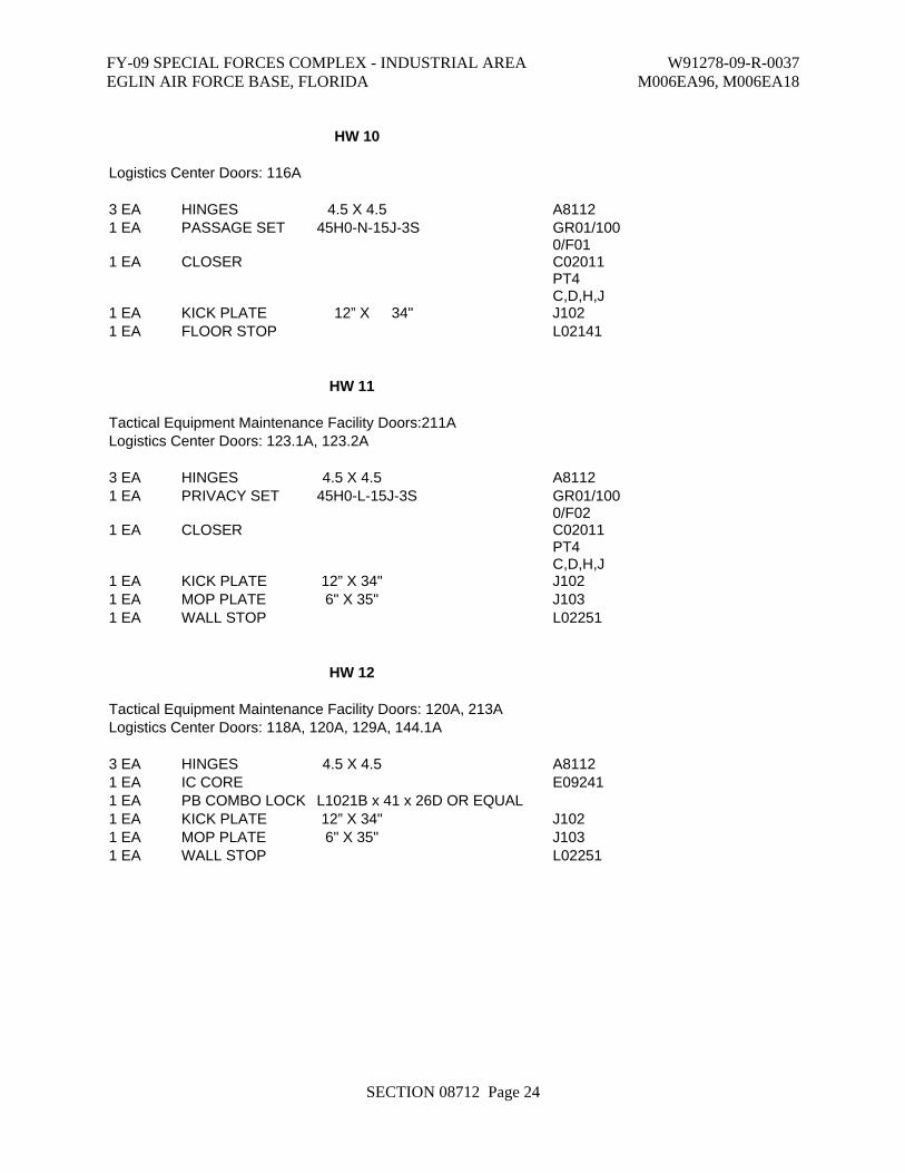
FY-09 SPECIAL FORCES COMPLEX - INDUSTRIAL AREA W91278-09-R-0037 EGLIN AIR FORCE BASE, FLORIDA M006EA96, M006EA18
SECTION 08712 Page 24
HW 10
Logistics Center Doors: 116A
3 EA HINGES 4.5 X 4.5 A8112 1 EA PASSAGE SET 45H0-N-15J-3S GR01/100
0/F01 1 EA CLOSER C02011
PT4 C,D,H,J
1 EA KICK PLATE 12” X 34" J102 1 EA FLOOR STOP L02141
HW 11
Tactical Equipment Maintenance Facility Doors:211A Logistics Center Doors: 123.1A, 123.2A
3 EA HINGES 4.5 X 4.5 A8112 1 EA PRIVACY SET 45H0-L-15J-3S GR01/100
0/F02 1 EA CLOSER C02011
PT4 C,D,H,J
1 EA KICK PLATE 12” X 34" J102 1 EA MOP PLATE 6" X 35" J103 1 EA WALL STOP L02251
HW 12
Tactical Equipment Maintenance Facility Doors: 120A, 213A Logistics Center Doors: 118A, 120A, 129A, 144.1A
3 EA HINGES 4.5 X 4.5 A8112 1 EA IC CORE E09241 1 EA PB COMBO LOCK L1021B x 41 x 26D OR EQUAL 1 EA KICK PLATE 12” X 34" J102 1 EA MOP PLATE 6" X 35" J103 1 EA WALL STOP L02251

FY-09 SPECIAL FORCES COMPLEX - INDUSTRIAL AREA W91278-09-R-0037 EGLIN AIR FORCE BASE, FLORIDA M006EA96, M006EA18
SECTION 08712 Page 25
HW 13
Tactical Equipment Maintenance Facility Doors: 106A, 107B, 109A, 115A, 116A, 124B, 131B, 132A, 200A, 204A, 205A, 206A, 207A, 208A, 209A, 215A, 216A, 216B, 2117ALogistics Center Doors: 104B, 107A, 108A, 109A, 114A, 115A, 121A, 122A, 122B, 123A, 123B, 130A, 132A, 135A, 136A, 147A, 146A, 154A, 153A, 153B, 128A, 131A, 145A, 155A
3 EA HINGES 4.5 X 4.5 (NRP @ OUTSWING) A8112 1 EA IC CORE E09241 1 EA PB COMBO LOCK L1021B x 41 x 26D OR EQUAL 1 EA CLOSER C02011/C
02021 PT4 C,D,H,J
1 EA KICK PLATE 12” X 34" J102 1 EA WALL STOP L02251
HW 13A
Tactical Equipment Maintenance Facility Doors:131A
3 EA HINGE 4.5 X 4.5 A8111 1 EA IC CORE E09241 1 EA PB COMBO LOCK L1021B x 41 x 26D OR EQUAL 1 EA CLOSER C02021 1 EA KICK PLATE 12” X 34" J102 1 EA WALL STOP L02251
HW 14
Tactical Equipment Maintenance Facility Doors:210A Logistics Center Doors:127A
3 EA HINGES 4.5 X 4.5 NRP A8112 1 EA IC CORE E09241 1 EA PB COMBO LOCK L1021B x 41 x 26D OR EQUAL 1 EA CDX-09 COMBO LOCK 1 EA CLOSER C02021 1 EA WALL STOP L02251

FY-09 SPECIAL FORCES COMPLEX - INDUSTRIAL AREA W91278-09-R-0037 EGLIN AIR FORCE BASE, FLORIDA M006EA96, M006EA18
SECTION 08712 Page 26
HW 15
Tactical Equipment Maintenance Facility Doors:100A, 214A
3 EA HINGES 4.5 X 4.5 A8112 1 EA RIM CYLINDER E09261 1 EA PANIC BAR F99L OR EQUAL TY01/F081 EA CLOSER C02011
PT4 C,D,H,J
1 EA KICK PLATE 12” X 34" J102 1 EA FLOOR STOP L02141
HW 16
Tactical Equipment Maintenance Facility Doors: 102A, 108A, 124A, 105A, 112A, 131C Logistics Center Doors:111A, 104A, 133B, 134A
6 EA HINGES 4.5 X 4.5 (NRP @ OUTSWING) A8112 2 EA MD FLUSHBOLTS L04251 1 EA IC CORE E09241 1 EA PB COMBO LOCK L1021B x 41 x 26D OR EQUAL 1 EA CLOSER AS REQUIRED C02011/C
02021 PT4 C,D,H,J
2 EA KICK PLATE 12” X 35” J102 1 EA WALL STOP L02251
HW 17
Tactical Equipment Maintenance Facility Doors: 104A, 103A Logistics Center Doors: 138A
1 EA X09 COMBINATION LOCK & BALANCE OF HARDWARE
BY DOOR MANUFACTURER
FY-09 SPECIAL FORCES COMPLEX - INDUSTRIAL AREA W91278-09-R-0037 EGLIN AIR FORCE BASE, FLORIDA M006EA96, M006EA18
SECTION 08712 Page 27
HW 18
Logistics Center Doors: 148A
1 EA GROUP 1R COMBINATION LOCK & BALANCE OF HARDWARE BY DOOR MANUFACTURER
END OF SECTION 08712

This page was intentionally left blank for duplex printing.
FY-09 SPECIAL FORCES COMPLEX - INDUSTRIAL AREA W91278-09-R-0037 EGLIN AIR FORCE BASE, FLORIDA M006EA96, M006EA18
SECTION 08800 Page 1
SECTION 08800 – GLAZING
PART 1 - GENERAL
1.1 RELATED DOCUMENTS
A. Drawings and general provisions of the Contract, including General and Supplementary Conditions and Division 1 Specification Sections, apply to this Section.
1.2 SUMMARY
A. This Section includes glazing for the following products and applications, including those specified in other Sections where glazing requirements are specified by reference to this Section:
1. Windows. 2. Doors. 3. Storefront framing.
B. Related Sections include the following:
1. Division 8 Section "Aluminum-Framed Entrances and Storefronts." 2. Division 8 Section “Steel Windows”. 3. Division 8 Section “Aluminum Windows”.
1.3 DEFINITIONS
A. Manufacturers of Glass Products: Firms that produce primary glass, fabricated glass, or both, as defined in referenced glazing publications.
B. Glass Thicknesses: Indicated by thickness designations in millimeters according to ASTM C 1036.
C. Interspace: Space between lites of an insulating-glass unit that contains dehydrated air or a specified gas.
D. Deterioration of Coated Glass: Defects developed from normal use that are attributed to the manufacturing process and not to causes other than glass breakage and practices for maintaining and cleaning coated glass contrary to manufacturer's written instructions. Defects include peeling, cracking, and other indications of deterioration in metallic coating.
E. Deterioration of Insulating Glass: Failure of hermetic seal under normal use that is attributed to the manufacturing process and not to causes other than glass breakage and practices for maintaining and cleaning insulating glass contrary to manufacturer's written instructions. Evidence of failure is the obstruction of vision by dust, moisture, or film on interior surfaces of glass.

FY-09 SPECIAL FORCES COMPLEX - INDUSTRIAL AREA W91278-09-R-0037 EGLIN AIR FORCE BASE, FLORIDA M006EA96, M006EA18
SECTION 08800 Page 2
F. Deterioration of Laminated Glass: Defects developed from normal use that are attributed to the manufacturing process and not to causes other than glass breakage and practices for maintaining and cleaning laminated glass contrary to manufacturer's written instructions. Defects include edge separation, delamination materially obstructing vision through glass, and blemishes exceeding those allowed by referenced laminated-glass standard.
1.4 PERFORMANCE REQUIREMENTS
A. General: Provide glazing systems capable of withstanding normal thermal movement and wind and impact loads (where applicable) without failure, including loss or glass breakage attributable to the following: defective manufacture, fabrication, and installation; failure of sealants or gaskets to remain watertight and airtight; deterioration of glazing materials; or other defects in construction.
B. Glass Design: Glass thickness designations indicated are minimums and are for detailing only. Confirm glass thicknesses by analyzing Project loads and in-service conditions. Provide glass lites in the thickness designations indicated for various size openings, but not less than thicknesses and in strengths (annealed or heat treated) required to meet or exceed the following criteria:
1. Glass Thicknesses: Select minimum glass thicknesses to comply with UFC 4-010-01 dated 22 January 2007, ASTM E 1300, and according to the following requirements:
a. Specified Design Wind Loads: As indicated on the Structural drawings.
b. Minimum Glass Thickness for Exterior Lites: Not less than 1/4 inch. c. Thickness of Tinted and Heat-Absorbing Glass: Provide the same thickness for
each tint color indicated throughout Project.
C. Thermal Movements: Provide glazing that allows for thermal movements resulting from the following maximum change (range) in ambient and surface temperatures acting on glass framing members and glazing components. Base engineering calculation on surface temperatures of materials due to both solar heat gain and nighttime-sky heat loss.
1. Temperature Change (Range): 120 deg F, ambient; 180 deg F, material surfaces.
D. Thermal and Optical Performance Properties: Provide glass with performance properties specified based on manufacturer's published test data, as determined according to procedures indicated below:
1. For monolithic-glass lites, properties are based on units with lites 1/4 inch thick. 2. For laminated-glass lites, properties are based on products of construction indicated. 3. For insulating-glass units, properties are based on units of thickness indicated for overall
unit and for each lite.
1.5 SUBMITTALS
A. Product Data: For each glass product and glazing material indicated.

FY-09 SPECIAL FORCES COMPLEX - INDUSTRIAL AREA W91278-09-R-0037 EGLIN AIR FORCE BASE, FLORIDA M006EA96, M006EA18
SECTION 08800 Page 3
B. Samples: For the following products, in the form of 12-inch- square Samples for glass.
1. Each color of tinted float glass. 2. Wired glass. 3. Fire-resistive glazing products. 4. Insulating glass for each designation indicated.
C. Glazing Schedule: Use same designations indicated on Drawings for glazed openings in preparing a schedule listing glass types and thicknesses for each size opening and location.
D. Product Certificates: Signed by manufacturers of glass and glazing products certifying that products furnished comply with requirements.
E. Qualification Data: For installers.
F. Product Test Reports: For each of the following types of glazing products:
1. Tinted float glass. 2. Insulating glass. 3. Glazing sealants. 4. Glazing gaskets.
G. Warranties: Special warranties specified in this Section.
1.6 QUALITY ASSURANCE
A. Installer Qualifications: An experienced installer who has completed glazing similar in material, design, and extent to that indicated for this Project; whose work has resulted in glass installations with a record of successful in-service performance; and who employs glass installers for this Project who are certified under the National Glass Association's Certified Glass Installer Program.
B. Source Limitations for Glass: Obtain the following through one source from a single manufacturer for each glass type: clear float glass, laminated glass and insulating glass.
C. Source Limitations for Glazing Accessories: Obtain glazing accessories through one source from a single manufacturer for each product and installation method indicated.
D. Glass Product Testing: Obtain glass test results for product test reports in "Submittals" Article from a qualified testing agency based on testing glass products.
1. Glass Testing Agency Qualifications: An independent testing agency with the experience and capability to conduct the testing indicated, as documented according to ASTM E 548.
2. Glass Testing Agency Qualifications: An independent testing agency accredited according to the NFRC CAP 1 Certification Agency Program.
E. Elastomeric Glazing Sealant Product Testing: Obtain sealant test results for product test reports in "Submittals" Article from a qualified testing agency based on testing current sealant formulations within a 36-month period.

FY-09 SPECIAL FORCES COMPLEX - INDUSTRIAL AREA W91278-09-R-0037 EGLIN AIR FORCE BASE, FLORIDA M006EA96, M006EA18
SECTION 08800 Page 4
1. Sealant Testing Agency Qualifications: An independent testing agency qualified according to ASTM C 1021 to conduct the testing indicated, as documented according to ASTM E 548.
2. Test elastomeric glazing sealants for compliance with requirements specified by reference to ASTM C 920, and where applicable, to other standard test methods.
F. Glazing for Fire-Rated Door Assemblies: Glazing for assemblies that comply with NFPA 80 and that are listed and labeled by a testing and inspecting agency acceptable to authorities having jurisdiction, for fire-protection ratings indicated, based on testing according to NFPA 252.
G. Safety Glazing Products: Comply with testing requirements in 16 CFR 1201 and, for wired glass, ANSI Z97.1.
1. Subject to compliance with requirements, obtain safety glazing products permanently marked with certification label of the Safety Glazing Certification Council or another certification agency acceptable to authorities having jurisdiction.
2. Where glazing units, including Kind FT glass and laminated glass, are specified in Part 2 articles for glazing lites more than 9 sq. ft. in exposed surface area of one side, provide glazing products that comply with Category II materials, for lites 9 sq. ft. or less in exposed surface area of one side, provide glazing products that comply with Category I or II materials, except for hazardous locations where Category II materials are required by 16 CFR 1201 and regulations of authorities having jurisdiction.
H. Glazing Publications: Comply with published recommendations of glass product manufacturers and organizations below, unless more stringent requirements are indicated. Refer to these publications for glazing terms not otherwise defined in this Section or in referenced standards.
1. GANA Publications: GANA Laminated Division's "Laminated Glass Design Guide" and GANA's "Glazing Manual."
2. IGMA Publication for Insulating Glass: SIGMA TM-3000, "Glazing Guidelines for Sealed Insulating Glass Units."
1.7 DELIVERY, STORAGE, AND HANDLING
A. Protect glazing materials according to manufacturer's written instructions and as needed to prevent damage to glass and glazing materials from condensation, temperature changes, direct exposure to sun, or other causes.
B. For insulating-glass units that will be exposed to substantial altitude changes, comply with insulating-glass manufacturer's written recommendations for venting and sealing to avoid hermetic seal ruptures.
1.8 PROJECT CONDITIONS
A. Environmental Limitations: Do not proceed with glazing when ambient and substrate temperature conditions are outside limits permitted by glazing material manufacturers and when glazing channel substrates are wet from rain, frost, condensation, or other causes.

FY-09 SPECIAL FORCES COMPLEX - INDUSTRIAL AREA W91278-09-R-0037 EGLIN AIR FORCE BASE, FLORIDA M006EA96, M006EA18
SECTION 08800 Page 5
1. Do not install liquid glazing sealants when ambient and substrate temperature conditions are outside limits permitted by glazing sealant manufacturer or below 40 deg F.
1.9 WARRANTY
A. Manufacturer's Special Warranty on Laminated Glass: Manufacturer's standard form, made out to Owner and signed by laminated-glass manufacturer agreeing to replace laminated-glass units that deteriorate as defined in "Definitions" Article, f.o.b. the nearest shipping point to Project site, within specified warranty period indicated below.
1. Warranty Period: Five years from date of Substantial Completion.
B. Manufacturer's Special Warranty on Insulating Glass: Manufacturer's standard form, made out to Owner and signed by insulating-glass manufacturer agreeing to replace insulating-glass units that deteriorate as defined in "Definitions" Article, f.o.b. the nearest shipping point to Project site, within specified warranty period indicated below.
1. Warranty Period: 10 years from date of Substantial Completion.
PART 2 - PRODUCTS
2.1 GLASS PRODUCTS
A. Annealed Float Glass: ASTM C 1036, Type I (transparent flat glass), Quality-Q3; of class indicated.
B. Heat-Treated Float Glass: ASTM C 1048; Type I (transparent flat glass); Quality-Q3; of class, kind, and condition indicated.
1. Fabrication Process: By horizontal (roller-hearth) process with roll-wave distortion parallel to bottom edge of glass as installed, unless otherwise indicated.
2. Provide Kind FT (fully tempered) float glass in place of annealed or Kind HS (heat-
strengthened) float glass where indicated.
C. Wired Glass: ASTM C 1036, Type II (patterned and wired flat glass), Class 1 (clear), Quality-Q-6; and of form and mesh pattern specified.
D. Laminated Glass: ASTM C 1172, and complying with other requirements specified and with the following:
1. Interlayer: Polyvinyl butyral of thickness indicated with a proven record of no tendency to bubble, discolor, or lose physical and mechanical properties after laminating glass lites and installation.
a. For polyvinyl butyral interlayers, laminate lites in autoclave with heat plus pressure.

FY-09 SPECIAL FORCES COMPLEX - INDUSTRIAL AREA W91278-09-R-0037 EGLIN AIR FORCE BASE, FLORIDA M006EA96, M006EA18
SECTION 08800 Page 6
2. Laminating Process: Fabricate laminated glass to produce glass free of foreign substances and air or glass pockets.
E. Insulating-Glass Units, General: Factory-assembled, impact-resistant units consisting of sealed lites of glass separated by a dehydrated interspace, and complying with ASTM E 774 for Class CBA units and with requirements specified in this Article and in Part 2 "Insulating-Glass Units" Article. 1. Provide Kind FT (fully tempered) glass lites where safety glass is indicated. 2. Overall Unit Thickness and Thickness of Each Lite: Dimensions indicated for insulating-
glass units are nominal and the overall thicknesses of units are measured perpendicularly from outer surfaces of glass lites at unit's edge.
3. Sealing System: Manufacturer’s standard structural sealants.
4. Spacer Specifications: Manufacturer's standard spacer material and construction.
2.2 FIRE-RATED GLAZING PRODUCTS
A. Monolithic Ceramic Glazing Material: Proprietary product in the form of clear flat sheets of 3/16-inch nominal thickness weighing 2.5 lb/sq. ft., and as follows:
1. Fire-Protection Rating: As indicated for the fire window in which glazing material is installed, and permanently labeled by a testing and inspecting agency acceptable to authorities having jurisdiction.
2. Basis of Design: "Premium FireLite" (polished on both surfaces) by Nippon Electric
Glass Co., Ltd., and distributed by Technical Glass Products.
2.3 GLAZING GASKETS
Unless noted otherwise, provide manufacturer’s standard glazing gaskets in compliance with one of the following:
A. Dense Compression Gaskets: Molded or extruded gaskets of material indicated below, complying with standards referenced with name of elastomer indicated below, and of profile and hardness required to maintain watertight seal: 1. Silicone, ASTM C 1115. 2. Thermoplastic polyolefin rubber, ASTM C 1115. 3. Any material indicated above.
B. Soft Compression Gaskets: Extruded or molded, closed-cell, integral-skinned gaskets of material indicated below; complying with ASTM C 509, Type II, black; and of profile and hardness required to maintain watertight seal:

FY-09 SPECIAL FORCES COMPLEX - INDUSTRIAL AREA W91278-09-R-0037 EGLIN AIR FORCE BASE, FLORIDA M006EA96, M006EA18
SECTION 08800 Page 7
1. Silicone. 2. Thermoplastic polyolefin rubber. 3. Any material indicated above.
2.4 GLAZING SEALANTS
A. General: Provide products of type indicated, complying with the following requirements:
1. Compatibility: Select glazing sealants that are compatible with one another and with other materials they will contact, including glass products, seals of insulating-glass units, and glazing channel substrates, under conditions of service and application, as demonstrated by sealant manufacturer based on testing and field experience.
2. Suitability: Comply with sealant and glass manufacturers' written instructions for
selecting glazing sealants suitable for applications indicated and for conditions existing at time of installation.
3. VOC Content: For sealants used inside of the weatherproofing system, not more than
250 g/L when calculated according to 40 CFR 59, Subpart D (EPA Method 24). 4. Colors of Exposed Glazing Sealants: White unless otherwise indicated.
B. Elastomeric Glazing Sealants: Comply with ASTM C 920 and other requirements indicated for each liquid-applied chemically curing sealant specified, including those referencing ASTM C 920 classifications for type, grade, class, and uses related to exposure and joint substrates.
1. Single-Component Neutral-Curing Silicone Glazing Sealants:
a. Available Products:
1) Dow Corning Corporation; 790. 2) GE Silicones; SilPruf LM SCS2700. 3) Or other approved equal.
b. Type and Grade: S (single component) and NS (nonsag). c. Class: 100/50. d. Use Related to Exposure: NT (nontraffic). e. Uses Related to Glazing Substrates: M, G, A, and, as applicable to glazing
substrates indicated, O.
1) Use O Glazing Substrates: aluminum coated with a high-performance coating.
C. Glazing Sealants for Fire-Resistive Glazing Products: Identical to products used in test assemblies to obtain fire-protection rating.

FY-09 SPECIAL FORCES COMPLEX - INDUSTRIAL AREA W91278-09-R-0037 EGLIN AIR FORCE BASE, FLORIDA M006EA96, M006EA18
SECTION 08800 Page 8
D. Glazing Sealants for Impact Resistant Glazing Products: Identical to products used in test assemblies to obtain impact protection rating.
2.5 GLAZING TAPES
A. Back-Bedding Mastic Glazing Tapes: Preformed, butyl-based elastomeric tape with a solids content of 100 percent; nonstaining and nonmigrating in contact with nonporous surfaces; with or without spacer rod as recommended in writing by tape and glass manufacturers for application indicated; packaged on rolls with a release paper backing; and complying with ASTM C 1281 and AAMA 800 for products indicated below: 1. AAMA 806.3 tape, for glazing applications in which tape is subject to continuous
pressure. 2. AAMA 807.3 tape, for glazing applications in which tape is not subject to continuous
pressure.
B. Expanded Cellular Glazing Tapes: Closed-cell, PVC foam tapes; factory coated with adhesive on both surfaces; packaged on rolls with release liner protecting adhesive; and complying with AAMA 800 for the following types:
1. Type 1, for glazing applications in which tape acts as the primary sealant. 2. Type 2, for glazing applications in which tape is used in combination with a full bead of
liquid sealant.
2.6 MISCELLANEOUS GLAZING MATERIALS
A. General: Provide products of material, size, and shape complying with referenced glazing standard, requirements of manufacturers of glass and other glazing materials for application indicated, and with a proven record of compatibility with surfaces contacted in installation.
B. Cleaners, Primers, and Sealers: Types recommended by sealant or gasket manufacturer.
C. Setting Blocks: Elastomeric material with a Shore, Type A durometer hardness of 85, plus or minus 5.
D. Spacers: Elastomeric blocks or continuous extrusions with a Shore, Type A durometer hardness required by glass manufacturer to maintain glass lites in place for installation indicated.
E. Edge Blocks: Elastomeric material of hardness needed to limit glass lateral movement (side walking).
F. Cylindrical Glazing Sealant Backing: ASTM C 1330, Type O (open-cell material), of size and density to control glazing sealant depth and otherwise produce optimum glazing sealant performance.
G. Perimeter Insulation for Fire-Resistive Glazing: Identical to product used in test assembly to obtain fire-resistance rating.

FY-09 SPECIAL FORCES COMPLEX - INDUSTRIAL AREA W91278-09-R-0037 EGLIN AIR FORCE BASE, FLORIDA M006EA96, M006EA18
SECTION 08800 Page 9
2.7 FABRICATION OF GLAZING UNITS
A. Fabricate glazing units in sizes required to glaze openings indicated for Project, with edge and face clearances, edge and surface conditions, and bite complying with written instructions of product manufacturer and referenced glazing publications, to comply with system performance requirements.
B. Clean-cut or flat-grind vertical edges of butt-glazed monolithic lites in a manner that produces square edges with slight kerfs at junctions with outdoor and indoor faces.
C. Grind smooth and polish exposed glass edges and corners.
2.8 MONOLITHIC FLOAT-GLASS UNITS
A. Uncoated Clear Float-Glass Units: Class 1 (clear) or Kind FT (fully tempered) float glass.
1. Thickness: 1/4 inch unless noted otherwise.
B. Uncoated Tinted Float-Glass Units: Class 2 (tinted) Kind FT (fully tempered) float glass as indicated or required.
1. Tint Color: As indicated in Section 09915 COLOR SCHEDULE.
2. Thickness: ¼ inch unless noted otherwise.
2.9 MONOLITHIC WIRED-GLASS UNITS
A. Polished Wired-Glass Units: Form 1 (wired glass, polished both sides), Quality-Q6, Mesh 1 (M1) (Diamond) ¼ inch thick.
2.10 LAMINATED-GLASS UNITS
A. Interior Laminated-Glass Units:
1. Consisting of two lites of fully tempered float glass. 2. Outer Lite: Class 1 (clear) fully tempered float glass.
a. Thickness: 1/8 inch unless noted otherwise.
3. Plastic Interlayer:
a. Thickness: as required to comply as a Type II safety glass material. b. Interlayer Color: Clear.
4. Inner Lite: Class 1 (clear) fully tempered float glass.
a. Thickness: 1/8 inch unless noted otherwise.

FY-09 SPECIAL FORCES COMPLEX - INDUSTRIAL AREA W91278-09-R-0037 EGLIN AIR FORCE BASE, FLORIDA M006EA96, M006EA18
SECTION 08800 Page 10
B. Exterior Laminated-Glass Units
1. Consisting of two lites of fully tempered float glass. 2. Outer Lite: Class 2 (tinted) fully tempered float glass typical except provide Class 1
(clear) fully tempered float glass in insulating-glass units. a. Thickness: ¼ inch thick.
3. Plastic Interlayer:
a. Thickness: 0.090 inch. b. Interlayer Color: Clear.
4. Inner Lite: Class 1 (clear) fully tempered float glass.
a. Thickness: ¼ inch thick.
2.11 INSULATING-GLASS UNITS
A. Tinted Insulating-Glass Units (impact resistant):
1. Overall Unit Thickness and Thickness of Each Lite: 1 ¼ inch thick, nominal. 2. Interspace Content: Air. 3. Outdoor Lite: Class 2 (tinted) float glass.
a. Tint Color: As indicated in Section 09915 COLOR SCHEDULE. b. Kind FT (fully tempered).
4. Indoor Lite: Class 1 (clear) exterior laminated glass. 5. Visible Light Transmittance: approximately 40 percent minimum. 6. Winter Nighttime U-Factor: approximately 0.47 maximum.
PART 3 - EXECUTION
3.1 EXAMINATION
A. Examine framing glazing, with Installer present, for compliance with the following:
1. Manufacturing and installation tolerances, including those for size, squareness, and offsets at corners.

FY-09 SPECIAL FORCES COMPLEX - INDUSTRIAL AREA W91278-09-R-0037 EGLIN AIR FORCE BASE, FLORIDA M006EA96, M006EA18
SECTION 08800 Page 11
2. Presence and functioning of weep system. 3. Minimum required face or edge clearances. 4. Effective sealing between joints of glass-framing members.
B. Proceed with installation only after unsatisfactory conditions have been corrected.
3.2 PREPARATION
A. Clean glazing channels and other framing members receiving glass immediately before glazing. Remove coatings not firmly bonded to substrates.
3.3 GLAZING, GENERAL
A. Comply with combined written instructions of manufacturers of glass, sealants, gaskets, and other glazing materials, unless more stringent requirements are indicated, including those in referenced glazing publications. Comply with requirements of tested assembly for hurricane resistant, impact resistant glazing assemblies.
B. Glazing channel dimensions: Provide necessary bite on glass, minimum edge and face clearances, and adequate sealant thicknesses, with reasonable tolerances. Adjust as required by Project conditions during installation. Comply with requirements of tested assembly for impact resistant glazing assemblies.
C. Protect glass edges from damage during handling and installation. Remove damaged glass from Project site and legally dispose of off Project site. Damaged glass is glass with edge damage or other imperfections that, when installed, could weaken glass and impair performance and appearance.
D. Apply primers to joint surfaces where required for adhesion of sealants, as determined by preconstruction sealant-substrate testing.
E. Install setting blocks in sill rabbets, sized and located to comply with referenced glazing publications, unless otherwise required by glass manufacturer. Set blocks in thin course of compatible sealant suitable for heel bead.
F. Do not exceed edge pressures stipulated by glass manufacturers for installing glass lites.
G. Provide spacers for glass lites where length plus width is larger than 50 inches as follows:
1. Locate spacers directly opposite each other on both inside and outside faces of glass. Install correct size and spacing to preserve required face clearances, unless gaskets and glazing tapes are used that have demonstrated ability to maintain required face clearances and to comply with system performance requirements.
2. Provide 1/8-inch minimum bite of spacers on glass and use thickness equal to sealant width. With glazing tape, use thickness slightly less than final compressed thickness of tape.

FY-09 SPECIAL FORCES COMPLEX - INDUSTRIAL AREA W91278-09-R-0037 EGLIN AIR FORCE BASE, FLORIDA M006EA96, M006EA18
SECTION 08800 Page 12
H. Provide edge blocking where indicated or needed to prevent glass lites from moving sideways in glazing channel, as recommended in writing by glass manufacturer and according to requirements in referenced glazing publications.
I. Set glass lites in each series with uniform pattern, draw, bow, and similar characteristics.
J. Where wedge-shaped gaskets are driven into one side of channel to pressurize sealant or gasket on opposite side, provide adequate anchorage so gasket cannot walk out when installation is subjected to movement.
K. Square cut wedge-shaped gaskets at corners and install gaskets in a manner recommended by gasket manufacturer to prevent corners from pulling away; seal corner joints and butt joints with sealant recommended by gasket manufacturer.
3.4 TAPE GLAZING
A. Position tapes on fixed stops so that, when compressed by glass, their exposed edges are flush with or protrude slightly above sightline of stops.
B. Install tapes continuously, but not necessarily in one continuous length. Do not stretch tapes to make them fit opening.
C. Cover vertical framing joints by applying tapes to heads and sills first and then to jambs. Cover horizontal framing joints by applying tapes to jambs and then to heads and sills.
D. Place joints in tapes at corners of opening with adjoining lengths butted together, not lapped. Seal joints in tapes with compatible sealant approved by tape manufacturer.
E. Do not remove release paper from tape until just before each glazing unit is installed.
F. Apply heel bead of elastomeric sealant.
G. Center glass lites in openings on setting blocks and press firmly against tape by inserting dense compression gaskets formed and installed to lock in place against faces of removable stops. Start gasket applications at corners and work toward centers of openings.
H. Apply cap bead of elastomeric sealant over exposed edge of tape.
3.5 GASKET GLAZING (DRY)
A. Fabricate compression gaskets in lengths recommended by gasket manufacturer to fit openings exactly, with allowance for stretch during installation.
B. Insert soft compression gasket between glass and frame or fixed stop so it is securely in place with joints miter cut and bonded together at corners.
C. Center glass lites in openings on setting blocks and press firmly against soft compression gasket by inserting dense compression gaskets formed and installed to lock in place against faces of removable stops. Start gasket applications at corners and work toward centers of openings.

FY-09 SPECIAL FORCES COMPLEX - INDUSTRIAL AREA W91278-09-R-0037 EGLIN AIR FORCE BASE, FLORIDA M006EA96, M006EA18
SECTION 08800 Page 13
Compress gaskets to produce a weathertight seal without developing bending stresses in glass. Seal gasket joints with sealant recommended by gasket manufacturer.
D. Install gaskets so they protrude past face of glazing stops.
3.6 SEALANT GLAZING (WET)
A. Install continuous spacers, or spacers combined with cylindrical sealant backing, between glass lites and glazing stops to maintain glass face clearances and to prevent sealant from extruding into glass channel and blocking weep systems until sealants cure. Secure spacers or spacers and backings in place and in position to control depth of installed sealant relative to edge clearance for optimum sealant performance.
B. Force sealants into glazing channels to eliminate voids and to ensure complete wetting or bond of sealant to glass and channel surfaces.
C. Tool exposed surfaces of sealants to provide a substantial wash away from glass.
3.7 CLEANING AND PROTECTION
A. Protect glass from damage immediately after installation by attaching crossed streamers to framing held away from glass. Do not apply markers to glass surface. Remove nonpermanent labels, and clean surfaces.
B. Protect glass from contact with contaminating substances resulting from construction operations, including weld splatter. If, despite such protection, contaminating substances do come into contact with glass, remove substances immediately as recommended by glass manufacturer.
C. Examine glass surfaces adjacent to or below exterior concrete and other masonry surfaces at frequent intervals during construction, but not less than once a month, for buildup of dirt, scum, alkaline deposits, or stains; remove as recommended in writing by glass manufacturer.
D. Remove and replace glass that is broken, chipped, cracked, or abraded or that is damaged from natural causes, accidents, and vandalism, during construction period.
E. Wash glass on both exposed surfaces in each area of Project not more than four days before date scheduled for inspections that establish date of Substantial Completion. Wash glass as recommended in writing by glass manufacturer.
END OF SECTION 08800

This page was intentionally left blank for duplex printing.

FY-09 SPECIAL FORCES COMPLEX - INDUSTRIAL AREA W91278-09-R-0037 EGLIN AIR FORCE BASE, FLORIDA M006EA96, M006EA18
SECTION 09111 Page 1
SECTION 09111 - NON-LOAD-BEARING STEEL FRAMING
PART 1 - GENERAL
1.1 RELATED DOCUMENTS
A. Drawings and general provisions of the Contract, including General and Supplementary Conditions and Division 1 Specification Sections, apply to this Section.
1.2 SUMMARY
A. This Section includes non-load-bearing steel framing members for the following applications:
1. Interior framing systems (e.g., supports for partition walls, framed soffits, furring, etc.).
2. Interior suspension systems (e.g., supports for ceilings, suspended soffits, etc.).
B. Related Sections include the following: 1. Division 9 Section "Gypsum Board Shaft-Wall Assemblies" for non-load-bearing
metal shaft-wall framing, gypsum panels, and other components of shaft-wall assemblies.
1.3 SUBMITTALS
A. Product Data: For each type of product indicated.
B. LEED Submittal:
1. Product Data for Credit MR 4.1 and Credit MR 4.2: For products having recycled content, documentation indicating percentages by weight of postconsumer and preconsumer recycled content.
a. Include statement indicating costs for each product having recycled content.
1.4 QUALITY ASSURANCE
A. Fire-Test-Response Characteristics: For fire-resistance-rated assemblies that incorporate non-load-bearing steel framing, provide materials and construction identical to those tested in assembly indicated according to ASTM E 119 by an independent testing agency.

FY-09 SPECIAL FORCES COMPLEX - INDUSTRIAL AREA W91278-09-R-0037 EGLIN AIR FORCE BASE, FLORIDA M006EA96, M006EA18
SECTION 09111 Page 2
B. STC-Rated Assemblies: For STC-rated assemblies, provide materials and construction identical to those tested in assembly indicated according to ASTM E 90 and classified according to ASTM E 413 by an independent testing agency.
PART 2 - PRODUCTS
2.1 NON-LOAD-BEARING STEEL FRAMING, GENERAL
A. Recycled Content of Steel Products: Provide products with average recycled content of steel products such that postconsumer recycled content plus one-half of preconsumer recycled content is not less than 25 percent.
B. Framing Members, General: Comply with ASTM C 754 for conditions indicated.
1. Steel Sheet Components: Comply with ASTM C 645 requirements for metal, unless otherwise indicated.
2. Protective Coating: ASTM A 653/A 653M, G60, hot-dip galvanized, unless otherwise indicated.
2.2 SUSPENSION SYSTEM COMPONENTS
A. Tie Wire: ASTM A 641/A 641M, Class 1 zinc coating, soft temper, 0.0625-inch- diameter wire, or double strand of 0.0475-inch-diameter wire.
B. Wire Hangers: ASTM A 641/A 641M, Class 1 zinc coating, soft temper, 0.162-inch diameter.
C. Carrying Channels: Cold-rolled, commercial-steel sheet with a base-metal thickness of 0.0538 inch and minimum 1/2-inch- wide flanges.
1. Depth: 1-1/2 inches.
D. Furring Channels (Furring Members):
1. Hat-Shaped, Rigid Furring Channels: ASTM C 645, 7/8 inch deep unless otherwise indicated on the drawings..
a. Minimum Base Metal Thickness: 0.0312 inch, unless otherwise indicated.

FY-09 SPECIAL FORCES COMPLEX - INDUSTRIAL AREA W91278-09-R-0037 EGLIN AIR FORCE BASE, FLORIDA M006EA96, M006EA18
SECTION 09111 Page 3
2.3 STEEL FRAMING FOR FRAMED ASSEMBLIES
A. Steel Studs and Runners: ASTM C 645.
1. Minimum Base Metal Thickness: Metal studs supporting cementitious backer units shall be a minimum of 0.032 inches (20gauge) and designed for a deflection of L/360 based on load of 10psf and shall be braced at intervals not exceeding 4 feet on center. Metal stud partitions to receive ceramic tile finish shall have minimum uncoated design thickness of 0.0428 inches (18 gauge) and shall be braced at intervals not exceeding 4 feet on center. Contractor shall select gauge of framing members and establish spacing to comply with requirements of ASTM C 754 unless otherwise specifically indicated. Spacing shall not be greater that 16 inches on center. Maximum deflection: L/240 at 5 lbf per square foot unless noted otherwise
2. Depth: As indicated on Drawings.
B. Slip-Type Head Joints: Where indicated, provide the following: 1. Deflection Track: Steel sheet top runner manufactured to prevent cracking of
finishes applied to interior partition framing resulting from deflection of structure above; in thickness not less than indicated for studs and in width to accommodate depth of studs.
a. Available Products: Subject to compliance with requirements, products that may be incorporated into the Work include, but are not limited to, the following:
1) Steel Network Inc. (The); VertiTrack VTD Series. 2) Superior Metal Trim; Superior Flex Track System (SFT). 3) Or other approved equal.
C. Firestop Tracks: Top runner manufactured to allow partition heads to expand and contract with movement of the structure while maintaining continuity of fire-resistance-rated assembly indicated; in thickness not less than indicated for studs and in width to accommodate depth of studs.
1. Available Products: Subject to compliance with requirements, products that may be incorporated into the Work include, but are not limited to, the following:
a. Fire Trak Corp.; Fire Trak attached to studs with Fire Trak Slip Clip. b. Metal-Lite, Inc.; The System. c. Or other approved equal.
D. Flat Strap and Backing Plate: Steel sheet for blocking and bracing in length and width indicated.
1. Minimum Base-Metal Thickness: As indicated on Drawings or, if not indicated, provide as required for design load but not less than 20 gage.
FY-09 SPECIAL FORCES COMPLEX - INDUSTRIAL AREA W91278-09-R-0037 EGLIN AIR FORCE BASE, FLORIDA M006EA96, M006EA18
SECTION 09111 Page 4
E. Cold-Rolled Channel Bridging: 0.0538-inch bare-steel thickness, with minimum 1/2-inch- wide flanges.
1. Depth: As indicated on Drawings or 1-1/2 inches 2. Clip Angle: Not less than 1-1/2 by 1-1/2 inches, 0.068-inch- thick, galvanized
steel.
F. Hat-Shaped, Rigid Furring Channels: ASTM C 645.
1. Minimum Base Metal Thickness: 0.0312 inch. 2. Depth: As indicated on Drawings.
2.4 AUXILIARY MATERIALS
A. General: Provide auxiliary materials that comply with referenced installation standards.
1. Fasteners for Metal Framing: Of type, material, size, corrosion resistance, holding power, and other properties required to fasten steel members to substrates.
B. Isolation Strip at Exterior Walls: Provide one of the following:
1. Asphalt-Saturated Organic Felt: ASTM D 226, Type I (No. 15 asphalt felt), nonperforated.
2. Foam Gasket: Adhesive-backed, closed-cell vinyl foam strips that allow fastener penetration without foam displacement, 1/8 inch thick, in width to suit steel stud size.
PART 3 - EXECUTION
3.1 EXAMINATION
A. Examine areas and substrates, with Installer present, and including welded hollow-metal frames, cast-in anchors, and structural framing, for compliance with requirements and other conditions affecting performance.
1. Proceed with installation only after unsatisfactory conditions have been corrected.
3.2 PREPARATION
A. Suspended Assemblies: Coordinate installation of suspension systems with installation of overhead structure to ensure that inserts and other provisions for anchorages to building structure have been installed to receive hangers at spacing required to support the Work and that hangers will develop their full strength.

FY-09 SPECIAL FORCES COMPLEX - INDUSTRIAL AREA W91278-09-R-0037 EGLIN AIR FORCE BASE, FLORIDA M006EA96, M006EA18
SECTION 09111 Page 5
3.3 INSTALLATION, GENERAL
A. Installation Standard: ASTM C 754, except comply with framing sizes and spacing indicated.
1. Gypsum Board Assemblies: Also comply with requirements in ASTM C 840 that
apply to framing installation.
B. Install supplementary metal framing, and metal blocking to support fixtures, equipment services, heavy trim, grab bars, toilet accessories, furnishings, or similar construction.
C. Install bracing at terminations in assemblies.
D. Do not bridge building control and expansion joints with non-load-bearing steel framing members. Frame both sides of joints independently.
3.4 INSTALLING SUSPENSION SYSTEMS
A. Install suspension system components in sizes and spacings indicated on Drawings, but not less than those required by referenced installation standards for assembly types and other assembly components indicated.
B. Isolate suspension systems from building structure where they abut or are penetrated by building structure to prevent transfer of loading imposed by structural movement.
C. Suspend hangers from building structure as follows:
1. Install hangers plumb and free from contact with insulation or other objects within ceiling plenum that are not part of supporting structural or suspension system.
a. Splay hangers only where required to miss obstructions and offset resulting horizontal forces by bracing, countersplaying, or other equally effective means.
2. Where width of ducts and other construction within ceiling plenum produces hanger spacings that interfere with locations of hangers required to support standard suspension system members, install supplemental suspension members and hangers in the form of trapezes or equivalent devices.
a. Size supplemental suspension members and hangers to support ceiling loads within performance limits established by referenced installation standards.
3. Wire Hangers: Secure by looping and wire tying, either directly to structures or to inserts, eye screws, or other devices and fasteners that are secure and appropriate for substrate, and in a manner that will not cause hangers to deteriorate or otherwise fail.
4. Do not attach hangers to steel roof deck.

FY-09 SPECIAL FORCES COMPLEX - INDUSTRIAL AREA W91278-09-R-0037 EGLIN AIR FORCE BASE, FLORIDA M006EA96, M006EA18
SECTION 09111 Page 6
5. Do not attach hangers to permanent metal forms. Furnish cast-in-place hanger inserts that extend through forms.
6. Do not attach hangers to rolled-in hanger tabs of composite steel floor deck. 7. Do not connect or suspend steel framing from ducts, pipes, or conduit.
D. Fire-Resistance-Rated Assemblies: Wire tie furring channels to supports.
E. Installation Tolerances: Install suspension systems that are level to within 1/8 inch in 12 feet measured lengthwise on each member that will receive finishes and transversely between parallel members that will receive finishes.
3.5 INSTALLING FRAMED ASSEMBLIES
A. Where studs are installed directly against exterior masonry walls or dissimilar metals at exterior walls, install isolation strip between studs and exterior wall.
B. Install studs so flanges within framing system point in same direction.
1. Space studs as follows:
a. Single-Layer Application: 16 inches o.c. maximum, unless otherwise indicated.
b. Multilayer Application: 16 inches o.c. maximum, unless otherwise indicated.
c. Tile backing panels: 16 inches o.c. maximum, unless otherwise indicated.
C. Install tracks (runners) at floors and overhead supports. Extend framing full height to structural supports or substrates above suspended ceilings, except where partitions are indicated to terminate at or just above suspended ceilings. Continue framing around ducts penetrating partitions above ceiling.
1. Slip-Type Head Joints: Where framing extends to overhead structural supports, install to produce joints at tops of framing systems that prevent axial loading of finished assemblies.
2. Door Openings: Screw vertical studs at jambs to jamb anchor clips on door frames; install runner track section (for cripple studs) at head and secure to jamb studs.
a. Install two studs at each jamb, unless otherwise indicated. b. Install cripple studs at head adjacent to each jamb stud, with a minimum
1/2-inch clearance from jamb stud to allow for installation of control joint in finished assembly.
c. Extend jamb studs through suspended ceilings and attach to underside of overhead structure.

FY-09 SPECIAL FORCES COMPLEX - INDUSTRIAL AREA W91278-09-R-0037 EGLIN AIR FORCE BASE, FLORIDA M006EA96, M006EA18
SECTION 09111 Page 7
3. Other Framed Openings: Frame openings other than door openings the same as required for door openings, unless otherwise indicated. Install framing below sills of openings to match framing required above door heads.
4. Fire-Resistance-Rated Partitions: Install framing to comply with fire-resistance-rated assembly indicated and support closures and to make partitions continuous from floor to underside of solid structure.
a. Firestop Track: Where indicated, install to maintain continuity of fire-resistance-rated assembly indicated.
5. Sound-Rated Partitions: Install framing to comply with sound-rated assembly indicated. Where STC ratings are noted, apply a ¼” bead of acoustical sealant to all stud surfaces which will contact drywall.
D. Direct Furring: 1. Attach to concrete or masonry with stub nails, screws designed for masonry
attachment, or powder-driven fasteners spaced 24 inches o.c.
E. Installation Tolerance: Install each framing member so fastening surfaces vary not more than 1/8 inch from the plane formed by faces of adjacent framing.
END OF SECTION 09111

This page was intentionally left blank for duplex printing.

FY-09 SPECIAL FORCES COMPLEX - INDUSTRIAL AREA W91278-09-R-0037 EGLIN AIR FORCE BASE, FLORIDA M006EA96, M006EA18
SECTION 09250 Page 1
SECTION 09250 - GYPSUM BOARD
PART 1 - GENERAL
1.1 SUMMARY
A. This Section includes the following:
1. Interior gypsum board. 2. Cementitious tile backing panels. 3. Exterior Sheathing. 4. Impact Resistant Gypsum Board. 5. Sound Attenuation Blankets.
1.2 SUBMITTALS
A. Product Data: For each type of product indicated.
B. Samples: For the following products:
1. Textured Finishes: Manufacturer's standard size for each textured finish indicated and on same backing indicated for Work.
C. LEED Submittals: For Credit EQ 4.1, manufacturers' product data for adhesives used to laminate gypsum board panels to substrates, including printed statement of VOC content.
1.3 QUALITY ASSURANCE
A. Fire-Resistance-Rated Assemblies: For fire-resistance-rated assemblies, provide materials and construction identical to those tested in assembly indicated according to ASTM E 119 by an independent testing agency.
B. STC-Rated Assemblies: For STC-rated assemblies, provide materials and construction identical to those tested in assembly indicated according to ASTM E 90 and classified according to ASTM E 413 by an independent testing agency.

FY-09 SPECIAL FORCES COMPLEX - INDUSTRIAL AREA W91278-09-R-0037 EGLIN AIR FORCE BASE, FLORIDA M006EA96, M006EA18
SECTION 09250 Page 2
PART 2 - PRODUCTS
2.1 INTERIOR GYPSUM BOARD
A. General: Complying with ASTM C 36/C 36M or ASTM C 1396/C 1396M, as applicable to type of gypsum board indicated and whichever is more stringent.
1. Available Manufacturers: Subject to compliance with requirements, manufacturers offering products that may be incorporated into the Work include, but are not limited to, the following:
a. G-P Gypsum. b. National Gypsum Company. c. USG Corporation. d. Or other approved equal.
B. Regular Type:
1. Thickness: 5/8 inch typical unless otherwise noted on drawings. 2. Long Edges: Tapered.
C. Type X:
1. Thickness: 5/8 inch 2. Long Edges: Tapered.
D. Type C:
1. Thickness: 5/8 inch typical unless otherwise noted on drawings. 2. Long Edges: Tapered.
E. Ceiling Type: Manufactured to have more sag resistance than regular-type gypsum board.
1. Thickness: 1/2 inch. 2. Long Edges: Tapered.
F. High-Impact Type: Manufactured with Type X core, plastic film laminated to back side for greater resistance to through-penetration (impact resistance).
1. Core: 5/8 inch typical unless otherwise indicated on drawings. 2. Plastic-Film Thickness: 0.081 inch unless otherwise noted.
G. Moisture- and Mold-Resistant Type: With moisture- and mold-resistant core and surfaces.
1. Core: 5/8 inch, Type X type where required. 2. Long Edges: Tapered.

FY-09 SPECIAL FORCES COMPLEX - INDUSTRIAL AREA W91278-09-R-0037 EGLIN AIR FORCE BASE, FLORIDA M006EA96, M006EA18
SECTION 09250 Page 3
2.2 EXTERIOR SHEATHING
A. Glass-Mat Gypsum Sheathing Board: ASTM C 1177/C 1177M.
1. Basis of Design: "DensGlass Gold" by G-P Gypsum. 2. Core: 1/2 inch, regular type typical, 5/8 inch, Type X, where fire resistant
construction is indicated.
2.3 TILE BACKING PANELS
A. Cementitious Backer Units: ANSI A118.9.
1. Available Products: Subject to compliance with requirements, products that may be incorporated into the Work include, but are not limited to, the following:
a. Custom Building Products; Wonderboard. b. FinPan, Inc.; Util-A-Crete Concrete Backer Board. c. USG Corporation; DUROCK Cement Board. d. Or other approved equal.
2. Thickness: 1/2 inch
2.4 TRIM ACCESSORIES
A. Interior Trim: ASTM C 1047.
1. Material: Paper-faced galvanized steel sheet. 2. Shapes:
a. Cornerbead. b. Bullnose bead. c. LC-Bead: J-shaped; exposed long flange receives joint compound. d. L-Bead: L-shaped; exposed long flange receives joint compound. e. U-Bead: J-shaped; exposed short flange does not receive joint compound. f. Expansion (control) joint. g. Curved-Edge Cornerbead: With notched or flexible flanges.
B. Exterior Trim: ASTM C 1047.
1. Material: Hot-dip galvanized steel sheet, plastic, or rolled zinc. 2. Shapes:
a. Cornerbead. b. LC-Bead: J-shaped; exposed long flange receives joint compound. c. Expansion (Control) Joint: One-piece, rolled zinc with V-shaped slot and
removable strip covering slot opening.

FY-09 SPECIAL FORCES COMPLEX - INDUSTRIAL AREA W91278-09-R-0037 EGLIN AIR FORCE BASE, FLORIDA M006EA96, M006EA18
SECTION 09250 Page 4
C. Aluminum Trim: Extruded accessories of profiles and dimensions indicated.
1. Available Manufacturers: Subject to compliance with requirements, manufacturers offering products that may be incorporated into the Work include, but are not limited to, the following:
a. Fry Reglet Corp. b. Gordon, Inc. c. Pittcon Industries. d. Or other approved equal.
2. Aluminum: Alloy and temper with not less than the strength and durability properties of ASTM B 221, Alloy 6063-T5.
3. Finish: Corrosion-resistant primer compatible with joint compound and finish materials specified.
2.5 JOINT TREATMENT MATERIALS
A. General: Comply with ASTM C 475/C 475M.
B. Joint Tape:
1. Interior Gypsum Wallboard: Paper. 2. Glass-Mat Gypsum Sheathing Board: 10-by-10 glass mesh. 3. Tile Backing Panels: As recommended by panel manufacturer.
C. Joint Compound for Interior Gypsum Wallboard: For each coat use formulation that is compatible with other compounds applied on previous or for successive coats.
1. Prefilling: At open joints, rounded or beveled panel edges, and damaged surface areas, use setting-type taping compound.
2. Embedding and First Coat: For embedding tape and first coat on joints, fasteners, and trim flanges, use setting-type taping compound.
a. Use setting-type compound for installing paper-faced metal trim accessories.
3. Fill Coat: For second coat, use setting-type, sandable topping compound. 4. Finish Coat: For third coat, use drying-type, all-purpose compound.
D. Joint Compound for Exterior Applications: 1. Glass-Mat Gypsum Sheathing Board: As recommended by sheathing board
manufacturer.
E. Joint Compound for Tile Backing Panels:

FY-09 SPECIAL FORCES COMPLEX - INDUSTRIAL AREA W91278-09-R-0037 EGLIN AIR FORCE BASE, FLORIDA M006EA96, M006EA18
SECTION 09250 Page 5
1. Cementitious Backer Units: As recommended by backer unit manufacturer.
2.6 AUXILIARY MATERIALS
A. General: Provide auxiliary materials that comply with referenced installation standards and manufacturer's written recommendations.
B. Laminating Adhesive: Adhesive or joint compound recommended for directly adhering gypsum panels to continuous substrate.
1. Use adhesives that have a VOC content of 50 g/L or less when calculated according to 40 CFR 59, Subpart D (EPA Method 24).
C. Steel Drill Screws: ASTM C 1002, unless otherwise indicated.
1. Use screws complying with ASTM C 954 for fastening panels to steel members from 0.033 to 0.112 inch thick.
2. For fastening cementitious backer units, use screws of type and size recommended by panel manufacturer.
D. Sound Attenuation Blankets: ASTM C 665, Type I (blankets without membrane facing) produced by combining thermosetting resins with mineral fibers manufactured from glass, slag wool, or rock wool.
E. Acoustical Sealant: As specified in Division 7 Section "Joint Sealants."
F. Thermal Insulation: As specified in Division 7 Section "Building Insulation."
G. Vapor Barrier: As specified in Division 7 Section "Building Insulation."
2.7 SOUND ISOLATION
A. Framing:
1. No contact between opposing faces is permitted in double stud construction. Where double stud construction is required, track shall be spaced to provide a minimum of ½” or more of clearance between opposing faces or other obstructions protruding from the opposite face along the length of entire wall.
2. Apply a ¼” bead of acoustical sealant to all stud surfaces which will contact drywall.
B. Electrical: Make sure that outlet boxes on opposite sides of sound isolated partitions are spaced by more than 24” on center; and connected by slack flexible conduit (2 times longer than distance between outlets).
C. Drywall, caulking, and sealing:

FY-09 SPECIAL FORCES COMPLEX - INDUSTRIAL AREA W91278-09-R-0037 EGLIN AIR FORCE BASE, FLORIDA M006EA96, M006EA18
SECTION 09250 Page 6
1. Apply base layer of drywall on studs with long edge of drywall parallel to framing members, and with vertical joints only at framing members. In single–layer construction provide backing (gypsum board, framing member, or steel strip) at horizontal joints which are unavoidable. Undercut all face drywall layers at head and base by ¼”.
2. In multiple–layer construction, apply acoustical sealant to surface of base layer in 1/8” thick stripes, 24” on center. Fasten second layer with drywall screws, or as directed by manufacturer.
3. Cutouts for electrical boxes and penetrating piping/conduit shall be no more than ¼” oversize.
4. Caulk gap between drywall and electrical boxes and/or piping/conduit airtight with acoustical sealant.
5. Apply J – Box mastic (Insul-Pad by Dottie Corporation, or approved equal) to back wallboard to provide an airtight seal.
6. Caulk undercut at head and base airtight to depth of drywall layers with acoustical sealant.
2.7 TEXTURE FINISHES
A. Primer: As recommended by textured finish manufacturer.
B. Texture: Fine Aggregate Finish: Water-based, job-mixed, aggregated, drying-type texture finish for spray application.
1. Available Products: Subject to compliance with requirements, products that may be incorporated into the Work include, but are not limited to, the following:
a. G-P Gypsum; Georgia-Pacific Ceiling Textures/Vermiculite. b. USG Corporation; SHEETROCK Wall and Ceiling Spray Texture
(Aggregated). c. Or other approved equal.
2. Texture: Orange Peel.
PART 3 - EXECUTION
3.1 APPLYING AND FINISHING PANELS, GENERAL
A. Comply with ASTM C 840.
B. Examine panels before installation. Reject panels that are wet, moisture damaged, and mold damaged.
C. Isolate perimeter of gypsum board applied to non-load-bearing partitions at structural abutments, except floors. Provide 1/4- to 1/2-inch- wide spaces at these locations, and

FY-09 SPECIAL FORCES COMPLEX - INDUSTRIAL AREA W91278-09-R-0037 EGLIN AIR FORCE BASE, FLORIDA M006EA96, M006EA18
SECTION 09250 Page 7
trim edges with edge trim where edges of panels are exposed. Seal joints between edges and abutting structural surfaces with acoustical sealant.
D. STC-Rated Assemblies: Seal construction at perimeters, behind control joints, and at openings and penetrations with a continuous bead of acoustical sealant. Install acoustical sealant at both faces of partitions at perimeters and through penetrations. Comply with ASTM C 919 and with manufacturer's written recommendations for locating edge trim and closing off sound-flanking paths around or through assemblies, including sealing partitions above acoustical ceilings.
3.2 APPLYING INTERIOR GYPSUM BOARD
A. Install interior gypsum board in the following locations:
1. Regular Type: Vertical surfaces, unless otherwise indicated. 2. Type X: As required for fire-resistance-rated assembly. 3. Type C: As required for specific fire-resistance-rated assembly indicated. 4. Ceiling Type: Ceiling surfaces. 5. High-Impact Type: As indicated on Drawings. 6. Moisture- and Mold-Resistant Type: As indicated on Drawings.
3.3 APPLYING TILE BACKING PANELS
A. Cementitious Backer Units: ANSI A108.11, at locations indicated to receive wall tile typical and where noted elsewhere.
B. Areas Not Subject to Wetting: Install regular-type gypsum wallboard panels to produce a flat surface except at locations indicated to receive moisture-resistant panels.
C. Where cementitious backing panels abut other types of panels in same plane, shim as required surfaces to produce a uniform plane across panel surfaces.
3.4 INSTALLING TRIM ACCESSORIES
A. General: For trim with back flanges intended for fasteners, attach to framing with same fasteners used for panels. Otherwise, attach trim according to manufacturer's written instructions.
B. Control Joints: Install control joints at locations indicated on Drawings, or if not indicated, according to ASTM C 840 and in specific locations approved by Architect for visual effect.
C. Interior Trim: Install in the following locations:
1. Cornerbead: Use at outside corners, unless otherwise indicated. 2. L-Bead: Use where indicated.

FY-09 SPECIAL FORCES COMPLEX - INDUSTRIAL AREA W91278-09-R-0037 EGLIN AIR FORCE BASE, FLORIDA M006EA96, M006EA18
SECTION 09250 Page 8
3. U-Bead: Use at exposed panel edges.
D. Exterior Trim: Install in the following locations:
1. Cornerbead: Use at outside corners.
3.5 FINISHING GYPSUM BOARD
A. General: Treat gypsum board joints, interior angles, edge trim, control joints, penetrations, fastener heads, surface defects, and elsewhere as required to prepare gypsum board surfaces for decoration. Promptly remove residual joint compound from adjacent surfaces.
B. Prefill open joints, rounded or beveled edges, and damaged surface areas.
C. Apply joint tape over gypsum board joints, except those with trim having flanges not intended for tape.
D. Gypsum Board Finish Levels: Finish panels to levels indicated below and according to ASTM C 840:
1. Level 1: Ceiling plenum areas, concealed areas, and where indicated. 2. Level 4: At panel surfaces that will be exposed to view, unless otherwise
indicated.
a. Primer and its application to surfaces are specified in other Division 9 Sections.
E. Exterior (Glass-Mat Gypsum) Sheathing Board: Finish according to manufacturer's written instructions.
F. Cementitious Backer Units: Finish according to manufacturer's written instructions.
3.6 APPLYING TEXTURE FINISHES
A. Surface Preparation and Primer: Prepare and apply primer to gypsum panels and other surfaces receiving texture finishes. Apply primer to surfaces that are clean, dry, and smooth.
B. Texture Finish Application: Mix and apply finish using powered spray equipment, to produce a uniform texture free of starved spots or other evidence of thin application or of application patterns.
C. Prevent texture finishes from coming into contact with surfaces not indicated to receive texture finish by covering them with masking agents, polyethylene film, or other means. If, despite these precautions, texture finishes contact these surfaces, immediately
FY-09 SPECIAL FORCES COMPLEX - INDUSTRIAL AREA W91278-09-R-0037 EGLIN AIR FORCE BASE, FLORIDA M006EA96, M006EA18
SECTION 09250 Page 9
remove droppings and overspray to prevent damage according to texture-finish manufacturer's written recommendations.
3.7 PROTECTION
A. Protect installed products from damage from weather, condensation, direct sunlight, construction, and other causes during remainder of the construction period.
B. Remove and replace panels that are wet, moisture damaged, and mold damaged.
1. Indications that panels are wet or moisture damaged include, but are not limited to, discoloration, sagging, or irregular shape.
2. Indications that panels are mold damaged include, but are not limited to, fuzzy or splotchy surface contamination and discoloration.
END OF SECTION 09250

This page was intentionally left blank for duplex printing.

FY-09 SPECIAL FORCES COMPLEX - INDUSTRIAL AREA W91278-09-R-0037 EGLIN AIR FORCE BASE, FLORIDA M006EA96, M006EA18
SECTION 09310 Page 1
SECTION 09310 - CERAMIC TILE
PART 1 - GENERAL
1.1 RELATED DOCUMENTS
A. Drawings and general provisions of the Contract, including General and Supplementary Conditions and Division 1 Specification Sections, apply to this Section.
1.2 SUMMARY
A. This Section includes the following:
1. Ceramic mosaic tile. 2. Glazed wall tile. 3. Waterproof membrane for thin-set tile installations. 4. Crack-suppression membrane for thin-set tile installations. 5. Metal edge strips installed as part of tile installations.
B. Related Sections include the following:
1. Division 3 Section "Cast-in-Place Concrete" for monolithic slab finishes specified for tile substrates.
2. Division 7 Section "Joint Sealants" for sealing of expansion, contraction, control, and isolation joints in tile surfaces.
3. Division 9 Section "Gypsum Board Assemblies" for cementitious backer units.
1.3 DEFINITIONS
A. Module Size: Actual tile size (minor facial dimension as measured per ASTM C 499) plus joint width indicated.
B. Facial Dimension: Nominal tile size as defined in ANSI A137.1.
1.4 PERFORMANCE REQUIREMENTS
A. Static Coefficient of Friction: For tile installed on walkway surfaces, provide products with the following values as determined by testing identical products per ASTM C 1028:
1. Level Surfaces: Minimum 0.6. 2. Step Treads: Minimum 0.6. 3. Ramp Surfaces: Minimum 0.8.

FY-09 SPECIAL FORCES COMPLEX - INDUSTRIAL AREA W91278-09-R-0037 EGLIN AIR FORCE BASE, FLORIDA M006EA96, M006EA18
SECTION 09310 Page 2
1.5 SUBMITTALS
A. Product Data: For each type of product indicated.
B. Shop Drawings: Show locations of each type of tile and tile pattern. Show widths, details, and locations of expansion, contraction, control, and isolation joints in tile substrates and finished tile surfaces.
C. Samples for Initial Selection: For each type of tile and grout indicated. Include Samples of accessories involving color selection.
D. LEED Submittal:
1. Credit EQ 4.1: Manufacturers' product data for adhesives and sealants, including printed statement of VOC content.
E. Qualification Data: For Installer.
1.6 QUALITY ASSURANCE
A. Source Limitations for Tile: Obtain all tile of same color or finish from one source or producer.
1. Obtain tile from same production run and of consistent quality in appearance and physical properties for each contiguous area.
B. Source Limitations for Setting and Grouting Materials: Obtain ingredients of a uniform quality for each mortar, adhesive, and grout component from a single manufacturer and each aggregate from one source or producer.
C. Source Limitations for Other Products: Obtain each of the following products specified in this Section through one source from a single manufacturer for each product: 1. Waterproofing. 2. Joint sealants. 3. Metal edge strips.
D. Mockups: Build mockups to verify selections made under sample Submittals and to demonstrate aesthetic effects and qualities of materials and execution. 1. Approved mockups may become part of the completed Work if undisturbed at time of
Substantial Completion.
1.7 DELIVERY, STORAGE, AND HANDLING
A. Deliver and store packaged materials in original containers with seals unbroken and labels intact until time of use. Comply with requirement in ANSI A137.1 for labeling sealed tile packages.
B. Store tile and cementitious materials on elevated platforms, under cover, and in a dry location.

FY-09 SPECIAL FORCES COMPLEX - INDUSTRIAL AREA W91278-09-R-0037 EGLIN AIR FORCE BASE, FLORIDA M006EA96, M006EA18
SECTION 09310 Page 3
C. Store aggregates where grading and other required characteristics can be maintained and contamination avoided.
D. Store liquid latexes and emulsion adhesives in unopened containers and protected from freezing.
E. Handle tile that has temporary protective coating on exposed surfaces to prevent coated surfaces from contacting backs or edges of other units. If coating does contact bonding surfaces of tile, remove coating from bonding surfaces before setting tile.
1.8 PROJECT CONDITIONS
A. Environmental Limitations: Do not install tile until construction in spaces is complete and ambient temperature and humidity conditions are maintained at the levels indicated in referenced standards and manufacturer's written instructions.
1.9 EXTRA MATERIALS
A. Furnish extra materials described below that match products installed and that are packaged with protective covering for storage and identified with labels describing contents.
1. Tile and Trim Units: Furnish quantity of full-size units equal to 3 percent of amount installed, for each type, composition, color, pattern, and size indicated.
PART 2 - PRODUCTS
2.1 MANUFACTURERS
1. Basis-of-Design Product: The design for each tile type is based on the product named in
Section 09915. Subject to compliance with requirements, provide either the named product or a comparable product by one of the other manufacturers specified.
2.2 PRODUCTS, GENERAL
A. ANSI Ceramic Tile Standard: Provide tile that complies with ANSI A137.1, "Specifications for Ceramic Tile," for types, compositions, and other characteristics indicated.
1. Provide tile complying with Standard grade requirements, unless otherwise indicated. 2. For facial dimensions of tile, comply with requirements relating to tile sizes specified in
Part 1 "Definitions" Article.
B. ANSI Standards for Tile Installation Materials: Provide materials complying with ANSI standards referenced in "Setting and Grouting Materials" Article.
C. Colors, Textures, and Patterns: Where manufacturer's standard products are indicated for tile, grout, and other products requiring selection of colors, surface textures, patterns, and other

FY-09 SPECIAL FORCES COMPLEX - INDUSTRIAL AREA W91278-09-R-0037 EGLIN AIR FORCE BASE, FLORIDA M006EA96, M006EA18
SECTION 09310 Page 4
appearance characteristics, provide specific products or materials complying with the following requirements:
1. As indicated by manufacturer's designations in Section 09915.
D. Factory Blending: For tile exhibiting color variations within ranges selected during Sample submittals, blend tile in factory and package so tile units taken from one package show same range in colors as those taken from other packages and match approved Samples.
E. Mounting: For factory-mounted tile, provide back- or edge-mounted tile assemblies as standard with manufacturer, unless otherwise indicated.
1. Where tile is indicated for installation in wet areas, do not use back- or edge-mounted tile assemblies unless tile manufacturer specifies in writing that this type of mounting is suitable for installation indicated and has a record of successful in-service performance.
F. Factory-Applied Temporary Protective Coating: Where indicated under tile type, protect exposed surfaces of tile against adherence of mortar and grout by precoating with continuous film of petroleum paraffin wax, applied hot. Do not coat unexposed tile surfaces.
2.3 TILE PRODUCTS
A. Available Manufacturers:
1. American Marazzi Tile, Inc. 2. American Olean; Div. of Dal-Tile International Corp. 3. Buchtal Corporation USA. 4. Cerim-Floor Gres Ceramiche. 5. Crossville Ceramics Company, L.P. 6. Daltile; Div. of Dal-Tile International Inc. 7. Florida Tile Industries, Inc. 8. GranitiFiandre. 9. Interceramic. 10. KPT, Inc. 11. Laufen USA. 12. Lone Star Ceramics Company. 13. Metropolitan Ceramics. 14. Monarch Tile, Inc. 15. Porcelanite, Inc. 16. Quarry Tile Company. 17. Seneca Tiles, Inc. 18. Summitville Tiles, Inc. 19. United States Ceramic Tile Company. 20. Winburn Tile Manufacturing Company. 21. Or other approved equal.
B. Unglazed Ceramic Mosaic Tile PCT-1: Factory-mounted flat tile as follows:
1. Composition: Vitreous or impervious natural clay or porcelain. 2. Surface: Slip-resistant, with abrasive admixture.
FY-09 SPECIAL FORCES COMPLEX - INDUSTRIAL AREA W91278-09-R-0037 EGLIN AIR FORCE BASE, FLORIDA M006EA96, M006EA18
SECTION 09310 Page 5
3. Module Size: blend pattern consisting of tiles 1 by 1 inch 4. Nominal Thickness: 1/4 inch. 5. Face: Plain with cushion edges. 6. Basis-of-Design Product: As indicated in Section 09915.
C. Glazed Wall TileCT-1, CT-2, CT-3: Flat tile as follows:
1. Module Size: 4-1/4 by 4-1/4 inches 2. Thickness: 5/16 inch. 3. Face: Plain with cushion edges 4. Finish: Semi-Gloss glaze. 5. Mounting: Factory back-mounted. 6. Basis-of-Design Product: As indicated in Section 09915.
D. Glazed Wall Tile Trim Units: Matching characteristics of adjoining flat tile and coordinated with sizes and coursing of adjoining flat tile where applicable. Provide shapes as follows, selected from manufacturer's standard shapes: 1. Base for Thin-Set Mortar Installations: Cove, module size 4-1/4 by 4-1/4 inches 2. Wainscot Cap for Thin-Set Mortar Installations: Surface bullnose, module size 4-1/4 by
4-1/4 inches 3. External Corners for Thin-Set Mortar Installations: Surface bullnose. 4. Internal Corners: Field-butted square corners except with coved base and cap angle
pieces designed to fit with stretcher shapes.
2.4 THRESHOLDS
A. General: Fabricate to sizes and profiles indicated or required to provide transition between adjacent floor finishes.
1. Bevel edges at 1:2 slope, aligning lower edge of bevel with adjacent floor finish. Limit height of bevel to 1/2 inch or less, and finish bevel to match face of threshold.
B. Marble Thresholds: ASTM C 503 with a minimum abrasion resistance of 10per ASTM C 1353 or ASTM C 241 and with honed finish.
1. Description: Uniform, fine- to medium-grained white stone with gray veining unless noted otherwise in Section 09915.
2.5 WATERPROOFING AND CRACK-SUPPRESSION MEMBRANES FOR THIN-SET TILE INSTALLATIONS
A. General: Manufacturer's standard product that complies with ANSI A118.10,.
B. Chlorinated-Polyethylene-Sheet Product: Nonplasticized, chlorinated polyethylene faced on both sides with high-strength, nonwoven polyester fabric, for adhering to latex-portland cement mortar; 60 inches wide by 0.030-inch nominal thickness.
1. Basis of Design: Noble Company (The); Nobleseal TS.

FY-09 SPECIAL FORCES COMPLEX - INDUSTRIAL AREA W91278-09-R-0037 EGLIN AIR FORCE BASE, FLORIDA M006EA96, M006EA18
SECTION 09310 Page 6
2.6 SETTING AND GROUTING MATERIALS
A. Available Manufacturers:
1. Atlas Minerals & Chemicals, Inc. 2. Bonsal, W. R., Company. 3. Bostik. 4. C-Cure. 5. Custom Building Products. 6. DAP, Inc. 7. LATICRETE International Inc. 8. MAPEI Corporation. 9. Southern Grouts & Mortars, Inc. 10. Summitville Tiles, Inc. 11. TEC Specialty Products Inc. 12. Or other approved equal.
B. Additives:
1. Latex Additive: Manufacturer's standard water emulsion, serving as replacement for part or all of gaging water, of type specifically recommended by latex-additive manufacturer for use with field-mixed portland cement and aggregate mortar bed.
C. Dry-Set Portland Cement Mortar (Thin Set): ANSI A118.1.
1. For wall applications, provide nonsagging mortar that complies with Paragraph C-4.6.1 in addition to the other requirements in ANSI A118.1.
D. Latex-Portland Cement Mortar (Thin Set): ANSI A118.4, consisting of the following:
1. Prepackaged dry-mortar mix containing dry, redispersible, ethylene vinyl acetate additive to which only water must be added at Project site.
2. Prepackaged dry-mortar mix combined with liquid-latex additive.
a. For wall applications, provide nonsagging mortar that complies with Paragraph F-4.6.1 in addition to the other requirements in ANSI A118.4.
E. Sand-Portland Cement Grout: ANSI A108.10, composed of white or gray cement and white or colored aggregate as required to produce color indicated.
F. Standard Sanded Cement Grout: ANSI A118.6, color as indicated.
G. Standard Unsanded Cement Grout: ANSI A118.6, color as indicated.
H. Polymer-Modified Tile Grout: ANSI A118.7, color as indicated.
1. Polymer Type: Ethylene vinyl acetate, in dry, redispersible form, prepackaged with other dry ingredients.
2. Polymer Type: Acrylic resin or styrene-butadiene rubber in liquid-latex form for addition to prepackaged dry-grout mix.

FY-09 SPECIAL FORCES COMPLEX - INDUSTRIAL AREA W91278-09-R-0037 EGLIN AIR FORCE BASE, FLORIDA M006EA96, M006EA18
SECTION 09310 Page 7
3. Polymer Type: Either ethylene vinyl acetate, in dry, redispersible form, prepackaged with other dry ingredients, or acrylic resin or styrene-butadiene rubber in liquid-latex form for addition to prepackaged dry-grout mix.
a. Unsanded grout mixture for joints 1/8 inch and narrower. b. Sanded grout mixture for joints 1/8 inch and wider.
2.7 ELASTOMERIC SEALANTS
A. General: Provide manufacturer's standard chemically curing, elastomeric sealants of base polymer and characteristics indicated that comply with applicable requirements in Division 7 Section "Joint Sealants."
1. Use sealants that have a VOC content of 250 g/L or less when calculated according to 40 CFR 59, Subpart D (EPA Method 24).
B. Colors: Provide colors of exposed sealants to match colors of grout in tile adjoining sealed joints, unless otherwise indicated.
C. One-Part, Mildew-Resistant Silicone Sealant: ASTM C 920; Type S; Grade NS; Class 25; Uses NT, G, A, and, as applicable to nonporous joint substrates indicated, O; formulated with fungicide, intended for sealing interior ceramic tile joints and other nonporous substrates that are subject to in-service exposures of high humidity and extreme temperatures.
1. Available Products:
a. Dow Corning Corporation; Dow Corning 786. b. GE Silicones; Sanitary 1700. c. Pecora Corporation; Pecora 898 Sanitary Silicone Sealant. d. Tremco, Inc.; Tremsil 600 White. e. Or other approved equal.
2.8 MISCELLANEOUS MATERIALS
A. Trowelable Underlayments and Patching Compounds: Latex-modified, portland cement-based formulation provided or approved by manufacturer of tile-setting materials for installations indicated.
B. Metal Edge Strips: Angle or L-shape, height to match tile and setting-bed thickness, metallic or combination of metal and PVC or neoprene base, designed specifically for flooring applications, stainless steel; ASTM A 666, 300 Series exposed-edge material.
C. Temporary Protective Coating: Either product indicated below that is formulated to protect exposed surfaces of tile against adherence of mortar and grout; compatible with tile, mortar, and grout products; and easily removable after grouting is completed without damaging grout or tile.
1. Petroleum paraffin wax, fully refined and odorless, containing at least 0.5 percent oil with a melting point of 120 to 140 deg F per ASTM D 87.

FY-09 SPECIAL FORCES COMPLEX - INDUSTRIAL AREA W91278-09-R-0037 EGLIN AIR FORCE BASE, FLORIDA M006EA96, M006EA18
SECTION 09310 Page 8
2. Grout release in form of manufacturer's standard proprietary liquid coating that is specially formulated and recommended for use as temporary protective coating for tile.
D. Tile Cleaner: A neutral cleaner capable of removing soil and residue without harming tile and grout surfaces, specifically approved for materials and installations indicated by tile and grout manufacturers.
E. Grout Sealer: Manufacturer's standard silicone product for sealing grout joints that does not change color or appearance of grout.
1. Available Products:
a. Bonsal, W. R., Company; Grout Sealer. b. Bostik; CeramaSeal Grout Sealer. c. C-Cure; Penetrating Sealer 978. d. Custom Building Products; Surfaceguard Grout and Tile Sealer. e. Southern Grouts & Mortars, Inc.; Silicone Grout Sealer. f. Summitville Tiles, Inc.; SL-15, Invisible Seal Penetrating Grout and Tile Sealer g. Or other approved equal.
2.9 MIXING MORTARS AND GROUT
A. Mix mortars and grouts to comply with referenced standards and mortar and grout manufacturers' written instructions.
B. Add materials, water, and additives in accurate proportions.
C. Obtain and use type of mixing equipment, mixer speeds, mixing containers, mixing time, and other procedures to produce mortars and grouts of uniform quality with optimum performance characteristics for installations indicated.
PART 3 - EXECUTION
3.1 EXAMINATION
A. Examine substrates, areas, and conditions where tile will be installed, with Installer present, for compliance with requirements for installation tolerances and other conditions affecting performance of installed tile.
1. Verify that substrates for setting tile are firm; dry; clean; free of oil, waxy films, and curing compounds; and within flatness tolerances required by referenced ANSI A108 Series of tile installation standards for installations indicated.
2. Verify that installation of grounds, anchors, recessed frames, electrical and mechanical units of work, and similar items located in or behind tile has been completed before installing tile.
3. Verify that joints and cracks in tile substrates are coordinated with tile joint locations; if not coordinated, adjust joint locations in consultation with Architect.

FY-09 SPECIAL FORCES COMPLEX - INDUSTRIAL AREA W91278-09-R-0037 EGLIN AIR FORCE BASE, FLORIDA M006EA96, M006EA18
SECTION 09310 Page 9
B. Proceed with installation only after unsatisfactory conditions have been corrected.
3.2 PREPARATION
A. Remove coatings, including curing compounds and other substances that contain soap, wax, oil, or silicone, that are incompatible with tile-setting materials.
B. Provide concrete substrates for tile floors installed with thin-set mortar that comply with flatness tolerances specified in referenced ANSI A108 Series of tile installation standards.
1. Fill cracks, holes, and depressions with trowelable leveling and patching compound according to tile-setting material manufacturer's written instructions. Use product specifically recommended by tile-setting material manufacturer.
2. Remove protrusions, bumps, and ridges by sanding or grinding.
C. Blending: For tile exhibiting color variations within ranges selected during Sample submittals, verify that tile has been factory blended and packaged so tile units taken from one package show same range of colors as those taken from other packages and match approved Samples. If not factory blended, either return to manufacturer or blend tiles at Project site before installing.
D. Field-Applied Temporary Protective Coating: Where indicated under tile type or needed to prevent grout from staining or adhering to exposed tile surfaces, precoat them with continuous film of temporary protective coating, taking care not to coat unexposed tile surfaces.
3.3 INSTALLATION, GENERAL
A. ANSI Tile Installation Standards: Comply with parts of ANSI A108 Series "Specifications for Installation of Ceramic Tile" that apply to types of setting and grouting materials and to methods indicated in ceramic tile installation schedules.
B. TCA Installation Guidelines: TCA's "Handbook for Ceramic Tile Installation." Comply with TCA installation methods indicated in ceramic tile installation schedules.
C. Extend tile work into recesses and under or behind equipment and fixtures to form complete covering without interruptions, unless otherwise indicated. Terminate work neatly at obstructions, edges, and corners without disrupting pattern or joint alignments.
D. Accurately form intersections and returns. Perform cutting and drilling of tile without marring visible surfaces. Carefully grind cut edges of tile abutting trim, finish, or built-in items for straight aligned joints. Fit tile closely to electrical outlets, piping, fixtures, and other penetrations so plates, collars, or covers overlap tile.
E. Jointing Pattern: Lay tile in grid pattern, unless otherwise indicated. Align joints when adjoining tiles on floor, base, walls, and trim are same size. Lay out tile work and center tile fields in both directions in each space or on each wall area. Adjust to minimize tile cutting. Provide uniform joint widths, unless otherwise indicated.
1. For tile mounted in sheets, make joints between tile sheets same width as joints within tile sheets so joints between sheets are not apparent in finished work.

FY-09 SPECIAL FORCES COMPLEX - INDUSTRIAL AREA W91278-09-R-0037 EGLIN AIR FORCE BASE, FLORIDA M006EA96, M006EA18
SECTION 09310 Page 10
F. Lay out tile wainscots to next full tile beyond dimensions indicated.
G. Expansion Joints: Locate expansion joints and other sealant-filled joints, including control, contraction, and isolation joints, where indicated during installation of setting materials, mortar beds, and tile. Do not saw-cut joints after installing tiles.
1. Locate joints in tile surfaces directly above joints in concrete substrates. 2. Prepare joints and apply sealants to comply with requirements in Division 7 Section
"Joint Sealants."
H. Grout tile to comply with requirements of the following tile installation standards:
1. For ceramic tile grouts (sand-portland cement; dry-set, commercial portland cement; and latex-portland cement grouts), comply with ANSI A108.10.
I. Where indicated, install cementitious backer units and treat joints to comply with ANSI A108.11 and manufacturer's written instructions for type of application indicated.
3.4 WATERPROOFING AND CRACK-SUPPRESSION MEMBRANEINSTALLATION:
A. Install waterproofing to comply with ANSI A108.13 and waterproofing manufacturer's written instructions to produce waterproof membrane of uniform thickness bonded securely to substrate.
B. Install crack-suppression membrane to comply with manufacturer's written instructions to produce membrane of uniform thickness bonded securely to substrate.
C. Do not install tile over waterproofing until waterproofing has cured and been tested to determine that it is watertight.
3.5 FLOOR TILE INSTALLATION
A. General: Install tile to comply with requirements in the Floor Tile Installation Schedule, including those referencing TCA installation methods and ANSI A108 Series of tile installation standards.
1. For installations indicated below, follow procedures in ANSI A108 Series tile installation standards for providing 95 percent mortar coverage. a. Tile floors in wet areas. b. Tile floors composed of tiles 8 by 8 inches or larger. c. Tile floors composed of rib-backed tiles.
B. Joint Widths: Install tile on floors with the following joint widths:
1. Ceramic Mosaic Tile: 1/16 inch.
C. Metal Edge Strips: Install at locations indicated or where exposed edge of tile flooring meets carpet, wood, or other flooring that finishes flush with top of tile.

FY-09 SPECIAL FORCES COMPLEX - INDUSTRIAL AREA W91278-09-R-0037 EGLIN AIR FORCE BASE, FLORIDA M006EA96, M006EA18
SECTION 09310 Page 11
D. Grout Sealer: Apply grout sealer to cementitious grout joints according to grout-sealer manufacturer's written instructions. As soon as grout sealer has penetrated grout joints, remove excess sealer and sealer that has gotten on tile faces by wiping with soft cloth.
3.6 WALL TILE INSTALLATION
A. Install types of tile designated for wall installations to comply with requirements in the Wall Tile Installation Schedule, including those referencing TCA installation methods and ANSI setting-bed standards.
B. Joint Widths: Install tile on walls with the following joint widths:
1. Ceramic Mosaic Tile: 1/16 inch. 2. Glazed Wall Tile: 1/16 inch.
3.7 CLEANING AND PROTECTING
A. Cleaning: On completion of placement and grouting, clean all ceramic tile surfaces so they are free of foreign matter.
1. Remove latex-portland cement grout residue from tile as soon as possible. 2. Clean grout smears and haze from tile according to tile and grout manufacturer's written
instructions, but no sooner than 10 days after installation. Use only cleaners recommended by tile and grout manufacturers and only after determining that cleaners are safe to use by testing on samples of tile and other surfaces to be cleaned. Protect metal surfaces and plumbing fixtures from effects of cleaning. Flush surfaces with clean water before and after cleaning.
3. Remove temporary protective coating by method recommended by coating manufacturer that is acceptable to tile and grout manufacturer. Trap and remove coating to prevent it from clogging drains.
B. When recommended by tile manufacturer, apply coat of neutral protective cleaner to completed tile walls and floors. Protect installed tile work with kraft paper or other heavy covering during construction period to prevent staining, damage, and wear.
C. Prohibit foot and wheel traffic from tiled floors for at least seven days after grouting is completed.
D. Before final inspection, remove protective coverings and rinse neutral cleaner from tile surfaces.
END OF SECTION 09310

This page was intentionally left blank for duplex printing.

FY-09 SPECIAL FORCES COMPLEX - INDUSTRIAL AREA W91278-09-R-0037 EGLIN AIR FORCE BASE, FLORIDA M006EA96, M006EA18
Section 09511 – Page 1
SECTION 09511- ACOUSTICAL PANEL CEILINGS
PART 1 - GENERAL
1.1 RELATED DOCUMENTS
A. Drawings and general provisions of the Contract, including General and Supplementary Conditions and Division 1 Specification Sections, apply to this Section.
1.2 SUMMARY
A. This Section includes acoustical panels and exposed suspension systems for ceilings.
1.3 DEFINITIONS
A. AC: Articulation Class.
B. CAC: Ceiling Attenuation Class.
C. LR: Light Reflectance coefficient.
D. NRC: Noise Reduction Coefficient.
1.4 SUBMITTALS
A. Product Data: For each type of product indicated.
B. Coordination Drawings: Reflected ceiling plans, drawn to scale, on which the following items are shown and coordinated with each other, based on input from installers of the items involved:
1. Ceiling suspension system members. 2. Method of attaching hangers to building structure.
a. Furnish layouts for cast-in-place anchors, clips, and other ceiling attachment devices whose installation is specified in other Sections.
3. Ceiling-mounted items including lighting fixtures, diffusers, grilles, speakers, sprinklers, access panels, and special moldings.
4. Minimum Drawing Scale: 1/8 inch = 1 foot.
C. Samples for Initial Selection: For components with factory-applied color finishes.
1. Acoustical Panel: Set of 6- inch square Samples of each type, color, pattern, and texture. 2. Exposed Suspension System Members, Moldings, and Trim: Set of 12-inch- long
Samples of each type, finish, and color.

FY-09 SPECIAL FORCES COMPLEX - INDUSTRIAL AREA W91278-09-R-0037 EGLIN AIR FORCE BASE, FLORIDA M006EA96, M006EA18
Section 09511 – Page 2
D. LEED Submittals:
1. Product Data for Credit MR 4.1: For products having recycled content, documentation indicating percentages by weight of postconsumer and preconsumer recycled content.
a. Include statement indicating costs for each product having recycled content.
2. Product Data for Credit EQ 4.1: For sealants, including printed statement of VOC content.
E. Maintenance Data: For finishes to include in maintenance manuals.
1.5 QUALITY ASSURANCE
A. Source Limitations:
1. Acoustical Ceiling Panel: Obtain each type through one source from a single manufacturer.
2. Suspension System: Obtain each type through one source from a single manufacturer.
1.6 DELIVERY, STORAGE, AND HANDLING
A. Deliver acoustical panels, suspension system components, and accessories to Project site in original, unopened packages and store them in a fully enclosed, conditioned space where they will be protected against damage from moisture, humidity, temperature extremes, direct sunlight, surface contamination, and other causes.
B. Before installing acoustical panels, permit them to reach room temperature and a stabilized moisture content.
C. Handle acoustical panels carefully to avoid chipping edges or damaging units in any way.
1.7 PROJECT CONDITIONS
A. Environmental Limitations: Do not install acoustical panel ceilings until spaces are enclosed and weatherproof, wet work in spaces is complete and dry, work above ceilings is complete, and ambient temperature and humidity conditions are maintained at the levels indicated for Project when occupied for its intended use.
1.8 COORDINATION
A. Coordinate layout and installation of acoustical panels and suspension system with other construction that penetrates ceilings or is supported by them, including light fixtures, HVAC equipment, fire-suppression system, and partition assemblies.

FY-09 SPECIAL FORCES COMPLEX - INDUSTRIAL AREA W91278-09-R-0037 EGLIN AIR FORCE BASE, FLORIDA M006EA96, M006EA18
Section 09511 – Page 3
PART 2 - PRODUCTS
2.1 ACOUSTICAL PANELS, GENERAL
A. Recycled Content: Provide acoustical panels with recycled content such that postconsumer recycled content plus one-half of preconsumer recycled content constitutes a minimum of 50 percent by weight.
B. Acoustical Panel Standard: Provide manufacturer's standard panels of configuration indicated that comply with ASTM E 1264 classifications as designated by types, patterns, acoustical ratings, and light reflectances, unless otherwise indicated.
C. Acoustical Panel Colors and Patterns: Match appearance characteristics indicated for each product type.
1. Where appearance characteristics of acoustical panels are indicated by referencing pattern designations in ASTM E 1264 and not manufacturers' proprietary product designations, provide products selected by Architect from each manufacturer's full range that comply with requirements indicated for type, pattern, color, light reflectance, acoustical performance, edge detail, and size.
D. Broad Spectrum Antimicrobial Fungicide and Bactericide Treatment: Provide acoustical panels treated with manufacturer's standard antimicrobial formulation that inhibits fungus, mold, mildew, and gram-positive and gram-negative bacteria and showing no mold, mildew, or bacterial growth when tested according to ASTM D 3273 and evaluated according to ASTM D 3274 or ASTM G 21.
E. Antimicrobial Fungicide Treatment: Provide acoustical panels with face and back surfaces coated with antimicrobial treatment consisting of manufacturer's standard formulation with fungicide added to inhibit growth of mold and mildew and showing no mold or mildew growth when tested according to ASTM D 3273 and evaluated according to ASTM D 3274 or ASTM G 21.
2.2 ACOUSTICAL PANELS FOR ACOUSTICAL PANEL CEILING (ACT-1)
A. Basis-of-Design Product: As indicated in Section 09915.
B. Color: As indicated in Section 09915.
C. LR: Not less than 0.85.
D. NRC: Not less than 0.75.
E. CAC: Not less than 35.
F. AC: Not less than 180.
G. Edge/Joint Detail: Square Lay-in.

FY-09 SPECIAL FORCES COMPLEX - INDUSTRIAL AREA W91278-09-R-0037 EGLIN AIR FORCE BASE, FLORIDA M006EA96, M006EA18
Section 09511 – Page 4
H. Thickness: 7/8 inch.
I. Modular Size: 24 by 24 inches.
J. Antimicrobial Treatment: ASTM D3273.
K. Material: Mineral Composition with fine texture.
2.3 METAL SUSPENSION SYSTEMS, GENERAL
A. Recycled Content: Provide products made from steel sheet with average recycled content such that postconsumer recycled content plus one-half of preconsumer recycled content is not less than 25 percent.
B. Metal Suspension System Standard: Provide manufacturer's standard direct-hung metal suspension systems of types, structural classifications, and finishes indicated that comply with applicable requirements in ASTM C 635.
C. Finishes and Colors, General: Comply with NAAMM's "Metal Finishes Manual for Architectural and Metal Products" for recommendations for applying and designating finishes. Provide manufacturer's standard factory-applied finish for type of system indicated.
1. High-Humidity Finish: Comply with ASTM C 635 requirements for "Coating Classification for Severe Environment Performance" where high-humidity finishes are indicated.
D. Attachment Devices: Size for five times the design load indicated in ASTM C 635, Table 1, "Direct Hung," unless otherwise indicated. Comply with seismic design requirements.
1. Anchors in Concrete: Anchors of type and material indicated below, with holes or loops for attaching hangers of type indicated and with capability to sustain, without failure, a load equal to five times that imposed by ceiling construction, as determined by testing per ASTM E 488 or ASTM E 1512 as applicable, conducted by a qualified testing and inspecting agency.
a. Type: As recommended by Manufacturer. b. Corrosion Protection: Stainless-steel components complying with ASTM F 593
and ASTM F 594, Group 1 Alloy 304 or 316 for bolts; Alloy 304 or 316 for anchor.
E. Wire Hangers, Braces, and Ties: Provide wires complying with the following requirements:
1. Zinc-Coated, Carbon-Steel Wire: ASTM A 641/A 641M, Class 1 zinc coating, soft temper OR.
2. Stainless-Steel Wire: ASTM A 580/A 580M, Type 304, nonmagnetic. 3. Size: Select wire diameter so its stress at 3 times hanger design load (ASTM C 635,
Table 1, "Direct Hung") will be less than yield stress of wire, but provide not less than 0.106-inch diameter wire.
FY-09 SPECIAL FORCES COMPLEX - INDUSTRIAL AREA W91278-09-R-0037 EGLIN AIR FORCE BASE, FLORIDA M006EA96, M006EA18
Section 09511 – Page 5
F. Seismic Stabilizer Bars: Manufacturer's standard perimeter stabilizers designed to accommodate seismic forces.
G. Seismic Struts: Manufacturer's standard compression struts designed to accommodate seismic forces.
H. Seismic Clips: Manufacturer's standard seismic clips designed and spaced to secure acoustical panels in-place.
2.4 METAL SUSPENSION SYSTEM FOR ACOUSTICAL PANEL CEILING
A. Basis-of-Design Product: As indicated in Section 09915.
B. Components: All main beams and cross tees shall be commercial quality hot-dipped galvanized as per ASTM A 653. Main beams and cross tees are double-web steel construction with type exposed flange design. Exposed surfaces chemically cleansed, capping pre-finished galvanized steel with baked polyester paint finish. Main beams and cross tees shall have rotary stitching. .
1. Structural Classification: Intermediate-duty system. 2. Face Design with 15/16- inch-wide bottom flange. 3. Face Finish: Painted white.
2.5 METAL EDGE MOLDINGS AND TRIM
A. Roll-Formed, Sheet-Metal Edge Moldings and Trim: Type and profile indicated or, if not indicated, manufacturer's standard moldings for edges and penetrations that comply with seismic design requirements; formed from sheet metal of same material, finish, and color as that used for exposed flanges of suspension system runners.
1. Provide manufacturer's standard edge moldings that fit acoustical panel edge details and suspension systems indicated and that match width and configuration of exposed runners, unless otherwise indicated.
2. For circular penetrations of ceiling, provide edge moldings fabricated to diameter required to fit penetration exactly.
PART 3 - EXECUTION
3.1 EXAMINATION
A. Examine substrates, areas, and conditions, including structural framing to which acoustical panel ceilings attach or abut, with Installer present, for compliance with requirements specified in this and other Sections that affect ceiling installation and anchorage and with requirements for installation tolerances and other conditions affecting performance of acoustical panel ceilings.
1. Proceed with installation only after unsatisfactory conditions have been corrected.

FY-09 SPECIAL FORCES COMPLEX - INDUSTRIAL AREA W91278-09-R-0037 EGLIN AIR FORCE BASE, FLORIDA M006EA96, M006EA18
Section 09511 – Page 6
3.2 PREPARATION
A. Measure each ceiling area and establish layout of acoustical panels to balance border widths at opposite edges of each ceiling. Avoid using less-than-half-width panels at borders, and comply with layout shown on reflected ceiling plans.
3.3 INSTALLATION
A. General: Install acoustical panel ceilings to comply with ASTM C 636 or UBC Standard 25-2 and seismic design requirements indicated, per manufacturer's written instructions and CISCA's "Ceiling Systems Handbook."
B. Suspend ceiling hangers from building's structural members and as follows:
1. Install hangers plumb and free from contact with insulation or other objects within ceiling plenum that are not part of supporting structure or of ceiling suspension system.
2. Splay hangers only where requiredto miss obstructions; offset resulting horizontal forces by bracing, countersplaying, or other equally effective means.
3. Where width of ducts and other construction within ceiling plenum produces hanger spacings that interfere with location of hangers at spacings required to support standard suspension system members, install supplemental suspension members and hangers in form of trapezes or equivalent devices.
4. Secure wire hangers to ceiling suspension members and to supports above with a minimum of three tight turns. Connect hangers directly either to structures or to inserts, eye screws, or other devices that are secure and appropriate for substrate and that will not deteriorate or otherwise fail due to age, corrosion, or elevated temperatures.
5. Do not support ceilings directly from permanent metal forms or floor deck. Fasten hangers to cast-in-place hanger inserts, postinstalled mechanical or adhesive anchors, or power-actuated fasteners that extend through forms into concrete.
6. When steel framing does not permit installation of hanger wires at spacing required, install carrying channels or other supplemental support for attachment of hanger wires.
7. Do not attach hangers to steel deck tabs. 8. Do not attach hangers to steel roof deck. Attach hangers to structural members. 9. Space hangers not more than 48 inches o.c. along each member supported directly from
hangers, unless otherwise indicated; provide hangers not more than 8 inches from ends of each member.
10. Size supplemental suspension members and hangers to support ceiling loads within performance limits established by referenced standards and publications.
C. Secure bracing wires to ceiling suspension members and to supports with a minimum of four tight turns. Suspend bracing from building's structural members as required for hangers, without attaching to permanent metal forms, steel deck, or steel deck tabs. Fasten bracing wires into concrete with cast-in-place or postinstalled anchors.
D. Install edge moldings and trim of type indicated at perimeter of acoustical ceiling area and where necessary to conceal edges of acoustical panels. 1. Screw attach moldings to substrate at intervals not more than 16 inches o.c. and not more
than 3 inches from ends, leveling with ceiling suspension system to a tolerance of 1/8 inch in 12 feet. Miter corners accurately and connect securely.
2. Do not use exposed fasteners, including pop rivets, on moldings and trim.

FY-09 SPECIAL FORCES COMPLEX - INDUSTRIAL AREA W91278-09-R-0037 EGLIN AIR FORCE BASE, FLORIDA M006EA96, M006EA18
Section 09511 – Page 7
E. Install suspension system runners so they are square and securely interlocked with one another. Remove and replace dented, bent, or kinked members.
F. Install acoustical panels with undamaged edges and fit accurately into suspension system runners and edge moldings. Scribe and cut panels at borders and penetrations to provide a neat, precise fit.
1. For square-edged panels, install panels with edges fully hidden from view by flanges of suspension system runners and moldings.
2. Paint cut edges of panel remaining exposed after installation; match color of exposed panel surfaces using coating recommended in writing for this purpose by acoustical panel manufacturer.
3.4 CLEANING
A. Clean exposed surfaces of acoustical panel ceilings, including trim, edge moldings, and suspension system members. Comply with manufacturer's written instructions for cleaning and touchup of minor finish damage. Remove and replace ceiling components that cannot be successfully cleaned and repaired to permanently eliminate evidence of damage.
END OF SECTION 09511

This page was intentionally left blank for duplex printing.

FY-09 SPECIAL FORCES COMPLEX – INDUSTRIAL AREA W91278-09-R-0037 EGLIN AIR FORCE BASE, FLORIDA M006EA96, M006EB18
Section 09651 – Page 1
SECTION 09651 - RESILIENT FLOOR TILE
PART 1 - GENERAL
1.1 RELATED DOCUMENTS
A. Drawings and general provisions of the Contract, including General and Supplementary Conditions and Division 1 Specification Sections, apply to this Section.
1.2 SUMMARY
A. Section Includes: 1. Vinyl composition floor tile.
B. Related Sections: 1. Division 9 Section "Resilient Wall Base and Accessories" for resilient base, reducer
strips, and other accessories installed with resilient floor coverings.
1.3 SUBMITTALS
A. Product Data: For each type of product indicated.
B. LEED Submittals:
1. Product Data for Credit EQ 4.1: For adhesives, sealants and chemical-bonding compounds, including printed statement of VOC content.
C. Shop Drawings: For each type of floor tile. Include floor tile layouts, edges, columns, doorways, enclosing partitions, built-in furniture, cabinets, and cutouts.
1. Show details of special patterns.
D. Samples for Initial Selection: For each type of floor tile indicated.
E. Samples for Verification: Full-size units of each color and pattern of floor tile required.
F. Product Schedule: For floor tile. Use same designations indicated on Drawings.
G. Qualification Data: For qualified Installer.
H. Maintenance Data: For each type of floor tile to include in maintenance manuals.
FY-09 SPECIAL FORCES COMPLEX – INDUSTRIAL AREA W91278-09-R-0037 EGLIN AIR FORCE BASE, FLORIDA M006EA96, M006EB18
Section 09651 – Page 2
1.4 QUALITY ASSURANCE
A. Installer Qualifications: A qualified installer who employs workers for this Project who are competent in techniques required by manufacturer for floor tile installation indicated.
1. Engage an installer who employs workers for this Project who are trained or certified by manufacturer for installation techniques required.
B. Fire-Test-Response Characteristics: As determined by testing identical products according to ASTM E 648 or NFPA 253 by a qualified testing agency.
1. Critical Radiant Flux Classification: Class I, not less than 0.45 W/sq. cm.
1.5 DELIVERY, STORAGE, AND HANDLING
A. Store floor tile and installation materials in dry spaces protected from the weather, with ambient temperatures maintained within range recommended by manufacturer, but not less than 50 deg F or more than 90 deg F Store floor tiles on flat surfaces.
1.6 PROJECT CONDITIONS
A. Maintain ambient temperatures within range recommended by manufacturer, but not less than 70 deg For more than 95 deg F, in spaces to receive floor tile during the following time periods:
1. 48 hours before installation. 2. During installation. 3. 48 hours after installation.
B. Until Substantial Completion, maintain ambient temperatures within range recommended by manufacturer, but not less than 55 deg For more than 95 deg F.
C. Close spaces to traffic during floor tile installation.
D. Close spaces to traffic for 48 hours after floor tile installation.
E. Install floor tile after other finishing operations, including painting, have been completed.
1.7 EXTRA MATERIALS
A. Furnish extra materials that match products installed and that are packaged with protective covering for storage and identified with labels describing contents.
1. Floor Tile: Furnish 1 box for every 50 boxes or fraction thereof, of each type, color, and pattern of floor tile installed.

FY-09 SPECIAL FORCES COMPLEX – INDUSTRIAL AREA W91278-09-R-0037 EGLIN AIR FORCE BASE, FLORIDA M006EA96, M006EB18
Section 09651 – Page 3
PART 2 - PRODUCTS
2.1 VINYL COMPOSITION FLOOR TILE
A. Tile Standard: ASTM F 1066, Class 2, through-pattern tile
B. Wearing Surface: Smooth
C. Thickness: 0.125 inch.
D. Size: 12 by 12 inches.
E. Colors and Patterns: As indicated in Section 09915.
2.2 INSTALLATION MATERIALS
A. Trowelable Leveling and Patching Compounds: Latex-modified, portland cement based or blended hydraulic-cement-based formulation provided or approved by manufacturer for applications indicated.
B. Adhesives: Water-resistant type recommended by manufacturer to suit floor tile and substrate conditions indicated.
1. Use adhesives that comply with the following limits for VOC content when calculated according to 40 CFR 59, Subpart D (EPA Method 24):
a. VCT and Asphalt Tile Adhesives: Not more than 50 g/L.
C. Floor Polish: Provide protective liquid floor polish products as recommended in writing by manufacturer.
PART 3 - EXECUTION
3.1 EXAMINATION
A. Examine substrates, with Installer present, for compliance with requirements for maximum moisture content and other conditions affecting performance of the Work.
B. Verify that finishes of substrates comply with tolerances and other requirements specified in other Sections and that substrates are free of cracks, ridges, depressions, scale, and foreign deposits that might interfere with adhesion of floor tile.
C. Proceed with installation only after unsatisfactory conditions have been corrected.

FY-09 SPECIAL FORCES COMPLEX – INDUSTRIAL AREA W91278-09-R-0037 EGLIN AIR FORCE BASE, FLORIDA M006EA96, M006EB18
Section 09651 – Page 4
3.2 PREPARATION
A. Prepare substrates according to manufacturer's written instructions to ensure adhesion of resilient products.
B. Concrete Substrates: Prepare according to ASTM F 710.
1. Verify that substrates are dry and free of curing compounds, sealers, and hardeners. 2. Remove substrate coatings and other substances that are incompatible with adhesives and
that contain soap, wax, oil, or silicone, using mechanical methods recommended by manufacturer. Do not use solvents.
3. Alkalinity and Adhesion Testing: Perform tests recommended by manufacturer. Proceed with installation only after substrates pass testing.
4. Moisture Testing: Perform tests recommended by manufacturer and as follows. Proceed with installation only after substrates pass testing.
a. Perform anhydrous calcium chloride test, ASTM F 1869. Proceed with installation only after substrates have maximum moisture-vapor-emission rate of 3 lb of water/1000 sq. ft. in 24 hours.
b. Perform relative humidity test using in situ probes, ASTM F 2170. Proceed with installation only after substrates have a maximum 75% relative humidity level measurement.
C. Fill cracks, holes, and depressions in substrates with trowelable leveling and patching compound and remove bumps and ridges to produce a uniform and smooth substrate.
D. Do not install floor tiles until they are same temperature as space where they are to be installed.
1. Move resilient products and installation materials into spaces where they will be installed at least 48 hours in advance of installation.
E. Sweep and vacuum clean substrates to be covered by resilient products immediately before installation.
3.3 FLOOR TILE INSTALLATION
A. Comply with manufacturer's written instructions for installing floor tile.
B. Lay out floor tiles from center marks established with principal walls, discounting minor offsets, so tiles at opposite edges of room are of equal width. Adjust as necessary to avoid using cut widths that equal less than one-half tile at perimeter.
1. Lay tiles in pattern indicated or if not indicated, square with room axis.
C. Match floor tiles for color and pattern by selecting tiles from cartons in the same sequence as manufactured and packaged, if so numbered. Discard broken, cracked, chipped, or deformed tiles.
1. Lay tiles with grain running in one direction and in pattern of colors and sizes indicated.

FY-09 SPECIAL FORCES COMPLEX – INDUSTRIAL AREA W91278-09-R-0037 EGLIN AIR FORCE BASE, FLORIDA M006EA96, M006EB18
Section 09651 – Page 5
D. Scribe, cut, and fit floor tiles to butt neatly and tightly to vertical surfaces and permanent fixtures including built-in furniture, cabinets, pipes, outlets, and door frames.
E. Extend floor tiles into toe spaces, door reveals, closets, and similar openings. Extend floor tiles to center of door openings.
F. Maintain reference markers, holes, and openings that are in place or marked for future cutting by repeating on floor tiles as marked on substrates. Use chalk or other nonpermanent, nonstaining marking device.
G. Install floor tiles on covers for telephone and electrical ducts, building expansion-joint covers, and similar items in finished floor areas. Maintain overall continuity of color and pattern between pieces of tile installed on covers and adjoining tiles. Tightly adhere tile edges to substrates that abut covers and to cover perimeters.
H. Adhere floor tiles to flooring substrates using a full spread of adhesive applied to substrate to produce a completed installation without open cracks, voids, raising and puckering at joints, telegraphing of adhesive spreader marks, and other surface imperfections.
3.4 CLEANING AND PROTECTION
A. Comply with manufacturer's written instructions for cleaning and protection of floor tile.
B. Perform the following operations immediately after completing floor tile installation:
1. Remove adhesive and other blemishes from exposed surfaces. 2. Sweep and vacuum surfaces thoroughly. 3. Damp-mop surfaces to remove marks and soil.
C. Protect floor tile products from mars, marks, indentations, and other damage from construction operations and placement of equipment and fixtures during remainder of construction period.
D. Floor Polish: Remove soil, visible adhesive, and surface blemishes from floor tile surfaces before applying liquid floor polish per manufacturer’s written recommendations.
E. Cover floor tile until Substantial Completion.
END OF SECTION 09651

This page was intentionally left blank for duplex printing.

FY-09 SPECIAL FORCES COMPLEX - INDUSTRIAL AREA W91278-09-R-0037 EGLIN AIR FORCE BASE, FLORIDA M006EA96, M006EA18
SECTION 09653 Page 1
SECTION 09653 - RESILIENT WALL BASE AND ACCESSORIES
PART 1 - GENERAL
1.1 RELATED DOCUMENTS
A. Drawings and general provisions of the Contract, including General and Supplementary Conditions and Division 1 Specification Sections, apply to this Section.
1.2 SUMMARY
A. Section Includes:
1. Resilient base. 2. Resilient stair accessories. 3. Resilient molding accessories.
B. Related Sections: 1. Division 9 Section "Resilient Floor Tile for resilient floor tile." 2. Division 9 Section "Static-Control Resilient Floor Coverings" for resilient floor coverings
designed to control electrostatic discharge.
1.3 SUBMITTALS
A. Product Data: For each type of product indicated.
B. LEED Submittals:
1. Product Data for Credit EQ 4.1: For adhesives, including printed statement of VOC content.
C. Samples for Verification: For each type of product indicated, in manufacturer's standard-size Samples but not less than 12 inches long, of each resilient product color, texture, and pattern required.
D. Product Schedule: For resilient products. Use same designations indicated on Drawings.
1.4 QUALITY ASSURANCE
A. Fire-Test-Response Characteristics: As determined by testing identical products according to ASTM E 648 or NFPA 253 by a qualified testing agency.
1. Critical Radiant Flux Classification: Class I, not less than 0.45 W/sq. cm.
FY-09 SPECIAL FORCES COMPLEX - INDUSTRIAL AREA W91278-09-R-0037 EGLIN AIR FORCE BASE, FLORIDA M006EA96, M006EA18
SECTION 09653 Page 2
1.5 DELIVERY, STORAGE, AND HANDLING
A. Store resilient products and installation materials in dry spaces protected from the weather, with ambient temperatures maintained within range recommended by manufacturer, but not less than 50 deg For more than 90 deg F.
1.6 PROJECT CONDITIONS
A. Maintain ambient temperatures within range recommended by manufacturer, but not less than 70 deg For more than 95 deg F, in spaces to receive resilient products during the following time periods:
1. 48 hours before installation. 2. During installation. 3. 48 hours after installation.
B. Until Substantial Completion, maintain ambient temperatures within range recommended by manufacturer, but not less than 55 deg For more than 95 deg F.
C. Install resilient products after other finishing operations, including painting, have been completed.
1.7 EXTRA MATERIALS
A. Furnish extra materials that match products installed and that are packaged with protective covering for storage and identified with labels describing contents.
1. Furnish not less than 10 linear feetfor every 500 linear feetor fraction thereof, of each type, color, pattern, and size of resilient product installed.
PART 2 - PRODUCTS
2.1 RESILIENT BASE
A. Resilient Base:
1. Manufacturers: Subject to compliance with requirements, provide products by one of the following:
a. Allstate Rubber Corp.; Stoler Industries. b. Armstrong World Industries, Inc. c. Burke Mercer Flooring Products; Division of Burke Industries, Inc. d. Endura Rubber Flooring; Division of Burke Industries, Inc. e. Estrie Products International; American Biltrite (Canada) Ltd. f. Flexco, Inc. g. Johnsonite. h. Mondo Rubber International, Inc. i. Musson, R. C. Rubber Co.

FY-09 SPECIAL FORCES COMPLEX - INDUSTRIAL AREA W91278-09-R-0037 EGLIN AIR FORCE BASE, FLORIDA M006EA96, M006EA18
SECTION 09653 Page 3
j. Nora Rubber Flooring; Freudenberg Building Systems, Inc. k. PRF USA, Inc. l. Roppe Corporation, USA. m. VPI, LLC; Floor Products Division. n. Or other approve equal.
B. Resilient Base Standard: ASTM F 1861.
1. Material Requirement: Type TS (rubber, vulcanized thermoset) or Type TP (rubber, thermoplastic).
2. Manufacturing Method: Group I (solid, homogeneous). 3. Style: Cove (base with toe).
C. Minimum Thickness: 0.125 inch.
D. Height: 4 inches.
E. Lengths: Coils in manufacturer's standard length.
F. Outside Corners: Job formed.
G. Inside Corners: Job formed.
H. Finish: Matte.
I. Colors and Patterns: As indicated in 09915.
2.2 RESILIENT STAIR ACCESSORIES
A. Resilient Stair Treads:
1. Manufacturers: Subject to compliance with requirements, provide products by one of the following:
a. Burke Mercer Flooring Products; Division of Burke Industries, Inc. b. Endura Rubber Flooring; Division of Burke Industries, Inc. c. Estrie Products International; American Biltrite (Canada) Ltd. d. Flexco, Inc. e. Johnsonite. f. Mondo Rubber International, Inc. g. Musson, R. C. Rubber Co. h. Nora Rubber Flooring; Freudenberg Building Systems, Inc. i. PRF USA, Inc. j. R.C.A. Rubber Company (The). k. Roppe Corporation, USA. l. VPI, LLC; Floor Products Division. m. Or other approved equal.
B. Resilient Stair Treads Standard: ASTM F 2169.

FY-09 SPECIAL FORCES COMPLEX - INDUSTRIAL AREA W91278-09-R-0037 EGLIN AIR FORCE BASE, FLORIDA M006EA96, M006EA18
SECTION 09653 Page 4
1. Material Requirement: Type TS (rubber, vulcanized thermoset) or Type TP (rubber, thermoplastic).
C. Nosing Style: Round.
D. Thickness: 1/4 inch.
E. Size: Lengths and depths to fit each stair tread in one piece.
F. Risers: Smooth, flat, toeless, height and length to cover risers; produced by same manufacturer as treads and recommended by manufacturer for installation with treads.
1. Thickness: 0.125 inch.
G. Stringers: Of same thickness as risers, height and length after cutting to fit risers and treads and to cover stair stringers; produced by same manufacturer as treads and recommended by manufacturer for installation with treads.
H. Colors and Patterns: As indicated in 09915.
2.3 INSTALLATION MATERIALS
A. Trowelable Leveling and Patching Compounds: Latex-modified, portland cement based or blended hydraulic-cement-based formulation provided or approved by manufacturer for applications indicated.
B. Adhesives: Water-resistant type recommended by manufacturer to suit resilient products and substrate conditions indicated.
1. Use adhesives that comply with the following limits for VOC content when calculated according to 40 CFR 59, Subpart D (EPA Method 24):
a. Cove Base Adhesives: Not more than 50 g/L. b. Rubber Floor Adhesives: Not more than 60 g/L.
C. Stair-Tread-Nose Filler: Two-part epoxy compound recommended by resilient tread manufacturer to fill nosing substrates that do not conform to tread contours.
D. Metal Edge Strips: Extruded aluminum with mill finish of width shown, of height required to protect exposed edges of tiles, and in maximum available lengths to minimize running joints.
E. Floor Polish: Provide protective liquid floor polish products as recommended by resilient stair tread manufacturer.

FY-09 SPECIAL FORCES COMPLEX - INDUSTRIAL AREA W91278-09-R-0037 EGLIN AIR FORCE BASE, FLORIDA M006EA96, M006EA18
SECTION 09653 Page 5
PART 3 - EXECUTION
3.1 EXAMINATION
A. Examine substrates, with Installer present, for compliance with requirements for maximum moisture content and other conditions affecting performance of the Work.
B. Verify that finishes of substrates comply with tolerances and other requirements specified in other Sections and that substrates are free of cracks, ridges, depressions, scale, and foreign deposits that might interfere with adhesion of resilient products.
C. Proceed with installation only after unsatisfactory conditions have been corrected.
3.2 PREPARATION
A. Prepare substrates according to manufacturer's written instructions to ensure adhesion of resilient products.
B. Concrete Substrates for Resilient Stair Treads and Accessories: Prepare according to ASTM F 710.
1. Verify that substrates are dry and free of curing compounds, sealers, and hardeners. 2. Remove substrate coatings and other substances that are incompatible with adhesives and
that contain soap, wax, oil, or silicone, using mechanical methods recommended by manufacturer. Do not use solvents.
3. Alkalinity and Adhesion Testing: Perform tests recommended by manufacturer. 4. Moisture Testing: Perform tests recommended by manufacturer and as follows. Proceed
with installation only after substrates pass testing.
a. Perform anhydrous calcium chloride test, ASTM F 1869. Proceed with installation only after substrates have maximum moisture-vapor-emission rate of 3 lb of water/1000 sq. ft. in 24 hours.
b. Perform relative humidity test using in situ probes, ASTM F 2170. Proceed with installation only after substrates have maximum 75 percent relative humidity level measurement.
C. Fill cracks, holes, and depressions in substrates with trowelable leveling and patching compound and remove bumps and ridges to produce a uniform and smooth substrate.
D. Do not install resilient products until they are same temperature as the space where they are to be installed.
1. Move resilient products and installation materials into spaces where they will be installed at least 48 hours in advance of installation.
E. Sweep and vacuum clean substrates to be covered by resilient products immediately before installation.

FY-09 SPECIAL FORCES COMPLEX - INDUSTRIAL AREA W91278-09-R-0037 EGLIN AIR FORCE BASE, FLORIDA M006EA96, M006EA18
SECTION 09653 Page 6
3.3 RESILIENT BASE INSTALLATION
A. Comply with manufacturer's written instructions for installing resilient base.
B. Apply resilient base to walls, columns, pilasters, casework and cabinets in toe spaces, and other permanent fixtures in rooms and areas where base is required.
C. Install resilient base in lengths as long as practicable without gaps at seams and with tops of adjacent pieces aligned.
D. Tightly adhere resilient base to substrate throughout length of each piece, with base in continuous contact with horizontal and vertical substrates.
E. Do not stretch resilient base during installation.
F. On masonry surfaces or other similar irregular substrates, fill voids along top edge of resilient base with manufacturer's recommended adhesive filler material.
G. Job-Formed Corners:
1. Outside Corners: Use straight pieces of maximum lengths possible. Form without producing discoloration (whitening) at bends.
2. Inside Corners: Use straight pieces of maximum lengths possible.
3.4 RESILIENT ACCESSORY INSTALLATION
A. Comply with manufacturer's written instructions for installing resilient accessories.
B. Resilient Stair Accessories:
1. Use stair-tread-nose filler to fill nosing substrates that do not conform to tread contours. 2. Tightly adhere to substrates throughout length of each piece. 3. For treads installed as separate, equal-length units, install to produce a flush joint
between units.
C. Resilient Molding Accessories: Butt to adjacent materials and tightly adhere to substrates throughout length of each piece. Install reducer strips at edges of carpet and resilient floor covering that would otherwise be exposed.
3.5 CLEANING AND PROTECTION
A. Comply with manufacturer's written instructions for cleaning and protection of resilient products.
B. Perform the following operations immediately after completing resilient product installation:
1. Remove adhesive and other blemishes from exposed surfaces. 2. Sweep and vacuum surfaces thoroughly. 3. Damp-mop surfaces to remove marks and soil.

FY-09 SPECIAL FORCES COMPLEX - INDUSTRIAL AREA W91278-09-R-0037 EGLIN AIR FORCE BASE, FLORIDA M006EA96, M006EA18
SECTION 09653 Page 7
C. Protect resilient products from mars, marks, indentations, and other damage from construction operations and placement of equipment and fixtures during remainder of construction period.
D. Floor Polish: Remove soil, visible adhesive, and surface blemishes from resilient stair treads before applying liquid floor polish per manufacturer’s written recommendations.
E. Cover resilient products until Substantial Completion.
END OF SECTION 09653

This page was intentionally left blank for duplex printing.

FY-09 SPECIAL FORCES COMPLEX - INDUSTRIAL AREA W91278-09-R-0037 EGLIN AIR FORCE BASE, FLORIDA M006EA96, M006EA18
SECTION 09680 Page 1
SECTION 09680 - CARPET
PART 1 - GENERAL
1.1 RELATED DOCUMENTS
A. Drawings and general provisions of the Contract, including General and Supplementary Conditions and Division 1 Specification Sections, apply to this Section.
1.2 SUMMARY
A. This Section includes the following:
1. Static Dissipative.
B. Related Sections include the following: 1. Division 9 Section "Resilient Wall Base and Accessories" for resilient wall base and
accessories installed with carpet.
1.3 SUBMITTALS
A. Product Data: For the following, including installation recommendations for each type of substrate:
1. Carpet: For each type indicated. Include manufacturer's written data on physical characteristics, durability, and fade resistance.
B. Shop Drawings: Show the following:
1. Columns, doorways, enclosing walls or partitions, built-in cabinets, and locations where cutouts are required in carpet.
2. Carpet type, color, and dye lot. 3. Locations where dye lot changes occur. 4. Seam locations, types, and methods. 5. Type of subfloor. 6. Type of installation. 7. Pattern type, repeat size, location, direction, and starting point. 8. Pile direction. 9. Type, color, and location of insets and borders. 10. Type, color, and location of edge, transition, and other accessory strips. 11. Transition details to other flooring materials.
C. Samples: For each of the following products and for each color and texture required. Label each Sample with manufacturer's name, material description, color, pattern, and designation indicated on Drawings and in schedules.

FY-09 SPECIAL FORCES COMPLEX - INDUSTRIAL AREA W91278-09-R-0037 EGLIN AIR FORCE BASE, FLORIDA M006EA96, M006EA18
SECTION 09680 Page 2
1. Carpet: 12-inch-square Sample. 2. Exposed Edge, Transition, and other Accessory Stripping: 12-inch-long Samples.
D. Product Schedule: For carpet Use same designations indicated on Drawings.
E. Qualification Data: For Installer.
F. Product Test Reports: Based on evaluation of comprehensive tests performed by a qualified testing agency.
G. Maintenance Data: For carpet to include in maintenance manuals. Include the following:
1. Methods for maintaining carpet, including cleaning and stain-removal products and procedures and manufacturer's recommended maintenance schedule.
2. Precautions for cleaning materials and methods that could be detrimental to carpet.
H. Warranties: Special warranties specified in this Section.
1.4 QUALITY ASSURANCE
A. Installer Qualifications: An experienced installer who is certified by the Floor Covering Installation Board or who can demonstrate compliance with its certification program requirements.
B. Fire-Test-Response Characteristics: Provide products with the critical radiant flux classification indicated in Part 2, as determined by testing identical products per ASTM E 648 by an independent testing and inspecting agency acceptable to authorities having jurisdiction.
1.5 DELIVERY, STORAGE, AND HANDLING
A. Comply with CRI 104, Section 5, "Storage and Handling."
1.6 PROJECT CONDITIONS
A. Comply with CRI 104, Section 7.2, "Site Conditions; Temperature and Humidity" and Section 7.12, "Ventilation."
B. Environmental Limitations: Do not install carpet until wet work in spaces is complete and dry, and ambient temperature and humidity conditions are maintained at the levels indicated for Project when occupied for its intended use.
C. Do not install carpet over concrete slabs until slabs have cured, are sufficiently dry to bond with adhesive, and have pH range recommended by carpet manufacturer.
D. Where demountable partitions or other items are indicated for installation on top of carpet, install carpet before installing these items.

FY-09 SPECIAL FORCES COMPLEX - INDUSTRIAL AREA W91278-09-R-0037 EGLIN AIR FORCE BASE, FLORIDA M006EA96, M006EA18
SECTION 09680 Page 3
1.7 WARRANTY
A. Special Warranty for Carpet: Manufacturer's standard form in which manufacturer agrees to repair or replace components of carpet installation that fail in materials or workmanship within specified warranty period.
1. Warranty does not include deterioration or failure of carpet due to unusual traffic, failure of substrate, vandalism, or abuse.
2. Failures include, but are not limited to, more than 10 percent loss of face fiber, edge raveling, snags, runs, loss of tuft bind strength, excess static discharge, and delamination.
3. Warranty Period: 10 years from date of Substantial Completion.
1.8 EXTRA MATERIALS
A. Furnish extra materials described below, before installation begins, that match products installed and that are packaged with protective covering for storage and identified with labels describing contents.
1. Carpet: Full-width rolls equal to 5 percent of amount installed for each type indicated, but not less than 10 sq. yd..
PART 2 - PRODUCTS
2.1 STATIC DISSIPATIVE CARPET (CPT-1)
A. Products: Broadloom Carpet
1. Refer to Section 09915.
B. Construction: Textured Loop.
C. Yarn Weight: 26 oz./sq.yd.
D. Total Weight: 61.6 oz./sq.yd.
E. Stitches per inch: 9.0
F. Pile Height: 0.187".
G. Fiber: ECO Solution Q SD Nylon
H. Conductive Fiber: Continuous conductive StaticSmarttm FibreLink monofilament in every tuft.
I. kV rating: AATCC 134-1996 electrostatic propensity: less than 1 kV. Tested at 20% relative humidity at 20° Celsius and 70° Fahrenheit.
J. Electrical Resistance:

FY-09 SPECIAL FORCES COMPLEX - INDUSTRIAL AREA W91278-09-R-0037 EGLIN AIR FORCE BASE, FLORIDA M006EA96, M006EA18
SECTION 09680 Page 4
1. ESD S7.1/NFPA 99 Resistive Characterization of Materials: Six or more readings from surface to groundable point. Tested with an applied voltage of 100V. Measured in Ohms, 1.0 x 10⁵ minimum, 1.0 x 10⁸ maximum.
2. ESD S7.1/NFPA 99 Resistance Characterization of Materials: Six or more readings between electrodes placed 1 foot apart. Tested with an applied voltage of 100V. Measured in Ohms, 2.5 x 10⁴ minimum, 5.0 x 10⁷ maximum.
3. Electrical Resistance/Voltage Test ANSI/ESD S-20.20, compliant when using approved conductive footwear system. Results within recommended range < 35 x 106 Ohm or < 100 volts.
4. D.O.D. HDBK263A, Section 40.1.2: Meets recommended guidelines for sensitive ESD devices, Class 1.
5. Roller Caster Electrical Test (CET) Assessment. After 100,000 chair caster cycles there was no depreciable changed in conductivity or electrical performance.
K. Groundable path: StaticSmarttm ground strip.
L. Grounding frequency: 1 per 1,000 sq. ft.
M. Backing Systems: Dissipative unitary.
N. Adhesives: Premium high grade multipurpose.
O. Flammability:
1. ASTM E 648 flooring radiant panel – Class 1 (≥ .45 W/cm2). 2. ASTM E 662 NBS smoke density – less than 450.
2.2 INSTALLATION ACCESSORIES
A. Trowelable Leveling and Patching Compounds: Latex-modified, hydraulic-cement-based formulation provided or recommended by carpet manufacturer.
B. Adhesives: Water-resistant, mildew-resistant, nonstaining type to suit products and subfloor conditions indicated, that complies with flammability requirements for installed carpet and is recommended or provided by carpet manufacturer .
1. VOC Limits: Provide adhesives with VOC content not more than 50g/L when calculated according to 40 CFR 59, Subpart D (EPA method 24).
C. Tackless Carpet Stripping: Water-resistant plywood, in strips as required to match cushion thickness and that comply with CRI 104, Section 12.2.
D. Seam Adhesive: Hot-melt adhesive tape or similar product recommended by carpet manufacturer for sealing and taping seams and butting cut edges at backing to form secure seams and to prevent pile loss at seams.

FY-09 SPECIAL FORCES COMPLEX - INDUSTRIAL AREA W91278-09-R-0037 EGLIN AIR FORCE BASE, FLORIDA M006EA96, M006EA18
SECTION 09680 Page 5
PART 3 - EXECUTION
3.1 EXAMINATION
A. Examine substrates, areas, and conditions, with Installer present, for compliance with requirements for maximum moisture content, alkalinity range, installation tolerances, and other conditions affecting carpet performance. Examine carpet for type, color, pattern, and potential defects.
B. Concrete Subfloors: Verify that concrete slabs comply with ASTM F 710 and the following:
1. Slab substrates are dry and free of curing compounds, sealers, hardeners, and other materials that may interfere with adhesive bond. Determine adhesion and dryness characteristics by performing bond and moisture tests recommended by carpet[ cushion] manufacturer.
2. Subfloor finishes comply with requirements specified in Division 3 Section "Cast-in-Place Concrete" for slabs receiving carpet.
3. Subfloors are free of cracks, ridges, depressions, scale, and foreign deposits.
C. Proceed with installation only after unsatisfactory conditions have been corrected.
3.2 PREPARATION
A. General: Comply with CRI 104, Section 7.3, "Site Conditions; Floor Preparation," and with carpet manufacturer's written installation instructions for preparing substrates.
B. Use trowelable leveling and patching compounds, according to manufacturer's written instructions, to fill cracks, holes, depressions, and protrusions in substrates. Fill or level cracks, holes and depressions 1/8 inch wide or wider, and protrusions more than 1/32 inch, unless more stringent requirements are required by manufacturer's written instructions.
C. Remove coatings, including curing compounds, and other substances that are incompatible with adhesives and that contain soap, wax, oil, or silicone, without using solvents. Use mechanical methods recommended in writing by carpet manufacturer.
D. Broom and vacuum clean substrates to be covered immediately before installing carpet.
3.3 INSTALLATION
A. Comply with CRI 104 and carpet manufacturer's written installation instructions.
B. Comply with carpet manufacturer's written recommendations and Shop Drawings for seam locations and direction of carpet; maintain uniformity of carpet direction and lay of pile. At doorways, center seams under the door in closed position.
1. Level adjoining border edges.
C. Do not bridge building expansion joints with carpet.

FY-09 SPECIAL FORCES COMPLEX - INDUSTRIAL AREA W91278-09-R-0037 EGLIN AIR FORCE BASE, FLORIDA M006EA96, M006EA18
SECTION 09680 Page 6
D. Cut and fit carpet to butt tightly to vertical surfaces, permanent fixtures, and built-in furniture including cabinets, pipes, outlets, edgings, thresholds, and nosings. Bind or seal cut edges as recommended by carpet manufacturer.
E. Extend carpet into toe spaces, door reveals, closets, open-bottomed obstructions, removable flanges, alcoves, and similar openings.
F. Maintain reference markers, holes, and openings that are in place or marked for future cutting by repeating on finish flooring as marked on subfloor. Use nonpermanent, nonstaining marking device.
G. Install pattern parallel to walls and borders to comply with CRI 104, Section 15, "Patterned Carpet Installations" and with carpet manufacturer's written recommendations.
3.4 CLEANING AND PROTECTING
A. Perform the following operations immediately after installing carpet:
1. Remove excess adhesive, seam sealer, and other surface blemishes using cleaner recommended by carpet manufacturer.
2. Remove yarns that protrude from carpet surface. 3. Vacuum carpet using commercial machine with face-beater element.
B. Protect installed carpet to comply with CRI 104, Section 16, "Protection of Indoor Installations."
C. Protect carpet against damage from construction operations and placement of equipment and fixtures during the remainder of construction period. Use protection methods indicated or recommended in writing by carpet manufacturer and carpet adhesive manufacturer.
END OF SECTION 09680
FY-09 SPECIAL FORCES COMPLEX - INDUSTRIAL AREA W91278-09-R-0037 EGLIN AIR FORCE BASE, FLORIDA M006EA96, M006EA18
SECTION 09911 Page 1
SECTION 09911 - EXTERIOR PAINTING
PART 1 - GENERAL
1.1 RELATED DOCUMENTS
A. Drawings and general provisions of the Contract, including General and Supplementary Conditions and Division 1 Specification Sections, apply to this Section.
1.2 SUMMARY
A. This Section includes surface preparation and the application of paint systems on the following exterior substrates:
1. Steel. 2. Galvanized metal.
B. Related Sections include the following:
1. Division 5 Sections for shop priming of metal substrates with primers specified in this Section.
2. Division 9 Section "Interior Painting" for surface preparation and the application of paint systems on interior substrates.
1.3 SUBMITTALS
A. Product Data: For each type of product indicated.
B. Samples for Verification: For each type of paint system and each color and gloss of topcoat indicated.
1. Submit Samples on rigid backing, 8 inches square. 2. Step coats on Samples to show each coat required for system. 3. Label each coat of each Sample. 4. Label each Sample for location and application area.
C. Product List: For each product indicated, include the following:
1. Cross-reference to paint system and locations of application areas. Use same designations indicated on Drawings, in schedules and in Specification Section 09915.
1.4 QUALITY ASSURANCE
A. MPI Standards:

FY-09 SPECIAL FORCES COMPLEX - INDUSTRIAL AREA W91278-09-R-0037 EGLIN AIR FORCE BASE, FLORIDA M006EA96, M006EA18
SECTION 09911 Page 2
1. Products: Complying with MPI standards indicated and listed in "MPI Approved Products List unless otherwise noted."
2. Preparation and Workmanship: Comply with manufacturer’s written requirements or requirements in "MPI Architectural Painting Specification Manual" for products and paint systems indicated.
1.5 DELIVERY, STORAGE, AND HANDLING
A. Store materials not in use in tightly covered containers in well-ventilated areas with ambient temperatures continuously maintained at not less than 45 deg F.
1. Maintain containers in clean condition, free of foreign materials and residue. 2. Remove rags and waste from storage areas daily.
1.6 PROJECT CONDITIONS
A. Apply paints only when temperature of surfaces to be painted and ambient air temperatures are between 50 and 95 deg F.
B. Do not apply paints in snow, rain, fog, or mist; when relative humidity exceeds 85 percent; at temperatures less than 5 deg F above the dew point; or to damp or wet surfaces.
1.7 EXTRA MATERIALS
A. Furnish extra materials described below that are from same production run (batch mix) as materials applied and that are packaged for storage and identified with labels describing contents.
1. Quantity: Furnish an additional 5 percent, but not less than 1 gal.of each material and color applied.
PART 2 - PRODUCTS
2.1 MANUFACTURERS
A. Available Manufacturers: Subject to compliance with requirements, manufacturers offering products that may be incorporated into the Work include, but are not limited to, the following:
1. Benjamin Moore & Co. 2. Dunn-Edwards Corporation. 3. ICI Paints. 4. PPG Architectural Finishes, Inc. 5. Sherwin-Williams Company (The). 6. Or other approved equal.

FY-09 SPECIAL FORCES COMPLEX - INDUSTRIAL AREA W91278-09-R-0037 EGLIN AIR FORCE BASE, FLORIDA M006EA96, M006EA18
SECTION 09911 Page 3
2.2 PAINT, GENERAL
A. Material Compatibility:
1. Provide materials for use within each paint system that are compatible with one another and substrates indicated, under conditions of service and application as demonstrated by manufacturer, based on testing and field experience.
2. For each coat in a paint system, provide products recommended in writing by manufacturers of topcoat for use in paint system and on substrate indicated.
B. Colors: As indicated in Section 09915 COLOR SCHEDULE.
PART 3 - EXECUTION
3.1 EXAMINATION
A. Examine substrates and conditions, with Applicator present, for compliance with requirements for maximum moisture content and other conditions affecting performance of work.
B. Verify suitability of substrates, including surface conditions and compatibility with existing finishes and primers.
C. Begin coating application only after unsatisfactory conditions have been corrected and surfaces are dry.
1. Beginning coating application constitutes Contractor's acceptance of substrates and conditions.
3.2 PREPARATION
A. Comply with manufacturer's written instructions and recommendations in "MPI Architectural Painting Specification Manual" applicable to substrates and paint systems indicated.
B. Remove plates, machined surfaces, and similar items already in place that are not to be painted. If removal is impractical or impossible because of size or weight of item, provide surface-applied protection before surface preparation and painting.
1. After completing painting operations, use workers skilled in the trades involved to reinstall items that were removed. Remove surface-applied protection if any.
2. Do not paint over labels of independent testing agencies or equipment name, identification, performance rating, or nomenclature plates.
C. Clean substrates of substances that could impair bond of paints, including dirt, oil, grease, and incompatible paints and encapsulants.
1. Remove incompatible primers and reprime substrate with compatible primers as required to produce paint systems indicated.

FY-09 SPECIAL FORCES COMPLEX - INDUSTRIAL AREA W91278-09-R-0037 EGLIN AIR FORCE BASE, FLORIDA M006EA96, M006EA18
SECTION 09911 Page 4
D. Concrete Substrates: Remove release agents, curing compounds, efflorescence, and chalk. Do not paint surfaces if moisture content or alkalinity of surfaces to be painted exceeds that permitted in manufacturer's written instructions.
E. Concrete Masonry Substrates: Remove efflorescence and chalk. Do not paint surfaces if moisture content or alkalinity of surfaces to be painted exceeds that permitted in manufacturer's written instructions.
F. Steel Substrates: Remove rust and loose mill scale. Clean using methods recommended in writing by paint manufacturer.
G. Galvanized-Metal Substrates: Remove grease and oil residue from galvanized sheet metal fabricated from coil stock by mechanical methods to produce clean, lightly etched surfaces that promote adhesion of subsequently applied paints.
H. Aluminum Substrates: Remove surface oxidation.
I. Wood Substrates:
1. Scrape and clean knots, and apply coat of knot sealer before applying primer. 2. Sand surfaces that will be exposed to view, and dust off. 3. Prime edges, ends, faces, undersides, and backsides of wood. 4. After priming, fill holes and imperfections in the finish surfaces with putty or plastic
wood filler. Sand smooth when dried.
J. Plaster Substrates: Do not begin paint application until plaster is fully cured and dry.
3.3 APPLICATION
A. Apply paints according to manufacturer's written instructions.
1. Use applicators and techniques suited for paint and substrate indicated. 2. Paint surfaces behind movable items same as similar exposed surfaces. Before final
installation, paint surfaces behind permanently fixed items with prime coat only.
B. Tint each undercoat a lighter shade to facilitate identification of each coat if multiple coats of same material are to be applied. Tint undercoats to match color of topcoat, but provide sufficient difference in shade of undercoats to distinguish each separate coat.
C. If undercoats or other conditions show through topcoat, apply additional coats until cured film has a uniform paint finish, color, and appearance.
D. Apply paints to produce surface films without cloudiness, spotting, holidays, laps, brush marks, roller tracking, runs, sags, ropiness, or other surface imperfections. Cut in sharp lines and color breaks.

FY-09 SPECIAL FORCES COMPLEX - INDUSTRIAL AREA W91278-09-R-0037 EGLIN AIR FORCE BASE, FLORIDA M006EA96, M006EA18
SECTION 09911 Page 5
3.4 FIELD QUALITY CONTROL
A. Testing of Paint Materials: Owner reserves the right to invoke the following procedure at any time and as often as Owner deems necessary during the period when paints are being applied:
1. Owner will engage the services of a qualified testing agency to sample paint materials being used. Samples of material delivered to Project site will be taken, identified, sealed, and certified in presence of Contractor.
2. Testing agency will perform tests for compliance of paint materials with product requirements.
3. Owner may direct Contractor to stop applying paints if test results show materials being used do not comply with product requirements. Contractor shall remove noncomplying-paint materials from Project site, pay for testing, and repaint surfaces painted with rejected materials. Contractor will be required to remove rejected materials from previously painted surfaces if, on repainting with complying materials, the two paints are incompatible.
3.5 CLEANING AND PROTECTION
A. At end of each workday, remove rubbish, empty cans, rags, and other discarded materials from Project site.
B. After completing paint application, clean spattered surfaces. Remove spattered paints by washing, scraping, or other methods. Do not scratch or damage adjacent finished surfaces.
C. Protect work of other trades against damage from paint application. Correct damage to work of other trades by cleaning, repairing, replacing, and refinishing, as approved by Architect, and leave in an undamaged condition.
D. At completion of construction activities of other trades, touch up and restore damaged or defaced painted surfaces.
3.6 EXTERIOR PAINTING SCHEDULE
A. Concrete Substrates: Pre-sealers and water repellant sealer for exposed concrete.
1. Pre-Sealer: Pre-sealer used on all concrete surfaces to fill capillaries and large pores prior to the application of the water repellant sealer. Pre-sealer must be manufactured by and compatible with the water repellant sealer.
2. Water Repellant Sealer: Water based, VOC compliant, deep penetrating clear silane
and/or siloxane blend to protect horizontal and vertical surfaces. Manufacturer must have a minimum of 5 years experience in the manufacturer of masonry sealer.
3. Cleaning Solution: Non-acidic, not harmful to masonry work or adjacent material.
B. Waterproof Elastomeric Coating for Concrete, CMU, Plaster and Stucco Surfaces, Exterior Insulation Finish System: :

FY-09 SPECIAL FORCES COMPLEX - INDUSTRIAL AREA W91278-09-R-0037 EGLIN AIR FORCE BASE, FLORIDA M006EA96, M006EA18
SECTION 09911 Page 6
1. Basis of Design: “Silflex” as manufactured by BASF Building Systems; waterproof 100 percent acrylic-emulsion coating..
a. Weight: 10.6 pounds per b. Solids by content, per ASTM D5201; 6.9% by weight, 45.25% by volume. c. Viscosity: 131 KU. d. Texture: Smooth. e. Color: As indicated in Section 09915 COLOR SCHEDULE and the drawings.
C. Steel Substrates: The coating systems for exterior metals are intended to resist the corrosive coastal conditions at the project location. Also of extreme importance is the ability of the coating systems to properly cure in the highly humid environment. Basis of Design: Sherwin Willliams.
1. Surface Preparation.
a. Commercial blast clean per SSPC-SP6 using a sharp angular abrasive for optimum surface profile (2 mils).
b. Prime any bare steel within 8 hours or before flash rusting occurs.
2. Primer: Sherwin Williams Macropoxy HS High Solids Epoxy.
a. B58-400, B58V400 @ 4.0-6.0 mils DFT per coat.
3. Intermediate Coat: Sherwin Williams Macropoxy HS High Solids Epoxy
a. B58-400, B58V400 @ 4.0-6.0 mils DFT per coat.
4. Finish Coat: Sherwin Williams HI-Solids Polyurethane.
a. B65-300, B60V30 @ 3.0-4.0 mils DFT per coat.
D. Galvanized-Metal Substrates: The coating systems for exterior metals are intended to resist the corrosive coastal conditions at the project location. Also of extreme importance is the ability of the coating systems to properly cure in the highly humid environment. Basis of Design: Sherwin Williams. 1. Surface Preparation:
a. Prepare substrate as recommended by manufacturer’s written recommendations. b. Prime any bare steel within 8 hours or before flash rusting occurs.
2. Primer: Sherwin Williams Macropoxy HS High Solids Epoxy.
a. B58-400, B58V400 @ 4.0-6.0 mils DFT per coat.
3. Intermediate Coat: Sherwin Williams Macropoxy HS High Solids Epoxy
a. B58-400, B58V400 @ 4.0-6.0 mils DFT per coat.
4. Finish Coat: Sherwin Williams HI-Solids Polyurethane.

FY-09 SPECIAL FORCES COMPLEX - INDUSTRIAL AREA W91278-09-R-0037 EGLIN AIR FORCE BASE, FLORIDA M006EA96, M006EA18
SECTION 09911 Page 7
a. B65-300, B60V30 @ 3.0-4.0 mils DFT per coat.
E. Aluminum Substrates: The coating systems for exterior metals are intended to resist the corrosive coastal conditions at the project location. Also of extreme importance is the ability of the coating systems to properly cure in the highly humid environment. Basis of Design: Sherwin Williams.
1. Primer: Sherwin Williams DTM Wash Primer
a. B71Y1 @ 0.7 mils DFT per coat.
2. Intermediate Coat: Sherwin Williams Macropoxy HS High Solids Epoxy
a. B58-400, B58V400 @ 4.0-6.0 mils DFT per coat.
3. Finish Coat: Sherwin Williams HI-Solids Polyurethane.
a. B65-300, B60V30 @ 3.0-4.0 mils DFT per coat.
END OF SECTION 09911

This page was intentionally left blank for duplex printing.

FY-09 SPECIAL FORCES COMPLEX - INDUSTRIAL AREA W91278-09-R-0037 EGLIN AIR FORCE BASE, FLORIDA M006EA96, M006EA18
SECTION 09912 Page 1
SECTION 09912 - INTERIOR PAINTING
PART 1 - GENERAL
1.1 RELATED DOCUMENTS
A. Drawings and general provisions of the Contract, including General and Supplementary Conditions and Division 1 Specification Sections, apply to this Section.
1.2 SUMMARY
A. This Section includes surface preparation and the application of paint systems on the following interior substrates:
1. Concrete masonry units (CMU). 2. Steel. 3. Galvanized metal. 4. Aluminum (not anodized or otherwise coated). 5. Wood. 6. Gypsum board.
B. Related Sections include the following:
1. Division 1 Section "LEED Requirements" for additional LEED requirements. 2. Division 5 Sections for shop priming of metal substrates with primers specified in
this Section. 3. Division 6 Sections for shop priming carpentry with primers specified in this
Section. 4. Division 9 Section "Exterior Painting" for surface preparation and the application
of paint systems on exterior substrates. 5. Division 9 Section "Wood Stains and Transparent Finishes" for surface
preparation and the application of wood stains and transparent finishes on interior wood substrates.
6. Division 9 painting Sections for special-use coatings.
1.3 SUBMITTALS
A. Product Data: For each type of product indicated.
B. Samples for Initial Selection: For each type of topcoat product indicated.
C. Samples for Verification: For each type of paint system and in each color and gloss of topcoat indicated.

FY-09 SPECIAL FORCES COMPLEX - INDUSTRIAL AREA W91278-09-R-0037 EGLIN AIR FORCE BASE, FLORIDA M006EA96, M006EA18
SECTION 09912 Page 2
1. Submit Samples on rigid backing, 8 inches square. 2. Step coats on Samples to show each coat required for system. 3. Label each coat of each Sample. 4. Label each Sample for location and application area.
D. Product List: For each product indicated, include the following:
1. Cross-reference to paint system and locations of application areas. Use same designations indicated on Drawings and in schedules.
2. Printout of current "MPI Approved Products List" for each product category specified in Part 2, with the proposed product highlighted.
E. LEED Submittals: For Credit EQ 4.2, manufacturers' product data for paints, including printed statement of VOC content and chemical components.
1.4 QUALITY ASSURANCE
A. MPI Standards:
1. Products: Complying with MPI standards indicated and listed in "MPI Approved Products List."
2. Preparation and Workmanship: Comply with requirements in "MPI Architectural Painting Specification Manual" for products and paint systems indicated.
1.5 DELIVERY, STORAGE, AND HANDLING
A. Store materials not in use in tightly covered containers in well-ventilated areas with ambient temperatures continuously maintained at not less than 45 deg F.
1. Maintain containers in clean condition, free of foreign materials and residue. 2. Remove rags and waste from storage areas daily.
1.6 PROJECT CONDITIONS
A. Apply paints only when temperature of surfaces to be painted and ambient air temperatures are between 50 and 95 deg F.
B. Do not apply paints when relative humidity exceeds 85 percent; at temperatures less than 5 deg F above the dew point; or to damp or wet surfaces.
1.7 EXTRA MATERIALS
A. Furnish extra materials described below that are from same production run (batch mix) as materials applied and that are packaged for storage and identified with labels describing contents.

FY-09 SPECIAL FORCES COMPLEX - INDUSTRIAL AREA W91278-09-R-0037 EGLIN AIR FORCE BASE, FLORIDA M006EA96, M006EA18
SECTION 09912 Page 3
1. Quantity: Furnish an additional 5 percent, but not less than 1 gal. of each material and color applied.
PART 2 - PRODUCTS
2.1 MANUFACTURERS
A. Available Manufacturers: Subject to compliance with requirements, manufacturers offering products that may be incorporated into the Work include, but are not limited to, the following:
1. Benjamin Moore & Co. 2. Coronado Paint. 3. Dunn-Edwards Corporation. 4. ICI Paints. 5. PPG Architectural Finishes, Inc. 6. Sherwin-Williams Company (The). 7. Or other approved equal.
2.2 PAINT, GENERAL
A. Material Compatibility:
1. Provide materials for use within each paint system that are compatible with one another and substrates indicated, under conditions of service and application as demonstrated by manufacturer, based on testing and field experience.
2. For each coat in a paint system, provide products recommended in writing by manufacturers of topcoat for use in paint system and on substrate indicated.
B. Chemical Components of Field-Applied Interior Paints and Coatings: Provide products that comply with the following limits for VOC content, exclusive of colorants added to a tint base, when calculated according to 40 CFR 59, Subpart D (EPA Method 24) and the following chemical restrictions; these requirements do not apply to primers or finishes that are applied in a fabrication or finishing shop:
1. Flat Paints and Coatings: VOC content of not more than 50 g/L. 2. Nonflat Paints and Coatings: VOC content of not more than 150 g/L. 3. Aromatic Compounds: Paints and coatings shall not contain more than 1.0
percent by weight of total aromatic compounds (hydrocarbon compounds containing one or more benzene rings).
4. Restricted Components: Paints and coatings shall not contain any of the following:
a. Acrolein. b. Acrylonitrile.

FY-09 SPECIAL FORCES COMPLEX - INDUSTRIAL AREA W91278-09-R-0037 EGLIN AIR FORCE BASE, FLORIDA M006EA96, M006EA18
SECTION 09912 Page 4
c. Antimony. d. Benzene. e. Butyl benzyl phthalate. f. Cadmium. g. Di (2-ethylhexyl) phthalate. h. Di-n-butyl phthalate. i. Di-n-octyl phthalate. j. 1,2-dichlorobenzene. k. Diethyl phthalate. l. Dimethyl phthalate. m. Ethylbenzene. n. Formaldehyde. o. Hexavalent chromium. p. Isophorone. q. Lead. r. Mercury. s. Methyl ethyl ketone. t. Methyl isobutyl ketone. u. Methylene chloride. v. Naphthalene. w. Toluene (methylbenzene). x. 1,1,1-trichloroethane. y. Vinyl chloride.
C. Colors: As indicated in SECTION 09915.
PART 3 - EXECUTION
3.1 EXAMINATION
A. Examine substrates and conditions, with Applicator present, for compliance with requirements for maximum moisture content and other conditions affecting performance of work.
B. Maximum Moisture Content of Substrates: When measured with an electronic moisture meter as follows:
1. Concrete: 12 percent. 2. Masonry (Clay and CMU): 12 percent. 3. Wood: 15 percent. 4. Gypsum Board: 12 percent. 5. Plaster: 12 percent.
C. Verify suitability of substrates, including surface conditions and compatibility with existing finishes and primers.

FY-09 SPECIAL FORCES COMPLEX - INDUSTRIAL AREA W91278-09-R-0037 EGLIN AIR FORCE BASE, FLORIDA M006EA96, M006EA18
SECTION 09912 Page 5
D. Begin coating application only after unsatisfactory conditions have been corrected and surfaces are dry.
1. Beginning coating application constitutes Contractor's acceptance of substrates and conditions.
3.2 PREPARATION
A. Comply with manufacturer's written instructions and recommendations in "MPI Architectural Painting Specification Manual" applicable to substrates indicated.
B. Remove plates, machined surfaces, and similar items already in place that are not to be painted. If removal is impractical or impossible because of size or weight of item, provide surface-applied protection before surface preparation and painting.
1. After completing painting operations, use workers skilled in the trades involved to reinstall items that were removed. Remove surface-applied protection if any.
2. Do not paint over labels of independent testing agencies or equipment name, identification, performance rating, or nomenclature plates.
C. Clean substrates of substances that could impair bond of paints, including dirt, oil, grease, and incompatible paints and encapsulants.
1. Remove incompatible primers and reprime substrate with compatible primers as required to produce paint systems indicated.
D. Concrete Substrates: Remove release agents, curing compounds, efflorescence, and chalk. Do not paint surfaces if moisture content or alkalinity of surfaces to be painted exceeds that permitted in manufacturer's written instructions.
E. Concrete Masonry Substrates: Remove efflorescence and chalk. Do not paint surfaces if moisture content or alkalinity of surfaces to be painted exceeds that permitted in manufacturer's written instructions.
F. Steel Substrates: Remove rust and loose mill scale. Clean using methods recommended in writing by paint manufacturer.
G. Galvanized-Metal Substrates: Remove grease and oil residue from galvanized sheet metal fabricated from coil stock by mechanical methods to produce clean, lightly etched surfaces that promote adhesion of subsequently applied paints.
H. Aluminum Substrates: Remove surface oxidation.
I. Wood Substrates:
1. Scrape and clean knots, and apply coat of knot sealer before applying primer. 2. Sand surfaces that will be exposed to view, and dust off.

FY-09 SPECIAL FORCES COMPLEX - INDUSTRIAL AREA W91278-09-R-0037 EGLIN AIR FORCE BASE, FLORIDA M006EA96, M006EA18
SECTION 09912 Page 6
3. Prime edges, ends, faces, undersides, and backsides of wood. 4. After priming, fill holes and imperfections in the finish surfaces with putty or
plastic wood filler. Sand smooth when dried.
J. Gypsum Board Substrates: Do not begin paint application until finishing compound is dry and sanded smooth.
3.3 APPLICATION
A. Apply paints according to manufacturer's written instructions.
1. Use applicators and techniques suited for paint and substrate indicated. 2. Paint surfaces behind movable equipment and furniture same as similar exposed
surfaces. Before final installation, paint surfaces behind permanently fixed equipment or furniture with prime coat only.
3. Paint front and backsides of access panels, removable or hinged covers, and similar hinged items to match exposed surfaces.
B. Tint each undercoat a lighter shade to facilitate identification of each coat if multiple coats of same material are to be applied. Tint undercoats to match color of topcoat, but provide sufficient difference in shade of undercoats to distinguish each separate coat.
C. If undercoats or other conditions show through topcoat, apply additional coats until cured film has a uniform paint finish, color, and appearance.
D. Apply paints to produce surface films without cloudiness, spotting, holidays, laps, brush marks, roller tracking, runs, sags, ropiness, or other surface imperfections. Cut in sharp lines and color breaks.
E. Painting Mechanical and Electrical Work: Paint items exposed in equipment rooms and occupied spaces including, but not limited to, the following:
1. Mechanical Work:
a. Uninsulated metal piping. b. Pipe hangers and supports. c. Tanks that do not have factory-applied final finishes. d. Visible portions of internal surfaces of metal ducts, without liner, behind air
inlets and outlets. e. Duct, equipment, and pipe insulation having cotton or canvas insulation
covering or other paintable jacket material. f. Mechanical equipment that is indicated to have a factory-primed finish for
field painting.
2. Electrical Work: a. Electrical equipment that is indicated to have a factory-primed finish for
field painting.

FY-09 SPECIAL FORCES COMPLEX - INDUSTRIAL AREA W91278-09-R-0037 EGLIN AIR FORCE BASE, FLORIDA M006EA96, M006EA18
SECTION 09912 Page 7
3.4 FIELD QUALITY CONTROL
A. Testing of Paint Materials: Owner reserves the right to invoke the following procedure at any time and as often as Owner deems necessary during the period when paints are being applied:
1. Owner will engage the services of a qualified testing agency to sample paint materials being used. Samples of material delivered to Project site will be taken, identified, sealed, and certified in presence of Contractor.
2. Testing agency will perform tests for compliance with product requirements. 3. Owner may direct Contractor to stop applying paints if test results show materials
being used do not comply with product requirements. Contractor shall remove noncomplying-paint materials from Project site, pay for testing, and repaint surfaces painted with rejected materials. Contractor will be required to remove rejected materials from previously painted surfaces if, on repainting with complying materials, the two paints are incompatible.
3.5 CLEANING AND PROTECTION
A. At end of each workday, remove rubbish, empty cans, rags, and other discarded materials from Project site.
B. After completing paint application, clean spattered surfaces. Remove spattered paints by washing, scraping, or other methods. Do not scratch or damage adjacent finished surfaces.
C. Protect work of other trades against damage from paint application. Correct damage to work of other trades by cleaning, repairing, replacing, and refinishing, as approved by Architect, and leave in an undamaged condition.
D. At completion of construction activities of other trades, touch up and restore damaged or defaced painted surfaces.
3.6 INTERIOR PAINTING SCHEDULE
A. Concrete Substrates, Nontraffic Surfaces:
1. Institutional Low-Odor/VOC Latex System: MPI INT 3.1M.
a. Prime Coat: Institutional low-odor/VOC interior latex matching topcoat. b. Intermediate Coat: Institutional low-odor/VOC interior latex matching
topcoat. c. Topcoat: Institutional low-odor/VOC interior latex (semigloss).
B. Concrete Substrates, Traffic Surfaces:

FY-09 SPECIAL FORCES COMPLEX - INDUSTRIAL AREA W91278-09-R-0037 EGLIN AIR FORCE BASE, FLORIDA M006EA96, M006EA18
SECTION 09912 Page 8
1. Water-Based Clear Sealer System: MPI INT 3.2G.
a. First Coat: Interior/exterior clear concrete floor sealer (water based). b. Topcoat: Interior/exterior clear concrete floor sealer (water based).
C. CMU Substrates:
1. Institutional Low-Odor/VOC Latex System: MPI INT 4.2E.
a. Prime Coat: Interior/exterior latex block filler. b. Intermediate Coat: Institutional low-odor/VOC interior latex matching
topcoat. c. Topcoat: Institutional low-odor/VOC interior latex (semigloss), unless
otherwise indicated.
D. Steel Substrates:
1. Institutional Low-Odor/VOC Latex System: MPI INT 5.1S.
a. Prime Coat: Rust-inhibitive primer (water based). b. Intermediate Coat: Institutional low-odor/VOC interior latex matching
topcoat. c. Topcoat: Institutional low-odor/VOC interior latex (semigloss).
E. Galvanized-Metal Substrates:
1. Institutional Low-Odor/VOC Latex System: MPI INT 5.3N.
a. Prime Coat: Waterborne galvanized-metal primer. b. Intermediate Coat: Institutional low-odor/VOC interior latex matching
topcoat. c. Topcoat: Institutional low-odor/VOC interior latex (semigloss), unless
otherwise noted.
F. Dressed Lumber Substrates: Including architectural woodwork, doors.
1. Institutional Low-Odor/VOC Latex System: MPI INT 6.3V.
a. Prime Coat: Interior latex-based wood primer. b. Intermediate Coat: Institutional low-odor/VOC interior latex matching
topcoat. c. Topcoat: Institutional low-odor/VOC interior latex (semigloss).
G. Gypsum Board Substrates:
1. Institutional Low-Odor/VOC Latex System: MPI INT 9.2M.
a. Prime Coat: Interior latex primer/sealer.
FY-09 SPECIAL FORCES COMPLEX - INDUSTRIAL AREA W91278-09-R-0037 EGLIN AIR FORCE BASE, FLORIDA M006EA96, M006EA18
SECTION 09912 Page 9
b. Intermediate Coat: Institutional low-odor/VOC interior latex matching topcoat.
c. Topcoat: Institutional low-odor/VOC interior latex (eggshell), unless otherwise indicated.
END OF SECTION 09912

This page was intentionally left blank for duplex printing.

FY-09 SPECIAL FORCES COMPLEX - INDUSTRIAL AREA W91278-09-R-0037 EGLIN AIR FORCE BASE, FLORIDA M006EA96, M006EA18
SECTION 09915 Page 1
SECTION 09915 -COLOR SCHEDULE
PART 1 GENERAL 1.1 GENERAL This section covers only the color of the exterior and interior materials and products that are exposed to view in the finished construction. The word "color" as used herein includes surface color and pattern. Requirements for quality and method of installation are covered in other appropriate sections of the specifications. Specific locations where the various materials are required are shown on the drawings. Items not designated for color in this section may be specified in other sections. When color is not designated for items, the Contractor shall submit the manufacturer’s standard range of colors. 1.2 SUBMITTALS The following shall be submitted in accordance with Section 01330 SUBMITTAL PROCEDURES:
Samples – Four labeled samples of each finish material listed in this section. Interior Finish Materials/Colors/Samples: All interior finish materials/colors/samples,
including but not limited to, flooring, base, paint/stain/coatings, acoustic ceiling/suspension system, plastic laminate, corner guards, etc. shall be submitted as a group in one submittal to allow review / selection / coordination of the interior finish materials/colors prior to incorporation into the work. Where selection of finish is required, upon receipt of the initial selections, the Contractor shall provide the reviewer with actual samples of each finish, minimum size 4"x 4" unless noted otherwise, except plastic laminate chips shall be manufacturer's standard size.
Exterior Finish Materials/Colors/Samples: All exterior finish materials/colors/samples, for
components including but not limited to brick, paint/stain/coatings, roofing, prefinished flashing, pavers, prefinished fenestration, etc., shall be submitted as a group in one submittal to allow review / selection / coordination of the exterior finish materials/colors prior to incorporation into the work. Where selection of finish is required, upon receipt of the initial selections, the Contractor shall provide the reviewer with actual samples of each finish, minimum size 4" x 4" unless noted otherwise.
PART 2 PRODUCTS 2.1 REFERENCE TO MANUFACTURER'S COLOR Where color is shown as being specific to one manufacturer, an equivalent color by another manufacturer may be submitted for approval. Manufacturers and materials specified are not intended to limit the selection of equal colors from other manufacturers.

FY-09 SPECIAL FORCES COMPLEX - INDUSTRIAL AREA W91278-09-R-0037 EGLIN AIR FORCE BASE, FLORIDA M006EA96, M006EA18
SECTION 09915 Page 2
2.2 COLOR SCHEDULE The color schedule lists the colors, patterns and textures required for exterior and interior finishes, including both factory applied and field applied colors. 2.2.1 Exterior Walls Exterior wall colors shall apply to exterior wall surfaces including recesses at entrances and projecting vestibules unless otherwise noted. Conduit shall be painted to closely match the adjacent surface color. Wall color shall be provided to match the colors listed below. 2.2.1.1 Integrally Colored Smooth Faced Concrete Masonry Units: (CMU-1): Shall match Stucco Finish S-2. 2.2.1.2 Paint: Shall match colors as indicated. 2.2.1.3 Metal Wall Panels, Hardware, and Associated Trim:
(M-1) Match Butler Building; Shell Gray. (M-2) Match Butler Building; Mesa Gray.
2.2.1.4 Glass and Glazing: PPG Industries, Inc.,“Solargray” 2.2.2 Exterior Trim Exterior trim shall be provided to match the colors listed below. 2.2.2.1 Steel Doors, Door Frames, and Overhead Coiling Doors: Match M-1 and M-2 as indicated on the drawings. 2.2.2.2 Steel Windows (mullion, muntin, sash, trim, and sill): Match M-1 and M-2 as indicated on the drawings. 2.2.2.3 Fascia: To match roof color. 2.2.2.4 Soffits and Ceilings: White. 2.2.2.5 Overhangs: White. 2.2.2.6 Downspouts, Gutters, Louvers: Match M-1 and M-2 as indicated on the drawings. 2.2.2.7 Flashings and Copings: To match roof color.

FY-09 SPECIAL FORCES COMPLEX - INDUSTRIAL AREA W91278-09-R-0037 EGLIN AIR FORCE BASE, FLORIDA M006EA96, M006EA18
SECTION 09915 Page 3
2.2.2.8 Caulking and Sealants: To match adjacent surface. 2.2.2.9 Bollards: Yellow. 2.2.2.10 Control Joints: To match adjacent surface color. 2.2.2.11 Exterior Stairs, Ladders, Handrails and Guardrails: As indicated on drawings. 2.2.2.12 Signage: Reflectorized with white letters and numbers on Engineer-Grade brown background (excluding Handicap Accessibility Signage). 2.2.3 Exterior Roof and Awnings Roof color shall apply to exterior roof surfaces including sheet metal flashings and copings, mechanical units, roof trim, pipes, conduits, electrical appurtenances, and similar items. Roof color shall be provided to match the colors listed below. 2.2.3.1 Metal:
(MR-1) Manufacturer’s standard to match MBCI Hunter Green. 2.2.3.1.1 Roof Penetrations: Shall match roof in color. 2.2.4 Interior Floor Finishes Flooring materials shall be provided to match the colors listed below. 2.2.4.1 Vinyl Composition Tile:
(VCT-1) Mannington Vinyl Composition Tile, Solid Point; Color: 313-Prairie. (VCT-2) Mannington Vinyl Composition Tile, Color Point; Color: 639-Jute.
2.2.4.2 Stair Treads, Kick Strips, and Risers:
(ST-1) Flexco Vinyl Stair Treads Standard Safety Rib Tread – Square; Color: Dark Beige (LEED).
2.2.4.3 Porcelain Ceramic Tile:
(PCT-1) Dal Tile; 1” x 1”; Keystone Custom Blends; Colors: D050 Mottled Brown and D161 Urban Putty – 50/50 Blend.
2.2.4.4 Grout: Mapei, Color: 35 Navajo Brown. 2.2.4.5 Entrance Walk-Off Carpet:
(WM-2) Mannington “Ruffian Ridge”, Color: Granite.

FY-09 SPECIAL FORCES COMPLEX - INDUSTRIAL AREA W91278-09-R-0037 EGLIN AIR FORCE BASE, FLORIDA M006EA96, M006EA18
SECTION 09915 Page 4
2.2.4.6 Concrete Sealer:
(SC-1) Clear sealed concrete. 2.2.4.7 Static Dissipative Carpet:
(CPT-1) Static Smart Environments by Julie Industries; 12’-0” Broadloom; 26 oz.; Frontier Series “# 4105 Kit Carson.
2.2.4.8 Static Dissipative Tile: (SDT-1) Armstrong 51955 Moss Green
2.2.5 Interior Base Finishes Base materials shall be provided to match the colors listed below: 2.2.5.1 Resilient Base and Moldings:
(RB-1) Allstate Color 48; 4”. 2.2.5.2 Ceramic Tile:
(CTB-1) Dal-Tile Semi-Gloss (4 ¼” x 4 ¼”) Cove A-3401; Urban Putty D161. 2.2.5.3 Grout: Mapei Navajo Brown 35. 2.2.6 Interior Wall Finishes Interior wall color shall apply to the entire wall surface, including reveals, vertical furred spaces, grilles, diffusers, electrical and access panels, and exposed piping and conduit adjacent to wall surfaces unless otherwise specified. Items not specified in other paragraphs shall be painted to match adjacent wall surface. Materials shall be provided to match the colors listed below. 2.2.6.1 Paint:
(P-1) Sherwin Williams, Semi-Gloss Finish, SW7036 Accessible Beige. (P-2) Sherwin Williams, Semi-Gloss Finish, SW 7032 Warm Stone. (P-5) Sherwin Williams, Gloss Finish, SW7036 Accessible Beige.
2.2.6.2 Ceramic Tile:
(CT-1) Dal Tile Semi-Gloss, Color: Almond 0135 (4 ¼” x 4 ¼”). (CT-2) Dal Tile Semi-Gloss, Color: 0161 Urban Putty (4 ¼” x 4 ¼”).

FY-09 SPECIAL FORCES COMPLEX - INDUSTRIAL AREA W91278-09-R-0037 EGLIN AIR FORCE BASE, FLORIDA M006EA96, M006EA18
SECTION 09915 Page 5
(CT-3) Dal Tile Semi-Gloss, Color: 0195 Oak Moss (4 ¼” x 4 ¼”). 2.2.6.3 Ceramic Tile Grout: Standard Alabaster H189. 2.2.6.4 Metal Liner Panels: Factory Finish White. 2.2.6.5 Columns (Exposed Structure):
(P-3) Sherwin Williams, Semi-gloss Finish; Color: SW7007, Ceiling Bright White.
2.2.7 Interior Ceiling Finishes Unless otherwise noted, ceiling colors shall apply to ceiling surfaces including soffits, furred down areas, grilles, diffusers, registers, and access panels. Ceiling color shall also apply to joist, underside of roof deck, and conduit and piping where joists and deck are exposed and required to be painted. Ceiling materials shall be provided to match the colors listed below. 2.2.7.1 Acoustical Tile and Grid:
(ACT-1) Armstrong “Cirrus Open Plan #563, 2’ x 2’ with PRELUDE XL 15/16” EXPOSED TEE grid (white).
2.2.7.2 Painted Gypsum Wallboard:
(P-3) Sherwin Williams, Semi-gloss Finish; Color: SW7007, Ceiling Bright White.
2.2.7.3 Exposed Structural Framing including metal deck and exposed framing: (P-3) Sherwin Williams, Semi-gloss Finish; Color: SW7007, Ceiling Bright White. 2.2.8 Interior Trim Interior trim shall be provided to match the colors listed below. 2.2.8.1 Steel Doors:
(P-2) Sherwin Williams, Semi-Gloss Latex , SW 7032 Warm Stone. 2.2.8.2 Steel Door Frames:
(P-2) Sherwin Williams, Semi-Gloss Latex, SW 7032 Warm Stone. 2.2.8.3 Steel Windows (mullion, muntin, sash, trim, and stool):
(P-2) Sherwin Williams, Semi-Gloss Latex, SW 7032 Warm Stone.

FY-09 SPECIAL FORCES COMPLEX - INDUSTRIAL AREA W91278-09-R-0037 EGLIN AIR FORCE BASE, FLORIDA M006EA96, M006EA18
SECTION 09915 Page 6
2.2.8.4 Wood Doors:
(WD-1) Stain to match Formica, 7759-43 Select Cherry. 2.2.8.5 Fire Extinguisher Cabinets: Paint to match adjacent wall. 2.2.8.6 Handrails:
(P-4) Sherwin Williams, Gloss, SW6080 Utterly Beige. 2.2.8.7 NOT USED 2.2.8.8 Ladders:
(P-4) Sherwin Williams, Gloss, SW6080 Utterly Beige.
2.2.8.9 Metal Stairs:
(P-4) Sherwin Williams, Gloss, SW6080 Utterly Beige. 2.2.8.10 Closet Shelving: white. 2.2.8.11 Locker Benches: Pedestals- Manufacturer’s standard color to match M-2 with
manufacturer’s standard bench top. 2.2.8.12 Vault Door and Day Gate: (P-2) Sherwin Williams, Semi-Gloss Latex, SW 7032 Warm
Stone. 2.2.9 Interior Window Treatment Window treatments shall be provided to match the colors listed below. 2.2.9.1 Horizontal Blinds: Color to match Levelor 310 Sand 2.2.10 Interior Miscellaneous Miscellaneous items shall be provided to match the colors listed below. 2.2.10.1 Toilet Partitions and Urinal Screens:
(TP-1) Phenolic Core with plastic laminate finish: Global Partitions color: Match Graphite Graphix - 3320.
2.2.10.2 Plastic Laminate:

FY-09 SPECIAL FORCES COMPLEX - INDUSTRIAL AREA W91278-09-R-0037 EGLIN AIR FORCE BASE, FLORIDA M006EA96, M006EA18
SECTION 09915 Page 7
(PL-1) WilsonArt, #D96-60 Shadow.
2.2.10.3 Solid Surfacing Material: (SS-1) Corian, Burnt Amber.
2.2.10.4 Signage
2.2.10.4.1 Message Color (including handicapped signage): Black. 2.2.10.4.2 Signage Background Color (including handicapped signage): Nevamar Green Matrix textured MR5001T. 2.2.10.4.3 Signage Foreground Color (including handicapped signage): Nevamar Straw Matrix textured MR2006T. 2.2.10.5 Corner Guards: (CP-1) IPC-Haze, #0114. 2.2.10.6 Wall Switch Handles and Standard Receptacle Bodies: White. 2.2.10.7 Electrical Device Cover Plates: White. 2.2.10.8 Electrical Panels: Paint to match adjacent wall. 2.2.10.9 Shower Curtain: White. 2.2.10.10 Shower Wall Kits, Trim and Shower Pan: Manufacturer’s Standard to match CT-1. 2.2.10.11 Metal Lockers: Manufacturer’s standard color to match M-2. PART 3 EXECUTION (Not Applicable) END OF SECTION 09915

This page was intentionally left blank for duplex printing.

FY-09 SPECIAL FORCES COMPLEX - INDUSTRIAL AREA W91278-09-R-0037 EGLIN AIR FORCE BASE, FLORIDA M006EA96, M006EA18
SECTION 10155 Page 1
SECTION 10155 - TOILET COMPARTMENTS
PART 1 - GENERAL
1.1 RELATED DOCUMENTS
A. Drawings and general provisions of the Contract, including General and Supplementary Conditions and Division 1 Specification Sections, apply to this Section.
1.2 SUMMARY
A. Section Includes: 1. Phenolic-core toilet compartments configured as toilet enclosures, entrance screens, and
urinal screens.
B. Related Sections: 1. Division 10 Section "Toilet and Bath Accessories" for toilet tissue dispensers, grab bars,
and similar accessories.
1.3 SUBMITTALS
A. Product Data: For each type of product indicated. Include construction details, material descriptions, dimensions of individual components and profiles, and finishes.
B. Shop Drawings: For toilet compartments. Include plans, elevations, sections, details, and attachments to other work.
1. Show locations of cutouts for compartment-mounted toilet accessories. 2. Show locations of reinforcements for compartment-mounted grab bars. 3. Show locations of centerlines of toilet fixtures. 4. Show overhead support or bracing locations.
C. Samples for Initial Selection: For each type of unit indicated. Include Samples of hardware and accessories involving material and color selection.
D. Maintenance Data: For toilet compartments to include in maintenance manuals.
1.4 QUALITY ASSURANCE
A. Comply with requirements in GSA's CID-A-A-60003, "Partitions, Toilets, Complete."
B. Surface-Burning Characteristics: As determined by testing identical products according to ASTM E 84, or another standard acceptable to authorities having jurisdiction, by a qualified testing agency. Identify products with appropriate markings of applicable testing agency.

FY-09 SPECIAL FORCES COMPLEX - INDUSTRIAL AREA W91278-09-R-0037 EGLIN AIR FORCE BASE, FLORIDA M006EA96, M006EA18
SECTION 10155 Page 2
1. Flame-Spread Index: 25 or less. 2. Smoke-Developed Index: 450 or less.
C. Regulatory Requirements: Comply with applicable provisions in the U.S. Architectural & Transportation Barriers Compliance Board's "Americans with Disabilities Act (ADA) and Architectural Barriers Act (ABA) Accessibility Guidelines for Buildings and Facilities" and ICC/ANSI A117.1 for toilet compartments designated as accessible.
1.5 PROJECT CONDITIONS
A. Field Measurements: Verify actual locations of toilet fixtures, walls, columns, ceilings, and other construction contiguous with toilet compartments by field measurements before fabrication.
PART 2 - PRODUCTS
2.1 MATERIALS
A. Aluminum Castings: ASTM B 26.
B. Aluminum Extrusions: ASTM B 221.
C. Brass Castings: ASTM B 584.
D. Brass Extrusions: ASTM B 455.
E. Steel Sheet: Commercial steel sheet for exposed applications; mill phosphatized and selected for smoothness.
1. Electrolytically Zinc Coated: ASTM A 879, 01Z. 2. Hot-Dip Galvanized: ASTM A 653, either hot-dip galvanized or galvannealed.
F. Stainless-Steel Sheet: ASTM A 666, Type 304, stretcher-leveled standard of flatness.
G. Stainless-Steel Castings: ASTM A 743.
H. Zamac: ASTM B 86, commercial zinc-alloy die castings.
I. Plastic Laminate: NEMA LD 3, general-purpose HGS grade.
2.2 PHENOLIC-CORE UNITS
A. Manufacturers: Subject to compliance with requirements, available manufacturers offering products that may be incorporated into the Work include, but are not limited to, the following: 1. Bobrick Washroom Equipment, Inc. 2. Bradley Corporation; Mills Partitions. 3. Sanymetal; a Crane Plumbing company.

FY-09 SPECIAL FORCES COMPLEX - INDUSTRIAL AREA W91278-09-R-0037 EGLIN AIR FORCE BASE, FLORIDA M006EA96, M006EA18
SECTION 10155 Page 3
4. Or other approved equal.
B. Toilet-Enclosure Style: Overhead braced and Floor anchored.
C. Entrance-Screen Style: Overhead braced and Floor anchored.
D. Urinal-Screen Style: Floor anchored and Overhead braced.
E. Door, Panel, and Pilaster Construction: Solid phenolic-core panel material with melamine facing on both sides fused to substrate during panel manufacture (not separately laminated), and with eased and polished edges. Provide minimum 3/4-inch thick doors and pilasters and minimum 1/2-inch-thick panels.
F. Pilaster Shoes and Sleeves (Caps): Fabricated from stainless-steel sheet, not less than 0.031-inchnominal thickness and 3 inches high, finished to match hardware.
G. Urinal-Screen Post: Manufacturer's standard post design of monolithic phenolic urinal screen cut out at bottom to form a post; with shoe and sleeve (cap) matching that on the pilaster.
H. Brackets (Fittings): 1. Full-Height (Continuous) Type: Manufacturer's standard design.
I. Phenolic-Panel Finish:
1. Facing Sheet Finish: One color and pattern in each room. 2. Color and Pattern: As indicated in Section 09915.
2.3 ACCESSORIES
A. Hardware and Accessories: Manufacturer's standard design, heavy-duty operating hardware and accessories.
1. Material: Chrome-plated zamac, Clear-anodized aluminum, Stainless steel, or Chrome-plated brass.
2. Hinges: Manufacturer's standard. 3. Latch and Keeper: Manufacturer's standard latch unit designed for emergency access and
with combination rubber-faced door strike and keeper. Provide units that comply with regulatory requirements for accessibility at compartments designated as accessible.
4. Coat Hook: Manufacturer's standard combination hook and rubber-tipped bumper, sized to prevent in-swinging door from hitting compartment-mounted accessories.
5. Door Bumper: Manufacturer's standard rubber-tipped bumper at out-swinging doors and entrance-screen doors.
6. Door Pull: Manufacturer's standard unit at out-swinging doors that complies with regulatory requirements for accessibility. Provide units on both sides of doors at compartments designated as accessible.
B. Overhead Bracing: Manufacturer's standard continuous, extruded-aluminum head rail with antigrip profile and in manufacturer's standard finish.

FY-09 SPECIAL FORCES COMPLEX - INDUSTRIAL AREA W91278-09-R-0037 EGLIN AIR FORCE BASE, FLORIDA M006EA96, M006EA18
SECTION 10155 Page 4
C. Anchorages and Fasteners: Manufacturer's standard exposed fasteners of stainless steel or chrome-plated steel or brass, finished to match the items they are securing, with theft-resistant-type heads. Provide sex-type bolts for through-bolt applications. For concealed anchors, use stainless steel, hot-dip galvanized steel, or other rust-resistant, protective-coated steel.
2.4 FABRICATION
A. Overhead-Braced Units: Provide manufacturer's standard corrosion-resistant supports, leveling mechanism, and anchors at pilasters to suit floor conditions. Provide shoes at pilasters to conceal supports and leveling mechanism.
B. Floor-Anchored Units: Provide manufacturer's standard corrosion-resistant anchoring assemblies with leveling adjustment nuts at pilasters for structural connection to floor. Provide shoes at pilasters to conceal anchorage.
C. Urinal-Screen Posts: Provide manufacturer's standard corrosion-resistant anchoring assemblies with leveling adjustment at tops and bottoms of posts. Provide shoes and sleeves (caps) at posts to conceal anchorage.
D. Door Size and Swings: Unless otherwise indicated, provide 24-inch-wide, in-swinging doors for standard toilet compartments and 36-inch-wide, out-swinging doors with a minimum 32-inch-wide, clear opening for compartments designated as accessible.
PART 3 - EXECUTION
3.1 INSTALLATION
A. General: Comply with manufacturer's written installation instructions. Install units rigid, straight, level, and plumb. Secure units in position with manufacturer's recommended anchoring devices.
1. Maximum Clearances:
a. Pilasters and Panels: 1/4 inch. b. Panels and Walls: 1/2 inch.
2. Stirrup Brackets: Secure panels to walls and to pilasters with no fewer than three brackets attached at midpoint and near top and bottom of panel.
a. Locate wall brackets so holes for wall anchors occur in masonry or tile joints. b. Align brackets at pilasters with brackets at walls.
B. Overhead-Braced Units: Secure pilasters to floor and level, plumb, and tighten. Set pilasters with anchors penetrating not less than 1-3/4 inches into structural floor unless otherwise indicated in manufacturer's written instructions. Secure continuous head rail to each pilaster with no fewer than two fasteners. Hang doors to align tops of doors with tops of panels, and adjust so tops of doors are parallel with overhead brace when doors are in closed position.

FY-09 SPECIAL FORCES COMPLEX - INDUSTRIAL AREA W91278-09-R-0037 EGLIN AIR FORCE BASE, FLORIDA M006EA96, M006EA18
SECTION 10155 Page 5
C. Floor-Anchored Units: Set pilasters with anchors penetrating not less than 2 inches into structural floor unless otherwise indicated in manufacturer's written instructions. Level, plumb, and tighten pilasters. Hang doors and adjust so tops of doors are level with tops of pilasters when doors are in closed position.
D. Urinal Screens: Attach with anchoring devices to suit supporting structure. Set units level and plumb, rigid, and secured to resist lateral impact.
3.2 ADJUSTING
A. Hardware Adjustment: Adjust and lubricate hardware according to hardware manufacturer's written instructions for proper operation. Set hinges on in-swinging doors to hold doors open approximately 30 degrees from closed position when unlatched. Set hinges on out-swinging doors and doors in entrance screens to return doors to fully closed position.
END OF SECTION 10155

This page was intentionally left blank for duplex printing.

FY-09 SPECIAL FORCES COMPLEX - INDUSTRIAL AREA W91278-09-R-0037 EGLIN AIR FORCE BASE, FLORIDA M006EA96, M006EA18
SECTION 10200 Page 1
SECTION 10200 - LOUVERS AND VENTS
PART 1 - GENERAL
1.1 RELATED DOCUMENTS
A. Drawings and general provisions of the Contract, including General and Supplementary Conditions and Division 1 Specification Sections, apply to this Section.
1.2 SUMMARY
A. Section Includes:
1. Fixed, extruded-aluminum louvers.
B. Related Sections:
1. Division 8 Section "Steel Doors and Frames" for louvers in hollow-metal doors. 2. Division 15 Sections for louvers that are a part of mechanical equipment.
1.3 DEFINITIONS
A. Louver Terminology: Definitions of terms for metal louvers contained in AMCA 501 apply to this Section unless otherwise defined in this Section or in referenced standards.
B. Horizontal Louver: Louver with horizontal blades; i.e., the axes of the blades are horizontal.
C. Vertical Louver: Louver with vertical blades; i.e., the axes of the blades are vertical.
D. Drainable-Blade Louver: Louver with blades having gutters that collect water and drain it to channels in jambs and mullions, which carry it to bottom of unit and away from opening.
E. Storm-Resistant Louver: Louver that provides specified wind-driven rain performance, as determined by testing according to AMCA 500-L.
1.4 PERFORMANCE REQUIREMENTS
A. Delegated Design: Design louvers, including comprehensive engineering analysis by a qualified professional engineer, using structural performance requirements and design criteria indicated.
B. Structural Performance: Louvers shall withstand the effects of gravity loads and the following loads and stresses within limits and under conditions indicated without permanent deformation of louver components, noise or metal fatigue caused by louver blade rattle or flutter, or permanent damage to fasteners and anchors. Wind pressures shall be considered to act normal to the face of the building.

FY-09 SPECIAL FORCES COMPLEX - INDUSTRIAL AREA W91278-09-R-0037 EGLIN AIR FORCE BASE, FLORIDA M006EA96, M006EA18
SECTION 10200 Page 2
1. Wind Loads: Determine loads based on pressures as indicated on Drawings.
1.5 SUBMITTALS
A. Product Data: For each type of product indicated.
B. Shop Drawings: For louvers and accessories. Include plans, elevations, sections, details, and attachments to other work. Show frame profiles and blade profiles, angles, and spacing.
1. Show weep paths, gaskets, flashing, sealant, and other means of preventing water intrusion.
2. Show mullion profiles and locations.
C. Samples for Initial Selection: For units with factory-applied color finishes.
D. Delegated-Design Submittal: For louvers indicated to comply with structural performance requirements and design criteria, including analysis data signed and sealed by the qualified professional engineer responsible for their preparation.
E. Product Test Reports: Based on evaluation of comprehensive tests performed according to AMCA 500-L by a qualified testing agency or by manufacturer and witnessed by a qualified testing agency, for each type of louver and showing compliance with performance requirements specified.
1.6 QUALITY ASSURANCE
A. Source Limitations: Obtain louvers and vents from single source from a single manufacturer where indicated to be of same type, design, or factory-applied color finish.
B. Welding: Qualify procedures and personnel according to the following:
1. AWS D1.2/D1.2M, "Structural Welding Code - Aluminum."
C. SMACNA Standard: Comply with recommendations in SMACNA's "Architectural Sheet Metal Manual" for fabrication, construction details, and installation procedures.
1.7 PROJECT CONDITIONS
A. Field Measurements: Verify actual dimensions of openings by field measurements before fabrication.
PART 2 - PRODUCTS
2.1 MATERIALS
A. Aluminum Extrusions: ASTM B 221, Alloy 6063-T5, T-52, or T6.

FY-09 SPECIAL FORCES COMPLEX - INDUSTRIAL AREA W91278-09-R-0037 EGLIN AIR FORCE BASE, FLORIDA M006EA96, M006EA18
SECTION 10200 Page 3
B. Aluminum Sheet: ASTM B 209, Alloy 3003 or 5005 with temper as required for forming, or as otherwise recommended by metal producer for required finish.
C. Aluminum Castings: ASTM B 26/B 26M, Alloy 319.
D. Fasteners: Use types and sizes to suit unit installation conditions.
1. Use tamper-resistant screws for exposed fasteners unless otherwise indicated. 2. For fastening aluminum, use aluminum or 300 series stainless-steel fasteners. 3. For fastening stainless steel, use 300 series stainless-steel fasteners. 4. For color-finished louvers, use fasteners with heads that match color of louvers.
E. Bituminous Paint: Cold-applied asphalt emulsion complying with ASTM D 1187.
2.2 FABRICATION, GENERAL
A. Assemble louvers in factory to minimize field splicing and assembly. Disassemble units as necessary for shipping and handling limitations. Clearly mark units for reassembly and coordinated installation.
B. Maintain equal louver blade spacing, including separation between blades and frames at head and sill, to produce uniform appearance.
C. Fabricate frames, including integral sills, to fit in openings of sizes indicated, with allowances made for fabrication and installation tolerances, adjoining material tolerances, and perimeter sealant joints.
1. Frame Type: Channel unless otherwise indicated.
D. Include supports, anchorages, and accessories required for complete assembly.
E. Provide vertical mullions of type and at spacing indicated, but not more than recommended by manufacturer, or 72 inches o.c., whichever is less. 1. Exposed Mullions: Where indicated, provide units with exposed mullions of same width
and depth as louver frame. Where length of louver exceeds fabrication and handling limitations, provide interlocking split mullions designed to permit expansion and contraction.
2. Exterior Corners: Prefabricated corner units with mitered and welded blades and with mullions at corners.
F. Join frame members to each other and to fixed louver blades with fillet welds, threaded fasteners, or both, as standard with louver manufacturer unless otherwise indicated or size of louver assembly makes bolted connections between frame members necessary.
2.3 FIXED, EXTRUDED-ALUMINUM LOUVERS
A. Horizontal Storm-Resistant Louver:

FY-09 SPECIAL FORCES COMPLEX - INDUSTRIAL AREA W91278-09-R-0037 EGLIN AIR FORCE BASE, FLORIDA M006EA96, M006EA18
SECTION 10200 Page 4
1. Manufacturers: Subject to compliance with requirements, available manufacturers offering products that may be incorporated into the Work include, but are not limited to, the following:
a. Air Balance Inc.; a Mestek company. b. Air Flow Company, Inc. c. Airolite Company, LLC (The). d. Arrow United Industries; a division of Mestek, Inc. e. Construction Specialties, Inc. f. Greenheck Fan Corporation. g. Ruskin Company; Tomkins PLC. h. Or other approved equal.
2. Louver Depth: 4 inches. 3. Frame and Blade Nominal Thickness: Not less than 0.080 inch for blades and 0.080 inch
for frames. 4. Louver Performance Ratings:
a. Free Area: Not less than 6.0 sq. ft. for 48-inch-wide by 48-inch-high louver unless otherwise indicated.
b. Air Performance: As indicated on the drawings. c. Wind-Driven Rain Performance: Not less than 95 percent effectiveness when
subjected to a rainfall rate of 8 inches per hour and a wind speed of 50 mph.
2.4 LOUVER SCREENS
A. General: Provide screen at each exterior louver.
1. Screen Location for Fixed Louvers: Interior face. 2. Screening Type: Insect screening.
B. Secure screen frames to louver frames with stainless-steel machine screws or machine screws with heads finished to match louver, spaced a maximum of 6 inches from each corner and at 12 inches o.c.
C. Louver Screen Frames: Fabricate with mitered corners to louver sizes indicated.
1. Metal: Same kind and form of metal as indicated for louver to which screens are attached. Reinforce extruded-aluminum screen frames at corners with clips.
2. Finish: Same finish as louver frames to which louver screens are attached. 3. Type: Non-rewirable, U-shaped frames.
D. Louver Screening for Aluminum Louvers: 1. Insect Screening: Aluminum, 18-by-16 mesh, 0.012-inch wire.
2.5 BLANK-OFF PANELS
A. Uninsulated, Blank-Off Panels: Metal sheet attached to back of louver.

FY-09 SPECIAL FORCES COMPLEX - INDUSTRIAL AREA W91278-09-R-0037 EGLIN AIR FORCE BASE, FLORIDA M006EA96, M006EA18
SECTION 10200 Page 5
1. Aluminum sheet for aluminum louvers, not less than 0.050-inch nominal thickness. 2. Panel Finish: Same type of finish applied to louvers, but black color. 3. Attach blank-off panels with sheet metal screws.
B. Insulated, Blank-Off Panels: Laminated panels consisting of insulating core surfaced on back and front with metal sheets and attached to back of louver. Provide insulated blank-off panels where required in wall of conditioned spaces.
1. Thickness: 1 inch. 2. Metal Facing Sheets: Aluminum sheet, not less than 0.032-inchnominal thickness. 3. Insulating Core: Rigid, glass-fiber-board insulation. 4. Edge Treatment: Trim perimeter edges of blank-off panels with louver manufacturer's
standard channel frames, with corners mitered and with same finish as panels. 5. Seal perimeter joints between panel faces and louver frames with gaskets or sealant. 6. Panel Finish: Same type of finish applied to louvers, but black color. 7. Attach blank-off panels with sheet metal screws.
2.6 FINISHES, GENERAL
A. Comply with NAAMM's "Metal Finishes Manual for Architectural and Metal Products" for recommendations for applying and designating finishes.
2.7 ALUMINUM FINISHES
A. Finish louvers after assembly.
B. High-Performance Organic Finish: 2-coat fluoropolymer finish complying with or AAMA 2605 and containing not less than 70 percent PVDF resin by weight in color coat. Prepare, pretreat, and apply coating to exposed metal surfaces to comply with coating and resin manufacturers' written instructions.
1. Color and Gloss: As indicated in Section 09915 COLOR SCHEDULE.
PART 3 - EXECUTION
3.1 EXAMINATION
A. Examine substrates and openings, with Installer present, for compliance with requirements for installation tolerances and other conditions affecting performance.
B. Proceed with installation only after unsatisfactory conditions have been corrected.
3.2 PREPARATION
A. Coordinate setting drawings, diagrams, templates, instructions, and directions for installation of anchorages that are to be embedded in concrete or masonry construction. Coordinate delivery of such items to Project site.

FY-09 SPECIAL FORCES COMPLEX - INDUSTRIAL AREA W91278-09-R-0037 EGLIN AIR FORCE BASE, FLORIDA M006EA96, M006EA18
SECTION 10200 Page 6
3.3 INSTALLATION
A. Locate and place louvers and vents level, plumb, and at indicated alignment with adjacent work.
B. Use concealed anchorages where possible. Provide brass or lead washers fitted to screws where required to protect metal surfaces and to make a weathertight connection.
C. Form closely fitted joints with exposed connections accurately located and secured.
D. Provide perimeter reveals and openings of uniform width for sealants and joint fillers, as indicated.
E. Repair finishes damaged by cutting, welding, soldering, and grinding. Restore finishes so no evidence remains of corrective work. Return items that cannot be refinished in the field to the factory, make required alterations, and refinish entire unit or provide new units.
F. Protect unpainted galvanized and nonferrous-metal surfaces that will be in contact with concrete, masonry, or dissimilar metals from corrosion and galvanic action by applying a heavy coating of bituminous paint or by separating surfaces with waterproof gaskets or nonmetallic flashing.
G. Install concealed gaskets, flashings, joint fillers, and insulation as louver installation progresses, where weathertight louver joints are required. Comply with Division 7 Section "Joint Sealants" for sealants applied during louver installation.
3.4 ADJUSTING AND CLEANING
A. Test operation of adjustable louvers and adjust as needed to produce fully functioning units that comply with requirements.
B. Clean exposed surfaces of louvers and vents that are not protected by temporary covering, to remove fingerprints and soil during construction period. Do not let soil accumulate during construction period.
C. Before final inspection, clean exposed surfaces with water and a mild soap or detergent not harmful to finishes. Thoroughly rinse surfaces and dry.
D. Restore louvers and vents damaged during installation and construction so no evidence remains of corrective work. If results of restoration are unsuccessful, as determined by Architect, remove damaged units and replace with new units.
1. Touch up minor abrasions in finishes with air-dried coating that matches color and gloss of, and is compatible with, factory-applied finish coating.
END OF SECTION 10200

FY-09 SPECIAL FORCES COMPLEX - INDUSTRIAL AREA W91278-09-R-0037 EGLIN AIR FORCE BASE, FLORIDA M006EA96, M006EA18
SECTION 10265 Page 1
SECTION 10265– IMPACT-RESISTANT WALL PROTECTION
PART 1 - GENERAL
1.1 RELATED DOCUMENTS
A. Drawings and general provisions of the Contract, including General and Supplementary Conditions and Division 1 Specification Sections, apply to this Section.
1.2 SUMMARY
A. This Section includes the following:
1. Corner guards.
B. Related Sections include the following: 1. Division 8 Section "Door Hardware" for metal armor, kick, mop, and push plates.
1.3 SUBMITTALS
A. Product Data: Include construction details, material descriptions, impact strength, dimensions of individual components and profiles, and finishes for each impact-resistant wall-protection unit.
B. Shop Drawings: For each impact-resistant wall-protection unit showing locations and extent. Include sections, details, and attachments to other work.
C. Samples for Initial Selection: For each type of impact-resistant wall-protection unit indicated.
D. LEED Submittals:
1. Product Data for Credit EQ 4.1: For adhesives, including printed statement of VOC content.
E. Maintenance Data: For each impact-resistant wall-protection unit to include in maintenance manuals.
1. Include recommended methods and frequency of maintenance for maintaining optimum condition of plastic covers under anticipated traffic and use conditions. Include precautions against using cleaning materials and methods that may be detrimental to plastic finishes and performance.
F. Warranty: Special warranty specified in this Section.

FY-09 SPECIAL FORCES COMPLEX - INDUSTRIAL AREA W91278-09-R-0037 EGLIN AIR FORCE BASE, FLORIDA M006EA96, M006EA18
SECTION 10265 Page 2
1.4 DELIVERY, STORAGE, AND HANDLING
A. Store impact-resistant wall-protection units in original undamaged packages and containers inside well-ventilated area protected from weather, moisture, soiling, extreme temperatures, and humidity.
1. Maintain room temperature within storage area at not less than 70 deg F during the period plastic materials are stored.
2. Keep plastic sheet material out of direct sunlight. 3. Store plastic wall-protection components for a minimum of 72 hours, or until plastic
material attains a minimum room temperature of 70 deg F.
a. Store corner-guard covers in a vertical position.
1.5 PROJECT CONDITIONS
A. Environmental Limitations: Do not deliver or install impact-resistant wall-protection units until building is enclosed and weatherproof, wet work is complete and dry, and HVAC system is operating and maintaining temperature at 70 deg F for not less than 72 hours before beginning installation and for the remainder of the construction period.
B. Field Measurements: Verify actual locations of walls, columns, and other construction contiguous with impact-resistant wall-protection units by field measurements before fabrication and indicate measurements on Shop Drawings.
1.6 WARRANTY
A. Special Warranty: Manufacturer's standard form in which manufacturer agrees to repair or replace components of impact-resistant wall-protection units that fail in materials or workmanship within specified warranty period.
1. Failures include, but are not limited to, the following:
a. Structural failures. b. Deterioration of plastic and other materials beyond normal use.
2. Warranty Period: Five years from date of Substantial Completion.
PART 2 - PRODUCTS
2.1 MANUFACTURERS
A. In other Part 2 articles where titles below introduce lists, the following requirements apply to product selection:
1. Available Manufacturers: Subject to compliance with requirements, manufacturers offering products that may be incorporated into the Work include, but are not limited to, manufacturers specified.

FY-09 SPECIAL FORCES COMPLEX - INDUSTRIAL AREA W91278-09-R-0037 EGLIN AIR FORCE BASE, FLORIDA M006EA96, M006EA18
SECTION 10265 Page 3
2.2 MATERIALS
A. Extruded Rigid Plastic: ASTM D 1784, Class 1, textured, chemical- and stain-resistant, high-impact-resistant acrylic-modified vinyl plastic with integral color throughout; thickness as indicated.
1. Impact Resistance: Minimum 30.2 ft-lbs/in. of notch when tested according to ASTM D 256, Test Method A.
2. Chemical and Stain Resistance: Tested according to ASTM D 543. 3. Self-extinguishing when tested according to ASTM D 635. 4. Flame-Spread Index: 10or less. 5. Smoke-Developed Index: 450 or less.
B. Aluminum Extrusions: Alloy and temper recommended by manufacturer for type of use and finish indicated but with not less than strength and durability properties specified in ASTM B 221 for Alloy 6063-T5.
C. Fasteners: Aluminum, nonmagnetic stainless-steel, or other noncorrosive metal screws, bolts, and other fasteners compatible with items being fastened. Use security-type fasteners where exposed to view.
D. Adhesive: Type recommended by manufacturer for use with material being adhered to substrate indicated.
1. Use adhesives and sealants that comply with the following limits for VOC content when calculated according to 40 CFR 59, Subpart D (EPA Method 24):
a. Gypsum Board and Panel Adhesives: 50 g/L. b. Multipurpose Construction Adhesives: 70 g/L. c. Contact Adhesive: 80 g/L.
2.3 CORNER GUARDS
A. Surface-Mounted, Resilient, Plastic Corner Guards : Assembly consisting of snap-on plastic cover installed over continuous retainer; including mounting hardware; fabricated with 90- or 135-degree turn to match wall condition.
1. Basis-of-Design Product: IPC Door and Wall Protection Systems; 150 High Impact Corner Guard or a comparable product by one of the following: a. Construction Specialties, Inc. b. Pawling Corporation. c. Or other approved equal.
2. Cover: Extruded rigid plastic, minimum 0.080 in. wall thickness;
a. Profile: Nominal 3-inch-long leg and 1/4-inchcorner radius. b. Height: 4 feet. c. Color and Texture: As indicated in Section 09915.
3. Retainer: Minimum 0.070-inch- thick, 1-piece, extruded aluminum.

FY-09 SPECIAL FORCES COMPLEX - INDUSTRIAL AREA W91278-09-R-0037 EGLIN AIR FORCE BASE, FLORIDA M006EA96, M006EA18
SECTION 10265 Page 4
4. Top and Bottom Caps: Prefabricated, injection-molded plastic; color matching cover; field adjustable for close alignment with snap-on cover.
2.4 FABRICATION
A. Fabricate impact-resistant wall-protection units to comply with requirements indicated for design, dimensions, and member sizes, including thicknesses of components.
B. Assemble components in factory to greatest extent possible to minimize field assembly. Disassemble only as necessary for shipping and handling.
C. Fabricate components with tight seams and joints with exposed edges rolled. Provide surfaces free of wrinkles, chips, dents, uneven coloration, and other imperfections. Fabricate members and fittings to produce flush, smooth, and rigid hairline joints.
PART 3 - EXECUTION
3.1 EXAMINATION
A. Examine substrates and wall areas, with Installer present, for compliance with requirements for installation tolerances and other conditions affecting performance of work.
1. Examine walls to which impact-resistant wall protection will be attached for blocking, grounds, and other solid backing that have been installed in the locations required for secure attachment of support fasteners.
2. Proceed with installation only after unsatisfactory conditions have been corrected.
3.2 PREPARATION
A. Complete finishing operations, including painting, before installing impact-resistant wall-protection system components.
B. Before installation, clean substrate to remove dust, debris, and loose particles.
3.3 INSTALLATION
A. General: Install impact-resistant wall-protection units level, plumb, and true to line without distortions. Do not use materials with chips, cracks, voids, stains, or other defects that might be visible in the finished Work.
1. Provide splices, mounting hardware, anchors, and other accessories required for a complete installation.
a. Provide anchoring devices to withstand imposed loads. b. Adjust top caps as required to ensure tight seams.
FY-09 SPECIAL FORCES COMPLEX - INDUSTRIAL AREA W91278-09-R-0037 EGLIN AIR FORCE BASE, FLORIDA M006EA96, M006EA18
SECTION 10265 Page 5
3.4 CLEANING
A. Immediately after completion of installation, clean plastic covers and accessories using a standard, ammonia-based, household cleaning agent.
B. Remove excess adhesive using methods and materials recommended in writing by manufacturer.
END OF SECTION 10265

This page was intentionally left blank for duplex printing.
FY-09 SPECIAL FORCES COMPLEX - INDUSTRIAL AREA W91278-09-R-0037 EGLIN AIR FORCE BASE, FLORIDA M006EA96, M006EA18
SECTION 10431 Page 1
SECTION 10431 SIGNAGE
PART 1 - GENERAL
1.1 RELATED DOCUMENTS
A. Drawings and general provisions of the Contract, including General and Supplementary Conditions and Division 1 Specification Sections, apply to this Section.
1.2 SUMMARY
A. This Section includes the following: 1. Panel signs.
B. Related Sections include the following: 1. Division 15 Section "Mechanical Identification" for labels, tags, and nameplates for mechanical
equipment. 2. Division 16 Section "Electrical Identification" for labels, tags, and nameplates for electrical
equipment. 3. Division 16 Section "Interior Lighting" for illuminated Exit signs.
1.3 DEFINITIONS
A. ADA-ABA Accessibility Guidelines: U.S. Architectural & Transportation Barriers Compliance Board's "Americans with Disabilities Act (ADA) Accessibility Guidelines for Buildings and Facilities; Architectural Barriers Act (ABA) Accessibility Guidelines."
1.4 SUBMITTALS
A. Product Data: For each type of product indicated.
B. Shop Drawings: Show fabrication and installation details for signs.
1. Show sign mounting heights, locations of supplementary supports to be provided by others, and accessories.
2. Provide message list, typestyles, graphic elements, including tactile characters and Braille, and layout for each sign.
C. Samples for Verification: For each of the following products and for the full range of color, texture, and sign material indicated, of sizes indicated:
1. Panel Signs: Not less than 12 inches square including border. 2. Trim and Frame: 6-inch- long sections of each profile. 3. Accessories: Manufacturer's full-size unit.
D. Sign Schedule: Use same designations indicated on Drawings.

FY-09 SPECIAL FORCES COMPLEX - INDUSTRIAL AREA W91278-09-R-0037 EGLIN AIR FORCE BASE, FLORIDA M006EA96, M006EA18
SECTION 10431 Page 2
E. Maintenance Data: For signs to include in maintenance manuals.
F. Warranty: Special warranty specified in this Section.
1.5 QUALITY ASSURANCE
A. Installer Qualifications: Fabricator of products or an employer of workers trained and approved by manufacturer.
B. Fabricator Qualifications: Shop that employs skilled workers who custom-fabricate products similar to those required for this Project and whose products have a record of successful in-service performance.
C. Source Limitations for Signs: Obtain each sign type indicated from one source from a single manufacturer.
D. Regulatory Requirements: Comply with applicable provisions in ADA-ABA Accessibility Guidelines and ICC/ANSI A117.1.
1.6 PROJECT CONDITIONS
A. Weather Limitations: Proceed with installation only when existing and forecasted weather conditions permit installation of signs in exterior locations to be performed according to manufacturers' written instructions and warranty requirements.
B. Field Measurements: Verify recess openings by field measurements before fabrication and indicate measurements on Shop Drawings.
1.7 COORDINATION
A. Coordinate placement of anchorage devices with templates for installing signs.
1.8 WARRANTY
A. Special Warranty: Manufacturer's standard form in which manufacturer agrees to repair or replace components of signs that fail in materials or workmanship within specified warranty period.
1. Failures include, but are not limited to, the following:
a. Deterioration of polymer finishes beyond normal weathering. b. Deterioration of embedded graphic image colors and sign lamination.
2. Warranty Period: Five years from date of Substantial Completion.

FY-09 SPECIAL FORCES COMPLEX - INDUSTRIAL AREA W91278-09-R-0037 EGLIN AIR FORCE BASE, FLORIDA M006EA96, M006EA18
SECTION 10431 Page 3
PART 2 - PRODUCTS
2.1 PANEL SIGNS
A. Basis-of-Design Product for Interior Panel Signs: Fusion Signs, Arch Collection # 30 as manufactured by Takeform Architectural Graphics, One Mahar Way, Medina, NY 14103, 1.800.528.1398 or other approved equal.
B. Interior Panel Sign Materials: Provide smooth sign panel surfaces constructed to remain flat under installed conditions within a tolerance of plus or minus 1/16 inchmeasured diagonally from corner to corner, complying with the following requirements: 1. Sign face shall be 0.035" (nominal) standard grade, high pressure surface laminate. A painted sign
face shall not be acceptable. 2. The sign core shall be a fiber reinforced resin material. The sign shall have a balanced
construction with the core sandwiched between laminates to prevent warping. An acrylic core shall not be acceptable. Laminate on the sign face only shall not be acceptable.
3. Tactile lettering shall be precision machined, raised 1/32", matte PETG and subsurface colored for scratch resistance.
4. Signs shall incorporate a metal accent bar. Bars shall be clear anodized with a brushed satin finish.
5. The signage shall be capable of accepting paper or acetate inserts to allow changing and updating as required. Insert components shall have a 0.080” thickness non-glare acrylic window and shall be inlayed flush to sign face for a smooth, seamless appearance.
6. The signage shall, with the exception of directories and directionals, be a uniform 8½" width to facilitate inserts printed on standard width paper.
7. The signage contractor shall provide and install all signage inserts. 8. Manufacturer shall provide a template containing layout, font, color, artwork and trim lines to
allow Owner to produce inserts on laser or ink jet printer. The template shall be in an Acrobat or Word format (.pdf).
9. The signage shall include modules allowing for inserts, notice holders, occupancy sliders, marker, magnetic, and cork pin boards. All modules shall be flush to sign face for a smooth, seamless appearance.
10. The laminates (front and back) shall be pressure laminated and precision machined together to a 90-degree angle. Edges shall be smooth, void of chips, burrs, sharp edges, marks and shall be treated with a hot wax seal for moisture integrity.
11. The signage shall utilize an acrylic sphere for Grade II Braille inserted directly into a scratch resistant, high pressure laminate sign face. Braille dots are to be pressure fit in high tolerance drilled holes.
12. Braille dots shall be half hemispherical domed and protruding a minimum 0.025". 13. The signage shall utilize an ethylene-vinyl acetate (EVA) adhesive. The adhesive shall be
nonhazardous and shall allow for flexing and deflection of the adhered components due to changes in temperature and moisture without bond failure.
14. All signs shall be provided with appropriate mounting hardware. Hardware shall be finished and architectural in appearance and suitable for the mounting surface.
15. Face/background color shall be standard grade, high pressure laminate, all colors and finishes. See Section 09915.
16. Standard tactile colors shall match manufacturer's ADA standard color selection. 17. Sign and backer edge shall be treated with a hot wax seal for moisture integrity. 18. Type style: Helvetica. Copy shall be a true, clean, accurate reproduction of typeface(s) specified.
Upper and lower case or all caps as indicated in Sign Type drawings and Signage Schedule. Letter spacing to be normal and interline spacing shall be set by manufacturer. Permanent Room Numbers: Helvetica.
19. Arrows, symbols and logo art: To be provided in style, sizes, colors and spacing as shown in drawings.

FY-09 SPECIAL FORCES COMPLEX - INDUSTRIAL AREA W91278-09-R-0037 EGLIN AIR FORCE BASE, FLORIDA M006EA96, M006EA18
SECTION 10431 Page 4
20. Signage Message: See drawings.
B. Exterior Panel Signs: Provide smooth sign panel surfaces constructed to remain flat under installed conditions within a tolerance of plus or minus 1/16 inch measured diagonally from corner to corner, complying with the following requirements:
1. Aluminum Sheet: 0.090 inch thick, 6 inches by 12 inches. 2. Edge Condition: Bullnose. 3. Corner Condition: Match Base Standard. 4. Mounting:
a. Wall mounted. b. Manufacturer's standard noncorroding anchors for substrates encountered.
5. Custom Paint Colors: Match Base Standard. Text shall be reflective type. Confirm message with Contracting Officer’s Representative prior to fabrication.
6. Building Number Signs: Provide 4 exterior building number signs. Signs shall be mounted on 4 corners of the facility. Verify location of signage mounting with Contracting Officer’s Representative.
2.2 FABRICATION
A. General: Provide manufacturer's standard signs of configurations indicated. 1. Mill joints to tight, hairline fit. Form joints exposed to weather to exclude water penetration. 2. Preassemble signs in the shop to greatest extent possible. Disassemble signs only as necessary for
shipping and handling limitations. Clearly mark units for reassembly and installation, in location not exposed to view after final assembly.
3. Conceal fasteners if possible; otherwise, locate fasteners where they will be inconspicuous.
2.3 FINISHES, GENERAL
A. Protect mechanical finishes on exposed surfaces from damage by applying a strippable, temporary protective covering before shipping.
B. Appearance of Finished Work: Variations in appearance of abutting or adjacent pieces are acceptable if they are within one-half of the range of approved Samples. Noticeable variations in the same piece are not acceptable. Variations in appearance of other components are acceptable if they are within the range of approved Samples and are assembled or installed to minimize contrast.
PART 3 - EXECUTION
3.1 EXAMINATION
A. Examine substrates, areas, and conditions, with Installer present, for compliance with requirements for installation tolerances and other conditions affecting performance of work.
B. Verify that items, including anchor inserts, are sized and located to accommodate signs.
C. Proceed with installation only after unsatisfactory conditions have been corrected.

FY-09 SPECIAL FORCES COMPLEX - INDUSTRIAL AREA W91278-09-R-0037 EGLIN AIR FORCE BASE, FLORIDA M006EA96, M006EA18
SECTION 10431 Page 5
3.2 INSTALLATION
A. Locate signs and accessories where indicated, using mounting methods of types described and complying with manufacturer's written instructions.
1. Install signs level, plumb, and at heights indicated, with sign surfaces free of distortion and other defects in appearance.
2. Interior Wall Signs: Unless otherwise noted, install signs on walls adjacent to latch side of door where applicable. Where not indicated or possible, such as double doors, install signs on nearest adjacent walls. Locate to allow approach within 3 inches of sign without encountering protruding objects or standing within swing of door.
B. Wall-Mounted Signs: Comply with sign manufacturer's written instructions except where more stringent requirements apply.
1. Signs Mounted on Glass: Provide matching opaque plate on opposite side of glass to conceal
mounting materials.
C. Bracket-Mounted Signs: Provide manufacturer's standard brackets, fittings, and hardware for mounting signs that project at right angles from walls and ceilings. Attach brackets and fittings securely to walls and ceilings with concealed fasteners and anchoring devices to comply with manufacturer's written instructions.
3.3 CLEANING AND PROTECTION
A. After installation, clean soiled sign surfaces according to manufacturer's written instructions. Protect signs from damage until acceptance by Owner.
END OF SECTION 10431

This page was intentionally left blank for duplex printing.

FY-09 SPECIAL FORCES COMPLEX - INDUSTRIAL AREA W91278-09-R-0037 EGLIN AIR FORCE BASE, FLORIDA M006EA96, M006EA18
J:\2007prj\07001\SUPPORT\SPECS\100% Unreviewed 10505 - 1
SECTION 10505–METAL LOCKERS
PART 1 - GENERAL
1.1 RELATED DOCUMENTS
A. Drawings and general provisions of the Contract, including General and Supplementary Conditions and Division 1 Specification Sections, apply to this Section.
1.2 SUMMARY
A. This Section includes the following:
1. Knocked-down, standard metal lockers. 2. Locker benches.
B. Related Sections include the following:
1. Division 6 Section "Rough Carpentry" for concealed wood support base, furring, blocking, and shims required for installing metal lockers and concealed within other construction before metal locker installation.
1.3 DEFINITIONS
A. Uncoated Steel Sheet Thicknesses: Indicated as the minimum thicknesses.
1.4 SUBMITTALS
A. Product Data: Include construction details, material descriptions, dimensions of individual components and profiles, and finishes for each type of metal locker and bench.
B. Shop Drawings: Include plans, elevations, sections, details, and attachments to other work.
1. Show base, filler panels, and other accessories. 2. Include locker identification system.
C. Samples for Initial Selection: For units with factory-applied color finishes.
D. Samples for Verification: For metal lockers and locker benches, in manufacturer's standard sizes.
E. Qualification Data: For Installer.
F. Maintenance Data: For adjusting, repairing, and replacing locker doors and latching mechanisms to include in maintenance manuals.

FY-09 SPECIAL FORCES COMPLEX - INDUSTRIAL AREA W91278-09-R-0037 EGLIN AIR FORCE BASE, FLORIDA M006EA96, M006EA18
J:\2007prj\07001\SUPPORT\SPECS\100% Unreviewed 10505 - 2
G. Warranty: Special warranty specified in this Section.
1.5 QUALITY ASSURANCE
A. Installer Qualifications: An authorized representative of metal locker manufacturer for installation and maintenance of units required for this Project.
B. Source Limitations: Obtain metal lockers and accessories through one source from a single manufacturer.
C. Product Options: Drawings indicate size, profiles, and dimensional requirements of metal lockers and are based on the specific system indicated. Refer to Division 1 Section "Product Requirements."
1. Do not modify intended aesthetic effects, as judged solely by Architect, except with Architect's approval. If modifications are proposed, submit comprehensive explanatory data to Architect for review.
D. Regulatory Requirements: Where metal lockers are indicated to comply with accessibility requirements, comply with the U.S. Architectural & Transportation Barriers Compliance Board's "Americans with Disabilities Act (ADA), Accessibility Guidelines for Buildings and Facilities (ADAAG)."
1. Provide not less than 1 shelf located no higher than 48 inches above the floor for forward and 54 inches above the floor for side reach.
2. Provide 1 shelf located at bottom of locker no lower than 15 inches above the floor for forward and 9 inches above the floor for side reach.
3. Provide hardware that does not require tight grasping, pinching, or twisting of the wrist, and that operates with a force of not more than 5 lbf.
E. Preinstallation Conference: Conduct conference at Project site to comply with requirements in Division 1 Section "Project Management and Coordination."
1.6 DELIVERY, STORAGE, AND HANDLING
A. Do not deliver metal lockers until spaces to receive them are clean, dry, and ready for metal locker installation.
1.7 PROJECT CONDITIONS
A. Field Measurements: Verify the following by field measurements before fabrication and indicate measurements on Shop Drawings:
1. Concealed framing, blocking, and reinforcements that support metal lockers before they are enclosed.
2. Recessed openings. 3. Established Dimensions: Where field measurements cannot be made without delaying
the Work, establish recessed opening dimensions and proceed with fabricating metal

FY-09 SPECIAL FORCES COMPLEX - INDUSTRIAL AREA W91278-09-R-0037 EGLIN AIR FORCE BASE, FLORIDA M006EA96, M006EA18
J:\2007prj\07001\SUPPORT\SPECS\100% Unreviewed 10505 - 3
lockers without field measurements. Coordinate wall and floor construction to ensure that actual recessed opening dimensions correspond to established dimensions.
1.8 COORDINATION
A. Coordinate sizes and locations of framing, blocking, furring, reinforcements, and other related units of Work specified in other Sections to ensure that metal lockers can be supported and installed as indicated.
1.9 WARRANTY
A. Special Warranty: Manufacturer's standard form in which manufacturer agrees to repair or replace components of metal lockers that fail in materials or workmanship, excluding finish, within specified warranty period.
1. Failures include, but are not limited to, the following:
a. Structural failures. b. Faulty operation of latches and other door hardware.
2. Damage from deliberate destruction and vandalism is excluded. 3. Warranty Period for Knocked-Down Metal Lockers: Lifetime product warranty from
date of Substantial Completion.
PART 2 - PRODUCTS
2.1 MANUFACTURERS
A. In other Part 2 articles where titles below introduce lists, the following requirements apply to product selection: 1. Basis-of-Design Product: The design for each metal locker specified is based on the
product named. Subject to compliance with requirements, provide either the named product or a comparable product by one of the other manufacturers specified.
2.2 MATERIALS
A. Cold-Rolled Steel Sheet: ASTM A 1008, Commercial Steel (CS) Type B, suitable for exposed applications.
B. Fasteners: Zinc- or nickel-plated steel, slotless-type exposed bolt heads, and self-locking nuts or lock washers for nuts on moving parts.
C. Anchors: Select material, type, size, and finish required for secure anchorage to each substrate.
1. Provide nonferrous-metal or hot-dip galvanized anchors and inserts on inside face of exterior walls and elsewhere as required for corrosion resistance.

FY-09 SPECIAL FORCES COMPLEX - INDUSTRIAL AREA W91278-09-R-0037 EGLIN AIR FORCE BASE, FLORIDA M006EA96, M006EA18
J:\2007prj\07001\SUPPORT\SPECS\100% Unreviewed 10505 - 4
2. Provide toothed-steel or lead expansion sleeves for drilled-in-place anchors.
2.3 KNOCKED-DOWN, STANDARD METAL LOCKERS
A. Basis-of-Design Product: Lyon Workspace Products; Category no. 5022 Double Tier Lockers or a comparable product of one of the following: 1. Penco Products, Inc., Subsidiary of Vesper Corporation; 99 Brower Ave, Oaks, PA,
19456; (800) 562-1000. 2. Republic Storage Systems Company; 1038 Beldon Ave. NE, Canton, OH, 44705; (800)
477-1255. 3. Or approved equal.
B. Locker Arrangement: As indicated on Drawings.
C. Body: Assembled by riveting or bolting body components together. Fabricate from unperforated, cold-rolled steel sheet with thicknesses as follows:
1. Tops, Bottoms, and Intermediate Dividers: 0.0209 inch, with single bend at sides. 2. Backs and Sides: 0.0209 inch thick, with full-height, double-flanged connections. 3. Shelves: 0.0209 inch thick, with double bend at front and single bend at sides and back.
D. Frames: Channel formed; fabricated from 0.0528-inch- thick, cold-rolled steel sheet; lapped and factory welded at corners; with top and bottom main frames factory welded into vertical main frames. Form continuous, integral door strike full height on vertical main frames.
E. Doors: One-piece; fabricated from 0.0528-inch- thick, cold-rolled steel sheet; formed into channel shape with double bend at vertical edges, and with right-angle single bend at horizontal edges. 1. Stiffeners: Manufacturer's standard full-height stiffener fabricated from 0.0428-inch-
thick, cold-rolled steel sheet; welded to inner face of doors. 2. Door Style: Vented panel as follows:
a. Louvered Vents: Not less than three louver openings at top and bottom for double-tier lockers.
F. Hinges: Self-closing; welded to door and attached to door frame with not less than 2 factory-installed rivets per hinge that are completely concealed and tamper resistant when door is closed; fabricated to swing 180 degrees. 1. Hinges: Manufacturer's standard, steel continuous or knuckle type.
G. Projecting Door Handle and Latch: Manufacturer's standard, pull handle latch control designed for use with either built-in combination locks or padlocks; positive automatic, prelocking, pry resistant; chromium-plated, vandal-resistant, pull handle.
H. Equipment: Equip each metal locker with identification plate and the following, unless otherwise indicated: 1. Double-Tier Units: One double-prong ceiling hook and two single-prong wall hooks.
I. Accessories:

FY-09 SPECIAL FORCES COMPLEX - INDUSTRIAL AREA W91278-09-R-0037 EGLIN AIR FORCE BASE, FLORIDA M006EA96, M006EA18
J:\2007prj\07001\SUPPORT\SPECS\100% Unreviewed 10505 - 5
1. Curb: 4” Poured-in-Place concrete.
2. Continuous Sloping Tops: Fabricated from cold-rolled steel sheet, manufacturer's standard thickness, but not less than 0.0329 inch thick.
a. Closures: Vertical-end type. b. Sloped top corner fillers, mitered.
3. Recess Trim: Fabricated from 0.0428-inch- thick, cold-rolled steel sheet. 4. Filler Panels: Fabricated from cold-rolled steel sheet, manufacturer's standard thickness,
but not less than 0.0329 inch thick. 5. Finished End Panels: Fabricated from 0.0209-inch- thick, cold-rolled steel sheet.
J. Finish: Baked enamel.
1. Color(s): As indicated in Section 09915.
2.
2.4 LOCKER BENCHES
A. General: Provide locker benches fabricated by same manufacturer as metal lockers.
B. Bench Tops: Manufacturer's standard 1-piece units, of the following material, minimum 9-1/2 inches wide by 1-1/4 inches thick, with rounded corners and edges:
1. Laminated maple with one coat of clear sealer on all surfaces, and one coat of clear lacquer on top and sides.
C. Fixed Pedestals: Manufacturer's standard supports, with predrilled fastener holes for attaching bench top and anchoring to floor, complete with fasteners and anchors. 1. Color: As indicated in Section 09915.
2.5 FABRICATION
A. General: Fabricate metal lockers square, rigid, and without warp; with metal faces flat and free of dents or distortion. Make exposed metal edges free of sharp edges and burrs, and safe to touch.
1. Form body panels, doors, shelves, and accessories from one-piece steel sheet, unless otherwise indicated.
2. Provide fasteners, filler plates, supports, clips, and closures as required for a complete installation.
B. Unit Principle: Fabricate each metal locker with an individual door and frame; individual top, bottom, and back; and common intermediate uprights separating compartments.

FY-09 SPECIAL FORCES COMPLEX - INDUSTRIAL AREA W91278-09-R-0037 EGLIN AIR FORCE BASE, FLORIDA M006EA96, M006EA18
J:\2007prj\07001\SUPPORT\SPECS\100% Unreviewed 10505 - 6
C. Knocked-Down Construction: Fabricate metal lockers for nominal assembly at Project site using nuts, bolts, screws, or rivets. Factory weld frame members together to form a rigid, one-piece assembly.
D. Hooks: Manufacturer's standard ball-pointed type, aluminum or steel; zinc plated.
E. Identification Plates: Manufacturer's standard etched, embossed, or stamped aluminum plates; with numbers and letters at least 3/8 inch high.
F. Recess Trim: Fabricated with minimum 2-1/2-inch face width and in lengths as long as practicable; finished to match lockers.
G. Filler Panels: Fabricated in an unequal leg angle shape; finished to match lockers. Provide slip joint filler angle formed to receive filler panel.
H. Finished End Panels: Designed for concealing unused penetrations and fasteners, except for perimeter fasteners, at exposed ends of nonrecessed metal lockers; finished to match lockers.
1. Provide one-piece panels for double-row (back-to-back) locker ends.
2.6 STEEL SHEET FINISHES
A. General: Comply with NAAMM's "Metal Finishes Manual for Architectural and Metal Products" for recommendations for applying and designating finishes.
B. Factory finish steel surfaces and accessories except stainless-steel and chrome-plated surfaces.
C. Surface Preparation: Clean surfaces of dirt, oil, grease, mill scale, rust, and other contaminants that could impair paint bond. Use manufacturer's standard methods.
D. Baked-Enamel Finish: Immediately after cleaning, pretreating, and phosphatizing, apply manufacturer's standard thermosetting baked-enamel finish. Comply with paint manufacturer's written instructions for application, baking, and minimum dry film thickness.
PART 3 - EXECUTION
3.1 EXAMINATION
A. Examine walls, floors, and support bases, with Installer present, for compliance with requirements for installation tolerances and other conditions affecting performance of work.
1. For the record, prepare written report, endorsed by Installer, listing conditions detrimental to performance of work.
B. Proceed with installation only after unsatisfactory conditions have been corrected.

FY-09 SPECIAL FORCES COMPLEX - INDUSTRIAL AREA W91278-09-R-0037 EGLIN AIR FORCE BASE, FLORIDA M006EA96, M006EA18
J:\2007prj\07001\SUPPORT\SPECS\100% Unreviewed 10505 - 7
3.2 INSTALLATION
A. General: Install level, plumb, and true; shim as required, using concealed shims.
1. Anchor locker runs at ends and at intervals recommended by manufacturer, but not more than 36 inches o.c. Install anchors through backup reinforcing plates, channels, or blocking as required to prevent metal distortion, using concealed fasteners.
2. Anchor single rows of metal lockers to walls near top [and bottom of lockers] [of lockers and to floor].
3. Anchor back-to-back metal lockers to floor.
B. Knocked-Down Metal Lockers: Assemble knocked-down metal lockers with standard fasteners, with no exposed fasteners on door faces or face frames.
C. Equipment and Accessories: Fit exposed connections of trim, fillers, and closures accurately together to form tight, hairline joints, with concealed fasteners and splice plates.
1. Attach hooks with at least two fasteners. 2. Attach door locks on doors using security-type fasteners. 3. Identification Plates: Identify metal lockers with identification indicated on Drawings.
a. Attach plates to each locker door, near top, centered, with at least two aluminum rivets.
b. Attach plates to upper shelf of each open-front metal locker, centered, with a least two aluminum rivets.
4. Attach recess trim to recessed metal lockers with concealed clips. 5. Attach filler panels with concealed fasteners. Locate fillers panels where indicated on
Drawings. 6. Attach finished end panels with fasteners only at perimeter to conceal exposed ends of
nonrecessed metal lockers.
D. Fixed Locker Benches: Provide not less than 2 pedestals for each bench, uniformly spaced not more than 72 inches apart. Securely fasten tops of pedestals to undersides of bench tops, and anchor bases to floor.
3.3 ADJUSTING, CLEANING, AND PROTECTION
A. Clean, lubricate, and adjust hardware. Adjust doors and latches to operate easily without binding.
B. Protect metal lockers from damage, abuse, dust, dirt, stain, or paint. Do not permit metal locker use during construction.
C. Touch up marred finishes, or replace metal lockers that cannot be restored to factory-finished appearance. Use only materials and procedures recommended or furnished by metal locker manufacturer.
END OF SECTION 10505

This page was intentionally left blank for duplex printing.

FY-09 SPECIAL FORCES COMPLEX - INDUSTRIAL AREA W91278-09-R-0037 EGLIN AIR FORCE BASE, FLORIDA M006EA96, M006EA18
SECTION 10522 Page 1
SECTION 10522 - FIRE EXTINGUISHER CABINETS
PART 1 - GENERAL
1.1 RELATED DOCUMENTS
A. Drawings and general provisions of the Contract, including General and Supplementary Conditions and Division 1 Specification Sections, apply to this Section.
1.2 SUMMARY
A. Section Includes:
1. Fire protection cabinets for the following:
a. Portable fire extinguishers.
B. Related Sections:
1. Division 9 Painting Sections for field painting fire protection cabinets. 2. Division 10 Section "Fire Extinguishers."
1.3 SUBMITTALS
A. Product Data: For each type of product indicated. Include construction details, material descriptions, dimensions of individual components and profiles, and finishes for fire protection cabinets.
1. Fire Protection Cabinets: Include roughing-in dimensions, details showing mounting methods, relationships of box and trim to surrounding construction, door hardware, cabinet type, trim style, and panel style.
B. Shop Drawings: For fire protection cabinets. Include plans, elevations, sections, details, and attachments to other work.
C. Maintenance Data: For fire protection cabinets to include in maintenance manuals.
1.4 QUALITY ASSURANCE
A. Fire-Rated, Fire Protection Cabinets: Listed and labeled to comply with requirements in ASTM E 814 for fire-resistance rating of walls where they are installed.
FY-09 SPECIAL FORCES COMPLEX - INDUSTRIAL AREA W91278-09-R-0037 EGLIN AIR FORCE BASE, FLORIDA M006EA96, M006EA18
SECTION 10522 Page 2
1.5 COORDINATION
A. Coordinate size of fire protection cabinets to ensure that type and capacity of fire extinguishers indicated are accommodated.
B. Coordinate sizes and locations of fire protection cabinets with wall depths.
1.6 SEQUENCING
A. Apply decals on field-painted, fire protection cabinets after painting is complete.
PART 2 - PRODUCTS
2.1 MATERIALS
A. Cold-Rolled Steel Sheet: ASTM A 1008/A 1008M, Commercial Steel (CS), Type B.
B. Tempered Float Glass: ASTM C 1048, Kind FT, Condition A, Type I, Quality q3, 3 mm thick, Class 1 (clear).
2.2 FIRE PROTECTION CABINET
A. Cabinet Type: Suitable for 10 lb. fire extinguisher.
1. Products: Subject to compliance with requirements, available manufacturers offering products that may be incorporated into the Work include, but are not limited to, the following:
a. Fire End & Croker Corporation b. J. L. Industries, Inc., a division of Activar Construction Products Group c. Larsen's Manufacturing Company d. Potter Roemer LLC e. Watrous Division, American Specialties, Inc. f. Or other approved equal.
B. Cabinet Construction: Nonrated, 1-hour fire rated, 2-hour fire rated as required in order to avoid compromising fire rated construction.
1. Fire-Rated Cabinets: Construct fire-rated cabinets with double walls fabricated from 0.0428-inch- thick, cold-rolled steel sheet lined with minimum 5/8-inch- thick, fire-barrier material. Provide factory-drilled mounting holes.
C. Cabinet Material: Steel sheet.
1. Shelf: Same metal and finish as cabinet.

FY-09 SPECIAL FORCES COMPLEX - INDUSTRIAL AREA W91278-09-R-0037 EGLIN AIR FORCE BASE, FLORIDA M006EA96, M006EA18
SECTION 10522 Page 3
D. Semi-recessed Cabinet: Cabinet box partially recessed in walls of sufficient depth to suit style of trim indicated; with one-piece combination trim and perimeter door frame overlapping surrounding wall surface with exposed trim face and wall return at outer edge (backbend). Provide where walls are of insufficient depth for recessed cabinets but are of sufficient depth to accommodate semi-recessed cabinet installation.
1. Square-Edge Trim: 1-1/4- to 1-1/2-inch backbend depth.
E. Surface-Mounted Cabinet: Cabinet box fully exposed and mounted directly on wall with no trim. Provide where walls are of insufficient depth for semi-recessed cabinet installation.
F. Cabinet Trim Material: Steel sheet.
G. Door Material: Steel sheet.
H. Door Style: Fully glazed panel with frame. 1. Door Glazing: Tempered float glass (clear).
I. Door Hardware: Manufacturer's standard door-operating hardware of proper type for cabinet type, trim style, and door material and style indicated. 1. Provide manufacturer's standard hinge permitting door to open 180 degrees.
J. Accessories:
1. Mounting Bracket: Manufacturer's standard steel, designed to secure fire extinguisher to fire protection cabinet, of sizes required for types and capacities of fire extinguishers indicated, with plated or baked-enamel finish.
2. Lettered Door Handle: One-piece, cast-iron door handle with the word "FIRE" embossed into face.
3. Identification: Lettering complying with authorities having jurisdiction for letter style, size, spacing, and location. Locate as indicated.
a. Identify fire extinguisher in fire protection cabinet with the words "FIRE EXTINGUISHER."
1) Location: Applied to cabinet glazing. 2) Application Process: Decals. 3) Lettering Color: White. 4) Orientation: Vertical.
K. Finishes: 1. Steel: Factory primed for field painting.

FY-09 SPECIAL FORCES COMPLEX - INDUSTRIAL AREA W91278-09-R-0037 EGLIN AIR FORCE BASE, FLORIDA M006EA96, M006EA18
SECTION 10522 Page 4
2.3 FABRICATION
A. Fire Protection Cabinets: Provide manufacturer's standard box (tub) with trim, frame, door, and hardware to suit cabinet type, trim style, and door style indicated.
1. Weld joints and grind smooth. 2. Provide factory-drilled mounting holes. 3. Prepare doors and frames to receive locks.
B. Cabinet Doors: Fabricate doors according to manufacturer's standards, from materials indicated and coordinated with cabinet types and trim styles selected.
1. Fabricate door frames with tubular stiles and rails and hollow-metal design, minimum 1/2 inch thick.
2. Fabricate door frames of one-piece construction with edges flanged. 3. Miter and weld perimeter door frames.
C. Cabinet Trim: Fabricate cabinet trim in one piece with corners mitered, welded, and ground smooth.
2.4 GENERAL FINISH REQUIREMENTS
A. Comply with NAAMM's "Metal Finishes Manual for Architectural and Metal Products" for recommendations for applying and designating finishes.
B. Protect mechanical finishes on exposed surfaces of fire protection cabinets from damage by applying a strippable, temporary protective covering before shipping.
C. Finish fire protection cabinets after assembly.
D. Appearance of Finished Work: Noticeable variations in same piece are not acceptable. Variations in appearance of adjoining components are acceptable if they are within the range of approved Samples and are assembled or installed to minimize contrast.
2.5 STEEL FINISHES
A. Surface Preparation: Remove mill scale and rust, if present, from uncoated steel, complying with SSPC-SP 5/NACE No. 1, "White Metal Blast Cleaning".
B. Factory Prime Finish: Apply manufacturer's standard, fast-curing, lead- and chromate-free, universal primer immediately after surface preparation and pretreatment.

FY-09 SPECIAL FORCES COMPLEX - INDUSTRIAL AREA W91278-09-R-0037 EGLIN AIR FORCE BASE, FLORIDA M006EA96, M006EA18
SECTION 10522 Page 5
PART 3 - EXECUTION
3.1 EXAMINATION
A. Examine walls and partitions for suitable framing depth and blocking where semi-recessed cabinets will be installed.
B. Proceed with installation only after unsatisfactory conditions have been corrected.
3.2 PREPARATION
A. Prepare recesses for semi-recessed fire protection cabinets as required by type and size of cabinet and trim style.
3.3 INSTALLATION
A. General: Install fire protection cabinets in locations and at mounting heights indicated or, if not indicated, at heights indicated below:
1. Fire Protection Cabinets: 54 inches above finished floor to top of cabinet.
B. Fire Protection Cabinets: Fasten cabinets to structure, square and plumb. 1. Fasten mounting brackets to inside surface of fire protection cabinets, square and
plumb.
C. Identification: Apply decals at locations indicated.
3.4 ADJUSTING AND CLEANING
A. Remove temporary protective coverings and strippable films, if any, as fire protection cabinets are installed unless otherwise indicated in manufacturer's written installation instructions.
B. Adjust fire protection cabinet doors to operate easily without binding. Verify that integral locking devices operate properly.
C. On completion of fire protection cabinet installation, clean interior and exterior surfaces as recommended by manufacturer.
D. Touch up marred finishes, or replace fire protection cabinets that cannot be restored to factory-finished appearance. Use only materials and procedures recommended or furnished by fire protection cabinet and mounting bracket manufacturers.

FY-09 SPECIAL FORCES COMPLEX - INDUSTRIAL AREA W91278-09-R-0037 EGLIN AIR FORCE BASE, FLORIDA M006EA96, M006EA18
SECTION 10522 Page 6
E. Replace fire protection cabinets that have been damaged or have deteriorated beyond successful repair by finish touchup or similar minor repair procedures.
END OF SECTION 10522

FY-09 SPECIAL FORCES COMPLEX - INDUSTRIAL AREA W91278-09-R-0037 EGLIN AIR FORCE BASE, FLORIDA M006EA96, M006EA18
SECTION 10523 - FIRE EXTINGUISHERS
PART 1 - GENERAL
1.1 RELATED DOCUMENTS
A. Drawings and general provisions of the Contract, including General and Supplementary Conditions and Division 01 Specification Sections, apply to this Section.
1.2 SUMMARY
A. Section includes portable, hand-carried fire extinguishers and mounting brackets for fire extinguishers.
B. Related Sections:
1. Division 10 Section "Fire Extinguisher Cabinets."
1.3 SUBMITTALS
A. Product Data: For each type of product indicated. Include rating and classification, material descriptions, dimensions of individual components and profiles, and finishes for fire extinguisher and mounting brackets.
B. Product Schedule: For fire extinguishers. Coordinate final fire extinguisher schedule with fire protection cabinet schedule to ensure proper fit and function.
C. Operation and Maintenance Data: For fire extinguishers to include in maintenance manuals.
D. Warranty: Sample of special warranty.
1.4 QUALITY ASSURANCE
A. NFPA Compliance: Fabricate and label fire extinguishers to comply with NFPA 10, "Portable Fire Extinguishers."
B. Fire Extinguishers: Listed and labeled for type, rating, and classification by an independent testing agency acceptable to authorities having jurisdiction.
1.5 COORDINATION
A. Coordinate type and capacity of fire extinguishers with fire extinguisher cabinets to ensure fit and function.
1.6 WARRANTY
A. Special Warranty: Manufacturer's standard form in which manufacturer agrees to repair or replace fire extinguishers that fail in materials or workmanship within specified warranty period.

FY-09 SPECIAL FORCES COMPLEX - INDUSTRIAL AREA W91278-09-R-0037 EGLIN AIR FORCE BASE, FLORIDA M006EA96, M006EA18
1. Failures include, but are not limited to, the following:
a. Failure of hydrostatic test according to NFPA 10. b. Faulty operation of valves or release levers.
2. Warranty Period: Six years from date of Substantial Completion.
PART 2 - PRODUCTS
2.1 PORTABLE, HAND-CARRIED FIRE EXTINGUISHERS
A. Fire Extinguishers: Type, size, and capacity for each fire protection cabinet and mounting bracket indicated.
1. Manufacturers: Subject to compliance with requirements, available manufacturers offering products that may be incorporated into the Work include, but are not limited to, the following:
a. Amerex Corporation. b. Ansul Incorporated; Tyco International Ltd. c. Badger Fire Protection; a Kidde company. d. Fire End & Croker Corporation. e. J. L. Industries, Inc.; a division of Activar Construction Products Group. f. Larsen's Manufacturing Company. g. Potter Roemer LLC. h. Or other approved equal.
2. Valves: Manufacturer's standard. 3. Handles and Levers: Manufacturer's standard. 4. Instruction Labels: Include pictorial marking system complying with NFPA 10, Appendix B and
bar coding for documenting fire extinguisher location, inspections, maintenance, and recharging.
B. Multipurpose Dry-Chemical Type in Steel Container : UL-rated 2-A:10-B:C, 10-lbnominal capacity, with monoammonium phosphate-based dry chemical in enameled-steel container.
2.2 MOUNTING BRACKETS
A. Mounting Brackets: Manufacturer's standard galvanized steel, designed to secure fire extinguisher to wall or structure, of sizes required for types and capacities of fire extinguishers indicated, with plated or red baked-enamel finish.
B. Identification: Lettering complying with authorities having jurisdiction for letter style, size, spacing, and location. Locate as indicated by Architect.
1. Identify bracket-mounted fire extinguishers with the words "FIRE EXTINGUISHER" in red letter decals applied to mounting surface.
a. Orientation: Horizontal.
PART 3 - EXECUTION

FY-09 SPECIAL FORCES COMPLEX - INDUSTRIAL AREA W91278-09-R-0037 EGLIN AIR FORCE BASE, FLORIDA M006EA96, M006EA18 3.1 EXAMINATION
A. Examine fire extinguishers for proper charging and tagging.
1. Remove and replace damaged, defective, or undercharged fire extinguishers.
B. Proceed with installation only after unsatisfactory conditions have been corrected.
3.2 INSTALLATION
A. General: Install fire extinguishers and mounting brackets in locations indicated and in compliance with requirements of authorities having jurisdiction.
1. Mounting Brackets: 54 inches above finished floor to top of fire extinguisher.
B. Mounting Brackets: Fasten mounting brackets to surfaces, square and plumb, at locations indicated.
END OF SECTION 10523

This page was intentionally left blank for duplex printing.

FY-09 SPECIAL FORCES COMPLEX - INDUSTRIAL AREA W91278-09-R-0037 EGLIN AIR FORCE BASE, FLORIDA M006EA96, M006EA18
SECTION 10605 Page 1
SECTION 10605 - WIRE MESH PARTITIONS
PART 1 - GENERAL
1.1 RELATED DOCUMENTS
A. Drawings and general provisions of the Contract, including General and Supplementary Conditions and Division 1 Specification Sections, apply to this Section.
1.2 SUMMARY
A. Section Includes:
1. Heavy-duty wire mesh partitions.
B. Related Sections:
1. Division 2 Section "Chain-Link Fences and Gates" for chain-link fencing. 2. Division 3 Section "Cast-in-Place Concrete" for building anchors into concrete
construction for wire mesh partitions.
1.3 DEFINITIONS
A. As defined in ASTM E 2016:
1. Intermediate Crimp: Wires pass over one and under the next adjacent wire in both directions, with wires crimped before weaving and with extra crimps between the intersections.
2. Lock Crimp: Deep crimps at points of the intersection that lock wires securely in place.
1.4 PERFORMANCE REQUIREMENTS
A. Delegated Design: Design wire mesh units, including comprehensive engineering analysis by a qualified professional engineer, using performance requirements and design criteria indicated.
1.5 SUBMITTALS
A. Product Data: For each type of product indicated. Include construction details, material descriptions, dimensions of individual components and profiles, and finishes for wire mesh items.
B. Shop Drawings: Include plans, elevations, sections, details, and attachments to other work.
1. Include clearances required for operation of service windows, doors, and gates.

FY-09 SPECIAL FORCES COMPLEX - INDUSTRIAL AREA W91278-09-R-0037 EGLIN AIR FORCE BASE, FLORIDA M006EA96, M006EA18
SECTION 10605 Page 2
C. Setting Drawings: For anchorages, including sleeves, concrete inserts, anchor bolts, and items with integral anchors, that are to be embedded in concrete, or masonry.
D. Samples for Initial Selection: For units with factory-applied color finishes.
E. Samples for Verification: 12-by-12-inch panel constructed of specified frame members and wire mesh. Show method of finishing members at intersections.
F. Welding certificates.
G. Maintenance Data: For wire mesh unit hardware to include in maintenance manuals.
1.6 QUALITY ASSURANCE
A. Installer Qualifications: Fabricator of products.
1. Installer's responsibilities include fabricating and installing wire mesh items and providing professional engineering services needed to assume engineering responsibility.
2. Engineering Responsibility: Preparation of data for wire mesh items, including Shop Drawings, based on testing and engineering analysis of manufacturer's standard units in assemblies similar to those indicated for this Project.
B. Source Limitations: Obtain wire mesh items from single source from single manufacturer.
C. Welding Qualifications: Qualify procedures and personnel according to the following:
1. AWS D1.1/D1.1M, "Structural Welding Code - Steel." 2. AWS D1.3, "Structural Welding Code - Sheet Steel."
1.7 DELIVERY, STORAGE, AND HANDLING
A. Deliver wire mesh items with cardboard protectors on perimeters of panels and doors and with posts wrapped, to provide protection during transit and Project-site storage. Use vented plastic.
B. Inventory wire mesh partition door hardware on receipt and provide secure lockup for wire mesh partition door hardware delivered to Project site.
1. Tag each item or package separately with identification and include basic installation instructions with each item or package.
C. Deliver keys to Contracting Officer’s Representative by registered mail or overnight package service.
1.8 PROJECT CONDITIONS
A. Field Measurements: Verify actual dimensions of construction contiguous with wire mesh units by field measurements before fabrication.

FY-09 SPECIAL FORCES COMPLEX - INDUSTRIAL AREA W91278-09-R-0037 EGLIN AIR FORCE BASE, FLORIDA M006EA96, M006EA18
SECTION 10605 Page 3
1.9 EXTRA MATERIALS
A. Furnish extra materials that match products installed and that are packaged with protective covering for storage and identified with labels describing contents.
1. Door Padlocks: Provide 3 extra padlocks.
PART 2 - PRODUCTS
2.1 MANUFACTURERS
A. Manufacturers: Subject to compliance with requirements, available manufacturers offering products that may be incorporated into the Work include, but are not limited to, the following:
1. Acorn Wire & Iron Works, Inc. 2. American Woven Wire Corporation. 3. California Wire Products Corporation. 4. Folding Guard Corporation. 5. Jesco Industries, Inc. 6. Kentucky Metal Products Co. 7. King Wire Partitions, Inc. 8. Lakeside Wire and Iron Company. 9. Miller Wire Works, Inc. 10. Newark Wire Works Inc. 11. Standard Wire & Steel Works. 12. Wire Crafters, LLC. 13. Or other approved equal.
2.2 MATERIALS
A. Steel Wire: ASTM A 510
B. Steel Plates, Channels, Angles, and Bars: ASTM A 36/A 36M.
C. Cold-Rolled Steel Sheet: ASTM A 1008/A 1008M, Commercial Steel (CS), Type B.
D. Steel Pipe: ASTM A 53/A 53M, Schedule 40 unless another weight is indicated or required by structural loads.
E. Square Steel Tubing: ASTM A 500, cold-formed structural-steel tubing.
F. Metallic-Coated Steel Sheet: ASTM A 653/A 653M, Commercial Steel (CS), Type B; with G60zinc (galvanized) or A60 zinc-iron-alloy (galvannealed) coating designation.
G. Panel-to-Panel Fasteners: Manufacturer's standard steel bolts, nuts, and washers.
H. Postinstalled Expansion Anchors: With capability to sustain, without failure, load imposed within factors of safety indicated, as determined by testing per ASTM E 488, conducted by a qualified independent testing agency.

FY-09 SPECIAL FORCES COMPLEX - INDUSTRIAL AREA W91278-09-R-0037 EGLIN AIR FORCE BASE, FLORIDA M006EA96, M006EA18
SECTION 10605 Page 4
1. Carbon Steel: Zinc plated to comply with ASTM B 633, Class Fe/Zn 5 (0.005 mm) for Class SC 1 service condition (mild).
2. Stainless Steel: ASTM F 593 and ASTM F 594, Alloy Group 1 or 2, for bolts and nuts; ASTM A 276 or ASTM A 666, Type 304 or 316, for anchors.
3. For Postinstalled Anchors in Concrete: Capability to sustain, without failure, a load equal to four times the loads imposed.
4. For Postinstalled Anchors in Grouted Masonry Units: Capability to sustain, without failure, a load equal to six times the loads imposed.
I. Power-Actuated Fasteners in Concrete: Fastener system of type suitable for application indicated and fabricated from corrosion-resistant materials; with clips or other accessory devices for attaching hangers of type indicated, and with capability to sustain, without failure, a load equal to 10 times that imposed by wire mesh construction, as determined by testing per ASTM E 1190, conducted by a qualified testing and inspecting agency.
J. Shop Primers: Provide primers that comply with Division 9 painting Sections. .
K. Universal Shop Primer: Fast-curing, lead- and chromate-free, universal modified-alkyd primer, complying with MPI#79.
1. Use primer containing pigments that make it easily distinguishable from zinc-rich primer.
L. Zinc-Rich Primer: Compatible with topcoat, complying with SSPC-Paint 20 or SSPC-Paint 29.
M. Galvanizing Repair Paint: High-zinc-dust-content paint for regalvanizing welds in steel, complying with SSPC-Paint 20.
2.3 HEAVY-DUTY WIRE MESH PARTITIONS
A. Mesh: 0.192-inch-diameter, intermediate-crimp steel wire woven into 2-inchdiamond mesh.
B. Vertical and Horizontal Panel Framing: 1-1/2-by-3/4-by-1/4-inchcold-rolled steel channels; with 3/8-inch-diameter bolt holes spaced not more than 18 inches o.c. along center of framing. Provide vertical panel stiffeners in shapes and sizes as recommended by manufacturers.
C. Horizontal Panel Stiffeners: 2 cold-rolled steel channels, not less than 1 by 1/2 by 1/8 inch, bolted or riveted toe to toe through mesh or 1-1/2-by-3/4-by-1/8-inchcold-rolled steel channels with wire woven through.
D. Top Capping Bars: 3-inch-by-4.1-lbhot-rolled steel channels.
E. Posts for 90-Degree Corners: 2-by-2-by-1/8-inchsteel angles with 3/8-inch-diameter bolt holes aligning with bolt holes in vertical framing; with floor anchor clips.
F. Posts for Other-Than-90-Degree Corners: Manufacturer's standard steel 2-inch-OD pipe or tubing with 3/8-inch-diameter bolt holes aligning with bolt holes in vertical framing.
G. Adjustable Corner Posts: 2, manufacturer's standard steel pipe or tubing posts connected by steel hinges at 36 inches o.c. attached to posts; with 1/4-inch-diameter bolt holes aligning with bolt holes in vertical framing.

FY-09 SPECIAL FORCES COMPLEX - INDUSTRIAL AREA W91278-09-R-0037 EGLIN AIR FORCE BASE, FLORIDA M006EA96, M006EA18
SECTION 10605 Page 5
H. Line Posts: 3-inch-by-4.1-lbor 3-1/2-by-1-1/4-by-0.1265-inchsteel channels; with 5-by-18-by-1/4-inchsteel base plates punched for attachment to floor.
I. Three and Four Way Intersection Posts: 2-by-2-inchtubular steel, with 3/8-inch-diameter bolt holes aligned for bolting to adjacent panels.
J. Floor Shoes: Steel, cast iron, or cast aluminum, not less than 2 inches high; sized to suit vertical framing, drilled for attachment to floor, and with set screws for leveling adjustment.
K. Swinging Doors: Fabricated from same mesh as partitions, with framing fabricated from 1-1/2-by-3/4-by-1/8-inch steel channels or C-channels, banded with 1-1/2-by-1/8-inchflat steel bar cover plates on 4 sides, and with 1/8-inch-thick angle strike bar and cover on strike jamb.
1. Hinges: Full-surface type, 3-1/2-by-3-1/2-inchsteel, 1-1/2 pairs per door; bolted, riveted, or welded to door and jamb framing.
2. Padlock Lug: Mortised into door framing and enclosed with steel cover. 3. Cylinder Lock: Mortise type with manufacturer's standard cylinder; operated by key
outside and lever inside. 4. Inactive Leaf Hardware: Cane bolt at bottom and chain bolt at top.
L. Sliding Doors: Fabricated from same mesh as partitions, with framing fabricated from 1-1/2-by-3/4-by-1/8-inchsteel channels or C-channels, banded with 1-1/2-by-1/8-inchflat steel bar cover plates on 4 sides.
1. Hardware: Two, four-wheel roller-bearing carriers, box track, and bottom guide channel for each door.
2. Padlock Lug: Mortised into door framing and enclosed with steel cover. 3. Cylinder Lock: Mortise type with manufacturer's standard cylinder; operated by key
outside and lever inside.
M. Accessories:
1. Sheet Metal Base: Not less than 0.060-inch-thick, cold-rolled steel sheet. 2. Adjustable Filler Panels: Not less than 0.0598-inch-thick, cold-rolled steel sheet; capable
of filling openings from 2 to 12 inches. 3. Wall Clips: Manufacturer's standard, cold-rolled steel sheet; allowing up to 1 inch of
adjustment.
N. Finish for Uncoated Ferrous Steel: Powder-coated finish unless otherwise indicated.
1. Color: As indicated in Section 09915.
2.4 FABRICATION
A. General: Fabricate wire mesh items from components of sizes not less than those indicated. Use larger-sized components as recommended by wire mesh item manufacturer. As required for complete installation, provide bolts, hardware, and accessories with manufacturer's standard finishes.
1. Fabricate wire mesh items to be readily disassembled.

FY-09 SPECIAL FORCES COMPLEX - INDUSTRIAL AREA W91278-09-R-0037 EGLIN AIR FORCE BASE, FLORIDA M006EA96, M006EA18
SECTION 10605 Page 6
2. Welding: Weld corner joints of framing and grind smooth, leaving no evidence of joint.
B. Heavy-Duty Wire Mesh Partitions: Fabricate wire mesh partitions with cutouts for pipes, ducts, beams, and other items indicated. Finish edges of cutouts to provide a neat, protective edge.
1. Mesh: Securely clinch mesh to framing. 2. Framing: Fabricate framing with mortise and tenon corner construction.
a. Provide horizontal stiffeners as indicated or, if not indicated, as required by panel height and as recommended by wire mesh partition manufacturer. Weld horizontal stiffeners to vertical framing.
b. Fabricate three- and four-way intersections using intersection posts [manufacturer's standard connecting clips and fasteners].
c. Fabricate partition and door framing with slotted holes for connecting adjacent panels.
3. Fabricate wire mesh partitions with bottom horizontal framing flush with finished floor. 4. Doors: Align bottom of door with bottom of adjacent panels.
a. For doors that do not extend full height of partition, provide transom over door, fabricated from same mesh and framing as partition panels.
5. Hardware Preparation: Mortise, reinforce, drill, and tap doors and framing as required to install hardware.
C. Wire Mesh Storage Lockers: Fabricate initial storage locker with front and two sides. Fabricate additional storage lockers similarly, so each unit is independent.
1. Fabricate wall panel and door framing with slotted holes for connecting adjacent panels. 2. Pre-hang doors in factory.
2.5 GENERAL FINISH REQUIREMENTS
A. Comply with NAAMM's "Metal Finishes Manual for Architectural and Metal Products" for recommendations for applying and designating finishes.
B. Protect mechanical finishes on exposed surfaces from damage by applying a strippable, temporary protective covering before shipping.
2.6 STEEL AND IRON FINISHES
A. Galvanizing: Hot-dip galvanize items as indicated to comply with applicable standard listed below:
1. ASTM A 123/A 123M, for galvanizing steel and iron components. 2. ASTM A 153/A 153M, for galvanizing steel and iron hardware. 3. Preparation for Shop Priming: After galvanizing, thoroughly clean wire mesh
components of grease, dirt, oil, flux, and other foreign matter, and treat with metallic-phosphate process.

FY-09 SPECIAL FORCES COMPLEX - INDUSTRIAL AREA W91278-09-R-0037 EGLIN AIR FORCE BASE, FLORIDA M006EA96, M006EA18
SECTION 10605 Page 7
B. Preparation for Shop Priming: Prepare uncoated ferrous-metal surfaces to comply with minimum requirements indicated below for SSPC surface-preparation specifications and environmental exposure conditions of installed metal fabrications:
1. Exteriors (SSPC Zone 1B) and Items Indicated to Receive Zinc-Rich Primer: SSPC-SP 6/NACE No. 3, "Commercial Blast Cleaning."
2. Interiors (SSPC Zone 1A): SSPC-SP 3, "Power Tool Cleaning."
C. Shop Priming: Apply shop primer to uncoated surfaces of metal fabrications, except those with galvanized finishes and those to be embedded in concrete or masonry, unless otherwise indicated. Comply with SSPC-PA 1, "Paint Application Specification No. 1: Shop, Field, and Maintenance Painting of Steel," for shop painting.
1. Stripe paint corners, crevices, bolts, welds, and sharp edges.
D. Powder-Coat Finish: Immediately after cleaning and pretreating, apply manufacturer's standard 2-coat, baked-on finish, suitable for use indicated, consisting of prime coat and thermosetting topcoat, with a minimum dry film thickness of 1 mil for topcoat.
1. Color and Gloss: As indicated in Section 09915.
PART 3 - EXECUTION
3.1 EXAMINATION
A. Examine areas, with Installer present, for compliance with requirements for installation tolerances and other conditions affecting performance of the Work.
B. Examine floors for suitable conditions where wire mesh items will be installed.
C. Examine walls to which wire mesh items will be attached for properly located blocking, grounds, and other solid backing for attachment of support fasteners.
D. Proceed with installation only after unsatisfactory conditions have been corrected.
3.2 WIRE MESH PARTITIONS ERECTION
A. Anchor wire mesh partitions to floor with 3/8-inch- diameter, post-installed expansion anchors at 12 inches o.c. through anchor clips located at each post and corner. Shim anchor clips as required to achieve level and plumb installation.
1. Anchors may be set with power-actuated fasteners instead of post-installed expansion anchors if indicated on Shop Drawings.
B. Anchor wire mesh partitions to walls at 12 inches o.c. through back corner panel framing and as follows:
1. For concrete and solid masonry anchorage, use drilled-in expansion shields and hanger or lag bolts.
FY-09 SPECIAL FORCES COMPLEX - INDUSTRIAL AREA W91278-09-R-0037 EGLIN AIR FORCE BASE, FLORIDA M006EA96, M006EA18
SECTION 10605 Page 8
2. For hollow masonry anchorage, use toggle bolts. 3. For steel-framed gypsum board assemblies, fasten brackets directly to steel framing or
concealed reinforcements using self-tapping screws of size and type required to support structural loads.
C. Secure top capping bars to top framing channels with 1/4-inch-diameter "U" bolts spaced not more than 28 inches o.c.
D. Provide line posts at locations indicated or, if not indicated, as follows:
1. On each side of sliding door openings. 2. For partitions that are 7 to 9 feet high, spaced at 15 to 20 feet o.c. 3. For partitions that are 10 to 12 feet high, located between every other panel. 4. For partitions that are more than 12 feet high, located between each panel.
E. Where standard-width wire mesh partition panels do not fill entire length of run, provide adjustable filler panels to fill openings.
F. Install doors complete with door hardware.
G. Install service windows complete with window hardware.
H. Weld or bolt sheet metal bases to wire mesh partitions and doors where indicated.
I. Bolt accessories to wire mesh partition framing.
3.3 ADJUSTING AND CLEANING
A. Adjust doors, gates and service windows to operate smoothly and easily, without binding or warping. Adjust hardware to function smoothly. Confirm that latches and locks engage accurately and securely without forcing or binding.
B. Remove and replace defective work including doors and framing that are warped, bowed, or otherwise unacceptable.
C. Touchup Painting: Immediately after erection, clean field welds, bolted connections, and abraded areas. Paint uncoated and abraded areas with the same material as used for shop painting to comply with SSPC-PA 1 for touching up shop-painted surfaces.
D. Galvanized Surfaces: Clean field welds, bolted connections, and abraded areas and repair galvanizing to comply with ASTM A 780.
END OF SECTION 10605

FY-09 SPECIAL FORCES COMPLEX - INDUSTRIAL AREA W91278-09-R-0037 EGLIN AIR FORCE BASE, FLORIDA M006EA96, M006EA18
SECTION 10801 Page 1
SECTION 10801 - TOILET AND BATH ACCESSORIES
PART 1 - GENERAL
1.1 RELATED DOCUMENTS
A. Drawings and general provisions of the Contract, including General and Supplementary Conditions and Division 1 Specification Sections, apply to this Section.
1.2 SUMMARY
A. This Section includes the following:
1. Toilet and shower accessories 2. Under lavatory guards. 3. Custodial accessories.
B. Related Sections include the following: 1. Division 9 Section "Ceramic Tile" for ceramic toilet and bath accessories.
1.3 SUBMITTALS
A. Product Data: For each type of product indicated. Include the following:
1. Construction details and dimensions. 2. Anchoring and mounting requirements, including requirements for cutouts in
other work and substrate preparation. 3. Material and finish descriptions. 4. Features that will be included for Project. 5. Manufacturer's warranty.
B. Product Schedule: Indicating types, quantities, sizes, and installation locations by room of each accessory required. 1. Identify products using designations indicated on Drawings.
C. Maintenance Data: For toilet and bath accessories to include in maintenance manuals.
1.4 QUALITY ASSURANCE
A. Source Limitations: For products listed together in the same articles in Part 2, provide products of same manufacturer unless otherwise approved by Architect.

FY-09 SPECIAL FORCES COMPLEX - INDUSTRIAL AREA W91278-09-R-0037 EGLIN AIR FORCE BASE, FLORIDA M006EA96, M006EA18
SECTION 10801 Page 2
1.5 COORDINATION
A. Coordinate accessory locations with other work to prevent interference with clearances required for access by people with disabilities, and for proper installation, adjustment, operation, cleaning, and servicing of accessories.
B. Deliver inserts and anchoring devices set into concrete or masonry as required to prevent delaying the Work.
1.6 WARRANTY
A. Special Mirror Warranty: Manufacturer's standard form in which manufacturer agrees to replace mirrors that develop visible silver spoilage defects and that fail in materials or workmanship within specified warranty period.
1. Warranty Period: 15 years from date of Substantial Completion.
PART 2 - PRODUCTS
2.1 MATERIALS
A. Stainless Steel: ASTM A 666, Type 304, 0.0312-inch minimum nominal thickness, unless otherwise indicated.
B. Brass: ASTM B 19 flat products; ASTM B 16, rods, shapes, forgings, and flat products with finished edges; or ASTM B 30, castings.
C. Steel Sheet: ASTM A 1008/A 1008M, Designation CS (cold rolled, commercial steel), 0.0359-inch minimum nominal thickness.
D. Galvanized Steel Sheet: ASTM A 653/A 653M, with G60 hot-dip zinc coating.
E. Galvanized Steel Mounting Devices: ASTM A 153/A 153M, hot-dip galvanized after fabrication.
F. Fasteners: Screws, bolts, and other devices of same material as accessory unit and tamper-and-theft resistant where exposed, and of galvanized steel where concealed.
G. Chrome Plating: ASTM B 456, Service Condition Number SC 2 (moderate service).
H. Mirrors: ASTM C 1503, Mirror Glazing Quality, clear-glass mirrors, nominal 6.0 mm thick.
I. ABS Plastic: Acrylonitrile-butadiene-styrene resin formulation.

FY-09 SPECIAL FORCES COMPLEX - INDUSTRIAL AREA W91278-09-R-0037 EGLIN AIR FORCE BASE, FLORIDA M006EA96, M006EA18
SECTION 10801 Page 3
2.2 ACCESSORIES
A. Basis-of-Design Product: The design for accessories is based on products indicated. Subject to compliance with requirements, provide the named product or a comparable product by one of the following: 1. American Specialties, Inc. 2. Bobrick Washroom Equipment, Inc. 3. Bradley Corporation.. 4. Or other approved equal.
B. Toilet Tissue (Roll) Dispenser (TTD):
1. Basis-of-Design Product: Bobrick #B-76867. 2. Description: Double-roll dispenser. 3. Mounting: Surface mounted. 4. Operation: Non-control delivery with standard spindle. 5. Capacity: Designed for 4-1/2- or 5-inch diameter tissue rolls. 6. Material and Finish: Stainless steel, No. 4 finish (satin.
C. Paper Towel (Folded) Dispenser (PTD-2):
1. Basis-of-Design Product: Bobrick #B-262 2. Mounting: Surface mounted. 3. Minimum Capacity: 400 C-fold or 525 multifold towels. 4. Material and Finish: Stainless steel, No. 4 finish (satin). 5. Lockset: Tumbler type. 6. Refill Indicators: Pierced slots at sides or front.
D. Wall Mounted Liquid-Soap Dispenser (SD-1):
1. Basis-of-Design Product: Bobrick B-5050. 2. Description: Designed for dispensing soap in liquid form. 3. Mounting: Vertically oriented, surface mounted. 4. Capacity: 50 fl. oz. 5. Materials: Antibacterial soap resistant and impact resistant gray polymer. 6. Refill Indicator: Window type.
E. Counter / Lavatory Mounted Liquid-Soap Dispenser (SD-2):
1. Basis-of-Design Product: Bobrick B-822. 2. Description: Designed for dispensing soap in liquid form; vandal-resistant spout. 3. Mounting: Counter / lavatory mounted. 4. Capacity: 34 fl. oz. 5. Materials: Antibacterial soap resistant and shatter resistant polyethelene
container, type 304 stainless steel piston, spout and top cover.
F. Grab Bar (GB-1):

FY-09 SPECIAL FORCES COMPLEX - INDUSTRIAL AREA W91278-09-R-0037 EGLIN AIR FORCE BASE, FLORIDA M006EA96, M006EA18
SECTION 10801 Page 4
1. Basis-of-Design Product: Bobrick B-6806-36 2. Mounting: Flanges with concealed fasteners. 3. Material: Stainless steel, 0.05 inchthick.
a. Finish: Smooth, No. 4, satin finish.
4. Outside Diameter: 1-1/2 inches 5. Configuration and Length: Straight, 36 incheslong.
G. Grab Bar (GB-2):
1. Basis-of-Design Product: Bobrick B-6806-42. 2. Mounting: Flanges with concealed fasteners. 3. Material: Stainless steel, 0.05 inch thick.
a. Finish: Smooth, No. 4, satin finish.
4. Outside Diameter: 1-1/2 inches. 5. Configuration and Length: Straight, 42 inches
H. Grab Bar (GB-3):
1. Basis-of-Design Product: Bobrick B 68616.99 2. Mounting: Flanges with concealed fasteners. 3. Material: Stainless steel, 0.05 inch thick.
a. Finish: Smooth, No. 4, satin finish on ends and slip-resistant texture in grip area.
4. Outside Diameter: 1-1/2 inches. 5. Configuration and Length: “L”-shaped as indicated on Drawings.
I. Sanitary-Napkin Disposal Unit (SND):
1. Basis-of-Design Product: Bobrick B-254. 2. Mounting: Surface mounted. 3. Door and Disposal Cover: Self-closing disposal-opening cover and hinged face
panel with tumbler lockset. 4. Receptacle: Removable, 1.2 gallon capacity. 5. Material and Finish: Stainless steel, type 304 finish (satin).
J. Mirror Unit (MR-1):
1. Basis-of-Design Product: Bobrick B-165 2. Frame: Stainless-steel channel.
a. Corners: Manufacturer's standard.

FY-09 SPECIAL FORCES COMPLEX - INDUSTRIAL AREA W91278-09-R-0037 EGLIN AIR FORCE BASE, FLORIDA M006EA96, M006EA18
SECTION 10801 Page 5
3. Hangers: Produce rigid, tamper- and theft-resistant installation, using method indicated below.
a. One-piece, galvanized steel, wall-hanger device with spring-action locking mechanism to hold mirror unit in position with no exposed screws or bolts.
b. Wall bracket of galvanized steel, equipped with concealed locking devices requiring a special tool to remove.
4. Size: 24 inches by 36 inches.
K. Mirror Unit (MR-2):
1. Basis-of-Design Product: Bobrick B-290 2. Frame: Stainless-steel angle, 0.05 inch thick.
a. a. Corners: Manufacturer's standard. 3. Hangers: Produce rigid, tamper- and theft-resistant installation, using method
indicated below.
a. One-piece, galvanized steel, wall-hanger device with spring-action locking mechanism to hold mirror unit in position with no exposed screws or bolts.
b. Wall bracket of galvanized steel, equipped with concealed locking devices requiring a special tool to remove.
4. Size: 36 inches high by width of counter less 2 inches.
L. Mirror Unit (MR-3):
1. Basis-of-Design Product: Bobrick B-165 2. Frame: Stainless-steel channel.
a. Corners: Manufacturer's standard. 3. Hangers: Produce rigid, tamper- and theft-resistant installation, using method
indicated below.
a. One-piece, galvanized steel, wall-hanger device with spring-action locking mechanism to hold mirror unit in position with no exposed screws or bolts.
b. Wall bracket of galvanized steel, equipped with concealed locking devices requiring a special tool to remove.
4. Size: 24 inches by 60 inches.
M. Shower Curtain Rod (SR):
1. Basis-of-Design Product: Bobrick B-6047.

FY-09 SPECIAL FORCES COMPLEX - INDUSTRIAL AREA W91278-09-R-0037 EGLIN AIR FORCE BASE, FLORIDA M006EA96, M006EA18
SECTION 10801 Page 6
2. Description: 1-1/4-inch OD; fabricated from nominal 0.05-inch-thick stainless steel.
3. Mounting Flanges: Stainless-steel flanges designed for exposed fasteners. 4. Finish: No. 304 (satin).
N. Shower Curtain (SC-1):
1. Basis-of-Design Product: Bobrick B-204-2. 2. Size: Minimum 6 inches wider than opening by 72 inches high. 3. Material: Nylon-reinforced vinyl, minimum 10-oz.or 0.008-inch-thick vinyl, with
integral antibacterial agent. 4. Color: White unless indicated otherwise in Section 09915 COLOR SCHEDULE. 5. Grommets: Corrosion resistant at minimum 6 inches o.c. through top hem. 6. Shower Curtain Hooks: Chrome-plated or stainless-steel, spring wire curtain
hooks with snap fasteners, sized to accommodate specified curtain rod. Provide one hook per curtain grommet.
O. Folding Shower Seat (SS):
1. Basis-of-Design Product: Bobrick B-518. 2. Configuration: L-shaped seat, designed for wheelchair access. 3. Seat: White vinyl padded seat. 4. Mounting Mechanism: Stainless steel, No.304 finish (satin).
P. Soap Dish (SPD):
1. Basis-of-Design Product: Bobrick B-7680. 2. Description: With washcloth bar. 3. Mounting: Surface mounted. 4. Material and Finish: Stainless steel,.
Q. Robe Hook (RH):
1. Basis-of-Design Product: Bobrick B-7671. 2. Description: Single-prong unit. 3. Material and Finish: Stainless steel, No. 4 finish (satin.
2.3 UNDERLAVATORY GUARDS
A. Available Manufacturers: Subject to compliance with requirements, manufacturers offering products that may be incorporated into the Work include, but are not limited to, the following:
1. Plumberex Specialty Products, Inc. 2. TCI Products. 3. Truebro, Inc. 4. Or other approved equal.

FY-09 SPECIAL FORCES COMPLEX - INDUSTRIAL AREA W91278-09-R-0037 EGLIN AIR FORCE BASE, FLORIDA M006EA96, M006EA18
SECTION 10801 Page 7
B. Underlavatory Guard:
1. Description: Insulating pipe covering for supply and drain piping assemblies that prevent direct contact with and burns from piping, and allow service access without removing coverings.
2. Material and Finish: Manufacturer’s standard.
2.4 CUSTODIAL ACCESSORIES
A. Mop and Broom Holder (MBH):
1. Basis-of-Design Product: Bobrick B-224. 2. Description: Unit with shelf, hooks, holders, and rod suspended beneath shelf. 3. Length: 36 inches. 4. Hooks: Three. 5. Mop/Broom Holders: Four, spring-loaded, rubber hat, cam type. 6. Material and Finish: Stainless steel, type 304 finish (satin).
a. Shelf: Not less than nominal 18 gage thick stainless steel. b. Rod: Approximately 1/4-inch diameter stainless steel.
2.5 FABRICATION
A. General: Fabricate units with tight seams and joints, and exposed edges rolled. Hang doors and access panels with full-length, continuous hinges. Equip units for concealed anchorage and with corrosion-resistant backing plates.
B. Keys: Provide universal keys for internal access to accessories for servicing and resupplying. Provide minimum of six keys to Owner's representative.
PART 3 - EXECUTION
3.1 INSTALLATION
A. Install accessories according to manufacturers' written instructions, using fasteners appropriate to substrate indicated and recommended by unit manufacturer. Install units level, plumb, and firmly anchored in locations and at heights indicated.
B. Grab Bars: Install to withstand a downward load of at least 250 lbf, when tested according to method in ASTM F 446.

FY-09 SPECIAL FORCES COMPLEX - INDUSTRIAL AREA W91278-09-R-0037 EGLIN AIR FORCE BASE, FLORIDA M006EA96, M006EA18
SECTION 10801 Page 8
3.2 ADJUSTING AND CLEANING
A. Adjust accessories for unencumbered, smooth operation. Replace damaged or defective items.
B. Remove temporary labels and protective coatings.
C. Clean and polish exposed surfaces according to manufacturer's written recommendations.
END OF SECTION 10801
FY-09 SPECIAL FORCES COMPLEX - INDUSTRIAL AREA W91278-09-R-0037 EGLIN AIR FORCE BASE, FLORIDA M006EA96, M006EA18
Section 11024 – Page 1
SECTION 11024 - VAULT DOORS AND DAY GATES
PART 1 - GENERAL
1.1 RELATED DOCUMENTS
A. Drawings and general provisions of the Contract, including General and Supplementary Conditions and Division 1 Specification Sections, apply to this Section.
1.2 SUMMARY
A. Section includes Class V vault door assemblies, complete with door, frame, day gates, and associated door hardware.
B. Related Sections:
1. Division 3 Section "Cast-in-Place Concrete" for building anchors into concrete construction for Class V vault door frames.
2. Division 4 Section "Unit Masonry” for building anchors into masonry construction for Class V vault door frames.
1.3 SUBMITTALS
A. Product Data: For each type of product indicated. Include construction details, material descriptions, dimensions of individual components and profiles, finishes, and operating characteristics for Class V vault door assemblies.
B. Shop Drawings: For Class V vault door assemblies. Include plans, elevations, sections, details, and attachments to other work. Show operational clearances and coordination of adjustable frame with designed wall thicknesses.
C. Setting Drawings: For anchorages, including sleeves, concrete inserts, anchor bolts, and items with integral anchors that are to be embedded in concrete or masonry.
D. Samples for Initial Selection: For units with factory-applied color finishes.
E. Qualification Data: For qualified Installer.
F. Product Test Reports: Based on evaluation of comprehensive tests performed by a qualified testing agency, for Class V vault door assemblies.
G. Operation and Maintenance Data: For Class V vault door assemblies to include in emergency, operation, and maintenance manuals. In addition to items specified in Division 1 Section "Operation and Maintenance Data," include keying and combination information.

FY-09 SPECIAL FORCES COMPLEX - INDUSTRIAL AREA W91278-09-R-0037 EGLIN AIR FORCE BASE, FLORIDA M006EA96, M006EA18
Section 11024 – Page 2
1.4 QUALITY ASSURANCE
A. Installer Qualifications: Manufacturer's authorized representative who is trained and approved for installation of units required for this Project.
1. Maintenance Proximity: Not more than two hours' normal travel time from Installer's place of business to Project site.
B. Source Limitations: Obtain Class V vault door assemblies from single source from single manufacturer.
C. Class V Vault Door Assemblies: Assemblies complying with UL 155, including hose-stream test, for fire resistance and that are listed and labeled for fire-protection ratings indicated by a qualified testing agency.
D. Standard: Comply with NFPA 232, "Standard for the Protection of Records."
1.5 DELIVERY, STORAGE, AND HANDLING
A. Deliver Class V vault door assemblies wrapped and crated to provide protection during transit and Project-site storage. Use vented plastic.
B. Deliver keys to Owner by registered mail or overnight package service, addressed to the Contracting Officer’s Representative.
1.6 PROJECT CONDITIONS
A. Environmental Limitations: Do not deliver or install Class V vault door assemblies until spaces are enclosed and weathertight, wet work in spaces is complete and dry, and temporary HVAC system is operating and maintaining ambient temperature and humidity conditions at occupancy levels during the remainder of the construction period.
1.7 COORDINATION
A. Coordinate installation of anchorages for Class V vault door frames. Furnish setting drawings, templates, and directions for installing anchorages, including sleeves, concrete inserts, anchor bolts, and items with integral anchors, that are to be embedded in concrete or masonry. Deliver such items to Project site in time for installation.
PART 2 - PRODUCTS
2.1 MANUFACTURERS
A. Manufacturers: Subject to compliance with requirements, available manufacturers offering products that may be incorporated into the Work include, but are not limited to, the following:

FY-09 SPECIAL FORCES COMPLEX - INDUSTRIAL AREA W91278-09-R-0037 EGLIN AIR FORCE BASE, FLORIDA M006EA96, M006EA18
Section 11024 – Page 3
1. Overly Door Co. 2. Diebold, Incorporated. 3. Schwab Corporation. 4. Or other approved equal.
2.2 MATERIALS
A. Steel Plate, Shapes, and Bars: ASTM A 36.
B. Steel Sheet: ASTM A 1008, Commercial Steel (CS), Type B.
C. Stainless-Steel Sheet: ASTM A 666, Type 304.
2.3 VAULT DOOR AND FRAME ASSEMBLY
A. Door: Fabricated from all-welded, insulated steel sheet construction; overall thickness not less than 3-1/2 inches thick; with jambs and head shaped to interlock with frame.
1. Type: Vault door. 2. Clear Opening Size: 48 inches wide by 81 inches high for single doors, 87 inches wide
by 81 inches high for pair of doors,.
B. Frame: Beveled entrance frame, tapered no more than 10 degrees, fabricated from steel sheet of thickness required by UL listing, and designed for non-grout installation; with removable rear architrave and adjustable wall flange to accommodate wall thicknesses indicated, fabricated from steel sheet and finished to match frame.
2.4 HARDWARE AND ACCESSORIES
A. General: Provide hardware components as required for specified UL listing.
B. Hinges: No fewer than three roller-thrust-bearing hinges of design, size, and weight required for smooth operation of door and to allow full, clear door opening; with hinge cover(s).
C. Door Bolts: Permanently lubricated, not less than 11/16 inches in diameter, and fabricated from nickel-plated steel. On each vertical side of door, provide five door bolts that engage frame when extended. Bolts shall automatically retract when handle is operated and automatically extend when door closes.
D. Handle: Manufacturer's standard.
E. Combination Lock: UL 768, Group 2, three-tumbler, key change, mechanical type, capable of not less than one million possible combinations; equipped with UL 140 relocking device that automatically locks bolt when lock is subjected to mechanical attack.
1. Provide drill-resistant metal plate for protection of lock case and locking mechanism.

FY-09 SPECIAL FORCES COMPLEX - INDUSTRIAL AREA W91278-09-R-0037 EGLIN AIR FORCE BASE, FLORIDA M006EA96, M006EA18
Section 11024 – Page 4
F. Relocking Device: UL 140 listed, designed to automatically lock door bolts when door is subjected to mechanical or torch attack.
G. Escape Mechanism: Provide emergency operation of lock from vault side of door by means of inside door release fabricated from stainless-steel rod.
H. Door Closer: Automatic, with electromagnetic system and sensor that releases door on detection of heat or smoke; with 180-degree, hold-open position.
I. Sill: Reinforced formed-steel or flat-steel plate.
J. Trim: Stainless steel, chromium plated, or other trim standard with door manufacturer.
K. Day Gate: Manufacturer's standard gate fabricated from round or square, bar stock flattened steel mesh with clear anodic finish; full width of door opening and designed to restrict entry through Class V vault door; with piano-type or self-closing gravity hinges that swing gate into room.
1. Lock: Equip gate with cylinder-type lock, controlled by key on non-secure side and by lever on secure side.
2.5 FABRICATION
A. Fabricate Class V vault door assemblies rigid, neat in appearance, and free of defects, warp, or buckle. Accurately form metal to required sizes and profiles, with minimum radius for thickness of metal. Weld exposed joints continuously; grind, fill, dress, and make smooth, flush, and invisible. Where practical, fit and assemble units in manufacturer's plant. To ensure proper assembly at Project site, clearly identify work that cannot be permanently factory assembled before shipment.
B. Factory prepare Class V vault door assemblies and frames to receive hardware and accessories, including cutouts, reinforcements, mortising, drilling, and tapping.
2.6 GENERAL FINISH REQUIREMENTS
A. Comply with NAAMM's "Metal Finishes Manual for Architectural and Metal Products" for recommendations for applying and designating finishes.
B. Protect mechanical finishes on exposed surfaces from damage by applying a strippable, temporary protective covering before shipping.
C. Appearance of Finished Work: Noticeable variations in same piece are not acceptable. Variations in appearance of adjoining components are acceptable if they are within the range of approved Samples and are assembled or installed to minimize contrast.

FY-09 SPECIAL FORCES COMPLEX - INDUSTRIAL AREA W91278-09-R-0037 EGLIN AIR FORCE BASE, FLORIDA M006EA96, M006EA18
Section 11024 – Page 5
2.7 PAINT FINISHES
A. Finish: Manufacturer's standard factory-applied, baked-on paint finish applied to door, frame, and wall flanges.
1. Color and Gloss: As indicated in Section 09115.
PART 3 - EXECUTION
3.1 EXAMINATION
A. Examine substrates, areas, and conditions, with Installer present, for compliance with requirements for installation tolerances and other conditions affecting performance of the Work.
B. For the record, prepare written report, endorsed by Installer, listing conditions detrimental to performance of the Work.
C. Proceed with installation only after unsatisfactory conditions have been corrected.
3.2 PREPARATION
A. Provide temporary shoring or bracing of floors while transporting Class V vault door assemblies to final location, as required to prevent surface damage to floors or deflections in excess of design loads.
3.3 INSTALLATION
A. Install Class V vault door assemblies complete with doors, frames, and accessories and according to requirements of Class V vault door assemblies' UL listing.
B. Set Class V vault door frames accurately in position; plumbed, aligned, and braced securely until permanent anchors are set. After wall construction is complete, remove temporary braces and spreaders, leaving surfaces smooth and undamaged.
3.4 ADJUSTING AND CLEANING
A. Adjust vault door hardware and operating mechanism to function smoothly, and lubricate as recommended by manufacturer.
B. Remove and replace work that cannot be successfully cleaned and repaired to permanently eliminate evidence of damage, including dented and bent units.
C. Touchup Painting: Immediately after erection, clean field welds, bolted connections, and abraded areas of shop paint; paint exposed areas with same material as used for shop painting to comply with SSPC-PA 1 for touching up shop-painted surfaces.

FY-09 SPECIAL FORCES COMPLEX - INDUSTRIAL AREA W91278-09-R-0037 EGLIN AIR FORCE BASE, FLORIDA M006EA96, M006EA18
Section 11024 – Page 6
D. Touchup Painting: Cleaning and touchup painting of field welds, bolted connections, and abraded areas of shop paint are specified in Division 9 Section "Interior Painting."
END OF SECTION 11024

FY-09 SPECIAL FORCES COMPLEX - INDUSTRIAL AREA W91278-09-R-0037 EGLIN AIR FORCE BASE, FLORIDA M006EA96, M006EA18
SECTION 11160 Page 1
SECTION 11160 – LOADING DOCK EQUIPMENT
PART 1 - GENERAL
1.1 RELATED DOCUMENTS
A. Drawings and general provisions of the Contract, including General and Supplementary Conditions and Division 1 Specification Sections, apply to this Section.
1.2 SUMMARY
A. Section Includes:
1. Dock levelers. 2. Dock bumpers.
B. Related Sections: 1. Division 5 Section "Metal Fabrications" for curb angles at edges of recessed pits and
loading dock platform edge channels. 2. Division 16 Sections "Interior Lighting" and "Exterior Lighting" for dock lighting
fixtures.
1.3 SUBMITTALS
A. Product Data: For each type of product indicated. Include construction details, material descriptions, dimensions of individual components and profiles, and finishes for loading dock equipment.
B. Shop Drawings: For loading dock equipment. Include plans, elevations, sections, details, and attachments to other work.
1. Detail equipment assemblies and indicate dimensions, weights, loads, required clearances, method of field assembly, components, and location and size of each field connection.
C. Qualification Data: For qualified Installer.
1.4 QUALITY ASSURANCE
A. Source Limitations: Obtain loading dock equipment from single source from single manufacturer.
B. Welding Qualifications: Qualify procedures and personnel according to the following:

FY-09 SPECIAL FORCES COMPLEX - INDUSTRIAL AREA W91278-09-R-0037 EGLIN AIR FORCE BASE, FLORIDA M006EA96, M006EA18
SECTION 11160 Page 2
1. AWS D1.1/D1.1M, "Structural Welding Code - Steel." 2. AWS D1.3, "Structural Welding Code - Sheet Steel."
1.5 PROJECT CONDITIONS
A. Field Measurements: Verify actual dimensions of construction contiguous with loading dock equipment, including recessed pit dimensions, slopes of driveways, and heights of loading docks, by field measurements before fabrication.
PART 2 - PRODUCTS
2.1 MATERIALS
A. Steel Plates, Shapes, and Bars: ASTM 36/A 36M.
B. Rolled-Steel Floor Plate: ASTM A 786/A 786M, rolled from steel plate complying with ASTM A 572/A 572M, Grade 55.
C. Steel Tubing: ASTM A 500, cold formed.
D. Welding Rods and Bare Electrodes: Select according to AWS specifications for metal alloy welded.
2.2 Recessed Dock Leveler
A. General: Recessed, hinged-lip-type dock levelers designed for permanent installation in concrete pits preformed in the edge of loading platform; of type, function, operation, capacity, size, and construction indicated; and complete with controls, safety devices, and accessories required. 1. Basis-of-Design Product: Subject to compliance with requirements, provide Pentalift
“MD series mechanical dock leveler”; or comparable product by one of the following:
a. Beacon Industries, Inc. b. Blue Giant Equipment Corporation. c. McGuire, W. B. Co., Inc.; Division of Overhead Door Corporation. d. Pentalift Equipment Corporation. e. Pioneer Loading Dock Equipment. f. Or approved equal.
B. Platform Ramp Width: As indicated on Drawings.
C. Accessories:
1. Weather seal (rubber or brush). 2. Full range toe guards. 3. 20” lip length.

FY-09 SPECIAL FORCES COMPLEX - INDUSTRIAL AREA W91278-09-R-0037 EGLIN AIR FORCE BASE, FLORIDA M006EA96, M006EA18
SECTION 11160 Page 3
2.3 DOCK BUMPERS
A. Manufacturers: Subject to compliance with requirements, available manufacturers offering products that may be incorporated into the Work include, but are not limited to, the following: 1. Beacon Industries, Inc. 2. Pentalift Equipment Corporation. 3. Pioneer Loading Dock Equipment. 4. Rite-Hite Corporation. 5. Or other approved equal.
B. Laminated-Tread Dock Bumper: Fabricated from multiple, uniformly thick plies cut from fabric-reinforced rubber tires. Laminate plies under pressure on not less than two 3/4-inch-diameter, steel supporting rods that are welded at one end to 1/4-inch-thick, structural-steel end angle and secured with a nut and angle at the other end. Fabricate angles with predrilled anchor holes and sized to provide not less than 1 inchof tread plies extending beyond the face of closure angles.
1. Thickness: 12 inches minimum. 2. Horizontal Style: 12 inches minimum.
2.4 GENERAL FINISH REQUIREMENTS
A. Finish loading dock equipment after assembly and testing.
2.5 STEEL FINISHES
A. Galvanizing: Hot-dip galvanize components as indicated to comply with the following:
1. ASTM A 123/A 123M for iron and steel loading dock equipment.
B. Galvanized-Steel Finish: Immediately after cleaning and pretreating, apply manufacturer's standard two-coat, baked-on finish consisting of prime coat and thermosetting topcoat in manufacturer's standard color.
PART 3 - EXECUTION
3.1 EXAMINATION
A. Examine areas and conditions, with Installer present, for compliance with requirements for installation tolerances and other conditions affecting performance of loading dock equipment.
B. Examine roughing-in for electrical systems for loading dock equipment to verify actual locations of connections before equipment installation.
C. Examine walls and floors of pits for suitable conditions where recessed loading dock equipment is to be installed. Pits shall be plumb and square and properly sloped for drainage from back to front of loading dock.

FY-09 SPECIAL FORCES COMPLEX - INDUSTRIAL AREA W91278-09-R-0037 EGLIN AIR FORCE BASE, FLORIDA M006EA96, M006EA18
SECTION 11160 Page 4
D. Proceed with installation only after unsatisfactory conditions have been corrected.
3.2 PREPARATION
A. Coordinate size and location of loading dock equipment indicated to be attached to or recessed into concrete or masonry, and furnish anchoring devices with templates, diagrams, and instructions for their installation.
B. Set curb angles in concrete edges of dock-leveler recessed pits with tops flush with loading platform. Fit exposed connections together to form hairline joints.
C. Clean recessed pits of debris.
3.3 INSTALLATION
A. General: Install loading dock equipment, as required for a complete installation.
B. Dock Bumpers: Attach dock bumpers to face of loading dock in a manner that complies with requirements indicated for spacing, arrangement, and position relative to top of platform and anchorage. 1. Bolted Attachment: Attach dock bumpers to preset anchor bolts embedded in concrete or
to cast-in-place inserts or threaded studs welded to embedded-steel plates or angles. If preset anchor bolts, cast-in-place inserts, or threaded studs welded to embedded-steel plates or angles are not provided, attach dock bumpers by drilling and anchoring with expansion anchors and bolts.
3.4 ADJUSTING
A. After completing installation of exposed, factory-finished loading dock equipment, inspect exposed finishes and repair damaged finishes.
END OF SECTION 11160

FY-09 SPECIAL FORCES COMPLEX - INDUSTRIAL AREA W91278-09-R-0037 EGLIN AIR FORCE BASE, FLORIDA M006EA96, M006EA18
SECTION 12491 Page 1
SECTION 12491 - HORIZONTAL LOUVER BLINDS
PART 1 - GENERAL
1.1 RELATED DOCUMENTS
A. Drawings and general provisions of the Contract, including General and Supplementary Conditions and Division 1 Specification Sections, apply to this Section.
1.2 SUMMARY
A. This Section includes the following:
1. Horizontal louver blinds with aluminum slats.
1.3 SUBMITTALS
A. Product Data: For each type of product indicated.
B. Shop Drawings: Show fabrication and installation details for horizontal louver blinds.
C. Samples for Initial Selection: For each type and color of horizontal louver blind indicated.
1. Include similar Samples of accessories involving color selection.
D. Product Certificates: For each type of horizontal louver blind, signed by product manufacturer.
E. Maintenance Data: For horizontal louver blinds to include in maintenance manuals.
1.4 QUALITY ASSURANCE
A. Source Limitations: Obtain horizontal louver blinds through one source from a single manufacturer.
B. Product Standard: Provide horizontal louver blinds complying with WCSC A 100.1.
1.5 DELIVERY, STORAGE, AND HANDLING
A. Deliver horizontal louver blinds in factory packages, marked with manufacturer and product name, and location of installation using same designations indicated on Drawings and in a window treatment schedule.

FY-09 SPECIAL FORCES COMPLEX - INDUSTRIAL AREA W91278-09-R-0037 EGLIN AIR FORCE BASE, FLORIDA M006EA96, M006EA18
SECTION 12491 Page 2
1.6 PROJECT CONDITIONS
A. Environmental Limitations: Do not install horizontal louver blinds until construction and wet and dirty finish work in spaces, including painting, is complete and dry and ambient temperature and humidity conditions are maintained at the levels indicated for Project when occupied for its intended use.
B. Field Measurements: Where horizontal louver blinds are indicated to fit to other construction, verify dimensions of other construction by field measurements before fabrication and indicate measurements on Shop Drawings. Allow clearances for operable glazed units' operation hardware throughout the entire operating range. Notify Architect of discrepancies. Coordinate fabrication schedule with construction progress to avoid delaying the Work.
PART 2 - PRODUCTS
2.1 HORIZONTAL LOUVER BLINDS, ALUMINUM SLATS
A. Products: Subject to compliance with requirements, provide product from one of the following manufacturers:
1. Hunter Douglas. 2. Levolor, a Newell Rubbermaid Company. 3. Springs Window Fashions Division, Inc.. 4. Or other approved equal.
B. Slats: Aluminum; alloy and temper recommended by producer for type of use and finish indicated; with crowned profile and radiused corners.
1. Width: 1 inch.
a. Spacing: Manufacturer's standard.
2. Thickness: Manufacturer's standard. 3. Finish: As indicated.
a. Ionized Coating: Antistatic, dust-repellent, baked polyester finish.
C. Headrail: Formed steel or extruded aluminum; long edges returned or rolled; fully enclosing operating mechanisms on three sides and end plugs and the following:
1. Capacity: One blind per headrail. 2. Integrated Headrail/Valance: Curved face. 3. Light-blocking lower back lip. 4. Tilt limiter with preselected degree settings.
D. Bottom Rail: Formed-steel or extruded-aluminum tube, with plastic or metal capped ends with enclosed ladders and tapes to prevent contact with sill.
E. Ladders: Evenly spaced to prevent long-term slat sag.

FY-09 SPECIAL FORCES COMPLEX - INDUSTRIAL AREA W91278-09-R-0037 EGLIN AIR FORCE BASE, FLORIDA M006EA96, M006EA18
SECTION 12491 Page 3
1. For Blinds with Nominal Slat Width 1 Inch or Less: Braided string.
a. Tape Color, Texture, and Pattern: Color, texture, and pattern as selected by Architect from manufacturer's full range.
F. Lift Cords: Manufacturer's standard.
G. Tilt Control: Enclosed worm-gear mechanism, slip clutch or detachable wand preventing overrotation, and linkage rod, and the following:
1. Tilt Operation: Manual with clear plastic wand. 2. Length of Tilt Control: Length required to make operation convenient from floor level. 3. Tilt: Two-direction, positive stop or lock-out limited at an angle of 60 degrees from zero-
degree horizontal, both directions.
H. Lift Operation: Manual, top-locking cord lock; locks pull cord to stop blind in either fully opened or fully closed position only and is equipped with a ring pull not more than 4 inches long.
I. Tilt-Control and Cord-Lock Position: Right and left side of headrail, respectively, unless otherwise indicated.
J. Valance: Manufacturer's standard.
1. Finish Color Characteristics: Match color, texture, pattern, and gloss of slats.
K. Mounting: As indicated, permitting easy removal and replacement without damaging blind or adjacent surfaces and finishes; with spacers and shims required for blind placement and alignment indicated.
1. Provide intermediate support brackets if end support spacing exceeds spacing recommended by manufacturer for weight and size of blind.
L. Hold-Down Brackets and Hooks or Pins: Manufacturer's standard.
M. Side Channels and Perimeter Light Gap Seals: Manufacturer's standard.
N. Colors, Textures, Patterns, and Gloss: As indicated in Section 09915.
2.2 HORIZONTAL LOUVER BLIND FABRICATION
A. Concealed Components: Noncorrodible or corrosion-resistant-coated materials.
1. Lift-and-Tilt Mechanisms: With permanently lubricated moving parts.
B. Unit Sizes: Obtain units fabricated in sizes to fill window and other openings as follows, measured at 74 deg F:
1. Blind Units Installed between (inside) Jambs: Width equal to 1/4 inch per side or 1/2 inch total, plus or minus 1/8 inch, less than jamb-to-jamb dimension of opening in which

FY-09 SPECIAL FORCES COMPLEX - INDUSTRIAL AREA W91278-09-R-0037 EGLIN AIR FORCE BASE, FLORIDA M006EA96, M006EA18
SECTION 12491 Page 4
each blind is installed. Length equal to 1/4 inch, plus or minus 1/8 inch, less than head-to-sill dimension of opening in which each blind is installed.
2. Blind Units Installed outside Jambs: Width and length as indicated, with terminations between blinds of end-to-end installations at centerlines of mullion or other defined vertical separations between openings.
C. Installation Brackets: Designed for easy removal and reinstallation of blind, for supporting headrail, valance, and operating hardware, and for hardware position and blind mounting method indicated.
D. Installation Fasteners: No fewer than two fasteners per bracket, fabricated from metal noncorrosive to blind hardware and adjoining construction; type designed for securing to supporting substrate; and supporting blinds and accessories under conditions of normal use.
E. Color-Coated Finish:
1. Metal: For components exposed to view, apply manufacturer's standard baked finish complying with manufacturer's written instructions for surface preparation including pretreatment, application, baking, and minimum dry film thickness.
F. Component Color: Provide rails, cords, ladders, and exposed-to-view metal, and plastic matching or coordinating with slat color, unless otherwise indicated.
PART 3 - EXECUTION
3.1 EXAMINATION
A. Examine substrates, areas, and conditions, with Installer present, for compliance with requirements for installation tolerances, operational clearances, and other conditions affecting performance.
1. Proceed with installation only after unsatisfactory conditions have been corrected.
3.2 LOCATION
A. Provide Horizontal Louver Blinds in the following locations:
1. Logistics: at all exterior windows.
2. TEMF: at all exterior windows in Rooms 205, 206, 215, 216.
3.3 INSTALLATION
A. Install horizontal louver blinds level and plumb and aligned with adjacent units according to manufacturer's written instructions, and located so exterior slat edges in any position are not closer than 1 inch to interior face of glass. Install intermediate support as required to prevent

FY-09 SPECIAL FORCES COMPLEX - INDUSTRIAL AREA W91278-09-R-0037 EGLIN AIR FORCE BASE, FLORIDA M006EA96, M006EA18
SECTION 12491 Page 5
deflection in headrail. Allow clearances between adjacent blinds and for operating glazed opening's operation hardware if any.
B. Flush Mounted: Install horizontal louver blinds with slat edges flush with finish face of opening if slats are tilted open.
3.4 ADJUSTING
A. Adjust horizontal louver blinds to operate smoothly, easily, safely, and free of binding or malfunction throughout entire operational range.
3.5 CLEANING AND PROTECTION
A. Clean horizontal louver blind surfaces after installation, according to manufacturer's written instructions.
B. Provide final protection and maintain conditions, in a manner acceptable to manufacturer and Installer, that ensure that horizontal louver blinds are without damage or deterioration at time of Substantial Completion.
C. Replace damaged horizontal louver blinds that cannot be repaired, in a manner approved by Architect, before time of Substantial Completion.
3.6 DEMONSTRATION
A. Engage a factory-authorized service representative to train Owner's maintenance personnel to adjust, operate, and maintain systems.
END OF SECTION 12491

This page was intentionally left blank for duplex printing.

FY-09 SPECIAL FORCES COMPLEX - INDUSTRIAL AREA W91278-09-R-0037 EGLIN AIR FORCE BASE, FLORIDA M006EA96, M006EA18
SECTION 12500 Page 1
SECTION 12500- MODULAR WORKSTATIONS (BID OPTION ) PART 1 GENERAL 1.1 REFERENCES The publications listed below form a part of this specification to the extent referenced. The publications are referred to within the text by the basic designation only. ASTM INTERNATIONAL (ASTM) ASTM C 423(2007a) Sound Absorption and Sound Absorption Coefficients by the Reverberation Room Method ASTM E 290(1997a; R 2004) Bend Testing of Material for Ductility ASTM E 84(2007) Standard Test Method for Surface Burning Characteristics of Building Materials BIFMA INTERNATIONAL (BIFMA) BIFMA X5.5(1998) Desk Products BIFMA X5.6(2003) Panel Systems NATIONAL ELECTRICAL MANUFACTURERS ASSOCIATION (NEMA) NEMA WD 1(1999; R 2005) Standard for General Requirements for Wiring Devices NEMA WD 6(2002) Standard for Wiring Devices - Dimensional Requirements NATIONAL FIRE PROTECTION ASSOCIATION (NFPA) NFPA 101(2005; Errata 2006; TIA 2006; TIA 2006) Life Safety Code, 2006 Edition NFPA 255(2005; Errata 2006) Standard Method of Test of Surface Burning Characteristics of Building Materials NFPA 70(2005; TIA 2005) National Electrical Code TELECOMMUNICATIONS INDUSTRY ASSOCIATION (TIA) TIA-569-B(2004) Commercial Building Standard for Telecommunications Pathways and Spaces U.S. GREEN BUILDING COUNCIL (USGBC) LEED(2002; R 2005) Leadership in Energy and Environmental Design(tm) Green Building Rating System for New Construction (LEED-NC) UNDERWRITERS LABORATORIES (UL) UL 1286(1999; Rev thru Jul 2004) Office Furnishings
FY-09 SPECIAL FORCES COMPLEX - INDUSTRIAL AREA W91278-09-R-0037 EGLIN AIR FORCE BASE, FLORIDA M006EA96, M006EA18
SECTION 12500 Page 2
UL 723(2003; Rev thru May 2005) Standard for Test for Surface Burning Characteristics of Building Materials 1.2 SUBMITTALS Submit the following in accordance with Section 01 33 00 SUBMITTAL PROCEDURES: Shop Drawings Detail Drawings; Installation; Drawings showing the proposed workstation installation at a scale of 1/4 inch = 1 foot, unless otherwise specified. Product Data Modular Workstations; Manufacturer's product and construction specifications which provide technical data for modular workstations and components specified, including task lighting and illumination performance information. Literature shall include adequate information to verify that the proposed product meets the specification. Warranty Two copies of the warranty. Workstations Complete listing of part/model numbers for all components to be furnished, including names and codes of components referenced on updated drawings. Samples Workstations; Four sets of the finish samples listed below. The Government reserves the right to reject any finish samples that do not satisfy the construction or color requirements. The Contractor shall submit additional samples as required to obtain final approval. Work shall not proceed without sample approval in writing from the Contracting Officer’s Representative and Architect’s Representative or Architect. a. Panel tackboard and flipper door finish. Minimum 6 x 6 inches with label designating the manufacturer, color, fiber content, fabric weight, fire rating, and use (panel and/or tackboard). b. Frame, work surface, modesty panel, and component finish. Minimum 2-1/2 x 3 inches with label designating the manufacturer, material composition, thickness, color, and finish. c. Task lights. Test Reports

FY-09 SPECIAL FORCES COMPLEX - INDUSTRIAL AREA W91278-09-R-0037 EGLIN AIR FORCE BASE, FLORIDA M006EA96, M006EA18
SECTION 12500 Page 3
Selected Components; Panel Acoustics; Fire Safety; Emissions One complete set of test reports for the proposed system. Certificates Workstations Two complete sets of certificates attesting that the proposed workstation meets specified requirements. The certificate shall be dated after the award of contract, shall name the project, and shall list specific requirements being certified. Operation and Maintenance Data Assembly Manuals; Three sets of assembly manuals describing assembly and reconfiguration procedures. Maintenance Manuals; Cleaning; Three sets of maintenance manuals describing proper cleaning and minor repair procedures. 1.3 WORKSTATIONS 1.3.1 General Requirements This specification establishes the minimum requirements for the acquisition and installation of a complete and usable system of modular workstations composed of freestanding work surfaces or base units, supporting components, and accessories. Workstation requirements and configurations shall be in accordance with the furniture layout and typical workstation types shown in drawings and specified herein. Components and hardware shall be provided by a single manufacturer and shall be a standard product as shown in the most recent published price lists or amendments. The completed installation shall comply with NFPA 70 and NFPA 101. The Contractor shall coordinate the work of this section with that to be performed under other sections. This specification may include items which are not manufactured by the furniture manufacturer; any such items shall be furnished by the Contractor under this section. 1.3.2 Detail Drawings Drawing requirements, which are the furniture manufacturer's responsibility, shall be provided as a single submittal. Electronic drawings shall be provided to the user for future re-configuration in the software package requested by the user. The electronic drawings shall include all modifications made during installation. As a minimum, the Contractor shall submit the following: a. Overall reference drawings: Drawings showing workstation locations and overall plan view within each floor. The scale shall be 1/8 inch = 1 foot. Layouts shall reflect field verified conditions. b. Installation drawings: Drawings showing workstations, components, and plan view within each floor. Workstations shall be identified by workstation type. Scale of drawings shall be identical to Architectural plans. Installation drawings shall reflect field verified conditions, showing panel locations

FY-09 SPECIAL FORCES COMPLEX - INDUSTRIAL AREA W91278-09-R-0037 EGLIN AIR FORCE BASE, FLORIDA M006EA96, M006EA18
SECTION 12500 Page 4
and critical dimensions from finished face of walls, columns and workstations, including clearances and aisle widths. Assemblies shall be keyed to a legend which shall include width, height, and configuration. c. Workstation elevations: Dimensioned workstation elevations showing each type of workstation with all components identified with manufacturer's catalog numbers. Elevations shall be drawn at 1/2 inch = 1 foot scale. 1.4 DELIVERY, STORAGE, AND HANDLING Components shall be delivered to the jobsite in the manufacturer's original packaging with the brand, item identification, and project reference clearly marked thereon. Remove furniture system components from packaging and store in an unoccupied, dry location that is ventilated. Storage shall be free from dirt and dust, water, and other contaminants, and in a manner that permits easy access for inspection and handling. 1.5 PATTERN AND COLOR Pattern and color of finishes and fabrics for panels, components, and trim shall be in accordance with the illustrated sheets in the “Comprehensive Interior Design Furniture, Fixtures and Equipment Illustration Guide”.. 1.6 ALTERNATE DESIGN Manufacturers who are unable to provide workstations that conform exactly to the furniture layouts and typical workstation types shown in the contract drawings, may submit alternate designs for consideration by the Contracting Officer’s Representative and Architect. Alternate designs must meet or exceed the following criteria. Alternate designs that are submitted but do not meet these criteria will be rejected. 1.6.1 Workstation Size and Configuration The alternate design shall provide workstations and components of the same basic size and configuration shown, with only the sizes of the individual components within the workstation changed to meet the standard product of the manufacturer. 1.6.2 Component Requirements The types of components or elements utilized shall be as shown on the drawings and as specified in PART 2 PRODUCTS of this specification. 1.6.3 Layout The storage capacity, number of workstations accommodated, width of aisles, or workstation configuration shall not be reduced. 1.7 WARRANTY The Contractor shall warrant the furniture systems for a period of 12 years, 24/7 usage with the following exceptions: fabrics and other covering materials shall be guaranteed for 3 years, and task lights shall be warranted for 2 years. Electromagnetic ballasts shall be warranted for 2 years. Warranties shall be signed by the authorized representative of the manufacturer. Warranties accompanied by document authenticating the signer as an authorized representative of the guarantor, shall be presented to the Contracting Officer’s Representative and Architect upon the completion of the project. The Contractor
FY-09 SPECIAL FORCES COMPLEX - INDUSTRIAL AREA W91278-09-R-0037 EGLIN AIR FORCE BASE, FLORIDA M006EA96, M006EA18
SECTION 12500 Page 5
shall guarantee that the workstation products and installation are free from any defects in material and workmanship from the date of delivery. PART 2 PRODUCTS 2.1 MATERIALS 2.1.1 Modular Workstations Modular workstations shall contain a minimum of 40 percent recycled content, with a minimum of 15 percent post-consumer recycled content. Modular workstation system must be Green Guard certified. System product must contribute to LEED credits due to returnable/reusable packaging durability, post and pre-consumer recycled content and Green Guard Certification. 2.1.2Basis of Design The Basis of Design for the modular workstation is Herman Miller Passage. 2.2 PERFORMANCE AND SAFETY REQUIREMENTS Frames and frame covers, screens, connection system, work surfaces, pedestals, shelf units, flipper door units, lateral files, locks, accessories, and miscellaneous hardware shall meet testing as specified. ISO 9001 certified manufacturers may perform in-house testing. Manufacturers not ISO 9001 qualified shall be required to produce testing by an independent testing laboratory. Component specific requirements are listed in appropriate paragraphs. The freestanding desking system shall feature freestanding desk units with attachable privacy screens, storage and other components to support the work process. Panels or partitions supporting the work surfaces or overhead storage components will not be accepted. The freestanding furniture system shall be “skiddable,” meaning that a fully constructed workstation can be moved nominal distances across the floor while intact. 2.2.1 Selected Components The system must meet and/or exceed all standards for systems furniture as published by the Business and Institutional Furniture Manufacturers Association (BIFMA) and the American National Standards Institute (ANSI). It shall be UL-listed. 2.2.2 Privacy Screen Desk-mounted screens shall be available in fabric rectangular, glass, and marker board surface materials. The fabric rectangular screens shall be tackable on both sides and the marker board screen shall be tackable on the opposite side. Screens shall be added or removed without affecting any other part of the workstation. Desk-mounted privacy screens shall be able to be stacked two-high and provide both seated- and standing-height privacy. Rectangular desk-mounted screens shall be available in 10” and 18” heights. When stacked two high atop a desk module, stackable screens shall be able to reach a total of 67" high.

FY-09 SPECIAL FORCES COMPLEX - INDUSTRIAL AREA W91278-09-R-0037 EGLIN AIR FORCE BASE, FLORIDA M006EA96, M006EA18
SECTION 12500 Page 6
(Both height stackable screens shall be available in 24", 30", 36", 42", 48", 54", 60", 66”, 72", and 78" widths.) 2.2.3 Fire Safety Components shall meet requirements for flame spread and smoke development as specified by NFPA 101 except as follows. Testing shall have been conducted in accordance with either ASTM E 84, UL 723, or NFPA 255 on the entire assembled panel and each different combination of fabric and interior construction. In addition, fabric shall meet the requirements of NFPA 265. Panel flame spread shall not exceed 25 for Class A and panel smoke development shall not exceed 450 for Class A, B and C. 2.2.4 General Safety Workstation products shall be free of rough or sharp edges. Desk-based workstation components shall have the option for a positive, integral locking device that secures components to the base units. 2.2.5 Task Lights Task lights shall be UL approved and shall meet the requirements of NFPA 70. 2.3 MODULAR WORKSTATION 2.3.1 Workstation System Desk modules must form a structural “core” for creating individual and group work spaces. A unitized desk module shall include a work surface, stanchions, end supports, back panel(s), utility raceway(s), filler kit, and adjustable glides. Work surfaces for the freestanding desk units shall be available in multiple shapes that include rectangular, curvilinear corners, and curvilinear p- and d-shaped peninsulas. Rectangular work surfaces shall be available in 24” to 78” widths at six-inch increments. Work surfaces abutting at equal heights shall provide a continuous and level work surface. The work surfaces shall have a finished top surface of high pressure plastic laminate, and shall have a smoothly finished underside. The work surface shall not be affected by ordinary household solvents, acids, alcohols, or salt solutions, and shall be capable of being cleaned with ordinary household cleaning solutions. Edges shall have rounded ergonomic edge. Two stanchions shall have an integrated height adjustment range of 26” to 31”, allowing the work surfaces to be installer-adjustable in one–inch increments. The end support choices shall include the following options: a full-end panel, a C-leg, or a recessed leg. The C-leg and recessed leg shall be of 12-gauge steel and the full-end panel shall consist of 22-gauge steel. The end support choices can be changed in the field to any option: full-end panel, C-leg, or recessed leg by a qualified installer. A 3-in-1 back panel option shall be constructed of 18-gauge steel and shall include a full-back panel, which provides enclosure from the work surface to the floor, a raised back panel (14” opening to the floor), and an open back panel (18” opening to the floor). The back panel can be changed in the field, by a qualified installer, to any option: full, raised, or open. Where unit is against a building wall, back panel opening height must clear wall duplex and data receptacles.

FY-09 SPECIAL FORCES COMPLEX - INDUSTRIAL AREA W91278-09-R-0037 EGLIN AIR FORCE BASE, FLORIDA M006EA96, M006EA18
SECTION 12500 Page 7
The cable management and electrical raceways shall be an integral part of the desk unit, not a separate part that needs to be attached separately to the desk unit at the time of installation. The desk unit shall be available in a powered and a non-powered version. All units this installation will be non-powered. Integral raceways will be used for data cords and equipment power cords. Each workstation will have a 6 outlet power strip in the raceway, but plugged directly into a floor box. 2.3.2 Finishes The workstation modules shall be available in the following options: Exposed trim shall have a factory baked enamel or epoxy powder finish. Filler trim shall match the exposed trim. Each fabric-faced privacy screen shall have a seamless width of fabric stretched over the entire face of the screen and the color of each fabric utilized shall be consistent throughout the installation. Fabric shall be factory installed. 2.3.3 Raceways Raceways shall be an integral part of the base framework. 2.3.4 Leveling Glides The system shall provide precise alignment of adjacent workstations and shall include leveling glides to compensate for uneven floors. A minimum 3/4 inch adjustment range is required for all systems. 2.4 WORK SURFACES 2.4.1 General Requirements Work surfaces shall be constructed to prevent warpage. Work surfaces shall be either fully supported from the panels or supported jointly by the panels and supplemental legs, pedestals, or furniture end panels. Supplemental end supports shall be used only under work surfaces when the work station configuration does not permit full support by the panels. Metal support brackets shall be used to support work surfaces from the panels, provide metal-to-metal fitting to the vertical uprights of the panels, shall be vertically adjustable, and shall lock the work surfaces in place without panel modifications. Work surfaces shall be fully floor supported with legs, pedestals, or furniture end panels. Abutting work surfaces shall mate closely and be at equal heights when used in side-by-side configurations in order to provide a continuous and level work surface. Work surfaces shall either have pre-drilled holes to accommodate storage components, pedestals and additional supports, or holes shall be able to be drilled at the job site to accommodate these items. Work surfaces shall be provided in sizes and configurations shown on the drawings. Work surfaces shall be available in nominal depths of 24 inches, and 30 inches, plus or minus 2 inches, nominal lengths from 24 to 72 inches, and a nominal thickness from 1 to 1-3/4 inches. Work surfaces shall be height adjustable in 1 to 1 1/2 inch increments from 25 to 41 inches above the finished floor. Work surfaces abutting at equal heights shall provide a continuous and level work surface. 2.4.2 Finishes The work surfaces shall have a finished top surface of high pressure plastic laminate, and shall have a smoothly finished underside. The work surface shall not be affected by ordinary household solvents, acids, alcohols, or salt solutions, and shall be capable of being cleaned with ordinary household cleaning solutions. Metal support brackets shall match the color and finish of trim. Edges shall be post formed or vinyl molding.

FY-09 SPECIAL FORCES COMPLEX - INDUSTRIAL AREA W91278-09-R-0037 EGLIN AIR FORCE BASE, FLORIDA M006EA96, M006EA18
SECTION 12500 Page 8
2.5 PEDESTALS Drawer configurations and pedestal height shall be as shown on the drawings. The deepest possible pedestal shall be provided for each work surface size specified. 2.5.1 Construction Pedestals and drawers shall be of steel construction. Drawer faces shall be securely attached to the drawer front. 2.5.2 Finishes The finish of steel surfaces shall be a factory baked enamel finish or powder coated. Drawer fronts shall be steel. 2.5.3 Drawer Requirements Pedestals shall be work surface hung, or shall be free standing; as shown. Drawers shall stay securely closed when in the closed position and each drawer shall contain a safety catch to prevent accidental removal when fully open. File drawers shall have either a cradle type or full extension ball bearing suspension with hanging folder frames or compressor dividers. File drawers shall be 12 inch high. Box drawers shall be provided with pencil trays and stationary trays. 2.6 STORAGE Overhead flipper door cabinets, shelf units and lateral files shall be provided in the sizes and configurations shown on the drawings. 2.6.1 Overhead/Desk Mounted Storage Overhead storage shall be available as a shelf or flipper door unit in 24", 30", 36", 42", 48", 54", 60", 66", 72", and 78" widths. Height shall be 18"; usable interior height shall be 13 15/16". Overhead storage shall accept A4 binders. Depth shall be 15"; usable interior depth shall be 13". The 54"- to 78"-wide units shall have 2 doors. Overhead storage products shall be supported at each end by uprights that stack onto the leg stanchions of the desk module and are available in modular dimensions compatible with the desk modules. The overhead storage unit shall mount in one of two positions on a desk module. The forward position should allow a screen to be mounted behind the unit; the back position shall place the unit flush with the back of the desk module. The vertical clearance under the flipper door unit shall be 20" when used with a 29"-high work surface. Overhead storage products shall span multiple desk module units as long as there is a stanchion location for mounting. The width of the flipper door unit should match the width of the desk module. If the flipper door unit spans more than one module, it must match the combined length of the two adjoining desk modules and be properly supported. The lockable storage unit shall be available with painted metal door fronts. Flipper door cabinets shall contain a back-panel with a painted finish. Flipper door units shall be able to be keyed-alike with other lockable components within the workstation and shall be available with weight-reduced lift/soft close for all fronts.

FY-09 SPECIAL FORCES COMPLEX - INDUSTRIAL AREA W91278-09-R-0037 EGLIN AIR FORCE BASE, FLORIDA M006EA96, M006EA18
SECTION 12500 Page 9
Task lights shall be concealed beneath the flipper door cabinets and shelves and shall not be visible when a user stands facing the front of the cabinet. 2.6.2 Lateral File Unit Construction Lateral files shall be of steel construction. File drawers shall have full extension ball bearing drawer slides or rack and pinion suspension. File drawers shall have hanging folder frames, compressor dividers or rails and shall be capable of hanging side-to-side or front-to-back. 2.6.3 Finish Shelves and dividers and top dust cover shall have a factory baked enamel finish. Metal doors shall have an exterior finish of factory baked enamel. Metal drawers shall have a factory baked enamel finish. 2.7 ACCESSORIES 2.7.2 Keyboard Tray Work surfaces shall be capable of accepting a fully articulating keyboard on workstations as shown on the drawings. The keyboard tray shall have the capability to be fully recessed under the work surface and extend to give the user full access to the keyboard. Side travel rotation shall be a 180-degree swing. The keyboard tray shall have tilting capability and shall contain a wrist support. It should also include a mouse pad at the same level as the keyboard, and accommodate either right or left-handed users. 2.8 MISCELLANEOUS HARDWARE Brackets, supports, hangers, clips, panel supported legs, connectors, adjustable feet, cover plates, stabilizers, and other miscellaneous hardware shall be provided. 2.9 LOCKS AND KEYING Drawers, flipper door cabinets, and lateral files shall have keyed locks, unless otherwise noted. Field changeable lock cylinders shall be provided with a minimum of 100 different key options. Each workstation shall be individually keyed and locks within a workstation shall be keyed alike. Drawers within a pedestal shall be lockable either by a central lock that controls all pedestals under one work surface or an individual keyed lock in each pedestal. Central file and storage units which are grouped together but are not a part of a workstation shall be keyed alike unless otherwise specified. Two keys shall be provided for each lock or 2 keys per workstation when keyed alike, and 3 master keys shall be provided per area as shown on the contract drawings. Keys and lock cylinders shall be numbered for ease of replacement. Locks shall be clearly labeled with a key number, except for those manufacturers who have removal format locks. 2.10 ELECTRICAL 2.10.1 Electrical Connections 2.10.2 Task Lighting Provide under-shelf task lights. Task light size and placement shall be provided as indicated on the contract drawings. Such lights shall be a standard component of the manufacturer's workstation products.

FY-09 SPECIAL FORCES COMPLEX - INDUSTRIAL AREA W91278-09-R-0037 EGLIN AIR FORCE BASE, FLORIDA M006EA96, M006EA18
SECTION 12500 Page 10
The ends of the task light length shall not extend beyond the edges of the overhead unit. Task lights shall have structurally sound panel bracket mounting devices which will prevent accidental displacement, but will allow easy removal and replacement when necessary. Fixtures shall be UL approved for use in the configurations indicated on the drawings. 2.10.2.2 Wiring Each fixture shall have a 6 foot minimum, factory installed, heavy duty electrical cordset with a grounded plug. Unless otherwise indicated, cords shall be concealed. Cord concealment shall be built-in within panels or shall utilize field installed, manufacturer approved accessories. Cords may be extended through dedicated channels located at any point within panels or may be placed in vertical slots or in the space between panels if held in place by retainers and concealed by a cover plate. PART 3 EXECUTION 3.1 INSTALLATION The workstations shall be installed complete and ready to use by certified (manufacturer approved) furniture installers in accordance with manufacturer's recommended installation instructions. The Contractor shall in no way jeopardize the furniture and furnishings warranties during the installation process. Workstation components shall be installed level, plumb, square, and with proper alignment with adjoining furniture. The components shall be securely interconnected and securely attached to the building where required. Three sets of special tools and equipment necessary for the relocation of workstations and other components shall be furnished. Verify that equipment is properly installed, connected, and adjusted. 3.2 CLEANING Upon completion of installation, all products shall be cleaned and polished and the area shall be left in a clean and neat condition. Any defects in material and installation shall be repaired, and damaged products that cannot be satisfactorily repaired shall be replaced. The Contractor shall submit Maintenance Manuals as specified in the Submittals paragraph. 3.4 WASTE MANAGEMENT Separate corrugated cardboard and packing materials in accordance with the Waste Management Plan and reuse or recycle. All waste materials shall be carted off site or coordinated with the base recycling effort. -- End of Section --
FY-09 SPECIAL FORCES COMPLEX – INDUSTRIAL AREA W91278-09-R-0037 EGLIN AIR FORCE BASE, FLORIDA M006EA96, M006EB18
SECTION 12700 Page 1
SECTION 12700 - COMPREHENSIVE INTERIOR DESIGN (BID OPTION) PART 1 GENERAL 1.1 SUBMITTALS The following shall be submitted in accordance with Section 01 33 00 SUBMITTAL PROCEDURES: Samples Fabric and finish samples; Fabric and finish samples; All Fabric and finish materials/colors/samples shall be submitted as a group in one submittal to allow review / selection / coordination of the FF&E finish materials/colors prior to incorporation into the work. Where selection of finish is required, upon receipt of the initial selections, the Contractor shall provide the reviewer with actual samples of each finish, minimum size 4"x 4" unless noted otherwise, except plastic laminate chips shall be manufacturer's standard size. Finish/fabric samples and furniture illustrations associated with CID FF&E (furniture, fixtures, and equipment) shall be submitted concurrently with the interior finish samples submitted for the building. Each CID FF&E item shall be addressed and all information submitted must accurately represent the Contractor's intent.
Submit Catalogue Cut Sheets, details, specifications and finish samples for all substitution items. If the manufacturer that is specified in the bid package is not substituted, samples and cut sheets are not required. The Offeror is to make a statement that "this item is not substituted". Shop Drawings Coded Comprehensive FF&E Layout; A coded comprehensive FF&E layout using the codes provided in the CID shall be provided as a submittal. Overall reference drawings: Drawings showing FF&E locations and overall plan view within each floor. The scale shall be (1/4 inch = 1 foot). Layouts shall reflect field verified conditions with critical dimensions provided to show aisle widths/lengths between workstations. Coded Plan for Modular Workstations; A coded plan only for modular workstations shall be submitted and shall include typical workstation layouts with associated isometrics. Shop drawings shall show the proposed workstation installation at a scale of 1/4 inch = 1 foot, unless otherwise specified. Drawing requirements which are the furniture manufacturer's responsibility shall be provided as a single submittal. Electronic drawings shall be provided to the user for future re-configuration. Workstation elevations;

FY-09 SPECIAL FORCES COMPLEX – INDUSTRIAL AREA W91278-09-R-0037 EGLIN AIR FORCE BASE, FLORIDA M006EA96, M006EB18
SECTION 12700 Page 2
Dimensioned workstation elevations showing each type of workstation with panel frame configurations and all components identified with manufacturer's catalog numbers. Elevations shall be drawn at 1/2 inch = 1 foot scale. SD-03 PRODUCT DATA Product Data; a. The Contractor shall submit documentation as appropriate to provide a complete submittal. b. Written assurance that all finishes/color for CID FF&E shall be available at the time it is required during that phase of construction. Substitutions, without Government approval shall not be accepted. Final Installed CID Provide two complete copies of the final installed CID in a three-ring binder format to the U.S. Army Corps of Engineers, address to be provided. PART 2 PRODUCTS 2.1 COMPREHENSIVE INTERIOR DESIGN DESCRIPTION a. Definition of Comprehensive Interior Design (CID): The Comprehensive Interior Design (CID) is the documentation of a consolidated procurement furniture, fixtures and equipment (FF&E) package developed during the design phase of this project and shall be implemented by the Construction Contactor during the construction phase of this project. The illustrated sheets in the “Comprehensive Interior Design Furniture, Fixtures and Equipment Illustration Guide” serve as the Basis of Design to generally define the item specified. The CID also includes performance criteria specifications, and Basis of Design specifications for CID products including product information, sizes, configuration and finish. The FF&E placement plans are included in the set of drawings. When installed, the CID is to be fully coordinated with the architectural layout and finishes, building life safety, and all the building engineered systems and devices (structural, electrical, communication, mechanical, etc.) to ensure the full integration of the building related design and the CID package. The Contractor is responsible for ensuring the vendors supply all the required parts and pieces to make for a complete and useable system. b. Contractor services shall require a complete turnkey CID package be implemented. The CID FF&E includes, but is not limited to, Accessories (all kinds), Chairs (all kinds), Desks (all kinds), Files and Storage Systems (all kinds), Tables (all kinds), Equipment (all kinds), and Modular Workstation systems (all kinds). d. Placement of FF&E items as shown in CID and drawings must be verified by the Contractor at the site. 2.2 CID REQUIREMENTS
a. Sources: All FF&E CID shall be from government sources, primarily General Services Administration (GSA), Federal Supply Schedules (FSS), in accordance with the Federal Acquisition Regulations (FAR) Part 8 Required Sources of Supply.

FY-09 SPECIAL FORCES COMPLEX – INDUSTRIAL AREA W91278-09-R-0037 EGLIN AIR FORCE BASE, FLORIDA M006EA96, M006EB18
SECTION 12700 Page 3
b. CID Installation Requirements. The Contractor is required to purchase and install all items required by the CID. To ensure the furniture and furnishings warrantees are not compromised, all requirements for installation by a factory trained, manufacturer approved installer in accordance with the manufacturer’s recommended installation instructions shall be adhered to. Overall the installers are to have a minimum of 5 years experience installing furniture systems workstations and general office furnishing and file storage systems. If the installation of the furniture systems workstations requires the relocation of electrical or mechanical/communications devises, this shall be performed by the Contractor at no addition cost to the Government. See Section 12500 for further requirements for modular workstations. The CID FF&E (high density storage, metal shelving units, furniture systems, etc) shall be fully coordinated with mechanical thermostats, fire alarm pull boxes/devices, and electrical/communication devices/items, etc. to ensure access to these switches, plates and receptacles are not interfered with when the furniture is installed and that the moveable furnishings comply with NFPA 70 and NFPA 101.
c. Completion Schedule: All Contractor services involving the CID FF&E shall be completed within the specified construction contract completion date for the building. Installation shall be complete when all items are in place as shown on the drawings, when all necessary adjustments have been made so the items are ready for use, and all packing materials and rubbish have been removed from the premise. d. The Contractor shall be entirely responsible for receiving, handling and delivery of furniture, furnishings and other materials, including warehousing as may be necessary until completion of the installation, and shall make his own arrangements with all concerned in this regard. The Contractor must notify the COR forty eight (48) hours before making deliveries or beginning installation. e. The Contractor must supply the COR with an instruction list describing the proper maintenance of all items covered in his contract.
2.3 COMPLIANCE VERIFICATION
Compliance with the CID Description and CID Requirements shall be determined by review of the drawings, specifications and construction submittals, as required. The completed installation shall comply with NFPA 70 and NFPA 101. The Contractor shall coordinate the work of this section with that to be performed under other sections.
PART 3 EXECUTION 3.1 INSTALLATION SERVICES
a. All furniture, equipment and modular workstations shall be installed in accordance with the manufacturer's written instructions. All components shall be installed plumb, laser-level and true with no distortion. All doors and drawers shall be level and aligned to open and close smoothly and securely. The modular workstations shall be coordinated with the buildings electrical and communications system design providing clear access to floor and wall receptacles.

FY-09 SPECIAL FORCES COMPLEX – INDUSTRIAL AREA W91278-09-R-0037 EGLIN AIR FORCE BASE, FLORIDA M006EA96, M006EB18
SECTION 12700 Page 4
b. All CID FF&E shall be installed level and aligned and all doors, drawers and accessories shall be level and aligned to open, close and/or otherwise operate smoothly and securely.
-- End of Section --

FY-09 SPECIAL FORCES COMPLEX – INDUSTRIAL AREA W91278-09-R-0037 EGLIN AIR FORCE BASE, FLORIDA M006EA96, M006EB18
Section 13110 – Page 1
SECTION 13110 - CATHODIC PROTECTION SYSTEM (SACRIFICIAL ANODE) PART 1 - GENERAL 1.1 RELATED DOCUMENTS
A. Drawings and general provisions of the Contract, including General and Supplementary Conditions and Division 1 Specification Sections, apply to this Section.
B. This specification section shall be included as part of the contract documents of
numerous contracts pertaining to the construction of various buildings and other facilities related to the FY-09 Special Forces Complex, Eglin Air Force Base, Florida. Consequently, where this specification section is included in any contract, all applicable portions of this section shall apply to that specific project. Contractually binding (i.e., those included with contract documents) cathodic protection drawings and details applicable to this section shall be as defined in this paragraph. If cathodic protection galvanic drawings and details are included in a particular set of contract documents, then references to non-contractor produced drawings in this specification section shall be understood to be to those specific drawings and details and the contractor shall fully comply with the requirements defined therein when producing his design drawings. However, if cathodic protection galvanic drawings and details are not included in a particular set of contract documents, then references to non-contractor produced drawings and details in this specification section shall be understood to be references to the “Cathodic Protection Galvanic Details” sheets as contained in the drawing package of the “Eglin Air Force Base, Florida, FY-09 Special Forces Complex, Infrastructure, Access Road and Building Sites” contract. In the event that a specific contractor, as part of his work relating to any specific contract of the FY-09 Special Forces Complex, requires, but does not have, the Cathodic Protection Drawings and Details as contained in the aforementioned Infrastructure, Access Road and Building Site contract documents, then he shall request and obtain these drawings from the Contracting Officer’s representative and fully comply with the requirements defined therein when producing his design drawings.
1.2 SUMMARY
A. This Section includes passive (i.e., galvanic) cathodic protection systems that use magnesium anodes to protect cast iron, ductile iron, and steel piping and metallic components of non-metallic pipelines and facilities.
B. Related Sections include the following:
1. Division 9 Section “High-Performance Coatings” for insulating pipe and joint coatings used with cathodic protection.
1.3 PERFORMANCE REQUIREMENTS

FY-09 SPECIAL FORCES COMPLEX – INDUSTRIAL AREA W91278-09-R-0037 EGLIN AIR FORCE BASE, FLORIDA M006EA96, M006EB18
Section 13110 – Page 2
A. Engage a qualified corrosion engineer to design and supervise, test, and inspect
installation of cathodic protection systems.
1. Design cathodic protection for pipelines according to NACE SP0169 and according to the minimum requirements of these specifications and the drawing details.
B. Select anodes and accessories relevant to level of protection. Design anodes for an
estimated life of 30 years before replacement. However, the minimum number of anodes per component must be provided as specified and shown.
C. Survey site and determine soil or water corrosivity (resistivity), current requirements,
potential surveys, stray currents, and water chemistry/corrosivity (pH). D. Cathodic protection systems shall provide protective potential that complies with
referenced NACE standards and as otherwise indicated herein. 1.4 SUBMITTALS
A. Product Data: For each of the following items:
1. Anodes. 2. Insulating flange sets. 3. Casings, insulation, and seals. 4. Dielectric unions. 5. Test stations. 6. Wire and cable. 7. Reference electrodes.
B. Shop Drawings: Detail location of cathodic protection equipment, devices, and outlets, with characteristics and cross-references to products. Include calculations and details of anode designs. Include plans, elevations, sections, details for attachments to other work, and list of equipment and materials.
C. Coordination Drawings: Plans drawn to scale and coordinating connections to piping
and other metallic structures. D. Qualification Data: For corrosion engineer specified in “Quality Assurance” Article.
Submit evidence of current license, corporate registration (if applicable) of the engineering business, and NACE certifications.
E. Field quality-control test reports.

FY-09 SPECIAL FORCES COMPLEX – INDUSTRIAL AREA W91278-09-R-0037 EGLIN AIR FORCE BASE, FLORIDA M006EA96, M006EB18
Section 13110 – Page 3
F. Operation and Maintenance Data: For cathodic protection systems to include in emergency, operation, and maintenance. The proposed Training course materials shall be provided with this data.
1.5 QUALITY ASSURANCE
A. Corrosion Engineer Qualifications and Services: The Contractor shall obtain the services of a "corrosion expert" to supervise, inspect, and test the installation and performance of the cathodic protection system. "Corrosion expert" refers to a person, who by thorough knowledge of the physical sciences and the principles of engineering and mathematics, acquired by professional education and related practical experience, is qualified to engage in the practice of corrosion control of buried or submerged metallic surfaces. Such a person must be accredited or certified by NACE International (i.e., NACE, formerly the National Association of Corrosion Engineers) as a NACE Accredited Corrosion Specialist or a NACE certified Cathodic Protection (CP) Specialist or be a registered professional engineer who has certification or licensing that includes education and experience in corrosion control of buried or submerged metallic piping and tank systems, if such certification or licensing includes 5 years experience in corrosion control on underground metallic surfaces of the type under this contract. The "corrosion expert" shall make at least 3 visits to the project site. The first of these visits shall be to conduct a preparatory meeting with the installer for installation training and to inspect and confirm the type of pipeline coatings to be used and the components listed in Paragraph 1.7 are being provided with proper corrosion protection. After the installation is substantially complete but before final grade is achieved, the “expert” will make a second visit to the site to conduct initial testing to confirm the design is functioning properly, this visit will not require a report. The third visit shall involve final testing of the installed cathodic protection systems and training applicable personnel on proper maintenance techniques. The "corrosion expert" shall supervise installation and testing of all cathodic protection.
1.6 DELIVERY, STORAGE, AND HANDLING
A. Protect anodes from exposure to rain and direct sunlight. Replace anodes damaged due to improper handling or exposure.
1.7 GENERAL REQUIREMENTS
A. The Contractor shall design, furnish, and install a complete, operating, sacrificial anode cathodic protection system in complete compliance with NFPA 70, with all applicable Federal, State, and local regulations and with minimum requirements of this contract. The services required include planning, installation, adjusting and testing of a cathodic protection system, using sacrificial anodes for cathodic protection of the water lines, gas lines (contractor installed; government owned and maintained), force main lines, and fire protection lines, including their connectors and lines under the slab or floor foundation. Additionally, all buried metallic components of sewer lift stations, water

FY-09 SPECIAL FORCES COMPLEX – INDUSTRIAL AREA W91278-09-R-0037 EGLIN AIR FORCE BASE, FLORIDA M006EA96, M006EB18
Section 13110 – Page 4
wells, backflow preventors, oil/water separators, and other such buried metallic structures, shall be cathodically protected. For any contract which including the construction of new sewer treatment and process plants, all buried metallic components relating to this plant shall be cathodically protected. The cathodic protection system shall include anodes, cables, connectors, corrosion protection test stations, and any other equipment required for a complete operating system providing the NACE criteria of protection as specified. Insulators are required whenever needed to insulate the pipes from any other structure. Any pipe crossing the cathodically protected pipe shall have a test station. If the contractor at his option chooses to use all metallic pipe or install portions of metallic pipe longer than 10’, the contractor’s corrosion expert shall design and submit for approval the coating and cathodic protection design for this pipe section.
B. Contractor's Modifications: The designed and specified system is based on a complete
system with magnesium sacrificial anodes. The Contractor may modify the cathodic protection system after review of the project, site verification, and analysis, if the proposed modifications include the anodes specified and will provide better overall system performance. The modifications shall be fully described, shall be approved by the Contracting Officer's representative, and shall meet the following criteria. The proposed system shall achieve a minimum pipe-to-soil "instant off" potential of minus 850 millivolts with reference to a saturated copper-copper sulfate reference cell on the underground components of the piping or other metallic surface. The Contractor shall take resistivity measurements of the soil in the vicinity of the pipes and ground bed sites. Based upon the measurements taken, the current and voltage shall be required to produce a minimum of minus 850 millivolts "instant off" potential between the structure being tested and the reference cell. This potential shall be obtained over 95 percent of the metallic area. The anode system shall be designed for a life of thirty (30) years of continuous operation.
C. Isolators: Isolators are required to insulate the cathodically protected pipes from any
other structure. Isolators shall be provided with lightning protection and a test station as shown and/or as required. For surge protection on PVC pipe systems refer to Paragraph 1.7 D in this specification.
D. Anode and Bond Wires: The minimum quantity and weight of magnesium anodes per
metallic component of a non-metallic pipeline line shall be provided as specified elsewhere in this specification section and as detailed on the drawings. For each metallic pipe section of a non-metallic pipeline, a minimum of two 17-pound anodes shall be provided at equally spaced distances, unless government approved calculations for current output and life indicate that a greater or lesser quantity and weight of anodes are required in order to meet potential criteria. A minimum of one test station shall be used for each metallic component or metallic pipe section of non-metallic pipelines. These anodes shall be in addition to anodes for the pipe under concrete slab and casing requirements. For each cathodic system, the metallic components and structures to be protected shall be made electrically continuous. This shall be accomplished by installing bond wires between the various structures.

FY-09 SPECIAL FORCES COMPLEX – INDUSTRIAL AREA W91278-09-R-0037 EGLIN AIR FORCE BASE, FLORIDA M006EA96, M006EB18
Section 13110 – Page 5
Bonding of existing buried structures may also be required to preclude detrimental stray current effects and safety hazards. Provisions shall be included to return stray current to its source without damaging structures intercepting the stray current. The electrical isolation of underground facilities in accordance with acceptable industry practice shall be included under this section. All tests shall be witnessed by the Contracting Officer's representative.
E. Surge Protection: Approved zinc grounding cells or sealed weatherproof lightning
arrestor devices shall be installed across insulated flanges or fittings installed in underground piping as indicated on the drawings and/or as required. The arrestor shall be gapless, self-healing, solid state type. Zinc anode composition shall conform to ASTM B 418, Type II. Lead wires shall be number 6 AWG copper with high molecular weight polyethylene (HMWPE) insulation. The zinc grounding cells shall not be prepackaged in backfill but shall be installed as detailed on the drawings and as specified. Lightning arrestors or zinc grounding cells are not required for insulated flanges on metallic components used on nonmetallic piping systems.
F. Summary of Services Required: The scope of services shall include, but shall not be
limited to, the following:
1. Close-interval potential surveys. 2. Cathodic Protection Systems design and installation. 3. System testing. 4. Casing corrosion control, Electrical isolation of casing from metallic carrier pipe. 5. Interference testing. 6. Training. 7. Operating and maintenance manual. 8. Insulator testing and bonding testing. 9. Coating and holiday testing shall be submitted within 45 days of notice to proceed.
G. Nonmetallic Pipe System: This specification is based on the assumption that non-
metallic pipe materials utilizing coated metallic components such as tees, elbows, change of direction devices, fire hydrants, valves, etc. will be utilized in this project. The use of unbonded coatings, such as PE encasement, is not allowed in this contract and, consequently, is not assumed as a viable coating system in this paragraph. In the event pipe other than non-metallic pipe is approved and used in lieu of non-metallic pipe, the "Corrosion Expert" must design (or re-design, if he has already submitted a previous design based upon non-metallic piping) the cathodic protection system in order to provide the required protection for all of the additional metallic surface area and submit the design or design modification for approval by the government. His design must be able to meet the potential criteria defined herein. An approved impressed current cathodic protection system specification, such as UFGS specification section 13112A, Cathodic protection (Impressed Current), must be used if necessary in order to meet the required potential criteria. However, if non-metallic pipe materials with metallic components are utilized, as assumed, then all metallic components of this pipe system shall be protected with cathodic protection utilizing

FY-09 SPECIAL FORCES COMPLEX – INDUSTRIAL AREA W91278-09-R-0037 EGLIN AIR FORCE BASE, FLORIDA M006EA96, M006EB18
Section 13110 – Page 6
the minimum design requirements provided in this contract. Detailed drawings of cathodic protection for each component shall be submitted to the Contracting Officer's representative for approval within 45 days after date of receipt of notice to proceed, and before commencement of any work.
1. Coatings: Coatings for metallic components shall be as required for metallic
fittings. Protective covering (coating and taping) shall be completed and tested on each metallic component (such as valves, hydrants and fillings). This covering shall be as required for underground metallic pipe. Each test shall be witnessed by the Contracting Officer's representative. The use of nonmetallic pipe does not change other requirements of the specifications. Any deviations due to the use of nonmetallic pipe shall be submitted for approval.
H. Tests of Components: A minimum of four (4) tests shall be made at each metallic
component in the piping system. Two (2) measurements shall be made directly over the anodes and the other two (2) tests shall be over the outer edge of the component, but at the farthest point from the anodes. Structure and pipes shall be shown with the cathodic protection equipment. All components of the cathodic protection system shall be shown on drawings, showing their relationship to the protected structure or component. A narrative shall describe how the cathodic protection system will work and provide testing at each component. Buried components requiring cathodic protection shall include, but not be limited to, the following:
1. Pipes under the floor slab or foundations (including cast iron, ductile iron, and
steel). 2. PIVs and fire hydrants. 3. Shutoff valves. 4. Metallic pipe extended from aboveground locations. 5. Each connector or change-of-direction device. 6. Any metallic pipe component or section. 7. Backflow preventor. 8. Metallic components of sewer lift stations and Sewer Treatment Plants 9. Culvert
I. Contractor’s Design Drawings: Detailed drawings shall be provided showing location
of anodes, insulated fittings, test stations, permanent reference cells, and bonding. Locations shall be referenced to two (2) permanent facilities or mark points.
J. Electrical Potential Measurements: All potential tests shall be made at a minimum of
2.5 foot intervals witnessed by the Contracting Officer's representative. Submittals shall identify test locations on separate drawing, showing all metal to be protected and all cathodic protection equipment. Test points equipment and protected metal shall be easily distinguished and identified.
K. Achievement of Criteria for Protection: All conductors, unless otherwise shown, shall
be routed to or through the test stations. Each system provided shall achieve a

FY-09 SPECIAL FORCES COMPLEX – INDUSTRIAL AREA W91278-09-R-0037 EGLIN AIR FORCE BASE, FLORIDA M006EA96, M006EB18
Section 13110 – Page 7
minimum pipe-to-soil "instant off" potential of minus 850 millivolt potentials with reference to a saturated copper-copper-sulfate reference cell on all underground components of the piping. Based upon the measurements taken, the current and voltage of the anodes should be adjusted as required to produce a minimum of minus 850 millivolts "instant off" potential between the structure being tested and the reference cell. This potential should be obtained over 95 percent of the metallic area. This must be achieved without the "instant off" potential exceeding 1300 millivolts. Testing will be witnessed by the Contracting Officer's representative. Additional anodes shall be provided by the Contractor if required to achieve the minus 850 millivolts "instant off". Although acceptance criteria of the cathodic protection systems are defined in NACE SP0169 2002 Revision, additionally the 100mv polarization criteria may be used as described in the above standard.
L. Metallic Components and Typicals:
1. Metallic components: As a minimum, each metallic component shall be protected
with two (2) magnesium anodes. This number of anodes is required to achieve minus 850 millivolts "instant off" potential on the metallic area and at the same time not provide overvoltage above 1150 millivolts "instant off." As a minimum, the magnesium anode unpackaged weight shall be 17 pounds. The magnesium anodes shall be located on each side of the metallic component and routed through a test station.
2. Fire Hydrants and Post Indicator Valves (PIV): Fire hydrant and PIV pipe
components shall have a minimum of two (2) anodes. These magnesium anodes shall have an unpackaged weight of 17 pounds.
3. Pipe Under Concrete Slab: Pipe under concrete slab shall have a minimum of 3
magnesium anodes. These magnesium anodes shall have an unpackaged weight of 17 pounds. Pipe under concrete slab shall have 2 permanent reference electrodes located under the slab. One (1) permanent reference electrode shall be located where the pipe enters the concrete slab. All conductors shall be routed to a test station.
4. Valves: Each valve shall be protected with 2 magnesium anodes. The magnesium
anodes shall have an unpackaged weight of 17 pounds.
5. Metallic Pipe Component or Section: Each section of metallic pipe shall be protected with 2 magnesium anodes. The magnesium anodes shall have an unpackaged weight of 17 pounds
6. Connectors or Change-of-Direction Devices: Each change-of-direction device
shall be protected with 2 magnesium anodes. The magnesium anode shall have an unpackaged weight of 17 pounds.

FY-09 SPECIAL FORCES COMPLEX – INDUSTRIAL AREA W91278-09-R-0037 EGLIN AIR FORCE BASE, FLORIDA M006EA96, M006EB18
Section 13110 – Page 8
M. Metallic Component Coating: Coatings for metallic components shall be as required for metallic fittings. The use of Polyethylene Encasement (PE encasement) or other unbonded coating is prohibited. This will include fire hydrants, T's, elbows, valves, etc. Coatings shall be selected, applied, and inspected in accordance with NACE SP0169 and as specified in these specifications.
PART 2 – PRODUCTS 2.1 MANUFACTURERS AND SUPPLIERS
A. Available Manufacturers and Suppliers: Subject to compliance with requirements, manufacturers and suppliers offering products that may be incorporated into the Work include, but are not limited to, the following:
1. Anodes, Cable, and Backfill:
a. Maggart and Associates, Inc. b. Galvotec. c. Corrosion Control, Inc. d. Electro-Chemical Devices, Inc. e. Corrpro Companies, Inc. f. Mesa Corrosion Control. g. MATCOR, Inc. h. International Metals. i. Allied Corrosion Industries, Inc.
2. Wire, Cable, and Wiring Accessories:
a. Continental Industries; thermOweld Division. b. ERICO International Corporation. c. Holloway Shunts. d. Rome Cable Corporation. e. Royston Laboratories Division; Chase Corporation. f. 3M; Electrical Products Division. g. Kalis Wire and Cable.
3. Sealing and Dielectric Compounds:
a. Royston Laboratories Division; Chase Corporation. b. Tapecoat Company.
4. Heat Shrinkable Sleeves:
a. 3M; Electrical Products Division.

FY-09 SPECIAL FORCES COMPLEX – INDUSTRIAL AREA W91278-09-R-0037 EGLIN AIR FORCE BASE, FLORIDA M006EA96, M006EB18
Section 13110 – Page 9
2.2 MAGNESIUM ANODES
A. The minimum number of anodes of specified weight shall be installed on each metallic component of a non-metallic pipeline. See typical drawing details and Paragraph METALLIC COMPONENTS AND TYPICALS for required locations of anodes and for the minimum anode quantities and weights.
B. Anodes shall be of high-potential magnesium alloy, made of primary magnesium
obtained from seawater or brine, and not made from scrap metal. Magnesium anodes shall conform to ASTM B 843 and to the following analysis (in percents) otherwise indicated:
1. Aluminum, max. 0.010 2. Manganese, max. 0.50 to 1.30 3. Zinc 0.05 4. Silicon, max. 0.05 5. Copper, max. 0.02 6. Nickel, max. 0.001 7. Iron, Max. 0.03 8. Other impurities max. 0.05 each or 0.3 max. total 9. Magnesium Remainder
The Contractor shall furnish spectrographic analysis on samples from each heat or batch of anodes used on this project and submit this document with the final report.
C. Dimensions and Weights: Dimensions and weights of anodes shall be approximately
as follows:
TYPICAL MAGNESIUM ANODE SIZE
(Cross sections may be round, square, or D shaped) NOMINAL WT. LBS.
APPROX. SIZE (IN)
NOMINAL GROSS WT (lb) PACKAGED IN BACKFILL
NOMINAL PACKAGE DIMENSION (IN)
9 3 X 3 X 14 27 5-1/4 X 20 17 4 X 4 X 17 45 7-1/2 X 24
D. Anodes Core: Galvanized steel with anode wire silver-soldered to the core. Connection shall be recessed and sealed with a tar based potting compound.
E. Anode Wires: Cables, with copper conductors, suitable for direct burial; not less than No. 10 AWG, unless otherwise shown on drawing details, with Type THWN insulation according to ASTM D 1248 and NEMA WC 70; long enough to extend to

FY-09 SPECIAL FORCES COMPLEX – INDUSTRIAL AREA W91278-09-R-0037 EGLIN AIR FORCE BASE, FLORIDA M006EA96, M006EB18
Section 13110 – Page 10
accompanying test station without splicing. Other insulation types may be used as allowable by drawings and other specification paragraphs.
F. Anode Backfill: Backfill materials packaged in water-permeable fabric sack or
cardboard container. Anodes shall be factory installed in packaged backfill using methods that result in dense packing of fill with factory-installed anode spacers to ensure centering of anode in packaged anode backfill. Backfill material shall have the following chemical composition by weight:
1. Hydrated Gypsum: 75 percent. 2. Bentonite Clay: 20 percent. 3. Anhydrous Sodium Sulfate: 5 percent.
2.3 WIRE AND CABLE
A. Test Lead wire will be #10 THWN or TW solid copper wire in compliance with NEMA WC 70.
B. Cables for Installation in Conduit: Type THWN copper conductors as specified in Division 16 Section “Conductors and Cables.”
2.4 TEST AND JUNCTION BOXES
In-Ground Level Test Stations: Traffic box with cast-iron covers, capable of
withstanding AASHTO’s “Standard Specifications for Structural Supports for Highway Signs, Luminaires and Traffic Signals,” H 20 traffic loads, and with welded bead legend “CP TEST.”
2.5 PATCH, SEAL, AND REPAIR COATING
A. Sealing and Dielectric Insulating Compound: Black rubber based, soft, permanently pliable, tacky, moldable, and unbacked; 0.125 inch (3 mm) thick.
B. Coating Compound: Cold-applied, coal-tar-based mastic. C. Pressure-Sensitive, Vinyl-Plastic Electrical Tape; Comply with UL 510.
2.6 POTTING COMPOUND
A. Cast-epoxy, two-package type; fabricated for this purpose and covered with heat-shrinkable tape.

FY-09 SPECIAL FORCES COMPLEX – INDUSTRIAL AREA W91278-09-R-0037 EGLIN AIR FORCE BASE, FLORIDA M006EA96, M006EB18
Section 13110 – Page 11
2.7 IDENTIFICATION MATERIALS
A. Materials are specified in Division 16 Section “Electrical Identification.”
1. Wire and Cables: Laminated-plastic material with black letters on yellow background. Include identifier legend on Shop Drawings.
2. Cable Warning Tape: Polyethylene tape, complying with requirements in Division 16 Section “Electrical Identification.”
2.8 INSULATING FLANGE SETS
A. Description: Insulating flange sets rated for operation at indicated pressure and temperature of piping system, with full-faced gaskets, insulating sleeves and washers, and steel washers.
1. Gaskets: ASME B16.21, Neoprene faced Phenolic material as indicated on
drawings. 2. Insulating Washers and Sleeves: Two sets of laminated phenolic insulating
material. Select washers to fit within bolt facing on flange over the outside of fabric-reinforced phenolic sleeve.
3. Washers: Steel, cadmium plated, to fit within bolt facing on flange.
2.9 STEEL FLANGES AND BOLTS
A. Steel Flanges: ASME B16.5; as required and/or as indicated. B. Bolts: ASTM A 307, Grade B for bolts; ASTM A 194/A 194M, Grade 2 for nuts.
1. Dimensions: ASME B18.2.1 for bolts; ASTM B18.2.2 for nuts. 2. Threads: ASTM B1.1; Class 2A fit for bolts, Class 2B for nuts. 3. Extend bolts completely through nuts. 4. Bolts may have reduced shanks of diameter not less than diameter at roof of
threads.
2.10 DIELECTRIC UNIONS
A. Description: ASTM B16.39, Class as required and/or as shown on drawings for dimensional, strength, and pressure requirements. Include insulation barrier that limits galvanic current to 1 percent of short-circuit current in a corresponding metallic joint and has insulating materials impervious to material in pipe.

FY-09 SPECIAL FORCES COMPLEX – INDUSTRIAL AREA W91278-09-R-0037 EGLIN AIR FORCE BASE, FLORIDA M006EA96, M006EB18
Section 13110 – Page 12
2.11 FLEXIBLE PIPE COUPLING BONDS
A. All pipe joint bonds will be #8 HMWPE Cable with appropriate Thermoweld Welder sleeves and charge size to make fitting groups electrically continuous. Bare Copper strap bonds will not be allowed.
2.12 EXOTHERMIC WELDS
A. Exothermic Weld Kits: Specifically designed by manufacturer for welding materials and shapes required.
B. Exothermic Weld Caps: Dome of high-density polyethylene, 10-mil (0.254-mm)
minimum thickness, filled with mastic and containing a tunnel portion to separate lead wire from exothermic weld.
2.13 UNDERGROUND STRUCTURE COATING A. This coating specification shall take precedence over any other project specification
and drawing notes, whether stated or implied, and shall also apply to the pipeline or structure supplier. No variance in coating quality shall be allowed by the Contractor or Base Construction Representative without the written consent of the Contractor’s Corrosion Expert and after approval by the government. All underground metallic pipelines and structures to be cathodically protected shall be afforded a good quality factory-applied coating. This includes all carbon steel, cast-iron and ductile-iron pipelines or vessels. If non-metallic pipelines are installed, all metallic fittings on pipe sections shall be coated in accordance with this specification section.
1. The nominal thickness of the metallic pipe joint or other component coating shall
be 15 mils, plus or minus 5 percent.
2. Pipe and joint coating for factory applied or field repair material shall be applied as recommended by the manufacturer and shall be one of the following:
a. Polyvinyl chloride pressure-sensitive adhesive tape. b. High density polyethylene/bituminous rubber compound tape. c. Butyl rubber tape. d. Coal tar epoxy.
B. Field Joints: All field joints shall be coated with materials compatible with the
pipeline coating compound. The joint coating material shall be applied to an equal thickness as the pipeline coating. Unbonded coatings shall not be used on these buried metallic components. This includes the elimination of all unbonded polymer wraps or tubes. Once the pipeline or vessel is set in the trench, an inspection of the coating

FY-09 SPECIAL FORCES COMPLEX – INDUSTRIAL AREA W91278-09-R-0037 EGLIN AIR FORCE BASE, FLORIDA M006EA96, M006EB18
Section 13110 – Page 13
shall be conducted. To the maximum extent possible where feasible, and specifically on pipe sections, this inspection shall include electrical holiday detection. Any damaged areas of the coating shall be properly repaired. The Contracting Officer's representative shall be asked to witness inspection of the coating and testing using a holiday detector.
C. Inspection of Pipe Coatings: Any damage to the protective covering during transit and
handling shall be repaired before installation. Lengths of pipe that are epoxy or tape coated with be tested with a high voltage holiday tester set to voltage of 100 volts per mil of coating thickness. Component coating will not require holiday testing but will require a visual inspection of the fitting after installation. All damaged areas will be repaired at the direction of the corrosion expert or the coating manufacturer. Bare bolts, Mechanical joints and other bare components will be coated using field applied Coal Tar Based mastic. Components are described in Paragraph 1.7 L.
1. Protective covering for aboveground piping system: Finish painting shall conform
to the applicable paragraph of the paint specification section referenced under paragraph 1.2 of this specification section and as follows:
2. Ferrous surfaces: Shop-primed surfaces shall be touched-up with ferrous metal
primer. Surfaces that have not been shop-primed shall be solvent-cleaned. Surfaces that contain loose rust, loose mil scale, and other foreign substances shall be mechanically-cleaned by power wire-brushing and primed with ferrous metal primer. Primed surface shall be finished with two (2) coats of exterior oil paint and vinyl paint.
2.14 PERMANENT REFERENCE ELECTRODES
A. Permanent reference electrodes shall be Cu-CuS04 electrodes suitable for direct burial.
Electrodes shall be designed for a life of 15 years' service in the environment in which they shall be placed. Electrodes shall be installed directly beneath pipe, or metallic component.
2.15 CASING
A. Where a pipeline is installed in a metallic casing under a roadway or railway, the
metallic pipeline shall be electrically insulated from the casing. Non metallic carrier does not require isolation from casing.
B. For metallic lines in a metallic casing, a test station shall be installed at each end of the
casing. Each test station shall have 4 test wire terminated within them. Two of these test wires shall extend to and be connected to the carrier pipe. The other two test wires shall extend to and be connected to the casing. Additionally, one 17 pound magnesium anode shall be connected to each end of the casing, through each test station. These magnesium anodes are not intended to cathodically protect the casing,

FY-09 SPECIAL FORCES COMPLEX – INDUSTRIAL AREA W91278-09-R-0037 EGLIN AIR FORCE BASE, FLORIDA M006EA96, M006EB18
Section 13110 – Page 14
but to provide a low resistance ground for any interference currents that might intercept the casing.
PART 3 – EXECUTION 3.1 GENERAL INSTALLATION REQUIREMENTS
A. Comply with ANSI C2 and NFPA 70. B. Make connections to ferrous pipe and metal structures using exothermic welding. C. Coat welds with primer and exothermic weld cap. D. Assure structures are coated only as specified in this section.
3.2 MAGNESIUM ANODE INSTALLATION
A. Install magnesium anodes at location that clear obstructions. Install minimum 24 inches (600 mm) and maximum 5 feet (1400 mm) from line or structure to be protected. Install in augured holes with top of anode 24 inches (600 mm) below pipe invert. In soils that will collapse augured holes, use casing of galvanized sheet metal. Anodes may be installed horizontally 12 inches (300mm) below the pipe invert.
B. Install anodes in a dry condition after plastic or waterproof protective covering has
been completely removed from water-permeable, permanent container housing the anode metal. Do not use anode connecting wire for lowering anode into hole. Backfill annular space around anode with fine earth in 6-inch (150-mm) layers; compact each layer using hand tools. Do not strike anode or connecting wire during compacting. After backfilling and compacting to 6 inches (150 mm) over the anode, pour approximately 5 gallons (20 L) of water into each filled hole. After the water has been absorbed by the earth, complete the backfilling to finish level.
C. Cover trench bottom for the anode wire with 3-inch (76-mm) layer of sand or stone-
free earth. Center wire in backfill layer and do not stretch or kink the conductor. Place backfill over wire in layers not exceeding 6 inches (150 mm) in depth, and compact each layer. Use clean fill, free from tree roots, wood scraps, vegetable matter, and refuse. Place cable warning tape within 18 inches (460 mm) of finished grade, above cable and conduit.
D. If rock strata is encounted before achieving specified augured hole depth, install
anodes horizontally at depth at least as deep as bottom of pipe to be protected.

FY-09 SPECIAL FORCES COMPLEX – INDUSTRIAL AREA W91278-09-R-0037 EGLIN AIR FORCE BASE, FLORIDA M006EA96, M006EB18
Section 13110 – Page 15
E. Install anodes spaced as indicated or as required, connected through a test station to the pipeline, allowing adequate slack in connecting wire to compensate for movement during backfill operation.
F. Do not use resistance wires to reduce current output of individual or group anodes
unless it is necessary to reduce current output to achieve a maximum polarized potential of 1300mv CSE.
3.4 CABLE AND WIRE INSTALLATION
A. Where indicated, install conductors in PVC conduit with waterproof PVC junction boxes according to Division 16 Section “Raceways and Boxes.”
1. Minimum Conductor Size: No. 10 AWG, unless otherwise shown on drawings.
B. Install direct-buried cables according to Division 16 Section “Conductors and Cables.”
1. Minimum Conductor Size: No. 8 AWG, unless otherwise shown on drawings.
3.5 TEST STATIONS
A. Install test stations as follows:
1. At 1000-foot (300-m) intervals or less along a metallic line. 2. At insulating joints. 3. At both ends of casings only where metallic carrier in casing. 4. Where metallic pipe crosses other metal pipes. 5. Where metallic pipe connects to existing piping system. 6. Where metallic pipe connects to dissimilar metal pipe. 7. At each metallic component in a non-metallic pipeline. 8. At each location where a pressure metallic piping extends beneath a concrete floor
slab.
B. Install test stations on controlled backfill complying with requirements for trench bottom fill for anode wires, unless otherwise indicated. Bottom of test station shaft shall rest on native soil, no gravel, concrete or asphalt in the bottom of the test station shaft
C. Terminate test conductors on terminal boards and install a spare set of test leads at
each testing location. Two leads on the pipe or fitting group.
3.6 INSULATING FLANGE SETS

FY-09 SPECIAL FORCES COMPLEX – INDUSTRIAL AREA W91278-09-R-0037 EGLIN AIR FORCE BASE, FLORIDA M006EA96, M006EB18
Section 13110 – Page 16
A. Cut piping and install flanges without stressing piping. Weld flanges according to ASME B16.25. Cover flanges with sealing and dielectric compound or a shrink sleeve.
3.7 PIPE JOINTS
A. Electrical Continuity: Install bonding wires on metallic pipe to and across buried flexible couplings, mechanical joints, and flanged joints, except at places where insulating joints are specified. Welded and threaded joints are considered electrically continuous. Use #8 HMWPE cable for all bond wires, two per joint.
B. Insulating Unions: Install electrical isolation at each building entrance, connection to
existing metallic pipe and at other locations indicated. Isolation flanges shall be installed in pipe at point of entry into building and above the floor slab. Where pipes pass through floor slabs, they shall be dielectrically isolated from the concrete, reinforcement mesh, and reinforcement bars by a dielectric materials, such as passing through a PVC sleeve. Cut pipe ends square, remove fins and burrs, and cut tapered pipe threads according to ASME B1.20.1. Apply joint compound or thread tape to male threads only. Install piping without stressing pipe. If joints are backed off to permit alignment of threaded joints, reapply joint compound or tape. Engage threads so not more than three threads remain exposed. Cover unions with sealing and dielectric compound.
3.8 DISSIMILAR METALS
A. Underground Dissimilar Piping: Install electrically isolated joints for new and existing steel piping, except valves. Coat insulating joint and pipe with sealing and dielectric compound for a minimum distance of 10 pipe diameters on both sides of joint.
B. Underground Dissimilar Valves: Coat dissimilar ferrous valves and pipe with sealing
and dielectric compound for a minimum distance of 10 pipe diameters on both sides of valve.
C. Aboveground Dissimilar Pipe and Valves: If dissimilar metal pipe joints and valves
are not buried and are exposed only to atmosphere, coat connection or valve, including pipe, with sealing and dielectric compound for a minimum distance of three pipe diameters on both sides of junction.
3.9 CASINGS, INSULATION, AND SEALS
A. If metallic piping is installed in casing, insulate piping from casing and seal the ends of the casing to prevent water intrusion.

FY-09 SPECIAL FORCES COMPLEX – INDUSTRIAL AREA W91278-09-R-0037 EGLIN AIR FORCE BASE, FLORIDA M006EA96, M006EB18
Section 13110 – Page 17
3.10 RECONDITIONING OF SURFACES
A. Sod Restoration: Restore grass and lawn surfaces disturbed during installation of anodes and wires to their original elevation and condition. Preserve sod and topsoil and replace after backfilling is completed. If surface is disturbed in a newly seeded area, re-seed area with same quality and formula of seed as that used in original seeding.
3.11 IDENTIFICATION
A. Identify test station as indicated on Shop Drawings and as detailed on drawings.
3.12 FIELD QUALITY CONTROL A. Acceptance Testing and Criteria of Protection: All cathodic protection testing,
including Acceptance Testing, shall be accomplished by the Contractor’s Corrosion Expert in the presence of the Contracting Officer’s representative. Acceptance criteria for determining the adequacy of protection on a buried pipe, metallic structure, and/or metallic component shall be in accordance with NACE SP0169 and as specified below.
B. Iron and Steel: The following method 1 shall be used for testing cathodic protection
voltages. If method 1 fails to indicate that the protected structure(s) meet criteria, then method 2 may be used, if prior to its use, it is submitted to and approved by the Contracting Officer's representative.
1. A negative voltage of at least minus 850 millivolts as measured between the
underground component and a saturated copper-copper sulphate reference electrode connecting the earth (electrolyte) directly over the underground component. Determination of this voltage shall be made with the cathodic protection system in operation. It must have been in operation for a minimum of 72 hours prior to taking these measurements. Voltage drops shall be considered for valid interpretation of this voltage measurement. A minimum of minus 850 millivolts "instant off" potential between the underground component being tested and the reference cell shall be achieved over 95 percent of the area of the structure. Adequate number of measurements shall be obtained over the entire structure, pipe, tank, or other metallic component to verify and record achievement of minus 850 millivolts "instant off." This potential shall be obtained over 95 percent of the total metallic area without the "instant off" potential exceeding 1150 millivolts.
2. A minimum polarization voltage shift of 100 millivolts as measured between the
structure and a saturated copper-copper sulphate reference electrode contacting the earth directly over the structure. This polarization voltage shift shall be

FY-09 SPECIAL FORCES COMPLEX – INDUSTRIAL AREA W91278-09-R-0037 EGLIN AIR FORCE BASE, FLORIDA M006EA96, M006EB18
Section 13110 – Page 18
determined by interrupting the protective current and measuring the polarization decay. When the protective current is interrupted, an immediate voltage shift will occur. The voltage reading, after the immediate shift (this reading shall be defined herein as being the same reading as the "instant off" reading described in the immediate paragraph above and this term will be utilized below), shall be used as the base reading from which to measure polarization decay. Measurements achieving 100 millivolts decay shall be made over 95 percent of the metallic surface. Alternatively, the "instant off" measurements can be compared to the native readings taken prior to energizing of the cathodic protection system and in the exact same locations. For comparison of "instant off" to native readings, the same number of measurements in corresponding locations must be taken. If the "instant off" reading is compared to the corresponding native reading in the same location, it must be a minimum of 100 mV more negative with respect to the copper/copper-sulfate reference cell than the native reading. The "Corrosion Expert" must assure that a complete set of native readings are taken prior to energizing the cathodic protection system at all of the same locations as the "on" and "instant off" measurements are taken, which is a mandatory requirement in order to utilize this specific measurement procedure. The "instant off" measurements shall be made after the system has been in operation for a minimum of 72 hours.
3. For any metallic component, a minimum of four (4) measurements shall be made
using subparagraph 1, above, and achieving the "instant off" potential of minus 850 millivolts. Two (2) measurements shall be made over the anodes and two (2) measurements shall be made at different locations near the component and farthest away from the anode.
C. Copper Piping: For copper piping, the following criteria shall apply: A minimum of
100 millivolts of cathodic polarization between the structure surface and a stable reference electrode contacting the electrolyte. The polarization voltage shift shall be determined as outlined for iron and steel.
D. The Corrosion Expert shall perform the following field tests and inspections in the
presence of the Contracting Officer’s representative. The Contractor shall notify the Contracting Officer's representative a minimum of five (5) working days prior to each test. Subsequent to tests and inspections, the Corrosion Expert shall prepare and submit to the government all test reports.
1. Baseline Potentials: After backfill of the metallic component, the static potential-
to-soil of the metallic structure shall be measured. The locations of these measurements shall be identical to the locations specified for structure to-soil potential measurements described below (i.e., same as for “on” and “instant off” measurements). The initial measurements shall be recorded.
2. Isolation Testing: Before the anode system is connected to the structure, an
isolation test shall be made at each isolating joint or fitting. This test shall
FY-09 SPECIAL FORCES COMPLEX – INDUSTRIAL AREA W91278-09-R-0037 EGLIN AIR FORCE BASE, FLORIDA M006EA96, M006EB18
Section 13110 – Page 19
demonstrate that no metallic contact or short circuit exists between the two isolated sections of the structure. Any isolating fittings installed and found to be defective shall be reported to the Contracting Officer's representative.
a. Insulation Checker: A Model 601 insulation checker, as manufactured by
"Gas Electronics", or an approved equal, using the continuity check circuit, shall be used for isolating joint (flange) electrical testing. Testing shall conform to the manufacturer's operating instructions. An isolating joint that is good will read full scale on the meter. If an isolating joint is shorted, the meter pointer will be deflected or near zero on the meter scale. Location of the fault shall be determined from the instructions, and the joint shall be repaired. If an isolating joint is located inside a vault, the pipe shall be sleeved with insulator when entering and leaving the vault.
b. Cathodic Protection Meter: A Model B3A2 or a Model LC-5 cathodic
protection meter, as manufactured by "M.C. Miller", or an approved equal, using the continuity check circuit, shall be used for isolating joint (flange) electrical testing. This test shall be performed in addition to the Model 601 insulation checker. Continuity is checked across the isolation joint after the test lead wire is shorted together and the meter adjusted to scale. A full-scale deflection indicates the system is shorted at some location. The Model 601 verifies that the particular insulation under test is good and the Model B3A2 verifies that the system is isolated. If the system is shorted, further testing shall be performed to isolate the location of the short.
3. Anode Output: As the anodes are connected to the structure, current output shall
be measured with an approved clamp-on milliammeter, calibrated shunt with a suitable millivoltmeter or multimeter, or a low resistance ammeter. (Of the three methods, the low-resistance ammeter is the least desirable and most inaccurate. The clamp-on milliammeter is the most accurate.) The values obtained and the date, time, and location shall be recorded.
4. Reference Electrode Potential Measurements: Upon completion of the installation
and with the entire cathodic protection system in operation, electrode potential measurements shall be made using a copper-copper sulphate reference electrode and a potentiometer-voltmeter, or a direct-current voltmeter having an internal resistance (sensitivity) of not less than 10 megohms per volt and a full scale of 10 volts. The locations of these measurements shall be identical to the locations used for baseline potentials and as is described below for piping. The values obtained and the date, time, and locations of measurements shall be recorded. No less than eight (8) measurements shall be made over any length of line or component. Additional measurements shall be made at each distribution service riser, with the reference electrode placed directly over the service line.
E. Location of Measurements for Piping: For piping or conduit, measurements shall be
taken from the reference electrode located in contact with the earth, directly over the
FY-09 SPECIAL FORCES COMPLEX – INDUSTRIAL AREA W91278-09-R-0037 EGLIN AIR FORCE BASE, FLORIDA M006EA96, M006EB18
Section 13110 – Page 20
pipe. Connection to the pipe shall be made at service risers, valves, test leads, or by other means suitable for test purposes. Pipe-to-soil potential measurements shall be made at intervals not exceeding 2.5 feet. The Contractor may use a continuous pipe-to-soil potential profile in lieu of 2.5 foot interval pipe-to-soil potential measurements. Additional measurements shall be made at each distribution service riser, with the reference electrode placed directly over the service line adjacent to the riser. Potentials shall be plotted versus distance to an approved scale. Locations where potentials do not meet or exceed the criteria shall be identified and reported to the Contracting Officer's representative.
F. Casing Tests: Before final acceptance of the installation, the electrical separation of
metallic carrier pipe from casings shall be tested and any short circuits corrected. G. Interference Testing: Before final acceptance of the installation, interference tests shall
be made with respect to any foreign metallic pipe or other buried metallic structure in cooperation with the owner of the foreign structure. A full report of the tests giving all details shall be made. Stray current measurements shall be performed at all isolating locations and at locations where the new pipeline crosses foreign metallic pipes; results of stray current measurements shall also be submitted for approval. The method of measurements and locations of measurements shall be submitted for approval. As a minimum, stray current measurements shall be performed at the following locations:
1. Connection point of new pipeline to existing pipeline.
2. Crossing points of new pipeline with existing lines.
H. Holiday Test: Any damage to the protective covering during transit and handling shall
be repaired before installation. After field-coating and wrapping has been applied, the entire pipe shall be inspected by an electric holiday detector with impressed current in accordance with NACE SP0188 using a full-ring, spring-type coil electrode. The holiday detector shall be equipped with a bell, buzzer, or other type of audible signal which sounds when a holiday is detected. Holidays in the protective covering shall be repaired upon detection. Holiday testing is not required on metallic component fittings but will be done on pipe runs in excess of 20’ only.
I. Recording Measurements: All structure to-soil potential measurements, including
initial potentials, shall be recorded. The Contractor shall locate, correct and report to the Contracting Officer's representative any short circuits to foreign metallic structures encountered during checkout of the installed cathodic protection system. Structure to-soil potential measurements shall be taken on as many metallic structures as necessary to determine the extent of protection or to locate short-circuits.
J. System Testing: The Contractor shall submit a report including potential
measurements taken at adequately-close intervals to establish that minus 850 millivolts potential, "instant-off" potential, is provided, and that the cathodic

FY-09 SPECIAL FORCES COMPLEX – INDUSTRIAL AREA W91278-09-R-0037 EGLIN AIR FORCE BASE, FLORIDA M006EA96, M006EB18
Section 13110 – Page 21
protection is not providing interference to other foreign pipes causing damage to paint or pipes. The report shall provide a narrative describing how the criteria of protection is achieved without damaging other pipe or structures in the area.
3,13 ADJUSTING
A. If necessary, adjust cathodic current using resistors as recommended by Corrosion Expert. However, prior to adjustment in this manner, submission to and approval by the government must be obtained. The Corrosion Expert shall adjust the system in the presence of the Contracting Officer’s representative.
3.14 TRAINING COURSE A. The Contractor shall conduct a training course for the operating staff as designated by
the Contracting Officer's representative. The training period shall consist of a total of 1 hour of normal working time and shall start after the system is functionally completed but prior to final acceptance tests. The field instructions shall cover all of the items contained in the operating and maintenance instructions, as well as demonstrations of routine maintenance operations, including testing procedures included in the maintenance instructions. At least 14 days prior to date of proposed conduction of the training course, the training course curriculum shall be submitted for approval, along with the proposed training date. Training shall consist of demonstration of test equipment, providing forms for test data and the tolerances which indicate that the system works.
END OF SECTION 13110

This page was intentionally left blank for duplex printing.

FY-09 SPECIAL FORCES COMPLEX - INDUSTRIAL AREA W91278-09-R-0037 EGLIN AIR FORCE BASE, FLORIDA M006EA96, M006EA18
SECTION 13125 Page 1
SECTION 13125 - METAL BUILDING SYSTEMS
PART 1 - GENERAL
1.1 RELATED DOCUMENTS
A. Drawings and general provisions of the Contract, including General and Supplementary Conditions and Division 1 Specification Sections, apply to this Section.
1.2 SUMMARY
A. This Section includes metal building systems that consist of integrated sets of mutually dependent components including structural framing , roof panels , wall panels, soffit panels and accessories. The metal building shall have pinned connection at foundation.
B. Related Sections include the following:
1. Division 3 Section "Cast-in-Place Concrete" for concrete foundations, slabs, and anchor-bolt installation.
2. Division 7 Section "Building Insulation" for insulation installed in metal roof and wall panel assemblies.
3. Division 7 Section "Roof Accessories" for roof hatches and roof curbs. 4. Division 8 Section "Steel Doors and Frames." 5. Division 8 Section "Overhead Coiling Doors." 6. Division 8 Section "Steel Windows." 7. Division 8 Section "Aluminum Storefront." 8. Division 8 Section "Door Hardware" for hardware to the extent not specified in this
Section. 9. Division 8 Section "Glazing" for materials and installation requirements for glazing lites
in personnel doors and installation requirements for glazing windows specified in this Section.
10. Division 9 Section "Gypsum Board Assemblies" for installing gypsum board as part of metal panel assemblies.
11. Division 9 painting Sections for finish painting of shop-primed structural framing. 12. Division 10 Section "Louvers" for metal louvers.
1.3 DEFINITIONS
A. Bay: Dimension between main frames measured normal to frame (at centerline of frame) for interior bays, and dimension from centerline of first interior main frame measured normal to end wall (outside face of end-wall girt) for end bays.
B. Building Length: Dimension of the building measured perpendicular to main framing from end wall to end wall (outside face of girt to outside face of girt).

FY-09 SPECIAL FORCES COMPLEX - INDUSTRIAL AREA W91278-09-R-0037 EGLIN AIR FORCE BASE, FLORIDA M006EA96, M006EA18
SECTION 13125 Page 2
C. Building Width: Dimension of the building measured parallel to main framing from sidewall to sidewall (outside face of girt to outside face of girt).
D. Clear Span: Distance between supports of beams, girders, or trusses (measured from lowest level of connecting area of a column and a rafter frame or knee).
E. Eave Height: Vertical dimension from finished floor to eave (the line along the sidewall formed by intersection of the planes of the roof and wall).
F. Clear Height under Structure: Vertical dimension from finished floor to lowest point of any part of primary or secondary structure, not including crane supports, located within clear span.
G. Terminology Standard: Refer to MBMA's "Metal Building Systems Manual" for definitions of terms for metal building system construction not otherwise defined in this Section or in referenced standards.
1.4 SYSTEM DESCRIPTION
A. General: Provide a complete, integrated set of metal building system manufacturer's mutually dependent components and assemblies that form a metal building system capable of withstanding structural and other loads, thermally induced movement, and exposure to weather without failure or infiltration of water into building interior. Include primary and secondary framing, metal roof panels, metal wall panels, and accessories complying with requirements indicated.
1. Provide metal building system of size and with spacings, slopes, and spans indicated.
B. Primary Frame Type:
1. Rigid Clear Span: Solid-member, structural-framing system without interior columns. 2. Lean To: Solid- or truss-member, structural-framing system without interior columns,
designed to be partially supported by another structure.
C. End-Wall Framing: Manufacturer's standard, for buildings not required to be expandable, consisting of primary frame, capable of supporting one-half of a bay design load, and end-wall columns.
D. Secondary Frame Type: Manufacturer's standard purlins and joists and flush-framed girts.
E. Eave Height: As indicated on the drawings.
F. Bay Spacing: As indicated on the drawings.
G. Roof Slope: As indicated on the drawings..
H. Roof System: Manufacturer's standard tapered-rib profile, lap-seam metal roof panels with insulation.
I. Exterior Wall System: Manufacturer's standard field-assembled, metal wall panels.

FY-09 SPECIAL FORCES COMPLEX - INDUSTRIAL AREA W91278-09-R-0037 EGLIN AIR FORCE BASE, FLORIDA M006EA96, M006EA18
SECTION 13125 Page 3
1.5 SYSTEM PERFORMANCE REQUIREMENTS
A. Structural Performance: Provide metal building systems capable of withstanding the effects of gravity loads and the following loads and stresses within limits and under conditions indicated:
1. Engineer metal building systems according to procedures in MBMA's "Metal Building Systems Manual and the drawings and specifications."
2. Design Loads: As indicated on Drawings. 3. Wind Loads: Include horizontal loads induced by a basic wind speed corresponding to a
50-year, mean-recurrence interval at Project site of 135 mph. 4. Collateral Loads: Include additional dead loads other than the weight of metal building
system for permanent items such as sprinklers, mechanical systems, electrical systems, and ceilings as indicated on the drawings.
5. Auxiliary Loads: Include live loads as indicated on Drawings. 6. Load Combinations: Design metal building systems to withstand the most critical effects
of load factors and load combinations as required by IBC 2006. 7. Deflection Limits: Engineer assemblies to withstand design loads with deflections no
greater than the following:
a. Purlins and Rafters: Vertical deflection of 1/240 of the span. b. Girts: Horizontal deflection of 1/240 of the span. c. Metal Roof Panels: Vertical deflection of 1/240 of the span. d. Metal Wall Panels: Horizontal deflection of 1/240 of the span.
8. Design secondary framing system to accommodate deflection of primary building structure and construction tolerances, and to maintain clearances at openings.
9. Provide metal panel assemblies capable of withstanding the effects of loads and stresses indicated, based on testing according to ASTM E 1592.
B. Seismic Performance: Design and engineer metal building systems capable of withstanding the effects of earthquake motions determined according to ASCE 7, "Minimum Design Loads for Buildings and Other Structures": Section 9, "Earthquake Loads."
C. Thermal Movements: Provide metal panel systems that allow for thermal movements resulting from the following maximum change (range) in ambient and surface temperatures by preventing buckling, opening of joints, overstressing of components, failure of joint sealants, failure of connections, and other detrimental effects. Base engineering calculation on surface temperatures of materials due to both solar heat gain and nighttime-sky heat loss.
1. Temperature Change (Range): 120 deg F, ambient; 180 deg F, material surfaces.
D. Air Infiltration for Metal Roof Panels: Air leakage through assembly of not more than 0.06 cfm/sq. ft.of roof area when tested according to ASTM E 1680 at negative test-pressure difference of 1.57 lbf/sq. ft.
E. Air Infiltration for Metal Wall Panels: Air leakage through assembly of not more than 0.06 cfm/sq. ft.of wall area when tested according to ASTM E 283 at static-air-pressure difference of 6.24 lbf/sq. ft.

FY-09 SPECIAL FORCES COMPLEX - INDUSTRIAL AREA W91278-09-R-0037 EGLIN AIR FORCE BASE, FLORIDA M006EA96, M006EA18
SECTION 13125 Page 4
F. Water Penetration for Metal Roof Panels: No water penetration when tested according to ASTM E 1646 at test-pressure difference of 2.86 lbf/sq. ft.
G. Water Penetration for Metal Wall Panels: No water penetration when tested according to ASTM E 331 at a minimum differential pressure of 20 percent of inward-acting, wind-load design pressure of not less than 6.24 lbf/sq. ft.and not more than 12 lbf/sq. ft.
H. Wind-Uplift Resistance: Provide metal roof panel assemblies that comply with UL 580 for 200 percent of the wind component uplift forces indicated.
1.6 SUBMITTALS
A. Product Data: Include construction details, material descriptions, dimensions of individual components and profiles, and finishes for each type of the following metal building system components:
1. Structural-framing system. 2. Metal roof panels. 3. Metal wall panels and metal liner panels. 4. Insulation and vapor retarders / barriers. 5. Flashing and trim. 6. Accessories.
B. Shop Drawings: For the following metal building system components. Include plans, elevations, sections, details, and attachments to other work.
1. For installed products indicated to comply with design loads, include structural analysis data signed and sealed by the qualified professional engineer responsible for their preparation.
2. Anchor-Bolt Plans: Submit anchor-bolt plans before foundation work begins. Include location, diameter, and projection of anchor bolts required to attach metal building to foundation. Indicate column reactions at each location.
3. Structural-Framing Drawings: Show complete fabrication of primary and secondary framing; include provisions for openings. Indicate welds and bolted connections, distinguishing between shop and field applications. Include transverse cross-sections.
a. Show provisions for attaching roof curbs, and platforms.
4. Metal Roof and Wall Panel Layout Drawings: Show layouts of metal panels including methods of support. Include details of edge conditions, joints, panel profiles, corners, anchorages, trim, flashings, closures, and special details. Distinguish between factory- and field-assembled work; show locations of exposed fasteners.
a. Show roof-mounted items including roof hatches, equipment supports, pipe supports and penetrations, lighting fixtures, and items mounted on roof curbs.
b. Show wall-mounted items including doors, windows, louvers, and lighting fixtures.
5. Accessory Drawings: Include details of the following items, at a scale of not less than 1/2 inch per 12 inches:

FY-09 SPECIAL FORCES COMPLEX - INDUSTRIAL AREA W91278-09-R-0037 EGLIN AIR FORCE BASE, FLORIDA M006EA96, M006EA18
SECTION 13125 Page 5
a. Flashing and trim. b. Gutters. c. Downspouts. d. Roof ventilators. e. Louvers.
C. Samples for Initial Selection: For each type of building component with factory-applied color finish. See Section 09915.
D. Product Certificates: For each type of metal building system, signed by product manufacturer.
1. Letter of Design Certification: Signed and sealed by a qualified professional engineer registered in the State of Florida. Include the following:
a. Name and location of Project. b. Order number. c. Name of manufacturer. d. Name of Contractor. e. Building dimensions including width, length, height, and roof slope. f. Indicate compliance with AISC standards for hot-rolled steel and AISI standards
for cold-rolled steel, including edition dates of each standard. g. Governing building code and year of edition. h. Design Loads: Include dead load, roof live load, collateral loads, deflection, wind
loads/speeds and exposure, seismic design category or effective peak velocity-related acceleration/peak acceleration, and auxiliary loads (cranes).
i. Load Combinations: Indicate that loads were applied acting simultaneously with concentrated loads, according to governing building code.
j. Building-Use Category: Indicate category of building use and its effect on load importance factors.
k. AISC Certification for Category MB: Include statement that metal building system and components were designed and produced in an AISC-Certified Facility by an AISC-Certified Manufacturer.
E. Welding certificates.
F. Erector Certificate: Signed by manufacturer certifying that erector complies with requirements.
G. Manufacturer Certificate: Signed by manufacturer certifying that products comply with requirements.
H. Qualification Data: For Erector, manufacturer, and professional engineer.
I. Material Test Reports: Signed by manufacturers certifying that the following products comply with requirements:
1. Structural steel including chemical and physical properties. 2. Bolts, nuts, and washers including mechanical properties and chemical analysis. 3. Tension-control, high-strength, bolt-nut-washer assemblies. 4. Shop primers.

FY-09 SPECIAL FORCES COMPLEX - INDUSTRIAL AREA W91278-09-R-0037 EGLIN AIR FORCE BASE, FLORIDA M006EA96, M006EA18
SECTION 13125 Page 6
5. Nonshrink grout.
J. Source quality-control test reports.
K. Field quality-control test reports.
L. Product Test Reports: Based on evaluation of comprehensive tests performed by manufacturer and witnessed by a qualified testing agency, for insulation and vapor retarders. Include reports for thermal resistance, fire-test-response characteristics, water-vapor transmission, and water absorption.
M. Surveys: Show final elevations and locations of major members. Indicate discrepancies between actual installation and the Contract Documents. Have surveyor who performed surveys certify their accuracy.
N. Maintenance Data: For metal panel finishes to include in maintenance manuals.
O. Warranties: Special warranties specified in this Section.
1.7 QUALITY ASSURANCE
A. Erector Qualifications: An experienced erector who has specialized in erecting and installing work similar in material, design, and extent to that indicated for this Project and who is acceptable to manufacturer.
B. Manufacturer Qualifications: A qualified manufacturer and member of MBMA.
1. AISC Certification for Category MB: An AISC-Certified Manufacturer that designs and produces metal building systems and components in an AISC-Certified Facility.
2. Engineering Responsibility: Preparation of Shop Drawings and comprehensive engineering analysis by a qualified professional engineer.
C. Testing Agency Qualifications: An independent agency qualified according to ASTM E 329 for testing indicated, as documented according to ASTM E 548.
D. Source Limitations: Obtain primary metal building system components, including structural framing and metal panel assemblies, through one source from a single manufacturer.
E. Product Options: Drawings indicate size, profiles, and dimensional requirements of metal building system and are based on the specific system indicated. Refer to Division 1 Section "Product Requirements."
1. Do not modify intended aesthetic effects, as judged solely by Architect, except with Architect's approval. If modifications are proposed, submit comprehensive explanatory data to Architect for review.
F. Welding: Qualify procedures and personnel according to AWS D1.1, "Structural Welding Code--Steel," and AWS D1.3, "Structural Welding Code--Sheet Steel."

FY-09 SPECIAL FORCES COMPLEX - INDUSTRIAL AREA W91278-09-R-0037 EGLIN AIR FORCE BASE, FLORIDA M006EA96, M006EA18
SECTION 13125 Page 7
G. Structural Steel: Comply with AISC's "Specification for Structural Steel Buildings--Allowable Stress Design, Plastic Design," or AISC's "Load and Resistance Factor Design Specification for Structural Steel Buildings," for design requirements and allowable stresses.
H. Cold-Formed Steel: Comply with AISI's "Specification for the Design of Cold-Formed Steel Structural Members," or AISI's "Load and Resistance Factor Design Specification for Steel Structural Members," for design requirements and allowable stresses.
I. Fire-Resistance Ratings: Where indicated, provide metal panel assemblies identical to those of assemblies tested for fire resistance per ASTM E 119 by a testing and inspecting agency acceptable to authorities having jurisdiction.
1. Combustion Characteristics: ASTM E 136. 2. Fire-Resistance Ratings: Indicated by design designations from UL's "Fire Resistance
Directory" or from the listings of another testing and inspecting agency. 3. Metal panels shall be identified with appropriate markings of applicable testing and
inspecting agency.
J. Surface-Burning Characteristics: Provide field-insulated metal panels having thermal insulation and vapor-retarder-facing materials with the following surface-burning characteristics as determined by testing identical products per ASTM E 84 by UL or another testing and inspecting agency acceptable to authorities having jurisdiction:
1. Flame-Spread Index: 25 or less, unless otherwise indicated. 2. Smoke-Developed Index: 450 or less, unless otherwise indicated.
K. Pre-Erection Conference: Conduct conference at Project site. Review methods and procedures related to metal building systems including, but not limited to, the following:
1. Inspect and discuss condition of foundations and other preparatory work performed by other trades.
2. Review structural load limitations. 3. Review and finalize construction schedule and verify availability of materials, Erector's
personnel, equipment, and facilities needed to make progress and avoid delays. 4. Review required testing, inspecting, and certifying procedures. 5. Review weather and forecasted weather conditions and procedures for unfavorable
conditions.
L. Preinstallation Roof Assembly Conference: Conduct conference at Project site. Review methods and procedures related to metal roof panel assemblies including, but not limited to, the following:
1. Examine purlin and rafter conditions for compliance with requirements, including flatness and attachment to structural members.
2. Review structural limitations of purlins and rafters during and after roofing. 3. Review flashings, special roof details, roof drainage, roof penetrations, equipment curbs,
and condition of other construction that will affect metal roof panels. 4. Review temporary protection requirements for metal roof panel assembly during and
after installation. 5. Review roof observation and repair procedures after metal roof panel installation.

FY-09 SPECIAL FORCES COMPLEX - INDUSTRIAL AREA W91278-09-R-0037 EGLIN AIR FORCE BASE, FLORIDA M006EA96, M006EA18
SECTION 13125 Page 8
M. Preinstallation Wall Assembly Conference: Conduct conference at Project site. Review methods and procedures related to metal wall panel assemblies including, but not limited to, the following:
1. Examine support conditions for compliance with requirements, including alignment between and attachment to structural members.
2. Review structural limitations of girts and columns during and after wall panel installation.
3. Review flashings, special siding details, wall penetrations, openings, and condition of other construction that will affect metal wall panels.
4. Review temporary protection requirements for metal wall panel assembly during and after installation.
5. Review wall observation and repair procedures after metal wall panel installation.
1.8 DELIVERY, STORAGE, AND HANDLING
A. Deliver components, sheets, panels, and other manufactured items so as not to be damaged or deformed. Package metal panels for protection during transportation and handling.
B. Unload, store, and erect metal panels in a manner to prevent bending, warping, twisting, and surface damage.
C. Stack metal panels horizontally on platforms or pallets, covered with suitable weathertight and ventilated covering. Store metal panels to ensure dryness and with positive slope for drainage of water. Do not store metal panels in contact with other materials that might cause staining, denting, or other surface damage.
1.9 PROJECT CONDITIONS
A. Weather Limitations: Proceed with installation only when weather conditions permit metal panels to be installed according to manufacturers' written instructions and warranty requirements.
B. Field Measurements:
1. Established Dimensions for Foundations: Comply with established dimensions on approved anchor-bolt plans, establishing foundation dimensions and proceeding with fabricating structural framing without field measurements. Coordinate anchor-bolt installation to ensure that actual anchorage dimensions correspond to established dimensions.
2. Established Dimensions for Metal Panels: Where field measurements cannot be made without delaying the Work, either establish framing and opening dimensions and proceed with fabricating metal panels without field measurements, or allow for field trimming metal panels. Coordinate construction to ensure that actual building dimensions, locations of structural members, and openings correspond to established dimensions.

FY-09 SPECIAL FORCES COMPLEX - INDUSTRIAL AREA W91278-09-R-0037 EGLIN AIR FORCE BASE, FLORIDA M006EA96, M006EA18
SECTION 13125 Page 9
1.10 COORDINATION
A. Coordinate size and location of concrete foundations and casting of anchor-bolt inserts into foundation walls and footings. Concrete, reinforcement, and formwork requirements are specified in Division 3 Section "Cast-in-Place Concrete."
B. Coordinate installation of equipment supports, and, roof penetrations, which are specified in Division 7 Section "Roof Accessories."
C. Coordinate metal panel assemblies with rain drainage work, flashing, trim, and construction of supports and other adjoining work to provide a leakproof, secure, and noncorrosive installation.
1.11 WARRANTY
A. Contractor’s Weathertightness Warranty: The Manufactured Metal Building System shall be warranted by the Contractor on a no penal sum basis for a period of five years against materials and workmanship deficiencies; system deterioration caused by exposure to the elements and/or inadequate resistance to specified service design loads, water leaks, and wind uplift damage. The Metal Building System covered under this warranty shall include but is not limited to the following: framing and structural members, roofing and siding panels and seams, accessories, fasteners, trim, flashings and miscellaneous building closure items such as doors and windows (when furnished by the manufacturer), connectors, components, and fasteners, and other system components and assemblies installed to provide a weathertight system; and items specified in other sections of these specifications that become part of the building system. All material and workmanship deficiencies, system deterioration caused by exposure to the elements and/or inadequate resistance to specified service design loads, water leaks and wind uplift damage shall be repaired. This warranty shall warrant and cover the entire cost of repair or replacement, including all material, labor, and related markups. The Contractor shall supplement this warranty with written warranties from the installer and/or system manufacturer, which shall be submitted along with Contractor’s warranty. However, the Contractor is ultimately responsible for this warranty.
B. Manufacturer’s Material Warranties and/or System Weathertightness Warranties: The Contractor shall furnish, in writing, the following manufacturer’s material warranties to the Owner which cover all Manufactured Metal Building System components:
1. A Manufacturer’s 10-year material warranty warranting that the specified zinc-coated steel, aluminum-zinc alloy coated steel or aluminum-coated steel will not rupture, structurally fail, fracture, deteriorate, or become perforated under normal design atmospheric conditions and design loads indicated. Liability under this warranty shall be limited exclusively to the cost of either repairing or replacing nonconforming, ruptured. Perforated, or structurally failed securement system including fasteners and coil material.
C. Special Warranty on Metal Panel Finishes: Manufacturer's standard form in which manufacturer agrees to repair finish or replace metal panels that show evidence of deterioration of factory-applied finishes within specified warranty period.
1. Fluoropolymer Finish: Deterioration includes, but is not limited to, the following:

FY-09 SPECIAL FORCES COMPLEX - INDUSTRIAL AREA W91278-09-R-0037 EGLIN AIR FORCE BASE, FLORIDA M006EA96, M006EA18
SECTION 13125 Page 10
a. Color fading more than 5 Hunter units when tested according to ASTM D 2244. b. Chalking in excess of a No. 8 rating when tested according to ASTM D 4214. c. Cracking, checking, peeling, or failure of paint to adhere to bare metal.
2. Finish Warranty Period: 20 years from date of Substantial Completion.
D. Special Weathertightness Warranty for Metal Roof Panels: Manufacturer's standard form in which manufacturer agrees to repair or replace standing-seam, metal roof panel assemblies that fail to remain weathertight, including leaks, within specified warranty period.
1. Warranty Period: 20 years from date of Substantial Completion.
PART 2 - PRODUCTS
2.1 MANUFACTURERS
A. Basis-of-Design Product: The design for metal building systems is based on the following: 1. Butler Manufacturing Company, Butlerib II.
2.2 STRUCTURAL-FRAMING MATERIALS
A. W-Shapes: ASTM A 992/A 992M; ASTM A 572/A 572M, Grade 50 or 55; or ASTM A 529/A 529M, Grade 50 or 55.
B. Channels, Angles, M-Shapes, and S-Shapes: ASTM A 36/A 36M; ASTM A 572/A 572M, Grade 50 or 55; or ASTM A 529/A 529M, Grade 50 or 55.
C. Plate and Bar: ASTM A 36/A 36M; ASTM A 572/A 572M, Grade 50 or 55 or ASTM A 529/A 529M, Grade 50 or 55
D. Steel Pipe: ASTM A 53/A 53M, Type E or S, Grade B.
E. Cold-Formed Hollow Structural Sections: ASTM A 500, Grade B or C, structural tubing.
F. Structural-Steel Sheet: Hot-rolled, ASTM A 1011/A 1011M, Structural Steel (SS), Grades 30 through 55, or High-Strength Low Alloy Steel (HSLAS), Grades 45 through 70; or cold-rolled, ASTM A 1008/A 1008M, Structural Steel (SS), Grades 25 through 80, or High-Strength Low Alloy Steel (HSLAS), Grades 45 through 70.
G. Metallic-Coated Steel Sheet: ASTM A 653/A 653M, Structural Steel (SS), Grades 33 through 80 or High-Strength Low Alloy Steel (HSLAS), Grades 50 through 80; with G60 coating designation; mill phosphatized.
H. Metallic-Coated Steel Sheet Prepainted with Coil Coating: Steel sheet metallic coated by the hot-dip process and prepainted by the coil-coating process to comply with ASTM A 755/A 755M.

FY-09 SPECIAL FORCES COMPLEX - INDUSTRIAL AREA W91278-09-R-0037 EGLIN AIR FORCE BASE, FLORIDA M006EA96, M006EA18
SECTION 13125 Page 11
1. Zinc-Coated (Galvanized) Steel Sheet: ASTM A 653/A 653M, Structural Steel (SS), Grades 33 through 80 or High-Strength Low Alloy Steel (HSLAS), Grades 50 through 80; with G90 coating designation.
2. Aluminum-Zinc Alloy-Coated Steel Sheet: ASTM A 792/A 792M, Structural Steel (SS), Grade 50 or 80; with Class AZ50 coating.
I. Steel Joists: Manufactured according to "Standard Specifications for Open Web Steel Joists, K-Series," in SJI's "Standard Specifications, Load Tables, and Weight Tables for Steel Joists and Joist Girders," with steel-angle, top- and bottom-chord members; with end- and top-chord arrangements as indicated and required for secondary framing.
J. Non-High-Strength Bolts, Nuts, and Washers: ASTM A 307, Grade A, carbon-steel, hex-head bolts; ASTM A 563 carbon-steel hex nuts; and ASTM F 844 plain (flat) steel washers.
1. Finish: Hot-dip zinc coating, ASTM A 153/A 153M, Class C.
K. High-Strength Bolts, Nuts, and Washers: ASTM A 325, Type 1, heavy hex steel structural bolts; ASTM A 563 heavy hex carbon-steel nuts; and ASTM F 436 hardened carbon-steel washers.
1. Finish: Hot-dip zinc coating, ASTM A 153/A 153M, Class C. 2. Tension-Control, High-Strength Bolt-Nut-Washer Assemblies: ASTM F 1852, Type 1,
heavy-hex-head steel structural bolts with splined ends.
a. Finish: Mechanically deposited zinc coating, ASTM B 695, Class 50.
L. Threaded Rods: ASTM A 193/A 193M.
1. Nuts: ASTM A 563 hex carbon steel. 2. Washers: ASTM F 436 hardened carbon steel. 3. Finish: Hot-dip zinc coating, ASTM A 153/A 153M, Class C.
M. Primer: SSPC-Paint 15, Type I, red oxide.
2.3 MATERIALS FOR FIELD-ASSEMBLED METAL PANELS
A. Metallic-Coated Steel Sheet Prepainted with Coil Coating: Steel sheet metallic coated by the hot-dip process and prepainted by the coil-coating process to comply with ASTM A 755/A 755M.
1. Zinc-Coated (Galvanized) Steel Sheet: ASTM A 653/A 653M, Structural Steel (SS), Grades 33 through 80, with G90 coating designation.
2. Aluminum-Zinc Alloy-Coated Steel Sheet: ASTM A 792/A 792M, Structural Steel (SS), Grade 50 or 80; with Class AZ50 coating designation.
3. Surface: Embossed finish. 4. Exposed Finishes: Apply the following coil coating, as specified or indicated on
Drawings:
a. High-Performance Organic Finish (3-Coat Fluoropolymer): AA-C12C40R1x (Chemical Finish: cleaned with inhibited chemicals; Chemical Finish: conversion

FY-09 SPECIAL FORCES COMPLEX - INDUSTRIAL AREA W91278-09-R-0037 EGLIN AIR FORCE BASE, FLORIDA M006EA96, M006EA18
SECTION 13125 Page 12
coatings; Organic Coating: manufacturer's standard 3-coat, thermocured system consisting of specially formulated inhibitive primer, fluoropolymer color coat, and clear fluoropolymer topcoat, with both color coat and clear topcoat containing not less than 70 percent polyvinylidene fluoride resin by weight), with a minimum total dry film thickness of 1.5 mil. Prepare, pretreat, and apply coating to exposed metal surfaces to comply with AAMA 2605 and with coating and resin manufacturers' written instructions, except as modified below:
1) Humidity Resistance: 2000 hours. 2) Salt-Spray Resistance: 2000 hours.
b. Concealed Finish: Apply pretreatment and manufacturer's standard white or light-colored backer finish, consisting of prime coat and wash coat with a total minimum dry film thickness of 0.5 mil.
2.4 THERMAL INSULATION FOR FIELD-ASSEMBLED METAL PANELS
A. Metal Building Insulation: ASTM C 553, glass-fiber-blanket insulation; 0.6-lb/cu. ft. density; continuous, with a factory-applied facing and a permeance rating of 0.02; vapor-tight edge tabs; and with a flame-spread index of 25 or less.
B. Vapor-Retarder Facing: ASTM C 1136, with permeance not greater than 0.02 perm when tested according to ASTM E 96, Desiccant Method.
1. Composition: White vinyl film facing, fiberglass scrim reinforcement, and metallized-
polyester film backing.
C. Retainer Strips: 0.019-inch- thick, formed, galvanized steel or PVC retainer clips colored to match insulation facing.
D. Vapor-Retarder Tape: Pressure-sensitive tape of type recommended by vapor-retarder manufacturer for sealing joints and penetrations in vapor retarder.
2.5 MISCELLANEOUS MATERIALS
A. Fasteners: Self-tapping screws, bolts, nuts, self-locking rivets and bolts, end-welded studs, and other suitable fasteners designed to withstand design loads. Provide fasteners with heads matching color of materials being fastened by means of plastic caps or factory-applied coating.
1. Fasteners for Metal Roof and Wall Panels: Self-drilling Type 410 stainless-steel or self-
tapping Type 304 stainless-steel or zinc-alloy-steel hex washer head, with neoprene sealing washer under heads of fasteners bearing on weather side of metal panels. All roof and wall fasteners shall be provided with neoprene sealing washers.
2. Fasteners for Flashing and Trim: Blind fasteners or self-drilling screws with hex washer head.
3. Blind Fasteners: High-strength stainless-steel rivets.

FY-09 SPECIAL FORCES COMPLEX - INDUSTRIAL AREA W91278-09-R-0037 EGLIN AIR FORCE BASE, FLORIDA M006EA96, M006EA18
SECTION 13125 Page 13
B. Bituminous Coating: Cold-applied asphalt mastic, SSPC-Paint 12, compounded for 15-mil dry film thickness per coat. Provide inert-type noncorrosive compound free of asbestos fibers, sulfur components, and other deleterious impurities.
C. Nonmetallic, Shrinkage-Resistant Grout: ASTM C 1107, factory-packaged, nonmetallic aggregate grout, noncorrosive, nonstaining, mixed with water to consistency suitable for application and a 30-minute working time.
D. Metal Panel Sealants:
1. Sealant Tape: Pressure-sensitive, 100 percent solids, gray polyisobutylene compound sealant tape with release-paper backing. Provide permanently elastic, nonsag, nontoxic, nonstaining tape of manufacturer's standard size.
2. Joint Sealant: ASTM C 920; one-part elastomeric polyurethane, polysulfide, or silicone-rubber sealant; of type, grade, class, and use classifications required to seal joints in metal panels and remain weathertight; and as recommended by metal building system manufacturer.
2.5 FABRICATION, GENERAL
A. General: Design components and field connections required for erection to permit easy assembly.
1. Mark each piece and part of the assembly to correspond with previously prepared erection drawings, diagrams, and instruction manuals.
2. Fabricate structural framing to produce clean, smooth cuts and bends. Punch holes of proper size, shape, and location. Members shall be free of cracks, tears, and ruptures.
B. Tolerances: Comply with MBMA's "Metal Building Systems Manual": Chapter IV, Section 9, "Fabrication and Erection Tolerances."
C. Metal Panels: Fabricate and finish metal panels at the factory to greatest extent possible, by manufacturer's standard procedures and processes, as necessary to fulfill indicated performance requirements. Comply with indicated profiles and with dimensional and structural requirements.
1. Provide panel profile, including major ribs and intermediate stiffening ribs, if any, for full length of metal panel.
2.6 STRUCTURAL FRAMING
A. General:
1. Primary Framing: Shop fabricate framing components to indicated size and section with baseplates, bearing plates, stiffeners, and other items required for erection welded into place. Cut, form, punch, drill, and weld framing for bolted field assembly.
a. Make shop connections by welding or by using high-strength bolts.

FY-09 SPECIAL FORCES COMPLEX - INDUSTRIAL AREA W91278-09-R-0037 EGLIN AIR FORCE BASE, FLORIDA M006EA96, M006EA18
SECTION 13125 Page 14
b. Join flanges to webs of built-up members by a continuous submerged arc-welding process.
c. Brace compression flange of primary framing with steel angles or cold-formed structural tubing between frame web and purlin or girt web, so flange compressive strength is within allowable limits for any combination of loadings.
d. Weld clips to frames for attaching secondary framing members. e. Shop Priming: Prepare surfaces for shop priming according to SSPC-SP 2. Shop
prime primary structural members with specified primer after fabrication.
2. Secondary Framing: Shop fabricate framing components to indicated size and section by roll-forming or break-forming, with baseplates, bearing plates, stiffeners, and other plates required for erection welded into place. Cut, form, punch, drill, and weld secondary framing for bolted field connections to primary framing.
a. Make shop connections by welding or by using non-high-strength bolts. b. Shop Priming: Prepare uncoated surfaces for shop priming according to SSPC-
SP 2. Shop prime uncoated secondary structural members with specified primer after fabrication.
B. Primary Framing: Manufacturer's standard structural primary framing system, designed to withstand required loads and specified requirements. Primary framing includes transverse and lean-to frames; rafters, rake, and canopy beams; sidewall, intermediate, end-wall, and corner columns; and wind bracing.
1. General: Provide frames with attachment plates, bearing plates, and splice members. Factory drill for field-bolted assembly. Provide frame span and spacing indicated.
a. Slight variations in span and spacing may be acceptable if necessary to meet manufacturer's standard, as approved by Architect.
2. Rigid Clear-Span Frames: I-shaped frame sections fabricated from shop-welded, built-up steel plates or structural-steel shapes. Interior columns are not permitted.
3. Frame Configuration: As indicated. 4. Exterior Column Type: Tapered. 5. Rafter Type: Tapered.
C. End-Wall Framing: As indicated on the Structural drawings.
D. Secondary Framing: Manufacturer's standard secondary framing members except as shown otherwise, including purlins, girts, eave struts, flange bracing, base members, gable angles, clips, headers, jambs, and other miscellaneous structural members. Fabricate framing from cold-formed, structural-steel sheet or roll-formed, metallic-coated steel sheet prepainted with coil coating, unless otherwise indicated, to comply with the following:
1. Purlins: C- or Z-shaped sections; fabricated from minimum 0.0598-inch- thick steel sheet, built-up steel plates, or structural-steel shapes; minimum 2-1/2-inch- wide flanges.
a. Depth: 10 inches unless otherwise indicated.
2. Purlins: Steel joists of depths indicated.

FY-09 SPECIAL FORCES COMPLEX - INDUSTRIAL AREA W91278-09-R-0037 EGLIN AIR FORCE BASE, FLORIDA M006EA96, M006EA18
SECTION 13125 Page 15
3. Girts: C- or Z-shaped sections; fabricated from minimum 0.0598-inch- thick steel sheet, built-up steel plates, or structural-steel shapes. Form ends of Z-sections with stiffening lips angled 40 to 50 degrees to flange and with minimum 2-1/2-inch- wide flanges.
a. Depth: 10 inches unless otherwise indicated.
4. Eave Struts: Unequal-flange, C-shaped sections; fabricated from 0.0598-inch- thick steel sheet, built-up steel plates, or structural-steel shapes; to provide adequate backup for metal panels.
5. Flange Bracing: As indicated. 6. Sag Bracing: Structural-steel angles as indicated. 7. Base or Sill Angles: As indicated. 8. Purlin and Girt Clips: Minimum 0.0598-inch- thick, steel sheet. Provide galvanized clips
where clips are connected to galvanized framing members. 9. Secondary End-Wall Framing: As indicated. 10. Framing for Openings: Channel shapes; fabricated from minimum 0.0598-inch- thick,
cold-formed, structural-steel sheet or structural-steel shapes. Frame head and jamb of door openings, and head, jamb, and sill of other openings.
11. Miscellaneous Structural Members: Manufacturer's standard sections fabricated from cold-formed, structural-steel sheet; built-up steel plates; or zinc-coated (galvanized) steel sheet; designed to withstand required loads.
E. Canopy Framing: As indicated, designed to withstand required loads, fabricated from shop-welded, built-up steel plates or structural-steel shapes. Provide frames with attachment plates and splice members, factory drilled for field-bolted assembly.
1. Type: Straight-beam, eave type.
F. Bracing: Provide adjustable wind bracing as indicated.
G. Bolts: Provide plain finish bolts for structural-framing components that are primed or finish painted. Provide hot-dipped galvanized bolts for structural-framing components that are galvanized.
H. Factory-Primed Finish: Apply specified primer immediately after cleaning and pretreating.
1. Prime primary, secondary, and end-wall structural-framing members to a minimum dry film thickness of 1 mil.
a. Prime secondary steel framing formed from uncoated steel sheet to a minimum dry film thickness of 0.5 mil on each side.
2.7 METAL ROOF PANELS
A. Tapered-Rib-Profile, Lap-Seam Metal Roof Panels: Formed with raised, trapezoidal major ribs and intermediate stiffening ribs symmetrically spaced between major ribs; designed to be field assembled by lapping side edges of adjacent panels and mechanically attaching panels to supports using exposed fasteners in side laps.
1. Material: Zinc-coated (galvanized) or Aluminum-zinc alloy-coated steel sheet, 24 gage.

FY-09 SPECIAL FORCES COMPLEX - INDUSTRIAL AREA W91278-09-R-0037 EGLIN AIR FORCE BASE, FLORIDA M006EA96, M006EA18
SECTION 13125 Page 16
a. Exterior Finish: Fluoropolymer. b. Color: As indicated in Section 09915.
2. Major-Rib Spacing: 12 inches o.c. 3. Panel Coverage: 36 inches . 4. Panel Height: 1.5 inches.
2.8 FIELD-ASSEMBLED METAL WALL PANELS
A. Tapered-Rib-Profile, Exposed-Fastener Metal Wall Panels: Formed with raised, trapezoidal major ribs and intermediate stiffening ribs symmetrically spaced between major ribs; designed to be field assembled by lapping side edges of adjacent panels and mechanically attaching panels to supports using exposed fasteners in side laps.
1. Material: Zinc-coated (galvanized) or Aluminum-zinc alloy-coated steel sheet, 24 gage.
a. Exterior Finish: Fluoropolymer. b. Color: As indicated in Section 09915.
2. Major-Rib Spacing: 6 inches12 inches o.c. 3. Panel Coverage: 36 inches. 4. Panel Height: 1.5 inches. 5.
B. Flush-Profile, Metal Liner Panels: Solid panels formed with vertical panel edges and intermediate stiffening ribs symmetrically spaced between panel edges; with flush joint between panels; designed for interior side of field-assembled metal wall panel assemblies and field assembled by lapping and interconnecting side edges of adjacent panels and mechanically attaching through panel to supports using concealed fasteners and factory-applied sealant in side laps.
1. Material: Zinc-coated (galvanized) or Aluminum-zinc alloy-coated steel sheet,24 gage.
a. Exterior Finish: Manufacturer’s standard finish. b. Color: As indicated in Section 09915.
2. Panel Coverage: 12 inches minimum.
2.9 METAL SOFFIT PANELS
A. General: Provide factory-formed metal soffit panels designed to be field assembled by lapping and interconnecting side edges of adjacent panels and mechanically attaching through panel to supports using concealed fasteners in side laps. Include accessories required for weathertight installation.
B. Concealed-Fastener Metal Soffit Panels: Formed with vertical panel edges and flush surface; with flush joint between panels; with 1-inch- wide flange for attaching interior finish; designed to be field assembled by lapping and interconnecting side edges of adjacent panels and mechanically attaching through panel to supports using concealed fasteners in side laps.

FY-09 SPECIAL FORCES COMPLEX - INDUSTRIAL AREA W91278-09-R-0037 EGLIN AIR FORCE BASE, FLORIDA M006EA96, M006EA18
SECTION 13125 Page 17
1. Material: Zinc-coated (galvanized) or Aluminum-zinc alloy-coated steel sheet, 0.0209 inch thick.
a. Exterior Finish: Fluoropolymer. b. Color: As indicated in Section 09915.
2. Panel Coverage: 12 inches minimum. 3. Panel Height: 1 inch.
2.10 ACCESSORIES
A. General: Provide accessories as standard with metal building system manufacturer and as specified. Fabricate and finish accessories at the factory to greatest extent possible, by manufacturer's standard procedures and processes. Comply with indicated profiles and with dimensional and structural requirements.
1. Form exposed sheet metal accessories that are without excessive oil canning, buckling, and tool marks and that are true to line and levels indicated, with exposed edges folded back to form hems.
B. Roof Panel Accessories: Provide components required for a complete metal roof panel assembly including copings, fasciae, corner units, ridge closures, clips, sealants, gaskets, fillers, closure strips, and similar items. Match material and finish of metal roof panels, unless otherwise indicated.
1. Closures: Provide closures at eaves and ridges, fabricated of same material as metal roof panels.
2. Clips: Manufacturer's standard, formed from stainless-steel sheet, designed to withstand negative-load requirements.
3. Cleats: Manufacturer's standard, mechanically seamed cleats formed from stainless-steel sheet.
4. Backing Plates: Provide metal backing plates at panel end splices, fabricated from material recommended by manufacturer.
5. Closure Strips: Closed-cell, expanded, cellular, rubber or crosslinked, polyolefin-foam or closed-cell laminated polyethylene; minimum 1-inch- thick, flexible closure strips; cut or premolded to match metal roof panel profile. Provide closure strips where indicated or necessary to ensure weathertight construction.
6. Thermal Spacer Blocks: Where metal panels attach directly to purlins, provide thermal spacer blocks of thickness required to provide 1 inch standoff; fabricated from extruded polystyrene.
C. Wall Panel Accessories: Provide components required for a complete metal wall panel assembly including copings, fasciae, mullions, sills, corner units, clips, sealants, gaskets, fillers, closure strips, and similar items. Match material and finish of metal wall panels, unless otherwise indicated.
1. Closures: Provide closures at eaves and rakes, fabricated of same material as metal wall panels.
2. Backing Plates: Provide metal backing plates at panel end splices, fabricated from material recommended by manufacturer.

FY-09 SPECIAL FORCES COMPLEX - INDUSTRIAL AREA W91278-09-R-0037 EGLIN AIR FORCE BASE, FLORIDA M006EA96, M006EA18
SECTION 13125 Page 18
3. Closure Strips: Closed-cell, expanded, cellular, rubber or crosslinked, polyolefin-foam or closed-cell laminated polyethylene; minimum 1-inch- thick, flexible closure strips; cut or premolded to match metal wall panel profile. Provide closure strips where indicated or necessary to ensure weathertight construction.
D. Flashing and Trim: Formed from minimum 0.0159-inch- thick, metallic-coated steel sheet or aluminum-zinc alloy-coated steel sheet prepainted with coil coating; finished to match adjacent metal panels.
1. Provide flashing and trim as required to seal against weather and to provide finished appearance. Locations include, but are not limited to, eaves, rakes, corners, bases, framed openings, ridges, fasciae, and fillers.
2. Opening Trim: Minimum 24 gage, metallic-coated steel sheet or aluminum-zinc alloy-coated steel sheet prepainted with coil coating. Trim head and jamb of door openings, and head, jamb, and sill of other openings.
E. Gutters: Formed from minimum 20 gage minimum thickness, metallic-coated steel sheet or aluminum-zinc alloy-coated steel sheet prepainted with coil coating; finished to match roof fascia and rake trim. Match profile of gable trim, complete with end pieces, outlet tubes, and other special pieces as required. Fabricate in minimum 96-inch- long sections, sized according to SMACNA's "Architectural Sheet Metal Manual."
1. Gutter Supports: Fabricated from same material and finish as gutters; spaced 36 inches o.c maximum.
2. Strainers: Bronze, copper, or aluminum wire ball type at outlets.
F. Downspouts: Formed from 0.0159-inch- thick, zinc-coated (galvanized) steel sheet or aluminum-zinc alloy-coated steel sheet prepainted with coil coating; finished to match metal wall panels. Fabricate in minimum 10-foot- long sections, complete with formed elbows and offsets.
1. Mounting Straps: Fabricated from same material and finish as gutters; spaced 10 feet o.c.
G. Roof Ventilators: Gravity type, complete with hardware, flashing, closures, and fittings.
1. Circular-Revolving Type: Minimum [20-inch-] <Insert dimension> diameter throat opening; fabricated from minimum 0.0209-inch- thick, metallic-coated steel sheet or aluminum-zinc alloy-coated steel sheet prepainted with coil coating; finished to match metal roof panels; with matching base and rain cap.
a. Type: [Directional] [Stationary] revolving. b. Bird Screening: Galvanized steel, 1/2-inch- square mesh, 0.041-inch wire, or
aluminum, 1/2-inch- square mesh, 0.063-inch wire. c. Dampers: Spring-loaded, butterfly type; pull-chain operation; with pull chain of
length required to reach within 36 inches above floor. d. Reinforce and brace units, with joints properly formed and edges beaded to be
watertight under normal positive-pressure conditions. e. Mount ventilators on square-to-round bases for ridge or on-slope mounting,
designed to match roof pitch and roll formed to match metal roof panel profile.

FY-09 SPECIAL FORCES COMPLEX - INDUSTRIAL AREA W91278-09-R-0037 EGLIN AIR FORCE BASE, FLORIDA M006EA96, M006EA18
SECTION 13125 Page 19
H. Roof Curbs: Fabricated from minimum 18 gage thick, metallic-coated steel sheet or aluminum-zinc alloy-coated steel sheet prepainted with coil coating; finished to match metal roof panels; with all welded construction, and integral full-length cricket; minimum 3 inch attachment flanges, minimum 8 inches high, with built-in rib configuration to match the specific roof panel to which it will be mounted and capable of withstanding indicated loads and of size and height indicated. Provide a watertight seal between the roof curb and roof panel.
1. Curb Subframing: Minimum 0.0528-inch- thick, angle-, C-, or Z-shaped steel sheet.
Insulation: 1-inch- thick, rigid type.
I. Pipe Flashing: Premolded, EPDM pipe collar with flexible aluminum ring bonded to base.
2.11 FINISHES, GENERAL
A. Comply with NAAMM's "Metal Finishes Manual for Architectural and Metal Products" for recommendations for applying and designating finishes.
B. Appearance of Finished Work: Variations in appearance of abutting or adjacent pieces are acceptable if they are within one-half of the range of approved Samples. Noticeable variations in the same piece are not acceptable. Variations in appearance of other components are acceptable if they are within the range of approved Samples and are assembled or installed to minimize contrast.
2.12 SOURCE QUALITY CONTROL
A. Special Inspector: Owner will engage a qualified special inspector to perform the following tests and inspections and to submit reports. Special Inspector will verify that manufacturer maintains detailed fabrication and quality-control procedures and will review the completeness and adequacy of those procedures to perform the Work.
B. Tests and Inspections:
1. Bolted Connections: Shop-bolted connections shall be tested and inspected according to RCSC's "Specification for Structural Joints Using ASTM A 325 or A 490 Bolts."
2. Welded Connections: In addition to visual inspection, shop-welded connections shall be tested and inspected according to AWS D1.1 and the following inspection procedures, at inspector's option:
a. Liquid Penetrant Inspection: ASTM E 165. b. Magnetic Particle Inspection: ASTM E 709; performed on root pass and on
finished weld. Cracks or zones of incomplete fusion or penetration will not be accepted.
c. Ultrasonic Inspection: ASTM E 164. d. Radiographic Inspection: ASTM E 94.
C. Correct deficiencies in Work that test reports and inspections indicate do not comply with the Contract Documents.

FY-09 SPECIAL FORCES COMPLEX - INDUSTRIAL AREA W91278-09-R-0037 EGLIN AIR FORCE BASE, FLORIDA M006EA96, M006EA18
SECTION 13125 Page 20
PART 3 - EXECUTION
3.1 EXAMINATION
A. Examine substrates, areas, and conditions, with Erector present, for compliance with requirements for installation tolerances and other conditions affecting performance of work.
1. For the record, prepare written report, endorsed by Erector, listing conditions detrimental to performance of work.
B. Before erection proceeds, survey elevations and locations of concrete- and masonry-bearing surfaces and locations of anchor rods, bearing plates, and other embedments to receive structural framing, with Erector present, for compliance with requirements and metal building system manufacturer's tolerances.
1. Engage land surveyor to perform surveying.
C. Proceed with erection only after unsatisfactory conditions have been corrected.
3.2 PREPARATION
A. Clean and prepare surfaces to be painted according to manufacturer's written instructions for each particular substrate condition.
B. Provide temporary shores, guys, braces, and other supports during erection to keep structural framing secure, plumb, and in alignment against temporary construction loads and loads equal in intensity to design loads. Remove temporary supports when permanent structural framing, connections, and bracing are in place, unless otherwise indicated.
3.3 ERECTION OF STRUCTURAL FRAMING
A. Erect metal building system according to manufacturer's written erection instructions and erection drawings.
B. Do not field cut, drill, or alter structural members without written approval from metal building system manufacturer's professional engineer.
C. Set structural framing accurately in locations and to elevations indicated and according to AISC specifications referenced in this Section. Maintain structural stability of frame during erection.
D. Base and Bearing Plates: Clean concrete- and masonry-bearing surfaces of bond-reducing materials, and roughen surfaces prior to setting plates. Clean bottom surface of plates.
1. Set plates for structural members on wedges, shims, or setting nuts as required. 2. Tighten anchor rods after supported members have been positioned and plumbed. Do not
remove wedges or shims but, if protruding, cut off flush with edge of plate before packing with grout.

FY-09 SPECIAL FORCES COMPLEX - INDUSTRIAL AREA W91278-09-R-0037 EGLIN AIR FORCE BASE, FLORIDA M006EA96, M006EA18
SECTION 13125 Page 21
3. Promptly pack grout solidly between bearing surfaces and plates so no voids remain. Neatly finish exposed surfaces; protect grout and allow to cure. Comply with manufacturer's written installation instructions for shrinkage-resistant grouts.
E. Align and adjust structural framing before permanently fastening. Before assembly, clean bearing surfaces and other surfaces that will be in permanent contact with framing. Perform necessary adjustments to compensate for discrepancies in elevations and alignment.
1. Level and plumb individual members of structure. 2. Make allowances for difference between temperature at time of erection and mean
temperature when structure will be completed and in service.
F. Primary Framing and End Walls: Erect framing true to line, level, plumb, rigid, and secure. Level baseplates to a true even plane with full bearing to supporting structures, set with double-nutted anchor bolts. Use grout to obtain uniform bearing and to maintain a level base-line elevation. Moist cure grout for not less than seven days after placement.
1. Make field connections using high-strength bolts installed according to RCSC's "Specification for Structural Joints Using ASTM A 325 or A 490 Bolts" for type of bolt and type of joint specified.
a. Joint Type: Snug tightened or pretensioned.
G. Secondary Framing: Erect framing true to line, level, plumb, rigid, and secure. Fasten secondary framing to primary framing using clips with field connections using non-high-strength bolts.
1. Provide rake or gable purlins with tight-fitting closure channels and fasciae. 2. Locate and space wall girts to suit openings such as doors and windows. 3. Locate canopy framing as indicated. 4. Provide supplemental framing at entire perimeter of openings, including doors, windows,
louvers, ventilators, and other penetrations of roof and walls.
H. Steel Joists: Install joists and accessories plumb, square, and true to line; securely fasten to supporting construction according to SJI's "Standard Specifications, Load Tables, and Weight Tables for Steel Joists and Joist Girders," joist manufacturer's written recommendations, and requirements in this Section.
1. Before installation, splice joists delivered to Project site in more than one piece. 2. Space, adjust, and align joists accurately in location before permanently fastening. 3. Install temporary bracing and erection bridging, connections, and anchors to ensure that
joists are stabilized during construction. 4. Bolt joists to supporting steel framework using carbon-steel bolts, unless otherwise
indicated. 5. Bolt joists to supporting steel framework using high-strength structural bolts, unless
otherwise indicated. Comply with RCSC's "Specification for Structural Joints Using ASTM A 325 or A 490 Bolts" for high-strength structural bolt installation and tightening requirements.
6. Install and connect bridging concurrently with joist erection, before construction loads are applied. Anchor ends of bridging lines at top and bottom chords if terminating at walls or beams.

FY-09 SPECIAL FORCES COMPLEX - INDUSTRIAL AREA W91278-09-R-0037 EGLIN AIR FORCE BASE, FLORIDA M006EA96, M006EA18
SECTION 13125 Page 22
I. Bracing: Install bracing in roof and sidewalls where indicated on erection drawings.
1. Tighten rod and cable bracing to avoid sag. 2. Locate interior end-bay bracing only where indicated.
J. Framing for Openings: Provide shapes and size as indicated to reinforce openings and to carry loads and vibrations imposed, including equipment furnished under mechanical and electrical work. Securely attach to structural framing.
K. Erection Tolerances: Maintain erection tolerances of structural framing within AISC's "Code of Standard Practice for Steel Buildings and Bridges."
3.4 METAL PANEL INSTALLATION, GENERAL
A. Examination: Examine primary and secondary framing to verify that structural panel support members and anchorages have been installed within alignment tolerances required by manufacturer.
1. Examine roughing-in for components and systems penetrating metal panels to verify actual locations of penetrations relative to seam locations of metal panels before metal panel installation.
B. General: Anchor metal panels and other components of the Work securely in place, with provisions for thermal and structural movement.
1. Field cut metal panels as required for doors, windows, and other openings. Cut openings as small as possible, neatly to size required, and without damage to adjacent metal panel finishes.
a. Field cutting of metal panels by torch is not permitted unless approved in writing by manufacturer.
2. Install metal panels perpendicular to structural supports, unless otherwise indicated. 3. Flash and seal metal panels with weather closures at perimeter of openings and similar
elements. Fasten with self-tapping screws. 4. Locate and space fastenings in uniform vertical and horizontal alignment. 5. Locate metal panel splices over, but not attached to, structural supports with end laps in
alignment. Stagger panel splices and end laps to avoid a four-panel lap splice condition. 6. Lap metal flashing over metal panels to allow moisture to run over and off the material.
C. Lap-Seam Metal Panels: Install screw fasteners with power tools having controlled torque adjusted to compress neoprene washer tightly without damage to washer, screw threads, or metal panels. Install screws in predrilled holes.
1. Arrange and nest side-lap joints so prevailing winds blow over, not into, lapped joints. Lap ribbed or fluted sheets one full rib corrugation. Apply metal panels and associated items for neat and weathertight enclosure. Avoid "panel creep" or application not true to line.

FY-09 SPECIAL FORCES COMPLEX - INDUSTRIAL AREA W91278-09-R-0037 EGLIN AIR FORCE BASE, FLORIDA M006EA96, M006EA18
SECTION 13125 Page 23
D. Metal Protection: Where dissimilar metals will contact each other or corrosive substrates, protect against galvanic action by painting contact surfaces with bituminous coating, by applying rubberized-asphalt underlayment to each contact surface, or by other permanent separation as recommended by metal roof panel manufacturer.
E. Joint Sealers: Install gaskets, joint fillers, and sealants where indicated and where required for weatherproof performance of metal panel assemblies. Provide types of gaskets, fillers, and sealants indicated or, if not indicated, types recommended by metal panel manufacturer.
1. Seal metal panel end laps with double beads of tape or sealant, full width of panel. Seal side joints where recommended by metal panel manufacturer.
2. Prepare joints and apply sealants to comply with requirements in Division 7 Section "Joint Sealants."
3.5 METAL ROOF PANEL INSTALLATION
A. General: Provide metal roof panels of full length from eave to ridge, unless otherwise indicated or restricted by shipping limitations.
1. Install ridge caps as metal roof panel work proceeds. 2. Flash and seal metal roof panels with weather closures at eaves and rakes. Fasten with
self-tapping screws.
B. Field-Assembled, Lap-Seam Metal Roof Panels: Fasten metal roof panels to supports with exposed fasteners at each lapped joint at location and spacing recommended by manufacturer.
1. Provide neoprene washers under heads of exposed fasteners bearing on weather side of metal roof panels.
2. Provide sealant tape at lapped joints of metal roof panels and between panels and protruding equipment, vents, and accessories.
3. Apply a continuous ribbon of sealant tape to weather-side surface of fastenings on end laps and on side laps of nesting-type metal panels; on side laps of ribbed or fluted metal panels; and elsewhere as needed to make metal panels weatherproof to driving rains.
4. At metal panel splices, nest panels with minimum 6-inch end lap, sealed with butyl-rubber sealant and fastened together by interlocking clamping plates.
C. Metal Fascia Panels: Align bottom of metal panels and fasten with blind rivets, bolts, or self-tapping screws. Flash and seal metal panels with weather closures where fasciae meet soffits, along lower panel edges, and at perimeter of all openings.
D. Metal Roof Panel Installation Tolerances: Shim and align metal roof panels within installed tolerance of 1/4 inch in 20 feet on slope and location lines as indicated and within 1/8-inch offset of adjoining faces and of alignment of matching profiles.
3.6 METAL WALL PANEL INSTALLATION
A. General: Install metal wall panels in orientation, sizes, and locations indicated on Drawings. Install panels perpendicular to girts, extending full height of building, unless otherwise

FY-09 SPECIAL FORCES COMPLEX - INDUSTRIAL AREA W91278-09-R-0037 EGLIN AIR FORCE BASE, FLORIDA M006EA96, M006EA18
SECTION 13125 Page 24
indicated. Anchor metal wall panels and other components of the Work securely in place, with provisions for thermal and structural movement.
1. Unless otherwise indicated, begin metal panel installation at corners with center of rib lined up with line of framing.
2. Shim or otherwise plumb substrates receiving metal wall panels. 3. When two rows of metal panels are required, lap panels 4 inches minimum. 4. When building height requires two rows of metal panels at gable ends, align lap of gable
panels over metal wall panels at eave height. 5. Rigidly fasten base end of metal wall panels and allow eave end free movement due to
thermal expansion and contraction. Predrill panels. 6. Flash and seal metal wall panels with weather closures at eaves, rakes, and at perimeter
of all openings. Fasten with self-tapping screws. 7. Install screw fasteners in predrilled holes. 8. Install flashing and trim as metal wall panel work proceeds. 9. Apply elastomeric sealant continuously between metal base channel (sill angle) and
concrete, and elsewhere as indicated, or if not indicated, as necessary for waterproofing. 10. Align bottom of metal wall panels and fasten with blind rivets, bolts, or self-tapping
screws. 11. Provide weatherproof escutcheons for pipe and conduit penetrating exterior walls.
B. Field-Assembled, Metal Wall Panels: Install metal wall panels on exterior side of girts. Attach metal wall panels to supports with fasteners as recommended by manufacturer.
1. Field-Insulated Assemblies: Install thermal insulation as specified. Install metal liner panels over insulation on interior side of girts at locations indicated. Fasten with exposed fasteners as recommended by manufacturer.
C. Installation Tolerances: Shim and align metal wall panels within installed tolerance of 1/4 inch in 20 feet, nonaccumulative, on level, plumb, and location lines as indicated and within 1/8-inchoffset of adjoining faces and of alignment of matching profiles.
3.7 METAL SOFFIT PANEL INSTALLATION
A. Provide metal soffit panels full width of soffits. Install panels perpendicular to support framing.
B. Flash and seal metal soffit panels with weather closures where panels meet walls and at perimeter of all openings.
3.8 THERMAL INSULATION INSTALLATION FOR FIELD-ASSEMBLED METAL PANELS
A. General: Install insulation concurrently with metal wall panel installation, in thickness indicated to cover entire wall, according to manufacturer's written instructions.
1. Set vapor-retarder-faced units with vapor retarder to exterior side of construction, unless otherwise indicated. Do not obstruct ventilation spaces, except for firestopping.
2. Tape joints and ruptures in vapor retarder, and seal each continuous area of insulation to surrounding construction to ensure airtight installation.

FY-09 SPECIAL FORCES COMPLEX - INDUSTRIAL AREA W91278-09-R-0037 EGLIN AIR FORCE BASE, FLORIDA M006EA96, M006EA18
SECTION 13125 Page 25
3. Install factory-laminated, vapor-retarder-faced blankets straight and true in one-piece lengths with both sets of facing tabs sealed to provide a complete vapor retarder.
4. Install blankets straight and true in one-piece lengths. Install vapor retarder over insulation with both sets of facing tabs sealed to provide a complete vapor retarder.
B. Blanket Roof Insulation: Comply with the following installation method: 1. Three-Layers-between-Purlin-with-Spacer-Block Installation: Extend insulation
withperforated facing between purlins. The facing should be placed toward the interior of the building. Install two layers of filler insulation over first layer to fill space between purlins formed by thermal spacer blocks. The top layer of insulation shall have a vapor retarder facing which is to be placed to the exterior of the building. Carry vapor-retarder facing tabs up and over purlin, overlapping adjoining facing of next insulation course maintaining continuity of retarder. Hold in place with bands and crossbands below insulation.
2. Retainer Strips: Install retainer strips at each longitudinal insulation joint, straight and taut, nesting with secondary framing to hold insulation in place.
3. Thermal Spacer Blocks: Where metal roof panels attach directly to purlins, install thermal spacer blocks.
C. Blanket Wall Insulation: Extend insulation and vapor retarder over and perpendicular to top flange of secondary framing members. The vapor retarder shall be placed toward the exterior of the building. Extend an additional layer of R-13 batt insulation the full height of the wall. Hold in place by metal wall panels fastened to secondary framing.
1. Retainer Strips: Install retainer strips at each longitudinal insulation joint, straight and taut, nesting with secondary framing to hold insulation in place.
3.9 ACCESSORY INSTALLATION
A. General: Install accessories with positive anchorage to building and weathertight mounting, and provide for thermal expansion. Coordinate installation with flashings and other components.
1. Install components required for a complete metal roof panel assembly including trim, copings, ridge closures, seam covers, flashings, sealants, gaskets, fillers, closure strips, and similar items.
2. Install components for a complete metal wall panel assembly including trim, copings, corners, seam covers, flashings, sealants, gaskets, fillers, closure strips, and similar items.
3. Where dissimilar metals will contact each other or corrosive substrates, protect against galvanic action by painting contact surfaces with bituminous coating, by applying rubberized-asphalt underlayment to each contact surface, or by other permanent separation as recommended by manufacturer.
B. Flashing and Trim: Comply with performance requirements, manufacturer's written installation instructions, and SMACNA's "Architectural Sheet Metal Manual." Provide concealed fasteners where possible, and set units true to line and level as indicated. Install work with laps, joints, and seams that will be permanently watertight and weather resistant.
1. Install exposed flashing and trim that is without excessive oil canning, buckling, and tool marks and that is true to line and levels indicated, with exposed edges folded back to
FY-09 SPECIAL FORCES COMPLEX - INDUSTRIAL AREA W91278-09-R-0037 EGLIN AIR FORCE BASE, FLORIDA M006EA96, M006EA18
SECTION 13125 Page 26
form hems. Install sheet metal flashing and trim to fit substrates and to result in waterproof and weather-resistant performance.
2. Expansion Provisions: Provide for thermal expansion of exposed flashing and trim. Space movement joints at a maximum of 10 feet with no joints allowed within 24 inches of corner or intersection. Where lapped or bayonet-type expansion provisions cannot be used or would not be sufficiently weather resistant and waterproof, form expansion joints of intermeshing hooked flanges, not less than 1 inchdeep, filled with mastic sealant (concealed within joints).
C. Gutters: Join sections with lapped and sealed joints. Attach gutters to eave with gutter hangers using manufacturer's standard fasteners. Provide end closures and seal watertight with sealant. Provide for thermal expansion.
D. Downspouts: Join sections with 1-1/2-inchtelescoping joints. Provide fasteners designed to hold downspouts securely 1 inchaway from walls; locate fasteners at top and bottom and at approximately 60 incheso.c. in between.
1. Provide elbows at base of downspouts to direct water away from building. 2. Tie downspouts to underground drainage system indicated.
E. Circular Roof Ventilators: Set ventilators complete with necessary hardware, anchors, dampers, weather guards, rain caps, and equipment supports. Mount ventilators on flat level base. Install preformed filler strips at base to seal ventilator to metal roof panels.
F. Roof Curbs: Install curbs at locations indicated on Drawings. Install flashing around bases where they meet metal roof panels.
G. Pipe Flashing: Form flashing around pipe penetration and metal roof panels. Fasten and seal to panel as recommended by manufacturer.
3.10 FIELD QUALITY CONTROL
A. Special Inspector: Owner will engage a qualified special inspector to perform the following tests and inspections and to submit reports.
B. Tests and Inspections:
1. High-Strength, Field-Bolted Connections: Connections shall be tested and inspected during installation according to RCSC's "Specification for Structural Joints Using ASTM A 325 or A 490 Bolts."
2. Welded Connections: In addition to visual inspection, field-welded connections shall be tested and inspected according to AWS D1.1 and the following inspection procedures, at inspector's option:
a. Liquid Penetrant Inspection: ASTM E 165. b. Magnetic Particle Inspection: ASTM E 709; performed on root pass and on
finished weld. Cracks or zones of incomplete fusion or penetration will not be accepted.
c. Ultrasonic Inspection: ASTM E 164. d. Radiographic Inspection: ASTM E 94.

FY-09 SPECIAL FORCES COMPLEX - INDUSTRIAL AREA W91278-09-R-0037 EGLIN AIR FORCE BASE, FLORIDA M006EA96, M006EA18
SECTION 13125 Page 27
C. Correct deficiencies in Work that test reports and inspections indicate do not comply with the Contract Documents.
3.11 ADJUSTING
A. Roof Ventilators: After completing installation, including work by other trades, lubricate, test, and adjust units to operate easily, free of warp, twist, or distortion as needed to provide fully functioning units.
1. Adjust louver blades to be weathertight when in closed position.
3.12 CLEANING AND PROTECTION
A. Repair damaged galvanized coatings on galvanized items with galvanized repair paint according to ASTM A 780 and manufacturer's written instructions.
B. Touchup Painting: After erection, promptly clean, prepare, and prime or reprime field connections, rust spots, and abraded surfaces of prime-painted structural framing, bearing plates, and accessories.
1. Clean and prepare surfaces by SSPC-SP 2, "Hand Tool Cleaning," or SSPC-SP 3, "Power Tool Cleaning."
2. Apply a compatible primer of same type as shop primer used on adjacent surfaces.
C. Touchup Painting: Cleaning and touchup painting are specified in Division 9 painting Sections.
D. Metal Panels: Remove temporary protective coverings and strippable films, if any, as metal panels are installed. On completion of metal panel installation, clean finished surfaces as recommended by metal panel manufacturer. Maintain in a clean condition during construction.
1. Replace metal panels that have been damaged or have deteriorated beyond successful repair by finish touchup or similar minor repair procedures.
3.13 DEMONSTRATION
A. Engage a factory-authorized service representative to train Owner's maintenance personnel to adjust, operate, and maintain operable accessories.
END OF SECTION 13125

This page was intentionally left blank for duplex printing.

FY-09 SPECIAL FORCES COMPLEX - INDUSTRIAL AREA W91278-09-R-0037 EGLIN AIR FORCE BASE, FLORIDA M006EA96, M006EA18
SECTION 13852 Page 1
SECTION 13852 - DIGITAL, ADDRESSABLE FIRE-ALARM SYSTEM
PART 1 - GENERAL
1.1 RELATED DOCUMENTS
A. Drawings and general provisions of the Contract, including General and Supplementary Conditions and Division 1 Specification Sections, apply to this Section.
1.2 SUMMARY
A. Section Includes:
1. Fire-alarm control unit. 2. Manual fire-alarm boxes. 3. System smoke detectors. 4. Nonsystem smoke detectors. 5. Heat detectors. 6. Notification appliances. 7. Firefighters' two-way telephone communication service. 8. Magnetic door holders. 9. Remote annunciator. 10. Addressable interface device. 11. Digital alarm communicator transmitter. 12. Radio alarm transmitter. 13. System printer.
1.3 DEFINITIONS
A. LED: Light-emitting diode.
B. NICET: National Institute for Certification in Engineering Technologies.
1.4 SYSTEM DESCRIPTION
A. Noncoded, [UL-certified] addressable system, with multiplexed signal transmission, dedicated to fire-alarm service only.
B. Noncoded addressable system, with automatic sensitivity control of certain smoke detectors and multiplexed signal transmission, dedicated to fire-alarm service only.
1.5 PERFORMANCE REQUIREMENTS
A. Seismic Performance: Fire-alarm control unit and raceways shall withstand the effects of earthquake motions determined according to SEI/ASCE 7.

FY-09 SPECIAL FORCES COMPLEX - INDUSTRIAL AREA W91278-09-R-0037 EGLIN AIR FORCE BASE, FLORIDA M006EA96, M006EA18
SECTION 13852 Page 2
1. The term "withstand" means "the unit will remain in place without separation of any parts from the device when subjected to the seismic forces specified and the unit will be fully operational after the seismic event."
1.6 SUBMITTALS
A. General Submittal Requirements:
1. Submittals shall be approved by authorities having jurisdiction prior to submitting them to Architect.
2. Shop Drawings shall be prepared by persons with the following qualifications:
a. Trained and certified by manufacturer in fire-alarm system design. b. NICET-certified fire-alarm technician, Level III minimum. c. Licensed or certified by authorities having jurisdiction.
B. Product Data: For each type of product indicated.
C. Shop Drawings: For fire-alarm system. Include plans, elevations, sections, details, and attachments to other work.
1. Comply with recommendations in the "Documentation" Section of the "Fundamentals of Fire Alarm Systems" Chapter in NFPA 72.
2. Include voltage drop calculations for notification appliance circuits. 3. Include battery-size calculations. 4. Include performance parameters and installation details for each detector, verifying that
each detector is listed for complete range of air velocity, temperature, and humidity possible when air-handling system is operating.
5. Include plans, sections, and elevations of heating, ventilating, and air-conditioning ducts, drawn to scale and coordinating installation of duct smoke detectors and access to them. Show critical dimensions that relate to placement and support of sampling tubes, detector housing, and remote status and alarm indicators. Locate detectors according to manufacturer's written recommendations.
6. Include voice/alarm signaling-service equipment rack or console layout, grounding schematic, amplifier power calculation, and single-line connection diagram.
7. Include floor plans to indicate final outlet locations showing address of each addressable device. Show size and route of cable and conduits.
D. Delegated-Design Submittal: For smoke and heat detectors indicated to comply with performance requirements and design criteria, including analysis data signed and sealed by the qualified professional engineer responsible for their preparation.
1. Drawings showing the location of each smoke and heat detector, ratings of each, and installation details as needed to comply with listing conditions of the detector.
2. Design Calculations: Calculate requirements for selecting the spacing and sensitivity of detection, complying with NFPA 72.
E. Qualification Data: For qualified Installer.

FY-09 SPECIAL FORCES COMPLEX - INDUSTRIAL AREA W91278-09-R-0037 EGLIN AIR FORCE BASE, FLORIDA M006EA96, M006EA18
SECTION 13852 Page 3
F. Seismic Qualification Certificates: For fire-alarm control unit, accessories, and components, from manufacturer.
1. Basis for Certification: Indicate whether withstand certification is based on actual test of assembled components or on calculation.
2. Dimensioned Outline Drawings of Equipment Unit: Identify center of gravity and locate and describe mounting and anchorage provisions.
3. Detailed description of equipment anchorage devices on which the certification is based and their installation requirements.
G. Field quality-control reports.
H. Operation and Maintenance Data: For fire-alarm systems and components to include in emergency, operation, and maintenance manuals. In addition to items specified in Division 1 Section "Operation and Maintenance Data," deliver copies to authorities having jurisdiction and include the following:
1. Comply with the "Records" Section of the "Inspection, Testing and Maintenance" Chapter in NFPA 72.
2. Provide "Record of Completion Documents" according to NFPA 72 article "Permanent Records" in the "Records" Section of the "Inspection, Testing and Maintenance" Chapter.
3. Record copy of site-specific software. 4. Provide "Maintenance, Inspection and Testing Records" according to NFPA 72 article of
the same name and include the following:
a. Frequency of testing of installed components. b. Frequency of inspection of installed components. c. Requirements and recommendations related to results of maintenance. d. Manufacturer's user training manuals.
5. Manufacturer's required maintenance related to system warranty requirements. 6. Abbreviated operating instructions for mounting at fire-alarm control unit. 7. Copy of NFPA 25.
I. Software and Firmware Operational Documentation:
1. Software operating and upgrade manuals. 2. Program Software Backup: On magnetic media or compact disk, complete with data
files. 3. Device address list. 4. Printout of software application and graphic screens.
1.7 QUALITY ASSURANCE
A. Installer Qualifications: Personnel shall be trained and certified by manufacturer for installation of units required for this Project.
B. Installer Qualifications: Installation shall be by personnel certified by NICET as fire-alarm Level IV technician.

FY-09 SPECIAL FORCES COMPLEX - INDUSTRIAL AREA W91278-09-R-0037 EGLIN AIR FORCE BASE, FLORIDA M006EA96, M006EA18
SECTION 13852 Page 4
C. Source Limitations for Fire-Alarm System and Components: Obtain fire-alarm system from single source from single manufacturer. Components shall be compatible with, and operate as, an extension of existing system.
D. Electrical Components, Devices, and Accessories: Listed and labeled as defined in NFPA 70, by a qualified testing agency, and marked for intended location and application.
E. NFPA Certification: Obtain certification according to NFPA 72 by an NRTL.
F. NFPA Certification: Obtain certification according to NFPA 72 by a UL-listed alarm company.
G. NFPA Certification: Obtain certification according to NFPA 72 in the form of a placard by an FMG-approved alarm company.
H. NFPA Certification: Obtain certification according to NFPA 72.
1.8 PROJECT CONDITIONS
A. Interruption of Existing Fire-Alarm Service: Do not interrupt fire-alarm service to facilities occupied by Owner or others unless permitted under the following conditions and then only after arranging to provide temporary guard service according to requirements indicated:
1. Notify Construction Manager no fewer than seven days in advance of proposed interruption of fire-alarm service.
2. Do not proceed with interruption of fire-alarm service without Construction Manager's written permission.
1.9 SEQUENCING AND SCHEDULING
A. Existing Fire-Alarm Equipment: Maintain existing equipment fully operational until new equipment has been tested and accepted. As new equipment is installed, label it "NOT IN SERVICE" until it is accepted. Remove labels from new equipment when put into service and label existing fire-alarm equipment "NOT IN SERVICE" until removed from the building.
B. Equipment Removal: After acceptance of new fire-alarm system, remove existing disconnected fire-alarm equipment and wiring.
1.10 SOFTWARE SERVICE AGREEMENT
A. Comply with UL 864.
B. Technical Support: Beginning with Substantial Completion, provide software support for two years.
C. Upgrade Service: Update software to latest version at Project completion. Install and program software upgrades that become available within two years from date of Substantial Completion. Upgrading software shall include operating system. Upgrade shall include new or revised licenses for use of software.

FY-09 SPECIAL FORCES COMPLEX - INDUSTRIAL AREA W91278-09-R-0037 EGLIN AIR FORCE BASE, FLORIDA M006EA96, M006EA18
SECTION 13852 Page 5
1. Provide 30 days' notice to Owner to allow scheduling and access to system and to allow Owner to upgrade computer equipment if necessary.
1.11 EXTRA MATERIALS
A. Furnish extra materials that match products installed and that are packaged with protective covering for storage and identified with labels describing contents.
1. Lamps for Remote Indicating Lamp Units: Quantity equal to 10 percent of amount installed, but no fewer than 1 unit.
2. Lamps for Strobe Units: Quantity equal to 10 percent of amount installed, but no fewer than 1 unit.
3. Smoke Detectors, Fire Detectors: Quantity equal to 10 percent of amount of each type installed, but no fewer than 1 unit of each type.
4. Detector Bases: Quantity equal to 2 percent of amount of each type installed, but no fewer than 1 unit of each type.
5. Keys and Tools: One extra set for access to locked and tamperproofed components. 6. Audible and Visual Notification Appliances: One of each type installed. 7. Fuses: Two of each type installed in the system.
PART 2 - PRODUCTS
2.1 MANUFACTURERS
A. Manufacturers: Subject to compliance with requirements, provide products by one of the following offering products that may be incorporated into the Work include.
B. Basis-of-Design Product: Subject to compliance with requirements, provide fire alarm and mass notification systems or comparable product by one of the following:
1. Amseco - a Potter brand; Potter Electric Signal Company. 2. Bosch Security Systems. 3. Commercial Products Group/CPG Life Safety Signals. 4. Faraday; Siemens Building Technologies, Inc. 5. Federal Signal Corporation. 6. Fire Control Instruments, Inc.; a Honeywell company. 7. Fire Lite Alarms; a Honeywell company. 8. Gamewell; a Honeywell company. 9. GE Infrastructure; a unit of General Electric Company. 10. Gentex Corporation. 11. Harrington Signal, Inc. 12. NOTIFIER; a Honeywell company. 13. Siemens Building Technologies, Inc.; Fire Safety Division. 14. Silent Knight; a Honeywell company. 15. SimplexGrinnell LP; a Tyco International company.

FY-09 SPECIAL FORCES COMPLEX - INDUSTRIAL AREA W91278-09-R-0037 EGLIN AIR FORCE BASE, FLORIDA M006EA96, M006EA18
SECTION 13852 Page 6
2.2 SYSTEMS OPERATIONAL DESCRIPTION
A. Fire-alarm signal initiation shall be by one or more of the following devices[ and systems]:
1. Manual stations. 2. Heat detectors. 3. Flame detectors. 4. Smoke detectors. 5. Duct smoke detectors. 6. Verified automatic alarm operation of smoke detectors. 7. Automatic sprinkler system water flow. 8. Heat detectors in elevator shaft and pit. 9. Fire-extinguishing system operation. 10. Fire standpipe system.
B. Fire-alarm signal shall initiate the following actions:
1. Continuously operate alarm notification appliances. 2. Identify alarm at fire-alarm control unit[ and remote annunciators]. 3. Transmit an alarm signal to the remote alarm receiving station. 4. Unlock electric door locks in designated egress paths. 5. Release fire and smoke doors held open by magnetic door holders. 6. Activate voice/alarm communication system. 7. Switch heating, ventilating, and air-conditioning equipment controls to fire-alarm mode. 8. Activate smoke-control system (smoke management) at firefighter smoke-control system
panel. 9. Activate stairwell and elevator-shaft pressurization systems. 10. Close smoke dampers in air ducts of designated air-conditioning duct systems. 11. Recall elevators to primary or alternate recall floors. 12. Activate emergency lighting control. 13. Activate emergency shutoffs for gas and fuel supplies. 14. Record events in the system memory. 15. Record events by the system printer.
C. Supervisory signal initiation shall be by one or more of the following devices and actions:
1. Valve supervisory switch. 2. Low-air-pressure switch of a dry-pipe sprinkler system. 3. Elevator shunt-trip supervision.
D. System trouble signal initiation shall be by one or more of the following devices and actions:
1. Open circuits, shorts, and grounds in designated circuits. 2. Opening, tampering with, or removing alarm-initiating and supervisory signal-initiating
devices. 3. Loss of primary power at fire-alarm control unit. 4. Ground or a single break in fire-alarm control unit internal circuits. 5. Abnormal ac voltage at fire-alarm control unit. 6. Break in standby battery circuitry. 7. Failure of battery charging. 8. Abnormal position of any switch at fire-alarm control unit or annunciator.
FY-09 SPECIAL FORCES COMPLEX - INDUSTRIAL AREA W91278-09-R-0037 EGLIN AIR FORCE BASE, FLORIDA M006EA96, M006EA18
SECTION 13852 Page 7
9. Fire-pump power failure, including a dead-phase or phase-reversal condition. 10. Low-air-pressure switch operation on a dry-pipe or preaction sprinkler system.
E. System Trouble and Supervisory Signal Actions: Initiate notification appliance and annunciate at fire-alarm control unit[ and remote annunciators]. Record the event on system printer.
2.3 FIRE-ALARM CONTROL UNIT
A. General Requirements for Fire-Alarm Control Unit:
1. Field-programmable, microprocessor-based, modular, power-limited design with electronic modules, complying with UL 864 and listed and labeled by an NRTL.
a. System software and programs shall be held in flash electrically erasable programmable read-only memory (EEPROM), retaining the information through failure of primary and secondary power supplies.
b. Include a real-time clock for time annotation of events on the event recorder and printer.
2. Addressable initiation devices that communicate device identity and status.
a. Smoke sensors shall additionally communicate sensitivity setting and allow for adjustment of sensitivity at fire-alarm control unit.
b. Temperature sensors shall additionally test for and communicate the sensitivity range of the device.
3. Addressable control circuits for operation of mechanical equipment.
B. Alphanumeric Display and System Controls: Arranged for interface between human operator at fire-alarm control unit and addressable system components including annunciation and supervision. Display alarm, supervisory, and component status messages and the programming and control menu.
1. Annunciator and Display: Liquid-crystal type, 3 line(s) of 80 characters, minimum. 2. Keypad: Arranged to permit entry and execution of programming, display, and control
commands and to indicate control commands to be entered into the system for control of smoke-detector sensitivity and other parameters.
C. Circuits:
1. Initiating Device, Notification Appliance, and Signaling Line Circuits: NFPA 72, Class A.
a. Initiating Device Circuits: Style D. b. Notification Appliance Circuits: Style Z. c. Signaling Line Circuits: Style 2. d. Install no more than 50 addressable devices on each signaling line circuit.
2. Initiating Device, Notification Appliance, and Signaling Line Circuits: NFPA 72, Class B.
FY-09 SPECIAL FORCES COMPLEX - INDUSTRIAL AREA W91278-09-R-0037 EGLIN AIR FORCE BASE, FLORIDA M006EA96, M006EA18
SECTION 13852 Page 8
a. Initiating Device Circuits: Style A b. Notification Appliance Circuits: Style W. c. Signaling Line Circuits: Style 0.5 d. Retain first subparagraph below if the number of devices on signaling line circuits
is not shown on Drawings. See Editing Instruction No. 4 in the Evaluations for discussion about determining the number of addressable devices on a signaling line circuit.
e. Install no more than 50 addressable devices on each signaling line circuit.
3. Serial Interfaces: TwoRS-232 ports for printers.
D. Stairwell Pressurization: Provide an output signal using an addressable relay to start the stairwell pressurization system. Signal shall remain on until alarm conditions are cleared and fire-alarm system is reset. Signal shall not stop in response to alarm acknowledge or signal silence commands.
1. Pressurization starts when any alarm is received at fire-alarm control unit. 2. Alarm signals from smoke detectors at pressurization air supplies have a higher priority
than other alarm signals that start the system.
E. Smoke-Alarm Verification:
1. Initiate audible and visible indication of an "alarm-verification" signal at fire-alarm control unit.
2. Activate an NRTL-listed and -approved "alarm-verification" sequence at fire-alarm control unit and detector.
3. Record events by the system printer. 4. Sound general alarm if the alarm is verified. 5. Cancel fire-alarm control unit indication and system reset if the alarm is not verified.
F. Notification Appliance Circuit: Operation shall sound in a <Insert pattern>.
G. Elevator Recall:
a. Not used.
H. Door Controls: Door hold-open devices that are controlled by smoke detectors at doors in smoke barrier walls shall be connected to fire-alarm system.
I. Remote Smoke-Detector Sensitivity Adjustment: Controls shall select specific addressable smoke detectors for adjustment, display their current status and sensitivity settings, and change those settings. Allow controls to be used to program repetitive, time-scheduled, and automated changes in sensitivity of specific detector groups. Record sensitivity adjustments and sensitivity-adjustment schedule changes in system memory, and print out the final adjusted values on system printer.
J. Transmission to Remote Alarm Receiving Station: Automatically transmit alarm, supervisory, and trouble signals to a remote alarm station.

FY-09 SPECIAL FORCES COMPLEX - INDUSTRIAL AREA W91278-09-R-0037 EGLIN AIR FORCE BASE, FLORIDA M006EA96, M006EA18
SECTION 13852 Page 9
K. Voice/Alarm Signaling Service: Central emergency communication system with redundant microphones, preamplifiers, amplifiers, and tone generators provided as a special module that is part of fire-alarm control unit.
1. Indicated number of alarm channels for automatic, simultaneous transmission of different announcements to different zones or for manual transmission of announcements by use of the central-control microphone. Amplifiers shall comply with UL 1711 and be listed by an NRTL.
a. Allow the application of and evacuation signal to indicated number of zones and, at same time, allow voice paging to the other zones selectively or in any combination.
b. Programmable tone and message sequence selection. c. Standard digitally recorded messages for "Evacuation" and "All Clear." d. Generate tones to be sequenced with audio messages of type recommended by
NFPA 72 and that are compatible with tone patterns of notification appliance circuits of fire-alarm control unit.
2. Status Annunciator: Indicate the status of various voice/alarm speaker zones and the status of firefighters' two-way telephone communication zones.
3. Preamplifiers, amplifiers, and tone generators shall automatically transfer to backup units, on primary equipment failure.
L. Printout of Events: On receipt of signal, print alarm, supervisory, and trouble events. Identify zone, device, and function. Include type of signal (alarm, supervisory, or trouble) and date and time of occurrence. Differentiate alarm signals from all other printed indications. Also print system reset event, including same information for device, location, date, and time. Commands initiate the printing of a list of existing alarm, supervisory, and trouble conditions in the system and a historical log of events.
M. Primary Power: 24-V dc obtained from 120-V ac service and a power-supply module. Initiating devices, notification appliances, signaling lines, trouble signals, supervisory and digital alarm communicator transmitters and digital alarm radio transmitters shall be powered by 24-V dc source.
1. Alarm current draw of entire fire-alarm system shall not exceed 80 percent of the power-supply module rating.
N. Secondary Power: 24-V dc supply system with batteries, automatic battery charger, and automatic transfer switch.
1. Batteries: Sealed, valve-regulated, recombinant lead acid.
O. Instructions: Computer printout or typewritten instruction card mounted behind a plastic or glass cover in a stainless-steel or aluminum frame. Include interpretation and describe appropriate response for displays and signals. Briefly describe the functional operation of the system under normal, alarm, and trouble conditions.

FY-09 SPECIAL FORCES COMPLEX - INDUSTRIAL AREA W91278-09-R-0037 EGLIN AIR FORCE BASE, FLORIDA M006EA96, M006EA18
SECTION 13852 Page 10
2.4 MANUAL FIRE-ALARM BOXES
A. General Requirements for Manual Fire-Alarm Boxes: Comply with UL 38. Boxes shall be finished in red with molded, raised-letter operating instructions in contrasting color; shall show visible indication of operation; and shall be mounted on recessed outlet box. If indicated as surface mounted, provide manufacturer's surface back box.
1. Single-action mechanism, [breaking-glass or pull-lever type; with integral addressable module arranged to communicate manual-station status (normal, alarm, or trouble) to fire-alarm control unit.
2. Double-action mechanism requiring two actions to initiate an alarm, breaking-glass or pull-lever type; with integral addressable module arranged to communicate manual-station status (normal, alarm, or trouble) to fire-alarm control unit.
3. Station Reset: Key- or wrench-operated switch. 4. Indoor Protective Shield: Factory-fabricated clear plastic enclosure hinged at the top to
permit lifting for access to initiate an alarm. Lifting the cover actuates an integral battery-powered audible horn intended to discourage false-alarm operation.
5. Weatherproof Protective Shield: Factory-fabricated clear plastic enclosure hinged at the top to permit lifting for access to initiate an alarm.
2.5 SYSTEM SMOKE DETECTORS
A. General Requirements for System Smoke Detectors:
1. Comply with UL 268; operating at 24-V dc, nominal. 2. Detectors shall be four-wire type. 3. Integral Addressable Module: Arranged to communicate detector status (normal, alarm,
or trouble) to fire-alarm control unit. 4. Base Mounting: Detector and associated electronic components shall be mounted in a
twist-lock module that connects to a fixed base. Provide terminals in the fixed base for connection to building wiring.
5. Self-Restoring: Detectors do not require resetting or readjustment after actuation to restore them to normal operation.
6. Integral Visual-Indicating Light: LED type indicating detector has operated[ and power-on status].
7. Remote Control: Unless otherwise indicated, detectors shall be analog-addressable type, individually monitored at fire-alarm control unit for calibration, sensitivity, and alarm condition and individually adjustable for sensitivity by fire-alarm control unit.
a. Rate-of-rise temperature characteristic shall be selectable at fire-alarm control unit for 20 deg F (11 deg C) per minute.
b. Fixed-temperature sensing shall be independent of rate-of-rise sensing and shall be settable at fire-alarm control unit to operate at 155 deg F (68 deg C).
c. Provide multiple levels of detection sensitivity for each sensor.
B. Photoelectric Smoke Detectors:
1. Detector address shall be accessible from fire-alarm control unit and shall be able to identify the detector's location within the system and its sensitivity setting.

FY-09 SPECIAL FORCES COMPLEX - INDUSTRIAL AREA W91278-09-R-0037 EGLIN AIR FORCE BASE, FLORIDA M006EA96, M006EA18
SECTION 13852 Page 11
2. An operator at fire-alarm control unit, having the designated access level, shall be able to manually access the following for each detector:
a. Primary status. b. Device type. c. Present average value. d. Present sensitivity selected. e. Sensor range (normal, dirty, etc.).
C. Ionization Smoke Detector:
1. Detector address shall be accessible from fire-alarm control unit and shall be able to identify the detector's location within the system and its sensitivity setting.
2. An operator at fire-alarm control unit, having the designated access level, shall be able to manually access the following for each detector:
a. Primary status. b. Device type. c. Present average value. d. Present sensitivity selected. e. Sensor range (normal, dirty, etc.).
D. Duct Smoke Detectors: Photoelectric type complying with UL 268A.
1. Detector address shall be accessible from fire-alarm control unit and shall be able to identify the detector's location within the system and its sensitivity setting.
2. An operator at fire-alarm control unit, having the designated access level, shall be able to manually access the following for each detector:
a. Primary status. b. Device type. c. Present average value. d. Present sensitivity selected. e. Sensor range (normal, dirty, etc.).
3. Weatherproof Duct Housing Enclosure: NEMA 250, Type 4X; NRTL listed for use with the supplied detector.
4. Each sensor shall have multiple levels of detection sensitivity. 5. Sampling Tubes: Design and dimensions as recommended by manufacturer for specific
duct size, air velocity, and installation conditions where applied. 6. Relay Fan Shutdown: Rated to interrupt fan motor-control circuit.
2.6 NONSYSTEM SMOKE DETECTORS
A. Single-Station Smoke Detectors:
1. Comply with UL 217; suitable for NFPA 101, residential occupancies; operating at 120-V ac with 9-V dc battery as the secondary power source. Provide with "low" or "missing" battery chirping-sound device.
2. Auxiliary Relays: One Form A and one Form C, both rated at 0.5 A.

FY-09 SPECIAL FORCES COMPLEX - INDUSTRIAL AREA W91278-09-R-0037 EGLIN AIR FORCE BASE, FLORIDA M006EA96, M006EA18
SECTION 13852 Page 12
3. Audible Notification Appliance: Piezoelectric sounder rated at 90 dBA at 10 feet (3 m) according to UL 464.
4. Visible Notification Appliance: 177-cd strobe. 5. Heat sensor, 135 deg F (57 deg C) combination rate-of-rise and fixed temperature. 6. Test Switch: Push to test; simulates smoke at rated obscuration. 7. Tandem Connection: Allow tandem connection of number of indicated detectors; alarm
on one detector shall actuate notification on all connected detectors. 8. Plug-in Arrangement: Detector and associated electronic components shall be mounted
in a plug-in module that connects to a fixed base. Provide terminals in the fixed base for connection to building wiring.
9. Self-Restoring: Detectors shall not require resetting or readjustment after actuation to restore them to normal operation.
10. Integral Visual-Indicating Light: LED type indicating detector has operated.
B. Single-Station Duct Smoke Detectors:
1. Comply with UL 268A; operating at 120-V ac. 2. Sensor: LED or infrared light source with matching silicon-cell receiver.
a. Detector Sensitivity: Smoke obscuration between 2.5 and 3.5 percent/foot (0.008 and 0.011 percent/mm) when tested according to UL 268A.
3. Base Mounting: Detector and associated electronic components shall be mounted in a twist-lock module that connects to a fixed base. The fixed base shall be designed for mounting directly to air duct. Provide terminals in the fixed base for connection to building wiring.
a. Weatherproof Duct Housing Enclosure: NEMA 250, Type 4X; NRTL listed for use with the supplied detector.
4. Sampling Tubes: Design and dimensions as recommended by manufacturer for specific duct size, air velocity, and installation conditions where applied.
5. Relay Fan Shutdown: Rated to interrupt fan motor-control circuit.
2.7 HEAT DETECTORS
A. General Requirements for Heat Detectors: Comply with UL 521.
B. Heat Detector, Combination Type: Actuated by either a fixed temperature of 135 deg F (57 deg C) or a rate of rise that exceeds 15 deg F (8 deg C) per minute unless otherwise indicated.
1. Mounting: Twist-lock base interchangeable with smoke-detector bases. 2. Integral Addressable Module: Arranged to communicate detector status (normal, alarm,
or trouble) to fire-alarm control unit.
C. Heat Detector, Fixed-Temperature Type: Actuated by temperature that exceeds a fixed temperature of 190 deg F (88 deg C).
1. Mounting: Twist-lock base interchangeable with smoke-detector bases.

FY-09 SPECIAL FORCES COMPLEX - INDUSTRIAL AREA W91278-09-R-0037 EGLIN AIR FORCE BASE, FLORIDA M006EA96, M006EA18
SECTION 13852 Page 13
2. Integral Addressable Module: Arranged to communicate detector status (normal, alarm, or trouble) to fire-alarm control unit.
D. Continuous Linear Heat-Detector System:
1. Detector Cable: Rated detection temperature 155 deg F (68 deg C). NRTL listed for "regular" service and a standard environment. Cable includes two steel actuator wires twisted together with spring pressure, wrapped with protective tape, and finished with PVC outer sheath. Each actuator wire is insulated with heat-sensitive material that reacts with heat to allow the cable twist pressure to short- circuit wires at the location of elevated temperature.
2. Control Unit: Two-zone or multizone unit as indicated. Provide same system power supply, supervision, and alarm features as specified for fire-alarm control unit.
3. Signals to Fire-Alarm Control Unit: Any type of local system trouble shall be reported to fire-alarm control unit as a composite "trouble" signal. Alarms on each detection zone shall be individually reported to central fire-alarm control unit as separately identified zones.
4. Integral Addressable Module: Arranged to communicate detector status (normal, alarm, or trouble) to fire-alarm control unit.
2.8 NOTIFICATION APPLIANCES
A. General Requirements for Notification Appliances: Individually addressed, connected to a signaling line circuit, equipped for mounting as indicated and with screw terminals for system connections.
B. General Requirements for Notification Appliances: Connected to notification appliance signal circuits, zoned as indicated, equipped for mounting as indicated and with screw terminals for system connections.
1. Combination Devices: Factory-integrated audible and visible devices in a single-mounting assembly, equipped for mounting as indicated and with screw terminals for system connections.
C. Chimes, Low-Level Output: Vibrating type, 75-dBA minimum rated output.
D. Chimes, High-Level Output: Vibrating type, 81-dBA minimum rated output.
E. Horns: Electric-vibrating-polarized type, 24-V dc; with provision for housing the operating mechanism behind a grille. Comply with UL 464. Horns shall produce a sound-pressure level of 90 dBA, measured 10 feet (3 m) from the horn, using the coded signal prescribed in UL 464 test protocol.
F. Visible Notification Appliances: Xenon strobe lights comply with UL 1971, with clear or nominal white polycarbonate lens mounted on an aluminum faceplate. The word "FIRE" is engraved in minimum 1-inch- (25-mm-) high letters on the lens.
1. Rated Light Output:
a. 75 cd. Unless noted otherwise

FY-09 SPECIAL FORCES COMPLEX - INDUSTRIAL AREA W91278-09-R-0037 EGLIN AIR FORCE BASE, FLORIDA M006EA96, M006EA18
SECTION 13852 Page 14
b. 15/30/75/110 cd, selectable in the field.
2. Mounting: Wall mounted unless otherwise indicated. 3. For units with guards to prevent physical damage, light output ratings shall be determined
with guards in place. 4. Flashing shall be in a temporal pattern, synchronized with other units. 5. Strobe Leads: Factory connected to screw terminals. 6. Mounting Faceplate: Factory finished, red
G. Voice/Tone Notification Appliances:
1. Appliances shall comply with UL 1480 and shall be listed and labeled by an NRTL. 2. High-Range Units: Rated 2 to 15 W. 3. Low-Range Units: Rated 1 to 2 W. 4. Mounting: semi recessed or surface mounted and bidirectional. 5. Matching Transformers: Tap range matched to acoustical environment of speaker
location.
2.9 FIREFIGHTERS' TWO-WAY TELEPHONE COMMUNICATION SERVICE
A. Dedicated, two-way, supervised, telephone voice communication links between fire-alarm control unit[, the fire command center, and remote firefighters' telephone stations. Supervised telephone lines shall be connected to talk circuits by controls in a control module. Provide the following:
1. Common-talk type for firefighter use only. 2. Selective-talk type for use by firefighters and fire wardens. 3. Controls to disconnect phones from talk circuits if too many phones are in use
simultaneously. 4. Audible Pulse and Tone Generator, and High-Intensity Lamp: When a remote telephone
is activated, it causes audible signal to sound and high-intensity lamp to flash. 5. Selector panel controls shall provide for simultaneous operation of up to six telephones in
selected zones. Indicate ground faults and open or shorted telephone lines on the panel front by individual LEDs.
6. Display: Liquid-crystal digital] to indicate location of caller. 7. Remote Telephone Cabinet: Flush- or surface-mounted cabinet as indicated, factory-
standard red finish, with handset.
a. Install one-piece handset to cabinet with vandal-resistant armored cord. Silk-screened or engraved label on cabinet door, designating[ "Fire Warden Phone" or "Fire Emergency Phone."
b. With "break-glass" type door access lock.
8. Remote Telephone Jack Stations: Single-gang, stainless-steel-plate mounted plug, engraved[ "Fire Warden Phone" or "Fire Emergency Phone."
9. Handsets: 4 push-to-talk-type sets with noise-canceling microphone stored in a cabinet adjacent to fire-alarm control unit.

FY-09 SPECIAL FORCES COMPLEX - INDUSTRIAL AREA W91278-09-R-0037 EGLIN AIR FORCE BASE, FLORIDA M006EA96, M006EA18
SECTION 13852 Page 15
2.10 MAGNETIC DOOR HOLDERS
A. Description: Units are equipped for wall or floor mounting as indicated and are complete with matching doorplate.
1. Electromagnet: Requires no more than 3 W to develop 25-lbf (111-N) holding force. 2. Wall-Mounted Units: Flush mounted unless otherwise indicated. 3. Rating: 24-V ac or dc. 4. Rating: 120-V ac.
B. Material and Finish: Match door hardware.
2.11 REMOTE ANNUNCIATOR
A. Description: Annunciator functions shall match those of fire-alarm control unit for alarm, supervisory, and trouble indications. Manual switching functions shall match those of fire-alarm control unit, including acknowledging, silencing, resetting, and testing.
1. Mounting: Flush cabinet, NEMA 250, Type 1.
B. Display Type and Functional Performance: Alphanumeric display and LED indicating lights shall match those of fire-alarm control unit. Provide controls to acknowledge, silence, reset, and test functions for alarm, supervisory, and trouble signals.
2.12 ADDRESSABLE INTERFACE DEVICE
A. Description: Microelectronic monitor module, NRTL listed for use in providing a system address for alarm-initiating devices for wired applications with normally open contacts.
2.13 DIGITAL ALARM COMMUNICATOR TRANSMITTER
A. Digital alarm communicator transmitter shall be acceptable to the remote central station and shall comply with UL 632 and be listed and labeled by an NRTL.
B. Functional Performance: Unit shall receive an alarm, supervisory, or trouble signal from fire-alarm control unit and automatically capture one telephone line(s) and dial a preset number for a remote central station. When contact is made with central station(s), signals shall be transmitted. If service on line is interrupted for longer than 45 seconds, transmitter shall initiate a local trouble signal and transmit the signal indicating loss of telephone line to the remote alarm receiving station over the remaining line. Transmitter shall automatically report telephone service restoration to the central station. If service is lost on both telephone lines, transmitter shall initiate the local trouble signal.
C. Local functions and display at the digital alarm communicator transmitter shall include the following:
1. Verification that both telephone lines are available. 2. Programming device.

FY-09 SPECIAL FORCES COMPLEX - INDUSTRIAL AREA W91278-09-R-0037 EGLIN AIR FORCE BASE, FLORIDA M006EA96, M006EA18
SECTION 13852 Page 16
3. LED display. 4. Manual test report function and manual transmission clear indication. 5. Communications failure with the central station or fire-alarm control unit.
D. Digital data transmission shall include the following:
1. Address of the alarm-initiating device. 2. Address of the supervisory signal. 3. Address of the trouble-initiating device. 4. Loss of ac supply or loss of power. 5. Low battery. 6. Abnormal test signal. 7. Communication bus failure.
E. Secondary Power: Integral rechargeable battery and automatic charger.
F. Self-Test: Conducted automatically every 24 hours with report transmitted to central station.
2.14 RADIO ALARM TRANSMITTER
A. Transmitter shall comply with NFPA 1221 and shall be listed and labeled by an NRTL.
B. Comply with 47 CFR 90.
C. Description: Manufacturer's standard commercial product; factory assembled, wired, tested, and ready for installation and operation.
1. Packaging: A single, modular, NEMA 250, Type 1 metal enclosure with a tamper-resistant flush tumbler lock.
2. Signal Transmission Mode and Frequency: VHF or UHF 2-W power output, coordinated with operating characteristics of the established remote alarm receiving station designated by Owner.
3. Normal Power Input: 120-V ac. 4. Secondary Power: Integral-sealed, rechargeable, 12-V battery and charger. Comply with
NFPA 72 requirements for battery capacity; submit calculations. 5. Antenna: Omnidirectional, coaxial half-wave, dipole type with driving point impedance
matched to transmitter and antenna cable output impedance. Wind-load strength of antenna and mounting hardware and supports shall withstand 100 mph (160 km/h) with a gust factor of 1.3 without failure.
6. Antenna Cable: Coaxial cable with impedance matched to the transmitter output impedance.
7. Antenna-Cable Connectors: Weatherproof. 8. Alarm Interface Devices: Circuit boards, modules, and other auxiliary devices, integral
to the transmitter, matching fire-alarm and other system outputs to message-generating inputs of the transmitter that produce required message transmissions.
D. Functional Performance: Unit shall receive an alarm, supervisory, or trouble signal from fire-alarm control unit or from its own internal sensors or controls and shall automatically transmit signal along with a unique code that identifies the transmitting station to the remote alarm receiving station. Transmitted messages shall correspond to standard designations for fire-

FY-09 SPECIAL FORCES COMPLEX - INDUSTRIAL AREA W91278-09-R-0037 EGLIN AIR FORCE BASE, FLORIDA M006EA96, M006EA18
SECTION 13852 Page 17
reporting system to which the signal is being transmitted and shall include separately designated messages in response to the following events or conditions:
1. Transmitter Low-Battery Condition: Sent when battery voltage is below 85 percent of rated value.
2. System Test Message: Initiated manually by a test switch within the transmitter cabinet, or automatically at an optionally preselected time, once every 24 hours, with transmission time controlled by a programmed timing device integral to transmitter controls.
3. Transmitter Trouble Message: Actuated by failure, in excess of one-minute duration, of the transmitter normal power source, derangement of the wiring of the transmitter, or any alarm input interface circuit or device connected to it.
4. Local Fire-Alarm-System Trouble Message: Initiated by events or conditions that cause a trouble signal to be indicated on the building system.
5. Local Fire-Alarm-System Alarm Message: Actuated when the building system goes into an alarm state. Identifies device that initiated the alarm.
6. Local Fire-Alarm-System Supervisory-Alarm Message: Actuated when the building alarm system indicates a supervisory alarm.
2.15 SYSTEM PRINTER
A. Printer shall be listed and labeled by an NRTL as an integral part of fire-alarm system.
2.16 DEVICE GUARDS
A. Description: Welded wire mesh of size and shape for the manual station, smoke detector, gong, or other device requiring protection.
1. Factory fabricated and furnished by manufacturer of device. 2. Finish: Paint of color to match the protected device.
PART 3 - EXECUTION
3.1 EQUIPMENT INSTALLATION
A. Comply with NFPA 72 for installation of fire-alarm equipment.
B. Equipment Mounting: Install fire-alarm control unit on concrete base with tops of cabinets not more than 72 inches (1830 mm) above the finished floor. Comply with requirements for concrete base specified in Division 3 Section "Cast-in-Place Concrete.
1. Install seismic bracing. Comply with requirements inDivision 16 Section "Vibration and Seismic Controls for Electrical Systems."
2. Install dowel rods to connect concrete base to concrete floor. Unless otherwise indicated, install dowel rods on 18-inch (450-mm) centers around the full perimeter of concrete base.
3. For supported equipment, install epoxy-coated anchor bolts that extend through concrete base and anchor into structural concrete floor.

FY-09 SPECIAL FORCES COMPLEX - INDUSTRIAL AREA W91278-09-R-0037 EGLIN AIR FORCE BASE, FLORIDA M006EA96, M006EA18
SECTION 13852 Page 18
4. Place and secure anchorage devices. Use setting drawings, templates, diagrams, instructions, and directions furnished with items to be embedded.
5. Install anchor bolts to elevations required for proper attachment to supported equipment.
C. Equipment Mounting: Install fire-alarm control unit on finished floor with tops of cabinets not more than 72 inches (1830 mm) above the finished floor.
1. Comply with requirements for seismic-restraint devices specified in Division 16 Section "Vibration and Seismic Controls for Electrical Systems."
D. Install wall-mounted equipment, with tops of cabinets not more than 72 inches (1830 mm) above the finished floor.
1. Comply with requirements for seismic-restraint devices specified in Division 16 Section "Vibration and Seismic Controls for Electrical Systems."
E. Connecting to Existing Equipment: Verify that existing fire-alarm system is operational before making changes or connections.
1. Connect new equipment to existing control panel in existing part of the building. 2. Connect new equipment to existing monitoring equipment at the supervising station. 3. Expand, modify, and supplement existing control and monitoring equipment as necessary
to extend existing control and monitoring functions to the new points. New components shall be capable of merging with existing configuration without degrading the performance of either system.
F. Smoke- or Heat-Detector Spacing:
1. Comply with NFPA 72, "Smoke-Sensing Fire Detectors" Section in the "Initiating Devices" Chapter, for smoke-detector spacing.
2. Comply with NFPA 72, "Heat-Sensing Fire Detectors" Section in the "Initiating Devices" Chapter, for heat-detector spacing.
3. Smooth ceiling spacing shall not exceed 30 feet (9 m). 4. Spacing of detectors for irregular areas, for irregular ceiling construction, and for high
ceiling areas shall be determined according to Appendix A or Appendix B in NFPA 72. 5. HVAC: Locate detectors not closer than 3 feet (1 m) from air-supply diffuser or return-
air opening. 6. Lighting Fixtures: Locate detectors not closer than 12 inches (300 mm) from any part of
a lighting fixture.
G. Duct Smoke Detectors: Comply with NFPA 72 and NFPA 90A. Install sampling tubes so they extend the full width of duct.
H. Heat Detectors in Elevator Shafts: Coordinate temperature rating and location with sprinkler rating and location.
I. Single-Station Smoke Detectors: Where more than one smoke alarm is installed within a dwelling or suite, they shall be connected so that the operation of any smoke alarm causes the alarm in all smoke alarms to sound.
FY-09 SPECIAL FORCES COMPLEX - INDUSTRIAL AREA W91278-09-R-0037 EGLIN AIR FORCE BASE, FLORIDA M006EA96, M006EA18
SECTION 13852 Page 19
J. Remote Status and Alarm Indicators: Install near each smoke detector and each sprinkler water-flow switch and valve-tamper switch that is not readily visible from normal viewing position.
K. Audible Alarm-Indicating Devices: Install not less than 6 inches (150 mm) below the ceiling. Install bells and horns on flush-mounted back boxes with the device-operating mechanism concealed behind a grille.
L. Visible Alarm-Indicating Devices: Install adjacent to each alarm bell or alarm horn and at least 6 inches (150 mm) below the ceiling.
M. Device Location-Indicating Lights: Locate in public space near the device they monitor.
N. Fire-Alarm Control Unit: Surface mounted, with tops of cabinets not more than 72 inches (1830 mm) above the finished floor.
O. Annunciator: Install with top of panel not more than 72 inches (1830 mm) above the finished floor.
P. Antenna for Radio Alarm Transmitter: Mount to building structure where indicated. Use mounting arrangement and substrate connection that will resist 100-mph (160-km/h) wind load with a gust factor of 1.3 without damage.
3.2 CONNECTIONS
A. For fire-protection systems related to doors in fire-rated walls and partitions and to doors in smoke partitions, comply with requirements in Division 8 Section "Door Hardware." Connect hardware and devices to fire-alarm system.
1. Verify that hardware and devices are NRTL listed for use with fire-alarm system in this Section before making connections.
B. Make addressable connections with a supervised interface device to the following devices and systems. Install the interface device less than 3 feet (1 m) from the device controlled. Make an addressable confirmation connection when such feedback is available at the device or system being controlled.
1. Alarm-initiating connection to smoke-control system (smoke management) at firefighter smoke-control system panel.
2. Alarm-initiating connection to stairwell and elevator-shaft pressurization systems. 3. Smoke dampers in air ducts of designated air-conditioning duct systems. 4. Alarm-initiating connection to elevator recall system and components. 5. Alarm-initiating connection to activate emergency lighting control. 6. Alarm-initiating connection to activate emergency shutoffs for gas and fuel supplies. 7. Supervisory connections at valve supervisory switches. 8. Supervisory connections at low-air-pressure switch of each dry-pipe sprinkler system. 9. Supervisory connections at elevator shunt trip breaker. 10. Supervisory connections at fire-pump power failure including a dead-phase or phase-
reversal condition. 11. Supervisory connections at fire-pump engine control panel.

FY-09 SPECIAL FORCES COMPLEX - INDUSTRIAL AREA W91278-09-R-0037 EGLIN AIR FORCE BASE, FLORIDA M006EA96, M006EA18
SECTION 13852 Page 20
3.3 IDENTIFICATION
A. Identify system components, wiring, cabling, and terminals. Comply with requirements for identification specified in Division 16 Section "Electrical Identification."
B. Install framed instructions in a location visible from fire-alarm control unit.
3.4 GROUNDING
A. Ground fire-alarm control unit and associated circuits; comply with IEEE 1100. Install a ground wire from main service ground to fire-alarm control unit.
3.5 FIELD QUALITY CONTROL
A. Field tests shall be witnessed by Authorities having jurisdiction
B. Manufacturer's Field Service: Engage a factory-authorized service representative to inspect, test, and adjust components, assemblies, and equipment installations, including connections.
C. Perform tests and inspections.
1. Manufacturer's Field Service: Engage a factory-authorized service representative to inspect components, assemblies, and equipment installations, including connections, and to assist in testing.
D. Tests and Inspections:
1. Visual Inspection: Conduct visual inspection prior to testing.
a. Inspection shall be based on completed Record Drawings and system documentation that is required by NFPA 72 in its "Completion Documents, Preparation" Table in the "Documentation" Section of the "Fundamentals of Fire Alarm Systems" Chapter.
b. Comply with "Visual Inspection Frequencies" Table in the "Inspection" Section of the "Inspection, Testing and Maintenance" Chapter in NFPA 72; retain the "Initial/Reacceptance" column and list only the installed components.
2. System Testing: Comply with "Test Methods" Table in the "Testing" Section of the "Inspection, Testing and Maintenance" Chapter in NFPA 72.
3. Test audible appliances for the public operating mode according to manufacturer's written instructions. Perform the test using a portable sound-level meter complying with Type 2 requirements in ANSI S1.4.
4. Test audible appliances for the private operating mode according to manufacturer's written instructions.
5. Test visible appliances for the public operating mode according to manufacturer's written instructions.
6. Factory-authorized service representative shall prepare the "Fire Alarm System Record of Completion" in the "Documentation" Section of the "Fundamentals of Fire Alarm

FY-09 SPECIAL FORCES COMPLEX - INDUSTRIAL AREA W91278-09-R-0037 EGLIN AIR FORCE BASE, FLORIDA M006EA96, M006EA18
SECTION 13852 Page 21
Systems" Chapter in NFPA 72 and the "Inspection and Testing Form" in the "Records" Section of the "Inspection, Testing and Maintenance" Chapter in NFPA 72.
E. Reacceptance Testing: Perform reacceptance testing to verify the proper operation of added or replaced devices and appliances.
F. Fire-alarm system will be considered defective if it does not pass tests and inspections.
G. Prepare test and inspection reports.
H. Maintenance Test and Inspection: Perform tests and inspections listed for weekly, monthly, quarterly, and semiannual periods. Use forms developed for initial tests and inspections.
I. Annual Test and Inspection: One year after date of Substantial Completion, test fire-alarm system complying with visual and testing inspection requirements in NFPA 72. Use forms developed for initial tests and inspections.
3.6 DEMONSTRATION
A. Engage a factory-authorized service representative to train Owner's maintenance personnel to adjust, operate, and maintain fire-alarm system.
END OF SECTION 13852

This page was intentionally left blank for duplex printing.

FY-09 SPECIAL FORCES COMPLEX – INDUSTRIAL AREA W91278-09-R-0037 EGLIN AIR FORCE BASE, FLORIDA M006EA96, M006EB18
SECTION 13921 Page 1
SECTION 13921 - ELECTRIC-DRIVE, CENTRIFUGAL FIRE PUMPS
PART 1 - GENERAL
1.1 RELATED DOCUMENTS
A. Drawings and general provisions of the Contract, including General and Supplementary Conditions and Division 1 Specification Sections, apply to this Section.
1.2 SUMMARY
A. Section Includes:
1. Split-case fire pumps. 2. Fire-pump accessories and specialties. 3. Flowmeter systems.
1.3 PERFORMANCE REQUIREMENTS
A. Pump Equipment, Accessory, and Specialty Pressure Rating: 175 psig (1200 kPa) minimum unless higher pressure rating is indicated.
1.4 SUBMITTALS
A. Product Data: For each type of product indicated. Include rated capacities, operating characteristics, performance curves, electrical characteristics, and furnished specialties and accessories.
B. Shop Drawings: For fire pumps, motor drivers, and fire-pump accessories and specialties. Include plans, elevations, sections, details, and attachments to other work.
1. Detail equipment assemblies and indicate dimensions, weights, loads, required clearances, method of field assembly, components, and location and size of each field connection.
2. Wiring Diagrams: For power, signal, and control wiring.
C. Product Certificates: For each fire pump, from manufacturer.
D. Source quality-control reports.
E. Field quality-control reports.
F. Operation and Maintenance Data: For fire pumps to include in operation and maintenance manuals.

FY-09 SPECIAL FORCES COMPLEX – INDUSTRIAL AREA W91278-09-R-0037 EGLIN AIR FORCE BASE, FLORIDA M006EA96, M006EB18
SECTION 13921 Page 2
1.5 QUALITY ASSURANCE
A. Electrical Components, Devices, and Accessories: Listed and labeled as defined in NFPA 70, by a qualified testing agency, and marked for intended location and application.
B. NFPA Compliance: Comply with NFPA 20, "Installation of Stationary Pumps for Fire Protection."
1.6 COORDINATION
A. Coordinate sizes and locations of concrete bases with actual equipment provided.
PART 2 - PRODUCTS
2.1 GENERAL REQUIREMENTS FOR CENTRIFUGAL FIRE PUMPS
A. Description: Factory-assembled and -tested fire-pump and driver unit.
B. Base: Fabricated and attached to fire-pump and driver unit with reinforcement to resist movement of pump during seismic events when base is anchored to building substrate.
C. Finish: Red paint applied to factory-assembled and -tested unit before shipping.
2.2 HORIZONTALLY MOUNTED, SINGLE-STAGE, SPLIT-CASE FIRE PUMPS
A. Manufacturers: Subject to compliance with requirements, provide products by one of the following:
1. A-C Fire Pump Systems; a business of ITT Industries. 2. Patterson Pump Company; a subsidiary of the Gorman-Rupp Company. 3. PACO Pumps; Grundfos Pumps Corporation, U.S.A. 4. Peerless Pump, Inc.
B. Pump:
1. Standard: UL 448, for split-case pumps for fire service. 2. Casing: Axially split case, cast iron with ASME B16.1 pipe-flange connections. 3. Impeller: Cast bronze, statically and dynamically balanced, and keyed to shaft. 4. Wear Rings: Replaceable bronze. 5. Shaft and Sleeve: Steel shaft with bronze sleeve.
a. Shaft Bearings: Grease-lubricated ball bearings in cast-iron housing. b. Seals: Stuffing box with minimum of four rings of graphite-impregnated braided
yarn and bronze packing gland.
6. Mounting: Pump and driver shafts are horizontal, with pump and driver on same base.

FY-09 SPECIAL FORCES COMPLEX – INDUSTRIAL AREA W91278-09-R-0037 EGLIN AIR FORCE BASE, FLORIDA M006EA96, M006EB18
SECTION 13921 Page 3
C. Coupling: Flexible and capable of absorbing torsional vibration and shaft misalignment. Include metal coupling guard.
D. Driver: 1. Type: Electric motor; NEMA MG 1, polyphase Design B.
2.3 FIRE-PUMP ACCESSORIES AND SPECIALTIES
A. Automatic Air-Release Valves: Comply with NFPA 20 for installation in fire-pump casing.
B. Circulation Relief Valves: UL 1478, brass, spring loaded; for installation in pump discharge piping.
C. Inlet Fitting: Eccentric tapered reducer at pump suction inlet.
D. Outlet Fitting: Concentric tapered reducer at pump discharge outlet.
E. Hose Valve Manifold Assembly:
1. Standard: Comply with requirements in NFPA 20. 2. Header Pipe: ASTM A 53/A 53M, Schedule 40, galvanized steel with ends threaded
according to ASME B1.20.1. 3. Header Pipe Fittings: ASME B16.4, galvanized cast-iron threaded fittings. 4. Automatic Drain Valve: UL 1726. 5. Manifold:
a. Test Connections: Comply with UL 405 except provide outlets without clappers instead of inlets.
b. Body: Flush type, brass or ductile iron, with number of outlets required by NFPA 20.
c. Nipples: ASTM A 53/A 53M, Schedule 40, galvanized-steel pipe with ends threaded according to ASME B1.20.1.
d. Adapters and Caps with Chain: Brass or bronze, with outlet threaded according to NFPA 1963 and matching local fire-department threads.
e. Escutcheon Plate: Brass or bronze; rectangular. f. Hose Valves: UL 668, bronze, with outlet threaded according to NFPA 1963 and
matching local fire-department threads. g. Exposed Parts Finish: chrome plated. h. Escutcheon Plate Marking: Equivalent to "FIRE PUMP TEST."
2.4 GROUT
A. Standard: ASTM C 1107, Grade B, post-hardening and volume-adjusting, dry, hydraulic-cement grout.
B. Characteristics: Nonshrink and recommended for interior and exterior applications.
C. Design Mix: 5000-psi (34-MPa), 28-day compressive strength.

FY-09 SPECIAL FORCES COMPLEX – INDUSTRIAL AREA W91278-09-R-0037 EGLIN AIR FORCE BASE, FLORIDA M006EA96, M006EB18
SECTION 13921 Page 4
D. Packaging: Premixed and factory packaged.
2.5 SOURCE QUALITY CONTROL
A. Testing: Test and inspect fire pumps according to UL 448 requirements for "Operation Test" and "Manufacturing and Production Tests."
1. Verification of Performance: Rate fire pumps according to UL 448.
B. Fire pumps will be considered defective if they do not pass tests and inspections.
C. Prepare test and inspection reports.
PART 3 - EXECUTION
3.1 EXAMINATION
A. Examine equipment bases and anchorage provisions, with Installer present, for compliance with requirements and for conditions affecting performance of fire pumps.
B. Examine roughing-in for fire-suppression piping systems to verify actual locations of piping connections before fire-pump installation.
C. Proceed with installation only after unsatisfactory conditions have been corrected.
3.2 INSTALLATION
A. Fire-Pump Installation Standard: Comply with NFPA 20 for installation of fire pumps, relief valves, and related components.
B. Equipment Mounting: Install fire pumps on concrete bases. Comply with requirements for concrete bases specified in Division 3.
1. Install dowel rods to connect concrete base to concrete floor. Unless otherwise indicated, install dowel rods on 18-inch (450-mm) centers around the full perimeter of concrete base.
2. For supported equipment, install epoxy-coated anchor bolts that extend through concrete base and anchor into structural concrete floor.
3. Place and secure anchorage devices. Use setting drawings, templates, diagrams, instructions, and directions furnished with items to be embedded.
4. Install anchor bolts to elevations required for proper attachment to supported equipment.
C. Install fire-pump suction and discharge piping equal to or larger than sizes required by NFPA 20.
D. Support piping and pumps separately so weight of piping does not rest on pumps.

FY-09 SPECIAL FORCES COMPLEX – INDUSTRIAL AREA W91278-09-R-0037 EGLIN AIR FORCE BASE, FLORIDA M006EA96, M006EB18
SECTION 13921 Page 5
E. Install valves that are same size as connecting piping. Comply with requirements for fire-protection valves specified in Division 13 Section "Wet-Pipe Fire-Suppression Sprinklers."
F. Install pressure gages on fire-pump suction and discharge flange pressure-gage tappings. Comply with requirements for pressure gages specified in Division 13 Section "Wet-Pipe Fire-Suppression Sprinklers."
G. Install piping hangers and supports, anchors, valves, gages, and equipment supports according to NFPA 20.
H. Electrical Wiring: Install electrical devices furnished by equipment manufacturers but not factory mounted. Furnish copies of manufacturers' wiring diagram submittals to electrical Installer.
I. Wiring Method: Conceal conductors and cables in accessible ceilings, walls, and floors where possible.
3.3 ALIGNMENT
A. Align pump and driver shafts after complete unit has been leveled on concrete base, grout has set, and anchor bolts have been tightened.
B. After alignment is correct, tighten anchor bolts evenly. Fill baseplate completely with grout, with metal blocks and shims or wedges in place. Tighten anchor bolts after grout has hardened. Check alignment and make required corrections.
C. Align piping connections.
D. Align pump and driver shafts for angular and parallel alignment according to HI 1.4 and to tolerances specified by manufacturer.
3.4 CONNECTIONS
A. Comply with requirements for piping and valves specified in Division 13 Section "Wet-Pipe Fire-Suppression Sprinklers." Drawings indicate general arrangement of piping, fittings, and specialties.
B. Install piping adjacent to pumps and equipment to allow service and maintenance.
C. Connect relief-valve discharge to drainage piping or point of discharge.
D. Connect fire pumps to their controllers.
3.5 IDENTIFICATION
A. Identify system components. Comply with requirements for fire-pump marking according to NFPA 20.
FY-09 SPECIAL FORCES COMPLEX – INDUSTRIAL AREA W91278-09-R-0037 EGLIN AIR FORCE BASE, FLORIDA M006EA96, M006EB18
SECTION 13921 Page 6
3.6 FIELD QUALITY CONTROL
A. Test each fire pump with its controller as a unit. Comply with requirements for electric-motor-driver fire-pump controllers specified in Division 13 Section "Controllers for Fire-Pump Drivers."
B. Manufacturer's Field Service: Engage a factory-authorized service representative to inspect, test, and adjust components, assemblies, and equipment installations, including connections.
C. Perform tests and inspections.
1. Manufacturer's Field Service: Engage a factory-authorized service representative to inspect components, assemblies, and equipment installations, including connections, and to assist in testing.
D. Tests and Inspections:
1. After installing components, assemblies, and equipment including controller, test for compliance with requirements.
2. Test according to NFPA 20 for acceptance and performance testing. 3. Leak Test: After installation, charge system and test for leaks. Repair leaks and retest
until no leaks exist. 4. Operational Test: After electrical circuitry has been energized, start units to confirm
proper motor rotation and unit operation. 5. Test and adjust controls and safeties. Replace damaged and malfunctioning controls and
equipment.
E. Components, assemblies, and equipment will be considered defective if they do not pass tests and inspections.
F. Prepare test and inspection reports.
G. Furnish fire hoses in number, size, and length required to reach storm drain or other acceptable location to dispose of fire-pump test water. Hoses are for tests only and do not convey to Owner.
3.7 STARTUP SERVICE
A. Engage a factory-authorized service representative to perform startup service.
1. Complete installation and startup checks according to manufacturer's written instructions.
3.8 DEMONSTRATION
A. Train Owner's maintenance personnel to adjust, operate, and maintain fire pumps.
END OF SECTION 13921

FY-09 SPECIAL FORCES COMPLEX – INDUSTRIAL AREA W91278-09-R-0037 EGLIN AIR FORCE BASE, FLORIDA M006EA96, M006EB18
SECTION 13928 Page 1
SECTION 13928 - PRESSURE-MAINTENANCE PUMPS
PART 1 - GENERAL
1.1 RELATED DOCUMENTS
A. Drawings and general provisions of the Contract, including General and Supplementary Conditions and Division 1 Specification Sections, apply to this Section.
1.2 SUMMARY
A. Section Includes:
1. Multistage, pressure-maintenance pumps.
1.3 PERFORMANCE REQUIREMENTS
A. Pump Equipment, Accessory, and Specialty Pressure Rating: 175 psig (1200 kPa) minimum unless higher pressure rating is indicated.
1.4 SUBMITTALS
A. Product Data: For each type of product indicated. Include rated capacities, operating characteristics, performance curves, electrical characteristics, and furnished specialties and accessories.
B. Shop Drawings: For pumps, accessories, and specialties. Include plans, elevations, sections, details, and attachments to other work.
1. Detail equipment assemblies and indicate dimensions, weights, loads, required clearances, method of field assembly, components, and location and size of each field connection.
2. Wiring Diagrams: For power, signal, and control wiring.
C. Field quality-control reports.
D. Operation and Maintenance Data: For pumps to include in operation and maintenance manuals.
1.5 QUALITY ASSURANCE
A. Electrical Components, Devices, and Accessories: Listed and labeled as defined in NFPA 70, by a qualified testing agency, and marked for intended location and application.

FY-09 SPECIAL FORCES COMPLEX – INDUSTRIAL AREA W91278-09-R-0037 EGLIN AIR FORCE BASE, FLORIDA M006EA96, M006EB18
SECTION 13928 Page 2
1.6 COORDINATION
A. Coordinate sizes and locations of concrete bases with actual equipment provided.
PART 2 - PRODUCTS
2.1 MULTISTAGE, PRESSURE-MAINTENANCE PUMPS
A. Manufacturers: Subject to compliance with requirements, provide products by one of the following:
1. A-C Fire Pump Systems; a business of ITT Industries. 2. Grundfos Management A/S; Grundfos Pumps Corporation U.S.A. 3. PACO Pumps; Grundfos Pumps Corporation U.S.A. 4. TACO Incorporated.
B. Description: Factory-assembled and -tested, multistage, barrel-type vertical pump as defined in HI 2.1-2.2 and HI 2.3; designed for surface installation with pump and motor direct coupled and mounted vertically.
C. Pump Construction:
1. Barrel: Stainless steel. 2. Suction and Discharge Chamber: Cast iron with flanged inlet and outlet. 3. Pump Head/Motor Mount: Cast iron. 4. Impellers: Stainless steel, balanced, and keyed to shaft. 5. Pump Shaft: Stainless steel. 6. Seal: Mechanical type with carbon rotating face and silicon-carbide stationary seat. 7. Intermediate Chamber Bearings: Aluminum-oxide ceramic or bronze. 8. Chamber-Base Bearing: Tungsten carbide. 9. O-Rings: EPDM or NBR.
D. Motor: Single speed with permanently lubricated ball bearings and rigidly mounted to pump head. Comply with requirements in Division 15 Section "Common Motor Requirements for Mechanical."
E. Nameplate: Permanently attached to pump and indicating capacity and characteristics.
2.2 MOTORS
A. Comply with NEMA designation, temperature rating, service factor, enclosure type, and efficiency requirements for motors specified in Division 15 Section "Common Motor Requirements for Mechanical."
1. Motor Sizes: Minimum size as indicated; if not indicated, large enough so driven load will not require motor to operate in service factor range above 1.0.
2. Electrical Devices, and Wiring: Comply with requirements for electrical devices and connections specified in Division 16 Sections.

FY-09 SPECIAL FORCES COMPLEX – INDUSTRIAL AREA W91278-09-R-0037 EGLIN AIR FORCE BASE, FLORIDA M006EA96, M006EB18
SECTION 13928 Page 3
PART 3 - EXECUTION
3.1 EQUIPMENT INSTALLATION
A. NFPA Standard: Comply with NFPA 20 for installation of pressure-maintenance pumps.
B. Base-Mounted Pump Mounting: Install pumps on concrete bases. Comply with requirements for concrete bases specified in Division 3.
1. Install dowel rods to connect concrete base to concrete floor. Unless otherwise indicated, install dowel rods on 18-inch (450-mm) centers around the full perimeter of concrete base.
2. For supported equipment, install epoxy-coated anchor bolts that extend through concrete base and anchor into structural concrete floor.
3. Place and secure anchorage devices. Use setting drawings, templates, diagrams, instructions, and directions furnished with items to be embedded.
4. Install anchor bolts to elevations required for proper attachment to supported equipment. 5. Attach pumps to equipment base using anchor bolts.
C. Install multistage, pressure-maintenance pumps according to HI 1.4.
3.2 FIELD QUALITY CONTROL
A. Manufacturer's Field Service: Engage a factory-authorized service representative to inspect, test, and adjust components, assemblies, and equipment installations, including connections.
B. Perform tests and inspections.
1. Manufacturer's Field Service: Engage a factory-authorized service representative to inspect components, assemblies, and equipment installations, including connections, and to assist in testing.
C. Tests and Inspections:
1. Operational Test: After electrical circuitry has been energized, start units to confirm proper motor rotation and unit operation.
2. Test and adjust controls and safeties. Replace damaged and malfunctioning controls and equipment.
D. Pressure-maintenance pumps will be considered defective if they do not pass tests and inspections.
E. Prepare test and inspection reports.
3.3 ADJUSTING
A. Lubricate pumps as recommended by manufacturer.
B. Set field-adjustable pressure-switch ranges as indicated.

FY-09 SPECIAL FORCES COMPLEX – INDUSTRIAL AREA W91278-09-R-0037 EGLIN AIR FORCE BASE, FLORIDA M006EA96, M006EB18
SECTION 13928 Page 4
END OF SECTION 13928

FY-09 SPECIAL FORCES COMPLEX – INDUSTRIAL AREA W91278-09-R-0037 EGLIN AIR FORCE BASE, FLORIDA M006EA96, M006EB18
SECTION13929 Page 1
SECTION 13929 - CONTROLLERS FOR FIRE-PUMP DRIVERS
PART 1 - GENERAL
1.1 RELATED DOCUMENTS
A. Drawings and general provisions of the Contract, including General and Supplementary Conditions and Division 1 Specification Sections, apply to this Section.
1.2 SUMMARY
A. Section Includes:
1. Full-service, full-voltage controllers rated 600 V and less. 2. Limited-service controllers rated 600 V and less. 3. Controllers for diesel-drive fire pumps. 4. Remote alarm panels. 5. Low-suction-shutdown panels.
B. Related Sections:
1. Division 13 Section "Pressure-Maintenance Pumps" for pressure-maintenance-pump (jockey-pump) controllers.
1.3 DEFINITIONS
A. ATS: Automatic transfer switch(es).
B. ECM: Electronic control module.
C. MCCB: Molded-case circuit breaker.
D. N.O.: Normally open.
1.4 SUBMITTALS
A. Product Data: For each type of product indicated. Include rated capacities, operating characteristics, electrical characteristics, and furnished specialties and accessories.
B. Shop Drawings: For each type of product indicated. Include dimensioned plans, elevations, sections, details, and attachments to other work, including required clearances and service spaces around controller enclosures.
1. Show tabulations of the following:
a. Each installed unit's type and details.

FY-09 SPECIAL FORCES COMPLEX – INDUSTRIAL AREA W91278-09-R-0037 EGLIN AIR FORCE BASE, FLORIDA M006EA96, M006EB18
SECTION13929 Page 2
b. Enclosure types and details for types other than NEMA 250, Type 2. c. Factory-installed devices. d. Nameplate legends. e. Short-circuit current (withstand) rating of integrated unit. f. Features, characteristics, ratings, and factory settings of individual overcurrent
protective devices. g. Specified modifications.
2. Detail equipment assemblies and indicate dimensions, weights, loads, method of field assembly, components, and location and size of each field connection.
3. Schematic and Connection Diagrams: For power, signal, alarm, and control wiring and for pressure-sensing tubing.
C. Qualification Data: For qualified testing agency.
D. Product Certificates: For each type of product indicated, from manufacturer.
E. Manufacturer's factory test reports of fully assembled and tested equipment.
F. Source quality-control reports.
G. Field quality-control reports.
H. Operation and Maintenance Data: For each type of product indicated to include in emergency, operation, and maintenance manuals. In addition to items specified in Division 1 Section "Operation and Maintenance Data," include the following:
1. Manufacturer's written instructions for setting field-adjustable timers, controls, and status and alarm points.
2. Manufacturer's written instructions for testing, adjusting, and reprogramming microprocessor-based logic controls.
1.5 QUALITY ASSURANCE
A. Testing Agency Qualifications: Member company of an NRTL.
B. Source Limitations: Obtain fire-pump controllers and all associated equipment from single source or producer.
C. Electrical Components, Devices, and Accessories: Listed and labeled as defined in NFPA 70, by a qualified testing agency, and marked for intended location and application.
D. Comply with standards of authorities having jurisdiction pertaining to materials and installation.
E. Comply with NFPA 20 and NFPA 70.
F. IEEE Compliance: Fabricate and test enclosed controllers according to IEEE 344 to withstand seismic forces defined in Division 16 Section "Vibration and Seismic Controls for Electrical Systems."

FY-09 SPECIAL FORCES COMPLEX – INDUSTRIAL AREA W91278-09-R-0037 EGLIN AIR FORCE BASE, FLORIDA M006EA96, M006EB18
SECTION13929 Page 3
1.6 DELIVERY, STORAGE, AND HANDLING
A. Store controllers indoors in clean, dry space with uniform temperature to prevent condensation. Protect enclosed controllers from exposure to dirt, fumes, water, corrosive substances, and physical damage.
B. If stored in areas subject to weather, protect controllers from weather, dirt, dust, corrosive substances, and physical damage. Remove loose packing and flammable materials from inside controllers.
1.7 PROJECT CONDITIONS
A. Environmental Limitations:
1. Ambient Temperature Rating: Not less than 40 deg F (5 deg C) and not exceeding 122 deg F (50 deg C) unless otherwise indicated.
2. Altitude Rating: Not exceeding 6600 feet (2010 m) unless otherwise indicated.
1.8 COORDINATION
A. Coordinate layout and installation of controllers with other construction including conduit, piping, fire-pump equipment, and adjacent surfaces. Maintain required clearances for workspace and equipment access doors and panels. Ensure that controllers are within sight of fire-pump drivers.
B. Coordinate sizes and locations of concrete bases with actual equipment provided.
1.9 EXTRA MATERIALS
A. Furnish extra materials that match products installed and that are packaged with protective covering for storage and identified with labels describing contents.
1. Indicating Lights: Two of each type and color of lens installed; two of each type and size of lamp installed.
2. Power Contacts: Three for each size and type of magnetic contactor installed. 3. Contactor Coils: One for each size and type of magnetic controller installed. 4. Relay Boards: One for each size and type of relay board installed.
PART 2 - PRODUCTS
2.1 FULL-SERVICE CONTROLLERS
A. Manufacturers: Subject to compliance with requirements, provide products by one of the following: 1. ASCO Power Technologies, LP; Firetrol Products. 2. Eaton Electrical Inc.; Cutler-Hammer Business Unit.

FY-09 SPECIAL FORCES COMPLEX – INDUSTRIAL AREA W91278-09-R-0037 EGLIN AIR FORCE BASE, FLORIDA M006EA96, M006EB18
SECTION13929 Page 4
3. Hubbell Incorporated; Hubbell Industrial Controls. 4. Joslyn Clark Corporation. 5. Master Control Systems, Inc. 6. Metron, Inc.
B. General Requirements for Full-Service Controllers:
1. Comply with NFPA 20 and UL218. 2. Listed by an NRTL for electric-motor driver for fire-pump service. 3. Combined automatic and nonautomatic operation. 4. Factory assembled, wired, and tested; continuous-duty rated. 5. Service Equipment Label: NRTL labeled for use as service equipment.
C. Method of Starting:
1. Pressure-switch actuated.
a. Water-pressure-actuated switch and pressure transducer with independent high- and low-calibrated adjustments responsive to water pressure in fire-suppression piping.
b. System pressure recorder, electric ac driven, with spring backup. c. Programmable minimum-run-time relay to prevent short cycling. d. Programmable timer for weekly tests.
2. Magnetic Controller: Across-the-line type. 3. Emergency Start: Mechanically operated start handle that closes and retains the motor
RUN contactor independent of all electric or pressure actuators.
D. Method of Stopping: Automatic and nonautomatic shutdown after automatic starting
E. Capacity: Rated for fire-pump-driver horsepower and short-circuit-current (withstand) rating equal to or greater than short-circuit current available at controller location.
F. Method of Isolation and Overcurrent Protection: Interlocked isolating switch and nonthermal MCCB; with a common, externally mounted operating handle, and providing locked-rotor protection.
G. Door-Mounted Operator Interface and Controls:
1. Monitor, display, and control the devices, alarms, functions, and operations listed in NFPA 20 as required for drivers and controller types used.
2. Method of Control and Indication:
a. Microprocessor-based logic controller, with multiline digital readout. b. Membrane keypad. c. LED alarm and status indicating lights.
3. Local Alarm and Status Indications:
a. Controller power on. b. Motor running condition.

FY-09 SPECIAL FORCES COMPLEX – INDUSTRIAL AREA W91278-09-R-0037 EGLIN AIR FORCE BASE, FLORIDA M006EA96, M006EB18
SECTION13929 Page 5
c. Loss-of-line power. d. Line-power phase reversal. e. Line-power single-phase condition.
4. Audible alarm, with silence push button. 5. Nonautomatic START and STOP push buttons or switches.
H. Optional Features:
1. Extra Output Contacts:
a. One N.O. contact(s) for motor running condition. b. One set(s) of contacts for loss-of-line power. c. One each, Form C contacts for high and low reservoir level.
2. Local alarm bell.
2.2 ENCLOSURES
A. Fire-Pump Controllers, ATS, Remote Alarm Panels, and Low-Suction-Shutdown Panels: NEMA 250, to comply with environmental conditions at installed locations and NFPA 20.
1. Indoor, Dry and Clean Locations: Type 1 (IEC IP10).
B. Enclosure Color: Manufacturer's standard "fire-pump-controller red".
C. Nameplates: Comply with NFPA 20; complete with capacity, characteristics, approvals, listings, and other pertinent data.
D. Optional Features:
2.3 SOURCE QUALITY CONTROL
A. Testing: Test and inspect fire-pump controllers according to requirements in NFPA 20 and UL218.
1. Verification of Performance: Rate controllers according to operation of functions and features specified.
B. Fire-pump controllers will be considered defective if they do not pass tests and inspections.
C. Prepare test and inspection reports.

FY-09 SPECIAL FORCES COMPLEX – INDUSTRIAL AREA W91278-09-R-0037 EGLIN AIR FORCE BASE, FLORIDA M006EA96, M006EB18
SECTION13929 Page 6
PART 3 - EXECUTION
3.1 EXAMINATION
A. Examine areas and surfaces to receive equipment, with Installer present, for compliance with requirements and other conditions affecting performance.
B. Examine equipment before installation. Reject equipment that is wet or damaged by moisture or mold.
C. Proceed with installation only after unsatisfactory conditions have been corrected.
3.2 CONTROLLER INSTALLATION
A. Install controllers within sight of their respective drivers.
B. Connect controllers to their dedicated pressure-sensing lines.
C. Wall-Mounting Controllers: Install controllers on walls with disconnect operating handles not higher than 79 inches (2006 mm) above finished floor, and bottom of enclosure not less than 12 inches (305 mm) above finished floor unless otherwise indicated. Bolt units to wall or mount on lightweight structural-steel channels bolted to wall. For controllers not on walls, provide freestanding racks complying with Division 16 Section "Hangers and Supports for Electrical Systems."
D. Comply with NEMA ICS 15.
3.3 POWER WIRING INSTALLATION
A. Install power wiring between controllers and their services or sources, and between controllers and their drivers. Comply with requirements in NFPA 20, NFPA 70, and Division 16 Section "Conductors and Cables."
B. Comply with NECA 1.
3.4 CONTROL AND ALARM WIRING INSTALLATION
A. Install wiring between controllers and remote devices. Comply with requirements in NFPA 20, NFPA 70, and Division 16 Section "Control-Voltage Electrical Power Cables."
B. Install wiring between controllers and the building's fire-alarm system. Comply with requirements specified in Division 13 Section "Digital, Addressable Fire-Alarm System."
C. Bundle, train, and support wiring in enclosures.
D. Connect remote manual and automatic activation devices where applicable.

FY-09 SPECIAL FORCES COMPLEX – INDUSTRIAL AREA W91278-09-R-0037 EGLIN AIR FORCE BASE, FLORIDA M006EA96, M006EB18
SECTION13929 Page 7
3.5 IDENTIFICATION
A. Comply with requirements in NFPA 20 for marking fire-pump controllers.
B. Identify system components, wiring, cabling, and terminals. Comply with requirements for identification in NFPA 20 and as specified in Division 16 Section "Electrical Identification."
3.6 FIELD QUALITY CONTROL
A. Testing Agency: Engage a qualified testing agency to perform tests and inspections.
B. Manufacturer's Field Service: Engage a factory-authorized service representative to inspect, test, and adjust components, assemblies, and equipment installations, including connections.
C. Perform tests and inspections.
1. Manufacturer's Field Service: Engage a factory-authorized service representative to inspect components, assemblies, and equipment installations, including connections, and to assist in testing.
D. Acceptance Testing Preparation:
1. Inspect and Test Each Component:
a. Inspect wiring, components, connections, and equipment installations. Test and adjust components and equipment.
b. Test insulation resistance for each element, component, connecting supply, feeder, and control circuits.
c. Test continuity of each circuit.
2. Verify and Test Each Electric-Driver Controller:
a. Verify that voltages at controller locations are within plus 10 or minus 1 percent of motor nameplate rated voltages, with motors off. If outside this range for any motor, notify the contracting officer is representative and architect before starting the motor(s).
b. Test each motor for proper phase rotation.
3. Operational Test: After electrical circuitry has been energized, start units to confirm proper unit operation.
4. Test and adjust controls and safeties. Replace damaged and malfunctioning controls and equipment.
E. Field Acceptance Tests:
1. Do not begin field acceptance testing until suction piping has been flushed and hydrostatically tested and the certificate for flushing and testing has been submitted to the contracting officer is representative and architect and authorities having jurisdiction.
2. Prior to starting, notify authorities having jurisdiction of the time and place of the acceptance testing.

FY-09 SPECIAL FORCES COMPLEX – INDUSTRIAL AREA W91278-09-R-0037 EGLIN AIR FORCE BASE, FLORIDA M006EA96, M006EB18
SECTION13929 Page 8
3. Engage manufacturer's factory-authorized service representative to be present during the testing.
4. Perform field acceptance tests as outlined in NFPA 20.
F. Controllers will be considered defective if they do not pass tests and inspections.
G. Prepare test and inspection reports.
3.7 STARTUP SERVICE
A. Engage a factory-authorized service representative to perform startup service.
1. Complete installation and startup checks according to manufacturer's written instructions.
3.8 ADJUSTING
A. Adjust controllers to function smoothly and as recommended by manufacturer.
B. Set field-adjustable switches, auxiliary relays, time-delay relays, and timers.
C. Program microprocessors for required operational sequences, status indications, alarms, event recording, and display features. Clear events memory after final acceptance testing and prior to Substantial Completion.
D. Set field-adjustable pressure switches.
3.9 PROTECTION
A. Temporary Heating: Apply temporary heat to maintain temperature according to manufacturer's written instructions until enclosed controllers are ready to be energized and placed into service.
B. Replace controllers whose interiors have been exposed to water or other liquids prior to Substantial Completion.
3.10 DEMONSTRATION
A. Train Owner's maintenance personnel to adjust, operate, and maintain controllers, and to use and reprogram microprocessor-based controls within this equipment.
END OF SECTION 13929

FY-09 SPECIAL FORCES COMPLEX – INDUSTRIAL AREA W91278-09-R-0037 EGLIN AIR FORCE BASE, FLORIDA M006EA96, M006EB18
WET-PIPE FIRE-SUPPRESSION SPRINKLERS 13930 - 1
SECTION 13930 - WET-PIPE FIRE-SUPPRESSION SPRINKLERS
PART 1 - GENERAL
1.1 RELATED DOCUMENTS
A. Drawings and general provisions of the Contract, including General and Supplementary Conditions and Division 1 Specification Sections, apply to this Section.
1.2 SUMMARY
A. Section Includes:
1. Pipes, fittings, and specialties. 2. Fire-protection valves. 3. Fire-department connections. 4. Sprinklers. 5. Alarm devices. 6. Pressure gages.
1.3 DEFINITIONS
A. Standard-Pressure Sprinkler Piping: Wet-pipe sprinkler system piping designed to operate at working pressure of 175 psig (1200 kPa) maximum.
1.4 SYSTEM DESCRIPTIONS
A. Wet-Pipe Sprinkler System: Automatic sprinklers are attached to piping containing water and that is connected to water supply through alarm valve. Water discharges immediately from sprinklers when they are opened. Sprinklers open when heat melts fusible link or destroys frangible device. Hose connections are included if indicated.
1.5 PERFORMANCE REQUIREMENTS
A. Standard-Pressure Piping System Component: Listed for 175-psig (1200-kPa) minimum working pressure.
B. Delegated Design: Design sprinkler system(s), including comprehensive engineering analysis by a qualified fire professional engineer (FPE), using performance requirements and design criteria indicated. In accordance with UFC 3-600-01 1-4.1, the project FPE must review the design submission of fire suppression plans and specifications and certify in writing that the design is in compliance with this UFC and all applicable criteria.
1. Available fire-hydrant flow test: See Drawings.

FY-09 SPECIAL FORCES COMPLEX – INDUSTRIAL AREA W91278-09-R-0037 EGLIN AIR FORCE BASE, FLORIDA M006EA96, M006EB18
WET-PIPE FIRE-SUPPRESSION SPRINKLERS 13930 - 2
C. Sprinkler system design shall be approved by authorities having jurisdiction.
1. Margin of Safety for Available Water Flow and Pressure: 10 percent, including losses through water-service piping, valves, and backflow preventers.
2. Sprinkler Occupancy Hazard Classifications: As indicated on plans.
3. Maximum Protection Area per Sprinkler: Per UL listing. 4. Maximum Protection Area per Sprinkler: Per NFPA 13 and UFC 3-600-1.
a. Total Combined Hose-Stream Demand Requirement: As indicated on plans.
D. Seismic Performance: Sprinkler piping shall withstand the effects of earthquake motions determined according to NFPA 13.
1.6 SUBMITTALS
A. Product Data: For each type of product indicated. Include rated capacities, operating characteristics, electrical characteristics, and furnished specialties and accessories.
B. Shop Drawings: For wet-pipe sprinkler systems. Include plans, elevations, sections, details, and attachments to other work.
1. Wiring Diagrams: For power, signal, and control wiring.
C. Delegated-Design Submittal: For sprinkler systems indicated to comply with performance requirements and design criteria, including analysis data signed and sealed by the qualified professional engineer responsible for their preparation.
D. Coordination Drawings: Sprinkler systems, drawn to scale, on which the following items are shown and coordinated with each other, using input from installers of the items involved: 1. Items penetrating finished ceiling include the following:
a. Lighting fixtures. b. Air outlets and inlets.
E. Qualification Data: For qualified Installer.
F. Approved Sprinkler Piping Drawings: Working plans, prepared according to NFPA 13, that have been approved by authorities having jurisdiction, including hydraulic calculations if applicable.
G. Welding certificates.
H. Fire-hydrant flow test report.
I. Field Test Reports and Certificates: Indicate and interpret test results for compliance with performance requirements and as described in NFPA 13. Include "Contractor's Material and Test Certificate for Aboveground Piping."
J. Field quality-control reports.

FY-09 SPECIAL FORCES COMPLEX – INDUSTRIAL AREA W91278-09-R-0037 EGLIN AIR FORCE BASE, FLORIDA M006EA96, M006EB18
WET-PIPE FIRE-SUPPRESSION SPRINKLERS 13930 - 3
K. Operation and Maintenance Data: For sprinkler specialties to include in emergency, operation, and maintenance manuals.
1.7 QUALITY ASSURANCE
A. Installer Qualifications:
1. Installer's responsibilities include designing, fabricating, and installing sprinkler systems and providing professional engineering services needed to assume engineering responsibility. Base calculations on results of fire-hydrant flow test.
a. Engineering Responsibility: Preparation of working plans, calculations, and field test reports by a qualified professional engineer.
B. Welding Qualifications: Qualify procedures and operators according to ASME Boiler and Pressure Vessel Code.
C. Electrical Components, Devices, and Accessories: Listed and labeled as defined in NFPA 70, by a qualified testing agency, and marked for intended location and application.
D. NFPA Standards: Sprinkler system equipment, specialties, accessories, installation, and testing shall comply with the following:
1. NFPA 13, "Installation of Sprinkler Systems." 2. NFPA 24, "Installation of Private Fire Service Mains and Their Appurtenances."
E. Unified Facilities Standards;
1. UFC 3-600-1 Fire protection engineering for facilities.
1.8 The Contracting Officer’s representative and ArchitectThe Contracting Officer’s representative and ArchitectCOORDINATION
A. Coordinate layout and installation of sprinklers with other construction that penetrates ceilings, including light fixtures, HVAC equipment, and partition assemblies.
1.9 EXTRA MATERIALS
A. Furnish extra materials that match products installed and that are packaged with protective covering for storage and identified with labels describing contents.
1. Sprinkler Cabinets: Finished, wall-mounted, steel cabinet with hinged cover, and with space for minimum of six spare sprinklers plus sprinkler wrench. Include number of sprinklers required by NFPA 13 and sprinkler wrench. Include separate cabinet with sprinklers and wrench for each type of sprinkler used on Project.

FY-09 SPECIAL FORCES COMPLEX – INDUSTRIAL AREA W91278-09-R-0037 EGLIN AIR FORCE BASE, FLORIDA M006EA96, M006EB18
WET-PIPE FIRE-SUPPRESSION SPRINKLERS 13930 - 4
PART 2 - PRODUCTS
2.1 PIPING MATERIALS
A. Comply with requirements in "Piping Schedule" Article for applications of pipe, tube, and fitting materials, and for joining methods for specific services, service locations, and pipe sizes.
2.2 STEEL PIPE AND FITTINGS
A. Standard Weight, Galvanized- and Black-Steel Pipe: ASTM A 53/A 53M, Type E,Grade B. Pipe ends may be factory or field formed to match joining method.
B. Galvanized-and Black-Steel Pipe Nipples: ASTM A 733, made of ASTM A 53/A 53M, standard-weight, seamless steel pipe with threaded ends.
C. Galvanized and Uncoated, Steel Couplings: ASTM A 865, threaded.
D. Galvanized and Uncoated, Gray-Iron Threaded Fittings: ASME B16.4, Class 125, standard pattern.
E. Malleable- or Ductile-Iron Unions: UL 860.
F. Cast-Iron Flanges: ASME 16.1, Class 125.
G. Steel Flanges and Flanged Fittings: ASME B16.5, Class 150.
H. Steel Welding Fittings: ASTM A 234/A 234M and ASME B16.9.
I. Grooved-Joint, Steel-Pipe Appurtenances:
1. Pressure Rating: 175 psig (1200 kPa) minimum. 2. Galvanized and Uncoated, Grooved-End Fittings for Steel Piping: ASTM A 47/A 47M,
malleable-iron casting or ASTM A 536, ductile-iron casting; with dimensions matching steel pipe.
3. Grooved-End-Pipe Couplings for Steel Piping: AWWA C606 and UL 213, rigid pattern, unless otherwise indicated, for steel-pipe dimensions. Include ferrous housing sections, EPDM-rubber gasket, and bolts and nuts.
2.3 PIPING JOINING MATERIALS
A. Pipe-Flange Gasket Materials: AWWA C110, rubber, flat face, 1/8 inch (3.2 mm) thick or ASME B16.21, nonmetallic and asbestos free.
1. Class 125, Cast-Iron Flanges and Class 150, Bronze Flat-Face Flanges: Full-face gaskets.
B. Metal, Pipe-Flange Bolts and Nuts: ASME B18.2.1, carbon steel unless otherwise indicated.

FY-09 SPECIAL FORCES COMPLEX – INDUSTRIAL AREA W91278-09-R-0037 EGLIN AIR FORCE BASE, FLORIDA M006EA96, M006EB18
WET-PIPE FIRE-SUPPRESSION SPRINKLERS 13930 - 5
C. Welding Filler Metals: Comply with AWS D10.12M/D10.12 for welding materials appropriate for wall thickness and chemical analysis of steel pipe being welded.
2.4 LISTED FIRE-PROTECTION VALVES
A. General Requirements:
1. Valves shall be UL listed or FM approved. 2. Minimum Pressure Rating for Standard-Pressure Piping: 175 psig (1200 kPa).
B. Bronze Butterfly Valves:
1. Standard: UL 1091. 2. Pressure Rating: 175 psig (1200 kPa). 3. Body Material: Bronze. 4. End Connections: Threaded.
C. Iron Butterfly Valves:
1. Standard: UL 1091. 2. Pressure Rating: 175 psig (1200 kPa). 3. Body Material: Cast or ductile iron. 4. Style: Lug or wafer. 5. End Connections: Grooved.
D. Check Valves:
1. Standard: UL 312. 2. Pressure Rating: 250 psig (1725 kPa) minimum. 3. Type: Swing check. 4. Body Material: Cast iron. 5. End Connections: Flanged or grooved.
E. Bronze OS&Y Gate Valves:
1. Standard: UL 262. 2. Pressure Rating: 175 psig (1200 kPa). 3. Body Material: Bronze. 4. End Connections: Threaded.
F. Iron OS&Y Gate Valves:
1. Standard: UL 262. 2. Pressure Rating: 250 psig (1725 kPa) minimum. 3. Body Material: Cast or ductile iron. 4. End Connections: Flanged or grooved.
G. Indicating-Type Butterfly Valves:
1. Standard: UL 1091.

FY-09 SPECIAL FORCES COMPLEX – INDUSTRIAL AREA W91278-09-R-0037 EGLIN AIR FORCE BASE, FLORIDA M006EA96, M006EB18
WET-PIPE FIRE-SUPPRESSION SPRINKLERS 13930 - 6
2. Pressure Rating: 175 psig (1200 kPa) minimum. 3. Valves NPS 2 (DN 50) and Smaller:
a. Valve Type: Ball or butterfly. b. Body Material: Bronze. c. End Connections: Threaded.
4. Valves NPS 2-1/2 (DN 65) and Larger:
a. Valve Type: Butterfly. b. Body Material: Cast or ductile iron. c. End Connections: Flanged, grooved, or wafer.
5. Valve Operation: Integral electrical, 115-V ac, prewired, single-circuit, supervisory switch indicating device.
H. NRS Gate Valves:
1. Standard: UL 262. 2. Pressure Rating: 250 psig (1725 kPa) minimum. 3. Body Material: Cast iron with indicator post flange. 4. Stem: Nonrising. 5. End Connections: Flanged or grooved.
2.5 TRIM AND DRAIN VALVES
A. General Requirements:
1. Standard: UL's "Fire Protection Equipment Directory" listing or "Approval Guide," published by FM Global, listing.
2. Pressure Rating: 175 psig (1200 kPa) minimum.
2.6 SPECIALTY VALVES
A. General Requirements:
1. Standard: UL's "Fire Protection Equipment Directory" listing or "Approval Guide," published by FM Global, listing.
2. Pressure Rating:
a. Standard-Pressure Piping Specialty Valves: 175 psig (1200 kPa) minimum.
3. Body Material: Cast or ductile iron. 4. Size: Same as connected piping. 5. End Connections: Flanged or grooved.
B. Alarm Valves:
1. Standard: UL 193.
FY-09 SPECIAL FORCES COMPLEX – INDUSTRIAL AREA W91278-09-R-0037 EGLIN AIR FORCE BASE, FLORIDA M006EA96, M006EB18
WET-PIPE FIRE-SUPPRESSION SPRINKLERS 13930 - 7
2. Design: For horizontal or vertical installation. 3. Include trim sets for bypass, drain, electrical sprinkler alarm switch, pressure gages, and
fill-line attachment with strainer. 4. Drip Cup Assembly: Pipe drain without valves and separate from main drain piping.
C. Automatic (Ball Drip) Drain Valves:
1. Standard: UL 1726. 2. Pressure Rating: 175 psig (1200 kPa) minimum. 3. Type: Automatic draining, ball check. 4. Size: NPS 3/4 (DN 20). 5. End Connections: Threaded.
2.7 FIRE-DEPARTMENT CONNECTIONS
A. Exposed-Type, Fire-Department Connection:
1. Standard: UL 405. 2. Type: Exposed, projecting, for wall mounting. 3. Pressure Rating: 175 psig (1200 kPa) minimum. 4. Body Material: Corrosion-resistant metal. 5. Inlets: Brass with threads according to NFPA 1963 and matching local fire-department
sizes and threads. Include extension pipe nipples, brass lugged swivel connections, and check devices or clappers.
6. Caps: Brass, lugged type, with gasket and chain. 7. Escutcheon Plate: Round, brass, wall type. 8. Outlet: Back, with pipe threads. 9. Number of Inlets: Two. 10. Escutcheon Plate Marking: Similar to AUTO SPKR." 11. Finish: Polished chrome plated. 12. Outlet Size: NPS 4 (DN 100).
2.8 SPRINKLER SPECIALTY PIPE FITTINGS
A. Branch Outlet Fittings:
1. Standard: UL 213. 2. Pressure Rating: 175 psig (1200 kPa) minimum. 3. Body Material: Ductile-iron housing with EPDM seals and bolts and nuts. 4. Type: Mechanical-T and -cross fittings. 5. Configurations: Snap-on and strapless, ductile-iron housing with branch outlets. 6. Size: Of dimension to fit onto sprinkler main and with outlet connections as required to
match connected branch piping. 7. Branch Outlets: Grooved, plain-end pipe, or threaded.
B. Flow Detection and Test Assemblies:
1. Standard: UL's "Fire Protection Equipment Directory" listing or "Approval Guide," published by FM Global, listing.
FY-09 SPECIAL FORCES COMPLEX – INDUSTRIAL AREA W91278-09-R-0037 EGLIN AIR FORCE BASE, FLORIDA M006EA96, M006EB18
WET-PIPE FIRE-SUPPRESSION SPRINKLERS 13930 - 8
2. Pressure Rating: 175 psig (1200 kPa) minimum. 3. Body Material: Cast- or ductile-iron housing with orifice, sight glass, and integral test
valve. 4. Size: Same as connected piping. 5. Inlet and Outlet: Threaded.
C. Branch Line Testers:
1. Standard: UL 199. 2. Pressure Rating: 175 psig (1200 kPa). 3. Body Material: Brass. 4. Size: Same as connected piping. 5. Inlet: Threaded. 6. Drain Outlet: Threaded and capped. 7. Branch Outlet: Threaded, for sprinkler.
D. Sprinkler Inspector's Test Fittings:
1. Standard: UL's "Fire Protection Equipment Directory" listing or "Approval Guide," published by FM Global, listing.
2. Pressure Rating: 175 psig (1200 kPa) minimum. 3. Body Material: Cast- or ductile-iron housing with sight glass. 4. Size: Same as connected piping. 5. Inlet and Outlet: Threaded.
2.9 SPRINKLERS
A. General Requirements:
1. Standard: UL's "Fire Protection Equipment Directory" listing or "Approval Guide," published by FM Global, listing.
2. Pressure Rating for Automatic Sprinklers: 175 psig (1200 kPa) minimum. 3. Pressure Rating for High-Pressure Automatic Sprinklers: 250 psig (1725 kPa) minimum.
B. Automatic Sprinklers with Heat-Responsive Element:
1. Early-Suppression, Fast-Response Applications: UL 1767. 2. Nonresidential Applications: UL 199. 3. Characteristics: Nominal 1/2-inch (12.7-mm) orifice with Discharge Coefficient K of
5.6, and for "Ordinary" temperature classification rating unless otherwise indicated or required by application.
C. Sprinkler Finishes:
1. Chrome plated. 2. Bronze.
D. Special Coatings:
1. Wax.

FY-09 SPECIAL FORCES COMPLEX – INDUSTRIAL AREA W91278-09-R-0037 EGLIN AIR FORCE BASE, FLORIDA M006EA96, M006EB18
WET-PIPE FIRE-SUPPRESSION SPRINKLERS 13930 - 9
2. Corrosion-resistant paint.
E. Sprinkler Escutcheons: Materials, types, and finishes for the following sprinkler mounting applications. Escutcheons for concealed, flush, and recessed-type sprinklers are specified with sprinklers.
1. Ceiling Mounting: Chrome-plated steel, one piece, flat 2. Sidewall Mounting: Chrome-plated steel, one piece, flat.
F. Sprinkler Guards:
1. Standard: UL 199. 2. Type: Wire cage with fastening device for attaching to sprinkler.
2.10 ALARM DEVICES
A. Alarm-device types shall match piping and equipment connections.
B. Electrically Operated Alarm Bell:
1. Standard: UL 464. 2. Type: Vibrating, metal alarm bell. 3. Size: 6-inch (150-mm) minimum-diameter. 4. Finish: Red-enamel factory finish, suitable for outdoor use.
C. Water-Flow Indicators:
1. Standard: UL 346. 2. Water-Flow Detector: Electrically supervised. 3. Components: Two single-pole, double-throw circuit switches for isolated alarm and
auxiliary contacts, 7 A, 125-V ac and 0.25 A, 24-V dc; complete with factory-set, field-adjustable retard element to prevent false signals and tamperproof cover that sends signal if removed.
4. Type: Paddle operated. 5. Pressure Rating: 250 psig (1725 kPa). 6. Design Installation: Horizontal or vertical.
D. Valve Supervisory Switches:
1. Standard: UL 346. 2. Type: Electrically supervised. 3. Components: Single-pole, double-throw switch with normally closed contacts. 4. Design: Signals that controlled valve is in other than fully open position.
2.11 PRESSURE GAGES
A. Standard: UL 393.
B. Dial Size: 3-1/2- to 4-1/2-inch (90- to 115-mm) diameter.

FY-09 SPECIAL FORCES COMPLEX – INDUSTRIAL AREA W91278-09-R-0037 EGLIN AIR FORCE BASE, FLORIDA M006EA96, M006EB18
WET-PIPE FIRE-SUPPRESSION SPRINKLERS 13930 - 10
C. Pressure Gage Range: 0 to 250 psig (0 to 1725 kPa) minimum.
D. Water System Piping Gage: Include "WATER" or "AIR/WATER" label on dial face.
E. Air System Piping Gage: Include retard feature and "AIR" or "AIR/WATER" label on dial face.
2.12 ESCUTCHEONS – See Section 15053 Common Work Results for Mechanical
2.13 SLEEVES – See Section 15053 Common work Results for Mechanical
PART 3 - EXECUTION
3.1 PREPARATION
A. Perform fire-hydrant flow test according to NFPA 13 and NFPA 291. Use results for system design calculations required in "Quality Assurance" Article.
B. Report test results promptly and in writing.
3.2 SERVICE-ENTRANCE PIPING
A. Connect sprinkler piping to water-service piping for service entrance to building. Comply with requirements for exterior piping in Division 2 Section "Facility Fire-Suppression Water-Service Piping."
B. Install shutoff valve, backflow preventer, pressure gage, drain, and other accessories indicated at connection to water-service piping. Comply with requirements for backflow preventers in Division 2 Section "Facility Fire-Suppression Water-Service Piping."
C. Install shutoff valve, check valve, pressure gage, and drain at connection to water service.
3.3 PIPING INSTALLATION
A. Locations and Arrangements: Drawing plans, schematics, and diagrams indicate general location and arrangement of piping. Install piping as indicated, as far as practical.
1. Deviations from approved working plans for piping require written approval from authorities having jurisdiction. File written approval with The Contracting Officer’s representative and Architect before deviating from approved working plans.
B. Piping Standard: Comply with requirements for installation of sprinkler piping in NFPA 13.
C. Install seismic restraints on piping. Comply with requirements for seismic-restraint device materials and installation in NFPA 13.

FY-09 SPECIAL FORCES COMPLEX – INDUSTRIAL AREA W91278-09-R-0037 EGLIN AIR FORCE BASE, FLORIDA M006EA96, M006EB18
WET-PIPE FIRE-SUPPRESSION SPRINKLERS 13930 - 11
D. Use listed fittings to make changes in direction, branch takeoffs from mains, and reductions in pipe sizes.
E. Install unions adjacent to each valve in pipes NPS 2 (DN 50) and smaller.
F. Install flanges, flange adapters, or couplings for grooved-end piping on valves, apparatus, and equipment having NPS 2-1/2 (DN 65) and larger end connections.
G. Install "Inspector's Test Connections" in sprinkler system piping, complete with shutoff valve, and sized and located according to NFPA 13.
H. Install sprinkler piping with drains for complete system drainage.
I. Install sprinkler control valves, test assemblies, and drain risers adjacent to standpipes when sprinkler piping is connected to standpipes.
J. Install automatic (ball drip) drain valve at each check valve for fire-department connection, to drain piping between fire-department connection and check valve. Install drain piping to and spill over floor drain or to outside building.
K. Install alarm devices in piping systems.
L. Install hangers and supports for sprinkler system piping according to NFPA 13. Comply with requirements for hanger materials in NFPA 13.
M. Install pressure gages on riser or feed main, at each sprinkler test connection, and at top of each standpipe. Include pressure gages with connection not less than NPS 1/4 (DN 8) and with soft metal seated globe valve, arranged for draining pipe between gage and valve. Install gages to permit removal, and install where they will not be subject to freezing.
N. Fill sprinkler system piping with water.
O. Install electric heating cables and pipe insulation on sprinkler piping in areas subject to freezing. Comply with requirements for heating cables in Division 15 Section "Heat Tracing for Fire-Suppression Piping" and for piping insulation in Division 15 Section "Fire-Suppression Systems Insulation."
3.4 JOINT CONSTRUCTION
A. Install couplings, flanges, flanged fittings, unions, nipples, and transition and special fittings that have finish and pressure ratings same as or higher than system's pressure rating for aboveground applications unless otherwise indicated.
B. Install unions adjacent to each valve in pipes NPS 2 (DN 50) and smaller.
C. Install flanges, flange adapters, or couplings for grooved-end piping on valves, apparatus, and equipment having NPS 2-1/2 (DN 65) and larger end connections.
D. Ream ends of pipes and tubes and remove burrs. Bevel plain ends of steel pipe.

FY-09 SPECIAL FORCES COMPLEX – INDUSTRIAL AREA W91278-09-R-0037 EGLIN AIR FORCE BASE, FLORIDA M006EA96, M006EB18
WET-PIPE FIRE-SUPPRESSION SPRINKLERS 13930 - 12
E. Remove scale, slag, dirt, and debris from inside and outside of pipes, tubes, and fittings before assembly.
F. Flanged Joints: Select appropriate gasket material in size, type, and thickness suitable for water service. Join flanges with gasket and bolts according to ASME B31.9.
G. Threaded Joints: Thread pipe with tapered pipe threads according to ASME B1.20.1. Cut threads full and clean using sharp dies. Ream threaded pipe ends to remove burrs and restore full ID. Join pipe fittings and valves as follows:
1. Apply appropriate tape or thread compound to external pipe threads. 2. Damaged Threads: Do not use pipe or pipe fittings with threads that are corroded or
damaged.
H. Welded Joints: Construct joints according to AWS D10.12M/D10.12, using qualified processes and welding operators according to "Quality Assurance" Article.
1. Shop weld pipe joints where welded piping is indicated. Do not use welded joints for galvanized-steel pipe.
I. Steel-Piping, Cut-Grooved Joints: Cut square-edge groove in end of pipe according to AWWA C606. Assemble coupling with housing, gasket, lubricant, and bolts. Join steel pipe and grooved-end fittings according to AWWA C606 for steel-pipe joints.
J. Steel-Piping, Roll-Grooved Joints: Roll rounded-edge groove in end of pipe according to AWWA C606. Assemble coupling with housing, gasket, lubricant, and bolts. Join steel pipe and grooved-end fittings according to AWWA C606 for steel-pipe grooved joints.
K. Brazed Joints: Join copper tube and fittings according to CDA's "Copper Tube Handbook," "Brazed Joints" Chapter.
L. Dissimilar-Material Piping Joints: Make joints using adapters compatible with materials of both piping systems.
3.5 VALVE AND SPECIALTIES INSTALLATION
A. Install listed fire-protection valves, trim and drain valves, specialty valves and trim, controls, and specialties according to NFPA 13 and authorities having jurisdiction.
B. Install listed fire-protection shutoff valves supervised open, located to control sources of water supply except from fire-department connections. Install permanent identification signs indicating portion of system controlled by each valve.
C. Install check valve in each water-supply connection. Install backflow preventers instead of check valves in potable-water-supply sources.
D. Specialty Valves:
1. General Requirements: Install in vertical position for proper direction of flow, in main supply to system.

FY-09 SPECIAL FORCES COMPLEX – INDUSTRIAL AREA W91278-09-R-0037 EGLIN AIR FORCE BASE, FLORIDA M006EA96, M006EB18
WET-PIPE FIRE-SUPPRESSION SPRINKLERS 13930 - 13
2. Alarm Valves: Include bypass check valve and retarding chamber drain-line connection.
3.6 SPRINKLER INSTALLATION
A. Install sprinklers in suspended ceilings in center of acoustical ceiling panels.
B. Install dry-type sprinklers with water supply from heated space. Do not install pendent or sidewall, wet-type sprinklers in areas subject to freezing.
3.7 FIRE-DEPARTMENT CONNECTION INSTALLATION
A. Install wall-type, fire-department connections.
B. Install automatic (ball drip) drain valve at each check valve for fire-department connection.
3.8 IDENTIFICATION
A. Install labeling and pipe markers on equipment and piping according to requirements in NFPA 13.
B. Identify system components, wiring, cabling, and terminals. Comply with requirements for identification specified in Division 16 Section "Electrical Identification."
3.9 FIELD QUALITY CONTROL
A. Perform tests and inspections.
B. Tests and Inspections:
1. Leak Test: After installation, charge systems and test for leaks. Repair leaks and retest until no leaks exist.
2. Test and adjust controls and safeties. Replace damaged and malfunctioning controls and equipment.
3. Flush, test, and inspect sprinkler systems according to NFPA 13, "Systems Acceptance" Chapter.
4. Energize circuits to electrical equipment and devices. 5. Start and run excess-pressure pumps. 6. Coordinate with fire-alarm tests. Operate as required. 7. Coordinate with fire-pump tests. Operate as required. 8. Verify that equipment hose threads are same as local fire-department equipment.
C. Sprinkler piping system will be considered defective if it does not pass tests and inspections.
D. Prepare test and inspection reports.

FY-09 SPECIAL FORCES COMPLEX – INDUSTRIAL AREA W91278-09-R-0037 EGLIN AIR FORCE BASE, FLORIDA M006EA96, M006EB18
WET-PIPE FIRE-SUPPRESSION SPRINKLERS 13930 - 14
3.10 CLEANING
A. Clean dirt and debris from sprinklers.
B. Remove and replace sprinklers with paint other than factory finish.
3.11 SPRINKLER SCHEDULE
A. Use sprinkler types in subparagraphs below for the following applications:
1. Rooms without Ceilings: Upright sprinklers. 2. Rooms with Suspended Ceilings: Pendent sprinklers. 3. Wall Mounting: Sidewall sprinklers.
B. Provide sprinkler types in subparagraphs below with finishes indicated. 1. Upright Pendent and Sidewall Sprinklers: Chrome plated in finished spaces exposed to
view; rough bronze in unfinished spaces not exposed to view; wax coated where exposed to acids, chemicals, corrosive fumes, and at drying tower.
3.12 PIPING SCHEDULE
A. Piping between Fire-Department Connections and Check Valves: Galvanized, standard-weight steel pipe with grooved ends; grooved-end fittings; grooved-end-pipe couplings; and grooved joints.
B. Sprinkler specialty fittings may be used, downstream of control vales, instead of specified fittings.
C. Standard-pressure, wet-pipe sprinkler system, NPS 2 (DN 50) and smaller, shall be one of the following:
1. Standard-weight, black-steel pipe with threaded ends; uncoated, gray-iron threaded fittings; and threaded joints.
D. Standard-pressure, wet-pipe sprinkler system, NPS 2-1/2 and larger, shall be one of the following:
1. Standard-weight, black-steel pipe with threaded ends; uncoated, gray-iron threaded fittings; and threaded joints.
2. Standard-weight, galvanized-steel pipe with threaded ends; galvanized, gray-iron threaded fittings; and threaded joints.
3. Thinwall black-steel pipe with roll-grooved ends; uncoated, grooved-end fittings for steel piping; grooved-end-pipe couplings for steel piping; and grooved joints.
END OF SECTION 13930

FY-09 SPECIAL FORCES COMPLEX – INDUSTRIAL AREA W91278-09-R-0037 EGLIN AIR FORCE BASE, FLORIDA M006EA96, M006EB18
SECTION 13935 Page 1
SECTION 13935 - DRY-PIPE FIRE-SUPPRESSION SPRINKLERS
PART 1 - GENERAL
1.1 RELATED DOCUMENTS
A. Drawings and general provisions of the Contract, including General and Supplementary Conditions and Division 1 Specification Sections, apply to this Section.
1.2 SUMMARY
A. Section Includes:
1. Pipes, fittings, and specialties. 2. Fire-protection valves. 3. Sprinkler specialty pipe fittings. 4. Sprinklers. 5. Alarm devices. 6. Manual control stations. 7. Control panels. 8. Pressure gages.
B. Related Sections:
1. Division 13 Section "Fire-Alarm System for alarm devices not specified in this Section. 2. Division 13 Section "Wet-Pipe Fire-Suppression Sprinklers" for wet-pipe sprinkler
piping.
1.3 DEFINITIONS
A. Standard-Pressure Sprinkler Piping: Dry-pipe sprinkler system piping designed to operate at working pressure 175 psig (1200 kPa) maximum.
1.4 SYSTEM DESCRIPTIONS
A. Dry-Pipe Sprinkler System: Automatic sprinklers are attached to piping containing compressed air. Opening of sprinklers releases compressed air and permits water pressure to open dry-pipe valve. Water then flows into piping and discharges from sprinklers that are open.
1.5 PERFORMANCE REQUIREMENTS
A. Standard-Pressure Piping System Component: Listed for 175-psig (1200-kPa) minimum working pressure.

FY-09 SPECIAL FORCES COMPLEX – INDUSTRIAL AREA W91278-09-R-0037 EGLIN AIR FORCE BASE, FLORIDA M006EA96, M006EB18
SECTION 13935 Page 2
B. Delegated Design: Design sprinkler system(s), including comprehensive engineering analysis by a qualified professional engineer, using performance requirements and design criteria indicated.
C. Sprinkler system design shall be approved by authorities having jurisdiction.
1. Margin of Safety for Available Water Flow and Pressure: 10 percent, including losses through water-service piping, valves, and backflow preventers.
2. Sprinkler Occupancy Hazard Classifications: as indicated on plans.
3. Maximum Protection Area per Sprinkler: Per UL listing. 4. Maximum Protection Area per Sprinkler: Per NFPA 13 and UFC 3-600-1
5. Total Combined Hose-Stream Demand Requirement: According to NFPA 13 unless otherwise indicated:
D. Seismic Performance: Sprinkler piping shall withstand the effects of earthquake motions determined according to NFPA 13.
1.6 SUBMITTALS
A. Product Data: For each type of product indicated.
B. Shop Drawings: For dry-pipe sprinkler systems. Include plans, elevations, sections, details, and attachments to other work.
1. Wiring Diagrams: For power, signal, and control wiring.
C. Delegated-Design Submittal: For sprinkler systems indicated to comply with performance requirements and design criteria, including analysis data signed and sealed by the qualified professional engineer responsible for their preparation.
D. Qualification Data: For qualified Installer.
E. Approved Sprinkler Piping Drawings: Working plans, prepared according to NFPA 13, that have been approved by authorities having jurisdiction, including hydraulic calculations if applicable.
F. Fire-hydrant flow test report.
G. Field Test Reports and Certificates: Indicate and interpret test results for compliance with performance requirements and as described in NFPA 13. Include "Contractor's Material and Test Certificate for Aboveground Piping."
H. Field quality-control reports.
I. Operation and Maintenance Data: For sprinkler specialties to include in emergency, operation, and maintenance manuals.

FY-09 SPECIAL FORCES COMPLEX – INDUSTRIAL AREA W91278-09-R-0037 EGLIN AIR FORCE BASE, FLORIDA M006EA96, M006EB18
SECTION 13935 Page 3
1.7 QUALITY ASSURANCE
A. Installer Qualifications:
1. Installer's responsibilities include designing, fabricating, and installing sprinkler systems and providing professional engineering services needed to assume engineering responsibility. Base calculations on results of fire-hydrant flow test.
a. Engineering Responsibility: Preparation of working plans, calculations, and field test reports by a qualified professional engineer.
B. Electrical Components, Devices, and Accessories: Listed and labeled as defined in NFPA 70, by a qualified testing agency, and marked for intended location and application.
C. NFPA Standards: Sprinkler system equipment, specialties, accessories, installation, and testing shall comply with the following:
1. NFPA 13, "Installation of Sprinkler Systems." 2. NFPA 24, "Installation of Private Fire Service Mains and Their Appurtenances."
D. Unified facilities standards: 1. UFC 3-600-1 Fire Protection Engineering for facilities.
1.8 COORDINATION
A. Coordinate layout and installation of sprinklers with other construction that penetrates ceilings, including light fixtures, HVAC equipment, and partition assemblies.
1.9 EXTRA MATERIALS
A. Furnish extra materials that match products installed and that are packaged with protective covering for storage and identified with labels describing contents.
1. Sprinkler Cabinets: Finished, wall-mounted, steel cabinet with hinged cover, and with space for minimum of six spare sprinklers plus sprinkler wrench. Include number of sprinklers required by NFPA 13 and sprinkler wrench. Include separate cabinet with sprinklers and wrench for each type of sprinkler used on Project.
PART 2 - PRODUCTS
2.1 PIPING MATERIALS
A. Comply with requirements in "Piping Schedule" Article for applications of pipe, tube, and fitting materials, and joining methods for specific services, service locations, and pipe sizes.

FY-09 SPECIAL FORCES COMPLEX – INDUSTRIAL AREA W91278-09-R-0037 EGLIN AIR FORCE BASE, FLORIDA M006EA96, M006EB18
SECTION 13935 Page 4
2.2 STEEL PIPE AND FITTINGS
A. Standard Weight, Galvanized-Steel Pipe: ASTM A 53/A 53M, Type E, Grade B. Pipe ends may be factory or field formed to match joining method.
B. Galvanized-Steel Pipe Nipples: ASTM A 733, made of ASTM A 53/A 53M, standard-weight, seamless steel pipe with threaded ends.
C. Galvanized, Steel Couplings: ASTM A 865, threaded.
D. Galvanized, Gray-Iron Threaded Fittings: ASME B16.4, Class 125, standard pattern.
E. Malleable- or Ductile-Iron Unions: UL 860.
F. Cast-Iron Flanges: ASME B16.1, Class 125.
G. Grooved-Joint, Steel-Pipe Appurtenances:
1. Pressure Rating: 175 psig (1200 kPa)minimum. 2. Galvanized, Grooved-End Fittings for Steel Piping: ASTM A 47/A 47M, malleable-iron
casting or ASTM A 536, ductile-iron casting; with dimensions matching steel pipe. 3. Grooved-End-Pipe Couplings for Steel Piping: AWWA C606 and UL 213, rigid pattern,
unless otherwise indicated, for steel-pipe dimensions. Include ferrous housing sections, EPDM-rubber gasket, and bolts and nuts.
2.3 PIPING JOINING MATERIALS
A. Pipe-Flange Gasket Materials: AWWA C110, rubber, flat face, 1/8 inch (3.2 mm) thick or ASME B16.21, nonmetallic and asbestos free.
1. Class 125, Cast-Iron and Class 150, Bronze Flat-Face Flanges: Full-face gaskets.
B. Metal, Pipe-Flange Bolts and Nuts: ASME B18.2.1, carbon steel unless otherwise indicated.
2.4 LISTED FIRE-PROTECTION VALVES
A. General Requirements:
1. Valves shall be UL listed or FM approved. 2. Minimum Pressure Rating for Standard-Pressure Piping: 175 psig (1200 kPa).
B. Check Valves:
1. Standard: UL 312 2. Pressure Rating: 250 psig (1725 kPa) minimum. 3. Type: Swing check. 4. Body Material: Cast iron. 5. End Connections: Flanged or grooved.
C. Bronze OS&Y Gate Valves:

FY-09 SPECIAL FORCES COMPLEX – INDUSTRIAL AREA W91278-09-R-0037 EGLIN AIR FORCE BASE, FLORIDA M006EA96, M006EB18
SECTION 13935 Page 5
1. Standard: UL 262. 2. Pressure Rating: 175 psig (1200 kPa). 3. Body Material: Bronze. 4. End Connections: Threaded.
D. Iron OS&Y Gate Valves:
1. Standard: UL 262. 2. Pressure Rating: 250 psig (1725 kPa) minimum 3. Body Material: Cast or ductile iron. 4. End Connections: Flanged or grooved.
2.5 TRIM AND DRAIN VALVES
A. General Requirements:
1. Standard: UL's "Fire Protection Equipment Directory" listing or "Approval Guide," published by FM Global, listing.
2. Pressure Rating: 175 psig (1200 kPa) minimum.
2.6 SPECIALTY VALVES
A. General Requirements:
1. Standard: UL's "Fire Protection Equipment Directory" listing or "Approval Guide," published by FM Global, listing.
2. Pressure Rating:
a. Standard-Pressure Piping Specialty Valves: 175 psig (1200 kPa) minimum.
3. Body Material: Cast or ductile iron. 4. Size: Same as connected piping. 5. End Connections: Flanged or grooved.
B. Dry-Pipe Valves:
1. Standard: UL 260 2. Design: Differential-pressure type. 3. Include UL 1486, quick-opening devices, trim sets for air supply, drain, priming level,
alarm connections, ball drip valves, pressure gages, priming chamber attachment, and fill-line attachment.
4. Air-Pressure Maintenance Device:
a. Standard: UL 260. b. Type: Automatic device to maintain minimum air pressure in piping. c. Include shutoff valves to permit servicing without shutting down sprinkler piping,
bypass valve for quick filling, pressure regulator or switch to maintain pressure, strainer, pressure ratings with 14- to 60-psig (95- to 410-kPa) adjustable range, and 175-psig (1200-kPa) 300-psig (2070-kPa) outlet pressure.

FY-09 SPECIAL FORCES COMPLEX – INDUSTRIAL AREA W91278-09-R-0037 EGLIN AIR FORCE BASE, FLORIDA M006EA96, M006EB18
SECTION 13935 Page 6
5. Air Compressor:
a. Standard: UL's "Fire Protection Equipment Directory" listing or "Approval Guide," published by FM Global, listing.
b. Motor Horsepower: Fractional. c. Power: 120-V ac, 60 Hz, single phase.
6. End Connections: Threaded.
2.7 FIRE-DEPARTMENT CONNECTIONS: See Section 13930 – Wet Pipe Fire Suppression Sprinklers.
2.8 SPRINKLER SPECIALTY PIPE FITTINGS
A. General Requirements for Dry-Pipe-System Fittings: UL listed for dry-pipe service. See Section 13930 Wet Pipe Fire Suppression Sprinklers.
2.9 SPRINKLERS – comply with Section 13930 Wet Pipe Fire Suppression Sprinklers except provide UL listed for dry pipe systems.
2.10 ALARM DEVICES – See Section 13930 Wet Pipe Fire Suppression Sprinklers for Addition Devices
A. Alarm-device types shall match piping and equipment connections.
B. Pressure Switches:
1. Standard: UL 346. 2. Type: Electrically supervised water-flow switch with retard feature. 3. Components: Single-pole, double-throw switch with normally closed contacts. 4. Design Operation: Rising pressure signals water flow.
2.11 PRESSURE GAGES – See Section 13930 Wet Pipe Fire Suppression Sprinklers
2.12 ESCUTCHEONS – See Section 15053 Common Work Results for Mechanical.
2.13 SLEEVES - See Section 15053 Common Work Results for Mechanical.
PART 3 - EXECUTION
3.1 PREPARATION
A. Perform fire-hydrant flow test according to NFPA 13 and NFPA 291. Use results for system design calculations required in "Quality Assurance" Article.

FY-09 SPECIAL FORCES COMPLEX – INDUSTRIAL AREA W91278-09-R-0037 EGLIN AIR FORCE BASE, FLORIDA M006EA96, M006EB18
SECTION 13935 Page 7
B. Report test results promptly and in writing.
3.2 PIPING INSTALLATION – See Section 13930
A. Connect compressed-air supply to dry-pipe sprinkler piping.
B. Connect air compressor to the following piping and wiring:
1. Pressure gages and controls. 2. Electrical power system. 3. Fire-alarm devices, including low-pressure alarm.
C. Install alarm devices in piping systems.
D. Install hangers and supports for sprinkler system piping according to NFPA 13. Comply with requirements in NFPA 13 for hanger materials.
E. Install pressure gages on riser or feed main, at each sprinkler test connection, and at top of each standpipe. Include pressure gages with connection not less than NPS 1/4 (DN 8) and with soft metal seated globe valve, arranged for draining pipe between gage and valve. Install gages to permit removal, and install where they will not be subject to freezing.
F. Drain dry-pipe sprinkler piping.
G. Pressurize and check dry-pipe sprinkler system piping and air compressors.
3.3 JOINT CONSTRUCTION – See Section 13930
3.4 VALVE AND SPECIALTIES INSTALLATION
A. Install listed fire-protection valves, trim and drain valves, specialty valves and trim, controls, and specialties according to NFPA 13 and authorities having jurisdiction.
B. Install listed fire-protection shutoff valves supervised open, located to control sources of water supply except from fire-department connections. Install permanent identification signs indicating portion of system controlled by each valve.
C. Install check valve in each water-supply connection. Install backflow preventers instead of check valves in potable-water-supply sources.
D. Specialty Valves:
1. General Requirements: Install in vertical position for proper direction of flow, in main supply to system.
2. Dry-Pipe Valves: Install trim sets for air supply, drain, priming level, alarm connections, ball drip valves, pressure gages, priming chamber attachment, and fill-line attachment.
a. Install air compressor and compressed-air supply piping.

FY-09 SPECIAL FORCES COMPLEX – INDUSTRIAL AREA W91278-09-R-0037 EGLIN AIR FORCE BASE, FLORIDA M006EA96, M006EB18
SECTION 13935 Page 8
b. Air-Pressure Maintenance Device: Install shutoff valves to permit servicing without shutting down sprinkler system; bypass valve for quick system filling; pressure regulator or switch to maintain system pressure; strainer; pressure ratings with 14- to 60-psig (95- to 410-kPa) adjustable range; and 175-psig (1200-kPa) maximum inlet pressure.
c. Install compressed-air supply piping from building's compressed-air piping system.
3.5 IDENTIFICATION
A. Install labeling and pipe markers on equipment and piping according to requirements in NFPA 13.
B. Identify system components, wiring, cabling, and terminals. Comply with requirements for identification specified in Division 16 Section "Electrical Identification."
3.6 FIELD QUALITY CONTROL
A. Perform tests and inspections.
B. Tests and Inspections:
1. Leak Test: After installation, charge systems and test for leaks. Repair leaks and retest until no leaks exist.
2. Test and adjust controls and safeties. Replace damaged and malfunctioning controls and equipment.
3. Flush, test, and inspect sprinkler systems according to NFPA 13, "Systems Acceptance" Chapter.
4. Energize circuits to electrical equipment and devices. 5. Start and run air compressors. 6. Coordinate with fire-alarm tests. Operate as required. 7. Coordinate with fire-pump tests. Operate as required. 8. Verify that equipment hose threads are same as local fire-department equipment.
C. Sprinkler piping system will be considered defective if it does not pass tests and inspections.
D. Prepare test and inspection reports.
3.7 CLEANING
A. Clean dirt and debris from sprinklers.
B. Remove and replace sprinklers with paint other than factory finish.
3.8 DEMONSTRATION
A. Train Owner's maintenance personnel to adjust, operate, and maintain specialty valves.

FY-09 SPECIAL FORCES COMPLEX – INDUSTRIAL AREA W91278-09-R-0037 EGLIN AIR FORCE BASE, FLORIDA M006EA96, M006EB18
SECTION 13935 Page 9
3.9 PIPING SCHEDULE
A. Piping between Fire-Department Connections and Check Valves: Galvanized, standard-weight steel pipe with grooved ends; grooved-end fittings; grooved-end-pipe couplings; and grooved joints.
B. Sprinkler specialty fittings may be used, downstream of control vales, instead of specified fittings.
C. Standard-pressure, dry-pipe sprinkler system, NPS 2 (DN 50) and smaller, shall be one of the following:
1. Standard-weight, galvanized-steel pipe with threaded ends; galvanized, gray-iron threaded fittings; and threaded joints.
D. Standard-pressure, dry-pipe sprinkler system, NPS 2-1/2 to NPS 4 (DN 65 to DN 100), shall be one of the following:
1. Standard-weight, galvanized-steel pipe with threaded ends; galvanized, gray-iron threaded fittings; and threaded joints.
3.10 SPRINKLER SCHEDULE
A. Provide sprinkler types in subparagraphs below with finishes indicated. 1. Upright, Pendent, and Sidewall Sprinklers: Chrome plated in finished spaces exposed to
view; rough bronze in unfinished spaces not exposed to view; wax coated where exposed to acids, chemicals, or other corrosive fumes.
END OF SECTION 13935

This page was intentionally left blank for duplex printing.

SPECIAL FORCES COMPLEX - FINAL (100% UNR) SUBMITTAL/50% CIVIL SUBMITTAL GSB TACTICAL EQUIPMENT MAINTENANCE FACILITY M006EA96 GSB LOGISTICS CENTER M006EA18 HAZMAT STORAGE, ORGANIZATIONAL EQUIP STORAGE, M007EB24 OIL STORAGE FACILITY AND WASHRACK INFRASTRUCTURE, ACCESS ROAD AND BUILDING SITES UREG-08-0002 M006FA85 EGLIN AFB, FL SPECIAL FORCES COMPLEX – BUILDING NAME FINAL SUBMITTAL EGLIN AFB, FL CADD CODE
J:\2007prj\07001\SUPPORT\SPECS\100% Unreviewed 14600 - 1 HOISTS AND CRANES 14600 - 2
SECTION 14600 – HOISTS AND CRANES
PART 1 - GENERAL
1.1 REFERENCES
The publications listed below form a part of this section to the extent referenced:
AMERICAN BEARING MANUFACTURERS ASSOCIATION (ABMA)
ABMA 9 (1990; R 2000) Load Ratings and Fatigue Life for Ball Bearings
AMERICAN GEAR MANUFACTURERS ASSOCIATION (AGMA)
AGMA 250.04 (1981) Lubrication of Industrial Enclosed Gear Drives
AMERICAN INSTITUTE OF STEEL CONSTRUCTION (AISC)
AISC 317 (1992) Manual of Steel Construction, Volume II, Connections AISC S329 (1996) Structural Joints Using ASTM A 325 or ASTM A 490 Bolts
AMERICAN NATIONAL STANDARDS INSTITUTE (ANSI)
ANSI B18.22.1 (1975; R 1998) Plain Washers ANSI B18.22M (1981; R 2000) Metric Plain Washers ANSI C80.1 (1994; R 1995) Rigid Steel Conduit - Zinc Coated
AMERICAN WELDING SOCIETY (AWS)
AWS A2.4 (1998) Standard Symbols for Welding, Brazing and Nondestructive Examination AWS D1.1 (2004) Structural Welding Code - Steel
ASTM INTERNATIONAL (ASTM)
ASTM A 167 (1999) Standard Specification for Stainless and Heat-Resisting Chromium-Nickel Steel Plate, Sheet, and Strip ASTM A 307 (2003) Standard Specification for Carbon Steel Bolts and Studs, 60,000 psi Tensile Strength ASTM A 325 (2004) Standard Specification for Structural Bolts, Steel, Heat Treated, 120/105 ksi Minimum Tensile Strength
SPECIAL FORCES COMPLEX - FINAL (100% UNR) SUBMITTAL/50% CIVIL SUBMITTAL GSB TACTICAL EQUIPMENT MAINTENANCE FACILITY M006EA96 GSB LOGISTICS CENTER M006EA18 HAZMAT STORAGE, ORGANIZATIONAL EQUIP STORAGE, M007EB24 OIL STORAGE FACILITY AND WASHRACK INFRASTRUCTURE, ACCESS ROAD AND BUILDING SITES UREG-08-0002 M006FA85 EGLIN AFB, FL SPECIAL FORCES COMPLEX – BUILDING NAME FINAL SUBMITTAL EGLIN AFB, FL CADD CODE
J:\2007prj\07001\SUPPORT\SPECS\100% Unreviewed 14600 - 2 HOISTS AND CRANES 14600 - 2
ASTM A 325M (2004) Standard Specification for High Strength Bolts for Structural Steel Joints (Metric) ASTM A 36 (2003a) Standard Specification for Carbon Structural Steel ASTM A 366 (1997e1) Standard Specification for Steel, Sheet, Carbon, Cold-Rolled, Commercial Quality ASTM A 48 (2003) Standard Specification for Gray Iron Castings ASTM A 490 (2004) Standard Specification for Heat-Treated Steel Structural Bolts, 150 psi Minimum Tensile Strength ASTM A 490M (2004) Standard Specification for High-Strength Steel Structural Bolts, Classes 10.9 and 10.9.3, for Structural Steel Joints (Metric) ASTM B 633 (1998) Standard Specification for Electrodeposited Coatings of Zinc on Iron and Steel ASTM F 568M (2002) Standard Specification for Carbon and Alloy Steel Externally Threaded Metric Fasteners
CRANE MANUFACTURERS ASSOCIATION OF AMERICA (CMAA)
CMAA 70 (2004) Top Running Bridge and Gantry Type Multiple Girder Electric Overhead Traveling Cranes CMAA 74 (2004) Specification for Top Running and Under Running Single Girder Electric Traveling Cranes Utilizing Under Running Trolley Hoist
JOINT INDUSTRIAL COUNCIL (JIC)
JIC-01 (1967) Electrical Standards for Mass Production Equipment
NATIONAL ELECTRICAL MANUFACTURERS ASSOCIATION (NEMA)
NEMA 250 (2003) Enclosures for Electric Equipment (1000 Volts Maximum) NEMA BU 1 (1999) Busways NEMA ICS 1 (2000) Industrial Control and Systems: General Requirements NEMA KS 1 (2001) Enclosed and Miscellaneous Distribution Equipment Switches (600 Volts Maximum) NEMA ST 1 (1988) Specialty Transformers (Except General Purpose Type)
NATIONAL FIRE PROTECTION ASSOCIATION (NFPA)
NFPA 70 (2002) National Electrical Code
U.S. GENERAL SERVICES ADMINISTRATION (GSA)
FED-STD 595 (1994b) Colors Used in Government Procurement

SPECIAL FORCES COMPLEX - FINAL (100% UNR) SUBMITTAL/50% CIVIL SUBMITTAL GSB TACTICAL EQUIPMENT MAINTENANCE FACILITY M006EA96 GSB LOGISTICS CENTER M006EA18 HAZMAT STORAGE, ORGANIZATIONAL EQUIP STORAGE, M007EB24 OIL STORAGE FACILITY AND WASHRACK INFRASTRUCTURE, ACCESS ROAD AND BUILDING SITES UREG-08-0002 M006FA85 EGLIN AFB, FL SPECIAL FORCES COMPLEX – BUILDING NAME FINAL SUBMITTAL EGLIN AFB, FL CADD CODE
J:\2007prj\07001\SUPPORT\SPECS\100% Unreviewed 14600 - 3 HOISTS AND CRANES 14600 - 2
FS FF-B-171 (Rev A; Am 1) Bearings, Ball, Annular (General Purpose) FS FF-B-185 (Am 4) Bearings, Roller, Cylindrical; and Bearings, Roller, Self and Aligning FS RR-C-271 (1995d) Chains and Attachments, Welded and Weldless FS RR-W-410 (2002e) Wire Rope and Strand
UNDERWRITERS LABORATORIES (UL)
UL 50 (2003) UL Standard for Safety - Enclosures for Electrical Equipment UL 674 (2003) UL Standard for Safety Electric Motors and Generators for Use in Hazardous (Classified) Locations UL 857 (2002) UL Standard for Safety Busways and Associated Fittings UL Elec Const Dir (2003) Electrical Construction Equipment Directory
1.2 SUBMITTALS
A. The following shall be submitted in accordance with Section 01330, "Submittals," in sufficient detail to show full compliance with the specification:
1. Shop Drawings
a. Fabrication Drawings shall be submitted for electric overhead crane systems in
accordance with paragraph entitled, "Preproduction Design Data," of this section. b. Installation Drawings shall be submitted for electric overhead crane systems in
accordance with the paragraph entitled, "Erection Procedure," of this section.
2. Test Reports
a. The following test reports shall be submitted for the electric overhead crane systems in accordance with MS MIL-C-28546.
1) Operation Tests 2) Temperature Tests 3) Mechanical Tests 4) Dielectric Tests 5) Voltage Drop and Short Circuit Tests 6) Continuity Tests 7) Insulation Tests
3. Certificates

SPECIAL FORCES COMPLEX - FINAL (100% UNR) SUBMITTAL/50% CIVIL SUBMITTAL GSB TACTICAL EQUIPMENT MAINTENANCE FACILITY M006EA96 GSB LOGISTICS CENTER M006EA18 HAZMAT STORAGE, ORGANIZATIONAL EQUIP STORAGE, M007EB24 OIL STORAGE FACILITY AND WASHRACK INFRASTRUCTURE, ACCESS ROAD AND BUILDING SITES UREG-08-0002 M006FA85 EGLIN AFB, FL SPECIAL FORCES COMPLEX – BUILDING NAME FINAL SUBMITTAL EGLIN AFB, FL CADD CODE
J:\2007prj\07001\SUPPORT\SPECS\100% Unreviewed 14600 - 4 HOISTS AND CRANES 14600 - 2
a. Certificates shall be submitted for electric hoist and crane system shall be submitted in accordance with paragraph entitled, "Certificates," of this section.
4. Operation and Maintenance Data
a. Operation and Maintenance Manuals shall be submitted in accordance with
paragraph entitled, "Operation and Maintenance," of this section.
1.3 DEFINITIONS
A. Capacity shall mean the rated load in pounds (or tons of 2,000 pounds), each specified by the manufacturer for the hoist, shall be legibly marked on the crane hoist and load block. In determining the applied load, handling devices shall be included.
B. Hoisting speed shall mean the velocity in feet per minute (fpm) at which the hoisting mechanism will lift the rated load. Actual lifting speed shall be within plus or minus 10 percent of the manufacturer's rating.
C. Rated lift shall mean the distance between the upper and lower elevations of travel of the load block.
D. Bridge shall mean the main structural and mechanical portions of the crane, consisting of a structural frame of main and auxiliary girders, braces, and ties that support and carry the trolley and hoisting mechanism; the travel drive mechanism; the end trucks and related parts; and fabricated to span from one runway to the other and to travel parallel to runway.
E. Trolley shall mean the unit consisting of a frame, trucks, and trolley drive, moving on bridge rails in a direction at right angles to crane runway.
F. Hoisting mechanism shall mean a unit consisting of a motor drive, coupling, brakes, gearing, drum, ropes, and load block designed to raise, hold, and lower the maximum rated load.
G. Unit hoist shall mean a standard-production, monorail hoist of the specified capacity, type, and suspension, mounted on the crane bridge.
H. Bridge speed shall mean the velocity in fpm at which a motor-driven bridge with trolley and hoisting mechanism will carry the rated load in horizontal travel along the crane runway.
I. Trolley speed shall mean the velocity in fpm at which a motor-driven trolley and hoisting mechanism will carry the rated load in horizontal travel across the crane bridge.
J. Rated load shall mean the maximum load for which a crane or individual hoist is designed and built by the manufacturer and shown on the equipment identification plate.
SPECIAL FORCES COMPLEX - FINAL (100% UNR) SUBMITTAL/50% CIVIL SUBMITTAL GSB TACTICAL EQUIPMENT MAINTENANCE FACILITY M006EA96 GSB LOGISTICS CENTER M006EA18 HAZMAT STORAGE, ORGANIZATIONAL EQUIP STORAGE, M007EB24 OIL STORAGE FACILITY AND WASHRACK INFRASTRUCTURE, ACCESS ROAD AND BUILDING SITES UREG-08-0002 M006FA85 EGLIN AFB, FL SPECIAL FORCES COMPLEX – BUILDING NAME FINAL SUBMITTAL EGLIN AFB, FL CADD CODE
J:\2007prj\07001\SUPPORT\SPECS\100% Unreviewed 14600 - 5 HOISTS AND CRANES 14600 - 2
K. L-10 Rating Life of a group of apparently identical ball bearings is defined as the number of hours at some given constant speed that 90 percent of a group of bearings will complete or exceed before the first evidence of fatigue develops.
1.4 WELDING
A. [Section 05095, "Welding Steel Construction," applies to work specified in this section.]
B.A. [Welding procedures shall be in accordance with AWS D1.1 unless otherwise noted.]
1.5 STANDARD PRODUCTS
A. Crane and its component hoists, electrification system components, parts, attachments, and accessories shall be of size, design, and quality to meet requirements specified herein and shall be the standard, fabricated products of the manufacturer or his supplier, so that prompt and continuing service and the delivery of repair parts and replacement components may be ensured. Parts, assemblies, and components shall be new.
1.6 PREPRODUCTION DESIGN DATA
A. Contractor shall provide construction drawings and supporting design data before fabrication of each proposed crane assembly.
B. Fabrication Drawings shall be submitted for electric overhead crane Systems consisting of fabrication and assembly details to be performed in the factory.
1.7 FIELD MEASUREMENTS
A. Field measurements shall be taken prior to preparation of shop drawings and fabrication to ensure proper fits.
1.8 DELIVERY, HANDLING, AND STORAGE
A. Crane, crane components, and accessories shall be delivered and unloaded as directed.
B. Crane bridge assembly shall be stored off the ground on platforms, skids, or other supports and shall be protected from weather.
SPECIAL FORCES COMPLEX - FINAL (100% UNR) SUBMITTAL/50% CIVIL SUBMITTAL GSB TACTICAL EQUIPMENT MAINTENANCE FACILITY M006EA96 GSB LOGISTICS CENTER M006EA18 HAZMAT STORAGE, ORGANIZATIONAL EQUIP STORAGE, M007EB24 OIL STORAGE FACILITY AND WASHRACK INFRASTRUCTURE, ACCESS ROAD AND BUILDING SITES UREG-08-0002 M006FA85 EGLIN AFB, FL SPECIAL FORCES COMPLEX – BUILDING NAME FINAL SUBMITTAL EGLIN AFB, FL CADD CODE
J:\2007prj\07001\SUPPORT\SPECS\100% Unreviewed 14600 - 6 HOISTS AND CRANES 14600 - 2
C. Materials shall be kept free from dirt and protected from moisture and corrosion.
1.9 PERFORMANCE REQUIREMENTS
A. Design Safety Factor
1. Allowable structural design stresses for members of the crane or crane complex shall be limited to a safety factor of 5, based on the ultimate strength of the material used.
B. Design Loads
1. Design loads for dead load, horizontal travel load induced by bridge or trolley travel, and impact load shall conform to MS MIL-C-28546.
2. Wind load for cranes in exterior service shall be not less than 35 pounds per square foot.
C. Allowable Deflection
1. Bridge girder and runway track deflection in combination with whatever applicable camber that may exist in the girder or beam shall be such that the wheel-running surfaces will not deviate above or below a level line connecting the tops of the ends of the surfaces any more than that allowed in the following table under any combination of empty hook or hooks, fully loaded hook or hooks, trolley or trolleys in any work position, bridges in any work position; and with no impact included:
2. MAXIMUM ALLOWABLE DEVIATION, INCLUDING CRANE DUTY DEFLECTION OF BRIDGE GIRDER OR RUNWAY CLASS TRACK BEAMS, IN INCH PER INCHES OF SPAN
A 1 in 450 B 1 in 600 C 1 in 800
D. Operational Requirements
1. Performance response to controls shall be instantaneous, except where time delay devices and relays are provided. Operation shall be smooth and quiet. Heat rise in motors, brakes, and transistors during maximum capacity operation shall not exceed the design limitation. Cranes shall be capable of continuous maximum load and speed operation without electrical breakdown or overheating of motors, resistors, or brakes as follows:

SPECIAL FORCES COMPLEX - FINAL (100% UNR) SUBMITTAL/50% CIVIL SUBMITTAL GSB TACTICAL EQUIPMENT MAINTENANCE FACILITY M006EA96 GSB LOGISTICS CENTER M006EA18 HAZMAT STORAGE, ORGANIZATIONAL EQUIP STORAGE, M007EB24 OIL STORAGE FACILITY AND WASHRACK INFRASTRUCTURE, ACCESS ROAD AND BUILDING SITES UREG-08-0002 M006FA85 EGLIN AFB, FL SPECIAL FORCES COMPLEX – BUILDING NAME FINAL SUBMITTAL EGLIN AFB, FL CADD CODE
J:\2007prj\07001\SUPPORT\SPECS\100% Unreviewed 14600 - 7 HOISTS AND CRANES 14600 - 2
CRANE DUTY CLASS MINIMUM CONTINUOUS HOURS A 2.5 B 4.0
C 9.0
2. Safety devices and brakes shall be positive in action without slipping, chattering, or jamming and shall have a fail-safe design.
E. Bearings and Bearing Life
1. Bearings, except those subject only to small rocker motion, shall be precision, antifriction type conforming to FS FF-B-171, Grade OO, for ball bearings and to FS FF-B-185 for roller bearings.
2. Squaring-shaft bearings shall be internally self-aligning or spherically mounted on cranes of Duty Classes A and B and shall be spaced at not over 60 times the shaft diameter nor more than 10 feet apart, whichever is less.
3. Bearings subject to thrust from deflection of bearing supports and bearings for herringbone and double helical gear sets shall include one fixed and one floating bearing.
4. Housings (including pillow blocks) shall be dust tight, of cast steel or nodular graphitic cast iron, and secured by not less than four bolts. When practical, housings shall be split. Split-bearing housings shall be fastened together with not less than four bolts. One-piece housings shall be designed and located to facilitate shaft and bearing removal.
5. Bearings shall be shielded, sealed, and lubricated as specified for the application. Bearings in exposed applications and bearings lubricated with an oil bath shall be sealed to prevent leakage.
6. Antifriction bearings, except hook bearings, shall be designed for dead load, direct reactions of the hook load (applied as a dead load), and torque reactions. Hook bearings shall be of the thrust type, designed on the basis of hours of life and load for the applicable hoist duty class at an arbitrary speed of 10 revolutions per minute. Dead load and hook load shall be reduced to percentage with normal impact, shock, and similar loadings omitted. Antifriction bearings shall be designed for the speeds resulting from operation of the driving motor at its 30-minute rated speed. Percentage of dead load and hook load and the applicable L-10 standard ABMA 9, rating life of bearings in hours, as applicable to the crane duty class, shall be as follows:
CRANE DUTY HOIST TROLLEY BRIDGE CLASS RATING PERCENT RATING PERCENT RATING PERCENT LIFE* LOAD LIFE* LOAD LIFE* LOAD
A 7,000 75 5,000 75 5,000 75

SPECIAL FORCES COMPLEX - FINAL (100% UNR) SUBMITTAL/50% CIVIL SUBMITTAL GSB TACTICAL EQUIPMENT MAINTENANCE FACILITY M006EA96 GSB LOGISTICS CENTER M006EA18 HAZMAT STORAGE, ORGANIZATIONAL EQUIP STORAGE, M007EB24 OIL STORAGE FACILITY AND WASHRACK INFRASTRUCTURE, ACCESS ROAD AND BUILDING SITES UREG-08-0002 M006FA85 EGLIN AFB, FL SPECIAL FORCES COMPLEX – BUILDING NAME FINAL SUBMITTAL EGLIN AFB, FL CADD CODE
J:\2007prj\07001\SUPPORT\SPECS\100% Unreviewed 14600 - 8 HOISTS AND CRANES 14600 - 2
B 7,000 85 5,000 75 7,500 75
C 15,000 75 10,000 85 15,000 85
*The L-10, rating life of a group of apparently identical ball bearings is defined as the number of revolutions (or hours at some given constant speed) that 90 percent of a group of bearings will complete or exceed before the first evidence of fatigue develops, ABMA 9.
1.10 CRANE CLASSIFICATION
A. Type, Duty Class, and Capacity
1. Crane units shall be overhead traveling and underhung electric powered, conforming to MS MIL-C-28546 and to the type, class, and material requirements specified.
2. Crane shall be Type I, Class (A1) (A2) (B) (C), single-girder, [underhung bridge and trolley, and single span.] [top-running bridge with top-runningunderhung trolley hoist.] [underhung bridge and trolley, and multiple span.]
3. Each crane shall be type, service duty class, and capacity as indicated. 4. Crane shall be designed and fabricated for [Class A "standby service"] [Class B "light
service"] [Class C "moderate service"] duty classification. 5. Total rated capacity of the crane assembly shall be not less than [_____]10 ton(s) at the
indicated span. Total rated capacity of each transfer crane, or crane complex, shall be as indicated and shall include the dead load and the capacity load of possible combinations of hoist units.
6. Rated capacity shall be shown in tons on not less than two capacity plates, at least one on each side, attached to the crane bridge in fully exposed locations.
B. Transfer Bridge 1. [Crane bridge shall be equipped with manually operated, safety interlock transfer devices
to effect accurate register of crane bridge with connecting tracks and to provide uninterrupted electrical service through the track connections.]
1.11 OPERATING CHARACTERISTICS
A. Operating Speeds
1. Operating speeds shall be as follows:

SPECIAL FORCES COMPLEX - FINAL (100% UNR) SUBMITTAL/50% CIVIL SUBMITTAL GSB TACTICAL EQUIPMENT MAINTENANCE FACILITY M006EA96 GSB LOGISTICS CENTER M006EA18 HAZMAT STORAGE, ORGANIZATIONAL EQUIP STORAGE, M007EB24 OIL STORAGE FACILITY AND WASHRACK INFRASTRUCTURE, ACCESS ROAD AND BUILDING SITES UREG-08-0002 M006FA85 EGLIN AFB, FL SPECIAL FORCES COMPLEX – BUILDING NAME FINAL SUBMITTAL EGLIN AFB, FL CADD CODE
J:\2007prj\07001\SUPPORT\SPECS\100% Unreviewed 14600 - 9 HOISTS AND CRANES 14600 - 2
a. [Bridge - [Single] [Variable]-speed, approximately [100] [125] [150] fpm [maximum]].
b. [Bridge - Speed characteristics as indicated] c.[Bridge - [Hand-operated gear] [Manual push] type] d.b. [Trolley - [Single] [Variable]-speed, approximately [50] [75] [100] fpm]. e. [Trolleys - Variable-speed, each trolley speed as indicated] f.[Trolley - Manually propelled, as specified hereinafter] g.[Hoist - Single-speed, standard-lift, [1-ton and 1-1/2-ton] [2-ton to 6-ton] [7-1/2-ton
and 8-ton] [10-ton] capacity, maximum [30] [15] [25] fpm] h.c. [Hoist - 2-speed, standard-lift, [1-ton and 1-1/2-ton] [2-ton to 6-ton] [8-ton and 10-
ton] capacity, [10 and 30] [5 and 15] [8 and 24] fpm maximum]. i.[Hoist - [Single] [2]-speed, high-lift, speeds as indicated] j.[Hoists - Each hoist shall be lift and speed as indicated] k.[Hoist - Variable-speed and lift as indicated]
B. Hoist Lift
1. [Hoist shall be standard lift with a minimum hook lift of [_____]20 feet.] 2.[Each hoist shall have minimum height of hook lift as indicated.]
C. Number of Hoists Per Crane
1. [Crane assembly shall have one unit hoist or hoisting mechanism of the specified total rated capacity.]
2.[Crane assembly shall have two unit hoists or two hoisting mechanisms with a combined capacity not exceeding that specified for the crane assembly.]
D. Noncorroding, Nonsparking Requirements
1. [Hoists and trolleys shall be equipped with noncorroding, nonsparking wire rope, hook, and trolley assembly.]
2.[Hoists and trolleys shall be equipped with the specified wire rope with no noncorroding, nonsparking requirements.]
3.[Hoist and trolley assembly shall be Form A and Form B with noncorroding, nonsparking requirements as indicated.]
E. Hoist Type
1. Unit hoists for Style 1 and 2 cranes shall be monorail-type, electric-motor-driven wire-rope or chain hoists.
F. Hoist Suspension

SPECIAL FORCES COMPLEX - FINAL (100% UNR) SUBMITTAL/50% CIVIL SUBMITTAL GSB TACTICAL EQUIPMENT MAINTENANCE FACILITY M006EA96 GSB LOGISTICS CENTER M006EA18 HAZMAT STORAGE, ORGANIZATIONAL EQUIP STORAGE, M007EB24 OIL STORAGE FACILITY AND WASHRACK INFRASTRUCTURE, ACCESS ROAD AND BUILDING SITES UREG-08-0002 M006FA85 EGLIN AFB, FL SPECIAL FORCES COMPLEX – BUILDING NAME FINAL SUBMITTAL EGLIN AFB, FL CADD CODE
J:\2007prj\07001\SUPPORT\SPECS\100% Unreviewed 14600 - 10 HOISTS AND CRANES 14600 - 2
1. Crane hoists, Mark [IMT] [HGT] [HPT], shall have [integral, motor-driven] [plain, hand-propelled] trolley suspension.
2. Crane hoists, Mark TEMD, shall be tractor mounted, with electric-motor-driven tractor-trolley unit.
3. Hoist shall be suspended [parallel to trolley track.] [at right angle to trolley track.] [as indicated.]
G. Headroom
1. [Hoist and suspension shall be [standard-headroom type] [minimum-headroom type].] 2.[Each hoist shall be standard-headroom or minimum-headroom type as indicated.]
1.12 CERTIFICATES
A. Certificate that crane and component hoists and controls comply with the requirements specified.
B. Certificate that crane has been factory tested for the tests specified.
C. Certificate that electric crane bridge motors, hoist and trolley motors, wiring, contact conductors, controls, overcurrent protection, and grounding conform to NFPA 70, and to UL standards; the label or listing with reexamination of the UL will be accepted as evidence that the materials conform to this requirement and to NFPA 70.
D. Manufacturer's warranty.
E. Reports of chemical composition, mechanical, usability, and soundness tests as specified in the particular reference specification for the material for electrodes.
F. Certified copies of previous tests on identical electrification systems under actual conditions shall be submitted for voltage-drop and short-circuit tests.
PART 2 - PRODUCTS
2.1 CRANE BRIDGE MATERIALS
A. Structural Steel
1. Steel for crane bridges, end truck frames, auxiliary girders, trusses, and reinforcing shall be hot-rolled structural steel I-beam, wide flange beams, channels, and angles and plates

SPECIAL FORCES COMPLEX - FINAL (100% UNR) SUBMITTAL/50% CIVIL SUBMITTAL GSB TACTICAL EQUIPMENT MAINTENANCE FACILITY M006EA96 GSB LOGISTICS CENTER M006EA18 HAZMAT STORAGE, ORGANIZATIONAL EQUIP STORAGE, M007EB24 OIL STORAGE FACILITY AND WASHRACK INFRASTRUCTURE, ACCESS ROAD AND BUILDING SITES UREG-08-0002 M006FA85 EGLIN AFB, FL SPECIAL FORCES COMPLEX – BUILDING NAME FINAL SUBMITTAL EGLIN AFB, FL CADD CODE
J:\2007prj\07001\SUPPORT\SPECS\100% Unreviewed 14600 - 11 HOISTS AND CRANES 14600 - 2
not less than ASTM A 36/A 36M. Girders and track beams shall be true, straight, and free of twists with standard mill tolerances for crane use.
2. Runway track beams that carry rolling loads on the lower flange shall conform to MS MIL-C-28546.
3. Runway track beams that carry rails shall conform to CMAA 70.
B. High-Strength Threaded Fasteners
1. High-strength bolts shall be quenched and tempered medium-carbon-steel bolts for structural joints and shall have suitable nuts and hardened washers. Bolts, nuts, and washers shall conform to ASTM A 325, or to ASTM A 490.
C. Standard Fasteners
1. Unfinished, threaded fasteners shall consist of regular hexagon-head carbon steel bolts and nuts and special flathead bolts and nuts conforming to ASTM A 307, Grade A.Washers shall be plain carbon steel conforming to ANSI B18.22.1, Type B.
D. Crane Bridge Design and Fabrication
1. Crane bridge and end truck assembly, trolley rails, and beam runways shall be designed and fabricated in accordance with AISC 317 and CMAA 70, Section 70-2, "Crane Classifications."
2. High-strength bolt fasteners shall be installed in accordance with AISC S329. 3. Bridge assembly shall be all-welded construction, except for removable subassemblies
and girder splices required to maintain shop alignment and for shipment. Removable subassemblies and track beam splices shall be fastened with high-strength bolt fasteners. Splices for bridge girders shall be made by means of continuous, complete penetration butt welds.
E. Maximum Spans and Bridge Arrangement
1. Styles 1, 1T, and 2 cranes shall not be used for single spans over 50 feet or for multiple spans totaling over 70 feet and shall consist of main girder, trolley and hoist, an auxiliary bracing girder or outrigger beam laterally braced to the main girder with end trucks for each runway track beam. Auxiliary girder shall be spaced not less than 1/10 the largest bridge span nor less than 4 feet from the main girder and shall be of a depth not less than one-half of that of the main girder. Auxiliary girder hall be fully trussed to top flange of main girder with structural steel shapes.
F. Bridge and Trolley Drive
SPECIAL FORCES COMPLEX - FINAL (100% UNR) SUBMITTAL/50% CIVIL SUBMITTAL GSB TACTICAL EQUIPMENT MAINTENANCE FACILITY M006EA96 GSB LOGISTICS CENTER M006EA18 HAZMAT STORAGE, ORGANIZATIONAL EQUIP STORAGE, M007EB24 OIL STORAGE FACILITY AND WASHRACK INFRASTRUCTURE, ACCESS ROAD AND BUILDING SITES UREG-08-0002 M006FA85 EGLIN AFB, FL SPECIAL FORCES COMPLEX – BUILDING NAME FINAL SUBMITTAL EGLIN AFB, FL CADD CODE
J:\2007prj\07001\SUPPORT\SPECS\100% Unreviewed 14600 - 12 HOISTS AND CRANES 14600 - 2
1. Mechanical design of bridge and trolley drive, shafts, axles, gears and gearing, bearings, wheels, couplings, brakes, bumpers, and stops shall conform to MS MIL-C-28546 and to the requirements specified.
G. Trucks
1. End trucks shall be of either the rigid or the articulated type and shall be connected to the bridge girders frame by body-bound bolts in reamed holes, by dowels and bolts, or keys and bolts. Trolleys shall be integral with hoisting mechanism or with hoist.
2. Each assembly shall have not less than four wheels. Sufficient wheels shall be provided to distribute the load on the track beams. Static wheel loading in pounds for cylindrical treads shall not exceed 1,200 DW for crane Duty Classes A and B and 1,000 DW for Duty Class C where "D" equals the diameter of the wheel in inches and "W" equals the nominal width of bearing on the tread.
3. Wheels shall be flanged type, manufactured from forged or wrought alloy steel with machined, hardened treads and flanges or high-strength cast or nodular iron with machined flanges and treads, chill hardened not less than 1/16 inch deep. Wheels shall be designed to operate on either sloped or flat flange I-beams or on crane rail as indicated.
4. Noncorroding, nonsparking end truck wheels shall be AISI Type 304 corrosion-resistant steel or suitable copper alloy.
5. Wheels shall be carried on sealed, self-aligning, permanently lubricated antifriction bearings designed for axial and thrust loading. Bearings shall be provided with fittings for pressure lubrication.
6. Wheel gear teeth shall not touch track beams. Wheels shall be readily removable anywhere along the track beams. Provision shall be made for equal bearing of wheels on both sides of bridge girders and the runway track beams.
7. Side frames shall be fabricated from structural quality rolled-steel shapes or plate, milled or formed to the required profile with integral bosses where necessary to support equalizing pins and fitted with safety hangers and end bumpers.
8. Wheel base of the end truck assembly for bridges having four pairs of wheels shall be not less than 1/7 of the bridge span; for bridges having eight pairs of wheels, the center-to-center distance of the rocker pins on which the equalizer bar pivots shall be not less than 1/7 of the longest bridge span. Safety lugs shall be provided to limit the drop to not more than 0.5 inch in case of wheel or axle breakage and to maintain the crane or trolley on the track beam.
2.2 TROLLEYS
A. General Trolley Characteristics

SPECIAL FORCES COMPLEX - FINAL (100% UNR) SUBMITTAL/50% CIVIL SUBMITTAL GSB TACTICAL EQUIPMENT MAINTENANCE FACILITY M006EA96 GSB LOGISTICS CENTER M006EA18 HAZMAT STORAGE, ORGANIZATIONAL EQUIP STORAGE, M007EB24 OIL STORAGE FACILITY AND WASHRACK INFRASTRUCTURE, ACCESS ROAD AND BUILDING SITES UREG-08-0002 M006FA85 EGLIN AFB, FL SPECIAL FORCES COMPLEX – BUILDING NAME FINAL SUBMITTAL EGLIN AFB, FL CADD CODE
J:\2007prj\07001\SUPPORT\SPECS\100% Unreviewed 14600 - 13 HOISTS AND CRANES 14600 - 2
1. Each trolley assembly shall be a type designed for use with the specified crane. Trolley shall be fabricated as an integral part of the hoisting mechanism or as an assembly bolted to a unit hoist.
2. Trolley assembly shall conform to applicable requirements specified and to the type requirements as specified.
3. Plain trolley and geared manual drive trolleys shall have suitable quick-acting, steel track clamps. Clamps shall be adjustable for wear and shall not injure track flanges. They shall function satisfactorily on curved and straight track and shall be capable of withstanding a pull equivalent to one-third the rated capacity of the hoist when executed parallel to the track.
4. Hand chain wheel of geared trolleys shall be manufactured from steel, malleable iron, high-strength cast iron or aluminum alloy, with accurately shaped pockets to receive hand chain and with guides which will permit operation of the hand chain from an angle of 10 degrees from either side of the chain wheel without slipping or jumping the wheel rim.
5. Hand chain shall be endless coil, welded-link, cadmium-plated, proof-coil steel chain conforming to FS RR-C-271, Type I, Grade C, Class 4.
6. Noncorroding, nonsparking hand chain shall be endless coil link type fabricated from AISI Type 304 corrosion-resistant steel or suitable bronze or aluminum alloy.
7. Hand-chain reach distance shall be standard length for specified lift height of hoist and shall reach to a point approximately 30 inches above the operating floor.
B. Trolley Types
1. [Trolley shall be an electric-motor drive, geared type conforming to the requirements specified.]
2. [Trolley shall be an electric-motor-driven-tractor type conforming to the requirements specified. Motor shall drive through a totally enclosed gear train to an adjustable tension, spring-loaded, rubber-tired drive wheel. Trolley wheels shall be flangeless type, carried on the specified type of antifriction bearings. Tractor frame shall include two guide rollers on each side of the frame, carried on sealed, permanently lubricated antifriction bearings.]
3.[Trolley shall be a [geared, hand-chain operated, manual drive] [plain, manual push] type.]
4.[Each trolley shall be type as indicated.]
2.3 HOISTS
A. General
1. Hoist assembly shall include hook, load block, wire rope and drum, gearing, brakes, motor drive and controls with integral or attached trolley. Electric hoists wiring, contact conductors, controls, overcurrent protection and grounding shall conform to NFPA 70

SPECIAL FORCES COMPLEX - FINAL (100% UNR) SUBMITTAL/50% CIVIL SUBMITTAL GSB TACTICAL EQUIPMENT MAINTENANCE FACILITY M006EA96 GSB LOGISTICS CENTER M006EA18 HAZMAT STORAGE, ORGANIZATIONAL EQUIP STORAGE, M007EB24 OIL STORAGE FACILITY AND WASHRACK INFRASTRUCTURE, ACCESS ROAD AND BUILDING SITES UREG-08-0002 M006FA85 EGLIN AFB, FL SPECIAL FORCES COMPLEX – BUILDING NAME FINAL SUBMITTAL EGLIN AFB, FL CADD CODE
J:\2007prj\07001\SUPPORT\SPECS\100% Unreviewed 14600 - 14 HOISTS AND CRANES 14600 - 2
and to the applicable UL standards and specified requirements. Each unit shall be factory wired and ready for operation.
2. Electric hoist and trolley unit shall conform to MS MIL-C-28546 and shall be of capacity, lift, type, suspension, headroom, and materials specified.
3. Each hoist shall be factory lubricated and shall be complete and ready for operation with the specified controls and accessories.
4. All parts of the hoist shall be designed and constructed for safety of operation and durability of components. Replacement parts shall be interchangeable and readily accessible.
B. Wiring
1. Each hoist shall be completely wired by the manufacturer in accordance with NFPA 70 and UL standards. Exposed, flexible wiring from controller housing to hoist and trolley motors shall be Type SO flexible neoprene oil-resistant cable.
C. Rope
1.Wire rope for standard applications shall be extra flexible, preformed, improved, plow steel, 6 by 37, fiber-core wire conforming to FS RR-W-410, Type I, Class 3.
2.Wire rope for single-line application shall be preformed, improved plow steel, 18 by 7, fiber-core, nonrotating wire conforming to FS RR-W-410, Type IV, Class 2.
3.1. Wire rope for noncorroding, nonsparking hoist application shall be preformed, AISI Type 304, 18-8 corrosion-resistant steel, 6 by 19, bright finish, conforming to FS RR-W-410, Type I, Class 2.
4.2. Wire rope shall be anchored to drum or dead-end. Anchoring shall be of captive type, easily detached for changing and repair.
5.3. Wire rope shall have a safety factor of not less than 5, based on the minimum ultimate strength of the material used, for Class A and B cranes, and a safety factor of 6 for Class C cranes.
D. Rope Drum
1. Rope drum shall be hardened steel or special-grade cast iron. Drum shall have accurate, machine-cut grooves, cut to full depth of wire-rope radius, with rounded corners of dimension as required for the indicated lift. Groove diameter and pitch centers shall be not less than 1/32 inch greater than diameter of rope. Drum shall be flanged at each end and shall have enclosed tops and sides to preclude cable binding and jamming.
2. Drum shall be proportioned to store not more than one layer of rope with the load hook at the upper operating limit and shall have not less than two full turns remaining on the drum in the lowest elevation of the lift. Drum and sheave pitch diameters (in rope diameter units) shall be not less than the following:

SPECIAL FORCES COMPLEX - FINAL (100% UNR) SUBMITTAL/50% CIVIL SUBMITTAL GSB TACTICAL EQUIPMENT MAINTENANCE FACILITY M006EA96 GSB LOGISTICS CENTER M006EA18 HAZMAT STORAGE, ORGANIZATIONAL EQUIP STORAGE, M007EB24 OIL STORAGE FACILITY AND WASHRACK INFRASTRUCTURE, ACCESS ROAD AND BUILDING SITES UREG-08-0002 M006FA85 EGLIN AFB, FL SPECIAL FORCES COMPLEX – BUILDING NAME FINAL SUBMITTAL EGLIN AFB, FL CADD CODE
J:\2007prj\07001\SUPPORT\SPECS\100% Unreviewed 14600 - 15 HOISTS AND CRANES 14600 - 2
CRANE DUTY CLASS DRUMS RUNNING SHEAVES EQUALIZER SHEAVES
A 20 16 12
B 20 18 12
C 24 20 12
E. Load Block and Sheaves
1. Cable load block shall be an enclosed steel safety type which will shroud the sheave and protect the operator. Sheave assembly shall be mounted on a steel axle and carried on sealed, prelubricated antifriction bearings.
2. Wire-rope sheaves shall be machine-grooved, hardened steel or cast iron with chilled groove surfaces.
F. Hook Assembly
1.Hooks and hook swivels shall be heat-treated alloy steel forgings. Yokes, crossheads, and bars shall be of suitable strength steel or cast iron.
2.1. Load blocks and hook assembly shall be nonsparking, noncorroding type, fabricated of AISI Type 304, 18-8 chrome-nickel, corrosion-resistant steel or a bronze alloy of suitable strength and section for the rated capacity load.
3.2. Hook assembly for electric hoists shall be carried on antifriction bearings to permit free swivel under rated-capacity load without twisting load chain or wire.
4.3. Each hook assembly shall include a machined and threaded shaft and swivel locknut with an effective locking device to prevent nut from backing off.
5.4. Each hook shall have a spring-loaded safety latch.
G. Gear Assembly
1. Gears and gearing shall conform to MS MIL-C-28546. 2. Gear shafts shall be manufactured from high-carbon steel or alloy steel, machined and
ground for accurate fit and splined for fitting to the mating gear. 3. Gear-train assembly shall be carried on antifriction bearings and enclosed in the hoist
frame casting. Assembly shall operate in a sealed oil bath. Frame casting shall be provided with lubrication fittings and inspection ports.
H. Bearings

SPECIAL FORCES COMPLEX - FINAL (100% UNR) SUBMITTAL/50% CIVIL SUBMITTAL GSB TACTICAL EQUIPMENT MAINTENANCE FACILITY M006EA96 GSB LOGISTICS CENTER M006EA18 HAZMAT STORAGE, ORGANIZATIONAL EQUIP STORAGE, M007EB24 OIL STORAGE FACILITY AND WASHRACK INFRASTRUCTURE, ACCESS ROAD AND BUILDING SITES UREG-08-0002 M006FA85 EGLIN AFB, FL SPECIAL FORCES COMPLEX – BUILDING NAME FINAL SUBMITTAL EGLIN AFB, FL CADD CODE
J:\2007prj\07001\SUPPORT\SPECS\100% Unreviewed 14600 - 16 HOISTS AND CRANES 14600 - 2
1. Bearings in the hoist mechanism shall be precision manufactured antifriction bearings, either needle-type roller bearings or end and radial thrust ball bearings, operating in an oil bath and conforming to the requirements specified.
2. Exposed bearings and load block bearings shall be prelubricated and factory sealed.
I. Frame and Housing
1. Operating parts of the hoist shall be mounted and enclosed in a sealed, factory painted metal frame of malleable iron, cast steel, welded steel, or aluminum.
2. Welded or bolted frames shall be designed to carry loads on the fabricated pieces. Welds or bolts shall be used only to hold the fabricated parts in position.
2.4 LUBRICATION
A. General
1. Means shall be provided for adequate lubrication of moving parts of the crane bridge hoist and trolley, and for filling, draining, and checking the level of the lubricant.
2. Lubricant shall be designed for use in an ambient temperature of 0 to 150 degrees F. Hoist, trolley, bridge, and end truck assemblies shall be conspicuously tagged to identify the lubricants used and their temperature range. Complete crane complexes shall be completely lubricated after installation and prior to acceptance testing.
3. Fittings shall be located as required for easy accessibility for lubrication. Pressure lubrication fittings shall not be used where lubricating pressure may damage grease seals or other parts.
4. Vertical gear trains shall be provided with positive lubrication to the upper gears and to oil-lubricated bearings. Enclosed reduction gearing and automatic loadlowering brakes shall be lubricated in an oil bath. Gear reduction at trolley and bridge wheels for cranes of Duty Classes A and B may be of open design and grease lubricated. Trolley and bridge wheel gears on Duty Class C cranes shall run in oil. Cases for oil baths shall have a drain plug, dusttight and weathertight filler opening, and a ready means for determining the oil level. Grease-lubricated bearings shall be lubricated through individual pressure lines to each bearing. Each line shall be equipped with a lubrication fitting.
5. Bearings shall be provided with a positive oil feed, or shall be grease lubricated, and fitted with shields to prevent entry of grease to gear oil. Worm gear housing shall be integral with that for other gears in the train. Lubricant shall not be permitted to contact motor windings. Exposed bearings shall be fitted with dusttight seals.
B. Factory Lubrication

SPECIAL FORCES COMPLEX - FINAL (100% UNR) SUBMITTAL/50% CIVIL SUBMITTAL GSB TACTICAL EQUIPMENT MAINTENANCE FACILITY M006EA96 GSB LOGISTICS CENTER M006EA18 HAZMAT STORAGE, ORGANIZATIONAL EQUIP STORAGE, M007EB24 OIL STORAGE FACILITY AND WASHRACK INFRASTRUCTURE, ACCESS ROAD AND BUILDING SITES UREG-08-0002 M006FA85 EGLIN AFB, FL SPECIAL FORCES COMPLEX – BUILDING NAME FINAL SUBMITTAL EGLIN AFB, FL CADD CODE
J:\2007prj\07001\SUPPORT\SPECS\100% Unreviewed 14600 - 17 HOISTS AND CRANES 14600 - 2
1. Where practical, moving parts of hoist, trolley, bridge, and end truck assemblies shall be lubricated prior to delivery. Lubricant shall conform to AGMA 250.04, type as recommended by manufacturer.
2.5 MOTORS AND CONTROLS
A. General
1. Motors and controls shall conform to MS MIL-C-28546, and to the requirements specified. Motor mounting, shaft, and keyway dimensions shall conform to manufacturer's standards.
2. Crane, trolley and hoist wiring, conductors, controls, overcurrent protection, and grounding shall conform to NFPA 70 and to the requirements specified.
B. Motor Rating
1. Motor ratings shall be determined by either CMAA 70 or CMAA 74. These specifications are developed for the purpose of promoting standardization and to provide a basis for equipment selection.
C. Voltage RatingsElectrical Requirements
1. Voltage rating of [single] [3]-phase electric motors 1/2 horsepower and larger for connection to [120/240] [120/208] [240] [277/480] [480]-volt, [single] [3]-phase, [3] [4]-wire distribution circuits shall be [115/230] [200] [230/460]-volt, [3-phase] 60-hertz.Refer to Electrical Drawings for information.
D. Bridge and End Truck Motors
1. Bridge and end truck motors shall be single-speed, high-starting-torque, high-slip, squirrel-cage ac motors with motor brake and fluid coupling or other mechanical device to provide smooth and even acceleration and deceleration.
2. Bridge and end truck motors shall be variable-speed, low-slip, wound-rotor ac motors with motor brake.
E. Trolley Motor
1. [Each trolley motor shall be a single-speed, high-starting-torque, high-slip, squirrel-cage ac motor, with motor brake and fluid coupling or other mechanical device to provide smooth and even acceleration and deceleration.]
2.[Each trolley motor shall be a variable-speed, low-slip, wound-rotor, ac motor with motor brake.]
3.[Each trolley motor shall be of the type and speed characteristics as indicated.]

SPECIAL FORCES COMPLEX - FINAL (100% UNR) SUBMITTAL/50% CIVIL SUBMITTAL GSB TACTICAL EQUIPMENT MAINTENANCE FACILITY M006EA96 GSB LOGISTICS CENTER M006EA18 HAZMAT STORAGE, ORGANIZATIONAL EQUIP STORAGE, M007EB24 OIL STORAGE FACILITY AND WASHRACK INFRASTRUCTURE, ACCESS ROAD AND BUILDING SITES UREG-08-0002 M006FA85 EGLIN AFB, FL SPECIAL FORCES COMPLEX – BUILDING NAME FINAL SUBMITTAL EGLIN AFB, FL CADD CODE
J:\2007prj\07001\SUPPORT\SPECS\100% Unreviewed 14600 - 18 HOISTS AND CRANES 14600 - 2
F. Hoist Motor
1. [Each hoist motor shall be a [single] [two]-speed, high-starting-torque, high-slip, squirrel-cage ac motor.]
2.[Each hoist motor shall be a variable-speed, low-slip, wound-rotor ac motor.] 3.[Each hoist motor shall be of type and speed characteristics as indicated.]
G. Motor Type
1. Motors shall be totally enclosed, nonventilated type, certified for 30-minute time-rated operation at full identification plate power output in an ambient temperature of 104 degrees F, maximum temperature rise 167 degrees F, insulation not less than Class B system.
2. Motors where indicated shall be explosionproof, certified for 30-minute time-rated operation at full identification plate power output in an ambient temperature of 104 degrees F, maximum temperature rise 167 degrees F, insulation not less than Class B system. Enclosure shall be fitted with a UL-approved drain and breather and shall be certified and labeled in accordance with UL 674, Class 1, Groups C and D.
H. Motor Bearings
1. Motor bearings shall be heavy-duty ball or roller antifriction type with full provision for the type of thrust imposed by the specific duty load and meeting the requirements specified.
2. Bearings in motors shall be either factory sealed and lubricated for life or prelubricated. Prelubricated bearing shall be equipped with lubrication service fittings and with provision for automatic positive relief of lubrication pressure. This may be accomplished by either built-in relief devices or automatic ball-and-spring relief fittings at the bottom of the bearing housing. Pressure relief shall be to the outside of the housing. Lubrication fittings shall be fitted with color-coded plastic or metal dust caps.
3. Bearings in any motor that is lubricated at the factory for extended duty periods shall be identified with tags. Tag shall state the lubrication requirements for a given number of operating hours.
I. Motor Brakes
1. Motor brakes shall be provided on electric-motor-operated hoists, trolleys, and bridges. Motor brake shall be an externally adjustable, electrically operated shoe or multiple friction electromagnetic disk brake which shall apply automatically when the power is interrupted.
2. Torque rating of the bridge and trolley brakes shall be not more than 50 percent of the full-load torque of the bridge and trolley motors and shall be adjustable to 25 percent for all duty classes.

SPECIAL FORCES COMPLEX - FINAL (100% UNR) SUBMITTAL/50% CIVIL SUBMITTAL GSB TACTICAL EQUIPMENT MAINTENANCE FACILITY M006EA96 GSB LOGISTICS CENTER M006EA18 HAZMAT STORAGE, ORGANIZATIONAL EQUIP STORAGE, M007EB24 OIL STORAGE FACILITY AND WASHRACK INFRASTRUCTURE, ACCESS ROAD AND BUILDING SITES UREG-08-0002 M006FA85 EGLIN AFB, FL SPECIAL FORCES COMPLEX – BUILDING NAME FINAL SUBMITTAL EGLIN AFB, FL CADD CODE
J:\2007prj\07001\SUPPORT\SPECS\100% Unreviewed 14600 - 19 HOISTS AND CRANES 14600 - 2
3. Hoist motor brake shall be capable of holding the capacity load of the hoist at any point independent of the load brake and, in addition to stopping and safely holding 125 percent of the rated load from any operating speed, shall hold a static load equal to 150 percent of the rated capacity.
J. Hoist Load Brake
1. Each hoisting unit shall be provided with two means of braking. One brake shall be an electric motor brake as specified. The other brake shall be a mechanical load brake, directly applied to the hoist motor shaft or other shaft in the hoist gear reduction.
2. Load brake shall be a totally enclosed, automatic, mechanical-type, externally adjustable brake with hardened steel, Weston-type ratchet and pawl mechanism that will hold the capacity load of the hoist at any point when the motor is stopped.
K. Eddy-Current Load Brake
1. Eddy-current-type brake shall be provided for hoist control of wound-rotor motors. Eddy-current brakes shall provide an adjustable varying artificial load on four lowering speed points and on not less than two hoisting speed points. Provision shall be made to prevent operation of the hoist on any eddy-current-brake-controlled point upon loss of brake excitation. Eddy-current brake shall be excited with reduced voltage when the control is in the off position. There shall be a positive downdrive with the control set on any lowering point. Speed on the first-speed point hoisting shall not exceed 20 percent of full-load hoist speed with no load on the hook and shall be more than zero with 125 percent of the full load. Speed on the second-speed point hoisting shall not exceed 60 percent of the full-load hoist speed with no hook load or 25 percent with full load. Speed on the first point lowering shall not exceed 15 percent of rated hoist speed under full load. On the second point lowering, the speed shall be between 10 percent and 20 percent of the full-load hoist speed with no load and between 30 percent and 40 percent of the full-load hoist speed with full load. Last or fifth lowering speed point shall be a regenerative speed point with the full-load speed not more than 115 percent of the full-load hoist speed. Third and fourth speed points shall be evenly spaced between the second and fifth speed points. When eddy current brakes and motors are not determined from root-mean-square computations, the crane torque rating of the eddy-current brakes shall be not less than 1.2 times the torque rating of the motor.
L. Motor Controller
1. Each motor shall be provided with a full magnetic, electrically operated, reversing-type controller with thermal-overload protection, fused disconnect switch, and control-circuit transformer.
2. Controllers for cranes of Duty Class I shall be in accordance with NEMA ICS 1, Part 3-442 and Part 3-443.

SPECIAL FORCES COMPLEX - FINAL (100% UNR) SUBMITTAL/50% CIVIL SUBMITTAL GSB TACTICAL EQUIPMENT MAINTENANCE FACILITY M006EA96 GSB LOGISTICS CENTER M006EA18 HAZMAT STORAGE, ORGANIZATIONAL EQUIP STORAGE, M007EB24 OIL STORAGE FACILITY AND WASHRACK INFRASTRUCTURE, ACCESS ROAD AND BUILDING SITES UREG-08-0002 M006FA85 EGLIN AFB, FL SPECIAL FORCES COMPLEX – BUILDING NAME FINAL SUBMITTAL EGLIN AFB, FL CADD CODE
J:\2007prj\07001\SUPPORT\SPECS\100% Unreviewed 14600 - 20 HOISTS AND CRANES 14600 - 2
3. Controllers for cranes of Duty Class II shall be in accordance with NEMA ICS 1, Part 3-442 and Part 3-443, Service Classes A2 and B.
4. Operating parts of the controllers shall be contained in an enclosure as specified. Enclosure shall be accessible for service. When resistors are mounted in the same enclosure as controllers, air circulation by natural convection shall be provided.
5. Controller component ratings shall conform or be in proportion to the tabulated ratings of NEMA ICS 1. All contactors shall be provided with arc shields or suppressors or the contacts shall be enclosed in an arc box.
6. Contactors for starting, stopping, and reversing shall be mechanically and electrically interlocked. A line contactor shall be provided for each motor controller on the crane or crane complex.
7. An emergency stop button and a reset button shall be provided to operate the main-line contactor.
8. Controllers for variable speed motors shall be provided with five speed points, not less than three of which shall be hand-controlled points. When provided with three hand-controlled points, points one, two, and five shall be the hand-controlled points, and points three and four shall be automatic. Accelerating relays, adjustable from at least 1/4 second to 2 seconds, shall be provided for points above the second.
9. Overcurrent protection shall consist of externally operable, manual reset, thermal-overload relays in each pole of the controller. Thermal overload relays shall be melting alloy or bimetallic, nonadjustable type with continuous current ratings and service-limit current ratings in accordance with Section 2, Part 2-321A of NEMA ICS 1.
10. Magnetic motor controllers shall be capable of interrupting operating overloads up to and including 10 times their normal motor rating. Continuous current ratings shall be based on temperature rise above an ambient temperature of 104 degrees F. Core and coil assembly, auxiliary contacts, and other control-circuit devices shall be rated at 120 volts.
11. Resistors shall have a thermal capacity of not less than Class No. 150 series and shall be rated for continuous duty. Accelerating resistors shall be rated for Duty Classes A and B cranes, hoists, and trolleys: 15 seconds on and 45 seconds off; for Duty Class C: 15 seconds on and 30 seconds off. Resistors for variable-speed bridge motors shall provide not more than 25-percent full-load motor torque for the first speed point of bridge travel.
12. Resistors for variable speed hoists and trolleys shall provide not more than 50-percent full-load motor torque for the first (slow)-speed point hoisting and not more than 25 percent for the first-speed point of trolley travel. Resistors shall be designed for operation within temperature ratings of 707 degrees F, ambient plus rise when wires are bare, and 572 degrees F when embedded. Resistors shall be of the nonbreakable, noncorroding, wound type capable of adjustment by taps and shall be thoroughly ventilated. Resistors shall be mounted in substantial end frames and shall be enclosed in louvered enclosures for both indoor and outdoor service.
13. Control-circuit transformers shall be provided within the enclosure of all motor controllers when the line voltage is in excess of 120 volts. Transformer shall be dry-type, single-phase, 60-hertz ac with a 120-volt, isolated, secondary winding in accordance with NEMA ST 1. Controls shall operate at 120 volts or less.
SPECIAL FORCES COMPLEX - FINAL (100% UNR) SUBMITTAL/50% CIVIL SUBMITTAL GSB TACTICAL EQUIPMENT MAINTENANCE FACILITY M006EA96 GSB LOGISTICS CENTER M006EA18 HAZMAT STORAGE, ORGANIZATIONAL EQUIP STORAGE, M007EB24 OIL STORAGE FACILITY AND WASHRACK INFRASTRUCTURE, ACCESS ROAD AND BUILDING SITES UREG-08-0002 M006FA85 EGLIN AFB, FL SPECIAL FORCES COMPLEX – BUILDING NAME FINAL SUBMITTAL EGLIN AFB, FL CADD CODE
J:\2007prj\07001\SUPPORT\SPECS\100% Unreviewed 14600 - 21 HOISTS AND CRANES 14600 - 2
14. Rated primary voltage of the transformer shall be not less than the rated voltage of the controller. Rated secondary current of the transformer shall be not less than continuous-duty current of the control circuit.
15. Voltage regulation of the transformer shall be such that with rated primary voltage and frequency, the secondary voltage will be not less than 95 percent nor more than 105 percent of rated secondary voltage.
16. Source of supply for control-circuit transformers shall be taken from the load side of the main disconnecting device. Secondary winding of the transformer and control-circuit wiring shall be protected against overloads and short circuits by fuses selected in accordance with Tables 4-4 and 4-5 of JIC-01. Secondary winding of the control-circuit transformer shall be grounded in accordance with JIC-01.
M. Motor-Controller Enclosure
1. Motor-controller enclosure shall be NEMA 250, [Type 1 - general-purpose sheet steel case.] [Type 3 - dusttight, raintight, and sleet(ice)-resistant sheetsteel case.] [Type 4 - watertight and dusttight, cast-iron or corrosion-resistant steel case.] [Type 7 - hazardous; cast-iron case, location, class, and group as indicated.] [Type 12 - industrial use; dusttight and driptight sheet-steel case.]
2. Cast iron for control enclosures shall conform to ASTM A 48. 3. Sheet steel for control enclosures shall be fabricated from commercial quality uncoated
carbon steel conforming to ASTM A 366. 4. Control enclosures shall be fabricated from corrosion-resistant, chromium-nickel, steel
sheet conforming to ASTM A 167, 300 series, ASM No. 4 finish. 5. Box dimensions and thickness of steel shall conform to UL 50. 6. Sheet steel and cast iron enclosures shall be chemically cleaned, phosphatized, and then
painted, both interior and exterior, with the manufacturer's standard finish to a minimum dry-film thickness of 2 mils. Enclosure interiors shall be painted white or light gray.
N. Protective Equipment
1. Protective devices shall conform to NEMA ICS 1 and shall include a fused circuit switch for each motor controller, a main-line magnetic contactor incorporating undervoltage protection, main overload protection, and motor overload protection. Two overload relays shall be provided for each 3-phase motor winding. Operation of any protective device (overload, undervoltage, control circuit fuse, or stop pushbutton) shall stop motions. Fuses shall be of the nonrenewable cartridge type. Each hoist shall be provided with undervoltage and overload protection in accordance with NEMA ICS 1. Overload relays of inverse-time characteristics shall be provided. Undervoltage protection shall be provided for cranes of Duty Class C. Overload relays shall be connected in each phase of a 3-phase, ac circuit. Control circuit shall be fused.
O. Pushbutton Control Stations

SPECIAL FORCES COMPLEX - FINAL (100% UNR) SUBMITTAL/50% CIVIL SUBMITTAL GSB TACTICAL EQUIPMENT MAINTENANCE FACILITY M006EA96 GSB LOGISTICS CENTER M006EA18 HAZMAT STORAGE, ORGANIZATIONAL EQUIP STORAGE, M007EB24 OIL STORAGE FACILITY AND WASHRACK INFRASTRUCTURE, ACCESS ROAD AND BUILDING SITES UREG-08-0002 M006FA85 EGLIN AFB, FL SPECIAL FORCES COMPLEX – BUILDING NAME FINAL SUBMITTAL EGLIN AFB, FL CADD CODE
J:\2007prj\07001\SUPPORT\SPECS\100% Unreviewed 14600 - 22 HOISTS AND CRANES 14600 - 2
1. Pushbuttons and pushbutton stations for crane control shall be heavy-duty, oiltight,
momentary contact devices rated 600 volts with the number of buttons and the marking of identification plates in accordance with NEMA ICS 1. Color code for pushbuttons shall be in accordance with JIC-01.
2. [Crane shall be floor controlled with pendant pushbutton, suspended from trolley to provide control at point of loading.]
3.[Crane shall be floor controlled with pendant pushbutton, suspended from crane bridge where indicated to provide control at the distance indicated from the point of loading.]
4.3. Unit shall have a pendant-mounted conductor cable with a permanently attached strain-reliever chain or cable integral with the pendant conductor cable.
5.4. Pushbutton station shall be grounded to the hoist and crane bridge. Strain-reliever chain or cable shall not be used as a grounding circuit.
6.5. Pushbuttons shall be designed to transmit a distinct notch or step feeling to the operator for each pressure or release action on hand-controlled speed points. Pendant pushbuttons shall be legibly and permanently marked and shall be vertically arranged in the following top to bottom grouped order: TROLLEY FORWARD, TROLLEY REVERSE; BRIDGE FORWARD, BRIDGE REVERSE; UP, DOWN; and RESET, STOP. Stop control shall be a red, plastic-covered, mushroom-head button. A pilot light to indicate that power is available shall be furnished integral with the pushbutton cases.
7.6. An emergency stop pushbutton and a reset button shall be provided to operate the main line contactor.
8.7. Bottom of the control station shall be approximately 48 inches above the operating floor level.
9.8. A limit switch shall be provided to prevent power being applied to the crane travel motor when the crane track beam is interlocked to a fixed track beam. Operation of the interlock shall be controlled by means of nylon ropes or chains with suspended, unbreakable, insulated handles having a reach and location as indicated. Handles shall be approximately 54 inches above the operating floor level.
P. Limit Switches
1. Adjustable upper limit switch shall be provided to prevent overtravel of the hook or load block in the hoisting direction. Limit switches shall be arranged to stop the hoist motor and apply the motor brake before reaching the uppermost safe limit of travel. In case of hook overtravel, the motor shall be automatically and momentarily reversed.
2. Adjustable lower limit switch to stop the hoist motor shall be provided. Motor brake shall be applied when the load hook reaches a predetermined lower limit.

SPECIAL FORCES COMPLEX - FINAL (100% UNR) SUBMITTAL/50% CIVIL SUBMITTAL GSB TACTICAL EQUIPMENT MAINTENANCE FACILITY M006EA96 GSB LOGISTICS CENTER M006EA18 HAZMAT STORAGE, ORGANIZATIONAL EQUIP STORAGE, M007EB24 OIL STORAGE FACILITY AND WASHRACK INFRASTRUCTURE, ACCESS ROAD AND BUILDING SITES UREG-08-0002 M006FA85 EGLIN AFB, FL SPECIAL FORCES COMPLEX – BUILDING NAME FINAL SUBMITTAL EGLIN AFB, FL CADD CODE
J:\2007prj\07001\SUPPORT\SPECS\100% Unreviewed 14600 - 23 HOISTS AND CRANES 14600 - 2
2.6 ELECTRIFICATION SYSTEM
A. General
1. Crane, bridge-trolley and hoist wiring, contact conductors, controls, over-current protection, and grounding shall conform to NFPA 70 and to the requirements specified herein.
B. Safety Contact Conductor System
1. Electrification system for power distribution from the source of supply to mobile tapoff devices on crane runway and crane bridge shall consist of an approved, 3-wire safety contact conductor system of a type listed in UL Elec Const Dir for the quality of materials and type of service specified.
2. System shall be complete with unit length conductors, insulating conductor covers, insulators, splices and splice covers, end caps, support brackets and fasteners, current collectors, expansion, isolation and power-interrupting sections, disconnect switch, and conduit and wiring to power takeoff point.
C. Bridge and Runway Electrification
1. Maximum voltage drop from the building power takeoff point for the track electrification system to the hoist motor shall not exceed 4 percent, and the equivalent conductance shall not be less than No. 4 American Wire Gage (AWG) copper wire. Size of bridge conductors shall be proportioned to limit the total voltage drop in the conductors to a maximum of 3 percent of the supply voltage when the current on the individual motors is full load.
2. Short-circuit current rating of conductors shall be not less than 10,000 amperes. 3. Continuous-current, thermal rating of conductors shall not exceed 140 degrees F based on
an ambient temperature of 86 degrees F.
D. Enclosed Safety Type Conductors
1. Conductors shall be in accordance with MS MIL-C-28546.
E. Current Collectors
1. Current collector assembly shall consist of a shoe-type, current collector case mounted on an articulated trolley arm. Assembly shall be dead-front construction of ample current-carrying capacity for the specified equipment. Exposed parts of current collectors shall be grounded and of corrosion-resistant material.
2. Shoe collector shall be a spring-loaded, sliding contact type with a shoe of hard copper alloy or sintered copper graphite. Shoe shall be mounted in an insulating case of phenolic

SPECIAL FORCES COMPLEX - FINAL (100% UNR) SUBMITTAL/50% CIVIL SUBMITTAL GSB TACTICAL EQUIPMENT MAINTENANCE FACILITY M006EA96 GSB LOGISTICS CENTER M006EA18 HAZMAT STORAGE, ORGANIZATIONAL EQUIP STORAGE, M007EB24 OIL STORAGE FACILITY AND WASHRACK INFRASTRUCTURE, ACCESS ROAD AND BUILDING SITES UREG-08-0002 M006FA85 EGLIN AFB, FL SPECIAL FORCES COMPLEX – BUILDING NAME FINAL SUBMITTAL EGLIN AFB, FL CADD CODE
J:\2007prj\07001\SUPPORT\SPECS\100% Unreviewed 14600 - 24 HOISTS AND CRANES 14600 - 2
or urea compound of suitable temperature and insulation quality. Each collector shall be fitted with the required length of extra-flexible No. 10 AWG copper conductor Type SO neoprene cable.
3. Current collector assembly shall be designed to operate through gaps, splices, and switches and shall be self-centering. System shall include expansion sections for every 150 feet for systems using galvanized steel conductors and every 100 feet for systems using copper conductors.
4. Conductors shall be accurately aligned to ensure positive electrical contact between the collector and the conductor.
F. Electric Cable Reel
1. Cable reel shall be an automatic rewind assembly with the specified length of 3- or 4-wire No. 14 or No. 12 AWG Type SO cable. Reel shall have a replaceable spring motor with adjustable tension and sufficient takeup for the entire cable length. Main shaft shall be carried on permanently lubricated antifriction bearings. Unit shall include a 4-pole bronze brush and collector ring assembly, wired into a safety terminal block. Unit shall be listed in the UL Elec Const Dir. Each reel shall include a guide-roller cable outlet and cable length as follows:
a. [Cable length shall be not less than [25] [35] [40] [50] feet.] Verify length with
used prior to installation. b. [Cable length shall be length as indicated.] c.b. [Cable reel assembly shall include a swivel mount base that will permit the
indicated turn in either direction.] d.c. [Cable reel assembly shall be an explosion proof type, furnished with extra
grounding ring and color-coded grounding wire to provide an uninterrupted grounding circuit in accordance with NFPA 70, Article 500.]
G. Disconnect Switch, Conduit, and Wiring
1. Feed-in boxes for the attachment of feeder conductor to runway conductor shall consist of bus tap connections for terminal lugs without overcurrent protection in a protective enclosure.
2. Enclosures shall be formed from cast iron, corrosion-resistant steel, or carbon steel with thickness of metal and box dimensions in accordance with UL 857. Seams and joints shall be closed and reinforced with flanges formed of the same material from which the box is made. Box shall be provided with a screwed-on cover plate. Carbon-steel enclosure shall be zinc coated after fabrication with Type SC3 minimum thickness of coating in accordance with ASTM B 633.
3. Enclosure shall be the same type material and paint finish of NEMA enclosure as specified herein.

SPECIAL FORCES COMPLEX - FINAL (100% UNR) SUBMITTAL/50% CIVIL SUBMITTAL GSB TACTICAL EQUIPMENT MAINTENANCE FACILITY M006EA96 GSB LOGISTICS CENTER M006EA18 HAZMAT STORAGE, ORGANIZATIONAL EQUIP STORAGE, M007EB24 OIL STORAGE FACILITY AND WASHRACK INFRASTRUCTURE, ACCESS ROAD AND BUILDING SITES UREG-08-0002 M006FA85 EGLIN AFB, FL SPECIAL FORCES COMPLEX – BUILDING NAME FINAL SUBMITTAL EGLIN AFB, FL CADD CODE
J:\2007prj\07001\SUPPORT\SPECS\100% Unreviewed 14600 - 25 HOISTS AND CRANES 14600 - 2
4. Disconnect switch shall be a surface-mounted, heavy-duty, single-throw, air-break, enclosed type conforming to NEMA KS 1 as indicated and as follows:
a. Disconnect switch shall be [fused] or [nonfused] as indicated on Electrical
Drawings. b. Switch box shall be installed with centerline 66 inches above the finished floor and
at the approximate center of the crane runway length. c. Conduit between monorail feeder enclosures and disconnect switches and fixed
control stations shall be zinc-coated, rigid-steel conduit, couplings, elbows, bends, and nipples conforming to ANSI C80.1. Zinc coating shall be an electrodeposited coating conforming to ASTM B 633.
d. Building wire for use in conduits, raceways, and wireways in wet or dry locations shall be single-conductor, 600-volt, heat and moisture resistant, Type RHW or THW with a maximum temperature rating of 167 degrees F, or cross-linked thermosetting polyethylene insulation with a temperature rating of 194 degrees F.
e. Wiring in the vicinity of resistors shall employ insulation Types AVA, A, AA, AI, or AIA, as applicable to heat conditions.
f. Wiring of control and protective panels shall be Type AVB, AVE, or SIS. g. Switchboard wire shall run vertically and horizontally only and in such manner
that each wire is accessible and firmly supported. h. Bus bars shall be made of hard-drawn rectangular copper with silver-plated contact
surfaces. Buses shall be rigidly supported and spaced to provide ample room for connecting cables and to prevent arcing.
i. Wiring, except panel wiring, shall be protected by drained or moisturetight, zinc-coated, rigid conduit. Flexible leads, where required, shall be enclosed in moistureproof flexible steel conduit. Crane complex wiring and conduit shall be arranged for a minimum of wiring during assembly and construction on site. Junction boxes shall be provided, where practical.
H. Fungus Resistance
1. Electrical connections, including terminal and circuit connections, components, and circuit elements, shall be coated with varnish conforming to MS MIL-V-173, except that:
a. Components and elements inherently inert to fungi or in hermetically sealed
housings need not be treated. b. Components and elements whose operation will be adversely affected by the
application of varnish shall not be treated. c. One percent of copper 8-quinolinolate (by weight based on the nonvolatile content
of the varnish) may, at the supplier's option, be substituted for the salicylanilide specified in MS MIL-V-173, provided that the varnish conforms to MS MIL-V-173 in all other respects.

SPECIAL FORCES COMPLEX - FINAL (100% UNR) SUBMITTAL/50% CIVIL SUBMITTAL GSB TACTICAL EQUIPMENT MAINTENANCE FACILITY M006EA96 GSB LOGISTICS CENTER M006EA18 HAZMAT STORAGE, ORGANIZATIONAL EQUIP STORAGE, M007EB24 OIL STORAGE FACILITY AND WASHRACK INFRASTRUCTURE, ACCESS ROAD AND BUILDING SITES UREG-08-0002 M006FA85 EGLIN AFB, FL SPECIAL FORCES COMPLEX – BUILDING NAME FINAL SUBMITTAL EGLIN AFB, FL CADD CODE
J:\2007prj\07001\SUPPORT\SPECS\100% Unreviewed 14600 - 26 HOISTS AND CRANES 14600 - 2
I. Electromagnetic Interference Characteristics
1. Equipment shall conform to the electromagnetic characteristic requirements and test limits specified in MS MIL-C-28546.
2.7 PAINT FINISH
A. Crane bridge assembly, trolley and hoist, and electrical and mechanical equipment shall receive a factory-applied paint finish.
B.Painting shall be in accordance with Section 09970, "Coatings for Steel," Coating System No. 2.
C.B. Finish of the crane bridge and the trolley and hoist assembly shall be inspected after erection. Fasteners, welds, abrasions, and handling marks shall be painted in the finish color; brackets and hangers of electrification system shall be painted in the finish color of the track.
D.C. [Color finish of moving parts of crane and trolley and hoist assembly shall be as selected from manufacturer's standard machinery finish colors. Trolley and hoist assembly and crane bridge shall be in contrasting colors. Other steel work shall be painted to match the color of existing adjacent surfaces.]
E.[Color finish of all moving parts of crane and trolley and hoist assembly shall be of color selected from FED-STD 595. Other steel work shall be painted to match the color of existing adjacent surfaces.]
F.D. Hook blocks and pendant pushbutton stations shall be brilliant yellow, Color No. 13538, of FED-STD 595. Other steel work shall be painted to match the color of existing adjacent surfaces.
2.8 CRANE IDENTIFICATION PLATES
A. Identification plates shall be in accordance with MS MIL-C-28546.
PART 3 - EXECUTION
3.1 GENERAL
A. Crane manufacturer shall provide a qualified erection superintendent to supervise the delivery, unloading, assembly, and erection of the crane; to inspect and approve the installation; and to place the crane in operation.

SPECIAL FORCES COMPLEX - FINAL (100% UNR) SUBMITTAL/50% CIVIL SUBMITTAL GSB TACTICAL EQUIPMENT MAINTENANCE FACILITY M006EA96 GSB LOGISTICS CENTER M006EA18 HAZMAT STORAGE, ORGANIZATIONAL EQUIP STORAGE, M007EB24 OIL STORAGE FACILITY AND WASHRACK INFRASTRUCTURE, ACCESS ROAD AND BUILDING SITES UREG-08-0002 M006FA85 EGLIN AFB, FL SPECIAL FORCES COMPLEX – BUILDING NAME FINAL SUBMITTAL EGLIN AFB, FL CADD CODE
J:\2007prj\07001\SUPPORT\SPECS\100% Unreviewed 14600 - 27 HOISTS AND CRANES 14600 - 2
B. Crane shall be assembled at the factory, properly wired, tested without load, and disassembled only as required for shipment. Each disassembled part shall be matchmarked for field assembly.
C. Adequate and safe erection equipment and tackle shall be provided as required to mount crane assembly on crane runway.
3.2 CRANE RAILS AND RUNWAYS
A. Previously erected runway assembly shall be inspected before erection of crane.
B. Runways shall be level, in straight alignment, and true to span.
C. Gage tolerance for span shall be plus or minus 1/8-inch. Runway shall be held to an alignment and elevation tolerance of plus or minus 1/8-inch.
D. Joints shall be smooth, level, and in true alignment to offer no obstruction to end truck movement. Welded joints shall be ground smooth.
3.3 ERECTION PROCEDURE
A. Crane shall be erected in accordance with the manufacturer's printed instructions and as directed by the manufacturer's erection superintendent and in his presence.
B. Installation drawings shall consist of the following:
1. General arrangement drawings showing location, floor plan, runway layout, span, capacities, duty class, speeds, building sections, and details of all of the main features of the crane or crane complex; and shall include clearances, lifts, speeds, hook approaches to sides and ends, hook loads, maximum wheel loads, and other simultaneous wheel loads without impact and weight breakdown. Weights, as applicable, shall be shown for: bridge girders and rails only; end trucks complete with wheels, axles, and gears; bridge-driving machinery; trolley complete with rope and blocks; total net weight of the crane assembly. Each assembled integral overhead traveling crane shall be shown in plan, elevation, and end view.
2. Specific arrangement drawings of the bridge, bridge drive, trolley, trolley drive, and hoisting machinery shall show in plan, section, and elevation, as applicable: gears, reducers, shafts, bearings, couplings, drums, wheels, blocks, rope reeving, and framing. In addition, these drawings shall show, as applicable, controlling dimensions, the load-operating ranges and speeds for all load-carrying parts, and a description of motors, controllers, limit switches, couplings, brakes, bearings, and similar parts, with a parts list for hoists, transfer cranes, and trolleys. Description shall include, as applicable, time and

SPECIAL FORCES COMPLEX - FINAL (100% UNR) SUBMITTAL/50% CIVIL SUBMITTAL GSB TACTICAL EQUIPMENT MAINTENANCE FACILITY M006EA96 GSB LOGISTICS CENTER M006EA18 HAZMAT STORAGE, ORGANIZATIONAL EQUIP STORAGE, M007EB24 OIL STORAGE FACILITY AND WASHRACK INFRASTRUCTURE, ACCESS ROAD AND BUILDING SITES UREG-08-0002 M006FA85 EGLIN AFB, FL SPECIAL FORCES COMPLEX – BUILDING NAME FINAL SUBMITTAL EGLIN AFB, FL CADD CODE
J:\2007prj\07001\SUPPORT\SPECS\100% Unreviewed 14600 - 28 HOISTS AND CRANES 14600 - 2
power ratings, revolutions per minute, service factors, temperature, torque, current characteristics, and manufacturer's model designations. Details shall be provided as required to show dimensions with tolerances at track beams, supports, and girders; surface finishes; hardness-material specification designations; and welding symbols. Welding symbols and instructions for their use shall be in accordance with AWS A2.4.
3. Drawings indicating the complete electrification system, including: a general drawing of the electrical equipment, raceway conductors, wiring and conduit, showing and identifying electrical equipment, manufacturer's name, model numbers, ratings, ohmic values or resistor segments, wire types and sizes, conduit types and sizes, and diagrams showing connections including manufacturer's panel wiring diagrams with schematics and interconnections of panels, hook-speed and hook-load curves (hoisting and lowering) of controllers for hoist motors, and motor-speed and motor-torque curves for controllers for trolley and bridge travel, all carried to 200 percent of the full rated load.
3.4 FACTORY TESTS BEFORE SHIPMENT
A. Crane manufacturer shall assemble, wire, and test each overhead crane assembly at the point of manufacture in accordance with the requirements of MS MIL-C-28546.
3.5 EXAMINATION
A. Examination shall be in accordance with MS MIL-C-28546.
3.6 CRANE TESTS AFTER ERECTION
A. Completed crane complex, erected, adjusted, lubricated, and made ready for operation, shall be tested by the Contractor in the presence of the Contracting Officer in accordance with MS MIL-C-28546.
3.7 MONORAIL HOIST OPERATION TESTS
A. Operation tests shall be performed in accordance with MS MIL-C-28546.
3.8 CRANE ELECTRIFICATION SYSTEM FACTORY TESTS
A. Factory tests on crane electrification systems and associated fittings shall be made in accordance with the applicable provisions of the referenced standards.

SPECIAL FORCES COMPLEX - FINAL (100% UNR) SUBMITTAL/50% CIVIL SUBMITTAL GSB TACTICAL EQUIPMENT MAINTENANCE FACILITY M006EA96 GSB LOGISTICS CENTER M006EA18 HAZMAT STORAGE, ORGANIZATIONAL EQUIP STORAGE, M007EB24 OIL STORAGE FACILITY AND WASHRACK INFRASTRUCTURE, ACCESS ROAD AND BUILDING SITES UREG-08-0002 M006FA85 EGLIN AFB, FL SPECIAL FORCES COMPLEX – BUILDING NAME FINAL SUBMITTAL EGLIN AFB, FL CADD CODE
J:\2007prj\07001\SUPPORT\SPECS\100% Unreviewed 14600 - 29 HOISTS AND CRANES 14600 - 2
B. Temperature tests, mechanical tests, and dielectric tests shall be in accordance with UL 857. Voltage-drop and short-circuit tests shall be in accordance with "Testing Standards" of NEMA BU 1.
C. Routine tests shall include dielectric tests on crane electrification system. Certification of dielectric tests shall be submitted and shall show compliance with the referenced standard. Certification test reports shall be provided to the Contracting Officer. Reports shall have a cover letter/sheet clearly marked with the System name, date, and the words "Final Test Reports - Forward to the Systems Engineer/Condition Monitoring Office/Predictive Testing Group for inclusion in the Maintenance Database."
3.9 ON-SITE COMPLEX ELECTRIFICATION SYSTEM TESTS
A. Crane complex electrification system shall be given continuity tests and insulation tests after the installation has been completed but before equipment is energized.
B. Contractor shall provide necessary test equipment, labor, and personnel to perform the tests as herein specified. Insulation testing instruments shall consist essentially of a direct-reading ohmmeter and a motor-driven dc generator. Continuity tests shall be conducted using a dc device with bell or buzzer.
C. Electrification-system equipment shall be completely isolated from all extraneous electrical connections. Substation and switchboard feeder breakers, circuit breakers in panelboards, and other disconnecting devices shall be used to isolate the equipment under test.
D. Insulation tests on 480-volt equipment shall be conducted using a 1,000-volt, insulation-testing instrument. Readings shall be recorded every minute and until three equal and consecutive readings are obtained. Resistance between phase conductors and between phase conductors and ground shall be not less than 50 megohms.
E. Insulation tests on equipment, 300 volts or less, shall be conducted using a 500-volt, insulation-testing instrument. Readings shall be recorded after 1 minute or until the reading is constant for 15 seconds. Resistance between phase conductors and between phase conductors and ground shall be not less than 25 megohms.
F. Test data shall be recorded and shall include location and identification of busway and megohm readings versus time. Final acceptance shall depend upon satisfactory performance under test. No electrification system shall be energized until recorded test data are approved.
G. Final test reports shall be provided to the Contracting Officer. Reports shall have a cover letter/sheet clearly marked with the System name, Date, and the words "Final Test Reports - Forward to the Systems Engineer/Condition Monitoring Office/Predictive Testing Group for inclusion in the Maintenance Database."

SPECIAL FORCES COMPLEX - FINAL (100% UNR) SUBMITTAL/50% CIVIL SUBMITTAL GSB TACTICAL EQUIPMENT MAINTENANCE FACILITY M006EA96 GSB LOGISTICS CENTER M006EA18 HAZMAT STORAGE, ORGANIZATIONAL EQUIP STORAGE, M007EB24 OIL STORAGE FACILITY AND WASHRACK INFRASTRUCTURE, ACCESS ROAD AND BUILDING SITES UREG-08-0002 M006FA85 EGLIN AFB, FL SPECIAL FORCES COMPLEX – BUILDING NAME FINAL SUBMITTAL EGLIN AFB, FL CADD CODE
J:\2007prj\07001\SUPPORT\SPECS\100% Unreviewed 14600 - 30 HOISTS AND CRANES 14600 - 2
3.10 OPERATION AND MAINTENANCE
A. Unless otherwise noted, Contractor shall submit [6] [_____] copies of the Operation and Maintenance Manuals 30 calendar days prior to testing the electric overhead crane system. Data shall be updated and resubmitted for final approval no later than 30 calendar days prior to contract completion.
END OF SECTION 14600

FY-09 SPECIAL FORCES COMPLEX - INDUSTRIAL AREA W91278-09-R-0037 EGLIN AIR FORCE BASE, FLORIDA M006EA96, M006EA18
SECTION 14605 Page 1
SECTION 14605 - ELECTRIC HOIST PART 1 GENERAL 1.1 REFERENCES The publications listed below form a part of this specification to the extent referenced. The publications are referred to within the text by the basic designation only. AMERICAN BEARING MANUFACTURERS ASSOCIATION (ABMA) ABMA 11(1990; R 1999) Load Ratings and Fatigue Life for Roller Bearings ABMA 9(1990; R 2000) Load Ratings and Fatigue Life for Ball Bearings AMERICAN GEAR MANUFACTURERS ASSOCIATION (AGMA) AGMA 9005(2002; Rev. E) Industrial Gear Lubrication AMERICAN INSTITUTE OF STEEL CONSTRUCTION (AISC) AISC 348(2000) Structural Joints Using ASTM A325 or A490 Bolts AMERICAN NATIONAL STANDARDS INSTITUTE (ANSI) ANSI C80.1(1994) Rigid Steel Conduit - Zinc Coated ANSI MH27.1(1996) Patented Track Underhung Cranes and Monorail Systems AMERICAN WELDING SOCIETY (AWS) AWS D1.1/D1.1M(2002) Structural Welding Code - Steel AWS D14.1(1997) Welding Industrial and Mill Cranes and Other Material Handling Equipment ASME INTERNATIONAL (ASME) ASME B30.16(2003) Overhead Hoists (Underhung) ASME HST-1(1999) Electric Chain Hoists ASME HST-2(1999) Hand Chain Manually Operated Chain Hoists ASME HST-4(1999) Overhead Electric Wire Rope Hoists ASME HST-5(1999) Air Chain Hoists ASME HST-6(1999) Air Wire Rope Hoists ASTM INTERNATIONAL (ASTM)

FY-09 SPECIAL FORCES COMPLEX - INDUSTRIAL AREA W91278-09-R-0037 EGLIN AIR FORCE BASE, FLORIDA M006EA96, M006EA18
SECTION 14605 Page 2
ASTM A 325(2002) Structural Bolts, Steel, Heat Treated, 120/105 ksi Minimum Tensile Strength ASTM A 325M(2003) Structural Bolts, Steel, Heat Treated, 830Mpa Minimum Tensile Strength (Metric) ASTM A 36/A 36M(2003a) Carbon Structural Steel ASTM A 490(2002) Structural Bolts, Alloy Steel, Heat Treated, 150 ksi Minimum Tensile Strength ASTM A 490M(2003) High-Strength Steel Bolts, Classes 10.9 and 10.9.3, for Structural Steel Joints (Metric) ASTM B 209(2002a) Aluminum and Aluminum-Alloy Sheet and Plate ASTM B 209M(2002a) Aluminum and Aluminum-Alloy Sheet and Plate (Metric) ASTM B 633(1998e1) Electrodeposited Coatings of Zinc on Iron and Steel ASTM E 10(2001) Brinell Hardness of Metallic Materials CRANE MANUFACTURERS ASSOCIATION OF AMERICA (CMAA) CMAA 74(2000) Top Running and Under Running Single Girder Electric Overhead Cranes Utilizing Under Running Trolley Hoist, No. 74 NATIONAL ELECTRICAL MANUFACTURERS ASSOCIATION (NEMA) NEMA ICS 6(1993; R 2001) Industrial Control and Systems: Enclosures NEMA KS 1(2001) Enclosed and Miscellaneous Distribution Equipment Switches (600 Volts Maximum) NEMA WC 3(1992; Rev 1 1994) Rubber-Insulated Wire and Cable for the Transmission and Distribution of Electrical Energy NATIONAL FIRE PROTECTION ASSOCIATION (NFPA) NFPA 70(2002) National Electrical Code SOCIETY OF AUTOMOTIVE ENGINEERS INTERNATIONAL (SAE) SAE J534(1998) Lubrication Fittings U.S. GENERAL SERVICES ADMINISTRATION (GSA) FS RR-C-271(Rev D; AM 1) Chains and Attachments, Welded and Weldless FS RR-W-410(Rev E) Wire Rope and Strand

FY-09 SPECIAL FORCES COMPLEX - INDUSTRIAL AREA W91278-09-R-0037 EGLIN AIR FORCE BASE, FLORIDA M006EA96, M006EA18
SECTION 14605 Page 3
UNDERWRITERS LABORATORIES (UL) UL 355(1996; Rev thru Sep 2001) Cord Reels UL 50(1995; Rev thru Nov 1999) Enclosures for Electrical Equipment UL 674(1994; Rev thru Oct 1998) Electric Motors and Generators for Use in Division 1 Hazardous (Classified) Locations 1.2 DEFINITIONS 1.2.1 Capacity Capacity shall mean the rated load in pounds, or tons of 2,000 pounds each, specified by the manufacturer for the hoist and marked plainly on the hoist and loadblock so as to be clearly legible. In determining the applied load, the weight of the handling devices shall be included. 1.2.2 Hoisting Speed Hoisting speed shall mean the velocity in feet per minute at which the hoist will lift the rated load. Actual lifting speed shall be within plus or minus 10 percent of the manufacturer's rating. 1.2.4 Rated Lift Rated lift shall mean the distance between the upper and lower elevations of travel. 1.2.5 Headroom Headroom shall be measured with the load hook in the highest position with full load which is the distance between the saddle of the load hook and the following points: a. The bottom of floor support beams. 1.3 SUBMITTALS Shop Drawings Detailed drawings of Hoist Assembly. Product Data
Materials and Equipment: A complete list of equipment and materials, including manufacturer's descriptive data and technical literature, performance charts and curves, catalog cuts, and installation instructions shall be submitted.
Hoist: Manufacturer's catalog data shall be submitted showing the equipment and accessories to be provided. Diagrams, instructions, and other sheets proposed for posting shall be submitted.

FY-09 SPECIAL FORCES COMPLEX - INDUSTRIAL AREA W91278-09-R-0037 EGLIN AIR FORCE BASE, FLORIDA M006EA96, M006EA18
SECTION 14605 Page 4
Spare Parts: Spare parts data shall be submitted and shall include a complete list of parts and supplies, with current unit prices and source of supply.
Test Reports
Electrification System Tests: Results of electrification system tests shall be submitted.
Acceptance Testing: Test reports in booklet form shall be submitted showing all field tests performed to adjust each component and all field tests performed to prove compliance with the specified performance criteria, upon completion and testing of the installed system. The report shall include the information as required by paragraph ACCEPTANCE TESTING.
Certificates Certification shall be submitted attesting that a sample hoist of each type specified has been factory tested for the tests specified.
Motor Controller: Certified results of thermal monitoring of motor components during tests shall be submitted.
Electric Hoists, Wiring, Hoist Controls, Overcurrent Protection, Grounding: Certification shall be submitted attesting that electric hoists, wiring,controls, overcurrent protection, and grounding conform to NFPA 70 and to UL standards. The label or listing with reexamination by the UL will be accepted as evidence that the materials conform to this requirement and to NFPA 70. Certification shall be submitted attesting that each hoist, and hoist control has been factory tested for rated load capacity and operation, and that each hoist complies with the requirements specified.
Operation and Maintenance Data
Operating and Maintenance Instructions: Six copies of operation manuals shall be furnished for the equipment furnished. Operation manuals shall detail the step-by-step procedures required for system startup, operation, and shutdown. Operation manuals shall include the manufacturer's name, model number, parts list, and brief description of all equipment and their operating features. Operation manuals shall include an overall description of the system describing any unique features that may need special attention. Six copies of maintenance manuals shall be furnished for the equipment furnished. Maintenance manuals shall list routine maintenance procedures, possible breakdowns and repairs, and troubleshooting guides. Maintenance manuals shall include piping, layout diagrams, equipment layout diagrams, and wiring and control diagrams of the system as installed. Maintenance manuals shall include a spare parts list of manufacturers recommended spare parts that should be maintained onsite and any long lead time items should be clearly identified. Maintenance manuals shall contain replacement part numbers for the entire assembly.
1.4 DELIVERY AND STORAGE Equipment delivered shall be placed in indoor storage, protected from the weather, humidity and temperature variations, dirt and dust, or other contaminants.
FY-09 SPECIAL FORCES COMPLEX - INDUSTRIAL AREA W91278-09-R-0037 EGLIN AIR FORCE BASE, FLORIDA M006EA96, M006EA18
SECTION 14605 Page 5
1.5 SYSTEM DESCRIPTION 1.5.1 General Requirements 1.5.1.1 Materials and Equipment Materials and equipment shall be standard products of manufacturers regularly engaged in the fabrication of hoists and shall essentially duplicate items which have been in satisfactory use for at least 2 years prior to bid opening. Any company licensed by a hoist manufacturer to manufacture hoists bearing their name shall have the design and components approved by the licensor prior to submission to the Government for approval. 1.5.1.2 Nameplates Each major component of equipment shall have the manufacturer's name, address, type or style, model or catalog number, and serial number on a metal plate secured to the equipment. 1.5.1.3 Verification of Dimensions The Contractor shall verify all dimensions in the field and shall advise the Contracting Officer of any discrepancy before performing any work. 1.5.1.4 Welding Welding shall be in accordance with qualified procedures using AWS D14.1 as modified herein. Written welding procedures shall specify the Contractor's standard dimensional tolerances for deviation from camber and sweep and such tolerances shall not exceed those specified in AWS D14.1. All welding shall be performed indoors. Welders and welding operators shall be qualified in accordance with AWS D1.1/D1.1M or AWS D14.1. Allowable stress values shall be in accordance with CMAA 74. 1.5.1.5 Detailed Drawings The Contractor shall submit detailed drawings containing complete wiring and schematic diagrams and any other details required to demonstrate that the system has been coordinated and will properly function as a unit. Drawings shall show proposed layout, anchorage of equipment and appurtenances, and equipment relationship to other parts of the work including clearances for maintenance and operation. 1.5.1.6 Spare Parts The Contractor shall provide spare parts data for each different item of material and equipment specified. Coordinate this paragraph with the requirements specified in the Submittals paragraph. 1.5.2 Design Criteria The hoist shall be designed to operate in the spaces indicated. The hook coverage and hook vertical travel shall not be less than that indicated.

FY-09 SPECIAL FORCES COMPLEX - INDUSTRIAL AREA W91278-09-R-0037 EGLIN AIR FORCE BASE, FLORIDA M006EA96, M006EA18
SECTION 14605 Page 6
1.5.2.2 Hoist Characteristics Hoist shall be an electric-wire-rope hoist of type, class, control, suspension, lift, and operating characteristics specified. Each hoist shall have the capacity, lift-height, suspension, power source, and operating characteristics indicated and as follows: a. Hoist capacity shall be 1 ton. b. Hoist shall be a standard lift with a minimum lift of 66 feet. c. The hoist shall be the twin hook floor mounted type. d. Components of the hoist shall be designed and constructed for safety of operation and durability of components. Replacement parts shall be interchangeable and readily accessible. PART 2 PRODUCTS 2.1 ELECTRIC HOIST 2.1.1 General Electric hoist shall be of capacity, lift, type, suspension, headroom, and materials specified. Each unit shall be factory wired and ready for operation. Load-carrying parts of the hoist shall be designed so that the calculated static stress of the material, based on the rated capacity, will not exceed 20 percent of the average theoretical strength of the material. Each hoist shall be factory lubricated and shall be complete and ready for operation with the specified hoist controls and accessories. 2.1.2 Types of Electric Hoists 2.1.2.2 Electric Twin Wire-Rope Hoists Electric twin wire-rope hoists shall be equipped with a noncorroding, nonsparking wire-rope assembly. 2.1.3 Hoist Speed Each electric wire-rope hoist speed shall be approximately 30 fpm, multi-speed. 2.1.4 Load and Motor Brakes Load brake shall be a totally enclosed, automatic, mechanical-type brake with a hardened-steel, Weston-type ratchet and pawl mechanism that will hold the capacity load of the hoist at any point when the motor is stopped. 2.3 HOIST MECHANICAL EQUIPMENT 2.3.2 Wire-Rope Hoist 2.3.2.1 Hoist Wire Rope

FY-09 SPECIAL FORCES COMPLEX - INDUSTRIAL AREA W91278-09-R-0037 EGLIN AIR FORCE BASE, FLORIDA M006EA96, M006EA18
SECTION 14605 Page 7
Wire rope for noncorroding, nonsparking hoist application shall be preformed AISC Type 304, 18-8 corrosion-resistant steel, 6 by 19, bright finish, conforming to FS RR-W-410, Type I, Class 2. Wire rope shall be anchored to drum or dead end. Anchoring shall be of captive type, easily detached for changing and repair. Wire rope shall have a factor of safety of not less than 5, based on the minimum ultimate tensile strength of the material. 2.3.2.2 Hoist-Rope Drums Wire-rope drums shall be hardened steel or special grade alloy ductile iron. Minimum diameter of the drum shall be 20 times the diameter of the hoisting rope for hoists with a capacity of 2,000 pounds or less and 24 times the diameter of the hoisting rope for hoists over 2,000-pound capacity. Drum shall have accurate, machine-cut grooves, cut to full depth of wire-rope diameter, with rounded corners of dimension as required for the specified lift. In addition, the drum shall have not less than two complete turns of rope around it when the hook is in its lowest position. Groove diameter and pitch centers shall be 1/32 inch greater than diameter of rope. Drum shall be flanged at each end and shall have enclosed tops and sides to preclude cable binding and jamming. Cable reeving shall be arranged for double reeving. Hook shall remain centered under the drum at all times. 2.3.4 Hoist Gear Assembly 2.3.4.1 Gears Gears shall be spur, helical, spiral, or bevel-type, accurately machined, and conforming to AGMA standards for this type of service. 2.3.4.2 Gear Shafts Gear shafts shall be manufactured from high-carbon steel or alloy steel, machined and ground for accurate fit, and splined for fitting to the mating gear. 2.3.4.3 Gear Train Assembly Gear train assembly shall be totally enclosed in the hoist frame casting and shall operate in a sealed oil bath. Frame casting shall be provided with lubrication fittings and inspection ports. 2.3.5 Hoist Bearings 2.3.5.1 Antifriction Bearings Bearings in the hoist mechanism of electric- or air-powered hoists shall be antifriction bearings. 2.3.5.2 Factory Sealed Bearings Motor bearings shall be prelubricated factory sealed bearings. 2.3.6 Hoist Lubrication

FY-09 SPECIAL FORCES COMPLEX - INDUSTRIAL AREA W91278-09-R-0037 EGLIN AIR FORCE BASE, FLORIDA M006EA96, M006EA18
SECTION 14605 Page 8
Adequate lubrication shall be provided for moving parts of the hoist and for filling, draining, and checking the level of the lubricant. Lubricant shall be designed for use in an ambient temperature of 54 to 109 degrees F. Lubrication and mechanism housing shall prevent leaking and shall prevent lubricant from coming into contact with electric motors and equipment. Lubricant shall conform to AGMA 9005. 2.3.7 Hoist Frame and Housing Operating parts of the hoist shall be mounted factory-painted metal frame of welded steel. Welded or bolted frames shall carry loads on the fabricated pieces. Welds or bolts shall be used only to hold the fabricated parts in position. 2.3.8 Hoist Paint Finish Each hoist and accessory shall receive a factory-applied paint finish. 2.10 ELECTRICAL Materials and installation, including electrical wiring, controls, overcurrent protection, and grounding shall meet the requirements of NFPA 70 and applicable UL and NEMA standards and specified requirements. 2.10.1 Power Supply Electrical power for operation of the hoist will be supplied from the nominal 480 volt, 3 phase, 60-Hz alternating-current (a-c) power distribution system. 2.10.3 Control Station Each hoist shall have a wall-mounted conductor cable and pushbutton station. The control station shall be a full-guarded, momentary-contact, pushbutton type with each button clearly marked to indicate its function. A separate button or a single button providing steps for each speed of multispeed hoists shall be provided. The pushbuttons shall return to the off (normally open contacts) position when pressure is released by operator. The pushbutton station shall be grounded to the hoist. 2.10.4 Mainline Disconnect Switch A mainline disconnect switch shall be provided and shall be a surface- mounted, heavy-duty, single-throw, air-break, enclosed type conforming to NEMA KS 1 as indicated. Disconnect switch shall be nonfused. Enclosure shall be NEMA Type 1. 2.10.5 Hoist Limit Switches Adjustable upper-limit switch shall be provided to prevent overtravel of the hook or load block in the hoisting direction. Limit switch shall be arranged to stop the hoist motor and apply the motor brake before reaching the uppermost safe limit of travel. In case of hook overtravel, the motor shall automatically and momentarily be reversed. Adjustable lower-limit switch shall be

FY-09 SPECIAL FORCES COMPLEX - INDUSTRIAL AREA W91278-09-R-0037 EGLIN AIR FORCE BASE, FLORIDA M006EA96, M006EA18
SECTION 14605 Page 9
provided to stop the hoist motor and apply the motor brake when the load hook reaches a predetermined lower limit. 2.10.7 Hoist Motors Hoist motor shall be a high-starting torque, high-slip, 30-minute time rated, reversible electric motor specifically designed for hoist duty and capable of operating at the specified duty class, capacity, and speed. The motor shall be 480-volts, 3-phase, 60-hertz and horsepower as recommended by manufacturer for capacity and lift speed of hoist. The hoist motors shall be provided with Class B, F or H insulation, and motor enclosures shall be totally enclosed, nonventilated (TENV). Enclosure shall be fitted with a UL-approved drain and breather and shall be certified and labeled in accordance with UL 674, Class 1, Groups C and D. 2.10.10 Conduit and Wire 2.10.10.1 Conduit Conduit between feeder enclosure and disconnect switches and fixed control stations shall be zinc-coated rigid-steel conduit, couplings, elbows, bends, and nipples conforming to ANSI C80.1. Zinc coating shall be an electrodeposited coating conforming to ASTM B 633. 2.10.10.2 Wire Building wire for use in conduits, raceways, and wireways in wet or dry locations shall be single-conductor, 600-volt, heat- and moisture-resistant Type RHW or THW with a maximum temperature rating of 75 degrees C, or cross-linked thermosetting, polyethylene insulation with a temperature rating of 90 degrees C. PART 3 EXECUTION 3.1 ERECTION Erection shall be in accordance with the manufacturer's instructions. 3.4 ACCEPTANCE TESTING Acceptance testing shall comply with the following paragraphs. 3.4.1 Acceptance Test The Contractor shall provide all personnel necessary to conduct the tests including but not limited to operators, riggers, rigging gear, and test weights. Testing shall be performed in the presence of Contracting Officer. The Contractor shall notify the Contracting Officer 5 days prior to testing operations. 3.4.1.1 Test Sequence The equipment shall be tested according to the applicable paragraphs of this procedure in the sequence provided.

FY-09 SPECIAL FORCES COMPLEX - INDUSTRIAL AREA W91278-09-R-0037 EGLIN AIR FORCE BASE, FLORIDA M006EA96, M006EA18
SECTION 14605 Page 10
3.4.1.2 Test Data Operating and startup current measurements shall be recorded for electrical equipment (motors and coils) using appropriate instrumentation. Speed measurements shall be recorded as required by the facility evaluation tests (normally at 100-percent load). Recorded values shall be compared with design specifications or manufacturer's recommended values; abnormal differences shall be explained in the remarks and submitted for approval or appropriate adjustments performed. In addition, high temperatures or abnormal operation of any equipment or machinery shall be noted, investigated, and corrected. Hoist and trolley speeds should be recorded during each test cycle. 3.4.1.3 Equipment Monitoring During the load test, improper operation or poor condition of safety devices, electrical components, mechanical equipment, and structural assemblies shall be monitored. Observed defects critical to continued testing shall be reported immediately to the Contracting Officer and testing shall be suspended until the deficiency is corrected. During and immediately following each load test, the following inspections shall be made: a. Inspect for evidence of bending, warping, permanent deformation, cracking, or malfunction of structural components. b. Inspect for evidence of slippage in wire-rope sockets and fittings. c. Check for overheating in brake operation; check for proper stopping. All safety devices, including emergency stop switches and POWER OFF pushbuttons, shall be tested and inspected separately to verify proper operation of the brakes. d. Check for abnormal noise or vibration and overheating in machinery drive components. e. Check wire rope sheaves and drum spooling for proper operation, freedom of movement, abnormal noise, or vibration. f. Check electrical drive components for proper operation, freedom from chatter, noise, or overheating. g. Inspect external gears for abnormal wear patterns, damage, or inadequate lubrication. 3.4.2 No-Load Testing 3.4.2.1 Hoist Operating and Limit Switch Test The load hook shall be raised and lowered through the full range of normal travel at rated speed and other speeds of the hoist. The load hook shall be stopped below the geared limit switch upper setting. In slow speed only, proper operation of upper and lower limit switches shall be verified. The test shall be repeated a sufficient number of times (minimum of three) to demonstrate proper operation. Brake action shall be tested in each direction. 3.4.2.3 Hoist Loss of Power No-Load Test

FY-09 SPECIAL FORCES COMPLEX - INDUSTRIAL AREA W91278-09-R-0037 EGLIN AIR FORCE BASE, FLORIDA M006EA96, M006EA18
SECTION 14605 Page 11
The hooks shall be raised to a height of approximately 6 feet or less. While slowly lowering the hook, the main power source shall be disconnected verifying that the hook will not lower and that the brake will set. 3.4.3 Load Test 3.4.3.1 Hoist Unless otherwise indicated, the following tests shall be performed using a test load of 125 percent of rated load. a. Dynamic Load Test: The test load shall be raised and lowered through the full-range while operating in each speed. The machinery shall be completely stopped at least once in each direction to ensure proper brake operation. b. Hoist Loss of Power Test: After raising the test load to approximately 6 feet above ground level and while slowly lowering the test load, the main power source and the control pushbutton shall be released verifying that the brake will set and that the test load will stop lowering. 3.5 MANUFACTURER'S SERVICES Services of a manufacturer's representative who is experienced in the installation, adjustment, erection, and operation of the equipment specified shall be provided. The representative shall supervise the installation, adjustment, and testing of the equipment. 3.6 FIELD TRAINING A field training course shall be provided for designated operating staff members. Field training shall cover all of the items contained in the operating and maintenance instructions. The Contracting Officer shall be given at least 2 weeks advance notice of such training. End of Section

This page was intentionally left blank for duplex printing.