volume 148 dna–protein interactionstest1.bicpu.edu.in/ebooks/bioinformatics/basic...
TRANSCRIPT
HUMANA PRESSHUMANA PRESS
Edited by
Tom Moss
Methods in Molecular BiologyTMMethods in Molecular BiologyTM
VOLUME 148
DNA–ProteinInteractions
SECOND EDITIONSECOND EDITION
Principles and ProtocolsPrinciples and Protocols
Edited by
Tom Moss
DNA–ProteinInteractions
POLII
TFIIH


DNA–Protein Interactions
M e t h o d s i n M o l e c u l a r B I O L O G Y TM
John M. Walker, Series Editor
178.`Antibody Phage Display: Methods and Protocols, edited byPhilippa M. O’Brien and Robert Aitken, 2001
177. Two-Hybrid Systems: Methods and Protocols, edited by PaulN. MacDonald, 2001
176. Steroid Receptor Methods: Protocols and Assays, edited byBenjamin A. Lieberman, 2001
175. Genomics Protocols , edited by Michael P. Starkey andRamnath Elaswarapu, 2001
174. Epstein-Barr Virus Protocols, edited by Joanna B. Wilsonand Gerhard H. W. May, 2001
173. Calcium-Binding Protein Protocols, Volume 2: Methods andTechniques, edited by Hans J. Vogel, 2001
172. Calcium-Binding Protein Protocols, Volume 1: Reviews andCase Histories, edited by Hans J. Vogel, 2001
171. Proteoglycan Protocols, edited by Renato V. Iozzo, 2001170. DNA Arrays: Methods and Protocols, edited by Jang B.
Rampal, 2001169. Neurotrophin Protocols, edited by Robert A. Rush, 2001168. Protein Structure, Stability, and Folding, edited by Kenneth
P. Murphy, 2001167. DNA Sequencing Protocols, Second Edition, edited by Colin
A. Graham and Alison J. M. Hill, 2001166. Immunotoxin Methods and Protocols , edited by Walter A.
Hall, 2001165. SV40 Protocols, edited by Leda Raptis, 2001164. Kinesin Protocols, edited by Isabelle Vernos, 2001163. Capillary Electrophoresis of Nucleic Acids, Volume 2:
Practical Applications of Capillary Electrophoresis, edited byKeith R. Mitchelson and Jing Cheng, 2001
162. Capillary Electrophoresis of Nucleic Acids, Volume 1:Introduction to the Capillary Electrophoresis of Nucleic Acids,edited by Keith R. Mitchelson and Jing Cheng, 2001
161. Cytoskeleton Methods and Protocols , edited by Ray H. Gavin,2001
160. Nuclease Methods and Protocols, edited by Catherine H.Schein, 2001
159. Amino Acid Analysis Protocols, edited by Catherine Cooper,Nicole Packer, and Keith Williams, 2001
158. Gene Knockoout Protocols, edited by Martin J. Tymms andIsmail Kola, 2001
157. Mycotoxin Protocols, edited by Mary W. Trucksess and AlbertE. Pohland, 2001
156. Antigen Processing and Presentation Protocols, edited byJoyce C. Solheim, 2001
155. Adipose Tissue Protocols, edited by Gérard Ailhaud, 2000154. Connexin Methods and Protocols, edited by Roberto
Bruzzone and Christian Giaume, 2001153. Neuropeptide Y Protocols , edited by Ambikaipakan
Balasubramaniam, 2000152. DNA Repair Protocols: Prokaryotic Systems , edited by
Patrick Vaughan, 2000151. Matrix Metalloproteinase Protocols, edited by Ian M. Clark, 2001150. Complement Methods and Protocols, edited by B. Paul
Morgan, 2000149. The ELISA Guidebook , edited by John R. Crowther, 2000148. DNA–Protein Interactions: Principles and Protocols (2nd
ed.), edited by Tom Moss, 2001
147. Affinity Chromatography: Methods and Protocols, edited byPascal Bailon, George K. Ehrlich, Wen-Jian Fung, andWolfgang Berthold, 2000
146. Mass Spectrometry of Proteins and Peptides, edited by JohnR. Chapman, 2000
145. Bacterial Toxins: Methods and Protocols , edited by Otto Holst,2000
144. Calpain Methods and Protocols, edited by John S. Elce, 2000143. Protein Structure Prediction: Methods and Protocols ,
edited by David Webster, 2000142. Transforming Growth Factor-Beta Protocols , edited by Philip
H. Howe, 2000141. Plant Hormone Protocols , edited by Gregory A. Tucker and
Jeremy A. Roberts, 2000140. Chaperonin Protocols , edited by Christine Schneider, 2000139. Extracellular Matrix Protocols , edited by Charles Streuli and
Michael Grant, 2000138. Chemokine Protocols, edited by Amanda E. I. Proudfoot, Timothy
N. C. Wells, and Christine Power, 2000137. Developmental Biology Protocols, Volume III , edited by
Rocky S. Tuan and Cecilia W. Lo, 2000136. Developmental Biology Protocols, Volume II, edited by Rocky
S. Tuan and Cecilia W. Lo, 2000135. Developmental Biology Protocols, Volume I, edited by Rocky
S. Tuan and Cecilia W. Lo, 2000134. T Cell Protocols: Development and Activation, edited by Kelly
P. Kearse, 2000133. Gene Targeting Protocols, edited by Eric B. Kmiec, 2000132. Bioinformatics Methods and Protocols, edited by Stephen
Misener and Stephen A. Krawetz, 2000131. Flavoprotein Protocols, edited by S. K. Chapman and G. A.
Reid, 1999130. Transcription Factor Protocols, edited by Martin J. Tymms,
2000129. Integrin Protocols, edited by Anthony Howlett, 1999128. NMDA Protocols, edited by Min Li, 1999127. Molecular Methods in Developmental Biology: Xenopus and
Zebrafish, edited by Matthew Guille, 1999126. Adrenergic Receptor Protocols, edited by Curtis A. Machida, 2000125. Glycoprotein Methods and Protocols: The Mucins, edited by
Anthony P. Corfield, 2000124. Protein Kinase Protocols, edited by Alastair D. Reith, 2001123. In Situ Hybridization Protocols (2nd ed.), edited by Ian A.
Darby, 2000122. Confocal Microscopy Methods and Protocols, edited by
Stephen W. Paddock, 1999121. Natural Killer Cell Protocols: Cellular and Molecular
Methods, edited by Kerry S. Campbell and Marco Colonna, 2000120. Eicosanoid Protocols, edited by Elias A. Lianos, 1999119. Chromatin Protocols, edited by Peter B. Becker, 1999118. RNA–Protein Interaction Protocols, edited by Susan R.
Haynes, 1999117. Electron Microscopy Methods and Protocols, edited by M.
A. Nasser Hajibagheri, 1999116. Protein Lipidation Protocols, edited by Michael H. Gelb, 1999115. Immunocytochemical Methods and Protocols (2nd ed.), edited
by Lorette C. Javois, 1999
Humana Press Totowa, New Jersey
M e t h o d s i n M o l e c u l a r B I O L O G YTM
Edited by
Tom MossCentre de Recherche en Cancérologie de l’Université Laval,
Centre Hopital Universitaire de Québec et Départmentde biologie médicale, Université Laval,
Québec, QC, Canada
DNA–ProteinInteractions
Principles and Protocols
Second Edition

©2001 Humana Press Inc.999 Riverview Drive, Suite 208Totowa, New Jersey 07512
All rights reserved. No part of this book may be reproduced, stored in a retrieval system, or transmitted inany form or by any means, electronic, mechanical, photocopying, microfilming, recording, or otherwisewithout written permission from the Publisher. Methods in Molecular Biology™ is a trademark of TheHumana Press Inc.
Cover design by Patricia F. Cleary
Cover Figure: A structural model for the RNA polymerase II open complex as determined by site-specificprotein-DNA UV photo-cross-linking. Promoter DNA is wrappedaround RNA polymerase II (POL II),allowing contacts by the Xeroderma Pigmentosum Group B (XPB) helicase of transcription factor TFIIH tothe template strand of the melted DNA duplex immediately upstream of the transcription initiation site.Transcription factors TBP, TFIIB, TFIIE and TFIIF, which are part of the complex, are not shown. Foradditional details, see Douziech et al. (2000) Mol. Cell. Biol. 20: 8168-8177.
Cover image kindly provided by Dr. Benoit Coulombe, Univerity of Sherbrooke, Quebec, Canada; Imaging:MOLECULAR IMAGE, University ofSherbrooke, Quebec, Canada.
Production Editor: Jason Runnion
The content and opinions expressed in this book are the sole work of the authors and editors, who havewarranted due diligence in the creation and issuance of their work. The publisher, editors, and authors arenot responsible for errors or omissions or for any consequences arising from the information or opinionspresented in this book and make no warranty, express or implied, with respect to its contents.
For additional copies, pricing for bulk purchases, and/or information about other Humana titles, contactHumana at the above address or at any of the following numbers: Tel: 973-256-1699; Fax: 973-256-8341;E-mail: [email protected] or visit our Website at www.humanapress.com
Photocopy Authorization Policy:Authorization to photocopy items for internal or personal use, or the internal or personal use of specificclients, is granted by Humana Press Inc., provided that the base fee of US $10.00 per copy, plus US $00.25per page, is paid directly to the Copyright Clearance Center at 222 Rosewood Drive, Danvers, MA 01923.For those organizations that have been granted a photocopy license from the CCC, a separate system ofpayment has been arranged and is acceptable to Humana Press Inc. The fee code for users of the TransactionalReporting Service is: [0-89603-625-1/01 $10.00 + $00.25].
Printed in the United States of America. 10 9 8 7 6 5 4 3 2 1
Library of Congress Cataloging in Publication Data
DNA-protein interactions : principles and protocols / edited by Tom Moss.--2nd ed. p. cm.--(Methods in molecular biology ; v. 148) Includes bibliographical references and index. ISBN 0-89603-625-1 (hc : alk. paper) -- ISBN 0-89603-671-5 (pbk.: alk. paper) 1. DNA-protein interactions. I. Moss, Tom. II. Series.
QP624.75.P74 D57 2001572.8'6--dc21 00-054100
CIP

DNA–protein interactions are fundamental to the existence of life forms,providing the key to the genetic plan as well as mechanisms for its mainte-nance and evolution. The study of these interactions is therefore fundamentalto our understanding of growth, development, differentiation, evolution, anddisease. The manipulation of DNA–protein interactions is also becoming increas-ingly important to the biotechnology industry, permitting among other thingsthe reprogramming of gene expression. The success of the first edition of DNA–Protein Interactions; Principles and Protocols was the result of Dr. G. GeoffKneale's efforts in bringing together a broad range of relevant techniques. Inproducing the second edition of this book, I have tried to further increase thisdiversity while presenting the reader with alternative approaches to obtainingthe same information.
A major barrier to the study of interactions between biological macro-molecules has always been detection and hence the need to obtain sufficientmaterial. The development of molecular cloning and subsequently of proteinoverexpression systems has essentially breached this barrier. However, in thecase of DNA–protein interactions, the problem of quantity and hence of de-tection is often offset by the high degree of selectivity and stability of DNA–protein interactions. DNA–protein binding reactions will often go to nearcompletion at very low component concentrations even within crude proteinextracts. Thus, although many techniques described in this volume were ini-tially developed to study interactions between highly purified components,these same techniques are often just as applicable to the identification of novelDNA–protein interactions within systems as undefined as a whole cell extract.In general, these techniques use a DNA rather than a protein detection systembecause the former is more sensitive. Radiolabeled DNA fragments are easilyproduced by a range of techniques commonly available to molecular biolo-gists.
DNA–protein complexes may be studied at three distinct levels—at thelevel of the DNA, of the protein, and of the complex. At the level of the DNA,the DNA binding site may be delimited and exact base sequence requirementsdefined. The DNA conformation can be studied and the exact bases contacted
v
Preface
vi Preface
by the protein identified. At the protein level, the protein species binding agiven DNA sequence can be identified. The amino acids contacting DNA andthe protein surface facing the DNA may be defined and the amino acids essentialto the recognition process can be identified. Furthermore, the protein’s tertiarystructure and its conformational changes on complex formation can be stud-ied. Finally, global parameters of a DNA–protein complex such as stoichiom-etry, the kinetics of its formation and dissociation, its stability, and the energyof interaction can be measured.
Filter binding, electrophoretic mobility shift assay (EMSA/gel shift),DNaseI footprinting, and Southwestern blotting have been the most commonlyused techniques to identify potentially interesting DNA target sites and to definethe proteins that bind them. For example, gel shift or footprinting of a clonedgene regulation sequence by proteins in a crude cell extract may define bindingactivities for a given DNA sequence that correlates with gene expression orsilencing. These techniques can be used as an assay during subsequent isolationof the protein(s) responsible. Interference assays, SELEX, and more refinedfootprinting techniques, such as hydroxy radical footprinting and DNA bend-ing assays, can then be used to study the DNA component of the DNA–proteincomplex, whereas the protein binding surface can be probed by amino acidside chain modification, DNA–protein crosslinking, and of course by the pro-duction of protein mutants. Genetic approaches have also opened the way toengineer proteins recognizing chosen DNA targets.
DNA–protein crosslinking has in recent years become a very importantapproach to investigate the relative positions of proteins in multicomponentprotein–DNA complexes such as the transcription initiation complex. Here,crosslinkable groups are incorporated at specific DNA sequences and theseare used to map out the “positions” of different protein components along theDNA. Extension of this technique can also allow the mapping of the crosslinkwithin the protein sequence. Similar data can be obtained by incorporatingcrosslinking groups at known sites within the protein and then identifying thenucleotides targeted.
Once the basic parameters of a DNA–protein interaction have beendefined, it is inevitable that a deeper understanding of the driving forcesbehind the DNA–protein interaction and the biological consequences of itsformation will require physical and physicochemical approaches. These canbe either static or dynamic measurements, but most techniques have beendeveloped to deal with steady-state situations. Equilibrium constants can beobtained by surface plasmon resonance, by spectroscopic assays that differen-tiate complexed and uncomplexed components, and, for more stable products,by footprinting and gel shift. Spectroscopy can also give specific answers about
Preface vii
the conformation of proteins and any conformational changes they undergoon interacting with DNA as well as providing a rapid quantitative measure ofcomplex formation. Microcalorimetry gives a global estimation of the forcesstabilizing a given complex. Static pictures of protein–DNA interactions can beobtained by several techniques. At atomic resolution, X-ray crystallography,and nuclear magnetic resonance (NMR) studies require large amounts of highlyhomogeneous material. Lower resolution images can be obtained by electronand, more recently, by atomic force microscopies. Large multiprotein com-plexes are generally beyond the scope of NMR or even of X-ray crystallogra-phy. These are therefore more often studied using the electron microscope,either in a direct imaging mode or via the analysis of data obtained from 2Dpseudocrystalline arrays.
Dynamic measurements of complex formation or dissociation can beobtained by biochemical techniques when the DNA–protein complexes havehalf-lives of several minutes to several hours. For footprinting and crosslinking,a general rule is that the complexes should be stable for a time well in excessof the proposed period of the enzymatic or chemical reaction. For gel shift, thecomplex half-life should at least approach that of the time of gel migration,although the cage effect may tend to stabilize the complex within the gel ma-trix, extending the applicability of this technique. More rapid assembly kinet-ics, multistep assembly processes, and short-lived DNA–protein complexesrequire much more rapid techniques such as UV laser-induced crosslinking,surface plasmon resonance, and spectroscopic assays. UV-laser induced DNA–protein crosslinking is a promising development because it potentially per-mits the kinetics of complex assembly to be followed both in vitro and in vivo.
When I decided to edit a second edition of the present volume, I was ofcourse aware of the limitations of many of the more commonly used tech-niques. But as I read the various chapters I realized that each technique was atleast as much limited by the conditions necessary for the probing reactionitself as by the type of information the probe could deliver. This is perhapsmost evident for in vivo applications, which require agents that can easilyenter cells, e.g., DMS and potassium permanganate are able to penetrate cellswhile DNaseI and DEPC are either too large or insufficiently water soluble toenter cells unaided. (Appendix II presents a summary of the activities andapplications of the various DNA modification and cleavage reagents describedin this book.) Gel shift assays are limited by the finite range of useable elec-trophoresis conditions. Because buffers must have low conductance, the KClor NaCl solutions typically used for DNA–protein binding reactions are gen-erally inappropriate. (Appendix I contains a list of the different gel shiftconditions described in various chapters of this book.) Thus, it is often as
viii Preface
important to choose a technique appropriate to the conditions under whichone wishes to observe the DNA–protein interaction as it is to choose theappropriate probing activity.
The present volume attempts to bring together a broad range of tech-niques used to study DNA–protein interactions. Such a volume can never becomplete nor definitive, but I hope this book will provide a useful source oftechnical advice for molecular biologists. Its preparation required the coop-eration of many people. In particular I would like to thank all the authors fortheir very significant efforts. Thanks are also due to John Walker for hisencouragement and to the previous editor Geoff Kneale and to Craig Adamsof Humana Press for their help. I also thank Margrit and Peter Wittwer forproviding space in the Pfarrhaus of the Predigerkirche, Zürich, where much ofthe chapter editing was done, and Bernadette for her patience, understanding,corrections, and advice.
Tom Moss
Contents
Preface .............................................................................................................v
Contributors ................................................................................................... xiii
1 Filter-Binding AssaysPeter G. Stockley ................................................................................... 1
2 Electrophoretic Mobility Shift Assays for the Analysisof DNA–Protein Interactions
Marc-André Laniel, Alain Béliveau, and Sylvain L. Guérin ............ 133 DNase I Footprinting
Benoît Leblanc and Tom Moss .......................................................... 314 Footprinting with Exonuclease III
Willi Metzger and Hermann Heumann ............................................... 395 Hydroxyl Radical Footprinting
Evgeny Zaychikov, Peter Schickor, Ludmilla Denissova,and Hermann Heumann .................................................................. 49
6 The Use of Diethyl Pyrocarbonate and PotassiumPermanganate as Probes for Strand Separation and StructuralDistortions in DNA
Brenda F. Kahl and Marvin R. Paule ................................................. 637 Footprinting DNA–Protein Interactions in Native Polyacrylamide Gels
by Chemical Nucleolytic Activity of 1,10-Phenanthroline-CopperAthanasios G. Papavassiliou ............................................................. 77
8 Uranyl PhotofootprintingPeter E. Nielsen .................................................................................. 111
9 Osmium Tetroxide Modification and the Studyof DNA–Protein Interactions
James A. McClellan ........................................................................... 12110 Determination of a Transcription-Factor-Binding Site by Nuclease
Protection Footprinting onto Southwestern BlotsAthanasios G. Papavassiliou ........................................................... 135
11 Diffusible Singlet Oxygen as a Probe of DNA DeformationMalcolm Buckle and Andrew A. Travers ........................................ 151
ix
x Contents
12 Ultraviolet-Laser FootprintingJohannes Geiselmann and Frederic Boccard ............................... 161
13 In Vivo DNA AnalysisRégen Drouin, Jean-Philippe Therrien, Martin Angers,
and Stéphane Ouellet.................................................................... 17514 Identification of Protein–DNA Contacts with Dimethyl Sulfate:
Methylation Protection and Methylation InterferencePeter E. Shaw and A. Francis Stewart ............................................ 221
15 Ethylation InterferenceIain W. Manfield and Peter G. Stockley........................................... 229
16 Hydroxyl Radical InterferencePeter Schickor, Evgeny Zaychikov, and Hermann Heumann ...... 245
17 Identification of Sequence-Specific DNA-Binding Proteinsby Southwestern Blotting
Simon Labbé, Gale Stewart, Olivier LaRochelle,Guy G. Poirier, and Carl Séguin .................................................. 255
18 A Competition Assay for DNA Binding Using the FluorescentProbe ANS
Ian A. Taylor and G. Geoff Kneale ................................................... 26519 Site-Directed Cleavage of DNA by Linker Histone Protein-Fe(II)
EDTA ConjugatesDavid R. Chafin and Jeffrey J. Hayes ............................................. 275
20 Nitration of Tyrosine Residues in Protein–Nucleic Acid ComplexesSimon E. Plyte .................................................................................... 291
21 Chemical Modification of Lysine by Reductive Methylation:A Probe of Residues Involved in DNA Binding
Ian A. Taylor and Michelle Webb ..................................................... 30122 Limited Proteolysis of Protein–Nucleic Acid Complexes
Simon E. Plyte and G. Geoff Kneale................................................ 31523 Ultraviolet Crosslinking of DNA–Protein Complexes
via 8-AzidoadenineRainer Meffert, Klaus Dose, Gabriele Rathgeber,
and Hans-Jochen Schäfer ............................................................ 32324 Site-Specific Protein–DNA Photocrosslinking: Analysis of Bacterial
Transcription Initiation ComplexesNikolai Naryshkin, Younggyu Kim, Qianping Dong,
and Richard H. Ebright ................................................................. 337
25 Site-Directed DNA Photoaffinity Labeling of RNA Polymerase IIITranscription Complexes
Jim Persinger and Blaine Bartholomew ......................................... 36326 Use of Site-Specific Protein–DNA Photocrosslinking to Analyze
the Molecular Organization of the RNA PolymeraseII Initiation Complex
François Robert and Benoît Coulombe .......................................... 38327 UV Laser-Induced Protein–DNA Crosslinking
Stefan I. Dimitrov and Tom Moss .................................................... 39528 Plasmid Vectors for the Analysis of Protein-Induced
DNA BendingChristian Zwieb and Sankar Adhya ................................................. 403
29 Engineering Nucleic Acid-Binding Proteins by Phage DisplayMark Isalan and Yen Choo ................................................................ 417
30 Genetic Analysis of DNA–Protein Interactions Using a ReporterGene Assay in Yeast
David R. Setzer, Deborah B. Schulman,and Michael J. Bumbulis .............................................................. 431
31 Assays for Transcription Factor ActivityVirgil Rhodius, Nigel Savery, Annie Kolb,
and Stephen Busby ....................................................................... 45132 Assay of Restriction Endonucleases Using Oligonucleotides
Bernard A. Connolly, Hsiao-Hui Liu, Damian Parry,Lisa E. Engler, Michael R. Kurpiewski, and Linda Jen-Jacobson ............................................................. 465
33 Analysis of DNA–Protein Interactions by Intrinsic FluorescenceMark L. Carpenter, Anthony W. Oliver, and G. Geoff Kneale ....... 491
34 Circular Dichroism for the Analysis of Protein–DNA InteractionsMark L. Carpenter, Anthony W. Oliver, and G. Geoff Kneale ....... 503
35 Calorimetry of Protein–DNA Complexes and Their ComponentsChristopher M. Read and Ilian Jelesarov ....................................... 511
36 Surface Plasmon Resonance Applied to DNA–Protein ComplexesMalcolm Buckle .................................................................................. 535
37 Reconstitution of Protein–DNA Complexes for CrystallizationRachel M. Conlin and Raymond S. Brown ..................................... 547
38 Two-Dimensional Crystallization of Soluble Protein ComplexesPatrick Schultz, Nicolas Bischler, and Luc Lebeau ...................... 557
Contents xi

39 Atomic Force Microscopy of DNA and Protein–DNA ComplexesUsing Functionalized Mica Substrates
Yuri L. Lyubchenko, Alexander A. Gall,and Luda S. Shlyakhtenko ........................................................... 569
40 Electron Microscopy of Protein–Nucleic Acid Complexes: UniformSpreading of Flexible Complexes, Staining with a Uniform ThinLayer of Uranyl Acetate, and Determining Helix Handedness
Carla W. Gray ..................................................................................... 57941 Scanning Transmission Electon Microscopy
of DNA–Protein ComplexesJoseph S. Wall and Martha N. Simon .............................................. 589
42 Determination of Nuleic Acid Recognition Sequences by SELEXPhilippe Bouvet .................................................................................. 603
43 High DNA–Protein Crosslinking Yield with Two-WavelengthFemtosecond Laser Irradiation
Christoph Russmann, Rene Beigang, and Miguel Beato ............. 611Appendices:
Appendix I: EMSA/Gel Shift Conditions .............................................. 617
Appendix II: DNA-Modification/Cleavage Reagents ........................... 619
Index ............................................................................................................ 621
xii Contents

xiii
Contributors
SANKAR ADHYA • Laboratory of Molecular Biology, National Institutesof Health, NCI, Bethesda, MD
MARTIN ANGERS • Division de Pathologie, Department de Biologie Médicale,Université Laval, et Unité de Recherche en Génétique Humaineet Moléculaire, Centre de Recherche, Pavilion Saint-Francois d’Assise,Québec, Canada
BLAINE BARTHOLOMEW • Department of Biochemistry and Molecular Biology,School of Medicine, Southern Illinois University, Carbondale, IL
MIGUEL BEATO • Insitute für Molekularbiologie und Tumorforshung,Philipps-Universität Marburg, Marburg, Germany
RENE BEIGANG • Fachbereich Physik, Universität Kaiserlautern, GermanyALAIN BÉLIVEAU • Laboratory of Molecular Endocrinologie, Centre
Hopitalier Universitaire de Québec, Université Laval, Québec, CanadaNICOLAS BISCHLER • Faculté de Médicine, IGBMC, Illkirch, FranceFREDERIC BOCCARD • Centre de Génétique Moléculaire, CNRS, Yvette, FrancePHILIPPE BOUVET • Laboratoire de Pharmacologie et de Biologie Structurale,
CNRS, Toulouse, FranceRAYMOND S. BROWN • Laboratory of Molecular Medicine, Howard Hughes
Medical Institute, Children’s Hospital, Boston, MAMALCOLM BUCKLE • Unité Physicochimie des Macromolécules Biologiques,
Institut Pasteur, Paris, FranceMICHAEL J. BUMBULIS • Department of Molecular Biology and Microbiology,
School of Medicine, Case Western Reserve University, Cleveland,and the Department of Biology, Baldwin-Wallace College, Berea, OH
STEPHEN BUSBY • School of Biochemistry, University of Birmingham,Birmingham, UK
MARK L. CARPENTER • University of Oxford, Oxford, UKDAVID R. CHAFIN • Department of Biochemistry, University of Rochester,
Rochester, NYYEN CHOO • Laboratory of Molecular Biology, Medical Research Council,
Cambridge, UKRACHEL M. CONLIN • Laboratory of Molecular Medicine, Howard Hughes
Medical Institute, Children’s Hospital, Boston, MA

xiv Contributors
BERNARD A. CONNOLLY • Department of Biochemistry and Genetics, MedicalSchool, University of Newcastle upon Tyne, Newcastle upon Tyne, UK
BENOÎT COULOMBE • Départment de Biologie, Centre de Recherche surles Méchanismes d’Expression Génétique, Université de Sherbrooke,Sherbrooke, Québec, Canada
LUDMILLA DENISSOVA • Max Planck Institute of Biochemistry, Martinsried, GermanySTEFAN I. DIMITROV • Faculté de Médecine, Institut Albert Bonniot, Université
Joseph Fourier Grenoble I, La Tronche, FranceQIANPING DONG • Waksman Institute and Department of Chemistry, Howard
Hughes Medical Institute, Rutgers University, Piscataway, NJKLAUS DOSE • Institut für Biochemie, Johannes Gutenberg-Universität,
Mainz, GermanyRÉGEN DROUIN • Department de Biologie Médicale, Université Laval, et
Unité de Recherche en Génétique Humaine et Moléculaire, Centre deRecherche, Pavilion Saint-Francois d’Assise,Québec, Canada
RICHARD H. EBRIGHT • Waksman Institute and Department of Chemistry,Howard Hughes Medical Institute, Rutgers University, Piscataway, NJ
LISA E. ENGLER • Department of Biological Sciences, University of Pittsburgh,Pittsburgh, PA
ALEXANDER A. GALL • Seattle Genetics, Bothell, WAJOHANNES GEISELMANN • Plasticité et Expression des Génomes Microbiens,
Université Joseph Fourier, Grenoble, FranceCARLA W. GRAY • Department of Molecular and Cell Biology, University
of Texas at Dallas, Richardson, TXSYLVAIN GUÉRIN • Laboratory of Molecular Endocrinologie, Centre
Hopitalier Universitaire de Québec, Université Laval, Québec, CanadaJEFFREY J. HAYES • Department of Biochemistry and Biophysics, University of
Rochester Medical Center, Rochester, NYHERMANN HEUMANN • Max Planck Institute of Biochemistry, Martinsried, GermanyMARK ISALAN • Laboratory of Molecular Biology, Medical Research Council,
Cambridge, UKILIAN JELESAROV •Biochemisches Institut der Universität Zurich, Zurich, SwitzerlandLINDA JEN-JACOBSON • Department of Biological Sciences, University of Pittsburgh,
Pittsburgh, PABRENDA F. KAHL • Department of Biochemistry and Molecular Biology,
Colorado State University, Fort Collins, COYOUNGGYU KIM • Waksman Institute and Department of Chemistry, Howard
Hughes Medical Institute, Rutgers University, Piscataway, NJ

Contributors xv
G. GEOFF KNEALE • Biophysics Laboratories, School of Biological Sciences,University of Portsmouth, Portsmouth, UK
ANNIE KOLB • Institut Pasteur, Paris, FranceMICHAEL R. KURPIEWSKI • Department of Biological Sciences, University
of Pittsburgh, Pittsburgh, PASIMON LABBÉ • Department of Biological Chemistry, The University of Michigan
Medical School, Ann Arbor, MIMARC-ANDRÉ LANIEL • Laboratory of Molecular Endocrinologie, Centre
Hopitalier Universitaire de Québec, Université Laval, Québec, CanadaOLIVIER LAROCHELLE • Centre de Recherche en Cancérologie, Université
Laval, CHUQ/L´Hotel-Dieu de Québec, Québec, CanadaLUC LEBEAU • Faculté de Médecine, Illkirch, FranceBENOIT LEBLANC • NIDDK, NIH, Bethesda, MDHSIAO-HUI LIU • Department of Biochemistry and Genetics, Medical School,
University of Newcastle upon Tyne, Newcastle upon Tyne, UKYURI L. LYUBCHENKO • Departments of Biology and Microbiology, Arizona
State University, Tempe, AZIAN W. MANFIELD • Department of Genetics, University of Leeds, Leeds, UKJAMES A. MCCLELLAN • Biophysics Laboratories, School of Biological Sciences,
University of Portsmouth, Portsmouth, UKRAINER MEFFERT • Ministerium für Umwelt und Forsten des Landes Rheinland-
Pfalz, Mainz, GermanyWILLI METZGER • Ministerium für Umwelt und Forsten des Landes Rheinland-
Pfalz, Mainz, GermanyTOM MOSS • Centre de Recherche en Cancérologie et départment de
Biologie Médicale de l’Université Laval, Centre Hopital Universitairede Québec, Québec, Canada
NIKOLAI NARYSHKIN • Waksman Institute and Department of Chemistry,Howard Hughes Medical Institute, Rutgers University, Piscataway, NJ
PETER E. NIELSEN • Department of Medical Biochemistry and Genetics,Laboratory of Biochemistry, The Panum Institute, Copenhagen, Denmark
ANTHONY W. OLIVER • Biophysics Laboratories, School of BiologicalSciences, University of Portsmouth, Portsmouth, UK
STÉPHANE OUELLET • Department de Biologie Médicale, Université Laval, etUnité de Recherche en Génétique Humaine et Moléculaire, Centre de Recherche,Pavilion Saint-Francois d’Assise, Québec, Canada
ATHANASIOS G. PAPAVASSILIOU • Department of Biochemistry, School of Medi-cine, University of Patras, Patras, Greece
DAMIAN PARRY • Department of Biochemistry and Genetics, Medical School,University of Newcastle upon Tyne, Newcastle upon Tyne, UK
MARVIN PAULE • Department of Biochemistry and Molecular Biology, Colo-rado State University, Fort Collins, CO
JIM PERSINGER • Department of Biochemistry and Molecular Biology, Schoolof Medicine, Southern Illinois University, Carbondale, IL
SIMON E. PLYTE • Pharmacia and Upjohn, Milano, ItalyGUY G. POIRIER • Unité Santé et Environment, CHUQ, Pavillon CHUL,
Québec, CanadaGABRIELE RATHGEBER • Merck KGaA, Darmstadt, GermanyCHRISTOPHER M. READ • Biophysics Laboratories, School of Biological Sciences,
University of Portsmouth, Portsmouth, UKVIRGIL RHODIUS • School of Biochemistry, University of Birmingham,
Birmingham, UKFRANÇOIS ROBERT • Whitehead Institute for Biomedical Research, Cambridge, MACHRISTOPH RUSSMANN • Fachbereich Physik, Universität Kaiserlautern, GermanyNIGEL SAVERY • School of Biochemistry, University of Birmingham,
Birmingham, UKHANS-JOCHEN SCHAFER • Institute für Biochemie, Johannes Gutenberg-Universität,
Mainz, GermanyPETER SCHICKOR • Max Planck Institute of Biochemistry, Martinsried, GermanyDEBORAH B. SCHULMAN • Department of Molecular Biology and Microbiology,
School of Medicine, Case Western Reserve University, Cleveland, OHPATRICK SCHULTZ • Faculté de Médecine, Illkirch, FranceCARL SÉGUIN • Centre de Recherche en Cancérologie, Université Laval,
CHUQ/L´Hotel-Dieu de Québec, Québec, CanadaDAVID R. SETZER • Department of Molecular Biology and Microbiology,
School of Medicine, Case Western Reserve University, Cleveland, OHPETER E. SHAW • Department of Biochemistry, School of Biomedical Sciences,
University of Nottingham, Queen’s Medical Center, Nottingham, UKLUDA S. SHLYAKHTENKO • Departments of Plant Biology and Microbiology,
Arizona State University, Tempe, AZMARTHA N. SIMON • Brookhaven National Laboratory, Biology Department,
Upton, NYA. FRANCIS STEWART • European Molecular Biology Laboratory, Heidelberg,
GermanyGALE STEWART • Centre de Recherche en Cancérologie, Université Laval,
CHUQ/L´Hotel-Dieu de Québec, Québec, CanadaPETER G. STOCKLEY • Department of Genetics, University of Leeds, Leeds, UKIAN TAYLOR • Laboratory of Molecular Biophysics, University of Oxford,
Oxford, UK
xvi Contributors
Contributors xvii
JEAN-PHILIPPE THERRIEN • Division de Pathologie, Department de BiologieMédicale, Université Laval, et Unité de Recherche en Génétique Humaineet Moléculaire, Centre de Recherche, Pavilion Saint-Francois d’Assise,Québec, Canada
ANDREW A. TRAVERS • Lab Molecular Biology, Medical Research Council,Cambridge, UK
JOSEPH S. WALL • Brookhaven National Laboratory, Biology Department,Upton, NY
MICHELLE WEBB • Department of Chemistry, University of Sheffield, SheffieldUK
EVGENY ZAYCHIKOV • Max Planck Institute of Biochemistry, Martinried, GermanyCHRISTIAN ZWIEB • Department of Molecular Biology, The University of Texas
Health Center at Tyler, Tyler, TX
Filter-Binding Assays 1
1
From: Methods in Molecular Biology, vol. 148: DNA–Protein Interactions: Principles and Protocols, 2nd ed.Edited by: T. Moss © Humana Press Inc., Totowa, NJ
1
Filter-Binding Assays
Peter G. Stockley
1. IntroductionMembrane filtration has a long history in the analysis of protein–nucleic
acid complex formation, having first been used to examine RNA–protein inter-actions (1), before being introduced to DNA–protein interaction studies byJones and Berg in 1966 (2). The principle of the technique is straightforward.Under a wide range of buffer conditions, nucleic acids pass freely throughmembrane filters, whereas proteins and their bound ligands are retained. Thus,if a particular protein binds to a specific DNA sequence, passage through thefilter will result in retention of a fraction of the protein–DNA complex by vir-tue of the protein component of the complex. The amount of DNA retained canbe determined by using radioactively labeled DNA to form the complex andthen determining the amount of radioactivity retained on the filter by scintilla-tion counting. The technique can be used to analyze both binding equilibriaand kinetic behavior, and if the DNA samples retained on the filter and in thefiltrate are recovered for further processing, the details of the specific bindingsite can be probed by interference techniques.
The technique has a number of advantages over footprinting and gel retarda-tion assays, although there are also some relative disadvantages, especiallywhere multiple proteins are binding to the same DNA molecule. However, fil-ter binding is extremely rapid, reproducible, and, in principle, can be used toextract accurate equilibrium and rate constants (3–5). We have used thetechnique to examine the interaction between the E. coli methionine repressor,MetJ, and various operator sites cloned into restriction fragments (6,7, seealso Chapter 15). Results from these studies will be used to illustrate thebasic technique.

2 Stockley
Before discussing the experimental protocols it is important to understandsome fundamental properties of the filter-binding assay. The molecular basisof the discrimination between nucleic acids and proteins during filtration isstill not fully understood. Care should therefore be taken to characterize theassay with the system under study. Nucleic acid–protein complex retentionoccurs with differing efficiencies, depending on the lifetime of the complex,the size of the protein component, the buffer conditions, and the extent of wash-ing of the filter. Experiments with the lac repressor system have shown thatprior filtration of protein followed by passage of DNA containing operatorsites does not result in significant retention of the nucleic acid, presumablybecause filter-bound protein is inactive for further operator binding. The DNAretained on filters is therefore a direct reflection of the amount of complexpresent when filtration began. Furthermore, incubation of the lac repressor withlarge amounts of DNA that does not contain an operator site followed by filtra-tion also does not lead to significant retention. Because the lac repressor (and,indeed, essentially all DNA-binding proteins) binds nonsequence-specificallyto DNA, forming short-lived complexes, it is clear that these are not readilyretained. The experiments with the lac repressor (3–5) can therefore be used asa guide when designing experimental protocols. The repressor is a large pro-tein (being a tetramer of 38-kDa subunits) but the basic features seem to applyeven to short peptides with molecular weights <2 kDa (8).
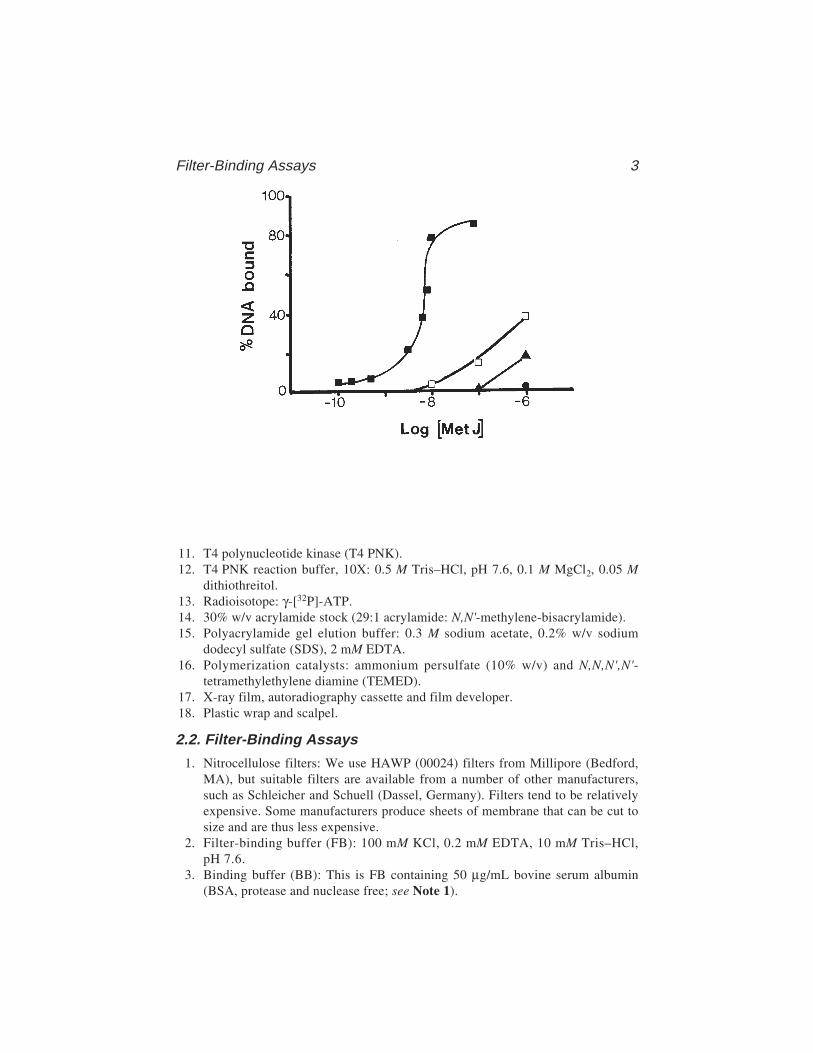
In any particular system, the percentage of the DNA–protein complex insolution retained by the filter should ideally be constant throughout the bind-ing curve, and this is known as the retention efficiency. Experimental valuesrange from 30 to >95%. An example of the sort of results obtained with theMetJ repressor is shown in Fig. 1.
2. Materials2.1. Preparation of Radioactively End-Labeled DNA
1. Plasmid DNA carrying the binding site for a DNA-binding protein on a conve-nient restriction fragment (usually <200 bp).
2. Restriction enzymes and the appropriate buffers as recommended by the suppliers.3. Phenol: redistilled phenol equilibrated with 100 mM Tris–HCl, pH 8.0.4. Chloroform.5. Solutions for ethanol precipitation of DNA: 4 M NaCl and ethanol (absolute and
70% v/v).6. Calf intestinal alkaline phosphatase (CIAP).7. CIAP reaction buffer (10X): 0.5 M Tris–HCl, pH 9.0, 0.01 M MgCl2, 0.001 M ZnCl2.8. TE buffer: 10 mM Tris–HCl, pH 8.0, 1 mM ethylenediaminetetraacetic acid (EDTA).9. 20% w/v Sodium dodecyl sulfate (SDS).
10. 0.25 M EDTA, pH 8.0.
Filter-Binding Assays 3
11. T4 polynucleotide kinase (T4 PNK).12. T4 PNK reaction buffer, 10X: 0.5 M Tris–HCl, pH 7.6, 0.1 M MgCl2, 0.05 M
dithiothreitol.13. Radioisotope: γ-[32P]-ATP.14. 30% w/v acrylamide stock (29:1 acrylamide: N,N'-methylene-bisacrylamide).15. Polyacrylamide gel elution buffer: 0.3 M sodium acetate, 0.2% w/v sodium
dodecyl sulfate (SDS), 2 mM EDTA.16. Polymerization catalysts: ammonium persulfate (10% w/v) and N,N,N',N'-
tetramethylethylene diamine (TEMED).17. X-ray film, autoradiography cassette and film developer.18. Plastic wrap and scalpel.
2.2. Filter-Binding Assays
1. Nitrocellulose filters: We use HAWP (00024) filters from Millipore (Bedford,MA), but suitable filters are available from a number of other manufacturers,such as Schleicher and Schuell (Dassel, Germany). Filters tend to be relativelyexpensive. Some manufacturers produce sheets of membrane that can be cut tosize and are thus less expensive.
2. Filter-binding buffer (FB): 100 mM KCl, 0.2 mM EDTA, 10 mM Tris–HCl,pH 7.6.
3. Binding buffer (BB): This is FB containing 50 µg/mL bovine serum albumin(BSA, protease and nuclease free; see Note 1).
4 Stockley
4. Filtration manifold and vacuum pump: We use a Millipore 1225 Sampling Mani-fold (cat. no. XX27 025 50), which has 12 sample ports.
5. Liquid scintillation counter, vials, and scintillation fluid.6. Siliconized glass test tubes.7. TBE buffer: 89 mM Tris, 89 mM boric acid, 10 mM EDTA, pH 8.3.8. Formamide/dyes loading buffer: 80% v/v formamide, 0.5X TBE, 0.1% w/v
xylene cyanol, 0.1% w/v bromophenol blue.9. Sequencing gel electrophoresis solutions and materials: 19% w/v acrylamide,
1% w/v bis-acrylamide, 50% w/v urea in TBE.10. Acetic acid (10% v/v).
3. Methods3.1. Preparation of End-Labeled DNA
1. Digest the plasmid ( 20 µg in 200 µL) with the restriction enzymes used to releasea suitably sized DNA fragment (usually <200 bp). Extract the digest with anequal volume of buffered phenol and add 2.5 volumes of ethanol to the aqueouslayer in order to precipitate the digested DNA. If preparing samples for inter-ference assays) only one restriction digest should be carried out at this stage,see Chapter 15.
2. Add 50 µL 1X CIAP reaction buffer to the ethanol-precipitated DNA pellet (<50 µg).Add 1 U CIAP and incubate at 37°C for 30 min followed by the addition of afurther aliquot of enzyme and incubate for a further 30 min. Terminate the reac-tion by adding SDS and EDTA to 0.1% (w/v) and 20 mM, respectively in a finalvolume of 200 µL and incubate at 65°C for 15 min. Extract the digest with buff-ered phenol, then with 1:1 phenol:chloroform, and, finally, ethanol precipitatethe DNA from the aqueous phase as above.
3. Redissolve the DNA pellet in 18 µL 1X T4 PNK buffer. Add 20 µCi γ-[32P]-ATPand 10 U T4 PNK and incubate at 37°C for 30 min. Terminate the reaction byphenol extraction and ethanol precipitation (samples for interference assaysshould be digested with the second restriction enzyme at this poin)t. Redissolvethe pellet in nondenaturing gel loading buffer and electrophorese on a non-denaturing polyacrylamide gel.
4. After electrophoresis, separate the gel plates, taking care to keep the gel on thelarger plate. Cover the gel with plastic wrap and in the darkroom, under the safe-light, tape a piece of X-ray film to the gel covering the sample lanes. With a syringeneedle, puncture both the film and the gel with a series of registration holes. Alter-natively, register the film and the gel using fluorescent marker strips. Locate therequired DNA fragments by autoradiography of the wet gel at room temperaturefor several min (approx 10 min). Excise slices of the gel containing the bands ofinterest using the autoradiograph as a guide. Elute the DNA into elution bufferovernight (at least) at 37°C. Ethanol precipitate the eluted DNA by adding 2.5 volof ethanol, wash the pellet thoroughly with 70% v/v ethanol, dry briefly undervacuum, and rehydrate in a small volume (approx 50 µL) of TE. Determine theradioactivity of the sample by liquid scintillation counting of a 1-µL aliquot.
Filter-Binding Assays 5
3.2. Filter-Binding Assays
3.2.1. Determination of the Equilibrium Constant
1. Presoak the filters in FB at 4°C for several hours before use. Care must be takento ensure that the filters are completely “wetted.” This is best observed by layingthe dry filters carefully onto the surface of the FB using blunt-ended tweezersand observing buffer uptake.
2. Prepare a stock solution of radioactively labeled DNA fragment in an appropri-ate buffer, such as FB. We adjust conditions so that each sample to be filteredcontains roughly 20 kcpm. Under these conditions, the DNA concentration is<1 pM. Aliquot the stock DNA solution into plastic Eppendorf tubes. It is best atthis stage if relatively large volumes are transferred in order to minimize errorscaused by pipeting. We use 180 µL/sample. If the DNA-binding protein beingstudied requires a cofactor, it is best to add it to the stock solution at saturatinglevels so that its concentration is identical for every sample.
3. Prepare a serially diluted range of protein concentrations diluting into BB. Aconvenient range of concentrations for the initial assay is between 10–11 and10–5 M protein.
4. Immediately add 20 µL of each protein concentration carefully to the sides of theappropriately labeled tubes of stock DNA solution. When the additions are com-plete centrifuge briefly (5 s) to mix the samples and then incubate at a tempera-ture at which complex formation can be observed (37°C for MetJ). For eachbinding curve it is important to prepare two control samples. The first containsno protein in the 20 µL of BB and is filtered to determine the level of backgroundretention. The second is identical to the first but is added to a presoaked filter ina scintillation vial (see step 6) and is dried directly without filtering. This gives avalue for 100% input DNA.
5. After an appropriate time interval to allow equilibrium to be established, recen-trifuge the tubes to return the liquid to the bottom of the tube and begin filtering.
6. The presoaked filters are placed carefully on the filtration manifold ensuring thatexcess FB is removed and that the filter is not damaged. Cracks and holes areeasily produced by rough handling. The sample aliquot (200 µL) is then immedi-ately applied to the filter, where it should be held stably by surface tension. Applythe vacuum. If further washes are used they should be applied as soon as thesample volume has passed through the filter. Remove the filter to a scintillationvial and continue until all the samples have been filtered.
7. The scintillation vials should be transferred to an oven at 60°C to dry the filtersthoroughly (approx 20 min) before being allowed to cool to room temperatureand 3–5 mL of scintillation fluid added. The radioactivity associated with eachfilter can now be determined by counting on an open channel (see Note 2).
8. Correct the value for each sample by subtracting the counts in the backgroundsample (no protein). Calculate the percentage of input DNA retained at each pro-tein concentration using the value for 100% input from the unaltered sample. Plota graph of percentage retained vs the logarithm of the protein concentration (e.g.,
6 Stockley
Fig. 1). The binding curve should increase from left to right until a plateau isreached. This is rarely at 100% of input DNA. The plateau value can be assumedto represent the retention efficiency, and for quantitative measurements, thedata points can be adjusted accordingly. There is not enough space here todescribe in detail the form of the binding curve or how best to interpret thedata. (For an authoritative yet accessible account, see ref. 9). For our pur-poses, the protein concentration at 50% saturation can be thought of as the equi-librium dissociation constant.
9. Once an initial binding curve has been obtained, the experiment should berepeated with sample points concentrated in the appropriate region (i.e., theregion where the percentage retained is changing most rapidly).
Control experiments with DNAs that do not contain specific binding sitesshould also be carried out to prove that binding is sequence-specific. Highlydiluted protein solutions appear to lose activity in our hands, possibly because ofnonspecific absorption to the sides of tubes, among other things. We thereforeproduce freshly diluted samples daily. BB can be stored at 4°C for several dayswithout deleterious effect. Ideally, binding curves should be reproducible. How-ever, there is some variability between batches of filters and we therefore recom-mend not switching lot numbers during the course of one set of experiments.
3.2.2. Kinetic Measurements
Kinetic analysis of the binding reaction depends on prior determination of theequilibrium binding curve, especially the concentration of DNA-binding proteinrequired to saturate the input DNA. This information allows a reaction mixturecontaining a limiting amount of protein to be set up (e.g., at a protein concentrationthat produces 75% retention). Both association and dissociation kinetics can bestudied. The major technical problem arises because of the relatively rapid sam-pling rates that are required. However, it is almost always possible to adjust solu-tion conditions such that sampling at 10 s intervals is all that is needed. Dissociationmeasurements often need to be made over periods of up to 1 h, whereas associationreactions are usually complete within several min.
3.2.2.1. DISSOCIATION
Repeat steps 1 and 2 of Subheading 3.2.1. but do not aliquot the stock DNAsolution. Add to this sample the appropriate concentration (i.e., which pro-duces approx 75% retention) of stock protein and allow to equilibrate. Add a20-fold excess of unlabeled DNA fragment containing the binding site andbegin sampling (approx 200 µL aliquots) by filtration. Plots of radioactivityretained vs time can then be analyzed to derive kinetic constants. In the sim-plest case of a bimolecular reaction, a plot of the natural logarithm of the radio-activity retained at time t divided by the initial radioactivity vs time yields thefirst-order dissociation constant from the slope. An important control experi-
Filter-Binding Assays 7
ment is to repeat the experiment with DNA that does not contain a specificbinding site to show that dissociation is sequence-specific.
A variation of this experiment can be used in which the concentration ofprotein in the reaction mix is diluted across the range where most complexformation occurs. In this case it is necessary to prepare the initial complex in asmall volume (approx 50 µL) and then dilute 100 times with BB, followed byfiltering 500 µL aliquots.
3.2.2.2. ASSOCIATION
Set up a stock DNA concentration in a single test tube in (Subheading 3.2.1.(steps 1 and 2). Incubate both this DNA and the appropriate solution of proteinat the temperature at which complexes form. Add the appropriate volume ofprotein (e.g., 200 µL) to the DNA stock solution (1800 µL) and immediatelybegin sampling (10 × 200 µL aliquots).
3.2.3. Interference Measurements
Experiments of this type can be used to gain information about the site onthe DNA fragment being recognized by the protein. The principle is identicalto that used in gel retardation interference assays but has the advantage that theDNA does not have to be eluted from gels after fractionation.
1. Modify the purified DNA fragment radiolabeled (approx 100 kcpm) at a singlesite with the desired reagent; for example, hydroxyl radicals, which result in theelimination of individual nucleotide groups (10) (see Chapter 16), dimethyl sul-fate (DMS) (11) (see Chapter 14), which modifies principally guanines, or ethylnitrosourea, ENU (see Chapter 15), which ethylates the nonesterified phosphateoxygens. The extent of modification should be adjusted so that any one fragmenthas no more than one such modification. This can be assessed separately in testreactions and monitored on DNA sequencing gels.
2. Ethanol precipitate the modified DNA, wash twice with 70% (v/v) ethanol andthen dry briefly under vacuum. Resuspend in 200 µL FB. Remove 20 µL as acontrol sample. Add 20 µL of the appropriate protein concentration to form acomplex and allow equilibrium to be reached. Filter as usual but with a siliconizedglass test tube positioned to collect the filtrate. (The Millipore manifold has aninsert for just this purpose.) Do not over dry the filter.
3. Place the filter in an Eppendorf tube containing 250 µL FB, 250 µL H2O, and0.5% (w/v) SDS. Transfer the filtrate into a similar tube and then add SDSand H2O to make the final volume and concentration the same as the filter-retained sample. Add an equal volume of buffer-saturated phenol to each tube,vortex, and centrifuge to separate the phases. Remove the aqueous top layers,re-extract with chloroform:phenol (1:1), and then ethanol precipitate. A Geigercounter can be used to monitor efficient elution of radioactivity from the filter,which can be re-extracted if necessary.
8 Stockley
4. Recover all three DNA samples (control, filter-retained, and filtrate) after etha-nol precipitation and, if necessary, process the modification to completion (e.g.,piperidine for DMS modification, NaOH for ENU, and so on). Ethanol precipi-tate the DNA, dry briefly under vacuum, and then redissolve the pellets in 4 µLformamide/dyes denaturing loading buffer. At this stage, it is often advisable toquantitate the radioactivity in each sample by liquid scintillation counting of1-µL aliquots. Samples for sequencing gels should be adjusted to contain roughlyequal numbers of counts in all three samples.
5. Heat the samples to 90°C for 2 min and load onto a 12% w/v polyacrylamidesequencing gel alongside Maxam–Gilbert sequencing reaction markers (12).Electrophorese at a voltage that will warm the plates to around 50°C. After elec-trophoresis, fix the gel in 1 L 10% v/v acetic acid for 15 min. Transfer the gel to3MM paper and dry under vacuum at 80°C for 60 min. Autoradiograph the gel at–70°C with an intensifying screen.
6. Compare lanes corresponding to bound, free, and control DNAs for differencesin intensity of bands at each position (see Note 3). A dark band in the “free frac-tion” (and a corresponding reduction in the intensity of the band in the “boundfraction”) indicates a site where prior modification interferes with complex for-mation. This is interpreted as meaning that this residue is contacted by the pro-tein or a portion of the protein comes close to the DNA at this point. (See Chapters14–16 for more extensive discussions of interference experiments.)
3.3. Results and Discussion
Figure 1 shows a typical filter-binding curve for the E. coli methioninerepressor binding to its idealized operator site of (dAGACGTCT)2 cloned intoa pUC-polylinker. In the presence of saturating amounts of cofactor (SAM), asigmoidal binding curve is produced, whereas in the absence of SAM, the bind-ing curve does not saturate in the protein concentration range tested. Similarbinding curves have been analyzed to produce Scatchard and Hill plots (9) inorder to examine the cooperativity with respect to protein concentration (6).However, such multiple binding events should also be studied by gel retardationassays which yield data about the individual complex species (see Chapter 2).
Table 1 shows the results obtained for binding to a series of variant operatorsites and illustrates the apparent sensitivity of the technique. However, in orderto make such comparisons, it is essential to determine the binding curves accu-rately and with the same batches of protein and filters to minimize minor dif-ferences between experiments. Table 1 lists the affinities of a number of variantmet operator sites cloned into pUC-polylinkers as determined by filter bindingin the presence of saturating levels of corepressor, SAM. The repressor bindscooperatively to tandem arrays of an 8-bp met-box sequence (dAGACGTCT)with a stoichiometry of one repressor dimer per met-box. The variant operatorswere designed to examine both the tandem binding and the alignment ofrepressor dimers with the two distinct dyads in tandem met-box sequences (6).

Filter-Binding Assays 9
Operator variants are as follows:
1. 00045-A single 8-bp met-box or half-site. The binding curve does not saturatebecause singly bound repressor dimers dissociate very rapidly.
2. 00048-Two perfect met-boxes representing the idealized minimum operatorsequence. Repressors bind cooperatively with high affinity.
3. 00184-Two met-boxes with the central T–A step reversed. The crystal structureof the repressor–operator complex shows that the central T–A step is not con-tacted directly by the repressors, rather the pyrimidine–purine step promotes asequence-dependent DNA distortion that results in protein–DNA contacts else-where in the operator fragment. The A–T step has less tendency to undergo thisconformational change and this is reflected in its lowered affinity.
4. 00299-A “shifted” two met-box operator used to define the alignment betweenthe repressor twofold axis and the operator dyads. The low affinity of this con-struct compared to 00048 confirms that each repressor dimer is centered on themiddle of a met-box.
3.3.1. In Vitro Selection Experiments
In recent years, in vitro selection experiments have been used to identify therange of preferred DNA target sequences by DNA-binding proteins (13,14),(see also Chapter 42). The technique depends on the separation of protein-bound DNA sequences from unbound, nonspecific, or low-affinity sites. Filterbinding is an attractive option for this selection step because of the speed withwhich filtration and recovery of the bound fraction can be achieved. However,it is important to be aware that some minor DNA variants can be retained spe-cifically by the filters, thus biasing the selected sequences. One way to avoidthis and still retain the advantages of filter binding is to alternate rounds offilter binding with separation by gel retardation (see Chapter 2). A detaileddiscussion of the factors involved in such experiments is beyond the scope
Table 1The Relative Kds of a Number of Variant Met Operator Sites
Variant Operator Sequence Relative Kd
00045 AGACGTCT >12.200048 AGACGTCTAGACGTCT 1.000184 AGACGTCatGACGTCT 2.800299 gtctAGACGTCTagac 4.9
Note: The Kd is the concentration of protein that produces 50% binding ofinput DNA. Values are averages of several experiments and are quoted relativeto the two met-box perfect consensus sequences (00048) which, under the con-ditions used, had an apparent Kd of 82 ± 5 nM MetJ monomer. Sequences incapitals represent matches to the consensus met box.
10 Stockley
of this chapter and the reader is referred to more detailed descriptions (e.g.,ref. 15).
4. Notes1. None of the radioactivity is retained by the filter. This again can be caused by a
variety of factors. Check that the preparation of DNA-binding protein is still func-tional (if other assays are available) or that the protein is still intact by SDS-polyacrylamide gel electrophoresis. Check the activity/concentration of thecofactor if required. A common problem we have encountered arises because ofthe different grades of commercially available BSA. It is always advisable to usea preparation that explicitly claims to be nuclease and protease free.
2. All of the radioactivity is retained by the filter. This is a typical problem whenfirst characterizing a system by filter binding and can have many causes. Checkthat the filters being used “wet” completely in FB and do not dry significantlybefore filtration. Make sure that the DNA remains soluble in the buffer beingused by simple centrifugation in a bench-top centrifuge. If the backgroundremains high, add dimethyl sulfoxide to the filtering solutions. Classically,5% (v/v) is used but higher concentrations (approx 20% v/v) have been reportedwith little, if any, effect on the binding reaction. We have experienced excessiveretention when attempting to analyze the effects of divalent metal ions on com-plex formation, and, in general, it is best to avoid such buffer conditions.
3. Poor recoveries from the filter-retained samples in interference assays, or otherproblems in processing such samples further, can often be alleviated by additionof 20 µg of tRNA as a carrier during the SDS/phenol extraction step.
AcknowledgmentI am grateful to Yi-Yuan He for providing the data shown in Table 1 and
Fig. 1.
References1. Nirenberg, M. and Leder, P. (1964) RNA codewords and protein synthesis. The
effect of trinucleotides upon the binding of sRNA to ribosomes. Science 145,1399–1407.
2. Jones, O. W. and Berg, P. (1966) Studies on the binding of RNA polymerase topolynucleotides. J. Mol. Biol. 22, 199–209.
3. Riggs, A. D., Bourgeois, S., Newby, R. F., and Cohn, M. (1968) DNA binding ofthe lac repressor. J. Mol. Biol. 34, 365–368.
4. Riggs, A. D., Suzuki, H., and Bourgeois, S. (1970) lac repressor-operator interac-tion. I. Equilibrium studies. J. Mol. Biol. 48, 67–83.
5. Riggs, A. D., Bourgeois, S., and Cohn, M. (1970) The lac repressor-operatorinteraction. III. Kinetic studies. J. Mol. Biol. 53, 401–417.
6. Phillips, S. E. V., Manfield, I., Parsons, I., Davidson, B. E., Rafferty, J. B.,Somers, W. S., et al. (1989) Cooperative tandem binding of Met repressor fromEscherichia coli. Nature 341, 711–715.
Filter-Binding Assays 11
7. Old, I. G., Phillips, S. E. V., Stockley, P. G., and Saint-Girons, I. (1991) Regula-tion of methionine biosynthesis in the enterobacteriaceae. Prog. Biophys. Mol.Biol. 56,145–185.
8. Ryan, P. C., Lu, M., and Draper, D. E. (1991) Recognition of the highly con-served GTPase center of 23S ribosomal RNA by ribosomal protein L11 and theantibiotic thiostrepton. J. Mol. Biol. 221, 1257–1268.
9. Wyman, J. and Gill, S. J. (1990) In Binding and Linkage: Functional Chemistry ofBiological Macromolecules, chap. 2, University Science Books, Mill Valley, CA.
10. Siebenlist, U. and Gilbert, W. (1980) Contacts between Escherichia coli RNApolymerase and an early promoter of phage T7. Proc. Natl. Acad. Sci. USA 77,122–126.
11. Hayes, J. J. and Tullius, T. D. (1989) The missing nucleoside experiment: a newtechnique to study recognition of DNA by protein. Biochemistry 28, 9521–9527.
12. Maxam, A. M. and Gilbert, W. K. (1980) Sequencing end-labelled DNA withbase-specific chemical cleavages. Methods Enzymol. 65, 499–560.
13. Tuerk, C. and Gold, L. (1990) Systematic evolution of ligands by exponentialenrichment: RNA ligands to bacterophage T4 DNA polymerase. Science 249,505–510.
14. Ellington, A. D. and Szostak, J. W. (1990) In vitro selection of RNA moleculesthat bind specific ligands. Nature 346, 818–822.
15. Conrad, R. C., Giver, L., Tian, Y. and Ellington, A. D. (1996) In vitro selection ofnucleic acid aptamers that bind proteins. Methods Enzymol. 267, 336–367.

EMSAs for Analysis of DNA–Protein 13
13
From: Methods in Molecular Biology, vol. 148: DNA–Protein Interactions: Principles and Protocols, 2nd ed.Edited by: T. Moss © Humana Press Inc., Totowa, NJ
2
Electrophoretic Mobility Shift Assaysfor the Analysis of DNA-Protein Interactions
Marc-André Laniel, Alain Béliveau, and Sylvain L. Guérin
1. IntroductionSeveral nuclear mechanisms involve specific DNA–protein interactions. The
electrophoretic mobility shift assay (EMSA, also known as the gel mobilityshift or gel retardation assay), first described almost two decades ago (1,2),provides a simple, efficient and widely used method to study such interactions.Its ease of use, its versatility, and especially its high sensitivity (10–18 mol ofDNA [2]) make it a powerful method that has been successfully used in a vari-ety of situations not only in gene regulation analyzes but also in studies ofDNA replication, repair, and recombination. Although very useful for qualita-tive purposes, EMSA has the added advantage of being suitable for quantita-tive and kinetic analyzes (3). Furthermore, because of its very high sensitivity,EMSA makes it possible to resolve complexes of different protein or DNAstoichiometry (4) and even to detect conformational changes.
1.1. Principle of the Method
Electrophoretic mobility shift assay (EMSA) is based on the simple ratio-nale that proteins of differing size, molecular weight, and charge will havedifferent electrophoretic mobilities in a nondenaturing gel matrix. In the caseof a DNA–protein complex, the presence of a given DNA-binding protein willcause the DNA to migrate in a characteristic manner, usually more slowly thanthe free DNA, and will thus cause a change or shift in the DNA mobility visibleupon detection.
While the kinetic analysis of EMSA, which has been extensively coveredelsewhere (ref. 5 and references therein), is not the prime focus of this chapter,it will be useful to understand the basic theory underlying such analyzes. A

14 Laniel, Béliveau, and Guérin
univalent protein, P, binding to a unique site on a DNA molecule, D, will yielda complex, PD, in equilibrium with the free components:
where ka is the rate of association and kd is the rate of dissociation. In the caseof a strong interaction between protein and DNA, with ka > kd, two distinctbands are observed, corresponding to the complex PD and to the free DNA.However, because of the dissociation that inevitably occurs during electro-phoresis and because the DNA released from a complex during electrophoresiscan never catch up with the free DNA, a faint smear may be seen between thetwo major bands. In contrast, a weak DNA–protein interaction, with ka < kd,should produce a fainter band corresponding to the complex PD and a moreintense smear. However, even weak DNA–protein interactions may lead todistinct bands in EMSA because of their stabilization in the gel matrix as aresult of the cage effect (6) and/or of molecular sequestration (7). In both cases,the dissociation of the complex is slower within the gel than it is in free solu-tion, but in the cage effect, the gel matrix prevents dissociated components Pand D from freely diffusing and thus favors a reformation of the complex PD,whereas in molecular sequestration, the gel matrix isolates complex PD fromcompeting molecules that could promote its dissociation.
As for a single DNA molecule bearing multiple binding sites for a givenprotein, there will generally be as many mobility shifts formed as there arebinding sites. For example, in the case of two independent binding sites on theDNA fragment (D):
this would result in three DNA containing bands: the free DNA (D), the com-plex with both sites occupied by protein (P2D), and the complexes with onlyone occupied site (PD1 and PD2, which will generally migrate together).
The kinetics of more complex situations, such as dimerizing protein com-plexes and multiple DNA–protein interactions, are beyond the scope of thischapter, but some interesting and insightful articles have been recently pub-lished (4,8) in which these questions are expressly addressed.
P + D PD
k a
kd
2P + D PD 1 + P
PD 2 + P P2D
k a
k d1
k a
k d4
k a k d2 k a k d3
EMSAs for Analysis of DNA–Protein 15
1.2. Applications of the EMSA
Because EMSA often allows the detection of specific DNA-binding pro-teins in unpurified protein extracts (see ref. 9 and Fig. 1A), the technique hasbeen widely used to analyze crude cell or tissue extracts or partially purified
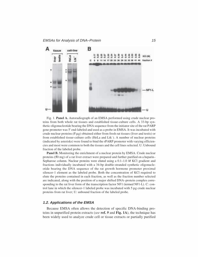
Fig. 1. Panel A. Autoradiograph of an EMSA performed using crude nuclear pro-teins from both whole rat tissues and established tissue-culture cells. A 33-bp syn-thetic oligonucleotide bearing the DNA sequence from the initiator site of the rat PARPgene promoter was 5' end-labeled and used as a probe in EMSA. It was incubated withcrude nuclear proteins (5 µg) obtained either from fresh rat tissues (liver and testis) orfrom established tissue-culture cells (HeLa and Ltk–). A number of nuclear proteins(indicated by asterisks) were found to bind the rPARP promoter with varying efficien-cies and most were common to both the tissues and the cell lines selected. U: Unboundfraction of the labeled probe.
Panel B. Monitoring the enrichment of a nuclear protein by EMSA. Crude nuclearproteins (50 mg) of a rat liver extract were prepared and further purified on a heparin–Sepharose column. Nuclear proteins were eluted using a 0.1–1.0 M KCl gradient andfractions individually incubated with a 34-bp double-stranded synthetic oligonucle-otide bearing the DNA sequence of the rat growth hormone promoter proximalsilencer-1 element as the labeled probe. Both the concentration of KCl required toelute the proteins contained in each fraction, as well as the fraction number selectedare indicated, along with the position of a major shifted DNA–protein complex corre-sponding to the rat liver form of the transcription factor NF1 (termed NF1-L). C: con-trol lane in which the silencer-1 labeled probe was incubated with 5 µg crude nuclearproteins from rat liver; U: unbound fraction of the labeled probe.
16 Laniel, Béliveau, and Guérin
extracts for the presence of protein factors implicated in transcription (10–13)and in DNA replication (9,14), recombination (15), and repair (16). The use ofunlabeled competitor DNA fragments further aids in identification of DNA-binding proteins (see ref. 9, 15, and 17 and Fig. 2A), and their purification canbe easily monitored by EMSA (see ref. 9, and 13 and Fig. 1B). Moreover,mutation or bases delection on the labeled DNA probe is often an efficientapproach to use when identifying the binding site of the protein of interest(10,12).
EMSA yields invaluable data when purified or recombinant proteins are tobe analyzed, because quantification and kinetic studies are rapidly achieved(10,14). Parameters of a DNA–protein interaction, such as association, disso-ciation, and affinity constants, can be accurately measured (2,3,7,10), and theeffect of salt, divalent metals, protein concentration and the temperature ofincubation on complex formation can be directly observed (see ref. 15, 20, and21 and Fig. 3A,B). EMSA has also greatly contributed to the elaboration ofmodels of complex assembly in the areas of transcription (11), DNA replica-tion (14) and DNA repair (16).
Although EMSA is an informative and versatile method on its own, itbecomes more powerful when used in combination with other techniques.Methylation (23) and other forms of binding interference studies (see Chapters14 to 16), where a partially modified DNA probe is used, help to define theexact position of the DNA binding site of the protein (10,24). Immunologicalmethods using specific antibodies, as in supershift experiments (see refs. 12and 13 and Fig. 2B), are also very helpful in identifying the identity of theprotein component of given complexes. However, when analyzing large ormultiprotein complexes, supershifts may not be suitable because the supershiftedcomplexes may not be distinguished from the shifted ones or may not identifythe different proteins involved. Immunoblotting of EMSA gels (25), “Shift-Western blotting” (26) and immunodepletion EMSA (27) can be used to resolvesuch problems. In addition, determination of the molecular weight of the DNA-binding protein(s) identified by EMSA can be achieved by sodium dodecylsulfate-polyacrylamide gel electrophoresis (SDS-PAGE), either directly (28)or following ultraviolet cross-linking of the DNA–protein complex (29).
1.3. Overview of the Procedure
Several components are required for EMSA and may influence the outcomeof the procedure.
1.3.1. Nuclear Extract
The choice of protein extract is governed by the objective of the study.Whole-cell or nuclear extracts are very useful in analyzing the regulatory
EMSAs for Analysis of DNA–Protein 17
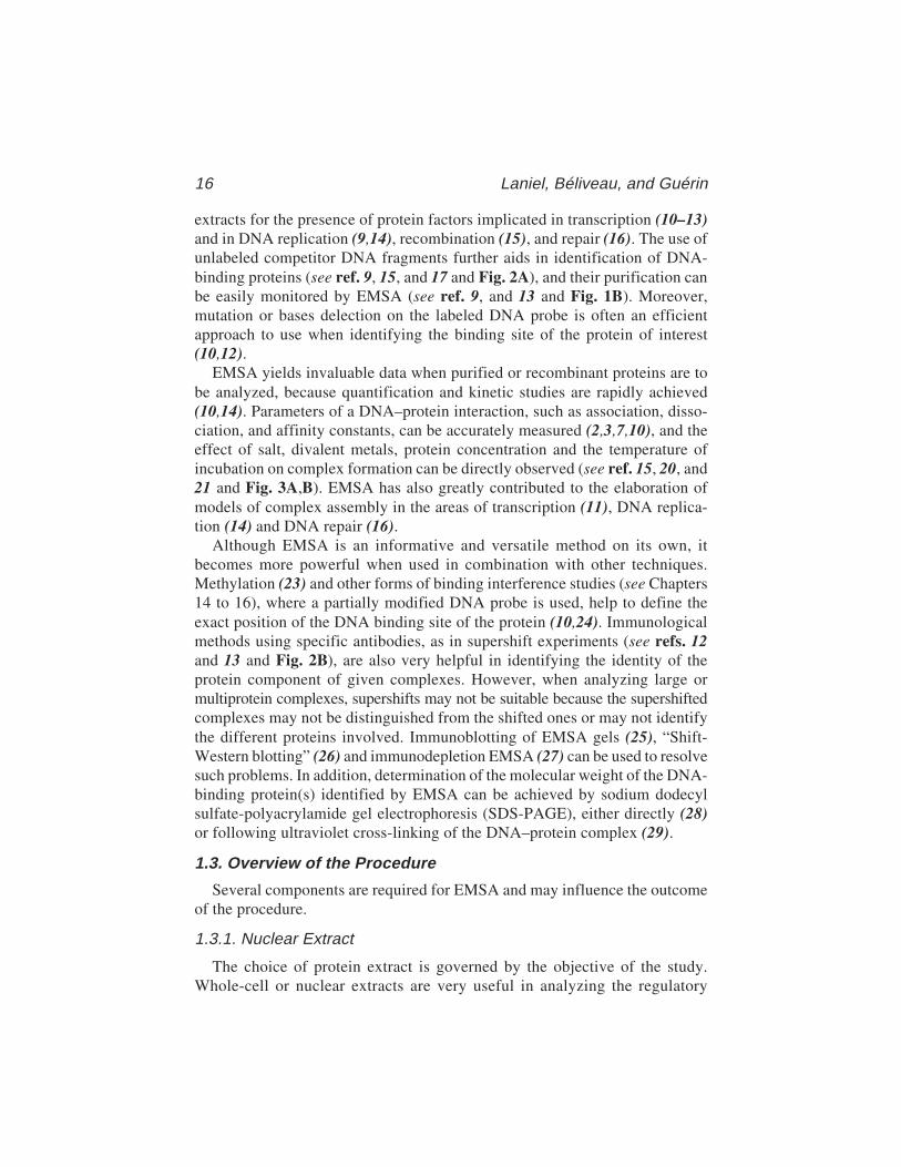
Fig. 2. Panel A. Competition in EMSA as a tool to evaluate the specific formationof DNA–protein complexes. A synthetic double-stranded oligonucleotide bearing theNF1 binding site from the Fp1 element of the human CRBP1 gene was 5' end labeledand incubated with 1 µg of a heparin–Sepharose-enriched preparation of rat liverNF1-L. Increasing concentrations (50-, 200-, and 1000-fold molar excess) ofunlabeled, double-stranded oligonucleotides containing various DNA binding sites(Fp1, NF1, or Sp1) were added as competitors during the binding assays, and DNA/protein complex formation was analyzed on native 8% polyacrylamide gels. Controllanes containing the labeled probe alone (C–) or incubated with proteins in theabsence of any competitor DNA (C+) have also been included. The position of thespecifically retarded DNA/protein complex (NF1-L) and that of the free probe (U) isalso shown. (Modified from ref. 18: reprinted with permission from Mol. Endocrinol.,Copyright [1994].)
Panel B. The identity of DNA-binding proteins as revealed by supershift analysesin EMSA. The rGH silencer-1 labeled probe used in Fig. 1B was incubated with (+) orwithout (–) 0.2 µg of a heparin–Sepharose-enriched preparation of NF1-L (seepanel A) , in the presence of either nonimmune serum (1 µL) or a polyclonal anti-body directed against rat liver NF1-L. Formation of DNA/protein complexes wasthen monitored by EMSA as in Fig. 1B. The position of the previously character-ized NF1-L DNA/protein complex is shown (NF1-L) along with that of asupershifted complex (NF1-L/Ab) resulting from the specific interaction of theanti-NF1-L antibody with the NF1-L/silencer-1 complex. The position of a nonspe-cific complex (NS), resulting from the binding of an unknown serum protein to thelabeled probe selected, is indicated, as well as the position of the remaining free probe(U). (Modified from ref. 19: reprinted with permission from Eur. J. Biochem., Copy-right [1994].)
18 Laniel, Béliveau, and Guérin
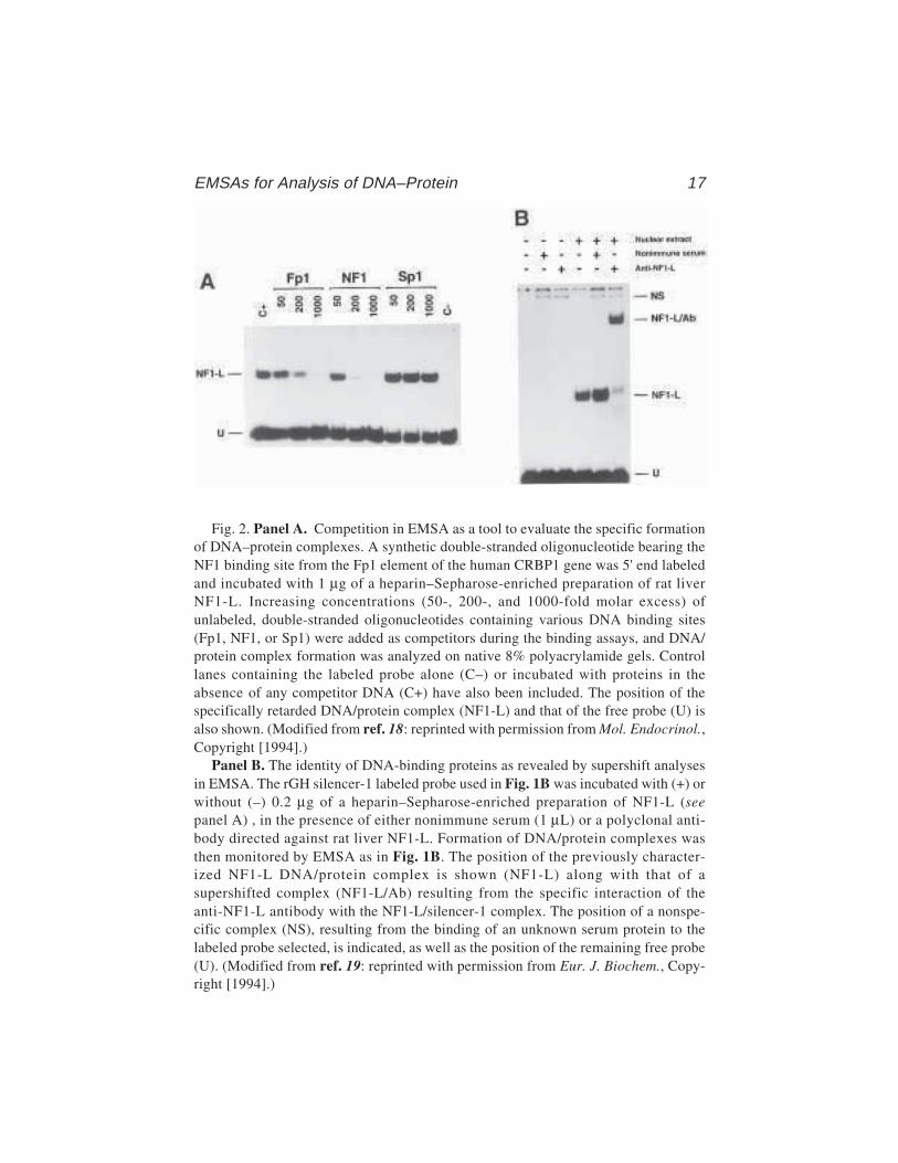
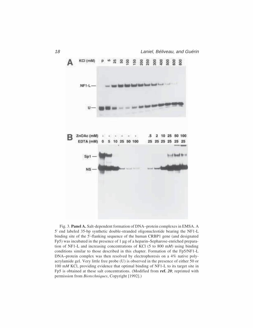
Fig. 3. Panel A. Salt-dependent formation of DNA–protein complexes in EMSA. A5' end labeled 35-bp synthetic double-stranded oligonucleotide bearing the NF1-Lbinding site of the 5'-flanking sequence of the human CRBP1 gene (and designatedFp5) was incubated in the presence of 1 µg of a heparin–Sepharose-enriched prepara-tion of NF1-L and increasing concentrations of KCl (5 to 800 mM) using bindingconditions similar to those described in this chapter. Formation of the Fp5/NF1-LDNA–protein complex was then resolved by electrophoresis on a 4% native poly-acrylamide gel. Very little free probe (U) is observed in the presence of either 50 or100 mM KCl, providing evidence that optimal binding of NF1-L to its target site inFp5 is obtained at these salt concentrations. (Modified from ref. 20; reprinted withpermission from Biotechniques, Copyright [1992].)

EMSAs for Analysis of DNA–Protein 19
elements of a DNA fragment such as a gene promoter. Partial protein purifica-tion allows further characterization of a DNA–protein interaction and can beachieved by column chromatography on DNA-cellulose or heparin–Sepharose, orby SDS-polyacrylamide gel fractionation and subsequent protein renaturation (seeref. 30 and Note 1). Purified or recombinant proteins give valuable information onprotein interactions, competition, dimerization or cooperativity. Whatever pro-tein extract used, its quality is a key factor in EMSA (see Notes 2 and 3).
1.3.2. DNA Probe
Cloned DNA fragments of 50–400 bp in length or synthetic oligonucleotidesof 20–70 nucleotides work very well in EMSA (see ref. 17 and Note 4) andalthough double-stranded DNA is used most often, single-stranded DNA mayalso be effective (15). Although larger DNA fragments usually encompassmore extensive regulatory sequences, oligonucleotides will generally containfewer protein binding sites and thereby yield more specific information,the two approaches often complementing one another. The detection ofDNA–protein complexes is usually achieved by labeling of DNA probe (seeNote 5), and this is performed using a [32P]-labeled deoxynucleotide. However,other, less hazardous methods are available (see Note 5), including labelingwith 33P (31), with digoxygenin (32) or with biotin (33).
1.3.3. Gel Matrix
Acrylamide gels (see Note 6) combine high resolving power with broadsize-separation range and provide the most widely used matrix. Alternatively,
Panel B. DNA-binding properties of nuclear proteins revealed by EDTA chelationin EMSA. A double-stranded synthetic oligonucleotide bearing the sequence of the ratPARP US-1 binding site for the transcription activation factor Sp1 was 5' end-labeledand incubated with 10 µg crude nuclear proteins from HeLa cells in the presence ofincreasing concentrations of EDTA (0–100 mM) under binding conditions identical tothose described in this chapter. Formation of DNA/protein complexes was evaluatedby EMSA on a 8% polyacrylamide gel. As little as 10 mM EDTA proved to be sufficient tochelate zinc ions and to totally prevent binding of Sp1 to the US-1 element. Similarly,reaction mixtures containing the US-1 labeled probe incubated with 10 µg nuclearproteins from HeLa cells in the presence of 25 mM final concentration of EDTA weresupplemented with increasing concentrations (0.5–100 mM) of zinc acetate (ZnOAc)to evaluate the binding recovery for both Sp1 and the nonspecific DNA–protein complex(NS). A substantial proportion of the DNA-binding capability of both the Sp1 and the NSproteins could be recovered upon further addition of 25 mM zinc acetate, providingevidence that both factors probably interact with DNA through the use of a Zn-finger-containing DNA binding domain, a fact that was already known for Sp1. (Modifiedfrom ref. 22: reprinted with permission from Eur. J. Biochem., Copyright [1993].)
20 Laniel, Béliveau, and Guérin
the use of less toxic, commercially available matrices has been reported (34–36).Because of their larger pore size, agarose gels are sometimes used, either aloneor in combination with acrylamide, to study larger DNA fragments ormultiprotein complexes (37). Gel concentration is also important in EMSA(see Note 7), however although lower concentration will generally allow theresolution of larger complexes, it may affect their stability (7).
1.3.4. Buffer
Different low-ionic-strength buffers can be used in EMSA (see ref. 36 andNote 8), and can include cofactors such as Mg2+ or cAMP, which may be nec-essary for some DNA–protein interactions (37).
1.3.5. Nonspecific Competitors
To ensure specificity of the DNA–protein interaction, a variety of nonspe-cific competitors may be used. This is particularly important when using crudeprotein extracts which contain nonspecific DNA-binding proteins. To avoidnonspecific binding activities interfering with the EMSA, an excess of a non-specific DNA such as salmon sperm DNA, calf thymus DNA or syntheticDNAs such as poly(dI:dC) is used (see refs. 37 and 38 and Notes 9 and 10).The addition of nonionic or zwitterionic detergents (39) or nonspecific pro-teins (e.g., albumin [40]) may also increase specific DNA–protein interactions.
2. Materials2.1. Probe Labeling
1. [γ-32P] ATP. Caution: 32P emits high-energy beta radiation. Refer to the rules ofyour local control radioactivity agency for handling and proper disposal of radio-active materials and waste (see Note 5).
2. Approximately 25–50 ng of DNA from a 30-bp double-stranded oligonucleotide. For atypical 70-bp probe derived from a subcloned promoter fragment, estimate the amountof the plasmid DNA that is required to end up with about 100–200 ng of the DNAfragment of interest following its isolation from the polyacrylamide gel (see Note 4).
3. Calf intestinal alkaline phosphatase (CIAP) and 10X CIAP reaction buffer: 0.5 MTris–HCl pH 9.0, 10 mM MgCl2, 1 mM ZnCl2, 10 mM spermidine.
4. T4 polynucleotide kinase and 10X kinase buffer: 0.5 M Tris–HCl pH 7.5, 0.1 MMgCl2, 40 mM DTT, 1 mM spermidine, 1 mM EDTA.
2.2. Probe Isolation
1. Standard electrophoresis apparatus for agarose gel.2. Stock solution of 10X TBE: 0.89 M Tris, 0.89 M boric acid, and 20 mM EDTA.3. 1% (w/v) agarose in 1X TBE supplemented with 0.5 µg/mL of ethidium bromide
from a 10-mg/mL solution. Caution: Ethidium bromide is a powerful mutagenicagent (see Note 11).

EMSAs for Analysis of DNA–Protein 21
4. Restriction enzyme(s) with corresponding buffer(s).5. For DNA precipitation, a preparation of 1 mg/mL tRNA, a solution of 3 M NaOAc
(pH 5.2), and a supply of dry ice.6. Phenol/chloroform: Phenol saturated with 100 mM Tris–HCl pH 8.0.7. 40% (w/v) 29:1 acrylamide–bisacrylamide: 29:1 (w/w) acrylamide and
N',N'-methylene bis-acrylamide. After complete dissolution of the components,the solution should be filtered using Whatman No. 1 paper and can be stored atroom temperature. Caution: Acrylamide is a potent neurotoxic agent (see Note 6).
8. Dialysis tubing: molecular weight cutoff of 3500 and flat width of 18 mm.9. Plastic wrap.
10. Autoradiography cassettes and film: Kodak XOmat AR.
2.3. Electrophoretic Mobility Shift Assay
1. Standard vertical electrophoresis apparatus for polyacrylamide gels, a gel lengthof 15 cm is adequate. (See Note 12.)
2. 40% (w/v) 39:1 acrylamide–bisacrylamide: 39:1 (w/w) acrylamide and N',N'-methyl-ene bis-acrylamide. Caution: Acrylamide is a potent neurotoxic agent (see Note 6).
3. 5X Tris–glycine: 250 mM Tris, 12,5 mM EDTA, and 2 M glycine. (See Note 8.)4. Extract (crude or enriched) containing cell or tissue nuclear proteins. (See Note 2.)5. 2X binding buffer: 20 mM HEPES pH 7.9, 20% glycerol, 0.2 mM EDTA, 1 mM
tetrasodium pyrophosphate (see Note 3) and 0.5 mM PMSF.6. 6X loading buffer: 0.25% bromophenol blue, 0.25% xylene cyanol, and
40% sucrose.7. Whatman chromatographic paper (3MM) and plastic wrap.8. Standard gel dryer.9. Autoradiography cassettes and film: Kodak XOmat AR.
3. Methods
3.1. Probe Labeling
3.1.1. Labeling DNA Fragments Derived from a Subcloned Sequence
1. Select restriction enzymes that produce the shortest DNA fragment containingthe sequence of interest. One of these restriction enzymes should produce a pro-truding 5' end or blunt end to support labeling with T4 polynucleotide kinase (seeNote 13). Following the manufacturer’s optimal enzymatic conditions, prepare adigestion mix with one of the restriction enzymes in 50 µL to linearize the vector.The initial amount of DNA should be calculated to end up with at least 100–200 ngof DNA after double-restriction enzyme digestion and further isolation of theDNA fragment from the polyacrylamide gel.
2. Before proceeding with dephosphorylation, make sure that digestion is completeby loading a sample (50–100 ng) on a 1% (w/v) agarose minigel. Once completedigestion of the plasmid DNA has been verified, add directly to the digestionreaction mix 1 U of CIP, 10 µL of 10X CIP buffer, and fill to 100 µL with H2O.Incubate at 37°C for 90 min.
22 Laniel, Béliveau, and Guérin
3. To totally eliminate and inactivate CIAP, transfer the reaction mix at 70°C for 10 minand perform a phenol/chloroform followed by a chloroform extraction. Precipi-tate DNA by adding a 1/10th volume of 3 M NaOAc, pH 5.2 and 2 volumes ofcold 95% ethanol. Allow DNA to precipitate on dry ice for 30 min, then centri-fuge for 15 min.
4. Resuspend DNA in 33 µL of H2O, add 5 µL of 10X kinase buffer, 10 µL (100 µCi) of[γ-32P]ATP and 2 µL of T4 polynucleotide kinase. Mix and incubate at 37°C for 2 h.
5. Following the labeling procedure, reprecipitate DNA and resuspend in 30 µL ofH2O. Keep a 2-µL sample and digest the remainder with the second restrictionenzyme, following manufacturer’s conditions.
3.1.2. Labeling Double-Stranded Synthetic Oligonucleotides
1. Mix equal amounts of the complementary strands, heat at 5°C over the specificmelting temperature (TM) of the sequence for 5 min, and let cool to room tem-perature (RT). When DNA reaches RT, place at 4°C for a few hours prior to use.
2. Use 25–50 ng of the double-stranded oligonucleotide preparation and performDNA labeling with T4 polynucleotide kinase as described in step 4 of Subhead-ing 3.1.1. but using 30 µCi of [γ-32P] ATP.
3.2. Probe Isolation
3.2.1. For a Typical 70-bp Probe Derivedfrom a Subcloned Promoter Fragment
1. Rigorously clean and dry the polyacrylamide gel apparatus and its accessoriesprior to use. Gel plates should be cleaned using any good quality commercialsoap and then rinsed with 95% ethanol. One plate can be treated with a coat ofSigmacote (chlorinated organopolysiloxane in heptane) to facilitate gel removalfrom the plates after running.
2. Prepare a 6% polyacrylamide gel (41) as follows; mix 2.5 mL of 10X TBE, 3.75 mLof 40% acrylamide (29:1) stock solution, and H2O to 25 mL final volume.Add 180 µL of 10% ammonium persulfate and 30 µL of TEMED. Carefullystir and pour the acrylamide solution between the plates. Insert well-formingcomb and allow the gel to set for 30 min., then mount the gel in the electro-phoresis tank and fill the chamber with 1X TBE .
3. To the double-digested DNA, add 10 µL of 6X loading buffer and load into twoseparate wells. For the 2-µL control sample from the single digestion, add 2 µL ofloading buffer and load in a free well. Migration should be stopped when bro-mophenol blue, which is used as a migration marker, reaches two-thirds ofthe gel length.
4. Carefully disassemble the apparatus and discard the running buffer as radio-active waste. Remove one plate and leave the gel on the remaining plate. Coverthe gel with plastic wrap and, in a dark room, place a film over it. It is veryimportant to mark the exact position of the gel on the film as a reference. Thiscan be achieved by using [32P]-labeled black ink. Expose the film for 3 minand develop.
EMSAs for Analysis of DNA–Protein 23
5. If the digestion step with restriction enzymes is complete, two labeled bandsresulting from the double digestion should appear on the autoradiogram (pro-vided that each of the restriction enzymes selected initially cut the probe-bearingrecombinant plasmid only once). Using a razor blade, cut out from the film thelower band corresponding to the selected probe. Replace the film on the gel(which is still covered with plastic wrap), aligning the reference marks carefully.Using the aperture in the film as guide, remove the probe-containing gel frag-ment using a scalpel blade.
6. Place the acrylamide fragment in a dialysis tubing closed at one end and add1 mL of 1X TBE. Remove any remaining air bubbles, close the other end, andplace the dialysis tubing in a standard horizontal electrophoresis tank filled with1X TBE. Run at 100 V for 15 min.
7. Through the action of electrophoretic migration, the labeled probe will pass fromthe acrylamide fragment to the TBE solution contained in the dialysis tubing.DNA will concentrate as a thin line along the dialysis tubing (on the cathodeside) and must be removed by gently rubbing the tubing with a solid object. Usinga Pasteur pipet, transfer the labeled probe-containing TBE from the dialysistubing into three separate microcentrifuge tubes (about 300 µL each). Other pro-cedures may also be selected for extracting the labeled probe from the polyacry-lamide gel (42).
8. Repeat steps 6 and 7 to make sure that all of the probe has been eluted from theacrylamide fragment. At the end of the second elution, recover the TBE againinto three other microcentrifuge tubes.
9. Precipitate the probe by adding 1/10th volume of 3 M NaOAc pH 5.2 and two vol-umes of cold 95% ethanol. Allow labeled DNA to precipitate on dry ice for 30 min.
10. Centrifuge and discard the supernatant and resuspend DNA in 50 µL of sterile H2O.Pool the samples into one microcentrifuge tube and reprecipitate as in step 9.
11. Estimate the recovery of labeled DNA by counting the Cerenkov radiation emit-ted by the pellet using a β counter or by resuspending the DNA in a small volume(100 µL) and counting a 1-µL aliquot in scintillation liquid.
12. Resuspend the labeled DNA in order to obtain 30,000 cpm/µL.
3.2.2. For a Double-Stranded Oligonucleotide Labeled Probe
Proceed as in Subheading 3.2.1. except that steps 1 through 8 should beomitted and replaced by two sequential precipitations in the presence of 5 µgtotal tRNA as described in step 9. (See Note 14.)
3.3. EMSA
1. Rigorously clean and dry the electrophoresis tank and its accessories prior to useand treat the glass plates as previously described for probe isolation (step 1; Sub-heading 3.2.1.).
2. For a typical 70-bp probe, prepare a 6% polyacrylamide gel (see Note 7) by mix-ing 2.5 mL of 10X Tris–glycine, 3.75 mL of 40% acrylamide (39:1) stock solu-tion, and H2O to 25 mL. Add 180 µL of 10% ammonium persulfate and 30 µL of
24 Laniel, Béliveau, and Guérin
TEMED. Carefully stir and pour the acrylamide solution between the plates (seeNote 15). Use a comb that has 0.8-cm-width teeth. Allow the gel to set for at least2 h, then mount gel in the electrophoresis tank and fill the chamber with 1X Tris–glycine (see Note 8). As soon as the gel is mounted and set, remove the comb andcarefully wash the wells with running buffer.
3. Prerun the gel at 4°C and 120 V (8 V/cm) until the current becomes invariant(this takes around 30 min). Prerunning ensures that the gel will remain at a con-stant temperature from the moment of sample loading.
4. When the gel is ready for loading, prepare samples as follows. For each sample,mix 12 µL of 2X binding buffer, 1 µL of 1 mg/mL poly(dI:dC) (see Notes 9 and10), and 0.6 µL of 2M KCl (see Note 10); then add 30,000 cpm of labeled probe.Where possible, to minimize pipeting errors, prepare a single mix of the commonreaction components and distribute equal volumes into the reactions. Finally, add1–10 µg protein extract and H2O to a final volume of 24 µL. Mix each tube gentlyand incubate at RT for 3 min. As a control, prepare a sample without protein extractand add 1 µL of 6X loading buffer containing bromophenol blue and xylene cyanol.
5. Load samples by changing the pipet tip for each sample.6. Run at 120 V (8 V/cm) and let samples migrate until the free probe reaches the
bottom of the gel (see Note 16). In the case of a 70-bp probe loaded on 6%acrylamide gel, this means 5–6 h of migration.
7. After the gel run, disassemble the apparatus and remove one of the glass plates,place a Whatman paper over the gel, and carefully lift the gel off the remainingplate. Make sure that the gel is well fixed on the Whatman before lifting the gel toavoid gel breakage. Place plastic wrap over the gel and dry at 80°C for 30 min.
8. Place an X-ray film over the gel in an autoradiography cassette and expose at–70°C overnight.
4. Notes1. Very intense, large or smeary shifted complexes usually result from multiple
comigrating DNA–protein complexes that possess nearly identical electro-phoretic mobilities in native polyacrylamide gels despite the fact that the pro-teins they contain usually have distinctive molecular masses on denaturingSDS-PAGE (43,44). An attractive method that helps to distinguish between theproteins yielding these multiple, comigrating complexes is the SDS–polyacryla-mide gel fractionation–renaturation procedure (30). This procedure allowsrecovery and enrichment of specific proteins suitable for further analyzes byEMSA, in addition to providing their approximate molecular masses.
2. When using crude nuclear extracts for detecting DNA–protein complexes inEMSA, the quality of the extract is very critical. Whenever possible, nuclei puri-fication procedures using a sucrose cushion or pad (45) is to be preferred in orderto eliminate contamination by cytosolic proteins that most often also containsubstantial amounts of proteases. Purifying nuclei on sucrose pads has generallyyielded high-quality nuclear extract samples. However, such extracts requirelarge quantities of fresh tissue, rendering the approach inappropriate when
EMSAs for Analysis of DNA–Protein 25
limiting amounts of small animal tissues such as spleen, pancreas or prostateare available. In these cases, short microprocedures adapted to prevent pro-tease actions can also be performed (46). Once the crude extract has beenobtained, its quality must be evaluated. An informative way to test extracts isto assess the DNA-binding ability of the ubiquitously expressed transcriptionfactor Sp1. We have found this transcription factor to be particularly sensi-tive to proteases (47). Little or no Sp1 binding to its high-affinity binding site(5'-GATCATATCTGCGGGGCGGGGCAGACACAG–3') (48) is usuallyindicative of a poor quality nuclear extract. Although such an assay is clearlyinvaluable when crude extracts are obtained from established tissue-culture cells,caution must be observed when extracts are prepared from whole animal tissuesbecause not all organs express Sp1 at the same level (22,47,49).
3. The analysis of crude extracts prepared from whole animal tissues by EMSA issomewhat restricted because of the numerous enzymatic activities, such as pro-teases and deacetylases, these may contain. Degradation of nuclear proteins byendogenous proteases can be prevented by the addition of protease inhibitors.Whole animal tissue extracts are also often contaminated with highly activeendogenous phosphatases. Tissues such as liver, kidney, and bone have beenreported to be rich in these enzymes (50), some of which substantially decreasethe sensitivity of the EMSA by removing the [32P]-labeled phosphate from theDNA probe. Although addition of phosphatase inhibitors, such as tetrasodiumpyrophosphate or sodium fluoride, to the reaction buffer can efficiently preventdephosphorylation, we have found that the same can also be achieved by simplyreducing either the temperature at which the binding reaction is normally per-formed (30 min of incubation at 4°C) or the time allowed for the DNA–proteininteraction to occur (as low as 1 min of incubation at 22°C) (21). Alternatively,probes labeled by fill-out of unpaired 5' termini using T4 DNA polymerase or theKlenow fragment of DNA polymerase I and an appropriate [α-32P] dNTP may beused. (See also Note 13.)
4. When double-stranded oligonucleotides are selected as labeled probes inEMSA, we recommend their size be in the range 20–70 bp. When workingwith subcloned DNA sequences, optimal signal strength and resolution canbe achieved using fragments of 50–250 bp. Although larger fragments maybe used, they require longer migration times in order to efficiently resolvethe potential DNA–protein complexes. Furthermore, larger labeled probesare likely to bind an increased number of nuclear proteins, which may compli-cate the interpretation of the results.
5. Handling [γ-32P] ATP requires that special care be taken when labeling the DNAprobes used in EMSA. The reader is referred to the standard procedures and theguidelines on manipulation of radioactive materials in effect at each researchfacility. Alternative procedures for nonradioactive probe labeling have beenreported for EMSA analyzes (32,33).
6. Acrylamide is a potent neurotoxic compound that is easily absorbed through skin.Wearing gloves and a mask to avoid direct contact with the skin or inhalation is

26 Laniel, Béliveau, and Guérin
therefore required when manipulating dry acrylamide or acrylamide solutions.Similar care should also be taken with polyacrylamide gels, as they may stillcontain low levels of unpolymerized acrylamide. Acrylamide solution is lightsensitive and should be kept away from direct light. It is worth noting thatacrylamide and bis-acrylamide are slowly converted to acrylic and bisacrylic acid,respectively, upon prolonged storage. To avoid the use of acrylamide, alternativenontoxic gel matrices are available, whose resolution properties are comparableto those of polyacrylamide (34,35). The use of agarose gels containing a non-toxic synergistic gelling and sieving agent (Synergel™) that helps improve theresolution of DNA–protein complexes has also been reported recently (36).
7. The concentration of the polyacrylamide gel used in EMSA is primarily dictatedby both the size of the labeled probe selected and the resolution of the DNA–protein complexes obtained. It can vary from 4% with large labeled DNA frag-ments (of over 150 bp in length) to 12% with synthetic oligonucleotides. Two (ormore) closely migrating DNA–protein complexes that would normally appear asa single diffuse, smeary complex on a 4% gel can usually be resolved on a 8%gel. However, although increasing the gel concentration usually improved theresolution of DNA–protein complexes, other complexes became unstable in highconcentration gels.
8. Although we feel DNA–protein interactions are best revealed using the Tris–glycine buffer system, some complexes may not be detectable under such condi-tions. The alternative use of other running buffer systems with varying ionicstrength, such as Tris–acetate, pH 7.5 or TBE, pH 8.0 (23) is advisable in order toexplore a broader range of DNA–protein complexes.
9. Nonspecific DNA–protein interactions are usually prevented by the addition tothe reaction mix of 1–5 µg of a nonspecific competitor DNA. Although this isclearly very effective when crude nuclear extracts are used, such high concentra-tions of nonspecific competitor DNA were found to compete even for specificDNA–protein complexes when enriched preparations of nuclear proteins are usedin EMSA (38). The more enriched the nuclear protein of interest, the lower theamount of nonspecific competitor required. For example, we routinely use 1–2 µgpoly(dI:dC) with crude nuclear proteins, 250 ng when the nuclear extract isenriched on a heparin–Sepharose column, and no more than 25–50 ng with puri-fied or recombinant proteins.
10. The signal strength of a shifted DNA–protein complex can be substantiallyincreased by procedures which favor the interaction between the protein of interestand its target sequence. This can easily be achieved with enriched preparations ofnuclear proteins either by increasing the amount of the labeled probe used or bydecreasing the concentration of poly(dI:dC), or both. Furthermore, the DNA-bind-ing ability of some nuclear proteins proved to be highly dependent on the salt con-centration (usually KCl) of the reaction mix. Transcription factors such as NF1-Land Sp1 interact best with their respective target sequence in the presence of100 mM and 150 mM KCl, respectively (20). It is therefore useful to evaluate theoptimum KCl concentration for complex formation on any given DNA probe.
EMSAs for Analysis of DNA–Protein 27
11. Ethidium bromide is a powerful carcinogen that also possesses a moderate toxic-ity. Wearing gloves is essential when manipulating solutions that contain thisDNA dye. Decontamination of ethidium bromide-containing solutions can beachieved using either hypophosphorous acid or potassium permanganate (seeref. 41 for an overview and detailed protocols).
12. Nearly all vertical electrophoresis apparatus can be used to perform EMSA ana-lyzes. Although gel electrophoresis is performed at room temperature in someEMSA protocols, we recommend 4°C. With some apparatus this can be easilyachieved using a specially designed cooling unit. However, for apparatus notequipped with a cooling unit, simply run the gel in a cold room.
13. Although 5' end-labeling of the selected DNA fragment is best done using poly-nucleotide kinase, very efficient labeling can also be accomplished using alterna-tive procedures, such as filling 5' protruding ends using the Klenow fragment ofE. coli DNA polymerase I (41), a particularly attractive alternative when crudenuclear extracts rich in various phosphatases are used (in the event that no phos-phatase inhibitors are used in the binding buffer). Larger DNA segments can alsobe efficiently labeled by PCR.
14. Chemical synthesis of olignonucleotides yields a substantial proportion of interme-diate products of progressively decreasing length. This is particularly true for largeroligonucleotides, because the efficiency of each nucleotide addition normallyranges between 98.5% and 99%. For a 40-mer oligonucleotide, this means that60% of the synthesized products are of the correct length and that the remaining40% range in size between 1 and 39 nucleotides. Further purification by high-performance liquid chromatography, OPC column, or gel electrophoresis is rec-ommended before annealing oligonucleotides. The loss of even a few bases at theends of the synthetic duplex may be sufficient to prevent protein binding andtherefore reduce the ability to detect the DNA–protein complex in EMSA.
15. We have found that the thickness of the native polyacrylamide gel strongly affectsthe resolution of shifted DNA–protein complexes; the thinner the gel, the betterthe resolution. We currently use 0.75-mm-thick gels.
16. Formation of DNA–protein complexes is highly dependent on the voltageselected for their migration into the polyacrylamide gel (7). We have found thatreducing the migration time by running the EMSA at voltage higher than 120 Vor 8 V/cm (usually corresponding to 10 mA for a single gel) renders most DNA–protein complexes unstable, preventing their detection.
References1. Garner, M. M. and Revzin, A. (1981) A gel electrophoresis method for quantify-
ing the binding of proteins to specific DNA regions: application to compo-nents of the Escherichia coli lactose operon regulatory system. Nucleic AcidsRes. 9, 3047–3059.
2. Fried, M. and Crothers, D. M. (1981) Equilibria and kinetics of lac repressor–operator interactions by polyacrylamide gel electrophoresis. Nucleic Acids Res. 9,6505–6525.
28 Laniel, Béliveau, and Guérin
3. Gerstle, J. T. and Fried, M. G. (1993) Measurement of binding kinetics using thegel electrophoresis mobility shift assay. Electrophoresis 14, 725–731.
4. Fried, M. G. and Daugherty, M. A. (1998) Electrophoretic analysis of multipleprotein–DNA interactions. Electrophoresis 19, 1247–1253.
5. Cann, J. R. (1998) Theoretical studies on the mobility-shift assay of protein–DNAcomplexes. Electrophoresis 19, 127–141.
6. Cann, J. R. (1989) Phenomenological theory of gel electrophoresis of protein-nucleic acid complexes. J. Biol. Chem. 264, 17,032–17,040.
7. Vossen, K. M. and Fried, M. G. (1997) Sequestration stabilizes lac repressor-DNA complexes during gel electrophoresis. Anal. Biochem. 245, 85–92.
8. Cann, J. R. (1997) Models of mobility-shift assay of complexes between dimeriz-ing protein and DNA. Electrophoresis 18, 1092–1097.
9. Murakami, Y., Huberman, J. A., and Hurwitz, J. (1996) Identification, purifica-tion, and molecular cloning of autonomously replicating sequence-binding pro-tein 1 from fission yeast Schizosaccharomyces pombe. Proc. Natl. Acad. Sci. USA93, 502–507.
10. Zhang, W., Shields, J. M., Sogawa, K., Fujii-Kuriyama, Y., and Yang, V. M.(1998) The gut-enriched Kruppel-like factor suppresses the activity of theCYP1A1 promoter in an Sp1-dependent fashion. J. Biol. Chem. 273, 17,917–17,925.
11. Tyree, C. M., George, C. P., Lira-DeVito, L. M., Wampler, S. L., Dahmus, M. E.,Zawel, L., et al. (1993) Identification of a minimal set of proteins that is required foraccurate initiation of transcription by RNA polymerase II. Genes Dev. 7, 1254–1265.
12. Gille, J., Swerlick, R. A., and Caughman, S. W. (1997) Transforming growth fac-tor-β-induced transcriptional activation of the vascular permeability factor (VPF/VEGF) gene requires AP-2-dependent DNA binding and transactivation. EMBOJ. 16, 750–759.
13. Roy, A. L., Du, H., Gregor, P. D., Novina, C. D., Martinez, E., and Roeder, R. G.(1997) Cloning of an Inr- and E-box-binding protein, TFII-I, that interacts physi-cally and functionally with USF1. EMBO J. 16, 7091–7104.
14. Ng, J. Y. and Marians, K. J. (1996) The ordered assembly of the ØX174-typeprimosome. I. Isolation and identification of intermediate protein–DNA com-plexes. J. Biol. Chem. 271, 15642–15648.
15. Kironmai, K. M., Muniyappa, K., Friedman, D. B., Hollingsworth, N. M., andByers, B. (1998) DNA-binding activities of Hop1, a synaptonemal complex com-ponent from Saccharomyces cerevisiae. Mol. Cell. Biol. 18, 1424–1435.
16. Wakasugi, M., and Sancar, A. (1998) Assembly, subunit composition, and foot-print of human DNA repair excision nuclease. Proc. Natl. Acad. Sci. USA 95,6669–6674.
17. Laniel, M. A., Bergeron, M. J., Poirier, G. G., and Guérin, S. L. (1997) A nuclearfactor other than Sp1 binds the GC-rich promoter of the gene encoding ratpoly(ADP-ribose) polymerase in vitro. Biochem. Cell Biol. 75, 427–434.
18. Eskild, W., Robidoux, S., Simard, J., Hansson, V., and Guérin, S. L. (1994) Bind-ing of a member of the NF1 family of transcription factors to two distinct cis-acting elements in the promoter and 5'-flanking region of the human cellularretinol binding protein 1 gene. Mol. Endocrinol. 8, 732–745.
EMSAs for Analysis of DNA–Protein 29
19. Roy, R. and Guérin, S. L. (1994) The 30-kDa rat liver transcription factor nuclearfactor 1 binds the rat growth-hormone proximal silencer. Eur. J. Biochem. 219,799–806.
20. Robidoux, S., Eskild, W., Kroepelin, C. F., Hansson, V., and Guérin, S. L. (1992)Salt-dependent formation of DNA/protein complexes in vitro, as viewed by thegel mobility shift assay. Biotechniques 13, 354–358.
21. Laniel, M. A. and Guérin, S. L. (1997) Improving sensitivity of the EMSA byrestricting tissue phosphatase activities. Biotechniques 24, 964–970.
22. Potvin, F., Roy, R. J., Poirier, G. G., and Guérin, S. L. (1993) The US-1 elementfrom the gene encoding rat poly(ADP-ribose) polymerase binds the transcriptionfactor Sp1. Eur. J. Biochem. 215, 73–80.
23. Ausubel, F. M., Brent, R., Kingston, R. E., Moore, D. D., Seidman, J. G., Smith, J. A.,et al. (1992) In Short Protocols in Molecular Biology, 2nd ed., Wiley, New York.
24. Bergeron, M. J., Leclerc, S., Laniel, M. A., Poirier, G. G., and Guérin, S. L. (1997)Transcriptional regulation of the rat poly(ADP-ribose) polymerase gene by Sp1.Eur. J. Biochem. 250, 342–353.
25. Granger-Schnarr, M., Lloubes, R., De Murcia, G., and Schnarr, M. (1988) Spe-cific protein–DNA complexes: immunodetection of the protein component aftergel electrophoresis and Western blotting. Anal. Biochem. 174, 235–238.
26. Demczuk, S., Harbers, M., and Vennström, B. (1993) Identification and analysisof all components of a gel retardation assay by combination with immunoblotting.Proc. Natl. Acad. Sci. USA 90, 2574–2578.
27. Dyer, R. B. and Herzog, N. K. (1995) Immunodepletion EMSA: a novelmethod to identify proteins in a protein–DNA complex. Nucleic Acids Res.23, 3345–3346.
28. Yamamoto, H. (1997) DNA mobility shift assay coupled with SDS-PAGE fordetection of DNA-binding proteins. Biotechniques 22, 210–211.
29. Williams, M., Brys, A., Weiner, A. M., and Maizels, N. (1992) A rapid methodfor determining the molecular weight of a protein bound to nucleic acid in amobility shift assay. Nucleic Acids Res. 20, 4935–4936.
30. Ossipow, V., Laemmli, U. K., and Schibler, U. (1993) A simple method to rena-ture DNA-binding proteins separated by SDS-polyacrylamide gel electrophore-sis. Nucleic Acids Res. 21, 6040–6041.
31. Wolf, S. S., Hopley, J. G., and Schweizer, M. (1994) The application of 33P-label-ing in the electrophoretic mobility shift assay. Biotechniques 16, 590–592.
32. Suske, G., Gross, B., and Beato, M. (1989) Non-radioactive method to visualize spe-cific DNA–protein interactions in the band shift assay. Nucleic Acids Res. 17, 4405.
33. Ludwig, L. B., Hughes, B. J., and Schwartz, S. A. (1995) Biotinylated probes inthe electrophoretic mobility shift assay to examine specific dsDNA, ssDNA orRNA–protein interactions. Nucleic Acids Res. 23, 3792–3793.
34. Ramanujam, P., Fogerty, S., Heiser, W., and Jolly, J. (1990) Fast gel electro-phoresis to analyze DNA–protein interactions. Biotechniques 8, 556–563.
35. Vanek, P. G., Fabian, S. J., Fisher, C. L., Chirikjian, J. G., and Collier, G. B.(1995) Alternative to polyacrylamide gels improves the electrophoretic mobilityshift assay. Biotechniques 18, 704–706.
30 Laniel, Béliveau, and Guérin
36. Chandrasekhar, S., Souba, W. W., and Abcouwer, S. F. (1998) Use of modifiedagarose gel electrophoresis to resolve protein–DNA complexes for electrophoreticmobility shift assay. Biotechniques 24, 216–218.
37. Revzin, A. (1989) Gel electrophoresis assays for DNA–protein interactions.Biotechniques 7, 346–355.
38. Larouche, K., Bergeron, M. J., Leclerc, S., and Guérin, S. L. (1996) A careful useof the non-specific synthetic competitor poly(dI–dC):poly(dI–dC) is advisedin DNA–protein interaction studies involving enriched nuclear proteins.Biotechniques 20, 439–444.
39. Hassanain, H. H., Dai, W., and Gupta, S. L. (1993) Enhanced gel mobility shiftassay for DNA-binding factors. Anal. Biochem. 213, 162–167.
40. Zhang, X. Y., Asiedu, C. K., Supakar, P. C., and Ehrlich, M. (1992) Increasing theactivity of affinity-purified DNA-binding proteins by adding high concentrationsof nonspecific proteins. Anal. Biochem. 201, 366–374.
41. Sambrook, J., Fritsch, E. F., and Maniatis, T. (1989) In Molecular Cloning, ALaboratory Manual , 2nd ed. (Nolan, C., ed.), Cold Spring Harbor Laboratory,Cold Spring Harbor, New York.
42. Harvey, M., Brisson, I., and Guérin, S. L. (1993) A simple apparatus for fast andinexpensive recovery of DNA from polyacrylamide gels. Biotechniques 14, 942–948.
43. Larouche, K., Leclerc, S., Giasson, M., and Guérin, S. L. (1996) Multiple nuclear regu-latory proteins bind a single cis-acting promoter element to control basal transcription ofthe human α4 integrin gene in corneal epithelial cells. DNA Cell Biol. 15, 779–792.
44. Leclerc, S., Eskild, W., and Guérin, S. L. (1997) The rat growth hormone andhuman cellular retinol binding protein 1 genes share homologous NF1-like bind-ing sites that exert either positive or negative influences on gene expression invitro, DNA Cell Biol. 16, 951–967.
45. Graves, B. J., Johnson, P. F., and McKnight, S. L. (1986) Homologous recognition ofa promoter domain common to the MSV LTR and HSV Tk gene. Cell 44, 565–576.
46. Roy, R., Gosselin, P., and Guérin, S. L. (1991) A short protocol for micro-purification of nuclear proteins from whole animal tissues. Biotechniques 11,770–777.
47. Robidoux, S., Gosselin, P., Harvey, M., Leclerc, S., and Guérin, S. L. (1992)Transcription of the mouse secretory protease inhibitor p12 gene is activated bythe developmentally regulated positive transcription factor Sp1. Mol. Cell. Biol.12, 3796–3806.
48. Dynan,W. S. and Tjian, R. (1983) The promoter-specific transcription factor Sp1binds to upstream sequences in the SV40 early promoter. Cell 35, 79–87.
49. Saffer, J. D., Jackson, S. P., and Annarella, M. B. (1991) Developmental expres-sion of Sp1 in the mouse. Mol. Cell. Biol. 11, 2189–2199.
50. McComb, R. B., Bowers, G. N., and Posen, S. (1979) Alkaline Phosphatase.Plenum, New York.
DNase I Footprinting 31
31
From: Methods in Molecular Biology, vol. 148: DNA–Protein Interactions: Principles and Protocols, 2nd ed.Edited by: T. Moss © Humana Press Inc., Totowa, NJ
3
DNase I Footprinting
Benoît Leblanc and Tom Moss
1. IntroductionDNase I footprinting was developed by Galas and Schmitz in 1978 as a
method to study the sequence-specific binding of proteins to DNA (1). In thetechnique, a suitable uniquely end-labeled DNA fragment is allowed to inter-act with a given DNA-binding protein and then the complex partially digestedwith DNase I. The bound protein protects the region of the DNA with which itinteracts from attack by the DNase. Subsequent molecular-weight analysis ofthe degraded DNA by electrophoresis and autoradiography identifies the regionof protection as a gap in the otherwise continuous background of digestionproducts; for examples see Fig. 1. The technique can be used to determine thesite of interaction of most sequence-specific DNA-binding proteins but hasbeen most extensively applied to the study of transcription factors. Because theDNase I molecule is relatively large as compared to other footprinting agents(see Chapters 5 and 6 on the use of hydroxy radicals and diethylpyrocarbonate),its attack on the DNA is relatively easily sterically hindered. Thus, DNase Ifootprinting is the most likely of all the footprinting techniques to detect aspecific DNA–protein interaction. This is clearly demonstrated by our studieson the transcription factor xUBF (see Fig. 1B). The xUBF interaction with theXenopus ribosomal DNA enhancer can be easily detected by DNase I foot-printing but has still not been detected by other footprinting techniques.
DNase I footprinting can not only be used to study the DNA interactions ofpurified proteins but also as an assay to identify proteins of interest within acrude cellular or nuclear extract (e.g., see ref. 2). Thus, it can serve much thesame function as a gel shift analysis (EMSA, Chapter 2) in following a specificDNA-binding activity through a series of purification steps. Because DNase Ifootprinting can often be used for proteins that do not “gel shift” (UBF,
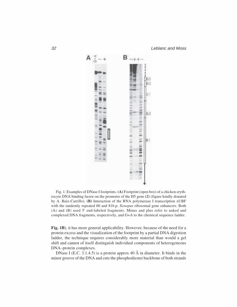
32 Leblanc and Moss
Fig. 1B), it has more general applicability. However, because of the need for aprotein excess and the visualization of the footprint by a partial DNA digestionladder, the technique requires considerably more material than would a gelshift and cannot of itself distinguish individual components of heterogeneousDNA–protein complexes.
DNase I (E.C. 3.1.4.5) is a protein approx 40 Å in diameter. It binds in theminor groove of the DNA and cuts the phosphodiester backbone of both strands
Fig. 1. Examples of DNase I footprints. (A) Footprint (open box) of a chicken eryth-rocyte DNA binding factor on the promoter of the H5 gene (2) (figure kindly donatedby A. Ruiz-Carrillo). (B) Interaction of the RNA polymerase I transcription xUBFwith the tandemly repeated 60 and 81b.p. Xenopus ribosomal gene enhancers. Both(A) and (B) used 5' end-labeled fragments. Minus and plus refer to naked andcomplexed DNA fragments, respectively, and G+A to the chemical sequence ladder.
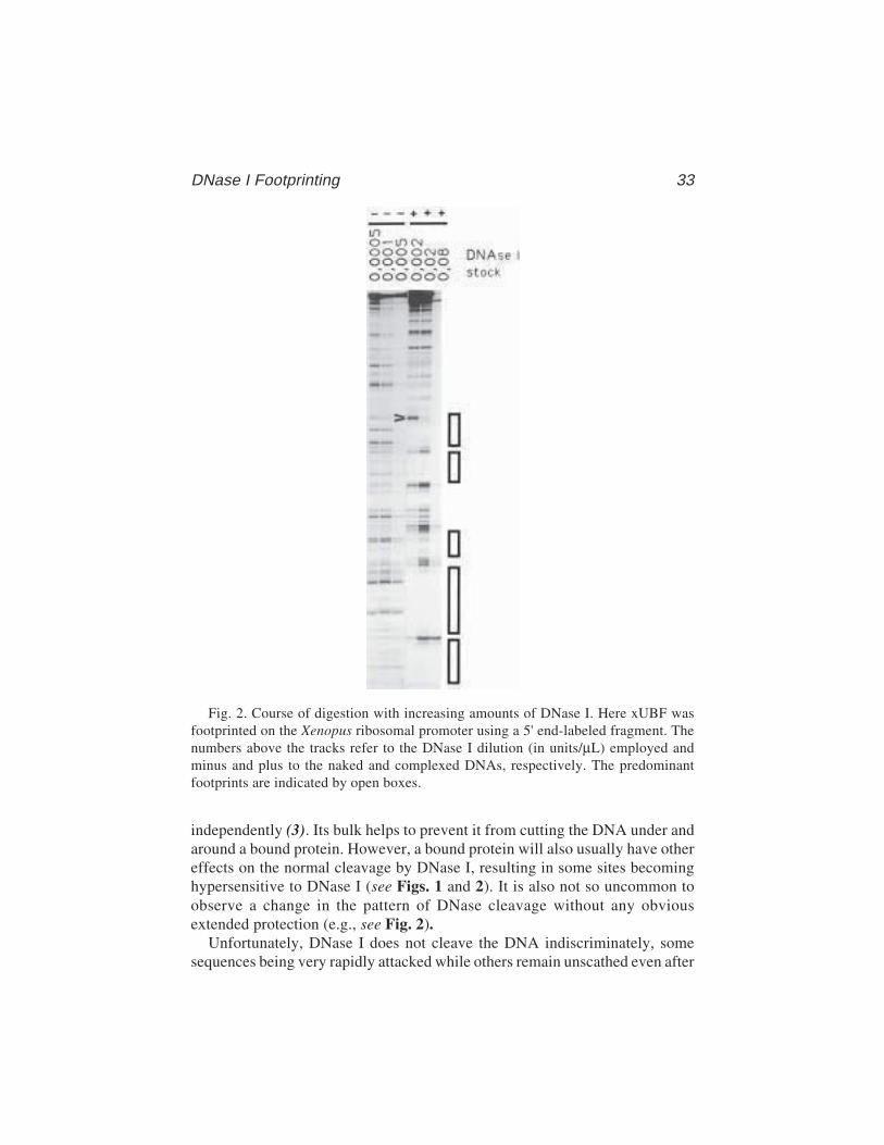
DNase I Footprinting 33
independently (3). Its bulk helps to prevent it from cutting the DNA under andaround a bound protein. However, a bound protein will also usually have othereffects on the normal cleavage by DNase I, resulting in some sites becominghypersensitive to DNase I (see Figs. 1 and 2). It is also not so uncommon toobserve a change in the pattern of DNase cleavage without any obviousextended protection (e.g., see Fig. 2).
Unfortunately, DNase I does not cleave the DNA indiscriminately, somesequences being very rapidly attacked while others remain unscathed even after
Fig. 2. Course of digestion with increasing amounts of DNase I. Here xUBF wasfootprinted on the Xenopus ribosomal promoter using a 5' end-labeled fragment. Thenumbers above the tracks refer to the DNase I dilution (in units/µL) employed andminus and plus to the naked and complexed DNAs, respectively. The predominantfootprints are indicated by open boxes.

34 Leblanc and Moss
extensive digestion (4). This results in a rather uneven “ladder” of digestionproducts after electrophoresis, something which limits the resolution of thetechnique, see naked DNA tracks in Figs. 1 and 2. However, when the protein-protected and naked DNA ladders are run alongside each other, the footprintsare normally quite apparent. To localize the position of the footprints, G+Aand/or C+T chemical sequencing ladders of the same end-labeled DNA probe(5) should accompany the naked and protected tracks (see Note 1). As a singleend-labeled fragment allows one to visualize interactions on one strand only ofthe DNA, it is usual to repeat the experiment with the same fragment labeledon the other strand. DNA fragments can be conveniently 5' labeled with T4polynucleotide kinase and 3' labeled using the Klenow or the T4 DNA poly-merases (fill out) or terminal transferase (e.g., see ref. 6). A combination of 5'and 3' end labeling allows both DNA strands to be analyzed side by side fromthe same end of the DNA duplex.
DNase I footprinting requires an excess of DNA-binding activity over DNAfragment used. The higher the percent occupancy of a site on the DNA, theclearer a footprint will be observed. It is therefore important not to titrate theavailable proteins with too much DNA. This limitation can, in part, be over-come when a protein also generates a gel shift. It is then feasible to fractionatethe partially DNase-digested protein–DNA complex by nondenaturing gelelectrophoresis and to excise the shifted band (which is then a homogeneousprotein–DNA complex) before analyzing the DNA by denaturing gel electro-phoresis as in the standard footprint analysis (see Chapters 2, 4, 5, and 7 foranalogous procedures).
Footprinting crude or impure protein fractions usually requires that an excessof a nonspecific competitor DNA be added. The competitor binds nonspecificDNA-binding proteins as effectively as the specific labeled target DNA frag-ment and hence, when present in sufficient excess, leaves the main part of thelabeled DNA available for the sequence specific protein. Homogeneous andhighly enriched protein fractions usually do not require the presence of a non-specific competitor during footprinting. When planning a footprinting experi-ment, it is a prerequisite to start by determining the optimal concentration ofDNase I to be used. This will be a linear function of the amount of nonspecificDNA competitor but more importantly and less reproducibly, will be a func-tion of the amount and purity of the protein fraction added. As a general rule,more DNase is required if more protein is present in the binding reaction,whether or not this protein binds specifically. Thus, very different DNase con-centrations may be required to produce the required degree of digestion onnaked and protein-bound DNA. A careful titration of the DNase concentrationis therefore essential to optimize the detection of a footprint and can even makethe difference between the detection or lack of detection of a given interaction.
DNase I Footprinting 35
The following protocol was developed to study the footprinting of the Xeno-pus ribosomal transcription factor xUBF, which is a rather weak DNA-bindingprotein with a rather broad sequence specificity. The protocol is not original,being derived from several articles (e.g., refs. 1 and 7). It does however repre-sent a very practical approach which can be broadly applied. We recommendthat the reader also refer to (6) for more information on the quantitative analy-sis of protein–DNA interactions by footprinting.
2. Materials1. Binding buffer (2X): 20% glycerol, 0.2 mM EDTA, 1 mM dithiothreitol (DTT)
20 mM HEPES pH 7.9 and 4% poly(vinyl alcohol) (see Note 2).2. poly dAdT–poly dAdT (Pharmacia LKB): 1 mg/mL solution in TE. Keep at –20°C
(see Note 3).3. End-labeled DNA fragment of high-specific activity (see Note 1).4. Cofactor solution: 10 mM MgCl2 and 5 mM CaCl2.5. DNase I stock solution: A standardized vial of DNase I (Sigma, D4263) is dis-
solved in 50% glycerol, 135 mM NaCl, 15 mM CH3COONa pH 6.5 at 10 Kunitzunits/µL. This stock solution can be kept at –20°C for many months (see Note 4).
6. 1 M KCl7. Reaction Stop buffer: 1% sodium dodecyl sulfate (SDS), 200 mM NaCl, 20 mM
EDTA pH 8.0, and 40 µg/mL tRNA (see Note 5).8. 10X TBE buffer: 900 mM Tris-borate pH 8.3, 20 mM EDTA9. Loading buffer: 7 M urea, 0.1X TBE, 0.05% of xylene cyanol and of bromophe-
nol blue.10. 6% acrylamide, 7 M urea, and 1X TBE sequencing gel.11. Phenol–chloroform (1:1) saturated with 0.3 M TNE.
3. Methods
The footprinting reaction is done in three stages: binding of the protein tothe DNA, partial digestion of the protein–DNA complex with DNase I, andseparation of the digestion fragments on a DNA sequencing gel.
1. The binding reaction is performed in a total volume of 50 µL containing 25 µL of2X binding buffer, 0.5 µL of 1 mg/mL poly dAdT. poly dAdT, 2–3 ng of end-labeled DNA fragment (approx 15,000 CPM), (see Note 6), the protein fractionand 1 M KCl to bring the final KCl concentration to 60 mM. The maximum vol-ume of the protein fraction that can be used will depend on the salt concentrationof this solution. The reaction is performed in a 1.5-mL Eppendorf tube.
2. Incubate on ice for 20 min.3. During the binding reaction, dilute the DNase I stock solution in water at 0°C.
We suggest working concentrations of about 0.0005 to 0.1 Kunitz units/µL,depending on the level of protein present (see Note 7 and step 5). A good rangeis 0.0005; 0.001; 0.002; 0.005; 0.02; 0.08 U/µL.
36 Leblanc and Moss
4. After the incubation, transfer the reaction tubes in batches of eight to a rack atroom temperature (RT) and add 50 µL of the cofactor solution to each.
5. Add 5 µL of the appropriate DNase I dilution to a tube every 15 s. (0.0005–0.005for naked DNA; 0.002–0.08 for DNA + proteins).
6. After 2 min digestion, each reaction is stopped by the addition of 100 µL of thestop solution (RT), see Note 8.
7. After all the reactions have been processed, phenol–chloroform extract eachreaction once.
8. Add two volumes (400 µL) of ethanol (–20°C) and allow nucleic acids to precipi-tate at –80°C for 20 min.
9. Microcentrifuge for 15 min, at approx 10,000g and remove the supernatant witha Pasteur pipet. Check for the presence of a radioactive pellet before discardingthe ethanol.
10. Add 200 µL of 80% ethanol (–20°C) and microcentrifuge again. After removingsupernatant, dry the pellets in a vacuum desiccator.
11. Resuspend each pellet in 4.5 µL loading buffer, vortex, and centrifuge briefly.12. A G+A ladder and a molecular-weight marker should be run in parallel with the
samples on the sequencing gel (step 13) (see Note 9). The G+A ladder can beprepared as follows (5): approx 200,000 cpm of end-labeled DNA are dilutedinto 30 µL H2O (no EDTA). 2 µL of 1 M piperidine formate, pH 2.0, are addedand the solution incubated at 37°C for 15 min; 150 µL of 1 M piperidine areadded directly and the solution incubated at 90°C for 30 min in a well-sealed tube(we use a 500-µL microtube in a thermal cycler). Add 20 µL of 3 M CH3COONaand 500 µL of ethanol and precipitate at –80°C for 10–20 min. Micro-centrifuge (10,000g, 10 min) and repeat precipitation. Finally, redissolve in 200 µLof H2O and lyophilize. Resuspend in gel loading buffer and apply about 5000 cpmper track.
13. Prerun a standard 6% acrylamide sequencing gel for 30 min before loading eachof the aliquots. Wash the wells thoroughly with a syringe, denature the DNA for2 min at 90°C, and load with thin-ended micropipet tips. Run the gel hot to keepthe DNA denatured (see Note 10). After the run, wrap the gel in plastic wrap andexpose it O/N at –70°C with an intensifying screen (see Note 11). Several differ-ent exposures will probably be required to obtain suitable band densities.
4. Notes1. Single-stranded breaks in the end-labeled DNA fragment must be avoided as they
give false signals indistinguishable from genuine DNase I cleavage and hencecan mask an otherwise good footprint. It is therefore advisable to check thefragment on a denaturing gel before use. Always use a freshly labeled fragment(3–4 d at the most), as radiochemical nicking will degrade it.
2. This binding buffer has been shown to work well for the transcription factor NF-1(6) and in our lab for both the hUBF and xUBF factors and thus should work formany factors. Glycerol and poly(vinyl alcohol) (an agent used to reduce the avail-able water volume and hence concentrate the binding activity) are not manda-
DNase I Footprinting 37
tory. The original footprinting conditions of Galas and Schmitz (1) for the bind-ing of the lac repressor on the lac operator were 10 mM cacodylate buffer pH 8.0,10 mM MgCl2, 5 mM CaCl2 and 0.1 mM DTT. Particular conditions of pH,cofactors and ionic strength may need to be determined for an optimal binding ofdifferent factors to DNA.
3. Because poly dIdC, another nonspecific general competitor, has been shown tocompete quite efficiently with G–C-rich DNA sequences, poly dAdT is preferredhere. The choice of an appropriate nonspecific competitor (be it synthetic as inthis case or natural, for example, pBR322 or calf thymus DNA) may have to bedetermined empirically for the protein studied. When working with a pure orhighly enriched protein, no competitor is usually needed. The DNase I concen-tration must then be reduced accordingly (to about naked DNA values).
4. These standardized vials allow for very reproducible results. Glycerol will keepthe enzyme from freezing, as repeated freeze–thaw cycles will greatly reduceits activity.
5. Do not be tempted to use too much RNA, as it causes a very annoying fuzzinessof the gel bands, preventing resolution of the individual bands. The RNA carriercan be completely omitted if care is taken at the precipitation step.
6. The use of 5' end labeling with polynucleotide kinase in the presence of crudeprotein extracts can sometimes lead to a severe loss of signal because of the pres-ence of phosphatases. In these cases 3' end labeling by “fill out” with Klenow orT4 DNA polymerases is to be preferred.
7. For naked DNA and very low amounts of protein, dilutions of 0.0005 to 0.005give a good range of digestion.
8. It is convenient to work with groups of eight sample during the DNase I digestion.The cofactor solution is added to eight samples at a time and then the DNase Idigestions are begun at 15-s intervals. Fifteen seconds after adding DNase to theeighth sample, the stop solution is added to sample 1 and then to the other samplesat 15-s intervals.
9. In comparing a chemical sequencing ladder with the products of DNase I diges-tion, one must bear in mind that because the chemical modification and cleavagedestroys the target base, each band in the sequencing ladder corresponds to afragment ending in the base preceding the one read. For example, if a DNase I gelband corresponds in mobility to the sequence ladder band read as G in thesequence ACGT, then the DNase I cleavage occurred between the bases C and G.DNase I cleaves the phosphodiester bond, leaving a 3'-OH, whereas the G+A andC+T sequencing reactions leave a 3'-PO4, causing a mobility shift between thetwo types of cleavage ladders. This is a further potential source of error. How-ever, in our experience, the shift is less than a half a base and, hence, cannot leadto an error in the deduced cleavage site.
10. Sequencing gels are not denaturing unless run hot (7 M urea produces only asmall reduction in the Tm of the DNA). A double-stranded form of the DNAfragment is therefore often seen on the autoradiogram, especially at low levels ofDNase I digestion and can sometimes be misinterpreted as a hypersensitive cleav-
38 Leblanc and Moss
age. By running a small quantity of undigested DNA fragment in parallel withthe footprint, this error can be avoided.
11. For detection of 32P-labeled DNA in sequencing gels we have used either CronexLightning Plus (Dupont) or Kyokko Special (Fuji) intensifying screens, the latterbeing, in practice, 30% less sensitive but often much less expensive. Fuji-RX orsimilar films are, in practice, 30% slower than Kodak X-omat AR film, but inNorth America, at the time of writing, they are five to six times less expensive.Hence, the combinations of screens and films Kyokko/RX:Cronex/RX: Kyokko/AR:Cronex/AR give relative sensitivities of about; 1:1.5:1.5:2. Should the newerslightly higher sensitivity films be used (e.g., Kodak BioMax), it is essential thatthe appropriate intensifying screens be employed. These newer films are usuallymost sensitive to green light and do not work well with the Cronex LightningPlus/Kyokko Special type screens, which emit a blue light.
AcknowledgmentsThe authors wish to thank Dr. A. Ruiz-Carrillo for providing the autoradio-
gram in Fig. 1A. This work was supported by a project grant from the MedicalResearch Council (MRC) of Canada. Tom Moss is an MRC of Canada Scien-tist and a member of the Centre de Recherche en Cancérologie de l’UniversitéLaval which is supported by the FRSQ of Québec.
References1. Schmitz, A. and Galas, D. J. (1978). DNAase I footprinting: a simple method
for the detection of protein-DNA binding specificity. Nucleic Acids Res. 5,3157–3170.
2. Rousseau, S., Renaud, J., and Ruiz-Carrillo, A. (1989). Basal expression of thehistone H5 gene is controlled by positive and negative cis-acting sequences.Nucleic Acids Res. 17, 7495–7511.
3. Suck, D., Lalm, A., and Oefner, C. (1988). Structure refined to 2 Å of a nickedDNA octanucleotide complex with DNAse I. Nature 332, 464–468.
4. Drew, H. R. (1984). Structural specificities of five commonly used DNAnucleases. J. Mol. Biol. 176, 535–557.
5. Maxam, A. M. and Gilbert, W. (1980). Sequencing end-labeled DNA with base-specific chemical cleavages, in Methods in Enzymology, Vol. 65 (Grossman, L.and Moldave, K., eds.), Academic, New York, pp. 499–560.
6. Brown, T. (1987). Analysis of RNA by Northern and slot blot hybridisation, inCurrent Protocols in Molecular Biology (Ausubel, F. M., Brent, R., Kingston, R.E., Moore, D. D., Seidman, J. G., Smith, J. A., et al., eds.), Greene PublishingAssociates/Wiley-Interscience, New York, pp. 4.9.1–4.9.14.
7. Walker, P. and Reeder, R. H. (1988). The Xenopus laevis ribosomal genepromoter contains a binding site for nuclear factor-1. Nucleic Acids Res. 16,10,657–10,668.
Footprinting with Exonuclease III 39
39
From: Methods in Molecular Biology, vol. 148: DNA–Protein Interactions: Principles and Protocols, 2nd ed.Edited by: T. Moss © Humana Press Inc., Totowa, NJ
4
Footprinting with Exonuclease III
Willi Metzger and Hermann Heumann
1. IntroductionWithin the last few years footprinting techniques have become increasingly
important in the study of protein–nucleic acid interactions. This is partly theresult of a fast-growing number of known nucleic acid-binding proteins butalso because of an increase in the available probes that can be chosen in orderto tackle a specific problem. There are two major groups of probes—the chemi-cal probes and the enzymatic probes. The enzymatic probes, such as DNase Ior exonuclease III, have the advantage of acting specifically on the DNA.Chemical probes are often less specific and may also react with the protein,possibly disturbing the correct interaction of protein with DNA. For the studyof very fragile protein–DNA complexes, enzymatic probes are therefore oftenpreferable.
The exploitation of a specific enzymatic function can also be a reason forchoosing an enzymatic probe. The exonuclease activity and processivity ofexonuclease III makes this enzyme a suitable probe when information aboutthe position of a sequence-specific bound protein is required. A prerequisitefor the successful use of exonuclease III as a footprinting probe is, however,that the half-life of the protein–DNA complex should be long compared withthe time required for the exonuclease III reaction.
1.1. Enzymatic Activities of Exonuclease III
Exonuclease III (Exo III) is a monomeric enzyme with a molecular weightof 28,000 kDa. It contains several distinct activities: a 3'–5' exonuclease activ-ity, a DNA 3' phosphatase activity, an AP endonuclease activity, and an RNaseH activity (1).
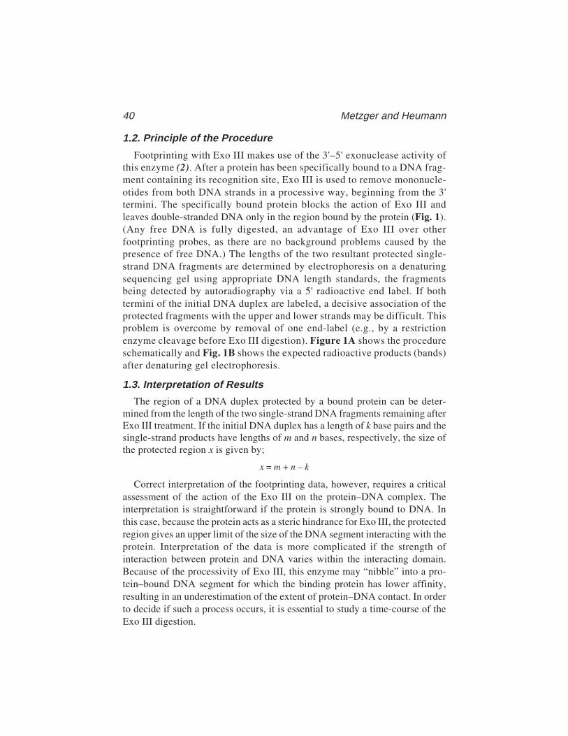
40 Metzger and Heumann
1.2. Principle of the Procedure
Footprinting with Exo III makes use of the 3'–5' exonuclease activity ofthis enzyme (2). After a protein has been specifically bound to a DNA frag-ment containing its recognition site, Exo III is used to remove mononucle-otides from both DNA strands in a processive way, beginning from the 3'termini. The specifically bound protein blocks the action of Exo III andleaves double-stranded DNA only in the region bound by the protein (Fig. 1).(Any free DNA is fully digested, an advantage of Exo III over otherfootprinting probes, as there are no background problems caused by thepresence of free DNA.) The lengths of the two resultant protected single-strand DNA fragments are determined by electrophoresis on a denaturingsequencing gel using appropriate DNA length standards, the fragmentsbeing detected by autoradiography via a 5' radioactive end label. If bothtermini of the initial DNA duplex are labeled, a decisive association of theprotected fragments with the upper and lower strands may be difficult. Thisproblem is overcome by removal of one end-label (e.g., by a restrictionenzyme cleavage before Exo III digestion). Figure 1A shows the procedureschematically and Fig. 1B shows the expected radioactive products (bands)after denaturing gel electrophoresis.
1.3. Interpretation of Results
The region of a DNA duplex protected by a bound protein can be deter-mined from the length of the two single-strand DNA fragments remaining afterExo III treatment. If the initial DNA duplex has a length of k base pairs and thesingle-strand products have lengths of m and n bases, respectively, the size ofthe protected region x is given by;
x = m + n – k
Correct interpretation of the footprinting data, however, requires a criticalassessment of the action of the Exo III on the protein–DNA complex. Theinterpretation is straightforward if the protein is strongly bound to DNA. Inthis case, because the protein acts as a steric hindrance for Exo III, the protectedregion gives an upper limit of the size of the DNA segment interacting with theprotein. Interpretation of the data is more complicated if the strength ofinteraction between protein and DNA varies within the interacting domain.Because of the processivity of Exo III, this enzyme may “nibble” into a pro-tein–bound DNA segment for which the binding protein has lower affinity,resulting in an underestimation of the extent of protein–DNA contact. In orderto decide if such a process occurs, it is essential to study a time-course of theExo III digestion.
Footprinting with Exonuclease III 41
1.4. Examples of the Application of Exo IIIas a Footprinting Probe
Exonuclease III has been used to follow the movement of E. coli RNA poly-merase during RNA synthesis (3,4). RNA synthesis was arrested at specificpositions and the arrested complexes were subjected to Exo III digestion. A setof single–strand products marking the boundaries of RNA polymerase on theDNA at each step of RNA synthesis was observed. Exo III also offers the pos-sibility of detecting specific DNA–protein interactions in crude extracts,because those proteins whose half-lives are greater than the reaction time actas a block for Exo III (5–7).
Fig. 1. (A) Schematic representation of the Exo III footprinting procedure. (B) ExoIII footprint of the complex shown in (A). Lane 1: Size markers; lane 2: labeled DNAfragment; lane 3: labeled DNA fragment, after Exo III treatment; lane 4: DNA fromDNA–protein complex, after Exo III treatment, both 5' ends of duplex labeled; lane 5:DNA from DNA–protein complex, after Exo III treatment, DNA duplex singly end-labeled label was removed beforehand by cutting with a restriction enzyme as indi-cated in (A).
42 Metzger and Heumann
2. Materials2.1. Exonuclease III
Exonuclease III is available from BRL (Gaithersburg, MD) or BoehringerMannheim (Indianapolis, IN). It can be stored for many months at –20°C.
2.2. Sequencing Gel
1. Acrylamide solution: 40% acrylamide, and 0.66% bis-acrylamide in H2O.2. 10X TBE: 1 M Tris-HCl, pH 8.6, 840 mM boric acid; and 10 mM EDTA.3. 10% Ammonium persulfate (freshly prepare before use).4. N,N,N'N'-tetramethylethylene diame (TEMED).5. Preparation of an 8% acrylamide gel: Weigh 21 g of urea, and add 5 mL of 10X
TBE solution and 10 mL of acrylamide solution. Dissolve under mild heating.Add double-distilled water to a final volume of 50 mL. Filter and degas the solu-tion (filter pore size 0.2 µm). Add 500 µL of 10% ammonium persulfate solutionand 30 µL of TEMED. Pour gel immediately.
6. Formamide loading buffer for the sequencing gel: 100 mL deionized formamide,30 mg xylenecyanol FF, 30 mg bromophenol blue, and 750 mg EDTA.
7. Electrophoresis buffer: 1X TBE.
2.3. Nondenaturing Gel for the Band-Shift Assay
1. Acrylamide solution: 30% acrylamide and 0.8% bis-acrylamide in H2O.2. 1 M Tris-HCl, pH 7.9.3. 10% Ammonium persulfate (freshly prepare before use).4. 5% TEMED (diluted in water).5. Preparation of nondenaturing gel: Mix 240 µL of 1 M Tris-HCl, pH 7.9, 2.75 mL
acrylamide solution, and 25.7 mL of H2O and degas. Add 300 µL of 10% ammo-nium persulfate and 70 µL of 5% TEMED. Pour gel.
6. Loading buffer for the nondenaturing gel (10X solution): 40% sucrose and 0.1%bromophenol blue.
7. 5% Dichloro-dimethylsilane solution (in chloroform).8. 0.3% g-Methacryl-oxypropyl-trimethoxy-silane and 0.3% acetic acid dissolved
in ethanol.9. Electrophoresis buffer: 8 mM Tris-HCl, pH 7.9.
Store the solutions protected from light at 4°C. Dilute buffers withbidistilled water.
2.4. Other Items
1. Sequencing gel apparatus (Pharmacia, Piscataway, NJ).2. Filters for drop dialysis VS, 0.025 µm (Millipore, Bedford, MA).3. Peristaltic pump.4. SpeedVac concentrator.
Footprinting with Exonuclease III 43
3. Methods3.1. Establishing Conditions for Optimum Yieldof Specific Protein–DNA Complexes
A very elegant method for establishing the optimum conditions for theformation of a specific protein–DNA complex is acrylamide gel electrophore-sis under nondenaturing conditions. This electrophoretic mobility shift assay(EMSA) or “band shift assay” allows one to differentiate between complexedand uncomplexed DNA (8,9) and thus to determine the stoichiometry of givencomplexes and the optimum salt conditions for their formation (see Chapter 2).This method can even be applied to high-molecular-weight protein DNAcomplexes, given the acrylamide concentration is low enough to enable thecomplex to enter the gel matrix. The gel composition given in Subheading2.3. is optimal for the study of high-molecular-weight complexes (see Note 6).
To facilitate the handling of low-concentration polyacrylamide gels, theglass gel plates are subjected to a special treatment ensuring the gel will remainbound to only one of the two plates after electrophoresis:
1. Wash the glass plates (20 × 20 cm) with ethanol.2. Treat one plate with g-methacryl-oxypropyl-trimethoxysilane solution, then wash
this plate carefully four times with ethanol.3. Treat the second plate with dichloro-dimethylsilane solution.4. Form the protein–DNA complex in a volume of about 15 µL under the desired
conditions.5. Dialyze the complex, if necessary, against the electrophoresis buffer by drop
dialysis as follows:a. Pour the dialysis buffer into a Petri dish.b. Place a VS filter (Millipore, see Subheading 2.4.) with the glossy side upward
onto the buffer so that it can float freely.c. Place the sample as a drop on the filter. Remove the drop after 1 h when
dialysis is complete.6. Add 1/10 volume of the 10X loading buffer to the dialyzed complex and apply
the sample to the nondenaturing polyacrylamide gel.7. Run the gel at 20 V/cm for approx 2 h. Pump the buffer from the anode to the cathode
chambers and back again to avoid pH decrease in the anode chamber (see Note 1).
3.2. Establishing the Conditions for the Digestion of the DNA
1. Label the DNA at the 5'-ends using T4 polynucleotide kinase and [γ-32P] ATP.Take an aliquot of end-labeled DNA and remove one 5'-label by asymmetriccleavage with an appropriate restriction enzyme. Use the cleaved and uncleavedlabeled DNA in separate analyses as described the following steps.
2. Ensure that the total amount of DNA in an assay of 20 µL is not below 100 ng.The total amount of radioactivity in one assay should be approx 20,000 cpm. Use

44 Metzger and Heumann
the optimal salt conditions optimal for complex. Add 6 mM Mg2+, if this is notalready present.
3. Add Exo III and incubate at 37oC. In order to establish the optimum conditions,perform a series of experiments using concentrations Exo III between 1 and200 U per reaction (20 µL) and incubation times varying between 1 and 45 min.Exo III seems to be rather stable over a wide range of ionic strengths, and nolarge changes in activity were observed in the range between 0 and 100 mM NaCl(or KCl) in the incubation mixture (see Note 2).
4. Add EDTA to a final concentration of 20 mM in order to stop the reaction at theappropriate time.
5. Add sodium acetate to a final concentration of 0.3 M followed by 2.5 volumes ofice-cold 100% ethanol to precipitate the digested DNA. Keep the solution at –70°Cfor 20 min.
6. Spin down the solution in a microcentrifuge for 15 min. Wash the pellet withice-cold 75% ethanol, dry under vacuum, and dissolve in formamide load-ing buffer.
7. Heat sample at 100oC for 2 min and apply onto a 6–10% sequencing gel. (For theanalysis of fragments in the range of 50–150 bases, 8% polyacrylamide isadequate, as described in Subheading 2.2.). Use as a length standard a Maxam–Gilbert sequencing reaction of the 5'-end-labeled DNA fragment.
8. Run the gel at 50 W and a temperature of 60°C for 2 h.9. After electrophoresis, expose the gel overnight at –70°C to X-ray film using an
intensifying screen.10. Ensure that the free DNA is fully digested (usually much shorter single-strand
DNA fragments than the predicted half-full-length [2] are obtained).
3.3. Exo III Digestion of the Protein–DNA Complex
1. Form the complex using the conditions established under Subheading 3.1.2. Subject the complex to Exo III digestion using the conditions established under
Subheading 3.2. (see Notes 1 and 3–6).3. Add 20 mM EDTA, 1% sodium dodecyl fulfate (SDS) (final concentration) to
stop the reaction. SDS is necessary in order to destroy the protein–DNA complex.4. Proceed as described in Subheading 3.2. (steps 5–9) for recovery and gel elec-
trophoretic analysis of the DNA. For recovery of the DNA, a phenol extractionbefore the ethanol precipitation is advisable if a crude protein extract has beenused for complex formation.
3.4. Modifications of the Procedure
Depending on the kind of protein–DNA complexes being investigated, sev-eral modifications of the procedure described in the previous section may beuseful or necessary. If the protein–DNA complexes are not homogeneous (e.g.,more than one type of protein complex can form or the DNA contains multiplebinding sites for a given protein), the desired complex can be purified on a

Footprinting with Exonuclease III 45
nondenaturing acrylamide gel, as described in Subheading 3.1., provided thecomplexes show different gel mobilities and have half-lives long enough tosurvive the electrophoresis. Such a purification step requires the use of 10 timesmore radioactively labeled DNA.
The procedure is as follows:
1. Form the complex.2. Subject the complex to digestion with Exo III according to Subheading 3.3.,
step 2.3. Dialyze the complex by drop dialysis against a low salt buffer (e.g., 10 mM
Tris-HCl, pH 7.9) in order to avoid salt effects during electrophoresis (Subhead-ing 3.1., step 5).
4. Apply the complex to a nondenaturing gel as described in Subheading 3.1., steps6 and 7. The half-life of the complex is in most cases not changed by the Exo IIIdigestion of the DNA.
5. Expose the gel at –70°C to X-ray film using an intensifying screen. A 1-h expo-sure should be enough to recognize the complexed bands. If not, the recoveredDNA will be insufficient for the subsequent sequencing gel analysis.
6. Before removing the film for development mark exactly its position on the gel.7. Excise the complex bands of interest with a spatula. The band representing the
free DNA will be visible as a smear after Exo III digestion.8. To elute the complexed DNA, put the excised gel slice in 600 µL of bidistilled
water. Heat the complex to 90°C for 3 min and shake overnight at room tempera-ture. The effectiveness of the elution can be easily monitored by comparing theradioactivity of the eluate with the radioactivity of the gel slice.
9. Vacuum-dry the eluate in a SpeedVac concentrator.10. Dissolve the pellet in 10 µL formamide buffer and spin down the gel residue.11. Transfer the supernatant to a new Eppendorf tube and apply the sample to a
sequencing gel as described in Subheading 3.2., steps 7–9.
4. Notes1. The gel concentration has to be adjusted according to the molecular weight of the
protein–DNA complex. Here we describe the conditions established for the studyof the E. coli RNA polymerase (MW 455,000) and a DNA fragment of 130 bpcarrying a promoter (9). For some applications, another widely used non-denaturing gel system may be appropriate: 1X TBE buffer, 4% acrylamide, and0.1% bis-acrylamide. Recirculation of the buffer is not necessary here.
2. It has been observed that many batches of commercially available Exo III contain anactivity that removes the 5' label. A 5'-phosphatase or a 5'–3' exonuclease activ-ity could account for this phenomenon. Filling in the 5' protruding ends using α-thio-dNTPs as described by some authors (10,11) may eliminate the problem.Addition of E. coli tRNA can reduce the effect, but will not completely avoid it.
46 Metzger and Heumann
3. Investigation of the complexes of specific binding of proteins and DNA in crudeextracts using Exo III requires additional precautions in order to avoid problemscaused by endogenous nuclease activities during Exo III exposure. To avoid thisproblem, sodium-phosphate, tRNA, deoxyoligonucleotides and fragmentedphage DNA (e.g., 2 mM sodium phosphate, 1 µg of FX 174 DNA cut with HaeIII,10 µg of yeast tRNA, and 1 µg mixed p[dN]5) should be added to the assay (5).We find this suppresses nuclease and possibly phosphatase activities containedin the crude extracts (see also Note 2).
4. Testing different concentrations of Exo III and different incubation periods can pro-vide additional information about the nature of the protein–DNA complex understudy. If Exo III is able to “nibble” into a protected area with increasing exposuretime, this indicates differences in the strength of protein–DNA interaction (10).
5. Different binding sites for one or more proteins may be detected as distinct stoppoints for Exo III, as shown in refs. 12–14. This applies as much when workingwith crude extracts as when using purified factors. It is necessary, however, thatthe ratio of DNA to binding proteins be >1.
6. Heparin, which is often used as a DNA competitor for E. coli RNA–polymeraseand other DNA-binding proteins, also interacts with Exo III and reduces its activ-ity markedly.
References1. Rogers, S. G. and Weiss, B. (1980) Exonuclease III of Escherichia coli K-12, an
AP endonuclease. Methods Enzymol. 65, 201–211.2. Shalloway, D., Kleinberger, T., and Livingston, D. M. (1980) Mapping of SV 40
DNA replication origin region binding sites for the SV 40 DNA replication anti-gen by protection against Exonuclease III digestion, Cell 20, 411–422.
3. Metzger, W., Schickor, P., and Heumann, H. (1989) A cinematographic view ofEscherichia coli RNA polymerase translocation. EMBO J. 8, 2745–2754.
4. Pavco, P. A. and Steege, D. A. (1990) Elongation by Escherichia coli RNA poly-merase is blocked in vitro by a site specific DNA binding protein. J. Biol. Chem.265, 9960–9969.
5. Wu, C. (1985) An exonuclease protection assay reveals heat-shock element andTATA box binding proteins in crude nuclear extracts. Nature 317, 84–87.
6. Loh, T. P., Sievert, L. L., and Scott, R. W. (1990) Evidence for a stem cell-spe-cific repressor of Moloney murine leukemia virus expression in embryonic carci-noma cells. Mol. Cell. Biol. 10, 4045–4057.
7. Carnevali, F., La Porta, C., Ilardi, V., and Beccari, E. (1989) Nuclear factors spe-cifically bind to upstream sequences of a Xenopus laevis ribosomal protein genepromoter. Nucleic Acids Res. 17, 8171–8184.
8. Fried, M. and Crothers, D. M. (1981) Equilibria and kinetics of lac repressor-operator interactions by polyacrylamide gel electrophoresis. Nucleic Acids Res. 9,6505–6525.
9. Heumann, H., Metzger, W., and Niehörster, M. (1986) Visualization of interme-diary transcription states in the complex between Escherichia coli DNA-depen-
Footprinting with Exonuclease III 47
dent RNA polymerases and a promoter-carrying DNA fragment using the gelretardation method. Eur. J. Biochem. 158, 575–579.
10. Straney, D. C. and Crothers, D. M. (1987) A stressed intermediate in the formationof stably initiated RNA chains at the Escherichia coli lac UV 5 promoter. J. Mol.Biol. 193, 267–278.
11. Straney, D. C. and Crothers, D. M. (1987) Comparison of the open complexesformed by RNA polymerase at the Escherichia coli lac UV 5 promoter. J. Mol.Biol. 193, 279–292.
12. Gaur, N. K., Oppenheim, J., and Smith, I. (1991) The Bacillus subtilis sin gene, aregulator of alternate developmental processes, codes for a DNA-binding protein.J. Bact. 173, 678–686.
13. Owen, R. D., Bortner, D. M., and Ostrowski, M. C. (1990) ras Oncogene activa-tion of a VL30 transcriptional element is linked to transformation. Mol. Cell. Biol.10, 1–9.
14. Wilkison, W. O., Min, H. Y., Claffey, K. P., Satterberg, B. L., and Spiegelman, B.M. (1990) Control of the adipisin gene in adipocyte differentiation. J. Biol. Chem.265, 477–482.
Further ReadingKow, Y. W. (1989) Mechanism of action of Escherichia coli Exonuclease III.
Biochemistry 28, 3280–3287.

Hydroxyl Radical Footprinting 49
49
From: Methods in Molecular Biology, vol. 148: DNA–Protein Interactions: Principles and Protocols, 2nd ed.Edited by: T. Moss © Humana Press Inc., Totowa, NJ
5
Hydroxyl Radical Footprinting
Evgeny Zaychikov, Peter Schickor, Ludmilla Denissova,and Hermann Heumann
1. IntroductionThe basic principle of the DNA footprinting technique is the measurement
of accessibility of the DNA using a probe. The probe can be any enzyme or achemical reagent that is able to cut the DNA backbone. When the target DNAis a fragment containing a signal sequence for a sequence-specific bindingprotein, sites on the DNA that interact with the protein are inaccessible to theprobe. After electrophoretic separation based on molecular weight, these inac-cessible sites appear as blanks in an otherwise regular DNA cleavage pattern,thus revealing the characteristic interaction footprint for the binding protein.
Although the footprinting pattern is a characteristic of the protein–DNAinteraction, it is also greatly affected by the type of probe used. Hydroxyl radi-cals provide DNA footprinting probes, which are very convenient to handleand are distinguished by a number of distinct advantages:
1. Hydroxyl radicals cut the DNA with almost no sequence dependence.2. Because the probe is very small, the resolution of the footprint is very high (1 bp).3. The cleavage reaction is effective over a wide range of buffer compositions, salt
concentrations, pHs, and temperatures. Only glycerol, a radical scavenger, inter-feres with the cutting when present at concentrations higher than 0.5%.
4. All chemicals needed are easily available and uncomplicated in their handling.
1.1. Generation and Action of Hydroxyl Radicals
Hydroxyl radicals are generated according to the Fenton reaction by reduc-tion of iron(II) with hydrogen peroxide as follows:
ascorbate or diothiothreited
Fe2+(EDTA4–) + H2O2 → Fe3+(EDTA4–) + OH·
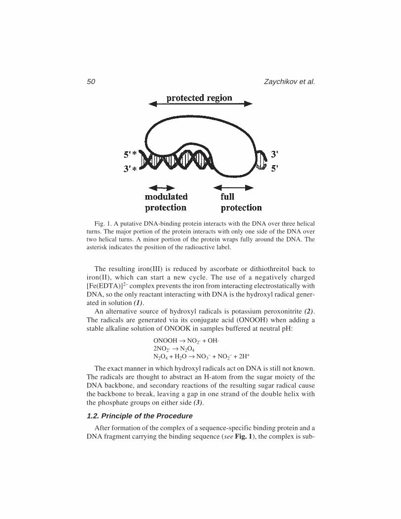
50 Zaychikov et al.
The resulting iron(III) is reduced by ascorbate or dithiothreitol back toiron(II), which can start a new cycle. The use of a negatively charged[Fe(EDTA)]2– complex prevents the iron from interacting electrostatically withDNA, so the only reactant interacting with DNA is the hydroxyl radical gener-ated in solution (1).
An alternative source of hydroxyl radicals is potassium peroxonitrite (2).The radicals are generated via its conjugate acid (ONOOH) when adding astable alkaline solution of ONOOK in samples buffered at neutral pH:
ONOOH → NO2· + OH·2NO2· → N2O4
N2O4 + H2O → NO3– + NO2
– + 2H+
The exact manner in which hydroxyl radicals act on DNA is still not known.The radicals are thought to abstract an H-atom from the sugar moiety of theDNA backbone, and secondary reactions of the resulting sugar radical causethe backbone to break, leaving a gap in one strand of the double helix withthe phosphate groups on either side (3).
1.2. Principle of the Procedure
After formation of the complex of a sequence-specific binding protein and aDNA fragment carrying the binding sequence (see Fig. 1), the complex is sub-
Fig. 1. A putative DNA-binding protein interacts with the DNA over three helicalturns. The major portion of the protein interacts with only one side of the DNA overtwo helical turns. A minor portion of the protein wraps fully around the DNA. Theasterisk indicates the position of the radioactive label.
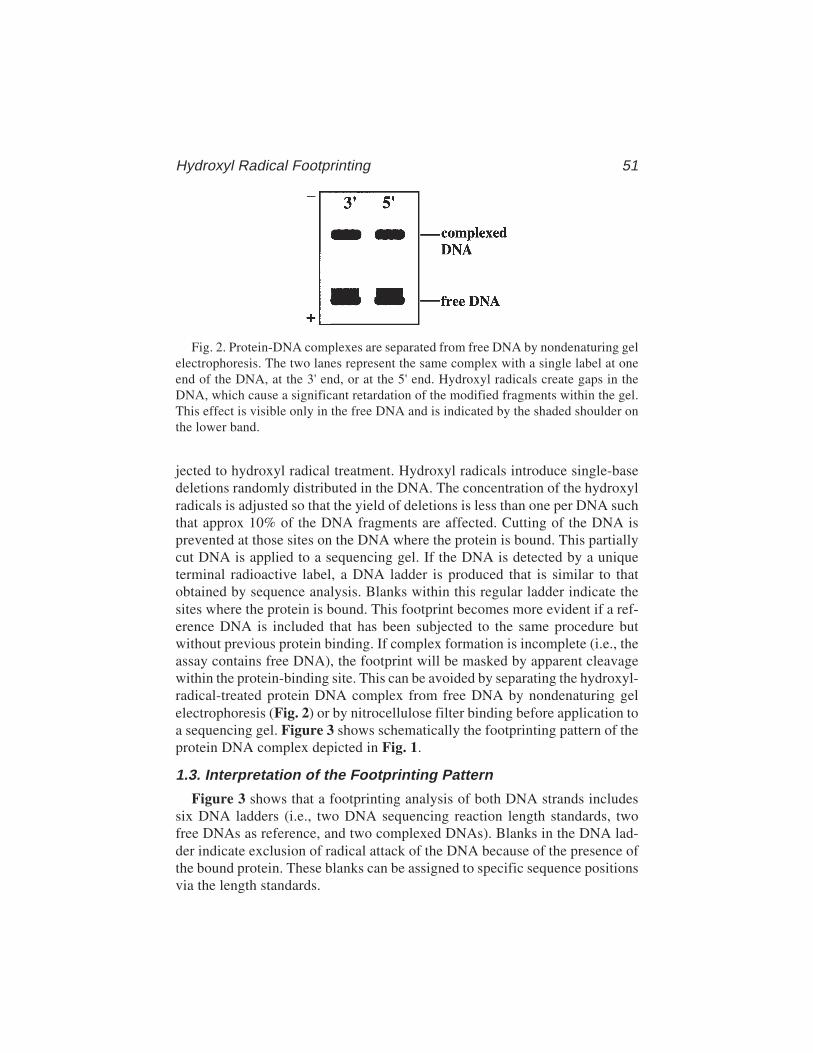
Hydroxyl Radical Footprinting 51
jected to hydroxyl radical treatment. Hydroxyl radicals introduce single-basedeletions randomly distributed in the DNA. The concentration of the hydroxylradicals is adjusted so that the yield of deletions is less than one per DNA suchthat approx 10% of the DNA fragments are affected. Cutting of the DNA isprevented at those sites on the DNA where the protein is bound. This partiallycut DNA is applied to a sequencing gel. If the DNA is detected by a uniqueterminal radioactive label, a DNA ladder is produced that is similar to thatobtained by sequence analysis. Blanks within this regular ladder indicate thesites where the protein is bound. This footprint becomes more evident if a ref-erence DNA is included that has been subjected to the same procedure butwithout previous protein binding. If complex formation is incomplete (i.e., theassay contains free DNA), the footprint will be masked by apparent cleavagewithin the protein-binding site. This can be avoided by separating the hydroxyl-radical-treated protein DNA complex from free DNA by nondenaturing gelelectrophoresis (Fig. 2) or by nitrocellulose filter binding before application toa sequencing gel. Figure 3 shows schematically the footprinting pattern of theprotein DNA complex depicted in Fig. 1.
1.3. Interpretation of the Footprinting Pattern
Figure 3 shows that a footprinting analysis of both DNA strands includessix DNA ladders (i.e., two DNA sequencing reaction length standards, twofree DNAs as reference, and two complexed DNAs). Blanks in the DNA lad-der indicate exclusion of radical attack of the DNA because of the presence ofthe bound protein. These blanks can be assigned to specific sequence positionsvia the length standards.
Fig. 2. Protein-DNA complexes are separated from free DNA by nondenaturing gelelectrophoresis. The two lanes represent the same complex with a single label at oneend of the DNA, at the 3' end, or at the 5' end. Hydroxyl radicals create gaps in theDNA, which cause a significant retardation of the modified fragments within the gel.This effect is visible only in the free DNA and is indicated by the shaded shoulder onthe lower band.

52 Zaychikov et al.
The following information can be extracted from the hydroxyl radicalfootprinting pattern:
1. The total size of the DNA sequence interacting with the protein can be deter-mined from the extent of the uncleaved or blank positions.
2. A variation of the intensity of the bands within the interacting sequence reflectsdifferences in the modes of interaction. By a comparison of the footprints on bothstrands, the modes of interaction can often be interpreted:a. If both strands show a blank at the same region, it indicates that the protein
wraps around the DNA.b. A blank on only one strand indicates single-strand formation, with one strand
protected by interaction with the protein.
Fig. 3. The bands of the nondenaturing gel in Fig. 2 containing the complex and thefree DNA are eluted and applied (under denaturing conditions) to a sequencing gel.Lanes 1 and 4 show the free DNA labeled respectively at the 3' and the 5' ends. Lanes2 and 3 show the DNA recovered from the complex. The complex depicted schemati-cally in Fig. 1 would result in the footprint displayed in lanes 2 and 3. Lanes G containthe length standards obtained by a G-specific Maxam–Gilbert sequencing reaction.
Hydroxyl Radical Footprinting 53
c. Modulation of the intensity of the bands with a regular phasing according tothe helix repeat (e.g., 10.3 bp for B-DNA) indicates binding of the protein toone side of the DNA. This interpretation is supported if the complementarystrand shows the same pattern but with an offset of two or three bases. Thisoffset is a consequence of the double-helical nature of the DNA, as shownschematically in Fig. 1.
1.4. Examples of the Applicationof Hydroxyl Radicals as Footprinting Probes
1.4.1. Protein DNA Complexes
Numerous Fe2+-dependent hydroxyl radical footprinting studies were per-formed on protein–DNA complexes. Most useful were those studies of protein–DNA contacts within the transcription machinery.
1. Hydroxyl radicals were used to follow the formation of the transcriptionallyactive complex between the DNA-dependent RNA polymerase of E. coli andT7A1 promoter (4). Temperature-dependent footprinting studies showed that thetranscription initiation complex undergoes three different conformations charac-terized by a specific “footprint” until a transcription competent complex isformed. These conformations could be attributed to the so-called closed,intermediate, and open complex. A bent conformation of DNA in complex withDNA was concluded from the OH radical probing of the lambda PR promotercomplex (5).
2. Site-specific cleavage of the DNA of a RNA polymerase binary complex by bothfree and EDTA-chelated Fe2+ was detected in absence of Mg2+ ions (6,7). A phe-nomenon in FeEDTA-dependent OH radical footprints is hypercleavage of DNAwhich can be observed in footprints of Mg2+-dependent proteins such as E. coliRNA polymerase (6) or HIV reverse transcriptase (8). The E. coli RNA poly-merase footprint contains a hyperreactive cleavage spot within the protectedregion. This spot could be attributed to a site-specific OH radical cleavage mecha-nism. This view was supported by footprinting studies using peroxonitrite as analternative reagent for generating OH radicals. Using this latter reagent, nohyperreactive spot was visible in the OH radical footprint of E. coli RNA poly-merase, indicating that specifically bound FeEDTA probe was responsible forthe hyperreactive cleavage. Free Fe2+ ion can replace the catalytically active Mg2+
at the polymerization site of RNA polymerase, being chelated with aspartates ofthe active site (7). The chelated Fe2+ generates OH radicals probably accordingto a mechanism that is analogous to the Fenton reaction and causes a strong localcleavage of both DNA and protein. This hyperreactivity was also observed inFe2+-dependent OH radical footprints of reverse transcriptase (RT) of the humanimmunodeficiency virus (HIV-RT). The catalytically active Mg2+ of the RNaseHactive site of HIV-RT was replaced by Fe2+, leading to site-specific OH radicalcleavage of the DNA. It is interesting to note that no hyperreactive cleavage wasobserved at the other Mg2+-carrying active site of HIV-RT (i.e., at the polymer-
54 Zaychikov et al.
ization site). These different effects of Mg2+/Fe2+ substitution in the polymeriza-tion sites of HIV-RT and E. coli RNA polymerase probably reflect a variation ofthe redox potentials of the two sites.
3. The movement of E. coli RNA polymerase during mRNA synthesis was followed by prob-ing a series of specifically arrested transcribing complexes with hydroxyl radicals (9–11).
1.4.2. Antibiotic DNA Complexes
Mithramycin, a small antitumor antibiotic drug, was shown to bind to theminor groove of GC-rich DNA sequences, thereby protecting only three basesfrom hydroxyl radical attack (12).
1.4.3. DNA Structures
The accessibility of bent DNA was studied using hydroxyl radicals. Thebend was induced by A tracts repeated in phase with the helical repeat (13).Hydroxyl radicals can also be used to measure the number of base pairs perhelical turn along any DNA molecule. The DNA is adsorbed onto crystallinecalcium phosphate before being subjected to radical treatment. From the varia-tion of the intensity of the bands, the helical periodicity of the DNA can bedirectly obtained (14).
1.4.4. RNA Protein Complexes
Splicing-specific ribonucleoprotein complexes were analyzed by hydroxylradical treatment. These studies revealed that several regions of the 3'-splicesite of mRNA precursors are not accessible for hydroxyl radicals, for example,the 3'-intron/exon junction, the polypyrimidine tract, and the site of branchformation were found to be all inaccessible (15).
1.4.5. RNA Structures
By using hydroxyl radicals, Celander and Cech (16) demonstrated that at leastthree magnesium ions are necessary for formation of a catalytically active ribozymeRNA molecule. By using both FeEDTA and ONOOK-generated hydroxyl radi-cals, information on higher-order structures of tRNA was obtained (2).
2. Materials2.1. The Cutting Reaction
Prepare the following solutions separately (see Note 1):
1. 0.1 M dithiotreitol (DTT).2. 1% Hydrogen peroxide.3. Iron(II)–EDTA mix: Mix equal volumes of 2 mM ammonium iron(II) sulfate
hexahydrate ((NH4)2Fe(SO4)2·6H2O) and 4 mM EDTA.4. Stop mix: 4% glycerol, 0.6 M sodium acetate, 0.1 mg/mL carrier DNA.
Hydroxyl Radical Footprinting 55
2.2. The Sequencing Gel
1. Urea (ultra pure).2. 20X TBE: 1 M Tris-base, 1 M boric acid, and 20 mM EDTA.3. Acrylamide solution: 40% acrylamide and 0.66% bis-acrylamide (see Note 2).4. 10% Sodium persulfate (see Note 3).5. 10% N,N,N',N'-tetramethylethylene diame (TEMED).6. Sequencing gel (8%): 21 g urea, 2.5 mL of 20X TBE, and 10 mL of the 40% acrylamide
solution are made up to 50 mL with bidistilled H2O and stirred under mild heating untilurea is dissolved. The solution is filtered (filter pore size: 0.2 µm) and degassed for5 min. Immediately before pouring the solution between the glass plates, add 0.3 mLof 10% sodium persulfate and 0.3 mL of 10% TEMED.
7. Loading buffer for the sequencing gel (stock solution): 100 mL forma-mide (deionized), 30 mg xylenecyanol FF, 30 mg bromophenol blue, and750 mg EDTA.
8. Electrophoresis buffer: 1X TBE.
2.3. The Nondenaturing Gel for DNA Isolationand Electrophoretic Mobility Shift Assay
1. 20X TBE.2. Acrylamide solution: 30% acrylamide, and 0.8% bis-acrylamide (see Note 2).3. 10% Sodium persulfate (see Note 3)4. 10% TEMED (aqueous solution).5. 3% Nondenaturing gel: 1.5 mL of 20X TBE, 3 mL of the acrylamide solution,
and 25.5 mL of bidistilled water are mixed and degassed for 5 min. Before pour-ing the solution between the glass plates add 300 µL of 10% ammonium persulfateand 300 mL of 10% TEMED.
6. Loading buffer for the nondenaturing gel (stock solution): 50% glycerol and 0.1%bromophenol blue.
7. Electrophoresis buffer: 1X TBE.
2.4. Other Items
1. Sequencing gel apparatus.2. Apparatus for nondenaturing gel electrophoresis.3. Filters for drop dialysis, VS 0.025 µm (Millipore, Bedford, MA).4. Filtration device (optional).5. Nitrocellulose filters (BA85, Schleicher & Schüll) (optional).6. Peristaltic pump (optional).
3. Method3.1. Establishing the Conditions for Obtaining Optimum Yieldof Specific Protein–DNA Complexes
The method of establishing the conditions for complex formation using theband-shift assay is described in Chapter 4, see also Chapter 2.
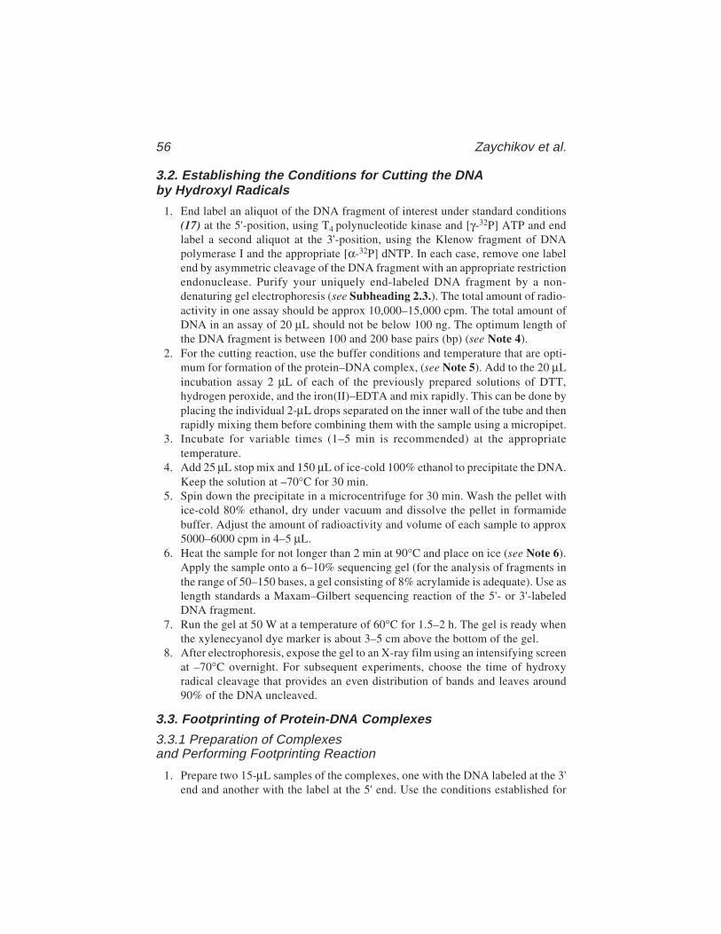
56 Zaychikov et al.
3.2. Establishing the Conditions for Cutting the DNAby Hydroxyl Radicals
1. End label an aliquot of the DNA fragment of interest under standard conditions(17) at the 5'-position, using T4 polynucleotide kinase and [γ-32P] ATP and endlabel a second aliquot at the 3'-position, using the Klenow fragment of DNApolymerase I and the appropriate [α-32P] dNTP. In each case, remove one labelend by asymmetric cleavage of the DNA fragment with an appropriate restrictionendonuclease. Purify your uniquely end-labeled DNA fragment by a non-denaturing gel electrophoresis (see Subheading 2.3.). The total amount of radio-activity in one assay should be approx 10,000–15,000 cpm. The total amount ofDNA in an assay of 20 µL should not be below 100 ng. The optimum length ofthe DNA fragment is between 100 and 200 base pairs (bp) (see Note 4).
2. For the cutting reaction, use the buffer conditions and temperature that are opti-mum for formation of the protein–DNA complex, (see Note 5). Add to the 20 µLincubation assay 2 µL of each of the previously prepared solutions of DTT,hydrogen peroxide, and the iron(II)–EDTA and mix rapidly. This can be done byplacing the individual 2-µL drops separated on the inner wall of the tube and thenrapidly mixing them before combining them with the sample using a micropipet.
3. Incubate for variable times (1–5 min is recommended) at the appropriatetemperature.
4. Add 25 µL stop mix and 150 µL of ice-cold 100% ethanol to precipitate the DNA.Keep the solution at –70°C for 30 min.
5. Spin down the precipitate in a microcentrifuge for 30 min. Wash the pellet withice-cold 80% ethanol, dry under vacuum and dissolve the pellet in formamidebuffer. Adjust the amount of radioactivity and volume of each sample to approx5000–6000 cpm in 4–5 µL.
6. Heat the sample for not longer than 2 min at 90°C and place on ice (see Note 6).Apply the sample onto a 6–10% sequencing gel (for the analysis of fragments inthe range of 50–150 bases, a gel consisting of 8% acrylamide is adequate). Use aslength standards a Maxam–Gilbert sequencing reaction of the 5'- or 3'-labeledDNA fragment.
7. Run the gel at 50 W at a temperature of 60°C for 1.5–2 h. The gel is ready whenthe xylenecyanol dye marker is about 3–5 cm above the bottom of the gel.
8. After electrophoresis, expose the gel to an X-ray film using an intensifying screenat –70°C overnight. For subsequent experiments, choose the time of hydroxyradical cleavage that provides an even distribution of bands and leaves around90% of the DNA uncleaved.
3.3. Footprinting of Protein-DNA Complexes
3.3.1 Preparation of Complexesand Performing Footprinting Reaction
1. Prepare two 15-µL samples of the complexes, one with the DNA labeled at the 3'end and another with the label at the 5' end. Use the conditions established for

Hydroxyl Radical Footprinting 57
optimal complex formation from Subheading 3.1. The total amount of radioac-tivity in one assay should be approx 60,000–80,000 cpm.
2. Pour 30–40 mL of the dialysis buffer containing 8 mM Tris–HCl, pH 7.9, into aPetri dish (see Note 5). Place a Millipore filter (VS 0.025 µm) on the surface ofthe buffer, shiny side (hydrophobic side) up. Put the samples containing the com-plexes onto the filter for 1 h in order to remove glycerol and salt (see Note 7).Remove the samples from the filter using a micropipet and transfer them to afresh 1.5-mL Eppendorf tube.
3. Subject the two samples to hydroxyl radical treatment as described in Subhead-ing 3.2., steps 2 and 3 only.
3.3.2. Separation of the Complex and the Free DNAby Nondenaturing Acrylamide Gel Electrophoresis
The conditions for studying a high-molecular-weight complex are describedbelow (see Note 8). Use the conditions for preparing the nondenaturing gel asdescribed in Subheading 2.3. These low-concentration gels are difficult tohandle, therefore, the glass plates must be subjected to a special treatment by whichthe gel is bound to one of the plates. Wash the glass plates (20 × 20 cm) withethanol. Treat one plate with γ-methacryl-oxypropyl-trimethoxy-silane.Wash this plate carefully four times with ethanol to avoid sticking of theother plate to the gel. Treat the second plate with dichlorodimethylsilane.Use spacers 1–1.5 mm thick. Use combs that allow you to apply amounts ofthe 50-µL sample.
1. Add loading buffer to the sample (1/10 of the sample volume). Apply the sample ontothe nondenaturing acrylamide gel (20 × 20 cm). Run the gel at 20 V/cm for about2 h. The gel is ready when the dye marker is approx 3–5 cm above the end of the gel.
2. Remove one of the plates by lifting it carefully with a spatula and cover the gel(which sticks to the other glass plate) with plastic wrap. Place an X-ray film onthe gel. Put the gel and the film into a cassette and expose for 1–2 h at 4°C. Markthe bands containing the complex and, if visible, the free DNA. This is possibleby replacing the film after developing on the gel in exactly the same position.The use of fluorescent marker tapes (e.g., from Stratagene) during exposure ofthe gel may be very helpful for exact repositioning of the film.
3. Remove the plastic wrap from the gel, cut out the marked bands with a scalpel orspatula, and cut them into small pieces. Put the slices into a eppendorf tube alongwith 300 µL of elution buffer (0.5% SDS, 1 mM EDTA, 0.1 mg/mL carrier DNA)and shake for several hours at room temperature.
4. Spin the tube for a few seconds in a microcentrifuge and transfer the liquid to anew tube. Avoid transferring gel pieces to the new tube. Add 200 µL of water-saturated neutralized phenol, shake 1 min, and centrifuge for 5 min at room tem-perature. Remove aqueous layer (upper), transfer it to a fresh Eppendorf tube,and add 30 µL of 3 M sodium acetate and 1 mL of ice-cold 100% ethanol. Shakethe tube for a few seconds and put into –70°C for at least 30 min.

58 Zaychikov et al.
5. Spin the sample in a microcentrifuge for 30 min and remove the supernatant.Wash once with 1 mL of ice-cold 80% ethanol. Dry the sample under vacuum.Dissolve the pellet in a small volume of formamide buffer (usually 5–10 µL,depending on the amount of radioactivity).
3.3.3. Separation of the Complexand the Free DNA Filtration Through Nitrocellulose Filter(Alternative to Subheading 3.3.2., see Note 9)
The reader may also find it useful to refer to Chapter 1, which discusses theuses of the filter binding assay, and to Subheading 3.2.3. of that chapter, whichdeals with the recovery of DNA from filter-retained complexes.
1. Stop the hydroxyl radical reaction by dilution (at least twofold) with bindingbuffer containing 2% glycerol. (Alternatively, the sample may be poureddirectly into the filtration device after completion of the reaction and immedi-ately washed).
2. Mount a nitrocellulose filter (BA85, Schleicher & Schüll) into the filtrationdevice and connect it to a peristaltic pump. (See Note 10.)
3. Pore the solution containing the complex treated with radicals onto the filter.Switch on the pump and filter off the solution at the speed of 1–2 mL/min. Washthe filter twice with binding buffer at the same speed. Switch off the pump.
4. Disassemble the filtration device, take off the filter and cut it into small pieces.Place the pieces into an Eppendorf tube.
5. Add 300 µL of solution containing 1% SDS, 0.3 M sodium acetate, and 10 µg/mLcarrier DNA to the tube and shake for 15 min at room temperature.
6. Carefully transfer the liquid into fresh tube (avoid transferring the nitrocellulose)and add 1 mL of ethanol. Shake the tube for a few seconds and put into –70°C forat least 30 min.
7. Spin the sample in a microcentrifuge for 20 min and remove the supernatant.Wash once with 1 mL of ice-cold 80% ethanol. Dry the sample under vacuum.Dissolve the pellet in a small volume of formamide buffer (usually 5–10 µL,depending on the amount of radioactivity).
3.3.4. Analysis of DNA by Denaturing Gel Electrophoresis
Heat the samples at 90°C for 1–2 min. Proceed as described for free DNA inSubheading 3.2., steps 7–10. For both 3' and 5' end-labeled DNA, load thefollowing samples on the gel: the DNA recovered from the complex, the freeDNA (either recovered from the gel and/or prepared separately as in Subhead-ing 3.2.) and the Maxam–Gilbert reaction ladders as length standard.
4. Notes1. The iron(II), iron–EDTA mix, and the H2O2 solutions should be freshly made
before use. The solutions of DTT (0.1 M), EDTA (4 mM), H2O2 (as a 30% stocksolution), and the stop mix are stable for months stored at –20°C.
Hydroxyl Radical Footprinting 59
2. The acrylamide solutions are stable for months if protected from light andkept at 4°C.
3. Sodium persulfate has an advantage over routinely used ammonium persulfate ofbeing much more stable in aqueous solution. The 10% sodium persulfate solutionmay be kept at least 1 mo at +4°C without loss of activity.
4. It is strongly recommended to check the quality of the labeled DNA before useon a sequencing gel. Nicks in the double strand, which could be derived fromDNase activities during preparation, will appear as additional bands in thesequencing gel. This admixture of bands will spoil the whole footprint, even whenpresent in only small amounts. Furthermore, it is recommended not to store thepure, labeled DNA longer than 2 wk at –70°C, because the radiation of the labelalso creates nicks in the DNA.
6. Longer heating or boiling creates additional cuts in the DNA.5. The buffer conditions can be varied (e.g., the pH), but the ionic strength should
not be too high (maximum 50 mM NaCl) in order to obtain sharp bands duringthe nondenaturing electrophoresis to separate complexed and uncomplexed DNA.Many protein–DNA complexes are very stable at low ionic strength (e.g., com-plexes between RNA polymerase and promoters [18]). Therefore, in most casesthe stability of the pH in the following electrophoresis is the only limitation tolowering the ionic strength.
7. The purpose of the dialysis is twofold: Removal of glycerol which interfereswith the cutting reaction and removal of salt which lowers the quality of theelectrophoresis pattern. As a rough approximation, one can remove up to80–90% of the glycerol and salt present in the sample within 1 h using dropdialysis as described.
8. The gel concentration should be adjusted according to the molecular weightof the protein–DNA complex. Here we have described the conditions establishedfor the study of the E. coli RNA polymerase (molecular weight 490,000) and aDNA fragment of 130 bp carrying a promoter (3).
9. Filtration via nitrocellulose is a simpler and faster way to remove unboundDNA, but it does not resolve complexes having different stoichiometries ofprotein and DNA.
10. A variety of filtration devices may be used allowing handling of relatively smallvolumes (below 1 mL). Mild vacuum may be used instead of a peristaltic pump.
References1. Tullius, Th. D., Dombroski, B. A., Churchill, M. E. A., and Kam, L. (1987)
Hydroxyl radical footprinting: a high resolution method for mapping protein–DNAcontacts. Methods Enzymol. 155, 537–558.
2. Götte, M., Marquet, R., Isel, C., Anderson, V. E., Keith, G., Gross, H., Ehresmann, C.,et al. (1996) Probing the higher order structure of RNA with peroxonitrous acid. FEBSLett. 390, 226–228.
3. Shafer, G. E., Price, M. A., and Tullius, Th. D. (1989) Use of the hydroxyl radicaland gel electrophoresis to study DNA structure. Electrophoresis 10, 397–404.

60 Zaychikov et al.
4. Schickor, P., Metzger, W., Werel, W., Lederer, H., and Heumann, H. (1990)Topography of intermediates in transcription initiation of E. coli. EMBO J. 9,2215–2220.
5. Craig, M. L., Suh, W. C., and Record T. M. (1995) HO. and DNase I probingof Eσ70 RNA polymerase–λPR promoter open complexes: Mg2+ binding andits structural consequences at the transcription start site. Biochemistry 34,15,624–15,632.
6. Zaychikov, E., Denissova L., Meier, T., Götte, M., and Heumann H. (1997) Influ-ence of Mg2+ and temperature on formation of the transcription bubble J. Biol.Chem. 272, 2259–2267.
7. Zaychikov, E., Martin, E., Denissova, L., Kozlov, M., Markovtsov, V., Kashlev,M., et al. (1996) Mapping of catalytic residues in the RNA polymerase activecenter. Science 273, 107–109.
8. Götte, M., Maier, G., Gross, H., and Heumann, H. (1998) Localization of theactive site of HIV-1 reverse transcriptase–associated RNase H domain on a DNAtemplate using site-specific generated hydroxyl radicals. J. Biol. Chem. 273,10,139–10,146.
9. Metzger, W., Schickor, P., and Heumann, H. (1989) A cinematographic view ofEscherichia coli RNA polymerase translocation. EMBO J. 8, 2745–2754.
10. Zaychikov, E., Denissova, L., and Heumann, H. (1995) Translocation of theEscherichia coli transcription complex observed in the registers 11 to 20: “Jumping”of RNA polymerase and asymmetric expansion and contraction of the “transcriptionbubble”. Proc. Natl. Acad. Sci. USA 92, 1739–1743.
11. Heumann, H., Zaychikov, E., Denissova, L., and Hermann, T. (1997) Transloca-tion of DNA-dependent E. coli RNA polymerase during RNA synthesis, inNucleic Acids and Molecular Biology, vol. 11, (Eckstein, F. and Lilley, D., eds.),Springer-Verlag, Heidelberg, Germany, pp. 151–177.
12. Cons, B. M. G. and Fox, K. R. (1989) High resolution hydroxyl radicalfootprinting of the binding of mithramycin and related antibiotics to DNA. NucleicAcids Res. 17, 5447–5459.
13. Burkhoff, A. M. and Tullius, Th. D. (1988) Structural details of an adenine tractthat does not cause DNA to bend. Nature 331, 455–457.
14. Tullius, Th. D. and Dombroski, B. A. (1985) Iron(II) EDTA used to measure thehelical twist along any DNA molecule. Science 230, 679–681.
15. Wang, X. and Padgett, R. A. (1989) Hydroxyl radical “footprinting” of RNA: appli-cation to pre-mRNA splicing complexes. Proc. Natl. Acad. Sci. USA 86, 7795–7799.
16. Celander, D. W. and Cech, Th. R. (1991) Visualizing the higher order folding of acatalytic RNA molecule. Science 251, 401–407.
17. Maniatis, T., Fritsch, E. F., and Sambrock, J. (1982) Molecular Cloning, a Labo-ratory Manual, Cold Spring Harbor Laboratory, Cold Spring Harbor, NY.
18. Heumann, H., Metzger, W., and Niehörster, M. (1986) Visualization of intermedi-ary transcription states in the complex between Escherichia coli DNA-dependentRNA polymerase and a promoter-carrying DNA fragment using the gel retardationmethod. Eur. J. Biochem. 158, 575–579.
Hydroxyl Radical Footprinting 61
Further ReadingTullius, Th. D. (1989) Physical studies of protein–DNA complexes by footprinting.
Annu. Rev. Biophys. Biophys. Chem. 18, 213–237.Tullius, Th. D. (1989) Structural studies of DNA through cleavage by the hydroxyl
radical, in Nucleic Acids and Molecular Biology, vol. 3, (Eckstein, F. and Lilley,D., eds.), Springer-Verlag, Heildelberg, Germany, pp. 1–12.
Use of DEPC and Potassium Permanganate as Probes 63
63
From: Methods in Molecular Biology, vol. 148: DNA–Protein Interactions: Principles and Protocols, 2nd ed.Edited by: T. Moss © Humana Press Inc., Totowa, NJ
6
The Use of Diethyl Pyrocarbonate and PotassiumPermanganate as Probes for Strand Separationand Structural Distortions in DNA
Brenda F. Kahl and Marvin R. Paule
1. IntroductionIn the search for methods to explore the interaction between proteins and
DNA, a plethora of footprinting techniques have been developed, many ofwhich are discussed elsewhere in the present work. Most footprinting tech-niques are based on the simple premise of specific DNA regions being pro-tected from the reagent by the bound protein or molecule of interest. However,a number of studies over the past decade have revealed remarkable distortionof the DNA molecule, including bending and strand separation, in response tothe bound protein. These distortions are often within the classical footprint butare rarely detected by these classical techniques. Thus, their detection requiresalternative approaches. Unlike enzymatic methods, the chemical probes diethylpyrocarbonate (DEPC) and potassium permanganate can access and react withthe entire sequence of the DNA, distinguishing DNA distortions “under thefoot” of a typical footprinting experiment. Combining the information obtainedfrom these chemical probing techniques with the spatial information affordedby traditional footprinting gives an in-depth account of the various ways pro-teins and other molecules interact with DNA.
Diethyl pyrocarbonate and potassium permanganate are useful probesbecause of their preferential reactivity with single-stranded vs double-strandedDNA. In addition, unlike typical footprinting techniques where near saturationof the DNA with protein is necessary to observe a clean footprint, potassiumpermanganate and DEPC probing does not require most of the DNA to be incomplex with the protein or molecule of interest. Because of the sensitivity of
64 Kahl and Paule
these chemical probes, it is possible to observe reactive bases even when thepopulation of single-stranded DNA is very small.
The mechanism by which DEPC modifies bases has been investigated, but itis still not clearly understood (1–3). DEPC predominantly reacts with purineresidues, but it may react weakly with cytosine residues as well. DEPC modi-fies DNA by an out-of-plane attack on several of the nucleophilic centers inpurines, leading to the scission of the glycosidic bond. Double-stranded B-formDNA does not undergo modification by DEPC because the close stacking ofneighboring bases occludes access to the out-of-plane surfaces. However, underconditions in which the conformation deviates from B form (such as strandseparation or bending), purines in the sequence become more accessible tomodification by DEPC. Carbethoxylation of the imidazole ring N-7 producesstrand scission under alkaline conditions. Thus, DEPC is commonly used todetect purines that are present in melted or distorted DNA sequences. AlthoughDEPC can react with both purines, it shows a marked preference for adeninesvs guanines in most instances.
Potassium permanganate reacts with double bonds, oxidizing them to vici-nal diols. In nucleic acids, the base thymine is oxidized most vigorously,whereas reaction with C, G, and A is minimal. The mechanism behind thispreferential reactivity is believed to arise from an out-of-plane attack on the5,6 double bond of the thymine ring (4–9). Although the ring is still intact, theloss of aromaticity resulting from insertion of hydroxyl groups on the 5 and 6carbons leads to a reduction in hypochromicity. Treatment of the vicinal diolwith strong base leads to ring opening and cleavage of the phosphodiester back-bone. As with DEPC, stereochemical hindrance from base stacking prohibitsreactivity of double-stranded B-form DNA. In DNA, which is denatured or isaltered from the B form, the thymine ring becomes susceptible to modificationby potassium permanganate. Because of their base preferences, the combineduse of DEPC and potassium permanganate allows complete analysis of bothGC– and AT–containing sequences in DNA.
Diethyl pyrocarbonate and potassium permanganate modification have beenused to detect a number of distorted DNA structures in both prokaryotic andeukaryotic cells, including open complex formation during transcription (10–14a),steps in promoter clearance (14a–17), elongation (17–19), and termination(20,21), RNA–DNA hybrid structures in transcription elongation complexes(22,23), drug binding to DNA (24–26), chromatin positioning (27,28), recom-bination events (29–31), and single-stranded binding protein binding domains(32–34). On DNA alone, these reagents can reveal sequence-dependent distor-tions (35–37), negatively supercoiled DNA (38–40), cruciform DNA structures(41,42), DNA hairpins such as those found in triplet expansion diseases likefragile X-syndrome (43,44), and Z-DNA, H-DNA, or triplex DNA (45–48).
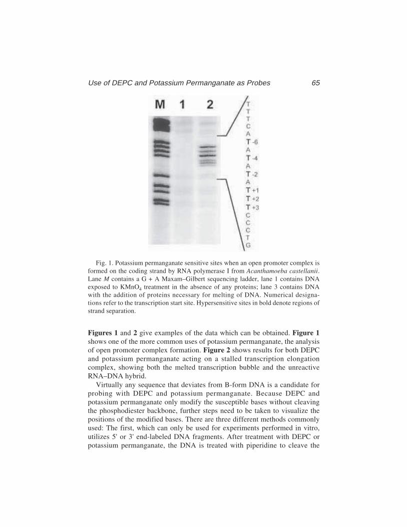
Use of DEPC and Potassium Permanganate as Probes 65
Figures 1 and 2 give examples of the data which can be obtained. Figure 1shows one of the more common uses of potassium permanganate, the analysisof open promoter complex formation. Figure 2 shows results for both DEPCand potassium permanganate acting on a stalled transcription elongationcomplex, showing both the melted transcription bubble and the unreactiveRNA–DNA hybrid.
Virtually any sequence that deviates from B-form DNA is a candidate forprobing with DEPC and potassium permanganate. Because DEPC andpotassium permanganate only modify the susceptible bases without cleavingthe phosphodiester backbone, further steps need to be taken to visualize thepositions of the modified bases. There are three different methods commonlyused: The first, which can only be used for experiments performed in vitro,utilizes 5' or 3' end-labeled DNA fragments. After treatment with DEPC orpotassium permanganate, the DNA is treated with piperidine to cleave the
Fig. 1. Potassium permanganate sensitive sites when an open promoter complex isformed on the coding strand by RNA polymerase I from Acanthamoeba castellanii.Lane M contains a G + A Maxam–Gilbert sequencing ladder, lane 1 contains DNAexposed to KMnO4 treatment in the absence of any proteins; lane 3 contains DNAwith the addition of proteins necessary for melting of DNA. Numerical designa-tions refer to the transcription start site. Hypersensitive sites in bold denote regions ofstrand separation.
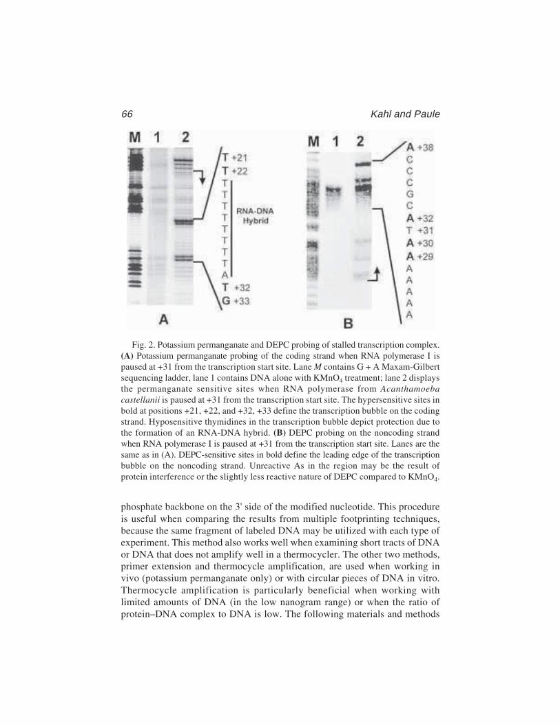
66 Kahl and Paule
phosphate backbone on the 3' side of the modified nucleotide. This procedureis useful when comparing the results from multiple footprinting techniques,because the same fragment of labeled DNA may be utilized with each type ofexperiment. This method also works well when examining short tracts of DNAor DNA that does not amplify well in a thermocycler. The other two methods,primer extension and thermocycle amplification, are used when working invivo (potassium permanganate only) or with circular pieces of DNA in vitro.Thermocycle amplification is particularly beneficial when working withlimited amounts of DNA (in the low nanogram range) or when the ratio ofprotein–DNA complex to DNA is low. The following materials and methods
Fig. 2. Potassium permanganate and DEPC probing of stalled transcription complex.(A) Potassium permanganate probing of the coding strand when RNA polymerase I ispaused at +31 from the transcription start site. Lane M contains G + A Maxam-Gilbertsequencing ladder, lane 1 contains DNA alone with KMnO4 treatment; lane 2 displaysthe permanganate sensitive sites when RNA polymerase from Acanthamoebacastellanii is paused at +31 from the transcription start site. The hypersensitive sites inbold at positions +21, +22, and +32, +33 define the transcription bubble on the codingstrand. Hyposensitive thymidines in the transcription bubble depict protection due tothe formation of an RNA-DNA hybrid. (B) DEPC probing on the noncoding strandwhen RNA polymerase I is paused at +31 from the transcription start site. Lanes are thesame as in (A). DEPC-sensitive sites in bold define the leading edge of the transcriptionbubble on the noncoding strand. Unreactive As in the region may be the result ofprotein interference or the slightly less reactive nature of DEPC compared to KMnO4.
Use of DEPC and Potassium Permanganate as Probes 67
sections are general guidelines for probing with DEPC and potassium perman-ganate. Care and attention to detail is necessary for all of these methods, asfootprinting with these reagents is generally somewhat more difficult than withmany other footprinting reagents. There is usually a need to optimize condi-tions for each particular application; guidelines for this can be found in theNotes section.
2. Materials1. Potassium permanganate, DEPC, piperidine, and 2-mercaptoethanol can be pur-
chased from Sigma (St. Louis, MO). DEPC, piperidine, and 2-mercaptoethanolshould be stored at 4°C and used with caution in a fume hood. Other reagentslisted below should be of the highest quality. Low-adhesion microcentrifuge tubes(siliconized) can be obtained from USA Scientific (Ocala, FL).
2. The following stock solutions can be made, filter sterilized, divided into aliquotsand stored at –20°C until ready for use:
1 M HEPES pH 7.91 M MgCl2
0.5 M dithiothreitol (DTT)2 M KCl10 mg/mL bovine serum albumin (BSA), DNase free0.5 M EDTA pH 8.03 M Sodium acetate pH 5.25 mg/mL linear polyacrylamide (acrylamide polymerized without N,N'-methylene
bisacrylamide)10 mg/mL Proteinase K10% sodium dodecyl sulfate (SDS)DEPC stop buffer: 0.2% SDS and 0.6 M sodium acetate pH 5.2TE: 10 mM Tris–HCl pH 8.0 and 1 mM EDTAElectrophoresis loading buffer: 0.1% bromophenol blue, 0.1% xylene cyanol,
10 mM EDTA, and 80% deionized formamide3. A 300 mM stock solution of KMnO4 can be made by heating 2.73 g of KMnO4 in
50 mL of deionized water. The solution can be stored at room temperature in abrown bottle for 1 mo.
4. 10X reaction buffer, for example: 200 mM HEPES pH 7.9, 100 mM MgCl2, 1 mMDTT, 1 mg/mL BSA, and 100 mM KCl. The choice of this buffer will depend onthe conditions needed to form the complex under study.
5. Protein dilution buffer, for example: 20 mM HEPES pH 7.9, 1 mM EDTA, and10% glycerol. Choice will depend on protein used.
6. 1 M piperidine: 10% v/v in water, freshly made.7. 0.6 M sodium acetate.8. 0.6 M sodium acetate, 20 mM EDTA9. 10X neutralization buffer: 0.5 M HEPES pH 7.9, 0.1 M MgSO4, and 2 mM DTT.
10. dNTP mix: 5 mM of each dNTP.
68 Kahl and Paule
3. MethodsExperiments using DEPC or potassium permanganate follow similar proto-
cols. The only exceptions are the addition of 2-mercaptoethanol to quenchreactions using potassium permanganate, the duration of the DNA modifica-tion reactions, and the necessity to purify the modified DNA away from DEPCbefore the cleavage step.
3.1. In Vitro Experiments on Linear DNA Fragments
1. End-labeled DNA (5' or 3') should be separated from excess radiolabeled precur-sor either by agarose gel electrophoresis or size-exclusion column chromatogra-phy, and stored in TE.
2. In a 1.5-mL siliconized microcentrifuge tube, add 4 µL 10X reaction buffer,40,000 cpm of DNA, and sterile deionized water to a volume of 20 µL. Proteins,diluted in an appropriate buffer, are added to the reaction to give a final volumeof 40 µL (see Note 1). Incubate for the desired amount of time to form DNA–protein complexes.
3. Modifying the susceptible bases (see Notes 2–4):KMnO4 treatment: Add freshly diluted potassium permanganate to give the
appropriate concentration and incubate for desired time period. Forexample, adding 2 µL of 100 mM KMnO4 (approximately 9 mM final con-centration) for 2 min seems to work well for detecting melted DNA intranscription initiation complexes.
Diethyl procarbonate treatment: Add 1 µL of DEPC to each tube. Mix bybriefly vortexing and repeat vortexing every 5 min for 15 min. Vortexingis necessary because DEPC is sparingly soluble in aqueous solutions, soall reactions are run at essentially saturating DEPC and the concentrationcannot be altered significantly.
4. Stopping the reactions:KMnO4 treatment: Quench the reaction by adding 3 µL of 2-mercaptoethanol,
vortex and place on ice. Add 45 µL of 0.2% SDS and 2 mg/mL proteinaseK and incubate at 50°C for 1 h. Add 90 µL of 0.6 M sodium acetate,300 µg/mL linear polyacrylamide, and 2.5 volumes 95% ethanol. Mix andcentrifuge 30 min at 14,000 rpm in a microfuge. Remove supernatant andwash with 150 µL of 70% ethanol. Centrifuge 5 min, as above. Removesupernatant and dry pellet on medium heat for 5 min in a Speed Vac.
Diethyl procarbonate treatment: Stop the reaction by adding an equal volumeof DEPC stop buffer and phenol–CHCl3 extract. Add 5 µL of 5 mg/mLlinear acrylamide, and precipitate with 2.5 volumes of ethanol as above.After centrifugation, rinse with 70% ethanol and centrifuge again. Removesupernatant and dry pellet on medium heat for 5 min in a Speed Vac.
5. Alkaline cleavage: Suspend the pellet in 50 µL of 1 M piperidine (10% v/v) andincubate at 90°C for 30 min. Place a lead weight on top of the tubes or use tubelocks to prevent the lids from opening.
Use of DEPC and Potassium Permanganate as Probes 69
6. Place tubes on ice to cool and centrifuge briefly. Add 50 µL of 0.6 M sodiumacetate, 300 µg/mL linearized polyacrylamide, and 250 µL 95% ethanol. Mixand centrifuge 30 min as above. Wash pellet with 150 µL of 70% ethanol. Spinsamples for 5 min. Remove supernatant.
7. To remove residual piperidine, add 30 µL sterile deionized water to each sampleand dry on medium heat in a Speed Vac (see Note 5).
8. Add 5 µL electrophoresis loading buffer, vortex samples for 30 s, and heatsamples at 95°C for 3 min. Place samples on ice.
9. Load samples on sequencing gel and analyze by standard methods (see Notes 6 and 7).
3.2. Treatment of DNA In Vivo with KMnO4 and Purification
Potassium permanganate has been used to modify DNA in vivo, followedby analysis of modifications by primer extension or polymerase chain reaction(PCR). DEPC cannot be used for in vivo experiments because of its low solu-bility. The procedure for in vivo modification is fairly straightforward, how-ever, certain nutrient-rich media can quench permanganate. To avoid thisproblem, use minimal medium or increase the permanganate concentration sothat the reaction mixture does not turn brown in less than 1 min. For someexperiments, one can dilute the culture in minimal medium just prior to treat-ment with potassium permanganate. In vivo modification of mammalian cellcultures usually requires the removal of the growth medium just prior to treatment.
1. To 10 mL of diluted bacterial or yeast culture, add the appropriate amount ofKMnO4 (typically in the low millimolar range, depending on the medium, approx10–20 mM for most media) for the desired amount of time (10 s to 5 min) in ashaking water bath. To quench treatment, remove samples from the water bathand pour immediately into prechilled Corex tubes and add 2-mercaptoethanoluntil the purple color disappears. Centrifuge to pellet cells in a cold Sorvall SS34rotor for 5 min at 3015g. Discard the supernatant.
2. For mammalian cells grown to subconfluence on plastic growth dishes, removegrowth medium and wash twice with phosphate-buffered saline or minimalgrowth medium. Add the desired concentration of potassium permanganate (usu-ally 2–20 mM) for the necessary period of time (10 s to 5 min). Stop the perman-ganate reaction by washing cell monolayers twice with phosphate-buffered salinecontaining 2% 2-mercaptoethanol and once with phosphate-buffered saline. Cellsare then harvested with a rubber policeman or cell scraper.
3. Plasmid and genomic DNA can be isolated by a variety of standard methods(49–51). Purified modified DNA should be adjusted to a final concentration ofapprox 15 ng/µL and be free of contaminants that interfere with extension reac-tions. Extractions involving phenol should be repeated three to four times or untilthere is no contaminating interphase. Modifications to the DNA can then be visu-alized by PCR amplification, as detailed in Subheading 3.4. An alternativemethod for identifying modified genomic DNA is the use of ligation mediatedPCR (LMPCR) (52,53).
70 Kahl and Paule
3.3. Primer Extension Analysis of DNA Treated In Vitro or In Vivo
Because DNA modified in vivo or when in circular form is not end labeled,primer extension is the method of choice to analyze the sites of modification.Modified bases result in extension stop sites because they block the elongatingDNA polymerase. For in vitro studies, follow steps 2–4 of Subheading 3.1.,substituting 20–500 ng of purified DNA in place of radiolabeled DNA. For invivo studies, follow the steps of Subheading 3.2.
1. To the isolated, modified DNA (20–500 ng for in vitro and 500 ng for in vivostudies), add (0.3–0.5) × 106 cpm of 5' end-labeled primer and dilute to 36 µLwith distilled water.
2. Add 4 µL of 0.01 M NaOH to each reaction and mix well.3. Denature DNA by heating to 95°C for 2 min.4. Add 5 µL of 10X neutralization buffer and mix.5. Hybridize primer to DNA by heating sample for 3 min at or just under the calcu-
lated Tm of the primer.6. Add 5 µL of a solution containing all four dNTPs at a concentration of 5 mM
each.7. Add 0.5–1.0 unit of the Klenow fragment of DNA polymerase I and mix gently.
Incubate tube for exactly 10 min at 50°C.8. Quench by adding an equal volume (~50 µL) of 0.6 M sodium acetate, and 20 mM
EDTA and place on ice.9. Precipitate DNA by adding 300 µL of 95% ethanol, mix and centrifuge 30 min.
Wash the pellet with 150 µL of 70% ethanol. Centrifuge for 5 min, remove super-natant, and dry pellet.
10. Suspend pellet in 5 µL electrophoresis loading buffer and run on a normalsequencing gel. Analyze by standard techniques (see Notes 8 and 9).
3.4. PCR Amplification of DNA Treated In Vivo or In Vitro
1. In a 0.65-mL microcentrifuge tube, add the following:5 µL 10X reaction buffer supplied with the thermostable polymerase2 µL dNTP mix0.5 × 106 cpm end-labeled primerDistilled water to a final volume of 49.5 µL
2. Program thermocycler. For example:1 Round:
2 min at 95°C , pause and add 0.5 µL of thermostable polymerase(2.5 units/µL)
30 s at Tm of primer30 s at 72°C
15–20 Rounds:1 m at 95°C30 s at Tm of primer30 s at 72°C
Use of DEPC and Potassium Permanganate as Probes 71
1 Round:5 min at 72°C
3. Precipitate DNA by adding 50 µL of 0.6M sodium acetate, 300 mg/mL linearpolyacrylamide, and 250 µL 95% ethanol. Mix and centrifuge 30 min at14,000 rpm in a microfuge. Wash pellet with 150 µL of 70% ethanol andcentrifuge for 5 min. Remove supernatant and dry pellet on medium heat for5 min in a Speed Vac.
4. Suspend pellet in 5 µL loading buffer and run on sequencing gel. Analyze bystandard techniques (see Notes 8 and 9).
4. Notes1. False positive results can occur from the presence of nucleases in any of the
proteins being tested. A necessary control is to incubate each protein with theDNA in the absence of further treatment with the modifying reagent. The DNAisolated from these reactions is run through the remainder of the analysis proce-dure to reveal any digestion of the DNA by contaminating nucleases.
2. Certain sequences of DNA are sensitive to DEPC and potassium permanganatetreatment even in the absence of proteins. It is important to run a control lane ofDNA to obtain a background level of sensitive sites.
3. To optimize reaction conditions, a titration of potassium permanganate for vary-ing amounts of time may be necessary. Too little potassium permanganate resultsin no signal, and too much potassium permanganate can result in a high back-ground. Two to five millimolars of potassium permanganate is typical for in vitroexperiments, but for in vivo experiments, where the medium may quench thereagent, concentrations up to 200 mM can be used. Times of reaction have beenvaried from 10 s up to 5 min, but in our hands, there is much less difference in theresults obtained with different reaction times than with different potassium per-manganate concentrations. Thus, one can set up the experiment for a convenientperiod of time.
4. Potassium permanganate and DEPC react with proteins as well as DNA, whichcan impair their function. Thus, negative experiments may result from proteindenaturation rather than a lack of DNA modification by the protein.
5. It is important to remove all the piperidine from the DNA following cleavage. Ifsmeared bands are found on the gel, try doing more than one round of drying inthe Speed Vac by redissolving the pellet in 30 µL of deionized water and dryingas described in step 7 of Subheading 3.1.
6. To obtain the maximum amount of information from the DNA of interest, performseparate experiments with either the template or the RNA-like strand radiolabeled.
7. A Maxam and Gilbert sequencing ladder of the DNA being analyzed run adja-cent to the probing reactions is useful to identify specific modified sites.
8. For primer extension and PCR amplification reactions, several factors can affectthe observed signal. A loss of signal can be the result of the following:a. Improper primer sequenceb. Annealing temperature higher than Tm
72 Kahl and Paule
c. Contaminants present in reactiond. High concentration of magnesium ion
9. Extra bands or smearing can occur if the annealing temperature is suboptimal andallows mispriming. Nonspecific hybridization can also occur if the radiolabledprimer has undergone extensive decay. Freshly labeled primer reduces the risk ofmispriming events. Supercoiled DNA can cause sequence-induced stopping ofthe DNA polymerase. Linearizing the plasmid before fill-in or amplification canreduce improper extension.
References
1. Leonard, N. J., McDonald, J. J., and Reichmann, M. E. (1970) Reaction of diethylpyrocarbonate with nucleic acid components I: Adenine. Proc. Natl. Acad. Sci.USA 67, 93–98.
2. Leonard, N. J., McDonald, J. J., Henderson, R. E. L., and Reichmann, M. E.(1971) Reaction of diethyl pyrocarbonate with nucleic acid components:Adenosine. Biochemistry 10, 3335–3342.
3. Mendel, D. and Dervan, P. B. (1987) Hoogsteen base pairs proximal and distalto echinomycin binding sites on DNA. Proc. Natl. Acad. Sci. USA 84, 910–914.
4. Hayatsu, H. and Ukita, T. (1967) The selective degredation of pyrimidines innucleic acids by permanganate oxidation. Biochem. Biophys. Res. Commun. 29,556–561.
5. Howgate, P., Jones, A. S., and Tittensor, J. J. (1968) The permanganate oxida-tion of thymidine. J. Chem. Soc. C, 275–279.
6. Iida, S. and Hayatsu, H. (1971) The permanganate oxidation of thymidine. J.Biophys. Acta 240, 370–375.
7. Rubin, C. M. and Schmid, C. W. (1980) Pyrimidine-specific chemical reactionsuseful for DNA sequencing. Nucleic Acids Res. 8, 4613–4619.
8. Akman, S. A., Doroshow, J. H., and Dizdaroglu, M. (1990) Base modifica-tions in plasmid DNA caused by potassium permanganate. Arch. Biochem.Biophys. 282, 202–205.
9. Akman, S. A., Forrest, G. P., Doroshaw, J. H., and Dizdaroglu, M. (1991) Muta-tion of potassium permanganate- and hydrogen peroxide-treated plasmid pZ189replicating in CV-1 monkey kidney cells. Mutat. Res. 261, 123–130.
10. Sasse-Dwight, S. and Gralla, D. (1988) Probing the Escherichia coli glnALGupstream activation mechanism in vivo. Proc. Natl. Acad. Sci. USA 85, 8934–8938.
11. Sasse-Dwight, S. and Gralla, . D. (1989) KMnO4 as a probe for lac promoter DNAmelting and mechanism in vivo. Proc. Natl. Acad. Sci. USA 264, 8074–8081.
12. Grimes, E., Busby, S., and Minchin, S. (1991) Differential thermal energyrequirement for open complex formation by Escherichia coli RNA polymeraseat two related promoters. Nucleic Acids Res. 19, 6113–6118.
13. Suh, W. C., Ross, W., and Record, M. T., Jr. (1992) Two open complexes and arequirement for magnesium to open the lambda-P-R transcription start site.Science 259, 358–361.
14. Lofquist, A. K., Li, H., Imboden, M. A., and Paule, M. R. (1993) Promoter open-ing (melting) and transcription initiation by RNA polymerase I requires neither

Use of DEPC and Potassium Permanganate as Probes 73
nucleotide β,γ hydrolysis nor protein phosphorylation. Nucleic Acids Res. 21,3233–3238.
14a. Kahl, B. F., Li, H., and Paule, M. R. (2000) DNA melting and promoter clear-ance by eukaryotic RNA polymerase I. J. Mol. Biol. 299, 75–89.
15. Kassavetis, G. A., Blanco, J. A., Johnson, T. E., and Geiduschek, E. P. (1992)Formation of open and elongating transcription complexes by RNA polymeraseIII. J. Mol. Biol. 226, 47–58.
16. Wong, C. and Gralla, J. D. (1992) A role for the acidic repeat region of tran-scription factor sigma 54 in setting the rate and temperature dependence of pro-moter melting in vivo. J. Biol. Chem. 267, 24,762–24,768.
17. Kainz, M. and Roberts, J. (1992) Structures of transcription elongation com-plexes in vivo. Science 255, 838–841.
18. Ohlsen, K. L. and Gralla, J. D. (1992) Melting during steady-state transcriptionof the RRNB P–1 promoter in vivo and in vitro. J. Bact. 174, 6071–6075.
19. Li, B., Weber, J. A., Chen, Y., Greenleaf, A. L., and Gilmour D. S. (1996) Analysisof promoter-proximal pausing by RNA polymerase II on the hsp70 heat shockgene promoter in a Drosophila nuclear extract. Mol. Cell. Biol. 16, 5433–5443.
20. Hartvig L. and Christiansen J. (1996) Intrinsic termination of T7 RNA poly-merase mediated by either RNA or DNA. EMBO J. 15, 4767–4774.
21. Komissarova N. and Kashlev, M. (1997) Transcriptional arrest: Escherichia coliRNA polymerase translocates backward, leaving the 3' end of the RNA intactand extruded. Proc. Natl. Acad. Sci. USA 94, 1755–1760.
22. Lee, D. N. and Landick, R. (1992) Structure of RNA and DNA chains in pausedtranscription complexes containing Escherichia coli RNA polymerase. J. Mol.Biol. 228, 759–777.
23. Carles-Kinch, K. and Kreuzer, K. N. (1997) RNA-DNA hybrid formation atbacteriophage T4 replication origin. J. Mol. Biol. 266, 915–926.
24. Jeppesen, C. and Nielsen, P. E. (1988) Detection of intercalation-inducedchanges in DNA structure by reaction with diethyl pyrocarbonate or potassiumpermanganate. FEBS Lett. 231, 172–176.
25. Fox, K. R. and Grigg, G. W. (1988) Diethyl pyrocarbonate and permanganateprovide evidence for an unusual DNA conformation induced by binding of theantitumour antibiotics bleomycin and phleomycin. Nucleic Acids Res. 16,2063–2075.
26. Bailly C., Gentle, D., Hamy, F., Purcell, M., and Waring, M. J. (1994) Localizedchemical reactivity in DNA associated with the sequence-specific bisinter-calation of echinomycin. Biochemical J. 300, 165–173.
27. Michelottic, G. A., Michelotti, E. F., Pullner, A., Duncan, R. C., Eick, D., andLevens, D. (1996) Multiple single-stranded cis elements are associated with acti-vated chromatin of the human c-myc gene in vivo. Mol. Cel. Biol. 16, 2656–2669.
28. Hershkovitz, M. and Riggs, A. D. (1997) Ligation-mediated PCR for chromatin-structure analysis of interphase and metaphase chromatin. Methods 11, 253–263.
29. Chiu, S. K., Rao, B. J., Story, R. M., and Radding, C. M. (1993) Interactions ofthree strands in joints made by RecA protein. Biochemistry 32, 13,146–13,155.

74 Kahl and Paule
30. Voloshin, O. N. and Camerini-Otero, R. D. (1997) The duplex DNA is veryunderwound in the three-stranded RecA protein-mediated synaptic complex.Genes Cells 2, 303–314.
31. Plug, A. W., Peters, A. H. F. M., Keegan, K. S., Hoekstra, M. F., De Boer, P.,and Ashley, T. (1998) Changes in protein composition of meiotic nodules dur-ing mammalian meiosis. J. Cell Sci. 111, 413–423.
32. Duncan, R., Bazar, L., Michelotti, G., Tomonaga, T., Krutzch, H., Avigan, M.,et al. (1994) A sequence-specific, single-strain binding protein activates the farupstream element of c-myc and defines a new DNA-binding motif. Genes Dev.4, 465–480.
33. Sun, W. and Godson, G. N. (1998) Structure of the Escherichia coli primase/single-strand DNA-binding protein/phage G4ori-c complex required for primerRNA synthesis. J. Mol. Biol. 276, 689–703.
34. Godson, G. N., Mustaev, A. A., and Sun, W. (1998) ATP cross-linked toEscherichia coli single-strand DNA-binding protein can be utilized by thecatalytic center of primase as initiating nucleotide for primer RNA synthesis onphage G4ori-c template. Biochemistry 37, 3810–3817.
35. McCarthy, J. G. and Rich, A. (1991) Detection of an unusual distortion in A-tractDNA using potassium permanganate effect of temperature and distamycin onthe altered conformation. Nucleic Acids Res. 19, 3421–3430.
36. Matyasek R., Fulnecek, J., Fajkus, J., and Bazdek, M. (1996) Evidence for asequence-directed conformation periodicity in the genomic highly repetitiveDNA detectable with single-strand-specific chemical probe potassium perman-ganate. Chromosome Res. 4, 340–349.
37. Epplen J. T., Kyas, A., and Maeueler, W. (1996) Genomic simple repetitiveDNAs are targets for differential binding of nuclear proteins. FEBS Lett. 389,92–95.
38. Herr, W. (1985) Diethyl pyrocarbonate: a chemical probe for secondary struc-ture in negatively supercoiled DNA Proc. Nat. Acad. Sci. USA 82, 8009–8013.
39. Voloshin, O. N., Mirkin, S. M., Lyamichev, V. I., Belotserkovskii, B. P., andFrank-Kamenetskii, M. D. (1988) Chemical probing of homopurine-homo-pyrimidine mirror repeats in supercoiled DNA. Nature 333, 475–476.
40. Bentin, T. and Nielsen, P. E. (1996) Enhanced peptide nucleic acid bindingto supercoiled DNA: possible implications for DNA “breathing” dynamics.Biochemistry 35, 8863–8869.
41. Furlong, J. C. and Lilley, D. M. J. (1986) Highly selective chemical modificationof cruciform loops by diethyl pryrocarbonate. Nucleic Acids Res. 14, 3995–4007.
42. Scholten, P. M. and Nordheim, A. (1986) Diethylpyrocarbonate: a chemicalprobe for DNA cruciforms. Nucleic Acids Res. 14, 3981–3993.
43. Balagurumoorthy, P. and Brahmachari, S. K. (1994) Sturcture and stability ofhuman telomeric sequences. J. Biol. Chem. 269, 21,858–21,869.
44. Nadel, Y., Weisman-Shomer, P., and Fry, M. (1995) The fragile X syndromesingle strand d(CGG)n nucleotide repeats readily fold back to form unimolecularhairpin structures. J. Biol. Chem. 270, 28,970–28,977.
Use of DEPC and Potassium Permanganate as Probes 75
45. Jiang, H., Zacharia, W., and Amirhaeri, S. (1991) Potassium permanganate as anin situ probe for B-Z and Z-Z junctions. Nucleic Acids Res. 19, 6943–6948.
46. Woelfl, S., Wittig, B., and Rich, A. (1995) Identification of transcriptionallyinduced Z-DNA segments in the human c-myc gene. Biochim. Biophys. Acta1264, 294–302.
47. Glover, J. N. M., Farah, C. S., and Pulleyblank, D. E. (1990) Structural charac-terization of separated H-DNA conformers. Biochemistry 29, 11,110–11,115.
48. Haner, R. and Dervan, P. B. (1990) Single-strand DNA triple-helix formation,Biochemistry 29, 9761–9765.
49. Huibregtse, J. M. and Engelke, D. R. (1991) Direct sequence and footprint analy-sis of yeast DNA by primer extension. Methods Enzymol. 194, 550–562.
50. Holmes, D. S. and Quigley, M. (1981) A rapid boiling method for the prepara-tion of bacterial plasmids. Anal. Biochem. 114, 193–197.
51. Owen, R. J. and Borman, P. (1987) A rapid biochemical method for purifyinghigh molecular weight chromosomal DNA for restriction enzyme analysis.Nucleic Acids Res. 15, 3631.
52. Mueller, P. R. and Wold, B. J. (1989) In vivo footprinting of a muscle specificenhancer by ligation mediated PCR. Science 246, 780–786.
53. Garrity, PA. and Wold, B. J. (1992) Effects of different DNA polymerases inligation-mediated PCR: enhanced genomic sequencing and in vivo footprinting.Proc. Natl. Acad. Sci. USA 89, 1021–1025.

In Gel OP–Cu Footprinting 77
77
From: Methods in Molecular Biology, vol. 148: DNA–Protein Interactions: Principles and Protocols, 2nd ed.Edited by: T. Moss © Humana Press Inc., Totowa, NJ
7
Footprinting DNA–Protein Interactionsin Native Polyacrylamide Gels by ChemicalNucleolytic Activity of 1,10-Phenanthroline-Copper
Athanasios G. Papavassiliou
1. Introduction The existence of cell-type specific promoter and enhancer elements has
been known for several years. However, the mechanisms responsible for theremarkable specificity of such elements, in comparison to the ubiquitouslyactive promoters and enhancers of “housekeeping” genes and DNA tumorviruses, have remained elusive until recently. Although transfection andmutagenesis experiments have taught us a great deal about the structure ofcell-type-specific cis-acting elements, the breakthrough in understanding themolecular basis for the differential activity of these elements has come fromthe analysis of their recognition by specific DNA-binding proteins.
Several techniques have been developed for the detection of cell-type-spe-cific DNA-binding activities and the identification of sequence-specific con-tacts (“footprints”) of a protein on DNA. Many of these techniques involveforming DNA–protein complexes (by incubating an asymmetrically labeleddouble-stranded DNA fragment containing the region of interest with a crudeor partly purified protein extract), exposing the complex to enzymatic or tochemical reagents that can cleave or modify the DNA, and determining whichbases are protected from attack when the protein(s) is bound. The most widelyused reagents are deoxyribonuclease I (DNase I, an endonuclease) and dim-ethyl sulfate (DMS). Footprinting experiments with DNase I are performedusing parallel reactions with free DNA and with DNA–protein complexes, andthe nuclease is allowed to digest DNA only to a limited extent (1). The DNA isthen purified and denatured, and the single-stranded end-labeled DNA frag-ments are resolved on a sequencing gel and autoradiographed. Comparing the
78 Papavassiliou
digestion pattern of the DNA–protein complexes revealed on the autoradio-graph with that of free DNA shows a band-free region (footprint) where thebound protein(s) has prevented access of the enzyme to DNA (see Chapter 3).In a similar analysis, the DNA is allowed to react mildly with DMS, whichmethylates primarily deoxyguanosine residues and renders their phosphodiesterlinkages labile under conditions of Maxam–Gilbert chemistry (see Chapter 14).The binding of a protein(s) to a specific DNA region will result in a protectionof the corresponding bases from chemical modification (2).
The suitability of the above assays in determining the binding sequences ofproteins on DNA is hindered by several disadvantages. First, the clarity of thefootprint is highly dependent on the extent of occupancy of the binding site(s)(i.e., a “clear” footprint is observed only if all DNA molecules are involved incomplexes). Unfortunately, this is not always easy to achieve, especially whenthe concentration and/or purity of the specific binding protein(s) is not satis-factory. Second, DNA–protein complexes formed in crude extracts may oftenbe heterogeneous in terms of both binding specificity and kinetic stability.Therefore, direct footprinting in solution will not correspond to a single spe-cies, but, instead, reflect an “integral” of the multiple equilibria operating overthe entire region of interest (i.e., the protection pattern will actually represent acomposite of more than one complex, with complexes having a very low disso-ciation rate dominating the footprint). Finally, two different proteins thatrecognize the same sequence within the probe are most likely to yield indistin-guishable footprints. These drawbacks may be overcome by coupling treat-ment with a footprinting reagent in solution with the electrophoretic mobilityshift assay (EMSA; also known as gel retardation assay, see Chapter 2) (3–5).In this approach, the protein and DNA molecules are incubated together, andthe equilibrated reaction mixture is exposed to DNase I or DMS, as before. TheDNA–protein complexes are subsequently isolated from the free probe by elec-trophoresis in a nondenaturing polyacrylamide gel. Although the negativelycharged free DNA migrates rapidly toward the anode, once it is bound by aspecific protein its mobility decreases (3,4). Following the separation of thefree and bound DNA species, the corresponding bands are cut out of the gel,and the DNA eluted and analyzed on a sequencing gel. The region(s) of protec-tion evident in the DNA derived from the complexed fraction, indicates thebinding site (5). Because the complexes are separated from contaminatingunbound DNA fragments, their footprints will be free of background cutting,and thus considerably more evident. Similar considerations apply when morethan one complex can be formed on the fragment. As long as the DNA-bindingproteins differ in their molecular masses and charges, they will cause alteredelectrophoretic mobilities of the corresponding complexes and, hence, differ-ent migration in the native polyacrylamide gel. These complexes can be iso-
In Gel OP–Cu Footprinting 79
lated and run in individual lanes on the sequencing gel. Thus, the exposure ofthe binding reaction to footprinting reagents, in combination with the fraction-ation offered by mobility shift gels, permits identification of the regions ofDNA bound by protein in different complexes, even if a low percentage of theinitial DNA molecules has been complexed.
Although one can substantially increase the sensitivity of DNase I or DMSfootprinting experiments in solution by employing the EMSA, several addi-tional problems have still to be faced:
1. DNase I is a relatively bulky molecule (molecular weight [MW] 30,400) thatcannot cleave the DNA in the immediate vicinity of a bound protein because ofsteric hindrance. As a result, the region(s) protected from cutting extends beyondthe actual protein-binding site.
2. The nonrandom nature of DNA cleavage by DNase I makes it impossible to assessthe involvement in protein binding of nucleotides that lie in an area of the frag-ment resistant to the endonucleolytic activity of this enzyme (e.g., tracts of A andT residues, or TpA [as opposed to ApT] dinucleotide islands scattered within oradjacent to the binding site), so that binding sites or parts of binding sites may notbe detected.
3. The primary site of reaction of DMS with B-DNA is the N-7 atoms of guaninebases, which are located in the major groove. Thus, those guanines in close prox-imity with the protein will be protected from methylation. However, if a proteinprimarily makes contacts with a DNA sequence in the minor groove, or if thereare no guanine residues in a major groove-binding site, DMS will not revealthese interactions.
4. In many instances, particularly when a complex has a relatively high “off” rate,the bound protein can dissociate from the protected DNA fragment and reassoci-ate to other DNA fragments that have already been nicked by DNase I or modi-fied by DMS. In this case, the DNA-cleavage pattern derived from the complexedfraction will closely resemble that of the uncomplexed DNA, rendering it diffi-cult to observe a footprint. The limitations imposed by the size and the sequenceor base specificity of the aforementioned footprinting reagents, as well as theproblem of protein exchange from the binding site(s) during treatment, are cir-cumvented by merging the advantages inherent in the EMSA, with the subse-quent exposure of the gel (hence of the resolved complexes while embedded inthe polyacrylamide matrix) to a chemical DNA-scission reagent namely the 1,10-phenanthroline–copper ion (OP–Cu) (6).
1.1. OP–Cu as a Footprinting Agent
1.1.1. Chemistry of DNA Cleavage
1,10 Phenanthroline–copper (Fig. 1) is an efficient chemical nuclease thatcleaves the phosphodiester backbone of nucleic acids at physiological pH andtemperature by oxidation of the deoxyribose (DNA) or ribose (RNA) moiety
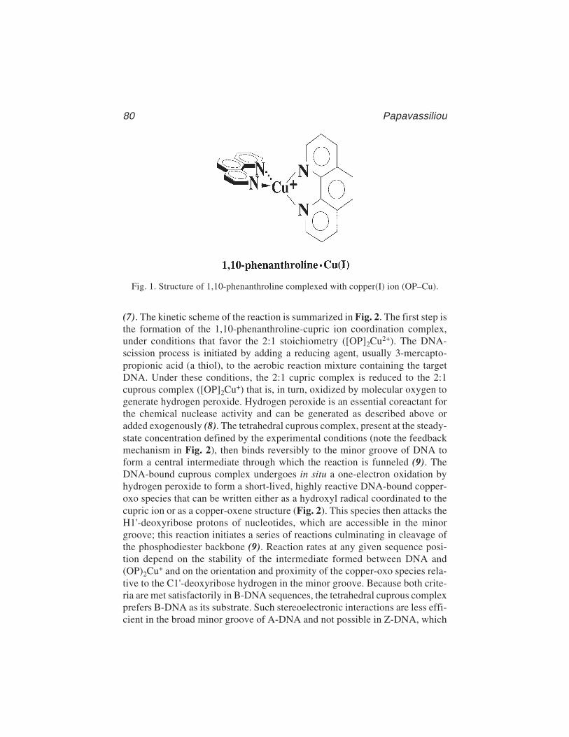
80 Papavassiliou
(7). The kinetic scheme of the reaction is summarized in Fig. 2. The first step isthe formation of the 1,10-phenanthroline-cupric ion coordination complex,under conditions that favor the 2:1 stoichiometry ([OP]2Cu2+). The DNA-scission process is initiated by adding a reducing agent, usually 3-mercapto-propionic acid (a thiol), to the aerobic reaction mixture containing the targetDNA. Under these conditions, the 2:1 cupric complex is reduced to the 2:1cuprous complex ([OP]2Cu+) that is, in turn, oxidized by molecular oxygen togenerate hydrogen peroxide. Hydrogen peroxide is an essential coreactant forthe chemical nuclease activity and can be generated as described above oradded exogenously (8). The tetrahedral cuprous complex, present at the steady-state concentration defined by the experimental conditions (note the feedbackmechanism in Fig. 2), then binds reversibly to the minor groove of DNA toform a central intermediate through which the reaction is funneled (9). TheDNA-bound cuprous complex undergoes in situ a one-electron oxidation byhydrogen peroxide to form a short-lived, highly reactive DNA-bound copper-oxo species that can be written either as a hydroxyl radical coordinated to thecupric ion or as a copper-oxene structure (Fig. 2). This species then attacks theH1'-deoxyribose protons of nucleotides, which are accessible in the minorgroove; this reaction initiates a series of reactions culminating in cleavage ofthe phosphodiester backbone (9). Reaction rates at any given sequence posi-tion depend on the stability of the intermediate formed between DNA and(OP)2Cu+ and on the orientation and proximity of the copper-oxo species rela-tive to the C1'-deoxyribose hydrogen in the minor groove. Because both crite-ria are met satisfactorily in B-DNA sequences, the tetrahedral cuprous complexprefers B-DNA as its substrate. Such stereoelectronic interactions are less effi-cient in the broad minor groove of A-DNA and not possible in Z-DNA, which
Fig. 1. Structure of 1,10-phenanthroline complexed with copper(I) ion (OP–Cu).
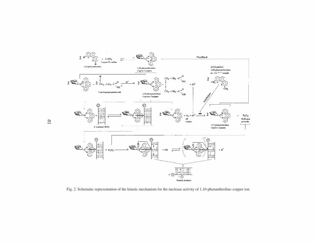
In Gel O
P–C
u Footprinting
81
81
Fig. 2. Schematic representation of the kinetic mechanism for the nuclease activity of 1,10-phenanthroline–copper ion.
82 Papavassiliou
has practically no minor groove; as a result, A-DNA is cleaved at 25–33% ofthe rate with which B-DNA is cleaved and Z-DNA is not cleaved at all (9).The products of the strand-scission event include the free base, DNA frag-ments bearing 5'- and 3'-phosphorylated termini, and the deoxyribose oxida-tion product 5-methylene-2-furanone (10). The DNA-chain cleavagereaction can be efficiently quenched by adding to the mixture 2,9-dimethyl-1,10-phenanthroline (2,9-dimethyl–OP). This phenanthroline derivative canalso chelate copper ions to form a minor groove-associated cuprous complex(thus competing with [OP]2Cu+), but the reduction potential of the Cu2+/Cu+
couple is too positive to allow significant nuclease activity under normal assayconditions (11).
1.1.2. OP–Cu Footprinting Following EMSAs
In as much as the structural and functional properties of DNA are not alteredby entrapment in a polyacrylamide gel matrix (6), the small size and the readydiffusibility of all reaction components in solid supports permit the coupling ofOP–Cu footprinting with the EMSA to study DNA–protein interactions(12,13). In this method, the DNA-binding reaction is performed as usual, elec-trophoresed under established, nondenaturing conditions, and the entire mobil-ity shift gel is immersed in a footprinting reaction mixture containing1,10-phenanthroline, cupric ion, and 3-mercaptopropionic acid. Following thereaction quench with 2,9-dimethyl–OP, footprints are obtained after elution ofthe radioactive free and protein-bound DNA cleavage products from themobility shift gel and analysis on a sequencing gel (Fig. 3). Because thenuclease activity of (OP)2Cu+ produces 3'-phosphorylated and 5'-phosphory-lated ends as cleavage products, sequencing gels can be accurately calibratedwith the Maxam–Gilbert sequencing reactions.
1.2. Advantages of OP–Cu over Other Footprinting Agents
1.2.1. General Considerations
The nuclease activity of (OP)2Cu+ bears several advantages as a footprintingreagent relative to protection analyses using DNase I or DMS as a probe. First,the (OP)2Cu+ chelate is a small molecule (compared to DNase I) that permitscleavage closer to the edge of the DNA sequence protected by protein bindingand, therefore, a more precise definition of it. Second, because the scissionchemistry involves attack on the deoxyribose moiety, (OP)2Cu+ is able to cut atall sequence positions regardless of base. However, the intensity of cutting(rate of cleavage) does depend on local sequence, with attack at adenines ofTAT triplets being most preferred (14; see also legend to Fig. 3). Interestingly,a preference for C-3',5'-G steps, rather than T-3',5'-A steps, is observed at a
In Gel OP–Cu Footprinting 83
phenanthroline to copper ratio of 1:1, which strongly favors formation of theOPCu+ complex (15). Nevertheless, the cutting patterns obtained with(OP)2Cu+ are usually sufficiently well-defined to identify protected regions,even though this endonucleolytic agent exhibits some degree of sequence speci-ficity in its rate of cleavage of naked DNA. Third, because (OP)2Cu+ binds tothe minor groove of DNA, it will reveal minor-groove interactions. Becausethe binding of the coordination complex should be restricted to three basepairs, the complex is more sensitive to local, protein-induced conformationalchanges than DNase I, which by possessing an extended minor groove-bind-ing site, may be unable to sense. In this context, the complex will also detectbinding in the major groove when its approach to its minor groove-binding siteis sterically blocked or if the interaction of the protein in the major groovealters the minor groove geometry so that the tetrahedral coordination complexbinds poorly (both being frequent features of DNA–protein interactions). Fur-thermore, because of the difference in their respective mechanisms of cleav-age, DNase I and (OP)2Cu+ probe different aspects of the structure of aDNA–protein complex. DNase I cleavage relies on the accessibility of a par-ticular phosphodiester bond, and thus protection is indicative of an interactionon the outer face of the DNA helix. In contrast, protection from (OP)2Cu+-mediated cleavage is most likely caused by the inhibition of its binding to theminor groove and implies that a portion of the protein occupies at least theminor groove. Finally, in contrast to other chemical nucleases such as ferrousEDTA (introduces single-stranded nicks in DNA through the generation ofdiffusible hydroxyl radicals; see Chapter 5), the nucleolytic activity of OP–Cuis not inhibited by glycerol, a free radical scavenger, which is present in mostprotein storage buffers.
1.2.2. Benefits of OP–Cu Footprinting Within Mobility Shift Gels
The major advantage of the combined OP–Cu footprinting procedure arisesfrom the topography of treatment: Preformed DNA–protein complexes areexposed to the chemical nuclease within the gel (i.e., not prior but subsequentto an electrophoretic mobility shift experiment). This characteristic of the tech-nique makes it ideal for protection analysis of kinetically labile complexes (16).At least three factors account for the latter. The first is that the backgroundcleavage is greatly reduced by the separation of unbound DNA from the DNA–protein complex(es) pool. The second factor is the so-called “caging effect”(3,4). The gel matrix forms “cagelike” compartments that prevent a dissoci-ated protein from diffusing away from the DNA, so that by enhancingreassociation, the apparent affinity constant will be higher than the true value.The protein could also interact with the gel matrix, thereby orienting its diffu-sion toward reassociation. Whatever the mechanism(s), the increase in stabil-
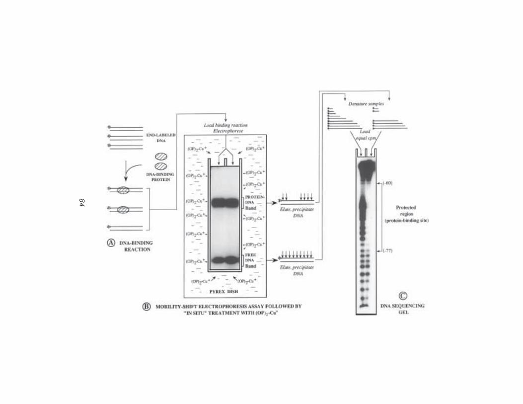
84P
apavassiliou
84
In Gel OP–Cu Footprinting 85
ity of the complex contributed by the gel leads to a more efficient blockage ofthe access of the (OP)2Cu+ chelate to the protein-binding DNA segment.The third factor comes from the nature and site of action of the cuprylintermediate through which the reaction is funneled, and it acts synergisti-cally with the previous one. Because this highly reactive oxidative species isgenerated near the surface of the DNA (in situ), diffusible radicals, if formed atall, will have a short or restricted diffusive path and, therefore, will be unableto achieve a fast equilibrium distribution along the DNA polymer. Conse-quently, protein-binding sites exposed during multiple dissociation events willescape the nucleolytic attack most of the time and hence remain intact.
In addition to the fact that discrete complexes with defined stoichiometriesand a wide range of kinetic stabilities can be mapped simultaneously, the insitu OP–Cu footprinting procedure is superior to oligonucleotide-binding com-petition assays in the analysis of multiple complexes frequently obtained inelectrophoretic mobility shift experiments employing unfractionated extractpreparations. For example, multiple retarded bands can arise from protein–protein interactions between a non-DNA-binding transcription factor(s) and aspecific DNA-binding protein, or from two proteins binding to distinct DNAsequences in a cooperative manner (12). Although both complexes would be
Fig. 3. (previous page) Outline of the combined electrophoretic mobility-shift/ingel OP–Cu footprinting assay. (A) DNA restriction fragments containing a protein-binding site(s) are labeled with 32P at a unique end and incubated with a crude orpartially purified extract containing the DNA-binding protein(s) of interest, underoptimized binding conditions. (B) After equilibration of the DNA-binding reaction,the free and bound DNA fragment populations are separated by electrophoresis througha nondenaturing polyacrylamide gel; the gel is then transferred into a buffer-contain-ing Pyrex dish, and the retarded and unretarded DNA species are exposed in situ to thenuclease activity of (OP)2Cu+. The two DNA fractions are subsequently located byautoradiography of the wet gel, excised and eluted from the gel matrix, precipitated,and recovered in formamide buffer. (C) Samples are heat-denatured and equal amountsof radioactivity from the two fractions are electrophoresed on a denaturing polyacryla-mide gel (DNA sequencing gel) and autoradiographed. In the sample prepared fromthe free-DNA band, bands will appear in the gel corresponding to positions of proteinbinding. For the sample(s) prepared from the protein–DNA band(s), bands will appearat all positions except those bound by the protein(s) (protected region). The particularexample depicts the OP–Cu mapping of a DNA–protein complex formed between bac-terially expressed LFB1 (a liver-specific transcription factor) and an oligonucleotidebearing its binding site within the –95 to –54 region of the α1-antitrypsin promoter.Arrowheads connected by line demarcate the footprinted site. The enhanced cleavageobserved within the protein-binding site in the free-DNA sample is the result of thepresence of repeated TA elements in this sequence (see Subheading 1.2.1.).
86 Papavassiliou
abolished by competition with oligonucleotides, these possibilities can bereadily distinguished by direct footprinting within the gel.
1.3. Additional Applications and Outlook
The nucleolytic activity of (OP)2Cu+ in a polyacrylamide matrix has beenalso demonstrated to be a viable means of gaining insight into the interactionsof RNA-binding proteins with their recognition sequences (17,18). Applica-tion of OP–Cu in this context may be invaluable toward defining structuralperturbations in RNA on protein binding and mapping the binding domains ofvarious proteins. Because of the preferential nucleolytic activity of (OP)2Cu+
toward single-stranded bulge and loop RNA regions (double-stranded stemregions can be cut at elevated concentrations of the chemical nuclease), hyper-sensitive sites may be obtained on footprinting an RNA–protein complexfollowing a gel retardation assay. Such sites would imply an unwinding of ahelical structure on protein binding or perturbations in the minor groove acces-sibility of the bound RNA molecule.
The in gel OP–Cu footprinting methodology has already expanded the“tool box” available to investigators wishing to explore the structure andfunction relationships of nucleic acid–protein complexes, and emergingimprovements in the chemical mechanism (e.g., DNA-strand scission by thecoordination complex of OP with a non-redox-active metal) as well as futuremodifications will likely make this technology even more efficient andbroadly useful.
2. Materials2.1. Analytical and Preparative EMSA
2.1.1. Solutions
1. A variety of binding and gel buffers are commonly employed in EMSA (see Chap-ter 2). A suitable binding buffer is 10 mM HEPES pH 7.9, 10% glycerol,0.1 mM EDTA, 0.5 mM tetrasodium pyrophosphate, and 0.5 mM PMSF. Themost common gel buffers are Tris-glycine: 50 mM Tris, 2.5 mM EDTA, and 0.4 Mglycine; 0.5X TBE: 45 mM Tris, 45 mM boric acid, and 1 mM EDTA; Tris–acetate:6.7 mM Tris-HCl, pH 7.5, 3.3 mM sodium acetate, and 1 mM EDTA.
2. Ammonium persulfate (10%; w/v): Weigh out 1 g of ammonium persulfate andput it in a sterile plastic tube containing 10 mL of distilled, deionized water.Vortex vigorously until the salt is completely dissolved. Filter through a 0.22-µmmembrane filter. This solution may be stable for a period of a few days at 4°C,but it is recommended that you prepare it freshly for each new gel. Ammoniumpersulfate is extremely destructive to tissue of the mucous membranes and upperrespiratory tract, eyes, and skin. Inhalation may be fatal. Exposure can causegastrointestinal disturbances and dermatitis. Wear gloves, safety glasses, respira-
In Gel OP–Cu Footprinting 87
tor, and other protective clothing and work in a chemical fume hood. Wash thor-oughly after handling.
3. Dye-containing binding buffer: 0.05% (w/v) bromophenol blue in 1X optimizedbinding buffer (store at 4°C after filtering).
2.1.2. Reagents/Special Equipment
1. Highly purified duplex DNA fragment labeled exclusively at one of its four ends(5' or 3'); use standard procedures for unique labeling (19). All necessary precau-tions should be observed to minimize exposure to ionizing radiation during label-ing and isolation of the probe. Consult the institutional environmental health andsafety office for further guidance in the appropriate use of radioactive materials.
2. Reagents employed in the optimized binding reaction.3. (16–18) × (16–18)-cm front and back glass gel electrophoresis plates: The plates
must be absolutely clean before use. Wash them with warm soapy water; then,holding them by the edges, rinse several times first in tap water and then in deion-ized water. Finally, rinse with ethanol and let them air-dry. Using a pad ofKimwipes, siliconize the inner side of the back plate with a 2% dimethyl-dichlorosilane solution in 1,1,1-trichloroethane in a chemical fume hood (thisproduct is particularly toxic; gloves, safety glasses, respirator, and other protec-tive clothing should be worn when handling it.
4. 0.3-cm spacers.5. Electroresistant plastic tape (e.g., 3M yellow electrical tape).6. 0.22 and 0.45-µm filters (Millipore, Bedford, MA).7. N,N,N',N'-Tetramethylethylenediamine (TEMED; Bio-Rad, Richmond, CA).
TEMED is extremely destructive to tissue of the mucous membranes and upperrespiratory tract, eyes, and skin. Inhalation may be fatal. Prolonged contact cancause severe irritation or burns. Wear gloves, safety glasses, respirator, and otherprotective clothing and work in a chemical fume hood (TEMED is also flammable!).Wash thoroughly after handling.
8. 3-mm gel comb with 10-mm-wide teeth.9. 10-mL syringe and 18-gage needle.
10. 100- to 200-µL Hamilton syringe.11. Additional reagents and equipment: Powdered acrylamide and N,N'-methylene–
bis-acrylamide (Bio-Rad); plenty of binder clamps (fold-back spring clips); razorblades; polyacrylamide gel electrophoresis apparatus; constant current powersupply; peristaltic pump for recirculating electrophoresis buffer (if required);siliconized 1.5-mL Eppendorf microcentrifuge tubes; spatula. Acrylamide andN,N '-methylene–bis-acrylamide are potent neurotoxins and are absorbedthrough the skin. Their effects are cumulative. Wear gloves and a face maskwhen weighing these substances and when handling solutions containing them.Although polyacrylamide is considered to be nontoxic, it should be handledwith care because of the possibility that it might contain small quantities ofunpolymerized acrylamide.

88 Papavassiliou
2.2. DNA Chemical Cleavage (Footprinting) Reactions within the Gel
2.2.1. Solutions
1. 10 mM Tris-HCl, pH 8.0 (store at room temperature after autoclaving).2. MPA solution (58 mM 3-mercaptopropionic acid): Add 100 µL of neat 3-mercapto-
propionic acid (Aldrich, Milwaukee, WI) to a sterile 50-mL conical tube contain-ing 19.9 mL of distilled, deionized water. Mix by vortexing. 3-Mercaptopropionicacid is toxic and causes burns in contact with skin and eyes; wear gloves andhandle accordingly. Store the liquid reagent in a place protected from light. Diluteimmediately prior to use.
3. OP solution (40 mM 1,10-phenanthroline): Weigh out 80 mg of 1,10-phenanthroline monohydrate (Aldrich or G. F. Smith) and dissolve (by vortexingand shaking vigorously for 2 min) in 10 mL of absolute ethanol in a sterile 50-mLconical tube. Wear gloves and dust mask when weighing this reagent. Store thepowdered reagent in a place protected from light. Prepare just prior to use.
4. Cu2+ solution (9 mM CuSO4): Weigh out 72 mg of anhydrous copper(II) sulfate(Aldrich or Mallinckrodt, Chesterfield, MO) and dissolve (by vortexing for 1 min)in 50 mL of distilled, deionized water in a sterile 50-mL conical tube. Powderedcopper(II) sulfate is irritating to eyes, respiratory system, and skin; wear glovesand eye/face protection when weighing this chemical. Store the powdered chemi-cal sealed in a dry place. Prepare just prior to use.
5. (OP)2Cu+-STOP solution (28 mM 2,9-dimethyl–OP): Weigh out 127 mg of 2,9-dimethyl–1,10-phenanthroline (Neocuproine) monohydrate (Aldrich or G. F.Smith) and dissolve (by vortexing vigorously for 2 min) in 20 mL of absoluteethanol in a sterile 50-mL conical tube. Wear gloves and dust mask when weigh-ing this reagent. Store the powdered reagent in a place protected from light. Pre-pare just prior to use.
2.2.2. Reagents/Special Equipment
1. 20 × 20-cm Pyrex dish (available in most supermarkets); wash the dish withdetergent, water, and then ethanol. Rinse with deionized water and dry with tissues.
2. Sterile 50-mL conical tubes.3. Additional equipment: protective gloves, glass or plastic beaker, 20-mL glass
pipet, and vacuum aspirator.
2.3. Isolation of Free and Complexed DNA Fractions
2.3.1. Direct Elution from the Polyacrylamide Gel Matrix
2.3.1.1. SOLUTIONS
1. Gel elution buffer: 0.5 M ammonium acetate, pH 7.5 (promotes diffusion of theDNA out of the gel matrix and is readily soluble in ethanol in the subsequentprecipitation step), 1 mM EDTA, and 0.1% sodium dodecyl sulfate (SDS; w/v;effectively denatures any contaminating DNAase activity). For improved recov-ery of DNA fragments smaller than 60 bp, the buffer should also include 10 mM
In Gel OP–Cu Footprinting 89
magnesium chloride. This stock solution can be stored at room temperature pro-tected from light for several months.
2. Phenol/chloroform/isoamyl alcohol (25:24:1; v/v): Mix 25 vol of phenol (redis-tilled under nitrogen and equilibrated with 100 mM Tris-HCl, pH 8.0, and 1 mMEDTA in the presence of 0.1% [w/v] 8-hydroxyquinoline) with 24 vol ofchloroform and 1 vol of isoamyl alcohol. Phenol can be stored at 4°C in dark(brown) bottles for up to 2 mo. It is highly corrosive and can cause severe burns.Any areas of skin that come in contact with phenol should be rinsed with a largevolume of water or PEG 400 and washed with soap and water (do not use etha-nol!). Chloroform is irritating to the skin, eyes, mucous membranes, andrespiratory tract. It is also a carcinogen and may damage the liver and kidneys.Wear gloves, protective clothing, safety glasses, and respirator when handlingthese substances and carry out all manipulations in a chemical fume hood.
3. Chloroform/isoamyl alcohol (24:1; v/v): Mix (in a chemical fume hood and wear-ing gloves, safety glasses, and respirator) 24 vol of chloroform with 1 vol ofisoamyl alcohol. This organic mixture can be stored at room temperature in dark(brown) bottles indefinitely.
4. 70% and 90% (v/v) ethanol.5. Sequencing-gel loading buffer: 90% (v/v) deionized formamide, 1X TBE
(see Subheading 2.3.2.), 0.025% (w/v) xylene cyanol, and 0.025% (w/v)bromophenol blue. Store at –20°C after filtering. (Preparation of deionizedformamide: Combine 200 mL of formamide with 5 g of AG501-X8 [D] [Bio-Rad] in a 250-mL Erlenmeyer flask. Cover the mouth of the flask with Parafilmand gently stir the mixture at room temperature for 30 min. Avoid aerationof the formamide when stirring the mixture. Filter the solution through acoarse-sintered-glass funnel, and store the deionized formamide at –20°C.Formamide is a teratogen; take all safety precautions to avoid contact dur-ing the above manipulations.)
2.3.1.2. REAGENTS/SPECIAL EQUIPMENT
1. Plastic wrap, such as Saran Wrap® or cling film.2. Old X-ray film covered with plastic wrap.3. Glass stirring rod.4. Small adhesive labels (or Scotch Tape®).5. Radioactive ink: Mix a small amount of 32P with waterproof black drawing ink,
to a concentration of approx 200 cps (on a Geiger counter) per microliter.6. Fiber-tip pen.7. Kodak X-Omat AR film.8. Lightproof cardboard film holder.9. Aluminum foil.
10. Lab marking pen.11. Sharp scalpel.12. Fine-tip waterproof marking pen.13. Single-edged disposable razor blades.
90 Papavassiliou
14. 18-gage syringe needles or sterile forceps.15. Sterile 3-mL syringes attached to a shortened 18-gage needle (broken with pliers).16. Siliconized 1.5-mL Eppendorf microcentrifuge tubes.17. 22-gage syringe needle.18. Siliconized capless 0.5-mL Eppendorf microcentrifuge tubes.19. Conformable self-sealing tape (e.g., Parafilm).20. 1-mL sterile syringes (Becton Dickinson, Heidelberg, Germany).21. 0.22-µm syringe filters (Millipore).22. Ice-cold absolute ethanol.23. Glycogen (from Boehringer, Indianapolis, IN, or Sigma, St. Louis, MO).24. Drawn-out Pasteur pipets.25. Elutip™-d mini-columns (Schleicher & Schuell, Dassel, Germany) and low- and
high-salt solutions as recommended by manufacturer.26. Additional equipment: Geiger counter, all equipment for autoradiography, low-
speed centrifuge (Beckman J6B or Sorvall RC3), microcentrifuge (Eppendorf orequivalent), 37–42°C shaking incubator, vacuum centrifuge (e.g., SpeedVac,Savant, Hicksville, NY); scintillation counter or Bioscan Quick Count for 32P,and water bath at 68°C.
2.3.2. Electrotransfer of the Entire Gel and Elutionfrom NA-45 Membrane
2.3.2.1. SOLUTIONS
1. 10 mM EDTA, pH 7.6 (store at room temperature after autoclaving).2. 0.5 M NaOH.3. 1X TBE buffer: 89 mM Tris base, 89 mM borate, and 2.5 mM EDTA. To prepare
5 L of 5X TBE buffer, dissolve (stirring for at least 1 h) 272.5 g of ultrapure Trisbase, 139.1 g of boric acid, and 23.3 g of disodium EDTA dihydrate in 4.5 L ofdistilled, deionized water, and make up to a final volume of 5 L. It is not neces-sary to adjust the pH of the resulting solution, which should be about 8.3. Store atroom temperature; this stock solution is stable for many months, but it is susceptibleto the formation of a precipitate and should occasionally be inspected visually.
4. 20 mM Tris-HCl, pH 8.0, and 0.1 mM EDTA (store at room temperatureafter autoclaving).
5. NA-45 membrane elution buffer: 1.0 M NaCl, 20 mM Tris-HCl, pH 8.0, 0.1 mMEDTA (store at room temperature after autoclaving).
6. Solutions 2–5 of Subheading 2.3.1.1.
2.3.2.2. REAGENTS/SPECIAL EQUIPMENT
1. NA-45 membrane sheets (0.45-µm pore size; Schleicher & Schuell).2. Filter paper (Whatman [Clifton, NJ] 3 MM or equivalent).3. Clean glass plate.4. Items 1, 2, and 4–7 in Subheading 2.3.1.2.5. Metal cassette.6. Items 10–14, 16, and 22–24 in Subheading 2.3.1.2.
In Gel OP–Cu Footprinting 91
7. Additional equipment: protective gloves, electrotransfer unit (high-current[2–3 A] power supply, e.g., Bio-Rad or Hoefer, San Francisco, CA),Kimwipes, Geiger counter, all equipment for autoradiography, microcentrifuge(Eppendorf or equivalent), 55°C water bath with agitation; vacuum centri-fuge (e.g., SpeedVac, Savant), scintillation counter or Bioscan Quick Countfor 32P, and water bath at 68°C.
2.4. Preparation of the G + A Sequencing Ladder
2.4.1. Solutions
1. Carrier DNA stock solution: salmon sperm DNA extracted sequentially with phe-nol/chloroform/isoamyl alcohol (25:24:1; v/v) and chloroform/isoamylalcohol(24:1; v/v), precipitated with ethanol, resuspended in distilled, deionized water at1 mg/mL, and sonicated to an average chain length of 200 bp.
2. 1.0 M aqueous piperidine: Add 100 µL of concentrated piperidine (reagent grade;BDH, London, England) into 0.9 mL of distilled, deionized water. Piperidine issomewhat hard to pipet; when diluting rinse the micropipet tip thoroughly byrepeated pipeting and then mix the solution well by vortexing. Make dilution in achemical fume hood just prior to use.
3. 1% sodium dodecyl sulfate (SDS): Prepare a 10% (w/v) solution of SDS in dis-tilled, deionized water (wear dust mask when weighing powdered SDS); heat at68°C to assist dissolution (do not autoclave). Dilute 1:10 with distilled, deion-ized water. Store at room temperature.
4. Solution 5 in Subheading 2.3.1.1.
2.4.2. Reagents/Special Equipment
1. Siliconized 1.5-mL Eppendorf microcentrifuge tubes.2. 20,000 cpm of the end-labeled DNA fragment used in the preparative EMSA.3. 88% aqueous formic acid.4. Conformable self-sealing tape (e.g., Parafilm).5. 1-butanol (n-butylalcohol).6. Drawn-out Pasteur pipet.7. Additional equipment: wet ice, 37°C water bath with agitation, thermostatted
heating block at 90°C, lead weight, microcentrifuge (Eppendorf or equivalent),vacuum centrifuge (e.g., SpeedVac, Savant); water bath at 68°C.
2.5. Analysis of the Chemical Cleavage Productson a DNA Sequencing Gel
2.5.1. Solutions
1. 40% (w/v; 19:1) acrylamide:N,N'-methylene–bis-acrylamide solution.2. Solution 3 in Subheading 2.3.2.1.3. Solution 2 in Subheading 2.1.1.4. Fixing solution: 10% (v/v) acetic acid, and 10% (v/v) methanol.
92 Papavassiliou
2.5.2. Reagents/Special Equipment
1. Urea (enzyme grade).2. 34 × 40-cm front and back glass plates; treat the plates as described in Subhead-
ing 2.1.2.3.3. 0.04-cm spacers.4. 0.4-mm custom-ordered sample comb with 5-mm lanes spaced on 10-mm centers.5. 10-mL syringe with a 22-gage needle.6. Calibrated glass capillaries with finely drawn tips or disposable flat-capillary
pipet tips (National Scientific Supply Company, Inc., San Rafael, CA).7. 30-mL syringe with a bent 20-gage needle.8. Backing paper (Whatman No. 1 or equivalent).9. Plastic wrap, such as Saran Wrap® or cling film.
10. Filter paper (Whatman 3MM or equivalent).11. Kodak X-Omat AR film.12. Large metal autoradiography cassette.13. Intensifying screen (DuPont [Wilmington, DE] Cronex Lightning Plus).14. Additional reagents and equipment: TEMED, plenty of binder clamps (fold-back
spring clips), sequencing gel electrophoresis apparatus; power supply deliveringhigh voltage (2500–3000 V) (e.g., Bio-Rad, LKB-Pharmacia, Piscataway, NJ);dry-block heater at 90°C, wet ice, aluminum plate of an appropriate size, razorblade, plastic tank at gel dimensions, 10-mL glass pipet, Kimwipes, gel dryer, allequipment for autoradiography.
3. Methods3.1. Analytical EMSA
1. Perform a preliminary EMSA (see Chapter 2 and Note 1) to identify condi-tions for the formation of the complex(es) to be footprinted. Because no uni-versal binding and/or gel system is likely to be found for the study of allDNA–protein interactions, it may be necessary to optimize conditions for for-mation and adequate resolution of the DNA–protein complex(es) of interest(see Note 1).
2. If crude or partly fractionated extracts are employed, ascertain the DNA-bindingspecificity of the resolved complex(es) by performing an analytical competitionbinding assay (see Chapter 2 and Note 2).
3. It is advisable, prior to proceeding to the more laborious preparative gel retarda-tion/in situ footprinting assay, to perform an additional analytical experimentand obtain a qualitative estimation of the dissociation rates of preequilibratedprotein–DNA complexes of interest (see Note 3). Although the (OP)2Cu+-medi-ated cleavage reactions in the gel are relatively insensitive to the kinetic stabilityof the DNA–protein complex(es) under investigation (see Subheading 1.2.2.),this information can be used in adjusting the exposure time to the chemicalnuclease (see step 6 in Subheading 3.3. and Note 4), thereby enhancing the clar-ity of the expected footprint.
In Gel OP–Cu Footprinting 93
3.2. Preparative EMSA
1. Assemble (16–18) × (16–18)-cm front and back glass plates and 0.3-cm spacersfor casting a preparative mobility shift polyacrylamide gel (3-mm-thick poly-acrylamide gels are preferable, because they are easier to load and give sharperbands than 1.5-mm-thick gels). The plates must be scrupulously clean and free ofgrease spots to avoid trapping air bubbles while pouring the gel; it is highly rec-ommended to use one glass plate (preferably the back) that has been siliconizedon the inner side for ease of removal after electrophoresis is completed. Takingparticular care (to prevent leakage), seal the entire length of the two sides and thebottom of the plates with electrician’s plastic tape.
2. Prepare, filter (through a 0.45-µm filter), and degas (by applying vacuum) 100 mLof the acrylamide gel solution found during optimization of the analytical assay(Subheading 3.1, step 1). Because of the ready permeability of the gel matrix toall reagent and quenching solutions used for the subsequent chemical treatmentand the lack of diffusible radicals mediating the DNA-scission reaction, the(OP)2Cu+ in situ footprinting technique is compatible with a broad spectrum ofgel porosities (ranging from 3.5% to 6% [w/v], with an acrylamide to N,N'-meth-ylene–bis-acrylamide molar ratio of 19:1 to 80:1) and gel/running-buffercompositions (from glycerol-containing/low-ionic-strength [pH 7.5–7.9] to high-ionic-strength TBE [pH 8.3] or Tris–glycine [pH 8.5] buffer systems).
3. Add to the solution 0.8 mL of 10% ammonium persulfate and 75 µL of TEMEDand swirl the mixture gently.
4. Slowly pour the acrylamide gel mix between the glass plates and quickly insert a3-mm comb bearing 10-mm-wide teeth. Allow the gel to polymerize (lying flator nearly flat, to avoid undesirable hydrostatic pressure on the bottom) at roomtemperature for about 45 min.
5. After polymerization is complete, remove the electrical tape from the bottom ofthe gel (by cutting with a razor blade) and clamp the gel into place on the electro-phoresis apparatus. Fill both chambers of the electrophoresis tank with the bufferused for preparation of the acrylamide gel mix (step 2), carefully remove thecomb, and immediately rinse the sample wells with reservoir buffer using a 10-mLsyringe with an 18-gage needle.
6. Prior to assembling the preparative binding reaction, pre-electrophorese the gelfor 60 min at 20 mA, with or without buffer recirculation between the two com-partments, depending on the nature of the gel/running-buffer system used (low orhigh ionic strength). This removes any excess persulfate and unpolymerizedacrylamide. Prerunning of the gel should be done at the temperature at which thebinding reaction will be performed (known from step 1 in Subheading 3.1.).
7. In a siliconized 1.5-mL Eppendorf tube, scale up the optimized analytical reac-tion 5- to 10-fold, depending on the relative proportion of the DNA–proteincomplex(es) obtained. If the detected specific DNA-binding activity(ies) (Sub-heading 3.1., step 1) represents <1% of the total label input, the amount of radio-active probe in the scaled reaction should be at least 250,000 cpm (see also Note 5).
8. Turn off the electric power. Using a 100- to 200-µL Hamilton syringe, load thepreparative binding reaction onto one or two wells (depending on the total vol-
94 Papavassiliou
ume of the sample) in the middle of the gel. Raise the tip of the needle as thesample is loaded into the well. Do not attempt to expel all of the sample from thesyringe because this almost always produces air bubbles that blow the sample outof the well. If the glycerol concentration in the binding buffer is low (<5%), it isimportant to load the well gently to prevent dilution (see also Note 6). Avoidadding bromophenol blue to the binding reaction prior to loading because thisdye can rapidly disrupt some DNA–protein complexes. Instead, you may loadjust dye-containing binding buffer in one of the adjacent lanes to monitor theprogress of electrophoresis.
9. Run the gel at 25–35 mA (it may be necessary to adjust the voltage occasionallyif a constant power supply is not available) for a time sufficient to allow migra-tion of the free DNA probe to approx 2 cm from the bottom of the gel. Providedthe same plate size has been used in establishing the optimal electrophoresis con-ditions, this can be monitored by the migration of the tracking dye, in correlationwith the position of the free probe on the autoradiogram obtained from the opti-mized analytical assay (step 1 in Subheading 3.1.). If electrophoresis is performedat room temperature, the glass plates should be allowed to become only slightlywarm, because excess heating may perturb the equilibrated complexes, or evencause protein denaturation; decrease the current if the plates become any hotter.
10. Following electrophoresis, detach the glass plates from the gel apparatus, andusing a spatula, carefully remove the spacers and pry the glass plates apart, tak-ing extreme care not to distort or tear the gel, which should remain attached toonly one of the plates (the nonsiliconized front plate).
3.3. DNA Chemical Cleavage (Footprinting) Reactionswithin the Gel
1. Wear protective gloves and wash your fingers thoroughly in a beaker contain-ing deionized water to remove the talc powder. Immerse the whole gel, stillattached to the lower plate (with the gel facing up), in a 20 × 20 cm scrupulouslyclean Pyrex dish (never use a plastic tray!), containing 200 mL of 10 mMTris-HCl, pH 8.0. Loosen it on its supporting glass plate (omit this step if usingTris–glycine-containing or low-percentage/low-ionic-strength polyacrylamidegels [e.g., a 3.5–4% gel], which are very sticky and extremely difficult tomanipulate without fracturing).
2. Prepare the MPA, OP, and Cu2+ solutions (see Note 7).3. In a sterile 50-mL conical tube, transfer 1 mL of the freshly made OP solution.
To this, add 1 mL of the freshly prepared Cu2+ solution, and wait 1 min whilepipeting up and down (the mixture should turn light blue, indicating efficientformation of the [OP]2Cu2+ chelate). Add 18 mL of distilled, deionized water andvortex the tube. This is the OP/Cu2+ solution (1,10-phenanthroline to copper ratioof approx 4.5:1).
4. Add the OP/Cu2+ solution (20 mL) to the gel equilibrating in the 200-mL buffer,and shake the Pyrex dish while laying it on an even horizontal surface to distrib-ute evenly.

In Gel OP–Cu Footprinting 95
5. Initiate the chemical nuclease reaction by adding the MPA solution (20 mL);distribute evenly by quickly shaking the Pyrex dish, as earlier. The gel will turnbrownish. The appearance of a dark brown precipitate indicates the presence ofimpurities in the original CuSO4 solution, which will interfere with the cascadeleading to DNA-strand scission. It is, therefore, crucial for the assay to usecopper(II) sulfate of the best available analytical grade.
6. Incubate for a period of 8–30 min without shaking (do not disturb the equili-brated complexes; the small size and the ready diffusibility of all reaction com-ponents within the gel matrix are sufficient for a productive attack on the targetDNAs). To obtain an intelligible and homogeneous cleavage pattern of all DNAspecies in the gel, the exact time of chemical treatment has to be adjusted foreach particular case, based on the considerations discussed in Note 4.
7. During the last 5 min of the incubation period, prepare the (OP)2Cu+-STOP solution.8. Quench the reaction by adding the (OP)2Cu+ stop solution (20 mL), and wait
2 min while shaking the Pyrex dish (see Note 8). The gel will turn yellowish,which is diagnostic for the quality of 2,9-dimethyl–OP, and hence for efficienttermination of the chemical nuclease action.
9. Using a 20-mL glass pipet, aspirate (staying away from the corners of the gel) allthe liquid from the Pyrex dish and carefully rinse the gel (still on the glass plate)with four changes of deionized water. Remove the plate with the gel on it fromthe Pyrex dish. It is not necessary to take any specific precautions in dispensingthe original mixture and the washing material, because all reaction componentsare oxidatively destroyed. Immerse the Pyrex dish in household bleach for 1 h atroom temperature, followed by extensive washing down the drain with tap water.
3.4. Isolation of Free and Complexed DNA Fractions
3.4.1. Direct Elution from the Polyacrylamide Gel Matrix
1. Smoothly wrap the gel and plate with plastic wrap or, preferably, peel off the gelonto a suitable backing material (old X-ray film covered with plastic wrap isbest) and wrap it with plastic wrap. Using a glass stirring rod as a rolling pin,remove any air bubbles trapped under the plastic wrap, being careful not to dis-turb the shape of the gel.
2. To aid accurate subsequent alignment of gel and film, trace three corners of theplastic wrap covering the gel with small adhesive labels (or pieces of ScotchTape), marked with radioactive ink spots; use an almost equal amount of radio-activity in each ink dot to that in the protein-bound DNA fraction(s) (this canbe monitored by a Geiger counter). Use a fiber-tip pen to apply ink of thedesired activity to the sticky labels; let the ink dots dry completely before expos-ing to X-ray film.
3. In the darkroom, tape the sealed gel to a piece of Kodak X-Omat AR film. Enclosethe assembly in a lightproof cardboard film holder, exerting an even gentle pres-sure on the “sandwich”, and wrap the entire packet with aluminum foil to ensurea lighttight environment.
96 Papavassiliou
4. Expose the film at 4°C for 1–3 h (the length of exposure time depends on therelative abundance of the specific complex[es]) to assess the position of theretarded (bound) and unretarded (free) DNA fragments. The energy of the β par-ticles produced by the 32P decay is sufficient to penetrate several millimetersthickness of hydrated gels, without significant absorption (quenching by the gelis <40%), thus allowing the direct autoradiographic detection of [32P]-labeledDNA embedded in the gel matrix.
5. Develop the film and, using a lab marking pen, encircle the position of thecomplex(es) to be mapped as well as that of the unretarded probe. Any DNAreleased by dissociation during the run will trail just above the free DNA band asa smear; do not include this region in your marking.
6. Using a sharp scalpel, cut out the marked rectangles containing the autoradio-graphic images of the free and bound probe from the X-ray film.
7. Line up the radioactive ink spots on the film with the corresponding markings atthe three corners of the plastic wrap. With a fine-tip waterproof marking pen,mark the position of the free and bound probe on the plastic wrap, using theperiphery of the rectangular holes on the film as a template.
8. Remove the film and cut through the marks on the plastic wrap with a disposablerazor blade for each species. Separate the polyacrylamide slices from the rest of thegel (and from the plastic wrap), using either 18-gage single-use syringe needles orsterile forceps, and transfer them onto a piece of plastic wrap. It is desirable tokeep the size of the polyacrylamide strips to a minimum (see Note 5).
9. Crush the gel slices by extruding them from a sterile 3-mL syringe barrel through ashortened 18-gage needle (broken with pliers) into a siliconized 1.5-mL Eppendorftube by low-speed centrifugation (5 min at 2500g) in a swinging bucket rotor.Alternatively, punch a small hole by forcing a 22-gage sterile needle through thebottom of a siliconized capless 0.5-mL Eppendorf tube, place this tube into anothersiliconized capped 1.5-mL Eppendorf tube, put the gel slice in the upper tube, andspin at 12,000g in a microcentrifuge (minus rotor cover) for 1 min. The gel willbe crushed through the hole into the lower tube.
10. To each tube, add enough gel elution buffer to cover the gel paste and mix wellby vortexing. The volume of the buffer added depends on the size of gel slice,but, as a guide, 0.5-0.6 mL is used for a slice 10 × 3.5 × 3 mm.
11. Seal each tube with conformable self-sealing tape and allow the DNA fragmentsto diffuse out by incubating at 37–42°C for 10–16 h in a shaking incubator.
12. Vortex the tubes vigorously and pellet the gel paste by centrifuging at room tem-perature for 1 min in a microcentrifuge (12,000g).
13. Using a micropipet, pipet off the supernatant solution, taking care to avoid poly-acrylamide pieces, and transfer it to a 1-mL sterile syringe.
14. Remove any remaining tiny pieces of polyacrylamide by slowly passing thesupernatant through a 0.22-µm syringe filter into a fresh siliconized Eppendorftube (do not use polystyrene tubes to collect the filtrate, as they cannot withstandthe subsequent organic extractions). The eluted yield of DNA fragments shouldbe >90%.
In Gel OP–Cu Footprinting 97
15. Extract the filtered supernatant sequentially with an equal volume of phenol/chloroform/isoamyl alcohol (25:24:1; v/v) and chloroform/isoamyl alcohol(24:1; v/v), to eliminate contaminating proteins that might distort DNA fragmentmigration during subsequent electrophoresis. In both steps, mix the contents ofthe tube thoroughly by vortexing for 30 s and centrifuge at 12,000g (micro-centrifuge) for 5 min at room temperature to separate the organic and aqueousphases (see Note 9).
16. With a micropipet, transfer the aqueous phase (no more than 0.55 mL) to a freshsiliconized Eppendorf tube. Add approx 2 volumes of ice-cold absolute ethanol(no additional salt is required!), vortex well, and precipitate the radioactive DNAfragments by chilling the tube at –20°C for a minimum of 60 min. Although it isgenerally not necessary to add carrier to aid precipitation (the small acrylamidepolymers released from the crushed gel slice will suffice), it is recommended toprecipitate the DNA in the presence of glycogen (10 µg/sample, added prior toethanol) to improve the recovery of DNA even further.
17. Recover DNA by centrifugation at 12,000g for 30 min in a microcentrifuge (4°C).Carefully aspirate off the ethanol supernatant with a drawn out Pasteur pipet,taking care not to disturb the faintly visible radioactive pellet (its presence can bemonitored by a Geiger counter, and its location identified from the position of thetube in the rotor). (See also Note 10.)
18. Remove traces of salt trapped in the precipitate (which interfere with subsequentelectrophoresis) by rinsing the pellet twice with 1 mL of 70% and 90% (v/v)ethanol, respectively, centrifuging each time at 12,000g (microcentrifuge) for 2 minat 4°C. For both washes, invert the tube gently several times; do not vortex.
19. Dry the pellet for 5 min in a vacuum centrifuge.20. Measure each pellet by Cerenkov counting to determine radioactivity (1500–2000
cpm is sufficient for an overnight exposure with intensifying screen).21. Resuspend the pellets (by heating at 68°C for 2 min, vortexing vigorously, and
repeatedly pipeting) in sequencing-gel loading buffer, so that 5 µL will containequal Cerenkov cpm from the free and bound DNA fractions. It is important toequalize the number of cpm/µL in the two fractions in order to compare theircleavage patterns accurately. If the sequencing gel is not to be run immediately,the DNA samples can be stored at –70°C.
3.4.2. Electrotransfer of the Entire Geland Elution from NA-45 Membrane
If the EMSA was performed using Tris–glycine-containing or low-percent-age/low-ionic-strength polyacrylamide gels, which behave like poorly set“Jello” and are, therefore, extremely difficult both to manipulate for auto-radiography and to handle as polyacrylamide strips in the subsequent DNAelution steps, it is highly recommended to transfer the entire gel electrophoreti-cally onto a sheet of NA-45 membrane (DEAE cellulose in membrane form).Following electroblotting, the NA-45 membrane is exposed to X-ray film, the
98 Papavassiliou
bands corresponding to free and bound species are cut out, and DNA is eluted.The remaining steps in the procedure, beginning with organic extractions ofthe eluates, are identical to those described in Subheading 3.4.1., steps 15–21.
1. Cut a piece of NA-45 membrane and four pieces of filter paper to the exact sizeof the gel; cut the membrane between liner sheets wearing gloves.
2. To increase binding capacity, wash the membrane for 10 min in 10 mM EDTA,pH 7.6, and for 5 min in 0.5 M NaOH, followed by several rapid washes in dis-tilled, deionized water; let the membrane soak in 1X TBE buffer.
3. Remove the plate with gel from the Pyrex dish and place it on a flat surface.Carefully lay two pieces of prewet (in 1X TBE buffer) filter paper onto the sur-face of the gel, making sure no air bubbles are trapped between the filter paperand gel.
4. Slowly and with extreme care, lift the gel (adhered to the filter paper) and place it(with the gel facing up) on a clean glass plate. Wet the gel with a thin layer of 1XTBE buffer.
5. Wearing gloves, lay the wet membrane sheet over the gel, again being careful notto trap air bubbles beneath the membrane.
6. Complete the “sandwich” by placing the two remaining pieces of prewet (in 1XTBE buffer) filter paper on top of the membrane.
7. Insert the “sandwich” of filter paper/gel/membrane/filter paper into a gel-holdercassette, and load the assembly into one of the center slots in a (wet) transferapparatus (any of the commercially available electroblot units are suitable), withthe NA-45 membrane positioned between the gel and the anode (positive electrode).
8. Fill the transfer apparatus with 1X TBE buffer (precooled at 4°C) and transfer thechemically cleaved double-stranded DNA fragments electrophoretically fromthe gel to the NA-45 membrane. Electroblotting is performed at 4°C for 3 h, at either20 V (approx 1 V/cm) if small DNA fragments (40–90 bp) are being transferred or at35 V (approx 2 V/cm) if fragments >100 bp have been employed in the EMSA.
9. When transfer is completed, turn off the power, remove the gel “sandwich,” liftthe membrane sheet away from gel while wearing gloves, and rinse it in 20 mMTris–HCl, pH 8.0, and 0.1 mM EDTA to remove residual polyacrylamide. Do notlet the membrane dry!
10. Place the wet membrane (with transferred DNA face up) on the surface of a usedpiece of X-ray film wrapped in plastic wrap and cover it with a tightly drawnlayer of plastic wrap. With a pad of Kimwipes, push out any trapped air bubblesunder the plastic wrap. Efficient transfer can be monitored by checking with aGeiger counter.
11. Follow steps 2 and 3 in Subheading 3.4.1.; use a metal cassette instead of acardboard film holder to expose the membrane to X-ray film.
12. Autoradiograph the membrane at 4°C for 15–45 min (about one-fourth the timerequired for the wet gel).
13. Follow steps 5–8 in Subheading 3.4.1. Using sterile forceps, transfer the wetNA-45 membrane strips into siliconized 1.5-mL Eppendorf tubes.
In Gel OP–Cu Footprinting 99
14. Add to each NA-45 membrane strip 0.6 mL of NA-45 membrane elution bufferand spin for a few seconds in a microcentrifuge to submerge the whole strip.
15. Incubate at 55°C for 2–3 h in a water bath with agitation.16. Vortex the tubes vigorously and pellet the NA-45 membrane strips by centrifug-
ing at room temperature for 10 s in a microcentrifuge.17. Remove the buffer, and place it in a fresh siliconized 1.5-mL Eppendorf tube.
Monitor paper for loss of radioactivity; typically, approx 90% of the membrane-bound DNA is released with this technique.
18. Follow steps 15–21 in Subheading 3.4.1.
3.5. Preparation of the G + A Sequencing Ladder
Provided the sequence of the DNA probe is known, you may perform at thisstage a Maxam–Gilbert guanine- and adenine-specific modification/cleavagereaction (G + A sequencing ladder) of the end-labeled DNA fragment used inthe gel retardation assay. This reaction will be coelectrophoresed with the DNAsamples eluted from the free and bound fractions, to identify nucleotides pro-tected from chemical cleavage (protein-contact sites) in the final stage of thefootprinting analysis (Subheading 3.6.). Below is a fast version (requiring only1 h) of this otherwise time-consuming reaction.
1. In a siliconized 1.5-mL Eppendorf tube mix successively:• 20,000 cpm of the end-labeled DNA fragment used in the EMSA• 1.5 µL of carrier DNA stock solution• Distilled, deionized water to 10 µL
2. Chill the tube on ice and add 1.5 µL of 88% aqueous formic acid.3. Incubate at 37°C for 14 min in a water bath.4. Chill again on ice and add 150 µL of freshly prepared 1.0 M aqueous piperidine.
Close the tube and wrap the cap tightly with a conformable self-sealing tape.5. Heat at 90°C for 30 min in a thermostatted heating block, with the wells filled
with water. It is necessary to put a lead weight on top of the tube to prevent itfrom popping open as pressure builds up inside.
6. Cool the tube on ice. Remove the conformable tape and spin for a few seconds ina microcentrifuge; transfer to a fresh siliconized Eppendorf tube.
7. Add 1 mL of 1-butanol. Vortex vigorously until only one phase is obtained.8. Mark the position of the tube in the rotor and spin at 12,000g for 2 min in a
microcentrifuge (room temperature).9. Carefully remove and discard the supernatant using a drawn-out Pasteur pipet,
taking care not to disturb the tiny pellet or the area of the tube where the pelletshould be located.
10. Add 150 µL of 1% SDS and vortex the tube. Add 1 mL of 1-butanol. Mix wellby repeatedly inverting the tube. This step removes remaining traces of pip-eridine trapped in the precipitate that interfere with the subsequent electro-phoretic separation.
11. Resediment the precipitate by centrifuging at 12,000g for 2 min in a micro-centrifuge and remove the supernatant as in step 9.

100 Papavassiliou
12. Spin for a few seconds in a microcentrifuge to collect any traces of liquid at thebottom of the tube, and carefully remove it using a micropipet.
13. Dry the pelleted DNA for 5 min in a vacuum centrifuge.14. Resuspend the samples (as in step 21 of Subheading 3.4.1.) in 5 µL of sequencing-
gel loading buffer, and store at –70°C until ready to load onto the sequencing gel.
3.6. Analysis of the Chemical Cleavage Products on a DNA Sequencing Gel
Visualization of the length(s) on the DNA affected by protein(s) bindingspecifically to it (i.e., the protein-binding site[s], or footprint[s] left by theprotein[s] on the DNA) requires electrophoretic fractionation of the single-stranded fragments resulting from the chemical nuclease attack in a denaturingpolyacrylamide gel of the type employed in DNA sequencing, followed byautoradiography. The location of the footprint(s) in the known DNA sequenceis identified by including the sequencing marker G + A track prepared in Sub-heading 3.5.
1. Assemble and pour a 34 × 40 × 0.04-cm 6–15% (w/v) sequencing polyacryla-mide gel, containing 1X TBE buffer and 8.3 M urea (20). The percentage ofacrylamide depends on the size of the DNA fragments to be separated as well ason the size and location (relative to the labeled end) of the suspected protein-binding site(s). As for the preparative EMSA, you should siliconize the insidesurface of the back glass plate to aid pouring into gel mold and removal at the endof electrophoresis. To avoid dispersing of radioactivity across lanes (which mightproduce significant errors in a subsequent densitometric analysis of the free andbound DNA chemical cleavage patterns on the autoradiogram; see Note 12), it isrecommended to use a 0.4-mm custom-made sample comb with 5-mm lanes and5-mm spacing. You may wrap the polymerized gel in plastic wrap and keep it atroom temperature until use (it can be stored as such for up to 36 h).
2. Attach the gel apparatus to the gel electrophoresis tank. Fill both the top andbottom electrode chambers with 1X TBE buffer and remove the well-formingcomb. Check that wells are free from “tails” of polyacrylamide adhering to sides,which may lead to uneven loading of samples and consequently band-shape dis-tortion.
3. Pre-electrophorese the gel for 45–60 min before loading the samples. Thisremoves persulfate ions and heats the gel. Prerunning of the gel is performed atconstant temperature (approx 55°C), which is most easily achieved by applica-tion of constant power (approx 50–70 W). If the surface temperature becomestoo high (>65°C), the glass plates will crack.
4. Thaw the DNA samples (if frozen), heat-denature them (including the G + Asequencing ladder) at 90°C in a dry-block heater for 5 min, and quick-chill inwet ice.
5. Disconnect the power supply, and immediately prior to applying the samples,thoroughly rinse out (using a 10-mL syringe with a 22-gage needle) the wells of
In Gel OP–Cu Footprinting 101
the gel with the upper reservoir TBE buffer; this prevents streaking of the DNAsamples caused by urea that has diffused into the wells.
6. Using calibrated glass capillaries with finely drawn tips or, preferably, dispos-able flat-capillary pipet tips, load (as quickly as possible) 5 µL of each sample(plus the G + A sequencing ladder) onto the wells of the sequencing gel, sweep-ing the sample evenly from side to side. An untreated naked DNA sample (i.e.,not subjected to the gel retardation assay) should always be diluted in sequenc-ing-gel loading buffer, heat-denatured, and coelectrophoresed with the treatedsamples to verify the integrity of the DNA, as single-strand nicks can mask pro-tein binding sites or even create artificial ones.
7. Remove all bubbles from the bottom of the gel (they may prevent even migrationof the samples) using a 30-mL syringe with a bent 20-gage needle.
8. Run the gel under pre-electrophoresing conditions (constant power, approx50–70 W), taking care not to overheat the glass plates. Uneven migration of frag-ments (“smiling”) caused by an uneven gel temperature can be avoided by clampingan aluminum plate to the front glass plate. It is customary to electrophorese thesamples until the bromophenol blue marker dye is about 3–5 cm from the bottom ofthe gel, but longer electrophoresis times may be required to obtain single-bandresolution in the area of the footprint(s). The location of this region(s) depends onthe distance between the radioactive label and the suspected protein-binding site(s)as well as on the length of the DNA fragment. Make use of available tables in theliterature (referring to the migration of oligodeoxynucleotides in sequencing gelsin relation to marker dyes) to determine how long to run your gel in order toachieve the desired electrophoretic resolution in the region of the expectedfootprint(s) (19); this will allow you to discern differences between the chemicalcleavage patterns of the free DNA and that derived from the complexed fraction(s).
9. After completion of electrophoresis, remove the gel from the apparatus, and withthe aid of a razor blade, slowly lift the siliconized plate. The thin polyacrylamidesheet will stick to the unsiliconized plate. Fix the gel for 15–20 min by gentlyimmersing it (still attached to the lower plate) in a tank containing enough fixingsolution; this removes excess urea that would otherwise crystallize out.
10. Carefully remove the plate, bringing the gel on it from the tank, and lay it on aflat surface. Place a prewet (in fixing solution) sheet of backing paper (cut slightlybigger than gel dimensions) over the gel, press it gently down on the gel, roll outany air pockets (using a 10-mL glass pipet), and peel it off patiently and withextreme care together with the gel attached.
11. Cover the gel surface (but not the back of the filter paper) with a tightly drawn layerof plastic wrap. With a Kimwipe, push out any trapped air bubbles under the plasticwrap that might interfere with good uniform contact among the film, gel, andscreen. Add two sheets of filter paper next to the backing paper as a support pad andput the “sandwich” into a gel dryer (paper pad closest to vacuum source).
12. Dry the gel under vacuum at 80°C for 45–60 min. Do not release the vacuumbefore the gel is completely dried (sequencing gels with acrylamide concentra-tions >10% are susceptible to fracturing).
102 Papavassiliou
13. In the dark room, place a sheet of Kodak X-Omat AR film against the plastic-covered face of the gel. It is advisable to preflash the X-ray film, that is, exposingthe film to a 1-ms flash of light prior to placing it in contact with the sample to anoptical density of 0.15 (A540) above the absorbance of the unexposed film. Thisincreases sensitivity (all of the time of exposure to the radioactivity-generatedlight produces blackening) and linearity of the film response (the degree of black-ening above the background is proportional to the amount of radioactivity), whichare both essential if a densitometric analysis of the chemical cleavage products isto be performed (see Note 11). Preflashing requires a photographic flash unitappropriately fitted with filters and adjusted as described (21).
14. Autoradiograph in a metal cassette containing a single calcium tungstate intensi-fying screen (place the flashed face of film toward intensifying screen) at –70° to–80°C (to reduce scattering) for 12–16 h. Shorter or longer periods of time maybe also required, as the clarity of the footprint depends on the intensity of thebands in the autoradiograph.
15. Immediately remove the film from the cassette and develop it, preferably in anautomatic processing machine for X-Omat films. If re-exposing the gel, it is nec-essary to let the cassette warm up before inserting a second film (cold cassetteswill quickly collect moisture from the air).
16. Compare the chemical cleavage pattern of the naked DNA to that of the DNA–protein complex(es). The position of a band in the gel corresponds to the distancebetween the label and the point at which the DNA has been cleaved by the chemi-cal reagent. Accordingly, bands at the bottom of the gel represent the smallestend-labeled DNA fragments, increasing in size as one reads up the gel until thepattern terminates abruptly in a strongly labeled band, corresponding to theuncleaved full-length probe (see Fig. 3). The protected region(s) (indicatingsequence-specific protein binding) appears as an area resistant to cleavage (foot-print), resulting in an almost complete absence of fragments (gap) arising fromwithin the protein-binding site(s) in the chemical cleavage pattern of thecomplexed DNA. The nucleotides exhibiting protection are identified by align-ing the bands in the cutting pattern of the free DNA with positions (bonds) in thesequence of the coelectrophoresed Maxam–Gilbert marker G + A track. In thiscomparison, it is necessary to note that, regardless of the end of the DNA frag-ment labeled in the experiment (5' or 3'), the obtained set of products from thechemical cleavage reaction matches the mobilities of the G + A sequencing frag-ments exactly. This is a consequence of the identical 3' and 5' ends generated byboth chemistries at the cleavage points (22).
4. Notes1. Optimization of the analytical EMSA. This is generally achieved by assessing
binding-reaction parameters and gel electrophoresis conditions. Furthermore,success in interpretation of results from the coupled gel retardation/in situOP–Cu footprinting assay depends critically on some properties of the DNA frag-ment used in the initial binding reaction.

In Gel OP–Cu Footprinting 103
a. Properties of the DNA fragment used in the binding reaction. An EMSAemploying crude extracts works best with short DNA fragments, as thesereduce nonspecific interactions of proteins in the extract with sequences flank-ing the specific binding site(s) and are able to detect binding of large proteinsmore readily. Optimal sizes range between 100 and 150 bp, with the putativeprotein-binding site(s) located at approximately the center or at least 20–25 bpaway from the radioactive labeled end. If a 20- to 25-bp synthetic oligonucle-otide is to be used as a probe, it is advisable to design it in a way that it can bereadily subcloned into the polylinker region of a suitable vector, and thenlabeled and released as a 40- to 45-bp restriction fragment, in order to obtainthe desired single-base resolution within and around the expected footprint(s).Although the DNA fragment may be labeled at all ends for EMSAs, the sub-sequent footprinting analysis requires the DNA fragment to be radioactivelylabeled (to a high specific activity) at the 3' or 5' end of one of the two strands.Klenow enzyme-labeled probes are preferable to kinased probes because someprotein extracts contain substantial phosphatase activities. Finally, the labeledprobe should be unnicked, because the resulting fragments may obscure thecleavage pattern obtained after the chemical attack in the footprinting analy-sis. Therefore, sufficient care should be taken to minimize nuclease activitiesduring all steps of preparation, labeling, and isolation. To this end, we havefound that purification of singly end-labeled probes from native polyacryla-mide gels by “crush-and-soak” methods (similar to that described in Sub-heading 3.4.1.) results in less damage to DNA than electroelution.
b. Binding-reaction parameters. These include binding-buffer composition (pH,ionic strength, metal ion content, and presence or absence of nonionic deter-gents and/or stabilizer polycations), amount of crude or partly-fractionatedextract or purified protein, concentration of labeled DNA probe, type andamount of bulk carrier DNA, and temperature and duration of incubation.Specifically, the following considerations should be evaluated: The optimalratio of protein to DNA for the assay is best determined by titrating a fixedconcentration of the radioactively labeled DNA fragment with increasingamounts of crude or partly-fractionated extracts, or purified protein. Fre-quently, as protein concentration increases, binding passes through amaximum. Note, however, that increasing amounts of protein to a fixed con-centration of DNA will not necessarily increase the yield of specificcomplex(es) seen. This is because of the fact that whereas a given preparationof any DNA-binding protein(s) tends to be fully active in nonspecific bind-ing, it is typically only fractionally active in site-specific binding activity (theapparent fractional activity varying from 5% to 75%, depending on the par-ticular protein[s] and the individual sample). Therefore, too much protein,particularly with crude extract preparations, leads to occlusion of the bindingsite(s) by proteins interacting with DNA in a sequence-independent manner.This problem can be minimized by raising simultaneously the concentrationof bulk carrier (competitor) DNA (typically of the order of 250- to 5000-fold
104 Papavassiliou
[w/w] excess over binding-site DNA); this increases the occupancy of thebinding site(s) by sequestering nonspecifically bound proteins, including non-specific DNA-binding nucleases that may degrade the end-labeled DNA dur-ing the binding incubation. Bear in mind, however, that although someproteins are able to locate their target binding site(s) in the presence of vastexcesses of nonspecific natural DNAs (sonicated salmon sperm or calf thy-mus DNA), other proteins cannot tolerate natural DNA carriers, but bindreadily in the presence of an excess of synthetic polynucleotides, such as polyd(I-C) · d(I-C) or poly d(A-T) · d(A-T). It is noteworthy in the latter case thatthe efficacy of competition for nonspecific binding can vary among differentbatches from the same vendor. On the other hand, if too much carrier DNA isadded, it will compete for the specific factor(s) of interest, and the level ofcomplex(es) will decrease. Finally, provided an adequate resolution of DNA-bound species is obtained for a fixed concentration of competitor, increasingthe amount of probe increases the fraction of DNA driven into complex(es),until the limit set by the binding constant(s) is reached.
c. Gel electrophoresis conditions. Gel parameters, such as percentage ofacrylamide, degree of crosslinking, and pH and type of gel/running-buffersystem (high- or low-ionic-strength) dramatically affect the size, aggregationstate, and stability of DNA–protein complexes, hence their abundance andquality of separation. Accordingly, it may be necessary to try more than onegel fractionation/buffer system to obtain sufficient formation of the DNA–protein complex(es) of interest. The electrophoresis time has to be optimizedfor the complex(es) studied and the separation required (if more than onecomplex has to be mapped). The most promising conditions can then beapplied in the subsequent preparative EMSA.
2. Binding competition analysis. If competitor DNA is identical to and in relativelylarge excess over the labeled DNA, >90% of the radioactive signal should beeliminated from complexes corresponding to protein(s) that interact with thebinding-site DNA in a sequence-specific manner. Complexes unaffected or onlyslightly affected by the addition of competitor are thought to arise from nonspe-cific, low-affinity binding by abundant proteins that are present in excess to bind-ing-site DNA; DNA derived from these complexes after the in situ chemicalcleavage reactions can serve as a negative control in the footprinting analysis,because its cutting pattern will closely resemble that of the free (unbound) probe.
3. Assaying relative dissociation rates of DNA–protein complexes. To follow dis-sociation kinetics, complexes are allowed to form under optimal reaction condi-tions and, at time zero, exposed to a large excess of an agent that does notperturb their stability (commonly 100- to 250-fold mass excess of nonspecificcompetitor DNA or, preferably, of the same DNA fragment unlabeled). The“scavenger” molecules sequester the protein(s) as it dissociates from its specificbinding site(s), hence preventing it from rebinding. Analysis by the EMSA ofaliquots at various times (from a few seconds to 2 h) after quenching the reactionwith the sequestering agent shows the amount of free DNA increasing while the
In Gel OP–Cu Footprinting 105
level of protein-bound label diminishes. The experiment can be designed in away that individual reactions can be started and quenched at different times, suchthat all reach the point at which they will be applied to the gel more or less simul-taneously and electrophoresed for the same period of time. Because dissociationof typical DNA–protein complexes is a first-order process (i.e., independent ofthe concentration of complexes), the results of the analytical study are alsoapplied to the subsequent preparative assay.
4. Optimizing the time of in situ chemical treatment. The length of incubationperiod is determined by several factors, among which the following are of par-ticular importance:a. Kinetic stability of the complex(es) (step 3 in Subheading 3.1.). In principle,
the higher the dissociation rate of the complex(es), the lower the time ofexposure to the chemical nuclease. However, because of the gel “cagingeffect” and the in situ (on the DNA surface) funneling of the reaction (seeSubheading 1.1.1.), this rule of thumb is applicable only for DNA–proteincomplexes with half-lives either <<1 min or >>60 min; provided thecomplex(es) is relatively abundant (see below), incubation times <8 min and>30 min, respectively, should be used in these cases.
b. Relative abundance of the complex(es). The aim of the reaction is to generate,on average, about one chemical cleavage event per DNA strand. Assumingthat the cleavage process is governed by Poisson statistics, the product oligo-nucleotides will statistically be the result of a single cleavage (“single-hitkinetics”) when the concentration of the full-length labeled strand isapprox 50–70% of its original value (i.e., approx 50–70% of the DNA frag-ments should be left uncleaved). Accordingly, when the abundance of thetarget complex(es) is very low (i.e., a bound DNA to free DNA ratio of <<1),early termination of the reactions will be critical for high-“off”-rate com-plexes, beneficial for intermediate-stability complexes, and safe for extremelystable complexes.
c. Temperature of incubation. If optimization of the DNA-binding reaction and,consequently, of the EMSA requires that both be performed at low tempera-ture (4°C), you should carry out the chemical nuclease treatment at low tem-perature as well. However, the amount of dissolved air oxygen in the reactionmixture under these conditions is considerably higher (increases with decreas-ing temperature); since molecular oxygen catalyzes a rate-limiting step thatgenerates in situ hydrogen peroxide (an essential coreactant for the chemicalnuclease activity; see Fig. 2), its presence in more than stoichiometric amountswill shift the subsequent equilibria toward the right side, leading to increasedrates of DNA-strand scission. To compensate for this accelerated cleavagekinetics, you should decrease the time of exposure to the chemical nuclease.Inversely, incubation times should be longer than originally established (oryou may add hydrogen peroxide exogenously) for chemical treatmentsperformed at bench temperature during hot summer days in non-air-condi-tioned rooms.
106 Papavassiliou
d. Concentration of reagents. Increasing the concentration of OP while holdingthe concentrations of copper(II) sulfate and 3-mercaptopropionic acid con-stant increases the overall rate of DNA-strand scission, without significantlyaffecting the sequence preferences of cleavage and the resulting fragment sizedistribution (15). On the other hand, substituting 3-mercaptopropionic acidby the same concentration of ascorbic acid reduces the overall rate of DNAcleavage both at low (1:1) and high (>4.5:1) 1,10-phenanthroline/coppermolar ratios (15). These observations are of practical significance to estimat-ing the time of chemical treatment, particularly when extremely labile orextraordinary stable complexes are being mapped. A higher concentration ofOP and a short incubation time might be used in the former case, whereasascorbate (as the reducing agent) and prolonged treatments are recommendedin the latter.
e. Presence of dithiothreitol (DTT). DTT (often employed in EMSAs to main-tain the activity and/or stability of DNA-binding proteins) slows the DNAcleavage rate because this chemical sequesters the copper necessary for theoxidative cleavage to occur. If excessive amounts of DTT (i.e., >1 mM) havebeen used either in the preparative binding reaction or for casting the gel inwhich the (OP)2Cu+ cleavage reaction is to be performed, longer incubationtimes or increased (OP)2Cu+ concentrations should be used to restore thecleavage efficiency.
5. Trailing of the bands during electrophoresis. Glycerol-containing binding buff-ers tend to cause significant trailing at the edges of the bands during electro-phoresis. If you noticed this trailing under the optimized conditions in theanalytical assay, you may substitute glycerol for Ficoll (2.5% [w/v]; Type 400,Pharmacia) in the preparative binding buffer. The presence of Ficoll (a copolymerof sucrose and epichlorohydrin), although not interfering with the thermodynamicand kinetic parameters of the binding reaction, gives rise to straight bands in thegel (by tending not to spread so much because of surface-tension effects whenloading the sample), thus minimizing the size of the polyacrylamide strips in thesubsequent DNA-elution steps (Subheading 3.4.1.).
6. Loading the preparative polyacrylamide gel. If you have problems with the samplenot sinking to the bottom of the well (which may be caused by substantialdifferences between the binding buffer and the electrophoresis buffer, and/or thelarge volume of the preparative reaction), you can preload the well(s) of the gelwith binding buffer or, alternatively, load your sample with the power supply runningat 10–15 mA. (Wear dry plastic gloves and use only plastic tips if you do this!)
7. Preparation of the MPA, OP, and Cu2+ solutions:a. Use the recommended suppliers to obtain the liquid and powdered reagents.
The care given to the preparation of reagents is crucial. In particular, the waterused must be of the highest quality. Our laboratory uses only water purifiedwith a Milli-Q system (Millipore), which removes virtually all organics, ions,and bacteria. Such precautions help prevent spurious reactions of impuritieswith the reagents.
In Gel OP–Cu Footprinting 107
b. You may try to footprint the complexes using a 1:1 ratio of 1,10-phenanth-roline to copper, if your suspected protein-binding site(s) or the adjacentregions are particularly rich in 5'-CG-3' elements (see Subheading 1.2.1.). Inthis case, prepare the following solution: 100 mM of 3-mercaptopropionicacid, 5 mM OP, and 5 mM CuSO4.
8. 2,9-Dimethyl–OP is a redox inert analog of OP which acts as a Cu+-specificchelator; it will bind all the metal ion, preventing further oxidative chemistry andDNA cleavage.
9. Phase inversion during organic extractions of the gel- or membrane-eluted DNAsamples. Because of the high-salt content of the elution buffers, the aqueous phase(which normally forms the upper layer) may sometimes be dense enough to formthe lower layer. If this is the case, the aqueous phase can be easily identified bymonitoring the eluted radioactivity with a Geiger counter or by following thestrong yellow color of the organic phase (contributed by 8-hydroxyquinoline thatis added to phenol during equilibration as an antioxidant; see Subheading2.4.1.1.).
10. Excess acrylamide in the gel-eluted DNA samples. If the DNA pellet is highlycontaminated with acrylamide monomers or other impurities from the gel matrix(a problem sometimes encountered when employing low-percentage mobility-shift gels and is usually apparent from the formation of an excessive turbidityduring the ethanol-precipitation step), you can further purify it by passing througha pre-equilibrated Elutip™-d mini-column (an ion-exchange column) accordingto the manufacturer’s instructions. Adsorption to and desorption from the col-umn can be followed with a Geiger counter. Alternatively, you may follow theexperimental strategy developed by Ragnhildstveit et al. (22).
11. Wondering about the footprint: scanning the autoradiogram. If the effects of proteinbinding on the cleavage rate of the chemical nuclease are not clearly discernible byeye, or when partial protection is obtained, you may analyze the ladders quantita-tively by subtracting the cleavage pattern of the DNA derived from the boundfraction from that derived from the free fraction. This involves calculating theprobability of cleavage at each bond (which is related to the amount of radioactivity,or intensity, in the corresponding band in the cutting pattern) and, finally, for eachlane, the average number of cuts in the DNA strand, with the aid of automated laserdensitometers linked to a computer (available from, for instance, Bio-Rad or LKB-Pharmacia). Because quantification of band intensity is limited within the linearresponse of Kodak X-Omat AR films to radioactivity (bands with an optical density>0.15 and <1.8 absorbance units), it is essential not to use overexposed films forthis type of analysis. Moreover, the film should be free of scratches, fingerprints, orother blemishes that will appear as optical signals indistinguishable from 32P, thusinterfering with the calculations. A difference probability plot along the entirelength of the binding site(s) and surrounding DNA can be obtained, revealing theprotein-binding site(s) much more clearly and reliably than can be done bycomparison by eye of the chemical cleavage patterns. If still in doubt, however,you may analyze the footprint on the other DNA strand.
108 Papavassiliou
12. Appearance of the bands on the autoradiogram. If the band sharpness or shape inthe chemical cleavage patterns on the autoradiogram suffers (e.g., narrowing ofthe bands toward the smallest end-labeled DNA fragments), the DNA samplescontain residual proteins, salts, or acrylamide contaminants. These faults shouldbe expected if uneven running and retardation of marker dyes is observed duringelectrophoresis, and they can be avoided if careful attention is paid during steps15–18 in Subheading 3.4.1. If necessary, the number of organic extractions (step15 in Subheading 3.4.1.) and/or ethanol washes (step 18 in Subheading 3.4.1.)can be increased; acrylamide contaminants are efficiently removed by the use ofElutip™-d mini-columns (see Note 10). Note, however, that smeared or fuzzybands without apparent electrophoretic problems may also arise from scatteringduring autoradiography; use a lighttight metal film cassette with a particularlyeffective closure mechanism, capable of firmly fixing filter/gel and film, andwith intensifying screen in place (those produced by Wolf or Picker InternationalHealth Care Products [Highland Heights, OH] are best in that).
AcknowledgmentsThis work has profited greatly from discussions of the author with the
students and teachers participating in the 1991–1996 EMBO Courses on“DNA-Protein Interactions.”
References1. Schmitz, A. and Galas, D. J. (1978) The interaction of RNA polymerase and lac
repressor with the lac control region. Nucleic Acids Res. 6, 111–137.2. Humayun, Z., Kleid, D., and Ptashne, M. (1977) Sites of contact between λ opera-
tors and λ repressor. Nucleic Acids Res. 4, 1595–1607.3. Garner, M. M. and Revzin, A. (1981) A gel electrophoresis method for quantify-
ing the binding of proteins to specific DNA regions: application to compo-nents of the Escherichia coli lactose operon regulatory system. Nucleic AcidsRes. 9, 3047–3060.
4. Revzin, A. (1989) Gel electrophoresis assays for DNA–protein interactions.Biotechniques 7, 346–355.
5. Topol, J., Ruden, D. M., and Parker, C. S. (1985) Sequences required for in vitrotranscriptional activation of a Drosophila hsp 70 gene. Cell 42, 527–537.
6. Kuwabara, M. D. and Sigman, D. S. (1987) Footprinting DNA–protein complexesin situ following gel retardation assays using 1,10-phenanthroline–copper ion:Escherichia coli RNA polymerase–lac promoter complexes. Biochemistry 26,7234–7238.
7. Sigman, D. S., Graham, D. R., D’Aurora, V., and Stern, A. M. (1979) Oxy-gen-dependent cleavage of DNA by the 1,10-phenanthroline–cuprous com-plex. Inhibition of Escherichia coli DNA polymerase I. J. Biol. Chem. 254,12,269–12,272.
8. Marshall, L. E., Graham, D. R., Reich, K. A., and Sigman, D. S. (1981) Cleav-age of DNA by the 1,10-phenanthroline–cuprous complex. Hydrogen perox-
In Gel OP–Cu Footprinting 109
ide requirement: primary and secondary structure specificity. Biochemis-try 20, 244–250.
9. Goyne, T. E. and Sigman, D. S. (1987) Nuclease activity of 1,10-phenan-throline–copper ion. Chemistry of deoxyribose oxidation. J. Am. Chem. Soc. 109, 2846–2848.
10. Pope, L. M., Reich, K. A., Graham, D. R., and Sigman, D. S. (1982) Products ofDNA cleavage by the 1,10-phenanthroline copper complex. Identification of E.coli DNA polymerase I inhibitors. J. Biol. Chem. 257, 12,121–12,128.
11. Tamilarasan, R., McMillin, D. R., and Liu, F. (1989) Excited-state modalities forstudying the binding of copper phenanthrolines to DNA, in Metal–DNA Chemis-try (Tullius, T. D., ed.), ACS Symposium Series 402, American Chemical Soci-ety, Washington, DC, pp. 48–58.
12. Kakkis, E. and Calame, K. (1987) A plasmacytoma-specific factor binds the c-mycpromoter region. Proc. Natl. Acad. Sci. USA 84, 7031–7035.
13. Flanagan, W. M., Papavassiliou, A. G., Rice, M., Hecht, L. B., Silverstein, S., andWagner, E. K. (1991) Analysis of the Herpes Simplex Virus type 1 promotercontrolling the expression of UL38, a true late gene involved in capsid assembly.J. Virol. 65, 769–786.
14. Veal, J. M. and Rill, R. L. (1988) Sequence specificity of DNA cleavage bybis(1,10-phenanthroline)copper(I). Biochemistry 27, 1822–1827.
15. Veal, J. M., Merchant, K., and Rill, R. L. (1991) The influence of reducing agentand 1,10-phenanthroline concentration on DNA cleavage by phenanthroline +copper. Nucleic Acids Res. 19, 3383–3388.
16. Papavassiliou, A. G. and Silverstein, S. J. (1990) Interaction of cell and virusproteins with DNA sequences encompassing the promoter/regulatory and leaderregions of the Herpes Simplex Virus thymidine kinase gene. J. Biol. Chem. 265,9402–9412.
17. Darsillo, P. and Huber, P. W. (1991) The use of chemical nucleases to analyzeRNA-protein interactions: the TFIIIA-5S rRNA complex. J. Biol. Chem. 266,21,075–21,082.
18. Papavassiliou, A. G. (1993) In situ (OP)2-Cu+ mapping of electrophoreticallyresolved RNA-protein complexes. Anal. Biochem. 214, 331–334.
19. Sambrook, J., Fritsch, E. F., and Maniatis, T. (1982) Molecular Cloning: A Labo-ratory Manual. Cold Spring Harbor Laboratory, Cold Spring Harbor, NY.
20. Sambrook, J., Fritsch, E., and Maniatis, T. (1989) Molecular Cloning. A Labo-ratory Manual, Second Edition. Cold Spring Harbor Laboratory, Cold SpringHarbor, NY.
21. Laskey, R. A. (1980) The use of intensifying screens or organic scintillators forvisualizing radioactive molecules resolved by gel electrophoresis. MethodsEnzymol. 65, 363–371.
22. Maxam, A. and Gilbert, W. (1980) Sequencing end-labeled DNA with base-spe-cific chemical cleavages. Methods Enzymol. 65, 499–560.
23. Ragnhildstveit, E., Fjose, A., Becker, P. B., and Quivy, J. P. (1997) Solid phasetechnology improves coupled gel shift/footprinting analysis. Nucleic Acids Res.25, 453–454.

110 Papavassiliou
Further ReadingPapavassiliou, A. G. (1995) Chemical nucleases as probes for studying DNA–protein
interactions. Biochem. J. 305, 345–357.Sigman, D. S., Kuwabara, M. D., Chen, C. H., and Bruice, T. W. (1991) Nuclease
activity of 1,10-phenanthroline–copper in study of protein–DNA interactions.Methods Enzymol. 208, 414–433.
Uranyl Photofootprinting111
111
From: Methods in Molecular Biology, vol. 148: DNA–Protein Interactions: Principles and Protocols, 2nd ed.Edited by: T. Moss © Humana Press Inc., Totowa, NJ
8
Uranyl Photofootprinting
Peter E. Nielsen
1. IntroductionIt has long been known that the uranyl(VI) ion (UO2
2+) forms strong com-plexes with various inorganic and organic anions, including phosphates, andthat the photochemically excited state of this ion is a very strong oxidant (1).For instance, uranyl-mediated photooxidation of alcohols has been studied indetail (2,3). It is also widely recognized that uranyl chemistry and photo-physics/photochemistry are very complex. Thus monomeric UO2
2+ is onlypresent at low pH (pH approx 2), whereas polynuclear species and various“hydroxides,” which often precipitate, form at a higher pH (4).
In spite of this complexity we have found that uranyl-mediated photocleavageof DNA can be used to probe for accessibility of the phosphates in the DNAbackbone (5–8). Thus, uranyl is a sensitive probe for protein–DNA–phosphatecontacts (5,6) as well as for DNA conformation in terms of DNA minor–groovewidth (7–10). Furthermore, binding sites for divalent metal ions in folded DNA(11) or RNA (12,13,13a,13b) can be studied by uranyl photocleavage.
The systems that have so far been analyzed by uranyl-mediated DNAphotocleavage include the λ-repressor/OR1 operator complex (5), E. coli RNApolymerase/deoP1 promoter transcription initiation open complex (6), tran-scription factor IIIA (TFIIIA)/Xenopus 5S internal control region (ICR) com-plex (14), catabolite regulatory protein (CRP)/operator DNA complex and theCRP/RNA polymerase/deoP2 promoter initiation complex (15), bent kineto-plast DNA (7) and triplex DNA (16). Furthermore, we have found that somedrug–DNA complexes (exemplified by mitramycin [17] and distamycin [18])may also be studied by uranyl photofootprinting. Finally, divalent metal ion-binding sites in an RNA polymerase–promoter open complex (6), a four wayDNA “Holliday junction” (11), a hammer head ribozyme (12), and yeast
112 Nielsen
tRNAphe (13) and the tetrahymeria group I intron (13b) have been analyzed byuranyl photocleavage. This technique takes advantage of competition of low-affinity cleavage (binding) sites by a chelating agent such as citrate.
The molecular mechanism for uranyl-mediated photocleavage of DNA isnot fully understood, but we have shown that uranyl binds to the phosphates ofDNA and oxidizes the proximal deoxyriboses, most likely via a direct electrontransfer mechanism (19). The main products are 3'-phosphate and 5'-phosphatetermini in the DNA and the free nucleobases are liberated in the process (19).Because uranyl binding is to the phosphate groups of the DNA, very littlesequence dependence of the photocleavage is seen.
2. Materials1. Uranyl nitrate (UO2(NO3)2), analytical grade: 100 mM stock solution in H2O.
This solution was found to be stable for photofootprinting purposes for atleast 12 mo, and was diluted to working concentrations immediately prior touse (see Note 1).
2. 32P end-labeled DNA restriction fragments (see Note 2).3. Buffer for formation of protein–DNA complex (see Note 3).4. 0.5 M Na-acetate, pH 4.5.5. 96% Ethanol.6. 70% Ethanol.7. 2 mg/mL Calf thymus DNA.8. Gel loading buffer: 80% formamide in TBE buffer, 0.05% bromphenol blue, and
0.05% xylene cyanol.9. TBE buffer: 90 mM Tris–borate, 1 mM EDTA, pH 8.3.
10. Polyacrylamide gel: 8% acrylamide, 0.3% bis-acrylamide, 7 M urea, and TBEbuffer. Size: 0.2 mm × 60 cm × 20 cm.
11. λ-Repressor: 1 µg/µL (see Note 4).12. MgCl2, 1 mM CaCl2, 0.1 mM EDTA, and 200 mM KCl.13. DNase I: 1 mg/mL in 10 mM Tris-HCl, pH 7.4, and 1 mM MgCl2.14. X-ray film: Agfa Curix RP1.15. Philips TL 40W/03 fluorescent light tube that fits into standard (20 W) fluores-
cent light tube sockets if the transformer is changed to 40 W (see Note 5).
3. Methods3.1. Uranyl-Photoprobing Protocol
A typical uranyl photoprobing experiment is performed as follows:
1. Form the complex to be analyzed by mixing the 32P end-labeled DNA fragment(>20,000 cpm/sample) (see Note 2) with the DNA binding ligand in 90 µL offootprinting buffer (see Note 3) (containing 0.5 µg calf thymus DNA carrier) in a1.5-mL polypropylene microfuge tube at the desired temperature.
2. Dilute the 100 mM uranyl stock solution to 10 mM in H2O.

Uranyl Photofootprinting113
3. Add 10 µL of this to the sample and mix well (see Note 6).4. Place the sample in a thermostated heating/cooling block if the temperature
is critical.5. Irradiate the sample for 30 min at 420 nm by placing the open microfuge tube
directly under the fluorescent light tube (see Note 5).6. Add 20 µL of 0.5 M Na–acetate, pH 4.5 to prevent coprecipitation of uranyl
(which will interfere with subsequent gel analysis) and precipitate the DNA bythe addition of 250 µL of 96% ethanol.
7. Place the sample on dry ice for 15 min (or overnight at –20°C) and centrifuge 30 minat 20,000g.
8. Wash the pellet with 100 µL 70% ethanol, dry in vacuo and redissolve in 4–10 µL80% formamide gel loading buffer.
9. Heat the sample at 90°C for 5 min.10. Load 10,000 cpm on a polyacrylamide sequencing gel (0.2–0.4 mm thick, 60 cm
long) and run the gel at 2000 V. A sequence ladder (e.g., A+G) is run in parallel(see Subheading 3.2.).
11. Visualize radioactive bands by autoradiography overnight (or longer) at –70°Cusing an intensifying screen, or by phosphorimager.
12. Quantitate the results by densitometric scanning of the autoradiograms, if desired(see Note 7).
3.2. Example Photofootprint
Figure 1 shows a footprinting experiment of the complex between λ-repres-sor and the OR1 operator DNA using uranyl and DNase I. Quantitative analysisof these results by densitometric scanning, summarized in Fig. 2A, reveals thatfour predominant regions of the OR1 operator are protected from photocleavageby uranyl. These regions coincide with those protected from hydroxy radicalattack and include the phosphates indicated by ethylation interference andX-ray crystallography to be involved in protein binding (20). However, as dis-cussed in Subheading 3.3., the “footprinting” patterns revealed by these dif-ferent techniques are not identical. The display of uranyl footprinting data onthe double helical model of DNA is often very informative. In the case of theλ-repressor/OR1 complex such display (Fig. 2B) shows that the repressor bindsto one face of the helix and that the phosphate contacts predominantly lieeither side of the major groove of the DNA, in full accord with binding ofthe α3-recognition protein helix of each repressor subunit within the major groove.
3.3. Comparison of Uranyl Photoprobing to Other Techniques
The results obtained by uranyl photofootprinting are comparable to thoseobtained by hydroxyl radical (EDTA[FeII]) footprinting (21,22) and ethylationinterference experiments (23). However, because the uranyl ion binds to thephosphates of the DNA, a uranyl-photofootprinting experiment reports onphosphates of the DNA backbone that are accessible to the uranyl and that are
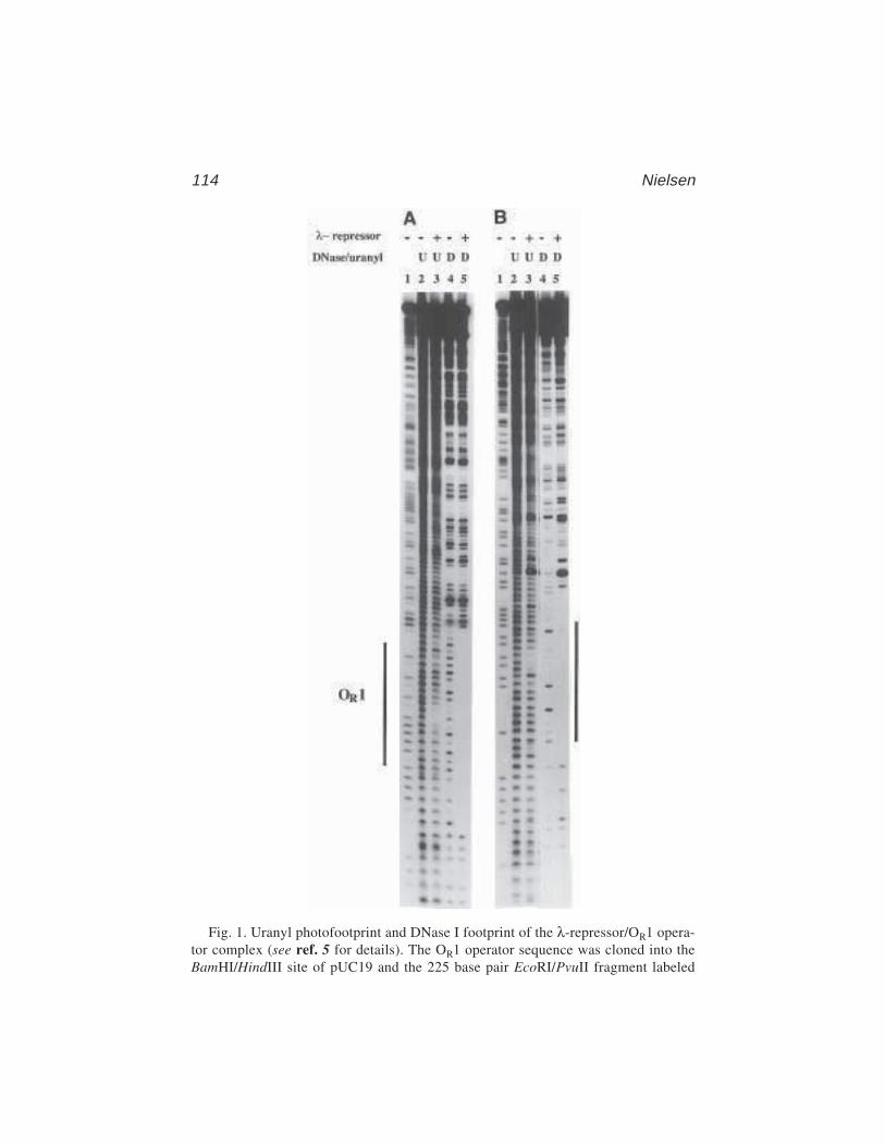
114 Nielsen
Fig. 1. Uranyl photofootprint and DNase I footprint of the λ-repressor/OR1 opera-tor complex (see ref. 5 for details). The OR1 operator sequence was cloned into theBamHI/HindIII site of pUC19 and the 225 base pair EcoRI/PvuII fragment labeled

Uranyl Photofootprinting115
therefore not involved in contacts with the bound ligand. On the other hand,hydroxyl radical footprinting reports on the accessibility of the deoxyribosesof the DNA backbone. In the cases studied with both uranyl and hydroxyl radi-cal probing (λ-repressor [5,21], RNA polymerase [6,24] and TFIIIA [14,25]),the footprint obtained by uranyl involves fewer nucleotides than that obtainedby EDTA(FeII).
Interference probing by phosphate ethylation using ethyl-nitroso-urea alsoreports on the involvement of individual phosphate groups in protein–DNAinteraction. However, this is an interference technique; therefore, only phos-phate groups that are indispensable for complex formation are detected. Thus,for small complexes (e.g., the λ-repressor-OR1 complex), ethylation interfer-ence and uranyl results are virtually equivalent, whereas for larger complexes(e.g., RNA polymerase–promoter complexes), only some of the contactsdetected by uranyl photofootprinting are picked up by ethylation interference.Thus, the data from ethylation interference and hydroxyl radical and uranylfootprinting experiments complement each other, hydroxyl radical attackreflecting the accessibility of individual deoxyriboses, uranyl photofootprintingreporting on the accessibility of individual phosphates, and ethylation interfer-ence reporting on phosphates, which are indispensable for complex formation.Furthermore, both hydroxyl radicals and uranyl are able to sense variations inDNA conformation, and for both of these probes, groove width has been impli-cated as the determinant. Generally speaking, hydroxyl radical cleavage is moreintense as the major groove widens, whereas uranyl photocleavage is moreintense as it narrows.
UO22+, being a divalent cation, may to some extent mimic Mg2+ in terms of
high-affinity binding sites in protein–nucleic acid complexes and in foldednucleic acids. Consequently, such high-affinity binding sites for the UO2
2+ ioncan result in hypersensitive cleavage sites. In this respect the uranyl photo-probing can be compared to oxidative cleavage of nucleic acids by the Fe2+/Fe3+
ion redox pair (30,31).Finally, uranyl, being a photochemical technique, has the added, but so far
unexplored, potential to be used for temperature and kinetic studies.
with 32P at the 3' or 5' end of the EcoRI site was used in the experiments. Lanes 1 and3 are controls without added λ-repressor (0.7 µg/sample). Lanes 1 and 2 are uranylphotofootprints, and lanes 3 and 4 are DNase I (0.5 µg/mL, 5 min at room tempera-ture) footprints. Lanes S are A+G sequence reactions obtained by treating the DNAwith 60% formic acid for 5 min at room temperature, and subsequent piperidine treat-ment. The samples were analyzed on an 8% polyacrylamide gel and run at 2500 V.The gel was subjected to autoradiography for 16 h at –70°C using intensifying screens.

116 Nielsen
4. Notes1. Uranyl acetate (UO2[CH3COO]2) gives identical results, but the 100 mM stock
solution in this case has to be made 50 mM in HCl in order for it to be stable.2. The 32P end-labeled DNA fragments of 50 to 300 base pairs in length are prepared
by standard techniques (28). Typically, the plasmid containing the protein-bindingsite is opened using a restriction enzyme that cleaves at a distance of 20–50 basepairs from the binding site. (This distance is important because the best resolutionis obtained in the 20- to 70-bases interval and the bands of uranyl-cleaved DNAfragments become “fuzzy” above 100 bases). The plasmid is labeled either at the 3'end with [α–32P] dNTP and the Klenow fragment of DNA polymerase, or at the 5'end (after dephosphorylation with alkaline phosphatase) with [γ-32P] ATP and poly-nucleotide kinase. The plasmid is then treated with a second restriction enzymecutting 50–300 bp from the labeling site and the DNA fragment containing theprotein binding site is purified by gel electrophoresis in 5% polyacrylamide, TBEbuffer. The DNA fragment is extracted from the excised gel slice with 0.5 M NH4–acetate, 1 mM EDTA (16 h, room temperature) and precipitated by addition of2 vol of 96% ethanol. The pellet is washed with 70% ethanol and dried.
3. Choice of footprinting buffer. The choice of an optimal buffer for a uranyl-photofootprinting experiment is crucial for a successful result. In particular, the
Fig. 2. (A) OR1–operator sequence (box) showing uranyl photofootprint (arrows),EDTA/FeII footprint (dots [20]) ethylation interference (arrow heads [21]) and DNaseI footprint (brackets). (B) Display of the uranyl photofootprint on OR1–DNA doublehelix. The size of the dots signify the degree of protection.
Uranyl Photofootprinting117
pH of the medium is important. The uranyl-mediated photocleavage of DNA isextremely dependent on pH, cleavage being most efficient at pH 6, less efficientat pH 5 and 7, and virtually absent at pH 8 (19). Furthermore, as the pH is low-ered, a strong modulation of the sequence dependence of the cleavage is observed.In fact, this modulation reflects the conformation of the DNA (7–10). Thus whenconformation-independent DNA cleavage is required, buffers of pH 6.5–7.0 areadvantageous, whereas buffers of pH 6.0–6.5 should be chosen for studies ofDNA structure. If information about metal-ion-binding sites is desired, citrate(0.1–1 mM) should be included in the buffer.
The composition of the buffer and the buffer capacity is also of importance.Because the uranyl solution is acidic, it should be checked that its addition doesnot significantly affect the pH of the chosen buffer. Furthermore, uranyl-medi-ated photocleavage of DNA is most efficient in acetate or formate buffers, lessefficient in Tris-HCl, very inefficient in HEPES or PIPES buffer, and virtuallyabsent in phosphate buffers (uranyl phosphate precipitates). The ionic strength(as Na+) is of minor importance and the cleavage is not affected by the presenceof Mg2+ or dithiothreitol (DTT). Finally, the uranyl photoreaction is not influ-enced by temperature (0–70°C) (19). Within these constraints, a buffer that allowsprotein–DNA binding must be chosen.
4. λ-Repressor was prepared according to ref. 29 using an overproducer plasmid:pAE305 in E. coli.
5. Light source. Any light source emitting at 300–420 nm can be used. This couldbe the Philips TL 40 W/03 tube emitting at 420 ± 30 nm. Alternative fluorescentlight tubes are Philips TL 20W/12 (300 nm) or TL 20W/09N (365 nm). Lampsemitting below 300 nm are not recommended because of absorption by the DNAbases at these wavelengths. The fluorescent light tubes suggested in this chapterare not very powerful but are quite sufficient for footprinting, they are also inex-pensive and do not require sophisticated power supplies. However, if shorterirradiation times are required, uranyl-photofootprinting experiments are quiteadequately performed with pyrex-filtered light from high-pressure Hg lamps,xenon lamps, or lasers of the appropriate wavelength (300–420 nm).
6. Order of mixing. It is important that the uranyl be added last because the uranyl–DNA complex is very stable (Ka is estimated to 1010 M–1 [19]). Uranyl–DNAaggregates that precipitate often form, but this does not adversely affect the out-come of the footprinting reaction. However, if uranyl is added prior to addition ofthe DNA-binding ligand, the ligand will have limited access to the DNA.
It is also extremely important that dilution of the uranyl stock solution be per-formed immediately prior to use since uranyl solutions are not stable at pH 2.0.
7. Examples of densitometric scanning and quantification of footprinting experi-ments can be found in refs. 8, 30, and 31.
References1. Burrows, H. D. and Kemp, T. J. (1974) The photochemistry of the uranyl ion.
Chem. Soc. Rev. 3, 138–165.
118 Nielsen
2. Azenha, M. E. D. G., Burrows, H. D., Furmosinho, S. J., and Miguel, M. G. M.(1989) Photophysics of the excited uranylionin aqueous solutions. Part 6. Quench-ing effects of aliphatic alcohols. J. Chem. Soc. Faraday Trans. 85, 2625–2634.
3. Cunningham, J. and Srijaranai, S. (1990) Sensitized photo-oxidations of dissolvedalcohols in homogeneous and heterogenous systems. 1. Homogeneous photo-sentization by uranyl ions. J. Photochem. Photobiol. A. Chem. 55, 219–232.
4. Greenwood, N. N. and Earnshaw, A. (1986) In Chemistry of the Elements.Oxford, Pergamon, p. 1478.
5. Nielsen, P. E., Jeppesen, C., and Buchardt, O. (1988) Uranyl salts as photo-chemical agents for cleavage of DNA and probing of protein-DNA contacts.FEBS Lett. 235, 122–124.
6. Jeppesen, C. and Nielsen, P. (1989) Uranyl mediated photofootprinting revealsstrong E. coli RNA polymerase-DNA backbone contacts in the +10 region of thedeoP1 promoter open complex. Nucleic Acids Res. 17, 4947–4956.
7. Nielsen, P. E., Møllegaard, N. E., and Jeppesen, C. (1990) Uranyl photoprobingof conformational changes in DNA induced by drug binding. Anti-Cancer DrugDesign 5, 105–110.
8. Nielsen, P. E., Møllegaard, N. E., and Jeppesen, C. (1990) DNA conformational analysisin solution by uranyl mediated photocleavage. Nucleic Acids Res. 18, 3847–3851.
9. Bailly, C., Møllegaard, N. E., Nielsen, P. E., and Waring, M. J. (1995) The influ-ence of the 2-amino group of guanine on DNA conformation. Uranyl and DNaseI probing of inosine/diaminopurine substituted DNA. EMBO J. 9, 2121–2131.
10. Sönnichsen, S. H. and Nielsen, P. E (1996) Enhanced uranyl photocleavageacross the minor groove of all (A/T)4 sequences indicates a similar narrow minorgroove conformation. J. Mol. Recogn. 9, 219–227.
11. Møllegaard, N. E., Murchie, A. I. H. Lilley, D. M. J., and Nielsen, P. E. (1994)Uranyl photoprobing of a four-way DNA junction. Evidence for specific metalion binding. EMBO J. 13, 1508–1513.
12. Bassi, G. S. Møllegaard, N. E., Murchie, A. I., von Kitzing, E., and Lilley, D. M.(1995) Ionic interactions and the global conformations of the hammerheadribozyme. Nature Struct. Biol. 2, 45–55.
13. Nielsen, P. E. and Møllegaard, N. E. (1996) Sequence/structure selectivethermal and photochemical cleavage of yeast-tRNAPhe by UO2
2+ J. Mol.Recogn. 9, 228–232.
13a. Møllegaard, N. E. and Nielsen, P. E. (2000) Applications of uranyl cleavagemapping of RNA structure. Meth. Enzymol. 318, 43–47.
13b. Wittberger, D., Berens, C., Hamman, C., Westhof, E., and Schroeder, R. (2000)Evaluation of uranyl photocleavage as a probe to monitor ion binding and flex-ibility in RNAs. J. Mol. Biol. 300, 339–352.
14. Nielsen, P. E. and Jeppesen, C. (1990) Photochemical probing of DNA com-plexes. Trends Photochem. Photobiol. 1, 39–47.
15. Møllegaard, N. E., Rasmussen, P. B., Valentin-Hansen, P., and Nielsen, P. E.(1993) Characterization of promoter recognition complexes are formed by CRPand CytR for repression and by CRP and RNA polymerase for avtivation oftranscription on the E. coli deoCp2 promoter. J. Biol. Chem. 268, 17,471–17,477.
Uranyl Photofootprinting119
16. Nielsen, P. E. (1992) Uranyl photofootprinting of triple helical DNA. NucleicAcids Res. 20, 2735–2739.
17. Nielsen, P. E., Cons, B. M. G., Fox, K. R., and Sommer, V. B. (1990) Uranylphotofootprinting. DNA structural changes upon binding of mithramycin, inMolecular Basis of Specificity in Nucleic Acid Drug Interactions, vol. 23 (Pull-man, B. and Jortner, J., eds.), Kluwer Academic, Dordrecht, pp. 423–432.
18. Møllegaard, N. E. and Nielsen, P. E. (1997) Uranyl photoprobing of DNA struc-tures and drug-DNA complexes, in Drug-DNA Interaction Protocols (Fox, K.R., ed.), Humana, Totowa, NJ, pp. 43–50.
19. Nielsen, P. E., Hiort, C., Buchardt, O., Dahl, O., Sönnichsen, S. H., and Nordèn, B.(1992) DNA Binding and Photocleavage by Uranyl(VI) (UO2
2+) Salts. J. Amer.Chem. Soc. 114, 4967–4975.
20. Schultz, S. C., Shields, G. C., and Steitz, T. A. (1991) Crystal structure of aCAP-DNA complex: the DNA is bent by 90°. Science 253, 1001–1007.
21. Tullius, T. D. and Dombroski, B. A. (1986) Hydroxyl radical “footprinting”:high-resolution information about DNA protein contacts and application tolambda repressor and Cro protein. Proc. Natl. Acad. Sci. USA 83, 5469–5473.
22. Burkhoff, A. M. and Tullius, T. D. (1987) The unusual conformation adopted bythe adenine tracts in kinetoplast DNA. Cell 48, 935–943.
23. Siebenlist, U., Simpson, R. B., and Gilbert, W. (1980) E. coli RNA polymeraseinteracts homologously with two different promoters. Cell 20, 269–281.
24. O’Halloran, T. V., Frantz, B., Shin, M. K., Ralston, D. M., and Wright, J. G.(1989) The MerR heavy metal receptor mediates positive activation in a topo-logically novel transcription complex. Cell 56, 119–129.
25. Vrana, K. E., Churchill, M. E. A., Tullius, T. D., and Brown, D. D. (1988)Mapping functional regions of transcription factor TFIIIA. Mol. Cell. Biol. 8,1684–1696.
26. Berens, C. Streicher, B., Schroeder, R., and Hillen, W. (1998) Visualizingmetal-ion-binding sites in group I introns by iron(II)-mediated Fenton reactions.Chem. Biol. 5, 163–175.
27. Zaychikov, E., Martin, E., Denissova, L., Kozlov, M., Markovtsov, V., Kashlev,M., et al. (1996) Mapping of catalytic residues in the RNA polymerase activecenter. Science 273, 107–109.
28. Maniatis, T. Fritsch, E. F., and Sambrook, J. (1982) Molecular Cloning. A Labo-ratory Manual, Cold Spring Harbor Laboratory, Cold Spring Harbor, NY.
29. Amann, E., Brosins, J., and Ptasne, M. (1983) Vectors bearing a hybrid trp-lacpromoter useful for regulated expression of cloned genes in Escherichia coli.Gene 25, 167–178.
30. Jeppesen, C. and Nielsen, P. E. (1989) Photofootprinting of drug-binding siteson DNA using diazo- and azido–9-aminoacridine derivatives. Eur. J. Biochem.182, 437–444.
31. Dabrowiak, J. C., Kissinger, K., and Goodisman, J. (1989) Quantitative foot–printing analysis of drug–DNA interactions: Fe(III)methidium–propyl–EDTAas a probe. Electrophoresis 10, 404–412.
Osmium modification121
121
From: Methods in Molecular Biology, vol. 148: DNA–Protein Interactions: Principles and Protocols, 2nd ed.Edited by: T. Moss © Humana Press Inc., Totowa, NJ
9
Osmium Tetroxide Modificationand the Study of DNA–Protein Interactions
James A. McClellan
1. IntroductionOsmium tetroxide is an foul-smelling chemical used as a fixative in electron
microscopy that can also be used to modify thymidine residues within DNA(1,2). The ability of osmium tetroxide to modify DNA is very sensitive to DNAconformation. In particular, osmium tetroxide will attack thymidines that areunstacked, either because they are in a single-stranded region or for some otherreason (e.g., because the DNA is bent or because it is overwound [3]).
As a footprinting agent, osmium tetroxide has not been widely used. This isprincipally for historical reasons, and one of the reasons for writing the firstversion of this chapter was to encourage experimentation with osmium tetrox-ide as a footprinting agent. Since then, the use of osmium tetroxide in the studyof DNA–protein interactions has mushroomed; a search of PubMed usingosmium, DNA, and protein as keywords pulled down over 300 references inlate 1998. However, it is true that the exquisite sequence specificity of osmiumtetroxide is a disadvantage when one wishes to know all the contacts that aprotein makes in a particular sequence. Additionally, osmium tetroxide hasbeen shown to damage proteins (4), although this is probably a problem com-mon to virtually all chemical footprinting agents rather than a specificdisadvantage of osmium tetroxide. On the other hand, osmium tetroxide hasdefinite advantages in the study of certain DNA–protein interactions, specifi-cally those interactions that result in a changed conformation of the DNAdouble helix. Examples of such interactions include the initiation of transcrip-tion (5) and the formation of nonstandard conformations in DNA that areknown to be recombinogenic and to have the potential to modulate geneexpression (6–8).

122 McClellan
The main advantages of osmium tetroxide are that it is very easy to workwith and that the osmium modification reaction takes place under a very widevariety of environmental conditions (9), including in vivo (10–12). This makesit possible to study nucleic acid conformation as a function of environmentalconditions, such as salt concentration, temperature, and presence or absence ofproteins and polyamines. All that is required is that there should be susceptiblethymidines (Ts) involved in the conformational change; because most siteswhere conformational changes occur in DNA are A+T rich, this is not a hardcriterion to satisfy.
As an indication of the kinds of information that can be obtained usingosmium tetroxide modification, we may cite the results of in vivo modificationexperiments on AT sequences (12). Experiments like these provided the firstdirect evidence that cruciform structures may be seen in vivo. Our experimentsalso show that previously observed environmentally induced changes in plas-mid linking numbers actually do result in changes in torsional stress in vivo,rather than being compensated for by the binding of extra histonelike proteins.However, the data also show that cruciforms are not a normal component ofthe bacterial genome; we do not see cruciforms if there are significant kineticbarriers to extrusion, and we do not see cruciforms unless we artificially raisethe in vivo level of supercoiling by osmotically shocking the cells. Neverthe-less, because environmentally induced changes in DNA supercoiling arethought to regulate the bacterial response to osmotic and other stresses (13),we cannot rule out the possibility that transient formation of unusual DNAstructures could be instrumental in such responses. It is particularly interestingthat the sequence 5'-ATTATATATATATATATATATATATAAT-3' is foundaround the promoter of a key pathogenic gene in Haemophilus influenzae (14).This sequence could attain cruciform geometry at the levels of DNA torsionalstrain, which we find to be operative inside environmentally stressed bacteria.Moreover, cruciform geometry at artificial promoters is thought to affecttranscription (15).
2. Materials1. 20 mM osmium tetroxide, thawed (see Notes 1 and 2).2. 6% v/v aqueous pyridine or 20 mM aqueous 2,2' bipyridyl (see Notes 2 and 3).3. 10X buffer; 50 mM Tris-HCl, 5 mM EDTA, pH 8.4. 1–5 µg of plasmid DNA. Miniprep DNA is adequate; gradient-purified DNA
is better.5. Absolute ethanol.6. 3 M sodium acetate, pH 4.5.7. Restriction enzymes.8. Enzymes and radionucleotides for end labeling DNA. In this protocol, the enzyme
used is the Klenow fragment of DNA polymerase I. One also needs an [α-P32]

Osmium modification123
dNTP at specific activity >6000 Ci/mmol, and the other three dNTPs as nonra-dioactive 2 mM stocks.
9. Agarose gel with slots large enough to take >60 mL (they can be made by tapingup smaller slots), powerpack and gel tank.
10. 5X loading dye: 10% Ficoll 400, 0.1 M sodium EDTA, 1% sodium dodecylsulfate (SDS), 0.25% bromophenol blue, and 0.25% xylene cyanol.
11. Ethidium bromide (10 mg/mL in water).12. Long-wavelength (360-nm) ultraviolet (UV) transilluminator.13. Electroeluter. We use the IBI model UEA.14. 1 M aqueous piperidine, made freshly.15. High-capacity vacuum pump with trap and desiccator.16. Alkaline formamide dye; 200 µL deionized formamide, 1 µL of 1 M NaOH and
xylene cyanol and bromophenol blue to taste. (A needle dipped in the powdereddye and then tapped to remove excess will give quite enough.)
17. Whatmann 3MM paper.
3. Methods3.1. Osmium Tetroxide Modification
This protocol describes the in vitro modification of plasmid DNA andthe sequence-level detection of adducts by piperidine cleavage after specific3-prime end labeling.
1. Solution 1: Combine the plasmid DNA with 5 µL of 10X modification buffer andadd distilled water to a total volume of 45 µL.
2. Solution 2: Mix 2.5 µL of 20 mM osmium tetroxide with 2.5 µL of 6% pyridineor 20 mM bipyridine.
3. Equilibrate solutions 1 and 2 at the desired reaction temperature.4. Add solution 1 to solution 2, mix well, and incubate for the desired time.5. Meanwhile, make the stop solution; 180 mL of absolute ethanol and 5 mL of 3 M
sodium acetate pH 4.5. Chill at –70°C.6. Add stop solution to reaction, mix well and chill at –70°C for 10 min.7. Spin at maximum speed in a Eppendorf microfuge for 10 min. Note, non-
Eppendorf microcentrifuges are NOT, in general, adequate substitutes. We donot know exactly why, but we suspect it has to do with heating of the rotorduring spinning.
8. Pipet off the supernatant and discard as potentially carcinogenic waste. Be care-ful not to disturb the pellet.
9. Add 1 mL of absolute ethanol to the tube and spin in the microfuge at maximumspeed for 5 min.
10. Pipet off the supernatant and discard as in step 8.11. Dry the pellet for 5 min in a vacuum desiccator.12. Add 44 µL of distilled water.13. Transfer to a fresh tube. This is important; sometimes residual osmium on the
reaction tube can interfere with the subsequent steps (see Note 4).

124 McClellan
14. Add 5 µL of 10X restriction enzyme buffer and 1 µL (about 10 U) of restrictionenzyme. The enzyme chosen should give unpaired 5' ends and ideally has a uniquesite approx 40–200 bases from the site at which modification is expected.
15. Incubate at 37°C for about 1 h.16. Meanwhile, dry down 5 mCi of a >6000-Ci/mmol [α–32P] dNTP. This should be
the first nucleotide to be incorporated by DNA polymerase (e.g., if the enzymeused is EcoRI, it should be dATP).
17. To the dried-down radionucleotide, add 2 µL of each 2 mM unlabeled stocks ofthe other dNTPs (i.e., if the labeling is with [α–32P] dATP, add dGTP, dCTP, anddTTP). Mix well.
18. Add this nucleotide mix to the restriction digest. Then, add 1 µL (about 6 U) ofthe Klenow fragment of E. coli DNA polymerase I. We find that Klenow poly-merization works well in a variety of restriction enzyme buffers, especially thoseused for EcoRI and BamHI.
19. Incubate for 1 h (not more) at 37°C.20. Add 10 µL of 5X loading dye and electrophorese on, for example, a 1% agarose
1X TBE gel until the xylene cyanol (light blue) dye is about halfway down thegel, or, in general until the fragment of interest can be easily excised from the gel.Exactly which gel is chosen will depend on the particular system under study.
21. Stain the gel with 1 µg/mL ethidium bromide. Visualize by long-wave UV andexcise the bands of interest from the gel.
22. Electrolelute the labeled DNA into high salt (or use another method).23. Precipitate and wash the DNA with ethanol. If precipitating from high salt, do
not chill!24. If it is desired to see only the signals on one strand, cut off one of the labeled ends
(Note 5). After restriction, the DNA should be ethanol precipitated, washed anddried. Do this by repeating steps 5–11; it is not necessary to discard the waste aspotentially mutagenic.
25. To the dried pellet, add 100 µL of 1 M piperidine. Heat at 90°C for 30 min.26. Transfer to a new tube. Close the tube. Use a needle to punch holes in the cap.27. Place the tube in liquid nitrogen for about 5 s.28. Place the tube in a rack in a vacuum desiccator, attach a high-capacity vacuum
pump with a trap, and turn it on. Do this quickly, so that the frozen sample doesnot have time to thaw.
29. Lyophilize for about 2 h.30. Add 50 µL of water to the tube and repeat lyophilization step 28 for about 1 h.31. Repeat steps 29 and 30.32. Resuspend the samples in at least 3 µL of alkaline formamide dye.33. Heat to 90°C for 5 min and then chill on ice.34. Load aliquots of about 50 counts per second on a standard TBE–8 M urea
sequencing gel and electrophorese. Exact details of the sequencing gel willdepend on the system under study.
35. Fix the gel in 10% acetic acid for 15 min, transfer to 3MM paper, dry, andautoradiograph.

Osmium modification125
3.2. Results of Osmium Tetroxide Modification
Figure 1 shows a time-course of osmium tetroxide modification on a 68-bp-long tract of alternating adenines and thymidines within a bacterial plasmid.This sequence is found in the first intron of the frog globin gene. The modifica-tion was done at 37°C in the absence of added salt and for the indicated times.A BamHI–EcoRI fragment containing the tract was labeled at both ends byKlenow polymerase and [α-32P] dATP. The adducts were cleaved using hotpiperidine and electrophoresed on a sequencing gel. The gel was fixed, driedonto paper, and autoradiographed.
The gel shows information from both strands. This is possible because(1) the AT tract is asymmetrically placed on the BamHI–EcoRI fragment, and(2) osmium modification is almost completely specific for the AT tract. As canbe seen, the modifications are biased toward the label-proximal end of the tracton both strands, and this is intensified at later time-points. In fact, this is alsothe pattern when the label is placed at the 5' ends (data not shown). Thus, thelabel-proximal bias of the signals simply indicates multiple modificationsrather than an asymmetric structure.
Figure 1 also shows the result of modifying the AT tract in the presence ofions. Here, the patterns are quite different. In the presence of sodium ions, wesee modifications at the center of the AT tract and at its ends. In the presence ofmagnesium ions, we see modifications at the center of the AT tract but not atits ends. These patterns are interpreted as indicating the presence of cruciformstructures at the AT tract, either with tight scissor-shaped osmium resistantjunctions (in the presence of magnesium) or with floppy square planar osmiumsensitive junctions (in the presence of sodium) (16). The central modificationsare at what would be the loop of the cruciform, and the modifications at the endof the tract would be at the junction of the cruciform with flanking DNA(Fig. 2) (see Note 6).
The nature of the symmetric structure observed in Fig. 1 remains obscure;we have termed it the U-structure (9), but this is only a name, not a description.What we know about this structure is that it is easy to interconvert between itand the cruciform, and the conditions under which the U-structure is favored(higher supercoiling and temperature, lower salt concentration) suggest thatthe U-structure is more unwound than the cruciform. Furthermore, other A+T-rich sequences that form cruciforms can exhibit U-like patterns of modifica-tion under the appropriate conditions. One interesting possibility is that theU-structure may be a locally parallel-stranded conformation, in which the A atthe 5' end of the top strand makes a reverse Watson–Crick pair to the A at the 5'end of the bottom strand; the Ts following those As pair to each other in thesame mode, the As following those Ts pair to each other in the same mode: and
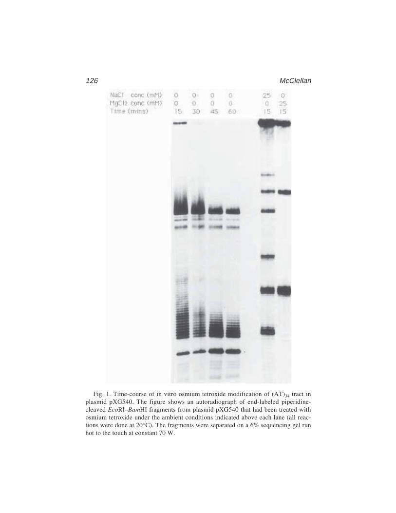
126 McClellan
Fig. 1. Time-course of in vitro osmium tetroxide modification of (AT)34 tract inplasmid pXG540. The figure shows an autoradiograph of end-labeled piperidine-cleaved EcoRI–BamHI fragments from plasmid pXG540 that had been treated withosmium tetroxide under the ambient conditions indicated above each lane (all reac-tions were done at 20°C). The fragments were separated on a 6% sequencing gel runhot to the touch at constant 70 W.
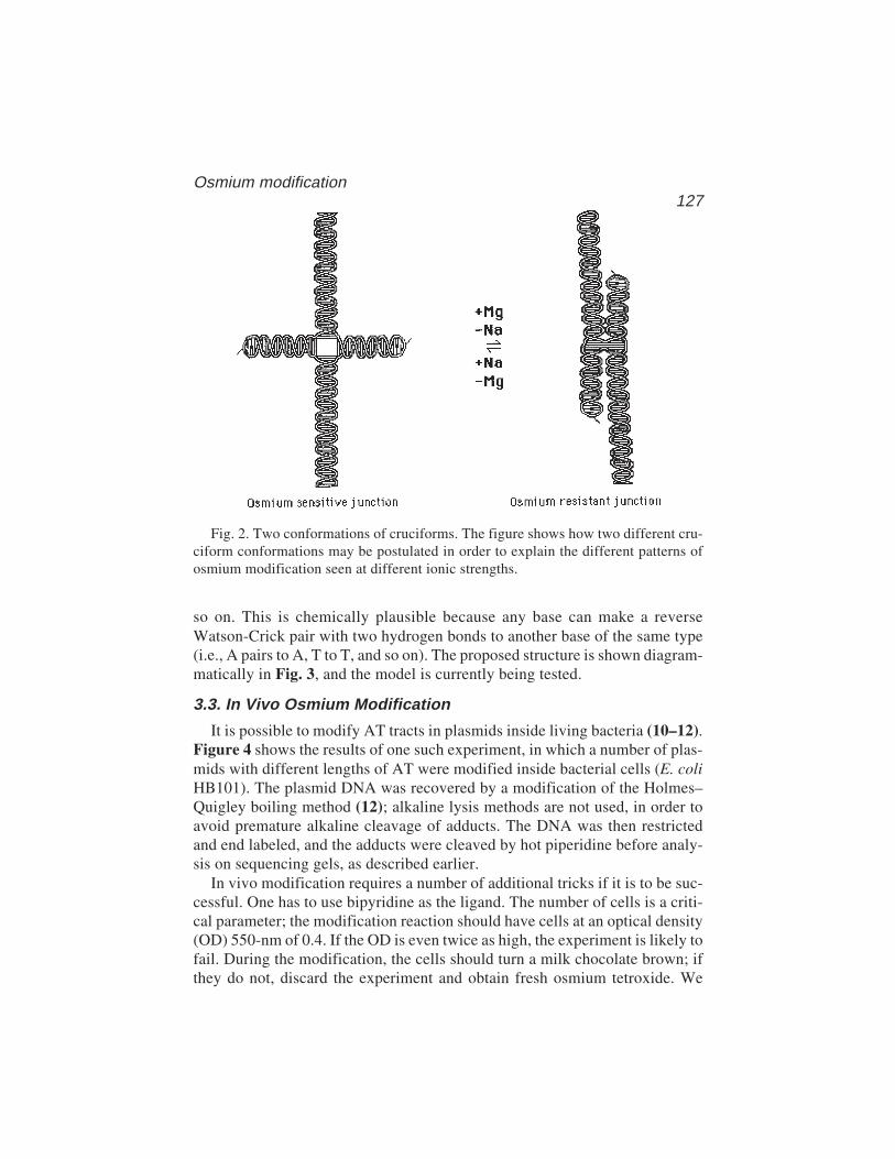
Osmium modification127
so on. This is chemically plausible because any base can make a reverseWatson-Crick pair with two hydrogen bonds to another base of the same type(i.e., A pairs to A, T to T, and so on). The proposed structure is shown diagram-matically in Fig. 3, and the model is currently being tested.
3.3. In Vivo Osmium Modification
It is possible to modify AT tracts in plasmids inside living bacteria (10–12).Figure 4 shows the results of one such experiment, in which a number of plas-mids with different lengths of AT were modified inside bacterial cells (E. coliHB101). The plasmid DNA was recovered by a modification of the Holmes–Quigley boiling method (12); alkaline lysis methods are not used, in order toavoid premature alkaline cleavage of adducts. The DNA was then restrictedand end labeled, and the adducts were cleaved by hot piperidine before analy-sis on sequencing gels, as described earlier.
In vivo modification requires a number of additional tricks if it is to be suc-cessful. One has to use bipyridine as the ligand. The number of cells is a criti-cal parameter; the modification reaction should have cells at an optical density(OD) 550-nm of 0.4. If the OD is even twice as high, the experiment is likely tofail. During the modification, the cells should turn a milk chocolate brown; ifthey do not, discard the experiment and obtain fresh osmium tetroxide. We
Fig. 2. Two conformations of cruciforms. The figure shows how two different cru-ciform conformations may be postulated in order to explain the different patterns ofosmium modification seen at different ionic strengths.
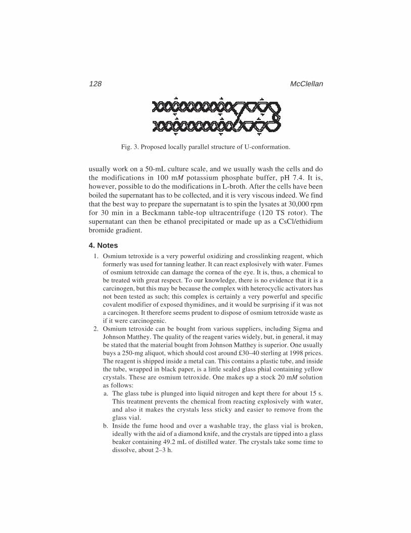
128 McClellan
Fig. 3. Proposed locally parallel structure of U-conformation.
usually work on a 50-mL culture scale, and we usually wash the cells and dothe modifications in 100 mM potassium phosphate buffer, pH 7.4. It is,however, possible to do the modifications in L-broth. After the cells have beenboiled the supernatant has to be collected, and it is very viscous indeed. We findthat the best way to prepare the supernatant is to spin the lysates at 30,000 rpmfor 30 min in a Beckmann table-top ultracentrifuge (120 TS rotor). Thesupernatant can then be ethanol precipitated or made up as a CsCl/ethidiumbromide gradient.
4. Notes1. Osmium tetroxide is a very powerful oxidizing and crosslinking reagent, which
formerly was used for tanning leather. It can react explosively with water. Fumesof osmium tetroxide can damage the cornea of the eye. It is, thus, a chemical tobe treated with great respect. To our knowledge, there is no evidence that it is acarcinogen, but this may be because the complex with heterocyclic activators hasnot been tested as such; this complex is certainly a very powerful and specificcovalent modifier of exposed thymidines, and it would be surprising if it was nota carcinogen. It therefore seems prudent to dispose of osmium tetroxide waste asif it were carcinogenic.
2. Osmium tetroxide can be bought from various suppliers, including Sigma andJohnson Matthey. The quality of the reagent varies widely, but, in general, it maybe stated that the material bought from Johnson Matthey is superior. One usuallybuys a 250-mg aliquot, which should cost around £30–40 sterling at 1998 prices.The reagent is shipped inside a metal can. This contains a plastic tube, and insidethe tube, wrapped in black paper, is a little sealed glass phial containing yellowcrystals. These are osmium tetroxide. One makes up a stock 20 mM solutionas follows:a. The glass tube is plunged into liquid nitrogen and kept there for about 15 s.
This treatment prevents the chemical from reacting explosively with water,and also it makes the crystals less sticky and easier to remove from theglass vial.
b. Inside the fume hood and over a washable tray, the glass vial is broken,ideally with the aid of a diamond knife, and the crystals are tipped into a glassbeaker containing 49.2 mL of distilled water. The crystals take some time todissolve, about 2–3 h.

Osmium modification129
Fig. 4. In vivo modification of AT tracts: cruciform geometry in bacterial plasmidsas a consequence of physiological salt shock. Bacterial cells containing isogenic plas-mids with various lengths of AT were salt-shocked and treated with osmium tetroxidein vivo. Adducts were detected by preparing the DNA, end labeling, and piperidinecleavage, followed by electrophoresis on thin 6% sequencing gels and autoradiogra-phy. Strong central modification of the AT tract shows that (AT)34 adopts cruciformgeometry in salt-shocked but not in control cells, and that (AT)22 and (AT)15 but not(AT)12 also adopt cruciform geometry in salt-shocked cells.
c. Once the crystals have dissolved, the reagent is aliquoted ready for use. Glasscontainers such as Universals with screw tops should be used, and storageshould be at –70°C. It is best to keep the reagent as several separate aliquots

130 McClellan
and to use them one at a time. One problem with storage is that the glasscontainers often crack, which is obviously very dangerous. Volumetric flasksand non-Pyrex containers are particularly sensitive in this regard. The reagentshould always be thawed with the container inside a glass beaker in the fumehood. If the reagent is blackish when thawed, discard it; the black color indi-cates lower oxidation states of osmium, including the metal.
3. By itself, osmium tetroxide is not very reactive with DNA. The species thatattacks DNA is a complex of osmium tetroxide with a heterocyclic compoundsuch as pyridine or bipyridine (Fig. 5). The attack is on the 5–6 double bond ofthymidines (ref. 3 and references therein). Curiously, neither cytosines nor uracilsshow significant modifiability with osmium tetroxide, but guanine residuesoccasionally may.
Bipyridine is rather insoluble in water. To make a stock solution, it may benecessary to heat the bipyridine and water to 80°C for about 30 min. Onceosmium tetroxide is added to pyridine, the mixed reagents should become a straw-yellow color; if they do not, discard them and obtain fresh osmium tetroxide.
One can change the reactivity of an osmium tetroxide preparation by changingthe concentration of osmium and/or ligand, and the overall degree of reaction canbe varied from single to multiple hits per molecule by changing the time and/ortemperature of the modification reaction. Typical times and temperatures used inour laboratory to obtain single hits are as follows: 45 min at ice temperature; 15 minat 20°C; 5 min at 37°C; 1 min at 40°C.
4. Various methods of detecting osmium tetroxide adducts exist, namely retarda-tion of bands in agarose or acrylamide gels (5), immunoprecipitation (3), cleav-age by S1 nuclease (5), cleavage by hot piperidine (6), and failure of primerextension (11). In some cases, inhibition of restriction enzyme cleavage can beused (10,17).
Fig. 5. Stereochemistry of OsO4 attack on thymidines.

Osmium modification131
5. A good way to do this is to cut with a frequent cutter thata. has a site near to the end from which it is not required to see signalsb. does not have a site between the end from which it is desired to see signals
and the tract where modifications are expectedFor example, the EcoRI site of pXG540 has a HaeIII site 18 bp anticlockwise
(in the direction of the Amp promoter). There is no HaeIII site in the clockwise170 bp up to the start of the AT tract. So, we often cut and label at EcoRI, andthen do a limit digest with HaeIII. This reults in a long labeled fragment thathas the information we want on it, and a short fragment (18 bp) that we runoff the gel.
6. Osmium tetroxide modification of DNA now has a substantial pedigree, havingbeen used to modify a wide range of sequences in different unusual conforma-tions in vitro, and a narrower range of sequences in different conformations in vivo.Figure 6 shows some of the actual or proposed structures that have been treatedwith osmium tetroxide. However, it is very important to be cautious in usingosmium modification results, or any other kind of chemical or enzymatic prob-ing, to deduce that a particular structure is forming. This is because osmium doesnot report on global conformation; it only tells you whether or not a particular Tresidue has an exposed 5–6 double bond. If a T is exposed, this could be forseveral reasons:a. The T might be in a single-stranded region of the DNA (e.g., a bubble, mis-
match [18], B–Z junction or cruciform or H-structure loop).b. The T might be in a helix with a shallow or bulging major groove (e.g., at a
bend or within a GT/AC tract that was forming Z–DNA).c. The T might be in an overwound helix, with exposure of the 5–6 double bond
resulting from a loss of base overlap, because of the sharp rotation of eachbase relative to its neighbors.These considerations make it very difficult to conclude on the basis of osmium
modification that, for example, Z–DNA is forming; osmium results do notdistinguish in any simple way between what we have called the “U”-structure(9), Z-DNA and a conformation (possibly the eightfold D-helix), which we haveobserved in locally positively stressed AT tracts (19). Detecting the loops andjunctions of cruciform or H-form DNA can sometimes be done in such a way asto virtually exclude alternative interpretations of the data, but even this is notalways possible; for example, a GC tract with ATAT in the middle will react inthe same way with osmium tetroxide whether it is in a Z-conformation or cruci-form (11); and there is a published interpretation of chemical modification atH-forming sequences that is radically at odds with the H-structure model (20).
In addition to these difficulties, there is a need to be cautious about the effectof the probing chemical on the structural features deduced. Because osmiummodification works under a wide range of conditions, it presents fewer such prob-lems of interpretation than some other more fastidious chemicals. Nevertheless,we observe that the ligand used can have an effect on the result obtained; otherthings being equal, we find that bipyridine is more likely to give a cruciformlike

132 McClellan
pattern of modification and pyridine is more likely to give a U-structure-likepattern when superhelically stressed AT tracts are probed in vitro. This probablyhas to do with different helix-unstacking potential of the two heterocycles; alter-natively, it could be an artifact of contaminating cations in the heterocycles orion–heterocycle interactions.
Fig. 6. Unusual DNA structures that react with osmium tetroxide.
Osmium modification133
References1. Beer, M., Stern, S., Carmalt, D., and Mohlenrich, K. H. (1966) Determination of
base sequence in nucleic acids with the electron microscope. V. The thymine-specific reactions of osmium tetroxide with deoxyribonucleic acid and its compo-nents. Biochemistry 5, 2283–2288.
2. Burton, K. and Riley, W. T. (1966) Selective degradation of thymidine and thym-ine deoxynucleotides. Biochem. J. 98, 70–77.
3. Palecek, E. (1989) Local open DNA structures in vitro and in the cell as detectedby chemical probes, in Highlights of Modern Biochemistry, (Kotyk, A., Skoda, J.,Paces, V., and Kostka, V., eds.), VSP International Science, Zeist, The Nether-lands, pp. 53–71.
4. Behrman, E. J. (1988) The chemistry of the interactions of osmium tetroxide withDNA and proteins, in Symposium on Local Changes in DNA Structure and TheirBiological Implications, Book of Abstracts, p. 6.
5. Buckle, M., Spassky, A., Herbert, M., Lilley, D. M. J., and Buc, H. (1988) Chemi-cal probing of single stranded regions of DNA formed in complexes between RNApolymerase and promoters, in Symposium on Local Changes in DNA Structureand their Biological Implications, Book of Abstracts, p. 11.
6. Lilley, D. M. J. and Palecek, E. (1984) The supercoil-stabilised cruciform ofColE1 is hyper-reactive to osmium tetroxide. EMBO J. 3, 1187–1192.
7. Johnston, H. and Rich, A. (1985) Chemical probes of DNA conformation: detec-tion at nucleotide resolution. Cell 42, 713–724.
8. Vojtiskova, M. and Palecek, E. (1987) Unusual protonated structure in thehomopurine. homopyrimidine tract of supercoiled and linearised plasmidsrecognised by chemical probes. J. Biomol. Struct. Dyn. 5, 283–296.
9. McClellan, J. A. and Lilley, D. M. J. (1987) A two-state conformational equilib-rium for alternating A-T)n sequences in negatively supercoiled DNA. J. Mol. Biol.197, 707–721.
10. Palecek, E., Boublikova, P., and Karlovsky, P. (1987) Osmium tetroxide recognizesstructural distortions at junctions between right- and left-handed DNA in a bacte-rial cell. Gen. Physiol. Biophys. 6, 593–608.
11. Rahmouni, A. R. and Wells, R. D. (1989) Stabilisation of Z DNA in vivo bylocalized supercoiling. Science 246, 358–363.
12. McClellan, J. A., Boublikova, P., Palecek, E., and Lilley, D. M. J. (1990) Super-helical torsion in cellular DNA responds directly to environmental and geneticfactors. Proc. Natl. Acad. Sci. USA 87, 8373–8377.
17. Palecek, E., Boublikova, P., Galazka, G., and Klysik, J. (1987) Inhibition ofrestriction endonuclease cleavage due to site-specific chemical modification ofthe B–Z junction in supercoiled DNA. Gen. Physiol. Biophys. 6, 327–341.
16. Duckett, D. R., Murchie, A. I. H., Diekmann, S., von Kitzing, E., Kemper B., andLilley, D. M. J. (1988) The structure of the Holliday junction, and its resolution.Cell 55, 79–89.
13. Dorman, C. J. (1991) DNA supercoiling and environmental regulation of geneexpression in pathogenic bacteria. Inf. Immun. 59, 745–749.
134 McClellan
14. Langermann, S. and Wright, A. (1990) Molecular analysis of the Haemophilusinfluenzae type b pilin gene. Mol. Microbiol. 4, 221–230.
15. Horwitz, M. S. Z. and Loeb, L. A. (1988) An E. coli promoter that regulatestranscription by DNA superhelix-induced cruciform extrusion. Science 241,703–705.
18. Cotton, R. G. H., Rodrigues, N. R., and Campbell, R. D. (1988) Reactivity ofcytosine and thymine in single-base-pair mismatches with hydroxylamine andosmium tetroxide and its app. lication to the study of mutations. Proc. Natl. Acad.Sci. USA 85, 4397–4401.
19. McClellan, J. A. and Lilley, D. M. J. (1991) Structural alteration in alternatingadenine–thymine sequences in positively supercoiled DNA. J. Mol. Biol. 219,145–149.
20. Pulleyblank, D. E., Haniford, D. B., and Morgan, A. R. (1985) A structural basisfor S1 sensitivity of double stranded DNA. Cell 42, 271–280.
Combined SW–Nuclease Footprinting 135
135
From: Methods in Molecular Biology, vol. 148: DNA–Protein Interactions: Principles and Protocols, 2nd ed.Edited by: T. Moss © Humana Press Inc., Totowa, NJ
10
Determination of a Transcription-Factor-BindingSite by Nuclease Protection Footprintingonto Southwestern Blots
Athanasios G. Papavassiliou
1. IntroductionThe interaction of cell-type-specific or inducible transcription factors with
regulatory DNA sequences in gene promoters or enhancers is a pivotal step ingenetic reprograming during cell proliferation and differentiation and inresponse to extracellular stimuli. The study of these interactions and the char-acterization of the factors involved are, therefore, a critical aspect of genecontrol. Transcription factor–DNA interactions in eukaryotes have been dem-onstrated by a wide variety of biochemical approaches, including deoxyribo-nuclease I (DNase I) and chemical nuclease footprinting (1–3) (Chapter 3),methylation protection (4) (Chapter 14), electrophoretic mobility-shift (5,6)(Chapter 2), and Southwestern (SW) assays (7) (Chapter 17). Despite theirbroad applicability, these techniques provide only partial information aboutthe DNA–protein system under investigation. The first three techniques iden-tify either the site(s) of transcription factor binding within the DNA (size andlocation of nucleotide stretches or atoms on individual bases) or the complex-ity of the binding pattern (stoichiometry), but do not yield information aboutthe protein(s) involved. On the other hand, the SW assay reveals the relativemolecular mass of renaturable (on a membrane support) active species inheterogeneous protein mixtures facilitating their identification, but fails tolocalize the exact target element within the probing DNA sequence.
Combining SW and DNase I (but also chemical nuclease and methylationprotection, see below) footprinting methodologies has the dual potential foraccurately determining the size of individual DNA-binding transcription fac-tors and precisely mapping their cognate binding sites (8) (Fig. 1) . In addition

136 Papavassiliou
to allowing the detection of only fractional binding (footprints in solution canbe obtained only when the binding site[s] is almost completely occupied), cou-pling in situ DNase I footprinting with the SW technique offers the advantageof both resolving the protein component and mapping the binding site of com-plexes formed by either different factors recognizing an identical sequencewithin the DNA probe or by two factors interacting in a noncooperative man-ner with adjacent but distinct sequences. However, this is dependent on thefactor being able to bind to DNA as a monomer or a homodimer. If the activeform is not a single species (i.e., a heterodimeric or heteromeric complex isrequired to reconstitute the binding activity), specific DNA binding will not bedetected and the procedure will not be applicable. The most critical stage of thecoupled assay lies within its first part, namely the SW procedure, and concernsthe ability of a transcription factor to efficiently renature into its active form (atleast in terms of DNA-binding capacity) on the membrane. Many transcriptionfactors are composed of domains with distinct structural conformations, whichaids the process of renaturation. However, because the protein surface immo-bilized on the membrane poses an impediment on the refolding process, the
Fig. 1. Rationale in a combined SW–DNase I footprinting procedure. The “ham-mer”-shaped extensions from the DNA-binding protein indicate immobilization onthe blotting membrane. The black-filled sphere indicates the end label in one strand ofthe DNA footprint probe. MW denotes the molecular size of the membrane-blottedDNA-binding protein (estimated by comparing the position of the active membranearea to the mobilities of coelectroblotted protein MW standards). Arrows mark repre-sentative sites of DNase I attack. (A) DNase I digestion pattern of free (in solution)probe; (B) DNase I digestion pattern of protein-complexed (membrane-bound) probe.
Combined SW–Nuclease Footprinting 137
likelihood of successful renaturation increases with increased size of the DNA-binding transcription factor(s) under study. As a result of the increased kineticstability of a membrane-immobilized DNA–protein complex (reversible bind-ing to even low-affinity proteins is enhanced because excess unbound DNAhas been washed out and hence is not present to compete), reaction parameterssuch as the size of the DNA probe, the concentration of DNase I, and digestiontime are no longer determined by the dissociation rate of the complex, a normallimitation of DNase I protection assays performed in solution.
The fidelity of the combined analytical assay is demonstrated in Fig. 2. Evi-dently, the structural and functional properties of DNA are not altered byentrapment on the blotting membrane surface (i.e., the probe exhibits identicalprotection pattern and sequence-dependent reactivity with DNase I as it doesin solution). Therefore, this coupled assay provides a fast and reliable methodthat will allow the user who has identified specific regulatory regions in thegene of interest to begin characterizing in detail the transcription factor(s) thatbind to them in a certain cellular milieu.
Modifications of the presented DNase I protection analysis on Southwesternblotting membranes (in situ) substitute the enzymatic probe for either thechemical nuclease 1,10-phenanthroline–copper ion (OP–Cu) (9) or dimethylsulfate (DMS) (10). Both protocols have the additional advantage of providinginformation on the nature (i.e., specific–protected versus nonspecific–nonprotected) of several membrane-immobilized DNA–protein species oftenobserved in a SW assay. The molecular and functional properties of DNase I(i.e., its relatively large size, mode of target searching and binding to cleave,and requirement for Mg2+ [which often stabilizes both specific and nonspecificcomplexes]) highly reduce its potential to detect these differences. In addition,these methodologies are useful in rapidly confirming the binding specificity ofa protein isolated by screening a cDNA expression library with recognition-site DNA.
2. Materials2.1. SW Blotting
2.1.1. Solutions
1. Sodium dodecyl sulfate (SDS; 20%; w/v): Dissolve 100 g of SDS (Sigma, St.Louis, MO) in distilled, deionized water to a 0.5 L final volume; heat at 68°C toassist dissolution (do not autoclave). Store at room temperature in a clear bottle.A respirator or dust mask should be worn when handling powdered SDS.
2. Lower (separating) gel buffer (4X stock): 1.5 M Tris-HCl, pH 8.8, and 0.4% (w/v)SDS. Filter through a 0.22-µm membrane filter. Store at 4°C.
3. Upper (stacking) gel buffer (4X stock): 0.5 M Tris-HCl, pH 6.8, and 0.4% (w/v)SDS. Filter through a 0.22-µm membrane filter. Store at 4°C.
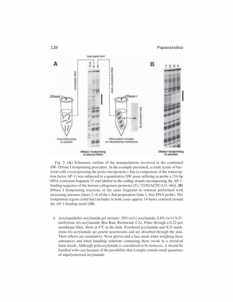
138 Papavassiliou
4. Acrylamide/bis-acrylamide gel mixture: 30% (w/v) acrylamide, 0.8% (w/v) N,N'-methylene–bis-acrylamide (Bio-Rad, Richmond, CA). Filter through a 0.22-µmmembrane filter. Store at 4°C in the dark. Powdered acrylamide and N,N'-meth-ylene-bis-acrylamide are potent neurotoxins and are absorbed through the skin.Their effects are cumulative. Wear gloves and a face mask when weighing thesesubstances and when handling solutions containing them (work in a chemicalfume hood). Although polyacrylamide is considered to be nontoxic, it should behandled with care because of the possibility that it might contain small quantitiesof unpolymerized acrylamide.
Fig. 2. (A) Schematic outline of the manipulations involved in the combinedSW–DNase I footprinting procedure. In the example presented, a crude lysate of bac-terial cells overexpressing the proto-oncoprotein c-Jun (a component of the transcrip-tion factor AP-1) was subjected to a quantitative SW assay utilizing as probe a 134-bpDNA restriction fragment (5'-end labeled in the coding strand) encompassing the AP-1-binding sequence of the human collagenase promoter [5'(-72)TGAGTCA3'(–66)]. (B)DNase I footprinting reactions of the same fragment in solution performed withincreasing amounts (lanes 2–4) of the c-Jun preparation (lane 1, free-DNA probe). Thefootprinted region (solid bar) includes in both cases approx 14 bases centered aroundthe AP-1-binding motif (20).
Combined SW–Nuclease Footprinting 139
5. Ammonium persulfate (10%; w/v): Dissolve (by vigorous vortexing) 1 g ofammonium persulfate (Bio-Rad) in 10 mL of distilled, deionized water. Filterthrough a 0.22-µm membrane filter. Store at 4°C; make fresh weekly. Ammo-nium persulfate is extremely destructive to tissue of the mucous membranes andupper respiratory tract, eyes, and skin. Inhalation may be fatal. Exposure cancause gastrointestinal disturbances and dermatitis. Wear gloves, safety glasses,respirator, and other protective clothing and work in a chemical fume hood. Washthoroughly after handling.
6. SDS–polyacrylamide gel electrophoresis (PAGE) running buffer (10X stock):0.25 M Tris base (Sigma) and 1.92 M glycine (Sigma). It is not necessary toadjust the pH. The proportions of Tris base and glycine give pH 8.3. Store atroom temperature in a large vessel (carboy). Dilute to 1X with distilled, deion-ized water, then add SDS to a final concentration of 0.1% (w/v).
7. SDS-PAGE sample buffer (4X stock): 0.5 M Tris–HCl pH 6.8, 8% (w/v) SDS,40% (v/v) glycerol (Sigma), and 0.4% (w/v) bromophenol blue (Sigma). Store inaliquots at –20°C. Before use, make a working solution of SDS-PAGE samplebuffer by diluting the 4X stock buffer and adding 2-mercaptoethanol (Sigma)to a final concentration of 5% (v/v) (see Note 1). 2-Mercaptoethanol is harm-ful if inhaled or absorbed through the skin. High concentrations are extremelydestructive to the mucous membranes, upper respiratory tract, skin, and eyes.Use only in a chemical fume hood. Gloves, safety glasses, and respirator shouldbe worn.
8. Western transfer buffer: 50 mM Tris base, 380 mM glycine, 0.1% (w/v) SDS, and20% (v/v) methanol (see Note 2). There is no need to adjust the pH of this bufferby the addition of acid or alkali. Store at room temperature in a large vessel.
9. Dithiothreitol (stock): Prepare a stock solution of 0.5 M dithiothreitol (Sigma)in distilled, deionized water and store in aliquots at –20°C. (See safety note initem 7.)
10. Phenylmethylsulfonyl fluoride (PMSF; stock): Prepare a 100 mM stock solutionof PMSF (Boehringer, Indianapolis, IN) in absolute ethanol and store in aliquotsat –20°C. PMSF is extremely destructive to the mucous membranes of the respi-ratory tract, the eyes, and the skin. It may be fatal if inhaled, swallowed, orabsorbed through the skin. It is a highly toxic cholinesterase inhibitor. Therefore,it should be used in a chemical fume hood and gloves and safety glasses shouldbe worn during handling.
11. 1 M KCl.12. 0.5 M MgCl2.13. SW blocking/renaturation buffer: 3% (w/v) nonfat dried milk (or 5% [w/v] lipid-
free bovine serum albumin [BSA]; see Note 3a), 25 mM HEPES·KOH, pH 7.5,50 mM KCl, 6.25 mM MgCl2, 1 mM dithiothreitol (freshly added from the 0.5 Mstock solution immediately before use), 10% (v/v) glycerol, 0.1% (v/v) NonidetP-40 (BDH, London, UK), and 0.2 mM PMSF (freshly added from the 100 mMstock solution just prior to use). Store at 4°C. Prepare also some SW blocking/renaturation buffer minus dried milk (or BSA).
140 Papavassiliou
14. Poly(vinyl alcohol) (stock): Prepare a 10% (w/v) stock solution of poly(vinylalcohol) (Sigma P 8136; average mol. wt. = 10,000) in distilled, deionized waterand store at –20°C.
15. SW binding/washing buffer: 12.5 mM HEPES.KOH, pH 7.5, 50 mM KCl, 6.25 mMMgCl2, 0.5 mM dithiothreitol (freshly added from the 0.5 M stock solution im-mediately before use), 2% (w/v) polyvinyl alcohol, 10% (v/v) glycerol, 0.05%(v/v) Nonidet P-40, and 0.2 mM PMSF (freshly added from the 100 mM stocksolution just prior to use). Store at 4°C. (See Note 4b.)
16. Phenol/chloroform/isoamyl alcohol (25:24:1; v/v): Mix just prior to use 25 volof phenol with 24 vol of chloroform and 1 vol of isoamyl alcohol. Phenol is highlycorrosive and can cause severe burns. Any areas of skin that come in contact withphenol should be rinsed with a large volume of water or PEG 400 (Sigma) andwashed with soap and water (do not use ethanol!). Chloroform is irritating to theskin, eyes, mucous membranes, and respiratory tract. It is also a carcinogen andmay damage the liver and kidneys. Wear gloves, protective clothing, safetyglasses, and respirator when handling these substances and carry out all manipu-lations in a chemical fume hood.
17. Chloroform/isoamyl alcohol (24:1; v/v): Mix 24 vol of chloroform with 1 volof isoamyl alcohol. This organic mixture can be stored at room temperature indark (brown) bottles indefinitely.
18. Nonspecific competitor DNA (stock solution): Dissolve salmon/herring sperm orcalf thymus DNA in distilled water, deproteinize it by sequential phenol/chloro-form/isoamyl alcohol (25:24:1; v/v) and chloroform/isoamylalcohol (24:1; v/v)extractions, sonicate to reduce the mean DNA length to 100–200 bp, precipitatethe DNA with ethanol, then resuspend it at 1 mg/mL in distilled, deionized water.
2.1.2. Reagents/Special Equipment
1. N,N,N' ,N'-tetramethylethylenediamine (TEMED; Bio-Rad). TEMED isextremely destructive to tissue of the mucous membranes and upper respiratorytract, eyes, and skin. Inhalation may be fatal. Prolonged contact can cause severeirritation or burns. Wear gloves, safety glasses, respirator, and other protectiveclothing and work in a chemical fume hood (TEMED is flammable!). Wash thor-oughly after handling.
2. Protein extract of interest (e.g., whole-cell-free extract, crude nuclear extract, orpartially purified extract), as concentrated as possible.
3. Prestained nonradioactive MW standards (Bio-Rad) or [14C]-methylated proteinMW markers (Amersham).
4. Nonfat dried milk powder (e.g., Cadbury’s Marvel or Carnation), or fatty acid-free BSA (Boehringer; fraction V).
5. Phenol: Redistilled (under nitrogen) phenol equilibrated with 100 mM Tris-HCl,pH 8.0, and 1 mM EDTA in the presence of 0.1% (w/v) 8-hydroxyquinoline.Phenol can be stored at 4°C in dark (brown) bottles for up to 2 mo. See the rel-evant safety note in Subheading 2.1.1.
6. Absolute ethanol.
Combined SW–Nuclease Footprinting 141
7. Salmon/herring sperm or calf thymus DNA (Sigma or Boehringer).8. Singly 32P end-labeled DNA probe bearing the binding site(s) of interest (see
Note 5). All necessary precautions should be observed to minimize exposure toionizing radiation during labeling and isolation of the probe; work behind protec-tive screens whenever possible.
9. Radioactive ink: Mix a small amount of 32P with waterproof black drawing ink,to a concentration of approx 200 cps (on a Geiger counter) per microliter.
10. 0.22-µm membrane filters (Millipore, Bedford, MA).11. Mini-slab gel electrophoresis apparatus, giving 0.5- to 1.0-mm-thick mini-gels
(e.g., Bio-Rad Mini Protean II system), and accompanying equipment.12. High-current (2–3 A) power supply (e.g., Bio-Rad or Hoefer, San Francisco, CA)
and electroblotting apparatus for Western transfer (e.g., Bio-Rad Trans-Blot);additional equipment for Western transfer (11).
13. Nitrocellulose membrane: suitable membranes comprised of unsupported or sup-ported nitrocellulose are available from a number of manufacturers, such asSchleicher & Schuell (Keene, NH; BA85, 0.45 µm), Millipore (Immobilon-NC),and Amersham (Hybond-C/C extra).
14. Plastic trays.15. Forceps.16. Plastic wrap such as cling film or Saran Wrap®.17. X-ray film (e.g., Kodak X-Omat AR, Rochester, NY).18. Additional equipment: protective gloves/glasses/respirator, 4°C shaking air
incubator, sonicator, 25°C shaking air incubator, Geiger counter, Kimwipes, allequipment for autoradiography.
2.2. Exposure of SW Blots to DNase I Treatment
2.2.1. Solutions
1. Eppendorf tube siliconization solution: 2% (v/v) dimethyldichlorosilane in 1,1,1-trichloroethane (BDH). Eppendorf tubes should be silanized by briefly immers-ing the opened tubes in a beaker containing this solution, pouring off excesssolution, and allowing the tubes to dry in air at room temperature. Dimethyl-dichlorosilane is particularly toxic. Gloves, safety glasses, respirator, and otherprotective clothing should be worn when handling it and should only be used in achemical fume hood.
2. Solutions 1, 12, and 15–17 of Subheading 2.1.1.3. DNase I (stock solution): Dissolve DNase I in 50% glycerol (in distilled, deion-
ized water) to a concentration of 2.5 mg/mL. Store frozen in 10-µL aliquots at –20°Cor –70°C. This stock is stable indefinitely.
4. 1 M CaCl2.5. DNase I reaction buffer: 10 mM MgCl2 and 5 mM CaCl2. Store at room temperature.6. DNase STOP solution A: 20 mM HEPES·KOH, pH 7.5, 20 mM EDTA, and 0.5%
(w/v) SDS. Store at 4°C.7. 5 M NaCl.8. DNase-STOP solution B: 60 mM HEPES.KOH, pH 7.5, 0.6 M NaCl, 60 mM
EDTA, 1.5% (w/v) SDS. Store at 4°C.
142 Papavassiliou
9. Proteinase K (stock solution): Dissolve Proteinase K in TE (10 mM Tris-HCl,pH 7.4, and 1 mM EDTA) to a concentration of 2.5 mg/mL. Store in aliquots at –20°C.
10. Probe elution buffer: 20 mM HEPES·KOH, pH 7.5, 0.3 M NaCl, 3 mM EDTA,0.2% (w/v) SDS, and 50 µg/mL Proteinase K.
11. Glycogen (stock solution): Prepare a stock solution of 10 mg/mL glycogen(Sigma G 0885) in distilled, deionized water and store in aliquots at –20°C; gly-cogen is used as a carrier to promote the precipitation of nucleic acids.
12. Ice-cold 80% (v/v) ethanol.13. Formamide loading buffer: 90% (v/v) deionized formamide, 1X TBE (see below),
0.025% (w/v) xylene cyanol FF (Sigma), and 0.025% (w/v) bromophenol blue.Store at –20°C after filtering. Formamide is a teratogen; take all safety precau-tions to avoid contact during manipulations involving this reagent.
14. TBE buffer (5X stock): 445 mM Tris base, 445 mM borate, 12.5 mM EDTA.Dissolve (under stirring for at least 1 h) 272.5 g ultrapure Tris base, 139.1 g boricacid (Sigma), and 23.3 g EDTA·(Na2) dihydrate (Sigma) in 4.5 L of distilled,deionized water. Make up to a final volume of 5 L. It is not necessary to adjustthe pH of the resulting solution, which should be around 8.3. Store at room tem-perature in a large vessel. This stock solution is stable for many months, but it issusceptible to the formation of a precipitate and should be inspected visuallyfrom time to time.
15. Fixing solution: 10% (v/v) acetic acid and 10% (v/v) methanol.
2.2.2. Reagents/Special Equipment
1. DNase I (DPFF grade; Worthington, Freehold, NJ).2. Proteinase K (Boehringer).3. Absolute ethanol (at –20°C).4. Single-edged disposable razor blades.5. Forceps.6. Siliconized 0.5-mL Eppendorf microcentrifuge tubes.7. Siliconized 1.5-mL Eppendorf microcentrifuge tubes.8. Drawn-out Pasteur pipets.9. Whatman (Clifton, NJ) 3MM paper.
10. Items 16 and 17 in Subheading 2.1.2.11. Intensifying screen (e.g., Cronex Lightning Plus; DuPont, Wilmington, DE).12. Additional equipment: beaker, sharp-tip pencil, wet ice, scintillation vials/
counter, vortexer, electronic timer, microcentrifuge (Eppendorf or equivalent),vortexing shaker set at 37°C, Geiger counter, SpeedVac concentrator (Savant,Hicksville, NY), thermostatted heating block at 95°C, plastic tank at gel dimen-sions (for gel fixing), vacuum gel dryer, and all equipment for autoradiography.
3. Methods3.1. SW Blotting
The SW protocol involves four steps: electrophoretic separation of proteinsby SDS-PAGE, electroblotting of the gel-fractionated proteins onto nitrocellu-
Combined SW–Nuclease Footprinting 143
lose (NC) membrane, probing of the blocked blot with the desired DNA probe,and detection of bound DNA by autoradiography of the washed, wet membrane.
1. Prepare and load the sample(s) and protein MW markers onto a standard SDS–polyacrylamide gel (11,12) and electrophorese at an appropriate voltage until thebromophenol blue dye reaches the bottom of the gel. An 8–10% polyacrylamideseparating gel is capable to resolve throughout most of the known DNA-bindingtranscription factor size range. Because the strength of the final signal obtainedby the SW technique is proportional to the quantity of protein electrophoresed onthe gel, best results are obtained by running the maximum amount of extract thatdoes not overload the gel. For typical 0.5- to 1-mm-thick protein mini-gels, thisis usually 30–150 µg of whole-cell-free, crude nuclear, or partially purified extractprotein per lane. (See Note 1.)
2. Remove the electrophoresed gel from the glass plates. Assemble a Western blotsandwich, place it in the electrophoresis tank containing an appropriate volumeof Western transfer buffer, and electroblot the proteins in the electrophoresed gelonto a NC membrane according to standard Western blotting protocols (11,13).Bear in mind that the best protein transfer is usually achieved by longer transfertimes (i.e., 30 V [40 mA] overnight at 4°C). (See Note 2).
3. When transfer is complete, gently peel the NC membrane off the gel, place it in aplastic tray, and gently wash for 10 min with 20–30 mL of SW blocking/renatur-ation buffer, omitting dried milk (or BSA).
4. Decant the solution and replace it with a sufficiently large volume of SW block-ing/renaturation buffer to completely immerse the membrane (usually 30–50 mL).
5. Incubate overnight at 4°C with gentle rocking or shaking to block nonspecificbinding sites on the membrane and to allow renaturation of the filter-immobi-lized proteins. (See Note 3.)
6. Using forceps, transfer the membrane to a fresh plastic tray and gently washfor 5 min with 20–30 mL of SW binding/washing buffer. The membrane can bestored in this buffer at 4°C for up to 1 d before incubation with the DNA probe.
7. Immerse the membrane (using forceps) in a fresh plastic tray containing a radio-active probe mixture consisting of the following:• SW binding/washing buffer (see Note 4).• 5–10 µg (specific activity approx 107 cpm/µg) of an asymmetrically [32P]-
labeled DNA fragment bearing the recognition site(s) for the sequence-spe-cific DNA-binding factor(s) of interest (see Note 5).
• 20 µg/mL nonspecific competitor DNA (see Note 6).To make the probe concentration as high as possible, the volume of SW bind-
ing/washing buffer should be the minimum needed to cover the membrane fully(smallest volumes are achieved if the membrane is sealed in a plastic bag). Workbehind Perspex or glass shields!
8. Incubate for 2–4 h at room temperature with gentle rocking or shaking. Longerincubation times at a lower temperature may result in a better signal from a poorlybinding factor.

144 Papavassiliou
9. Carefully remove the radioactive probe mixture and dispose of it safely (workbehind Perspex or glass shields!).
10. Using forceps, transfer the membrane to a plastic tray and wash for 10 min with100 mL of SW binding/washing buffer on a platform shaker (room temperature).
11. Repeat step 10 two to three times or until the radioactive level of the membraneno longer falls appreciably between washes (this can be monitored by a Geigercounter). (See Note 7.)
12. Place the wet NC sheet between two layers of tightly drawn cling film. With apad of Kimwipes, push out any trapped air bubbles under the cling film.
13. Expose to X-ray film at 4°C to locate regions of radioactive signal (protein[s]-bound probe). Exposure times of 1–3 h are usually sufficient to detect the radio-active species on the membrane. (See Note 8.)
3.2. Exposure of SW Blots to DNase I Treatment
The in situ footprinting reaction is done in four stages: localization andexcision of the areas on the NC sheet corresponding to protein-bound probe,partial digestion of the individual strip-associated and control (free in solution)DNAs with DNase I, extraction of the protein-bound DNA from the strip-immobilized protein–DNA complex, and analysis of the free and complexedDNA digestion products on a DNA sequencing gel.
1. Following autoradiography, align the NC sheet with the autoradiogram (seeNote 8), mark the precise position of radioactive signal(s) with a sharp-tip pencil(this will permit determination of the relative molecular weight of the detectedDNA-binding factor[s]), and cut the strip(s) corresponding to radioactivesignal(s) with a clean, sharp razor blade.
2. Using forceps, uncover the strip from the cling film and immediately transfer itinto a siliconized 0.5-mL Eppendorf tube containing 200 µL of SW binding/wash-ing buffer.
3. Allow the strip to equilibrate for 15 min on ice. Meanwhile, thaw an aliquot ofthe 2.5-mg/mL DNase I stock solution.
4. Bring the tube to room temperature, place it in a scintillation vial, and determinecpm of the probe retained on the strip by Cerenkov counting.
5. Transfer an equal amount of radioactivity of free probe to a separate, siliconized0.5-mL Eppendorf tube containing 200 µL of SW binding/washing buffer, andsubject it to the same manipulation as its membrane-associated counterpart (step 3).
6. Prepare an appropriate dilution of DNase I in ice-cold distilled, deionized water.Mix thoroughly by inversion and gentle vortexing.
7. Add to both samples 200 µL of DNase I reaction buffer and mix by flicking. Letthe tubes stand for 1 min at room temperature. It is not necessary to close the capson the tubes until addition of the DNase stop solutions (step 10).
8. Add dilute DNase I to a final concentration of 25 ng/mL and quickly distribute byflicking. It is helpful—especially when footprinting several strips—to have allnecessary items (pipetmen, buffers, timer, DNase I) in close proximity. The
Combined SW–Nuclease Footprinting 145
smoother this procedure goes, the better (and more reproducible!) the footprint(s)will be.
9. Incubate for 1 min at room temperature (see Note 9). As with solution footprintingprotocols, the exposure time for the free-DNA control reaction can be titrated toachieve the cutting intensity profile of the membrane-bound form. Nevertheless,we have found (employing probes of various lengths) that the above combinationof digestion time and DNase I concentration generates sufficient cleavage for agood signal-to-noise ratio.
10. Following treatment, remove the strip (with forceps) from the tube and rapidlyimmerse it in 500 µL of ice-cold DNase-STOP solution A. Leave on ice for 2 min(do not vortex!). Terminate the control reaction (free probe) by adding 200 µL ofice-cold DNase-STOP solution B; vortex thoroughly, spin briefly, transfer into asiliconized 1.5-mL Eppendorf tube, and proceed directly to step 15.
11. Place the strip (using forceps) in a siliconized 0.5-mL Eppendorf tube containing200 µL of probe elution buffer. Spin briefly in a microcentrifuge to submerge theentire strip.
12. Incubate the tube on a vortexing shaker at 37°C for 2 h.13. Add 100 µL of distilled, deionized water and vortex the tube vigorously (2 min).14. Microcentrifuge for 2 min to pellet the NC strip, and transfer the supernatant into
a siliconized 1.5-mL Eppendorf tube. A Geiger counter can be used to monitorefficient recovery of radioactivity; typically, >90% of the membrane-bound probeis released by this process.
15. Extract once with phenol/chloroform/isoamyl alcohol (25:24:1; v/v) and oncewith chloroform/isoamyl alcohol (24:1; v/v). In both cases, mix by vortexing (for10 s) and spin for 5 min.
16. Transfer the aqueous (top) layer to a fresh siliconized 1.5-mL Eppendorf tube.Precipitate the DNA with cold (–20°C) ethanol in the presence of 10 mMMgCl2 (added from the 0.5 M stock solution; MgCl2 aids in the recovery ofsmall DNA fragments) and 10 µg carrier glycogen; mix by inversion, spin at12,000g for 15 min.
17. Remove and discard the supernatant with a drawn-out Pasteur pipet, being care-ful not to aspirate the DNA (the bottom of the tube can be held to a Geiger counterto check that the DNA pellet remains). Add 800 µL of ice-cold 80% ethanol andrinse the pellet by gently rolling the microcentrifuge tube. Respin for 3 min.
18. Remove and discard the supernatant using a drawn-out Pasteur pipet, takingextreme care not to disturb the tiny, whitish pellet or the area of the tube wherethe pellet should be located (the DNA pellet frequently adheres only loosely tothe walls of the tube). Dry the pellet in a SpeedVac rotary concentrator. Do notallow the drying procedure to continue past the point of dryness because thesample may be difficult to resuspend.
19. Dissolve the pellet in 6–8 µL of formamide loading buffer; pipet the loadingbuffer onto the upper, inside surface of tube and tap the tube to drop the dropletonto the DNA pellet. Vortex briefly at high speed for approx 15 s and micro-centrifuge for 30 s to collect all of the solution to the bottom of the tube.
146 Papavassiliou
20. Transfer to fresh siliconized 1.5-mL Eppendorf tubes and determine the totalradioactivity recovered by Cerenkov counting each sample for 1 min in a scintil-lation counter.
21. Heat samples to 95°C for 3 min to denature DNA and immediately chill in wet ice.22. Spin briefly to bring the liquid to the bottom of the tubes. Samples can be electro-
phoresed immediately or stored at –70°C for no more than 24 h after footprinting.23. Load 1500–2000 cpm of each DNA digestion product (adjust volumes accord-
ingly if necessary; it is essential that a consistent volume of sample be loaded oneach lane) onto a pre-electrophoresed, 5–10% denaturing urea (sequencing) gel(see Notes 9b and 10a). Electrophorese in 1X TBE buffer at 60–70 W constantpower (for a 34 × 40 cm, 0.4-mm-thick gel) until the marker dye fronts havemigrated the appropriate distance in order to visualize the DNA region of interest(11). To determine the location of the transcription factor-binding site(s), theDNase I digests are electrophoresed alongside a Maxam–Gilbert G + A sequenc-ing ladder prepared from the end-labeled footprint probe (14). See Chapter 7 fora fast protocol for preparing such a ladder.
24. Disassemble gel apparatus, carefully lift off one glass plate and soak the gel (stillon the second glass plate) in fixing solution for 15 min (see Note 10b).
25. Drain briefly, overlay the gel with two sheets of 3MM paper, and carefully peel itoff the glass plate. Cover the gel surface with plastic wrap and dry under vacuumat 80°C for approx 1 h.
26. Expose the dry gel to X-ray film overnight at –70°C with an intensifying screen(a piece of paper placed between the gel and the film will prevent spurious expo-sure of the film resulting from static electricity). Several different exposures maybe required to obtain suitable band densities.
27. Compare lanes corresponding to free and protein-bound DNAs to identify theregion(s) of protection; the region(s) of the DNA fragment that is bound by thefactor appears as a blank stretch (footprint) in the otherwise continuous back-ground of digestion products.
4. Notes1. The diversity of properties characteristic of DNA-binding transcription factors
imposes an empirical determination of the conditions under which the sample(s)is prepared for SDS-PAGE. In some cases, the reducing agent (2-mercapto-ethanol) should be omitted from the sample buffer and, in others, the SDS con-centration should be lowered to 0.5%. Furthermore, some DNA-binding proteinsmay not withstand the sample boiling before loading on the gel.
2. The presence of methanol in the Western transfer buffer may cause a problemduring the electrophoretic transfer of some bulky DNA-binding proteins (gelshrinkage reduces pore size).
3. a. The commercially available nonfat dried milk preparations from various sup-pliers contain large amounts of protein kinase/phosphatase activities; theseactivities can potentially interfere with binding of the DNA probe to transcrip-tion factors whose DNA-binding capacity is known, or suspected, to be subject to
Combined SW–Nuclease Footprinting 147
regulation by inducible phosphorylation/dephosphorylation events. If this is thecase, substitute nonfat dried milk in the SW blocking/renaturation buffer forthe recommended grade of lipid-free BSA; this particular grade contains onlytrace amounts of the aforementioned activities and should be preferred as block-ing agent (15,16). Moreover, the use of lipid-free BSA results in an even back-ground throughout and enhances the specific signal-to-noise ratio in theDNA-probing step (17).b. By manipulating the conditions for renaturation of the membrane-immobilizedproteins (e.g., by incorporating a cycle of protein denaturation and renaturation[16]), the method may be extended to the analysis of proteins resolved in two-dimensional gels (18). This offers a powerful and convenient means for studyingcell cycle/type/stimulus-dependent DNA–transcription factor interactions andtheir regulatory roles in gene activity.
4. a. Inclusion of poly(vinyl alcohol) (a molecular crowding agent [volumeexcluder]) in the buffer decreases the amount of small ions/water available forhydration of any probe dissociated from the immobilized protein matrix and ren-ders the aqueous environment unfavorable for the unbound DNA. Consequently,the effective concentration of the probe is increased and interactions with lowbinding constants are stabilized.b. It may be important in some cases to supplement this buffer with ZnSO4(Aldrich, Milwaukee, WI; final concentration 10 µM) if the transcription factor(s)under study is known, or suspected, to contain a zinc-finger domain(s).
5. a. The DNA chosen for probing the protein blot can be a cis-acting regulatory (pro-moter/enhancer) DNA restriction fragment in the size range of 125–250 bp, with theputative transcription-factor-binding sites located no less than 20–25 bp from thelabeled end. This is to ensure that the region of DNA to be investigated for the pres-ence of footprints is capable of being accurately resolved on a sequencing gel.b. A prerequisite for the subsequent DNase I footprinting analysis is the use of aDNA probe that has been labeled on only one strand of the DNA duplex. Thelabeling of only one strand of a promoter/enhancer restriction fragment can beachieved in a number of ways, such as using T4 polynucleotide kinase and [γ-32P]ATP (5'-end labeling), the large (Klenow) fragment of E. coli DNA polymerase Iand [α-32P] dNTPs (3'-end labeling [“filling in”]), or the polymerase chain reac-tion (PCR) amplification (19). Preparation of radiolabeled DNA employing anyof these methodologies requires about 8 h. A combination of 5' and 3' end-labeledDNA probes allows both strands to be analyzed side by side from the same end ofthe DNA duplex.c. For optimal sensitivity in the SW procedure, the probe should be of as high aspecific activity as possible and highly purified. The latter can be assured byusing a nucleic acid-specific, ion-exchange column, such as the Elutip™-d(Schleicher & Schuell) or the NACS prepac cartridge (BRL, Gaithersburg, MD)(11). It is recommended not to store the pure, labeled DNA probe longer than2–4 d, because the radiation creates nicks in the DNA that will appear as addi-tional bands in the sequencing gel.
148 Papavassiliou
6. Synthetic alternate copolymers, such as poly[dI–dC] · poly[dI–dC] or poly[dA–dT] · poly[dA–dT] (Boehringer or Pharmacia), at similar final concentrationsmay be more suitable competitors for some DNA-binding transcription factors.
7. Longer washing times at room temperature are detrimental resulting in dissocia-tion of the bound probe, but longer washing times with cold (4°C) SW binding/washing buffer can reduce background without significant signal loss. To reducepossible low-specificity DNA–protein complexes, the final wash can be per-formed in cold SW binding/washing buffer with higher salt concentration (i.e.,100–200 mM KCl).
8. If prestained nonradioactive protein MW standards have been used, the edges ofthe plastic wrap should be marked with pieces of tape labeled with radioactive(or fluorescent) ink (let the ink dots dry completely before exposing to X-rayfilm!). These marks allow the autoradiogram to be aligned with the protein sizemarkers on the NC sheet (Subheading 3.2., step 1), facilitating calculations onthe relative molecular weight of the specific DNA-bound protein species(obtained radioactive signal[s]). If [14C]-methylated protein MW markers havebeen used, their position will be apparent on the X-ray film without the need touse the radioactive (or fluorescent) ink procedure.
9. a. Although longer digestion times do not enhance background cutting(uncomplexed DNA is minimized), they may lead to substantial deviations fromthe required “single-hit kinetics” (i.e., on average, each DNA molecule is nickedat most once; this corresponds to nicking approx 30–50% of the DNA molecules).b. Intense bands due to uncleaved, full-length probe should be visible at the topof each lane in the DNA sequencing gel. This aids in determining whether single-hit kinetics are operative and whether equal amounts of total radioactivity areloaded in each lane.
10. a. If the DNA probe is relatively long (i.e., >175 bp) and multiple transcription-fac-tor-binding sites are to be resolved, a gradient or wedge sequencing gel can be used.b. Wedge-shaped gels must be soaked in fixing solution, followed by 5% glyc-erol for 10 min prior to drying.
References1. Galas, D. J. and Schmitz, A. (1978) DNase footprinting: A simple method for the
detection of protein-DNA binding specificities. Nucleic Acids Res. 5, 3157–3170.2. Tullius, T. D. and Dombroski, B. A. (1986) Hydroxyl radical “footprinting”: high-
resolution information about DNA–protein contacts and application to λ repres-sor and Cro protein. Proc. Natl. Acad. Sci. USA 83, 5469–5473.
3. Kuwabara, M. D. and Sigman, D. S. (1987) Footprinting DNA–protein complexes insitu following gel retardation assays using 1,10-phenanthroline–copper ion: Escheri-chia coli RNA polymerase–lac promoter complexes. Biochemistry 26, 7234–7238.
4. Johnsrud, L. (1978) Contacts between Escherichia coli RNA polymerase and alac operon promoter. Proc. Natl. Acad. Sci. USA 75, 5314–5318.
5. Garner, M. M. and Revzin, A. (1981) A gel electrophoresis method for quantify-ing the binding of proteins to specific DNA regions: application to compo-
Combined SW–Nuclease Footprinting 149
nents of the Escherichia coli lactose operon regulatory system. Nucleic AcidsRes. 9, 3047–3060.
6. Fried, M. and Crothers, D. M. (1981) Equilibria and kinetics of lac repressor-operator interactions by polyacrylamide gel electrophoresis. Nucleic Acids Res. 9,6505–6525.
7. Miskimins, W. K., Roberts, M. P., McClelland, A., and Ruddle, F. H. (1985) Useof a protein-blotting procedure and a specific DNA probe to identify nuclear pro-teins that recognize the promoter region of the transferrin receptor gene. Proc.Natl. Acad. Sci. USA 82, 6741–6744.
8. Smith, S. E. and Papavassiliou, A. G. (1992) A coupled Southwestern–DNase Ifootprinting assay. Nucleic Acids Res. 20, 5239–5240.
9. Polycarpou-Schwarz, M. and Papavassiliou, A. G. (1993) Probing of DNA–proteincomplexes immobilized on protein-blotting membranes by the chemical nuclease1,10-phenanthroline (OP)–cuprous ion. Methods Mol. Cell. Biol. 4, 22–26.
10. Polycarpou-Schwarz, M. and Papavassiliou, A. G. (1993) Distinguishing specificfrom nonspecific complexes on Southwestern blots by a rapid DMS protectionassay. Nucleic Acids Res. 21, 2531–2532.
11. Sambrook, J., Fritsch, E. F., and Maniatis, T. (1989) Molecular Cloning: A Labo-ratory Manual, Cold Spring Harbor Laboratory, Cold Spring Harbor, NY.
12. Laemmli, U. K. (1970) Cleavage of structural proteins during the assembly of thehead of bacteriophage T4. Nature 227, 680–685.
13. Towbin, H., Staehelin, T., and Gordon, J. (1979) Electrophoretic transfer of pro-teins from polyacrylamide gels to nitrocellulose sheets: procedure and someapplications. Proc. Natl. Acad. Sci. USA 76, 4350–4354.
14. Maxam, A. and Gilbert, W. (1980) Sequencing end-labeled DNA with base-spe-cific chemical cleavages. Methods Enzymol. 65, 499–560.
15. Papavassiliou, A. G., Bohmann, K., and Bohmann, D. (1992) Determining theeffect of inducible protein phosphorylation on the DNA-binding activity of tran-scription factors. Anal. Biochem. 203, 302–309.
16. Polycarpou-Schwarz, M. and Papavassiliou, A. G. (1995) Protein–DNA interac-tions revealed by the Southwestern blotting procedure. Methods Mol. Cell. Biol.5, 152–161.
17. Papavassiliou, A. G. and Bohmann, D. (1992) Optimization of the signal-to-noiseratio in south-western assays by using lipid-free BSA as blocking reagent. NucleicAcids Res. 20, 4365–4366.
18. Moreland, R. B., Montross, L., and Garcea, R. L. (1991) Characterization of theDNA-binding properties of the polyomavirus capsid protein VP1. J. Virol. 65,1168–1176.
19. Lakin, N. D. (1993) Determination of DNA sequences that bind transcription fac-tors by DNA footprinting, in Transcription Factors: A Practical Approach(Latchman, D. S., ed.), IRL, Oxford, pp. 27–47.
20. Angel, P., Imagawa, M., Chiu, R., Stein, B., Imbra, R. J., Rahmsdorf, H. J., et al.(1987) Phorbol ester-inducible genes contain a common cis element recognizedby a TPA-modulated trans-acting factor. Cell 49, 729–739.
1O2 Modification of DNA 151
151
From: Methods in Molecular Biology, vol. 148: DNA–Protein Interactions: Principles and Protocols, 2nd ed.Edited by: T. Moss © Humana Press Inc., Totowa, NJ
11
Diffusible Singlet Oxygenas a Probe of DNA Deformation
Malcolm Buckle and Andrew A. Travers
1. IntroductionThe DNA double helix is highly malleable and, when constrained, either as
a small circle or by the action of a protein, can be readily distorted from itsenergetically favored conformation. Such distortions may be relativelymoderate, as exemplified by smooth bending (which maintains base stacking),or more extreme when this stacking can be disrupted. Deformations of thislatter type include kinks, where the direction of the double helical axis ischanged abruptly at a single-base step, and localized strand separation, whichmay be a direct consequence of protein-induced unwinding or of high negativesuperhelicity in free DNA. Both kinks and localized unwinding can arisetransiently during the enzymatic manipulation of DNA by recombinases andby protein complexes involved in the establishment of unwound regions duringthe initiation of transcription or of DNA replication.
The detection of localized lesions in the DNA double helix requires that thebases at the site of the lesion be accessible to a chemical reagent only when theDNA is distorted. Further, because protein-induced distortions are not neces-sarily sequence dependent, it is desirable that any reagent used for detectionpossesses minimal selectivity with respect to the base. Additionally the reagentitself should ideally be noninvasive; that is, it should not form a stablenoncovalent complex with DNA and thereby possess the potential to perturbthe local conformation of the double helix. Other highly desirable attributes forreagents used for this purpose is that they should possess short half-lives andcan be generated on demand in situ. These latter characteristics permit the studyand detection of transient intermediates in the processes leading to the
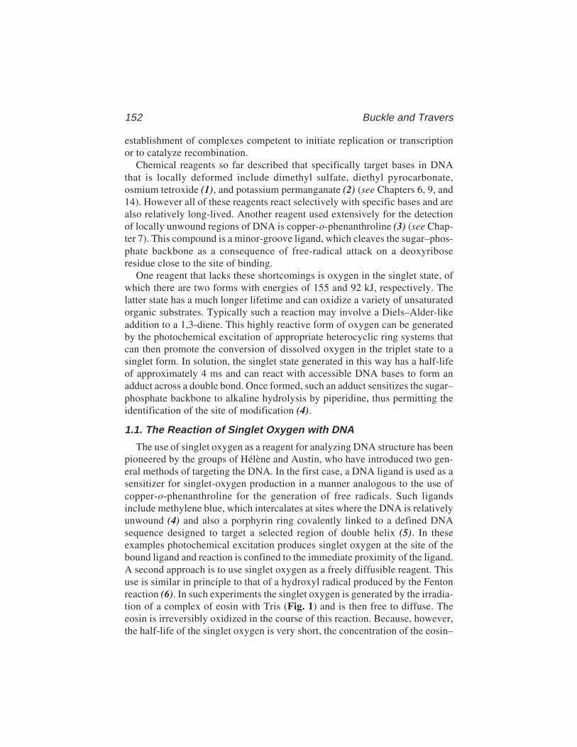
152 Buckle and Travers
establishment of complexes competent to initiate replication or transcriptionor to catalyze recombination.
Chemical reagents so far described that specifically target bases in DNAthat is locally deformed include dimethyl sulfate, diethyl pyrocarbonate,osmium tetroxide (1), and potassium permanganate (2) (see Chapters 6, 9, and14). However all of these reagents react selectively with specific bases and arealso relatively long-lived. Another reagent used extensively for the detectionof locally unwound regions of DNA is copper-o-phenanthroline (3) (see Chap-ter 7). This compound is a minor-groove ligand, which cleaves the sugar–phos-phate backbone as a consequence of free-radical attack on a deoxyriboseresidue close to the site of binding.
One reagent that lacks these shortcomings is oxygen in the singlet state, ofwhich there are two forms with energies of 155 and 92 kJ, respectively. Thelatter state has a much longer lifetime and can oxidize a variety of unsaturatedorganic substrates. Typically such a reaction may involve a Diels–Alder-likeaddition to a 1,3-diene. This highly reactive form of oxygen can be generatedby the photochemical excitation of appropriate heterocyclic ring systems thatcan then promote the conversion of dissolved oxygen in the triplet state to asinglet form. In solution, the singlet state generated in this way has a half-lifeof approximately 4 ms and can react with accessible DNA bases to form anadduct across a double bond. Once formed, such an adduct sensitizes the sugar–phosphate backbone to alkaline hydrolysis by piperidine, thus permitting theidentification of the site of modification (4).
1.1. The Reaction of Singlet Oxygen with DNA
The use of singlet oxygen as a reagent for analyzing DNA structure has beenpioneered by the groups of Hélène and Austin, who have introduced two gen-eral methods of targeting the DNA. In the first case, a DNA ligand is used as asensitizer for singlet-oxygen production in a manner analogous to the use ofcopper-o-phenanthroline for the generation of free radicals. Such ligandsinclude methylene blue, which intercalates at sites where the DNA is relativelyunwound (4) and also a porphyrin ring covalently linked to a defined DNAsequence designed to target a selected region of double helix (5). In theseexamples photochemical excitation produces singlet oxygen at the site of thebound ligand and reaction is confined to the immediate proximity of the ligand.A second approach is to use singlet oxygen as a freely diffusible reagent. Thisuse is similar in principle to that of a hydroxyl radical produced by the Fentonreaction (6). In such experiments the singlet oxygen is generated by the irradia-tion of a complex of eosin with Tris (Fig. 1) and is then free to diffuse. Theeosin is irreversibly oxidized in the course of this reaction. Because, however,the half-life of the singlet oxygen is very short, the concentration of the eosin–
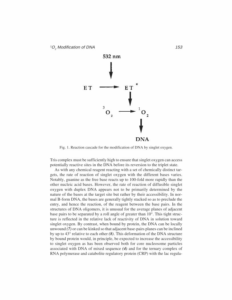
1O2 Modification of DNA 153
Tris complex must be sufficiently high to ensure that singlet oxygen can accesspotentially reactive sites in the DNA before its reversion to the triplet state.
As with any chemical reagent reacting with a set of chemically distinct tar-gets, the rate of reaction of singlet oxygen with the different bases varies.Notably, guanine as the free base reacts up to 100-fold more rapidly than theother nucleic acid bases. However, the rate of reaction of diffusible singletoxygen with duplex DNA appears not to be primarily determined by thenature of the bases at the target site but rather by their accessibility. In nor-mal B-form DNA, the bases are generally tightly stacked so as to preclude theentry, and hence the reaction, of the reagent between the base pairs. In thestructures of DNA oligomers, it is unusual for the average planes of adjacentbase pairs to be separated by a roll angle of greater than 10°. This tight struc-ture is reflected in the relative lack of reactivity of DNA in solution towardsinglet oxygen. By contrast, when bound by protein, the DNA can be locallyunwound (7) or can be kinked so that adjacent base-pairs planes can be inclinedby up to 43° relative to each other (8). This deformation of the DNA structureby bound protein would, in principle, be expected to increase the accessibilityto singlet oxygen as has been observed both for core nucleosome particlesassociated with DNA of mixed sequence (4) and for the ternary complex ofRNA polymerase and catabolite regulatory protein (CRP) with the lac regula-
Fig. 1. Reaction cascade for the modification of DNA by singlet oxygen.

154 Buckle and Travers
tory region (9). In the latter case, which is the only example for whichinformation is so far available, reaction is observed with all four DNAbases, although there are insufficient sites documented to preclude somebase selectivity of the reagent. If the local structure of the DNA is the princi-pal determinant of reactivity, the reagent should be able to access the basesthrough both the major and minor grooves, as is indeed observed (9). How-ever, the precise range of DNA structures available for reaction with singletoxygen remains to be established, as does the possible influence of bound pro-tein on sensitizing or quenching the reactivity of the bases.
A major advantage of a photoactivated reaction is the ability to produce thereactive species under highly controlled conditions. Both porphyrins andmethylene blue can be activated by a continuous laser beam. However, eosinabsorbs maximally at 523.2 nm, a wavelength that is close to the 532-nm out-put from a neodymium–YAG laser. This fortuitous proximity is of particularutility, as it permits the production of singlet oxygen either from an effectivelycontinuous output or from a discrete number of pulses, each of approximately7 ns duration. This method of activation utilizes the high-energy output of theNd–YAG laser and also allows the kinetics of the protein-induced structuralalterations in DNA to be followed with high precision. It should be noted thatbecause the half-life of singlet oxygen in solution is only 4 ms (10), the timeavailable for reaction with the DNA is essentially limited by the time of irra-diation. This short half-life also means that it is unnecessary to terminate anyreaction by the addition of a quenching reagent.
2. Materials1. A neodymium–yttrium–aluminium garnet (Nd-YAG) laser (Spectra-Physics
DCR-11) set up as illustrated in Fig. 2 is used to generate a beam of polarizedcoherent light at a wavelength of 1064 nm. A doubling crystal correctly alignedin the beam path produces a mixture of light at 1064 and 532 nm. A dichroicmirror arranged so that the 532-nm beam is deflected down onto a thermostattedEppendorf tube containing 20 µL of the sample to be irradiated subsequentlyseparates this mixture. Alternatively, if the volume of the irradiated solution issmall, the different wavelengths can be separated by an appropriate arrangementof prisms and the 532-nM beam directed into an Eppendorf tube held horizon-tally in a metal block maintained at the required temperature. It is essential toobtain an adequate separation of these two wavelengths because even a relativelylow proportion of the primary emission at 1064 nm could result in a rapid heatingof the sample. The DCR-11 functions at a frequency of 10 Hz each pulse of about7 ns duration delivering 160 mJ of energy. Other NdYAG lasers are obtainablethat can deliver up to twice this energy per pulse.
2. Eosin isothiocyanate is obtained from Molecular Probes.3. 10 mM Tris-HCl, pH 7.9.
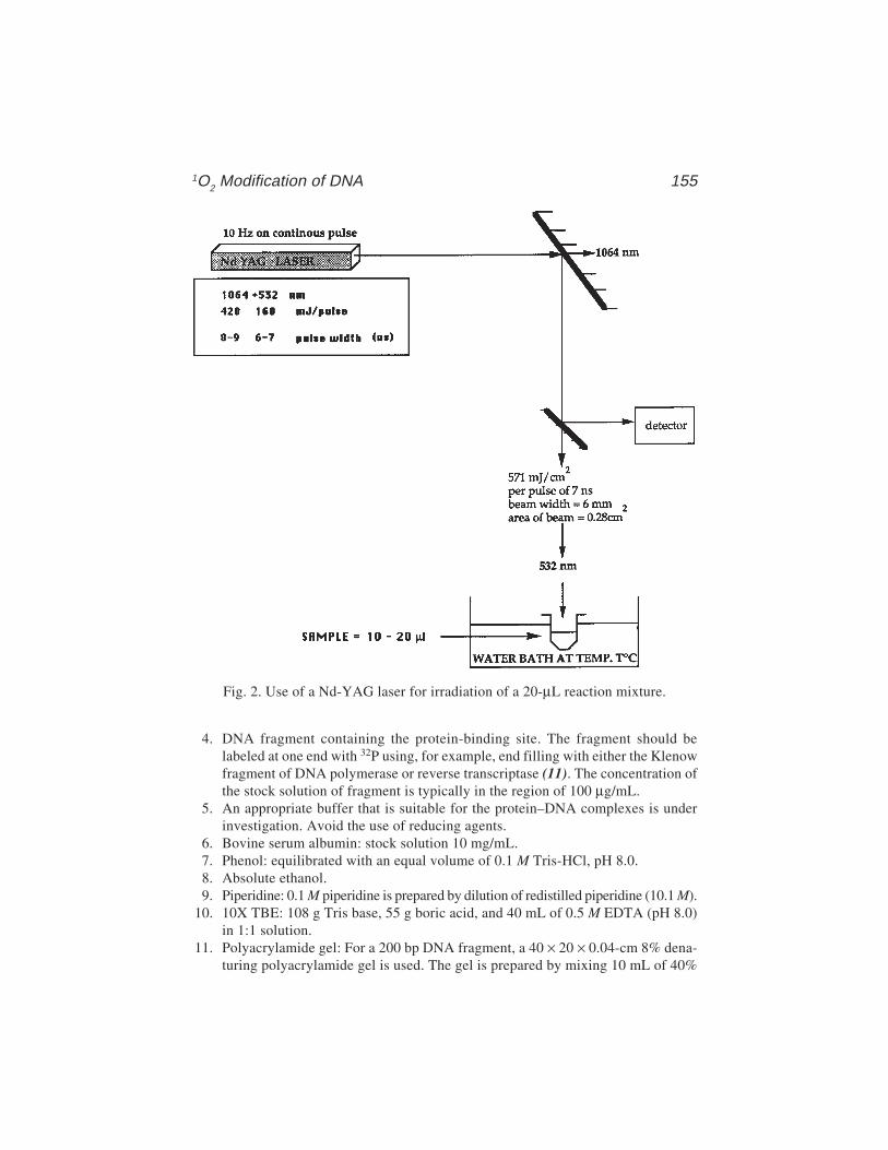
1O2 Modification of DNA 155
4. DNA fragment containing the protein-binding site. The fragment should belabeled at one end with 32P using, for example, end filling with either the Klenowfragment of DNA polymerase or reverse transcriptase (11). The concentration ofthe stock solution of fragment is typically in the region of 100 µg/mL.
5. An appropriate buffer that is suitable for the protein–DNA complexes is underinvestigation. Avoid the use of reducing agents.
6. Bovine serum albumin: stock solution 10 mg/mL.7. Phenol: equilibrated with an equal volume of 0.1 M Tris-HCl, pH 8.0.8. Absolute ethanol.9. Piperidine: 0.1 M piperidine is prepared by dilution of redistilled piperidine (10.1 M).
10. 10X TBE: 108 g Tris base, 55 g boric acid, and 40 mL of 0.5 M EDTA (pH 8.0)in 1:1 solution.
11. Polyacrylamide gel: For a 200 bp DNA fragment, a 40 × 20 × 0.04-cm 8% dena-turing polyacrylamide gel is used. The gel is prepared by mixing 10 mL of 40%
Fig. 2. Use of a Nd-YAG laser for irradiation of a 20-µL reaction mixture.
156 Buckle and Travers
acrylamide solution (380 g DNA-sequencing grade acrylamide, 20 g N,N'-methylenebisacrylamide in 1:1 solution), 5 mL 10X TBE, 23 g urea, deionizedwater to 50 mL. When the urea is fully dissolved, add 100 µL of 10% ammoniumpersulfate and mix with rapid stirring, Then, add 60 µL TEMED (N,N,N'N'-tetramethylethylene diamine) and mix rapidly. Pour the gel solution between thesealed gel plates and insert a comb with 0.25-cm teeth into the gel solution. Allowto set, remove comb, and clean slots with gel buffer using a Hamilton syringe.
12. Gel running buffer, 1X TBE: 90 mM Tris, 90 mM borate, pH 8.3, and 10 mMethylenediaminetetracetate (EDTA) pH 8.0 made by dilution of 10X TBE.
13. Gel loading buffer: 95% formamide, 10 mM ethylenediaminetetracetate (pH 8.0),1 mg/mL xylene cyanol FF, and 1 mg/mL bromophenol blue.
14. X-ray film.15. 10 mM dithiothreitol (DTT).
3. Methods3.1. Preparation of Eosin–Tris Complex
1. A 10 mM stock solution of this complex is formed by incubating 10 mM eosinisothiocyanate in 10 mM Tris-HCl, pH 7.9 for 2 h at 37°C, taking care to avoidexposure to light. The eosin isocyanate is diluted from a freshly prepared 100 mMstock solution.
2. The concentration of eosin is estimated from the absorption of the solution at 525 nm(ε523.2 = 25.6 for a 1 M solution) and adjusted by the addition of the appropriatevolume of double-distilled water.
3.2. Formation of Nucleoprotein Complexes
1. The first step in the detection of protein-induced deformation of DNA is the for-mation of a nucleoprotein complex. For example, RNA polymerase (100 nM)and end-labeled fragments of DNA containing the lac UV5 promoter (4 nM) aremixed in a buffer containing 100 mM KCl, 10 mM MgCl2, 20 mM HEPES(pH 8.4), 3% glycerol, and 100 µg/mL bovine serum albumin in a total volumeof 20 µL (9).
2. This mixture is then incubated for 30 min at 37°C.
3.3. Irradiation of the Nucleoprotein Complex
1. Once the nucleoprotein complex has been formed a fresh stock of the eosin–Triscomplex is added at an appropriate concentration to 20 µL of the target solutionin a small Eppendorf tube. Typically, a final concentration of 50 mM is used (seeNote 1).
2. Immediately after the addition of the eosin–Tris complex the whole mixture isirradiated for 20 s at 10 Hz. This corresponds to a total energy dose of 115 J/cm2
(see Note 2). Successful activation of the eosin–Tris complex is apparent by adetectable change in the color of the solution consequent upon a shift in theabsorption maximum from 523 to 514 nm on oxidation.
1O2 Modification of DNA 157
3. Although the half-life of singlet oxygen is sufficiently short to obviate the needto remove excess reagent, it is advisable to add a quenching agent such asdithiothreitol immediately on cessation of irradiation to minimize any secondaryradical reactions. Typically, 1 µL of 10 mM dithiothreitol is added to the irradi-ated solution.
3.4. Detection of Sites of Reaction with Singlet Oxygen
1. After irradiation and quenching, 30 µL double-distilled water is added to each sample.2. Fifty microliters of a phenol freshly prepared by equilibration of melted phenol
with an equal volume of 0.1 M Tris-HCl is then added.3. After mixing with a vortex mixer, the samples are centrifuged for 1 min in a
bench-top microcentrifuge at 5000g to separate the aqueous and organic layers.4. The upper aqueous layer is removed with an automatic pipet to a clean Eppendorf tube.5. Three to four volumes of ethanol at 0°C are then added and the samples placed in
a dry ice/ethanol bath for 1 h.6. Centrifuge the samples for 15 min at 5000g in a bench-top centrifuge.7. Remove the ethanol using an automatic pipet.8. Dry the samples in a centrifugal evaporator.9. Resuspend in 100 µL of freshly prepared piperidine solution.
10. Heat at 90°C for 30 min (see Note 6).11. Sites of cleavage are determined by separation on polyacrylamide gels (typically
40 cm, run at 60 W constant power until the xylene cyanol FF marker hasmigrated 23 cm into gel) followed by autoradiography (typically 2–24 h expo-sure depending on the specific activity of the labeled DNA fragment). A typicalresult is shown in Fig. 3. Cleavage at a particular site results in the generation ofa band of defined length. Standard Maxam and Gilbert sequencing reactions (12)can be performed and loaded on the same gel to identify the cleavage sites.
4. Notes1. Because the half-life of singlet oxygen is short, the average path length for diffu-
sion is also short. Consequently, to ensure an adequate rate of reaction, the eosin–Tris concentration must be sufficiently high to ensure that all potential targets inthe DNA are accessible to the reactive entity.
2. Although the energy dose used during irradiation may appear to be substantial, itshould be borne in mind that even with a high-intensity laser, each pulse deliversonly 160 mJ and consequently, full saturation of the system requires a consider-able pulse repetition rate.
3. For optimum reactivity, it is essential that radical scavengers such as mercapto–groups should, as far as possible, be rigorously excluded from the reaction mix-ture, as they would effectively prevent any singlet oxygen from arriving at itstarget site. For the same reasons, the concentrations of alcohols such as glycerolshould be kept as low as possible.
4. Ideally, protein–DNA complexes should be insensitive to the presence of thenonirradiated eosin–Tris complex. However, it has been observed that the half-

158 Buckle and Travers
Fig. 3. Reaction of singlet oxygen with a binary complex of E. coli RNA poly-merase with the lac UV5 promoter. The figure shows an autoradiograph of the patternof reactivity on the transcribed strand in the presence and absence of RNA polymerase.Note that the bands visible in the DNA only lane result from piperidine cleavage at(Py)3 sequences and their occurrence is independent of both irradiation and the pres-ence of eosin–Tris.

1O2 Modification of DNA 159
life of certain complexes, in particular the binary CAP–DNA and RNA poly-merase–DNA complexes, is reduced by approximately an order of magnitudewith the sensitizer present (9). For stable complexes in which the protein has along residence time this effect does not significantly interfere with the detectionof DNA deformations because the time of irradiation is short relative to the sta-bility of the complex. At this time, it is unclear whether this effect is general or isrestricted to particular complexes. Nevertheless, it is essential to determine thestability of complexes under study under the precise conditions corresponding tothose prevailing during irradiation. The method of choice is gel retardation (elec-trophoretic mobility shift assay).
5. The short time of irradiation allows the use of the singlet-oxygen reaction inkinetic studies. Here again, to prevent any perturbation of an enzymatic manipu-lation of DNA, it would be necessary to add the eosin–Tris complex immediatelyprior to irradiation after the reaction under study had proceeded for the requiredtime. For this purpose, a rapid-mixing device would be necessary.
6. To obtain sharp bands on polyacrylamide gels, it is advisable for the samples tobe transferred to clean Eppendorf tubes immediately prior to the evaporation ofpiperidine. Removal of piperidine in a centrifugal evaporator should also be car-ried out as rapidly as possible, and any form of heating should be avoided, as thisincreases the nonspecific background cleavage of DNA by piperidine.
References1. Lilley, D. M. J. and Palecek, C. (1984) The supercoil-stabilised cruciform of colE1
is hyper-reactive to osmium tetroxide. EMBO J. 3, 1187–1195.2. Sasse-Dwight, S. and Gralla, J. D. (1989) KMnO4 as a probe for lac promoter
DNA melting and mechanism in vivo. J. Biol. Chem. 264, 8074–8081.3. Sigman, D. S., Spassky, A., Rimsky, S., and Buc, H. (1985) Conformational analy-
sis of lac promoters using the nuclease activity of 1,10-phenanthroline–copperion. Biopolymers 24, 183–197.
4. Hogan, M. E., Rooney, T. F., and Austin, R. H. (1987) Evidence for kinks in DNAfolding in the nucleosome. Nature 328, 554–557.
5. Le Doan, T., Perrouault, L., Hélène, C., Chassignol, M., and Thuong, N. T. (1986)Targeted cleavage of polynucleotides by complementary oligonucleotidescovalently linked to iron-porphyrins. Biochemistry 25, 6736–6739.
6. Tullius, T. D., Dombroski, B. A., Churchill, M. E. A., and Kam, L. (1987)Hydroxylradical footprinting: a high resolution method for mapping protein–DNAcontacts. Methods Enzymol. 155, 537–558.
7. Ansari, A. Z., Chael, M. L., and O’Halloran, T. V. (1992) Allosteric underwinding ofDNA is a critical step in positive control of transcription by Hg-MerR. Nature 355, 87–89.
8. Schultz, S. C., Shields, S. C., and Steitz, T. A. (1991) Crystal structure of a CAP–DNA complex: the DNA is bent by 90°. Science 253, 1001–1007.
9. Buckle, M., Buc, H., and Travers, A. A. (1992) DNA deformation in nucleopro-tein complexes between RNA polymerase, cAMP receptor protein and the lacUV5 promoter probed by singlet oxygen. EMBO J. 11, 2619–2625.

160 Buckle and Travers
10. Rougée, M. and Bensasson, R. V. (1986) Détermination des constantes de vitessede désactivation de l’oxygène singulet (1D7) en presénce de biomolécules. Comp.Rend. Acad. Sci. Paris 302, 1223–1226.
11. Travers, A. A., Lamond, A. I., Mace, H. A. F., and Berman, M. L. (1983) RNApolymerase interactions with the upstream region of the E. coli tyrT promoters.Cell 35, 265–273.
12. Maxam, A. M. and Gilbert, W. (1980) Sequencing end-labeled DNA with base-specific chemical cleavages. Methods Enzymol. 155, 560–568.
UV-Laser Footprinting 161
161
From: Methods in Molecular Biology, vol. 148: DNA–Protein Interactions: Principles and Protocols, 2nd ed.Edited by: T. Moss © Humana Press Inc., Totowa, NJ
12
Ultraviolet-Laser Footprinting
Johannes Geiselmann and Frederic Boccard
1. Introduction1.1. Measurement of DNA–Protein Interactions In Vitro
A large number of processes within the cell, in particular the regulation ofgene expression, rely on the binding of proteins to specific sites on the DNA. Aprimary ingredient to understanding these processes is the characterization ofthe protein–DNA interaction (1). Such a characterization consists in determin-ing the position of the binding site on the DNA and measuring the affinity ofthe protein for this recognition site. A wide variety of footprinting techniquescan accomplish this task (2,3).
1.2. Footprinting Techniques
These techniques involve the reaction of a footprinting reagent (in the larg-est sense) with DNA and the subsequent localization and quantification of theresultant DNA modification. Commonly used footprinting reagents includeDNase I, KMnO4, or dimethylsulfate (DMS) (2,3); see Chapters 3–14. Most ofthese methods require extended incubation times of the reagent with the DNA–protein complex, which may lead to artifacts if the footprinting reagent modi-fies the complex. For example, DMS may react with the protein; DNase Irelaxes a supercoiled plasmid, which may destabilize the DNA–protein com-plex under investigation. UV-laser footprinting eliminates several of thesedisadvantages, but also creates others (see Subheading 1.4.).
1.3. Principle of UV-Laser Footprinting
The principle of ultraviolet (UV)-laser footprinting is schematized in Fig. 1.The sample containing the nucleoprotein complex is irradiated with a short(less than 10 ns) pulse of UV-laser light. An identical sample, but lacking the
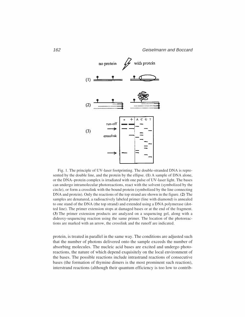
162 Geiselmann and Boccard
protein, is treated in parallel in the same way. The conditions are adjusted suchthat the number of photons delivered onto the sample exceeds the number ofabsorbing molecules. The nucleic acid bases are excited and undergo photo-reactions, the nature of which depend exquisitely on the local environment ofthe bases. The possible reactions include intrastrand reactions of consecutivebases (the formation of thymine dimers is the most prominent such reaction),interstrand reactions (although their quantum efficiency is too low to contrib-
Fig. 1. The principle of UV-laser footprinting. The double-stranded DNA is repre-sented by the double line, and the protein by the ellipse. (1) A sample of DNA alone,or the DNA–protein complex is irradiated with one pulse of UV-laser light. The basescan undergo intramolecular photoreactions, react with the solvent (symbolized by thecircle), or form a crosslink with the bound protein (symbolized by the line connectingDNA and protein). Only the reactions of the top strand are shown in the figure. (2) Thesamples are denatured, a radioactively labeled primer (line with diamond) is annealedto one stand of the DNA (the top strand) and extended using a DNA polymerase (dot-ted line). The primer extension stops at damaged bases or at the end of the fragment.(3) The primer extension products are analyzed on a sequencing gel, along with adideoxy-sequencing reaction using the same primer. The location of the photoreac-tions are marked with an arrow, the crosslink and the runoff are indicated.
UV-Laser Footprinting 163
ute to footprinting signals), reactions with solvent molecules (e.g., with H2O),and crosslinks with the protein (4–8).
In general, it is not possible, but neither is it necessary, to determine thenature of the photoreaction at a particular base. Because the photoreactions arehighly sensitive to the local environment of the DNA, binding of a proteinchanges this environment and thus produces a footprint (i.e., a differencebetween the DNA photoreactivity in the absence and presence of the protein).In the example of Fig. 1, the photoreaction at the left extremity of the DNAfragment remains constant because the protein does not change the local envi-ronment of this base. However, the presence of the protein prevents a photo-reaction toward the right end of the fragment (perhaps by excluding water fromthe vicinity of the base) and favors a new photoreaction with an amino acidside chain, resulting in a covalent bond, a crosslink, between the protein andthe DNA. All such reactions modify the nucleotide base and, hence, impedethe progression of DNA polymerase during subsequent replication of the dam-aged DNA strand. Arrest of the polymerase is detected in a primer extensionreaction by the appearance of shortened replication products, which then serveto localize the modified base.
1.4. Advantages and Disadvantages of UV-Laser Footprinting
Ultraviolet-laser footprinting circumvents many potential artifacts of moreclassical techniques by trapping the complex under investigation at the time ofirradiation. The signal is acquired very rapidly (on the order of microseconds)(i.e., faster than typical rearrangements of a DNA–protein complex [on theorder of milliseconds]), and the footprint thereby freezes the initial state of thecomplex (9). Laser light, as opposed to ordinary UV light, is needed in order tolimit the “incubation time” to several ns while providing a sufficient number ofphotons to excite all nucleotide bases of the sample. The rapidity of signalacquisition allows one to obtain kinetic structural signals by irradiating a com-plex at different times after mixing the components. The technique has thefurther advantage that it can be transposed to in vivo experiments in a straight-forward manner because UV light readily penetrates bacterial cells. However,because of the limited sample size of in vivo experiments, the present versionof the technique is only suitable for studying DNA–protein interactions in bac-teria when using a binding site carried on a multicopy plasmid.
Using the UV-laser technology, it is possible to follow the kinetics of theassembly of DNA–protein complexes. This technique can be used to determinethe order in which protein–DNA contacts are established in a multiprotein–DNAcomplex. Proteins and DNA are mixed at time zero and the sample is irradiatedat a specific time interval after mixing (10). Modern mixing techniques allow atime resolution on the order of a several milliseconds (11).
164 Geiselmann and Boccard
The main disadvantage of UV-laser footprinting is the unpredictability ofthe footprinting signal. It should be noted that the footprint is not the result ofthe protein shielding the DNA from the UV irradiation. The presence of theprotein merely changes the probability of certain photoreactions by excludingsolvent, changing the conformation of the DNA, or juxtaposing a reactiveamino acid and a particular base. A structural interpretation of the footprintingsignal is therefore, in general, not possible. A more practical limitation of thetechnique is the need for a relatively expensive laser.
We describe the experiment for the particular case of the binding of anEscherichia coli protein, the integration host factor (IHF), to one of its specificbinding sites, the yjbE site (12), in vitro and in vivo. IHF is a small,heterodimeric protein (molecular weight [MW] of the dimer is approx 19 kDa)that binds to specific sites on the DNA (for a review, see ref. 13). Upon bind-ing to DNA IHF bends the DNA by about 180º (14). This DNA bending givesrise to a very strong UV-laser footprinting signal, probably because two con-secutive pyrimidines are brought into optimal alignment for the formation of apyrimidine dimer (15). Variations of this basic protocol, applicable to the studyof any DNA–protein interaction, are described in Subheading 4.
2. Materials1. Ultraviolet-laser: The most commonly used lasers are YAG lasers, e.g., the Spec-
tra-Physics Quanta-Ray GCR series lasers, which emit infrared light of 1064 nm.Two consecutive passes through a frequency-doubling crystal yields high-inten-sity light of 266 nm, which is sufficiently close to the absorption maximum ofnucleic acid bases. Frequency doublers are a standard add-on for virtually allcommercially available YAG lasers. The laser power should be between 30 and50 mJ per pulse at 266 nm and a pulse duration of 5 ns is standard. The energy ofone 30-mJ pulse represents about 4 × 10¹⁶ photons (i.e., 67 nmol photons).
2. Power meter to measure the energy of the laser beam.3. Thermostated water bath.4. Spectrophotometer.5. Water pump and 0.45-µM filter device for washing E. coli cells.6. Phosphoimager: A phospho-storage device is ideal for quantifying sequencing
gels. The most commonly used instruments are sold by Molecular Dynamics,Fuji, or by Bio-Rad.
7. IHF binding buffer: 50 mM Tris-HCl, pH 7.5, 70 mM KCl, 7 mM MgCl2, 3 mMCaCl2, 1 mM EDTA, 10% glycerol, 200 mg/mL bovine serum albumin (BSA),and 1 mM β-mercaptoethanol.
8. IHF: working stock solution at 3–5 µM in 50 mM Tris-HCl, pH 7.4, 800 mM KCl,40 mM K-phosphate, 2 mg/mL BSA, and 10% glycerol.
9. Plasmid pBluescriptII (Strategene) containing the IHF binding site cloned intothe multicloning site (MCS). Stock solution in water at 100 nM.

UV-Laser Footprinting 165
10. Primer extension reaction. Annealing buffer: 1 M Tris-HCl, pH 7.6, 100 mMMgCl2, and 160 mM dithiothreitol (DTT). Elongation mix for 2 µL: 2 U of T7DNA polymerase in 2.4 mM of each deoxyribonucleotide, 3 mM Tris-HCl,pH 7.5, 0.75 mM DTT, 15 mg/mL BSA, and 0.75% glycerol (see Subheading 3.for the annealing and elongation steps). Stop solution: 95% formamide, 20 mMEDTA, 0.05% bromophenol blue, and 0.05% xylene cyanol.
11. Sequencing reaction. Enzyme dilution buffer: 20 mM Tris-HCl, pH 7.5, 5 mM DTT,0.1 mg/mL BSA, and 5% glycerol. Stop solution: 95% formamide, 1 mM EDTA,0.05% bromophenol blue, 0.05% xylene cyanol.
12. Sequencing gel: Sequencing reactions are analyzed on 40-cm-long denaturing(7 M urea) 8% polyacrylamide (ratio acrylamide:bis acrylamide 19:1) gels in 90 mMTris–borate, and 2 mM EDTA (TBE), and TBE used as running buffer. Gels weretransferred onto Whatman (3MM Chr) paper and dried at 80°C for 40 min in a geldryer (Bio-Rad model 583) linked to a vacuum pump.
13. Extraction of plasmid DNA. Solution I: 100 mM Tris-HCl, pH 7.5, 10 mM EDTA,400 µg/mL RNase I. Solution II: 0.2 N NaOH, and 1% sodium dodecyl sulfate(SDS) made freshly. Solution III: 3 M potassium, and 5 M acetate solution, madeby adding 11.5 mL of glacial acetic acid and 28.5 mL of H2O to 60 mL of 5 Mpotassium acetate.
14. LB and minimal M9 media are used to grow and wash E. coli cells, respectively (16).
3. Methods3.1. In Vitro UV-Laser Footprinting
1. Arrange the laser beam, using appropriate mirrors, such that it is directed verti-cally into a water bath.
2. Align, and fix firmly, an Eppendorf holder in the water bath such that the laserbeam enters precisely in the center of an open Eppendorf tube. A piece of blackpaper stuck into the bottom of the Eppendorf tube can help align the tube with thelaser beam; the impact of the laser light is very audible and “burns” the site ofimpact, whitening the otherwise black paper.
3. Operate the laser in repetition mode (see Note 1) for at least 10 min and adjust thedoubling crystals to obtain a laser power at 266 nm of at least 30 mJ per pulse.This laser power is measured during the warm-up period with an appropriatepower meter, before the actual footprinting reaction.
4. Incubate IHF at the desired concentration with 5 nM plasmid DNA in 40 µLbinding buffer for 20 min at 25°C (see Note 2). It is best to use a flat-bottomedEppendorf tube, but regular 1.5-mL Eppendorf tubes are adequate. The laser beamgenerally has a diameter of 5 mm, and for maximal use of the light energy, thesample should have roughly the same dimensions. Care should be taken to ensurethat all of the sample is irradiated by the laser beam.
5. Place the sample under the laser beam and irradiate with one pulse of UV-laserlight. It is best to operate the laser in repetition mode (i.e., continuously emittingaround 10 pulses per second). Most lasers also have the possibility to emit asingle pulse of light. However, the power of such a pulse is not very well con-

166 Geiselmann and Boccard
trolled, because the yield of the doubling crystals is extremely sensitive totemperature. Continuous emission of laser pulses at a frequency of about 10 Hzensures a constant temperature of the crystals and therefore a stable pulse energy.An electronically controlled shutter is used to obstruct the beam. The shutteropening is coordinated with the emission of the laser pulses to ensure that onlyone pulse of laser light passes for each opening of the shutter.
6. After irradiation, remove the protein from the irradiated DNA by incubating with50 µg/mL proteinase K for 15 min at 50°C. Extract the samples with half a vol-ume of a phenol/chloroform solution (made by adding equal volumes of phenolpH 8 and chloroform), precipitate with 2 vol of ethanol, and resuspend the DNAin 18.5 µL of H2O.
7. Primer extension (see Note 3): Add 2 µL of a solution of 0.2 µM radiolabeledprimer (5'-[32P] labeled using T4-kinase) to 18.5 mL of DNA. (Increasing theprimer concentration beyond this twofold excess over template will increase thestrength of the primer extension signals only marginally.) Denature the samplesby heating to 100°C for 3 min and chill on ice for 5 min. After the addition of 2.5 µLof annealing buffer, incubate the samples for 3 min at 50°C (to anneal primer)and chill again for 5 min on ice. Add 2 µL of the elongation mix (see Note 4) andincubate the reaction for 10 min at 37°C. The mix is prepared freshly but can bekept on ice for several hours.
8. Precipitate the DNA by adding 150 µL of ethanol and incubating for 10 min at–20°C. Centrifuge for 10 min at full speed (about 12,000g) in a microcentrifuge.Resuspend the DNA in 10 µL of loading dye.
9. Analyze 3 µL by gel electrophoresis on a denaturing 8% polyacrylamide sequenc-ing gel. After electrophoresis, transfer the gel onto Whatman paper and vacuumdry at 80°C for 40 min.
10. To determine precisely the location of the footprint, a reference ladder is gener-ated by sequencing the same plasmid DNA using the same radiolabeled primer(see Note 5). Denature 15 nM of plasmid DNA in a volume of 8 µL by heating to100°C for 2 min. Chill on ice for 5 min. Add 1 µL of radiolabeled primer (0.25 µM)and 1 µL of annealing buffer. Incubate for 3 min at 50°C. Chill annealing reac-tion on ice for 5 min. Add 2.8 µL of each Deaza G/A T7 Sequencing™ Mixes(Pharmacia) to four termination reaction tubes and prewarm at 37°C. Dilute 1 µLof T7 DNA polymerase with 4 µL of enzyme dilution buffer. Add 2 µL of dilutedT7 DNA polymerase to the annealing reaction. Dispense 2.8 µL of annealingreaction in each of the termination tubes. Incubate for 5 min at 37°C. Add 4 µL ofthe stop solution.
11. Expose the dried gel to a phospoimager screen overnight and scan the screenusing the phospho-imager and its associated software (e.g., ImageQuant fromMolecular Dynamics).
12. Deduce a line profile of the different lanes using the Phospho-Imager software.13. Transfer the data to Microsoft Excel and superimpose the scans on the same graph
in order to visualize and quantify the footprint (see Notes 6–11).
UV-Laser Footprinting 167
3.2. In Vivo UV-Laser Footprinting
1. Grow cultures of IHF+ (W3110) and IHF– (W3110 hip) strains (12) transformedwith the plasmid carrying the ihf site in LB medium to the desired OD600 (0.6 orto saturation).
2. Wash the cells in minimal M9 medium (optically transparent buffer), resuspendin minimal M9 medium to a final OD600 of 1, and incubate the cells at 37°C (seeNote 12).
3. Irradiate as described above a large number (40–60), of 50-µL cell aliquots (seeNote 13). Freeze the cells immediately after irradiation in a dry-ice bath.
4. Pool the cells and extract plasmid DNA from 2–3 mL of cells using the followingalkaline lysis procedure. Centrifuge the bacteria for 5 min in a tabletop Eppendorfcentrifuge. Resuspend the pellet in 100 µL of solution I and add 100 µL of solu-tion II. Mix by inversion several times. Add 100 µL of solution III and mix byinverting the tube several times. Centrifuge the tubes at full speed in a tabletopEppendorf centrifuge (>10,000g) for 5 min. Transfer the supernatant to a cleantube and add 210 µL of isopropanol. Incubate for 5 min at room temperature andcentrifuge the tubes at full speed for 10 min. Wash the pellet with 70% ethanoland dissolved the DNA in 37 µL of H2O.
5. For primer extension, add 2 µL of a solution of 0.2 µM primer (5'-[32P] labeled)to 18.5 mL of DNA and process and analyze the samples in the same way as forthe in vitro reactions, steps 7–13 of Subheading 3.1. (see Notes 10 and 11).
4. Notes
1. Laser setup. As mentioned in the Subheading 3. in order to obtain a stable laserpower it is best to operate the laser in repetition mode. If a single-pulse mode isused the energy of a particular pulse is ill-defined and the absence of afootprinting signal may simply be the consequence of diminishing laser power.
All lasers provide an electrical signal that allows external equipment to becoordinated with the laser pulse. To our knowledge, shutters are not commer-cially available. However, it is an easy task for a good mechanics shop to con-struct such a shutter. We used a shutter made of a small sheet of blackened Teflonobstructing a hole of approx 8-mm in diameter through which the laser beam hadto pass in order to reach the sample. Any material can be used, but it should bekept in mind that the laser will eventually burn a hole into the material and that itis best to use a black material in order to minimize hazardous reflections of thelaser light. A simple electronic circuit controlled the opening of the shutter byactivating an electomagnet that pulled the Teflon sheet (via an attached piece ofmetal) away from the hole. After the light had passed, the current to the magnetwas cut and a spring pulled the sheet back over the hole.
2. The binding buffer described is the standard buffer used for measuring DNAbinding of IHF. Other proteins may require different buffer conditions. The buffermay be adjusted with certain limitations. The salt concentration should not be toolow in order to avoid nonspecific binding of the protein to DNA. The buffershould not include a high concentration of reagents that absorb at 266 nm. For
168 Geiselmann and Boccard
example, the interaction of the cyclic AMP receptor protein (CRP) with DNArequires the presence of cAMP in the buffer (17). Keep the concentration of suchnucleotides below 100 µM. As mentioned in Subheading 3., one laser pulse con-tains the equivalent of about 100 nmol in photons. A typical reaction volume is50 µL; therefore 100 µM ATP absorbs about 5 nmol of photons. A more physi-ological concentration of ATP in the millimolar range would dramaticallydecrease the yield of the photoreaction.
3. The procedure describes the footprinting reaction for only one strand of DNA.Evidently, the other strand can be analyzed in the same way using the appropriateprimer. The primers should be chosen such that the region of interest is within200 nucleotides from the primer. Most photoreactions have a quantum efficiencybelow 1%, the formation of thymine dimers reaching several percent. Therefore,on average, there will be roughly 1 photoreaction per 100 base pairs (bp).Considering only the 100-bp region downstream of a primer assures single-hitconditions. If the DNA carries too many photoreactions, the primer extensionwill stop at the first defect and the signal of a photoreaction further downstreamwill pass undetected.
4. The detection of photoreactions. All DNA polymerases are very sensitive to dam-aged bases. It is not important to use T7 DNA polymerase in the primer extensionreaction, any other DNA polymerase (e.g., Klenow, Taq) gives equivalent sig-nals. However, signals obtained with different polymerases may not necessarilybe identical because some may be more sensitive to particular photodamagedbases than others. Even RNA polymerases can be used if the template harbors anappropriate promoter. We have successfully used T7 RNA polymerase to tran-scribe the region of interest from a T7 promoter located on the vector DNA. Themajor signal of the IHF footprint remained unchanged, but, instead of a singleband, T7 RNA polymerase generates a doublet of bands (15).
5. To determine the location of termination sites precisely, we generated a refer-ence DNA ladder consisting of a sequencing reaction of the same DNA region(see Subheading 3.). In general, it is assumed that the primer extension reactionof the irradiated DNA stops just before the modified base. For example, if thesequence of the DNA read on the gel is 5'-GGAC-3' and the primer extensionreaction of the irradiated DNA shows a band at the position of the A in thesequencing reaction (run in parallel on the gel), then the photoreaction most likelytook place on the following base pair (the C in the above sequence). Because theprimer extension reaction reads the opposite strand, the photoreaction actuallydamaged the G marked with an asterisk:
5'-GGAC-3'3'-CCTG*-5'
6. There are several possible reasons for not detecting a UV-laser footprinting sig-nal. The most obvious problem is that the protein does not bind to the DNA.Generally, we verify binding by a gel retardation assay. The second reason maybe that protein binding does not change the photoreactivity of the bases in therecognition site. This is the case, for example, for CRP, which yields very weak
UV-Laser Footprinting 169
signals in UV-laser footprinting despite a strong interaction measured by othertechniques (J. Geiselmann, unpublished results). Because photoreactivitydepends on the sequence, a particular site might not be photosensitive; forexample, the main IHF signal had not been observed for the ssb site, probablybecause the sequence of this site does not contain the highly reactive TC pyrimi-dine doublet (15).
7. A trivial reason for not detecting a photoreaction is that the laser did not hit thesample. The best control, and a control to include in all laser footprinting reac-tions, is to analyze the primer extension reaction of DNA alone. Two DNA-alonesamples should always be included: one irradiated sample and an identical samplethat has not been exposed to UV-laser light. The irradiated sample should yieldreadily visible bands all along the lane (Fig. 2, lane f), whereas the nonirradiatedsample should show no elongation arrests (Fig. 2, lane e).
8. The irradiated DNA does not give any elongation arrests with T7 DNA poly-merase. Verify the primer extension mix. Perform a control primer extensionreaction using the nonirradiated plasmid template, but cut about 100 bp down-stream of the primer with a convenient restriction enzyme. Primer extension usingthis template should give a very strong band corresponding to the elongationreaction reaching the end of the fragment.
9. Artifactual footprinting signals. A contaminated template preparation or a dam-aged DNA template could be misinterpreted as giving a footprinting signal. It isvery important to verify that the nonirradiated template does not produce anybands during the primer extension reaction. This is particularly important for invivo reactions because the plasmid preparation could partially damage the plas-mid and lead to artifactual bands (Fig. 2, lanes c and d).
10. Comparing signals obtained under different conditions in vitro, or comparing invitro to in vivo signals. The efficiency of sample preparation or of the primer exten-sion reaction can vary from sample to sample. In order to compare different laneswe run a small portion (10%) of the primer extension reactions on a sequencing geland quantify the lanes using a phosphoimager. We then load the same samples on asecond sequencing gel, but equilibrating the amounts loaded according to the sig-nal intensities on the first gel. For example, if one of the reactions was only half asefficient as the other ones, we load two times more of this sample on the secondgel. This readjustment should not be allowed to exceed a factor of 2.
11. Quantifying lanes. Once an intensity equilibrated gel exposure is obtained, weobtain line profiles of all lanes using the Phospo-Imager software and comparelanes by superimposing the line profiles in Microsoft Excel. Remaining small(several percent) differences in the intensities of the lanes should be normalizedby multiplying the scans with a scaling factor between 0.9 and 1.1 that is deter-mined subjectively by the user in such a way that the global patterns superim-pose. Lanes containing a high background of nonspecific radioactivity cannot bequantified with confidence.
12. It is important to keep in vivo samples at the physiological temperature (37°C forE. coli) to ensure optimal binding.
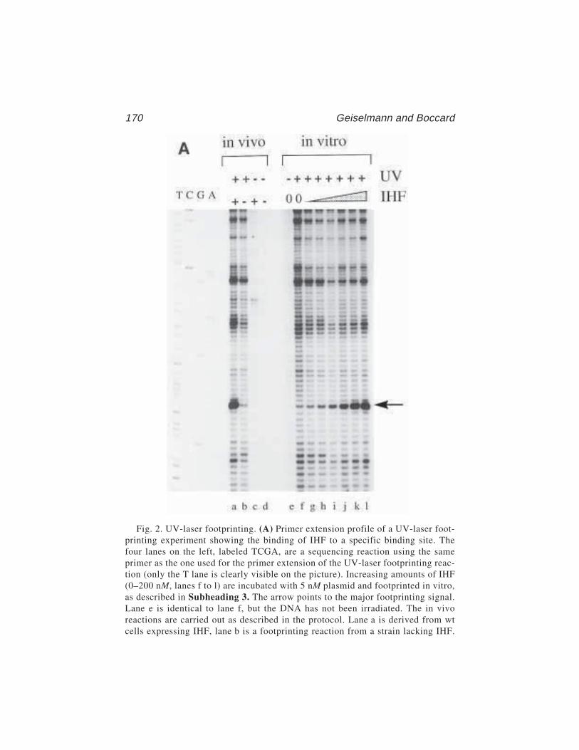
170 Geiselmann and Boccard
Fig. 2. UV-laser footprinting. (A) Primer extension profile of a UV-laser foot-printing experiment showing the binding of IHF to a specific binding site. Thefour lanes on the left, labeled TCGA, are a sequencing reaction using the sameprimer as the one used for the primer extension of the UV-laser footprinting reac-tion (only the T lane is clearly visible on the picture). Increasing amounts of IHF(0–200 nM, lanes f to l) are incubated with 5 nM plasmid and footprinted in vitro,as described in Subheading 3. The arrow points to the major footprinting signal.Lane e is identical to lane f, but the DNA has not been irradiated. The in vivoreactions are carried out as described in the protocol. Lane a is derived from wtcells expressing IHF, lane b is a footprinting reaction from a strain lacking IHF.

UV-Laser Footprinting 171
The control lanes c and d show that the preparation of the plasmid DNA is suffi-ciently clean for an efficient primer extension and that the bands seen in lanes aand b are due to the UV irradiation. (B) Superposition of line profiles from lanes f,h, and l, corresponding to the indicated concentrations of IHF. The intensities ofthe bands are in arbitrary units. (C) An equivalent superposition of the in vivoprofiles and the in vitro profile corresponding to the 50-nM IHF lane shows thatE. coli contains roughly the same amount of free IHF in stationary-phase cells aswas present in the in vitro sample using 50 nM (total) IHF. As expected, the foot-print in a strain lacking functional IHF shows the same profile as DNA alone inthe in vitro reaction.
172 Geiselmann and Boccard
13. In vivo footprinting. Primer extension of the irradiated template can only be per-formed in vitro. It is therefore necessary to extract the irradiated DNA from thebacteria. Our current technology allows the measurement of protein binding tospecific binding sites carried on a multicopy plasmid. In principle, a primerextension reaction on chromosomal DNA should work as well. In practice thesignals obtained from chromosomal DNA are too weak. Increasing the numberof samples irradiated does not remedy the problem. Because of the large excessof chromosomal DNA with respect to the primer extension product, we observeabnormal migration of the band in the sequencing gel.
The sample for in vivo UV-laser footprinting must be prepared such that asingle pulse of the laser (typically about 30 mJ per pulse, corresponding to4 × 1016 photons [i.e., 67 nmol of photons]) delivers more photons than there areabsorbing molecules in the sample. For an in vivo experiment, the absorbingmolecules are mostly made up of cellular DNA and RNA, as well as free nucleo-side phosphates. An upper estimate of the concentration of absorbing moleculeswithin an Escherichia coli cell is about 100 mM, corresponding to 6 × 10⁸
absorbers per cell. Because a single pulse delivers 4 × 10¹⁶ photons and becausewe want an excess of photons over absorbers, we want to irradiate less than about108 E. coli cells per pulse. This numbers corresponds to about 100 µL of a sus-pension at 1 OD600. A large number of 50-µL samples are therefore irradiatedand the cells are frozen immediately after irradiation.
References1. von Hippel, P. H. and Berg, O. G. (1986) On the specificity of DNA–protein
interactions. Proc. Natl. Acad. Sci. USA 83(6), 1608–1612.2. Sauer, R. T. (1991) Protein–DNA interactions, in Methods in Enzymology, vol.
208, Academic Press, San Diego, CA.3. Jost, J.-P. and Saluz, H. P. (1991) A laboratory guide to in vitro studies of protein-
DNA interactions, in Biomethods, vol. 5, Birkhäuser Verlag, Basel.4. Hockensmith, J. W., Kubasek, W. L., Vorachek, W. R., and von Hippel, P. H.
(1993) Laser cross-linking of proteins to nucleic acids. I. Examining physicalparameters of protein–nucleic acid complexes. J. Biol. Chem. 268, 15,712–15,720.
5. Pashev, I. G., Dimitrov, S. I., and Angelov, D. (1991) Crosslinking proteins tonucleic acids by ultraviolet laser irradiation. Trends Biochem. Sci. 16, 323–326.
6. Panyutin, I. G., Kovalsky, O. I., and Budowsky, E. I. (1989) Irradiation of thetemplate with high-intensity (pulse-laser) ultraviolet light results in DNA–poly-merase termination events at deoxyguanosine residues. FEBS Lett. 258, 274–276.
7. Menshonkova, T. N., Simukova, N. A., Budowsky, E. I., and Rubin, L. B. (1980)The effect of high intensity ultraviolet irradiation on nucleic acids and their com-ponents. Cleavage of N-glycosidic bond in thymidine, adenosine and 2'-deoxy-adenosine. FEBS Lett. 112, 299–301.
8. Matsunaga, T., Hieda, K., and Nikaido, O. (1991) Wavelength dependent formationof thymine dimers and (6–4) photoproducts in DNA by monochromatic ultravioletlight ranging from 150 to 365 nm. Photochem. Photobiol. 54, 403–410.
UV-Laser Footprinting 173
9. Hockensmith, J. W., Kubasek, W. L., Vorachek, W. R., Evertsz, E. M., and vonHippel, P. H. (1991) Laser cross-linking of protein-nucleic acid complexes. Meth-ods Enzymol. 208, 211–236.
10. Eichenberger, P., Dethiollaz, S., Buc, H., and Geiselmann, J. (1997) Structuralkinetics of transcription activation at the malT promoter of Escherichia coli byUV laser footprinting. Proc. Natl. Acad. Sci. USA 94, 9022–9027.
11. Buckle, M., Pemberton, I. K., Jacquet, M. A., and Buc, H. (1999) The kinetics ofsigma subunit directed promoter recognition by E. coli RNA polymerase. J. Mol.Biol. 285, 955–964.
12. Murtin, C., Engelhorn, M., Geiselmann, J., and Boccard, F. (1998) A quantitativeUV laser footprinting analysis of the interaction of IHF with specific bindingsites: re-evaluation of the effective concentration of IHF in the cell. J. Mol. Biol.284, 949–961.
13. Nash, H. A. (1996) The HU and IHF proteins: accessory factors for complex pro-tein-DNA assemblies, in Regulation of Gene Expression in Escherichia coli (Lin,E. E. C. and Lynch, A. S., eds.), R.G. Landes Company, Austin, TX, pp. 149–179.
14. Rice, P. A., Yang, S., Mizuuchi, K., and Nash, H. A. (1996) Crystal structure ofan IHF-DNA complex: a protein-induced DNA U-turn. Cell 87, 1295–1306.
15. Engelhorn, M., Boccard, F., Murtin, C., Prentki, P., and Geiselmann, J. (1995) Invivo interaction of the Escherichia coli integration host factor with its specificbinding sites. Nucleic Acids Res. 23, 2959–2965.
16. Miller, J. H. (1992) A Short Course in Bacterial Genetics. Cold Spring HarborLaboratory, Cold Spring Harbor, NY.
17. Buckle, M., Buc, H., and Travers, A. (1992) DNA deformation in nucleoproteincomplexes between RNA polymerase, cAMP receptor protein and the lac UV5promoter probed by singlet oxygen. EMBO J. 11, 2619–2625.
In Vivo DNA Analysis 175
175
From: Methods in Molecular Biology, vol. 148: DNA–Protein Interactions: Principles and Protocols, 2nd ed.Edited by: T. Moss © Humana Press Inc., Totowa, NJ
13
In Vivo DNA Analysis
Régen Drouin, Jean-Philippe Therrien, Martin Angers,and Stéphane Ouellet
1. IntroductionThe in vivo analysis of DNA–protein interactions and chromatin structure
can provide several kinds of critical information regarding regulation of geneexpression and gene function. For example, DNA sequences spanned bynuclease-hypersensitive sites or bound by transcription factors often corre-spond to genetic regulatory elements. Using the ligation-mediated polymerasechain reaction (LMPCR) technology it is possible to map such DNA sequencesand to demonstrate the existence of unusual DNA structures directly in livingcells. LMPCR analyses can thus be used as a primary investigative tool toidentify the regulatory sequences involved in gene expression. Once specificpromoter sequence sites are shown to be bound by transcription factors in liv-ing cells, it is often possible to establish the identity of these factors simply bycomparison with the consensus binding sites of known factors such as Sp1,AP-1, NF-1, and so forth. The identity of each factor can then be confirmedusing in vitro gel shift (electrophoretic mobility shift assay [EMSA]) orfootprinting assays.
Clearly, gene promoters are best studied in their natural state in the livingcell and, thus, it is not surprising that in vivo DNA footprinting is one of themost accurate predictors of the state of transcriptional activity of genes (1–3).The native state of a gene and most of the special DNA structures are unavoid-ably lost when DNA is cloned or purified (1–4). Hence, the commonly used invitro methods, such as in vitro footprinting and EMSAs, cannot demonstratethat a given DNA–protein interaction actually occurs within the cells of inter-est. With the advent of in vivo DNA footprinting, in vitro studies have beenextended to the situation in living cells, revealing the cellular processes impli-

176 Drouin et al.
cated in the regulation of gene expression. LMPCR is the method of choice forin vivo footprinting and DNA structure studies because it can be used to inves-tigate complex animal genomes, including that of human. The quality and use-fulness of the information obtained from any in vivo DNA analysis, however,depends on three parameters: (1) the integrity of the native chromatin substrateused in the experiment, (2) the structural specificity of the chromatin probe,and (3) the sensitivity of the assay. The ideal chromatin substrate is, of course,that found inside intact cells. However, a near-ideal chromatin substrate is stillto be found in permeabilized cells, allowing the application of a wider range ofDNA cleavage agents, including DNase I.
In vivo footprinting assesses the local reactivity of modifying agents on theDNA of living cells as compared to that on purified DNA (see Figs. 1–4). Twosteps characterize an in vivo footprinting analysis: (1) the treatment of purifiedDNA and of cells with a given DNA modifying agent and (2) the visualizationof nucleotide modifications on a DNA sequencing gel. The latter step requiresthat the modifying agent either directly induces DNA strand breaks or modi-fies DNA nucleotides such that strand breaks can subsequently be induced invitro. A comparison is then made between the modification frequency on puri-fied DNA and that on the DNA in living cells. For example, each guanineresidue of purified DNA has a near-equivalent probability of being methylatedby dimethylsulfate (DMS) and, thus, the cleavage pattern of in vitro modifiedDNA appears on a sequencing gel as a ladder of bands of roughly equal inten-sity. However, as a result of the presence of DNA-binding proteins, all guanineresidues do not show the same accessibility to DMS in living cells (Fig. 1).Thus, differences between banding patterns obtained from in vitro and in vivomodified DNA can be used to infer the sites of protein binding in living cells.As will be seen, it is always advisable to validate such interpretations usingmore than one footprinting agent.
The step of visualizing in vivo footprints has historically been problematicbecause of the dilute nature of the sequences of interest and the complexity ofthe genomes of higher eukaryotes. The development of an extremely sensitiveand specific technique, such as LMPCR, was thus necessary. The LMPCR tech-
Fig. 1. (opposite page) Overall scheme for in vivo DNA analysis using DMS. Themethylation of guanine residues following DMS treatment of purified DNA (in vitro)and cells (in vivo) is shown by vertical arrows and methylated residues (Me). Whenpurified DNA is treated with DMS, every guanine residue has a similar probability ofbeing methylated. However, the guanine residue in intimate contact with a sequence-specific DNA-binding protein illustrated by the dotted oval is protected from DMSmethylation, whereas the guanine residues localized close to the boundary of a DNA–protein contact that modifies DNA structure, allowing a better accessibility to DMS, is
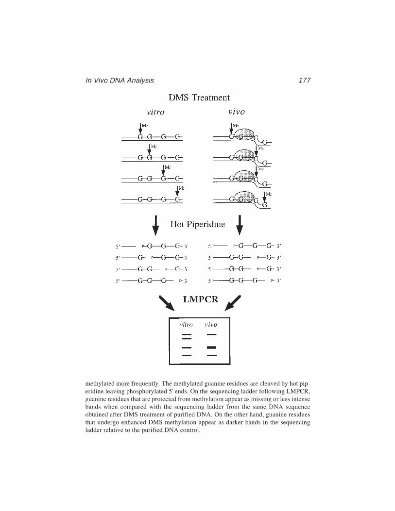
In Vivo DNA Analysis 177
methylated more frequently. The methylated guanine residues are cleaved by hot pip-eridine leaving phosphorylated 5' ends. On the sequencing ladder following LMPCR,guanine residues that are protected from methylation appear as missing or less intensebands when compared with the sequencing ladder from the same DNA sequenceobtained after DMS treatment of purified DNA. On the other hand, guanine residuesthat undergo enhanced DMS methylation appear as darker bands in the sequencingladder relative to the purified DNA control.
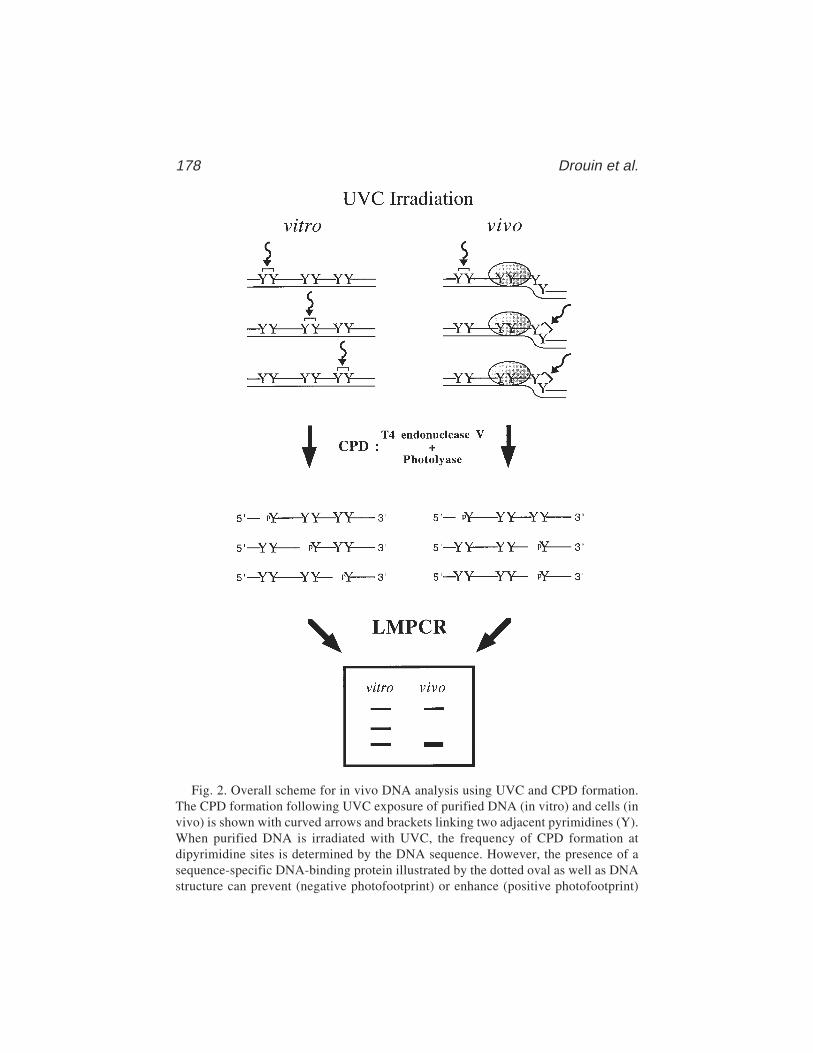
178 Drouin et al.
Fig. 2. Overall scheme for in vivo DNA analysis using UVC and CPD formation.The CPD formation following UVC exposure of purified DNA (in vitro) and cells (invivo) is shown with curved arrows and brackets linking two adjacent pyrimidines (Y).When purified DNA is irradiated with UVC, the frequency of CPD formation atdipyrimidine sites is determined by the DNA sequence. However, the presence of asequence-specific DNA-binding protein illustrated by the dotted oval as well as DNAstructure can prevent (negative photofootprint) or enhance (positive photofootprint)
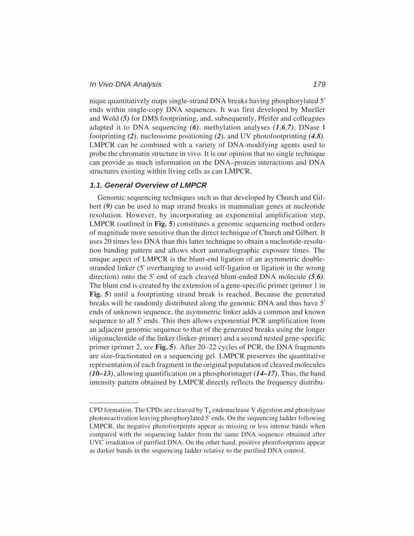
In Vivo DNA Analysis 179
nique quantitatively maps single-strand DNA breaks having phosphorylated 5'ends within single-copy DNA sequences. It was first developed by Muellerand Wold (5) for DMS footprinting, and, subsequently, Pfeifer and colleaguesadapted it to DNA sequencing (6), methylation analyses (1,6,7), DNase Ifootprinting (2), nucleosome positioning (2), and UV photofootprinting (4,8).LMPCR can be combined with a variety of DNA-modifying agents used toprobe the chromatin structure in vivo. It is our opinion that no single techniquecan provide as much information on the DNA–protein interactions and DNAstructures existing within living cells as can LMPCR.
1.1. General Overview of LMPCR
Genomic sequencing techniques such as that developed by Church and Gil-bert (9) can be used to map strand breaks in mammalian genes at nucleotideresolution. However, by incorporating an exponential amplification step,LMPCR (outlined in Fig. 5) constitutes a genomic sequencing method ordersof magnitude more sensitive than the direct technique of Church and Gilbert. Ituses 20 times less DNA than this latter technique to obtain a nucleotide-resolu-tion banding pattern and allows short autoradiographic exposure times. Theunique aspect of LMPCR is the blunt-end ligation of an asymmetric double-stranded linker (5' overhanging to avoid self-ligation or ligation in the wrongdirection) onto the 5' end of each cleaved blunt-ended DNA molecule (5,6).The blunt end is created by the extension of a gene-specific primer (primer 1 inFig. 5) until a footprinting strand break is reached. Because the generatedbreaks will be randomly distributed along the genomic DNA and thus have 5'ends of unknown sequence, the asymmetric linker adds a common and knownsequence to all 5' ends. This then allows exponential PCR amplification froman adjacent genomic sequence to that of the generated breaks using the longeroligonucleotide of the linker (linker-primer) and a second nested gene-specificprimer (primer 2, see Fig. 5). After 20–22 cycles of PCR, the DNA fragmentsare size-fractionated on a sequencing gel. LMPCR preserves the quantitativerepresentation of each fragment in the original population of cleaved molecules(10–13), allowing quantification on a phosphorimager (14–17). Thus, the bandintensity pattern obtained by LMPCR directly reflects the frequency distribu-
CPD formation. The CPDs are cleaved by T4 endonuclease V digestion and photolyasephotoreactivation leaving phosphorylated 5' ends. On the sequencing ladder followingLMPCR, the negative photofootprints appear as missing or less intense bands whencompared with the sequencing ladder from the same DNA sequence obtained afterUVC irradiation of purified DNA. On the other hand, positive photofootprints appearas darker bands in the sequencing ladder relative to the purified DNA control.
180 Drouin et al.
Fig. 3. Overall scheme for in vivo DNA analysis using UVC and 6–4PP formation.The 6–4PP formation following UVC exposure of purified DNA (in vitro) and cells(in vivo) is shown with curved arrows and brackets linking two adjacent pyrimidines(Y). When purified DNA is irradiated with UVC, the frequency of 6–4PP formation atdipyrimidine sites is determined by the DNA sequence. However, the presence of asequence-specific DNA-binding protein illustrated by the dotted oval as well as DNAstructure can prevent (negative photofootprint) or enhance (positive photofootprint)

In Vivo DNA Analysis 181
tion of 5'-phosphoryl DNA breaks along a 200-bp sequence adjacent to thenested primer.
Two methods exist to reveal the sequence and footprinting ladders createdby LMPCR. Pfeifer and colleagues (6) took advantage of electroblotting DNAonto a nylon membrane followed by hybridization with a gene-specific probeto reveal sequence ladders, otherwise known as “indirect end labeling”. On theother hand, Mueller and Wold (5) used a nested third radiolabeled primer forthe last one or two cycles of the PCR amplification step. We find Pfeifer’smethod much more sensitive than Mueller and Wold’s (unpublished data). Inthis chapter, we will describe our LMPCR protocol as modified from the pro-tocol of Pfeifer and colleagues.
In summary, LMPCR is the method of choice to study the in vivo structureof promoters with respect to the positions of DNA–protein interactions, ofspecial DNA structures and of chromatin structures such as nucleosomes. Toperform in vivo DNA analysis, three probing agents are regularly combinedwith LMPCR: DMS, ultraviolet (UV) and DNase I (Figs. 1–4, Table 1). Theseprobing agents provide complementary information and each has its associatedadvantages and drawbacks (Table 2). To best characterize DNA–proteininteractions, it is often necessary to use two or even all three of these methods.Treatments with any probing agents must produce either strand breaksor modified nucleotides that can be converted to DNA strand breaks with a5'-phosphate in vitro (Figs. 1–4, Table 3). In this chapter, we describe protocolsroutinely used in our laboratory for DMS, UV, and DNase I in vivo treatmentsas well as the associated LMPCR technology. These protocols may also beadapted to footprinting with other probing agents, such as KMnO4 and OsO4(see Chapters 6 and 9), although a detailed description is beyond the scope ofthe present chapter.
1.2. In Vivo Dimethylsulfate (DMS) Footprint Analysis (Fig. 1)
Dimethylsulfate is a small, highly reactive molecule that easily diffusesthrough the outer cell membrane and into the nucleus. It preferentially methy-lates not only the N7 position of guanine residues via the major groove but, toa lesser extent, also the N3 position of adenine residues via the minor groove.
6–4PP formation. First, CPDs are photoreactivated by photolyase and then 6–4PPs arecleaved by hot piperidine treatment leaving phosphorylated 5' ends. On the sequenc-ing ladder following LMPCR, the negative photofootprints appear as missing or lessintense bands when compared with the sequencing ladder from the same DNAsequence obtained after UVC irradiation of purified DNA. On the other hand, positivephotofootprints appear as darker bands in the sequencing ladder relative to the puri-fied DNA control.
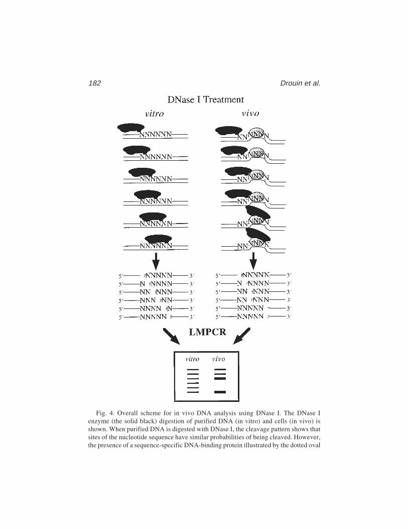
182 Drouin et al.
Fig. 4. Overall scheme for in vivo DNA analysis using DNase I. The DNase Ienzyme (the solid black) digestion of purified DNA (in vitro) and cells (in vivo) isshown. When purified DNA is digested with DNase I, the cleavage pattern shows thatsites of the nucleotide sequence have similar probabilities of being cleaved. However,the presence of a sequence-specific DNA-binding protein illustrated by the dotted oval
In Vivo DNA Analysis 183
The most significant technical advantage of in vivo DMS footprinting is thatDMS can be simply added to the cell culture medium, requiring no cellmanipulation (see Table 2 for advantages and drawbacks). Each guanine resi-due of purified DNA displays about the same probability of being methylatedby DMS. Because DNA inside living cells forms chromatin and is often foundassociated with a number of proteins, it is expected that its reactivity towardDMS will differ from purified DNA. Figures 6 and 7 show in vivo DMS treat-ment patterns compared to the treatment of purified genomic DNA. Proteins incontact with DNA either decrease accessibility of specific guanines to DMS(protection) or, as frequently observed at the edges of a footprint, increasereactivity (hyperreactivity) (1). Hyperreactivity can also indicate a greaterDMS accessibility of special in vivo DNA structures (19). Hot piperidinecleaves the glycosylic bond of methylated guanines and adenines, leaving aligatable 5'-phosphate (20).
Genomic footprinting using DMS reveals DNA–protein contacts located inthe major groove of the DNA double helix (Table 1). However, it should benoted that in vivo DNA studies using DMS alone may not detect some DNA–protein interactions (21). First, no DNA–protein interaction will be detected inthe absence of guanine residues. Second, some proteins do not affect DNAaccessibility to DMS. Third, certain weak DNA–protein contacts could actuallybe disrupted because of the high reactivity of the DMS. Thus when using DMS,it is often important to also apply alternative footprinting approaches (21,22).
1.3. Photofootprint Analysis (Figs. 2 and 3)
Ultraviolet light (UVC: 200–280 nm; UVB: 280–320 nm) can also be usedas a modifying agent for in vivo footprinting (4,8,23–25). When cells are sub-jected to UV light (UVC or UVB), two major classes of lesions may be intro-duced into the DNA at dipyrimidine sequences (CT, TT, TC, and CC): thecyclobutane pyrimidine dimer (CPD) and the pyrimidine (6–4) pyrimidonephotoproduct (6–4PP) (26). CPDs are formed between the 5,6 bonds of anytwo adjacent pyrimidines, whereas a stable bond between positions 6 and 4of two adjacent pyrimidines characterizes 6–4PPs. 6–4PP are formed at a rate15–30% of that of CPDs (27) and are largely converted to their Dewar valence
as well as DNA structure can prevent (protection) or enhance (hypersensitive) DNaseI cleavage. The DNase I cleavage leaves phosphorylated 5' ends. On the sequencingladder following LMPCR, DNA sequences that are protected from DNase I cleavageappear as missing or less intense bands when compared with the sequencing ladderfrom the same DNA sequence obtained after DNase I digestion of purified DNA. Onthe other hand, hypersensitive sites that undergo enhanced DNase I cleavage appear asdarker bands in the sequencing ladder relative to the purified DNA control.
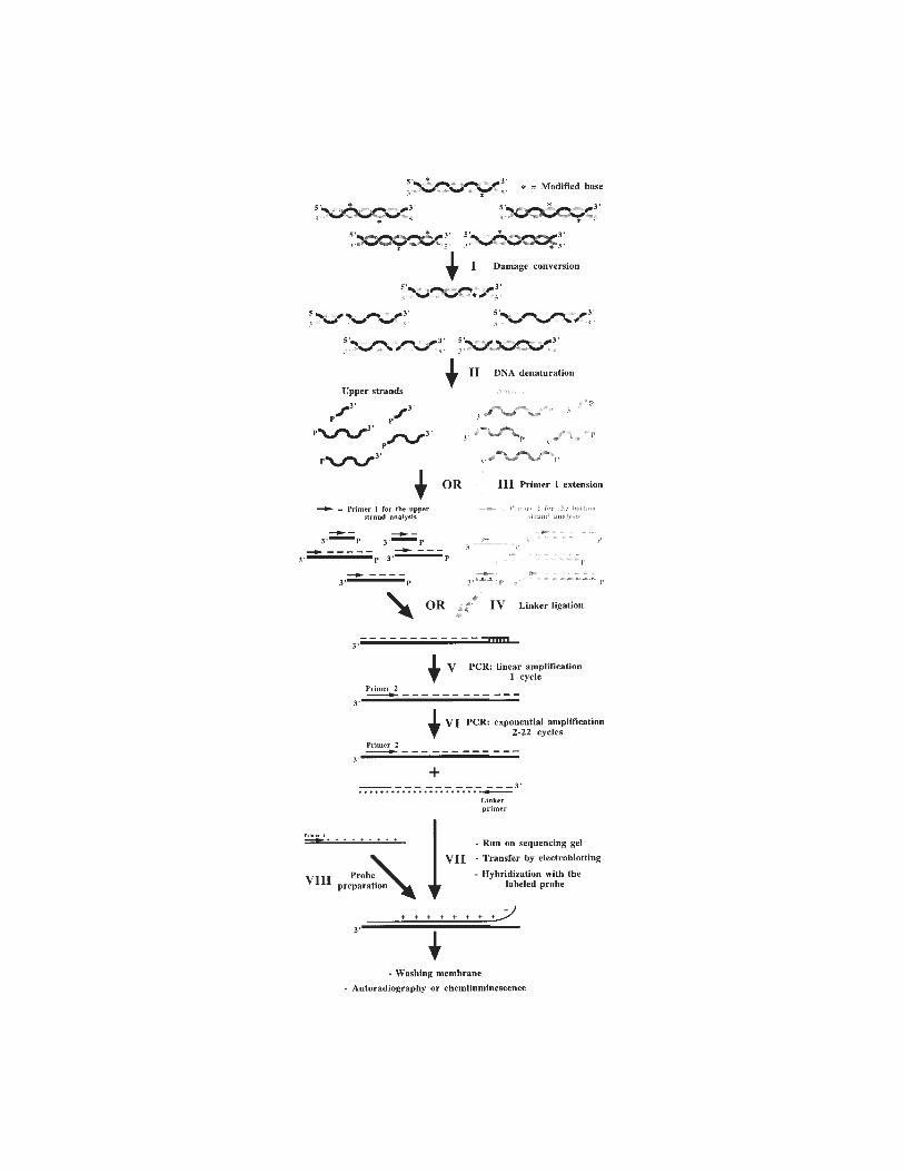
184 Drouin et al.
In Vivo DNA Analysis 185
isomers by direct secondary photolysis (photoisomerization) (27). In livingcells, the photoproduct distribution is determined both by sequence contextand chromatin structure (28). In general, CPDs and 6–4PPs appear to formpreferentially in longer pyrimidine runs. Because UVB and UVC radiation areprimarily absorbed in the cell by the DNA, there are relatively few perturba-tions of other cellular processes, and secondary events that could modify thechromatin structure or release DNA–protein interactions. Furthermore, intactcells are exposed for a short period of time only to a high-intensity UV irradia-tion. Thus, UV irradiation is probably one of the least disruptive footprintingmethod and, hence, truly reflects the in vivo situation (Table 2). As for DMS,DNA-binding proteins influence the distribution of UV photoproducts in a sig-nificant way (23). When the photoproduct spectrum of irradiated purified DNAis compared with that obtained after irradiation of living cells, some strikingdifferences become apparent. These are referred to as “photofootprints” (23).The photoproduct frequency within sequences bound by sequence-specificDNA-binding proteins (transcription factors) is suppressed or enhanced in com-parison to purified DNA (4,8,29). Effects of chromatin structure may be sig-nificant in regulatory gene regions that bind transcription factors (Fig. 6).Mapping of CPDs at the single-copy gene level can reveal positioned nucleo-somes because CPDs are modulated in a 10-bp periodicity within nucleosomecore DNA (30,31). 6–4PPs form more frequently in linker DNA than in coreDNA (32).
Photofootprints reveal variations in DNA structure associated with the pres-ence of transcription factors or other proteins bound to the DNA. UV light hasthe potential to reveal all DNA–protein interactions provided there is adipyrimidine sequence on either DNA strand within a putative protein-bindingsequence. Because photofootprints can be seen outside protein-binding sites,
Fig. 5. (previous page) Outline of the LMPCR procedure. Step I: specific conver-sion of modified bases to phosphorylated 5' single-strand breaks; Step II: denaturationof genomic DNA; Step III: annealing and extension of primer 1 (although both strandscan be studied, each LMPCR protocol only involves the analysis of either thenontranscribed strand or the transcribed strand); Step IV: ligation of the linker;Step V: first cycle of PCR amplification, this cycle is a linear amplification becauseonly the gene-specific primer 2 can anneal; Step VI: cycles 2 to 22 of exponential PCRamplification of gene-specific fragments with primer 2 and the linker primer (thelonger oligonucleotide of the linker); Step VII: separation of the DNA fragments on asequencing gel, transfer of the sequence ladder to a nylon membrane by electroblotting,and visualization of the sequence ladder by hybridization with a labeled single-stranded probe; Step VIII: preparation and isotopic or nonisotopic labeling of single-stranded probe.
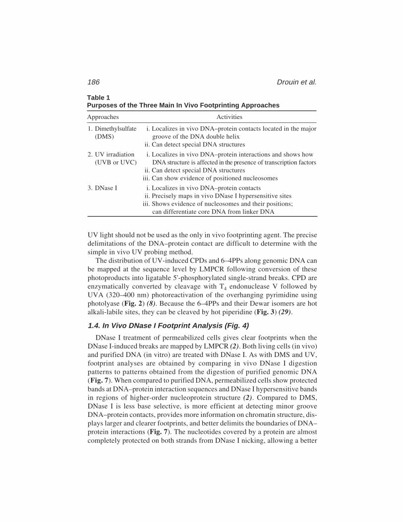
186 Drouin et al.
UV light should not be used as the only in vivo footprinting agent. The precisedelimitations of the DNA–protein contact are difficult to determine with thesimple in vivo UV probing method.
The distribution of UV-induced CPDs and 6–4PPs along genomic DNA canbe mapped at the sequence level by LMPCR following conversion of thesephotoproducts into ligatable 5'-phosphorylated single-strand breaks. CPD areenzymatically converted by cleavage with T4 endonuclease V followed byUVA (320–400 nm) photoreactivation of the overhanging pyrimidine usingphotolyase (Fig. 2) (8). Because the 6–4PPs and their Dewar isomers are hotalkali-labile sites, they can be cleaved by hot piperidine (Fig. 3) (29).
1.4. In Vivo DNase I Footprint Analysis (Fig. 4)
DNase I treatment of permeabilized cells gives clear footprints when theDNase I-induced breaks are mapped by LMPCR (2). Both living cells (in vivo)and purified DNA (in vitro) are treated with DNase I. As with DMS and UV,footprint analyses are obtained by comparing in vivo DNase I digestionpatterns to patterns obtained from the digestion of purified genomic DNA(Fig. 7). When compared to purified DNA, permeabilized cells show protectedbands at DNA–protein interaction sequences and DNase I hypersensitive bandsin regions of higher-order nucleoprotein structure (2). Compared to DMS,DNase I is less base selective, is more efficient at detecting minor grooveDNA–protein contacts, provides more information on chromatin structure, dis-plays larger and clearer footprints, and better delimits the boundaries of DNA–protein interactions (Fig. 7). The nucleotides covered by a protein are almostcompletely protected on both strands from DNase I nicking, allowing a better
Table 1Purposes of the Three Main In Vivo Footprinting Approaches
Approaches Activities
1. Dimethylsulfate i. Localizes in vivo DNA–protein contacts located in the major(DMS) groove of the DNA double helix
ii. Can detect special DNA structures
2. UV irradiation i. Localizes in vivo DNA–protein interactions and shows how(UVB or UVC) DNA structure is affected in the presence of transcription factors
ii. Can detect special DNA structuresiii. Can show evidence of positioned nucleosomes
3. DNase I i. Localizes in vivo DNA–protein contactsii. Precisely maps in vivo DNase I hypersensitive sites
iii. Shows evidence of nucleosomes and their positions;can differentiate core DNA from linker DNA
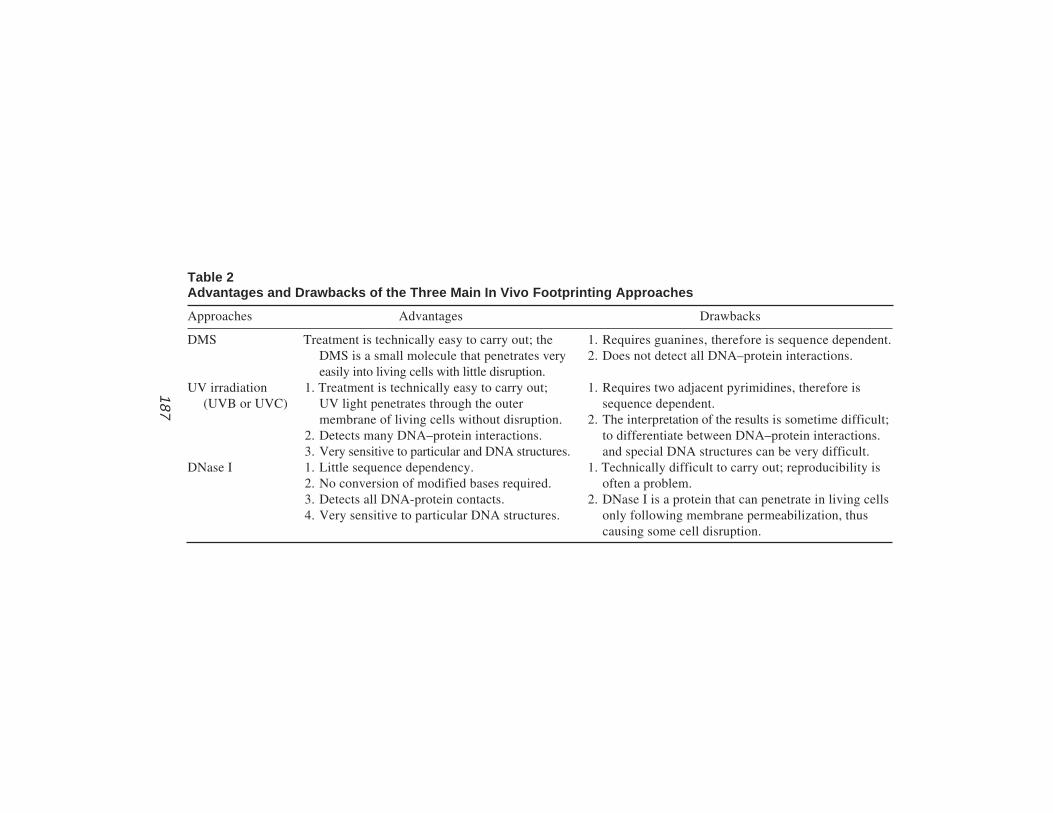
In Vivo D
NA
Analysis
187
187
Table 2Advantages and Drawbacks of the Three Main In Vivo Footprinting Approaches
Approaches Advantages Drawbacks
DMS Treatment is technically easy to carry out; the 1. Requires guanines, therefore is sequence dependent.DMS is a small molecule that penetrates very 2. Does not detect all DNA–protein interactions.easily into living cells with little disruption.
UV irradiation 1. Treatment is technically easy to carry out; 1. Requires two adjacent pyrimidines, therefore is(UVB or UVC) UV light penetrates through the outer sequence dependent.
membrane of living cells without disruption. 2. The interpretation of the results is sometime difficult;2. Detects many DNA–protein interactions. to differentiate between DNA–protein interactions.3. Very sensitive to particular and DNA structures. and special DNA structures can be very difficult.
DNase I 1. Little sequence dependency. 1. Technically difficult to carry out; reproducibility is2. No conversion of modified bases required. often a problem.3. Detects all DNA-protein contacts. 2. DNase I is a protein that can penetrate in living cells4. Very sensitive to particular DNA structures. only following membrane permeabilization, thus
causing some cell disruption.

188 Drouin et al.
delimitation of the boundaries of DNA–protein contacts. However, it shouldbe underlined that the relatively bulky DNase I molecule cannot cleave theDNA in the immediate vicinity of a bound protein because of steric hindrance.Consequently, the regions protected from cutting can extend beyond the actualDNA–protein contact site. On the other hand, when DNA is wrapped around anucleosome-size particle, DNase I cutting activity is increased at 10-bp inter-vals and no footprint is observed (Tables 1 and 2).
DNase I, a relatively large 31-kDa protein, cannot penetrate cells withoutprevious cell-membrane permeabilization. Cells can be efficiently permeabi-lized by lysolecithin (2) or Nonidet P40 (33). It has been shown that cellspermeabilized by lysolecithin remain intact, replicate their DNA veryefficiently, and show normal transcriptional activities (34,35). There arenumerous studies showing that lysolecithin-permeabilized cells maintain a nor-mal nuclear structure to a greater extent than isolated nuclei, because thechromatin structure can be significantly altered during the nuclear isolationprocedures (2). Indeed, DNase I footprinting studies using isolated nucleican be flawed because transcription factors are lost during the isolation ofnuclei in polyamine containing buffers (2). Even though other buffers may beless disruptive, factors can still be lost during the isolation procedure, leadingto the loss of footprints or partial loss of footprints.
DNase I digestion of DNA leaves ligatable 5’-phosphorylated breaks, butthe 3’-ends are free hydroxyl groups. Pfeifer and colleagues (2,36) observedthat these genomic 3'-OH ends can be used as primers and be extended by theDNA polymerases during the initial extension and/or PCR steps of LMPCR,thereby reducing significantly the overall efficiency of LMPCR and giving a
Table 3Mapping Schemes Used with the Three Main In Vivo Footprinting Approaches
Conversion of modified Strand bases to DNA
Approaches breaks Modified bases single-strand breaks
DMS Few Guanine: methylated guanines Hot piperidineat N7 position
Adenine: to a much lesserextent, methylated adeninesat N3 position
UV irradiation Very (i) Cyclobutane pyrimidine (i) T4 endonuclease V(UVB or UVC) few dimers followed by photolyase
(ii) 6–4 Photoproducts (ii) Photolyase followedby hot piperidine
DNase I Yes None No conversion required
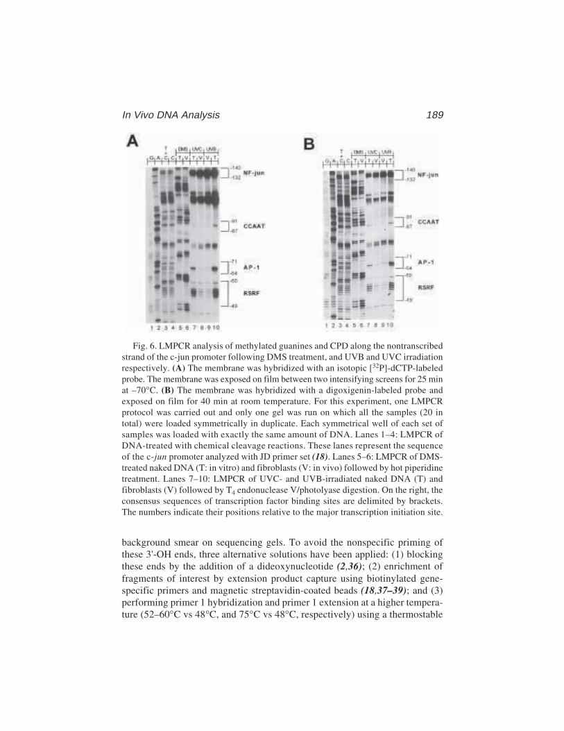
In Vivo DNA Analysis 189
background smear on sequencing gels. To avoid the nonspecific priming ofthese 3'-OH ends, three alternative solutions have been applied: (1) blockingthese ends by the addition of a dideoxynucleotide (2,36); (2) enrichment offragments of interest by extension product capture using biotinylated gene-specific primers and magnetic streptavidin-coated beads (18,37–39); and (3)performing primer 1 hybridization and primer 1 extension at a higher tempera-ture (52–60°C vs 48°C, and 75°C vs 48°C, respectively) using a thermostable
Fig. 6. LMPCR analysis of methylated guanines and CPD along the nontranscribedstrand of the c-jun promoter following DMS treatment, and UVB and UVC irradiationrespectively. (A) The membrane was hybridized with an isotopic [32P]-dCTP-labeledprobe. The membrane was exposed on film between two intensifying screens for 25 minat –70°C. (B) The membrane was hybridized with a digoxigenin-labeled probe andexposed on film for 40 min at room temperature. For this experiment, one LMPCRprotocol was carried out and only one gel was run on which all the samples (20 intotal) were loaded symmetrically in duplicate. Each symmetrical well of each set ofsamples was loaded with exactly the same amount of DNA. Lanes 1–4: LMPCR ofDNA-treated with chemical cleavage reactions. These lanes represent the sequenceof the c-jun promoter analyzed with JD primer set (18). Lanes 5–6: LMPCR of DMS-treated naked DNA (T: in vitro) and fibroblasts (V: in vivo) followed by hot piperidinetreatment. Lanes 7–10: LMPCR of UVC- and UVB-irradiated naked DNA (T) andfibroblasts (V) followed by T4 endonuclease V/photolyase digestion. On the right, theconsensus sequences of transcription factor binding sites are delimited by brackets.The numbers indicate their positions relative to the major transcription initiation site.
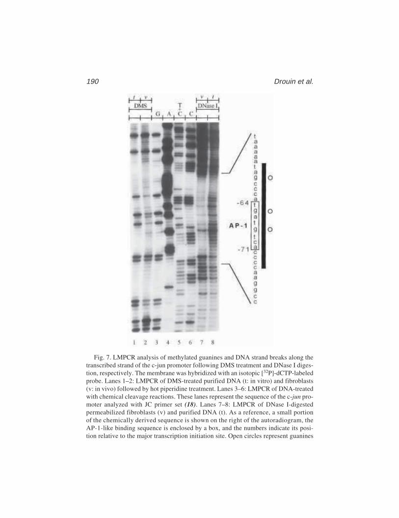
190 Drouin et al.
Fig. 7. LMPCR analysis of methylated guanines and DNA strand breaks along thetranscribed strand of the c-jun promoter following DMS treatment and DNase I diges-tion, respectively. The membrane was hybridized with an isotopic [32P]-dCTP-labeledprobe. Lanes 1–2: LMPCR of DMS-treated purified DNA (t: in vitro) and fibroblasts(v: in vivo) followed by hot piperidine treatment. Lanes 3–6: LMPCR of DNA-treatedwith chemical cleavage reactions. These lanes represent the sequence of the c-jun pro-moter analyzed with JC primer set (18). Lanes 7–8: LMPCR of DNase I-digestedpermeabilized fibroblasts (v) and purified DNA (t). As a reference, a small portionof the chemically derived sequence is shown on the right of the autoradiogram, theAP-1-like binding sequence is enclosed by a box, and the numbers indicate its posi-tion relative to the major transcription initiation site. Open circles represent guanines
In Vivo DNA Analysis 191
enzyme such as Vent exo– DNA polymerase and cloned Pfu DNA polymerase(3,40–42). Although effective, the first two alternatives involve additionalmanipulations that are time-consuming. Because of its simplicity, we selectprimer 1 with a higher Tm (52–60°C) and use the cloned Pfu DNA polymerasefor the primer 1 extension.
1.5. Choice of DNA Polymerases for LMPCR
Ligation-mediated PCR involves the PCR amplification of a mixture ofgenomic DNA fragments of different size. During the LMPCR procedure, DNApolymerases are required for two steps: primer extension (PE) and PCR ampli-fication. For the PE step, the best DNA polymerase would be one that (1) isthermostable and very efficient, (2) has no terminal transferase activity, (3) is ableto efficiently polymerize about 0.75 kb of DNA even when the DNA is veryGC rich, and (4) is able to polymerize through any DNA secondary structures.For the PCR step, the best DNA polymerase would be (1) thermostable, (2)very efficient, (3) able to amplify indiscriminately a mixture of DNA frag-ments of different lengths (between 50 and 750 bp) and of varying GC-rich-ness (from 5% to 95%), and (4) able to efficiently resolve DNA secondarystructures. We find cloned Pfu DNA polymerase that corresponds to Pfu exo–
is the best enzyme for the PE and PCR steps of LMPCR (42). In this chapter,LMPCR protocols using cloned Pfu DNA polymerase for PE and PCR stepswill be described in detail. However, because the more frequently used combi-nation of DNA polymerases is Sequenase™ 2.0 for the PE step and Taq DNApolymerase for the PCR step, a description of an alternative LMPCR protocolusing Sequenase 2.0 and Taq DNA polymerase will also be included.
2. Materials2.1. DNA Purification (for 107 to 108 cells)
1. Any types of cells (i.e., fibroblasts, lymphocytes, etc.).2. Trypsin–EDTA (Gibco-BRL).3. Hank’s Balanced Salt Solution (HBSS) (Gibco-BRL).4. Buffer A: 300 mM sucrose, 60 mM KCl, 15 mM NaCl, 60 mM Tris-HCl, pH 8.0,
0.5 mM spermidine, 0.15 mM spermine, and 2 mM EDTA. Store at –20°C.5. Buffer A + 1% Nonidet P40. Store at –20°C.6. Conical tissue culture tubes, 50 mL.7. Buffer B: 150 mM NaCl and 5 mM EDTA pH 7.8.
that are protected against DMS-induced methylation (negative DMS footprints) invivo. The black bar shows the protected sequence against DNase I-induced cleavagein vivo. Thus, in vivo DNase I footprinting analysis delimits much better the DNA–protein interactions.
192 Drouin et al.
8. Buffer C: 20 mM Tris-HCl, pH 8.0, 20 mM NaCl, 20 mM EDTA, and 1% sodiumdodecyl sulfate (SDS).
9. Proteinase K from Tritirachium album (Roche Molecular Biochemicals).10. RNase A from bovine pancreas (Roche Molecular Biochemicals).11. Phenol, equilibrated with 0.1 M Tris-HCl, pH 8.0 (Roche Molecular Biochemicals,
cat. no. 108-95-2).12. Chloroform.13. 5 M NaCl.14. Precooled absolute ethanol (–20°C).15. Precooled 70% ethanol (–20°C).16. N-2-Hydroxyethylpiperazine-N'-2-ethanesulfonic acid (HEPES).17. 4'–6-Diamidino-2-phenylindole (DAPI).18. Nanopure H2O should be used in making any buffers, solutions, and dilutions,
unless otherwise specified.
2.2. Chemical Cleavage for DNA-Sequencing Products
1. Potassium tetrachloropalladate(II) (K2PdCl4, Aldrich).2. K2PdCl4 solution: 10 mM K2PdCl4 and 100 mM HCl, pH 2.0 (adjusted with
NaOH). Store at –20°C.3. K2PdCl4 stop: 1.5 M sodium acetate, pH 7.0, and 1 M β-mercaptoethanol.4. Dimethylsulfate (DMS, 99+%, Fluka). Considering its toxic and carcinogenic nature,
DMS should be manipulated in a well-ventilated hood. DMS is stored under nitrogen at4°C and should be replaced every 12 mo. DMS waste is detoxified in 5 M NaOH.
5. DMS buffer: 50 mM sodium cacodylate and 1 mM EDTA pH 8.0. Store at 4°C.6. DMS stop: 1.5 M sodium acetate pH 7.0 and 1 M β-mercaptoethanol. Store at –20°C.7. Hydrazine (Hz, anhydrous, Aldrich). Considering its toxic and carcinogenic
potentials, Hz should be manipulated in a well-ventilated hood. Hz is stored undernitrogen at 4°C in an explosion-proof refrigerator and the bottle should bereplaced at least every 6 mo. Hz waste is detoxified in 3 M ferric chloride.
8. Hz stop: 300 mM sodium acetate pH 7.0 and 0.1 mM EDTA. Store at 4°C.9. 5 M NaCl.
10. 3 M Sodium acetate pH 7.0.11. Precooled absolute ethanol (–20°C).12. Precooled 80% ethanol (–20°C).13. Dry ice.14. Piperidine (99+%, Fluka or Sigma): 10 M stock diluted to 2 M with H2O just
before use by adding 250 µL stock under 1 mL H2O in a 1.5-mL microtube onice. Cap immediately to minimize evaporation. Considering its toxic and carci-nogenic potentials, piperidine should be manipulated in a well-ventilated hood.Piperidine 10 M is stored at 4°C under nitrogen atmosphere.
15. Teflon tape.16. Lock caps.17. 3 M Sodium acetate pH 5.2.18. 20 µg/µL glycogen.19. Vacuum concentrator (SpeedVac concentrator, Savant).

In Vivo DNA Analysis 193
2.3. Treatment of Purified DNA and Living Cells with Modifying Agents
2.3.1. DMS Treatment
1. DMS (99+%, Fluka).2. Trypsin–EDTA (Gibco-BRL).3. Hank’s Balanced Salt Solution (HBSS).
2.3.2. 254-nm UV and UVB Irradiation
1. Germicidal lamp (254 nm) for UVC irradiation (Philips G15 T8, TUV 15W).2. UVB light for UVB irradiation (Philips, FS20T12/UVB/BP).3. UVX digital radiometer (Ultraviolet Products, Upland, CA).4. 0.9% NaCl.5. UV irradiation buffer: 150 mM KCl, 10 mM NaCl, 10 mM Tris-HCl, pH 8.0, and
1 mM EDTA.6. Buffer A + 0.5% Nonidet P40. Store at –20°C.7. Scraper.
2.3.3. DNase I Treatment
1. Deoxyribonuclease I (DNase I, Worthington biochemical corporation; 45A134).2. Trypsin–EDTA (Gibco-BRL).3. Hank’s Balanced Salt Solution (HBSS).4. L-α-Lysophosphatidylcholine (L-α-Lysolecithin).5. Nonidet P40.6. Solution I: 150 mM sucrose, 80 mM KCl, 35 mM HEPES, pH 7.4, 5 mM MgCl2,
and 0.5 mM CaCl2.7. Solution II: 150 mM sucrose, 80 mM KCl, 35 mM HEPES, pH 7.4, 5 mM MgCl2,
and 2 mM CaCl2.8. Conical tubes, 15 and 50 mL.9. Buffer B: 150 mM NaCl and 5 mM EDTA, pH 7.8.
10. Buffer C: 20 mM Tris-HCl, pH 8.0, 20 mM NaCl, 20 mM EDTA, and 1% SDS.11. Proteinase K from Tritirachium album (Roche Molecular Biochemicals).12. RNase A from bovine pancreas (Roche Molecular Biochemicals).13. Phenol (see Subheading 2.1., item 11).14. Chloroform.15. 5 M NaCl.16. Precooled absolute ethanol (–20°C).17. Precooled 80% ethanol (–20°C).
2.4. Conversion of Modified Basesto DNA Single-Strand Breaks
2.4.1. DMS-Induced Base Modifications
Piperidine (99+%, see Subheading 2.2., item 14).
194 Drouin et al.
2.4.2. UV-Induced Base Modifications
1. 10X dual buffer: 500 mM Tris-HCl, pH 7.6, 500 mM NaCl, and 10 mM EDTA.2. 1 M 1,4-Dithiothreitol (DTT, Roche Molecular Biochemicals).3. 5 mg/mL nuclease-free bovine serum albumine (BSA, Roche Molecular
Biochemicals).4. T4 endonuclease V enzyme (Epicentre Technologies). The saturating amount of
T4 endonuclease V enzyme can be estimated by digesting UV-irradiated genomicDNA with various enzyme quantities and separating the cleavage products onalkaline agarose gel (43). The saturating amount of the enzyme is the next to theminimum quantity that produces the maximum cleavage frequency as evaluatedon the alkaline agarose gel.
5. E. coli photolyase enzyme (Pharmingen). The saturating amount of photolyasecan be estimated by photoreactivating UV-irradiated genomic DNA with variousenzyme quantities, digestion with T4 endonuclease V, and separating the cleav-age products on alkaline agarose gel (43). The saturating amount of photolyase isthe next to the minimum enzyme quantity which produces no cleavage followingT4 endonuclease V digestion as evaluated on the gel. Because photolyase is lightsensitive, all steps involving photolyase should be carried out under yellow light.
6. UVA black light (UV F15T8BLB 360 nm, Philips, 15W).7. Plastic film (plastic wrap).8. 0.52% SDS solution.9. Phenol (see Subheading 2.1., item 11).
10. Chloroform.11. 5 M NaCl.12. Precooled absolute ethanol (–20°C).13. Precooled 80% ethanol (–20°C).14. Piperidine (99+%, see Subheading 2.2., item 14).
2.5. Ligation-Mediated Polymerase Chain Reaction Technology
2.5.1. Primer Extension (Steps II and III, Fig. 5)
1. A gene-specific primer (primer 1) is used to initiate primer extension. The primer1 used in the first-strand synthesis are 15- to 22-mer oligonucleotides and have acalculated melting temperature (Tm) of 50–60°C. They are selected using a com-puter program (Oligo 4.0 software, National Biosciences) (44) and, optimally,their Tm, as calculated by a computer program (GeneJockey software), should beabout 10°C lower than that of subsequent primers (see Note 1) (45). The first-strand synthesis reaction is designed to require very little primer 1 with a lowerTm so that this primer does not interfere with subsequent steps (11–13,46). Theprimer 1 concentration is set at 50 µM in H2O and then diluted 1:100 in H2O togive 0.5 pmol/µL.
2. Siliconized microtubes (0.625 µL) (National Scientific Supply Co, Inc.).3. Thermocycler (PTC™, MJ research, Inc.).
In Vivo DNA Analysis 195
4. 10X cloned Pfu buffer: 200 mM Tris-HCl, pH 8.8, 20 mM MgSO4, 100 mMNaCl, 100 mM (NH4)2SO4, 1% (v/v) Triton X-100, and 1 mg/mL nuclease-freeBSA (see Note 2).
5. Cloned Pfu mix: 1.5 mM of each dNTP and 1.5 U cloned Pfu DNA polymerase,also named Pfu exo– (2.5 U/µL, Stratagene).
6. 5X Sequenase buffer: 200 mM Tris-HCl, pH 7.7, and 250 mM NaCl.7. Mg–dNTPs mix: 20 mM MgCl2, 20 mM DTT, and 0.375 mM of each dNTP.8. T7 Sequenase V.2 (Amersham).9. 310 mM Tris-HCl, pH 7.7.
2.5.2. Ligation (Step IV, Fig. 5)
1. The DNA molecules that have a 5' phosphate group and a double stranded bluntend are suitable for ligation. A DNA linker with a single blunt end is ligateddirectionally onto the double-stranded blunt end of the extension product usingT4 DNA ligase. This linker has no 5' phosphate and is staggered to avoid self-ligation and provide directionality. Also, the duplex between the 25-mer(5' GCGGTGACCCGGGAGATCTGAATTC) and 11-mer (5' GAATTCAGATC)is stable at the ligation temperature, but denatures easily during subsequent PCRreactions (5,46). The linker was prepared in aliquots of 500 µL by annealing in250 mM Tris-HCl, pH 7.7, 20 pmol/µL each of the 25-mer and 11-mer, heating at95°C for 3 min, transferring quickly at 70°C, and cooling gradually to 4°C over aperiod of 3 h. Linkers are stored at –20°C and thawed on ice before use. Linker:L25 (60 pmol/µL, 5'-GCGGTGACCCGGGAGATCTGAATTC), L11 (60 pmol/µL,5'-GAATTCAGATC), 2 M Tris-HCl, pH 7.7, and 1 M MgCl2.
2. T4 DNA ligase (1 U/µL, Roche Molecular Biochemicals).3. Ligation mix: 30 mM DTT, 1 mM ATP, 83.3 µg/mL of BSA, 100 pmol of linker,
and 3.25 U/microtube of T4 DNA ligase. If cloned Pfu DNA polymerase wasused for primer extension (step III, Fig. 5), the ligation mix is prepared by addingper microtube: 1.35 µL of 1 M DTT, 0.5 µL of 100 mM ATP, 0.15 µL of 5 µg/µLBSA, 1.1 µL of Tris-HCl, pH 7.4, 5.0 µL of 20 pmol/µL linker, 3.25 µL of 1 U/µLT4 ligase, and 33.65 µL of H2O. If Sequenase was used for primer extension(step III, Fig. 5), the ligation mix is prepared by adding per microtube: 1.35 µL of1 M DTT, 0.5 µL of 100 mM ATP, 0.75 µL of 5 µg/µL BSA, 5.0 µL of 20 pmol/µLlinker, 3.25 µL of 1 U/µL T4 ligase, and 34.15 µL of H2O.
4. 7.5 M ammonium acetate.5. 0.5 M EDTA, pH 8.0.6. 20 µg/µL glycogen.7. Precooled absolute ethanol (–20°C).8. Precooled 80% ethanol (–20°C).
2.5.3. Polymerase Chain Reaction (Steps V and VI, Fig. 5)
1. At this step, gene-specific fragments can be exponentially amplified becauseprimer sites are available at each end of the target fragments (i.e., primer 2 on oneend and the longer oligonucleotide of the linker on the other end). Primer 2 may
196 Drouin et al.
or may not overlap with primer 1. The overlap, if present, should not be morethan seven to eight bases (11–13,46). Primer 2 is diluted in H2O to give 50 pmol/µL.
2. 10X cloned Pfu buffer: 200 mM Tris-HCl, pH 8.8, 20 mM MgSO4, 100 mMNaCl, 100 mM (NH4)2SO4, 1% (v/v) Triton X–100, and 1 mg/mL nuclease-freeBSA (see Note 2).
3. Cloned Pfu DNA polymerase, also named Pfu exo– (2.5 U/µL, Stratagene).4. Cloned Pfu DNA polymerase mix per microtube: 2X cloned Pfu buffer, 0.5 mM
of each dNTP, 10 pmol of LP25 (Linker Primer), 10 pmol of primer 2, and 3.5 Uof cloned Pfu DNA polymerase.
5. Mineral oil.6. Cloned Pfu DNA polymerase stop: 1.56 M sodium acetate pH 5.2 and 20 mM
EDTA.7. Formamide loading dye: 94% formamide, 2 mM EDTA, pH 7.7, 0.05% xylene
cyanole FF, and 0.05% bromophenol blue (11–13). The formamide loading dyeis freshly premixed by adding 1 part H2O to 2 parts formamide loading dye.
8. 5X Taq buffer: 50 mM Tris-HCl, pH 8.9, 200 mM NaCl, and 0.05% [w/v] gelatin(see Note 2).
9. Taq DNA polymerase (5 U/µL, Roche Molecular Biochemicals).10. Taq DNA polymerase mix per microtube: 2X Taq buffer, 4 mM MgCl2, 0.5 mM
of each dNTP, 10 pmol LP25 (Linker Primer), 10 pmol primer 2, and 3 U TaqDNA polymerase.
11. Taq DNA polymerase stop: 1.56 M sodium acetate pH 5.2 and 60 mM EDTA.12. Phenol (see Subheading 2.1., item 11) premixed with chloroform in a ratio of 92 µL
of phenol for 158 µL of chloroform.13. Precooled absolute ethanol (–20°C).14. Precooled 80% ethanol (–20°C).
2.5.4. Gel Electrophoresis and Electroblotting (Step VII, Fig. 5)
1. 60-cm-long × 34.5-cm-wide sequencing gel apparatus (Owl Scientific).2. Spacers (0.4-mm thick).3. Plastic well-forming comb (0.4-mm thick, Bio-Rad).4. 5X (0.5 M) Tris–borate–EDTA (TBE) buffer: 500 mM Tris, 830 mM boric acid,
and 10 mM EDTA, pH 8.3. Use this stock to prepare 1X (100 mM) TBE buffer.5. 8% Polyacrylamide, to prepare 1 L, add 77.3 g of acrylamide, 2.7 g of bis-
acrylamide, 420.42 g of urea, and 200 mL of 0.5 M TBE dissolved in H2O. Poly-acrylamide solution should be kept at 4°C.
6. Gel preparation: Mix 100 mL of 8% polyacrylamide with 1 mL of 10% ammo-nium persulfate (APS) and 30 µL of N,N,N',N'-tetra-methylethylenediamide(TEMED). This mix is prepared immediately before pouring the solution betweenthe glass plates. Without delay, take the gel mix into a 50-mL syringe and injectthe mix between the plates, maintaining a steady flow. During pouring, the platesshould be kept at a 30° angle and tilted to the side into which the mix is injected.Any air bubbles should be avoided and removed if they form. The gel should beleft to polymerize for a minimum of 3 h before use. If the gel is to be left over-
In Vivo DNA Analysis 197
night, 45 min after pouring, place a moistened paper tissue over the comb, andcover the upper end of the assembly with a plastic film to prevent the gel fromdrying out.
7. Flat gel loading tips (National Scientific Supply Co).8. Power supply (Bio-Rad PowerPac 3000).9. Electroblotting apparatus (HEP3, Owl Scientific Inc.) used according to the
manufacturer’s instructions.10. Whatman 3MM Chr paper (Fisher Scientific).11. Plastic film (plastic wrap).12. Whatman 17 Chr papers (Fisher Scientific).13. Nylon membrane, positively charged (Roche Molecular Biochemicals, cat.
no. 1 417 240).14. Power supply (Bio-Rad, model 200/2.0).15. UVC (254 nm) germicidal lamp.
2.5.5. Hybridization (Step VII, Fig. 5)
The hybridization is performed in a rolling 8-cm-diameter × 22 cm longborosilicate glass hybridization tubes in a hybridization oven (Hoefer). Thenylon membrane is soaked in 100 mM TBE and, using a 25-mL pipet, placed inthe tube so that the membrane sticks completely to the wall of the hybridiza-tion tube. Following hybridization and washing, the membranes are placed inan autoradiography cassette FBAC 1417 (Fisher Scientific) and exposed toKodak X-ray film (XAR-5, 35 × 43 cm, Kodak Scientific Imaging Film) withintensifying screens (35 × 43 cm, Fisher Scientific, cat. no. FB-IS-1417) at–70°C when a radiolabeled probe has been hybridized and without intensify-ing screens at room temperature when a digoxigenin-labeled probe has beenhybridized.
2.5.5.1. RADIOLABELED PROBE
1. Hybridization buffer: 250 mM sodium phosphate pH 7.2, 1 mM EDTA, 7% SDS,and 1% BSA.
2. Radiolabeled probe diluted in 6–7 mL of hybridization buffer.3. Washing buffer I: 20 mM sodium phosphate pH 7.2, 1 mM EDTA, 0.25% BSA,
and 2.5% SDS.4. Washing buffer II: 20 mM sodium phosphate pH 7.2, 1 mM EDTA, and 1% SDS.5. Plastic film (plastic wrap).
2.5.5.2. DIGOXIGENIN-LABELED PROBE
1. Prehybridization buffer: 5X SSC (750 mM NaCl and 75 mM sodium citratepH 7.0), 1% casein, 0.1% N-lauroylsarcosin, and 0.02% SDS.
2. Digoxigenin-labeled probe diluted in 15 mL of prehybridization buffer (use only7.5 mL for hybridization).
3. 2X washing solution: 2X SSC and 0.1% SDS.
198 Drouin et al.
4. 0.5X washing solution: 0.5X SSC and 0.1% SDS.5. Buffer 1: 150 mM NaCl and 100 mM maleic acid, pH 7.5.6. Buffer 2: buffer 1 + 1% (w/v) casein.7. Antidigoxigenin antibodies (Roche Molecular Biochemicals).8. Buffer 1 + 0.3% Tween-20.9. Buffer 3: 100 mM Tris-HCl, pH 9.5, 100 mM NaCl, and 50 mM MgCl2.
10. CSPD® [disodium 3-(4-methoxyspiro 1,2-dioxetane–3,2'-(5' chloro)tricyclo[3.3.1.13,7]decan–4-yl)phenyl phosphate] substrate (Roche Molecular Bio-chemicals, cat. no. 1 655 884).
11. Acetate sheets.12. Doubleseal (Model 855, Decosonic).
2.6. Preparation of Single-Stranded Hybridization Probes(Step VIII, Fig. 5)
2.6.1. Template Preparation: PCR Products
2.6.1.1. PCR AMPLIFICATION
1. 5X Taq buffer: 50 mM Tris-HCl, pH 8.9, 200 mM NaCl, and 0.05% (w/v) gelatin(see Note 2).
2. Taq DNA polymerase (5 U/µL, Roche Molecular Biochemicals).3. One primer 2 (50 pmol/µL) for each strand of the DNA fragment to be amplified
distant from 150 to 450 bp.4. Taq DNA polymerase mix per microtube: 2X Taq buffer, 4 mM MgCl2, 0.4 mM
of each dNTP, 10 pmol of each primer 2, and 3 U Taq DNA polymerase.5. Mineral oil.6. Taq DNA polymerase stop: 1.56 M sodium acetate, pH 5.2, and 60 mM EDTA.7. Phenol (see Subheading 2.1., item 11) premixed with chloroform in a ratio of 92 µL
of phenol to 158 µL of chloroform.8. Precooled absolute ethanol (–20°C).9. Precooled 80% ethanol (–20°C).
10. 5X TAE loading buffer: 5X TAE (200 mM Tris base, 100 mM glacial aceticacid, and 5 mM EDTA, pH 8.0), 0.025% bromophenol blue, 30% Ficoll 400,and 2% SDS.
2.6.1.2. PURIFICATION AND QUANTIFICATION OF PCR PRODUCTS
1. Agarose.2. 1X TAE buffer: 40 mM Tris base, 20 mM glacial acetic acid, and 1 mM EDTA,
pH 8.0.3. DNA size standards (φX 174 RF, Canadian life technologies, cat. no. 15611-015).4. Ethidium bromide.5. Siliconized microtubes (0.625 mL) and 1.5-mL microtubes.6. Glass wool.7. 3 M sodium acetate, pH 7.0.8. Precooled absolute ethanol (–20°C).
In Vivo DNA Analysis 199
9. Precooled 80% ethanol (–20°C).10. Low DNA mass ladder (Gibco-BRL, cat. no. 10068-013).11. 5X universal neutral loading buffer: 0.25% bromophenol blue, 0.25% xylene
cyanol FF, and 30% glycerol in H2O. Store at 4°C.
2.6.2. Labeling of Single-Strand Hybridization Probes
2.6.2.1. ISOTOPIC LABELING
1. Siliconized microtubes (0.625 mL) and 1.5-mL microtubes.2. 5X Taq buffer: 50 mM Tris-HCl, pH 8.9, 200 mM NaCl, and 0.05% (w/v) gelatin
(see Note 2).3. 100 mM MgCl2.4. DNA templates: PCR products (10 ng/µL) or DNA plasmids (20 ng/µL).5. Primer 2 (50 pmol/µL).6. dNTP (dATP, dGTP, dTTP) mix (200 µM of each).7. dNTP (dATP, dGTP, dTTP) mix diluted 1:10 in H2O. This mix is changed every
2 wk.8. Taq DNA polymerase (5 U/µL, Roche Molecular Biochemicals).9. α-[32P]dCTP (3000 Ci/mmol, New England Nuclear).
10. 7.5 M ammonium acetate.11. 20 µg/µL glycogen12. Precooled absolute ethanol (–20°C)13. Geiger counter.14. TE buffer pH 8.0: 10 mM Tris-HCl, pH 8.0, and 1 mM EDTA, pH 7.8.15. Hybridization buffer: 250 mM sodium phosphate, pH 7.2, 1 mM EDTA, 7% SDS,
and 1% BSA.
2.6.2.2. DIGOXIGENIN (NONISOTOPIC) LABELING
1. Siliconized microtubes (0.625 mL) and 1.5-mL microtubes.2. 5X Taq buffer: 50 mM Tris-HCl, pH 8.9, 200 mM NaCl, and 0.05% (w/v)
gelatin (see Note 2).3. 100 mM MgCl2.4. DNA templates: PCR products (10 ng/µL) or DNA plasmids (20 ng/µL).5. Primer 2 (50 pmol/µL).6. dNTP mix (A:G:C:T = 25 mM : 25 mM : 25 mM : 20 mM).7. dNTP mix diluted 1:8.3 in H2O. This mix is changed every 2 wk.8. 1 mM digoxigenin-11-dUTP (Roche Molecular Biochemicals) diluted 1:2 in H2O.9. Taq DNA polymerase (5 U/µL, Roche Molecular Biochemicals).
10. 7.5 M ammonium acetate.11. 20 µg/µL glycogen.12. Precooled absolute ethanol (–20°C).13. TE buffer pH 8.0: 10 mM Tris-HCl, pH 8.0, and 1 mM EDTA, pH 7.8.14. Prehybridization buffer: 5X SSC (750 mM NaCl and 75 mM sodium citrate
pH 7.0), 1% casein, 0.1% N-lauroylsarcosine, and 0.02% SDS.

200 Drouin et al.
3. Methods3.1. DNA Purification (for 107 to 108 Cells)
1. Detach cells using trypsin (if needed) and sediment the cell suspension by cen-trifugation in 50-mL conical tubes.
2. Resuspend the cells in 5–15 mL of buffer A.3. Add 1 volume (5–15 mL) of buffer A containing 1% Nonidet P40.4. Incubate on ice for 5 min.5. Sediment nuclei by centrifugation at 4500g for 10 min at 4°C.6. Remove the supernatant. Resuspend nuclei in 1–10 mL of buffer A by gentle
vortexing. Resediment nuclei at 4500g for 10 min at 4°C.7. Remove supernatant. It is recommended to leave a small volume (100–500 µL)
of buffer A to facilitate resuspension of nuclei.8. Dilute the nuclei in 1–2 mL of buffer B.9. Add an equivalent volume of buffer C and proteinase K to a final concentration
of 450 µg/mL.10. Incubate at 37°C for 3 h, shake occasionally (see Note 3).11. Add RNase A to a final concentration of 150 µg/mL.12. Incubate at 37°C for 1 h.13. Purify DNA by extraction with 1 vol phenol (one to two times as needed), 1 vol
phenol:chloroform (one to two times as needed), and 1 vol chloroform. Phenolextraction and phenol-chloroform extraction should be repeated if the aqueousphase is not clear (see Note 3).
14. Precipitate DNA in 200 mM NaCl and 2 vol of precooled absolute ethanol. Ethanolshould be added slowly and to facilitate DNA recovery, rock the tube very gently.
15. Recover DNA by spooling the floating DNA filament with a micropipet tip. IfDNA is in small pieces or not clearly visible, recover DNA by centrifugation(5000g for 30 min at 4°C), but expect RNA contamination (see Note 4). RNAcontamination does not cause any problems for LMPCR. RNase digestion can berepeated if needed.
16. Remove supernatant and wash DNA once with 10 mL of 70% ethanol.17. Centrifuge the DNA (5000g for 10 min at 4°C).18. Remove supernatant and air-dry DNA pellet.19. Dissolve DNA in 10 mM HEPES, pH 7.4, and 1 mM EDTA (HE buffer) at an
estimated concentration of 60–100 µg/mL. The quantity of DNA can be esti-mated based upon the number of cells that were initially used for DNA purifica-tion. About 6 µg of DNA should be purified from 1 × 10⁶ cells.
20. Carefully measure DNA concentration by spectrophotometry at 260 nm. Alter-natively, DNA can be measure by fluorometry after staining with DAPI. Onlydouble-strand DNA concentration has to be measured, be careful if there is RNAcontamination (see Note 5).
3.2. Chemical Cleavage for DNA Sequencing Products
In vivo DNA analysis using LMPCR requires complete DNA sequencingladders from genomic DNA. Base-specific chemical modifications are per-

In Vivo DNA Analysis 201
formed according to Iverson and Dervan (47) for the A reaction and Maxamand Gilbert for the G, T+C, and C reactions. DNA from each of these base-modification reactions is processed by LMPCR concomitantly with the ana-lyzed samples and loaded in adjacent lanes on the sequencing gel to allow theidentification of the precise location and sequence context of footprinted regions.The chemical modifications induced by DMS, Hz, and K2PdCl4 and cleaved bypiperidine destroy the target base. Therefore, one must bear in mind that whenanalyzing a chemical-sequencing ladder, each band corresponds to a DNA frag-ment ending at the base preceding the one read. In this section, we will describethe chemical sequencing of genomic DNA. The cleavage protocol below worksoptimally with 10–50 µg of genomic DNA per microtube. Before chemicalsequencing, the required amount of DNA per microtube is ethanol precipitatedand the pellet is air-dried. For each base-specific reaction, we usually carriedout the treatment in three microtubes containing 50 µg of genomic DNA forthree different incubation times with the modifying agent in order to obtainlow, medium and high base-modification frequencies.
3.2.1. A Reaction
1. Add 160 µL of H2O and 40 µL of K2PdCl4 solution to the DNA pellet and care-fully mix on ice using a micropipet.
2. Incubate at 20°C for 5, 10, or 15 min.3. Add 50 µL of K2PdCl4 stop.4. Add 750 µL of precooled absolute ethanol.
3.2.2. G Reaction
1. Add 5 µL of H2O, 200 µL of DMS buffer, and 1 µL of DMS to the DNA pelletand carefully mix on ice using a micropipet.
2. Incubate at 20°C for 30, 45, or 60 s.3. Add 50 µL of DMS stop.4. Add 750 µL of precooled absolute ethanol.
3.2.3. T+C Reaction
1. Add 20 µL of H2O and 30 µL of Hz to the DNA pellet and carefully mix on iceusing a micropipet.
2. Incubate at 20°C for 120, 210, or 300 s.3. Add 200 µL of Hz stop.4. Add 750 µL of precooled absolute ethanol.
3.2.4. C Reaction
1. Add 5 µL of H2O, 15 µL of 5 M NaCl, and 30 µL of Hz to the DNA pellet andcarefully mix on ice using a micropipet.
2. Incubate at 20°C for 120, 210, or 300 s.
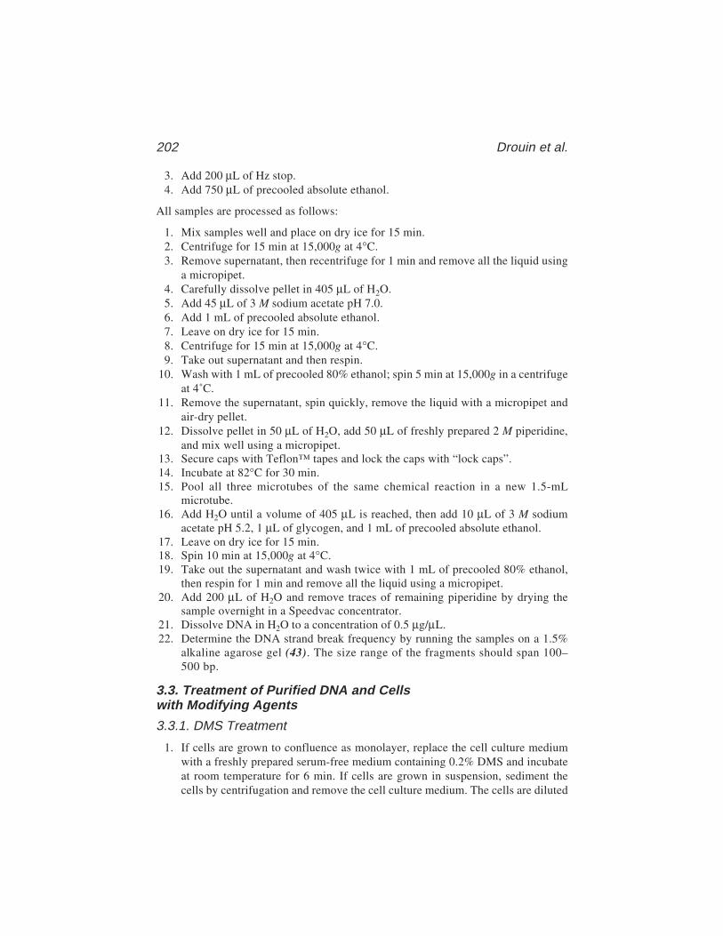
202 Drouin et al.
3. Add 200 µL of Hz stop.4. Add 750 µL of precooled absolute ethanol.
All samples are processed as follows:
1. Mix samples well and place on dry ice for 15 min.2. Centrifuge for 15 min at 15,000g at 4°C.3. Remove supernatant, then recentrifuge for 1 min and remove all the liquid using
a micropipet.4. Carefully dissolve pellet in 405 µL of H2O.5. Add 45 µL of 3 M sodium acetate pH 7.0.6. Add 1 mL of precooled absolute ethanol.7. Leave on dry ice for 15 min.8. Centrifuge for 15 min at 15,000g at 4°C.9. Take out supernatant and then respin.
10. Wash with 1 mL of precooled 80% ethanol; spin 5 min at 15,000g in a centrifugeat 4˚C.
11. Remove the supernatant, spin quickly, remove the liquid with a micropipet andair-dry pellet.
12. Dissolve pellet in 50 µL of H2O, add 50 µL of freshly prepared 2 M piperidine,and mix well using a micropipet.
13. Secure caps with Teflon™ tapes and lock the caps with “lock caps”.14. Incubate at 82°C for 30 min.15. Pool all three microtubes of the same chemical reaction in a new 1.5-mL
microtube.16. Add H2O until a volume of 405 µL is reached, then add 10 µL of 3 M sodium
acetate pH 5.2, 1 µL of glycogen, and 1 mL of precooled absolute ethanol.17. Leave on dry ice for 15 min.18. Spin 10 min at 15,000g at 4°C.19. Take out the supernatant and wash twice with 1 mL of precooled 80% ethanol,
then respin for 1 min and remove all the liquid using a micropipet.20. Add 200 µL of H2O and remove traces of remaining piperidine by drying the
sample overnight in a Speedvac concentrator.21. Dissolve DNA in H2O to a concentration of 0.5 µg/µL.22. Determine the DNA strand break frequency by running the samples on a 1.5%
alkaline agarose gel (43). The size range of the fragments should span 100–500 bp.
3.3. Treatment of Purified DNA and Cellswith Modifying Agents
3.3.1. DMS Treatment
1. If cells are grown to confluence as monolayer, replace the cell culture mediumwith a freshly prepared serum-free medium containing 0.2% DMS and incubateat room temperature for 6 min. If cells are grown in suspension, sediment thecells by centrifugation and remove the cell culture medium. The cells are diluted
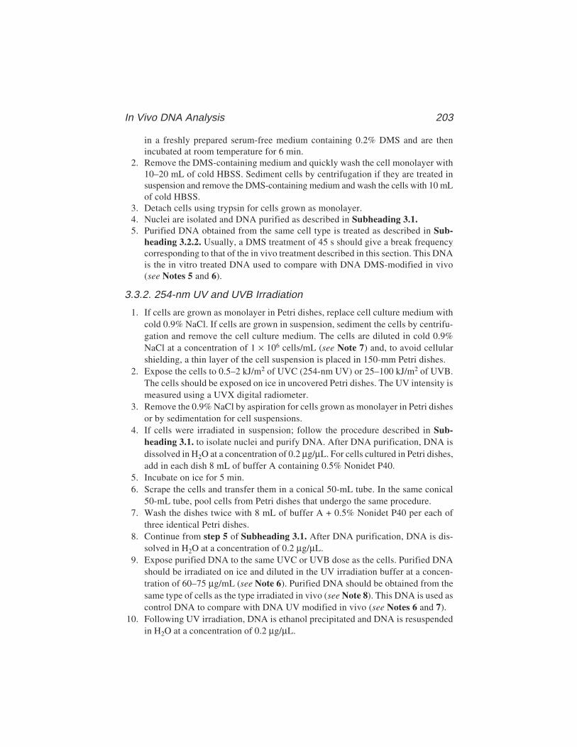
In Vivo DNA Analysis 203
in a freshly prepared serum-free medium containing 0.2% DMS and are thenincubated at room temperature for 6 min.
2. Remove the DMS-containing medium and quickly wash the cell monolayer with10–20 mL of cold HBSS. Sediment cells by centrifugation if they are treated insuspension and remove the DMS-containing medium and wash the cells with 10 mLof cold HBSS.
3. Detach cells using trypsin for cells grown as monolayer.4. Nuclei are isolated and DNA purified as described in Subheading 3.1.5. Purified DNA obtained from the same cell type is treated as described in Sub-
heading 3.2.2. Usually, a DMS treatment of 45 s should give a break frequencycorresponding to that of the in vivo treatment described in this section. This DNAis the in vitro treated DNA used to compare with DNA DMS-modified in vivo(see Notes 5 and 6).
3.3.2. 254-nm UV and UVB Irradiation
1. If cells are grown as monolayer in Petri dishes, replace cell culture medium withcold 0.9% NaCl. If cells are grown in suspension, sediment the cells by centrifu-gation and remove the cell culture medium. The cells are diluted in cold 0.9%NaCl at a concentration of 1 × 10⁶ cells/mL (see Note 7) and, to avoid cellularshielding, a thin layer of the cell suspension is placed in 150-mm Petri dishes.
2. Expose the cells to 0.5–2 kJ/m2 of UVC (254-nm UV) or 25–100 kJ/m2 of UVB.The cells should be exposed on ice in uncovered Petri dishes. The UV intensity ismeasured using a UVX digital radiometer.
3. Remove the 0.9% NaCl by aspiration for cells grown as monolayer in Petri dishesor by sedimentation for cell suspensions.
4. If cells were irradiated in suspension; follow the procedure described in Sub-heading 3.1. to isolate nuclei and purify DNA. After DNA purification, DNA isdissolved in H2O at a concentration of 0.2 µg/µL. For cells cultured in Petri dishes,add in each dish 8 mL of buffer A containing 0.5% Nonidet P40.
5. Incubate on ice for 5 min.6. Scrape the cells and transfer them in a conical 50-mL tube. In the same conical
50-mL tube, pool cells from Petri dishes that undergo the same procedure.7. Wash the dishes twice with 8 mL of buffer A + 0.5% Nonidet P40 per each of
three identical Petri dishes.8. Continue from step 5 of Subheading 3.1. After DNA purification, DNA is dis-
solved in H2O at a concentration of 0.2 µg/µL.9. Expose purified DNA to the same UVC or UVB dose as the cells. Purified DNA
should be irradiated on ice and diluted in the UV irradiation buffer at a concen-tration of 60–75 µg/mL (see Note 6). Purified DNA should be obtained from thesame type of cells as the type irradiated in vivo (see Note 8). This DNA is used ascontrol DNA to compare with DNA UV modified in vivo (see Notes 6 and 7).
10. Following UV irradiation, DNA is ethanol precipitated and DNA is resuspendedin H2O at a concentration of 0.2 µg/µL.
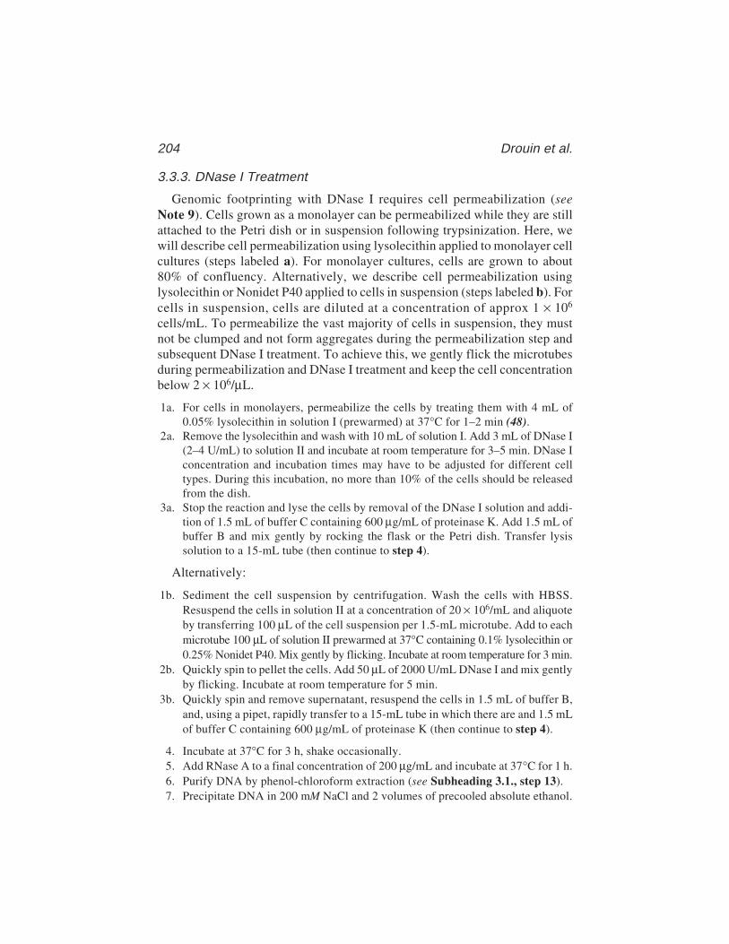
204 Drouin et al.
3.3.3. DNase I Treatment
Genomic footprinting with DNase I requires cell permeabilization (seeNote 9). Cells grown as a monolayer can be permeabilized while they are stillattached to the Petri dish or in suspension following trypsinization. Here, wewill describe cell permeabilization using lysolecithin applied to monolayer cellcultures (steps labeled a). For monolayer cultures, cells are grown to about80% of confluency. Alternatively, we describe cell permeabilization usinglysolecithin or Nonidet P40 applied to cells in suspension (steps labeled b). Forcells in suspension, cells are diluted at a concentration of approx 1 × 10⁶
cells/mL. To permeabilize the vast majority of cells in suspension, they mustnot be clumped and not form aggregates during the permeabilization step andsubsequent DNase I treatment. To achieve this, we gently flick the microtubesduring permeabilization and DNase I treatment and keep the cell concentrationbelow 2 × 10⁶/µL.
1a. For cells in monolayers, permeabilize the cells by treating them with 4 mL of0.05% lysolecithin in solution I (prewarmed) at 37°C for 1–2 min (48).
2a. Remove the lysolecithin and wash with 10 mL of solution I. Add 3 mL of DNase I(2–4 U/mL) to solution II and incubate at room temperature for 3–5 min. DNase Iconcentration and incubation times may have to be adjusted for different celltypes. During this incubation, no more than 10% of the cells should be releasedfrom the dish.
3a. Stop the reaction and lyse the cells by removal of the DNase I solution and addi-tion of 1.5 mL of buffer C containing 600 µg/mL of proteinase K. Add 1.5 mL ofbuffer B and mix gently by rocking the flask or the Petri dish. Transfer lysissolution to a 15-mL tube (then continue to step 4).
Alternatively:
1b. Sediment the cell suspension by centrifugation. Wash the cells with HBSS.Resuspend the cells in solution II at a concentration of 20 × 106/mL and aliquoteby transferring 100 µL of the cell suspension per 1.5-mL microtube. Add to eachmicrotube 100 µL of solution II prewarmed at 37°C containing 0.1% lysolecithin or0.25% Nonidet P40. Mix gently by flicking. Incubate at room temperature for 3 min.
2b. Quickly spin to pellet the cells. Add 50 µL of 2000 U/mL DNase I and mix gentlyby flicking. Incubate at room temperature for 5 min.
3b. Quickly spin and remove supernatant, resuspend the cells in 1.5 mL of buffer B,and, using a pipet, rapidly transfer to a 15-mL tube in which there are and 1.5 mLof buffer C containing 600 µg/mL of proteinase K (then continue to step 4).
4. Incubate at 37°C for 3 h, shake occasionally.5. Add RNase A to a final concentration of 200 µg/mL and incubate at 37°C for 1 h.6. Purify DNA by phenol-chloroform extraction (see Subheading 3.1., step 13).7. Precipitate DNA in 200 mM NaCl and 2 volumes of precooled absolute ethanol.

In Vivo DNA Analysis 205
8. Leave on dry ice for 20 min.9. Recover DNA by centrifugation (5000g for 30 min at 4°C), but expect RNA
contamination. RNA contamination does not cause any problems for LMPCR.RNase A digestion can be repeated if needed.
10. Remove supernatant and wash DNA once with 10 mL of precooled 80% ethanol.11. Centrifuge the DNA (5000g for 10 min at 4°C). Remove supernatant and air-dry
DNA pellet.12. Dissolve DNA in H2O and carefully measure DNA concentration (see Subhead-
ing 3.1., step 20).13. To obtain purified DNA controls (see Notes 6 and 8), digest 50 µg of purified
DNA in solution II with 4–8 U/µL of DNase I at room temperature for 10 min.Stop the reaction by adding 400 µL of phenol. Extract once with phenol–chloroformand once with chloroform. Dissolve DNA in H2O at a concentration of 0.5 µg/µL.
3.4. Conversion of Modified Bases to DNA Single-Strand Breaks
When purified DNA or cells are treated with DMS and UV, DNA base modi-fications are induced (Table 3). These modifications must be converted tosingle-strand breaks before running LMPCR. Following UV exposure, CPDsand 6–4PPs are converted individually because they use different conversionprocedures (Table 3). On the other hand, DNase I digestion generates DNAstrand breaks suitable for LMPCR without any conversion procedures. Beforerunning LMPCR, the DNA strand break frequency must be determined by run-ning the samples on a 1.5% alkaline agarose gel (43). The size range of thefragments should span 200–2000 bp (see Note 6).
3.4.1. DMS-Induced Base Modifications (see Fig. 1)
1. Dissolve DNA (10–50 µg) in 50 µL H2O, add 50 µL of 2 M piperidine and mixwell using a micropipet.
2. Samples are processed as described in Subheading 3.2., steps 13–20.3. Dissolve DNA in H2O to a concentration of 0.2 µg/µL.
3.4.2. UV-Induced Base Modifications
3.4.2.1. CPD (SEE FIG. 2)
1. To specifically cleave CPDs, dissolve 10 µg of UV-irradiated DNA in 50 µL H2O,add 50 µL of a solution containing 10 µL of 10X dual buffer, 0.1 µL of 1 M DTT,0.2 µL of 5 mg/mL BSA, a saturating amount of T4 endonuclease V and complete withH2O to a final volume of 50 µL. Mix well by flicking the microtube and quick spin.
2. Incubate at 37°C for 1 h.3. To perform the photolyase digestion to remove the overhanging dimerized base
that would otherwise prevent ligation (8), add 10 µL of the following mix: 1 µLof 10X dual buffer, 1 µL of 1 M DTT, 0.2 µL of 5 mg/mL BSA, a saturatingamount of photolyase, and complete with H2O to a final volume of 10 µL. Mixwell by flicking the microtube and quick spin.

206 Drouin et al.
4. Preincubate the microtubes at room temperature for 3–5 min under yellow lightwith their caps opened.
5. Leaving their caps open, cover the microtubes with a plastic film to prevent UVB-induced damage and place open ends 2–3 cm from a UVA black light for 1 h.
6. Add 290 µL of 0.52% SDS, mix well, and extract DNA using 1 vol (400 µL)phenol, 1 vol phenol:chloroform, and 1 volume chloroform.
7. To precipitate DNA, add 18 µL of 5 M NaCl and 1 mL of precooled absolute ethanol.8. Leave 15 min on dry ice, spin 20 min at 15,000g in a centrifuge at 4°C.9. Wash once with 1 mL of precooled 80% ethanol.
10. Spin 8 min at 15,000g in a centrifuge at 4°C.11. Air-dry the pellet and dissolve DNA in H2O to a concentration of 0.2 µg/µL.
3.4.2.2. 6–4PP (SEE FIG. 3)
1. Dissolve DNA (10–50 µg) in 50 µL of H2O, add 50 µL of 2 M piperidine and mixwell using a micropipet.
2. Samples are processed as described in Subheading 3.2., steps 13–20.3. Dissolve DNA in H2O to a concentration of 0.2 µg/µL.
3.5. Ligation-Mediated Polymerase Chain Reaction Technology
The LMPCR protocol using cloned Pfu DNA polymerase for primer exten-sion and PCR steps is labeled with a in Subheadings 3.5.1. and 3.5.3. Analternative LMPCR protocol using Sequenase for primer extension steps andTaq DNA polymerase for PCR steps is labeled b in Subheadings 3.5.1. and3.5.3. Aside from the ligation mix (see Subheading 2.5.2.), the ligation step(Subheading 3.5.2.) is identical with both enzyme combinations. The primerextension, ligation, and PCR steps are carried out in siliconized 0.625-mLmicrotubes and a thermocycler is used for all incubations.
3.5.1. Primer Extension (Steps II and III, Fig. 5)
1a. Mix 0.5–2 µg of genomic DNA, 3 µL of cloned Pfu buffer, and 1 pmol of primer1 in a final volume of 25 µL.
2a. Denature DNA at 98°C for 3 min.3a. Incubate for 20 min at 45°C to 55°C, depending of the Tm of the primer 1.4a. Cool to 4°C.5a. Add 5 µL of the cloned Pfu mix. Flick and quick spin.6a. Incubate the samples at the annealing temperature for 30 s, then increase the
temperature to 75°C at a rate of 0.3°C/s and incubate at 75°C for 10 min. Finally,the samples are cooled to 4°C.
Alternatively:
1b. Mix 0.5–1.6 µg of DNA in Sequenase buffer with 1 pmol of primer 1 in a finalvolume of 15–18 µL.
2b. Denature DNA at 98°C for 3 min.

In Vivo DNA Analysis 207
3b. Incubate for 20 min at 45°C to 50°C, depending of the Tm of the primer 1.4b. Cool to 4°C.5b. Add 9 µL of the following mix: 7.5 µL of Mg–dNTP mix, 1.1 µL of H2O, and 0.4 µL
of T7 Sequenase V.2. Flick and quick spin.6b. Incubate at 48°C for 5 min, 50°C for 1 min, 51°C for 1 min, 52°C for 1 min, 54°C
for 1 min, 56°C for 1 min, 58°C for 1 min, and 60°C for 1 min. Then, the samplesare cooled to 4°C.
7b. Add 6 µL of cold 310 mM Tris-HCl, pH 7.7.8b. Incubate at 67°C for 15 min to inactivate the Sequenase, then cool to 4°C.
3.5.2. Ligation (Step IV, Fig. 5)
1. To the primer extension reaction, add 45 µL of the ligation mix and mix well withthe pipet. Note that the composition of the ligation mix (see Subheading 2.5.2.)is different whether Sequenase or cloned Pfu DNA polymerase was used for theprimer extension (Section 3.5.1 and Step III in Fig. 5).
2. Incubate at 18°C overnight.3. On ice, precipitate DNA by adding 28.75 µL of 7.5 M ammonium acetate, 0.25 µL
of 0.5 M EDTA, pH 8.0, 1 µL of 20 µg/µL glycogen, and 275 µL of precooledabsolute ethanol.
4. Leave 15 min on dry ice and spin 20 min at 15,000g in a centrifuge at 4°C.5. Wash once with 500 µL of precooled 80% ethanol.6. Spin 8 min at 15,000g in a centrifuge at 4°C.7. Air-dry DNA pellets and dissolve DNA pellets in 50 µL of H2O.
3.5.3. Polymerase Chain Reaction (Steps V and VI, Fig. 5)
1a. Add 50 µL of the cloned Pfu DNA polymerase mix and mix with a pipet. Thereaction mix is overlaid with 50 µL of mineral oil.
2a. Cycle 22 times as described in Table 4 for cloned Pfu DNA polymerase. The lastextension should be done for 10 min to fully extend all DNA fragments.
3a. Add 25 µL of cloned Pfu DNA polymerase stop under the mineral oil layer. Then,continue to step 4.
Alternatively:
1b. Add 50 µL of the Taq DNA polymerase mix and mix with the pipet. The reactionis overlaid with 50 µL of mineral oil.
2b. Cycle 22 times as described in Table 4 for Taq DNA polymerase. The last exten-sion should be done for 10 min to fully extend all DNA fragments.
3b. Add 25 µL of Taq DNA polymerase stop mix under the mineral oil layer. Then,continue to step 4.
4. Extract with 250 µL of premixed phenol–chloroform (92 µL :158 µL) and trans-fer to 1.5-mL microtubes.
5. Add 400 µL of precooled absolute ethanol.6. Leave 15 min on dry ice; spin 20 min at 15,000g in a centrifuge at 4˚C.
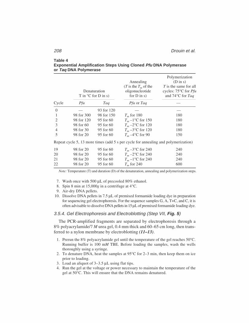
208 Drouin et al.
7. Wash once with 500 µL of precooled 80% ethanol.8. Spin 8 min at 15,000g in a centrifuge at 4°C.9. Air-dry DNA pellets.
10. Dissolve DNA pellets in 7.5 µL of premixed formamide loading dye in preparationfor sequencing gel electrophoresis. For the sequence samples G, A, T+C, and C, it isoften advisable to dissolve DNA pellets in 15 µL of premixed formamide loading dye.
3.5.4. Gel Electrophoresis and Electroblotting (Step VII, Fig. 5)
The PCR-amplified fragments are separated by electrophoresis through a8% polyacrylamide/7 M urea gel, 0.4 mm thick and 60–65 cm long, then trans-ferred to a nylon membrane by electroblotting (11–13).
1. Prerun the 8% polyacrylamide gel until the temperature of the gel reaches 50°C.Running buffer is 100 mM TBE. Before loading the samples, wash the wellsthoroughly using a syringe.
2. To denature DNA, heat the samples at 95°C for 2–3 min, then keep them on iceprior to loading.
3. Load an aliquot of 3–3.5 µL using flat tips.4. Run the gel at the voltage or power necessary to maintain the temperature of the
gel at 50°C. This will ensure that the DNA remains denatured.
Table 4Exponential Amplification Steps Using Cloned Pfu DNA Polymeraseor Taq DNA Polymerase
PolymerizationAnnealing (D in s)
(T is the Tm of the T is the same for allDenaturation oligonucleotide cycles: 75°C for Pfu
T in °C for D in s) for D in s) and 74°C for Taq
Cycle Pfu Taq Pfu or Taq —
0 — 93 for 120 — —1 98 for 300 98 for 150 Tm for 180 1802 98 for 120 95 for 60 Tm –1°C for 150 1803 98 for 60 95 for 60 Tm –2°C for 120 1804 98 for 30 95 for 60 Tm –3°C for 120 1805 98 for 20 95 for 60 Tm –4°C for 90 150
Repeat cycle 5, 13 more times (add 5 s per cycle for annealing and polymerization)
19 98 for 20 95 for 60 Tm –3°C for 240 24020 98 for 20 95 for 60 Tm –2°C for 240 24021 98 for 20 95 for 60 Tm –1°C for 240 24022 98 for 20 95 for 60 Tm for 240 600
Note: Temperature (T) and duration (D) of the denaturation, annealing and polymerization steps.
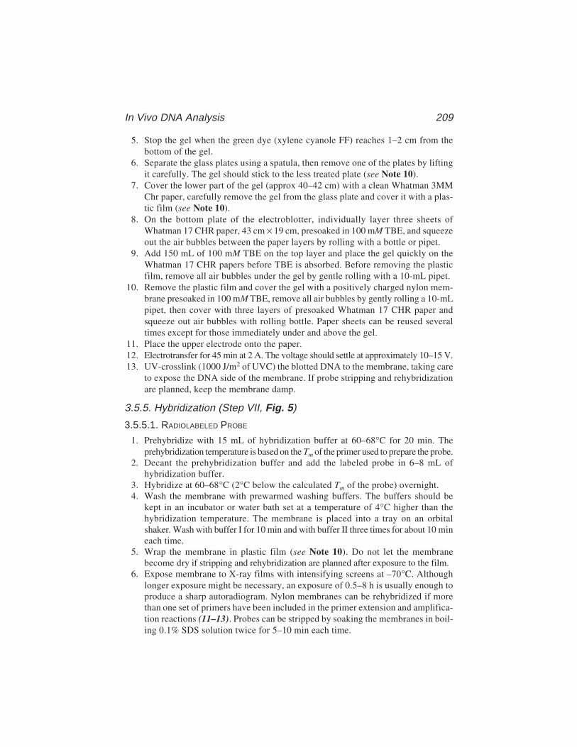
In Vivo DNA Analysis 209
5. Stop the gel when the green dye (xylene cyanole FF) reaches 1–2 cm from thebottom of the gel.
6. Separate the glass plates using a spatula, then remove one of the plates by liftingit carefully. The gel should stick to the less treated plate (see Note 10).
7. Cover the lower part of the gel (approx 40–42 cm) with a clean Whatman 3MMChr paper, carefully remove the gel from the glass plate and cover it with a plas-tic film (see Note 10).
8. On the bottom plate of the electroblotter, individually layer three sheets ofWhatman 17 CHR paper, 43 cm × 19 cm, presoaked in 100 mM TBE, and squeezeout the air bubbles between the paper layers by rolling with a bottle or pipet.
9. Add 150 mL of 100 mM TBE on the top layer and place the gel quickly on theWhatman 17 CHR papers before TBE is absorbed. Before removing the plasticfilm, remove all air bubbles under the gel by gentle rolling with a 10-mL pipet.
10. Remove the plastic film and cover the gel with a positively charged nylon mem-brane presoaked in 100 mM TBE, remove all air bubbles by gently rolling a 10-mLpipet, then cover with three layers of presoaked Whatman 17 CHR paper andsqueeze out air bubbles with rolling bottle. Paper sheets can be reused severaltimes except for those immediately under and above the gel.
11. Place the upper electrode onto the paper.12. Electrotransfer for 45 min at 2 A. The voltage should settle at approximately 10–15 V.13. UV-crosslink (1000 J/m2 of UVC) the blotted DNA to the membrane, taking care
to expose the DNA side of the membrane. If probe stripping and rehybridizationare planned, keep the membrane damp.
3.5.5. Hybridization (Step VII, Fig. 5)
3.5.5.1. RADIOLABELED PROBE
1. Prehybridize with 15 mL of hybridization buffer at 60–68°C for 20 min. Theprehybridization temperature is based on the Tm of the primer used to prepare the probe.
2. Decant the prehybridization buffer and add the labeled probe in 6–8 mL ofhybridization buffer.
3. Hybridize at 60–68°C (2°C below the calculated Tm of the probe) overnight.4. Wash the membrane with prewarmed washing buffers. The buffers should be
kept in an incubator or water bath set at a temperature of 4°C higher than thehybridization temperature. The membrane is placed into a tray on an orbitalshaker. Wash with buffer I for 10 min and with buffer II three times for about 10 mineach time.
5. Wrap the membrane in plastic film (see Note 10). Do not let the membranebecome dry if stripping and rehybridization are planned after exposure to the film.
6. Expose membrane to X-ray films with intensifying screens at –70°C. Althoughlonger exposure might be necessary, an exposure of 0.5–8 h is usually enough toproduce a sharp autoradiogram. Nylon membranes can be rehybridized if morethan one set of primers have been included in the primer extension and amplifica-tion reactions (11–13). Probes can be stripped by soaking the membranes in boil-ing 0.1% SDS solution twice for 5–10 min each time.
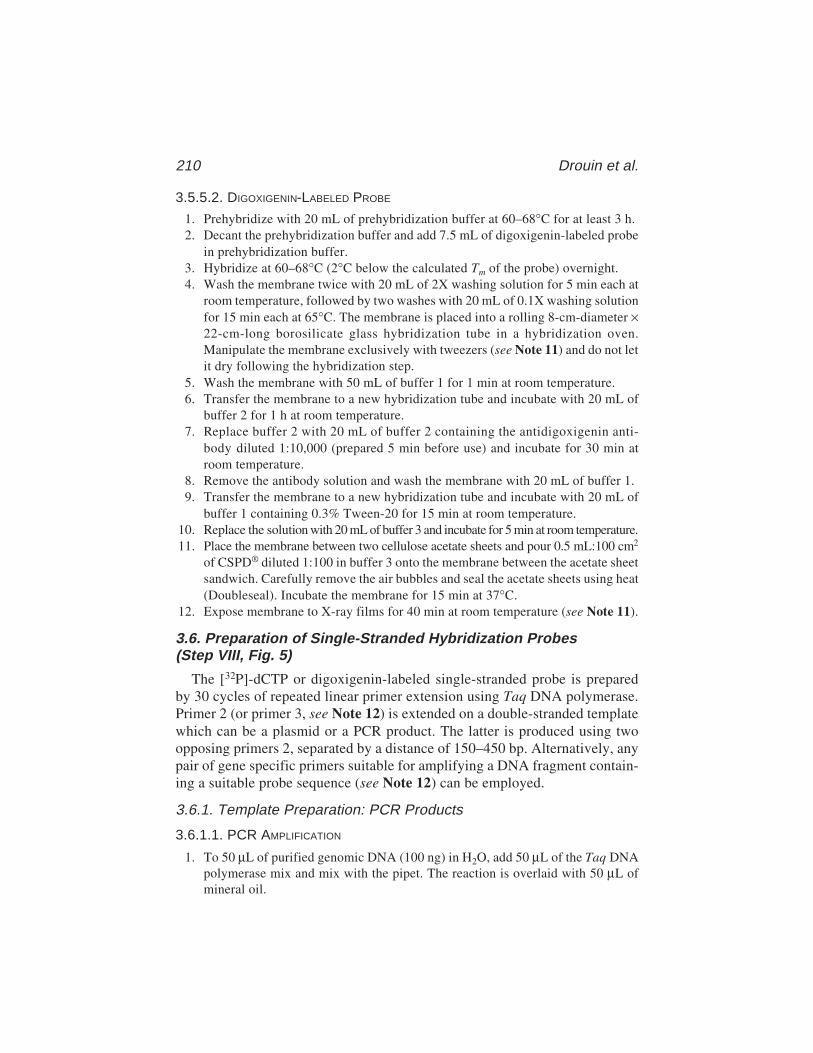
210 Drouin et al.
3.5.5.2. DIGOXIGENIN-LABELED PROBE
1. Prehybridize with 20 mL of prehybridization buffer at 60–68°C for at least 3 h.2. Decant the prehybridization buffer and add 7.5 mL of digoxigenin-labeled probe
in prehybridization buffer.3. Hybridize at 60–68°C (2°C below the calculated Tm of the probe) overnight.4. Wash the membrane twice with 20 mL of 2X washing solution for 5 min each at
room temperature, followed by two washes with 20 mL of 0.1X washing solutionfor 15 min each at 65°C. The membrane is placed into a rolling 8-cm-diameter ×22-cm-long borosilicate glass hybridization tube in a hybridization oven.Manipulate the membrane exclusively with tweezers (see Note 11) and do not letit dry following the hybridization step.
5. Wash the membrane with 50 mL of buffer 1 for 1 min at room temperature.6. Transfer the membrane to a new hybridization tube and incubate with 20 mL of
buffer 2 for 1 h at room temperature.7. Replace buffer 2 with 20 mL of buffer 2 containing the antidigoxigenin anti-
body diluted 1:10,000 (prepared 5 min before use) and incubate for 30 min atroom temperature.
8. Remove the antibody solution and wash the membrane with 20 mL of buffer 1.9. Transfer the membrane to a new hybridization tube and incubate with 20 mL of
buffer 1 containing 0.3% Tween-20 for 15 min at room temperature.10. Replace the solution with 20 mL of buffer 3 and incubate for 5 min at room temperature.11. Place the membrane between two cellulose acetate sheets and pour 0.5 mL:100 cm2
of CSPD® diluted 1:100 in buffer 3 onto the membrane between the acetate sheetsandwich. Carefully remove the air bubbles and seal the acetate sheets using heat(Doubleseal). Incubate the membrane for 15 min at 37°C.
12. Expose membrane to X-ray films for 40 min at room temperature (see Note 11).
3.6. Preparation of Single-Stranded Hybridization Probes(Step VIII, Fig. 5)
The [32P]-dCTP or digoxigenin-labeled single-stranded probe is preparedby 30 cycles of repeated linear primer extension using Taq DNA polymerase.Primer 2 (or primer 3, see Note 12) is extended on a double-stranded templatewhich can be a plasmid or a PCR product. The latter is produced using twoopposing primers 2, separated by a distance of 150–450 bp. Alternatively, anypair of gene specific primers suitable for amplifying a DNA fragment contain-ing a suitable probe sequence (see Note 12) can be employed.
3.6.1. Template Preparation: PCR Products
3.6.1.1. PCR AMPLIFICATION
1. To 50 µL of purified genomic DNA (100 ng) in H2O, add 50 µL of the Taq DNApolymerase mix and mix with the pipet. The reaction is overlaid with 50 µL ofmineral oil.

In Vivo DNA Analysis 211
2. Cycle 35 times at 95°C for 1 min (97°C for 3 min for the first cycle), 61–73°C(1–2°C below the calculated Tm of primer 2 with the lowest Tm) for 2 min, and74°C for 3 min. The last extension should be done for 10 min.
3. Add 25 µL of Taq DNA polymerase stop under the mineral oil layer.4. Extract with 250 µL of premixed phenol–chloroform (92 µL:158 µL) and trans-
fer to 1.5-mL microtubes.5. Add 400 µL of precooled absolute ethanol.6. Leave 15 min on dry ice, spin 20 min at 15,000g in a centrifuge at 4°C.7. Wash once with 1 mL of precooled 80% ethanol.8. Spin 8 min at 15,000g in a centrifuge at 4°C.9. Air-dry DNA pellets.
10. Resuspend DNA pellets in 25 µL of 1X TAE loading buffer.
3.6.1.2. PURIFICATION AND QUANTIFICATION OF PCR PRODUCTS
1. Load 25 µL of PCR products per well along with an appropriate DNA mass ladder.2. Migrate the PCR products on a neutral 1.2–1.5% agarose gel.3. Stain the gel with ethidium bromide and recover the band containing the DNA fragment
of expected molecular weight on a UV transilluminator using a clean scalpel blade. Mini-mize the size of the slice by removing as much extraneous agarose as possible.
4. Crush the slice and put it in a 0.625-mL microtube pierced at the bottom andcontaining a column of packed dry glass wool (see Note 13).
5. Insert the 0.625-mL microtube containing the column in a 1.5-mL microtube andspin 15 min at 7000g. Transfer the flowthrough to a new 1.5-mL microtube. Ifthere is still some visible agarose remaining, repeat step 5.
6. Add 50 µL of H2O to wash the column of any remaining DNA by spinning 8 minat 7000g. Pool all of the flowthrough contents in one 1.5-mL microtube.
7. Complete the volume to 405 µL with H2O, add 45 µL of 3 M sodium acetatepH 7.0, and 1 mL of precooled absolute ethanol to precipitate DNA. Leave 15 minon dry ice, spin 20 min at 15,000g in a centrifuge at 4°C.
8. Wash once with 1 mL of precooled 80% ethanol and spin 8 min at 15,000g in acentrifuge at 4°C.
9. Air-dry DNA pellet.10. Dissolve DNA pellets in 103 µL of H2O.11. Load aliquots of 1 and 2 µL of the DNA template dissolved in 1X universal neu-
tral loading buffer along with a quantitative DNA molecular-weight ladder andelectrophorese on a neutral 1.5% agarose gel.
12. Stain the gel with ethidium bromide and photograph on a UV transilluminator.The DNA concentration of the aliquots is estimated by comparison with the DNAladder band intensities and H2O is added to obtain a final concentration of tem-plate DNA of 3 ng/µL. The DNA template is aliquoted and stored at –20˚C.
3.6.2. Labeling of Single-Strand Hybridization Probes
3.6.2.1. ISOTOPIC LABELING
1. Prepare 150 µL of the following mix: 30 µL of 5X Taq buffer, 3 µL of 100 mMMgCl2, 1 µL of dNTPs mix diluted 1:10 in H2O, 20–40 ng of plasmid or 10–20 ng
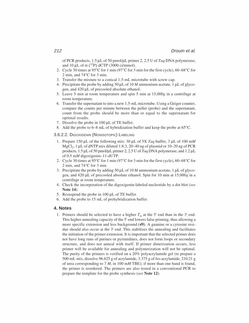
212 Drouin et al.
of PCR products, 1.5 µL of 50 pmol/µL primer 2, 2.5 U of Taq DNA polymerase,and 10 µL of α-[32P]-dCTP (3000 ci/mmol).
2. Cycle 30 times at 95°C for 1 min (97°C for 3 min for the first cycle), 60–68°C for2 min, and 74°C for 3 min.
3. Transfer the mixture to a conical 1.5-mL microtube with screw cap.4. Precipitate the probe by adding 50 µL of 10 M ammonium acetate, 1 µL of glyco-
gen, and 420 µL of precooled absolute ethanol.5. Leave 5 min at room temperature and spin 5 min at 15,000g in a centrifuge at
room temperature.6. Transfer the supernatant to into a new 1.5-mL microtube. Using a Geiger counter,
compare the counts per minute between the pellet (probe) and the supernatant,count from the probe should be more than or equal to the supernatant foroptimal results.
7. Dissolve the probe in 100 µL of TE buffer.8. Add the probe to 6–8 mL of hybridization buffer and keep the probe at 65°C.
3.6.2.2. DIGOXIGENIN (NONISOTOPIC) LABELING
1. Prepare 150 µL of the following mix: 30 µL of 5X Taq buffer, 3 µL of 100 mMMgCl2, 1 µL of dNTP mix diluted 1:8.3, 20–40 ng of plasmid or 10–20 ng of PCRproducts, 1.5 µL of 50 pmol/µL primer 2, 2.5 U of Taq DNA polymerase, and 1.2 µLof 0.5 mM digoxigenin–11-dUTP.
2. Cycle 30 times at 95°C for 1 min (97°C for 3 min for the first cycle), 60–68°C for2 min, and 74°C for 3 min.
3. Precipitate the probe by adding 50 µL of 10 M ammonium acetate, 1 µL of glyco-gen, and 420 µL of precooled absolute ethanol. Spin for 10 min at 15,000g in acentrifuge at room temperature.
4. Check the incorporation of the digoxigenin-labeled nucleotide by a dot blot (seeNote 14).
5. Resuspend the probe in 100 µL of TE buffer.6. Add the probe to 15 mL of prehybridization buffer.
4. Notes1. Primers should be selected to have a higher Tm at the 5' end than in the 3' end.
This higher annealing capacity of the 5' end lowers false priming, thus allowing amore specific extension and less background (49). A guanine or a cytosine resi-due should also occur at the 3' end. This stabilizes the annealing and facilitatesthe initiation of the primer extension. It is important that the selected primer doesnot have long runs of purines or pyrimidines, does not form loops or secondarystructure, and does not anneal with itself. If primer dimerization occurs, lessprimer will be available for annealing and polymerization will not be optimal.The purity of the primers is verified on a 20% polyacrylamide gel (to prepare a500-mL mix, dissolve 96.625 g of acrylamide, 3.375 g of bis-acrylamide, 210.21 gof urea corresponding to 7 M, in 100 mM TBE); if more than one band is found,the primer is reordered. The primers are also tested in a conventional PCR toprepare the template for the probe synthesis (see Note 12).

In Vivo DNA Analysis 213
2. Originally, Pfu and Taq buffers were prepared using KCl, which was, however,shown to stabilize secondary DNA structures, thus preventing an optimal poly-merization (50). The use of NaCl prevents, to some extent, the ability of DNA toform secondary structures. This is particularly helpful when GC-rich regions ofthe genome are being investigated.
3. The genomic DNA used for LMPCR needs to be very clean and undegraded. Anyshearing of the DNA during preparation and handling before the first primerextension must be avoided. After an incubation of 3 h, if clumps of nuclei are stillvisible, proteinase K at a final concentration of 300 µg/mL should be added andthe sample reincubated at 37˚C for another 3 h.
4. If no DNA can be seen, add glycogen (1–2 µg) to the DNA solution and putthe DNA on dry ice for 20 min and centrifuge the DNA (5000g for 20 min at4°C). This should help DNA recovery but increases the probability of RNAcontamination.
5. Because in vivo DNA analysis is based on the comparison of DNA samples modi-fied in vivo with DNA control modified in vitro, given the quantitative character-istic and high sensitivity of LMPCR technology, the DNA concentrations shouldbe as accurate as possible. Indeed, it is critical to start LMPCR with similaramounts of DNA in every sample to be analyzed. The method used to evaluateDNA concentration should measure only double-stranded nucleic acids. RNAcontamination does not affect LMPCR, although it can interfere with the precisemeasurement of the DNA concentration.
6. The DNA frequency of DNA breakage is even more critical than the DNA con-centration. For DMS and UV, the base-modification frequency determines thebreak frequency following conversion of the modified bases to single-strandbreaks, whereas for DNase I, the frequency of cleavage is exactly the break fre-quency. The break frequency must be similar among the samples to be analyzed.It should not average more than one break per 150 bp for in vivo DNA analysis,the optimal break frequency varying from one break per 200 bp to one break per2000 bp. When the break frequency is too high, we typically observe dark bandsover the bottom half of the autoradiogram and very pale bands over the upperhalf, reflecting the low number of long DNA fragments. In summary, to make thecomparison of the in vivo modified DNA sample with a purified DNA controleasily interpretable and valid, the amount of DNA and the break frequency mustbe similar between the samples to be compared. On the other hand, it is not socritical that the break frequency of the sequence ladders (G, A, T+C, and C) besimilar to that of the samples to be studied. However, to facilitate sequence read-ing, the break frequency should be similar between the sequence reactions. It isoften necessary to load less DNA for the sequence ladders.
7. If the cell density is too high, multiple cell layers will be formed and the uppercell layer will obstruct the lower ones. This will result in an inhomogeneous DNAphotoproduct frequency.
8. It is imperative that the purified DNA samples used as DNA control and the invivo DNA samples come from the same cell type. For instance, differing cytosine

214 Drouin et al.
methylation patterns of genomic DNA from different cell types affect photoprod-uct formation (17,29) and give altered DNase I cleavage patterns (2).
9. A nearly ideal chromatin substrate can be maintained in permeabilized cells.Nonionic detergents such as lysolecithin (48) and Nonidet P40 (33) permeabilizethe cell membrane sufficiently to allow the entry of DNase I. Conveniently, thisassay can be performed with cells either in a suspension or in a monolayer. Oneconcern is that permeabilized cells will lyse after a certain time in a detergent,thus care must be taken to monitor cell integrity by microscopy during the courseof the experiment. A further difficulty with the permeabilization technique con-cerns the relatively narrow detergent concentration range over which the treat-ment can be performed. Each cell type appears to require specific conditions forthe detergent cell permeabilization. Furthermore, the DNase I concentration mustbe calibrated for each cell type to produce an appropriate cleavage frequency.Optimally, the in vivo DNase I protocol works better if the enzyme has cleavedthe DNA backbone every 1.5–2 kb. Cutting frequencies greater than 1 kb areassociated with higher LMPCR backgrounds because the number of 3'-OH endsis much higher, making suppression of the extension of these ends more difficult.
10. To facilitate sequencing gel removal following migration, it is crucial to siliconizethe inner face of both glass plates prior to pouring the gel. For security, cost-effectiveness, efficiency, and time-saving, we recommend treating the glassplates with RAIN-AWAY® solution (Wynn’s Canada, product no. 63020). Weapply 0.75 mL on one plate and 1.5 mL on the other before each five utilizationsas specified by the manufacturer. In this way, the gel is easier to pour and tends tostick on the less siliconized plate.
Whenever plastic film is needed, we recommend plastic wrap brand. Thisbrand was found to be less permeable to liquids and more resistant to tears thanother brands. This is particularly important when membranes are exposed on thephosphorimager plate in order to avoid the moistening of the plate and irrevers-ibly damaging it.
11. We adapted the nonisotopic digoxigenin-based probe labeling method and chemi-luminescent detection system (Roche Molecular Biochemicals) to reveal DNAsequence ladders after LMPCR amplification, sequencing gel electrophoresis,and electroblotting. Compared to the isotopic method, the nonisotopic methodhas a higher specificity, higher sensitivity, lower background, and lower cost,and is therefore a highly recommendable alternative. As shown in Fig. 6B, thesequence ladder revealed by nonisotopic labeling was clearer, sharper and pre-sented lesser background compared to the isotopic labeling method (Fig. 6A).Unlike isotopic probes, digoxigenin-labeled probes are innocuous, can be easilydisposed of, can be stored for long periods, and can even be reused. It is worthnoting, however, that this nonisotopic detection method requires some minor pre-cautions. First, the nylon membrane used for this type of detection must bear aspecific density and homogeneous distribution of positive charge. Among mem-branes we tested, the one sold by Roche Molecular Biochemicals, unquestion-ably gave the best results. Secondly, care should be taken with the manipulation
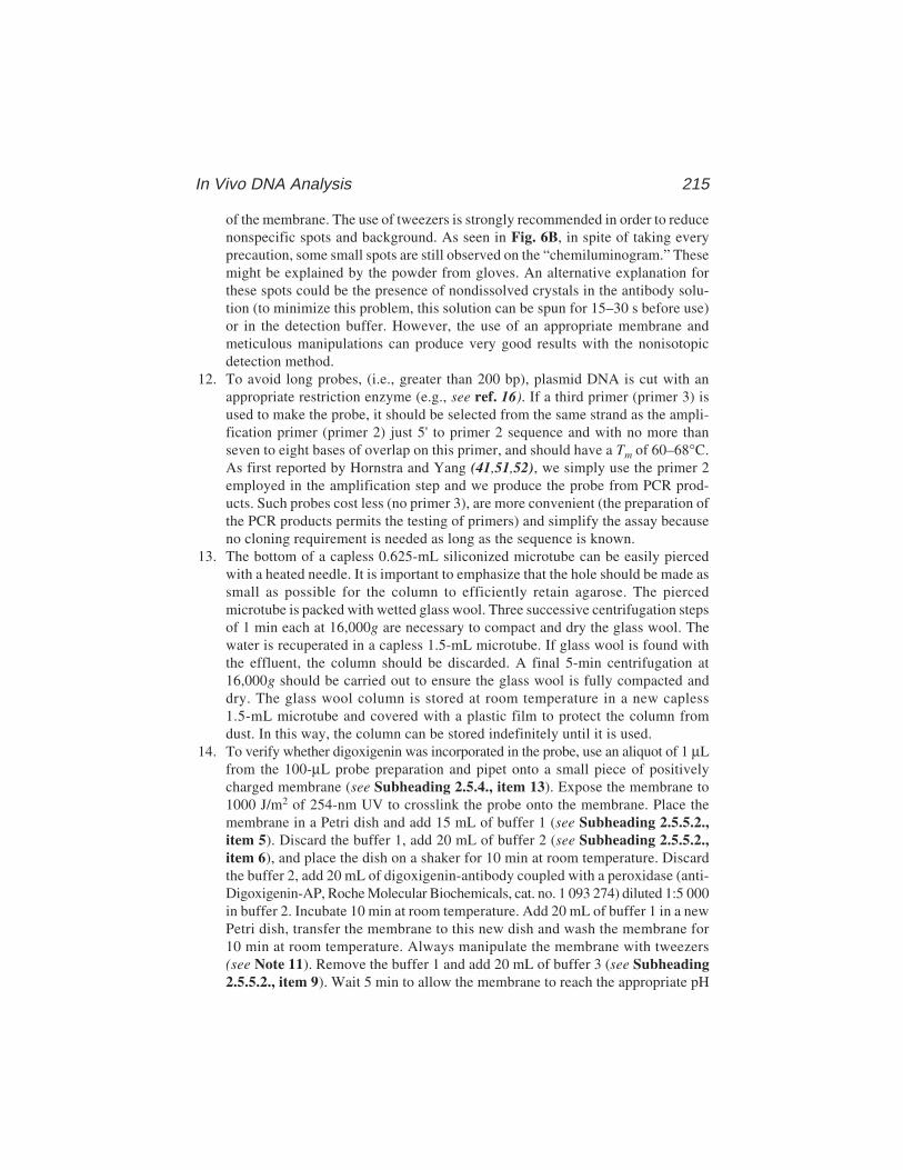
In Vivo DNA Analysis 215
of the membrane. The use of tweezers is strongly recommended in order to reducenonspecific spots and background. As seen in Fig. 6B, in spite of taking everyprecaution, some small spots are still observed on the “chemiluminogram.” Thesemight be explained by the powder from gloves. An alternative explanation forthese spots could be the presence of nondissolved crystals in the antibody solu-tion (to minimize this problem, this solution can be spun for 15–30 s before use)or in the detection buffer. However, the use of an appropriate membrane andmeticulous manipulations can produce very good results with the nonisotopicdetection method.
12. To avoid long probes, (i.e., greater than 200 bp), plasmid DNA is cut with anappropriate restriction enzyme (e.g., see ref. 16). If a third primer (primer 3) isused to make the probe, it should be selected from the same strand as the ampli-fication primer (primer 2) just 5' to primer 2 sequence and with no more thanseven to eight bases of overlap on this primer, and should have a Tm of 60–68°C.As first reported by Hornstra and Yang (41,51,52), we simply use the primer 2employed in the amplification step and we produce the probe from PCR prod-ucts. Such probes cost less (no primer 3), are more convenient (the preparation ofthe PCR products permits the testing of primers) and simplify the assay becauseno cloning requirement is needed as long as the sequence is known.
13. The bottom of a capless 0.625-mL siliconized microtube can be easily piercedwith a heated needle. It is important to emphasize that the hole should be made assmall as possible for the column to efficiently retain agarose. The piercedmicrotube is packed with wetted glass wool. Three successive centrifugation stepsof 1 min each at 16,000g are necessary to compact and dry the glass wool. Thewater is recuperated in a capless 1.5-mL microtube. If glass wool is found withthe effluent, the column should be discarded. A final 5-min centrifugation at16,000g should be carried out to ensure the glass wool is fully compacted anddry. The glass wool column is stored at room temperature in a new capless1.5-mL microtube and covered with a plastic film to protect the column fromdust. In this way, the column can be stored indefinitely until it is used.
14. To verify whether digoxigenin was incorporated in the probe, use an aliquot of 1 µLfrom the 100-µL probe preparation and pipet onto a small piece of positivelycharged membrane (see Subheading 2.5.4., item 13). Expose the membrane to1000 J/m2 of 254-nm UV to crosslink the probe onto the membrane. Place themembrane in a Petri dish and add 15 mL of buffer 1 (see Subheading 2.5.5.2.,item 5). Discard the buffer 1, add 20 mL of buffer 2 (see Subheading 2.5.5.2.,item 6), and place the dish on a shaker for 10 min at room temperature. Discardthe buffer 2, add 20 mL of digoxigenin-antibody coupled with a peroxidase (anti-Digoxigenin-AP, Roche Molecular Biochemicals, cat. no. 1 093 274) diluted 1:5 000in buffer 2. Incubate 10 min at room temperature. Add 20 mL of buffer 1 in a newPetri dish, transfer the membrane to this new dish and wash the membrane for10 min at room temperature. Always manipulate the membrane with tweezers(see Note 11). Remove the buffer 1 and add 20 mL of buffer 3 (see Subheading2.5.5.2., item 9). Wait 5 min to allow the membrane to reach the appropriate pH
216 Drouin et al.
(pH 9.5) for the detection. During this time, prepare the detection solution byadding 90 µL of NBT (4-Nitroblue tetrazolium chloride, Roche MolecularBiochemicals, cat. no. 1 383 213) and 70 µL of BCIP (X-phosphate/5-bromo-4-chloro-3-indolyl-phosphate, Roche Molecular Biochemicals, cat. no. 1 383 221)to 20 mL of buffer 3. Discard buffer 3 and add the detection solution to the dishcontaining the membrane and place it in a dark room. Check occasionally andmonitor the appearance of staining. If no staining appears after 1 h, this meansthat the incorporation of DIG was not efficient. The detection solution is verytoxic, manipulate it carefully and eliminate this solution as toxic waste.
AcknowledgmentsThe authors wish to thank Dr. Elliot A. Drobetsky for his precious help in
editing this text and for exciting LMPCR discussions. We are grateful to Mrs.Nancy Dallaire, Isabelle Paradis, and Nathalie Bastien for their technical assis-tance and valuable contribution to the development of the LMPCR technology.This work was supported by the Medical Research Council of Canada (MRC)and the Canadian Genetic Diseases Network (MRC/NSERC NCE program).R. Drouin is presently a research scholar (“Chercheur-boursier”) of the “Fondsde la Recherche en Santé du Québec” (FRSQ).
References1. Pfeifer, G. P., Tanguay, R. L., Steigerwald, S. D., and Riggs, A. D. (1990) In vivo
footprint and methylation analysis by PCR-aided genomic sequencing: compari-son of active and inactive X chromosomal DNA at the CpG island and promoterof human PGK–1. Genes Dev. 4, 1277–1287.
2. Pfeifer, G. P. and Riggs, A. D. (1991) Chromatin differences between active andinactive X chromosomes revealed by genomic footprinting of permealized cellsusing DNase I and ligation-mediated PCR. Genes Dev. 5, 1102–1113.
3. Chen, C.-J., Li, L. J., Maruya, A., and Shively, J. E. (1995) In vitro and in vivofootprint analysis of the promoter of carcinoembryonic antigen in colon carci-noma cells: effects of interferon γ treatment. Cancer Res. 55, 3873–3882.
4. Tornaletti, S. and Pfeifer, G. P. (1995) UV light as a footprinting agent: modula-tion of UV-induced DNA damage by transcription factors bound at the promotersof three human genes. J. Mol. Biol. 249, 714–728.
5. Mueller P. R. and Wold, B. (1989) In vivo footprinting of a muscle specificenhancer by ligation mediated PCR. Science 246, 780–786.
6. Pfeifer, G. P., Steigerwald, S. D., Mueller, P. R., Wold, B., and Riggs, A. D.(1989) Genomic sequencing and methylation analysis by ligation mediated PCR.Science 246, 810–813.
7. Pfeifer, G. P., Steigerwald, S. D., Hansen, R. S., Gartler, S. M., and Riggs, A. D.(1990) Polymerase chain reaction-aided genomic sequencing of an X chromo-some-linked CpG island: methylation patterns suggest clonal inheritance, CpGsite autonomy, and an explanation of activity state stability. Proc. Natl. Acad. Sci.USA 87, 8252–8256.

In Vivo DNA Analysis 217
8. Pfeifer, G. P., Drouin, R., Riggs, A. D., and Holmquist, G. P. (1992) Binding oftranscription factors creates hot spots for UV photoproducts in vivo. Mol. Cell.Biol. 12, 1798–1804.
9. Church, G. M. and Gilbert, W. (1984) Genomic sequencing. Proc. Natl. Acad.Sci. USA 81, 1991–1995.
10. Pfeifer, G. P. (1992) Analysis of chromatin structure by ligation-mediated PCR.PCR Methods Appl. 2, 107–111.
11. Pfeifer, G. P. and Riggs, A. D. (1993) Genomic footprinting by ligation mediatedpolymerase chain reaction, in PCR Protocols: Current Methods and Applications(White, B., ed.), Humana, Totowa, NJ, pp. 153–168.
12. Pfeifer, G. P. and Riggs, A. D. (1993) Genomic sequencing, in DNA SequencingProtocols (Griffin, H. G. and Griffin, A. M., eds.), Humana, Totowa, NJ, pp.169–181.
13. Pfeifer, G. P., Singer-Sam, J., and Riggs, A. D. (1993) Analysis of methylationand chromatin structure. Methods Enzymol. 225, 567–583.
14. Gao, S., Drouin, R., and Holmquist, G. P. (1994) DNA repair rates mapped alongthe human PGK1 gene at nucleotide resolution. Science 263, 1438–1440.
15. Tornaletti, S. and Pfeifer, G. P. (1994) Slow repair of pyrimidine dimers at p53mutation hotspots in skin cancer. Science 263, 1436–1438.
16. Rodriguez, H., Drouin, R., Holmquist, G. P., O’Connor, T. R., Boiteux, S., Laval,J., Doroshow, J. H., and Akman, S. A. (1995) Mapping of copper/hydrogenperoxide-induced DNA damage at nucleotide resolution in human genomicDNA by ligation-mediated polymerase chain reaction. J. Biol. Chem. 270,17,633–17,640.
17. Drouin, R. and Therrien, J.-P. (1997) UVB-induced cyclobutane pyrimidine dimerfrequency correlates with skin cancer mutational hotspots in p53. Photochem.Photobiol. 66, 719–726.
18. Rozek, D. and Pfeifer, G. P. (1993) In vivo protein–DNA interactions at the c-junpromoter: preformed complexes mediate the UV response. Mol. Cell. Biol. 13,5490–5499.
19. Cartwright, I. L. and Kelly, S. E. (1991) Probing the nature of chromosomal DNA–protein contacts by in vivo footprinting. BioTechniques 11, 188–203.
20. Maxam, A. M. and Gilbert, W. (1980) Sequencing end-labeled DNA with base-specific chemical cleavages. Methods Enzymol. 65, 499–560.
21. Chin P. L., Momand, J., and Pfeifer, G. P. (1997) In vivo evidence for binding ofp53 to consensus binding sites in the p21 and GADD45 genes in response to ion-izing radiation. Oncogene 15, 87–99.
22. Angers, M., Drouin, R., Bachvarova, M., Paradis, I., Marceau, F., and Bachvarov,D. R. (2000) In vivo protein–DNA interactions at the kinin B1 receptor pro-moter: no modification upon interleukin-1 beta or lipopolysaccharide induc-tion. J. Cell. Biochem. 78, 278–296.
23. Becker, M. M. and Wang, J. C. (1984) Use of light for footprinting DNA in vivo.Nature 309, 682–687.
24. Pfeifer, G. P. and Tornaletti, S. (1997) Footprinting with UV irradiation andLMPCR. Methods 11, 189–196.

218 Drouin et al.
25. Pfeifer, G. P., Chen, H. H., Komura, J., and Riggs, A.D. (1999) Chromatin struc-ture analysis by ligation-mediated and terminal transferase-mediated polymerasechain reaction. Methods Enzymol. 304, 548–571.
26. Cadet, J., Anselmino, C., Douki, T., and Voituriez, L. (1992) Photochemistry ofnucleic acids in cells. J. Photochem. Photobiol. B: Biol. 15, 277–298.
27. Mitchell, D. L. and Nairn, R. S. (1989) The biology of the (6–4) photoproducts.Photochem. Photobiol. 49, 805–819.
28. Holmquist, G. P. and Gao, S. (1997) Somatic mutation theory, DNA repair rates,and the molecular epidemiology of p53 mutations. Mutat. Res. 386, 69–101.
29. Pfeifer, G. P., Drouin, R., Riggs, A. D., and Holmquist, G. P. (1991) In vivo map-ping of a DNA adduct at nucleotide resolution: detection of pyrimidine (6–4)pyrimidone photoproducts by ligation-mediated polymerase chain reaction. Proc.Natl. Acad. Sci. USA 88,1374–1378.
30. Gale, J. M. and Smerdon, M. J. (1990) UV induced (6–4) photoproducts are dis-tributed differently than cyclobutane dimers in nucleosomes. Photochem.Photobiol. 51, 411–417.
31. Gale, J. M., Nissen, K. A., and Smerdon, M. J. (1987) UV-induced formation ofpyrimidine dimers in nucleosome core DNA is strongly modulated with a periodof 10.3 bases. Proc. Natl. Acad. Sci. USA 84, 6644–6648.
32. Mitchell, D. L., Nguyen, T. D., and Cleaver, J. E. (1990) Nonrandom induction ofpyrimidine–pyrimidone (6–4) photoproducts in ultraviolet-irradiated human chro-matin. J. Biol. Chem. 265, 5353–5356.
33. Rigaud, G., Roux, J., Pictet, R., and Grange, T. (1991) In vivo footprinting of ratTAT gene: dynamic interplay between the glucocorticoid receptor and a liver-specific factor. Cell 67, 977–986.
34. Miller, M. R., Castellot, J. J., and Pardee, A. B. (1978) A permeable animal cellpreparation for studying macromolecular synthesis. DNA synthesis and the roleof deoxyribonucleotides in S phase initiation. Biochemistry 17, 1073–1080.
35. Contreras, R. and Fiers, W. (1981) Initiation of transcription by RNA polymeraseII in permeable SV40-infected CV-1 cells; evidence of multiple promoters forSV40 late transcription. Nucleic Acids Res. 9, 215–236.
36. Tanguay, R. L., Pfeifer, G. P., and Riggs, A. D. (1990) PCR-aided DNase Ifootprinting of single-copy gene sequences in permeabilized cells. Nucleic AcidsRes. 18, 5902.
37. Törmänen, V., Pfeifer, G. P., Swiderski, P. M., et al. (1992) Extension product cap-ture improves genomic sequencing and DNase I footprinting by legation-mediatedPCR. Nucleic Acids Res. 20, 5487–5488.
38. Tornaletti, S., Bates, S., and Pfeifer, G. P. (1996) A high-resolution analysis ofchromatin structure along p53 sequences. Mol. Carcinogen. 17, 192–201.
39. Szabo, P. E., Pfeifer, G. P., and Mann, J. R. (1998) Characterization of novelparent-specific epigenetic modifications upstream of the imprinted mouse H19gene. Mol. Cell. Biol. 18, 6767–6776.
40. Garrity, P. A. and Wold, B. J. (1992) Effects of different DNA polymerases inligation-mediated PCR: enhanced genomic sequencing and in vivo footprinting.Proc. Natl. Acad. Sci. USA 89, 1021–1025.
In Vivo DNA Analysis 219
41. Hornstra, I. K. and Yang, T. P. (1994) High resolution methylation analysis of thehuman hypoxanthine phosphoribosyltransferase gene 5' region on the active andinactive X chromosomes: correlation with binding sites for transcription factors.Mol. Cell. Biol. 14, 1419–1430.
42. Angers, M., Cloutier, J.-F., and Drouin, R. (2000) The effectiveness of Pfu exo–
DNA polymerase in ligation-mediated PCR is mainly modulated by the ratio ofDNA molecules per unit of enzyme. Submitted.
43. Drouin, R., Gao, S., and Holmquist, G. P. (1996) Agarose gel electrophoresis forDNA damage analysis, in Technologies for Detection of DNA Damage and Muta-tions (Pfeifer, G. P., ed.), Plenum, New York, pp. 37–43.
44. Rychlik, W. and Rhoads, R. E. (1989) A computer program for choosing optimaloligonucleotides for filter hybridization, sequencing and in vitro amplification ofDNA. Nucleic Acids Res. 17, 8543–8551.
45. Drouin, R., Rodriguez, H., Holmquist, G. P., and Akman, S. A. (1996) Ligation-mediated PCR for analysis of oxidative DNA damage, in Technologies for Detec-tion of DNA Damage and Mutations (Pfeifer, G. P., ed.), Plenum, New York, pp.211–225.
46. Mueller PR, Wold, B. (1991) Ligation-mediated PCR: applications to genomicfootprinting. Methods 2, 20–31.
47. Iverson, B. L. and Dervan, P. B. (1987) Adenine specific DNA chemical sequenc-ing reaction. Nucleic Acids Res. 19, 7823–7830.
48. Zhang, L. and Gralla, J. D. (1989) In situ nucleoprotein structure at the SV40major late promoter: melted and wrapped DNA flank the start site. Genes Dev. 3,1814–1822.
49. Rychlik, W. (1993) Selection of primers for polymerase chain reaction, in PCRProtocols: Current Methods and Applications (White, B., ed.), Humana, Totowa,NJ, pp. 31–40.
50. Fry, M. and Loeb, L. A. (1994) The fragile X syndrome d(CGG)n nucleotiderepeats form a stable tetrahelical structure. Proc. Natl. Acad. Sci. USA 91,4950–4954.
51. Hornstra, I. K. and Yang, T. P. (1992) Multiple in vivo footprints are specific tothe active allele of the X-linked human hypoxanthine phosphoribosyltransferasegene 5' region: implications for X chromosome inactivation. Mol. Cell. Biol. 12,5345–5354.
52. Hornstra, I. K. and Yang, T. (1993) In vivo footprinting and genomic sequencingby ligation-mediated PCR. Anal. Biochem. 213, 179–193.

Methylation Protection and Interference 221
221
From: Methods in Molecular Biology, vol. 148: DNA–Protein Interactions: Principles and Protocols, 2nd ed.Edited by: T. Moss © Humana Press Inc., Totowa, NJ
14
Identification of Protein–DNA Contactswith Dimethyl Sulfate
Methylation Protection and Methylation Interference
Peter E. Shaw and A. Francis Stewart
1. IntroductionDimethyl sulfate (DMS) is an effective and widely used probe for sequence-
specific protein–DNA interactions. It is the only probe routinely used both forin vitro (methylation protection, methylation interference) and in vivo (DMSgenomic footprinting) applications because it rapidly reacts with DNA at roomtemperature and readily penetrates intact cells (1). DMS methylates predomi-nantly the 7-nitrogen of guanine and the 3-nitrogen of adenine. Thus reactivitywith G residues occurs in the major groove and with A residues in the minorgroove. In standard Maxam and Gilbert protocols (2), the methylated bases aresubsequently converted to strand breaks and displayed on sequencing gels.
Methylation protection and interference are essentially combinations of thegel retardation assay or electrophoretic mobility shift assay (EMSA) (3,4)(Chapter 2) with the DMS reaction of the Maxam and Gilbert sequencing pro-cedure. Protein–DNA interactions are reflected either as changes in DMS reac-tivities caused by bound protein (methylation protection) or as selective proteinbinding dictated by methylation (methylation interference).
In methylation protection, protein is first bound to DNA that is uniquely endlabeled and the complex is reacted with DMS. DMS reactivities of specificresidues are altered by bound protein either by exclusion, resulting in reducedmethylation, or by increased local hydrophobicity, resulting in enhancedmethylation, or by local DNA conformational changes, such as unwinding,resulting in altered reactivity profiles (5–7). After the DMS reaction, free DNAis separated from protein-bound DNA by gel retardation and both DNA

222 Shaw and Stewart
fractions are recovered from the gel. Methylated residues are converted intostrand scissions and the free and bound DNA fractions are compared on asequencing gel. A complete analysis requires the examination of both strands.This is accomplished by preparing two DNA probes, each uniquely labeled atone end, and carrying both probes through the protocols. A binding site char-acterized by methylation protection will therefore appear as a cluster of alteredDMS reactivities.
In methylation interference (8,9), DNA is first reacted with DMS, purifiedand then presented to protein. Under the reaction conditions used methylationis partial, yielding approximately one methylated base per DNA molecule.Thus, the protein is presented with a mixture of DNA molecules that differwith respect to the positions of methyl groups. Some methyl groups willinterfere with protein binding because they lie in or near the binding site. Gelretardation separates the mixture into two fractions: free DNA, which, as longas DNA is in excess over binding activity, represents the total profile of methy-lation reactivity, and bound DNA, which will not contain any molecules withmethyl groups incompatible with binding. Both free and bound DNA fractionsare recovered, methylated residues are converted to strand scissions, and thefractions are compared on a sequencing gel. The binding site is observed asthe absence of bands in the bound sample corresponding to the positions wheremethylation interferes with binding.
It is obvious that these two uses of DMS may not deliver identical results.For example, Fig. 1 presents a comparison obtained from experiments with theserum response element binding factors p67SRF p62TCF and their binding site inthe human c-fos promoter (SRE). Because the use of DMS in vivo for genomicfootprinting is limited to the equivalent of methylation protection, a direct com-parison between in vivo and in vitro data excludes the more widely usedmethylation interference assay.
The two techniques are, however, very similar in practical terms and thusare presented together. Both techniques rely on preestablished conditions thatpermit a protein–DNA complex to be resolved in a gel retardation assay(Chapter 2) and on chemical DNA sequencing methodologies, for which thereader is advised to consult ref. 2 for a detailed treatment.
2. Materials1. Dimethyl sulfate (DMS) (Merck), analytical grade.2. Piperidine (Sigma), analytical grade; use freshly made 1:10 dilution in double-
distilled water.3. Phenol/chloroform 50% v/v, buffered with 50 mM Tris-HCl, pH 8.0.4. NA45 paper (Schleicher & Schuell).5. 3MM paper (Whatman) or GB 002 paper (Schleicher & Schuell).
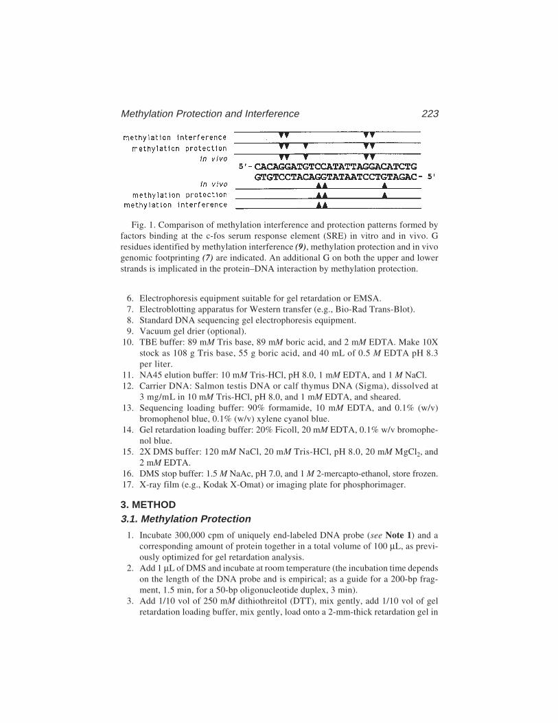
Methylation Protection and Interference 223
6. Electrophoresis equipment suitable for gel retardation or EMSA.7. Electroblotting apparatus for Western transfer (e.g., Bio-Rad Trans-Blot).8. Standard DNA sequencing gel electrophoresis equipment.9. Vacuum gel drier (optional).
10. TBE buffer: 89 mM Tris base, 89 mM boric acid, and 2 mM EDTA. Make 10Xstock as 108 g Tris base, 55 g boric acid, and 40 mL of 0.5 M EDTA pH 8.3per liter.
11. NA45 elution buffer: 10 mM Tris-HCl, pH 8.0, 1 mM EDTA, and 1 M NaCl.12. Carrier DNA: Salmon testis DNA or calf thymus DNA (Sigma), dissolved at
3 mg/mL in 10 mM Tris-HCl, pH 8.0, and 1 mM EDTA, and sheared.13. Sequencing loading buffer: 90% formamide, 10 mM EDTA, and 0.1% (w/v)
bromophenol blue, 0.1% (w/v) xylene cyanol blue.14. Gel retardation loading buffer: 20% Ficoll, 20 mM EDTA, 0.1% w/v bromophe-
nol blue.15. 2X DMS buffer: 120 mM NaCl, 20 mM Tris-HCl, pH 8.0, 20 mM MgCl2, and
2 mM EDTA.16. DMS stop buffer: 1.5 M NaAc, pH 7.0, and 1 M 2-mercapto-ethanol, store frozen.17. X-ray film (e.g., Kodak X-Omat) or imaging plate for phosphorimager.
3. METHOD3.1. Methylation Protection
1. Incubate 300,000 cpm of uniquely end-labeled DNA probe (see Note 1) and acorresponding amount of protein together in a total volume of 100 µL, as previ-ously optimized for gel retardation analysis.
2. Add 1 µL of DMS and incubate at room temperature (the incubation time dependson the length of the DNA probe and is empirical; as a guide for a 200-bp frag-ment, 1.5 min, for a 50-bp oligonucleotide duplex, 3 min).
3. Add 1/10 vol of 250 mM dithiothreitol (DTT), mix gently, add 1/10 vol of gelretardation loading buffer, mix gently, load onto a 2-mm-thick retardation gel in
Fig. 1. Comparison of methylation interference and protection patterns formed byfactors binding at the c-fos serum response element (SRE) in vitro and in vivo. Gresidues identified by methylation interference (9), methylation protection and in vivogenomic footprinting (7) are indicated. An additional G on both the upper and lowerstrands is implicated in the protein–DNA interaction by methylation protection.
224 Shaw and Stewart
1X TBE (or an alternative buffer as determined to be best for the given complex)and run as optimized for analytical gels. The load may need to be spread over upto 10 times more well area as compared with an analytical retardation assay (seeNote 2).
4. After electrophoresis, separate the glass plates carefully so that the gel adheres toone plate and cover the gel with cling film. Expose to X-ray film long enough toreveal complexes clearly (i.e., 6 h to overnight). The alignment of the film to thegel must be reliably marked.
5. Put the developed film on a light box. Remove the gel from the cling film andrealign it on the X-ray film. Cut pieces of NA45 paper sufficiently large to coverindividual complexes in the gel yet small enough to fit into 1.5-mL tubes whenrolled up. Wet the paper pieces in retardation gel running buffer and, with thehelp of tweezers, position one over each complex of interest in the gel, asvisualized from the underlying film. Also position a similar sized piece of paperover (some of) the uncomplexed DNA. NA45 paper can be labeled with pencilbefore wetting.
6. Carefully cover the gel and paper pieces with two sheets of 3MM paper wetted in1X TBE (or alternative gel running buffer from step 3). Lay a ScotchBrite padfrom the electroblotting apparatus on top of the paper and turn the gel over. Care-fully remove the second glass plate, cover the other side of the gel with 3MMpaper and ScotchBrite as before and insert the package into an electrotransferapparatus as described in the manufacturer’s instructions with the NA45 papertoward the anode. Transfer in 1X TBE (or the alternative retardation gel buffer)at 80 V for 1.5 h (see Note 3).
7. Stop the transfer, unpack the gel carefully with the NA45 paper on top and trans-fer each piece to a labeled 1.5-mL tube containing 600 µL of elution buffer (checkthat the radioactivity has transferred to the paper). Incubate at 70°C for 1 h.
8. Remove NA45 paper from each tube, check that at least half the radioactivity haseluted into the buffer (do not expect quantitative elution, but at least 50% shouldcome off), add 20 µg carrier DNA, extract with phenol/chloroform and precipi-tate with 1 volume of isopropanol. Wash precipitate once in 70% ethanol and dryunder vacuum. (See Notes 4 and 5.)
9a. To reveal modified Gs: Dilute piperidine 1:10 in water and add 50 µL to eachpellet. Vortex briefly and incubate at 90oC for 30 min (tubes must be clampedor weighted down to prevent the lids opening); then dry under a good vacuum.Take up the samples in 100 µL of water and repeat the drying process. Thisstrand scission protocol should not convert methylated A residues into strandbreaks. It is often observed, however, that breakages at As do occur with reason-able efficiency.
9b. To reveal modified As and Gs: The following modification will produce efficientcleavage at both methyl-G and methyl-A residues. After the preparative retarda-tion gel, resuspend the dried, purified DNA in 30 µL of 10 mM sodium phosphatepH 6.8, and 1 mM EDTA. Incubate for 15 min at 92°C. Then add 3 µL of 1 MNaOH and incubate for 30 min at 92°C, followed by 320 µL of 500 mM NaCl,
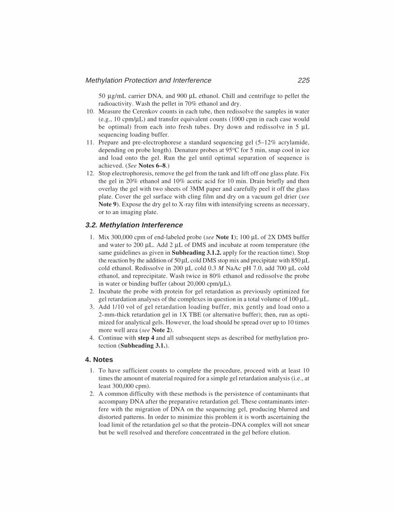
Methylation Protection and Interference 225
50 µg/mL carrier DNA, and 900 µL ethanol. Chill and centrifuge to pellet theradioactivity. Wash the pellet in 70% ethanol and dry.
10. Measure the Cerenkov counts in each tube, then redissolve the samples in water(e.g., 10 cpm/µL) and transfer equivalent counts (1000 cpm in each case wouldbe optimal) from each into fresh tubes. Dry down and redissolve in 5 µLsequencing loading buffer.
11. Prepare and pre-electrophorese a standard sequencing gel (5–12% acrylamide,depending on probe length). Denature probes at 95oC for 5 min, snap cool in iceand load onto the gel. Run the gel until optimal separation of sequence isachieved. (See Notes 6–8.)
12. Stop electrophoresis, remove the gel from the tank and lift off one glass plate. Fixthe gel in 20% ethanol and 10% acetic acid for 10 min. Drain briefly and thenoverlay the gel with two sheets of 3MM paper and carefully peel it off the glassplate. Cover the gel surface with cling film and dry on a vacuum gel drier (seeNote 9). Expose the dry gel to X-ray film with intensifying screens as necessary,or to an imaging plate.
3.2. Methylation Interference
1. Mix 300,000 cpm of end-labeled probe (see Note 1); 100 µL of 2X DMS bufferand water to 200 µL. Add 2 µL of DMS and incubate at room temperature (thesame guidelines as given in Subheading 3.1.2. apply for the reaction time). Stopthe reaction by the addition of 50 µL cold DMS stop mix and precipitate with 850 µLcold ethanol. Redissolve in 200 µL cold 0.3 M NaAc pH 7.0, add 700 µL coldethanol, and reprecipitate. Wash twice in 80% ethanol and redissolve the probein water or binding buffer (about 20,000 cpm/µL).
2. Incubate the probe with protein for gel retardation as previously optimized forgel retardation analyses of the complexes in question in a total volume of 100 µL.
3. Add 1/10 vol of gel retardation loading buffer, mix gently and load onto a2-mm-thick retardation gel in 1X TBE (or alternative buffer); then, run as opti-mized for analytical gels. However, the load should be spread over up to 10 timesmore well area (see Note 2).
4. Continue with step 4 and all subsequent steps as described for methylation pro-tection (Subheading 3.1.).
4. Notes1. To have sufficient counts to complete the procedure, proceed with at least 10
times the amount of material required for a simple gel retardation analysis (i.e., atleast 300,000 cpm).
2. A common difficulty with these methods is the persistence of contaminants thataccompany DNA after the preparative retardation gel. These contaminants inter-fere with the migration of DNA on the sequencing gel, producing blurred anddistorted patterns. In order to minimize this problem it is worth ascertaining theload limit of the retardation gel so that the protein–DNA complex will not smearbut be well resolved and therefore concentrated in the gel before elution.

226 Shaw and Stewart
3. It is also possible to use a semidry electrotransfer apparatus (e.g., Bio-Rad Trans-blot SD) to transfer the DNA from the gel retardation gel onto NA45 paper. Inthis case, both the transfer time and potential are reduced.
4. In some instances, it may prove difficult to elute the DNA from the NA45 paper,in which case raising the salt concentration or the temperature may improve elu-tion. (Extending the incubation time does not seem to help.) If not, the batch ofNA45 may be to blame or it is even conceivable that the DNA–protein complexin question is adsorbed too tightly onto the paper. It is not possible to phenolextract the NA45 paper in order to remove bound protein–DNA.
5. Retain the isopropanol supernatants until you are sure the samples have precipi-tated quantitatively. Add more carrier DNA if required.
6. It is similarly advisable to load as little material onto the sequencing gel as prac-ticable. With the advent of the phosphorimager, the lower limit for the sequenc-ing gel is well under 1000 cpm/lane.
7. If the end-labeled DNA fragment is relatively long and multiple binding sites areto be resolved, a gradient or wedge sequencing gel can be used in step 11 ofSubheading 3.1.
8. An appropriate complement for the final result is to perform the Maxam andGilbert G+A reactions on the end-labeled probe. On the sequencing gel, thesereactions should provide unambiguous sequence information and, in case diffi-culties are encountered, clues as to the steps that are problematic.
9. It is not essential to dry down the sequencing gel because after one glass plate hasbeen removed, it can be covered with cling film and exposed to X-ray film at–70°C with one screen. This alternative should only be considered if the signal issufficiently strong or if a gel drier is not available.
References1. Church, G. M. and Gilbert, W. (1984). Genomic sequencing. Proc. Natl. Acad.
Sci. USA 81, 1991–1995.2. Maxam, A. and Gilbert, W. (1980) Sequencing end-labelled DNA with base-spe-
cific chemical cleavages. Methods Enzymol. 65, 499–560.3. Fried, A. and Crothers, D. M. (1981) Equilibria and kinetics of lac repressor–
operator interactions by polyacrylamide gel electrophoresis. Nucleic Acids Res. 9,6505–6525.
4. Garner, M. M. and Revzin, A. (1981) A gel electrophoresis method for quantify-ing the binding of protein to specific DNA regions: application to components ofthe E. coli lactose operon regulatory system. Nucleic Acids Res. 9, 3047–3059.
5. Gilbert, W., Maxam, A., and Mirzabekov, A. (1976) Contacts between the LACrepressor and DNA revealed by methylation. in Control of Ribosome Biosynthe-sis, Alfred Benzon Symposium IX (Kjelgaard, N. O. and Maaloe, O., eds.), Academic,New York, pp. 139–148.
6. Johnsrud, L. (1978) Contacts between Escherichia coli RNA polymerase and alac operon promoter. Proc. Natl. Acad. Sci. USA 75, 5314–5318.
Methylation Protection and Interference 227
7. Herrera, R. E., Shaw, P. E., and Nordheim, A. (1989). Occupation of the c-fosserum response element in vivo by a multi-protein complex is unaltered by growthfactor induction. Nature 340, 68–70.
8. Siebenlist, U. and Gilbert, W. (1980) Contacts between E. coli RNA polymeraseand an early promoter of phage T7. Proc. Natl. Acad. Sci. USA 77, 122–126.
9. Shaw, P. E., Schröter, H., and Nordheim, A. (1989). The ability of a ternary com-plex to form over the serum response element correlates with serum inducibilityof the human c-fos promoter. Cell 56, 563–572.
Ethylation Interference 229
15
Ethylation Interference
Iain W. Manfield and Peter G. Stockley
1. IntroductionStructural studies of DNA–protein complexes have now made it clear that
specific sequence recognition in these systems is accomplished in two ways,either directly by the formation of hydrogen bonds to base-pair edges fromamino acid side chains located on a DNA-binding motif, such as a helix–turn–helix, or indirectly as a result of sequence-dependent distortions of the DNAconformation (1). These contacts occur in the context of oriented complexesbetween macromolecules that juxtapose the specific recognition elements. Aspart of these processes, proteins make a large number of contacts to thephosphodiester backbone of DNA, as was predicted from biochemical assaysof the ionic strength dependence of DNA binding.
Contacts to phosphate groups can be inferred by the ethylation interferencetechnique (2). Ethylnitrosourea (EtNU) reacts with DNA to form, principally,phosphotriester groups at the nonesterified oxygens of the otherwisephosphodiester backbone. Minor products are the result of the reactions ofEtNU with oxygen atoms in the nucleotide bases themselves (see Note 1).Under alkaline conditions and at high temperature, the backbone can be cleavedat the site of the modification to form a population of molecules carrying either3'-OH or 3'-ethylphosphate groups.
The length of the ethyl group (approx 4.5 Å) means that at a number ofpositions along a DNA molecule encompassing the binding site for a protein,complex formation will be inhibited by the presence of such a modification. Atother sites, outside the binding site, no interference with protein binding at thespecific site will be observed. Addition of the DNA-binding protein to arandomly ethylated DNA sample, followed by some procedure to separate thecomplexes formed from unbound DNA, will fractionate the DNA sample into
229
From: Methods in Molecular Biology, vol. 148: DNA–Protein Interactions: Principles and Protocols, 2nd ed.Edited by: T. Moss © Humana Press Inc., Totowa, NJ

230 Manfield and Stockley
those molecules able to bind protein with high affinity and those for which theethylation has lowered the affinity (Fig. 1). In practice, modification at differ-ent sites produces molecules with a spectrum of affinities for the protein. It is,therefore, not possible to prove conclusively that a particular phosphate is con-tacted by the protein, but only that ethylation at that site interferes with com-plex formation.
Only occasionally are large amounts of pure protein readily available for invitro biochemical assay of DNA-binding activity and, often, only smallamounts of crude nuclear extracts are available. In many commonly usedassays, complex formation could not easily be detected in such situations. Forexample, using DNase I or hydroxyl radicals, a high level of binding-site occu-pancy is required for a footprint to be detected. Fractional occupancy is readilydetected by gel retardation of complexes (electrophoretic mobility shift[EMSA]; see Chapter 2) but offers only limited characterization of the detailsof the protein–DNA interaction. Interference techniques, such as the ethylationand hydroxyl radical interference (see Chapter 16) techniques (3), do allow themolecular details of complex formation to be studied even when only smallamounts of crude protein are available (4). Whatever the level of saturation,DNA fragments modified at sites reducing the affinity of protein for DNA areless likely to form complexes. Therefore, the bound fraction on gel retardationassays will always give an indication of the sites that do not inhibit complexformation when modified. The groups on the DNA recognized by the proteincan then be inferred. Ethylation can also be used to analyze RNA–protein com-plexes (5,6).
We have used the ethylation interference technique to probe the interactionof the Escherichia coli methionine repressor, MetJ, with its binding site invitro. Binding sites for MetJ consist of two, or more, immediately adjacentcopies of an 8-bp site with the consensus sequence 5'-AGACGTCT-3', whichhas been termed a “met box.” X-ray crystallography has been used to deter-mine the structure of the MetJ dimer, the complex with corepressor, S-adenosylmethionine (SAM), and a complex of the holorepressor with a 19-mer oligo-nucleotide containing two met boxes (7,8). The structure of the protein–DNAcomplex in the crystal reveals two MetJ dimers (one per met box) binding tothe DNA by insertion of a β-ribbon into the major groove. The general featuresof this model are corroborated by the results of the ethylation interferenceexperiments and by data from a range of other footprinting techniques.
2. Materials2.1. Preparation of Radioactively End-Labeled DNA
1. Plasmid DNA carrying the binding site for a DNA-binding protein on a conve-nient restriction fragment (usually <200 bp).

Ethylation Interference 231
Fig. 1. Diagrammatic outline of the ethylation interference experiment. The uppersection shows ethylation of end-labeled DNA (ethyl groups represented by small solidtriangles) and complex formation with protein (represented by large open triangles).The expected mobility of each species on nondenaturing gels is shown in the middlesection. In idealized form, the pattern of cleavage products that might be expectedfrom recovery of each species after gel retardation assay is shown in the lower section.In practice, samples represented by 1 + 3 and 2 + 4 migrate to the same position on theretardation gel and are, therefore, not separated. The resultant pattern is shown in Fig. 2.
2. Restriction enzymes and the appropriate buffers as recommended by the suppliers.3. Phenol: redistilled phenol equilibrated with 100 mM Tris-HCl, pH 8.0.4. Chloroform.
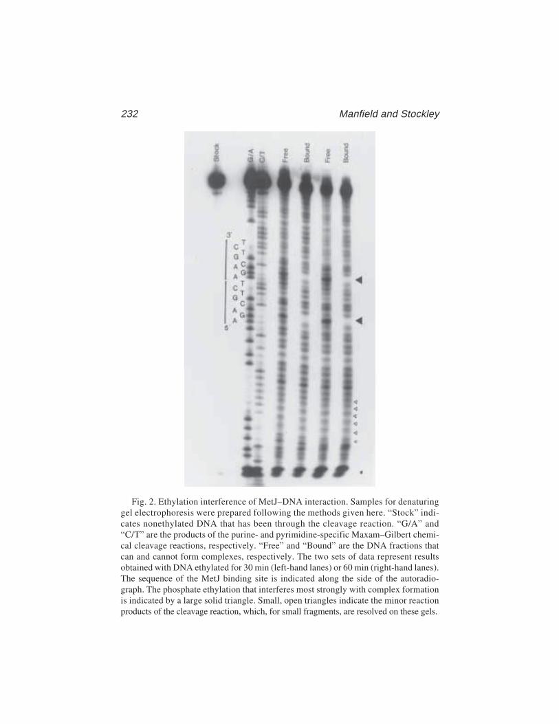
232 Manfield and Stockley
Fig. 2. Ethylation interference of MetJ–DNA interaction. Samples for denaturinggel electrophoresis were prepared following the methods given here. “Stock” indi-cates nonethylated DNA that has been through the cleavage reaction. “G/A” and“C/T” are the products of the purine- and pyrimidine-specific Maxam–Gilbert chemi-cal cleavage reactions, respectively. “Free” and “Bound” are the DNA fractions thatcan and cannot form complexes, respectively. The two sets of data represent resultsobtained with DNA ethylated for 30 min (left-hand lanes) or 60 min (right-hand lanes).The sequence of the MetJ binding site is indicated along the side of the autoradio-graph. The phosphate ethylation that interferes most strongly with complex formationis indicated by a large solid triangle. Small, open triangles indicate the minor reactionproducts of the cleavage reaction, which, for small fragments, are resolved on these gels.
Ethylation Interference 233
5. Solutions for ethanol precipitation of DNA: 4 M NaCl and ethanol (absolute and70% v/v).
6. Alkaline phosphatase (AP), from calf intestine (CIAP) or shrimp.7. 10X AP reaction buffer: 0.5 M Tris-HCl, pH 9.0, 0.1 M MgCl2, and 0.001 M ZnCl2.8. TE buffer: 10 mM Tris-HCl, pH 8.0, and 1 mM ethylenediaminetetraacetic acid
(EDTA).9. Sodium dodecyl sulfate (SDS) 20% w/v.
10. EDTA (0.25 M, pH 8.0).11. T4 polynucleotide kinase (T4-PNK).12. 10X T4-PNK reaction buffer: 0.5 M Tris-HCl, pH 7.6, 0.1 M MgCl2, and 0.05 M
dithiothreitol (DTT).13. Radioisotope: [γ-32P]-ATP.14. 30% w/v Acrylamide stock: 29:1 :: acrylamide: N,N'-methylene–bis-acrylamide.15. Polyacrylamide gel elution buffer: 0.3 M sodium acetate, 0.2% (w/v) SDS,
and 2 mM EDTA.16. Polymerization catalysts: ammonium persulfate (APS) (10% w/v) and N,N,N',N'-
tetramethylethylenediamine (TEMED).
2.2. Ethylation Modification and Fractionation of DNA
1. End-labeled DNA in TE: 250,000 cpm are required per ethylation reaction to beperformed (roughly 20 ng DNA fragment/reaction). Ethylation of more DNAallows a range of protein concentrations to be used when protein–DNA bindingreactions are prepared. Standard safety procedures should be used when handlingradiolabeled DNA (e.g., work behind Lucite shields).
2. Cacodylate buffer: 50 mM sodium cacodylate (used without adjustment of thepH, which is usually close to 8.0). Cacodylate buffer contains arsenic and there-fore should be handled with caution. It is only necessary to prepare small vol-umes (approx 10 mL) of this solution. Passing the solution through a 0.45-µmfilter is the preferred method of sterilization.
3. Ethylnitrosourea (EtNU): This reagent is readily synthesized (9) provided, theappropriate safety measures are used. Commercial suppliers do not appear toprovide this material at present. The solid material should be stored at –20°C andallowed to warm to room temperature before use. EtNU should be handled in afume hood and contaminated waste stored there until disposal. Wear two pairs oflatex gloves when handling samples containing EtNU.
4. tRNA (1 mg/mL).5. Solutions for ethanol precipitation of DNA: 4 M NaCl and ethanol (absolute and
70% v/v).6. Complex buffer: for MetJ, for example, 10 mM Tris-HCl, pH 7.4, 150 mM NaCl,
and 1 mM S-adenosyl methionine p-toluene sulfonate salt (SAM). Add glycerolto this buffer to 10% (v/v).
7. Purified DNA-binding protein or protein extract.8. Nondenaturing gel acrylamide stock solution: 30% (w/v) (37:1 acrylamide:
N,N'-methylene–bis-acrylamide).
234 Manfield and Stockley
9. Electrophoresis buffer stock solution: 1.0 M Tris-HCl, pH 8.0, and solid SAM.10. Ammonium persulfate (APS) (10% w/v).11. TEMED.12. Glass plates: 150 × 150 × 1.5 mm.13. Peristaltic pump capable of recirculating buffer at 5–10 mL/min.14. X-ray film.15. Autoradiography cassette.16. X-ray film developer and fixer.17. Plastic wrap.18. Scalpel blade.19. Syringe needle.20. Polyacrylamide gel elution buffer: 0.3 M sodium acetate, 0.1% (w/v) SDS,
and 1 mM EDTA.21. 10 mM sodium phosphate, pH 7.0, and 1 mM EDTA.22. 1.0 M NaOH (freshly prepared).23. Acetic acid solutions: 1.0 M and 10% v/v.24. Sequencing gel loading buffer: 80% (v/v) formamide, 0.5X TBE, 0.1% (w/v)
xylene cyanol, 0.1% (w/v) bromophenol blue.25. Acrylamide stock solutions for sequencing gel: 19% (w/v) acrylamide, 1% (w/v)
N,N'-methylene–bis-acrylamide, and 50% (w/v) urea in TBE.26. TBE (1X): 89 mM Tris, 89 mM boric acid, and 10 mM EDTA, pH 8.3.
2.3. Maxam–Gilbert Chemical DNA Sequencing Reactions
There is insufficient space to cover these methods in detail here, but exten-sive information, materials, methods, and troubleshooting guides are readilyavailable in published literature (10,11).
3. Methods3.1. Preparation of End-Labeled DNA
1. Digest the plasmid (e.g., 10 µg of the plasmid in a reaction volume of 200 µLwith one of the pair of restriction enzymes used to release a suitably sizedDNA fragment [usually <200 bp]). Extract the digest with an equal volume ofbuffered phenol and then add 2.5 vol of ethanol to the aqueous layer to precipi-tate the DNA.
2. Add 50 µL 1X AP reaction buffer to the ethanol-precipitated DNA pellet (<50 µg).Add 1 U AP, incubate at 37°C for 30 min, followed by addition of a furtheraliquot of enzyme, and incubate for a further 30 min. Terminate the reaction byadding SDS and EDTA to 0.1% (w/v) and 20 mM, respectively, in a final volumeof 200 µL and incubate at 65°C for 15 min. Extract the digest with an equalvolume of buffered phenol, then with 1:1 phenol:chloroform, and finally ethanolprecipitate the DNA from the aqueous phase by addition of 2.5 vol of ethanol.
3. Redissolve the DNA pellet (~2.5 µg) in 18 µL 1X T4-PNK buffer. Add 20 µCi[γ–32P]-ATP and 10 U T4-PNK, and incubate at 37°C for 30 min. Terminate the
Ethylation Interference 235
reaction by phenol extraction (followed by ethanol precipitation and a secondrestriction enzyme digest) or by addition of nondenaturing gel loading buffer,and electrophoresis on a nondenaturing polyacrylamide gel. We use 12% (w/v)polyacrylamide gels (19:1, acrylamide:bis-acrylamide) with 1X TBE as the elec-trophoresis buffer.
4. After electrophoresis, locate the required DNA fragments by autoradiography ofthe wet gel. Excise slices of the gel containing the bands of interest using theautoradiograph as a guide. Elute the DNA into 500 µL elution buffer overnight(at least) at 37°C. Ethanol precipitate the DNA, wash the pellet thoroughly with70% (v/v) ethanol, dry under vacuum, and rehydrate in a small volume of TEbuffer (e.g., 50 µL). Determine the radioactivity of the sample by liquid scintilla-tion counting of a 1 µL aliquot.
3.2. Ethylation Modification and Protein-Binding Assay
3.2.1. Ethylation Reaction
1. Dispense the required volume containing approx 250,000 cpm of radiolabeledDNA solution into an Eppendorf tube, add cacodylate buffer to a final volume of100 µL and heat the solution to 50°C in a heating block. Prepare the minimumvolume of EtNU-saturated ethanol (at 50°C) for the required reactions, add 100 µLof this to the DNA, mix, and incubate at 50°C for 60 min (see Notes 1 and 2).
2. Add to the sample 5 µL of 4 M NaCl, 2 µg of tRNA, and 150 µL of ethanol. Mixand place at –20°C for 60 min or in a dry ice/ethanol bath for 15 min. Pellet theDNA by centrifugation in a microfuge for 15 min and remove the supernatant(store separately to be destroyed by incineration). Add 500 µL of 70% ethanol,mix thoroughly, recentrifuge, and remove the supernatant. Dry the pellet brieflyunder vacuum.
3.2.2. Fractionation of DNA by Gel Retardation Assay
The following procedure allows the separation of free and bound DNA bymeans of gel retardation. The precise conditions will depend on the proteinunder investigation (see Notes 3–6).
1. Mix 10 mL of nondenaturing acrylamide stock solution, 1.5 mL of 1.0 MTris-HCl, pH 8.0, 29.5 mL of distilled water, 0.2 mL of APS, 15 µL of TEMED,and 1.5 mg of SAM, and pour into gel frame. Insert the well former and leave topolymerize for 1–2 h.
2. When polymerized, insert the gel into the tank and connect peristaltic pump tub-ing such that buffer is pumped in both directions (i.e., top to bottom and bottomto top reservoirs). Pre-electrophorese gel for 30 min at 100 V.
3. Redissolve the pellet of ethylated DNA in complex buffer plus glycerol (seeNote 6). Set aside 10% of the ethylated DNA sample, which will be used as anunfractionated control to indicate the variation in level of modification at eachresidue. Dry this sample under vacuum and store at –20°C until step 1 of Sub-heading 3.2.4. Add DNA-binding protein to a concentration that would saturate
236 Manfield and Stockley
unmodified DNA and incubate at 37°C for 15 min to allow complex formation.Note: Exact conditions will vary depending on the protein being studied.
4. Load the DNA–protein complex solution onto the gel and electrophorese into thegel at 250 V for 2 min. Reduce the voltage to 100 V and continue electrophoresisuntil a small amount of bromophenol blue dye loaded into an unused lane hasreached the bottom of the gel.
3.2.3. DNA Recovery
1. After electrophoresis, remove one plate and wrap the gel and remaining plate inclear plastic wrap film (we use Saran Wrap™). Cut a piece of X-ray film largeenough to cover the lanes used on the gel and fix it to the gel firmly with maskingtape. Using a syringe needle, make a number of holes through the film and gelthat will serve to orient the developed film with respect to the gel. Alternatively,align the film and the gel using fluorescent marker strips.
2. Place the assembly in an autoradiography cassette and leave at 4°C overnight.3. Take the film off the gel and develop as usual. When dry, align the film and gel
using the holes created previously. Using a syringe needle, make a series of holesinto the gel around the fragments of interest using the bands on the film as aguide. Remove the film and excise the marked regions of polyacrylamide. Placegel fragments (10 × 5 mm) in Eppendorf tubes, add 600 µL of gel elution buffer,and incubate at 37°C overnight (at least).
4. Transfer 400 µL of the eluate to a fresh tube, add 2 µg of tRNA and 1 mL ofethanol, mix, and place at –20°C for 60 min. Pellet DNA by centrifugation in amicrofuge for 15 min. Discard the supernatant (check for absence of radioactiv-ity), wash the pellet with 500 µL of 70% ethanol, recentrifuge, and discard thesupernatant. Dry the pellet briefly under vacuum. If the DNA does not pelletreadily, incubate the sample at –20°C for longer or recentrifuge at 4°C.
3.2.4. Phosphotriester Cleavage and DNA Sequencing
1. Redissolve each pellet in 15 µL sodium phosphate buffer and add 2.5 µL of 1 MNaOH. Seal tube with plastic film (e.g., Parafilm) and incubate at 90°C for30 min. Centrifuge samples briefly to collect any condensation. Add 2.5 µLof 1.0 M acetic acid, 2 µL of 4 M NaCl, 1 µg of tRNA, and 70 µL of ethanol.Leave samples at –20°C for 60 min. Pellet DNA as described in step 4 of Sub-heading 3.2.3.
2. Redissolve the pellet in 4 µL of sequencing gel loading buffer. Heat to 90°C for2 min and load samples onto a 12% w/v polyacrylamide sequencing gel along-side Maxam–Gilbert sequencing reaction markers. Electrophorese at a voltagethat will warm the plates to around 50°C. After electrophoresis, fix the gel in1 L of 10% (v/v) acetic acid for 15 min. Transfer the gel to 3MM paper anddry under vacuum at 80°C for 60 min. Autoradiograph the gel at –70°C with anintensifying screen.
3. Compare lanes corresponding to bound, free, and control DNA for differences inintensity of bands at each position. A dark band in the “free fraction” (and a
Ethylation Interference 237
corresponding reduction in the intensity of the band in the “bound fraction”)indicates a site where ethylation interferes with complex formation. This is inter-preted as meaning that this residue is contacted by the protein or a portion of theprotein comes close to the DNA at this point. For 5' end-labeled DNA, theethylation reaction products migrate slightly more slowly than the Maxam–Gilbert chemical sequencing products (see Notes 7 and 8, and also Fig. 1).
3.3. Results and Discussion
The result of an ethylation interference experiment with MetJ is shown inFig. 2 along with densitometer traces showing quantitative comparisons of thedistribution of products in bound and free fractions (Fig. 3) (13). Visualexamination of the autoradiograph shows that ethylation at 5'-pG2 results intotal exclusion of such fragments from protein–DNA complexes. Densitom-etry indicates that ethylation at other sites inhibits complex formation to vary-ing degrees and that there are more sites in the 3' half-site than in the 5' half-sitefor which ethylation inhibits complex formation. These data can be interpretedin terms of the MetJ-DNA crystal structure (8). The site at which ethylationcompletely inhibits complex formation corresponds to the phosphate 5' to theguanine at position 2 of each met box. The crystal structure shows a contact tothis phosphate from the N-terminus of the repressor B-helix. Indeed, at thecenter of the operator site, sequence-dependent distortions of the oligonucle-otide fragment away from B-DNA result in displacement of this 5' G2 phos-phate by up to 2 Å in the direction of the protein. Thus, this site of completeinhibition of complex formation corresponds to an important contact betweenthe DNA and a secondary structural element in the protein, which presumablyis unable to adjust to the presence of a bulky ethyl group. The other sites ofethylation interference effects are contacted by amino acid side chains and pep-tide backbone groups in extended loops of the repressor. It might be expectedthat side chains and loops could be flexible enough to reorient in order to reducesteric hindrance between the protein and the ethyl group, thus explaining thepartial interference effects. Similar good correlations between the contactsidentified by ethylation interference experiments and those seen in crystalshave been demonstrated in other systems, such as the phage 434 repressor (14)and the phage Lambda repressor (15).
MetJ shows a high level of sequence specificity; therefore, clear interfer-ence effects are observed. However, we have observed that proteins with low-sequence specificity show weak interference effects. Densitometry andquantitation may be necessary to resolve these effects from the background ofcleavage from fragments shifted by nonspecifically bound proteins. Addition-ally, proteins binding to DNA asymmetrically (e.g., to sites which do not showthe dyad symmetry common to prokaryotic repressor proteins) will show dif-
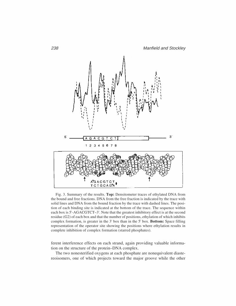
238 Manfield and Stockley
Fig. 3. Summary of the results. Top: Densitometer traces of ethylated DNA fromthe bound and free fractions. DNA from the free fraction is indicated by the trace withsolid lines and DNA from the bound fraction by the trace with dashed lines. The posi-tion of each binding site is indicated at the bottom of the trace. The sequence withineach box is 5'-AGACGTCT–3'. Note that the greatest inhibitory effect is at the secondresidue (G2) of each box and that the number of positions, ethylation of which inhibitscomplex formation, is greater in the 3' box than in the 5' box. Bottom: Space fillingrepresentation of the operator site showing the positions where ethylation results incomplete inhibition of complex formation (starred phosphates).
ferent interference effects on each strand, again providing valuable informa-tion on the structure of the protein–DNA complex.
The two nonesterified oxygens at each phosphate are nonequivalent diaste-reoisomers, one of which projects toward the major groove while the other

Ethylation Interference 239
projects toward the minor groove. Although, upon modification, both isomerswill show the same charge-neutralization effects, the steric effects on protein–nucleic acid complex formation will be markedly different. The effect has beeninvestigated by incorporation of unique diastereoisomers of ethyl and methylphosphonates into synthetic oligonucleotides. These modified target sites havethen been used in binding assays for restriction enzymes and repressors usingstandard gel retardation or filter binding assays. Ethylated phosphotriestershave been shown to reduce the Tm of a d[GGAA(Et)TTCC] duplex with theRp–Rp duplex melting 11ºC lower than the unmodified duplex, as a result ofsteric clashes (16). Therefore, incorporation of methyl phosphonates may be abetter approach and has been used to probe lac repressor–operator interactions.Modification of phosphates outside the binding site had no effect on complex for-mation, whereas sites shown to be important by biochemical assays showed differ-ent effects for each isomer. In one case, the alkyl group blocked direct interactionwith the phosphate or close approach of the protein, whereas in the other case,ionic or hydrogen bonded interactions with phosphate remained possible (17).
4. Notes1. Modification at secondary (nonphosphate) sites: Early work on the reaction of
alkylating agents with DNA showed that a number of products are obtained. WithEtNU, phosphotriester groups comprise 60–65% of the reaction products (9).The remaining products are the result of reactions at base oxygen groups withrelative abundance in the order thymine O2 = guanine O6 > thymine O4 >>cytosine O2 for double-stranded DNA (12). To our knowledge, the effects ofsuch modifications on DNA binding by proteins have not been addressed in theliterature on ethylation interference experiments. However, some prediction ofthe effects might be made based on a knowledge of the structure of DNA. Thym-ine O2 and cytosine O2 are in the minor groove, and guanine O6 and thymine O4are in the major groove. For sequence-specific DNA-binding proteins interactingwith DNA via the major groove, it would be expected that the presence of anethyl group would inhibit complex formation, but that a modification in the minorgroove would be less inhibitory.
2. Level of modification of DNA by EtNU: A similar intensity of each band (sub-ject to the position-dependent variation of reactivity observed with EtNU) is therequired level of modification. We have used a single batch of “home-produced”EtNU for all our ethylation interference experiments. The conditions of time andtemperature used with this batch give an appropriate level of probe modification.There may be variations in the reactivity of EtNU from different sources leadingto undermodification or overmodification. The correct modification conditionscan readily be determined by performing a test ethylation on a small amount ofDNA, such as 20,000 cpm, followed by alkaline cleavage (omitting the gel frac-tionation step), sequencing gel electrophoresis, and autoradiography. Over-modification will produce a bias toward short fragments.
240 Manfield and Stockley
3. Choice of fractionation method: The original report of the use of the phosphateethylation reaction used the filter binding assay to fractionate protein-bound andprotein-free DNA (2); see also Chapter 1. Filter-bound DNA is then eluted bywashing the filter in a high-salt buffer containing SDS. For other experiments,we find that TE + 0.1 % (w/v) SDS efficiently elutes DNA from nitrocellulosefilters. The rapid recovery of DNA from filters is an advantage of using the filterbinding assay compared with the gel retardation assay. Despite this, fractionationby gel retardation assay has proven to be by far the most popular method in theliterature. The advantage of the gel retardation assay is that both the presence andamounts of multiple complexes can be determined, and these complexes recov-ered separately, something not possible by filter binding. Parallel binding reac-tions with ethylated and unethylated DNA and separation on nondenaturingpolyacrylamide gels readily demonstrate any differences in the mobility of com-plexes formed with each DNA sample.
4. Cofactor requirements: High-affinity DNA binding in our system (MetJ) isdependent on the presence of S-adenosyl methionine at millimolar concentra-tions. This cofactor is present in binding reactions and is included in the gel mix,but it would be prohibitively expensive also to include it in the electrophoresisbuffer. This does not seem to affect the results obtained by this technique. Elec-trophoresis for extended times does deplete the lower region of the gel of core-pressor, leading to some complex dissociation. Another feature specific to thissystem is the hydrolysis of the corepressor to presumably inactive products. Forthis reason, gels were not left to polymerize for more than 2 h.
In other systems where a cofactor is not required or in which the cofactor ischeap and/or stable over extended periods, the conditions used for the gel-retardation-assay fractionation step should be optimized by a consideration ofthe specific features of the system under study. For further details, consultChapter 2.
5. Effects of salt precipitates: During ethanol precipitation of DNA, salt is oftenalso precipitated. This white crystalline precipitate is readily distinguished fromthe almost clear nucleic acid pellets. The interaction of DNA-binding proteinswith their sites is strongly ionic strength dependent, and therefore the presence ofa high concentration of salt following ethanol precipitations will inhibit complexformation in addition to any ethylation interference effects. After the cleavagereaction at modified sites, another ethanol precipitation is performed. The pres-ence of a large amount of salt at this stage will prevent complete dissolution ofthe pellet and will interfere with subsequent electrophoresis. A dark backgroundbetween each band was often observed on autoradiographs. It is believed that thisis caused by the presence of salt in the sample. Reprecipitation as described belowhelps to reduce this problem.
To remove any salt precipitate, the pellet can be dissolved in a small volumeof TE (e.g., 100 µL) and precipitated by addition of 2 volumes of ethanol withoutaddition of further amounts of salt. The DNA can be pelleted as described in step4 in Subheading 3.2.3.

Ethylation Interference 241
6. Recommended controls for the gel-retardation-assay (EMSA) fractionation step:With a precomplex formation modification reaction such as ethylation, it isimportant to perform appropriate control reactions especially for the gel retarda-tion step. For such binding reactions, we use 20,000-cpm unmodified DNA in thepresence and absence of MetJ at the concentration used in the binding reactionwith ethylated DNA samples. The specific activity of protein samples may varyfrom batch to batch. The control reaction outlined above will confirm that theprotein sample used is active for DNA binding. In gel retardation assays, themobility of complexes is a function of a number of properties of the system, suchas charge and molecular weight of the protein, stoichiometry of the complex, andbending of the DNA induced by binding of the protein. Demonstration that themobility of complexes formed with ethylated and unethylated DNA is the sameis probably good evidence that there are no significant differences betweenthe complexes.
The protein concentration used in the fractionation step dictates how manyinterfering sites are reported. Because the ethyl groups at different sites affectprotein binding to differing degrees, increasing the protein concentration canmask any weak interference effects such that only the most strongly interferingsites will be detected. Comparison of the yield of complex on modified DNAwith the control complex on unmodified DNA will show the level of binding-sitesaturation and, therefore, indicate the level of discrimination between stronglyand weakly interfering sites that can be expected. Using a range of protein con-centrations in the binding reaction with aliquots of the ethylated DNA shouldtherefore allow the strength of the inhibitory effect at each site to be placed inrank order. This is valuable structural information, as it might be expected thatthe strongest effects will be observed at sites that are in closest contact to theprotein in the complex.
7. The presence of multiple cleavage products at each phosphate: The productsof the cleavage reaction at phosphotriester groups carry either 3'-OH or3'-ethylphosphate groups. For large fragments on low-percentage polyacrylamidegels, these two species are not resolved. However, for short fragments on high-percentage gels, two bands are observed at each residue. In practice, this does notproduce problems with data analysis.
8. Troubleshooting: We have experienced few problems with this technique. Mostproblems have been associated with the specific properties of the proteins wehave studied. However, it is possible to envisage a number of potential problemsand explanations for these, and remedies are presented here.
Of the available structures of DNA-binding proteins complexed to DNA frag-ments, there are none in which the protein does not make some contacts to thephosphodiester backbone. Thus, it is expected that because of the size of theethyl group, an interference effect will always be observed. In the event that noinhibition of complex formation is observed, it should be confirmed thatethylation has occurred by performing a titration of the ethylation reaction asdiscussed in Note 2.
242 Manfield and Stockley
It is possible that an increase in free DNA is observed on the gel retardation(EMSA) assay but that no cleavage products are observed on the sequencing gel,although the full-length DNA is present. This could be caused by an error withthe buffer used to resuspend the eluted DNA pellet, the NaOH solution used toperform strand scission, or the temperature of the reaction, all of which can bereadily checked.
References1. Otwinowski, Z., Schevitz, R. W., Zhang, R.-G., Lawson, C. L., Joachimiak, A.,
Marmorstein, R. Q., et al. (1988) Crystal structure of the trp repressor/operatorcomplex at atomic resolution. Nature 335, 321–329.
2. Siebenlist, U. and Gilbert, W. (1980) Contacts between Escherichia coli RNApolymerase and an early promoter of phage T7. Proc. Natl. Acad. Sci. USA 77,122–126.
3. Hayes, J. J. and Tullius, T. D. (1989) The missing nucleoside experiment: anew technique to study recognition of DNA by protein. Biochemistry 28,9521–9527.
4. Damante, G., Fabbro, D., Pellizzari, L., Civitareale, D., Guazzi, S., Poly-carpouschwartz, M., et al. (1994) Sequence-specific DNA recognition by thethyroid transcription factor–1 homeodomain. Nucleic Acids Res. 22, 3075–3083.
5. Calnan, B. J., Tidor, B., Biancalana, S., Hudson, D., and Frankel, A. D. (1991)Arginine-mediated RNA recognition—the arginine fork. Science 252, 1167–1171.
6. Li, H. L. and Nicholson, A. W. (1996) Defining the enzyme binding domain ofa ribonuclease III processing signal. Ethylation interference and hydroxylradical footprinting using catalytically inactive RNase III mutants. EMBO J. 15,1421–1433.
7. Rafferty, J. B., Somers, W. S., Saint-Girons, I., and Phillips, S. E. V. (1989) Threedimensional crystal structures of Escherichia coli met repressor with and withoutcorepressor. Nature 341, 705–710.
8. Somers, W. S. and Phillips, S. E. V. (1992) Crystal structure of the met repressol-operator complex at 28Å resolution: DNA recognition by β-strands. Nature 359,387–393.
9. Jensen, D. E. and Reed, D. J. (1978) Reaction of DNA with alkylating agents.Quantitation of alkylation by ethylnitrosourea of oxygen and nitrogen sites onpoly [dA-dT] including phosphotriester formation. Biochemistry 17, 5098–5107.
10. Maxam, A. M. and Gilbert, W. (1977) A new method for sequencing DNA. Proc.Natl. Acad. Sci. USA 74, 560–564.
11. Maxam, A. M. and Gilbert, W. (1980) Sequencing end-labelled DNA with base-specific chemical cleavages. Methods Enzymol. 65, 499–560.
12. Singer, B. (1976) All oxygens in nucleic acids react with carcinogenic ethylatingagents. Nature 264, 333–339.
13. Phillips, S. E. V., Manfield, I., Parsons, I., Davidson, B. E., Rafferty, J. B., Somers,W. S., et al. (1989) Cooperative tandem binding of Met repressor from Escheri-chia coli. Nature 341, 711–715.
Ethylation Interference 243
14. Bushman, F. D., Anderson, J. E., Harrison, S. C., and Ptashne, M. (1985)Ethylation interference and X-ray crystallography identify similar interactionsbetween 434 repressor and operator. Nature 316, 651–653.
15. Ptashne, M. (1992) A genetic switch: Phage [lambda] and higher organisms. Celland Blackwell Scientific, Cambridge, MA; 2nd edition.
16. Summers, M. F., Powell, C., Egan, W., Byrd, R. A., Wilson, W. D., and Zon, G.(1986) Alkyl phosphotriester modified oligodeoxyribonucleotides. VI. NMR andUV spectroscopic studies of ethyl phospotriester (Et) modified Rp–Rp and Sp–Spduplexes, d[GGAA(Et)TTCC]2. Nucleic Acids Res. 14, 7421–7436.
17. Noble, S. A., Fisher, E. F., and Caruthers, M. H. (1984) Methylphosphonates asprobes of protein–nucleic acid interactions. Nucleic Acids Res. 12, 3387–3304.

Hydroxyl Radical Interference 245
245
From: Methods in Molecular Biology, vol. 148: DNA–Protein Interactions: Principles and Protocols, 2nd ed.Edited by: T. Moss © Humana Press Inc., Totowa, NJ
16
Hydroxyl Radical Interference
Peter Schickor, Evgeny Zaychikov, and Hermann Heumann
1. IntroductionInterference studies are just the inverse approach of “footprinting” experi-
ments. In one type of experiment, the effect of a chemical modification of asingle base on the subsequent binding of a sequence-specific protein is deter-mined, whereas in the other, it is the accessibility of the protein-bound DNA tomodification that is determined. Thus, the experiments necessarily differ inthe order in which the protein binding and DNA modification steps occur. The“interference” approach is characterized first by chemical modification of theDNA and by subsequent protein binding. Such studies provide information onthe change of the binding strength following single-base modification. Thischange can either be positive or negative and can be quantified by the gel shiftassay (1) (see Chapters 2 and 5).
Here, we describe the use of hydroxyl radicals as the modifying reagent.This probe has a number of advantages compared to the most commonly usedprobes, such as dimethylsulfate (DMS) or ethylnitrosourea. Hydroxyl radicalscleave the backbone of DNA with almost no sequence dependence, whereasmost other reagents react in a highly sequence-dependent manner with thebases of the DNA. Furthermore, hydroxyl radicals modify the DNA by elimi-nation of a nucleoside, producing a “gap” in one DNA strand (for details of thechemical reaction, see Chapter 5). This allows the study of two kinds of effect:
1. The effect on protein binding caused by missing contacts. Other reagents preventbinding by introducing bulky groups into a base of the DNA. Whether this reflectsthe importance of a base for protein–DNA interaction or whether the bulky groupis just a steric hindrance is difficult to determine.
2. The effect on the DNA structure because of the eliminated base. The missingnucleoside is a center of enhanced flexibility in the DNA. Therefore, the effect of
246 Schickor, Zaychikov, and Heumann
DNA flexibility on the protein–DNA interaction can be studied. The modifica-tion of the DNA by hydroxyl radicals is a very fast and highly reproducibleexperiment in contrast to other methods. The reagents needed are easily available.
1.1. Generation and Action of Hydroxyl Radicals
Hydroxyl radicals introduce randomly distributed nucleoside eliminationsand associated backbone cleavages in the DNA. The generation and action ofhydroxyl radicals is described in detail in Chapter 5.
1.2. Principle of the Procedure
A DNA fragment labeled either at the 3' or the 5' end is subjected to hydroxylradical treatment. The concentration of the hydroxyl radicals is adjusted so thatthe number of base eliminations is less than one per DNA, this means that onlyapprox 10% of the DNA fragments will be modified. This population of ran-domly modified DNA molecules is incubated with the protein under study (seeFig. 1). Those DNA molecules that are still able to bind the protein can beseparated from those DNA molecules that are no longer able to bind the pro-tein by nondenaturing gel electrophoresis or electrophoretic mobility shift. Thebands containing free DNA and the complexed DNA (Fig. 2) are eluted and,after denaturation, are applied on a sequencing gel in order to determine thepositions of the modifications (Fig. 3). The relative effect on the bindingstrength caused by a single-base elimination can be quantified by determiningthe intensity change of the different bands by densitometric scanning.
1.3. Interpretation of the Interference Pattern
The interpretation of an electrophoresis pattern obtained by hydroxyl radi-cal interference studies (Fig. 3) is not as straightforward as hydroxyl radicalfootprinting studies. The reason is that a single-base elimination generated byhydroxyl radicals can cause two effects on protein binding:
1. Lack of specific contacts between the protein and the DNA. This leads to adecrease in the binding strength.
2. Enhanced flexibility of the DNA at the position of the base elimination and back-bone cleavage. This can lead to an increase or a decrease of the binding strength.
A quantitative interpretation of the interference pattern is not always pos-sible, as the intensity of the bands of the interference pattern reflects the sum ofthe different effects contributing to the binding strength. Additional informa-tion concerning the protection of the DNA by the protein (e.g., by usinghydroxyl radical footprinting) is necessary in order to differentiate between thetwo effects. The examples in the following subheadings may be used as a guide-line for interpretation.

Hydroxyl Radical Interference 247
1.4. Examples of the Application of Hydroxyl Radicalsas Interference Probes
1.4.1. Transcription Factors
The interference of binding of some eubacterial and eukaryotic transcrip-tion factors was investigated using hydroxyl radical pretreated DNA-bindingsequences. In all cases, the single-base elimination led to a decrease of the
Fig. 1. A schematic representation of a protein–DNA complex with two distinctinteraction sites. At the first binding site, the protein interacts with only one side of theDNA. At the second binding site, the protein wraps fully around the DNA. The aster-isk indicates the position of the radioactive label.
Fig. 2. Nondenaturing gel electrophoresis of the complex with hydroxyl radicalpretreated DNA as target for the protein binding. The two lines show the same com-plex labeled at the 3' and the 5' ends, as indicated in Fig. 1. Note: The single-baseelimination leads to an enhanced flexibility of the DNA indicated by the “smear” ofthe band representing the free DNA.
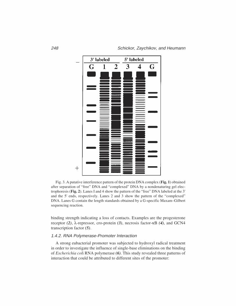
248 Schickor, Zaychikov, and Heumann
binding strength indicating a loss of contacts. Examples are the progesteronereceptor (2), λ-repressor, cro-protein (3), necrosis factor-κB (4), and GCN4transcription factor (5).
1.4.2. RNA Polymerase-Promoter Interaction
A strong eubacterial promoter was subjected to hydroxyl radical treatmentin order to investigate the influence of single-base eliminations on the bindingof Escherichia coli RNA polymerase (6). This study revealed three patterns ofinteraction that could be attributed to different sites of the promoter:
Fig. 3. A putative interference pattern of the protein DNA complex (Fig. 1) obtainedafter separation of “free” DNA and “complexed” DNA by a nondenaturing gel elec-trophoresis (Fig. 2). Lanes I and 4 show the pattern of the “free” DNA labeled at the 3'and the 5' ends, respectively. Lanes 2 and 3 show the pattern of the “complexed”DNA. Lanes G contain the length standards obtained by a G-specific Maxam–Gilbertsequencing reaction.

Hydroxyl Radical Interference 249
1. Direct base contact with the template strand in the “–35 region”: This was con-cluded from the reduced affinity of the polymerase for a promoter having a baseeliminations in this region together in combination with the results of hydroxylradical footprinting studies (7), which revealed close contacts between the basesof this sequence and the protein. This is an example in which a base eliminationleads to missing contacts between protein and DNA.
2. A DNA-structure-dependent interaction in the “–10 region”: This was inferredfrom the increased binding affinity of the polymerase for a promoter having baseeliminations in this region in conjunction with footprinting studies that revealedthat this region is in close contact with the protein (7). This is an example inwhich a base elimination leads to enhanced flexibility of the DNA favoring pro-tein binding and suggests that the DNA adopts a particular conformation whenbound to the protein.
3. An interaction that is based on a defined spatial relationship between the “–35region” and the “–10 region” domains. This conclusion was drawn from thefollowing findings:a. Base elimination within the promoter region between the two domains reduces
the binding affinity of RNA polymerase.b. The eliminated bases had no contact with the protein (as shown by their
accessibility to hydroxyl radical footprinting studies [7]).c. The effect was observed for both DNA strands. This is an example in
which base elimination leads to a loss of the defined spatial relationshipbetween two functionally important sites because of an enhancement inDNA flexibility.
2. Materials2.1. The Cutting Reaction
Prepare the following solutions separately (see Note 1):
1. 0.1 M dithiotreitol (DTT).2. 1% Hydrogen peroxide.3. Iron(II)–EDTA-mix: Mix equal volumes of 2 mM ammonium iron(II) sulfate
hexahydrate ([NH4]2Fe[SO4]2·6H2O) and 4 mM EDTA.4. Stop mix: 4% glycerol, and 0.6 M sodium acetate.
2.2. The Sequencing Gel
1. Urea (ultra pure).2. 20X TBE: 1 M Tris base, 1 M boric acid, and 20 mM EDTA.3. Acrylamide solution: 40% acrylamide, and 0.66% bis-acrylamide (see Note 2).4. 10% Sodium persulfate (see Note 3).5. 10% TEMED.6. Sequencing gel (8%): 21 g urea, 2.5 mL of 20X TBE, and 10 mL of 40%
acrylamide solution are made up to 50 mL with bidistilled H2O and stirred undermild heating until urea is dissolved. The solution is filtered (filter pore size: 0.2 µm)
250 Schickor, Zaychikov, and Heumann
and degassed for 5 min. Then, 0.3 mL of 10% sodium persulfate and 0.3 mL of10% TEMED are added immediately before pouring the solution between theglass plates.
7. Loading buffer for the sequencing gel (stock solution): 100 mL formamide(deionized), 30 mg xylenecyanol FF, 30 mg bromophenol blue, and 750 mgEDTA.
8. Electrophoresis buffer: 1X TBE.
2.3. The Nondenaturing Gel for DNA Isolationand Electrophoretic Mobility Shift Assay
1. 20X TBE: as described in Subheading 2.2.2. Acrylamide solution: 30% acrylamide, and 0.8% bis-acrylamide (see Note 2).3. 10% Sodium persulfate (see Note 3)4. 10% N,N,N',N'-tetramethylethylene diamine (TEMED) (aqueous solution).5. 3% Nondenaturing gel: 1.5 mL of 20X TBE, 3 mL of the acrylamide solution,
and 25.5 mL of bidistilled water are mixed and degassed for 5 min. Then 300 µLof 10% ammonium persulfate and 300 µL of 10% TEMED are added beforepouring the solution between the glass plates.
6. Loading buffer for the nondenaturing gel (stock solution): 50% glycerol, and0.1% bromophenol blue.
7. Electrophoresis buffer: 1X TBE.
2.4. Other Items
1. Sequencing gel apparatus.2. Apparatus for nondenaturing gel electrophoresis.3. Filters for drop dialysis, VS, 0.025 µm (Millipore, Bedford, MA).4. SpeedVac concentrator.5. 1X TE: 10 mM Tris-HCl, pH 7.9, and 1 mM EDTA.
3. Methods3.1. Establishing the Conditionsfor Obtaining Specific Protein–DNA Complexes
The method of establishing the conditions for complex formation using theelectrophoretic mobility-shift assay is described in Chapter 4. The enzyme toDNA ratio should be adjusted so that the ratio of complexed to free DNA isabout 1:1 (see Note 4).
3.2. Hydroxyl Radical Base Elimination
1. End-label an aliquot of the DNA fragment of interest under standard conditions(8) at the 5'-position, using T4 polynucleotide kinase and [γ-32P] ATP and endlabel a second aliquot at the 3'-position, using the Klenow fragment of DNApolymerase I and the appropriate [α-32P] dNTP. In each case remove one labelend by asymmetric cleavage of the DNA fragment with an appropriate restriction

Hydroxyl Radical Interference 251
endonuclease. Purify the uniquely end-labeled DNA fragments by nondenaturinggel electrophoresis. The total amount of DNA in an assay of 20 µL should not bebelow 100 ng (see Note 5).
2. Dissolve each end-labeled DNA preparation in 20 mL of 1X TE buffer. Add toboth samples 2 µL each of the previously prepared solutions of DTT, hydrogenperoxide, and the iron(II)–EDTA mix by putting single drops of each solution onthe inner wall of the tube and rapidly mixing the three drops before combiningthem with the sample using a micropipet.
3. Incubate for 3–4 min at room temperature.4. Add 25 mL stop mix and 150 µL of ice-cold 100% ethanol to precipitate the
DNA. Keep the solution at –70°C for 30 min.5. Recover the DNA by microcentrifugation for 30 min. Wash the pellet with ice-
cold 80% ethanol, dry the pellet under vacuum, and redissolve the pellet in 20–50 mLof 1X TE buffer.
6. Heat the sample for not longer than 2 min at 90°C and place on ice (see Note 5).Apply the sample onto a 6–10% sequencing gel (for the analysis of fragments inthe range of 50–150 bases a gel consisting of 8% acrylamide is adequate). Use aslength standards a Maxam–Gilbert sequencing reaction of the 5'- or 3'- labeledDNA fragment.
7. Run the gel at 50 W at a temperature of 60°C for 1.5–2 h. The gel is ready whenthe xylenecyanol dye marker is about 3–5 cm above the bottom of the gel.
8. After electrophoresis, expose the gel to an X-ray film using an intensifying screenat –70°C overnight. For subsequent experiments choose the time of hydroxy radi-cal cleavage that provides an even distribution of bands and leaves around 90%of the DNA uncleaved.
3.3. Interference Studies on Protein-DNA Complexes
1. Prepare two 20-µL samples of the complex to be studied using DNA labeledrespectively at the 3' and the 5' ends and hydroxy radical treated as described inSubheading 3.2. Use conditions established for optimal complex formation (seeSubheading 3.1.). The total amount of radioactivity in one assay should bearound 60,000–80,000 cpm.
2. Pour 30–40 mL of the dialysis buffer containing 8 mM Tris-HCl, pH 7.9, into aPetri dish (see Note 6). Place a Millipore filter (see Subheading 2.4.) on thesurface of the buffer, shiny side (hydrophobic side) up. Put the samples contain-ing the complexes onto the filter for 1 h in order to remove salt (see Note 7).Remove the samples from the filter by a micropipet and transfer them to a fresh1.5-mL Eppendorf tube.
3. Separate the complex and the free DNA on a nondenaturing acrylamide gel elec-trophoresis. The method for separation of complexes from free DNA is describedin Subheading 3.3.2. in Chapter 5.
4. The whole procedure for the recovery of DNA from the gel is described in Sub-heading 3.3.2. in Chapter 5.
252 Schickor, Zaychikov, and Heumann
5. Adjust the amount of radioactivity and volume in each sample to about 5000–6000 cpm in 4–5 µL. Heat the samples for not longer than 2 min at 90°C and putthem on ice (see Note 8).
6. Analyze the DNA by denaturing gel electrophoresis. Apply the samples to a6–10% sequencing gel (for the analysis of fragments in the range of 50–150 basesa gel consisting of 8% acrylamide is adequate). Load the following samples onthe gel: end-labeled DNA, the Maxam–Gilbert reaction as length standard, thefree DNA recovered from the gel, and the DNA recovered from the complex.
7. Run the gel for 1.5–2 h at about 50 W to obtain a temperature of 60°C.8. Expose the gel after electrophoresis to an X-ray film using an intensifying screen
at –70°C overnight.
4. Notes1. The iron(II), iron-EDTA mix, and the H2O2 solutions should be freshly made
before use. The solutions of DTT (0.1 M), EDTA (4 mM), H2O2 (as a 30% stocksolution), and the stop mix are stable for months being stored at –20°C.
2. The acrylamide solutions are stable for months if protected from light andkept at 4°C.
3. Sodium persulfate has an advantage over routinely used ammonium persulfate ofbeing much more stable in aqueous solution. The 10% sodium persulfate solutionmay be kept at least 1 mo at 4°C without loss of activity.
4. It is advisable to keep the enzyme-to-DNA ratio <1 in order to assure stringentsequence selection conditions.
5. It is strongly recommended to check the quality of the labeled DNA on asequencing gel before use. Nicks in the double strand, which could result fromDNase activities during the preparation procedure, will appear as additional bandsin the sequencing gel. This admixture of bands would spoil the whole footprint,even when present in only small amounts. Furthermore, it is recommended not tostore the freshly labeled DNA longer than 2 wk because of the danger of radia-tion damage to the DNA.
6. The buffer conditions can be varied (e.g., the pH), but the ionic strength shouldnot be too high (a maximum of 50 mM NaCl) in order to obtain sharp bandsduring the following electrophoresis. Many protein–DNA complexes are verystable at low ionic strength (e.g., complexes between RNA polymerase and pro-moters [6]). Therefore, in most cases the stability of the pH in the followingelectrophoresis is the only limitation to lowering the ionic strength.
7. The purpose of the dialysis is the removal of salt, the presence of which wouldlower the quality of the electrophoresis pattern. As a rough approximation, one canremove up to 80–90% of the salt present in the sample within 1 h of drop dialysis.
8. Longer heating or boiling creates additional cuts in the DNA.
References1. Heumann, H., Metzger, W., and Niehörster, M. (1986) Visualization of interme-
diary transcription states in the complex between Escherichia coli DNA-depen-
Hydroxyl Radical Interference 253
dent RNA polymerase and a promoter-carrying DNA fragment using the gelretardation method. Eur. J. Biochem. 158, 575–579.
2. Chalepakis, G. and Beato, M. (1989) Hydroxyl radical interference: a new methodfor the study of protein–DNA interaction. Nucleic Acids Res. 17, 1783.
3. Hayes, J. J. and Tullius, Th. D. (1989) The missing nucleoside experiment: a newtechnique to study recognition of DNA by protein. Biochemistry 28, 9521–9527.
4. Schreck, R., Zorbas, H., Winnacker, E. L., and Baeuerle, P. A. (1990) Thenf-kappa-b transcription factor induces DNA bending which is modulated by its65-kd subunit. Nucleic Acids Res. 18, 6497–6502.
5. Gartenberg, M. R., Ampe, C., Steitz, T. A., and Crothers, D. M. (1990) Molecularcharacterisation of the GCN4-DNA complex. Proc. Natl. Acad. Sci. USA 87,6034–6038.
6. Werel, W., Schickor, P., and Heumann, H. (1991) Flexibility of the DNA enhancespromoter affinity of Escherichia coli RNA polymerase. EMBO J. 10, 2589–2594.
7. Schickor, P., Metzger, W., Werel, W., Lederer, H., and Heumann, H. (1990)Topography of intermediates in transcription initiation of E. coli. EMBO J. 9,2215–2220.
8. Maniatis, T., Fritsch, E. F., and Sambrock, J. (1982) Molecular Cloning. A Labo-ratory Manual. Cold Spring Harbor Laboratory, Cold Spring Harbor, NY.
Identification of DNA-Binding Proteins 255
255
From: Methods in Molecular Biology, vol. 148: DNA–Protein Interactions: Principles and Protocols, 2nd ed.Edited by: T. Moss © Humana Press Inc., Totowa, NJ
17
Identification of Sequence-Specific DNA-BindingProteins by Southwestern Blotting
Simon Labbé, Gale Stewart, Olivier LaRochelle, Guy G. Poirier,and Carl Séguin
1. IntroductionSouthwestern blotting was first described by Bowen et al. (1) and was used
to identify DNA-binding proteins that specifically interact with a chosen DNAfragment in a sequence-specific manner. In this technique, mixtures of pro-teins such as crude nuclear extracts or partially purified preparations are firstfractionated on a sodium dodecyl sulfate (SDS) denaturing gel; the gel is thenequilibrated in a SDS-free buffer to remove detergent and the proteins trans-ferred by electroblotting to an immobilizing membrane. During the transfer theproteins renature and hence DNA-binding proteins may subsequently bedetected on the membrane by their ability to bind radiolabeled DNA. Fraction-ation of crude nuclear extracts on an SDS gel followed by electroblotting andanalysis for sequence-specific DNA binding directly on the blot combinesthe advantages of a high-resolution fractionation step with the ability to rap-idly analyze for a large number of different DNA-binding specificities.
The successful identification of specific DNA-binding proteins by the South-western technique largely depends on the renaturation of the proteins after theirseparation by SDS-polyacrylamide gel electrophoresis (PAGE). The ease withwhich renaturation can be achieved after treatment with SDS varies from pro-tein to protein. Some DNA-binding proteins may be inefficiently renaturedand thus be unable to bind DNA once they are adsorbed onto membranes. Inaddition, any multimeric protein that requires a combination of differentmolecular-weight subunits to bind DNA will be missed. Proteins requiring acofactor(s) in order to show their ability to specifically interact with DNA mayalso be difficult to detect.
256 Labbé et al.
Site-specific protein–DNA interactions may also be obscured by the largenumber of nonspecific DNA-binding proteins present in a typical crude nuclearextract. Conditions for DNA binding, such as pH, ionic strength, and divalentcation requirement, as well as the type and amount of nonspecific DNA used ascompetitor, should be optimized for each protein under investigation. Specialattention should also be given DNA-binding proteins frequently present incrude nuclear extracts and known to copurify with sequence-specific DNA-binding proteins (see Note 1). Despite these shortcomings, Southwestern blot-ting has, over the last few years, been used to identify and characterize severalsequence-specific DNA-binding proteins, histones, and nonhistone proteins;for examples, see Fig. 1 and refs. 2–14, as well as RNA-binding proteins (15–17).In addition, preparative Southwestern blots have been used to define DNAsequences recognized by a given DNA-binding protein (18), whereas South-western screening of cDNA libraries has been used to isolate several sequence-specific DNA-binding proteins (19,20).
2. MaterialsAll solutions are made with double-distilled or Milli Q water.
1. Crude nuclear extracts or protein chromatographic fractions.2. 1.5 M Tris-HCl, pH 8.8.3. 0.5 M Tris-HCl, pH 6.8.4. Sodium dodecyl sulfate (SDS) 10% and 2-bis-mercaptoethanol.5. Tris–glycine buffer 10X: 250 mM Tris base and 1.92 M glycine pH 8.3. To make
this up, dissolve 30 g Tris base, and 144 g glycine in 1 L of water (see Note 2).6. Electrophoresis running buffer: 2X Tris–glycine buffer containing 1% SDS.7. Transfer buffer: Tris–glycine buffer 1X.8. Binding buffer 1X: 20 mM HEPES, pH 7.9, 5 mM MgCl2, 50 mM NaCl, and 1 mM
dithiothreitol (DTT) (see Notes 3 and 4).9. Sample loading buffer 2X: 125 mM Tris, pH 6.8, 4% (w/v) SDS, 20% (v/v) glyc-
erol, 10% (v/v) 2-bis-mercaptoethanol, and 0.025% (w/v) bromophenol blue.Make 1-mL aliquots and store at –20°C.
10. Acrylamide (50:1) and (30:0.8):acrylamide:N',N'-methylene–bis-acrylamidemade up in water (see Note 5). Deionize the acrylamide solution with a mixed-bed resin (21) and store at 4°C. Note: Acrylamide is a potent neurotoxin. Weargloves and a facemask when handling the dry powder.
11. 10% Ammonium persulfate (w/v) in water (prepared weekly and stored inaliquots at –20°C ), and N,N,N',N'-tetramethylethylenediamine (TEMED).
12. Methanol and isobutanol.13. Blocking buffer–5%: 5% (w/v) nonfat dried milk and 0.01% (v/v) Antifoam A
emulsion (Sigma) in 1X binding buffer.14. Blocking buffer–0.25%: 0.25% (w/v) nonfat dry milk, 0.01% (v/v) Antifoam A
emulsion in 1X binding buffer.
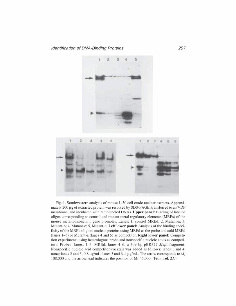
Identification of DNA-Binding Proteins 257
Fig. 1. Southwestern analysis of mouse L-50 cell crude nuclear extracts. Approxi-mately 200 µg of extracted protein was resolved by SDS-PAGE, transferred to a PVDFmembrane, and incubated with radiolabeled DNAs. Upper panel: Binding of labeledoligos corresponding to control and mutant metal regulatory elements (MREs) of themouse metallothionein 1 gene promoter. Lanes: 1, control MREd; 2, Mutant-a; 3,Mutant-b; 4, Mutant-c; 5, Mutant-d. Left lower panel: Analysis of the binding speci-ficity of the MREd oligo to nuclear proteins using MREd as the probe and cold MREd(lanes 1–3) or Mutant-a (lanes 4 and 5) as competitor. Right lower panel: Competi-tion experiments using heterologous probe and nonspecific nucleic acids as competi-tors. Probes: lanes, 1–3, MREd; lanes 4–6, a 309 bp pBR322 MspI fragment.Nonspecific nucleic acid competitor cocktail was added as follows: lanes 1 and 4,none; lanes 2 and 5, 0.8 µg/mL; lanes 3 and 6, 4 µg/mL. The arrow corresponds to Mr
108,000 and the arrowhead indicates the position of Mr 45,000. (From ref. 21.)
258 Labbé et al.
15. End-labeled oligonucleotides (oligos) or DNA fragments of high specific activ-ity. Standard procedures (21) can be followed in the preparation of DNA samples(see Note 6).
16. Poly(dA–dT)·poly(dA–dT), poly(dI–dC)·poly(dI–dC), calf thymus DNA, salmonsperm DNA, Escherichia coli DNA.
17. 14C-Labeled protein standards (5 µCi/mL, Amersham) and prestained proteinstandards such as the Kaleidoscope Prestained Standards from Bio-Rad.
18. Vertical electrophoresis apparatus with a central cooling core (e.g., Protean IIslab cell, Bio-Rad) and glass plates (see Note 7).
19. Electroblotting apparatus with cooling coil (e.g., Trans-blot transfer cell, Bio-Rad).20. Electrophoresis DC power supply capable of 200 V and 2 Amp (e.g., model 200/
2.0 of Bio-Rad).21. Recirculating water chiller apparatus.22. Immobilon™–PVDF membrane (Millipore).23. Whatman 3MM paper.
3. MethodThe Southwestern procedure is conducted in three stages: Crude nuclear
protein extracts or purified or partially purified protein preparations are sepa-rated by electrophoresis on an SDS–polyacrylamide gel, transferred to thePVDF membrane, and then the immobilized proteins assessed for their abilityto bind a labeled oligo corresponding to a given DNA cis-acting regulatoryelement or a labeled DNA promoter fragment.
1. Prepare an 8% acrylamide–bis-acrylamide (50:1) separating gel (see Note 4).Mix 25 mL 1.5 M Tris-HCl, pH 8.8, 15.7 mL acrylamide, and 57.2 mL water.Filter the solution through a 0.45-µm membrane and then add 0.5 mL 10% SDS,0.5 mL of 10% ammonium persulfate (APS), and 35 µL TEMED. Mix gently byinversion and pour the gel. Gently overlayer the acrylamide solution withisobutanol and allow the gel to set for at least 1 h. Remove the isobutanol, rinsegel surface thoroughly with water. Prepare the stacking gel by mixing 6.25 mL of0.5 M Tris-HCl, pH 6.8, 3.35 mL acrylamide–bis-acrylamide (30:0.8), 15 mLwater. Filter the solution and add 0.25 mL of 10% SDS, 0.25 mL of 10% APS and17 µL TEMED. Mix gently, pour over the separating gel, add a comb, and allowthe stacking gel to set for at least 1 h. Just before using, carefully wash the wellswith running buffer using a syringe.
2. Dilute equal volumes of protein preparation and 2X loading buffer. We typicallyuse 100–400 µg (protein) of a crude nuclear extract (prepared according toDignam [22]) in the presence of a cocktail of four protease inhibitors (i.e.,leupeptin, polymethylsulfonyl fluoride [PMSF], antipain, and chemostatin A).Lower amounts are required when using purified or partially purified proteinpreparations. Mix loading buffer and samples just before loading to avoid SDSprecipitation. We do not boil or otherwise purposely denature the protein prepa-rations (see Note 8). Include 15 µL of 14C-labeled protein markers in a separate
Identification of DNA-Binding Proteins 259
lane. Run gel in electrophoresis electrode buffer (2X Tris–glycine buffer, 1%SDS) overnight at 75 V (constant voltage). Do not prerun the gel. We perform theelectrophoresis at 4°C by connecting the cooling coil provided with the electro-phoresis apparatus to a recirculating water chiller (see Note 9).
3. Electrophoresis gels should be pre-equilibrated in transfer buffer prior to com-mencement of electrophoretic transfer. Pre-equilibration will aid the removal ofSDS, contaminating the electrophoresis salts from the proteins, and will facilitatesubsequent renaturation to the native conformation (see Note 10). In addition,the pretransfer step will allow any changes in the size of the gel resulting fromthe swelling or shrinking to occur at this stage rather than during the transfer.Thus, after the gel is run, dismantle the apparatus, remove the gel from the plates,and soak it in transfer buffer for 60 min with gentle agitation. We usually per-form this operation in the cold room (see Note 9). Wear clean disposable gloves.
4. Lay the gel onto 3MM paper prewetted with transfer buffer. Always keep the gelwet by regularly pouring buffer over it.
5. Prewet the PVDF membrane in methanol for few seconds and transfer it to water.6. Begin mounting the protein-blotting sandwich by placing one sponge (provided
with the blotting transfer apparatus) into the holder, followed by the 3MM supportpaper and placing the gel (see Fig. 2 and Note 11).
7. Lay the prewetted PVDF membrane over the gel.8. Carefully remove any air bubbles trapped between the gel and the membrane. We
use a 10-mL glass pipet gently rolled over the membrane.9. Place a second prewetted (with transfer buffer) 3MM paper and repeat step 8.
Place the second foam pad onto the sandwich and close the holder. Introduce theholder into the transfer apparatus, previously filled with cold transfer buffer. Besure that the membrane is toward the positive electrode. Place the transfer appa-ratus on the stirring plate and connect it to a circulating cooler unit (see Note 12).
10. It is important that a stirring bar be placed inside the transfer apparatus and thatthe transfer buffer be stirred during the course of the experiment. This willhelp to maintain uniform conductivity and temperature during electrophoretic
Fig. 2. Schematic representation of the protein blotting sandwich assemblage usedin Southwestern experiments. The orientation of the sandwich in relation to the cath-ode (+) and the anode (–) is indicated.
260 Labbé et al.
transfer. Failure to do so will result in poor transfer of proteins and may pose asafety hazard.
11. Transfer at 50 V constant for 3 h.12. After the transfer is completed, dismantle the apparatus, remove the membrane
from the gel, and successively place it in (1) 200 mL of binding buffer in a plasticdish for 15 min with gentle agitation, (2) 250 mL blocking buffer–5% for a mini-mum of 1 h with agitation, (3) and 150 mL blocking buffer–0.25% containing106 cpm/mL of probe DNA and leave overnight with agitation (see Note 13).Never let the membrane dry between the transfer and the binding steps.
13. After the transfer, the gel may be transferred in 50% methanol for subsequentsilver staining to visualize untransferred proteins (see Note 14).
14. Wash the membrane by successively soaking it under continuous agitation in(1) blocking buffer–0.25% for 30 s, (2) blocking buffer–0.25% for 20 min, (3)blocking buffer–0.25% for 20 min, and (4) Binding buffer 1X for 20 min. Recoverwash liquids because they contain 32P.
15. Let the membrane dry on 3MM paper at room temperature for 1 h, then autorad-iograph using an X-ray film and intensifying screen if necessary.
4. Notes1. Crude nuclear extracts prepared from human HeLa and mouse L cells contain
three common nonspecific DNA-binding proteins that often contaminatepreparations of affinity-purified factors. These are poly (ADP–ribose) poly-merase (PARP), which has an Mr of 116,000 (as well as a typical proteolyticfragment of Mr-60,000) (27) , the Ku antigen, which consist of twopolypeptides of Mr-70,000 and 80,000 (28), and replication protein A (RP-A)of Mr-74,000 (29). The heat-shock protein hsp70 (Mr-70,000), which canstick rather tenaciously to proteins that are improperly folded, may also causeproblems. Thus, when Southwestern analyses are performed with affinity-purified nuclear proteins, it is recommended to be suspicious of positivepolypeptides of Mr-60,000, 70,000–74,000, 80,000, and 110,000, and to per-form control experiments. For instance, in the case of PARP, if a polypeptidewith an Mr in the range of this protein is detected in the Southwestern proce-dure, a Western analysis could be performed on an aliquot of the proteinpreparation using anti-PARP antibodies available commercially (Roche Diag-nostics/Boehringer). Alternatively, a chromatographic step with Red Agarose(Bio-Rad), which binds PARP with high affinity, can be performed to removeof this possible contaminant (27). One should, however, bear in mind thatPARP has recently been shown to act as a coactivator for a number of tran-scription factors, including AP-2 (30), E47 (31), and TEF-1 (32); thus, itsdetection using a specific DNA probe corresponding to the binding site of aknown transcription factor could actually be functionally relevant.
2. Tris–glycine buffers should not be pH adjusted.3. Dithiothreitol should be stored at –20°C, thawed on ice, and added when the
solution is ice-cold.
Identification of DNA-Binding Proteins 261
4. Several DNA-binding proteins require zinc ions to efficiently bind DNA. As aprecaution, we routinely add 5 µM ZnCl2 to all solutions (loading, electrophore-sis, transfer, binding, and wash buffers).
5. The percentage of gel and the ratio of acrylamide to bis-acrylamide will dependon the Mr of the protein of interest. We have used a ratio of 50:1 to increaseresolution of the high-molecular-weight protein species. A ratio of 30:0.8 or 29:1may be more appropriate for average protein species. Plates are cleaned withphosphate-free soap and rinsed with deionized water, Milli Q water, and ethanol95%. We usually do not silanize the plates with dichlorodimethylsilane, as weobserved that it could interfere with the subsequent steps.
6. Synthetic oligos or DNA fragments can be conveniently 5' labeled with T4 kinase(21). A radiolabeled probe with a high specific activity increases the sensitivityof detection and reduces background (23). A nonradioactive Southwestern pro-cedure, using chemiluminescent detection, has also been described (24).
7. The procedure can both be carried out using a standard electrophoresis and trans-fer apparatus or a small-size apparatus such as the Mini-protean II and mini-Trans-Blot transfer cell of Bio-Rad (2).
8. We do not boil samples before electrophoresis in order to avoid irreversiblydenaturing proteins or to affect the DNA-binding properties of more sensitiveprotein species (4).
9. Depending of the biochemical properties of the protein under investigation andof its stability at room temperature, it is generally recommended to perform thewhole procedure at 4°C. Particular conditions of temperature may need to bedetermined for an optimal binding of different factors to DNA.
10. Although the extent of renaturation is not known, this wash, by removing SDSfrom the proteins, permits functional binding to the DNA recognition sequence.Triton X-100 (1,12), urea (3,5,8,11) or guanidium HCl (9,10) can be included inthe transfer buffer to promote the removal of SDS and to facilitate subsequentrenaturation of the proteins. Low-molecular-weight proteins (≤10 kDa) may dif-fuse more readily out of gels during the pre-equilibration step. To avoid this, onecan shorten the pre-equilibration period, changing the buffer several times to aidequilibration. Methanol (20%) can also be added to the transfer buffer (5,9,25).However, this organic solvent may affect the DNA-binding properties of the pro-teins. The choice of renaturation procedure and buffers should be determinedempirically and will depend on the factors studied.
11. Each layer of the sandwich is thoroughly prewetted with buffer and then care-fully positioned on top of the previous layer, taking care to avoid trapping any airbubbles which would distort the resulting transfer.
12. Placing the trans-blot apparatus in the cold room is an inadequate means of con-trolling transfer buffer temperature. Efficient heat removal is obtained by con-necting the transfer apparatus to a recirculating cooler. Transfer is a function ofmolecular weight, with the largest proteins being transferred more slowly. Theprecise transfer conditions should take into account the molecular-weight rangeof the proteins under investigation and the composition of the gel.

262 Labbé et al.
13. It is important to block any remaining free binding sites on the membrane inorder to reduce nonspecific binding of the DNA probe. The binding buffer should,thus, be designed to optimize the specific binding of the radiolabeled probe whilekeeping nonspecific binding to a minimum. Nonspecific binding can be reducedby the addition of an excess of unlabeled DNA such as poly(dI–dC)·poly(dI–dC)or poly(dA–dT)·poly(dA–dT), or sheared E. coli, salmon sperm, or calf thymusDNA. Nonspecific binding can also be reduced by increasing salt concentrationsin the binding reaction and/or in the wash buffer. In addition, the use of lipid-freebovine serum albumin (BSA) instead of nonfat dry milk has been reported tooptimize the signal-to-noise ratio (26). Although specific high-affinity DNA–protein interactions will not normally be competed by nonspecific competitorDNA, the addition of a large excess of competitor DNA may eventually do so.Thus, the amount of competitor DNA and the salt concentration of buffers willdepend on the factor of interest. The specificity and affinity of binding should befurther examined by adding an unlabeled target sequence or a nonfunctionalmutated target sequence DNA as a competitor to the blocking and/or bindingsolutions. Alternatively, to determine the specificity of an interaction, the bind-ing of a radiolabeled mutant target DNA can be compared with the binding of theunmutated sequence (see Fig. 1) (2).
14. Some proteins may not retain their ability to bind selectively with their targetDNA after immobilization of the protein on the membrane. Furthermore, themembrane will not necessarily retain all of the proteins that have migrated outthe gel. It is, thus, useful to determine which proteins have been transferred to themembrane. Detection of the transferred proteins may be achieved after autorad-iography by staining the membrane with either Coomassie brilliant blue R-250,Amido black, or Ponceau rouge. Proteins remaining in the gel after transfer canbe visualized by silver staining.
AcknowledgmentsWe thank R. Hancock for comments on the manuscript and S. Desnoyers for
helpful suggestions. S.L. is the recipient of a scholarship from FRSQ, and O.L.of a Studentship from NSERC. This work was supported by a Grant fromNSERC to C.S.
References1. Bowen, B., Steinberg, J., Laemmli, U. K., and Weintraub, H. (1980) The detec-
tion of DNA-binding proteins by protein blotting. Nucleic Acids Res. 8, 1–20.2. Séguin, C. and Prévost, J. (1988) Detection of a nuclear protein that interacts with
a metal regulatory element of the mouse metallothionein 1 gene. Nucleic AcidsRes. 16, 10,547–10,560.
3. Jack, R. S., Brown, M. T., and Gehring, W. J. (1983) Protein blotting as a meansto detect sequence-specific DNA-binding proteins. Cold Spring Harb. Symp.Quant. Biol. 47(Pt 1), 483–491.
Identification of DNA-Binding Proteins 263
4. Miskimins, W. K., Roberts, M. P., McClelland, A., and Ruddle, F. H. (1985) Useof a protein-blotting procedure and a specific DNA probe to identify nuclear pro-teins that recognize the promoter region of the transferrin receptor gene. Proc.Natl. Acad. Sci. USA 82, 6741–6744.
5. Silva, C. M., Tully, D. B., Petch, L. A., Jewell, C. M., and Cidlowski, J. A. (1987)Application of a protein-blotting procedure to the study of human glucocorticoidreceptor interactions with DNA. Proc. Natl. Acad. Sci. USA 84, 1744–1748.
6. Hughes, E. N., Engelsberg, B. N., and Billings, P. C. (1992) Purification of nuclearproteins that bind to cisplatin-damaged DNA. Identity with high mobility groupproteins 1 and 2. J. Biol. Chem. 267, 13,520–13,527.
7. Wegenka, U. M., Buschmann, J., Lutticken, C., Heinrich, P. C., and Horn, F.(1993) Acute-phase response factor, a nuclear factor binding to acute-phaseresponse elements, is rapidly activated by interleukin-6 at the posttranslationallevel. Mol. Cell. Biol. 13, 276–288.
8. Kwast-Welfeld, J., Debelle, I., Walker, P. R., Whitfield, J. F., and Sikorska, M.(1993) Identification of a new cAMP response element-binding factor by south-western blotting. J. Biol. Chem. 268, 19,581–19,585.
9. Dhawan, P., Chang, R., and Mehta, K. D. (1997) Identification of essential nucle-otides of the FP1 element responsible for enhancement of low density lipoproteinreceptor gene transcription. Nucleic Acids Res. 25, 4132–4138.
10. Villafuerte, B. C., Zhao, W., Herington, A. C., Saffery, R., and Phillips, L. S.(1997) Identification of an insulin-responsive element in the rat insulin-likegrowth factor-binding protein-3 gene. J. Biol. Chem. 272, 5024–5030.
11. Wu, J., Jiang, Q., Chen, X., Wu, X. H., and Chan, J. S. (1998) Identification of anovel mouse hepatic 52 kDa protein that interacts with the cAMP response ele-ment of the rat angiotensinogen gene. Biochem. J. 329, 623–629.
12. Melkonyan, H., Hofmann, H. A., Nacken, W., Sorg, C., and Klempt, M. (1998)The gene encoding the myeloid-related protein 14 (MRP14), a calcium-bindingprotein expressed in granulocytes and monocytes, contains a potent enhancer ele-ment in the first intron. J. Biol. Chem. 273, 27,026–27,032.
13. Carrion, A. M., Mellstrom, B., and Naranjo, J. R. (1998) Protein kinase A-depen-dent derepression of the human prodynorphin gene via differential binding to anintragenic silencer element. Mol. Cell. Biol. 18, 6921–6929.
14. Chen, A. and Davis, B. H. (1999) UV irradiation activates JNK and increases alphaI(I)collagen gene expression in rat hepatic stellate cells. J. Biol. Chem. 274, 158–164.
15. Katsu, Y., Yamashita, M., and Nagahama, Y. (1997) Isolation and characteriza-tion of goldfish Y box protein, a germ-cell- specific RNA-binding protein. Eur. J.Biochem. 249, 854–861.
16. Johnston, K. A., Polymenis, M., Wang, S., Branda, J., and Schmidt, E. V. (1998)Novel regulatory factors interacting with the promoter of the gene encoding themRNA cap binding protein (eIF4E) and their function in growth regulation. Mol.Cell. Biol. 18, 5621–5633.
17. Hamann, S. and Stratling, W. H. (1998) Specific binding of Drosophila nuclearprotein PEP (protein on ecdysone puffs) to hsp70 DNA and RNA. Nucleic AcidsRes. 26, 4108–4115.
264 Labbé et al.
18. Keller, A. D. and Maniatis, T. (1991) Selection of sequences recognized by aDNA binding protein using a preparative Southwestern blot. Nucleic Acids Res.19, 4675–4680.
19. Singh, H., Clerc, R. G., and LeBowitz, J. H. (1989) Molecular cloning ofsequence-specific DNA binding proteins using recognition site probes.BioTechniques 7, 252–261.
20. Stuempfle, K. J. and Floros, J. (1997) Caution is advised when cDNA expressionlibraries are screened by southwestern methodologies. BioTechniques 22, 260–264.
21. Sambrook, J., Fritsch, E. F., and Maniatis, T. (1989) Molecular Cloning. A Labo-ratory Manual (Ford, N., Nolan, C., and Ferguson, M., eds.), Cold Spring HarborLaboratory, Cold Spring Harbor, NY.
22. Dignam, J. D. (1990) Preparation of extracts from higher eukaryotes. MethodsEnzymol. 182, 194–203.
23. Handen, J. S. and Rosenberg, H. F. (1997) An improved method for southwesternblotting. Front. Biosci. 2, c9–c11.
24. Dooley, S., Welter, C., and Blin, N. (1992) Nonradioactive Southwestern analysisusing chemiluminescent detection. BioTechniques 13, 540–543.
25. Schaufele, F., Cassill, J. A., West, B. L., and Reudelhuber, T. (1990) Resolutionby diagonal gel mobility shift assays of multisubunit complexes binding to a func-tionally important element of the rat growth hormone gene promoter. J. Biol.Chem. 265, 14,592–14,598.
26. Papavassiliou, A. G. and Bohmann, D. (1992) Optimization of the signal-to-noiseratio in south-western assays by using lipid-free BSA as blocking reagent. NucleicAcids Res. 20, 4365–4366.
27. Mazen, A., Ménissier-de Murcia, J., Molinete, M., Simonin, F., Gradwohl, G.,Poirier, G., et al. (1989) Poly(ADP-ribose) polymerase: a novel finger protein.Nucleic Acids Res. 12, 4689–4698.
28. Mimori, T., Hardin, J. A., and Steitz, J. A. (1986) Characterization of the DNA-binding protein antigen Ku recognized by autoantibodies from patients with rheu-matic disorders. J. Biol. Chem. 261, 2274–2278.
29. Wold, M. S. (1997) Replication protein A: A heterotrimeric, single-strandedDNA- binding protein required for eukaryotic DNA metabolism. Annu. Rev.Biochem. 66, 61–92.
30. Kannan, P., Yu, Y., Wankhade, S., and Tainsky, M. A. (1999) PolyADP-ribosepolymerase is a coactivator for AP-2-mediated transcriptional activation . NucleicAcids Res. 27, 866–874.
31. Dear, T. N., Hainzl, T., Follo, M., Nehls, M., Wilmore, H., Matena, K., andBoehm, T. (1997) Identification of interaction partners for the basic-helix-loop-helix protein E47. Oncogene 14, 891–898.
32. Butler, A. J. and Ordahl, C. P. (1999) Poly(ADP-ribose) polymerase binds withtranscription enhancer factor 1 to MCAT1 elements to regulate muscle-specifictranscription. Mol. Cell. Biol. 19, 296–306.

Competition Assay Using ANS 265
265
From: Methods in Molecular Biology, vol. 148: DNA–Protein Interactions: Principles and Protocols, 2nd ed.Edited by: T. Moss © Humana Press Inc., Totowa, NJ
18
A Competition Assay for DNA Binding Usingthe Fluorescent Probe ANS
Ian A. Taylor and G. Geoff Kneale
1. IntroductionFluorescence spectroscopy is a useful technique for investigating the inter-
action of DNA-binding proteins with DNA. Generally, use is made of theintrinsic fluorescence of the protein arising from the aromatic amino acids,which is frequently perturbed in a DNA–protein complex (see Chapter 33). Insome cases, however, changes in the intrinsic fluorescence emission of a pro-tein arising from its interaction with nucleic acid may not be detectable. Forexample, if tryptophan and/or tyrosine residues are not located in the proxim-ity of the DNA-binding site, the emission spectrum may not be perturbed bythe interaction. Furthermore, in the presence of a large number of tryptophanand tyrosine residues, a relatively small perturbation in the overall emissionspectrum brought about by DNA binding may be masked.
To overcome these problems, an alternative approach is to add an extrinsicfluorescence probe to the system that competes with DNA for the binding siteof the protein. One can then measure the change in the fluorescence emissionspectrum of the probe as DNA is added. If the fluorescence characteristicsof the free and bound probe differ, displacement of the probe by DNA can thenbe observed.
The fluorescent probe 1-anilinonaphthalene-8-sulfonic acid (ANS) and itsderivatives have long been used to study protein structure (1) and, morerecently, to study protein–nucleic acid interactions (2–4). ANS has the prop-erty that its fluorescence emission spectrum undergoes a 50-nm blue shift alongwith an approx 100-fold enhancement when transferred from an aqueous envi-ronment to a less polar solvent, such as methanol (see Fig. 1). ANS will bindweakly to hydrophobic patches on protein molecules with an average dissocia-
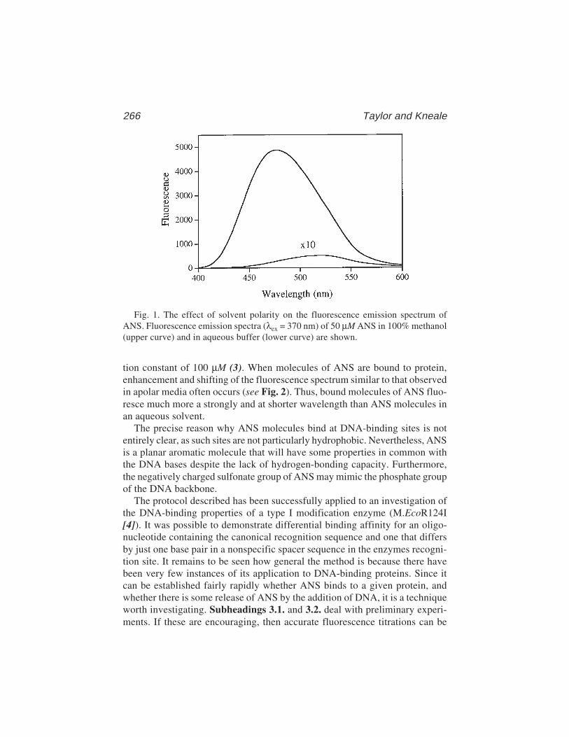
266 Taylor and Kneale
tion constant of 100 µM (3). When molecules of ANS are bound to protein,enhancement and shifting of the fluorescence spectrum similar to that observedin apolar media often occurs (see Fig. 2). Thus, bound molecules of ANS fluo-resce much more a strongly and at shorter wavelength than ANS molecules inan aqueous solvent.
The precise reason why ANS molecules bind at DNA-binding sites is notentirely clear, as such sites are not particularly hydrophobic. Nevertheless, ANSis a planar aromatic molecule that will have some properties in common withthe DNA bases despite the lack of hydrogen-bonding capacity. Furthermore,the negatively charged sulfonate group of ANS may mimic the phosphate groupof the DNA backbone.
The protocol described has been successfully applied to an investigation ofthe DNA-binding properties of a type I modification enzyme (M.EcoR124I[4]). It was possible to demonstrate differential binding affinity for an oligo-nucleotide containing the canonical recognition sequence and one that differsby just one base pair in a nonspecific spacer sequence in the enzymes recogni-tion site. It remains to be seen how general the method is because there havebeen very few instances of its application to DNA-binding proteins. Since itcan be established fairly rapidly whether ANS binds to a given protein, andwhether there is some release of ANS by the addition of DNA, it is a techniqueworth investigating. Subheadings 3.1. and 3.2. deal with preliminary experi-ments. If these are encouraging, then accurate fluorescence titrations can be
Fig. 1. The effect of solvent polarity on the fluorescence emission spectrum ofANS. Fluorescence emission spectra (λex = 370 nm) of 50 µM ANS in 100% methanol(upper curve) and in aqueous buffer (lower curve) are shown.
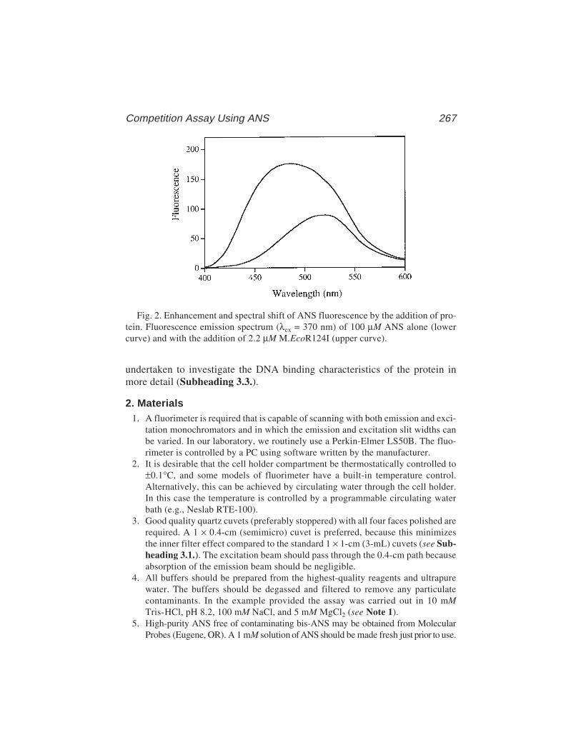
Competition Assay Using ANS 267
undertaken to investigate the DNA binding characteristics of the protein inmore detail (Subheading 3.3.).
2. Materials1. A fluorimeter is required that is capable of scanning with both emission and exci-
tation monochromators and in which the emission and excitation slit widths canbe varied. In our laboratory, we routinely use a Perkin-Elmer LS50B. The fluo-rimeter is controlled by a PC using software written by the manufacturer.
2. It is desirable that the cell holder compartment be thermostatically controlled to±0.1°C, and some models of fluorimeter have a built-in temperature control.Alternatively, this can be achieved by circulating water through the cell holder.In this case the temperature is controlled by a programmable circulating waterbath (e.g., Neslab RTE-100).
3. Good quality quartz cuvets (preferably stoppered) with all four faces polished arerequired. A 1 × 0.4-cm (semimicro) cuvet is preferred, because this minimizesthe inner filter effect compared to the standard 1 × 1-cm (3-mL) cuvets (see Sub-heading 3.1.). The excitation beam should pass through the 0.4-cm path becauseabsorption of the emission beam should be negligible.
4. All buffers should be prepared from the highest-quality reagents and ultrapurewater. The buffers should be degassed and filtered to remove any particulatecontaminants. In the example provided the assay was carried out in 10 mMTris-HCl, pH 8.2, 100 mM NaCl, and 5 mM MgCl2 (see Note 1).
5. High-purity ANS free of contaminating bis-ANS may be obtained from MolecularProbes (Eugene, OR). A 1 mM solution of ANS should be made fresh just prior to use.
Fig. 2. Enhancement and spectral shift of ANS fluorescence by the addition of pro-tein. Fluorescence emission spectrum (λex = 370 nm) of 100 µM ANS alone (lowercurve) and with the addition of 2.2 µM M.EcoR124I (upper curve).
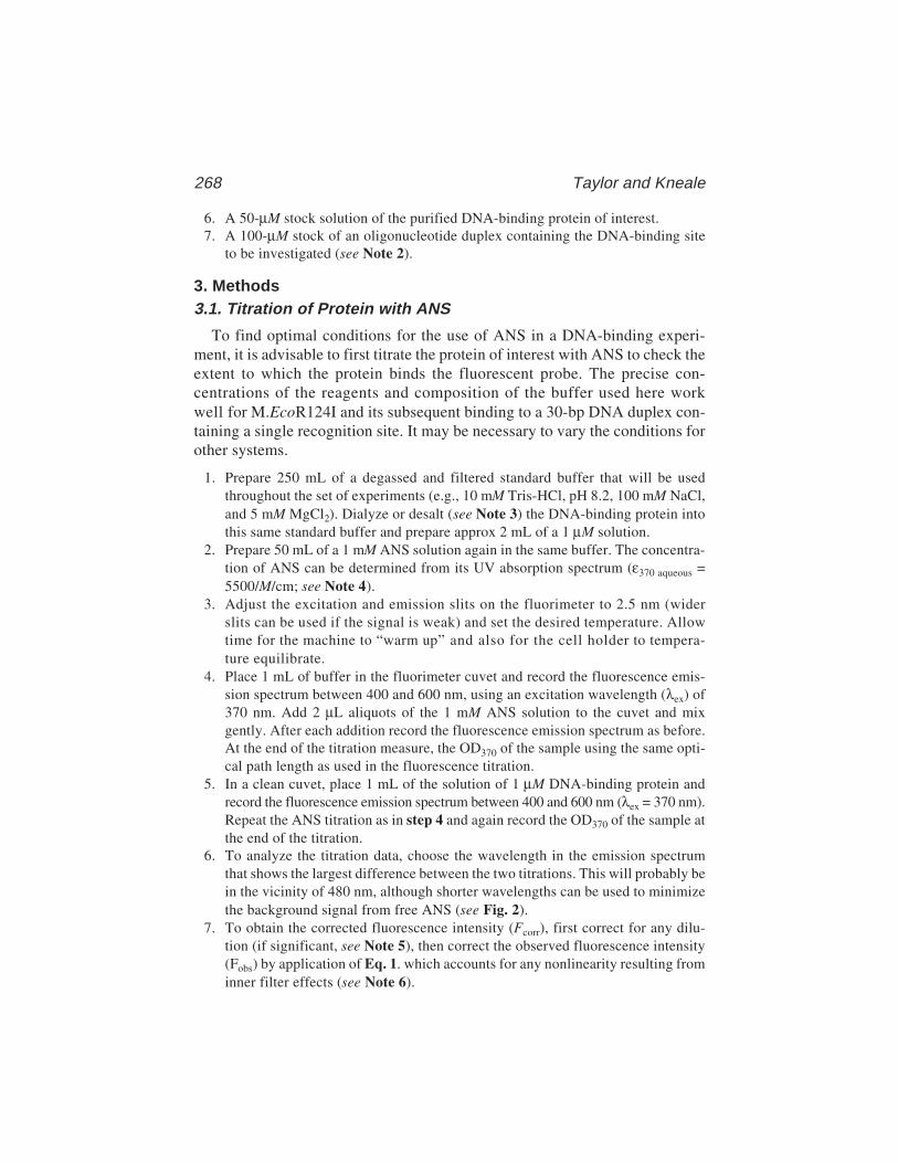
268 Taylor and Kneale
6. A 50-µM stock solution of the purified DNA-binding protein of interest.7. A 100-µM stock of an oligonucleotide duplex containing the DNA-binding site
to be investigated (see Note 2).
3. Methods3.1. Titration of Protein with ANS
To find optimal conditions for the use of ANS in a DNA-binding experi-ment, it is advisable to first titrate the protein of interest with ANS to check theextent to which the protein binds the fluorescent probe. The precise con-centrations of the reagents and composition of the buffer used here workwell for M.EcoR124I and its subsequent binding to a 30-bp DNA duplex con-taining a single recognition site. It may be necessary to vary the conditions forother systems.
1. Prepare 250 mL of a degassed and filtered standard buffer that will be usedthroughout the set of experiments (e.g., 10 mM Tris-HCl, pH 8.2, 100 mM NaCl,and 5 mM MgCl2). Dialyze or desalt (see Note 3) the DNA-binding protein intothis same standard buffer and prepare approx 2 mL of a 1 µM solution.
2. Prepare 50 mL of a 1 mM ANS solution again in the same buffer. The concentra-tion of ANS can be determined from its UV absorption spectrum (ε370 aqueous =5500/M/cm; see Note 4).
3. Adjust the excitation and emission slits on the fluorimeter to 2.5 nm (widerslits can be used if the signal is weak) and set the desired temperature. Allowtime for the machine to “warm up” and also for the cell holder to tempera-ture equilibrate.
4. Place 1 mL of buffer in the fluorimeter cuvet and record the fluorescence emis-sion spectrum between 400 and 600 nm, using an excitation wavelength (λex) of370 nm. Add 2 µL aliquots of the 1 mM ANS solution to the cuvet and mixgently. After each addition record the fluorescence emission spectrum as before.At the end of the titration measure, the OD370 of the sample using the same opti-cal path length as used in the fluorescence titration.
5. In a clean cuvet, place 1 mL of the solution of 1 µM DNA-binding protein andrecord the fluorescence emission spectrum between 400 and 600 nm (λex = 370 nm).Repeat the ANS titration as in step 4 and again record the OD370 of the sample atthe end of the titration.
6. To analyze the titration data, choose the wavelength in the emission spectrumthat shows the largest difference between the two titrations. This will probably bein the vicinity of 480 nm, although shorter wavelengths can be used to minimizethe background signal from free ANS (see Fig. 2).
7. To obtain the corrected fluorescence intensity (Fcorr), first correct for any dilu-tion (if significant, see Note 5), then correct the observed fluorescence intensity(Fobs) by application of Eq. 1. which accounts for any nonlinearity resulting frominner filter effects (see Note 6).
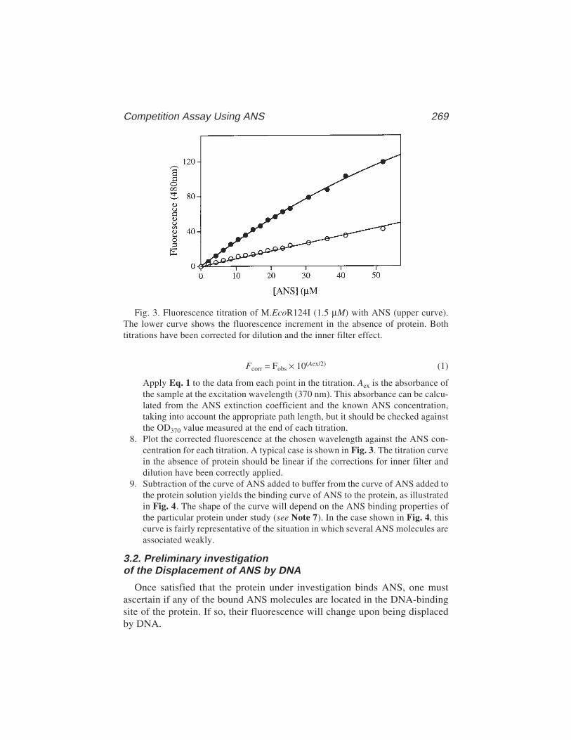
Competition Assay Using ANS 269
Fcorr = Fobs × 10(Aex/2) (1)
Apply Eq. 1 to the data from each point in the titration. Aex is the absorbance ofthe sample at the excitation wavelength (370 nm). This absorbance can be calcu-lated from the ANS extinction coefficient and the known ANS concentration,taking into account the appropriate path length, but it should be checked againstthe OD370 value measured at the end of each titration.
8. Plot the corrected fluorescence at the chosen wavelength against the ANS con-centration for each titration. A typical case is shown in Fig. 3. The titration curvein the absence of protein should be linear if the corrections for inner filter anddilution have been correctly applied.
9. Subtraction of the curve of ANS added to buffer from the curve of ANS added tothe protein solution yields the binding curve of ANS to the protein, as illustratedin Fig. 4. The shape of the curve will depend on the ANS binding properties ofthe particular protein under study (see Note 7). In the case shown in Fig. 4, thiscurve is fairly representative of the situation in which several ANS molecules areassociated weakly.
3.2. Preliminary investigationof the Displacement of ANS by DNA
Once satisfied that the protein under investigation binds ANS, one mustascertain if any of the bound ANS molecules are located in the DNA-bindingsite of the protein. If so, their fluorescence will change upon being displacedby DNA.
Fig. 3. Fluorescence titration of M.EcoR124I (1.5 µM) with ANS (upper curve).The lower curve shows the fluorescence increment in the absence of protein. Bothtitrations have been corrected for dilution and the inner filter effect.
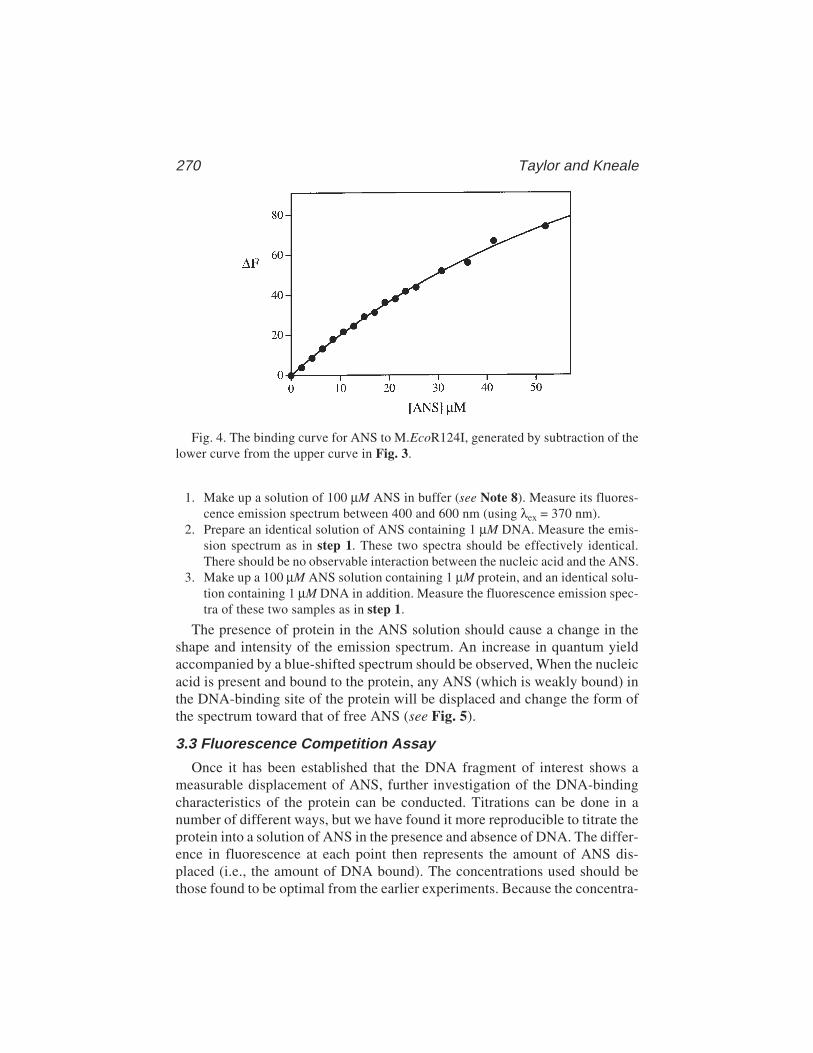
270 Taylor and Kneale
1. Make up a solution of 100 µM ANS in buffer (see Note 8). Measure its fluores-cence emission spectrum between 400 and 600 nm (using λex = 370 nm).
2. Prepare an identical solution of ANS containing 1 µM DNA. Measure the emis-sion spectrum as in step 1. These two spectra should be effectively identical.There should be no observable interaction between the nucleic acid and the ANS.
3. Make up a 100 µM ANS solution containing 1 µM protein, and an identical solu-tion containing 1 µM DNA in addition. Measure the fluorescence emission spec-tra of these two samples as in step 1.
The presence of protein in the ANS solution should cause a change in theshape and intensity of the emission spectrum. An increase in quantum yieldaccompanied by a blue-shifted spectrum should be observed, When the nucleicacid is present and bound to the protein, any ANS (which is weakly bound) inthe DNA-binding site of the protein will be displaced and change the form ofthe spectrum toward that of free ANS (see Fig. 5).
3.3 Fluorescence Competition Assay
Once it has been established that the DNA fragment of interest shows ameasurable displacement of ANS, further investigation of the DNA-bindingcharacteristics of the protein can be conducted. Titrations can be done in anumber of different ways, but we have found it more reproducible to titrate theprotein into a solution of ANS in the presence and absence of DNA. The differ-ence in fluorescence at each point then represents the amount of ANS dis-placed (i.e., the amount of DNA bound). The concentrations used should bethose found to be optimal from the earlier experiments. Because the concentra-
Fig. 4. The binding curve for ANS to M.EcoR124I, generated by subtraction of thelower curve from the upper curve in Fig. 3.

Competition Assay Using ANS 271
tion of ANS is constant throughout, the absorbance at 370 nm should remainunchanged and no inner filter correction need be applied.
1. Place 1 mL of a 100 µM ANS solution in the cuvet and record the emission spec-trum between 400 and 600 nm (λex = 370 nm).
2. Add small (2–10 µL) aliquots of the 50 µM stock protein solution to the cell up toa final concentration of 3 µM. After each addition record the fluorescence emis-sion spectrum.
3. Make up 1 mL of 100 µM ANS, this time containing 1 µM DNA, and record thefluorescence emission spectrum as in step 1.
4. Titrate the same small aliquots of the stock 50 µM protein solution into the ANS/DNA mixture and record the emission spectrum after each addition.
5. Select an appropriate wavelength (e.g., 480 nm; see step 6 of Subheading 3.1.)and plot the fluorescence intensity at each point in the titration against the proteinconcentration for both experiments (see Fig. 6).
6. To obtain a binding curve for the protein–nucleic acid interaction, subtract thefluorescence intensities at each point in the two experiments (with and withoutDNA) and replot against protein concentration (see Fig. 7). This difference rep-resents the amount of bound DNA, because DNA is solely responsible for thedecrease in fluorescence through displacement of ANS from the binding site. Fora high-affinity DNA protein interaction (with Kd substantially less than the con-centration of DNA used in the titration), competition from the ANS will be neg-ligible and a stoichiometric binding curve will be produced; the sharp break inthe curve at the stoichiometric point indicates the point at which all the DNA is
Fig. 5. Fluorescence emission spectra (λex = 370 nm) of 100 µM ANS in buffer(lower), in a solution of 1 µM M.EcoR124 (upper), and in a solution of 1 µMM.EcoR124I and 1 µM DNA (middle).
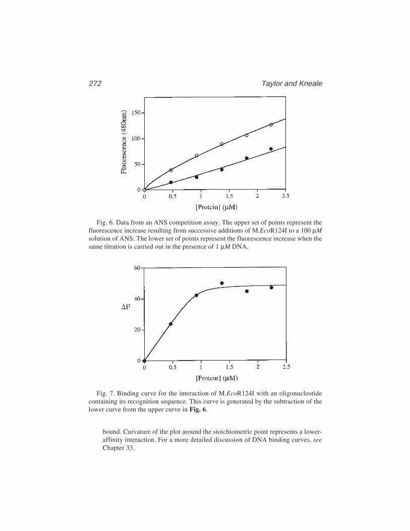
272 Taylor and Kneale
Fig. 6. Data from an ANS competition assay. The upper set of points represent thefluorescence increase resulting from successive additions of M.EcoR124I to a 100 µMsolution of ANS. The lower set of points represent the fluorescence increase when thesame titration is carried out in the presence of 1 µM DNA.
Fig. 7. Binding curve for the interaction of M.EcoR124I with an oligonucleotidecontaining its recognition sequence. This curve is generated by the subtraction of thelower curve from the upper curve in Fig. 6.
bound. Curvature of the plot around the stoichiometric point represents a lower-affinity interaction. For a more detailed discussion of DNA binding curves, seeChapter 33.
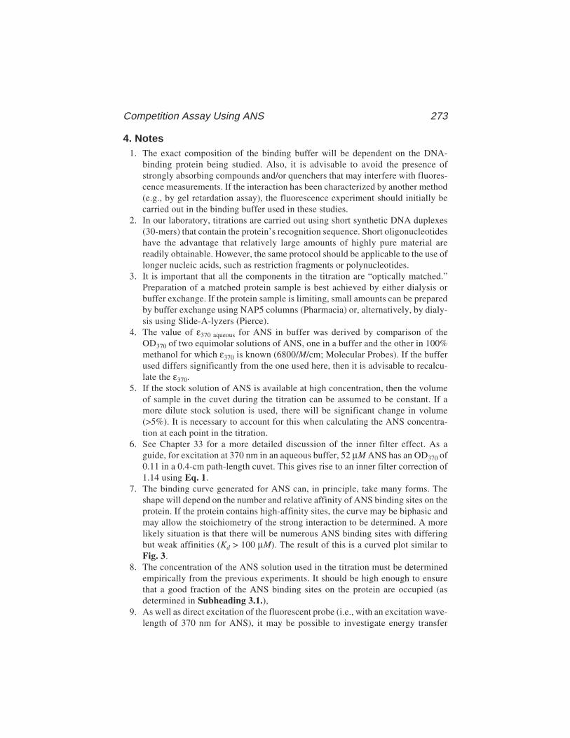
Competition Assay Using ANS 273
4. Notes1. The exact composition of the binding buffer will be dependent on the DNA-
binding protein being studied. Also, it is advisable to avoid the presence ofstrongly absorbing compounds and/or quenchers that may interfere with fluores-cence measurements. If the interaction has been characterized by another method(e.g., by gel retardation assay), the fluorescence experiment should initially becarried out in the binding buffer used in these studies.
2. In our laboratory, titrations are carried out using short synthetic DNA duplexes(30-mers) that contain the protein’s recognition sequence. Short oligonucleotideshave the advantage that relatively large amounts of highly pure material arereadily obtainable. However, the same protocol should be applicable to the use oflonger nucleic acids, such as restriction fragments or polynucleotides.
3. It is important that all the components in the titration are “optically matched.”Preparation of a matched protein sample is best achieved by either dialysis orbuffer exchange. If the protein sample is limiting, small amounts can be preparedby buffer exchange using NAP5 columns (Pharmacia) or, alternatively, by dialy-sis using Slide-A-lyzers (Pierce).
4. The value of ε370 aqueous for ANS in buffer was derived by comparison of theOD370 of two equimolar solutions of ANS, one in a buffer and the other in 100%methanol for which ε370 is known (6800/M/cm; Molecular Probes). If the bufferused differs significantly from the one used here, then it is advisable to recalcu-late the ε370.
5. If the stock solution of ANS is available at high concentration, then the volumeof sample in the cuvet during the titration can be assumed to be constant. If amore dilute stock solution is used, there will be significant change in volume(>5%). It is necessary to account for this when calculating the ANS concentra-tion at each point in the titration.
6. See Chapter 33 for a more detailed discussion of the inner filter effect. As aguide, for excitation at 370 nm in an aqueous buffer, 52 µM ANS has an OD370 of0.11 in a 0.4-cm path-length cuvet. This gives rise to an inner filter correction of1.14 using Eq. 1.
7. The binding curve generated for ANS can, in principle, take many forms. Theshape will depend on the number and relative affinity of ANS binding sites on theprotein. If the protein contains high-affinity sites, the curve may be biphasic andmay allow the stoichiometry of the strong interaction to be determined. A morelikely situation is that there will be numerous ANS binding sites with differingbut weak affinities (Kd > 100 µM). The result of this is a curved plot similar toFig. 3.
8. The concentration of the ANS solution used in the titration must be determinedempirically from the previous experiments. It should be high enough to ensurethat a good fraction of the ANS binding sites on the protein are occupied (asdetermined in Subheading 3.1.),
9. As well as direct excitation of the fluorescent probe (i.e., with an excitation wave-length of 370 nm for ANS), it may be possible to investigate energy transfer
274 Taylor and Kneale
effects between aromatic amino acid residues in the protein and the bound probe.If the excitation is performed at 280 nm to excite both tyrosine and tryptophan,energy transfer to ANS will be apparent from the emission spectrum between400 and 600 nm. In principle this effect could also be useful to for followingdisplacement of ANS in a titration with DNA.
10. A further extension of the fluorescent probe approach is to employ the covalentprobe 5-((((2-iodoacetyl) amino) ethyl) amino) naphthalene-1-sulfonic acid(1,5-IAEDANS) (5). This reagent reacts with accessible cysteine residues in theprotein and has a higher quantum yield than ANS in aqueous solution. One canlook at the emission spectrum of the bound probe, or it may be possible to observeenergy transfer from aromatic residues in the protein. Any of these fluorescencecharacteristics could change when the DNA is bound if the probe is located nearthe DNA-binding site. We have used this technique to study the interaction ofM.EcoR124I with DNA and found that energy transfer from the protein to thebound probe decreased by over 30% when DNA was bound. As long as the pres-ence of the probe does not inhibit binding, then titrations with DNA can be usedto produce DNA-binding curves. However if the probe does inhibit, this can alsobe informative; the labelled cysteine(s) can be identified by peptide mapping byanalogy with the methods reported in Chapter 20.
References1. Brand, L. and Gohlke, J. R. (1972) Fluorescence probes for structure. Annu. Rev.
Biochem. 41, 843–868.2. Secnik, J., Wang, Q., Chang, C. M., and Jentoft, J. E. (1990) Interactions at the
nucleic acid binding site of the avian retroviral nucleocapsid protein: studies uti-lizing the fluorescent probe 4,4'-bis(phenylamino)(1,1'-binaphthalene)-5,5'-disulfonic acid. Biochemistry 29, 7991–7997.
3. York, S. S., Lawson, R. C., Jr., and Worah, D. M. (1978) Binding of recrystallizedand chromatographically purified 8-anilino-1-naphthalenesulfonate to Escheri-chia coli lac repressor. Biochemistry 17, 4480–4486.
4. Taylor, I., Patel, J., Firman, K., and Kneale, G. (1992) Purification and biochemi-cal characterization of the EcoR124 type I modification methylase. Nucleic AcidsRes. 20, 179–186.
5. Kelsey, D. E., Rounds, T. C., and York, S. S. (1979) lac repressor changes confor-mation upon binding to poly[dA-T)]. Proc. Natl. Acad. Sci. USA 76, 2649–2653.
Cleavage of DNA by Histone–Fe(II) EDTA 275
275
From: Methods in Molecular Biology, vol. 148: DNA–Protein Interactions: Principles and Protocols, 2nd ed.Edited by: T. Moss © Humana Press Inc., Totowa, NJ
19
Site-Directed Cleavage of DNAby Linker Histone-Fe(II) EDTA Conjugates
David R. Chafin and Jeffrey J. Hayes
1. IntroductionThe ordered and regular packaging of eukaryotic DNA within the chromatin
complex allows the efficient utilization of this substrate for nuclear processessuch as DNA replication, transcription, recombination, and repair (1,2). Thus,an understanding of the organization of protein–DNA interactions and associa-tions within the chromatin complex is a prerequisite for a complete moleculardescription of these processes. For example, the linker histone protein playscrucial roles in the stability and organization of the chromatin fiber (3,4). Thismultidomain protein undoubtedly makes complicated and diverse but poorlyunderstood interactions within the chromatin fiber (1). Currently, there is dis-agreement regarding the site of association of the globular domain of this pro-tein within the nucleosome proper (5,6). Moreover, the molecular interactionsand chemical activities of its N- and C-terminal tails are most likely modulatedby the multiple posttranslational phosphorylation events known to occur withinthese domains (1,2). Thus, the linker histone tails represent critical points forsignal transduction within the chromatin complex likely to be manifested asstructural alterations within chromatin.
To elucidate the multiple interactions between the linker histone protein andseveral model chromatin complexes, we have opted for a site-directed chemi-cal cleavage methodology originally introduced by Ebright and colleagues andFox and colleagues (7,8). This method relies on targeting a DNA cleavagereagent via the unique nucleophilic properties of a cysteine sulfhydryl engi-neered at rationally selected locations within the protein of interest. The linkerhistone protein is a particularly suitable candidate for this type of approachbecause only in one rare instance (9) has this protein been found to contain a
276 Chafin and Hayes
cysteine residue. The single sulfhydryl group within the protein is modifiedwith a bifunctional reagent that contains a cysteine-specific moiety at one endand an iron(II)-based DNA cleavage reagent at the other (Fig. 1) (7,8,10–12).The protein is then assembled into the chromatin complex of interest and DNAcleavage is initiated by standard Fenton chemistry (7,8). The DNA from suchcomplexes is prepared and the location of DNA cleavage is mapped to single-base-pair resolution on DNA sequencing gels.
2. Materials2.1. Construction of Cysteine Substituted Protein
2.1.1. Point Mutation by PCR
1. Oligonucleotide primers: Two oligonucleotide primers complimentary to the 5'and 3' ends of the sequence to be amplified are needed. In addition, if the codonto be altered is located more than approx 10–15 nucleotides from the end of thecoding sequence, one additional primer is needed that must contain the sequencesubstitutions for the altered codon flanked by 12–15 nucleotides of complemen-tary sequence on each side. Store at –20°C.
2. 10X stock containing all four dNTPs at 10 mM concentration each.3. A source of clean reliable 18 meg Ω water, free of chemical contaminants.4. 10X polymerase chain reaction (PCR) buffer; can be obtained commercially from
the supplier of the PCR enzyme of choice.5. Vent or Taq DNA polymerase; can be obtained from commercial sources.
2.1.2. Ligation and Transformation of PCR Insertinto DH5α or BL21 Cells
1. DH5α or BL21 cells can be obtained commercially or prepared in competentform; store at –70°C.
2. Luria–Bertani (LB) medium, sterile.3. 1000X stock of ampicillin (100 mg/mL).4. LB–agar plates containing 0.1 mg/mL ampicillin.
2.1.3. Overexpression and Purification of Mutant Histone Proteins
1. 100X (0.2 M) stock of isopropyl β-D-thiogalactopyranoside (IPTG).2. Luria–Bertani (LB) medium, sterile.3. 10 mg/mL lysozyme solution.4. 1000X PMSF (phenylmethylsulfonyl fluoride): 100 mM in ethanol.5. Triton-X100 detergent.6. A 2-M solution of NaCl.7. A 50% (v/v) slurry of Bio-Rex 70, 100-mesh chromatography resin (Bio-Rad).8. 10 mM Tris-HCl, pH 8.0, and 1 mM EDTA solutions containing 0.5 M, 0.6 M, 1.0 M,
and 2.0 M NaCl.
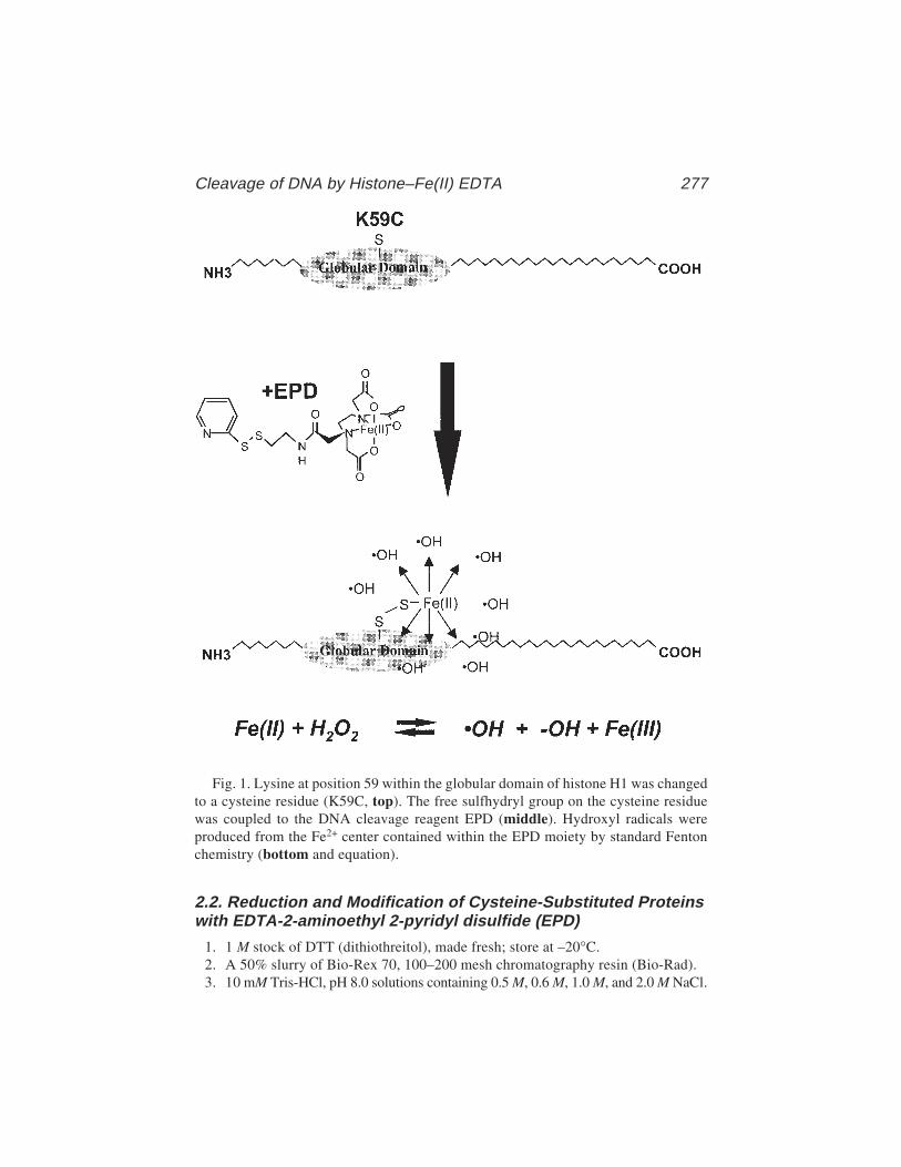
Cleavage of DNA by Histone–Fe(II) EDTA 277
2.2. Reduction and Modification of Cysteine-Substituted Proteinswith EDTA-2-aminoethyl 2-pyridyl disulfide (EPD)
1. 1 M stock of DTT (dithiothreitol), made fresh; store at –20°C.2. A 50% slurry of Bio-Rex 70, 100–200 mesh chromatography resin (Bio-Rad).3. 10 mM Tris-HCl, pH 8.0 solutions containing 0.5 M, 0.6 M, 1.0 M, and 2.0 M NaCl.
Fig. 1. Lysine at position 59 within the globular domain of histone H1 was changedto a cysteine residue (K59C, top). The free sulfhydryl group on the cysteine residuewas coupled to the DNA cleavage reagent EPD (middle). Hydroxyl radicals wereproduced from the Fe2+ center contained within the EPD moiety by standard Fentonchemistry (bottom and equation).
278 Chafin and Hayes
4. 0.3 M stock of EPD synthesized according to refs. 7 and 8. Alternatively,iodoacetamido-1,10 phenanthroline–Cu2+ can be employed in place of EPD(Molecular Probes, Eugene, OR).
5. Disposable 10 mL plastic chromatography columns (Bio-Rad).6. Coomassie blue stain: 45% methanol, 10% acetic acid, and 0.25% coomassie
brilliant blue R250.
2.3. Radioactive End-Labelingof a Purified DNA Restriction Fragment
1. Linear DNA fragment with convenient restriction sites on either end, previ-ously phosphatased.
2. 10X T4 polynucleotide kinase buffer (supplied with enzyme).3. [γ-32P]dATP, 6000 Ci/mmol.4. T4 polynucleotide kinase 10,000 units/mL (Promega).5. 2.5 M ammonium acetate.6. 95% Ethanol, –20°C.7. 70% Ethanol, –20°C.8. 10% SDS stock solution.9. Alkaline phosphatase from calf intestine (Boehringer Mannheim)
10. TE buffer: 10 mM Tris-HCl, pH 8.0, and 1 mM EDTA.
2.4. In Vitro Reconstitution of Nucleosomes
1. 10 mM Tris-HCl, pH 8.0, and 1 mM EDTA solutions containing 1.2 M, 1.0 M,0.8 M, and 0.6 M NaCl.
2. TE buffer.3. Stock of 6000–8000 molecular-weight cutoff dialysis tubing, 14 mm in diameter.4. Stock of sonicated calf thymus (CT) DNA, approx 1–2 mg/mL.5. Stock of 5 M NaCl.6. Source of purified core histone proteins H2A/H2B and H3/H4, ours were puri-
fied from chicken erythrocytes (see Note 7).
2.5. Maxim–Gilbert G-Specific Reaction
1. 10X G-specific reaction buffer: 0.5 M NaCacodylate and 10 mM EDTA.2. Dimethylsulfate (DMS) (Sigma).3. G-reaction stop buffer: 1.5 M Na acetate, 1 M β-mercaptoethanol and 0.004 µg/µL
sonicated calf thymus DNA.4. Piperidine (neat, 10 M stock) (Sigma).
2.6. Chemical Mapping of Protein–DNA Interactions with EPD
1. 0.7% agarose made with 0.5X TBE. (Note: Treat all solutions with chelex 100 resin[Bio-Rad] to remove adventitious redox-active metals.)
2. Histone dilution buffer: 10 mM Tris-HCl, pH 8.0, and 50 mM NaCl.3. Stock solution of 20 mM sodium ascorbate, store frozen at –20°C.4. Stock solution of 1 mM Fe(II) 2 mM EDTA; store frozen at –20°C.

Cleavage of DNA by Histone–Fe(II) EDTA 279
5. Solution of 0.15% H2O2, freshly made.6. Stop solution: 50% glycerol and 10 mM EDTA.7. Microcentrifuge filtration devices (Series 8000 can be obtained from Lida Manu-
facturing Corporation).8. 10 mM Tris-HCl, pH 8.0, and 0.1% SDS.9. Microcentrifuge pestles, can be obtained from Stratagene.
10. 95% and 70% ethanol solutions, cooled to –20°C.11. 3 M sodium acetate.
2.7. Sequencing Gel Analysis
1. Solid urea; molecular biology grade.2. 5X TBE.3. 40% Acrylamide (19:1 acrylamide:bis-acrylamide).4. 20% APS (ammonium persulfate).5. TEMED (N,N,N',N'-tetramethylethylenediamine).6. 1 mL formamide loading buffer: 100% formamide, 0.05% bromophenol blue,
0.05% xylene cyanol, and 1 mM EDTA.
3. Methods3.1. Overexpression and Purification of Single-Cysteine-Substituted Proteins
The following methods work well for incorporating a single amino acid sub-stitution into any protein of interest. Standard three or four primer PCR meth-ods are used.
1. Standard PCR methods are used to amplify a DNA fragment containing a cysteinecodon in place of the wild-type codon. If the codon to be changed is near the endof the amplified coding region, then only two primers are necessary with thechange incorporated into one of these “parent” primers. If more central to thesequence, then a 3 primer technique is used with the change incorporated into aninternal primer, amplify with the internal primer and one of the parent primersand then use the short amplified fragment as a primer with the remaining parentprimer and the original DNA as the template. Finally, if this method fails, twocomplementary internal primers with the intended change are used to amplifyoverlapping short fragments using the appropriate parent primers; these two frag-ments are then combined with the parent primers and the entire insert amplifiedwithout an additional template added.
2. Gel purify the DNA insert of interest. We typically use the electroelution tech-nique after separating the PCR DNA on a 1% agarose gel. A slice of agarosecontaining the insert of interest is placed into a dialysis membrane with enoughTBE to cover the agarose. Both ends of the dialysis membrane are clipped shutand placed into a standard DNA electrophoresis apparatus containing 1X TBEbuffer; the DNA electroeluted is for 15 min at 150 V. Remove the TBE bufferfrom the dialysis membrane containing the PCR DNA and precipitate.
280 Chafin and Hayes
3. Ligate the insert containing the single cysteine substitution into the appropriateexpression vector. We typically use the pET expression system (Novagen). BothDNAs must be digested with the same restriction endonucleases. Incubateequimolar amounts of insert DNA and pET3d DNA in 1X T4 ligation buffer.Add 400 U of T4 DNA ligase (Bio-Labs) and incubate at 4°C overnight (see Note 2).
4. Check the efficiency of the ligation by transforming a small amount of the liga-tion sample into DH5a cells. Place the transformation on LB–ampicillin platesand incubate at 37°C overnight.
5. Prepare DNA from several colonies by placing a single colony into 3–5 mL ofLB–ampicillin medium and grow at 37°C. Isolate the DNA from these culturesby standard DNA mini-prep techniques (see Note 3).
6. Digest part of the isolated plasmid with the original restriction endonucleasesused for ligation to liberate the DNA fragment corresponding to the originalinsert. The plasmids that contain correct inserts can be used to transform BL21cells for overexpression.
7. Transform the pET plasmid containing the insert into BL21 cells in the samemanner as for the DH5a cells (see step 4).
8. Place one BL21 colony from the LB–ampicillin plate into 200 mL of LB–ampi-cillin medium.
9. Grow the culture in the absence of IPTG at 37°C to an optical density of 0.6 at595-nm wavelength light. Add IPTG to a final concentration of 0.2 mg/mL andreturn the culture to 37°C for approx 2–4 h (see Note 4).
10. After 2–4 h, pellet the bacteria by centrifugation at 4000g for 15 min.11. Decant the supernatant and resuspend the pellet in 5–10 mL of TE buffer.12. Add 10 mg/mL lysozyme to a final concentration of 0.2 mg/mL. Then, add
Triton-X 100 to a final concentration of 0.2% and incubate for 30 min atroom temperature.
13. Dilute the bacteria twofold with 2 M NaCl to a final concentration of 1 M NaCl.Transfer the bacteria to Oakridge centrifuge tubes on ice.
14. Sonicate the bacterial slurry for 6 min total in two 3-min sonication steps (seeNote 5).
15. Pellet the cell debris by centrifugation at 10,000g for 30 min at 4°C.16. Add PMSF to a final concentration of 0.1 mM. Dilute the supernatants twofold
with TE buffer to bring the NaCl concentration to 0.5 M.17. Incubate the diluted supernatant with 12.5 mL of a 50% suspension of Bio-Rex
70-mesh beads for 4 h at 4°C with rotation. Linker histones and most other pro-teins will bind directly to the Bio-Rex 70 beads. However, core histone proteinsmust first be incubated with their dimerization partner proteins before they willbind to the chromatography matrix (i.e., H2A with H2B) (see Note 6).
18. After 4 h collect the beads in a plastic 10-mL disposable chromatography col-umn. Collect the flowthrough fraction in a 50-mL conical tube and freeze.
19. Wash the column with 2–3 column volumes of 10 mM Tris-HCl, pH 8.0 contain-ing 0.6 M NaCl. Collect the first 10 mL of the wash fraction in a 15-mL conicaltube and freeze.
Cleavage of DNA by Histone–Fe(II) EDTA 281
20. Elute the bound proteins with two separate 1-column volume elution steps of 10 mMTris-HCl, pH 8.0 containing 1.0 M NaCl. Collect the 1.0 M elution steps in sepa-rate 15 mL conical tubes and freeze.
21. After elution, wash the column with one column volume of 10 mM Tris-HCl,pH 8.0 containing 2.0 M NaCl. Collect the 2.0 M elution step in a 15-mL conicaltube and freeze.
22. Check 10 µL of each fraction for protein by loading a small amount on a 12% or18% SDS–polyacrylamide gel.
3.2. Reduction and Modification of Cysteine-Substituted Proteins
3.2.1. Reduction of Cysteine-Substituted Proteins
1. Incubate protein of interest in a 15-mL conical tube with 50 mM DTT final con-centration for 1 h on ice.
2. Dilute the protein sample twofold with TE; this dilutes the NaCl concentration to500 mM NaCl.
3. Add 0.8 mL of a 50% slurry of Bio-Rex 70 chromatography resin and incubatefor 2 h at 4°C with rotation. We have found that Bio-Rex 70 can bind approx 0.5 mgprotein/g resin.
4. Pour slurry into a 10-mL plastic, disposable chromatography column and collectthe flowthrough fraction. Disposable chromatography columns are commerciallyavailable from Bio-Rad or other manufacturers.
5. Wash the column with 3–5 column volumes of buffer containing 10 mM Tris-HCl,pH 8.0, and 0.5 M NaCl. Immediately remove 20 µL of the freshly eluted washsample into a separate Eppendorf tube for analysis later on a 12% SDS–polyacryla-mide gel and immediately freeze the larger sample in case the protein did not bindthe resin. Aliquoting the sample in this manner ensures that the sample does notneed to be thawed for analysis.
6. An intermediate wash of the column with buffer containing 0.6 M NaCl is per-formed to remove proteins that are less well-bound because of partial degrada-tion. Aliquots of these samples are obtained in the same manner as the previouswash step.
7. Linker histone protein can be eluted with 1-column volume steps of the samebuffer except with 1.0 M NaCl. Typically, five separate 1-column volume 1.0 MNaCl elution steps are performed and collected separately. Usually, only 5 µL ofthe elution steps needs be aliquoted for SDS–polyacrylamide gel analysis. Asabove, the large elution fractions are frozen immediately. A final elution withbuffer containing 2.0 M NaCl buffer will ensure that all of the protein has beeneluted from the column.
8. Check the protein content of each aliquot obtained from the wash and elutionsteps on a 12% SDS–polyacrylamide gel. After separation, incubate the proteingel in enough Coomassie blue stain to cover the protein gel. Stain for approx 1 hat room temperature and destain with 45% methanol and 10% acetic acid untilthe background of the gel is clear.
282 Chafin and Hayes
3.2.2. Modification of Cysteine Substituted Proteins with EPD
1. Thaw the fraction containing the reduced protein to be modified with EPD on ice.Working as quickly as possible, add a 1.1 fold molar excess of EPD to 60 µL(approx 30 µg) of reduced protein. Incubate for 1 h at room temperature inthe dark.
2. Removal of excess cleavage reagent requires one more round of Bio-Rex 70 chro-matography, identical to that in step 3 of Subheading 3.2.1. except that 60 µL ofthe 50% slurry is added to the protein. In addition, the slurry is poured into acolumn made from a blue 1-mL pipet tip fitted with glass wool at the opening.Wash and elute as in step 5 of Subheading 3.2.1. except all elution volumes arescaled according to the resin amount. Aliquots for protein analysis are exactly thesame size as previously indicated.
3. Postmodification labeling with 14C-NEM (N-[ethyl–1–14C]-maleimide) (NewEngland Nuclear) can be used to quantitatively determine the extent of modifica-tion with the DNA cleavage reagent. Add 0.25–0.5 µCi of 14C-NEM to eachprotein aliquot made from the elution fractions of the Bio-Rex column. After10 min, add 2 volumes of 2X protein loading buffer and separate the proteinson a 12% SDS-polyacrylamide gel. Stain and destain the gel as in step 8 ofSubheading 3.2.1. and dry the gel onto a piece of Whatman filter paper. Visual-ize the labeled proteins by exposing the dried gel to ultra sensitive Bio-Max auto-radiography film.
4. A protein gel at this step performs two functions. (1) It determines which frac-tions contain the protein of interest and (2) it determine the extent of modifica-tion with the DNA cleavage reagent.
3.3. Radioactive End-Labelingof a Purified DNA Restriction Fragment
1. Treat approx 5 µg of plasmid DNA or 1 µg of a purified DNA fragment with theappropriate restriction endonuclease in the manufacturer’s buffer.
2. Precipitate the DNA by adjusting the solution to 0.3 M sodium acetate and add-ing of 2.5 vol of cold ethanol.
3. Resuspend the DNA in phosphatase buffer and treat with alkaline phosphatasefor 1 h at 37°C.
4. Adjust the solution to 0.1% SDS, phenol extract the solution, and then precipitatethe aqueous phase twice with ethanol and sodium acetate.
5. Resuspend the DNA in 10 µL TE and add 2.5 µL of 10X T4 polynucleotidekinase buffer.
6. Add 50 µCi of [γ-32P]dATP and adjust the volume to 24 µL with water.7. Start the reaction by adding 10 units of T4 polynucleotide kinase and incubate for
30 min at 37°C.8. Stop the kinase with 200 µL of 2.5 M ammonium acetate (NH4Oac) and 700 µL
of cold 95% ethanol.9. Pellet the DNA in a microcentrifuge for 30 min at room temperature.

Cleavage of DNA by Histone–Fe(II) EDTA 283
10. Wash the DNA pellet briefly with cold 70% ethanol and dry the DNA in aSpeedvac concentrator.
11. Dissolve the DNA in 34 µL of TE buffer.12. Digest the DNA fragment with a second restriction endonuclease that liberates
the fragment of interest and yields fragments that can be easily separated on anative 6% polyacrylamide gel.
13. After separation, wrap the gel tightly in plastic wrap and apply fluorescent mark-ers onto various portions of the gel for alignment purposes (can be obtained fromStratagene) or accurately mark the position of the gel on the film. Expose the wetgel to the autoradiography film for 1 min, which is sufficient to detect the spe-cific band containing the labeled fragment.
14. Excise the band of interest from the polyacrylamide gel and place into a cleanEppendorf tube. Crush the acrylamide gel slice with a Eppendorf pestle andadd 700 µL of TE buffer. The labeled fragment will elute overnight with pas-sive diffusion.
15. Split the sample equally into two Series 8000 Microcentrifuge Filtration Devicesand spin for 30 min in a microcentrifuge.
16. Precipitate the eluted DNA and dissolve in TE buffer pH 8.0. Add enough TEbuffer so that the labeled DNA is approx 1000 cpm/µL (see Note 7).
3.4. Reconstitution of Nucleosomes by Salt Step Dialysis
The method described here for the reconstitution of nucleosomes allows forlarge quantities of nearly homogeneous core particles in 12 h (13). Moreover,reconstituted nucleosomes are known to bind linker histone in a physiologi-cally relevant manner according to multiple criteria. Virtually any piece ofDNA 147 bp or longer can be used. However to obtain nucleosomes with onlyone translational position, the DNA sequence should contain nucleosome posi-tioning sequences such as that from the Xenopus borealis somatic 5S rRNAgene (14–16). The DNA can be labeled on the 5' or 3' end with commerciallyavailable enzymes after phosphatase treatment as described above.
1. Add approx 5–8 µg of unlabeled calf thymus DNA, 200,000–400,000 cpm ofsingly labeled Xenopus borealis 5S ribosomal DNA, purified chicken erythro-cyte core histone protein fractions (H2A/H2B and H3/H4) (see Note 1), 160 µLof 5 M NaCl (2.0 M final), and TE buffer to a final of volume 400 µL.
2. Place the reconstitution mixture into a 6 to 8 kDa molecular weight cut-off dialy-sis bag. All subsequent dialysis steps are for 2 h at 4°C against 1 L of dialysisbuffers unless specified. The first dialysis buffer is 10 mM Tris-HCl, pH 8.0, 1.2 MNaCl and 1 mM EDTA. Subsequent dialyses steps are with fresh buffer contain-ing 1.0 M, 0.8 M, and then 0.6 M NaCl. The procedure is completed with a finaldialysis against TE buffer overnight. Nucleosomes at this stage can be used forgel-shift experiments where EDTA does not interfere.
3. For DNA cleavage experiments with EPD, two additional dialysis steps arerequired. First dialyze the reconstitutes against 10 mM Tris-HCl, pH 8.0 several
284 Chafin and Hayes
hours to remove the EDTA. A second dialysis against fresh 10 mM Tris-HCl,pH 8.0 removes trace amounts of EDTA and prepares the samples for chemicalmapping with EPD.
3.5. Maxim–Gilbert G-Specific Reaction
The G-specific reaction used in the Maxim–Gilbert sequencing method pro-vides an easy and quick method to identify the exact location of bases withinany known sequence on sequencing gels. It is used here to determine the sitesof DNA to base-pair resolution. Because this method is not generally used anylonger, the steps are outlined as follows:
1. Add approx 20,000 cpm of singly labeled DNA (same DNA used to reconsti-tute nucleosomes).
2. Add 20 µL of 10X G-specific reaction buffer.3. Add water to a final volume of 200 µL.4. Start by adding 1 µL of straight dimethylsulfate (DMS) to the tube. Mix immedi-
ately and spin briefly in a microfuge (do this in a hood; be careful not to get anyDMS on your skin or on standard laboratory gloves. Store DMS in a tightlycapped brown glass bottle at 4°C).
5. Add 50 µL of G-reaction stop solution and mix immediately.6. Add 2.5 vol of –20°C 95% ethanol to precipitate the DNA.7. Wash the DNA with –20°C ethanol; dry and dissolve the DNA in 90 µL of H2O.8. Add 10 µL of piperidine and incubate at 90°C for 30 min.9. Dry the DNA solution in a Speedvac to completion.
10. Dissolve the DNA in 20 µL of water and repeat the drying step. Repeat this stepone more time.
11. Dissolve DNA in 100 µL TE buffer and store at 4°C.
3.6. Site-Directed Hydroxyl Radical Cleavage of DNA
3.6.1. Binding Single-Cysteine-Substituted Linker Histone Proteinsto Reconstituted Nucleosomes
1. The exact amount of each mutant linker histone protein needed to stoichiometri-cally bind the nucleosome needs to be determined empirically. Increasingamounts of the linker histone are titrated to a fixed volume of reconstitutednucleosomes (typically 5000 cpm) and analyzed via a gel-shift procedure (17).This is typically scaled up 10-fold for the site-specific cleavage reaction.
2. Add 5% glycerol final to the binding reaction (analytical scale only, site-specificcleavage reactions contain 10-fold less glycerol).
3. Add 50 mM NaCl final to the binding reaction (see Note 8).4. Incubate the binding reactions for 15 min at room temperature.5. Separate the complexes on a 0.7% agarose and 0.5X TBE gel. After drying the
gel, expose to autoradiograpic film and determine the amount of protein neces-sary for good complex formation.
Cleavage of DNA by Histone–Fe(II) EDTA 285
6. Several assays for the correct binding of linker histones to DNA have been per-formed (17,18). One of the easiest involves a brief digestion with micrococcalnuclease in the chromatosome stop assay (13).
3.6.2. Site-Directed Hydroxyl Radical Mappingof Linker Histone-DNA Interaction
1. Scale up the binding reaction to include 40,000–50,000 cpm of labeled reconsti-tuted nucleosomes and add enough modified mutant linker histone to formH1–nucleosome complexes.
2. Add glycerol to 0.5% final concentration (see Note 9).3. Add sodium ascorbate to a final concentration of 1 mM.4. Add H2O2 to a final concentration of 0.0075%.5. Incubate for 30 min at room temperature in the dark.6. After 30 min, add 1/10 vol of 50% glycerol and 10 mM EDTA solution.7. Load samples immediately onto a running (90 V) preparative 0.7% agarose and
0.5X TBE gel.8. Separate the samples so that the H1–nucleosome complexes are well resolved
from tetramer and free DNA bands.9. Next, wrap the gel tightly with plastic wrap so that the gel cannot move within
the plastic. Lay fluorescent markers onto various portions of the gel for align-ment purposes (can be obtained from Stratagene) or accurately mark the positionof the gel on the film.
10. Expose the wet gel for several hours at 4°C.11. Next, develop the autoradiograph and overlay onto the wet gel, lining up the
fluorescent markers.12. Cut and remove the agarose containing the H1–nucleosome complexes or bands
of interest and place them into Series 8000 Microcentrifuge Filtration Devices.13. Freeze the filtration tubes containing the agarose plugs on dry ice for 15 min.14. Spin down the agarose in a microcentrifuge at maximum speed for 30 min at
room temperature. The fluid from the agarose matrix will be collected in the2-mL centrifuge tube surrounding the filtration device.
15. Gently remove the agarose plug from the bottom of the filtration device and placeinto a clean Eppendorf tube. Save the centrifugation devices for use later.
16. Using a microcentrifuge pestle, crush the agarose pellet and add 500 µL of 10 mMTris-HCl, pH 8.0, and 0.1% SDS and continue to crush the agarose.
17. After the agarose is crushed into tiny pieces, place all samples at 4°Covernight.
18. Place the crushed agarose into the same centrifugation device and pellet.Spin down the agarose in a microcentrifuge at maximum speed for 30 min atroom temperature.
19. Combine identical samples from both spins and precipitate the DNA.20. Dissolve the DNA in 15 µL of TE buffer.21. Heat the samples to 90°C for 2 min to denature.
286 Chafin and Hayes
3.7. Sequencing Gel Analysis of H1°C-EPD Cleavage
3.7.1. Sequencing Gel Electrophoresis
1. Add equal numbers of counts from each sample, including the G specific reac-tion, to clean eppendorf tubes.
2. Place the samples into a Speedvac concentrator and dry to completeness.3. Dissolve the samples in 4 µL of formamide loading buffer.4. Place samples directly onto ice to prevent renaturation.5. Separate samples on a 6% polyacrylamide and 8 M urea sequencing gel running
at constant 2000 V.
3.7.2 Example of Site-Directed Cleavageof Nucleosomal DNA by EPD
An example of a linker histone site-directed DNA cleavage reaction is pre-sented in Fig. 2. A schematic of the 5S mononucleosome is shown in the leftpanel. The thick black line represents the 5S ribosomal DNA fragment thatcontains the transcriptional coding sequence for this gene (gray arrow). The 5Sribosomal gene fragment was used because it contains a nucleosomal position-ing sequence that precisely wraps the DNA around the core histones and pro-vides a homogeneous population of nucleosomes. Furthermore, because onemajor translational position predominates within this population of nucleo-somes, the precise orientation of the DNA as it wraps around the core histonesis known. This enables us to determine to base-pair resolution, the sites ofcleavage by EPD with respect to the nucleosome structure. A singly end-labeled 5S DNA fragment was incorporated into nucleosomes via the saltdialysis procedure detailed earlier. Labeled mononucleosomes were bound byan EPD-modified linker histone containing a single cysteine substitution forthe lysine residue at position 59, referred to as K59C-EPD. After allowinghydroxyl radical cleavage for 30 min, the protein–DNA complexes were sepa-rated on a 0.7% agarose gel (Fig. 2A) and the labeled DNA fragments corre-sponding to the H1–nucleosome complexes were purified. These purifiedDNAs were then analyzed on a 6% sequencing gel (Fig. 2B, right panel).
Fig. 2 (opposite page). (A) Various DNAs from control or hydroxyl radical cleav-age reactions were separated on a 0.7% agarose gel. The wet gel was exposed to auto-radiographic film for 3–4 h according to Subheading 3.6.2. Lanes 1 and 2 contain freeDNA (FD) and bulk nucleosomes (Nuc.), respectively, not exposed to hydroxylradical cleavage. Lanes 3–5 contain nucleosomes or H1–nucleosome complexes(H1–Nuc.) subjected to hydroxyl radical cleavage. Nucleosomes–K59C (lane 3),nucleosomes with unmodified K59C (lane 4) or nucleosomes with K59C–EPD (lane 5).(B) A linear schematic of the 5S nucleosome is shown (left). The DNA (black line)

Cleavage of DNA by Histone–Fe(II) EDTA 287
was restricted with the restriction enzymes shown and radiolabeled (*) at the XbaI site.The position of the 5S nucleosome (white oval) is shown with respect to the start siteof transcription (gray arrow) and with respect to the size of DNAs in the sequencinggel (larger white oval). Labeled DNAs from hydroxyl radical cleavage reactions wereanalyzed on a 6% sequencing gel (right). Lane 1: Maxim–Gilbert G-specific reaction;lane 2: hydroxyl radical cleavage in the absence of histone H1; lanes 3 and 4: hydroxylradical cleavage with K59C (lane 3) or K59C–EPD (lane 4). Specific cleavages areshown to the right of the gel (black arrows).

288 Chafin and Hayes
The gel reveals that the reconstituted mononucleosomes used for thisexperiment give a characteristic 10-bp protection when footprinted by generalcleavage with hydroxyl radical in the absence of linker histone (15). This indi-cates that the 5S DNA has been properly assembled with the histone octamerinto a nucleosome (Fig. 2B, lane 2). The linker histone-directed cleavageexperiments are shown in lanes 3 and 4. No cleavages are observed when thereaction is carried out in the presence of unmodified K59C (Fig. 2B, lane 3). Incontrast, when the cleavage reagents are added in the presence of K59C-EPDbound nucleosomes, two sets of cleavages are evident (Fig. 2B, lane 4). Thecleavages at +62, +72, and +82 correspond to the end of the nucleosome wherethe DNA exits. This result is consistent with previous data suggesting thatthe linker histone binds the nucleosome at the periphery, tucked inside a super-helical gyre of DNA (12,19). A second set of cleavages occurs at –29 and –39.These cleavages occur on the DNA strand directly underneath that of the +62/+72/+82 cleavages as the DNA makes one full superhelical turn around thehistone octamer. It is possible that amino acid 59 makes close contacts withboth strands of the DNA, consistent with the strong cleavages seen at each site.It is also possible that hydroxyl radicals have diffused away from the –29/–39-cleavage site and cleave the DNA in other areas. Inconsistent with this, glyc-erol, a very good hydroxyl radical scavenger, does not seem to have an effecton the cleavages obtained with K59C-EPD at concentrations known to elimi-nate hydroxyl radical cleavage (Chafin and Hayes, unpublished results).
4. Notes1. A complication of the in vitro reconstitution procedure is that purified histone
proteins are often obtained in two fractions, H2A/H2B and H3/H4 (22). Thus, inaddition to total histone mass, the ratio between these two substituents must beempirically adjusted to yield maximum octamer–DNA complexes (13).
2. Many ligation procedures are available from primary literature or commercialsources. Ligation of two DNA fragments occurs more rapidly at room tempera-ture or 37°C if the base-pair overlap is sufficiently stable.
3. Many DNA mini-prep procedures are described in detail in ref. (20). The DNA isolatedfor the techniques described here were from the boiling DNA mini-prep procedure (20).
4. Before proceeding, it is recommended that a small amount of the culture bechecked for overexpression of the protein of interest. This can be done by remov-ing 1 mL of the culture before and after induction by IPTG.
5. Sonication techniques tend to increase the temperature of the sample quickly,which could induce proteolysis of the proteins. The sample must therefore becooled before and during sonication. Allow several min between sonication runsto keep the sample as cold as possible.
6. Histones H2A or H2B do not bind to Bio-Rex 70 when purified individually.However, we have found that when allowed to heterodimerize, they bind to the

Cleavage of DNA by Histone–Fe(II) EDTA 289
column and elute off consistently in 1 M NaCl (13). This characteristic could bethe result of the fact that histone H2A and H2B are completely unfolded whenseparated from each other (21).
7. Storing labeled DNA in a concentrated form is not advised, as autodegradation of theDNA takes place. DNA can be stored for several weeks at approx 5000 cpm/µL.
8. Several methods can be used for the incorporation of linker histones into recon-stituted mononucleosomes. The method described here involves direct additionof linker histones to mononucleosis in 50 mM NaCl. Linker histones are folded inlow-salt solutions in the presence of DNA (23). Indeed, we find that linker his-tones can be directly mixed to nucleosomes in either 5- or 50-mM NaCl solutionsand these proteins then bind in a physiologically relevant manner (17).
9. Glycerol is a good scavenger for hydroxyl radicals and will generally inhibithydroxyl-radical-based cleavage if added at a final concentration over 0.5% andtherefore should be avoided. However, adding small concentrations of glycerolwill allow hydroxyl radical cleavage to occur if the EPD moiety is in close prox-imity to the DNA backbone but not cleavage from sites farther away.
References1. Wolffe, A. P. (1995) Chromatin: Structure and Function. Academic, London.2. van Holde K. E. (1989) Chromatin. Springer-Verlag, New York.3. Thoma, F., Koller, T., and Klug, A. (1979) Involvement of histone H1 in the
organization of the nucleosome and the salt-dependent superstructures of chro-matin. J. Cell Biol. 83, 403–427.
4. Carruthers, L. M., Bednar, J., Woodcock, C. F. L., and Hansen, J. C. (1998)Linker histones stabilize the intrinsic salt-dependent folding of nucleosomalarrays: mechanistic ramifications for higher-order folding. Biochemistry 37,14,776–14,787.
5. Crane-Robinson, C. (1997) Where is the globular domain of linker histone locatedon the nucleosome? Trends Biochem. Sci. 22, 75–77.
6. Zhou, Y.-B., Gerchman, S. E., Ramakrishnan, V., Travers, Andrew, andMuyldermans, S. (1998) Position and orientation of the globular domain of linkerhistone H5 on the nucleosome. Nature 395, 402–405.
7. Ebright, Y. W., Chen, Y., Pendergrast, P. S., and Ebright, R. H. (1992)Incorportation of an EDTA–metal complex at a rationally selected site within aprotein: application to EDTA–iron DNA affinity cleaving with catabolite geneactivator protein (CAP) and Cro. Biochemistry 31, 10,664–10,670.
8. Ermacora, M. R., Delfino, J. M., Cuenoud, B., Schepartz, A., and Fox, R. O.(1992) Conformation-dependent cleavage of staphlyococcal nuclease with a dis-ulfide-linked iron chelate. Proc. Natl. Acad. Sci. USA 89, 6383–6387.
9. Neelin, J. M., Neelin, E. M., Lindsay, D. W., Palyga, J., Nichols, C. R., and Cheng,K. M. (1995) The occurrence of a mutant dimerizable histone H5 in Japanesequail erythrocytes. Genome 38, 982–990.
10. Chen, Y. and Ebright, R. H. (1993) Phenyl-azide-mediated photocrosslinkinganalysis of Cro–DNA interaction. J. Mol. Biol. 230, 453–460.
290 Chafin and Hayes
11. Lee, K.-M. and Hayes, J. J. (1997) The N-terminal Tail of Histone H2A Binds toTwo Distinct Sites Within the Nucleosome Core. Proc. Natl. Acad. Sci. USA 94,8959–8964.
12. Hayes, J. J. (1996) Site-directed cleavage of DNA by a linker histone–Fe(II)EDTAconjugate: localization of a globular domain binding site within a nucleosome.Biochemistry 35, 11,931–11,937.
13. Hayes, J. J. and Lee, K.-M. (1997) In vitro reconstitution and analysis ofmononucleosomes containing defined DNAs and proteins. Methods 12, 2–9.
14. Rhodes, D. (1985) Structural analysis of a triple complex between the histoneoctamer, a Xenopus gene for 5S RNA and transcription factor IIIA. EMBO J.4(13A), 3473–3482.
15. Hayes, J. J., Tullius, T. D., and Wolffe, A. P. (1990) The structure of DNA in anucleosome. Proc. Natl. Acad. Sci. USA 87, 7405–7409.
16. Simpson, R. T. (1991) Nucleosome positioning: occurrence, mechanisms andfunctional consequences. Prog. Nucleic Acids Res. Mol. Biol. 40, 143–184.
17. Hayes, J. J. and Wolffe, A. P. (1993) Preferential and asymmetric interaction oflinker histones with 5S DNA in the nucleosome. Proc. Natl. Acad. Sci. USA 90,6415–6419.
18. Allan, J., Hartman, P. G., Crane-Robinson, C., and Aviles, F. X. (1980) The struc-ture of histone H1 and its location in chromatin. Nature 288, 675–679.
19. Pruss, D., Bartholomew, B., Persinger, J., Hayes, J. J., Arents, G., Moudrianakis,E. N., et al. (1996) A new model for the nucleosome: a binding site for linkerhistone inside the DNA gyre. Science 274, 614–617.
20. Sambrook, J., Fritsch, E. F., and Maniatis, T. (1989) Molecular Cloning: ALaboratory Manual, 2nd ed., Cold Spring Harbor Laboratory, Cold Spring Har-bor, NY.
21. Karantza, V., Baxevanis, A. D., Freire, E., and Moudrianakis, E. N. (1995) Ther-modynamic studies of the core histones: Ionic strength and pH dependence ofH2A–H2B dimer stability. Biochemistry 34, 5988–5996.
22. Simon, R. H. and Felsenfeld, G. (1979) A new procedure for purifing histonepairs H2A + H2B and H3 + H4 from chromatin using hydroxyapatite. NucleicAcids Res. 6, 689–696.
23. Clark, D. J. and Thomas, J. O. (1986) Salt-dependent co-operative interaction ofhistone H1 with linear DNA. J. Mol. Biol. 187, 569–580.
Nitration of Tyrosine Residues 291
291
From: Methods in Molecular Biology, vol. 148: DNA–Protein Interactions: Principles and Protocols, 2nd ed.Edited by: T. Moss © Humana Press Inc., Totowa, NJ
20
Nitration of Tyrosine Residuesin Protein–Nucleic Acid Complexes
Simon E. Plyte
1. IntroductionChemical modification is a powerful tool for investigating the accessibility
and function of specific amino acids within folded proteins. It has providedsignificant information regarding the role of different amino acids at the bind-ing sites of numerous enzymes and DNA-binding proteins. The identificationof such residues by chemical modification has then often be used to plan sub-sequent site-directed mutagenesis experiments. These data complement thosefrom crystallographic and nuclear magnetic resonance (NMR) studies in deter-mining the residues located at the active site; thus, one needs to consider allthese techniques when elucidating protein structure and function. For example,chemical modification of leukotriene A4 hydrolase, 3-hydroxyisobutyratedehydrogenase, and lactate dehydrogenase (1–3) have contributed significantlyto the understanding of active-site mechanisms in these proteins and inelucidating the mechanisms of DNA binding in the Fd and Pf1 gene 5 pro-teins (4–5).
Reagents exist to modify cysteine, methionine, histidine, lysine, arginine,tyrosine and carboxyl groups selectively. However, in this chapter, we are onlyconcerned with the selective modification of tyrosine residues (for reagentsand conditions for the modification of the other amino acids, see ref. 6). Theside chain of tyrosine can react with several compounds, the most commonlyused being N-acetylimidizole and tetranitromethane (TNM). N-acetylimidizolewill O-acetylate tyrosine residues in solution (7), and this reagent has beenused to modify numerous proteins including the Fd gene 5 protein (4). How-ever, this reagent can also N-acetylate primary amines, and in the study on theFd gene 5 protein (4) in addition to acetylation of three tyrosine residues, all
292 Plyte
five lysine residues were found to be modified. Tetranitromethane is a reagenthighly specific for tyrosine residues and reacts under mild conditions to formthe substitution product 3-nitrotyrosine (8). The modified tyrosine has a char-acteristic adsorption maximum at 428 nm, and this can be used to quantitatethe number of tyrosine residues modified (8). However, under harsher condi-tions, there have been some reports of modification of sulfhydryl groups andlimited cases of reaction with histidine and tryptophan (9).
1.1. Strategies
1.1.1. Tyrosine Accessibility
The general strategy employed in chemical modification experiments is todetermine the accessibility of the target residues within the native protein andthe extent of protection offered by the bound substrate. Peptide mapping of thelabeled protein then allows the roles of the individual residues to be assessed.First, the free protein is nitrated and then digested into fragments by proteoly-sis. These peptides are then separated to enable identification of the modifiedresidue(s). The nucleoprotein complex is also nitrated and the modified resi-dues identified in a similar way. From a comparison of these data, the extent ofprotection at each site can be established.
For peptide mapping, a protease should be chosen that, on digestion of thetarget protein, will place each tyrosine in a separate peptide. However, this isnot essential if the modified residues are identified by N-terminal sequencing.It is possible that tyrosine modification may affect the efficiency of α-chymot-rypsin digestion and this enzyme should be avoided if possible. The peptidescan be separated by reverse-phase high-performance liquid chromatography(HPLC), and those containing tyrosine purified for further analysis. Thetyrosine-containing peptide can be easily identified directly after HPLC purifi-cation by the characteristic fluorescence emission maximum of 3-nitrotyrosineat 305 nm (when excited at 278 nm). A particular tyrosine residue can then beidentified by N-terminal sequence analysis.
The identification of nitrated tyrosine residues in the free protein providesinformation concerning the solvent accessibility of these residues in the pro-tein and indicates which residues are likely to be buried within the protein.DNA protection studies will indicate which of these residues may be involvedin protein–DNA interactions. However, the protection from nitration by boundDNA is only an indication of a functional role for a particular residue. Thebound DNA may confer protection to a residue several angstroms away or mayinduce protein oligomerization (cooperative binding) which protects thetyrosine by protein–protein interactions. Consequently, functional studies needto be performed to further determine the role of the protected residue(s). The
Nitration of Tyrosine Residues 293
situation is analogous to the two types of analysis frequently used in theinvestigation of the DNA bases involved in complexes: “footprinting” and“interference” techniques. The data obtained from chemical modification andprotection studies can then be used to design site-directed mutagenesis experi-ments to look at the function of an individual residue by observing the effectsof its replacement with other amino acids.
1.1.2. Functional Studies
A protocol for functional studies will not be described in this chapter, butsome general considerations will be mentioned here. One should nitrate thefree protein and determine whether the modified protein still binds to DNA.This information should indicate whether the residues protected in the nucle-oprotein complex are implicated in DNA binding. However, with proteins thatbind cooperatively to DNA, a reduction in DNA-binding affinity may resultfrom a disruption of protein–protein interactions rather than from protein–DNAinteractions. A possible way to resolve this ambiguity is to bind the native andmodified proteins to short oligonucleotides where the cooperativity factor isnegligible. Modification of residues involved in protein–protein interactionsshould not significantly affect the intrinsic binding of the modified protein toDNA, when compared to the native protein.
Tyrosine residues can interact with DNA either by hydrophobic interactionsvia stacking with DNA bases or by hydrogen-bonding with the nucleotidethrough the phenolic OH group (10). Nitrotyrosine has a pKa of 8.0, which maydisrupt H-bonding as well as base stacking interactions. However, the additionof sodium dithionate reduces 3-nitrotyrosine to 3-amino tyrosine (which has apKa similar to that of native tyrosine) and may restore H-bonding interactions(11). Reduction with this reagent may provide further information concerningthe nature of the tyrosine–nucleic acid interaction.
1.1.3. Rates of Modification
Nitration of a protein will initially report on the accessibility of specifictyrosine residues in the presence and absence of DNA. However, if the modi-fied tyrosine residues can be analyzed individually, one can look at the nitra-tion rates of the tyrosines and determine the degree of accessibility of eachresidue. This is achieved by removing aliquots of protein (at various time inter-vals) from a nitration experiment and determining the percentage nitration ofeach tyrosine for a given time-point. This can be done by quantitating thenitrated and unnitrated products after digestion, either by measuring the peakareas (recorded at 214 nm), taken directly from the HPLC profile (5), or byamino acid analysis of the purified peptides.
294 Plyte
2. ReagentsAll chemicals should be of AnalaR grade or higher and dissolved in double-
distilled water. For HPLC analysis, trifluoroacetic acid (TFA), water andacetonitrile should be of HPLC grade. Buffers for HPLC should be filtered(0.2 µm) and degassed before use.
1. Tetranitromethane (TNM) stock solution: a 300 mM stock solution of TNM inethanol. Store in the dark at 4°C. Note that TNM can cause irritation to the skinand lungs, and the solution should be made up in the fume hood. Additionally,TNM can be explosive in the presence of organic solvents such as toluene.
2. Nitration buffer: 150 mM NaCl and 10 mM Tris, pH 8.0.3. Desalting column: Disposable “10DG” Econo columns (Bio-Rad, Richmond,
CA) are preferred.4. µBondapak C18 HPLC column (Waters Associates, Milford, MA) or a similar
reverse-phase column.5. Trypsin (TPCK treated).6. Standard sodium dodecyl sulfate–polyacrylamide gel electrophoresis (SDS-
PAGE) equipment with DC power supply capable of 150 V.7. SDS–polyacrylamide gel stock solutions:
Solution A: 152 g acrylamide and 4 g bis-acrylamide. Make up to 500 mL.Solution B: 2 g SDS and 30 g Tris base, pH 8.8. Make up to 500 mL.Solution C: 2 g SDS and 30 g Tris base, pH 6.8. Make up to 500 mL.
When making up these solutions, they should all be degassed and filtered using aBuchner filter funnel. They should be stored in lightproof bottles; they will keepfor many months.
8. 10% ammonium persulfate (APS): dissolve 0.1 mg in 1 mL of dH2O.9. 15% SDS–polyacrylamide gel: Mix together 8.0 mL of solution A, 4.0 mL of
solution B, and 3.9 mL of dH2O. Add 150 µL of 10% APS and 20 µL ofN,N,N',N'-tetramethylethylene diamine (TEMED). Mix well and then pourbetween the plates. Immediately place a layer of dH2O (or butanol) on top ofthe gel to create a smooth interface with the stacking gel. When the resolvinggel has set, pour off the water and prepare the stacking gel. This is done byadding 750 mL of solution A and 1.25 mL of solution C to 3.0 mL of dH2O.Finally, add 40 µL of APS and 10 µL of TEMED, pour on the stacking gel andinsert the comb. To avoid the gel sticking to the comb, remove the comb assoon as the gel has set.
10. 10X SDS running buffer: 10 g SDS, 33.4 g Tris base, and 144 g glycine made upto 1 L.
11. High methanol protein stain: Technical-grade methanol 500 mL, 100 mL glacialacetic acid and 0.3 g PAGE 83 stain (Coomassie blue), made up to 1 L.
12. Destain solution: 100 mL methanol and 100 mL glacial acetic acid, made upto 1 L.
13. 2X SDS-PAGE loading buffer: 4% (w/v) SDS, 60 mM Tris-HCl, pH 6.8, 20%glycerol, 0.04% (w/v) bromophenol blue, and 1% (v/v) β-mercaptoethanol.

Nitration of Tyrosine Residues 295
3. MethodsThe method is a fairly general one for protein-nucleic acid complexes. How-
ever, precise details of conditions for nucleoprotein complex dissociation andpeptide mapping will vary with the system under investigation. As an exampleof the technique, nitration of the Pf1 gene 5 protein and nucleoprotein complexwill be described (5).
3.1. Nitration
1. Desalt the protein or nucleoprotein complex into nitration buffer to a concentra-tion between 0.5 and 5 mg/mL (see Note 1). For initial determination of nitratedresidues, 0.5 mg of protein should be sufficient. However, if a time-courseexperiment is performed, larger amounts of protein are required.
2. To 1 mL of sample, add a 10-fold molar excess of 300 mM TNM (in ethanol) andincubate at room temperature for 1 h, stirring gently (see Note 2). The reactionis stopped by the addition of acid (add HCl to pH 2.0) or by rapid desalting into10 mM Tris–HCl pH 8.0 (see Note 3).
3. Run an aliquot of the modified protein–nucleoprotein complex on an SDS gel,together with native protein, to determine whether there has been any TNM-induced crosslinking (see Note 4). If analyzing the free protein proceed to step 5;if modifying the nucleoprotein complex, proceed to step 4.
4. Dissociate the nucleoprotein complex by the addition of salt (see Note 5). LargeDNA fragments can be removed by ultracentrifugation, whereas smaller frag-ments can be either digested with nucleases or removed by gel filtration. Theprotein is then dialyzed or desalted into the appropriate protease digestion buffer.
5. Digest the protein to completion with the desired protease(s) and then lyophilizethe peptides for separation by HPLC. The peptides may be stored at –20°C.
In the example provided, the Pf1 gene 5 protein and nucleoprotein complexwere incubated at room temperature in the presence of a 64 M excess of TNM(300 mM in ethanol) for 3 h. The reaction was stopped by desalting the protein(and nucleoprotein complex) into 10 mM Tris-HCl, pH 8.0. The nucleoproteincomplex was dissociated by the addition of MgCl2 to 1 M and the phagegenomic DNA was then removed by ultracentrifugation at 221,000g (in aBeckman L8 ultracentrifuge; 70.1 Ti rotor) for 2.5 h. The protein was desaltedinto 10 mM Tris-HCl, pH 8.0 for proteolysis and digestion with trypsin (Sigma[St. Louis, MO], TCPK treated) at an enzyme substrate ratio of 1:25 (w/w) for3 h at 37°C. Phenylmethane sulfonyl fluoride was added to a final concentra-tion of 1 mM and the sample was lyophilized overnight. This procedure resultsin the complete separation of the three tyrosine-containing tryptic peptides.
3.2. Peptide Mapping
1. Peptides can usually be separated by reverse-phase HPLC on a C18 column. Gen-erally the peptides are applied to the column in 8 M urea and 2% β-mercapto-
296 Plyte
ethanol and separated in an acetonitrile gradient in the presence of 0.05–0.1%TFA. The acetonitrile gradient must be determined empirically for each particu-lar protein.
2. Determine separation conditions for peptides from the native protein (see Note6) and identify tyrosine-containing peptides (see Note 7).
3. Apply peptides from the nitrated protein and initially elute under the same condi-tions that were used for the native protein (see Note 8). If necessary, change theacetonitrile gradient to achieve separation of the tyrosine-containing peptides andtheir nitrated counterparts.
In the example provided, the tryptic peptides from a native gene 5 proteinwere resuspended in 200 µL of 8 M urea and 2% β-mercaptoethanol andclarified prior to HPLC analysis (Fig. 1, top). Tyrosine-containing pep-tides were initially detected by their fluorescence properties (see Note 7) andthen identified by automated Edman degradation on an Applied Biosystems477A pulsed liquid amino acid sequencer. Nitrated peptides were applied tothe C18 column and separated under identical conditions (Fig. 1, bottom). Thenitrated peptides were initially detected by their altered retention times and byvirtue of their yellow color in 10 mM Tris-HCl, pH 8.0. The identity of thenitrated peptides was subsequently confirmed by N-terminal sequencing (seeNote 9).
3.3. Functional Studies
As discussed in Subheading 1., one should check whether nitration of theprotein impairs the ability to bind DNA (other chapters in this volume can beconsulted for possible approaches such as EMSA [Chapter 2] or DNaseIfootprinting [Chapter 3]). The protein isolated from the nitrated nucleoproteincomplex should be checked for DNA binding. Because the target amino acidresidues in contact with the DNA should have been protected from modifica-tion, the protein from the nitrated complex would be expected to retain DNA-binding activity.
4. Notes1. As an alternative to desalting, the protein can be dialyzed into nitration buffer.2. The molar excess of TNM can be increased to ensure maximal modification (e.g.,
the Pf1 gene 5 protein was nitrated in a 64-fold molar excess of TNM in theexample provided). Note, however, that at high concentrations, protein insolubil-ity can become a problem.
3. One can desalt the protein into a buffer appropriate for proteolysis or dissociationof the nucleoprotein complex at this stage, as required.
4. Tetranitromethane-induced crosslinking has been widely reported, and an SDSgel should be run to check for the appearance of adducts. Reducing the concen-tration of portion or molar excess of TNM may help to limit adduct formation.
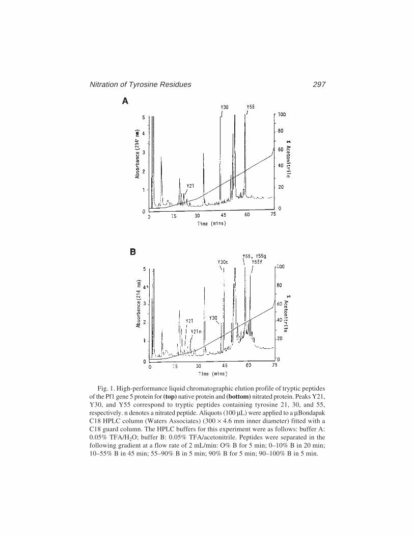
Nitration of Tyrosine Residues 297
Fig. 1. High-performance liquid chromatographic elution profile of tryptic peptidesof the Pf1 gene 5 protein for (top) native protein and (bottom) nitrated protein. Peaks Y21,Y30, and Y55 correspond to tryptic peptides containing tyrosine 21, 30, and 55,respectively. n denotes a nitrated peptide. Aliquots (100 µL) were applied to a µBondapakC18 HPLC column (Waters Associates) (300 × 4.6 mm inner diameter) fitted with aC18 guard column. The HPLC buffers for this experiment were as follows: buffer A:0.05% TFA/H2O; buffer B: 0.05% TFA/acetonitrile. Peptides were separated in thefollowing gradient at a flow rate of 2 mL/min: O% B for 5 min; 0–10% B in 20 min;10–55% B in 45 min; 55–90% B in 5 min; 90% B for 5 min; 90–100% B in 5 min.

298 Plyte
Gel filtration is another way of removing the adducts prior to peptide mapping(see also Note 10).
5. Usually, protein–nucleic acid interactions can be disrupted by the addition ofNaCl or MgCl2 to 1–2 M. The conditions required to effect separation will varywith the nature of the complex.
6. It is not essential to have complete separation of all fragments, only separation ofthe tyrosine-containing peptides and their nitrated counterparts. The HPLCconditions should be adjusted to achieve this.
7. Tyrosine residues have a characteristic fluorescence emission maximum at 303 nmwhen excited at 278 nm. This phenomenon can be used initially to determinewhich peptides contain a tyrosine residue (this may not be possible, however, ifthere is a tryptophan residue present in the same peptide as a result of energytransfer). If on-line fluorescence detection is not available, the fractions canbe taken directly from the HPLC and analyzed in a fluorimeter. The peptidesshould then be unambiguously identified by either N-terminal sequencing oramino acid analysis.
8. The addition of a nitrate group to the tyrosine should alter the hydrophobicityand, hence, the retention time of that particular peptide in an acetonitrile gradient.This should allow immediate identification of the nitrated peptides. However, itis possible that a nitrated peptide comigrates with another unmodified peptide.Therefore, freeze-dry all peptides from HPLC and resuspend in 10 mM Tris-HCl,pH 8.0: The nitrated peptides will have a faint yellow color (absorbance maxi-mum at 428 nm).
9. For peptides sequenced on an applied biosystems 477A pulse liquid amino acidsequencer (fitted with a 120A separation system for the analysis of PTH-derivitizedamino acids), PTC-3-nitrotyrosine elutes just after DTPU.
10. TNM induced oligomerization has been observed on the nitration of numerous pro-teins including several DNA-binding proteins (4,12,13). This is usually consideredundesirable, and steps are often taken to reduce the crosslinking and remove adductsbefore analysis (e.g., by gel filtration). However, advantage can be taken of thiscrosslinking ability; Martinson and McCarthy (14) used TNM as a reagent tocrosslink histones specifically. On nitration with TNM, we have also shown thatthe Pf1 gene 5 protein forms an SDS-stable dimer (13). Initial analysis of the pep-tide adduct in this case suggested that tyrosine 55 from one monomer wascrosslinked to phenylalanine 76 from the other monomer (forming an interdimercrosslink rather than an intradimer crosslink). The adducts are thought to form viaa free-radical mechanism, resulting in zero-length crosslinks between residues inclose proximity (14,15) Thus, if adduct formation is limited to one or two species,additional structural information can be obtained from the experiment. Thecrosslinked proteins should be digested and the peptide adduct purified byHPLC. N-Terminal sequencing, amino acid analysis, and gas chromatograpy–massspectroscopy (of the hydrolyzed peptide) should enable unambiguous identifica-tion of the two residues participating in the crosslink and provide structural infor-mation concerning the relative positions of these residues in the protein.
Nitration of Tyrosine Residues 299
References1. Mueller, M. J., Samuelson, B., and Haeggstrom, J. Z. (1995) Chemical modifica-
tion of leukotriene A4 hydrolase. Indications for essential tryosyl and arginyl resi-dues at the active site. Biochemistry 34, 3536–3543.
2. Hawes, J. W., Crabb, D. H., Chan, R. M., Rougraff, P. M., and Harris, A. (1994)Chemical modification and site-directed mutagenesis studies of rat 3-hydroxy-isobuyrate dehydrogenase. Biochemistry 34, 4231–4237.
3. Kochhar, S., Hunziker, P. E., Leong-Morgenthaler, P., and Hottinger, H. (1992)Primary strucure, physiochemical properties and hemical modification of NAD+-dependent d-lactate dehydrogenase. J. Biol. Chem. 267, 8499–8513.
4. Anderson, R., Nakashima, Y., and Coleman, J. (1975) Chemical modification offunctional residues of the Fd gene 5 DNA-binding protein. Biochemistry 14,907–917.
5. Plyte, S. E. and Kneale, G. G. (1991) Mapping the DNA binding site of the Pf1gene 5 protein. Protein Eng. 4(5), 553–560.
6. Lundblad, R. and Noyes, M. (1984) Chemical Reagents for Protein ModificationI and II, CRC, Boca Raton, FL.
7. Riordan, J., Sokolovsky, M., and Vallee, B. (1967) Environmentally sensitivetyrosine residues. Nitration with tetranitromethane. Biochemistry 6, 358.
8. Sokolovsky, M., Riordan, J., and Vallee, B. (1966) Tetranitromethane. A reagentfor the nitration of tyrosyl residues in proteins. Biochemistry 5, 3582–3589.
9. Sokolovsky, M., Harell, G., and Riordan, J. (1969) Reaction of tetranitromethanewith sulphydryl groips in proteins. Biochemistry 8, 4740–4745.
10. Dimicoli, J. and Helene, C. (1974) Interaction of aromatic redisues of proteinswith nucelic acids I and II. Biochemistry 13, 714–730.
11. Sokolovsky, M. Riordan, J., and Vallee, B. (1967) Conversion of 3-nitrotyrosineto 3-amino-tyrosine in peptides and proteins. Biochem. Biophys. Res. Commun.27, 20.
12. Anderson, R. and Coleman, J. (1975) Physiochemical properties of DNA-bindingproteins: gene 32 protein of T4 and Escherichia coli unwinding protein.Biochemistry 1, 5485–5491.
13. Plyte, S. E. (1990) The biochemical and biophysical characterization of the Pf1gene 5 protein and its complex with nucelic acids, Ph.D. thesis, Portsmouth Uni-versity, Portsmouth, UK.
14. Martinson, H. and McCarthy, B (1975) Histone–histone associations within chro-matin. Crosslinking studies using tetranitromethane. Biochemistry 14, 1073–1078.
15. Williams, J. and Lowe, J. (1971) The crosslinking of tyrosine with tetranitro-methane. Biochem. J. 121, 203–209.
Modification of Lysine by Reductive Methylation 301
301
From: Methods in Molecular Biology, vol. 148: DNA–Protein Interactions: Principles and Protocols, 2nd ed.Edited by: T. Moss © Humana Press Inc., Totowa, NJ
21
Chemical Modification of Lysineby Reductive Methylation
A Probe for Residues Involved in DNA Binding
Ian A. Taylor and Michelle Webb
1. IntroductionThe basic side chains of lysine residues often play essential roles in DNA–
protein recognition. They are able to contribute to the overall affinity of aninteraction through nonspecific charge–charge interactions with the phosphatebackbone and contribute substantially to the specificity of the interaction byforming direct hydrogen bonds with functional groups on the edges of thebases. This dual role and their almost ubiquitous presence in the interface ofDNA–protein complexes make them very attractive targets for chemical modi-fication experiments.
Numerous chemical reagents to chemically modify lysine side chains in pro-teins are available (1). Unfortunately, the conditions required for suchprocedures are often harsh and result in total denaturation of the protein. Fur-thermore, many reagents are not entirely specific to lysine and often react withother residues such as cysteine, histidine, and tyrosine. Two methods, that areable to specifically modify lysine residues under native conditions and havebeen applied successfully to the investigation of protein nucleic acid interac-tions, are amidination with imidoesters (2) and, the subject of this chapter,reductive alkylation (3).
Reductive alkylation has become a widespread and well-established tech-nique for the specific modification of lysine residues and a variety of reagentshave been used to produce this chemical modification (4). A reductivemethylation reaction using formaldehyde and the reducing agent sodiumcyanoborohydride (5) is particularly useful because under mild solution condi-

302 Taylor and Webb
tions (aqueous buffer, pH 7–8), the accessible lysine residues on proteins arecompletely converted to the ε-N,N-dimethyl derivatives. The reaction (Fig. 1)occurs in two distinct phases. Initially, the ε-amino group of the lysine formsan adduct with the formaldehyde to produce a Schiff base. This then undergoesreduction by sodium cyanoborohydride to the monomethylamine derivative inthe second part of the reaction. A further round of the reaction, which occursmore rapidly than the first produces the dimethyl derivative.
The attractiveness of this modification is that dimethylation of the lysineside chain is a relatively small chemical change. The pKa is only slightlyaffected and may even remain unchanged (5). Because of this, the residue main-tains its ionization properties and the potential for the formation of the sameion-pair interactions as in the unmodified protein remains, although there issome loss of hydrogen-bonding capacity. Nevertheless, the modification is amild one and unlikely to significantly perturb the native enzyme structure.
A major use of any chemical modification procedure is the incorporation ofisotopic labels at specific positions in proteins. Reductive methylation experi-ments that incorporate 13C have been used to probe the environment of lysineside chains in proteins using nuclear magnetic resonance (NMR) spectroscopy(7). The incorporation of radiolabels into proteins by reductive methylationenables the number of lysines that are accessible to be determined. In the caseof DNA-binding proteins, the labeling is carried out on the free protein and theDNA–protein complex. This immediately provides information about the num-ber of lysines present in the DNA-binding site. Subsequent peptide mappingstrategies allow identification of specific residues, the degree of labeling atparticular sites is then used to derive the location of that residue within theprotein. In this way, [3H] formaldehyde has been used as a source of radiolabelto probe the role of the lysine residues of the core histones in the nucleosome
Fig. 1. Reductive methylation of lysine. The reaction scheme (6) occurs in twodistinct phases. Adduction of formaldehyde to the lysine ε-amino group generates theSchiff base (A), which is then reduced by sodium cyanoborohydride to ε-N-mono-methyl-lysine (B). A second round of the reaction generates the final product ε-N,N-dimethyl-lysine (C).

Modification of Lysine by Reductive Methylation 303
(8), the interaction of the linker histone H5 with nucleosomes in long chroma-tin (9), and the role of lysine residues in a specific DNA–protein complexbetween the type I DNA methylase M.EcoR124I (10) and a short DNA duplexcontaining its recognition site.
Subheading 3. contains a set of protocols to enable quantification of thenumber of lysine residues susceptible to reductive methylation in a protein anda DNA–protein complex. The peptide mapping and N-terminal protein-sequencing procedures required to identify and determine the extent of modifi-cation at individual residues are also described. Because the modificationreaction is sensitive to contaminants in commercial grades of sodium cyano-borohydride (most likely cyanide), a method to recrystallize the reagent (6) isdescribed in Subheading 3.1. In order to obtain quantitative information aboutthe total extent of protein modification and/or determine the relative accessi-bility of individual residues, it is vital that the specific activity of the [3H]formaldehyde be determined accurately. Subheading 3.2. describes a protocolto do this using a simple peptide substrate α-melanocyte-stimulating hormone(α-MSH). The data from this experiment then allow quantitative conclusionsto be drawn from the subsequent protein protection and peptide mappingexperiments that are described in Subheadings 3.3. and 3.4.
2. Materials2.1. Reagents and Materials
1. Reagents were obtained as follows: urea, formic acid, hydrochloric acid andglacial acetic acid (ARISTAR grade), dichloromethane (dried, AnalaR), gly-cine, Tris (hydroxymethyl) methylamine, sodium chloride and Na2EDTA(AnalaR), trifluoroacetic acid and water (HiPerSolv grade), acetonitrile (farUV HiPerSolv grade), and sodium cyanoborohydride (Schuchardt), all fromMerck; dithiothreitol (DTT) and HEPES (both molecular biology grade), α-MSHand silica gel (Type III, indicating) from Sigma [3H] formaldehyde (approx100 Ci/mol). NEN radiochemicals; filter paper (No. 1) from Whatman; dialysismembrane (Slide-A-Lyser) from Pierce; scintillation fluid (Ecoscint™ H) fromNational Diagnostics); trypsin (sequencing grade) and Pefabloc™ fromBoehringer Mannheim.
2. DNA-binding protein (approx 10 mg).3. Stock solution of oligonucleotide duplex, 300 µM (1 µmol synthesis, high-per-
formance liquid chromatography [HPLC] purified).4. Formaldehyde (Sigma): 37% solution and 15% methanol stabilizer.5. 8 M urea and 50 mM acetic acid.6. 10 mM HEPES, pH 7.5.7. 1 M Na-glycine, pH 7.0.8. 50 mM TBS: 10 mM Tris-HCl, 50 mM NaCl, and 1 mM EDTA, pH 7.5.9. 2 M Tris base.
304 Taylor and Webb
2.2. Equipment
1. HPLC: binary gradient formation using high-pressure-mixing, variable-wave-length ultraviolet (UV) absorbance detector and fraction collection are required.
2. Reverse-phase HPLC columns: semipreparative C3 (9.4 × 250 mm), analyticalC3 (4.6 × 250 mm), and analytical C18 (4.6 × 250 mm). Zorbax 300SB or anequivalent wide-pore packing is recommended.
3. High-resolution anion-exchange column (e.g., TSK-GEL, DEAE-NPR [4.6 ×35 mm]).
4. Freeze-dryer.5. Scanning (UV/visible) spectrophotometer.6. Liquid scintillation counter.7. Protein-sequencing facilities.
3. Methods3.1. Recrystallization of Sodium Cyanoborohydride
1. Dissolve 44 g of sodium cyanoborohydride in 100 mL of acetonitrile and removeany undissolved material by centrifugation.
2. Add 600 mL of dichloromethane to the mixture place in a sealed container andallow the sodium cyanoborohydride to precipitate overnight at 4°C.
3. Filter the mixture (Whatman filter paper No. 1) to collect the precipitate andwash with an additional 100 mL of cold dichloromethane.
4. Allow the powder to dry and store in a vacuum desiccator containing silica gel.Prepare aqueous stock solutions immediately before use.
3.2. Determination of the Effective Specific Activityof 3H Formaldehyde
There is a substantial variation in the effective specific activity of differentbatches of [3H] formaldehyde. In order to accommodate this, it is necessary todetermine the effective specific activity of each individual batch. A convenientway to do this is to use a simple peptide substrate for which the number ofaccessible amino groups is known. The effective specific activity can then becalculated from the amount of radioactivity that can be incorporated intothe fully modified peptide. For this purpose the peptide hormone α-MSH(Ac-SYSMEHFRWGKPV-NH2) is recommended (see Note 1).
1. Redissolve the contents of a 1-mg vial of α-MSH in 1 mL of 8 M urea and 50 mMacetic acid.
2. Equilibrate a C18 reverse-phase column in 2% acetonitrile and 0.05% (v/v)trifluoroacetic acid (TFA) at a flow rate of 1 mL/min and set the UV absorbancedetector to 280 nm. Apply the peptide in approx 200-µg aliquots and elute with a0–60% increasing gradient of acetonitrile, 0.05% TFA (v/v) over 60 min.
3. Collect the peptide-containing fractions from multiple runs, pool, and lyophilizethem. Store the purified peptide at –20°C in a box containing silica gel.
Modification of Lysine by Reductive Methylation 305
4. Dissolve 100 nmol of purified α-MSH in 0.5 mL of 10 mM HEPES, pH 7.5. Add10 mM sodium cyanoborohydride (freshly made) followed by 2 mM [3H]formaldehyde (see Notes 2 and 3) and incubate at 24°C for 3 h. After this timeadd a second aliquot of the reagents and allow the reaction to continue for anadditional 3 h.
5. Adjust the sample to 8 M urea and 50 mM acetic acid and purify the modifiedpeptide by reverse-phase chromatography using the same gradient as in step 2.Pool the fractions, lyophilize, and store at –20°C in a box containing silica gel.
6. To determine the specific activity of the modified peptide, redissolve the labeledpeptide in 1 mL of water and determine its concentration from the absorbance at280 nm (ε280 = 7000/M/cm). Add 10 µL to 1 mL of liquid scintillant (Ecoscint Hor equivalent), mix well, and determine the amount of incorporated radioactivityby liquid scintillation counting. The specific activity of the labeled peptide(σα-MSH) (in nCi/nmol) is calculated from Eq. 1. The effective specific activityof the [3H] formaldehyde (σ[3H] formaldehyde) is simply half this value (Eq. 2) (seeNote 4):
σa-MSH = (dpm)/(No. nmoles counted × 2220) (1)
σ[3H] formaldehyde = 1/2 σα-MSH (2)
3.3. Surface Labeling of Proteinand DNA–Protein Complex by Reductive Methylationand Quantification of Residues Modified
Prior to mapping the positions of modified lysine residues, it is necessary todetermine the number of residues susceptible to reductive methylation and theproportion of these that are protected by the presence of DNA.
1. Prepare approx 3.0 mL of a solution of the DNA-binding protein in 10 mMHEPES, 50 mM NaCl, and 1 mM EDTA (pH 7.5) by either dialysis or bufferexchange. The concentration of DNA-binding protein in this solution should be1–2 mg/mL.
2. Take 1.5 mL of protein and add an equimolar amount, or slight excess, of theDNA duplex from a concentrated stock solution to form the DNA–protein complex.
3. Withdraw a 300-µg aliquot from the free protein and the DNA–protein complexsamples and add glycine to 50 mM from a neutral 1 M stock solution. Dilute thesamples to 1 mL with 50 mM TBS and load into dialysis cassettes (see Note 5).Dialyze against 2 L of 50 mM TBS at 4°C. These samples are controls forefficiency of the whole procedure and also serve as the “zero” time points(see below).
4. To the remaining solutions, add a 30-fold molar excess of sodium cyanoboro-hydride over the total lysine content of the protein. Then, add a 10-fold molarexcess of [3H] formaldehyde (see Note 6) and incubate at 24°C.
5. At timed intervals (10 min up to 5 h) withdraw 300 µg samples of protein fromeach time-course. Quench the reaction by the addition of 50 mM glycine and
306 Taylor and Webb
dilute to 1 mL with 50 mMTBS. Load the samples into dialysis cassettes anddialyze overnight against 2 L of 50 mM TBS using at least 3 changes.
6. After extensive dialysis, remove all the samples from the cassettes. For free-protein samples, continue from step 7 onward. Samples from the DNA–proteincomplex time-course need to be processed to remove the DNA as follows. Equili-brate a small-volume (1 mL or less) high-performance anion exchange (see Note 7)HPLC column (analytical TSK-GEL, DEAE-NPR [4.6 × 35 mm] or an equiva-lent) in 50 mM TBS at a flow rate of 1 mL/min. Set the UV detector to 280 nm.Apply each sample from the time-course to the column and collect anyflowthrough. Elute the protein (if bound) and the DNA by application of anincreasing NaCl gradient from 0.05 M to 1.0 M over 50 column volumes. Collectthe protein-containing fractions and proceed.
7. Determine the molar concentration of the samples from each time-course(including the “zero”) using the absorbance at 280 nm. Add 10 µL of each sampleto 1 mL of liquid scintillant, mix well, then determine the amount of incorporatedradioactivity at each time-point by liquid scintillation counting.
8. Calculate the specific activity (in nCi/nmol) of the labeled protein (σprotein) ateach time-point of the reaction using Eq. 3. Then, using the value for the effec-tive specific activity of the [3H] formaldehyde determined in Subheading 3.2.calculate the number of lysine residues modified at each point in the time-courseusing Eq. 4 (see Note 8):
σprotein = (dpm)/(No. nmoles counted × 2220) (3)
No. modified lysines = σ(protein) = 2σ([3H] formaldehyde) (4)
9. Plot the number of lysine residues modified against time and fit the data to asingle exponential process using Eq. 5 (Fig. 2). In most cases, the data should fitwell to this model (see Note 9) and the total number of modifiable lysine residuesis then given by the limit value (L). Fitting the data in this manner also allows arate constant (k) for the incorporation of radiolabel to be derived. Both of theseparameters can be affected by DNA binding.
No. modified lysines = L(1–e–kt) (5)
10. Compare the fitted curves of the time-course for the reaction of free protein andfor the DNA–protein complex (Fig. 3). Formation of the DNA–protein complexmay well reduce L, indicating the presence of a population of strongly protectedlysines. At the same time, differences in k are likely to arise from an overalllowering of the rate of modification because of decreased accessibility of lysineresidues in the presence of DNA.
3.4. Pulse Chase Labeling of Proteins
If the fraction of lysine residues protected by DNA is large, as determined inSubheading 3.3., then a pulse-labeling procedure carried out on the free pro-tein will reveal which lysine residues are surface accessible and likely to be

Modification of Lysine by Reductive Methylation 307
involved in DNA binding. If only a small number of lysine residues areprotected by DNA, then a modification to the procedure should be undertaken(see Note 10).
Fig. 2. Time-course of reductive methylation of the type I DNA methyltransferaseM.EcoR124I. The curve is the best fit of the data to a single exponential (L = 41, k =0.019/min).
Fig. 3. The effect of DNA binding on reductive methylation of the DNA recogni-tion subunit (HsdS) from M.EcoR124I. The upper curve is a best fit to the data from atime-course for the modification reaction of free protein (L = 19, k = 0.019/min). Thelower curve is the best fit to the data from a time-course for modification of the proteinin the DNA–protein complex (L = 14, k = 0.004/min).

308 Taylor and Webb
1. Prepare 1 mL of DNA-binding protein at a concentration of 1–2 mg/mL in 50 mMTBS by either dialysis or buffer exchange.
2. Add sodium cyanoborohydride to a 30-fold molar excess over the total lysinecontent of the protein and then initiate the chemical modification reaction bythe addition of [3H] formaldehyde at a 10-fold molar excess. Incubate at 24°C,the length of time will depend on the results from the experiments in Sub-heading 3.3. Aim to modify for a length of time when the reaction is about 50%complete (see Note 11). This will probably be between 10 and 60 min.
3. At the end of the pulse, quench the reaction by the addition of 50 mM glycine and dialyzeovernight against 1 L of 50 mM TBS. Change the dialysis buffer at least three times.
4. Equilibrate a semipreparative C3 reverse-phase column (9.4 × 250 mm) in 5%acetonitrile and 0.05% (v/v) TFA at a flow rate of 3 mL/min and set the UVdetector to 225 nm. Remove the protein from the dialysis cassette, add urea to afinal concentration of 8 M and DTT to 50 mM. Incubate the sample briefly atroom temperature, acidify by the addition of 100 mM acetic acid, and apply theprotein to the column. Elute with a 5–65% gradient of acetonitrile and 0.05% (v/v)TFA over 60 min. Collect the protein containing fractions and lyophilize them.
5. Redissolve the modified protein in 1 mL of 8 M urea and 10 mM HEPES (pH 7.5)and determine the protein concentration from the absorbance at 280 nm. At thispoint, the extent of label incorporation should be determined as in Subheading3.3., steps 7 and 8.
6. To “chase” the reaction with unlabeled reagent, add a 30-fold molar excess ofsodium cyanoborohydride over the total lysine content followed by a 10-foldexcess of unlabeled formaldehyde. Incubate for 3 h at 24°C, then add a secondaliquot of these reagents and continue the reaction for a further 3 h.
7. Add DTT to a final concentration of 50 mM, incubate briefly at room tempera-ture then acidify with 100 mM acetic acid. Purify the fully modified protein byreverse-phase chromatography as in step 4. Lyophilize the fractions containingprotein and store in aliquots of approx 2 nmol at –20°C in a box containing silica gel.
8. Redissolve a 2 nmol aliquot of modified protein in 100 µL of 0.9% formic acid(see Note 12). Ensure that the sample is fully dissolved then dilute to 500 µL withdH2O and titrate to pH 8 by the addition of 35 µL of 2 M Tris base.
9. Dissolve the contents of a vial of sequencing grade trypsin (see Note 13) in 1 mMHCl to give a concentration of 1 mg/mL. Add the trypsin to the protein to give anenzyme to a substrate ratio of 1:10 (w/w) and incubate at 37°C for approx 18 h.To increase the efficiency of cleavage add the trypsin in three aliquots at roughly4-h intervals. Terminate the digest by the addition of 1 mM Pefabloc and store at–20°C until required.
10. Equilibrate an analytical C3 reverse-phase HPLC column (4.6 × 250 mm) in 2%acetonitrile and 0.05% (v/v) TFA at a flow rate of 1 mL/min and set the UVabsorbance detector to 214 nm. Adjust the tryptic digests to 8 M urea and 50 mMDTT and incubate briefly at room temperature. Acidify the mixture by the addi-tion of 100 mM acetic acid and apply to the column. Elute the peptides with anincreasing gradient of acetonitrile collecting 250 µL fractions. For a complex

Modification of Lysine by Reductive Methylation 309
mixture of peptides, the following gradient works well: 2–35% in 45 min fol-lowed by 35–60% in 20 min. It may be necessary to alter this for the particularprotein under investigation.
11. Remove 25 µL from each fraction, add 1 mL of liquid scintillant, and determinethe level of radioactivity by liquid scintillation counting. Pool the fractionsacross each peak and lyophilize them. Store at –20°C in a box containing silicagel until required.
12. Construct an overlaid chromatogram as in Fig. 4 and use this to select peaks withan apparently high specific activity (see Note 14). These peaks require furtherfractionation by C18 reverse-phase chromatography (see Note 15) before ulti-mately submitting them for N-terminal amino acid sequencing.
13. Equilibrate an analytical C18 reverse-phase column in 2% acetonitrile and 0.05%TFA at a flow rate of 1 mL/min and set the UV detector to 214 nm. Redissolveeach selected peak in 500 µL of 8 M urea and 100 mM acetic acid and apply to thecolumn. Elute the bound peptides with a linear gradient of acetonitrile (2–50% in70 min) and collect 250-µL fractions.
14. Remove 25 µL from fractions across each peak and determine the incorporatedradioactivity as in step 11. Lyophilize the remainder and store at –20°C in a boxcontaining silica gel until required.
15. Analyze each purified peptide using automated N-terminal amino acid sequenc-ing. The objective is to determine the number of pmoles of each amino acidreleased at each cycle of the sequencing reaction and also to determine the amountof radioactivity associated with the residue. A suggested method for doing this isdescribed in Note 16.
Fig. 4. Separation of reductively methylated peptides from pulse-labeled HsdS byC4 reverse-phase chromatography. The absorbance at 214 nm and the amount ofradioactivity (nCi) are plotted for each fraction.
310 Taylor and Webb
3.5. Data Analysis
The data from the N-terminal sequencing are used to determine the specificactivity of each modified lysine as follows. Plot the number of pmoles of eachresidue released at each cycle pmole(n) versus the cycle number (n); then, fitthese data to Eq. 5 (see Fig. 5A). E is the efficiency of the sequencing process(usually around 90%) and pmole(0) is the amount of starting material.
pmole(n) = pmole(0) × En (5)
As PTH-dimethyl-lysine is not a standard amino acid, the number of pmolesof modified lysine is not determined directly from integration of the HPLCtrace. Instead, the value can be calculated by interpolation of the fitted curvefor the cycle at which the dimethyl-lysine was released. Plot the amount ofradioactivity released at each cycle versus the cycle number (Fig. 5B). Signifi-cant quantities of radioactivity should only be present at a cycle where a modi-fied lysine is present. Combine the data from the two plots and use Eq. 1 tocalculate the specific activity (σlysx); then, determine the fractional modifica-tion (σlysx/σα-MSH) for each dimethyl-lysine in a peptide. The value of this ratiois proportional to the accessibility of the residue during the pulse part of thechemical modification reaction. Values close to unity indicate a high degree ofaccessibility, whereas values close to zero indicate a residue that is inacces-sible to chemical modification.
These data can be used to build up a picture of the protein surface andidentify clusters of lysines that are potential surfaces for DNA binding.Residues identified by these methods are then targets for site-directed mutagen-esis experiments.
4. Notes1. The α-MSH peptide contains only a single lysine and has a blocked N-terminus.
The presence of the two aromatic residues allow its concentration to be deter-mined accurately from its UV absorbance at 280 nm (ε280 = 7000/M/cm). Wehave extensively characterized the reductive methylation reaction with this pep-tide using NMR and mass spectroscopy (10). Under the reaction conditions usedin Subheading 3.2., >95% of the product is dimethylated and the remaindermonomethylated. In principle, any peptide substrate with a known number offree amino groups and for which the concentration can be measured accuratelycould be used to determine the effective specific activity. However, if a differentpeptide substrate is used, it is advisable to extensively characterize the reactionin the same way. On a routine basis, if access can be gained to a mass spectrom-eter, it may be worthwhile checking the completeness of the reaction in this way.
2. [3H] Formaldehyde from NEN is supplied as a 0.3 M aqueous solution in snap-off glass vials. Make sure the whole contents of the vial are at the bottom andthen leave on ice for 10 min before breaking the seal. After opening, transfer the

Modification of Lysine by Reductive Methylation 311
contents to a screw-cap microfuge tube and store at 4°C. If possible, use all of thereagent within 1–2 d of opening.
3. The efficiency of the reductive methylation of proteins is greatly reduced by thepresence of amines in the solution because of competitive inhibition. Thus, com-
Fig. 5. Identification of radiolabeled lysine residues in the tryptic peptide D190-N220 from the reductively methylated pulse-labeled HsdS subunit from M.EcoR124I.(A) The pmole yield at each cycle of the Edman degradation sequencing reaction.Fitting of the data to Eq. 5 allows the yield of dimethyl-lysine to be determined byinterpolation. (B) A histogram showing the amount of radioactivity released at eachcycle of the same sequencing reaction. The combination of radioactivity and picomolereleased at each cycle allows estimation of the specific activity of individual residues.

312 Taylor and Webb
monly used buffers such as Tris–HCl and triethanolamine have to be avoided.HEPES and phosphate are good alternatives. A further problem is the potentialfor the formaldehyde–lysine adducts to undergo side reactions leading tounwanted protein crosslinking. To prevent this, the sodium cyanoborohydrideshould be added to the protein solution prior to addition of the formaldehyde.
4. The stoichiometry of the reductive methylation reaction dictates that two mol-ecules of formaldehyde are required to complete the modification of a lysineresidue to ε-N,N-dimethyl-lysine (see Fig. 1). Because of this, the effective spe-cific activity of the [3H] formaldehyde is half the value determined for the fullydimethylated peptide.
5. For dialysis of small volumes, (0.5–2 mL) Slide-A-Lyser cassettes (Pierce) areextremely useful. We find that a 1-mL sample volume is easy to inject and recoverfrom the cassette without large losses of sample and without large dilution. Ifnecessary, a smaller volume could be used.
6. The amount and the exact ratio of the reagents used for the reaction are somewhatempirical. The major concern is the prevention of side reactions resulting fromreactive formaldehyde–lysine adducts. For a detailed account, see ref. 6. Briefly,the concentration of formaldehyde needs to be at an excess over the number oflysine residues to drive the reaction to completion, but not so high as to favorprotein crosslinking. The other requirement is that the sodium cyano-borohydride be in excess over the formaldehyde to ensure efficient reduction ofthe Schiff bases.
7. To separate the DNA from protein, DEAE or Q ion-exchange columns are themethod of choice. DNA oligonucleotides will bind very strongly to these matri-ces and the protein either can be recovered from the flowthrough or will eluteearlier in a NaCl gradient. An alternative is to use heparin–Sepharose or, forbasic proteins, a cation-exchange resin. If the chromatographic separation of theDNA from the protein is problematic, treat each sample with DNase I (FPLCpure,Pharmacia) before application to the column.
8. The N-terminus of the protein can also be reductively methylated. If the proteinis relatively small or the total number of modified residues is low, then it is worth-while to consider this when calculating the extent of modification.
9. If the time-course is extended to 5 h incubation, the reaction should be completeand the data will usually fit well to a single exponential process. Occasionally,this is not the case—for instance, if the protein contains several distinct popula-tions of lysines with different kinetics. In this case, a more complex model willbe needed to deconvolve the various classes of reacting species.
10. The pulse-labeling method involves treating the protein with a short pulse oflabeled formaldehyde followed by a “cold” chase. This will identify all the sur-face lysines and provide information about their accessibility. If a large propor-tion of the total number of modifiable lysine residues are protected by DNA, thena pulse chase procedure of this kind will identify residues likely to be involved inDNA binding. However, if only a small proportion of lysines are protected byDNA, then an initial “cold” labeling should be performed on the DNA–protein

Modification of Lysine by Reductive Methylation 313
complex, followed by separation of the protein from the DNA before the pulsewith labeled reagents is applied.
11. This is a compromise between getting enough label into the protein to allow thesites of modification to be easily determined and providing for differential label-ing at individual sites so that information about the accessibility of each lysinecan be obtained.
12. There may be some difficulty in redissolving the lyophilized protein in the aque-ous buffers required for tryptic digestion (e.g., 20 mM Tris-HCl, pH 8.0). Theformic acid strategy described works well in some cases but is not guaranteed.An alternative is to dissolve the sample in 100 mM Tris-HCl and 8 M urea pH 8.0and then to add an equal volume of trypsin in 1 mM HCl such that the final ureaconcentration is 4 M and the trypsin concentration 1:10 (w/w).
13. The objective of the proteolytic digest is to produce peptides of an optimal length(5–30 amino acids) for quantitative analysis by automated Edman degradation. Atryptic digest of a reductively methylated protein will produce an arginine spe-cific digest, as ε-N,N-dimethyl-lysine residues are not substrates for tryptic cleav-age (11). Such a digest will yield some peptides that are suitable for N-terminalsequencing but will probably not cover the entire protein. In order to producefurther peptides of suitable length, other proteases and chemical cleavage reagentsshould be investigated. The usefulness of these agents can vary substantially. Ingeneral, the best enzymatic alternatives are chymotrypsin and V8 protease.Cyanogen bromide is the best alternative for chemical cleavage.
14. The main criterion for selection of peaks is an apparent high specific activity,indicating that surface accessible lysines are present in peptides eluted within thepeak. Additional information about the location of buried lysines within theprotein can be gained by sequencing peptides which show very low or appar-ently no label incorporation. Although this could yield valuable data, oneshould be aware that some of these “cold” peaks are likely to be peptides derivedfrom trypsin.
15. After an initial separation of a complex mixture of reductively methylated pep-tides, by C3 reverse-phase chromatography, a further fractionation of peptidesusing either C8 or C18 is highly recommended. Often a peak with an apparentlyhigh specific activity taken from an initial C3 separation will resolve into mul-tiple components on C8 or C18, only some of which are labeled. Avoid loadingpeptides eluted from a C3 column at high acetonitrile concentrations (>50%) ontocolumns with longer alkyl-chain-bonded phases as the interaction between thesample and the bonded phase may be too strong for efficient recovery. For theselarger, more hydrophobic peptides, it may be better to reapply to a C3 column andthen elute with a different gradient to the one used initially. Alternatively, redigestwith a different enzyme and separate the products on a C18 column.
16. A simple and effective way to quantify the degree of incorporated label at indi-vidual lysine residues involves splitting the peptide sample during the automatedEdman degradation sequencing reaction; most sequenators are equipped with thisfacility. After extraction of each 2-analino–5-thiazolinone-derivatized amino
314 Taylor and Webb
acid, split the sample and divert 50% to a fraction collector. Convert the remain-der to the phenylthiohydantoin derivative and identify the residue by on-lineHPLC analysis in the usual way. Calculate the number of picomoles of the newlyreleased residue by integration of the HPLC peak. Determine the amount ofradioactivity associated with the residue by liquid scintillation counting of thematerial that was diverted to the fraction collector. This method may requiremodification, depending on the configuration of the available sequenator.
References1. Lundblad, R. L. and Noyes, C. M. (1984) Chemical Reagents for Protein Modifi-
cation. CRC, Boca Raton, FL.2. Hunter, M. J. and Ludwig, M. L. (1962) J. Am. Chem. Soc. 84, 3491–3497.3. Means, G. E. and Feeney, R. E. (1968) Reductive alkylation of amino groups in
proteins. Biochemistry 7, 2192–2201.4. Means, G. E. and Feeney, R. E. (1995) Reductive alkylation of proteins. Anal.
Biochem. 224, 1–16.5. Jentoft, N. and Dearborn, D. G. (1983) Protein labelling by reductive alkylation.
Methods Enzymol. 91, 570–579.6. Jentoft, N. and Dearborn, D. G. (1979) Labelling of proteins by reductive methy-
lation using sodium cyanoborohydride. J. Biol. Chem. 254, 4359–4365.7. Zhang, M., Thulin, E., and Vogel, H. J. (1994) Reductive methylation and pKa
determination of the lysine side chains in calbindin D9k. J. Protein Chem. 13,527–535.
8. Lambert, S. F. and Thomas, J. O. (1986) Lysine-containing DNA-binding regionson the surface of the histone octamer in the nucleosome core particle. Eur. J.Biochem. 160, 191–201.
9. Thomas, J. O. and Wilson, C. M. (1986) Selective radiolabelling and identifica-tion of a strong nucleosome binding site on the globular domain of histone H5.EMBO J. 5, 3531–3537.
10. Taylor, I. A., Webb, M., and Kneale, G. G. (1996) Surface labeling of the type Imethyltransferase M.EcoR124I reveals lysine residues critical for DNA binding.J. Mol. Biol. 258, 62–73.
11. Poncz, L. and Dearborn, D. G. (1983) The resistance to tryptic hydrolysis of pep-tide bonds adjacent to N-epsilon, N-dimethyllysyl residues. J. Biol. Chem. 258,1844–1850.
Limited Proteolysis of Protein–Nucleic Acid 315
315
From: Methods in Molecular Biology, vol. 148: DNA–Protein Interactions: Principles and Protocols, 2nd ed.Edited by: T. Moss © Humana Press Inc., Totowa, NJ
22
Limited Proteolysisof Protein–Nucleic Acid Complexes
Simon E. Plyte and G. Geoff Kneale
1. IntroductionLimited Proteolysis is a useful structural probe for investigating the globu-
lar nature of proteins by preferentially digesting the more accessible regionsoften found between domains. Generally, proteases require a small region ofpolypeptide chain possessing conformational flexibility for accommodation inthe active site (1). The regions of a protein possessing conformational flexibil-ity are often found between tightly folded domains and are, therefore, prefer-ential sites for proteolysis. In practice, limited proteolysis is achieved bydilution of the enzyme sufficiently so that it will only digest the most acces-sible regions leaving the domains intact. Digestion of protein–nucleic acid isoften advantageous in that the DNA may provide steric protection of the DNA-binding domain not afforded by the free protein. The generation of domains bylimited proteolysis relies directly on the tertiary structure of the protein underinvestigation and provides much firmer evidence for their existence than thatprovided by sequence homology.
An increasing number of nucleic-acid-binding proteins are known in whichregions of their polypeptide chain are folded separately into compact globulardomains, each possessing a distinctive function. For example, digestion of theA1 heterogeneous nuclear ribonucleoprotein (A1 hnRNP) with Staphylococ-cus aureus V8 protease produces two discrete domains, both capable of bind-ing single-stranded nucleic acids (2,3). Similarly, digestion of the Pf1 gene 5nucleoprotein complex results in the production of a 12-kDa domain that retainsmuch of the single-stranded DNA-binding ability of the intact protein (4). Fur-ther, using limited proteolysis, a cryptic DNA-binding domain was revealed inthe COOH terminus of yeast TFIIIB70 and a core ssDNA-binding domain was

316 Plyte and Kneale
generated, possessing increased binding affinity, in human replication protein A(5,6). In addition to its use for the analysis of domain structure, limited proteolyticfragments from Escherichia coli DNA gyrase B, for example, permitted the suc-cessful crystallization and structure determination of one of its domains (7).
1.1. Strategy
The strategy adopted for the limited proteolysis of nucleoprotein complexescan be considered in four parts: optimization of the proteolysis, characteriza-tion of the proteolysed complex, purification of the DNA-binding domains,and sequence characterization of the fragment(s).
1.1.1. Proteolysis of Nucleoprotein Complex
The nucleoprotein complex should be digested with various proteases toestablish which conditions are optimal for generating a protease-resistantdomain. We routinely vary two parameters (enzyme/substrate ratio and time ofdigestion) when determining the best conditions for limited proteolysis.However, other parameters, such as temperature, ionic strength, and pH mayalso be varied. To determine the appropriate enzyme/substrate ratio for a par-ticular protease, the nucleoprotein complex is digested at several enzyme/sub-strate ratios, removing samples at regular time intervals for sodium dodecylsulfate–polyacrylamide gel electrophoresis (SDS-PAGE) analysis. The appear-ance of a discrete domain, resistant to further degradation (even if only tran-siently), is evidence for the existence of a domain, although not necessarilyone that binds DNA. Choice of protease is often critical (see Table 1). Ini-tially, it is best to try a relatively nonspecific enzyme (e.g., papain) becausethis decreases the likelihood of activity being dependent on primary sequencerather than tertiary structure.
1.1.2. Preliminary Characterization of DNA-Binding Propertiesof the Proteolyzed Nucleoprotein Complex
An initial indication of DNA binding can be found during the proteolysisexperiment by removing two aliquots for gel analysis that can be run on poly-acrylamide or agarose gels appropriate for the size of complex in the presenceand absence of the denaturant SDS. A retardation in the mobility of the DNA(seen under ultraviolet [UV] light) in the absence of SDS implies that the frag-ment is still associated with DNA and constitutes a DNA-binding domain.However, this does not prove that the proteolyzed fragment is a discrete DNA-binding domain; it is possible that the nucleoprotein complex has only been“nicked” by the protease and maintains its native tertiary structure by noncova-lent interactions. Therefore, it is necessary to purify the domain and fully char-acterize its DNA-binding properties.
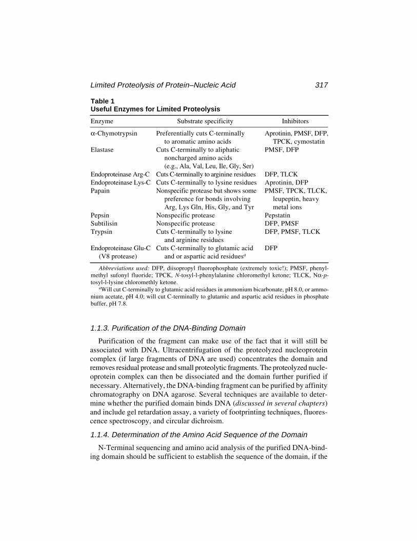
Limited Proteolysis of Protein–Nucleic Acid 317
1.1.3. Purification of the DNA-Binding Domain
Purification of the fragment can make use of the fact that it will still beassociated with DNA. Ultracentrifugation of the proteolyzed nucleoproteincomplex (if large fragments of DNA are used) concentrates the domain andremoves residual protease and small proteolytic fragments. The proteolyzed nucle-oprotein complex can then be dissociated and the domain further purified ifnecessary. Alternatively, the DNA-binding fragment can be purified by affinitychromatography on DNA agarose. Several techniques are available to deter-mine whether the purified domain binds DNA (discussed in several chapters)and include gel retardation assay, a variety of footprinting techniques, fluores-cence spectroscopy, and circular dichroism.
1.1.4. Determination of the Amino Acid Sequence of the Domain
N-Terminal sequencing and amino acid analysis of the purified DNA-bind-ing domain should be sufficient to establish the sequence of the domain, if the
Table 1Useful Enzymes for Limited Proteolysis
Enzyme Substrate specificity Inhibitors
α-Chymotrypsin Preferentially cuts C-terminally Aprotinin, PMSF, DFP,to aromatic amino acids TPCK, cymostatin
Elastase Cuts C-terminally to aliphatic PMSF, DFPnoncharged amino acids(e.g., Ala, Val, Leu, Ile, Gly, Ser)
Endoproteinase Arg-C Cuts C-terminally to arginine residues DFP, TLCKEndoproteinase Lys-C Cuts C-terminally to lysine residues Aprotinin, DFPPapain Nonspecific protease but shows some PMSF, TPCK, TLCK,
preference for bonds involving leupeptin, heavyArg, Lys Gln, His, Gly, and Tyr metal ions
Pepsin Nonspecific protease PepstatinSubtilisin Nonspecific protease DFP, PMSFTrypsin Cuts C-terminally to lysine DFP, PMSF, TLCK
and arginine residuesEndoproteinase Glu-C Cuts C-terminally to glutamic acid DFP
(V8 protease) and or aspartic acid residuesa
Abbreviations used: DFP, diisopropyl fluorophosphate (extremely toxic!); PMSF, phenyl-methyl sufonyl fluoride; TPCK, N-tosyl-l-phenylalanine chloromethyl ketone; TLCK, Nα-p-tosyl-l-lysine chloromethly ketone.
aWill cut C-terminally to glutamic acid residues in ammonium bicarbonate, pH 8.0, or ammo-nium acetate, pH 4.0; will cut C-terminally to glutamic and aspartic acid residues in phosphatebuffer, pH 7.8.
318 Plyte and Kneale
native amino acid sequence is known. Alternatively, N-terminal sequencingand mass spectroscopy should enable unambiguous identification of thedomain. If certain proteases have been used to generate the domain (e.g.,trypsin, α-chymotrypsin, endoproteinase Arg-C, and so forth), the C-terminalamino acid may also be known. If there are still ambiguities, carboxypeptidasedigestion of the fragment can also be used to help identify the C-terminal resi-dues, although this is not always reliable. If this still does not yield an unam-biguous result, one must resort to amino acid sequencing of the entire fragment.
2. Materials
1. Spectra-Por dialysis membrane washed thoroughly in double-distilled water.2. All proteases should be of the highest grade available and treated for contaminat-
ing protease activity, if necessary. A list of useful enzymes and their inhibitors isgiven in Table 1.
3. Buffers should be AnalR grade or higher and made up in double-distilled water.4. SDS–polyacrylamide gel stock solutions:
Solution A: 152 g acrylamide and 4 g bis-acrylamide. Make up to 500 mL.Solution B: 2 g SDS and 30 g Tris base, pH 8.8. Make up to 500 mL.Solution C: 2 g SDS, 30 g Tris base, pH 6.8. Make up to 500 mL.
When making up these solutions, they should all be degassed and filtered using a Buchnerfilter funnel. They should be stored in lightproof bottles and will keep for many months.
6. 10% ammonium persulfate (APS): dissolve 0.1 mg in 1 mL of dH2O.7. 15% SDS–polyacrylamide gel: Mix together 8.0 mL of solution A, 4.0 mL of
solution B, and 3.9 mL of dH2O. Add 150 µL of 10% APS and 20 µL of N,N,N',N'-tetramethylethylene diamine (TEMED). Mix well and then pour between theplates. Immediately place a layer of dH20 (or butanol) on top of the gel to createa smooth interface with the stacking gel. When the resolving gel has set, pouroff the water and prepare the stacking gel. This is done by adding 750 µL ofsolution A and 1.25 mL of solution C to 3.0 mL of dH2O. Finally, add 40 µLof APS and 10 µL of TEMED, pour on the stacking gel, and insert the comb.Remove the comb as soon as the gel has set to avoid the gel sticking to the comb.
8. 10X SDS running buffer: 10 g SDS, 33.4 g Tris base, and 144 g glycine made up to 1 L.9. High-methanol protein stain: technical-grade methanol 500 mL, 100 mL glacial
acetic acid and 0.3 g PAGE 83 stain (Coomassie blue), made up to 1 L.10. Destain solution: 100 mL methanol and 100 mL glacial acetic acid, made up to 1 L.11. 2X SDS-PAGE loading buffer: 4% (w/v) SDS, 60 mM Tris-HCl, pH 6.8, 20%
glycerol, 0.04% (w/v) bromophenol blue, and 1% (v/v) β-mercaptoethanol.12. 6X agarose gel loading buffer: 0.25% (w/v) bromophenol blue, 0.25% (w/v)
xylene cyanol, and 30% glycerol.13. 6X agarose gel loading buffer plus SDS: as in item 12 plus 12% SDS (w/v).14. TE buffer: 10 mM Tris-HCl, pH 7.5, and 1 mM EDTA.15. 5 M NaCl or MgCl2 (or other concentrated salt solutions for dissociation of the
nucleoprotein complex [e.g., NaSCN]).
Limited Proteolysis of Protein–Nucleic Acid 319
3. MethodsThe method given here covers the first three objectives outlined in Sub-
heading 1.1. Experimental details for the determination of the amino acidsequence of the fragment can be found in any standard text on proteinchemistry. The following protocol was used for the generation of an 11-kDaDNA-binding domain from the Pf1 gene 5 protein (8). This protein bindscooperatively to ssDNA to produce a nucleoprotein complex of several millionDaltons. Different nucleoprotein complexes will require different conditionsof digestion and purification, but the basic principles remain the same.
3.1. Limited Proteolysis1. Dialyze the nucleoprotein complex into the appropriate digestion buffer (see the
manufacturer’s recommendations for the buffer, temperature of reaction, andinhibitor). We routinely digest the nucleoprotein complex at approx 1 mg/mL,but the concentration is not too critical.
2. Prepare 40 tubes containing 5 mL of 2X SDS loading buffer plus 1 µL of theappropriate protease inhibitor. Leave on ice.
3. Pipet 55 µL of the nucleoprotein complex (55 mg) into each of four tubes labeled1:100, 1:200, 1:500, 1:1000, respectively. Place on ice until needed.
4. Dissolve the protease in digestion buffer to a concentration that will give anenzyme/substrate ratio of 1:100 (w/w) when 1 µL of the protease is added to50 µL of nucleoprotein complex (i.e., 0.5 mg/mL).
5. Prepare three dilutions of the protease. In this case, the protease is diluted 1:2,1:5, and 1:10 with digestion buffer that will result in a final enzyme substrateratio of 1:200, 1:500, and 1:1000 (w/w).
6. Remove 5 µL of the nucleoprotein complex from each of the four tubes and addto 1 of the 40 tubes containing 2X loading buffer (plus inhibitor) and place onice. This is the time = 0 tube and should be labeled accordingly.
7. Add 1 µL of the protease to the appropriate nucleoprotein solution (e.g., pro-tease diluted 1:5 to the nucleoprotein solution marked 1:500) and incubate atthe specified temperature.
8. Remove 5 µL samples every 15 min and add to 2X loading buffer (in the appro-priately marked tube) and then place on ice.
9. At the end of the experiment, boil the samples and run an SDS polyacrylamidegel. The presence of a degraded fragment(s), resistant to further proteolysis, isevidence for a discrete domain (see Note 1).
10. Adjustment of the enzyme/substrate ratios, time course, and choice of enzymes isoften necessary. The optimum conditions must be found by trial and error.
3.2. Purification of the DNA-Binding Domain
1. Digest a large quantity (several milligrams) of the nucleoprotein complex underthe optimized conditions determined in Subheading 3.1. to produce the DNA-binding domain (see Note 2). Add the appropriate inhibitor and run a sample onSDS-PAGE to check the digestion.

320 Plyte and Kneale
2. For very large nucleoprotein complexes, the proteolyzed complex can be puri-fied away from the protease and small proteolytic fragments by ultracentrifuga-tion. Spin the nucleoprotein complex at 229,000g (Beckman 70.1 Ti rotor)for 3 h at 4°C (see Note 3). Carefully wash the centrifuge tube with 4 mL of TEbuffer, discard the washings, and resuspend the nucleoprotein complex in 2 mLof TE buffer on ice. Another ultracentrifugation step can be performed to removeall traces of the protease. For smaller nucleoprotein complexes, the DNA canbe immobilized on a large resin (e.g., DNA cellulose) prior to interaction withthe DNA-binding protein. Low-speed centrifugation can then be used to purifythe DNA-associated domain. Sometimes, limited proteolysis can generate sev-eral fragments that bind DNA. These may arise from the same region of the pro-tein; if so, this can be overcome by allowing the proteolysis to proceed further orby increasing the amount of protease.
3. Dissociate the proteolyzed nucleoprotein complex by the addition of salt to theappropriate concentration (see Note 4). The DNA can then be removed by ultra-centrifugation (if sufficiently large) or nuclease digestion. If the DNA wasoriginally bound on a solid support, then it can be removed by low-speed centri-fugation (see Note 5).
4. Remove the high-salt buffer by desalting or dialysis. If the sample contains sev-eral different domains or a residual undigested protein, it will be necessary topurify the domains to homogeneity. Various chromatographic techniques areavailable to further purify the domains, including chromatofocusing, ionexchange, affinity, and gel filtration chromatography. These techniques permitrecovery of the domain in a native state for further biochemical analysis. Alterna-tively, if the fragment is only to be used for sequence analysis, the mixture can beapplied to a C3 reverse-phase high-performance liquid chromatography columnand separated in an acetonitrile gradient.
5. If the sequence of the native protein is known, then the sequence of the DNA-binding domain can be established by N-terminal sequencing and amino acidanalysis. Additionally, the mass of the fragment (determined by mass spectros-copy) should help locate the sequence of the DNA-binding domain.
4. Notes1. Often during the experiment, a protease-resistant fragment is only transiently
formed during complete digestion of the protein. If this occurs, vary some of theparameters (enzyme dilution, temperature, etc.) to try and prolong the lifetime ofthe fragment.
2. Scaling up of the digestion is not generally a problem and we routinely digestseveral milligrams (>10) of nucleoprotein complex if necessary.
3. The speed and duration of centrifugation will vary depending on the size of thenucleoprotein complex. For smaller complexes, ultracentrifugation may not beappropriate.
4. In many cases, a NaCl concentration between 1 M and 2 M is sufficient to disso-ciate the nucleoprotein complex. However, some nucleoprotein complexes
Limited Proteolysis of Protein–Nucleic Acid 321
remain associated above 2 M NaCl and require 1 M MgCl2 or 1 M NaSCN fordissociation (8). The appropriate salt concentration can be determined by SDS-PAGE analysis of the pellet and supernatant after ultracentrifugation at differentionic strengths.
5. The DNA can also be removed by DNase digestion followed by gel fitration (i.e.,desalting column) or by extensive dialysis against TE buffer.
References1. Vita, C., Dalzoppo, D., and Fontana, A (1987) Limited proteolysis of globular
proteins: molecular aspects deduced from studies on thermolysin, in Macromo-lecular Biorecognition (Chaiken, I., Chaiancone, E., Fontana, A., and Veri, P.,eds.), Humana Press, Clifton, NJ.
2. Merril, B., Stone, K., Cobianchi, F., Wilson, S., and Williams, K. (1988)Phenylalanines that are conserved among several RNA-binding proteins form partof a nucleic acid binding pocket in the heterogeneous nuclear ribonucleoprotein.J. Biol. Chem. 263, 3307–3313.
3. Bandziulis, R., Swanson, M., and Dreyfuss, G. (1989) RNA binding proteins asdevelopmental regulators. Genes Dev. 4, 431–437.
4. Plyte, S.E. and Kneale, G.G. (1993) Characterization of the DNA-binding domainof the Pf1 gene 5 protein. Biochemistry 32, 3623–3628
5. Huet, J., Conesa, C., Carles, C., and Sentenac, A. (1997) A cryptic DNA-bindingdomain at th COOH terminus of TFIIIB70 affects formation, stability and func-tion of perinitiation complexes. J. Biol. Chem. 272, 18,341–18,349.
6. Bochareva, E., Frappier, L., Edwards, A., and Bochareva, A. (1998) The RPA32subunit of human replication protein A contains a single stranded DNA-bindingdomain. J. Biol. Chem., 273, 3932–3936.
7. Wigley, D., Davies, G., Dodson, E., Maxwell, A., and Dodson, G. (1991) Crystalstructure of an N-terminal fragment of the DNA gyrase B protein. Nature 351,624–629.
8. Kneale, G.G. (1983) Dissociation of the Pf1 nucleoprotein assembly complex andcharacterization of the DNA-binding protein. Biochem. Biophys. Acta 739, 216–224.
DNA–Protein Photocrosslinking 323
323
From: Methods in Molecular Biology, vol. 148: DNA–Protein Interactions: Principles and Protocols, 2nd ed.Edited by: T. Moss © Humana Press Inc., Totowa, NJ
23
Ultraviolet Crosslinking of DNA–ProteinComplexes via 8-Azidoadenine
Rainer Meffert, Klaus Dose, Gabriele Rathgeber,and Hans-Jochen Schäfer
1. IntroductionIn biological systems, photoreactive derivatives have been widely applied
to study specific interactions of receptor molecules with their ligands byphotoaffinity labeling (1–3). While the receptors are generally proteins (e.g.,enzymes, immunoglobulins, or hormone receptors), the ligands differ widelyin their molecular structure (e.g., sugars, amino acids, nucleotides, or oligo-mers of these compounds).
The advantage of photoaffinity labeling compared with affinity labeling, orchemical modification with group-specific reagents is that photoactivatablenonreactive precursors can be activated at will by irradiation (Fig. 1). Thesereagents do not bind covalently to the protein unless activated. On irradiationof the precursors, highly reactive intermediates are formed that react indis-criminately with all surrounding groups. Therefore, after activation, aphotoaffinity label, interacting at the specific binding site, can label all thedifferent amino acid residues of the binding area. Today, aromatic azido com-pounds are mostly used as photoactivatable ligand analogs. They form highlyreactive nitrenes upon irradiation because of the electron sextet in the outerelectron shell of these intermediates (Fig. 2).
In addition to the azido derivatives, photoreactive precursors formingradicals or carbenes on irradiation can be used as photoaffinity labels. All ofthese intermediates (nitrenes, e.g.) vigorously try to complete an electron octet(Fig. 3).
To produce covalent crosslinks between proteins and DNA, various meth-ods have been applied (4–11): ultraviolet (UV) irradiation, γ-irradiation, chemi-
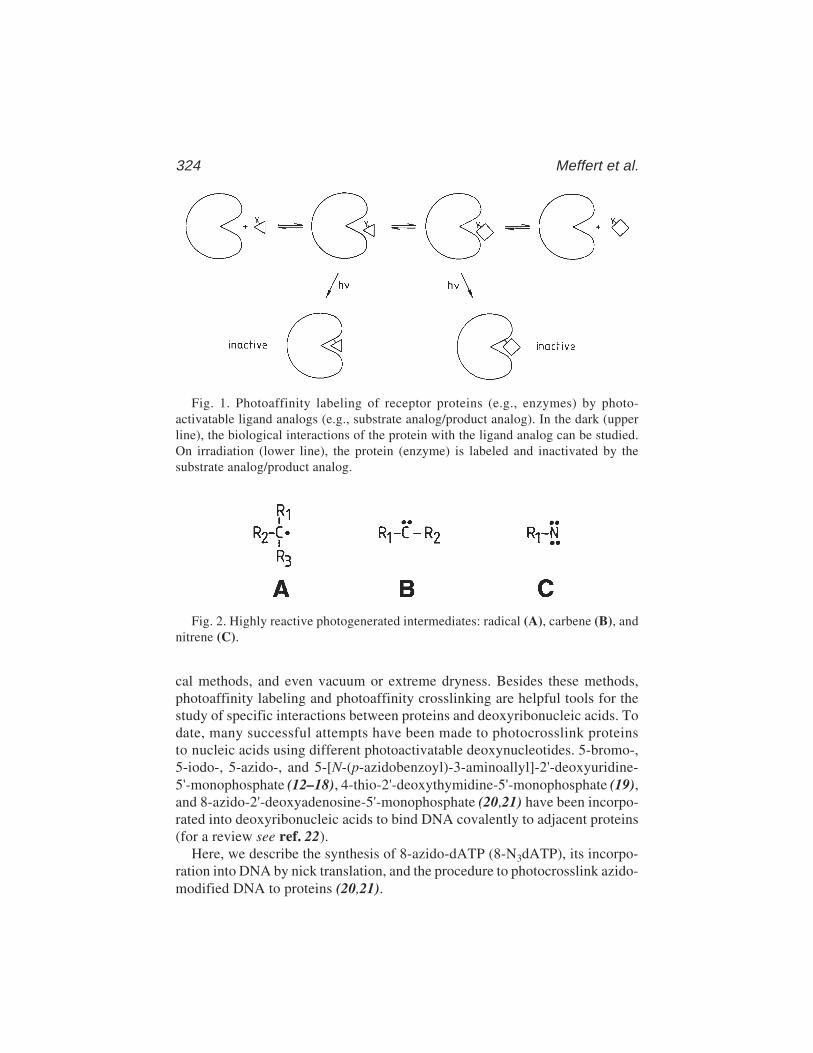
324 Meffert et al.
Fig. 1. Photoaffinity labeling of receptor proteins (e.g., enzymes) by photo-activatable ligand analogs (e.g., substrate analog/product analog). In the dark (upperline), the biological interactions of the protein with the ligand analog can be studied.On irradiation (lower line), the protein (enzyme) is labeled and inactivated by thesubstrate analog/product analog.
Fig. 2. Highly reactive photogenerated intermediates: radical (A), carbene (B), andnitrene (C).
cal methods, and even vacuum or extreme dryness. Besides these methods,photoaffinity labeling and photoaffinity crosslinking are helpful tools for thestudy of specific interactions between proteins and deoxyribonucleic acids. Todate, many successful attempts have been made to photocrosslink proteinsto nucleic acids using different photoactivatable deoxynucleotides. 5-bromo-,5-iodo-, 5-azido-, and 5-[N-(p-azidobenzoyl)-3-aminoallyl]-2'-deoxyuridine-5'-monophosphate (12–18), 4-thio-2'-deoxythymidine-5'-monophosphate (19),and 8-azido-2'-deoxyadenosine-5'-monophosphate (20,21) have been incorpo-rated into deoxyribonucleic acids to bind DNA covalently to adjacent proteins(for a review see ref. 22).
Here, we describe the synthesis of 8-azido-dATP (8-N3dATP), its incorpo-ration into DNA by nick translation, and the procedure to photocrosslink azido-modified DNA to proteins (20,21).
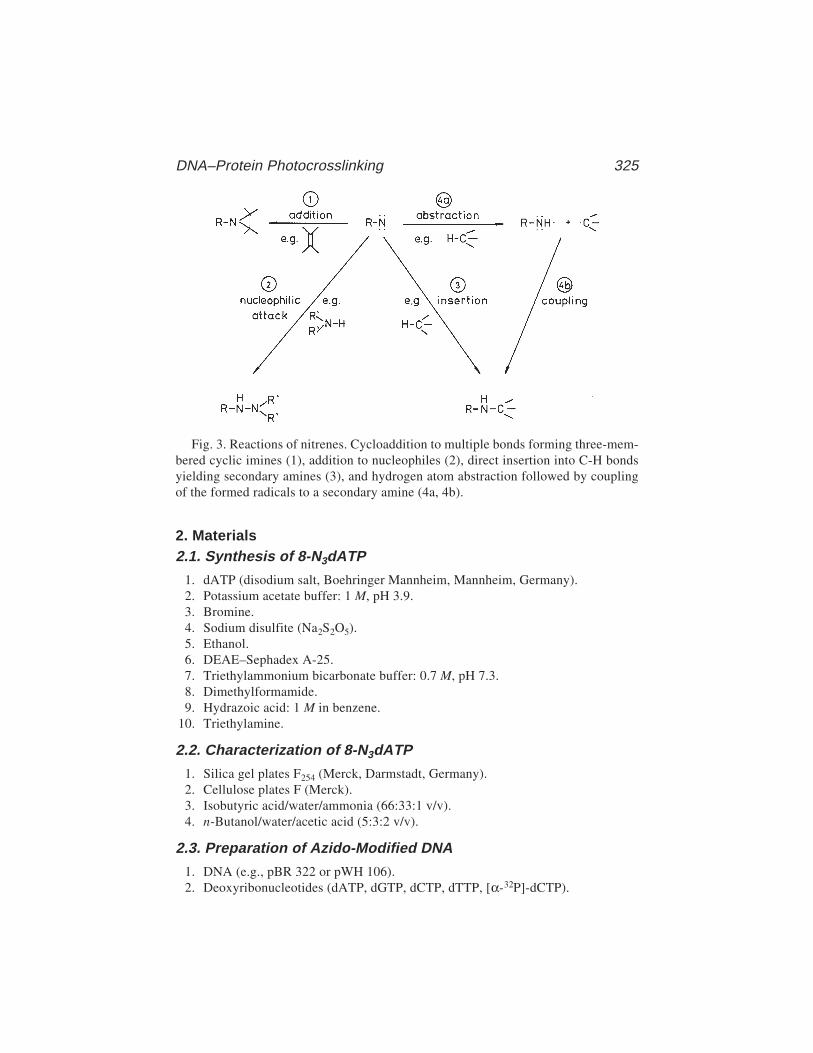
DNA–Protein Photocrosslinking 325
2. Materials2.1. Synthesis of 8-N3dATP
1. dATP (disodium salt, Boehringer Mannheim, Mannheim, Germany).2. Potassium acetate buffer: 1 M, pH 3.9.3. Bromine.4. Sodium disulfite (Na2S2O5).5. Ethanol.6. DEAE–Sephadex A-25.7. Triethylammonium bicarbonate buffer: 0.7 M, pH 7.3.8. Dimethylformamide.9. Hydrazoic acid: 1 M in benzene.
10. Triethylamine.
2.2. Characterization of 8-N3dATP
1. Silica gel plates F254 (Merck, Darmstadt, Germany).2. Cellulose plates F (Merck).3. Isobutyric acid/water/ammonia (66:33:1 v/v).4. n-Butanol/water/acetic acid (5:3:2 v/v).
2.3. Preparation of Azido-Modified DNA
1. DNA (e.g., pBR 322 or pWH 106).2. Deoxyribonucleotides (dATP, dGTP, dCTP, dTTP, [α-32P]-dCTP).
Fig. 3. Reactions of nitrenes. Cycloaddition to multiple bonds forming three-mem-bered cyclic imines (1), addition to nucleophiles (2), direct insertion into C-H bondsyielding secondary amines (3), and hydrogen atom abstraction followed by couplingof the formed radicals to a secondary amine (4a, 4b).
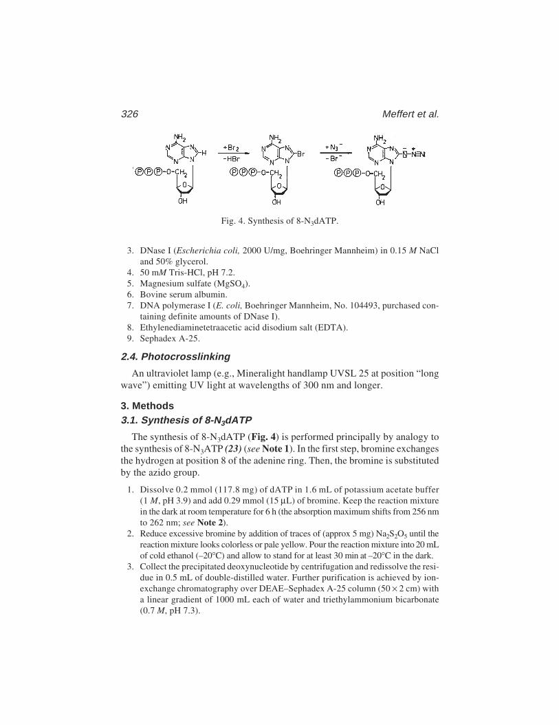
326 Meffert et al.
3. DNase I (Escherichia coli, 2000 U/mg, Boehringer Mannheim) in 0.15 M NaCland 50% glycerol.
4. 50 mM Tris-HCl, pH 7.2.5. Magnesium sulfate (MgSO4).6. Bovine serum albumin.7. DNA polymerase I (E. coli, Boehringer Mannheim, No. 104493, purchased con-
taining definite amounts of DNase I).8. Ethylenediaminetetraacetic acid disodium salt (EDTA).9. Sephadex A-25.
2.4. Photocrosslinking
An ultraviolet lamp (e.g., Mineralight handlamp UVSL 25 at position “longwave”) emitting UV light at wavelengths of 300 nm and longer.
3. Methods3.1. Synthesis of 8-N3dATP
The synthesis of 8-N3dATP (Fig. 4) is performed principally by analogy tothe synthesis of 8-N3ATP (23) (see Note 1). In the first step, bromine exchangesthe hydrogen at position 8 of the adenine ring. Then, the bromine is substitutedby the azido group.
1. Dissolve 0.2 mmol (117.8 mg) of dATP in 1.6 mL of potassium acetate buffer(1 M, pH 3.9) and add 0.29 mmol (15 µL) of bromine. Keep the reaction mixturein the dark at room temperature for 6 h (the absorption maximum shifts from 256 nmto 262 nm; see Note 2).
2. Reduce excessive bromine by addition of traces of (approx 5 mg) Na2S2O5 until thereaction mixture looks colorless or pale yellow. Pour the reaction mixture into 20 mLof cold ethanol (–20°C) and allow to stand for at least 30 min at –20°C in the dark.
3. Collect the precipitated deoxynucleotide by centrifugation and redissolve the resi-due in 0.5 mL of double-distilled water. Further purification is achieved by ion-exchange chromatography over DEAE–Sephadex A-25 column (50 × 2 cm) witha linear gradient of 1000 mL each of water and triethylammonium bicarbonate(0.7 M, pH 7.3).
Fig. 4. Synthesis of 8-N3dATP.
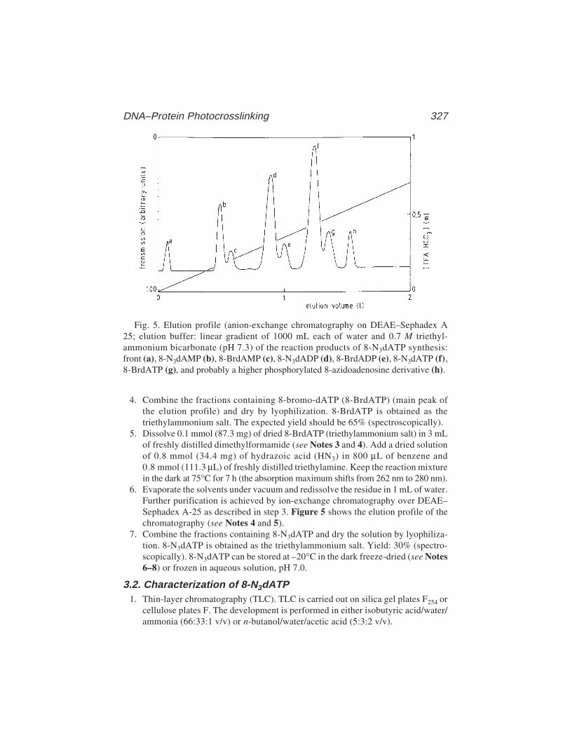
DNA–Protein Photocrosslinking 327
4. Combine the fractions containing 8-bromo-dATP (8-BrdATP) (main peak ofthe elution profile) and dry by lyophilization. 8-BrdATP is obtained as thetriethylammonium salt. The expected yield should be 65% (spectroscopically).
5. Dissolve 0.1 mmol (87.3 mg) of dried 8-BrdATP (triethylammonium salt) in 3 mLof freshly distilled dimethylformamide (see Notes 3 and 4). Add a dried solutionof 0.8 mmol (34.4 mg) of hydrazoic acid (HN3) in 800 µL of benzene and0.8 mmol (111.3 µL) of freshly distilled triethylamine. Keep the reaction mixturein the dark at 75°C for 7 h (the absorption maximum shifts from 262 nm to 280 nm).
6. Evaporate the solvents under vacuum and redissolve the residue in 1 mL of water.Further purification is achieved by ion-exchange chromatography over DEAE–Sephadex A-25 as described in step 3. Figure 5 shows the elution profile of thechromatography (see Notes 4 and 5).
7. Combine the fractions containing 8-N3dATP and dry the solution by lyophiliza-tion. 8-N3dATP is obtained as the triethylammonium salt. Yield: 30% (spectro-scopically). 8-N3dATP can be stored at –20°C in the dark freeze-dried (see Notes6–8) or frozen in aqueous solution, pH 7.0.
3.2. Characterization of 8-N3dATP1. Thin-layer chromatography (TLC). TLC is carried out on silica gel plates F254 or
cellulose plates F. The development is performed in either isobutyric acid/water/ammonia (66:33:1 v/v) or n-butanol/water/acetic acid (5:3:2 v/v).
Fig. 5. Elution profile (anion-exchange chromatography on DEAE–Sephadex A25; elution buffer: linear gradient of 1000 mL each of water and 0.7 M triethyl-ammonium bicarbonate (pH 7.3) of the reaction products of 8-N3dATP synthesis:front (a), 8-N3dAMP (b), 8-BrdAMP (c), 8-N3dADP (d), 8-BrdADP (e), 8-N3dATP (f),8-BrdATP (g), and probably a higher phosphorylated 8-azidoadenosine derivative (h).
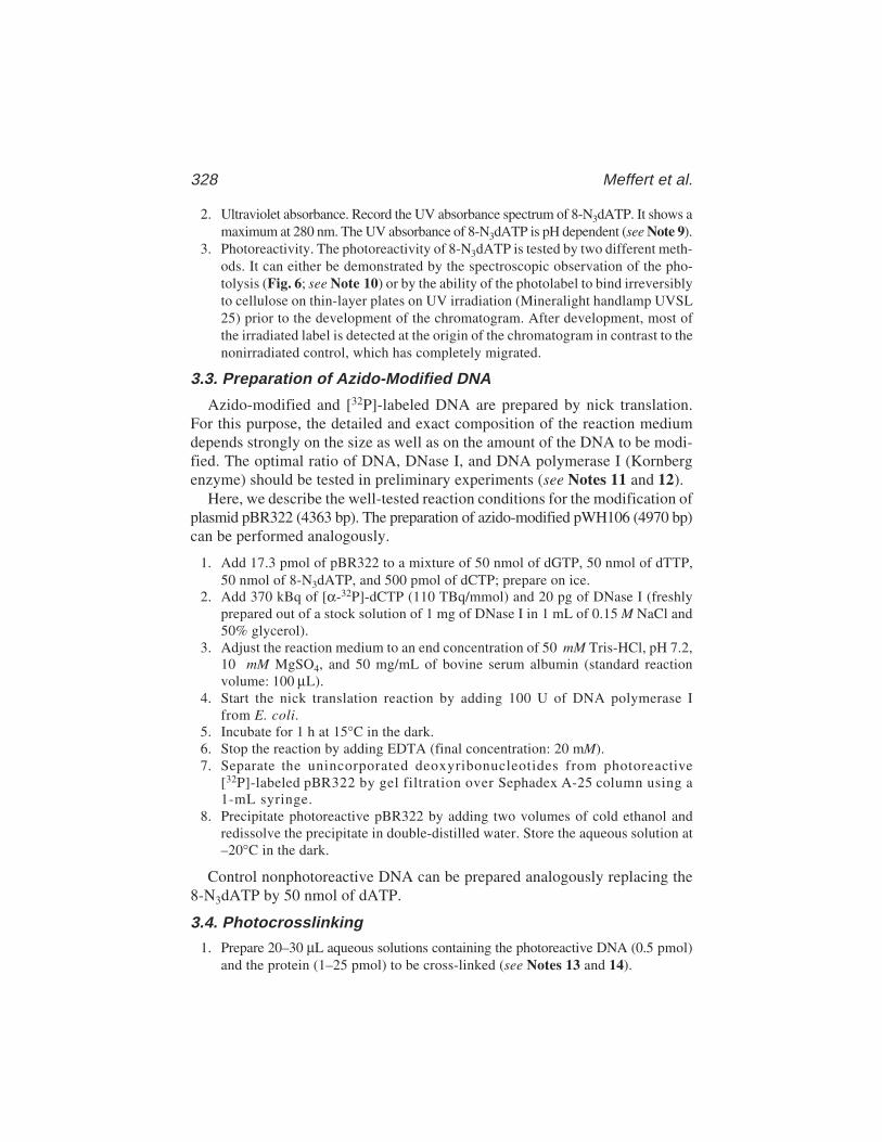
328 Meffert et al.
2. Ultraviolet absorbance. Record the UV absorbance spectrum of 8-N3dATP. It shows amaximum at 280 nm. The UV absorbance of 8-N3dATP is pH dependent (see Note 9).
3. Photoreactivity. The photoreactivity of 8-N3dATP is tested by two different meth-ods. It can either be demonstrated by the spectroscopic observation of the pho-tolysis (Fig. 6; see Note 10) or by the ability of the photolabel to bind irreversiblyto cellulose on thin-layer plates on UV irradiation (Mineralight handlamp UVSL25) prior to the development of the chromatogram. After development, most ofthe irradiated label is detected at the origin of the chromatogram in contrast to thenonirradiated control, which has completely migrated.
3.3. Preparation of Azido-Modified DNA
Azido-modified and [32P]-labeled DNA are prepared by nick translation.For this purpose, the detailed and exact composition of the reaction mediumdepends strongly on the size as well as on the amount of the DNA to be modi-fied. The optimal ratio of DNA, DNase I, and DNA polymerase I (Kornbergenzyme) should be tested in preliminary experiments (see Notes 11 and 12).
Here, we describe the well-tested reaction conditions for the modification ofplasmid pBR322 (4363 bp). The preparation of azido-modified pWH106 (4970 bp)can be performed analogously.
1. Add 17.3 pmol of pBR322 to a mixture of 50 nmol of dGTP, 50 nmol of dTTP,50 nmol of 8-N3dATP, and 500 pmol of dCTP; prepare on ice.
2. Add 370 kBq of [α-32P]-dCTP (110 TBq/mmol) and 20 pg of DNase I (freshlyprepared out of a stock solution of 1 mg of DNase I in 1 mL of 0.15 M NaCl and50% glycerol).
3. Adjust the reaction medium to an end concentration of 50 mM Tris-HCl, pH 7.2,10 mM MgSO4, and 50 mg/mL of bovine serum albumin (standard reactionvolume: 100 µL).
4. Start the nick translation reaction by adding 100 U of DNA polymerase Ifrom E. coli.
5. Incubate for 1 h at 15°C in the dark.6. Stop the reaction by adding EDTA (final concentration: 20 mM).7. Separate the unincorporated deoxyribonucleotides from photoreactive
[32P]-labeled pBR322 by gel filtration over Sephadex A-25 column using a1-mL syringe.
8. Precipitate photoreactive pBR322 by adding two volumes of cold ethanol andredissolve the precipitate in double-distilled water. Store the aqueous solution at–20°C in the dark.
Control nonphotoreactive DNA can be prepared analogously replacing the8-N3dATP by 50 nmol of dATP.
3.4. Photocrosslinking
1. Prepare 20–30 µL aqueous solutions containing the photoreactive DNA (0.5 pmol)and the protein (1–25 pmol) to be cross-linked (see Notes 13 and 14).
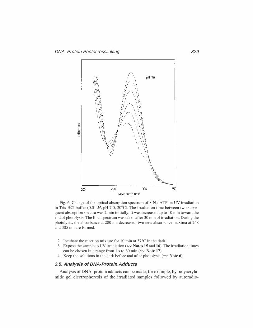
DNA–Protein Photocrosslinking 329
Fig. 6. Change of the optical absorption spectrum of 8-N3dATP on UV irradiationin Tris-HCl buffer (0.01 M, pH 7.0, 20°C). The irradiation time between two subse-quent absorption spectra was 2 min initially. It was increased up to 10 min toward theend of photolysis. The final spectrum was taken after 30 min of irradiation. During thephotolysis, the absorbance at 280 nm decreased; two new absorbance maxima at 248and 305 nm are formed.
2. Incubate the reaction mixture for 10 min at 37°C in the dark.3. Expose the sample to UV irradiation (see Notes 15 and 16). The irradiation times
can be chosen in a range from 1 s to 60 min (see Note 17).4. Keep the solutions in the dark before and after photolysis (see Note 6).
3.5. Analysis of DNA-Protein Adducts
Analysis of DNA–protein adducts can be made, for example, by polyacryla-mide gel electrophoresis of the irradiated samples followed by autoradio-
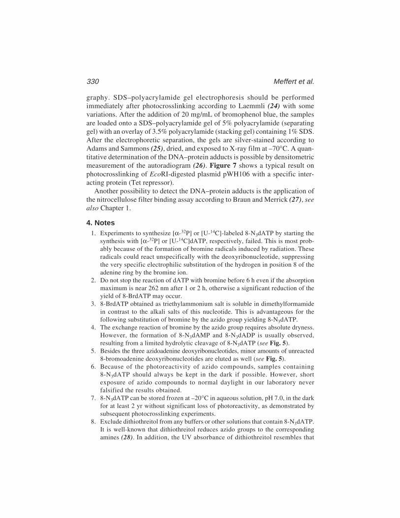
330 Meffert et al.
graphy. SDS–polyacrylamide gel electrophoresis should be performedimmediately after photocrosslinking according to Laemmli (24) with somevariations. After the addition of 20 mg/mL of bromophenol blue, the samplesare loaded onto a SDS–polyacrylamide gel of 5% polyacrylamide (separatinggel) with an overlay of 3.5% polyacrylamide (stacking gel) containing 1% SDS.After the electrophoretic separation, the gels are silver-stained according toAdams and Sammons (25), dried, and exposed to X-ray film at –70°C. A quan-titative determination of the DNA–protein adducts is possible by densitometricmeasurement of the autoradiogram (26). Figure 7 shows a typical result onphotocrosslinking of EcoRI-digested plasmid pWH106 with a specific inter-acting protein (Tet repressor).
Another possibility to detect the DNA–protein adducts is the application ofthe nitrocellulose filter binding assay according to Braun and Merrick (27), seealso Chapter 1.
4. Notes1. Experiments to synthesize [α-32P] or [U-14C]-labeled 8-N3dATP by starting the
synthesis with [α-32P] or [U-14C]dATP, respectively, failed. This is most prob-ably because of the formation of bromine radicals induced by radiation. Theseradicals could react unspecifically with the deoxyribonucleotide, suppressingthe very specific electrophilic substitution of the hydrogen in position 8 of theadenine ring by the bromine ion.
2. Do not stop the reaction of dATP with bromine before 6 h even if the absorptionmaximum is near 262 nm after 1 or 2 h, otherwise a significant reduction of theyield of 8-BrdATP may occur.
3. 8-BrdATP obtained as triethylammonium salt is soluble in dimethylformamidein contrast to the alkali salts of this nucleotide. This is advantageous for thefollowing substitution of bromine by the azido group yielding 8-N3dATP.
4. The exchange reaction of bromine by the azido group requires absolute dryness.However, the formation of 8-N3dAMP and 8-N3dADP is usually observed,resulting from a limited hydrolytic cleavage of 8-N3dATP (see Fig. 5).
5. Besides the three azidoadenine deoxyribonucleotides, minor amounts of unreacted8-bromoadenine deoxyribonucleotides are eluted as well (see Fig. 5).
6. Because of the photoreactivity of azido compounds, samples containing8-N3dATP should always be kept in the dark if possible. However, shortexposure of azido compounds to normal daylight in our laboratory neverfalsified the results obtained.
7. 8-N3dATP can be stored frozen at –20°C in aqueous solution, pH 7.0, in the darkfor at least 2 yr without significant loss of photoreactivity, as demonstrated bysubsequent photocrosslinking experiments.
8. Exclude dithiothreitol from any buffers or other solutions that contain 8-N3dATP.It is well-known that dithiothreitol reduces azido groups to the correspondingamines (28). In addition, the UV absorbance of dithiothreitol resembles that

DNA–Protein Photocrosslinking 331
Fig. 7. Photocrosslinking of proteins to DNA (pWH106). Autoradiogram of a dena-turing 5% SDS-polyacrylamide gel electrophoresis showing photocrosslinking of Tetrepressor to azido-activated 187-bp and 3848-bp fragments of pWH106 (radioactivelabeled by 32P). Each 187-bp fragment contains two tet operator sequences, the 3848-bp fragment none. UV irradiation of azidomodified 187-bp fragment in the presenceof Tet repressor results in a reduced migration of the 187-bp fragment because ofcovalent crosslinking of the DNA to one or two Tet repressor dimers. In each of lanes1–7, 0.06 pmol pWH106 (cleaved by EcoRI) and 20 pmol Tet repressor were applied.Lane 1: photoactive fragments of pWH 106 without protein (30' UV); lane 2:nonphotoactive fragments of pWH106 with Tet repressor (30' UV); lanes 3–7:photoactive fragments of pWH106 with Tet repressor (0', 1', 4', 10', 30' UV). Frac-tions: Origin of sample loading (a); traces of 3848-bp fragment covalently crosslinked(unspecifically) to Tet repressor (b); 3848-bp fragment (no Tet repressor bound) (c);187-bp fragment covalently crosslinked to two Tet repressor dimers (d); 187-bp frag-ment covalently crosslinked to one Tet repressor dimer (e); 187-bp fragment (no Tetrepressor bound) (f).
of 8-N3dATP because of the formation of disulfide bonds by oxidation on stor-age in aqueous solution. This results in a reduced rate of photocrosslinking by theUV irradiation.
9. The UV absorption of 8-N3dATP shows a maximum at 280 nm. The absorbanceat 280 nm increases with decreasing pH value (see step 2 of Subheading 3.2.). Asecond absorption maximum at 219 nm shifts to 204 nm in acidic solution. Botheffects are a result of the protonation at N1 of the purine ring (29). The UVabsorption spectrum of 8-N3dATP resembles that of 8-N3ATP (23).
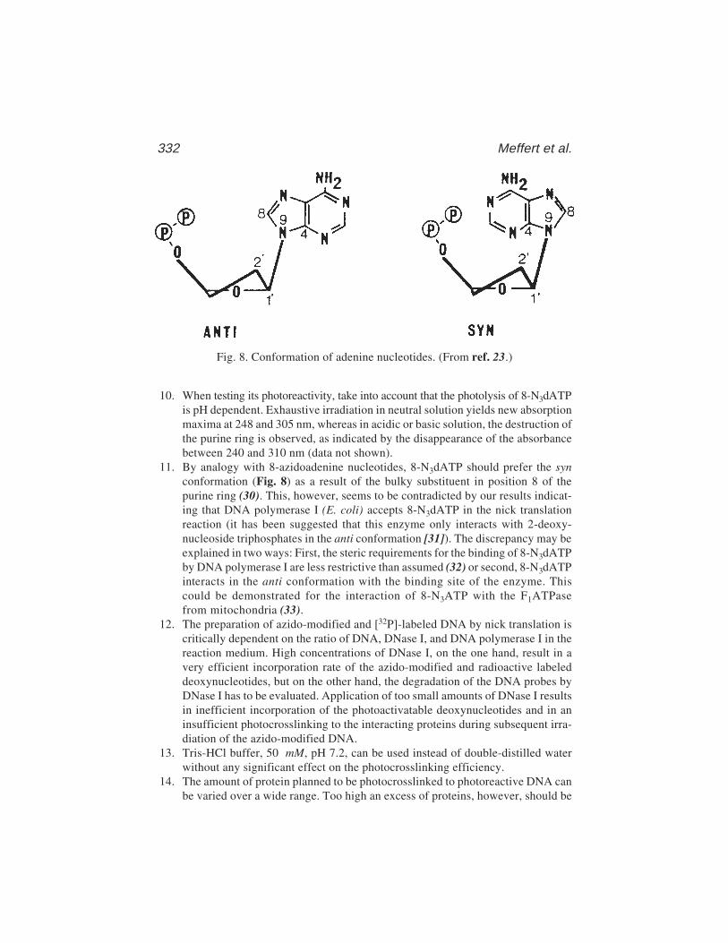
332 Meffert et al.
10. When testing its photoreactivity, take into account that the photolysis of 8-N3dATPis pH dependent. Exhaustive irradiation in neutral solution yields new absorptionmaxima at 248 and 305 nm, whereas in acidic or basic solution, the destruction ofthe purine ring is observed, as indicated by the disappearance of the absorbancebetween 240 and 310 nm (data not shown).
11. By analogy with 8-azidoadenine nucleotides, 8-N3dATP should prefer the synconformation (Fig. 8) as a result of the bulky substituent in position 8 of thepurine ring (30). This, however, seems to be contradicted by our results indicat-ing that DNA polymerase I (E. coli) accepts 8-N3dATP in the nick translationreaction (it has been suggested that this enzyme only interacts with 2-deoxy-nucleoside triphosphates in the anti conformation [31]). The discrepancy may beexplained in two ways: First, the steric requirements for the binding of 8-N3dATPby DNA polymerase I are less restrictive than assumed (32) or second, 8-N3dATPinteracts in the anti conformation with the binding site of the enzyme. Thiscould be demonstrated for the interaction of 8-N3ATP with the F1ATPasefrom mitochondria (33).
12. The preparation of azido-modified and [32P]-labeled DNA by nick translation iscritically dependent on the ratio of DNA, DNase I, and DNA polymerase I in thereaction medium. High concentrations of DNase I, on the one hand, result in avery efficient incorporation rate of the azido-modified and radioactive labeleddeoxynucleotides, but on the other hand, the degradation of the DNA probes byDNase I has to be evaluated. Application of too small amounts of DNase I resultsin inefficient incorporation of the photoactivatable deoxynucleotides and in aninsufficient photocrosslinking to the interacting proteins during subsequent irra-diation of the azido-modified DNA.
13. Tris-HCl buffer, 50 mM, pH 7.2, can be used instead of double-distilled waterwithout any significant effect on the photocrosslinking efficiency.
14. The amount of protein planned to be photocrosslinked to photoreactive DNA canbe varied over a wide range. Too high an excess of proteins, however, should be
Fig. 8. Conformation of adenine nucleotides. (From ref. 23.)
DNA–Protein Photocrosslinking 333
avoided because the absorbance maximum of proteins at 280 nm will lead toinefficient crosslinking rates.
15. One way to expose the samples to UV light is to deposit the probes (typically 30–50 µL) in plastic wells (normally used for radioimmunoassay or enzyme-linkedimmunosorbent assay tests). The UV lamp is positioned directly above thesamples; thus more than one probe can be irradiated simultaneously.
16. The emitted light of the UV lamp used for photocrosslinking should not containlight of shorter wavelengths than 300 nm because of the possibility of photo-damaging DNA or protein. For example, the Mineralight handlamp UVSL 25(long wave) emits UV light of mainly 366 nm. The small portion of UV light ofwavelengths between 300 and 320 nm emitted allows the photoactivation of theazido group without any significant photodamage of DNA or protein.
17. Ultraviolet irradiation times for photocrosslinking can be chosen over a widerange (see step 3 of Subheading 3.4.). Optimal UV irradiation rates (flux perunit area) must be tested. In our experiments (using the Mineralight handlampUVSL 25 fixed in a position resulting in a fluence rate of 4 J/m2/s at the positionof the sample) DNA–protein adducts are first detectable after irradiation times of10–30 s; irradiation periods longer than 15–20 min do not improve the yield ofphotocrosslink products.
AcknowledgmentsThe authors thank Dr. Marianne Schüz (Wiesbaden) for editing the manu-
script. This work was supported by the Bundesministerium für Forschungund Technologie (07QV8942) and by the Deutsche Forschungsgemeinschaft(Scha 344/1-3).
References1. Bayley, H. and Knowles, J. R. (1977) Photoaffinity labeling. Methods Enzymol.
46, 69–114.2. Bayley, H. (1983) Photogenerated reagents in biochemistry and molecular biol-
ogy, in Laboratory Techniques in Biochemistry, vol. 12 (Work, T. S. and Burdon,R. H., eds.), Elsevier, Amsterdam.
3. Schäfer, H.-J. (1987) Photoaffinity labeling and photoaffinity crosslinking ofenzymes, in Chemical Modifications of Enzymes, Active Site Studies (Eyzaguirre,J., ed.), Ellis Horwood, Chichester, pp. 45–62.
4. Smith, K. C. (1962) Dose dependent decrease in extractability of DNA from bac-teria (by UV-light). Biochem. Biophys. Res. Commun. 8, 157–163.
5. Shetlar, M. D. (1980) Crosslinking of proteins to nucleic acids by UV-light.Photochem. Photobiol. Rev. 5, 105–197.
6. Welsh, J. and Cantor, C. R. (1984) Protein–DNA crosslinking. Trends Biochem.Sci. 9, 505–508.
7. Ekert, B., Giocanti, N., and Sabattier, R. (1986) Study of several factors in RNA–protein crosslink formation induced by ionizing radiations within 70S ribosomesof E. coli MRE 600. Int. J. Radiat. Biol. 50, 507–525.
334 Meffert et al.
8. Lesko, S. A., Drocourt, J. L., and Yang, S. U. (1982) DNA–protein and DNAinterstrand crosslinks induced in isolated chromatin by H2O2. and Fe-EDTA-che-lates. Biochemistry 21, 5010–5015.
9. Wedrychowsky, A., Ward, W. S., Schmidt, W. N., and Hnilica, L. S. (1985) Chro-mium-induced crosslinking of nuclear proteins and DNA. J. Biol. Chem. 260,7150–7155.
10. Summerfield, F. W. and Tappel, A. L. (1984) Crosslinking of DNA in liver andtestis of rats fed 1,3-propanediol. Chem. Biol. Interact. 50, 87–96.
11. Dose, K., Bieger-Dose, A., Martens, K.-D., Meffert, R., Nawroth, T., Risi, S., et al.(1987) Survival under space vacuum—biochemical aspects. Proc. 3rd Eur. Symp.Life Sci. Res. in Space (ESA SP–271), pp. 193–195.
12. Lin, S. Y. and Riggs, A. D. (1974) Photochemical attachment of lac repressor tobromodeoxyuridine-substituted lac operator by UV radiation. Proc. Natl. Acad.Sci. USA 71, 947–951.
13. Evans, R. K., Johnson, J. D., and Haley, B. E. (1986) 5-Azido-2'-deoxyuridine-5'-triphosphate: a photoaffinity labeling reagent and tool for the enzymatic synthesisof photoactive DNA. Proc. Natl. Acad. Sci. USA 83, 5382–5386.
14. Bartholomew, B., Kassavetis, G. A., Braun, B. R., and Geiduschek, E. P. (1990)The subunit structure of Saccharomyces cerevisiae transcription factor IIICprobed with a novel photocrosslinking reagent. EMBO J. 9, 2197–2205.
15. Lee, D. K., Evans, R. K., Blanco, J., Gottesfeld, J., and Johnson, J. D. (1991)Contacts between 5 S DNA and Xenopus TFIIIA identified using 5-azido-2'-deoxyuridine-substituted DNA. J. Biol. Chem. 266, 16,478–16,484.
16. Blatter, E. E., Ebright, Y. W., and Ebright, R. H. (1992) Identification of an aminoacid-base contact in the GCN4-DNA complex by bromouracil-mediated photo-crosslinking. Nature 83, 650–652.
17. Willis, M. C., Hicke, B. J., Uhlenbeck, O. C., Cech, T. R., and Koch, T. H. (1993)Photocrosslinking of 5-iodouracil-substituted RNA and DNA to proteins. Science262, 1255–1257.
18. Hicke, B. J., Willis, M. C., Koch, T. H., and Cech, T. R. (1994) Telomeric protein–DNA point contacts identified by photo-cross-linking using 5-bromodeoxyuridine.Biochemistry 33, 3364–3373.
19. Bartholomew, B., Braun, B. R., Kassavetis, G. A., and Geiduschek, E. P. (1994)Probing close DNA contacts of RNA–polymerase III transcription complexeswith the photoactive nucleoside 4-thiodeoxythymidine. J. Biol. Chem. 269,18,090–18,095.
20. Meffert, R. and Dose, K. (1988) UV-induced crosslinking of proteins to plasmidpBR322 containing 8-azidoadenine 2'-deoxyribonucleotides. FEBS Lett. 239,190–194.
21. Meffert, R., Rathgeber, G., Schäfer, H.-J., and Dose, K. (1990) UV-induced cross-linking of Tet repressor to DNA containing tet operator sequences and 8-azido-adenines. Nucleic Acids Res. 18, 6633–6636.
22. Bartholomew, B., Tinker, R. L., Kassavetis, G. A., and Geiduschek, E. P. (1995)Photochemical crosslinking assay for DNA tracking by replication proteins. Meth-ods Enzymol. 262, 476–494.

DNA–Protein Photocrosslinking 335
23. Schäfer, H.-J., Scheurich, P., and Dose, K. (1978) Eine einfache darstellungvon 8-N3ATP: ein Agens zur Photoaffinitätsmarkierung von ATP-bindendenProteinen. Liebigs Ann. Chem. 1978, 1749–1753.
24. Laemmli, U. K. (1970) Cleavage of structural proteins during the assembly of thehead of bacteriophage T4. Nature 227, 680.
25. Adams, L. D. and Sammons, D. W. (1981) A unique silver staining procedure forcolor characterization of polypeptides. Electrophoresis 2, 155–165.
26. Westermeier, R., Schickle, H., Thesseling, G., and Walter, W. W. (1988)Densitometrie von gelelektrophoresen. GIT Labor-Medizin 4/88, 194–202.
27. Braun, A. and Merrick, B. (1975) Properties of UV-light-mediated binding ofBSA to DNA. Photochem. Photobiol. 21, 243–247.
28. Staros, J. V., Bayley, H., Standring, D. N., and Knowles, J. R. (1978) Reductionof aryl azides by thiols: implications for the use of photoaffinity reagents.Biochem. Biophys. Res. Commun. 80, 568–572.
29. Koberstein, R., Cobianchi, L., and Sund, H. (1976) Interaction of the photoaffinitylabel 8-azido-ADP with glutamate dehydrogenase. FEBS Lett. 64, 176–180.
30. Vignais, P. V. and Lunardi, J. (1985) Chemical probes of the mitochondrial ATPsynthesis and translocation. Annu. Rev. Biochem. 54, 977–1014.
31. Czarnecki, J. J. (1978) Ph.D. Thesis, University of Wyoming, Laramie, WY.32. Englund, P. T., Kelly, R. B., and Kornberg, A. (1969) Enzymatic synthesis of
DNA: binding of DNA to DNA polymerase. J. Biol. Chem. 244, 3045–3052.33. Garin, J., Vignais, P. V., Gronenborn, A. M., Clore, G. M., Gao, Z., and Bäuerlein,
E. (1988) 1H-NMR studies on nucleotide binding to the catalytic sites of bovinemitochondrial F1-ATPase. FEBS Lett. 242, 178–182.
Protein–DNA Photocrosslinking 337
337
From: Methods in Molecular Biology, vol. 148: DNA–Protein Interactions: Principles and Protocols, 2nd ed.Edited by: T. Moss © Humana Press Inc., Totowa, NJ
24
Site-Specific Protein–DNA Photocrosslinking
Analysis of Bacterial Transcription Initiation Complexes
Nikolai Naryshkin, Younggyu Kim, Qianping Dong,and Richard H. Ebright
1. Introduction1.1. Site-Specific Protein-DNA Photocrosslinking
In work carried out in collaboration with the laboratory of D. Reinberg(University of Medicine and Dentistry of New Jersey), we have developed asite-specific protein–DNA photocrosslinking procedure to define positions ofproteins relative to DNA in protein–DNA and multiprotein–DNA complexes(1–3). The procedure has four parts (Fig. 1):
1. Chemical (4–6) and enzymatic (7) reactions are used to prepare a DNA fragmentcontaining a photoactivatible crosslinking agent and an adjacent radiolabelincorporated at a single, defined DNA phosphate (with a 9.7 Å linker betweenthe photoreactive atom of the crosslinking agent and the phosphorus atom of thephosphate, and with an approximately 11 Å maximum “reach” between potentialcrosslinking targets and the phosphorus atom of the phosphate).
2. The multiprotein–DNA complex of interest is formed using the site-specificallyderivatized DNA fragment, and the multiprotein–DNA complex is ultraviolet(UV)-irradiated, initiating covalent crosslinking with proteins in direct physicalproximity to the photoactivatible crosslinking agent.
3. Extensive nuclease digestion is performed, eliminating uncrosslinked DNA andconverting crosslinked DNA to a crosslinked, radiolabeled 3–5 nucleotide “tag.”
4. The “tagged” proteins are identified.
The procedure is performed in systematic fashion, with preparation andanalysis of at least 10 derivatized DNA fragments, each having the photo-activatible crosslinking agent incorporated at a single, defined DNA phosphate

338 Naryshkin et al.
(typically each second DNA phosphate—each 12 Å—on each DNA strandspanning the region of interest (1–3,8).
The results of the procedure define the translational positions of proteinsrelative to the DNA sequence. Plotted on a three-dimensional representation ofa DNA helix, the results also define the rotational orientations of proteins rela-tive to the DNA helix axis, and the groove orientations of proteins relative tothe DNA major and minor grooves (1–3,8).
Fig. 1. Site-specific protein–DNA photocrosslinking (1–3). (A,B) Chemical andenzymatic reactions are used to prepare a full-length-promoter DNA fragment with aphenyl-azide photoactivatible crosslinking agent (R) and an adjacent radioactivephosphorus (*) incorporated at a single, defined site. Based on the chemistry of incorpora-tion, the maximum distance between the site of incorporation and the photoreactiveatom is 9.7 Å; the maximum distance between the site of incorporation and a cross-linked atom is approx 11 Å. (C) UV irradiation of the derivatized protein–DNA complexinitiates crosslinking. Nuclease digestion eliminates uncrosslinked DNA and convertscrosslinked, radiolabeled DNA to a crosslinked, radiolabeled 3–5 nucleotide “tag.”
Protein–DNA Photocrosslinking 339
The procedure has been validated in experiments with three multiprotein–DNA complexes for which crystallographic structures are available (i.e., theTBP–DNA complex, the TBP-TFIIA-DNA complex, and the TBP–TFIIB–DNA complex (1,9–13). In each case, there was a one-to-one correspondencebetween sites at which strong crosslinking was observed and sites that in thecrystallographic structure were within 11 Å of crosslinked proteins (1,9–13).The procedure also has been applied to multiprotein-DNA complexes for whichcrystallographic structures are not available (1–3,8), including a eukaryotictranscription complex containing 16 distinct polypeptides and having amolecular mass in excess of 800 kDa (the RNAPII–TBP–TFIIB–TFIIF–DNAcomplex [2]) and a eukaryotic transcription complex containing 27 distinctpolypeptides and having a molecular mass in excess of 1700 kDa (the RNAPII–TBP–TFIIB–TFIIE–TFIIF–TFIIH–DNA complex [2a]).
The procedure is related to a procedure developed by Geiduschek andco-workers (14–17; see also refs. 18–23), but offers important advantages.First, because the photoactivatible crosslinking agent is incorporated into DNAchemically, it can be incorporated at a single, defined site. (In the procedure ofGeiduschek and co-workers, this is true only at certain DNA sequences.) Sec-ond, because the photoactivatible crosslinking agent is incorporated on theDNA phosphate backbone, it can be incorporated at any nucleotide: A, T, G, orC. Third, since the photoactivatible crosslinking agent is incorporated on theDNA phosphate backbone, it probes interactions both in the DNA minor grooveand in the DNA minor groove.
1.2. Bacterial Transcription Initiation Complexes
Escherichia coli RNA polymerase holoenzyme (RNAP) consists of two cop-ies of an α-subunit (36.5 kDa), one copy of a β-subunit (151 kDa), onecopy of a β'-subunit (155 kDa), and one copy of a σ-subunit (70.3 kDa for theprinciple σ subunit species, σ70) (24). RNAP is a molecular machine that car-ries out a complex series of reactions in transcription initiation (24–26). For-mation of a catalytically competent transcription initiation complex involvesthree steps (24–26):
1. RNAP binds to promoter DNA, interacting solely with DNA upstream of thetranscription start, to yield an RNAP–promoter closed complex (RPc; alsoreferred to as RPc1).
2. RNAP then wraps promoter DNA around its circumference, capturing and inter-acting with DNA downstream of the transcription start, and RNAP undergoes aprotein conformational change, clamping tightly onto DNA, to yield an RNAP–promoter intermediate complex (RPi; also referred to as RPc2 and I2).
3. RNAP then melts approx 14 bp of promoter DNA surrounding the transcriptionstart, rendering accessible the genetic information in the template strand of DNA,to yield a catalytically competent RNAP–promoter open complex (RPo).
340 Naryshkin et al.
In the case of the E. coli lacPUV5 promoter, the RNAP–promoter interme-diate complex (RPi) and the RNAP–promoter open complex (RPo) can betrapped by formation at 14–19°C in the absence of NTPs, and formation at37°C in the absence of NTPs, respectively (27,28). Electrophoretic mobilityshift, DNA footprinting, fluorescence anisotropy, and 2-aminopurine fluores-cence experiments suggest that the trapped complexes are stable and homoge-neous (28–31; A. Kapanidis, X. Shao, N.N., Y.K., and R.H.E., unpublisheddata). Kinetic experiments suggest that the trapped complexes correspond tobona fide on-pathway intermediates (27,28).
In current work, we are using systematic site-specific protein–DNAphotocrosslinking to define RNAP–promoter interactions in RNAP–promoterintermediate and open complexes. We are constructing a set of 110 derivatizedDNA fragments, each containing a photoactivatible crosslinking agent incor-porated at a single, defined position of the lacPUV5 promoter (positions –79 to+30). For each derivatized DNA fragment, we are forming RNAP–promoterintermediate and open complexes, isolating complexes using nondenaturingpolyacrylamide gel electrophoresis, UV-irradiating complexes in situ—in thegel matrix—and identifying crosslinked polypeptides. We are performingexperiments both with wild-type RNAP and with RNAP derivatives havingdiscontinuous β and β' subunits (“split-β RNAP” and “split-β' RNAP;”reconstituted in vitro from recombinant α, recombinant σ70, and sets of recom-binant fragments of β and β'; 32,33). Use of split-β and split-β' RNAP permitsunambiguous assignment of crosslinks to β and β' (which are not well-resolvedin SDS–polyacrylamide gel electrophoresis) and permits rapid, immediatemapping of crosslinks to segments of β and β' (e.g., N-terminal segment, centralsegment, or C-terminal segment) (Fig. 2).
In this chapter, we present protocols for preparation of derivatized lacPUV5promoter DNA fragments, formation of RNAP–promoter intermediate andopen complexes, UV irradiation of complexes, and identification of crosslinks.In addition, we present support protocols for preparation of wild-type RNAP,split-β RNAP, and split-β' RNAP.
2. Materials2.1. Preparation of Derivatized DNA Fragment,Chemical Reactions
1. Azidophenacyl bromide (Sigma).2. Tetraethylthiuram disulfide/acetonitrile (PE Biosystems).3. dA-CPG, dC-CPG, dG-CPG, T-CPG (1 µmol, 500 Å) (PE Biosystems).4. dA, dC, dG, T β-cyanoethylphosphoramidites (PE Biosystems).5. Reagent kit for oligodeoxyribonucleotide synthesis (0.02 M iodine) (PE Biosystems).
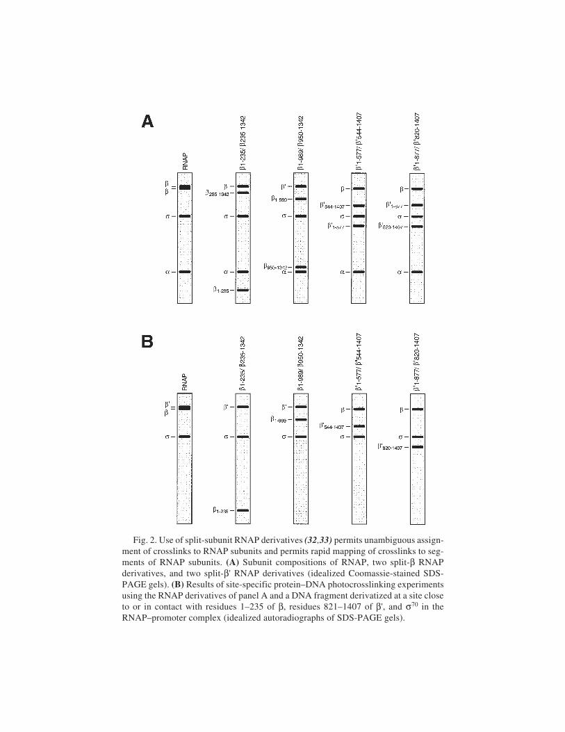
Protein–DNA Photocrosslinking 341
Fig. 2. Use of split-subunit RNAP derivatives (32,33) permits unambiguous assign-ment of crosslinks to RNAP subunits and permits rapid mapping of crosslinks to seg-ments of RNAP subunits. (A) Subunit compositions of RNAP, two split-β RNAPderivatives, and two split-β' RNAP derivatives (idealized Coomassie-stained SDS-PAGE gels). (B) Results of site-specific protein–DNA photocrosslinking experimentsusing the RNAP derivatives of panel A and a DNA fragment derivatized at a site closeto or in contact with residues 1–235 of β, residues 821–1407 of β', and σ70 in theRNAP–promoter complex (idealized autoradiographs of SDS-PAGE gels).
342 Naryshkin et al.
6. Denaturing loading buffer: 0.3% bromophenol blue, 0.3% xylene cyanol, and 12 mMEDTA, in formamide.
7. 0.5X TBE: 45 mM Tris-borate, pH 8.3, and 1 mM EDTA.8. TE: 10 mM Tris-HCl, pH 7.6, 1 mM EDTA.9. 50 mM triethylammonium acetate, pH 7.0 (Prime Synthesis).
10. 1 M potassium phosphate, pH 7.0.11. 3 M sodium acetate, pH 5.2.12. 100% ethanol (store at –20°C).13. 70% ethanol (store at –20°C).14. Dichloromethane (anhydrous) (PE Biosystems).15. Acetonitrile (anhydrous) (PE Biosystems).16. Acetonitrile (high-performance liquid chromatographic [HPLC] grade) (Fisher).17. Formamide (Sigma).18. 12% polyacrylamide (29:1 acrylamide:bis-acrylamide), 8 M urea, 0.5X TBE slab
gel (10 × 7 × 0.075 cm).19. Oligonucleotide purification cartridge (OPC) (PE Biosystems).20. LiChrospher 100 RP–18 reversed-phase HPLC column (5 µm) (Merck).21. Autoradiography intensifying screen (Sigma).22. 254-nm germicidal lamp.23. ABI392 DNA/RNA synthesizer (PE Biosystems).24. Varian 5000 HPLC (Varian).25. L-3000 diode-array HPLC UV detector (Hitachi).26. Speedvac evaporator (Savant).
2.2. Preparation of Derivatized DNA Fragment,Enzymatic Reactions
1. Derivatized oligodeoxyribonucleotide (Subheading 3.1.).2. M13mp2(ICAP-UV5) or M13mp2(ICAP-UV5)-rev ssDNA (see Notes 1 and 2).3. T4 polynucleotide kinase (10 U/µL) (New England Biolabs, cat. no. M0201L).4. T4 DNA polymerase (3 U/µL) (New England Biolabs, cat. no. M0203L).5. T4 DNA ligase (5 U/µL) (Roche Molecular Biochemicals, cat. no. 799009).6. HaeIII (40 U/µL)(Roche Molecular Biochemicals, cat. no. 1336029).7. PvuII (40 U/µL)(Roche Molecular Biochemicals, cat. no. 899216).8. [γ32P]-ATP (10 mCi/mL, 6000 Ci/mmol) (NEN).9. 100 mM ATP (Amersham Pharmacia Biotech).
10. 100 mM dNTPs (Amersham Pharmacia Biotech).11. Upstream primer (5'-CGGTGCGGGCCTCTTCGCTATTAC–3').12. 10X phosphorylation buffer: 500 mM Tris-HCl, pH 7.6, 100 mM MgCl2, 15 mM
β-mercaptoethanol.13. 10X annealing buffer: 400 mM Tris-HCl, pH 7.9, 500 mM NaCl, and 100 mM MgCl2.14. 10X digestion buffer: 100 mM Tris-HCl, pH 7.9, 500 mM NaCl, and 100 mM
MgCl2, (see Note 3).15. Elution buffer: 0.5 M ammonium acetate, 10 mM magnesium acetate pH 7.5, and
1 mM EDTA.
Protein–DNA Photocrosslinking 343
16. Denaturing loading buffer: 0.3% bromophenol blue, 0.3% xylene cyanol, and 12 mMEDTA, in formamide.
17. Nondenaturing loading buffer: 0.3% bromophenol blue, 0.3% xylene cyanol, and30% glycerol, in water.
18. 0.5X TBE: 45 mM Tris-borate pH 8.3, and 1 mM EDTA.19. TE: 10 mM Tris-HCl, pH 8.0, and 1 mM EDTA.20. Low-EDTA TE: 10 mM Tris-HCl, pH 8.0, and 0.1 mM EDTA.21. 0.5 M EDTA, pH 8.0.22. 10% sodium dodecyl sulfate (SDS).23. 100% ethanol (store at –20°C).24. 70% ethanol (store at –20°C).25. 12% polyacrylamide (29:1 acrylamide:bis-acrylamide), 8 M urea, and 0.5X TBE
slab gel (10 × 7 × 0.075 cm).26. 7.5% polyacrylamide (29:1 acrylamide:bis-acrylamide), and 0.5X TBE slab gel
(10 × 7 × 0.15 cm).27. CHROMA SPIN+TE–10 spin column (Clontech).28. CHROMA SPIN+TE–100 spin column (Clontech).29. Spin-X centrifuge filter (0.22 µm, cellulose acetate) (Fisher).30. PicoGreen dsDNA quantitation kit (Molecular Probes, cat. no. P-7589).31. Disposable scalpels (Fisher).32. Autoradiography markers (Stratagene).33. Light box (VWR).34. Speedvac evaporator (Savant).
2.3. Preparation of RNAP and RNAP Derivatives
1. E. coli strain XL1-blue (Stratagene, cat. no. 200249).2. E. coli strain BL21(DE3) pLysS (Novagen, cat. no. 69388-3).3. Plasmids encoding RNAP subunits (see Table 1).4. Plasmids encoding fragments of RNAP subunits (see Table 2).5. LB broth: 10 g/L tryptone, 5 g/L yeast extract, and 10 g/L NaCl; autoclave sterilized.6. TYE agar plates containing 200 µg/mL ampicillin and 35 µg/mL chlorampheni-
col: 10 g/L tryptone, 5 g/L yeast extract, 8 g/L NaCl, and 15 g/L agar; autoclavesterilized without antibiotics; supplemented with antibiotics after cooling to55°C; poured into sterile 100 × 15 mm Petri plates at approx 25 mL/plate.
7. TYE agar plates containing 200 µg/mL ampicillin and 20 µg/mL tetracycline.8. TYE agar plates containing 40 µg/mL kanamycin and 35 µg/mL chloramphenicol.9. TYE agar plates containing 40 µg/mL kanamycin and 20 µg/mL tetracycline.
10. 100 mg/mL ampicillin (filter sterilized) (Sigma).11. 35 mg/mL chloramphenicol in ethanol (filter sterilized) (Sigma).12. 40 mg/mL kanamycin (filter sterilized) (Sigma).13. 20 mg/mL tetracycline in methanol (filter sterilized) (Sigma).14. 1 M IPTG (filter sterilized) (Roche Molecular Biochemicals).15. Buffer A: 20 mM Tris-HCl, pH 7.9, 500 mM NaCl, and 5 mM imidazole.16. Buffer B: 20 mM Tris-HCl, pH 7.9, 6 M guanidine chloride, and 500 mM NaCl.
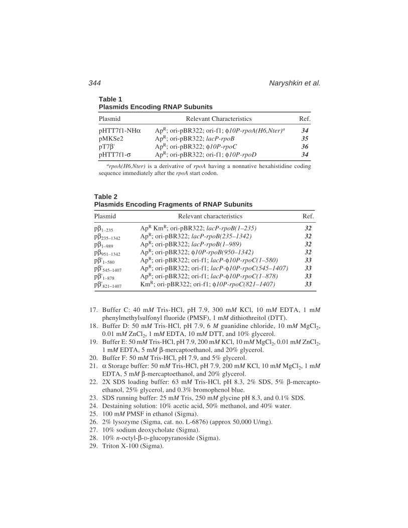
344 Naryshkin et al.
17. Buffer C: 40 mM Tris-HCl, pH 7.9, 300 mM KCl, 10 mM EDTA, 1 mMphenylmethylsulfonyl fluoride (PMSF), 1 mM dithiothreitol (DTT).
18. Buffer D: 50 mM Tris-HCl, pH 7.9, 6 M guanidine chloride, 10 mM MgCl2,0.01 mM ZnCl2, 1 mM EDTA, 10 mM DTT, and 10% glycerol.
19. Buffer E: 50 mM Tris-HCl, pH 7.9, 200 mM KCl, 10 mM MgCl2, 0.01 mM ZnCl2,1 mM EDTA, 5 mM β-mercaptoethanol, and 20% glycerol.
20. Buffer F: 50 mM Tris-HCl, pH 7.9, and 5% glycerol.21. α Storage buffer: 50 mM Tris-HCl, pH 7.9, 200 mM KCl, 10 mM MgCl2, 1 mM
EDTA, 5 mM β-mercaptoethanol, and 20% glycerol.22. 2X SDS loading buffer: 63 mM Tris-HCl, pH 8.3, 2% SDS, 5% β-mercapto-
ethanol, 25% glycerol, and 0.3% bromophenol blue.23. SDS running buffer: 25 mM Tris, 250 mM glycine pH 8.3, and 0.1% SDS.24. Destaining solution: 10% acetic acid, 50% methanol, and 40% water.25. 100 mM PMSF in ethanol (Sigma).26. 2% lysozyme (Sigma, cat. no. L-6876) (approx 50,000 U/mg).27. 10% sodium deoxycholate (Sigma).28. 10% n-octyl-β-D-glucopyranoside (Sigma).29. Triton X-100 (Sigma).
Table 1Plasmids Encoding RNAP Subunits
Plasmid Relevant Characteristics Ref.
pHTT7f1-NHα ApR; ori-pBR322; ori-f1; φ10P-rpoA(H6,Nter)a 34pMKSe2 ApR; ori-pBR322; lacP-rpoB 35pT7β' ApR; ori-pBR322; φ10P-rpoC 36pHTT7f1-σ ApR; ori-pBR322; ori-f1; φ10P-rpoD 34
arpoA(H6,Nter) is a derivative of rpoA having a nonnative hexahistidine codingsequence immediately after the rpoA start codon.
Table 2Plasmids Encoding Fragments of RNAP Subunits
Plasmid Relevant characteristics Ref.
pβ1–235 ApR KmR; ori-pBR322; lacP-rpoB(1–235) 32pβ235–1342 ApR; ori-pBR322; lacP-rpoB(235–1342) 32pβ1–989 ApR; ori-pBR322; lacP-rpoB(1–989) 32pβ951–1342 ApR; ori-pBR322; φ10P-rpoB(950–1342) 32pβ'1–580 ApR; ori-pBR322; ori-f1; lacP-φ10P-rpoC(1–580) 33pβ'545–1407 ApR; ori-pBR322; ori-f1; lacP-φ10P-rpoC(545–1407) 33pβ'1–878 ApR; ori-pBR322; ori-f1; lacP-φ10P-rpoC(1–878) 33pβ'821–1407 KmR; ori-pBR322; ori-f1; φ10P-rpoC(821–1407) 33
Protein–DNA Photocrosslinking 345
30. 2 M imidazole (pH adjusted to 8.0 with 10 M HCl) (Sigma).31. Glycerol (Fisher).32. Trichloroacetic acid (Aldrich).33. Coomassie Brilliant Blue G-250 (Bio-Rad).34. Acetone (Aldrich).35. 10% polyacrylamide (37.5:1 acrylamide:bis-acrylamide), and 0.1% SDS, slab
gel (10 × 7 × 0.075 cm).36. Prestained protein molecular-weight markers (7-210 kDa) (Bio-Rad).37. Bio-Rad Protein Assay Kit (cat. no. 500-0002).38. Ni:NTA-agarose (Qiagen).39. Dialysis membranes (10-kDa molecular-weight cutoff) (VWR, cat. no. 25223-821).40. Dialysis-membrane closures (VWR).41. Collodion dialysis bags (10-kDa molecular-weight cutoff) (Schleicher & Schuell).42. Nanosep-30K centrifugal concentrators (VWR).43. Econo-Pac 20-mL chromatography columns (Bio-Rad).44. Chromatography column frits (1.5 × 0.3 cm) (Bio-Rad).45. 15 mL culture tubes (autoclave-sterilized) (VWR).46. Culture-tube stainless-steel closures (autoclave sterilized) (VWR).47. 2.8-L triple-baffled Fernbach flask (autoclave sterilized) (Bellco Glass, cat. no.
2551-02800).48. 30-mL polypropylene copolymer centrifuge tube with cap (VWR, cat. no.
21010-567).49. 250-mL polypropylene copolymer centrifuge bottle with cap (VWR, cat. no.
21020-028).50. 1-L polypropylene copolymer centrifuge bottle with cap (VWR, cat. no. 21020-061).51. 200-mL steel beaker (VWR).52. Branson 450 sonicator (VWR).53. Sorvall RC-3B centrifuge (DuPont).54. Sorvall RC-5B centrifuge (DuPont).
2.4. In-Gel Photocrosslinking
1. Cystamine dihydrocloride (Sigma).2. Acryloyl chloride (Aldrich).3. Acrylamide (Bio-Rad).4. TEMED (Bio-Rad).5. 10% ammonium persulfate (freshly made).6. SurfaSil siliconizing agent (Pierce).7. Derivatized promoter DNA fragment (Subheading 3.2.).8. RNAP or RNAP derivative (Subheading 3.3.).9. DNase I (126 units/µL) (Sigma, cat. no. D7291).
10. Micrococcal nuclease in nuclease dilution solution (50 U/µL) (Pharmacia,cat no. 27-0584).
11. Nuclease dilution solution: 5 mM CaCl2, 0.1 mM PMSF, and 50% glycerol.
346 Naryshkin et al.
12. 2X DTT-free transcription buffer: 50 mM HEPES–HCl, pH 8.0, 200 mM KCl, 20 mMMgCl2, and 10% glycerol.
13. Nondenaturing loading buffer: 0.3% bromophenol blue, 0.3% xylene cyanol, and30% glycerol.
14. 5X SDS loading buffer: 300 mM Tris-HCl, pH 8.3, 10% SDS, 20 mM EDTA,25% β-mercaptoethanol, 0.1% bromophenol blue, 50% glycerol.
15. 0.5X TBE: 45 mM Tris-borate, pH 8.0, and 1 mM EDTA.16. SDS running buffer: 25 mM Tris, 250 mM glycine, pH 8.3, and 0.1% SDS.17. 10% SDS.18. 1 M DTT (freshly made).19. 0.2 mM PMSF (Sigma).20. 0.22 mg/mL heparin (Sigma, cat. no. H-3393) (grade I-A, from porcine intestinal
mucosa, approx 170 USP units/mg).21. 4–15% gradient polyacrylamide (37.5:1 acrylamide:bis-acrylamide) Tris–HCl
slab gel (Bio-Rad, cat. no. 161-1176).22. Prestained protein molecular-weight markers (7–210 kDa) (Bio-Rad).23. Silicone rubber heating mat (200 W, 120 V AC; 25 × 10 cm) (Cole-Parmer, cat.
no. P-03125-40).24. Variable voltage controller (Cole-Parmer, cat. no. P-01575-10).25. Digital thermometer (Cole-Parmer, cat. no. P-91000-00).26. Thermocouple probe (needle, 0.7 mm in diameter) (Cole-Parmer, cat. no.
P-91000-00).27. Large binder clips (5-cm width) (Staples).28. Filter unit (22-µm pore size, 250 mL) (Millipore).29. 50-mL Büchner funnel with glass frit (10 µm pore size) (Fisher).30. 500-mL separating funnel (Fisher).31. Disposable scalpels (VWR).32. X-ray exposure holder with intensifying screen (Kodak).33. Light box (VWR).34. Rayonet RPR-100 photochemical reactor equipped with 16 RPR-3500 Å tubes
(Southern New England Ultraviolet).35. Speedvac evaporator (Savant).
3. Methods3.1. Preparation of Derivatized DNA Fragment,Chemical Reactions
3.1.1. Preparation of Phosphorothioate Oligodeoxyribonucleotide
1. Perform 24 standard cycles of solid-phase β-cyanoethylphosphoramiditeoligodeoxyribonucleotide synthesis to prepare CPG-linked precursor containingresidues 3–26 of desired oligodeoxyribonucleotide. Use the following settings:cycle, 1.0 µM CE; DMT, on; end procedure, manual.
2. Replace iodine/water/pyridine/tetrahydrofuran solution (bottle 15) by tetraeth-ylthiuram disulfide/acetonitrile solution. Perform one modified cycle of solid-
Protein–DNA Photocrosslinking 347
phase β-cyanoethylphosphoramidite oligodeoxyribonucleotide synthesis to addresidue 2 and phosphorothioate linkage. Use the following settings: cycle, 1.0 mMsulfur; DMT, on; end procedure, manual.
3. Replace tetraethylthiuram disulfide/acetonitrile solution (bottle 15) by iodine/water/pyridine/tetrahydrofuran solution. Place collecting vial on the DNA syn-thesizer. Perform one standard cycle of solid-phase β-cyanoethylphosphoramiditeoligodeoxyribonucleotide synthesis to add residue 1. Use the following settings:cycle, 1.0 µM CE; DMT, on; end procedure, CE.
4. Remove collecting vial, screw cap tightly, and deblock by incubating 8 h at 55°C.Transfer sample to 6-mL polypropylene round-bottomed tube, place tube inSpeedvac, and spin 20 min with Speedvac lid ajar and with no vacuum (allowingevaporation of ammonia). Close Speedvac lid, apply vacuum, and dry.
5. Detritylate and purify approx 0.075 µmol on OPC according to supplier’s protocol.6. Dry in Speedvac.7. Resuspend in 100 µL TE. Remove 2-µL aliquot, dilute with 748 µL TE, and
determine concentration from UV absorbance at 260 nm (molar extinctioncoefficient = 240,000 AU/M/cm).
8. To confirm purity of oligodeoxyribonucleotide, mix aliquot containing 1 nmololigodeoxyribonucleotide with equal volume of formamide. Apply to 12% poly-acrylamide (29:1 acrylamide:bis-acrylamide), 8 M urea, 0.5X TBE slab gel (10 ×7 × 0.075 cm). As marker, load in adjacent lane 5 mL denaturing loading buffer.Electrophorese 30 min at 25 V/cm. Disassemble gel, place on intensifying screen,and view in dark using 254 nm germicidal lamp. Oligodeoxyribonucleotideshould appear as dark shadow against green background and should migrate moreslowly than bromophenol blue. If purity is ≥95%, proceed to next step.
9. Divide remainder of sample into 50-nmol aliquots, transfer to 1.5-mL siliconizedpolypropylene microcentrifuge tubes, dry in Speedvac, and store at –20°C (stablefor at least 2 yr).
3.1.2. Derivatization of Oligodeoxyribonucleotide(All Steps Carried Out Under Subdued Lighting [see Note 4])
1. Dissolve 10 mg (42 µmol) azidophenacyl bromide in 1 mL chloroform. Transfer100-µL aliquots (4.2 µmol) to 1.5-mL siliconized polypropylene microcentrifugetubes, and dry in Speedvac. Wrap tubes with aluminum foil, and store desiccatedat 4°C (stable indefinitely).
2. Resuspend 50-nmol aliquot of phosphorothioate oligodeoxyribonucleotide (Sub-heading 3.1.1.) in 50 µL water, and resuspend 4.2-µmol aliquot of azidophenacylbromide in 220 µL methanol.
3. Mix 50 µL (50 nmol) phosphorothioate oligodeoxyribonucleotide solution, 5 µL1 M potassium phosphate (pH 7.0), and 55 µL (1 µmol) azidophenacyl bromidesolution in a 1.5-mL siliconized polypropylene microcentrifuge tube. Incubate 3 hat 37°C in the dark.
4. Precipitate derivatized oligodeoxyribonucleotide by adding 11 µL of 3 M sodiumacetate (pH 5.2) and 275 µL ice-cold 100% ethanol. Invert tube several times,

348 Naryshkin et al.
and place at –80°C for 30 min. Centrifuge 5 min at 13,000g at 4°C. Removesupernatant, and wash pellet with ice cold 70% ethanol. Air-dry 15 min at roomtemperature (RT). Store at –20°C (stable for at least 1 yr).
3.1.3. Purification of Derivatized Oligodeoxyribonucleotide(All Steps Carried Out Under Subdued Lighting [see Note 4])
1. Resuspend derivatized oligodeoxyribonucleotide in 100 µL of 50 mM triethyl-ammonium acetate (pH 7.0).
2. Analyze 5-µL aliquot by C18 reversed-phase HPLC to confirm efficiency ofderivatization reaction. Use LiChrospher 100 RP-18 C18 reversed-phase HPLCcolumn (5 µm), with solvent A = 50 mM triethylammonium acetate (pH 7.0) and5% acetonitrile; solvent B = 100% acetonitrile; and flow rate = 1 mL/min. Equili-brate column with 10 column volumes of solvent A before loading sample. Afterloading sample, wash column with 6 column volumes of solvent A and elute witha 50 min gradient of 0–70% solvent B in solvent A. Derivatized and underivatizedoligodeoxyribonucleotides elute at approx 25% solvent B and approx 16% sol-vent B, respectively (see Notes 5 and 6).
3. If derivatization efficiency is ≥80%, purify remainder of sample using procedurein step 2, collecting peak fractions (see Notes 5 and 6).
4. Pool peak fractions, divide into 1-mL aliqouts, and dry in Speedvac. Store desic-cated at –20°C in the dark (stable for at least 1 yr).
5. Resuspend one aliquot in 100 µL TE. Remove 5 µL, dilute with 495 µL water,and determine concentration from UV absorbance at 260 nm (molar extinctioncoefficient = 242,000 AU/M/cm).
6. Divide remainder of derivatized-oligodeoxyribonucleotide/TE solution from step5 into 20, 5-pmol aliquots and one larger aliquot, dry in Speedvac, and storedesiccated at –20°C in the dark (stable for at least 1 yr).
3.2. Preparation of Derivatized DNA Fragment, Enzymatic Reactions3.2.1. Radiophosphorylation of Derivatized Oligodeoxyribonucleotide(All Steps Carried Out Under Subdued Lighting [see Note 4])
1. Resuspend 5 pmol derivatized oligodeoxyribonucleotide in 12 µL water. Add 2 µLof 10X phosphorylation buffer, 5 µL of [γ-32P]ATP (50 µCi) and 1 µL (10 U) T4polynucleotide kinase. Incubate 15 min at 37°C. Terminate reaction by heating5 min at 65°C (see Note 7).
2. Add 15 µL water.3. Desalt radiophosphorylated derivatized oligodeoxyribonucleotide into TE using
CHROMA SPIN+TE–10 spin column according to supplier’s protocol.4. Immediately proceed to next step, or, if necessary, store radiophosphorylated derivatized
oligodeoxyribonucleotide solution at –20°C in the dark (stable for up to 24 h).
3.2.2. Annealing, Extension, and Ligationof Radiophosphorylated Derivatized Oligodeoxyribonucleotide(All Steps Carried Out Under Subdued Lighting [see Note 4])
1. In 1.5-mL siliconized polypropylene microcentrifuge tube, mix 34 µL radio-phosphorylated derivatized oligodeoxyribonucleotide, 1 µL of 10 µM upstream
Protein–DNA Photocrosslinking 349
primer, 1 µL of 1 µM M13mp2(ICAP-UV5) ssDNA (for analysis of crosslinksto template DNA strand) or M13mp2(ICAP-UV5)-rev ssDNA (for analysisof crosslinks to nontemplate DNA strand), and 4 µL of 10X annealing buffer.
2. Heat 5 min at 65°C (see Note 7). Transfer to 500-mL beaker containing 200 mLwater at 65°C, and place beaker at room temperature to permit slow cooling(65°C to 25°C in approx 60 min).
3. Add 2 µL of 25 mM dNTPs, 1 µL of 100 mM ATP, 3 µL (9 units) T4 DNApolymerase, and 1 µL (5 units) T4 DNA ligase. Perform parallel reaction withoutligase as “no-ligase” control.
4. Incubate 15 min at room temperature, followed by 3 h at 37°C. Terminate reac-tion by adding 1 µL of 10% SDS.
5. Desalt into TE using CHROMA SPIN+TE-100 spin column according tosupplier’s protocol. Immediately proceed to next step.
3.2.3. Digestion and Purification of Derivatized DNA Fragment(All Steps Carried Out Under Subdued Lighting [see Note 4])
1. In 1.5-mL siliconized polypropylene microcentrifuge tube, mix 40 µL productfrom Subheading 3.2.2., 4.5 µL of 10X digestion buffer, 0.25 µL (10 units)HaeIII or 0.25 µL (10 units) PvuII (see Note 8). Incubate 1 h at 37°C.
2. Perform parallel reaction using 40 µL “no-ligase” control from step 3 of Sub-heading 3.2.2.
3. Mix 3 µL aliquots of reaction of step 1 and of “no-ligase” control reaction of step2, each with 7 µL denaturing loading buffer. Heat 5 min at 65°C, and then apply to12% polyacrylamide (29:1 acrylamide:bis-acrylamide), 8 M urea, 0.5X TBE slabgel (10 × 7 × 0.075 cm). As a marker, load 5 µL denaturing loading buffer in theadjacent lane. Electrophorese 30 min at 25 V/cm. Dry gel, expose to X-ray film 1 hat room temperature, and process film. Estimate ligation efficiency by comparingreaction and “no-ligase” control lanes. If the ligation efficiency is ≥80%, proceedto the next step. If not, repeat the steps of Subheadings 3.2.1. and 3.2.2.
4. Mix remainder of reaction of step 1 (42 µL) with 10 µL 50% glycerol. Apply tonondenaturing 7.5% polyacrylamide (29:1 acrylamide:bis-acrylamide), 0.5XTBE slab gel (10 × 7 × 0.15 cm). As a marker, load 5 µL nondenaturing loadingbuffer in the adjacent lane. Electrophorese at 25 V/cm until the bromophenolblue reaches the bottom of the gel.
5. Remove one glass plate, and cover the gel with plastic wrap. Attach two autora-diography markers to the gel. Expose to X-ray film for 60 s at room temperatureand process the film. Cut out the portion of the film corresponding to thederivatized DNA fragment. Using a light box, superimpose the cut-out film onthe gel, using autorad markers as the alignment reference points. Using dispos-able scalpel, excise portion of gel corresponding to derivatized DNA fragment.
6. Place the excised gel slice in a 1.5-mL siliconized polypropylene microcentrifugetube, and crush with a 1-mL pipet tip. Add 300 µL elution buffer, centrifuge 5 s at5000g, and incubate 12 h at 37°C.
7. Transfer supernatant to Spin-X centrifuge filter and centrifuge 1 min at 13,000gat room temperature in fixed-angle microcentrifuge.
350 Naryshkin et al.
8. Transfer filtrate to a 1.5-mL siliconized polypropylene microcentrifuge tube. Pre-cipitate the derivatized DNA fragment by the addition of 1 mL ice-cold 100%ethanol. Invert the tube several times and place at –20°C for 30 min. Centrifuge 5 minat 13,000g at 4°C in a fixed-angle microcentrifuge. Remove and dispose of superna-tant, wash pellet with 500 µL ice cold 70% ethanol, and air-dry for 15 min at roomtemperature.
9. Resuspend in 30 µL Low-EDTA TE. Determine radioactivity by Cerenkov count-ing. Remove 1 µL aliquot, and determine DNA concentration using PicoGreendsDNA quantitation kit according to supplier’s protocol. Calculate specificactivity (expected specific activity ≈5,000 Ci/mmol).
10. Store derivatized DNA fragment at 4°C in the dark (stable for ≈1 wk).
3.3. Preparation of RNAP and RNAP Derivatives
3.3.1. Preparation of Hexahistidine-Tagged Recombinant α-Subunit
1. Transform E. coli strain BL21(DE3) pLysS with plasmid pHTT7f1-NHα. Plateto TYE agar containing 200 µg/mL ampicillin and 35 µg/mL chloramphenicol,and incubate 12 h at 37°C.
2. Inoculate single colony into 5 mL LB containing 200 µg/mL ampicillin and35 µg/mL chloramphenicol in a 15-mL culture tube with a culture tube stainless-steel closure, and shake vigorously for 12 h at 37°C. Transfer to a 15 mL polypro-pylene centrifuge tube, and centrifuge 5 min at 3000g at room temperature.Discard supernatant, wash cell pellet twice with 5 mL LB, and resuspend cellpellet in 5 mL LB in a new 15-mL polypropylene centrifuge tube.
3. Inoculate into 1 L LB containing 200 µg/mL ampicillin and 35 µg/mL chloram-phenicol in a 2.8-L Fernbach flask, and shake vigorously at 37°C until OD600 =0.6. Add 1 mL of 1 M IPTG, and shake vigorously for an additional 3 h at 37°C.
4. Transfer culture to a 1-L polypropylene copolymer centrifuge bottle. Harvest cellsby centrifugation 20 min at 5000g at 4°C.
5. Resuspend cell pellet in 100 mL buffer A at 4°C. Transfer into a 200-mL steelbeaker and place beaker on ice. Lyse cells with four 40-s sonication pulses at25% maximum sonicator output (2-min pause between each pulse).
6. Transfer lysate to a 250-mL polypropylene copolymer centrifuge bottle. Centri-fuge for 15 min at 15,000g at 4°C. Collect supernatant.
7. Transfer supernatant to a 250-mL glass beaker. Add 35 g ammonium sulfate andstir for 20 min on ice.
8. Transfer suspension to a 250-mL polypropylene copolymer centrifuge bottle.Centrifuge for 20 min at 15,000g at 4°C. Discard the supernatant.
9. Resuspend the pellet in 28 mL buffer B containing 5 mM imidazole. Transfer toa 30-mL polypropylene copolymer centrifuge tube and rock gently for 30 min at4°C. Centrifuge for 15 min at 15,000g at 4°C.
10. Load the supernatant onto a 5-mL Ni:NTA–agarose column pre-equilibrated with25 mL buffer B containing 5 mM imidazole (see Note 9). Collect flowthroughand reload onto column. Wash column with 50 mL buffer B containing 5 mMimidazole, and 25 mL buffer B containing 10 mM imidazole. Elute column with
Protein–DNA Photocrosslinking 351
15 mL buffer B containing 20 mM imidazole, 15 mL buffer B containing 30 mMimidazole, 15 mL buffer B containing 40 mM imidazole, and 15 mL buffer Bcontaining 150 mM imidazole. Collect 5-mL fractions.
11. Transfer a 10-µL aliquot of each fraction to a 1.5-mL siliconized polypropylenemicrocentrifuge tube, add 90 µL water and 100 µL of 10% trichloroacetic acid.Place on ice for 20 min. Centrifuge for 5 min at 13,000g at room temperature.Discard the supernatant. Wash the pellet with 500 µL acetone and air-dry for 15 min.Dissolve the pellet in 5 µL water, add 5 µL of 2X SDS loading buffer, heat for 3 minat 100°C, and apply to 10% polyacrylamide (37.5:1 acrylamide:bis-acrylamide)and 0.1% SDS slab gel (10 × 7 × 0.075 cm). As a marker, load 5 µL prestainedprotein molecular weight markers into the adjacent lane. Electrophorese in SDSrunning buffer at 25 V/cm until the bromophenol blue reaches the bottom of gel.Stain the gel by gently shaking for 5 min in 50 mL of 0.2% Coomassie BrilliantBlue G–250 in the destaining solution. Destain by gently shaking for 10 h in 100 mLdestaining solution.
12. Pool fractions containing homogenous α (typically fractions with buffer B con-taining 40–150 mM imidazole). Dialyze using a 10-kDa molecular-weight-cutoffdialysis membrane against two 1-L changes of α storage buffer for 16 h at 4°C.
13. Determine protein concentration and total protein amount using Bio-Rad ProteinAssay according to the supplier’s protocol.
14. After dialysis, measure the volume and transfer to a 30-mL polypropylenecopolymer centrifuge tube. Add 3 g ammonium sulfate per 10 mL and rock gentlyfor 20 min at 4°C. Centrifuge for 20 min at 15,000g at 4°C.
15. Remove and discard 10 mL of supernatant. Resuspend pellet in the remainingsupernatant. Divide into 50-µL aliquots and transfer to 1.5-mL siliconizedpolypropylene microcentrifuge tubes. Centrifuge aliquots for 5 min at 13,000g at4°C. Store at –80°C (stable for at least 1 yr). Expected yield: 20–30 mg (250–500µg/aliquot). Expected purity: >99%.
3.3.2. Preparation of Crude Recombinant RNAP Subunitsand Subunit Fragments
1. Transform plasmid encoding RNAP subunit or subunit fragment into E. coli strainBL21(DE3) pLysS (for plasmids with φ10P- or lacP-φ10P-based expression;Tables 1 and 2) or E. coli strain XL1-blue (for plasmids with lacP-based expres-sion; Tables 1 and 2). Plate transformants of BL21(DE3) pLysS to TYE agarcontaining 200 µg/mL ampicillin (40 µg/mL kanamycin for plasmid pβ'821–1407)and 35 µg/mL chloramphenicol, and incubate for 12 h at 37°C. Plate trans-formants of XL1-blue to TYE agar containing 200 µg/mL ampicillin (40 µg/mLkanamycin for plasmid pβ1–235) and 20 µg/mL tetracycline, and incubate for 16 hat 37°C.
2. Inoculate a single colony into 5 mL LB containing antibiotics at concentrationsspecified in step 1 in a 15-mL culture tube with stainless-steel closure, and shakevigorously for 12 h at 37°C. Transfer to a 15-mL polypropylene centrifuge tubeand centrifuge for 5 min at 3000g at room temperature. Discard the supernatant,
352 Naryshkin et al.
wash the cell pellet twice with 5 mL LB, and resuspend the cell pellet in 5 mL LB.3. Inoculate into 1 L LB containing antibiotics at concentrations specified in step 1
in a 2.8-L Fernbach flask, and shake vigorously at 37°C until OD600 = 0.6. Add 1 mLof 1 M IPTG and shake vigorously for an additional 3 h [transformants ofBL21(DE3) pLysS] or 5 h (transformants of XL1-blue) at 37°C.
4. Transfer culture to a 1 L polypropylene copolymer centrifuge bottle. Harvest thecells by centrifugation for 20 min at 5000g at 4°C.
5. Resuspend the cell pellet in 10 mL buffer C containing 0.2% sodium deoxycho-late and 0.02% lysozyme in a 30-mL polypropylene copolymer centrifuge tube at4°C. Place the tube on ice. Lyse cells with five 30-s sonication pulses at 25%maximum sonicator output (2-min pause between each pulse).
6. Centrifuge 20 min at 15,000g at 4°C. Discard the supernatant.7. Resuspend the pellet in 10 mL buffer C containing 0.2% n-octyl-β-D-gluco-
pyranoside (0.5% Triton X–100 for preparation of σ70) and 0.02% lysozyme at4°C. Sonicate as in step 5. Centrifuge for 20 min at 15,000g at 4°C. Discard thesupernatant.
8. Resuspend pellet in 10 mL buffer C containing 0.2% n-octyl-β-D-glucopyranoside(0.5% Triton X–100 for preparation of σ70) at 4°C. Sonicate as in step 5. Centri-fuge for 20 min at 15,000g at 4°C. Discard the supernatant.
9. Resuspend pellet in 10 mL buffer C at 4°C. Place tube on ice and sonicate for 10 sat 25% maximum sonicator output. Divide into 500-µL aliquots and transfer to1.5-mL siliconized polypropylene microcentrifuge tubes. Centrifuge for 5 min at13,000g at 4°C. Discard the supernatant.
10. Add 100 µL ice-cold buffer C containing 10% glycerol to each aliquot. Storeat –80°C (stable for at least 2 yr). Expected yield: 50–100 mg (1.5–3 mg/ali-quot). Expected purity: 50–90%.
3.3.3. Reconstitution of RNAP and RNAP Derivatives
1. Thaw aliquots containing purified subunit (from Subheading 3.3.1., step 15)and crude recombinant RNAP subunits and subunit fragments (from Subhead-ing 3.3.2., step 10) by placing on ice for 10 min. Centrifuge for 30 s at 13,000g at4°C. Discard supernatants.
2. Resuspend each pellet in 500 µL buffer D. Incubate for 30 min at 4°C, rockinggently. Centrifuge for 5 min at 13,000g at 4°C.
3. Transfer supernatants to new 1.5-mL siliconized polypropylene microcentrifugetubes at 4°C. Determine the protein concentrations using Bio-Rad Protein Assayaccording to the supplier’s protocol (expected concentrations: 3–6 mg/mL).
4. Prepare core reconstitution mixture by combining in a 1.5-mL siliconizedpolypropylene microcentrifuge tube the following: 30 µg N-terminallyhexahistidine-tagged α, 300 µg β (or 170 µg β1–235 and 800 µg β235–1342; or 700 µgβ1–989 and 300 µg β951–1342) and 500 µg β' (or 400 µg β'1–581 and 500 µg β'545–1407;or 700 µg β'1–877 and 330 µg β'821–1407), and diluting with buffer D to a totalprotein concentration of 450 µg/mL.

Protein–DNA Photocrosslinking 353
5. Prepare σ70 reconstitution mixture by adding 250 µg σ70 to a 1.5-mL siliconizedpolypropylene microcentrifuge tube and diluting with buffer D to a total proteinconcentration of 1500 µg/mL.
6. Dialyze core and σ70 reconstitution mixtures separately in collodion dialysis bagsagainst two 1-L changes of buffer E for 16 h at 4°C.
7. Transfer core and σ70 reconstitution mixtures to separate 2.0-mL siliconizedpolypropylene microcentrifuge tubes. Centrifuge for 5 min at 13,000g at 4°C.Combine supernatants in a single, new 2.0-mL siliconized polypropylenemicrocentrifuge tube.
8. Incubate 45 min at 30°C. Centrifuge for 10 min at 13,000g at 4°C.
3.3.4. Purification of RNAP and RNAP Derivatives1. During incubation of step 8 of Subheading 3.3.3., place 200 µL Ni:NTA–agar-
ose in a 2.0-mL siliconized polypropylene microcentrifuge tube and centrifugefor 2 min at 13,000g at 4°C. Remove supernatant.
2. Resuspend Ni:NTA–agarose in 1 mL buffer F containing 5 mM imidazole at 4°C.Centrifuge 2 min at 13,000 × g at 4°C. Remove supernatant. Repeat two times.
3. Add supernatant of step 8 of Subheading 3.3.3. to Ni:NTA–agarose from step 2.Incubate 45 min at 4°C, rocking gently. Centrifuge for 2 min at 13,000g at 4°C.Discard the supernatant.
4. Resuspend in 1.5 mL buffer F containing 5 mM imidazole at 4°C. Rock gently for 15 sat 4°C. Centrifuge 2 min at 13,000g at 4°C. Discard the supernatant. Repeat two times.
5. Resuspend in 250 µL buffer F containing 150 mM imidazole. Rock gently for 2 minat 4°C. Centrifuge for 2 min at 13,000g at 4°C.
6. Transfer supernatant to Nanosep-30K centrifugal concentrator. Centrifuge at13,000g at 4°C until sample volume is reduced to approx 50 mL (approx 15 min).
7. Transfer the sample to a 1.5-mL siliconized polypropylene microcentrifuge tube.Add, in order, 1 µL of 0.1 M β-mercaptoethanol and 50 µL glycerol, mix well,and store at –20°C (stable for at least 1 mo).
8. Determine the protein concentration using the Bio-Rad Protein Assay accordingto the supplier’s protocol. Expected yield: 100 µg. Expected purity: >90%.
3.4. In-Gel Photocrosslinking
3.4.1. Synthesis of N,N'-Bisacryloylcystamine (BAC) (see Note 10)1. Acryloyl chloride is highly toxic. Therefore, all manipulations in this section
must be performed in a fume hood.2. Dissolve 4.0 g (18 mmol) cystamine dihydrochloride in 40 mL of 3 M NaOH
(120 mmol). Dissolve 4.3 mL (54 mmol) acryloyl chloride in 40 mL chloroform.Mix solutions in 500 mL flask (see Note 11). (Two phases will form: an upper,aqueous phase; and a lower, organic phase.) Place flask on a plate stirrer and stir3 min at room temperature, followed by 15 min at 50°C.
3. Discontinue stirring. Immediately transfer reaction mixture to a 500-mL separat-ing funnel, allow phases to separate (approx 2 min), and transfer lower, organicphase to a 250-mL beaker.
354 Naryshkin et al.
4. Place on ice for 10 min. Collect precipitate by filtration in Büchner funnel.5. Transfer precipitate to a 250-mL beaker with 30 mL chloroform at room tem-
perature. Place beaker on plate stirrer and stir 1 min at room temperature, fol-lowed by 5 min at 50°C. Place on ice for 10 min and collect precipitate (BAC) byfiltration in Büchner funnel.
6. Transfer precipitate to a 50-mL polypropylene centrifuge tube. Seal tube with Parafilm,pierce seal several times with a syringe needle, place tube in vacuum desiccator, anddry under a vacuum for 16 h at room temperature. Expected yield: 1.5–1.9 g.
3.4.2. Preparation of Polyacrylamide:BAC Gel
1. Prepare 20% acrylamide:BAC (19:1) stock solution by dissolving, in order, 19 gacrylamide and 1 g BAC in 80 mL water in a 200-mL beaker at room tempera-ture. Place on a plate stirrer and stir for 10 min at 60°C (see Note 12). Adjustvolume to 100 mL with water. Allow solution to cool to room temperature. Filterstock solution using 0.22-µm filter unit and store at room temperature in the dark(stable for at least 2 mo).
2. Mix 9 mL of 20% acrylamide:BAC (19:1) stock solution, 1.8 mL of 10X TBE,and 25.2 mL water. Add 180 µL TEMED and 90 µL freshly prepared 10%ammonium persulfate (see Note 13). Immediately pour into slab gel assembly withsiliconized notched glass plate (27 × 16 × 0.1 cm) (see Note 14). Insert comb andheat slab gel assembly to approx 60°C by positioning a bench lamp with a 60-Wtungsten bulb 2 cm from the outer glass plate (see Note 15). Allow 10–20 min forpolymerization. (The polyacrylamide:BAC gel is stable for up to 72 h at 4°C.)
3.4.3. Formation and Isolation of RNAP–Promoter Complexes
3.4.3.1. FORMATION AND ISOLATION OF RNAP–PROMOTER INTERMEDIATE COMPLEX
(ALL STEPS CARRIED OUT UNDER SUBDUED LIGHTING [SEE NOTE 4])
1. Place polyacrylamide:BAC slab gel in electrophoresis apparatus and pour 0.5XTBE into upper and lower reservoirs.
2. Prerun gel for 2 h at 20 V/cm.3. Prechill electrophoresis unit by placing in 15°C cabinet for 3 h.4. During 15°C prechilling of step 3, dilute RNAP or RNAP derivative to
180 µg/mL (400 nM) in buffer F containing 1 mM β-mercaptoethanol and 50%glycerol, and place tubes containing diluted RNAP, derivatized DNA fragment,2X DTT-free transcription buffer, and water, at 15°C.
5. Immediately after 15°C gel prechilling of step 3, add the following, in order, to a1.5-mL siliconized polypropylene microcentrifuge tube: 2 µL of 5 nM derivatizedDNA fragment (approx 5000 Ci/mmol), 5 µL 2X DTT-free transcription buffer, 2 µLwater, and 1 µL of 180 µg/mL (400 nM) RNAP or RNAP derivative (all at 15°C).
6. Incubate 20 min at 15°C in the dark.7. During incubation of step 6, apply voltage to gel in a 15°C cabinet: 16 V/cm.
Wash wells of gel carefully with 0.5X TBE to remove unpolymerized acrylamideand BAC. (Caution: care must be exercised to avoid electrocution.)

Protein–DNA Photocrosslinking 355
8. After completing incubation of step 6, immediately add 1 µL of 0.22 mg/mLheparin (prechilled to 15°C), mix, and immediately apply sample to gel in 15°Ccabinet (see Note 16). Load 5 µL nondenaturing loading buffer into adjacent lane.(Caution: care must be exercised to avoid electrocution.) Continue electrophore-sis in a 15°C cabinet for 20 min at 16 V/cm. Monitor gel temperature at 5-minintervals by inserting the thermocouple probe into the gel for 5 s (and removingimmediately thereafter). Maintain the gel temperature at 15°C. If the gel tem-perature rises above 15°C, temporarily reduce electrophoresis voltage to 10 V/cm.
9. Immediately proceed to the next step (Subheading 3.4.4.).
3.4.3.2. FORMATION AND ISOLATION OF RNAP–PROMOTER OPEN COMPLEX
(ALL STEPS CARRIED OUT UNDER SUBDUED LIGHTING [SEE NOTE 4])
1. Place polyacrylamide:BAC slab gel in electrophoresis apparatus, clip 10 × 25-cmsilicone heating mat directly to outer glass plate of the slab gel assembly withfour large binder clips, and pour 0.5X TBE buffer in upper and lower reservoirs.
2. Prerun gel for 2 h at 20 V/cm.3. Prewarm electrophoresis unit by placing in 37°C cabinet for 3 h.4. During 37°C prewarming of step 3, dilute RNAP or RNAP derivative to 180 µg/mL
(400 nM) in buffer F containing 1 mM β-mercaptoethanol and 50% glycerol.5. Immediately after 37°C prewarming of step 3, add the following, in order, to a
1.5-mL siliconized polypropylene microcentrifuge tube: 2 µL of 5 nM derivatizedDNA fragment (approx 5000 Ci/mmol), 5 µL of 2X DTT-free transcription buffer,2 µL water, and 1 µL of 180 µg/mL (400 nM) RNAP or RNAP derivative (all atroom temperature).
6. Incubate for 20 min at 37°C in the dark.7. During incubation of step 6 apply voltage to the gel: 16 V/cm. Wash wells of gel
carefully with 0.5X TBE to remove unpolymerized acrylamide and BAC.(Caution: Care must be exercised to avoid electrocution.) Connect heating matto variable-voltage controller. Monitor the gel temperature at 5-min intervals byinserting thermocouple probe into the gel for 5 s (and removing immediatelythereafter). Maintain gel temperature at 37°C, adjusting heater voltage as neces-sary (typically 12–14V).
8. After completing incubation of step 6, immediately add 1 µL of 0.22 mg/mLheparin (prewarmed to 37°C), mix, and immediately apply sample to gel (seeNote 16). Load 5 µL nondenaturing loading buffer into adjacent lane. (Caution:care must be exercised to avoid electrocution.) Continue electrophoresis 20 min at16 V/cm. Monitor the gel temperature at 5-min intervals by inserting the thermocoupleprobe into the gel for 5 s (and removing immediately thereafter). Maintain the geltemperature at 37°C, adjusting heater voltage as necessary (typically 12–14V).
9. Immediately proceed to next step (Subheading 3.4.4.).
3.4.4. In-Gel UV Irradiation of RNAP–Promoter Complex
1. Remove gel with both glass plates in place (see Note 17) and mount vertically ina Rayonet RPR-100 photochemical reactor equipped with 16 RPR-3500 Å tubes.

356 Naryshkin et al.
2. Immediately UV irradiate for 3 min (17 mJ/mm2 at 350 nm) (see Note 18).3. Immediately proceed to the next step (Subheading 3.4.5.).
3.4.5. Identification, Excision, and Solubilization of Portionof Gel Containing RNAP–Promoter Complex
1. Remove one glass plate, and cover gel with plastic wrap (leaving the other glassplate in place). Attach two autorad markers. Expose to X-ray film for 1.5 h atroom temperature (see Note 19). Process the film.
2. Cut out the portion of film corresponding to the RNAP–promoter complex ofinterest. Using a light box, superimpose the cut-out film on gel, using autoradmarkers as reference points. Using disposable scalpel, excise the portion of gelcorresponding to the RNAP–promoter complex. Transfer excised gel slice to a1.5-mL siliconized microcentrifuge tube.
3. Solubilize the gel slice by adding 10 µL of 1 M DTT (approx 0.4 M final) andheating for 5 min at 37°C (see Note 20).
4. Immediately proceed to the next step (Subheading 3.4.6.).
3.4.6. Nuclease Digestion
1. During X-ray film exposure of step 1 of Subheading 3.4.5., dilute DNase I andmicrococcal nuclease with ice cold nuclease dilution solution to a final concen-tration of 10 U/µL.
2. Transfer 10 µL of the solubilized gel slice (Subheading 3.4.5., step 3) to a new1.5-mL siliconized polypropylene microcentrifuge tube and add 1 µL of 200 mMCaCl2, 1 µL of 0.2 mM PMSF, 0.5 µL (5 U) micrococcal nuclease, and 0.5 µL(5 U) DNase I. Incubate for 20 min at 37°C. Terminate reaction by adding 3 µL of5X SDS loading buffer and heating for 5 min at 100°C.
3. Immediately proceed to next step (Subheading 3.4.7.).
3.4.7. Analysis
1. Apply the entire sample (16 µL) to a 4–15% gradient polyacrylamide (37.5:1acrylamide:bis-acrylamide) slab gel. As a marker, load 5 µL prestained proteinmolecular-weight markers into the adjacent lane. Electrophorese in SDS runningbuffer at 25 V/cm until the bromophenol blue reaches the bottom of the gel.
2. Dry gel, and autoradiograph or phosphorimage.
4. Notes1. M13mp2(ICAP-UV5) carries the lacP(ICAP-UV5) promoter, a derivative of the
lacP promoter having a consensus DNA site for CAP (37) and a consensus –10element (38). M13mp2(ICAP-UV5) was prepared from M13mp2-lacP1(ICAP)(39) by use of site-directed mutagenesis to introduce a consensus –10 element(40). M13mp2(ICAP-UV5)-rev carries the lacP(ICAP-UV5) promoter in an ori-entation opposite to that in M13mp2(ICAP-UV5). M13mp2(ICAP-UV5)-rev wasprepared from M13mp2(ICAP-UV5) by excising the PvuII-PvuII segment corre-
Protein–DNA Photocrosslinking 357
sponding to positions –217 to -125 of lacP(ICAP-UV5) and inverting the PvuII–PvuII segment corresponding to positions –124 to +145 of lacP(ICAP-UV5).
2. M13mp2(ICAP-UV5) and M13mp2(ICAP-UV5)-rev ssDNAs carry respectivelythe nontemplate and template strands of lacP(ICAP-UV5). M13mp2(ICAP-UV5)and M13mp2(ICAP-UV5)-rev ssDNAs are prepared as in ref. 7.
3. The specified 10X digestion buffer is for PvuII and HaeIII. Use 10X digestion bufferrecommended by supplier—omitting DTT (see ref. 41)—for other restriction enzymes.
4. Fluorescent light and daylight must be excluded. Low to moderate levels ofincandescent light (e.g., from a single bench lamp with a 60-W tungsten bulb)are acceptable.
5. The derivatized oligodeoxyribonucleotide tolerates exposure to the HitachiL-3000 diode-array HPLC UV detector. The derivatized oligodeoxyribo-nucleotide can be identified unambiguously by monitoring the UV-absorbancespectrum from 200 nm to 350 nm. The derivatized oligodeoxyribonucleotideexhibits an absorbance peak at 260 nm, attributable to DNA, and a shoulder at300–310 nm, attributable to the azidophenacyl group.
6. The derivatization procedure yields two diastereomers in an approximately one-to-one ratio: one in which azidophenacyl is incorporated at the sulfur atom corre-sponding to the phosphate O1P, and one in which azidophenacyl is incorporatedat the sulfur atom corresponding to the phosphate O2P (see refs. 4 and 6).Depending on oligodeoxyribonucleotide sequence and HPLC conditions, the twodiastereomers may elute as a single peak, or as two peaks (e.g., at 24% and 25%solution B). In most cases, no effort is made to resolve the two diastereomers,and experiments are performed using the unresolved diastereomeric mixture. Thispermits simultaneous probing of protein–DNA interactions in the DNA minorgroove (probed by the O1P-derivatized diastereomer) and the DNA major groove(probed by the O2P-derivatized diastereomer).
7. Phenyl azides are unstable at temperatures above 70°C. Avoid heatingabove 70°C.
8. HaeIII digestion, which yields a DNA fragment corresponding to positions –141to +63 of lacP(ICAP-UV5), is used for preparation of DNA fragments derivatizedbetween positions –80 and –1, inclusive. PvuII digestion, which yields a DNAfragment corresponding to positions –124 to +145 of lacP(ICAP-UV5), is usedfor preparation of DNA fragments derivatized between positions +1 and +80inclusive. (Use of DNA fragments with >60 bp between the site of derivatizationand the nearest DNA fragment end eliminates “nonspecific” crosslinking fromthe subpopulation of complexes having RNAP bound at a DNA-fragment end[42] rather than at the promoter.)
9. Pour 10 mL Ni:NTA–agarose suspension into a 20-mL Econo-Pac column.Remove snap-off tip at bottom and allow liquid to drain. Place the frit on the topof the column bed.
10. BAC is a disulfide-containing analog of bis-acrylamide (43–45) Polyacryla-mide:BAC gels can be solubilized by addition of reducing agents (43–45). Thesynthesis of BAC in this chapter is adapted from ref. 43.
358 Naryshkin et al.
11. Acryloyl chloride reacts violently with water. Add acryloyl chloride in 0.5-mLportions, waiting 30 s between successive additions.
12. BAC is substituted for bis-acrylamide on a mole-equivalent, not mass-equiva-lent, basis (43–45). The solubility of BAC in water is increased by addingacrylamide before adding BAC and by performing additions at 60°C.
13. TEMED and ammonium persulfate concentrations are critical variables in thepreparation of polyacrylamide:BAC gels (44,45). (Use of nonoptimal TEMEDand ammonium persulfate concentrations in preparing of polyacrylamide:BACresults in difficulties in subsequently solubilizing gels.)
14. Siliconize notched glass plate by applying 30 µL SurfaSil siliconizing agent andspreading evenly with a Kimwipe.
15. Heating during polymerization yields polyacrylamide:BAC gels that aremaximally solubilizable upon the addition of reducing agents (44,45). Heatthe glass plates of the gel assembly evenly. (If necessary, use two task lamps.)Avoid heating above 70°C, as this can result in the formation of bubbles and/or detachment of gels from the glass plates.
16. Do not add loading buffer to the reaction mixture. The reaction mixture is suffi-ciently dense for loading (because of the presence of glycerol).
17. Ultraviolet irradiation is performed with both glass plates in place. The glassplates exclude wavelengths <300 nm, minimizing photodamage to the proteinand DNA. It is important to verify that the plates exhibit absorbances of ≤1.5 AUat 320 nm (e.g., by sacrificing a glass plate and placing a piece in the cuvet holderof a UV/Vis spectrophotometer). Glass plates purchased from Aladin (San Fran-cisco, CA, USA) have performed satisfactorily.
18. For in-gel UV irradiation of the RNAP–promoter intermediate complex, prechillphotochemical reactor for 15 min in a 15°C cabinet.
19. Do not use tight-fitting X-ray autoradiography cassettes, which can squeeze anddistort the gel on the glass plate during exposure. The Kodak X-ray exposureholder with intensifying screen has performed satisfactorily.
20. 2–4 M β-mercaptoethanol can be substituted for 1 M DTT.
AcknowledgmentsThe basic protocol for preparation of derivatized DNA fragments was
developed by T. Lagrange (1), the basic protocol for preparation of RNAP wasdeveloped by H. Tang and K. Severinov (34,46), and the basic protocol forin-gel UV irradiation was developed by T.-K. Kim (2).
We thank K. Severinov for plasmids and T.-K. Kim, T. Lagrange, D.Reinberg, and K. Severinov for discussions; and we are grateful for the HowardHughes Medical Institute Investigatorship and National Institutes of Healthgrant GM41376 to R.H.E. for financial support.
References1. Lagrange, T., Kim, T. K., Orphanides, G., Ebright, Y., Ebright, R., and Reinberg,
D. (1996) High-resolution mapping of nucleoprotein complexes by site-specific
Protein–DNA Photocrosslinking 359
protein–DNA photocrosslinking: organization of the human TBP–TFIIA–TFIIB–DNA quaternary complex. Proc. Natl. Acad. Sci. USA 93, 10,620–10,625.
2. Kim, T.-K., Lagrange, T., Wang, Y.-H., Griffith, J., Reinberg, D., and Ebright, R.(1997) Trajectory of DNA in the RNA polymerase II transcription preinitiationcomplex. Proc. Natl. Acad. Sci. USA 94, 12,268–12,273.
2a. Kim, T.-K., Ebright, R., and Reinberg, D. (2000) Mechanisms of ATP-dependentpromoter melting by transcription factor IIH. Science 288, 1418–1421.
3. Lagrange, T., Kapanidis, A., Tang, H., Reinberg, D., and Ebright, R. (1998) Newcore promoter element in RNA polymerase II-dependent transcription: sequence-specific DNA binding by transcription factor IIB. Genes Dev. 12, 34–44.
4. Fidanza, J., Ozaki, H., and McLaughlin, L. (1992) Site-specific labeling ofDNA sequences containing phosphorothioate diesters. J. Am. Chem. Soc. 114,5509–5517.
5. Yang, S.-W. and Nash, H. (1994) Specific photocrosslinking of DNA–proteincomplexes: identification of contacts between integration host factor and its targetDNA. Proc. Natl. Acad. Sci. USA 91, 12,183–12,187.
6. Mayer, A. and Barany, F. (1995) Photoaffinity cross-linking of TaqI restrictionendonuclease using an aryl azide linked to the phosphate backbone. Gene 153, 1–8.
7. Sambrook, J., Fritsch, E., and Maniatis, T. (1989) Molecular Cloning: A Labora-tory Manual. Cold Spring Harbor Laboratory, Cold Spring Harbor, NY.
8. Wang, Y. and Stumph, W. (1998) Identification and topological arrangement ofDrosophila proximal sequence element (PSE)-binding protein subunits thatcontact the PSEs of U1 and U6 small nuclear RNA genes. Mol. Cell. Biol. 18,1570–1579.
9. Kim, Y., Geiger, J., Hahn, S., and Sigler, P. (1993) Crystal structure of a yeastTBP/TATA-box complex. Nature 365, 512–520.
10. Kim, J., Nikolov, D., and Burley, S. (1993) Co-crystal structure of TBP recogniz-ing the minor groove of a TATA element. Nature 365, 520–527.
11. Geiger, J., Hahn, S., Lee, S., and Sigler, P. (1996) Crystal structure of the yeastTFIIA/TBP/DNA complex. Science 272, 830–836.
12. Tan, S., Hunziker, Y., Sargent, D., and Richmond, T. (1996) Crystal structure of ayeast TFIIA/TBP/DNA complex. Nature 381, 127–134.
13. Nikolov, D., Chen, H., Halay, E., Usheva, A., Hisatake, K., Lee, D. K., et al.(1995) Crystal structure of a TFIIB–TBP–TATA-element ternary complex. Nature377, 119–128.
14. Bartholomew, B., Kassavetis, G., Braun, B., and Geiduschek, E. P. (1990) Thesubunit structure of Saccharomyces cerevisiae transcription factor IIIC probedwith a novel photocrosslinking reagent. EMBO J. 9, 2197–2205.
15. Bartholomew, B., Kassavetis, G., and Geiduschek, E. P. (1991) Two componentsof Saccharomyces cerevisiae transcription factor IIIB (TFIIIB) are stereospecifi-cally located upstream of a tRNA gene and interact with the second-largest sub-unit of TFIIIC. Mol. Cell. Biol. 11, 5181–5189.
16. Braun, B., Bartholomew, B., Kassavetis, G., and Geiduschek, E. P. (1992)Topography of transcription factor complexes on the Saccharomyces cerevisiae 5S RNA gene. J. Mol. Biol. 228, 1063–1077.

360 Naryshkin et al.
17. Kassavetis, G., Kumar, A., Ramirez, E., and Geiduschek, E. P. (1998) Functionaland structural organization of Brf, the TFIIB-related component of the RNA poly-merase III transcription initiation complex. Mol. Cell. Biol. 18, 5587–5599.
18. Bell, S., and Stillman, B. (1992) ATP-dependent recognition of eukaryotic ori-gins of DNA replication by a multiprotein complex. Nature 357, 128–134.
19. Coulombe, B., Li, J., and Greenblatt, J. (1994) Topological localization of the humantranscription factors IIA, IIB, TATA Box-binding protein, and RNA polymerase II-associated protein 30 on a class II promoter. J. Biol. Chem. 269, 19,962–19,967.
20. Gong, X., Radebaugh, C., Geiss, G., Simon, S., and Paule, M. (1995) Site-directedphoto-crosslinking of rRNA transcription initiation complexes. Mol. Cell. Biol.15, 4956–4963.
21. Pruss, D., Bartholomew, B., Persinger, J., Hayes, J., Arents, G., Moudrianakis, E.,and Wolffe, A. (1996) An asymmetric model for the nucleosome: a binding sitefor linker histones inside the DNA gyres. Science 274, 614–617.
22. Robert, F., Forget, D., Li, J., Greenblatt, J., and Coulombe, B. (1996) Localiza-tion of subunits of transcription factors IIE and IIF immediately upstream of thetranscriptional initiation site of the adenovirus major late promoter. J. Biol. Chem.271, 8517–8520.
23. Forget, D., Robert, F., Grondin, G., Burton, Z., Greenblatt, J., and Coulombe, B.(1997) RAP74 induces promoter contacts by RNA polymerase II upstream anddownstream of a DNA bend centered on the TATA box. Proc. Natl. Acad. Sci.USA 94, 7150–7155.
24. Record, M. T., Reznikoff, W., Craig, M., McQuade, K., and Schlax, P. (1996)Escherichia coli RNA polymerase (Eσ70), promoters, and the kinetics of the stepsof transcription initiation, in Escherichia coli and Salmonella, vol. 1 (Neidhart,F., ed.), ASM, Washington, DC, pp. 792-820.
25. deHaseth, P., Zupancic, M., and Record, M. (1998) RNA polymerase–promoterinteractions. J. Bact. 180, 3019–3025.
26. Ebright, R. (1998) RNA polymerase–DNA interaction: structures of intermediate,open, and elongation complexes. Cold Spring Harbor Symp. Quant. Biol. 63, 11–20.
27. Buc, H. and McClure, W. (1985) Kinetics of open complex formation betweenEscherichia coli RNA polymerase and the lac UV5 promoter. Evidence for asequential mechanism involving three steps. Biochemistry 24, 2712–2723.
28. Spassky, A., Kirkegaard, K., and Buc, H. (1985) Changes in the DNA structure ofthe lac UV5 promoter during formation of an open complex with Escherichia coliRNA polymerase. Biochemistry 24, 2723–2731.
29. Kirkegaard, K., Buc, H., Spassky, A., and Wang, J. (1983) Mapping of single-stranded regions in duplex DNA at the sequence level: single-strand-specificcytosine methylation in RNA polymerase–promoter complexes. Proc. Natl. Acad.Sci. USA 80, 2544–2548.
30. Becker, M. and Wang, J. (1984) Use of light for footprinting DNA in vivo. Nature309, 682–687.
31. Straney, D. and Crothers, D. (1985) Intermediates in transcription initiation fromthe E. coli lac UV5 promoter. Cell 43, 449–459.
Protein–DNA Photocrosslinking 361
32. Severinov, K., Mustaev, A., Severinova, E., Bass, I., Kashlev, M., Landick, R., etal. (1995) Assembly of functional Escherichia coli RNA polymerase containingβ subunit fragments. Proc. Natl. Acad. Sci. USA 92, 4591–4595.
33. Severinov, K., Mustaev, A., Kukarin, A., Muzzin, O., Bass, I., Darst, S., et al.(1996) Structural modules of the large subunits of RNA polymerase. Introducingarchaebacterial and chloroplast split sites in the β and β' subunits of Escherichiacoli RNA polymerase. J. Biol. Chem. 271, 27,969–27,974.
34. Tang, H., Severinov, K., Goldfarb, A., and Elbright, E. (1995) Rapid RNA poly-merase genetics: one-day, no-column preparation of reconstituted recombinantEscherichia coli RNA polymerase. Proc. Natl. Acad. Sci. USA 92, 4902–4906.
35. Martin, E., Sagitov, V., Burova, E., Nikiforov, V., and Goldfarb, A. (1992)Genetic dissection of the transcription cycle. A mutant RNA polymerase that can-not hold onto a promoter. J. Biol. Chem. 267, 20,175–20,180.
36. Zalenskaya, K., Lee, J., Chandrasekhar, N. G., Shin, Y. K., Slutsky, M., andGoldfarb, A. (1990) Recombinant RNA polymerase: inducible overexpression,purification and assembly of Escherichia coli rpo gene products. Gene 89, 7–12.
37. Ebright, R., Ebright, Y., and Gunasekera, A. (1989) Consensus DNA site for theEscherichia coli catabolite gene activator protein (CAP): CAP exhibits a 450-foldhigher affinity for the consensus DNA site than for the E. coli lac DNA site.Nucleic Acids Res. 17, 10,295–10,305.
38. Gilbert, W. (1976) Starting and stopping sequences for the RNA polymerase, inRNA Polymerase (Losick, R., and Chamberlin, M., eds.), Cold Spring HarborLaboratory, Cold Spring Harbor, NY, pp. 193–206.
39. Zhang, X., Zhou, Y., Ebright, Y., and Ebright, R. (1992) Catabolite gene activatorprotein (CAP) is not an acidic-activating-region transcription activator protein:negatively charged amino acids of CAP that are solvent-accessible in the CAP–DNA complex play no role in transcription activation at the lac promoter. J. Biol.Chem. 267, 8136–8139.
40. Kunkel, T. (1985) Rapid and efficient site-specific mutagenesis without pheno-typic selection. Proc. Natl. Acad. Sci. USA 82, 488–492.
41. Staros, J., Bayley, H., Standring, D., and Knowles, J. (1978) Reduction of arylazides by thiols: implications for the use of photoaffinity reagents. Biochem.Biophys. Res. Commun. 80, 568–572.
42. Melancon, P., Burgess, R., and Record, M. (1983) Direct evidence for the prefer-ential binding of Escherichia coli RNA polymerase holoenzyme to the ends ofdeoxyribonucleic acid restriction fragments. Biochemistry 22, 5169–5176.
43. Hansen, J. N. (1976) Electrophoresis of ribonucleic acid on a polyacrylamide gelwhich contains disulfide cross-linkages. Anal. Biochem. 76, 37–44.
44. Hansen, J. N. (1980) Chemical and electrophoretic properties of solubilizable dis-ulfide gels. Anal. Biochem. 105, 192–201.
45. Hansen, J. N. (1981) Use of solubilizable acrylamide disulfide gels for isolationof DNA fragments suitable for sequence analysis. Anal. Biochem. 116, 146–151.
46. Tang, H., Kim, Y., Severinov, K., Goldfarb, A., and Ebright, R. (1996) Escheri-chia coli RNA polymerase holoenzyme: rapid reconstitution from recombinant α,β, β', and σ subunits. Methods Enzymol. 273, 130–134.
Site-Directed DNA Photoaffinity Labeling 363
25
Site-Directed DNA Photoaffinity Labelingof RNA Polymerase III Transcription Complexes
Jim Persinger and Blaine Bartholomew
1. IntroductionSite-specific DNA photoaffinity labeling is a useful technique for mapping
interactions of proteins with DNA in complex systems such as the yeast RNApolymerase III (Pol III) transcription complex, which consists of at least 25different proteins (1,2). This technique allows probing of protein–DNAinteractions across large stretches of DNA and can be done in relatively crudeextracts. The regions or domains of the protein contacting DNA can beidentified by peptide mapping of the photoaffinity labeled protein. Ourdiscussion of DNA photoaffinity labeling will focus on (1) the synthesis ofphotoreactive nucleotide analogs, (2) the manner in which the photoreactivenucleotide is incorporated into DNA, and (3) experimental details of DNAphotoaffinity labeling.
Our group has used this technique to map the locations of many of the pro-teins of the Pol III transcription complex to sites within the SUP4 tRNATyr
gene (3–5). Some of the advantages of this approach are (1) detailed mappingof protein interactions with DNA in large multisubunit protein–DNA com-plexes and (2) the ability to use crude protein extracts potentially containingimportant auxiliary factors that may be lost upon purification. Solid-phaseDNA probe synthesis allows for the synthesis of multiple probes in a singleday, whereas in the past, this process would have taken several days. The syn-thesis of modified analogs for dATP, dCTP, and dTTP allow for the incorpora-tion at nearly all positions in DNA. The photoreactive moiety can be changedon these nucleotides to place the more photoreactive phenyl diazirine into DNAto better target all potential protein surfaces. These photoreactive groups haveshort half-lives of less than 1 ns to approx 5 µs and can be used for kinetic
363
From: Methods in Molecular Biology, vol. 148: DNA–Protein Interactions: Principles and Protocols, 2nd ed.Edited by: T. Moss © Humana Press Inc., Totowa, NJ
364 Persinger and Bartholomew
analysis of changes in specific protein–DNA contacts. The 4-thiothymidinenucleotide has also been used for zero-distance crosslinking of protein to DNAand may be use useful for probing very close protein–DNA contacts (6).
2. Materials2.1. Synthesis of Modified Nucleotides
1. Para-azidobenzoic acid (4-ABA) (Molecular Probes).2. Succinimidyl esters of 4-azidobenzoic acid, 4-azido-2,3,5,6-tetrafluorobenzoic
acid, and 4-benzoylbenzoic acid (Molecular Probes).3. 5-[N-(3-Aminoallyl)]-deoxyuridine triphosphate (5-aa-dUTP) (Sigma).4. dCTP (Sigma).5. Ethylene diamine, dicyclohexylcarbodiimide, anhydrous dioxane (99+%), ethyl
ether, and sodium metabisulfite (Aldrich).6. DEAE–Sephadex A-25 resin (Pharmacia).7. Glycine, glycyl glycine, and glycylglycyl glycine (Sigma).8. pH indicator strip (Panpeha, Schleicher & Schull).9. Polyethyleneimine (PEI)–cellulose thin-layer chromatography (TLC) plates
(J. T. Baker, with fluorescence indicator).10. TE: 10 mM Tris-HCl, pH 8.0, 1 mM EDTA.
2.2. Immobilized DNA Templates
1. Buffer A: 10 mM Tris-HCl (pH 8.0), 10 mM MgCl2, 50 mM NaCl, and 1 mMdithiothreitol (DTT).
2. Buffer B: 1 M LiCl, 10 mM Tris-HCl (pH 8.0), 1 mM EDTA, and 0.1% sodiumdodecyl sulfate (SDS).
3. Plasmid DNA pTZ1 containing the SUP4 tRNATyr gene with promoter-up muta-tion inserted into pGEM1 (7).
4. Magnetic separation stand for DNA bead isolation (Promega).5. M-280 Streptavidin Dynabeads (Dynal).6. Buffer C: 2 M NaCl, 10 mM Tris-HCl (pH 7.5), and 1 mM EDTA (pH 8.0).7. Buffer D: 30 mM Tris-HCl (pH. 8.0), 50 mM KCl, 7 mM MgCl2, 1 mM of 2-mer-
captoethanol, and 0.05% Tween-20.8. Polystrene chromatography columns (5 in. [12.5 cm]) with a 45- to 90-µm
filter (Evergreen Scientific). These disposable columns are ideal for the 2.5-mLspin columns.
9. Bio-11–dUTP and Bio-14–dATP (Sigma).
2.3. DNA Probe Synthesis
1. Buffer E: 150 mM Tris-HCl (pH 8.0), 250 mM KCl, 35 mM MgCl2, 5 mM of2-mercaptoethanol, and 0.25% Tween-20.
2. Storage buffer F: 50 mM potassium phosphate (pH 7.0), 5 mM of 2-mercap-toethanol, and 50% glycerol.
Site-Directed DNA Photoaffinity Labeling 365
3. Storage buffer G: 50 mM KCl, 10 mM Tris (pH 7.5), 0.1 mM EDTA, 5 mM of2-mercaptoethanol, 200 mg/mL bovine serum albumin (BSA), and 50% glycerol.
4. Site-specific oligonucleotides and upstream oligonucleotide (50-nmol-scale synthesis).
5. 4-Thiothymidine triphosphate (Amersham/Pharmacia).6. Exonuclease-free version of the Klenow fragment of DNA Polymerase I
(Amersham/Pharmacia, 5 U/µL) diluted to 0.25 U/µL with storage buffer F.7. T4 DNA ligase (New England Biolabs, high concentration form, 2000 U/µL)
diluted to approx 300 U/µL with storage buffer G containing 5 mM of2-mercaptoethanol.
8. TE: 10 mM Tris-HCl (pH 8.0) and 1 mM EDTA.9. PBS: phosphate-buffered saline solution (pH 7.4).
10. T4 DNA polymerase from New England Biolabs, comes stored in 100 mM potas-sium phosphate (pH 6.5), 10 mM of 2-mercaptoethanol, and 50% glycerol.
2.4. Photoaffinity Labeling
1. Buffer H: 100 mM Tris-HCl (pH 8.0), 25 mM MgCl2 and 250 mM NaCl.2. Buffer I: 100 mM NaCl, 40 mM Tris-HCl (pH 8.0), 5 mM MgCl2, 1 mM EDTA,
20% glycerol, 10 mM of 2-mercaptoethanol, 0.5 mM phenylmethylsulfonyl fluo-ride (PMSF), 1 µg/mL pepstatin, and 1 µg/mL leupeptin.
3. Zinc acetate solution: 0.5 M glacial acetic acid and 12.5 mM zinc acetate.4. 5X DB: 10% SDS, 25% 2-mercaptoethanol, 0.3 M Tris-HCl (pH 6.8), 0.4%
bromophenol blue.5. 3 NTP mix: 2 µL of 100 mM ATP, UTP, and CTP (Boehringer Mannheim), 20 µL
buffer H, 35 µL Buffer I, and 43 µL sterile deionized water.
2.5. Peptide Mapping
1. Formic acid (99%, Sigma).2. Diphenylamine (ACS 99+%, Aldrich).2. Cyanogen bromide (97%, Aldrich.3. Centricon 30 (Millipore).
3. MethodsSynthesis of modified nucleotides and DNA photoaffinity probes is done
with indirect lighting conditions using 40-W incandescent lamps.
3.1. Synthesis of Modified Nucleotides
We have used a variety of modified nucleotides to probe the RNA poly-merase III transcription complex. This section contains procedures for the syn-thesis of some of the commonly used nucleotides.
3.1.1. AB–dUTP
AB–dUTP (Fig. 1) is synthesized as follows:
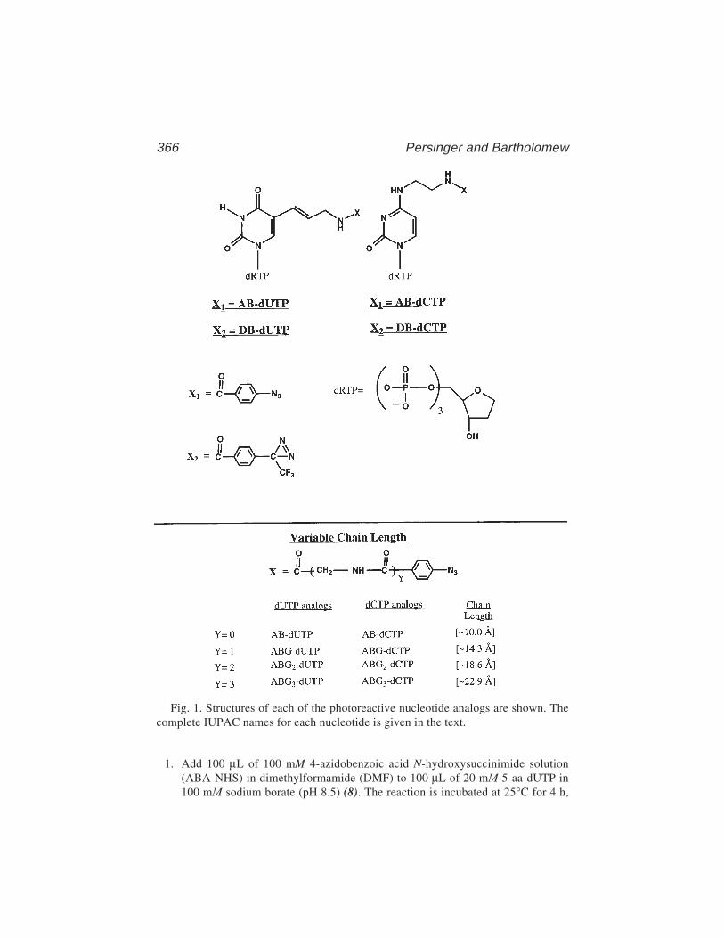
366 Persinger and Bartholomew
1. Add 100 µL of 100 mM 4-azidobenzoic acid N-hydroxysuccinimide solution(ABA-NHS) in dimethylformamide (DMF) to 100 µL of 20 mM 5-aa-dUTP in100 mM sodium borate (pH 8.5) (8). The reaction is incubated at 25°C for 4 h,
Fig. 1. Structures of each of the photoreactive nucleotide analogs are shown. Thecomplete IUPAC names for each nucleotide is given in the text.

Site-Directed DNA Photoaffinity Labeling 367
and the pH of the reaction is checked with pH indicator strips (pH 8.5). Anyexcess precipitation that forms can be eliminated by addition of DMF.
2. The coupling reaction is stopped by the addition of 200 µL sterile deionized waterand the product applied to a 0.7 × 8-cm (1.6-mL) DEAE–Sephadex A-25 columnequilibrated in 100 mM TEAB (pH 8.0). The column is washed with 5 mL of thesame buffer at a flow rate of 5 mL/h, and eluted with a 30-mL linear gradient of0.1 to 1.5 M TEAB (pH 8.0), and 500 µL fractions are collected.
3. Every third fraction from the column is evaporated to dryness by vacuumcentrifugation and resuspended in 250 µL of sterile deionized water. The samplesare dried down and this process repeated a further time.
4. The fractions are resuspended in 50 µL of sterile deionized water and 2 µL ofeach analyzed on PEI-cellulose TLC plates (see Note 1). The plates weredeveloped with 1 M LiCl and visualized with ultraviolet (UV) light source(254 nM). The reported Rf values for 5-aa-dUTP and AB–dUTP are 0.54 and0.098, respectively (8).
5. All of the fractions containing AB–dUTP are combined and TEAB is removedby repeated drying and resuspension in sterile deionized water. The final productis resuspended in 200 µL of TE. An estimated extinction coefficient of AB–dUTPat 270 nm is 10.3 × 10³/M/cm at pH 8.0 (based on the sum of the extinctioncoefficients of ABA and 5-aa-dUTP at the indicated pH and wavelength). A con-centrated stock of AB–dUTP is stable at –80°C for several years, and a 0.2-mMworking stock can be stored at –20°C wrapped in foil (see Notes 2–4).
3.1.2. Varied Tether-Length Nucleotides
The tether of AB–dUTP is 9–10 Å in length and places the photoreactivegroup near the edge of the major groove of DNA. We have synthesized differ-ent dUTP and dCTP analogs with varying tether lengths by the addition ofglycine residues into the tether (4). Synthesis of these nucleotide analogs issimilar to that of AB–dUTP and is as follows (Fig. 1).
Para-azidobenzoic acid (4-ABA) was esterified with N-hydroxysuccinimide(NHS) using the coupling reagent dicyclohexylcarbodiimide (DCI) and theproduct was recrystallized from anhydrous dioxane and ethyl ether (1:1) (9).
1. A typical reaction contained 28 mmol ABA and 28 mmol NHS in 50 mL of anhy-drous dioxane (99+%).
2. The solution is cooled in ice, and DCI in 15 mL dioxane is added and stirred forapprox 24 h at room temperature.
3. Dicyclohexyl urea is removed by centrifugation and the supernatant was evapo-rated to dryness by vacuum centrifugation.The ABA-NHS is coupled to glycine, (Gly-Gly), or (GlyGlyGly) to make ABAderivatives with glycine, Gly-Gly, or Gly-Gly-Gly, respectively, attached to thecarboxylic group of 4-ABA.
4. The reaction is started on ice and contains 2 mmol of glycine, the Gly-Gly, orGly-Gly-Gly and 4 mmol of sodium bicarbonate in 4 mL of deionized
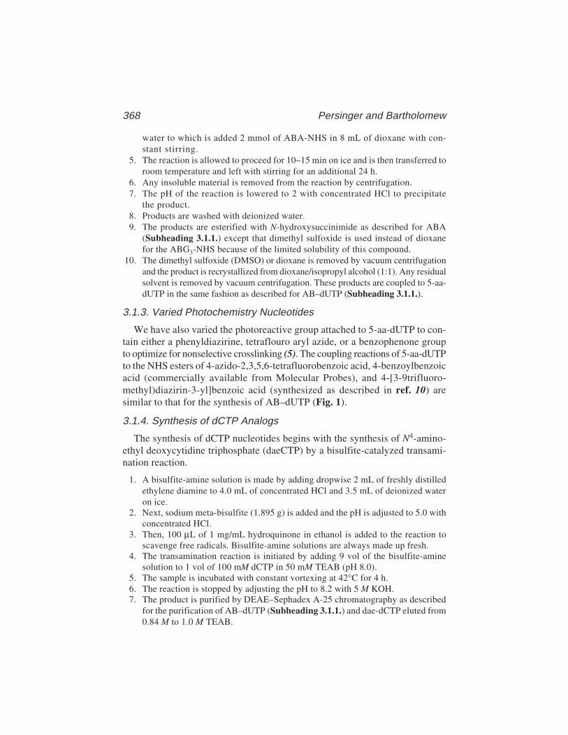
368 Persinger and Bartholomew
water to which is added 2 mmol of ABA-NHS in 8 mL of dioxane with con-stant stirring.
5. The reaction is allowed to proceed for 10–15 min on ice and is then transferred toroom temperature and left with stirring for an additional 24 h.
6. Any insoluble material is removed from the reaction by centrifugation.7. The pH of the reaction is lowered to 2 with concentrated HCl to precipitate
the product.8. Products are washed with deionized water.9. The products are esterified with N-hydroxysuccinimide as described for ABA
(Subheading 3.1.1.) except that dimethyl sulfoxide is used instead of dioxanefor the ABG3-NHS because of the limited solubility of this compound.
10. The dimethyl sulfoxide (DMSO) or dioxane is removed by vacuum centrifugationand the product is recrystallized from dioxane/isopropyl alcohol (1:1). Any residualsolvent is removed by vacuum centrifugation. These products are coupled to 5-aa-dUTP in the same fashion as described for AB–dUTP (Subheading 3.1.1.).
3.1.3. Varied Photochemistry Nucleotides
We have also varied the photoreactive group attached to 5-aa-dUTP to con-tain either a phenyldiazirine, tetraflouro aryl azide, or a benzophenone groupto optimize for nonselective crosslinking (5). The coupling reactions of 5-aa-dUTPto the NHS esters of 4-azido-2,3,5,6-tetrafluorobenzoic acid, 4-benzoylbenzoicacid (commercially available from Molecular Probes), and 4-[3-9trifluoro-methyl)diazirin-3-yl]benzoic acid (synthesized as described in ref. 10) aresimilar to that for the synthesis of AB–dUTP (Fig. 1).
3.1.4. Synthesis of dCTP Analogs
The synthesis of dCTP nucleotides begins with the synthesis of N4-amino-ethyl deoxycytidine triphosphate (daeCTP) by a bisulfite-catalyzed transami-nation reaction.
1. A bisulfite-amine solution is made by adding dropwise 2 mL of freshly distilledethylene diamine to 4.0 mL of concentrated HCl and 3.5 mL of deionized wateron ice.
2. Next, sodium meta-bisulfite (1.895 g) is added and the pH is adjusted to 5.0 withconcentrated HCl.
3. Then, 100 µL of 1 mg/mL hydroquinone in ethanol is added to the reaction toscavenge free radicals. Bisulfite-amine solutions are always made up fresh.
4. The transamination reaction is initiated by adding 9 vol of the bisulfite-aminesolution to 1 vol of 100 mM dCTP in 50 mM TEAB (pH 8.0).
5. The sample is incubated with constant vortexing at 42°C for 4 h.6. The reaction is stopped by adjusting the pH to 8.2 with 5 M KOH.7. The product is purified by DEAE–Sephadex A-25 chromatography as described
for the purification of AB–dUTP (Subheading 3.1.1.) and dae-dCTP eluted from0.84 M to 1.0 M TEAB.

Site-Directed DNA Photoaffinity Labeling 369
8. Column fractions are analyzed by TLC as described in Subheading 3.1.1. The Rfof daeCTP is 0.221 (3).
9. Fractions containing product are pooled and concentrated to 10–12 mM. The arylazido or phenyl diazirine (Fig. 1) are coupled to daeCTP as discussed in Sub-heading 3.1.1. for 5-aa-dUTP. Tether length versions of AB–dCTP have alsobeen synthesized with similar lengths of tether to those for the other tether-lengthnucleotides discussed (Fig. 1), and the Rf values of these range from 0.067 forABG–dCTP to 0.078 for ABG3–dCTP.
3.2. Immobilized DNA Templates
pTZ1 plasmid DNA is used for the synthesis of the SUP4 tRNATyr DNAphotoaffinity probes.
1. DNA is biotinylated by initially digesting 200 pmol of pTZ1 plasmid with eitherHindIII for nontranscribed strand templates or EcoRI for transcribed strand tem-plates (see Note 6) (Fig. 2, step 1).
2. The 5' overhangs are biotinylated by the incorporation of Bio-11–dUTP and Bio-14–dATP (Sigma Chemical Co.) using the exonuclease-free version of the Klenowfragment of DNA Polymerase I (Amersham/Pharmacia). The 200-µL reaction con-tains 200 pmol of linearized pTZ1, 20 µM Bio-14–dATP, dCTP, and dGTP, 25 µMBio-11–dUTP, and 150 U of Klenow fragment in buffer A (Fig. 2, step 2).
3. Unincorporated dNTPs are removed by spin-column chromatography (11) with a2.5-mL Sephacryl S-200 spin column (Pharmacia) equilibrated in buffer B(Fig. 2, step 3). Aliquots of the samples are removed before and after the spincolumn to quantitate recovery.
4. Biotinylated DNA is precipitated by the addition of 2.5 vol of ethanol and placingthe sample at –20°C overnight.
5. The sample is then resuspended and digested with EcoRI and RsaI for non-transcribed strand templates or HindIII and Pvu2 for transcribed strand templatesto generate a 315-base-pair biotinylated DNA fragment containing the SUP4tRNATyr gene (Fig. 2, step 4).
Biotinylated DNA (40 pmol) is bound to Dynabeads M-280 Streptavidin(Dynal) in the following procedure:
1. Washing Dynabeadsa. The supernatant from 200 µL Streptavidin Dynabeads (10 mg/mL) is removed
using a MagneSphere® Technology magnetic separation stand (Promega) andthe beads are resuspended in 200 µL PBS + 0.1 mg/mL BSA.
b. The beads are washed one time with 200 µL buffer C, and resuspended in400 µL 2X B/W at 5 mg/mL (see Note 7).
2. Binding Reactiona. A reaction is assembled consisting of 400 µL of the 5-mg/mL washed
Dynabeads and 400 µL of the 0.4-pmol/µL biotinylated DNA (see Note 8).

370 Persinger and Bartholomew

Site-Directed DNA Photoaffinity Labeling 371
b. The reaction is mixed by gentle vortexing every 5 min during a 45-min incu-bation at 37°C (see Note 9).
c. Buffer is removed using a magnetic stand and analyzed for binding efficiencyby agarose gel electrophoresis (Fig. 3, lanes 2 and 5).
d. Beads are washed with 200 µL of 0.5X buffer C and the washes saved forfurther analysis (Fig. 3, lanes 3 and 6).
e. The beads are resuspended in 100 µL of 0.5X buffer C and stored at 4°C(Fig. 2, step 5) for extended periods of time.
3. Stripping off nonbiotinylated DNA stranda. Supernatant is removed from the beads and the beads are resuspended in 20 µL
of 0.1 M NaOH.b. The sample is incubated with occasional vortexing for 10 min at room tem-
perature.c. The supernatant is removed and beads are washed one time with 50 µL of 0.1 M
NaOH and washed one time with sterile deionized water (Fig. 2, step 6).4. Dephosphorylating DNA Beads
a. DNA beads are washed three times with 50 µL buffer D and resuspended in100 µL buffer D.
b. Five units of shrimp alkaline phosphatase (Amersham/Pharmacia) is added tothe reaction and incubated at 37°C for 60 min.
c. Another 5 units of enzyme is added and incubated for an additional 60 min.d. Beads are washed three times with 50 µL of TE (pH 8.0) + 0.1% SDS.e. The beads are washed three times with 50 µL PBS + 0.1 mg/mL BSA and resus-
pended in 100 µL PBS + 0.1 mg/mL BSA (final concentration, 0.2 pmol/µL).f. The remaining enzyme is heat inactivated by incubating the reaction at 65°C
for 15 min and gently vortexing every 5 min. The single-stranded DNA beadscan be stored for several months up to 1 yr at 4°C.
3.3. DNA Probe Synthesis
Immobilized DNA templates made by the previous procedure (Subheading3.2.) are used to construct DNA photoaffinity probes on either the transcribedor nontranscribed strand of the gene in the following procedure.
1. First primer extension. Remove 1 pmol of immobilized template and place in a1.5-mL microcentrifuge tube.
2. Wash the beads three times with buffer D and resuspend in 10 µL of buffer D.3. To each reaction add 5 µL of sterile deionized water, 1 µL of 2 mg/mL BSA, 2 µL
buffer E, and 2 µL of 2 pmol/µL site-specific oligonucleotide (see Note 10).4. Reactions are vortexed and heated at 70°C for 3 min and vortexed gently again
before placing at 37°C for 30 min to allow the oligonucleotide primer to anneal
Fig. 2. (previous page) Diagrammatic representation DNA template preparation forsolid-phase DNA probe synthesis.
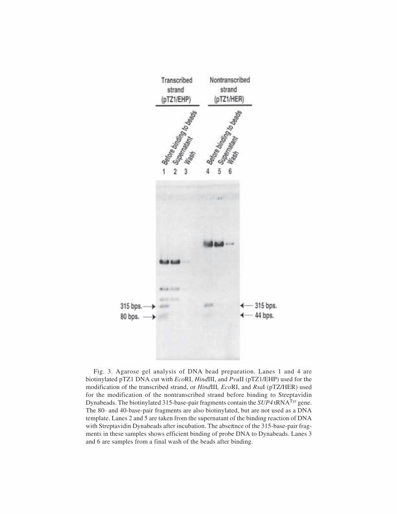
372 Persinger and Bartholomew
Fig. 3. Agarose gel analysis of DNA bead preparation. Lanes 1 and 4 arebiotinylated pTZ1 DNA cut with EcoRI, HindIII, and PvuII (pTZ1/EHP) used for themodification of the transcribed strand, or HindIII, EcoRI, and RsaI (pTZ/HER) usedfor the modification of the nontranscribed strand before binding to StreptavidinDynabeads. The biotinylated 315-base-pair fragments contain the SUP4 tRNATyr gene.The 80- and 40-base-pair fragments are also biotinylated, but are not used as a DNAtemplate. Lanes 2 and 5 are taken from the supernatant of the binding reaction of DNAwith Streptavidin Dynabeads after incubation. The abseπnce of the 315-base-pair frag-ments in these samples shows efficient binding of probe DNA to Dynabeads. Lanes 3and 6 are samples from a final wash of the beads after binding.
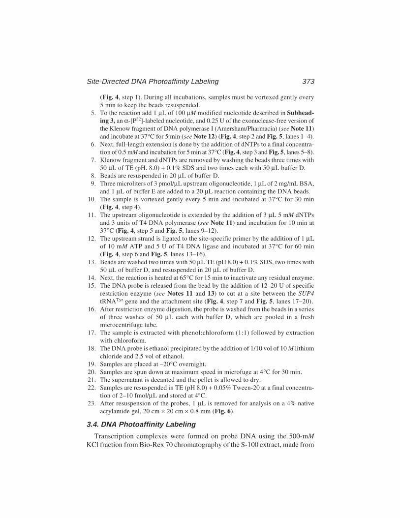
Site-Directed DNA Photoaffinity Labeling 373
(Fig. 4, step 1). During all incubations, samples must be vortexed gently every5 min to keep the beads resuspended.
5. To the reaction add 1 µL of 100 µM modified nucleotide described in Subhead-ing 3, an α-[P32]-labeled nucleotide, and 0.25 U of the exonuclease-free version ofthe Klenow fragment of DNA polymerase I (Amersham/Pharmacia) (see Note 11)and incubate at 37°C for 5 min (see Note 12) (Fig. 4, step 2 and Fig. 5, lanes 1–4).
6. Next, full-length extension is done by the addition of dNTPs to a final concentra-tion of 0.5 mM and incubation for 5 min at 37°C (Fig. 4, step 3 and Fig. 5, lanes 5–8).
7. Klenow fragment and dNTPs are removed by washing the beads three times with50 µL of TE (pH. 8.0) + 0.1% SDS and two times each with 50 µL buffer D.
8. Beads are resuspended in 20 µL of buffer D.9. Three microliters of 3 pmol/µL upstream oligonucleotide, 1 µL of 2 mg/mL BSA,
and 1 µL of buffer E are added to a 20 µL reaction containing the DNA beads.10. The sample is vortexed gently every 5 min and incubated at 37°C for 30 min
(Fig. 4, step 4).11. The upstream oligonucleotide is extended by the addition of 3 µL 5 mM dNTPs
and 3 units of T4 DNA polymerase (see Note 11) and incubation for 10 min at37°C (Fig. 4, step 5 and Fig. 5, lanes 9–12).
12. The upstream strand is ligated to the site-specific primer by the addition of 1 µLof 10 mM ATP and 5 U of T4 DNA ligase and incubated at 37°C for 60 min(Fig. 4, step 6 and Fig. 5, lanes 13–16).
13. Beads are washed two times with 50 µL TE (pH 8.0) + 0.1% SDS, two times with50 µL of buffer D, and resuspended in 20 µL of buffer D.
14. Next, the reaction is heated at 65°C for 15 min to inactivate any residual enzyme.15. The DNA probe is released from the bead by the addition of 12–20 U of specific
restriction enzyme (see Notes 11 and 13) to cut at a site between the SUP4tRNATyr gene and the attachment site (Fig. 4, step 7 and Fig. 5, lanes 17–20).
16. After restriction enzyme digestion, the probe is washed from the beads in a seriesof three washes of 50 µL each with buffer D, which are pooled in a freshmicrocentrifuge tube.
17. The sample is extracted with phenol:chloroform (1:1) followed by extractionwith chloroform.
18. The DNA probe is ethanol precipitated by the addition of 1/10 vol of 10 M lithiumchloride and 2.5 vol of ethanol.
19. Samples are placed at –20°C overnight.20. Samples are spun down at maximum speed in microfuge at 4°C for 30 min.21. The supernatant is decanted and the pellet is allowed to dry.22. Samples are resuspended in TE (pH 8.0) + 0.05% Tween-20 at a final concentra-
tion of 2–10 fmol/µL and stored at 4°C.23. After resuspension of the probes, 1 µL is removed for analysis on a 4% native
acrylamide gel, 20 cm × 20 cm × 0.8 mm (Fig. 6).
3.4. DNA Photoaffinity Labeling
Transcription complexes were formed on probe DNA using the 500-mMKCl fraction from Bio-Rex 70 chromatography of the S-100 extract, made from
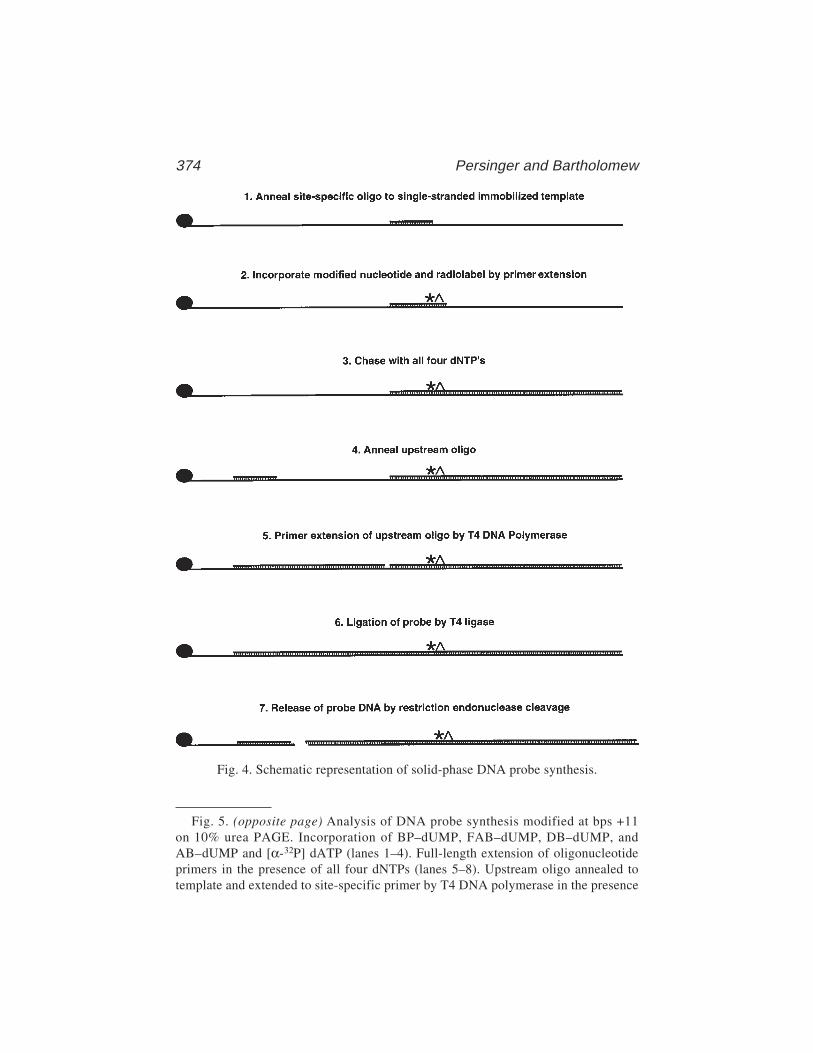
374 Persinger and Bartholomew
Fig. 4. Schematic representation of solid-phase DNA probe synthesis.
Fig. 5. (opposite page) Analysis of DNA probe synthesis modified at bps +11on 10% urea PAGE. Incorporation of BP–dUMP, FAB–dUMP, DB–dUMP, andAB–dUMP and [α-32P] dATP (lanes 1–4). Full-length extension of oligonucleotideprimers in the presence of all four dNTPs (lanes 5–8). Upstream oligo annealed totemplate and extended to site-specific primer by T4 DNA polymerase in the presence
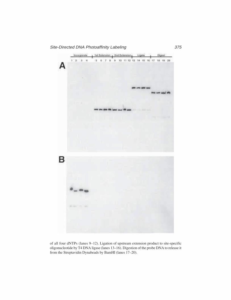
Site-Directed DNA Photoaffinity Labeling 375
of all four dNTPs (lanes 9–12). Ligation of upstream extension product to site-specificoligonucleotide by T4 DNA ligase (lanes 13–16). Digestion of the probe DNA to release itfrom the Streptavidin Dynabeads by BamHI (lanes 17–20).
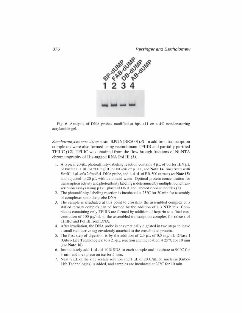
376 Persinger and Bartholomew
Saccharomyces cerevisiae strain BJ926 (BR500) (3). In addition, transcriptioncomplexes were also formed using recombinant TFIIIB and partially purifiedTFIIIC (12). TFIIIC was obtained from the flowthrough fractions of Ni-NTAchromatography of His-tagged RNA Pol III (3).
1. A typical 20-µL photoaffinity-labeling reaction contains 4 µL of buffer H, 9 µLof buffer I, 1 µL of 500 ng/µL pLNG-56 or pTZ1, see Note 14, linearized withEcoRI, 1 µL of a 2 fmol/µL DNA probe, and 1–4 µL of BR-500 extract (see Note 15)and adjusted to 20 µL with deionized water. Optimal protein concentration fortranscription activity and photoaffinity labeling is determined by multiple round tran-scription assays using pTZ1 plasmid DNA and labeled ribonucleotides (3).
2. The photoaffinity-labeling reaction is incubated at 25°C for 30 min for assemblyof complexes onto the probe DNA.
3. The sample is irradiated at this point to crosslink the assembled complex or astalled ternary complex can be formed by the addition of a 3 NTP mix. Com-plexes containing only TFIIIB are formed by addition of heparin to a final con-centration of 100 µg/mL to the assembled transcription complex for release ofTFIIIC and Pol III from DNA.
4. After irradiation, the DNA probe is enzymatically digested in two steps to leavea small radioactive tag covalently attached to the crosslinked protein.
5. The first step of digestion is by the addition of 2.3 µL of 0.5 mg/mL DNase I(Gibco Life Technologies) to a 21-µL reaction and incubation at 25°C for 10 min(see Note 16).
6. Immediately add 1 µL of 10% SDS to each sample and incubate at 90°C for3 min and then place on ice for 5 min.
7. Next, 2 µL of the zinc acetate solution and 1 µL of 20 U/µL S1 nuclease (GibcoLife Technologies) is added, and samples are incubated at 37°C for 10 min.
Fig. 6. Analysis of DNA probes modified at bps +11 on a 4% nondenaturingacrylamide gel.
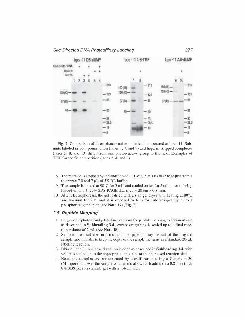
Site-Directed DNA Photoaffinity Labeling 377
8. The reaction is stopped by the addition of 1 µL of 0.5 M Tris base to adjust the pHto approx 7.0 and 7 µL of 5X DB buffer.
9. The sample is heated at 90°C for 3 min and cooled on ice for 5 min prior to beingloaded on to a 4–20% SDS-PAGE that is 20 × 20 cm × 0.8 mm.
10. After electrophoresis, the gel is dried with a slab gel dryer with heating at 80°Cand vacuum for 2 h, and it is exposed to film for autoradiography or to aphosphorimager screen (see Note 17) (Fig. 7).
3.5. Peptide Mapping
1. Large-scale photoaffinity-labeling reactions for peptide mapping experiments areas described in Subheading 3.4., except everything is scaled up to a final reac-tion volume of 2 mL (see Note 18).
2. Samples are irradiated in a multichannel pipettor tray instead of the originalsample tube in order to keep the depth of the sample the same as a standard 20-µLlabeling reaction.
3. DNase I and S1 nuclease digestion is done as described in Subheading 3.4. withvolumes scaled up to the appropriate amounts for the increased reaction size.
4. Next, the samples are concentrated by ultrafiltration using a Centricon 30(Millipore) to lower the sample volume and allow for loading on a 0.8-mm-thick8% SDS polyacrylamide gel with a 1.4-cm well.
Fig. 7. Comparison of three photoreactive moieties incorporated at bps –11. Sub-units labeled in both preinitiation (lanes 1, 7, and 9) and heparin-stripped complexes(lanes 5, 8, and 10) differ from one photoreactive group to the next. Examples ofTFIIIC-specific competition (lanes 2, 4, and 6).
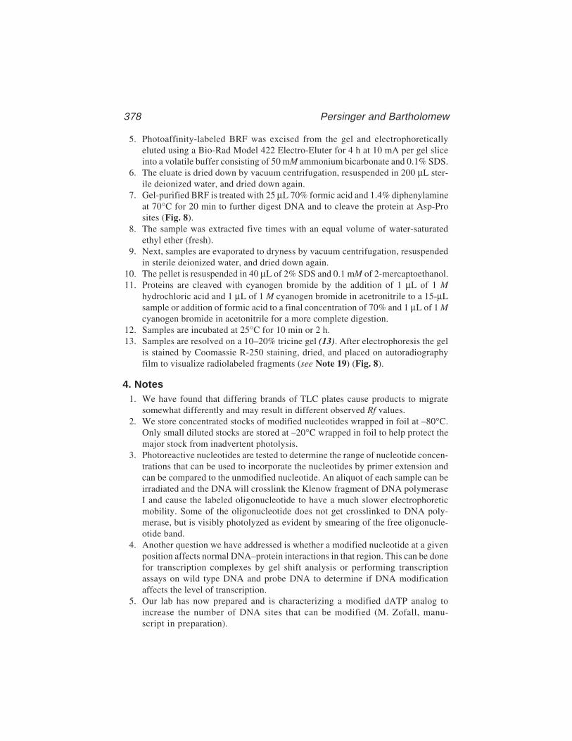
378 Persinger and Bartholomew
5. Photoaffinity-labeled BRF was excised from the gel and electrophoreticallyeluted using a Bio-Rad Model 422 Electro-Eluter for 4 h at 10 mA per gel sliceinto a volatile buffer consisting of 50 mM ammonium bicarbonate and 0.1% SDS.
6. The eluate is dried down by vacuum centrifugation, resuspended in 200 µL ster-ile deionized water, and dried down again.
7. Gel-purified BRF is treated with 25 µL 70% formic acid and 1.4% diphenylamineat 70°C for 20 min to further digest DNA and to cleave the protein at Asp-Prosites (Fig. 8).
8. The sample was extracted five times with an equal volume of water-saturatedethyl ether (fresh).
9. Next, samples are evaporated to dryness by vacuum centrifugation, resuspendedin sterile deionized water, and dried down again.
10. The pellet is resuspended in 40 µL of 2% SDS and 0.1 mM of 2-mercaptoethanol.11. Proteins are cleaved with cyanogen bromide by the addition of 1 µL of 1 M
hydrochloric acid and 1 µL of 1 M cyanogen bromide in acetronitrile to a 15-µLsample or addition of formic acid to a final concentration of 70% and 1 µL of 1 Mcyanogen bromide in acetonitrile for a more complete digestion.
12. Samples are incubated at 25°C for 10 min or 2 h.13. Samples are resolved on a 10–20% tricine gel (13). After electrophoresis the gel
is stained by Coomassie R-250 staining, dried, and placed on autoradiographyfilm to visualize radiolabeled fragments (see Note 19) (Fig. 8).
4. Notes1. We have found that differing brands of TLC plates cause products to migrate
somewhat differently and may result in different observed Rf values.2. We store concentrated stocks of modified nucleotides wrapped in foil at –80°C.
Only small diluted stocks are stored at –20°C wrapped in foil to help protect themajor stock from inadvertent photolysis.
3. Photoreactive nucleotides are tested to determine the range of nucleotide concen-trations that can be used to incorporate the nucleotides by primer extension andcan be compared to the unmodified nucleotide. An aliquot of each sample can beirradiated and the DNA will crosslink the Klenow fragment of DNA polymeraseI and cause the labeled oligonucleotide to have a much slower electrophoreticmobility. Some of the oligonucleotide does not get crosslinked to DNA poly-merase, but is visibly photolyzed as evident by smearing of the free oligonucle-otide band.
4. Another question we have addressed is whether a modified nucleotide at a givenposition affects normal DNA–protein interactions in that region. This can be donefor transcription complexes by gel shift analysis or performing transcriptionassays on wild type DNA and probe DNA to determine if DNA modificationaffects the level of transcription.
5. Our lab has now prepared and is characterizing a modified dATP analog toincrease the number of DNA sites that can be modified (M. Zofall, manu-script in preparation).
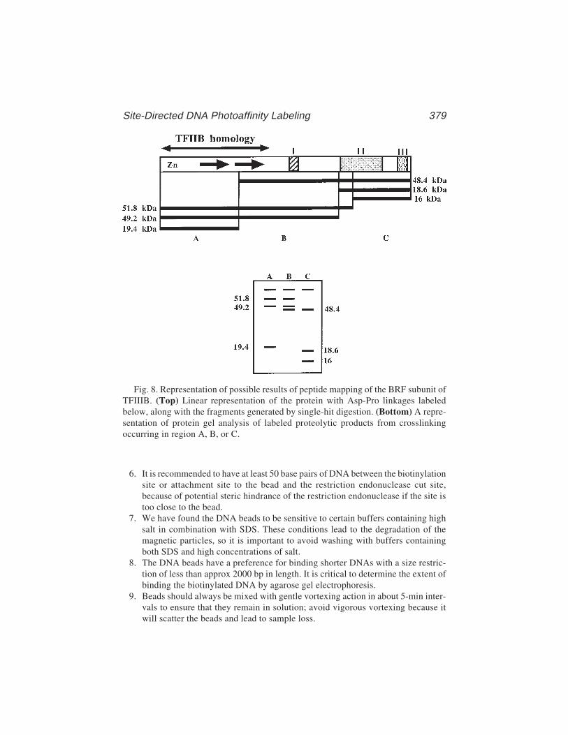
Site-Directed DNA Photoaffinity Labeling 379
6. It is recommended to have at least 50 base pairs of DNA between the biotinylationsite or attachment site to the bead and the restriction endonuclease cut site,because of potential steric hindrance of the restriction endonuclease if the site istoo close to the bead.
7. We have found the DNA beads to be sensitive to certain buffers containing highsalt in combination with SDS. These conditions lead to the degradation of themagnetic particles, so it is important to avoid washing with buffers containingboth SDS and high concentrations of salt.
8. The DNA beads have a preference for binding shorter DNAs with a size restric-tion of less than approx 2000 bp in length. It is critical to determine the extent ofbinding the biotinylated DNA by agarose gel electrophoresis.
9. Beads should always be mixed with gentle vortexing action in about 5-min inter-vals to ensure that they remain in solution; avoid vigorous vortexing because itwill scatter the beads and lead to sample loss.
Fig. 8. Representation of possible results of peptide mapping of the BRF subunit ofTFIIIB. (Top) Linear representation of the protein with Asp-Pro linkages labeledbelow, along with the fragments generated by single-hit digestion. (Bottom) A repre-sentation of protein gel analysis of labeled proteolytic products from crosslinkingoccurring in region A, B, or C.
380 Persinger and Bartholomew
10. Oligonucleotides for probe synthesis are usually between 18- and 20-mers inlength with a GC rich 5' end.
11. Enzymes containing DTT need to be avoided because DTT can reduce aryl azides.Some enzymes with DTT can be sufficiently diluted in buffers containing 2-mer-captoethanol (5 mM) in place of DTT.
12. If the DNA probe is to be used for peptide mapping, the modified nucleotide willhave to be incorporated first, followed by dATP or dGTP, to leave a nucleotidetag covalently attached to the crosslinked protein upon chemical degradation ofthe DNA probe.
13. Choosing restriction enzymes with good cutting efficiency to remove probes fromthe DNA beads can be very beneficial to overall probe yields.
14. Proper controls such as DNA competition with specific-pTZ1 DNA (containingan up mutation in the box B region of DNA) vs nonspecific-pLNG56 DNA(containing a down mutation in the Box B region of the DNA) and heparin strip-ing of samples are necessary to ensure labeling specificity.
15. We have found the crude extract BR-500 to be more efficient for photoaffinitylabeling, probably because of higher activities of the proteins and factors thatmay be lost during extensive purification.
16. Because of the short sequential incubation times, it is best to cycle samples intoand out of incubation baths to ensure equal incubation times for all samples. Thismeans the addition of the enzyme or solution to the first sample and immediatelyplacing it in the temperature bath, followed by processing the second sample inthe same way and so on. The samples are removed in the same order so that theyenter the bath with a 15-s delay between each sample.
17. Crosslinked proteins have a slightly greater electrophoretic mobility than unmodi-fied protein because of the DNA tag left behind, and it is more noticeable forsmaller proteins.
18. Labeling reactions used for peptide mapping are scaled up to ensure adequatesignal. Sufficient amounts of labeled protein is necessary because of losses dur-ing the extensive purification and the partial proteolytic conditions creating onlya small percentage of labeled proteolytic fragments.
19. Care should be taken in constructing a map of potential proteolytic fragmentscreated by single-hit digests for peptide mapping. Chemical cleavage of proteinis preferable to enzymatic cleavage, because chemical cleavage has no apparentspecificity or site preference that can make it difficult to interpret the peptidemapping results.
References1. Huet, J., Manaud, N., Dieci, G., Peyroche, G., Conesa, C., Lefebvre, O., et al.
(1996) RNA polymerase III and class III transcription factors from Saccharomy-ces cerevisiae. Methods Enzymol. 273, 249.
2. Geiduschek, E. P. and Kassavetis, G. A. (1992) RNA polymerase III transcriptioncomplexes., in Transcriptional Regulation (McKnight, S. L. and Yamamoto, K.R., eds.) Cold Spring Harbor Laboratory, Cold Spring Harbor, NY. p. 247.
Site-Directed DNA Photoaffinity Labeling 381
3. Lannutti, B. J., Persinger, J., and Bartholomew, B. (1996) Probing the protein-DNA contacts of a yeast RNA polymerase III transcription complex in a crudeextract: solid phase synthesis of DNA photoaffinity probes containing a novelphotoreactive deoxycytidine analog. Biochemistry 35, 9821.
4. Persinger, J. and Bartholomew, B. (1996) Mapping the contacts of yeast TFIIIBand RNA polymerase III at various distances from the major groove of DNA byDNA photoaffinity labeling. J. Biol. Chem. 271, 33,039.
5. Tate, J. J., Persinger, J., and Bartholomew, B. (1998) Survey of four differentphotoreactive moieties for DNA photoaffinity labeling of yeast RNA polymeraseIII transcription complexes. Nucleic Acids Res. 26, 1421.
6. Bartholomew, B., Braun, B. R., Kassavetis, G. A., and Geiduschek, E. P. (1994)Probing close DNA contacts of RNA polymerase III transcription complexes withthe photoactive nucleoside 4-thiodeoxythymidine. J. Biol. Chem. 269, 18,090.
7. Kassavetis, G. A., Riggs, D. L., Negri, R., Nguyen, L. H., and Geiduschek, E. P.(1989) Transcription factor IIIB generates extended DNA interactions in RNApolymerase III transcription complexes on tRNA genes. Mol. Cell. Biol. 9, 2551.
8. Bartholomew, B., Meares, C. F., and Dahmus, M. E. (1990) Photoaffinity label-ing of RNA polymerase III transcription complexes by nascent RNA. J. Biol.Chem. 265, 3731.
9. Galardy, R. E., Craig, L. C., Jamieson, J. D., and Printz, M. P. (1974) Photoaffinitylabeling of peptide hormone binding sites. J. Biol. Chem. 249, 3510.
10. Nassal, M. (1983) 4-(1-Azi-2,2,2-trifluroethyl)benzoic scid, a highly photolabilecarbine generating label Readily fixable to biochemical agents. Liebigs Ann.Chem. 1510.
11. Bartholomew, B., Tinker, R. L., Kassavetis, G. A., and Geiduschek, E. P. (1995)Photochemical cross-linking assay for DNA tracking by replication proteins.Methods Enzymol. 262, 476.
12. Bartholomew, B., Durkovich, D., Kassavetis, G. A., and Geiduschek, E. P. (1993)Orientation and topography of RNA polymerase III in transcription complexes.Mol. Cell. Biol. 13, 942.
13. Schagger, H. and von Jagow, G. (1987) Tricine-sodium dodecyl sulfate-polyacry-lamide gel electrophoresis for the separation of proteins in the range from 1 to 100kDa. Anal. Biochem. 166, 368.
Photocrosslinking of RNA Pol II Complexes 383
383
From: Methods in Molecular Biology, vol. 148: DNA–Protein Interactions: Principles and Protocols, 2nd ed.Edited by: T. Moss © Humana Press Inc., Totowa, NJ
26
Use of Site-Specific Protein–DNAPhotocrosslinking to Analyzethe Molecular Organizationof the RNA Polymerase II Initiation Complex
François Robert and Benoit Coulombe
1. IntroductionSite-specific protein–DNA photocrosslinking has proved to be the method
of choice for analysis of the formation of nucleoprotein complexes such asthose involved in transcription by mammalian RNA polymerase II (RNA PolII). The method has two principal advantages. First, it yields structural infor-mation on large, multisubunit complexes that in general cannot be analyzedusing standard high-resolution techniques such as X-ray crystallography ornuclear magnetic resonance (NMR). For example, site-specific protein–DNAphotocrosslinking, in conjunction with complementary methods such as pro-tein-affinity chromatography and electron microscopy, has produced informa-tion on both the molecular organization and the composition of the RNA Pol IIpre-initiation complex on promoter DNA (1–4). This complex contains RNAPol II and the general transcription factors TBP, TFIIA, TFIIB, TFIIE, TFIIF(RAP74 and RAP30), and TFIIH, and is composed of more than 25 polypep-tides ranging in Mr from 10 to 220 kDa (5). Neither X-ray crystallography norNMR, which can only resolve the structure of complexes containing short pro-tein fragments bound to small pieces of promoter DNA, could provide anydetailed structural information on this complex. Second, the method has suffi-cient technical flexibility so as to allow the rapid analysis of complexesassembled under various conditions. Over the past few years, we have analyzeda large collection of complexes assembled in the presence of various combina-tions of the general transcription factors (wild-type or different deletion
384 Robert and Coulombe
mutants) and RNA Pol II (1–4). These experiments have enabled us to drawconclusions on the dynamics of RNA Pol II pre-initiation complex assemblyand has led to the notion that isomerization of the RNA Pol II pre-initiationcomplex proceeds through wrapping of the promoter DNA around the enzyme (4).
Site-specific protein–DNA photocrosslinking is a method composed of twosuccessive steps. First, a number of photoprobes that place one (or a few)photoreactive nucleotide(s) into juxtaposition with one (or a few) radiolabelednucleotide(s) at various specific positions along the promoter DNA are pre-pared. Second, transcription complexes are assembled onto the variousphotoprobes, irradiated with ultraviolet (UV) light so as to induce protein–DNA crosslinking, and the processed in order to identify the crosslinkedpolypeptides. Because the crosslinking of protein to DNA is site-specific, theuse of a series of photoprobes that place the photonucleotide derivative at vari-ous positions along the promoter DNA provides information on the relativeposition of the various factors within the complex.
2. Materials1. Buffer A (10X): 300 mM Tris-HCl, pH 8.0, 500 mM KCl, and 70 mM MgCl2,
freshly prepared.2. Bovine serum albumin (BSA) solution: Prepare a 25-mg/mL solution of BSA in
deionized distilled water. Store in aliquots at –20°C.3. Dilute with water to 5 mg/mL prior to use.4. dNTP mix: 20 mM each of dATP, dCTP, dGTP, and dTTP in buffer A (1X),
freshly prepared.5. ND buffer: 20 mM HEPES, pH 7.9, 100 mM KCl, 20% glycerol, 0.2 mM
EDTA, 0.2 mM EGTA, and 10 mM of β-mercaptoethanol. Store in aliquotsat –20°C.
6. TBE buffer (10X): Prepare 1 L by mixing 108 g Tris base, 55 g boric acid, and 40 mLEDTA (0.5 M, pH 8.0).
7. Gel loading solution (10X): For polyacrylamide native gels, use a solution con-taining 0.25% bromophenol blue, 0.25% xylene cyanol, and 25% Ficoll (type400) in deionized distilled water.
8. MBS (5X): 40 mM MgCl2, 100 mM HEPES, pH 7.9, 100 µg/mL BSA, and5 mM ATP.
9. Store in aliquots at –20°C.10. Complex mix: 50 µL MBS (5X) and 2 µL (NH4)2SO4 (2 M), freshly prepared.11. Poly(dI.dC–dI.dC) stock: Prepare a 25-mg/mL solution of poly(dI.dC–dI.dC) in
deionized distilled water. Store in aliquots at –20°C.12. DNase mix: A solution containing 200 units/mL DNase I and 32 mM CaCl2,
freshly prepared.13. Acid mix: Mix equal volumes of 5% acetic acid and 30 mM ZnCl2, freshly
prepared.14. S1 mix: 30,000 U/mL S1 nuclease in deionized distilled water, freshly prepared.
Photocrosslinking of RNA Pol II Complexes 385
15. Dilution mix: 50 mM Tris-HCl, pH 8.0, 10 mM EDTA, 10 mM EGTA, 500 mMNaCl, 5 mM NaF, 1 mM phenymethylsulfonyl fluoride (PMSF), and 1% (v/v)Triton X-100, freshly prepared.
16. Protein A mix: 100 mg/mL Protein A in the dilution mix.17. Wash 1 solution: 10 mM Tris-HCl, pH 8.0, 150 mM NaCl, 1% Triton X-100, 1%
NP-40, 0.1% sodium dodecyl sulfate (SDS), 1 mg/mL BSA, 0.5% NaN3, and0.5% Na-deoxychlorate, freshly prepared.
18. Wash 2 solution: 10 mM Tris-HCl, pH 8.0, and 1.5 M NaCl.19. Wash 3 solution: 10 mM Tris-HCl, pH 8.0, and 150 mM NaCl.
3. Methods3.1. Day 1: Synthesis and Purification of the Photoprobes
The first step of the procedure is the synthesis of the photoprobes. This partis illustrated in Fig. 1 which shows, as an example, a scheme for the synthesisof a photoprobe designed to place the photoreactive nucleotide at position –2relative to the transcriptional initiation site of the adenovirus major latepromoter. The site-specific incorporation of the photoreactive nucleotide (seeNote 1) and the radiolabeled nucleotide is directed through the annealing of aprimer, referred to as the specific primer, with a single-stranded DNA templatecontaining the promoter DNA. The promoter is flanked by two restriction sites(in this example, DraI and SacI). A second primer, referred to as the upstreamprimer, is annealed a few base pairs upstream of the DraI site. After annealing,the photoreactive and radiolabeled nucleotides are incorporated by primerextension using T4 DNA polymerase with limiting amounts of dNTPs (seeNote 2). After the labeling step, the extension reaction is completed by theaddition of an excess of cold dNTPs (see Note 3). The photoprobe is generatedby digestion with the restriction enzymes and gel purified (see Fig. 2 for anexample of a gel on which the products of a photoprobe synthesis reactionhave been separated).
1. Mix 700 ng of single-stranded (ss) DNA (approx 0.5 pmol) with 40 ng (approx5 pmol) of both the specific and upstream primers. Add 1 µL of Buffer A (10X)and complete to 10 µL with deionized distilled water.
2. Mix well and incubate for 3 min at 90°C.3. Incubate for 30 min at room temperature.4. From this point on, all manipulations must be carried out under reduced light
conditions (see Note 4). Add 1 µL BSA (5 mg/mL), 1 µL N3R–dUMP (seeNote 1), 25 µCi of the appropriate [α-32P]–dNTP ([α-32P]–dCTP for the exampleshown in Fig. 1), 5–10 U T4 DNA polymerase, and 1 µL buffer A (10X). Com-plete to a final volume of 20 µL with deionized distilled water.
5. Incubate for 30 min at room temperature.6. Add 5 µL of dNTP mix.7. Incubate for 5 min at room temperature.

386 Robert and Coulombe
Fig. 1. Synthesis and purification of the photoprobes. Schematic representation ofthe synthesis of a photoprobe that places a photoreactive nucleotide at position –2 andthree radiolabeled nucleotides at positions –4, –3, and –1 of the adenovirus major latepromoter. The sequence of the adenovirus major late promoter flanked by plasmidDNA is shown. The primers used to direct the incorporation of N3R–dUMP (U) andradiolabeled nucleotides (*) are shown in boxes. The TATA element is in bold typeand the transcriptional initiation site is indicated by an arrow. DraI and SacI restric-
Photocrosslinking of RNA Pol II Complexes 387
8. Incubate for 20 min at 37°C.9. Add 10–20 U of each restriction enzyme (SacI and DraI in the example shown in
Fig. 1).10. Incubate for 90 min at the temperature recommended by the supplier of restric-
tion enzymes (37°C for SacI and DraI).11. Add 3.5 µL of gel loading solution (10X).12. Load on a native 8% polyacrylamide gel in TBE buffer (1X).13. Run at 150 V for about 1 h in TBE buffer (1X).14. Remove the glass plates containing the gel from the gel box.15. Separate the glass plates and leave the gel on one of them.16. Wrap the gel/glass plate in plastic wrap.17. Wrap the entire package in aluminum foil.18. Move to a dark room (see Note 5).19. Place a Kodak X-OMAT AR film on a clean bench.20. Remove the foil and place the gel on the film with the glass plate facing up (e.g.,
gel side down).21. Expose 5 min.22. During the exposition time, mark the film using a sharp tool by tracing the con-
tour of the glass plate (this will be helpful later for the localization of thephotoprobe in the gel).
23. Remove the gel and rewrap it with the foil.24. Develop the film (see Note 6).25. Using a scalpel, cut the film so that the square piece containing the band corre-
sponding to the photoprobe is removed. This operation leaves the film with awindow at the position of the photoprobe.
26. Superimpose the film on the gel by taking advantage of the marks made in step 22,and mark the square corresponding to the photoprobe on the saran wrap using a pen.
27. Cut out the gel slice containing the photoprobe using a clean scalpel.28. Cut the gel slice in small pieces (six to eight fragments).29. Place the gel fragments in an Eppendorf tube and add water in order to com-
pletely submerge the gel (usually 100–150 µL of water).30. Incubate overnight at room temperature.31. Collect the liquid containing the probe.32. Purify the probe on a Micro-Spin S-200 HR column (Pharmacia Biotech) to
remove any salts and other putative contaminants.
tion sites used for the excision of the photoprobe are indicated. In the first step, theprimers are annealed to single-stranded DNA containing the promoter sequence(Annealing). In the second step, the photoreactive and the radiolabeled nucleotidesare incorporated using T4 DNA polymerase (Labeling). In the third step, the extensionreaction is completed by a chase with excess of cold dNTPs (Chase). In the fourthstep, the site-specifically labeled promoter fragment is excised using restrictionenzymes and gel purified (Digestion and purification).

388 Robert and Coulombe
33. Count 1 µL of the photoprobe solution by liquid scintillation, and dilute the probeto 1250 cpm/µL with deionized distilled water.
34. The probe is ready for use and can be stored in the dark at 4°C for 1–2 wk (seeNote 7).
3.2. Day 2: Protein–DNA Photocrosslinking
The gel-purified photoprobe is used for pre-initiation complex assemblywith the purified transcription factors (TBP, TFIIA, TFIIB, TFIIE, TFIIF, andTFIIH) and RNA Pol II. Reactions are irradiated with ultraviolet (UV) light toinduce protein–DNA crosslinking and treated with DNase I and S1 nuclease inorder to liberate polypeptides that are covalently attached to a very short pieceof DNA carrying one to four radiolabeled nucleotides. After sodium dodecylsulfate–polyacrylamide gel electrophoresis (SDS-PAGE) separation of thephotocrosslinked polypeptides, the gel is dried and exposed to X-ray film.Examination of the ensuing autoradiogram permits identification of theprotein(s) that interact with a particular site. For the RNA Pol II initiationcomplex, the specificity of the photocrosslinking signals can be assessed bycomparing reactions performed with photoprobes containing either a wild-type or a mutated TATA element and/or by comparing reactions performed ineither the presence or the absence of TBP (see Note 8). The photocrosslinkedpolypeptides can be identified according to their Mr (Fig. 3A,B) and to theirimmunoreactivity with specific antibodies (Fig. 3C). In the latter case,crosslinking reactions are submitted to immunoprecipitation with antibodiesdirected against specific factors prior to SDS-PAGE (see Note 9).
35. Mix the proteins (50–200 ng each) and complete the volume to 16 µL with NDbuffer (see Note 10). Add 5.2 µL of the complex mix, 1 µL of diluted poly(dI.dC–
Fig. 2. Example of the autoradiogram of a gel after electrophoresis of the productsof a synthesis reaction. The positions of the photoprobe, the free nucleotides, and theplasmid fragment are shown. The photoprobe is then purified from the gel.
Photocrosslinking of RNA Pol II Complexes 389
dI.dC) (see Note 11) and 5000 cpm of the photoprobe (4 µL of 1250 cpm/µL).The final volume is 26.2 µL.
36. Mix well and incubate for 30 min at 30°C.37. Open the lids of the tubes and irradiate 10 min with UV light (see Notes 12 and 13).38. Add 5 µL of DNase mix.39. Incubate for 20 min at 37°C.40. Add 1.5 µL of 10% SDS.41. Incubate for 3 min at 90°C.42. Spin for 10 s in a microfuge (16,000g)43. Add 2 µL of Acid mix.44. Add 1 µL of S1 mix.45. Incubate for 20 min at 37°C.46. For regular reactions, go directly to step 62.47. For immunoprecipitation reactions, add 315 µL of the dilution mix.48. Add 5 µL of antibody (see Note 14).49. Incubate for 60 min at 4°C.50. Add 80 µL of Protein A mix.51. Agitate 60 min at 4°C using a rocker.52. Spin down the Protein A beads (1 min in a microfuge at 16,000g).53. Remove the supernatant by pipetting.54. Wash with 400 µL of wash 1 solution.55. Repeat steps 52–54 twice.56. Wash with 400 µL of wash 2 solution.57. Spin down the Protein A beads (1 min in a microfuge at 16,000g).58. Remove the supernatant by pipetting.59. Wash with 400 µL of wash 3 solution.60. Spin down the Protein A beads (1 min in a microfuge at 16,000g).61. Remove the supernatant by pipetting.62. Add SDS gel loading solution and boil 5 min (see Note 15).63. Resolve the photocrosslinked polypeptides by SDS-PAGE (run at 30 mA in the
stacking gel and 50 mA in the separating gel) (see Note 15).64. Transfer the gel to Whatman paper and dry.65. Expose the dried gel to X-ray film using an intensifying screen (see Note 16).
4. Notes1. The nucleotide derivative we use, namely 5-[N-(azidobenzoyl)-3-aminoallyl]–
dUMP (N3R–dUMP or AB–dUMP) (see Chapter 25 for further details on thestructure and the chemical synthesis of N3R–dUMP), possesses a side chain thatplaces a reactive nitrene 10 Å away from the DNA backbone in the major grooveof the double helix. For this reason, the crosslinking of a polypeptide to thephotoprobe does not require a direct interaction of the polypeptide with the DNAhelix. The amount of N3R–dUMP to be added to the reaction is determinedempirically for each preparation of the photoreactive nucleotide and is generallybetween 0.5 and 2 µL (often 1 µL).

390 Robert and Coulombe
Fig. 3. Typical SDS-PAGE gels of photocrosslinked proteins. (A) Crosslinkingreactions assembled either in the absence of TBP or using a probe with a mutatedTATA box give identical results. Crosslinking reactions were performed with TFIIB,RAP30, RAP74, TFIIE34, TFIIE56, and RNA Pol II in the presence (+) or in theabsence (–) of TBP using either a wild-type (TATAAA) or a mutated (TAGAGA)TATA element. In the example shown here (the photonucleotide derivative is placedat position –15 of the adenovirus major late promoter), the crosslinking of both thesecond largest subunit of RNA Pol II (RPB2) and RAP74 are considered to be specific(dark arrowhead). The crosslinking of RPB1 is considered as nonspecific (open arrow-head) because it is not affected by the omission of TBP or the use of a probe with amutation in the TATA box. The positions of the molecular weight markers (MW) areindicated. (B) The use of truncated polypeptides as a tool to identify the photo-crosslinked polypeptides. Crosslinking reactions were performed using TFIIB, RAP30,TFIIE34, TFIIE56, and RNA Pol II in the presence (+) or in the absence (–) of TBP,

Photocrosslinking of RNA Pol II Complexes 391
2. The specific primer must be designed in such a manner that T4 DNA polymeraseonly adds a few nucleotides. In the example shown in Fig. 1, the incorporation isrestricted to positions –4 to –1 by omitting dATP from the reaction (see refs. 1–4for additional examples). The success of this step can be monitored by analysisof the reaction products on a sequencing gel.
3. The addition of dNTPs in large excess is crucial because it is necessary to limitprimer extension to the incorporation of standard dNTPs, preventing the additionof any more radiolabeled and photoreactive nucleotides.
4. The use of a standard dark room is not necessary at this stage. As a rule, we findthat conditions that provide just enough light to be able to work are acceptable.
5. A conventional red light can be used.6. An example of gel photoprobe purification is shown in Fig. 2. The position of the
band corresponding to the photoprobe can be easily identified because the size ofthe DNA fragment generated by digestion with restriction enzymes is known.
7. Fresh probes (less than a week old) give the best results.8. Because some of the general transcription factors and RNA Pol II bind non-
specifically to DNA, it is important to discriminate between specific and nonspe-cific crosslinking signals. For the adenovirus major late promoter, it iswell-documented that mutations of two bases in the TATA box (TATAAA toTAGAGA) completely abolish pre-initiation complex formation. The comparisonof crosslinking signals obtained with probes containing either a wild-type or amutated TATA box permits differentiation between specific and nonspecific sig-nals. However, this strategy is not simple, as it doubles the number of probes to besynthesized. Because the basic function of the TATA box is to bind TBP, thespecificity can be assessed by comparing crosslinking reactions performed in thepresence or the absence of TBP. The absence of TBP was found to give the sameresult as the use of a probe with a mutated TATA box (1–4). An example is shownin Fig. 3A. The crosslinking signal at the top of the gel (RPB1) is considered asnonspecific because its intensity is not affected by either a mutation in the TATA boxor the absence of TBP. The two additional crosslinking signals (RPB2 and RAP74)are specific because their intensities are significantly affected by both mutation ofthe TATA box and the omission of TBP in the crosslinking reaction.
9. Identification of the photocrosslinked polypeptides is a central issue in themethod. The main difficulty comes from the fact that several factors have a Mr
between 30 and 40 kDa. At least three different means can be used to identify the
using full-length (1–517) or truncated (1–409) RAP74. The different mobilities ofRAP74 fragments are diagnostic for RAP74 contact at this promoter position. (C) Immuno-precipitation of photocrosslinked polypeptides. Crosslinking reactions were performedusing TFIIB, RAP30, RAP74, TFIIE34, TFIIE56, and RNA Pol II in the presence (+)or in the absence (–) of TBP. The photocrosslinked polypeptides were either processednormally (first two lanes) or immunoprecipitated using an antibody directed againstRAP74 or a control antibody.
392 Robert and Coulombe
crosslinking signals. First, SDS-PAGE analysis provides direct information onthe size of photocrosslinked polypeptides (see Fig. 3A). Second, the use of trun-cated forms of a factor can be useful. An example is shown in Fig. 3B in whichall factors included in the crosslinking reactions are the same, except for RAP74,which is either full-length (lanes 1 and 2) or truncated in its C-terminus (lanes 3and 4). The different fragments of RAP74 migrate with different mobilities,allowing the identification of the photocrosslinked polypeptide. Third, thephotocrosslinked polypeptides can be identified after immunoprecipitation witha specific antibody. Following nuclease treatment, the crosslinking productsare immunoprecipitated and then submitted to SDS-PAGE analysis. An exampleis shown in Fig. 3C, where the photocrosslinked polypeptides shown in lane 1have been immunoprecipitated using an antibody raised against RAP74 (lane 3)or a control antibody (lane 4). This shows that the photocrosslinked polypeptideis RAP74.
10. In the crosslinking reactions, we routinely use 200 ng of each recombinanthuman (rh) TFIIB, rhRAP30, rhRAP74, rhTFIIE34, and rhTFIIE56, 100 ng ofcalf thymus RNA Pol II, 50 ng of natural human TFIIH, 50–200 ng of rhTFIIA,and 200 ng of recombinant yeast TBP. The amounts of the different protein fac-tors should be optimized for each different combination of proteins and for eachprotein preparation.
11. The poly(dI.dC–dI.dC) stock should be diluted just prior to use. The exact dilu-tion should be determined experimentally in order to favor specific versus non-specific signals without adversely affecting the intensity of the specific signals.
12. Irradiation time with UV light should be optimized by performing a time-coursewith the particular system to be used. We use a UV Stratalinker 2400 (Stratagene)with 254-nm bulbs.
13. From this point on, normal light conditions can be used.14. The amounts of antibody to be used should be optimized. Purified antibodies
provide the best results.15. Detailed procedures for SDS-PAGE electrophoresis have been described (e.g.,
see ref. 6).16. The use of BioMax (Kodak) screens and films is recommended.
AcknowledgmentsWe thank members of our laboratory for valuable discussions and Will
Home for critical reading of the manuscript. B.C. is the recipient of fundingfrom the Medical Research Council of Canada, the Cancer Research Societyand the Fonds de la Recherche en Santé du Québec. F.R. holds a studentshipfrom the FCAR.
References1. Coulombe, B., Li, J., and Greenblatt, J. (1994) Topological localization of human
transcription factors IIA, IIB, TATA box-binding protein and RNA polymeraseII-associated protein 30 on a class II promoter. J. Biol. Chem. 269, 19,962–19,967.
Photocrosslinking of RNA Pol II Complexes 393
2. Robert, F., Forget, D., Li, J., Greenblatt, J., and Coulombe, B. (1996) Topologicallocalization of transcription factors IIE and IIF immediately upstream the tran-scription start site of a class II promoter. J. Biol. Chem. 271, 8517–8520.
3. Forget, D., Robert, F., Grondin, G., Burton, Z. F., Greenblatt, J., and Coulombe,B. (1997) RAP74 induces promoter contacts of RNA polymerase II upstream anddownstream of a DNA bend at the TATA box. Proc. Natl. Acad. Sci. USA 94,7150–7155.
4. Robert, F., Douziech, M., Forget, D., Egly, J. M., Greenblatt, J., Burton, Z. F., etal. (1998) Wrapping of promoter DNA around the RNA polymerase II initiationcomplex induced by TFIIF. Mol. Cell 2, 341–351.
5. Hampsey, M. (1998) Molecular genetics of the RNA polymerase II general tran-scription machinery. Microbiol. Mol. Biol. Rev. 62, 465–503.
6. Sambrook, J., Fritsch, E. F., and Maniatis, T. (1989) Molecular Cloning: ALaboratory Manual, 2nd ed., Cold Spring Harbor Laboratory, Cold SpringHarbor, NY.
UV Laser-Induced Protein–DNA Crosslinking 395
395
From: Methods in Molecular Biology, vol. 148: DNA–Protein Interactions: Principles and Protocols, 2nd ed.Edited by: T. Moss © Humana Press Inc., Totowa, NJ
27
UV Laser-Induced Protein-DNA Crosslinking
Stefan I. Dimitrov and Tom Moss
1. Introduction1.1. The Method
Photochemical crosslinking is a powerful method for studying all types ofprotein-nucleic acids interactions. In particular UV-induced crosslinking hasbeen successfully applied to the study of protein–DNA interactions (e.g., ref. 1, seeChapters 23–26 and 43). Ultraviolet (UV) light is a zero-length crosslinkingagent. It is therefore not subject to the steric problems that can be associatedwith chemical crosslinking agents and provides strong evidence for close pro-tein–DNA interactions. However, crosslinking with conventional UV-lightsources requires exposure times ranging from minutes to several hours (e.g.,see refs. 1–3), permitting protein redistribution and the crosslinking of UV-damaged molecules. Because UV-laser irradiation is intense enough to inducecrosslinking after very short exposure times, artifactual crosslinking can beavoided. The typically nanosecond or picosecond exposures times also allowUV-laser-induced crosslinking to be applied to study the intermediate states inrapid protein–DNA binding reactions (4,5).
Ultraviolet-crosslinking of protein to DNA occurs in two distinct steps. Inthe first step, the bases of DNA are excited by light absorption. This excite-ment rapidly gives rise to radicals of the bases, resulting in chemical cross-linking and macromolecular damage, mainly to the DNA. The time to excitethe bases is simply the time of UV irradiation. Completion of the crosslinkingreaction then occurs in less than a microsecond (6). Most micro-conforma-tional transitions of macromolecules take more than 100 µs (see ref. 7). Nano-seconds or picosecond UV-laser irradiation therefore avoids almost allpossibility of artifactual rearrangement during the crosslinking reaction.What is more, such a rapid crosslinking reaction can be used to freeze protein–

396 Dimitrov and Moss
DNA interactions, providing “time-lapse views” of the assembly of protein–DNA complexes. Laser-induced reactions, as opposed to those generated byconventional UV sources, proceed via the higher (Sn and Tn) excited states ofnucleotide bases, which are induced by the rapid sequential absorption of twophotons. This leads to a higher quantum yield of cationic radicals and to highercrosslinking efficiencies (6,8–10). Although the photochemistry is still notunderstood, UV-laser irradiation probably also induces mechanisms ofcrosslinking that simply cannot occur when using conventional light sources(6,10). In a typical UV crosslinking experiment, 5–15% of UV-laser-irradiatedprotein–DNA complexes are crosslinked (6,10,11), nearly two orders of mag-nitude higher than with conventional UV sources (4,5,8,10,12). UV-laser-induced crosslinking produces exclusively protein–DNA adducts (4,6,8,9) andis applicable to a broad range of protein–DNA complexes. Even complexes tooweak to be seen by methods such as gel shift (electrophoretic mobility shiftassay [EMSA]) or footprinting can be crosslinked. In fact, only nonspecificprotein–DNA interactions with association constants of less than 103/M are notcrosslinked (4,6).
1.2. Practical Applications
Photocrosslinking induced by UV-laser irradiation has been applied to mea-sure binding constants (6), to map the extent of protein–nucleic acid bindingsites (6), to determine protein–DNA (5,6) and protein–RNA (9) interactions,and to identify protein–DNA contacts (13). It was found possible to study theweak DNA-ATPase complex from the T4 DNA replication system by UV-laser crosslinking despite this complex being invisible to DNase I footprinting(6). UV-laser crosslinking has also provided data on the distribution of chro-mosomal proteins in vivo (8). The presence of the histones and the high-mobil-ity group 1 proteins on the Xenopus ribosomal DNA was determined and shownto be regulated (8,14,15). Only the N-terminal domains of the histones werefound to be crosslinked to DNA, and hyperacetylation of these domains did notaffect their interaction with the DNA (14–16). An excellent guide to the prac-tical application of in vitro laser protein–DNA crosslinking can be found in themethodological review by von Hippel and co-authors (6). It is likely that newdevelopments in the use of femtosecond lasers will provide important improve-ments to the use of UV-laser crosslinking (17 and see Chapter 63).
1.3. The Experimental Approach
Here, we describe a procedure used to induce histone–DNA crosslinking incell nuclei and to determine the DNA sequence distribution of the various his-tone fractions. The procedures used are quite general and could well be appliedto study any type of protein–DNA complex. Indeed, we have essentially used a
UV Laser-Induced Protein–DNA Crosslinking 397
similar approach to determine the kinetics of the TBP–polymerase II promoterinteraction (11).
1. UV-laser irradiation of nuclei.2. Isolation of the crosslinked protein–DNA complexes (see Note 1).3. Detection of specific proteins crosslinked to bulk DNA using immunochemi-
cal techniques.4. Immunoprecipitation of the crosslinked protein–DNA complex.5. Identification and quantitation of the DNA sequences covalently attached to a
given protein using hybridization with specific DNA probes.
2. Materials
2.1. Laser Irradiation
When using a passively mode-locked picosecond neodymium–yttrium–aluminum–garnet (Nd:YAG) laser (8), the parameters of the laser radiationat 266 nm were as follows: pulse duration, 30 ps (in a Gaussian pulse shapeassumption), pulse energy 4 mJ; diameter of the beam, 0.5 cm; repetitionrate 0.5 Hz. The intensity of irradiation was controlled by focusing anddefocusing using fused silica lenses. The energy of radiation was measuredwith pyroelectrical detectors calibrated with a Model Rj7200 energy meter(Laser Precision Corp.). (The Nd:YAG lasers produce pulsed radiation at1064 nm and the conversion to 266 nm [wavelength at which the samplesare irradiated] was performed by quadrupling the main frequency by meansof angle-matched KDP crystals.) A nanosecond Nd:YAG laser (ModelDCR-3J, Spectra-Physics Inc. [Mountain View, CA] or YAGMasterYM1000/1200, Lumonics [Canada]) can also be used (6,11). Pulses in theUV are about 5 ns in duration, and the energy per pulse at 266 nm wastypically 80 mJ (see Note 2).
2.2. Reagents and Solutions
2.2.1. Procedures Described in Subheading 3.1.
1. 8 M urea.2. 1% sodium dodecyl sulfate (SDS).
2.2.2. Procedures Described in Subheading 3.2.
1. 10 mM Tris-HCl, pH 7.5, and 1 mM CaCl2.2. 0.48 M Na phosphate buffer, pH 6.8.3. 0.12 M Na phosphate buffer, pH 6.8.4. 0.12 M Na phosphate buffer (pH 6.8) 2 M NaCl, and 5 M urea.5. CsCl.6. Microccocal nuclease.7. Hydroxyapatite (Bio-Rad).

398 Dimitrov and Moss
2.2.3. Procedures Described in Subheading 3.3.1. Phosphate-buffered saline (PBS).2. PBS–0.05% Triton X-100 (PBS-T).3. 1% bovine serum albumin (BSA) in PBS-T.4. PBS, 0.4% Triton X-100.5. 0.3% 4-chloronaphtol, 0.03% H2O2 in 50 mM Tris-HCl, pH 7.5, and 150 mM NaCl.6. Nitrocellulose filter (Schleicher & Schuell).
2.2.4. Procedures Described in Subheading 3.4.1. IgGsorb (The Enzyme Center, Malden, MA).2. Antibody buffer: 50 mM HEPES, pH 7.5, 2 M NaCl, 0.1% SDS, 1% Triton X-100,
1% Na-deoxycholate, 5 mM EDTA, and 0.1% BSA.3. Rinse buffer: 50 mM HEPES, pH 7.5, 0.15 M NaCl, 5 mM EDTA.4. 3.5 M KSCN and 20 mM Tris-HCl, pH 7.5.5. RNase A (1 mg/mL).6. Pronase (1 mg/mL).7. Ethanol.8. 10 mM Tris-HCl, pH 7.5, and 0.25 mM EDTA.
2.2.5. Procedures Described in Subheading 3.5.1. Zeta Probe blotting membranes (Bio-Rad).2. Pre-hyb buffer: 6X SSC, 10X Denhardt’s solution, 0.1 mg/mL denatured
Escherichia coli DNA, 1% SDS, 0.2% Na-pyrophosphate, and 50% formamide.3. 0.5X SSC and 0.5% SDS.4. 0.1% SSC.
3. Methods3.1. Irradiation Techniques
One to two milliliters of the nuclei/cell suspension are placed in a standard rect-angular fused silica cuvet, thermostated at 4°C and the sample constantly stirred(see Note 3). The optical density of the solution should be kept in the range of2 <A260 <5 (i.e., optically thick samples (see Note 4). In the case of a picosecondlaser, the conditions of irradiation should be such that 10–20 photons are absorbedper nucleotide (about 500 mJ of incident light per 1 OD260 of optically thick sample)at a constant laser intensity 0.7 GW/cm2. In the case of the nanosecond UV laseruse 250 mJ of incident light per 1 A260 of optically thick sample. Dependent on thepower of the laser used, it may be necessary to irradiate with multiple pulses.
3.2. Separation of Covalently CrosslinkedHistone–DNA Complexes
1. Digest the irradiated nuclei with microccocal nuclease (5 U/A260 unit, 15 min,37°C) in 10 mM Tris-HCl, pH 7.5, 1 mM CaCl2 This is simply to reduce the DNAsize (see Notes 1 and 5).
UV Laser-Induced Protein–DNA Crosslinking 399
2. Add 0.12 M phosphate buffer (pH 6.8) 2 M NaCl, 5 M urea to stop the reactiona. Load the material on a hydroxyapatite column (1 g hydroxyapatite/mg DNA)
equilibrated with 0.12 M phosphate buffer (pH 6.8) 2 M NaCl , 5 M urea.b. Wash the column with 5 vol of the same buffer, then with 0.12 M phos-
phate buffer.c. Elute the free DNA and the crosslinked complex with 0.48 M phosphate
buffer, pH 6.8.4. Apply the eluted material on a preformed CsCl gradient (four layers, 2.2 mL
each, density (ρ) = 1.76, 1.57, 1.54, and 1.32 g/mL) and run in a SW 41 Beckmanrotor at 15°C for 35–40 h at 35,000 rpm.
5. Collect 250-µL fractions and monitor optical density at 260 nm.6. The gradient profile should show a clear shoulder to the light side of the major
(free-DNA) peak. This shoulder is a highly enriched fraction of protein–DNAcrosslinked complexes.
7. Collect the material from the peak (or, better, from the shoulder only) and dialyzeextensively against 10 mM Tris-HCl, pH 7.5, and 0.25 mM EDTA.
3.3. Dot Immunoassayfor Abundant Crosslinked Protein–DNA Complexes
1. Dot the crosslinked material (about 0.5 µg DNA) on nitrocellulose filters.2. Wash filters twice for 5 min in PBS-T with gentle shaking to remove
unbound antigen.3. Repeat step 2 with PBS only.4. Block the filters in BSA (1% in PBS-T) for 1 h at 37°C.5. Incubate overnight at 4°C with a suitable dilution of specific antibody in PBS-T,
and 1% BSA.6. Wash three times with PBS-T then three times with PBS only with gentle
shaking.7. Incubate with peroxidase-conjugated goat anti-rabbit IgG (Sigma, 1:1000 dilu-
tion) in PBS containing 1% BSA for 4 h at 37°C.8. Repeat step 6.9. Develop filters in 0.3% 4-chloro-1-naphtol, 0.03% H2O2 in 50 mM Tris-HCl,
pH 7.5, and 150 mM NaCl.
3.4. Immunoprecipitation of Crosslinked Protein–DNA Complex
1. Suspend 0.05 mL IgGsorb in 0.5 mL of 1% BSA in PBS and shake for 30 min atroom temperature to block the sites of nonspecific absorption.
2. Centrifuge for 30 s in a microcentrifuge (see Note 8) and suspend IgGsorbdirectly in 0.5 mL of a mixture of the specific antibody and the crosslinked DNA–protein complexes (w:w ratio 1:2.5) in antibody buffer (20–50 µg of crosslinkedmaterial, see Note 9).
3. Shake for 2 h at room temperature.4. Recover IgGsorb by microcentrifugation and resuspend in 0.5 mL antibody
buffer. Repeat this procedure five times.
400 Dimitrov and Moss
5. Recover IgGsorb by microcentrifugation and resuspend in 0.5 mL of rinse buffer.Repeat this procedure three times.
6. Release the immunoprecipitate in 0.1 mL of 3.5 M KSCN, and 20 mM Tris-HCl,pH 8.2, and remove IgGsorb by microcentrifugation.
5. Treat eluate with RNase A (0.015 mg per sample, 30 min, room temperature[RT]) and then with Pronase (1 mg/mL for at least 4 h, RT).
6. Precipitate released DNA with ethanol (3 vol, leave overnight at –20°C).7. Recover precipitate by 10-min microcentrifugation and resuspend in 10 mM
Tris-HCl, pH 7.5, and 0.25 mM EDTA.
3.5. Identification of Crosslinked DNA Sequencesby DNA Hybridization
1. The DNA samples from Subheading 3.4. are alkali denatured and loaded ontoZeta-Probe Blotting membranes (Bio-Rad); see Notes 9 and 10.
2. Prehybridize the membranes in Pre-hyb Buffer for 3–5 h at 42°C.3. Hybridize at 42°C for 16–20 h with 50–100 ng of DNA probe, 32P-labeled by
random priming.4. Wash the filters extensively with 0.5X SSC, 0.5% SDS at 42°C and, finally, with
0.1X SSC at 65°C and autoradiograph at –70°C using Cronex Lightning-plusintensifying screens (Dupont).
4. Notes1. When working with the laser crosslinked protein–DNA complexes, never use
acids: The crosslinked adducts are unstable under acidic conditions.2. To date we have found that Nd:YAG lasers are most suitable for protein–DNA
crosslinking. The description of the lasers and the irradiation techniques maysound obscure to biologists, but most laser spectroscopy laboratories will havethe equipment necessary.
3. 2-Mercaptoethanol or dithiothreitol in solutions will reduce the efficiency ofcrosslinking by 50–60%.
4. The optical density of the nuclei can be determined in 8 M urea or 1% SDS.5. Micrococcal nuclease was used to reduce the molecular weight of DNA in irradi-
ated samples. Alternatively, sonication could be used. Recover the irradiatednuclei by centrifugation and resuspend them in 300–400 µL of 1% sarkosyl in anEppendorf tube (A260 = 10–12). Sonicate the sample with a Model W-35 sonica-tor (Heat Systems Ultrasonics Inc.) or equivalent, using a microtip at a powersetting of 5 for ten 30-s bursts in an ice bath. Under these conditions, the size ofDNA is reduced to about 150–200 bp.
6. Hydroxyapatite is used to remove excess protein and so forth from the crudenuclear lysate. To avoid large losses, the molecular weight of the DNA must bereduced to 200–300 bp before it is applied to the hydroxyapatite column. Evenwhen purifying low molecular material on this column, we sometimes lose20–25% of the loaded material. This step is not essential and hence is best omit-ted if only small quantities of the irradiated samples are available.
UV Laser-Induced Protein–DNA Crosslinking 401
7. Although shoulder in the CsCl sedimentation profile contains an enriched frac-tion of the protein–DNA complexes, some crosslinked material is present in otherregions of the DNA peak. Thus, if it is essential to recover all crosslinked mate-rial, the complete DNA peak must be pooled. Free DNA does not significantlyinterfere with the immunoprecipitation procedure. Overexposure of DNA toUV-laser irradiation can induce such severe damage that this of itself will reducethe DNA density and give rise to aberrant peaks. This situation can be recognizedbecause usually a large proportion of the DNA will be shifted toward the lightend of the gradient.
8. When washing the IgGsorb, microcentrifuge for 30 s only. Longer centrifugationcauses the pellet to become very compact and difficult to resuspend.
9. Usually, 20–50 µg of crosslinked material (from the whole CsCl peak) were takenfor the immunoprecipitations. The results with smaller samples were found tobe irreproducible.
10. In our studies, different membranes were used for the hybridization. Best resultswere obtained with the Zeta-Probe membrane (Bio-Rad).
11. If a quantitative estimation of the protein(s) present on a specific DNAsequence(s) is required, as for example was made for the histones on the XenopusrDNA (16), the following procedure is recommended. Dot aliquots from theantibody-precipitated DNA preparations on a Zeta-Probe filter. Apply increasingamounts of genomic DNA (in the range 50–1000 ng) to the same filter to producea calibration curve and repeat exactly the same set of dots on a second filter.Hybridize one filter with the specific DNA probe and the second with labeledtotal genomic DNA. Exposure of the autoradiogram must be made within thelinear range of the film or using a phosphorimager. Scan the hybridization sig-nals and estimate (in nanograms of bulk DNA) the amount of DNA precipitatedby the antibody, using the respective calibration curve (genomic hybridizationsignal versus nanogram of total DNA or sequence-specific signal, versus nano-gram of total DNA). If the crosslinked protein does not exhibit sequence-specificDNA binding, the signals obtained with the two hybridization probes, althoughdiffering in magnitude, should indicate the same amount of bulk DNA. If, how-ever, the protein is a sequence-specific one, the two results will differ.
AcknowledgmentsThis work was supported by project grant from the Medical Research Coun-
cil (MRC) of Canada. T.M. is an MRC of Canada Scientist and a member ofthe Centre de Recherche en Cancérologie de l’Université Laval which is sup-ported by the FRSQ of Québec.
References1. Welsh, J. and Cantor, C.R. (1984) Protein–DNA crosslinking. Trends Biochem.
Sci. 9, 505–507.2. Markovitz, A. (1972) Ultraviolet light-induced stable complexes of DNA and
DNA polymerase. Biochim. Biophys. Acta 281, 522–534.
402 Dimitrov and Moss
3. Labbé, S., Prévost, J., Remondelli, P., Leone, A., and Séguin, C. (1991) A nuclearfactor binds to the metal regulatory elements of the mouse gene encodingmetallothionein-I. Nucleic Acids Res. 19, 4225–4231.
4. Hockensmith, J. W., Kubasek, W. L., Vorachek, W. R., and Von Hippel, P. H.(1986) Laser cross linking of nucleic acids to proteins. Methodology and firstapplications to the phage T4 DNA replication system. J. Biol. Chem. 261,3512–3518.
5. Harrison, C. A., Turner, D. H., and Hinkle, D. C. (1982) Laser crosslinking of E.coli RNA polymerase and T7 DNA. Nucleic Acids Res. 10, 2399–2414.
6. Hockensmith, J. W., Kubasek, W. L., Vorachek, W. R., Evertsz, E. M., and VonHippel, P. H. (1991) Methods Enzymol. 288, 211–236.
7. Careri, G., Fasella, P., and Gratton, E. (1975) Statistical time events in enzymes:a physical assessment. CRC Crit. Rev. Biochem. 3, 141–164.
8. Angelov, D., Stefanovsky, V. Y., Dimitrov, S. I., Russanova, V. R., Keskinova,E., and Pashev, I. G. (1988) Protein–DNA crosslinking in reconstituted nucleohi-stone, nuclei and whole cells by picosecond UV laser irradiation. Nucleic AcidsRes. 16, 4525–4538.
9. Budowsky, E. I., Axentyeva, M. S., Abdurashidova, G. G., Simukova, N. A., andRubin, L. B. (1986) Induction of polynucleotide–protein crosslinkages by ultra-violet irradiation. Peculiarities of the high-intensity laser pulse irradiation. Eur. J.Biochem. 159, 95–101.
10. Pashev, I. G., Dimitrov, S. I., and Angelov, D. (1991) Crosslinking proteins tonucleic acids by ultraviolet laser irradiation. Trends Biochem. Sci. 16, 323–326.
11. Moss, T., Dimitrov, S. I., and Houde, D. (1997) UV-laser crosslinking of proteinsto DNA. Methods 11, 225–234.
12. Dobrov, E. N., Arbieva, Z. K., Timofeeva, E. K., Esenaliev, R. O., Oraevsky, A. A., andNikogosyan, D. N. (1989) UV-laser-induced RNA–protein crosslinks and RNA chainbreaks in tobacco mosaic virus RNA in situ. Photochem. Photobiol. 49, 595–598.
13. Buckle, M., Geiselmann, J., Kolb, A., and Buc, H. (1991) Protein–DNA cross-linking at the lac promoter. Nucleic Acids Res. 19, 833–840.
14. Stefanovsky, V. Y., Dimitrov, S. I., Russanova, V. R., Angelov, D., and Pashev, I.G. (1989) Laser-induced crosslinking of histones to DNA in chromatin and coreparticles: implications in studying histone–DNA interactions. Nucleic Acids Res.17, 10,069–10,081.
15. Stefanovsky, V. Y., Dimitrov, S. I., Angelov, D., and Pashev, I. G. (1989) Interac-tions of acetylated histones with DNA as revealed by UV laser induced histone-DNA crosslinking. Biochem. Biophys. Res. Commun. 164, 304–310.
16. Dimitrov, S. I., Stefanovsky, V. Y., Karagyozov, L., Angelov, D., and Pashev, I.G. (1990) The enhancers and promoters of the Xenopus laevis ribosomal spacerare associated with histones upon active transcription of the ribosomal genes.Nucleic Acids Res. 18, 6393–6397.
17. Russmann, C., Stollhof, J., Weiss, C., Beigang, R., and Beato, M. (1998) Twowavelength femtosecond laser-induced DNA–protein crosslinking. Nucleic AcidsRes. 26, 3967–3970.
DNA-Bending Vectors 403
403
From: Methods in Molecular Biology, vol. 148: DNA–Protein Interactions: Principles and Protocols, 2nd ed.Edited by: T. Moss © Humana Press Inc., Totowa, NJ
28
Plasmid Vectors for the Analysisof Protein-Induced DNA Bending
Christian Zwieb and Sankar Adhya
1. IntroductionBending of DNA by proteins plays an important role in transcription initia-
tion, DNA replication, and recombination. The degree of protein-inducedDNA-bending can be simply and conveniently determined by combining gelelectrophoresis of DNA–protein complexes with the use of special plasmidvectors carrying the bendable DNA sequence (1,2). The vectors contain dupli-cate sets of restriction sites in a direct repeat order and cloning sites for inser-tion of protein-binding sequences between the two sets. Restriction enzymedigestion readily generates DNA fragments, which are identical in size butdiffer in the location of the protein-binding site (Fig. 1).
The mobility of a DNA fragment is less when a bend is located at its centerthan when the same bend is located toward one or the other end (3,4). Thebending angle α is defined as the angle by which a segment of the rod-likeDNA duplex bends away from linearity. Thus, the bending angle is 0° for astraight DNA-fragment. α can be estimated by measuring µM (mobility of thecomplex with the protein bound in the middle of the fragment) and µE (mobil-ity of the complex with the protein bound near the end of a DNA fragment)using the empirical relationship µM/µE = cos(1/2α) (4,5).
To carry out a bending experiment, the protein-binding site is inserted intothe bending vector. Next, DNA fragments with the binding site located at avariety of positions are generated by digestion of the vector with differentrestriction enzymes. Finally, DNA–protein complexes formed with these DNAfragments are analyzed by gel electrophoresis to determine the bending angleα. As an example, we illustrate bending at the lac promoter by cyclic AMPreceptor protein (CRP) (4,6). However, the method is easily adopted to other
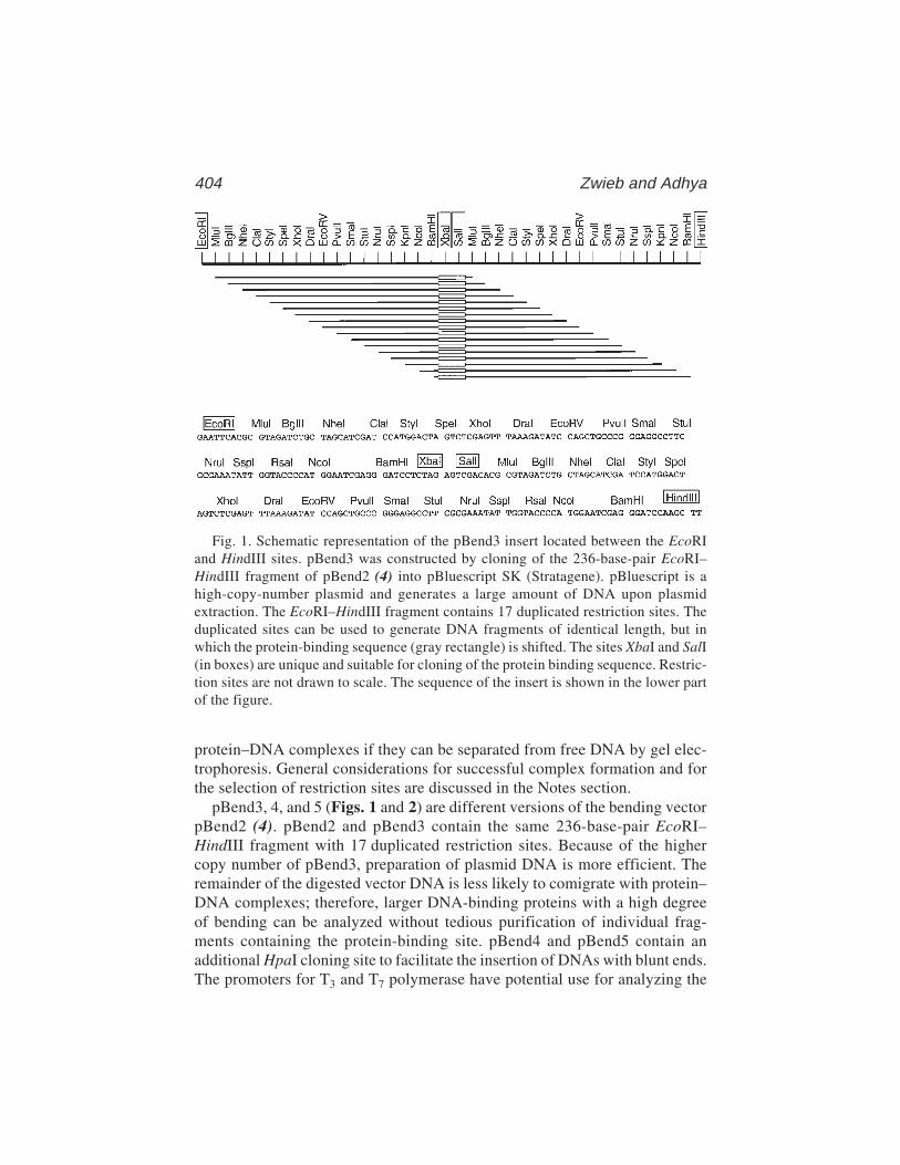
404 Zwieb and Adhya
protein–DNA complexes if they can be separated from free DNA by gel elec-trophoresis. General considerations for successful complex formation and forthe selection of restriction sites are discussed in the Notes section.
pBend3, 4, and 5 (Figs. 1 and 2) are different versions of the bending vectorpBend2 (4). pBend2 and pBend3 contain the same 236-base-pair EcoRI–HindIII fragment with 17 duplicated restriction sites. Because of the highercopy number of pBend3, preparation of plasmid DNA is more efficient. Theremainder of the digested vector DNA is less likely to comigrate with protein–DNA complexes; therefore, larger DNA-binding proteins with a high degreeof bending can be analyzed without tedious purification of individual frag-ments containing the protein-binding site. pBend4 and pBend5 contain anadditional HpaI cloning site to facilitate the insertion of DNAs with blunt ends.The promoters for T3 and T7 polymerase have potential use for analyzing the
Fig. 1. Schematic representation of the pBend3 insert located between the EcoRIand HindIII sites. pBend3 was constructed by cloning of the 236-base-pair EcoRI–HindIII fragment of pBend2 (4) into pBluescript SK (Stratagene). pBluescript is ahigh-copy-number plasmid and generates a large amount of DNA upon plasmidextraction. The EcoRI–HindIII fragment contains 17 duplicated restriction sites. Theduplicated sites can be used to generate DNA fragments of identical length, but inwhich the protein-binding sequence (gray rectangle) is shifted. The sites XbaI and SalI(in boxes) are unique and suitable for cloning of the protein binding sequence. Restric-tion sites are not drawn to scale. The sequence of the insert is shown in the lower partof the figure.

DNA-Bending Vectors 405
bending of double-stranded RNA or RNA/DNA hybrids by proteins such astranscription factor TFIIIA (7). Details of the construction of pBend3, 4, and 5are described in the legends to Figs. 1 and 2.
For unidirectional cloning of the protein-binding site into any of the pBendvectors, one has to use two cloning sites (e.g., XbaI and SalI). Because theefficiency of cleavage by both enzymes is somewhat impaired when the twotarget sites are close to each other, incomplete cutting results in a large amountof recircularized vector DNA without insert after ligation. This may make clon-ing of a binding site difficult. To make detection of cloned inserts easier,another pBend-derivative pBendBlue (Fig. 3) has been made (8). pBendblue,available from the authors in this reference, allows a color (blue/white) screen-ing of the transformants after cloning of the inserts. The construction of thepBendBlue plasmid is described in the legend to Fig. 3.
2. Materials2.1. Insertion of the Protein-Binding Site into a pBend Plasmid
1. pBend vector (provided by the authors upon request).2. Oligonucleotides or DNA fragments containing the binding site of the protein
being investigated with ends compatible with the cloning sites of pBend.
Fig. 2. Restriction and cloning sites of pBend3, 4, and 5. Portions of pBluescript SK(Stratagene) are shown in gray; the XbaI and SalI sites of pBluescript are abolished bypartial digestion with XbaI or SalI, filling in with DNA polymerase (Klenow) andligation with T4 DNA ligase. Promoters for T3 and T7 polymerase are indicated by thearrows. They can be used to study the bending by proteins that bind to double-strandedRNA or to RNA–DNA hybrids. The region between the EcoRI and HindIII sites (indi-cated in black) is identical to the one shown in Fig. 1. pBend4 and pBend5 containadditional SalI and HpaI sites as shown.
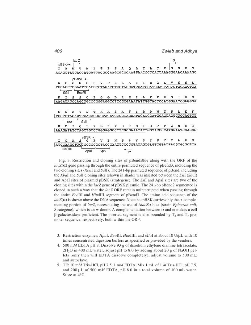
406 Zwieb and Adhya
3. Restriction enzymes: HpaI, EcoRI, HindIII, and MluI at about 10 U/µL with 10times concentrated digestion buffers as specified or provided by the vendors.
4. 500 mM EDTA pH 8: Dissolve 93 g of disodium ethylene diamine tetraacetate.2H2O in 400 mL water, adjust pH to 8.0 by adding about 20 g of NaOH pel-lets (only then will EDTA dissolve completely), adjust volume to 500 mL,and autoclave.
5. TE: 10 mM Tris-HCl, pH 7.5, 1 mM EDTA. Mix 1 mL of 1 M Tris-HCl, pH 7.5,and 200 µL of 500 mM EDTA, pH 8.0 in a total volume of 100 mL water.Store at 4°C.
Fig. 3. Restriction and cloning sites of pBendBlue along with the ORF of thelacZ(α) gene passing through the entire permuted sequence of pBend3, including thetwo cloning sites (XbaI and SalI). The 241-bp permuted sequence of pBend, includingthe XbaI and SalI cloning sites (shown in shade) was inserted between the SstI (SacI)and ApaI sites of plasmid pBSK (strategene). The SstI and ApaI sites are two of thecloning sites within the lacZ gene of pBSK plasmid. The 241-bp pBend2 segmented iscloned in such a way that the lacZ ORF remain uninterrupted when passing throughthe entire EcoRI and HindIII segment of pBend3. The amino acid sequence of thelacZ(α) is shown above the DNA sequence. Note that pBSK carries only the α-comple-menting portion of lacZ, necessitating the use of ∆lacZα host (strain Epicuran coli,Strategene), which is an w donor. A complementation between α and ω makes a cellβ-galactosidase proficient. The inserted segment is also bounded by T3 and T7 pro-moter sequence, respectively, both within the ORF.
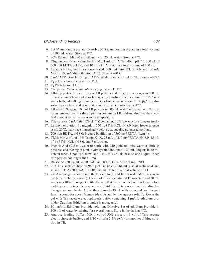
DNA-Bending Vectors 407
6. 7.5 M ammonium acetate: Dissolve 57.8 g ammonium acetate in a total volumeof 100 mL water. Store at 4°C.
7. 80% Ethanol: Mix 80 mL ethanol with 20 mL water. Store at 4°C.8. Oligonucleotide annealing buffer: Mix 1 mL of 1 M Tris-HCl, pH 7.5, 200 µL of
500 mM EDTA pH 8.0, and 10 mL of 1 M NaCl in a total volume of 100 mL.9. Ligation buffer, five times concentrated: 500 mM Tris-HCl, pH 7.6, and 100 mM
MgCl2, 100 mM dithiothreitol (DTT). Store at –20°C10. 5 mM ATP: Dissolve 3 mg of ATP (disodium salt) in 1 mL of TE. Store at –20°C.11. T4 polynucleotide kinase: 10 U/µL.12. T4 DNA ligase: 1 U/µL.13. Competent Escherichia coli cells (e.g., strain DH5α.14. LB-amp plates: Suspend 10 g of LB powder and 7.5 g of Bacto-agar in 500 mL
of water; autoclave and dissolve agar by swirling, cool solution to 55°C in awater bath, add 50 mg of ampicillin (for final concentration of 100 µg/mL), dis-solve by swirling, and pour plates and store in a plastic bag at 4°C.
15. LB media: Suspend 10 g of LB powder in 500 mL water and autoclave. Store atroom temperature. For the ampicillin containing LB, add and dissolve the speci-fied amount to the media at room temperature.
16. Tris–sucrose: 5 mM Tris-HCl (pH 7.8) containing 10% (w/v) sucrose (prepare fresh).17. Lysozyme solution: 10 mg/mL in 250 mM Tris-HCl, pH 8.0. Keep frozen aliquots
at mL 20°C, thaw once immediately before use, and discard unused portions.18. 200 mM EDTA, pH 8.0: Prepare by dilution of 500 mM EDTA (item 4).19. TLM: Mix 3 mL of 10% Triton X100, 75 mL of 250 mM EDTA pH 8.0, 15 mL
of 1 M Tris-HCl, pH 8.0, and 7 mL water.20. Phenol: Add 62.5 mL water to bottle with 250 g phenol, mix, warm as little as
possible, add 300 mg of 8 mL hydroxychinoline, and fill 20-mL aliquots in 30-mLFalcon tubes. Upon use, thaw, add 1 mL of 1 M Tris base to one aliquot. Keeprefrigerated not longer than 1 mo.
21. RNase A: 250 µg/mL in 10 mM Tris-HCl, pH 7.5. Store at mL –20°C.22. 20X Tris–acetate: Dissolve 96.8 g of Tris base, 22.84 mL glacial acetic acid, and
40 mL EDTA (500 mM, pH 8.0), and add water to a final volume of 1 L.23. 2% Agarose gel, about 5 mm thick, 7 cm long, and 10 cm wide: Mix 0.6 g agar-
ose (electrophoresis grade), 1.5 mL of 20X concentrated Tris–acetate and 30 mLwater in a 100-mL reagent bottle. Be sure that the cap of the bottle is loose beforemelting agarose in a microwave oven. Swirl the mixture occasionally to dissolvethe agarose completely. Adjust the volume to 30 mL with water and pour the gel.Insert a comb for about 3-mm-wide slots and let the agarose solidify. Cover thegel with Tris–acetate electrophoresis buffer containing 1 µg/mL ethidium bro-mide (Caution: Ethidium bromide is mutagenic).
24. 10 mg/mL Ethidium bromide solution: Dissolve 1 g of ethidium bromide in100 mL of water by stirring for several hours. Store in the dark at 4°C.
25. Agarose loading buffer: Mix 1 vol of 50% glycerol, 1 vol of Tris–acetateelectrophoresis buffer, and 1/10 vol of a 2.5% (w/v) bromophenol blue solu-tion in TE.
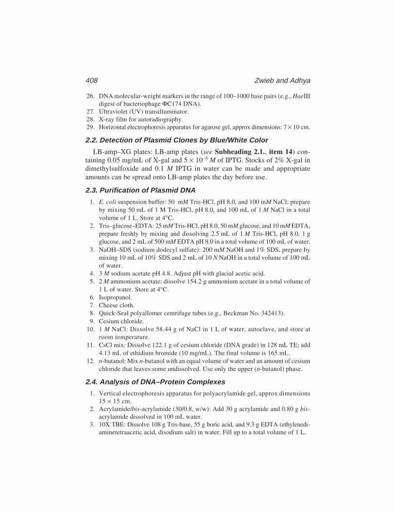
408 Zwieb and Adhya
26. DNA molecular-weight markers in the range of 100–1000 base pairs (e.g., HaeIIIdigest of bacteriophage ΦC174 DNA).
27. Ultraviolet (UV) transilluminator.28. X-ray film for autoradiography.29. Horizontal electrophoresis apparatus for agarose gel, approx dimensions: 7 × 10 cm.
2.2. Detection of Plasmid Clones by Blue/White Color
LB-amp–XG plates: LB-amp plates (see Subheading 2.1., item 14) con-taining 0.05 mg/mL of X-gal and 5 × 10⁻⁵ M of IPTG. Stocks of 2% X-gal indimethylsulfoxide and 0.1 M IPTG in water can be made and appropriateamounts can be spread onto LB-amp plates the day before use.
2.3. Purification of Plasmid DNA
1. E. coli suspension buffer: 50 mM Tris-HCl, pH 8.0, and 100 mM NaCl; prepareby mixing 50 mL of 1 M Tris-HCl, pH 8.0, and 100 mL of 1 M NaCl in a totalvolume of 1 L. Store at 4°C.
2. Tris–glucose–EDTA: 25 mM Tris-HCl, pH 8.0, 50 mM glucose, and 10 mM EDTA,prepare freshly by mixing and dissolving 2.5 mL of 1 M Tris-HCl, pH 8.0, 1 gglucose, and 2 mL of 500 mM EDTA pH 8.0 in a total volume of 100 mL of water.
3. NaOH–SDS (sodium dodecyl sulfate): 200 mM NaOH and 1% SDS, prepare bymixing 10 mL of 10% SDS and 2 mL of 10 N NaOH in a total volume of 100 mLof water.
4. 3 M sodium acetate pH 4.8. Adjust pH with glacial acetic acid.5. 2 M ammonium acetate: dissolve 154.2 g ammonium acetate in a total volume of
1 L of water. Store at 4°C.6. Isopropanol.7. Cheese cloth.8. Quick-Seal polyallomer centrifuge tubes (e.g., Beckman No. 342413).9. Cesium chloride.
10. 1 M NaCl: Dissolve 58.44 g of NaCl in 1 L of water, autoclave, and store atroom temperature.
11. CsCl mix: Dissolve 122.1 g of cesium chloride (DNA grade) in 128 mL TE; add4.13 mL of ethidium bromide (10 mg/mL). The final volume is 165 mL.
12. n-butanol: Mix n-butanol with an equal volume of water and an amount of cesiumchloride that leaves some undissolved. Use only the upper (n-butanol) phase.
2.4. Analysis of DNA–Protein Complexes
1. Vertical electrophoresis apparatus for polyacrylamide gel, approx dimensions15 × 15 cm.
2. Acrylamide/bis-acrylamide (30/0.8, w/w): Add 30 g acrylamide and 0.80 g bis-acrylamide dissolved in 100 mL water.
3. 10X TBE: Dissolve 108 g Tris-base, 55 g boric acid, and 9.3 g EDTA (ethylenedi-aminetetraacetic acid, disodium salt) in water. Fill up to a total volume of 1 L.
DNA-Bending Vectors 409
4. 8% Polyacrylamide slab gel (about 15 × 15 cm, 1 mm thick): Mix 31 mL of water,13.3 mL of 30% acrylamide/bis-acrylamide, 5 mL of 10X TBE, 600 µL of 10% APS(dissolve 1 g of ammonium persulfate in 10 mL of water), and 60 µL of TEMED(N,N,N',N'-tetrαmethylethylene diamide). Pour solution between the glass plates ofthe assembled vertical electrophoresis apparatus. Insert a comb for about 1-cm-wide slots. Let the gel polymerize for several hours, preferably overnight.
5. 5X DNA–protein binding buffer for Gal repressor: 50 mM KCl, 10 mM Tris-HCl,pH 7.5, 50 mM KCl, 1.0 mM EDTA, 20 µM cyclic AMP, 50 µg/mL bovine serumalbumin (BSA), 10% glycerol.
6. Ethidium bromide stain: Add 100 µL of ethidium bromide solution (10 mg/mL)to 1 L of TE.
2.5. E. coli Host Strains
For pBendBlue, Epicuran coli SURE2 competent cells (Strategene) are rec-ommended. For other pBend plasmids, any transformation proficient E. colistrains may be used.
3. Methods3.1. Insertion of the Protein-Binding Site into pBend
1. Add 25 µL of pBend DNA (1 mg/mL), 10 µL of 10X HpaI digestion buffer, 55 µLof water, and 10 µL (100 U) of HpaI restriction endonuclease to a 1.5-mL Eppendorftube. Mix and incubate at 37°C for 2 h or overnight.
2. To precipitate the restriction enzyme, place the digest on ice, add 3 µL of500 mM EDTA pH 8, 100 µL of ice-cold TE, and 100 µL of ice-cold 7.5 Mammonium acetate. Keep the sample at 4°C for 10 min. Centrifuge in a tabletopcentrifuge for 10 min. Remove the supernatant (containing the DNA) and add itto 600 µL ice-cold ethanol. Incubate at mL –70°C for 20 min, and centrifuge in atabletop centrifuge for 10 min. Discard the supernatant, add 500 µL of ice-cold80% ethanol, centrifuge for 5 min, and discard the supernatant. Dry the DNApellet in a vacuum centrifuge and dissolve the sample in 250 µL of TE. Store thelinearized pBend DNA at mL –20°C.
3. Synthesize two complementary oligonucleotides that, when annealed to eachother, form the protein-binding site. (See Note 1 for the design of DNA inserts.)The purification of the oligonucleotides is likely to be unnecessary if they areshorter than 30 nucleotides. Dissolve each oligonucleotide in autoclaved distilledwater at a concentration of 200 µg/mL.
4. Add 10 µL of each oligonucleotide and 180 µL of oligonucleotide annealingbuffer to a 1.5-mL Eppendorf tube. Incubate the sample for 3 min in a 300-mLbeaker with about 150 mL of boiling water. Place the beaker with the tubes in thecoldroom at 4°C to allow for annealing of the oligonucleotides over a period ofseveral hours. Store the DNA at mL –20°C.
5. Mix in a 1.5-mL Eppendorf tube, 2 µL of annealed oligonucleotides, 3 µL offive times concentrated ligation buffer, 1 µL of 5 mM ATP , 8.5 µL of water,
410 Zwieb and Adhya
and 0.5 µL of T4 polynucleotide kinase. Incubate for 10 min at 37°C. Placethe sample on ice and add 3 µL of five times concentrated ligation buffer, 1 µLof linearized vector DNA (from step 2), 1 µL of 5 mM ATP, 9 µL of water, and1 µL of T4 DNA ligase. Incubate at 15°C for several hours or overnight. Thesamples can be stored in a refrigerator for several days and aliquots can be usedfor several transformations.
6. Transform competent E. coli cells according to the protocol provided by the ven-dor and plate on LB-amp plates. Incubate the plates at 37°C overnight or until thecolonies appear.
7. For preparation of the plasmid DNA on a small scale, use sterile toothpicks totransfer individual colonies to 15 mL tubes containing 5 mL of LB with 200 µg/mLampicillin; also, streak cells from each transformant onto a LB-amp plate. Incu-bate this master plate at 37°C and shake the liquid cultures at 37°C overnight.
8. Pellet the cells by centrifugation for 15 min at about 700g at 4°C (e.g., at3000 rpm in a Sorvall RT6000B refrigerated centrifuge with a H1000B rotor).Decant the supernatant, add 200 µL Tris–sucrose and transfer to 1.5-mLEppendorf tubes. Add 25 µL of lysozyme solution. Mix and add 130 µL of 200 mMEDTA pH 8.0, and 130 µL of TLM. Mix and place at 65°C until lysis occurs(which usually takes a few min). Vortex briefly and centrifuge for 15 min in atabletop centrifuge. Remove the pellet with a sterile toothpick; add half a volumeof the prepared phenol and half a volume of chloroform. Vortex for 10 s, centri-fuge for 10 min and carefully remove about 200 µL of the aqueous (upper) phasewhile staying clear of the interface. Add 400 µL of ice-cold ethanol, mix andcentrifuge for 5 min, decant the supernatant, add 1 mL of 80% ethanol, centri-fuge for 2 min, carefully decant the supernatant and dry the pellet in a vacuumcentrifuge. Dissolve the pellet in 30 µL of TE with occasional mixing. Store thesamples at –20°C.
9. To verify successful insertion of the protein-binding site, digest an aliquot of theDNA with EcoRI and HindIII. To a 5-µL aliquot of the plasmid preparation, add2 µL of water, 1 µL of 10 times concentrated EcoRI digestion buffer, 1 µL ofEcoRI, 1 µL of HindIII, and 1 µL of RNase. As a control, digest 1 µg of pBendDNA. Incubate all samples at 37°C for several hours or overnight. Place digestson ice, add 1 µL of 200 mM EDTA pH 8.0, 90 µL of ice-cold TE, and 50 µL ofice-cold 7.5 M ammonium acetate. Keep on ice for 10 min. Centrifuge in a table-top centrifuge for 10 min. Collect the supernatant and add it to an Eppendorf tubecontaining 300 µL ice-cold ethanol. Mix and incubate at mL 70°C for 20 min.Centrifuge in a tabletop centrifuge for 10 min. Remove supernatant, add 300 µLice-cold 80% ethanol to the pellet, centrifuge for 5 min, and discard supernatant.Carefully dry the pelleted DNA in a vacuum centrifuge and dissolve it in 5 µL ofTE. Add 5 µL of Tris–acetate loading buffer and mix briefly.
10. Prepare a 2% agarose gel. Load the samples from step 9 in parallel with DNAmolecular-weight markers. Electrophorese at 80 V until the bromophenol bluehas migrated about 4 cm. Examine the DNA under a UV transilluminator andtake a picture with a Polaroid camera (film type 57 or 55). Successful insertion is
DNA-Bending Vectors 411
indicated by an EcoRI–HindIII fragment of the expected mobility (242 base pairsplus insert). Electrophoresis can be continued to discover minor mobility differ-ences, but then fresh electrophoresis buffer should be used. Eventually, the natureof the positive clone must be verified by DNA sequencing, which also revealsthe orientation of the inserted binding site (see Note 2 for the selection of suit-able sequencing primers).
3.2. Detection of the Protein-Binding Site Clonedinto pBend Blue by Blue/White Color Screening
After ligation of the DNA segment corresponding to the protein-binding siteinto pBendBlue DNA, as described in steps 1–5 of Subheading 3.1., trans-form competent E. coli cells (strain Epicuvan) and plate on LB-amp–XG plates.Incubate the plates at 37°C overnight or until the colonies are large enough todistinguish their blue/white color phenotype. By this procedure, usually 1–10%of the transformed colonies on LB-amp–XG plates are white. Verify the whitecolonies by purifying on LB-amp–XG plates. Sequence verification shows thatalmost all of the white colonies contain the desired insert. Thus, when the clon-ing efficiency is poor, the color screening allows successful use of pBendBluein cloning short DNA sequences for studying DNA binding.
3.3. Purification of pBend DNA
1. To obtain pure DNA of the positive pBend derivative, set up a 5-mL culture ofthe positive clone in LB with 500 µg/mL of ampicillin starting from an indi-vidual colony of the master plate (step 7 of Subheading 3.1.). Shake at 37°C forseveral hours until the culture becomes turbid. Transfer the cells to a 2-L sterileErlenmeyer containing 400 mL of LB with ampicillin. Shake overnight at 37°C.
2. Place the culture on ice and transfer the cells into centrifuge bottles. Pellet thecells by centrifugation at 4°C at about 1600g (e.g., 3500 rpm in a H6000A rotorof a Sorvall RC3C centrifuge). Decant the supernatant, resuspend the pellet in20 mL E. coli suspension buffer and transfer the cells to a 50-mL centrifuge tube(preferably Nalgene, cat. no. 3131-0024). Centrifuge at 4°C for 10 min at about5000g (e.g., in Sorvall SS34 rotor at 10,000 rpm). Freeze the pellet completelyby placing the sample on dry ice or in a –80°C freezer.
3. Thaw the pellet and resuspend the cells in 6 mL of Tris–glucose–EDTA. Add12 mg of lysozyme powder, mix and keep on ice for 30 min. Bring to room tem-perature and add 12 mL of NaOH–SDS. Mix and place on ice for 5 min.
4. Add 9 mL of 3 M sodium-acetate pH 4.8, shake, and leave on ice for 30 min.Centrifuge at about 12,000g at 4°C for 15 min (e.g., in an SS34 rotor at15,000 rpm).
5. Transfer the supernatant to a new centrifuge tube by filtering through a cheese-cloth. Add half a volume of isopropanol to the transferred solution, leave 5 minat room temperature and centrifuge at 4°C for 10 min at 5000 g (e.g., in the SS34rotor at 10,000 rpm).
412 Zwieb and Adhya
6. Discard the supernatant and add 6 mL of ice-cold 2 M ammonium-acetate to thepellet. Vortex repeatedly to dissolve the plasmid DNA until only small particlesare visible. Centrifuge at 4°C for 10 min at 5000g.
7. Transfer the supernatant (containing the plasmid DNA) to a new centrifuge tube,add 4 mL of isopropanol, mix, and centrifuge at 4°C for 10 min at 5000g.
8. Discard the supernatant and completely dissolve the pellet in 7 mL of TE withoccasional shaking. Add 8 g of cesium chloride, 400 µL of 1 M NaCl, 400 µL of1 M Tris-HCl, pH 8.0, 160 µL of ethidium bromide (10 mg/mL) and 2.5 mL ofCsCl mix.
9. After the CsCl is dissolved, draw the solution into a 20-mL syringe and transfer itinto a Quick-Seal centrifuge tube. Fill a second tube with CsCl mix and makesure that the two tubes are balanced. Seal the tubes and centrifuge overnight atabout 20,000g at 20°C (e.g., at 50,000 rpm in a Beckman NTV65 rotor).
10. Remove the tubes from the rotor, puncture the top of the tube, then collect thelower of the two visible bands with a syringe by puncturing the side of the tube.Transfer the DNA into a 15-mL Corex glass centrifuge tube.
11. Extract the ethidium bromide by adding 1 mL of n-butanol that has been satu-rated with water and cesium chloride. Vortex and remove the upper phase with aglass pipet. Repeat this process beyond the point where the color becomes invis-ible (usually about six times).
12. Add 2.5 mL of water and 7 mL of ethanol. Mix and incubate at mL –70°C for15 min. (Do not leave too long, otherwise CsCl will precipitate). Centrifuge for15 min at 4°C at about 7000g preferably in a swinging-bucket rotor (e.g., SorvallHB4 rotor at 10,000 rpm).
13. Pour off the supernatant, add 5 mL of ice-cold 80% ethanol to the pellet, repeat thecentrifugation, discard the supernatant and evaporate excess ethanol under vacuum.
14. Dissolve the DNA in 500 µL of TE and determine the absorbance at 260 nm.Add the appropriate amount of TE to adjust the concentration of the plasmidDNA to 1 mg/mL (1 A260 is equivalent to 50 µg/mL). Store the DNA at 4°C.
3.4. Analysis of DNA–Protein Complexes
1. To generate restriction fragments with the protein-binding site located at the endor in the middle, digest the pBend construct with MluI (end) and EcoRV (middle)separately or with the entire set of restriction enzymes with duplicated targetsindividually. One digestion contains 100 µL (100 µg) of plasmid DNA fromstep 14 of Subheading 3.3., 30 µL of 10 times concentrated MluI (or EcoRV)digestion buffer, 160 µL of water, and 10 µL of MluI or EcoRV restrictionenzyme (100 U). Incubate the samples at 37°C for several hours or overnight.Place the samples on ice, add 15 µL of 500 mM EDTA, pH 8.0, 150 µL of ice-cold 7.5 M ammonium acetate and leave at 4°C for 10 min. Centrifuge in a table-top machine for 10 min. Remove and add the supernatant (containing the DNA)to a new Eppendorf tube filled with 900 µL of ice-cold ethanol. Mix and incu-bate at –70°C for 20 min. Centrifuge for 10 min. Discard the supernatant, add500 µL of ice-cold 80% ethanol, centrifuge again for 5 min and decant the super-

DNA-Bending Vectors 413
natant. Carefully dry the pellet in a vacuum centrifuge and dissolve the DNA in50 µL of water. Verify the success of the digestion by electrophoresis of an ali-quot on a 2% agarose gel (described in item 23 of Subheading 2.1.).
2. Pour a vertical 8% polyacrylamide slab gel. Assemble the electrophoresis appa-ratus and pre-electrophorese at room temperature for 1 h at 100 V with TBEbuffer containing 1.0 µM cyclic AMP in the reservoirs.
3. Isolate the different DNA fragments containing the protein-binding site after gelelectrophoresis for end labeling, if necessary (see Note 6). Label the ends of theDNA fragments by T4 polynucleotide kinase and [γ-32P]ATP as recommendedby the supplier of the enzyme.
4. Mix at room temperature 2 µL of digested DNA fragments (from step 1 or step 3),1.6 µL of five times concentrate solution of CRP binding buffer, 4.4 µL of water,and 2 µL of diluted CRP. Keep the time between diluting the protein and additionto the DNA as short as possible. Do not vortex; mix gently with the tip of thepipet. Prepare a control without added protein. Incubate all samples for 10 min atroom temperature.
5. Flush the wells of the polyacrylamide gel with reservoir buffer and load sampleswithout the addition of loading buffer and tracking dyes. The glycerol in thebinding buffer gives the sample sufficient density. A long plastic microcapillarytip is helpful for delivering the sample to the bottom of the slot. Glass capillariesshould be avoided because proteins tend to stick to glass. In a separate slot, loadDNA molecular-weight markers with bromophenol blue. Electrophorese at roomtemperature for 5 h at 200 V. Separate the glass plates and immerse the gel inethidium bromide stain for visualization of the DNA under UV light. Take apicture with a Polaroid camera and subsequently autoradiograph gel (consultNotes 3 and 4 if complexes cannot be detected).
6. Measure the distances between the gel loading slot and the position of the pro-tein–DNA complex of the MluI (µE) and the EcoRV digest (µM). Also, examinethe mobilities of the free DNA (Fig. 4) to make sure that the DNA fragmentscontain no intrinsic bending. Calculate the bending angle α using the empiricalformula µM/µE = cos(1/2α).
4. Notes1. Protein-binding sites can be inserted into the pBend vectors using restriction frag-
ments or synthetic oligonucleotides. Restriction fragments should not be consid-erably larger than the protein-binding site to be tested. Oligonucleotides arenormally available with blunt ends and can be cloned into the HpaI sites ofpBend4 or pBend5 (Fig. 2). Newly synthesized oligonucleotides can be designedwith “sticky” ends such that they are compatible with the XbaI and the SalI sites;they can be cloned more efficiently and inserted in a single orientation.
2. Insertion of the protein-binding site may not occur if the oligonucleotides are ofpoor quality. In this case, they should be purified and checked by polyacrylamidegel electrophoresis. If the transformation efficiency with supercoil control DNAis high, yet very few transformants are obtained with the annealed oligonucle-
414 Zwieb and Adhya
otides, reduce the amount of insert DNA. Multiple insertion of the binding sitecan occur and is detected by gel electrophoresis and sequencing. For sequencing,use primers named T3, T7, M13-20, or reverse primer (Stratagene). Do not usethe SK and KS primers (Stratagene) because they are not fully complementary topBend3, 4, and 5.
3. Bending experiments with radioactively labeled DNA are particularly useful ifthe protein has not been purified or if its availability is limited. Labeling can beaccomplished with T4 polynucleotide kinase and [γ–32P]ATP. Often, the DNAends generated by the various restriction enzymes are labeled to different degrees.This problem can be overcome by loading the gel with aliquots of the bindingreaction adjusted for the efficiency of fragment labeling. It is best to purify andisolate the protein-binding fragments because the radioactively labeled plasmid–DNA might obscure the region where the complexes are located. Another poten-tial problem (which is also the case with unlabeled DNA) might be that bandsappear which represent minor digestion products. In order to identify these, makesure to include controls without added protein.
4. One of the frustrating aspects of conducting a bending experiment can be theinability to detect a complex on the polyacrylamide gel. Even if the binding andelectrophoresis conditions are known one should be careful to avoid solutionsand equipment that have been in contact with SDS. If possible, dedicate oneelectrophoresis setup to “gel-shift” experiments. Many DNA-binding proteins areinsoluble in the low salt concentration of the electrophoresis buffer and must be storedat high ionic strength. Limit the time between dilution and addition to the DNA.Avoid vortexing during complex formation and do not add tracking dyes becausethey interact with the complex and might change its mobility. Larger protein–DNA complexes (e.g., Lac repressor [6]) behave better in low percentage poly-acrylamide gels (e.g., 4%) with a high acrylamide/bis-acrylamide ratio (80:1).The protein concentration for obtaining about equal amounts of free andcomplexed DNA should always be determined in a preliminary experiment.
5. If many transformants are obtained, but none contain the protein-binding site, thepBend DNA might not have been fully linearized. Alter the DNA–enzyme ratioin favor of the enzyme and confirm complete digestion of an aliquot by electro-phoresis on an agarose gel.
6. In the initial bending experiment, it is advisable to restrict only with MluI orBamHI (to place the binding site close to the ends) and EcoRV or PvuII (to placethe binding site in the middle). Do not select restriction sites that also occur in theprotein-binding sequence. When exploiting the 17 circular permutated restrictionsites, attention must be paid to the property of some of the restriction enzymes asfollows: ClaI sites are methylated in most E. coli strains; its use is therefore lim-ited to prior growth of the plasmid in a methylation-defective (dam-) host. StyIwill also cut at NcoI of the repeat; for the purpose of a bending experiment, it cantherefore only be used under partial digestion conditions. An additional SpeI siteis present in the vicinity of the single EcoRI site as part of pBluescript SK (seeFig. 2). SpeI digestion generates an additional small fragment, which contains no
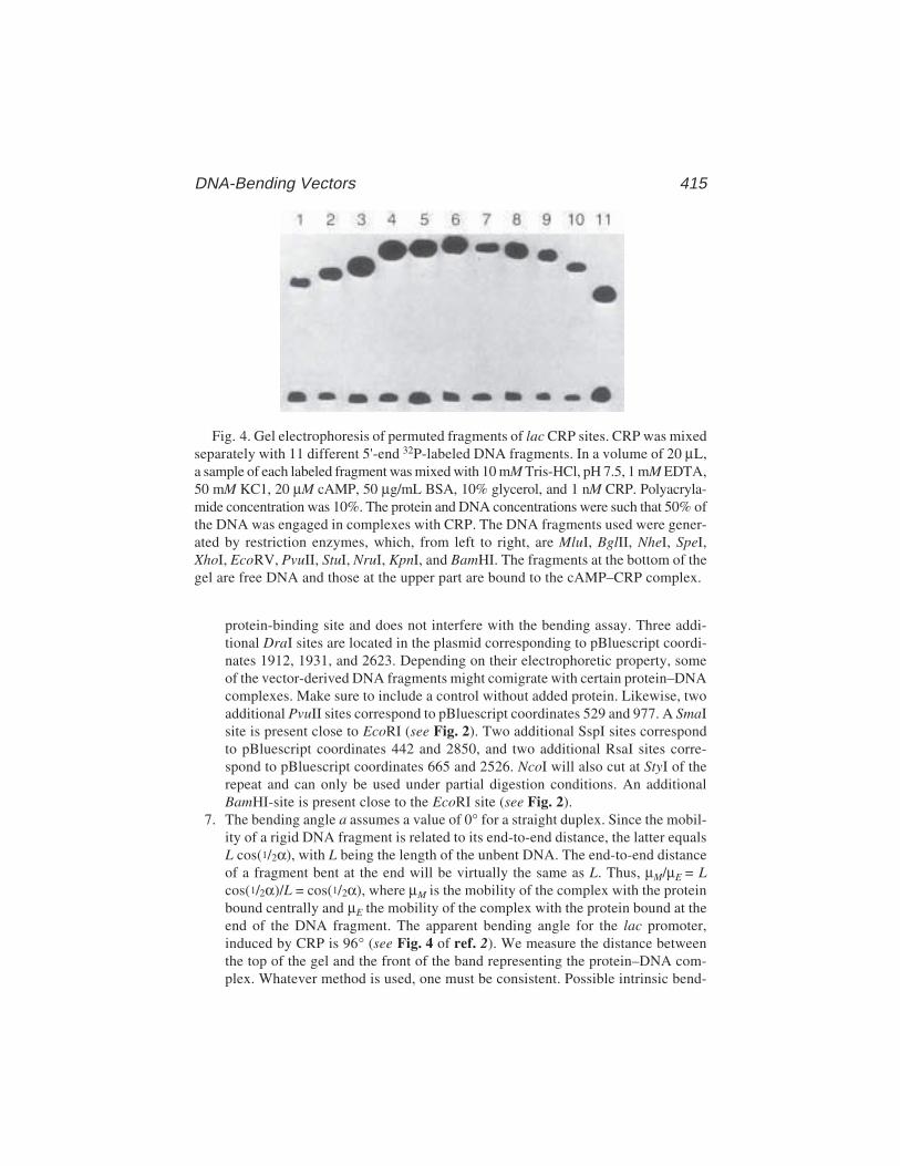
DNA-Bending Vectors 415
protein-binding site and does not interfere with the bending assay. Three addi-tional DraI sites are located in the plasmid corresponding to pBluescript coordi-nates 1912, 1931, and 2623. Depending on their electrophoretic property, someof the vector-derived DNA fragments might comigrate with certain protein–DNAcomplexes. Make sure to include a control without added protein. Likewise, twoadditional PvuII sites correspond to pBluescript coordinates 529 and 977. A SmaIsite is present close to EcoRI (see Fig. 2). Two additional SspI sites correspondto pBluescript coordinates 442 and 2850, and two additional RsaI sites corre-spond to pBluescript coordinates 665 and 2526. NcoI will also cut at StyI of therepeat and can only be used under partial digestion conditions. An additionalBamHI-site is present close to the EcoRI site (see Fig. 2).
7. The bending angle a assumes a value of 0° for a straight duplex. Since the mobil-ity of a rigid DNA fragment is related to its end-to-end distance, the latter equalsL cos(1/2α), with L being the length of the unbent DNA. The end-to-end distanceof a fragment bent at the end will be virtually the same as L. Thus, µM/µE = Lcos(1/2α)/L = cos(1/2α), where µM is the mobility of the complex with the proteinbound centrally and µE the mobility of the complex with the protein bound at theend of the DNA fragment. The apparent bending angle for the lac promoter,induced by CRP is 96° (see Fig. 4 of ref. 2). We measure the distance betweenthe top of the gel and the front of the band representing the protein–DNA com-plex. Whatever method is used, one must be consistent. Possible intrinsic bend-
Fig. 4. Gel electrophoresis of permuted fragments of lac CRP sites. CRP was mixedseparately with 11 different 5'-end 32P-labeled DNA fragments. In a volume of 20 µL,a sample of each labeled fragment was mixed with 10 mM Tris-HCl, pH 7.5, 1 mM EDTA,50 mM KC1, 20 µM cAMP, 50 µg/mL BSA, 10% glycerol, and 1 nM CRP. Polyacryla-mide concentration was 10%. The protein and DNA concentrations were such that 50% ofthe DNA was engaged in complexes with CRP. The DNA fragments used were gener-ated by restriction enzymes, which, from left to right, are MluI, BglII, NheI, SpeI,XhoI, EcoRV, PvuII, StuI, NruI, KpnI, and BamHI. The fragments at the bottom of thegel are free DNA and those at the upper part are bound to the cAMP–CRP complex.
416 Zwieb and Adhya
ing in the free DNA must be considered in the calculation of the bending angle. Itshould be noted that the calculated values may be different from absolute bend-ing angles, because factors other than the end-to-end distance influence themobility of protein-bound and unbound DNA fragments. The method measuresthe net bend and cannot distinguish between a single sharp bend at one positionand a smooth curving over a larger DNA region. For precise determination ofbending angles, at least three independent experiments should be conducted. Ifpossible, use control lanes containing a similar size complex in which a DNAfragment is bent to a known degree by binding to a specific protein.
References1. Crothers, D. M. and Fried, M. G. (1983) Transmission of long-range effects in
DNA. Cold Spring Harbor Symp. Quant. Biol. 47, 263–269.2. Zwieb, C., Kim, J., and Adhya, S. (1989) DNA bending by negative regulatory
proteins: Gal and Lac repressors. Genes Dev. 3, 606–611.3. Wu, H.-M. and Crothers, D. M. (1986) The locus of sequence-directed and pro-
tein-induced DNA bending. Nature (London) 308, 509–513.4. Kim, J., Zwieb, C., Wu, C.. and Adhya, S. (1989) Bending of DNA by gene-
regulatory proteins: construction and use of a DNA bending vector. Gene 85, 15–23.5. Thompson, J. F. and Landy, A. (1988) Empirical estimation of protein-induced
DNA bending angles: application to site-specific recombination complexes.Nucleic Acids Res. 20, 9687–9705.
6. Fried, M. G. and Crothers, D. M. (1983) CAP and RNA polymerase interactionwith the lac promoter: binding stoichiometry and longe-range effects. NucleicAcids Res. 11, 141–185.
7. Zwieb, C. and Brown, R. S. (1990) Absence of substantial bending in the Xenopuslaevis transcription factor IIIA–DNA complex. Nucleic Acids Res 18, 583–587.
8. Sperbeck, S. J. and Wistow, G. J. (1998) pBendBlue: modification of the pBendsystem for color selectability. BioTechniques 24, 66–68.
Engineering Nucleic Acid-Binding Proteins 417
417
From: Methods in Molecular Biology, vol. 148: DNA–Protein Interactions: Principles and Protocols, 2nd ed.Edited by: T. Moss © Humana Press Inc., Totowa, NJ
29
Engineering Nucleic Acid-Binding Proteinsby Phage Display
Mark Isalan and Yen Choo
1. IntroductionIn the phage display method, peptides (1) or protein domains (2,3) cloned as
fusions to the coat proteins of filamentous bacteriophage are displayed on thecapsid, which encloses the viral genome. Proteins of interest and their associ-ated phage can be selected from a large pool of variants (a library) by affinitypurification using an appropriate ligand bound to a solid support. Thus, whileweakly interacting phage are removed by washing, strongly bound phage areretained and can be subsequently amplified by passage through a bacterial host.Sequential rounds of selection and amplification lead to enrichment of thoseclones with the highest affinity for the target ligand. The identities of theseclones can then be deduced by sequencing part of the phage genome.
Protein–nucleic acid interactions (4,5), which often involve complicatednetworks of intermolecular contacts, can be investigated expeditiously usingphage display because large numbers of protein variants can be screenedsimultaneously. We and others have used this powerful technique to study DNAbinding by the TFIIIA-type zinc finger motif (6–11) and, more recently, byRNA binding by zinc fingers (12,13), the HIV-1 Tat protein (14), and an RNPdomain from the U1A spliceosomal protein (15). In this chapter, we describethe steps involved in cloning phage display libraries of nucleic-acid-bindingproteins (1) preparation of high-quality vector for cloning; (2) preparation of acassette coding for the protein library to be expressed on phage; and (3) liga-tion of these two components and transformation of competent bacteria. Alsodescribed are the protocols we use to (1) perform selections of nucleic-acid-binding proteins displayed on phage and (2) assay the binding affinity andspecificity of selected clones using phage enzyme-linked immunosorbent assay

418 Isalan and Choo
(ELISA). Moreover, since we have found that the success of such phage-display experiments is as dependent on experimental strategy as it is ontechnique, we have commented on the rationale underlying our publishedphage-display experiments (8,11,16) in Subheading 4. We anticipate that thesegeneral principles and methods can be applied to the phage display of manyother nucleic-acid-binding motifs.
2. Materials2.1. Preparation of Phage Vector
1. 2X TY medium: 16 g/L Bactotryptone, 10 g/L Bactoyeast extract, and 5 g/L NaCl).2. Tetracycline.3. Escherichia coli strain expressing the F pilus (e.g., E. coli TG1 [F' traD36 lacIq
∆(lacZ)M15 proA+B+/supE ∆(hsdM-mcrB)5(rK-mK-McrB-) thi ∆(lac-proAB])grown on minimal medium.
4. Phage vector suitable for phage display, (e.g., Fd-TET-SN [8]).5. Plasmid purification system (e.g., Wizard Maxiprep kit [Promega]).6. TE buffer: 10 mM Tris, pH 7.4, and 1 mM EDTA, pH 8.0.7. Cesium chloride.8. Water-saturated butan–2-ol.9. SfiI 20,000 U/mL, and NEBuffer 2 (New England Biolabs).
10. NotI 10,000 U/mL, and NEBuffer 3 (New England Biolabs).11. Mineral oil.12. TAE, 50X stock solution: 242 g Tris base, 57.1 mL glacial acetic acid, 37.2 g
Na2EDTA·2H2O, and H2O to 1 L.13. Ethidium bromide, 10 mg/mL.14. AgaraseI (Sigma).
2.2. Construction of a Gene Cassette Codingfor a Protein Library
1. T4 polynucleotide kinase (10 U/µL) and buffer (New England Biolabs).2. T4 DNA ligase (400 U/µL) and buffer (New England Biolabs).
2.3. Cloning of Library DNA Cassette into Phage Vector
1. Electrocompetent E. coli (e.g., strain TG1).2. Electroporation cuvets (2-mm path, Equibio).3. SOC medium: 0.5% (w/v) yeast extract, 2% (w/v) tryptone, 10 mM NaCl, 2.5 mM
KCl, 10 mM MgCl2, 10 mM MgSO4, and 20 mM glucose.4. TYE medium: 1.5% (w/v) agar, 1% (w/v) Bactotryptone, 0.5% (w/v) Bactoyeast
extract, and 0.8% (w/v) NaCl.
2.4. Phage Selection Against Nucleic Acid Targets
1. 2X nucleic acid annealing buffer: 40 mM Tris buffer, pH 8.0, and 200 mM NaCl).2. Streptavidin-coated paramagnetic beads (Dynal AS).
Engineering Nucleic Acid-Binding Proteins 419
3. Phosphate-buffered saline (PBS): 10X stock: 80 g NaCl, 2 g KCl, 11.5 gNa2HPO4·7H2O, 2 g KH2PO4, water to 1 L.
4. Fat-free freeze-dried milk (Marvel).5. Tween-20.6. Sonicated salmon sperm DNA (10 mg/mL).7. 0.1 M triethanolamine.8. 1 M Tris-HCl, pH 7.4.
2.5. Assaying Binding Properties of Selected Clonesby Phage ELISA
1. Streptavidin-coated microtiter wells (Roche).2. Horseradish peroxidase-conjugated anti-M13 IgG (Pharmacia Biotech).3. 3,3',5,5'-tetramethyl-benzidine (TMB, Sigma).4. Dimethyl sulfoxide (DMSO).5. 3 M Sodium acetate (pH 5.5).6. 30% (v/v) hydrogen peroxide.7. 1 M sulfuric acid.
3. Method3.1. Preparation of Phage Vector
1. Prepare vector DNA (see Note 1) from a 1-L bacterial culture by using alarge-scale plasmid preparation kit (e.g., Wizard Maxipreps, Promega) fol-lowed by additional purification on a cesium chloride gradient (see Note 2).We have found that only cesium-chloride-pure phage DNA is suitable forlibrary construction.
2. Resuspend 40 µg pure vector in 460 µL of 1X NEBuffer 2 containing 100 µg/mLbovine serum albumin (BSA). Add 10 µL (200 U) of SfiI, overlay with mineraloil, and incubate at 50°C. Supplement the reaction with 10 µL (200 U) of SfiIevery 2 h to a total incubation time of 8 h.
3. Purify DNA by extracting once with phenol and once with chloroform, followedby ethanol precipitation.
4. Resuspend DNA in 460 µL of 1X NEBuffer 3 containing 100 µg/mL BSA. Add10 µL (100 U) of NotI and incubate at 37°C. Supplement the reaction with 10 µL(200 U) of NotI every 2 h to a total incubation time of 8 h.
5. Purify the cut vector by agarose gel electrophoresis prior to cloning. Run the cutvector DNA on a 1% low-melting-point agarose gel, made up in 1X TAE con-taining 0.5 µg/mL ethidium bromide.
6. Excise the vector DNA band under ultraviolet (UV) light.7. Extract the vector DNA from the gel slice by digestion using AgaraseI (Sigma).
Purify DNA by extracting once with phenol and once with chloroform, followedby ethanol precipitation.
8. Resuspend DNA in sterile water and quantitate by spectrophotometry. Vectormay be stored in aliquots at –20°C.
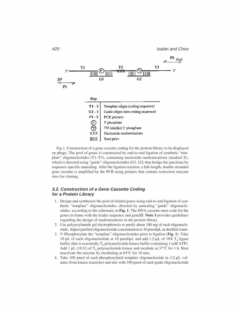
420 Isalan and Choo
3.2. Construction of a Gene Cassette Codingfor a Protein Library
1. Design and synthesize the pool of related genes using end-to-end ligation of syn-thetic “template” oligonucleotides, directed by annealing “guide” oligonucle-otides, according to the schematic in Fig. 1. The DNA cassette must code for thegenes in frame with the leader sequence and geneIII. Note 3 provides guidelinesregarding the design of randomizations in the protein library.
2. Use polyacrylamide gel electrophoresis to purify about 100 mg of each oligonucle-otide. Adjust purified oligonucleotide concentration to 10 pmol/µL in distilled water.
3. 5'-Phosphorylate the “template” oligonucleotides prior to ligation (Fig. 1). Take10 µL of each oligonucleotide at 10 pmol/µL and add 1.2-µL of 10X T4 ligasebuffer (this is essentially T4 polynucleotide kinase buffer containing 1 mM ATP).Add 1 µL (10 U) of T4 polynucleotide kinase and incubate at 37°C for 1 h. Heatinactivate the enzyme by incubating at 65°C for 10 min.
4. Take 100 pmol of each phosphorylated template oligonucleotide in (12-µL vol-umes from kinase reactions) and mix with 100 pmol of each guide oligonucleotide
Fig 1. Construction of a gene cassette coding for the protein library to be displayedon phage. The pool of genes is constructed by end-to-end ligation of synthetic “tem-plate” oligonucleotides (T1–T3), containing nucleotide randomizations (marked X),which is directed using “guide” oligonucleotides (G1, G2) that bridge the junctions bysequence-specific annealing. After the ligation reaction, a full-length, double-strandedgene cassette is amplified by the PCR using primers that contain restriction enzymesites for cloning.
Engineering Nucleic Acid-Binding Proteins 421
(10 µL of 10 pmol/µL in 1X T4 DNA ligase buffer). Place in a boiling waterbath for3 min, then turn off the heat source and leave to cool to room temperature to allowannealing of the template and guide oligonucleotides. Finally, place on ice.
5. Add an equal volume of 1X T4 DNA ligase buffer to the oligonucleotide mixture.Supplement with 8 µL (3200 U [DNA end ligation units]) of T4 DNA ligase per100 µL. Incubate at 16°C for 8–24 h.
6. Carry out a small-scale (25-µL) trial polymerase chain reaction (PCR) reaction,with appropriate primers (as shown in Fig. 1), to amplify full-length double-stranded DNA cassette (see Note 4). Typically, 1 µL of the ligation reactioncontains sufficient template. The correct size of the PCR product should be veri-fied by agarose gel electrophoresis. When PCR conditions are optimized, scaleup the PCR reaction 10-fold. If the PCR product is not of the predicted size, thengel purification of the ligated single-stranded template may be required. Purifica-tion is facilitated by 32P end labeling of the 3'-terminal oligonucleotide used inconstructing the gene cassette.
7. Prepare the PCR product for restriction digestion by extracting once with phenoland once with chloroform, followed by ethanol precipitation.
8. Resuspend DNA in 460 µL 1X NEBuffer 2 containing 100 µg/mL BSA. Add 10 µL(200 U) of SfiI, overlay with mineral oil, and incubate at 50°C. Supplement thereaction with 10 µL (200 U) of SfiI every 2 h to a total incubation time of 8 h.
9. Prepare DNA for the second digestion by extracting once with phenol and oncewith chloroform, followed by ethanol precipitation.
10. Resuspend DNA in 460 µL 1X NEBuffer 3 containing 100 µg/mL BSA. Add 10 µL(100 U) of NotI and incubate at 37°C. Supplement the reaction with 10 µL (200 U)of NotI every 2 h to a total incubation time of 8 h.
11. Remove small restriction fragments and prepare the cassette for cloning usingagarose gel purification: run the cut cassette on 2% low-melting-point agarosegel in 1X TAE containing 0.5 µg/mL ethidium bromide. Excise the band of interestfrom the gel and extract DNA by any suitable method such as AgaraseI digestion.
12. The DNA yield should be quantitated and the cassette stored in distilled water at–20°C. This protocol gives 1–3 µg of library cassette, of which less than 0.5 µg istypically required to clone a library of 5 million transformants.
3.3. Cloning of the Library DNA Cassette into Phage Vector
1. Ligate DNA insert into a 1 µg (approx 0.2 pmol) phage vector. This is carried outin a total volume of 30 µL in 1X T4 DNA ligase buffer supplemented with 3 µL(1200 U) of T4 DNA ligase. Incubate at 16°C for 16 h. A 5:1 molar ratio of insertto the vector should give good yields, but results can be improved by optimizingthis ratio after each new vector and insert preparation.
2. Purify ligation products by phenol/chloroform extraction followed by ethanolprecipitation. Wash the precipitate thoroughly with 70% ethanol and dry for 5 minin a lyophilizer. Resuspend pellet in 10 µL of distilled water. It is important tominimize the amount of salt carried through because this can cause arcing duringelectroporation.
422 Isalan and Choo
3. Electroporate 2-µL (approx 200 ng) samples of ligated vector into 50–70 µL ofelectrocompetent E. coli (see Note 5) in a 2-mm-path electroporation cuvet (Equibio).
4. Pulse cells in electroporation apparatus set to 2.5 kV and 25 µF, with a pulsecontroller set to 200 Ω.
5. Immediately resuspend cells in 1 mL room-temperature SOC. Incubate for 1 h at37°C with shaking.
6. Plate cells out on TYE medium containing 15 µg/mL tetracycline and grow 16 hat 30°C. Large 24-cm × 24-cm plates are convenient for plating out approx 106
transformant colonies. Plate out a dilution series of the transformation on smallerplates to estimate the total number of colonies obtained (i.e., the library size).
7. The efficiency of the cloning can be verified by PCR screening 20 randomlyselected colonies using internal primers that amplify the cloned cassette (see Note4). Individual colonies can be cultured in liquid medium to produce phage (seeNote 6) for DNA sequencing to confirm that the library contains unbiasedrandomizations at the expected positions.
8. Harvest the library by gently scraping colonies into 1–3 mL of 2X TY. Bacteriamay be stored at –70°C after the addition of 50% (v/v) glycerol.
9. To obtain phage particles, grow phage-infected bacteria in 2X TY containing15 µg/mL tetracycline. Use 50 mL of culture medium/mL of harvested bacteriaand incubate for 8–24 h at 30°C.
10. Centrifuge cultures at 500g for 20 min to obtain clear phage-containing superna-tant. This may be filtered through a 2-µm filter to remove bacteria, stored at 4°Cor –20°C, or alternatively used for selection experiments.
3.4. Phage Selection Against Nucleic Acid Targets
1. Nucleic acid targets used for selection are prepared by annealing complementaryDNA oligonucleotides together, or refolding an RNA hairpin structure. At leastone of the oligonucleotides must be biotinylated. Mix 10 µL of (each) oligo-nucleotide at 10 pmol/µL with 20 µL of 2X nucleic acid annealing buffer. Placein a boiling waterbath for 3 min, then turn off the heat source and allow to cool toroom temperature. Finally, place on ice. Annealed binding sites may be diluted inwater to a 1 pmol/µL stock solution stored at –20°C.
2. Fresh phage are prepared for selection by growing phage-infected bacteria in 2XTY containing 15 µg/mL tetracycline for 8–24 h at 30°C. Grow 1 mL of culturefor each selection experiment (see Note 7).
3. Take 50 µL of dynabeads solution and separate the beads from the preservativebuffer using a magnet. Then, add 1 pmol of nucleic acid target site to the blockedbeads in 50 µL PBS and allow to bind for 30 min (see Note 8).
4. Start growing 1 mL of fresh TG1 bacteria per selection experiment, in 2X TY at37°C. The bacteria will be ready when an OD600 of 0.6 is reached (this takesabout 3 h if 2–5 mL of 2X TY is inoculated with a single colony). In the mean-time, steps 5–10 of the selection should be performed.
5. Block the nucleic-acid-coated beads for 1 h at 20°C by adding 1 mL of PBScontaining 4% (w/v) fat-free freeze-dried milk (Marvel).
Engineering Nucleic Acid-Binding Proteins 423
6. Centrifuge bacterial cultures from step 2 on a bench-top microfuge at top speedfor 10 min to obtain clear phage-containing supernatants.
7. Prepare 1 mL phage binding mixture for each selection (see Note 9):897 µL of PBS containing 2% (w/v) fat-free dried milk (Marvel) and 1%
(v/v) Tween-20100 µL phage-containing supernatant (see Note 10)2 µL (10 mg/mL) of sonicated salmon sperm DNA (or tRNA) competitor1 mL (10 pmol) unbiotinylated competitor nucleic acid
8. Separate the nucleic-acid -coated beads from the blocking mixture and add 1 mLof phage binding mixture. Incubate for up to 1 h at 20°C. RNA selections mayrequire shorter incubations at lower temperatures. We have selected variants ofthe U1A RNA-binding motif by incubating for 5 min on ice. In this case, theaddition of ribonuclease inhibitors (e.g., RNasin [Promega]), is optional.
9. Wash away unbound phage from the beads with 15–20 washes of 1 mL PBScontaining 2% (w/v) fat-free freeze-dried milk (Marvel) and 1% (v/v) Tween-20.Vortex the beads thoroughly during washes. The number of washes may need tobe optimized for a particular selection. If too few washes are carried out, thenselection is poor as many nonspecific binding phage are carried through. Toomany washes can reduce phage yield to the point where specific binders are lost.Carry out one final wash with 1 mL PBS.
10. Remove PBS and elute phage from beads by adding 100 µL of 0.1 M triethanola-mine. Mix on vortex for 1 min, then collect beads and remove the supernatantthat should be immediately neutralized with 100 µL of 1 M Tris buffer, pH 7.4.
11. Infect 500 µL of fresh logarithmic phase TG1 (from step 4) with 50 µL of eluted,neutralized phage solution. Incubate without shaking at 37°C for 1 h. Dilutions of theinfected E. coli culture may be plated out on TYE containing tetracycline to estimatephage yields in order to follow the progress of the selection over several rounds.
12. Centrifuge the infected culture for 5 min at top speed in a bench-top microfuge toharvest the bacteria. Resuspend bacterial pellet in 2 mL 2X TY supplementedwith 15 µg/mL tetracycline, and grow for 16 h at 30°C to obtain phage for furtherrounds of selection (see Note 11).
13. After the final round of selection, infected bacteria are plated out and individualcolonies are cultured to produce phage for binding assays and DNA sequencing.
3.5. Assaying Binding Properties of Selected Clonesby Phage ELISA
1. Prepare biotinylated nucleic acid binding sites as in step 1 of Subheading 3.4.2. Prepare a fresh phage culture for ELISA (see Note 12) by inoculating 2 mL of
2X TY containing 15 µg/mL tetracycline with a single bacterial colony and incu-bating for 8–24 h at 30°C.
3. Add between 0 and 100 pmol of biotinylated nucleic acid target site (in 50 µL ofPBS) to each streptavidin-coated microtiter well (250 µL capacity, Boehringer-Mannheim) and allow to bind for 30 min. Initially, it may be worthwhile to carryout binding assays using a range of nucleic acid target concentrations. Bear in
424 Isalan and Choo
mind the biotin binding capacity of the streptavidin-coated microtiter plate.4. Block microtiter-plate wells for 1 h at 20°C by adding 150 µL PBS containing
4% (w/v) fat-free freeze-dried milk (Marvel).5. Centrifuge phage cultures from step 2 on a bench-top microfuge for 10 min at top
speed to obtain clear phage-containing culture supernatant.6. Prepare 50 µL phage-binding mixture for each ELISA well by mixing 5 µL phage
supernatant (see Note 10) with 45 µL of PBS containing 2% (w/v) fat-free freeze-dried milk (Marvel), 1% (v/v) Tween-20, and 1-µg competitor nucleic acid (e.g.,calf liver tRNA or sonicated salmon sperm DNA, depending on the application).
7. Discard blocking mixture from microtiter plate wells and add 50 µL of phage-binding mixture per well. Incubate for up to 1 h at 20°C. Assays using RNAtargets may require shorter incubations at lower temperatures. We have assayedvariants of the U1A RNA-binding motif by incubating for 5 min on ice. Theaddition of ribonuclease inhibitors (e.g., RNasin [Promega]) is optional.
8. Remove unbound phage by washing microtiter-plate wells seven times with PBScontaining 1% (v/v) Tween-20, followed by three washes with PBS.
9. Remove all PBS and add 100 µL of PBS containing 2% (w/v) fat-free freeze-dried milk (Marvel) and 0.02% (v/v) peroxidase-conjugated anti-M13 IgG(Pharmacia Biotech). Incubate for 1 h at 20°C.
10. About 10 min before the incubation from step 9 is over, prepare the reagents forthe ELISA developing solution. Dissolve a 1-mg TMB tablet in 100 µL of DMSO.Make up a 10-mL solution of 0.1 M sodium acetate (pH 5.5) and add 2 µL of 30%(v/v) hydrogen peroxide.
11. Remove unbound antibody by washing microtiter-plate wells three times withPBS containing 0.05% (v/v) Tween-20, followed by three washes with PBS. Dis-card all traces of PBS from the final wash.
12. Mix the solutions from step 10 to make developing solution and immediately add100 µL to each microtiter-plate well.
13. Allow the colorimetric reaction to develop between 1–10 min. The time requiredfor developing depends on factors such as the concentration of nucleic acid targetbound to the plate, the amount of phage added to the reaction, and the quality ofthe antibody used. A blue color develops in microtiter-plate wells that containphage, whereas empty control wells and wells to which phage have not boundremain colorless.
14. Stop the reaction with 100 µL of 1 M sulfuric acid per well, which converts anyblue signal to yellow. Absorbance may be quantitated in a plate-reader spectro-photometer at 450 nm.
4. Notes1. Nucleic-acid-binding motifs such as the zinc finger (17) and the ribonucleopro-
tein motif (18) have been displayed on the surface of filamentous bacteriophageas fusions to the minor coat protein encoded by gene III. This type of display canbe achieved using either phage vectors (which encode gIII and all functionsrequired for phage replication, packaging and infection, as well as antibiotic
Engineering Nucleic Acid-Binding Proteins 425
resistance) or phagemid vectors (which comprise only plasmid-encoded gIII andrequire “rescue” with “helper phage” in order to replicate and package the single-stranded genome) (19). Although either vector type is suitable for the experi-ments described, each system has its own particular advantage. Phagemid vectorsare advantageous because they can be used to transform E. coli with greater effi-ciency (107–108 clones/µg DNA) relative to phage vectors (105–106 clones/µgDNA), hence facilitating cloning of larger combinatorial libraries. On the otherhand, we have found that phage vectors are more suitable for phage ELISA, whichcan be used to study protein–nucleic acid interactions without the need tosubclone the selected genes into protein expression vectors. This may be becausethe phage vectors permit polyvalent display of proteins, allowing for strongerbinding to ligands attached onto a solid support. Because the choice betweenphage and phagemid depends on the application, we have almost always used aphage vector, as we consider this vector system easier to work with and phageELISA to be particularly useful in our experiments.
2. Cesium chloride gradient purification of the phage vector is carried out as fol-lows. Dissolve 10–100 µg of DNA in 4 mL TE buffer containing 4 g of cesiumchloride and 0.1 mL of ethidium bromide solution (10 mg/mL). Mix well to dis-solve and dispense into a 5-mL ultracentifuge tube. Centrifuge at 370,000g for20 h at 20°C using a Beckman Vti 65.2 rotor. Two bands of DNA should bevisible under UV light. The lower (supercoiled plasmid) band should be col-lected with a syringe and washed four times with water-saturated butanol toremove all traces of ethidium bromide. The resulting solution is diluted threefoldin TE buffer and then ethanol precipitated to recover pure phage vector.
3. A key step in designing the randomized gene cassette that will code for proteinsto be displayed on phage is to clearly define the purpose of the phage-displayexperiment in order to decide the nature and extent of combinatorial randomiza-tions. These decisions concern mainly (1) the part of the protein structure that isto be varied, (2) the number of positions that should be randomized, and (3) theamino acids to be represented at each varied position.
The process can be illustrated by analyzing the strategy behind our initialexperiments using the phage display of zinc fingers, which were designed to studyDNA recognition by the three-finger DNA-binding domain from transcriptionfactor Zif268. In the earliest experiment (8), our goal was to determine whichresidue positions of the zinc-finger structure were responsible for DNA base rec-ognition, and the amino acids at those positions which would effect nucleotidediscrimination. We therefore chose to randomize residues in only one zinc fingerof the three-finger DNA-binding domain such that the register of the protein–DNA interaction would be defined by the interaction of the other two wild-typefingers with the DNA-binding site.
The X-ray crystal structure of the Zif268 DNA-binding domain in complexwith DNA (20) showed that only three or four amino acids on the α-helix of eachzinc finger were responsible for base contacts. To determine whether it wasindeed these α-helical positions that were responsible for DNA-binding specific-

426 Isalan and Choo
ity, we decided to randomize several additional residues (in fact a total of sevenresidues) in the zinc-finger α-helix in order to compare biases in the identity ofselected amino acids throughout the helix.
As we did not want to bias the selection to particular residues, we decided thateach randomization would represent most of the 20 amino acids, but we reducedthe theoretical library size by designing the randomized codons such that the firstbase in the triplet was not thymine, thus precluding all stop codons and the codonsfor Phe, Tyr, Trp, and Cys, which occur very rarely in the α-helices of zinc fin-gers. The theoretical library size for the combinatorial variation of seven posi-tions, each with 16 possible amino acids, was approx 5 × 10⁸; however, becauseof the practical limitations (essentially the poor efficiency of transformation withphage vector) we were only able to clone approx 2 × 10⁶ members of the library.Thus, the randomizations to be designed into a phage display library dependpartly on the aims of the experiment and partly on the practical limitations of thetechnique, particularly the library size that can be cloned in practice.
Another important consideration in the phage display of proteins is that theassembly of phage particles requires the gIII fusion protein to be translocated tothe periplasmic space of E. coli to await packaging (see ref. 15). Nor-mally, this can be achieved by the presence of a cleavable signal peptidesequence that is coded by most phage-display vectors. However, in theevent that phage yield is poor or that phage particles are not assembled at all,particular attention must be paid to the amino acid sequence directly C-terminalof the signal peptide. In many cases, it is worthwhile randomizing two to threeamino acids of this sequence in a pilot experiment, to select phage that are capableof displaying the relevant nucleic-acid-binding protein. It should be noted, how-ever, that certain nucleic acid binding motifs will prove very difficult or indeedimpossible to display on phage. In this case, the failure will become apparentwhen phage particles fail to be produced on growing a culture of E. coli that havebeen transformed with the recombinant phage vector.
4. Polymerase chain reactions typically contain 10 µL 10X Taq reaction buffer,4 µL of each primer (stock conc., 10 pmol/µL), 1 µL of 20 mM dNTPs, 1.4 µLTaq polymerase, and 1 µL ligation mixture, in a final volume of 100 mL.
5. Assuming all prior steps have proceeded smoothly, the efficiency of transforma-tion will dictate the practical limit of the library size: 105–106 transformants permicrogram of well-prepared phage vector is a typical yield. For best results, trans-formations are carried out by electroporation of fresh (unfrozen) electrocompetentcells prepared to a competency of at least 109 transformants per microgramsupercoiled pUC19 plasmid. As this technique requires practice and is alsounpredictable, it may be prudent to purchase such cells from a commercial supplier.
6. At this stage, it is worthwhile growing phage from individual colonies that con-tain the recombinant phage vector in order to check that the construct is compe-tent for phage particle assembly. The phage titer can be estimated by reinfectingfresh E. coli from a liquid culture grown to mid-log phase, and plating on TYEcontaining tetracycline.

Engineering Nucleic Acid-Binding Proteins 427
7. Certain nucleic-acid-binding motifs may require supplements to the growingmedium to ensure biological activity. For example, during phage display of zincfingers, we recommend supplementing all solutions with 50 µM zinc chloride.
8. The 1 pmol of target site will be used to select phage from 1 mL of bindingmixture. The concentration of binding site is therefore roughly in the nanomolarrange; phage that can bind with a Kd below this range will be retained. For nucleic-acid-binding motifs that bind their targets more weakly, the amount of targetsite may have to be increased. Streptavidin-coated tubes or plates can also beused for selection.
9. Phage displaying nucleic-acid-binding motifs of interest are selected from a largelibrary by affinity purification using biotinylated nucleic acid targets that havebeen immobilized on a streptavidin-coated matrix. Unbound phage are washedaway and the phage that remain are eluted and amplified by passaging throughbacteria. After several (three to six) rounds of selection, the phage librarybecomes enriched in those members that display proteins with the highest affini-ties for the target sites.
Conditions of binding, washing, and elution can influence the results of aphage-display experiment. We have found that selections using streptavidin-coated paramagnetic beads (e.g., Dynabeads, Dynal) are more reliable thanselections using streptavidin-coated microtiter plates or tubes. The amount ofbiotinylated nucleic acid target used for selection will determine the stringencyof the selection (see Note 8).
The amount and type of nonspecific competitor nucleic acid can also have aneffect. In early rounds of selection, nonspecific competitor such as sonicatedsalmon sperm DNA, or tRNA, may be used. In later rounds, the selection may berefined by adding competitor sequences that are closely related to the desiredtarget site but containing systematic base variations from the target sequence.
The composition of the binding and washing buffers will also affect the strin-gency of selection. High-ionic-strength buffers tend to increase the stringency,whereas relatively high concentrations of detergents help to reduce background.It is important to wash away nonspecific binding phage thoroughly, and for thispurpose, we recommend at least 15 changes of buffer.
Finally, the method of elution can affect the results of the selection experi-ments and can be manipulated accordingly; for example to yield all retained phage(elution with alkali or acid) or only those bound phage with the highest specific-ity (elution with nucleic competitors).
10. This protocol suggests a 1:10 dilution of the phage-containing supernatant, whichwe find typically contains about 109–1010 colony-forming units/mL, but this isonly intended as a guideline. Depending on the application, we have also previ-ously used 1:1 dilutions of the phage-containing supernatant, or indeed 50-foldconcentrates of the phage-containing supernatant. Higher concentrations of phageare particularly useful during the early rounds of selection, when specificallybinding phage are rare in the library. Precipitation of the phage (e.g., by centrifu-gation at 60,000 rpm for 20 min) is also useful prior to binding reactions involv-

428 Isalan and Choo
ing RNA, in order to minimize exposure to ribonucleases present in the bacterialculture supernatant.
11. It is convenient to do one round of selection per day so that transfected phage canbe grown overnight for another round the next day. In practice, three to six roundsof selection are usually sufficient to obtain clones of interest. Depending on thenature of the library, however, the number of rounds required may vary greatly.An alternative strategy is to plate out the bacteria infected with selected phageafter each round and to start a culture using a pool of the bacteria the next day.This increases the number of phage that are produced in the overnight culture,and reduces the selection advantage of fast-growing clones.
12. Phage clones isolated by selection against a nucleic acid target site must beassayed to characterize their range of binding affinities and specificities. This isconveniently done by phage ELISA, in which phage-displaying nucleic-acid-binding proteins bind to microtiter-plate wells coated with appropriate nucleic-acid-binding sites and are detected using an antiphage antibody. We routinelyperform phage ELISA using phage derived from Fd-TET-SN and displayingeither zinc-finger domains or the RNA-binding domain from U1A protein. How-ever, we do not have any data on phage ELISA carried out with phagemid-derivedphage particles.
References1. Smith, G. P. (1985) Filamentous fusion phage: novel expression vectors that dis-
play cloned antigens on the virion surface. Science 228, 1315–1317.2. McCafferty, J., Griffiths, A. D., Winter, G., and Chiswell, D. J. (1990) Phage
antibodies: filamentous phage displaying antibody variable domains. Nature 348,552–554.
3. Bass, S., Greene, R., and Wells, J. A. (1990) Hormone phage: an enrichmentmethod for variant proteins with altered binding properties. Proteins 8, 309–314.
4. Pabo, C. O. and Sauer, R. T. (1992) Transcription factors: structural families andprinciples of DNA recognition. Annu. Rev. Biochem. 61, 1053–1095.
5. Klug, A. (1993) Protein designs for the specific recognition of DNA. Gene 135,83–92.
6. Rebar, E. J. and Pabo, C. O. (1994) Zinc finger phage: affinity selection of fingerswith new DNA-binding specificities. Science 263, 671–673.
7. Jamieson, A. C., Kim, S.-H., and Wells, J. A. (1994) In vitro selection of zincfingers with altered DNA-binding specificity. Biochemistry 33, 5689–5695.
8. Choo, Y. and Klug, A. (1994) Toward a code for the interactions of zinc fingerswith DNA: Selection of randomised zinc fingers displayed on phage. Proc. Natl.Acad. Sci. USA 91, 11,163–11,167.
9. Wu, H., Yang, W.-P., and Barbas III, C. F. (1995) Building zinc fingers by selec-tion: Toward a therapeutic application. Proc. Natl. Acad. Sci. USA 92, 344–348.
10. Rebar, E. J., Greisman, H. A., and Pabo, C. O. (1996) Phage display methods forselecting zinc finger proteins with novel DNA-binding specificities. MethodsEnzymol. 267, 129–149.
Engineering Nucleic Acid-Binding Proteins 429
11. Choo, Y. and Klug, A. (1995) Designing DNA-binding proteins on the surface offilamentous phage. Curr. Opin. Biotech. 6, 431–436.
12. Friesen, W. J. and Darby, M. K. (1997) Phage display of RNA binding zinc fin-gers from transcription factor IIIA. J. Biol. Chem. 272, 10,994–10,997.
13. Friesen, W. J. and Darby, M. K. (1998) Specific RNA binding proteins constructedfrom zinc fingers. Nat. Struct. Biol. 5, 543–546.
14. Hoffmann, S. and Willbold, D. (1997) A selection system to study protein–RNAinteractions: functional display of HIV-1 Tat protein on filamentous bacterioph-age M13. Biochem. Biophys. Res. Com. 235, 806–811.
15. Laird-Offringa, I. A. and Belasco, J. G. (1996) In vitro genetic analysis of RNA-binding proteins using phage display libraries. Methods Enzymol. 267, 149–168.
16. Choo, Y. and Klug, A. (1994) Selection of DNA binding sites for zinc fingersusing rationally randomized DNA reveals coded interactions. Proc. Natl. Acad.Sci. USA 91, 11,168–11,172.
17. Klug, A. and Rhodes, D. (1987) “Zinc fingers”: a novel protein motif for nucleicacid recognition. Trends Biochem. Sci. 12, 464–469.
18. Nagai, K., Oubridge, C., Ito N, Avis J., and Evans P. (1995) The RNP domain: asequence-specific RNA-binding domain involved in processing and transport ofRNA. Trends Biochem. Sci. 20, 235–240.
19. Harrison, J. L., Williams, S. C., Winter, G., and Nissim, A. (1996) Screening ofphage antibody libraries. Methods Enzymol. 267, 83–109.
20. Pavletich, N. P. and Pabo, C. O. (1991) Zinc finger-DNA recognition: crystalstructure of a Zif268-DNA complex at 2.1 Å. Science 252, 809–817.
Genetic Analysis of DNA-Binding Proteins 431
431
From: Methods in Molecular Biology, vol. 148: DNA–Protein Interactions: Principles and Protocols, 2nd ed.Edited by: T. Moss © Humana Press Inc., Totowa, NJ
30
Genetic Analysis of DNA–Protein InteractionsUsing a Reporter Gene Assay in Yeast
David R. Setzer, Deborah B. Schulman,and Michael J. Bumbulis
1. IntroductionUnderstanding the underlying structural and physico-chemical basis for the
recognition of specific DNA sequences by regulatory proteins is a central goalof modern biochemical genetics. A method for the rapid identification ofmutant molecules altered in the affinity and/or specificity of such interactionscould be a powerful tool in the hands of those studying this difficult problem.Conventional genetic approaches for obtaining and analyzing interestingmutant forms of specific DNA-binding proteins are often infeasible because ofthe genetic intractability of the species being studied or as a result of difficul-ties in identifying relevant and specific phenotypes associated with alterationsin the interaction under investigation. High-resolution genetic analysis ofDNA–protein interactions is particularly problematic in metazoans. We havedevised an approach that makes use of the modularity in structure and functionof eukaryotic transcription factors (1), the power of the polymerase chain reac-tion (PCR) to generate specific DNA fragments with defined levels ofmutagenesis in vitro (2,3), and the recombinogenic potential of S. cerevisiae(2,4) to carry out a high-resolution genetic analysis of the sequence-specificDNA-binding properties of Xenopus transcription factor IIIA (TFIIIA) (5). Itseems likely that this approach will be generally applicable to the study ofmany DNA–protein interactions.
1.1. Outline of the Approach
In its simplest form, the method we describe here involves the constructionand introduction of two plasmids into an appropriate yeast strain (Fig. 1). The
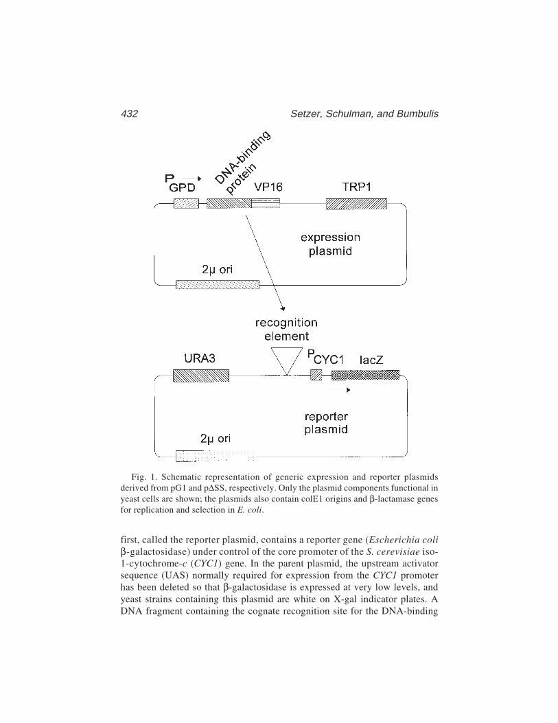
432 Setzer, Schulman, and Bumbulis
first, called the reporter plasmid, contains a reporter gene (Escherichia coliβ-galactosidase) under control of the core promoter of the S. cerevisiae iso-1-cytochrome-c (CYC1) gene. In the parent plasmid, the upstream activatorsequence (UAS) normally required for expression from the CYC1 promoterhas been deleted so that β-galactosidase is expressed at very low levels, andyeast strains containing this plasmid are white on X-gal indicator plates. ADNA fragment containing the cognate recognition site for the DNA-binding
Fig. 1. Schematic representation of generic expression and reporter plasmidsderived from pG1 and p∆SS, respectively. Only the plasmid components functional inyeast cells are shown; the plasmids also contain colE1 origins and β-lactamase genesfor replication and selection in E. coli.
Genetic Analysis of DNA-Binding Proteins 433
protein to be analyzed is substituted for the normal UAS. In the second plas-mid, called the expression construct, the VP16 activation domain from Herpessimplex is fused in-frame to a sequence encoding the DNA-binding domain ofthe protein of interest. The DNA-binding-domain–VP16 fusion protein isexpressed under control of the constitutive glyceraldehyde-3-phosphate dehy-drogenase (GPD) promoter of S. cerevisiae. The reporter and expression plas-mids carry different selectable markers (URA3 and TRP1, for example) so thatboth can be selected and maintained in an appropriate yeast strain (ura3–trp1–,for example). When both plasmids are introduced into a single yeast cell and ifthe DNA-binding domain of the protein of interest binds with sufficiently highaffinity and specificity to its recognition site in the reporter construct, theVP16 activation domain will be displayed in the vicinity of the core CYC1promoter and result in activation of transcription of the β-galactosidasereporter gene. On X-gal indicator plates, such a strain will be blue. Thus, thisblue phenotype can be used as a marker for high-affinity interaction of theDNA-binding domain of interest with its recognition sequence. Mutations ineither the DNA-binding protein or the DNA sequence to which it binds mayadversely affect binding, resulting in white or light blue colonies, or mayincrease the affinity of binding, resulting in dark blue colonies (see Notes 1–5).
Generation of randomly mutated sequences encoding either the protein ofinterest or its cognate recognition site and the introduction of these mutatedsequences into their appropriate contexts in either the expression or reporterplasmids is achieved with technical ease and high efficiency using a combina-tion of error-prone PCR in vitro and homologous recombination in vivo fol-lowing transformation (Fig. 2). Unusually long oligonucleotide primers areused for error-prone PCR (about 60–70 nucleotides, but see Note 6). The 3'portion of these primers anneals to a substrate plasmid at sites flanking thesequence to be mutagenized. The primers also contain 5' sequences identi-cal to those which flank the ends of a linear version of the plasmid constructinto which the mutated sequences are to be introduced. Error-prone PCR isused to synthesize a population of mutant DNA fragments containing thesequence of interest flanked by the sequences defined by the long amplifica-tion primers. In parallel, the plasmid into which the mutagenized PCR productis to be inserted is linearized or gapped by digestion at one or two sites, respec-tively, such that the unique ends of the PCR product correspond to sequencesat the ends of the linear or gapped plasmid. When cotransformed into compe-tent yeast cells, the linear plasmid and mutant PCR products undergo homolo-gous recombination in vivo to produce a circular plasmid product in which themutagenized fragment is integrated into the target plasmid at or between therestriction sites used in linearization/gapping. Successful recombination eventscan be clonally selected using the marker (URA3 or TRP1, for example) on the
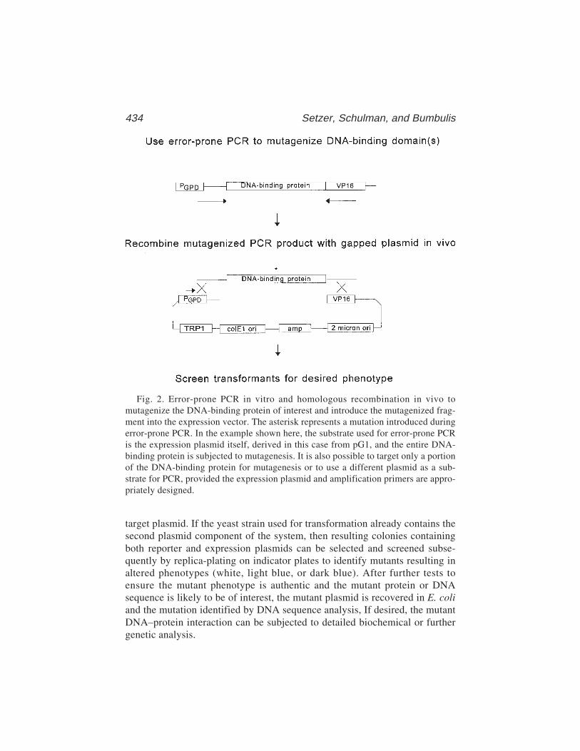
434 Setzer, Schulman, and Bumbulis
target plasmid. If the yeast strain used for transformation already contains thesecond plasmid component of the system, then resulting colonies containingboth reporter and expression plasmids can be selected and screened subse-quently by replica-plating on indicator plates to identify mutants resulting inaltered phenotypes (white, light blue, or dark blue). After further tests toensure the mutant phenotype is authentic and the mutant protein or DNAsequence is likely to be of interest, the mutant plasmid is recovered in E. coliand the mutation identified by DNA sequence analysis, If desired, the mutantDNA–protein interaction can be subjected to detailed biochemical or furthergenetic analysis.
Fig. 2. Error-prone PCR in vitro and homologous recombination in vivo tomutagenize the DNA-binding protein of interest and introduce the mutagenized frag-ment into the expression vector. The asterisk represents a mutation introduced duringerror-prone PCR. In the example shown here, the substrate used for error-prone PCRis the expression plasmid itself, derived in this case from pG1, and the entire DNA-binding protein is subjected to mutagenesis. It is also possible to target only a portionof the DNA-binding protein for mutagenesis or to use a different plasmid as a sub-strate for PCR, provided the expression plasmid and amplification primers are appro-priately designed.
Genetic Analysis of DNA-Binding Proteins 435
2. Materials2.1. Initial Design and Testing of the System
1. S. cerevisiae strain BJ2168 (6) or other haploid strain with appropriate genotype(stable mutant alleles of genes used as selectable markers in expression andreporter plasmids) (see Note 1).
2. p∆SS (7) or other plasmid to be used as parent for reporter plasmid construction(see Note 2).
3. pG1 (7) or other plasmid to be used as parent for expression plasmid construction(see Note 3).
4. pSJT-1193-CRF1 (8) or other source of DNA encoding the VP16 activationdomain (see Note 4)
5. Source of DNA encoding the DNA-binding protein or DNA-binding domainof interest.
6. Source of DNA including the recognition sequence for the DNA-binding proteinor DNA-binding domain of interest.
7. Complete medium (C) agar plates lacking appropriate nutrients to permit selec-tion of yeast strains containing reporter and expression plasmids. These willinclude C-uracil, C-tryptophan, and C-uracil–tryptophan for systems making useof derivatives of p∆SS and pG1. Procedures for preparation of liquid C mediumand C agar are described by Rose et al. (9). Our specific procedures are as follows:a. Dissolve in 1 L water the following: 20 g dextrose, 20 g Bactoagar, 1.7 g
yeast nitrogen base without amino acids and without ammonium sulfate, 5 gammonium sulfate, and 0.5 g amino acid mixture (see step 7b). Autoclave tosterilize and use to pour approx forty 100-mm plates.
b. The amino acid mixture used to prepare C agar plates contains 0.2 g arginine,0.2 g histidine, 0.5 g lysine, 0.4 g methionine, 0.2 g phenylalanine, 0.4 gtryptophan, 2.0 g threonine, 0.4 g tyrosine, 0.5 g serine, 0.2 g adenine, and 0.1 guracil. For selective plates, the appropriate combination of nutrients (uraciland tryptophan [e.g., to select for plasmids containing URA3 and TRP1 mark-ers]) should be omitted from the mixture.
8. SSX agar plates lacking appropriate nutrients as described in step 7, but alsocontaining 40 µg/mL X-gal, prepared as follows:a. Dissolve the following in 900 mL water: 1.7 g yeast nitrogen base without
amino acids and without ammonium sulfate, and 5 g ammonium sulfate, 20 gdextrose, 14 g Sigma agar, 0.5 g appropriate amino acid mixture (see step7b). Autoclave to sterilize.
b. Cool to 48°C and add aseptically: 1 mL of 40 mg/mL X-gal prepared in N,N-dimethylformamide and 100 mL 10X phosphate buffer (see step 8c).
c. 10X phosphate buffer is prepared by mixing the following in 1 L water: 136.1 gKH2PO4 (1 M), 19.8 g (NH4)2SO4 (0.15 M), and 42.1 g KOH (0.75 N). Adjustthe pH to 7.0 and autoclave to sterilize.
9. Standard reagents and methods for subcloning DNA fragments into plasmids.

436 Setzer, Schulman, and Bumbulis
2.2. Error-Prone PCR
1. Plasmid(s) or other source(s) of DNA containing the sequence encoding the pro-tein of interest and/or the DNA sequence recognized by the protein of interest.
2. Oligonucleotide primers that contain, at their 5' ends, approx 50 nucleotides ofsequence identity to the site immediately adjacent to the end of the linear plasmidinto which the PCR product is to be inserted. The 3' 15–20 nucleotides ofthese primers should have sequence identity with the parts of the substrateplasmid that define the DNA sequence to be amplified and mutagenized (seeFig. 2 and Note 6).
2. Taq DNA polymerase.3. Stock solutions of 100 mM MgCl2 and 100 mM MnCl2.4. 10X stock solution of Taq PCR buffer, lacking MgCl2: 100 mM Tris, pH 9.0,
500 mM KCl, and 1% Triton X-100 (Promega).5. Individual stock solutions of dATP, dGTP, dCTP, and dTTP, each at a concen-
tration of 10 mM. In addition, individual stock solutions of the same, each at aconcentration of 2 mM.
6. Thermal cycler.
2.3. Yeast Transformation and Homologous Recombination
1. S. cerevisiae strain BJ2168 or other appropriate strain (see Note 1).2. If the DNA-binding protein is to be mutagenized, BJ2168 containing the reporter
plasmid and BJ2168 containing the parent of the reporter plasmid (p∆SS, forexample).
3. If the DNA recognition site is to be mutagenized, BJ2168 containing the expres-sion plasmid and BJ2168 containing the parent of the expression plasmid (pG1,for example).
4. Linearized or gapped plasmid to be used as the target for integration of the PCR-generated DNA fragment.
5. Crude product of the error-prone PCR6. C-agar plates lacking the relevant nutrients for selection and maintenance of both
reporter and expression plasmids (uracil and tryptophan for p∆SS- and pG1-derived plasmids).
7. Sterile stock solution of 100 mM lithium acetate, 1 mM EDTA, 10 mM Tris–Cl,pH 8.0.
8. Sonicated salmon sperm DNA of about 10,000 bp average length, denatured byheating to 100°C for 5 min at a concentration of about 5–10 mg/mL. Commer-cially available salmon sperm DNA should be extracted with phenol/chloroformand precipitated prior to use.
9. 40% (w/v) Polyethylene glycol (PEG) (average molecular weight of 3350). Toprepare this solution, autoclave 2 g solid PEG in a sealable tube. The PEG willmelt during sterilization and resolidify at room temperature. Many sterile PEGaliquots can be prepared simultaneously. On the day of use, add 3.5 mL sterilesolution from step 7 to one of these aliquots, heat to 65°C, and mix vigorously to

Genetic Analysis of DNA-Binding Proteins 437
dissolve (final concentration of PEG is 40%). This quantity of solution is suffi-cient for approx 10 transformations.
10. Sterile SOS solution: 2 mL 2 M sorbitol, 1.3 mL YEPD medium (9), 0.26 mL 100 mMCaCl2, 0.4 mL H2O. YEPD medium: per liter of water, add 10 g Bactoyeastextract, 20 g Bactopeptone, and 20 g glucose.
2.4. Screening for Mutants
1. C-agar plates lacking both uracil and tryptophan, and containing 40 mg/mL X-gal.2. Liquid C-trp or C-ura medium for selection of only one of the two plasmids in BJ2168.3. C-agar plates lacking uracil and tryptophan individually, as well as plates
lacking both.4. Standard E. coli strain for plasmid transformation, propagation, and isolation,
along with reagents for distinguishing reporter and expression plasmids byrestriction endonuclease analysis.
5. 2% Sodium dodecyl sulfate (SDS)6. Acid-washed glass beads (0.45 mm in diameter, from Sigma) prepared by wash-
ing overnight in 3 N HCl and then rinsing repeatedly in water.7. Reagents for protein concentration determination using the BCA method (Pierce).8. If possible, antibodies to the DNA-binding protein of interest and/or the activa-
tion domain used in the construction of the expression plasmid; reagents forWestern blotting.
2.5. Analysis of Mutants
1. Z buffer for determination of β-galactosidase activity: 60 mM Na2HPO4, 40 mMNaH2PO4, 10 mM KCl, 1 mM MgSO4, and 40 mM β-mercaptoethanol, pH 7.0.
2. Other reagents for determination of β-galactosidase activity: chloroform, 0.1%SDS, 4 mg/mL o-nitrophenol-β-D-galactoside (ONPG) prepared in Z buffer, and1 M Na2CO3.
3. Reagents for DNA sequence determination.
3. Methods3.1. Initial Design and Testing of the System
Details of the construction of appropriate reporter and expression constructswill depend on the specific features of the plasmids and clones to be used. It istherefore impossible to describe a step-by-step protocol for use in every case,but standard recombinant DNA methods should suffice for preparation ofthe desired plasmids. We will briefly outline the steps necessary for construc-tion and testing of reporter and expression constructs prepared in p∆SS andpG1, respectively.
3.1.1. Construction of the Reporter Plasmid
It is necessary that a DNA fragment containing one or more copies of theDNA sequence recognized by the protein of interest be subcloned upstream of

438 Setzer, Schulman, and Bumbulis
the CYC1 core promoter in p∆SS. The only unique restriction site in p∆SS thatis suitable for insertion of such a fragment is an XhoI site. A DNA fragmentwith XhoI-compatible ends and containing one or more copies of the relevantDNA sequence should be subcloned into the XhoI site of p∆SS. Most typically,this fragment would be either a restriction fragment from another plasmid or aPCR product digested to produce XhoI-compatible ends. It is possible, andprobably desirable, to obtain p∆SS derivatives with multiple inserts of the DNAsequence of interest, and with single inserts in either orientation. The numberand orientation of insert fragments must be diagnosed by some means, typi-cally including restriction endonuclease mapping using enzymes that cut asym-metrically within the insert fragment to determine orientation, PCR withprimers flanking the insert site to determine number of inserts, or DNAsequence analysis to determine either orientation or number of inserts if theinsert fragment is not too long. An alternative to subcloning the insert fragmentinto the XhoI site of p∆SS is to use homologous recombination as described inSubheading 3.3. to integrate a PCR-generated DNA fragment into XhoI-digested p∆SS. In this case, the PCR fragment should be produced under high-fidelity conditions; even so, we recommend sequencing of the insertedfragment in the resulting plasmid to ensure that no mutations were introducedduring amplification. If homologous recombination is used to generate thereporter plasmid, judicious choice of sequences in the long primers used forPCR can be used to regenerate either or both of the XhoI sites at the end of theinsert, or even to introduce novel restriction endonuclease recognition ele-ments. This may facilitate the introduction of multiple copies of the DNA-binding site into p∆SS.
3.1.2. Construction of the Expression Plasmid
One or more DNA fragments encoding an in-frame fusion of the DNA-bind-ing protein of interest and a transcriptional activation domain must be intro-duced into pG1 downstream of the GPD promoter. The unique SalI site in pG1is probably the most convenient site for doing this. Fusion of the DNA-bindingprotein of interest and the VP16 activation domain can be done directly in pG1or, perhaps more conveniently, in a smaller, simpler plasmid vector and thensubcloned as a unit into pG1. Subsequent mutagenesis (Subheading 3.2.) canbe more directly targeted to the DNA-binding protein rather than to the activa-tion domain if a unique restriction site (more precisely, one that does not occurelsewhere in the plasmid outside of the sequence encoding the DNA-bindingprotein) can be engineered at the junction of the DNA-binding protein and theactivation domain. It is also important to note that some DNA-binding pro-teins, and particularly transcriptional activator proteins acting through the RNApolymerase II core machinery, may contain endogenous transcriptional activa-

Genetic Analysis of DNA-Binding Proteins 439
tion domains that will function in S. cerevisiae; in that event, transcriptionalactivity in the absence of the VP16 activation domain may be observed. Theexistence of an intrinsic activation domain in the protein of interest mightobviate the need to prepare a fusion construct, but one must be careful in thesubsequent analysis to distinguish mutations affecting DNA-binding affinityfrom those affecting transcriptional activation directly. The VP16 activa-tion domain coding sequence followed by a polyadenylation signal from theH. simplex thymidine kinase gene can be excised on a KpnI–HindIII fragmentof approx 760 bp from the plasmid pSJT-1193-CRF1 (8). At the KpnI cleavagesite, the reading frame for fusion to VP16 is XXG-GTA-CCX, but other plas-mids in which the VP16 reading frame is shifted relative to the KpnI cleavagesite have also been constructed (8). The KpnI–HindIII fragment from this fam-ily of constructs is suitable for preparing a fusion protein in which the VP16domain is at the C-terminus. Depending on what is known about the polarity ofDNA binding by the protein of interest, this may or may not be desirable. Con-struction of N-terminal fusions may be preferable in some cases (see Note 7);these can be made by taking advantage of one of a number of vectors intendedfor the construction of libraries for use in two-hybrid screens (e.g., pACT-II,pGAD-GH, and pB42-AD from Clontech). One must be cautious in the choiceof vector, however (see Note 3). In the case of Xenopus TFIIIA binding to theXenopus 5S rRNA gene, some of these vectors (including pGAD10) result invery low levels of protein expression and no detectable transcription activa-tion. Also, see Note 4 concerning choice of activation domains vis-a-vis sensi-tivity of the genetic assay.
3.1.3. In Vivo Assay of the Reporter and Expression Constructs
For each reporter plasmid constructed and the parent vector (p∆SS), as con-trol, two strains derived from BJ2168 should be prepared, one containing theexpression plasmid in addition to the reporter, and one containing the parentplasmid from which the expression plasmid was derived (pG1) in combinationwith the reporter. The different selectable markers on these two plasmids(URA3 and TRP1) allow their simultaneous maintenance in BJ2168 (ura3–
trp1–) by selecting for growth in medium lacking uracil and tryptophan. Therequisite strains should be constructed by sequentially transforming BJ2168with the reporter and expression plasmids. Methods for transformation ofBJ2168 (or other yeast strains) are described in detail in Subheading 3.3. Oneneed only adjust the protocol to reflect the nutritional requirements of the strainbeing transformed and the selectable marker on the plasmid being introduced.Thus, the doubly transformed strain would be selected on C-ura-trp plates.
Colonies of strains containing both reporter and expression plasmids can bereplica plated, spotted, or streaked onto C-ura-trp plates containing 40 µg/mL
440 Setzer, Schulman, and Bumbulis
X-gal. Colony color is assessed at an empirically determined time after robustcolony growth has occurred. For analysis of the Xenopus TFIIIA–5S rRNAgene interaction, this was done typically after 2–3 d of growth at 30°C and anadditional 2–3 d at room temperature. For the system to be exploited success-fully, one must be able to distinguish reproducibly the color of strains contain-ing both the expression and reporter plasmids from that of all the other controlstrains (lacking either expression of the fusion protein containing the DNA-binding domain[s] of interest or the cognate recognition site in the reporterconstruct, or both). If this is not the case, it may be possible to correct theproblem by manipulation of parameters as described in Note 5. Of course, it isalso possible that the particular interaction being studied will not be amenableto analysis with this method; among other reasons, this could result from alow-affinity/specificity interaction or from the existence of endogenous yeastfactors that interact with the binding site introduced into the reporter plasmid,resulting in high levels of transcriptional activity in the absence of the interac-tion being targeted for study.
3.2. Error-Prone PCR
The DNA-binding protein or its recognition site can be subjected to randommutagenesis using error-prone PCR. In the following protocol, we assume thatthe DNA-binding protein is targeted for mutagenesis, but the procedure can beadapted readily for mutagenesis of the recognition site.
1. Set up a 50-µL polymerase chain reaction mixture containing 10–50 ng of plas-mid DNA containing the sequence encoding the region to be mutagenized. Thiscan be the expression plasmid itself (see Note 8) or another plasmid containingthe sequence of interest. In addition, add 5 mL of 10X PCR buffer lacking MgCl2,long amplification primers (see Subheading 2.2., Fig. 2, and Note 6) to a finalconcentration of 0.3 µM each, three deoxynucleoside triphosphates to a final con-centration of 1 mM each, the fourth deoxynucleoside triphosphate to a final con-centration of 0.2 mM, MgCl2 to a final concentration of 3 mM, MnCl2 to a finalconcentration of 0.05 mM, and 1 unit Taq DNA polymerase (see Note 9).
2. Amplify using a thermal cycler for 25 cycles, with each cycle being 94°C for1 min, 42°C for 2 min, and 72°C for 1 min. After 25 cycles, use a final extensionstep of 72°C for 7 min (see Note 9).
3. Use the crude PCR product (without purification) in a yeast transformation withlinearized/gapped target plasmid as described in Subheading 3.3.
3.3. Yeast Transformation and Homologous Recombination
1. Prepare a stock of linearized or gapped target plasmid by digesting to completionwith one or two restriction endoncleases that result in ends corresponding to thesite at which integration of the mutagenized DNA fragment is to occur. As anexample, with an expression plasmid derived from pG1, this might be a double
Genetic Analysis of DNA-Binding Proteins 441
digest with SalI and an enzyme recognizing the fusion junction between the DNA-binding protein and the VP16 activation domain (see Note 10). A stock of thisgapped plasmid can be prepared in 10 mM Tris–Cl, pH 8.0, and 1 mM EDTA ata concentration of 10–100 ng/µL and stored at –20°C.
2. Prepare competent yeast cells:a. Grow a 50-mL culture of the yeast strain containing the reporter plasmid
(if mutations in the DNA-binding protein are to be analyzed) or expressionplasmid (if mutations in the DNA recognition site are to be analyzed) over-night at 30°C until the OD600 = 0.5–1.0.
b. Pellet the yeast cells by spinning for 5 min in a clinical centrifuge (1000g) atroom temperature.
c. Resuspend the cells in 10 mL of 100 mM lithium acetate, 1 mM EDTA, and10 mM Tris–Cl, pH 8.0. Pellet again as in step 2b.
d. Resuspend again in 10 mL of 100 mM lithium acetate, 1 mM EDTA, and 10 mMTris–Cl, pH 8.0.
e. Incubate at 30°C for 30 min without agitation and pellet again as in step 2b.f. Resuspend in 500 mL of 100 mM lithium acetate, 1 mM EDTA, and 10 mM
Tris–Cl, pH 8.0. Place on ice until used for transformation.3. Combine 100 µL competent yeast cells with 40 µL of the error-prone PCR mixture
(Subheading 3.2.), 50 µg sonicated, denatured salmon sperm DNA, and 150 nggapped plasmid (see Notes 11 and 12).
4. Incubate at 30°C for 30 min without agitation.5. Add 0.5 mL of 40% PEG (3350 mol. wt.) in 100 mM lithium acetate, 1 mM
EDTA, and 10 mM Tris–Cl, pH 8.0, and incubate further at 30°C for 60 min.6. Incubate at 37°C for 5 min.7. Centrifuge for 10 s at room temperature in a microcentrifuge at 14,000 rpm (16,000g).8. Remove the supernatant and resuspend in 100 µL SOS solution.9. Plate half of the resuspended transformed cells on each of the two C-agar plates
lacking the appropriate nutrients for selection of both expression and reporterplasmids (e.g., C-ura-trp).
10. Incubate at 30°C for 2–3 d, until robust colony growth is obtained.
3.4. Screening for Mutants
1. Initial screen.a. Replica plate the colonies obtained in step 10 of Subheading 3.3. onto selec-
tive C agar plates (C-ura-trp, for example) containing 40 µg/mL X-gal.b. Place replica plates at 30°C for 2–3 d and then at room temperature for an
additional 2–3 d.c. Identify potentially interesting mutants by color. These could include light
blue, white, or dark blue colonies; in each case, the color is in comparison tothat exhibited by colonies containing wild-type versions of both the expres-sion and reporter plasmids.
2. Pick candidates for further study and respot on selective C-agar plates. Grow forabout 2 d at 30°C. Replica plate onto indicator media and score colony color

442 Setzer, Schulman, and Bumbulis
again after growth as in step 1. If the phenotype is consistent with that seeninitially, proceed to step 3.
3. Enrich for cells containing only the mutagenized plasmid.a. Pick one or more colonies with an interesting phenotype from selective C-agar
plates without X-gal indicator. Grow in 2 mL liquid C-trp medium (if theexpression plasmid has been mutagenized; grow in C-ura medium if thereporter plasmid has been mutagenized) overnight at 30°C.
b. Prepare a 1:200 dilution of this overnight culture in liquid medium and plate10 µL of this diluted culture on a C-trp plate (assuming throughout that theexpression plasmid has been mutagenized).
c. After 3 d of growth at 30°C, replica plate onto C-ura-trp as well as onto C-trp.d. Grow overnight at 30°C and compare the colonies that grew on the two rep-
lica plates. Choose several that grew on C-trp but not on C-ura-trp. These arelikely to have lost the reporter plasmid but not the expression plasmid. Usethese to inoculate 2-mL liquid cultures of C-trp and grow overnight at 30°C.
4. Isolate the mutated plasmid using Method 1 as described by Strathern and Higgins(10) (see Note 13).
5. Use the isolated plasmid to transform E. coli. Pick individual colonies and per-form standard plasmid minipreps. Analyze the plasmids thus obtained usingappropriate restriction digests to ensure that the plasmid isolated is the muta-genized plasmid (e.g., the expression plasmid) and not the other plasmid compo-nent of the system (e.g., the reporter plasmid).
6. Analyze isolated plasmids by retransformation.a. Use the purified plasmid to retransform the appropriate yeast strain (already
containing the reporter plasmid) and obtain colonies on selective C-ura-trpplates of cells with both reporter and expression plasmids.
b. Analyze transformants by replica plating onto indicator plates as describedin step 1. If the phenotype observed is consistent with that seen initially, thenone can conclude that the phenotype is plasmid dependent. If the expressionplasmid was mutagenized and it is the DNA-binding protein that is underanalysis, continue with step 7. If, instead, the reporter plasmid was muta-genized and is being studied, one can move directly to Subheading 3.5.
7. Western blot screen to ensure the expressed fusion protein is full length andexpressed at normal levelsa. Inoculate 30 mL of C-ura-trp medium with a mutant strain and grow over-
night at 30°C.b. Pellet the cells in a clinical centrifuge at (1000g) for 5 min. Resuspend the
pellet in 1 mL of 2% SDS.c. Add 1 g glass beads and vortex vigorously for 15 min.d. Transfer the mixture to another tube and spin in a microcentrifuge at top speed
(16,000g) for 15 s. Transfer the supernatant to another tube.e. Determine protein concentration in the extract using the BCA method
(reagents from Pierce) (11) with bovine serum albumin as the standard.
Genetic Analysis of DNA-Binding Proteins 443
f. Using standard Western blot methods, analyze 20 µg total protein from eachmutant and compare to equivalent amounts of protein from a control strainexpressing wild-type DNA-binding protein as well as a second, negative con-trol strain containing the parent plasmid from which the expression constructwas derived, but which lacks a coding sequence for the DNA-binding protein.The primary antibody used in the Western blot should be specific for theDNA-binding protein of interest; if such antibodies are unavailable, it may bepossible to obtain, from commercial sources, antibodies to the activationdomain used in the fusion. The point of the Western blot exercise is to excludefrom further consideration those mutants whose steady-state level of expres-sion is different from that of wild-type protein or which are truncated as aresult of chain-termination or frame-shift mutations. Some truncation mutantsmay be interesting, but recall that the activation domain will be completelyabsent from truncated proteins if the activation domain was fused to theC-terminus of the DNA-binding protein. We have found that a substantialfraction of potential loss-of-function mutants (white phenotype) of TFIIIAare truncation mutants and a Western blot screen was important in removingthem from further, more laborious analysis (5).
3.5. Analysis of Mutants
3.5.1. Quantitative Determination of β-Galactosidase Activity
We have found that relative DNA-binding affinities of various mutant formsof TFIIIA can be predicted with reasonable precision from measurementsof β-galactosidase activity in vivo in yeast reporter strains expressing themutant protein fused to the activation domain of VP16. Whether this willprove to be generally true remains to be seen, but β-galactosidase activitiescan be readily measured using standard methods and may prove informative.
1. Inoculate 12.5 mL liquid C-ura-trp medium with the yeast strain to be analyzed.In addition, prepare a similar culture of a control strain containing the samereporter plasmid but with the parent vector (e.g., pG1) of the expression con-struct, rather than the expression construct itself. This control will permitdetermination of β-galactosidase activity in the absence of the DNA–proteininteraction of interest. Grow the cultures overnight at 30°C until the OD600 =0.3–1.0. Note the actual optical density.
2. Pellet cells by spinning at 1000g for 5 min in a clinical centrifuge. Resuspend in3 mL of Z buffer.
3. Divide into three 1-mL fractions. In addition, process a tube containing 1 mL Zbuffer in parallel. This will serve as the blank for spectrophotometric determina-tion of β-galactosidase activity. Add 30 µL chloroform and 20 µL of 0.1% SDS toeach and vortex for 10 s.
4. Incubate at 30°C for 5 min and add 200 µL ONPG at a concentration of 4 mg/mLin Z buffer. Incubate at 30°C until a yellow color becomes apparent.
5. Add 500 mL Na2CO3 and note the elapsed time since ONPG was added.
444 Setzer, Schulman, and Bumbulis
6. Transfer 800 µL of the reaction mixture to a microfuge tube and centrifuge at16,000g for 2 min.
7. Measure the absorbance at 420 nm relative to that of the control processed in parallel.8. Calculate the number of units of β-galactosidase activity according to the follow-
ing formula:
Absorbance at 420 nm × 100
(Assay duration [min]) (culture volume analyzed [mL]) (OD600 of culture)
10. Average the three different determinations of activity to obtain a single value(see Note 14).
11. Normalize the final average β-galactosidase activity relative to that of the nega-tive control culture (see Note 14).
3.5.2. Sequence Determination
Ultimately, one must determine the sequence of the mutant DNA-bindingprotein or recognition site in the expression or reporter plasmid, respectively.The details of the sequencing strategy to be used will depend on the specificsystem under analysis and the technology available to the investigator. We dorecommend that the complete set of screens described in Subheading 3.4. becompleted prior to sequence analysis, as the latter is typically laborious,expensive, or both.
3.5.3. Biochemical Analysis of Mutants
Until correlations between in vivo phenotypes and DNA-binding affinityand/or specificity can be verified in a particular system, the approach describedhere can be applied best as a method for generating interesting mutants that canbe subjected to further biochemical analysis. In most cases, this will requireexpression and purification of the mutant DNA-binding protein under analysis,preferably without a fusion to the artificial activation domain. Again, the detailsof how this can be done will depend on the specific interaction being studied.We recommend, however, that the necessity of further sequence manipulation,including subcloning into other plasmid vectors, be taken into account in theinitial design and construction of the yeast expression vector.
4. Notes1. The genotype of strain BJ2168 is reported to be MATa ura3-52 trp1 leu2 pep4-3
prc1-407 prb1-1122 gal2 (6). A variety of alternative strains should also be suit-able for use. The only relevant genotypes for the approach used here pertain tothe nutritional markers used for plasmid selection. If HIS3 were to be used as areporter, then it would also be important that the parent strain be his3- or that thechromosomal HIS3 locus be placed under control of the hybrid promoter beingused in the analysis. Clearly, the mutant chromosomal alleles of the nutritional
Genetic Analysis of DNA-Binding Proteins 445
markers should be stable and not give rise to revertants at measurable frequen-cies. BJ2168 also contains mutations in three vacuolar proteases (the PEP4,PRC1, and PRB1 genes), but it is unlikely that these are relevant to the approachdescribed here. In fact, we have made use of other strains that presumably con-tain wild-type alleles at these loci without detectably altering the results obtainedusing the Xenopus TFIIIA/5S rRNA gene interaction.
2. A variety of reporter gene constructs probably can be used successfully. Plas-mid-based reporters could be constructed using various parent plasmids contain-ing different selectable markers, and alternative reporter genes might also bechosen. In addition, the use of a chromosomally integrated reporter gene is pos-sible; in fact, we have successfully used HIS3 as a chromosomal reporter gene inthis fashion to study the Xenopus TFIIIA–5S rRNA gene interaction. Advantagesof β-galactosidase as a reporter include the fact that it permits a range of pheno-types to be scored and the ease with which quantitative measurements of activitycan be made using a simple spectrophotometric assay. HIS3, on the other hand, isprobably much more sensitive, permitting detection of weaker DNA–proteininteractions or use of a single-copy reporter when multicopy β-galactosidasereporters are required. It also allows selection of rare gain-of-function mutantsthat might occur at such a low frequency that identifying them would be difficultor impossible using a screening protocol like that required with β-galactosidaseas a reporter. HIS3 expression does not provide a wide dynamic range of pheno-types in a single-plate assay; however, this limitation can be overcome partiallyby analyzing growth on plates containing variable 3-amino-triazole (3-AT)concentrations. 3-AT is an inhibitor of the HIS3 gene product and can, therefore,be used to adjust the level of HIS3 expression required to permit growth.
We have not investigated the use of different core promoter elements otherthan that derived from CYC1. Even for CYC1, however, levels of reporter geneexpression potentially can be manipulated by adjusting the number of copies andorientation of the DNA target sequence for the binding protein under study rela-tive to the core promoter. We have found that both orientation and number ofTFIIIA-binding sites in the promoter can have substantial effects on reporter geneactivity when a TFIIIA-VP16 fusion protein is expressed. In our case, the orien-tation dependence could be explained readily on the basis of the known polarityof TFIIIA binding to the 5S rRNA gene (12). If similar information is availablefor the DNA-binding protein of interest, it may be possible to design reporterconstructs rationally. Otherwise, it is probably advisable to generate multipleconstructs for testing. It is possible that homodimers binding to symmetrical sitesmay exhibit little or no orientation dependence. With TFIIIA, we found thatincreasing the number of binding sites from one to two in the reporter gene pro-moter resulted in a doubling of β-galactosidase activity (5). For many natural PolII activators, the effect of having multiple binding sites is synergistic (13), so it ispossible that even larger effects will be observed when the number of bindingsites for other DNA-binding proteins is increased. We have not investigated theeffects of varying spacing between the artificial upstream activator sequence and
446 Setzer, Schulman, and Bumbulis
the core promoter, but others have shown that transcriptional activity is onlymoderately affected by alterations in the wild-type spacing between these twoelements (14–16). Nonetheless, it is possible that attaining maximal activity inany particular system may require optimizing the spatial relationship betweenthe DNA recognition site of interest and the core promoter. In the end, it may benecessary or desirable to adjust several of these parameters to obtain a level ofreporter gene activity that is phenotypically detectable but that also provides forreasonable sensitivity in the detection of mutants weakening the DNA–proteininteraction under analysis.
3. A variety of alternative expression plasmids are available, including several fromcommercial sources that may be preferable to pG1 in some respects (see Sub-heading 3.1.2.). We have used vectors other than pG1 and, in some cases, thesevectors are better engineered for the easy introduction of DNA fragments encod-ing the DNA-binding protein of interest while producing an in-frame fusion to anN-terminal activation domain. Choice of expression vector may be affected bythe selectable marker used, the presence of an activation domain in the vector,whether the domain is to be N- or C-terminally fused to the DNA-binding domain,and the strength of the promoter driving expression of the fusion protein. It isalso possible that regulated expression of the fusion protein will be desirable, inwhich case a regulated promoter, like that of the GAL1 gene, might be chosenover the constitutive GPD promoter of pG1.
4. The VP16 activation domain we have used (8) is probably the best studied acti-vation domain acting to stimulate transcription by RNA polymerase II, and isprobably also the strongest one in common use. Depending on the system beingstudied (see Note 5) and the choice of expression plasmid, an alternative activa-tion domain might be chosen. We have used both the GAL4 activation domainand the synthetic domain B42 in addition to that of VP16 to study the XenopusTFIIIA–5S rRNA gene interaction.
5. It may be necessary to adjust the system’s parameters to achieve a level of tran-scriptional activity that affords a reasonable sensitivity of the assay to variationsin binding affinity. Potentially, activity may be affected not only by the affinityof the interaction but also by the number, spacing, functional synergy between,and orientation of the binding sites in the reporter construct (see Note 2), by thelevel of expression of the fusion protein (see Note 3) and the fraction of proteinthat is available for binding (effective in vivo concentration), by the copy numberof the reporter gene (see Note 2), by the choice of reporter gene (see Note 2), andby the choice of activation domain (see Note 4). Our experience in analyzing theXenopus TFIIIA–5S rRNA gene interaction suggests that, for TFIIIA–VP16under control of the GPD promoter on a 2 µ-containing plasmid, the effective invivo concentration of protein was much lower than the total in vivo concentra-tion as determined by Western blot (5). Transcriptional activation in this systemcould not be detected on X-gal plates when the Kd was above 2 nM, using an E. coliβ-galactosidase reporter gene containing two TFIIIA-binding sites upstream ofthe CYC1 promoter on a plasmid with a 2 µ origin of replication.
448 Setzer, Schulman, and Bumbulis
duced from the expression plasmid. To minimize this problem, we recommendseveral steps. If possible, use two different restriction endonucleases to generatethe linear, gapped plasmid. Second, treat the cut plasmid with phosphatase todephosphorylate the 5' termini generated by restriction digestion. Third, gel-purify the gapped plasmid to eliminate any small fragment that was removed bythe restriction digestion as well as to eliminate any uncut molecules that mightremain as a result of incomplete cleavage.
11. The quantities of gapped plasmid and error-prone PCR product that are optimalfor recovery of the maximal number of colonies containing plasmids with inte-grated PCR products have not been carefully optimized, and probably should be.We have some evidence that suggests that transformation efficiencies areimproved by reducing the amount of PCR product relative to the amount ofgapped plasmid recommended here.
12. We have routinely used the crude, unpurified products of the error-prone PCRreaction in cotransformations with the gapped expression plasmid to generateand study mutant forms of TFIIIA without encountering significant problems(5). In some related applications, however, we have noted that a high backgroundof colonies can be produced as a consequence of poorly characterized recombi-nation events that we believe derive from the production and integration of aber-rant PCR products into the gapped target plasmid. It is most likely that these aresmall DNA fragments, perhaps “primer dimers.” If these are produced at any-thing other than a very low frequency and are capable of recombining with thetarget plasmid, they can complicate the identification of loss-of-function mutantsin the DNA-binding protein of interest, because they result in the production ofwhite colonies on X-gal plates. If initial studies in a new system suggest that asimilar problem occurs with the use of the crude PCR product, then we recom-mend purifying the mutagenized PCR product prior to recombination/transfor-mation. Simply gel-isolating a product of the correct length should eliminate anyproblems derived from the presence of unincorporated primers, primer dimers, orother aberrant products of the PCR.
13. As minor modifications to the procedure of Strathern and Higgins (10), we haveisolated plasmids directly from yeast colonies in lieu of growing liquid cultures,have used Prep-a-Gene (Bio-Rad) rather than Geneclean reagents, do not pre-cipitate DNA after elution from Prep-a-Gene, and transform E. coli with 10% ofthe DNA sample recovered from the Prep-a-Gene reagent (2 µL of 20 µL total).
14. We recommend repeating the triplicate assays described here for each mutant atleast three times with independent cultures to obtain an overall average value.Normalization of activity to a standard seems to be important in correcting day-to-day variability in the determination of β-galactosidase activity.
References1. Brent, R. and Ptashne, M. (1985) A eukaryotic transcriptional activator bearing
the DNA specificity of a prokaryotic repressor. Cell 43, 729–736.

Genetic Analysis of DNA-Binding Proteins 449
2. Muhlrad, D., Hunter, R., and Parker, R. (1992) A rapid method for localizedmutagenesis of yeast genes. Yeast 8, 79–82.
3. Kuipers, O. P. (1996) Random mutagenesis by using mixtures of dNTP and dITPin PCR. Methods Mol. Biol. 57, 351–356.
4. Ma, H., Kunes, S., Schatz, P. J., and Botstein, D. (1987) Plasmid construction byhomologous recombination in yeast. Gene 58, 201–216.
5. Bumbulis, M. J., Wroblewski, G., McKean, D., and Setzer, D. R. (1998) Geneticanalysis of Xenopus transcription factor IIIA. J. Mol. Biol. 284, 1307–1322.
6. Jones, E. W. (1990) Vacuolar proteases in yeast Saccharomyces cerevisiae.Methods Enzymol. 185, 372–386.
7. Schena, M. and Yamamoto, K. R. (1988) Mammalian glucocorticoid receptorderivatives enhance transcription in yeast. Science 241, 965–967.
8. Triezenberg, S. J., Kingsbury, R. C., and McKnight, S. L. (1988) Functional dis-section of VP16, the trans-activator of Herpes simplex virus immediate early geneexpression. Genes Dev. 2, 718–729.
9. Rose, M. D., Winston, F., and Hieter, P. (1990) Methods in Yeast Genetics:A Laboratory Course Manual. Cold Spring Harbor Laboratory, Cold SpringHarbor, NY.
10. Strathern, J. N. and Higgins, D. R. (1991) Recovery of plasmids from yeast intoEscherichia coli: shuttle vectors. Methods Enzymol. 194, 319–329.
11. Smith, P. K. (1985) Measurement of protein using bicinchoninic acid. Anal.Biochem. 150, 76–85.
12. Smith, D. R., Jackson, I. J., and Brown, D. D. (1984) Domains of the positivetranscription factor specific for the Xenopus 5S RNA gene. Cell 37, 645–652.
13. Carey, M., Lin, Y.-S., Green, M. R., and Ptashne, M. (1990) A mechanism forsynergistic activation of a mammalian gene by GAL4 derivatives. Nature 345,361–364.
14. Struhl, K. (1982) The yeast his3 promoter contains at least two distinct elements.Proc. Natl. Acad. Sci. USA 79, 7385–7389.
15. Brent, R. and Ptashne, M. (1984) A bacterial repressor protein or a yeast tran-scriptional terminator can block upstream activation of a yeast gene. Nature 312,612–665.
16. Guarente, L. and Hoar, E. (1984) Upstream activation sites of the CYC1 gene ofSaccharomyces cerevisiae are active when inverted but not when placed down-stream of the “TATA” box. Proc. Natl. Acad. Sci. USA 81, 7860–7864.
17. Baudin, A., Ozier-Kalogeropoulos, O., Denouel, A., Lacroute, F., and Cullin, C.(1993) A simple and efficient method for direct gene deletion in Saccharomycescerevisiae. Nuceic Acids Res. 21, 3329–3330.
18. Oldenburg, K. R., Vo, K. T., Michaelis, S., and Paddon, C. (1997) Recombi-nation-mediated PCR-directed plasmid construction in vivo in yeast. NucleicAcids Res. 25, 451–452.
Assays for Transcription Factor Activity 451
451
From: Methods in Molecular Biology, vol. 148: DNA–Protein Interactions: Principles and Protocols, 2nd ed.Edited by: T. Moss © Humana Press Inc., Totowa, NJ
31
Assays for Transcription Factor Activity
Virgil Rhodius, Nigel Savery, Annie Kolb, and Stephen Busby
1. IntroductionMost transcription activator proteins have three important features that can
be probed at the molecular level: they bind to specific sequences near promot-ers, they can be interconverted between active and inactive forms by covalentor noncovalent modification, and, when bound at target promoters, they canstimulate the initiation of transcription by RNA polymerase (1). This chapter isconcerned with in vitro methods for measuring the transcription activationfunction of this important class of proteins. In most cases, these methods areapplied to activators that have been substantially purified, and for which thetarget sequences are known and the binding sites characterized (other chaptersin this volume cover methods for locating and investigating the binding sitesfor such activators). Here we are concerned with the measurement of the prod-ucts of activation. Because Escherichia coli transcription activators have beenstudied more than any others, we will take these as the paradigm, though, inprinciple, the techniques can be applied to any organism for which in vitrosystems have been developed.
The starting point of the methodology was the observation, made in the early1970s, that purified E. coli RNA polymerase could initiate transcription at pro-moters in purified DNA (2). With improvements in RNA methodology, it wasfound that the transcription start site in vitro, in many cases, was the same as invivo. Further, at a number of promoters, interactions with specific transcrip-tion activators could be demonstrated and factor-dependent transcription invitro occurred. The literature is now full of instances of factor-dependent tran-scription initiation with purified proteins and DNA, setting the scene for stud-ies on the mechanism of transcription activation. However, as with all in vitrotechniques, it is worth noting that the conditions found in the plastic tube differ
452 Rhodius et al.
greatly from those in vivo and that, for some instances, the reconstituted tran-scription system simply may not work.
Two principal methods can be used to monitor transcription activation: tran-script assays and abortive initiation (Fig. 1). In transcript assays, RNA poly-merase is incubated with a DNA template carrying the promoter of interesteither with or without the transcription activator protein. Radioactively labelednucleotides are then added and RNA polymerase molecules that have formedtranscriptionally competent complexes start to make RNA. RNA polymerasemolecules then “run” to a suitably placed downstream terminator (or to the endof the fragment), thus making labeled RNA of a discrete length that can bemonitored and quantified (3). In abortive initiation assays, nucleotide precur-sors corresponding just to the start of the message are added. RNA polymeraseforms transcriptionally competent complexes at the chosen promoter, but elon-gation is prevented because some of the four nucleoside triphosphates are with-held (4). The result is that RNA polymerase is “trapped” at the promoter andcan only synthesize a short oligonucleotide, which is released as the polymerasecycles between a number of conformations in the abortive complex (it is termedabortive because a longer transcript cannot be made). The consequence of thecycling is that each polymerase molecule, trapped at a single promoter, synthe-sizes the oligonucleotide continuously, and the appearance of the product canbe measured directly. The rate of product formation will be dependent on thenumber of promoters that are occupied by polymerase in an open complex.This, in turn, will usually depend on the activity of the transcription factorunder study. In most cases, transcript assays are used to locate transcriptionstarts and to monitor factor activity qualitatively, whereas abortive initiationassays are exploited for quantitative and kinetic work.
2. Materials1. E. coli RNA polymerase. This enzyme can be purified (5,6) or can be purchased
from Boehringer (Mannheim, Germany), Pharmacia (Piscataway, NJ), or othermolecular biology companies. The enzyme can also be reconstituted from indi-vidual subunits that have been overproduced using overexpression vectors (7,8).Purity can be easily checked by denaturing polyacrylamide gel electrophoresisand activity can be verified using standard templates. Preparations of RNA poly-merase are usually stored at –20°C in buffer containing 50% glycerol.
2. Transcription factors. These must be purified, at least partially, away from anynuclease activities. Transcription assays can be used to monitor the purification.
3. Plasmids and DNA fragments. The DNA used for transcription assays should befree from nicks and RNase activity. Short DNA sequences carrying different pro-moters can be constructed using standard recombinant DNA methodology andcloned into plasmid vectors such that a strong transcription terminator is locateddownstream of the promoter (9). Transcript assays can be performed directly on
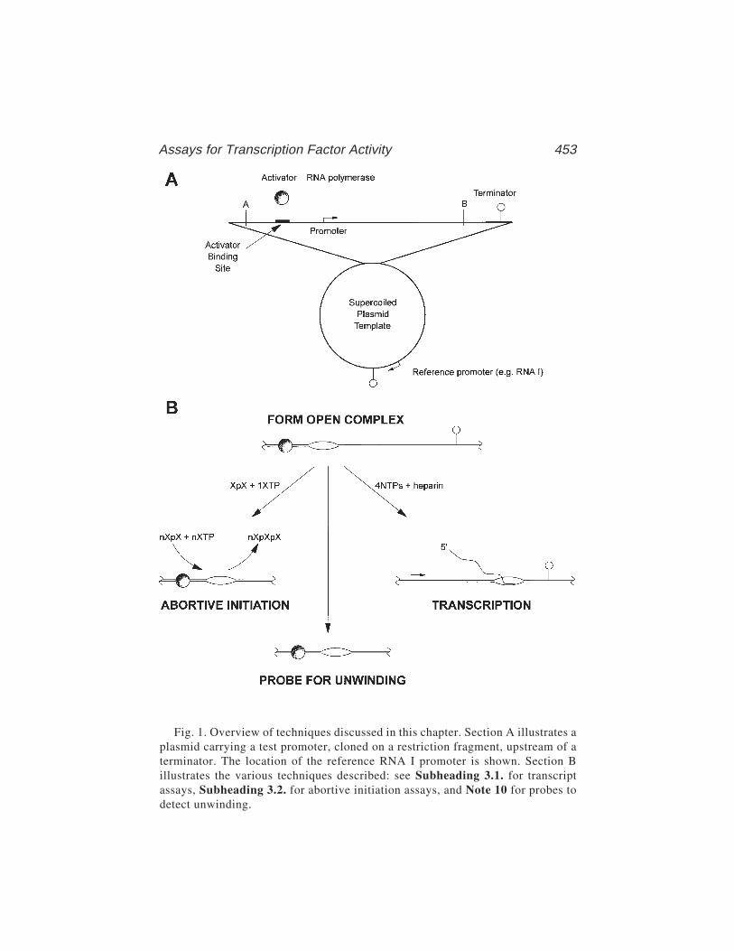
Assays for Transcription Factor Activity 453
Fig. 1. Overview of techniques discussed in this chapter. Section A illustrates aplasmid carrying a test promoter, cloned on a restriction fragment, upstream of aterminator. The location of the reference RNA I promoter is shown. Section Billustrates the various techniques described: see Subheading 3.1. for transcriptassays, Subheading 3.2. for abortive initiation assays, and Note 10 for probes todetect unwinding.
454 Rhodius et al.
such recombinant plasmids, providing they have been purified, for example byusing cesium chloride gradient centrifugation (10). Alternatively, linear, pro-moter-containing fragments can be purified from restricted plasmid DNA bypolyacrylamide or agarose gels by a variety of methods (10). Although any DNAfragments can be used (see Note 1), fragments around 200–1000 bp are mostdesirable. Stock solutions of most short fragments will be adjusted to around20 mg/mL, the concentration being checked after gel electrophoresis.
4. Transcription buffer: 20 mM Tris-HCl, pH 8.0, 100 mM NaCl, 5 mM MgC12,0.1 mM EDTA, 1 mM dithiothreitol (DTT), 50 µg/mL nuclease-free bovine serumalbumin (BSA), and 5% glycerol. This is a standard 1X buffer for many in vitrotranscription assays and can be prepared as a 10X stock. There are many varia-tions of this and the literature must be checked for any particular instance.
5. Heparin, cat. no. H6279 from Sigma (St. Louis, MO), made up as a 10 mg/mLstock solution in water.
6. Nucleotides. [α-32P] UTP from NEN (Boston, MA) or Amersham (ArlingtonHeights, IL) can be used in conjunction with the four nucleoside triphosphatesfrom Boehringer or Pharmacia. For transcription assays, most workers use finalconcentrations of 200 µM ATP/CTP/GTP, 10 µM UTP, 0.5–5.0 µCi of [α-32P]UTP per reaction, and 100 µg/mL heparin to prevent reinitiation. Typically, an8X stock NTP + heparin solution is prepared containing 80 µM UTP, 1.6 mM ofthe three other NTPs, and 800 µg/mL heparin in 2X transcription buffer. A “hot”NTP + heparin mix is then made by diluting this 1:1 with [α-32P] UTP in water.
7. Dinucleotides. These can be bought from Sigma and used without further purifica-tion as 10-mM stock solutions in water. The choice of the appropriate dinucleotidefor priming abortive initiation assays is discussed in Subheading 3.2.1.
8. Transcription stop solution: 80% deionized formamide, 0.1% xylene cyanol FF, 0.1%bromophenol blue, 20 mM EDTA in the standard gel running buffer, and 1X TBE.
9. RNA gels. Standard 6% polyacrylamide sequencing gels containing 6 M to 8 Murea and run in TBE (10) can be used to separate runoff transcripts. Autoradiog-raphy or a phosphor screen are used to detect the products.
10. Gel running buffer, TBE. This is usually made up in large volumes and kept as a5X stock solution. To make up 1 L of 5X stock use 54 g Tris base, 27.5 g boricacid, and 20 mL of 0.5 M EDTA.
11. Whatman 3MM paper. Cut into strips 20 cm in length for chromatography ofabortive products.
12. Chromatography buffer: 18:80:2 (v/v/v) water/saturated ammonium sulfate/isopropanol.13. RNA size markers. These are usually generated from runoff transcripts of well-
characterized DNA fragments. Alternatively, sequence ladders can be used.14. 0.1 M EDTA.
3. Methods3.1. Transcript Assays
1. The first step is the binding reaction. Purified transcription factor and supercoiledplasmid or linear template DNA (see Note 1) are mixed gently in 1X transcrip-
Assays for Transcription Factor Activity 455
tion buffer (see Note 2) in a final volume of 8 µL and incubated for 5 min at 37°C(see Note 3). It is important to include any cofactor required by the transcriptionalactivator. For example, the cyclic AMP receptor protein (CRP) requires cAMP inthe transcription buffer for activity. Some other transcription activators requirecovalent modification, such as phosphorylation. The active form must be used.
2. Next, 4 µL of RNA polymerase, diluted in 1X transcription buffer, is added andmixed in gently. The binding reaction is then incubated for a further 5–20 min at37°C. Typically, the incubations are performed in a final volume of 12 µL with atemplate concentration of 0.5–5 nM, a range of transcription factor con-centrations from 5 to 50 times the promoter concentration and up to 100 nMRNA polymerase.
3. The second step is the transcription reaction. Add 4 mL of “hot” NTP + heparinmix (see Note 4) to each 12 µL binding reaction, mix gently, and incubate at37°C for 5 min (see Note 5). For each individual DNA molecule, the RNA poly-merase may or may not have reached an open complex depending on the activityof the transcription factor. At molecules where an open complex has formed, thepolymerase will then “run” from the promoter to the downstream terminator (orto the end of the fragment) making a discrete-sized RNA product. Because onlyone molecule of polymerase can occupy a promoter at any time and because theinclusion of heparin prevents further initiation, the amount of any particular run-off transcript will be directly proportional to the amount of open-complex forma-tion (see Notes 6 and 7).
4. Terminate the reactions by adding 12 µL of transcription stop solution. Thesamples can be stored for short periods on ice, or for longer periods at –20°C,until ready for loading on a sequencing gel.
5. Heat the samples for 2 min at 90°C and load 8 µL on a sequencing gel, togetherwith size markers, and perform the electrophoresis. We routinely use the S2model from Gibco-BRL (Gaithersburg, MD), running the gel for 2–3 h at 60 Wconstant power. After running, the gel is dried, an autoradiograph is exposed, andthe film is developed. From the sequence marker it is possible to identify bandscaused by transcription initiation at the promoter under study and to determinethe effects of the transcription activator on the appearance of these bands. Anexample is shown in Fig. 2 (taken from ref. 11) (see Notes 8–10).
3.2. Abortive Initiation Assays1. Choose the nucleotides to be employed in the assay. Typically, this is done by
selecting a dinucleotide appearing in the sequence anywhere from position –4 to+2, and using the next nucleotide as the labeled precursor. For example, at the E.coli galP1 promoter (12), the sequence at the transcription start is 5'-TCATA-3'with the central A as +1. The dinucleotide CpA and [α-32P] UTP can be used togive the product, 32P-labeled CpApU. It is important to ensure that no extendedproducts can form (see Note 11).
2. Before the assay is performed, set up a series of Whatman 3MM paper chromato-grams (typically 20 cm long). Spot the origins with 20 µL of 0.1 M EDTA to

456 Rhodius et al.
ensure that product formation ceases the moment that the samples are loaded onthe chromatogram.
3. Set up the standard assay, using concentrations of reagents as for the transcriptanalysis experiment. In a typical starting experiment, excess RNA polymeraseand transcription factor will be premixed with DNA and incubated long enoughto reach complete open complex formation. The experiment will be started bythe addition of nucleotides. The final reaction mix will contain, for example,0.5–5 nM promoter DNA, 100 nM RNA polymerase, 0.5 mM dinucleotide, and0.05 mM UTP with 2.5 mCi [α-32P] UTP in 100 µL. Run experiments both withand without the transcription factor and perform a control with no DNA.
4. At different times after addition of the [α-32P] UTP, remove 15-µL aliquots andspot at the origin of the chromatogram. Six aliquots taken every 5 min will suffice.
5. Develop the chromatogram using chromatography buffer. After the solvent fronthas progressed 20 cm, remove the chromatogram and dry. Cut the paper into 5-mmslices and count each slice for Cerenkov radiation to locate the bands resultingfrom product and unincorporated UTP. For each time point, determine the num-ber of counts incorporated into the product (CPMproduct), and the number of countsin the unincorporated UTP (CPMu). From the ratio of counts in the product to thetotal counts (CPMproduct+CPMu), the amount of product at each time-point can bededuced. Alternatively, the products can be analyzed and quantified using aphosphorimager. In this case, it is sufficient to spot 2-µL aliquots onto the chro-
Fig. 2. In vitro transcription from plasmid carrying a CRP-independent promoter,lacUV5 (lanes 1–5) or a CRP-dependent promoter, CC(–41.5) (lanes 6–20), clonedupstream of a transcription terminator. The figure shows the transcripts produced usingpurified RNA polymerase containing wild-type or mutant α-subunits (EA261, RA265,TA285, and VA287 as indicated). Prior to the addition of RNA polymerase, CRP orCRP carrying the HL159 substitution (that interferes with the CRP–RNA polymeraseinteraction) was added to the reaction mixtures as indicated. The position of tran-scripts initiated at the lacUV5 or CC(–41.5) promoters, and the position of the plas-mid-encoded RNA I transcript are indicated. (From ref. 11.)

Assays for Transcription Factor Activity 457
matogram, and the transcription reactions can be scaled down threefold to five-fold (see Note 12).
A plot of product formed versus time should be linear, and from the slope, therate of product formation can be deduced (see Note 13). The rate of productformation per promoter (TON, turnover number) can then be calculated from themolar amount of DNA fragment that was used in the experiment. A control runwithout the transcription factor will give factor-independent activity and willallow the effect of the activator to be quantified. Assuming that the rate of prod-uct formation in the presence of the activator reflects 100% occupancy at thepromoter, the occupancy in the absence of the activator can be calculated (fromthe ratio of the TON values in the absence and the presence of the activator) (seeNote 14).
6. The analysis can then be taken a stage further (e.g., see refs. 13–16). In theexperiment above, RNA polymerase is preincubated with the DNA template priorto the addition of substrate, so product formation is linear from zero time. How-ever, if the reaction is started by the addition of polymerase, the plot of productformation versus time shows a lag where the RNA polymerase “installs” itself atthe promoter. This lag time (τ) can easily be measured and is a function of theinitial binding of polymerase to the promoter and subsequent isomerizations tothe open complex (see Fig. 3).
The interaction of holoenzyme with promoters involves at least two steps: arapid and reversible binding to promoter DNA, characterized by an associationconstant KB, which leads to the “closed” inactive complex, followed by a confor-mation change to the “open” complex characterized by the rate constant kf. Formost promoters, the reverse of open-complex formation is extremely slow. Thus,according to McClure (4), the measured lag time (τ) is related to the enzymeconcentration [RNP] by the relation
τ = 1/kf + 1/(KBkf[RNP])
To make a kinetic analysis, it is necessary to perform the assays with a range ofdifferent polymerase concentrations (typically 5–200 nM: for kinetic analysis,RNA polymerase should always be present in significant excess over promoterDNA). The lag time (τ) is measured in each case and is plotted as function of thereciprocal of the RNA polymerase concentration (Fig. 4). This plot can beextrapolated to infinite RNA polymerase concentrations (the intersect withthe y-axis) to give the reciprocal of kf, and KB can be deduced from the interceptof the τ plot with the x-axis. Alternatively, KB can be calculated from the ratio ofthe lag time at infinite enzyme concentration and the slope of the straight line.Data are normally fitted using a computer program, such as Enzfitter or Fig-P(see Notes 15 and 16).
4. Notes1. Transcript analysis assays are generally performed on templates with the tran-
scription start of interest positioned 50–150 bp upstream from a transcription

458 Rhodius et al.
terminator or the end of the fragment. Often, a longer fragment that carries morethan one promoter will be chosen; longer transcripts can be sized by running thesequence gels further. Individual transcripts can be identified by using familiesof fragments that are truncated from one end. Transcription assays can be per-formed using both relaxed and supercoiled DNA. Reference promoters can beused to aid in the quantification of transcripts (e.g., if colE1 plasmid derivativesare used as vectors for the promoter under study, the 107 nucleotide transcriptfrom the RNA I promoter can be used; see Figs. 1 and 2).
2. A number of alternative buffer systems can be used and the final choice is largelya matter of trial and error. An alternative system is 40 mM Tris, pH 8.0, 100 mMKCl, 10 mM MgCl2, 1 mM DTT, and 100 µg/mL acetylated bovine serum albu-min. In some cases, the effects of substituting different anions or cations may besignificant (17). Many recent studies have used glutamate-containing buffers toenhance DNA binding of different factors.
Fig. 3. Lag plots of a CRP-dependent promoter in the presence of different concen-trations of RNA polymerase (50 nM [RNP]1 and 16.7 nM [RNP]2). A 15-µL sample of4 nM DNA fragment in standard buffer containing CRP HL159 and cAMP waspreincubated for 10 min at 37°C with 5 µL of a mixture containing 3 mM ApU and300 mM UTP with 0.75 µCi [α-32P]UTP. At time 0, 10 µL of a prewarmed RNApolymerase solution was added (150 nM or 50 nM) and the reaction carefully mixed.At the indicated times, 2-µL portions of the reactions were removed for productquantification. The normalized quantity of ApUpU product was fitted using the Fig-Pprogram according to the equation Y = Vt – Vτ(1 – e–t/τ), where V is the final steady-state velocity (moles of ApUpU per mole of promoter per minute). Care was taken torun the reaction until t = 5τ and to check that the final slope V was in agreement ±15%with the value of the TON, determined after preincubation of promoter and holoen-zyme as described in step 5 of Subheading 3.2.
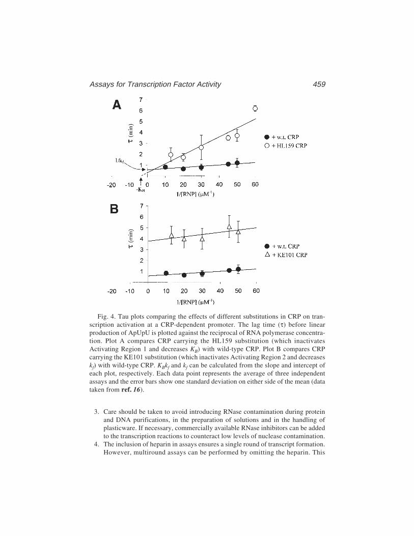
Assays for Transcription Factor Activity 459
3. Care should be taken to avoid introducing RNase contamination during proteinand DNA purifications, in the preparation of solutions and in the handling ofplasticware. If necessary, commercially available RNase inhibitors can be addedto the transcription reactions to counteract low levels of nuclease contamination.
4. The inclusion of heparin in assays ensures a single round of transcript formation.However, multiround assays can be performed by omitting the heparin. This
Fig. 4. Tau plots comparing the effects of different substitutions in CRP on tran-scription activation at a CRP-dependent promoter. The lag time (τ) before linearproduction of ApUpU is plotted against the reciprocal of RNA polymerase concentra-tion. Plot A compares CRP carrying the HL159 substitution (which inactivatesActivating Region 1 and decreases KB) with wild-type CRP. Plot B compares CRPcarrying the KE101 substitution (which inactivates Activating Region 2 and decreaseskf) with wild-type CRP. KBkf and kf can be calculated from the slope and intercept ofeach plot, respectively. Each data point represents the average of three independentassays and the error bars show one standard deviation on either side of the mean (datataken from ref. 16).
460 Rhodius et al.
can be useful when working with promoters where the open complex is sensitiveto heparin.
5. The transcription step of the protocol is very fast and complete in min. Some-times a doublet band is seen corresponding to a particular transcript. This is oftendue to “hesitation” by the polymerase at the end of the transcript. The relativeintensities of the doublet can depend on temperature or the length of time ofthe elongation step. In some cases, multiple bands are caused by ambiguity inthe starting base of the transcript. This can be resolved by working with [γ-32P]-labeled initiating nucleotide (e.g., see ref. 18).
6. The kinetics of open-complex formation can be monitored using transcript assays.After the addition of polymerase, take aliquots at different times and add to the“hot” NTP + heparin mix. Because heparin blocks reinitiation, the amount oftranscript from that sample will be proportional to the amount of open complexformed at that time (for an example, see ref. 19). Typically, for these conditions,the half-time for open-complex formation ranges from 20 s to 30 min. In prin-ciple, it is possible to make these measurements at different polymerase concen-trations and make the τ plot analysis, as for abortive initiation; in practice, this isextremely difficult and the abortive initiation assay is preferable.
7. Elongation can be studied by preforming open complexes and then adding nucle-otide precursors one by one. 3' O-methyl (20) or dideoxy (21) derivatives ofnucleotides can be used to freeze elongation complexes at particular lengths.
8. Transcript analysis assays provide a simple method for monitoring the effects oftranscription factors and their cofactors. However, it can also be exploited toinvestigate effects of conditions (e.g., temperature, salt, etc.) on open-complexformation. It is important to note that changes may affect elongation rather thantranscription initiation. This can be checked simply by preforming open com-plexes and then altering the conditions. In our experience, the elongation step isusually unaltered by changes in the assay conditions, and differences reflectchanges at one or other step in the formation of the open complex (22).
9. Many, but not all, promoters are active in transcript assays and there is no way ofpredicting whether a particular activator will or will not work in vitro. Manyworkers find that such experiments produce more bands than “ought” to be seen.In particular, some runoff transcripts made with purified fragments as templatesexceed the size of the template fragment (3). This results from RNA polymerasemolecules failing to stop when reaching the end of the fragment, turning around,and continuing to transcribe the opposite strand. This effect can be partially cir-cumvented by lowering NTP concentrations or decreasing the temperature.Another problem may arise because any DNA sequence will contain a number ofpotential transcription starts that are normally not used in vivo, because the com-petition for polymerase in vivo favors stronger promoters. In vitro conditions aresuch that there is little discrimination against weak promoters (e.g., see ref. 23).If the appearance of bands from these weak promoters “spoils” the results, theycan be reduced by using higher salt concentrations or lower concentrations ofpolymerase to increase specificity.
Assays for Transcription Factor Activity 461
10. Although the appearance of a transcript makes a good assay for the activity of atranscription factor, there may be situations in which the transcript cannot bedetected. In this case, the best strategy is to attempt to monitor open-complexbinding directly by the opening of the strands. In most cases, the activity of atranscription factor will cause a measurable unwinding of the DNA duplex aroundthe –10 sequence and transcription start. Many chemical reagents can be used tomonitor unwinding, but one of the simplest is potassium permanganate, that pref-erentially attacks nonbase-paired thymines. To measure the unwinding, start withend-labeled DNA and make open complexes with RNA polymerase and activatorproteins, as in the runoff assays. Typically, then add 1 µL of fresh 200 mM potas-sium permanganate per 20-µL sample and incubate for 1 min (still at 37°C). Afterthe addition of 50 µL stop buffer (3 M ammonium acetate, 0.1 mM EDTA, 1.5 Mβ-mercaptoethanol), phenol-extract the sample and alcohol-precipitate the DNA.The labeled DNA can then be cleaved at the sites of permanganate modificationby using the Maxam–Gilbert piperidine protocol. The resulting fragments are runon a sequence gel to find the sites of unwinding. A typical experiment will includeruns with DNA alone, DNA plus polymerase, and DNA plus polymerase plusactivator. This provides a simple method for checking that the activator is func-tional and provides information on the size of the region of unwinding in theopen complex (24,25).
11. A great feature of the abortive initiation assay is that it can be performed onpromoters carried by both circular DNA and linear fragments: the dinucleotideprimer picks out one promoter from others. Obviously, there is more chance ofinterference from other promoters with longer DNAs. Thus, if working with cir-cular plasmid, it is prudent to test the reaction using plasmid either with or with-out the insertion carrying the promoter under study. It may be possible to reduceinterfering signals from the vector by altering the dinucleotide used. Some prim-ers can be used without being completely specific for the promoter tested. Forinstance, CpA and UTP gives the trinucleotide CpApU at galP1, but also thelonger oligonucleotides CpApUpU and CpApUpUpU starting from galP2, whichcan be separated on the chromatogram (28).
12. The abortive initiation assay is tedious because of the chromatographic analysisof the products, which takes 2–3 h. One way to accelerate the procedure is toreplace radioactive UTP with a fluorescent analog, UTP-γ-ANS (1-naphtylamine-5-sulfonic acid UTP). The assay can then be measured fluorometrically byfollowing the increase in light emission caused by the release of the pyrophos-phate–ANS moiety each time a unit is incorporated (27). A considerable advan-tage of this method is that it allows the continuous monitoring of productformation. A disadvantage is that the fluorescent label may alter the kinetics,although, to date, this has not been reported.
13. In some cases, product formation may never become linear with respect to time.Assuming that there are no contaminating nucleases, this is likely to be a result ofthe consumption of nucleoside triphosphates, which reduces the reaction veloc-ity. This can be overcome by lowering the dinucleotide concentration. Ideally,any time-course needs to be run for at least five times τ.

462 Rhodius et al.
14. Before starting any kinetics, it is advisable to check chosen combinations ofprimer and nucleotide for specificity and for product formation: a TON value of<10/min is useless for kinetic studies. Some promoters give no abortive cyclingreaction, whereas others may give homopolymer synthesis caused by slippage inthe enzyme’s active site (28), rendering the abortive initiation assay useless.
15. The most powerful use of abortive initiation is to determine the microscopic rateconstants of individual steps during transcription initiation. Measurements of theserates in the absence or presence of a transcription factor can provide mechanisticinformation about the enzymology of activation. However, the method relies on anumber of assumptions that are true for most, but not all, promoters (4). First,active RNA polymerase must be present in significant (i.e., >5X) excess overthe promoter DNA; second, the isomerization from the closed to open complexmust be essentially irreversible over the time-course of the experiment; and third,in order for the equation in step 6 of Subheading 3.2. to hold true, the closedcomplex must be in rapid equilibrium with free polymerase and DNA.
16. In different situations, transcription activators can affect KB (14), kf (13), or TON(14). In a small number of cases, transcription factors have no effect on abortiveinitiation parameters. In such instances, the activator cannot be intervening at thelevel of open complex formation, but must be affecting later steps of the tran-scription process (e.g., see ref. 29). Such situations can be analyzed by single ormultiple rounds of transcript assays. Note that in some complex cases (e.g., over-lapping promoters), microscopic rate parameters cannot be deduced from abor-tive initiation assays (30).
References1. Raibaud, O. and Schwartz, M. (1984) Positive control of transcription initiation in
bacteria. Annu. Rev. Genet. 18, 173–206.2. Losick, R. and Chamberlin, M. (eds.) (1976) RNA Polymerase. Cold Spring Har-
bor Laboratory, Cold Spring Harbor, NY.3. Zubay, G. (1980) The isolation and properties of CAP, the catabolite gene activa-
tor. Methods Enzymol. 65, 856–877.4. McClure, W. (1980) Rate-limiting steps in RNA chain initiation. Proc. Natl. Acad.
Sci. USA 77, 5634–5638.5. Burgess, R. and Jendrisak, J. (1975) A procedure for the rapid, large-scale purifi-
cation of Escherichia coli DNA-dependent RNA polymerase involving PolyminP precipitation and DNA-cellulose chromatography. Biochemistry 14, 4634–4638.
6. Hager, D., Jun Jin, D., and Burgess, R. (1990) Use of mono Q high resolutionionic exchange chromotography to obtain highly pure and active Escherichia coliRNA polymerase. Biochemistry 29, 7890–7894.
7. Tang, H., Severinov, K., Goldfarb, A., and Ebright, R. (1995) Rapid RNA poly-merase genetics: one-day, no-column preparation of reconstituted recombinantEscherichia coli RNA polymerase. Proc. Natl. Acad. Sci. USA 92, 4902–4906.
8. Fujita, N. and Ishihama, A. (1996) Reconstitution of RNA polymerase. MethodsEnzymol. 273, 121–130.
Assays for Transcription Factor Activity 463
9. Kolb, A., Kotlarz, D., Kusano, S., and Ishihama, A. (1995) Selectivity of theEscherichia coli RNA polymerase Eσ38 for overlapping promoters and ability tosupport CRP activation. Nucleic Acids Res. 23, 819–826.
10. Sambrook, J., Fritsch, E., and Maniatis, T. (1989) Molecular Cloning. A Labo-ratory Manual, 2nd ed. Cold Spring Harbor Laboratory, Cold Spring Harbor, NY.
11. Savery, N., Lloyd, G., Kainz, M., Gaal, T., Ross, W., Ebright, R., et al. (1998)Transcription activation at Class II CRP-dependent promoters: identification ofdeterminants in the C-terminal domain of the RNA polymerase alpha subunit.EMBO J. 17, 3439–3447.
12. Herbert, M., Kolb, A., and Buc, H. (1986) Overlapping promoters and their con-trol in Escherichia coli: the gal case. Proc. Natl. Acad Sci. USA 83, 2807–2811.
13. Hawley, D. and McClure, W. (1982) Mechanism of activation of transcriptioninitiation from the λ PRM promoter. J. Mol. Biol 157, 493–525.
14. Malan, T., Kolb, A., Buc, H., and McClure. W. (1984) Mechanism of CRP-cAMPactivation of lac operon transcription initiation: activation of the P1 promoter. J.Mol. Biol. 180, 881–909.
15. Leirmo, S. and Gourse, R. (1991) Factor independent activation of E. coli rRNAtranscription (I) Kinetic analysis of the role of the upstream activator region andsupercoiling on transcription of the rrnB P1 promoter in vitro. J. Mol. Biol. 220,555–568.
16. Rhodius, V., West, D., Webster, C., Busby, S., and Savery, N. (1997) Transcrip-tion activation at Class II CRP-dependent promoters: the role of different activat-ing regions. Nucleic Acids Res. 25, 326–333.
17. Leirmo, S., Harrison, S., Cayley, D., and Burgess, R. (1987) Replacement ofpotassium chloride by potassium glutamate dramatically enhances protein DNAinteractions in vitro. Biochemistry 26, 2095–2101.
18. Hsu, L. (1996) Quantitative parameters for promoter clearance. Methods Enzymol.273, 59–71.
19. Chan, B. and Busby, S. (1989) Recognition of nucleotide sequences at theEscherichia coli galactose operon P1 promoter by RNA polymerase. Gene 84,227–236.
20. Straney, D. and Crothers, D. (1985) Intermediates in transcription initiation fromthe E. coli lac UV5 promoter. Cell 43, 449–459.
21. Krummel, B. and Chamberlin, M. (1992) Structural analysis of ternary complexesof E. coli RNA polymerase: individual complexes halted along different tran-scription units have distinct and unexpected biochemical properties. J. Mol. Biol.225, 221–237.
22. Grimes, E., Busby, S., and Minchin, S. (1991) Different thermal energy require-ment for open complex formation by Escherichia coIl RNA polymerase at tworelated promoters. Nucleic Acids Res. 19, 6113–6118.
23. Ponnambalam, S.. Spassky, A., and Busby, S. (1987) Studies with the Escheri-chia coli galactose operon regulatory region carrying a point mutation that simul-taneously inactivates the two overlapping promoters. Interactions with RNApolymerase and the cyclic AMP receptor protein. FEBS Lett. 219, 189–196.

464 Rhodius et al.
24. Gaston, K., Bell, A., Kolb, A., Buc, H., and Busby, S. (1990) Stringent spacingrequirements for transcription activation by CRP. Cell 62, 733–743.
25. Chan, B., Minchin, S., and Busby, S. (1990) Unwinding of the duplex DNA dur-ing transcription initiation at the Escherichia coli galactose operon overlappingpromoters. FEBS Lett. 267, 46–50.
26. Goodrich, J. and McClure, W. (1992) Regulation of open complex formation atthe galactose operon promoters. Simultaneous interaction of RNA polymerase,gal repressor and CAP/cyclic AMP. J. Mol Biol 224, 15–29.
27. Bertrand-Burggraf, E., Lefevre. J. F., and Daune, M. (1984) A new experimentalapproach for studying the association between RNA polymerase and the tet pro-moter of pBR322. Nucleic Acids Res. 12, 1697–1706.
28. Qi, F., Liu, C., Heath, L., and Turnbough, C. (1996) In vitro assay for reiterativetranscription during transcriptional initiation by Escherichia coli RNA poly-merase. Methods Enzymol. 273, 71–85.
29. Menendez, M., Kolb, A., and Buc, H. (1987) A new target for CRP action at themalT promoter. EMBO J. 6, 4227–4234.
30. Gussin, G. (1996) Kinetic analysis of RNA polymerase–promoter interactions.Methods in Enzymology 273, 45–59.
Assay of Restriction Endonucleases 465
465
From: Methods in Molecular Biology, vol. 148: DNA–Protein Interactions: Principles and Protocols, 2nd ed.Edited by: T. Moss © Humana Press Inc., Totowa, NJ
32
Assay of Restriction EndonucleasesUsing Oligonucleotides
Bernard A. Connolly, Hsiao-Hui Liu, Damian Parry,Lisa E. Engler, Michael R. Kurpiewski, and Linda Jen-Jacobson
1. IntroductionType II restriction endonucleases are familiar to most investigators in the
biological sciences as indispensable reagents for a variety of molecularbiology techniques. Usually, these dimeric enzymes cut double-stranded DNAat defined, palindromic, sequences 4, 6, or 8 base pairs in length (1). Restric-tion endonucleases have extremely high specificities, a key property thatunderlies their applications in genetic engineering and which has attracted theattention of scientists interested in sequence-specific DNA discrimination.Considerable effort has been expended in trying to elucidate the mechanismsthat underlie specificity, often using the “structural perturbation” approach(2,3). Here, an alteration is made to the protein by site-directed mutagen-esis, or to the nucleic acid by substituting with natural base pairs, or withsynthetic base, sugar and phosphate analogs and the effects on binding andcleavage observed. A useful measure of the perturbation can be obtained byevaluation of the parameter
(kst/KD)modified/(kst/KD)unmodified
where “unmodified” refers to the native endonuclease and the natural DNAtarget sequence and “modified” indicates that either the protein or thenucleic acid has been changed in order to delete a selected interaction. Theparameter kst is the first-order rate constant obtained under single-turnoverconditions. Provided that the association of DNA and the essential cofactorMg2+ with the protein are rapid (see Note 1), kst measures the slowest stepfollowing the assembly of the endonuclease–DNA–Mg2+ complex up to and
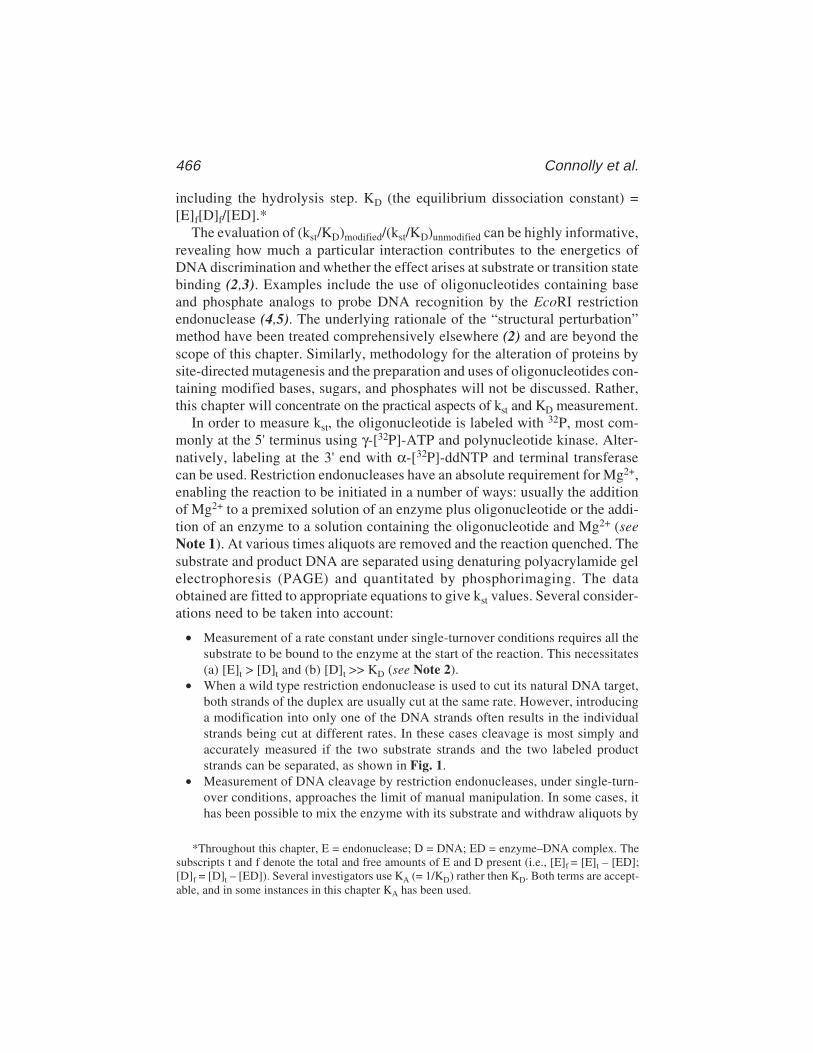
466 Connolly et al.
including the hydrolysis step. KD (the equilibrium dissociation constant) =[E]f[D]f/[ED].*
The evaluation of (kst/KD)modified/(kst/KD)unmodified can be highly informative,revealing how much a particular interaction contributes to the energetics ofDNA discrimination and whether the effect arises at substrate or transition statebinding (2,3). Examples include the use of oligonucleotides containing baseand phosphate analogs to probe DNA recognition by the EcoRI restrictionendonuclease (4,5). The underlying rationale of the “structural perturbation”method have been treated comprehensively elsewhere (2) and are beyond thescope of this chapter. Similarly, methodology for the alteration of proteins bysite-directed mutagenesis and the preparation and uses of oligonucleotides con-taining modified bases, sugars, and phosphates will not be discussed. Rather,this chapter will concentrate on the practical aspects of kst and KD measurement.
In order to measure kst, the oligonucleotide is labeled with 32P, most com-monly at the 5' terminus using γ-[32P]-ATP and polynucleotide kinase. Alter-natively, labeling at the 3' end with α-[32P]-ddNTP and terminal transferasecan be used. Restriction endonucleases have an absolute requirement for Mg2+,enabling the reaction to be initiated in a number of ways: usually the additionof Mg2+ to a premixed solution of an enzyme plus oligonucleotide or the addi-tion of an enzyme to a solution containing the oligonucleotide and Mg2+ (seeNote 1). At various times aliquots are removed and the reaction quenched. Thesubstrate and product DNA are separated using denaturing polyacrylamide gelelectrophoresis (PAGE) and quantitated by phosphorimaging. The dataobtained are fitted to appropriate equations to give kst values. Several consider-ations need to be taken into account:
• Measurement of a rate constant under single-turnover conditions requires all thesubstrate to be bound to the enzyme at the start of the reaction. This necessitates(a) [E]t > [D]t and (b) [D]t >> KD (see Note 2).
• When a wild type restriction endonuclease is used to cut its natural DNA target,both strands of the duplex are usually cut at the same rate. However, introducinga modification into only one of the DNA strands often results in the individualstrands being cut at different rates. In these cases cleavage is most simply andaccurately measured if the two substrate strands and the two labeled productstrands can be separated, as shown in Fig. 1.
• Measurement of DNA cleavage by restriction endonucleases, under single-turn-over conditions, approaches the limit of manual manipulation. In some cases, ithas been possible to mix the enzyme with its substrate and withdraw aliquots by
*Throughout this chapter, E = endonuclease; D = DNA; ED = enzyme–DNA complex. Thesubscripts t and f denote the total and free amounts of E and D present (i.e., [E]f = [E]t – [ED];[D]f = [D]t – [ED]). Several investigators use KA (= 1/KD) rather then KD. Both terms are accept-able, and in some instances in this chapter KA has been used.
Assay of Restriction Endonucleases 467
hand. In others, the reaction is too fast to be evaluated in this manner and a rapid-mixing quenched flow apparatus must be used. Alteration to the endonuclease orthe DNA often cause a reduction in the single-turnover rate constant and it isoften possible to use manual methods in these cases.
The most suitable method for KD determination depends critically on itsmagnitude and hence the stability of the protein–DNA complex (see Note 3).Several approaches for the measurement of KD are presented, enabling equilib-rium constant evaluation under conditions that range from very tight (KD ≈ pM)to very weak (KD ≈ mM) binding. When commencing experiments, the KD willnot be known and good practice requires an initial estimate, followed by anaccurate evaluation using the optimal approach. Modification to the endonu-clease or the DNA often weakens their interaction, sometimes by a consider-able amount. Therefore, the method used in the “natural” case may not be thebest when alterations to the macromolecules are present. Whatever method isused, it is important to prevent DNA hydrolysis and this is most simplyachieved by omission of Mg2+ and addition of EDTA.
Two commonly used methods for KD determination are filter binding andgel retardation (electrophoretic mobility shift assay [EMSA]). Both are dis-cussed elsewhere in this volume (see Chapters 1 and 2) and this chapter
Fig. 1. Oligonucleotides that have been used to measure single turnovers with theEcoRV and EcoRI restriction endonucleases (recognition sequence shown with line,cleavage sites with arrows). With EcoRV, both the substrate strands are differentlengths. In the case of EcoRI, the two substrate strands can be separated by denaturinggel electrophoresis, despite having the same length, as the top strand is dG rich and thebottom dC rich. dC-rich strands migrate faster than dG (dA and T base-pairs affectmigration much less). With EcoRV 3' labeling (*ddA) was used, and with EcoRI, 5'labeling (*P) was used. The offset recognition sites gives products of different sizes.The two arrangements ensure the separation of both substrate and both labelled prod-uct strands and so allow independent measure of the rate of cleavage of the two strands.Only the labeled products are shown. For both enzymes the “top” strands are writtenin the 5' → 3' direction and the “bottom” are written in the 3' → 5' direction.

468 Connolly et al.
emphasizes their application to restriction endonucleases and also the use ofcompetition titration. Most often, a 32P-labeled oligonucleotide is incubatedwith increasing amounts of restriction enzyme to produce a protein–DNA com-plex. The free and protein-bound DNA are then separated and the relativeamounts in each pool determined. This allows the construction of a bindingisotherm and KD evaluation. Data analysis is simplified when [E]t ≈ [E]f andexperimentation is usually carried out under these conditions (see Note 4). It isalso useful to carry out a “reverse” titration: incubating a fixed amount ofendonuclease with increasing quantities of 32P-labeled oligonucleotide.Titrations with a fixed [DNA] may give rise to shifts in the oligomeric state ofthe protein because of its increasing concentration, which can produce biphasicisotherms or curves that do not show asymptotic behavour. This arises due tothe coupled reactions E2 + E2 → E4 → En (where E2 is the active form) and isparticularly relevant to modified substrates that show weak binding; requiringtitration with concentrations of protein that may exceed the KD for the coupleddimer–tetramer equilibrium. If both procedures give identical KD values, onehas confidence that the coupled reaction can be ruled out as an obfuscatingfactor. In addition, the combination of the two approaches permits precisedetermination of the number of active protein molecules, providing that theDNA concentration is accurately known.
Filter binding and gel retardation differ in the manner used to separate thefree DNA and the protein–DNA complex. In filter binding, separation isachieved using a nitrocellulose filter that retains proteins, and hence protein–DNA complexes, but allows the passage of free DNA. Some proteins are poorlybound by nitrocellulose filters although this difficulty can sometimes be cir-cumvented by using a different filter material (e.g., pure nitrocellulose ratherthan mixed-ester filters). Gel retardation uses non denaturing PAGE; free DNAmigrates more rapidly than the protein–DNA complex giving, under ideal con-ditions, two well-resolved bands. Both approaches are sensitive (can be used atvery low [DNA] to measure tight binding), experimentally very simple to carryout, and do not require specialized equipment.
Whether filter-binding or gel-shift methods are chosen, the direct titrationprotocol is not recommended for modified substrates that show very weak bind-ing (i.e., KD > 10–7 M), because the lifetime of the complexes (see Note 3) isalways shorter than the time required either for filtration or for entry into thegel (see Note 5). This may result in partial dissociation of the endonuclease–DNA complex during the measurement (i.e., a “nonequilibrium” situation).For weak binding, a competition titration (6) protocol should be used. Here, afixed quantity of an endonuclease and a 32P-labeled oligonucleotide (most oftencontaining an unmodified recognition sequence for the endonuclease understudy) are allowed to form a complex. Progressively increasing amounts of a
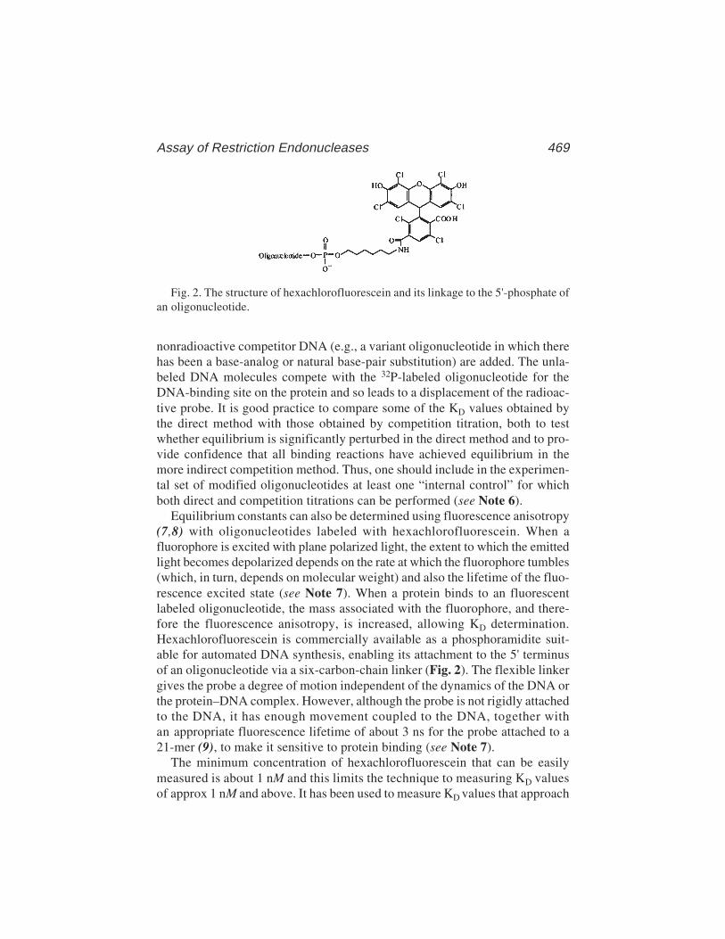
Assay of Restriction Endonucleases 469
nonradioactive competitor DNA (e.g., a variant oligonucleotide in which therehas been a base-analog or natural base-pair substitution) are added. The unla-beled DNA molecules compete with the 32P-labeled oligonucleotide for theDNA-binding site on the protein and so leads to a displacement of the radioac-tive probe. It is good practice to compare some of the KD values obtained bythe direct method with those obtained by competition titration, both to testwhether equilibrium is significantly perturbed in the direct method and to pro-vide confidence that all binding reactions have achieved equilibrium in themore indirect competition method. Thus, one should include in the experimen-tal set of modified oligonucleotides at least one “internal control” for whichboth direct and competition titrations can be performed (see Note 6).
Equilibrium constants can also be determined using fluorescence anisotropy(7,8) with oligonucleotides labeled with hexachlorofluorescein. When afluorophore is excited with plane polarized light, the extent to which the emittedlight becomes depolarized depends on the rate at which the fluorophore tumbles(which, in turn, depends on molecular weight) and also the lifetime of the fluo-rescence excited state (see Note 7). When a protein binds to an fluorescentlabeled oligonucleotide, the mass associated with the fluorophore, and there-fore the fluorescence anisotropy, is increased, allowing KD determination.Hexachlorofluorescein is commercially available as a phosphoramidite suit-able for automated DNA synthesis, enabling its attachment to the 5' terminusof an oligonucleotide via a six-carbon-chain linker (Fig. 2). The flexible linkergives the probe a degree of motion independent of the dynamics of the DNA orthe protein–DNA complex. However, although the probe is not rigidly attachedto the DNA, it has enough movement coupled to the DNA, together withan appropriate fluorescence lifetime of about 3 ns for the probe attached to a21-mer (9), to make it sensitive to protein binding (see Note 7).
The minimum concentration of hexachlorofluorescein that can be easilymeasured is about 1 nM and this limits the technique to measuring KD valuesof approx 1 nM and above. It has been used to measure KD values that approach
Fig. 2. The structure of hexachlorofluorescein and its linkage to the 5'-phosphate ofan oligonucleotide.

470 Connolly et al.
1 µM. Thus, fluorescence anisotropy is much less sensitive than filter bindingor gel retardation, which rely on the detection of 32P. The biggest advantage ofthis method is that it is a strictly equilibrium approach and does not suffer fromproblems caused by protein–DNA dissociation. Drawbacks include the require-ment for expensive equipment and inability to measure tight binding (KD< 1 nM).
2. Materials
2.1. Oligodeoxynucleotides and Restriction Endonucleases
1. [32P]-labeled oligodeoxynucleotides. These should be of high specific activity,prepared using either γ-[32P]-ATP (3000–6000 Ci/mmol)/polynucleotide kinase(5' labeling) or α-[32P]-ddATP(>5000 Ci/mmol)/terminal transferase (3'-label-ing) and purified by standard procedures (10). Duplex oligodeoxynucleotides areprepared by heating equimolar amounts of each strand to 95°C in buffer with thesame pH value and salt concentration to be used in kst or KD measurement andcooling slowly to room temperature. For kst determination, both strands must belabeled; for KD evaluation, only one strand needs to be labeled.
2. Oligodeoxynucleotides containing hexachlorofluorescein at their 5' termini.These can be prepared by chemical synthesis using commercially availablehexachlorofluorescein–phosphoramidite (Glen Research, Sterling, VA;Cruachem Ltd., Glasgow, Scotland) and purified by reverse-phase high-perfor-mance liquid chromatography (HPLC) (9). Duplexes, only one strand of whichneeds to contain the fluorophore, are prepared as in item 1.
3. Restriction endonucleases under study. In this case, EcoRI, EcoRV, and BamHIpurified from overproducing Escherichia coli strains.
2.2. kst Determination
1. Vertical slab gel apparatus (140 × 160 k 0.75 mm) (e.g., Hoefer SE600 or equiva-lent) and power pack with ≈200 V direct current output.
2. Denaturing polyacrylamide gel. Prepared from 16% acrylamide (acrylamide/bis-acrylamide, 19/1) in 0.089 M Tris–borate, pH 8.0, containing 8 M urea and 1 mMEDTA and polymerized with 0.05% ammonium persulfate (added from a freshly pre-pared 10% aqueous solution) and 1% TEMED (N,N,N'N'-tetramethylethylenediammine). The gel should be prerun at a constant power of 30 W, for 1 h, prior to use.
3. Gel running buffer: 0.089 M Tris–borate, pH 8.0, containing 1 mM EDTA.4. Hydrolysis buffer (made up at 2X the final concentration, freshly prepared and
stored at 4°C): in the examples given using EcoRV endonuclease; 20 mM HEPES,pH 7.5, 200 mM NaCl, and 20 mM MgCl2 (see Note 8).
5. Enzyme dilution buffer: Incubation buffer plus 5% (v/v) glycerol (see Note 8).6. Stop solution: 0.1 M Tris-HCl, pH 8.0, 0.1 M EDTA, 2.5 M urea, 10% (w/v)
sucrose, and 125 mg/mL (each) bromophenol blue and xylene cyanol FF.7. Vacuum bag sealer and plastic sheets.8. Phosphorimager (e.g., Fuji BAS-150) and phosphorimager screen (e.g., Fuji
BAS-MP) (or equivalent).
Assay of Restriction Endonucleases 471
9. Quenched flow apparatus (e.g., Hi-Tech RQF–63 [Hi-Tech Scientific, Salisbury,UK]) or equivalent.
2.3. KD Determination (Filter Binding)
1. Vacuum filtration manifold (e.g., Millipore 1225 Sampling Vacuum Manifold,Bedford, MA).
2. Mixed ester nitrocellulose membrane filters (e.g., Gelman GN6, MilliporeHAWP02500, Schleicher & Schuell ME25) or pure nitrocellulose membrane fil-ters (e.g., Schleicher & Schuell, type BA85), 25 mm disks, 0.45-µm pore size.
3. Enzyme dilution buffer: Binding buffer plus 5% glycerol and 0.2 M or 0.6 MNaCl (final concentrations), pH 7.4 (see Note 8).
4. Filter buffer (stored at 4°C): 10 mM BTP (bis-Tris propane), 1 mM EDTA, 0.02%NaN3 at desired pH (e.g., pH 7.4) and desired salt concentration (e.g., 0.2 MNaCl) (see Note 8).
5. Binding buffer (stored at 4°C): Filter buffer plus 0.1 mg/mL bovine serum albu-min and 50 µM dithiothreitol (DTT).
6. Polyethylene liquid-scintillation vials (6 mL capacity).7. Liquid-scintillation fluid (e.g., Scintisafe 30%, Fisher Biotech, Pittsburgh, PA).8. Liquid-scintillation counter (e.g., Packard model 1600; Meridan, CT).
2.4. KD Determination (Gel Retardation)
1. Vertical slab gel apparatus (140 × 160 × 0.75 mm) (e.g., Hoefer SE600 or equiva-lent) and power pack with ≈200 V direct current output.
2. 10% Nondenaturing polyacrylamide gel (acrylamide/bis-acrylamide, 37.5/1) in0.089 M Tris–borate, pH 8.0, and 1 mM EDTA and polymerized with 0.05%ammonium persulfate (added from a freshly prepared 10% aqueous solution) and1% TEMED. The gel should be prerun at a constant power of 20 W with gelrunning buffer and the wells rinsed with this buffer, prior to use.
3. Gel running buffer: Usually 0.089 M Tris–borate, pH 8.0, containing 1 mMEDTA. However, the running buffer can, to a limited extent, be varied to producea better match with the binding buffer (see Note 9).
4. Binding buffers and enzyme dilution buffers: As in Subheading 2.3., items 3 and 5except that the binding buffer should additionally contain 3% (v/v) glycerol (see Note 10).
5. Bromophenol blue solution: 0.25% (w/v) in 30% (v/v) glycerol.6. Vacuum bag sealer and plastic sheets.7. Phosphorimager e.g., Fuji BAS–150 and phosphorimager screen (e.g., Fuji
BAS-MP) (or equivalent).
2.5. KD Determination (Fluorescence Anisotropy)
1. Fluorimeter, with thermostated cuvet compartment, capable of measuring fluo-rescence anisotropy e.g., Aminco SLM-8100.
2. 3-mm-thick 570-nm longpass filter, (OG-570, Schott Glaswerke).3. 0.5 mL semimicro quartz fluorescence cuvets (excitation and emission
pathlengths 5 mm).

472 Connolly et al.
4. Fluorescence binding buffer and enzyme dilution buffer: In the examples givenwith the EcoRV endonuclease, 50 mM Tris-HCl, pH 7.5, 100 mM NaCl, 1 mMDTT, 1 mM EDTA, and 0.1 mg/mL acetylated bovine serum albumin. The fluo-rescence binding buffer should be prepared using the best quality reagents andHPLC-grade water and both degassed and passed through 0.22-µm filters (e.g.,Millex-GV13, Millipore) prior to use.
2.6. Data Analysis
Software capable of fitting reaction data to single and multiple exponentialdecay(s) and binding data to single-site binding isotherms using nonlinearregression analysis. The software used for binding analysis should be able todeal with direct titrations when the simplifying assumption [E]f = [E]t cannotbe made (see Note 4) and competitive titrations. Three packages described inthis chapter are GraFit (11), Scientist (12), and SigmaPlot (13), but any soft-ware with a similar capability is perfectly acceptable.
3. Methods3.1. Determination of kst
3.1.1. Slow Hydrolysis (t1/2 15 s or More ≈kst Values SlowerThan 3 min–1; KD Between 2 and 40 nM)(e.g., with Mutant EcoRV or Altered Oligodeoxynucleotides)
1. In a plastic microcentrifuge tube, prepare 11 µL of a solution containing 1.5 µMof radiolabeled DNA duplex in hydrolysis buffer (in this case for the EcoRVendonuclease, 10 mM HEPES, pH 7.5, 100 mM NaCl, and 10 mM MgCl2) (seeNote 8). Keep on ice.
2. Withdraw 1 µL of the above solution and add to 10 µL of stop solution (item 6 ofSubheading 2.2.). This serves as a zero time-point.
3. Prepare 5 µL of a solution containing 30 µM of EcoRV endonuclease in 10 mMHEPES, pH 7.5, 100 mM NaCl, and 10 mM MgCl2. Keep on ice.
4. Incubate the solutions prepared in steps 1 and 3 at 25°C for 10 min.5. Mix the two solutions to give a final oligonucleotide concentration of 1 µM and a
final endonuclease concentration of 10 µM (see Notes 1 and 2). Vortex briefly toensure thorough mixing and incubate at 25°C.
6. Withdraw 1-µL aliquots at times up to 25 h (the exact time range to be used mustbe found by trial and error and will depend on the particular mutant enzymeand/or altered oligodeoxynucleotide under study) and quench the reaction bythe addition to 10 µL of stop solution (item 6 of Subheading 2.2.). Store thequenched samples on ice.
7. Run the samples on 16% denaturing polyacrylamide gels (item 2 of Subheading2.2.) until the bromophenol blue dye marker reaches the bottom of the gel.
8. Remove the gel from the electrophoresis apparatus and seal in a plastic bag usinga vacuum bag sealer.
Assay of Restriction Endonucleases 473
9. Determine the amount of radioactivity present in each substrate and product bandusing a phosphorimager (see Note 11).
10. From the data obtained from the phosphorimager, determine the percentage ofthe two substrate and the two product strands present at each time-point.
3.1.2. Rapid Hydrolysis (t1/2 15 s or Less ≈kst Values FasterThan 3 min–1; KD Between 2 and 40 nM) (e.g., with Wild-Type EcoRVand Cognate GATATC Recognition Sites
1. Fill the three syringes of the quenched flow apparatus with the following:a. Reaction syringe 1: 0.1 mL of 2 µM radiolabeled DNA in 10 mM HEPES,
pH 7.5, 100 mM NaCl and 10 mM MgCl2.b. Reaction syringe 2; 0.1 mL of 20 µM EcoRV endonuclease in 10 mM HEPES,
pH 7.5, 100 mM NaCl, and 10 mM MgCl2.c. Quench syringe 3; 0.1 mL of 0.3 M EDTA.
2. Set the apparatus to mix the 0.1 mL of the oligonucleotide and enzyme solution(final concentrations of each 1 µM and 10 µM, respectively) and to quench thereaction at the first time-point (0.051 s) by the addition of the 0.1 mL of theEDTA solution.
3. Keep the quenched sample on ice.4. Repeat for each subsequent time-point (in this case, 19 further points between
0.094 and 20 s) (see Fig. 4).5. As a zero time-point, 0.1 mL of the oligonucleotide solution manually mixed
with 0.1 mL of 10 mM HEPES, pH 7.5, 100 mM NaCl, and 10 mM MgCl2, and0.1 mL of 0.3 M EDTA can be used.
6. Add 5 µL of each of the quenched samples to 5 µL of stop solution (Subheading2.2., item 6).
7. Proceed with the analysis by gel electrophoresis and phosphoroimaging (Sub-heading 3.1.1., step 6–9).
3.1.3. Data Analysis; kst Determination
1. Cleavage of a duplex oligonucleotide by a restriction endonuclease involves par-allel sequential reactions (Fig. 3), giving intermediates in which one strand isnicked, and described by four rate constants (14,15). In some instances, the reac-tion scheme can be simplified. This is usually true for wild-type endonucleasesacting on their natural, unmodified, target sequences. Here, both strands are effi-ciently cut in a concerted reaction and nicked intermediates do not accumulate.In this case, the cutting of each of the two substrate strands (or the accumulationof the two radiolabeled products) can be described by a single rate constant withan acceptable degree of accuracy.
2. If simplification is possible, fit the data to an equation describing a single expo-nential using GraFit (11). This equation is supplied within GraFit and almost allbiological kinetic software packages. The design of the oligonucleotides used(Fig. 1) means that the cutting of each strand can be evaluated individually. GraFitrequires time and the percentage of substrate or product present at these times to

474 Connolly et al.
Fig. 3. Parallel sequential cutting of a double-stranded oligodeoxynucleotide by theEcoRV endonuclease.
be entered into a spreadsheet and to use these data to evaluate kst. Concertedcutting of both strands implies that the kst for each of them should be, within thelimits of experimental error, identical. An example is shown in Fig. 4.
3. With modified oligonucleotides or enzymes altered by mutagenesis, cutting oftenbecomes inefficient and nicked intermediates accumulate. Altering any one pointin a palindromic recognition site produces structural asymmetry, leading to dif-ferent values of k1 and k2. In such cases, the following equations are used toobtain values of the four rate constants that describe the unsimplified reactionscheme (Fig. 3):
k2P1 = S1[1 – eλt – — (e–λt – ek4t)]k4 – λ
k1P2 = S2[1 – eλt – — (e–λt – ek3t)]k3 – λ
where λ = k1 + k2 and S1 and S2 are the percentages of total radioactivity in eachDNA substrate strand at t = 0. If end labeling of the two strands is equal, then S1
= S2 = 50%. The ability to separate the two DNA substrate strands permits nor-malizing for “differential labeling” in the event that the two strands have beenradiolabeled with slightly different efficiencies (e.g., if S1 = 40% and S2 = 60%,these values should be entered into the equations). If the radioactivity of the twostrands is markedly different, the program has more difficulty finding the best fit.This is especially the case when a strand that has an intrinsically faster cleavagerate constant has lower specific radioactivity than the other strand. Therefore, itis preferable to attempt to label both strands to the same specific activity.
Reaction times (t) and the amount of products (P1 and P2, expressed as per-centage of total radioactivity for each time point) are entered into the Scientist(12) software spreadsheet. A plot of the experimental and “fitted” values of P1
and P2 is generated along with numerical values of the rate constants k1 to k4.Such fits are most statistically robust when the uncertainties in the independent
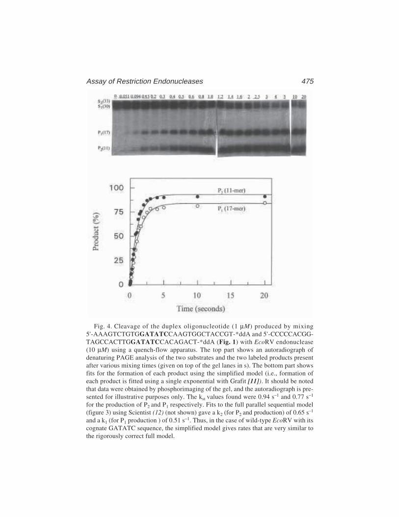
Assay of Restriction Endonucleases 475
Fig. 4. Cleavage of the duplex oligonucleotide (1 µM) produced by mixing5'-AAAGTCTGTGGATATCCAAGTGGCTACCGT-*ddA and 5'-CCCCCACGG-TAGCCACTTGGATATCCACAGACT-*ddA (Fig. 1) with EcoRV endonuclease(10 µM) using a quench-flow apparatus. The top part shows an autoradiograph ofdenaturing PAGE analysis of the two substrates and the two labeled products presentafter various mixing times (given on top of the gel lanes in s). The bottom part showsfits for the formation of each product using the simplified model (i.e., formation ofeach product is fitted using a single exponential with Grafit [11]). It should be notedthat data were obtained by phosphorimaging of the gel, and the autoradiograph is pre-sented for illustrative purposes only. The kst values found were 0.94 s–1 and 0.77 s–1
for the production of P2 and P1 respectively. Fits to the full parallel sequential model(figure 3) using Scientist (12) (not shown) gave a k2 (for P2 and production) of 0.65 s–1
and a k1 (for P1 production ) of 0.51 s–1. Thus, in the case of wild-type EcoRV with itscognate GATATC sequence, the simplified model gives rates that are very similar tothe rigorously correct full model.
476 Connolly et al.
variable (time) are much smaller than the uncertainties in the dependent variable(here, each radioactivity measurement in a product) and when the number of datapoints is sufficiently high to provide a good sampling of experimental uncertain-ties. The “goodness of fit” of the experimental data to the fitted curve is judgedby the individual reaction point residuals, which should vary no more than 10%.We have found that a rigorous test of the robustness of the fit to the above equa-tions is to measure the second strand cleavage rate constants for “nicked” con-structs, assembled from three individual fragments. When using the fullparallel-sequential model, it is good practice to apply the same calculation methodto reference reactions with the normal enzyme–substrate pair. A comparison ofthe rate constants obtained from the “full” and “simplified” calculation methodsthen tests the validity of using the simplified-model fit for the cleavage rate con-stants k1 and k2 for the reference pair (see Note 12).
3.2. Filter Binding
3.2.1. K D Determination: Direct Binding–Titration of DNAwith Protein. Example: KD = 0.66 nM KA = 1/KD = 1.5 × 10⁹ M–1
1. Presoak nitrocellulose membrane filters in filter buffer at the same salt concen-tration and pH used in the binding reaction. Place in the vacuum manifold.
2. Prepare a solution of 0.5 nM radiolabeled duplex DNA by diluting the radiola-beled stock DNA solution (100 nM) with binding buffer at the desired salt con-centration and pH. Add 10 µL of radiolabeled duplex oligonucleotide (0.5 nM) toeach of 10 microcentrifuge tubes; the final concentration of radiolabeled duplexDNA should be 0.05 nM after step 3 (see Note 4). Add the appropriate volume ofbinding buffer such that the total volume of the reaction after step 3 would be100 µL. Equilibrate on ice for 5 min.
3. To each of the above microcentrifuge tubes add restriction endonuclease to givefinal concentrations ranging from 0.05 nM to 5 nM (i.e., the midpoint proteinconcentration should be approx equal to the KD; see Note 4); equilibrate reac-tions on ice for 5 min more. During an experimental series, the protein stockshould always be kept on ice and any intermediate dilutions of the stock that arenot used directly in the final reactions are made using enzyme dilution buffer(salt type and pH always match the experimental conditions). The final dilutionto give the sample used in the reaction should be made with binding buffer (noglycerol) at the appropriate salt concentration (see Note 8). The salt derived fromthe diluted enzyme stock and the DNA source is always accounted for in design-ing the experiment.
4. Set up two “blank” tubes containing DNA, binding buffer, but no enzyme. Oneblank tube will be filtered to obtain RB (background counts) and the other used todetermine RT (the input counts).
5. Also set up a tube containing DNA, binding buffer, and enzyme at a concentra-tion 100-fold the KD (here, 50 nM enzyme). This tube will be filtered to obtainRmax, which represents the total available DNA for binding.
Assay of Restriction Endonucleases 477
6. Transfer the reaction tubes, the two blank tube, and the Rmax tubes to the desiredtemperature (e.g., 25°C) and incubate for 30 min.
7. Pipet 85 µL from each reaction tube, the RB blank, and the Rmax tube onto apresoaked 25 mm nitrocellulose filter in the vacuum filtration manifold withthe vacuum applied. The vacuum (flow rate about 0.5 mL/10 s) is appliedcontinuously throughout the experiment to pull the reaction aliquot throughthe filter.
8. As quickly as possible, wash each filter with 350 µL of filter buffer to removetrapped free DNA.
9. Place each filter in a liquid-scintillation vial and add 2.5 mL of liquid-scintilla-tion fluid. Count in a liquid scintillation counter.
10. Pipet 85 µL from the RT blank tube onto a nitrocellulose filter. Do not wash, butplace the filter directly into a liquid-scintillation vial, add 2.5 mL of liquid-scin-tillation fluid, and count.
3.2.2. KD Determination: Direct Binding–Titration of Proteinwith DNA Example: KD = 40 pM, KA = 1/KD= 2.5 × 10¹⁰ M–1
1. Presoak nitrocellulose membrane filters (Subheading 3.2.1., step 1).2. Prepare a 4 nM stock solution of radiolabeled DNA. For a 4 nM stock DNA
solution, the ratio of radiolabeled DNA to unlabeled DNA is typically 1:3 or 1:4,depending on the specific activity of the radiolabeled DNA.
3. To each of 10 microcentrifuge tubes, add radiolabeled DNA to give final concen-trations ranging from 10 pM to 600 pM. (the midpoint DNA concentration shouldbe approx equal to the KD, see Note 4).
4. Add the appropriate volume of binding buffer plus salt at the desired pH such thatthe total volume of the reaction after step 6 will be 100 µL. Transfer to ice andequilibrate for 5 min.
5. Prepare a solution (40 pM) of restriction endonuclease, at the desired salt concen-tration and pH, by making intermediate dilutions of the stock enzyme solutionwith enzyme dilution buffer and the final dilution (to give the 40 pM solution)with binding buffer as described in Subheading 3.2.1., step 3.
6. To the 10 reaction tubes prepared above, add 10 µL enzyme to give a final con-centration of 4 pM. Keep on ice for an additional 5 min.
7. Set up 10 “blank” reaction tubes (each with total volume 100 µL) that correspondto the reaction tubes prepared in steps 3 and 4 (i.e., 100 µL total volume; radiola-beled DNA concentrations ranging from 10 pM to 600 pM) except that no enzymeis added.
8. Transfer the reaction and blank tubes to the desired temperature (e.g., 25°C) andincubate for 30 min.
9. Remove 85 µL from each tube and carry out filter binding as described in Sub-heading 3.2.1., steps 5–7. As the DNA concentration varies in this experiment, adifferent blank (with a DNA concentration that corresponds to its reaction part-ner) is required for each reaction point.
478 Connolly et al.
3.2.3. Data Analysis: Direct Binding
1. For “normal titrations,” where DNA is titrated with protein, values of Kobs areobtained by nonlinear least-squares fits to a single-site binding isotherm:
[ED]=
KA[E]f
[D]t 1 + KA[E]f
Note that here Kobs is KA and not KD (see the footnote in Subheading 1.). Theactual equation entered into SigmaPlot is (this titration is carried out under con-ditions [E]f ≈ [E]t, see Note 4):
RF – RB = MAXKA[E]t
1 + KA[E]t
The experimental data entered into the spreadsheet are the enzyme concentra-tion, [E]t, for each titration point and RF (counts representing complex retainedon the filter) for each titration point; RB (counts obtained when radiolabeled DNAis filtered without enzyme). A plot of the experimental counts (circles) and ideal-ized counts (line) versus [E]t is generated as shown in Fig. 5. In this figure, [ED]/[ED]max i.e., (RF – RB)/MAX is plotted against [E]t. The nonlinear least squaresbest fit to the equation will give both KA and MAX. The parameter MAX is theasymptote of the binding isotherm and represents the theoretical maximum countsretained by the filter. This theoretical MAX can be checked against the experi-mentally determined Rmax (see Subheading 3.2.1., step 5). The retention effi-ciency, MAX/(RT – RB) or Rmax/(RT – RB), is a good index of reproducibility foreach set of conditions (enzyme, DNA, salt, pH, temperature). The three enzymes(EcoRI, BamHI, and EcoRV) have different retention efficiencies.
2. In the case of “reverse titration” (i.e., when protein is titrated with DNA), valuesfor KA are obtained essentially as above, except that here the equation for a single-site binding isotherm is
[ED]=
KA[D]f KA[D]t
[E]t 1 + KA[D]fand RF – RB = MAX (1 + KA[D]t
)Because the concentration of enzyme is held constant and titrated with DNA, [E]t
should be 5–10% of the KD value (see Note 4). This is in contrast to a “normaltitration” (DNA held constant and titrated with protein), where [D]t is 5–10% ofthe KD.
3.2.4. KD Determination: Competitive Equilibrium Binding. Examples:KD of Reference DNA = 0.25 nM; KD of Competitor DNA = 0.69 nM KDof reference DNA = 0.25 nM; KD of competitor DNA = 0.81 µM
1. Presoak nitrocellulose membrane filters as in Subheading 3.2.1., step 1.2. To each of 10 microcentrifuge tubes, add 10 µL of radiolabeled reference spe-
cific DNA from an 10 nM stock solution to give a final concentration of 1 nM(see Note 12).
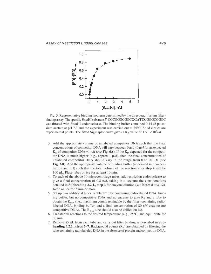
Assay of Restriction Endonucleases 479
Fig. 5. Representative binding isotherm determined by the direct equilibrium filter-binding assay. The specific BamHI substrate 5'-CGCGGGCGGCGGATCCGGGCGGGCwas titrated with BamHI endonuclease. The binding buffer contained 0.14 M potas-sium acetate at pH 7.3 and the experiment was carried out at 25°C. Solid circles areexperimental points. The fitted Sigmaplot curve gives a KA value of 1.51 × 10⁹/M.
3. Add the appropriate volume of unlabeled competitor DNA such that the finalconcentrations of competitor DNA will vary between 0 and 40 nM for an expectedKD of competitor DNA ≈1 nM (see Fig. 6A). If the KD expected for the competi-tor DNA is much higher (e.g., approx 1 µM), then the final concentrations ofunlabeled competitor DNA should vary in the range from 0 to 20 µM (seeFig. 6B). Add the appropriate volume of binding buffer (at desired salt concen-tration and pH) such that the total volume of the reaction after step 4 will be100 µL. Place tubes on ice for at least 10 min.
4. To each of the above 10 microcentrifuge tubes, add restriction endonuclease togive a final concentration of 0.8 nM, taking into account the considerationsdetailed in Subheading 3.2.1., step 3 for enzyme dilution (see Notes 8 and 12).Keep on ice for 5 min or more.
5. Set up two additional tubes: a “blank” tube containing radiolabeled DNA, bind-ing buffer, but no competitive DNA and no enzyme to give RB and a tube toobtain the Rmax (i.e., maximum counts retainable by the filter) containing radio-labeled DNA, binding buffer, and a final concentration of 80 nM enzyme (nocompetitive DNA). The Rmax tube should also be chilled on ice.
6. Transfer all reactions to the desired temperature (e.g., 25°C) and equilibrate for30 min.
7. Remove 85 µL from each tube and carry out filter binding as described in Sub-heading 3.2.1., steps 5–7. Background counts (RB) are obtained by filtering thetube containing radiolabeled DNA in the absence of protein and competitor DNA.
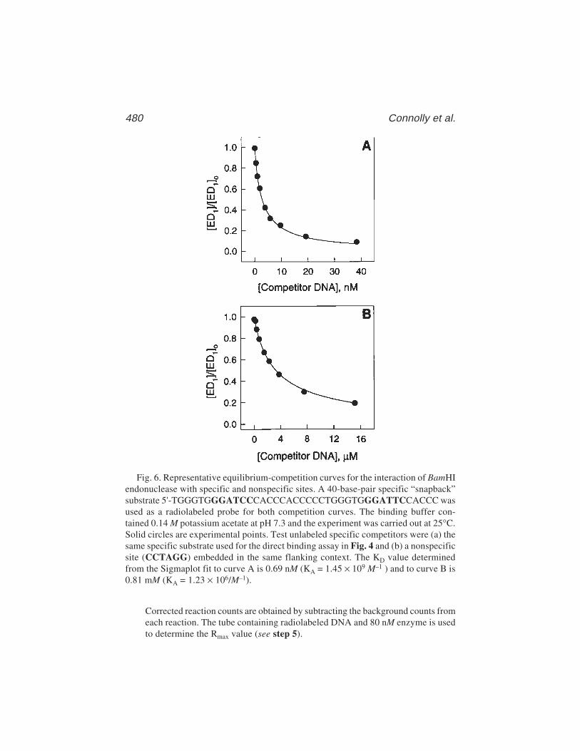
480 Connolly et al.
Fig. 6. Representative equilibrium-competition curves for the interaction of BamHIendonuclease with specific and nonspecific sites. A 40-base-pair specific “snapback”substrate 5'-TGGGTGGGATCCCACCCACCCCCTGGGTGGGATTCCACCC wasused as a radiolabeled probe for both competition curves. The binding buffer con-tained 0.14 M potassium acetate at pH 7.3 and the experiment was carried out at 25°C.Solid circles are experimental points. Test unlabeled specific competitors were (a) thesame specific substrate used for the direct binding assay in Fig. 4 and (b) a nonspecificsite (CCTAGG) embedded in the same flanking context. The KD value determinedfrom the Sigmaplot fit to curve A is 0.69 nM (KA = 1.45 × 10⁹ M–1 ) and to curve B is0.81 mM (KA = 1.23 × 10⁶/M–1).
Corrected reaction counts are obtained by subtracting the background counts fromeach reaction. The tube containing radiolabeled DNA and 80 nM enzyme is usedto determine the Rmax value (see step 5).
Assay of Restriction Endonucleases 481
3.2.5. Data Analysis: Competitive Equilibrium Titration
Results are fitted, using SigmaPlot, to a binding isotherm as previouslydescribed (6) using the equation
[ED1] =[E]t([D1]t – [ED1])
K1(1 + [D2]t) + ([D1]t – [ED1])K2
where [E]t = total enzyme concentration, [D1]t = total radiolabeled referenceDNA concentration, [D2]t = total unlabeled competitor DNA concentration,K1 = dissociation constant for the radiolabeled reference DNA; K2 = disso-ciation constant for the unlabeled competitor DNA. Solving the equation for[ED1] yields
[ED1] = 1 K1 +
K1 [D2]t + [E]t + [D1]t – [(K1 + K1[D2]t + [E1]t + [D1]t)2 – 4[D1]t[E1]t]2 K2 K2
where
[ED1] + [D1]tRF – RB
Rmax – RB
The dissociation constant K1 for the reference DNA is always determined bydirect equilibrium binding at the start of a competition experiment. Rmax,obtained at saturating concentrations of protein and without competitor DNA(see Subheading 3.2.4., step 5) represents the maximum available [D1]t. Theknown values for K1, [D1]t, [E], Rmax, and RB (see Subheading 3.2.4., step 5),are entered into the SigmaPlot software at the start of each calculation. Theexperimental data entered into spreadsheet columns are the corrected counts(counts retained on the filter for each titration point minus background counts;RF – RB) and the competitor DNA concentration [D2]t for each point. The curvegenerated by plotting the corrected counts as a function of increasing concen-trations of competitor DNA ([D2]t) is fitted to the best value for the equilibriumdissociation constant K2 using SigmaPlot nonlinear regression analysis.Figure 6 presents the results as a plot of the ratio of [ED1]/[ED1]0 where [ED1]0is the concentration of enzyme–DNA complex obtained in the absence of com-petitor. The [ED1]0 found in this experiment should not be significantly differ-ent from the [ED1]0 calculated for a direct binding experiment.
3.3. Gel Retardation
3.3.1. KD Determination: Direct Binding–Titration of DNA with Protein
1. Set up and equilibrate binding reactions as described in Subheading 3.2.1., steps2–4. The final reaction tubes should additionally contain 3% (v/v) glycerol (seeNote 10). A “blank” should contain all the components except endonuclease.Smaller samples (typically 10 µL) are used in gel retardation than are used for
482 Connolly et al.
filter binding (85 µL in the examples given above). Therefore, if only gel retarda-tion is being carried out, the final volume should be 10 µL. Alternatively, it canbe very useful to make up a binding reaction and split into aliquots for simulta-neous analysis by both filter binding and gel retardation (either direct or compe-tition titration).
2. Following incubation, load the aliquots of the samples, typically 10 µL, into thewells of 10% nondenaturing polyacryalmide gels (see Subheading 2.4., items 1and 2 and Note 9).
3. Run the gels at a constant power of 20–25 W, with cooling, until a bromophenolblue marker (see Subheading 2.4., item 5 and Note 10) in an adjacent lane, notcontaining the experimental samples, reaches the gel front (about 1 h).
4. Remove the gel from the electrophoresis apparatus and seal in plastic using avacuum bag sealer.
5. Determine the amount of radioactivity present in the bands that correspond to thefree and bound DNA using a phosphorimager (see Note 11).
3.3.2. KD Determination: Competitive Equilibrium Binding
1. Set up equilibrium competition reactions according to the steps outlined in Sub-heading 3.2.4., steps 2–4, except that the binding buffer for all reactions shouldinclude 3% (v/v) glycerol (see Note 10). If only gel retardation is being carriedout smaller volumes (see Subheading 3.3.1., step 1) (e.g., 10 µL should be used. A“blank” should contain all the components except endonuclease and competitor DNA.
2. Perform gel retardation analysis and phosphorimaging as described in Subhead-ing 3.3.1., steps 1–5.
3.3.3. Data Analysis: Gel Retardation
1. For direct titration it is possible to determine Kobs in an analogous manner to thatdescribed in Subheading 3.2.3. In this case, however,
[ED]/[D]t = Countscomplex/Countsfree + Countscomplex = fraction of countscomplex
where countscomplex and countsfree are the counts in the shifted (enzyme-DNA)and unshifted (free DNA) bands, respectively. The experimental data enteredinto the spreadsheet are fraction of countscomplex and the enzyme concentration[E]t for each titration point.
2. For competition binding the equations given in Subheading 3.2.5. are applicable.In this case,
[ED1] = [D1]tcountscomplex
countsmax
where countscomplex and countsmax are, respectively, the counts in the shifted bandfor each titration point at a particular competitor DNA concentration and for thecontrol using large amounts of enzyme and no competitor DNA (see Subhead-ing 3.2.4., step 5), where all the DNA is shifted into the complex. The knownvalues for K1, [D1]t, [E]t, and countsmax are entered into SigmaPlot at the start of
Assay of Restriction Endonucleases 483
each calculation. The experimental data entered into spreadsheet columns arecountscomplex and the competitor DNA concentration [D2]t for each titration point.
3.4. Fluorescence Anisotropy
3.4.1. KD Determination. Example: KD ≈40 nM
1. Set the fluorimeter to measure anisotropy in the “single-point polarization” mode.Each anisotropy value should be measured 10 times (measurement time, 5 s) andaveraged (automatically carried out by the fluorimeter). Set the G-factor to “permeasurement” (see Note 14).
2. An excitation wavelength of 530 nm is used with all the slits on the excitationmonochromator set to 8.
3. Anisotropy is measured in the “L” format through the right photomultiplier witha 570-nm long-pass filter between the sample and the photomultiplier. Using afilter rather than a monochromator on the emission side greatly increases thelight intensity at the photomultiplier and so allows measurement of lower con-centrations of fluorophore.
4. Place a 0.5-mL fluorescence cuvet in the fluorimeter. The cuvet should not beremoved from the fluorimeter or otherwise moved during the experiment. Addfluorescence binding buffer such that the final volume after step 3 will be0.5 mL. A measurement temperature of 25°C is used.
5. Add duplex DNA, one strand of which is labeled with hexachlorofluorescein(Subheading 2.1., item 2) to give a final concentration of 10 nM (see Note 15).Note the anisotropy.
6. Add EcoRV endonuclease in small aliquots (see Note 16), using a microliterHamilton syringe, to cover the range 0–400 nM. Mix thoroughly by gently with-drawing the contents with a plastic pipet tip and readding to the cuvet. After eachaddition, measure the anisotropy.
7. At the beginning (all oligonucleotide free in solution) and end (all oligonucle-otide bound to endonuclease) of the titration, the fluorescence emission intensityshould be noted (see Note 14).
3.4.2. Data Analysis
1. The fluorescence anisotropy measurements were carried out at [D]t ≈ KD (seeNote 15). Under these circumstances, [E]f ≠ [E]t and so the simplified, hyper-bolic, form of the binding equation cannot be used. Therefore, data must be fittedusing the full quadratic binding equation (see Note 4). A solution, in terms ofanisotropy, is
A = Amin + (Amax ––Amin)[× 1 (([D]t + [E]t + KD) – √[([D]t + [E]t + KD)2 – (4 [D]t[E]t)][D]t 2
where A is the measured anisotropy; Amin is the anisotropy of free DNA, and isthe Amax anisotropy of DNA when fully bound to the endonuclease.
2. The data should be fitted to the above equation using GraFit (11). This requiresentry of A and [E]t into the spreadsheet provided by the software. [D]t is a con-
484 Connolly et al.
stant (i.e., the concentration of oligonucleotide present at the start of the experi-ment). The titration consists of the addition of multiple aliquots of endonucleaseto the cuvet, resulting in a dilution of the components. Correction should be madefor the dilution of the endonuclease as aliquots are progressively added. Anisot-ropy, a ratio of fluorescence intensities, does not depend on concentration and is,therefore, unaffected by dilution. However, as [D]t is treated as a constant by thissoftware it is not possible to compensate for its dilution. Therefore, the finaldilution should not exceed about 10%. This may require endonuclease additionfrom several stocks of different concentration. GraFit also requires an estimate ofAmin, Amax, and KD; suitable values for the first two can be obtained from themeasured anisotropy values at the start (before endonuclease addition) and (afterthe final addition of endonuclease) at the end of the experiment. The softwareuses nonlinear regression analysis to calculate best-fit values of these threeparameters. Note that the equation given above only holds if the fluorescence emis-sion intensity of the free and protein-bound DNA are identical (see Note 14).This is determined in Subheading 3.4.1., step 6.
3. A representative titration curve is shown in Fig. 7.
4. Notes1. With restriction endonucleases, it is often found that the binding of DNA and
Mg2+ are rapid relative to subsequent events such as conformational changes,hydrolysis, and product release. This means that rate constants measured undersingle-turnover conditions are the same whether the reaction is initiated by add-ing Mg2+ to an endonuclease–DNA solution or adding the enzyme to a solutioncontaining DNA and Mg2+. This should, however, be checked by trying bothinitiating methods.
2. The KD values for the EcoRV endonuclease and the oligonucleotides used inSubheadings 3.1.1. and 3.1.2. vary between 2 and 40 nM. The DNA concentra-tion used in Subheadings 3.1.1. and 3.1.2. (25 × KD for a KD of 40 nM) and anendonuclease level 10 times higher ensures that ≥95.5% of the nucleic acidis bound to the protein. Many other concentrations of the two macromoleculesformally meet this requirement. A useful combination, especially for proteinsthat are unstable, poorly soluble, and prone to form inactive tetramers andinsoluble higher aggregates when free in solution is [D]t = 50 KD to100 KD and[E]t = 2 × [D]t. This results in at least 98% of the DNA being bound and avoids alarge excess of the labile free protein. When bound to DNA, many endonucleasesare both stabilized and protected from aggregation. For substrates with poor KDand kst (especially so-called “star” sites, where one of the bases in the recognitionsequence is replaced by another natural base), dissociation rate constants aremuch greater than the cleavage rate constants. Therefore, multiple proteindissociations and associations occur prior to a productive cleavage event and sovery poor substrates are never really cleaved under true single-turnover condi-tions. However, high concentrations of protein and nucleic acid ensure that therate (ka × [DNA][E]) of association is as fast as possible and minimizes the
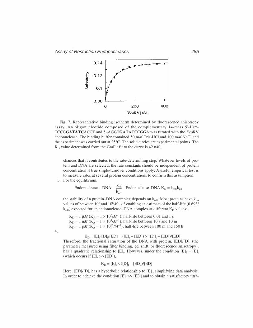
Assay of Restriction Endonucleases 485
Fig. 7. Representative binding isotherm determined by fluorescence anisotropyassay. An oligonucleotide composed of the complementary 14-mers 5'-Hex-TCCGGATATCACCT and 5'-AGGTGATATCCGGA was titrated with the EcoRVendonuclease. The binding buffer contained 50 mM Tris-HCl and 100 mM NaCl andthe experiment was carried out at 25°C. The solid circles are experimental points. TheKD value determined from the GraFit fit to the curve is 42 nM.
chances that it contributes to the rate-determining step. Whatever levels of pro-tein and DNA are selected, the rate constants should be independent of proteinconcentration if true single-turnover conditions apply. A useful empirical test isto measure rates at several protein concentrations to confirm this assumption.
3. For the equilibrium,
Endonuclease + DNAkon Endonuclease–DNA KD = koff/konkoff
the stability of a protein–DNA complex depends on koff. Most proteins have kon
values of between 106 and 108 M–1s–1 enabling an estimate of the half-life (0.693/koff) expected for an endonuclease–DNA complex at different KD values:
KD = 1 µM (KA = 1 × 10⁶/M–1); half-life between 0.01 and 1 sKD = 1 nM (KA = 1 × 10⁹/M–1); half-life between 10 s and 10 mKD = 1 pM (KA = 1 × 10¹²/M–1); half-life between 100 m and 150 h
4.KD = [E]f [D]f/[ED] = ([E]t – [ED]) × ([D]t – [ED])/[ED]
Therefore, the fractional saturation of the DNA with protein, [ED]/[D]t (theparameter measured using filter binding, gel shift, or fluorescence anisotropy),has a quadratic relationship to [E]t. However, under the condition [E]f = [E]t
(which occurs if [E]t >> [ED]),
KD = [E]t × ([D]t – [ED])/[ED]
Here, [ED]/[D]t has a hyperbolic relationship to [E]t, simplifying data analysis.In order to achieve the condition [E]t >> [ED] and to obtain a satisfactory titra-
486 Connolly et al.
tion it is also necessary to have [D]t < KD. DNA concentrations ≤15% KD aresufficient to satisfy the assumption [D]t < KD and give insignificantly differentKD values whether the hyperbolic or quadratic binding equation is used. How-ever, very low [D]t often gives binding curves of very poor quality. This mayresult from insufficient ligand stabilization of the protein by the nucleic acid.Therefore, a [D]t in the 5–15% KD range is recommended. Concentrations of pro-tein are chosen so that the midpoint of the titration curve yields a protein con-centration approx equal to the expected KD. Clearly, the KD will not be knownprior to experimentation, emphasizing the need for an initial estimation, followedby a second, more accurate, determination.
5. Filter binding requires passage of the mixture through a nitrocellulose filter and abrief washing of the filter with buffer to remove excess unbound DNA. The entireprocess can be carried out in seconds. Gel retardation takes longer; about1–2 min to load the samples and the same time to run them into the gel. Runningthe gel takes 30–60 min. Therefore, gel retardation can suffer, to a greater extentthan filter binding, from dissociation of the protein–DNA complex. To some degreethe problem is self-diagnostic, because it results in a smeared protein–DNA bandrather than the tightly focused one which arises when no dissociation takes place.In these cases, KD determination may be achieved by measurement of the free-DNA band (16), but if this approach is used, an alternative method is best used tocheck the validity of the result.
6. As an example, consider an unmodified DNA with a KD of 0.1 nM and fourmodified DNAs with KD values that range from 1 nM to 1 mM. Direct equilib-rium analyses are performed for the unmodified substrate and the modified sitewith KD = 1 nM. Equilibrium competition analyses are also performed for thefour modified sites. If identical values of KD are obtained from both direct andcompetition analyses for the modified site with KD = 1 nM, the modified siteserves as an internal control for the three modified sites which bind more weakly.
7. The relationship between fluorescence anisotropy, lifetime, and rotation is givenby the Perrin equation (7,8):
A = A0/(1 + τ/φ)
where A is the measured anisotropy, A0 = intrinsic anisotropy (i.e., the anisot-ropy measured under conditions where no depolarization takes place), τ is thelifetime of the fluorescence excited state, and φ is the rotational correlation time,a measure of rotational diffusion that depends on the molar volume and, hence,the molecular mass attached to the fluorophore. The values of τ and φ must bebalanced: a very short lifetime, relative to the correlation time, would lead toA = A0 ; a very long lifetime to A = 0. Use of this method requires 0 < A < A0. Theτ value of approx 3 ns for hexachlorofluorescein attached to oligonucleotides issuitable for distinguishing between free and protein-bound oligonucleotides. Themeasured anisotropy is given by:
A = (I|| – I⊥)/(⊥ I|| + 2I⊥)
Assay of Restriction Endonucleases 487
I|| and I⊥ are the intensities of the parallel and perpendicular components of theemitted light when parallel excitation is used.
8. The buffer components used for kst and KD determination will obviously varysomewhat depending on the enzyme under study and the particular experiment.However, for most DNA-binding proteins, including EcoRI, EcoRV, and BamHIrestriction endonucleases there is pronounced nonlinearity in the dependence oflog KD versus salt concentration (17) at salt concentrations ≤0.1 M, presumablybecause at these low salt concentrations, coupled protein–protein equilibria lead-ing to aggregation (18) become significant. This phenomenon can produce mis-leading quantitative comparisons and thus salt concentrations below 0.1 M shouldbe avoided. Bis-Tris propane is useful as it has two pK values (6.8 and 9), allow-ing pH-dependence studies with a single buffer. However, other buffers, ofappropriate pK can equally well be used. Bovine serum albumin and DTT canhelp to stabilize certain restriction endonucleases, especially at low concentra-tions. With several DNA-binding proteins, including EcoRI endonuclease,aggregation and ultimately precipitation, in the absence of the stabilizing DNAsubstrate, is quite common at salt concentrations below 0.4 M. In these cases,intermediate dilutions should be made with buffers containing 0.6 M NaCl. Fivepercent glycerol, in the dilution buffers, also aids stability.
9. The “classic” gel-shift buffer, used to prepare and run nondenaturing polyacryla-mide gel is 0.089 M Tris-borate, pH 8.0, containing 1 mM EDTA (19). Manyprotein–DNA complexes, particularly those of high affinity, are stable in thisbuffer. Therefore, it is often possible to incubate enzyme and DNA in a selectedbinding buffer and then carry out gel retardation in Tris-borate electrophoresisbuffer without disturbing the equilibrium initially set up. However, the bindingof restriction endonucleases to DNA depends on pH, salt concentration (NaCl orKCl), and divalent cations (Ca2+, a Mg2+ mimic that does not allow hydrolysis,often considerably strengthens binding) (18,20,21). Ideally it would be best touse identical incubation and electrophoresis buffers. We have obtained satisfac-tory gel retardation data using Tris-borate at pH 7.5. Replacing the EDTA withup to 5 mM CaCl2 is also not detrimental. However, many buffers are not suitablefor electrophoresis, giving poorly resolved or smeared bands, especially if NaClor KCl is added.
10. Gel retardation requires that the sample applied to the gel be denser than theelectrophoresis buffer and so sinks into the well. The presence of 3% glycerol inthe binding reactions ensures efficient sinking of the sample (18). If this methodis used, it should be checked that glycerol does not perturb KD values (e.g., by carry-ing out filter binding ± glycerol. An alternative involves addition of half a volume(i.e., in this case, 5 µL to the 10 µL binding reaction) of 25% (w/v) sucrose solutionfollowing incubation and immediately prior to loading on the gel. This dilutes thesample, and in cases of weak binding, the associated fast koff rates may lead to somedissociation. However, if the binding is strong, the small dilution factor is unlikelyto be a problem. It is best not to add the bromophenol blue marker to the solutionof enzyme and DNA, as the dye can diminish (18) binding.

488 Connolly et al.
11. Phosphorimaging is the best way to quantitate the amount of radioactivity inbands on gels. Phosphorimaging systems are now fairly standard in most labora-tories. As an alternative autoradiography followed by scanning of the bands maybe used, but it is more cumbersome and less accurate.
12. Fitting to the full kinetic model is actually the least robust for the unmodified enzyme-oligonucleotide pair because the rate constants are so similar numerically that theprogram has difficulty partitioning among them. Thus, many closely spaced, andaccurate, time-points should be taken and this will usually require rapid quench.
13. The total concentration of endonuclease and radiolabeled reference DNA (D1)are chosen to be at least fourfold over the predicted equilibrium dissociation con-stant (K1) for their interaction. [E]t and [D1]t in the range K1 to 30 K1 have beentested; the K2 (equilibrium dissociation constant for competitor DNA) is notaffected significantly.
14. The change in anisotropy is only strictly related to the molecular mass of thefluorophore and hence the amount of oligonucleotide complexed with endonu-clease, if the following two criteria are met. First, the detector response to theparallel and perpendicular polarized light must be identical. The G-factor mea-sures this response, which is automatically corrected for, at each reading, withthe fluorimeter used here. Second, the quantum yield of the free oligonucleotideand the enzyme-bound oligonucleotide must be the same (i.e., under identicalconditions, the free and bound oligonucleotide should emit the same amount oflight). If the quantum yield of the free and bound oligonucleotide varies the equa-tion used to fit the data will not be valid (7,22,23). In the example shown inFig. 7, the emission intensity of the free and bound oligonucleotide varies lessthan 10%. However, the use of other hexachlorofluorescein oligonucleotides anddifferent buffers with the EcoRV endonuclease often results in large intensitychanges (>10%). In these cases, fluorescence anisotropy cannot be used unlesscorrections are made (7,22,23).
15. Good results have been obtained using a DNA concentration about equal to theKD and varying protein concentrations from 0 to (20–30) KD. However, lowerconcentrations of DNA can also be used, although 1 nM represents the detectionlimit. DNA levels much higher than the KD should be avoided, as this promotesstoichiometric titration (where each protein molecule added binds to the nucleicacid), conditions under which accurate KD evaluation is not possible.
16. Purified endonucleases are often stored in buffers containing glycerol. Fluores-cence anisotropy is very sensitive to viscosity and the addition of large amountsof glycerol during the titration adversely effects the measurement. Therefore,intermediate dilutions should be made with buffers lacking glycerol. This usuallyensures that the amount of glycerol added to the fluorescence cuvet is negligible(≤2%). In the case of weak binding, when an enzyme may have to be addeddirectly from the storage buffer, dialysis is recommended to remove the glycerol.
AcknowledgmentsThe Newcastle group would like to thank G. Baldwin and S. Halford
(Bristol) for the use of their quench-flow apparatus and help with the data
Assay of Restriction Endonucleases 489
shown in Fig. 4. B.A.C. is supported by the UK BBSRC and MRC. L.J.J. issupported by a grant (GM-29207) from the National Institutes of Health (USA).B.A.C. and L.J.J. have a Wellcome Trust biomedical research collaboration grant.
References1. Roberts, R. J. and Macelis, D. Rebase; the restriction enzyme database. http://
www. neb. com/rebase/rebase. html2. Jen-Jacobson, L. (1995) Structural-perturbation approaches to thermodynamics
of site-specific protein-DNA interactions. Methods Enzymol. 259, 305–344.3. Jen-Jacobson, L. (1997) Protein-DNA recognition complexes: conservation of
structure and binding energy in the transition state. Biopolymers 44, 153–180.4. Lesser, D. R., Kurpiewski, M. R., Waters, T., Connolly, B. A., and Jen-Jacobson,
L. (1993) Facilitated distortion of the DNA site enhances EcoRI endonucleaseDNA interactions. Proc. Natl. Acad. Sci. USA 90, 7546–7552.
5. Kurpiewski, M. R., Koziolkiewicz, M., Wilk, A., Stec, W. J., and Jen-Jacobson,L. (1996) Chiral phosphorothioates as probes of protein interactions with indi-vidual DNA phosphoryl oxygens: essential interactions of the EcoRI endonucleasewith the phosphate at pGAATTC. Biochemistry 35, 8846–8854.
6. Lin, S. Y. and Riggs, A. D. (1972) lac Repressor binding to nonoperator DNA:detailed studies and a comparison of equilibrium and rate competition methods. J.Mol. Biol. 72, 671–690.
7. James, D. M and Sawyer, W. H. (1995) Fluorescence anisotropy applied to bimo-lecular interactions. Methods Enzymol. 246, 283–300.
8. Hill, J. J. and Roger, C. A. (1997) Fluorescence approaches to the study of pro-tein-nucleic acid complexes. Methods Enzymol. 278, 390–416.
9. Powell, L. M, Connolly, B. A., and Drained, D. T. F. (1998) The DNA bindingcharacteristics of trimeric EcoKI methyltransferase and its partially assembleddimeric form detected by fluorescence polarization and DNA footprinting. J. Mol.Biol. 283, 947–961.
10. Sambrook, J., Fritsch, E. F., and Maniatis, T. (1989) Molecular Cloning. A Labo-ratory Manual, 2nd ed., Cold Spring Harbor Laboratory, Cold Spring Harbor,NY, pp. 5.56–5.87 and 11.31–11.39.
11. GraFit (1998) Version 4.05, Erithacus Software, Staines, UK.12. Scientist (1995) Version 2.0, MicroMath Software Inc., Salt Lake City, UT.13. Sigma Plot (1996) Version 4.0 SPSS Inc, Chicago, IL.14. Lesser, D. R., Kurpiewski, M. R., and Jen-Jacobson, L. (1990) The energetic basis of
specificity in the EcoRI endonuclease–DNA interaction. Science 250, 776–786.15. Jen-Jacobson, L., Lesser, D. R., and Kurpiewski, M. R. (1991) DNA sequence
discrimination by the EcoRI endonuclease, in Nucleic Acids and MolecularBiology, Vol. 5 (Eckstein, F. and Lilley, D. M. J., eds.), Springer-Verlag, NY, pp.141–170.
16. Carey, J. (1991) Gel retardation. Methods Enzymol. 208, 103–118.17. Record, M. T., Jr., Anderson, C. F., and Lohman, T. M. (1978) Thermodynamic
analysis of ion effects on the binding and conformational equilibria of proteins
490 Connolly et al.
and nucleic acids: the roles of ion association or release, screening, and ion effectson water activity. Quart. Rev. Biophys. 11, 103–178.
18. Engler, L. E., Welch, K. K., and Jen-Jacobson, L. (1997) Specific binding by theEcoRV restriction endonuclease to its recognition site GATATC. J. Mol. Biol.269, 82–101.
19. Revzin, A. (1987) Gel electrophoresis assays for DNA–protein interactionsBioTechniques 7, 346–355.
20. Taylor, J. D. and Halford, S. E. (1989) Discrimination between DNA sequencesby the EcoRV restriction endonuclease. Biochemistry 28, 6198–6207.
21. Vipond, I. B. and Halford, S. E. (1995) Specific DNA recognition by EcoRVrestriction endonuclease induced by Ca2+ ions. Biochemistry 34, 1113–1119.
22. Eftink, M. R. (1997) Fluorescence methods for studying equilibrium macromol-ecule-ligand interactions. Methods Enzymol. 278, 221–257.
23. Gutfreund, H. (1995) The role of light in kinetic investigations, in Kinetics for theLife Sciences Receptors, Transmitters and Catalysts. Cambridge University Press,Cambridge, pp. 291–295.

Intrinsic Fluorescence 491
491
From: Methods in Molecular Biology, vol. 148: DNA–Protein Interactions: Principles and Protocols, 2nd ed.Edited by: T. Moss © Humana Press Inc., Totowa, NJ
33
Analysis of DNA–Protein Interactionsby Intrinsic Fluorescence
Mark L. Carpenter, Anthony W. Oliver, and G. Geoff Kneale
1. IntroductionChanges in the fluorescence emission spectrum of a protein upon binding to
DNA can often be used to determine the stoichiometry of binding and equilib-rium binding constants; in some cases the data can also give an indication ofthe location of particular residues within the protein. The experiments are gen-erally quick and easy to perform, requiring only small quantities of material(1). Spectroscopic techniques allow one to measure binding at equilibrium(unlike, for example, gel retardation assays and other separation techniquesthat are strictly nonequilibrium methods). Fluorescence is one of the most sen-sitive of spectroscopic techniques, allowing the low concentrations (typicallyin the nanomolar to micromolar range) required for estimation of binding con-stants for many protein–DNA interactions. Considerable care, however, needsto be exercised in the experiment itself and in the interpretation of results. Thefundamental principles of fluorescence are discussed briefly in the remainderof the Introduction.
A molecule that has been electronically excited with ultraviolet (UV)/vis-ible light can lose some of the excess energy gained and return to its groundstate by a number of processes. In two of these, fluorescence and phosphores-cence, this is achieved by emission of light. Phosphorescence is rarely observedfrom molecules at room temperature and will not be considered further.Although electrons can be excited to a number of higher-energy states, fluores-cence emission in most cases only occurs from the first vibrational level of thefirst excited state. This has two implications for the measurement of fluores-cence emission spectra. First, some of the energy initially absorbed is lost priorto emission, which means that the light emitted will be of longer wavelength
492 Carpenter, Oliver, and Kneale
(i.e., lower energy) than that absorbed. This is known as the Stoke’s shift. Sec-ond, the emission spectrum and therefore the wavelength of maximum fluores-cence will be independent of the precise wavelength used to excite themolecule. Thus, for tyrosine, the wavelength of the fluorescence maximum isobserved around 305 nm, regardless of whether excitation is at the absorptionmaximum (approx 278 nm) or elsewhere in the absorption band. Of course, thefluorescence intensity will change as a consequence of the difference in theamount of light absorbed at these two wavelengths.
The fraction of light emitted as fluorescence compared to that initiallyabsorbed is termed the quantum yield. The value of the quantum yield for aparticular fluorophore will depend on a number of environmental factors suchas temperature, solvent, and the presence of other molecules that may enhanceor diminish the probability of other processes deactivating the excited state.The deactivation or quenching of fluorescence by another molecule, eitherthrough collisional encounters or the formation of excited-state complexes,forms the basis of many of the fluorescence studies on protein–DNA interactions.
The study of protein–nucleic acid interactions is greatly simplified by thefact that all detectable fluorescence arises from the protein, all four of the natu-rally occurring DNA bases being nonfluorescent by comparison. Tyrosine andtryptophan residues account for almost all the fluorescence found in proteins.As a general rule, when both residues are present, the emission spectrum willbe dominated by tryptophan, unless the ratio of tyrosines to tryptophans is veryhigh. The quantum yield of a tyrosine residue in a protein compared to thatobserved in free solution is generally very low, illustrating the susceptibility oftyrosine to quenching. Tryptophan residues are highly sensitive to the polarityof the surrounding solvent, which affects the energy levels of the first excitedstate with the result that the emission maximum for tryptophan can range from330 nm in a hydrophobic environment to 355 nm in water. Thus, in proteinscontaining only one tryptophan, the general environment surrounding the resi-due can be ascertained. Tryptophan fluorescence, like that of tyrosine, can bequenched by a number of molecules, including DNA. Unlike tyrosine, the emis-sion maximum can also change if tryptophan is involved in the interaction andthis can also be used to monitor DNA binding (2).
The extent to which the fluorescence of a protein is quenched by DNA isproportional to the concentration of quencher. As quenching is the result of theformation of a complex between the protein and the DNA, the extent of quench-ing is proportional to the amount of bound protein. Thus by determining theextent to which the protein fluorescence is quenched when fully bound to DNA(i.e., at saturation), the fraction of bound and free protein at any point in atitration can be determined. From these data, the stoichiometry and bindingconstant of the interaction can often be obtained. Note that to establish an
Intrinsic Fluorescence 493
accurate stoichiometry, a high concentration of protein is preferred whentitrating with DNA (i.e., well above the Kd of the complex) to ensure stoichio-metric binding. To establish the binding constant itself, one should be workingat much lower concentrations of protein so that at the stoichiometric point,there is a measurable concentration of unbound protein. In the case of protein–DNA interactions having a low Kd, this may not be possible.
If fluorescence quenching is being used to follow DNA binding, it is vital totake account of sample dilution, as well as the increased absorption of thesample as DNA is titrated in. The latter effect is known as the inner filter effectand arises from the absorption of the excitation beam (and generally to a lesserextent, the emission beam) on passing through the sample (see Fig. 1). Oneshould aim to keep the absorption of the sample (at the excitation wavelength)as low as possible, although absorbances up to 0.2 can normally be correctedwithout too much difficulty. A small-pathlength cell will also help (if rectan-gular, the excitation beam should pass through the smallest path). Ideally, theabsorption of the sample at the excitation and emission wavelengths (Aex andAem ) should be measured for each point in the titration (if not, one can calculatethese values from the known concentrations of protein and nucleic acid at eachpoint). For normal right-angled geometry of observation, the corrected fluores-cence Fcorr can be obtained from the observed fluorescence Fobs by the formula
Fcorr = Fobs × 10(Aex/2 + Aem/2) (1)
Often, the value of Aem is small enough to ignore (for a detailed treatment ofthe inner filter correction, see ref. 3). Note that it is equally important to cor-rect for the inner filter effect whether titrating protein into DNA or vice versa.
The following method deals only with the determination of DNA bindingcurves by intrinsic fluorescence quenching. However, fluorescence anisotropycan also be used if the molecular size of the complex is sufficiently differentfrom the free protein; for example, to investigate proteins that bind coopera-tively to DNA (4). Time-resolved fluorescence techniques are also advanta-geous (for measurements of fluorescent lifetimes or rotational correlationtimes) but require sophisticated instrumentation (5).
The use of intrinsic fluorescence, as a method for investigating protein–DNA interactions, is widespread. For example, both binding parameters (Kobs)and stoichiometric ratios have been derived for the interaction of the HIV-1nucleocapsid protein NCp7 with the natural primer tRNA3
Lys and other relatedRNA molecules (6). Similarly, estimates of binding constants have been deter-mined for the interaction of human replication protein A (hRPA) with single-stranded homopolynucleotides (e.g., poly[dT] and poly[dA]) (7). Furthermore,both steady-state and time-resolved fluorescence have been used in a bindingstudy of the single-stranded DNA-binding protein of phage φ29 (8).
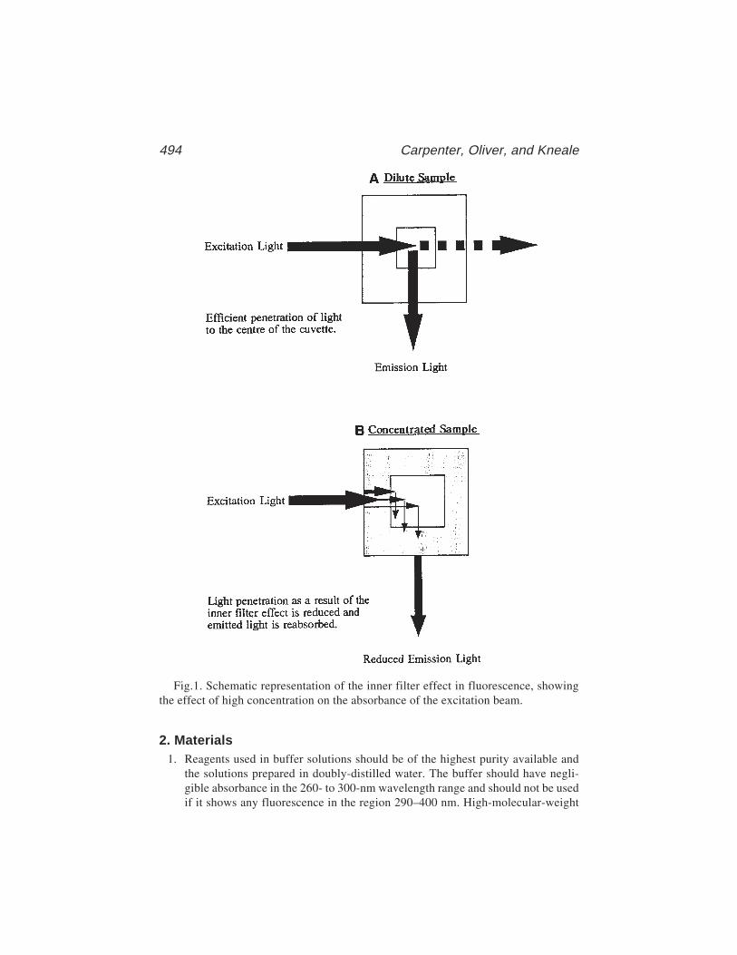
494 Carpenter, Oliver, and Kneale
2. Materials1. Reagents used in buffer solutions should be of the highest purity available and
the solutions prepared in doubly-distilled water. The buffer should have negli-gible absorbance in the 260- to 300-nm wavelength range and should not be usedif it shows any fluorescence in the region 290–400 nm. High-molecular-weight
Fig.1. Schematic representation of the inner filter effect in fluorescence, showingthe effect of high concentration on the absorbance of the excitation beam.
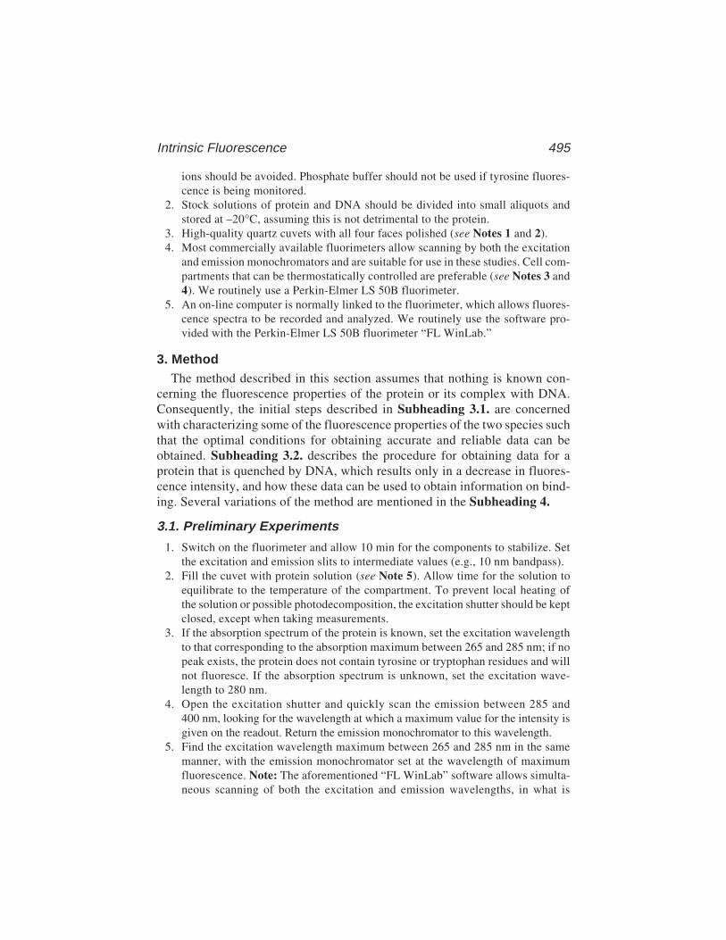
Intrinsic Fluorescence 495
ions should be avoided. Phosphate buffer should not be used if tyrosine fluores-cence is being monitored.
2. Stock solutions of protein and DNA should be divided into small aliquots andstored at –20°C, assuming this is not detrimental to the protein.
3. High-quality quartz cuvets with all four faces polished (see Notes 1 and 2).4. Most commercially available fluorimeters allow scanning by both the excitation
and emission monochromators and are suitable for use in these studies. Cell com-partments that can be thermostatically controlled are preferable (see Notes 3 and4). We routinely use a Perkin-Elmer LS 50B fluorimeter.
5. An on-line computer is normally linked to the fluorimeter, which allows fluores-cence spectra to be recorded and analyzed. We routinely use the software pro-vided with the Perkin-Elmer LS 50B fluorimeter “FL WinLab.”
3. MethodThe method described in this section assumes that nothing is known con-
cerning the fluorescence properties of the protein or its complex with DNA.Consequently, the initial steps described in Subheading 3.1. are concernedwith characterizing some of the fluorescence properties of the two species suchthat the optimal conditions for obtaining accurate and reliable data can beobtained. Subheading 3.2. describes the procedure for obtaining data for aprotein that is quenched by DNA, which results only in a decrease in fluores-cence intensity, and how these data can be used to obtain information on bind-ing. Several variations of the method are mentioned in the Subheading 4.
3.1. Preliminary Experiments
1. Switch on the fluorimeter and allow 10 min for the components to stabilize. Setthe excitation and emission slits to intermediate values (e.g., 10 nm bandpass).
2. Fill the cuvet with protein solution (see Note 5). Allow time for the solution toequilibrate to the temperature of the compartment. To prevent local heating ofthe solution or possible photodecomposition, the excitation shutter should be keptclosed, except when taking measurements.
3. If the absorption spectrum of the protein is known, set the excitation wavelengthto that corresponding to the absorption maximum between 265 and 285 nm; if nopeak exists, the protein does not contain tyrosine or tryptophan residues and willnot fluoresce. If the absorption spectrum is unknown, set the excitation wave-length to 280 nm.
4. Open the excitation shutter and quickly scan the emission between 285 and400 nm, looking for the wavelength at which a maximum value for the intensity isgiven on the readout. Return the emission monochromator to this wavelength.
5. Find the excitation wavelength maximum between 265 and 285 nm in the samemanner, with the emission monochromator set at the wavelength of maximumfluorescence. Note: The aforementioned “FL WinLab” software allows simulta-neous scanning of both the excitation and emission wavelengths, in what is

496 Carpenter, Oliver, and Kneale
termed a “3D” scan. This allows both the excitation and emission maxima to bedetermined in one experiment. However, for proteins, this is not normally necessary.
6. With both the excitation and emission wavelengths set at their peak values, adjustthe instrument to give a reading corresponding to about 90% of the full scale.Narrow slit widths and a lower amplification (expansion factor, gain) are pre-ferred and a compromise between the two may have to be found (see Note 6).
7. Determine the emission spectrum by scanning the emission monochromator overthe entire wavelength range over which fluorescence occurs. A scan speed of60 nm/min is generally suitable.
8. Add a small aliquot of a concentrated DNA solution to the cuvet such that theconcentration of DNA is in excess. Mix and immediately check the fluorescenceemission at the emission maximum of the protein. Check several times overthe next few min until a consistent reading is obtained. Allow this time for equili-bration in subsequent experiments. Do not adjust slit widths or the amplication.
9. Obtain an emission spectrum and compare with that obtained for the protein only.If fluorescence quenching is suspected, make sure that allowance for sampledilution has been made. If an inner filter correction is required, measure theabsorbance of the sample in a spectrophotometer (in the same cuvet) and correctthe observed fluorescence as discussed in Subheading 1.
10. Add aliquots of DNA until there is no further change in fluorescence intensity inthe emission spectrum (see Notes 7 and 8).
3.2. Protein-DNA Titrations1. Examine the emission spectrum of the free protein. If it is characteristic of
tyrosine fluorescence, check for interference from the Raman band (see Note 9).If it is characteristic of tryptophanlike, check for tyrosine contributions thatmay be masked (see Note 10).
2. Examine the emission spectrum of the protein bound to DNA. The titrationmethod described in the following passage is particularly applicable when theonly change in the spectrum is a change in fluorescence intensity. Several varia-tions of this method are described briefly in Notes 11 and 12 including an examplewhere the emission spectrum of the protein shifts on binding DNA.
3. Accurately determine the concentration of protein and DNA solutions by UVspectroscopy. Because we are titrating DNA into protein, try to use a stock con-centration of DNA, which is at least 20 times the concentration of protein used inthe experiment multiplied by the estimated stoichiometric ratio; for example, ifthe protein concentration used is 10 µM and the estimated stoichiometry is 5bases per protein, then the DNA concentration should be at least 20 × 10 µM × 5= 1000 µM (1 µM). This would mean that the dilution of the original proteinsolution will be only 5% at the stoichiometric point.
4. Using the protein solution set up the instrument as described in steps 1–6 of Sub-heading 3.1. If measuring tyrosine fluorescence, use an excitation wavelength nearthe maximum. This wavelength can also be used for tryptophan excitation if tyrosinefluorescence is insignificant, otherwise use an excitation wavelength of 295 nm.

Intrinsic Fluorescence 497
5. Run a buffer blank and check that the profile of the emission spectrum is consis-tent with that previously obtained. Subtract this spectrum from subsequent spec-tra if this can be done automatically.
6. Set the emission monochromator to the emission wavelength maximum andensure that the readout is about 90% of its maximum value. Note the value.
7. To begin the titration, add a small aliquot from the stock DNA solution to theprotein in the cuvet. Mix and allow the sample to equilibrate (use the time perioddetermined earlier) before taking a reading. The aliquots should be sufficientlysmall such that the protein is still greatly in excess and a linear change is observedas more DNA is added.
8. Continue to add the same quantity of DNA for 8–10 points. If changes are stillapproximately linear at this stage, gradually increase the volume of the DNAadded, noting the total amount added at each point.
9. When the change in intensity begins to deviate significantly from linearity,decrease the size of the aliquot so that more data points are obtained in this region.
10. As quenching approaches the maximum, larger aliquots of DNA can be added.Continue until no change in quenching is observed for several points.
11. After the last point, check that the emission spectrum of the complex is consis-tent with that previously obtained for the bound protein.
12. Remove the sample, wash the cuvet thoroughly, and run a blank spectrumconsisting of cell plus buffer. This should have negligible or no fluorescence.Subtract any value at the emission wavelength maximum from the data points, ifnot already done automatically (see Note 9).
13. For each data point, calculate the fluorescence quenching (Q= 100 [F0–F]/F0 ,where F is the measured fluorescence and F0 is the fluorescence in the absence ofDNA), having made any corrections for inner filter effects and dilution of thesample. Also calculate the nucleotide concentration at each point (N = ny/[n + x],where n is the total volume of DNA added up until that point, x is the initialvolume of sample in the cuvet and y is the molar concentration of DNA stocksolution). From the DNA concentration, calculate R, which is the ratio of theconcentration of DNA to that of protein. (For polynucleotides, it is usual toexpress N as the concentration of nucleotides; for short synthetic duplexes, it ismore usual to use the molar concentration of the duplex).
14. Plot a graph of Q against R (or N). If only one mode of binding is occurring, thegraph should look like one of the curves shown in Fig. 2. If the “break point” inthe titration is sharp, it indicates a high value for the binding constant (i.e., asmall dissociation constant compared with the protein concentration used). Con-versely, too weak a binding constant (or too dilute a protein solution) will giverise to a smoothly rising curve with no apparent break point.
15. The stoichiometry of binding is the value of R at which the slope obtained fromthe initial linear range of the titration crosses the horizontal line defined by Qmax,at which no further change in intensity occurs.
16. Further information can be extracted from the binding curve by fitting it to anappropriate model. In the simplest case of a bimolecular interaction (P + N =
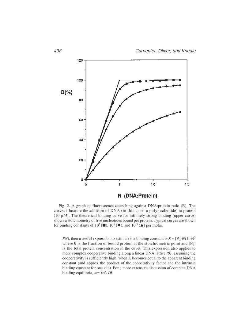
498 Carpenter, Oliver, and Kneale
PN), then a useful expression to estimate the binding constant is K = [P0]θ/(1–θ)2
where θ is the fraction of bound protein at the stoichiometric point and [P0]is the total protein concentration in the cuvet. This expression also applies tomore complex cooperative binding along a linear DNA lattice (9), assuming thecooperativity is sufficiently high, when K becomes equal to the apparent bindingconstant (and approx the product of the cooperativity factor and the intrinsicbinding constant for one site). For a more extensive discussion of complex DNAbinding equilibria, see ref. 10.
Fig. 2. A graph of fluorescence quenching against DNA:protein ratio (R). Thecurves illustrate the addition of DNA (in this case, a polynucleotide) to protein(10 µM). The theoretical binding curve for infinitely strong binding (upper curve)shows a stoichiometry of five nucleotides bound per protein. Typical curves are shownfor binding constants of 107 (), 106 (), and 10 5 () per molar.
Intrinsic Fluorescence 499
4. Notes1. Most fluorimeter cell compartments are designed to take cuvets with a 1-cm
pathlength (distance between opposite faces) and usually require 2.5–3.0 cm3 ofsample for measurements. If smaller sample volumes are required, then reducedvolume cuvets similar to those used in absorption studies but suitable for fluores-cence work can usually be obtained from most cuvet suppliers. Also, most sup-pliers are prepared to construct cuvets to your own specifications (at a cost). Themajor requirement is that the sample be located in the center of the cell (assum-ing standard right-angle observation). Cuvets holding as little as 300 µL havebeen successfully used by the authors.
2. Care should be taken when handling fluorescence cuvets, as both fingerprintsand scratches can introduce significant artifacts into the experiment. After use,cuvets should be thoroughly washed with distilled water and a mild detergent, ifnecessary. If greatly contaminated, then immerse the cells in a 50:50 mix of ethanolwith sulfuric acid (4 M) for several hours and then rinse thoroughly with water.
3. If the fluorimeter is not equipped with a magnetic stirrer unit, adequate mixingcan usually be achieved by gently drawing the solution in and out through a plas-tic pipet tip. Avoid introducing bubbles into the sample, as this can both denaturethe protein and cause light scattering. For accurate measurements, temperaturecontrol is essential, as fluorescence is highly sensitive to temperature.
4. If the use of a reduced-volume cell prevents the use of commercially availablemagnetic fleas, then substitutes can be made as follows: (1) Seal the narrow endof a Pasteur pipet or micropipet by heating it in the flame of a Bunsen burner. (2)Insert a small length of iron wire (cut up a paperclip) and shake it down to thesealed end. (3) Cut the pipet just above the wire using a glass cutter and seal theopen end in the flame. These fleas should only be used once, as some rustingoccurs with time.
5. Fluorescence intensity is only proportional to concentration when the absorbanceis no greater than 0.1 absorbance units at the excitation wavelength selected. If amolar extinction coefficient for the protein is known, use this to calculate a suit-able protein concentration. Remember that the absorption bands for proteins andnucleic acids overlap, and in titrations, the contribution of the nucleic acid to theoverall absorption must be considered.
6. Although it is preferable to have narrow excitation and emission slit widths and alow amplification factor, there may be a need to compromise in order to obtain astable reading. For proteins displaying tyrosine fluorescence, the small wave-length difference between the excitation and emission maxima suggests that itwould be better to maintain narrow slits and increase the signal amplification.For proteins dominated by tryptophan fluorescence, the greater the differencebetween the excitation and emission wavelengths, the greater the feasibility ofincreasing the slit widths and maintaining a lower amplification. In general, whenmeasuring emission spectra, it is better to use a narrow emission slit width andwiden the excitation slit width. For broad-banded spectra such as that seen withtryptophan, both slits can be widened.
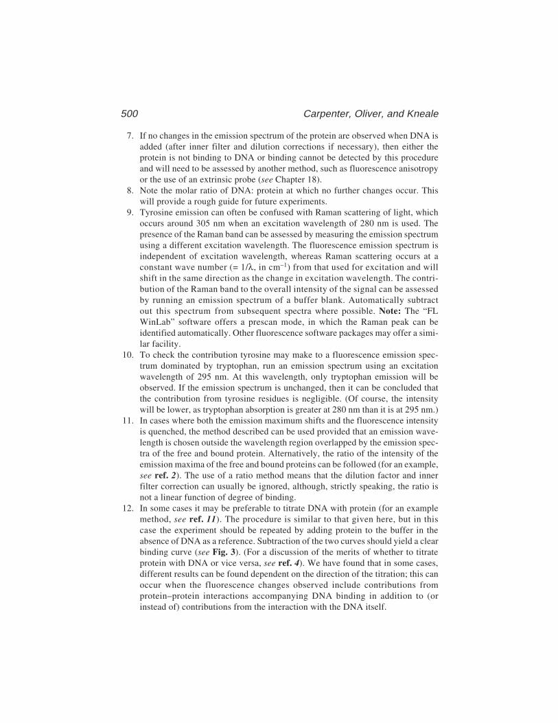
500 Carpenter, Oliver, and Kneale
7. If no changes in the emission spectrum of the protein are observed when DNA isadded (after inner filter and dilution corrections if necessary), then either theprotein is not binding to DNA or binding cannot be detected by this procedureand will need to be assessed by another method, such as fluorescence anisotropyor the use of an extrinsic probe (see Chapter 18).
8. Note the molar ratio of DNA: protein at which no further changes occur. Thiswill provide a rough guide for future experiments.
9. Tyrosine emission can often be confused with Raman scattering of light, whichoccurs around 305 nm when an excitation wavelength of 280 nm is used. Thepresence of the Raman band can be assessed by measuring the emission spectrumusing a different excitation wavelength. The fluorescence emission spectrum isindependent of excitation wavelength, whereas Raman scattering occurs at aconstant wave number (= 1/λ, in cm–1) from that used for excitation and willshift in the same direction as the change in excitation wavelength. The contri-bution of the Raman band to the overall intensity of the signal can be assessedby running an emission spectrum of a buffer blank. Automatically subtractout this spectrum from subsequent spectra where possible. Note: The “FLWinLab” software offers a prescan mode, in which the Raman peak can beidentified automatically. Other fluorescence software packages may offer a simi-lar facility.
10. To check the contribution tyrosine may make to a fluorescence emission spec-trum dominated by tryptophan, run an emission spectrum using an excitationwavelength of 295 nm. At this wavelength, only tryptophan emission will beobserved. If the emission spectrum is unchanged, then it can be concluded thatthe contribution from tyrosine residues is negligible. (Of course, the intensitywill be lower, as tryptophan absorption is greater at 280 nm than it is at 295 nm.)
11. In cases where both the emission maximum shifts and the fluorescence intensityis quenched, the method described can be used provided that an emission wave-length is chosen outside the wavelength region overlapped by the emission spec-tra of the free and bound protein. Alternatively, the ratio of the intensity of theemission maxima of the free and bound proteins can be followed (for an example,see ref. 2). The use of a ratio method means that the dilution factor and innerfilter correction can usually be ignored, although, strictly speaking, the ratio isnot a linear function of degree of binding.
12. In some cases it may be preferable to titrate DNA with protein (for an examplemethod, see ref. 11). The procedure is similar to that given here, but in thiscase the experiment should be repeated by adding protein to the buffer in theabsence of DNA as a reference. Subtraction of the two curves should yield a clearbinding curve (see Fig. 3). (For a discussion of the merits of whether to titrateprotein with DNA or vice versa, see ref. 4). We have found that in some cases,different results can be found dependent on the direction of the titration; this canoccur when the fluorescence changes observed include contributions fromprotein–protein interactions accompanying DNA binding in addition to (orinstead of) contributions from the interaction with the DNA itself.
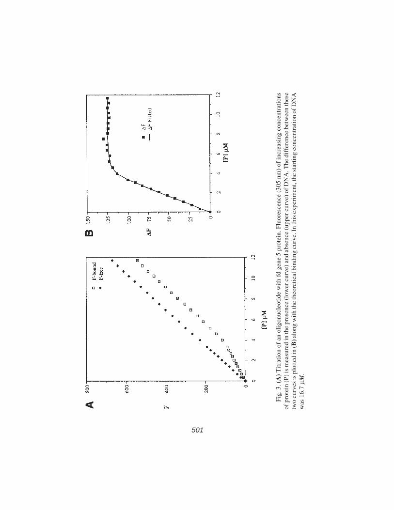
Intrinsic Fluorescence 501
Fig
. 3. (
A)
Tit
rati
on o
f an
oli
gonu
cleo
tide
wit
h fd
gen
e 5
prot
ein.
Flu
ores
cenc
e (3
05 n
m)
of in
crea
sing
con
cent
rati
ons
of p
rote
in (
P)
is m
easu
red
in th
e pr
esen
ce (
low
er c
urve
) an
d ab
senc
e (u
pper
cur
ve)
of D
NA
. The
dif
fere
nce
betw
een
thes
etw
o cu
rves
is p
lott
ed in
(B) a
long
wit
h th
e th
eore
tica
l bin
ding
cur
ve. I
n th
is e
xper
imen
t, th
e st
arti
ng c
once
ntra
tion
of D
NA
was
16.
7 µM
.
501
502 Carpenter, Oliver, and Kneale
References1. Harris, D. A. and Bashford, C. L. (eds.) (1987) Spectrophotometry and Spectro-
fluorimetry: A Practical Approach. IRL Press, Oxford, UK. (Chapters 1 and 4 areparticularly relevant.)
2. Kneale G. G. and Wijnaendts van Resandt, R. W. (1985) Time resolved fluores-cence of the Pf1 bacteriophage DNA-binding protein: determination of oligo- andpolynucleotide binding parameters. Eur. J. Biochem. 149, 85–93.
3. Birdsall, B., King, R. W., Wheeler, M. R., Lewis, C. A., Goode, S. R., Dunlap, R.B. et al. (1983) Anal. Biochem. 132, 353–361.
4. Carpenter, M. L. and Kneale, G. G. (1991) Circular dichroism and fluorescenceanalysis of the interaction of Pf1 gene 5 protein with poly(dT). J. Mol. Biol. 217,681–689.
5. Greulich, K. O., Wijnaendts van Resandt, R. W., and Kneale G. G (1985) Timeresolved fluorescence of bacteriophage Pf1 DNA-binding protein and its complexwith DNA. Eur. Biophys. J. 11, 195–201.
6. Mély, Y., de Rocquigny, H., Sorinas-Jimeno, M., Keith, G., Roques, B. P.,Marquet, R., et al. (1995) Binding of the HIV-1 nucleocapsid protein to the primertRNA3
Lys in vitro, is essentially not specific. J. Biol. Chem. 270, 1650–1656.7. Kim, C. and Wold, M. S. (1995) Recombinant human replication protein A binds
to polynucleotides with low cooperativity. Biochemistry 34, 2058–2064.8. Soengas, M. S., Mateo, C. R., Salas, M., Acuña, A. U., and Gutiérrez, C. (1997)
Structural features of φ29 single-stranded DNA-binding protein. J. Biol. Chem.272, 295–302.
9. Kelly, R. C., Jensen, D. E., and von Hippel, P. H. (1976) Fluorescence measure-ments of binding parameters for bacteriophage T4 gene 32 protein to mono-, oligo-, and polynucleotides. J. Biol. Chem. 251, 7240–7250.
10. McGhee, J. D. and von Hippel, P. H. (1974) Theoretical aspects of DNA–proteininteractions: cooperative and non-cooperative binding of large ligands to a one-dimensional homogeneous lattice. J. Mol. Biol. 86, 469–489.
11. Alma, N. C. M., Harmsen, B. J. M., de Jong, E. A. M., Ven, J. V. D., and Hilbers,C. W. (1983) Fluorescence studies of the complex formation between the gene 5protein of bacteriophage M13 and polynucleotides. J. Mol. Biol. 163, 47–62.
Circular Dichroism 503
503
From: Methods in Molecular Biology, vol. 148: DNA–Protein Interactions: Principles and Protocols, 2nd ed.Edited by: T. Moss © Humana Press Inc., Totowa, NJ
34
Circular Dichroism for the Analysisof Protein–DNA Interactions
Mark L. Carpenter, Anthony W. Oliver, and G. Geoff Kneale
1. IntroductionThe asymmetric carbon atoms present in the sugars of nucleotides and in all
the amino acids (with the exception of glycine) results in nucleic acids andproteins displaying optical activity. Further contributions to the optical activ-ity of the polymers result from their ability to form well-defined secondarystructures, in particular helices, which themselves possess asymmetry. As aconsequence, circular dichroism (CD) has found widespread use in secondarystructure prediction of proteins (1). Similar studies, though less widespread,have sought to correlate structural parameters of DNA with their CD spectrum(2), with some success particularly in assigning quaternary structures to nucleicacids (e.g., in the case of DNA triplexes and G-quartet mediated structures)(3,4). It follows that the disruption of secondary structure by, for example,denaturation or ligand binding can be usefully followed by circular dichroism.
Plane polarized light can be resolved into left- and right-handed circularlypolarized components. Circular dichroism measures the difference in theabsorption of these two components,
∆ε = εL – εR (1)
where ε is the molar extinction coefficient (M–1/cm–1) for the left (L) and right(R) components (see Note 1). When passing through an optically active sample,the plane of polarized light is also rotated, which means that the emergingbeam is elliptically polarized. Thus, CD is often expressed in terms of elliptic-ity (θλ, in degrees) or molar ellipticity ([θ]λ, in degrees cm2/dmol).
[θ]λ = 100 θλ/cl (2)

504 Carpenter, Oliver, and Kneale
where c is the molar concentration and l is the pathlength (in cm). The twoexpressions are interconvertible via the expression [θ]λ = 3300 ∆ε.
The overlap of the ultraviolet (UV) absorption bands of nucleic acids andproteins means that CD studies of protein–DNA interactions can be compli-cated by the contributions observed from both components. This is particularlytrue for wavelengths less than 250 nm. In practice, CD spectra between 250and 300 nm are dominated by that of the nucleic acid, the contribution arisingfrom the aromatic chromophores of the protein being weak by comparison.Changes in conformation can usually be attributed to the polynucleotide, as therandom distribution of aromatic amino acids means a large conformationalchange throughout the protein would be required to cause a significant changein the CD spectrum.
The low-molar ellipticity of polynucleotides means that for accurate CDmeasurements, high concentrations (10–4 M to 10 M) of nucleotide are required.For this reason, circular dichroism is not generally used to determine bindingconstants of protein–DNA interactions. However, circular dichroism can beused to obtain accurate values for the stoichiometry of protein–nucleic acidinteractions (5), and in the case of the bacteriophage, the fd gene 5 protein wasused to show the existence of two distinct binding modes (6). Circular dichro-ism has also been used to show that conformational changes induced by thebound Lac repressor are different for operator DNA and for random sequenceDNA (7). Similar studies on the Gal repressor demonstrated the involvementof the central G-C base pairs of the operator sequence in repressor-inducedconformational changes (8). Studies on the interaction of the cro protein ofbacteriophage λ have also revealed different conformational changes for specificand nonspecific DNA binding (9). Despite the apparent lack of any direct inter-action of the central base pair of the operator sequence with the cro protein, basesubstitution at this site was shown to affect the CD spectrum considerably.
Some additional examples in which CD has been used to examine protein–DNA interactions include the SRY-related protein Sox-5 (10), the type IC DNAmethyltransferase M. EcoR124I (11), and the bacteriophage Pf3 single-stranded DNA-binding protein (ssDBP) (12).
It should be emphasized that circular dichroism provides complementary data toother spectroscopic techniques such as fluorescence, because each technique canmonitor different components of the interaction. For this reason, even the apparentstoichiometry of binding estimated by each technique could be significantlydifferent despite it being measured under the same solution conditions (5).
2. Materials1. A high-quality quartz cell with low strain is required for accurate measurements.
The cell pathlength will depend on the absorption properties and concentration of
Circular Dichroism 505
the sample. Cells with pathlengths between 0.05 cm and 1 cm are often used,depending on the CD signal to be measured and the absorption of the sample(including the buffer). A pathlength of 1 cm is usually recommended for mea-surement of the DNA signal in the vicinity of 275 nm, where the signal is weakand buffer absorption is negligible.
2. Buffers should be prepared using high-quality reagents and water. Use buffersthat have low absorbance in the wavelength region of interest. Tris-HCl, perchlo-rate, and phosphate are routinely used.
3. Stock solutions of appropriate protein and nucleic acid solutions in the samebuffer. The protein should be as concentrated as possible to minimize dilutionduring the titration. If a synthetic DNA fragment containing the recognitionsequence is to be used, it should be close to the minimum size required for bind-ing to maximize the change in CD signal. To avoid denaturation and degradation,keep concentrated solutions of protein and DNA frozen in small aliquots, assum-ing it has been established that this procedure does not damage the protein.
4. A supply of dry nitrogen (oxygen free).5. (+)10-Camphor–sulfonic acid at a concentration of 0.5 mg/mL, used as a calibra-
tion standard. Check the accurate concentration by UV spectroscopy using amolar extinction coefficient of 34.5 at 285 nm (1).
6. A circular dichroism spectrometer (spectropolarimeter). We currently make useof a Jasco J720 spectrometer.
3. MethodsFor most proteins, there is only a weak signal from aromatic amino acids in
the region of the CD spectrum between 250 and 300 nm compared to that seenfor nucleic acids. Experiments involving the addition of protein can thus beconveniently carried out in this wavelength range, as described in the follow-ing. Below 250 nm, both proteins and DNA have optical activity and anyexperiments here may require resolution of the spectrum into protein and DNAcomponents (see ref. 13 for an example of where a mutant protein has beenused to assign and interpret overlapping CD bands).
1. To prevent damage to the optics, flush the instrument with nitrogen for 10–15 minbefore switching on the lamp. Continue to purge the instrument for the duration ofthe experiment (see Note 2).
2. Switch on the lamp and allow the instrument to stabilize for 30 min before mak-ing any measurements.
3. While waiting for the instrument to warm up, measure the UV spectrum ofboth the DNA and protein and calculate the concentration of the stock solu-tions from their extinction coefficients. The stock solution of protein should beas high a concentration as possible, to minimize corrections for dilution in subse-quent titrations.
4. Measure the UV absorbance of the cell to be used in the CD experiment againstan air blank (see Note 3).
506 Carpenter, Oliver, and Kneale
5. Using the data from steps 3 and 4, determine the concentrations of DNA andprotein that can be used in the experiment such that the total absorbance of allcomponents including the cell is <1.0.
6. Once the CD instrument has warmed up, use a 1-cm cell filled with water todetermine the baseline spectrum between 250 and 320 nm (see Note 4). Thisshould be flat.
7. Calibrate the instrument by replacing the water with the previously preparedsolution of camphor sulfonic acid and measure the CD between 250 and 320 nm.A 0.5-mg/mL solution in a 1-cm pathlength cell has ellipticity of 168 mdeg at290.5 nm.
8. Take the cell set aside for the experiment and fill with buffer. Place the cell in theinstrument, taking care to note the orientation of its faces in the beam. If using acylindrical cell, place it so that the neck of the cell rests against the side of thecell holder. Run a baseline spectrum between 250 and 320 nm.
9. Replace the buffer with the DNA solution and run the spectrum under the sameconditions. If you remove the cell to do this, remember to place the cell back inthe holder with the same face toward the light source.
10. Accurately pipet a small aliquot of the stock protein solution into the DNA in thecell and mix. Allow time for equilibration and measure the CD spectrum. Thevolume of the protein solution added will be determined by its concentration,the DNA concentration in the cuvet, and a rough idea of the expected stoichiom-etry. For initial experiments, the molar quantity of protein added at each stepshould be perhaps 10% of that of the DNA.
11. Repeat the addition of protein to the DNA until no further changes in the CDare observed.
12. Thoroughly wash the cell and refill with buffer. Rerun the baseline spectrum. Ifthe baseline has drifted from its initial value, this will have to be consideredwhen analyzing your results. If drifting is severe, see Note 5.
13. The collected data will need to be processed (i.e., to remove the CD signal due tobuffer components and/or to correct baseline values) (see Note 6.)
14. Plot the measured CD parameter at a particular wavelength against the concen-tration of protein added. The stoichiometry can be determined from the point atwhich a line drawn along the initial slope intersects that of the titration end point,which should be horizontal assuming dilution (if significant) has been correctedfor (see Fig. 1).
15. Once the spectral changes and stoichiometry have been established, it is oftenuseful to repeat the experiment with rather more titration points, using smaller
Fig. 1. (opposite page) Circular dichroism titrations of Pf1 gene 5 protein to polydT. In this example, the protein is a single-stranded DNA-binding protein that bindscooperatively to DNA with little sequence preference. (A) Successive CD spectraduring the titration of poly dT with Pf1 gene 5 protein. The top curve corresponds tofree DNA; below are increasing concentrations of protein corresponding to molarratios of nucleotide to protein of 19.2, 6.7 and 4.0 (which represents saturation).
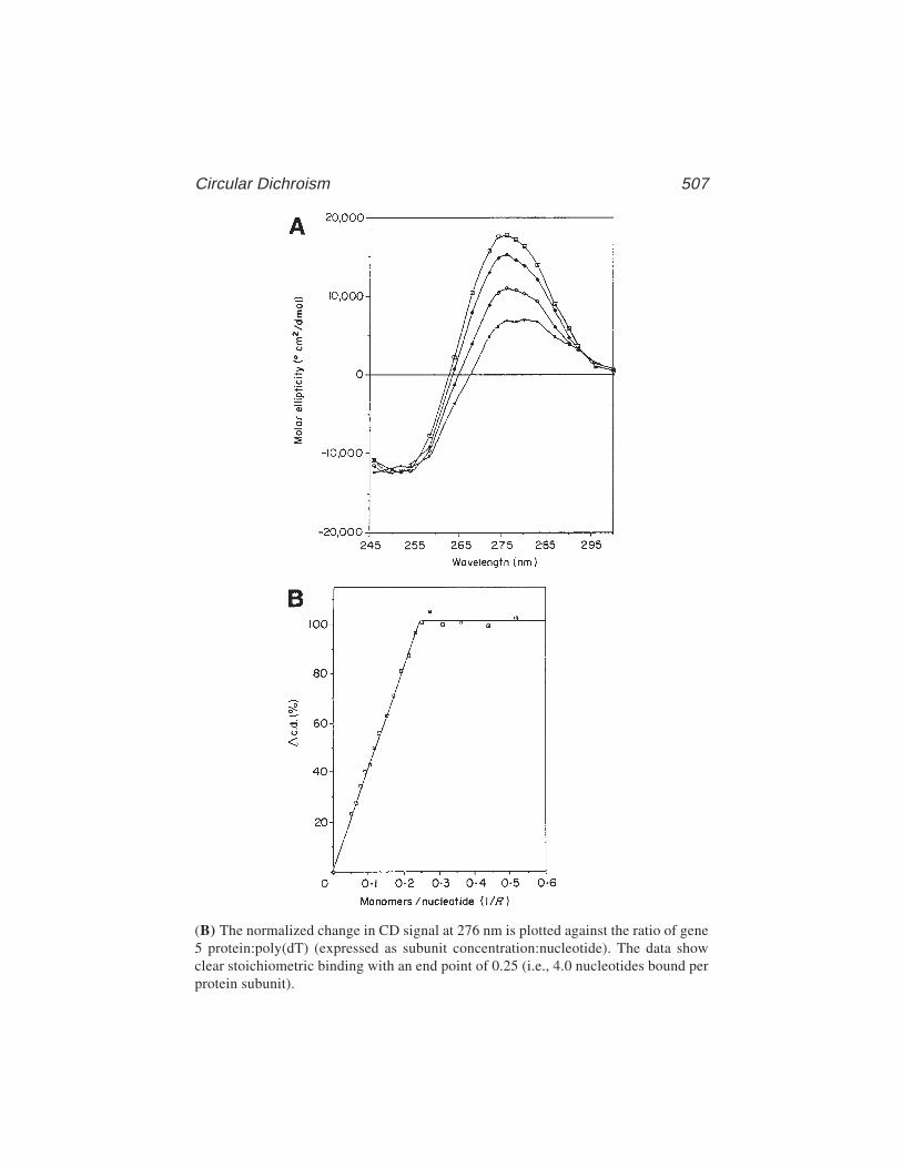
Circular Dichroism 507
(B) The normalized change in CD signal at 276 nm is plotted against the ratio of gene5 protein:poly(dT) (expressed as subunit concentration:nucleotide). The data showclear stoichiometric binding with an end point of 0.25 (i.e., 4.0 nucleotides bound perprotein subunit).
508 Carpenter, Oliver, and Kneale
aliquots of protein. This can be done at a single wavelength, without the need forscanning. Although the maximum CD signal from DNA is normally obtainedaround 275 nm, one should work at the wavelength that corresponds to the larg-est difference between free and bound DNA, which may well be different.
The CD spectrum of the DNA at saturation can be used to assess conforma-tional changes that result from protein binding to a given sequence. Althoughanalysis of the spectrum in terms of molecular structure is not straightforward(2), it may be possible to interpret CD spectra of double-stranded DNA in termsof changes in helical twist angle (underwinding or overwinding of the helix).The spectral changes that accompany protein binding to different DNAsequences or with a variety of cofactors can also be informative.
4. Notes1. For proteins and polynucleotides, molarity is sometimes expressed in terms of
moles of amino acid or nucleotide residue respectively for such calculations.2. High-intensity UV radiation converts oxygen to ozone, which damages the optics.
Failure to purge will lead to deterioration in instrument performance.3. For most experiments at these wavelengths, cells with pathlengths of 0.5 cm
or 1 cm can usually be used. Longer-pathlength cells for work with more dilutesolutions are available at a price.
4. A number of instrument parameters will normally need to be set before spectracan be recorded. For the Jasco J-700 series, these typically include slit width, CDscale, wavelength range, step resolution, scan speed, response time and numberof accumulations. Typically, the slit width is set to 1 nm, although for high-sen-sitivity (i.e., low CD signal) measurements, it can be increased to 2 nm (thusimproving the signal-to-noise ratio). The CD scale is set to reflect the expectedCD of the sample being measured (e.g., 0–50 mdeg). Similarly, the wavelengthrange is set to cover the region required for the experiment. We typically use astep resolution of 0.2 nm (which allows a maximum wavelength range of 400 nmto be covered) and a scan speed of between 20 and 100 nm/min. The responsetime is set in accordance with the scan speed (e.g., for a scan speed of 20 nm/min,
the response time is set to 2 s [for 100 nm/min an appropriate response timewould be 0.5 s]). It is advised that the manufacturer’s recommendations be fol-lowed when setting both scan speeds and response times, as the quality of thedata collected (in terms of the signal-to-noise ratio) can be adversely affected ifincorrect or incompatible settings are used. Between three and five accumula-tions are generally recorded (although more can be collected), the resulting aver-aged data offering an improvement in the CD signal-to-noise ratio.
5. If significant drifting of the baseline has occurred, the experiment may have to berepeated. To minimize the effect of drifting, use two cells, one as a baseline ref-erence and one containing sample. The baseline can then be standardized at eachpoint in the titration. Remember that when swapping cells, it is vitally importantto present the same section of the cell to the beam each time.
Circular Dichroism 509
6. The CD software supplied by Jasco allows simple calculations/derivations tobe performed with collected data (e.g., the subtraction of CD signal as a resultof the sample buffer, subtraction of a constant factor, or conversion betweenstandard units (millidegrees to molar ellipticity). If the signal-to-noise ratiois particularly problematic, data can also be treated with a number ofsmoothing or noise reduction functions; although if the data collectionparameters are correctly set up and the sample is at a sufficient concentration,these procedures should not be necessary. A further useful function of theJasco CD software allows the collected data to be “dumped” and importedinto other software packages (e.g., Microsoft Excel or other spreadsheet/graphing packages, which may be more familiar to the user).
References1. Johnson, W. C., Jr. (1990) Protein secondary structure and circular dichroism: a
practical guide. PROTEINS: Struct. Funct. Genet. 7, 205–214.2. Johnson, B. B., Dakl, K. S., Tinoco, I., Jr., Ivanov, V. I., and Zhurkin, V. B.
(1981) Correlations between deoxyribonucleic acid structural parameters and cal-culated circular dichroism spectra. Biochemistry 20, 73–78.
3. Gray, D. M., Hung, S. H., and Johnson, K. H. (1995) Absorption and circulardichroism spectroscopy of nucleic acid duplexes and triplexes. Methods Enzymol.246, 19–34.
4. Hardin, C. C., Henderson, E., Watson, T., and Prosser, J. K. (1991) Monovalentcation induced structural transitions in telomeric DNAs: G-DNA folding interme-diates. Biochemistry 30, 4460–4472.
5. Carpenter, M. L. and Kneale, G. G. (1991) Circular dichroism and fluorescenceanalysis of the interaction of Pf1 gene 5 protein with poly(dT). J. Mol. Biol. 27,681–689 .
6. Kansy, J. W., Cluck, B. A., and Gray, D. M. (1986) The binding of fd gene 5protein to polydeoxyribonucleotides: evidence from CD measurements for twobinding modes. J. Biomol. Struct. Dynam. 3, 1079–1110.
7. Culard, F. and Maurizot, J. C. (1981) Lac repressor–lac operator interaction.Circular dichroism study. Nucleic Acids Res. 9, 5175–5184.
8. Wartell, R. M. and Adhya, S. (1988) DNA conformational change in Gal repres-sor–operator complex: involvement of central G-C base pair(s) of dyad symme-try. Nucleic Acids Res. 16, 11,531–11,541.
9. Torigoe, C., Kidokoro, S., Takimoto, M., Kyoyoku, Y., and Wada, A. (1991)Spectroscopic studies on lambda cro protein–DNA interactions. J. Mol. Biol. 219,733–746.
10. Connor, F., Cary, D., Read, C., Preston, N. S., Driscoll, P. C., Denny, P., et al.(1994) DNA binding and bending properties of the post-meiotically expressedSry-related protein Sox–5. Nucleic Acids Res. 22, 3339–3346.
11. Taylor, I. A., Davis, K. G., Watts, D., and Kneale, G. G. (1994) DNA bindinginduces a major structural transition in a type I methyltransferase. EMBO J. 13,5772–5778.

510 Carpenter, Oliver, and Kneale
12. Powell, M. D. and Gray, D. M. (1995) Role of Tyr-22 in the binding of Pf3 ssDNAbinding proteins to nucleic acids. Biochemistry 34, 5635–5643.
13. Mark, B. L. and Gray, D. M. (1997) Tyrosine mutant helps define overlapping CDbands from fd gene 5 protein–nucleic acid complexes. Biopolymers 42, 337–348.
General Reading1. Bayley, P. M. (1973) The analysis of circular dichroism of biomolecules. Prog.
Biophys. 27, 1–76.2. Bush, C. A. (1974) Ultraviolet spectroscopy, circular dichroism and optical rota-
tory dispersion, in Basic Principles in Nucleic Acid Chemistry, vol. 2 (Ts’O,P.O.P., ed.), Academic, New York, pp. 91–169.
3. Drake, A. F. (1994) Circular dichroism. Methods Mol. Biol. 22, 219–44.4. Gratzer, W. B. (1971) Optical rotatory dispersion and circular dichroism of nucleic
acids, in Procedures in Nucleic Acid Research, vol. 2 (Cantoni G. L. and DaviesD. R., eds.), Harper and Row, New York, pp. 3–30.
5. Woody, R. W. (1995) Circular dichroism. Methods Enzymol. 246, 34–71.
Calorimetry of Protein–DNA Complexes 511
511
From: Methods in Molecular Biology, vol. 148: DNA–Protein Interactions: Principles and Protocols, 2nd ed.Edited by: T. Moss © Humana Press Inc., Totowa, NJ
35
Calorimetry of Protein-DNA Complexesand Their Components
Christopher M. Read and Ilian Jelesarov
1. IntroductionThe many detailed, though static, structures of protein–nucleic acid com-
plexes have revealed the underlying structural determinants of the binding pro-cess: a high surface complementarity and a precise orientation of interactinggroups. However, another important question not yet fully answered is why themolecules interact with each other. To answer such a question means that wehave to rationalize a structure energetically. This requires a deconvolution ofthe relatively large negative value of the free energy of association (∆G) intoits enthalpic (∆H) and entropic (∆S) contributions. Only then can one appreci-ate the true nature of the forces that drive the interaction of protein and nucleicacid. Despite some promising theoretical developments and the steady accu-mulation of experimental data, the deconvolution of ∆G into its componentsremains a difficult task
Proteins and nucleic acids behave cooperatively and often undergo struc-tural rearrangements on associating. These changes range from subtle adjust-ments of dihedral angles to rearrangements in the orientation of domains andeven the refolding of entire binding domains. Many DNA-binding domains areeither very flexible or partly unstructured or even fully unfolded in isolationand become folded only when bound to the specific DNA target site (1). TheDNA itself sometimes undergoes large structural deformation upon complexformation (2–5). In energetic terms, the view that binding specificity is simplythe accumulation of specific favorable interactions between rigid binding part-ners no longer holds and conformational changes in the two components aswell as solvent rearrangement in the binding site play an important role. Thus,

512 Read and Jelesarov
there is a complicated energetic profile involving changes in ∆G, ∆H, and ∆Son going from the free components to the final complex.
This chapter focuses on the practical aspects of measuring the energetics ofbinding of DNA-binding domains to short DNA duplexes. As an example, wewill consider the HMG domain of mouse Sox-5, hereafter referred to as justSox-5, as it illustrates the importance of structural changes that accompanycomplex formation (6). HMG domains contain three α-helices arranged intoan L-shaped fold. Nuclear magnetic resonance (NMR) derived structures ofthe HMG domain of human SRY bound to an 8-bp DNA duplex (4) as well asthe HMG domain of mouse LEF-1 complexed to 15 bp DNA (5) show that thedomain binds almost exclusively into a widened minor DNA groove. A largebend with considerable base unstacking is introduced into the DNA, in part asa result of the partial intercalation of an amino acid side chain (Ile in SRY andMet in LEF-1).
The interacting components, the free Sox-5 protein and the DNA duplexeshave been examined and both structures are seen to depend significantly ontemperature (7,8). A practical problem then arises because the temperaturedependence of the enthalpy of binding, as measured by isothermal titrationcalorimetry (ITC), can no longer be interpreted as being solely the result of aunique heat capacity increment, ∆Cp. As a result, the energetics of complexformation require a thorough understanding of the energetics of the free com-ponents (i.e., the study of the heat capacity Cp, of the complex, and its freecomponents over a broad temperature range) as can be directly obtained bydifferential scanning calorimetry (DSC). We thus wish to emphasize that forthe study of the energetics of protein–nucleic acid complexes the combineduse of ITC and DSC is necessary, because the DSC data are essential to correctthe data obtained by ITC.
1.1. The Energetics of Biomolecular Interaction
To characterize the thermodynamics of a binding reaction, it is necessary todetermine the association free energy ∆G and its enthalpic and entropic com-ponents, ∆H and ∆S, at a given reference temperature. The heat capacity incre-ment on binding, ∆Cp, is required to predict the change of the above threequantities with temperature, according to the general thermodynamic relation-ships. Values for ∆G, ∆H, and ∆S may then be obtained at temperatures thatare experimentally inaccessible. Furthermore, ∆Cp is a fundamental thermody-namic quantity and contains important structural information. For example, ithas been shown that ∆Cp changes with the proportion and chemical propertiesof the molecular surface buried at the binding site (9,10).
∆G is accessible through different types of binding experiments because itis related to the association constant, KA, by ∆G = –RTlnKA, where R is the gas

Calorimetry of Protein–DNA Complexes 513
constant and T is the absolute temperature. For the simple equilibrium describ-ing the interaction of protein P with DNA, D:
P + D ⇔ PD then KA =[PD]
(1)[P][D]
Techniques such as equilibrium dialysis, ultracentrifugation, the gel-shift,or radio-ligand binding assays yield direct values for [P], [D], and [PD] and,therefore, values for KA and ∆G at any fixed temperature. More indirect, mostlyspectroscopic, methods allow the construction of a binding isotherm in termsof the degree of saturation, Y:
Y =∆pi
=[PD]
=K
A[P]
(2)∆pmax [D] + [PD] 1 + K
A[P]
where ∆pi is the signal change obtained at some particular addition of P to aconstant amount of D and ∆pmax is the maximal signal change at full saturation(Y = 1). If the experiment is repeated at different temperatures, KA(T) and ∆G(T)are obtained. ∆H(T) and ∆S(T) can be derived from the integrated form of thevan Hoff equation. Further, the s derivative of ∆G(T) with respect to tempera-ture yields ∆Cp. This noncalorimetric analysis of binding data (sometimesreferred to as a van Hoff analysis) can be flawed. First, the analysis assumes amodel, which may or may not be correct, to describe the interaction of thecomponents. Second, for technical reasons, experiments can be performed onlyover a limited temperature range and the experimental errors propagate intolarge errors in ∆H, ∆S, and especially ∆Cp when the extrapolation from thereference temperature to any other temperature is large.
1.2. The ITC Experiment
Modern mixing microcalorimeters allow precise measurements of theenthalpy of binding, ∆Happ, between 5°C and 80°C. The basic principle is thatone binding partner (protein, P) is titrated at a constant temperature into aknown amount of the other binding partner (DNA, D) placed in the sample cellof the calorimeter. Heat is produced or released when binding occurs. The instru-ment measures the electrical power (in units of J/s) required to maintain a smalltemperature difference between the sample cell and the reference cell, which isfilled with buffer. The contents of the sample cell are stirred to allow rapid mixingand effective heat transfer over the surface of the cell. If KA is high and the degreeof saturation is still low, electrical power peaks of similar magnitude appear inthe thermogram at each addition. Integration with respect to time yields theapparent heat change, ∆qi,app, between additions i and i–1 as ∆qi,app = qi – qi–1.
As the fractional saturation increases, ∆qi,app gradually decreases and even-tually all binding sites become saturated. Small nonspecific heat effects, ∆qi,ns
514 Read and Jelesarov
registered after complete saturation may be caused by the heat of proteindilution, an imperfect match between the buffer composition of the proteinsolution and the DNA solution, or by other nonspecific effects. ∆qi,app is pro-portional to the volume of the calorimetric cell, Vcell, to the change in concen-tration of the bound protein ∆[P]i,bound = [P]i,bound = [P]i–1,bound and to theapparent molar enthalpy of association ∆Happ. Thus,
∆qi,app = ∆qi + ∆qi,ns (3)= ∆[P]i,bound Vcell ∆Happ
∆Happ at temperature T may therefore be calculated because Vcell is known and∆qi,ns may be obtained from a blank titration of protein into buffer.
For the binding of protein, P, with n identical and noninteracting sites toDNA, D,
∆qi = ∆qi,app + ∆qi,ns (4)= nR Vcell ∆Happ
∆qi is the effective heat change caused by the formation of complex, PD, atthe ith step of the titration and R is the root of the quadratic equation
Yi2 – Yi (1 +
1 +
[P]i,total ) + n[P]i,total[D]total = 0 (5)nKA[D]total n[D]total
where the fractional saturation is defined by Yi = ∆[P]i,bound / [D]total. [P]i,total isthe total concentration of protein, P, added until injection, i. A nonlinearregression procedure based on Eq. 4 yields n, KA, and ∆Happ at temperature T,from a single titration experiment. More complicated systems with multipleand interacting sites require a statistical mechanical treatment of the data(11,12). ∆Cp,app the apparent heat capacity change of association can be calcu-lated from a plot of ∆Happ versus temperature, because in general, ∆Cp = ∆H / ∆T.
As in other binding experiments, the dissociation constant, KD (equal to 1/KA)can only be reliably measured over a narrow concentration range. If the con-centration of binding sites is much larger than KD, the binding isotherm is ofrectangular shape with a sharp step at saturation. In the case of the binding-siteconcentration being much smaller than KD, the binding isotherm is very shal-low and is of limited use for calculating the dissociation constant. In practice,values of the ratio of the binding-site concentration to KD that range between10 and 100 represent an optimal experimental window to obtain precise valuesof the dissociation constant. Unfortunately, this window is not always acces-sible to ITC. For very small KD values, the optimal concentrations are so lowthat the released heat is below the sensitivity of the instrument, the specificenthalpy of biomolecular interactions never being very large. For this reason,there is an effective lower limit to the ITC measurement of KD to values of
Calorimetry of Protein–DNA Complexes 515
approx 10–9 M (∆G about –50 kJ/mol). Alternatively, if KD is high, then veryhigh concentrations are required and the heat of binding may be obscured byaggregation effects.
The two types of ITC measurement are normally obtained under differentconditions. The procedure to obtain n, KA, and ∆Happ is best carried out as afull titration at concentrations near the stoichiometric point of the interaction(i.e., at a DNA concentration 10–100 times the estimated value for KD and withthe injection of up to a 2 M to 4 M excess of protein. However, the directmeasurement of ∆Happ is best carried out in conditions where the system isfully associated and the degree of saturation is low (i.e., at high DNA concen-trations (>1000KD) and with the injection of low amounts of protein). The totalnumber of moles of added protein is then much less than the number of molesof binding sites available and virtually all protein molecules are bound to DNA,such that ∆[P]i,bound approximately equals ∆[P]i,total. Each injection of protein,∆[P]i,total thus produces an approximately equal change in heat, ∆qi,app. If theoverall fractional saturation is still low after completion of a series of injec-tions, then the average may be taken and Eq. 3 becomes
m m1 ∑∆qi,app =1 ∑ (∆qi + ∆qi,ns) (6)
m i=1 m i=1
m=
1 ∑ (∆[P]i,bound + Vcell ∆Happ)m i=1
where m is the number of injections. If low amounts of protein are injected,aggregation effects and nonspecific binding are also minimized.
1.3. The DSC Experiment
In a DSC experiment, the heat capacity of a macromolecule is measured as afunction of temperature. Typically, two thermally insulated cells, a sample cellcontaining the macromolecule of interest in buffer and a reference cell contain-ing buffer, are electrically heated at a known rate. At a temperature-inducedtransition, which is typically endothermic, the temperature of the sample cellwill lag behind that of the reference cell. An electrical feedback mechanism isused to maintain the reference cell at the same temperature as the sample cell.This amount of compensatory electrical power (in units of J/s or Watts) attemperature T divided by the heating rate is the apparent difference in heat capac-ity between the cell containing the sample and the reference cell, ∆Cp,app(T) (inunits of J/K). Because the sample containing cell has a smaller volume fraction ofbuffer as compared to that in the reference cell, the partial molar heat capacity ofthe dissolved macromolecule Cp,f(T) at temperature T (J/mol/K) is given by
516 Read and Jelesarov
CTp,φ(T) =Cp,buffer (T)Vφ˚ M∆Cp,app (T)
(7)Vbuffer m
where Cp,buffer(T) and Vbuffer are the partial molar heat capacity and molar vol-ume of buffer, respectively. Vf˚ and M are the partial molar volume and themolar mass of the macromolecule, respectively, and m is the mass of macro-molecule in the sample cell.
The excess molar heat capacity function is the heat absorbed in the meltingtransition above that of the intrinsic heat capacity of the macromolecule. Inte-gration of the excess molar heat capacity function with respect to temperatureyields the enthalpy of the melting transition:
T2∆H = Cp(T)dT (8)
T1
The intrinsic heat capacity of the initial (folded) and final (unfolded) statesof the macromolecule must be estimated within the melting transition. Formonomeric proteins, the heat capacity of the folded state is an approximatelinear function of temperature (13,14) and the unfolded state is a shallow para-bolic function of temperature (13).
The relationship of the partial molar heat capacity to the excess molar heatcapacity functions are schematically shown in Fig. 1.
1.4. Preliminary Characterization of the Sox-5–DNA Interaction
It must be emphasized that the in vitro interaction of the protein with DNAmust be characterized prior to the calorimetry experiments. Preliminaryknowledge of the number of (independent) binding sites, the stoichiometry ofthe interaction, and the magnitude of the association constant are all requiredfor the optimal design of the ITC experiments (see Subheading 1.2.). For DSC,the experiments must be performed with a fully associated complex (at lowtemperature) and therefore at a concentration well above the estimated KD.Furthermore, the protein–DNA complex and its components need to be solubleat this concentration, even at raised temperatures, and all temperature-inducedconformational transitions must be fully reversible. Knowledge of the mode ofinteraction is also required to obtain van Hoff enthalpies from the DSC data.
Site-selection and DNAse I footprinting assays (Chapter 3) defined theSox-5 target sequence as 5’-AACAAT-3' within a DNAse I protected region ofapprox 14 nucleotides on both DNA strands (15,16). This determined thesequence and size of the DNA duplexes that were to be used. A circular permu-tation assay showed that the binding of Sox-5 to these duplexes was able tointroduce a DNA bend of similar magnitude to that obtained with the complete
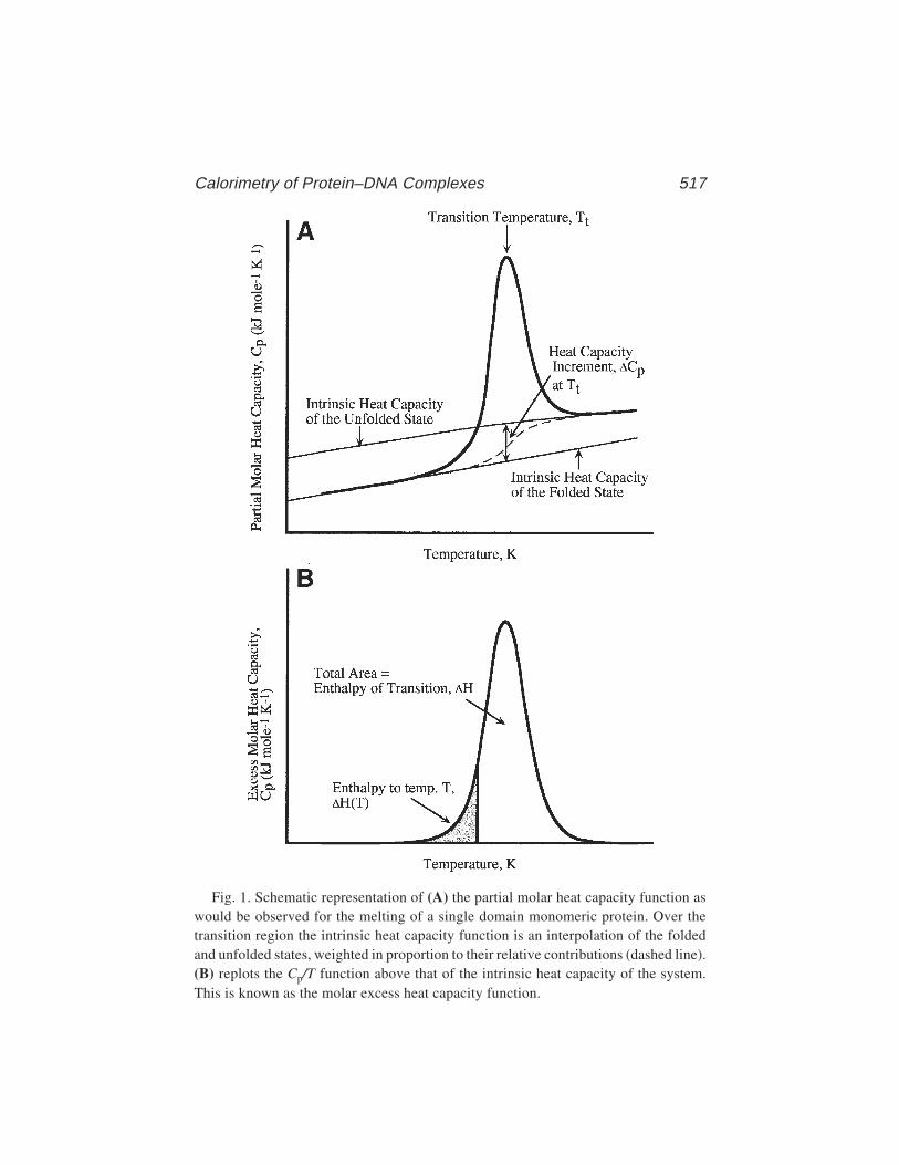
Calorimetry of Protein–DNA Complexes 517
Fig. 1. Schematic representation of (A) the partial molar heat capacity function aswould be observed for the melting of a single domain monomeric protein. Over thetransition region the intrinsic heat capacity function is an interpolation of the foldedand unfolded states, weighted in proportion to their relative contributions (dashed line).(B) replots the Cp/T function above that of the intrinsic heat capacity of the system.This is known as the molar excess heat capacity function.
518 Read and Jelesarov
Sox-5 protein (6,16). The dissociation constant and the stoichiometry of theSox-5–DNA interaction were determined from circular dichroism (CD) andgel-shift assays (Chapters 2 and 34):
1. The binding of Sox-5 to a 12-bp DNA duplex (10 µM) was followed by CD,monitoring the ellipticity of the positive DNA peak at 280 nm upon successiveadditions of the protein. The CD data were fitted to a 1:1 binding model with anestimated KD of lower than 100 nM (6). This same estimate was obtained at tem-peratures between 10°C and 37°C, suggesting no significant variation of bindingconstant with temperature.
2. A gel-shift assay using a radioactively labeled 12-bp DNA duplex (at 1 nM) wastitrated in molar excess with Sox-5 (6). This indicated that the primary bindingsite is characterized by a KD of about 35 nM at 4°C. No secondary protein bindingwas observed with <1 µM Sox-5.
These assays thus indicate a bimolecular interaction of Sox-5 with the DNA,with a single primary binding site characterized by a KD in the low nanomolarrange. Furthermore any secondary binding of Sox-5 to DNA, if present, musthave a KD of >10 µM (i.e., at least two orders greater than the primary bindingsite). Thus, for the DSC measurements, typically at a concentration of 100–500 µM complex, the preformed Sox-5–DNA complex is fully associated andthe effect of secondary binding is negligible.
Given the estimated KD value, the ITC measurement of a full binding iso-therm under optimal conditions requires a DNA concentration of betweenapprox 0.35 and 3.5 µM (see Subheading 1.2.). Preliminary titration experi-ments however showed only a small heat effect of association (a result of thetemperature dependency of ∆Happ which passes through zero at 17°C) and thepresence of a secondary binding event, with a large exothermic effect, aftersaturation of the primary binding site (Fig. 2). It was concluded that measure-ment of the entire binding isotherm was not possible by ITC.
However, conditions could be chosen that were optimal for the direct deter-mination of ∆Happ by ITC (i.e., total association at partial saturation (see Sub-heading 1.2.). At the chosen DNA concentration of 60 µM, total association ofinjected Sox-5 in an ITC experiment is achieved (the ratio of the DNA concen-tration to the estimated KD being approx 1700). The fractional molar saturationwas always kept lower than 0.5 to avoid any secondary binding effects. Becausehigh concentrations were to be used, the total heat effect was greater and moreeasily detectable, which meant that ∆Happ values could be accurately obtainedat temperatures close to 17°C.
Additional experiments included low-speed analytical ultracentrifugation atdifferent temperatures to demonstrate that the free Sox-5 is monomeric. Forthe free DNA, UV melting was performed as an initial check on its meltingtemperature and for two-state melting of the duplexes. UV melting of the

Calorimetry of Protein–DNA Complexes 519
Sox-5–DNA complex showed a single cooperative transition with a meltingtemperature above that of the free DNA.
Fig. 2. ITC titration experiment of Sox-5 into a 12-bp DNA duplex. (A) Fifteeninjections of 540 µM Sox-5 into 10 µM of 12-bp DNA at 9°C. The injection rate was5 µL in 8 s, with a time interval of 5 min between injections. (B) a plot of ∆Happ againstratio of Sox-5 to DNA showing the primary endothermic and secondary exothermicreactions that occur on either side of the stoichiometric point.

520 Read and Jelesarov
2. Materials2.1. Calorimeters
Isothermal titration calorimetry was performed on an OMEGA or MCS-ITCtitration calorimeter (MicroCal Inc., Northampton, MA). Technical details onthe construction of mixing microcalorimeters, their performance and sensitiv-ity, and on the theory of data analysis have been described elsewhere (17–20).
Differential scanning calorimetric experiments were usually carried out ona Nano-DSC calorimeter (Calorimetric Science Corp., Utah). The instrument’sperformance and data acquisition are detailed in ref. 21. In brief, the instru-ment operates over the temperature range –20°C to 130°C at any set heating/cooling rate. The sample and reference calorimetric cells are of approx 900 µLvolume. Control of the calorimeter and scan acquisition is achieved via thesupplied DSC_Acquisition program running on a PC computer connected tothe calorimeter. In experiments in which the amount of sample was limiting, anew version of the Nano-DSC calorimeter having cells of approx 300 µL vol-ume was used.
2.2. Reagents and Solutions
2.2.1. Calorimetry
1. For calorimetric experiments, it is important to ensure that the protein and DNAsamples are homogeneous, because even a few percent of contaminating speciesmight cause significant heat effects. Homogeneity of the samples is most reliablyverified by mass spectrometry.
2. Concentrations must be accurately determined because this affects the DSC andITC data (see Subheading 3.4.). The preparation of equimolar mixtures (ofcomplementary oligonucleotides or Sox-5-DNA complex) can then be madeprecisely, without further purification. Dilutions are made by weight on a preci-sion balance.
3. The DSC and ITC experiments with the Sox-5–DNA complex used a workingbuffer of 100 mM KCl, 10 mM potassium phosphate, and 1 mM EDTA (pH 6.0)(see Note 1). All buffer solutions were prepared from the highest-quality reagentsand ultrapure water. For ITC experiments, the solutions were filtered througha 0.45-µm membrane and thoroughly degassed prior to use.
2.2.2. Preparation of Sox-5 HMG Box–DNA Complexesand Components
1. DNA oligonucleotides were synthesized using phosphoramidite chemistry andpurified on a Mono Q HR16/10 column fitted to a Pharmacia FPLC system, elut-ing with a linear 0.1 M to 1.0 M NaCl gradient in 10 mM Tris-HCl, 1 mM EDTA,and 20% (v/v) acetonitrile (pH 7.0). Fractions containing oligonucleotide wereprecipitated with 3 vol of ethanol at –20°C overnight, then centrifuged down and
Calorimetry of Protein–DNA Complexes 521
redissolved in water. Oligonucleotides were extensively dialyzed usingSpectrapor tubing (molecular-weight cutoff 500 Daltons) against three changesof 1 L working buffer at 4°C.
2. DNA duplexes were prepared by mixing equimolar amounts of the complemen-tary oligonucleotides in working buffer and annealed by heating to 95°C in awater-bath followed by slow cooling to 4°C over a period of approx 4 h. DNAduplexes were then extensively dialyzed using 3000-Dalton molecular-weightcutoff tubing against three changes of 1 L working buffer at 4°C.
3. The HMG box of mouse Sox-5 (amino acids 182 to 260, [15]) was expressed asa fusion protein in pGEX-2T, using E. coli BL21 (DE3) plysS cells. After affinitypurification with glutathione-agarose and thrombin cleavage while stillattached to the column (22), reverse-phase high-performance liquid chromatog-raphy (HPLC) was used to purify the protein. Protein was redissolved in waterand refolded by extensive dialysis against three changes of 1 L working bufferat 4°C.
4. The Sox-5–DNA complex was prepared by the mixing together of equal volumesof the components (at equimolar concentration) in working buffer at 4°C. Sox-5was added in 10% aliquots, at 5-min intervals, to the DNA. The complex wasthen extensively dialyzed using 3000-Dalton molecular-weight cutoff tubingagainst three changes of 1 L working buffer at 4°C. The accuracy of the concen-trations of protein and DNA used to form the 1:1 complex may be checked bytrial additions of Sox-5 to DNA at various protein:DNA ratios followed by elec-trophoresis on a nondenaturing polyacrylamide gel.
2.2.3. DNA Concentrations
1. 100 mM Tris-HCl (pH 8.0).2. Snake venom phosphodiesterase I (PDE1, from Crotalus durissus terrificus, Sigma).
3. Methods3.1. Isothermal Titration Calorimetry
Before a series of experiments, the calorimeter was calibrated either byapplying electrically generated heat pulses or by standardized chemical reac-tions (e.g., the protonation of tris[hydroxymethyl] aminomethane or the bind-ing of Ba2+ to 18-crown-6 ether). It is recommended to equilibrate the jacketwith a circulating water-bath for about 10 h. at a temperature lower than thetemperature of the experiment by 3–5°C. Although such equilibration is notstrictly necessary when operating at above room temperature, it substantiallyimproves the baseline stability. The stirring speed during both the equilibra-tion and the experiment was 350 rpm (see Note 2).
1. Sample and reference cells are first rinsed with dialysis buffer. The reference cellis then filled with buffer and the sample cell filled with the DNA solution. Thesystem is heated to the working temperature and equilibrated until the differen-
522 Read and Jelesarov
tial power signal levels off. The injection syringe containing Sox-5 is insertedinto the sample cell, stirring is initiated, and the baseline is established over aperiod of 30–60 min. Typically, a baseline drift (differential power signal drift)of less than 20–30 nJ/min and an rms noise of less than 15–20 nJ/s (or nW) indi-cates complete thermal equilibration of the system under stirring (see Note 3).
2. The experiment is started with a small injection of 1–2 µL. The reason for this isthat during the long equilibration period, diffusion through the injection portsoccurs, thus causing a change in protein concentration near the syringe needletip. The actual injection schedule is then executed. To measure the enthalpy ofSox-5 binding to DNA, six to eight injections each of 8–12 µL and of 12–15 sduration were performed, with a 5-min interval between injections (see Note 4).Typical thermograms are depicted in Fig. 3A, traces a and c.
3. After completion of the experiment, the cells are thoroughly cleaned. Cleaning ofthe calorimetric cells and filling syringes follows a standard laboratory protocol(see Note 5).
4. The cells may then be filled with buffer and step 2 repeated. Injections of proteininto buffer will yield the heat associated with protein dilution and other non-specific effects. Typical control thermograms are depicted in Fig. 3A, traces band d. Because the heats obtained in steps 2 and 4 are directly compared in thedata analysis, it is crucial that (1) the blank titration is performed at exactly thesame temperature as the main experiment, (2) the same protein solution anddialysis buffer are used, and (3) an identical injection scheme is executed. Ifany of the listed requirements is not fulfilled, the results of the experiment couldbe misleading.
5. The titrations are performed at different temperatures to collect data on the tem-perature dependence of the binding enthalpy.
3.1.1. ITC Data Analysis
If a complete binding isotherm has been recorded over an optimal concen-tration range, the data can be subjected to a nonlinear least-squares analysis toobtain a full set of parameters (∆Happ, KA, and n) according to Eq. 4. In thecase of Sox-5 binding to DNA, the experiments were designed to measure onlythe enthalpy and heat capacity changes. Thus integration of the differentialpower peaks (see Note 6) collected as in step 2 of Subheading 3.1. yields∆qi,app and the nonspecific heats ∆qi,ns are obtained by integration of the peakscollected as in step 4 of Subheading 3.1. Under conditions of total association∆[P]i,bound equals ∆[P]i,total and is easily calculated from the known concentra-tion of protein in the injection syringe, the volume of each injection and the
Fig. 3. (opposite page) Representative records of a Sox-5 titration into DNA duplex(A) and enthalpies of binding of Sox-5 to a 12-bp DNA duplex as measured by ITC(B). (A) Trace a: six injections of 550 µM Sox-5 into 58 µM of 16-bp DNA at 9°C (i.e.,up to a fractional saturation of 0.45); trace b: control titration of Sox-5 into buffer at
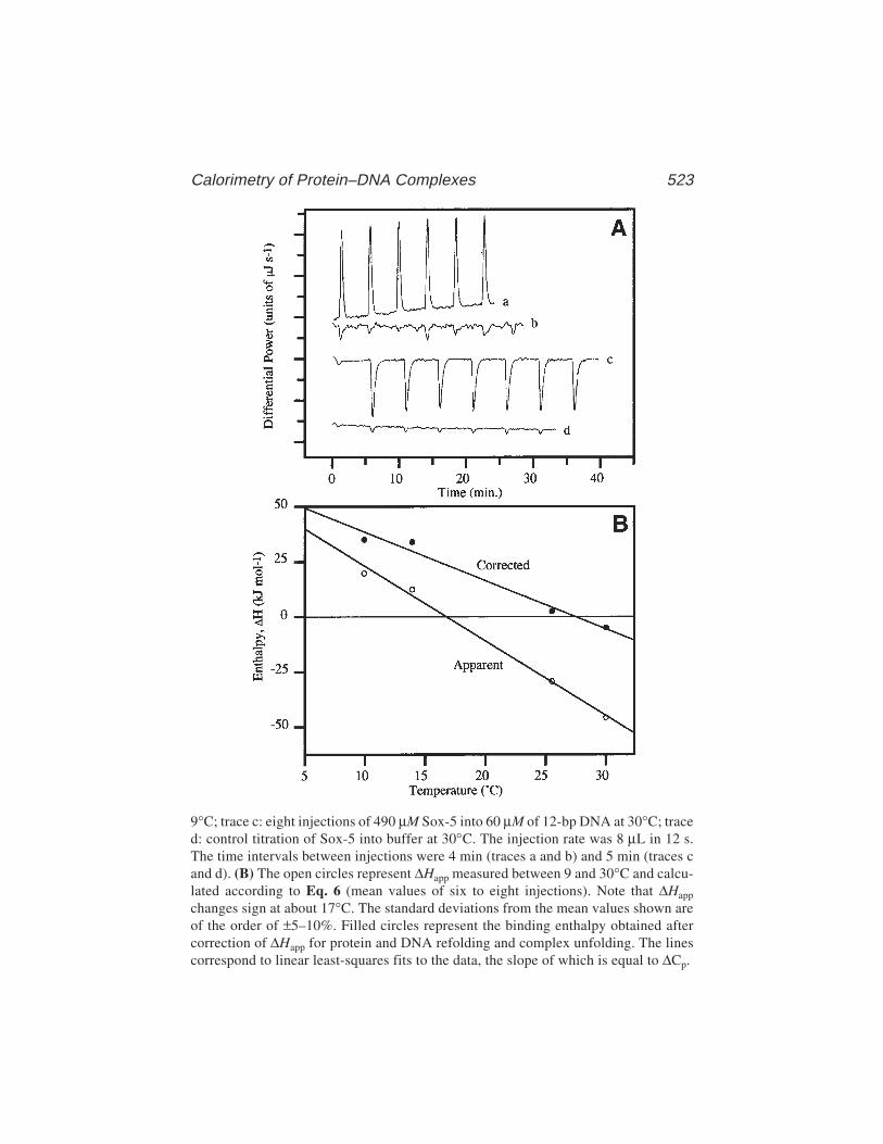
Calorimetry of Protein–DNA Complexes 523
9°C; trace c: eight injections of 490 µM Sox-5 into 60 µM of 12-bp DNA at 30°C; traced: control titration of Sox-5 into buffer at 30°C. The injection rate was 8 µL in 12 s.The time intervals between injections were 4 min (traces a and b) and 5 min (traces cand d). (B) The open circles represent ∆Happ measured between 9 and 30°C and calcu-lated according to Eq. 6 (mean values of six to eight injections). Note that ∆Happ
changes sign at about 17°C. The standard deviations from the mean values shown areof the order of ±5–10%. Filled circles represent the binding enthalpy obtained aftercorrection of ∆Happ for protein and DNA refolding and complex unfolding. The linescorrespond to linear least-squares fits to the data, the slope of which is equal to ∆Cp.

524 Read and Jelesarov
volume of the cell, Vcell. The enthalpy of association, ∆Happ, at temperature Tmay then be calculated from Eq. 6. This procedure is repeated for the pairs oftitrations at different temperatures. The experimentally observed enthalpies(∆Happ) obtained at a number of temperatures can be plotted as illustrated inFig. 3B.
3.2. Differential Scanning Calorimetry
1. Prior to starting experiments ensure that the Nano-DSC calorimeter sample andreference cells are at room temperature, thoroughly cleaned, and thermally bal-anced.
2. Add working buffer (100 mM KCl, 10 mM potassium phosphate, and 1 mMEDTA (pH 6.0)) which is at room temperature to both sample and reference cells.It is most important that no air bubbles are present in the calorimeter cells (seeNote 7). The presence of air bubbles will yield incorrect values for the partialmolar heat capacity of the macromolecule, because the volume of solution in thesample and reference cells is not identical (assumed in Eq. 7). Furthermoreexpansion of the minutes of air bubbles with heating results in significant heatoutput (and vice versa on cooling).
3. Seal the top of the chamber with the screw-threaded piston and let the calorim-eter settle to thermal equilibrium. Apply approx 2 atm of overpressure to the cellsby screwing down the piston. As pressure is applied note the compensatory powerreading—it should not change by more than a few microwatts (see Note 8).
4. Scan to obtain a buffer–buffer baseline. Initially, a number of scans are recordedin order to obtain a number of reproducible baselines (to within 0.5 µW, in thelinear region). A complete cycle of heating and cooling at a rate of 1 K/min actu-ally takes about 4 h because at the end of each heating or cooling scan, there is aperiod of thermal equilibration.
5. Remove the buffer from the sample cell. This is most easily accomplished with avacuum line attached to a water pump.
6. Slowly and carefully apply a 1.8-mL dialyzed sample to the cell, using the methodoutlined in Note 7. For concentrated protein samples, care is needed to removeall air bubbles. The excess sample is put to good use: first to determine sampleconcentration and, second, it is diluted with the final dialysate for use in furthercalorimetric runs. Again, apply a pressure of approx 2 atm to the cells.
7. Perform one heating and cooling scan to obtain the denaturation and renaturationcurves of the sample-buffer. Usually samples were heated from 0°C to 80°C andthen cooled to –8°C, both at a rate of 1 K/min. The heat effects of unfolding andrefolding should appear as mirror images, slightly shifted in temperature becausethe slower kinetics of refolding. Reproducibility shows that the heat-inducedunfolding/refolding is reversible. However, this may not be the case (see Note 9).
8. Remove the sample from the cell. Thoroughly wash out the cell with buffer andthen perform another scan of buffer. A heat-asorption peak may be observable ifthe previous sample is not completely removed (see Note 10).
Calorimetry of Protein–DNA Complexes 525
3.2.1. DSC Data Analysis
The subtraction of buffer scans to obtain an accurate baseline, the conver-sion to partial molar heat capacities, and the deconvolution of the excess molarheat capacity function into separate transitions were all performed using theCPCalc program. CPCalc provides a simple interactive mechanism, based onData Exchange Ports, for the parsing of data from one step to another.
1. The functions of differential power and temperature vs time are extracted fromthe DSC data acquisition files. Each file may contain more than one scan, butfurther analysis is on a one-scan basis.
2. A matching buffer–buffer scan is subtracted from a sample-buffer scan. Bothmust be from a heating (or cooling) scan. Since the absolute values of the molarheat capacities depend on good baseline subtraction and the buffer-buffer scansvary to a small extent, it is important that a number of subtractions are tried usingdifferent scans from the acquisition file.
3. The subtracted compensatory power curve is converted to the partial molar heatcapacity function by use of Eq. 7. Accurate values for the concentration (Sub-heading 3.4.), molecular mass, and partial specific volume of the macromoleculeare required (see Note 11).
4. Appropriate functions for the intrinsic heat capacity of the initial and final statesmay then be put onto the partial molar heat capacity function (Fig. 4). Thecalorimetric ∆H, ∆S, and melting temperature of the peak are obtained. Enthalpiesand entropies over a restricted temperature interval, ∆H(T) and ∆S(T), are obtainedby viewing the partial molar heat capacity function between the two temperatures.
5. The excess molar heat capacity function is deconvoluted into separate transitions.
3.3. Correction of ITC Derived Enthalpies
The value for ∆Cp,app calculated from the slope of the ∆Happ vs T plot(Fig. 3) is about –3.3 kJ/K/mol, implying that a considerable amount of hydro-phobic surface is buried at the complex interface. However, over the tempera-ture range (10–30°C) used for the ITC measurements, the partial molar heatcapacity functions for both free Sox-5 and DNA (DSC data, Fig. 4A) are greaterthan the calculated intrinsic heat capacity functions for the fully folded mol-ecules. Thus, the DSC experiments show significant heat absorption resultingfrom a temperature-dependent unfolding of the free Sox-5 and DNA. Signifi-cant refolding of both components must therefore take place when they associ-ate at these temperatures: a simple interaction between rigid-body molecules isnot observed. If one wishes to relate observed energetic parameters to struc-tural features of a rigid fully-folded complex, then the enthalpic contributionsarising from refolding of the free Sox-5 and DNA, as determined from DSC,must be added to the ITC-measured enthalpies of association to obtain theenthalpies applicable to a rigid-body interaction. Furthermore, because the

526 Read and Jelesarov
Fig. 4. (A) Partial molar heat capacity functions obtained for the free Sox-5 protein(dotted curve), the 12-bp DNA duplex that includes the AACAAT motif (dot–dashcurve) and the 1:1 Sox-5–12-bp DNA complex (solid curve). Note that the complexdissociates in a single cooperative trimolecular transition with a melting temperatureonly slightly above that of the 12-bp DNA duplex. The free Sox-5 protein and 12-bpDNA duplex dissociate in a monomolecular and bimolecular manner, respectively.(B) Partial molar heat capacity function for the Sox-5–12-bp DNA complex showingthe intrinsic heat capacity functions for the fully folded (N) and unfolded (D) complex(thin lines). The area above the dashed line corresponds to the total enthalpy of all thetemperature-induced changes in the complex.
Calorimetry of Protein–DNA Complexes 527
complex also absorbs heat over the 10–30°C temperature range (i.e., becomespartially unfolded [Fig. 4A]), such heats must be subtracted from the ITC-measured enthalpies of association to generate the net enthalpies applicable tothe formation of a fully folded complex. These corrections considerably affectthe enthalpy profile of binding (see Fig. 3B). The corrected plots of ∆Happ vs Tare now linear, with an average slope of about –1.5 kJ/K/mol and this correctedvalue of ∆Cp is in very good agreement with the amount and type of molecularsurface screened from the solvent upon association, calculated assuming arigid-body interaction.
3.4. Determination of Concentrations
The protein and DNA samples must be highly homogenous and their con-centrations must be known to the highest possible precision. In the first placethis enables an accurate preparation of DNA duplex from its complementaryoligonucleotides and of the Sox-5–DNA complex from protein and DNAduplex. In DSC, the accuracy with which the sample concentration can bedetermined directly affects the molar heat capacity values obtained. In ITC,unlike other binding assays, errors in the concentration of protein aredirectly reflected in the values of ∆Happ (Eqs. 3 and 4). Thus, in both ITC andDSC, concentrations are determined after dialysis. In the DSC experiments, itis also possible that a small amount of buffer from a previous scan remains inthe gold capillary cell. To eliminate this potential source of error, concentra-tions were determined using the excess sample that remains after filling thecalorimeter cell.
3.4.1. DNA
For oligonucleotides and DNA duplexes, concentrations were determinedfrom their UV absorption at 260 nm, after digestion to nucleotides with snakevenom phosphodiesterase I (PDE1).
1. Accurately dilute the solution of DNA to about 1.0 mL with 100 mM Tris-HCl(pH 8.0) so as to give an absorbance at 260 nm of about 0.5 in a 1-cm pathlengthcell. To overcome any reliance on the presumed accuracy of the pipets beingused, the dilutions are performed on a precision balance.
2. Record the UV absorption spectrum of the diluted DNA solution, using as referencea blank cell containing buffer. Note that for small oligonucleotides and DNA duplexeswith a biased nucleotide composition, the absorption maximum is not necessarily at260 nm. This is in fact an optional step, but the recording of UV spectra bothbefore and after the addition of PDE1 indicates that digestion has occurred andenables a determination of the hypochromicity of the DNA solution.
3. Remove the diluted DNA solution from the cell and place into a screw-capped1.5-mL tube. Add either 0.008 U (for oligonucleotides) or 0.08 U (for DNA
528 Read and Jelesarov
duplexes) of PDE1 to the solution, mix well, and incubate at 37°C overnight. Ifnecessary, a time-course of the digestion may be followed (at room temperature)in the UV spectrophotometer by direct addition of PDE1 to the DNA solution inthe quartz cell.
4. Accurately record the UV absorption spectrum of the DNA solution after PDE1digestion, using a black cell containing buffer as a reference. The contributionto the absorbance at 260 nm arising from overlap of the PDE1 280-nm peak maybe neglected
5. Optionally, calculate the percent hypochromicity (%H) from the equation
%H = (Aa – Ab) × 100
Aa
where Ab and Aa are the absorbances at 260 nm before and after PDE1 digestionrespectively, with dilution the result of the addition of PDE1 taken into account.Values of %H are usually approx 20% for oligonucleotides and approx 35–40%for duplex DNA. Lower values indicate that digestion may not be complete, thatthe original DNA is degraded, or that there is a failure to form duplex DNA.
6. Calculate the molar nucleotide concentration and thus the molar DNA concentra-tion from the following equations
[Nucleotide] = Aa(Dilution)N(12,010G) + (15,200A) + (8400T) + 7050C)
and[DNA] =
[Nucleotide]N
where N is the total number of nucleotides in the DNA and G, A, T, and C arerespectively the number of dG, dA, dT, and dC nucleotides. The extinctioncoefficients at 260 nm for the four nucleotides are from ref. 23.
3.4.2. Protein
The concentration of Sox-5 (in working buffer) was determined from its UVabsorption at 280 nm using an extinction coefficient of 17,460/M/cm. Thisextinction coefficient is based on the addition of the extinction coefficients oftryptophan and tyrosine (of which there are two and five in Sox-5, respec-tively). The accuracy of the concentration determination is within 5%.
3.4.3. Sox-5–DNA Complex
The concentration of complex was determined from its UV absorbance at260 nm. At this wavelength, the absorption is mainly the result of the DNA,but there is a significant absorption from the protein that must be taken intoaccount. There may also be additional hyperchomic effects because the DNAof the Sox-5–DNA complex is highly bent with considerable base unstacking.
Calorimetry of Protein–DNA Complexes 529
Thus, the approach taken was to measure the UV absorbance at 260 nm for asolution of DNA duplex and then again after the addition of an equimolaramount of Sox-5 protein to form the complex. The measurement was performedat approx 60 µM DNA in a 1-mm pathlength cell, such that the complex wasfully associated. For the Sox-5–12-bp DNA complex, an extinction coefficientat 260 nm of 158.6 × 10³/Molar complex/cm was obtained.
4. Notes1. The choice of assay buffer depends on the system under study and on the require-
ments of other assays performed in the context of a particular investigation. Buff-ers with a different heat of protonation may be used in an ITC experiment tocheck whether the protonation state of the system changes upon association.
2. In setting the stirring speed, the particular system under study must be consid-ered. Some proteins do not resist the forces arising from rapid stirring of thesolution placed in the narrow calorimetric cell and aggregate or unfold. Onthe other hand, very slow stirring may result in low rates of heat transfer, thuscausing broadening of the peaks observed in the thermogram and a decreasein sensitivity.
3. When working below room temperature, it is recommended to fill the cells withcold solutions, otherwise the equilibration time may be very long. Any particlesin the stirred sample cell as well as the formation of bubbles during filling maycause problems in establishing the baseline.
4. There is no general rule about the number, volume, and duration of injections. Toobtain an entire binding isotherm a 2–4 molar excess of ligand over the concen-tration of receptor binding sites should be injected by at least 10–15 additions.Five to 10 injections suffice to reliably measure the enthalpy of reaction. In thiscase, the degree of saturation must be less than 0.5 at the end of experiment. Thevolume and duration of injections should be chosen in such a way that the releasedheat is well above the threshold of sensitivity and sharp peaks appear in the ther-mogram. Typically, 5-min intervals between injection are sufficiently long timesfor the signal to return to the baseline. However, for very slow reactions, thisinterval should be prolonged. Because the heat of reaction is a temperature-dependent quantity, the injection scheme might be changed for experimentscarried out at different temperatures.
5. Alternating cycles of washing with 0.5 M NaOH and isopropanol are routinelyused. To remove heavily precipitated proteins, the cell can be rinsed with a hotsolution of 20% sodium dodecyl sulfate (SDS). The protocol for cleaning willdepend on the particular system under study and the material of the cell.
6. Integration requires construction of a proper baseline. Some software productssupport automatic procedures for baseline determination. However, it is oftenfound that manual adjustment of the baseline is a better practice, particularly incases when the signal-to-noise ratio is low or when the instrument baseline driftis substantial. In constructing the baseline manually, it is important to use the

530 Read and Jelesarov
same integration window for all the peaks observed, both in the specific bindingand in the blank titration experiments. This will avoid the introduction of nonran-dom bias in the data.
7. We would advocate filling each cell using a minimum of approx 1.8 mL of solu-tion by the following method (see also Fig. 5). First attach a 1-mL pipet tip usinga short length of silicon tubing to one port of the cell. Draw up 0.9 mL of solutionusing a pipettor fitted with a 1-mL tip and silicon tubing. Connect this to theother side of the cell and slowly introduce the solution into the cell. Disconnectand apply a second 0.9 mL of solution, without introducing any air bubbles. Asthe cell is only about 0.9 mL in volume, excess solution rises up into the 1-mL
Fig. 5. Arrangement for filling the capillary cells in the Nano-DSC calorimeter.

Calorimetry of Protein–DNA Complexes 531
pipet tip attached to the other side. The solution is then pipetted up and down, atfirst slowly and then more rapidly, for sufficient time to expel minute air bubblesfrom the cell. Eventually, excess solution may be removed by carefully with-drawing it into the 1.0-mL tip connected to the pipettor and then disconnectingby simultaneously pulling off both 1-mL tips with their connecting tubing.
8. If the microwatt reading rapidly increases or decreases on applying pressure, thenair bubbles are present in either of the cells. The cells must then be emptiedand refilled.
9. One reason may be temperature-induced aggregation, manifesting itself as a largepeak of heat evolution that typically commences close to the peak of maximumheat absorption of the cooperative transition (approximately at the melting tem-perature, Tm). A s possible reason for irreversibility is the presence of disulfidebonds in the protein, which may disrupt on heating but, on cooling form, mixeddisulfide bonds with incorrect Cys residues. This may be overcome by usingproteins (or domains) with no Cys residues (as in Sox-5) or by using engineeredversions in which the Cys residues are mutated to Ser. This strategy will, how-ever, depend on the contribution of the disulfide bonds in stabilizing the overallprotein fold.
10. The calorimetric cells may be thoroughly cleaned by filling them with 50% (v/v)formic acid, followed by heating from 25°C to 65°C (at 1 K/min). The cells arethen thoroughly rinsed with water and buffer. Multiple baseline scans of thebuffer are recommended before proceeding with the next sample.
11. The partial specific volumes used for oligonucleotides and DNA duplexes were0.53 and 0.54 mL/g. The partial specific volume of Sox-5 was calculated fromits composition as 0.723 mL/g, using the known partial specific volumes ofthe amino acids. The Sox-5–12-bp DNA complex partial specific volume of0.650 mL/g was calculated as the weight average of the partial specific volumesof Sox-5 and the DNA duplex.
AcknowledgmentsWe would like to thank Peter Privalov (Johns Hopkins University, Balti-
more), in whose laboratory the calorimetry was performed. We thank ColynCrane-Robinson for critical reading of the manuscript. Financial support froman NIH grant to the Baltimore laboratory (GM48036-06), a Wellcome Trustgrant to the Portsmouth laboratory, and NATO Collaborative Research Grantsare gratefully acknowledged.
References1. Patikoglou, G. and Burley, S. K. (1997) Eukaryotic transcription factor–DNA
complexes. Ann. Rev. Biophys. Biomol. Struct. 26, 289–325.2. Schultz, S. C., Shields, G. C., and Steitz, T. A. (1991) Crystal structure of a CAP–
DNA complex: the DNA is bent by 90°. Science 253, 1001–1007.3. Kim, J. L., Nikolov, D. B., and Burley, S. K. (1993) Co-crystal structure of TBP
recognising the minor groove of a TATA element. Nature 365, 520–527.
532 Read and Jelesarov
4. Werner, M. H., Huth, J. R., Gronenborn, A. M., and Clore, G. M. (1995) Molecu-lar basis of human 46X,Y sex reversal revealed from the three-dimensional solu-tion structure of the human SRY–DNA complex. Cell 81, 705–714.
5. Love, J. J., Li, X., Case, D. A., Giese, K., Grosschedl, R., and Wright, P. E. (1995)Structural basis for DNA bending by the architectural transcription factor LEF-1.Nature 376, 791–795.
6. Privalov, P. L., Jelesarov, I., Read, C. M., Crane-Robinson, C., et al. (1999) Theenergetics of HMG box interactions with DNA. Thermodynamics of the DNAbinding of the HMG box from mouse Sox-5. J. Mol. Biol. 294, 997–1013.
7. Crane-Robinson, C., Read, C. M., Cary, P. D., Driscoll, P. C., Dragan, A. I., andPrivalov, P. L. (1998) The energetics of HMG box interactions with DNA. Ther-modynamic description of the box from mouse Sox-5. J. Mol. Biol. 281, 705–717.
8. Jelesarov, I., Crane-Robinson, C., and Privalov, P. L. (1990) The energetics ofHMG box interactions with DNA. Thermodynamic description of DNA duplexesthe target. J. Mol. Biol. 294, 981–995.
9. Murphy, K. P. and Freire, E. (1992) Thermodynamics of structural stability andco-operative folding behaviour in proteins. Adv. Protein Chem. 43, 313–361.
10. Spolar, R. S., Livingstone, J. R., and Record, M. T., Jr. (1992) Use of liquidhydrocarbon and amide transfer data to estimate contributions to thermodynamicfunctions of protein folding from the removal of nonpolar and polar surface fromwater. Biochemistry 31, 3947–3955.
11. Ferrari, M. E. and Lohman, T. M. (1994) Apparent heat capacity change accom-panying a nonspecific protein-DNA interaction. Escherichia coli SSB tetramerbinding to oligodeoxyadenylates. Biochemistry 33, 12,896–12,910.
12. Bruzzese, F. J. and Connelly, P. R. (1997) Allosteric properties of inosine mono-phosphate dehydrogenase revealed through the thermodynamics of binding ofinosine 5'-monophosphate and mycophenolic acid. Temperature dependent heatcapacity of binding as a signature of ligand-coupled conformational equilibria.Biochemistry 36, 10,428–10,438.
13. Privalov, P. L. and Makhatadze, G. I. (1990) Heat capacity of proteins. J. Mol.Biol. 213, 385–391.
14. Makhatadze, G. I. and Privalov, P. L. (1995) Energetics of protein structure. Adv.Protein Chem. 47, 307–325.
15. Denny, P., Swift, S., Connor, F., and Ashworth, A. (1992) A Sry-related geneexpressed during spermatogenesis in the mouse encodes a sequence-specificDNA-binding protein. EMBO J. 11, 3705–3712.
16. Connor, F., Cary, P. D., Read, C. M., Preston, N. S., Driscoll, P. C., Denny, P.,et al. (1994) DNA binding and bending properties of the post-meioticallyexpressed Sry-related protein Sox-5. Nucleic Acids Res. 22, 3339–3346.
17. McKinnon, I. R., Fall, L., Parody-Morreale, A., and Gill, S. J. (1984) A twintitration microcalorimeter for the study of biochemical reactions. Anal. Biochem.139, 134–139.
18. Wiseman, T., Williston, S., Brandts, J. F., and Lin, L. N. (1989) Rapid measure-ment of binding constants and heats of binding using a new titration calorimeter.Anal. Biochem. 179, 131–137.
Calorimetry of Protein–DNA Complexes 533
19. Freire, E., Mayorga, O. L., and Straume, M. (1990) Isothermal titration. Anal.Chem. 62, 950A–959A.
20. Breslauer, K. J., Freire, E., and Straume, M. (1992) Calorimetry: a tool for DNAand ligand–DNA studies. Methods Enzymol. 211, 533–567.
21. Privalov, G., Kavina, V., Freire, E., and Privalov, P. L. (1995) Precise scanningcalorimeter for studying thermal properties of biological macromolecules in dilutesolution. Anal. Biochem. 232, 79–85.
22. Read, C. M., Cary, P. D., Preston, N. S., Lnenicek-Allen, M., and Crane-Robinson,C. (1994) The DNA sequence specificity of HMG boxes lies in the minor wing ofthe structure. EMBO J. 13, 5639–5646.
23. Wallace, R. B. and Miyada, C. G. (1987) Oligonucleotide probes for the screen-ing of recombinant DNA libraries. Methods Enzymol. 152, 432–442.

Surface Plasmon Resonance 535
535
From: Methods in Molecular Biology, vol. 148: DNA–Protein Interactions: Principles and Protocols, 2nd ed.Edited by: T. Moss © Humana Press Inc., Totowa, NJ
36
Surface Plasmon Resonance Appliedto DNA–Protein Complexes
Malcolm Buckle
1. Introduction1.1. The Relationship Between Refractive Index and Mass
Surface plasmon resonance (SPR) measures refractive index changes (∆n)at or near a surface and relates these to changes in mass at the surface (Fig 1).This relationship is given by the Clausius Mossotti form (Eq. 2) of the Debyeequation (Eq. 1):
ε – 1 N (α + µ) (1)ε + 2 =
3ε0 kT
ε – 1 Nα (2)ε + 2
= 3ε0
where ε is the real part of the dielectric constant or permittivity constant relatedto the refractive index by ε = n2, N is the number density given by NAρ/Ma (NAis Avogadro’s number, ρ is the density and Ma is the molecular mass). It isassumed that ∆n/∆C is a constant.
1.2. SPR Using the BIACORE Instrument
In physical terms, the detection system of this SPR machine consists of amonochromatic, plane polarized light source, and a photodetector that are con-nected optically through a glass prism (Fig. 1). A thin gold film (50 nm thick),deposited on one side of the prism, is in contact with the sample solution. Thisgold film is, in turn, covered with a long-chain hydroxyalkanethiol, whichforms a monolayer (approx 100 nm thick) at the surface. This layer essentiallyserves as an attachment point for carboxymethylated dextran chains that createa hydrophilic surface to which ligands can be covalently coupled. Light
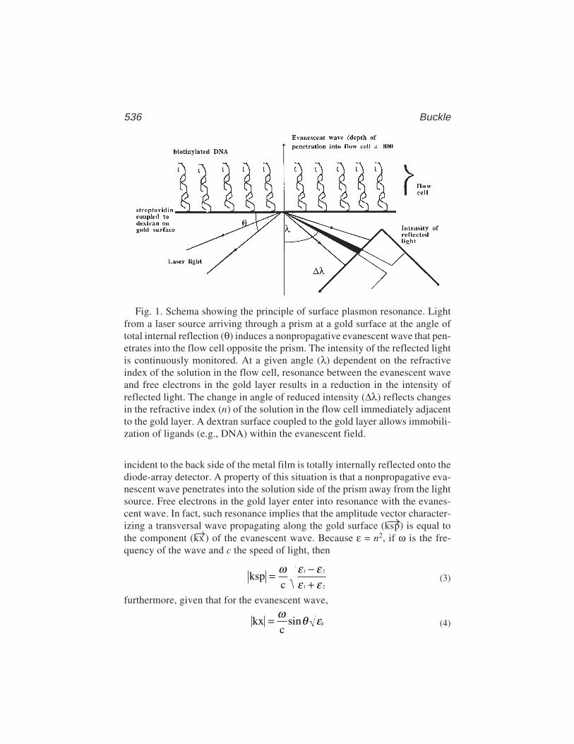
536 Buckle
incident to the back side of the metal film is totally internally reflected onto thediode-array detector. A property of this situation is that a nonpropagative eva-nescent wave penetrates into the solution side of the prism away from the lightsource. Free electrons in the gold layer enter into resonance with the evanes-cent wave. In fact, such resonance implies that the amplitude vector character-izing a transversal wave propagating along the gold surface (ks→p) is equal tothe component (kx→) of the evanescent wave. Because ε = n2, if ω is the fre-quency of the wave and c the speed of light, then
kspc
1 2
1 2
= −+
ω ε εε ε (3)
furthermore, given that for the evanescent wave,
kxc
g= ω θ εsin (4)
Fig. 1. Schema showing the principle of surface plasmon resonance. Lightfrom a laser source arriving through a prism at a gold surface at the angle oftotal internal reflection (θ) induces a nonpropagative evanescent wave that pen-etrates into the flow cell opposite the prism. The intensity of the reflected lightis continuously monitored. At a given angle (λ) dependent on the refractiveindex of the solution in the flow cell, resonance between the evanescent waveand free electrons in the gold layer results in a reduction in the intensity ofreflected light. The change in angle of reduced intensity (∆λ) reflects changesin the refractive index (n) of the solution in the flow cell immediately adjacentto the gold layer. A dextran surface coupled to the gold layer allows immobili-zation of ligands (e.g., DNA) within the evanescent field.
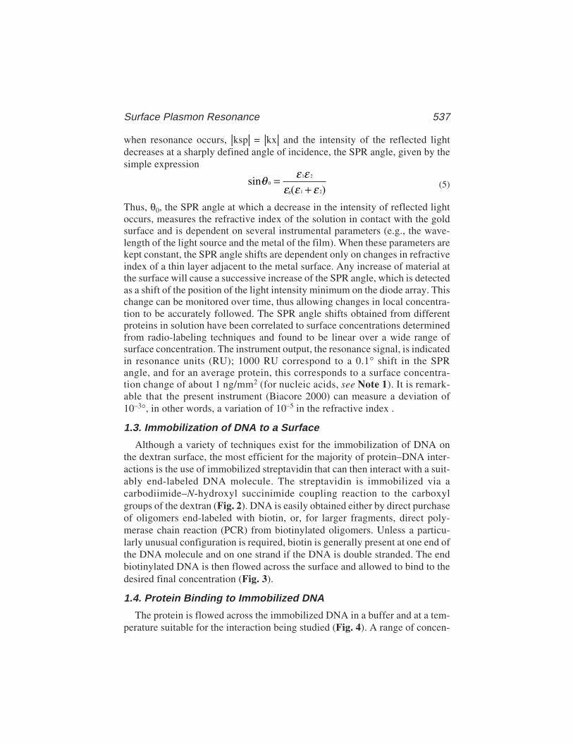
Surface Plasmon Resonance 537
when resonance occurs, |ksp| = |kx| and the intensity of the reflected lightdecreases at a sharply defined angle of incidence, the SPR angle, given by thesimple expression
sin·( )
0
1 2
g 1 2
θ ε εε ε ε
=+ (5)
Thus, θ0, the SPR angle at which a decrease in the intensity of reflected lightoccurs, measures the refractive index of the solution in contact with the goldsurface and is dependent on several instrumental parameters (e.g., the wave-length of the light source and the metal of the film). When these parameters arekept constant, the SPR angle shifts are dependent only on changes in refractiveindex of a thin layer adjacent to the metal surface. Any increase of material atthe surface will cause a successive increase of the SPR angle, which is detectedas a shift of the position of the light intensity minimum on the diode array. Thischange can be monitored over time, thus allowing changes in local concentra-tion to be accurately followed. The SPR angle shifts obtained from differentproteins in solution have been correlated to surface concentrations determinedfrom radio-labeling techniques and found to be linear over a wide range ofsurface concentration. The instrument output, the resonance signal, is indicatedin resonance units (RU); 1000 RU correspond to a 0.1° shift in the SPRangle, and for an average protein, this corresponds to a surface concentra-tion change of about 1 ng/mm2 (for nucleic acids, see Note 1). It is remark-able that the present instrument (Biacore 2000) can measure a deviation of10–3°, in other words, a variation of 10–5 in the refractive index .
1.3. Immobilization of DNA to a Surface
Although a variety of techniques exist for the immobilization of DNA onthe dextran surface, the most efficient for the majority of protein–DNA inter-actions is the use of immobilized streptavidin that can then interact with a suit-ably end-labeled DNA molecule. The streptavidin is immobilized via acarbodiimide–N-hydroxyl succinimide coupling reaction to the carboxylgroups of the dextran (Fig. 2). DNA is easily obtained either by direct purchaseof oligomers end-labeled with biotin, or, for larger fragments, direct poly-merase chain reaction (PCR) from biotinylated oligomers. Unless a particu-larly unusual configuration is required, biotin is generally present at one end ofthe DNA molecule and on one strand if the DNA is double stranded. The endbiotinylated DNA is then flowed across the surface and allowed to bind to thedesired final concentration (Fig. 3).
1.4. Protein Binding to Immobilized DNA
The protein is flowed across the immobilized DNA in a buffer and at a tem-perature suitable for the interaction being studied (Fig. 4). A range of concen-
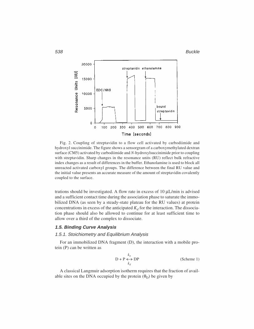
538 Buckle
Fig. 2. Coupling of streptavidin to a flow cell activated by carbodiimide andhydroxyl succinimide. The figure shows a sensorgram of a carboxymethylated dextransurface (CM5) activated by carbodiimide and N-hydroxylsuccinimide prior to couplingwith streptavidin. Sharp changes in the resonance units (RU) reflect bulk refractiveindex changes as a result of differences in the buffer. Ethanolamine is used to block allunreacted activated carboxyl groups. The difference between the final RU value andthe initial value presents an accurate measure of the amount of streptavidin covalentlycoupled to the surface.
trations should be investigated. A flow rate in excess of 10 µL/min is advisedand a sufficient contact time during the association phase to saturate the immo-bilized DNA (as seen by a steady-state plateau for the RU values) at proteinconcentrations in excess of the anticipated Kd for the interaction. The dissocia-tion phase should also be allowed to continue for at least sufficient time toallow over a third of the complex to dissociate.
1.5. Binding Curve Analysis
1.5.1. Stoichiometry and Equilibrium Analysis
For an immobilized DNA fragment (D), the interaction with a mobile pro-tein (P) can be written as
ka
D + P ↔ DP (Scheme 1)kd
A classical Langmuir adsorption isotherm requires that the fraction of avail-able sites on the DNA occupied by the protein (θD) be given by
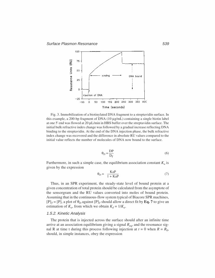
Surface Plasmon Resonance 539
Fig. 3. Immobilization of a biotinylated DNA fragment to a streptavidin surface. Inthis example, a 200-bp fragment of DNA (10 µg/mL) containing a single biotin labelat one 5' end was flowed at 20 µL/min in HBS buffer over the streptavidin surface. Theinitial bulk refractive index change was followed by a gradual increase reflecting DNAbinding to the streptavidin. At the end of the DNA injection phase, the bulk refractiveindex change was recovered and the difference in absolute RU values compared to theinitial value reflects the number of molecules of DNA now bound to the surface.
θD = DP
(6)Dt
Furthermore, in such a simple case, the equilibrium association constant Ka isgiven by the expression
θD =KaP
(7)1 + KaP
Thus, in an SPR experiment, the steady-state level of bound protein at agiven concentration of total protein should be calculated from the asymptote ofthe sensorgram and the RU values converted into moles of bound protein.Assuming that in the continuous-flow system typical of Biacore SPR machines,[P]T = [P], a plot of θD against [P]T should allow a direct fit by Eq. 7 to give anestimation of Ka, from which we obtain Kd = 1/Ka.
1.5.2. Kinetic Analysis
The protein that is injected across the surface should after an infinite timearrive at an association equilibrium giving a signal Req, and the resonance sig-nal R at time t during this process following injection at t = 0 when R = R0,should, in simple instances, obey the expression
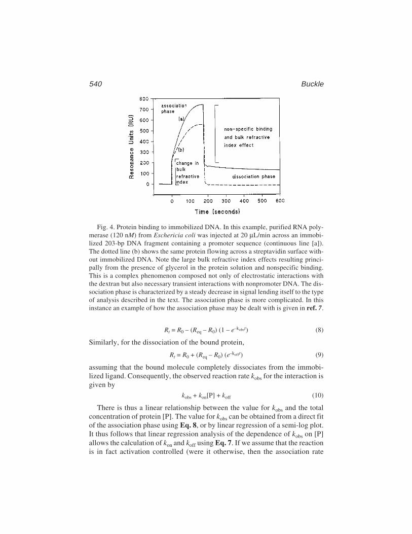
540 Buckle
Rt = R0 – (Req – R0) (1 – e–kobst) (8)
Similarly, for the dissociation of the bound protein,
Rt = R0 + (Req – R0) (e–kofft) (9)
assuming that the bound molecule completely dissociates from the immobi-lized ligand. Consequently, the observed reaction rate kobs for the interaction isgiven by
kobs + kon[P] + koff (10)
There is thus a linear relationship between the value for kobs and the totalconcentration of protein [P]. The value for kobs can be obtained from a direct fitof the association phase using Eq. 8, or by linear regression of a semi-log plot.It thus follows that linear regression analysis of the dependence of kobs on [P]allows the calculation of kon and koff using Eq. 7. If we assume that the reactionis in fact activation controlled (were it otherwise, then the association rate
Fig. 4. Protein binding to immobilized DNA. In this example, purified RNA poly-merase (120 nM) from Eschericia coli was injected at 20 µL/min across an immobi-lized 203-bp DNA fragment containing a promoter sequence (continuous line [a]).The dotted line (b) shows the same protein flowing across a streptavidin surface with-out immobilized DNA. Note the large bulk refractive index effects resulting princi-pally from the presence of glycerol in the protein solution and nonspecific binding.This is a complex phenomenon composed not only of electrostatic interactions withthe dextran but also necessary transient interactions with nonpromoter DNA. The dis-sociation phase is characterized by a steady decrease in signal lending itself to the typeof analysis described in the text. The association phase is more complicated. In thisinstance an example of how the association phase may be dealt with is given in ref. 7.
Surface Plasmon Resonance 541
would be of the order of 109/M/s, which is well beyond the range of currentSPR devices), then
koff = konKd (11)
Thus, the equilibrium dissociation constant (Kd) can be obtained from the ratioof the off and on rates.
There are many pitfalls to using SPR, which are covered in several fairlyrecent reviews (2,3). In the case of the Biacore instrumentation, the new dataevaluation software deals with certain situations. What it cannot do is to deter-mine the best strategy for setting up an experiment. In summary, certainimportant points must be taken into account even in the simple analysis givenabove. Several of these are covered in Notes 2–6.
2. Materials1. An SPR device. In this chapter, a Biacore instrument is referred to either as the
classic Biacore or the Biacore 2000. It is recommended (but not essential) thatthe machine be modified such that the two racks into which samples are placed inthe machine are separately thermostated. Rack 1 should be thermostated to 4°C;rack 2 should be thermostated to the temperature at which the interaction is to bemeasured. The protocols illustrated here require rack D in the first position andrack A in the second position.
2. Streptavidin from Pierce resuspended in 0.22 µm filtered distilled water to a finalconcentration of 5 mg/mL. This preparation may be stored at 4°C for up to 3 mo.
3. HBS buffer: 10 mM HEPES, pH 7.4, 150 mM NaCl, 3.4 mM EDTA, and 0.005%Biacore surfactant.
4. N-Ethyl-N'-(diethylaminopropyl) carbodiimide (EDC) and N-hydroxylsuccinimide (NHS) purchased from Biacore as lyophilized powders areresuspended in 0.22 µm filtered distilled water to a final concentration of100 mM each.
5. 1 M ethanolamine hydrochloride (pH 8.5), purchased from Biacore, storedat 4°C.
6. HBS buffer: 10 mM HEPES, pH 7.4, 150 mM NaCl, 3.4 mM EDTA, and 0.005%surfactant P20.
7. Sensor chip surface CM5 research grade installed in the Biacore apparatus andpreprimed with HBS buffer.
8. Reaction vials for the Biacore (small, plastic = 7 mm; medium, glass = 16 mm;large, glass = 2 mL) purchased from Biacore.
9. End biotinylated DNA suspended in HBS buffer to 10 µg/mL. This DNA caneither be purchased directly or constructed by polymerase chain reaction(PCR) using templates and an oligomer primer carrying a biotin group (pur-chased from Genset for example) as one of the primers. It is advisable to gelpurify or high-performance liquid chromatography (HPLC) purify the DNA priorto immobilization.
542 Buckle
3. Methods3.1. Immobilization of the Ligand on the Surface
3.1.1. Coupling of Streptavidin1. Prime the apparatus with HBS buffer.2. The thawed EDC solution, in an Eppendorf tube with the top removed, is placed
in rack 1 position a1 (r1a1).3. The thawed NHS solution in an Eppendorf tube with the top removed, is placed in r1a2.4. Streptavidin (5 mg/mL, 50 µL), in an Eppendorf tube with the top removed, is placed
in r1a3; 2 mL of filtered (0.2 µm) distilled water is placed in a large glass vial in r2f7.5. 1 M, sodium acetate buffer (1 mL, pH 4.5) is placed in a large glass vial in r2f3.6. 1 M ethanolamine (200 µL) is placed in a large tube in r2f4.7. Two small clean plastic vials are placed in r2a1 and r2a2.8. An empty large glass vial is placed in r2f5.9. The following method is programmed into the Biacore or Biacore 2000, checked
for errors, and run.
DEFINE APROG mixingFLOW 20TRANSFER r1a1 r2a1 50 !rack1a1 = EDCTRANSFER r1a2 r2a1 50 !rack1a2 = NHSMIX r2a1 50 !rack2a1 = EDC/NHS mixTRANSFER r2f7 r2a2 200 !rack2f7 = distilled waterTRANSFER r2f7 r2a2 290 !rack2f7 = distilled waterTRANSFER r2f3 r2a2 5 !rack2f3 = 1 M acetate pH 4.5TRANSFER r1a3 r2a2 5 !rack1a3 = streptavidin (5 µg/mL)MIX r2a2 50
ENDDEFINE APROG bind
CAPTION activationFLOW 20
* INJECT r2a1 50-0:20 RPOINT EDC/NHS -b
* INJECT r2a2 30-0:20 RPOINT streptavidin
* INJECT r2f4 35 !Ethanolamine (1 M)-0:20 RPOINT ethanolamine15:00 RPOINT bound
ENDMAINFLOWCELL 1APROG mixingFLOWCELL 1APROG bind
END(See Note 3.)

Surface Plasmon Resonance 543
3.1.2. Immobilization of the DNA
1. Place the streptavidin-activated sensor chip surface CM5 research grade in theBiacore apparatus and preprime with HBS buffer.
2. Select a surface pretreated with streptavidin.3. Flow HBS buffer at 20 µL/min across the surface.4. Inject the DNA solution across the surface, set the baseline to the point of injec-
tion, and monitor the change in RU during the injection phase. Ideally, between20 and 100 RU of DNA should be immobilized (Fig. 3).
5. Wash the surface with a 50-µL injection of 1 M NaCl in filtered (0.2 µm) distilledwater.
6. Allow the surface to equilibrate in HBS buffer to a stable baseline, the differencein RU between the beginning of the injection phase and the end of the washperiod reflects the amount of DNA bound. For stoichiometry, and availability ofsites, see Note 6.
7. Note that values in excess of 100 RU for DNA molecules of appro 100–1000 bpare to be avoided for a number of reasons (see Notes 2–6).
3.2. Protein Binding to the Immobilized DNA
1. The protein should be prepared in the required buffer over a range of concentra-tions, at least two orders of magnitude on either side of the suspected Kd. Thedetergent P20 should be present at concentrations of around 0.005% unless it hasbeen shown to have a deleterious effect on the interaction with the DNA.
2. Samples should be injected over the both the immobilized DNA surface and asurface that has been treated with streptavidin and ethanolamine but no DNA as ablank (Fig. 4).
3. The baseline should be stable with a slope inferior to 10 RU/min. If this is not thecase, then check the temperature of both the apparatus and the continuous-flowbuffer. If the problem persists, replace the sensor surface with an old used chipand carry out a desorb and sanitize. Re-equilibrate the immobilized DNA chip innew filtered (0.22-µm filters) buffer by running the prime command. If the prob-lem persists, a potential reason may be degradation of the integrated fluid car-tridge necessitating its replacement (see Note 8).
4. A typical sensorgram is shown in Fig. 4. Note that at low protein concentrationsit is very difficult to obtain steady-state saturation levels. Note also that there is anonspecific interaction with the control surface (curve b) and also a contributionfrom the bulk refractive index effect and that both of these must be taken intoconsideration when deducing kinetic or equilibrium values.
4. Notes1. The relationship between mass and refractive index changes as measured by
changes in the angle at which resonance occurs in this system, although theoreti-cally available through the additive properties of molar refractivity, has beenempirically established such that 10–1° is equivalent to 1000 resonance units (RU)
544 Buckle
and relates to a change in mass of 1 ng of a globular protein at the surface. Usingthese values, a similar relationship has been demonstrated where 0.78 ng of anucleic acid gives the same response (1000 RU) (4,5).
2. Mass transport: In instances where the association rate is particularly elevatedand the diffusion rate of the nonimmobilized molecules is not especially fast,then the interaction of the free molecules with the immobilized ligand may depletea layer of solvent immediately surrounding the immobilized ligand such that therate-limiting step for association now becomes the rate of repletion of this layerfrom the bulk solvent. Two practical solutions to this problem are first to use alow immobilization density and, second, to use relatively elevated flow rates(>20 µL/min).
3. Estimation of the amplitude of the signal allowing calculation of the finalequilibrium or steady-state level is often hampered by bulk refractive indexchanges that mask the initial and final phases of the injection period. Blank runsover free surfaces may be used to correct for this provided that the free surfacereflects as close as possible the ligand surface. For example, if streptavidin isbeing used to immobilize the DNA, then a surface containing a comparable quan-tity of streptavidin to the sample surface should be used as a blank (Fig. 4). Inci-dentally, this is again an argument in favor of low levels of DNA immobilizationso that the control surface is very similar in refractive properties to the surfaceunder study. Alternatively, and indeed if possible, preferably samples beinginjected across the surface should be desalted into the injection buffer so as tominimize bulk refractive index effects. An ideal method is to use fast desaltingcolumns on HPLC/FPLC systems such as the SMART (Amersham PharmaciaBiotech) which produce little dilution, are rapid and allow automatic quantifica-tion of the protein.
4. The asymptote of the binding curve should provide the stoichiometry of the reac-tion assuming that all the DNA molecules are available for binding. If this isuncertain, one way of ensuring that a double-stranded target DNA is accessiblewould be to hybridize the protein binding site in situ on the surface by immobi-lizing a single strand and then hybridizing a second homologous strand to consti-tute the double stranded site. The mass increase in the second hybridization stepwould give the number of accessible DNA molecules because it results from asuccessful hybridization at the surface. It goes without saying however that thisrequires great care in eliminating nonspecific adsorption of DNA onto the surface.
5. Steric hindrance: Let us imagine for the sake of argument that we have immobi-lized 1000 RU of a 100-bp double-stranded DNA molecule via biotin/streptavidinto a surface. This constitutes 1.2 × 10⁻¹⁴ mole of DNA or 2 × 10⁸ molecules. Letus further assume that these molecules are evenly and randomly distributed acrossthe 1-mm2 surface so a simple calculation shows that each molecule is separatedfrom its neighbor by 70 nm. The DNA molecules are around 30 nm long, so if thedextran is itself flexible, then these DNA molecules are going to be in contact.This may produce problems such as occlusion of sites, creation of new potentialbinding sites, or unusual DNA structures possessing aberrant binding modes for
Surface Plasmon Resonance 545
target proteins. Even if a relatively large molecule such as a prokaryotic RNApolymerase (500 kDa, approximate diameter-10 nm) were to bind to a single siteon the DNA, then there would be every possibility that adjacent bound moleculesare going to interact with complicated consequences upon binding kinetics.
6. The amplitude of each signal should be estimated manually from the steady-statesignal at the end of the injection period or, if this is difficult because of a slowoverall relaxation time or because of a perturbing bulk refractive index effect,from the projected Req value calculated from direct fits. Note that the projectedReq values should be identical for fits of both the association and dissociationphases. It is essential that in the equilibrium analysis of these curves, the stoichi-ometry reflects the biology of the situation. An immobilized DNA ligand con-taining a single site for a protein should bind only one protein per site atsaturation. If this is not the case, then no single- or double-binding site analysis isgoing to provide meaningful affinity values. It will be clear from careful inspec-tion of the dissociation phase, for example, that several interactions are involvedand a simple analysis cannot be made.
7. This procedure will activate surface 1. Other surfaces can be activated simply bychanging the designated flow cell.
8. The Biacore machines are robust but susceptible to poorly prepared solutions.All solutions entering the fluid system must be filtered through 0.2-µm mem-branes and preferentially be sterile. The machine should be cleaned periodicallywith the desorb and sanitize protocols, and when not in use, it is recommended tomaintain a continuous flow of distilled water containing 0.005% P20 at 20°C.
9. As pointed out in ref. 6, there are at least three consistency tests that should beapplied to a given analysis: First, the equilibrium or steady-state analysisprovides a dissociation constant Kd from the Langmuir isotherm derived fromEq. 6:
Req [P] = R0 + (Rsat – R0)[P]
(12)Kd + [P]
where Rsat corresponds to the asymptote of binding curves of the type shown inFig. 4. The value obtained for Kd here should be equal to that obtained from thethermodynamic relationship described in Eq. 11. In cases where this is not thecase neither treatment may reflect the correct situation. Second, the use of Eq. 10in a linear least squares analysis provides a value for koff. This value should agreewith that obtained from direct analysis of the dissociation phase of all sensor-grams at all concentrations of P (Eq. 9). Third, it should be obvious from Eq. 10that the value for koff should be inferior to that of kobs over all values of [P] becausekoff must always be in excess of zero. Any values that do not comply to thesesimple tests are thus derived from an erroneous treatment of the interaction.
10. Recapture: At high levels of immobilization, when a captured ligand dissociatesfrom the immobilized surface, it may subsequently be recruited to an adjacentmolecule. The effect of this will be to decrease the numerical values ascribed toderived dissociation constants. Thus, in practice, the density of immobilization
546 Buckle
must be adjusted so that the dissociation rate is independent of immobilizedligand density. If this proves difficult, then one can, with considerable error,extrapolate to infinite dilution. Finally, a free ligand may be included during thedissociation phase in order to calculate an affinity for the competitor and thusallow an estimation of a true dissociation constant.
References1. Buc, H. (1998) L’utilisation de la résonance de plasmon de surface pour la déter-
mination des constantes d’equilibre). Regard Biochim. 2, 21–26.2. Schuck, P. (1997) Reliable determination of binding affinity and kinetics using
surface plasmon resonance biosensors. Curr. Opin. Biotechnol. 8(4), 498–502.3. Schuck, P. and Minton, A. P. (1996) Analysis of mass transport-limited binding
kinetics in evanescent wave biosensors. Analy. Biochem. 240(2), 262–272.4. Buckle, M., et al. (1996) Real time measurements of elongation by a reverse
transcriptase using surface plasmon resonance. Proc. Natl. Acad. Sci. USA 93(2),889–894.
5. Fisher, R. J., et al. (1994) Real-time DNA binding measurements of the ETS1recombinant oncoproteins reveal significant kinetic differences between the p42and p51 isoforms. Protein Sci. 3(2), 257–266.
6. Schuck, P. and Minton, A. P. (1996) Kinetic analysis of biosensor data: elementarytests for self-consistency [see comments]. Trends Biochem. Sci. 21(12), 458–460.
7. Adelman, K., et al. (1998) Stimulation of bacteriophage T4 middle transcriptionby the T4 proteins MotA and AsiA occurs at two distinct steps in the transcriptioncycle. Proc. Natl. Acad. Sci. USA 95, 15,247–15,252.
Reconstitution of Complexes 547
547
From: Methods in Molecular Biology, vol. 148: DNA–Protein Interactions: Principles and Protocols, 2nd ed.Edited by: T. Moss © Humana Press Inc., Totowa, NJ
37
Reconstitution of Protein–DNA Complexesfor Crystallization
Rachel M. Conlin and Raymond S. Brown
1. IntroductionAn increasing number of structural studies are aimed at identifying the prin-
ciples that govern protein-DNA recognition in gene regulation (1). This workdepends on the successful reconstitution of protein–DNA complexes from theirpurified components. X-ray crystallography and two-dimensional nuclear mag-netic resonance (NMR) techniques require large amounts of pure protein andDNA. These can be supplied through expression in bacteria of the cDNA cod-ing for intact proteins or their smaller DNA-binding domains and the auto-mated chemical synthesis of DNA in the laboratory.
Expression of the protein of interest is usually achieved at high levels in bacte-ria. An increasingly popular system is the combination of Escherichia coli strainBL21(DE3) transformed with a pRSET expression vector containing a strongphage promoter adjacent to the cloning site (2). This particular bacterial strainhas an integrated T7 RNA polymerase gene that can be induced with IPTG (3).
Target DNA sequences are easily identified by DNase I footprinting of aradioactively labeled DNA restriction fragment to which the protein is bound(4). Little technical difficulty is experienced in the chemical synthesis of theseDNA sequences, up to about 40 base pairs in length, in amounts necessary toperform structural studies.
Considerable progress has been made in solving three-dimensional struc-tures of protein–DNA complexes (1), largely because proteins and their iso-lated DNA-binding domains are able to recognize and form stable complexeswith quite short duplexes containing the binding sequence. Indeed, protein–DNA complexes have been crystallized that contain duplexes that are as shortas 8 base pairs in length (5).
548 Colin and Brown
In this chapter, we describe the preparation of a protein–DNA complex com-posed of a six-zinc-finger fragment (22 kDa) of Xenopus laevis transcriptionfactor TFIIIA and a synthetic DNA duplex. The experimental strategy, recon-stitution conditions, and technical problems to be discussed are probably quitesimilar to those encountered with most other protein–DNA complexes. In thisexample, the solution properties of the protein are known and the limits of thetarget DNA sequence are precisely defined. It has generally been assumed thatassociation of the components takes place spontaneously to produce protein–DNA complexes of the desired molar composition. We have chosen to performbiochemical analysis in order to optimize authentic binding and ensure theefficient scaling up of reconstitution conditions.
2. Materials1. Expression plasmid pRSET B (Invitrogen, Carlsbad, CA).2. Buffer A: 500 mM NaCl, 2 mM benzamidine–HCl, 1 mM dithiothreitol (DTT),
1 mM NaN3, 50% (v/v) glycerol, and 50 mM Tris-HCl, pH 7.5.3. Standard protein solution: 1 mg/mL bovine serum albumin (BSA).4. Protein assay concentrate (Bio-Rad, Richmond, CA). Dilute 1:5 with water and
filter through Whatman 2v paper.5. 0.01% (w/v) Coomassie brilliant blue R250 in 20% (v/v) ethanol and 10% (v/v)
acetic acid.6. 1 M Tris-HCl, pH 8.0.7. DEAE–Sephacel (Pharmacia, Piscataway, NJ).8. 2 M sodium acetate.9. Repelcote solution (Hopkin and Williams, Chadwell Heath, Essex, UK).
10. Millex HA and Millex HV4 (0.45 µm) filter units (Millipore, Bedford, MA).11. Buffer B: 100 mM NaCl and 10 mM Tris-HCl, pH 8.0.12. Amberlite MB-150 resin (Sigma, St. Louis, MO).13. 150-mL (0.2-µm) NYL/50 filter unit (Sybron Corp., Rochester, NY).14. Thermal cycler for polymerase chain reaction (PCR).15. 5X binding buffer: 250 mM NaCl, 5 µM MgCl2, 5 mM DTT, 50 µM zinc acetate,
50% (v/v) glycerol and 100 mM Tris-HCl, pH 7.5.16. 1 M HEPES–NaOH, pH 7.5.17. 5 M NaCl.18. Buffer C: 100 mM NaCl, 1 mM DTT, 1 mM NaN3, and 20 mM Tris-HCl, pH 7.5.19. Collodion bags and 300-mL glass vacuum dialysis flask (Sartorius AG,
Göttingen, Germany).20. Magnetic micro flea 5-mm × 2-mm spinbar (Bel-Art products, Pequannock, NJ).21. Microcon-10 microconcentrators (Amicon, Beverly, MA).22. Natrix nucleic acid sparse matrix kit (Hampton Research, Lagnua Niguel, CA).23. Linbro tissue culture multiwell plate with cover. Twenty-four flat-bottomed wells
(1.7 cm × 1.6 cm) (Flow Laboratories, McLean, VA).24. AquaSil water-soluble siliconizing fluid (Pierce, Rockford, IL).
Reconstitution of Complexes 549
25. DiSPo plastic cover slips M6100 (American Scientific Products, McGaw Park, IL).26. High-vacuum grease (Dow Corning, Midland, MI).27. A 10cc plastic B-D syringe (Becton-Dickinson, Rutherford, NJ).
3. Methods3.1. Purification of a Recombinant DNA-Binding Protein
Standard laboratory techniques for protein purification (6) will not bedescribed in detail in this chapter. Advantage is usually taken of the ratherbasic nature of DNA-binding proteins to isolate them from the bacterial cellextract. Few of the bacterial proteins bind so strongly to chromatographymatrices, such as CM–Sepharose, Bio-Rex 70, S-Sepharose, phosphocellulose,and hydroxyapatite–Ultrogel. The protein of interest can usually be eluted witha NaCl gradient. Affinity chromatography with heparin–Sepharose, an immo-bilized dye–Sepharose, DNA–agarose or phenyl–Sepharose often provides anadequate final purification step.
3.1.1. Preparation of Protein
The cDNA for the 22-kDa fragment of TFIIIA (amino acids 1–190) wascloned into the vector pRSET B and expressed in strain BL21 (DE3) (see Note 1).After sonication, the cell pellet is stirred in 0.5 M NaCl and 7 M urea for 48 h at4°C. Purification of the protein (Fig. 1) is carried out in 7 M urea on columnsof Bio-Rex 70 and heparin–Sepharose (see Notes 2–4). Workup of the proteinfor use in DNA binding is described in detail as follows:
1. Pool those fractions that contain protein after heparin–Sepharose columnchromatography.
2. Concentrate the protein to 5 mg/mL by vacuum dialysis at 4°C in a collodion bag(see Note 5).
3. Dialyze against ice-cold buffer A.4. Store the protein at –20°C in a 1.5-mL Eppendorf tube.
3.1.2. Measurement of Protein Concentration
1. Construct a calibration curve of protein concentration versus absorbance fromsamples (in triplicate) containing 15, 25, 35, and 45 µL of the standard proteinsolution and water added to 100 µL in glass tubes (see Note 6).
2. Add 5 mL of protein assay reagent and read the absorbance at 595 nm with aspectrophotometer after the blue color has developed for 10 min.
3. Calculate the relative concentration from comparison of the values for the pro-tein sample with the calibration curve (see Notes 7 and 8).
4. Examine the purity of the protein sample by standard sodium dodecyl sulfate(SDS)/polyacrylamide gel electrophoresis. A 5% stacking/13.5% resolving slabgel (30:0.8 acrylamide:bis) is suitable for this purpose (see Note 9). At least 0.1 µg

550 Colin and Brown
of protein is detected in a band with Coomassie blue stain. If necessary, adjustthe protein concentration by an estimate of its gel purity.
3.2. Preparation of Synthetic Oligomers
Typically a 1-µmol scale synthesis with a commercially available machineprovides 1–2 mg of a purified 31-mer. The standard laboratory methods forisolation of the 5'-dimethoxytrityl full-length oligomer and subsequent chemi-cal removal of base protecting groups will not be described here (see Note 10).Oligomers pure enough for this work can be obtained with a fast protein liquidchromatography system (FPLC) and suitable columns (7).
3.2.1. Recovery and Concentration of Oligomers
1. Adjust the pH to 8.0 and apply the pooled Mono Q column fractions containingthe oligomer onto a 0.5-mL DEAE-Sephacel column equilibrated with 50 mMTris-HCl (pH 8.0) at room temperature.
Fig. 1. (A) 13.5% SDS-PAGE gel showing the expression of TFIIIA (residues1–190) in E. coli BL21(DE3). Dalton markers are in lane 1. Whole-cell extracts arerun in lanes 2 and 3 before and after induction with 1 mM IPTG. The TFIIIA proteinafter purification is shown in lane 4. (B) 6.5% PAGE mobility shift gel for analysis ofprotein-DNA binding. One microgram of the synthetic 31-mer DNA duplex was mixedwith 0.5 µg (lane 1) or 1 µg (lane 2) of the 22.1-kDa TFIIIA fragment. Bands thatcontain DNA are visualized by ethidium bromide stain and UV illumination.
Reconstitution of Complexes 551
2. Elute the bound oligomer with 5X 1 mL of 2 M sodium acetate into a silanized30-mL Corex tube.
3. Add 20 mL of 95% ethanol and precipitate the oligomer overnight at –20°C.4. Centrifuge (45 min at 7500g, 4°C) to recover the oligomer.5. Wash the pellet with 25 mL of 75% ethanol to remove excess sodium acetate and
centrifuge as in step 4. Pour off the supernatant and dry pellet under vacuum.6. Redissolve the oligomer in 1 mL of water (see Note 11) and then filter through a
Millex HV4 unit (0.45 µm).7. Measure the absorbance at 260 nm with a spectrophotometer (dilute the oligomer
as necessary with 100 mM NaCl). The concentration is calculated with a conver-sion factor of 25 A260 units = 1 mg. Store the oligomer at 1 mg/mL at –20°C.
3.2.2. Annealing the Duplex
1. Mix equal amounts of complementary DNA strands in 100 µL of buffer B at1 mg/mL in 0.25-mL PCR tubes.
2. Heat at 95°C for 5 min and then slowly cool to 4°C (see Note 12).3. Examine duplex formation by electrophoresis at 50 V in a nondenaturing 6.5%
polyacrylamide slab gel at room temperature. One-tenth microgram of DNA in agel band is easily visible after staining in ethidium bromide (1 mg/L) and illumi-nation with ultraviolet (UV) light.
3.3. Testing the Reconstitution Conditions
The duplex is titrated with increasing amounts of protein in order to mea-sure DNA-binding activity (Fig. 1). The resulting complexes are monitored bymobility shift on a nondenaturing 6.5% polyacrylamide gel (see Notes 13–15).This method is used to systematically optimize 1:1 molar complex formationwith respect to incubation time, temperature, concentration of monovalent anddivalent ions, pH, and the presence of glycerol and nonionic detergents likeNonidet P-40.
1. Mix 1 µg of DNA, 2 µL of 5X binding buffer, and 5 M NaCl (to make 0.5 M NaClafter step 2) in a 1.5-mL Eppendorf tube.
2. Add 0.5, 1, 1.5, and 2X molar excess of protein and stir in gently with thePipetman tip (see Note 16).
3. Dilute with 10 µL of 1X binding buffer and incubate at room temperature for 15 min.4. Apply the 20-µL samples, without tracking dyes, to a nondenaturing 6.5% poly-
acrylamide gel (see Note 17).5. Load dyes (bromophenol blue and xylene cyanol FF) in adjacent tracks to indicate
progress of the electrophoresis. The protein–DNA complex migrates between the dyes.6. Stain the gel first with ethidium bromide (1 mg/L) for DNA and then with 0.01%
Coomassie blue for protein.
3.3.1. Scaling-Up Reconstitution of the Complex
In low-salt conditions, the protein shows a strong tendency to aggregate.This is detected as material trapped at the top of the nondenaturing polyacryla-
552 Colin and Brown
mide gel. An excess of protein results in formation of some protein–DNAcomplexes with higher molar stoichiometries. We have discovered that theseunwanted effects can be substantially eliminated by dilution of NaCl in thescaled-up reconstitution mix in steps; from 0.75 M to 0.225 M NaCl (see Note 18).
1. Mix together 500 µg of DNA, 200 µL of 5X binding buffer, and 5 M NaCl waterin a 50-mL polypropylene Falcon tube (the final reconstitution mix, includingthe protein, is 0.75 M NaCl).
2. Add 625 µg of protein and mix together by gentle swirling.3. Dilute with 1 mL of 1X binding buffer and incubate for 5 min at room temperature.4. Add 1 mL of 1X binding buffer and incubate for 5 min.5. Add 1 mL of 1X binding buffer and incubate for 5 min.6. Concentrate the complex to 10 mg/mL by centrifugation 4°C with Microcon-10
microconcentrator units (Amicon).
3.3.2. Crystallization Trials
Crystallization conditions are often screened according to an incompletefactorial design (8). Supplies and kits are available from Hampton Research.Some typical crystallization results, mainly employing the hanging drop/vapordiffusion method, are shown in Table 1. Conditions are screened at 4°C and atroom temperature with small droplets (1–2 µL) of the protein–DNA complexin which the concentrations of salts, buffers, and precipitants are systemati-cally varied by small amounts. Crystallization often occurs at or close to thepoint of precipitation of the protein–DNA complex.
1. Pass all solutions of salts, buffers and precipitants through 0.45 µ filters (MillexHA units) before use.
2. Blow dust from plastic pipet tips and then place 1-µL aliquots of the protein–DNA complex onto silanized plastic cover slips (see Note 19).
3. Mix with 1 µL of appropriate salts, buffer and precipitant or the well solution(see Note 20).
4. Apply vacuum grease to the upper rim of the wells of the tissue culture plate (seeNote 21).
5. Into each well put 1 mL of suitable precipitant.6. Carefully invert a cover slip without disturbing the droplet and place onto the
greased rim so as to seal each well.7. Store the tissue culture plates in closed polystyrene boxes to avoid excessive
vibration and changes in temperature.8. After a week inspect the droplets for signs of crystallization with a stereo micro-
scope at ×50 magnification.
4. Notes1. Bacteria grown in LB broth are induced by addition of 1 mM IPTG and 100 µM
zinc acetate for 2 h at 37°C.2. Losses of protein during column chromatography may be decreased by addition
of 10% (v/v) glycerol.
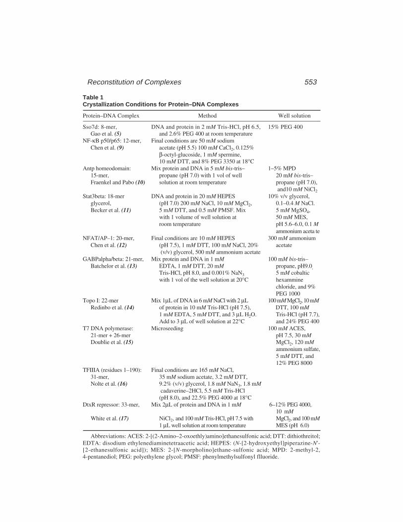
Reconstitution of Complexes 553
Table 1Crystallization Conditions for Protein–DNA Complexes
Protein–DNA Complex Method Well solution
Sso7d: 8-mer, DNA and protein in 2 mM Tris-HCl, pH 6.5, 15% PEG 400Gao et al. (5) and 2.6% PEG 400 at room temperature
NF-κB p50/p65: 12-mer, Final conditions are 50 mM sodiumChen et al. (9) acetate (pH 5.5) 100 mM CaCl2, 0.125%
β-octyl-glucoside, 1 mM spermine,10 mM DTT, and 8% PEG 3350 at 18°C
Antp homeodomain: Mix protein and DNA in 5 mM bis-tris– 1–5% MPD15-mer, propane (pH 7.0) with 1 vol of well 20 mM bis-tris–Fraenkel and Pabo (10) solution at room temperature propane (pH 7.0),
and10 mM NiCl2Stat3beta: 18-mer DNA and protein in 20 mM HEPES 10% v/v glycerol,
glycerol, (pH 7.0) 200 mM NaCl, 10 mM MgCl2, 0.1–0.4 M NaCl.Becker et al. (11) 5 mM DTT, and 0.5 mM PMSF. Mix 5 mM MgSO4,
with 1 volume of well solution at 50 mM MES,room temperature pH 5.6–6.0, 0.1 M
ammonium aceta teNFAT/AP–1: 20-mer, Final conditions are 10 mM HEPES 300 mM ammonium
Chen et al. (12) (pH 7.5), 1 mM DTT, 100 mM NaCl, 20% acetate (v/v) glycerol, 500 mM ammonium acetate
GABPalpha/beta: 21-mer, Mix protein and DNA in 1 mM 100 mM bis-tris–Batchelor et al. (13) EDTA, 1 mM DTT, 20 mM propane, pH9.0,
Tris-HCl, pH 8.0, and 0.001% NaN3 5 mM cobalticwith 1 vol of the well solution at 20°C hexammine
chloride, and 9%PEG 1000
Topo I: 22-mer Mix 1µL of DNA in 6 mM NaCl with 2 µL 100 mM MgCl2, 10 mMRedinbo et al. (14) of protein in 10 mM Tris-HCl (pH 7.5), DTT, 100 mM
1 mM EDTA, 5 mM DTT, and 3 µL H2O. Tris-HCl (pH 7.7),Add to 3 µL of well solution at 22°C and 24% PEG 400
T7 DNA polymerase: Microseeding 100 mM ACES,21-mer + 26-mer pH 7.5, 30 mMDoublie et al. (15) MgCl2, 120 mM
ammonium sulfate,5 mM DTT, and12% PEG 8000
TFIIIA (residues 1–190): Final conditions are 165 mM NaCl,31-mer, 35 mM sodium acetate, 3.2 mM DTT,Nolte et al. (16) 9.2% (v/v) glycerol, 1.8 mM NaN3, 1.8 mM
cadaverine–2HCl, 5.5 mM Tris-HCl(pH 8.0), and 22.5% PEG 4000 at 18°C
DtxR repressor: 33-mer, Mix 2µL of protein and DNA in 1 mM 6–12% PEG 4000,10 mM
White et al. (17) NiCl2, and 100 mM Tris-HCl, pH 7.5 with MgCl2, and 100 mM1 µL well solution at room temperature MES (pH 6.0)
Abbreviations: ACES: 2-[(2-Amino–2-oxoethly)amino]ethanesulfonic acid; DTT: dithiothreitol;EDTA: disodium ethylenediaminetetraacetic acid; HEPES: (N-[2-hydroxyethyl]piperazine-N'-[2-ethanesulfonic acid]); MES: 2-[N-morpholino]ethane-sulfonic acid; MPD: 2-methyl-2,4-pentanediol; PEG: polyethylene glycol; PMSF: phenylmethylsulfonyl flluoride.
554 Colin and Brown
3. Customized gradients can be supplied to standard laboratory chromatography col-umns using a programmed FPLC control unit and pumps. Flow rates of 1–50 mL/hare possible without significant back pressure.
4. The protein binds to heparin–Sepharose in 0.25 M NaCl and 7 M urea. A reversegradient is applied to remove urea. The protein is eluted in a 0.25 M NaCl to 2 MNaCl gradient and 10 µM zinc acetate.
5. The collodion bag is pre-equilibrated in buffer and contains a small magneticstirrer (5 mm × 2 mm) to aid dialysis and recovery of the protein.
6. This assay can be used to measure protein concentrations between 50 µg/mL and50 mg/mL according to the manufacturer’s directions.
7. Data may be conveniently analyzed by linear regression using commercial soft-ware like KaleidaGraph.
8. The protein concentration obtained by the Bradford colorimetric assay is rela-tive. An absolute value requires multiplication by a conversion factor. This fac-tor can be derived from simultaneous amino acid analysis or microKjeldahlnitrogen determination (18). In the case of the TFIIIA 22-kDa fragment, thededuced concentration of BSA is multiplied by 0.39.
9. TFIIIA and its fragments have anomalous electrophoretic mobilities. Reductionand carboxymethylation with 50 mM iodoacetamide restores the predicted gelmobility to the intact protein. Fragments containing zinc fingers generally runslower than expected after this treatment.
10. Chemical detritylation can be efficiently performed by passing 0.5% trifluoro-acetic acid for 3 min at room temperature through a reverse-phase ProRPCHR column (Pharmacia). Following deprotection of the bases (30% [w/v]NH4OH, 16 h at 65°C), the oligomer is purified with a Mono Q HR column(Pharmacia) and eluted in a NaCl gradient with 7 M urea according to themanufacturer’s instructions.
11. After the addition of water, the Corex tube is sealed with parafilm to avoid spillage.The water is rolled around the walls of the silanized tube as well as on the pellet.
12. This is conveniently done in a thermal cycler PCR machine at a linear coolingrate of 1°C/3 min.
13. A stock acrylamide solution (30:0.8 acrylamide:bis) is deionized with AmberliteMB–150 resin (10 g/100 mL) for 1 h, filtered through a NYL/50 filter unit (0.2 µm),and stored at 4°C. This treatment minimizes the sequestering of the protein fromprotein–DNA complexes during gel electrophoresis.
14. Glass plates, combs, spacers and the gel apparatus must be cleaned and washedcompletely free of detergent to avoid disruption of the protein–DNA complex.
15. The polyacrylamide gel is 1.5 mm thick and contains 50 mM NaCl, 40 mMHEPES–NaOH (pH 7.5), and 5% (v/v) glycerol. The running buffer consists of50 mM NaCl, 20 mM HEPES–NaOH (pH 7.5).
16. A duplex with an unrelated sequence of the same length may be used to monitorthe level of nonspecific protein binding. The affinity of the protein for each of thesingle strands of the duplex can also be tested.
17. Samples can be applied smoothly to the gel by slowly winding the Pipetmanvolume control back to zero.

Reconstitution of Complexes 555
18. At high salt concentration, above 0.65 M NaCl, the protein–DNA complex isdissociated and both components are soluble. The salt concentration is loweredstepwise to 0.225 M NaCl to reconstitute the complex (19). At the same time, theprotein is diluted and becomes less likely to aggregate or bind nonspecifically tothe duplex.
19. Wash dust off the cover slips with deionized water and dry in a suitable rack at50°C in an oven. Immerse cover slips for 15 min in dilute AquaSil (1:40) andleave to dry overnight. Wash in deionized water and dry at 50°C. Keep in a closedcontainer to avoid contact with dust.
20. It is customary to equilibrate against a well solution that contains double theconcentration of the droplet components. One volume of the well solution con-taining appropriate salts, buffers, and precipitant is added to the droplet of theprotein–DNA complex.
21. The grease can be applied accurately to the rim with a 10cc plastic syringe filledwith high-vacuum grease.
References1. Steitz, T. A. (1990) Structural studies of protein-nucleic acid interaction: the
sources of sequence-specific binding. Quart. Rev. Biophys. 23, 205–280.2. Dubendorff, J. W., and Studier, F. W. (1991) Controlling basal expression in an
inducible T7 expression system by blocking the target T7 promoter with lacrepressor. J. Mol. Biol. 219, 45–59.
3. Studier, F. W., Rosenberg, A. G., Dunn, J. J., and Dubendorff, J. W. (1990) Useof T7 RNA polymerase to direct the expression of cloned genes. MethodsEnzymol. 85, 60–89.
4. Engelke, D. R., Ng, S.-Y., Shastry, B. S., and Roeder, R. G. (1980) Specific inter-action of a purified transcription factor with an internal control regionof 5S RNAgenes. Cell 19, 717–728.
5. Gao, Y. G., Su, S. Y., Robinson, H., Padmanabhan, S., Lim, L., MacCrary, B. S.,et al. (1998) The crystal structure of the hyperthermophile chromosomal proteinSso7d bound to DNA. Nature Struct. Biol. 5, 782–786.
6. Deutscher, M. P. (ed.) (1990) Guide to Protein Purification, Methods in Enzy-mology, Academic, New York, p. 182.
7. Oliver, R. W. A. (ed.) (1989) HPLC of macromolecules: a practical approach.IRL, Oxford.
8. Carter, C. W.,Jr. (1992) Crystallization of Nucleic Acids and Proteins: A Practi-cal Approach (Ducruix, A. and Giege, R., eds.), IRL, NY, pp. 47–71.
9. Chen, F. E., Huang, D.-B., Chen, Y.-Q., and Ghosh, G. (1998) Crystal structure ofp50/p65 heterodimer. Nature 391, 410–413.
10. Fraenkel, E. and Pabo, C. O. (1998) Comparison of X-ray and NMR structurefor the Antennapedia homodomain–DNA complex. Nature Struct. Biol. 5,692–696.
11. Becker, S., Groner, B., and Muller, C. W. (1998) Three-dimensional structure ofthe Stat3beta homodimer bound to DNA. Nature 394, 145–151.
556 Colin and Brown
12. Chen, L., Glover, J. N. M., Hogan, P. G., Rao, A., and Harrison, S. C. (1998)Structure of the DNA-binding domains from NFAT, Fos and Jun bound specifi-cally to DNA. Nature 392, 42–48.
13. Batchelor, A. H., Piper, D. E., de la Brousse, F. C., McKnight, S. L., andWolberger, C. (1998) The structure of GABPalpha/beta: an ETS domain-ankyrinrepeat heterodimer bound to DNA. Science 279, 1037–1041.
14. Redinbo, M. R., Stewart, L., Kuhn, P., Champoux, J. J., and Hol, W. G. J. (1998)Crystal structures of human topoisomerase I in covalent and noncovalent com-plexes with DNA. Science 279, 1504–1513.
15. Doublie, S., Tabor, S., Long, A. M., Richardson, C. C., and Ellenberger, T. (1998)Crystal structure of a bacteriophage T7 DNA replication complex at 2. 2Å resolu-tion. Nature 391, 251–258.
16. Nolte, R. T, Conlin, R. M., Harrison, S. C., and Brown, R. S. (1998) Differingroles for zinc fingers in DNA recognition: structure of a six-finger transcriptionfactor IIIA complex. Proc. Natl. Acad. Sci. USA 95, 2938–2943.
17. White, A., Ding, X., vanderSpek, J. C., Murphy, J. R., and Ringe, D. (1998) Struc-ture of the metal-ion-activated diphtheria toxin repressor/tox operator complex.Nature 394, 502–506.
18. Jaenicke, L. (1974) A rapid micromethod for the determination of nitrogen andphosphate in biological material. Anal. Biochem. 61, 623–627.
19. Zwieb, C. and Brown, R. S. (1990) Absence of substantial bending in Xenopuslaevis transcription factor IIIA-DNA complexes. Nucleic Acids Res. 18, 583–587.
2-D Crystallization of Protein Complexes 557
557
From: Methods in Molecular Biology, vol. 148: DNA–Protein Interactions: Principles and Protocols, 2nd ed.Edited by: T. Moss © Humana Press Inc., Totowa, NJ
38
Two-Dimensional Crystallizationof Soluble Protein Complexes
Patrick Schultz, Nicolas Bischler, and Luc Lebeau
1. IntroductionStructural data on biological macromolecules provide invaluable insights
into the interactions of proteins with nucleic acids. Data obtained at atomicresolution by X-ray diffraction or nuclear magnetic resonance (NMR) studiesultimately describes the exact folding of polypeptide chains and the contactsbetween proteins and DNA. However, many complexes are difficult to analyzeat atomic resolution because either they are too large or too difficult to crystal-lize in three dimensions (3-D). Recent progress in electron microscopy, speci-men preservation, and image processing provides the possibility to calculatedetailed molecular envelopes that are complementary to X-ray crystallographywith little theoretical limit on specimen size. In the case of membrane proteinsorganized into one-molecule-thick two-dimensional (2-D) arrays, atomic mod-els could be elaborated from electron microscopy data (1,2). It is beyond thescope of this chapter to describe in detail the electron crystallographic methodsand computer image analysis required to calculate a 3-D model of a crystal-lized protein complex; these aspects are described elsewhere (3). Here, we willfocus on the formation of 2-D crystals of soluble proteins, an essentialpreliminary step in high-resolution structure determination by electron micros-copy, and provide the necessary information to set up, screen, and evaluatecrystallization experiments.
The remarkable achievements in the field of membrane protein 2-D crystalsprompted the pioneering work of Kornberg and collaborators aimed attransposing the crystallization mechanisms occurring in a lipid bilayer tosoluble proteins (4). The method consists in targeting the protein of interest to alipid surface self-assembled as a monomolecular film at an air–water interface.
558 Schultz, Bischler, and Lebeau
The buffer-exposed hydrophilic part of the lipid molecule may carry chargedgroups (5,6) or be chemically modified (7,8) in order to interact with the pro-tein. Consequently, the protein is concentrated at the lipid plane and adoptsonly a few orientations relatively to it. If the lipid molecules are free to diffusein the monolayer plane, the system permits the 2-D crystallization of the mac-romolecule. This achieved, the lipid–protein film is transferred onto a solidsupport and processed for electron microscopy observations. As was demon-strated by the study of streptavidin 2-D crystals (9), which revealed structuralinformation down to 3 Å in projection, such an approach can yield high-resolu-tion structural data.
Two categories of lipid derivatives can be used according to the specificityof the interaction to be established with the protein complex (10). On the onehand, a charged surface can be created by using lipids with positive or negativecharges that will interact with the surface potential of the protein to be crystal-lized (5). The characteristic behavior of the protein in ion-exchange chroma-tography may give a hint as to which type of charged lipids should be used.Typically used lipids are phosphatidyl serine which carries a negative charge,and stearyl amine or alkyl trimethyl ammonium, both of which are positivelycharged. On the other hand the lipid film may be derivatized by a specificligand recognized by the protein of interest. The ligand is chemically grafted tothe lipid moiety through a linker whose length modulates the accessibility forthe protein. The grafted molecule can be a natural ligand of the protein such asdinitrophenol for specific anti-DNP antibodies (4), novobiocin for gyrase Bsubunit (8) (Fig. 1), or biotin for streptavidin (11). More recently lipid mol-ecules have been designed to interact with specific tags (such as polyhistidines)introduced genetically into the sequence of the protein of interest (12,13). Thepolar head group of the lipid molecule carries a nitrilotriacetate moiety, whichchelates nickel ions and interacts with the histidine tag.
Stability and fluidity of the spread lipid layer are mainly provided by thehydrophobic part of the lipid (Fig. 1). The lipid layer has to be in the fluidphase at the incubation temperature because crystallization of the lipid chainswas shown to prevent protein organization probably by lowering its 2-Dmobility (11,13). In most cases, a cis double bond in the alkyl chains providessufficient fluidity. In addition, the lateral cohesion of the lipid molecules has tobe strong enough to allow the spreading of a stable monolayer and prevent thesolubilization of the lipid as micelles or liposomes. A double alkyl chain con-taining 18 carbon atoms (dioleyl) generally fulfills these requirements.
When protein–lipid interactions occur, the proteins are rapidly concentratedclose to the lipid layer and are likely to be partly oriented. In the case of aspecific interaction with a functionalized lipid, the macromolecules are teth-ered to the lipid film by a unique site and the extent of orientation is deter-
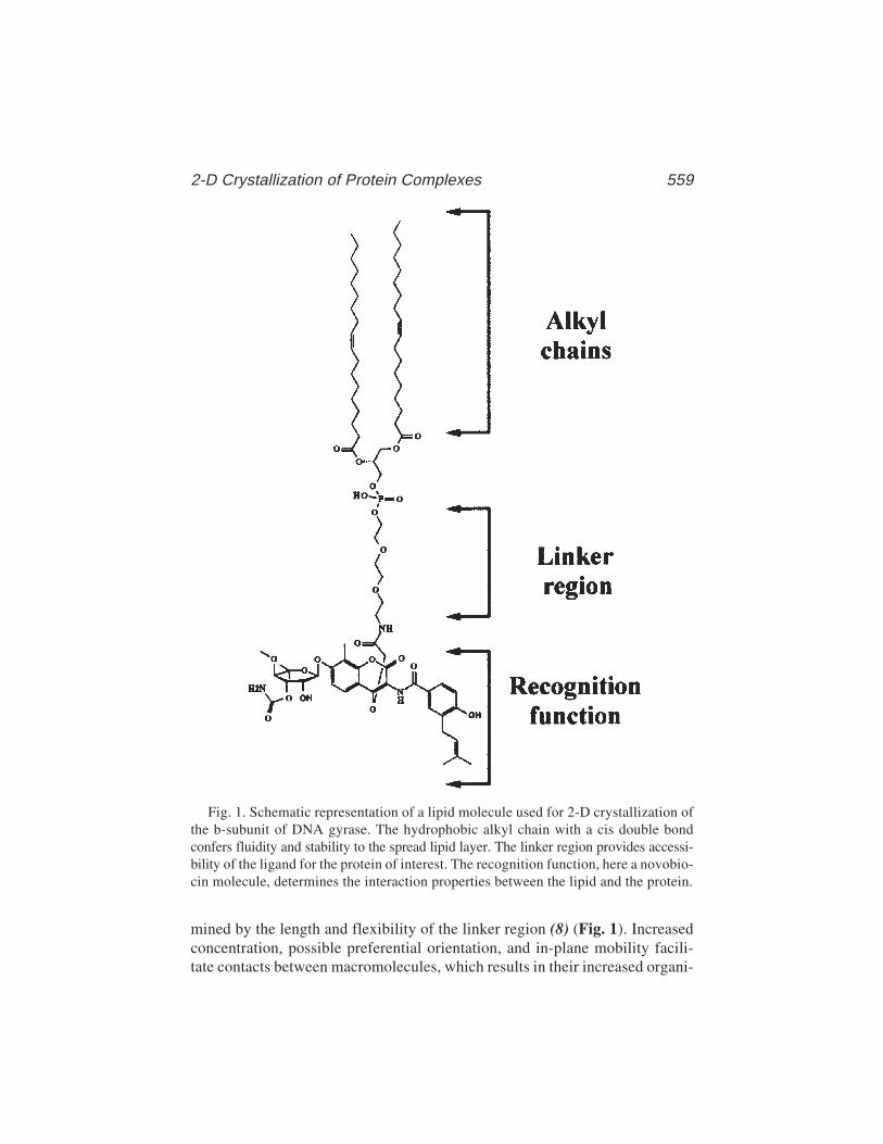
2-D Crystallization of Protein Complexes 559
mined by the length and flexibility of the linker region (8) (Fig. 1). Increasedconcentration, possible preferential orientation, and in-plane mobility facili-tate contacts between macromolecules, which results in their increased organi-
Fig. 1. Schematic representation of a lipid molecule used for 2-D crystallization ofthe b-subunit of DNA gyrase. The hydrophobic alkyl chain with a cis double bondconfers fluidity and stability to the spread lipid layer. The linker region provides accessi-bility of the ligand for the protein of interest. The recognition function, here a novobio-cin molecule, determines the interaction properties between the lipid and the protein.
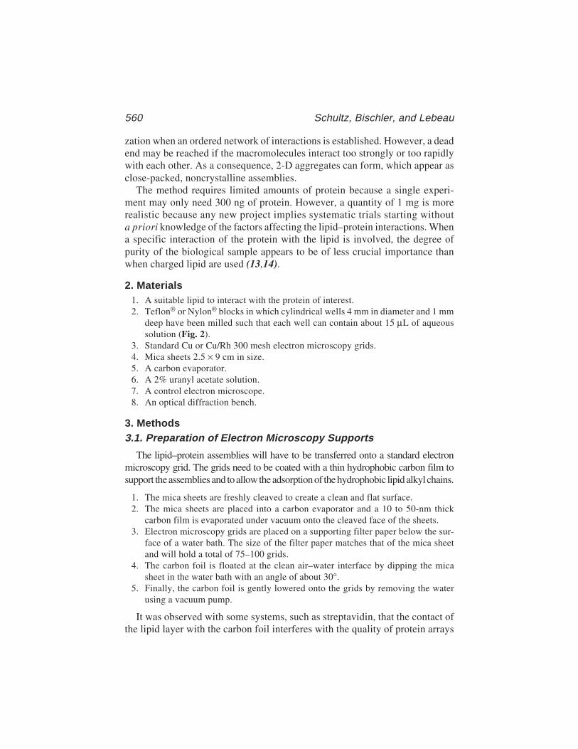
560 Schultz, Bischler, and Lebeau
zation when an ordered network of interactions is established. However, a deadend may be reached if the macromolecules interact too strongly or too rapidlywith each other. As a consequence, 2-D aggregates can form, which appear asclose-packed, noncrystalline assemblies.
The method requires limited amounts of protein because a single experi-ment may only need 300 ng of protein. However, a quantity of 1 mg is morerealistic because any new project implies systematic trials starting withouta priori knowledge of the factors affecting the lipid–protein interactions. Whena specific interaction of the protein with the lipid is involved, the degree ofpurity of the biological sample appears to be of less crucial importance thanwhen charged lipid are used (13,14).
2. Materials1. A suitable lipid to interact with the protein of interest.2. Teflon® or Nylon® blocks in which cylindrical wells 4 mm in diameter and 1 mm
deep have been milled such that each well can contain about 15 µL of aqueoussolution (Fig. 2).
3. Standard Cu or Cu/Rh 300 mesh electron microscopy grids.4. Mica sheets 2.5 × 9 cm in size.5. A carbon evaporator.6. A 2% uranyl acetate solution.7. A control electron microscope.8. An optical diffraction bench.
3. Methods3.1. Preparation of Electron Microscopy Supports
The lipid–protein assemblies will have to be transferred onto a standard electronmicroscopy grid. The grids need to be coated with a thin hydrophobic carbon film tosupport the assemblies and to allow the adsorption of the hydrophobic lipid alkyl chains.
1. The mica sheets are freshly cleaved to create a clean and flat surface.2. The mica sheets are placed into a carbon evaporator and a 10 to 50-nm thick
carbon film is evaporated under vacuum onto the cleaved face of the sheets.3. Electron microscopy grids are placed on a supporting filter paper below the sur-
face of a water bath. The size of the filter paper matches that of the mica sheetand will hold a total of 75–100 grids.
4. The carbon foil is floated at the clean air–water interface by dipping the micasheet in the water bath with an angle of about 30°.
5. Finally, the carbon foil is gently lowered onto the grids by removing the waterusing a vacuum pump.
It was observed with some systems, such as streptavidin, that the contact ofthe lipid layer with the carbon foil interferes with the quality of protein arrays
2-D Crystallization of Protein Complexes 561
(15). “Holey” carbon grids can then be used to transfer the crystals withoutinteractions with a carbon surface, the lipid–protein layer being spread overthe holes. A protocol to prepare “holey” carbon films is as follows (16):
1. The surface of an optical microscope glass slide is extensively cleaned by boilingin an aqueous detergent solution and extensive rinsing with demineralizedwater (H2Od).
2. The slide is immersed in a 0.1% Triton X405 (Sigma) solution for 30 min, brieflyrinsed with H2Od to remove the excess of detergent and left to dry. This willresult in a clean hydrophobic surface.
3. The slide is placed on a precooled aluminum block to allow minute water drop-lets to form on the surface by condensation. The size of the droplets depends onthe humidity of the room and on the condensation time.
Fig. 2. Design of a Teflon® block for 2-D crystallization experiments. (A) A Teflon®
cylinder 4 cm in diameter truncated into 1 cm-thick slices and 16 wells, 4 mm indiameter and 1 mm deep, are milled into the block such that each well can containabout 15 µL of solution. (B) During the crystallization experiments performed in thewells (a), the Teflon® block (b) is placed into a humid chamber consisting of a revertedPetri dish containing some buffer (c).
562 Schultz, Bischler, and Lebeau
4. One mL of a cellulose acetate or cellulose butyrate solution (0.4% [w/v] in ethylacetate) is poured with a pipet over the surface, excess solution is removed fromone end of the slide by touching a filter paper and left to dry. Upon drying, thecellulose forms a thin film around the water droplets, thus forming holes.
5. At this point, an optical microscope can be used to check the size of the holes andtheir distribution.
6. The slide is then immersed 30 min in a 0.5% (w/v) sodium dodecyl sulfosuccinatesolution to peal off the cellulose film.
7. Electron microscopy grids are deposited on a supporting filter paper just belowthe surface of a water bath.
8. The holey cellulose film is floated on the clean air–water interface and depositedonto the grids.
9. A 50-nm-thick carbon film is evaporated onto the cellulose-coated grids.10. The cellulose film is finally dissolved by placing the grids on a ethyl acetate-
soaked filter paper.
3.2. Crystallization Experiments
1. The lipids are best stored as a dry powder under an argon atmosphere at –80°C. Amother solution at a concentration of 10 mg/mL is produced by solubilizing thelipids in an organic solvent such as a 1:1 mixture of chloroform:hexane. Thissolution can be stored under argon up to 1 yr at –20°C. The working lipid solu-tion is at a concentration of 0.5–1 mg/L in an organic solvent. All solution arestored in 2 mL glass vials with Teflon® caps to prevent solvent evaporation.
2. The Teflon® wells have to be cleaned prior to use for crystallization experimentsto remove residues of proteins or lipids. The Teflon® support should be dippedinto a sulfochromic acid solution for 1 h, rinsed 10 times with H2Od, dipped for1 h into H2Od, and rinsed again three times with H2Od. Alternatively, the supportcan be rinsed 10 times with methanol to eliminate proteins, 10 times with achloroform:methanol 2:1 or hexane:methanol 9:1 solution to remove lipids andrinsed 10 times with hexane to remove fatty acids. Finally, the support is broughtinto contact with a filter paper to remove the excess of H2Od or organic solvent,without wiping to avoid electrostatic charging, and is allowed to dry in a dust-free chamber.
3. Incubations are performed in a humid chamber to prevent buffer evaporation(Fig. 2B). The Teflon® block is placed in a reverted Petri dish containing somebuffer with an opening in the top to let air in and out during removal of the lid.
4. In each well, 10 µL of buffer are added (Fig. 3B).5. To spread the lipid at the air-buffer interface, 1 µL of the lipid solution at a con-
centration of 0.5–1 mg/mL is placed on the top of the drop of buffer with amicropipet. At this moment it can be observed that the surface tension of the dropis released (Fig. 3C).
6. The organic solvent is allowed to evaporate for 5 min.7. The protein solution (5 µL) is injected into the aqueous phase (Fig. 3D). The
final protein concentration is generally set between 20 and 200 µg/mL.

2-D Crystallization of Protein Complexes 563
8. The incubation chamber is closed, and if oxidation is a problem air is replaced by argon.9. The incubation time will vary from one system to another but is generally in the
range of 1–36 h. Most experiments can be performed at room temperature, butlonger incubation times at 4°C may improve crystal quality in some cases.
3.3. Electron Microscopy
1. The 2-D crystal is transferred to the electron microscopy grid through hydropho-bic contacts between the lipid chains and the carbon foil (Fig. 3E). This is simplydone by placing the grid over the well for 1–2 min. The grid is then withdrawnand prepared for observation (see Notes 1 and 2).
2. To be visualized by electron microscopy, the specimen has to be contrasted bycreating a mould of heavy atoms around the proteins, a process named negative
Fig. 3. Setup of a crystallization experiment. In each well (A), a 10-µL drop ofbuffer is placed (B). Because the Teflon well is hydrophobic, the drop does not wet thesurface. Upon the addition of 1 µL of the lipid solution at a concentration of 0.5–1 mg/mL,the surface tension of the drop is released (C). After evaporation of the organic sol-vent, 5 µL of the protein solution is injected into the well (D) and is allowed to interactwith the lipid layer. The resulting lipid–protein assembly is transferred to a carbon-coated electron microscopy grid placed on the top of the drop (E).
564 Schultz, Bischler, and Lebeau
staining. The transferred specimen placed on the grid held by forceps is washedwith a drop of buffer that is quickly removed. The buffer is then replaced by adrop of a 1–2% aqueous solution of uranyl acetate and the grid is dried by touch-ing a piece of filter paper with the edge of the grid (see Notes 3 and 4).
3. The crystallization experiments have then to be evaluated in terms of proteinconcentration on the lipid layer and degree of organization (see Notes 11 and 12).When the specimen is large enough (> 50 kDa), individual molecules can beidentified visually during electron microscopy inspection. To ascertain that thespecimen is specifically bound to the lipid layer and not in a nonspecific way tothe carbon film, it is useful to locate breaks in the lipid layer in order to observea difference in binding efficiency with the underlying carbon film. A frequentlyobserved intermediate step in specimen ordering is the formation of symmetry-related oligomers that arise when a particular set of protein–protein interactionsis energetically favored. The formation of oligomers probably favors furtherorganization because interactions between symmetry related surfaces will propa-gate forming linear polymers or 2-D crystals. Once larger crystalline areas areobtained, electron micrographs are recorded and the extent of order is evaluated byoptical diffraction.
3.4. Feedback Loops
1. If the protein is not concentrated on the lipid film, it is advisable to act on thelipid region involved in protein recognition, on its environment, or on the buffercomposition. In the case of a specific lipid, the linker may be too short to allowthe ligand to be recognized by the protein. Alternatively, the surface potentialcreated by the lipid layer may have a repulsive effect on the protein and it may beof importance to modify the environment by the addition of a dilution lipid.Finally, the ionic strength of the buffer may be too high and screen electrostaticinteractions between the protein and the charged lipid (see Note 5).
2. When the protein tends to form close-packed arrays, which do not evolve towardorganized protein patches, it is advisable to reduce the kinetics of protein con-centration either by increasing the viscosity of the medium by adding glycerol(up to 40%) or by reducing the temperature or the protein concentration. Thespecific or charged lipid can also be diluted with a neutral lipid to reduce thelocal concentration of ligand or the charge density of the surface (see Note 10).
3. The experiment has to be evaluated further in terms of macromolecular organiza-tion. Higher degrees of order are recognized visually during the electron micros-copy inspection of the specimen by the appearance of patches of ordered arrays(Fig. 4A). Once larger crystalline areas are obtained, electron micrographs arerecorded and the extent of order is evaluated by optical diffraction. A large num-ber of parameters such as the pH, the ionic strength, the buffer composition, thepresence of divalent cations, the protein concentration, the presence of glycerol,the incubation temperature, or the incubation time can be modified to improvecrystal order (see Note 6). At this stage, the homogeneity of the specimen sus-pension may be crucial.
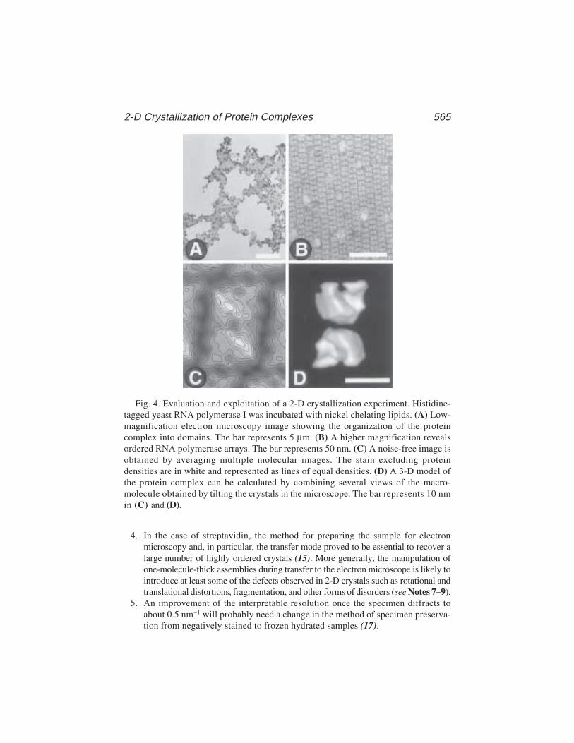
2-D Crystallization of Protein Complexes 565
4. In the case of streptavidin, the method for preparing the sample for electronmicroscopy and, in particular, the transfer mode proved to be essential to recover alarge number of highly ordered crystals (15). More generally, the manipulation ofone-molecule-thick assemblies during transfer to the electron microscope is likely tointroduce at least some of the defects observed in 2-D crystals such as rotational andtranslational distortions, fragmentation, and other forms of disorders (see Notes 7–9).
5. An improvement of the interpretable resolution once the specimen diffracts toabout 0.5 nm–1 will probably need a change in the method of specimen preserva-tion from negatively stained to frozen hydrated samples (17).
Fig. 4. Evaluation and exploitation of a 2-D crystallization experiment. Histidine-tagged yeast RNA polymerase I was incubated with nickel chelating lipids. (A) Low-magnification electron microscopy image showing the organization of the proteincomplex into domains. The bar represents 5 µm. (B) A higher magnification revealsordered RNA polymerase arrays. The bar represents 50 nm. (C) A noise-free image isobtained by averaging multiple molecular images. The stain excluding proteindensities are in white and represented as lines of equal densities. (D) A 3-D model ofthe protein complex can be calculated by combining several views of the macro-molecule obtained by tilting the crystals in the microscope. The bar represents 10 nmin (C) and (D).

566 Schultz, Bischler, and Lebeau
6. To calculate a 3-D model, astigmatism-free and well-focused images of theoriented or crystallized macromolecules must be recorded under minimal expo-sure conditions and generally at low temperature. These images are analyzed tocalculate a noise-free image representing a projection of the macromolecular den-sities (Fig. 4C). Because the particles are adsorbed on a planar surface, tiltedviews are then recorded to recover the information normal to the lipid plane. Theimages are then processed and the different views are merged into a 3-D model(3) (Fig. 4D).
4. Notes1. A good macroscopic indication that proteins bind to the lipid layers and that the
transfer is efficient is obtained by visual inspection of the carbon surface aftertransfer. The original hydrophobic grid becomes hydrophilic, as assessed by thechange in its wetting properties.
2. Storage of the carbon-coated grids in hexane atmosphere may provide higherreproducibility in the specimen transfer step by preventing adsorption of con-taminating material.
3. Do not use phosphate buffers or buffers with high ionic strength, which precipi-tate uranyl salts.
4. Other heavy metal solutions can be used for negative staining such as sodiumphosphotungstate or ammonium molybdate.
5. It is useful to check the specificity of the protein–lipid interactions. In the case ofcharged lipids, the protein binding should be reduced by increasing the ionicstrength. In the case of functionalized lipids, the amount of transferred proteinshould diminish by adding some competing ligand in solution. Note that in thecase of nickel-chelating lipids, it was observed that addition of small amounts ofimidazole prevented the nonspecific aggregation of the protein and allowed theselection of the specific interaction with the polyhistidine tag (13).
6. Detergents should be avoided in the incubation buffer because they may solubi-lize the lipid layer.
7. In some cases, it was observed that the grid side on which the carbon foil wasdeposited affected crystal transfer (13). This effect may be related to the surfaceroughness of the carbon foil and of the grid (18).
8. To strengthen the crystals, 1 µL of a 0.5% glutaraldehyde solution can be addedto the incubation drop before placing the electron microscopy grid in order tocrosslink the specimen.
9. Another method of specimen transfer is the loop method (19). A loop is formedwith a thin Pt/Pd wire (0.075 mm in diameter). The inside diameter must beslightly larger than the outside diameter of the electron microscopy grid. Theloop is then lowered onto the drop, the entire loop makes contact with the dropsurface at the same time. This can be observed through drop deformation. So thatno excess subphase is picked up, the loop should not go through the monolayerand into the subphase. The loop is then gently and carefully raised and loweredonto a glow-discharged grid. The grid is held with forceps and is parallel to the
2-D Crystallization of Protein Complexes 567
film in the loop. The transfer is made by hydrophilic contacts between the carbonfoil and the crystal. The film is then broken by tilting the loop to increase theangle between the film and the grid.
10. In order to better evaluate the organizational state of the molecule in the crystal-lization experiment, it is useful to control its shape and size by direct adsorptionof the sample on a carbon film and negative staining. Such an experiment willalso give an insight into the aggregation state of the protein in solution.
11. The appearance of vesicular structures is often an indication for a too large excessof lipids. The working lipid solution should then be diluted.
12. To remove excess lipids, a detergent solution at low concentration can be used(19). Care must be taken during this step because the drop might migrate to bothsides of the grid and interfere with the staining process.
References1. Henderson, R., Baldwin, J. M., Ceska, T. A., Zemlin, F., Beckmann, E., and
Downing, K. H. (1990) Model for the structure of bacteriorhodopsin based onhigh-resolution electron cryo-microscopy. J Mol. Biol. 213, 899–929.
2. Kuhlbrandt, W., Wang, D. N., and Fujiyoshi, Y. (1994) Atomic model of plantlight-harvesting complex by electron crystallography. Nature 367, 614–621.
3. Amos, L. A., Henderson, R., and Unwin, P. N. (1982) Three-dimensional struc-ture determination by electron microscopy of two-dimensional crystals. Prog.Biophys. Mol. Biol. 39 , 183–231.
4. Uzgiris, E. E. and Kornberg, R. D. (1983) Two-dimensional crystallization tech-nique for imaging macromolecules, with application to antigen-antibody-comple-ment complexes. Nature 301, 125–129.
5. Darst, S. A., Ribi, H. O., Pierce, D. W., and Kornberg, R. D. (1988) Two-dimen-sional crystals of Escherichia coli RNA polymerase holoenzyme on positivelycharged lipid layers. J. Mol. Biol. 203, 269–273.
6. Schultz, P., Celia, H., Riva, M., Darst, S. A., Colin, P., Kornberg, R. D., et al.(1990) Structural study of the yeast RNA polymerase A. Electron microscopyof lipid-bound molecules and two-dimensional crystals. J. Mol. Biol. 216,353–362.
7. Ribi, H. O., Reichard, P., and Kornberg, R. D. (1987) Two-dimensional crystalsof enzyme-effector complexes: ribonucleotide reductase at 18-A resolution. Bio-chemistry 26, 7974–7979.
8. Lebeau, L., Regnier, E., Schultz, P., Wang, J. C., Mioskowski, C., and Oudet, P.(1990) Two-dimensional crystallization of DNA gyrase B subunit on specificallydesigned lipid monolayers. FEBS Lett. 267, 38–42.
9. Avila-Sakar, A. J., and Chiu, W. (1996) Visualization of beta-sheets and side-chain clusters in two-dimensional periodic arrays of streptavidin on phospholipidmonolayers by electron crystallography. Biophys. J. 70, 57–68.
10. Lebeau, L., Schultz, P., Celia, H., Mesini, P., Nuss, S., Klinger, C., et al. (1996)Specifically designed lipid assemblies as tools for two-dimensional crystalliza-tion of soluble biological macromolecules, in Handbook of Nonmedical Applica-
568 Schultz, Bischler, and Lebeau
tions of Liposomes, vol. II (Barenholz Y. and Lasic D. D., eds.), CRC, Boca Raton,FL, pp. 155–188.
11. Darst, S. A., Ahlers, M., Meller, P. H., Kubalek, E. W., Blankenburg, R., Ribi, H.O., et al. (1991) Two-dimensional crystals of streptavidin on biotinylated lipidlayers and their interactions with biotinylated macromolecules. Biophys. J. 59,387–396.
12. Kubalek, E. W., Le Grice, S. F., and Brown, P. O. (1994) Two-dimensional crys-tallization of histidine-tagged, HIV-1 reverse transcriptase promoted by a novelnickel-chelating lipid. J. Struct. Biol. 113, 117–123.
13. Bischler, N., Balavoine, F., Milkereit, P., Tschochner, H., Mioskowski, C., andSchultz, P. (1998) Specific interaction and two-dimensional crystallization of his-tidine tagged yeast RNA polymerase I on nickel-chelating lipids. Biophys. J. 74,1522–1532.
14. Mosser, G. and Brisson, A. (1991) Structural analysis of two-dimensional arraysof cholera toxin B- subunit. J. Electron Microsc. Tech. 18, 387–394.
15. Kubalek, E. W., Kornberg, R. D., and Darst, S. A. (1991) Improved transfer oftwo-dimensional crystals from the air/water interface to specimen supportgrids for high-resolution analysis by electron microscopy. Ultramicroscopy 35,295–304.
16. Fukami, A. and Adachi, K. (1965) A new method of preparation of a self-perfo-rated micro plastic grid and its application. J. Electron Microscopy, 14, 112–118.
17. Dubochet, J., Adrian, M., Chang, J. J., Homo, J. C., Lepault, J., McDowall, A. W.,et al. (1988) Cryo-electron microscopy of vitrified specimens. Quart. Rev.Biophys. 21, 129–228.
18. Schmutz, M. and Brisson, A. (1996) Analysis of carbon film planarity by reflectedlight microscopy. Ultramicroscopy 63, 263–272.
19. Asturias, F. J. and Kornberg, R. D. (1995) A novel method for transfer of two-dimensional crystals from the air/water interface to specimen grids. EM samplepreparation/lipid-layer crystallization. J. Struct. Biol. 114, 60–66.

AFM of DNA and Nucleoproteins 569
569
From: Methods in Molecular Biology, vol. 148: DNA–Protein Interactions: Principles and Protocols, 2nd ed.Edited by: T. Moss © Humana Press Inc., Totowa, NJ
39
Atomic Force Microscopy of DNAand Protein-DNA ComplexesUsing Functionalized Mica Substrates
Yuri L. Lyubchenko, Alexander A. Gall,and Luda S. Shlyakhtenko
1. IntroductionAtomic force microscopy (AFM; also called scanning force microscopy
[SFM]) is a rather novel technique that offers unique advantages in the poten-tial for the very high resolution of DNA and small ligands in the absence ofstains, shadows, and labels (1,2). Furthermore, the scanning can be performedin air or liquid. The latter is particularly important for resolving fully hydratedstructures. The AFM is theoretically capable of resolving structural details atthe level of atomic dimensions, provided that the specimen is not dynamic.
A serious practical limitation to the application of AFM to structural andconformational studies of DNA and its complexes with proteins and other bio-logical macromolecules has been sample preparation. The macromoleculesmust be tethered to the substrate surface in order to avoid resolution-limitingmotion caused by the sweeping tip during scanning. Progress in sample prepa-ration for AFM studies of DNA has been achieved in a number of groups (3–7)and some of these approaches have been applied to studies of a number ofprotein–DNA complexes (3,4,8).
A versatile approach based on functionalization of surfaces with silanes wassuggested in refs. 9–11. A weak cationic surface is obtained if amino-propyltrietoxy silane (APTES) is used to functionalize the mica surface withamine groups (AP-mica). This technique in addition to imaging nucleic acidsunder different conditions (10,12–14) was applied to imaging of a number ofnucleoprotein complexes (9,11,15–17). Here, we describe a sample prepara-tion procedure for AFM using AP-mica substrates.
570 Lyubchenko et al.
The method of functionalization of mica is based on covalent attachment of3-aminopropyltriethoxy silane to the surface of the mica, as shown schemati-cally in Fig. 1. The amino groups of APTES are bound covalently to the freshlycleaved mica surface, giving it properties similar to an anion-exchange resinused in affinity chromatography. This group after being exposed to a watersolution becomes positively charged in a rather broad range of pH (aliphaticamino groups have a pK of around 10.5). Therefore, DNA, which is a nega-tively charged polymer, should adhere to this surface strongly. The binding ofDNA to AP-mica was monitored directly by the use of radiolabeled DNA. AFMimaging of AP-mica showed that very low concentration of APTES (less than1 µM) should be used to obtain smooth surface (9,10). Vapor deposition ofAPTES allowed one to obtain the surface with mean roughness of several ang-stroms (9–12), so the DNA and DNA–protein complexes can be visualizedeasily (see Fig. 2A,B, respectively).
The features of this procedure of sample preparation are as follows (9,11):
• DNA binding to AP-mica is insensitive to the type of buffer and presence ofMg2+ or other divalent and miltivalent cations; hence sample preparation can bedone in a variety of conditions.
• Deposition can be done in a wide variety of pH and over a wide range oftemperatures.
• Once prepared, samples are stable and do not absorb any contaminants for monthswith minimal precautions for storing.
• As low as 10 ng of DNA is sufficient for the preparation of one sample.
These characteristics of AP-mica were crucial for routine imaging nucleicacids (DNA, dsRNA, kinetoplast DNA) and nucleoprotein complexes of dif-ferent type (9,16,17).
2. Materials.1. Chemicals: commercially available 3-aminopropyltriethoxy silane (e.g., Fluka,
Chemika-BioChemika (Switzerland), Aldrich (USA), United Chemical Technol-ogy (USA), and N,N-diisopropylethylamine (Aldrich, Sigma). It is recommendedto redistill APTES and store under argon.
2. Mica substrate: any type of commercially available mica sheets (green or rubymica). Asheville-Schoonmaker Mica Co. (Newport News, VA) supplies boththick and large (more than 5 × 7 cm) sheets suitable for making the substrates ofdifferent sizes.
3. Water: Double glass distilled or deionized water filtered through a 0.5-µm filter.4. 2-L glass desiccators and vacuum line (50 mmHg is sufficient).5. Plastic syringes (5–10 mL) with a plastic tip for rinsing the samples.6. Plastic syringes (1 mL) for imaging in liquid.7. Gas tank with clean argon gas.8. Vacuum cabinet for storing the samples.
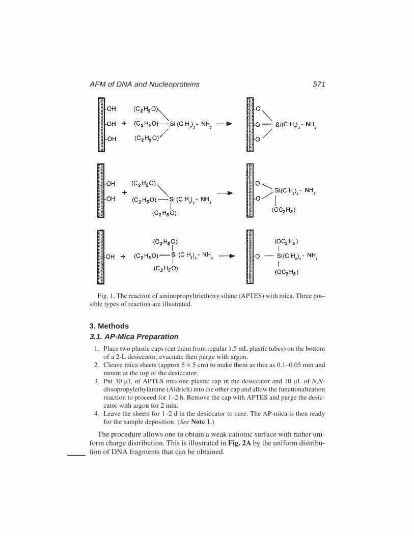
AFM of DNA and Nucleoproteins 571
3. Methods3.1. AP-Mica Preparation
1. Place two plastic caps (cut them from regular 1.5 mL plastic tubes) on the bottomof a 2-L desiccator, evacuate then purge with argon.
2. Cleave mica sheets (approx 5 × 5 cm) to make them as thin as 0.1–0.05 mm andmount at the top of the desiccator.
3. Put 30 µL of APTES into one plastic cap in the desiccator and 10 µL of N,N-diisopropylethylamine (Aldrich) into the other cap and allow the functionalizationreaction to proceed for 1–2 h. Remove the cap with APTES and purge the desic-cator with argon for 2 min.
4. Leave the sheets for 1–2 d in the desiccator to cure. The AP-mica is then readyfor the sample deposition. (See Note 1.)
The procedure allows one to obtain a weak cationic surface with rather uni-form charge distribution. This is illustrated in Fig. 2A by the uniform distribu-tion of DNA fragments that can be obtained.
Fig. 1. The reaction of aminopropyltriethoxy silane (APTES) with mica. Three pos-sible types of reaction are illustrated.

572 Lyubchenko et al.
AFM of DNA and Nucleoproteins 573
3.2. Sample Preparation for AFM Imaging in Air
3.2.1. The Droplet Procedure
1. Prepare the solution of the sample (DNA, RNA, protein–DNA complex) inappropriate buffer. DNA concentration should be between 0.1 and 0.01 µg/mL,depending on the size of the molecules (see Notes 2 and 3).
2. Place 5–10 µL of the solution in the middle of AP-mica substrate (usually 1 × 1-cmsquares) for 2–3 min.
3. Rinse the surface thoroughly with water (2–3 mL per sample) to remove all buffercomponents. A 10-mL plastic syringe is very useful for rinsing, but attach anappropriate plastic tip instead of a metal needle.
4. Dry the sample by blowing with clean argon gas. The sample is ready for imag-ing. Store the samples in vacuum cabinets or desiccators filled with argon.
3.2.2. The Immersion Procedure
This procedure is recommended if the deposition should be performed atstrictly controlled temperature conditions (0°C or elevated temperatures).
1. Prepare the solution (DNA, RNA, nucleoprotein complexes) and preincubate for10–20 min to allow the temperature to equilibrate. Recommended concentrationof DNA is 0.2 –0.01 µg/mL, depending on the size of the molecules (see Notes 2and 3).
2. Immerse a piece of AP-mica into the vials and leave it for 10–20 min to allow thesamples to adsorb to the surface.
3. Remove the specimen, rinse with water thoroughly, and dry under the argon flow.The sample is ready for imaging.
4. The samples can be stored in vacuum cabinet or under argon.
3.3. AFM Imaging in Air
1. Mount the sample and start approaching the probe.2. Both the contact and intermittent (tapping) modes can be used, but the latter is
preferable and allows one to obtain images of DNA and DNA–protein complexesroutinely. Our experience is mostly limited to a NanoScope III microscope(MultiMode system, Digital Instruments, CA), but samples prepared on AP-micawere imaged on other commercially available instruments (e.g., the microscopesmanufactured by Topometrix, Park Scientific Instruments, Molecular Imaging).With the MultiMode system, any type of probe designed for noncontact imagingcan be used. NanoProbe TESP tips (Digital Instruments, Inc.) and conical sharp
Fig. 2. (previous page) AFM images of a 800-bp fragment (A) and reconstitutedchromatin (B). The concentration of DNA was 0.5 µg/mL in (A). Reconstituted chro-matin was deposited onto the substrate after glutaraldehyde fixation. (The sample wasfrom D. Lohr [Arizona State University] and the images were taken in air with TMAFM [NanoScope III]).

574 Lyubchenko et al.
silicon probes from K-TEK International (Portland, OR) work well. Typically atapping frequency of 240–380 kHz and a scanning rate 2–3 Hz allows one toobtain stable images.
3.4. Imaging in Solution
The capability of AFM to perform scanning in liquid is its most attractivefeature for numerous biological applications, allowing imaging under near-physiological conditions. In addition, this mode of imaging permits one toeliminate the undesirable resolution-limiting capillary effect typical for imag-ing in air (3,8,9). As a results, images of DNA filaments as thin as approx 3 nmwere obtained in water solutions (13) and helical periodicity was observedwhen dried DNA samples were imaged in propanol (18). AP-mica can be usedas a substrate for imaging in liquid. Moreover, the first images of DNA in fullyhydrated state were obtained by the use of AP-mica (19). This section describesthe procedures of two types of imaging in solution.
3.4.1. Imaging of Dried Sample in Solutions
This type of imaging was successfully applied for high-resolution imagingof DNA (18,19).
1. Install an appropriate tip designed for imaging in liquid (fluid cell). Use stifftriangular Si3Ni4 cantilevers (20).
2. Mount the sample on the stage of the microscope. Coating the stage of the scan-ner with a thin plastic film prevents it from being wetted because of accidentalleakage of the fluid beneath the mica sheet.
3. Attach the head of the microscope with installed fluid cell and make appropriateadjustments to the microscope.
4. Approach the sample to the tip manually, leaving approx 20-µm gap between thetip and the surface.
5. Inject buffer solution or appropriate solvent with a 1-mL plastic syringe throughthe inlet hole in the fluid cell.
6. Change the position of the mirror to maximize the signal on the photodetector.7. Find a resonance peak. Typically, it is quite broad peak around 8–9 kHz for the
MultiMode system. Follow the recommendations given in the manual for thefluid cell on how to find the peak.
8. Minimize the drive amplitude. The numbers vary from tip to tip, but amplitudesas low as 10 nm or even less provide better quality pictures (see Note 4).
9. Allow the microscope to approach the sample and engage the surface.10. Operate with the setpoint voltage and drive the amplitude parameters to improve
the quality of images (see Note 4).
3.4.2. Imaging Without Drying of the Sample (AFM In Situ)
This type of imaging is recommended in cases in which dynamics are tobe studied.
AFM of DNA and Nucleoproteins 575
1. Prepare the solution of your sample in appropriate buffer. The concentration isthe same as it is needed for imaging in air (Subheading 3.2.)
2. After installing the tip in the fluid cell, mount a piece of AP-mica on the samplestage. Mica pieces of 1 cm × 1 cm are sufficient for NanoScope design of thefluid cell. As earlier, coating the stage with a plastic film is recommended forsecure operating of the microscope.
3. Take approx 50 µL of the sample with a 1-mL syringe. Use 200-µL plastic tipswith capillary ends instead of a metal needle. Cut both ends of the tip to fit thesyringe and the diameter of inlet hole of the fluid cell.
4. After necessary adjustments of the microscope (Subheading 3.4.1.) and manualapproaching of the tip, inject the solution into the cell. The use of additionalsyringe attached to the outlet of fluid cell as a suction helps in manipulating thesmall volume of solution.
5. Start approaching and follow the steps described in Subheading 3.4.1.
3.5. Alternative Procedures for AFM Sample Preparation
Among other techniques applied to AFM studies of DNA, the method basedon miltivalent cations (3,5,8) has permitted the imaging of a number of nucle-oprotein complexes (3,4,8). In this approach, the mica surface is simply treatedwith multivalent ions (e.g., Mg2+) to increase its affinity for DNA, the DNAthen being held in place strongly enough to permit reliable imaging by AFM.An alternative is to deposit the sample in the buffer containing a multivalention. This cation-assisted procedure of sample preparation was used for studiesof the process of DNA degradation with nuclease (21) and interaction of DNAwith photolyase (22). The mechanism underlying this technique remainsunclear and the protocol depends on the system studied and the type of thecation used, and the efficiency of DNA deposition is buffer sensitive (23,24).In some cases, a special type of tips (electron-beam-deposited tips) is requiredfor reliable imaging (25). A protocol describing the use of Mg-assisted proce-dure has been published (26).
4. Notes1. A dry argon atmosphere is crucial for obtaining the substrates for AFM studies and
for storage of the substrate. Allow the gas to flow while desiccator is opened.With these precautions, the AP-mica substrates retain their activity for several weeks.
2. DNA concentration. This parameter depends on the length of molecules. If themolecules are as small (e.g., several hundred base pairs), a concentration ofapprox 0.3 µg/mL is recommended to avoid intermolecular crossing. A lowerDNA concentration is recommended for larger DNA molecules. For example,concentration of lambda DNA (approx 48 kb) of approx 0.01 µg/mL allows oneto obtain images of individual DNA molecules (9–11,19).
3. DNA preparation. Very little DNA is needed to prepare the samples by the drop-let procedure. Typically, 10 ng of DNA is sufficient for the preparation of plas-

576 Lyubchenko et al.
mid DNA (approx 3 kb long). Because a band of DNA from agarose gel usuallycontains 100 ng of DNA, DNA extracted from a single gel slot can be sufficientfor preparation of a complete set of samples. The following procedures can beused for purification of DNA extracted from the gel:• Electrophoretic deposition of DNA bands onto DEAE paper. Strips of DEAE
paper are placed into a slot cut in the agarose gel 3–5 mm below the band tobe recovered and the DNA is electrophoresed onto the paper for 5–10 min(the time can be determined by direct examination the gel under an ultra-violet [UV] source). The DNA is extracted from the paper by elution into 2 MNaCl followed by two rounds of spin-column desalting and extensive etha-nol precipitation.
• Extraction from the gel. The procedure is based on the use of the extraction kitUltraClean15 (MoBio Laboratories, Solana Beach, CA). The purification con-sists of melting of the slice of agarose, immobilizing the DNA on the absorbentmatrix, washing off all contaminants, and eluting DNA from the matrix with alow-salt buffer. At least one step of the ethanol precipitation is needed to removeUV absorbing low-molecular-weight materials. A similar procedure can beapplied to purification of the sample eluted from polyacrylamide gel.
4. Imaging conditions. It was recommended to operate the instrument at the lowestpossible drive amplitude. This recommendation is based on the following con-siderations; the oscillating tip provides rather large energy to the sample.According to ref. 45, a total energy provided to the sample by oscillating tip canbe as high as 10–16–10–17 J at 30 nm amplitude of oscillation. However, this valueis almost three orders of magnitude lower if the microscope is operated at anamplitude as low as approx 3 nm. Such imaging conditions allow one to mini-mize the effect of the tip on the sample, to prevent damaging the tip, and to obtainimages with high contrast. In addition, such conditions simplify considerably thestudy by AFM of dynamic processes such as segmental DNA mobility (13,14) orthe process of protein–DNA interaction (27).
AcknowledgmentsThis work was supported by grant GM 54991 from the NIH.
References1. Binnig, G., Quate, C. F., and Gerber, C. H. (1986) Atomic force microscope Phys.
Rev. Lett. 56, 930–933.2. Hansma, P. K., Elings, V. B., Marti, O., and Bracker, C. E. (1988) Scanning tun-
neling microscopy and atomic force microscopy: some applications to biologyand technology. Science 242, 209–216.
3. Bustamante, C., Erie, D. A., and Keller, D. (1994) Biochemical and structuralapplications of scanning force microscopy. Curr. Opin. Struct. Biol. 3, 750–760.
4. Bustamante, C. and Rivetti, C. (1996) Visualizing protein-nucleic acid interac-tions on a large scale with scanning force microscope. Annu. Rev. Biophys. Biomol.Struct. 25, 395–429.
AFM of DNA and Nucleoproteins 577
5. Vesenka, J., Guthold, M., Tang, C. L., Keller, D., and Bustamante, C. (1992)Substrate preparation for reliable imaging of DNA molecules with the scanningforce microscopy. Ultramicroscopy 42–44, 1243–1249.
6. Yang, J., Takeyasu, K., and Shao, Z. (1992) Atomic force microscopy of DNAmolecules. FEBS Lett. 301, 173–176.
7. Allen, M. J., Dong, X. F., O’Neil, T. E., Yau, P., Kowalczykowski, S. C.,Gatewood, J., Balhorn, R., et al. (1993) Atomic force microscope measurementsof nucleosome cores assembled along defined DNA sequences. Biochemistry 32,8390–8396.
8. Hansma, H., G., and Hoh, J. (1994) Biomolecular imaging with the atomic forcemicroscopy. Ann. Rev. Biophys. Biochem. Struct. 23, 115–139.
9. Lyubchenko Y. L., Jacobs B. L., Lindsay S. M., and Stasiak A. (1995) Atomic forcemicroscopy of protein–DNA complexes [Review]. Scanning Microsc. 9, 705–727.
10. Lyubchenko, Y. L., Gall, A. A., Shlyakhtenko, L. S., Harrington, R. E., Oden, P.I., Jacobs, B. L., et al. (1992) Atomic force microscopy imaging of double strandedDNA and RNA J. Biomolec. Struct. Dynam. 9, 589–606.
11. Lyubchenko, Y. L., Blankenship, R. E., Lindsay, S. M., Simpson, L., Shlyakhtenko,L. S. (1996) AFM studies of nucleic acids, nucleoproteins and cellular complexes:The use of functionalized substrates. Scanning Microsc. 10(Suppl.), 97–109.
12. Lyubchenko, Y. L., Jacobs, B. L., and Lindsay, S. M. (1992) Atomic forcemicroscopy imaging of reovirus dsRNA: a routine technique for length measure-ments. Nucleic Acids Res. 20, 3983–3986.
13. Lyubchenko Y. L. and Shlyakhtenko, L. S. (1997) Visualization of supercoiledDNA with atomic force microscopyin situ. Proc. Natl. Acad. Sci. USA 94,496–501.
14. Shlyakhtenko, L. S, Potaman, V. N., Sinden, R. R., and Lyubchenko, Y. L. (1998)Structure and dynamics of supercoil-stabilized DNA cruciform. J. Mol. Biol.280, 61–72.
15. Lyubchenko, Y. L., Oden, P. I., Lampner, D., Lindsay, S. M., and Dunker, K.(1993) Atomic force microscopy of DNA and bacteriophage in air, water andpropanol: the role of adhesion forces, Nucleic Acids Res. 21, 1117–1123.
16. Lyubchenko, Y. L., Shlyakhtenko, L. S., Aki, T., and Adhya, S. (1997) AFMvisualization of GalR mediated DNA looping. Nucleic Acids Res. 25, 873–876.
17. Herbert A., Schade, M., Lowenkaupt, K., Alfken, J., Schwartz, T., Shlyakhtenko,L. S., et al. (1998) The Za domain from human ADAR1 binds to the Z-DNAconformer of many different sequences. Nucleic Acid Res. 26, 3486–3493.
18. Hansma, H. G., Laney, D. E., Bezanilla, M., Sinsheimer, R. L., and Hansma,P. K. (1995) Applications for atomic force microscopy of DNA. Biophys. J.68, 672–1677.
19. Lyubchenko, Y. L., Shlyakhtenko, L. S., Harrington, R. E., Oden, P. I., and Lind-say, S. M. (1993) AFM imaging of long DNA in air and under water. Proc. Natl.Acad. Sci. USA 90, 2137–2140.
20. Hansma, P. K., Cleveland, J. P., Radmacher, M., Walters, D. A., and Hillner, P. (1994)Tapping mode atomic force microscopy in liquids. Appl. Phys. Lett. 64, 1738–1740.

578 Lyubchenko et al.
21. Bezanilla, M., Drake, B., Nudler, E., Kashlev, M., Hansma, P. K., and Hansma,H. G. (1994 Motion and enzymatic degradation of DNA in the atomic forcemicroscope Biophys. J. 67, 2454–2459.
22. Han, W. H., Lindsay, S. M., and Jing, T. W (1996) A magnetically-driven oscil-lating probe microscope for operation in liquids. Appl. Phys. Lett. 69, 4111–4114.
23. Bezanilla, M., Manne, S., Laney, D. E., Lyubchenko, Y. L., and Hansma, H. G(1995) Adsorption of DNA to mica, silylated mica, and minerals: characterizationby atomic force microscopy. Langmuir 11, 655–659.
24. Hansma, H. G. (1996) A useful buffer for atomic force microscopy of DNA. Sci.Tools Pharmacia Biotech. 1(3), 7.
25. Kasas, S., Thomson, N. H., Smith, B. L., Hansma, H. G., Zhu, X., Guthold, M., et al.(1997) Escherichia coli RNA polymerase activity observed using atomic forcemicroscopy. Biochemistry 36, 461–468.
26. Hansma, H. G. (1998) Atomic force microscopy of DNA on mica in air and fluid,in Procedures for Scanning Probe Microscope (Colton, R. J., et al., eds.), Wiley,Chichester, pp. 389–393.
27. van Noort, S. J. T. , van der Werf, K. O., Eker, A. P. M., Wyman, C., Grooth, B.G., van Hulst, N. F., et al. (1998) Direct visualization of dynamic protein–DNAinteractions with a dedicated atomic force microscope. Biophys. J. 74, 2840–2849.
Additional ReadingColton et al., (eds.) (1998) Procedures in Scanning Probe Microscopes. Wiley,
Chichester.
Electron Microscopy of Nucleoprotein Complexes 579
579
From: Methods in Molecular Biology, vol. 148: DNA–Protein Interactions: Principles and Protocols, 2nd ed.Edited by: T. Moss © Humana Press Inc., Totowa, NJ
40
Electron Microscopyof Protein–Nucleic Acid Complexes
Uniform Spreading of Flexible Complexes, Stainingwith a Uniform Thin Layer of Uranyl Acetate,and Determining Helix Handedness
Carla W. Gray
1. IntroductionThere are a number of proteins involved in DNA replication, recombina-
tion, or repair that bind stoichiometrically to single DNA strands irrespectiveof the nucleotide sequence, and some of these proteins also bind to single-stranded RNA. Some of the best known examples are the ssb protein ofEscherichia coli, the gene 32 protein of phage T4, the gene 5 protein of theM13/fd/f1 filamentous bacterial viruses, and the more recently isolated humanreplication protein A (1–4). Complexes formed by these proteins contain pro-tein bound to the nucleic acid at defined ratios of the number of nucleotides permolecule of bound protein; the ratios are determined by the interactive proper-ties of the protein. These ratios, and the structures of the complexes that areformed, may vary with factors such as changes in solution conditions that alterthe binding properties of the proteins.
Stoichiometric, multiprotein complexes of proteins with nucleic acids willform structural repeats, arranged as discrete clusters of bound proteins or as acontinuous nucleoprotein helix. Although the individual proteins may not beresolved, the structural repeats tend to be of a size that can be visualized byelectron microscopy. “Negative” staining, in which protein masses are delin-eated by their exclusion of an electron-opaque stain, is a method of choicebecause negative staining provides a well-contrasted image at higher resolu-tion than is attained with other techniques such as shadowing with refractory
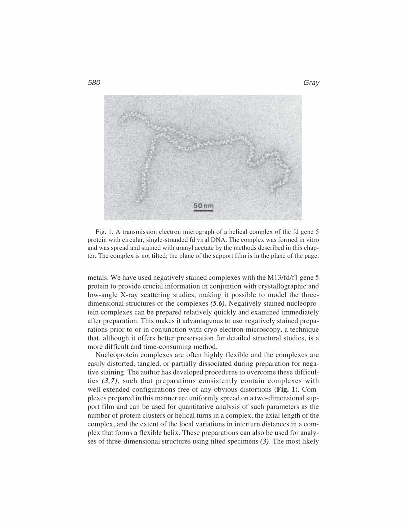
580 Gray
metals. We have used negatively stained complexes with the M13/fd/f1 gene 5protein to provide crucial information in conjuntion with crystallographic andlow-angle X-ray scattering studies, making it possible to model the three-dimensional structures of the complexes (5,6). Negatively stained nucleopro-tein complexes can be prepared relatively quickly and examined immediatelyafter preparation. This makes it advantageous to use negatively stained prepa-rations prior to or in conjunction with cryo electron microscopy, a techniquethat, although it offers better preservation for detailed structural studies, is amore difficult and time-consuming method.
Nucleoprotein complexes are often highly flexible and the complexes areeasily distorted, tangled, or partially dissociated during preparation for nega-tive staining. The author has developed procedures to overcome these difficul-ties (3,7), such that preparations consistently contain complexes withwell-extended configurations free of any obvious distortions (Fig. 1). Com-plexes prepared in this manner are uniformly spread on a two-dimensional sup-port film and can be used for quantitative analysis of such parameters as thenumber of protein clusters or helical turns in a complex, the axial length of thecomplex, and the extent of the local variations in interturn distances in a com-plex that forms a flexible helix. These preparations can also be used for analy-ses of three-dimensional structures using tilted specimens (3). The most likely
Fig. 1. A transmission electron micrograph of a helical complex of the fd gene 5protein with circular, single-stranded fd viral DNA. The complex was formed in vitroand was spread and stained with uranyl acetate by the methods described in this chap-ter. The complex is not tilted; the plane of the support film is in the plane of the page.
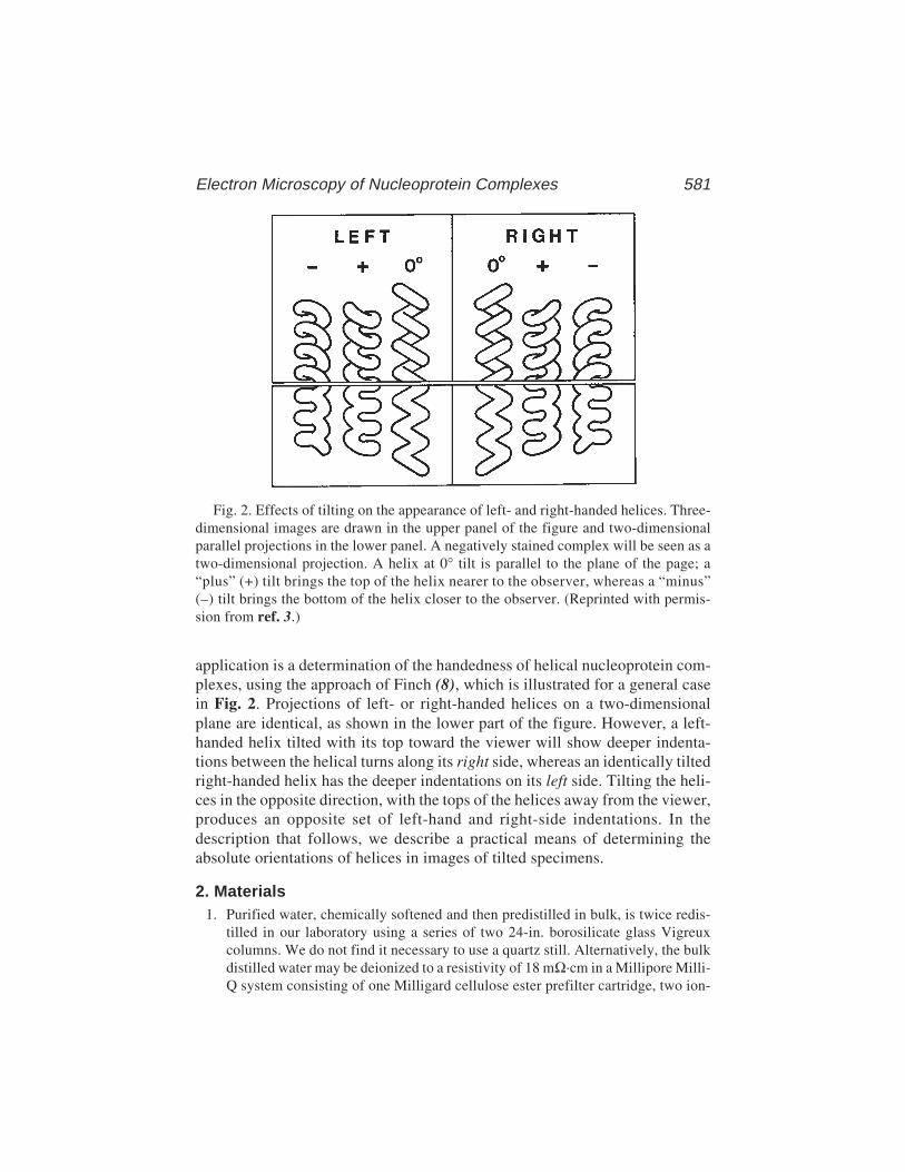
Electron Microscopy of Nucleoprotein Complexes 581
Fig. 2. Effects of tilting on the appearance of left- and right-handed helices. Three-dimensional images are drawn in the upper panel of the figure and two-dimensionalparallel projections in the lower panel. A negatively stained complex will be seen as atwo-dimensional projection. A helix at 0° tilt is parallel to the plane of the page; a“plus” (+) tilt brings the top of the helix nearer to the observer, whereas a “minus”(–) tilt brings the bottom of the helix closer to the observer. (Reprinted with permis-sion from ref. 3.)
application is a determination of the handedness of helical nucleoprotein com-plexes, using the approach of Finch (8), which is illustrated for a general casein Fig. 2. Projections of left- or right-handed helices on a two-dimensionalplane are identical, as shown in the lower part of the figure. However, a left-handed helix tilted with its top toward the viewer will show deeper indenta-tions between the helical turns along its right side, whereas an identically tiltedright-handed helix has the deeper indentations on its left side. Tilting the heli-ces in the opposite direction, with the tops of the helices away from the viewer,produces an opposite set of left-hand and right-side indentations. In thedescription that follows, we describe a practical means of determining theabsolute orientations of helices in images of tilted specimens.
2. Materials1. Purified water, chemically softened and then predistilled in bulk, is twice redis-
tilled in our laboratory using a series of two 24-in. borosilicate glass Vigreuxcolumns. We do not find it necessary to use a quartz still. Alternatively, the bulkdistilled water may be deionized to a resistivity of 18 mΩ·cm in a Millipore Milli-Q system consisting of one Milligard cellulose ester prefilter cartridge, two ion-
582 Gray
exchange cartridges, and a 0.22-µm filter, in series. No activated-charcoal filteris included in our system, because of the tendency of the charcoal filter to releaseminute charcoal particles, which are found in our preparations for electronmicroscopy. (See Note 1.)
2. Buffers in which the protein–DNA complexes are to be visualized. Concentratedbuffer stocks are passed through a 0.22-µm fiberless polycarbonate filter(Nuclepore/Costar) to remove particulates and are then stored in borosilicate glassor polystyrene containers. The buffers should generally not contain high concen-trations of salts or other nonvolatile components, as these components will tendto be retained on the carbon support film and can interfere with visualization ofthe protein–DNA complexes.
3. The protein–nucleic acid complexes are to be examined. These preparationsshould not contain significant excess quantities of noncomplexed or contam-inating proteins, and they must generally be free of contaminating nonaqueoussolvents as well as lipids, oils, salts, detergents, and other nonvolatile materials.We frequently repurify proteins and nucleic acids obtained commercially or fromother laboratories, using ethanol precipitation of nucleic acids, molecular-sievechromatography of proteins, or dialysis. About 0.2–2 nmol of DNA (measured asthe concentration of nucleotides), together with protein added at an appropriateratio, will be needed for a 50-µL incubation mixture from which the protein–DNA complexes are adsorbed to a single specimen grid.
4. Glutaraldehyde, purified for electron microscopy (distilled in vacuo and storedin sealed ampoules under inert gas). The contents of one ampoule are diluted to8% (v/v) in purified water and are stored at –20°C in a tightly capped borosilicateglass tube with a Teflon-lined screw cap; this solution can be used for as long as6 mo.
5. A suitable electron-opaque (“negative”) stain, preferably analytical reagent grade.We generally use uranyl acetate, which provides good surface detail and yieldssatisfactory images with many proteins. However, one should always considerthe possibility that other stains may be preferable for a particular application (9).A 2% (w/v) solution of a small amount of uranyl acetate in purified water isdissolved by stirring for 30 min in a borosilicate glass beaker. The beaker issealed with a wax film and stored in the dark. The solution is used within a fewdays or weeks, but only if precipitates have not begun to form. Uranyl salts areweakly radioactive, and discarded solutions should be collected and properly dis-posed of as radioactive waste.
6. Carbon support films, 8–10 nm thick, on 500-mesh copper grids. We make ourfilms in an Edwards E306A evaporator equipped with a liquid-nitrogen trap anda quartz crystal film thickness monitor (Edwards FTM5). The chamber is evacu-ated just to 1 × 10⁻⁴ mbar, contaminants are burnt off from the carbon rods (shut-ter closed, carbon rods brought to a red glow) and then evaporation is carried outover a period of several seconds. We use high-purity carbon rods (Bio-Rad/Polaron, <20 ppm impurities) that have been milled to form 1-mm tips. The car-bon is evaporated onto a freshly cleaved mica film (Ladd, tested by flame spec-
Electron Microscopy of Nucleoprotein Complexes 583
troscopy). The carbon films are then floated from the mica onto purified water ina Teflon dish, picked up on copper grids, and dried for 30 min under a heat lamp.
3. Methods3.1. Specimen Mounting and Negative Staining
1. Prepare stock solutions of DNA and protein, or of protein–DNA complexes, inhigh-quality, contamination-free, non-wetting polypropylene tubes. Care mustbe taken to avoid touching pipet tips or tube rims, to avoid contamination withoils and nucleases from the skin. (See Note 2.)
2. Prepare diluted DNA–protein mixtures for microscopy in a volume of 50 µL foreach specimen grid. The final concentration of DNA will be approx 4–40 nmol ofDNA nucleotides per milliliters; the optimal concentration must be determinedexperimentally, as it will vary with the adsorptive properties of the DNA andprotein in a buffer of given composition, pH, and ionic strength.
3. Clean a Teflon surface with reagent-grade ethanol and rinse it with purified water.For each specimen grid, place a row of droplets on the Teflon surface: leave anempty space for one droplet, then deposit two 50-µL droplets of purified water,then one 50-µL droplet of 2% uranyl acetate.
4. Initiate glutaraldehyde fixation. This will be required in most cases to maintainnoncovalent protein–DNA associations during adsorption to the charged (glow-discharge-activated) carbon film. (To confirm that fixation is effective and yieldsan unperturbed structure, stained preparations can be made by the method ofValentine et al. [10], which does not require fixation even for some relativelylabile complexes.) Add 0.5 µL of 8% glutaraldehyde to the bottom of a 0.5-mLconical polyethylene tube; immediately add 50 mL of the protein–DNA mixtureand gently mix by pipetting up and down once. Incubate the reaction mixture at20–25°C for 20 min.
5. Meanwhile, place carbon-coated grids, carbon side up, on a clean, inverted glassPetri dish and subject the grids to glow discharge. We use two parallel, L-shapedaluminum rods (6.5 mm in diameter) fitted to the high-tension electrodes of theEdwards E306A evaporator. Glow discharge is carried out at 0.1–0.2 mbar (withonly the rotary pump in operation), with the grids placed on the Petri dish at adistance of about 4 cm below the horizontal segments of the rods. The dischargeis continued for about 50 s at 40% of maximum voltage (i.e., at approx 2 kV) andcomplexes are adsorbed to the grids within 10 min.
6. Place a 50-µL droplet of each protein–DNA mixture on the Teflon surface, at thebeginning of a row of droplets prepared as described in step 3. Touch the grid,carbon side down, to the top of the droplet containing the protein–DNA mixturefor 20–60 s, then wick off (remove) excess solution from the grid onto a filterpaper, holding the grid perpendicular to the filter paper. Next, touch the grid toeach of the two water droplets for 1 s each and, finally, to the uranyl acetatedroplet for 20 s, wicking off excess liquid after each step.
7. Dry the grid for 10 s by holding it within 2–3 cm of a lamp bulb (we use anilluminator having a 30-W bulb and a polished metal reflector) and then dry it for
584 Gray
10 min, carbon side up, on a filter paper that is under the lamp and approx 12 cmfrom the bulb.
3.2. Specimen Tilting
Although specimen grids are readily tilted in an electron microscope fittedwith a goniometer, when dealing with flexible helical nucleoprotein complexesone is confronted with two problems: first, to find a specimen that will showthe helical asymmetries when it is tilted, and second, to determine which endof a tilted helix is closer to the viewer when the helix is seen on the fluorescentscreen, in negatives, and in prints. We deal with these problems in the following:
1. Flexible nucleoprotein helices will generally not have straight helical axes anduniform turns as in Fig. 2, but a much less regular structure. It is essential toselect a segment of a helical complex in which the turns are as regular as can befound, with a roughly linear (or only gently curved) helix axis extending for 5–10helical turns. Figure 3 contains a set of drawings taken from an actual tilt experi-ment (3). The helix axis of a relatively linear and regular helical segment hasbeen oriented approximately perpendicular to the tilt axis (which is horizontal inFig. 3) to maximize the changes observed upon tilting. The characteristic left-side and right-side indentations are seen when the complex in Fig. 3 is tiltedin opposite directions (+55°, –55°), even though there is significant flexing inthe helix axis. The change of indentations from one side to the other is faintlyvisible even in a diagonally oriented helical segment (arrows), but the effect ismore convincing in a segment that is perpendicular to the tilt axis.
2. The complexes must also have been prepared under conditions that yield a mini-mum of flattening of the helical structure; the use of a relatively deep layer ofnegative stain will tend to help support the three-dimensional structure. Flatten-ing of the helix makes the left-hand-side and right-hand-side indentations in tiltedhelices more difficult to observe, but they still can be seen when the helix isdistorted. Note that in Fig. 3 the width at a appears to be about half of the widthat b in the helix that is tilted –55°, indicating that the helix is flattened so that theheight of a helical coil above the support film is roughly half of the width of thecoil measured in a direction parallel to the support film.
3. In order to determine the absolute orientations of helical specimens as they areseen on the fluorescent screen of an electron microscope, focusing effects areutilized. An asymmetric marker (such as a macroscopic letter R punched on aspecimen grid) can be used to correlate what is seen on the screen with the knownposition of the tilted grid (oriented, for example, so that the top edge of the R isuppermost in the column at a tilt angle of +55°). We used such a device in thetop-entry stage of our Zeiss EM10C to demonstrate that when the objective lenscurrent is adjusted to focus on the central portion of a steeply tilted grid, then theedge of the grid that is uppermost in the microscope and furthest from the upperpolepiece of the objective (imaging) lens will be overfocused (lens current toostrong to focus on it), whereas the lower edge of the grid will be underfocused

Electron Microscopy of Nucleoprotein Complexes 585
(lens current too weak). These focusing effects can be used to determine whichend of any helical complex is uppermost in the column; that same upper end ofthe helix will be, in effect, the end that is nearest to the viewer who is looking atthe helix on the fluorescent screen.
4. The differing Fresnel patterns due to underfocusing and overfocusing of a tiltedspecimen support film are visible in a negative bearing an image of the specimen.Hence, proof of the three-dimensional orientation of the specimens is containedin each negative. To correctly interpret the hand of a helix from an image, thenegatives must be viewed from the emulsion side, which in the microscope faces
Fig. 3. Drawings made from electron micrographs of a left-handed helical complexof the IKe gene 5 protein with single-stranded fd viral DNA. The center image is ofthe nontilted complex that lies in the plane of the page. The upper image is of the samecomplex tilted –55° around a horizontal axis, so that the top of the complex is belowthe plane of the page and the bottom of the complex is closer to the observer. Thelower image is of the same complex tilted +55°, so that the bottom of the complex isbelow the plane of the page and the top of the complex is nearer to the observer. Thedrawings show the helical coils as three-dimensional structures to show how they canaccount for the projection images seen in the original electron micrographs, which areshown in ref. 3. (Reprinted with permission from ref. 3.)
586 Gray
in the same direction (toward the electron beam and toward the viewer) as doesthe viewing surface of the fluorescent screen. It is, of course, essential that theoperator correctly recognize the patterns corresponding to overfocusing asopposed to underfocusing; if in doubt, the patterns can be demonstrated by mak-ing exposures of deliberately underfocused and overfocused specimens at zerodegrees of tilting.
5. The Fresnel patterns will also be visible in prints made at a suitable magnifi-cation. To present the helical asymmetries correctly, the prints must be madewith the emulsion side of the negative facing the enlarger light source, so thatthe print will represent the same view of the object as that which is seen on thefluorescent screen.
6. Finally, we emphasize that it is essential to demonstrate that the indentationsbetween helical turns switch from one side to the other of the same helical nucle-oprotein segment as the helix is tilted in opposite orientations. We find that theflexing and partial compression of nucleoprotein helices can produce structuresthat show indentations on one side in one tilt orientation, but that do not showindentations on the other side when the helix is tilted in the opposite orientation.A satisfactory proof of the helical symmetry (hand of the helix) requires that bothsymmetrically related effects be demonstrated in the same helical segment.
4. Notes1. The purity of the water used as solvent can be critical to the success of prepara-
tions for electron microscopy. The chemical content of the water supplied to alaboratory varies greatly with the locale, and it sometimes happens that proce-dures that worked in one location will fail in another, when the only reagent notcarried to the new location is the water. If difficulties are encountered withexperimental procedures, alternative sources of water and alternative water puri-fication protocols should be explored.
2. The exercise of care to preclude the contamination of solutions is essential to thesuccess of these procedures. Negative staining of specimens mounted on glow-discharge-activated grids is a widely used technique, but long and flexible nucle-oprotein helices are particularly susceptible to the effects of contaminants thatcan interfere with the uniform adsorption of the complexes to an activated carbonfilm. The adsorption may fail to give satisfactory results if appropriate precau-tions are not taken.
3. We find that a more uniform layer of uranyl acetate stain can be obtained if thecarbon-coated grids are hydrated prior to step 5 of Subheading 3.1. This is doneby placing the grids carbon side up in a small plastic Petri dish, 2 cm in diameter,and then floating the small Petri dish on distilled water that has been brought to90°C and poured into a standard Petri dish bottom. Another standard Petri dishbottom is inverted over the first, creating a chamber in which steam is capturedand will be exposed to the carbon coatings on the grids. After 10 min of hydra-tion, the grids are dried under a lamp for 10 min and are immediately subjected toglow-discharge activation. The depth of the uranyl acetate stain layer can be con-
Electron Microscopy of Nucleoprotein Complexes 587
trolled by varying the times of hydration exposure and drying. In our hands, thisprocedure yields satisfactory staining on every grid, provided that there is nointerference resulting from contaminants in the specimen.
AcknowledgmentsThe author gratefully acknowledges support of this work by National Insti-
tutes of Health Research grant 5-RO1-GM34293-03 (to C.W.G.), by NIHBiomedical Research Support grant 2S07-RR07133-21, by NIH Small Instru-mentation grant 1-S15-NS25421-01, and by National Science FoundationInstrumentation grant PCM-8116109.
References1. Bujalowski, W. and Lohman, T. M. (1991) Monomer–tetramer equilibrium of
the Escherichia coli ssb-1 single-strand binding protein. J. Biol. Chem. 266,1616–1626.
2. Kodadek, T. (1990) The role of the bacteriophage T4 gene 32 protein in homolo-gous pairing. J. Biol. Chem. 265, 20,966–20,969.
3. Gray, C. W. (1989) Three-dimensional structure of complexes of single-strandedDNA binding proteins with DNA: IKe and fd gene 5 proteins form left-handedhelices with single-stranded DNA. J. Mol. Biol. 208, 57–64.
4. Bochkarev, A., Pfuetzner, R. A., Edwards, A. M., and Frappier, L. (1007). Struc-ture of the single-stranded-DNA-binding domain of replication protein A boundto DNA. Nature 385, 176–181.
5. Skinner, M. M., Zhang, H., Leschnitzer, D. H., Guan, Y., Bellamy, H., Sweet, R.M., et al. (1994). Structure of the gene V protein of bacteriophge f1 determined bymultiwavelength X-ray diffraction on the selenomethionyl protein. Proc. Natl.Acad. Sci. USA 91, 2071–2075.
6. Olah, G. A., Gray, D. M., Gray, C. W., Kergil, D. L., Sosnick, T. R., Mark, B. L.,et al. (1995) Structures of fd gene 5 protein-nucleic acid complexes: a combinedsolution scattering and electron microscopy study. J. Mol. Biol. 249, 576–594.
7. Gray, C. W., Brown, R. S., and Marvin, D. A. (1981) Adsorption complex offilamentous fd virus. J. Mol. Biol. 146, 621–627.
8. Finch, J. T. (1972). The hand of the helix of tobacco mosaic virus. J. Mol. Biol.66, 291–294.
9. Haschemeyer, R. H. and Myers, R. J. (1972). Negative staining, in Principles andTechniques of Electron Microscopy (Hayat, M. A., ed.), vol. 2, Van NostrandReinhold, New York, pp. 101–147.
10. Valentine, R. C., Shapiro, B. M., and Stadtman, E. R. (1968). Regulation ofglutamine synthetase, XII. Electron microscopy of the enzyme from Escherichiacoli. Biochemistry 7, 2143–2152.
STEM of DNA–Protein Complexes 589
589
From: Methods in Molecular Biology, vol. 148: DNA–Protein Interactions: Principles and Protocols, 2nd ed.Edited by: T. Moss © Humana Press Inc., Totowa, NJ
41
Scanning Transmission Electron Microscopyof DNA–Protein Complexes
Joseph S. Wall and Martha N. Simon
1. IntroductionThe scanning transmission electron microscope (STEM) at Brookhaven
National Laboratory* (BNL) is nearly unique in its ability not only to imageisolated unstained and unshadowed biological molecules but also to obtainquantitative information about them such as their oligomeric state (1) (seeNote 1). This makes it ideal, in principle, for looking at protein–DNA com-plexes and obtaining information about the masses bound. However, there arevery stringent requirements on the purity and stability of the samples.
The quantitative STEM offers significant advantages over other techniquesfor characterizing biological complexes (see Note 2). The STEM operates in adark-field imaging mode which gives high contrast for small objects. TheSTEM forms an image one point at a time by rastering a finely focused elec-tron beam over a specimen in a TV-type scan. Typically 1000 electrons areused for the readout of each picture element (pixel) in the specimen. Most ofthese pass directly through the specimen without losing energy or changingdirection. However, a few of these electrons interact with the specimen and arescattered into two annular detectors. The number of scattered electrons isdirectly proportional to the mass thickness at that point.
The digital STEM image is a two-dimensional projection map of thespecimen’s mass distribution. Adding up the mass in regions of the imagecontaining a complex gives the molecular weight, which usually identifiesthe complex and determines its oligomeric state. Thus, a link is establishedbetween biochemistry and imaging.
*The BNL STEM is a NIH Supported Resource Center, NIH P41-RR01777, with additionalsupport provided by the Department of Enrgy and Office of Biological and Environmental Research.

590 Wall and Simon
The high contrast and signal-to-noise-ratio (S/N) of a STEM dark-fieldimage permits direct visualization of unstained double-stranded DNA (dsDNA)and can provide an accurate measurement of its total length and the position ofa bound complex (see Note 3). The high contrast of the STEM also reveals anyproblems with the specimen such as denatured protein or residual salt. Thisforces rigorous attention to details of specimen preparation that, although some-times annoying, leads to results having high credibility.
We distinguish three types of complex that place different constraints onspecimen preparation, imaging, and analysis: (1) one-dimensional complexes(2) such as a protein binding to a specific sequence of nucleic acid, (2) two-dimensional complexes (3) such as chromatin, filamentous viruses and recA-type filaments, and (3) three-dimensional objects such as ribosomes (4),“spherical” virus particles (5),and intermediates in such viral assembly.
Objects of the last type tend to be the easiest to work with because the com-ponents are bound together in a relatively rigid and stable complex. Adsorbingsuch objects from solution onto a suitable EM substrate such as carbon filmgenerally causes minimal perturbation. The particles tend to have characteris-tic shapes and relatively few distinct orientations, so it is easy to recognizebroken or incompletely assembled particles. Compact shapes with distinct bound-aries make it relatively easy to identify complete particles for mass measurements.
Two-dimensional complexes are usually curved and may also be tangled insolution, so depositing them on a planar substrate may cause distortions ortopological problems. In this case also, the outside edges of the complex areusually composed of a relatively uniform compact protein shell, which is notsignificantly disrupted by contact with the substrate. Any areas that haveunraveled are easily recognized as different from sharp, well-preserved sec-tions for mass/length determinations.
One-dimensional complexes tend to be the most difficult with which towork. In solution, the dsDNA itself tends to be a random coil with low rigidity,so docking onto the substrate can give an uninterpretable tangle if the strandsare long. Searching for bound proteins on this can be slow, so the best approachis to use the shortest strands compatible with the experiment. A more seriousproblem comes from the fact that such complexes contain relatively largestretches of bare nucleic acid that attach poorly to the carbon film substrate.The entire coil in solution is undergoing rapid translational and rotationalBrownian motion. If the protein sticks first, as usually happens, the mechanicalforces transmitted to the binding region are frequently greater than the specificbinding forces and the complexes are disrupted. Shorter strands help, but cova-lent crosslinking is usually required to give reproducible complexes. Alterna-tively, poly-lysine pretreated grids will bind the dsDNA well, but, sometimes,this forces a weaker binding protein off so that the complexes are disrupted,
STEM of DNA–Protein Complexes 591
and, again crosslinking may be required. However, if the strands are too short(e.g., made from oligomers of 20 bases) such that the protein complex coversthem, it is not possible to determine the orientation of the complex on the DNA.
The use of general fixatives to crosslink, such as glutaraldehyde and formal-dehyde, raises the question of generating artifacts such as nonspecific bindingor binding of extraneous proteins and consequent increases in masses. The bestscenario is to have is a specific crosslinker between the protein(s) and thedsDNA, but that is not always available.
Whatever is used should be tested on the complex, and the minimum condi-tions to maintain it should be determined. This can be done by footprinting, gelretardation, or some other assay of the crosslinking conditions. The cross-linking need not be 100% and that should actually probably be avoided, becauseanything that is overcrosslinked will be uninterpretable (See Note 4.) If morethan 50% of the molecules are in complexes and the concentration is good(roughly 10 complexes per square micron), searching in the microscope can befairly rapid if the strands are reasonably short (<1000 bp). The histogram ofmass bound as a function of distance from the end of the strand is the final testof specimen quality.
2. MaterialsWe will describe in some detail the materials we use, as the physical purity
of most materials is critical to the success of a STEM project. The grids for theSTEM are prepared by the STEM staff, but the specimens themselves comefrom the users. (See Note 5.) Knowing the details involved in specimen prepa-ration enables users to understand the problems that can arise. One of the mostimportant is the physical purity of all of the materials involving the sample,which may end up on the grid in the STEM.
2.1. Water, Buffers, and Salts
1. Of surprising importance is that the water used in all the steps of sample prepara-tion must be physically clean. The water in some labs is very impure. STEMwater is deionized and freshly distilled daily. It is used for all grid and samplepreparation as well as for all buffers (see Note 6).
2. All solutions must be physically clean. Anything “dirty” involved in the purifica-tion such as fragments of column or gel material will show up on the grid andinterfere with the observations and analysis. Any physical additives that scatterelectrons will also interfere (see Note 7).
3. Most samples can be applied to the grid in the buffer which is necessary for theirbiological activity. Additives such as sucrose, glycerol, and dithiothreitol willusually wash off. If necessary, a sample can be applied to the grid in high salt.(A few washes with a high concentration of ammonium acetate will usuallyremove it.) (See Note 8.) However, some buffers and salts are known to cause

592 Wall and Simon
problems (see Note 9). HEPES and MOPS are good buffers. The final washes ofthe grid before freeze-drying must be with a volatile solution such as freshlyprepared ammonium acetate or STEM water. Because ammonium acetate is apoor buffer, it can be used at any desired pH.
2.2. Grids and Films
1. We use titanium grids for the STEM. This is for ease of handling in themicroscope and for their good thermal behavior. The supporting film (step3) is thin carbon. The grids are at liquid-nitrogen temperature in the micro-scope to prevent contamination and reduce radiation damage to the speci-mens. Carbon and titanium have similar thermal properties, so there is nodifferential contraction or expansion that would result in tearing of the film.Also, compared to copper grids, titanium grids are flat and chemically inert.However, to mimic STEM conditions in a conventional TEM, there aremany choices for grids.
2. The slots in our titanium grids are too large to support the thin carbon film neces-sary for STEM samples, so we put a “holey” film over the slots. This is a plasticfilm made on glass slides under controlled humidity conditions so little dropletsof condensation determine the hole size, which is approx 5–10 mm in diameter.The plastic holey film is heavily shadowed with carbon for strength. Again, tomimic our conditions, there are many available choices of grids with support forsmall areas of thin film.
3. The thin carbon film is critical to simulating STEM conditions for samples.Because carbon film behaves like activated charcoal in adsorbing everything fromthe atmosphere, it is made so that the side to which the sample is adsorbed hasnever seen air. We make it by lightly shadowing carbon (for the STEM, it needsto be 2–3 nm thick) onto a piece of freshly cleaved rock salt in an ion-pumpedvacuum system. (See Note 10.) We buy NaCl crystals from Bicron. We cleavethem with a Weck safety razor blade, which is placed on a corner edge of thecrystal (to give a piece several millimeters thick) and tapped with a hammer. Thefreshly cleaved side is lightly breathed on before putting it face down in the belljar. The carbon rods (from Fullam) are located below the rock salt in the shadowerso that cinders do not drop on it. (See Note 11.)
4. We often use poly-lysine pretreated grids for complexes on dsDNA, which doesnot stick well to carbon grids. However, if the grids are pretreated with poly-lysine, dsDNA binds very well. We use poly-lysine from Sigma, approx 3000Daltons, and dilute and freeze away aliquots at 10 µg/mL.
5. We sometimes fix complexes with low concentrations (approx 0.1%) of glu-taraldehyde for relatively short times (approx 15 min) before applying themto the grid. The sample washings will stop the fixation so that it does nothave to be quenched. (See Note 4.) We start with a new ampoule of 8% EMgrade from Polysciences. We usually open a new ampoule, but if the air isflushed out with dry nitrogen gas and it is resealed, it can be kept for a fewdays for further use.
STEM of DNA–Protein Complexes 593
2.3. Concentrations of Complexes and Components
1. Only small quantities of sample are needed for examination in the STEM, but itis useful if the concentration is relatively high. Because different samples absorbto the thin carbon film differently, a concentration series for a new specimen ismade. Twenty to 50 µL of a sample at 100 or 200 µg/mL is adequate. (See Note 12.)
2. It is often a good idea to look at the components tht go into a complex separately.On poly-lysine pretreated grids, a dsDNA concentration of 1–5 µg/mL is plenty.Depending on its size, a protein concentration of 50–100 µg/mL is good. Again,only 10–50 µL is needed.
3. The ideal sample is frozen in aliquots to be thawed and used as needed. However,many samples cannot be frozen. They can be shipped overnight on wet ice andthe grids can be made on the day of arrival (if it has been arranged). The grids arestored under liquid nitrogen until microscope time is available.
4. Occasionally, a complex is unstable, either over time or shipping conditions.Sometimes, frozen aliquots of the components can be shipped, but the complexitself cannot be frozen or it may not be stable overnight. Under those circum-stances, we can assemble (and incubate) a complex just prior to putting it on thegrids. We need a detailed protocol and all of the components.
3. Method3.1. Specimen Preparation
Details of specimen preparation for grids for the STEM are given in thissection. Specimens for the STEM are prepared by the STEM staff (see Note 5),but knowing the details enables users to understand the potential problems.A user with EM experience in other ways of visualizing proteins or DNA orcomplexes can mimic these conditions to screen their samples in a conven-tional TEM.
3.1.1. Wet Film, Hanging Drop Method
1. The thin (2–3 nm) carbon film, which has been shadowed onto freshly cleavedrock salt, is floated off the crystal onto a dish of STEM water (see Note 6).
2. The grids, covered with holey film (and for the STEM, in rings and caps) areplaced face down on it for approx 1 h.
3. A grid is picked up from above and retains a droplet of water. It is washed andwicked with STEM water two or three times, never being allowed to dry. Wateris applied from one side with an Eppendorf pipet and wicked from the other sidewith filter paper.
4. Three microliters of tobacco mosaic virus (TMV) at 100 µg/mL is injected intothe drop and allowed to adsorb to the thin carbon film for 1 min.
5. The grid is then washed and wicked two or three times with injection buffer forthe sample. Three microliters of the specimen is injected into the drop and allowedto adsorb for 1 min.
594 Wall and Simon
6. The grid is washed with sample buffer a couple of times, followed by washes(approx 10), ending with washes of 20–50 mM ammonium acetate (or, rarely,water). The intermediate washes depend on the sample buffer (e.g., high-salt buff-ers require washes with high ammonium acetate). (See Notes 8 and 9.).
7. For freeze-drying the grid, after the final wash the liquid is briefly blotted betweentwo pieces of filter paper to a thickness of a few micrometers and rapidly plungedinto liquid-nitrogen slush to freeze it.
3.1.2. Poly-lysine-Pretreated Grids
The dsDNA does not bind well to carbon films. However, if the grids arepretreated with poly-lysine, dsDNA binds very well to them. Poly-lysinegrids that have been made by this method contribute no additional detect-able background.
1. The thin carbon film is picked up as above and washed with water.2. Three microliters of poly-lysine at 10 µg/mL is injected into the drop and allowed
to adsorb to the carbon film for 1 min.3. The grid is then washed with water, approx eight times, and allowed to air-dry.4. Before use, 3 µL of water is put on its surface before the TMV is injected. Because
TMV also binds very well, a solution of 10 µg/mL should be used for these grids.(See Note 13.)
3.1.3. Fixation
In any multicomponent system, one part may bind more strongly to the car-bon film substrate. The rest of the complex may be coming apart throughBrownian motion as described earlier. Frequently, some kind of crosslinkingor fixation is required to keep the complex together.
The best results are when the users have been able to fix or crosslink theirsample before sending it to us. Sometimes they have determined the minimalfixation or crosslinking conditions for their sample, but it needs to be done justprior to applying the sample to a grid. Unless something very unusual is calledfor, we can do that.
If the complex is falling apart and optimal fixation conditions to preserve itare not known, we will often try a brief glutaraldehyde fixation on the samplejust prior to applying it to the grid. The washes involved in specimen prepara-tion will stop the fixation without having to worry about quenching conditions.Sometimes, this will help preserve the complexes, but it may not.
3.2. STEM Operation
The STEM is usually run by a trained operator to assure optimum data qual-ity and efficient use of microscope time. Frequent users can obtain training onrequest, but the alacrity of most STEM experiments makes this unnecessary.

STEM of DNA–Protein Complexes 595
The main factors considered by the STEM operator in taking data are describedas follows.
All biological specimens are sensitive to electron irradiation (see Note 14).Because unstained, freeze-dried specimens have only unprotected biologicalmaterial, radiation damage to them is particularly noticeable and limits quanti-tative interpretation. Therefore, searching for suitable areas must be done atthe lowest possible dose (low magnification). Potential areas of interest (AOIs)are boxed on the display for later scanning. Near the AOIs, but not overlappingthem, focusing areas are placed. The STEM beam is highly collimated withessentially no intensity outside the 0.3-nm-diameter focused spot, so scanningone area causes no damage to nearby areas. Once the microscope focus is veri-fied, an AOI is scanned and displayed (8.5 s per scan). At that point, the scansare shut off (meaning there is no additional radiation damage) while the opera-tor evaluates the quality of the data in the scan using the following criteria:background cleanliness, TMV profile, TMV mass, numbers, shapes, andmasses of sample particles. If the area is suitable for more complete analysis, itis recorded digitally and processed with another computer program (see Sub-heading 3.3.).
The STEM control computer is a PC with a custom interface designed totake full advantage of STEM capabilities. The computer directs the focusedbeam, scanning the next AOI upon command and recording the electron countsstriking the two annular detectors (large-angle and small-angle scattering) sur-rounding the beam. Most of the beam passes through the irradiated spot on thespecimen and strikes a bright-field detector used for normalization. The large-angle annular detector provides the most useful dark-field signal, which directlymaps the local mass thickness of the specimen. The computer display showstwo 512 × 512-element images (large-angle and small-angle detectors) wherethe intensity is proportional to the detector signal. Objects as small as singleheavy atoms or dsDNA are easily visible, especially with zoom or contrastenhancement. During this decision making, the beam is not scanning, so thereis no additional damage.
Once the image is saved, it can be viewed by any networked computer.Image files are usually distributed by FTP transfer on the Internet (requir-ing 1–10 s per image) to users. For users without Ethernet, images can be puton a CD (1300 images/CD) and mailed.
3.3. Analysis
The STEM images stored on a CD or a hard drive can be viewed usingcommercial software or our mass-analysis program, PCMass, provided by theSTEM Group. The format for the BNL STEM images is a header 4096 byteslong, followed by two 512 × 512, 8-bit images interleaved. Adobe PhotoShop

596 Wall and Simon
can read these images directly using its “AS RAW” option with the aboveparameters. We recommend this program for producing publication-qualityimages with a high-quality printer.
The PCMass program provides for rapid viewing of STEM images, with theability to perform accurate mass measurements on them. This program “reads”the image header and imports the image data with appropriate settings. Massaccuracy is most often limited by the cleanliness of the background carbonfilm between particles. The first step in analysis with PCMass is to mask outparticles and dirt and measure the background mass per unit area (mass–thick-ness) in the cleanest areas. There are several diagnostic criteria to indicate theseverity of background problems. The background determination is criticalbecause the mass of the carbon substrate in the measuring area is usually equalto or greater than the particle mass and it must be subtracted to get the netparticle mass. If the background quality is less than ideal, mass measurementscan still be made, but their interpretation requires caution.
Manual mass measurements require the user to position a measuring circleor rectangle around particles of interest using a mouse and keystrokes to changesize. A mouse click or ‘=’ keystroke saves the measurement in a database andshows the running average and standard deviation for particles in the selectedcategory. Automated mass measurements use a set of simple comparison mod-els to align and categorize particles, providing size and shape information aswell as mass. This offers the advantages of speed and reproducible particleselection, but it is not suitable for complicated specimens such as convolutedDNA–protein complexes.
Summarizing several thousand (automated) mass measurements for publi-cation involves answering two basic questions: (1) Are the particle selectionsreliable and unambiguous? (2) Is the standard deviation of the mass measure-ments what would be expected for a homogeneous population of particles withthe observed shape? Frequently, particles will break apart into subunits eitherduring preparation or attachment to the grid. This may be obvious both bycareful inspection of the images and by mass measurements of the various spe-cies observed. Knowing the molecular weights of the components facilitatesthis sorting. If the automatic particle selection with model fitting was used, onecan view histograms for all the fitting parameters and choose those selectionparameters that exclude clear outliers. However, one must be careful not toskew the “real” mass distribution.
The expected mass accuracy depends on particle size, shape, and measuringdose. A 100-kDa globular particle on a 2-nm carbon substrate measured with adose of 10 el/Å2 should give a standard deviation (SD) of 10%, whereas a1-MDa particle should give 2% (see Note 15). If the particle is extended or thebackground is dirty, the SD will be worse. The TMV reference particles should
STEM of DNA–Protein Complexes 597
give mass per unit length of 13.1 kDa/Å with a SD of 1%. With a large numberof measurements, one may be tempted to quote the standard error of the mean,but this is overly optimistic. Instead, we find that the standard deviation ofimage averages (for all images having more than 10 particles) gives a trueridea of accuracy. One can also plot the total mass histogram and fit multipleGaussians to it. If the spread in masses is larger than expected, caution is indicated.
A poor standard deviation, worse than that predicted, is most often causedby random background problems such as denatured protein, residual salt, andso forth. Unfortunately, these also give systematic errors that can shift the mea-surements in either direction. Residual salt tends to accumulate around theedges of particles (a meniscus effect), which raises the apparent mass. On theother hand, denatured protein may not be masked completely by the back-ground program, giving too much subtraction for the background and loweringthe apparent mass.
The example shown in Fig. 1 is particularly complex because it has fourdsDNA arms in a Holliday junction complex (see Note 16). In this example,the M/L of the dsDNA is greater than expected because of deviations fromstraightness and/or salt binding. The particle mass is also larger than theexpected value (800 kDa + 2 × 2 kDa/nm × 26 nm = 900 kDa), presumably theresult of binding of fixative or salt.
The TMV control particles are useful in identifying these problems. Residualsalt tends to accumulate in their hollow central hole and along their edges,giving an increased M/L and an altered radial mass profile. Denatured proteinfrom the sample tends to decrease the TMV M/L, because the TMV is addedbefore the sample and tends to protect the substrate from deposition of thisdenatured protein. Consequently, one cannot assume that specimen problemsobserved on the TMV will be the same for the specimen of interest and some“fudge factor” will make everything come out right. Rather, it is well worth theextra effort to try to solve the specimen problems by using added purification,fixation, other buffers or stabilizing agents (see Subheading 3.1.).
The results from the automated PCMass program are tabulated as TMV M/L,TMV SD, and the number of particles passing the selection parameters vs thenumber measured for each image file. On the same line are the results forparticles selected relative to one model, followed by apparent dose andbackground thickness. At the bottom of the summary, the global averages,standard deviations, and a mass histogram for the selected model are given.This provides a convenient format to identify images or blocks of images withproblems (e.g., poor TMV). It is not unusual for a single grid to have significantvariations in specimen quality from one area to another, so we strive to collectgood image data in at least three widely separated areas on each specimen.What is meant by “good” data is then clear: Discarding data based on poor
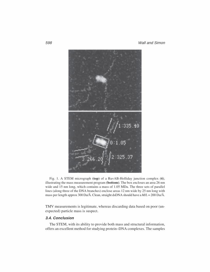
598 Wall and Simon
TMV measurements is legitimate, whereas discarding data based on poor (un-expected) particle mass is suspect.
3.4. Conclusion
The STEM, with its ability to provide both mass and structural information,offers an excellent method for studying protein–DNA complexes. The samples
Fig. 1. A STEM micrograph (top) of a RuvAB-Holliday junction complex (6),illustrating the mass measurement program (bottom). The box encloses an area 26 nmwide and 15 nm long, which contains a mass of 1.05 MDa. The three sets of parallellines (along three of the DNA branches) enclose areas 12 nm wide by 25 nm long withmass per length approx 300 Da/Å. Clean, straight dsDNA should have a M/L = 200 Da/Å.
STEM of DNA–Protein Complexes 599
do have to be very clean and the complexes have to be stable under conditionsfor applying them to our grids. All of the above information is meant to helpaddress the potential problems that can arise. However, if these conditions aremet, it is a relatively rapid and inexpensive method of obtaining a lot of infor-mation about the composition and location of proteins bound to dsDNA. Thequantitative link between observed structure and biochemistry provided bymass mapping, makes image interpretation highly believable.
4. Notes1. One cannot see bare dsDNA in a conventional TEM. It can be visualized if it is
stained, shadowed, or imbedded in a spreading solution, but under those condi-tions, the mass of any protein bound to it cannot be determined.
2. The STEM provides both mass and structural information simultaneously, as doessmall-angle scattering. Although the STEM does not have the atomic resolutionof X-ray crystallography, NMR, or cryoEM of 2-D arrays, it also does not dependon the ability of samples to form arrays. Comparatively, it is rapid and not verylabor intensive. Scanning probe microscopies potentially can offer similar capa-bilities. Electron spectroscopic imaging techniques are quantitative and offer thepossibility of distinguishing nucleic acids from proteins (6).
3. Single-stranded DNA (ssDNA) has been visualized in the STEM but only underconditions where it has a lot of secondary structure. If it were fully extended orstretched, it would be barely detectable in the STEM above the thin-carbon-film background.
4. Crosslinking conditions can be quite different for different samples. Becauseconditions depend on concentration, temperature, and time, frequently thecrosslinking has to be stopped by quenching. It is important that the quencher iseither removed or is known not to interfere with visualization of the complex inthe STEM. Overly crosslinked samples turn into large uninterpretable aggregates.
5. The STEM is a NIH Research Resource. As such, it is available to users withappropriate projects free of charge. A project is usually initiated by a discussionof it on the phone or by e-mail. A trial sample is sent by overnight mail to us.We can make the grids on the day it arrives, if it has been prearranged. The gridsare stored in a grid fridge under liquid nitrogen (stable for years) until they can befreeze-dried and examined in the microscope. Additional details about the facil-ity can be found on our web page, most easily accessed from www.bnl.gov, thenclick on Scientific Facilities, then on Scanning Transmission Electron Micro-scope. Our address is http://bnlstb.bio.bnl.gov/biodocs/stem/stem.htmlx
6. A water control grid can be made if it is likely that the water from a lab is aproblem. A 5-µL drop of water is applied to and completely dried on a grid in alaminar-flow clean hood (which is where the samples are made) and examined inthe STEM. If there is a problem, STEM water (deionized and freshly distilled)can be sent to the lab to make the buffers for the final steps of sample purifica-tion. Clean air during sample preparation is also critical, as “dust” particles cancarry both physical and biological contaminants.
600 Wall and Simon
7. Most physical additives (which may improve the biological activity) such asbovine serum albumin, trypsin, and high concentrations of peptides, oligonucle-otides, or PEG cannot be used. One way to remove these is by passing the sampleof interest over an appropriate sizing column, if one can be found where it comesoff in the void volume. This can also be a useful way of exchanging salts orbuffers. If one is in a lab where bacteria are a problem, low levels (0.2%) ofsodium azide can be tolerated in buffer solutions. It seems to wash off grids andnot interfere with STEM samples.
8. Ca2+ often does not wash off well, but Mg2+ usually does. A buffer containingCa2+ can be washed with Mg2+, then ammonium acetate.
9. Some salts and buffers are likely to cause problems. Phosphate buffers often donot wash off well and leave bright spots, which interfere with the analyses. Some-times, Tris buffers leave a bad background and they also interfere with glutaral-dehyde fixation. A buffer control grid is made for a new sample (especially in anunusual buffer) to see how well the components of the buffer wash off.
10. Carbon films are often made by shadowing onto cleaved mica. We have foundthat films made on freshly cleaved NaCl crystals will float off onto a dish ofwater much easier than off of mica. Mass analysis of the two background filmsare indistinguishable, indicating that they are just as flat.
11. Many experimental details about the grids, films, and shadowing can be found inCells: A Laboratory Manual, Vol. 3, pp. 125.2–125.7 (CSH Press, 1998). How-ever, to simulate STEM conditions for a sample, the only critical step is the thincarbon film because it is the only surface that the biological materials will see.Some additional capabilities of the STEM can be found in the same volume,Chapter 124.
12. Caution: Steps taken to concentrate a sample, such as Centricon filters, may alsoconcentrate contaminants of the same size.
13. Many, but not all, molecules adsorb well to poly-lysine-pretreated grids. Itmay be necessary to change the suggested concentrations to lower ones whenusing them.
14. Biological specimens are sensitive to radiation damage by the electron beam. Thismanifests itself in two ways, as a loss of mass and a loss of fine detail. For STEMmass measurements at 40 keV with the specimen at –150°C, the rate of mass loss isroughly 0.25% for every 1 el/Å2. The normal STEM imaging dose is 10 el/Å2,which results in 2.5% mass loss per scan. Measurements are usually done on firstscan images, but it is instructive to do a dose-response curve using sequential scansof the same area for a new specimen type. Most protein specimens plateau at approx50% mass loss even at high dose. DNA has much less mass loss, whereas carbohy-drate has much more. Resolution loss is seen most easily by examining the ends ofTMV rods. These have relatively sharp corners with one end concave and the otherconvex. After several scans, the corners become rounded, providing a visual moni-tor of the accumulated dose to that part of the specimen.
15. The expected error (standard deviation) for mass measurements arises from elec-tron counting statistics and thickness variations in the thin carbon substrate. These

STEM of DNA–Protein Complexes 601
can be calculated from first principles, but a more straightforward approach is touse image simulation with the appropriate model shape and mass. The simulationprogram places particles in random positions and orientations and adds Poissoncounting noise to produce an image that should closely resemble the speci-men image, but with homogeneous mass. Mass measurements on the simulatedimage should reflect only the random variations inherent in the STEM technique.
16. This complex was particularly difficult because it contained four dsDNAbranches of different lengths, ranging from 660 to 1940 base pairs, which arelong enough for tangling. Also because of these long branches, the complex hadto be exhaustively fixed to hold together on a STEM grid (7).
References1. Wall, J. S., Hainfeld, J. F., and Simon, M. N. (1998) Scanning transmission elec-
tron microscopy (STEM) of nuclear structures, in Methods in Cell Biology, vol.53 (Berrios, M., ed.), Academic, New York, pp. 139–164.
2. Antoshechkin, I., Bogenhagen, D. F., and Mastrangelo, I. A. (1997) The HMG-box mitochondrial transcription factor xl-mtTFA binds DNA as a tetramer toactivate bidirectional transcription. EMBO J. 16, 3198–3206.
3. Citovsky, V., Guralnick, B., Simon, M. N., and Wall, J. S. (1997) The molecularstructure of agrobacterium VirE2-single-stranded DNA complexes involved innuclear import. J. Mol. Biol. 271, 718–727.
4. Tumminia, S. J., Hellmann, W., Wall, J. S., and Boublik, M. (1994) Visualizationof protein–nucleic acid interactions involved in the in vitro assembly of theEscherichia coli 50S ribosomal subunit. J. Mol. Biol. 235, 1239–1250.
5. Caston, J. R., Trus, B. L., Booy, F. P., Wickner, R. B., Wall, J. S., and Steven, A.C. (1997) Structure of L-A virus: a specialized compartment for the transcriptionand replication of double-stranded RNA. J. Cell Biol. 138, 975–985.
6. Bazett-Jones, D. P., Hendzel, M. J., and Kruhlak, M. J. (1999) Stoichiometricanalysis of protein- and nucleic acid-based structures in the cell nucleus. Micron30, 151–157.
7. Yu, X., West, S. C., and Egelman, E. H. (1997) Structure and subunit compositionof the RuvAB–Holliday junction complex. J. Mol. Biol. 266, 217–222.
Nucleic Acid Recognition Sequences by SELEX 603
603
From: Methods in Molecular Biology, vol. 148: DNA–Protein Interactions: Principles and Protocols, 2nd ed.Edited by: T. Moss © Humana Press Inc., Totowa, NJ
42
Determination of Nucleic AcidRecognition Sequences by SELEX
Philippe Bouvet
1. IntroductionInteractions of proteins with nucleic acids play important roles in biological
phenomenon. Almost every stage in the regulation of gene expression involvesthe interaction of proteins with specific nucleic acids sequences. The identifi-cation of the nucleic acid recognition sequence of a given DNA-bindingprotein is therefore often the first step to be undertaken in the study of itsbiological function. Over the last 10 yr, the SELEX procedure (systematicevolution of ligands by exponential enrichment) has been used to identifyhigh-affinity nucleic acids ligands for a large number of different proteins.The method was first described for the identification of the DNA and RNAtarget sequences of nucleic-acid-binding proteins (1,2) but has since been usedfor the selection of the nucleic acid sequence ligands for other kinds ofmolecules (3). SELEX uses the power of genetic selection while takingadvantage of in vitro biochemistry. It is a rapid technique that is relativelyeasy to implement and can accelerate and simplify nucleic-acid/protein inter-action studies.
The SELEX procedure involves only the few simple steps described in Fig. 1.The procedure consists of the selection of a subset of oligonucleotides from acomplex mixture of nucleic acid sequences by repeated rounds of binding tothe protein of interest. First, ligand sequences that bind to the target protein arepartitioned from the unbound sequences. The bound sequences are then ampli-fied by polymerase chain reaction (PCR). This partitioning and amplificationis repeated until a very significant enrichment of nucleic acid sequences thatbind to the protein with high affinity is obtained. Finally, these sequences arecloned and analyzed.
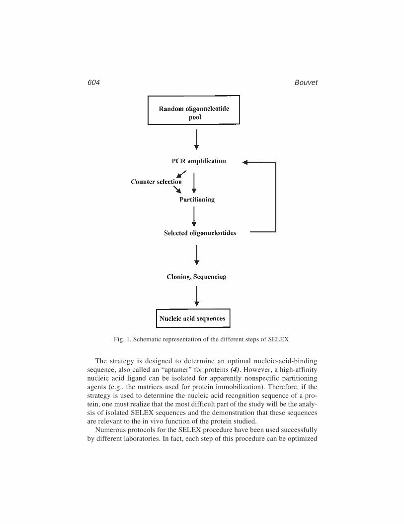
604 Bouvet
The strategy is designed to determine an optimal nucleic-acid-bindingsequence, also called an “aptamer” for proteins (4). However, a high-affinitynucleic acid ligand can be isolated for apparently nonspecific partitioningagents (e.g., the matrices used for protein immobilization). Therefore, if thestrategy is used to determine the nucleic acid recognition sequence of a pro-tein, one must realize that the most difficult part of the study will be the analy-sis of isolated SELEX sequences and the demonstration that these sequencesare relevant to the in vivo function of the protein studied.
Numerous protocols for the SELEX procedure have been used successfullyby different laboratories. In fact, each step of this procedure can be optimized
Fig. 1. Schematic representation of the different steps of SELEX.
Nucleic Acid Recognition Sequences by SELEX 605
(5) and modified as a function of the characteristics of the nucleic-acid-bindingprotein being studied.
We provide below a typical protocol that has been used successfully in sev-eral laboratories (6–9) to identify nucleic acid ligands for RNA-binding pro-teins. The same synthetic oligonucleotide DNA template can be used for theselection of DNA sequences by a DNA binding protein. In this case, steps 6and 18 of the method should be omitted.
2. Materials1. The following synthetic DNA template (see Note 7) has been used with success by
several laboratories: 5' TGGGCACTATTTATATCAAC (N25) AATGTCGTTG-GTGGCCC 3' with these flanking primers T7 5'-CGCGGATCCTAATACG-ACTCACTATAGGGGCCACCAACGACATT–3' and Rev 5'-CCCGACACCCGCGGATCCATGGGCACTATTTATATCAAC–3'. The T7-Xbaprimer 5' GGTCTAGATAATACGACTCACTATAGGGG 3' and Rev-HIIIprimer 5' ACCGCAAGCTTATGGGCACTATTTATAT 3' can be used for thefinal PCR amplification, and will allow an oriented cloning (XbaI and HindIII)of the PCR product in a cloning vector like pBluescript (Stratagene).
2. Thermocycler.3. Taq polymerase.4. TAE (Tris–acetate buffer); 40 mM Tris–acetate and 0.4 mM EDTA (pH 7.5).5. Partitioning matrix (to be chosen as a function of the studied protein; see Note 1).6. Nucleic acid electrophoresis system.7. NT2 buffer: 50 mM Tris-HCl (pH 7.4), 150 mM NaCl, 0.05% NP 40, and 1 mM
MgCl2.8. Binding buffer (BB): 50 mM Tris-HCl (pH 7.5), 150 mM NaCl, 20 mM KCl, 1 mM
dithiothreitol (DTT), 0.05% NP 40, 1 mM MgCl2, 2.5% polyvinyl alcohol (PVA),1 mM EGTA, 50 µg/mL poly(A), 2 µL/mL vanadyl ribonucleoside complex(VRC), 0.5 µg/mL tRNA, and 125 µg/mL bovine serum albumin (BSA).
9. 5X reverse transcription buffer: 250 mM Tris-HCl (pH 8.5), 40 mM MgCl2, 5 mMDTT, 250 µg/mL BSA, 150 mM KCl.
10. 1X transcription buffer: 40 mM Tris-HCl (pH 7.5), 6 mM MgCl2, 2 mM spermi-dine, 10 mM NaCl, and 10 mM DTT.
3. Method1. About 10 pmol of synthetic template DNA (N25) (see Note 2) is amplified by
PCR in a standard 100-µL reaction, in a 500-µL test tube, using 2 µL of a mix ofall four dNTPs (10 mM each) and 500 ng of each primer. One unit of Taq poly-merase is added just before the start of the amplification procedure. If thethermocycler does not have a hot cover, the reaction mixture is overlayed with2 drops of mineral oil.
2. Set up the thermocycler with the following cycle conditions: denaturation 1 minat 94°C, annealing 1 min at 50°C, and elongation 1 min at 72°C (see Note 8).
606 Bouvet
After 25 cycles of amplification, finish with an elongation of 10 min at 72°C. ThePCR reaction can be stored at 4°C without further purification.
3. Analyze 5 µL of the PCR reaction on a 3% agarose gel in TAE. Run in parallelwith a commercial DNA molecular-weight marker giving characteristic bandsaround 100 bp. The PCR reaction should produce a strongly staining product at108 bp.
4. Add 100 µL of phenol:chloroform (1:1) to the PCR reaction and mix vigorouslyfor 1 min. After a 5-min centrifugation at 15,000 rpm, the upper aqueous phase isextracted one more time with 1 volume of phenol:chloroform. Ten microliters of3 M sodium acetate (NaOAc) (pH 5.0) and 300 µL of cold ethanol are added.Allow DNA precipitation for at least 15 min at –20°C.
5. The PCR product is recovered by centrifugation (15 min at 15,000 rpm), washedwith 70% ethanol, dried, and resuspended in 10 µL of sterile water.
6. In vitro transcription. This step should be omitted for a SELEX with a DNA-binding protein. One microgram of PCR product of step 5 is incubated in 1Xtranscription buffer containing 0.5 mM of each rNTP, 1 unit of RNasin, and 20 Uof T7 RNA polymerase. The reaction is incubated for 1 h at 37°C. The DNAtemplate is eliminated by the addition of 1 unit of RNase-free DNase and incuba-tion for an additional 10 min at 37°C. After two sequential phenol:chloroformextractions, the RNA is purified through a G50 column (to remove most of theunincorporated nucleotides) then precipitated with 0.1 vol of 3M NaAc (pH 5.0)and 2 vol of 100% EtOH for 15 min at –20 °C. The RNA is pelleted for 15 min at15,000 rpm, washed with 70% EtOH, dried and resuspended in 20 µL of RNase-free water. One microliter of the transcription reaction is loaded on a 3% agarosegel to check the quality of the RNA. The RNA concentration is determined fromits ultraviolet (UV) adsorption at 260 nm.
7. Preparation of the partitioning matrix. The nature of this matrix will depend onthe protein to be used (see Note 1). We will provide here a detailed protocol for aselection procedure using a histidine-tagged protein. Other strategies are men-tioned in Note 1. Take 2 µL of Ni–NTA agarose beads (Qiagen) and wash twicewith 500 µL of sterile water to remove storage buffer (beads are recovered by a15-s centrifugation in a microcentrifuge). Wash the beads twice with 500 µL ofNT2 buffer. During the last wash, divide the suspension into two tubes (tubes Aand B), centrifuge, and eliminate 150 µL of the supernatant (i.e., leave beads in100 µL NT2).
8. Add about 1 pmol of purified histidine-tagged protein to tube A (see Note 10).Incubate 30 min at 4°C on a roller to allow binding of the protein on theNi–NTA beads.
9. Centrifuges tube A for 15 s, remove supernatant, then wash the beads twice with500 µL of NT2 buffer to remove all unbound protein.
10. Centrifuge tubes A and B, and remove most of the NT2 supernatant to leaveabout 10 µL of buffer above the beads. Ni–NTA beads must be visible at thebottom of the tube.
11. Add 100 µL of BB buffer in tube B (see Note 9).
Nucleic Acid Recognition Sequences by SELEX 607
12. Add 15 µg of nucleic acid from step 5 (for a DNA-binding protein) or from step6 (for an RNA-binding protein) to tube B (see Note 3). Incubate 5 min at roomtemperature. Centrifuge tube B for 15 s. Remove and save supernatant (see Note 4).
13. Add supernatant from step 12 to the tube containing the matrix-bound protein(tube A). Incubate 5 min at room temperature. Centrifuge tube A for 15 s, thenremove and discard supernatant.
14. Add 1 mL of NT2 buffer (see Note 5) to tubes A and B. Mix well by inverting thetubes three times. Centrifuge for 15 s to pellet the Ni–NTA beads. Remove asmuch the supernatant as possible.
15. Repeat this wash four more times. At the last wash, transfer the matrix-boundnucleic acid–protein complex to a new test tube (see Note 6).
16. After the last wash, leave 100 µL of NT2 buffer in each tube. Add 100 µL ofsterile water and 200 µL of phenol:chloroform (1:1). Vortex for 30 s and spin for5 min at full speed in a microcentrifuge. Repeat the extraction one more time.
17. Recover the upper aqueous phase and add 2 µL of 1 M MgCl2, 20 µL of 3 MNaOAc, and 700 µL of 100% EtOH. Precipitate for at least 30 min at –20°C, spinfor 30 min at 15,000 rpm. Wash the pellet with 70% EtOH, dry and resuspend itin 13 µL of sterile water.
18. Reverse transcribe the bond RNA (should be omitted if the SELEX is performedwith DNA). To each tube A and B, add 100 ng of Rev primer (in 1 µL), 2 µL ofa dNTP mix (each dNTP at 10 mM), 4 µL of 5X reverse transcription buffer,30 U of RNasin (Promega), and 25 U of AMV reverse transcriptase (BoehringerMannheim). The reaction is incubated for 5 min at 55°C, then for 1 h at 42°C.Five microliters of this reverse transcription reaction is used directly, withoutfurther purification, for the next PCR amplification.
19. Add to the recovered nucleic acid of step 17 or 18 the reagents necessary for thePCR reaction, as described in step 1. Include a control reaction without oligo-nucleotide template to assure that the PCR reaction is specific. No PCR productshould be obtained from the products of tube B (see Note 6).
20. Purify the PCR product obtained with tube A as described in steps 4 and 5.21. Repeat several rounds of partitioning on fresh binding protein matrix, steps 6–18
(but see Note 4).22. After several rounds of selection (usually between 4 and 10) check for an enrich-
ment of the oligonucleotide pool in the high-affinity ligand for the target protein.This can be done by binding a labeled aliquot of the selected oligonucleotidepool of each cycle (either direct 5' [32P] labeling of the PCR product withpolynucleotide kinase for DNA-binding protein, or in vitro transcribed with an[α-32P] rNTP for an RNA-binding protein) following steps 7–16. If a substantialenrichment is obtained, as determined by the fraction of labeled nucleic acidremaining on the matrix-bound protein and this fraction reaches a plateau after agiven number of partitioning cycles, the selection can be stopped and one shouldproceed to the cloning step. If no enrichment is observed, more rounds of selec-tion should be performed, either under the same experimental conditions or athigher stringency (see Note 5).
608 Bouvet
23. The final PCR can be performed with the primers T7–Xba and Rev–HIII (seeSubheading 2.). After gel purification, the PCR products are digested with therestriction enzymes XbaI and HindIII, and the oligonucleotides are cloned in asuitable vector (e.g., pBluescript). A number of individual clones are isolatedand their inserts are sequenced using standard methodology.
4. Notes1. Several methods of partitioning can be used as a function of what is available to
the researcher. If the target is a tagged recombinant protein (GST, histidine, orany other tag), nucleic acid–protein complexes can be recovered by classicalaffinity chromatography as described in the present protocol. If the protein ispure but not tagged, filtration of the binding reaction mixture through nitrocellu-lose (see Chapter 1) may allow separation of the bound and unbound molecules(15). An alternative method of partitioning is to use gel-shift analysis or EMSA(Chapter 2). When using EMSA, labeled oligonucleotides are to be preferred inorder to easily identify the nucleic acid–protein complex. Shifted oligonucle-otides are eluted from the EMSA gel and used for PCR amplification.
2. A custom-made random oligonucleotide can be easily synthesized using stan-dard chemistry. The variable sequence is flanked by fixed sequences that serve inthe PCR amplification steps. Full-length oligonucleotides should be purifiedbefore their amplification by PCR. The length of the random sequence may varyfrom a few nucleotides to as many as a hundred. If a simple DNA-binding site isexpected, a random sequence of as little as 20 nucleotides should be sufficient. Alibrary with a short random sequence has also the advantage of being more likelyto contain all possible random sequences and therefore to allow the selection ofthe best binding sequence. Sequencing of a few random sequences should beideally performed to ensure that the synthesis of the random sequences has notbeen biased by a preferential incorporation of one deoxynucleotide. If the com-position of the random sequence is severely biased, this should be corrected bymodifying the percentage of the addition of nucleotides accordingly during syn-thesis. If a binding site is already known for the protein, the SELEX procedurecan be used to determine nucleotides important for binding affinity and specific-ity. In this case, an oligonucleotide containing a degenerated sequence within theknown binding site can be synthesized (10). Libraries that contain genomicsequences can also be used to identify potential natural binding sites (11,12).
3. The amount of oligonucleotide present in the binding reaction should be in largeexcess over the protein. This ensures an efficient competition between ligandsfor the protein. The ratio oligonucleotide/protein is often within the range of 10and 1000. The volume of the binding reaction should also be determined as afunction of the diversity of the library. A binding reaction of several millilitersmight be required if one wished to test all possible sequences (4n, n: number ofrandom nucleotides) present in an initial library.
4. The interaction of the random oligonucleotide pool with the partitioning matrixalone (i.e., without bound protein [called counter selection or negative selec-
Nucleic Acid Recognition Sequences by SELEX 609
tion]) is important to remove oligonucleotide molecules with high affinity for thepartitioning matrix itself. This counter selection is not necessary if the DNAbound to the protein is recovered instead using electrophoretic mobility shiftassay (EMSA) gel shift (see Chapter 2) because only nucleic acid from the shiftedband will be used for the next selection cycles. The counter selection should onlybe performed during the first and possibly the second cycles of selection andshould subsequently be omitted in subsequent cycles.
5. The stringency of the binding and washing buffer can be increased if necessary.This could be done by increasing the salt concentration, or by adding 0.5–1.0 Murea. Usually, between 1% and 10% of the initial oligonucleotide pool bindsto the target protein. Preliminary binding tests should determine the optimalbuffer stringency to allow a binding that falls within this range. Buffer strin-gency can also be increased during the cycling process if no substantial enrich-ment is observed.
6. Although nucleic acids bind poorly to most plastic tubes, this binding is some-times sufficient to give a PCR product after the selection reaction. This problemmay be overcome by using siliconized tubes and/or by transferring the nucleicacid/protein complex to a new tubes during the washing procedure.
7. The random sequence is flanked by fixed sequences (17–20 nt) to allow PCRamplification with the corresponding primers (see Subheading 2. for an exampleof primer sequences). It is important to check that the flanking sequences are nota binding site for the protein. This can easily be done by performing a bindingassay between the random pool and the studied protein.
8. The PCR reaction can be modified to allow the production of single-strandedoligonucleotides, the incorporation of modified nucleotides or random mutations,and so forth. If the PCR reaction produces aberrant products (higher-molecular-weight DNA products, smear, etc.), several tests reactions (with various amountof primers, number of cycle) should be made.
9. The composition of the binding buffer should be adapted to the protein that isbeing studied. The addition of nucleic acid competitors, such as tRNA andhomopolymers like poly(A), may be necessary in some selection experiments inorder to reduce nonspecific binding. Preliminary tests of interaction of the randompool with the protein can be performed with nucleic acid competitors to deter-mine the best selection conditions.
10. In most published experiments, the SELEX procedure is performed with purifiedrecombinant proteins. However, it can be performed with crude cell extractscontaining the protein of interest or with multiprotein complexes if the partition-ing procedure allows a specific recovering of the nucleic acid-protein target(13,14). Epitope-tagged protein can be expressed in cells, or added to cell extractand used for the SELEX. For some SELEX experiments, it could also be interest-ing to use truncated protein with only the nucleic-acid-binding domain. In somecases, this can significantly reduce nonspecific binding of the random oligonucle-otide pool and therefore reduce the number of rounds necessary for the isolationof specific ligands.
610 Bouvet
References1. Oliphant, A. R., Brandl, C. J., and Struhl, K. (1989) Defining the sequence
specificity of DNA-binding proteins by selecting binding sites from random-sequence oligonucleotides: analysis of yeast GCN4 protein. Mol. Cell. Biol. 9,2944–2949.
2. Tuerk, C. and Gold, L. (1990) Systematic evolution of ligands by exponentialenrichment: RNA ligands to bacteriophage T4 DNA polymerase. Science 249,505–510.
3. Gold, L., Polisky, B., Uhlenbeck, O., and Yarus, M. (1995) Diversity of oligo-nucleotide functions. Annu. Rev. Biochem. 64, 763–797.
4. Ellington, A. D. and Szostak, J. W. (1990) In vitro selection of RNA moleculesthat bind specific ligands. Nature 346, 818–822.
5. Irvine, D., Tuerk, C., and Gold, L. (1991) SELEXION. Systematic evolution ofligands by exponential enrichment with integrated optimization by nonlinearanalysis. J. Mol. Biol. 222, 739–761.
6. Bouvet, P., Matsumoto, K., and Wolffe, A. P. (1995) Sequence-specific RNArecognition by the Xenopus Y-box proteins. An essential role for the cold shockdomain. J. Biol. Chem. 270, 28,297–28,303.
7. Ghisolfi-Nieto, L., Joseph, G., Puvion-Dutilleul, F., Amalric, F., and Bouvet, P.(1996) Nucleolin is a sequence-specific RNA-binding protein: characterization oftargets on pre-ribosomal RNA. J. Mol. Biol. 260, 34–53.
8. Triqueneaux, G., Velten, M., Franzon, P., Dautry, F., and Jacquemin-Sablon, H.(1999) RNA binding specificity of Unr, a protein with five cold shock domains.Nucleic Acids Res. 27, 1926–1934.
9. Tsai, D. E., Harper, D. S., and Keene, J. D. (1991) U1-snRNP-A protein selects aten nucleotide consensus sequence from a degenerate RNA pool presented in vari-ous structural contexts. Nucleic Acids Res. 19, 4931–4936.
10. Bartel, D. P., Zapp, M. L., Green, M. R., and Szostak, J. W. (1991) HIV-1 Revregulation involves recognition of non-Watson–Crick base pairs in viral RNA.Cell 67, 529–536.
11. Gao, F. B., Carson, C. C., Levine, T., and Keene, J. D. (1994) Selection of asubset of mRNAs from combinatorial 3' untranslated region libraries using neu-ronal RNA-binding protein Hel-N1. Proc. Natl. Acad. Sci. USA 91, 11,207–11,211.
12. Singer, B. S., Shtatland, T., Brown, D., and Gold, L. (1997) Libraries for genomicSELEX. Nucleic Acids Res. 25, 781–786.
13. Pollock, R. and Treisman, R. (1990) A sensitive method for the determination ofprotein–DNA binding specificities. Nucleic Acids Res. 18, 6197–6204.
14. Ringquist, S., Jones, T., Snyder, E. E., Gibson, T., Boni, I., and Gold, L. (1995)High-affinity RNA ligands to Escherichia coli ribosomes and ribosomal protein S1:comparison of natural and unnatural binding sites. Biochemistry 34, 3640–3648.
15. Tuerk, C., Eddy, S., Parma, D., and Gold, L. (1990) Autogenous translationaloperator recognized by bacteriophage T4 DNA polymerase. J Mol Biol 213,749–761.
DNA–Protein Crosslinking with TWF Irradiation 611
611
From: Methods in Molecular Biology, vol. 148: DNA–Protein Interactions: Principles and Protocols, 2nd ed.Edited by: T. Moss © Humana Press Inc., Totowa, NJ
43
High DNA–Protein Crosslinking Yieldwith Two-Wavelength FemtosecondLaser Irradiation
Christoph Russmann, Rene Beigang, and Miguel Beato
1. IntroductionDNA–protein interactions are instrumental in the replication, repair, recom-
bination, and expression of genetic information. Their study under physiologi-cal conditions requires rapid methods that do not cause extensive cell damage.Among the available techniques, crosslinking by ultraviolet (UV) laser irradia-tion seems best placed to fulfill these requirements, but the crosslinking yieldis still relatively low with the commonly used pulses in the nanosecond (ns)range (see Chapter 27). To attain higher crosslinking yields, laser parametersmust be adjusted to the underlying two-photon process, which strongly dependson pulse intensity and pulse length (1). The highest crosslink yields are achievedusing femtosecond (fs) laser pulses, but these also result in higher DNA dam-age (1). In order to reduce the UV-induced DNA damage, we have applied acombination of UV pulses for the first excitation step and blue pulses for thesecond step (2). This strategy has the advantage that the intensity of the UVpulse in the first step can be kept low, thus reducing DNA damage caused bythe UV photons. High crosslinking efficiency can, however, still be attained byapplying the second pulse with a very short time delay and at a visible wave-length too long to excite DNA bases from the ground state. This second pulsecannot alone damage DNA, but it can provide enough additional energy for theUV excited bases to pass their ionization threshold, leading to crosslinking.
1.1. The Method
Two-wavelength femtosecond (TWF) laser-induced DNA–protein cross-linking provides a significant improvement to classical laser crosslinking.

612 Russman, Beigang, and Beato
Optimized laser parameters lead to an increased crosslinking efficiency whileminimizing DNA damage.
1.2. Practical Applications
The practical applications of TWF-laser crosslinking are similar to theapplications of classical laser crosslinking (see Chapter 27).
1.3. The Basic Approach
The basic approach of TWF-laser crosslinking differs from classical UV-lasercrosslinking in the simultaneous irradiation of the sample with two preciselytimed fs pulses of different wavelengths. As a consequence, the laser equip-ment and the irradiation procedure have been modified. In the following, wedescribe the method in detail.
2 Materials2.1. Lasers
As a source for the fs laser pulses, we have used a continuous-wave (cw)-argon-ion-laser (514.5 nm)-pumped cw-mode-locked Ti:sapphire laser (Spectra Phys-ics, model Tsunami), which generates 150-fs-long pulses at a repetition rate of82 MHz with an average power of up to 2 W in a wavelength range from 720 to850 nm (2). Infrared pulses around 798 nm were frequency doubled and tripledin two β-barium borate crystals in a “flexible harmonic generator” (FHG), andpulses at the second harmonic frequency 2ω (λ = 399 nm) and the third har-monic frequency 3ω (λ = 266 nm) were used to irradiate the sample (Fig. 1).The pulse length in the ultraviolet was increased to about 200 fs as a result ofthe dispersion of the nonlinear crystals. We used the following physicalparameters in our approach (Table 1).
Using a variable delay line with a temporal resolution of 10 fs, the samplewas irradiated with UV and blue in a two-step excitation process with a well-defined time delay. The time delay between the UV and the blue pulses has tobe chosen accurately, as the lifetime of the intermediate singlet level of thebase pairs is of the order of the pulse length. It was determined with a delayline using a β-barium borate crystal and a photodiode for difference-fre-quency generation (DFG). If the two laser pulses arrive simultaneously inthe crystal, the generated difference-frequency signal is maximized. Thismethod is used to calibrate the delay line. For our approach, the optimumtemporal delay between the UV and the blue pulse was determined to be300 fs. The laser pulse was focused onto the sample with a quartz lens. Theenergy of the applied radiation was measured with a standard energy meter(see Note 1).
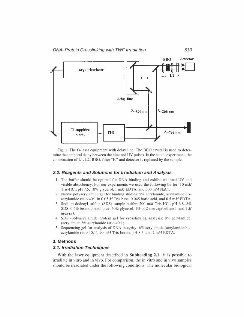
DNA–Protein Crosslinking with TWF Irradiation 613
2.2. Reagents and Solutions for Irradiation and Analysis
1. The buffer should be optimal for DNA binding and exhibit minimal UV andvisible absorbency. For our experiments we used the following buffer: 10 mMTris-HCl, pH 7.5, 10% glycerol, 1 mM EDTA, and 300 mM NaCl.
2. Native polyacrylamide gel for binding studies: 5% acrylamide, acrylamide:bis-acrylamide ratio 40:1 in 0.05 M Tris base, 0.045 boric acid, and 0.5 mM EDTA.
3. Sodium dodecyl sulfate (SDS) sample buffer: 200 mM Tris-HCl, pH 6.8, 8%SDS, 0.4% bromophenol blue, 40% glycerol, 1% of 2-mercaptoethanol, and 1 Murea (3).
4. SDS -polyacrylamide protein gel for crosslinking analysis: 8% acrylamide,(acrylamide:bis-acrylamide ratio 40:1).
5. Sequencing gel for analysis of DNA integrity: 6% acrylamide (acrylamide:bis-acrylamide ratio 40:1), 90 mM Tris-borate, pH 8.3, and 2 mM EDTA.
3. Methods3.1. Irradiation Techniques
With the laser equipment described in Subheading 2.1., it is possible toirradiate in vitro and in vivo. For comparison, the in vitro and in vivo samplesshould be irradiated under the following conditions. The molecular biological
Fig. 1. The fs-laser equipment with delay line. The BBO crystal is used to deter-mine the temporal delay between the blue and UV pulses. In the actual experiment, thecombination of L1, L2, BBO, filter “F,” and detector is replaced by the sample.
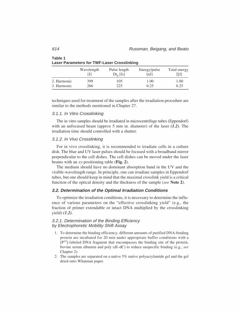
614 Russman, Beigang, and Beato
techniques used for treatment of the samples after the irradiation procedure aresimilar to the methods mentioned in Chapter 27.
3.1.1. In Vitro Crosslinking
The in vitro samples should be irradiated in microcentrifuge tubes (Eppendorf)with an unfocused beam (approx 5 mm in. diameter) of the laser (1,2). Theirradiation time should controlled with a shutter.
3.1.2. In Vivo Crosslinking
For in vivo crosslinking, it is recommended to irradiate cells in a culturedish. The blue and UV laser pulses should be focused with a broadband mirrorperpendicular to the cell dishes. The cell dishes can be moved under the laserbeams with an xy-positioning table (Fig. 2).
The medium should have no dominant absorption band in the UV and thevisible-wavelength range. In principle, one can irradiate samples in Eppendorftubes, but one should keep in mind that the maximal crosslink yield is a criticalfunction of the optical density and the thickness of the sample (see Note 2).
3.2. Determination of the Optimal Irradiation Conditions
To optimize the irradiation conditions, it is necessary to determine the influ-ence of various parameters on the “effective crosslinking yield” (e.g., thefraction of primer extendable or intact DNA multiplied by the crosslinkingyield) (1,2).
3.2.1. Determination of the Binding Efficiencyby Electrophoretic Mobility Shift Assay
1. To determine the binding efficiency, different amounts of purified DNA-bindingprotein are incubated for 20 min under appropriate buffer conditions with a[P32]-labeled DNA fragment that encompasses the binding site of the protein,bovine serum albumin and poly (dI–dC) to reduce unspecific binding (e.g., seeChapter 2).
2. The samples are separated on a native 5% native polyacrylamide gel and the geldried onto Whatman paper.
Table 1Laser Parameters for TWF-Laser Crosslinking
Wavelength Pulse length Energy/pulse Total energy[J] Dtp [fs] [nJ] 2[J]
2. Harmonic 399 105 1.00 1.003. Harmonic 266 225 0.25 0.25
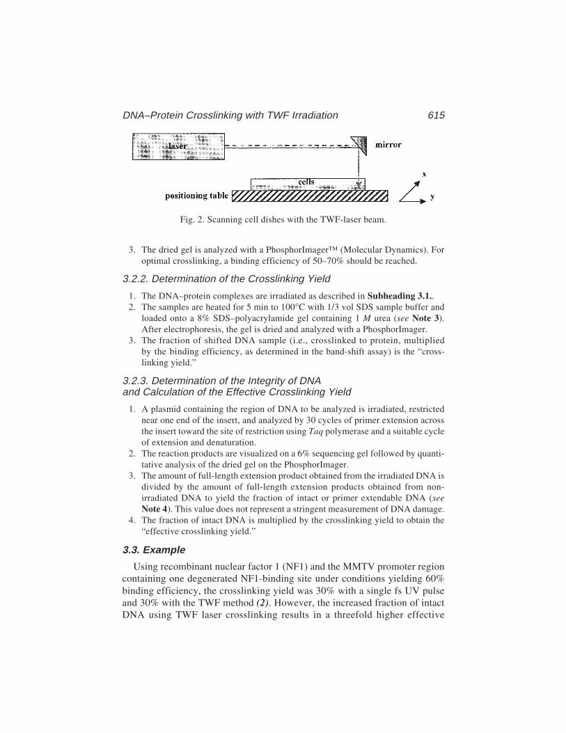
DNA–Protein Crosslinking with TWF Irradiation 615
3. The dried gel is analyzed with a PhosphorImager™ (Molecular Dynamics). Foroptimal crosslinking, a binding efficiency of 50–70% should be reached.
3.2.2. Determination of the Crosslinking Yield
1. The DNA–protein complexes are irradiated as described in Subheading 3.1..2. The samples are heated for 5 min to 100°C with 1/3 vol SDS sample buffer and
loaded onto a 8% SDS–polyacrylamide gel containing 1 M urea (see Note 3).After electrophoresis, the gel is dried and analyzed with a PhosphorImager.
3. The fraction of shifted DNA sample (i.e., crosslinked to protein, multipliedby the binding efficiency, as determined in the band-shift assay) is the “cross-linking yield.”
3.2.3. Determination of the Integrity of DNAand Calculation of the Effective Crosslinking Yield
1. A plasmid containing the region of DNA to be analyzed is irradiated, restrictednear one end of the insert, and analyzed by 30 cycles of primer extension acrossthe insert toward the site of restriction using Taq polymerase and a suitable cycleof extension and denaturation.
2. The reaction products are visualized on a 6% sequencing gel followed by quanti-tative analysis of the dried gel on the PhosphorImager.
3. The amount of full-length extension product obtained from the irradiated DNA isdivided by the amount of full-length extension products obtained from non-irradiated DNA to yield the fraction of intact or primer extendable DNA (seeNote 4). This value does not represent a stringent measurement of DNA damage.
4. The fraction of intact DNA is multiplied by the crosslinking yield to obtain the“effective crosslinking yield.”
3.3. Example
Using recombinant nuclear factor 1 (NF1) and the MMTV promoter regioncontaining one degenerated NF1-binding site under conditions yielding 60%binding efficiency, the crosslinking yield was 30% with a single fs UV pulseand 30% with the TWF method (2). However, the increased fraction of intactDNA using TWF laser crosslinking results in a threefold higher effective
Fig. 2. Scanning cell dishes with the TWF-laser beam.
616 Russman, Beigang, and Beato
crosslinking yield with the TWF method (14%) as compared with a single fsUV pulse (4.8%).
4. Notes1. The laser equipment used in the first experiments for TWF laser crosslinking is
rather complex and sophisticated. Molecular biologists interested in using thismethod are best advised to contact a laser laboratory. However, the recent devel-opment of compact, diode-laser-pumped, all-solid-state femtosecond lasers andthe use of new nonlinear materials for frequency conversion, like quasi-phase-matched crystals, will eventually result in reliable easy-to-operate femtosecondsystems at a reasonable price. These systems are well-suited for routine applica-tions of this new crosslinking method in molecular biology laboratories.
2. The irradiated samples should be as thin as possible to avoid dispersion effects,as these cause a change of the temporal distance between the blue and the UVpulses. The velocity of the positioning table should be precisely tunable. Changesin velocity can then be used to vary the applied energy per square millimeter ofcell layer. This is an important parameter for increasing the in vivo crosslinkingyield. However, irradiation should be fast enough to avoid drying of the cells.
3. Many crosslinked protein-DNA complexes do not enter a standard SDS–proteingel when solubilized in SDS–sample buffer without urea (3). Probably, urea pre-vents the aggregation of crosslinked material.
4. The amount of full-length extension product is only an operational value,depending on the irradiation conditions and on the length of the template. Oneshould keep in mind that this parameter is used to optimize the crosslink proce-dure and does not represent a stringent measurement of DNA damage.
References1. Rubmann, C., Truss, M., Fix, A., Naumer, C., Herrmann, T., Schmitt, J., et al.
(1997) Lasercrosslinking of progesterone receptor to DNA using tuneable nano-second, picosecond and femtosecond laser pulses. Nucleic Acids Res. 25(12),2478–2484.
2. Rubmann, C., Stollhof, J., Weib, C., Beigang, R., and Beato, M. (1998) Femto-second two wavelength crosslinking of DNA–protein-complexes. Nucleic AcidsRes. 26(17), 3967–3971.
3. Ho, D. T., Sauvé, D. M., and Roberge, M. (1994) Detection and isolation of DNA-binding proteins using single-pulse ultraviolet laser crosslinking. Anal. Biochem.218, 248–254.
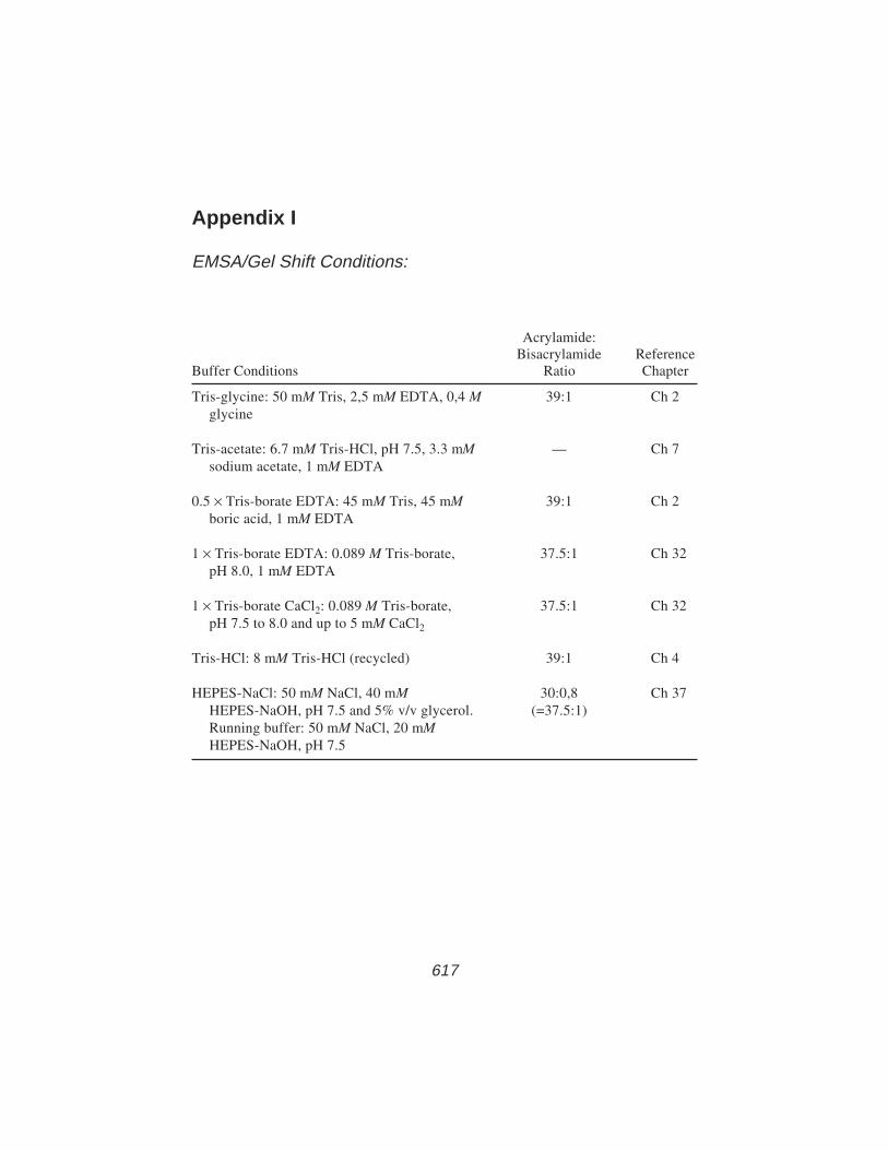
Appendix I 617
617
Appendix I
EMSA/Gel Shift Conditions:
Acrylamide:Bisacrylamide Reference
Buffer Conditions Ratio Chapter
Tris-glycine: 50 mM Tris, 2,5 mM EDTA, 0,4 M 39:1 Ch 2glycine
Tris-acetate: 6.7 mM Tris-HCl, pH 7.5, 3.3 mM — Ch 7sodium acetate, 1 mM EDTA
0.5 × Tris-borate EDTA: 45 mM Tris, 45 mM 39:1 Ch 2boric acid, 1 mM EDTA
1 × Tris-borate EDTA: 0.089 M Tris-borate, 37.5:1 Ch 32pH 8.0, 1 mM EDTA
1 × Tris-borate CaCl2: 0.089 M Tris-borate, 37.5:1 Ch 32pH 7.5 to 8.0 and up to 5 mM CaCl2
Tris-HCl: 8 mM Tris-HCl (recycled) 39:1 Ch 4
HEPES-NaCl: 50 mM NaCl, 40 mM 30:0,8 Ch 37HEPES-NaOH, pH 7.5 and 5% v/v glycerol. (=37.5:1)Running buffer: 50 mM NaCl, 20 mMHEPES-NaOH, pH 7.5
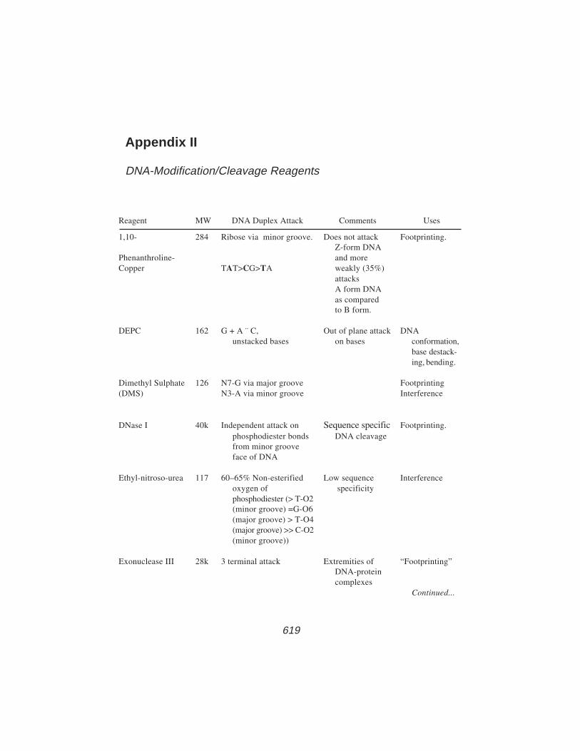
Appendix II 619
Reagent MW DNA Duplex Attack Comments Uses
1,10- 284 Ribose via minor groove. Does not attack Footprinting.Z-form DNA
Phenanthroline- and moreCopper TAT>CG>TA weakly (35%)
attacksA form DNAas comparedto B form.
DEPC 162 G + A ¨ C, Out of plane attack DNAunstacked bases on bases conformation,
base destack-ing, bending.
Dimethyl Sulphate 126 N7-G via major groove Footprinting(DMS) N3-A via minor groove Interference
DNase I 40k Independent attack on Sequence specific Footprinting.phosphodiester bonds DNA cleavagefrom minor grooveface of DNA
Ethyl-nitroso-urea 117 60–65% Non-esterified Low sequence Interferenceoxygen of specificityphosphodiester (> T-O2(minor groove) =G-O6(major groove) > T-O4(major groove) >> C-O2(minor groove))
Exonuclease III 28k 3 terminal attack Extremities of “Footprinting”DNA-proteincomplexes
Continued...
Appendix II
DNA-Modification/Cleavage Reagents
619

620 Appendix II
Hydroxy-radical 17 Sugar backbone Little sequence Footprintingpreference Interference
Osmium tetroxide 254 Unstacked T Very specific for DNAcertain, as yet conformationpoorly definedDNAconformationsincludingoverwinding
Permanganate 119 T » G, C, A Out of plane attack DNAon 5,6 double conformation,bond of T melting, base
destacking,bending.
Diffusible singlet 16 Unstaked/unwound DNA Little sequence DNAoxygen bases preference in conformation
duplex DNA(though as freebases, G is byfar the preferedtarget)
uranyl(VI) ion 268 Phosphates-photolysis Little sequence Footprinting(UO2
2+) dependence of bothmacromol-ecules anddrugs.
UV irradiation — TT >> CT, TC, or CC Products: Footprinting.i) cyclobutane Note, protein
pyrimidine does notdimer (CBD). prevent
ii) pyrimidine (6-4) access butpyrimidone changes DNAphotoproduct reactivity(6-4PP) locally.
Index 621
621
Index
A
AFM, see Atomic force microscopyAminopropyltrietoxy silane (APTES),
mica functionalization, seeAtomic force microscopy
1-Anilinonaphthalene-8-sulfonic acid(ANS),
competition assay for DNA binding,advantages over intrinsic
fluorescence, 265binding curve generation, 270–272materials, 267, 268, 273preliminary testing, 266, 267,
269, 270, 273principle, 265resonance energy transfer, 273, 274titration, 268, 269, 273
protein binding properties, 265, 266ANS, see 1-Anilinonaphthalene-8-
sulfonic acidAPTES, see Aminopropyltrietoxy silaneAtomic force microscopy (AFM),
advantages and limitations, 569functionalized mica substrates,
overview, 569, 570preparation, 571, 575
imaging in air,contact vs tapping modes,569, 570sample preparation,droplet procedure, 569, 571,572immersion procedure, 569,571, 572
imaging in solution,
advantages, 570dried samples, 570, 572in situ, 570, 571
materials for nucleoprotein imaging,570
multivalent cation method forsample preparation, 571
8-Azidoadenine,DNA incorporation,
materials, 325, 326nick translation, 328, 332
DNA–protein crosslinking,filter binding assay, 330gel electrophoresis analysis,
329, 330photocrosslinking, 328, 329,
332, 333photoaffinity labeling overview,
323, 324synthesis,
characterization, 327, 328, 331,332
materials, 325protocol, 326, 327, 330, 331radiolabeled compound, 330
B
Biacore, see Surface plasmon resonance
C
Calorimetry, see also Differentialscanning calorimetry; Isothermaltitration calorimetry,
DNA-binding protein applications, 512

622 Index
equilibrium, 513thermodynamic parameters,
energetics of protein–DNAinteraction, 512, 513
overview, 511, 512CD, see Circular dichroismCircular dichroism (CD),
applications for DNA-bindingproteins, 504, 508
DNA change measurement uponprotein binding,
materials, 504, 505titration, 505, 506, 508wavelength selection, 504, 505
origin of signal, 503principles, 503, 504sensitivity, 504Sox-5 HMG domain dissociation
constant determination forDNA, 518
Crystallography, see Reconstitution,protein–DNA complexes forcrystallization; Two-dimensionalcrystallization
D
DEPC footprinting, see Diethylpyrocarbonate footprinting
Diethyl pyrocarbonate (DEPC)footprinting,
advantages, 63, 64applications, 64, 65DNA modification,
detection of modified bases withpiperidine cleavage, 65, 66,68, 69, 71
reaction mechanism, 64in vitro experiments on linear
DNA fragments,binding reaction, 68, 71gel electrophoresis, 69, 71modification reaction and
stopping, 68, 71
piperidine cleavage, 68, 69, 71radiolabeling of probe, 68
materials, 67Differential scanning calorimetry
(DSC), see also Calorimetry,excess molar heat capacity, 516intrinsic heat capacity, 516partial molar heat capacity, 515, 516principle, 515, 516Sox-5 HMG domain interaction with
DNA,concentration determinations,
complex, 528, 529DNA, 527, 5286protein, 528
correction of isothermal titrationcalorimetry-derivedenthalpies, 525, 526
data acquisition, 524, 530, 531data analysis, 525instrumentation, 520materials, 520, 521, 529
Dimethyl sulfate (DMS) footprinting,combination with electrophoretic
mobility shift assay, 78, 79ligation-mediated polymerase chain
reaction for in vivofootprinting,
advantages and limitations, 183, 187cleavage for DNA sequencing
products,A reaction, 201C reaction, 201, 202G reaction, 201overview, 200, 201processing of samples, 202reagants, 192T+C reaction, 201
detectable DNA–proteininteractions, 183
dimethyl sulfate treatment, 193,202, 203, 213
DNA polymerase selection, 191
Index 623
DNA purification,DNA extraction, 200, 213materials, 191, 192nuclei isolation, 200quantification, 200, 213
gel electrophoresis andelectroblotting,blotting, 209, 214electrophoresis, 208, 209materials, 196, 197
hybridization,digoxigenin-labeled probe,197, 198, 210, 214, 215materials, 197radiolabeled probe, 197,209, 214
ligation,ligation reaction, 207materials, 195
modified bases and conversion tosingle-strand breaks, 181,188, 193, 205
overview, 176, 177polymerase chain reaction,
cycles, 207, 208materials, 195, 196, 213
primer extension,incubation conditions,206, 207materials, 194, 195, 212, 213
single-stranded hybridizationprobe preparation,amplification productpurification andquantification, 198, 199,211, 215digoxigenin labeling, 199,212, 215length, 210, 215materials, 198, 199, 213polymerase chain reactionamplification, 198, 210, 211radiolabeling, 199, 211, 212
methylation interference assay, seemethylation protection/interference, dimethyl sulfate
principle, 78sites of reaction with DNA, 79
DMS footprinting, see Dimethyl sulfatefootprinting
DNA bending,functions, 403pBend vectors for assay,
bending angle, 415, 416cloning sites, 405colony screening for clones, 408, 411electrophoretic analysis of
complexes, 408, 409, 412–414host strains of bacteria, 409materials, 405–409overview, 403, 404protein-binding site insertion into
plasmid, 405–411, 413purification of plasmid DNA, 408,
411, 412restriction sites, 404–406, 414, 415types of vectors, 404, 405
DNase I footprinting,applications, 31, 32autoradiography, 36, 38binding reaction, 35–37combination with electrophoretic
mobility shift assay, 78, 79digestion, 36, 37DNA probe labeling, 34DNase I,
sequence specificity, 33, 34, 79structure and function, 32, 33, 79
gel electrophoresis, 36, 37ligation-mediated polymerase chain
reaction for in vivofootprinting,
advantages and limitations, 186, 187cleavage for DNA sequencing
products,A reaction, 201
624 Index
C reaction, 201, 202G reaction, 201overview, 200, 201processing of samples, 202reagants, 192T+C reaction, 201
DNA polymerase selection, 191DNA purification,
DNA extraction, 200, 213materials, 191, 192nuclei isolation, 200quantification, 200, 213
DNase I treatment, 193, 204, 205,213, 214
gel electrophoresis andelectroblotting,blotting, 209, 214electrophoresis, 208, 209materials, 196, 197
hybridization,digoxigenin-labeled probe,197, 198, 210, 214, 215materials, 197radiolabeled probe, 197,209, 214
ligation,ligation reaction, 207materials, 195
modified bases and conversion tosingle-strand breaks, 188
nonspecific priming of 3'-ends,188, 189
overview, 182, 186, 188permeabilization of cells, 188polymerase chain reaction,
cycles, 207, 208materials, 195, 196, 213
primer extension,incubation conditions, 206,207materials, 194, 195, 212, 213
single-stranded hybridizationprobe preparation,
amplification productpurification andquantification, 198, 199,211, 215digoxigenin labeling, 199,212, 215length, 210, 215materials, 198, 199, 213polymerase chain reactionamplification, 198, 210, 211radiolabeling, 199, 211, 212
materials, 35–37nonspecific competitor DNA, 34principle, 31, 77, 78Southwestern blotting, see
Southwestern blottitration, 34
DSC, see Differential scanningcalorimetry
E
Electron microscopy, see also Scanningtransmission electron microscopy,
nucleoprotein structural repeatimaging,
focusing effects, 584, 585materials, 571–573, 586negative staining, 579, 580,
583, 584overview, 579specimen mounting, 583, 586, 587tilted specimens,
applications, 580, 581closer end identification,584–586Fresnel patterns, 585, 586helical asymmetryidentification, 584–586
two-dimensional crystallography,see also Two-dimensionalcrystallization,
crystal transfer to grid, 563,565–567

Index 625
evaluation of specimens, 564, 567negative staining, 563, 567support preparation, 616–614
Electrophoretic mobility shift assay(EMSA),
advantages, 13applications, 15, 16buffers, 20, 26combination with binding
interference studies, 16DNA probe,
isolation,double-stranded syntheticoligonucleotides, 23, 27fragments derived fromsubcloned sequence, 22, 23materials, 20, 21
labeling options, 19radiolabeling,
double-stranded syntheticoligonucleotides, 22fragments derived fromsubcloned sequence, 21,22, 27materials, 20, 25safety, 25
size, 19electrophoresis,
autoradiography, 24gel matrix selection, 19, 20, 25, 26gel preparation, 23, 24, 26loading and electrophoresis, 24, 26materials, 21, 25, 26
ethylation interference assay, 233–236,240, 241
exonuclease III footprintingoptimization, 43, 45, 46
hydroxyl radical footprintingoptimization, 55
hydroxyl radical interference,gel, 250, 252optimization, 250, 252
10-Phenanthroline-copperfootprinting coupling,
benefits, 83, 85, 86cleavage in gel, 94, 95, 106, 107competition binding assay, 92, 104dissociation rate determination,
92, 104, 105gel preparation, 93loading of gel, 94, 106materials, 86, 87optimization,
binding reaction parameters,103, 104electrophoresis conditions,104exposure time to chemicalnuclease, 92, 105, 106preliminary assay, 92, 102probe length, 103
preparative reaction, 93principle, 82running conditions, 94
reconstitution of protein–DNAcomplexes for crystallization,551, 554
restriction endonuclease dissociationconstant determination,
competitive equilibrumbinding, 482data analysis, 482, 383direct titration, 481, 482,487, 488materials, 471
sensitivity, 13two-wavelength femtosecond laser
crosslinking optimization,614, 615
ELISA, see Enzyme-linkedimmunosorbent assay
EMSA, see Electrophoretic mobilityshift assay
Enzyme-linked immunosorbent assay(ELISA), phage binding, 419,423, 424, 428
Equilibrium constant,filter-binding assay determination,
5, 6
626 Index
fluorescence anisotropydetermination, 469, 486, 487
Ethylation interference,ethylnitrosourea,
modification of phosphate groups,229
modification reaction, 233, 235, 239secondary modifications, 229, 239
fractionation of DNA byelectrophoretic mobility shiftassay, 233–236, 240, 241
materials, 230, 231, 233, 234MetJ methionine repressor
interaction with target DNA,230, 237–239
phosphotriester cleavage, 236principle, 230radiolabeling of DNA, 230, 231,
233–235recovery of DNA from gels, 236sequencing of DNA, 234, 236, 237,
241, 242Exonuclease III footprinting,
applications, 41digestion reaction, 43–46exonuclease III,
activities, 39sequence specificity, 39
gels,band-shift assay, 42electrophoresis, 44purification of binding
complexes, 44, 45sequencing, 42
interpretation, 40materials, 42optimization using electrophoretic
mobility shift assay, 43, 45, 46principle, 40
F
Filter-binding assay,
advantages, 1buffers, 3equilibrium constant determination,
5, 6equipment, 4filters, 3in vitro selection, 9, 10kinetic measurements,
association, 7dissociation, 6, 7interference measurements, 7, 8
methionine repressor binding tooperator variants, 8, 9
radiolabeling of DNA,gel electrophoresis and band
excision, 4labeling reaction, 4materials, 2, 3plasmid digestion, 4
restriction endonuclease dissociationconstant determination,
competitive equilibrium binding,478–480, 487, 484
data analysis,competitive titration, 481direct binding, 478, 485, 486
direct titrations, 476, 477, 485–487materials, 471
retention efficiency, 2troubleshooting, 10
Fluorescence anisotropy,DNA–protein dissociation constant
determination, 493equilibrium constant determination,
469, 486, 487restriction endonuclease dissociation
constant determination usinghexachlorofluorescein-labeledoligonucleotides,
data analysis, 483, 484, 488fluorescence measurements,
483, 488materials, 470–472overview, 469, 470, 486, 487

Index 627
Footprinting, see Diethyl pyrocarbonatefootprinting; Dimethyl sulfatefootprinting; DNase Ifootprinting; Exonuclease IIIfootprinting; Hydroxyl radicalfootprinting; In vivo DNAfootprinting; Osmium tetroxidefootprinting; 1,10-Phenanthroline-copper footprinting; Potassiumpermanganate footprinting;Singlet oxygen footprinting;Ultraviolet C footprinting;Ultraviolet-laser footprinting;Uranyl photofootprinting
G
Gel retardation assay, seeElectrophoretic mobility shift assay
H
Histone, see Linker histone-Fe(II)EDTA conjugate; Ultravioletlaser-induced protein–DNAcrosslinking
Hydroxyl radical footprinting,advantages, 49applications,
antibiotic–DNA complexes, 54DNA structure probing, 54protein–DNA complexes, 53, 54RNA–protein complexes, 54RNA structure probing, 54
binding reaction, 56, 57, 59cutting reaction,
materials, 54, 58mechanism, 50optimization, 56, 59
DNA probe preparation and labeling,56, 59
gels,nondenaturing, 55
sequencing, 55, 58, 59generation of radicals, 49, 50interpretation, 51–53optimization using electrophoretic
mobility shift assay, 55principle, 49–51separation of free DNA from
complex,nitrocellulose filter filtration, 58, 59nondenaturing gel electrophoresis,
57–59Hydroxyl radical interference,
advantages, 245, 246applications,
RNA polymerase–promoterinteraction, 248, 249
transcription factors, 247, 248cutting reaction, 249–252electrophoretic mobility shift assay,
gel, 250, 252optimization, 250, 252
generation of radicals, 246interpretation, 246materials, 249, 250, 252principle, 245, 246sequencing, 249–252
Hydroxyl radical site-directed cleavage,see Linker histone-Fe(II) EDTAconjugate
I
1,5-IAEDANS, competition assay forDNA binding, 274
In vivo DNA footprinting,dimethyl sulfate footprinting, see
Dimethyl sulfate footprintingDNase I footprinting, see DNase I
footprintingosmium tetroxide footprinting, see
Osmium tetroxide footprintingoverview, 176, 184parameters affecting outcomes, 176

628 Index
potassium permanganatefootprinting, see Potassiumpermanganate footprinting,
ultraviolet C footprinting, seeUltraviolet C footprinting
Intrinsic fluorescence,applications for DNA-binding
proteins, 491, 493DNA binding curve determination,
data analysis, 497, 498dissociation constant
considerations for titration,492, 490
materials, 494–495, 499preliminary experiments, 495,
496, 499, 500titration, 496, 497, 500
inner filter effects and correction offluorescence, 493
origins, 492principles of fluorescence, 491, 492
Isothermal titration calorimetry (ITC),see also Calorimetry,
apparent heat change, 513, 514dissociation constant determinations,
514, 515effective heat change, 514enthalpy of binding, 513–515, 518principle, 513–515Sox-5 HMG domain interaction
with DNA,concentration determinations,
complex, 528, 529DNA, 527, 528protein, 528
data analysis, 522, 524, 529, 530enthalpy correction using
differential scanningcalorimetry, 525, 527
instrumentation, 520materials, 520, 521, 529titration,
data acquisition, 521, 522, 529range for DNA, 518
titration calculations, 515ITC, see Isothermal titration
calorimetry
L
Ligation-mediated polymerase chainreaction (LMPCR),
violet C footprinting, see UltravioletC footprinting
Linker histone-Fe(II) EDTA conjugate,cysteine substituted protein
construction,ligation and transformation of
polymerase chain reactioninsert, 276, 280, 288
materials, 276overexpression and purification,
276, 280, 281, 288point mutation by polymerase
chain reaction, 276, 279rationale, 275, 276reduction and modification with
EDTA-2-aminoethyl 2-pyridyl disulfide, 277, 278,281, 282
linker histone function, 275site-directed hydroxyl radical
cleavage analysis,application, 286, 288binding to reconstituted
nucleosomes, 284, 285, 289cleavage reaction, 285, 289materials, 278, 279Maxim–Gilbert G-specific
reaction, 278, 284nucleosome reconstitution, 278,
283, 284, 288radiolabeling of DNA, 278, 282,
283, 289sequencing gel, 279, 286
LMPCR, see Ligation-mediatedpolymerase chain reaction
Lysine modification,
Index 629
modifying reagents, 301rationale for DNA-binding proteins, 301reductive methylation with sodium
cyanoborohydride,data analysis, 310isotope incorporation, 302, 303materials, 303, 304overview, 301–303peptide mapping, 308, 309, 313, 314pulse–chase labeling, 306–309,
312, 313quantification of modified
residues, 306, 312sodium cyanoborohydride
recrystallization, 304surface labeling of proteins and
complexes, 305, 306, 311, 312tritiated formaldehyde,
determination of effectivespecific activity, 304, 305,310, 311
M
Methionine repressor,ethylation interference assay with
MetJ, 230, 237–239filter-binding assay using operator
variants, 8, 9Methylation protection/interference,
dimethyl sulfate,DNA base reactivity, 221interference assay, 225materials, 222, 223principles,
interference assay, 222protection assay, 221, 222
protection assay, 223–226
N
Nitration, see Tyrosine nitrationNucleoprotein complex, limited
proteolysis,
applications, 315, 316materials, 318overview,
preliminary characterization ofDNA-binding domains, 316
proteolysis, 316purification of DNA-binding
domain, 317sequencing of protein, 317, 318, 320
protease selection, 316, 317proteolysis conditions, 319, 320purification of DNA-binding
domain, 319–321rationale, 315, 316
O
Osmium tetroxide footprinting,advantages and limitations, 121, 122applications, 122, 125, 127safety, 128materials, 122, 123, 128–130stock solution preparation, 128–130mechanism of thymidine attack, 130reaction conditions, 123detection of adducts, 123, 124, 130, 131gel electrophoresis, 124interpretation, 125, 127, 131, 132ion effects, 125in vivo modifications, 127, 128
P
pBend vectors, see DNA bendingPCR, see Polymerase chain reactionPeptide mapping,
lysine modifications, 308, 309, 313, 314RNA polymerase III after
photoaffinity labeling, 365, 377,378, 380
tyrosine nitrations, 295, 296, 298Phage display, nucleic acid-binding
proteins,
630 Index
applications, 417cloning into phage vector, 418, 421,
422, 426enzyme-linked immunosorbent assay
for binding, 419, 423, 424, 428gene cassette library construction,
418, 420, 421, 425, 426materials, 418, 419overview, 417, 418phage selection against nucleic acid
targets, 418, 419, 422, 423,427, 428
phage vector preparation, 418, 419,424, 425
principle, 4171,10-Phenanthroline-copper
footprinting,advantages over other footprinting
agents, 82, 83chemistry of DNA cleavage, 79, 80, 82complex isolation from free DNA,
direct elution from gels,autoradiography, 95, 96desalting, 97excision, 96extraction, 96, 97, 107materials, 88–90
electrotransfer and elution frommembrane,electrotransfer, 98elution, 99materials, 90, 91principle, 97, 98
DNA structure and reaction rates,80, 82
electrophoretic mobility shift assaycoupling,
benefits, 83, 85, 86cleavage in gel, 94, 95, 106, 107competition binding assay, 92, 104dissociation rate determination,
92, 104, 105gel preparation, 93
loading of gel, 94, 106materials, 86, 87optimization,
binding reaction parameters,103, 104electrophoresis conditions,104exposure time to chemicalnuclease, 92, 105, 106preliminary assay, 92, 102probe length, 103
preparative reaction, 93principle, 82running conditions, 94
in-gel cleavage,applications, 86materials, 88
kinetic scheme for nuclease activity,80, 81
RNA-binding protein analysis, 86sequencing,
autoradiography, 101, 102, 107, 108gel loading and electrophoresis,
100, 101ladder preparation, 91, 99, 100reagents and equipment, 92solutions, 91
Photoaffinity labeling, see also8-Azidoadenine,
overview of photolabeling groups,323, 324
RNA polymerase II transcriptioncomplex, site-specific labeling,
advantages and applications,383, 384
materials, 384, 385members of complex, 383overview, 384photocrosslinking, 388, 389,
391, 392photoprobe preparation,
AB-dUMP incorporation,385, 388

Index 631
annealing, 385gel purification, 385, 387,388, 391primer extension, 385, 391restriction digestion, 385
RNA polymerase III transcriptioncomplex, site-specific labeling,
DNA probe synthesis, 364, 365,371, 373, 380
DNA template immobilization,biotinylation, 369, 379materials, 364streptavidin bead binding,369, 371, 379
nucleotide synthesis,AB-dUTP, 365–367, 378dCTP analogs, 368, 369materials, 364varied photochemistrynucleotides, 368varied tether-lengthnucleotides, 367, 368
peptide mapping, 365, 377,378, 380
photoaffinity labeling, 365, 373,376, 377, 380
Polymerase chain reaction (PCR),see also Ligation-mediatedpolymerase chain reaction,
error-prone polymerase chainreaction for mutationintroduction, 433, 436, 440, 447
phage display gene cassette libraryconstruction, 418, 420, 421,425, 426
point mutation for cysteinesubstitution in histones,276, 279
potassium permanganate footprintingapplication, 66, 70–72
systematic evolution of ligands byexponential enrichment,603–604, 608–609
ultraviolet-laser footprintinganalysis, 166–168
Potassium permanganate footprinting,advantages, 63, 64applications, 64, 65DNA modification,
detection of modified bases,piperidine cleavage, 65, 66,68, 69, 71polymerase chain reactionamplification, 66, 70–72primer extension, 66, 70–72
reaction mechanism, 64in vitro experiments on linear DNA
fragments,binding reaction, 68, 71gel electrophoresis, 69, 71modification reaction and
stopping, 68, 71piperidine cleavage, 68, 69, 71radiolabeling of probe, 68
in vivo experiments, 69materials, 67
Primer extension, see Polymerase chainreaction
Proteolysis, see Nucleoprotein complex,limited proteolysis
R
Reconstitution, protein–DNAcomplexes for crystallization,
annealing of DNA duplex, 551, 554crystallization trials, 452, 553, 555electrophoretic mobility shift assay,
551, 554scale-up, 551, 552, 555synthetic oligomer preparation, 550,
551, 554TFIIIA recombinant protein
purification,chromatography, 549, 552, 554concentration determination, 549,
552, 554

632 Index
materials, 548, 549overview, 547, 548vectors, 549
Restriction endonuclease,oligonucleotide assays,
association rates of reactioncomponents, 465, 484
dissociation constant,data analysis for determination,
468, 472, 485, 486direct versus competition titration,
616, 557, 614electrophoretic mobility shift
assay for determination,competitive equilibrumbinding, 481data analysis, 482, 483direct titration, 481, 482,487, 488materials, 471
filter binding assay,competitive equilibriumbinding, 478–480, 487, 488data analysis forcompetitive titration, 481data analysis for directbinding, 478, 485, 486direct titrations, 476, 477,485–487materials, 471
fluorescence anisotropydetermination usinghexachlorofluorescein-labeled oligonucleotides,data analysis, 483, 484, 488fluorescence measurements,481, 488materials, 470–472overview, 469, 470, 486, 487
measurement techniques, 615, 616range of values, 467, 468
equilibrum constant determinationwith fluorescence anisotropy,
469, 486, 487single turnover rate constant,
components, 465, 466measurement,
data analysis, 471, 474,476, 488materials, 470, 471, 487principle, 466, 484, 485rapid-hydrolyzing enzymes,473slow-hydrolyzing enzymes,472, 473, 484, 485, 488
specificity determination usingstructural perturbationapproach, 465, 466
RNA polymerase–promoter interaction,bacterial holoenzyme structure, 339hydroxyl radical interference, 248, 249initiation complex formation, 339, 340RNA polymerase II transcription
complex, site-specificphotoaffinity labeling,
advantages and applications,383, 384
materials, 384, 385members of complex, 383overview, 384photocrosslinking, 388, 389,
391, 392photoprobe preparation,
AB-dUMP incorporation,385, 388annealing, 385gel purification, 385, 387,388, 391primer extension, 385, 391restriction digestion, 385
RNA polymerase III transcriptioncomplex, site-specificphotoaffinity labeling,
DNA probe synthesis, 364, 365,371, 373, 380
DNA template immobilization,

Index 633
biotinylation, 369, 379materials, 364streptavidin bead binding,369, 371, 379
nucleotide synthesis,AB-dUTP, 365–367, 378dCTP analogs, 368, 369materials, 364varied photochemistrynucleotides, 368varied tether-lengthnucleotides, 367, 368
peptide mapping, 365, 377,378, 380
photoaffinity labeling, 365, 373,376, 377, 380
site-specific protein–DNAphotocrosslinking,
DNA preparation,annealing, extension, andligation, 348, 349, 357chemical derivatization,347, 348, 357digestion and gelpurification, 349, 350, 357materials, 340, 342, 343,356, 357phosphorothioateoligodeoxyribonucleotidepreparation, 346, 347purification with reversed-phase high-performanceliquid chromatography,348, 357radiolabeling, 348, 357
intermediate complex preparation,354, 355, 358
nuclease digestion of complex andgel analysis, 356
open complex preparation, 355, 358photocrosslinking in-gel,
N,N’-bisacryloylcystaminesynthesis, 353, 354
excision and extraction ofcrosslinked complex, 356,358gel preparation, 354, 358irradiation, 355, 356, 358materials, 345, 346
RNA polymerase from bacteria,crude subunit and fragmentpreparation, 351, 352histidine-tagged a-subunitpreparation, 350, 351, 357materials for preparation,343–345nickel affinitychromatography, 353reconstitution, 352, 353split derivatives, 340
transcription factor assays, seeTranscription factor
S
Scanning transmission electronmicroscopy (STEM),
advantages for DNA–proteincomplex studies, 589, 598, 599
complex classification, 590crosslinking of DNA–protein
complexes, 591, 599image analysis, 595–598, 600materials for DNA–protein complex
imaging,additives, 591, 600buffers, 591, 592, 600films, 592, 600,grids, 592water, 591, 599
microscope operation, 594, 595, 600molecular weight determination, 589resolution, 590, 599specimen preparation,
concentrations of complexes andcomponents, 593
634 Index
fixation, 591, 594polylysine-pretreated grids,
594, 600wet film, hanging drop method,
593, 594, 599, 600SELEX, see Systematic evolution of
ligands by exponential enrichmentSinglet oxygen footprinting,
detection of reaction sites, 157, 159eosin–Tris complex preparation, 156instrumentation, 154irradiation conditions, 156, 157materials, 154–156nucleoprotein complex formation, 158overview, 152rationale and advantages, 151, 152reaction with DNA,
diffusion, 152, 153half-life of singlet oxygen, 154rate of reaction and DNA
structure, 153, 154Site-specific protein–DNA
photocrosslinking,applications, 339overview, 337, 338RNA polymerase–promoter
interactions,DNA preparation,
annealing, extension, andligation, 348, 349, 357chemical derivatization, 347,348, 357digestion and gelpurification, 349, 350, 357materials, 340, 342, 343,356, 357phosphorothioateoligodeoxyribonucleotidepreparation, 346, 347purification with reversed-phase high-performanceliquid chromatography,348, 357radiolabeling, 348, 357
intermediate complex preparation,354, 355, 358
nuclease digestion of complex andgel analysis, 356
open complex preparation, 355, 358photoaffinity labeling, see
Photoaffinity labelingphotocrosslinking in-gel,
N,N’-bisacryloylcystaminesynthesis, 353, 354excision and extraction ofcrosslinked complex, 356, 358gel preparation, 354, 358irradiation, 355, 356, 358materials, 345, 346
RNA polymerase from bacteria,crude subunit and fragmentpreparation, 351, 352histidine-tagged a-subunitpreparation, 350, 351, 357materials for preparation,343–345nickel affinitychromatography, 353reconstitution, 352, 353split derivatives, 340
validation with crystal structures, 339Sodium cyanoborohydride, see Lysine
modificationSouthwestern blot,
applications, 256DNase I footprinting combination,
alternative cleavage agents, 137blotting,
alignment markers, 144, 148autoradiography, 144, 148electroblotting, 143, 147gel electrophoresis, 143, 147overview, 142, 143probing with DNA, 143,147, 148reagents and equipment,140, 141, 147solutions, 137–140, 146, 147

Index 635
DNase I treatment of blots,extraction, 145gel electrophoresis andautoradiography, 146, 148reaction conditions, 144,145, 148reagents and equipment, 142solutions, 141, 142
fidelity, 137rationale and advantages,
135–137identification of DNA-binding
proteins,electroblotting, 259–261extract preparation, 256, 260gel electrophoresis, 258, 259, 261materials, 256, 258, 260, 261membrane probing, 260, 262overview, 135, 255, 256
principle, 255Sox-5 HMG domain,
differential scanning calorimetry ofinteraction with DNA,
concentration determinations,complex, 528, 529DNA, 527, 528protein, 528
correction of isothermal titrationcalorimetry-derivedenthalpies, 525, 527
data acquisition, 524, 530, 531data analysis, 525instrumentation, 520materials, 520, 521, 529
dissociation constant determinationfor DNA, 518
DNA sequence specificity, 516isothermal titration calorimetry of
interaction with DNA,concentration determinations,
complex, 528, 529DNA, 527, 528protein, 528
data analysis, 522, 524, 529, 530
enthalpy correction usingdifferential scanningcalorimetry, 525, 527
instrumentation, 520materials, 520, 521, 529titration,
data acquisition, 521,522, 529range for DNA, 518
structure, 512ultraviolet melting curve for DNA
complex, 518, 519SPR, see Surface plasmon resonanceSTEM, see Scanning transmission
electron microscopySurface plasmon resonance (SPR),
Biacore instrument principles,535–537, 541
binding curve analysis,kinetic analysis, 539–541, 544, 545stoichiometry and equilibrium
analysis, 538, 539consistency tests, 557DNA immobilization,
immobilization reaction, 543, 544overview, 537streptavidin coupling, 542, 544
materials for DNA–protein bindinganalysis, 541
protein binding to immobilizedDNA, 537, 538, 543, 545
recapture, 545, 546refractive index relationship to mass,
535, 541, 544Systematic evolution of ligands by
exponential enrichment (SELEX),applications for nucleic acid-binding
proteins, 603, 604complex formation and washing,
607–609DNA template and primers, 605,
608, 609in vitro transcription, 606materials, 605
636 Index
nickel bead binding of histidine-tagged proteins, 606, 609
overview, 603–605partitioning matrix preparation,
606, 608polymerase chain reaction, 605,
606–609reverse transcription of RNA
samples, 607rounds of selection, 607, 609
T
Tetranitromethane (TNM), see Tyrosinenitration
TNM, see TetranitromethaneTranscription factor,
functions, 447initiation complex formation, 339, 340RNA polymerase II transcription
complex, 383TFIIIA recombinant protein
purification,chromatography, 549, 552, 554concentration determination, 549,
550, 554materials, 548, 549overview, 547, 548vectors, 549
transcriptional activation assays,abortive initiation,
data analysis, 457, 461, 462dinucleotide primer, 455, 461fluorescence detection, 461incubation conditions, 456paper chromatography,455–457principal, 448
materials, 452, 454, 557, 458overview, 451–452transcript assays,
binding reaction, 454, 455,457–459
electrophoretic analysis,455, 460, 461principle, 452transcription reaction, 455,459, 460
Transmission electron microscopy, seeElectron microscopy
Tryptophan fluorescence, see Intrinsicfluorescence
Two-dimensional crystallization,advantages over X-ray
crystallography, 557crystallization conditions, 562, 563,
564, 567electron microscopy,
crystal transfer to grid, 563,564–567
evaluation of specimens, 564, 567negative staining, 563, 564, 566support preparation, 560–562
image analysis, 565, 566lipid–protein interactions, 557–560,
564, 566materials, 560
Two-wavelength femtosecond laserirradiation, see Ultraviolet laser-induced protein–DNAcrosslinking
Tyrosine fluorescence, see Intrinsicfluorescence
Tyrosine nitration,accessibility studies, 292, 293functional studies, 293, 296kinetic analysis, 293materials, 294modifying reagents and tyrosine
specificity, 291, 292peptide mapping, 295, 296, 298rationale for DNA-binding proteins,
291tetranitromethane nitration reaction,
295, 296, 298
U
Ultraviolet C footprinting, ligation-mediated polymerase chain
Index 637
reaction for in vivo footprinting,advantages and limitations, 185, 187cleavage for DNA sequencing
productss,A reaction, 201C reaction, 201, 202G reaction, 201overview, 200, 201processing of samples, 202reagants, 192T+C reaction, 201
DNA polymerase selection, 191DNA purification,
DNA extraction, 200, 213materials, 191, 192nuclei isolation, 200quantification, 200, 213
gel electrophoresis andelectroblotting,
blotting, 209, 214electrophoresis, 208, 209materials, 196, 197
hybridization,digoxigenin-labeled probe, 197,
198, 210, 214, 215materials, 197radiolabeled probe, 197, 209, 214
information from photofootprints,185, 186
instrumentation, 193ligation,
ligation reaction, 207materials, 195
modified bases and conversion tosingle-strand breaks, 186, 188,194, 205, 206
overview,cyclobutane pyrimidine dimer
formation, 178pyrimidine (6–4) pyrimidone
photoproduct, 180photoproduct distribution, 183, 185polymerase chain reaction,
cycles, 207, 208
materials, 195, 196, 213primer extension,
incubation conditions, 206, 207materials, 194, 195, 212, 213
single-stranded hybridization probepreparation,
amplification product purificationand quantification, 198, 199,211, 215
digoxigenin labeling, 199, 212, 215length, 210, 215materials, 198, 199, 213polymerase chain reaction
amplification, 198, 210, 211radiolabeling, 199, 211, 212
ultraviolet irradiation, 203, 213, 214Ultraviolet crosslinking of DNA–
protein complexes, see 8-Azidoadenine; Site-specificprotein–DNA photocrosslinking;Ultraviolet laser-induced protein–DNA crosslinking
Ultraviolet-laser footprinting,advantages over other footprinting
techniques, 161, 163binding reaction, 165, 167, 168disadvantages, 164in vivo footprinting, 167, 169, 172instrumentation, 164integration host factor/yjbE
interaction analysis, 164–167kinetic analysis, 163laser operation, 165–167materials, 164, 165photoreactions, 163primer extension, 166–168principle, 161–163sequencing and interpretation, 166,
168, 169troubleshooting, 168, 169
Ultraviolet laser-induced protein–DNAcrosslinking,
advantages, 395
638 Index
hypersensitive cleavage sites, 115interference probing by phosphate
ethylation, 115l-repressor/OR1 complex analysis, 113materials, 112, 116, 117mechanism of photocleavage, 112phosphate probing on DNA
backbone, 113, 115principle, 111
Y
Yeast reporter assay of DNA–proteininteractions,
activation domains, 433, 446biochemical analysis of mutants, 444error-prone polymerase chain
reaction for mutationintroduction, 433, 436, 440, 447
expression plasmid, 432, 433, 435,438, 439, 446, 447
β-galactosidase assay, 437, 439, 440,443, 444, 448
initial design and testing, 435,437–440
materials, 435–437optimization, 446overview, 431–434reporter plasmid, 432, 445, 435, 437,
438, 446screening for mutants, 437, 441–443,
448sequence analysis, 444transformation and homologous
recombination, 436, 437, 440,441, 447, 448
yeast strains, 435, 444, 445
applications, 396histone–DNA complexes,
DNA hybridization for sequenceidentification, 400, 401
dot immunoassay, 399immunoprecipitation, 399–401isolation of crosslinked
complexes, 398, 399, 400instrumentation, 397, 400irradiation techniques, 398, 400materials, 397, 398mechanism, 395, 396overview, 396, 397two-wavelength femtosecond laser
irradiation,applications, 612, 615, 616DNA integrity checking,
615, 616electrophoretic mobility shift
assay for optimization,614, 615
in vitro crosslinking, 614in vivo crosslinking, 614, 616lasers, 616, 616principal, 612rationale, 611, 612reagents and solutions, 613yield determination for crosslinks,
615, 616Uranyl photofootprinting,
applications, 111–113, 115binding reaction, 112, 116, 117cleavage reaction, 113, 117comparison with other footprinting
techniques, 113, 115gel electrophoresis and
autoradiography, 113, 117
9 780896 038875
9 0 0 0 0
CANCER DRUG DISCOVERY AND DEVELOPMENTSeries Editor: Beverly A. Teicher
Tumor Models in Cancer ResearchEdited by
Beverly A. TeicherLilly Research Laboratories, Indianapolis, IN
Contents
Cancer Drug Discovery and Development™
TUMOR MODELS IN CANCER RESEARCHISBN: 0-89603-887-4
humanapress.com
Reviews the state-of-the-art of the in vivo tumor models availablefor cancer research
Discusses the use and interpretation of tumor models and endpoints Covers metastatic models, including syngeneic, orthotopic,
and GFP-labeled tumor models Includes a comprehensive bibliography for each in vivo tumor model
Cancer researchers have made significant progress over the years by developing appropriate and accurate animaldisease models, the most important being transplantable rodent tumors. In Tumor Models in Cancer Research,Beverly A. Teicher and a panel of leading experts comprehensively describe for the first time in many years thestate-of-the-art in tumor model research. The wide array of model systems detailed form the basis for theselection of both compounds and treatments that go into clinical testing of patients, and include syngeneic, humantumor xenograft, orthotopic, metastatic, transgenic, and gene knockout models. These models represent theefforts of many investigators over the years and approach, with increasing precision, examples that serve as guidesfor the selection of agents and combinations for the treatment of human malignancy.
Synthesizing many years of experience with all the major in vivo models currently available for the study ofmalignant disease, Tumor Models in Cancer Research provides preclinical and clinical cancer researchers alike witha comprehensive guide to the selection of these models, their effective use, and the optimal interpretation oftheir results.
Part I: Introduction. Perspective on the History of Tumor Models. Part II: Transplantable Syngeneic Rodent Tumors. Murine L1210 and P388Leukemias. Transplantable Syngeneic Rodent Tumors: Solid Tumors of Mice. B16 Murine Melanoma: Historical Perspective on the Development of a SolidTumor Model. Part III: Human Tumor Xenografts. Xenotransplantation of Human Cell Cultures in Nude Mice. GFP-Expressing Metastatic-CancerMouse Models. Human Tumor Xenografts and Explants. Part IV: Carcinogen-Induced Tumors: Models of Carcinogenesis and Use for Therapy.Hamster Oral Cancer Model. Mammary Cancer in Rats. Carcinogen-Induced Colon-Cancer Models for Chemoprevention and Nutritional Studies.Part V: Mutant, Transgenic, and Knockout Mouse Models. Cancer Models: Manipulating the Transforming Growth Factor- Pathway in Mice. CyclinD1 Transgenic Mouse Models. Mice Expressing the Human Carcinoembryonic Antigen: An Experimental Model of Immunotherapy Directed at a Self, TumorAntigen. The p53-Deficient Mouse as a Cancer Model. The Utility of Transgenic Mouse Models for Cancer Prevention Research. Part VI: MetastasisModels. Metastasis Models: Lungs, Spleen/Liver, Bone, and Brain. Models for Evaluation of Targeted Therapies of Metastatic Disease. Part VII: NormalTissue Response Models. Animal Models of Oral Mucositis Induced by Antineoplastic Drugs and Radiation. The Intestine as a Model for StudyingStem-Cell Behavior. SENCAR Mouse-Skin Tumorigenesis Model. Murine Models of Bone-Marrow Transplant Conditioning. Anesthetic Considerationsfor the Study of Murine Tumor Models. Part VIII: Disease and Target-Specific Models. Tissue-Isolated Tumors in Mice: Ex Vivo Perfusion of HumanTumor Xenografts. Human Breast-Cancer Xenografts as Models of the Human Disease. Animal Models of Melanoma. Experimental Animal Models forRenal Cell Carcinoma. Animal Models of Mesothelioma. SCID Mouse Models of Human Leukemia and Lymphoma as Tools for New Agent Development.Models for Studying the Action of Topoisomerase-I Targeted Drugs. Spontaneous Pet Animal Cancers. Part IX: Experimental Methods and EndPoints. In Vivo Tumor Response End Points. Tumor-Cell Survival. Apoptosis In Vivo. Transparent Window Models and Intravital Microscopy: ImagingGene Expression, Physiological Function, and Drug Delivery in Tumors. Index.