voltage indicators - graceport.com · r-3w2 voltage indicator with bezel.....r-3w2-kb door mount...
TRANSCRIPT

VOLTAGE INDICATORSIlluminate whenever hazardous voltage is present in any individual phase
FOR MORE INFORMATION VISIT PESD.COM OR CALL 1.800.280.9517
▶ Grace Voltage Indicators are Permanent Electrical Safety Devices (PESDs) that visually represent presence of voltage with flashing or non-flashing redundant LED lights.
▶ Typically hardwired to the load side of disconnect, Voltage Indicators illuminate whenever hazardous voltage is present in any individual phase.
▶ R-3W Series Voltage Indicators are suitable for both AC and DC applications from 40-600VAC and 30-1000VDC is a one-size fits-all solution that detects 3-phase AC/DC voltage from 40-600VAC or 30-1000VDC
▶ Safely and productively validates zero energy presence and enhances compliance to OSHA & NFPA 70E/CSAZ462, when installed and verified by a qualified electrician and incorporated into the facility’s electrical safety procedure.
VOLTAGE INDICATOR FEATURES
SS-VI-DS-EN 1804
FREQUENTLY ASKED QUESTIONS
Warning: Verify an electrical conductor has been de-energized using an adequately rated test instrument before working on it. Follow appropriate Energy Control (Lockout/Tagout) procedures as per OSHA Subpart S.
© Grace Engineered Products, Inc. All rights reserved. Specifications are subject to change with/without notice.
Q: How do I know if the PESD is working?A: Once PESDs are installed and verified by a qualified
electrician and documented in the drawings and safety
procedures, a task qualified person can identify the
status of the device functionality from outside the cabinet.
For example, if ANY of the LEDs are “ON” in a voltage
indicator after throwing the disconnect switch to “OFF” this
triggers additional tests and verification of the deenergized
state by a qualified electrician.
Q: What is CAT III & CAT IV rating and why is it important for PESDs?
A: The CAT III & IV ratings defines the overvoltage
installation categories that applies to low voltage systems
of <1000Volts measuring and test equipment as defined
in IEC 1010 and UL61010-1 standards. The rating of
our voltage indicators allows their use as permanently
mounted test equipment used in fixed installations such as
switchgear, MCCs, bus and feeder in industrial plants and
low voltage connections made to utility power.
Q: Do the R-3W series voltage indicators have internal short circuit protection?
A: Yes, the voltage indicator is protected by high impedance
circuitry and recognized components that limit the power
to 1.2watts @ 750 Volts AC. The following chart gives the
phase to ground short circuit currents.
Voltage Indicator included Fault Current (PHASE-TO-GROUND SHORT)
3- Phase Line-To-Line (VAC) 30 120 240 480 750
0 OHM Phase-To-Ground Current (µA) 28 108 219 455 730
Q: Do PESDs satisfy the NEC feeder tap rule?A: Yes, the PESDs have a built-in high impedance between
the feeder line connecting leads and the circuitry, hence it
satisfies the NEC 10ft feeder tap rule without overcurrent
protection.
Q: Why are the GND LEDs “ON” in my delta connected system with isolated ground?
A: On a balanced 3 Phase, Delta Configuration, the GND
light will be off. If it is on, it is either because of an
unbalanced system or voltage on the GND. Test the
system to ensure balance, as little as 11% voltage
imbalance will start to turn on the LEDs and will be fully
illuminated by 15%. (Percentage is calculated by (AV-
UV)/AV where AV=Average Voltage and UV=Unbalanced
Voltage. Check to ensure no voltage on ground. At as
little as 15V, the GND lights will start to come on.)
Q: Do I need over current protection fuses with my voltage indicator?
A: Most voltage indicators installed are not fused because it
created additional failure points. Some codes or company
regulations will require fusing and the indicators will
function without any problem.
Q: Do PESDs have an output relay to connect to my PLC or an alarm circuit?
A: No, PESDs do not have an output relay or auxiliary
contacts. These devices are meant for verifying the
presence and absence of voltage at the connected source
only.
Q: Where should I use R-3F2 fiber optic voltage indicators?
A: Fiber optic voltage indicators are ideal for use in the dead
front electrical cabinets where voltage in excess of 24
Volts is not allowed on to the door.
®

Grace Voltage Indicators are self powered, UL listed, and permanently installed devices that visually represent
presence of voltage with flashing or non-flashing, redundant LED lights. Typically hardwired to the load side of
an electrical feeder or a disconnect switch, voltage indicators illuminate whenever hazardous voltage is present
in any individual phase. Voltage indicators greatly assist task qualified personnel with enhanced productivity and
reduced risk while performing mechanical and electrical LOTO tasks by verifing the release of stored electrical
energy per Article 120.5(4) of NFPA 70E 2018
OPERATION
TECHNICAL SPECIFICATIONS
COMPONENT CODE R-3W R-3W-SR R-3W2 R-3F2 R-3W-DC R-3D2
Voltage Indicator Flashing LEDs Non-Flashing LEDs Flashing LEDs Flashing/
Non-Flashing LEDs
Voltage Type AC/DC DC AC/DC
Mounting Location External (Door/Flange mounted) External (Conduit Knockout)
Voltage to Door Required Yes No Yes
Lead Connections 3 Phase, 4 Wire 1 or 3 Phase, 3 Wire 3 Phase, 4 and 5 wire
Storage Temperature Range -45°C to + 85°C -45°C to +55°C -45°C to + 85°C
Operational Temperature Range -20°C to +55°C -40°C to +55°C -20°C to +55°C
Operational Voltage Range
40 - 600 VAC 50/60/400Hz, 30 - 1000VDC
35 - 600 VAC 50/60/400Hz, 30 - 1000VDC
40 - 600 VAC 50/60/400Hz, 30 - 1000VDC
20 - 600 VAC 50/60/400Hz, 20 - 1000VDC
20 - 600 VAC 50/60/400Hz, 15 - 1000VDC
20 - 600 VAC 50/60/400Hz, 15 - 1000VDC
Wiring Specifcations PVC Insulated with Nylon Jacket, 6ft, 18 AWG, 90°C @ 1000 Volts, UL-1452
PVC Insulated with nylon jacket, 8ft,18
AWG 90ºC @ 1000V, UL-1452
PVC Insulated with nylon jacket, (3)
8ft,18 AWG 90ºC @ 1000V, UL-1452
PVC Insulated with Nylon Jacket, 3ft, 12 AWG, 90°C @ 1000
Volts, UL-1452
Fiber Optic Length N/A Available in: 12”, 24”, 36”, 48”, and 72” N/A N/A
Installation 30mm Pushbutton Hole 3/4“ or M20 conduit knockout
Certifications cUL Listed (#E56847) Type 4, 4X, 12, 13
cUL Listed (#E334957) Type 4X,
12, 13Class 1 Div 2 Group A, B, C & D, IP67,
CE
cUL Listed (#E256847) Type 4,
4X, 12, 13IP67
cUL Listed (#E56847) Type 4,
4X, 12, 13Class 1 Div 2 Group A, B, C, & D, IP67,
CE
cUL Listed (#E334957) Type 4X, 12, 13
CAT III, IV, Class 1 Div 2, IP67, CE FOR MORE INFORMATION VISIT PESD.COM OR CALL 1.800.280.9517
Warning: Verify an electrical conductor has been de-energized using an adequately rated test instrument before working on it. Follow appropriate Energy Control (Lockout/Tagout) procedures as per OSHA Subpart S.
© Grace Engineered Products, Inc. All rights reserved. Specifications are subject to change with/without notice.
COMBINATION UNITS
Bezel KitCreates a low-profile look. Bezel and Voltage indicator cannot
be purchased separately.
R-3W Voltage Indicator with Bezel......................R-3W-KBR-3W-SR Voltage Indicator with Bezel..........R-3W-SR-KBR-3W2 Voltage Indicator with Bezel..................R-3W2-KB
Door mount kit Applies to R-3W, R-3W2, R-3W-SRVoltage Indicator sold separately.
Door Mount Kit with 3’ cable..........................R-3W-DR-C3Door Mount Kit with 4’ cable..........................R-3W-DR-C4Door Mount Kit with 6’ cable..........................R-3W-DR-C6
ACCESSORIES
Grace PESD® Combination Units take our voltage indicator and portal PESDs and couple them together with our custom labels. With
SafeSide® Voltage indicator and portal connected to the same source, a task qualified worker or a qualified electrician can perform both
presence and absence of voltage tests by using either a Non-Contact Voltage Detector (NCVD) pen or an adequately rated portable
test instrument. Combination Units are available to order with custom procedure labels and NCVD pens.
R-3WSMT-LMH R-3W2MT-LMF
Side View
.250"
R-1A0033W-NPLPH R-T3W2-LCH R-T3W-LCF R-1A0033W2-NPLPF
R-3W2 Page 10 of 12
Many other variations available upon
request. Please call 1-800-280-9517 or visit
www.pesd.com
Part#: R-3W-NP-F*Part#: R-3W-L*
*These labels install around the R-3W2 with no affect on its UL certification. The lables are not UL approved.
Part#: R-3W-NP-F
E N G I N E E R E DPRODUCTS, INC
GRACE
WWW.GRACEPORT.COM
WARNING!Read instructions
before installing
VOLTAGE IF ILLUMINATED.
SAFETY PROCEDURES STILL APPLY.
TEST BEFORE TOUCHING.
DANGER
Part#: R-3W-LWWW.GRACEPORT.COM
E N G I N E E R E DPRODUCTS, INC
GRACEWARNING!
Read instructions before installing.
DANGERSAFETY PROCEDURES STILL APPLY.
TEST BEFORE TOUCHING.
VOLTAGE IF ILLUMINATED.
LABELS
*These labels install around the R-3W Series Voltage Indicators. The labels are not UL approved.
Custom label variations available upon request. Please call 1-800-280-9517
for more information.
Standard LabelR-3W-L*
Voltage Indicator with BezelFront View
1 1/2 conduit vertical Applies to R-3W, R-3W2, R-3W-SRVoltage Indicator sold separately.
1 1/2 Conduit vertical with VI nameplate (not shown)...........................................R-3W-NPT150-NP
Back View
Label for BezelR-3W-KB-L*
R-3W2 Page 10 of 12
Many other variations available upon
request. Please call 1-800-280-9517 or visit
www.pesd.com
Part#: R-3W-NP-F*Part#: R-3W-L*
*These labels install around the R-3W2 with no affect on its UL certification. The lables are not UL approved.
Part#: R-3W-NP-F
E N G I N E E R E DPRODUCTS, INC
GRACE
WWW.GRACEPORT.COM
WARNING!Read instructions
before installing
VOLTAGE IF ILLUMINATED.
SAFETY PROCEDURES STILL APPLY.
TEST BEFORE TOUCHING.
DANGER
Part#: R-3W-LWWW.GRACEPORT.COM
E N G I N E E R E DPRODUCTS, INC
GRACEWARNING!
Read instructions before installing.
DANGERSAFETY PROCEDURES STILL APPLY.
TEST BEFORE TOUCHING.
VOLTAGE IF ILLUMINATED.
Standard Flange-Mount Label
R-3W-NP-F*
®
CAT III & IV RATED

FOR MORE INFORMATION VISIT PESD.COM OR CALL 1.800.280.9517Warning: Verify an electrical conductor has been de-energized using an adequately rated test instrument before working on it. Follow appropriate Energy Control (Lockout/Tagout) procedures as per OSHA Subpart S.
© Grace Engineered Products, Inc. All rights reserved. Specifications are subject to change with/without notice.
R-3W SERIES DOOR CUTOUT FOR MOUNTING
R-3W2 Page 6 of 12
R-3W2 Page 6 of 12
R-3W SERIES WIRING CONFIGURATIONS
AC APPLICATIONS
THREE PHASE WYE, 4W + GND
R-3W2 03/2014 Page 12 of 12
Fig. 3 Fig. 4
THREE PHASE DELTA, 3W + GND
R-3W2 03/2014 Page 12 of 12
Fig. 3 Fig. 4
SINGLE PHASE, 3W + GND
R-3W2 03/2014 Page 12 of 12
Fig. 3 Fig. 4
DC SINGLE SOURCE, 2W ONLYNON-SAFETY APPLICATION
R-3W2 03/2014 Page 12 of 12
Fig. 3 Fig. 4
DC SINGLE SOURCE, 2W + GNDSAFETY APPLICATION
FUSEDSAFETYSWITCHORBREAKER
MAINFEED
N
UNGROUNDED ORHIGH RESISTANCE GROUND WYE
REDYELBLUGRN
L1
L2
L3
EARTHGROUND
PHASE-TO-PHASE &PHASE-TO-GROUNDVOLTAGE MONITOR #1
UNGROUNDED OR HIGH RESISTENCE GROUNDED WYE
FUSEDSAFETY SWITCHOR BREAKER
REDYELBLUGRN
L1
SINGLE PHASE, 3W + GND
MAINFEED
G
N
L2
DC+
DC-With or withoutDC- grounded
DC SINGLE SOURCE, 2W + GND
G
Redundancy
REDYELBLUGRN
DC+
DC-With or withoutNeutral grounded
DC SPLIT SUPPLY 3W + GND
G
REDYELBLUGRN
N
5001 Tremont AvenueDavenport, IA 52807
(800) 280-9517 Fax: (563) 386-9639
www.pesd.com
© 2014 Grace Engineered Products, Inc.DS: VI Additional Configurations 8/2014
LIT-DS-VICONFIGSafeSide is a Trademark of Grace Engineered Products, Inc®
Additional Configurationsfor Voltage Indicators
FUSEDSAFETYSWITCHORBREAKER
MAINFEED
N
UNGROUNDED ORHIGH RESISTANCE GROUND WYE
REDYELBLUGRN
L1
L2
L3
EARTHGROUND
PHASE-TO-PHASE &PHASE-TO-GROUNDVOLTAGE MONITOR #1
REDYELBLUGRN
L1
SINGLE PHASE, 2W + GND
MAINFEED
GN
REDYELBLUGRN
Redundancy
FUSEDSAFETY SWITCHOR BREAKER
UNGROUNDED WYE
Warning: Verify an electrical conductor has been de-energized using an adequately rated voltage detector before working on it. Follow appropriateEnergy Control (Lockout/Tagout) procedures as per OSHA Subpart S; the current edition of NFPA 70E; and the current edition of CSA Z462.Follow all Local, State, and national Electrical Codes when installing this equipment. Overcurrent protection of the supply leads may be necessary.The installation of overcurrent protection shall be in accordance with the requirements in the NEC (NFPA 70) or end product standard(s) when used inthe final installation.
UNGROUNDED OR HIGH RESISTENCE GROUNDED WYE
FUSEDSAFETYSWITCHORBREAKER
MAINFEED
N
UNGROUNDED ORHIGH RESISTANCE GROUND WYE
REDYELBLUGRN
L1
L2
L3
EARTHGROUND
PHASE-TO-PHASE &PHASE-TO-GROUNDVOLTAGE MONITOR #1
UNGROUNDED OR HIGH RESISTENCE GROUNDED WYE
FUSEDSAFETY SWITCHOR BREAKER
REDYELBLUGRN
L1
SINGLE PHASE, 3W + GND
MAINFEED
G
N
L2
DC+
DC-With or withoutDC- grounded
DC SINGLE SOURCE, 2W + GND
G
Redundancy
REDYELBLUGRN
DC+
DC-With or withoutNeutral grounded
DC SPLIT SUPPLY 3W + GND
G
REDYELBLUGRN
N
5001 Tremont AvenueDavenport, IA 52807
(800) 280-9517 Fax: (563) 386-9639
www.pesd.com
© 2014 Grace Engineered Products, Inc.DS: VI Additional Configurations 8/2014
LIT-DS-VICONFIGSafeSide is a Trademark of Grace Engineered Products, Inc®
Additional Configurationsfor Voltage Indicators
FUSEDSAFETYSWITCHORBREAKER
MAINFEED
N
UNGROUNDED ORHIGH RESISTANCE GROUND WYE
REDYELBLUGRN
L1
L2
L3
EARTHGROUND
PHASE-TO-PHASE &PHASE-TO-GROUNDVOLTAGE MONITOR #1
REDYELBLUGRN
L1
SINGLE PHASE, 2W + GND
MAINFEED
GN
REDYELBLUGRN
Redundancy
FUSEDSAFETY SWITCHOR BREAKER
UNGROUNDED WYE
Warning: Verify an electrical conductor has been de-energized using an adequately rated voltage detector before working on it. Follow appropriateEnergy Control (Lockout/Tagout) procedures as per OSHA Subpart S; the current edition of NFPA 70E; and the current edition of CSA Z462.Follow all Local, State, and national Electrical Codes when installing this equipment. Overcurrent protection of the supply leads may be necessary.The installation of overcurrent protection shall be in accordance with the requirements in the NEC (NFPA 70) or end product standard(s) when used inthe final installation.
DC SPLIT SUPPLY 3W + GND
R-3W-DC WIRING CONFIGURATIONS
DC APPLICATIONS
R-3W SERIES TRUTH TABLECondition L1 L2 L3 GND
Color Red Red Red Red
Normal: Delta System with Isolated Ground l l l VNormal with Ø to Ground Leakage l l l lØ Loss: L2 Open with Isolated Ground (Separately derived, standalone ground system) l V l lØ Unbal: Isolated Ground(Separately derived, standalone ground system) l l l lWye system with Grounded N (Not typically recommended for use with 4-Wire. Recommend using 5-Wire where applicable)
L2 Loss: Wye System with Grounded N* l V l lØUnbal: Wye System with Grounded N* l l l l
On (illuminated)=l Off=V Phase=Ø *Grounded N= N (Neutral) directly grounded or with resistance ground
Looking for a 5-wire option? Refer to the Flex-Mount Voltage Indicator datasheet for more information.
WIRE IDENTIFICATION
R-3W2 Page 11 of 12
Fig. 2
R-3W2 Page 11 of 12
Fig. 2
Applies to R-3W2 and R-3F2 Applies to R-3W and R-3W-SR
TRUSTED INDICATION.MORE PLACES.
MOTOR DISCONNECTS ℅ SAFETY SWITCHES
BREAKER PANELS ℅ GENERATORS AND MORE
®
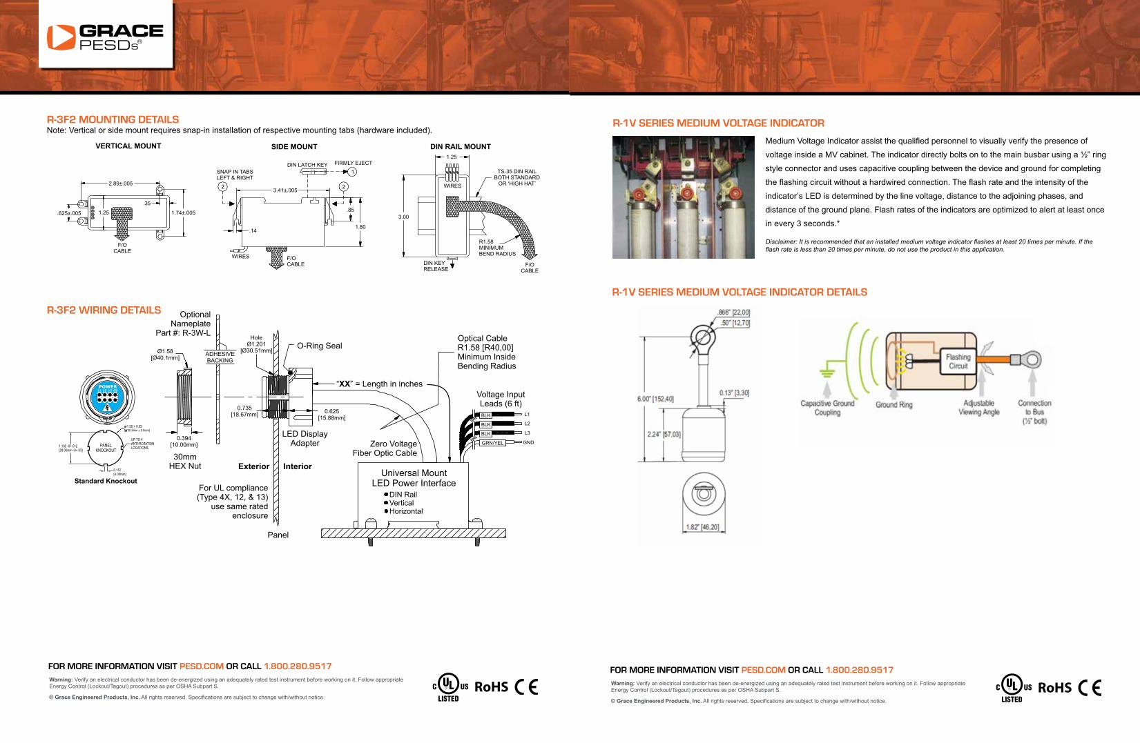
R-3F2 MOUNTING DETAILSNote: Vertical or side mount requires snap-in installation of respective mounting tabs (hardware included).
R-3F2 WIRING DETAILS
For UL compliance(Type 4X, 12, & 13)
use same ratedenclosure
OptionalNameplate
Part #: R-3W-L
LED DisplayAdapter
30mmHEX Nut
Optical CableR1.58 [R40,00]Minimum InsideBending Radius
O-Ring Seal
Panel
Exterior Interior
“ ” = Length in inchesXX
Voltage InputLeads (6 ft)
Zero VoltageFiber Optic Cable
Universal Mounting
APPLICATION EXAMPLETHREE PHASE DELTA, 3W + GND (Fig. 2)
PANELKNOCKOUT
0.157[4.00mm]
1.102 -0+.012[28.00mm -0+.03]
1.20 + 0.02[ 30.5mm + 0.5mm]
UP TO 4ANTI-ROTATIONLOCATIONS
Standard Knockout
L1 L2 L3 GD
POWER
+
_
Figure 1
CAUTION
Specifications
!
Do not operate above 750 3-Phase VAC or 1000VDC @ 55°C ambient.3-P Alternating Current Direct Current
OPERATIONAL RANGE: AC Single or 3-P: 20-600V** 50/60Hz; Operates to 400 Hz20 to 1000 VDCDC or Stored Energy:
DETECTION THRESHOLDS: 14V , 18.5V , 15V (TYPICAL CUTOFFS)
FLASH RATE (* flashes/sec): 120V (2.6), 240V (3.3), 480V (3.7), for @ 60Hz
MAX. POWER CONSUMPTION: 1.2 Watts @ 750V (Approximately)
OPERATING TEMPERATURE: -20°C to +55°C
TERMINATIONS: (4) 6 ft., 18 AWG 90°C @ 1000V, UL-1452
F/O CABLE: 'XX' inches of bundled cable in FR mesh sleeveDIN MODULE INDICATORS: (8) Red Super Bright LEDs (Interface to F/O cables)ZERO VOLT DISPLAY: Isolation by means of (8) 2mm all plastic F/O cables
*Epileptic Photosensitivity Compliant
3
3
1
3
3
Figure 3GND Indicators:For isolated 3-phase systems, it is normal for theL1, L2, & L3 to be illuminated. Typically the “GND”indicator LED pair to illuminate only during anunbalance or phase loss condition. Current mustpass through 2 LED indicator pairs to complete acircuit and illuminate the LEDs.
**nonUL Max 750VAC
Installation Information
Vertical Mount Side Mount DIN Rail Mount
NOTE: Vertical or Side mount requires snap-in installationof respective mounting tabs (hardware included).
Part #: R-3F2-L”__’30mm, with Thru-panel ‘Zero’ Voltage
Optical Cable Indication with Length “XX” inchesVoltage Indicator, Red LEDs,
Universal MountLED Power Interface
DIN RailVerticalHorizontal
0.625[15.88mm]
0.735[18.67mm]
0.394[10.00mm]
Ø1.58[Ø40.1mm]
ADHESIVEBACKING
HoleØ1.201
[Ø30.51mm]
BLK
BLK
BLK
GRN/YEL
L1
L2
L3
GND
FIBEROPTICCABLE
L1L2L3
GNDGRN/YEL EARTH
GROUND OR ISOLATED
L1
L2
L3
FUSEDSAFETY SW.OR BREAKER
MAINFEED
THREE PHASE DELTA, 3W + GND
.625±.005
2.89±.005
1.25
.35
1.74±.005
F/OCABLE
WIRES F/OCABLE
.14
2
SNAP IN TABSLEFT & RIGHT
3.41±.005
1
2
DIN LATCH KEY FIRMLY EJECT
.85
1.80
3.00
DIN KEYRELEASE
R1.58MINIMUMBEND RADIUS
F/OCABLE
TS-35 DIN RAILBOTH STANDARD
OR ‘HIGH HAT’
1.25
WIRES
VERTICAL MOUNT SIDE MOUNT DIN RAIL MOUNT
FOR MORE INFORMATION VISIT PESD.COM OR CALL 1.800.280.9517Warning: Verify an electrical conductor has been de-energized using an adequately rated test instrument before working on it. Follow appropriate Energy Control (Lockout/Tagout) procedures as per OSHA Subpart S.
© Grace Engineered Products, Inc. All rights reserved. Specifications are subject to change with/without notice.
R-1V SERIES MEDIUM VOLTAGE INDICATOR
Medium Voltage Indicator assist the qualified personnel to visually verify the presence of
voltage inside a MV cabinet. The indicator directly bolts on to the main busbar using a ½” ring
style connector and uses capacitive coupling between the device and ground for completing
the flashing circuit without a hardwired connection. The flash rate and the intensity of the
indicator’s LED is determined by the line voltage, distance to the adjoining phases, and
distance of the ground plane. Flash rates of the indicators are optimized to alert at least once
in every 3 seconds.*
Disclaimer: It is recommended that an installed medium voltage indicator flashes at least 20 times per minute. If the flash rate is less than 20 times per minute, do not use the product in this application.
R-1V SERIES MEDIUM VOLTAGE INDICATOR DETAILS
®