volatge control through synchronous condensers - rahul sharma
TRANSCRIPT

Abstract— This paper is written to study three projects
using synchronous condensers to control system voltage,
which are Granite Substation, MTA (Tennesse Valley
Authority) grid and Basslink HVDC. These projects are
using only synchronous condensers not any other FACTS
devices because synchronous condenser provides
additional features with dynamic reactive power. This
paper has also discussed structure, working and
performance of two new synchronous condensers. One is
developed by GE, which is also called next generation
synchronous condenser and other is developed by
American Superconductor that is called SuperVAR. Both
these synchronous condensers are good to provide
dynamic reactive power and have their own special
features.
Index Terms—condenser, Reactive Power Control, capacitor,
dynamic synchronous condensers, FACTS (Flexible AC
Transmission System), Inertia, reactive power, Super VAR,
SVC ( Static Var Compensator ) , Low voltage ride through
(LVRT).
CASE STUDY 1
I. INTRODUCTION
ERMONT Electric Power Company (VELCO) upgraded
their transmission project to meet the increasing demand
of electricity. These upgrade projects will do the following: 1)
improve the reliability of the electric system, 2) preserve
Vermont’s future energy options, and 3) contribute to
economics stability of the state.
II. ONE OF THE UPGRADED PROJECTS AND PROBLEM
Northern Vermont Reliability Project (NRP), includes
construction of 36 miles of 345 KV transmission lines
between existing line with new 115 KV transmission line,
and the upgrade of 13 stations between Williamstown and
Barre. The Granite 230 KV /115 KV station is located in
Williamstown, VT.
Second problem is that 50% of the summer peak load is
met by in-state generation and in northern Vermont, about
90% of the peak load is supplied with imported power
through the Highgate HVDC terminal on the north, the Sandy
Bar phase angle regulator to the west of Burlington, and the
230 KV line from New Hampshire via the Granite station on
the east side of the state.With a forecasted summer peak load
of 1200 MW, the Highgate HVDC back-to-back terminal out
of service, and with the subsequent loss of the 345 KV line
between Coolidge and Vermont Yankee, the flow on the 230
KV line connecting Granite 230 KV to Comerford 230KV
could reach 300 MW. To maintain an acceptable voltage at
Granite, approximately 180 MVArs is required with a portion
being dynamic compensation. Otherwise, voltage will
collapse.
III. DYNAMIC COMPENSATION EQUIPMENT
Several dynamic compensators are static var compensator
(SVC), a STATCOM and synchronous condensers.
IV. SELECTION CRITERIA
A wide range of factors were considered: equipment cost,
cost of losses, system harmonics, steady state overload, short
time overcurrent, low voltage ride-through capability and
interaction with other static devices with fast acting controls
on the VELCO system. From SVC static var compensator
(SVC), STATCOM, shunt capacitor bank and synchronous
condenser, Synchronous condenser is selected because of the
following advantages:
a) Synchronous condensers are harmonic free equipment.
b) Condensers are readily stimulated in load flow and stability
studies.
c) Condensers are active devices and can stabilize the local
power system by contributing short circuit current.
d) Synchronous condensers have internal voltage and
mechanical inertia that allows the synchronous condenser
to increase MVAr output during voltage dip because of
local fault.
e) Output of the condenser will never drop abruptly like other
static equipment during local fault.
f) Have inherent overload capacity.
Upgrading of the Granite station includes four (4) +25/-
12.5 MVAr synchronous condensers and four (4) 25 MVAr
115 KV shunt capacitors. Two condensers are connected to
each tertiary winding of two autotransformers. Tertiary
winding of autotransformer is rated 100 MVA to
accommodate 4 condensers, if needed.
Voltage Control through Synchronous
Condensers
R. Sharma and R.K. Varma, Senior Member, IEEE
V

Fig. 1 One line diagram of Granite Substation pixel (grayscale)[1].
V. GRANITE RPD SYSTEM PERFORMANCE
A. Steady State Rating
Each Granite synchronous condenser ranting is +25/-
12.5 MVAr continuous at 13.8 KV. Total supply is 100
MVAr (-Q) and absorb up to 50 (+Q), when four condensers
are used. Nominal Operating range of the granite condenser
unit is 150 MVAr. Condensers are connected to tertiary
winding of the transformer because of this MVAR deviates
slightly from the nameplate.
Fig. 2 Granite Condenser Q-V profile (1 p.u. service factor, graph not to
scale)[1].
Above graph (2) shows the working range of
synchronous condenser by Q-V graph from .90 to 1.1 p.u.
Upper graph (2) shows the overexcited operation and range of
supplying MVAR and lower graph (3) shows the absorption
of MVAr. Granite condensers have 1.15 service factor, which
means current is 1.15 p.u. of rated current at 1.0 p.u. terminal
voltage in the overexcited operation. At 1 p.u. voltage at
granite 115 KV, the four condensers can deliver up to +106/-
48 MVAr, which is slightly above the nameplate of
synchronous condensers
Fig. 3. Approximate Q-V profile at Granite 115 kV with 1.15 service factor and
the PSTs at maximum phase shift [1].
B. Dynamic Performance
Dynamic performance shows how synchronous condenser
reacts when there is a fault in the transmission line.
Fig 4. PSLF simulation of fault clearing on critical 345 kV line[1].
Above figure (4) shows that initially voltage of condenser
(blue) and 115 KV transmission line (red) were at 1.02 p.u. ,
but after the fault at 1 sec voltages drop up to .8 for .25 sec
and after that voltages recover back to 1.01 p.u. within 1 sec.
This is the performance of synchronous condenser which
helps the system to attain its normal voltage after few cycles
of fault.
VI. SYNCHRONOUS CONDENSERS
One of the unique characteristics of Granite synchronous
condenser is overloading capability on both steady state and
transient state. Synchronous condenser which is used in
granite substation was made by GE.
A. Features of synchronous condenser
In low-ambient temperature, the cooling capability of the
TEWAC (totally enclosed water-air cooling system with
50%/50% ethylene glycol) increases with increase in +MVAr
above the rating as shown in table below.
Fig. 5 Low-Ambient temperature condenser rating [1].

In elevated steady state, overloading capability increases for
short duration as shown in below table and in which under
excited capability will never change.
Fig. 6 Condenser short-time overload capability [1].
B. Excitation System
Next- generation condenser excitation system has:-
1) An alternator and rotating Diode bridge protected by
metal-oxide varistor- gated crowbar SCRs.
2) GE EX-2100 digital voltage regulator.
3) Digital relays for protection.
Excitation system for the Granite synchronous condensers are
designed for nominal 300 % excitation for 3 seconds.
C. Cooling
GE synchronous condensers utilize TEWAC (totally
enclosed water-air cooling) system. A radiator located above
the stator winding within the condensers enclosure cools
warm air from stator. A solution of water/glycol circulates in
the radiator that is cooled outside the condenser building in
three air cooled heat exchanger per condenser.
D. Switchgear
Per Fig. 1, a tiebreaker between the two autotransformer
will maximize the operating flexibility of the Granite RPD
together with twelve 15 kV class metal enclosed vacuum
circuit breaker. Any number of synchronous can be connected
to auto transformer.
Installation of circuit breaker near salient-pole synchronous
condensers contributes to higher short circuit currents and
transient recovery voltages (TRV) especially when the
condensers are overexcited [1]. Both short circuit current and
TVA requirements led to the selection of granite circuit
breaker.
E. Surge Protection
Surge protection is needed to protect from high TRV
frequencies. Granite substation MVA rating is several
multiple of condenser MVA rating thus minimizing the
transformer leakage and contributing to high TRV
frequencies. Every synchronous condenser in granite
substation is protected with surge arrestors and surge
capacitor.
F. Lubricant
In normal operation, oil is circulated in bearings via a pump
with a back-up unit.
VII. DISADVANTAGE
A. Static Var Compensator (SVC)
1) Produce harmonics.
2) Control interaction in between multiple electronic
device creates problem.
3) Does not posses any short term over current
capability.
4) Output MVAr is dependent on nominal voltage.
5) Output power is equal to square of the voltage
terminal.
B. STATCOM
1) High cost.
2) High audible noises.
3) Are designed to shut off in case to large voltage sag.
C. Disadvantages of Synchronous condensers
1) Maintenance of synchronous condenser because of
moving parts.
2) Slower response time than SVC and STATCOM.
3) Higher level of losses.
CASE STUDY 2
I. INTRODUCTION OF SUPERVAR
High Temperature Superconductor (HTS) SuperVAR
dynamic synchronous condenser (DSC) was developed by
American Superconductor. This synchronous condenser has
small foot print, easily transportable and is economic option
for providing peak and dynamic reactive compensation to a
power system. Transmission line voltage collapse when local
sources are not able to meet the reactive power demands.
Voltage of the transmission line drops and line current
increase, which further drops the voltage of transmission line
more. For these situations, static VAR devices are used
because their output varies in proportion to V or V2 – thus
making less efficient. DSC output is independent of system
voltage and can be increased up to 4 times in a second by
changing its excitation on the field winding.
Fig. 7 +/- 8 MVAR SuperVAR machine with key characteristics highlighted[3].

II. SUPER VAR DYNAMIC CONDENSER FEATURES
a) Field current of a conventional machine must be
increased by 3X between no- load and full- load, where
as High temperature superconductor (HTS) wire in the
rotor field winding requires only a small change in field
current between no-load and full load and it always
operate at a constant temperature.
b) HTS DSC is estimated to be 98.8% efficient, typically 1
% more efficient than copper based units and it
maintains this efficiency down to partial load of 25 %.
c) New DSC is expected to be very economic option for
providing peak and dynamic reactive compensation to a
power system.
d) DSC is highly reliable because in case of fault, it can
provide twice as nominal rating for about one minute
(peak rating) without change in temperature of winding.
e) DSC can also handle transients.
DSC support system consisting of the following subsystem:-
a) HTS Rotor
b) Stator lubrication and cooling systems
c) Refrigeration
d) Exciter, Control and Communication system
e) Start-up motor and controller.
A. Cooling
Cryocooler is a device used to reach cryogrnic temperatures
by cycling certain gases. Liquefied gases are liquid nitrogen
and liquid helium. In DSC helium gas is used.
Fig. 8 DSC support system [3].
B. Characteristic of HTS DSC VS Synchronous Condensers.
Figure (9) is comparing performance of SuperVAR with
conventional synchronous condensers. SupeVAR is taking
less excitation current form zero load to full load performance
where as conventional synchronous condenser is taking three
times excitation current to perform the same.
Fig. 9 V-curves for conventional and SuperVAR machines
Above fig represents that 3 times more excitation current is needed by
conventional synchronous condenser for the same performance as by HTS
DSC[3].
III. FACTORY TEST RESULTS
DSC machine was factory tested according to IEEE 115
standard and results are listed below:
a) Measure 98.8% efficiency.
b) Temperature rise curve shows that at rated load,
temperature of DSC is always less than allowed limit
(105 oC at a 25 oC ambient).
Fig. 10 DSC heat run –temperature rise of various stator components[3].
c) Open short circuit and short circuit results show that
machine exhibit any saturation effect over the operating
range (1.3 p.u. ).
Fig. 11 Open-circuit and short- circuit measurements on the
DSC[3].

IV. SIMULATION POWER RESULTS
Fig. 12 A simulation of a utility system power quality problem concerned with a
DSC[3].
Whenever a large motor starts it causes optional voltage drops
which is cover up by installing 8 MVAR Super VAR DSC
which increases local MVAR capability to mitigate large
motor starting voltage sags and other transient voltage
problems.
V. RESULTS
Fig . 13 A Simulation of power quality problem fixed by DSC – shows voltage
variation with and without DSC and MVARS contributed by DSC[3].
Above figure (13) show the working of HTS DSC working in
grid.
VI. ARC FURNACE TESTED
HTS SDC helped in reducing flicker caused by arc furnace.
MVARs supplied by the machine during a typical melt cycle
is shown in below figure
Fig. 14 MVARS supplied by HTS synchronous condenser during an Arc
Furnace Burn cycle[4].
The machine was absorbing high negative and zero
sequence current and producing heat, which was sunk by
damper winding in the form of copper shell.
VII. FIND FARM APPLICATION (SIMULATION FOR 78 MW
MIDWESTERN U.S.)
Simulation was performed to study the performance of
synchronous condenser on wind farm. Wind farm had
inadequate voltage regulation and low voltage ride though
capabilities (LVRT), which resulted in tripping of circuit
breaker before implementing HTS synchronous condenser.
Approximately, 40 MVAR of additional capacitive equipment
was needed to meet the voltage regulation and power factor
requirement.
To improve low voltage ride though (LVRT) capability of
virtual farm, two 12 MVA HTS dynamic synchronous
condensers were used. These condensers were connected to
34.5 kV bus via step up transformer of 13.8 kV.
Fig. 15 Wind farm with two HTS Dynamic synchronous condensers units
installed to improve LVRT [4].
With the installation of HTS synchronous condenser, LVRT
capability of solution was significantly improved.
Fig. 16 Wind Farm Bus Voltage and MW Output with and without superVAR
[4].
Above figure (16), shows the working and performance
characteristics of HST condensers. First figure shows the bus
voltage with and without condensers. During LVRT (without

HST synchronous condensers) voltages dropped to tripping
condition, where as with synchronous condenser voltage did
not drop to tripping condition. Second figure (16) shows
output of wind farm, at the condition of LVRT, voltage
dropped and tripped the farm and output dropped to zero, but
with synchronous condenser this output power not dropped to
zero.
CASE STUDY 3
I. INTRODUCTION
The Basslink HVDC interconnection is a connection
between the island of Tasmania and the mainland of
Australia for electricity exchange. Basslink is a 290 km
undersea HVDC link, which export 630 MW and import 480
MW. This HVDC link is monopolar with rated DC voltage of
400 KV, rated DC current of 1250 A and rated continuous
power of 500 MW. Dynamic power transfer capacity is 626
MW from Tasmania to Australia. Tasmania is expected to
export 630 MW energy to Victoria, generated through
Tasmania hydro generation and 140 MW of wind generation.
It also imports 480 MW of energy from Victoria to Tasmania.
To provide reactive power demand of the DC converter for
630 MW, a total of 313 MVAr shunt capacitance is required.
The available compensation was subdivided into five filter
sub-banks of 43 MVAr and one additional 98 MVAr to
comply both with the limitation on AC voltage change due to
filter switching and specified flicker limits. All five filters are
tuned to remove harmonics ( 3,5,7,11,13,23,etc), but 98
MVAr is specially tuned to attenuate the effect of 5th
harmonics. Triple tuned harmonic filters were foreseen at
George Town converter station to meet the specified
harmonic performance requirements.
Fig. 17 Representation of HVDC connection of Tasmania to mainland
Australian and interconnection into eastern seaboard national electricity market
[6].
Although 500 kV AC system at Loy Yang is very strong in
comparison with George town, then still reactive power is
needed to be provided. HVDC link is capable of operating at
.95 lagging power factor. Two types of triple-tuned filters,
each of 105 MVAr rating are used to provide filtering of
harmonics.
Fig. 18 Key physical components of Bsslink[7].
A. Power Transmission Capacity
Basslink HVDC has continuous rating of 500 MW (+/-
400kV , 1250 A) defined at DC rectifier side with nominal
range and maximum ambient temperature. The rated
transmission power will be met without any redundant
cooling system until maximum ambient temperature 30oC at
George Town and 40 oC Loy Yang.
B. Performance Requirement of HVDC link
Design of HVDC link was designed to have low loss for
technical and economical optimization, to achieve this
converter at both stations should have total loss less than 1.4
percent at 500 MW power transfer. At rated transmission
capacity the main source of losses is DC cables and DC
overhead lines with approximately 2.7 percent and 1.0
percent respectively.
II. PROBLEM AND SOLUTION
Inter link was suffering from two problems.
a) Rotating Inertia
b) Short circuit strength
A. Rotating Inertia
Thermal power sources provide inertia to the power system,
whereas renewable sources are not. Wind turbines can
provide inertia to the system, if they are used properly.
System inertia in Tasmania can be low enough, especially at
the time of import during low demand. System also faces
shortage of fast acting frequency control ancillary services
(FCAS) because of slow response of hydro generators to
frequency.
―Transend‖ studies indicate that rate of change of frequency
approaches 3 Hz that can lead to HVDC link trip because of
import of energy during low system inertia[6]. As more
renewable sources like wind farm attached to the system,
FCAS demands will increase. As situation is tight, Tasmania
is used Basslink to transfer FCAS from mainland, which
reduces power transfer capability of HVDC link. ―Transend‖
also identified potential future voltage stability issues because
of future load increase. In this case SVC’ and STATCOM are
not good because they only provide only voltage stability not
any support to inertia. Solution to this problem is Modern
synchronous condenser, which can provide dynamic MVAr as
well as inertia.
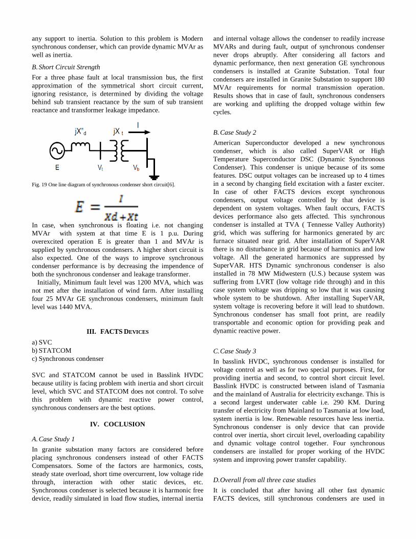
B. Short Circuit Strength
For a three phase fault at local transmission bus, the first
approximation of the symmetrical short circuit current,
ignoring resistance, is determined by dividing the voltage
behind sub transient reactance by the sum of sub transient
reactance and transformer leakage impedance.
Fig. 19 One line diagram of synchronous condenser short circuit[6].
In case, when synchronous is floating i.e. not changing
MVAr with system at that time E is 1 p.u. During
overexcited operation E is greater than 1 and MVAr is
supplied by synchronous condensers. A higher short circuit is
also expected. One of the ways to improve synchronous
condenser performance is by decreasing the impendence of
both the synchronous condenser and leakage transformer.
Initially, Minimum fault level was 1200 MVA, which was
not met after the installation of wind farm. After installing
four 25 MVAr GE synchronous condensers, minimum fault
level was 1440 MVA.
III. FACTS DEVICES
a) SVC
b) STATCOM
c) Synchronous condenser
SVC and STATCOM cannot be used in Basslink HVDC
because utility is facing problem with inertia and short circuit
level, which SVC and STATCOM does not control. To solve
this problem with dynamic reactive power control,
synchronous condensers are the best options.
IV. COCLUSION
A. Case Study 1
In granite substation many factors are considered before
placing synchronous condensers instead of other FACTS
Compensators. Some of the factors are harmonics, costs,
steady state overload, short time overcurrent, low voltage ride
through, interaction with other static devices, etc.
Synchronous condenser is selected because it is harmonic free
device, readily simulated in load flow studies, internal inertia
and internal voltage allows the condenser to readily increase
MVARs and during fault, output of synchronous condenser
never drops abruptly. After considering all factors and
dynamic performance, then next generation GE synchronous
condensers is installed at Granite Substation. Total four
condensers are installed in Granite Substation to support 180
MVAr requirements for normal transmission operation.
Results shows that in case of fault, synchronous condensers
are working and uplifting the dropped voltage within few
cycles.
B. Case Study 2
American Superconductor developed a new synchronous
condenser, which is also called SuperVAR or High
Temperature Superconductor DSC (Dynamic Synchronous
Condenser). This condenser is unique because of its some
features. DSC output voltages can be increased up to 4 times
in a second by changing field excitation with a faster exciter.
In case of other FACTS devices except synchronous
condensers, output voltage controlled by that device is
dependent on system voltages. When fault occurs, FACTS
devices performance also gets affected. This synchronous
condenser is installed at TVA ( Tennesse Valley Authority)
grid, which was suffering for harmonics generated by arc
furnace situated near grid. After installation of SuperVAR
there is no disturbance in grid because of harmonics and low
voltage. All the generated harmonics are suppressed by
SuperVAR. HTS Dynamic synchronous condenser is also
installed in 78 MW Midwestern (U.S.) because system was
suffering from LVRT (low voltage ride through) and in this
case system voltage was dripping so low that it was causing
whole system to be shutdown. After installing SuperVAR,
system voltage is recovering before it will lead to shutdown.
Synchronous condenser has small foot print, are readily
transportable and economic option for providing peak and
dynamic reactive power.
C. Case Study 3
In basslink HVDC, synchronous condenser is installed for
voltage control as well as for two special purposes. First, for
providing inertia and second, to control short circuit level.
Basslink HVDC is constructed between island of Tasmania
and the mainland of Australia for electricity exchange. This is
a second largest underwater cable i.e. 290 KM. During
transfer of electricity from Mainland to Tasmania at low load,
system inertia is low. Renewable resources have less inertia.
Synchronous condenser is only device that can provide
control over inertia, short circuit level, overloading capability
and dynamic voltage control together. Four synchronous
condensers are installed for proper working of the HVDC
system and improving power transfer capability.
D. Overall from all three case studies
It is concluded that after having all other fast dynamic
FACTS devices, still synchronous condensers are used in

utilities. Synchronous condensers have some special feature
for which it is used. Installation of synchronous condenser is
economical and can provide dynamic reactive power. It can
provide control over inertia, short circuit level and provide
overloading capability without harmonics, which any other
FACTS device cannot provide.
REFERENCES
[1] J. Skliutas , LaForest, R.D’Aquila, D.Derr and E.
Kronbeck,‖Next-Generation Synchronous Condenser
Installation at the VELCO Granite Substation‖.
[2] Paul E. Marken, M. Henderson, LaForest, J. Skliutas, J.
Roedel and Todd Campbell, ― Selection of synchronous
condenser technology for the Granite Substation‖.
[3] S.S. Kalsi, D. Madura and Mike Ingram,‖
Superconductor Synchronous Condenser for Reactive
Power support in an Electric Grid‖, IEEE Trans. On
Applied Superconductivity, Vol. 15, No. 2, June 2005.
[4] S. Kalsi, D. Madura and Mike Ross,‖ Performance of
Superconductor Dynamic Synchronous Condenser on an
Electric Grid‖, IEEE/PES Transmission and Distribution
Conference and Exhibition: Asia and Pacific Dalian,
China.
[5] S.S. Kalsi, D. Madura, G. Snitchler, M.Ross, J. Voccio
and M. Ingram,‖ Discussion of Test Results of a
Superconductor Synchronous Condenser on a Utility
Grid‖, IEE Trans. On Applied Superconductivity, VOL.
17, NO. 2., June 2007.
[6] Paul E.Marken, Arthur C. Depoian, John Skliutas and
Michael Verrier, ― Modern Synchronous Condenser
Performance Considerations‖, 978-1-4577-1002-
5/11/IEEE.
[7] Th. Westerweller and J.J. Price,‖ Basslink HVDC
Interconnector- System Design Considerations‖, IEEE.