volant nea005 seriesfile.yizimg.com/316215/murata/nea005.pdf · volant nea005 series non-isolated...
TRANSCRIPT

CDC_Volant NEA005 Series.B03 Page 1 of 25
Volant NEA005 SeriesNon-Isolated 5A SIP/SMT
DC/DC Converters
Technical enquiries - email: [email protected], tel: +44 (0)1908 615232www.murata-ps.com
4118 14th Avenue, Unit 4Markham, Ontario L3R 0J31-866-740-1232
Page 1NEA005_6200870000_A02_25Jun07
Volant NEA005 SeriesNon-Isolated 5A SIP/SMT DC/DC Converters
www.cd4power.com
Features:
Small size, minimal footprint – SMT/SIP package
5A Output Current (all voltages)
High Efficiency: up to 92%
High reliability
RoHS Compliant
Cost efficient open frame design
Output voltage programmable by an external resistor.
Monotonic Start with Pre-Bias.
Output Input EfficiencyPARD
(mVp-p)Regulation
MaxVin
Nom.(V)
Range(V)
IinTyp(A)
Full LoadVout(V)
Iout(A)
Typ. Max. Line Load Typ.0.75 5 30 50 +/-0.2% +/-0.5% 12 8.3 – 14 0.428 73%1.2 5 30 50 +/-0.2% +/-0.5% 12 8.3 – 14 0.625 80%1.5 5 30 50 +/-0.2% +/-0.5% 12 8.3 – 14 0.762 82%1.8 5 30 50 +/-0.2% +/-0.5% 12 8.3 – 14 0.893 84%2.0 5 30 50 +/-0.2% +/-0.5% 12 8.3 – 14 0.980 85%2.5 5 30 50 +/-0.2% +/-0.5% 12 8.3 – 14 1.197 87%3.3 5 30 50 +/-0.2% +/-0.5% 12 8.3 – 14 1.545 89%5.0 5 45 75 +/-0.2% +/-0.5% 12 8.3 – 14 2.264 92%
For full details go towww.murata-ps.com/rohs
Typical units
FEATURESnSmall size, minimal footprint –
SMT/SIP package
n5A Output Current (all voltages)
nHigh Efficiency: up to 92%
nHigh reliability
nRoHS Compliant
nCost efficient open frame design
nOutput voltage programmable by an external resistor
nIndependently regulated +3.3V, +5.1V and +12V outputs
nMonotonic Start with Pre-bias
Output Input Efficiency
Vout (Volts)
Iout
(Amps)
PARD (mVp-p) Regulation (Max.)Vin Nom.
(V)Range
(V)Iin Typ.
(A)Full
LoadTyp. Max. Line Load
0.75 5 30 50 ±0.02% ±0.5% 12 8.3–14 0.428 73%
1.2 5 30 50 ±0.02% ±0.5% 12 8.3–14 0.625 80%
1.5 5 30 50 ±0.02% ±0.5% 12 8.3–14 0.762 82%
1.8 5 30 50 ±0.02% ±0.5% 12 8.3–14 0.893 84%
2.0 5 30 50 ±0.02% ±0.5% 12 8.3–14 0.980 85%
2.5 5 30 50 ±0.02% ±0.5% 12 8.3–14 1.197 87%
3.3 5 30 50 ±0.02% ±0.5% 12 8.3–14 1.545 89%
5.0 5 45 75 ±0.02% ±0.5% 12 8.3–14 2.264 92%

Volant NEA005 SeriesNon-Isolated 5A SIP/SMT
DC/DC Converters
Technical enquiries - email: [email protected], tel: +44 (0)1908 615232www.murata-ps.com
CDC_Volant NEA005 Series.B03 Page 2 of 25
Performance Specifications and Ordering Guide
Input Characteristics
Input Characteristics Notes and Conditions Min. Type Max. Units
Input Voltage Operating Range 8.3 12 14 Vdc
Input Reflected Ripple Current 200 mA p-p
Inrush Current Transient 0.2 A2s
Input Filter Type (external) 47μF/20V Tantalum & 10μF/15V Ceramic 57 μF
Input Turn ON Threshold 8.0 V
Input Turn OFF Threshold 7.9 V
Enable (Positive enable has 20k pullup) (Negative enable has no internal pullup resistor)
Positive enable: ON open
Positive enable: OFF <0.4 Vdc
Negative enable: ON; open circuit or <0.4 Vdc
Negative enable: OFF 2 Vin
Output Characteristics Notes and Conditions Min. Type Max. Units
Vout Accuracy 100% load –1.5 +1.5 %
Output Loading 0 5 A
Output Ripple and Loading @ 20Mhz Bandwidth 75 mV
Maximum Capacitive Load Low ESR 3000 μF
Vout Trim Range (nom) 0.75 5.0 V
Total Accuracy Over line/load temperature <2%
Current Limit 8.5 A
Output Line Regulation –0.2 +0.2 %
Output Load Regulation –0.5 +0.5 %
Turn-on Overshoot 1 %
SC Protection Technique Hiccup with auto recovery
Pre-bias Start-up at output Unit starts monotonically with Pre-bias
Dynamic Characteristics Notes and Conditions Min. Type Max. Units
Load Transient 50% step, 0.1A/μs Settling Time
200 200
mV μs
Frequency 300 KHz
Rise Time 10% Vo to 90% Vo 3.5 ms
Start-Up Time Vin to Vout and On/Off to Vout Vout rise to monotonic
7 ms

Volant NEA005 SeriesNon-Isolated 5A SIP/SMT
DC/DC Converters
Technical enquiries - email: [email protected], tel: +44 (0)1908 615232www.murata-ps.com
CDC_Volant NEA005 Series.B03 Page 3 of 25
Thermal ConsiderationsThe power module operates in a variety of thermal environments; however, suf-ficient cooling should be provided to help ensure reliable operation of the unit.
The thermal data presented is based on measurements taken at various airflows. Note that airflow is parallel to the long axis of the module as shown in Figure 1 and derating applies accordingly.
As a rule of thumb however, we recommend to use a normal-blow or slow-blow fuse with a typical value of about twice the maximum input current, calculated at low line with the converter’s minimum efficiency.
The temperature at the thermal measurement location (TML) should not exceed 110°C. The output power of the module should not exceed the rated power for the module (Vo,set x Io,max).
Convection Requirements for CoolingTo predict the approximate cooling needed for the module, refer to the Power Derating Curves in Figures 2–17.
These derating curve are approximations of the ambient temperature and airflow required to keep the power module temperature below it’s maximum rating. Once the module is assembled in the actualsystem, the module’s tem-perature should be verified.
General Specifications Notes and Conditions Min. Type Max. Units
MTBF Calculated (MIL-HDBK-217F) 1.5 ×10⁶ Hrs
Thermal Protection Thermal Measurement locations (TML) 110 ˚C
Operating Temperature Without derating, 200LFM –40 50 ˚C
Operating Ambient Temperature See Power Derating Curve –40 85 ˚C
SIP Dimensions 0.9"L×0.4"W×0.22"H (22.9×10.16×5.6mm)
SMT Dimensions 0.8"L×0.45"W×0.24"H (20.3×11.43×6.09mm)
SIP Pin Dimensions 0.025" (0.64mm) square 0.64 mm
SIP Block Dimensions 0.090"L×0.062"W×0.062"H (0.64mm) square
Pin and Block Material Matte Sn finish on component leads
Weight 2.3 g
Flammability Rating UL94V-0
Standards Compliance
CSA C22.2, No.60950/UL 60950, Third edition (2000)
Performance Specifications and Ordering Guide (continued)
4118 14th Avenue, Unit 4Markham, Ontario L3R 0J31-866-740-1232
Page 4NEA005_6200870000_A02_25Jun07
Volant NEA005 SeriesNon-Isolated 5A SIP/SMT DC/DC Converters
www.cd4power.com
Standards Compliance
CSA C22.2, No.60950/UL 60950, Third Edition (2000)
Thermal Considerations
The power module operates in a variety of thermal environments; however, sufficient cooling should be provided to help ensure reliable operation of the unit.
The thermal data presented is based on measurements taken at various airflows. Note that airflow is parallel to the long axis of the module as shown in Figure 1 and derating applies accordingly.
Figure 1. Thermal Tests Set-Up.
The temperature at the thermal measurement location (TML) should not exceed 110°C. The output power of the module should not exceed the rated power for the module (Vo,set x Io,max).
Convection Requirements for Cooling
To predict the approximate cooling needed for the module, refer to the Power Derating Curves in Figures 2-17 .
These derating curve are approximations of the ambient temperature and airflow required to keep the power module temperature below it's maximum rating. Once the module is assembled in the actualsystem, the module's temperature should be verified.
TML TML
Figure 1. Thermal Tests Set-Up

Volant NEA005 SeriesNon-Isolated 5A SIP/SMT
DC/DC Converters
Technical enquiries - email: [email protected], tel: +44 (0)1908 615232www.murata-ps.com
CDC_Volant NEA005 Series.B03 Page 4 of 254118 14th Avenue, Unit 4Markham, Ontario L3R 0J31-866-740-1232
Page 5NEA005_6200870000_A02_25Jun07
Volant NEA005 SeriesNon-Isolated 5A SIP/SMT DC/DC Converters
www.cd4power.com
TYPICAL DERATING CURVES SIP/SMT VERSION
NEA0051501S0 Vo=0.75V Derating Curve
0.00
1.00
2.00
3.00
4.00
5.00
6.00
20 30 40 50 60 70 80 90 100
Ambient Temperature (C)
Out
put C
urre
nt (A
)
0LFM100LFM200LFM
Fig. 2. SMT Power Derating vs Output Current for 12Vin 0.75V Out.
NEA0051501B0 Vo=0.75V Derating Curve
0.00
1.00
2.00
3.00
4.00
5.00
6.00
20 30 40 50 60 70 80 90 100
Ambient Temperature (C)
Out
put C
urre
nt (A
)
0LFM100LFM200LFM
Fig. 3. SIP Power Derating vs Output Current for 12Vin 0.75V Out.
Typical Derating Curves SIP/SMT Version

Volant NEA005 SeriesNon-Isolated 5A SIP/SMT
DC/DC Converters
Technical enquiries - email: [email protected], tel: +44 (0)1908 615232www.murata-ps.com
CDC_Volant NEA005 Series.B03 Page 5 of 25
4118 14th Avenue, Unit 4Markham, Ontario L3R 0J31-866-740-1232
Page 6NEA005_6200870000_A02_25Jun07
Volant NEA005 SeriesNon-Isolated 5A SIP/SMT DC/DC Converters
www.cd4power.com
NEA0051501S0 Vo=1.2V Derating Curve
0.00
1.00
2.00
3.00
4.00
5.00
6.00
20 30 40 50 60 70 80 90 100
Ambient Temperature (C)
Out
put C
urre
nt (A
)
0LFM100LFM200LFM
Fig 4. SMT Power Derating vs Output Current for 12Vin 1.2V Out.
NEA0051501B0 Vo=1.2V Derating Curve
0.00
1.00
2.00
3.00
4.00
5.00
6.00
20 30 40 50 60 70 80 90 100
Ambient Temperature (C)
Out
put C
urre
nt (A
)
0LFM100LFM200LFM
Fig 5. SIP Power Derating vs Output Current for 12Vin 1.2V Out.
Typical Derating Curves SIP/SMT Version

Volant NEA005 SeriesNon-Isolated 5A SIP/SMT
DC/DC Converters
Technical enquiries - email: [email protected], tel: +44 (0)1908 615232www.murata-ps.com
CDC_Volant NEA005 Series.B03 Page 6 of 25
4118 14th Avenue, Unit 4Markham, Ontario L3R 0J31-866-740-1232
Page 7NEA005_6200870000_A02_25Jun07
Volant NEA005 SeriesNon-Isolated 5A SIP/SMT DC/DC Converters
www.cd4power.com
NEA0051501S0 Vo=1.5V Derating Curve
0.00
1.00
2.00
3.00
4.00
5.00
6.00
20 30 40 50 60 70 80 90 100
Ambient Temperature (C)
Out
put C
urre
nt (A
)
0LFM100LFM200LFM
Fig 6. SMT Power Derating vs Output Current for 12Vin 1.5V Out.
NEA0051501B0 Vo=1.5V Derating Curve
0.00
1.00
2.00
3.00
4.00
5.00
6.00
20 30 40 50 60 70 80 90 100
Ambient Temperature (C)
Out
put C
urre
nt (A
)
0LFM100LFM200LFM
Fig 7. SIP Power Derating vs Output Current for 12Vin 1.5V Out.
Typical Derating Curves SIP/SMT Version

Volant NEA005 SeriesNon-Isolated 5A SIP/SMT
DC/DC Converters
Technical enquiries - email: [email protected], tel: +44 (0)1908 615232www.murata-ps.com
CDC_Volant NEA005 Series.B03 Page 7 of 25
4118 14th Avenue, Unit 4Markham, Ontario L3R 0J31-866-740-1232
Page 8NEA005_6200870000_A02_25Jun07
Volant NEA005 SeriesNon-Isolated 5A SIP/SMT DC/DC Converters
www.cd4power.com
NEA0051501S0 Vo=1.8V Derating Curve
0.00
1.00
2.00
3.00
4.00
5.00
6.00
20 30 40 50 60 70 80 90 100
Ambient Temperature (C)
Out
put C
urre
nt (A
)
0LFM100LFM200LFM
Fig 8. SMT Power Derating vs Output Current for 12Vin 1.8V Out.
NEA0051501B0 Vo=1.8V Derating Curve
0.00
1.00
2.00
3.00
4.00
5.00
6.00
20 30 40 50 60 70 80 90 100
Ambient Temperature (C)
Out
put C
urre
nt (A
)
0LFM100LFM200LFM
Fig 9. SIP Power Derating vs Output Current for 12Vin 1.8V Out.
Typical Derating Curves SIP/SMT Version
Volant NEA005 SeriesNon-Isolated 5A SIP/SMT
DC/DC Converters
Technical enquiries - email: [email protected], tel: +44 (0)1908 615232www.murata-ps.com
CDC_Volant NEA005 Series.B03 Page 8 of 25
4118 14th Avenue, Unit 4Markham, Ontario L3R 0J31-866-740-1232
Page 9NEA005_6200870000_A02_25Jun07
Volant NEA005 SeriesNon-Isolated 5A SIP/SMT DC/DC Converters
www.cd4power.com
NEA0051501S0 Vo=2.0V Derating Curve
0.00
1.00
2.00
3.00
4.00
5.00
6.00
20 30 40 50 60 70 80 90 100
Ambient Temperature (C)
Out
put C
urre
nt (A
)
0LFM100LFM200LFM
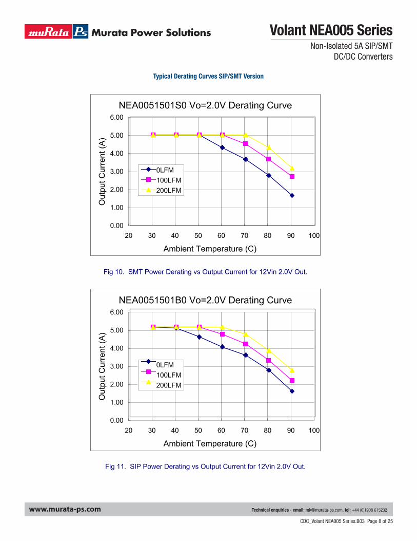
Fig 10. SMT Power Derating vs Output Current for 12Vin 2.0V Out.
NEA0051501B0 Vo=2.0V Derating Curve
0.00
1.00
2.00
3.00
4.00
5.00
6.00
20 30 40 50 60 70 80 90 100
Ambient Temperature (C)
Out
put C
urre
nt (A
)
0LFM100LFM200LFM
Fig 11. SIP Power Derating vs Output Current for 12Vin 2.0V Out.
Typical Derating Curves SIP/SMT Version
Volant NEA005 SeriesNon-Isolated 5A SIP/SMT
DC/DC Converters
Technical enquiries - email: [email protected], tel: +44 (0)1908 615232www.murata-ps.com
CDC_Volant NEA005 Series.B03 Page 9 of 25
4118 14th Avenue, Unit 4Markham, Ontario L3R 0J31-866-740-1232
Page 10NEA005_6200870000_A02_25Jun07
Volant NEA005 SeriesNon-Isolated 5A SIP/SMT DC/DC Converters
www.cd4power.com
NEA0051501S0 Vo=2.5V Derating Curve
0.00
1.00
2.00
3.00
4.00
5.00
6.00
20 30 40 50 60 70 80 90 100
Ambient Temperature (C)
Out
put C
urre
nt (A
)
0LFM100LFM200LFM
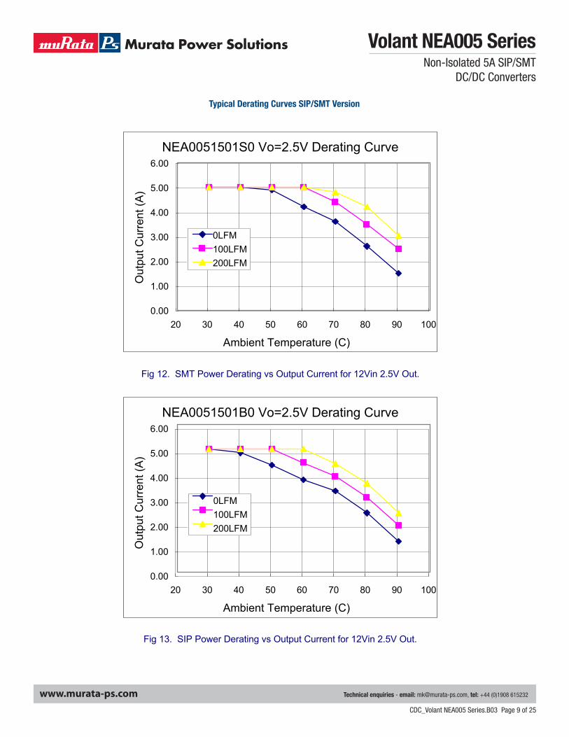
Fig 12. SMT Power Derating vs Output Current for 12Vin 2.5V Out.
NEA0051501B0 Vo=2.5V Derating Curve
0.00
1.00
2.00
3.00
4.00
5.00
6.00
20 30 40 50 60 70 80 90 100
Ambient Temperature (C)
Out
put C
urre
nt (A
)
0LFM100LFM200LFM
Fig 13. SIP Power Derating vs Output Current for 12Vin 2.5V Out.
Typical Derating Curves SIP/SMT Version

Volant NEA005 SeriesNon-Isolated 5A SIP/SMT
DC/DC Converters
Technical enquiries - email: [email protected], tel: +44 (0)1908 615232www.murata-ps.com
CDC_Volant NEA005 Series.B03 Page 10 of 25
4118 14th Avenue, Unit 4Markham, Ontario L3R 0J31-866-740-1232
Page 11NEA005_6200870000_A02_25Jun07
Volant NEA005 SeriesNon-Isolated 5A SIP/SMT DC/DC Converters
www.cd4power.com
NEA0051501S0 Vo=3.3V Derating Curve
0.00
1.00
2.00
3.00
4.00
5.00
6.00
20 30 40 50 60 70 80 90 100
Ambient Temperature (C)
Out
put C
urre
nt (A
)
0LFM100LFM200LFM
Fig. 14. SMT Power Derating vs Output Current for 12Vin 3.3V Out.
NEA0051501B0 Vo=3.3V Derating Curve
0.00
1.00
2.00
3.00
4.00
5.00
6.00
20 30 40 50 60 70 80 90 100
Ambient Temperature (C)
Out
put C
urre
nt (A
)
0LFM100LFM200LFM
Fig 15. SIP Power Derating vs Output Current for 12Vin 3.3V Out.
Typical Derating Curves SIP/SMT Version

Volant NEA005 SeriesNon-Isolated 5A SIP/SMT
DC/DC Converters
Technical enquiries - email: [email protected], tel: +44 (0)1908 615232www.murata-ps.com
CDC_Volant NEA005 Series.B03 Page 11 of 25
4118 14th Avenue, Unit 4Markham, Ontario L3R 0J31-866-740-1232
Page 12NEA005_6200870000_A02_25Jun07
Volant NEA005 SeriesNon-Isolated 5A SIP/SMT DC/DC Converters
www.cd4power.com
NEA0051501S0 Vo=5.0V Derating Curve
0.00
1.00
2.00
3.00
4.00
5.00
6.00
20 30 40 50 60 70 80 90 100
Ambient Temperature (C)
Out
put C
urre
nt (A
)
0LFM100LFM200LFM
Fig. 16. SMT Power Derating vs Output Current for 12Vin 5.0V Out
NEA0051501B0 Vo=5.0V Derating Curve
0.00
1.00
2.00
3.00
4.00
5.00
6.00
20 30 40 50 60 70 80 90 100
Ambient Temperature (C)
Out
put C
urre
nt (A
)
0LFM100LFM200LFM
Fig 17. SIP Power Derating vs Output Current for 12Vin 5.0V Out.
Typical Derating Curves SIP/SMT Version
Volant NEA005 SeriesNon-Isolated 5A SIP/SMT
DC/DC Converters
Technical enquiries - email: [email protected], tel: +44 (0)1908 615232www.murata-ps.com
CDC_Volant NEA005 Series.B03 Page 12 of 254118 14th Avenue, Unit 4Markham, Ontario L3R 0J31-866-740-1232
Page 13NEA005_6200870000_A02_25Jun07
Volant NEA005 SeriesNon-Isolated 5A SIP/SMT DC/DC Converters
www.cd4power.com
TYPICAL EFFICIENCY CURVES FOR VARIOUS VOLTAGE MODELS SIP/SMT VERSION.
NEA0051501S0 Vo=0.75V (Eff Vs Io)
55%
60%
65%
70%
75%
80%
85%
0 0.5 1 1.5 2 2.5 3 3.5 4 4.5 5Current Load (A)
Effic
incy
(%)
8.3V12V14V
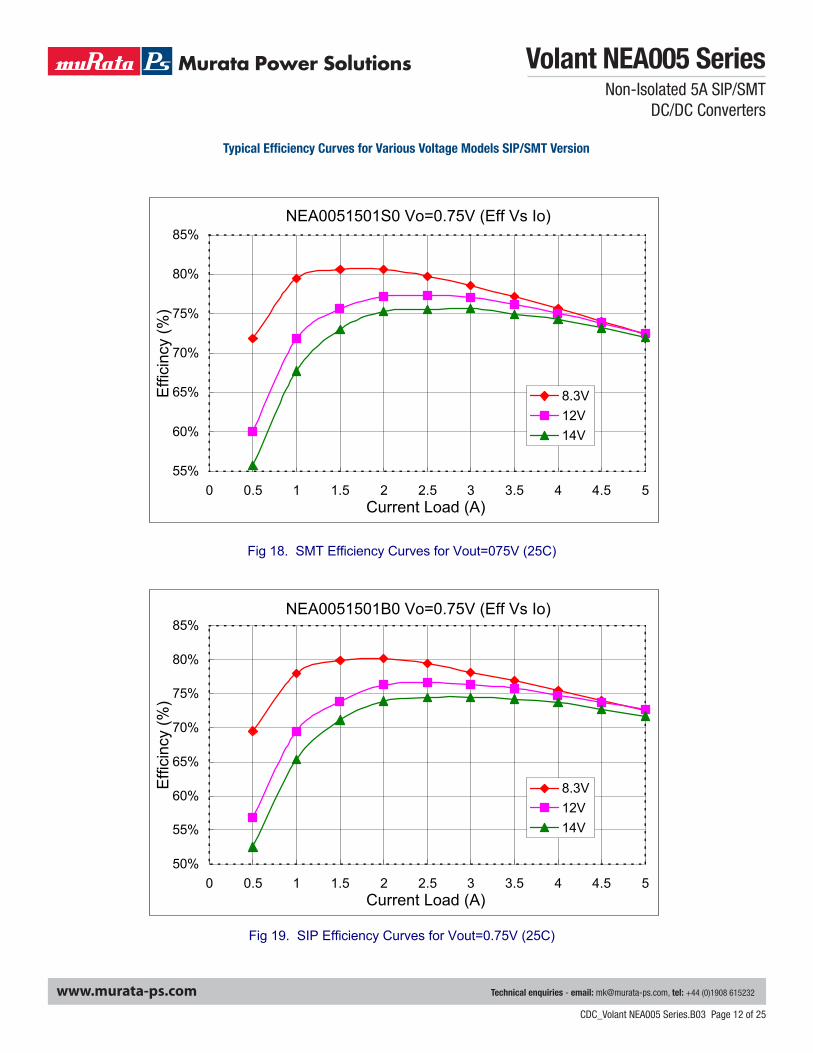
Fig 18. SMT Efficiency Curves for Vout=075V (25C)
NEA0051501B0 Vo=0.75V (Eff Vs Io)
50%
55%
60%
65%
70%
75%
80%
85%
0 0.5 1 1.5 2 2.5 3 3.5 4 4.5 5Current Load (A)
Effic
incy
(%)
8.3V12V14V
Fig 19. SIP Efficiency Curves for Vout=0.75V (25C)
Typical Efficiency Curves for Various Voltage Models SIP/SMT Version

Volant NEA005 SeriesNon-Isolated 5A SIP/SMT
DC/DC Converters
Technical enquiries - email: [email protected], tel: +44 (0)1908 615232www.murata-ps.com
CDC_Volant NEA005 Series.B03 Page 13 of 254118 14th Avenue, Unit 4Markham, Ontario L3R 0J31-866-740-1232
Page 14NEA005_6200870000_A02_25Jun07
Volant NEA005 SeriesNon-Isolated 5A SIP/SMT DC/DC Converters
www.cd4power.com
NEA0051501S0 Vo=1.2V (Eff Vs Io)
60%
65%
70%
75%
80%
85%
90%
95%
100%
0 0.5 1 1.5 2 2.5 3 3.5 4 4.5 5Current Load (A)
Effic
incy
(%)
8.3V12V14V
Fig 20. SMT Efficiency Curves for Vout=1.2V (25C)
NEA0051501B0 Vo=1.2V (Eff Vs Io)
60%
65%
70%
75%
80%
85%
90%
95%
100%
0 0.5 1 1.5 2 2.5 3 3.5 4 4.5 5Current Load (A)
Effic
incy
(%)
8.3V12V14V
Fig 21. SIP Efficiency Curves for Vout=1.2V (25C)
Typical Efficiency Curves for Various Voltage Models SIP/SMT Version
Volant NEA005 SeriesNon-Isolated 5A SIP/SMT
DC/DC Converters
Technical enquiries - email: [email protected], tel: +44 (0)1908 615232www.murata-ps.com
CDC_Volant NEA005 Series.B03 Page 14 of 25
4118 14th Avenue, Unit 4Markham, Ontario L3R 0J31-866-740-1232
Page 15NEA005_6200870000_A02_25Jun07
Volant NEA005 SeriesNon-Isolated 5A SIP/SMT DC/DC Converters
www.cd4power.com
NEA0051501S0 Vo=1.5V (Eff Vs Io)
60%
65%
70%
75%
80%
85%
90%
95%
100%
0 0.5 1 1.5 2 2.5 3 3.5 4 4.5 5Current Load (A)
Effic
incy
(%)
8.3V12V14V
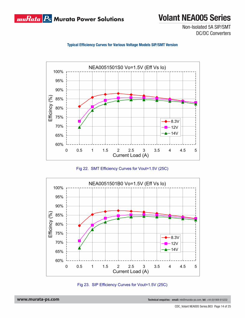
Fig 22. SMT Efficiency Curves for Vout=1.5V (25C)
NEA0051501B0 Vo=1.5V (Eff Vs Io)
60%
65%
70%
75%
80%
85%
90%
95%
100%
0 0.5 1 1.5 2 2.5 3 3.5 4 4.5 5Current Load (A)
Effic
incy
(%)
8.3V12V14V
Fig 23. SIP Efficiency Curves for Vout=1.5V (25C)
Typical Efficiency Curves for Various Voltage Models SIP/SMT Version

Volant NEA005 SeriesNon-Isolated 5A SIP/SMT
DC/DC Converters
Technical enquiries - email: [email protected], tel: +44 (0)1908 615232www.murata-ps.com
CDC_Volant NEA005 Series.B03 Page 15 of 25
4118 14th Avenue, Unit 4Markham, Ontario L3R 0J31-866-740-1232
Page 16NEA005_6200870000_A02_25Jun07
Volant NEA005 SeriesNon-Isolated 5A SIP/SMT DC/DC Converters
www.cd4power.com
NEA0051501S0 Vo=1.8V (Eff Vs Io)
60%
65%
70%
75%
80%
85%
90%
95%
100%
0 0.5 1 1.5 2 2.5 3 3.5 4 4.5 5Current Load (A)
Effic
incy
(%)
8.3V12V14V
Fig 24. SMT Efficiency Curves for Vout=1.8V (25C)
NEA0051501B0 Vo=1.8V (Eff Vs Io)
60%
65%
70%
75%
80%
85%
90%
95%
100%
0 0.5 1 1.5 2 2.5 3 3.5 4 4.5 5Current Load (A)
Effic
incy
(%)
8.3V12V14V
Fig 25. SIP Efficiency Curves for Vout=1.8V (25C)
Typical Efficiency Curves for Various Voltage Models SIP/SMT Version

Volant NEA005 SeriesNon-Isolated 5A SIP/SMT
DC/DC Converters
Technical enquiries - email: [email protected], tel: +44 (0)1908 615232www.murata-ps.com
CDC_Volant NEA005 Series.B03 Page 16 of 254118 14th Avenue, Unit 4Markham, Ontario L3R 0J31-866-740-1232
Page 17NEA005_6200870000_A02_25Jun07
Volant NEA005 SeriesNon-Isolated 5A SIP/SMT DC/DC Converters
www.cd4power.com
NEA0051501S0 Vo=2.0V (Eff Vs Io)
60%
65%
70%
75%
80%
85%
90%
95%
100%
0 0.5 1 1.5 2 2.5 3 3.5 4 4.5 5Current Load (A)
Effic
incy
(%)
8.3V12V14V
Fig 26. SMT Efficiency Curves for Vout=2.0V (25C)
NEA0051501B0 Vo=2.0V (Eff Vs Io)
60%
65%
70%
75%
80%
85%
90%
95%
100%
0 0.5 1 1.5 2 2.5 3 3.5 4 4.5 5Current Load (A)
Effic
incy
(%)
8.3V12V14V
Fig 27. SIP Efficiency Curves for Vout=2.0V (25C)
Typical Efficiency Curves for Various Voltage Models SIP/SMT Version

Volant NEA005 SeriesNon-Isolated 5A SIP/SMT
DC/DC Converters
Technical enquiries - email: [email protected], tel: +44 (0)1908 615232www.murata-ps.com
CDC_Volant NEA005 Series.B03 Page 17 of 25
4118 14th Avenue, Unit 4Markham, Ontario L3R 0J31-866-740-1232
Page 18NEA005_6200870000_A02_25Jun07
Volant NEA005 SeriesNon-Isolated 5A SIP/SMT DC/DC Converters
www.cd4power.com
NEA0051501S0 Vo=2.5V (Eff Vs Io)
60%
65%
70%
75%
80%
85%
90%
95%
100%
0 0.5 1 1.5 2 2.5 3 3.5 4 4.5 5Current Load (A)
Effic
incy
(%)
8.3V12V14V
Fig 28. SMT Efficiency Curves for Vout=2.5V (25C)
NEA0051501B0 Vo=2.5V (Eff Vs Io)
60%
65%
70%
75%
80%
85%
90%
95%
100%
0 0.5 1 1.5 2 2.5 3 3.5 4 4.5 5Current Load (A)
Effic
incy
(%)
8.3V12V14V
Fig 29. SIP Efficiency Curves for Vout=2.5V (25C)
Typical Efficiency Curves for Various Voltage Models SIP/SMT Version

Volant NEA005 SeriesNon-Isolated 5A SIP/SMT
DC/DC Converters
Technical enquiries - email: [email protected], tel: +44 (0)1908 615232www.murata-ps.com
CDC_Volant NEA005 Series.B03 Page 18 of 254118 14th Avenue, Unit 4Markham, Ontario L3R 0J31-866-740-1232
Page 19NEA005_6200870000_A02_25Jun07
Volant NEA005 SeriesNon-Isolated 5A SIP/SMT DC/DC Converters
www.cd4power.com
NEA0051501S0 Vo=3.3V (Eff Vs Io)
60%
65%
70%
75%
80%
85%
90%
95%
100%
0 0.5 1 1.5 2 2.5 3 3.5 4 4.5 5Current Load (A)
Effic
incy
(%)
8.3V12V14V
Fig 30. SMT Efficiency Curves for Vout=3.3V (25C)
NEA0051501B0 Vo=3.3V (Eff Vs Io)
60%
65%
70%
75%
80%
85%
90%
95%
100%
0 0.5 1 1.5 2 2.5 3 3.5 4 4.5 5Current Load (A)
Effic
incy
(%)
8.3V12V14V
Fig 31. SIP Efficiency Curves for Vout=3.3V (25C)
Typical Efficiency Curves for Various Voltage Models SIP/SMT Version
Volant NEA005 SeriesNon-Isolated 5A SIP/SMT
DC/DC Converters
Technical enquiries - email: [email protected], tel: +44 (0)1908 615232www.murata-ps.com
CDC_Volant NEA005 Series.B03 Page 19 of 25
4118 14th Avenue, Unit 4Markham, Ontario L3R 0J31-866-740-1232
Page 20NEA005_6200870000_A02_25Jun07
Volant NEA005 SeriesNon-Isolated 5A SIP/SMT DC/DC Converters
www.cd4power.com
NEA0051501S0 Vo=5.0V (Eff Vs Io)
60%
65%
70%
75%
80%
85%
90%
95%
100%
0 0.5 1 1.5 2 2.5 3 3.5 4 4.5 5Current Load (A)
Effic
incy
(%)
8.3V12V14V
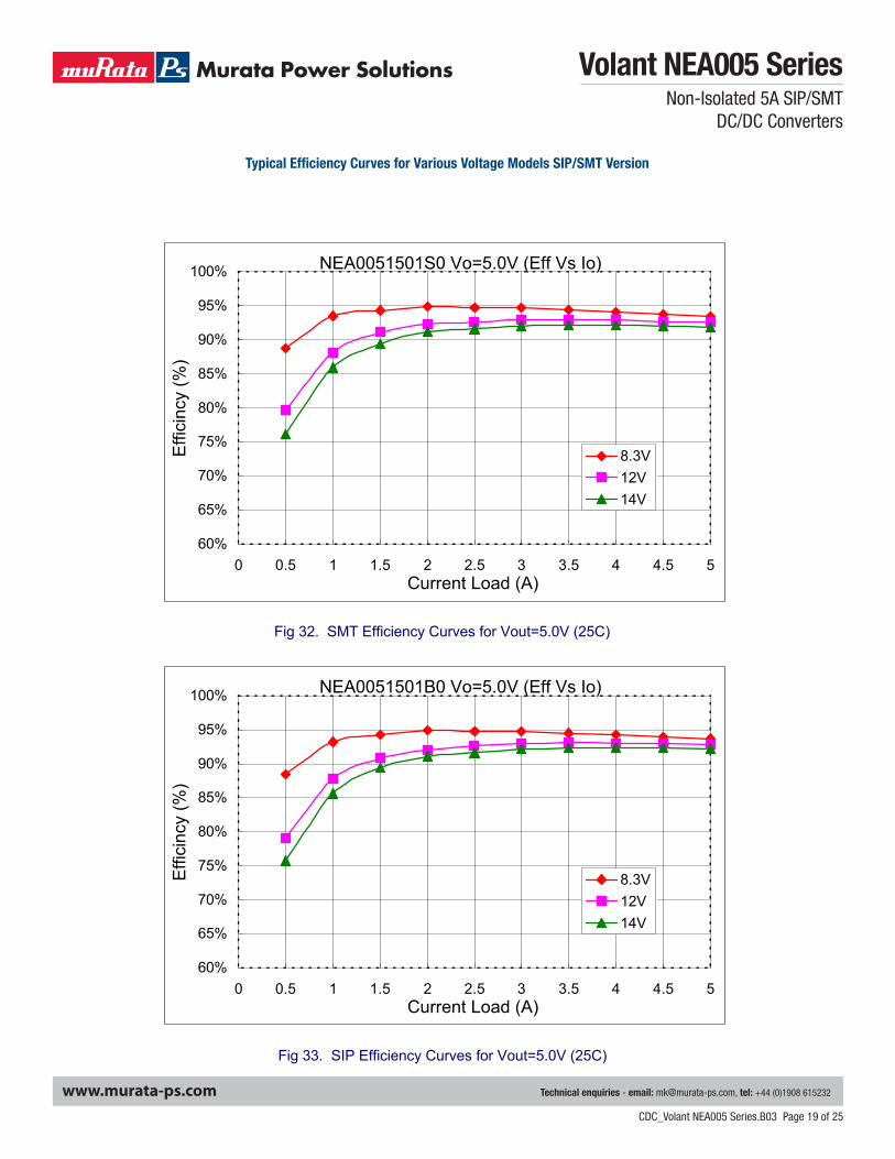
Fig 32. SMT Efficiency Curves for Vout=5.0V (25C)
NEA0051501B0 Vo=5.0V (Eff Vs Io)
60%
65%
70%
75%
80%
85%
90%
95%
100%
0 0.5 1 1.5 2 2.5 3 3.5 4 4.5 5Current Load (A)
Effic
incy
(%)
8.3V12V14V
Fig 33. SIP Efficiency Curves for Vout=5.0V (25C)
Typical Efficiency Curves for Various Voltage Models SIP/SMT Version

Volant NEA005 SeriesNon-Isolated 5A SIP/SMT
DC/DC Converters
Technical enquiries - email: [email protected], tel: +44 (0)1908 615232www.murata-ps.com
CDC_Volant NEA005 Series.B03 Page 20 of 25
4118 14th Avenue, Unit 4Markham, Ontario L3R 0J31-866-740-1232
Page 21NEA005_6200870000_A02_25Jun07
Volant NEA005 SeriesNon-Isolated 5A SIP/SMT DC/DC Converters
www.cd4power.com
Typical Start UpCh1. VinCh2. Vout, Full load.
Typical Start Up with pre-biasVin=12VdcCh1 : VoutCh2 : Output current at Full Load.
4118 14th Avenue, Unit 4Markham, Ontario L3R 0J31-866-740-1232
Page 22NEA005_6200870000_A02_25Jun07
Volant NEA005 SeriesNon-Isolated 5A SIP/SMT DC/DC Converters
www.cd4power.com
Typical Output Noise and Ripple
Vin = 12Vdc , Vo=5.0V/5AOutput with 1uF ceramic and 10uF tantalum capacitor
Typical Output Transient Response
Vin = 12Vdc , Vo=5.0V , 50% - 100% - 50% Load change , @0.1A/uS
Typical Start UpCh1 Vin
Ch2 Vout, Full Load
Typical Start Up with Pre-biasVin = 12VdcCh1 Vout
Ch2 Output current at Full Load

Volant NEA005 SeriesNon-Isolated 5A SIP/SMT
DC/DC Converters
Technical enquiries - email: [email protected], tel: +44 (0)1908 615232www.murata-ps.com
CDC_Volant NEA005 Series.B03 Page 21 of 25
4118 14th Avenue, Unit 4Markham, Ontario L3R 0J31-866-740-1232
Page 22NEA005_6200870000_A02_25Jun07
Volant NEA005 SeriesNon-Isolated 5A SIP/SMT DC/DC Converters
www.cd4power.com
Typical Output Noise and Ripple
Vin = 12Vdc , Vo=5.0V/5AOutput with 1uF ceramic and 10uF tantalum capacitor
Typical Output Transient Response
Vin = 12Vdc , Vo=5.0V , 50% - 100% - 50% Load change , @0.1A/uS
Typical Output Noise and RippleVin = 12Vdc, Vo = 5.0V/5AOutput with 1μF ceramic and 10μF tantulum capacitor
Typical Output Transient ResponseVin = 12Vdc, Vo = 5.0V, 50% - 100% - 50% Load change @0.1 A/us.

Volant NEA005 SeriesNon-Isolated 5A SIP/SMT
DC/DC Converters
Technical enquiries - email: [email protected], tel: +44 (0)1908 615232www.murata-ps.com
CDC_Volant NEA005 Series.B03 Page 22 of 25
Output Voltage Set Point AdjustmentThe following relationship establishes the calculation of external resistors:
Radj = − 1 (kΩ) 15 × 0.7
VO − 0.7525
For Vout setting an external resistor is connected between the TRIM and Ground Pin. Resistor values for different output voltages are calculated as given in the table:
SMT Lead Free Reflow Prefile
4118 14th Avenue, Unit 4Markham, Ontario L3R 0J31-866-740-1232
Page 23NEA005_6200870000_A02_25Jun07
Volant NEA005 SeriesNon-Isolated 5A SIP/SMT DC/DC Converters
www.cd4power.com
Output Voltage Set point adjustment.
The following relationship establish the calculation of external resistors:
)(K1)7525.0
7.015( Ω−−×
=Vo
Radj
For Vout setting an external resistor is connected between the TRIM and Ground Pin.
Resistor values for different output voltages are calculated as given in the table:
Vo, set (Volts) RAdj (KΩ)0.75 Open1.2 22.461.5 13.051.8 9.0242.0 7.4172.5 5.0093.3 3.1225.0 1.472
SMT Lead free Reflow profile
1. Ramp up rate during preheat : 1.33 ? /Sec ( From 30? to 150? )
2. Soaking temperature : 0.29 ? /Sec ( From 150? to 180? )
3. Ramp up rate during reflow : 0.8 ? /Sec ( From 220? to 250? )
4. Peak temperature : 250? , above 220? 40 to 70 Seconds
5. Ramp up rate during cooling : -1.56 ? /Sec ( From 220? to 150? )
1. Ramp up rate during preheat: 1.33°C/Sec (from 30°C to 150°C) 2. Soaking temperature: 0.29°C/Sec (from 150°C to 180°C) 3. Ramp up rate during reflow: 0.8°C/Sec (from 220°C to 250°C) 4. Peak temperature: 250°C, above 220°C 40 to 70 Seconds 5. Ramp up rate during cooling: –1.56°C/Sec (from 220°C to 150°C)
Resistor Values Vo, set (Volts) Radj kΩ
0.75 Open
1.2 22.46
1.5 13.05
1.8 9.024
2.0 7.417
2.5 5.009
3.3 3.122
5.0 1.472

Volant NEA005 SeriesNon-Isolated 5A SIP/SMT
DC/DC Converters
Technical enquiries - email: [email protected], tel: +44 (0)1908 615232www.murata-ps.com
CDC_Volant NEA005 Series.B03 Page 23 of 25
4118 14th Avenue, Unit 4Markham, Ontario L3R 0J31-866-740-1232
Page 24NEA005_6200870000_A02_25Jun07
Volant NEA005 SeriesNon-Isolated 5A SIP/SMT DC/DC Converters
www.cd4power.com
Mechanical and pinning Information. Given below is the outline drawing showing physical dimensions of the SIP & SMT package.
The external dimensions for SMT package are 20.3mm x 11.43mm x 6.09mm.
PAD SIZEMIN : 0.120" x 0.095 "MAX : 0.135" x 0.110 "
Dimensions are in Inches ( millimetes )
Recommended Pad Layout
0.340
0.180 0.160 0.160 0.190
0.350
0.6900.05
VOUT TRIM GND
VINON/OFF
(4.57) (4.06) (4.06) (4.83)
0.06(1.5) (1.3)
(17.53)
(8.89)
0.010(0.25)
(8.64)
Dimensions are in Inches (millimeters)Tolerances :x.xx = ±0.02in.( x.x = ±0.5mm) , unless otherwise noted
BOTTOM VIEW OF BOARD0.80
0.340
0.450
0.05
0.180
0.35
0.0620.090
0.1600.1600.1900.062
0.24
x.xxx = ±0.010in. ( x.xx = ±0.25mm)
Surface Mount Contact 5 Places
GND TRIM VOUT
ON/OFFVIN
(4.83) (4.06) (4.06) (4.06)
(20.3)
(2.29)(1.57)
(8.9) (8.64)
(11.43)
(1.5)
(1.3)
0.06
(1.57)
(6.09)
Mechanical and Pinning InformationGiven below is the outline drawing showing physical dimensions of the SIP & SMT package.
The external dimensions for SMT package are 0.8" x 0.45" x 0.24" (20.3mm x 11.43mm x 6.09mm).Recommended Pad Layout

Volant NEA005 SeriesNon-Isolated 5A SIP/SMT
DC/DC Converters
Technical enquiries - email: [email protected], tel: +44 (0)1908 615232www.murata-ps.com
CDC_Volant NEA005 Series.B03 Page 24 of 25
4118 14th Avenue, Unit 4Markham, Ontario L3R 0J31-866-740-1232
Page 25NEA005_6200870000_A02_25Jun07
Volant NEA005 SeriesNon-Isolated 5A SIP/SMT DC/DC Converters
www.cd4power.com
Whereas, the external dimensions of the SIP version are 22.9mm x 10.16mm x 5.6mm.
Safety Considerations
Ordering Information
Part Number Vin Vout Iout Enable Logic Pin LengthNEA0051500B0C 8.3V - 14.0V 0.75V – 5.0V 5A Negative 0.139"NEA0051500S0C 8.3V - 14.0V 0.75V – 5.0V 5A Negative SMTNEA0051501B0C 8.3V - 14.0V 0.75V – 5.0V 5A Positive 0.139"NEA0051501S0C 8.3V - 14.0V 0.75V – 5.0V 5A Positive SMT
PIN CONNECTION
FUNCTION
+Output
Trim
Common
+V Input
On/Off
Pin
1
2
3
4
5
All Dimmension In Inches(mm)
Tolerances : .XX = ± 0.02 ( ± 0.5 )
.XXX = ± 0.010 (± 0.25 )
1 2 3 4 5
LAYOUT PATTERNTOP VIEW
0.90(22.9)
0.400(10.16)
0.100(2.54)
0.700(17.78)
0.200(5.08)
0.14(3.6)
0.025(0.64)
0.24(6.1)0.20(5.1)
SIZE SIP05
1.1mm PLATED THROUGH HOLE1.6mm PAD SIZE
0.025(0.64)
0.800(20.32)
0.22(5.6)Max.
0.19(4.7)
The NEA series of converters are certified to IEC/EN/CSA/UL 60950. If this product is built into information technology equipment, the installation must comply with the above standard. An external input fuse of no more than 20 A must be used to meet the above requirements. The output of the converter [Vo(+)/Vo(-)] is considered to remain within SELV limits when the input to the converter meets SELV or TNV-2 requirements. The converters and materials meet UL 94V-0 flammability ratings.
Whereas, the external dimensions of the SIP version are 0.9" x 0.4" x 0.22" (22.9mm x 10.16mm x 5.6mm).
Safety ConsiderationsThe NEA series of converters are certified to IEC/EN/CSA/UL 60950. If this product is built into information technology equipment, the installation must comply with the above standard. An external input fuse of no more than 20 A must be used to meet the above requirements. The output of the converter [Vo(+)/Vo(–)] is considered to remain within SELV limits when the input to the converter meets SELV or TNV-2 requirements. The converters and materials meet UL 94V-0 flammability rating
Ordering Information
Part Number Vin Vout Iout Enable Logic Pin Length
NEA0051500B0C 8.3V – 14.0V 0.75V – 5.0V 5A Negative 0.139"
NEA0051500S0C 8.3V – 14.0V 0.75V – 5.0V 5A Negative SMT
NEA0051501B0C 8.3V – 14.0V 0.75V – 5.0V 5A Positive 0.139"
NEA0051501S0C 8.3V – 14.0V 0.75V – 5.0V 5A Positive SMT
Size SIP05
Pin Connection
Pin Function
1 +Output
2 Trim
3 Common
4 +V Input
5 On/Off

Volant NEA005 SeriesNon-Isolated 5A SIP/SMT
DC/DC Converters
Technical enquiries - email: [email protected], tel: +44 (0)1908 615232www.murata-ps.com
CDC_Volant NEA005 Series.B03 Page 25 of 25
Murata Power Solutions, Inc. makes no representation that the use of its products in the circuits described herein, or the use of other technical information contained herein, will not infringe upon existing or future patent rights. The descriptions contained herein do not imply the granting of licenses to make, use, or sell equipment constructed in accordance therewith. Specifications are subject to change without notice. © 2008 Murata Power Solutions, Inc.
USA: Tucson (Az), Tel: (800) 547 2537, email: [email protected]
Canada: Toronto, Tel: (866) 740 1232, email: [email protected]
UK: Milton Keynes, Tel: +44 (0)1908 615232, email: [email protected]
France: Montigny Le Bretonneux, Tel: +33 (0)1 34 60 01 01, email: [email protected]
Germany: München, Tel: +49 (0)89-544334-0, email: [email protected]
Japan: Tokyo, Tel: 3-3779-1031, email: [email protected] Osaka, Tel: 6-6354-2025, email: [email protected] Website: www.murata-ps.jp
China: Shanghai, Tel: +86 215 027 3678, email: [email protected] Guangzhou, Tel: +86 208 221 8066, email: [email protected]
Murata Power Solutions, Inc. 11 Cabot Boulevard, Mansfield, MA 02048-1151 U.S.A.Tel: (508) 339-3000 (800) 233-2765 Fax: (508) 339-6356www.murata-ps.com email: [email protected] ISO 9001 REGISTERED
DS-0528 2/12/08
RoHS CompliantThe NEA005 series of converters is in compliance with the European Union Directive 2002/95/EC (RoHS) with repsect to the following sustances: lead (Pb), mercury (Hg), cadmium (Cd), hexavalent chromium, polybrominated biphenyls (PBB) or polybrominated diphenyl ethers (PBDE).
Label Information
Place Holder
Non-isolated Family
Vin (value or range) C = 3.3V– 5.0V E = 8.3V–14V F = 6.0 –14V
N E A 0 15005 0
O = Standard (No PGood option)P = Power Good Option
XCC = RoHS compliant
-0 B
Vout Range F = Fixed A = Adjustable
Iout
Iout
X = Factory control character (not required when ordering)
Enable Logic O = –ve 1 = +ve
Pin Length Option B = 0.139" S = SMT