vol4no7page767to770
TRANSCRIPT
PIERS ONLINE, VOL. 4, NO. 7, 2008 767
Design of Low-cost Microstrip Antennas for Glonass Applications
Daniel C. Nascimento, Ricardo Schildberg, and J. C. da S. LacavaLaboratorio de Antenas e Propagacao, Instituto Tecnologico de Aeronautica, Brazil
Abstract— A new design procedure for low-cost circularly polarized microstrip antennas isproposed. Instead of the conventional truncated-corner square microstrip topology, a rectangularpatch with four truncated corners and an equal number of stubs is utilized here. As an application,a Glonass receiver antenna is designed. Comparisons between experimental and simulated resultsare presented, revealing very good agreement.
1. INTRODUCTION
The design of microstrip antennas as low-cost radiators for mobile communications can be chal-lenging. Additional complexities are introduced into the conventional microstrip design when theFR4 laminate is used as the antenna substrate, due to its high loss tangent and inaccurate relativepermittivity. The high losses in the antenna laminate have a direct effect on its radiation efficiency.Consequently, for higher efficiency, thicker substrates must be used [1]. In case, for instance, aprobe-fed truncated-corner square microstrip antenna (TCSMA), frequently used for achieving cir-cular polarization (CP), is designed following the conventional procedure, an extra limitation isposed if the patch is printed on a thick substrate: its inherently inductive input impedance can notbe properly matched to a 50-Ω SMA coaxial connector. In addition, the frequency where its axialratio is best does not coincide with the frequency where its return loss is best [2].
To overcome these limitations, a new design procedure is proposed here. Instead of the conven-tional topology (a square patch with two truncated corners), the new procedure utilizes a rectan-gular patch with four truncated corners. Besides, stubs are added to each corner to compensate forthe inaccuracy of the FR4 relative permittivity. This new patch topology gives the antenna designermore flexibility and the ability to properly compensate for the undesirable reactive inductance.
2. CIRCULARLY POLARIZED MICROSTRIP ANTENNAS
Antennas produce circularly polarized waves when two orthogonal field components with equal am-plitudes and in-phase quadrature are radiated. Probe-fed microstrip patches, classified as resonator-type antennas, can satisfy these requirements. Various configurations capable of CP operation havebeen reported [3], but square and circular patches are largely utilized in practice. Square and rect-angular patches for Glonass applications are discussed below.
2.1. TCSMA DesignFor Glonass applications, receiver antennas have to be right-hand circularly polarized over anoperating range from 1.598 to 1.609 GHz. Besides, their return loss, axial ratio and radiationefficiency have to meet specific requirements over the same frequency range [4]. TCSMA radiatorsthat are manufactured with high quality materials can comply with these specifications. Use oflow-loss RF laminates with high dielectric constant in their fabrication is currently expensive.Therefore, low-cost solutions are welcome since both market and technology are now ripe for massproduction [5].
The design of a TCSMA radiator printed on FR4 substrate of εr = 4.31, thickness= 1.524 mm,and loss tangent=0.02 for GPS applications has been recently presented [2]. However, such highloss tangent dramatically affected its axial ratio (AR) and degraded its gain, resulting in poorradiation efficiency of only 35%, which is unacceptable from a practical point of view.
By increasing the FR4 thickness to 6.2 mm, a new TCSMA radiator with the geometry shownin Figure 1 on a finite ground plane (70 × 70mm2) was designed for operation at 1.6035 GHzresulting in the following patch dimensions: S = 41.1mm, C = 9.35mm, and P = 9.55mm.Corresponding input impedance, axial ratio and return loss simulated with the HFSS package areshown in Figures 2 and 3.
As seen from these figures, the input reactance at the operating frequency is too large (Xin =j30.8Ω), so the antenna is not properly matched to the 50-Ω SMA coaxial connector. In addition,

PIERS ONLINE, VOL. 4, NO. 7, 2008 768
S
x
y C
C
Probe
P
S/2
S
Figure 1: Typical geometry of the TCSMA radiator.
10.0 25.0 50.0 100.0 250.0
-10.0j
10.0j
-25.0j
25.0j
-50.0j
50.0j
-100.0j
100.0j
-250.0j
250.0j
1.43 GHz
1.78 GHz
1.603 GHz
Figure 2: Input impedance of the TCSMA radiator.
the frequency where its axial ratio is best does not coincide with the frequency where its returnloss is best. The following antenna parameters were also obtained: directivity= 6.08 dB, 3-dBAR bandwidth= 52.7 MHz (3.28 %) and radiation efficiency= 68.4%. Although these parameterscomply with the Glonass requirements, return loss at 1.6035 GHz (−10.65 dB) is not acceptable.To overcome this limitation, fractal gap capacitors can be used to match the antenna to the coaxialfeed line [2]. However, a different procedure is implemented next.
1.43 1.48 1.53 1.58 1.63 1.68 1.73 1.78-25
-20
-15
-10
-5
0
0
4
8
12
16
20
Axi
al r
atio
(dB
)
Ret
urn
loss
(dB
)
Frequency (GHz)
Figure 3: Axial ratio and return loss of the TCSMAradiator.
2L
x
y 1C
1C
2C
2C
L1
Probe
P
L1/2
Figure 4: Proposed geometry for the TCRMA radi-ator.
2.2. TCRMA DesignAs previously mentioned, the use of a low-cost laminate adds complexity to the antenna design dueto the inaccuracy of its relative permittivity. To compensate for this effect, a topology consistingof four truncated corners with a stub added to each corner, as shown in Figure 4, is proposed. Byproper trimming of each stub length, frequency deviations can be compensated for. Moreover, thenew topology utilizes a rectangular patch (TCRMA) instead of the square one described in [2].These new additional parameters (i.e., the patch sides L1 and L2) provide more flexibility to theantenna designer.
Keeping the FR4 thickness the same as before, i.e., 6.2 mm, a TCRMA radiator on a finite groundplane (70 × 70mm2) has been designed (L1 = 40.2mm, L2 = 42.5mm, C1 = 10mm, C2 = 4mm,P = 7.25mm, length of the large stubs =5.5 mm, and length of the small stubs = 3.5mm) foroperation at 1.6035 GHz, resulting in the following antenna parameters: directivity= 6.12 dB, 3-dBAR bandwidth =52.5 MHz (3.27%), and radiation efficiency = 68%.
The corresponding input impedance, axial ratio, and return loss over the frequency range areshown in Figures 5–7. Simulated and experimental input impedance results show very good agree-ment. As expected, the microstrip antenna with the new geometry exhibits very good AR (0.39 dB)and return loss (−33.7 dB) characteristics at 1.6035 GHz, without any capacitive gaps. These are

PIERS ONLINE, VOL. 4, NO. 7, 2008 769
clearly excellent results from a practical point of view. A photo of the antenna prototype thatwas built is shown in Figure 8. The θ- and φ-components of the far electric fields radiated by
10.0 25.0 50.0 100.0 250.0
-10.0j
10.0j
-25.0j
25.0j
-50.0j
50.0j
-100.0j
100.0j
-250.0j
250.0j
Prototype HFSS
1.778 GHz
1.603 GHz
1.428 GHz
Figure 5: Input impedance of the TCRMA radiator.
1.45 1.50 1.55 1.60 1.65 1.70 1.75-20
0
20
40
60
80
100
120
140
Im [Zin]
Impe
danc
e (Ω
)
Frequency (GHz)
Prototype HFSS
Re [Zin]
Figure 6: Input impedance of the TCRMA radiator.
1.45 1.50 1.55 1.60 1.65 1.70 1.75-40
-35
-30
-25
-20
-15
-10
-5
0
0
2
4
6
8
10
12
14
16 Return loss (Prototype) Return loss (HFSS) Axial ratio (HFSS)
Ret
urn
loss
(dB
)
Frequency (GHz)
Axi
al r
atio
(dB
)
Figure 7: Axial ratio and return loss of the TCRMAradiator.
Figure 8: Photo of the Glonass antenna prototype.
the antenna are also analyzed. Experimental and simulated radiation patterns for the Eθ and Eφ
components, plotted in the xz -plane, are shown in Figures 9 and 10, respectively.
-30
-25
-20
-15
-10
-5
0
0
30
60
90
120
150
180
210
240
270
300
330
-30
-25
-20
-15
-10
-5
0
Prototype HFSS
xz-plane
Eth
eta
Nor
mal
ized
(dB
)
Figure 9: Eθ radiation pattern: xz -plane.
-30
-25
-20
-15
-10
-5
0
0
30
60
90
120
150
180
210
240
270
300
330
-30
-25
-20
-15
-10
-5
0
Prototype HFSS
xz-plane
Eph
i N
orm
aliz
ed (
dB)
Figure 10: Eφ radiation pattern: xz -plane.
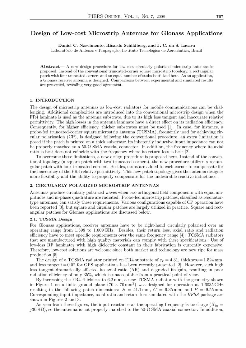
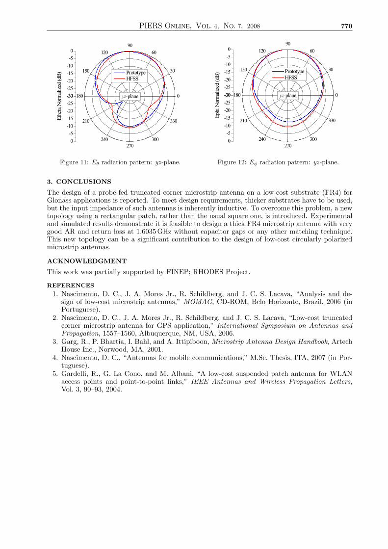
Results for the yz -plane are presented in Figures 11 and 12. Simulated and experimental resultsfor this important parameter also show very good agreement.
PIERS ONLINE, VOL. 4, NO. 7, 2008 770
-30
-25
-20
-15
-10
-5
0
0
30
60
90
120
150
180
210
240
270
300
330
-30
-25
-20
-15
-10
-5
0
Prototype HFSS
yz-plane
Eth
eta
Nor
mal
ized
(dB
)
Figure 11: Eθ radiation pattern: yz -plane.
-30
-25
-20
-15
-10
-5
0
0
30
60
90
120
150
180
210
240
270
300
330
-30
-25
-20
-15
-10
-5
0
Prototype HFSS
yz-plane
Eph
i N
orm
aliz
ed (
dB)
Figure 12: Eφ radiation pattern: yz -plane.
3. CONCLUSIONS
The design of a probe-fed truncated corner microstrip antenna on a low-cost substrate (FR4) forGlonass applications is reported. To meet design requirements, thicker substrates have to be used,but the input impedance of such antennas is inherently inductive. To overcome this problem, a newtopology using a rectangular patch, rather than the usual square one, is introduced. Experimentaland simulated results demonstrate it is feasible to design a thick FR4 microstrip antenna with verygood AR and return loss at 1.6035 GHz without capacitor gaps or any other matching technique.This new topology can be a significant contribution to the design of low-cost circularly polarizedmicrostrip antennas.
ACKNOWLEDGMENT
This work was partially supported by FINEP; RHODES Project.
REFERENCES
1. Nascimento, D. C., J. A. Mores Jr., R. Schildberg, and J. C. S. Lacava, “Analysis and de-sign of low-cost microstrip antennas,” MOMAG, CD-ROM, Belo Horizonte, Brazil, 2006 (inPortuguese).
2. Nascimento, D. C., J. A. Mores Jr., R. Schildberg, and J. C. S. Lacava, “Low-cost truncatedcorner microstrip antenna for GPS application,” International Symposium on Antennas andPropagation, 1557–1560, Albuquerque, NM, USA, 2006.
3. Garg, R., P. Bhartia, I. Bahl, and A. Ittipiboon, Microstrip Antenna Design Handbook, ArtechHouse Inc., Norwood, MA, 2001.
4. Nascimento, D. C., “Antennas for mobile communications,” M.Sc. Thesis, ITA, 2007 (in Por-tuguese).
5. Gardelli, R., G. La Cono, and M. Albani, “A low-cost suspended patch antenna for WLANaccess points and point-to-point links,” IEEE Antennas and Wireless Propagation Letters,Vol. 3, 90–93, 2004.