vol. 92/dec. 2000 - mitsubishi electric global · pdf file · 2007-09-10vol....
TRANSCRIPT
ISSN 1345-3041
VOL. 92/DEC. 2000
MITSUBISHIELECTRIC
Iron and Steel Plant Electrical Equipment Edition

lVol. 92/December 2000 Mitsubishi Electric ADVANCE
A Quarterly Survey of New Products, Systems, and Technology
TECHNICAL REPORTS
OVERVIEW
The Contributions of Information Technologyto the Steel Industry ............................................................................ 1by Kyoji Yonemasu
A Total Plant Operation and MaintenanceSupport System .................................................................................. 2by Kimio Yamanaka, Yasushi Kobayashi and Yukihiko Yoshida
A System for Automating Coke Machines ........................................ 6by Naokazu Watanabe and Takao Muranaka
Electrical Equipment for Hot-Rolling Mills ......................................... 9by Ken Okamoto and Yoshiaki Nakagawa
Controlling Quality in Steel Processing Lines .................................. 13by Nobuya Yamanaka and Naohiro Kubo
Variable-Speed Drive Systems forSteel Plants ....................................................................................... 17by Hiroyuki Masuda and Masaru Toyoda
Computer Systems for Controlling Steel Plants ............................. 21by Kazuo Sena and Shigehiko Matsuda
Control Systems for Steel Plants ..................................................... 27by Yuuji Takahashi and Keiichi Fuse
A Quality Control and DiagnosticSystem for Hot-Rolling Mills ............................................................. 30by Yoshinori Wakamiya and Isoko Nitta
A Camber-Profile Gauge Using a Laser Scanningand Light-Guide Detection Edge Sensor .......................................... 34by Masayuki Sugiyama and Michihiko Hamaguchi
CONTENTSCONTENTSCONTENTSCONTENTSCONTENTS
Mitsubishi Electric Advance is published online quarterly (in March, June, September,and December) by Mitsubishi ElectricCorporation.Copyright © 2000 by Mitsubishi ElectricCorporation; all rights reserved.Printed in Japan.
Shin Suzuki
Haruki NakamuraHiroo FujikawaKeizo HamaKazunori SasakiMasao HatayaHiroshi MuramatsuTakashi ItoMasatoshi ArakiHiroaki KawachiHiroshi KayashimaTakao YoshiharaOsamu MatsumotoKazuharu Nishitani
Yoshinori Wakamiya
Keizo HamaCorporate Total Productivity Management& Environmental ProgramsMitsubishi Electric Corporation2-2-3 MarunouchiChiyoda-ku, Tokyo 100-8310, JapanFax 03-3218-2465
Yasuhiko KaseGlobal Strategic Planning Dept.Corporate Marketing GroupMitsubishi Electric Corporation2-2-3 MarunouchiChiyoda-ku, Tokyo 100-8310, JapanFax 03-3218-3455
Editor-in-Chief
Editorial Advisors
Vol. 92 Feature Articles Editor
Editorial Inquiries
Product Inquiries
Mitsubishi Electric has a long history ofresearch and development for electricalequipment in iron and steel plants. Recently, the corporation�s efforts haveconcentrated on using its expertise in informa-tion technology to help iron and steel plantoperators minimize the total cost of ownership(TCO) by investments intended to reducestaffing needs and produce more competitiveproducts. Our cover shows the followingrepresentative products: (1) A large-multiscreen display for a plant supervisory system;(2) The MR2200 industrial computer, center ofinformation and control systems; (3) and (4)the P2000, our main control system forproduction and the OPS2000 operator stationthat provides the human-machine interface; (5)and (6) screens from the integrated engineer-ing support environment; (7) a diagramillustrating the basic principles of the opticalsensor, a key technology in controlling productquality; and (8) variable- speed drive system.
Iron and Steel Plant Electrical Equipment Edition

· 1December 2000
TECHNICAL REPORTS
*Kyoji Yonemasu is with the Energy & Industrial Systems Center.
OverviewThe Contributions of Information Technology to the Steel Industry
by Kyoji Yonemasu*
The twentieth century saw remarkable advances in industry ac-companied by a rapid expansion in the key market for iron and steel.Mitsubishi Electric Corporation has been taking a leadership role inindustry in the development and supply of new technologies.
The last quarter of the century, in particular, saw dramatic advancesin computers, plant controllers, drive systems and other electrical andelectronic equipment for the iron and steel industry paralleling acceler-ating advances in semiconductor technology. These have contributed tothe automation of operations and to significant improvements in yieldand product quality.
We mark the dawn of the new millennium with a special edition ofAdvance featuring iron and steel plant electrical equipment and intro-ducing some of the latest types of equipment and current trends in theirdevelopment.
Unquestionably, the technological revolution in iron and steel plantequipment will continue in the quest for production innovations to en-sure better quality products and higher productivity. The key phrase hereis �information technology� (IT). The corporation uses its advanced ITexpertise to support iron and steel plant operators by providing electricalequipment that minimizes their total cost of ownership. The lead articlein this special edition proposes a total plant operation and maintenancesupport system for iron and steel plants.
As an integrated manufacturer of electrical and electronic equipment,Mitsubishi Electric has an extremely wide range of available technolo-gies that it can call upon, and is integrating them in the service of theiron and steel industry. We look forward to ever closer relationships withour clients, learning how best to serve their special needs and cooperat-ing with them in providing the best possible means of satisfying thoseneeds.

T E C H N I C A L R E P O R T S
Mitsubishi Electric ADVANCE2 ·
Mitsubishi Electric Corporation not only pro-vides a wide range of electrical equipment usedin iron and steel plants but can also supply en-tire systems that support overall plant opera-tion and maintenance. These systems usesolutions based on information technology (IT),and contribute to the competitive strengths ofiron and steel manufacturers and to minimiz-ing their investments in plant and equipment.
Improving Product QualityThe iron and steel industry is currently, withvery few regional exceptions, in a state of world-wide oversupply. This means that investmentsare being made primarily to increase products�competitive strengths or to minimize the over-all cost of investments in plant and equipment.The corporation has responded to this situationby adding to its previous range of electrical
*Kimio Yamanaka, Yasushi Kobayashi & Yukihiko Yoshida are with the Energy & Industrial Systems Center.
by Kimio Yamanaka, Yasushi Kobayashi and Yukihiko Yoshida*
A Total Plant Operation andMaintenance Support System
equipment for the industry, concentrating onthe key themes of improved product quality, ad-vanced labor saving, maintenance support andenvironmental protection. Specifically, it hasapplied solutions derived from revolutionarydevelopments in IT to configure a system offer-ing total plant operating and maintenance sup-port, see Fig. 1. The article introduces theproduct development and corporate strategybehind this system.
Under the present situation of oversupply, theiron and steel industry is concentrating its ef-forts on improving product quality and, of course,on reducing costs. Other articles in this specialedition of �Advance� will give specific examplesof how product quality can be better controlledand improved, but here we note that it dependson three critically important factors.
The first of these is a super-stable and robust
Fig. 1 A total plant operating and maintenance system
Client’s own intranet
Enterprise server for production management
Fast, reliable real-time processor (MR series).
Small, reliable "open" machine (MWS series)
Variable speed drive equipment
Distributed PIO
Motors
Industrial computer
Universal architecture using open network.Can meet applicable international standards.Achieve high reliability and maintainability.Compatible with existing networks and sequencers (MELSEC series)
Open interface, Windows NT OS.
Installation near workplace reduces wiring
Connect ws to open field network
RAS functions for fault detection at unit PIO level
Lower switching losses, higher efficiencies and power factors.Low energy consumption thanks to higher voltages and larger capacities.
Support for fault diagnoses, displaying of locations, and restarting.
Compact circuit configurations save space.
RAS and network control functions forindustrial grade reliability
Improve high-speed response by reducing inertiaLow energy using highly efficient types
System for assessing equipment and quality
Integrated pulpit
Controllers
Intelligent sensors
I/O I/O
I/O I/OI/O
Fieldbus
Foundation FieldbusCC-LinkProfibusDeviceNet
Other equipment interfaces (I/Fs)
To FieldbusDeriving operating conditions
I/F
Othercompanies’equipment
Internet
Client’s server
Data storage machine
Data acquisition of learning model dataData acquisition for quality assessmentData acquisition for equipment assessmentData acquisition for data mining
Mobile terminal
Workplace maintenance supportAR (enhanced workplace) display
Sensors/Final control elements
To FieldbusConventional instruments
Two-way interface with integrated pulpit
Global support system
Handles Japanese and overseas needs.Supports operations with continuousassessment of the conditions of individual items of equipment and entire systems.The global network provides spare parts and educational support.
Support for remote operation and remote maintenance
M E L C O
Open network
High-speed real-time network (FDDI 100Mbps)Message communication & high speed recyclic communications (TCP/IP)Connections to general purposedevices (TCP/IP)Supports Ethernet.
Supports staff operations at home and over weekends or at night.Reduces need for three-shift working.Supports maintenance by operators.
Engineering tools
Real-time monitoring using MCD languageSimple programming using word processorsSupports IEC61131-3.
Client’s remote environment
Pursuit of high speed, functionality and reliability.
Comes with built-in web server.
Suitable for one-man operationCompact, space saving.Designed to form a pleasant, user friendly space.
Assessment of abnormal product quality and analysis of cause(s) of defects
Assessment of equipment abnormalities and analysis of their causes
Data mining for analysis of very long-term operations
The HMI makes use of operator sensibilities.Displays show operating conditions, provide automatic supervision, and identify faulty operations.Displays guidance for emergency responses.
Human-Machine Interface (HMI)
Fusion and association of sensors enables visualization of plant quality factors.Sensors for visual and organoleptic test.

T E C H N I C A L R E P O R T S
· 3December 2000
control system that provides �no-touch� opera-tion, i.e., free from the frequent need for opera-tor intervention.
The second is the automatic detection of ab-normal conditions in the manufacturing process,with automatic repair and restart.
And the third is the use of intelligent sensorsthat can assist in the visualization of controlledprocesses.
The full range of automatic controls availabletoday already ensure �no touch� operation un-der virtually all normal circumstances. How-ever, they frequently depend upon interventionby skilled and experienced operators when ab-normal conditions arise. The skills exercised atsuch times have a direct effect on product qual-ity and yield. Improvements here call for super-stable and robust control systems significantlyout-performing conventional �no-touch� con-trol systems. Such advanced systems should au-tomatically detect abnormal operation andachieve automatic repair and restart withoutrelying upon manual intervention by operators.
A number of different sensors and methodsare currently used to detect abnormal conditionsand to recover from them. In future, as moreintelligent sensors are used to achieve better vi-sualization of the processes being controlled,data-mining techniques will be used to identifyoperating abnormalities and their causes. Qual-ity improvements will readily follow when thenecessary repairs can be made automatically andnormal operation restored without operator in-tervention.
Advanced Labor SavingWe are already approaching the limits of whatcan be achieved in labor saving for individualproduction lines under normal �no-touch� op-eration and their integrated control rooms. Fur-ther advances in labor saving will require inte-grated control of multiple production lineswithin a single control room. This, in turn, willrequire an infrastructure that provides not only
the previously mentioned intelligent sensors andimproved process visualization but also anintranet, multimedia controllers, large multi-screen display systems, and sophisticated data-acquisition capabilities. It must also provide forone-man execution of unscheduled operationsusing agent functions that act for the operator,and optimum scheduling of materials handlingand yard operations so as to implement fullyautomated, unattended processes. IT solutionswill necessarily provide the technological sup-port for these labor-saving developments.
Maintenance SupportThe increased sophistication of production fa-cilities and the move to continuous operationhave made it desirable to form workplace main-tenance support environments that enable op-erators to cope with trouble as soon as it occurs,and speed the work of maintenance by facilitat-ing remote maintenance and the use of mobileintelligent terminals. The corporation is provid-ing the following solutions directed at meetingthese needs:1. Remote maintenance support using the
Internet (and/or an intranet).2. Workplace maintenance support systems
using mobile intelligent terminals.3. Operator support using maintenance agent
functions.
Remote maintenance support enables engi-neers to accurately grasp the situation via theInternet (or intranet) without necessarily visit-ing the workplace, and then to decide and imple-ment the required remedial actions. This greatlyreduces the number of service visits the main-tenance engineers have to make to the work-place and, even when visits do prove necessary,it minimizes the time taken to implement therequired measures.
Workplace support for mobile intelligent ter-minals enables engineers in the workplace tocarry small terminals with miniature ITV cam-eras and displays. These can then be used toshare with those in the control center images ofconditions at the workplace and the operatingsequences followed, and to convey instructions

T E C H N I C A L R E P O R T S
Mitsubishi Electric ADVANCE4 ·
from the center to maintenance engineers (seeFig. 2
To achieve fast and efficient maintenance op-erations with this approach requires timely ac-cess to maintenance information, with the mainpoint being to create an environment giving in-tegrated access to a number of databases ofdifferent kinds, including all the various main-tenance related databases and the plant operat-ing database. The corporation provides this envi-ronment in the form of a middle-ware system(Infoharness) for integrating heterogeneous in-formation sources, see Fig. 3.
Addressing Environmental ConcernsAs part of Mitsubishi Electric�s corporate responseto the quantitative targets for reduced CO2 emis-sions set by the Kyoto Global Warming EarthSummit held in December 1999, the corporationdeveloped the energy-saving MELTRAC-F500Hhigh-tension inverter. This inverter clears theguidelines set for suppression of higher harmoniccurrent with 24-phase converter inputs and com-
bines high power factor with high efficiency. Byusing five-level pulse-width modulation for con-trol, it is very easy on the loads it serves. Thecorporation also provides a number of key tech-nologies that address, directly or indirectly, en-vironmental concerns. These include:1. Optimized flow-rate control of the cooling
fans for main and optimized control auxil-iary motors.
2. Optimized flow-rate control of the inlet andexhaust fans for the electric room.
3. Main-motor field economizing control.4. Optimized control of the cooling-water
pumps in rolling mills.5. Optimized control of descaling pumps.
The approaches and proposals outlined above havealready been implemented in actual products andsystems, some of which are already being providedto the iron and steel industry. Future developmentsand applications along these lines will be modi-fied to reflect the opinions of iron-and-steel in-dustry experts. The corporation is committed to
Fig. 2 Workplace maintenance support system
Mobile PC with video camera
Step 8, Switch on NFB-1
Operational steps
Live picture from video camera
Instructions appropriate for the situation.

T E C H N I C A L R E P O R T S
· 5December 2000
Fig. 3 An integrated system with distributed heterogeneous databases.
expanding its proposals and implementing themwidely to support the iron and steel industry in itsefforts to reduce the total cost of ownership. q
Note:1. UNIX is a registered trademark licensed by X/Open Co., Ltd. in the
US and other countries.
2. Windows, Windows NT and Active-X are registered trademarks ofthe US company Microsoft Corp. in the US and other countries.
3. Java is a registered trademark of the US company Sun Micro-systems, Inc. in the US and other countries.
4. DeviceNet is a trademark of the US Open DeviceNet VendorsAssociation, Inc. (ODVA).
5. Ethernet is a trademark of the US company Xerox Corp.
Web browser
Web server Web server
HTMLMonitoringcomponents
Script language
Harness script
Infoharness
DC DC DC DC
Plant data
Log data
OperatingLog
Equipment& service
data
Plant bus
Supervisory & control data
<Screen for automatic detection of faulty equipment>
<Screen for remote plant monitoring>
Equipment maintenance & management data
T E C H N I C A L R E P O R T S
Mitsubishi Electric ADVANCE6 ·
The automation of coke machines calls for veryaccurate positioning of stops and highly stableoperation. Mitsubishi Electric has configuredautomatic systems with the required positionalaccuracy and achieved stable operation byadopting a combination of inductive radio andposition detectors.
A Brief Description of Coking Facilities andtheir Main SpecificationsIn recent years, automation and labor savingin coking facilities has proceeded with thetwin aims of improving both productivity andthe working environment. Systems for auto-mating coke machines operate the equipmentthat moves in parallel with the operation ofcoke ovens, making possible automatic orunattended operation and generally improv-ing efficiency.
Coke machines comprise four items of mov-ing equipment associated with the coke oven,
*Naokazu Watanabe and Takao Muranaka are with the Energy & Industrial System Center.
by Naokazu Watanabe and Takao Muranaka*
A System for AutomatingCoke Machines
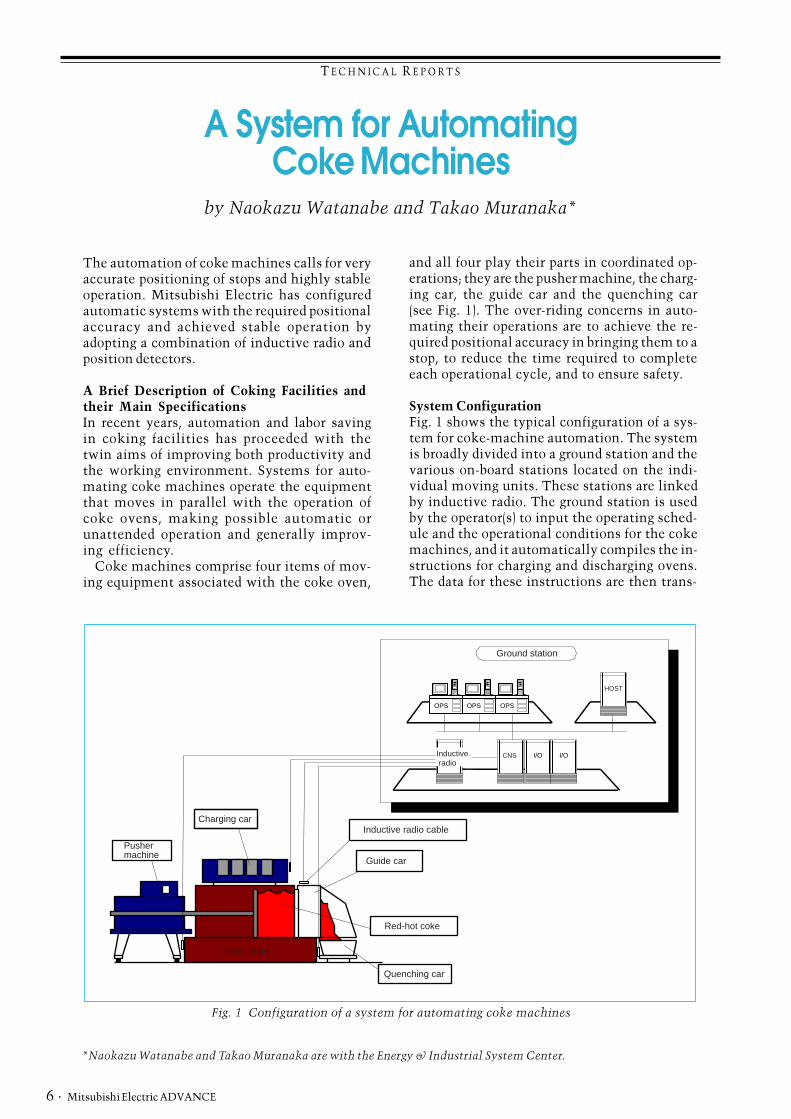
and all four play their parts in coordinated op-erations; they are the pusher machine, the charg-ing car, the guide car and the quenching car(see Fig. 1). The over-riding concerns in auto-mating their operations are to achieve the re-quired positional accuracy in bringing them to astop, to reduce the time required to completeeach operational cycle, and to ensure safety.
System ConfigurationFig. 1 shows the typical configuration of a sys-tem for coke-machine automation. The systemis broadly divided into a ground station and thevarious on-board stations located on the indi-vidual moving units. These stations are linkedby inductive radio. The ground station is usedby the operator(s) to input the operating sched-ule and the operational conditions for the cokemachines, and it automatically compiles the in-structions for charging and discharging ovens.The data for these instructions are then trans-
OPS OPS OPS
I/O I/O
HOST
CNS
Ground station
Inductive radio
Pusher machine
Charging car
Guide car
Inductive radio cable
Red-hot coke
Quenching car
Coke oven
Fig. 1 Configuration of a system for automating coke machines
T E C H N I C A L R E P O R T S
December 2000 · 7
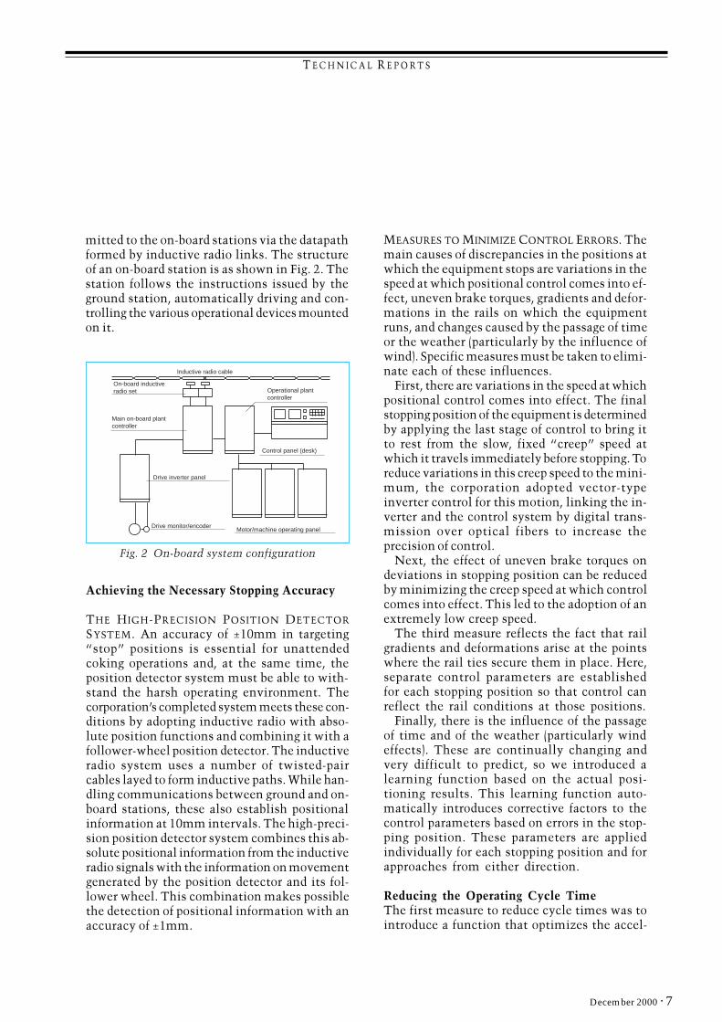
mitted to the on-board stations via the datapathformed by inductive radio links. The structureof an on-board station is as shown in Fig. 2. Thestation follows the instructions issued by theground station, automatically driving and con-trolling the various operational devices mountedon it.
Achieving the Necessary Stopping Accuracy
THE HIGH-PRECISION POSITION DETECTOR
SYSTEM. An accuracy of ±10mm in targeting�stop� positions is essential for unattendedcoking operations and, at the same time, theposition detector system must be able to with-stand the harsh operating environment. Thecorporation�s completed system meets these con-ditions by adopting inductive radio with abso-lute position functions and combining it with afollower-wheel position detector. The inductiveradio system uses a number of twisted-paircables layed to form inductive paths. While han-dling communications between ground and on-board stations, these also establish positionalinformation at 10mm intervals. The high-preci-sion position detector system combines this ab-solute positional information from the inductiveradio signals with the information on movementgenerated by the position detector and its fol-lower wheel. This combination makes possiblethe detection of positional information with anaccuracy of ±1mm.
Inductive radio cable
On-board inductiveradio set Operational plant
controller
Main on-board plant controller
Control panel (desk)
Drive inverter panel
Drive monitor/encoderMotor/machine operating panel
Fig. 2 On-board system configuration
MEASURES TO MINIMIZE CONTROL ERRORS. Themain causes of discrepancies in the positions atwhich the equipment stops are variations in thespeed at which positional control comes into ef-fect, uneven brake torques, gradients and defor-mations in the rails on which the equipmentruns, and changes caused by the passage of timeor the weather (particularly by the influence ofwind). Specific measures must be taken to elimi-nate each of these influences.
First, there are variations in the speed at whichpositional control comes into effect. The finalstopping position of the equipment is determinedby applying the last stage of control to bring itto rest from the slow, fixed �creep� speed atwhich it travels immediately before stopping. Toreduce variations in this creep speed to the mini-mum, the corporation adopted vector-typeinverter control for this motion, linking the in-verter and the control system by digital trans-mission over optical fibers to increase theprecision of control.
Next, the effect of uneven brake torques ondeviations in stopping position can be reducedby minimizing the creep speed at which controlcomes into effect. This led to the adoption of anextremely low creep speed.
The third measure reflects the fact that railgradients and deformations arise at the pointswhere the rail ties secure them in place. Here,separate control parameters are establishedfor each stopping position so that control canreflect the rail conditions at those positions.
Finally, there is the influence of the passageof time and of the weather (particularly windeffects). These are continually changing andvery difficult to predict, so we introduced alearning function based on the actual posi-tioning results. This learning function auto-matically introduces corrective factors to thecontrol parameters based on errors in the stop-ping position. These parameters are appliedindividually for each stopping position and forapproaches from either direction.
Reducing the Operating Cycle TimeThe first measure to reduce cycle times was tointroduce a function that optimizes the accel-
T E C H N I C A L R E P O R T S
Mitsubishi Electric ADVANCE8 ·
eration, deceleration and fixed speeds so as tominimize the time taken to arrive at each stop-ping point.
This was followed by an analysis of the mostefficient operating patterns for any given seriesof operations and perfecting a system of inter-locks that enables waiting times between op-erations to be kept to the minimum.
Further, comprehensive means of identifyingthe causes of any fault that occurs and of givingguidance on how each fault should be eliminatedhave been provided to reduce the time taken toclear faults and restart operations.
Achieving Operational SafetySafety measures include measures to prevent col-lisions and runaway operations.
The anti-collision function provided operatesby calculating the operational areas of all mov-ing equipment from their current positions andthe positions to which they are moving, anddevising running patterns that avoid mutual in-terference between these areas, so avoiding col-lisions. Additionally, a function has beenprovided that calculates the actual separationsbetween the various items of moving equipmentfrom their positions and speeds and the distanceswithin which they can be brought to a halt.When it judges that they are getting too close,it forces a reduction in speed or even stops themovement.
Hardware sensors are also provided to preventcollisions. Sensors on each item of equipmentdetect when close approaches require an emer-gency stop. Circularly polarized microwave sen-sors were selected in view of the harsh operatingenvironment and the need to prevent misopera-tion.
Other safety measures include the ability toestablish �no-go� areas that must not be enteredby the equipment while servicing or other workis in progress. This can be done both by delin-eating the areas on the ground-station CRT andby affixing limit switches at the edges of theseareas. Speed limits can also be imposed withineach of the operational areas, and the systemincludes functions monitoring runaway condi-tions, etc.
Systems for automating coking operations arenow, after intensive research and extensiveevaluation, approaching actual implementation.However, much of the coking being done in Ja-pan uses equipment that is nearly 20 years old,and new requirements are arising for measuresto inhibit the ageing process, extend their use-ful working life, and develop other useful tech-nologies. Mitsubishi Electric is committed tomeeting these growing needs, and is confidentthat the corporation�s sensing and other tech-nologies developed for systems to automate cokemachines will play a key role in doing so. q
TECHNICAL REPORTS
· 9December 2000
*Ken Okamoto & Yoshiaki Nakagawa are with the Energy & Industrial Systems Center.
by Ken Okamoto and Yoshiaki Nakagawa*
Electrical Equipment forHot-Rolling Mills
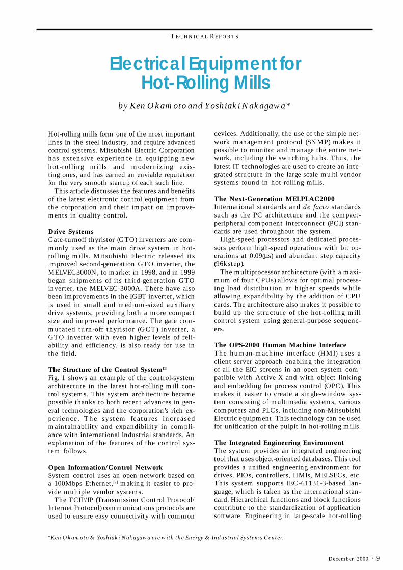
Hot-rolling mills form one of the most importantlines in the steel industry, and require advancedcontrol systems. Mitsubishi Electric Corporationhas extensive experience in equipping newhot-rolling mills and modernizing exis-ting ones, and has earned an enviable reputationfor the very smooth startup of each such line.
This article discusses the features and benefitsof the latest electronic control equipment fromthe corporation and their impact on improve-ments in quality control.
Drive SystemsGate-turnoff thyristor (GTO) inverters are com-monly used as the main drive system in hot-rolling mills. Mitsubishi Electric released itsimproved second-generation GTO inverter, theMELVEC3000N, to market in 1998, and in 1999began shipments of its third-generation GTOinverter, the MELVEC-3000A. There have alsobeen improvements in the IGBT inverter, whichis used in small and medium-sized auxiliarydrive systems, providing both a more compactsize and improved performance. The gate com-mutated turn-off thyristor (GCT) inverter, aGTO inverter with even higher levels of reli-ability and efficiency, is also ready for use inthe field.
The Structure of the Control System[1]
Fig. 1 shows an example of the control-systemarchitecture in the latest hot-rolling mill con-trol systems. This system architecture becamepossible thanks to both recent advances in gen-eral technologies and the corporation’s rich ex-perience. The system features increasedmaintainability and expandibility in compli-ance with international industrial standards. Anexplanation of the features of the control sys-tem follows.
Open Information/Control NetworkSystem control uses an open network based ona 100Mbps Ethernet,[2] making it easier to pro-vide multiple vendor systems.
The TCIP/IP (Transmission Control Protocol/Internet Protocol) communications protocols areused to ensure easy connectivity with common
devices. Additionally, the use of the simple net-work management protocol (SNMP) makes itpossible to monitor and manage the entire net-work, including the switching hubs. Thus, thelatest IT technologies are used to create an inte-grated structure in the large-scale multi-vendorsystems found in hot-rolling mills.
The Next-Generation MELPLAC2000International standards and de facto standardssuch as the PC architecture and the compact-peripheral component interconnect (PCI) stan-dards are used throughout the system.
High-speed processors and dedicated proces-sors perform high-speed operations with bit op-erations at 0.09(µs) and abundant step capacity(96kstep).
The multiprocessor architecture (with a maxi-mum of four CPUs) allows for optimal process-ing load distribution at higher speeds whileallowing expandibility by the addition of CPUcards. The architecture also makes it possible tobuild up the structure of the hot-rolling millcontrol system using general-purpose sequenc-ers.
The OPS-2000 Human Machine InterfaceThe human-machine interface (HMI) uses aclient-server approach enabling the integrationof all the EIC screens in an open system com-patible with Active-X and with object linkingand embedding for process control (OPC). Thismakes it easier to create a single-window sys-tem consisting of multimedia systems, variouscomputers and PLCs, including non-MitsubishiElectric equipment. This technology can be usedfor unification of the pulpit in hot-rolling mills.
The Integrated Engineering EnvironmentThe system provides an integrated engineeringtool that uses object-oriented databases. This toolprovides a unified engineering environment fordrives, PIOs, controllers, HMIs, MELSECs, etc.This system supports IEC-61131-3-based lan-guage, which is taken as the international stan-dard. Hierarchical functions and block functionscontribute to the standardization of applicationsoftware. Engineering in large-scale hot-rolling

TECHNICAL REPORTS
Mitsubishi Electric ADVANCE10 ·
mills is supported in the Windows[3] environ-ment using a client-server structure.
The Process I/O SystemThe control system is able to connect to exist-ing process I/Os and open field networks.
PROCESS I/O SYSTEMS. These use CC-LINK, anopen field network, to enable a distributed PIOsystem where the functional inputs and outputs(such as process I/Os and operator units on the
workfloor) can be distributed in the work area.
THE DRIVE INTERFACE. Profibus is used to pro-vide open connections with the drive system.
Hot-Rolling Quality Control[1]
The corporation is one of the few electricalmanufacturers that has a full line of quality-control tools such as setup models and dynamiccontrol for the entire process from furnace,through roughing mill, finishing mill and
Fig. 1 A typical control system configuration for a hot-rolling mill
PC
PC
PC
PCOPENHMI
MILLSCC
FCESCC
Backup SCC OPEN
HMIOPENHMI
HMISERVER
MELPLAC2000
MELPLAC2000
MELPLAC2000
MELPLAC2000
MELPLAC2000
MELPLAC2000
MELPLAC2000
B/C
Open network
Open data control network
Open control network
Heating entry/
delivery
WB control
Sizing pressRAWC
RM masterRM roll change
DT/CSFM
masterLooper
FM roll changeSellarinstru-
mentation
SimulatorActualdata
acquisition
R.O.TCTC
CoilerConveyer
FMAPC/AGPC/ORGBENDER

TECHNICAL REPORTS
· 11December 2000
coilers of the hot-rolling mill.
In recent years, as the needs for ever-higherproduct quality, process automation andstable operation have grown, the corporationhas established more sophisticated systems,as follows.
HIGHER PRODUCT QUALITY. For example, thetarget values for thickness deviation have de-creased from 50 microns to 30.
Rather than relying on interventions andassistance by operators, this system simulta-neously provides both stabilized operationsand built-in quality while minimizingmanufacturing costs through total automa-tion and labor rationalization. In particular,in the finishing mill (which requires thegreatest number of workers), this equipmenthas achieved “no-touch” (no-intervention)operations so that the finishing mill can berun by a single worker. At the same time,the system achieves stable threading controland improved thickness and width accuracy.
Quality Control Application TechnologiesThe mill-speed response in the speed-controlsystem has been improved by applying an ACmotor and GTO/GCT drive system for the mainmotor. At the same time, the looper control re-sponse and control capabilities have been im-proved through reducing the looper inertia, bythe use of ASR looper control, and by applyingmultivariable control. These improvements haveenabled fast recovery from excessive tension orstrip loops when threading, and improved sta-bility of mass-flow balance control and tensioncontrol along the entire length of the strip
New functions are provided in the automaticgauge controls (AGCs) such as absolute AGCapplied to the entire length/dynamic setup andfeed-forward AGCs (FF-AGCs), providing im-proved control accuracy.
In the setup model, the development of aspeed-balance learning function has resulted inimprovements in set speed balance at the topend of the strip, where the degree of mass un-balance is learned from the preceding strip and
the following strip. Additionally, the roll-gap set-ting accuracy has been improved through anadaptive function that uses an intermediatestand-thickness gauge.
The Results of Quality Control
“NO TOUCH” ROLLING OPERATIONS. Figs. 2 and3 show the looper angle charts before and aftermodernization. As a result of improving themass-flow balance along the entire length of thestrip, and as a result of the stability (of the looperangle), the speed intervention ratio was reduceddramatically to 4.6% of what it was before themodernization. Additionally, improvements inthe thickness control system completely elimi-nated rolling-gap interventions. The result ofthese improvements is that the entire finishing-line mill can be run by a single operator.
IMPROVEMENTS IN THICKNESS AND WIDTHQUALITY. This system has improved AGC gainthrough improving the threading stability.When combined with the effects of the newfunctions and of improvements in the setup,
Fig. 2 Looper angle (before modernization)
Loop
er A
ngle
(de
g) Top end
Bottom end
40
30
20
10
0
10sec
Top end Bottom end
Loop
er A
ngle
(de
g)
40
30
20
10
0
10sec
time
Fig. 3 Looper angle (after modernization)

TECHNICAL REPORTS
Mitsubishi Electric ADVANCE12 ·
these improvements have achieved a high degreeof thickness accuracy. The plate thickness accu-racy after the modernization improved by 2.7%(within a 30-micron tolerance throughout the to-tal length of the strip). Additionally, problems withtop-end narrow width were resolved, resulting ina large improvement in product quality.
LABOR RATIONALIZATION. In the finishing line,the ability to run the line by a single operatorhas made possible integrated operation of theroughing mill, the finishing mill, and the coil-ing line at an integrated pulpit, making it pos-sible to reduce the labor force.
New TechnologiesAlong with improving the level of quality andaccuracy of thickness, width, temperature, andshape (which conventionally have been detectedby sensors), the corporation has developed andapplied new technologies and new controls fo-cusing on instabilities in the hot-rolling processsuch as pinching, walking, and threadability,where sensing is difficult and complex controlis required.
NEW LOOPER CONTROLS. ASR multivariablelooper control, provided as a standard functionin recent years, has lead to a dramatic improve-ment in threading stability in the finishing line,contributing to improvements in thickness ac-curacy and in labor rationalization.
This new looper control, in the same style ofdevelopment, has resulted in further improve-
ments in robustness, in tension control perfor-mance, and in the ease of designing control pa-rameters. (See Fig. 4.)
TOP-END TENSION CONTROL. Although conven-tionally there has been no dynamic control inthe finishing line during the period from whenthe top end of the strip has entered the rolls towhen the looper control starts to function, nowboth mass-flow balance and tension is controlledfor this period. This makes it possible to improvethe top-end threading stability and the top-endgauge accuracy.
ANALYSIS/DIAGNOSTIC SUPPORT SYSTEMS.[2,3]
Analysis/diagnostic support systems includedata-collection functions that collect data suchas product information setting parameters, qual-ity data, control data, and so forth. There is alsoa database function that stores and controls thisdata and that supports classification of phenom-ena and graphical display of the data, and re-gression/simulation functions for analyzing therolling phenomena. These are used as engineer-ing support/adjustment tools when tuning thesystem. The addition of diagnostic functions al-lows the system to be used as an operation sup-port system/diagnostic system for analyzing anddiagnosing a rolling process.
Recent advances in hot-rolling mill technologiesand their benefits have been described above.Based on the experience and technological ca-pabilities of Mitsubishi Electric in this field, thecorporation has focused on the global movementtowards open systems, and is striving to developnew technologies and new systems, cooperat-ing with users to create the most advanced hot-rolling mill systems. ❑
References1. Kazunobi Takami, Yoshiaki Nakagawa: Advanced Electrical
Equipment for Hot-Rolling Mills, ADVANCE 79, JUN 1997, 2 - 4(1997)
2. Naoki Shimoda, Yoshinori Wakamiya: A Control Model AnalysisSupport System for Steel Mills, ADVANCE 79, JUN 1997 18 - 20(1997)
3. Isoko Nitta, Yoshinori Wakamiya: The Diagnostic System ForAutomatic Gauge Control in Hot Strip Mill, IFAC MMM ’98 (1998)
Notes1. iFIX is a registered trademark of Intellution, Inc. in the United
States.2. Ethernet is a trademark of Xerox Corp. in the United States.3. Windows is a trademark of Microsoft Corp. in the United States.
0 0.2 0.4 0.6 0.8 1 1.2 1.4 1.6 1.8 2
-4
-2
0
2x 10
5
Time [sec]
0 0.2 0.4 0.6 0.8 1 1.2 1.4 1.6 1.8 2
0
0.2
0.4
0.6
0.8
1
Time [sec]
Before changeover
After changeover
Before changeover
After changeover
Fig. 4 New looper control (simulation results)
T E C H N I C A L R E P O R T S
· 13December 2000
The move towards higher value-added productsin recent years means that steel processing linesare required to operate at high speed and with highprecision, creating products that satisfy everstricter standards for material quality and shape(dimensions). In meeting these requirements,Mitsubishi Electric has earned a valuablereputation by supplying highly reliable controlsystems that employ advanced quality controltechnology. The article introduces the qualitycontrol elements of these production controlsystems.
Quality Control in Steel Processing PlantsIn tandem cold mills, it is vitally important thatthe weld points (where the strips are joined to-gether) should pass through the mill withoutcausing line stoppages or affecting the stabilityof line running whatever the rolling conditions
*Nobuya Yamanaka and Naohiro Kuba are with the Energy & Industrial Systems Center
by Nobuya Yamanaka and Naohiro Kubo*
Controlling Quality in SteelProcessing Lines
they encounter—whether at high, steady-statespeeds, speeding up, or slowing down—so thatthe necessary qualities of strip thickness andshape can be maintained.
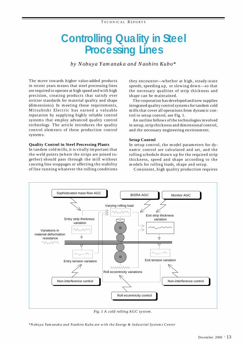
The corporation has developed and now suppliesintegrated quality control systems for tandem coldmills that cover all operations from dynamic con-trol to setup control, see Fig. 1.
An outline follows of the technologies involvedin setup, strip thickness and dimensional control,and the necessary engineering environment.
Setup ControlIn setup control, the model parameters for dy-namic control are calculated and set, and therolling schedule drawn up for the required stripthickness, speed and shape according to themodels for rolling loads, shape and setup.
Consistent, high quality production requires
Variations in material deformation
resistance
Sophisticated mass-flow AGCBISRA AGC Monitor AGC
Varying rolling load
Exit strip thickness variationEntry strip thickness
variation
Entry tension variation
Non-interference control Non-interference control
Roll eccentricity variations
Roll eccentricity control
Exit tension variation
Fig. 1 A cold rolling AGC system.

T E C H N I C A L R E P O R T S
Mitsubishi Electric ADVANCE14 ·
a detailed optimum rolling schedule that cov-ers everything from the initial slow-speed roll-ing to steady-state high-speed rolling, and thespeeding up and slowing down that precede andfollow it, and other operations at non-standardrolling forces, as when the weld point (the joinbetween two strips) passes through. There areseveral distinctive technologies used in achiev-ing this.
OPTIMUM-DISTRIBUTION SCHEDULE CALCULATION.A schedule is prepared that satisfies the require-ments of, and limitations on, the distribution ofpower, rolling forces, push-up forces, productquality, ease of operation, etc.
SETUP CALCULATION FOR HIGH-SPEED ROLLING.The setup calculations for steady-state high-speed operations are performed so as not to in-terfere with the planned path schedule for theinitial slow-speed start. This ensures that thepath schedule is maintained over the entirelength of the strip, stabilizing operations.
DYNAMIC SETUP (DSU). Automatic flying gaugecontrol is used to reduce the defective area atthe head of the strip following a weld or a shearoperation. Deviations in strip thickness at thehead of the next strip can be improved by reset-
ting the roll gap based on the actual tensions inthe preceding stand and the actual thicknessesat the entrance to the following stand.
Automatic Gauge Control (AGC)In tandem cold mills, strip thickness is influ-enced by the roll gap and the tension withinstands, and the extent of this influence is differ-ent for the preceding and following stands.Again, strip tension and thickness interfere withone another in complex ways via changes in theroll gap and the rolling speed.
The corporation’s AGC system takes accountof these process characteristics in using the fol-lowing distribution and allocation of controlfunctions, see Fig. 1 and 2.
HIGH-SPEED MASS-FLOW AGC. This uses stripthickness gauges and speeds for all stands, anduses controls strip thickness by tension or rollgap.
NON-INTERFERENCE CONTROL. This controls thechanges in strip thickness caused by changes instrip tension.
SELECTING THE OPTIMUM CONTROL MODE FORAGC. This selects the appropriate actuator (ten-sion or roll gap) on the basis of the calculated
Fig. 2 AGC control time chart
DSU
DSU
BISRA AGC
Monitor AGC
Roll eccentricity control
Accurate mass-flow AGC control (push-up force, tension)
Selecting optimum control mode
Non-interference control
DSU improves accuracy of thickness at head end
(transient part).
Uses thickness gauges and rev. counters for all stands, accurate mass-flow AGC, non-interference control, on-line identifi-cation of M, Q and NIC coefficients to improve steady-state strip thickness accuracy.
Following strip Preceding strip
FGC
FGC
T E C H N I C A L R E P O R T S
· 15December 2000
effective parameters for the correspondingschedule and automatically applies the opti-mum AGC mode.
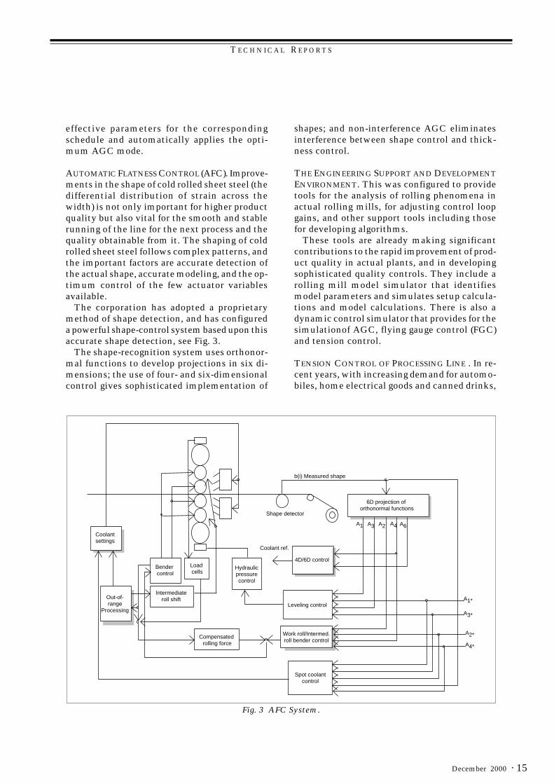
AUTOMATIC FLATNESS CONTROL (AFC). Improve-ments in the shape of cold rolled sheet steel (thedifferential distribution of strain across thewidth) is not only important for higher productquality but also vital for the smooth and stablerunning of the line for the next process and thequality obtainable from it. The shaping of coldrolled sheet steel follows complex patterns, andthe important factors are accurate detection ofthe actual shape, accurate modeling, and the op-timum control of the few actuator variablesavailable.
The corporation has adopted a proprietarymethod of shape detection, and has configureda powerful shape-control system based upon thisaccurate shape detection, see Fig. 3.
The shape-recognition system uses orthonor-mal functions to develop projections in six di-mensions; the use of four- and six-dimensionalcontrol gives sophisticated implementation of
shapes; and non-interference AGC eliminatesinterference between shape control and thick-ness control.
THE ENGINEERING SUPPORT AND DEVELOPMENTENVIRONMENT. This was configured to providetools for the analysis of rolling phenomena inactual rolling mills, for adjusting control loopgains, and other support tools including thosefor developing algorithms.
These tools are already making significantcontributions to the rapid improvement of prod-uct quality in actual plants, and in developingsophisticated quality controls. They include arolling mill model simulator that identifiesmodel parameters and simulates setup calcula-tions and model calculations. There is also adynamic control simulator that provides for thesimulationof AGC, flying gauge control (FGC)and tension control.
TENSION CONTROL OF PROCESSING LINE . In re-cent years, with increasing demand for automo-biles, home electrical goods and canned drinks,
Shape detector
6D projection of orthonormal functions
4D/6D control
Leveling control
Work roll/Intermed. roll bender control
Spot coolant control
Coolant ref.
Hydraulicpressurecontrol
Compensated rolling force
Load cells
Bender control
Intermediateroll shift
Coolantsettings
Out-of-range
Processing
b(i) Measured shape
A1*
A3*
A2*
A4*
A1 A3 A6A2 A4
Fig. 3 AFC System.

T E C H N I C A L R E P O R T S
Mitsubishi Electric ADVANCE16 ·
of the very thin strip and high speeds of linesrunning under low tensions. The corporation hasachieved the necessary sophisticated tensioncontrol technology for such continuous anneal-ing lines handling thin strip at high speeds. Ithas the following special characteristics.
Fluctuations in strip tension arise from dif-ferences in the speeds of adjacent rolls. These,in turn, arise from:1. Differences in the rapidity of responses of the
different rolls when changing speeds;2. Movements in the entry and delivery loopers
when changing speeds of entry and deliverysections;
3. Aerodynamic or hydrodynamic resistancecaused by air, water, etc.
4. Mechanical losses in the drive system; and5. Bending losses in the strip.
To suppress fluctuations in tension, each rollmust rotate at the same speed, and the accelera-tive response ωc must be improved. However,the helper rollers within the furnace have muchlarger inertias than motors, and it is thereforeimpossible to greatly increase the values of ωc.
Here, improvements were made by the effec-tive adoption of reference-model following con-trol for the inverters. Additionally, other factorswere investigated for each roller, taking intoconsideration its function, and consistency wasassured by adopting the appropriate form of con-trol for each one of them. This system is shownin Fig. 4.
Quality control is the heart of the large andcomplex systems used to control modern cold-rolling mill plants and steel processing plant. Awide range of control technologies and a longtrack record in the steel industry give MitsubishiElectric an advantage in serving the need forthese increasingly important systems. ❑
Reference1. S. Takayanagi, S. Hamada: Electrical Equipment for Steel
Processing Linies, ADVANCE, 79, No. 6, 5~7 (1997)
Fig. 4 Strip control functions.
Entry loop tower Annealing furnace section
Stable long-term operation, free from strip "walking"breakage and heat buckling.
Shockless speed referenceTorque compensation for smooth transferof tension settingOptimum mechanical loss compensationLoad balance control with inertiacompensation.Droop compensationOptimum control of tension changes
Carriage automatic speedregulator control Looper electrical tie controlDeflector roll driveInertia compensationMechanical loss compensationTension feedback control
Carriage automatic speedregulator controlLooper electrical-tie controlDeflector roll driveInertia compensationMechanical loss compensationTension feedback control
Individually driven AC motors with reference-model following control and adaptive-model following control are used throughout. Uniform automatic speed regulator (ASR) response (rad/s) is maintained through entire sections and real tension feedback control is used.
Delivery loop tower

T E C H N I C A L R E P O R T S
· 17December 2000
*Hiroyuki Masuda and Masaru Toyoda are with the Energy & Industrial Systems Center.
by Hiroyuki Masuda and Masaru Toyoda*
Variable-Speed Drive Systems forSteel Plants
Since the mid-1990s, the shift to the use of ACvoltage inverters in driver equipment in steelmills has expanded to encompass all processesin the steel mills, including the critical hot-roll-ing equipment. The development of six-inchGTO elements, six-inch GCT elements, andthree-level control technology has lead to largerinverters with better performance. There havealso been advances in low-voltage IGBT invert-ers and DC Leonard equipment.
New Drive Equipment (Table 1)In AC drive equipment, the MELVEC 1200N/NS two-level IGBT inverter is used in mid- andsmall-capacity auxiliary drive applications, andthe MELVEC 2000N three-level IGBT inverteris used in high-capacity auxiliary equipment andin low-capacity main drives. The MELVEC1200N/NS can house a maximum of 12 invert-ers in cabinets 600mm wide (with a maximumpower of 18kVA), or eight inverters in cabinets800mm wide (with a maximum power of75kVA). The MELVEC 2000N is 40% smallerthan conventional equipment.
In order to ensure the highest possible perfor-mance, all of the IGBT inverters use 32-bit RISCCPUs, allowing excellent controllability whileproviding a uniform control method. The
MELVEC 3000 series of GTO inverters has beenadded for high-capacity auxiliary equipment andmain drive applications. GCT inverters havealso been added to the series.
The new MELNARD CF-TD, CF-RD, and CF-UD Leonard equipment have the same range ofapplication as the earlier equipment, and can beused in applications with capacities rangingfrom 30kW to 6,673kW. These items of AC/DCdrive equipment provide excellent current re-sponsiveness (500rad/sec or more) while provid-ing open Windows[1] compatibility, affording ahigh level of uniformity in control and mainte-nance functions.
GTO/GCT InvertersMitsubishi Electric Corporation began applyinggate turn-off thyristor (GTO) inverters to steelmills in 1993, and began shipping six-inch GTOinverters in 1994. Innovations since that timehave increased the level of performance of theproduct, and voltage inverters containing the six-inch GTO inverters have become the establishedprimary drive equipment in steel mills. Thenumber of units has increased rapidly, with ship-ments already in excess of 100 sets.
As shown in Fig. 2, the third-generation prod-uct, the MELVEC-3000 A, has a 50% smaller
Table 1 Specifications for drive equipment for steel mills
yrogetactcudorP retrevniTBGIlevel-2 retrevniTBGIlevel-3 retrevniTCG/OTGlevel-3 dranoeLretsiryhT
ledoM SN/N0021CEVLEM N0002CEVLEM C/A0003CEVLEM DU/DR/DT-FCDRANLEM
)Wk/AVk(egnaryticapaC 0021~5.4 0063~0051 00002/00001 3766~03
)V(egatlovtupnI 006/003 0221 0543/0033 0221/077/005
)V(egatlovtuptuO 024/012 048 0593/0063 0221/077/005
)zH(ycneuqerftuptuO 09~ 06~ -
)%(noisicerplortnocdeepS 10.0
esnopserlortnoctnerruC)s/dar(
005 006 005
esnopserlortnocdeepS)s/dar(
06 03
gninekaewdleiffoegnaR 5:1
elppireuqroT 1~0 5.0~0 0
gnilooC riadecroF retaW riadecroF

T E C H N I C A L R E P O R T S
Mitsubishi Electric ADVANCE18 ·
installed footprint than the earlier model, andis 40% lighter; the efficiency of the equipmenthas reached the 97% level.
Advances have also been made in the controlequipment. Although in the past some 15 cir-cuit boards were required for the controller, thisnumber has been reduced to a total of fourboards—two boards for the converter and twofor the inverter. This was achieved by the use ofsurface-mount components, and by using awider range of ASICs. Reducing the number ofboards in the controller has not only resulted infurther improvements in reliability levels butalso increased maintainability. The field-thyrister rectifiers that are required when per-forming synchronous motor drive have also beenmade smaller through the conversion fromforced-air cooling to water cooling, where thecontrol unit and field-thyrister rectifiers havebeen combined into a single cabinet. The use ofwater cooling in the field-thyrister rectifiers hasalso reduced the load on the air conditioning inthe power room.
The corporation has also successfully completedthe commercial release of its gate-commutatedturn-off thyrister (GCT) inverter, the MELVEC3000C, using six-inch GCT (which are an improve-ment on the GTO).
The GCT inverter eliminates the snubber cir-cuit and the snubber energy regeneration cir-cuitry, thereby reducing the number of parts inthe equipment. The effect has been further in-
creases in reliability levels and efficiencies (tak-ing the latter over 98%). The six-inch GCT in-verter is used with the controller equipment andthe main circuit cabinet of the third-generationGTO inverter (the MELVEC 3000A). Althoughthe main circuit block is different, it is compat-ible structurally with the other, including thepositions of the terminals. This commonizationallows the new product to inherit the high reli-ability levels that have been developed through-out the long history of the GTO inverters. Fig. 1shows a picture of the MELVEC 3000C.
Table 2 Improvements in 6-inch GTO/GCT inverter
Fig. 1 The MELVEC-3000 C GCT inverter
noitarenegtcudorP OTGnoitareneg-ts1 OTGnoitareneg-dn2 retrevniOTGnoitareneg-dr3 TCG
ledoM 0003-VM N0003-VM A0003-VM C0003-VM
ezistenibactiucricniaM)mm,DxWxH( 0002x0009x0562 0002x0006x0562 0081x0084x0052 0081x0084x0052
ezistenibactiucriclortnoC 0301x008x0032 0002x0001x0562 0081x0001x0052 0081x0001x0052
ezistenibacreticxedleiF)gnilooc(
0321x0021x0032)riadecrof( )retaw(tenibaclortnocnidedulcnI
sdraoblortnocniaM sdraob51~41 sdraob4
ycneiciffE %69 %69 %79 %89revO
stnempihstsriF 4991 8991/hcraM 9991/hcraM 0002/rebotcO

T E C H N I C A L R E P O R T S
· 19December 2000
New Applications for PWM ConvertersThere is an increasing number of exampleswhere PWM converters have been used toachieve clean power sources (i.e., power sourceswith high power factors and low harmonics).
The use of PWM converters in modernizationof existing equipment makes it possible to elimi-nate all or most of the power compensatingequipment such as static capacitors, producinga variety of benefits such as smaller footprints,reduced maintenance work, and stabilized sys-tem operation. Additionally, because this in-creases the power factor, the use of PWMconverters in modernization can increase thecapacity of the motors by about 30% withoutrequiring increased capacity in the power-sup-ply equipment.
PWM converters have the benefit of flexiblecontrol of the input power factor, and leadingpower-factor operation is enabled. The laggingreactive power in the system is absorbed, mak-ing it possible to improve the power factor.
PWM converters have inherently very low lev-els of the low-order harmonics arising in thyris-tors. Additionally, when multiple PWMconverters are used in the same system (such asfound in tandem drive mills and twin drivemills), the harmonics can be canceled out byjointly controlling the PWM pulses to reducethe harmonic levels still further.
New Control FunctionsThe application of group control to table mo-tors in rolling equipment has become common-place. Table drives require a high torque outputsat low speed region. These requirements are ful-filled through the use of a speed sensor-less vec-tor control method. Improvements in the controlalgorithms in the MELVEC-1200N/NS have ledto increases in the number of applications ofsuch units. Fig.2 shows an actual waveform froma case where this group control was used. In typi-cal motors, speed sensors have been used tomeasure the behavior of the motors. However,acceleration in the electrical current limit sta-tus based on accelerative commands is nowpossible, and the match with the estimatedspeed has been verified in the various motors.
Sometimes there have been interruptions tooperations when thyristor converters andcycloconverters were used, such as when therewere commutation faults or blown fuses when
Speed reference 125r/m/div
Inferred speed feedback 125r/m/div
Second motor actual speed 125r/m/div
nth motor actual speed 125r/m/div
Torque current feedback value 100%/div
Second motor actual current 25A/div
nth motor actual current 25A/div
Inverter output current 385A/div
0
0
0
0
0
Fig. 2 Measured waveforms during group control
Fig. 3 Instantaneous voltage drop test results
Input voltage(100%div)
Convertereffective inverter current(50%div)
Motor speed(50%div)
Motor torque current(50%div)
0
0
0
Inverter output voltage
Inverter output current
50ms

T E C H N I C A L R E P O R T S
Mitsubishi Electric ADVANCE20 ·
the power supply fell below the rated voltage.Because the PWM converter has an electric cur-rent self-turn-off capacity, it has the advantageof allowing continuing operations even whenthere has been a dip in power-supply voltage.
Fig. 3 shows a chart that was used to confirmcontinuing operations when there was a simu-lated voltage dip, indicating that the highly re-sponsive control allowed the continuation ofstable operations even given an instantaneouspower dip.
Designs have been produced for plants wherevoltage dips due to lightning activity are com-mon; here, the use of PWM converters in thepower supply-side converter equipment withmain GTO inverters and auxiliary IGBT invert-ers will allow continued operation even given40% voltage dips for 0.1 seconds.
Mitsubishi Electric is proud to have pioneeredadvances in variable-speed control and powerelectronics that now serve in many of the mostadvanced steel-making plants in the world,providing the operators with greater economy,higher and more consistent quality, and reli-able operation even in the face of major volt-age dips. ❑

T E C H N I C A L R E P O R T S
· 21December 2000
*Kazuo Sena and Shigehiko Matsuda are with the Energy & Industrial Systems Center
by Kazuo Sena and Shigehiko Matsuda*
Computer Systems for ControllingSteel Plants
The iron and steel industry is calling for the cre-ation of open industrial computer systems (ICS),and for systems that are smaller and more easilymaintained than the systems of the past. This ar-ticle describes Mitsubishi Electric Corporation�sMR series of control computers for mission-criti-cal applications, and the Mitsubishi Windows[1]
System for Steel Plants (MWS) series of open-sys-tem control computers, describing the features ofthe systems, configuration concepts, the open soft-ware, and the maintenance support functions.
Computer systems used for controlling iron andsteel plants focus on appropriate system archi-tectures for each of the respective domains inwhich the systems are used, and there has beenrapid progress in both opening and right-sizingthese systems.
Systems have already been configured using thisapproach in the lower systems in rolling mills,even to the point that future applications to therolling lines themselves are being considered.
Computer systems for plant control today re-quire more than the already essential real-timeresponse and high reliability; system opennessmust now be added to the list. In the iron andsteel industry, where plant and equipment is ag-ing from long years of use, there is also aparticularly insisent call for uninterrupted main-tenance.
This article discusses trends in computerizedcontrol systems for iron and steel plants, con-cepts for system configurations, and the featuresand structures of the MR series and MWS seriesindustrial computer systems.
Trends in Control Systems in Iron and SteelPlant Controllers: Towards EIC Integration andTotal-Information and Control SystemsConventionally, separate dedicated machines havebeen used for business computer (B), electricals(E), instrumentation (I), and computers (C), pro-viding rapid execution and high standards of ser-vice and availability. On the other hand, the 1990ssaw a movement towards EIC integration, allow-ing an enterprise to pool all of its data. LANs pro-vided the technological underpinning for thismovement, and acceptance accelerated as the
technologies became more sophisticated, and thesystems were integrated by the creation of com-mon process I/O (PIO) and human-machine inter-faces (HMIs: these usually consist of a graphicdisplay device such as a CRT and means of enter-ing control commands). A hierarchy of LANs hasalso emerged, ranging from the general to the morespecialized, and from Ethernet[2] to FDDI systems,each with its own specific uses. The data handledis more than just control data, including a varietyof operational and processing data, seeking to es-tablish comprehensive systems that embrace bothdata systems and control systems.
In the future it will be necessary to intercon-nect a variety of support systems (engineeringsupport, operational support, diagnostic support,maintenance support, software development sup-port, etc.) so as to form a data and control systemcapable of optimizing manufacturing throughoutthe plant. Client-server configurations are nowbeing used for the functions. Fig. 1 shows changesin information and control systems over time.
Computer Automation Systems in Iron- andSteel-Information Control
SYSTEM CONFIGURATION. The above move to-wards automation implies a variety of con-straints that must be addressed whenconfiguring actual systems. The system-configu-ration concept shown in Fig. 2 makes it pos-sible to select and provide more far-rangingsolutions. The system must include structuresbasic to the entire system, open-system struc-tures positioned as support systems, and theoverall system configuration must rigorouslyimplement right sizing.
Mitsubishi Electric, taking advantage of itswealth of experience in factory-control systems,offers the MR series of industrial computers asbase systems, and the MWS series of industrialPCs as peripheral and lower-level machines.
System Configuration Using the MR Series ofIndustrial Computers
MAINTAINING REAL-TIME RESPONSIVENESS AND
OPEN SYSTEMS. The MR series inherits the tried-

T E C H N I C A L R E P O R T S
Mitsubishi Electric ADVANCE22 ·
and-true real-time OS concept, maintaining real-time response and ease of system analysis whileadopting POSIX-based real-time UNIX[3] to pro-vide superior accessibility in an open system.
HIGH-SPEED CALCULATIONS. The highest levelof calculation performance is provided througha process computer equipped with leading-edgehigh-speed RISC processors.
IIMPROVED RELIABILITY (THE RAS FACTOR) AND
MAINTAINABILITY. The system secures highlevels of reliability, and ease of continuous op-eration and maintainability, meeting the re-quirement that this equipment should runcontinuously.
FLEXIBILITY OF SYSTEM CONFIGURATION. Controlsystems for iron and steel manufacturing mustinterconnect with business-computer systems,plant controllers, design systems, and a varietyof others. The full set of network functions inthe MR Series units can be used in flexibly con-figuring the required system.
For example, for systems that require a highdegree of real-time interactivity, the integratedcontrol bus (MDWS-600S1) can be selected,while in those systems where there is a greaterneed for the system to be open, Ethernet con-nections may be selected. Conversely, the FDDI(the Fiber Distributed Data Interface) for con-trol can be selected when both real-time respon-siveness and openness are required. Use of theother communications options makes it easy to
Fig. 1 Changes in information and control systems over time
Fig. 2 Approach to industrial computer systems
EIC Distributed System
Dedicated real-time OS
Dedicated CPU
Dedicated data way (about 16Mbps)
Control Center
EIC integrated system
Dedicated real-time OS/UNIX OS
Dedicated CPU
Dedicated data way (about 32Mbps)
General-use LAN(about 10MBPS)
Dedicated CPU
Dedicated data way (about 32Mbps)
General-use LAN(about 10MBPS)
EIC integration including supportsystems
Overall data/control system
High reliability
Real-time UNIX-type OS
UNIX OS
Windows OS
RISC-type multipurpose MPU
High speed LAN
ATM:155Mbps or high
FAST Ethernet:100 Mbps or higher
General-use LANs
Ethernet, FDDI
Movement towards open/right sizing systems.
Inclusion of multimedia technology
M50 SeriesM60 Series
MR Series
MWS Series
Sys
tem
Per
form
ance
Information/ControlCenter
EIC integrated system
Dedicated real-time OS/UNIX OS
Late 1980s~ Early 1990s~ Late 1990s~
Proprietary Technologies
Striving for improved real-time performance.
Striving for improved reliability.
Open Technologies
+ Coexistent with others
Selection and provision of broader systems
MR Series (real-time UNIX) MR2200 Series
MWS Series (Windows-NT) MWS1000 Series
Multipurpose UNIX server MU Series
Multipurpose serverMultipurpose sequencerOther (shift to the HMI
of PCs)
Opening of systemsRight-sizing of systems
T E C H N I C A L R E P O R T S
· 23December 2000
IMPROVED MAINTAINABILITY. This system securesa mean-time-to-maintenance (MTTM) similar tothat of conventional industrial computers. Front-panel maintenance makes it easy to replace partssubject to wear (filters, fans, disks, etc.).
Open-System SoftwareThe software requirements are for the use of anopen operating system (OS) compatible with mul-tiple vendors, responsiveness to cost reductions,and improvements in software productivity.
OS SELECTION. The critical requirements of theOS for iron and steel ICS systems are real-timeresponse, high-speed execution, and high reliabil-ity and maintainability. There is also the need foropen-system architecture to support flexibility insystem configuration. The use of open-type UNIXservers is also a possibility based on the growingscope of PC applications and in view of the needfor customer maintenance by customers overseas.OS application regions and their changes over timeare shown in Fig. 4.
MIDDLEWARE SELECTION. With respect to the ironand steel middleware that Mitsubishi Electric has
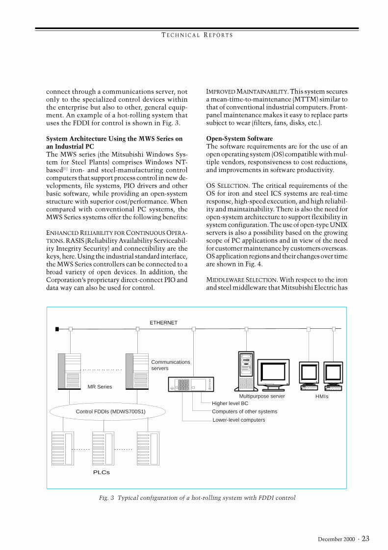
connect through a communications server, notonly to the specialized control devices withinthe enterprise but also to other, general equip-ment. An example of a hot-rolling system thatuses the FDDI for control is shown in Fig. 3.
System Architecture Using the MWS Series onan Industrial PCThe MWS series (the Mitsubishi Windows Sys-tem for Steel Plants) comprises Windows NT-based[1] iron- and steel-manufacturing controlcomputers that support process control in new de-velopments, file systems, PIO drivers and otherbasic software, while providing an open-systemstructure with superior cost/performance. Whencompared with conventional PC systems, theMWS Series systems offer the following benefits:
ENHANCED RELIABILITY FOR CONTINUOUS OPERA-TIONS. RASIS (Reliability Availability Serviceabil-ity Integrity Security) and connectibility are thekeys, here. Using the industrial standard interface,the MWS Series controllers can be connected to abroad variety of open devices. In addition, theCorporation�s proprietary direct-connect PIO anddata way can also be used for control.
Fig. 3 Typical configuration of a hot-rolling system with FDDI control
Control FDDIs (MDWS700S1)
MR Series
ETHERNET
Higher level BCHMIs
Computers of other systems
Lower-level computers
PLCs
Communicationsservers
Multipurpose server
T E C H N I C A L R E P O R T S
Mitsubishi Electric ADVANCE24 ·
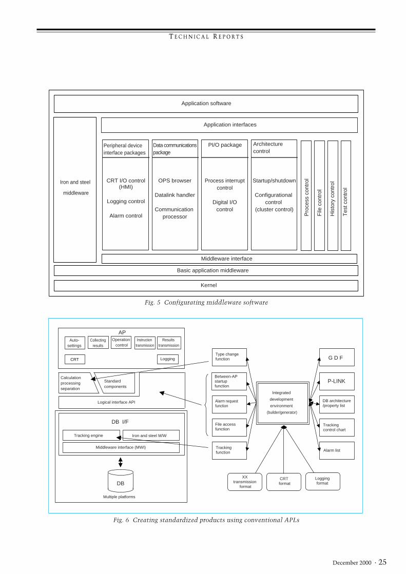
arise.The middleware software configuration shown
in Fig. 5 reflects all the above considerations
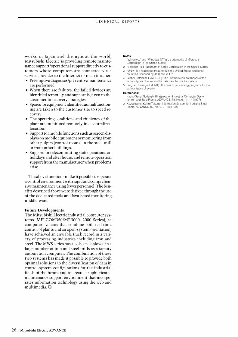
APL SELECTION. The following methods have beenused in order to create standardized products us-ing conventional APLs (which have been orientedtowards the engineers). These considerations areillustrated in Fig. 6,
l Simple arithmetical calculation processes areisolated
l Automatic generation of source code from thehigh level design such as GDFs[4], P-LINK[5], da-tabase structures and properties list, alarm lists,etc.
l Automatic generation of specifications for theparts generated automatically above.
l An integrated development environment inte-grating the above (builder/generator).
Facilitating MaintenanceAs a system by which to provide support for main-tenance rationalization in various iron and steel
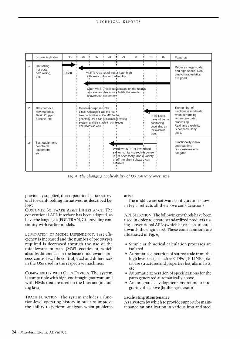
Fig. 4 The changing applicability of OS software over time
previously supplied, the corporation has taken sev-eral forward-looking initiatives, as described be-low:CUSTOMER SOFTWARE ASSET INHERITANCE. Theconventional APL interface has been adopted, ashave the languages (FORTRAN, C), providing con-tinuity with earlier models.
ELIMINATION OF MODEL DEPENDENCY. Test effi-ciency is increased and the number of prototypesrequired is decreased through the use of themiddleware interface (MWI) coefficient, whichabsorbs differences in the basic middleware (pro-cess control vs. file control, etc.) and differencesin the OSs used in the respective machines.
COMPATIBILITY WITH OPEN DEVICES. The systemis compatible with high-end imaging software andwith HMIs that are used on the Internet (includ-ing Java).
TRACE FUNCTION. The system includes a func-tion-level operating history in order to improvethe ability to perform analyses when problems
Scope of Application Features
Hot rolling,hot plate, cold rolling, etc.
Requires large scale and high speed. Real-time characteristics are good.
Test equipment/peripheral equipment, etc.
Functionality is lowand real-time responsiveness is not good.
OS60 MI-RT: Area requiring at least high real-time control and reliability.
Blast furnace, raw materials,Basic Oxygen furnace, etc.
Open VMS: This is used based on the results offshore and because it fulfills the needs of overseas customers.
General-purpose UNIXLinux: Although it lack the real-time capabilities of the MR Series,generally UNIX has a minimal operating system, and it is stable in continuous operations as well.
In the future, there will be no partitioning depending on the machine type.
The number of functions is moderate when performing large-scale data processing. Real-time capability is not particularly good.
Windows NT: For low-priced systems, high-speed response is not necessary, and a variety of off-the-shelf software can be used.
1
2
3
95 96 97 98 99 00 01 02
T E C H N I C A L R E P O R T S
· 25December 2000
Fig. 6 Creating standardized products using conventional APLs
Application software
Basic application middleware
Iron and steel
middleware
Application interfaces
Peripheral device interface packages
CRT I/O control(HMI)
Logging control
Alarm control
Data communications package
OPS browser
Datalink handler
Communication processor
PI/O package
Process interruptcontrol
Digital I/Ocontrol
Architecture control
Startup/shutdown
Configurational control
(cluster control)
Pro
cess
con
trol
File
con
trol
His
tory
con
trol
Tes
t con
trol
Middleware interface
Kernel
Fig. 5 Configurating middleware software
Auto-settings
Collectingresults
Operation control
Instruction transmission
Results transmission
CRT Logging
Calculation processing separation
Standard components
Logical interface API
Middleware interface (MWI)
Tracking engine Iron and steel M/W
Multiple platforms
Integrated
development
environment
(builder/generator)
DB architecture/property list
Tracking control chart
Alarm list
Type change function
Between-AP startup function
Alarm requestfunction
File accessfunction
Tracking function
XX transmission
format
CRT format
LoggingformatDB
AP
DB I/F
G D F
P-LINK
T E C H N I C A L R E P O R T S
Mitsubishi Electric ADVANCE26 ·
Notes:1. �Windows,� and �Windows NT� are trademarks of Microsoft
Corporation in the United States.2. �Ethernet� is a trademark of Xerox Corporation in the United States.3. �UNIX� is a registered trademark in the United States and other
countries, licensed by X/Open Co. Ltd.4. Global Database Flow (GDF): The flow between databases of the
various types of events in the data handled by the system.5. Program Linkage (P-LINK): The links to processing programs for the
various types of events.
References:1. Kazuo Sena, Noriyoshi Hiratsuka: An Industrial Computer System
for Iron and Steel Plants, ADVANCE, 79, No. 6, 11~14 (1997)2. Kazuo Sena, Keijiro Takeda: Information System for Iron and Steel
Plants, ADVANCE, 82, No. 3, 21~25 (1998)
works in Japan and throughout the world,Mitsubishi Electric is providing remote mainte-nance support/operational support directly to cus-tomers whose computers are connected via aservice provider to the Internet or to an intranet. l Preemptive diagnoses/preventive maintenance
are performed. l When there are failures, the failed devices are
identified remotely and support is given to thecustomer in recovery strategies.
l Spares for equipment identified as malfunction-ing are taken to the customer site to speed re-covery.
l The operating conditions and efficiency of theplant are monitored remotely in a centralizedlocation.
l Support for mobile functions such as screen dis-plays on mobile equipment or monitoring fromother pulpits (control rooms) in the steel millor from other buildings.
l Support for telecommuting staff operations onholidays and after hours, and remote operationsupport from the manufacturer when problemsarise.
The above functions make it possible to operatea control environment with rapid and comprehen-sive maintenance using fewer personnel. The ben-efits described above were derived through the useof the dedicated tools and Java-based monitoringmiddle-ware.
Future DevelopmentsThe Mitsubishi Electric industrial computer sys-tems (MELCOM350/MR3000, 2000 Series), ascomputer systems that combine both real-timecontrol of plants and an open-system orientation,have achieved an enviable track record in a vari-ety of processing industries including iron andsteel. The MWS series has also been deployed in alarge number of iron and steel mills as a factoryautomation computer. The combination of thesetwo systems has made it possible to provide bothoptimal solutions to the diversification of data incontrol-system configurations for the industrialfields of the future and to create a sophisticatedmaintenance support environment that incorpo-rates information technology using the web andmultimedia. q

T E C H N I C A L R E P O R T S
· 27December 2000
The primary requirements of control systems arethat they should provide fast, real-time responsesand achieve highly reliable operation. This haspreviously meant that each manufacturer at-tempted to use its own proprietary technology tomeet these requirements. However, in recentyears, an increasingly strong demand for more“open” control systems has been accompanied bygeneral technological advances that make itpossible to satisfy these requirements using opentechnology. Mitsubishi Electric Corporation hasdeveloped the new MELPLAC 2000 series of steel-plant control systems by actively adoptinginternational and industry-specific standardtechnologies. The system configuration is shownin Fig. 1.
Features of the ControllerMELPLAC 2000 controllers have adopted the
*Yuuji Takahashi and Keiichi Fuse are with the Energy & Industrial Systems Center.
by Yuuji Takahashi and Keiichi Fuse*
Control Systems for Steel Plants
General-purpose PC Mainframe OPS2000 OPS2000
Fast Ethernet information control network
HMI server
Engineering tools
Field network
MELPLAC 2000 Controller
Control network
Environment setting controllerMELSEC
Profibus, etc.
CC-Link
Distributed process I/O
Drive devices
MELSEC-NET
very latest control technologies to achievehighly reliable integrated control, both electri-cal (E) and instrumentation (I), as follows.
FASTER AND HIGHER CAPACITY CONTROL. Theseimprovements to control performance areachieved by combining high-performance pro-cessors and dedicated processors to execute ar-ithmetical bit operations in 0.09µs.Plant-oriented language (POL) supports up to 96kelectrical control steps and 320 instrument loopscan be handled. The adoption of a multiproces-sor configuration (supporting a maximum of fourCPUs) allows CPU performance to be upgradedby high-speed optimized load distribution.
STRUCTURED SOFTWARE. Top-down design and theencapsulation and modularization of softwaregreatly facilitates product design and production.
Fig. 1 A MELPLAC 2000 control system
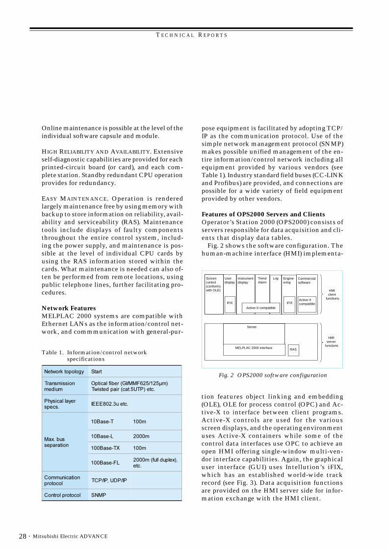
T E C H N I C A L R E P O R T S
Mitsubishi Electric ADVANCE28 ·
Online maintenance is possible at the level of theindividual software capsule and module.
HIGH RELIABILITY AND AVAILABILITY. Extensiveself-diagnostic capabilities are provided for eachprinted-circuit board (or card), and each com-plete station. Standby redundant CPU operationprovides for redundancy.
EASY MAINTENANCE. Operation is renderedlargely maintenance free by using memory withbackup to store information on reliability, avail-ability and serviceability (RAS). Maintenancetools include displays of faulty componentsthroughout the entire control system, includ-ing the power supply, and maintenance is pos-sible at the level of individual CPU cards byusing the RAS information stored within thecards. What maintenance is needed can also of-ten be performed from remote locations, usingpublic telephone lines, further facilitating pro-cedures.
Network FeaturesMELPLAC 2000 systems are compatible withEthernet LANs as the information/control net-work, and commmunication with general-pur-
Fig. 2 OPS2000 software configuration
Screen control(conforms with OLE)
User display
iFIX iFIX
Instrument display
Active-X compatible
TrendAlarm
Log Engine-ering
Active-X compatible
HMI client
functions
Server
RAS
HMI server
functionsMELPLAC 2000 interface
Commercial software
pose equipment is facilitated by adopting TCP/IP as the communication protocol. Use of thesimple network management protocol (SNMP)makes possible unified management of the en-tire information/control network including allequipment provided by various vendors (seeTable 1). Industry standard field buses (CC-LINKand Profibus) are provided, and connections arepossible for a wide variety of field equipmentprovided by other vendors.
Features of OPS2000 Servers and ClientsOperator’s Station 2000 (OPS2000) consists ofservers responsible for data acquisition and cli-ents that display data tables.
Fig. 2 shows the software configuration. Thehuman-machine interface (HMI) implementa-
tion features object linking and embedding(OLE), OLE for process control (OPC) and Ac-tive-X to interface between client programs.Active-X controls are used for the variousscreen displays, and the operating environmentuses Active-X containers while some of thecontrol data interfaces use OPC to achieve anopen HMI offering single-window multi-ven-dor interface capabilities. Again, the graphicaluser interface (GUI) uses Intellution’s iFIX,which has an established world-wide trackrecord (see Fig. 3). Data acquisition functionsare provided on the HMI server side for infor-mation exchange with the HMI client.
Table 1. Information/control networkspecifications
������������� ����
�����������������
���������������� �!�"��#���$%#��&�'�%��# ���������
������#���(&%�#��
%#��)%�*+,,,�
��!%-�����������
�.��/*� �**�
0.��/*� �***�
1�.��/**� �**�
0�.��/**�2�-�������" �***�
%#�
�����#������3��#�����
&��&4'2&��&3�
��#�����������3 &��

T E C H N I C A L R E P O R T S
· 29December 2000
Features of the Engineering ToolsThe engineering environment supports not onlythe macro control diagram (MCD) language, pri-marily for electrical control (see Fig. 4), but alsothe international standard language IEC61131-3 (see Fig. 5), with hardware settings, and a main-tenance environment integrated with aWindows environment to form an open envi-ronment. From an engineering perspective, anelectrical equipment database provides one-source control while high-level languages ap-propriate to the various objectives are used todescribe control regimes, to generate softwareautomatically, to provide for the transfer of in-formation on settings, and for monitoring. Inparticular, software visualizations, checkingfunctions for logical descriptions, and the auto-matic assignment of resources are among func-
Fig. 4 A typical MCD programming screen
tions supported to improve engineering effi-ciency. Again, the provision of remote mainte-nance capabilities enables engineering tools tobe used over the LAN or the public telephonenetwork connected to the control system, thusenabling the corporation to support user plant
maintenance directly from its maintenance ser-vice sites.
While the use of open systems has obvious ad-vantages for the end user, it also imposes newresponsibilities on control-system vendors.Mitsubishi Electric now offers a new generationof flexible and cost-effective solutions that usethe latest control technology to provide out-standing performance, high reliability, and greatease of maintenance. ❑
Fig. 3 A typical OPS2000 screen
Fig. 5 A programming screen using internationalstandard language
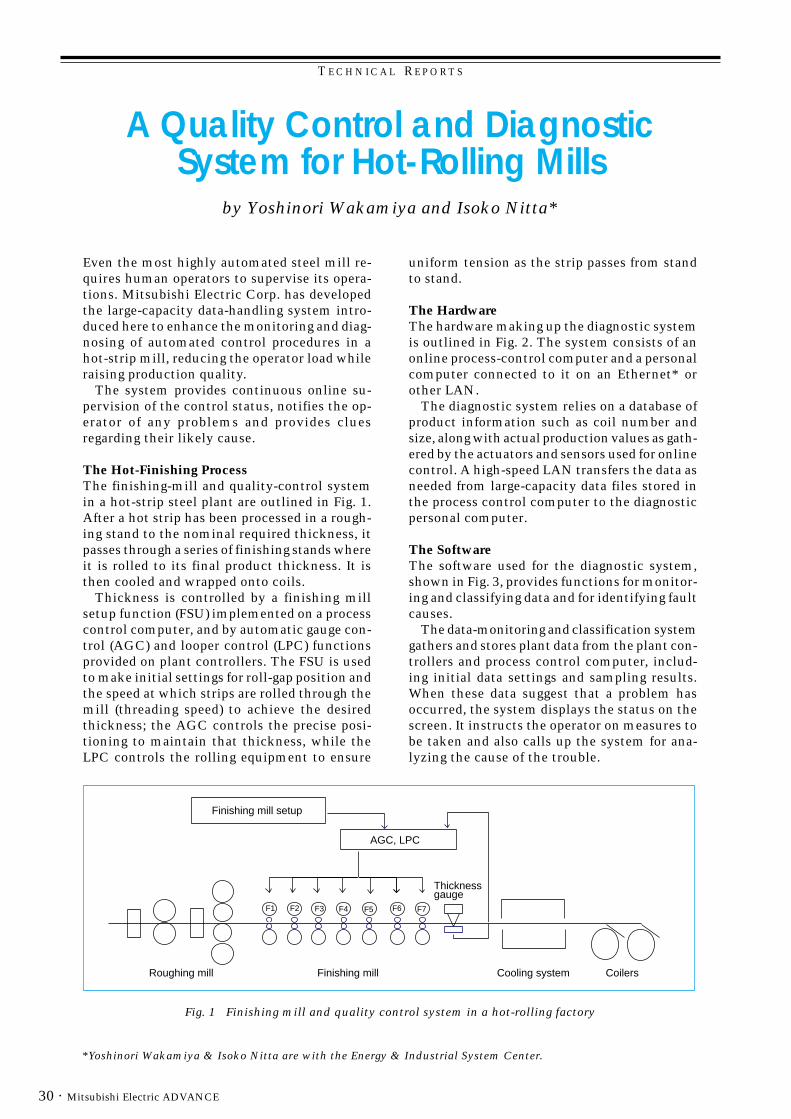
T E C H N I C A L R E P O R T S
Mitsubishi Electric ADVANCE30 ·
*Yoshinori Wakamiya & Isoko Nitta are with the Energy & Industrial System Center.
by Yoshinori Wakamiya and Isoko Nitta*
A Quality Control and DiagnosticSystem for Hot-Rolling Mills
Even the most highly automated steel mill re-quires human operators to supervise its opera-tions. Mitsubishi Electric Corp. has developedthe large-capacity data-handling system intro-duced here to enhance the monitoring and diag-nosing of automated control procedures in ahot-strip mill, reducing the operator load whileraising production quality.
The system provides continuous online su-pervision of the control status, notifies the op-erator of any problems and provides cluesregarding their likely cause.
The Hot-Finishing ProcessThe finishing-mill and quality-control systemin a hot-strip steel plant are outlined in Fig. 1.After a hot strip has been processed in a rough-ing stand to the nominal required thickness, itpasses through a series of finishing stands whereit is rolled to its final product thickness. It isthen cooled and wrapped onto coils.
Thickness is controlled by a finishing millsetup function (FSU) implemented on a processcontrol computer, and by automatic gauge con-trol (AGC) and looper control (LPC) functionsprovided on plant controllers. The FSU is usedto make initial settings for roll-gap position andthe speed at which strips are rolled through themill (threading speed) to achieve the desiredthickness; the AGC controls the precise posi-tioning to maintain that thickness, while theLPC controls the rolling equipment to ensure
Fig. 1 Finishing mill and quality control system in a hot-rolling factory
uniform tension as the strip passes from standto stand.
The HardwareThe hardware making up the diagnostic systemis outlined in Fig. 2. The system consists of anonline process-control computer and a personalcomputer connected to it on an Ethernet* orother LAN.
The diagnostic system relies on a database ofproduct information such as coil number andsize, along with actual production values as gath-ered by the actuators and sensors used for onlinecontrol. A high-speed LAN transfers the data asneeded from large-capacity data files stored inthe process control computer to the diagnosticpersonal computer.
The SoftwareThe software used for the diagnostic system,shown in Fig. 3, provides functions for monitor-ing and classifying data and for identifying faultcauses.
The data-monitoring and classification systemgathers and stores plant data from the plant con-trollers and process control computer, includ-ing initial data settings and sampling results.When these data suggest that a problem hasoccurred, the system displays the status on thescreen. It instructs the operator on measures tobe taken and also calls up the system for ana-lyzing the cause of the trouble.
Roughing mill Cooling system CoilersFinishing mill
Finishing mill setup
Thickness gauge
AGC, LPC
F1 F2 F3 F4 F5 F6 F7

T E C H N I C A L R E P O RT S
· 31December 2000
The cause-analysis function is activated onlywhen trouble occurs; it attempts to determinethe likely cause of the trouble by applying a di-agnostic rule base. It replicates the control sta-tus at the time the problem occurred by runninga control-model simulation that emulates theonline control system. By comparing this resultwith past observed data, the system can pinpointwhere a problem occurred in the control logic.
Process control computer
Control network
Personal computer
Controller Controller
Steel Plant
LAN
Fig. 2 Hardware configuration
of faults when the leading end of a strip is fedinto a finishing stand.
The diagnostic system consists of two mainfunctions, one for analyzing the status when aproblem occurred, and the other for identifyingthe cause.
Status analysis functionRolling faults in a finishing mill can occur whenexcessive strip tension between stands resultsin strip breakage, or when inadequate strip ten-sion leads to pinching and the like, causing therolling mill to decelerate (or be stopped by theoperator) due to the increased rolling force.
Essentially problems of this nature can becaught by monitoring tension and mill speed;but this system goes further, analyzing the pro-duction process based on collected data to de-termine how the strip breakage or decelerationoccurred.
First of all, it checks mill speed, rolling force,and looper height between stands to locate thestands where the problem arose. This prelimi-nary step reduces the amount of data that mustbe analyzed in the next step.
After the location has been found, it analyzesvarious data gathered upstream of that point af-ter rolling was started, determining the statesthat were passed through from the start of roll-ing.
Normally, problems of this sort occur for verybrief instants, making it difficult to detect themby human analysis of charts or other data. Thissystem is able to do so by time-checking ofsampled results data.
The flow of events leading up to a fault whenthe leading end of a strip passes through a millhas the relationship shown in the state transi-tion diagram in Fig. 4. These relational flowcharts and various state-transition conditionsare registered in a rule base for use in diagnosis.The system uses this rule base when carryingout its fault analysis.
Examples of collected data when a fault oc-curs are given in Fig. 5 and Fig. 6. Fig. 5 showsthe rolling force at the work side and drive sidebetween stands F6 and F7. Fig. 6 shows the looperangle between F6 and F7, the rolling speed at
Typical System ApplicationThe effectiveness of the diagnostic system is il-lustrated here by looking at a typical applica-tion, in which it is used to determine the cause
Fault diagnostic system running on PC
Data
Monitor and classify data Display
Rule base
Identify probable cause
Printer
CRT
LAN
Fig. 3 Software configuration
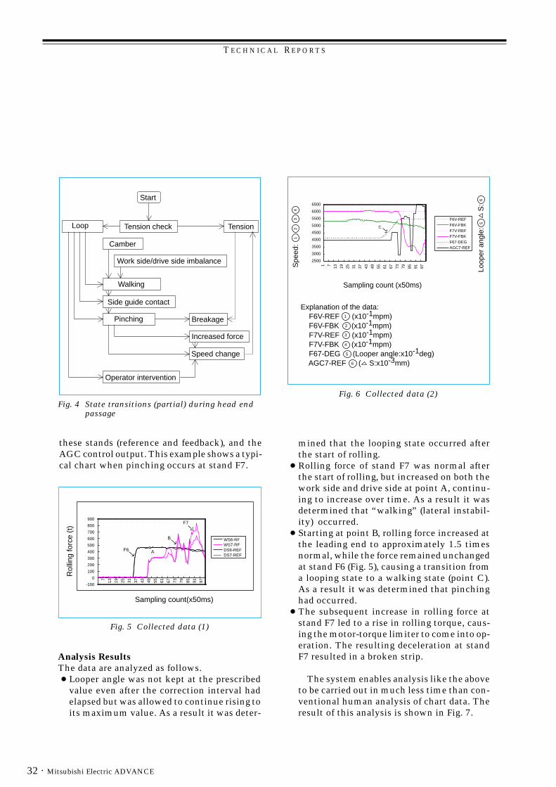
T E C H N I C A L R E P O R T S
Mitsubishi Electric ADVANCE32 ·
these stands (reference and feedback), and theAGC control output. This example shows a typi-cal chart when pinching occurs at stand F7.
mined that the looping state occurred afterthe start of rolling.
● Rolling force of stand F7 was normal afterthe start of rolling, but increased on both thework side and drive side at point A, continu-ing to increase over time. As a result it wasdetermined that “walking” (lateral instabil-ity) occurred.
● Starting at point B, rolling force increased atthe leading end to approximately 1.5 timesnormal, while the force remained unchangedat stand F6 (Fig. 5), causing a transition froma looping state to a walking state (point C).As a result it was determined that pinchinghad occurred.
● The subsequent increase in rolling force atstand F7 led to a rise in rolling torque, caus-ing the motor-torque limiter to come into op-eration. The resulting deceleration at standF7 resulted in a broken strip.
The system enables analysis like the aboveto be carried out in much less time than con-ventional human analysis of chart data. Theresult of this analysis is shown in Fig. 7.
Analysis ResultsThe data are analyzed as follows. ● Looper angle was not kept at the prescribed
value even after the correction interval hadelapsed but was allowed to continue rising toits maximum value. As a result it was deter-
Start
TensionTension checkLoop
Walking
Camber
Breakage
Side guide contact
Work side/drive side imbalance
Pinching
Increased force
Speed change
Operator intervention
Fig. 4 State transitions (partial) during head endpassage
Fig. 6 Collected data (2)
Fig. 5 Collected data (1)
Rol
ling
forc
e (t
)
Sampling count(x50ms)
A
7 13 19 25 31 37 43 49 55 61 67 73 79 85 91 97
WS6-RFWS7-RFDS6-REFDS7-REF
900
800
700
600
500
400
300
200
100
0
-100
F7
B
F6
Sampling count (x50ms)
F6V-REFF6V-FBKF7V-REFF7V-FBKF67-DEGAGC7-REF
Spe
ed:
Loo
per
angl
e:
S
:
Explanation of the data: F6V-REF (x10-1mpm) F6V-FBK (x10-1mpm) F7V-REF (x10-1mpm) F7V-FBK (x10-1mpm) F67-DEG (Looper angle:x10-1deg) AGC7-REF ( S:x10-3mm)
1 7 13 19 25 31 37 43 49 55 61 67 73 79 85 91 97
6500
6000
5500
5000
4500
4000
3500
3000
2500
C21
4
56
3
2
1
4
3
5
6

T E C H N I C A L R E P O RT S
· 33December 2000
Cause Identification FunctionThe above analysis shows that the rolling faultoccurred due to the looping state at the start ofrolling. To determine the real cause, however,it is necessary to identify which function (or op-erator) performed the operation that caused thelooping.
The main factors in looping are roll-gap posi-tion and rolling speed, and the functions relat-ing to these are the four below:
1. Control systems (AGC or LCP)2. Operator action (intervention)3. Equipment trouble4. Setup error
The basic rule for identifying fault causes hereis mass flow between stands. In the case of items1 to 3 above, account is taken of the effects ofeach control input on the mass flow designatedat setup. If this control input effect exceeds thetolerable amount (threshold), then the functionwith the greatest influence is the primary sus-pect.
If all the control inputs are within tolerance,setup error is the likely problem. In this case afurther comparison is made between the ex-pected rolling force at each stand in setup andthe actual measured force. This result, and the
actual mass-flow measurements, are used to de-termine whether the problem is in the forcemodel learning function, in the temperature pre-dictions (or entry temperature), or in the for-ward slip-ratio model. The rule base is appliedto this decision-making process.
In the example given in Fig. 5 and Fig. 6, theanalysis shows that this is not a control-systemor operator-intervention problem but setup er-ror. A further analysis of the setup error, com-paring the expected rolling force and actualmeasurements, shows that the cause of loopingbetween stands F6 and F7 is too great a stripthickness coming out of stand F6 and too littlecoming out of F7, due to overestimating the roll-ing force from F1 to F6 and underestimating atF7. The cause of the rolling force discrepancy isthat the temperature at the finishing mill entrywas below the lower limit and transformationoccurred between F6 and F7.
Future EnhancementsA fault-diagnostic system for hot-strip millingcontrol like that described here has been madepossible by recent advances in computer data-storage capacity and networking speeds. The sys-tem is still in the prototype-evaluation stage;but continued efforts will be made to enhanceits capabilities, making it applicable to onlineuse and improving its storing and handling ofmanufacturing parameters.
Systems of this nature are sure to play an in-creasingly important role in raising steel-plantefficiency and easing the operator load. The goalsof this development work are to realize a moreaccurate control model, accumulate more pre-cise knowledge for identifying fault causes, andultimately establish to technology for automati-cally reflecting the diagnostic results in controlinput. ❑
Note: Ethernet is a trademark of the U.S. company Xerox Corp.
Fig. 7 Diagnostic result screen (typical example)

TECHNICAL R EPORTS
Mitsubishi Electric ADVANCE34 ·
*Masayuki Sugiyama is with the Energy & Industrial Systems Center and Michihiko Hamaguchi with KOBE STEEL, Ltd.
by Masayuki Sugiyama and Michihiko Hamaguchi*
A Camber-Profile Gauge Using a LaserScanning and Light-Guide Detection
Edge Sensor
Controlling steel-plate camber (planar bending)in mill rolling is an important factor for main-taining high yield and preventing interruptionof the mill-rolling operation. We have developeda camber-profile gauge that employs a new high-resolution edge sensor, using laser scanning andlight-guide detection. This report describes thegauge and presents results of its application tocamber control.
Laser Scanning and Light-Guide DetectingEdge SensorEdge sensing is one of the most basic methodsfor measuring plate profile. Here we introduce anew method of edge sensing that uses high-reso-lution laser scanning and light-guide detectionin place of the conventional sensing by CCDcameras.
Edge-Sensor Measurement PrinciplesThe hardware configuration of the newly devel-oped edge sensor is shown in Fig. 1. A scanning
laser beam is applied to the plate and to a lightguide under the plate, in a direction perpendicu-lar to that in which the plate travels, by meansof a polygonal scanner. The laser beam is scat-
tered by a diffusion band inside the light guide,and the light guide is equipped with a photode-tector that detects this light at the edge.
The edge-detection method is illustrated in Fig.2. In this figure, the rise in the detector’s signal
reveals when the scanning laser beam entersthe light guide. By counting the number ofcounter signals between the start signal and therise of the detector’s signal, it is possible to de-tect the entry point of the laser beam and thusthe edge position of the plate.
Main Advantages of the Edge SensorConventional methods of measuring plate edgesare generally of the following three kinds.
1. Radiant energy detection: Cameras detect theenergy radiated from a hot steel plate.
2. Back-light detection: Light from a source un-der the plate reveals its edge positions to cam-eras above the plate.
3. Reflected light detection: Light is beamedonto the plate and cameras detect light re-flected from the plate.
A disadvantage of method (1) is that it cannotbe used to measure steel plates at low tempera-tures. Method (2), which requires mounting a
Fig. 1 Configuration of the edge sensor
Start point sensor
Polygonal scanner
Laser
Mirror
Plate
Moving direction
Diffusion band
Light guide
Photo detector
Start signal
time
Detector'ssignal
Counter signal
Edge position
Fig. 2 Edge detection method

TECHNICAL R EPORTS
· 35December 2000
light source under the plate, has the problemsof light-source reliability as well as installationspace and cost issues. The main problem withmethod (3) is the large variation in reflectivityfrom the plate due to surface roughness, water,etc., making it difficult to obtain stable mea-surements. The edge-sensing method using thecombination of laser scanning and light guideovercomes the disadvantage of (1) while repre-senting an improvement over methods (2) and(3).
This edge sensor has the advantages that it isnot affected by plate temperature or surfaceroughness; it has a compact structure; and it isnot affected by ambient water vapor. Applyingthis high-resolution edge-sensing technology asdescribed below, it is possible to measure platewidth and planar bending.
Camber Profile GaugeCamber, as noted above, is a planar bending thatcan occur along the length of a steel plate as itis milled by hot-rolling equipment. Because ofits effect on the yield of usable sheet product,online measurements of camber profile shouldprovide useful information for determining yieldand for use in milling control. Discussed belowis an application of the laser scanning and light-guide edge-sensing technology to camber-profilemeasurement.
Gauge ConfigurationThe camber-profile gauge we developed uses fouredge sensors arrayed along the plate in its direc-tion of travel. Each sensor consists of two laser-scanning mechanisms and one light guide todetect their light. This arrangement effectivelyeliminates the effects of vertical vibration, side“walk,” rotation or other noise caused by themoving plate. The noise from plate vertical vi-bration, warping and the like are eliminated bythe stereoscope-like twin-laser scanning mecha-nism used to detect the edge coordinates of theplate. The layout of the four edge sensors mea-suring the profile of the moving plate is illus-trated in Fig. 3. Edge sensors WS1 to WS3
measure camber profile, while the plate widthand side walk are measured by the combinationof edge sensors WS1 and DS (Here WS standsfor work side and DS for drive side.)
Algorithm Used to Calculate the CamberProfileAs a steel plate is transported through the mill-ing process, it is subject to vibration noise per-pendicular to its direction of travel and torotation noise along the direction of travel. Be-cause of these noise elements, it is not possiblefor one edge-sensor set to obtain accurate cam-ber-profile measurements of a moving plate, asshown in Fig. 4.
When the locus of a steel plate measured whileit is moving is represented as F(x,t), this F(x,t)includes a rotational fluctuation componentR(t).x and a side-walk (lateral fluctuation) com-ponent V(t), as expressed in Eq. 1.
F(x,t) = f(x) + R(t).x + V(t) ........................ Eq. 1
whereF(x,t): Locus of measured plate edgef(x): Strip camber profileR(t).x: Rotational fluctuationV(t): Side-walk (lateral fluctuation), andx: Strip longitudinal position
Fig. 3 Configuration of camber profile gauge
Edge sensor(WS1)
Edge sensor(WS2)
Edge sensor(WS3)
Edge sensor(DS)
Hot plate mill

TECHNICAL R EPORTS
Mitsubishi Electric ADVANCE36 ·
Camber-Profile Gauge FeaturesCamber could be measured in either of the fol-lowing ways: using two-dimensional CCD cam-eras or the like to obtain images of the entiresurface of the steel plate, or obtaining a seriesof measurements of the plate edge using theedge-measurement method described above, andcalculating the entire surface of the plate basedon these edge-position observations.
The first approach would require simulta-neously measuring the entire surface of a platethat might extend for tens of meters, which wouldbe difficult to do with the necessary resolution.
The second approach requires that noise com-ponents from the moving plate be eliminatedwhen calculating the overall profile from theseries of measurement results. The camber-pro-file calculation algorithm noted above can effec-tively eliminate such noise in the transport system.
The features of this algorithm are as follows.First, it makes possible measurement of the cam-ber profile of a moving plate independent of theinfluence of lateral and rotational fluctuation.Second, it can calculate with high accuracy evena profile that cannot be resolved by approximateanalysis using an n-order function.
Fig. 4 Measurement of edge position
To eliminate the noise components and findthe camber profile of the plate, we can makeuse of differential calculus and integral calcu-lus. First the rotational fluctuation componentR(t).x and lateral fluctuation component V(t)need to be eliminated as in Eq. 2, by second di-mensional differentiation of Eq. 1 with respectto longitudinal position x.
∂2F(x,t) = ∂2f(x) ................................ Eq. 2∂x2 ∂x2
Integral calculus is then applied to Eq. 2 tofind the camber profile f(x) as shown in Eq. 3.
f(x) = ∂2F(x,t) dx.dx ...................Eq. 3 ∂x2
Similar results to those in Eq. 2 can be obtainedby means of an algorithm using differential calcu-lus on the coordinates obtained by the three setsof edge sensors deployed along the direction oftravel. The resulting differential values are thenused to calculate the camber profile by an inte-grating process in accord with Eq. 3.
Steel plate
TravelEdge sensor
No transport fluctuation Lateral fluctuation (sidewalk) Rotational fluctuation

TECHNICAL R EPORTS
· 37December 2000
Effectiveness of Camber ControlThe basic steps in camber control are as follows.1. Measure the camber resulting from various
factors.2. Set the target thickness (drive side and work
side) for correcting camber on the next pass.3. Set the roll-gap positions on the drive side and
work side needed to achieve the target thick-ness.
It should therefore be possible to apply imme-diate feedback control on a plate undergoingrolling by installing camber-profile gauges alongthe mill, and in this way to enhance the effec-tiveness of measures against camber.
Fig. 5 illustrates the effect of this approach tocamber control, in which the camber-profilegauge described here is used and position con-trol is applied independently on the drive sideand work side of the mill. This shows that aver-age camber was reduced from approximately38mm before the camber control to around20mm after it was applied. It should be possibleto improve on this result further by refining thecontrol model.
The new sensing and control technologies intro-duced in this report, taking camber-profile gauge
development as an example, have great potentialfor raising steel-plant yield. That potential can beimproved even further by additional developmentwork, aimed at practical implementation of athickness-control model that applies the laser-scan-ning techniques discussed here. Such a modelwould incorporate further refinements in sensingand camber control, resulting in new advances inprocess control. ❑
Camber (mm)
Plate thickness :12 mmLength :30 m
Before camber control After control was applied
40
30
20
10
0
38
20
Fig. 5 Effectiveness of camber control using thistechnology
Country Address TelephoneU.S.A. Mitsubishi Electric America, Inc. 5665 Plaza Drive, P.O. Box 6007, Cypress, California 90630-0007 714-220-2500
Mitsubishi Electronics America, Inc. 5665 Plaza Drive, P.O. Box 6007, Cypress, California 90630-0007 714-220-2500Mitsubishi Consumer Electronics America, Inc. 2001 E. Carnegie Avenue, Santa Ana, California 92705 714-261-3200Mitsubishi Semiconductor America, Inc. Three Diamond Lane, Durham, North Carolina 27704 919-479-3333Horizon Research, Inc. 1432 Main Street, Waltham, Massachusetts 02154 617-466-8300Mitsubishi Electric Power Products Inc. Thorn Hill Industrial Park, 512 Keystone Drive, Warrendale, Pennsylvania 15086 412-772-2555Mitsubishi Electric Manufacturing Cincinnati, Inc. 4773 Bethany Road, Mason, Ohio 45040 513-398-2220Astronet Corporation 37 Skyline Drive, Suite 4100, Lake Mary, Florida 32746-6214 407-333-4900Powerex, Inc. Hills Street, Youngwood, Pennsylvania 15697 412-925-7272Mitsubishi Electric Research Laboratories, Inc. 201 Broadway, Cambridge, Massachusetts 02139 617-621-7500
Canada Mitsubishi Electric Sales Canada Inc. 4299 14th Avenue, Markham, Ontario L3R 0J2 905-475-7728Mitsubishi Electronics Industries Canada Inc. 1000 Wye Valley Road, Midland, Ontario L4R 4L8 705-526-7871
Mexico Melco de Mexico S.A. de C.V. Mariano Escobedo No. 69, Tlalnepantla, Edo. de Mexico 5-565-6269
Brazil MELCO do Brazil, Com. e Rep. Ltda. Av. Rio Branco, 123, a 1507, 20040, Rio de Janeiro 21-221-8343MELCO-TEC Rep. Com. e Assessoria Tecnica Ltda. Av. Rio Branco, 123, a 1507, 20040, Rio de Janeiro 21-221-8343
Argentina MELCO Argentina S.R.L. Florida 890-20º-Piso, C.P. 1005, Buenos Aires 1-312-6982
Colombia MELCO de Colombia Ltda. Calle 35 No. 7-25, Oficinas No. 1201/02, Edificio, Caxdac, Apartado Aereo 1-287-927729653, Bogotá
U.K. Mitsubishi Electric U.K. Ltd. Travellers Lane, Hatfield, Herts. AL10 8XB, England 1707-276100Apricot Computers Ltd. 3500 Parkside, Birmingham Business Park, Birmingham, B37 7YS, England 21-717-7171Mitsubishi Electric Europe Coordination Center Centre Point (18th Floor), 103 New Oxford Street, London, WC1A 1EB 71-379-7160
France Mitsubishi Electric France S.A. 55, Avenue de Colmar, 92563, Rueil Malmaison Cedex 1-47-08-78-00
Netherlands Mitsubishi Electric Netherlands B.V. 3rd Floor, Parnassustoren, Locatellikade 1, 1076 AZ, Amsterdam 20-6790094
Germany Mitsubishi Electric Europe GmbH Gothaer Strasse 8, 40880 Ratingen 2102-4860Mitsubishi Semiconductor Europe GmbH Konrad Zuse Strasse 1, 52477 Alsdorf 2404-990
Spain MELCO Iberica S.A. Barcelona Office Polígono Industrial “Can Magi”, Calle Joan Buscallà 2-4, Apartado de Correos 3-589-3900420, 08190 Sant Cugat del Vallés, Barcelona
Italy Mitsubishi Electric Europe GmbH, Milano Office Centro Direzionale Colleoni, Palazzo Perseo-Ingresso 2, Via Paracelso 12, 39-6053120041 Agrate Brianza, Milano
China Shanghai Mitsubishi Elevator Co., Ltd. 811 Jiang Chuan Rd., Minhang, Shanghai 21-4303030
Hong Kong Mitsubishi Electric (H.K.) Ltd. 41st Floor, Manulife Tower, 169 Electric Road, North Point 510-0555Ryoden Holdings Ltd. 10th Floor, Manulife Tower, 169 Electric Road, North Point 887-8870Ryoden Merchandising Co., Ltd. 32nd Floor, Manulife Tower, 169 Electric Road, North Point 510-0777
Korea KEFICO Corporation 410, Dangjung-Dong, K unpo, Kyunggi-Do 343-51-1403
Taiwan MELCO Taiwan Co., Ltd. 2nd Floor, Chung-Ling Bldg., No. 363, Sec. 2, Fu-Hsing S. Road, Taipei 2-733-2383Shihlin Electric & Engineering Corp. No. 75, Sec. 6, Chung Shan N. Rd., Taipei 2-834-2662China Ryoden Co., Ltd. Chung-Ling Bldg., No. 363, Sec. 2, Fu-Hsing S. Road, Taipei 2-733-3424
Singapore Mitsubishi Electric Singapore Pte. Ltd. 152 Beach Road #11-06/08, Gateway East, Singapore 189721 295-5055Mitsubishi Electric Sales Singapore Pte. Ltd. 307 Alexandra Road #05-01/02, Mitsubishi Electric Building, Singapore 159943 473-2308Mitsubishi Electronics Manufacturing Singapore Pte. Ltd. 3000, Marsiling Road, Singapore 739108 269-9711Mitsubishi Electric Asia Coordination Center 307 Alexandra Road #02-02, Mitsubishi Electric Building, Singapore 159943 479-9100
Malaysia Mitsubishi Electric (Malaysia) Sdn. Bhd. Plo 32, Kawasan Perindustrian Senai, 81400 Senai, Johor 7-5996060Antah MELCO Sales & Services Sdn. Bhd. 3 Jalan 13/1, 46860 Petaling Jaya, Selangor, P.O. Box 1036 3-756-8322Ryoden (Malaysia) Sdn. Bhd. 2nd Fl., Wisma Yan, Nos. 17 & 19, Jalan Selangor, 46050 Petaling Jaya 3-755-3277
Thailand Kang Yong W atana Co., Ltd. 15th Floor, Vanit Bldg., 1126/1, New Petchburi Road, Phayathai, Bangkok 10400 2-255-8550Kang Yong Electric Co., Ltd. 67 Moo 11, Bangna-Trad Highway, Km. 20 Bang Plee, Samutprakarn 10540 2-312-8151MELCO Manufacturing (Thailand) Co., Ltd. 86 Moo 4, Km. 23 Bangna-Trad, Bangplee, Semudparkarn 10540 2-312-8350~3Mitsubishi Elevator Asia Co., Ltd. Bangpakong Industrial Estate, 700/86~92, Moo 6 Tambon Don Hua Roh, 38-213-170
Muang District Chonburi 20000Mitsubishi Electric Asia Coordination Center 17th Floor, Bangna Tower, 2/3 Moo 14, Bangna-Trad Highway 6.5 Km, 2-312-0155~7(Thailand) Bangkawe, Bang Plee, Samutprakarn 10540
Philippines International Elevator & Equipment, Inc. Km. 23 West Service Road, South Superhighway, Cupang, Muntinlupa, 2-842-3161~5Metro Manila
Australia Mitsubishi Electric Australia Pty. Ltd. 348 Victoria Road, Postal Bag No. 2, Rydalmere, N.S.W. 2116 2-684-7200
New Zealand MELCO Sales (N.Z.) Ltd. 1 Parliament St., Lower Hutt, P.O. Box 30-772 Wellington 4-569-7350
Representatives
China Mitsubishi Electric Corp. Beijing Office SCITE Tower, Rm. 1609, Jianguo Menwai, Dajie 22, Beijing 1-512-3222Mitsubishi Electric Corp. Shanghai Office Room No. 1506-8, Shanghai Union Building 100, Yanan-East Street, Shanghai 21-320-2010
Korea Mitsubishi Electric Corp. Seoul Office Daehan Kyoyuk Insurance Bldg., Room No. 1204 #1, Chongno 1-ka, 2-732-1531~2Chongno-ku, Seoul
Viet Nam Mitsubishi Electric Corp. Ho Chi Minh City Office 8 B2, Han Nam Officetel 65, Nguyen Du St., 1st District, Ho Chi Minh City 8-243-984
MITSUBISHI ELECTRIC OVERSEAS NETWORK (Abridged)

MITSUBISHI ELECTRIC CORPORATIONHEAD OFFICE: MITSUBISHI DENKI BLDG., MARUNOUCHI, TOKYO 100-8310, FAX 03-3218-3455