vol. 5, issue 9, september 2016 prototype of remote...
TRANSCRIPT

ISSN(Online) : 2319-8753
ISSN (Print) : 2347-6710
International Journal of Innovative Research in Science, Engineering and Technology
(An ISO 3297: 2007 Certified Organization)
Vol. 5, Issue 9, September 2016
Copyright to IJIRSET DOI:10.15680/IJIRSET.2016.0509180 16697
Prototype of Remote Controlled Robot Vehicle to Scan Radioactive Contaminated Areas Ratongasoandrazana Jean Baptiste 1*, Raoelina Andriambololona 2, Gérard Rambolamanana 3,
Hery Andrianiaina 4, Rajaobelison Joël 5 P.G. Student, Department of Maintenance and Instrumentation, INSTN-Madagascar, Antananarivo, Madagascar1*
Full Professor, Department of Theoretical Physics, INSTN-Madagascar, B.P.4279, Antananarivo, Madagascar2
Full Professor, Institut Observatoire et Géophysique d’Antananarivo (IOGA), University of Antananarivo, Madagascar3
P.G. Student, Department of Maintenance and Instrumentation, INSTN-Madagascar, Antananarivo, Madagascar4
Professor, Department of Isotopic Hydrology, INSTN-Madagascar, B.P.4279, Antananarivo, Madagascar5
*Corresponding author
ABSTRACT: The ionizing radiations are not directly audible by the organs of sense of the human being. Maintenance and handling of sources of such ionizing radiations present some risks of very serious and often irreversible accident for human organism. The works of experimentation and maintenance in such zone also present the risks requiring some minimum of precaution. Thus, the main objective of this work is to design and develop (hard- and software) a prototype of educational semi-autonomous Radio Frequency controlled robot-vehicle based on 8-bit AVR-RISC Flash-microcontroller system (ATmega128L) able to detect, identify and map the radioactive contaminated area. An integrated video camera coupled with a UHF video transmitter module, placed in front of the robot, will be used as visual feedback control to well direct it toward a precise place to reach. The navigation information and the data collected are transmitted from the robot toward the Computer via 02 Radio Frequency Transceivers for peer-to-peer serial data transfer in half-duplex mode. A Joystick module which is connected to the Computer’s parallel port allows full motion control of the platform. Robot-vehicle user interface program for the PC has been designed to allow full control of all functions of the robot vehicles. KEYWORDS: ATmega128, LND7313 Geiger Muller detector, Robotics, microcontroller, radioactivity.
I. INTRODUCTION Nuclear is a topic in steady development in the world. There are also on the other hand risks and dangers because of the external irradiation, contamination, radioactive source leak in the nuclear reactor, apart from the influential and radioactive waste. Madagascar uses actually more and more of the radioactive sources in the industries, in the hospitals or in the mining exploitations. Most of these mentioned centers are not equipped with a real-time environmental monitoring system based on tele-operated vehicle with onboard radiation detectors able to perform detection, mapping, risk assessment and emergency response at contaminated areas, with minimum risk to human health. Local development of such kind of safety equipment seems to be the temporary solution for developing countries such as Madagascar. The environment in which evolves this first prototype is at present the horizontal cemented soil of our laboratory having 30m × 25m of surface.
II. RELATED WORK There are a wide variety of Unmanned Ground Vehicles (UGVs) in use today. These Robot-Vehicles are used to replace humans in hazardous situations, such as handling explosives and in bomb disabling vehicles, or where additional strength or smaller size is needed. Military applications include surveillance, reconnaissance, and target acquisition [7]. They are also used in industry in agriculture, mining, and construction [8].
ISSN(Online) : 2319-8753
ISSN (Print) : 2347-6710
International Journal of Innovative Research in Science, Engineering and Technology
(An ISO 3297: 2007 Certified Organization)
Vol. 5, Issue 9, September 2016
Copyright to IJIRSET DOI:10.15680/IJIRSET.2016.0509180 16698
UGVs are used in many emergency situations including Urban Search and Rescue (SAR), fire fighting, and nuclear response [9] [13]. Following the 2011 Fukushima Daiichi Nuclear Power Plant accident, UGVs were used in Japan for mapping and structural assessment in areas with too much radiation to warrant a human presence [10]. Portable radiation monitoring instruments developed around the series of LND7313 GM detectors are available on the markets [12]. Many of mobile controller robot projects were carried out using the ATmega128 AVR microcontroller [14]. This paper describes the hard- and software for the first prototype of Indoor Semi-Autonomous UGV to detect and Scan Radioactive Contaminated Areas developed at Madagascar-INSTN Instrumentation Lab.
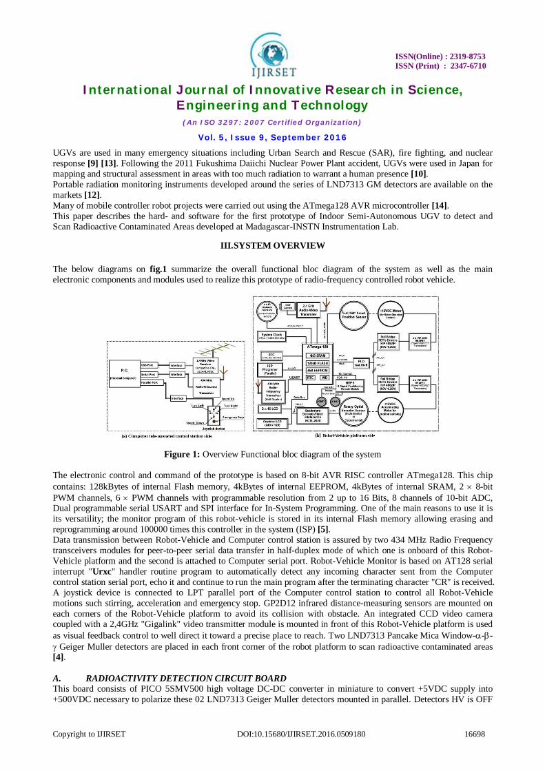
III. SYSTEM OVERVIEW The below diagrams on fig.1 summarize the overall functional bloc diagram of the system as well as the main electronic components and modules used to realize this prototype of radio-frequency controlled robot vehicle.
Figure 1: Overview Functional bloc diagram of the system The electronic control and command of the prototype is based on 8-bit AVR RISC controller ATmega128. This chip contains: 128kBytes of internal Flash memory, 4kBytes of internal EEPROM, 4kBytes of internal SRAM, 2 8-bit PWM channels, 6 PWM channels with programmable resolution from 2 up to 16 Bits, 8 channels of 10-bit ADC, Dual programmable serial USART and SPI interface for In-System Programming. One of the main reasons to use it is its versatility; the monitor program of this robot-vehicle is stored in its internal Flash memory allowing erasing and reprogramming around 100000 times this controller in the system (ISP) [5]. Data transmission between Robot-Vehicle and Computer control station is assured by two 434 MHz Radio Frequency transceivers modules for peer-to-peer serial data transfer in half-duplex mode of which one is onboard of this Robot-Vehicle platform and the second is attached to Computer serial port. Robot-Vehicle Monitor is based on AT128 serial interrupt "Urxc" handler routine program to automatically detect any incoming character sent from the Computer control station serial port, echo it and continue to run the main program after the terminating character "CR" is received. A joystick device is connected to LPT parallel port of the Computer control station to control all Robot-Vehicle motions such stirring, acceleration and emergency stop. GP2D12 infrared distance-measuring sensors are mounted on each corners of the Robot-Vehicle platform to avoid its collision with obstacle. An integrated CCD video camera coupled with a 2,4GHz "Gigalink" video transmitter module is mounted in front of this Robot-Vehicle platform is used as visual feedback control to well direct it toward a precise place to reach. Two LND7313 Pancake Mica Window--- Geiger Muller detectors are placed in each front corner of the robot platform to scan radioactive contaminated areas [4]. A. RADIOACTIVITY DETECTION CIRCUIT BOARD This board consists of PICO 5SMV500 high voltage DC-DC converter in miniature to convert +5VDC supply into +500VDC necessary to polarize these 02 LND7313 Geiger Muller detectors mounted in parallel. Detectors HV is OFF

ISSN(Online) : 2319-8753
ISSN (Print) : 2347-6710
International Journal of Innovative Research in Science, Engineering and Technology
(An ISO 3297: 2007 Certified Organization)
Vol. 5, Issue 9, September 2016
Copyright to IJIRSET DOI:10.15680/IJIRSET.2016.0509180 16699
when the PortD4 of the controller AT128 is Set to high logic state (1). And Detectors HV is ON when this PortD4 is Reset to low logic state (0). 04 Schottky diodes and CD40106N integrated circuit are used to shape and normalize the output signals of the detectors. These signals are then summed by NAND logic integrated circuit CD4011N. This summed signal is connected to Counter/Timer PortD7 of the AT128 for nuclear events counting. Below is the synoptic of the used Robot-Vehicle radioactivity detection circuit.
Figure 2: Synoptic of the Robot-Vehicle radioactivity detection circuit
B. IONISING RADIATION DETECTORS Two professional grade type LND7313 Pancake Mica Window--- Geiger Muller detectors are used in this prototype to locate and detect contamination surfaces. Its particularity is that it can detect the Alpha, Beta and Gamma radiations with the sensitivity of 60 pulses per second per 01mR.h-1 for the 60Co source [4]. Below are the photos of LND7313 detectors with their HVPS PCB as well as its gamma sensitivity curve related to 60Co.
Figure 3: Photos of LND7313 detectors with their HVPS board and its gamma sensitivity curve related to 60Co
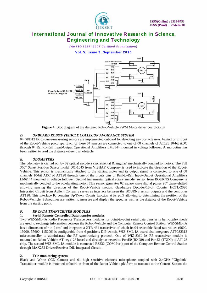
C. PWM MOTOR DRIVER BOARD This board is directly powered by the +12VDC – 7Ah Battery and allow to control two +12V – 3Nm – 2900 rpm DC Motors. One of the motors is used for speed while the second is for the direction. These motors are controlled from the Ports B0, B5 (OC1A), B1 and B6 (OC1B) of the controller AT128 using PWM commands. GAL16V8B PLD Integrated Circuit serves to generate the instantaneous logic states needed at the inputs of the 02 full bridge N-Channel FET drivers circuits HIP4082. Below is the bloc diagram of the circuit.
ISSN(Online) : 2319-8753
ISSN (Print) : 2347-6710
International Journal of Innovative Research in Science, Engineering and Technology
(An ISO 3297: 2007 Certified Organization)
Vol. 5, Issue 9, September 2016
Copyright to IJIRSET DOI:10.15680/IJIRSET.2016.0509180 16700
Figure 4: Bloc diagram of the designed Robot-Vehicle PWM Motor driver board circuit
D. ONBOARD ROBOT-VEHICLE COLLISION AVOIDANCE SYSTEM 04 GPD12 IR distance-measuring sensors are implemented onboard for detecting any obstacle near, behind or in front of the Robot-Vehicle prototype. Each of these 04 sensors are connected to one of 08 channels of AT128 10-bit ADC through 04 Rail-to-Rail Input-Output Operational Amplifiers LM6144 mounted in voltage follower. A subroutine has been written to read the distance value to an obstacle. E. ODOMETERS The odometry is carried out by 02 optical encoders (incremental & angular) mechanically coupled to motors. The Full 360° Smart Position Sensor model 601-1045 from VISHAY Company is used to indicate the direction of the Robot-Vehicle. This sensor is mechanically attached to the stirring motor and its output signal is connected to one of 08 channels 10-bit ADC of AT128 through one of the inputs pins of Rail-to-Rail Input-Output Operational Amplifiers LM6144 mounted in voltage follower. Second incremental optical rotary encoder sensor from BOURNS Company is mechanically coupled to the accelerating motor. This sensor generates 02 square wave digital pulses 90° phase-shifted allowing sensing the direction of the Robot-Vehicle motion. Quadrature Decoder/16-bit Counter HCTL-2020 Integrated Circuit from Agilent Company serves as interface between the BOURNS sensor outputs and the controller AT128. This interface IC contains Up/Down Counts function at its pin5 allowing to determining the position of the Robot-Vehicle. Subroutines are written to measure and display the speed as well as the distance of the Robot-Vehicle from the starting point. F. RF DATA TRANSCEIVER MODULES 1. Serial Remote Controlled Data transfer modules Two WIZ-SML-IA Radio Frequency Transceivers modules for point-to-point serial data transfer in half-duplex mode are used to exchange information between the Robot-Vehicle and the Computer Remote Control Station. WIZ-SML-IA has a dimension of 4 9 cm2 and integrates a XTR-434 transceiver of which its 04 selectable Baud rate values (9600, 19200, 57600, 115200) is configurable from 6 positions DIP switch. WIZ-SML-IA board also integrates AT90S2313 microcontroller to administrate the RF synchronizing protocol. One of WIZ-SML-IA RF transceiver module is mounted on Robot-Vehicle ATmega128 board and directly connected to PortE0 (RXD0) and PortE1 (TXD0) of AT128 chip. The second WIZ-SML-IA module is connected RS232 (COM Port) port of the Computer Remote Control Station through MAX232 Driver/Receiver DIL Integrated Circuit. 2. Tele-monitoring system Black and White CCD Camera and 01 high sensitive electrets microphone coupled with 2,4GHz "Gigalink" Transmitter module is mounted onboard in front of the Robot-Vehicle platform to transmit to the Control Station the

ISSN(Online) : 2319-8753
ISSN (Print) : 2347-6710
International Journal of Innovative Research in Science, Engineering and Technology
(An ISO 3297: 2007 Certified Organization)
Vol. 5, Issue 9, September 2016
Copyright to IJIRSET DOI:10.15680/IJIRSET.2016.0509180 16701
video of the environment in front of the Robot-Vehicle. The transmitted video/audio image is captured by the 2,4GHz "Gigalink" Video Receiver module (compatible PAL, SECAM and NTSC) connected to the Computer Control Station USB Port through the USBAV-190 Video Converter device. G. ROBOT-VEHICLE MOTION CONTROL DEVICE A Joystick device is conceived to full control of the Robot-Vehicle motion. This control device is connected to LPT parallel port of the Computer Control Station. It consists to permanently read the logic state of the internal register of the LPT1 port at $378+1 address when a of these 05 joystick switch buttons is pressed; the corresponding state coded into ASCII Character is sent to Robot-Vehicle platform to executing the Serial Interrupt Handler routine set on Robot Monitor Program. Below in fig.5 the simplified schematic of its circuit diagram.
Figure 5: Synoptic of the designed Joystick driver circuit board and computer LPT1 port registers properties tables
H. ROBOT-VEHICLE MONITOR PROGRAM BASCOM-AVR Compiler – IDE software is used for programming and debugging the Robot-Vehicle Monitor program stored in internal Flash memory of AT128 controller. This program is based on exchanging and handling the string of ASCII characters simultaneously arriving on the serial ports of Robot-Vehicle platform and the Computer Control Station. The table 1 below summarizes the main commands in ASCII characters between Computer and Robot-Vehicle [2].
Table 1: Main Commands in ASCII characters between Computer and Robot-Vehicle
Robot Monitor program was subdivided into several subroutines. All commands for controlling the Robot-Vehicle are based on the AT128 serial interrupt handler "Urxc" to waiting and detecting any incoming character sent from the Computer Control Station user interface program written in CEC TestPoint 4.1 object-oriented measurement software [1]. The receipt of the one of these particular characters provokes a jump to a specified subroutine or to instruction line corresponding to the interruption management subroutine. The main subroutines are:
- Hardware Initialization subroutine - Read Infrared distance-measuring sensors subroutine - Read Geiger Muller Counter subroutine - Read Rotary Encoder subroutine - Read Robot-Vehicle position subroutine - Read Direction sensor subroutine

ISSN(Online) : 2319-8753
ISSN (Print) : 2347-6710
International Journal of Innovative Research in Science, Engineering and Technology
(An ISO 3297: 2007 Certified Organization)
Vol. 5, Issue 9, September 2016
Copyright to IJIRSET DOI:10.15680/IJIRSET.2016.0509180 16702
Figure 6 below represents the flowchart of this serial interrupt "Urxc" hander routine.
Figure 6: Robot-Vehicle serial interrupt "Urxc" hander routine flowchart
1. Radioactive events counting subroutine The 02 onboard Robot-Vehicle Geiger Muller detectors are polarized by +500VDC when the Robot-Vehicle receives the "Z" character. This High Voltage is switched OFF by the "Y" character. Robot-Vehicle checks the G-M counter value when it received "G" character. The PortD7 (Timer2) of AT128 controller automatically counts all external rising pulses arriving on its input port. Timer0 read and reset to zero per the Counter2 value every second. Warning message will be sent to the Computer Control Station as soon as the counted radioactive countrate is bigger than the admissible threshold. Figure 7 below represents the flowchart of the Robot-Vehicle radioactive events counting interrupt subroutine.
Figure 7: Robot-Vehicle radioactive events counting interrupt subroutine flowchart

ISSN(Online) : 2319-8753
ISSN (Print) : 2347-6710
International Journal of Innovative Research in Science, Engineering and Technology
(An ISO 3297: 2007 Certified Organization)
Vol. 5, Issue 9, September 2016
Copyright to IJIRSET DOI:10.15680/IJIRSET.2016.0509180 16703
2. Robot-Vehicle Odometry subroutine The odometry is done by summing of small displacement of the Robot-Vehicle in the Cartesian plan x0y. We approximate the elementary trajectory travelled by Robot-Vehicle during regular time interval T on right line Li. We also supposes that the Robot-Vehicle keeps the same orientation that it had in the beginning of this element of trajectory and its speed remains constant on this trajectory element. Knowing its position at the instant i – 1, we looks for its position at the instant i with orientation i.
Figure 8: Robot-Vehicle motion in the X0Y plan
The distance travelled Pi (in meter) by the Robot-Vehicle between these 02 readings of the encoder during T is given by the above formula (1). And the total distance travelled Pi (in meter) by the Robot-Vehicle during the measurement time T is given by the formula (2). Below in Figure 9 the Odometry subroutine flowchart.
Figure 9: The Odometry subroutine flowchart
3. Robot-Vehicle IR Telemetry subroutine The Sharp GP2D12 IR distance-measuring sensors mounted onboard of Robot-Vehicle allow to detect the away objects between 5 to 80cm around the Robot-Vehicle platform. This sensor provides a non-linear voltage output in relation to the distance of object from it. Each voltage output of these 04 sensors are connected to one of 08 channels of AT128 10-bit ADC through 04 Rail-to-Rail Input-Output Operational Amplifiers LM6144 mounted in voltage follower. The Read_ir_sensor() subroutine in Robot-Vehicle Monitor program permanently reads the 04 corresponding LM6144 output voltages and respectively send "+" or "-" character to the Computer Control Station user interface program when one of the values is bigger or less than the threshold. There are 04 IR sensor LED status indicators on this user interface

ISSN(Online) : 2319-8753
ISSN (Print) : 2347-6710
International Journal of Innovative Research in Science, Engineering and Technology
(An ISO 3297: 2007 Certified Organization)
Vol. 5, Issue 9, September 2016
Copyright to IJIRSET DOI:10.15680/IJIRSET.2016.0509180 16704
program. It has green color when there is no object near the Robot-Vehicle platform and automatically changes in red color as soon as an object is present.
Figure 10: Positions of the 04 IR distance-measuring sensors on the Robot-Vehicle platform The flowchart in Figure 11 below shows the subroutine for reading the objects distance values from the Robot-Vehicle platform.
Figure 11: Subroutine for reading the Robot-Vehicle obstacles distance values
IV. REALIZATION OF ROBOT-VEHICLE AND SYSTEM A. THE ELECTRONIC CIRCUITS BOARDS EAGLE (Easy Applicable Graphics Layout Editor) for PCB design software has been used for tracing all the schematic circuits as well as the printed circuits boards for this first prototype. The design of these PCBs has been realized in double sided platted through technique allowing to separate or isolate the low power and high power side. Generally, Robot-Vehicle PCBs are connected between them by Ribbon cables. The 02 following Figures 12 and 13 show top view and perspective views of the realized prototype [6].

ISSN(Online) : 2319-8753
ISSN (Print) : 2347-6710
International Journal of Innovative Research in Science, Engineering and Technology
(An ISO 3297: 2007 Certified Organization)
Vol. 5, Issue 9, September 2016
Copyright to IJIRSET DOI:10.15680/IJIRSET.2016.0509180 16705
Figure 12: Top and Bottom views of the realized Robot-Vehicle prototype
Figure 13: Views from top and in perspective of the realized Robot-Vehicle prototype
B. THE INTEGRATED DEVELOPMENT ENVIRONMENT BASCOM-AVR IDE software with parallel ISP-Programmer STK 300 kit has been used for developing the Robot-Vehicle monitor program stored in internal Flash memory of AT128 controller. C. THE USER INTERFACE SOFTWARE CEC TestPoint 4.1 Object-Oriented Programming Software has been used for writing the Robot-Vehicle User Interface Software installed in the Computer Control station. This software allows full control of all functions of the Robot-Vehicle as acceleration and stirring as well as displaying of all relevant physical parameters as direction, speed, distance, obstacles, radioactive countrate and the video image transferred from the integrated video camera at the Robot-Vehicle platform side. Below in Figure 14 the screenshot of the developed user-interface for software [1].
Figure 14: The screenshot of the developed user-interface PC software for Robot-Vehicle

ISSN(Online) : 2319-8753
ISSN (Print) : 2347-6710
International Journal of Innovative Research in Science, Engineering and Technology
(An ISO 3297: 2007 Certified Organization)
Vol. 5, Issue 9, September 2016
Copyright to IJIRSET DOI:10.15680/IJIRSET.2016.0509180 16706
D. RADIOACTIVITY MEASUREMENT TESTS WITH THE PROTOTYPE 1. Backgrounds measurements The following table 2 represents the radioactivity backgrounds measured in different preset times with the LND7313 detectors on the Robot-Vehicle and display on Remote Controlled Robot-Vehicle user-interface computer software.
Table 2: Measured Robot-Vehicle radioactivity backgrounds on different preset times
2. Experimental measurement tests Comparative measurements tests with some sealed radioactive reference sources as 60Co, 137Cs, 241Am and 152Eu have been performed between the Robot-Vehicle prototype and the "Mini-rad series 1000" portable Geiger Counter. All these tests have been realized in the same condition (preset time= 180s, radioactive source vertically placed to 7cm in soil from detector). Summaries of the tests results realized in 09th December 2005 are respectively presented below in Table 3 and Curve 1.
Table 3: Summary of measurement tests results realized in 09th December 2005
Curve 1: Summary of measurement tests results realized in 09th December 2005 And the summaries of the tests results realized in 12th August 2016 are respectively presented below in Table 4 and Curve 2.

ISSN(Online) : 2319-8753
ISSN (Print) : 2347-6710
International Journal of Innovative Research in Science, Engineering and Technology
(An ISO 3297: 2007 Certified Organization)
Vol. 5, Issue 9, September 2016
Copyright to IJIRSET DOI:10.15680/IJIRSET.2016.0509180 16707
Table 4: Summary of measurement tests results realized in 12th August 2016
Curve 2: Summary of measurement tests results realized in 12th August 2016 E. COMPARISON BETWEEN THE ROBOT-VEHICLE POSITIONS MEASURED WITH RULER AND ONBOARD ROBOT-VEHICLE ODOMETER The following Curve 3 shows the differences between the Robot-Vehicle positions measured with the graduated ruler and those measured with odometer integrated on Robot-Vehicle platform and displayed on remote controlled Robot-Vehicle user-interface computer software.
Curve 3: Comparative curve between the Robot-Vehicle positions measured with ruler and the odometer integrated on integrated on Robot-Vehicle platform
ISSN(Online) : 2319-8753
ISSN (Print) : 2347-6710
International Journal of Innovative Research in Science, Engineering and Technology
(An ISO 3297: 2007 Certified Organization)
Vol. 5, Issue 9, September 2016
Copyright to IJIRSET DOI:10.15680/IJIRSET.2016.0509180 16708
V. CONCLUSION Standing in context of strengthening skills and capability of the technicians in developing countries within development and realization of modern and educational nuclear and scientific instruments adapted to their needs and situations: the realization, tests, and measures carried out show the quality and working state of the prototype (cf. fig.12 & fig.13). The total weight of this robot vehicle is 10kg. It mainly constitutes a platform in alloy of steel having 10mm of thickness of which the dimension is 450mm × 300mm. The design is therefore robust and operational. Robot position control subroutine program works in open loop. This means that path that the vehicle should follow to reach a desired place is uncertain. Experimental exercises results (cf. Curve 3) show that it is not possible to precisely determine the exact position of the robot in its environment by measuring the rotation angles of the front stirring wheel with these optical rotary encoders. It is due to the drift phenomena of the vehicle during its motion. Mainly these phenomena are due to the systematic errors generated by the optical rotary encoders and sliding of the robot wheels on the soil. According to the classical geometry model used, the mathematical integration of small element of displacement also integrates some errors so that vehicle position error grows or increases with time. This is one of reasons of the use of the one onboard integrated CCD Camera in front of the robot platform. It plays the role of servo-control to better toward the vehicle to the areas to reach. The experimental results represented in the tables 3,4 and Curves 1,2 show that there is a correlation between the measurements done with robot nuclear detectors and those measured with the portable analog dosimeter "Mini-rad series 1000".
ACKNOWLEDGEMENTS
We are grateful to Mr. Stefan Hollenthoner, former IAEA Expert at Instrumentation unit of the IAEA Laboratories in Seibersdorf, Vienna - AUSTRIA for supervising me along the realization of this prototype.
REFERENCES
[1] Capital Equipment Corporation (2001). Book. "TestPoint TM Software User’s Guide", Vol. 2, Seventh Edition. [2] Duval Jean-Pierre. "Compilateur et Système de Développement BASIC BASCOM-AVR ou apprendre à programmer les microcontrôleurs
RISC de l’Atmel, Version 1.11.7.0" (PDF). [3] Forschungszetrum Karlsruhe (1998). "Table des radionucléides". Handbook. [4] http://www.Indinc.com/gm/alpha/7313.htm. "LND 7313: A Pancake Mica Window-Alpha-Beta-Gamma Geiger Müller detector". [5] www.atmel.com/literature, "Datasheet of Atmega128L, a 8-bit AVR Microcontroller with 128K Bytes In-System Programmable Flash
memory", revision 2467J-AVR-12/03. [6] www.egr.msu.edu/classes/ece480/.../app_note_s11_dt5_kenji.pdf, "A Quick Guide to PCB Design in EAGLE", Application Note, April 2011. [7] Gage, Douglas (Summer 1995). "UGV HISTORY 101: A Brief History of Unmanned Ground Vehicle (UGV) Development Efforts" (PDF).
Unmanned Systems Magazine. 13 (3). Retrieved 3 September 2016. [8] Hebert Martial, Thorpe Charles, Stentz Anthony (2007). "Intelligent Unmanned Ground Vehicles". Volume 388 of the series The Springer
International Series in Engineering and Computer Science. Springer. pp. 1–17. ISBN 978-1-4613-7904-1. Retrieved 3 September 2016. [9] www.issuelab.org/resources/21683/21683.pdf . "Drones for Disaster Response and Relief Operations" (PDF). April 2015. [10] Siciliano Bruno, Khatib Oussama (2016). "Springer Handbook of Robotics". Springer. ISBN 9783319325521. Retrieved 3 September 2016. [11] Paul R. Steinmeyer, Health Physicist. "G-M Pancake Detectors: Everything You’ve Wanted to Know (But Were Afraid to Ask) " (PDF). RSO
Magazine, Volume 10, N° 5. 2005. [12] www.mirion.com/.../rds-80-radiation-contamination-survey/RDS_80A_Manual_v102.pdf, "RDS-80A Contamination Meter Users Manual
Version 1.02" (PDF). Document No. 2096 5741, Issue date: 29th September 2009. [13] "The 7th IARP Workshop HUDEM’2008 Final Program, 28-30 March, 2008, AUC, Cairo" (PDF). [14] Jong Hoon Ahnn. "The Robot control using the wireless communication and the serial communication" (PDF). Design Project Report for
Master of Electrical Engineering Program at Cornell University. Degree date: May 2007.

ISSN(Online) : 2319-8753
ISSN (Print) : 2347-6710
International Journal of Innovative Research in Science, Engineering and Technology
(An ISO 3297: 2007 Certified Organization)
Vol. 5, Issue 9, September 2016
Copyright to IJIRSET DOI:10.15680/IJIRSET.2016.0509180 16709
BIOGRAPHY
Ratongasoandrazana Jean Baptiste: has studied at Technical School of Mahajanga and obtained his TCE "A" level in Electrotechnics since 1986. He has his B.Sc. and B.Sc. "High level" degrees in General Physics from the University of Antsiranana in 1994. He received his M.Sc. degrees in Nuclear and Applied Physics from the University of Antananarivo with collaboration of INSTN-Madagascar in 1997. He is the Responsible of the maintenance and repair of the nuclear and scientific instruments used at the INSTN-Madagascar, and working on developing of microcontroller based system at the Maintenance and Instrumentation Department of INSTN-
Madagascar since 1998.
Prof. Raoelina Andriambololona: Full Professor, Founder and Director General of INSTN-Madagascar. He is fellow of many learned scientific societies and academics, The World Academy of Sciences for Developing Countries (TWAS), African Academy of Sciences (AAS), New York Academy, Malagasy Academy, American Physical Society, …. He is the author of many, about 250, scientific papers and of 2 university books in Mathematics and Quantum Mechanics. He has served as expert of IAEA, UNESCO, and OAU. Prof. Gérard Rambolamanana: Full Professor of Geophysics, Seismology, Acoustics and Electronics at the University of Antananarivo, Madagascar. He is the Head of the Laboratory of Seismology and Infrasound at the Institute Observatory of Geophysics of Antananarivo (IOGA), at the University of Antananarivo, and has been the Director of the IOGA since 2009. He has been involved in the Square Kilometer Array (SKA) in South Africa since 2009, and worked with the CTBTO since 2011. From 1992 to 2008 he was a Regular Associate then a Senior Associate at the International Centre for Theoretical Physics in Trieste, Italy. He is the author and co-author of several scientific papers related to seismology and infrasound in Madagascar.
Hery Andrianiaina: received the B.S. and M.Sc. degrees in Nuclear and Applied Physics from the University of Toliara in 1986 and the University of Antananarivo with collaboration of INSTN-Madagascar in 1999, respectively. Since 1994 up to now, he is the Head of the Maintenance and Instrumentation Department at INSTN-Madagascar, and involved on Research and Development activities in nuclear instrumentation.
Prof. Rajaobelison Joël: Professor in Nuclear Physics at the University of Antananarivo, Madagascar. He is the coach of the first author during the examination of his Thesis M.Sc. degree. He is the Technical Director for Development at INSTN-Madagascar since 1992 and the National Liaison Officer of IAEA for Madagascar since 2013.