vol. 5, issue 6, june 2016 gap-coupled rectangular ... · pdf filethe authors acknowledge...
TRANSCRIPT
ISSN(Online): 2319-8753 ISSN (Print) : 2347-6710
International Journal of Innovative Research in Science, Engineering and Technology
(An ISO 3297: 2007 Certified Organization)
Vol. 5, Issue 6, June 2016
Copyright to IJIRSET DOI:10.15680/IJIRSET.2015.0506198 11096
Gap-Coupled Rectangular Microstrip Antenna with CSRR Loaded on Driven and
Parasitic Patches for Wireless Communication Prashant R. T1., Vani R.M2, Hunagund P.V3
Research Student, Department of PG Studies and Research in Applied Electronics, Gulbarga University, Gulbarga,
Gulbarga, Karnataka, India1
Professor and Head, University Science Instrumentation Centre, Gulbarga University, Gulbarga,
Karnataka, India2
Professor, Department of PG Studies and Research in Applied Electronics, Gulbarga University, Gulbarga,
Gulbarga, Karnataka, India3
ABSTRACT: In this paper, we have presented the gap-coupled rectangular microstrip antenna with complimentary split ring resonator (CSRR) loaded on driven and parasitic patches. By using the combination of gap-coupling technique with CSRR structure, the antenna performance has been enhanced in terms of multiple resonances with virtual size reduction and improvement in the bandwidth. The combination of antenna with CSRR structure on driven patch is resonating at five particular frequency points with 2.04 GHz, 5.09 GHz, 8.24 GHz, 8.97 GHz, and 11.06 GHz. The size reduction of 65.38% has been achieved when compared to the size of the conventional microstrip antenna. IE3D Zeland simulation software has been used for the simulation of the proposed antennas and measured practically by using Vector Network Analyzer (VNA), which are in good agreement with each other. The proposed antennas are suitable for wireless communication. KEYWORDS: Gap-coupled, Driven and parasitic patch, CSRR, Miniaturization, Multiband, IE3D.
I. INTRODUCTION There is a considerable amount of interest in the development of dual and multiband microstrip patch antennas because of its versatile applications. In modern wireless communication systems, the microstrip patch antennas are commonly used in the wireless devices. Therefore, the miniaturization of the patch antenna becomes an important issue in reducing the volume of entire communication system. The common method for reducing the microstrip patch antenna size is to utilize a high permittivity dielectric substrate [1-2]. But, the antennas are more expensive, have less radiation efficiency and narrow bandwidth. To overcome the above drawbacks, many design techniques for the patch antenna have already been proposed. These antennas have the inserted slot, the meandering slots, the corrugation structure, iris structure and the shorting pin. However, all of these design strategies have limitations, which are complex structure and have low performance for miniaturization. So, the design methods of the miniaturized patch antenna with metamaterial technology [3-5] have been reported by some authors recently [6-8]. These would include the split ring resonators (SRR) or complimentary split ring resonator (CSRR) on the microstrip patch. In other words, the achievement of size reduction of antenna with the SRR and CSRR has special meaning in the field of microstrip antenna. In this paper, the miniaturized microstrip patch antenna with CSRRs is presented.

ISSN(Online): 2319-8753 ISSN (Print) : 2347-6710
International Journal of Innovative Research in Science, Engineering and Technology
(An ISO 3297: 2007 Certified Organization)
Vol. 5, Issue 6, June 2016
Copyright to IJIRSET DOI:10.15680/IJIRSET.2015.0506198 11097
II. DESIGN OF ANTENNA AND CSRR STRUCTURE
The geometry of the proposed conventional microstrip antenna is shown in Fig. 1, where a low cost FR4 dielectric material with relative permittivity (εr) of 4.4 and thickness (t) of 1.6mm is chosen. The conventional microstrip antenna is designed for 6 GHz with dimensions L= 11.33 mm and W= 15.25 mm, which is excited by simple 50 Ω microstrip feed having dimension of length Lf = 6.15 mm and width Wf = 3.05 mm using quarter wave length transformer of dimension length Lt = 4.90 mm and Wt = 0.50 mm for their impedance matching.
Fig. 1. Geometry of conventional microstrip antenna
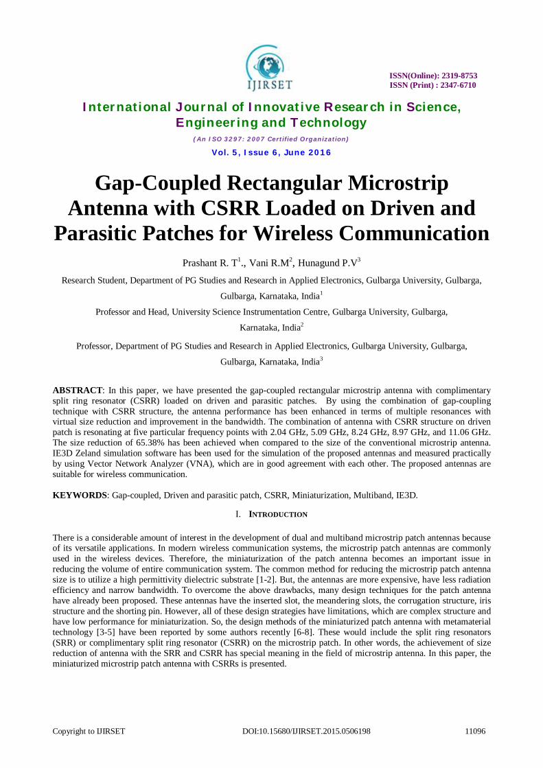
Further, the study is carried by coupling the conventional microstrip antenna with parasitic patches on both right and left sides. The gap between the radiating (i.e., driven) and parasitic patches is G = 1mm has been considered for all the cases. Fig. 2 shows all the four combination of proposed gap-coupled microstrip antennas with and without CSRR. In Case-1 only the coupling with plane parasitic patches is considered, Case-2 is a combination of CSRR loaded on driven patch with plane parasitic patches, Case-3 is a combination of CSRR loaded on parasitic patches with plane driven patch and Case-4 is a combination of CSRR loaded on both the driven and parasitic patches. Fig. 3 shows enlarged geometry of CSRR with dimensions SL =7.2mm, S =0.2mm, SW= 0.2mm and g= 0.2mm.
Fig. 2. Geometries of the proposed gap-coupled microstrip antennas of (a) Case-1 (b) Case-2 (c) Case-3 and (d) Case-4
ISSN(Online): 2319-8753 ISSN (Print) : 2347-6710
International Journal of Innovative Research in Science, Engineering and Technology
(An ISO 3297: 2007 Certified Organization)
Vol. 5, Issue 6, June 2016
Copyright to IJIRSET DOI:10.15680/IJIRSET.2015.0506198 11098
Fig. 3. Geometries of (a) A split ring resonator with the design parameters (b) complementary split ring resonator
III. RESULTS AND DISCUSSIONS
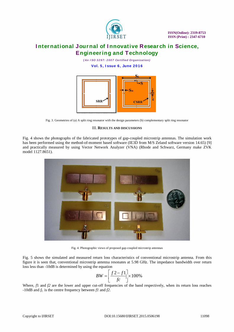
Fig. 4 shows the photographs of the fabricated prototypes of gap-coupled microstrip antennas. The simulation work has been performed using the method-of-moment based software (IE3D from M/S Zeland software version 14.65) [9] and practically measured by using Vector Network Analyzer (VNA) (Rhode and Schwarz, Germany make ZVK model 1127.8651).
Fig. 4. Photographic views of proposed gap-coupled microstrip antennas
Fig. 5 shows the simulated and measured return loss characteristics of conventional microstrip antenna. From this figure it is seen that, conventional microstrip antenna resonates at 5.98 GHz. The impedance bandwidth over return loss less than -10dB is determined by using the equation
2 1 100%f fBWfc
Where, f1 and f2 are the lower and upper cut-off frequencies of the band respectively, when its return loss reaches -10dB and fC is the centre frequency between f1 and f2.

ISSN(Online): 2319-8753 ISSN (Print) : 2347-6710
International Journal of Innovative Research in Science, Engineering and Technology
(An ISO 3297: 2007 Certified Organization)
Vol. 5, Issue 6, June 2016
Copyright to IJIRSET DOI:10.15680/IJIRSET.2015.0506198 11099
Fig. 5. Simulated and measured return loss characteristics of conventional microstrip antenna
Fig. 6 shows simulated and measured return loss characteristics of Case-1 antenna which is resonating at two particular frequency points 5.97 GHz (130MHz bandwidth) and 10.81GHz (920MHz). Fig. 7 shows simulated and measured return loss characteristics of Case-2 antenna which is a CSRR loaded driven patch with plane parasitic patch resonating at five particular frequencies with 2.04 GHz (50MHz), 5.09 GHz (160MHz), 8.24 GHz (490MHz), 8.97 GHz (260MHz), and 11.06 GHz (610MHz) and this is considered as optimized antenna in our work.
Fig. 6. Simulated and measured return loss characteristics of Case-1 antenna
ISSN(Online): 2319-8753 ISSN (Print) : 2347-6710
International Journal of Innovative Research in Science, Engineering and Technology
(An ISO 3297: 2007 Certified Organization)
Vol. 5, Issue 6, June 2016
Copyright to IJIRSET DOI:10.15680/IJIRSET.2015.0506198 11100
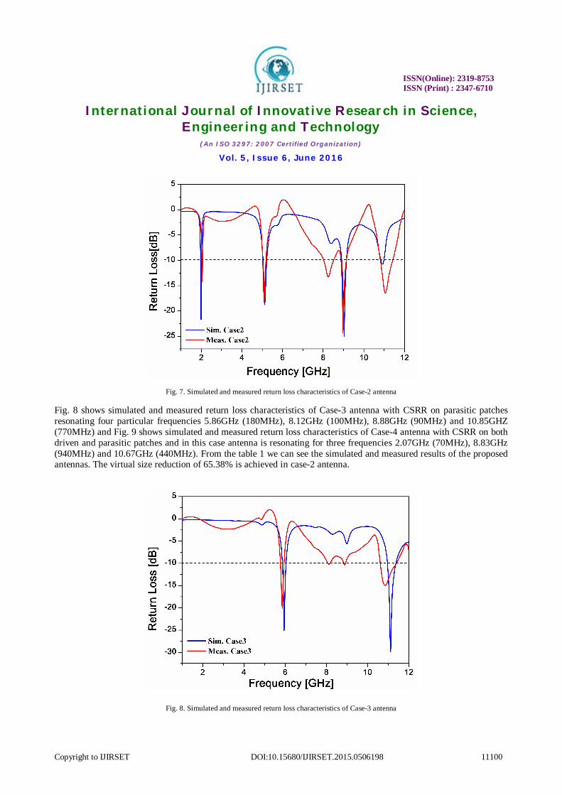
Fig. 7. Simulated and measured return loss characteristics of Case-2 antenna
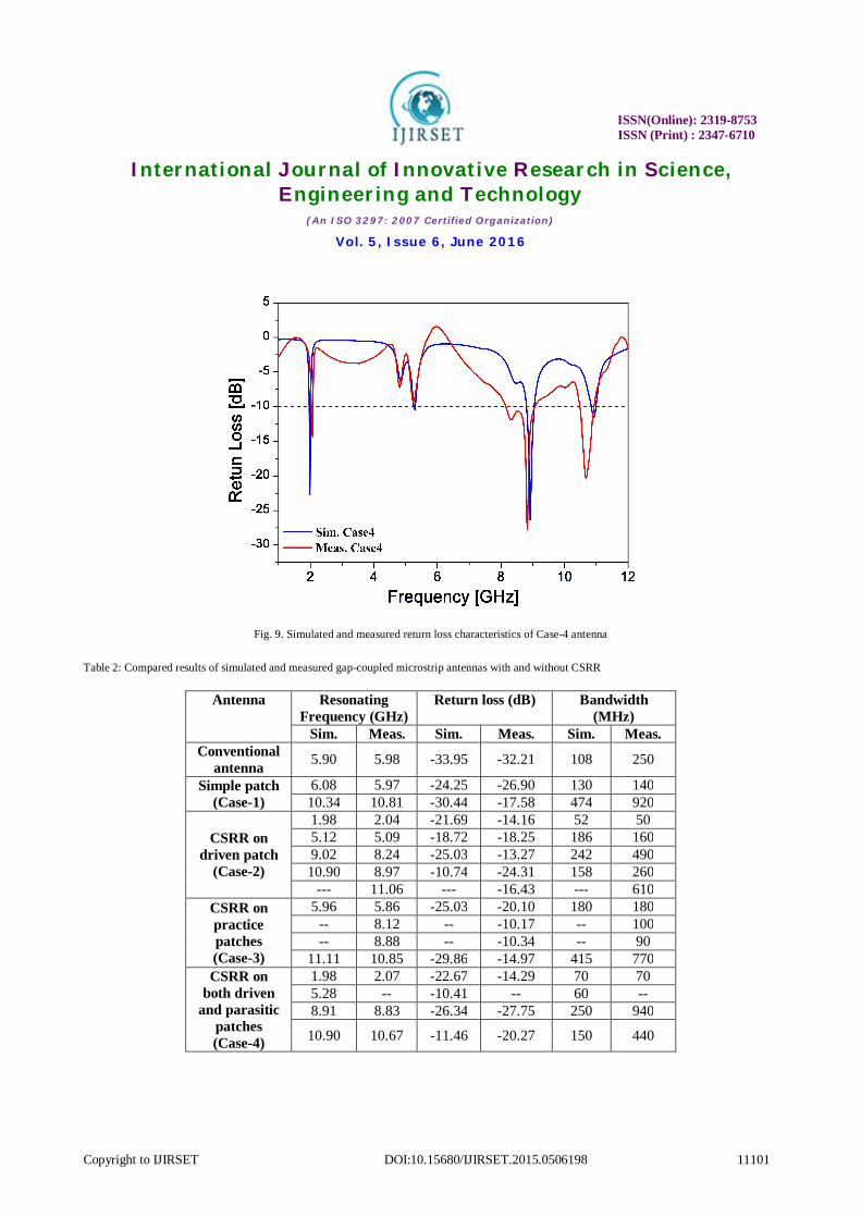
Fig. 8 shows simulated and measured return loss characteristics of Case-3 antenna with CSRR on parasitic patches resonating four particular frequencies 5.86GHz (180MHz), 8.12GHz (100MHz), 8.88GHz (90MHz) and 10.85GHZ (770MHz) and Fig. 9 shows simulated and measured return loss characteristics of Case-4 antenna with CSRR on both driven and parasitic patches and in this case antenna is resonating for three frequencies 2.07GHz (70MHz), 8.83GHz (940MHz) and 10.67GHz (440MHz). From the table 1 we can see the simulated and measured results of the proposed antennas. The virtual size reduction of 65.38% is achieved in case-2 antenna.
Fig. 8. Simulated and measured return loss characteristics of Case-3 antenna
ISSN(Online): 2319-8753 ISSN (Print) : 2347-6710
International Journal of Innovative Research in Science, Engineering and Technology
(An ISO 3297: 2007 Certified Organization)
Vol. 5, Issue 6, June 2016
Copyright to IJIRSET DOI:10.15680/IJIRSET.2015.0506198 11101
Fig. 9. Simulated and measured return loss characteristics of Case-4 antenna
Table 2: Compared results of simulated and measured gap-coupled microstrip antennas with and without CSRR
Antenna Resonating Frequency (GHz)
Return loss (dB) Bandwidth (MHz)
Sim. Meas. Sim. Meas. Sim. Meas. Conventional
antenna 5.90 5.98 -33.95 -32.21 108 250
Simple patch (Case-1)
6.08 5.97 -24.25 -26.90 130 140 10.34 10.81 -30.44 -17.58 474 920
CSRR on driven patch
(Case-2)
1.98 2.04 -21.69 -14.16 52 50 5.12 5.09 -18.72 -18.25 186 160 9.02 8.24 -25.03 -13.27 242 490 10.90 8.97 -10.74 -24.31 158 260
--- 11.06 --- -16.43 --- 610 CSRR on practice patches (Case-3)
5.96 5.86 -25.03 -20.10 180 180 -- 8.12 -- -10.17 -- 100 -- 8.88 -- -10.34 -- 90
11.11 10.85 -29.86 -14.97 415 770 CSRR on
both driven and parasitic
patches (Case-4)
1.98 2.07 -22.67 -14.29 70 70 5.28 -- -10.41 -- 60 -- 8.91 8.83 -26.34 -27.75 250 940
10.90 10.67 -11.46 -20.27 150 440

ISSN(Online): 2319-8753 ISSN (Print) : 2347-6710
International Journal of Innovative Research in Science, Engineering and Technology
(An ISO 3297: 2007 Certified Organization)
Vol. 5, Issue 6, June 2016
Copyright to IJIRSET DOI:10.15680/IJIRSET.2015.0506198 11102
Fig. 10 shows current distributions of Case-1 antenna at 6.08GHz, and Case-4 antenna at 5.29GHz. The current is flowing in almost entire patch, the different colors represents different magnitudes of the current. Fig. 11 (a) and (b) show the radiation patterns of Case-4 antenna taken at 1.98GHz and 5.29GHz. From these figures it is seen that, the patterns are broadside nature in both the cases.
Fig. 10. Current distributions of Case-1 antenna at 6.08GHz, and Case-4 antenna at 5.29GHz
Fig. 11. Radiation patterns of Case-4 antenna at 1.98GHz and 5.29GHz.

ISSN(Online): 2319-8753 ISSN (Print) : 2347-6710
International Journal of Innovative Research in Science, Engineering and Technology
(An ISO 3297: 2007 Certified Organization)
Vol. 5, Issue 6, June 2016
Copyright to IJIRSET DOI:10.15680/IJIRSET.2015.0506198 11103
IV. CONCLUSION
Gap-coupled rectangular microstrip antenna with combination of CSRR loaded on driven patch and parasitic patches have been presented. The proposed design helps to achieve both reduction in the antenna size with multiple resonances and the improvement in the bandwidth. The results presented in this paper are promising for designing of compact multiband antennas without much change in the antenna bandwidth, which makes the antenna useful for wireless communication.
ACKNOWLEDGEMENT
The authors acknowledge their thanks to UGC, New Delhi for sanctioning the IE3D simulation software under Major Research Project, which is most useful and reliable for designing microstrip antennas and DST, New Delhi for sanctioning Vector Network Analyzer for measuring the parameters of fabricated antennas.
REFERENCES [1] Rodney B. Waterhouse, “Microstrip Patch Antennas: A Designers Guide”, Kluwer Academic Publishers, ISBN: 1-4020-7373-9, 2003. [2] Constantine A. Balanis, “Antenna theory, Analysis and Design”, Third edition, Wiley India, ISBN: 978-81-265-2422-8, 2011. [3] V.G. Veselago, “The electrodynamics of substances with simultaneously negative values of ε and µ”, Sov Phys Usp , Vol.10, pp. 509–514,
1968. [4] D.R. Smith, W.J. Padilla, D.C. Vier, S.C. Nemat-Nasser, and S. Schultz, “Composite medium with simultaneously negative permeability
and permittivity”, Phys Rev Lett, Vol. 84, pp. 4184–4187, 2000. [5] R. Marques, F. Martin and M. Sorolla, “Metamaterials with Negative Parameters: Theory, Design and Microwave Applications”, Wiley,
2008. [6] Da Silva, I. B. T., de Andrade, H. D., da Silva, J. L., Fernandes, H. C. C. and Pereira, J. P. P., “Design of microstrip patch antenna with
complementary split ring resonator device for wideband systems application”, . Microw Opt Technol Lett., Vol. 57, pp.1326–1330, 2015. [7] L. M. Si, W. Zhu, and H. J. Sun, “A compact, planar, and CPW-fed metamaterial-inspired dual-band antenna”, IEEE Antennas Wirel Propag
Lett., Vol.12, pp. 305–308, 2013. [8] Xie, Y. H., Zhu, C., Li, L. and Liang, C. H., “A novel dual-band metamaterial antenna based on complementary split ring resonators”
Microw Opt Technol Lett., Vol. 54, pp.1007–1009, 2012. [9] Zeland Software, Inc., IE3D Electromagnetic Simulation and Optimization Package, Version 14.65, Zeland Software, Inc., Fremont, CA,
2010.