vol. 38 (nº 34) año 2017. pág. 8 failure evaluations in bucket conveyor ... · failure...
TRANSCRIPT
ISSN 0798 1015
HOME Revista ESPACIOS ! ÍNDICES ! A LOS AUTORES !
Vol. 38 (Nº 34) Año 2017. Pág. 8
Failure evaluations in bucket conveyor.Studies caseEvaluación de fallas en un transportador de cangilones. Caso deestudioHERNANDEZ, Herrera Hernan 1; CASTELLANOS Luis M. 2; CABELLO Eras Juan J. 3; SILVA Ortega Jorge I. 4;MANGA Carlos A. 5
Recibido: 14/02/2017 • Aprobado: 02/03/2017
Content1. Introduction2. Material and Methods3. Results and Discussion4. ConclusionsReferences
ABSTRACT:A failure in the bottom sheet of a bucket conveyor (KZB-Q.AUMUND) during service was investigated. Sheets arecoupled to the chain throught a screw connection; theyoperate in variable load scenarios causing fatigue. Achemical and microstructural analysis was made showingthat sheet was built in steel with 0.15 % of Carbone withoutalloying elements that contribute to the refined grain andresistance increase. Strength calculation, used todeterminate safety factor, consider load system and typematerial. Results concluded that geometry and thicknessvalue do not provide an adequate fatigue resistancecoefficient. Keywords: bucket conveyor; failure analysis, fatigueresistance, finite element analysis.
RESUMEN:Es investigada la falla en las láminas del fondo de untransportador de cangilones KZB-Q.AUMUND durante suservicio. Las láminas están acopladas a una cadena a travésde uniones atornilladas y operan bajo un régimen de cargasvariables causándoles fatiga. Se realiza un análisis químico ymicroestructural el cual evidencia que las láminas fueronelaboradas de un acero con 0,15 % de carbono sinelementos de aleación que contribuyan al afinamiento delgrano y al incremento de la resistencia. Se calculan lastensiones para determinar el coeficiente de seguridad a lafatiga considerando el sistema de cargas y el material de lasláminas. Los resultados concluyen que la geometría y losvalores de espesor no le proporcionan a las láminas unadecuado coeficiente de resistencia a la fatiga. Palabras claves: transportador de cangilones; análisis defalla, resistencia a la fatiga, análisis por elementos finitos.
1. IntroductionIn cement industry, a high number of raw material and products are processed and transported duringmanufacturing process; those involved equipment have significance in company’s productivity.Conveyors used to drive raw materials in cement industry usually are bands and bucket conveyors.The last ones are used commonly in Clinker transportation and finished final products which are drivento storage rooms. These systems are selected according with material properties, load requirementsand lifting [1], [2].
Mechanical failures are usually attributed to non-compliance maintenance intervals, errors duringdesign such as material selection, assemblies or incorrect operation [3], [4]. These failures conditionsare in disagree with industry expectances which specify that critical equipment must be defect-freeand systematic failure that cause stops in processes, increasing operation cost and delays duringdeliveries, affecting finances due to markets requirements and competitiveness [5 ]-[7].This paper analyze a case study to determinate failure causes in the bottom sheet of the bucketconveyor KZB-Q Clinker Conveyor-AUMUND in Colombian Cement Company. The reviewed unitevidenced four failures between July and December 2015, producing considerable financial losses.In order to identify failure causes a chemical and microstructural analysis at material using for bottomsheet manufacturing was carried out, also mechanical properties of the material were studied andresistance to fatigue assessment was developed [8-12].
2. Material and Methods.
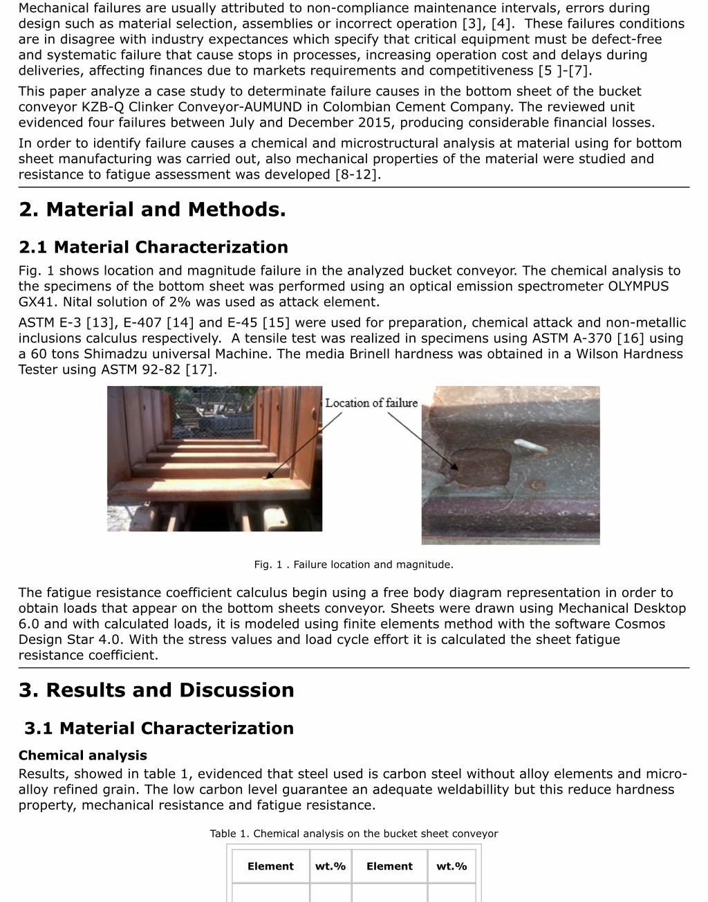
2.1 Material CharacterizationFig. 1 shows location and magnitude failure in the analyzed bucket conveyor. The chemical analysis tothe specimens of the bottom sheet was performed using an optical emission spectrometer OLYMPUSGX41. Nital solution of 2% was used as attack element. ASTM E-3 [13], E-407 [14] and E-45 [15] were used for preparation, chemical attack and non-metallicinclusions calculus respectively. A tensile test was realized in specimens using ASTM A-370 [16] usinga 60 tons Shimadzu universal Machine. The media Brinell hardness was obtained in a Wilson HardnessTester using ASTM 92-82 [17].
Fig. 1 . Failure location and magnitude.
The fatigue resistance coefficient calculus begin using a free body diagram representation in order toobtain loads that appear on the bottom sheets conveyor. Sheets were drawn using Mechanical Desktop6.0 and with calculated loads, it is modeled using finite elements method with the software CosmosDesign Star 4.0. With the stress values and load cycle effort it is calculated the sheet fatigueresistance coefficient.
3. Results and Discussion
3.1 Material CharacterizationChemical analysisResults, showed in table 1, evidenced that steel used is carbon steel without alloy elements and micro-alloy refined grain. The low carbon level guarantee an adequate weldabillity but this reduce hardnessproperty, mechanical resistance and fatigue resistance.
Table 1. Chemical analysis on the bucket sheet conveyor
Element wt.% Element wt.%

Carbon 0,149 Molybdenum 0,014M
Silicon 0,213 Nickel 0,086
Manganese 0,599 Copper 0,292
Phosphorus 0,14 Aluminum 0,0067
Sulfur 0,041 Titanium 0,0015
Chrome 0,086 Niobium 0,018
Micro-structural analysisSpecimens without attack showed nonmetallic shapes derived from Type A oxides. Using chemicalattack, it was detected high ferrite levels and very low pearlite presence as is shown in a micrographicanalysis presented in Fig. 2 .
Fig. 2 . Optical micrograph analysis
Mechanical PropertiesThe steel average hardness was 135 HB, otherwise the average mechanical resistance measured were223 MPa in the yield strength and 345 MPa with the maximum tensile value, they correspond to thestructure type and low carbon steel percentage.
3.2 Forces influencing on the sheetThe conveyor operates with a transmission chain joined to the bottom sheet using screw connections.Two wheels located at both ends support this; connections between wheels and conveyor is realizedthrough wheels axis, which is fixed to a “U” profile, welded in the bottom sheet. The distance betweenthe farthest Union “U” point and the wheel support is 177 mm as is shown in Fig. 3 .

Fig. 3 . Joint elements of the bottom sheet with chain drive and supports.
Forces values on the conveyor were calculated using information provided by industry. Conveyormoving parts weight has a value of 4.84 kN/m including chain transmission. The maximum Clinkerweight value deposited in the conveyor is 3.1 kN/m. As is shown in Fig. 4 , the distance value is 1.5m; the maximum weight value is presented in Fig. 5 and determined as follow:
Fig. 5 . Bucket conveyor KZB-Q Pan conveyor – Aumund geometry.
Considering the total weight (TW) and taking into account that the system is symmetric, on eachwheel is registered a force reaction of 5.59 kN. Reactions in the return (zone 2) only consider theweight from moving parts obtaining a reaction of 2,42 kN.

3.3 Tensile ValuesIn order to realize fatigue analysis, there were calculated tensile values in both zones:
Zone 1: Moving parts weight were considered while the conveyor was loaded.Zone 2: Considering only moving parts.
The maximum force value in the sheet is applied in the farthest point from the “U” weld point. Theforce is transmitted from structures supports using the axis lane as is shown in Fig. 3 a). The sheetwas modeled using the software Mechanical Desktop 6.0 for the design and the software CosmosDesign Star 4.0 for simulations. During modeling, there was considered a parabolic tetrahedral mesh,it allowed better results in order to have an adequate contour representation [18- 21]. In all modelswas realized a progressively convergence refining study until obtain a difference between stress valuefor the definitive model and the previous model with a value lower than 5%, ensuring that localmaximum stress values do not depend from the used mesh size [22], [23]. Using finite elementmethod it was obtained for the forces in zone 1 a stress value equal to 89,7 MPa and 32,42 MPa forZone 2. These results are shown in Fig. 6(a-b). As it is observed in Fig. 6 , the sections where was located the maximum stress value correspond tothe failure section as is shown in Fig. 7 .
Fig. 6 . Support the axle of the wheel in the bottom sheet conveyor and Tensile in zone 1 and 2
Fig. 7 . Point where the stress value of the sheet is maximum and place of the failure.
3.4. Asymmetry coefficient, medium tensile and amplitude tensile.Fig. 5 evidenced that the conveyor bottom sheet has worked using variable stress values during
operation. For this cycle there were determined the asymmetry, the average tensile during the cycleand the amplitude tensile value [8].
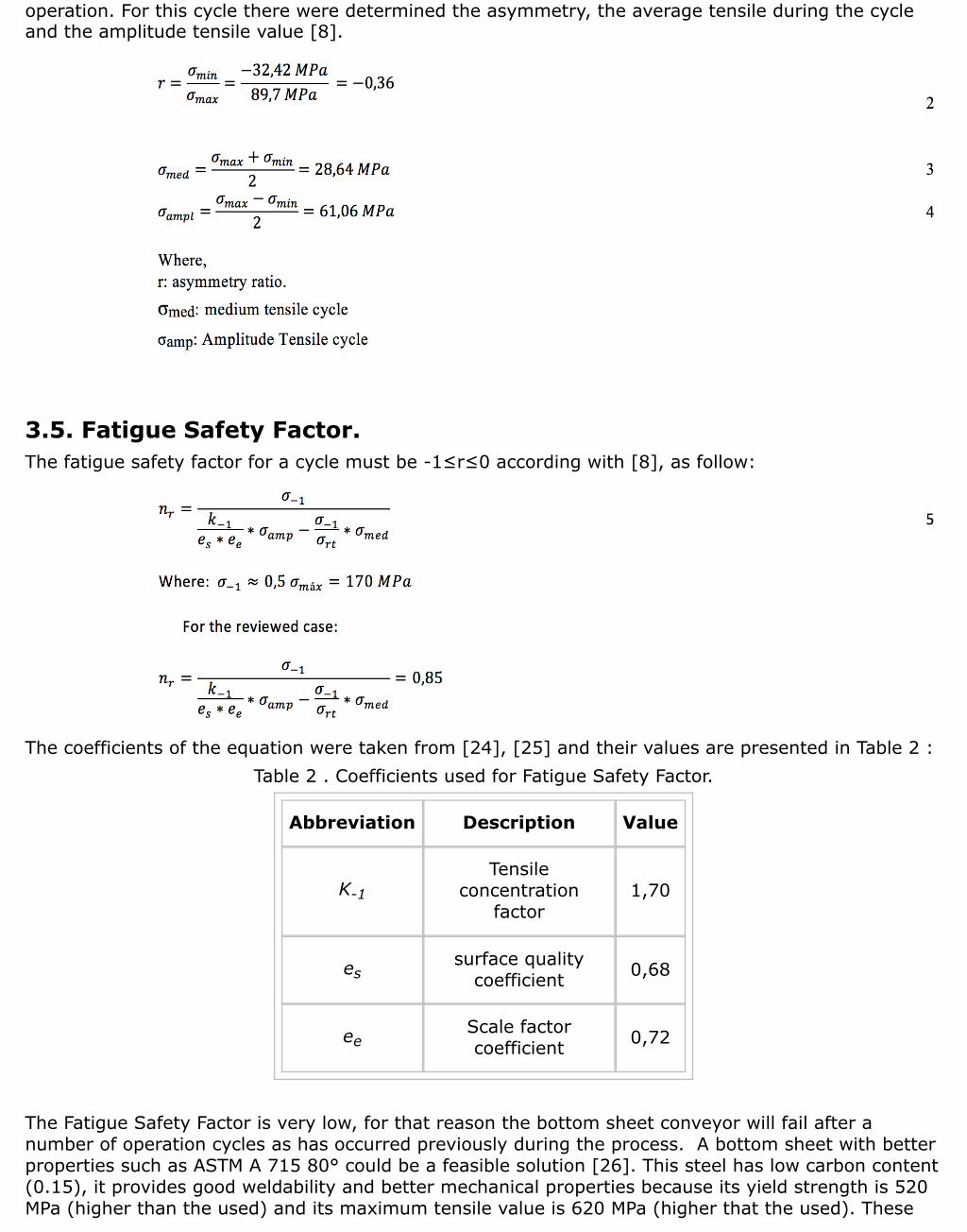
3.5. Fatigue Safety Factor.The fatigue safety factor for a cycle must be -1≤r≤0 according with [8], as follow:
The coefficients of the equation were taken from [24], [25] and their values are presented in Table 2 :Table 2 . Coefficients used for Fatigue Safety Factor.
Abbreviation Description Value
K-1Tensile
concentrationfactor
1,70
essurface quality
coefficient 0,68
eeScale factorcoefficient 0,72
The Fatigue Safety Factor is very low, for that reason the bottom sheet conveyor will fail after anumber of operation cycles as has occurred previously during the process. A bottom sheet with betterproperties such as ASTM A 715 80° could be a feasible solution [26]. This steel has low carbon content(0.15), it provides good weldability and better mechanical properties because its yield strength is 520MPa (higher than the used) and its maximum tensile value is 620 MPa (higher that the used). These

values increase the Fatigue Safety Factor as follow:
4. ConclusionsBucket conveyor was made with a standard steel with low carbon content, which implies a lowmechanical resistance and good weldability. The resistance analysis showed that bottom sheetgeometry and thickness does not provide an adequate fatigue safety factor, for that reason after anumber of cycles it will fail for this reason.In order to increase the fatigue safety factor there are solutions such as increase the bottom sheetthickness or replace the sheet with a more resistance material such as the ASTM A 715 80 degrees, itprovides an adequate fatigue safety factor.
References1. L. C. Giraldo, O. Flores, F. Higuera, “Design and construction of a mixer of screw conveyor for dry mortar,”
Scientia et Technica, vol. 2, no. 45, pp. 37-42, Ago, 2010.2. C. Hernández, “Creación de base de datos para equipos en planta y actualización de stock de repuestos
para elevadores de cangilones en una planta de cemento”, Tesis de Grado, Facultad de Ingeniería,Universidad de San Carlos de Guatemala, 2010.
3. J. Ledesma, J. C. Rosete, J. Pérez, “Aplicación del sistema RCM en la determinación de la causa crítica defallo en un elevador de cangilones.” Memorias del XVII Congreso Internacional Anual de la Somim. SanLuis Potosí, México. 21 al 23 de Sep, 2011, pp. 133-142.
4. C.W. Olarte, A. M. Botero, A. Benhur, “Importance of the industrial maintenance inside the processes ofproduction,” Scientia et Technica, vol. 1, no. 44, pp. 354-356, Abr, 2010.
5. Rajiv Kumar Sharma, Pooja Sharma. “Integrated framework to optimize RAM and cost decisions in aprocess plant”, Journal of Loss Prevention in the Process Industries, 25, 883-904, 2012.
6. A. Garofoli, J. Garofoli, ¨Elevadores de cangilones de descarga centrífuga, pérdidas por problemas dediseño¨. Revista Iberoamericana de Ingeniería Mecánica. vol. 18 no. 2, pp. 55-67, 2014.
7. K. Olivares, M. Arellano, M. López, K. Soler, “Sistemas de información para la gestión de mantenimiento enla gran industria del estado Zulia”. Revista Venezolana de Gerencia, vol.15, no. 49, pp. 125-140, 2010.
8. G. S. Fernández Levy, “Resistencia de Materiales”, La Habana, Editorial Pueblo y Educación 1983, 511 p.9. O. Araque, N. Arzola. “Estado del arte sobre la integridad estructural de uniones soldadas y modelos de
propagación de grietas para la gestión de vida en estructuras”. Revista Chilena de Ingeniería.21. No 2: 279-292. 2013.
10. Vansil, G. AlShali, A. Failure Analysis of conveyor pulley shaft. Case studies engineering failure analysis No1: 144-155. 2013.
11. S. González, D. Fernández, J. Álvarez, R. Ramos. “Estudio a fatiga de uniones soldadas a tope. Comparativay validación de las principales metodologías”. Dyna. vol. 88. No. 2, pp. 171-180. 2013.
12. O. Araque, J Cabello, “Estudio sobre la resistencia y rigidez de ejes huecos” Revista Scientia Et Technica.Vol. 1 No 30, pp. 219-224, 2006.
13. ASTM E3-11, Standard Guide for Preparation of Metallographic Specimens, ASTM International, WestConshohocken, PA, 2011,www.astm.org
14. ASTM E407-07(2015), Standard Practice for Microetching Metals and Alloys, ASTM International, WestConshohocken, PA, 2015, www.astm.org
15. ASTM E45-13, Standard Test Methods for Determining the Inclusion Content of Steel, ASTM International,West Conshohocken, PA, 2013, www.astm.org
16. ASTM A370-14, Standard Test Methods and Definitions for Mechanical Testing of Steel Products, ASTMInternational, West Conshohocken, PA, 2014, www.astm.org.
17. ASTM E92-82(2003)e2, Standard Test Method for Vickers Hardness of Metallic Materials (Withdrawn 2010),ASTM International, West Conshohocken, PA, 2003, www.astm.org
18. Chandrupatla, T., Belengundu, A. Introduction to Finite Elements in Engineering. Prentice Hall. USA. 1997.

19. E. Martínez, M. Estrems. “Desarrollo de un modelo matemático de diferencias finitas para el análisis delcampo de temperaturas en la soldadura por arco de chapas finas de acero inoxidable”. Revista deMetalurgia, 46 No 6: 511-519. 2010.
20. H. Hernández Herrera, R. Goytisolo, j. Moya, I. Jackson, “Nuevas expresiones para el cálculo a torsión decosturas soldadas de filete de configuración compleja. Vol. 3, pp. 27-34, 2006.
21. Felippa, Carlos A. Introduction to Finite Elements Methods. University of Colorado, 2001.586 p.22. Cernuschi, D. J., Elementos Finitos. Ejemplo de aplicación. Consideraciones sobre el uso de los Elementos
Finitos. Agosto 2003.23. Chau, T., Besnier, F. Numerical simulation of welding in shipbuilding. Marine. Technology V, 2003. Pp. 3-20.24. Feodosiev V.I. Diez conferencias sobre Resistencia de Materiales. Moscú: Editorial MIR, 1993.179 p.25. Fogiel M. Problem Solver in Strength of Materials and Mechanics of Solids. New Jersey: Editorial REA,
1988.1140 p.26. ASTM A715-98, Standard Specification for Steel Sheet and Strip, High-Strength, Low-Alloy, Hot-Rolled, and
Steel Sheet, Cold-Rolled, High-Strength, Low-Alloy, with Improved Formability. www.astm.org.
1. Grupo de Investigación en Optimización Energética GIOPEN. Universidad de la Costa, CUC. email [email protected]. Grupo de Investigación GEMAS. Facultad de Ingeniería. Universidad Simón Bolívar, email [email protected]. Grupo de Investigación en Optimización Energética GIOPEN. Universidad de la Costa, CUC. Email [email protected]. Grupo de Investigación en Optimización Energética GIOPEN. Universidad de la Costa, CUC. email [email protected]. Grupo de Investigación GEMAS. Facultad de Ingeniería. Universidad Simón Bolívar, email [email protected]
Revista ESPACIOS. ISSN 0798 1015Vol. 38 (Nº 34) Año 2017
[Índice]
[En caso de encontrar algún error en este website favor enviar email a webmaster]
©2017. revistaESPACIOS.com • Derechos Reservados