vol. 2/ design+ construction - manoa.hawaii.edu
TRANSCRIPT

Group Projects
VOL. 2/ DESIGN+
CONSTRUCTION
University of Hawaii at Manoa
Building Design and Performance Standards
1
To be used by Design and Construction Teams
Page 2 of 190
UHM BDPS - VOL.2/ DESIGN + CONSTRUCTION - GROUP 1 PROJECTS
[BLANK]
UHM BDPS - VOL.2/ DESIGN + CONSTRUCTION - GROUP 1 PROJECTS
Page 3 of 190
1/ PR
OJE
CT D
EFIN
ITION
2/ DE
SIG
N+
CO
NS
TR
UC
TIO
N 3/ P
OS
T-OC
CU
PAN
CY
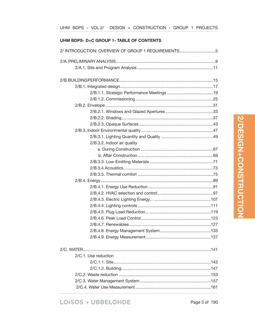
UHM BDPS- D+C GROUP 1- TABLE OF CONTENTS
2/ INTRODUCTION: OVERVIEW OF GROUP 1 REQUIREMENTS ...............................5
2/A. PRELIMINARY ANALYSIS......................................................................................9
2/A.1. Site and Program Analysis ..................................................................11
2/B. BUILDING PERFORMANCE.................................................................................15
2/B.1. Integrated design ................................................................................17
2/B.1.1. Strategic Performance Meetings ........................................19
2/B.1.2. Commissioning ...................................................................25
2/B.2. Envelope .............................................................................................31
2/B.2.1. Windows and Glazed Apertures .........................................33
2/B.2.2. Shading ...............................................................................37
2/B.2.3. Opaque Surfaces ................................................................43
2/B.3. Indoor Environmental quality ..............................................................47
2/B.3.1. Lighting Quantity and Quality .............................................49
2/B.3.2. Indoor air quality
a. During Construction ..... .........................................................67
b. After Construction ..... ...........................................................69
2/B.3.3. Low-Emitting Materials .......................................................71
2/B.3.4. Acoustics..............................................................................73
2/B.3.5. Thermal comfort .................................................................75
2/B.4. Energy .................................................................................................89
2/B.4.1. Energy Use Reduction ........................................................91
2/B.4.2. HVAC selection and control... .............................................97
2/B.4.3. Electric Lighting Energy... .................................................107
2/B.4.4. Lighting controls ...............................................................111
2/B.4.5. Plug Load Reduction... .....................................................119
2/B.4.6. Peak Load Control ............................................................123
2/B.4.7. Renewables ......................................................................127
2/B.4.8. Energy Management System ............................................133
2/B.4.9. Energy Measurement ........................................................137
2/C. WATER...... ........................................................................................................141
2/C.1. Use reduction
2/C.1.1. Site ....................................................................................143
2/C.1.2. Building..... ........................................................................147
2/C.2. Waste reduction ...............................................................................153
2/C.3. Water Management System .............................................................157
2/C.4. Water Use Measurement .................................................................161

Page 4 of 190
UHM BDPS - VOL.2/ DESIGN + CONSTRUCTION - GROUP 1 PROJECTS
2/D. SITE......... .........................................................................................................165
2/D.1 Landscape
2/D.1.1. Stormwater .......................................................................167
2/D.1.2. Erosion ..............................................................................169
2/D.2. Heat island ........................................................................................173
2/D.3. Light pollution reduction ...................................................................177
2/E. BUILDING MATERIALS .....................................................................................181
2/E.1. Source certified .................................................................................183
2/E.2. Construction and demolition waste ..................................................185
2/E.3. Design for disassembly .....................................................................187
UHM BDPS- D+C GROUP 1- TABLE OF CONTENTS (Continued)

UHM BDPS - VOL.2/ DESIGN + CONSTRUCTION - GROUP 1 PROJECTS
Page 5 of 190
1/ PR
OJE
CT D
EFIN
ITION
2/ DE
SIG
N+
CO
NS
TR
UC
TIO
N 3/ P
OS
T-OC
CU
PAN
CY
2/INTRODUCTION:OVERVIEW OF GROUP 1 REQUIREMENTS
[See Next Page]

UHM BDPS - VOL.2/ DESIGN + CONSTRUCTION - GROUP 1 PROJECTS
Page 6 of 190
2/ Introduction:: Overview of Group 1 Requirements (Continued)D
ATE
: FO
R U
HM
REV
IEW
ERS-
SP
MEE
TIN
G A
GEN
DAS
FOR
DES
IGN
TEA
MS-
CO
NS
VER
IFIC
ATI
ON
DES
IGN
CER
TIFI
CA
TIO
N,
PER
FOR
MA
NC
E A
ND
DES
IGN
REQ
UIR
EMEN
TSD
OES
IT R
EQU
IRE
PER
FOR
MAN
CE
MO
DEL
ING
?
TOTA
L LE
ED P
OIN
TS A
CH
IEVE
D51
61SP
#1SP
#2SP
#3
a . L
EED
FEA
SIBI
LITY
b. L
EED
V4
BD+C
: SS
CR
EDIT
1: S
ITE
ASSE
SSM
ENT
1
a. P
REL
IMIN
AR
Y EN
ERG
Y M
OD
ELIN
GYE
S
b. N
ET Z
ERO
FEA
SIB
ILIT
Y
c. P
REL
IMIN
AR
Y PE
RFO
RM
AN
CE
AN
ALY
SIS
d. W
ATE
R B
UD
GET
AN
ALY
SIS
LEED
V4
BD+C
: IP
CR
EDIT
1: I
NTE
GR
ATIV
E PR
OC
ESS
1
STR
ATE
GIC
PER
FOR
MA
NC
E M
EETI
NG
S
LEED
V4
BD+C
: EA
CR
EDIT
1: E
NH
ANC
ED C
OM
MIS
SIO
NIN
G6
AD
VAN
CED
CO
MM
ISSI
ON
NIN
G
a. IE
CC
201
5 W
IND
OW
SPE
CIF
ICA
TIO
NS
b. W
IND
OW
TO
WA
LL A
REA
c. W
IND
OW
OPE
RA
BIL
ITY
OPT
1M
AXI
MU
M A
NN
UA
L SO
LAR
EXP
OSU
RE
YES
OPT
2
PRO
FILE
AN
GLE
SN
O
a. E
XTER
IOR
SH
AD
ING
DEV
ICES
b.D
IREC
T VI
EW T
O T
HE
HO
RIZ
ON
AN
D L
OW
ALT
ITU
DE
SKY
IEC
C 2
015
THER
MA
L EN
VELO
PE R
EQU
IREM
ENTS
NO
NO
1Q
UA
NTI
TYO
FD
AYL
IGH
TIN
THE
SPA
CE
YES
YES
NO
DES
IGN
CER
TIFI
CAT
ION
N/A
YES
NO
DES
IGN
2.1
WIN
DO
WS
AN
D G
LAZE
D A
PER
TUR
ES R
ECO
MM
END
ATI
ON
LEED SILVER (50PTS M
NO
NO
2. S
ITE
AN
D P
RO
GR
AM
AN
ALY
SIS
CER
TIFI
CAT
ION
DES
IGN
CER
TIFI
CAT
ION
DES
IGN
TO B
E D
ISC
USS
ED
DU
RIN
G
STR
ATE
GIC
PE
RFO
RM
AN
CE
MEE
TIN
GS?
LEED GOLD (60PTS MIN)
YES
YES
A. P
REL
IMIN
AR
Y A
NA
LYSI
S N
ON
O
1.1
STR
ATE
GIC
PER
FOR
MA
NC
E M
EETI
NG
S
REC
OM
MEN
DA
TIO
N
1.IN
TEG
RA
TED
D
ESIG
N1.
2 C
OM
ISSI
ON
ING
2.3
OPA
QU
E SU
RFA
CES
N/A
N/A
YES
YES
INTE
GR
ATE
D D
ESIG
N
TO B
E IN
CLU
DED
IN
C
OM
MIS
SIO
NIN
G?
YES
NO
YES
2. E
NVE
LOPE
NO
NO
TYPE
OF
REQ
UIR
EMEN
T
PER
FOR
MA
NC
E
2.2
SHA
DIN
G
1.a
QU
AN
TITY
OF
DA
YLIG
HT
IN T
HE
SPA
CE
1.b
QU
ALI
TY O
F LI
GH
T IN
TH
E SP
AC
E
1.c.
QU
AN
TITY
OF
LIG
HT
FOR
ELE
CTR
IC L
IGH
TIN
G
1.d
IND
IREC
T LI
GH
TIN
G
1.e
ELEC
TRIC
LIG
HTI
NG
GLA
RE
CO
NTR
OL
2.a
WIN
DO
W D
ESIG
N A
ND
SPE
CIF
ICA
TIO
NS
2.b
SUN
AN
D G
LAR
E C
ON
TRO
L
2.c
OPT
IMIZ
E D
AYL
IGH
T PE
NET
RA
TIO
N
2.d
SUR
FAC
E B
RIG
HTN
ESS
2.e
MA
XIM
UM
CA
ND
LEPO
WER
2.f F
IXTU
RE
MO
UN
TIN
G
2.g
FIXT
UR
E D
ISTR
IBU
TIO
N
a. O
VER
ALL
PR
OG
RA
MM
ATI
C O
RG
AN
IZA
TIO
N
b. S
PAC
E PL
AN
NIN
G T
O A
VOID
GLA
RE
c. C
OLO
R R
END
ERIN
G
A. D
UR
ING
CO
NST
RU
CTI
ON
LEED
V4
BD+C
: EQ
CR
EDIT
3: C
ON
STR
UC
TIO
N IN
DO
OR
AIR
QU
ALIT
Y M
ANAG
EMEN
T PL
AN1
NO
NO
YES
NO
LEED
V4
BD+C
: EQ
CR
EDIT
4: I
ND
OO
R A
IR Q
UAL
ITY
ASSE
SSM
ENT
2
LEED
V4
BD+C
: EQ
CR
EDIT
1: E
NH
ANC
ED IN
DO
OR
AIR
QU
ALIT
Y ST
RAT
EGIE
S2
PREV
ENT
MO
LD F
RO
M IR
RIG
ATI
ON
YES
LEED
V4
BD+C
: EQ
CR
EDIT
2: L
OW
-EM
ITTI
NG
MAT
ERIA
LS3
NO
NO
NO
NO
LEED
V4
BD+C
: EQ
CR
EDIT
9: A
CO
UST
IC P
ERFO
RM
ANC
E1
NO
NO
NO
NO
LEED
V4
BD+C
: EQ
CR
EDIT
5: T
HER
MAL
CO
MFO
RT
1N
O
OPT
1H
VAC
AU
TON
OM
YYE
S
2.a
ENVE
LOPE
DES
IGN
AN
D S
PEC
IFIC
ATI
ON
S
2.b
OPT
IMIZ
E O
CC
UPA
NT
CO
MFO
RT
a. C
RIT
ERIA
FO
R P
ASS
IVEL
Y C
ON
DIT
ION
ED S
PAC
ES
b. M
ECH
AN
ICA
L VE
NTI
LATI
ON
LEED
V4
BD+C
: EA
CR
EDIT
2: O
PTIM
IZE
ENER
GY
PER
FOR
MAN
CE
1318
NO
, CO
MPL
IAN
CE
ON
LY
BEN
CH
MA
RK
BA
SED
TA
RG
ET A
CH
IEVE
MEN
T.YE
Sa.
MIX
ED M
OD
E C
ON
DIT
ION
ING
b.H
VAC
SPE
CIF
ICA
TIO
NS
NO
CER
TIFI
CAT
ION
CER
TIFI
CAT
ION
DES
IGN
PER
FOR
MA
NC
E
DES
IGN
CER
TIFI
CAT
ION
PER
FOR
MA
NC
EO
PT 2
DES
IGN
NO
NO
PER
FOR
MA
NC
E
OPT
1
CER
TIFI
CAT
ION
NO
NO
CER
TIFI
CAT
ION
CER
TIFI
CAT
ION
YES
NO
YES
YES
OPT
2
DES
IGN
YES
YES
3.1
LIG
HTI
NG
QU
AN
TITY
AN
D Q
UA
LITY
3.2
IND
OO
R
AIR
Q
UA
LITY
B. A
FTER
CO
NST
RU
CTI
ON
3.IE
Q
4.1
ENER
GY
USE
RED
UC
TIO
N
B. B
UIL
DIN
G
PER
FOR
MA
NC
EN
O
4.2
HVA
C S
ELEC
TIO
N +
CO
NTR
OL
YES
YES
3.4
AC
OU
STIC
S3.
3 LO
W-E
MIT
TIN
G M
ATE
RIA
LS
NO
NO
YES
YES
YES
YES
3.6
THER
MA
L C
OM
FOR
T
c. .A
PPR
OPR
IATE
HVA
C S
IZIN
G
LEED
V4
BD+C
: EQ
CR
EDIT
6: I
NTE
RIO
R L
IGH
TIN
G1
LIG
HTI
NG
PO
WER
ALL
OW
AN
CES
LEED
V4
BD+C
: EQ
CR
EDIT
6: I
NTE
RIO
R L
IGH
TIN
G1
a D
AYL
IGH
T C
ON
TRO
LS
b. C
ON
TIN
UO
US
DIM
MIN
G
c. O
CC
UPA
NC
Y SE
NSO
RS
d. M
AN
UA
L C
ON
TRO
LS
a. M
AXI
MU
M P
OW
ER D
ENSI
TY
b.EN
ERG
Y ST
AR
EQ
UIP
MEN
T
LEED
V4
BD+C
: EA
CR
EDIT
4: D
EMAN
D R
ESPO
NSE
2
DEM
AN
D R
EDU
CTI
ON
SYS
TEM
LEED
V4-
NC
-V4
EA C
RED
IT 5
: REN
EWAB
LE E
NER
GY
PRO
DU
CTI
ON
3N
O, C
OM
PLIA
NC
E O
NLY
ENH
AN
CED
REN
EWA
BLE
EN
ERG
Y PR
OD
UC
TIO
NYE
SA
DVA
NC
ED E
NER
GY
MA
NA
GEM
ENT
SYST
EMN
OYE
SN
O
LEED
V4
BD+C
: EA
CR
EDIT
3: A
DVA
NC
ED E
NER
GY
MET
ERIN
G1
ENH
AN
CED
EN
ERG
Y M
ETER
ING
LEED
V4
BD+C
: WE
CR
EDIT
1: O
UTD
OO
R W
ATER
USE
RED
UC
TIO
N1
a.W
ATE
R B
UD
GET
FO
R L
AN
DSC
APE
b.N
ATI
VE L
AN
DSC
APE
c.IR
RIG
ATI
ON
SYS
TEM
CO
NTR
OL
LEED
V4
BD+C
: WE
CR
EDIT
2: I
ND
OO
R W
ATER
USE
RED
UC
TIO
N1
6
LEE
D V
4 BD
+C: W
E C
RED
IT 3
: CO
OLI
NG
TO
WER
WAT
ER U
SE2
MA
XIM
IZE
WA
TER
EFF
ICIE
NC
Y
POTA
BLE
WA
TER
RED
UC
TIO
N F
OR
SEW
AG
E C
ON
VEYA
NC
EN
O
AD
VAN
CED
WA
TER
MA
NA
GEM
ENT
SYST
EM
NO
LEE
D V
4 BD
+C: W
E C
RED
IT 4
: WAT
ER M
ETER
ING
1
ENH
AN
CED
WA
TER
MET
ERIN
G
LEE
D V
4 BD
+C: S
S C
RED
IT4:
RAI
NW
ATER
MAN
AGEM
ENT
1
UH
M S
PEC
IFIC
STO
RM
WA
TER
MA
NA
GEM
ENT
ERO
SIO
N A
ND
SED
IMEN
TATI
ON
CO
NTR
OL
PLA
NN
OD
ESIG
N
DES
IGN
DES
IGN
DES
IGN
DES
IGN
DES
IGN
DES
IGN
DES
IGN
DES
IGN
CER
TIFI
CAT
ION
CER
TIFI
CAT
ION
CER
TIFI
CAT
ION
DES
IGN
DES
IGN
DES
IGN
CER
TIFI
CAT
ION
CER
TIFI
CAT
ION
CER
TIFI
CAT
ION
CER
TIFI
CAT
ION
CER
TIFI
CAT
ION
DES
IGN
PER
FOR
MA
NC
E
YES
YES
YES
NO
YES
NO
YES
NO
YES
4.EN
ERG
Y
1.2
ERO
SIO
N
2. W
ATE
R W
AST
E R
EDU
CTI
ON
C. W
ATE
R
4. W
ATE
R U
SE M
EASU
REM
ENT
4.6
PEA
K L
OA
D (d
eman
d) C
ON
TRO
L
4.9
ENER
GY
MEA
SUR
EMEN
T
1.2
BU
ILD
ING
1. W
ATE
R U
SE
RED
UC
TIO
N
3. W
ATE
R M
AN
AG
EMEN
T SY
STEM
4.8
ENER
GY
MA
NA
GEM
ENT
SYST
EM
4.5
PLU
G L
OA
D R
EDU
CTI
ON
1. L
AN
DSC
APE
1.1.
STO
RM
WA
TER
YES
NO
4.7
REN
EWA
BLE
S
NO
YES
YES
NO
NO
YES
NO
YES
YES
YES
NO
YES
YES
NO
NO
YES
CER
TIFI
CAT
ION
1.1
SITE
4.4
LIG
HTI
NG
CO
NTR
OLS
4.3
ELEC
TRIC
LIG
HTI
NG
EN
ERG
Y
LEED
V4
BD+C
: SS
CR
EDIT
5: H
EAT
ISLA
ND
RED
UC
TIO
N2
ON
SIT
E TR
EE P
RO
TEC
TIO
N
LEED
V4
BD+C
: SS
CR
EDIT
6: L
IGH
T PO
LLU
TIO
N R
EDU
CTI
ON
1
a. L
IMIT
INTE
RIO
R L
IGH
TIN
G C
ON
TRIB
UTI
ON
b.IE
SNA
PR
AC
TIC
ES
c. U
HM
EXT
ERIO
R L
IGH
TIN
G G
UID
ELIN
ES
LEED
V4
BD+C
: MR
CR
EDIT
3: B
UIL
DIN
G P
RO
DU
CT
DIS
CLO
SUR
E AN
D
OPT
IMIZ
ATIO
N -
SOU
RC
ING
OF
RAW
MAT
ERIA
LS1
LEED
V4
BD+C
: MR
CR
EDIT
5: C
ON
STR
UC
TIO
N A
ND
DEM
OLI
TIO
N W
ASTE
M
ANAG
EMEN
T2
DIS
ASS
EMB
LY P
LAN
TOTA
L LE
ED P
OIN
TS51
61SP
#1SP
#2SP
#3
`C
ERTI
FIC
ATI
ON
AN
D P
ERFO
RM
AN
CE
REQ
UIR
EMEN
T
DES
IGN
VER
IFIC
ATI
ON
DES
IGN
DES
IGN
DO
ES IT
REQ
UIR
E PE
RFO
RM
ANC
E M
OD
ELIN
G?
NO
YES
LEED GOLD (60PTS MIN)
LEED SILVER (50PTS MIN)
YES
TO B
E D
ISC
USS
ED
DU
RIN
G
STR
ATE
GIC
PE
RFO
RM
AN
CE
MEE
TIN
GS?
3. D
ESIG
N F
OR
DIS
SASE
MB
LY
2. H
EAT
ISLA
ND
INTE
GR
ATE
D D
ESIG
N
TO B
E IN
CLU
DED
IN
C
OM
MIS
SIO
NIN
G?
3. L
IGH
T PO
LLU
TIO
N R
EDU
CTI
ON
D. S
ITE
2. C
ON
STR
UC
TIO
N A
ND
DEM
OLI
TIO
N W
AST
EN
OE.
BU
ILD
ING
M
ATE
RIA
LSN
O
NO
NO
NO
NO
YES
NO
1. S
OU
RC
E C
ERTI
FIED
DES
IGN
CER
TIFI
CAT
ION
CER
TIFI
CAT
ION
CER
TIFI
CAT
ION
CER
TIFI
CAT
ION

Page 7 of 190
UHM BDPS - VOL.2/ DESIGN + CONSTRUCTION - GROUP 1 PROJECTS
2/ Introduction:: Overview of Group 1 Requirements (Continued)
DA
TE:
FOR
UH
M R
EVIE
WER
S- S
P M
EETI
NG
AG
END
ASFO
R D
ESIG
N T
EAM
S- C
ON
S
VER
IFIC
ATI
ON
DES
IGN
CER
TIFI
CA
TIO
N,
PER
FOR
MA
NC
E A
ND
DES
IGN
REQ
UIR
EMEN
TSD
OES
IT R
EQU
IRE
PER
FOR
MAN
CE
MO
DEL
ING
?
TOTA
L LE
ED P
OIN
TS A
CH
IEVE
D51
61SP
#1SP
#2SP
#3
a . L
EED
FEA
SIBI
LITY
b. L
EED
V4
BD+C
: SS
CR
EDIT
1: S
ITE
ASSE
SSM
ENT
1
a. P
REL
IMIN
AR
Y EN
ERG
Y M
OD
ELIN
GYE
S
b. N
ET Z
ERO
FEA
SIB
ILIT
Y
c. P
REL
IMIN
AR
Y PE
RFO
RM
AN
CE
AN
ALY
SIS
d. W
ATE
R B
UD
GET
AN
ALY
SIS
LEED
V4
BD+C
: IP
CR
EDIT
1: I
NTE
GR
ATIV
E PR
OC
ESS
1
STR
ATE
GIC
PER
FOR
MA
NC
E M
EETI
NG
S
LEED
V4
BD+C
: EA
CR
EDIT
1: E
NH
ANC
ED C
OM
MIS
SIO
NIN
G6
AD
VAN
CED
CO
MM
ISSI
ON
NIN
G
a. IE
CC
201
5 W
IND
OW
SPE
CIF
ICA
TIO
NS
b. W
IND
OW
TO
WA
LL A
REA
c. W
IND
OW
OPE
RA
BIL
ITY
OPT
1M
AXI
MU
M A
NN
UA
L SO
LAR
EXP
OSU
RE
YES
OPT
2
PRO
FILE
AN
GLE
SN
O
a. E
XTER
IOR
SH
AD
ING
DEV
ICES
b.D
IREC
T VI
EW T
O T
HE
HO
RIZ
ON
AN
D L
OW
ALT
ITU
DE
SKY
IEC
C 2
015
THER
MA
L EN
VELO
PE R
EQU
IREM
ENTS
NO
NO
1Q
UA
NTI
TYO
FD
AYL
IGH
TIN
THE
SPA
CE
YES
YES
NO
DES
IGN
CER
TIFI
CAT
ION
N/A
YES
NO
DES
IGN
2.1
WIN
DO
WS
AN
D G
LAZE
D A
PER
TUR
ES R
ECO
MM
END
ATI
ON
LEED SILVER (50PTS M
NO
NO
2. S
ITE
AN
D P
RO
GR
AM
AN
ALY
SIS
CER
TIFI
CAT
ION
DES
IGN
CER
TIFI
CAT
ION
DES
IGN
TO B
E D
ISC
USS
ED
DU
RIN
G
STR
ATE
GIC
PE
RFO
RM
AN
CE
MEE
TIN
GS?
LEED GOLD (60PTS MIN)
YES
YES
A. P
REL
IMIN
AR
Y A
NA
LYSI
S N
ON
O
1.1
STR
ATE
GIC
PER
FOR
MA
NC
E M
EETI
NG
S
REC
OM
MEN
DA
TIO
N
1.IN
TEG
RA
TED
D
ESIG
N1.
2 C
OM
ISSI
ON
ING
2.3
OPA
QU
E SU
RFA
CES
N/A
N/A
YES
YES
INTE
GR
ATE
D D
ESIG
N
TO B
E IN
CLU
DED
IN
C
OM
MIS
SIO
NIN
G?
YES
NO
YES
2. E
NVE
LOPE
NO
NO
TYPE
OF
REQ
UIR
EMEN
T
PER
FOR
MA
NC
E
2.2
SHA
DIN
G
1.a
QU
AN
TITY
OF
DA
YLIG
HT
IN T
HE
SPA
CE
1.b
QU
ALI
TY O
F LI
GH
T IN
TH
E SP
AC
E
1.c.
QU
AN
TITY
OF
LIG
HT
FOR
ELE
CTR
IC L
IGH
TIN
G
1.d
IND
IREC
T LI
GH
TIN
G
1.e
ELEC
TRIC
LIG
HTI
NG
GLA
RE
CO
NTR
OL
2.a
WIN
DO
W D
ESIG
N A
ND
SPE
CIF
ICA
TIO
NS
2.b
SUN
AN
D G
LAR
E C
ON
TRO
L
2.c
OPT
IMIZ
E D
AYL
IGH
T PE
NET
RA
TIO
N
2.d
SUR
FAC
E B
RIG
HTN
ESS
2.e
MA
XIM
UM
CA
ND
LEPO
WER
2.f F
IXTU
RE
MO
UN
TIN
G
2.g
FIXT
UR
E D
ISTR
IBU
TIO
N
a. O
VER
ALL
PR
OG
RA
MM
ATI
C O
RG
AN
IZA
TIO
N
b. S
PAC
E PL
AN
NIN
G T
O A
VOID
GLA
RE
c. C
OLO
R R
END
ERIN
G
A. D
UR
ING
CO
NST
RU
CTI
ON
LEED
V4
BD+C
: EQ
CR
EDIT
3: C
ON
STR
UC
TIO
N IN
DO
OR
AIR
QU
ALIT
Y M
ANAG
EMEN
T PL
AN1
NO
NO
YES
NO
LEED
V4
BD+C
: EQ
CR
EDIT
4: I
ND
OO
R A
IR Q
UAL
ITY
ASSE
SSM
ENT
2
LEED
V4
BD+C
: EQ
CR
EDIT
1: E
NH
ANC
ED IN
DO
OR
AIR
QU
ALIT
Y ST
RAT
EGIE
S2
PREV
ENT
MO
LD F
RO
M IR
RIG
ATI
ON
YES
LEED
V4
BD+C
: EQ
CR
EDIT
2: L
OW
-EM
ITTI
NG
MAT
ERIA
LS3
NO
NO
NO
NO
LEED
V4
BD+C
: EQ
CR
EDIT
9: A
CO
UST
IC P
ERFO
RM
ANC
E1
NO
NO
NO
NO
LEED
V4
BD+C
: EQ
CR
EDIT
5: T
HER
MAL
CO
MFO
RT
1N
O
OPT
1H
VAC
AU
TON
OM
YYE
S
2.a
ENVE
LOPE
DES
IGN
AN
D S
PEC
IFIC
ATI
ON
S
2.b
OPT
IMIZ
E O
CC
UPA
NT
CO
MFO
RT
a. C
RIT
ERIA
FO
R P
ASS
IVEL
Y C
ON
DIT
ION
ED S
PAC
ES
b. M
ECH
AN
ICA
L VE
NTI
LATI
ON
LEED
V4
BD+C
: EA
CR
EDIT
2: O
PTIM
IZE
ENER
GY
PER
FOR
MAN
CE
1318
NO
, CO
MPL
IAN
CE
ON
LY
BEN
CH
MA
RK
BA
SED
TA
RG
ET A
CH
IEVE
MEN
T.YE
Sa.
MIX
ED M
OD
E C
ON
DIT
ION
ING
b.H
VAC
SPE
CIF
ICA
TIO
NS
NO
CER
TIFI
CAT
ION
CER
TIFI
CAT
ION
DES
IGN
PER
FOR
MA
NC
E
DES
IGN
CER
TIFI
CAT
ION
PER
FOR
MA
NC
EO
PT 2
DES
IGN
NO
NO
PER
FOR
MA
NC
E
OPT
1
CER
TIFI
CAT
ION
NO
NO
CER
TIFI
CAT
ION
CER
TIFI
CAT
ION
YES
NO
YES
YES
OPT
2
DES
IGN
YES
YES
3.1
LIG
HTI
NG
QU
AN
TITY
AN
D Q
UA
LITY
3.2
IND
OO
R
AIR
Q
UA
LITY
B. A
FTER
CO
NST
RU
CTI
ON
3.IE
Q
4.1
ENER
GY
USE
RED
UC
TIO
N
B. B
UIL
DIN
G
PER
FOR
MA
NC
EN
O
4.2
HVA
C S
ELEC
TIO
N +
CO
NTR
OL
YES
YES
3.4
AC
OU
STIC
S3.
3 LO
W-E
MIT
TIN
G M
ATE
RIA
LS
NO
NO
YES
YES
YES
YES
3.6
THER
MA
L C
OM
FOR
T
c. .A
PPR
OPR
IATE
HVA
C S
IZIN
G
LEED
V4
BD+C
: EQ
CR
EDIT
6: I
NTE
RIO
R L
IGH
TIN
G1
LIG
HTI
NG
PO
WER
ALL
OW
AN
CES
LEED
V4
BD+C
: EQ
CR
EDIT
6: I
NTE
RIO
R L
IGH
TIN
G1
a D
AYL
IGH
T C
ON
TRO
LS
b. C
ON
TIN
UO
US
DIM
MIN
G
c. O
CC
UPA
NC
Y SE
NSO
RS
d. M
AN
UA
L C
ON
TRO
LS
a. M
AXI
MU
M P
OW
ER D
ENSI
TY
b.EN
ERG
Y ST
AR
EQ
UIP
MEN
T
LEED
V4
BD+C
: EA
CR
EDIT
4: D
EMAN
D R
ESPO
NSE
2
DEM
AN
D R
EDU
CTI
ON
SYS
TEM
LEED
V4-
NC
-V4
EA C
RED
IT 5
: REN
EWAB
LE E
NER
GY
PRO
DU
CTI
ON
3N
O, C
OM
PLIA
NC
E O
NLY
ENH
AN
CED
REN
EWA
BLE
EN
ERG
Y PR
OD
UC
TIO
NYE
SA
DVA
NC
ED E
NER
GY
MA
NA
GEM
ENT
SYST
EMN
OYE
SN
O
LEED
V4
BD+C
: EA
CR
EDIT
3: A
DVA
NC
ED E
NER
GY
MET
ERIN
G1
ENH
AN
CED
EN
ERG
Y M
ETER
ING
LEED
V4
BD+C
: WE
CR
EDIT
1: O
UTD
OO
R W
ATER
USE
RED
UC
TIO
N1
a.W
ATE
R B
UD
GET
FO
R L
AN
DSC
APE
b.N
ATI
VE L
AN
DSC
APE
c.IR
RIG
ATI
ON
SYS
TEM
CO
NTR
OL
LEED
V4
BD+C
: WE
CR
EDIT
2: I
ND
OO
R W
ATER
USE
RED
UC
TIO
N1
6
LEE
D V
4 BD
+C: W
E C
RED
IT 3
: CO
OLI
NG
TO
WER
WAT
ER U
SE2
MA
XIM
IZE
WA
TER
EFF
ICIE
NC
Y
POTA
BLE
WA
TER
RED
UC
TIO
N F
OR
SEW
AG
E C
ON
VEYA
NC
EN
O
AD
VAN
CED
WA
TER
MA
NA
GEM
ENT
SYST
EM
NO
LEE
D V
4 BD
+C: W
E C
RED
IT 4
: WAT
ER M
ETER
ING
1
ENH
AN
CED
WA
TER
MET
ERIN
G
LEE
D V
4 BD
+C: S
S C
RED
IT4:
RAI
NW
ATER
MAN
AGEM
ENT
1
UH
M S
PEC
IFIC
STO
RM
WA
TER
MA
NA
GEM
ENT
ERO
SIO
N A
ND
SED
IMEN
TATI
ON
CO
NTR
OL
PLA
NN
OD
ESIG
N
DES
IGN
DES
IGN
DES
IGN
DES
IGN
DES
IGN
DES
IGN
DES
IGN
DES
IGN
CER
TIFI
CAT
ION
CER
TIFI
CAT
ION
CER
TIFI
CAT
ION
DES
IGN
DES
IGN
DES
IGN
CER
TIFI
CAT
ION
CER
TIFI
CAT
ION
CER
TIFI
CAT
ION
CER
TIFI
CAT
ION
CER
TIFI
CAT
ION
DES
IGN
PER
FOR
MA
NC
E
YES
YES
YES
NO
YES
NO
YES
NO
YES
4.EN
ERG
Y
1.2
ERO
SIO
N
2. W
ATE
R W
AST
E R
EDU
CTI
ON
C. W
ATE
R
4. W
ATE
R U
SE M
EASU
REM
ENT
4.6
PEA
K L
OA
D (d
eman
d) C
ON
TRO
L
4.9
ENER
GY
MEA
SUR
EMEN
T
1.2
BU
ILD
ING
1. W
ATE
R U
SE
RED
UC
TIO
N
3. W
ATE
R M
AN
AG
EMEN
T SY
STEM
4.8
ENER
GY
MA
NA
GEM
ENT
SYST
EM
4.5
PLU
G L
OA
D R
EDU
CTI
ON
1. L
AN
DSC
APE
1.1.
STO
RM
WA
TER
YES
NO
4.7
REN
EWA
BLE
S
NO
YES
YES
NO
NO
YES
NO
YES
YES
YES
NO
YES
YES
NO
NO
YES
CER
TIFI
CAT
ION
1.1
SITE
4.4
LIG
HTI
NG
CO
NTR
OLS
4.3
ELEC
TRIC
LIG
HTI
NG
EN
ERG
Y
LEED
V4
BD+C
: SS
CR
EDIT
5: H
EAT
ISLA
ND
RED
UC
TIO
N2
ON
SIT
E TR
EE P
RO
TEC
TIO
N
LEED
V4
BD+C
: SS
CR
EDIT
6: L
IGH
T PO
LLU
TIO
N R
EDU
CTI
ON
1
a. L
IMIT
INTE
RIO
R L
IGH
TIN
G C
ON
TRIB
UTI
ON
b.IE
SNA
PR
AC
TIC
ES
c. U
HM
EXT
ERIO
R L
IGH
TIN
G G
UID
ELIN
ES
LEED
V4
BD+C
: MR
CR
EDIT
3: B
UIL
DIN
G P
RO
DU
CT
DIS
CLO
SUR
E AN
D
OPT
IMIZ
ATIO
N -
SOU
RC
ING
OF
RAW
MAT
ERIA
LS1
LEED
V4
BD+C
: MR
CR
EDIT
5: C
ON
STR
UC
TIO
N A
ND
DEM
OLI
TIO
N W
ASTE
M
ANAG
EMEN
T2
DIS
ASS
EMB
LY P
LAN
TOTA
L LE
ED P
OIN
TS51
61SP
#1SP
#2SP
#3
`C
ERTI
FIC
ATI
ON
AN
D P
ERFO
RM
AN
CE
REQ
UIR
EMEN
T
DES
IGN
VER
IFIC
ATI
ON
DES
IGN
DES
IGN
DO
ES IT
REQ
UIR
E PE
RFO
RM
ANC
E M
OD
ELIN
G?
NO
YES
LEED GOLD (60PTS MIN)
LEED SILVER (50PTS MIN)
YES
TO B
E D
ISC
USS
ED
DU
RIN
G
STR
ATE
GIC
PE
RFO
RM
AN
CE
MEE
TIN
GS?
3. D
ESIG
N F
OR
DIS
SASE
MB
LY
2. H
EAT
ISLA
ND
INTE
GR
ATE
D D
ESIG
N
TO B
E IN
CLU
DED
IN
C
OM
MIS
SIO
NIN
G?
3. L
IGH
T PO
LLU
TIO
N R
EDU
CTI
ON
D. S
ITE
2. C
ON
STR
UC
TIO
N A
ND
DEM
OLI
TIO
N W
AST
EN
OE.
BU
ILD
ING
M
ATE
RIA
LSN
O
NO
NO
NO
NO
YES
NO
1. S
OU
RC
E C
ERTI
FIED
DES
IGN
CER
TIFI
CAT
ION
CER
TIFI
CAT
ION
CER
TIFI
CAT
ION
CER
TIFI
CAT
ION
DA
TE:
FOR
UH
M R
EVIE
WER
S- S
P M
EETI
NG
AG
END
ASFO
R D
ESIG
N T
EAM
S- C
ON
S
VER
IFIC
ATI
ON
DES
IGN
CER
TIFI
CA
TIO
N,
PER
FOR
MA
NC
E A
ND
DES
IGN
REQ
UIR
EMEN
TSD
OES
IT R
EQU
IRE
PER
FOR
MAN
CE
MO
DEL
ING
?
TOTA
L LE
ED P
OIN
TS A
CH
IEVE
D51
61SP
#1SP
#2SP
#3
a . L
EED
FEA
SIBI
LITY
b. L
EED
V4
BD+C
: SS
CR
EDIT
1: S
ITE
ASSE
SSM
ENT
1
a. P
REL
IMIN
AR
Y EN
ERG
Y M
OD
ELIN
GYE
S
b. N
ET Z
ERO
FEA
SIB
ILIT
Y
c. P
REL
IMIN
AR
Y PE
RFO
RM
AN
CE
AN
ALY
SIS
d. W
ATE
R B
UD
GET
AN
ALY
SIS
LEED
V4
BD+C
: IP
CR
EDIT
1: I
NTE
GR
ATIV
E PR
OC
ESS
1
STR
ATE
GIC
PER
FOR
MA
NC
E M
EETI
NG
S
LEED
V4
BD+C
: EA
CR
EDIT
1: E
NH
ANC
ED C
OM
MIS
SIO
NIN
G6
AD
VAN
CED
CO
MM
ISSI
ON
NIN
G
a. IE
CC
201
5 W
IND
OW
SPE
CIF
ICA
TIO
NS
b. W
IND
OW
TO
WA
LL A
REA
c. W
IND
OW
OPE
RA
BIL
ITY
OPT
1M
AXI
MU
M A
NN
UA
L SO
LAR
EXP
OSU
RE
YES
OPT
2
PRO
FILE
AN
GLE
SN
O
a. E
XTER
IOR
SH
AD
ING
DEV
ICES
b.D
IREC
T VI
EW T
O T
HE
HO
RIZ
ON
AN
D L
OW
ALT
ITU
DE
SKY
IEC
C 2
015
THER
MA
L EN
VELO
PE R
EQU
IREM
ENTS
NO
NO
1Q
UA
NTI
TYO
FD
AYL
IGH
TIN
THE
SPA
CE
YES
YES
NO
DES
IGN
CER
TIFI
CAT
ION
N/A
YES
NO
DES
IGN
2.1
WIN
DO
WS
AN
D G
LAZE
D A
PER
TUR
ES R
ECO
MM
END
ATI
ON
LEED SILVER (50PTS M
NO
NO
2. S
ITE
AN
D P
RO
GR
AM
AN
ALY
SIS
CER
TIFI
CAT
ION
DES
IGN
CER
TIFI
CAT
ION
DES
IGN
TO B
E D
ISC
USS
ED
DU
RIN
G
STR
ATE
GIC
PE
RFO
RM
AN
CE
MEE
TIN
GS?
LEED GOLD (60PTS MIN)
YES
YES
A. P
REL
IMIN
AR
Y A
NA
LYSI
S N
ON
O
1.1
STR
ATE
GIC
PER
FOR
MA
NC
E M
EETI
NG
S
REC
OM
MEN
DA
TIO
N
1.IN
TEG
RA
TED
D
ESIG
N1.
2 C
OM
ISSI
ON
ING
2.3
OPA
QU
E SU
RFA
CES
N/A
N/A
YES
YES
INTE
GR
ATE
D D
ESIG
N
TO B
E IN
CLU
DED
IN
C
OM
MIS
SIO
NIN
G?
YES
NO
YES
2. E
NVE
LOPE
NO
NO
TYPE
OF
REQ
UIR
EMEN
T
PER
FOR
MA
NC
E
2.2
SHA
DIN
G
1.a
QU
AN
TITY
OF
DA
YLIG
HT
IN T
HE
SPA
CE
1.b
QU
ALI
TY O
F LI
GH
T IN
TH
E SP
AC
E
1.c.
QU
AN
TITY
OF
LIG
HT
FOR
ELE
CTR
IC L
IGH
TIN
G
1.d
IND
IREC
T LI
GH
TIN
G
1.e
ELEC
TRIC
LIG
HTI
NG
GLA
RE
CO
NTR
OL
2.a
WIN
DO
W D
ESIG
N A
ND
SPE
CIF
ICA
TIO
NS
2.b
SUN
AN
D G
LAR
E C
ON
TRO
L
2.c
OPT
IMIZ
E D
AYL
IGH
T PE
NET
RA
TIO
N
2.d
SUR
FAC
E B
RIG
HTN
ESS
2.e
MA
XIM
UM
CA
ND
LEPO
WER
2.f F
IXTU
RE
MO
UN
TIN
G
2.g
FIXT
UR
E D
ISTR
IBU
TIO
N
a. O
VER
ALL
PR
OG
RA
MM
ATI
C O
RG
AN
IZA
TIO
N
b. S
PAC
E PL
AN
NIN
G T
O A
VOID
GLA
RE
c. C
OLO
R R
END
ERIN
G
A. D
UR
ING
CO
NST
RU
CTI
ON
LEED
V4
BD+C
: EQ
CR
EDIT
3: C
ON
STR
UC
TIO
N IN
DO
OR
AIR
QU
ALIT
Y M
ANAG
EMEN
T PL
AN1
NO
NO
YES
NO
LEED
V4
BD+C
: EQ
CR
EDIT
4: I
ND
OO
R A
IR Q
UAL
ITY
ASSE
SSM
ENT
2
LEED
V4
BD+C
: EQ
CR
EDIT
1: E
NH
ANC
ED IN
DO
OR
AIR
QU
ALIT
Y ST
RAT
EGIE
S2
PREV
ENT
MO
LD F
RO
M IR
RIG
ATI
ON
YES
LEED
V4
BD+C
: EQ
CR
EDIT
2: L
OW
-EM
ITTI
NG
MAT
ERIA
LS3
NO
NO
NO
NO
LEED
V4
BD+C
: EQ
CR
EDIT
9: A
CO
UST
IC P
ERFO
RM
ANC
E1
NO
NO
NO
NO
LEED
V4
BD+C
: EQ
CR
EDIT
5: T
HER
MAL
CO
MFO
RT
1N
O
OPT
1H
VAC
AU
TON
OM
YYE
S
2.a
ENVE
LOPE
DES
IGN
AN
D S
PEC
IFIC
ATI
ON
S
2.b
OPT
IMIZ
E O
CC
UPA
NT
CO
MFO
RT
a. C
RIT
ERIA
FO
R P
ASS
IVEL
Y C
ON
DIT
ION
ED S
PAC
ES
b. M
ECH
AN
ICA
L VE
NTI
LATI
ON
LEED
V4
BD+C
: EA
CR
EDIT
2: O
PTIM
IZE
ENER
GY
PER
FOR
MAN
CE
1318
NO
, CO
MPL
IAN
CE
ON
LY
BEN
CH
MA
RK
BA
SED
TA
RG
ET A
CH
IEVE
MEN
T.YE
Sa.
MIX
ED M
OD
E C
ON
DIT
ION
ING
b.H
VAC
SPE
CIF
ICA
TIO
NS
NO
CER
TIFI
CAT
ION
CER
TIFI
CAT
ION
DES
IGN
PER
FOR
MA
NC
E
DES
IGN
CER
TIFI
CAT
ION
PER
FOR
MA
NC
EO
PT 2
DES
IGN
NO
NO
PER
FOR
MA
NC
E
OPT
1
CER
TIFI
CAT
ION
NO
NO
CER
TIFI
CAT
ION
CER
TIFI
CAT
ION
YES
NO
YES
YES
OPT
2
DES
IGN
YES
YES
3.1
LIG
HTI
NG
QU
AN
TITY
AN
D Q
UA
LITY
3.2
IND
OO
R
AIR
Q
UA
LITY
B. A
FTER
CO
NST
RU
CTI
ON
3.IE
Q
4.1
ENER
GY
USE
RED
UC
TIO
N
B. B
UIL
DIN
G
PER
FOR
MA
NC
EN
O
4.2
HVA
C S
ELEC
TIO
N +
CO
NTR
OL
YES
YES
3.4
AC
OU
STIC
S3.
3 LO
W-E
MIT
TIN
G M
ATE
RIA
LS
NO
NO
YES
YES
YES
YES
3.6
THER
MA
L C
OM
FOR
T
c. .A
PPR
OPR
IATE
HVA
C S
IZIN
G
LEED
V4
BD+C
: EQ
CR
EDIT
6: I
NTE
RIO
R L
IGH
TIN
G1
LIG
HTI
NG
PO
WER
ALL
OW
AN
CES
LEED
V4
BD+C
: EQ
CR
EDIT
6: I
NTE
RIO
R L
IGH
TIN
G1
a D
AYL
IGH
T C
ON
TRO
LS
b. C
ON
TIN
UO
US
DIM
MIN
G
c. O
CC
UPA
NC
Y SE
NSO
RS
d. M
AN
UA
L C
ON
TRO
LS
a. M
AXI
MU
M P
OW
ER D
ENSI
TY
b.EN
ERG
Y ST
AR
EQ
UIP
MEN
T
LEED
V4
BD+C
: EA
CR
EDIT
4: D
EMAN
D R
ESPO
NSE
2
DEM
AN
D R
EDU
CTI
ON
SYS
TEM
LEED
V4-
NC
-V4
EA C
RED
IT 5
: REN
EWAB
LE E
NER
GY
PRO
DU
CTI
ON
3N
O, C
OM
PLIA
NC
E O
NLY
ENH
AN
CED
REN
EWA
BLE
EN
ERG
Y PR
OD
UC
TIO
NYE
SA
DVA
NC
ED E
NER
GY
MA
NA
GEM
ENT
SYST
EMN
OYE
SN
O
LEED
V4
BD+C
: EA
CR
EDIT
3: A
DVA
NC
ED E
NER
GY
MET
ERIN
G1
ENH
AN
CED
EN
ERG
Y M
ETER
ING
LEED
V4
BD+C
: WE
CR
EDIT
1: O
UTD
OO
R W
ATER
USE
RED
UC
TIO
N1
a.W
ATE
R B
UD
GET
FO
R L
AN
DSC
APE
b.N
ATI
VE L
AN
DSC
APE
c.IR
RIG
ATI
ON
SYS
TEM
CO
NTR
OL
LEED
V4
BD+C
: WE
CR
EDIT
2: I
ND
OO
R W
ATER
USE
RED
UC
TIO
N1
6
LEE
D V
4 BD
+C: W
E C
RED
IT 3
: CO
OLI
NG
TO
WER
WAT
ER U
SE2
MA
XIM
IZE
WA
TER
EFF
ICIE
NC
Y
POTA
BLE
WA
TER
RED
UC
TIO
N F
OR
SEW
AG
E C
ON
VEYA
NC
EN
O
AD
VAN
CED
WA
TER
MA
NA
GEM
ENT
SYST
EM
NO
LEE
D V
4 BD
+C: W
E C
RED
IT 4
: WAT
ER M
ETER
ING
1
ENH
AN
CED
WA
TER
MET
ERIN
G
LEE
D V
4 BD
+C: S
S C
RED
IT4:
RAI
NW
ATER
MAN
AGEM
ENT
1
UH
M S
PEC
IFIC
STO
RM
WA
TER
MA
NA
GEM
ENT
ERO
SIO
N A
ND
SED
IMEN
TATI
ON
CO
NTR
OL
PLA
NN
OD
ESIG
N
DES
IGN
DES
IGN
DES
IGN
DES
IGN
DES
IGN
DES
IGN
DES
IGN
DES
IGN
CER
TIFI
CAT
ION
CER
TIFI
CAT
ION
CER
TIFI
CAT
ION
DES
IGN
DES
IGN
DES
IGN
CER
TIFI
CAT
ION
CER
TIFI
CAT
ION
CER
TIFI
CAT
ION
CER
TIFI
CAT
ION
CER
TIFI
CAT
ION
DES
IGN
PER
FOR
MA
NC
E
YES
YES
YES
NO
YES
NO
YES
NO
YES
4.EN
ERG
Y
1.2
ERO
SIO
N
2. W
ATE
R W
AST
E R
EDU
CTI
ON
C. W
ATE
R
4. W
ATE
R U
SE M
EASU
REM
ENT
4.6
PEA
K L
OA
D (d
eman
d) C
ON
TRO
L
4.9
ENER
GY
MEA
SUR
EMEN
T
1.2
BU
ILD
ING
1. W
ATE
R U
SE
RED
UC
TIO
N
3. W
ATE
R M
AN
AG
EMEN
T SY
STEM
4.8
ENER
GY
MA
NA
GEM
ENT
SYST
EM
4.5
PLU
G L
OA
D R
EDU
CTI
ON
1. L
AN
DSC
APE
1.1.
STO
RM
WA
TER
YES
NO
4.7
REN
EWA
BLE
S
NO
YES
YES
NO
NO
YES
NO
YES
YES
YES
NO
YES
YES
NO
NO
YES
CER
TIFI
CAT
ION
1.1
SITE
4.4
LIG
HTI
NG
CO
NTR
OLS
4.3
ELEC
TRIC
LIG
HTI
NG
EN
ERG
Y
LEED
V4
BD+C
: SS
CR
EDIT
5: H
EAT
ISLA
ND
RED
UC
TIO
N2
ON
SIT
E TR
EE P
RO
TEC
TIO
N
LEED
V4
BD+C
: SS
CR
EDIT
6: L
IGH
T PO
LLU
TIO
N R
EDU
CTI
ON
1
a. L
IMIT
INTE
RIO
R L
IGH
TIN
G C
ON
TRIB
UTI
ON
b.IE
SNA
PR
AC
TIC
ES
c. U
HM
EXT
ERIO
R L
IGH
TIN
G G
UID
ELIN
ES
LEED
V4
BD+C
: MR
CR
EDIT
3: B
UIL
DIN
G P
RO
DU
CT
DIS
CLO
SUR
E AN
D
OPT
IMIZ
ATIO
N -
SOU
RC
ING
OF
RAW
MAT
ERIA
LS1
LEED
V4
BD+C
: MR
CR
EDIT
5: C
ON
STR
UC
TIO
N A
ND
DEM
OLI
TIO
N W
ASTE
M
ANAG
EMEN
T2
DIS
ASS
EMB
LY P
LAN
TOTA
L LE
ED P
OIN
TS51
61SP
#1SP
#2SP
#3
`C
ERTI
FIC
ATI
ON
AN
D P
ERFO
RM
AN
CE
REQ
UIR
EMEN
T
DES
IGN
VER
IFIC
ATI
ON
DES
IGN
DES
IGN
DO
ES IT
REQ
UIR
E PE
RFO
RM
ANC
E M
OD
ELIN
G?
NO
YES
LEED GOLD (60PTS MIN)
LEED SILVER (50PTS MIN)
YES
TO B
E D
ISC
USS
ED
DU
RIN
G
STR
ATE
GIC
PE
RFO
RM
AN
CE
MEE
TIN
GS?
3. D
ESIG
N F
OR
DIS
SASE
MB
LY
2. H
EAT
ISLA
ND
INTE
GR
ATE
D D
ESIG
N
TO B
E IN
CLU
DED
IN
C
OM
MIS
SIO
NIN
G?
3. L
IGH
T PO
LLU
TIO
N R
EDU
CTI
ON
D. S
ITE
2. C
ON
STR
UC
TIO
N A
ND
DEM
OLI
TIO
N W
AST
EN
OE.
BU
ILD
ING
M
ATE
RIA
LSN
O
NO
NO
NO
NO
YES
NO
1. S
OU
RC
E C
ERTI
FIED
DES
IGN
CER
TIFI
CAT
ION
CER
TIFI
CAT
ION
CER
TIFI
CAT
ION
CER
TIFI
CAT
ION

UHM BDPS - VOL.2/ DESIGN + CONSTRUCTION - GROUP 1 PROJECTS
Page 8 of 190
[BLANK]

UHM BDPS - VOL.2/ DESIGN + CONSTRUCTION - GROUP 1 PROJECTS
Page 9 of 190
1/ PR
OJE
CT D
EFIN
ITION
2/ DE
SIG
N+
CO
NS
TR
UC
TIO
N 3/ P
OS
T-OC
CU
PAN
CY
2/A. PRELIMINARY ANALYSIS
Architectural Design Programs (ADP) and Project Development Reports (PDR) are
commissioned by the University of Hawai‘i at Manoa (UHM) to study and identify all
of the parameters that need to be considered for a project in narrative form prior to
the commencement of design. These parameters include all of the existing site and
building conditions, all applicable code requirements, a detailed project program, key
design criteria, and an overall project budget. ADPs and PDRs (typically for larger
CIP projects) are intended to be the foundational basis for design and should not be
interpreted as the architectural designs themselves (to be subsequently developed
when the design teams are chosen.)
Thus, ADPs and PDRs include, as part of the description of the existing site conditions,
both annual weather conditions at the site and a careful analysis of the existing
conditions of the site.
Climate descriptions include wind and rain patterns, sun trajectory throughout the
year, storm water run-off, high and low temperatures, etc. Site conditions description
onsist on listing and locating existing planters, trees, utilities (visible and hidden),
street traffic (traffic patterns, flow, etc.), pedestrian walkways and circulation spaces,
and any other items that may have an impact on the design.
This section of the Standards specifically affects the site, program and climate analysis
that focus on the elements and features that impact building performance (from energy
to occupant thermal and visual comfort, lighting quality, etc...) and would be the first
phase in the design process once the design team is involved in the project.
A climate analysis using typical weather data from the Honolulu Airport is provided
here and should be included in all ADPs and PDRs. As a summary of the weather
description included in the following pages, design teams for buildings in the UHM
Campus need to be aware of the following:
1. Mixed mode conditioning strategies are critical. Thermal comfort is achievable:
being outdoors, sitting on the shade and having a 1m/s air movement, provides
comfort during most of the year.
Page 10 of 190
UHM BDPS - VOL.2/ DESIGN + CONSTRUCTION - GROUP 1 PROJECTS
2. Sky and wind conditions change frequently throughout the day, impacting
daylighting and shading designs.
3. Building types or designs with intense internal loads perform quite differently
and require careful analysis as described in the Modeling Addendum.
Performing a thorough site analysis is critical to understanding all the opportunities
and complexities of a building site and ensuring informed decisions are made. It is
especially critical to perform a more exhaustive quantitative analysis in addition to an
objective description of the context for retrofit projects. This is discussed in section
2/A.1 Site and Program analysis.
2/A.Preliminary Phase (Continued)

UHM BDPS - VOL.2/ DESIGN + CONSTRUCTION - GROUP 1 PROJECTS
Page 11 of 190
1/ PR
OJE
CT D
EFIN
ITION
2/ DE
SIG
N+
CO
NS
TR
UC
TIO
N 3/ P
OS
T-OC
CU
PAN
CY
2/A.1. SITE AND PROGRAM ANALYSIS
Performing a thorough site and program analysis is critical to understanding all the
opportunities and complexities of a building site and ensuring informed decisions
are made. For retrofit projects, it is especially critical to perform a more exhaustive
quantitative performance study in addition to an objective description of the context
(as included in Architectural Design Programming (ADP) and Project Development
Report (PDR) documents. If a requirement included in these Standards seems
unreasonable based on the scope or the existing conditions, design teams should
provide justification through the site and program analysis.
1. REQUIREMENTS
A. CERTIFICATION
a. LEED Feasibility
All projects will include a LEED feasibility section in the preliminary analysis
submission. Refer to the appropriate LEED v4 Reference Guide for detailed
requirements.
b. Site Assessment
Fulfill the requirements to achieve 1 point from “LEED v4-BD+C SS Credit 1: Site
assessment” .
B. PERFORMANCE
Not Applicable.
C. DESIGN
a. Preliminary Energy Modeling
Perform a preliminary energy modeling analysis that explores how to reduce
energy loads in the building and accomplish related sustainability goals.
b. Net-zero Feasibility
Projects are not currently required to pursue net zero energy performance but
must demonstrate that the potential contribution of each building project is
understood as part of the overall campus move to achieving net zero performance
by 2035 (ACT99).
2/A. PRELIMINARY ANALYSIS

Page 12 of 190
UHM BDPS - VOL.2/ DESIGN + CONSTRUCTION - GROUP 1 PROJECTS
c. Preliminary Performance Analysis
Provide discussion and narrative on how a design solution might impact the
relationships between energy efficiency, optimal acoustics, thermal comfort,
ventilation, daylighting and safety.
d. Water Budget Analysis
Perform a preliminary water budget analysis. exploring how to reduce potable
water loads in the building and accomplish related sustainability goals.
DESCRIPTION AND IMPLEMENTATION
a. Net Zero Feasibility Study
A net zero performance study will be developed to establish the amount of re-
newable energy to be generated on site in order to achieve net zero performance
as required by ACT 99 by 2035 and describe the reasons why the project would
produce less energy than it consumes. Refer to the Add.4.E Energy Studies:: Net
Zero Feasibility Section of the Modeling Addendum for an example of a simple net
zero performance study.
b. Preliminary Performance Analysis
This will identify opportunities to achieve synergies across disciplines and building
systems described below and allow discussion with all relevant stakeholders.
c. Water Budget Analysis
Demonstrate how the analysis informed the design of the project, including
plumbing systems; sewage conveyance and/or on-site treatment systems;
rainwater quantity and quality management systems; landscaping, irrigation, and
site elements; roofing systems and/or building form and geometry; and other
systems.
A preliminary water budget analysis will assess and estimate the project’s potential
non-potable water supply sources and water demand volumes, including the
following:
• Indoor water demand. Assess flow and flush fixture design case demand
volumes.
• Outdoor water demand. Assess landscape irrigation design case demand
volume.
2/A.1 Site and Program Analysis (Continued)

Page 13 of 190
UHM BDPS - VOL.2/ DESIGN + CONSTRUCTION - GROUP 1 PROJECTS
2/A.1 Site and Program Analysis (Continued)
• Supply sources. Assess all potential non-potable water supply source
volumes, such as on-site rainwater and graywater and HVAC equipment
condensate.
2. INTEGRATED DESIGN
A. STRATEGIC PERFORMANCE MEETINGS
a. Strategic Performance Meeting #1.
Present and discuss the preliminary analysis results. Discuss LEED certification
achievement and UHM BDPS Implementation processes. Indicate areas where
further research is needed and critical findings to consider during the design.
B. COMMISSIONING
Document how the above analysis informed building and site design decisions in
the project’s Owner Performance Requirements (OPR) and Basis of Design (BOD)
documents.
3. VERIFICATION
A preliminary set of model assumptions for performance models should be
discussed as part of the preliminary analysis. Refer to requirements in 2/B. 4.1
Energy Use Intensity, 2/B.3.5 Thermal Comfort and 2/B.3.1 Lighting Quantity and
Quality for a description of performance modeling requirements during the design
process.
4. DELIVERABLES
A. LEED DOCUMENTATION
Submit the documentation required by USGBC for the “LEED v4-BD+C SS Credit
1: Site assessment” credit for each project phase.
B.STRATEGIC PERFORMANCE MEETING #1
a. Narratives
For each potential design solution, provide a narrative on how it might impact
the relationships between energy efficiency, optimal acoustics, thermal comfort,
ventilation, daylighting and safety.
Provide also narratives describing the following design approaches:
-to reduce energy use
- to reduce water use

Page 14 of 190
UHM BDPS - VOL.2/ DESIGN + CONSTRUCTION - GROUP 1 PROJECTS
2/A.1 Site and Program Analysis (Continued)
- to achieve good lighting
- to avoid overheating interior conditions
b. Simulations (Analysis and Results)
Provide a draft of model assumptions and other relevant information to be included
in Performance Models. Document how the preliminary energy modeling analysis
informed design and building form decisions in the project’s Owner Performance
Requirements (OPR) and Basis of Design (BOD) documents and the eventual
design of the project, including building and site program; building orientation,
form and geometry, envelope and façade treatments on different orientations;
elimination and/or significant downsizing of building systems (e.g., HVAC, lighting,
controls, Exterior materials, interior finishes, and functional program elements);
etc.
C. DESIGN REVIEW
Not required.
D. CONSTRUCTION REVIEW
Not required.
E. PERFORMANCE REVIEW
Not required.
5. RESOURCES
• LEED Reference Guides (http://www.usgbc.org/leed)
6. OTHER REQUIREMENTS TO CONSIDER
• 2/B.1.1 STRATEGIC PERFORMANCE MEETINGS
• 2/B.3.1 LIGHTING QUANTITY AND QUALITY
• 2/B.3.6 THERMAL COMFORT
• 2/B.4.1 ENERGY USE REDUCTION
• 2/B.4.3 ELECTRIC LIGHTING ENERGY
• 2/B.4.7 RENEWABLES
• 2/C.1 WATER:: USE REDUCTION

UHM BDPS - VOL.2/ DESIGN + CONSTRUCTION - GROUP 1 PROJECTS
Page 15 of 190
1/ PR
OJE
CT D
EFIN
ITION
2/ DE
SIG
N+
CO
NS
TR
UC
TIO
N 3/ P
OS
T-OC
CU
PAN
CY
In this section, critical performance metrics are established for UHM new buildings and
retrofits. When followed, the projects will meet code, achieve energy and environmental
goals and demonstrate the benefits of high performance buildings on the campus and
throughout the State. Not only that, these buildings will fulfill the required energy use
policy targets established by the State of Hawaii and the University, and will also
deliver superior indoor environmental quality for University occupants.
In other existing energy Standards, there are two fundamental methods to predict
future building energy use: the prescriptive and the performance method. The
prescriptive approach specifies minimum standards for building components such as
insulation, windows, thermal mass, lighting, HVAC systems, and equipment. Based
on the energy use of benchmark buildings that have these minimum standards, the
prescriptive approach helps to guarantee that the subject building will not exceed
a threshold of energy consumption. Using this approach can be fast and relatively
straightforward, but does not account for the specific contingencies of a design and it
does not allow or encourage creative flexibility and integration in the design process.
The second method of predicting building energy use is the performance approach. In
this method, there is no restriction on the specific performance of individual building
components and systems as long as the simulation predicts annual energy use lower
than the benchmark. The performance approach generates integrated, systemic
benefits and thus allows the design teams more flexibility in attaining and exceeding
the project goals. It also supports holistic high performing design.
This Standard encourages the performance approach by identifying goals for both
energy use and indoor environmental quality while providing guidance on how to
successfully follow an integrated design process to design an optimal response
for Hawaii’s climate in the UHM context in projects for new construction, larger
renovations and smaller projects as possible. The Standard also recognizes the time
and budget constraints of smaller projects and provides an appropriate prescriptive
approach as possible for these projects.
2/B. BUILDING PERFORMANCE

UHM BDPS - VOL.2/ DESIGN + CONSTRUCTION - GROUP 1 PROJECTS
Page 16 of 190
[BLANK]
UHM BDPS - VOL.2/ DESIGN + CONSTRUCTION - GROUP 1 PROJECTS
Page 17 of 190
1/ PR
OJE
CT D
EFIN
ITION
2/ DE
SIG
N+
CO
NS
TR
UC
TIO
N 3/ P
OS
T-OC
CU
PAN
CY
2/B. BUILDING PERFORMANCE
2/B.1. INTEGRATED DESIGN
An integrated design process includes the active and continuing participation
of occupants, building owners, building managers, architects, contractors, cost
consultants, mechanical and electrical engineers, structural engineers, specifications
specialists, and consultants from many specialized fields. The best high performance
buildings result from continual, organized collaboration among all players throughout
the building’s life cycle.
This section describes the standard operation of the integrated project team. To
assure the best result, all parties must adhere to the following principles:
• Consensus on the goals
• Clear and continuous communication
• Rigorous attention to detail
• Active collaboration among all team members throughout all phases of the
project
Page 18 of 190
UHM BDPS - VOL.2/ DESIGN + CONSTRUCTION - GROUP 1 PROJECTS
[BLANK]
UHM BDPS - VOL.2/ DESIGN + CONSTRUCTION - GROUP 1 PROJECTS
Page 19 of 190
2/B. BUILDING PERFORMANCE
1/ PR
OJE
CT D
EFIN
ITION
2/ DE
SIG
N+
CO
NS
TR
UC
TIO
N 3/ P
OS
T-OC
CU
PAN
CY
2/B.1. INTEGRATED DESIGN
1. REQUIREMENTS
A. CERTIFICATION
Fulfill the requirements to achieve 1 point from “LEED v4 BD+C IP Credit 1:
Integrative process”.
B. PERFORMANCE
Not Applicable.
C. DESIGN
a. Strategic Performance Meetings
Conduct at least 3 (three) Strategic Performance Meetings that identify the project’s
performance goals required by this Standard and target the best practices as an
ongoing part of design decision making.
DESCRIPTION AND IMPLEMENTATION
The intent of this Standard is to achieve optimized comfort, energy performance
and savings, higher levels of program functionality, sustainable design, and lower
construction costs by setting design and performance goals and consolidating the
design team around those goals at the beginning of the project.
Engage the entire project team in integrating performance goals early in the design
phase and in on-going decision making to maximize system integration, and the
associated efficiencies and benefits of sustainable buildings.
Strategic Performance Meetings should happen:
• Before the end of schematic design (Strategic Performance Meeting #1) to state
and review performance goals, manage expectations, and review the owner’s
project requirements (OPR) prepared by the commissioning agent (CA)
• In the late construction document phase (Strategic Performance Meeting #2)
to “quality check” the documents with particular emphasis on maintenance and
operational aspects,
• After the first year of occupancy (Strategic Performance Meeting #3)
2/B.1.1. Strategic Performance Meetings

UHM BDPS - VOL.2/ DESIGN + CONSTRUCTION - GROUP 1 PROJECTS
Page 20 of 190
2/B.1.1 Integrated Design:: Strategic Performance Meetings (Continued)
For all meetings, the participants should include all of the following (if part of the
project team): UHM representatives (UHM project coordinator, facilities management
representative, end users and Operations and Maintenance personnel), commissioning
agent, all design consultants (architect, engineers (mechanical, electrical, plumbing
and civil), acoustic and energy consultants, lighting designer and landscape architect).
For Strategic Performance Meeting #2, the contractor should be involved and
this meeting should also involve construction management representatives (general
contractor and/or major subcontractors) and occupant representatives (faculty,
operation staff, etc).
Design teams must collect and turn over documentation that will assist with efficient
operations of the buildings and be beneficial to the performance of future University
Projects. During these Strategic Performance Meetings, design teams should:
• Review applicable UHM BDP Standards with the whole team during the first
Strategic Performance Meeting.
• When setting goals, look at each Standards requirement and seek to set goals
that align or exceed this Standard.
• All viable components of both achieving a net zero energy building and required
by this Standard should be implemented as appropriate.
• Complete the UHM BDP Standards Checklist and explain if any requirements
cannot be achieved as appropriate.
• Review and track progress made towards project goals during each Strategic
Performance meeting.
• Track progress toward required LEED Silver certification.
In order to meet energy efficiency, Indoor Environmental Quality and Comfort goals,
projects should explicitly identify quantitative metrics and targets at the whole building
level as well as at the system level (included in these Standards) and track them
during the course of design, delivery, and operation.

Page 21 of 190
UHM BDPS - VOL.2/ DESIGN + CONSTRUCTION - GROUP 1 PROJECTS
2/B.1.1 Integrated Design:: Strategic Performance Meetings (Continued)
PDR/ ADP CONSULTANT
UHM CONSTRUCTION MANAGER AND ARCHITECT
“ UHM BDP STDS IMPLEMENTATION PLAN” FOR
DESIGN PHASE
“ UHM BDP STDS IMPLEMENTATION PLAN” FOR
CONSTRUCTION PHASE
PDR or ADP
DESIGN REVIEW (100%DD or 50% CD)
PERFORMANCE REVIEW
OWNER PROJECT REQUIREMENTS
(OPR)
BASIS OF DESIGN (BOD)
PRELIMINARY LIGHTING, COMFORT AND ENERGY
MODELING
STRATEGIC PERFORMANCE MEETING #2
PERFORMANCE MODELING
ONGOING VERIFICATION (BY UHM)
INTEGRATIVE PROCESS OVERVIEW
STRATEGIC PERFORMANCE MEETING #3
GROUP 1
GROUP 1
ANAL
YSIS
PH
ASE
PRE-
DES
IGN
PH
ASE
PRO
JEC
T D
EFIN
ITIO
ND
ESIG
N P
HAS
EC
ON
STR
UC
TIO
N
PHAS
EPO
ST-O
CC
UPA
NC
Y
LIGHTING, COMFORT AND ENERGY MODELING
LEED Design Submission
LEED Construction Submission
FINAL LIGHTING, COMFORT AND ENERGY MODELING
COMMISSIONING PLAN
FINAL COMMISSIONING DOCUMENTATION
PROJECT DEFINTION BY UHM
PRE-DESIGN BY PDR CONSULTANT
STRATEGIC PERFORMANCE MEETING
COMMISSIONING
UHM BDP IMPLEMENTATION
ON-GOING COMMISSIONING PLAN
BUILDING PERFORMANCE REPORTS
DESIGN TEAM
CONTRACTOR
COMMISSIONING AGENT
PROJECT NEED
ENERGY PERFORMANCE BENCHMARK BASED
TARGETS BY BLDG TYPE
STRATEGIC PERFORMANCE MEETING #1
Sche
mat
ic
Des
ign
Con
stru
ctio
n D
ocum
ents
1st Y
ear O
f O
ccup
ancy
CONSTRUCTION REVIEW
Des
ign
Dev
elop
men
t
DETAILED SITE ANALYSIS
PERFORMANCE UHM BDP IMPLEMENTATION
SITE AND PROGRAM ANALYSIS

UHM BDPS - VOL.2/ DESIGN + CONSTRUCTION - GROUP 1 PROJECTS
Page 22 of 190
2/B.1.1 Integrated Design:: Strategic Performance Meetings (Continued)
2. INTEGRATED DESIGN
A. STRATEGIC PERFORMANCE MEETINGS
The outcome of these Strategic Performance Meetings will be a “UHM BDP
Standards Implementation Plan” of how each metric of the standards will be
implemented, the person responsible for each, and a time line of key deliverables
or implementation procedures. One Implementation Plan should focus on the
design phase (submitted by the designer after Strategic Performance Meeting #1)
and a second one on the construction phase (submitted by the contractor after
Strategic Performance Meeting #2). They include the following requirements:
• Submit the appropriate checklist with the goals from these Standards (from
Volume 1/Project Definition), to be included in the construction drawings;
• Submit meeting agendas, attendee list with identifying roles for each
workshop;
• Submit meeting minutes that outline performance goals, implementation
procedures, topics that need further investigation or research and each team
member responsible for each goal.
Coordinate all documentation to follow consistent naming convention.
B. COMMISSIONING
Commissioning agent should attend all Strategic Performance Meetings.
a. Before Strategic Performance Meeting #1 (Pre-Design Phase)
Commissioning Agent should submit Owner’s Project Requirements (OPR).
b. After Strategic Performance Meeting #2
Commissioning agent to submit commissioning plan.
c. After Strategic Performance Meeting #3
Commissioning agent to submit on-going commissioning plan and update
Operation and Maintenance Manual.
3. VERIFICATION
Not Required.

Page 23 of 190
UHM BDPS - VOL.2/ DESIGN + CONSTRUCTION - GROUP 1 PROJECTS
2/B.1.1 Integrated Design:: Strategic Performance Meetings (Continued)
4. DELIVERABLES
A. LEED DOCUMENTATION
Submit the documentation required by USGBC for the “LEED NC-v4 IP Credit 1:
Integrative process” credit for each project phase.
B. BEFORE STRATEGIC PERFORMANCE MEETING #1
a. Simulation Results and Analysis
Design team to submit analysis phase report and Initial performance model
results for energy, daylight, electric lighting and thermal comfort with sensitivity or
comfort load analysis.
C. AFTER STRATEGIC PERFORMANCE MEETING #1
a. Narratives
Design team to produce a “UHM BDP Standards Implementation Plan- Design
Phase” to describe implementation during the design phase and a Basis of Design
(BOD) that reflects the needs developed in the Owner’s Project Requirements
(OPR).
D. BEFORE STRATEGIC PERFORMANCE MEETING #2
a. Simulation Results and Analysis
Design teams to submit complete design and base case models used for actual
energy performance prediction.
E. AFTER STRATEGIC PERFORMANCE MEETING #2
a. Narratives
Contractor to produce a “UHM BDP Standards Implementation Plan- Construction
Phase” to describe implementation during the construction phase.
F. BEFORE STRATEGIC PERFORMANCE MEETING #3
a. Performance Reports
UHM to complete performance assessment reports describing achievement
of the targets and requirements in these Standards (Please refer to “3/D Post-
Occupancy:: Performance Diagnostics and Maintenance” for further description
of this requirement).

UHM BDPS - VOL.2/ DESIGN + CONSTRUCTION - GROUP 1 PROJECTS
Page 24 of 190
2/B.1.1 Integrated Design:: Strategic Performance Meetings (Continued)
These Performance Assessment Report will address the following:
1. Energy use
2. Water use
3. Indoor Environmental Quality (including thermsl comfort and lighting
conditions at a minimum)
4. Space Usage Observations
5. Maintenance plan (including a review of shading device performance,
maintenance and operation)
6. RESOURCES
• LEED Reference Guides (http://www.usgbc.org/leed)
7. OTHER REQUIREMENTS TO CONSIDER
• 2/B.1.2 INTEGRATED DESIGN:: COMMISSIONING
• 3/D PERFORMANCE DIAGNOSTIC AND MAINTENANCE

UHM BDPS - VOL.2/ DESIGN + CONSTRUCTION - GROUP 1 PROJECTS
Page 25 of 190
2/B. BUILDING PERFORMANCE
1/ PR
OJE
CT D
EFIN
ITION
2/ DE
SIG
N+
CO
NS
TR
UC
TIO
N 3/ P
OS
T-OC
CU
PAN
CY
2/B.1. INTEGRATED DESIGN
2/B.1.2 Commissioning
1. REQUIREMENTS
A. CERTIFICATION
Fulfill the requirements to achieve 6 points (4pts from Path 2 and 2 pts from
Option 2) from “LEED v4 BD+C EA Credit 1: Enhanced commissioning”.
B. PERFORMANCE
Not Applicable.
C. DESIGN
a. Advanced Commissioning
Engage an independent, third-party commissioning agent (CA) to be responsible
for commissioning and acceptance testing the following building systems and
associate controls:
• Ventilation, cooling, and dehumidification systems (mechanical and/or
passive).
• Building envelope systems, components, and assemblies to verify the
airtightness and thermal and moisture integrity.
• Lighting systems.
• Fenestration control systems, including automatic controls for shading
devices and dynamic glazing.
• Irrigation.
• Plumbing systems.
• Domestic and process water pumping and mixing systems.
• Service water heating systems.
• Renewable energy systems.
• Water measurement devices.
• Energy Measurement devices.
DESCRIPTION AND IMPLEMENTATION
The intent of this requirement is to verify that fundamental building elements and
systems are designed, installed, and calibrated to operate as intended, and provide
UHM BDPS - VOL.2/ DESIGN + CONSTRUCTION - GROUP 1 PROJECTS
Page 26 of 190
2/B.1.2 Integrated Design:: Commissioning (Continued)
for the ongoing accountability and optimization of building energy performance over
time. In existing buildings, the intent is also to use the energy audit process to achieve
a holistic, iterative and integrated approach to retrofitting UHM buildings, improve
building operations, energy, and resource efficiency.
See applicable LEED Reference Guide for specific requirements for LEED certification
Compliance.
A commissioning process should be incorporated into the predesign, construction,
and first year occupancy of the building project that verifies that the delivered building
and its components, assemblies, and systems comply with the documented Owner’s
Project Requirements (OPR).
The Commissioning Agent (CA) will be responsible for the following tasks throughout
the project phases:
a. During the pre-design phase
Similar to the enhanced commissioning requirements in LEED and ASHRAE
Guideline 0, the commissioning agent (CA) (or commissioning authority (Cx)) will
document the Owner’s Project Requirements (OPR).
b. During the design phase
Review the design and the construction documents to verify that construction
documents include commissioning requirements and document properly all
relevant sensor locations, devices and control sequences.
c. Before starting construction
Develop a Commissioning Plan. The Commissioning Agent (CA) identifies
the systems to be commissioned, describes the scope of the commissioning
process, lays out a commissioning schedule, and defines the testing and reporting
procedures that are integral to the commissioning process. Most commissioning
plans include the following important elements:
• Installation checks. Ensure that specified equipment and accessories are
installed.
• Performance checks. Verify and document that systems are performing as
intended, and that sensors and other control devices are properly calibrated.
• Documentation. Ensure that all required documentation has been provided,

Page 27 of 190
UHM BDPS - VOL.2/ DESIGN + CONSTRUCTION - GROUP 1 PROJECTS
such as a statement of the design intent and operating protocols for all
building systems.
• Manuals and training. Prepare operation and maintenance (O&M) manuals
and provide training to the building operations staff.
d. During the construction phase
Systems must be commissioned to verify proper performance and conformance
to the Owner’s Project Requirements (OPR) and UHM personnel must be trained
as part of the commissioning process. Throughout the construction process,
the Commissioning Agent (CA) verifies that the systems are being installed as
specified, identifies any problems related to that particular system or its interaction
with other systems, and makes recommendations to the owner for correcting
those problems. These systems include:
• Completion of the construction checklist and verification,
• Implementation of IAQ management plan with building flush out, ventilation
rates and filter changes.
• Systems that, because their operation is seasonally dependent, cannot be
fully commissioned in accordance with the Cx plan at time of occupancy
should be commissioned at the earliest time after occupancy when operation
of systems is allowed to be fully demonstrated as determined by CA.
• Verification that lighting controls have been installed per design and are
functioning as intended. This includes occupancy sensors, day lighting
controls, multi-level switching, and automatic time clocks.
• Verification that ventilation and air conditioning equipment has been installed
per design and that outdoor air flow, supply air flow, fluid flow, and controls
function as specified in the design criteria.
• Ensure that any and all energy management and control systems (EMCSs)
perform the sequence of operations and provide trend logs per design. Also
establish that sensors are calibrated.
e. Before building occupancy
The Commissioning Agent should review the documentation submitted by the
contractor for commissioned equipment and review (or update for existing
buildings) the Operations and Maintenance manual. Verify that it includes a
systems manual following the requirements of ASHRAE Guideline 4-2008 and full
2/B.1.2 Integrated Design:: Commissioning (Continued)

UHM BDPS - VOL.2/ DESIGN + CONSTRUCTION - GROUP 1 PROJECTS
Page 28 of 190
warranty information. It should provide operating staff the information needed
to understand and optimally operate building systems and newly implemented
improvements. The Commissioning Agent (CA) should also confirm both training
of building operations and maintenance staff, and that the UHM building
administrator has received a copy of the Operation and Maintenance (O&M)
documentation.
Acceptance tests should be performed. For each acceptance test, complete test
form and include a signature and license number, as appropriate, for the party who
has performed the test. This should be documented in the final commissioning
report that includes:
• An assessment of the systems’ operating condition when the functional tests
are conducted;
• Problems discovered and the steps taken to correct them;
• Uncorrected operational problems that the owner decided to accept;
• Functional test procedures and results;
• Reports documenting all commissioning activities as they progress; and
• A description and estimated schedule of any deferred testing.
f. Post-Occupancy
The Commissioning Agent (CA) should establish an ongoing commissioning
process that includes planning, point monitoring, system testing, performance
verification, corrective action response, ongoing measurement, and documentation
to pro-actively address operating problems in the systems being commissioned.
This will be documented in an on-going commissioning plan that defines the
following:
• Roles and responsibilities;
• Measurement requirements (meters, points, metering systems, data access);
• The points to be tracked, with frequency and duration for trend monitoring;
• The limits of acceptable values for tracked points and metered values;
• The review process that will be used to evaluate performance;
• An action plan for identifying and correcting operational errors and deficiencies
• Planning for repairs needed to maintain performance;
2/B.1.2 Integrated Design:: Commissioning (Continued)
Page 29 of 190
UHM BDPS - VOL.2/ DESIGN + CONSTRUCTION - GROUP 1 PROJECTS
2. INTEGRATED DESIGN
A. STRATEGIC PERFORMANCE MEETINGS:
Commissioning agent should attend all Strategic Performance Meetings.
a. After Strategic Performance Meeting #1
The design team must document a Basis of Design (BOD). The Commissioning
Agent (CA) should review it and confirm that it reflects the needs developed in the
Owner’s Project Requirements (OPR).
3. DELIVERABLES
During the pre-design phase, Commissioning Agent to submit Owners Project
Requirements (OPR).
A. LEED DOCUMENTATION
Submit the documentation required by USGBC for the “LEED v4 BD+C EA Credit
1: Enhanced commissioning” credit for each project phase.
B. DESIGN REVIEW
a. Drawings
Construction drawings must include commissioning requirements with general
notes that commissioning is required, at what stages and where the commissioning
plan can be found.
b. Other submissions
Commissioning Agent to submit Commissioning Plan.
C. CONSTRUCTION REVIEW
a. Commissioning
Commissioning Agent to submit the final Commissioning Report.
D. PERFORMANCE REVIEW
a. Commissioning
Commissioning Agent to submit On-going Commissioning Plan and update
Operation and Maintenance Manual.
2/B.1.2 Integrated Design:: Commissioning (Continued)

UHM BDPS - VOL.2/ DESIGN + CONSTRUCTION - GROUP 1 PROJECTS
Page 30 of 190
2/B.1.2 Integrated Design:: Commissioning (Continued)
4. RESOURCES
• LEED Reference Guides (http://www.usgbc.org/leed)
5. OTHER REQUIREMENTS TO CONSIDER
• 2/B.1.1 STRATEGIC PERFORMANCE MEETINGS
• 2/B.2. ENVELOPE
• 2/B.3. IEQ
• 2/B.4. ENERGY
• 2/C. WATER
UHM BDPS - VOL.2/ DESIGN + CONSTRUCTION - GROUP 1 PROJECTS
Page 31 of 190
1/ PR
OJE
CT D
EFIN
ITION
2/ DE
SIG
N+
CO
NS
TR
UC
TIO
N 3/ P
OS
T-OC
CU
PAN
CY
2/B. BUILDING PERFORMANCE
In order to achieve optimum conditions on an ongoing basis, green building envelopes
are dynamic and adapt to changing conditions. Therefore, the overall building envelope
must function simultaneously as a defensive barrier to mitigate unwanted interactions
between the interior and exterior, while at the same time optimizing benefits and
providing strong visual and physical connections (through balconies, windows and
external doors) between the inside and out. This includes an aesthetically appropriate
control of thermal gains and losses, glare, air movement, moisture, views, day
lighting and sound while striving to maximize energy conservation, energy efficiency,
renewable energy and other sustainable design strategies.
To achieve a comfortable and energy-efficient building in Hawaii, controlling the
amount of sunlight and heat from the sun that enters the building is critical. Using site
features like foliage for shading with planting on East and West elevations can prevent
low sun angle exposure and provide the best shading opportunity. Landscaping also
has value as a psychological benefit, as mentioned in the UHM Landscape Master
Plan. Even tall narrow plantings, when viewed from inside, especially on higher floors,
can produce a benefit to users, connecting them with nature and potentially reducing
reflected glare and direct gains. Where site vegetation is not available, the use of
overhangs to shade walls and openings and incorporating covered porches would
have a similar effect. These strategies, in addition to light colored walls will help
optimize thermal performance.
Other climate and location appropriate strategies include:
• For new buildings, building form and orientation should be optimized to conduct
heat gain, daylight and ventilation.
• Opportunities to upgrade window systems from single glazing, should be captured
in all appropriate major and minor renovations and deferred maintenance projects.
• To size openings, select glazing, and utilize shading devices (interior and exterior)
to optimize daylighting and glare control while minimizing unwanted heat loss and
heat gain;
• Integrate glazing with lighting, HVAC, control systems and strategic passive/
hybrid design strategies to optimize occupant comfort and building performance.
2/B.2. ENVELOPE

UHM BDPS - VOL.2/ DESIGN + CONSTRUCTION - GROUP 1 PROJECTS
Page 32 of 190
• Optimize insulation to reduce cooling energy consumption by minimizing heat
gains through the building envelope;
• Moderate interior temperature extremes by using thermal mass where appropriate,
using best air/vapor barrier practices and avoiding thermal bridging.
Providing users with greater control over local environments is a central strategy in
most green buildings. Operability, digital control systems, and occupant education
lead to elevated awareness and interactions that improve building performance and
occupant satisfaction.
Passive Design Strategies reduce or eliminate the need for mechanical devices to
deliver comfort to a building’s occupants. Passive design strategies incorporate
natural resources of the site such as sun, water, wind and landscaping into building
design and its positive functions.
2/B.2. Envelope: (Continued)
UHM BDPS - VOL.2/ DESIGN + CONSTRUCTION - GROUP 1 PROJECTS
Page 33 of 190
2/B. BUILDING PERFORMANCE
1/ PR
OJE
CT D
EFIN
ITION
2/ DE
SIG
N+
CO
NS
TR
UC
TIO
N 3/ P
OS
T-OC
CU
PAN
CY
1. RECOMMENDATIONS
These Standards encourage a holistic, iterative, performance based design approach,
daylight, comfort (thermal and visual) and energy performance should be proven with
building simulations according to the goals stated in these Standards. This design
recommendation is not mandatory IF all other performance requirements in these
Standards are met.
As indicated in the performance requirements for lighting quantity and quality, thermal
comfort and energy use reduction, if detailed performance modeling is not within the
scope of the project, design teams are required to use the following:
a. IECC 2015 Window Specifications
Window specifications should meet the IECC 2015 Requirements for Climate
Zone 1 with Hawaii Amendments (Table C402.4 Building Envelope Fenestration
Maximum U-factor and SHGC Requirements).
b. Window To Wall Area
All buildings should have a window to wall area between 40 and 60%.
c. Window Operability
For all permanently occupied spaces, Ninety percent (90%) of new buildings, and
seventy five percent (75%) of major renovations, (classrooms and offices at a
minimum) should have operable windows that are reasonably accessible to the
occupants, (i.e., precludes use of ladders to adjust the window opening). These
operations must be coordinated with the HVAC system operation.
DESCRIPTION AND IMPLEMENTATION
The intent of this recommendations is to design windows that most efficiently mediate
the relationship between interior and exterior, while providing optimal visual and
thermal comfort and energy efficiency.
2/B.2.1. Windows and Glazed Apertures
2/B.2. ENVELOPE

UHM BDPS - VOL.2/ DESIGN + CONSTRUCTION - GROUP 1 PROJECTS
Page 34 of 190
The design, specification, and location of glazing and windows are very important
aspects of energy efficient, comfortable buildings. In particular, the following issues
should be considered:
a. Area of glazing: The area of glazing on a façade should balance aesthetics, daylight
quality and heat gains through the envelope.
b. Location: Where possible, windows and glazing should be designed on east and
west facades to avoid unwanted heat gains. Windows should also be placed
where they will provide a good view and higher up in walls to support good day
lighting.
c. Opening sections: Windows with opening sections at both high and low level
benefit from being able to use the stack effect to create air movement and could
be used to vent hot air out of the top of rooms and draw in cooler air in at low
levels. In buildings where cross ventilation is being used as a cooling strategy,
air movement should be directed around people and the ‘breeze path’ between
windows on opposite walls be made a direct as possible to ensure that air
movement is effective.
d. Controls: Window opening controls should be designed to give occupants control
over their local environment. This can be done by having regularly spaced
windows and providing at least one opening section per 5 m (16ft) of façade and
coordinating inlet and outlet aperture configurations.
e. Glass: The following characteristics of glass should be taken into consideration:
• Visible light transmittance: The percentage of visible light that will pass through
glass. Glass with a relatively high VT (such as 0.7) has a clear appearance and
is ideal for daylighting, reducing the requirement for artificial lighting. However,
clear skies and direct beam conditions in Hawaii may also cause glare issues
that need to be prevented and addressed by the design team. In such cases, it
is better to use view windows with well-shaded glazing. Direct beam radiation
should be diffused before being delivered to the interior for more even illuminance
and effectively managed heat gain.
• Solar heat gain coefficient: The fraction of incident radiation that enters a building
as heat gain. A value of 1.0 indicates that 100% of the solar gain enters the
2/B.2.1. Envelope:: Windows (Continued)

Page 35 of 190
UHM BDPS - VOL.2/ DESIGN + CONSTRUCTION - GROUP 1 PROJECTS
2/B.2.1. Envelope:: Windows (Continued)
building. A value of 0.0 indicates that no solar gain is entering the space.
• U-values: A measure of the rate of conductive heat transfer through the glazing as
a result of the temperature change between inside and outside surfaces.
• Decreasing U-values, for instance by using non metallic frames or double-glazing,
reduces heat losses and gains. No single glazing or louvers are accepted if
fulfillment of both comfort and lighting quality requirements cannot be proven.
• Spectral selectivity. The ability of glazing material to admit visible light while
rejecting unwanted infrared heat and ultraviolet wavelengths. Specifying glass
with a relatively high VT and a low SHGC results in a spectrally selective glazing
with good properties for daylighting the space in a non-residential building.
f. Air leakage Requirements
Comply with the IECC 2015 air leakage requirements. Exceptions are: Field-
fabricated fenestration assemblies and Fenestration in buildings that comply with
the air barrier testing alternative.
2. INTEGRATED DESIGN
A. STRATEGIC PERFORMANCE MEETINGS
Envelope design and specifications will be a critical topic to discuss during both
Strategic Performance Meeting #1 and #2.
B. COMMISSIONING
Systems must be commissioned to verify proper performance and conformance
to the Owner’s Project Requirements (OPR) and UHM personnel must be trained
as part of the commissioning process.
Commissioning agent (CA) to be responsible for commissioning and acceptance
testing of building envelope systems, components, and assemblies to verify the
airtightness and thermal and moisture integrity and fenestration control systems,
including automatic controls for dynamic glazing.
3. VERIFICATION
The performance of these components should be evaluated in the computational
models for thermal comfort, daylight and energy if specifications different from
the IECC 2015 requirements are included in the project.

UHM BDPS - VOL.2/ DESIGN + CONSTRUCTION - GROUP 1 PROJECTS
Page 36 of 190
4. DELIVERABLES
A. LEED DOCUMENTATION
Not required.
B. DESIGN REVIEW
a. Drawings
• Design teams must indicate in all building elevations the window to wall ratio.
• Design teams must indicate in all building elevations the percentage of
opening area for each total window area.
• Construction drawings must include window specifications that match the
energy and comfort model assumptions for the project.
C. CONSTRUCTION REVIEW
a. Commissioning
Include the fenestration as part of the final commissioning report.
D. PERFORMANCE REVIEW
Not required.
5. RESOURCES
• UHM BDPS: Modeling Addendum
6. OTHER REQUIREMENTS TO CONSIDER
• 2/B.1.2 COMMISSIONING
• 2/B.3.1. LIGHTING QUANTITY AND QUALITY
• 2/B.3.5 THERMAL COMFORT
• 2/B.4.1. ENERGY USE REDUCTION
2/B.2.1. Envelope:: Windows (Continued)
UHM BDPS - VOL.2/ DESIGN + CONSTRUCTION - GROUP 1 PROJECTS
Page 37 of 190
2/B. BUILDING PERFORMANCE
1/ PR
OJE
CT D
EFIN
ITION
2/ DE
SIG
N+
CO
NS
TR
UC
TIO
N 3/ P
OS
T-OC
CU
PAN
CY
2/B.2. ENVELOPE2/B.2.2. Shading
1. REQUIREMENTS
A. CERTIFICATION
Not Applicable.
B. PERFORMANCE
In order to prove required shading performance, design teams should pursue
one of the two options described below. These Standards encourage a holistic,
iterative, performance based design approach. Daylight, comfort (thermal and
visual) and energy performance should be proven with building simulations
[Option 1] according to the goals stated throughout these Standards. If detailed
performance modeling is not within the scope of the project, design teams are
encouraged to use a prescriptive recommendation for shading profile angles
[Option 2].
OPTION 1:: Maximum Annual Solar Exposure
Evaluate shading device performance to prove a Maximum Annual Solar
Exposure (ASE) of 10% for key space types (classroom and offices at a minimum)
for each orientation.
OPTION 2:: Profile Angles
All buildings should have exterior shading devices in all four orientations, according
to the following criteria:
• For south facades, tilting or fixed with profile angle between 45 and 65 degrees
louvers. A single overhang with the same profile angle range is also accepted
as long as the daylight performance requirements are met.
• For east and west facades, fully automated louvers outperform all other
shading options. Fixed strategies with profile angle between 35 (West) or
45 (East) and 65 degrees are also accepted but are less effective near the
window because of low sun angles.
• For north facades, a fixed horizontal overhang with profile angle higher than
65 degrees.

UHM BDPS - VOL.2/ DESIGN + CONSTRUCTION - GROUP 1 PROJECTS
Page 38 of 190
2/B.2.2 Envelope:: Shading (Continued)
C. DESIGN
a. Exterior Shading Devices
All exterior windows should have shading devices that block direct solar radiation
during the hottest times of the day. These shading devices should be designed to
avoid interference with achieving good daylight conditions as required in 2/B.3.1.
Building Performance:: IEQ:: Lighting Quantity and Quality for the changing sky
conditions in Hawaii.
b. Direct View To The Horizon And Low Altitude Sky
In all cases, where the view to the sky is not obstructed by vegetation, topography
or surrounding buildings (except those with large white surfaces that receive direct
sun) and there is a direct view to the horizon and low altitude sky some additional
dynamic response is necessary. The two Preferred options are automated interior
fabric roller shades or automated exterior louvers. Please refer to the description
and implementation section of this standard for further required specifications for
these options.
DESCRIPTION AND IMPLEMENTATION
The intent of this requirement is to optimize solar control and maximize useful daylight
illuminance. The sky conditions in Hawaii pose some unique challenges to meeting
these demands. The latitude and local climate conditions lead to periods of very
bright skies even at the horizon mixed with rapidly changing and sometimes quite
dark skies. In order to maintain visual comfort inside the building the window wall
needs a response the reduces the brightness of the view to the sky, but still allows
enough daylight during darker sky conditions.
In cases where the view to the sky is obstructed by vegetation, topography and
surrounding buildings (except those with large white surfaces that receive direct sun),
exterior shading (fixed horizontal overhang or fixed louvers) that effectively blocks
direct sun on the window works alone to create a visually comfortable interior.
In all other cases where there is a direct view to the horizon and low altitude sky some
dynamic response is necessary. Two Preferred options are recommended:
• Option 1:: Automated Interior fabric roller shades. This is a compliment to fixed
exterior overhangs that meet the profile angle requirements for each orientation.
Fabric on East and West facades where a direct view out the window is unavoidable

Page 39 of 190
UHM BDPS - VOL.2/ DESIGN + CONSTRUCTION - GROUP 1 PROJECTS
2/B.2.2 Envelope:: Shading (Continued)
for people seated at desks should have an openness of 1% and a visible light
transmittance > 5%. North and South facades, as well as East and West facades
where desks are arranged facing perpendicular to the window should have an
openness of 3% and visible light transmittance > 10%.
• Option 2:: Automated exterior louvers. Louvers should be light in color and matte
in appearance. They should be capable of adjusting the profile angle for light
penetration between 10 (mostly closed) and 45 degrees (1:1 ratio between louver
spacing and louver depth).
Automated Interior Shades could be considered as a standard to provide energy
savings from daylight dimming. Direct sun should be avoided but, when unavoidable,
direct sun on pulled shade results in daylit interior without the need for electric lights,
maintained by opening shades when the sun moves away. The lack of successful
examples in the past, has led to pushbacks but it has now been proved that less
maintenance is needed with automated shades than with tangled pull chains on
manual shades. Current motor technologies are very quiet and shade movement is
subtle and only noticed when watched for (about 1-2 inches of movement every 5-10
minutes) automate it as needed in multi-occupant spaces, such as classrooms to
enable adjustments that meet group needs and preferences.
2. INTEGRATED DESIGN
A. STRATEGIC PERFORMANCE MEETINGS
a. Strategic Performance Meetings #1 and #2: Envelope design and
specifications will be a critical topic to discuss during both Strategic Performance
Meeting #1 and #2.
b. Strategic Performance Meeting #3: Review and discuss shading device
performance, maintenance and operation as part of the performance assessment
report.
B. COMMISSIONING
Systems must be commissioned to verify proper performance and conformance
to the Owner’s Project Requirements (OPR) and UHM personnel must be trained
as part of the commissioning process.

UHM BDPS - VOL.2/ DESIGN + CONSTRUCTION - GROUP 1 PROJECTS
Page 40 of 190
2/B.2.2 Envelope:: Shading (Continued)
Commissioning agent (CA) to be responsible for commissioning and acceptance
testing of building envelope systems, components, and assemblies to verify the
airtightness and thermal and moisture integrity and fenestration control systems,
including automatic controls for shading devices.
3. VERIFICATION
The performance of different exterior shading strategies should be evaluated in terms
of the amount of useful daylight (percentage of the space that achieve between 30
and 300 FC with fractional credit for values below 30 FC) inside the space for each
orientation. Models and output results should be coordinated with requirement
“2/B.3.1. Lighting Quantity and Quality”
Please refer to the Modeling Addendum of these Standards for reference on how to
optimize solar controls and evaluate shading performance.
4. DELIVERABLES
A. LEED DOCUMENTATION
Not required.
B. DESIGN REVIEW
a. Drawings
Provide the Effective Shading Coefficients for every typical window configuration
on each orientation.
OR
Provide the Profile Angles for every typical window configuration on each
orientation.
b. Simulations (Analysis and Results)
Simulate the annual path of the sun relative to the building fenestration including
the exterior shading devices and report the resultant hours of direct sun penetration
and the hours of interior shade deployment to block sun penetration according to
the designed exterior shade profile angles. Provide a report describing analysis
process and results.
Page 41 of 190
UHM BDPS - VOL.2/ DESIGN + CONSTRUCTION - GROUP 1 PROJECTS
2/B.2.2 Envelope:: Shading (Continued)
C. CONSTRUCTION REVIEW
a. Operation Manual
Provide Operations & Maintenance Manuals for all automated shading devices
and controls.
b. Commissioning
Include shading devices (both exterior and interior) as part of the final
commissioning report.
c. Training
UHM personnel must be trained on how to operate and troubleshoot the systems.
D. PERFORMANCE REVIEW
a. Performance Reports
Complete a performance assessment report describing dayighting Conditions
and shading operation Post-Occupancy (Please refer to “3/D Post-Occupancy::
Performance Diagnostics and Maintenance” for further description of this
requirement).
b. Commissioning
Update the systems manual with any modifications or new settings, and give
the reason for any modifications from the original design. Define methods for
improving operations and maintenance.
5. RESOURCES
• UHM BDPS: Modeling Addendum
6. OTHER REQUIREMENTS TO CONSIDER
• 2/B.1.2 COMMISSIONING
• 2/B.3.1. LIGHTING QUANTITY AND QUALITY
• 2/B.3.5 THERMAL COMFORT
• 2/B.4.1. ENERGY USE REDUCTION

UHM BDPS - VOL.2/ DESIGN + CONSTRUCTION - GROUP 1 PROJECTS
Page 42 of 190
2/B.2.2 Envelope:: Shading (Continued)
7. TOOLS TO CREATE DOCUMENTATION
a. How to determine direct beam penetration and size shading devices?
Many digital modeling programs, such as Google Sketchup and Autodesk 3D
Studio Max, allow the user the ability to control the sun’s position by time, date,
and latitude. Such programs do not necessarily render daylight correctly, though
they are good tools for understanding the patterns of direct sun into a building.
By modeling a building and looking at the extremes of the year (December 21
and June 21 in the morning, noon, and afternoon) designers can get a good
sense of how direct sun will interact with the architecture. Parametric modeling
through informed trial and error is an excellent method for balancing aesthetics,
constructability, and shade in the early design stages.
UHM BDPS - VOL.2/ DESIGN + CONSTRUCTION - GROUP 1 PROJECTS
Page 43 of 190
2/B. BUILDING PERFORMANCE
1/ PR
OJE
CT D
EFIN
ITION
2/ DE
SIG
N+
CO
NS
TR
UC
TIO
N 3/ P
OS
T-OC
CU
PAN
CY
2/B.2.3. Opaque Surfaces
1. RECOMMENDATION
These Standards encourage a holistic, iterative, performance based design approach,
daylight, comfort (thermal and visual) and energy performance should be proven with
building simulations according to the goals stated in these Standards. This design
recommendation is not mandatory IF all other performance requirements in these
Standards are met.
If detailed performance modeling is not within the scope of the project, design teams
are required to use the following:
a. IECC 2015 Thermal Envelope Requirements
Follow all Prescriptive Building Thermal Envelope Requirements (Section
C402) from IECC 2015, including specific insulation requirements, roof solar
reflectance and solar emittance and air leakage of building envelope assemblies
with the amendments for Hawaii.
DESCRIPTION AND IMPLEMENTATION
The intent of this requirement is to optimize the physical components of the building
itself as passive mechanisms for regulating interior thermal conditions. Slow thermal
heat transfer into a building involves an understanding of the mechanisms of heat
transfer: heat conduction, convective heat transfer, and thermal radiation (primarily
from the sun).
Reflective materials and low conductive materials should be employed whenever
possible in all large and small renovations, capital renewal an deferred maintenance
projects. Materials used in walls, floor and other sun-exposed parts of the building
should have adequate thermal resistance or reflectance.
2. INTEGRATED DESIGN
A. STRATEGIC PERFORMANCE MEETINGS
Envelope design and specifications will be a critical topic to discuss during both
Strategic Performance Meeting #1 and #2.
2/B.2. ENVELOPE

UHM BDPS - VOL.2/ DESIGN + CONSTRUCTION - GROUP 1 PROJECTS
Page 44 of 190
2/B.2.3 Envelope:: Opaque Surfaces (Continued)
B. COMMISSIONING
Systems must be commissioned to verify proper performance and conformance
to the Owner’s Project Requirements (OPR) and UHM personnel must be trained
as part of the commissioning process.
Commissioning agent (CA) to be responsible for commissioning and acceptance
testing of building envelope systems, components, and assemblies to verify the
airtightness and thermal and moisture integrity.
3. VERIFICATION
The performance of these components should be included in the computational
models for thermal comfort, daylight and energy.
4. DELIVERABLES
A. LEED DOCUMENTATION
Not required.
B. DESIGN REVIEW
a. Narratives
The design team must provide a report on the materials chosen and how the
opaque surfaces contribute to occupant thermal control and building energy
use. Any opaque surface identified throughout the course of the design must be
included in the report.
C. CONSTRUCTION REVIEW
a. Commissioning
Include these systems as part of the final commissioning report.
D. PERFORMANCE REVIEW
Not required.
5. RESOURCES
• UHM BDPS: Modeling Addendum
• IECC 2015 (http://www.iccsafe.org/codes-tech-support/codes/2015-i-codes/
iecc/)
Page 45 of 190
UHM BDPS - VOL.2/ DESIGN + CONSTRUCTION - GROUP 1 PROJECTS
2/B.2.3 Envelope:: Opaque Surfaces (Continued)
6. OTHER REQUIREMENTS TO CONSIDER
• 2/B.1.2 COMMISSIONING
• 2/B.3.1. LIGHTING QUANTITY AND QUALITY
• 2/B.3.5 THERMAL COMFORT
• 2/B.4.1. ENERGY USE REDUCTION

UHM BDPS - VOL.2/ DESIGN + CONSTRUCTION - GROUP 1 PROJECTS
Page 46 of 190
[BLANK]
UHM BDPS - VOL.2/ DESIGN + CONSTRUCTION - GROUP 1 PROJECTS
Page 47 of 190
2/B. BUILDING PERFORMANCE
1/ PR
OJE
CT D
EFIN
ITION
2/ DE
SIG
N+
CO
NS
TR
UC
TIO
N 3/ P
OS
T-OC
CU
PAN
CY
In all projects, UHM requires teams to design for superior Indoor Environmental
Quality by taking a holistic view of the building design and operation. Special
consideration must be given to occupant comfort (thermal and visual) as well as the
health implications of material selection and building operation.
The intent of the following requirements is:
• To produce environments that enhance human comfort, well-being, performance,
and productivity by reducing sick-time.
• To optimize fresh air, use outside air wherever reasonable
• To provide and maintain indoor air quality, which is defined as: “Air in which there
are no known contaminants at harmful concentrations as determined by cognizant
authorities and with which a substantial majority (80% or more) of the people do
not express dissatisfaction.” (ASHRAE 62-2013).
• To monitor and avoid indoor air quality problems during renovation, demolition,
and construction activities.
• To provide occupants with operational control of windows, lighting and HVAC
systems whenever possible.
• To provide occupants with optimal lighting conditions (in terms of light quantity
and quality), during both daytime and nighttime.
All Group 1 projects on University of Hawaii at Manoa campus are now required to
achieve LEED Silver certification and strive for LEED Gold (UHM Executive Policy
EP.4.202). It is important then to mention that all Prerequisites included in LEED v4
should be fulfilled, even if not directly included in these Standards as requirements.
For this “Indoor Environmental Quality” section, such Prerequisites not specifically
part of these Standards include:
•EQ Prerequisite 1: Minimum indoor air quality performance
•EQ Prerequisite 2: Environmental tobacco smoke control
Other LEED credits not included in these Standards but that could help projects get
additionalpointstoachieveSilverorGoldCertificationare:
2/B.3. INDOOR ENVIRONMENTAL QUALITY

UHM BDPS - VOL.2/ DESIGN + CONSTRUCTION - GROUP 1 PROJECTS
Page 48 of 190
[BLANK]

UHM BDPS - VOL.2/ DESIGN + CONSTRUCTION - GROUP 1 PROJECTS
Page 49 of 190
2/B. BUILDING PERFORMANCE
1/ PR
OJE
CT D
EFIN
ITION
2/ DE
SIG
N+
CO
NS
TR
UC
TIO
N 3/ P
OS
T-OC
CU
PAN
CY
1. REQUIREMENTS
A. CERTIFICATION
Fulfill the requirements to achieve 1 point from “LEED v4 BD+C EQ Credit 6: Inte-
rior lighting” OPTION 2: LIGHTING QUALITY.
The following Performance requirements set the designs on the path to achieve 2
points from “LEED v4 BD+C EQ Credit 7: Daylight” credit. This credit is however
harder to achieve as it only accounts for regularly occupied spaces in the whole
building.
B. PERFORMANCE
These Standards encourage a holistic, iterative, performance based design
approach. In order to prove required lighting performance, design teams should
pursue one of the following two options:
- Run building simulations to prove fulfillment of requirements for quantity and
quality of daylight and electric light, including indirect lighting and glare control.
[Option 1]
- If detailed performance modeling is not within the scope of the project, follow a
set of design requirements including envelope design, window specifications, sun
and glare control, program and space planning, fixture distribution and mounting
and surface brightness [Option 2].
OPTION 1
1.a Quantity Of Daylight In The Space [OPTION 1]
Ensure appropriate illumination levels on all worksurfaces (vertical and horizontal)
and circulation area floors at all times including nighttime.
For classroom, office and laboratory spaces, demonstrate through computer
modeling that all key spaces for each orientation achieve both:
• Multiple Point Verification: illuminance levels are between 30Fc and 300 Fc for
9 a.m. and 3 p.m. on March 21st, AND
• Daylight Autonomy (DA) verification: Daylight Autonomy is at 55%.
Coordinate shading requirements with daylighting needs. Please refer to “2/B.2.2
2/B.3.1 Lighting Quantity and Quality
2/B.3 INDOOR ENVIRONMENTAL QUALITY

Page 50 of 190
UHM BDPS - VOL.2/ DESIGN + CONSTRUCTION - GROUP 1 PROJECTS
OPTION 1 (Continued)
Building Performance:: Envelope:: Shading” for examples of how to evaluate solar
control options according to daylighting performance.
1.b Quality of Light In The Space [OPTION 1]
Create luminous environment that is visually comfortable, avoiding excessive
contrast ratios and non-uniform indirect lighting. Define the appropriate visual field
for at least each typical permanently occupied space and locate potential glare
sources in the visual field of each typical permanently occupied space, Consider
overall scene brightness and vertical eye illuminance against the brightness of
potential glare sources, and target the following contrast ratios (luminance):
• 1:3 for immediate visual task surroundings,
• 1:10 when looking up and around from that task,
• 1:20 if the room is daylit (expectations of comfort expand when the light
source is natural),
• 1:40 if the bright zone/object is far in the periphery.
1.c Quantity Of Light For Electric Lighting [OPTION 1]
Ensure that electric lighting is designed in coordination with the daylighting system
to reduce energy consumption while maintaining desired lighting performance.
Average maintained lighting at work surfaces should be 30fc, with minimum of
25fc
1.d Indirect Lighting [OPTION 1]
For regularly occupied work areas (offices, classrooms and labs) use a combination
of direct and indirect sources so that:
• Ceilings have an average illumination between 20% and 150% of average
worksurface illumination.
• Large uninterrupted opaque vertical surfaces (portions free of windows and
doors) and larger than 100 sf) should have average illumination between 30%
and 150% of average worksurface illumination.
1.e. Electric Lighting Glare Control [OPTION 1]
Maintain a maximum of 10:1 illumination level between any two points within 10
feet of each other on any uninterrupted ceiling and vertical surface larger than
100sf.
2/B.3.1 IEQ:: Lighting Quantity and Quality (Continued)

Page 51 of 190
UHM BDPS - VOL.2/ DESIGN + CONSTRUCTION - GROUP 1 PROJECTS
2/B.3.1 IEQ:: Lighting Quantity and Quality(Continued)
OPTION 2
2.a. Window Design and Specifications [OPTION 2]
Follow all Design Recommendations in 2/B.2.1. Windows and Glazed Apertures.
2.b Sun and Glare Control [OPTION 2]
In all cases, where the view to the sky is not obstructed by vegetation, topography,
surrounding buildings (except those with large white surfaces that receive direct
sun) or exterior shading and there is a direct view to the horizon and low altitude
sky, automated interior fabric roller shades should be installed.
2.c. Optimize Daylight Penetration [OPTION 2]
Optimize the depth of daylight penetration into the space by keeping the path
between the high areas of glazing and the room as unobstructed as possible.
• Keep the ceiling height higher than the head height of the glazing and keep it
that height as much as possible, especially within 15 feet of the exterior wall.
• Coordinate mechanical system components (such as ducts or radiant panels)
and structural retrofits so they do not block daylight from exterior glazing.
2.d. Surface brightness [OPTION 2]
Specify surface finishes that distribute available light throughout the space and
minimize contrast ratios near the exterior wall glazing and to make indirect lighting
efficient.
• Ceilings should be matte white with a reflectance greater than 80%
• Walls and partitions should be matte finish with a reflectance equal to or
greater than 60%.
• Floors should be no less than 40% reflectance in the daylighted zone (within
15’ of the exterior glazing).
• Ductwork and structural elements should be considered part of the ceiling
finish
2.e. Maximum Candlepower [OPTION 2]
For fixtures with light emitting surface visible to occupants, limit luminaire
candlepower to 300 cd at a vertical angle of 55 degrees for the following:
• When fixtures are orthogonal to desks: at 0 and 90 degree horizontal angles.
• When fixtures are not orthogonal to desks: at 0, 22.5, 45, 67.5, and 90
degree horizontal angles.

Page 52 of 190
UHM BDPS - VOL.2/ DESIGN + CONSTRUCTION - GROUP 1 PROJECTS
2/B.3.1 IEQ:: Lighting Quantity and Quality (Continued)
OPTION 2 (Continued)
2.f. Fixture Mounting [OPTION 2]
Top of ceiling fixtures with indirect component to be minimum of 18” away from
ceiling surface or other exposed objects (ducts, sprinkler pipes, etc).
Use wall wash fixtures at distance from wall of 1/4 to 1/3 of wall height from the
wall they are to illuminate. Wall wash fixtures to have max. candela directed
between 10 and 30 degrees from vertical, and max candela value at least 1.5
times any value within 0 to 45 degrees from horizontal.
2.g. Fixture Distribution [OPTION 2]
For all ceiling fixtures with indirect component and located within 3 feet of ceiling
use uplight with non-lambertian distribution and preferably a performance batwing
distribution (max. candela between 10 and 35 degrees above horizontal, and max
candela at least two times value of vertical candela value).
Continuous linear or regularly spaced discrete wall wash fixtures may be used.
If regularly spaced discrete fixtures are used ensure adequate density to meet
performance requirements above.
C. DESIGN
The essentials of making the most of the daylight delivered through the building
envelope to the interior are the same for all building scales and especially
important for partial renovation projects that cannot alter the basic building
massing and envelope. In order to achieve required lighting performance, all
projects are encouraged to include a set of design requirements in the scope
regarding program and space planning and color rendering.
a. Overall Programmatic Organization.
The location and organization of programmatic spaces within the plan and section
of the building should make best use of available daylight for visual comfort,
energy savings, connection with nature and occupant delight.

Page 53 of 190
UHM BDPS - VOL.2/ DESIGN + CONSTRUCTION - GROUP 1 PROJECTS
2/B.3.1 IEQ:: Lighting Quantity and Quality (Continued)
b. Space Planning to Avoid Glare
Plan interior spaces to maximize visual comfort:
• Orient occupants and presentation boards relative to daylight apertures so
that daylight arrives from the side of the task. Office workstations and desks
should be arranged so that no one is looking at a monitor with a window or
bright aperture in the field of view.
• Orient monitors and presentation screens so that veiling reflections of the
windows are not visible. Often, veiling reflections not resolved with workspace
orientation can be solved with window shades. However, if veiling reflections
are still a potential issue, plan ahead for local solutions and provide partitions
or desk-scale furnishings to block the reflections received by the monitor
screen.
• Partitions used for privacy and acoustical control should also be reviewed for
daylight transmission properties and reflectance so they do not block daylight
more than necessary. Location and design of these partitions may help with
visual comfort if veiling reflections and glare are a problem.
• In classrooms, mount the screen or presentation board on a solid wall
positioned so that it does not receive direct daylight from a bright source.
If the room has a window wall or a view to a window wall, specify operable
shades to allow the occupants to control the reflections and view.
c. Color Rendering
When TM-30 data (preferred metric) is published, use sources that have a fidelity
index (Rf) of at least 80, a skin fidelity index (Rf,skin) of at least 80, a gamut index
(Rg) in the range of 90 to 120, and minimize red chroma shift (Rcs, h16) to the
-15% to +10% range. Note: If TM-30 data is not published, it can be calculated
from a spectral power distribution (SPD), available in an LM-79 test report and
software available with purchase of the TM30 document from the IES.
When TM-30 data is not available, it is acceptable to use sources that have a
minimum 80 CRI and R9 of at least 7.

Page 54 of 190
UHM BDPS - VOL.2/ DESIGN + CONSTRUCTION - GROUP 1 PROJECTS
2/B.3.1 IEQ:: Lighting Quantity and Quality (Continued)
DESCRIPTION AND IMPLEMENTATION
The intent of this Standard is to achieve optimal use of natural daylight in order to
reduce dependence on electrical lighting sources, as well as improve occupant
connection to the outdoors and achieve high quality lighting conditions with electric
lighting. This Standard establishes as guiding principle that daylight be treated as the
primary source of light, and that electric lighting is considered supplemental. Design
teams should consider the luminous environment without separating daylighting and
electric lighting. This includes defining zones for electric lights and selecting proper
task and ambient lights.
Proper light quality is important. Projects should ensure that luminance ratios are
appropriate for the users, activities, and tasks with daylight visual comfort. Use design
strategies and features (e.g.,shading, selection of lighting fixtures, installations,
and controls) to avoid glare in ways that support the program, user purposes, and
preferences.
Quality issues include the uniformity of light levels and control of glare and veiling
reflections. Some variation in light levels is pleasant, but too much causes eyestrain
and unnecessary use of shades and electric lights. A well-daylit space has relatively
even brightness, low contrast ratios (where the illuminance levels in the space vary by
less than a 3:1 ratio), and windows on two sides to provide more uniform light. Glare
and veiling reflections obscure people’s ability to see details and cause eyestrain.
(Glare is extreme brightness in the field of view; veiling reflections are caused by
vertical specular surfaces, such as computer monitors, that reflect light into the eye.)
A good daylighting system avoids these problems by minimizing or eliminating direct
daylight on visual tasks.
The daylight delivered to the building interior is dependent on many design aspects
associated with Whole-Building scale, such as site conditions, building orientation,
building massing, plan and section organization, size and dimension of floor plates and
floor-to-floor heights, size and location of apertures, glazing selection, shading and
curtain wall design. In Group 2 projects, the building envelope cannot be changed,
including the apertures the size and locations of windows or curtain wall, framing,
glazing) and exterior shading conditions. This means the amount, depth and visual
comfort of daylighting is best optimized through careful attention to interior design

Page 55 of 190
UHM BDPS - VOL.2/ DESIGN + CONSTRUCTION - GROUP 1 PROJECTS
2/B.3.1 IEQ:: Lighting Quantity and Quality (Continued)
decisions. Fulfilling these requirements will keep the project teams for all building
scales aware of daylighting performance throughout the design process.
a. Quantity of Light and Optimize Daylight Penetration
Use design strategies and features to ensure that the illuminance levels are
appropriate for the users, activities, and tasks during both daytime and evening
hours.
Light shelves can be used as part of glazing to ensure that areas deeper in buildings
receive daylight, when combined with high, reflective ceilings to bring natural light
deeper into perimeter spaces and control glare and excessive contrast. Light
shelves should also be easy to clean and avoid bird nesting if they are to remain
effective.
Delivering useful daylight as deeply as possible into a workspace is directly
related to the head height of the glazing or window. The daylighting zone is
typically 1.5 - 2.0 times the head height of the glazing. For example, a 10’ head
height will deliver daylight useful for work 15’ - 20’ into the space. Any sizeable
obstruction that blocks the path of daylight from the high glazing reduces the
available daylight in the space.
Early coordination with mechanical and structural members of the design/build
team is essential for all disciplines to understand potential impacts on daylight
delivery. If a ceiling needs to be dropped to incorporate services such as ducts,
sprinklers, cables, recessed light etc., keep the lower ceiling at least 15’ back
from the exterior wall to allow daylight distribution into the space.
b. Quality of Light, Sun and Glare Control
Proper light quality is important. Ensure that luminance Ratios are appropriate for
the users, activities, and tasks with daylight visual comfort. Use design strategies
and features to avoid glare in ways that support the program, user purposes,
and preferences. Quality issues include the uniformity of light levels and control
of glare and veiling reflections. Some variation in light levels is pleasant, but too
much causes eyestrain and unnecessary use of shades and electric lights. A
well-daylit space has relatively even brightness, low contrast ratios (where the
illuminance levels in the space vary by less than a 3:1 ratio), and windows on
Page 56 of 190
UHM BDPS - VOL.2/ DESIGN + CONSTRUCTION - GROUP 1 PROJECTS
2/B.3.1 IEQ:: Lighting Quantity and Quality (Continued)
two sides to provide more uniform light. Glare and veiling reflections obscure
people’s ability to see details and cause eyestrain. (Glare is extreme brightness in
the field of view; veiling reflections are caused by vertical specular surfaces, such
as computer monitors, that reflect light into the eye.) A good daylighting system
avoids these problems by minimizing or eliminating direct daylight on visual tasks.
In cases where the view to the sky is obstructed by vegetation, topography and
surrounding buildings (except those with large white surfaces that receive direct
sun) or exterior shading that effectively blocks direct sun on the window works
alone to create a visually comfortable interior.
In all other cases where there is a direct view to the horizon and low altitude
sky some dynamic response is necessary. Automated Interior fabric roller shades
are the preferred option. This is a compliment to fixed exterior overhangs that
meet the profile angle requirements for each orientation. Fabric on East and West
facades where a direct view out the window is unavoidable for people seated at
desks should have an openness of 1% and a visible light transmittance > 5%.
North and South facades, as well as East and West facades where desks are
arranged facing perpendicular to the window should have an openness of 3% and
visible light transmittance > 10%.
Direct sun should be avoided but, when unavoidable, direct sun on pulled shade
results in daylit interior without the need for electric lights, maintained by opening
shades when the sun moves away. The lack of successful examples in the past,
has led to pushbacks but it has now been proved that less maintenance is needed
with automated shades than with tangled pull chains on manual shades. Current
motor technologies are very quiet and shade movement is subtle and only noticed
when watched for (about 1-2 inches of movement every 5-10 minutes) automate it
as needed in multi-occupant spaces, such as classrooms to enable adjustments
that meet group needs and preferences.
c. Space Planning to Avoid Glare.
Visual comfort is highly dependent on avoiding discomfort glare and disabling
glare. Providing a visually comfortable daylighted workspace depends on proper
orientation of desks, office workstations and presentation boards relative to the
window wall, as well as design of partitions and local or movable shading.

Page 57 of 190
UHM BDPS - VOL.2/ DESIGN + CONSTRUCTION - GROUP 1 PROJECTS
2/B.3.1 IEQ:: Lighting Quantity and Quality (Continued)
When facing a window, occupants can be exposed to high window luminance.
The bright sky can cause discomfort, which will increase with over exposure time
as they work at their desk. This discomfort is increased if the sky is significantly
brighter than the monitor or screen they are working on, due to the high contrast
ratio between the screen luminance and the sky.
In open office spaces, workstation groupings are designed with many goals for
the workspace and occupants and often place occupants facing all orientations
without regard to the window wall and daylight source. Finding a design solution
that addresses workspace orientation to the window wall is important. Keeping
occupant visual comfort a high priority during space planning and furniture
selection will alleviate many issues once the space is occupied.
When bright reflections from a highly luminous source are visible on the monitor
screen or presentation board, the content on the screen behind the reflections
cannot be seen. These veiling reflections make very difficult to work and can
become aggravating. Providing options for occupants to position their monitors
and use personal moveable partitions or shades to control reflections as part of
the workstation design will enable occupants to increase their visual comfort as
desired.
Privacy and acoustical control often result in partitions that are opaque to light and
tall enough to block daylight distribution back onto the space. Partition design
and location can help with daylight performance rather than hinder it if trough
about early enough in the space planning process. Partitions that offer acoustical
performance may also advantageously transmit or reflect daylight. Opaque lower
areas may be topped with diffuse materials such as polycarbonate or diffusing
glass to maintain privacy and still deliver daylight to the next workstation. If veiling
reflections cannot be resolved with desk orientation diffuse partitions behind the
occupant may provide the control necessary for visual comfort.
d. Balance brightness of walls, ceiling, floor, and work-surfaces.
Reflected light from interior surfaces (the IRC or “Interior Reflected Component”)
provides a significant contribution to the daylighting on a work surface such as a
desktop, a counter or a whiteboard.
Balanced vertical illumination in the field of view reduces contrast, enhancing
Page 58 of 190
UHM BDPS - VOL.2/ DESIGN + CONSTRUCTION - GROUP 1 PROJECTS
visual acuity. This can be achieved in electric lighting using wall-washing with
down-lights on perimeter surfaces.
No other surface in a typical room will contribute more to the distribution of light
than the ceiling. To aid in the proper distribution of light, a white or nearly white
ceiling is recommended, with a minimum reflectance value of 0.80. A matte finish
is preferred over a semi-gloss or semi-specular finish because it eliminates the
possibility of reflecting the images of bright light sources from within the indirect
component of luminaires. Any color or tint present in the ceiling material will also
be contained in the light reflected off that surface, so care is needed in specifying
any finish other than white or near white.
Galvanized ducts and unfinished steel kept “raw” for aesthetic effects are dark
and absorb much of the available daylight, increasing contrast ratios and visual
discomfort. Galvanized finishes can also produce specular reflections and
uncomfortable contrast ratios.
Higher reflectance materials near the exterior glazing provide a transition in
contrast between the interior surfaces and the sky seen through the exterior
glazing, providing increased visual comfort. Accent walls with bright and darker
colors are best oriented perpendicular to the glazing and should be located farther
than 15’ from the exterior glazing.
Floors have more to do with contrast reduction in the visual field than with
contributing significantly to the ambient light level in a room. Floor surfaces can
be lighter near the glazing (in the daylighting zone) and transition to darker colors
farther from the exterior glazing. Higher floor reflectance values in the daylight
zone can work as a “light shelf” to reflect daylight up to the ceiling, decreasing
contrast ratios and increasing useful daylight in the space. The reflectance value
of a cream-colored tile is 0.45, while a dark brown floor has a reflectance value
of 0.1. These two color choices will create significantly different impressions of
brightness, even though the calculated illuminance levels will be almost identical.
Finally, dark bench tops and reagent shelves with miscellaneous items contribute
to an impression of overall lower brightness even though the design meets the
2/B.3.1 IEQ:: Lighting Quantity and Quality (Continued)

Page 59 of 190
UHM BDPS - VOL.2/ DESIGN + CONSTRUCTION - GROUP 1 PROJECTS
2/B.3.1 IEQ:: Lighting Quantity and Quality (Continued)
target luminance at the bench. Dark bench tops should therefore be avoided, if
possible.
e. Fixture Configuration
There are two primary aspects of the ambient lighting fixture configuration:
• Beam direction: direct, indirect, or direct/indirect.
• Fixture location relative to furniture: parallel, perpendicular, or other.
While there is no single “best” fixture configuration, a direct-indirect configuration
oriented parallel to the furniture is, typically, the preferred option. (A notable
exception to this guidance would be laboratories that require wash-down
capabilities.)
For regularly occupied work areas (offices, classrooms and labs) use a combination
of direct and indirect sources. Provide illumination of ceiling by means of at least
one of the following strategies:
a. pendants with indirect component.
b. wall mounted fixtures with indirect component.
e. Partition mounted fixtures with indirect component.
f. Cove mounted fixtures with indirect component.
If ceiling height or other factors preclude the use of suspended luminaires,
consider using a recessed direct-indirect fixture. This fixture is recessed into the
ceiling. It has a concave reflector and perforated metal drop basket in the center.
Since the drop basket extends below the ceiling plane, light is directed high-up
on vertical surfaces and onto the ceiling, providing a much more uniformly lit work
environment than conventional recessed fixtures (Losnegard 2004).
f. Color Temperature
Use design strategies and features to ensure that color temperature re, color
rendering, and modeling of light are appropriate for the users, activities, and
tasks. Light with good color rendering allows us to see colors accurately, or
similarly to how we would see them under full spectrum light (for example daylight
or incandescent light). The TM-30 metric is preferred over CRI. TM-30 measures
not only fidelity as CRI does, but also gamut (saturation) and does so with 99
color samples as opposed to the 8 color samples of CRI. This set of 99 colors

Page 60 of 190
UHM BDPS - VOL.2/ DESIGN + CONSTRUCTION - GROUP 1 PROJECTS
2/B.3.1 IEQ:: Lighting Quantity and Quality (Continued)
were statistically selected from a library of more than 100,000 spectral reflectance
measurements for real objects which included paints, textiles, natural objects, skin
tones, inks, and more. TM-30 includes the metric of skin fidelity based on the
average fidelity of 2 of the 99 color samples with the highest correlation in fidelity
to the thousand of measured skin samples. Color saturation is not considered
in CRI. Experiments have shown a preference for high average fidelity, slight
oversaturation of colors, and high red saturation. TM-30 also provides graphic
representation of hue and saturation changes from a reference source.
2. INTEGRATED DESIGN
A. STRATEGIC PERFORMANCE MEETINGS
a. Strategic Performance Meeting #1
Before the meeting, provide a lighting narrative with the following content:
• Specify kinds of glass that are needed for view windows and daylighting
windows at a given orientation.
• Describe strategies to ensure that light will be distributed uniformly, type of
overhead and task lighting fixtures that will be needed.
• Provide initial performance model results for daylight and electric lighting
b. Strategic Performance Meeting #2
Before the meeting, submit a report describing multiple parametric runs (daylight
and electric lighting) comparing options of systems and strategies. Provide
illumination levels on both horizontal and vertical task surfaces. For space types
without task surfaces (ex. hallways) show illuminance calculations on the floor.
Show uniformity ratios.
c. Strategic Performance Meeting #3: Review the building performance report
that includes this topic.
B. COMMISSIONING
Systems must be commissioned to verify proper performance and conformance
to the Owner’s Project Requirements (OPR) and UHM personnel must be trained
as part of the commissioning process.
Commissioning agent (CA) to be responsible for commissioning and acceptance
testing of lighting systems.

Page 61 of 190
UHM BDPS - VOL.2/ DESIGN + CONSTRUCTION - GROUP 1 PROJECTS
2/B.3.1 IEQ:: Lighting Quantity and Quality (Continued)
3. VERIFICATION
Use computer modeling tools to ensure that interior spaces have the proper
quantity as well as quality of light for a given set of tasks. Please refer to the
Modeling Addendum of these Standards for examples of studies that evaluate
daylight and visual comfort performance in a typical classroom.
4. DELIVERABLES
A. LEED DOCUMENTATION
Submit the documentation required by USGBC for the “LEED v4-BD+C EQ Credit
6: Interior lighting” credit for each project phase.
B. DESIGN REVIEW
a. Drawings
Submit a section through the exterior wall and workspace that calls out:
• window head height
• location and sizes of ceiling mounted mechanical equipment
• location and sizes of any structural members near the ceiling within 15’ of the
window wall
Submit a plan with full furniture layouts included.
• For each workstation that directly faces a window wall, identify the alternate
location available for the monitor to avoid views of the window wall.
• For each workstation that has a window wall or daylight source behind the
workstation, identify the mitigation that is planned for veiling reflections.
• Dimension the distance between the window wall and the first workstation.
b. Narratives
Lighting approach (including daylighting and electric lighting) and implementation
of these requirements.
c. Information in schedules and other submissions
Include material % reflectance on the material boards/palettes as proposed and
developed during early design phases. Alternatively, submit a perspective of each
space showing the daylight zone including the window wall and 20’ back with
material color and % reflectance called out.

Page 62 of 190
UHM BDPS - VOL.2/ DESIGN + CONSTRUCTION - GROUP 1 PROJECTS
Include material / surface % reflectances in the finish schedule in the CD phase.
For finishes without published reflectance data, use a surface reflectance chart to
determine reflectances for the annotations
d. Simulations (Analysis and Results)
Provide a report describing computer based simulations results including point by
point lighting predictions for each representative space type as part of the 50%
CD package, with the assumptions for electric lighting during nightime hours. A
minimum analysis grid of 4ft by 4ft, located so that no analysis points are closer
than 3ft to a wall.
C. CONSTRUCTION REVIEW
a. Performance Measurements
Provide Measurements taken at least 3’ from any wall on a 5’grid, that confirm
fulfillment of predicted calculations. Measurements should be taken with an
illuminance meter with a valid calibration certificate.
Measurements to check performance of electric lighting should be taken with
non-dimmed warmed up lamps after a 10-hour burn in before project closeout.
If measured lighting is below 15% of recommended measurements then
adjustments, additional placements, or reconfiguration of light fixtures will be
required as part of errors and omissions.
b. Commissioning
Include the electric lighting systems as part of the final commissioning report.
D. PERFORMANCE REVIEW
a. Performance Reports
Complete a performance assessment report describing Lighting Conditions Post-
Occupancy (Please refer to “3/D Post-Occupancy:: Performance Diagnostics and
Maintenance” for further description of this requirement).
b. Commissioning
Update the systems manual with any modifications or new settings, and give
the reason for any modifications from the original design. Define methods for
improving operations and maintenance.
2/B.3.1 IEQ:: Lighting Quantity and Quality (Continued)

Page 63 of 190
UHM BDPS - VOL.2/ DESIGN + CONSTRUCTION - GROUP 1 PROJECTS
2/B.3.1 IEQ:: Lighting Quantity and Quality (Continued)
5. RESOURCES• LEED Reference Guides (http://www.usgbc.org/leed)
• R.G. Hopkinson et al. Daylighting (London: Heinemann, 1966)
• UHM BDPS: Modeling Addendum
• IECC 2015 (http://www.iccsafe.org/codes-tech-support/codes/2015-i-codes/
iecc/)
• Tregenza and Wilson, Daylighting: Architecture and Lighting and Design.
Worksheet 12 “How to identify faults in workplace lighting” (London: Routledge,
2011)
• Illuminating Engineers Society of North America (IESNA) Lighting Handbook 10th
Edition, Sec 14.12 “Integration with Furnishings” and Table 32.2.
• Daylight in Buildings: A Source Book on Daylighting Systems and Components
(gaia.lbl.gov/iea21)
• Lawrence Berkeley Lab Daylighting Information (windows.lbl.gov/daylighting/
Default.htm)
• eLAD An eLearning platform for commercial building daylighting and lighting
systems (elad.lbl.gov/index.php/Body_of_Knowledge)
• Whole Building Design Guide (www.wbdg.org/resources/daylighting.php)
• Autodesk Ecotect Analysis (www.autodesk.com): Weather Tool climate analysis
software bundled with Ecotect
• Climate Consultant (www.energy-design-tools.aud.ucla.edu): Climate analysis
freeware
• Radiance (radsite.lbl.gov/radiance): Main portal for Radiance software including
freeware and tutorials
• DIVA (www.diva-for-rhino.com): Radiance plug-in for Rhino
6. OTHER REQUIREMENTS TO CONSIDER
• 2/B.1.2 COMMISSIONING
• 2/B.3.5 THERMAL COMFORT
• 2/B.4.1. ENERGY USE REDUCTION
• 2/B.4.3 ELECTRIC LIGHTING ENERGY
Page 64 of 190
UHM BDPS - VOL.2/ DESIGN + CONSTRUCTION - GROUP 1 PROJECTS
7. TOOLS TO CREATE DOCUMENTATION
A daylighting simulation tool that can perform accurate daylight illuminance calculations
for a grid of points under standard CIE skies for the times specified should be used.
Similar simulations including electric lighting assumptions should also be performed
with the same or a different software.
a. How to determine where and when there will be direct sun on a site?
Figuring out a site’s access to sun helps to not only understand daylight potential,
but also potential solar heat gain, and PV energy generation potential. The most
useful and accurate tool is a fisheye camera coupled with a sunpath overlay. The
view through a full fisheye lens is a half-hemisphere, so by pointing it straight up
at the sky’s zenith, the 360-degrees of the horizon is located around the outer
circumference of the image. Since a fisheye view is dependent on a particular
spot, it is a good idea to take photos at the extents of a site, such as the four
corners and see how solar access changes. When setting up the camera on site,
a level should be used to ensure the camera is pointing straight up, a compass to
note a landmark from which to get a bearing for north-south alignment, and the
person operating it should duck down below the lens when taking the picture.
The software SunPath allows to overlay a sunpath diagram over this photo.
Desisgners should check the image by comparing the position of the sun on the
solar path to the time the photo was taken. There may not be an exact time
correlation because of the differences between local time and solar time, but the
sunpath should be accurate to within 1/2 hour.
Other tools to do a similar analysis include: the Solmetric Suneye, that combines
the fisheye lens and the sunpath overlay in one device, and the iPhone Sun
Seeker and SunTraker, apps that use the iPhone camera to define where the sun
will appear in relation to the horizon.
b. How to determine daylight availability?
There are a few climate analysis tools that can quickly tell you the annual sky
conditions for a site using Typical Meteorological Year (TMY) data. Autodesk
Ecotect Weather Tool and Climate Consultant are two of the best. Since TMY
data gives the sky conditions for all 8,760 hours of the year, it is important to
graphically visualize this data in a way that is useful. You should decide what
works for you, but the idea is to be able to tell how much of the year the skies are
2/B.3.1 IEQ:: Lighting Quantity and Quality (Continued)
Page 65 of 190
UHM BDPS - VOL.2/ DESIGN + CONSTRUCTION - GROUP 1 PROJECTS
2/B.3.1 IEQ:: Lighting Quantity and Quality (Continued)
clear, partly cloudy, or overcast. Are there certain sky conditions that dominate
certain seasons? It’s always useful to compare data from a place you know well
to a new site so that you have a point of reference.
c. How to determine quality and quantity of daylight?
Accurately predicting the quality or quantity of daylight in a space requires some
time and expertise. Each part of the daylight system, from sky conditions and
neighboring buildings, to interior materials and geometry must be carefully
constructed, either physically or digitally. Physical daylight models are the most
accessible and immediate path for many designers. A daylight model differs from
a conventional architectural model in that it is light-tight and the materials used in
the model closely simulate the reflectances and textures of the proposed design.
A daylight model can be tested for light quality under analogous sky conditions as
the proposed building. The quantity of light can be measured using illuminance
sensors.
The accuracy of a digital daylight model depends on the expertise of the modeler
and the type of modeling engine being used. Most daylight software uses highly
simplified algorithms to predict light behavior and accuracy suffers, especially
when complex geometry or lighting situations are considered. Radiance is a
research-grade simulation engine that is extremely accurate when used correctly.
While it is processor intensive and requires extensive expertise, it is unparalleled
in predicting the quality and quantity of light in a space.

Page 66 of 190
UHM BDPS - VOL.2/ DESIGN + CONSTRUCTION - GROUP 1 PROJECTS
[BLANK]

UHM BDPS - VOL.2/ DESIGN + CONSTRUCTION - GROUP 1 PROJECTS
Page 67 of 190
2/B. BUILDING PERFORMANCE
1/ PR
OJE
CT D
EFIN
ITION
2/ DE
SIG
N+
CO
NS
TR
UC
TIO
N 3/ P
OS
T-OC
CU
PAN
CY
2/B.3. INDOOR ENVIRONMENTAL QUALITY
2/B.3.2.a Indoor Air Quality:: During Construction
1. REQUIREMENTS
A. CERTIFICATION
Fulfill the requirements to achieve 1 point from “LEED v4-BD+C EQc3: Construction
indoor air quality management plan”.
B. PERFORMANCE
Not Applicable.
C. DESIGN
Not Applicable.
DESCRIPTION AND IMPLEMENTATION
See applicable LEED Reference Guide.
2. INTEGRATED DESIGN
A. STRATEGIC PERFORMANCE MEETINGS
Strategic Performance Meeting #2: Review fulfillment of this credit’s
requirements in the final design and coordinate with the construction team.
B. COMMISSIONING
Systems must be commissioned to verify proper performance and conformance
to the Owner’s Project Requirements (OPR) and UHM personnel must be trained
as part of the commissioning process.
Commissioning agent (CA) to be responsible for Implementation of IAQ
management plan with building flush out, ventilation rates and filter changes.
3. VERIFICATION
Not Required.

Page 68 of 190
UHM BDPS - VOL.2/ DESIGN + CONSTRUCTION - GROUP 1 PROJECTS
4. DELIVERABLES
A. LEED DOCUMENTATION
Submit the documentation required by USGBC to achieve the LEED credit
mentioned above.
B. DESIGN REVIEW
Not required.
C. CONSTRUCTION REVIEW
Not required.
D. PERFORMANCE REVIEW
Not required.
5. RESOURCES
• ANSI/GREENGUARD Mold and Moisture Management Standard for New
Construction (www.greenguard.org/Default.aspx?tabid111 )
6. OTHER REQUIREMENTS TO CONSIDER
• 2/B.3.2.B IEQ:: INDOOR AIR QUALITY:: AFTER CONSTRUCTION
2/B.3.2.a IEQ:: Indoor Air Quality:: During Construction (Continued)

UHM BDPS - VOL.2/ DESIGN + CONSTRUCTION - GROUP 1 PROJECTS
Page 69 of 190
2/B. BUILDING PERFORMANCE
1/ PR
OJE
CT D
EFIN
ITION
2/ DE
SIG
N+
CO
NS
TR
UC
TIO
N 3/ P
OS
T-OC
CU
PAN
CY
1. REQUIREMENTS
A. CERTIFICATION
Fulfill the requirements to achieve 2 points from “LEED v4-BD+C EQc4: Indoor air
quality assessment” through OPTION 2. AIR TESTING.
Fulfill the requirements to achieve 2 points from “LEED v4-BD+C EQ Credit 1:
Enhanced indoor air quality strategies” through both Option 1. Enhanced IAQ
Strategies and Option 2. Additional Enhanced IAQ Strategies.
B. PERFORMANCE
Not Applicable.
C. DESIGN
Fulfill the following requirements that are specifically critical for the Hawaiian
Climate:
a. Prevent Mold From Irrigation
In order to prevent mold do not install irrigation systems in locations where they
may spray directly onto buildings.
DESCRIPTION AND IMPLEMENTATION
The intent of this Standard is to establish a minimum level of indoor air quality to
protect student and staff health. Permanent irrigation systems that spray on buildings
can cause structural damage and mold growth.
See also applicable LEED Reference Guide.
2. INTEGRATED DESIGN
A. STRATEGIC PERFORMANCE MEETINGS
Strategic Performance Meeting #2: Review fulfillment of this credit’s
requirements in the final design and coordinate with the construction team.
2/B.3. INDOOR ENVIRONMENTAL QUALITY
2/B.3.2.b Indoor Air Quality:: After Construction

Page 70 of 190
UHM BDPS - VOL.2/ DESIGN + CONSTRUCTION - GROUP 1 PROJECTS
B. COMMISSIONING
Commissioning agent (CA) to be responsible for commissioning and acceptance
testing of irrigation systems.
Systems must be commissioned to verify proper performance and conformance
to the Owner’s Project Requirements (OPR) and UHM personnel must be trained
as part of the commissioning process.
3. VERIFICATION:
Not Required.
4. DELIVERABLES
A. LEED DOCUMENTATION
Submit the documentation required by USGBC to achieve the required LEED
credits.
B. DESIGN REVIEW
a. Drawings
Construction drawings must include irrigation plans showing that sprinkler ranges
do not intersect with buildings.
C. CONSTRUCTION REVIEW
a. Commissioning
Include the irrigation systems as part of the final commissioning report.
D. PERFORMANCE REVIEW
a. Commissioning
Update the systems manual with any modifications or new settings, and give
the reason for any modifications from the original design. Define methods for
improving operations and maintenance.
5. RESOURCES• LEED Reference Guides (http://www.usgbc.org/leed)
6. OTHER REQUIREMENTS TO CONSIDER
• 2/B.4.2. HVAC SELECTION AND CONTROL
• 2/C 1.1 WATER:: USE REDUCTION: SITE
2/B.3.2.b IEQ:: Indoor Air Quality:: After Construction (Continued)

UHM BDPS - VOL.2/ DESIGN + CONSTRUCTION - GROUP 1 PROJECTS
Page 71 of 190
2/B. BUILDING PERFORMANCE
1/ PR
OJE
CT D
EFIN
ITION
2/ DE
SIG
N+
CO
NS
TR
UC
TIO
N 3/ P
OS
T-OC
CU
PAN
CY
1. REQUIREMENTS
A. CERTIFICATION
Fulfill the requirements to achieve 3 points from “LEED v4-BD+C EQc2: Low-
emitting materials” .
B. PERFORMANCE
Not Applicable.
C. DESIGN
Not Applicable.
DESCRIPTION AND IMPLEMENTATION
See applicable LEED Reference Guide.
2. INTEGRATED DESIGN
A. STRATEGIC PERFORMANCE MEETINGS
Strategic Performance Meeting #2: Review fulfillment of this credit’s
requirements in the final design and coordinate with the construction team.
B. COMMISSIONING
Not Applicable
3. VERIFICATION:
Not required.
4. DELIVERABLES
A. LEED DOCUMENTATION
Submit the documentation required by USGBC to achieve the LEED credit
mentioned above.
B. DESIGN REVIEW
Not required.
2/B.3.3. Low-Emitting Materials
2/B.3. INDOOR ENVIRONMENTAL QUALITY
UHM BDPS - VOL.2/ DESIGN + CONSTRUCTION - GROUP 1 PROJECTS
Page 72 of 190
C. CONSTRUCTION REVIEW
Not required.
D. PERFORMANCE REVIEW
Not required.
5. RESOURCES
• LEED Reference Guides (http://www.usgbc.org/leed)
2/B.3.3. Indoor Environmental Quality:: Low-Emitting Materials (Continued)
UHM BDPS - VOL.2/ DESIGN + CONSTRUCTION - GROUP 1 PROJECTS
Page 73 of 190
2/B. BUILDING PERFORMANCE
1/ PR
OJE
CT D
EFIN
ITION
2/ DE
SIG
N+
CO
NS
TR
UC
TIO
N 3/ P
OS
T-OC
CU
PAN
CY
1. REQUIREMENTS
A. CERTIFICATION
Fulfill the requirements to achieve 1 point from “LEED v4 BD+C EQc9: Acoustic
performance” credit .
B. PERFORMANCE
Not Applicable.
C. DESIGN
Not Applicable.
DESCRIPTION AND IMPLEMENTATION
See applicable LEED Reference Guide.
2. INTEGRATED DESIGN
A. STRATEGIC PERFORMANCE MEETINGS
Strategic Performance Meeting #2: Review fulfillment of this credit’s
requirements in the final design and coordinate with the construction team.
B. COMMISSIONING
Not Applicable
3. VERIFICATION
Not required.
4. DELIVERABLES
A. LEED DOCUMENTATION
Submit the documentation required by USGBC to achieve the LEED credit
mentioned above.
B. DESIGN REVIEW
Not required.
2/B.3. INDOOR ENVIRONMENTAL QUALITY
2/B.3.4. Acoustics
Page 74 of 190
UHM BDPS - VOL.2/ DESIGN + CONSTRUCTION - GROUP 1 PROJECTS
C. CONSTRUCTION REVIEW
Not required.
D. PERFORMANCE REVIEW
Not required.
5. OTHER REQUIREMENTS TO CONSIDER
It is essential that acoustical design assist with successful design of natural ventilation.
6. RESOURCES• LEED Reference Guides (http://www.usgbc.org/leed)
• Acoustical Society of America (http://asa.aip.org and http://asa.aip.org/classroom/
booklet.html)
• American National Standards Institute (www.ansi.org)
2/B.3.4. Indoor Environmental Quality:: Acoustics (Continued)

UHM BDPS - VOL.2/ DESIGN + CONSTRUCTION - GROUP 1 PROJECTS
Page 75 of 190
2/B. BUILDING PERFORMANCE
1/ PR
OJE
CT D
EFIN
ITION
2/ DE
SIG
N+
CO
NS
TR
UC
TIO
N 3/ P
OS
T-OC
CU
PAN
CY
1. REQUIREMENTS
A. CERTIFICATION
Fulfill the requirements to achieve 1 point from “LEED v4 BD+C EQc5: Thermal
comfort” through Option 1.
B. PERFORMANCE
These Standards encourage a holistic, iterative, performance based design
approach. In order to prove required thermal comfort performance, design teams
should pursue one of the following two options:
- Run building simulations to prove fulfillment of requirements for HVAC Autonomy.
[Option 1]
- If detailed performance modeling is not within the scope of the project, follow a
set of design recommendations including envelope design and specifications and
increasing thermal mass, [Option 2].
OPTION 1:: HVAC Autonomy
Simulation results from unconditioned models must show that the overheating
hours are less than 40% of the occupied hours or 10% of the total hours of
the year in average for all orientations for key spaces in classroom and office
buildings.
OPTION 2
2.a Envelope Design and Specifications [Option 2]
Follow all Design Recommendations for windows and opaque surfaces in 2/B.2.
Envelope.
2.b. Optimize Occupant Comfort [Option 2]
Design teams should maximize thermal mass in the interior surfaces to replicate
the model assumptions achieving the best results in the HVAC autonomy studies
included in the Modeling Addendum of these Standards.
2/B.3. INDOOR ENVIRONMENTAL QUALITY
2/B.3.5. Thermal Comfort
Page 76 of 190
UHM BDPS - VOL.2/ DESIGN + CONSTRUCTION - GROUP 1 PROJECTS
2/B.3.5. Indoor Environmental Quality:: Thermal Comfort (Continued)
C. DESIGN
a. Criteria For Passively Conditioned Spaces
Design passively conditioned spaces to meet both ASHRAE Standard 55 (Thermal
Environmental Conditions for Human Occupancy) Adaptive Comfort criteria
(equivalent to the LEED credit requirement above) AND ASHRAE Standard 62.1
(Ventilation for Acceptable Air Quality) .
b. Mechanical Ventilation
Provide increased air motion (to achieve at least 2 or 3 ACH) by mechanical means
(ceiling fans or conventional diffusers), without adding compressive mechanical
cooling in all non-Lab regularly occupied spaces, classroom and offices at a
minimum.
DESCRIPTION AND IMPLEMENTATION
The intent of this requirement is to provide appropriate thermal conditions by
addressing environmental and seasonal considerations for dry bulb temperature and
radiant temperature profile, relative humidity, and occupants’ activities and modes of
dress.
Thermal comfort depends on several factors, including air temperature, relative
humidity, air movement and the radiant temperature of surrounding surfaces. Thermal
comfort is affected by heat conduction, convection, radiation, and evaporative heat
loss. Thermal comfort is maintained when the heat generated by human metabolism,
equipment and other activities within the building is allowed to dissipate, thus
maintaining thermal equilibrium with the surroundings. Any heat gain beyond this
generates a sensation of discomfort.
Hawaii’s tropical and dynamic climate presents challenges: high humidity, salt laden
air, intense sunlight, and variable winds must be addressed to achieve optimum
comfort levels.
At UHM, the number one student complaint about their classroom is that the classrooms
are too cold. Many staff cope with similar conditions in their offices by adding space
heaters, covering up vents, complaining, conducting ‘thermostat wars’ with their co-
workers, or simply leaving the office. Occupants can be driven to distraction trying

Page 77 of 190
UHM BDPS - VOL.2/ DESIGN + CONSTRUCTION - GROUP 1 PROJECTS
2/B.3.5. Indoor Environmental Quality:: Thermal Comfort (Continued)
to adjust the comfort in their space. Improper temperature, humidity, ventilation, and
indoor air quality can also have significant impacts on productivity and health.
To understand occupant comfort, these Standards include a modeling addendum with
a compilation of results from simulations to study the passive ability of the building to
provide comfort. These models predict the number of occupied hours that occupants
will feel comfortable without mechanical conditioning (HVAC autonomy).
In this study, occupant comfort is calculated as defined by the ASHRAE 55 Adaptive
Thermal Comfort Standard. Indoor operative temperatures range between 65.8°F -
86.1°F (18.78°C - 30.1°C). This assumes that occupants will wear clothing appropriate
to the weather. Furthermore, air movement is assumed to be less than 40 fpm, as this
is the threshold for comfort cooling due to air movement.
Observing the comfort load factors for each space, the priorities to improve thermal
comfort were determined,which include increasing natural ventilation, reducing
internal heat from lighting, reducing the heat gain or loss through glazing areas, and
increasing the thermal mass effect. From these, studies then could identify how
much comfort can be improved relying only on passive strategies and building design
decisions. By parametrically modeling envelope improvements in an additive fashion,
the relative effect of each measure was then quantified.
In summary, the factors associated with decreased comfort in this analysis are the
solar radiation through the windows and internal loads (heat released to the space by
the occupants as well as from lighting and equipment).
The analysis also indicates that ventilation and thermal mass (interior floor and wall
conduction) improve building thermal performance and thus improving comfort and
reducing future HVAC loads. Ventilation introducing outside air when heat is building
up in the space due to high internal loads or solar radiation, can prevent overheating.
Thermal mass in the floor, such as a concrete slab contributes to comfortable
conditions by absorbing heat during the day and releasing it at night.

Page 78 of 190
UHM BDPS - VOL.2/ DESIGN + CONSTRUCTION - GROUP 1 PROJECTS
2/B.3.5. Indoor Environmental Quality:: Thermal Comfort (Continued)
Observing the thermal comfort results, the main recommendations for classroom and
offices are::
- Ceiling fans (to provide air motion) and operable windows are critical (as they allow
the adaptive comfort model and bring in 1ACH of outside air beyond breathing
requirements).
- For all orientations, good glazing and shading, in addition to efficient lighting with
controls (both occupancy and daylight) should be part of every retrofit project, if
possible.
- New buildings should be designed to include as much thermal mass and ventilation
as possible (ideally, to achieve 2 or 3 ACH minimum).
- Design teams that do not have the capacity to replicate the studies presented in this
section are encouraged to include the model assumptions that Achieve the highest
building performance results as part of the specifications for their projects (design
recommendations in these Standards).
The following criteria have been developed to set a thermal comfort standard for
interior environmental conditions at UHM. Criteria are described for three different
environmental classifications, based on the approach used for space conditioning.
a. Spaces that are conditioned solely by natural ventilation
Interior spaces shall meet the Adaptive Comfort criteria as outlined in ASHRAE
Standard 55-2013 (Section 5.3). The basic concept of adaptive comfort is that the
comfort zone, or range of acceptable indoor temperatures, drifts upwards in warm
weather and downwards in cooler weather, particularly in environments where
occupants have a variety of adaptive opportunities at their disposal (e.g., loose
dress codes, ability to partially control their own thermal environment through
operable windows or other devices).
The ASHRAE Committee that manages Standard 55 allows increases in the
acceptable maximum indoor temperature for naturally ventilated spaces when
there is elevated air speed. When modeling and predicting comfort conditions,
this can be accounted for by increasing the upper limit of the acceptable indoor
temperatures.
Impact of outdoor humidity. Mean outdoor effective temperature, ET*, should be
used as the driving function (de Dear and Brager 1998) for calculating the adaptive

Page 79 of 190
UHM BDPS - VOL.2/ DESIGN + CONSTRUCTION - GROUP 1 PROJECTS
2/B.3.5. Indoor Environmental Quality:: Thermal Comfort (Continued)
comfort range. ET*is defined as the temperature at 50% relative humidity which
would cause the same sensible plus latent heat exchange from a person as would
the actual environment. This combines temperature and humidity into a single
index, so two environments with the same ET* should provide the same thermal
response even though they have different temperatures and humidities, as long as
they have the same air velocities.
The optimum indoor operative temperature is given as follows:
optimum indoor temperature = 18.9°C + 0.255 * (outdoor mean ET*)
Acceptable temperature ranges around the optimum in naturally ventilated
buildings were specified as ±3.5°C for 80% general acceptability and ±2.5°C for
90% general acceptability.
b. Spaces that can be conditioned by either natural ventilation or mechanical
space conditioning (i.e. ‘mixed mode’)
Mixed-mode refers to a hybrid approach to space conditioning that uses a
combination of natural ventilation from operable windows (either manually or
automatically controlled) or other passive inlet vents, and mechanical systems
that provide air distribution and some form of cooling. A well-designed mixed
mode building allows spaces to be naturally ventilated during periods of the day
or year when it is feasible or desirable, and uses air-conditioning for supplemental
cooling and dehumidification when natural ventilation is not sufficient. The goal
is to provide acceptable comfort while minimizing the significant energy use and
operating costs of air conditioning (Brager 2006).
At first glance, the assessment of thermal comfort in a mixed-mode building
requires the evaluation of three different operating regimes.
a. Occupied hours when spaces are conditioned solely by natural ventilation.
b. Occupied hours when spaces are conditioned by mechanical conditioning
only.
c. Occupied hours that fall within an hour or two of the transition from one
mode of space conditioning to the other.
For conventional, mechanically-cooled buildings, people turn to ASHRAE Std 55’s
traditional comfort zone. In contrast to the field-based adaptive comfort zone just
described, the traditional comfort zone is based exclusively on laboratory studies,
from which was derived the widely used thermal comfort index “Predicted Mean

Page 80 of 190
UHM BDPS - VOL.2/ DESIGN + CONSTRUCTION - GROUP 1 PROJECTS
Vote” (PMV), which refers to a vote on a thermal sensation scale. For mixed-mode
buildings, there is no agreement about how to best define the thermal comfort
operating conditions in any of the three operation regimes described above.
There does seem to be agreement, however, that the chosen approach requires
considered discussion between the design team and the building owners (and/or
managers for the occupants, if different), as well as eventual occupant education
about the building operation and the occupants’ role in managing their own
thermal environments. In all of these approaches, there need to be decisions about
the extent to which you want to control (i.e., limit) or educate occupants about
how to use the windows. These can be through automated windows, window
locks, or red/green light signalling systems. In any of these approaches, whether
or not people will find the PMV-based (conventional systems) or adaptive-based
(natural ventilation) comfort zone acceptable has a lot to do with how the building
is designed, and how it is operated throughout the year.
In UHM mixed mode buildings, the Adaptive Comfort criteria should be consistently
maintained through alternative operation scenarios. Natural ventilation is used
exclusively as long as conditions are maintained within the Adaptive Comfort
limits as previously described. Fan assisted ventilation is activated to provide
additional air movement to maintain comfort conditions when natural ventilation
is not sufficient. Dehumidification is then activated if needed when outdoor
conditions are beyond the acceptable humidity levels. Mechanical cooling is used
only as needed to ensure the building temperature does not rise above the adaptive
comfort maximum temperature. This is most appropriate for spaces that operate
primarily in naturally ventilated mode during significant periods of the year, and
where the occupants are well-educated about building performance, and they are
willing to play an active role in managing their own thermal environment (i.e., there
is sufficient adaptive opportunity so that expectations are relaxed as well).
c. Transitional spaces: Comfort and dehumidification considerations.
Another important consideration, and for mixed-mode buildings in particular, is
the issue of transient comfort, including comfort perception when people first
enter a building. It is expected that pedestrians arriving at the building will tend
to be overheated due to their higher metabolic rate in combination with warm
and humid outdoor conditions. It is recommended to provide substantial air
2/B.3.5. Indoor Environmental Quality:: Thermal Comfort (Continued)

Page 81 of 190
UHM BDPS - VOL.2/ DESIGN + CONSTRUCTION - GROUP 1 PROJECTS
2/B.3.5. Indoor Environmental Quality:: Thermal Comfort (Continued)
movement in the transitional space during warm conditions. Air movement is the
fastest-acting way to cool overheated people. Furthermore, air movement within
rooms thins out the room surfaces’ boundary layers and desiccates surfaces so
they won’t support molds. It doesn’t have to be a lot of air movement to avoid
the undesirable stagnant conditions, where any drop in temperature can cause
condensed moisture in room surfaces, clothes, or furnishings.
Since the corridors will not be easily amenable to natural ventilation, this increased
air motion can be provided by mechanical means (ceiling fans or conventional
diffusers), and again the design should emphasize increased air movement to the
extent possible, before mechanical cooling (reduced temperature) is added.
Whether the decision is made to add mechanical cooling in the transitional
corridors can be determined from the climate data, assumed clothing and met
rate, and the SET-corrected comfort zone. If mechanical cooling is added, the
least amount possible should be added. This is desirable because humidity
control within a transition space with doors opening and people moving in and
out will be very difficult, and the less temperature change imposed, the fewer
humidity problems will arise.
Another reason not to use extensive mechanical cooling for the entry and
transitional spaces is that incoming people will experience evaporative cooling
on their skin when first entering the building, and overcooling the lobby down to
steady-state will cause occupant discomfort. When the people continue through
the transitional spaces and move into the more humid classrooms, there will be
adsorptive moisture gain on the clothing which can be perceived as a pulse of heat
(lasting a few minutes in lightweight clothing--45 minutes in heavier clothing like
a sweater). So again in this case, ventilation to provide increased air movement is
the best strategy, and the least amount of dehumidification and cooling the better
for such a transitional space.
To the extent possible, it is recommended to dehumidify without significantly
lowering the indoor air temperature. That can be done by using the AC’s condenser
coil heat to reheat the air after it passes through the (dehumidifying) evaporator
coil or a traditional dedicated dehumidificating unit. What should be avoided is
to cool the structure on an intermittent basis, such as at night. In the morning

Page 82 of 190
UHM BDPS - VOL.2/ DESIGN + CONSTRUCTION - GROUP 1 PROJECTS
2/B.3.5. Indoor Environmental Quality:: Thermal Comfort (Continued)
when the doors open and humid air comes in, a cooled structure may be below
dewpoint, the primary condition for mold.
In conclusion, it is required that any overnight dehumidification does not result in
the building structure being cooled below the predicted dewpoint temperature for
the following morning. This may allow some structural cooling, but not too much.
The main thing to be avoided is condensation forming on any of the building
surfaces.
d. Spaces that are conditioned by mechanical conditioning only
Interior spaces should meet the comfort criteria as outlined in Section 5 of
Standard 55-2013. Spaces of this classification are representative of conventional
design in which mechanical systems provide 100% of the space conditioning
requirements. Thermal comfort is assessed and evaluated using normal
methodologies described in Standard 55.
Note that in the design of HVAC systems, indoor comfort temperatures are
traditionally calculated based on the assumption that the clothing insulation is
equal to a constant value of 0.5 clo during the cooling season and a constant
value of 1.0 clo during heating season. These simplified modeling assumptions
need to be modified to account for the expected year-round lighter clothing levels
under Hawaiian climate conditions.
Elevated air speed for mechanically conditioned (PMV-based comfort) spaces.
Section 5.3.3 of ASHRAE Standard 55-2013 describes how elevated air speed
can be used to increase the maximum operative temperature for acceptability
under certain conditions. Limits are imposed depending on environmental and
personal factors and whether the occupants have local control of air speed.
Figure 3 shows an example case of equal skin heat loss contours created by the
Standard Effective Temperature (SET) model, which is the basis for determining
the extended range of comfort acceptability. The model, however, is not restricted
to this particular case and it is acceptable to use it to determine the comfort zone
for a broad range of applications.

Page 83 of 190
UHM BDPS - VOL.2/ DESIGN + CONSTRUCTION - GROUP 1 PROJECTS
2/B.3.5. Indoor Environmental Quality:: Thermal Comfort (Continued)
2. INTEGRATED DESIGN
A. STRATEGIC PERFORMANCE MEETINGS
a. Before Strategic Performance Meeting #1
Provide initial performance model results for thermal comfort with sensitivity or
comfort load analysis.
b. Before Strategic Performance Meeting #2
Submit a report describing results from multiple parametric runs comparing
options and strategies. Review fulfillment of this credit’s requirements in the final
design and coordinate with the construction team.
c. Strategic Performance Meeting #3: Review the building performance report
that includes this topic.
B. COMMISSIONING
Systems must be commissioned to verify proper performance and conformance
to the Owner’s Project Requirements (OPR) and UHM personnel must be trained
as part of the commissioning process.
Source: Thermal Comfort Standard, for consideration in Kuykendall Hall Renovation Project. April 25, 2011. Fred Bauman & Gail Brager, Center for the Built Environment, UC Berkeley

Page 84 of 190
UHM BDPS - VOL.2/ DESIGN + CONSTRUCTION - GROUP 1 PROJECTS
2/B.3.5. Indoor Environmental Quality:: Thermal Comfort (Continued)
Commissioning agent (CA) to be responsible for commissioning and acceptance
testing of ventilation, cooling, and dehumidification systems (mechanical and/or
passive).
3. VERIFICATION
Develop thermal comfort models during the Schematic Design phase to evaluate
building performance in terms of HVAC autonomy (total hours of discomfort
during both occupied times and the whole year in unconditioned spaces) for each
key space type in each orientation.
Design teams that do not have the capacity to replicate the studies presented
in the Modeling Addendum “HVAC Autonomy and Thermal Comfort” Section
are encouraged to include as design specifications the model assumptions that
achieve the highest building performance results.
*Additional Requirements for renovations: Develop a calibrated energy model
to more accurately match conditions on site. The calibrated model should be able
to compute sub-hourly heat flow through building elements and HVAC systems.
The model should also be calibrated for accurate modeling of envelope and HVAC
systems. Actual weather data should be compared to Typical Weather data and
used as appropriate to calibrate the model.
4. DELIVERABLES
A. LEED DOCUMENTATION
Submit the documentation required by USGBC for the “LEED v4 BD+C EQc5:
Thermal comfort” credit for each project phase.
B. DESIGN REVIEW
a. Drawings
Construction drawings must also include a table with seasonal temperatures and
humidity design criteria, and metabolic rates for each space.
• For spaces that are conditioned solely by natural ventilation, provide
documentation that the requirements of ASHRAE are met, including
maximum distance from a window or ventilation opening and the minimum
size of ventilation openings. Construction drawings must include diagrams

Page 85 of 190
UHM BDPS - VOL.2/ DESIGN + CONSTRUCTION - GROUP 1 PROJECTS
2/B.3.5. Indoor Environmental Quality:: Thermal Comfort (Continued)
and calculations showing that the design that the design meets the thermal
comfort and the natural ventilation requirements. Include tables showing floor
and window ratios of each space.
• For spaces that are conditioned by mechanical conditioning (including mixed
mode), construction drawings must include mechanical schedules with
requirements and other calculations.
b. Information in schedules and other submissions
• Provide supporting documentation with PMV/PPD calculations, and/ or
ASHRAE Comfort Tool results that standards have been met.
• Mechanical schedules with minimum required outside air CFM rates and
MERV level by air handler type.
• Include the ASHRAE 62.1 Mechanical Ventilation Calculation Worksheet.
c. Simulations (Analysis and Results)
Submit a thermal comfort report including model assumptions and hourly results
for indoor operative temperatures and mean outdoor effective temperatures (ET*),
a description of the comfort conditions for each key space type and orientation.
Specify number of hours when discomfort occurs, and degrees from comfort.
C. CONSTRUCTION REVIEW
a. Commissioning
Include the ventilation systems as part of the final commissioning report.
b. Operation Manual
Provide an operation and maintenance manual to UHM staff on the lighting
Control systems.
c. Training
UHM personnel must be trained on how to operate and troubleshoot the systems.
D. PERFORMANCE REVIEW
a. Performance Reports
Complete a performance assessment report describing Thermal Comfort
Conditions Post-Occupancy (Please refer to “3/D Post-Occupancy:: Performance
Diagnostics and Maintenance” for further description of this requirement).
Page 86 of 190
UHM BDPS - VOL.2/ DESIGN + CONSTRUCTION - GROUP 1 PROJECTS
2/B.3.5. Indoor Environmental Quality:: Thermal Comfort (Continued)
b. Commissioning
Update the systems manual with any modifications or new settings, and give
the reason for any modifications from the original design. Define methods for
improving operations and maintenance.
5. RESOURCES• LEED Reference Guides (http://www.usgbc.org/leed)
• UHM BDPS: Modeling Addendum
• Center for the Built Environment (CBE) Thermal Comfort Tool (http://comfort.cbe.
berkeley.edu/)
• Solar Control Facades (gaia.lbl.gov/hpbf/techno_a.htm): technical information on
glass and shading
• Designing with the Pilkington Sun Angle Calculator (www.sbse.org/resources/
sac/PSAC_Manual.pdf)
• Thermal mass calculator, part of Material Database for Whole Building Energy
Calculations (www.ornl.gov/sci/roofs+walls/AWT/Ref/sips.htm)
• ASHRAE Standard 55. Discussed in: A Better Way to Predict Comfort (www.cbe.
berkeley.edu/research/pdf_files/OlesenBrager2004_comfort.pdf)
• WUFI (www.ornl.gov/sci/ees/etsd/btric/wufi.shtml)
• THERM (eetd.lbl.gov/eetd-software-therm.html)
• HEED (www.energy-design-tools.aud.ucla.edu/heed)
• EnergyPlus Energy Simulation Software (apps1.eere.energy.gov/buildings/
energyplus/)
• COMFEN (windows.lbl.gov/software/comfen/comfen.html)
• National Institute of Building Sciences (www.wbdg.org/resources/
naturalventilation.php)
• University of Hong Kong, Faculty of Architecture (www.arch.hku.hk/teaching/
lectures/airvent/sect03.htm)
• NIST Natural Ventilation Resources (fire.nist.gov/bfrlpubs/bfrlall/key/key3263.
html)
• Architectural Aerodynamics by R.M. Aynsley, W. Melbourn, and B.J. Vickery.
London: Applied Science Publishers,1977
• Natural Ventilation in Buildings: A Design Handbook by Francis Allard and Mat
Santamouris, (Best (Buildings, Energy and Solar Technology))
Page 87 of 190
UHM BDPS - VOL.2/ DESIGN + CONSTRUCTION - GROUP 1 PROJECTS
2/B.3.5. Indoor Environmental Quality:: Thermal Comfort (Continued)
• Moving Air for Comfort by Ed Arens et al. Original Citation: ASHRAE Journal, May
51 (25), 8 – 18, 2009 1. Can be downloaded: escholarship.org/uc/item/6d94f90b
• High-Performance Building by Vidar Lerum. Hoboken, N.J. : John Wiley & Sons,
2008
6. OTHER REQUIREMENTS TO CONSIDER
• 2/B.4.2. HVAC SELECTION AND CONTROL
7. TOOLS TO CREATE DOCUMENTATION
Use software capable of thermal comfort modeling. Use actual weather data, schedules
(instead of default or placeholder inputs), site shading from trees, natural ventilation,
mixed mode operation, daylight controls and other critical strategies required by this
Standard need to be part of the comfort model to predict occupant comfort on an
hourly basis throughout the year.
a. How to predict thermal comfort in a non-conditioned space?
It is one thing for software to report how much energy machines are using in a
building, but it is quite another to report how an occupant is likely to feel. Few
simulation programs accurately predict thermal comfort because it is difficult
to simulate either the contribution of thermal mass to the thermodynamics of a
building envelope or to the occupants therein. EnergyPlus is a simulation engine
developed by the US Department of Energy that works from fundamental physical
principles to simulate all of the thermodynamic exchanges that occur between the
climate, a building, and an occupant. EnergyPlus is open source software, which
means that it is transparently coded, but it also means that there are several third-
party interfaces to the engine, including IDF Editor, Open Studio for Sketchup,
Comfen, and Design Builder.
b. How to predict thermal bridging and moisture migration?
The complex interactions between heat and moisture within envelope assemblies
directly influence energy consumption but are beyond the scope of what energy
programs typically simulate. Analysis of thermal bridging and condensation
require specialized software when trying to predict the performance of unusual
interactions. THERM is software that calculates two-dimensional heat-transfer

Page 88 of 190
UHM BDPS - VOL.2/ DESIGN + CONSTRUCTION - GROUP 1 PROJECTS
effects in building assemblies by modeling local temperature patterns. WUFI is
software that allows realistic calculation of not only heat flow but also moisture
transport through assemblies. It uses actual weather data and actual material
properties of vapor diffusion and liquid transport.
c. How to predict air movement?
Wind tunnels are laboratory scale facilities that generate a known air stream
for use with physical models. While many wind tunnels are used to study the
aerodynamics of aircraft, cars and space vehicles, the flow patterns of wind and
air around and within buildings require a boundary layer wind tunnel to simulate
the turbulence of the earth’s surface. Wind tunnels can generate data for the
velocity, direction of flow and pressure variations in and around buildings. They
also enable visualization of the flow patterns but cannot easily model thermally
driven air movement such as stack ventilation.
Computational fluid dynamics (CFD) uses algorithms and calculations to simulate
situations that involve fluid flows, including the flow of air. CFD analysis is
increasingly used to study complex air flows and thermally driven air movement
in and through building components (such as double skin facades) and urban
spaces between and around buildings. While CFD offers some advantages
compared to wind tunnel testing and simplified rules of thumb, there remain many
problems with the ability of the computer power to handle the complex conditions
of architecture. CFD validation still requires wind-tunnel data and this is likely to
be the case for the foreseeable future.
2/B.3.5. Indoor Environmental Quality:: Thermal Comfort (Continued)
UHM BDPS - VOL.2/ DESIGN + CONSTRUCTION - GROUP 1 PROJECTS
Page 89 of 190
2/B. BUILDING PERFORMANCE
1/ PR
OJE
CT D
EFIN
ITION
2/ DE
SIG
N+
CO
NS
TR
UC
TIO
N 3/ P
OS
T-OC
CU
PAN
CY
According to the US Energy Information Administration, Hawai`i is the most oil
dependent states in the nation. Almost 90% of primary energy needs were provided
by imported petroleum. In addition Hawai`i had the highest electricity prices in the
Nation. However, with the mild tropical climate, Hawai`i had in 2010, the third lowest
per capita energy use in the Nation.
University facilities can impact land, air, water, natural resources, and public health.
The University of Hawaii is committed to the protection of these resources at all
stages of acquisition, design, development, and operation of its campus facilities. The
University of Hawai`i at Manoa is the main research University of the ten campuses
of the University of Hawai`i system. It serves approximately 20,000 full and part-time
students and consumes roughly 120 million kWh of electricity and 415,000 Utherms
of synthetic natural gas annually at a total cost of at least $24.5 million. Due to the
high energy rates and an air conditioning intensive climate, the resulting energy cost
of $5.45 per square foot is significantly higher than most other universities in the
country (compared to the $2.29 Average Annual Energy Expenditures per Square Foot
of Commercial Floorspace in 2015 published by the DOE).
The Board of Regents has embraced Sustainability as a core aspect of the UH mission.
The UH System, one of the largest consumers of energy in the State, has established
an ambitious Sustainability policy. The goals of the University Executive Policy on
Sustainability - EP 4.202 include minimizing greenhouse emissions and becoming
carbon neutral by 2050. Furthermore, ACT 99, passed in June 2015, requires the
University of Hawaii to establish a collective goal of net-zero energy by 2035, across
all campuses.
In addition, all new projects on University of Hawaii at Manoa campus are now required
to achieve LEED Silver certification and strive for LEED Gold (UHM Executive Policy
EP.4.202). It is important then to mention that all Prerequisites included in LEED v4
should be fulfilled, even if not directly included in these Standards as requirements.
2/B.4. ENERGY

Page 90 of 190
UHM BDPS - VOL.2/ DESIGN + CONSTRUCTION - GROUP 1 PROJECTS
2/B.4 Energy (Continued)
For this “Energy” section, such Prerequisites not specifically part of these Standards
include:
-EA Prerequisite 4: Fundamental refrigerant management
Other LEED credits not included in these Standards but that could help projects get
additionalpointstoachieveSilverorGoldCertificationare:
- EA Credit 6: Enhanced refrigerant management
- EA Credit 7: Green power and carbon offsets

UHM BDPS - VOL.2/ DESIGN + CONSTRUCTION - GROUP 1 PROJECTS
Page 91 of 190
2/B. BUILDING PERFORMANCE
1/ PR
OJE
CT D
EFIN
ITION
2/ DE
SIG
N+
CO
NS
TR
UC
TIO
N 3/ P
OS
T-OC
CU
PAN
CY
1. REQUIREMENTS
A. CERTIFICATION
Fulfill the requirements to achieve a minimum of 13 points (30-32% improvement
compared to baseline) from “LEED v4 BD+C EA Credit 2: Optimize energy
performance” through Option 1: Whole-Building Energy Simulation.
B. PERFORMANCE
a. Benchmark based target achievement.
For new buildings: On a building type basis, UHM to provide Energy Use Intensity
(kBtu/square foot/ year) benchmarks from existing buildings on campus. Design
teams are required to provide predictive energy performance modeling results
achieving a minimum of 40% reduction in total building energy use (site energy) in
classroom and office buildings.
For existing: at the early project Capital Improvement Project planning stage,
before the project is approved, site monitoring should be installed if not already
instrumented. UHM to provide actual energy use benchmarks during at least
12 months before construction begins. Make this data available to the design
team before the Strategic Performance Meetings occur. Design teams should
demonstrate, via calibrated energy modeling, a minimum 40% reduction below
that benchmark energy use.
The benchmark-based energy use reduction targets will be reviewed and updated if
necessary every five years to ensure progress towards meeting both:
• ACT 99 (STATE OF HAWAII HB 1509): requirement for the University of Hawaii
to establish a collective goal of net-zero energy by 2035, across all campuses.
• Executive Policy EP. 4-202- UH System Sustainability: energy reductions of
10% by 2020, 20% by 2025, 30% by 2030, and 40% by 2035 , and carbon
neutral by 2050 compared to a 2008 baseline. It is also critical to establish a
set method of gauging the GHG metric.
2/B.4. ENERGY
2/B.4.1 Energy Use Reduction
UHM BDPS - VOL.2/ DESIGN + CONSTRUCTION - GROUP 1 PROJECTS
Page 92 of 190
2/B.4.1 Energy:: Energy Use Reduction (Continued)
C. DESIGN
Not Applicable.
DESCRIPTION AND IMPLEMENTATION
The intent of this requirement is to reduce environmental impacts and operational
costs associated with consuming energy. In order to achieve this, design teams should
consider the kama’aina (traditional, local) response to the climate, utilize the unique
qualities of the Hawaiian climate including breezes and sun exposure to enhance the
energy performance of the project to design for minimum energy use so as not to
exceed baseline energy use intensity budget (kBtu/sqft) by building type.
As designed energy model calculations for whole building energy use should be used
to accurately predict building energy use intensity. Information from architectural and
engineering plans will be used to define in detail specific energy, construction and
system operational profiles that include typical instructional days, non-instructional
days, weekend, holiday, recess and other schedules as provided by UHM. Using
data collected, the design team will develop a simulation model to monitor energy
performance to sub-hourly resolution.
ASHRAE Standard 90.1 is increasingly being used to assess the energy efficiency of
buildings during the design phase—especially those projects seeking a LEED rating.
Typically, this involves setting goals relative to the performance of a baseline building,
as defined in the stan¬dard. In practice, however, simply specifying a goal of “x%
better than ASHRAE 90.1” is inadequate because it leaves several key factors open to
interpretation, which in turn will affect the meaning of the percentage reduction goals.
While metrics based on ASHRAE 90.1 are useful for exploring design alternatives,
many owners and designers are uncomfortable with the wide variability in modeling
results. To that purpose, UHM projects should now aim to achieve an explicit energy
use target that the design should meet, which also serves as a reality check for the
modeled results.
While percentage reduction of total load is the primary metric that should be used,
it is also useful to track percentage reduction of regulated loads, since it provides a
measure of the efficiency of features that designers have significant control over.

Page 93 of 190
UHM BDPS - VOL.2/ DESIGN + CONSTRUCTION - GROUP 1 PROJECTS
2/B.4.1 Energy:: Energy Use Reduction (Continued)
2. INTEGRATED DESIGN
A. STRATEGIC PERFORMANCE MEETINGS
a. Strategic Performance Meeting #1
Before the meeting:
• Provide preliminary energy model results.
• Provide a narrative describing strategies to minimize energy use.
• Provide initial net zero feasibility study.
b. Strategic Performance Meeting #2
Before the meeting:
• Submit a report describing results from multiple parametric runs comparing
options of systems and strategies.
• Design teams to complete design and base case models used for actual energy
performance prediction and LEED and/or code compliance verification.
Review fulfillment of this credit’s requirements in the final design and coordinate
with the construction team.
c. Strategic Performance Meeting #3:
Review the building performance report that includes this topic.
B. COMMISSIONING
Not Applicable
3. VERIFICATION
Code compliance or “regulatory” modeling does not require any special study
of similar buildings but is essentially a set of analysis procedures to document
compliance. This traditional approach has two fundamental limitations. First,
these codes and standards only address a fraction of the energy-using systems in
the building (they avoid regulating process loads, including “plug” loads). Second,
the models are only as good as the assumptions about operating conditions and
building management practices (they include assumptions about operating hours
or equipment loads that are not representative of the conditions the building will
eventually encounter). These limitations mean that these models are not very
useful to inform the design team about how to improve the performance of a
design in-process.
UHM BDPS - VOL.2/ DESIGN + CONSTRUCTION - GROUP 1 PROJECTS
Page 94 of 190
2/B.4.1 Energy:: Energy Use Reduction (Continued)
With the zero net energy policy goal there is an increasing expectation that
building energy modeling results should also more accurately align with actual
measured building energy use. There must be intent to assess performance
relative to targets as-operated (measured) in addition to as-designed (modeled)
and performance targets must expand from a limited set of building systems
addressed by traditional codes and standards, to an all-systems accounting of
energy use. Designers are required to do analysis to provide the basis for LEED
compliance but also stand the test of validation by post-occupancy performance
monitoring.
Modeling assumptions sensitivity analysis: Energy modeling always requires
making a host of assumptions, either because some parameters are unknown, or
because the modeling tool does not directly support certain building features. As
a result, many building owners and designers are concerned about the validity of
modeling results. The following recommendations can help to mitigate this issue:
• Understand key assumptions: Modelers should document the key assumptions
and review them with designers to ensure that they are valid.
• Test the sensitivity of key assumptions: Modelers should run parametric
variations on the key assumptions and document the sensitivity of the results
to variations in the assumptions.
The design team should refine the thermal comfort model from “2/B.3.5 Thermal
Comfort” to simulate how the building will transition between naturally ventilated
and fully air-conditioned. Use a series of simulations to model strategies for how
to transition between these modes of operation in order to predict facility energy
use of particular strategies. Use simulation engines capable of quantifying both
energy and comfort impacts of the different operational strategies. This iterative
process should include simulations reflecting:
• Fully Naturally ventilated mode
• Mixed-Mode (partially natural ventilation, partially cooled, augmented by
ceiling fans)
Fully Mechanically space conditioned mode (only if the two previous options do
not fulfill acceptable comfort conditions)

Page 95 of 190
UHM BDPS - VOL.2/ DESIGN + CONSTRUCTION - GROUP 1 PROJECTS
2/B.4.1 Energy:: Energy Use Reduction (Continued)
4. DELIVERABLES
A. LEED DOCUMENTATION
Submit the documentation required by USGBC for the “LEED v4-BD+C EA Credit
2: Optimize energy performance” credit for each project phase.
B. DESIGN REVIEW
a. Drawings
Construction drawings should also include the Building Energy Performance
Summary (BEPS), reflecting the designed of submitted project’s plans.
b. Simulations (Analysis and Results)
Submit an Energy Model Assumptions Report summarizing selected or adjusted
TMY data, analysis method, description of operational strategies, and results.
Include a breeze study as part of the initial project set to study the feasibility of
natural ventilation.
• Provide multiple parametric runs comparing options of systems and strategies.
Results will include 8760 hour matrix of energy profiles for each operational
mode.
• Submit a final report summarizing the entire modeling process, including data
sources and assumptions. The report will be used for ongoing procurement
decisions as well as in developing a dashboard tool to present real-time
feedback to classroom users to help manage daily energy consumption.
• The following documents will be included as supporting documents:
• Sensitivity study of key assumptions
• Detailed descriptions of iterative operating strategies modeled
• Matrices of hourly, daily and monthly energy use by major end-uses:
HVAC, interior lighting, ceiling fans and informed estimates of plug loads
(computers, monitors, projector, server, etc)
C. CONSTRUCTION REVIEW
a. Other
Provide as-built energy model & electronic files.

UHM BDPS - VOL.2/ DESIGN + CONSTRUCTION - GROUP 1 PROJECTS
Page 96 of 190
D. PERFORMANCE REVIEW
a. Performance Reports
Complete a performance assessment report describing achievement of energy use
reduction target (Please refer to “3/D Post-Occupancy:: Performance Diagnostics
and Maintenance” for further description of this requirement).
5. RESOURCES• LEED Reference Guides (http://www.usgbc.org/leed)
• UHM BDPS: Modeling Addendum
6. OTHER REQUIREMENTS TO CONSIDER
• 1/B. BENCHMARKING
• 2/B.4. ENERGY
• 3/D POST- OCCUPANCY: PERFORMANCE AND DIAGNOSTICS
7. TOOLS TO CREATE DOCUMENTATION
Use software capable of performance modeling using benchmark-based energy
performance targets. Actual weather data, schedules and setpoints (instead of
default or placeholder inputs), site shading from trees, natural ventilation, mixed mode
operation, daylight controls and other critical strategies required by this Standard
need to be part of the energy model to predict total building energy use.
Available Software include EnergyPlus, a research-grade simulation platform that
accounts for sub-hourly building envelope heat flows through conduction, convection,
and radiation. The model contains envelope geometry, shading devices (overhangs),
and orientation, as well as assumptions about ventilation strategy, construction
assemblies, and internal gains.
2/B.4.1 Energy:: Energy Use Reduction (Continued)

UHM BDPS - VOL.2/ DESIGN + CONSTRUCTION - GROUP 1 PROJECTS
Page 97 of 190
2/B. BUILDING PERFORMANCE
1/ PR
OJE
CT D
EFIN
ITION
2/ DE
SIG
N+
CO
NS
TR
UC
TIO
N 3/ P
OS
T-OC
CU
PAN
CY
1. REQUIREMENTS
A. CERTIFICATION
Not Applicable.
B. PERFORMANCE
Not Applicable.
C. DESIGN
In principle, HVAC systems should fulfill the thermal comfort requirements of
these Standards using the conditioning strategy that requires the least amount
of energy use. For all design decisions affecting mechanical systems refer to the
guidelines included in the UH Manoa FMO Mechanical Standards for Consultants.
In addition, designs should fulfill the following requirements that are specifically
critical for the Hawaiian Climate:
a. Mixed Mode Conditioning
Design all buildings to be conditioned by the “mixed mode” hybrid approach
that uses a combination of natural ventilation and mechanical systems that
provide air distribution and some form of cooling. Natural ventilation should
be used exclusively as long as conditions are maintained within the Adaptive
Comfort limits, and mechanical cooling is used only as needed to ensure the
building temperature does not rise above the adaptive comfort maximum
temperature. Refer to the Thermal Comfort Requirements of these Standards
(2/B.3.6.IEQ::Thermal Comfort) to establish the adaptive comfort limits.
b. HVAC Specifications
Comply with the IECC 2015 minimum efficiency requirements for all HVAC
systems.
c. Appropriate HVAC Sizing
Avoid oversizing as a strategy to ensure adequate capacity. Appropriate sizing of
AC components is critical to the design of energy-efficient AC systems.
2/B.4. ENERGY
2/B.4.2 HVAC Selection and Control

UHM BDPS - VOL.2/ DESIGN + CONSTRUCTION - GROUP 1 PROJECTS
Page 98 of 190
DESCRIPTION AND IMPLEMENTATION
The intent of this requirement is to design the building ventilation and air conditioning
(HVAC) system to minimize energy use while maintaining standards for indoor air
quality and occupant comfort.
The approach to new buildings or refurbishment of existing facilities on the
UHM campus must include and accept proven passive and hybrid design strategies.
The principles of passive and hybrid design will help UHM campus buildings harness
natural resources, deliver occupant comfort by reducing energy bills and green house
gas emissions.
The HVAC system and controls, including the distribution system of air into the
spaces, are the mechanical parts of buildings that affect thermal comfort. While not
usually a part of the aesthetics of a building, they are critical to its operations and
occupant satisfaction.
Hybrid and Integrated Design Strategies is the elegant combination of various
passive, mechanical, programmatic and occupant solutions to meet a building’s
performance demands. For instance, cooling strategies for one building could vary
from room to room- day-to-day or season-to-season depending on the conditions
and the occupants’ programmatic needs.
All spaces should adhere to natural ventilation guidelines such as:
• Maximize wind-induced ventilation by sitting the ridge of a building perpendicular
to prevailing trade winds.
• Each room should have two separate supply and exhaust openings. Locate
exhaust high above inlet to maximize stack effect. Orient windows across the room
and offset from each other to maximize mixing within the room while minimizing
the obstructions to airflow within the room.
The design team should:
• Group similar building functions into the same HVAC control zone so that those
areas can be scheduled separately (e.g., separate around-the-clock areas from
classrooms and offices).
• Modulate outside air according to occupancy, activities, and operations. Use
occupancy sensors and variable air volume distribution systems to minimize
unnecessary cooling.
2/B.4.2 Energy:: HVAC Selection and Control (Continued)

Page 99 of 190
UHM BDPS - VOL.2/ DESIGN + CONSTRUCTION - GROUP 1 PROJECTS
• Coordinate the operable window operations with the HVAC system activation.
• Use zero CFC-based refrigerants in HVAC and refrigeration equipment. Phase
out CFC-based refrigerants for renovation projects.
• Comply with the IECC 2015 minimum efficiency requirements for all HVAC systems
The minimum mechanical equipment efficiencies are those required by the National
Appliance Energy Conservation Act (NAECA), the Energy Policy Act (EPACT), and the
Energy Independence and Security Act (EISA).
This Standard modifies the minimum size requirements for economizers from those
of Standard 90.1 and requires rooftop units with a capacity of less than 60,000 Btu/h
(17 584 W) to have two stages of capacity control with the first stage relying on the
economizer and the second stage adding the mechanical cooling. It also requires
integrated economizers for all economized units such that the economizer and
mechanical cooling can be used together. The changeover control for economizers
must be either differential enthalpy or differential dry bulb. To reduce the energy waste
associated with simultaneous operation of heating and cooling equipment, zone
controls are required. These controls are intended to prevent reheating, recooling and
the mixing or simultaneous supply of air that has been previously heated with air that
has been previously cooled either by mechanical systems or by an economizer.
a. HVAC Design Tools
The design tool should:
1. Calculate design cooling loads with heat balance method;
2. Calculate annual cooling load profile;
3. Do psychometric analysis for system load calculation and sizing; and
4. Provide interface to CADD programs for air duct and pipe sizing.
b. Controls
Individual HVAC zones must be capable of responding to temperatures within that
zone. Humidity control devices must be provided for systems with humidification,
dehumidification, or both.
Individual HVAC zones must also be equipped with setback controls that are
controlled by either an automatic clock or programmable control system.
2/B.4.2 Energy:: HVAC Selection and Control (Continued)
UHM BDPS - VOL.2/ DESIGN + CONSTRUCTION - GROUP 1 PROJECTS
Page 100 of 190
c. Ventilation
As a rule, buildings should have operable windows, an open lobby, and study the
feasibility of avoiding an AC system unless required by the performance criteria
of the end user.
Non-full height partitions allow for airflow throughout the space or floor. If full
height partitions are required, provide open distribution grilles to allow ventilation
room to room without mechanical ventilation.
• Wind orientation: Take advantage of the unique leeward location of the
campus, as well as the location of the proposed building on campus.
• Demand-controlled Ventilation: Specify controls (both manual by user and
automated) to adjust ventilation rate for spaces with varying occupancy to
prevent unnecessary cooling of large quantities of outside air, and ensure that
adequate ventilation is provided when needed. Ventilation systems should
be designed to meet the requirements of ASHRAE Standard 62.1 Section
6.2.7. Occupancy assumptions should be shown in the design documents for
spaces provided with DCV. All CO2 sensors used as part of the DCV system
or any other system that dynamically controls outdoor air should meet the
following: ASHRAE 189.1 Section 7.4.3.2. Please refer also to the requirements
of 2/A.3.3.b IEQ:: Indoor Air Quality:: After Construction of these Standards.
d. Cooling
Air conditioning systems are intended to provide adequate cooling comfort,
dehumidification, and ventilation to occupied spaces at a reasonable cost.
Like there are code compliance requirements for the building envelope, AC
component ratings, and whole building energy performance, there are also
code requirements for AC sizing. Both the Hawaii energy codes and ASHRAE
Standard 90.1 include load calculation and sizing guidelines. However, surveys
and experience have revealed that most AC systems are oversized. Avoid
oversizing as a strategy to ensure adequate capacity. Appropriate sizing of
AC components is critical to the design of energy-efficient AC systems.
Negative impacts of over sizing can be reduced by incorporating capacity controls
and unloading strategies. For example:
2/B.4.2 Energy:: HVAC Selection and Control (Continued)
Page 101 of 190
UHM BDPS - VOL.2/ DESIGN + CONSTRUCTION - GROUP 1 PROJECTS
• Select multiple chillers of different sizes instead of one large chiller for
redundance and better performance;
• Select a multi-compressor chiller instead of a single compressor;
• Chiller; select a multi-stage compressor instead of a single- stage compressor;
or select variable-speed motors instead of constant-speed motors. Try to
avoid over sizing chillers, fans, pumps, and motors if there are no capacity
control or unloading strategies.
e. Guidance on Component Sizing
• Zone Air Flow: Zone airflow should also maintain air velocity between 10 to 50
fpm in the vicinity of occupants to prevent a draft effect, and should address
ventilation and space pressurization needs.
• Cooling Coil Maintenance: To improve coil heat transfer performance and
reduce air-side pressure drop, select coils with a low face velocity of 250 to
300 fpm instead of 500 to 600 fpm, and low approach temperatures of 5°F to
8°F instead of 10°F to 15°F.
• Chiller: At the time of writing of these Standards, there are 4 chilled water
loops serving districts of 4-8 buildings. Integration and operation of these
loops should be implemented as part of future revisions of these Standards.
• Based on the annual load profile, selecting two or more smaller chillers to
meet varying load requirements may be cost effective. Multiple chillers also
provide redundancy for routine maintenance and equipment failure. For many
typical facilities, sizing one chiller at one-third and another chiller at two-
thirds of the peak load enables the system to meet most cooling conditions at
relatively high chiller part-load efficiencies.
• Cooling Tower: Once cooling capacity is determined, size the cooling tower
using the ASHRAE design wet-bulb temperature conditions. Select cooling
towers with multiple cells and with VSD fans.
• Fans: In general, avoid over sizing fans. This Standard reduces the maximum
allowable fan power by 10% versus ASHRAE Standard 90.1. If a fan has to
deal with a wide range of airflows, a variable-speed drive should be installed
for the fan motor. Fan efficiency should be calculated in combination w/all
system components (heat exchangers, etc...)
• All constant volume DX units with a capacity greater than 110,000 Btu/ h (32
238 W) and all fan coils with a motor horsepower greater than 5 hp (3.7 kW)
are required to have at least a two-speed fan or variable speed fan to allow for
2/B.4.2 Energy:: HVAC Selection and Control (Continued)

UHM BDPS - VOL.2/ DESIGN + CONSTRUCTION - GROUP 1 PROJECTS
Page 102 of 190
reductions in fan power at lower loads.
• Pumps, Pipes, Ducts and Diffusers: Avoid over sizing pumps. If a pump has
to deal with a wide range of water flows, a variable- speed drive should be
installed for the pump motor.
As far as space and cost allow, oversized pipes will downsize pumps and
save energy, as long as there are no partial flow and cavitation problems.
Avoid 90o bends in piping when possible to reduce the load on the pumps.
As far as space and cost allows, over sizing air ducts will decrease air velocity
and pressure drop and will allow the fan to be downsized.
Avoid over sizing diffusers because during low load conditions, airflow may
be low and oversized diffusers may dump cold air.
• Efficient Air Distribution System: Design the air distribution system to minimize
pressure drop and noise by increasing duct size; eliminating duct turns and
specifying low-loss duct transitions and plenums. Use the lowest possible fan
speed that maintains adequate airflow. Pay special attention to the longest or
most restricted duct branch because the fan pressure required for adequate
airflow is dictated by the duct run with the greatest pressure loss. The energy
code sets requirements for duct insulation, sealing and testing. In addition,
individual HVAC systems with more than 25 hp of fans face efficiency limits of
0.8 W/cfm for constant-volume systems and 1.25 W/cfm for variable-volume
systems.
• Efficient Chilled Water Distribution: Utilize variable-flow chilled water
distribution when a central plant is needed, and consider using a primary-only
pumping system for greater energy savings.
The energy code includes several requirements related to chilled water
distribution systems. Insulation is required on all chilled water pipes. Variable
flow systems are required for pumping systems that include control valves
that are designed to modulate flow based on load and that have pumps larger
than 25 hp. This requirement covers most large chilled water-cooling systems
and essentially requires the use of two-way valves rather than three-way valves
that bypass unneeded chilled water around the cooling coil. Avoid hot gas,
bypass systems or other passive control strategies that waste energy.
• Single-zone DX AC System: If choosing a single-zone direct-expansion
(DX) system be sure to properly size the system for good dehumidification
performance and consider including refrigerant sub cooling to increase the
latent capacity.
2/B.4.2 Energy:: HVAC Selection and Control (Continued)

Page 103 of 190
UHM BDPS - VOL.2/ DESIGN + CONSTRUCTION - GROUP 1 PROJECTS
• Comply with the IECC 2015 minimum efficiency requirements for all HVAC
systems ( SEER value of 11.2 for both split and packaged rooftop systems
smaller than 65,000 Btu/h, etc... )
• Heat Pump Water Heating and Heat Recovery: The Hawaii energy codes
require heat recovery in certain buildings that have both space cooling
and water heating loads. Condenser heat recovery from air conditioning or
refrigeration equipment is required for any single cooling system larger than
10 tons of cooling capacity or compressor size of greater than 15 hp for
buildings with service hot water heaters with more than 75,000 Btu/h or 12
kW input rating, unless the system can be shown to be not cost effective over
its anticipated service life.
• Ultraviolet Light Germicidal Irradiation: Use ultraviolet (UV) light systems in air
handling equipment to improve indoor air quality, control biological growth,
and maintain system efficiency. ARI Standard 850-93 “Commercial and
Industrial Air Filter Equipment.”
f. Dehumidification
Controlling humidity in buildings used to be a difficult undertaking that was best
accomplished by overcooling the supply air to increase moisture removal, then
reheating the overcooled air to the desired temperature. This was a significant
waste of energy while not always ensuring good results. While gas desiccant
systems have been a viable alternative, they were relatively costly and more often
used for industrial applications where very low humidity levels were required. The
advent in recent years of alternative dehumidification technologies has made the
dehumidification process more energy efficient and affordable.
The demand for dehumidification systems for commercial buildings has been
largely driven by concerns over indoor air quality (IAQ) and energy usage. Ironically,
one of the major causes of IAQ problems has been a revised code requirement
that have necessitated more outdoor air be introduced into buildings. As a result,
outdoor air today can account for up to 80 percent of the dehumidification
load in a building and can tax the ability of existing A/C systems to handle this
increased latent load. Since extracting moisture from the warm moist Hawaii air
is the fundamental initial energy load in AC systems, design teams should seek
methods to reduce the load of conditioning outside air as a means of reducing
2/B.4.2 Energy:: HVAC Selection and Control (Continued)

UHM BDPS - VOL.2/ DESIGN + CONSTRUCTION - GROUP 1 PROJECTS
Page 104 of 190
the overall load of HVAC systems through emerging dehumidification and other
innovative technical approaches.
Any overnight dehumidification should not result in the building structure being
cooled below the predicted dewpoint temperature for the following morning.
Applications for Dehumidification Systems: Classrooms: A comfortable, healthy
environment is required for proper teaching and learning to take place. Concerns
over illnesses caused by air-borne bacteria are another motivating factor. It is also
important to note that one way of controlling mold is to ventilate a space. Stagnant
air is the primary cause of mold growth. To satisfy these concerns outside air must
be continuously introduced during occupied periods.
2. INTEGRATED DESIGN
A. STRATEGIC PERFORMANCE MEETINGS
a. Strategic Performance Meeting #1
Provide a narrative describing the conditioning approach based on the thermal
comfort results from fulfilling “2/B3.6:: IEQ:: Thermal Comfort”.
b. Strategic Performance Meeting #2
Before the meeting, submit a report describing results from multiple parametric
runs comparing conditioning options and strategies. Compare results in terms of
energy use and thermal comfort (HVAC autonomy).
Review fulfillment of this credit’s requirements in the final design and coordinate
with the construction team.
c. Strategic Performance Meeting #3
Review the building performance report that includes this topic.
B. COMMISSIONING
Systems must be commissioned to verify proper performance and conformance
to the Owner’s Project Requirements (OPR) and UHM personnel must be trained
as part of the commissioning process.
Commissioning agent (CA) to be responsible for commissioning and acceptance
testing of ventilation, cooling, and dehumidification systems (mechanical and/
2/B.4.2 Energy:: HVAC Selection and Control (Continued)
Page 105 of 190
UHM BDPS - VOL.2/ DESIGN + CONSTRUCTION - GROUP 1 PROJECTS
or passive). Commissioning agent (CA) should also verify that ventilation and air
conditioning equipment has been installed per design and that outdoor air flow,
supply air flow, fluid flow, and controls function as specified in the design criteria.
Include these systems as part of the final commissioning report and air balancing
report. As part of the commissioning effort, perform systems adjusting and
balancing and functional performance testing for all equipment, controls and
economizers.
3. VERIFICATION
Decisions about HVAC Selection and Control will have a significant impact on
achieving the “2/B.4.1 Energy Use Reduction” requirement. Simulations should
be able to transition between different modes of operation in order to predict
facility energy use of particular strategies. This iterative process should include
simulations reflecting:
• Fully Naturally ventilated mode
• Mixed-Mode (partially natural ventilation, partially cooled, augmented by
ceiling fans)
• Fully Mechanically space conditioned mode (only if the two previous options
do not fulfill acceptable comfort conditions)
4. DELIVERABLES
A. LEED DOCUMENTATION
Not required.
B. DESIGN REVIEW
a. Drawings
Construction drawings and the whole-building energy model should reflect the
energy model assumptions and include the HVAC systems specifications as
required in these Standards.
b. Narratives
Provide a narrative of the proposed sequence of operations and building controls.
Describe the modes of operation, setpoints and controls logic for natural ventilation
2/B.4.2 Energy:: HVAC Selection and Control (Continued)

UHM BDPS - VOL.2/ DESIGN + CONSTRUCTION - GROUP 1 PROJECTS
Page 106 of 190
2/B.4.2 Energy:: HVAC Selection and Control (Continued)
mode, fan-assist mode, cooling mode, and night purge mode (if applicable) for
each key space type (as a minimum for each classroom/ office orientation, labs
and transitional spaces.
C. CONSTRUCTION REVIEW
a. Operation Manual
Provide Operations & Maintenance Manuals for all HVAC systems and controls.
b. Commissioning
Provide final commissioning report.
c. Training
UHM personnel must be trained on how to operate and troubleshoot the systems.
D. PERFORMANCE REVIEW
a. Commissioning
Update the systems manual with any modifications or new settings, and give
the reason for any modifications from the original design. Define methods for
improving operations and maintenance.
5. RESOURCES• LEED Reference Guides (http://www.usgbc.org/leed)
• UHM BDPS: Modeling Addendum
• University of Hawaii – Manoa, Mechanical Standards for Consultants
• IECC 2015 (http://www.iccsafe.org/codes-tech-support/codes/2015-i-codes/
iecc/)
6. OTHER REQUIREMENTS TO CONSIDER
• 2/B.1.2 COMMISSIONING
• 2/B.3.2.b IEQ:: INDOOR AIR QUALITY:: AFTER CONSTRUCTION
• 2/B.3.5. THERMAL COMFORT
• 2/B.4.1. ENERGY USE REDUCTION
• 2/B.4.8. ENERGY MANAGEMENT SYSTEM
• 3/D POST- OCCUPANCY: PERFORMANCE AND DIAGNOSTICS

UHM BDPS - VOL.2/ DESIGN + CONSTRUCTION - GROUP 1 PROJECTS
Page 107 of 190
2/B. BUILDING PERFORMANCE
1/ PR
OJE
CT D
EFIN
ITION
2/ DE
SIG
N+
CO
NS
TR
UC
TIO
N 3/ P
OS
T-OC
CU
PAN
CY
2/B.4.3 Electric Lighting Energy
1. REQUIREMENTS
A. CERTIFICATION
Not required.
B. PERFORMANCE
Not Applicable.
C. DESIGN
a. Lighting Power Allowances
Fulfill the requirements from IECC 2015, Section 405.4.2 for whole Lighting Power
Allowances for building area method 0.87 W/sqft (School, University), 0.82 W/sqft
(Offices). Exceed the Space-by-Space lighting power allowances for classrooms
and offices to both achieve 0.6 W/sqft.
DESCRIPTION AND IMPLEMENTATION
The intent of this requirement is to provide high quality and flexible space lighting
while increasing lighting energy efficiency use in UHM Buildings.
Electrical lighting must always be designed as a supplement to effective daylighting.
Not only light levels are important, but also the distribution of light. Designers should
concentrate more light to the task area and then gently manage that light in the
surrounding surfaces to create the sense of place that the program calls for. In doing
this they will not only create a superior lighting environment but also one that due
to its targeted use of light is much more efficient. It is important to note that the
effectiveness of lighting is a function of a wide range of performance parameters, not
just task illuminance. Designers should take care to avoid overestimating required
illuminance levels. An effective lighting design should achieve visual performance
and comfort by taking into account task illuminance levels in conjunction with other
parameters such as surface brightness, color rendition, and visual variation. The
following are requirements on these topics in UHM buildings.
2/B.4. ENERGY
Page 108 of 190
UHM BDPS - VOL.2/ DESIGN + CONSTRUCTION - GROUP 1 PROJECTS
Please refer to 2/B.3.1 Lighting Quantity and Quality to find more information on
electric lighting design such as fixture configuration.
a. Use energy-efficient lamps and ballasts.
Over the past two decades, significant progress has been made in efficiency
improvements to lamps and ballasts, and they are one of the most cost-effective
measures for improving energy efficiency in buildings. Efficacy can be evaluated
on at least three levels:
• Lamp efficacy – which compares the efficacy of different lamps, without
considering ballasts.
• Combined lamp and ballast efficacy – which includes ballast losses.
• Luminaire efficacy – which considers the efficacy of the luminaire system
within the context of architectural space. Efficacy metrics can be obtained
from manufacturers and other resources.
b. Maintenance
Lighting system maintenance should be addressed beginning with the actual
luminaire specification. Newer lamp technologies with reduced physical size
have driven the design of sleeker, smaller luminaires. These have become
correspondingly harder to physically maintain than larger versions simply because
appropriate clearances between lamps, reflectors and luminaire housings are often
forsaken for aesthetics. It is the lighting designer’s responsibility to specify lighting
fixtures that are clearly well-constructed and assembled with maintainability in
mind. Accessories to avoid are those that require special tools to remove or that
complicate routine maintenance procedures, such as clipped-on external baffles
or louvers with sharp edges that snag dust cloths.
2. INTEGRATED DESIGN
A. STRATEGIC PERFORMANCE MEETINGS
a. Strategic Meeting #1
Before the meeting submit preliminary energy modeling to assess alternative
fixture configurations in terms of lighting energy use.
Provide a lighting narrative with the following content:
• Describe type of overhead and task lighting fixtures that will be needed.
• Provide initial performance model results for daylight and electric lighting
(equivalent to requirement for 2/B. 3.1 Lighting Quality).
2/B.4.3 Energy:: Electric Lighting Energy (Continued)
Page 109 of 190
UHM BDPS - VOL.2/ DESIGN + CONSTRUCTION - GROUP 1 PROJECTS
b. Strategic Performance Meeting #2
Before the meeting, submit multiple parametric runs comparing options of
systems and strategies. Provide energy use and lighting power densities.
c. Strategic Performance Meeting #3
Review the building performance report that includes this topic.
B. COMMISSIONING
Commissioning agent (CA) to be responsible for commissioning and acceptance
testing of lighting systems.
Systems must be commissioned to verify proper performance and conformance
to the Owner’s Project Requirements (OPR) and UHM personnel must be trained
as part of the commissioning process.
3. VERIFICATION:
Use detailed modeling and mock-ups to evaluate alternative electrical lighting
and control configurations. Evaluate installed W/sf, illuminance, brightness
ratios, uniformity, color rendition. If requirements are demonstrated by running
performance modeling, provide computer based simulations results including
point by point lighting predictions, illuminance calculations for ceilings and
opaque walls.
4. DELIVERABLES
A. LEED DOCUMENTATION
Not applicable.
B. DESIGN REVIEW
a. Drawings
• Determine zone size, switching requirements.
• Submit typical electrical plans, including point-by-point lighting calculations
for each representative space type as part of the 50% CD package, with the
assumptions for electric lighting during nightime hours.
2/B.4.3 Energy:: Electric Lighting Energy (Continued)

Page 110 of 190
UHM BDPS - VOL.2/ DESIGN + CONSTRUCTION - GROUP 1 PROJECTS
2/B.4.3 Energy:: Electric Lighting Energy (Continued)
c. Information in schedules and other submissions
• In fixture schedule, for fixtures that fall within open offices and where light
emitting surface is visible to occupants, include max candela value for vertical
angle of 55 degrees and horizontal angles of either 0 and 90 degrees (when
fixtures are orthogonal to desks) or 0,22.5,45,67.5, and 90 degrees (when
fixtures are not orthogonal to desks).
• Fixture schedule to include color rendering metrics.
C. CONSTRUCTION REVIEW
a. Commissioning
Include these systems as part of the final commissioning report.
D. PERFORMANCE REVIEW
a. Commissioning
Update the systems manual with any modifications or new settings, and give
the reason for any modifications from the original design. Define methods for
improving operations and maintenance.
5. RESOURCES
• UHM BDPS: Modeling Addendum
• IECC 2015 (http://www.iccsafe.org/codes-tech-support/codes/2015-i-codes/
iecc/)
• Illuminating Engineers Society of North America (IESNA) Lighting Handbook 10th
Edition, Table 32.2.
• IES Method for Evaluating Light Source Color Rendition (TM-30-15)
6. OTHER REQUIREMENTS TO CONSIDER
• 2/B.1.2 COMMISSIONING
• 2/B 3.1 LIGHTING QUANTITY AND QUALITY
7. TOOLS TO CREATE DOCUMENTATION
Lighting computer program should be used to determine the performance
characteristics of the electric lighting systems. Please refer to B/3.1. Building
Performance: IEQ: Light Quantity and Quality Section for appropriate tools to evaluate
the performance of the different design options.
UHM BDPS - VOL.2/ DESIGN + CONSTRUCTION - GROUP 1 PROJECTS
Page 111 of 190
2/B. BUILDING PERFORMANCE
1/ PR
OJE
CT D
EFIN
ITION
2/ DE
SIG
N+
CO
NS
TR
UC
TIO
N 3/ P
OS
T-OC
CU
PAN
CY
1. REQUIREMENTS
A. CERTIFICATION
Fulfill the requirements to achieve 1 point from “LEED v4 BD+C EQ Credit 6:
Interior lighting” OPTION !: Lighting Control.
B. PERFORMANCE
Not Applicable.
C. DESIGN
Designs should fulfill the following requirements that are specifically critical for
UHM:
a. Daylight Controls
Lighting control system to dim or turn off electric ambient lights in response to
available daylight (measured by photosensors) while meeting illumination criteria
in perimeter zones.
b. Continous Dimming
All fixtures in daylight zones shall have continuous dimming down to at least 10%
c. Occupancy Sensor Lighting Controls
Use occupancy sensors for ambient and task lighting. Dim or shut off electric
lighting as appropriate when spaces are unoccupied, taking into account
occupancy patterns. Lighting in storage areas must be controlled by an occupancy
sensor. The sensor must reduce lighting power by at least 50% within 20 minutes
of the area becoming unoccupied.
d. Manual Controls
Provide manual control of lighting (can be manual override of automated system)
in all regularly occupied spaces to include ON/ OFF control and continuous
dimming. Manual control should be readily accessible and intuitively located near
entry doors to the space or in an aisle.
2/B.4.4. Lighting Controls
2/B.4. ENERGY

Page 112 of 190
UHM BDPS - VOL.2/ DESIGN + CONSTRUCTION - GROUP 1 PROJECTS
2/B.4.4. Energy:: Lighting Controls (Continued)
DESCRIPTION AND IMPLEMENTATION
The intent of this Standard is to provide a high level of lighting system control by
occupants or automate it as needed in multi-occupant spaces, such as classrooms ,
to enable adjustments that meet group needs and preferences.
Integrate lighting systems controllability into the overall lighting design, providing
ambient and task lighting while managing the overall energy use of the building. Lights
are switched on corresponding to the use and layout of the lit areas, in order to avoid
lighting a large area if only a small part of it needs light. The following factors and
recommendations should be taken into account in UHM buildings.
a. Daylight controls
One of the major benefits of daylighting is the ability to save energy by reducing
the use of electrical lighting by dimming or switching. The cost-effectiveness of
daylight-based dimming is a function of electricity prices and the cost of dimming
systems. One way to improve cost-effectiveness is to right-size the HVAC system
by accounting for the reductions in cooling load that result from lower internal heat
gains achieved by reducing electrical lighting loads. Another way to improve cost-
effectiveness is to use dimming technology further into the occupied space rather
than at the perimeter. The rationale for this is that a well-daylit space provides
enough daylight at the perimeter so that perimeter luminaires can be switched
rather than dimmed. It is more economical to limit use of daylight-harvesting
dimming ballasts to luminaires further away from the fenestration, where they
will be most effective. A caveat to this approach is that it assumes users at the
perimeter will turn off the lights when there is adequate daylight. Consider the
use of physical models or computation daylight simulation software such as
RADIANCE to optimize integrated daylight designs and establish life cycle costs.
b. Ensure that lighting zones are small enough to provide local control.
Occupants generally prefer manual control of their environments over automatic
control. Something as simple as an override to a larger low-voltage switching/
dimming system satisfies this desire for direct local control. To limit lighting in
unoccupied areas in periods of low occupancy, use smaller lighting zones of
about 800 to 1000 sf. Note that task lighting effectively provides local control.

Page 113 of 190
UHM BDPS - VOL.2/ DESIGN + CONSTRUCTION - GROUP 1 PROJECTS
c. Use at least bi-level switching.
Light levels are often greater than required, but occupants do not have the choice
to reduce them. Bi-level controls are a low-cost or no-cost add-on (if done at
construction) and allow two or three levels. In a typical installation, one switch
controls 1/3 of the lamps in a space while the other controls 2/3 of the lamps.
This allows for four light levels: off, 1/3, 2/3, and full. Bi-level switching is now
required by code in some locations, and may be very appropriate for laboratory
spaces, because they are designed to high light levels that many tasks may not
even require.
d. Occupancy sensors
Lighting in general and task lights in particular tend to be left on by users. They
become part of the visual “landscape,” and users are not consciously aware that
they should be turned off when not required. Occupancy sensors are an effective
way to reduce energy waste for both ambient and task lighting in laboratories.
Dual sensors, composed of both passive infrared and ultrasonic technologies,
require the absence of both heat and motion to shut off, minimizing false-triggering
problems. To maximize savings, lighting should be controlled separately for
each bay. The cost-effectiveness of occupancy controls can be improved if they
are also used for laboratory HVAC system control. As in other building types,
occupancy sensors are also effective in conference rooms, rest rooms, and other
intermittently used rooms.
e. Use sweep-off lighting schedule with manual overrides.
This is appropriate for spaces that tend to be occupied on a predictable schedule,
and are not occupied around the clock. Lights are turned off according to preset
schedules, based on occupancy patterns.
f. Time control
Time controls should switch on and off automatically in each zone to a preset
schedule for light use. Each space with time-switch controls must also have a
manual control for lighting reduction and include an override switching device
that has:
• A 7-day clock
• 7 different day types/week
• An automatic holiday “shutoff”
2/B.4.4. Energy:: Lighting Controls (Continued)

Page 114 of 190
UHM BDPS - VOL.2/ DESIGN + CONSTRUCTION - GROUP 1 PROJECTS
2/B.4.4. Energy:: Lighting Controls (Continued)
• Program backup capabilities
• Limits for controlled lighting to be on for less than 2 hours
g. Passive Infra-Red (PIR) Occupancy sensing
In areas which are occupied intermittently, occupancy sensors can be used
to indicate whether or not anybody is present and switch the light on or off
accordingly. Occupant sensors for all spaces must:
• Automatically turn off lights within 30 minutes of all occupancies leaving
space
• Be manual on or controlled to automatically turn lighting on to not more than
50% power.
• Include manual control to allow occupants to turn lights off
h. Light level monitoring
Light level monitoring consists of switching or dimming artificial lighting to
maintain a light level measured by a photocell. Light-reduction controls must
allow occupants to reduce connected lighting by at least 50% in a reasonably
uniform illumination pattern. Light-reduction methods include:
• Controlling all lamps or luminaires
• Dual switching of alternate rows of luminaires, alternate luminaires or alternate
lamps.
• Switching of the middle lamp luminaires independently of the outer lamps.
• Switching each luminaire or lamp
i. Sign Lighting
Sign lighting that operates more than one hour per day during daylight hours must
be operated with controls that automatically reduce lighting power by at least
65% for one hour after sunset to one hour before sunrise. A notable exception
is metal halide, high-pressure sodium, induction, cold cathode and neon sign
lighting that automatically reduces lighting power by 30% during the same hours.
All other sign lighting must feature controls that automatically turn the lighting
OFF during daylight hours. The controls must automatically reduce the lighting
power by at least 30% for period from midnight (or within an hour of the end of
building operations, whichever is later) to 6:00 AM (or building opening, whichever
is earlier).

Page 115 of 190
UHM BDPS - VOL.2/ DESIGN + CONSTRUCTION - GROUP 1 PROJECTS
2/B.4.4. Energy:: Lighting Controls (Continued)
j. Exterior Lighting
Exterior lighting serving uncovered parking areas must be controlled by a
photosensor that automatically turns OFF the luminaire during daylight hours. The
lighting must also feature an astronomical time switch that turns the luminaires
OFF on a schedule.
An exterior luminaire serving an uncovered parking area, if larger than 50 rated
input watts and mounted 24 ft. or less above the ground, must be automatically
reduced based on occupancy. Specifically, lighting power must be reduced by
at least 40% when no activity has been detected in the controlled area after 15
minutes or less. No more than 1500W of lighting power can be controlled by a
single controller.
k. Presentation Surfaces
Luminaires installed 3 ft horizontally of any permanently installed presentation
surface (such as a whiteboard, chalkboard or projection screen) must be controlled
separately from other general lighting in the space. Each control device must be
labeled with its light settings. The light settings at a minimum should include those
below, depending on the type of presentation system.
• Permanently installed whiteboards: The lighting and controls must be able to
light the whiteboard with a vertical light level of an average of 300 lux (about
28 footcandles, rounding up) or higher. The average-to-minimum light level
ratio across the whiteboard’s full area must be 3:1 or lower.
• Permanently installed screens for front-screen projection units: The lighting
and controls must be able to light the screen to a vertical light level of 50 lux
(about 5 footcandles, rounding up) or lower. Maximum-to-average light level
ratio across the full screen must be 2:1 or lower. Compliance is not met by
turning OFF all luminaires in the space.
• Permanently installed screens for rear-projection units: The lighting and
controls must be able to light the screen to a vertical light level of 150 lux
(about 14 footcandles, rounding up). Maximum-to-average light level ratio
across the full screen must be 2:1 or lower. Compliance is not met by turning
OFF all the luminaires in the space.

Page 116 of 190
UHM BDPS - VOL.2/ DESIGN + CONSTRUCTION - GROUP 1 PROJECTS
2. INTEGRATED DESIGN
A. STRATEGIC PERFORMANCE MEETINGS
Lighting controls should be discussed within the Electric Lighting Energy and
Design credits.
B. COMMISSIONING
Systems must be commissioned to verify proper performance and conformance
to the Owner’s Project Requirements (OPR) and UHM personnel must be trained
as part of the commissioning process.
Commissioning agent (CA) to be responsible for verification that lighting controls
have been installed per design and are functioning as intended. This includes
occupancy sensors, day lighting controls, multi-level switching, and automatic
time clocks. A clear process for commissioning of the electric lighting controls
should be defined in response to daylight, especially occupancy and daylight-
based controls.
Include these systems as part of the final commissioning report. Commissioning
and calibration of lighting controls are essential if energy savings are to be achieved
and maintained. For example, occupancy sensors with sensitivity set too high can
fail to save energy, but occupancy sensors with too low a sensitivity or too short a
delay time can be annoying or even potentially hazardous to occupants. Similarly,
improperly adjusted daylighting controls or improperly located photosensors can
dim the lights too low, causing occupants to override them (e.g., by taping over
the sensor), or can fail to dim the lights at all.
During the Lighting System Functional Testing, test lighting control system to
ensure control hardware and software are calibrated, adjusted, programmed
and in proper working condition per the design and manufacturer’s instructions.
This applies to occupancy sensor controls, time-switch controls and daylight
responsive controls.
3. VERIFICATION
Lighting controls should be included in all applicable performance models.
2/B.4.4. Energy:: Lighting Controls (Continued)
Page 117 of 190
UHM BDPS - VOL.2/ DESIGN + CONSTRUCTION - GROUP 1 PROJECTS
2/B.4.4. Energy:: Lighting Controls (Continued)
4. DELIVERABLES
A. LEED DOCUMENTATION
Submit the documentation required by USGBC for the “LEED v4 BD+C EQ Credit
6: Interior lighting” credit for each project phase.
B. DESIGN REVIEW
a. Drawings
Provide lighting plans that specify the controllability of the systems.
In a building section view , provide a minimum of independently controlled primary
and secondary daylight control zones adjacent to exterior glazing. The primary
zone is from the envelope to a depth of one window head height into the space.
The secondary zone is from a depth of one window head height to two window
head heights into the space.
In plan view, provide individually controlled daylight zones corresponding to the
granularity of manual shade overrides (One per structural bay is often appropriate).
Less available daylight as a result of shades being manually deployed should
trigger an associated ramping up of of electric lights in that area, while in an
adjacent area with with an automatically retracted shade lights should be dimmed
in response to the higher availability of daylight.
Construction documents must also define the process for commissioning
electrical lighting control systems.
b. Narratives
As a diagram to be included in the lighting controls narrative, Indicate daylight
occupancy and manual zones on plans (groups of lights that are controlled
together in response to daylight, vacancy/ occupancy or manual control). Include
lowest possible dimming level for each fixture on fixture schedule
c. Information in schedules and other submissions
Fixture schedule to include identification of fixtures dedicated to illuminating
task surfaces. Include lowest possible dimming level for each fixture on fixture
schedule.

Page 118 of 190
UHM BDPS - VOL.2/ DESIGN + CONSTRUCTION - GROUP 1 PROJECTS
C. CONSTRUCTION REVIEW
a. Commissioning
Include these systems as part of the final commissioning report.
b. Operation Manual
Provide an operation and maintenance manual to UHM staff on the lighting
Control systems.
c. Training
UHM personnel must be trained on how to operate and troubleshoot the systems.
D. PERFORMANCE REVIEW
a. Commissioning
Update the systems manual with any modifications or new settings, and give
the reason for any modifications from the original design. Define methods for
improving operations and maintenance.
5. RESOURCES• LEED Reference Guides (http://www.usgbc.org/leed)
• UHM BDPS: Modeling Addendum
• IECC 2015 (http://www.iccsafe.org/codes-tech-support/codes/2015-i-codes/
iecc/)
• Illuminating Engineers Society of North America (IESNA) Lighting Handbook 10th
Edition, Table 32.2.
6. OTHER REQUIREMENTS TO CONSIDER
• 2/B.1.2 COMMISSIONING
• 2/B 3.1 LIGHTING QUANTITY AND QUALITY
• 2/B.4.1. ENERGY USE REDUCTION
• 2/B.4.3 ELECTRIC LIGHTING ENERGY AND DESIGN
• 3/D POST- OCCUPANCY: PERFORMANCE AND DIAGNOSTICS
2/B.4.4. Energy:: Lighting Controls (Continued)

UHM BDPS - VOL.2/ DESIGN + CONSTRUCTION - GROUP 1 PROJECTS
Page 119 of 190
2/B. BUILDING PERFORMANCE
1/ PR
OJE
CT D
EFIN
ITION
2/ DE
SIG
N+
CO
NS
TR
UC
TIO
N 3/ P
OS
T-OC
CU
PAN
CY
2/B.4.5 Plug Load Reduction
1. REQUIREMENTS
A. CERTIFICATION
Not Applicable.
B. PERFORMANCE
Not Applicable.
C. DESIGN
Designs should fulfill the following requirements that are specifically critical for the
Hawaiian Climate:
a. Maximum Power Density
Maximum Power density for plug loads: Classroom buildings : 0.5 W/sqft, Office
Buildings 0.75 W/sqft. Design Teams are required to pursue programmatic
aggregation of building plug loads and public efficiency rather than private
individual equipment installation. Encourage best management practices for
occupants, preventing by design the over-use of personal equipment as much
as possible.
b. Energy Star Equipment
Energy Star equipment and appliances are required, where available, for all new
purchases. Purchase of low efficiency products is prohibited.
DESCRIPTION AND IMPLEMENTATION
The intent of this requirement is to reduce the electric load from plugged-in equipment
where efficiencies are available and controls can be utilized. Plug and process
loads (PPLs) account for 33% of U.S. commercial building electricity consumption
(McKenney et al. 2010). The design team should develop a plug load reduction plan
that identifies all potential plug loads and devices to turn off or sleep when not in use.
2/B.4. ENERGY
Page 120 of 190
UHM BDPS - VOL.2/ DESIGN + CONSTRUCTION - GROUP 1 PROJECTS
2/B.4.5 Energy:: Plug Load Reduction (Continued)
Some of the actions to reduce plug load energy use include:
• Turning off equipment while not in use (manually or automatically)
• Conducting a usage audit to identify equipment that may be turned off or retired.
• Procuring high efficiency equipment.
Plug loads include computers, vending machines and other miscellaneous equipment
that are not hard-wired into the building. Examples of plug load reduction strategies
include using a timer or smart socket technology on computers, installing energy
misers in vending machines and prohibiting unsanctioned personal appliances such
as refrigerators, coffee makers and microwaves in individual classrooms or offices.
Hawaii HB 175 (ACT 96) from 2006, directs agencies to purchase ENERGY STAR
equipment to the extent possible. ENERGY STAR is the trusted, government-backed
symbol for energy efficiency helping buildings save money and protect the environment
through energy-efficient products and practices. The ENERGY STAR label makes
it easy for consumers to identify and purchase energy-efficient products that offer
savings on energy bills without sacrificing performance, features, and comfort.
ENERGY STAR brings a proven energy management strategy to save money for repair
and renovation, hiring of new faculty, new construction, and other core activities.
For product categories that have ENERGY STAR rated products available, procurement
efforts should be focused on products with an ENERGY STAR rating consistent with
leading practice. For those goods already in use across the system, available energy
conservation features shall be ENERGY STAR enabled.
2. INTEGRATED DESIGN
A. STRATEGIC PERFORMANCE MEETINGS:
a. Strategic Performance Meeting #1
Establish maximum equipment power density goals to be used in performance
models. Discuss strategies to minimize equipment energy use.
b. Strategic Performance Meeting #2
Review fulfillment of this credit’s requirements in the final design and coordinate
with the construction team.

Page 121 of 190
UHM BDPS - VOL.2/ DESIGN + CONSTRUCTION - GROUP 1 PROJECTS
2/B.4.5 Energy:: Plug Load Reduction (Continued)
c. Strategic Performance Meeting #3
Review the building performance report that includes this topic.
B. COMMISSIONING:
Not Applicable
3. VERIFICATION:
Actual equipment power densities to be used in performance models. Analyze
schedules and implications of other relevant modeling assumptions.
4. DELIVERABLES
A. LEED DOCUMENTATION
Not required.
B. DESIGN REVIEW
a. Narratives
Submit a plug load reduction plan, including the inventory of equipment and the
identification of the responsible party for implementation of the plan.
C. CONSTRUCTION REVIEW
a. Narratives or Other Submittals
Provide a list along with proof of purchase for all equipment and appliances. The
list must include the brand, product name and model number. Compliance will be
verified through the ENERGY STAR website.
D. PERFORMANCE REVIEW
a. Commissioning
Update the systems manual with any modifications or new settings, and give
the reason for any modifications from the original design. Define methods for
improving operations and maintenance.
5. OTHER REQUIREMENTS TO CONSIDER
• 2/B.4.1. ENERGY USE REDUCTION

Page 122 of 190
UHM BDPS - VOL.2/ DESIGN + CONSTRUCTION - GROUP 1 PROJECTS
[BLANK]
UHM BDPS - VOL.2/ DESIGN + CONSTRUCTION - GROUP 1 PROJECTS
Page 123 of 190
2/B. BUILDING PERFORMANCE
1/ PR
OJE
CT D
EFIN
ITION
2/ DE
SIG
N+
CO
NS
TR
UC
TIO
N 3/ P
OS
T-OC
CU
PAN
CY
2/B.4. ENERGY
1. REQUIREMENTS
A. CERTIFICATION
Fulfill the requirements to achieve 2 points from “LEED v4-BD+C EA Credit 4:
Demand response”.
B. PERFORMANCE
Not Applicable.
C. DESIGN
Designs should fulfill the following requirements that are specifically critical for the
Hawaiian Climate:
a. Demand Reduction System
All building projects contain automatic systems, such as demand limiting or load
shifting, that are capable of reducing electrical peak demand of the building by
not less than 10% exclusive of any demand reduction that may be provided by
standby power generation. This peak load reduction requirement is lowered to 5%
if all the mechanical equipment efficiencies meet the ENERGY STAR requirements.
DESCRIPTION AND IMPLEMENTATION
The intent of this requirement is to reduce dependence on purchased energy sources
during peak demand hours through overall reduction and load shifting.
Load management, also known as demand side management (DSM), is the process of
balancing the supply of electricity on the network with the electrical load by adjusting
or controlling the load rather than the power station output. This can be achieved by
direct intervention of the utility in real time, by the use of frequency sensitive relays
triggering the circuit breakers (ripple control), by time clocks, or by adjusting energy
use to the utility special tariffs. Load management allows utilities to reduce demand
for electricity during peak usage times, which can, in turn, reduce costs by eliminating
the need for peaking power plants.
2/B.4.6. Peak Load Control

UHM BDPS - VOL.2/ DESIGN + CONSTRUCTION - GROUP 1 PROJECTS
Page 124 of 190
2/B.4.6. Energy:: Peak Load Control (Continued)
2. INTEGRATED DESIGN
A. STRATEGIC PERFORMANCE MEETINGS
a. Strategic Performance Meeting #2
Review fulfillment of this credit’s requirements in the final design and coordinate
with the construction team.
b. Strategic Performance Meeting #3
Review the building performance report that includes this topic.
B. COMMISSIONING
Systems must be commissioned to verify proper performance and conformance
to the Owner’s Project Requirements (OPR) and UHM personnel must be trained
as part of the commissioning process.
3. VERIFICATION:
Not required
4. DELIVERABLES
A. LEED DOCUMENTATION
Submit the documentation required by USGBC for the “LEED v4 BD+C EA Credit
4: Demand response” credit for each project phase.
B. DESIGN REVIEW
a. Narratives
Submit a peak load control plan describing how this requirement would be fulfilled,
including the inventory of equipment and the end uses that would be part of the
system and the identification of the responsible party for implementation of the
plan.
C. CONSTRUCTION REVIEW
a. Operation Manual
Provide a PDF of the manual or plan provided to staff on the Peak Load Control
System addressing how to controla and operate the system.
b. Commissioning
Include this system as part of the final commissioning report.
Page 125 of 190
UHM BDPS - VOL.2/ DESIGN + CONSTRUCTION - GROUP 1 PROJECTS
2/B.4.6. Energy:: Peak Load Control (Continued)
c. Training
UHM personnel must be trained on how to operate and troubleshoot the systems.
D. PERFORMANCE REVIEW
a. Commissioning
Update the systems manual with any modifications or new settings, and give
the reason for any modifications from the original design. Define methods for
improving operations and maintenance.

UHM BDPS - VOL.2/ DESIGN + CONSTRUCTION - GROUP 1 PROJECTS
Page 126 of 190
[BLANK]
UHM BDPS - VOL.2/ DESIGN + CONSTRUCTION - GROUP 1 PROJECTS
Page 127 of 190
2/B. BUILDING PERFORMANCE
1/ PR
OJE
CT D
EFIN
ITION
2/ DE
SIG
N+
CO
NS
TR
UC
TIO
N 3/ P
OS
T-OC
CU
PAN
CY
1. REQUIREMENTS
A. CERTIFICATION
Fulfill the requirements to achieve 3 points (10% renewable energy produced from
predicted total building annual energy cost) from “LEED v4 BD+C EA Credit 5:
Renewable energy production”
B. PERFORMANCE
Designs should fulfill the following requirements that are specifically critical for the
Hawaiian Climate:
a. Enhanced Renewable Energy Production
Use on-site renewable energy sources for electricity production for at least 20%
of the expected annual electricity use** of the building without the renewable
system.
** Note that LEEDCertification specifies a percentage of total building annual
energy cost, whereas these Standards (according to ACT 99 requirements)
specifiesapercentageofexpectedannualelectricityuse.
C. DESIGN
Not Applicable.
DESCRIPTION AND IMPLEMENTATION
The intent of this requirement is to encourage on-site energy generation from
renewable resources. Use alternative energy sources and supply systems to reduce
the building’s total energy load and minimize environmental impacts of burning fossil
fuels such as air pollution and global warming. Evaluate possibilities for the use
of renewable energy (such as solar water heaters, geothermal heating and cooling
systems, and solar walls).
2/B.4. ENERGY2/B.4.7. Renewables

UHM BDPS - VOL.2/ DESIGN + CONSTRUCTION - GROUP 1 PROJECTS
Page 128 of 190
Most renewable power technologies do not produce greenhouse gases and emit far
less pollution than burning oil and coal to generate electricity. With the exception
of biomass technologies, the fuel source is free, and indigenous renewable energy
sources also represent a secure and stable source of energy.
The proposed buildings should incorporate energy generation integrated within the
building design. Examples would be photovoltaics used as shade structures for
pedestrians or rain screens. Campus wide initiatives for renewable energy generation
are designed to supplement this requirement, not replace.
ACT 99 superseeds Executive Policy EP. 4-202- UH System Sustainability (that
requiring projects to provide energy generation of 10% by 2020, 20% by 2025, 30%
by 2030, and 40% by 2035). ACT 99 requires that the University of Hawaii to establish
a collective goal of becoming net-zero with respect to energy use, producing as much
energy as the system consumes across all campuses, by January 1, 2035.
a. Solar Power
Photovoltaic (PV) panels should be oriented to collect sun and large enough to
meet the building’s electric load. At tropical latitudes, because the sun is high, tilt
can be more important that orientation. PV arrays may be:
• Integrated with the building and even add R-value to the envlope;
• Mounted on racks and attached to the building’s structure
• Affixed to short stand-off mounts above the weather envelope
• Integrally mounted to the structure, with PV’s serving as the building skin
• Integrated as a part of other materials, such as roofing tiles, spandrel panels,
shading devices, or glazing
Roof design strategies that support the use of PV into roof ridges oriented east-
west, larger roofs sloped toward the south, with smaller roofs sloped to the north,
and chimneys, plumbing vents, and other roof penetrations located on non-south
oriented roofs.
b. Wind Power
Harnessing Wind energy to UHM is beneficial to achieve its energy conservation
goals. Unlike any type of centralized power generation, wind energy is completely
renewable and available all year round.
2/B.4.7. Energy:: Renewables (Continued)

Page 129 of 190
UHM BDPS - VOL.2/ DESIGN + CONSTRUCTION - GROUP 1 PROJECTS
2/B.4.7. Energy:: Renewables (Continued)
There are two wind farms available for UHM to harnessing power in the Islands,
located in the island of Maui and The Big Island of Hawaii. Both wind farms
produce about 30-35 megawatts of clean energy back to the grid, which HECO
distributes around the Islands. With the potential for more Wind farm installation,
UHM could investigate the potential for micro turbines.
Use energy storage technologies to complement Solar and wind power intermittent
availability. The design team should evaluate the feasibility and potential size on a
case by case basis.
All projected energy generation should be calculated using a predictive energy
performance model.
To reduce hazardous situations for utility service technicians, the utility may require
the renewable generation system inverter to automatically shut off generation during a
power outage of power feeding the building from the grid. In this situation, a renewable
generation system might not be capable of functioning as a backup power supply in
case of a grid outage.
2. INTEGRATED DESIGN
A. STRATEGIC PERFORMANCE MEETINGS
a. Strategic Performance Meeting #1.
Provide initial net zero feasibility study. (Please refer to 2/A. 2 Site and Program
Analysis). The net zero performance study should establish the amount of
renewable energy to be generated on site in order to achieve net zero performance
should be developed.
b. Strategic Performance Meeting #2
Review the net zero feasibility study with updated and more detailed energy use
results before the construction phase starts. Review fulfillment of this credit’s
requirements in the final design and coordinate with the construction team.
c. Strategic Performance Meeting #3
Review the building performance report that includes this topic.
UHM BDPS - VOL.2/ DESIGN + CONSTRUCTION - GROUP 1 PROJECTS
Page 130 of 190
2/B.4.7. Energy:: Renewables (Continued)
B. COMMISSIONING
Systems must be commissioned to verify proper performance and conformance
to the Owner’s Project Requirements (OPR) and UHM personnel must be trained
as part of the commissioning process.
Commissioning agent (CA) to be responsible for commissioning and acceptance
testing of renewable energy systems.
3. VERIFICATION:
Use the same calculations or methodology used for estimating the Building
Energy Use Intensity to show that the installed system will supply the required
percentage of the load.
4. DELIVERABLES
A. LEED DOCUMENTATION
Submit the documentation required by USGBC for the “LEED v4 BD+C EA Credit
5: Renewable energy production” credit for each project phase.
B. DESIGN REVIEW
a. Drawings
Construction drawings must include the location of the system, details for
installation and calculations showing the renewable energy systems performance.
b. Narratives
Describe the approach to maximize renewable energy production.
c. Simulations (Analysis and Results)
Provide simulation results that estimate total energy produced by month and
percentage of energy used that is provided by renewable sources..
C. CONSTRUCTION REVIEW
a. Commissioning
Include these systems as part of the final commissioning report.

Page 131 of 190
UHM BDPS - VOL.2/ DESIGN + CONSTRUCTION - GROUP 1 PROJECTS
2/B.4.7. Energy:: Renewables (Continued)
D. PERFORMANCE REVIEW
a. Performance Reports
Complete a performance assessment report describing achievement of energy
production target (Please refer to “3/D Post-Occupancy:: Performance Diagnostics
and Maintenance” for further description of this requirement).
b. Commissioning
Update the systems manual with any modifications or new settings, and give
the reason for any modifications from the original design. Define methods for
improving operations and maintenance.
5. RESOURCES• LEED Reference Guides (http://www.usgbc.org/leed)
• UHM BDPS: Modeling Addendum
• IECC 2015 (http://www.iccsafe.org/codes-tech-support/codes/2015-i-codes/
iecc/)
• NREL PV Watts Calculator ( http://pvwatts.nrel.gov)
6. OTHER REQUIREMENTS TO CONSIDER
• 2/B.1.2 COMMISSIONING
• 2/B.4.1. ENERGY USE REDUCTION
• 3/D POST- OCCUPANCY: PERFORMANCE AND DIAGNOSTICS

UHM BDPS - VOL.2/ DESIGN + CONSTRUCTION - GROUP 1 PROJECTS
Page 132 of 190
[BLANK]

UHM BDPS - VOL.2/ DESIGN + CONSTRUCTION - GROUP 1 PROJECTS
Page 133 of 190
2/B. BUILDING PERFORMANCE
1/ PR
OJE
CT D
EFIN
ITION
2/ DE
SIG
N+
CO
NS
TR
UC
TIO
N 3/ P
OS
T-OC
CU
PAN
CY
2/B.4.8. Energy Management System
1. REQUIREMENTS
A. CERTIFICATION
Not Applicable.
B. PERFORMANCE
Not Applicable.
C. DESIGN
Designs should fulfill the following requirements that are specifically critical for
Post-Occupancy building performance verification process and required by UH-
Executive Policy, EP 4.202.
a. Advanced Energy Management System
Install an advanced Energy Management System (EMS) and coordinate it to
include and display the information collected in all energy meters installed in
the building according to the requirement 2/A.4.8 Energy Measurement of these
Standards.
DESCRIPTION AND IMPLEMENTATION
The intent of this requirement is to provide control, accountability, and optimization of
building energy performance. This Energy Management System (EMS) should be used
to reduce energy by tracking the real time performance of the system and manages
demand response to reduce overall demand and peak loads.
A EMS is computer-based system that automatically monitors and controls a range
of building energy services. The essence of Building Management Systems is in the
control technologies, which allow integration, automation, and optimization of all the
services and equipment that provide services and manages the environment of the
building concerned.
2/B.4. ENERGY

UHM BDPS - VOL.2/ DESIGN + CONSTRUCTION - GROUP 1 PROJECTS
Page 134 of 190
The meter data management system should be capable of electronically storing energy
meter monitoring systems and submeter data and creating reports showing calculated
hourly, daily, monthly, and annual energy consumption for each measurement device
and submeter and provide alarming notification capabilities as needed to support the
requirements of the Energy Use Efficiency Plan for Operation.
The EMS should include the following features:
• Temperature and ventilation control of spaces
• Temperature and status monitoring and data storage for all HVAC equipment
input and output points and outdoor air temperature and humidity points
• An alarm interface to notify operators when conditions are out of range
• A web based operating graphical user interface for remote access to all data,
graphics, operating schedules and trend reporting
• Sensors to trend outdoor air temperature
• Sensors to monitor and trend equipment status for all equipment with motors
greater than 1/2 hp
• Indication and trending of damper and valve commanded position
• Sensors to monitor building electrical and natural gas demand and consumption
• Sensors to monitor indoor and outdoor CO2
Monitoring capabilities of the EMS should allow for comparison between various types
of building loads throughout all spaces of the building. This information is valuable
and can be used to manage and optimize energy use. By trending and monitoring
the building operation, any deviation from the design operation can be identified
and corrected before an impact on occupant comfort and energy performance of
the building is created. Building performance can also be optimized by longer-term
trending, observation of performance characteristics, and benchmarking performance
against expected operation.
Usage and correct operation are vital for effective results: staff must be provided
with a manual and training on how to operate the EMS and utilize the information.
Education of users; improved systems-design user-friendliness, and the provision of
relevant instructions and information are all critical to enable theory to translate into
practice, and for potential effectiveness and savings to be realized.
2/B.4.8. Energy:: Energy Management System (Continued)

Page 135 of 190
UHM BDPS - VOL.2/ DESIGN + CONSTRUCTION - GROUP 1 PROJECTS
2/B.4.8. Energy:: Energy Management System (Continued)
2. INTEGRATED DESIGN
A. STRATEGIC PERFORMANCE MEETINGS:
a. Strategic Performance Meeting #2
Review fulfillment of this credit’s requirements in the final design and coordinate
with the construction team.
b. Strategic Performance Meeting #3
Review the building performance report that includes this topic.
B. COMMISSIONING:
Systems must be commissioned to verify proper performance and conformance
to the Owner’s Project Requirements (OPR) and UHM personnel must be trained
as part of the commissioning process.
Commissioning agent (CA) to be responsible for ensuring that any and all energy
management and control systems (EMCSs) perform the sequence of operations
and provide trend logs per design. Also establish that sensors are calibrated.
3. VERIFICATION:
Not required.
4. DELIVERABLES
A. LEED DOCUMENTATION
Not required.
B. DESIGN REVIEW
a. Drawings
Construction drawings must include the Energy Management System and required
features. The specifications should include a list of all the sensors installed
according to the requirement 2/B.4.8 Energy Measurement and actuators (devices
to be controlled). It should also specify the protocol for communication between
the sensors, actuators and the computer (controller) and the requirements for the
graphic user interface (GUI).

UHM BDPS - VOL.2/ DESIGN + CONSTRUCTION - GROUP 1 PROJECTS
Page 136 of 190
2/B.4.8. Energy:: Energy Management System (Continued)
C. CONSTRUCTION REVIEW
a. Operation Manual
Provide a PDF of the manual or plan provided to staff on the EMS addressing how
the operator interface works.
b. Commissioning
Include these systems as part of the final commissioning report.
c. Training
UHM personnel must be trained on how to operate and troubleshoot the EMC
system.
D. PERFORMANCE REVIEW
a. Commissioning
Update the systems manual with any modifications or new settings, and give
the reason for any modifications from the original design. Define methods for
improving operations and maintenance.
5. OTHER REQUIREMENTS TO CONSIDER
• 2/B.1.2 COMMISSIONING
• 2/B.4.9. ENERGY USE MEASUREMENT
• 2/B. 3. WATER:: WATER MANAGEMENT SYSTEM
• 3/D POST- OCCUPANCY: PERFORMANCE AND DIAGNOSTICS

UHM BDPS - VOL.2/ DESIGN + CONSTRUCTION - GROUP 1 PROJECTS
Page 137 of 190
2/B. BUILDING PERFORMANCE
1/ PR
OJE
CT D
EFIN
ITION
2/ DE
SIG
N+
CO
NS
TR
UC
TIO
N 3/ P
OS
T-OC
CU
PAN
CY
1. REQUIREMENTS
A. CERTIFICATION
Fulfill the requirements to achieve 1 point from the “LEED v4 BD+C EA Credit 3:
Advanced energy metering” credit.
B. PERFORMANCE
Not Applicable.
C. DESIGN
Designs should fulfill the following requirements that are specifically critical for
Post-Occupancy building performance verification process and required by UH-
Executive Policy, EP 4.202.
a. Enhanced Energy Metering*
In case the requirements to achieve LEED compliance do not fulfill the needs
for UHM to monitor building performance and energy use over time once the
building is occupied, all projects should install permanent energy metering for the
following:
• All whole-building energy sources used by the building or submeters that
can be aggregated to provide building-level data representing total building
energy consumption (electricity and chilled water as a minimum).
• End uses including as a minimum: lighting, plug loads, HVAC and renewable
energy (depending on project scope for Group 2 Projects).
* Note that these requirements seem to be equivalent to the ones implied in the
certificationcompliance.Theintentionofthisperformancerequirementistomake
sure that critical end uses are metered, independently from the percentage of the
total annual energy consumption of the building that they represent. In addition,
the energy metering characteristics described in the “description and Standard”
section below are more advanced than the ones outlined in the LEED Reference
Guide.
2/B.4. ENERGY
2/B.4.9. Energy Measurement
Page 138 of 190
UHM BDPS - VOL.2/ DESIGN + CONSTRUCTION - GROUP 1 PROJECTS
DESCRIPTION AND IMPLEMENTATION
The intent of this requirement is to support energy management and identify
opportunities for additional energy savings by tracking building-level energy use,
system-level energy use. This also fulfills the requirements included in the University
of Hawaii Executive Policy 4.202 on System Sustainability to establish reporting
mechanisms to track energy conservation and energy efficiency.
Ongoing monitoring of any new or retrofitted building is integral to its energy efficient
performance: an important part of ensuring the sustainable performance of an energy
efficient building is establishing that it continues to perform as designed. To better
facilitate that performance, energy consumption data must be captured and retained.
The energy metering must have the following characteristics.
• Be fully coordinated with the energy management system (EMS)
• Meter readings should be automated.
• Meters must be permanently installed and transmit data to a remote location.
• The system must be capable of collecting and storing all meter data for at least
36 months.
• All meters in the system must be capable of reporting daily, monthly, and annual
energy use.
• Electricity meters must record both consumption and demand. Whole-building
electricity meters should record the power factor, if appropriate.
2. INTEGRATED DESIGN
A. STRATEGIC PERFORMANCE MEETINGS
a. Strategic Performance Meeting #2
Review fulfillment of this credit’s requirements in the final design and coordinate
with the construction team.
b. Strategic Performance Meeting #3
Review the building performance report that includes this topic.
B. COMMISSIONING
Systems must be commissioned to verify proper performance and conformance
to the Owner’s Project Requirements (OPR) and UHM personnel must be trained
as part of the commissioning process.
2/B.4.9. Energy:: Energy Measurement (Continued)

Page 139 of 190
UHM BDPS - VOL.2/ DESIGN + CONSTRUCTION - GROUP 1 PROJECTS
2/B.4.9. Energy:: Energy Measurement (Continued)
Commissioning agent (CA) to be responsible for ensuring that any and all energy
management and control systems (EMCSs) perform the sequence of operations
and provide trend logs per design. Also establish that sensors are calibrated.
3. VERIFICATION:
Not required.
4. DELIVERABLES
A. LEED DOCUMENTATION
Submit the documentation required by USGBC for the “LEED v4 BD+C EA Credit
3: Advanced energy metering” credit for each project phase.
B. DESIGN REVIEW
a. Drawings
• Construction drawings must include a riser diagram highlighting metering of
all systems.
• Construction drawings must include the Energy Measuring Equipment and
required features. The specifications should include a list of all the sensors
(measurements to be taken throughout the building) and be coordinated
with the Energy Management System included as required in 2/A.4.7. Energy
Management System of these Standards.
b. Other submittals
Create and submit a monitoring plan that includes:
1. Monitoring Narrative
2. Proposed Monitoring Locations
3. Electrical Monitoring Equipment
C. CONSTRUCTION REVIEW
a. Operation Manual
Provide a PDF of the Operation and Maintenance manual to staff.
b. Commissioning
Include these systems as part of the final commissioning report.

Page 140 of 190
UHM BDPS - VOL.2/ DESIGN + CONSTRUCTION - GROUP 1 PROJECTS
2/B.4.9. Energy:: Energy Measurement (Continued)
c. Training
UHM personnel must be trained on how to operate and troubleshoot the systems.
D. PERFORMANCE REVIEW
a. Commissioning
Update the systems manual with any modifications or new settings, and give
the reason for any modifications from the original design. Define methods for
improving operations and maintenance.
6. RESOURCES• LEED Reference Guides (http://www.usgbc.org/leed)
7. OTHER REQUIREMENTS TO CONSIDER
• 2/B.1.2 COMMISSIONING
• 2/B.4.8. ENERGY:: ENERGY MANAGEMENT SYSTEM
• 3/D POST- OCCUPANCY: PERFORMANCE AND DIAGNOSTICS

Page 141 of 190
UHM BDPS - VOL.2/ DESIGN + CONSTRUCTION - GROUP 1 PROJECTS
Oahu sustains a population of about 1 million people. Fresh groundwater is naturally
filtered and is a vital, yet limited resource in many parts of Hawaii. Responsible design
that manages water use and collection saves money and extends the lifetime of
Hawaii’s reserves.
Sustainable design dictates that water and its relationships to building design,
development, and operations are managed carefully. The principle of sustainable
building seeks to increase the value derived from water resources by designing and
operating UHM structures more efficiently.
Hawaii’s limited aquifer capacity and large run off to adjacent oceans means a
careful and considerate approach to water management is a necessity. Sound water
management involves maintaining water quality, re-using water where possible and
controlling the storm water.
Buildings should incorporate features to reduce the amount of potable water
consumed. Features should include efficient fixtures, condensate capture and/or
graywater systems. To achieve overall water conservation goals, it is important to
limit the use of potable water for non-potable purposes. On-site water reclamation
and reuse should be encouraged and facilitated wherever possible.
Objectives of these Standards:
• Preserve site watersheds and groundwater aquifers.
• Conserve and reuse storm water
• Maintain appropriate level of water quality on the site and in the building(s).
• Reduce potable water consumption
• Reduce off-site treatment of wastewater
Each project should encompass responsibilities beyond the walls of the building and
beneficially tie into the infrastructure. Catchment from roofs and hardscape will be
directed to storage, recharge or swales on or near the site.
2/C. WATER
1/ PR
OJE
CT D
EFIN
ITION
2/ DE
SIG
N+
CO
NS
TR
UC
TIO
N 3/ P
OS
T-OC
CU
PAN
CY
Page 142 of 190
UHM BDPS - VOL.2/ DESIGN + CONSTRUCTION - GROUP 1 PROJECTS
All new projects on University of Hawaii at Manoa campus are now required to achieve
LEED Silver certification and strive for LEED Gold (UHM Executive Policy EP.4.202).
It is important then to mention that all Prerequisites included in LEED v4 should be
fulfilled, even if not directly included in these Standards as requirements.
For this “Water” section, all LEED Prerequisites are fulfilled with the Standards
requirements, which are more strict or demanding than the LEED Prerequisites
themselves. These include :
•LEED v4 NC- WE Prerequisite 1: Outdoor water use reduction
•LEED v4 NC WE Prerequisite 2: Indoor water use reduction
•LEED v4 NC WE Prerequisite 3: Building-level water metering
2/C. Water (continued)

Page 143 of 190
2/C. WATER
UHM BDPS - VOL.2/ DESIGN + CONSTRUCTION - GROUP 1 PROJECTS
2/C.1. USE REDUCTION
2/C.1.1. Site
1. REQUIREMENTS
A. CERTIFICATION
Fulfill the requirements to achieve a minimum of 1 point (50% reduction compared
to baseline) from “LEED v4- NC WE Credit 1: Outdoor water use reduction”.
B. PERFORMANCE
Not Applicable.
C. DESIGN
Designs should fulfill the following requirements that are specifically critical for the
Hawaiian Climate:
a. Water Budget For Landscape
Develop a water budget in accordance with the U.S. Environmental Protection
Agency’s WaterSense Water Budget Tool including both the Landscape Water
Requirement (LWR) and the Landscape Water Allowance (LWA). The allowance
is based on the landscaped area, evapotransporation rates specific to Hawaii
climates and historical rainfall.
b. Native Landscape
Refer to the UHM Landscape Masterplan for requirements on landscape area to
be biodiverse planting of native plants and adapted plants.
c. Irrigation System Control
Any irrigation system for the project site must be controlled by a qualifying smart
controller that uses evapotranspiration (ET) and weather data to adjust irrigation
schedules or an on-site rain or moisture in the soil that automatically shuts the
system off after a predetermined amount of rainfall or sensed moisture in the soil.
1/ PR
OJE
CT D
EFIN
ITION
2/ DE
SIG
N+
CO
NS
TR
UC
TIO
N 3/ P
OS
T-OC
CU
PAN
CY
Page 144 of 190
UHM BDPS - VOL.2/ DESIGN + CONSTRUCTION - GROUP 1 PROJECTS
2/C.1.1 Water:: Use Reduction:: Site (continued)
DESCRIPTION AND IMPLEMENTATION
The intent of this Standard is to reduce and optimize potable water use for irrigation.
A water budget is a reasonable estimate of the amount of irrigation water required for
a specific landscape over a given time interval.
In the State of Hawaii the patterns of precipitation can vary greatly from coastal areas
to mountain tops. When the demand of potable water increases, more water is drawn
to accommodate that demand and underground aquifers can be stressed to the point
of creating water shortages. To minimize the shortage problem, the irrigation should
be designed with water efficient irrigation systems if landscape irrigation is necessary,
or, do not install permanent irrigation systems for landscaping. Specify water-efficient
native (or adapted) climate-tolerant plantings, high-efficiency irrigation controllers,
rainfall sensors or use captured rain or reclaimed water.
2. INTEGRATED DESIGN
A. STRATEGIC PERFORMANCE MEETINGS
a. Strategic Performance Meeting #1
Submit a narrative describing water needs for the site as part of the water budget
analysis developed in the preliminary analysis phase. (Please refer to 2/A.2 Site
and Program Analysis for specific requirements on this analysis).
b. Strategic Performance Meeting #2
Review fulfillment of this credit’s requirements in the final design and coordinate
with the construction team.
c. Strategic Performance Meeting #3
Review the building performance report that includes this topic.
B. COMMISSIONING
Commissioning agent (CA) to be responsible for commissioning and acceptance
testing of irrigation systems.
Systems must be commissioned to verify proper performance and conformance
to the Owner’s Project Requirements (OPR) and UHM personnel must be trained
as part of the commissioning process.

Page 145 of 190
UHM BDPS - VOL.2/ DESIGN + CONSTRUCTION - GROUP 1 PROJECTS
2/C.1.1 Water:: Use Reduction:: Site (continued)
3. VERIFICATION:
Not required.
4. DELIVERABLES
A. LEED DOCUMENTATION
Submit the documentation required by USGBC for the “LEED v4 BD+C WE Credit
1: Outdoor water use reduction” credit for each project phase. In addition, submit
the following:
B. DESIGN REVIEW
a. Drawings
• Construction drawings must include all outputs of the U.S. Environmental
Protection Agency’s WaterSense Water Budget Tool including both the
Landscape Water Requirement (LWR) and Landscape Water Allowance (LWA).
• Construction drawings must include complete landscape drawings identifying
irrigation system components and specifications for efficient irrigation
equipment.
b. Narratives
If no permanent irrigation will be provided, provide a letter signed by the landscape
architect certifying that permanent irrigation systems have not been specified and
that only drought resistant or native or adapted plants have been specified in
these areas. Letter must clearly state that no irrigation, manual or otherwise, will
be needed in these areas after plants are established, and the species of plants
that have been specified.
c. Information in schedules and other submissions
The outputs should reflect the landscape plans provided. The water budget should
be reflected in the landscaping plan and in specifications for efficient irrigation
equipment.
C. CONSTRUCTION REVIEW
a. Commissioning
Include these systems as part of the final commissioning report.
Page 146 of 190
UHM BDPS - VOL.2/ DESIGN + CONSTRUCTION - GROUP 1 PROJECTS
2/C.1.1 Water:: Use Reduction:: Site (continued)
D. PERFORMANCE REVIEW
a. Commissioning
Update the systems manual with any modifications or new settings, and give
the reason for any modifications from the original design. Define methods for
improving operations and maintenance.
5. RESOURCES• LEED Reference Guides (http://www.usgbc.org/leed)
• HI- CHPS Criteria 2012- WE.P1 Outdoor Water Budget and Irrigation System
Performance
• LEED Reference Manual: Water Credit 1: Outdoor Water Use Reduction
• U.S. Environmental Protection Agency’s WaterSense Water Budget Tool (http://
www.epa.gov/WaterSense/nhspecs/wb_data_finder.html)
• ASHRAE 189.1- 2014 Standard for the Design of High Performance Green
buildings
6. OTHER REQUIREMENTS TO CONSIDER
• 2/B.1.2 COMMISSIONING
• 2/D.1.1 STORMWATER
Page 147 of 190
2/C. WATER
2/C.1. WATER USE REDUCTION
UHM BDPS - VOL.2/ DESIGN + CONSTRUCTION - GROUP 1 PROJECTS
1. REQUIREMENTS
A. CERTIFICATION
Fulfill the requirements to achieve a minimum of 1 point (25% reduction compared
to baseline) from “LEED v4- NC WE Credit 2: Indoor water use reduction”.
Fulfill the requirements to achieve a minimum of 2 points from “LEED v4-NC-v4
WEc3: Cooling tower water use“.
B. PERFORMANCE
Not Applicable.
C. DESIGN
Designs should fulfill the following requirements that are specifically critical for the
Hawaiian Climate:
a. Maximize Water Efficiency
Provide a water efficiency narrative that supports the water budget analysis
developed in the analysis phase in order to maximize water efficiency.
DESCRIPTION AND IMPLEMENTATION
The intent of this Standard is to maximize water efficiency within buildings to reduce
the burden on the local water supply, aquifers, and wastewater treatment systems.
Buildings should minimize the use of Domestic Water by ensuring a proper selection
of plumbing fixtures, equipment, and fittings to minimize end use of domestic water
while conserving water quality and availability.
This Standard also fulfills the requirements included in the University of Hawaii
Executive Policy 4.202 on System Sustainability to establish best management
practices methods for rainwater/stormwater storage, recharge and reuse on the
campus.
2/C.1.2. Building
1/ PR
OJE
CT D
EFIN
ITION
2/ DE
SIG
N+
CO
NS
TR
UC
TIO
N 3/ P
OS
T-OC
CU
PAN
CY
UHM BDPS - VOL.2/ DESIGN + CONSTRUCTION - GROUP 1 PROJECTS
Page 148 of 190
One of the most important ways to begin using water more efficiently is to create a
water balance. A water balance shows the sources and uses of water on a site. The
objective is to show where and how water is being used, what the sources are, and
how much water is being disposed of. In new facilities, a balance can help designers
plan equipment layouts and identify opportunities for greater efficiency. In existing
facilities, it can help building managers identify leaks, other losses, and possible
misuses.
a. Water Using Equipment
The first step is to document all major water-using equipment and processes at
the site and usage amounts. The water quality required for each use can also be
included, as well as information about the local climate, such as monthly averages
for evapotranspiration rate, relative humidity, temperature, and precipitation. The
second step is to determine whether known purchases equal known usage. If
these two are in balance, the next step is to look for opportunities for greater
efficiency in each major usage category and determine whether water from one
process can be used elsewhere cost effectively. If purchases and usage do not
balance, however, more investigation is needed. Often, the chief culprit is a lack
of information. A thorough review can help building managers fill in any missing
information and discover the source of the imbalance.
Select plumbing fixtures and fittings that evince state-of-the-art capabilities in
terms of water conservation–especially those that perform above the standards
already mandated by federal, state and local laws. Use low flow toilets, preferably
dual-flush, that have been tested and rated to function reliably. Use waterless
or very low flow (0.5 gallons per flush) urinals. Use lavatory faucets with flow
restrictors for a maximum rate of 0.5 gallons per minute (GPM), or use metering
faucets at 0.25 gallons per cycle. Use low-flow kitchen faucets. Use low-flow
showerheads.
b. Cooling Towers
Both cooling towers and evaporative condensers should be equipped with
makeup water meters, conductivity controllers and overflow alarms and efficient
drift eliminators that reduce drift to maximum of 0.002% of recirculated water
volume for counterflow towers and 0.005% of recirculated water flow for cross-
flow towers.
2/C.1.2. Water:: Use Reduction:: Building (continued)

Page 149 of 190
UHM BDPS - VOL.2/ DESIGN + CONSTRUCTION - GROUP 1 PROJECTS
2/C.1.2. Water:: Use Reduction:: Building (continued)
No once-through cooling with potable water for any equipment or appliances that
reject heat.
2. INTEGRATED DESIGN
A. STRATEGIC PERFORMANCE MEETINGS
a. Strategic Performance Meeting #1
Before the meeting, submit a water efficiency narrative draft that discusses the
following:
• Identify appropriate alternative water sources.
• Locate collection or storage areas.
• Include a process or cooling loop for all equipment.
• Include a vacuum system.
• Include condensate and chilled water return systems.
Discuss the water budget analysis developed in the preliminary analysis phase.
(Please refer to credit 2/A.2 Site and Program Analysis of these Standards for
specific requirements on this analysis).
b. Strategic Performance Meeting #2
Review fulfillment of this credit’s requirements in the final design and coordinate
with the construction team.
c. Strategic Performance Meeting #3
Review the building performance report that includes this topic.
B. COMMISSIONING
Commissioning agent (CA) to be responsible for commissioning and acceptance
testing of plumbing, domestic and process water pumping and mixing and service
water heating systems.
Systems must be commissioned to verify proper performance and conformance
to the Owner’s Project Requirements (OPR) and UHM personnel must be trained
as part of the commissioning process.
Page 150 of 190
UHM BDPS - VOL.2/ DESIGN + CONSTRUCTION - GROUP 1 PROJECTS
2/C.1.2. Water:: Use Reduction:: Building (continued
3. VERIFICATION:
Not required.
4. DELIVERABLES
A. LEED DOCUMENTATION
Submit the documentation required by USGBC for both “LEED v4 BD+C WE
Credit 2: Indoor water use reduction” and “LEED v4 BD+C WEc3: Cooling tower
water use“ credits for each project phase. In addition, submit the following:
B. DESIGN REVIEW
a. Drawings
Construction drawings must include a plumbing fixture schedule that reflects the
indoor water calculations.
b. Narratives
Submit a water efficiency narrative that discusses the following:
• Identify any processes that can use water from other processes or that can
supply water to processes.
• Select equipment with water-saving features.
C. CONSTRUCTION REVIEW
a. Commissioning
Include these systems as part of the final commissioning report.
D. PERFORMANCE REVIEW
a. Performance Reports
Complete a performance assessment report describing achievement of water
use target (Please refer to “3/D Post-Occupancy:: Performance Diagnostics and
Maintenance” for further description of this requirement).
b. Commissioning
Update the systems manual with any modifications or new settings, and give
the reason for any modifications from the original design. Define methods for
improving operations and maintenance.

Page 151 of 190
UHM BDPS - VOL.2/ DESIGN + CONSTRUCTION - GROUP 1 PROJECTS
2/C.1.2. Water:: Use Reduction:: Building (continued)
5. RESOURCES• LEED Reference Guides (http://www.usgbc.org/leed)
• HI- CHPS Criteria 2012- WE.C1 Indoor Water Use Reduction
• U.S. Environmental Protection Agency’s WaterSense Water Budget Tool
6. OTHER REQUIREMENTS TO CONSIDER
• 2/A.2 SITE AND PROGRAM ANALYSIS
• 2/B.1.2 COMMISSIONING

Page 152 of 190
UHM BDPS - VOL.2/ DESIGN + CONSTRUCTION - GROUP 1 PROJECTS
[BLANK]

Page 153 of 190
2/C. WATER
UHM BDPS - VOL.2/ DESIGN + CONSTRUCTION - GROUP 1 PROJECTS
2/C.2. WATER WASTE REDUCTION
1. REQUIREMENTS
A. CERTIFICATION
Not Applicable.
B. PERFORMANCE
Not Applicable.
C. DESIGN
Designs should fulfill the following requirements that are specifically critical for the
Hawaiian Climate:
a. Potable Water Reduction For Sewage Conveyance
Projects must reduce the use of potable water (fixture and fitting aggregate water
consumption) for building sewage conveyance by 20% through the utilization of
water-efficient fixtures.
DESCRIPTION AND IMPLEMENTATION
The intent of this Standard is to reduce the amount of water leaving the project site,
either by way of the surrounding landscape or waste water treatment facilities, through
management and recycling/reuse.
Use water-efficient fixtures and reclaimed water to reduce the amount of potable
water used for sewage conveyance. Only those sources that produce black water
(such as toilet and urinals, are included in this requirement. Reclaimed water (tertiary
treated wastewater) and/ or greywater generated and treated on-site are suitable for
flushing toilets and urinals, which typically produce the largest amounts of wastewater
in UHM buildings.
This Standard fulfills the requirements included in the University of Hawaii Executive
Policy 4.202 on System Sustainability to establish best management practices
methods for wastewater management to reduce effluent discharge into local surface
1/ PR
OJE
CT D
EFIN
ITION
2/ DE
SIG
N+
CO
NS
TR
UC
TIO
N 3/ P
OS
T-OC
CU
PAN
CY

Page 154 of 190
UHM BDPS - VOL.2/ DESIGN + CONSTRUCTION - GROUP 1 PROJECTS
water supplies. It also addresses the requirements described in State of Hawaii SB454
HD1 (ACT 233) to encourage the widespread use of gray water.
To quantify water use reduction, list each fixture that produces blackwater, the amount
of daily uses, number of occupants and total water use. Calculate Daily water use per
fixture using the following equation:
Daily Water Use= (Flow rate) x (Duration) x (Occupants) x (Daily Uses)
Sum Daily Water Volumes for each fixture to find Total Daily Volume.
Multiply the Total Daily Volume by the number of school days for Total Annual Volume.
Subtract the amount of reclaimed water used to find Total Potable Water Used for
Sewage Conveyance.
Provide shut-off capabilities (manual or automatic) for water supply to all urinals and
water closets to prevent water leakage when unoccupied. Use infrared faucet sensors
and delayed action shut-off or automatic shut-off valves.
Technical Strategies for Water Waste Reduction include:
• Rainwater use. Collect and use rainwater for landscape irrigation, urban
gardening, toilet/urinal flushing, roof cooling (for uninsulated roofs), and for other
purposes as appropriate. A rainwater catchment system should be designed
with a water storage capacity for sewage conveyance and irrigation in typical
years under average conditions. Oversizing water storage will be costly and
undersizing storage may simply result in a system that is too small to significantly
offset potable water consumption. In addition, mold growth and accumulation of
bacteria should be avoided.
• Condensate Recovery: In Hawaii, mechanical space conditioning is likely to
generate significant quantities of condensate, as warm humid air is cooled and
dried for temperature and humidity control. The condensate from air conditioners,
dehumidifiers, and refrigeration units can provide facilities with a steady supply of
relatively pure water for many processes. Laboratories are excellent sites for this
technology because they typically require dehumidification of a large amount of
100% outside air. Condensate should not be considered potable because it can
contain dissolved contaminants and bacteria. However, because biocide is added
to cooling towers, condensate is an excellent option for cooling tower make¬up.
2/C.2. Water Waste Reduction (continued)

Page 155 of 190
UHM BDPS - VOL.2/ DESIGN + CONSTRUCTION - GROUP 1 PROJECTS
2/C.2. Water Waste Reduction (continued)
• Recycled water:: The Hawai‘i State Department of Health Recycled Water
Guidelines include irrigation, flushing toilets, urinals, and sanitary sewers where
permitted by the applicable county plumbing code, and cooling in air conditioning
systems as Suitable use of recycled water depends on its quality and application
method.
2. INTEGRATED DESIGN
A. STRATEGIC PERFORMANCE MEETINGS
a. Strategic Performance Meeting #2
Review fulfillment of this credit’s requirements in the final design and coordinate
with the construction team.
B. COMMISSIONING
Commissioning agent (CA) to be responsible for commissioning and acceptance
testing of plumbing, domestic and process water pumping and mixing and service
water heating systems.
Systems must be commissioned to verify proper performance and conformance
to the Owner’s Project Requirements (OPR) and UHM personnel must be trained
as part of the commissioning process.
3. VERIFICATION:
Not required.
4. DELIVERABLES
A. LEED DOCUMENTATION
Not required.
B. DESIGN REVIEW
a. Drawings
Construction drawings must include a plumbing fixture schedule that reflects the
indoor water calculations and identify shut-off capabilities for restrooms facilities.
C. CONSTRUCTION REVIEW
a. Commissioning
Include these systems as part of the final commissioning report.
1/ PR
OJE
CT D
EFIN
ITION
2/ DE
SIG
N+
CO
NS
TR
UC
TIO
N 3/ P
OS
T-OC
CU
PAN
CY

Page 156 of 190
UHM BDPS - VOL.2/ DESIGN + CONSTRUCTION - GROUP 1 PROJECTS
D. PERFORMANCE REVIEW
Not required.
5. RESOURCES
• HI- CHPS Criteria 2012- WE.C2 Reduce Potable Water Use for Sewage
Conveyance
• HI- CHPS Criteria 2012- WE.C5 Irrigation System Commissioning
• Recycled Water Guidelines:: Volume II: Recycled Water Projects, Prepared by
Hawai‘i State Department of Health, Wastewater Branch
2/C.2. Water Waste Reduction (continued)

Page 157 of 190
2/C. WATER
UHM BDPS - VOL.2/ DESIGN + CONSTRUCTION - GROUP 1 PROJECTS
1. REQUIREMENTS
A. CERTIFICATION
Not Applicable.
B. PERFORMANCE
Not Applicable.
C. DESIGN
Designs should fulfill the following requirements that are specifically critical for
Post-Occupancy building performance verification process and required by UH-
Executive Policy, EP 4.202.
a. Advanced Water Management System
Install a Water Management System (WMS) on all equipment and systems on all
indoor and outdoor water uses.
Coordinate the WMS to include and display the information collected in all
water meters installed in the building according to the requirement 2/B.4 Water
Measuring Equipment of these Standards.
DESCRIPTION AND IMPLEMENTATION
The intent of this Standard is to fulfill the requirements included in the University
of Hawaii Executive Policy 4.202 on System Sustainability to establish reporting
mechanisms to track water conservation and water efficiency. A water management
system (WMS) must monitor both indoor and outdoor water usage to detect leaks and
improve efficiency.
When selecting a water management system take into consideration how the system
could be integrated with an energy management system. A water management
system can potentially save significant water but only if staff understands its report
and how to operate it.
2/C.3. WATER MANAGEMENT SYSTEM
1/ PR
OJE
CT D
EFIN
ITION
2/ DE
SIG
N+
CO
NS
TR
UC
TIO
N 3/ P
OS
T-OC
CU
PAN
CY
Page 158 of 190
UHM BDPS - VOL.2/ DESIGN + CONSTRUCTION - GROUP 1 PROJECTS
2/C.3. Water Management System (continued)
The meter data management system should be capable of electronically storing water
meter, monitoring systems and submeter data and creating reports showing calculated
hourly, daily, monthly, and annual water consumption for each measurement device
and submeter and provide alarming notification capabilities as needed to support the
requirements of the Water Use Efficiency Plan for Operation.
2. INTEGRATED DESIGN
A. STRATEGIC PERFORMANCE MEETINGS
a. Strategic Performance Meeting #2
Review fulfillment of this credit’s requirements in the final design and coordinate
with the construction team.
b. Strategic Performance Meeting #3
Review the building performance report that includes this topic.
B. COMMISSIONING
Commissioning agent (CA) to be responsible for commissioning and acceptance
testing of water measurement devices.
Systems must be commissioned to verify proper performance and conformance
to the Owner’s Project Requirements (OPR) and UHM personnel must be trained
as part of the commissioning process.
3. VERIFICATION:
Not required.
4. DELIVERABLES
A. LEED DOCUMENTATION
Not required.
B. DESIGN REVIEW
a. Drawings
Construction drawings must include the Water Management System and required
features. The specifications should include a list of all the sensors installed
according to the requirement 2/B.4 Water Measuring Equipment and actuators

Page 159 of 190
UHM BDPS - VOL.2/ DESIGN + CONSTRUCTION - GROUP 1 PROJECTS
2/C.3. Water Management System (continued)
(devices to be controlled). It should also specify the protocol for communication
between the sensors, actuators and the computer (controller) and the requirements
for the graphic user interface (GUI).
C. CONSTRUCTION REVIEW
a. Operation Manual
Provide a PDF of the manual or plan provided to staff on the WMS addressing
how the operator interface works; and proof of purchase and installation.
b. Commissioning
Include these systems as part of the final commissioning report.
D. PERFORMANCE REVIEW
a. Commissioning
Update the systems manual with any modifications or new settings, and give
the reason for any modifications from the original design. Define methods for
improving operations and maintenance.
5. OTHER REQUIREMENTS TO CONSIDER
• 2/B.1.2 COMMISSIONING
• 2/B.4.8. ENERGY MANAGEMENT SYSTEM
• 2/C.4. WATER USE MEASUREMENT
Page 160 of 190
UHM BDPS - VOL.2/ DESIGN + CONSTRUCTION - GROUP 1 PROJECTS
[BLANK]

Page 161 of 190
UHM BDPS - VOL.2/ DESIGN + CONSTRUCTION - GROUP 1 PROJECTS
2/C.4. WATER USE MEASUREMENT
1. REQUIREMENTS
A. CERTIFICATION
Fulfill the requirements to achieve a minimum of 1 point from “LEED v4 BD+C
WEc4: Water metering”.
B. PERFORMANCE
Not Applicable.
C. DESIGN
Designs should fulfill the following requirements that are specifically critical for
Post-Occupancy building performance verification process and required by UH-
Executive Policy, EP 4.202.
a. Enhanced Water Measurement
In case the requirements to achieve LEED compliance do not fulfill the needs for
UHM to monitor building performance and water use over time once the building
is occupied, all projects should install permanent water metering for the whole-
building or submeters that can be aggregated to provide building-level data
representing total building water use and other critical end uses such as irrigation
and indoor plumbing fixtures as a minimum.
* Note that these requirements seem to be equivalent to the ones implied in the
certification compliance. The intention of this performance requirement is to make
sure that critical water uses are metered, independently from the percentage of the
total water use of the building that they represent. In addition, the water metering
characteristics described in the “Water Management System” are more advanced
than the ones outlined in the LEED Reference Guide.
DESCRIPTION AND IMPLEMENTATION
The intent of this Standard is also to support water management and identify
opportunities for additional water savings by tracking water consumption.
See applicable LEED Reference Guide.
2/C. WATER
1/ PR
OJE
CT D
EFIN
ITION
2/ DE
SIG
N+
CO
NS
TR
UC
TIO
N 3/ P
OS
T-OC
CU
PAN
CY

Page 162 of 190
UHM BDPS - VOL.2/ DESIGN + CONSTRUCTION - GROUP 1 PROJECTS
2/C.4. Water Use Measurement (continued)
2. INTEGRATED DESIGN
A. STRATEGIC PERFORMANCE MEETINGS
a. Strategic Performance Meeting #2
Review fulfillment of this credit’s requirements in the final design and coordinate
with the construction team.
b. Strategic Performance Meeting #3: Review the building performance report
that includes this topic.
B. COMMISSIONING
Commissioning agent (CA) to be responsible for commissioning and acceptance
testing of water measurement devices.
Systems must be commissioned to verify proper performance and conformance
to the Owner’s Project Requirements (OPR) and UHM personnel must be trained
as part of the commissioning process.
3. VERIFICATION:
Not required.
4. DELIVERABLES
A. LEED DOCUMENTATION
Submit the documentation required by USGBC to achieve the LEED credit
mentioned above. In addition, submit the following:
B. DESIGN REVIEW
a. Drawings
Construction drawings must include the Water Measuring Equipment and
required features. The specifications should include a list of all the sensors
(measurements to be taken throughout the building) and be coordinated with the
Water Management System included as required in 2/B.3. Water Management
System of these Standards.

Page 163 of 190
UHM BDPS - VOL.2/ DESIGN + CONSTRUCTION - GROUP 1 PROJECTS
2/C.4. Water Use Measurement (continued)
b. Narratives
Create and submit a monitoring plan that includes:
1. Monitoring and Datalogging Narrative
2. Proposed Monitoring and Datalogging Locations
3. Water Monitoring Equipment
C. CONSTRUCTION REVIEW
a. Commissioning
Include these systems as part of the final commissioning report.
D. PERFORMANCE REVIEW
a. Commissioning
Update the systems manual with any modifications or new settings, and give
the reason for any modifications from the original design. Define methods for
improving operations and maintenance.
4. OTHER REQUIREMENTS TO CONSIDER
• 2/B.1.2 COMMISSIONING
• 2/C.3. WATER MANAGEMENT SYSTEM

Page 164 of 190
UHM BDPS - VOL.2/ DESIGN + CONSTRUCTION - GROUP 1 PROJECTS
[BLANK]

UHM BDPS - VOL.2/ DESIGN + CONSTRUCTION - GROUP 1 PROJECTS
Page 165 of 190
1/ PR
OJE
CT D
EFIN
ITION
2/ DE
SIG
N+
CO
NS
TR
UC
TIO
N 3/ P
OS
T-OC
CU
PAN
CY
2/D. SITE
The intent of site sustainability is to support efficient use of campus land and resources,
protect environmentally sensitive lands, reduce heat island effect, minimize site light
pollution, maximize pervious surfaces, retain native and biodiverse vegetation and
manage on-site storm water through reuse, infiltration or evapotranspiration.
Landscaping also has value as a psychological benefit. Even tall narrow plantings,
when viewed from inside, especially on higher floors, can produce a benefit to users,
connecting them with nature and potentially reducing reflected glare and direct gains.
As described in the UHM Landscape Masterplan (5.3.3 Guidelines Related To
Environmental Aspects Of Planting Design), campus plantings should be increased to
improve environmental benefits to the campus community. Additional benefits from
plantings in terms of building performance include:
• Reducing urban heat island
• Regulating local climate through moderation of heat and evapotranspiration
• Contributing to global climate regulation by sequestering CO2
• Reducing cooling demand of buildings through shading
• Slowing and reducing the volume of storm water runoff
• Improving storm water quality through infiltration and filtering sediment
• Controlling soil erosion
• Reducing air pollution through sequestering polluting gases and particulates.
All Group 1 projects on University of Hawaii at Manoa campus are now required to
achieve LEED Silver certification and strive for LEED Gold (UHM Executive Policy
EP.4.202). It is important then to mention that all Prerequisites included in LEED v4
should be fulfilled, even if not directly included in these Standards as requirements.
For this “Site” section, such Prerequisites not specifically part of these Standards
include:
• LEED v4 SS Prerequisite 1: Construction activity pollution prevention

UHM BDPS - VOL.2/ DESIGN + CONSTRUCTION - GROUP 1 PROJECTS
Page 166 of 190
[BLANK]

UHM BDPS - VOL.2/ DESIGN + CONSTRUCTION - GROUP 1 PROJECTS
Page 167 of 190
1/ PR
OJE
CT D
EFIN
ITION
2/ DE
SIG
N+
CO
NS
TR
UC
TIO
N 3/ P
OS
T-OC
CU
PAN
CY
2/D. SITE
2/D.1. LANDSCAPE
1. REQUIREMENTS
A. CERTIFICATION
Fulfill the requirements to achieve a minimum of 2 points from “LEED NC-v4 SSc4:
Rainwater management”.
B. PERFORMANCE
Not Applicable.
C. DESIGN
For all site design decisions affecting stormwater management refer to the
guidelines included in the UH Manoa Landscape Master Plan and UH Manoa
Drainage, Sewer and Water Master Plans. Designs should fulfill the following
requirements that are specifically critical for the Hawaiian Climate:
a. UHM Specific Stormwater Management
The fulfillment of this requirement should be pursued in conjunction with the
UHM Landscape Masterplan (SECTION 5 - Landscape System Guidelines, 5.1
Landscape Guidelines for Drainage Systems) and the Drainage, Sewer and Water
Master Plan.
DESCRIPTION AND IMPLEMENTATION
The intent of this Standard is to manage stormwater after construction to control
erosion and runoff, recharge local aquifers, and maintain the quality of receiving
waters.
As described in the UH Manoa Landscape Masterplan, at the beginning of a new
project, the design team should perform a geotechnical exploration of the soils within
the project area. The geotechnical report should include analysis of the limit of soils
with low permeability, infiltration tests, groundwater levels and depth to bedrock.
2/D.1.1. Stormwater

UHM BDPS - VOL.2/ DESIGN + CONSTRUCTION - GROUP 1 PROJECTS
Page 168 of 190
2. INTEGRATED DESIGN
A. STRATEGIC PERFORMANCE MEETINGS
a. Strategic Performance Meeting #2
Review fulfillment of this credit’s requirements in the final design and coordinate
with the construction team.
B. COMMISSIONING
Not Applicable
3. VERIFICATION
Not required
4. DELIVERABLES
A. LEED DOCUMENTATION
Submit the documentation required by USGBC to achieve the LEED credit
mentioned above. in addition, submit the following:
B. DESIGN REVIEW
a. Drawings
• Include the geotechnical report as part of the drawing submittals.
• Clearly identify them in the drawing plans.
C. CONSTRUCTION REVIEW
a. Narratives or Other Submittals
Provide a site-specific Stormwater Pollution Prevention Plan (SWPPP) and
pictures identifying measures taken throughout construction.
D. PERFORMANCE REVIEW
Not required.
5. RESOURCES• LEED Reference Guides (http://www.usgbc.org/leed)
6. OTHER REQUIREMENTS TO CONSIDER
• 2/C.1.1. STORMWATER
2/D.1.1. Stormwater (Continued)

UHM BDPS - VOL.2/ DESIGN + CONSTRUCTION - GROUP 1 PROJECTS
Page 169 of 190
2/D. SITE
2/D.1. LANDSCAPE
1/ PR
OJE
CT D
EFIN
ITION
2/ DE
SIG
N+
CO
NS
TR
UC
TIO
N 3/ P
OS
T-OC
CU
PAN
CY
1. REQUIREMENTS
A. CERTIFICATION
Not Applicable.
B. PERFORMANCE
Not Applicable.
C. DESIGN
For all site design decisions affecting site erosion refer to the guidelines included
in the UH Manoa Landscape Master Plan and UH Manoa Drainage, Sewer and
Water Master Plans.
Designs should fulfill the following requirements that are specifically critical for the
Hawaiian Climate:
a. Erosion And Sedimentation Control Plan
Design and implement a site-specific erosion and sedimentation control (ESC)
plan for all construction activities associated with the project.
DESCRIPTION AND IMPLEMENTATION
The intent of this Standard is to prevent soil erosion before, during, and after
construction by controlling storm water runoff and wind erosion.
Control erosion and the transport of soil and other pollutants off the site during
construction. Protect hillsides using adequate erosion control measures such as
hydro seeding, erosion control blankets, and/or sedimentation ponds to collect runoff.
Consider silt fencing, sediment traps, construction phasing, stabilization of slopes,
and maintaining and enhancing vegetation and ground cover.
The site-specific erosion and sedimentation control (ESC) plan must describe the
measures implemented, conform to the erosion and sedimentation requirements of
the 2012 U.S. Environmental Protection Agency (EPA) Construction General Permit
2/D.1.2. Erosion

UHM BDPS - VOL.2/ DESIGN + CONSTRUCTION - GROUP 1 PROJECTS
Page 170 of 190
(CGP) and incorporate the use of best management practices in compliance with the
U.S. EPA’s National Pollutant Discharge Elimination System (NPDES). The erosion
and sedimentation control plan should also meet the following objectives:
• Prevent soil loss by wind and water erosion, including protecting topsoil by
stockpiling for reuse.
• Prevent transport of sediment and particulate matter to storm sewers or receiving
waters and/or to air.
• Eliminate or reduce off-site discharge of construction waste.
• Prevent pollution of the air with dust and particulate matter.
2. INTEGRATED DESIGN
A. STRATEGIC PERFORMANCE MEETINGS
a. Strategic Performance Meeting #2
Review fulfillment of this credit’s requirements in the final design and coordinate
with the construction team.
B. COMMISSIONING
Not Applicable
3. VERIFICATION:
Not required
4. DELIVERABLES
A. LEED DOCUMENTATION
Not required.
B. DESIGN REVIEW
a. Drawings
Construction drawings must include the site runoff control measures.
b. Other Submittals
Submit the site-specific erosion and sedimentation control (ESC) plan.
2/D.1.2. Erosion (Continued)

Page 171 of 190
UHM BDPS - VOL.2/ DESIGN + CONSTRUCTION - GROUP 1 PROJECTS
2/D.1.2. Erosion (Continued)
C. CONSTRUCTION REVIEW
Not required.
D. PERFORMANCE REVIEW
Not required.
5. RESOURCES• LEED Reference Guides (http://www.usgbc.org/leed)
6. OTHER REQUIREMENTS TO CONSIDER
• 2/C.1.1. STORMWATER

UHM BDPS - VOL.2/ DESIGN + CONSTRUCTION - GROUP 1 PROJECTS
Page 172 of 190
[BLANK]

UHM BDPS - VOL.2/ DESIGN + CONSTRUCTION - GROUP 1 PROJECTS
Page 173 of 190
1/ PR
OJE
CT D
EFIN
ITION
2/ DE
SIG
N+
CO
NS
TR
UC
TIO
N 3/ P
OS
T-OC
CU
PAN
CY
1. REQUIREMENTS
A. CERTIFICATION
Fulfill the requirements to achieve 2 points from “LEED v4 BD+C SSc5: Heat
Island Reduction”.
B. PERFORMANCE
Not Applicable.
C. DESIGN
Designs should fulfill the following requirements that are specifically critical for the
Hawaiian Climate:
a. On Site Tree Protection
Protect existing mature and heritage trees on site prior to, and during construction
to preserve their historic value, and the high level of air quality, water, quality,
social and global environmental benefits they provide. Follow the guidelines
included in the UHM Landscape Masterplan (6.3 Policy For Tree Protection During
Construction).
DESCRIPTION AND IMPLEMENTATION
Heat Islands are particularly problematic in tropical climates. The intent of this Standard
is to prevent the effects of heat islanding on microclimate and human and wildlife
habitat. Minimize the effect of heat-absorbing materials used for site hardscape,
walls and roofs through careful materials choices. Consider the effects on adjacent
buildings and landscaping.
See applicable LEED Reference Guide.
a. Tree protection
Follow the guidelines included in the UHM Landscape Masterplan (6.3 Policy For
Tree Protection During Construction).
2/D. SITE
2/D.2. HEAT ISLAND

Page 174 of 190
UHM BDPS - VOL.2/ DESIGN + CONSTRUCTION - GROUP 1 PROJECTS
• Designate a tree protection zone around mature (greater than 12” trunk
diameter or 20 years of age) and heritage tree trunks to protect their root
system and canopy. The zone includes a fence that is either 10 x the diameter
of the tree or 10 feet, whichever is greater, and must be in place prior to any
site work and remain until occupancy.
• No new trenching or construction may occur within the tree protection zone.
• No mature or heritage trees may be removed,(unless an arborist determines
they are dangerous or diseased), unless replanted on the same site, if they are
not detrimental to the foundation.
2. INTEGRATED DESIGN
A. STRATEGIC PERFORMANCE MEETINGS
a. Strategic Performance Meeting #2
Review fulfillment of this credit’s requirements in the final design and coordinate
with the construction team.
B. COMMISSIONING
Included as a requirement for all lighting systems. See 2/B.4.3. Electric Lighting
Energy
3. VERIFICATION:
Not required
4. DELIVERABLES
A. LEED DOCUMENTATION
Submit the documentation required by USGBC to achieve the LEED credit
mentioned above for each project phase. In addition, submit the following:
B. DESIGN REVIEW
a. Drawings
Construction drawings, likely the landscaping plans, must provide the results
described, and identify mature and heritage trees on the site. The plans must
show the required tree protection measures and instructions on when and how
long they must be implemented.
2/D.2. Heat Island (Continued)

Page 175 of 190
UHM BDPS - VOL.2/ DESIGN + CONSTRUCTION - GROUP 1 PROJECTS
2/D.2. Heat Island (Continued)
C. CONSTRUCTION REVIEW
Not required.
D. PERFORMANCE REVIEW
Not required.
5. RESOURCES• LEED Reference Guides (http://www.usgbc.org/leed)

Page 176 of 190
UHM BDPS - VOL.2/ DESIGN + CONSTRUCTION - GROUP 1 PROJECTS
[BLANK]

UHM BDPS - VOL.2/ DESIGN + CONSTRUCTION - GROUP 1 PROJECTS
Page 177 of 190
2/D. SITE
1/ PR
OJE
CT D
EFIN
ITION
2/ DE
SIG
N+
CO
NS
TR
UC
TIO
N 3/ P
OS
T-OC
CU
PAN
CY
1. REQUIREMENTS
A. CERTIFICATION
Fulfill the requirements to achieve 1 point from “LEED v4 BD+C SSc6: Light
pollution reduction”.
B. PERFORMANCE
Not Applicable.
C. DESIGN
Designs should fulfill the following requirements that are specifically critical for the
Hawaiian Climate:
a. Limit Interior Lighting Contribution
Design interior lighting so that the angle of maximum candela from each interior
luminaire as located in the building intersects opaque building interior surfaces
and not exit through the windows (only if work is in scope for Group 2 projects).
b. IESNA Practices
Meet but do not exceed the lighting limits in IESNA Recommended Practices.
c. UHM Exterior Lighting Guidelines
Follow the guidelines for exterior lighting included in UHM Landscape Masterplan
(5.5.14 Exterior Lighting)
DESCRIPTION AND IMPLEMENTATION
The intent of this Standard is to minimize the impact of site illumination on the
nocturnal environment. Light pollution is a broad term used to describe unwanted or
unnecessary nighttime illumination, classified as light trespass, glare and skyglow.
Design site lighting and select lighting styles and technologies to have minimal impact
off-site and minimal contribution to sky glow. rovide adequate lighting for safety,
2/D.3. LIGHT POLLUTION REDUCTION

UHM BDPS - VOL.2/ DESIGN + CONSTRUCTION - GROUP 1 PROJECTS
Page 178 of 190
incorporating excellence in design and energy efficiency and compliance with dark-
sky principles.
Plants and animals depend on Earth’s daily cycle of light and dark rhythm to govern
life-sustaining behaviors such as reproduction, nourishment, sleep and protection
from predators. According to the Dark Sky Association,scientific evidence suggests
that artificial light at night has negative and deadly effects on many creatures including
amphibians, birds, mammals, insects and plants.
Specify IESNA cutoff or IESNA Full cutoff for all exterior-site and building- mounted
lighting fixtures greater than 13 watts. Specify IESNA Full cutoff for fixtures greater
than 70 watts. Cutoff and full cutoff fixtures may not be the adjustable type.
This section also requires adherence to the exterior lighting power allowances of
ASHRAE/IES Standard 90.1 Addendum in an attempt to balance visual needs with
the desire to eliminate unnecessary light. Exterior luminaires must have controlled
backlight and uplight emissions plus glare control so as to minimize “light pollution.”
Exterior luminaires must meet BUG (backlight, uplight, glare) ratings, referenced in IES
TM-15, Addendum A. Section 5.3.6.
See applicable LEED Reference Guide.
2. INTEGRATED DESIGN
A. STRATEGIC PERFORMANCE MEETINGS
a. Strategic Performance Meeting #
Review fulfillment of this credit’s requirements in the final design and coordinate
with the construction team.
B. COMMISSIONING
Not Applicable
3. VERIFICATION:
Simulations should show predicted illuminances at ground level. Refer to 2/B.3.1Light
Quantity and Quality for a more detailed description of available tools to use for this
analysis.
2/D.3. Light Pollution Reduction (continued)
Page 179 of 190
UHM BDPS - VOL.2/ DESIGN + CONSTRUCTION - GROUP 1 PROJECTS
2/D.3. Light Pollution Reduction (continued)
4. DELIVERABLES
A. LEED DOCUMENTATION
Submit the documentation required by USGBC for the “LEED v4 BD+C SSc6:
Light pollution reduction ” credit for each project phase.
B. DESIGN REVIEW
a. Drawings
Construction drawings for interior lighting should provide building section(s)
diagramming the angle of the maximum candela value. The lighting plans should
also show that all non-emergency lighting is on a programmable timer that
turns lighting off during non-operable hours and that provides manual override
capability for after hours use.
b. Information in schedules and other submissions
Include exterior lighting fixture schedule with manufacturers and model numbers,
and manufacturers spec sheets, with a clear description of the specified lamps,
wattage, IESNA cutoff classification, Light Loss Factor and shielding accessories
for each fixture.
c. Simulations (Analysis and Results)
Provide a photometric site plan (that shows at least 10’ beyond the property line)
that includes the average, maximum, and minimum illuminances for each area.
Horizontal illuminances at ground level on a minimum 10ft by 10ft grid with the
property line clearly marked in bold. Indicate the location and mounting height of
all site building mounted exterior fixtures.
C. CONSTRUCTION REVIEW
Not required.
D. PERFORMANCE REVIEW
Not required.
5. RESOURCES• LEED Reference Guides (http://www.usgbc.org/leed)

Page 180 of 190
UHM BDPS - VOL.2/ DESIGN + CONSTRUCTION - GROUP 1 PROJECTS
2/D.3. Light Pollution Reduction (continued)
6. OTHER REQUIREMENTS TO CONSIDER
• 2/B.3.1 LIGHT QUANTITY AND QUALITY
• 2/B.4.3. ELECTRIC LIGHTING ENERGY

UHM BDPS - VOL.2/ DESIGN + CONSTRUCTION - GROUP 1 PROJECTS
Page 181 of 190
1/ PR
OJE
CT D
EFIN
ITION
2/ DE
SIG
N+
CO
NS
TR
UC
TIO
N 3/ P
OS
T-OC
CU
PAN
CY
The high cost of living in Hawaii is not without reason- land and buildings are relatively
more expensive due to its location, which limits access to, as well as the tangible
limits of, native natural resources. Efficient design reduces material use and minimizes
waste and pollutions while maximizing performance. Using less material and
sustainable construction practices decreases initial costs, disposal costs, waste, and
environmental burden. This is especially relevant given the carbon miles associated
with transporting materials to Hawaii. Furthermore, using non-toxic building materials
and furnishings creates a healthy indoor environment for occupants.
From a sustainability perspective, the best building materials are those that are long-
lived, least disruptive to harvest, ship, and install, and are also easiest and safest
to maintain and reuse. Sustainable design at all stages of building development,
including plans to recycle or reuse construction and demolition waste, can help to
further alleviate the pressure on our natural resources and our landfills.
For the true realization of high performance building we must consider the full life
cycle of a building, which requires the selection of materials of low life cycle cost,
low toxicity material preferably locally sourced, climate responsive (high albedo
(reflectance), thermal mass properties, durability) and glare reducing both internally
and externally.
Appendix of these Standards includes the review of successful LEED case studies in
Hawaii. The goal was to identify all, if any, limitations that seem to be specific to green
building design in Hawaii. This document recognizes that some of the LEED credits
are not easy to achieve in Hawaii or not applicable to the Hawaiian conditions, such as
MR.c4.2 Materials reuse, Recycled content over 20%, MR.c5.2 Regional materials
over 20%, and MR.c6 Rapidly renewable materials.
In addition to providing a sense of permanence, design the building with materials and
systems that require less maintenance, appropriate to the tropical climate including
the effects of sun, rain, salt air, humidity, and termites.
2/E. BUILDING MATERIALS

UHM BDPS - VOL.2/ DESIGN + CONSTRUCTION - GROUP 1 PROJECTS
Page 182 of 190
Objectives:
• Reduce consumption and depletion of material resources, particularly
nonrenewable resources.
• Minimize the life-cycle impact of materials on the environment.
• Enhance indoor environmental quality.
• Minimize waste generated from construction, renovation, and demolition of
buildings.
• Minimize waste generated during building occupancy.
• Increase potential for material reuse.
All Group 1 projects on University of Hawaii at Manoa campus are now required to
achieve LEED Silver certification and strive for LEED Gold (UHM Executive Policy
EP.4.202). It is important then to mention that all Prerequisites included in LEED v4
should be fulfilled, even if not directly included in these Standards as requirements.
For this “Building Materials” section, such Prerequisites not specifically part of these
Standards include:
MR Prerequisite 1: Storage and collection of recyclables
MR Prerequisite 2: Construction and demolition waste management planning
2/E. Building Materials (Continued)

UHM BDPS - VOL.2/ DESIGN + CONSTRUCTION - GROUP 1 PROJECTS
Page 183 of 190
2/E. BUILDING MATERIALS
1/ PR
OJE
CT D
EFIN
ITION
2/ DE
SIG
N+
CO
NS
TR
UC
TIO
N 3/ P
OS
T-OC
CU
PAN
CY
2/E.1. SOURCE CERTIFIED
1. REQUIREMENTS
A. CERTIFICATION
Fulfill the requirements to achieve 1 point from “LEED v4 BD+C MR Credit 3:
Building product disclosure and optimization - sourcing of raw materials”.
B. PERFORMANCE
Not Applicable.
C. DESIGN
Not Applicable.
DESCRIPTION AND IMPLEMENTATION
The intent of this Standard is to encourage the use of products and materials for
which life cycle information is available and that have environmentally, economically,
and socially preferable life cycle impacts. Project teams are encouraged to select
products verified to have been extracted or sourced in a responsible manner.
See applicable LEED Reference Guide.
2. INTEGRATED DESIGN
A. STRATEGIC PERFORMANCE MEETINGS
a. Strategic Performance Meeting #2
Review fulfillment of this credit’s requirements in the final design and coordinate
with the construction team.
B. COMMISSIONING
Not Applicable
3. VERIFICATION:
Not required

UHM BDPS - VOL.2/ DESIGN + CONSTRUCTION - GROUP 1 PROJECTS
Page 184 of 190
2/E.1. Source Certified (continued)
4. DELIVERABLES
A. LEED DOCUMENTATION
Submit the documentation required by USGBC for the LEED credit mentioned
above for each project phase.
B. DESIGN REVIEW
Not required.
C. CONSTRUCTION REVIEW
Not required.
D. PERFORMANCE REVIEW
Not required.
5. RESOURCES• LEED Reference Guides (http://www.usgbc.org/leed)

UHM BDPS - VOL.2/ DESIGN + CONSTRUCTION - GROUP 1 PROJECTS
Page 185 of 190
2/E. BUILDING MATERIALS
1/ PR
OJE
CT D
EFIN
ITION
2/ DE
SIG
N+
CO
NS
TR
UC
TIO
N 3/ P
OS
T-OC
CU
PAN
CY
2/E.2. CONSTRUCTION AND DEMOLITION WASTE
1. REQUIREMENTS
A. CERTIFICATION
Fulfill the requirements to achieve 2 points from “LEED v4 BD+C MR Credit 5:
Construction and demolition waste management”.
B. PERFORMANCE
Not Applicable.
C. DESIGN
Not Applicable.
DESCRIPTION AND IMPLEMENTATION
The intent of this Standard is to divert as much construction and demolition waste from
landfills and incarceration facilities as possible by recovering, reusing and recycling
materials.
This requirement is feasible in all parts of Hawaii. Construction waste management can
even take place through sub-contractors sorting the waste into multiple dumpsters.
Recycling construction and demolition materials reduces demand for virgin resources
and diminishes the need for landfill space.
See applicable LEED Reference Guide.
2. INTEGRATED DESIGN
A. STRATEGIC PERFORMANCE MEETINGS
a. Strategic Performance Meeting #2 (or #1 in Group 3 Projects)
Review fulfillment of this credit’s requirements in the final design and coordinate
with the construction team.
B. COMMISSIONING
Not Applicable
UHM BDPS - VOL.2/ DESIGN + CONSTRUCTION - GROUP 1 PROJECTS
Page 186 of 190
3. VERIFICATION:
Not required
4. DELIVERABLES
A. LEED DOCUMENTATION
Submit the documentation required by USGBC for the “LEED v4 BD+C MR Credit
5: Construction and demolition waste management” credit for each project phase.
B. DESIGN REVIEW
Not required.
C. CONSTRUCTION REVIEW
Not required.
D. PERFORMANCE REVIEW
Not required.
5. RESOURCES
• LEED Reference Guides (http://www.usgbc.org/leed)
• A Contractor’s Waste Management Guide, Best Practices and Tools for Job Site
Recycling and Waste Reduction in Hawaii. Prepared by O’Brien & Company for
DBEDT (http:/hawaii.gov/dbet/info/energy/publications/cwmg.pdf).
• Minimizing Construction and Demolition Waste in Hawaii. Clean Hawaii Center
(http:/hawaii.gov/health/environmental/compliance/sb_library/c_and_d_waste_
min.pdf)
2/E.2. Construction and Demolition Waste (continued)

UHM BDPS - VOL.2/ DESIGN + CONSTRUCTION - GROUP 1 PROJECTS
Page 187 of 190
2/E. BUILDING MATERIALS
1/ PR
OJE
CT D
EFIN
ITION
2/ DE
SIG
N+
CO
NS
TR
UC
TIO
N 3/ P
OS
T-OC
CU
PAN
CY
1. REQUIREMENTS
A. CERTIFICATION
Not Applicable.
B. PERFORMANCE
Not Applicable.
C. DESIGN
Designs should fulfill the following requirements that are specifically critical for
UHM Buildings:
a. Disassembly Plan
Provide UHM with a Disassembly Plan that has the method of disassembly for
major systems during renovations and end-of-life, and the properties of major
materials and components.
DESCRIPTION AND IMPLEMENTATION
The intent of this Standard is to optimize environmental performance and economic
savings through decision-making based on operational life, and to provide spaces
that are adaptable, durable, and flexible. Design teams should design major systems
with differing functions and lifespan to promote disentanglement and provide access
to, and types of connections that allow, disassembly.
Incorporate interior or exterior design options into the project to facilitate building
adaptability. Consider site planning and building configuration to accommodate future
additions and alterations. The UHM buildings serve as a primary facility in conducting
its teachings, research and management throughout the whole campus. With its 11
colleges with different academic programs, it’s able to accommodate 20,005 of its
total student population and 1,272 of its full time faculty. Depending on the program
department of the campus, each building facilitates as classrooms, laboratories and
office spaces. With the long term use of each of the buildings in mind, the facilities
2/E.3. DESIGN FOR DISASSEMBLY

UHM BDPS - VOL.2/ DESIGN + CONSTRUCTION - GROUP 1 PROJECTS
Page 188 of 190
management is not just looking for ways to increase the performance of the external
building but the spaces within the buildings as well.
By implementing ‘Smart Growth,’ UHM is looking to increase its enrollment rate with
high quality programs that will be filled by students who are looking for emerging
fields and degrees needed for the economy of the future. Such growth in development
requires a plan for flexible programs, and UHM must assess how to maximize the
facilities and spaces efficiently as possible. One of the main solutions to this challenge
is the installation of modular wall and partition systems inside the buildings.
2. INTEGRATED DESIGN
A. STRATEGIC PERFORMANCE MEETINGS
a. Strategic Performance Meeting #2
Review fulfillment of this credit’s requirements in the final design and coordinate
with the construction team.
B. COMMISSIONING
Not Applicable
3. VERIFICATION:
Not required
4. DELIVERABLES
A. LEED DOCUMENTATION
Not required.
B. DESIGN REVIEW
a. Drawings
• Construction drawings must show major system designs to promote
disentanglement. It may be necessary to provide additional sketches or
drawings that are not typically found in plan sets.
• Construction drawings must show system connection drawings.
2/E.3. Design for Disassembly (continued)

Page 189 of 190
UHM BDPS - VOL.2/ DESIGN + CONSTRUCTION - GROUP 1 PROJECTS
2/E.3. Design for Disassembly (continued)
C. CONSTRUCTION REVIEW
a. Narratives/ other submittals
Submit a Disassembly Plan. At a mininum the plan should include:
• An explanation of reusable, recyclable, and durable component and material
selections.
• An explanation of modular components and dimensions, and plug-and-play
components for major systems.
• A plan for major component repairs and replacements, potential conversions,
and end-of-life disassembly.
• A complete set of as-built drawings if different than design drawings.
An inventory of chemical and mechanical properties as appropriate, ratings
and warranties, manufacturer name and date and production.
• A description of strategies to minimize the use of coatings and composites.
• A plan to allow for movement of workers and equipment in the deconstruction
phase.
D. PERFORMANCE REVIEW
Not required.
5. RESOURCES
• LEED Reference Guides (http://www.usgbc.org/leed)
• HI- CHPS Criteria 2012- II.C10: Design for Adaptability, Durability and Disassem-
bly

Page 190 of 190
UHM BDPS - VOL.2/ DESIGN + CONSTRUCTION - GROUP 1 PROJECTS