voip trunking with session border controllers
TRANSCRIPT

VoIP Trunking with Session Border Controllers
By
Chris Mackall
Submitted to the Faculty of the Information Technology Program
in Partial Fulfillment of the Requirements for the Degree of Bachelor of Science
in Information Technology
University of Cincinnati College of Applied Science
June 2011

VoIP Trunking with Session Border Controllers
by
Chris Mackall
Submitted to the Faculty of the Information Technology Program
in Partial Fulfillment of the Requirements for
the Degree of Bachelor of Science in Information Technology
© Copyright 2011 Chris Mackall
The author grants to the Information Technology Program permission to reproduce and distribute copies of this document in whole or in part.
___________________________________________________ __________________ Chris Mackall Date ___________________________________________________ __________________ John Nyland, Faculty Advisor Date

i
Acknowledgements
This author would like to thank Verizon Business for providing them time with their
engineers for lab testing and configuration certification. This author would also like to
thank Acme Packet Inc. for providing trial equipment for lab testing.

ii
Table of Contents Section Page Acknowledgements i Table of Contents ii List of Figures iii Abstract vi 1. Project Description and Intended Use 1 1.1 Organization and Scope 1
1.2 Statement of the Problem 2 1.3 Description of the Solution 3
1.3.1 User Profile 4 2. Design Protocols 4 2.1 Technical Requirements 4 2.2 Physical Lab Layout 7 2.3 Logical Lab Network Layout 9 3. Deliverables 10 4. Project Planning 11
4.1 Budget 11 4.2 Timeline 12 4.3 Software 12 4.4 Hardware 12
5. Proof of Design 13 6. Testing 58 7. Conclusions and Recommendations 60
7.1. Conclusions 60 7.2. Recommendations 60
Appendix A. 61

iii
List of Figures
Figure 1. Current call flow 3
Figure 2. Centralized trunking call flow 6
Figure 3. Physical lab layout 8
Figure 4. Logical lab network layout 10
Figure 5. Original timeline 12
Figure 6. Inbound call originator release 15
Figure 7. Inbound call answering party release 16
Figure 8. Inbound call cancel 17
Figure 9. Inbound call rejection 18
Figure 10. Caller-ID packet information 19
Figure 11. Call waiting trace 20
Figure 12. Inbound fax 21
Figure 13. Inbound Call with Blocked Caller-ID 22
Figure 14. Busy Signal 23
Figure 15. No answer expiration 24
Figure 16. Long duration inbound call 25
Figure 17. Outbound call originator release 26
Figure 18. Outbound call answering party release 27
Figure 19. Outbound call cancel 28
Figure 20. Outbound call 1+ 29
Figure 21. Outbound international call 30
Figure 22. Directory assistance 5551212 31
Figure 23. Directory assistance 411 32
Figure 24. Directory assistance 1411 33

iv
Figure 25. 711 telephone relay services 34
Figure 26. 911 Services 35
Figure 27. 511 Information 36
Figure 28. Outbound toll free 37
Figure 29. Operator assistance 0+local number 38
Figure 30. Operator assistance 0+toll number 39
Figure 31. Operator assistance 0 40
Figure 32. Operator assistance 00 41
Figure 33. Operator assistance 01+international number 42
Figure 34. Outbound fax 43
Figure 35. Early answer 44
Figure 36. Invalid caller-ID 45
Figure 37. Long duration outbound call 46
Figure 38. Outbound DTMF 47
Figure 39. Inbound DTMF 48
Figure 40. G.711 media 49
Figure. 41 G.729 media 50
Figure 42. Early media 51
Figure 43. Internal SIP NAT traffic 52
Figure 44. External SIP NAT traffic 52
Figure 45. Internal private header traffic 53
Figure 46. External private header traffic 54
Figure 47. Unknown number rejection 55
Figure 48. Call path limiting 56
Figure 49. HA media failover 57

v
Figure 50. MAC address table pre-failover 57
Figure 51. MAC address table post-failover 58

vi
Abstract
VoIP Trunking with Session Border Controllers was a proof of concept project designed to illustrate a new telephony architecture that can significantly reduce the cost of telephony services for large distributed organizations. VoIP trunking is voice over Internet Protocol services offered by telephony service providers. VoIP trunking offers the ability for a company to have one (or several) large telephony service provider connection(s) in a data center rather than a small one at each remote location by using IP data networks. This large connection lowers cost because it can be shared by many locations. This data center connection needs to be secured just as any other gateway in/out of an organizations network. This security is provided by a session border controller. This paper will document a VoIP trunking environment using Verizon Business BEST (Burstable Enterprise SIP Trunking) services, an Acme Packet Net-Net 4500 session border controller, and a Nortel Networks Business Communication Manager 450 phone system. Test cases show that all the features of the legacy connections still work and that the communications to the carrier do not expose the organization to an unacceptable security risk.

1
1. Project Description and Intended Use Telephony services are a set of technologies that just about every organization
utilizes today. The cost associated with using telephony services can be a major recurring
budget item for large organizations, especially those with many distributed locations.
This network project focused on a migration from a traditional method of accessing the
Public Switched Telephone Network (PSTN) to a newer method utilizing VoIP trunking
in order to reduce operational cost.
1.1 Organization and Scope The specific organization this project was intended for will remain anonymous.
Specific technological details, budgets, and other information are intentionally excluded
or worded in generic terms.
The target organization for this proposal is headquartered in Ohio, with dozens of
divisional offices, and has thousands remote retail locations throughout the country.
Since the offices each have unique requirements they will be out of scope for this
document. The focus will only be on the more standardized retail locations.
This project was a proof of concept implementation of VoIP trunking for a retail
location. The first setup was a lab configuration. The original plan was to also implement
this is production if company funding was available before the end of senior however this
was not the case. Funding has been delayed and the production implementation will not
be until this summer when senior design has already ended.

2
1.2 Statement of the Problem
Each retail location has a wide range of technology in order to support store
applications. As part of this technology each location has a data T1 that connects its LAN
to the company MPLS wide area network. With normal operation this data T1 only uses
around 10% of its total bandwidth with peak usage around 30%.
The current telephony infrastructure is in a fully distributed architecture. Each
location has an IP enabled Private Branch Exchange (PBX), or more simply put an IP
enabled phone system. This PBX currently uses digital handsets (phones). It also has as a
Primary Rate Interface (PRI) T1 connection to a carrier for PSTN access. Just as a
reference for telephony jargon, the connection to the outside from the local PBX is call
trunk side, vs. line side which is the local side of the PBX. So this PBX uses the PRI for
trunk access and digital handsets on the line side. PRI T1s use Time Division
Multiplexing (TDM) to split the T1 into 23 voice channels in order to support a max of
23 concurrent calls to the PSTN. On average these locations only use a few concurrent
calls and peak at a max of 12 concurrent calls during busy hour. The call flow for remote
locations in their current state is shown in Figure 1. The PBX currently only uses IP
connectivity for remote administration. The IP enabled PBXs are capable of using IP
based trunking known generally as VoIP trunking. To recap, and illustrate the problem,
each remote store location has two T1s going to it that are both underutilized. This is
extra unused bandwidth represents wasted monthly expense for the company.

3
Figure 1. Current call flow
1.3 Description of the Solution
The solution was that the voice traffic be combined on the data T1 in order to
provide a lower cost of operation by only having one T1 per location.
With removing the voice T1 each remote location will no longer have a direct
connection to a PSTN carrier. Without the connection to a PSTN carrier locally there
must still exist PSTN access somewhere in the network. This connection will be
maintained in a data center. When the access to the PSTN is aggregated for many
locations there are many financial benefits. Supporting traffic over a few very large
connections is less expensive than buying many small connections. Also when calls from
multiple locations are aggregated the overall number of concurrent call paths required to
support call volumes is decreased significantly. This is especially true for locations that
have the same busy hour time but are in different time zones. With a lower number of
total concurrent call paths being leased there is again a major cost reduction in total

4
recurring spend. The Design Protocols section will outline how this was accomplished
technically.
1.3.1 User Profiles
Assuming the project is implemented correctly the end users will never know that
the project took place. The main users of impact are the systems administrators and
support personnel. This author had gained knowledge of the Acme Packet SBC. This
author will then train the rest of the level 3 support team on general call routing changes
and support when this infrastructure is built in production. The level 2 support personnel
will be trained on determining if a location has been migrated to VoIP trunking yet and
escalate to level 3 for related issues.
2. Design Protocols
2.1 Technical Requirements
With the access to/from the PSTN being moved from the remote location to a data
center there are infrastructure changes required in order to accommodate this call flow.
These components are the centralized PSTN gateway, a session routing platform, and
quality of service enabled on the data network.
2.1.1 PSTN Gateway In the distributed architecture there is a direct PSTN gateway attached to each
remote locations PBX (the PRI connection). In the newer centralized model all the
trunking resides in the datacenter as one large (redundant) connection. However, this
centralized connection will not be TDM (legacy). Certain carriers are now offering IP
based trunking using a protocol called Session Initiation Protocol (SIP). SIP allows for
calls to be setup over standard IP data networks as Voice over IP (VoIP) calls. Using

5
VoIP trunking allows the entire call to exist as an IP stream directly to a carrier. This is
more efficient than the call being an IP stream from the remote location to the datacenter
and then being converted back into TDM signaling. If the calls were converted back into
TDM signaling at the datacenter when connecting to the carrier’s network it would
require a large amount of expensive call processing servers in order to translate the calls.
When the entire call flow exist as an IP stream the call can be sent as data packets with
no need for conversion when connecting to the carrier’s network. With the use of an IP
data connection in order to connect to the carrier’s network there is now the same risk as
connecting to any other untrusted data network. In order to provide security and a
demarcation between the customer and carrier networks a device called a session border
controller (SBC) is used. An SBC is a full application level proxy and firewall that
protects an organization from malicious calls and attacks such as denial of service. In this
project an SBC will be used for security protection and connecting to the carrier’s
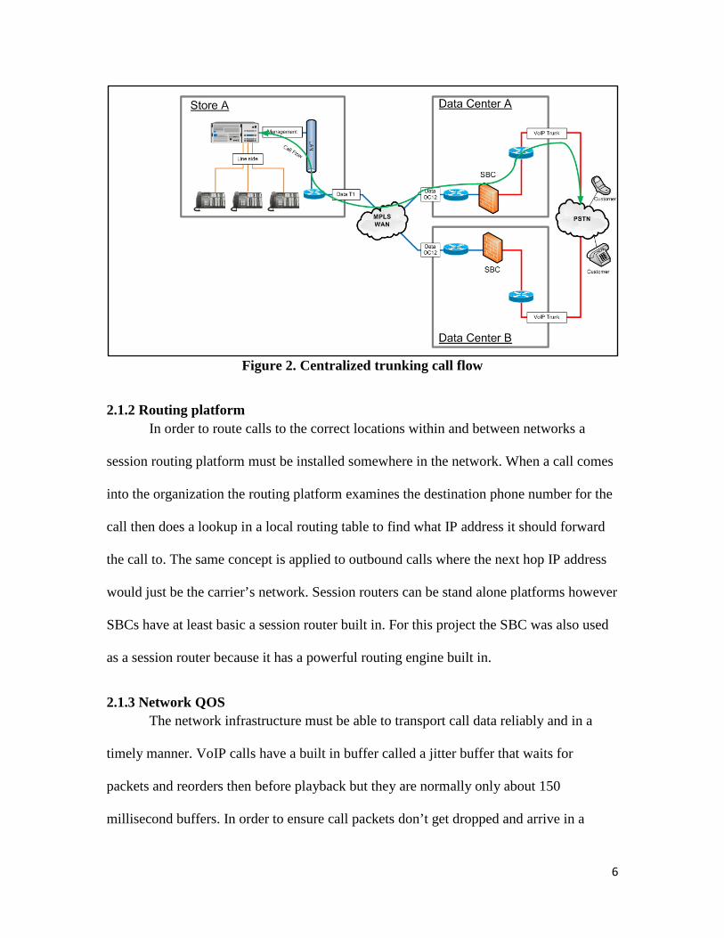
network as the PSTN gateway. Figure 2 shows a basic call flow using centralized
trunking.
6
Figure 2. Centralized trunking call flow
2.1.2 Routing platform In order to route calls to the correct locations within and between networks a
session routing platform must be installed somewhere in the network. When a call comes
into the organization the routing platform examines the destination phone number for the
call then does a lookup in a local routing table to find what IP address it should forward
the call to. The same concept is applied to outbound calls where the next hop IP address
would just be the carrier’s network. Session routers can be stand alone platforms however
SBCs have at least basic a session router built in. For this project the SBC was also used
as a session router because it has a powerful routing engine built in.
2.1.3 Network QOS The network infrastructure must be able to transport call data reliably and in a
timely manner. VoIP calls have a built in buffer called a jitter buffer that waits for
packets and reorders then before playback but they are normally only about 150
millisecond buffers. In order to ensure call packets don’t get dropped and arrive in a

7
timely manner the network in which the calls are traveling should be enabled for quality
of service (QoS). The remote routers along with the edge routers at the datacenter will be
performing QOS tagging on voice traffic to ensure packet priority. QOS will also be
purchased as a service on the data T1s going to the remote locations along with the
circuits at the data center in order to ensure the packets remain a priority while traveling
through the service provider’s network.
2.2 Physical Lab Layout Figure 3 shows the physical layout of the lab environment. At the top is the edge
router. The tan line to Verizon is a T1 data connection to an MPLS network connection
the lab to Verizon’s VoIP services. It also has a connection to the lab switch on the
switch port 1 VLAN 2.
The switch then connection to each SBC on SBC ports S0P0 and switch ports 21
and 22 which are also on VLAN 2. This connection is for the SBC untrusted traffic
facing Verizon.
The switch again connects to each SBC on SBC ports S0P1 and switch ports 23
and 24 which are on VLAN 3. This connection is for the SBC trusted traffic to the
internal network facing the Nortel BCM phone systems.
The SBCs are connected to each other via two crossover cables that allow them to
work as one unit for the high availability. The SBC management interfaces are also
connected to the switch on ports 19 and 20 on VLAN 4.
Each of the phone systems are connect to the switch on ports 2 and 4 on VLAN 3.

8
Figure 3. Physical lab layout
Edge Router
Switch
SBC0
SBC1
BCM0 BCM1
S0P0 S1P0

9
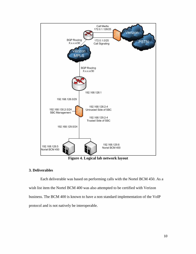
2.3 Logical Lab Network Layout Figure 4 shows the logical network layout of the lab environment. These subnets
are changed from the actual IP subnets but provide a reference for how the lab is
configured.
An example inbound call would initially send a packet containing call setup
information from Verizon’s call signaling subnet (172.0.1.0/25) to the untrusted interface
of the lab SBC (192.168.128.2). The SBC would then examine the packet and if it is valid
it will perform network address translation up to layer 7 and forward the packet to the
destination phone system IP address. The phone system would respond along the same
path in reverse. The call would then start streaming from both sides in both directions. On
Verizon’s side a different subnet is used for media (172.0.1.1) rather than using the same
one as the call signaling. The lab side uses the same subnet for signaling and media.
10
Figure 4. Logical lab network layout
3. Deliverables
Each deliverable was based on performing calls with the Nortel BCM 450. As a
wish list item the Nortel BCM 400 was also attempted to be certified with Verizon
business. The BCM 400 is known to have a non standard implementation of the VoIP
protocol and is not natively be interoperable.

11
3.1 Perform inbound and outbound calls / faxes
The end user should be able to make calls just as they normally do today. All
PSTN features should be available to the end user as they are today.
3.2 Application layer SIP NAT
The SBC should provide the internal network with topology hiding.
3.3 SIP private header removal
The SBC should remove all sensitive information before traffic exits into the
untrusted network facing Verizon.
3.4 Call admission control
The SBC should be able to protect the voice service as well as itself by limiting
the number of connections an endpoint can make. It should also block incoming calls
destined for unknown numbers.
3.5 High Availability
The SBC should be configured in a highly available mode so that it is not a single
point of failure.
4. Project Planning
4.1 Budget
For the lab proof of concept all of the equipment is already in available. Each
manufacture (or service provider) has provided test equipment/services at no cost for lab
testing. For the production implementation the target company will be purchasing all
equipment at their confidential negotiated rates. There have been no unexpected
additional costs related to this project.

12
4.2 Timeline
Figure 5 shows the original timeline from the conception of the project. The lab
configuration piece went according to plan with the exception of the configuration certification
with Verizon. The certification did not happen until early May due to other changes that were
happening in the lab with the Verizon circuit. The production implementation was eliminated
from the senior design schedule because the company funding has been delayed. The
production implementation will still happen but not until senior design has already ended.
Figure 5. Original timeline
4.3 Software
The only PC software used was Wireshark. This application was used for packet
capturing. The remaining software was just the firmware embedded into the networking
equipment.
4.4 Hardware
The following hardware platforms were used in the lab testing.

13
4.4.1 Session Border Controller
The SBC was the Acme Packet Net-Net Session Director 4500 running firmware
SCX6.1.0 MR-4 Patch 2 (Build 682). This platform acted as the core security and session
routing platform.
4.4.2 Endpoint PBX
The remote location PBX was a Nortel BCM450 Revision 5 Software
9.0.1.01.480.
4.4.3 Network
The data infrastructure consisted of a Cisco 2821 router and 3750 switch.
4.4.4 SIP Trunking Service
The service provider was Verizon Business using their Burstable Enterprise SIP
Trunking (BEST) product. They are provided a data T1 with QOS and concurrent call
ports in order to replicate the datacenter centralized trunking services on a small scale.

14
5. Proof of Design
The following sections outline how each deliverable was met.
5.1 Perform inbound and outbound calls / faxes
The following test cases show packet captures various types of PSTN calls
routing through the system successfully or failing when they should. These test cases
prove that all the normal PSTN features are available for users and that the migration will
be transparent to end users. For proof of interoperability a letter from the Verizon
engineer this author worked with can be found in Appendix A. The interoperability
testing was completed and this configuration is now certified for interoperability for use
with Verizon VoIP services.
As a note for the packet captures some of the information has been blocked out.
For reference the IP address ending in x.x.x.17 is the Verizon call signaling address. The
IP address ending in x.x.x.132 is the Verizon media address. The two Verizon IPs are on
the same subnet. The IP address ending in x.x.x.2 is the lab session border controller
untrusted interface for signaling and media. The lab IP is on a difference subnet.
5.1.1 Inbound Call
A Wireshark packet capture was taken during a simple inbound call from my cell
phone to the remote location phone system. Figure 6 shows the successful inbound call
flow using the call graphing feature of Wireshark. In this call flow the originator ends the
call. This can be seen by the fact that the BYE message was sent by the same side that
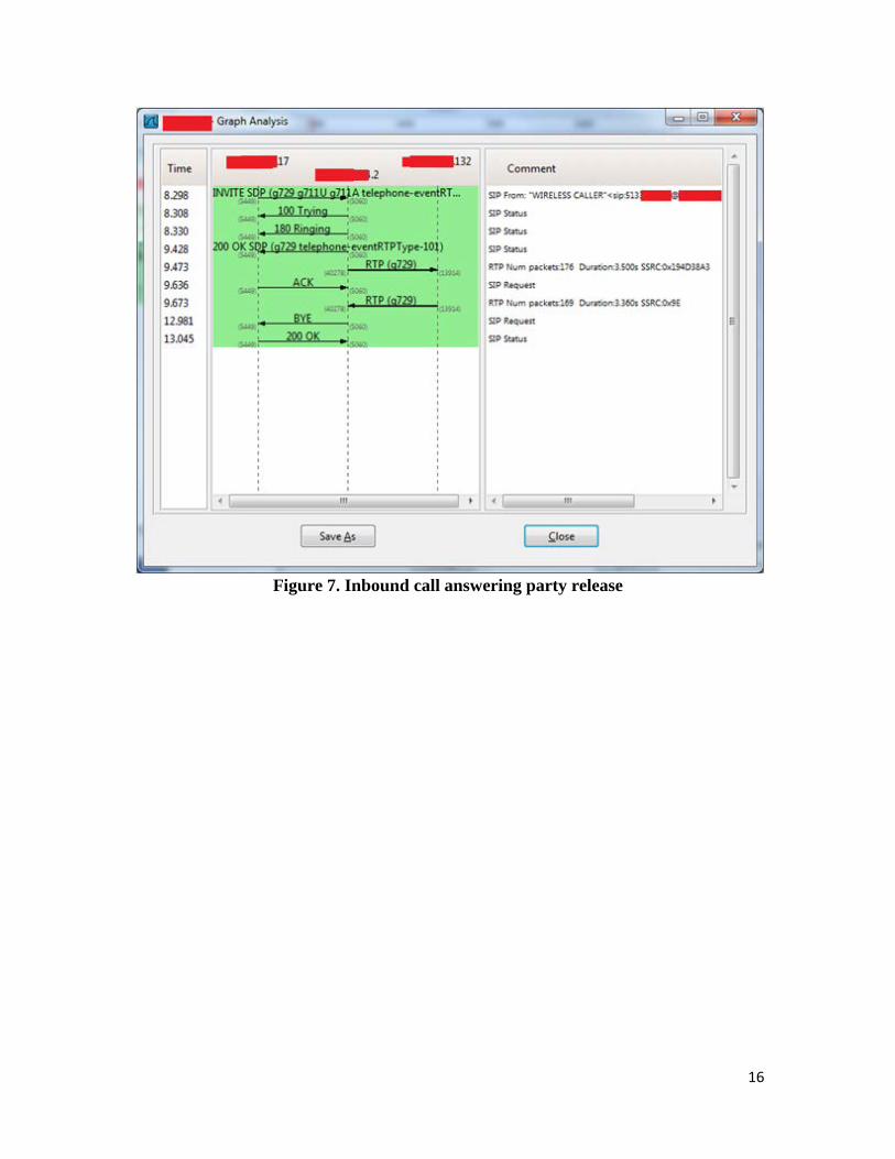
sent the first INVITE packet. Figure 7 shows the same type of inbound call with the

15
answering party ending the call. This can be seen by the fact that the BYE message was
sent by the other side rather than the side that sent the first INVITE packet.
Figure 6. Inbound call originator release
16
Figure 7. Inbound call answering party release

17
5.1.2 Inbound Call Cancel
Figure 8 shows the call flow of a call that starts ringing but the caller hangs up before the
call is answered. This test is to ensure the call request terminates properly.
Figure 8. Inbound call cancel

18
5.1.3 Inbound call rejection
Figure 9 shows a call coming in from Verizon destined for a number that is not
recognized as belonging to this company. The lab SBC rejects the call with a 404 Not
Found error.
Figure 9. Inbound call rejection

19
5.1.4 Caller-ID Support
Figure 10 shows deep into the INVITE packet and the FROM header is highlighted in
blue. This shows that the call is from “WIRELSS CALLER” and that the calling number
starts with 513. The entire number shows up on the phone system handsets along with the
name.
Figure 10. Caller-ID packet information

20
5.1.5 Call Waiting
Figure 11 shows a packet trace of two calls in order to prove call waiting works.
The first packet is an invite to a number destined for the lab phone system. This call is
setup and answered. While the first call is still going on a second call is placed to the
same number. The highlighted packet shows a response of 180 Ringing for the second
call. This shows that the configuration can handle call waiting.
Figure 11. Call waiting trace

21
5.1.6 Inbound Fax
Figure 12 shows an inbound call that is answered. The call comes up in the
default codec of G.729. This codec compresses calls in order to save bandwidth however
it disrupts faxes. Once the call and answered and the fax tones travel through the audio
path the phone system detects this and sends a INVITE message asking for the codec to
change to G.711 which is uncompressed and supports faxes. In the trace it can be seen
that the RTP packets start out as G.729 but after the second invite they switch to G.711.
The fax was received successfully.
Figure 12. Inbound fax

22
5.1.7 Inbound Call with Blocked Caller-ID
Figure 13 shows a successful inbound call. This call has a blocked caller-ID
value. This can be seen highlighted in the blue box that the call is from “Anonymous”.
Figure 13. Inbound Call with Blocked Caller-ID

23
5.1.8 Busy Signal
Figure 14 shows an inbound call that is rejected because the line is busy. This is a
configuration in the phone system to send a busy when a line is already in use or put the
user in call waiting. In this case it was configured to send a busy signal.
Figure 14. Busy Signal

24
5.1.9 No Answer Expiration
Figure 15 shows an inbound call that is not answered. After two minutes of
ringing (shown as 119.781 seconds and highlighted in blue) the Verizon network send a
CANCEL for the call.
Figure 15. No answer expiration

25
5.1.10 Long Duration Inbound Call
Figure 16 shows an inbound that stays up for over 20 minutes. The timestamp in
seconds of the BYE message is highlighted in blue.
Figure 16. Long duration inbound call

26
5.1.11 Outbound call
Figure 17 shows the successful outbound call. In this call flow the originator ends
the call. This can be seen by the fact that the BYE message was sent by the same side that
sent the first INVITE packet. Figure 18 shows the same type of outbound call with the
answering party ending the call. This can be seen by the fact that the BYE message was
sent by the other side rather than the side that sent the first INVITE packet.
Figure 17. Outbound call originator release

27
Figure 18. Outbound call answering party release

28
5.1.12 Outbound Call Cancel
Figure 19 shows the call flow of an outbound call that starts ringing but the caller
hangs up before the call is answered. This test is to ensure the call request terminates
properly.
Figure 19. Outbound call cancel

29
5.1.13 Outbound Call 1+
Figure 20 shows an outbound call working when dialing 1+ 10 digits. The dialed
number is highlighted in blue as 1513xxxxxxx.
Figure 20. Outbound call 1+

30
5.1.14 Outbound International Call
Figure 21 shows an outbound call successfully terminating to an international
number. The dialed digits are highlighted in blue as 011442074931232.
Figure 21. Outbound international call

31
5.1.15 Directory Assistance
Figure 22, 23, and 24 each show an outbound call to directory service at 5551212,
411, and 1411 respectively. The dialed digits are each highlighted in blue.
Figure 22. Directory assistance 5551212

32
Figure 23. Directory assistance 411

33
Figure 24. Directory assistance 1411

34
5.1.16 711 Telephone Relay Services
Figure 25 shows a successful outbound call to 711 Telephone Relay Services. The
dialed number, 711, is highlighted in blue.
Figure 25. 711 telephone relay services
35
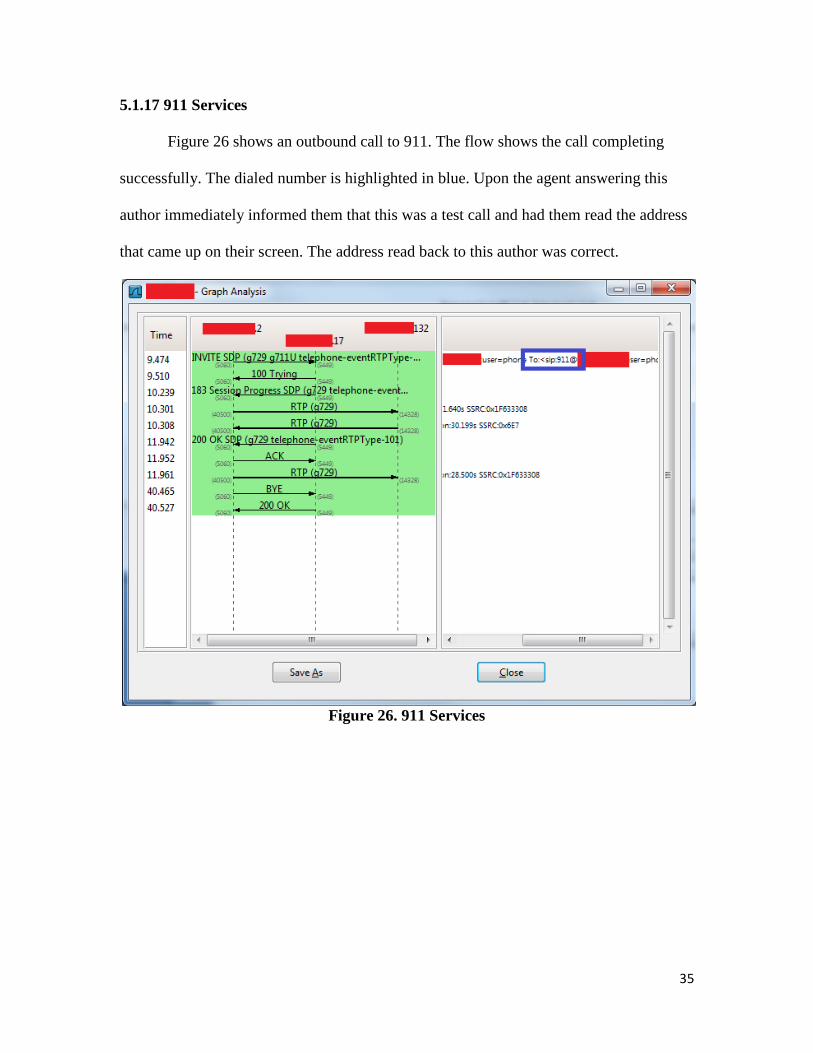
5.1.17 911 Services
Figure 26 shows an outbound call to 911. The flow shows the call completing
successfully. The dialed number is highlighted in blue. Upon the agent answering this
author immediately informed them that this was a test call and had them read the address
that came up on their screen. The address read back to this author was correct.
Figure 26. 911 Services

36
5.1.18 511 Information
Figure 27 shows an outbound call complete successfully to 511 information
services. The dialed number is highlighted in blue.
Figure 27. 511 Information

37
5.1.19 Outbound Toll Free
Figure 28 shows an outbound call complete to an 800 number. The dialed number
is highlighted in blue.
Figure 28. Outbound toll free

38
5.1.20 Operator Assistance
Figures 29, 30, 31, 32, and 33 each show an operator assisted call by dialing
0+local number, 0+toll number, 0, 00, and 01+international number respectively. For
each figure the dialed number is highlighted in blue.
Figure 29. Operator assistance 0+local number

39
Figure 30. Operator assistance 0+toll number

40
Figure 31. Operator assistance 0

41
Figure 32. Operator assistance 00

42
Figure 33. Operator assistance 01+international number

43
5.1.21 Outbound Fax
Figure 34 shows an outbound call that is answered. The call comes up in the
default codec of G.729. This codec compresses calls in order to save bandwidth however
it disrupts faxes. Once the call and answered and the fax tones travel through the audio
path the Verizon network detects this and sends a INVITE message asking for the codec
to change to G.711 which is uncompressed and supports faxes. In the trace it can be seen
that the RTP packets start out as G.729 but after the second invite they switch to G.711.
The fax was sent successfully.
Figure 34. Outbound fax

44
5.1.22 Early Answer
Figure 35 shows an outbound call to a system that does something called early
answer. The remote side starts to send the media stream before it actually sends a 200 OK
response to the INVITE message containing the media stream description. The capture
shows that the call still gets setup and completes successfully.
Figure 35. Early answer

45
5.1.23 Invalid Caller-ID
Figure 36 shows an outbound call attempt with a bogus caller-ID value.
Highlighted in blue the FROM value can be seen as 1234567890. This is not a phone
number that Verizon has configured as belonging to this location so it blocked attempts to
use this caller-ID by sending a 408 Request Timeout message.
Figure 36. Invalid caller-ID

46
5.1.24 Long Duration Outbound Call
Figure 37 shows an outbound that stays up for over 20 minutes. The timestamp in
seconds of the BYE message is highlighted in blue.
Figure 37. Long duration outbound call

47
5.1.25 DTMF
DTMF tones are the tones played when keys are pressed on a phone. Figure 38
shows an outbound call into a conference bridge. As with most conference bridges a
passcode must be entered in order to join the bridge. The capture shows the passcode
digits 8330 followed by # highlighted in blue. The conference bridge responded
according and let me enter the bridge as expected.
Figure 38. Outbound DTMF

48
Figure 39 Shows an inbound call to the Nortel BCM 450. The BCM was
configured to automatically answer with an auto attendant menu. Once the call was
automatically answered the menu was played and this author selected 7 as shown
highlighted blue. The menu responded accordingly and played the submenu message.
Figure 39. Inbound DTMF

49
5.1.26 G.711 Media
Figure 40 shows an outbound call with two media options offered to Version. The
two options are highlighted in blue. They are G.711 followed by G.729. This order shows
the preference. Since G.711 is listed first it is the presented preference. The lower RTP
media packets show that the media stream came up in G.711.
Figure 40. G.711 media

50
5.1.27 G.729 Media
Figure 41 shows an outbound call with two media options offered to Version. The
two options are highlighted in blue. They are G.729 followed by G.711. This order shows
the preference. Since G.729 is listed first it is the presented preference. The lower RTP
media packets show that the media stream came up in G.729.
Figure. 41 G.729 media

51
5.1.28 Early Media
Figure 42 shows an outbound call where the remote system responds to the invite
with a 183 Session Progress packet rather than a 200 OK. It also starts sending media
before the 183 message. This is not standard however the SBC and Nortel BCM450 still
handle the call and it completes successfully.
Figure 42. Early media

52
5.2 Application Layer SIP NAT
In order to provide topology hiding the session border controller needs to change
the IP address not only in the IP headers but within the data payload. Figure 43 shows a
packet capture of an inbound call between the SBC and the Nortel BCM phone system.
For reference the IP address ending in 114 is the internal network interface of the SBC
and the IP address ending in 13 is the Nortel BCM phone system. Highlighted in blue is
the IP address of the phone system in the data payload.
Figure 44 shows the same call after the SBC has done the translation. The IP
address of the Nortel BCM phone system gets translated to the public facing IP address
of SBC.
Figure 43. Internal SIP NAT traffic
Figure 44. External SIP NAT traffic

53
5.3 SIP Private Header Removal
Certain headers within the SIP payloads can contain information that shouldn’t
leave a private network. An example of the User-Agent field is highlighted in Figure 45.
Figure 45 is a packet from the Nortel BCM phone system destined for the SBC which
will pass it along to Verizon. The User-Agent header contains the version of the of SIP
library that is being used by the Nortel BCM phone system. External parties do not need
this information. This type of information can also be used by an attacker to research
what vulnerabilities that SIP library is vulnerable to and exploit those weaknesses.
Although it is unlikely that information would lead to an exploit removing it before the
packets leave the network is one more layer of security.
Figure 46 shows the same packet after it has been processed by the SBC. The
User-Agent header is completely removed from the packet.
Figure 45. Internal private header traffic

54
Figure 46. External private header traffic

55
5.4 Call Admission Control
Figure 47 shows an inbound call attempt for a number that the SBC has does not
have in its local routing table. The call attempt is blocked with a 404 Not Found.
Figure 47. Unknown number rejection

56
Figure 48 shows multiple call attempts into the SBC. The first 3 calls are all to the
same number being routed to the Nortel BCM 450. The fourth call is being routed to
other equipment in the testing lab. Call path limiting was enabled on the connection to the
Nortel BCM 450 to only allow one concurrent call. This allowed the first call to complete
but rejected more calls to the BCM while the first call was still active. This configuration
still allowed calls to be placed to other connections off the SBC which is shown by the
fourth call.
Figure 48. Call path limiting
5.5 High Availability
Figure 49 shows part of the RTP (media) packets for an active call during the high
availability failover. It can be seen that the first four packets alternate destinations show
the bidirectional media flows. After the first four packets only the inbound packets from
Verizon are seen. At the point the SBC is working on failing over. The standby SBC
sends out Gratuitous ARP message in order to take control of the IP address facing
Verizon. Shortly after the RTP (media) packets become bidirectional again. As seen by
the time stamps this entire process took about a third of one second. This is barely
noticeable to a user on a call.

57
Figures 50 and 51 also show the shared virtual MAC address of the SBC moving
switch interfaces from gigabit interface 23 to gigabit interface 24.
Figure 49. HA media failover
Figure 50. MAC address table pre-failover

58
Figure 51. MAC address table post-failover
6. Testing Scenarios
Each deliverable was tested using the following methods.
6.1 Perform inbound and outbound calls / faxes
These test cases not only validate that the calls appears to work correctly but the
test are performed with a Verizon engineer who validates at the packet level that the call
meet their protocol specifications. The interoperability certification based on these test
cases will serve as proof of this deliverable.
6.2 Application layer SIP NAT
SIP NAT ensures the topology hiding function of the session border controller. This can
be validated by a packet capture showing the SIP dialog of the call setup. The packet
capture should show that the packets on the untrusted side of the session border controller
(facing Verizon) contain no IP addresses of the internal equipment. The internal IP
address should be replaced by the IP address facing Verizon.

59
6.3 SIP private header removal
By default many phone system generate information within the SIP packet regarding the
make and model of the phone system. This information could be used by a hacker
attempting to find system weaknesses. A packet capture showing both the trusted and
untrusted side of the session boarder controller will show the removal of this information
before it is sent to Verizon.
6.4 Call admission control
Each session agent (remote phone system) needs to be limited to how many phone calls
that location can make due to bandwidth and security reasons. Call admission control sets
limits on how many concurrent phone calls a session agent can make. The session border
controller will be set to an arbitrarily low number of concurrent calls allowed (such as 3).
A packet capture will be taken showing the setup of 3 concurrent calls and a 4th
concurrent call attempt that is blocked by the session border controller.
6.5 High Availability
This test should prove that active calls are not dropped in the event that one of the two
session boarder controllers fail. This will be proven by setting up an active call and then
pulling the power on the active node. This should cause the cluster to fail over with no
disruption in service. (By no disruption in service it is meant that the user has no
knowledge of the failover. In reality there is a short loss of audio but it is so minimal, sub
100ms, that the user doesn’t notice.) During the failover there will be a set of assistants
speaking and listening on the call to sure they can communicate throughout the failover.

60
7. Conclusions and Recommendations
7.1. Conclusions
This author has very confidently concluded that VoIP trunking is a workable
solution for organization looking to migrate their telephony infrastructure to the next
generation.
7.2. Recommendations
After working closely with VoIP products for the last year this author has come
across many weaknesses in default configurations. This author has found that many
technology partners just want to make things work and that don’t seriously consider
security when installing systems. Any technologist looking to implement direct VoIP
communications with external parties needs to devote the time and effort at the packet
level to deeply understand the traffic in order to define a best security practice for their
environment.
Examining packets and lab testing can also lead to many discoveries about a
manufactures implementation of VoIP. It is common knowledge among system
administrators that SIP (the main VoIP protocol) is a loosely defined protocol. It was
only after working with various systems in the lab did this author fully understand how
different every manufacturer implementation is. A manufacturer’s claims regarding SIP
support does not mean that they have implemented the entire feature set or that the
product will work with other devices. This author’s primary recommendation is to do
thorough lab testing before making any major VoIP related investments.

61
Appendix A