voicemanager 110 - customer engineer manual
DESCRIPTION
sophoTRANSCRIPT

VoiceManager 110 - Customer Engineer Manual ADDENDUM TO SECTION 8.2 Using IAS Application Loader V1.00 with Windows XP When starting the IAS Application Loader V1.00 one should keep in mind that when it is running on Windows XP operating system, the application sometimes hangs-up or the BCS protocol times out. A patch is available to repair above mentioned problem. Do the following : 1. Open Windows Explorer (Start “Right Hand Mouse Click” Explore) 2. Navigate to the directory where the IAS application loader (AL.EXE) is
installed. 3. Modify the properties of AL.EXE by :
• Selecting AL.EXE • Click “Right Hand Mouse Click” Properties. • Select the MISC tab • Move the slider “Idle sensitivity” to high • Click “Apply”
4. Restart the application loader and all should work correctly now.

nten
ts
AMENDMENTS 1
PREFACE 2
1. INTRODUCTION 3
1.1. WHAT THE IASA IS 31.2. WHAT THE IASA DOES 3
1.2.1. IASA Functionality 31.3. WHERE THE IASA IS USED 31.4. IASA CHARACTERISTICS 3
2. BOARD LAYOUT AND CONNECTORS 5
2.1. FRONT VIEW OF CIRCUIT BOARD 52.2. PLAN VIEW OF CIRCUIT BOARD (COMPONENT SIDE) 62.3. CONNECTORS 7
2.3.1. Rear Connectors - PM Bus and Power 72.3.2. Rear Connector - Ground 82.3.3. Front Connector - V.24 Serial Interface (F122) 82.3.4. BIST Connector 8
3. INSTALLATION - GENERAL SEQUENCE 9
3.1. INTRODUCTION 93.2. INSTALLATION SEQUENCE 9
4. HARDWARE INSTALLATION 11
4.1. STRAP SETTINGS 114.1.1. On-board Battery 114.1.2. Interface Selection 12
4.2. CARD POSITION IN ISPBX 124.2.1. Slot Width 124.2.2. Position in Unit Group 12
4.3. SPEECH MEMORY 134.3.1. Fitting Memory Boards to the IAS Circuit Board 144.3.2. Removing Memory Boards from the IAS Circuit Board 15
4.4. LEDs 174.5. BIST CONNECTOR 17
5. EQUIPMENT CONNECTION 18
5.1. INSERTING IAS CIRCUIT BOARD INTO AN ISPBX 185.2. DIRECT CONNECTIONS 19
5.2.1. Using a Null-modem Cable 195.2.2. Using Modems 20
i
Tab
le o
f co
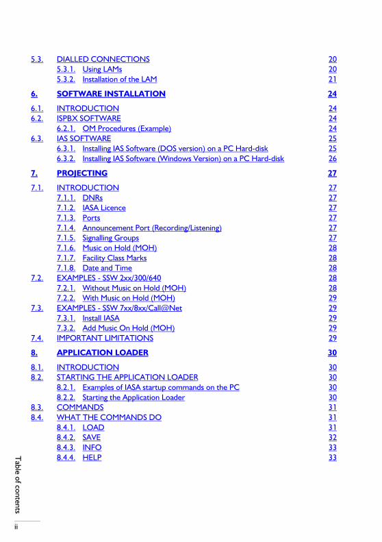
ii
Table of contents
5.3. DIALLED CONNECTIONS 205.3.1. Using LAMs 205.3.2. Installation of the LAM 21
6. SOFTWARE INSTALLATION 24
6.1. INTRODUCTION 246.2. ISPBX SOFTWARE 24
6.2.1. OM Procedures (Example) 246.3. IAS SOFTWARE 25
6.3.1. Installing IAS Software (DOS version) on a PC Hard-disk 256.3.2. Installing IAS Software (Windows Version) on a PC Hard-disk 26
7. PROJECTING 27
7.1. INTRODUCTION 277.1.1. DNRs 277.1.2. IASA Licence 277.1.3. Ports 277.1.4. Announcement Port (Recording/Listening) 277.1.5. Signalling Groups 277.1.6. Music on Hold (MOH) 287.1.7. Facility Class Marks 287.1.8. Date and Time 28
7.2. EXAMPLES - SSW 2xx/300/640 287.2.1. Without Music on Hold (MOH) 287.2.2. With Music on Hold (MOH) 29
7.3. EXAMPLES - SSW 7xx/8xx/Call@Net 297.3.1. Install IASA 297.3.2. Add Music On Hold (MOH) 29
7.4. IMPORTANT LIMITATIONS 29
8. APPLICATION LOADER 30
8.1. INTRODUCTION 308.2. STARTING THE APPLICATION LOADER 30
8.2.1. Examples of IASA startup commands on the PC 308.2.2. Starting the Application Loader 30
8.3. COMMANDS 318.4. WHAT THE COMMANDS DO 31
8.4.1. LOAD 318.4.2. SAVE 328.4.3. INFO 338.4.4. HELP 33

nten
ts
8.4.5. QUIT 348.5. ERROR MESSAGES 34
9. IASA MANAGEMENT 37
9.1. INTRODUCTION 379.2. STARTING IASA MANAGEMENT 389.3. PULL-DOWN MENUS 389.4. "CONNECT" - PULL-DOWN MENU 39
9.4.1. Direct Connection 399.4.2. Dialled Connection 409.4.3. Disconnect 409.4.4. Serial Port 409.4.5. Exit IASA Management 40
9.5. "DIRECTORY" -- PULL-DOWN MENU 419.5.1. Own 429.5.2. Common 429.5.3. Global 429.5.4. Disk 429.5.5. Switch (F10) 429.5.6. Backup Drive and Directory 439.5.7. Print 439.5.8. Print to File 43
9.6. "ANNOUNCEMENTS" -- PULL-DOWN MENU 439.6.1. Play 439.6.2. Re-Record 439.6.3. Erase (DEL) 449.6.4. Create 449.6.5. Edit Description 449.6.6. Edit Index 449.6.7. Backup 449.6.8. Restore 459.6.9. View Statistics 459.6.10. Hide Statistics 459.6.11. Reset Statistics 469.6.12. Refresh Statistics 46
9.7. PORTS 469.7.1. System Configuration 469.7.2. Port Mapping 489.7.3. Backup 509.7.4. Restore 519.7.5. Print 52
iii
Tab
le o
f co

iv
Table of contents
9.7.6. Print to File 529.7.7. View Alarms 529.7.8. Backup Registry 54
9.8. REGISTRY 549.8.1. Change Password 549.8.2. Maintain Registry 549.8.3. Restore Registry 55
9.9. HELP 569.9.1. Help System Overview 569.9.2. Complete Help Text 569.9.3. About IASA 569.9.4. About IASA Management 56
10. SYSTEM LIMITATIONS 58
10.1. SIMULTANEOUS ANNOUNCEMENTS 5810.2. SLOT WIDTH 5810.3. POSITION IN UNIT GROUP 5810.4. TIME REQUIRED TO LOAD/RETRIEVE ANNOUNCEMENTS 5810.5. TRUNKS AND OPERATOR QUEUES 58
10.5.1. SSW 7xx/8xx/Call@Net 5910.5.2. SSW 2xx/300/640 59
10.6. DATE AND TIME 59
11. PASSWORDS 61
11.1. INTRODUCTION 6111.2. DEFAULT PASSWORDS 6111.3. ONE-DAY PASSWORD TOOL 62
11.3.1. DOS version 6211.3.2. Windows version 62
12. PERSONAL MESSAGES 64
12.1. INTRODUCTION 6412.1.1. Personal messages 6412.1.2. General Messages 64
12.2. MESSAGE SEQUENCE 6412.3. MESSAGE CREATION 64
12.3.1. Messages owned by a DNR User (Personal Messages) 6412.3.2. Messages Created by the User "Personal" (General Messages) 65
13. APPLIANCES 66
13.1. TRANSFERRING TAPED RECORDINGS 66

nten
ts
13.1.1. Making recordings 6713.1.2. Initialising the SOPHO-SET S375D 67
13.2. MUSIC ON HOLD 6813.3. MESSAGE WAITING AND WAKE-UP 6813.4. TRUNK ANNOUNCEMENTS 68
A . CABLES 69
A.1. V.24 CABLES 69A.1.1. Null-Modem Cable (D9 Connector) 70A.1.2. Null-Modem Cable (D25 Connector) 71A.1.3. One-to-One Cable (D25 Connector) 72
B . SYSTEM SOFTWARE SUPPORTING IASA 73
C . SURVEY OF ALARMS 75
v
Tab
le o
f co
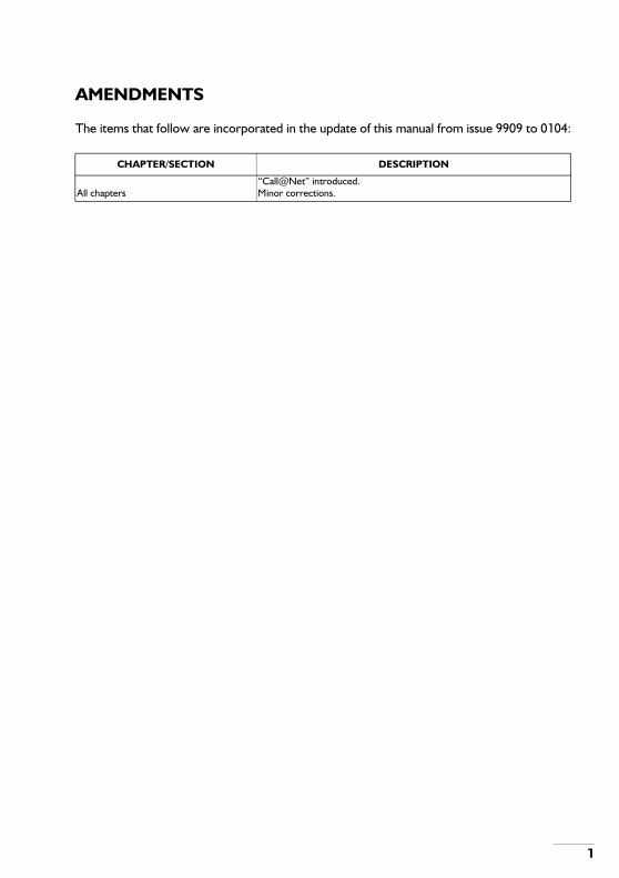
AMENDMENTS
The items that follow are incorporated in the update of this manual from issue 9909 to 0104:
CHAPTER/SECTION DESCRIPTION
All chapters“Call@Net” introduced.Minor corrections.
1
2
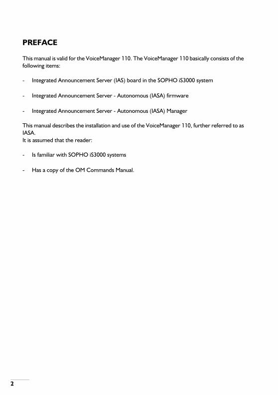
PREFACE
This manual is valid for the VoiceManager 110. The VoiceManager 110 basically consists of the following items:
- Integrated Announcement Server (IAS) board in the SOPHO iS3000 system
- Integrated Announcement Server - Autonomous (IASA) firmware
- Integrated Announcement Server - Autonomous (IASA) Manager
This manual describes the installation and use of the VoiceManager 110, further referred to as IASA.It is assumed that the reader:
- Is familiar with SOPHO iS3000 systems
- Has a copy of the OM Commands Manual.

1. INTRODUCTION
1.1. WHAT THE IASA IS
The Integrated Announcement Server Autonomous (IASA) is a full-height IAS printed wiring board, loaded with IASA firmware; it is inserted into a SOPHO ISPBX shelf. This circuit board is exactly the same hardware as the IAS circuit board; the only difference is that it has different firmware loaded into its memory. The name printed on the front edge of the circuit board is therefore 'IAS'.
1.2. WHAT THE IASA DOES
The IASA functionality is shown below.
1.2.1. IASA Functionality
- Records voice messages;- Supports personal announcements created by extension users;- Stores up to 255 voice messages in battery-backed static RAM;- Plays back voice messages;- Allows back-up of voice messages to a PC disk file;- Allows restoration of voice messages from a PC disk file.- Diverts incoming calls to a user-defined destination, after an announcement is played.
This is done under control of the IASA's own CPU, not that of the ISPBX;- Plays Music on Hold (MOH);- Checks the current IASA time against the IASA Management time and allows it to be
updated if they do not agree.
1.3. WHERE THE IASA IS USED
The IASA is used in SOPHO iS3000 systems that use the following System SoftWare (SSW) : 200/205, 300, 640, 730/735, 740/741, 800, 805 and [email protected] the IAS, more than one IASA can be used per ISPBX unit.
Note: Projecting the IASA board is different in the various iS3000 SSWs. Consult the OM Commands Manual of the particular SSW for more details.
1.4. IASA CHARACTERISTICS
1. The IASA emulates a DLC-C or DLC-U15.
3
4
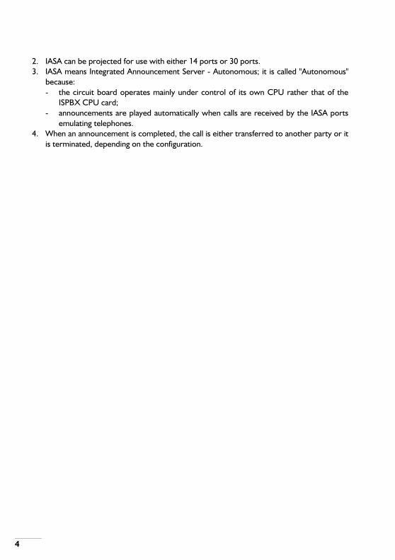
2. IASA can be projected for use with either 14 ports or 30 ports.3. IASA means Integrated Announcement Server - Autonomous; it is called "Autonomous"
because:- the circuit board operates mainly under control of its own CPU rather that of the
ISPBX CPU card;- announcements are played automatically when calls are received by the IASA ports
emulating telephones.4. When an announcement is completed, the call is either transferred to another party or it
is terminated, depending on the configuration.

2. BOARD LAYOUT AND CONNECTORS
2.1. FRONT VIEW OF CIRCUIT BOARD
Figure 2-1 Front Layout of the IAS Circuit Board.
5

6
2.2. PLAN VIEW OF CIRCUIT BOARD (COMPONENT SIDE)
Figure 2-2 IAS Board Layout.
2.3. CONNECTORS
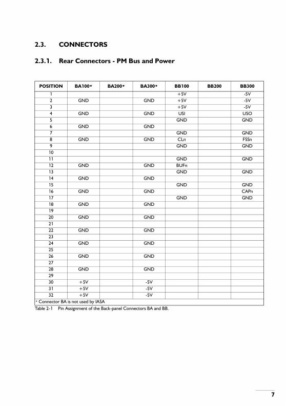
2.3.1. Rear Connectors - PM Bus and Power
Table 2-1 Pin Assignment of the Back-panel Connectors BA and BB.
POSITION BA100* BA200* BA300* BB100 BB200 BB300
1 +5V -5V2 GND GND +5V -5V3 +5V -5V4 GND GND USI USO5 GND GND6 GND GND7 GND GND8 GND GND CLn FSSn9 GND GND
1011 GND GND12 GND GND BUFn13 GND GND14 GND GND15 GND GND16 GND GND CAPn17 GND GND18 GND GND1920 GND GND2122 GND GND2324 GND GND2526 GND GND2728 GND GND2930 +5V -5V31 +5V -5V32 +5V -5V
* Connector BA is not used by IASA
7

8
2.3.2. Rear Connector - Ground
Table 2-2 Ground Connector (BP).
2.3.3. Front Connector - V.24 Serial Interface (F122)
Table 2-3 Pin Assignment - V.24 Serial Interface Connector FCC (F122).
2.3.4. BIST Connector
The IAS circuit board has a BIST connector (X.5.1.) mounted on the component side of the circuit board; BIST = Built-in Self Test. This connector is designed only to be used during factory testing and external equipment should not be connected to it.
Table 2-4 BIST Connector Signals.
BP 101 BP 102
- GND
POSITION FCC 100 FCC 200 FCC 300
1 - - TXD2 - - GND3 RXD - RTS4 - - -5 CTS - DSR6 - - -7 DTR - DCD8 - - -
POSITIONX.5.1
100 200
1 - -2 BIST# -3 RESET# -4 +5V* -5 RXD -6 TXD -7 - -8 GND -
* The +5V is a signal voltage, it does not allow any current to be drawn from this point.
3. INSTALLATION - GENERAL SEQUENCE
3.1. INTRODUCTION
This chapter describes the general sequence in which installation should be done. The list below refers to both hardware and software items; look in the relevant hardware and software chapters for more details of each.
3.2. INSTALLATION SEQUENCE
• INSTALLATION SEQUENCE
Actions
1. Install IASA software onto a PC hard disk.2. Check strap settings on IAS board.3. Insert IAS board into the ISPBX.4. Connect a cable between the PC and the IAS board.
orConnect a LAM between the ISPBX and the IAS board (connector FCC) and connect aLAM between the ISPBX and the PC.
5. Use the program "Application Loader" to load IASA firmware onto the IAS board.6. Use OM commands to project the board as an IASA board.7. Install the IASA Management software on the PC hard disk.
(The windows version of the IASA Management software comes as part of the SysManager410.)
8. Check that the PC's date and time are correct.9. Change passwords for users "Service" "Common" and "Personal" to ensure system
security.10. Log into the IASA as the user "common" and create users in the registry.11. Log into IASA as the user "service", if prompted to update the IASA time then do so; do
system configuration and port mapping.12. Check that the date and time shown by IASA are correct (Look in the pull-down menu
"HELP - ABOUT IASA" to see what the IASA time is, refer to section About IASA on page56).
Note: Look also in section DATE AND TIME on page 59.
13. Store any system announcements that are required (for example, Music on Holdannouncements (MOH), personal announcement prompt.)
9

10
14. Use the one-day password tool to create one-day passwords for defined users.15. Distribute one-day passwords to users.16. Put the floppy disk containing the one-day password tool in a safe and secure storage
place.17. Use the system and ensure that it is working to the customer's satisfaction.

4. HARDWARE INSTALLATION
4.1. STRAP SETTINGS
There are two straps on the IAS circuit board which must be correctly set before the IAS card is inserted in an ISPBX; the straps and their functions are listed below:
Table 4-1 Straps.
4.1.1. On-board Battery
There are two NiCad batteries fitted on the IAS circuit board, which maintain the static RAM used to store speech. The voltage provided by the batteries is 2.4V. The battery life is 7.5 years.The batteries are maintained by the on-board battery charging circuit; if the charging circuit is disconnected or the power has been removed from the IAS circuit board, the batteries will maintain data contained in the speech RAM for the periods defined in the table below; these are the minimum periods, measurements show that much longer periods can be expected but they cannot be guaranteed, rely only on the periods shown in the table.
Table 4-2 Data Retention Periods (Speech Memory).
Note: The values quoted assume that the on-board batteries are fully charged; to achieve this the IAS circuit board must have supply connected for an uninterrupted period of 40 hours;The IAS circuit board is normally supplied with the NiCad batteries fitted but with strap X3.1. in the "BATTERY DISCONNECTED" position; this ensures that the batteries retain their fully charged state while the circuit board is being transported or while it is not in use (NiCad batteries that are not in use do lose their charge gradually but over a much longer period than shown in the table). Strap X3.1. must be set in the correct position before the board is put into use, so that the battery charge is continuously maintained. Look at table below.
STRAP FUNCTION
X 3.1 Speech memory back-up battery connected/disconnected.X 3.2 PM bus enable/disable.
NUMBER OF MEMORY BOARDS DATA RETENTION PERIOD
0 33 days1 7 days2 4 days3 3 days
11

12
Table 4-3 Strap Positions - Battery Charging Circuit.
4.1.2. Interface Selection
The IASA firmware uses only the 2 Mb/s PM bus on the back plane, it does not use the 2 Mb/s SCU interface at the FAC front connector. Strap X3.2. must be set in the correct position. See table below.
Table 4-4 Strap Positions - 2 Mb/s Bus Selection.
The SCU connector is an F122 connector located in the FAC position on the front edge of the IAS circuit board. The connector is for use when the SCU interface has been selected, see BOARD LAYOUT AND CONNECTORS on page 5.
4.2. CARD POSITION IN ISPBX
4.2.1. Slot Width
The IAS circuit board requires a slot width of 1 inch (25.4 mm) in the ISPBX card-frame. Therefore, in some shelves, such as in a SOPHO-S250, the PCT slot to the right of the IAS circuit board must be left vacant.
4.2.2. Position in Unit Group
The IAS card with IASA firmware uses only the PM bus and may only be placed in the first position of a Unit Group; if it is fitted in the wrong position it may not establish communication with the PPU. The IAS with IASA firmware may be projected to use only half of the timeslots of a unit group (timeslots 0 to 15. This will allow other circuit boards to use the second half of the timeslots of that user group (timeslots 16 to 31).
Note: The IASA firmware uses timeslot 2 for recording or listening to announcements;The IAS with IASA firmware can be projected as a DLC-C.IASA can be projected to use a half unit group (14 ports) or a full unit group (30 ports). Each port is a voice port but port 2 can only be used for recording and
X3.1 BATTERY CONNECTED BATTERY DISCONNECTED
Strap position 101/102 102/103
X3.2USE PM BUS FROM
BACKPANELUSE SCU INTERFACE FROM
FRONT CONNECTOR*
Strap position 101/102 102/103* This position is not allowed with the IASA firmware.

listening to announcements, thus limiting the available announcement ports to 13 and 29 respectively;Any number of ports can be projected and, when only 14 ports or fewer have been projected, the second half of a unit group can be used for other boards.
4.3. SPEECH MEMORY
Speech memory consists of two 128Kx8 static RAMs configured to provide 128Kx16 storage space; extra speech memory, supplied on a "memory card", can be added if required. There are three positions for "memory cards" on the IASA board and, so, up to three "memory cards" can be fitted. The speech memory is maintained by an on-board battery. Speech memory is used to store:
- The announcements that are to be replayed when requested;- Speech control data;- A directory of the announcements.
In operation, the contents of speech RAM will be checked periodically using a 16 bit checksum; if an error is found, it will be logged on the IASA and an alarm indication bit will be sent to the IASA Management program (if it is connected) and the alarm can be viewed in the "View Alarms" screen.
Note: Announcements with errors are still played when requested because errors in the announcement stored are not always audible; an operator can listen to the announcement and replace it if its quality is found to be unacceptable;Errors can be caused by a faulty RAM chip or the battery being defective or not being fully charged; look at the section 4.1.1. "On-board Battery" and note the figures quoted for battery voltage and battery life.
The IAS circuit board can have up to three extra memory boards fitted, look at table. The table shows that, when there are 0 extra boards fitted, the total length of announcements that can be stored is 31 seconds; when extra memory boards are fitted the total length of announcements that can be stored is increased as shown.
Table 4-5 Speech Capacity.
NUMBER OF MEMORY BOARDS SPEECH WITH 1 Mbyte MEMORY BOARDS
SPEECH WITH 4 Mbyte MEMORY BOARDS
0 31 seconds 31 seconds1 161 seconds 551 seconds2 291 seconds 1071 seconds3 421 seconds 1591 seconds
13
14
4.3.1. Fitting Memory Boards to the IAS Circuit Board
Make sure you take electrostatic precautions when handling the board; to add memory boards do the following, in the sequence shown:
• If the circuit board is not initially in an ISPBX
Actions
1. Take electrostatic precautions before going any further;2. Insert the IAS circuit board into the ISPBX (It is not necessary to bring the board into
service);3. Back up the announcements, registry and port map contained in the IAS circuit board
memory;(if not already backed up; this can take a long time, see the note below)
4. Remove the IAS circuit board from the ISPBX;5. Disconnect the IAS circuit board memory batteries using strap X3.1; failure to do this
could damage the memory boards;(move strap X3.1. to the "battery disconnected" position. See table on page 12)
6. Fit the extra memory boards;(look at figure on page 6; fit a memory board to one of the memory-board positionsshown, any position or order is allowed.)
7. Connect the IAS circuit board memory batteries;(move strap X3.1. to the "battery connected" position. See table on page 12)
8. Insert the IAS circuit board into the ISPBX;9. Restore backed-up announcements, registry and port map to IAS circuit board memory;
(this can take a long time, see the note below)10. Make the required ports active;11. Set the IAS circuit board in service;
(use OM commands)12. Ensure the board is operating correctly, playing announcements and performing the
functions expected.
In operation, the IAS circuit board will determine how much speech memory is fitted.
Note: It takes approximately 100 seconds, using the V.24 port, to load 10 seconds of announcements, from a PC, into the IAS circuit board memory. These figures assume a data rate of 9600 bits/second. The time taken to retrieve announcements (to do a backup) is the same. The time taken to transfer larger amounts of speech information (announcements) is proportionately longer.
• If the circuit board is already fitted in an ISPBX
Actions
1. Back up the announcements, registry and port map contained in the IAS circuit boardmemory;(if not already backed up; this can take a long time, see the note above)
2. Set the IAS circuit board out of service;(use OM commands)
3. Take electrostatic precautions before removing the IAS circuit board from the ISPBX andbefore going any further;
4. Remove the IAS circuit board from the ISPBX;(it is not necessary to switch the ISPBX off)
5. Disconnect the IAS circuit board memory batteries using strap X3.1; failure to do thiscould damage the memory boards;(move strap X3.1. to the "battery disconnected" position. See Table on page 12)
6. Fit the extra memory boards;(look at Figure on page 6; fit a memory board to one of the memory-board positionsshown, any position or order is allowed.)
7. Connect the IAS circuit board memory batteries;(move strap X3.1. to the "battery connected" position. See Table on page 12)
8. Insert the IAS circuit board into the ISPBX;9. Restore backed-up announcements, registry and port map to IAS circuit board memory;
(this can take a long time, see the note above)10. Make the required ports active;11. Set the IAS circuit board in service;
(use OM commands)12. Ensure the board is operating correctly, playing announcements and performing the
functions expected.
4.3.2. Removing Memory Boards from the IAS Circuit Board
Make sure you take electrostatic precautions when handling the board; to remove memory boards do the following, in the sequence shown:
• If the circuit board is already fitted in an ISPBX
Actions
1. Back up the announcements, registry and port map contained in the IAS memory; (see the
15

16
note in section Fitting Memory Boards to the IAS Circuit Board on page 14)2. Set the IAS circuit board out of service; (use OM commands)3. Take electrostatic precautions before removing the IAS circuit board from the ISPBX and
before going any further;4. Remove the IAS board from the ISPBX; (it is not necessary to switch the ISPBX off)5. Disconnect the IAS circuit board memory batteries using strap X3.1; failure to do this
could damage the memory boards;(move strap X3.1. to the "battery disconnected" position. See table on page 12)
6. Remove memory boards;7. Store the memory boards in anti-static packaging;8. If the circuit board is to be re-inserted in the ISPBX then re-connect the IAS memory
batteries;9. Re-insert the circuit board in the ISPBX and re-load announcements if required. (If the
amount of announcement memory on the circuit board has been reduced then it may notbe possible to restore all the previous announcements and you will therefore need todecide which ones you wish to restored.
10. Make ports active, bring the board into service and ensure the IASA operates correctly.11. If the circuit board is not to be re-inserted in the ISPBX then leave the memory batteries
disconnected and store the circuit board in anti-static packaging.
• If the circuit board has already been removed from the ISPBX
Actions
1. Make sure electrostatic precautions have been taken before going any further;2. Disconnect the IAS circuit board memory batteries using strap X3.1; failure to do this
could damage the memory boards;(move strap X3.1. to the "battery disconnected" position. See table on page 12)
3. Remove memory boards;4. Store the memory boards in anti-static packaging;5. If the circuit board is to be re-inserted in the ISPBX then re-connect the IAS memory
batteries;6. Re-insert the circuit board in the ISPBX and re-load announcements if required. (If the
amount of announcement memory on the circuit board has been reduced then it may notbe possible to restore all the previous announcements and you will therefore need todecide which ones you wish to restore.).
7. Make ports active, bring the board into service and ensure the IASA operates correctly.8. If the circuit board is not to be re-inserted in the ISPBX then leave the memory batteries
disconnected and store the circuit board in anti-static packaging.

4.4. LEDs
There are three LEDs on the front edge of the IAS circuit board, they show the status of the circuit board at all stages of power-up and operation. Look at table on page 17.
Table 4-6 LEDs
4.5. BIST CONNECTOR
The BIST connector is X5.1. as shown in figure on page 6. It is for factory use only.
GREEN RED YELLOW IAS BOARD STATUS
OFF OFF OFF No power.OFF ON OFF Circuit board initializing or board error.ON ON OFF Waiting for board activation from ISPBX.ON OFF OFF Board functional.ON OFF ON Speech recording or download or firmware installation in
progress.
17

18
5. EQUIPMENT CONNECTION
5.1. INSERTING IAS CIRCUIT BOARD INTO AN ISPBX
Figure 5-1 Local Connections.
Note: Make sure straps are set correctly (Section 4);Make sure the required amount of speech memory is fitted (Section 4);Choose the correct position in the shelf for the IAS circuit board (Section 4);The IAS circuit board with IASA firmware cannot use the SCU interface, it can only use the PM bus.

5.2. DIRECT CONNECTIONS
"DIRECT CONNECTION" is one of the choices available from the "Connect" pull-down menu, when you need to set up a connection to the IASA. There are two types of direct connection, one type uses a V.24 null-modem cable (Figure on page 19) and the other uses modems (Figure on page 20)
5.2.1. Using a Null-modem Cable
Figure 5-2 Local Connections - Less than 15 metres - Using a Null-modem Cable.
19
20
5.2.2. Using Modems
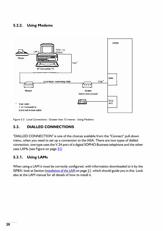
Figure 5-3 Local Connections - Greater than 15 metres - Using Modems
5.3. DIALLED CONNECTIONS
"DIALLED CONNECTION" is one of the choices available from the "Connect" pull-down menu, when you need to set up a connection to the IASA. There are two types of dialled connection, one type uses the V.24 port of a digital SOPHO Business telephone and the other uses LAMs (see Figure on page 21)
5.3.1. Using LAMs
When using a LAM it must be correctly configured, with information downloaded to it by the ISPBX; look at Section Installation of the LAM on page 21. which should guide you in this. Look also at the LAM manual for all details of how to install it.

Figure 5-4 Dialled Connections - using LAMs.
5.3.2. Installation of the LAM
• Installation of the LAM
Actions
1. Connect the LAM or SOPHO Business telephone to the ISPBX. See the LAM or SOPHOBusiness telephone Customer Engineer Manual for details of the LAM or SOPHO Businesstelephone connection;
2. Refer to the ISPBX documentation for other LAM or SOPHO Business telephoneinstallation details;
3. Project using the OM commands shown below (the command strings are only examples,the meaning of the CRCVAL parameters is shown also in table on page 22), refer to the
21
22
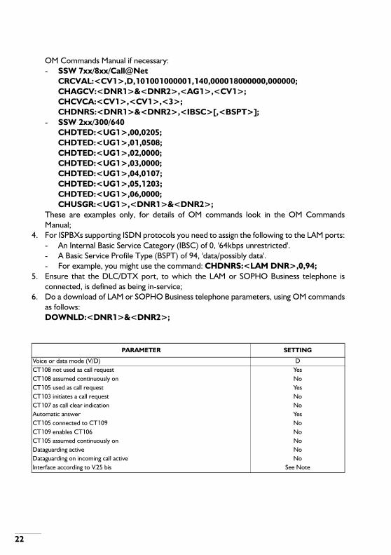
OM Commands Manual if necessary:- SSW 7xx/8xx/Call@Net
CRCVAL:<CV1>,D,101001000001,140,000018000000,000000;CHAGCV:<DNR1>&<DNR2>,<AG1>,<CV1>;CHCVCA:<CV1>,<CV1>,<3>;CHDNRS:<DNR1>&<DNR2>,<IBSC>[,<BSPT>];
- SSW 2xx/300/640CHDTED:<UG1>,00,0205;CHDTED:<UG1>,01,0508;CHDTED:<UG1>,02,0000;CHDTED:<UG1>,03,0000;CHDTED:<UG1>,04,0107;CHDTED:<UG1>,05,1203;CHDTED:<UG1>,06,0000;CHUSGR:<UG1>,<DNR1>&<DNR2>;
These are examples only, for details of OM commands look in the OM CommandsManual;
4. For ISPBXs supporting ISDN protocols you need to assign the following to the LAM ports:- An Internal Basic Service Category (IBSC) of 0, '64kbps unrestricted'.- A Basic Service Profile Type (BSPT) of 94, 'data/possibly data'.- For example, you might use the command: CHDNRS:<LAM DNR>,0,94;
5. Ensure that the DLC/DTX port, to which the LAM or SOPHO Business telephone isconnected, is defined as being in-service;
6. Do a download of LAM or SOPHO Business telephone parameters, using OM commandsas follows:DOWNLD:<DNR1>&<DNR2>;
PARAMETER SETTING
Voice or data mode (V/D) DCT108 not used as call request YesCT108 assumed continuously on NoCT105 used as call request YesCT103 initiates a call request NoCT107 as call clear indication NoAutomatic answer YesCT105 connected to CT109 NoCT109 enables CT106 NoCT105 assumed continuously on NoDataguarding active NoDataguarding on incoming call active NoInterface according to V.25 bis See Note
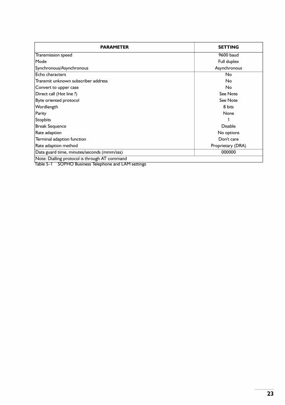
Table 5-1 SOPHO Business Telephone and LAM settings
Transmission speed 9600 baudMode Full duplexSynchronous/Asynchronous AsynchronousEcho characters NoTransmit unknown subscriber address NoConvert to upper case NoDirect call (Hot line ?) See NoteByte oriented protocol See NoteWordlength 8 bitsParity NoneStopbits 1Break Sequence DisableRate adaption No optionsTerminal adaption function Don't careRate adaption method Proprietary (DRA)Data guard time, minutes/seconds (mmm/sss) 000000Note: Dialling protocol is through AT command
PARAMETER SETTING
23

24
6. SOFTWARE INSTALLATION
6.1. INTRODUCTION
Two types of software must be installed, they are:
The following text describes how to install the above-mentioned software (except for the IASA firmware, this is described in section LOAD on page 31).If the installation is part of the installation of the SysManager 410, please refer to the customer engineer manual of the SysManager 410.
6.2. ISPBX SOFTWARE
Software in this section has already been installed in the ISPBX software package delivered by the factory. The information in section OM Procedures (Example) on page 24. is an example only and is intended to give a simple indication of the OM projecting one might expect to use when modifying or upgrading an existing installation.
Note: The IAS with IASA firmware emulates a DLC-C with up to 30 SOPHO Business telephones attached; the SOPHO Business telephones emulated by an IAS with IASA firmware installed can be projected just like a normal SOPHO Business telephone. Read this section and look also at chapter 7 for more descriptions of projecting.
6.2.1. OM Procedures (Example)
The following OM commands can be used when projecting an IAS with IASA firmware:
- ASBRDS; Assign boards- SETINS Set in service- CHDNRC.
• ISPBX SOFTWARE- OM PROCEDURES OM commands related to IASA might already have been done in the
factory. Section 6.2. is intended as a general guide, if the projecting has not already been done.
• IAS SOFTWARE- IASA Application Loader Load this software onto a PC that is connected to the IAS circuit board;- IASA Manager Load this software onto a PC that is connected to the IAS circuit board;- IASA Firmware Ensure that the firmware file (application.bin) is on the PC and load it onto
the IAS circuit board using the Application Loader as described in section 8.4.1.

• Example of OM Commands
Suppose:
- The IAS board is being used in an exchange that uses SSW 800 software;- The IAS board is at position 3012, 1;- The IASA functionality applies to 29 ports.
The following projecting commands would be appropriate:ASBRDS:3012,1,9,280D;SETINS:3012,1;SETINS:3012,1,2&&31;CHDNRC:<DNR>,3012,1,2&&31;
6.3. IAS SOFTWARE
6.3.1. Installing IAS Software (DOS version) on a PC Hard-disk
The IASA floppy disks that you receive contain the following files:
• IASA Firmware
- IASAxxx.bin; (example name only)- AL.EXE
• IASA Manager
- IASAMAN.EXE;- INSTALL.EXE;- ENGLISH.LNG; (there may also be files for other languages)- 1D.EXE. (a one-day password file)
• IASA Manager
Actions
1. Create a directory to contain the files mentioned above;e.g. md C: \IASA (Use the drive letter of your hard-disk.)
2. Change the active directory to the one you have just created;e.g. cd IASA
25

26
3. Copy the files, from the floppy disks, to the directory you have created;4. Type "INSTALL"
Press <Enter>You will now see a list of the languages that have been supplied with the IASA software;
5. Use the up, down, left and right keys to select the language you want.Press <Enter>;
6. You will now see a screen showing where the INSTALL program is going to put theIASAMAN.EXE and language file you have selected (*.LNG) on the hard disk; the programoffers the default C:\IASA, change the path and directory name shown if you wish.The IASA software will be put into the PC directory that you specify; if the directory namedoesn't already exist then the program will create it. The language you have chosen will beinstalled in the file IASAMAN.LNG;
7. When the installation is complete you will see the message "Installation complete";Press <Enter>.
8. Change the directory displayed, to the IASA directory you have just specified duringinstallation (use the normal MSDOS commands);
9. The IASA Management software is ready to be used.
6.3.2. Installing IAS Software (Windows Version) on a PC Hard-disk
The Windows version is part of the installation of the SysManager 410. Please refer to the customer engineer manual of the SysManager 410.Windows is a trademark of Microsoft Corporation.

7. PROJECTING
7.1. INTRODUCTION
The IAS circuit board with IASA firmware is projected as a DLC-C. IASA can simulate the attachment of 30 SOPHO Business telephones. IASA uses only the PM bus, it does not use the SCU interface.
7.1.1. DNRs
Although the IASA can be projected to simulate up to 30 telephones there are no telephones connected to the card; however, the required number of DNRs has still got to be projected.
7.1.2. IASA Licence
The number of DNRs that can be projected is defined by the licence that the customer has; this is derived from the serial number of the IASA package. Any ports that are active but currently outside the number licensed to be used, will be made inactive and will not be used by the IASA.
7.1.3. Ports
All the IASA ports (also known as circuit numbers) that have been licensed can be projected as voice ports or used for Music on Hold (MOH) or personal announcements.
7.1.4. Announcement Port (Recording/Listening)
Port 2 of the IASA is reserved for recording and listening to announcements; it should always be projected as a voice port and given a DNR but MOH should not be projected for this port.
7.1.5. Signalling Groups
The IASA can support a full user group; for this, a byte in the signalling group may need to be changed so that the PPU supports the required number of ports.The signalling group number, for an IASA card configured for 30 ports, is different from that used for a real DLC-C card that may be installed in the ISPBX.The signalling group numbers recommended are:
- IASA configured for 14 ports: 2807; (also used for a real DLC-C)- IASA configured for 30 ports: 280D;
27
28
7.1.6. Music on Hold (MOH)
Install Music on Hold (MOH) by assigning MOH to a circuit that is not yet projected.If the circuit is already projected, then delete the projecting with DEPCTB, before projecting the port for Music on Hold (MOH).
7.1.7. Facility Class Marks
The IASA simulates SOPHO Business telephones and, amongst other things, can answer incoming calls, play announcements and divert calls to other destinations. Facility class marks must be assigned to the IASA DNR where these things are required, just as they would be assigned to the DNR of a normal extension.
7.1.8. Date and Time
The IASA synchronises its date and time with the date and time of the ISPBX that it is installed in. The date and time is downloaded to the IASA automatically by the ISPBX software (except for SSW 640 and SSW 730). If the difference between the IASA time and the time on the PC running the IASA Management software is greater than 15 minutes, then the program offers the opportunity to update the date and time (See section DATE AND TIME on page 59)
Note: There may be some limitations on the IASA functionality, depending on which combination of CPU software and PPU software is contained in the ISPBX. Look at the information distributed with the ISPBX software packages that you have.
7.2. EXAMPLES - SSW 2xx/300/640
7.2.1. Without Music on Hold (MOH)
• 14 Ports
PROJPA:4000,uvv02,uvv15,02,2807; projects IASA voice ports.
• 30 Ports
PROJPA:4000,uvv02,uvv31,02,280D; projects IASA voice ports.
Where: u = shelf number
4vv = board position in the shelf
xx = circuit position on board; this depends on the number of ports the IASA has
to support; circuit 02 is mandatory.
7.2.2. With Music on Hold (MOH)
PROJPA:4000,uvv02,uvv13,02,280D; projects voice ports (02...13).
PROJPA:4000,uvv15,uvv31,02,280D; projects voice ports (15...31).
PROJPA:4020,uvv14,,03,280D; projects Music on Hold port (14).
In SSW 300/640 the MOH application requires an MOH port in each PM shelf.
7.3. EXAMPLES - SSW 7xx/8xx/Call@Net
The sequence of projecting should be as follows:
- Install IASA;- Add MOH (if required).
The following examples are given:
7.3.1. Install IASA
14 circuits: ASBRDS:3012,1,5,2807,255;
30 circuits: ASBRDS:3012,1,9,280D,255;
Note: These commands assume the IASA circuit board is inserted at position 3012, 1;
7.3.2. Add Music On Hold (MOH)
DEPCTB:3012,1,14; delete circuit.
ASPCTB:3012,1,14,11,280D,255; assign MOH (PCT type 11).
7.4. IMPORTANT LIMITATIONS
Look at chapter SYSTEM LIMITATIONS on page 58 "SYSTEM LIMITATIONS", section TRUNKS AND OPERATOR QUEUES on page 58 to see comments about "TRUNKS" and "OPERATOR QUEUES"
29
30
8. APPLICATION LOADER
8.1. INTRODUCTION
The Application Loader does three things:
- Transfers application files from a PC to the FEPROM of the IAS circuit board;- Transfers application files from the FEPROM of the IAS circuit board to a PC;- Displays information about an application in the FEPROM of the IAS circuit board or an
application that is stored on the PC.
The Application Loader is used to load the firmware package that the IAS circuit board needs for its operation. Table on page 31 shows the commands available.
8.2. STARTING THE APPLICATION LOADER
<...> these brackets indicate parts of the command line, you do not have to type the brackets.[...] square brackets indicate that a command is optional, you do not have to type the brackets.
8.2.1. Examples of IASA startup commands on the PC
The following are examples of commands that could be used to start the Application Loader program:
- C:\IASA\AL Starts the application loader contained in the directory C:\IASA and directsinput/output to the COM1 serial port.or
- C:\IASA\AL COM2 Starts the application loader contained in the directory C:\IASA anddirects input/output to the COM2 serial port.
8.2.2. Starting the Application Loader
To start the application loader do the following:
- Make sure the Application Loader file AL.EXE is on the hard disk of the PC;- type <dos path><al> <[com port]> (see the examples above.);- press <Enter>, the following message will be displayed:

- Re-boot the IAS circuit board;A re-boot is done as follows:- pull the circuit board out of the PABX slot;- re-insert it;- press any key on the PC WITHIN 30 SECONDS.
The following is then displayed:
When the IAS self-test routines are complete the following will appear on the PC screen:
The application loader is now started and you may enter any of the commands that follow, see table on page 31.
8.3. COMMANDS
Table 8-1 Application Loader Commands.
8.4. WHAT THE COMMANDS DO
8.4.1. LOAD
The "LOAD" command is used to transfer a binary application file to the IAS, where it is programmed into FEPROM.The command destroys the original contents of FEPROM, therefore it is recommended that, before you use the "LOAD" command, you save the original application contained in the IAS
IAS application Loader Vx.xx - (c) 1992 Philips Electronics N.V.
Re-boot IAS, then press any key to continue *
*) Note that the full name of the application loader is ''IAS Application Loader'' but, in the text of this manual it is referred to simply as ''Application Loader''; this is done to avoid confusion with the two different products, IAS and IASA; they can both be loaded with the same application loader.
Attempting to initialise BCS link... ESC to abort
AL:>>
COMMAND SYNTAX FUNCTION
LOAD LOAD filename Transfers a binary file from PC to IAS FEPROMSAVE SAVE Transfers a binary file from IAS FEPROM to PCINFO INFO Displays header information of the application currently in FEPROMINFO INFO filename Displays header information of the specified file stored on the PCHELP HELP Displays a screen showing the commands in this tableQUIT QUIT Leaves the Application Loader program
31

32
FEPROM using the "SAVE" command. In this way the contents of FEPROM can be returned to their original state if required.At the "AL:>>" prompt type the following and press <Enter>:
As the application is loaded the screen will show a "thermometer" type display; when the "thermometer" reaches 100% a "successful load" message will be displayed as shown in the example display, figure on page 32:
Figure 8-1 Loading an Application (Example "Thermometer" Display).
8.4.2. SAVE
The "SAVE" command transfers the application that is currently in FEPROM to the PC. Each application contains a header followed by executable code; the filename is specified in the header, so it does not need to be typed when the "SAVE" command is used. The application retrieved from FEPROM is saved on the PC, with the ".BAK" extension, in the current directory.At the "AL:>>" prompt type the following and press <Enter>; the following is displayed (example):
LOAD application.bin application.bin is the name of the application file that you want to load into FEPROM on the IAS circuit board. (e.g. "LOAD IASA100.BIN")
orLOAD C:\apps\application.bin this is the same kind of command but it shows how you can use a path
name to refer to the file. (e.g. "LOAD C:\apps\IASA100.BIN")

Figure 8-2 Saving an Application (Example Display).
8.4.3. INFO
At the "AL:>>" prompt type the following and press <Enter>:
In either case a screen such as the following will be displayed:
Figure 8-3 The INFO Command (Example Display).
8.4.4. HELP
At the "AL:>>" prompt type the following and press <Enter>:HELPA list of all valid commands and their syntax will be displayed as follows:
INFO the program assumes you want information about the application that is already loaded in FEPROM on the IAS circuit board.
or:INFO filename the program assumes you want information about an application that is stored on the
PC.
33

34
8.4.5. QUIT
The "QUIT" command closes communications with the IAS circuit board and terminates the application loader program.If a valid application exists in the IAS FEPROM it will be run when this command is received.If no valid application is found, the on-board firmware loader will continue to run.At the "AL:>>" prompt type the following and press <Enter>:QUIT
8.5. ERROR MESSAGES
When the Application Loader program is in use the error messages shown in table on page 34 could be generated; this section describes what the error messages mean and offers possible solutions.Table 8-2 ERROR MESSAGES.
AL:>> HELP
LOAD -> transfer a binary file to FEPROM
SAVE -> transfer a binary file from FEPROM
INFO -> display application header information
HELP -> display this help screen
QUIT -> terminates the program
ERROR MESSAGE EXPLANATION PROBABLE CAUSE SUGGESTED SOLUTION
An error occurred during programming
After programming an application into FEPROM its checksum is verified against the checksum contained in the applications header. If a mismatch occurs this message is displayed.
Binary file is corrupted. Ensure an original, uncorrupted, IASA binary file is being used.
BCS initialisation failed An error has occurred during initialisation of the PC's communications port.
Port not connected Wrong port connected.
Connect PC port Try using a different port.
BCS failed retries If an error occurs during transmission or reception of data the BCS protocol attempts to re-transmit the information. This can occur a maximum of 9 times before this message is displayed.
Data corruption during transmission.
Check cable length is not too long. Check that the cable is not passing through an environment that is electrically noisy. Check that the PC is not overloaded with background tasks.

BCS timed out After transmitting information to the IAS circuit board the PC waits for a response. If no response has been received within 10 seconds this message is displayed.
IAS circuit board faulty. Replace IAS circuit board.
BCS overflow Characters are being received by the IAS circuit board too quickly for the receiver to cope with and its ring buffer has overflowed.
Baud rates of PC and IAS circuit board are different.
Make a record of the error and report it to your service centre.
Cannot identify firmware installer
The identity of the application received was not the firmware installer or, an error occurred during the reception of the identity string.
IAS circuit board is not running the application loader program because:
Re-boot the IAS circuit board and start "Application Loader" again.
- More than 60 seconds have elapsed since a key on the PC was pressed.or- The IAS circuit board was not re-booted.
Data reception error The size of the data block received by the IAS circuit board is incorrect.
Data corruption during transmission. Baud rates of IAS circuit board and PC are different.
Make a record of the error and report it to your service centre.
Expected ACK but received no response
After sending a block of data or issuing a command the PC running the Application Loader expected to receive an "ACK" character but didn't.
Faulty cable connection. Data corruption.
Check the port connecting cable. Check PC/IAScircuit board baud rates are the same.
Illegal binary file format The binary file used during a LOAD or INFO command has a corrupted or illegal header format.
The string "IAS APPL" is not in the header. The load address specified in the header is not even.
Ensure an original, uncorrupted, IAS binary file is being used.
Illegal filename or path not found
The filename typed in at the AL:>> prompt as part of the LOAD or INFO command contained characters not allowed under the operating system (MSDOS).
Error entering filename/pathname
Enter correct filename/pathname
Illegal number of arguments
More than one argument has been typed in when the AL>> was displayed.(save, cls, quit and help are all examples of "one-argument" commands.
More than one agrument has been typed in
Press return to see the help screen, if required. Type in just one argument
Invalid application header received
The header field of the application received from the IAS circuit board has been corrupted during transmission.
Faulty connection. PC/IAS circuit board baud rates are different.
Check cable from PC port. Ensure PC/IAS circuit board baud rates are the same.
Unable to create file The file specified as an argument, when using the LOAD or INFO commands, could not be created.
Directory does not exist. DOS file input/output error.
Create the directory using MDOS commands.
ERROR MESSAGE EXPLANATION PROBABLE CAUSE SUGGESTED SOLUTION
35

36
Unable to open file The file specified as an argument, when using the LOAD or INFO commands, could not be opened.
Wrong filename typed. DOS file input/output error.
Type the correct filename.
Unknown command The command typed in at the AL:>> prompt was not recognised.
Typing error Press return to see a help screen showing a list of valid commands.
The FEPROM does not contain an application
The IAS circuit board has received a SAVE or INFO command whenno application is present in FEPROM.
No application loaded. Load an application.
ERROR MESSAGE EXPLANATION PROBABLE CAUSE SUGGESTED SOLUTION
9. IASA MANAGEMENT
9.1. INTRODUCTION
IASA Management is a software package that is used on a PC connected to the IAS board; it is used to do the following:
- Record, play and erase announcements;- Backup announcements to PC disks;- Restore announcements from PC disks;- Control acquisition of statistics on announcement usage;- Generate reports listing announcements and their attributes, on paper or in a text file or
both;- Generate reports listing announcements and their usage statistics, on paper or in a text file
or both.
The IASA Management files needed are contained in the self-extracting file IMAN.EXE, they are:
- Main program file:- IASAMAN.EXE; the main program file.
- Support files:- INSTALL.EXE; the file used to install the IASA Management files.- 1D.EXE. a one-day password program used by the system manager.
- Language files:- IASAMAN.LNG; the ASCII file where all text strings used by IASA Management are
stored (See note below.).- ENGLISH.LNG; you must have the language file appropriate to your requirement (See
note below.).Further language file examples:- DEUTSCH.LNG;- XXX.LNG;- etc (See note below.)
These files will be supplied on 3 1/2 inch and 5 1/4 inch floppy disk.
Note: Language files contain all the text that the IASA Management software presents on screen, including the text contained in pull-down menus.
37

38
9.2. STARTING IASA MANAGEMENT
Do the following:
- Make sure IASA Management files are on the hard-disk of the PC (A floppy disk can beused instead but that would not operate so quickly);
- Use the "cd" command (MSDOS command) to select the directory that contains the IASAsoftware files;
- Type IASAMAN; (see the note below)- Press <Enter>.
Note: If you are using a PC with a monochrome liquid crystal display, you should type IASAMAN -Icd. This will improve the quality of the display that you see;If you suspect communication errors and wish to verify this, use the command IASAMAN -showerr to start the IASA Management program. When the program is terminated, a list of communication errors will be displayed, if there are any.
The program will now start. The first thing you will see is a window displayed on the screen showing IASA product information; after 5 seconds the window will disappear, a line will appear at the top of the screen showing the titles of the pull-down menus available and the first pull-down menu will be displayed.
Note: You will not be able to choose other pull-down menus until you have logged on with a valid name and password, look in the description of the first pull-down menu ("CONNECT") to find out how to do this.If this menu or any other disappears, perhaps because you have pressed a wrong key, then restore the menu line by pressing <Esc> or the "right" key of the mouse.
9.3. PULL-DOWN MENUS
There are six pull-down menus available, each having a range of selections. Selections can be made using a mouse or by using the <Alt> key and the highlighted letter of the pull-down menu.Once the pull-down menu is selected make a selection by moving the menu highlight over the option you want and pressing <Enter>. If you have a "Mouse" connected to the PC then click on the option using the left button of the mouse (or you can press <Enter> if you wish).Sections "CONNECT" - PULL-DOWN MENU on page 39 to HELP on page 56 describe each selection.The pull down menus:

9.4. "CONNECT" - PULL-DOWN MENU
9.4.1. Direct Connection
This selection makes a direct connection between the PC and the IAS board; the connection uses a V.24 serial cable between the COM port of the PC and the V.24 connector on the front of the IAS board. The cable used is a standard "null-modem" cable which is described in appendix CABLES on page 69.The connection uses the serial port parameters defined in Section Serial Port on page 40and the IAS board automatically adapts its serial port to accept those.The connection uses the BCS protocol.
CONNECT PORTS- Direct Connection; - System Configuration;- Dialled Connection; - Port Mapping;- Disconnect; - Backup;- Serial Port; - Restore;- Exit IASA Management (ALT-X). - Print;
- Print to File;DIRECTORY - View Alarms.- Own;- Common; REGISTRY- Global; - Change Password;- Disk, - Maintain Registry;- Switch (F10); - Backup Registry;- Backup Drive and Directory; - Restore Registry;- Print;- Print to File. HELP
- Help System Overview;ANNOUNCEMENTS -Complete help text;- Play; - About IASA;- Re-record; - About IASA Management.- Erase (DEL);- Create;- Edit Description;- Edit Index;- Backup;- Restore;- View Statistics;- Hide Statistics;- Reset Statistics;- Refresh Statistics.
39
40
When this selection is made, a log-on window appears on the screen; reply to the prompts by entering a username followed by a password (Read the note below and look also at Chapter PASSWORDS on page 61, for a full description of passwords.).
Note: The first time the IASA board is used there are only default usernames and passwords available, look at PASSWORDS on page 61 see what these are.New usernames and passwords can be introduced using the "one day password" tool, look at section ONE-DAY PASSWORD TOOL on page 62.
After a valid log-on, the announcements stored in the IASA are displayed on screen under the heading "OWN DIRECTORY". You can alternate ("toggle") between this and the backup directory using the "F10" key.The backup directory contains announcements that have been saved on the PC hard-disk.After a valid log-on other menus can be selected as required by using the cursor keys of the PC or the mouse.
9.4.2. Dialled Connection
Connect to an IASA via a dial-up data connection. A menu of previously entered numbers appears and the user can select the one required.The user can also delete, add or edit numbers, or save them to disk.
9.4.3. Disconnect
Break an established connection.
9.4.4. Serial Port
The parameters of the serial port are displayed and can be changed; the default settings are:
- serial port: COM1 (parameter range: COM1, COM2)- baud rate: 9600 (parameter range: 1200, 2400, 4800, 9600)
Changes to these parameters do not affect an established connection; the changes take effect only when the next connection is made. If a change is made, the user is offered the option of saving these changes to the IASA configuration file.
9.4.5. Exit IASA Management
Terminates the IASA Management application. The mouse or ALT-X can be used for this.

An option is available to write a list of all known IASA announcements to a disk file upon leaving the program. The file is named IASAMAN.LST and is formatted as ASCII text using fixed-width fields, each record being delimited by carriage return plus line-feed.The fields are:
- Owner;- Index;- Description;- Record date;- Backup status.
The format is identical to that used by the print to disk feature except that column headings and form-feed characters are suppressed.
Note: The IASAMAN.LST file is a list of the global directory from the last IASAMAN session; therefore, if a different IASA is used, then the IASAMAN. LST file on the PC will be overwritten with announcements for another IASA. This can be avoided by leaving the current IASAMAN session in a different way (other than by choosing the "Exit" option from the "CONNECT pull-down menu). Do the following:- While the current IASAMAN session is still running, choose "DIRECT
CONNECTION" or "DIALLED CONNECTION" from the "CONNECT" pull-down menu, whichever is appropriate to the current setup;
- Enter "YES" in reply to the question "ABANDON EXISTING CONNECTION?"; (this will start a new login session.)
- Press "ESC" (the escape key); (This will allow you to escape from this login session.)
- Select the "CONNECT" pull-down menu again;- Select "EXIT" or "DISCONNECT" from this menu; the previous IASAMAN.LST
file will not be overwritten.- ALT-X can be used instead of "EXIT" or "DISCONNECT" in the pull-down
menu.
9.5. "DIRECTORY" -- PULL-DOWN MENU
Directory contents may be displayed on the PC screen and changed as required. F10 is used to switch the directory displayed between the current directory (Own, Common or Global) and the Backup directory.
41

42
9.5.1. Own
This command lists announcements contained in the "Speech Memory" of the IAS board. These announcements are the announcements that belong to the user who is logged on.
9.5.2. Common
This command lists the announcements that belong to the user "common". The only operations allowed by users other than the users "common" or "service" is the PLAY facility from the ANNOUNCEMENTS menu.
9.5.3. Global
This command lists all the announcements contained on the IAS board. The announcements are grouped according to their owner and they are listed in order of their index number. Only the users "service" or "common" can use this command.
9.5.4. Disk
This command lists announcements stored in a directory on a PC disk; the user is prompted to specify the directory.IASA Management suggests a directory by taking the currently defined default backup drive and directory and appending the name of the IASA to it as a sub-directory name.If a direct V.24 connection is being used the string "BACKUP" is used instead of the IASA name.If the user accepts the suggested directory, IASA Management will create the directory if it does not already exist.If the user specifies a different directory then that directory must already exist.
9.5.5. Switch (F10)
This command or F10 can be used to switch the PC display easily between the current IASA directory and the default backup drive and directory.If the current directory displayed is Own, Global or Common then the display switches to the default backup drive and directory without further prompting.If the current directory displayed is a disk directory, then this command switches the display to one of the directories Own, Global or Common depending on which was last used.
9.5.6. Backup Drive and Directory
Select base default backup drive and directory; the initial default is C:\IASA. (Note that this is the base directory only, sub-directories are created within it using the IAS name, refer to backup and restore features for details). If changes are made, the user is offered the option of saving the changes to the configuration file.
9.5.7. Print
Print the announcement directory data from the workspace displayed on screen, including statistics if selected.
9.5.8. Print to File
Copy the announcement directory data from the selected workspace, including statistics if selected, to a text file. The program prompts the user for a file name.
9.6. "ANNOUNCEMENTS" -- PULL-DOWN MENU
9.6.1. Play
Use this command to play back selected announcements to the voice port. This command is available when the Own, Common or Global directories have been selected and displayed on screen and a voice connection is established.
9.6.2. Re-Record
Use this command to record over a selected announcement. This command is available when the Own, Common or Global directories have been selected and displayed on screen and the voice port is connected. IASA Management will not allow users to exceed their space allocation, nor will it allow the users "service" or "common" to exceed the space allocation of a different user on behalf of that user (such an attempt might be made when the users "service" or "common" are using the Global directory).
Note: It is possible for someone who has logged in to the IASA as the user "personal" (owner = 01) to exceed their speech memory allocation if recordings are done via IASA Management and not via the phone.
43

44
9.6.3. Erase (DEL)
Erase the announcement selected; the DEL key can also be used.
9.6.4. Create
Use this command to create a new announcement; the command is available when the Own, Common or Global directories have been selected and the IASA voice port is connected.IASA Management uses a dialogue box to prompt the user for an index number and an announcement description before the record operation begins.IASA Management suggests the next free index number but allows the user to enter any other unused index number. A search mouse button is available to suggest unused index numbers.If the users "service" or "common" are using the Global directory the dialogue box will also require an owner number to be entered.IASA Management will not allow a user's space allocation to be exceeded; nor will it allow the users "service" or "common" to exceed the space allocation of a different user on behalf of that user (such an attempt might be made when the users "service" or "common" are using the Global directory).
Note: It is possible for someone who has logged in to the IASA as the user "personal" (owner = 01) to exceed their speech memory allocation if recordings are done via IASA Management and not via the phone.
9.6.5. Edit Description
Use this command to edit the description of an announcement. The command can be used when any of the directories is displayed on screen.
9.6.6. Edit Index
Use this command to edit the index number of an announcement; it can be used when any of the directories Own, Common or Global is displayed on screen.The user is prevented from creating announcements with identical index numbers.
9.6.7. Backup
This command is used to backup selected announcements to disk (copies them from IASA RAM to PC disk). The command is available when the Own, Common or Global directories are displayed on screen. A dialogue box prompts the user to specify:

- A disk drive and directory;- Whether to "Overwrite existing files automatically ? Y/N ?"
9.6.8. Restore
Restores selected announcements from PC disk to IASA RAM; this command is only available when a disk directory is displayed on the PC screen. Users other than "service" or "common" can only overwrite announcements they own.IASA Management will not allow a user's space allocation to be exceeded; nor will it allow the users "service" or "common" to exceed the space allocation of a different user on behalf of that user.A dialogue box prompts the user to specify a yes/no answer in reply to the question "Overwrite existing announcements automatically".If, during "restore" the program needs to overwrite an announcement that is being played, IASA Management will wait until the announcement has stopped before restoring the announcement. During this waiting period an information panel will appear on the screen to inform the user of the situation and offer the option of not restoring this announcement (in other words, "skipping" the announcement).If more than one announcement is being restored and announcements are "skipped", as described, then those announcements will remain selected and the user will be able to retry with minimal effort.
9.6.9. View Statistics
This command shows the count and reset dates of all the announcements displayed on the screen.
Note: The statistics functions use the terms "count" and "reset date"; these terms mean the following:- Count: A usage count showing the number of times an announcement has been
played. This does not include the number of times the recording has been listened to using IASA Management.
- Reset Date: The date when the usage count was last reset.
9.6.10. Hide Statistics
This command removes the count and reset dates from the screen, it does not remove them from the directory in which they are stored.
45
46
9.6.11. Reset Statistics
This command resets the counts of selected announcements.
9.6.12. Refresh Statistics
This command reads the IASA directory and updates the display.The command is needed because the statistics display is not a dynamic display; in other words it does not get updated as the statistics change (all other announcement attributes are updated dynamically). This command makes it possible therefore for the user to obtain an immediate update of the statistics information displayed.
9.7. PORTS
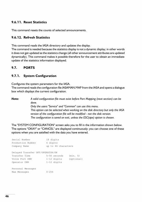
9.7.1. System Configuration
Configures the system parameters for the IASA.The command reads the configuration file IASAMAN.MAP from the IASA and opens a dialogue box which displays the current configuration.
Note: A valid configuration file must exist before Port Mapping (next section) can be done.Only the users "Service" and "Common" can use this menu.This option can be selected when working on the disk directory but only the IASA version of the configuration file will be modified - not the disk version.The configuration is saved on exit, unless the ESC(ape) option is chosen.
The "SYSTEM CONFIGURATION" screen asks you to fill in the information shown below. The options "OKAY" or "CANCEL" are displayed continuously; you can choose one of these options when you are satisfied with the data you have entered.
Serial Number 18 digits
Production Number 6 digits
Company Name up to 46 characters
Delayed Transfer OFF/OPERATOR/ON
Transfer Time 5-50 seconds (min. 5)
Voice Port DNR 1-12 digits (optional)
Operator DNR 1-12 digits
Personal Messages
Max Messages 0-254

Note: The company name, production number and serial number are obtained with the purchase of the IASA Management program. They are also available on the readme.txt file of the iS3000 Software CD-ROM.The company name is "CASE SENSITIVE" -- it must be entered exactly as shown on the release certificate.Delayed call transfer means that the IASA will put the call on 'hold', dial the transfer DNR then hold on to the call for the duration that the 'Transfer timeout' states.If this option is off, then 'Fast call transfer' will occur in which the IASA hangs up after the DNR has been dialled, thus releasing the IASA port for a new call. If 'Delayed Transfer' is set to operator, then delayed call transfers will only occur for calls being transferred to the operator.For SSW 640 and 730 the 'transfer timeout' is always used (independent of whether 'delayed transfer' is on or not) to determine the rate that calls pass through the call progress states.For SSW 2xx, 300 and 640 'Delayed transfer' is required if internal calls are required to be transferred to the operator.The voice port DNR is optional; if it is entered, then the DNR will be displayed when the user is prompted to make a voice connection. If no DNR is entered, then the DNR will be displayed as "???".A system operator DNR is required. This is used for all ports that have the Transfer to Operator action selected.Owner "01" is the only user allowed to have personal announcements mapped to them.The "Max Messages" entry is used by IASAMAN to generate a number of blank personal announcements. When this data is saved IASAMAN automatically generates the specified number of personal announcements, using the lowest free announcement numbers.If there are already a number of personal announcements on the IASA, then it will generate the extras to make the total correct.If the number is less than the present number of personal announcements, then IASAMAN will display a warning and not accept the entry.The announcements created will be initialised as having 0 seconds used, the owner will be "personal" with user ID "01" and description "?"
Max Memory Usage 1-30 (lenght of announcement in seconds)
Recording Index 0-254 (optional)
OK CANCEL
47

48
• Ports
- The number of ports licensed will be allocated on exiting the system configuration withvalid licence information.
- Any ports active outside the number licensed to be used, will be made inactive and theirstatus cannot be viewed or modified by any user.
• Personal Announcements
- The number of personal announcements specified will be created when the configurationis saved; if, during creation, the IASA runs out of memory, IASAMAN will display a warningand will alter the system configuration to show the number of personal announcementsactually created.
• Delayed Transfer
- An option is available to specify delayed transfer; delayed transfer can be selected for:- All calls;- No calls;- Calls being transferred from the IASA to the operator.
Note: The delayed transfer option is usually only required for transferring internal calls to the operator. (SSW 2xx/300/640 systems.)
9.7.2. Port Mapping
Configures the Port Mappings for the IASA.
Note: A valid configuration file (previous section) must exist before Port Mapping can be done.
The Port Mapping command reads the configuration file IASAMAN.MAP from the IASA and opens a subsidiary workspace. A number of keys can be used within the subsidiary workspace:
- F1 help- F2 edit- F3 save- F4 on/off- F5 reset- F6 refresh
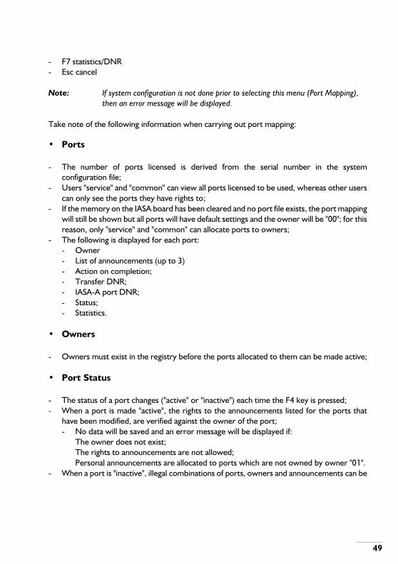
- F7 statistics/DNR- Esc cancel
Note: If system configuration is not done prior to selecting this menu (Port Mapping), then an error message will be displayed.
Take note of the following information when carrying out port mapping:
• Ports
- The number of ports licensed is derived from the serial number in the systemconfiguration file;
- Users "service" and "common" can view all ports licensed to be used, whereas other userscan only see the ports they have rights to;
- If the memory on the IASA board has been cleared and no port file exists, the port mappingwill still be shown but all ports will have default settings and the owner will be "00"; for thisreason, only "service" and "common" can allocate ports to owners;
- The following is displayed for each port:- Owner- List of announcements (up to 3)- Action on completion;- Transfer DNR;- IASA-A port DNR;- Status;- Statistics.
• Owners
- Owners must exist in the registry before the ports allocated to them can be made active;
• Port Status
- The status of a port changes ("active" or "inactive") each time the F4 key is pressed;- When a port is made "active", the rights to the announcements listed for the ports that
have been modified, are verified against the owner of the port;- No data will be saved and an error message will be displayed if:
The owner does not exist;The rights to announcements are not allowed;Personal announcements are allocated to ports which are not owned by owner "01".
- When a port is "inactive", illegal combinations of ports, owners and announcements can be
49

50
saved.
• Special Announcements
- The special announcement "PER" can only be used by owner "01";
• New Port Mapping Data
- If new data is entered, for an active port that is to remain active, then IASAMAN willtemporarily make the port inactive and then active. If the port is in use then IASAMAN willdisplay a message until it is free to perform the change without affecting the servicing ofannouncements to listeners;
• Port Usage
- A count is kept of the number of times a port is used;- The count is read only when the "Port Mapping" option is chosen or the F6 key is pressed.- The F6 key will update the count on all ports.
• Port Statistics
- The statistics count is the number of times the port has been used since the statistics dategiven for the port.
- The statistics date and count, for the highlighted port, can be reset using the F5 key.- The F7 key can be used to display or hide the statistics count.- When statistics are hidden, the transfer DNR is displayed.- When statistics are shown, both the statistics count and the statistics base date are
displayed.
9.7.3. Backup
This option is used to backup the system and port configurations of the IASA to disk.The option is available to users "common" and "service" only.
- Both system configuration and port map data are stored as a file on the IASA; the backupoption enables the file to be copied to the PC for future disaster recovery;
- The file name is always IASAMAN.MAP;
Note: IASA Management suggests a directory to store this file; it takes the currently defined backup directory and appends the name of the IASA to it as a sub-directory

name; if a direct V.24 connection is being used, the string "BACKUP" is used instead of the IASA name;If the user accepts the suggested directory, IASA Management will create the directory (If the directory does not already exist);If the user specifies a different directory from the one suggested by IASA Management, the directory must already exist;The disk is checked for sufficient free space; if insufficient space is available an error panel is displayed;The file IASAMAN.MAP is stored in an unencrypted binary format.
9.7.4. Restore
Enables the disk file IASAMAN.MAP to be copied back into the IASA; this overwrites the system and port configuration currently stored on the IASA.Only the users "service" and "common" can use this function.The new IASAMAN.MAP file is checked for corruption before a restore is performed.
• Ports
- The IASA ports must be inactive before the restore is performed and all ports will remaininactive after the restore operation;
• File Location
- IASA Management prompts the user for the location of the IASAMAN.MAP file;
• Port Status
- The IASA ports will be restored to an INACTIVE state, even if they were active when theIASAMAN file was backed up.
- A warning will be displayed to prompt the user to make the ports active.
• Personal Announcements
- The number of personal announcements specified in the restored configuration will bechecked against the existing system configuration.
- If the existing number and the required number do not match, a warning will be displayed.- The number of personal announcements specified will be created when the configuration
is saved; if, during creation, the IASA runs out of memory, IASAMAN will display a warningand will alter the system configuration to show the number of personal announcements
51

52
actually created.- If more personal announcements are required then, saving the configuration, once it has
been restored, will generate the required number.
Note: The current user remains logged on after a restore has been successfully completed.
9.7.5. Print
Prints the visible port configuration data from the selected workspace; the printout includes statistics, if shown in the display.
Note: Selecting this option causes a panel to appear on the screen, which gives the option to cancel if required; this is useful if the printer jams.
9.7.6. Print to File
Copies the visible port configuration data from the selected workspace to a file; this data includes statistics, if shown:
Note: The program prompts the user for a file name;the disk is checked for sufficient space; if it is not available, an error panel is displayed.
9.7.7. View Alarms
Displays the alarms generated by the IASA.
• Users
- Only the users "service" and "common" can access the alarm menu.
• Alarm Status
- The IASA polls for the alarm status of the IASA while an IASAMAN session is active;- All users are informed if any alarms exist on the IASA, via an alarm signal in the main screen.
Note: The alarm status indication will appear to all users;The alarm status indication can have two states:- Flashing (There are alarms in the alarm buffer which have not yet been seen

by the users "service" or "common".)- Steady (All alarms have been viewed but still remain in the alarm buffer, they
have not been cleared by "service" or "common").
• Keys
- Certain keys are available within the "View Alarms" workspace;
Table 9-1 Registry Fields.
The user indicates acceptance of the fields in the dialogue box by pressing <Enter> on the last field or by using the mouse to click on an "K" button displayed on the screen. The user can abort the "maintain registry" function by using the mouse to click on a "CANCEL" button displayed on the screen or by pressing <Esc>.If changes have been made but not yet saved the user is offered the option of saving them when the Maintain Registry command is completed. If the user chooses not to save the changes at that time then the changes are discarded, so that the IASA registry and the IASA Manager's copy of the registry remain identical.
Note: The following restrictions apply:- The Maintain Registry feature is available only to the users "common" and
"service";- Owner numbers are unique (no two users are allowed to have the same owner
number);- A user cannot be erased if that user owns announcements stored in the IAS
that is currently connected.
F3 Refresh - get any new alarms while viewing present alarms.F4 Clear Alarms - clear the alarm buffer.F5 Print - print the contents of the alarm buffer to a printer.F6 Print to file - print the contents of the alarm buffer to disk.
PARAMETER RANGE
Username Maximum 8 charactersOwner 2 digitsMaximum announcements 0...254Maximum memory usage * - 0 memory boards : 31 seconds
- 1 memory board : 161 seconds- 2 memory boards : 292 seconds- 3 memory boards : 422 seconds
* A figure greater than the capacity of the memory boards can be entered.
53

54
9.7.8. Backup Registry
This facility can only be used by the users "service" and "common". The facility copies the registry, which is a file stored on the IAS board, to the PC that is connected; this allows a backup of the registry to be saved on disk so that it can be restored to the IASA if the need arises. This will guard against difficulties caused by power failures, board faults or anything unforeseen. The name of the file copied to the PC is always IASAMAN.REG.IASA Management suggests a directory in which to store this file, as follows:It takes the default backup drive and directory and adds the name of the particular IASA to it as a sub-directory, for example:Suppose:
- the default backup directory is "C:\IASA;- the name of the particular IASA is "firm XYZ".
9.8. REGISTRY
9.8.1. Change Password
After users log on they can use this feature to change their password. The password that was used to log on must be re-entered and then the new password must be entered twice. Passwords are not displayed when they are being entered. After validation, any changes are transferred to the registry on the IAS board.
9.8.2. Maintain Registry
This allows the attributes of all users to be displayed and edited, with the exception of a user's password. The attributes are:
- Username;- Owner;- Maximum number of announcements allowed;- Maximum storage space (in seconds).
Note: It is possible for someone who has logged in to the IASA as the user "personal" (owner = 01) to exceed their speech memory allocation if recordings are done via IASA Management and not via the phone.
Users "service" and "common" do not appear in the list because "user id" and "owner" are fixed and these two users do not have storage space limits.
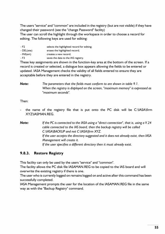
The users "service" and "common" are included in the registry (but are not visible) if they have changed their password (see the "change Password" facility)The user can scroll the highlight through the workspace in order to choose a record for editing. The following keys are used for editing:
These key assignments are shown in the function-key area at the bottom of the screen. If a record is created or selected, a dialogue box appears allowing the fields to be entered or updated. IASA Management checks the validity of all fields entered to ensure they are acceptable before they are entered in the registry.
Note: The parameters that the fields must conform to are shown in table 9.1.When the registry is displayed on the screen, "maximum memory" is expressed as "maximum seconds".
Then:
- the name of the registry file that is put onto the PC disk will be C:\IASA\firmXYZ\IASMAN.REG.
Note: If the PC is connected to the IASA using a "direct connection", that is, using a V.24 cable connected to the IAS board, then the backup registry will be called C:\IASA\BACKUP and not C:\IASA\firm XYZ.If the user accepts the directory suggested and it does not already exist, then IASA Management will create it.If the user specifies a different directory then it must already exist.
9.8.3. Restore Registry
This facility can only be used by the users "service" and "common".The facility allows the PC disk file IASAMAN.REG to be copied to the IAS board and will overwrite the existing registry if there is one.The user who is currently logged on remains logged on and active after this command has been successfully completed.IASA Management prompts the user for the location of the IASAMAN.REG file in the same way as with the "Backup Registry" command.
- F2 selects the highlighted record for editing;- DEL(ete) erases the highlighted record;- INS(ert) creates a new record;- F3 saves the data to the IAS registry.
55
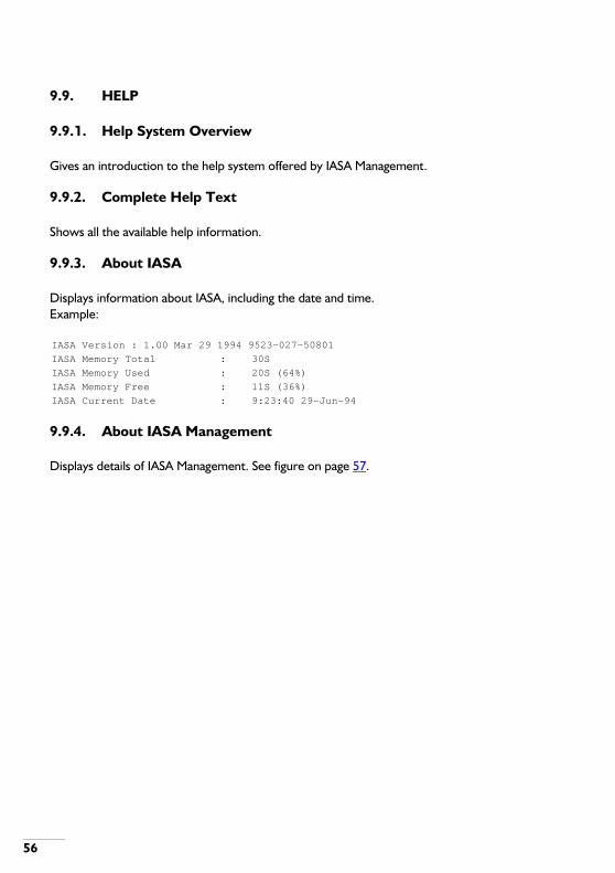
56
9.9. HELP
9.9.1. Help System Overview
Gives an introduction to the help system offered by IASA Management.
9.9.2. Complete Help Text
Shows all the available help information.
9.9.3. About IASA
Displays information about IASA, including the date and time.Example:
9.9.4. About IASA Management
Displays details of IASA Management. See figure on page 57.
IASA Version : 1.00 Mar 29 1994 9523-027-50801
IASA Memory Total : 30S
IASA Memory Used : 20S (64%)
IASA Memory Free : 11S (36%)
IASA Current Date : 9:23:40 29-Jun-94
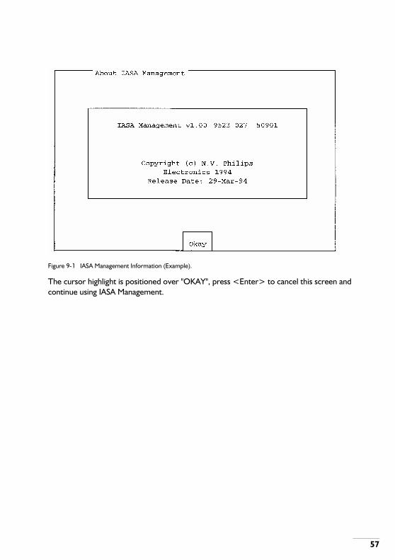
Figure 9-1 IASA Management Information (Example).
The cursor highlight is positioned over "OKAY", press <Enter> to cancel this screen and continue using IASA Management.
57

58
10. SYSTEM LIMITATIONS
10.1. SIMULTANEOUS ANNOUNCEMENTS
The maximum number of announcements that can be played back at any one time is:
- IASA projected as a full unit group : 29;- IASA projected as a half unit group : 13.
10.2. SLOT WIDTH
The IAS circuit board requires a width of 1 inch (25,4 mm) in the PABX card-frame; therefore, in some ISPBXs the board position to the right of the IAS circuit board must be left vacant.
10.3. POSITION IN UNIT GROUP
The IAS circuit board must be placed in the first position of a unit group when the PM bus is being used; look at section CARD POSITION IN ISPBX on page 12.
10.4. TIME REQUIRED TO LOAD/RETRIEVE ANNOUNCEMENTS
It takes approximately 100 seconds, using the V.24 port, to load 10 seconds of announcements, from a PC, into the IAS memory. These figures assume a data rate of 9600 bits/second.The time taken to retrieve announcements (to do a backup) is the same.The time taken to transfer larger amounts of speech information (announcements) is proportionately longer.
10.5. TRUNKS AND OPERATOR QUEUES
The IAS with IASA firmware is projected as a DLC-C and associated phones; this means the IASA performs automatically, some of the operations that SOPHO-SET users would perform; one of these is that a caller may hang up at any time.
WARNING: MAKE SURE THAT TRUNKS USED WITH IASA HAVE "CLEAR FORWARD" CAPABILITY.
This is particularly important if "Loop" announcements or long announcements are being used. "Clear Forward" will also avoid the operator receiving phantom calls if the external party has hung up before a call transfer.

10.5.1. SSW 7xx/8xx/Call@Net
If incoming trunk calls are first answered by IASA and then transferred to an operator, the calls will not arrive in the "A queue"; they will arrive in the "M queue", which is where internal calls would normally arrive.It is better to avoid confusion between internal and external calls, so do the following:
- Do not allow internal calls to arrive in the "M queue";- Use the "M queue" exclusively for incoming trunks and not for any other purpose;- Retrain operators to make sure that trunk calls arriving at the operator are handled
correctly.
10.5.2. SSW 2xx/300/640
WARNING: SET THE DELAYED TRANSFER OPTION.
If "delayed transfer" is not set then trunk calls will go directly to the "C queue" and internal call transfers to the operator will not succeed.If "delayed transfer" is set a call will first appear in the operator's "M queue"; if this call is answered it will be presented to the operator as "party B". If the call is not answered within the transfer time then a trunk call will go into the "C queue".This is a characteristic of the System Software Releases (SSWs) mentioned in this section. See also note 2 of section System Configuration on page 46.
10.6. DATE AND TIME
The IAS with IASA firmware synchronises its date and time to the date and time of the ISPBX that it is installed in (except with software releases SSW 640 and SSW 730).When the IASA Management program (running on a PC) establishes a connection with the IASA card it compares the IASA date and time with the date and time of the PC. If there is a difference of more than 15 minutes then the program will present a warning and, if the user is "service" or "common", it will offer the user the opportunity to update the date and time on the IASA (see the note below).
Note: The IASA must be "in service" for the board to synchronise to the ISPBX date and time.When the IASA is first set "in service" the ISPBX may not update the IASA date and time immediately.If the opportunity to update the date and time is accepted, when it is shown on the PC, then the IASA time will become the same as the PC time. Therefore, before
59

60
starting the IASA Management program, make sure the PC time is correct.The IASA date and time can be seen in the pull-down menu "HELP" (About IASA)

11. PASSWORDS
11.1. INTRODUCTION
This chapter is referred to earlier, in Section Direct Connection on page 39.The first time the IASA board is used there are only default usernames and passwords available, they are shown in table on page 61.
11.2. DEFAULT PASSWORDS
Table 11-1 Default Usernames and Passwords.
Note: New usernames and passwords can be introduced using the "one day password" tool.
If any of the default users ("common""personal" and "service") changes their password from the default, the new passwords will be saved in the registry, a file stored on the IAS circuit board. The users "common", "personal" and "service" have the owner numbers shown in table on page 61.The users "common" and "service" are privileged users and they have unrestricted access to all IASA Manager features and facilities; they also have access to all users' announcements and can use all of the facilities record/play/backup/restore/delete/edit. Therefore, it is important that their passwords are changed before any users or announcements are recorded.The user "service" is normally the service engineer of the telephone company (PTT).The user "common" is normally the telephone manager of the company where the IASA is installed.
Note: The users "common" and "service" have access to the following features, which are not available to other users:Maintain registry;Global backup and restore of announcements;Registry backup and restore;Operate on other users data;Reset Statistics.When default usernames and passwords are used (see table on page 61), the IASA
USERNAME PASSWORD OWNER
common 19071964 00personal 01051953 01service 03101956 99
61

62
Manager automatically invokes the "Change Password" feature immediately after the initial log-on session. This feature is intended to avoid the defaults becoming generally known and therefore producing a security problem.
11.3. ONE-DAY PASSWORD TOOL
There is a one-day password tool which can be used to generate a password for a user.The tool is a file called 1D.EXE if you have the DOS version, or 1DAYWIN.EXE if you have the Windows version.
Note: The filename is "1D" not "ID"
To obtain a one-day password, do the following:
11.3.1. DOS version
- Use MSDOS commands to change the DOS prompt, to the directory containing the file1D.EXE.;
- Type ID <username>;- Press <Enter>.
11.3.2. Windows version
Start the one-day password tool by selecting it on screen and pressing Enter.
Note: The username used when creating a one-day password must conform to the following requirements:- Maximum 8 characters (Case insensitive);- Alphanumeric characters only (A-Z. 1-9, 0).
The password is valid for only the one day on which it is issued and should be used on that day. When the one-day password is used to log on to the IASA Manager a menu is presented, requesting the user of the one-day password to change it to a new password immediately. The user can then use this new password, which only he or she knows, at any subsequent log-on.The "one-day" characteristic is produced by the program 1D.EXE (or 1DAYWIN.EXE if you have the Windows version), which looks at the system clock of the PC on which it is running and then generates a password based on the clock value.When the one-day password is used to log onto IASA Manager the program IASA Manager looks at the clock of the PC on which it is running and calculates the one-day password it expects to see.

If the one-day password is the same as that calculated by IASA Manager then it is accepted and the user is logged on.The program 1D.EXE will continue to run until:
- A valid username is used as shown aboveor
- A blank line is entered (in other words, only the prompt on the MSDOS command line,followed by <Enter>)
After a valid username is entered a password is displayed which uses only letters and figures. The one-day password is totally independent of language.
Note: The one-day password tool assumes that the clock date of the PC is the same as the date on the IASA;The one-day password tool will not work if:- the IASA is not in service;- the dates stored by the PC clock and the IASA do not match.
Note: For a user to be able to log in with a one-day password, the password must have been entered in the registry, see section 9.8.
63

64
12. PERSONAL MESSAGES
12.1. INTRODUCTION
12.1.1. Personal messages
These can be created by any DNR user, they are used for whatever purpose the DNR user decides; for example, to tell a caller that the DNR user is at a meeting and will be back at a certain time.
12.1.2. General Messages
These are messages owned by the user "Personal"; the user "Personal" creates these messages by using IASA Manager at a PC; they are played either before or after the personal message created by the DNR user (this can be defined using IASA Manager). They tell the caller what action to take, for example: "Wait a few seconds and your call will be transferred to the operator".
12.2. MESSAGE SEQUENCE
A sequence of messages that a caller would hear might be for example:
1. DNR user's personal message: "I'm sorry not to be available at the moment. I'm at ameeting until 10 o'clock, will you please call back after that time."
2. General message recorded by the user "personal": "If you do not wish to wait please hangup now or, if you hold the line, your call will be transferred to the operator."
The sequence is defined by the telephone system manager using IASA Manager.
Note: The user "Personal" is normally the telephone system manager, not an ordinary user.
12.3. MESSAGE CREATION
12.3.1. Messages owned by a DNR User (Personal Messages)
These messages are created by the DNR user in the following way:
- DNR user lifts the handset and dials the "personal message port (DNR)" allocated by the

system manager;- User hears the message that has already been recorded (if any);- User records the new message by speaking into the handset;- User replaces handset.
The personal message has now been created. If the DNR user sets a divert option to the personal DNR, then incoming calls will be diverted to the personal DNR and the caller will hear the personal message. A second message may also be heard if:
- The second message has been created by the user "personal";- The system manager has configured IASA to play this second message.
Note: The system manager can configure the IASA to play the second message either after the user's personal message or before it.
12.3.2. Messages Created by the User "Personal" (General Messages)
The user "Personal" is normally the telephone system manager or a system engineer. When the IASA is first installed "Personal" (the system manager or engineer) must log in to IASA Manager using the default password shown in table on page 61, "Personal" is asked to create a new password at login and this is used for subsequent sessions.The user "Personal" can record messages in the same way that a DNR user can but the owner of these messages will always be "01".When "personal" has created the messages required and logged out of IASA Manager, the system manager can log in to IASA Manager (as "system" or "common", with the appropriate password); then, the system manager can define:
- Which DNRs will hear the messages recorded by "Personal";- Whether the messages will be played before a DNR user's personal message or after.
65
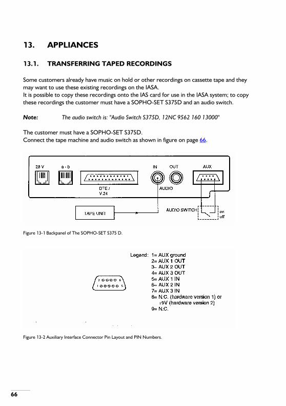
66
13. APPLIANCES
13.1. TRANSFERRING TAPED RECORDINGS
Some customers already have music on hold or other recordings on cassette tape and they may want to use these existing recordings on the IASA.It is possible to copy these recordings onto the IAS card for use in the IASA system; to copy these recordings the customer must have a SOPHO-SET S375D and an audio switch.
Note: The audio switch is: "Audio Switch S375D, 12NC 9562 160 13000"
The customer must have a SOPHO-SET S375D.Connect the tape machine and audio switch as shown in figure on page 66.
Figure 13-1 Backpanel of The SOPHO-SET S375 D.
Figure 13-2 Auxiliary Interface Connector Pin Layout and PIN Numbers.
13.1.1. Making recordings
• Making recordings
The sequence of operations for making recordings from an existing tape is as follows:Actions
- Connect the tape machine and audio switch to the SOPHO-SET S375D (See figure onpage 66);
- Start the IASA Manager program;- Select the "Announcements" pull-down menu, choose the "Create" option;- Initialise the SOPHO-SET S375D (See "Initialising the SOPHO-SET S375D" below);- Switch the audio switch "OFF";- Switch the audio switch "ON";- From the SOPHO-SET S375D, dial the voice port (DNR) of the IASA (This was defined in
the IASA Manager application, with the option "SYSTEM CONFIGURATION" in the"PORTS" pull-down menu);
- Wait for the "CREATE ANNOUNCEMENT" screen to appear;- Fill in the details on the screen (do not forget to give the message a description);- Make sure the screen highlight is on "START";- Press "RETURN";- Start the tape machine;- Start the recording session in the IASA Manager;- Make sure the screen highlight is positioned over "STOP";- When the recording is finished press "RETURN".
13.1.2. Initialising the SOPHO-SET S375D
• Initialising the SOPHO-SET S375D
(You do not have to lift the handset of the S375D.)Actions
- Press the "Program" key;- Press the "Facility" key;- Press the "down arrow" key 11 times;- Ensure the following appears in the SOPHO-SET S375D display:
"Set Operation: Telephone Answer- Press the "Exit" key.
67
68
13.2. MUSIC ON HOLD
Depending on the software package installed on the SOPHO ISPBX, it is possible to define one or more of the IASA ports as music on hold ports. Transfer the music on hold recording to the IASA as described in the previous section.From the pull down menus, select Port mapping and configure the music on hold ports with:
- owner 0;- continuous action;- the announcement index of the recording transferred from tape.
See also sections With Music on Hold (MOH) on page 29 and EXAMPLES - SSW 7xx/8xx/Call@Net on page 29.
13.3. MESSAGE WAITING AND WAKE-UP
How to deal with message waiting and wake-up, depends on the software package installed on the SOPHO ISPBX.
- SSW 640 and up: use OM command ASPORE; The port type must specify a normalextension and the port address must be an extension number of the IASA port.
- SSW 730 and up: use OM command CHTMST.
The ports are defined in two files of the SOPHO SystemManager: WAKPROJ.PDT for wake-up calls and MWWAPROJ.PDT for message waiting. Refer to the relevant SOPHO System Manager Installation and Test manual for information on how to customize these files.
13.4. TRUNK ANNOUNCEMENTS
Use OM command CHPLEX to assign an IASA circuit or DNR as Permanent Line Extension.After the announcement calls can be transferred to the operator or a specified DNR. This DNR must be defined in the Port mapping menu.

A . CABLES
A.1. V.24 CABLES
The cables shown in figures on page 70 and on page 71 are used when making "Direct Connections" from a PC to the IASA circuit board; they are known as "Modem Bypass" or "Null Modem" cables. Figure on page 72 shows the cables used for "Dialled Connections".A V.24 cable should not be longer than 15 metres; cables longer than this may not transfer data reliably. Experience shows that very long cables almost always work perfectly but you should be aware of this limitation if problems are encountered. Table on page 69 shows some cables that are available.
Table A-1 Connecting Cables
Note: Screened cables should be used when making V.24 connections to the MSA. This will ensure that EMC requirements are met. If screened cables are not used, problems might be experienced with V.24 data transfer or system behaviour.If a D.25 connector is used at the ISPBX for IASA V.24 connections, the cable screen should be connected to the metal of the D.25 connector at the PABX end; this will ensure that there is continuity between the screen and the metalwork of the PABX.The screen is not shown in the diagrams that follow, in order to retain clarity of the diagrams.
CABLE LENGTH (metres)
12NC
CONNECTORS
NOTESCABLE END A
CABLE END B
1,5 9562 157 68100 F122 D.25
11 9562 162 04100 F122 F122
The cable can be cut in two and a D.9 or D.25 (female) connector fitted at one end, to match the COM port connector on the customer's PC.
50 9562 162 33100 F122 F122
The cable can be cut in two and a D.9 or D.25 (female) connector fitted at one end, to match the COM port connector on the customer's PC
69

70
A.1.1. Null-Modem Cable (D9 Connector)
Figure A-1 Connection to a PC with a DO Serial Interface Connector.

A.1.2. Null-Modem Cable (D25 Connector)
Figure A-2 Connection to a PC with a D25 Serial Interface Connector.
71

72
A.1.3. One-to-One Cable (D25 Connector)
Figure A-3 Cable used for "Dialled Connections" (One-to-One - D25 Serial Interface Connector).

B . SYSTEM SOFTWARE SUPPORTING IASA
Table on page 73 shows which software supports IASA when it is installed in an ISPBX.
SOPHO ISPBXs
SOFTWARE PACKAGECOMMENTS
CPU PPU
S250/1000
640.7 641.6 Change signalling group. MOH restriction *.641.7 MOH restriction*.
300 300.21 Change signalling group. MOH restriction *.300.22 MOH restriction *.
805 405.x/505.x -
iS3010/3030
200.7 205.8 Change signalling group. Do not place IASA in UG 9 **200.7 205.9 -205.6 205.8 Change signalling group. Do not place IASA in UG 9 **205.7 205.9 -300 300.21 Change signalling group. Do not place IASA in UG 9 **
300.22 -800.23 400.x/500.x Circuits 16-731 are not supported.800.23 401.4/501.4 -800.23 405.x/505.x -805 405.x/505.x -
iS3050
300 300.21 Change signalling group. Do not place IASA in UG 9 **. MOH restriction *.
300.22 MOH restriction *.800.23 400.x/500.x Circuits 16-31 are not supported.800.23 401.4/501.4 -800.23 405.x/505.x -805 405.x/505.x -
iS3070/3090
730.30 144.4/244.4 Change signalling group.144.5/244.5 -
735.20 144.4/244.4 Change signalling group.144.5/244.5 -
740.23 400.x/500.x Circuits 16-31 are not supported.401.4/501.4 -405.x/505.x -152.x/252.x Circuits 16-31 are not supported.154.4/254.4 -162.x/262.x -
741.20 154.3/254.3 -162.x/262.x -401.3/501.3 -405.x/505.x -
805 162.x/262.x - 405.x/505x -
73
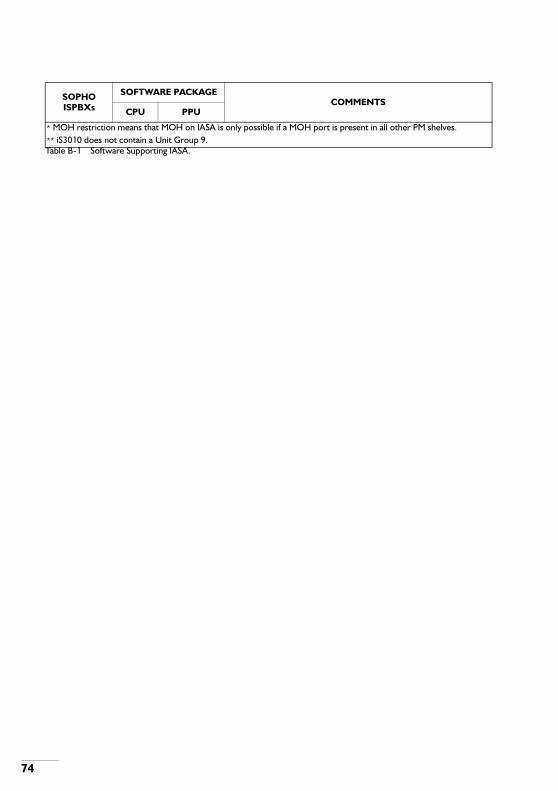
74
Table B-1 Software Supporting IASA.
* MOH restriction means that MOH on IASA is only possible if a MOH port is present in all other PM shelves.** iS3010 does not contain a Unit Group 9.
SOPHO ISPBXs
SOFTWARE PACKAGECOMMENTS
CPU PPU
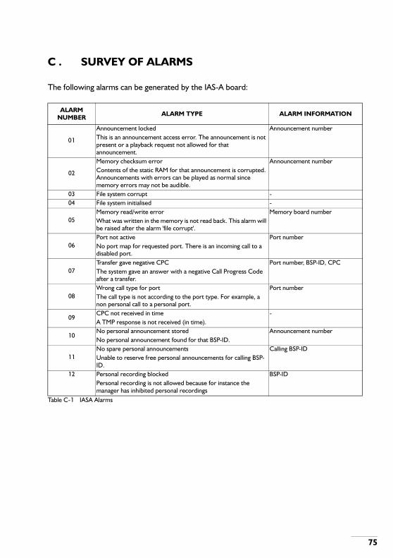
C . SURVEY OF ALARMS
The following alarms can be generated by the IAS-A board:
Table C-1 IASA Alarms
ALARM NUMBER ALARM TYPE ALARM INFORMATION
01
Announcement locked Announcement numberThis is an announcement access error. The announcement is not present or a playback request not allowed for that announcement.
02
Memory checksum error Announcement numberContents of the static RAM for that announcement is corrupted. Announcements with errors can be played as normal since memory errors may not be audible.
03 File system corrupt -04 File system initialised -
05Memory read/write error Memory board numberWhat was written in the memory is not read back. This alarm will be raised after the alarm 'file corrupt'.
06Port not active Port numberNo port map for requested port. There is an incoming call to a disabled port.
07Transfer gave negative CPC Port number, BSP-ID, CPCThe system gave an answer with a negative Call Progress Code after a transfer.
08Wrong call type for port Port numberThe call type is not according to the port type. For example, a non personal call to a personal port.
09CPC not received in time -A TMP response is not received (in time).
10No personal announcement stored Announcement numberNo personal announcement found for that BSP-ID.
11No spare personal announcements Calling BSP-IDUnable to reserve free personal announcements for calling BSP-ID.
12 Personal recording blocked BSP-ID Personal recording is not allowed because for instance the
manager has inhibited personal recordings
75