voice over ip (voip) part 1 - strongsec · • g.729 audio codec for frame relay @ 8 kbit/s ......
TRANSCRIPT

A. Steffen, 9.12.2001, KSy_VoIP_1.ppt 1
ZürcherHochschuleWinterthurKommunikationssysteme (KSy) - Block 5
Voice over IP (VoIP)Part 1
Voice over IP (VoIP)Part 1
Dr. Andreas Steffen
1999-2001 Zürcher Hochschule Winterthur
VoIP Scenarios• Classical telecommunications networks• Present: separate data and voice networks• Future: unified networks• Migration path to VoIP• Least cost routing - today and tomorrow• VoIP - pro and contraH.323 Multimedia Communication Standard• OverviewVideo Compression• H.261 / H.262 / H.263 DCT-based compression algorithms• Macroblock based encoding of color information• Motion vector estimation• Group of pictures difference coding scheme• Video conferencing picture formatsAudio Compression• G.711 pulse code modulation @ 64 kbit/s• G.722 adaptive differential pulse code modulation @ 64 / 32 kbit/s• Linear prediction coder @ 2.5 kbit/s• G.728 code excited linear prediction coder @ 16 kbit/s• G.729 audio codec for frame relay @ 8 kbit/s• G.723.1 low rate audio codec @ 6.3 / 5.3 kbit/s• GSM 06.10 enhanced full rate coder @ 13 kbit/s• Mean opinion score (MOS)H.32x Family• H.320 Videoconferencing over ISDN / H.324 Videoconferencing over POTS

A. Steffen, 9.12.2001, KSy_VoIP_1.ppt 2
ZürcherHochschuleWinterthurVoIP - Themenübersicht
Theorie Teil 1 (heute)VoIP Anwendungen - Heute und MorgenÜbersicht H.323 StandardAudio / Video Kompression
Theorie Teil 2 (nächste Woche)Call Setup / Capabilities Exchange / Channel MultiplexingH.323 Gatekeepers / Gateways / Multipoint ConferencesIETF Session Initiation Protocol (SIP)
Praktikum (24./25.1.2002)H.323 Gateway und Gatekeeper FunktionalitätSiemens Hicom Xpress Call Center ApplikationH.323 SW Client „Microsoft Netmeeting“ / IP Phones

A. Steffen, 9.12.2001, KSy_VoIP_1.ppt 3
ZürcherHochschuleWinterthurVoice / Multimedia over IP
Voice over IP ScenariosVoice over IP Scenarios

A. Steffen, 9.12.2001, KSy_VoIP_1.ppt 4
ZürcherHochschuleWinterthur
Site BSite A
The Classical ApproachSeparate Voice and Data Networks
Internet
PSTN
Private VoiceNetworkVoice
SwitchVoice
Switch
IntranetIP
Router PC
Phone
Fax
IPRouterPC
Phone
Fax
Modem Modem
Past: Classical Telecommunications Networks• The classical telecommunications network is voice-oriented. A companyusually has a Private Branch eXchange (PBX) that switches internal voice callsand connects external calls to and from the Public Switched Telephone Network(PSTN). Since Fax transmission is based on an analog modulation within thevoice band, it is treated in exactly the same way as a voice connection.
• For connections between locations that have a high traffic volume, many companiesuse leased lines in order to minimize costs, thereby creating a Private VoiceNetwork.
• When the first data applications turned up several decades ago, data was carriedover voice lines using analog modems. Still today, remote login from teleworkersinto the company data network is done mostly as direct dial-in over the PSTN.
Present: Separate Data and Voice Networks• Today many companies have a separate data network carrying the backbone trafficbetween locations. This is often done over leased lines in order to minimize costs.When ATM is used as a transport medium then voice and data lines may sharethe same physical line but are otherwise treated as separate logical connections.
• Together with the LAN cabling at the various locations, these data connectionsform the Intranet of a company. External Internet Access is usually realized overa separate leased line to an Internet Service Provider (ISP). Using Virtual PrivateNetwork mechanisms like IPsec tunnels, Intranet connections can alternativelybe carried over the Internet at lower costs and without compromising security.
• In the Company Data Network the IP Routers immediately attached to the endpoints of both Internet and Intranet data connections have the task of forwardingthe IP datagrams within the network using packet-based IP routing mechanisms.
• In the Company Voice Network the Voice Switch has the task of setting upvoice and fax connections using private/public switching mechanisms.
A. Steffen, 9.12.2001, KSy_VoIP_1.ppt 5
ZürcherHochschuleWinterthur
Site BSite A
Internet
The Future ApproachVoice/Fax over IP - A Unified Network
IntranetIP
Router
PC withVoice/Fax
IP Phone
PSTNGateway
PSTNGateway
PC withVoice/Fax
IP Phone
IPRouter
PSTN
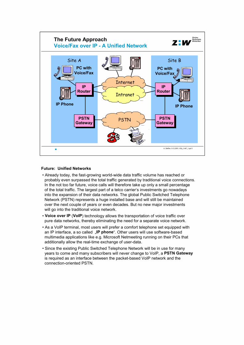
Future: Unified Networks• Already today, the fast-growing world-wide data traffic volume has reached orprobably even surpassed the total traffic generated by traditional voice connections.In the not too far future, voice calls will therefore take up only a small percentageof the total traffic. The largest part of a telco carrier‘s investments go nowadaysinto the expansion of their data networks. The global Public Switched TelephoneNetwork (PSTN) represents a huge installed base and will still be maintainedover the next couple of years or even decades. But no new major investmentswill go into the traditional voice network.
• Voice over IP (VoIP) technology allows the transportation of voice traffic overpure data networks, thereby eliminating the need for a separate voice network.
• As a VoIP terminal, most users will prefer a comfort telephone set equipped withan IP interface, a so called „IP phone“. Other users will use software-basedmultimedia applications like e.g. Microsoft Netmeeting running on their PCs thatadditionally allow the real-time exchange of user-data.
• Since the existing Public Switched Telephone Network will be in use for manyyears to come and many subscribers will never change to VoIP, a PSTN Gatewayis required as an interface between the packet-based VoIP network and theconnection-oriented PSTN.
A. Steffen, 9.12.2001, KSy_VoIP_1.ppt 6
ZürcherHochschuleWinterthur
Site BSite A
Internet
The Intermediate ApproachMigration Path to Voice/Fax over IP
Intranet
PC withVoice/Fax
IP Phone
PC withVoice/Fax
IP PhonePSTNGateway
PSTNGateway
VoiceSwitch
Phone
Fax
VoiceSwitch
Phone
Fax
IPRouter
IPRouter
PSTN
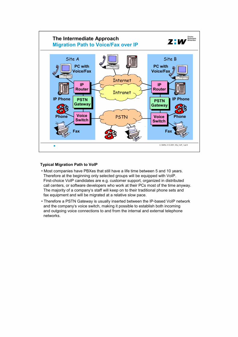
Typical Migration Path to VoIP• Most companies have PBXes that still have a life time between 5 and 10 years.Therefore at the beginning only selected groups will be equipped with VoIP. First-choice VoIP candidates are e.g. customer support, organized in distributedcall centers, or software developers who work at their PCs most of the time anyway.The majority of a company‘s staff will keep on to their traditional phone sets andfax equipment and will be migrated at a relative slow pace.
• Therefore a PSTN Gateway is usually inserted between the IP-based VoIP networkand the company‘s voice switch, making it possible to establish both incomingand outgoing voice connections to and from the internal and external telephonenetworks.

A. Steffen, 9.12.2001, KSy_VoIP_1.ppt 7
ZürcherHochschuleWinterthur
Site A Site B
Least Cost Routing of Voice/FaxToday: Over the Private Voice Network
PSTN
Fax
Phone
Fax
VoiceSwitch
VoiceSwitch
Private VoiceNetwork Phone
CA
Least Cost Routing over a Private Voice Network• The scenario is the following: An employee at site B wants to make an externalcall to a customer CA. The least cost routing algorithm running in the voice switchat site B determines the cheapest route to CA at the current time of day.
• As a result of this search, instead of setting up a direct long distance call over thePSTN from site B, the call is first switched over the private voice network to thePBX at site A where a local call is set up over the PSTN to the customer CA.

A. Steffen, 9.12.2001, KSy_VoIP_1.ppt 8
ZürcherHochschuleWinterthur
Site BSite A
Internet
Least Cost Routing of Voice/FaxTomorrow: Over the Intranet / Internet
IntranetIP
Router
PC withVoice/Fax
IP Phone
PSTNGateway
PSTNGateway
PC withVoice/Fax
IP Phone
IPRouter
PSTN
CA
Least Cost Routing over the Intranet or Internet• We now assume a company voice network based completely on VoIP. ThePBXs have been replaced by PSTN gateways.
• When an employee at site B wants to call an external customer CA, the leastcost routing algorithm running at the local H.323 gatekeeper determines thePSTN gateway at site A as the optimal exit point to customer CA. All VoIPpackets for this call are now routed either over the private Intranet or over the public Internet to the PSTN gateway at site A.

A. Steffen, 9.12.2001, KSy_VoIP_1.ppt 9
ZürcherHochschuleWinterthurVoIP - The „Pros and Cons“
AdvantagesCost savings on long distance callsFewer leased lines for private networks Single RJ-45 connector at the workplace for all servicesElimination of expensive voice switchesEnables new multimedia features, e.g. human operatorassisted e-commerce
Problems / Open QuestionsControl of delay, jitter and packet loss over IP-based networksQoS guarantees (RSVP, ATM traffic contracts)Universal directory services (X.500, LDAP)Interoperability (compliance with ITU-T and IETF standards)

A. Steffen, 9.12.2001, KSy_VoIP_1.ppt 10
ZürcherHochschuleWinterthurVoice / Multimedia over IP
H.323 StandardH.323 Standard

A. Steffen, 9.12.2001, KSy_VoIP_1.ppt 11
ZürcherHochschuleWinterthur
System Control
ITU-T H.323 : Packet-BasedMultimedia Communications Systems
Video I/OEquipment
Audio I/OEquipment
System ControlUser Interface
RAS Control
Q.931 Call Setup
H.245 Control
User DataApplications
T.120, etc.
Audio CodecG.711, G.722,
G.723.1, G.728,G.729
Video CodecH.261, H.263
LAN
H.323
H.225.0Layer
RTP
The ITU-T Standard H.323• The H.323 recommendation for „Packet-Based Multimedia CommunicationsSystems“ is an umbrella standard comprising the numerous ITU-Trecommendations listed below:
Video Streams (Video Codecs H.261, H.263)• These recommendations define various digital video compression algorithms.
Audio Streams (Audio Codecs - G.711, G.722, G.723.1, G.729, G.729)• These recommendations define various digital audio compression algorithms.
User Data Applications (T.120, etc.)• These recommendations define how user data applications are encoded. Examples are shared whiteboard applications and user file transfer.
System Control• RAS Control: Registration with a H.323 gatekeeper. Name resolution services.• Q.931 Call Setup with an VoIP peer using the ISDN basic call control protocol.• H.245 Control: Negotiation of common multimedia properties between VoIP peers.
Call Signalling Protocols and Media Stream Packetization (H.225.0)• Defines the packet-based multiplexing of the various video and audio streamsusing the unreliable Real-time Transfer Protocol (RTP).
• Defines the transmission of user data streams using the reliable TCP protocol.• Defines the format and structure of the various system control messages.

A. Steffen, 9.12.2001, KSy_VoIP_1.ppt 12
ZürcherHochschuleWinterthurVoice / Multimedia over IP
Video CompressionVideo Compression

A. Steffen, 9.12.2001, KSy_VoIP_1.ppt 13
ZürcherHochschuleWinterthurH.261/H.263 Video Compression based on the
Discrete Cosine Transform (DCT)
EntropyEncoderQuantizer2D- DCT
CompressedData
SourceImage Data
Dequantizer2D- IDCT
ReconstructedImage Data
EntropyDecoder
Video Compression Algorithms based on the DCT• In H.323 packet-based multimedia applications one of the two ITU-T standards
H.261 or H.263 (which were optimized for small transmission bandwidths) arecommonly used.
• When a sufficienty large transmission bandwidth (2-6 Mbit/s) is available, also theMPEG-2 standard H.262 could be used for H.323 based video communication.
Building Blocks• 2D-DCT / IDCT: The two-dimensional discrete cosine transform (DCT) transformsimage sub-blocks of 8x8 color pixels into a frequency domain representation of8x8 frequency components. The luminance and chrominance components aretransformed separately. The DCT is a lossless operation since the inverse discretecosine transform (IDCT) restores the original image pixels given the frequencydistribution information.
• Quantizer / Dequantizer: Using quantization tables, each luminance andchrominance frequency component is quantized to a variable number of bits.Usually the number of allocated bits decrease with increasing image frequenciessince the human eye is less sensitive to errors in high image frequencies.Due to the finite number of 2b quantisation steps corresponding to the number ofb allocated bits, quantization in the sender is a lossy process that cannot bereversed by the dequantization process in the receiver. This translates into atradeoff between the achieved compression factor and the resulting image quality.
• Entropy Coder / Decoder: The resulting bit values of the quantized luminance andchrominance frequency components are optimally compressed using a Huffmanrun-length encoding. This is a lossless compression operation that can bereversed by the entropy decoder at the receiver.

A. Steffen, 9.12.2001, KSy_VoIP_1.ppt 14
ZürcherHochschuleWinterthurH.261 / H.263 Coding of 16x16 Macroblocks
uses 8x8 DCTs and 4:2:0 Color Format
Y CB CR
1 23 4
5 6
Luminance SampleChrominance Sample(Average based on 4 adjacent pixels)
Coding of Macroblocks• The 16x16 pixel macroblocks are the basis for the coding of color images inDCT-based video compression schemes.
• The luminance component Y is transformed into the frequency domain at thenominal resolution using four 8x8 DCTs, whereas the macroblock of the twochrominance components CB and CR is first reduced to a single 8x8 block byaveraging 4 adjacent pixels, effectively reducing both the horizontal and verticalresolution of the color information by a factor of two. This can be done withouta significant loss of picture quality because the human eye is much more sensitiveto the resolution of the luminance component than to that of the color information.
• Using this so called 4:2:0 color format, a total of only six 8x8 DCTs are requiredto code a 16x16 macroblock of true color pixels..
A. Steffen, 9.12.2001, KSy_VoIP_1.ppt 15
ZürcherHochschuleWinterthurH.261 / H.263 Motion Compensation
Frame 3Motion Vector Estimation:
Frame 1Frame 2
hidden
H.261: 1 pixel ResolutionH.263: 1/2 pixel Resolution
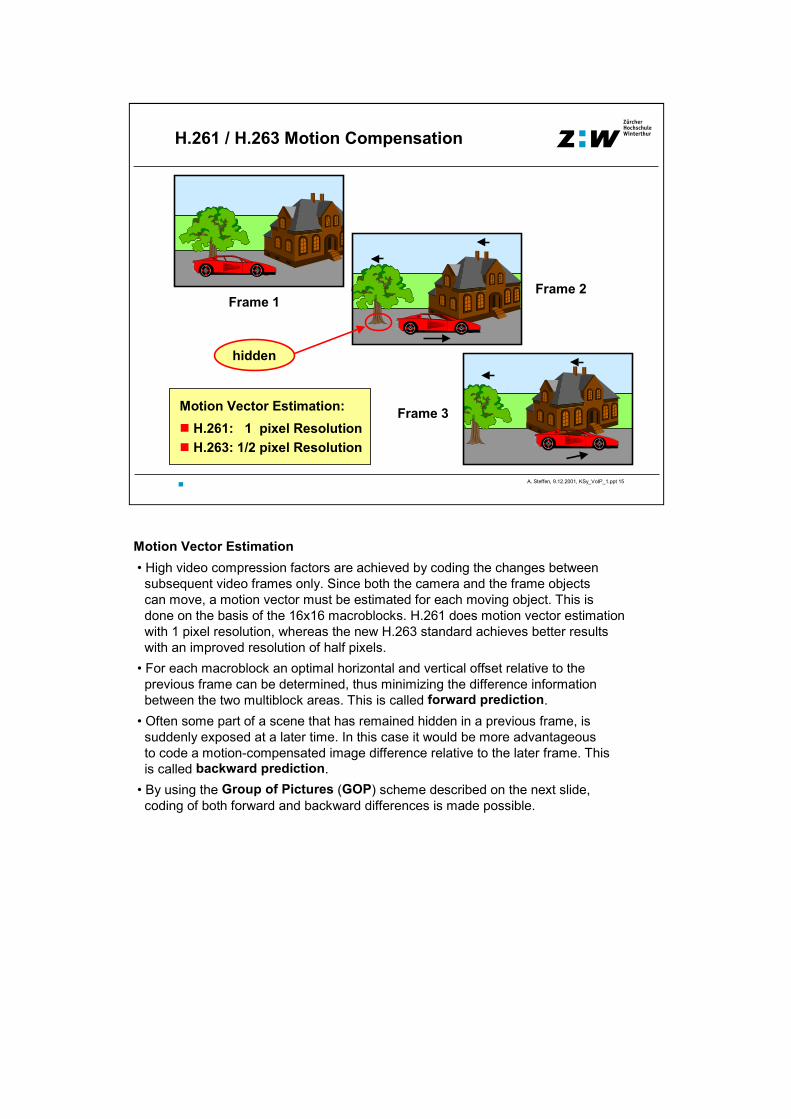
Motion Vector Estimation• High video compression factors are achieved by coding the changes betweensubsequent video frames only. Since both the camera and the frame objectscan move, a motion vector must be estimated for each moving object. This isdone on the basis of the 16x16 macroblocks. H.261 does motion vector estimationwith 1 pixel resolution, whereas the new H.263 standard achieves better resultswith an improved resolution of half pixels.
• For each macroblock an optimal horizontal and vertical offset relative to theprevious frame can be determined, thus minimizing the difference informationbetween the two multiblock areas. This is called forward prediction.
• Often some part of a scene that has remained hidden in a previous frame, issuddenly exposed at a later time. In this case it would be more advantageousto code a motion-compensated image difference relative to the later frame. Thisis called backward prediction.
• By using the Group of Pictures (GOP) scheme described on the next slide,coding of both forward and backward differences is made possible.
A. Steffen, 9.12.2001, KSy_VoIP_1.ppt 16
ZürcherHochschuleWinterthurGroup of Pictures (GOP)
I: Intra frame B: Bidirectional frameP: Prediction frame
I
13
P
12
B
11
B
10
B
9
P
8
B
7
B
6
B
5
P
4
B
3
B
2
B
1
I
0
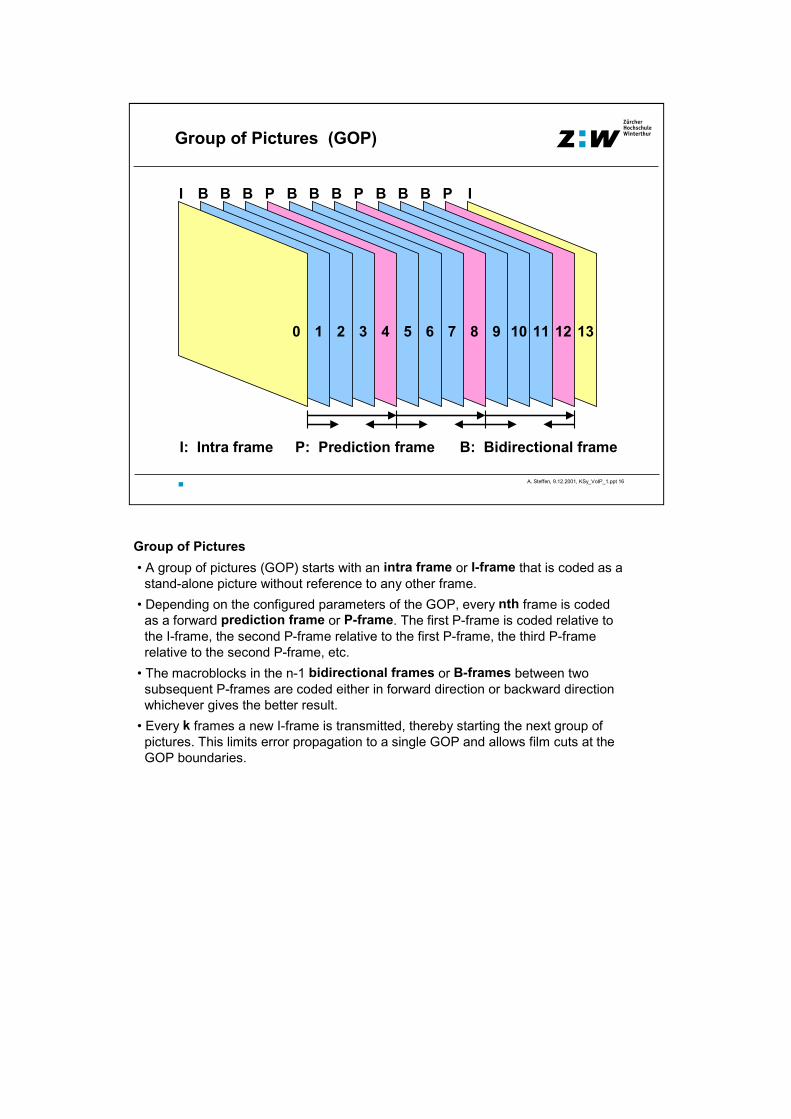
Group of Pictures• A group of pictures (GOP) starts with an intra frame or I-frame that is coded as astand-alone picture without reference to any other frame.
• Depending on the configured parameters of the GOP, every nth frame is codedas a forward prediction frame or P-frame. The first P-frame is coded relative tothe I-frame, the second P-frame relative to the first P-frame, the third P-frame relative to the second P-frame, etc.
• The macroblocks in the n-1 bidirectional frames or B-frames between twosubsequent P-frames are coded either in forward direction or backward directionwhichever gives the better result.
• Every k frames a new I-frame is transmitted, thereby starting the next group ofpictures. This limits error propagation to a single GOP and allows film cuts at theGOP boundaries.

A. Steffen, 9.12.2001, KSy_VoIP_1.ppt 17
ZürcherHochschuleWinterthur
16CIF 1408 x 1152
Video Conferencing Picture FormatsCommon Interchange Format (CIF)
4CIF 704 x 576
CIF 352 x 288
1 QCIF 176 x 144 pixels 2 sub-QCIF 128 x 96 pixels
12 Macroblock 16 x 16 pixels
Video Conferencing Picture Formats• For video conferencing applications a Common Interchange Format (CIF)
with a standardized picture size of 325 x 288 pixels has been defined. • For applications over narrow-band connections (e.g. 33.6 kbit/s POTS or64-128 kbit/s ISDN channels) and/or low-end multimedia terminals (littlecomputing power, usually with SW-based encoders/decoders), the standardhas been extended to include the smaller Quarter-CIF and the even smallersub-Quarter-CIF formats.
• For applications using broad-band connections (> 2 Mbit/s) and powerfulmultimedia terminals (usually with HW-based encoders/decoders), the standardhas been extended to include the TV and high-resolution formats 4CIF and 16CIF,respectively.
• All standardized picture sizes are multiples of the 16 x 16 pixel macroblocksused by the DCT-based video compression algorithms to encode the chrominanceinformation. The required processing power for real-time encoding and decodingis directly proportional to the total number of macroblocks in the picture.
Picture Sizes• sub-QCIF 128 x 96 pixels 8 x 6 = 48 macroblocks• QCIF 176 x 144 pixels 11x 9 = 99 macroblocks• CIF 352 x 288 pixels 22 x 18 = 396 macroblocks• 4CIF 704 x 576 pixels 44 x 36 = 1584 macroblocks• 16CIF 1408 x 1152 pixels 88 x 72 = 6336 macroblocks
A. Steffen, 9.12.2001, KSy_VoIP_1.ppt 18
ZürcherHochschuleWinterthurVoice / Multimedia over IP
Audio CompressionAudio Compression

A. Steffen, 9.12.2001, KSy_VoIP_1.ppt 19
ZürcherHochschuleWinterthur
16 Bit linear PCM - 128 kbit/s
G.711 : PCM - 64 kbit/sA-Law / µµµµ-Law Pulse Code Modulation
#0 #1 #2 #3 #4 #5 #6 #7
0 t [µµµµs]125 250 375 500 625 750 875
16
#0 #1 #2 #3 #4 #5 #6 #7
2ms
#8 #9
64 Bit Audio DataPacket
1ms t [ms]
88 bit A-Law / µµµµ-Law
ITU-T G.711 - Pulse Code Modulation• In telephony systems the voice band is usually limited to 300 Hz .. 3.4 kHz. According to the Nyquist theorem this band-limited speech can be sampledwith an aliasfree sampling rate of 8 kHz. This means that a signal sample is takenevery 125 s and converted into a 16 bit linear PCM value.
• As a next step the dynamic range of the 16 bit linear PCM value is compressedinto an 8 bit amplitude value by using a logarithmic mapping function. In NorthAmerica the -Law function is used, whereas in Europe and the rest of the worldthe A-Law function is applied.
G.711 embedded in RTP-Packets• When VoIP applications are operated over a 10 Mbit/s or 100 Mbit/s LAN, as itis usually the case in call centers, then the G.711 speech format is used. Sinceno speech compression algorithm must be applied, the PCM speech samplescan be transmitted with little delay and with a high speech quality. In order tokeep the overhead due to the UDP and RTP headers at a reasonably low level,H.225.0 recommends to group 8 PCM samples together and to transmit them in aUDP datagram every 1 ms.

A. Steffen, 9.12.2001, KSy_VoIP_1.ppt 20
ZürcherHochschuleWinterthur
2 bit @ 8 kHz
6 bit @ 8 kHz
G.722 : ADPCM 7 kHz Voice - 64 kbit/s Adaptive Differential Pulse Code Modulation
ADPCM 3.4 kHz Voice - 32kbit/s
#0a
#1a
#2a
#3a
#4a
#5a
#6a
#7a
#0b
#1b
#2b
#3b
#4b
#5b
#6b
#7b
0 t [µµµµs]125 250 375 500 625 750 875
16
65
#0a
#0b
#1a
#1b
16 bit @ 16 kHz
2
2 ~~
~~4 - 8 kHz
0 - 4 kHz+
AFB
AFB
+
AFB Adaptive Feedback
ITU-T G.722 - Adaptive Differential Pulse Code Modulation• Extensive studies have found out that the perceived quality of a real-time videoconference depends to a large extent on voice quality. If speech quality is good,people are ready to accept imperfections in the transmitted video stream.
• Therefore in high-end video conferencing systems the voice bandwidth is oftenincreased to 7 kHz, requiring a doubling of the sampling rate to 16 kHz.
• The goal is to have an increased voice bandwidth but without increasing the bit rate of 64 kbit/s. This can be achieved with Adaptive Differential Pulse CodeModulation (ADPCM) that works as follows:
• The 16 bit linear PCM speech samples aquired with a sampling rate of 16 kHz areapplied to a filter bank consisting of a low pass filter with a passband of 0 - 4 kHzand a high pass filter with a passband of 4 - 8 kHz. Through filtering the effectivebandwidths have been reduced to 4 kHz, so without incurring aliasing effects, thesampling rate can be halved to 8 kHz by throwing away every second samplecoming out of the filters. This process is called „down-sampling“.
• The amplitudes of the filtered high-pass and low-pass signals are now quantizedto a finite number of bits. Since the human ear is less sensitive to high frequencies,only 2 bits are assigned to the high-pass signal, whereas the low-pass signal gets6 bits, resulting in a total rate of 8 bits @ 8 kHz = 64 kbit/s.
• Since G.711 assigns 8 bits to a 4 kHz signal, the quality of the low-pass signalin G.722 would be worse with only 6 bits. The trick behind ADPCM consists ofan adaptive feedback loop (AFB) that subtracts the quantized output signalfrom the original input signal, so that only the changes of the speech signal getencoded. Since the difference signal has much smaller amplitudes, 6 bits and2 bits for the low-pass and high-pass signals, respectively are sufficient.
• A variant of the G.722 ADPCM method differentially encodes a 3.4 kHz signalat 8 kHz with only 4 bits per sample, resulting in a bit rate of 32 kbit/s. Thisalgorithm is used e.g. by DECT.

A. Steffen, 9.12.2001, KSy_VoIP_1.ppt 21
ZürcherHochschuleWinterthurLinear Prediction Coder (LPC) - 2.4 kbit/s
Vocal Tract Model / Parameter Estimation
LPC10E - 2.4 kbit/s
Switch
Reflection Coefficients
Vocal Tract Model
180 Samples @ 8 kHz
Pitch Period
VoicedSpeech
Gain
NoiseUnvoicedSpeech
Gain
0 ms 22.5 ms
Processing Delay
LPC
Speech Frame
54 Bits Parameters
22.5 ms 45 ms
Speech Compression Algorithms based on Vocal Tract Models• If speech rates below 16 kbit/s are to be achieved, then the way how humanspeech is generated in the vocal tract has to be modelled:
• The cavities of the mouth, nose, throat and larynx, as well as the influence of thetongue can be modelled by a series of cylindrical rings with variable lengths anddiameters. These cavities are traversed by sound waves generated by thevocal chords in the larynx, with the effect that the spectral components of the sound wave are filtered according to the current shape of the vocal tract.
• A diameter change from one cylindrical segment to the next is equivalent to acorresponding change in the wave impedance. This causes part of the travellingsound wave to be reflected a the segment boundaries, the exact amount dependingon the set of reflection coefficients that can be derived from the diameters.
Linear Prediction Coders• In order to determine the current settings of the vocal tract model, a speech frameof 22.5 ms duration must first be recorded. This introduces a significant delay towhich the processing delay required to encode the speech frame must be added.
• Using sophisticated algorithms the optimum parameter settings for the reflectioncoefficients are computed out of the 180 collected speech samples. Thesynthesized output from the model should be as close to the original speechframe as possible.
• It is a crucial task to determine if currently a vowel or a consonant is spoken. In thefirst case a periodic pulse train producing harmonics is applied to the vocal tractmodel, in the second case a noise generator is connected. The estimation of thecurrent pitch frequency of the pulse train generator is even trickier.
• For each speech frame only the parameter settings of the speech model are transmitted. An exact copy of the speech model at the receiver resynthesizes thespeech frame. This leads to an intelligible but rather impersonal type of speech.Therefore pure LPC coders are only used by the military and in cheap toys.
A. Steffen, 9.12.2001, KSy_VoIP_1.ppt 22
ZürcherHochschuleWinterthurG.728 : LD-CELP - 16 kbit/s
Low-Delay Code-Excited Linear Prediction
LD-CELP - 16 kbit/s
Processing Delay
LD-CELP
Speech Block
#0 #1 #2 #3 #4
0 ms 0.625 ms
Reflection Coefficients
Vocal Tract Model
10 Bits Codevector
Excitation Codebook20 3
GainIndex
9
Shape VectorIndex
0.625 ms 1.25 ms
Best Match
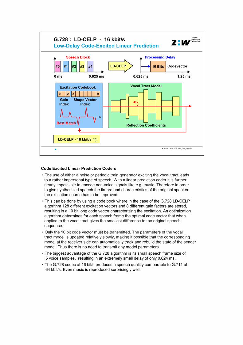
Code Excited Linear Prediction Coders• The use of either a noise or periodic train generator exciting the vocal tract leadsto a rather impersonal type of speech. With a linear prediction coder it is furthernearly impossible to encode non-voice signals like e.g. music. Therefore in orderto give synthesized speech the timbre and characteristics of the original speakerthe excitation source has to be improved.
• This can be done by using a code book where in the case of the G.728 LD-CELPalgorithm 128 different excitation vectors and 8 different gain factors are stored,resulting in a 10 bit long code vector characterizing the excitation. An optimizationalgorithm determines for each speech frame the optimal code vector that whenapplied to the vocal tract gives the smallest difference to the original speechsequence.
• Only the 10 bit code vector must be transmitted. The parameters of the vocaltract model is updated relatively slowly, making it possible that the correspondingmodel at the receiver side can automatically track and rebuild the state of the sendermodel. Thus there is no need to transmit any model parameters.
• The biggest advantage of the G.728 algorithm is its small speech frame size of5 voice samples, resulting in an extremely small delay of only 0.624 ms.
• The G.728 codec at 16 bit/s produces a speech qualitiy comparable to G.711 at64 kbit/s. Even music is reproduced surprisingly well.

A. Steffen, 9.12.2001, KSy_VoIP_1.ppt 23
ZürcherHochschuleWinterthurG.729 : CS-ACELP - 8 kbit/s
Conjugate-Structure Algebraic CELP
CS-ACELP - 8 kbit/s
80 Samples @ 8 kHz
0 ms 10 ms
Processing Delay
CS-ACELP
Speech Frame
80 Bits Parameters,Codevector
10 ms 20 ms
Variant of a Code-Excited Linear Prediction Coder Default Voice Coding Algorithm for Frame Relay
A. Steffen, 9.12.2001, KSy_VoIP_1.ppt 24
ZürcherHochschuleWinterthurG.723.1 : MP-MLQ / ACELP - 6.3 / 5.3 kbit/s
Multi-Pulse Maximum Likelihood Quantization
CELP - 4.8 kbit/s
240 Samples @ 8 kHz
0 ms 30 ms
Speech Frame 6.3 kBit/s
Processing Delay
192 Bits
30 ms 60 ms
Variants of a Code-Excited Linear Prediction Coder Default Voice Coding Algorithm for H.324 over POTS
5.3 kBit/s
Processing Delay
160 Bits
30 ms 60 ms
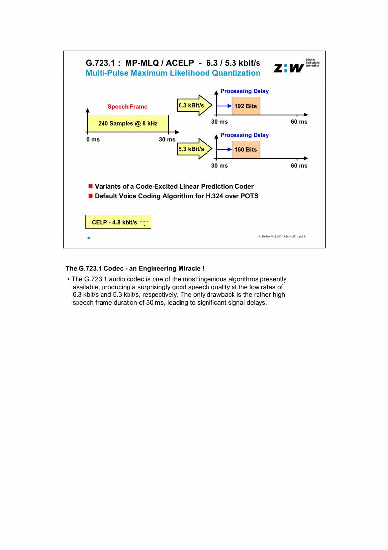
The G.723.1 Codec - an Engineering Miracle !• The G.723.1 audio codec is one of the most ingenious algorithms presently
available, producing a surprisingly good speech quality at the low rates of6.3 kbit/s and 5.3 kbit/s, respectively. The only drawback is the rather highspeech frame duration of 30 ms, leading to significant signal delays.

A. Steffen, 9.12.2001, KSy_VoIP_1.ppt 25
ZürcherHochschuleWinterthurGSM 06.10 : RPE-LTP - 13 kbit/s
GSM Enhanced Full Rate Coder (EFR)
EFR - 13 kbit/s
160 Samples @ 8 kHz
0 ms 20 ms
Speech Frame Processing Delay
RPE-LTP 260 Bits
20 ms 40 ms
Regular Pulse Excitation Long-Term Predictor (RPE-LTP) Variant of a Linear Prediction Coder
GSM 06.10 Enhanced Full Rate Codec• The new EFR codec is much superior to the original FR codec. Its modernarchitecture delivers at 13 kbit/s a speech quality comparable to G.711 at 64 kbit/s.

A. Steffen, 9.12.2001, KSy_VoIP_1.ppt 26
ZürcherHochschuleWinterthur
Speech Quality
MOS - Mean Opinion Score (ITU-T P.800)
5 - Excellent4 - Good3 - Fair2 - Poor1 - Bad
Poor 2
Fair 3
Good 4
Excellent 5
64 32 16 8 4.8 2.4Bit Rate [kbps]
Mean Opinion Score (MOS)• Today the most reliable method to determine speech quality on an absolute scaleis through a subjective opinion test where speech sequences are played to severalpeople who are asked about their opinion immediately afterwards.
• The opinion scale is standardized and goes from bad (1) over poor (2), fair (3) andgood (4) to a maximum rating of excellent (5). The MOS value is then computedas the average or mean over all answers.
• The ITU-T recommendation P.800 meticulously defines the laboratory setupfor the MOS listening tests, including speech and noise levels, the speakers (atleast two males and two females), ... up to detailed instructions for the subjects.
• The MOS graph as a function of the speech transmission rate clearly showsthat speech rates down to about 16 kbit/s are generally perceived as having goodquality, whereas the military-grade LPC algorithms with rates of 2.5 kbit/s and lessare judged to be significantly below fair. Depending on the particular speechcompression algorithm, the rates in the range from 5 .. 13 kbit/s come to liesomewhere between good and fair.

A. Steffen, 9.12.2001, KSy_VoIP_1.ppt 27
ZürcherHochschuleWinterthur
G. 71164 kbps
Speech Samples in Various Environments
ADPCM32 kbps
G. 72816 kbps
G. 7298 kbps
CELP4.8 kbps
LPC2.4 kbps
SpaceShuttle
ShuttleCrew
Music
Bit Errors0.1%
Bit Errors1%
GSM13 kbps
Various Speech Environments• Space Shuttle: A single speaker plus the typical background noise occuringin the cockpit of a space shuttle. Speech compression algorithms should notonly work well under studio conditions but should also behave robustly in noisyenvironments.
• Shuttle Crew: Sentence spoken by a group of people. Shows the ability of thealgorithms to model several voices simultaneously. LPC as a single vocal tractmodel fails miserably.
• Music: Most speech compression algorithms model music quite acceptably, theexception being again the LPC that tracks the lead singer only.
• Bit Errors: Bit errors in G.711 PCM produce clicking noises, in differential PCMalso sudden volume changes can occur. Speech models are quite robust as longas the error rate remains small (0.1%) but they start to get unstable with highererror rates (1%). The GSM enhanced full rate coder is a typical example for thisbehaviour.
A. Steffen, 9.12.2001, KSy_VoIP_1.ppt 28
ZürcherHochschuleWinterthurVoice / Multimedia over IP
H.32x FamilyH.32x Family
A. Steffen, 9.12.2001, KSy_VoIP_1.ppt 29
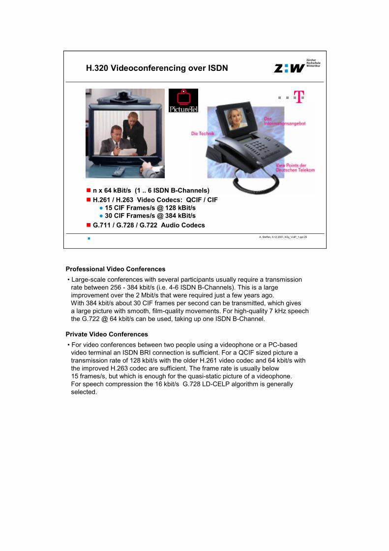
ZürcherHochschuleWinterthurH.320 Videoconferencing over ISDN
n x 64 kBit/s (1 .. 6 ISDN B-Channels)H.261 / H.263 Video Codecs: QCIF / CIF
15 CIF Frames/s @ 128 kBit/s 30 CIF Frames/s @ 384 kBit/s
G.711 / G.728 / G.722 Audio Codecs
Professional Video Conferences• Large-scale conferences with several participants usually require a transmissionrate between 256 - 384 kbit/s (i.e. 4-6 ISDN B-Channels). This is a largeimprovement over the 2 Mbit/s that were required just a few years ago.With 384 kbit/s about 30 CIF frames per second can be transmitted, which givesa large picture with smooth, film-quality movements. For high-quality 7 kHz speechthe G.722 @ 64 kbit/s can be used, taking up one ISDN B-Channel.
Private Video Conferences• For video conferences between two people using a videophone or a PC-basedvideo terminal an ISDN BRI connection is sufficient. For a QCIF sized picture atransmission rate of 128 kbit/s with the older H.261 video codec and 64 kbit/s withthe improved H.263 codec are sufficient. The frame rate is usually below15 frames/s, but which is enough for the quasi-static picture of a videophone.For speech compression the 16 kbit/s G.728 LD-CELP algorithm is generallyselected.

A. Steffen, 9.12.2001, KSy_VoIP_1.ppt 30
ZürcherHochschuleWinterthurH.324 Videophone over POTS I
V.34 Analog Modem H.263 Video CodecG.723.1 Audio Codec
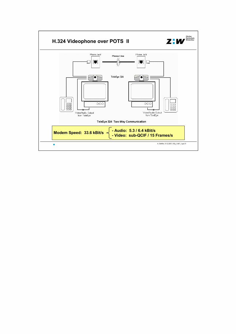
Video Conferences over POTS• The H.324 standard is an attempt at videoconferencing over the Plain OldTelephone System (POTS) using analog modem technology. Since for abidirectional transmission between two modems (V.34 or V.90) the maximumachievable speed is only 33.6 kbit/s, both video and audio have to be heavilycompressed.
• For audio transmission the extremely efficient G.723.1 codec with compressedspeech rates of 5.6 and 6.3 kbit/s was developed. The remaining bandwidthallows the H.263 codec to transmit sub-QCIF pictures at a not very excitingrate of 10-15 frames/s.
• H.324 based telephony has rather remained a gadget for the consumer marketthat up to now hasn‘t found a large acceptance.
A. Steffen, 9.12.2001, KSy_VoIP_1.ppt 31
ZürcherHochschuleWinterthurH.324 Videophone over POTS II
- Audio: 5.3 / 6.4 kBit/s- Video: sub-QCIF / 15 Frames/sModem Speed: 33.6 kBit/s
A. Steffen, 9.12.2001, KSy_VoIP_1.ppt 32
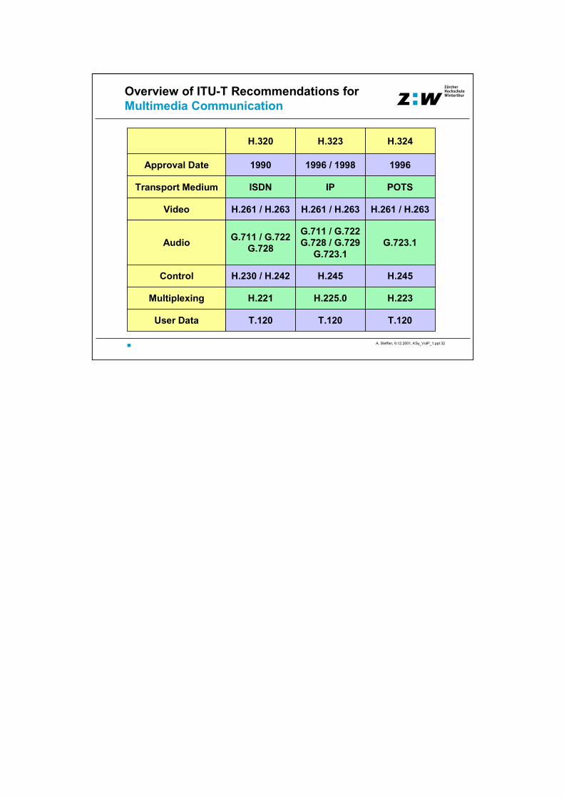
ZürcherHochschuleWinterthurOverview of ITU-T Recommendations for
Multimedia Communication
H.320 H.323 H.324
ISDN
1990
IP
1996 / 1998
POTS
1996Approval Date
Transport Medium
Video H.261 / H.263 H.261 / H.263 H.261 / H.263
Audio G.711 / G.722G.728
G.711 / G.722G.728 / G.729
G.723.1G.723.1
Control H.230 / H.242 H.245 H.245
H.221 H.225.0 H.223Multiplexing
User Data T.120 T.120 T.120