voice over ip implementation agreement - columbia …hgs/papers/others/1997/vip97053.doc · web...
TRANSCRIPT

VoIP97-053
IMTC VoIP Forum Contribution
Subject: VoIP IA 1.0
Contact: Michael Knappe Scott Petrack
Cisco Systems, Inc. VocalTec Communications Ltd.170 West Tasman Drive 1 Maskit StreetSan Jose, CA 95134 Herzeliya, Israel 46733Phone: (408) 527-3849 Phone: +972 9 952 5862Fax: (408) 526-4287 Fax: +972.9956.1867E-mail: [email protected] Email: [email protected]
Jim Toga Stan Naudus
Intel, Corp 3Com, Corp.2111 N.E. 25th Ave 2070 Chain Bridge Rd.Hillsboroh, Or. Suite 100
Vienna, Va 22182Phone: (503) 264-8816 Phone: (703) 848-7710Fax: (503) 264-8816 Fax: (703) 848-7740E-Mail: [email protected] E-Mail: [email protected]
Date: Sept 26, 1997
Location: Boston World Trade Center
Distribution: Participants in the IMTC Voice over IP Forum
Abstract: Draft copy of the VoIA IA 1.0.
Draft 1
VoIP97-053
IMTC Voice over IP ForumService Interoperability
Implementation Agreement
Draft 1.00
IMTC Voice over IP Forum Technical Committee
August, 29 1997
Draft 2

VoIP97-053
Voice Over IP Implementation Agreement
IMTC Voice Over IP Technical Committee
File IA100.docTable of Contents
1. INTRODUCTION1.1 Abstract
1.2 Purpose
1.3 Baseline Interoperability Requirement Summary
1.4 Terminology
1.5 Acronyms
1.6 References
2. VOIP OPERATIONAL ENVIRONMENT2.1 VoIP Network Elements
2.1.1 Internet and Intranet infrastructure2.1.2 H.323 Terminals2.1.3 VoIP-H.323 Gateways2.1.4 PSTN infrastructure2.1.5 Directory Services
2.2 VoIP Connectivity Configurations
3. VOIP STACK OVERVIEW3.1 Call Establishment And Control
3.2 Presentation
3.3 Addressing3.3.1 RAS3.3.2 DNS3.3.3 LDAP
3.4 G.723.1
3.5 H.245
3.6 H.2253.6.1 Q.9313.6.2 RTP/RTCP3.6.3 Transport Layer
Draft 3

VoIP97-053
3.6.4 Network Layer
4. H.323 CALL PROCESSING4.1 High Level Call Setup
4.2 Detailed Call Setup
5. ADDITIONAL H.323 ISSUES5.1 Presentation Layer
5.1.1 Encoded Speech5.1.2 Voice Activity Detection5.1.3 DTMF Digit Carriage
6. DIRECTORY SERVICES AND CALL MANAGEMENT AGENT6.1 Logical Voice Service Modules
6.2 Directory Servers
6.3 The CMA System6.3.1 Overview
6.4 E.164 to dynamic IP resolution6.4.1 Introduction6.4.2 Practical examples of dynamic Address Mappings in RAS
7. ANNEXES (NORMATIVE)
8. APPENDIXES (INFORMATIVE)
Draft 4

VoIP97-053
1Introduction
1.1AbstractThe VoIP Service Interoperability Implementation Agreement combines, clarifies and complements existing standards to provide a complete Internet telephony interoperability protocol. The foundation of the IA is the use of H.323 for call establishment and capability negotiation. Call signaling between service elements is handled via Q.931 messages as part of H.323, with each service element providing the necessary conversion from its local endpoint signaling to the H.323/Q.931 backbone protocol. Other telephony specific requirements such as the transfer and reproduction of DTMF data have been added to provide a high level of connectivity with the traditional telephone infrastructure. Directory services are also a critical element of an Internet telephony system, and is something currently missing from the base H.323 specification. The VoIP IA 1.0 takes a significant first step by defining dynamic IP address resolution mechanisms. Work will continue on the definition of a more comprehensive directory and call management service called the Call Management Agent System. Further elements from CMA may be adopted into future revisions of the VoIP IA as this work matures.
To ensure interoperability, the VoIP IA specifies baseline requirements that all service elements must adhere to, and also allows optional extensions for some parameters.
1.2Purpose
Client PC and workstation software has emerged in the marketplace from multiple vendors to support voice over the Internet. Existing software does not always allow interworking between different vendor's products as voice coding, silence compression, addressing and related functions are not compatible. The purpose of this specification is to provide common functions that will allow products complying with this specification and its references to interoperate.
It is the goal of this specification to support two-party voice and similar audio communications over IP networks in a manner similar and compatible (via gateways) with existing SCN (Switched Circuit Network) telephone calls. Every attempt has been made to utilize existing IETF and ITU protocols and services. Interworking via H.323 gateways to SCN communications equipment is provided. While only two-party service is supported in this document it is anticipated that extensibility to multipoint communications may be implemented in the future in a manner backward compatible with this document and existing formal multi-point circuit mode conferencing standards.
Draft 5

VoIP97-053
1.3Baseline Interoperability Requirement Summary
This section describes a summary of the baseline VoIP interoperability requirements at a high level. Other sections of this document deal with specific specific functionality of VoIP.
1. All VoIP connections are made using the H.323 / H.245 / H.225 session protocol suite. Some sample high level flows of this occurring is shown in section 5. In general, the requirements for establishing an individual call is:
· Establish a TCP session used to carry using H.225’s Q.931 call signaling protocol, which in turn is used to setup the call.
· Establish another TCP session used to carry the H.245 control protocol. This is used for the setting up and maintenance of individual audio channels.
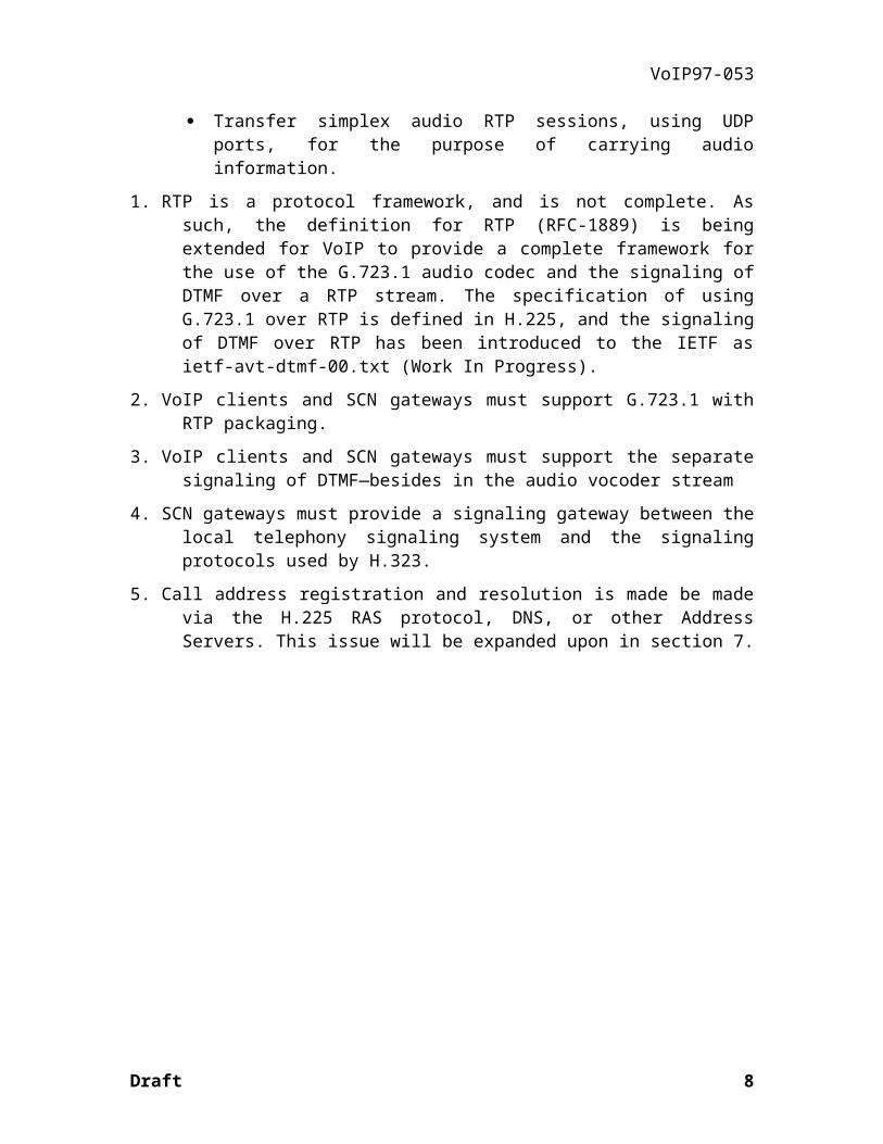
· Transfer simplex audio RTP sessions, using UDP ports, for the purpose of carrying audio information.
1. RTP is a protocol framework, and is not complete. As such, the definition for RTP (RFC-1889) is being extended for VoIP to provide a complete framework for the use of the G.723.1 audio codec and the signaling of DTMF over a RTP stream. The specification of using G.723.1 over RTP is defined in H.225, and the signaling of DTMF over RTP has been introduced to the IETF as ietf-avt-dtmf-00.txt (Work In Progress).
2. VoIP clients and SCN gateways must support G.723.1 with RTP packaging.
3. VoIP clients and SCN gateways must support the separate signaling of DTMF—besides in the audio vocoder stream
4. SCN gateways must provide a signaling gateway between the local telephony signaling system and the signaling protocols used by H.323.
5. Call address registration and resolution is made be made via the H.225 RAS protocol, DNS, or other Address Servers. This issue will be expanded upon in section 7.
Draft 6

VoIP97-053
1.4Terminology
Addressable: An entity on the Internet having a Transport Address. Not the same as being callable. A client or server is addressable and callable. A gatekeeper is addressable but not callable.
Call (noun): Point-to-point multimedia communication between two Internet endpoints. The call begins with the call setup procedure and ends with the call termination procedure. The call consists of the collection of reliable and unreliable channels between the endpoints. In case of interworking with some SCN endpoints via a gateway, all the channels terminate at the Gateway where they are converted to the appropriate representation for the SCN end system.
CMA Sys Entity: Any CMA Sys component, including client(s) and server(s).
CMAP: Call Management Agent Protocol. The protocol between a CMAC and a CMAS.
CMA Logic: The computation performed by the CMA for a specific request.
Caller: The entity initiating a call.
Called: The destination of a call.
E&M: Ear & Mouth signaling
Endpoint: An H.323 Gateway, CMA client, LDAP server, or CMA Server. An endpoint can call and be called. It generates and/or terminates information streams.
Gatekeeper: The Gatekeeper (GK) is an H.323 entity on the Internet that provides address translation and controls access to the network for H.323 Terminals and Gateways. The Gatekeeper may also provide other services to the H.323 terminals and Gateways, such as bandwidth management and locating Gateways.
Gateway: An H.323 Gateway (GW) is an endpoint on the Internet which provides for real-time, two-way communications between H.323 Terminals on the Network and other ITU Terminals on a wide area network, or to VoIP Clients. Other ITU Terminals include those complying with Recommendations H.310 (H.320 on B-ISDN), H.320 (ISDN), H.321 (ATM), H.322 (GQOS-LAN), H.324 (GSTN), H.324M (Mobile), and V.70 (DSVD).
H.323 Entity: Any H.323 component, including H.323 Terminals, Gateways, Gatekeepers.
Information Stream: A flow of information of a specific media type (e.g. audio) from a single source to one or more destinations.
Internet address: The network layer address of a H.323 or CMA Sys entity as defined by the (inter)network layer protocol in use (e.g. an IP address). This address is mapped onto the layer one address of the respective system by some means defined in the (inter)networking protocol.
Internet: An inter-network of networks interconnected by bridges or routers. LANs described in H.323 may be considered part of such internetworks .
Draft 7
VoIP97-053
RAS Channel: Unreliable channel used to convey the registration, admissions, bandwidth change, and status messages (following H.225.0) between H.323 entities or CMA Sys entities.
Reliable Channel: A transport connection used for reliable transmission of an information stream from its source to one or more destinations.
Reliable Transmission: Transmission of messages from a sender to a receiver using connection-mode data transmission. The transmission service guarantees sequenced, error-free, flow-controlled transmission of messages to the receiver for the duration of the transport connection.
Soft Link: A referral from one CMA to another.
Subscriber: An “owner” of a CMA. A subscriber can be a person or an organization.
Switched Circuit Network (SCN): A public or private switched telecommunications network such as the GSTN, N-ISDN, or B-ISDN.
Transport Address: The transport layer address of an addressable H.323 entity as defined by the (inter)network protocol suite in use. The Transport Address of an H.323 entity is composed of the LAN address plus the TSAP identifier of the addressable H.323 entity.
Transport Connection: An association established by a transport layer between two H.323 entities for the transfer of data. In the context of H.323, a transport connection provides reliable transmission of information.
TSAP Identifier: The piece of information used to multiplex several transport connections of the same type on a single H.323 entity with all transport connections sharing the same LAN address, (e. g. the port number in a TCP/UDP/IP environment). TSAP identifiers may be (pre)assigned statically by some international authority or may be allocated dynamically during setup of a call. Dynamically assigned TSAP identifiers are of transient nature, i. e. their values are only valid for the duration of a single call.
Unicast: A process of transmitting messages from one source to one destination.
VoIP: Voice over Internet Protocol. The VoIP Forum is the developer of this specification
Well-known TSAP Identifier: A TSAP identifier that has been allocated by an (international) authority that is in charge for the assignment of TSAP identifiers for a particular (inter)networking protocol and the related transport protocols -- (e.g. the IANA for TCP and UDP port numbers). This identifier is guaranteed to be unique in the context of the respective protocol.
Draft 8

VoIP97-053
1.5Acronyms
CMA: Call Management Agent
CMAA: Call Management Agent Address. An address through which a given CMA can be located and then accessed.
CMAS: Call Management Agent Server
CMA Sys: Call Management System
CMAC: Call Management Agent Client
CMAP: Call Management Agent Protocol
CS-ACELP: Conjugate Structure - Algebraic Code-Excited Linear Prediction
CT: Communication Terminal
CTT: Communication Terminal Type
CTA: Communication Terminal Address
CTAT: Communication Terminal Address Type
DTMF: Dual Tone Multiple Frequency
GSM: Global System for Mobile communications
IANA: Internet Assigned Numbers Authority
IETF: Internet Engineering Task Force
IP: Internet Protocol
ISDN: Integrated Services Digital Network
ITU: International Telecommunication Union
IVR: Interactive Voice Response.
LDAP: Lightweight Directory Access Protocol
LAN: Local Area Network
PBX: Private Branch eXchange
POTS: Plain Old Telephone Service
PRI: ISDN Primary Rate Interface
PSTN: Public Switched Telephone Network
QoS: Quality of Service
RAS: Registration, Admission and Status
RFC: Request For Comment
RTP: Real-Time Protocol
Draft 9
VoIP97-053
TCP: Transmission Control Protocol
TSAP: Transport Service Access Point
UDP: User Datagram Protocol
Draft 10

VoIP97-053
1.6References
The following references contain provisions which are referenced in this text. At the time of publication, the editions indicated were valid.
[1] ITU-T Recommendation H.225.0 (1996): " Media Stream Packetization and Synchronization for Visual Telephone Systems on Non-Guaranteed Quality of Service LANs ".
[2] ITU-T Recommendation H.245 (1995): "Control of communications between Visual Telephone Systems and Terminal Equipment".
[3] ITU-T Recommendation T.120 (1994): "Transmission protocols for multimedia data"
[4] ITU-T Recommendation H.320 (1995): "Narrow-band ISDN visual telephone systems and terminal equipment".
[5] ITU-T Recommendation H.321 (1995): "Adaptation of H.320 Visual Telephone Terminals to B-ISDN Environments".
[6] ITU-T Recommendation H.322 (1995): "Visual Telephone Systems and Terminal Equipment for Local Area Networks which Provide a Guaranteed Quality of Service".
[7] ITU-T Recommendation H.324 (1995): Terminal for Low Bitrate Multimedia Communications".
[8] ITU-T Recommendation H.310 (1996): "Broadband audio-visual communications systems and terminal equipment".
[9] ITU-T Recommendation Q.931 (1993): "Digital Subscriber Signalling System No. 1 (DSS 1) - ISDN User-Network Interface Layer 3 Specification for Basic Call Control"
[10] ITU-T Recommendation Q.932 (1993): "Digital Subscriber Signalling System No. 1 (DSS 1) - Generic Procedures for the Control of ISDN Supplementary Services".
[11] ITU-T Recommendation Q.950 (1993): "Digital Subscriber Signalling System No. 1 (DSS 1) - Supplementary Services Protocols, Structure, and General Principles".
[12] ISO/IEC 10646-1 (1993): "Information Technology - Universal Multiple-Octet Coded Character Set (USC) -- Part I: Architecture and Basic Multilingual Plane".
[13] ITU-T Recommendation E.164 (1991) “Numbering Plan for the ISDN Era”.
[14] IETF RFC 822 “Standard for the format of ARPA Internet text messages. D. Crocker. Aug-13-1982”
[15] IETF RFC1823 “The LDAP Application Program Interface. August 1995”
Draft 11
VoIP97-053
[16] IETF RFC1959 “An LDAP URL Format. June 1996.”
[17] IETF RFC1960 “A String Representation of LDAP Search Filters. June 1996.”
[18] ITU-T Recommendation X.509: “The directory-authentication framework”
[19] GUID, Microsoft
[20] IETF RFC1889 “RTP: A Transport Protocol for Real-Time Applications. Audio-Video Transport Working Group. January 1996.”
[21] IETF RFC 1890 "RTP Profile for Audio and Video Conferences with Minimal Control"
[22] IETF Internet Draft “ietf-avt-profile-new-00.txt” (Work In Progress), March 26, 1997
[23] IETF Internet Draft “ietf-avt-dtmf-00.txt” (Work In Progress), July 8, 1997
[24] ITU-T Recommendation H.323 "Visual Telephone Systems And Equipment For Local Area Networks Which Provide A Non-Guaranteed Quality Of Service"
[25] ITU-T Recommendation G.729 "Coding Of Speech At 8 kbit/sUsing Conjugate-Structure Algebraic-Code-Excited Linear-Prediction
(CS- ACELP)"
[26] ITU-T Recommendation G.723.1 "Dual Rate Speech Coder For Multimedia Communications Transmitting At 5.3 And 6.3 kbit/s"
[27] ITU-T Recommendation H.235 “Security and Encryption for H Series (H.323 and other H.245 based) multimedia terminals”
[28] ITU-T Recommendation X.509: “The directory-authentication framework”
[29] Internet Engineering Task Force, 1996 “RTP: A Transport Protocol for Real-Time Applications,” RFC 1889, H. Schulzrinne, S. Casner, R. Frederick, and V.
[30] CCITT Recommendation X.800 (1991), Security Architecture for Open Systems Interconnection for CCITT applications. (ISO 7498-2:1989, Information processing systems – Open Systems Interconnection – Basic Reference Model – Part 2: Security Architecture.)
[31] ITU-T Recommendation X.803 (1994) | ISO/IEC 10745:1995, Information technology – Open Systems Interconnection – Upper layers security model.
[32] ITU-T Recommendation X.810 (1995) | ISO/IEC 10181-1:1996, Information technology – Open Systems Interconnection – Security frameworks for open systems: Overview.
[33] ITU-T Recommendation X.811 (1995) | ISO/IEC 10181-2:1996, Information technology – Open Systems Interconnection – Security frameworks for open systems: Authentication framework.
Draft 12

VoIP97-053
[34] Internet Engineering Task Force, 1997 “The TLS Protocol Version 1.0” draft-ietf-tls-protocol-01.txt, T. Dieks, C. Allen
Draft 13
VoIP97-053
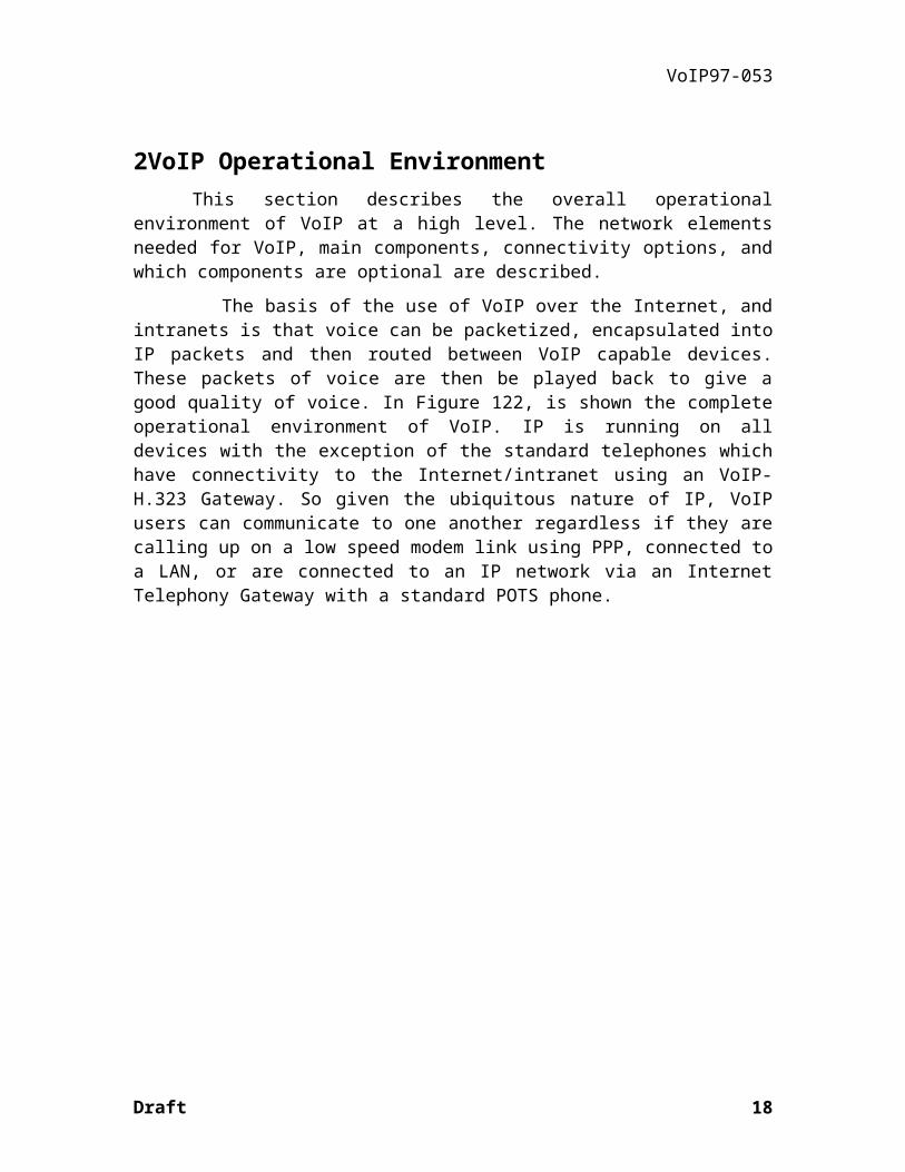
2VoIP Operational EnvironmentThis section describes the overall operational environment of VoIP at a high
level. The network elements needed for VoIP, main components, connectivity options, and which components are optional are described.
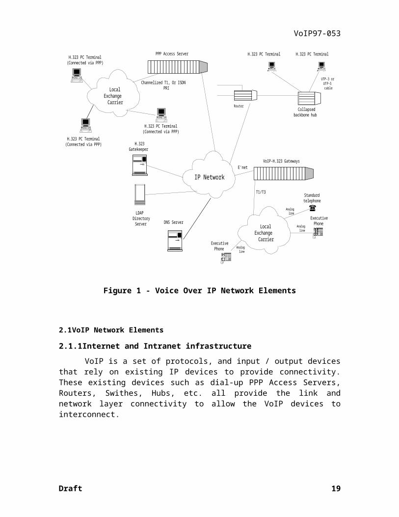
The basis of the use of VoIP over the Internet, and intranets is that voice can be packetized, encapsulated into IP packets and then routed between VoIP capable devices. These packets of voice are then be played back to give a good quality of voice. In Figure 122, is shown the complete operational environment of VoIP. IP is running on all devices with the exception of the standard telephones which have connectivity to the Internet/intranet using an VoIP-H.323 Gateway. So given the ubiquitous nature of IP, VoIP users can communicate to one another regardless if they are calling up on a low speed modem link using PPP, connected to a LAN, or are connected to an IP network via an Internet Telephony Gateway with a standard POTS phone.
LocalExchange
Carrier
Analogline
Standardtelephone
Analogline
ExecutivePhone
IP Network
VoIP-H.323 Gateways
T1/T3
E'net
ExecutivePhone
Router
UTP-3 orUTP-5cable
Collapsedbackbone hub
LocalExchange
Carrier
H.323 PC Terminal(Connected via PPP)
PPP Access Server
Channelized T1, Or ISDNPRI
H.323Gatekeeper
DNS Server
LDAPDirectory
Server
H.323 PC Terminal(Connected via PPP)
H.323 PC Terminal(Connected via PPP)
H.323 PC Terminal H.323 PC Terminal
Analogline
Figure 1 - Voice Over IP Network Elements
Draft 14
VoIP97-053
2.1VoIP Network Elements
2.1.1Internet and Intranet infrastructure
VoIP is a set of protocols, and input / output devices that rely on existing IP devices to provide connectivity. These existing devices such as dial-up PPP Access Servers, Routers, Swithes, Hubs, etc. all provide the link and network layer connectivity to allow the VoIP devices to interconnect.
2.1.2H.323 Terminals
H.323 terminals are one of the several initial Input / Output devices of the VoIP service. The terminals use an G.723.1 codec to encode/decode audio sound waves into audio frames that can then be encapulsated into IP packets and routed to another H.323 entity. Also, the terminals have the H.323 signaling stack (H.225, H.245) that is used for establishing and maintaining the VoIP calls.
2.1.3VoIP-H.323 Gateways
Given the global deployment of POTS terminals, interaction with legacy networks will be an important element of a VoIP network. Users on the VoIP network may address users on the PSTN or vice versa via VoIP-H.323 gateways. Gateways may connect directly to the PSTN using telephony protocols or may connect to private networks via PBX’s. Gateways may be either embedded in PBX’s or stand-alone equipment.
Gateways will also enable phone to phone conversation enabling a long distance conversation to be routed via an TCP/IP network.
Detailed information on the gateway reference model is available in the draft H.246.
2.1.4PSTN infrastructure
When connecting between H.323 devices and PSTN devices, the PSTN communication devices such as Telephones, Public Telephony switches, etc. provide all needed connectivity.
2.1.5Directory Services
Directory services provide the ability for H.323 users to do a lookup function between text based strings and IP addresses (for other H.323 devices) or E.164 phone
Draft 15

VoIP97-053
numbers (for PSTN based users). There are several methods that these directory services can be provided. Section 7 describes the method that has been agreed upon for this document.
2.2VoIP Connectivity Configurations
This section describes the three possible connectivity configurations that this document addresses and are shown in ( a Figure 3, and 55). All three configurations have as a commonality that they use either IP or the PSTN to provide the communication infrastructure. H.323 is used to provide the VoIP functionality, while traditional telephony services are used to provide PSTN functionality. Finally, directory services are used to provide H.323/PSTN device location.
IP Cloud
PC
H.323 Gatekeeper DNS ServerLDAP DirectoryServer
PC
Figure 2 - Network Elements Used For The PC To PC Connection
Draft 16

VoIP97-053
IP Cloud
Telephone
Public Switch GateWayPC
H.323 Gatekeeper DNS ServerLDAP DirectoryServer
Figure 3 - Network Elements Used For The PC To Phone Connection
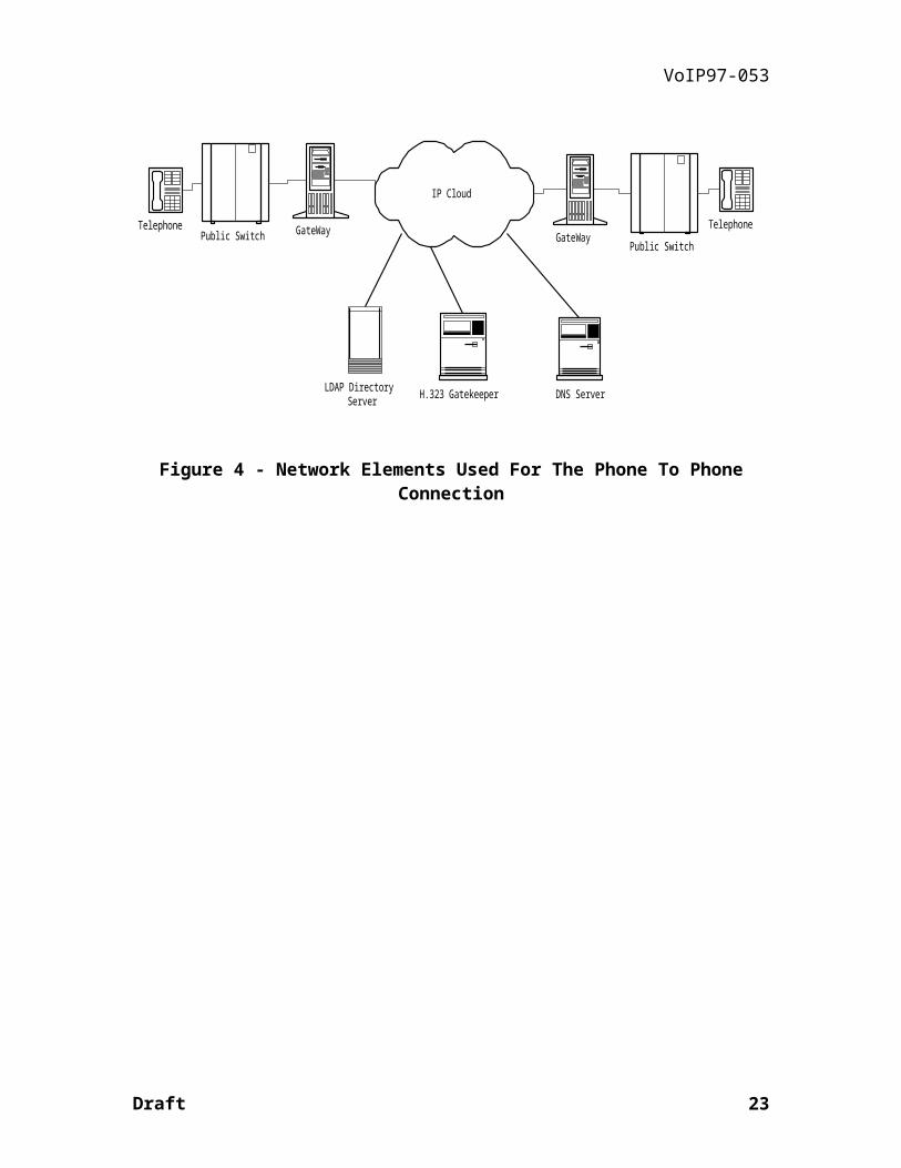
IP Cloud
TelephonePublic Switch GateWay
H.323 Gatekeeper DNS ServerLDAP DirectoryServer
Telephone
Public SwitchGateWay
Figure 4 - Network Elements Used For The Phone To Phone Connection
Draft 17
VoIP97-053
3VoIP Stack OverviewThis section describes each of the elements that comprise the H.323 stack—
as used in this document. Each protocol is defined according to what its purpose is, and what relevant standard (or draft) defines it. In Figure 5 the H.323 protocol stack is shown. The same ITU H.323 protocol suite is used in all VoIP devices.
3.1Call Establishment And Control
Call establishment and control is the overall driver of the H.323 entries. It determines the sequences and timing of establishing and disconnect procedures, as well as the control of the H.323 session after it is established.
References: H.323, H.225, and H.245.
3.2Presentation
Presentation refers to the interpretation of the syntax of all transferred audio and ‘in-band’ control data (such as DTMF, and comfort noise).
References: H.323, H.245, H.225, RFC1889, RFC1890, G.723.1
3.3Addressing
The Internet and intranets are dynamic addressing environments. It cannot be assumed that an IP address that defined a certain remote user, will define the same user at a future time. Furthermore, having each person know the IP address of everyone they wish to converse with is impractical. So some method of looking up users by name, company, location, etc. is needed.
In the H.323 protocol the only method defined to do this is with Gatekeepers. However, DNS, LDAP or some other directory service may also be used to provide this lookup and address translation function.
This issue will be addressed more fully in a section .
Reference: H.323, H.225
Draft 18
VoIP97-053
3.3.1RAS
Registration, Admission, Status (RAS) is a protocol—defined in H.225—that defines how H.323 entities can access Gatekeepers to perform—among other things—address translation.
Reference: H.323, H.225.
3.3.2DNS
Domain Name System (DNS) is a IETF standard used on the Internet to provide resolution of domain names to IP addresses, and to provide other information as well. In this document, DNS is defined as a method to either locate end users, or to locate specific H.323 devices such as a Gatekeeper(s) in a specific administrative zone.
References: RFC2065, RFC2136, RFC2137, etc. , and H.225.
3.3.3LDAP
Lightweight Directory Access Protocol (LDAP) is an IETF standard that defines an extensible directory service that provides a way to: name, manage, search, and update collections of stored information. For the purposes of VoIP, it provides a much richer search capability than DNS.
References: RFC1777, and RFC1778.
3.4G.723.1
The G.723.1 is the current standard VoIP codec. It defines a method for compressing speech and other audio signal components into a very low bit stream (5.3 and 6.3 kbit/s).
References: H.323, G.723.1
3.5H.245
H.245 defines the control protocol for multimedia communications. In Internet Telephony it specifies the method that channel(s) inside of calls will be established and controlled. It also includes one of the several methods that can be used for sending and receiving DTMF.
References: H.323, H.245
Draft 19

VoIP97-053
3.6H.225
H.225 defines the method by which the audio, control and DTMF is associated, coded and packetized for transport over IP networks. It defines the Q.931 session setup protocol, RTP/RTCP, G.723.1 audio encoding, QoS and protocol to access the Gatekeeper services.
References: H.323, H.225, Q.931, RFC1889, RFC1890
Work In Progress: draft-ietf-avt-profile-new-01.txt, ietf-avt-dtmf-00.txt
3.6.1Q.931
Q.931—as used in H.323—is defined in H.225. It is used to setup, teardown, and to control H.323 communication sessions.
References: H.323, H.225, Q.931
3.6.2RTP/RTCP
While RTP/RTCP and the G.723.1 RTP audio encoding was originally standardized by the IETF, it is now quoted in H.225 for use in H.323. RTP/RTCP defines the real time protocol, and the G.723.1 RTP encoding defines how the G.723.1 audio frames will be encoded into RTP.
References: H.323, H.225, RFC1889, RFC1890
3.6.3Transport Layer
Two types of transport layers are used in VoIP. These are UDP, and TCP. UDP a unreliable transport layer protocol used for RAS, DNS, and RTP/RTCP. While TCP is a reliable transport layer protocol used for H.245, Q.931, LDAP and sometimes for DNS.
References: H.323, H.225, H.245, RFC768, RFC793
3.6.4Network Layer
The network layer used for VoIP is IP.
References: H.323, H.225, RFC791
Draft 20

VoIP97-053
Physical
Link
Network (IP)
Unreliable Transport (UDP) Reliable Transport (TCP)
H.245 Q.931(H.225)RTP/RTCP
G.723.1
Presentation
RAS(H.225)
Addressing
Call Establishment And Control
LDAPDNS DNS
AddressingDTMF
Figure 5 - H.323 Protocol Stack
Draft 21

VoIP97-053
4H.323 Call Processing
4.1High Level Call Setup
A quick overview of how the different VoIP protocols work together is illustrated by following step-by-step a sample call setup between two Internet telephones:
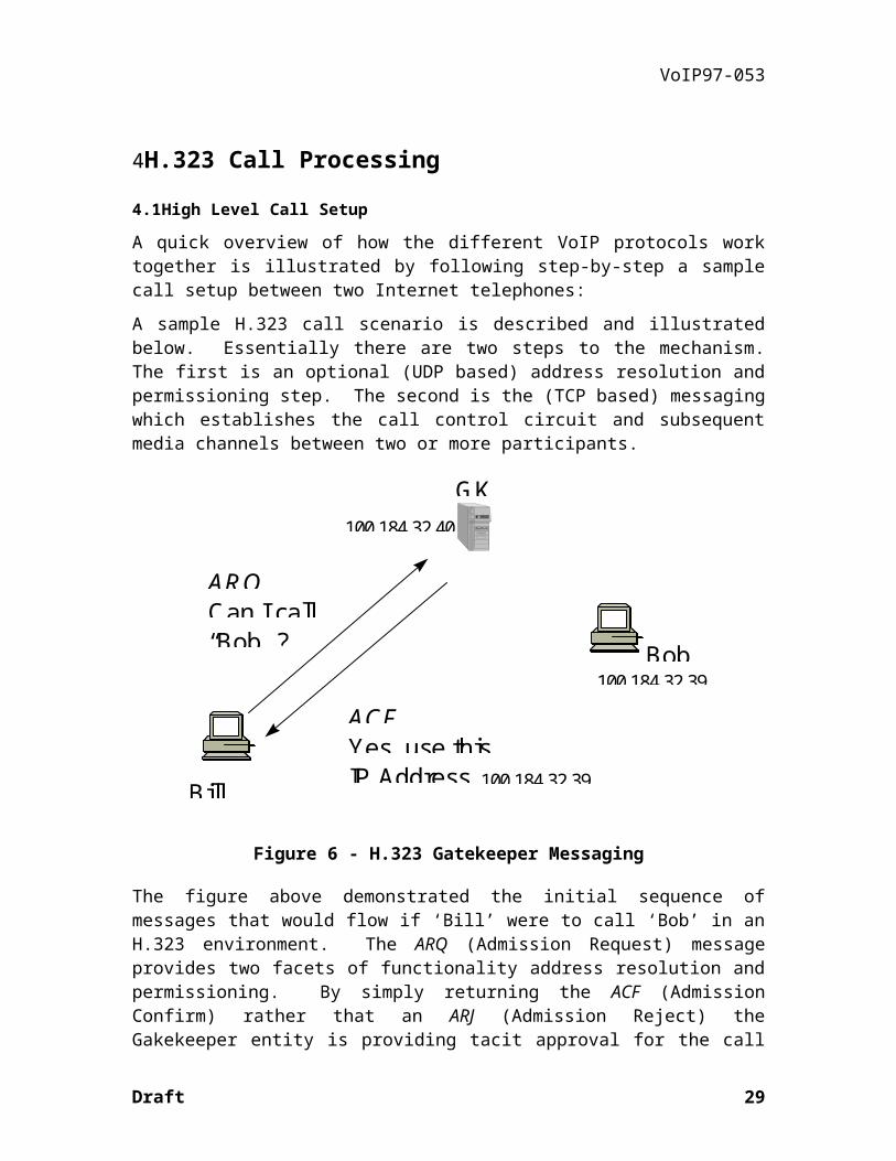
A sample H.323 call scenario is described and illustrated below. Essentially there are two steps to the mechanism. The first is an optional (UDP based) address resolution and permissioning step. The second is the (TCP based) messaging which establishes the call control circuit and subsequent media channels between two or more participants.
ARQCan I call“Bob” ?
ACFYes, use thisIP AddressBill
Bob
GK
100.184.32.39
100.184.32.39
100.184.32.40
Figure 6 - H.323 Gatekeeper Messaging
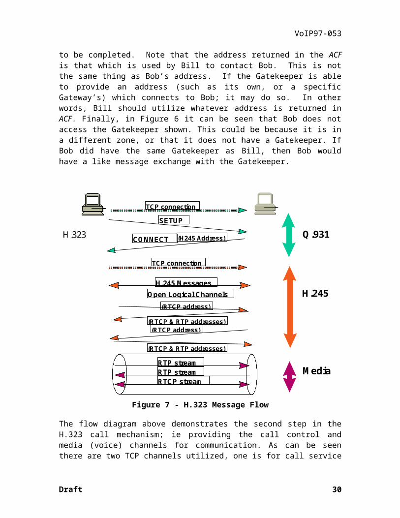
The figure above demonstrated the initial sequence of messages that would flow if ‘Bill’ were to call ‘Bob’ in an H.323 environment. The ARQ (Admission Request) message provides two facets of functionality address resolution and permissioning. By simply returning the ACF (Admission Confirm) rather that an ARJ (Admission Reject) the Gakekeeper entity is providing tacit approval for the call to be completed. Note that the address returned in the ACF is that which is used by Bill to contact Bob. This is not the same thing as Bob’s address. If the Gatekeeper is able to provide an address (such as its own, or a specific Gateway’s) which connects to Bob; it may do so. In other words, Bill should utilize whatever address is returned in ACF. Finally, in Figure 6 it can be seen that Bob does not access the Gatekeeper shown. This could be because it is in a different zone, or that it does not have a Gatekeeper. If Bob did have the same Gatekeeper as Bill, then Bob would have a like message exchange with the Gatekeeper.
Draft 22
VoIP97-053
TCP connection
SETUP
CONNECT (H245 Address) Q.931
TCP connection
H.245 MessagesOpen Logical Channels
(RTCP address)
(RTCP & RTP addresses)(RTCP address)
(RTCP & RTP addresses)
H.245
RTP streamRTP streamRTCP stream
Media
H.323
Figure 7 - H.323 Message Flow
The flow diagram above demonstrates the second step in the H.323 call mechanism; ie providing the call control and media (voice) channels for communication. As can be seen there are two TCP channels utilized, one is for call service control and the other is for media capabilities coordination, and channel opening. Note that the media flow occurs on ‘standard’ RTP/RTCP sessions within the context to the H.323 call.
4.2Detailed Call Setup
The previous section described at a very high level how calls are setup in a H.323 environment. This section will describe the process in a more detailed manner. This section however, is only provided for illustrative purposes and the actual definition of call setup is defined in H.323, H.225, and H.245.
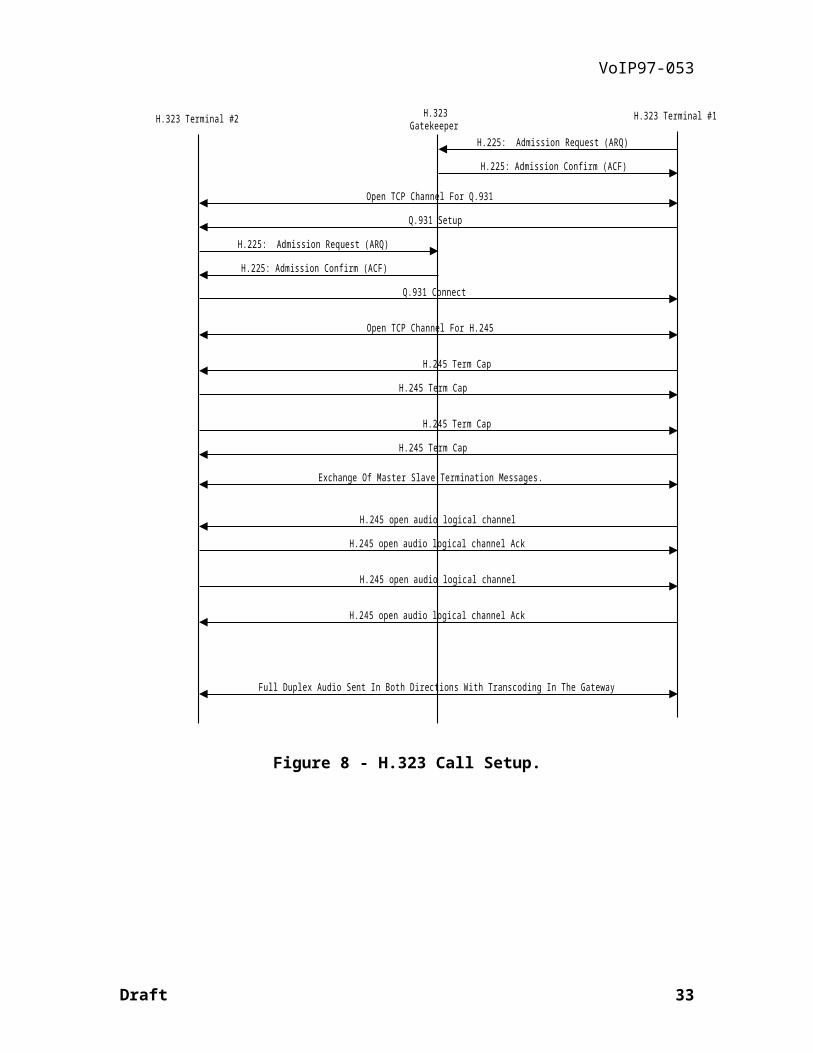
In Figure 7 the call setup is shown. A description of the steps are listed below:
1. Terminal #1 requests of the H.323 Gatekeeper permission to call Terminal #2, and it requests the IP address for Terminal #2 as well. Terminal #1 sends an ARQ, and received a ACF.
Draft 23

VoIP97-053
2. Terminal #1 initiates the opening of the TCP connection for Q.931. Also, it sends the H.323 Terminal #2 a Q.931 Setup.
3. Upon receiving the Q.931 Setup, Terminal #2 requests permission of the H.323 Gatekeeper to communicate with Terminal #1. It sends a Admission Request (ARQ) to the Gatekeeper, and receives back a Admission Confirm (ACF).
4. Terminal #2 sends a Q.931 Connect back to Terminal #1. Inside of the Q.931 Connect is the H.245 TCP port address that the Terminal #2 wishes to use.
5. Terminal #1 initiates the opening of the H.245 TCP connection between itself and Terminal #2.
6. Terminal #1 and Terminal #2 exchange H.245 Terminal Capabilities.
7. Sometime before Audio channels are opened, Terminal #1 and Terminal #2 use H.245 Master Slave Determination messages to determine who is the master and who is the slave.
8. Terminal #1 sends a H.245 Open Logical Channel requesting that an audio channel be opened. Inside of the H.245 Open Logical Channel is the characteristics of the channel, as well as the UDP port that it wishes to receive the RTCP receiver reports on.
9. Terminal #2 sends a H.245 Open Logical Channel Ack and indicates the UDP ports that it wishes to use for the RTP audio stream as well as the RTCP sender reports.
10. Terminal #2 sends a H.245 Open Logical Channel requesting that an audio channel be opened. Inside of the H.245 Open Logical Channel is the characteristics of the channel, as well as the UDP port that it wishes to receive the RTCP receiver reports on.
11. Terminal #1 sends a H.245 Open Logical Channel Ack and indicates the UDP ports that it wishes to use for the RTP audio stream as well as RTCP sender reports.
12. Audio flows between the two terminals.
Draft 24
VoIP97-053
H.323 Terminal #2 H.323Gatekeeper
H.323 Terminal #1
Q.931 Setup
Open TCP Channel For Q.931
H.225: Admission Request (ARQ)
H.225: Admission Confirm (ACF)
H.225: Admission Request (ARQ)
H.225: Admission Confirm (ACF)
H.245 open audio logical channel
H.245 open audio logical channel Ack
H.245 open audio logical channel
H.245 open audio logical channel Ack
Full Duplex Audio Sent In Both Directions With Transcoding In The Gateway
Q.931 Connect
H.245 Term Cap
H.245 Term Cap
H.245 Term Cap
H.245 Term Cap
Open TCP Channel For H.245
Exchange Of Master Slave Termination Messages.
Figure 8 - H.323 Call Setup.
Draft 25
VoIP97-053
5Additional H.323 Issues The first is an optional (UDP based) address resolution and permissioning step. The second is the (TCP based) messagblishes the ca
ARQCan I call“Bob” ?
ACFYes, use thisIP AddressBill
Bob
GK
100.184.32.39
100.184.32.39
100.184.32.40
The flow diagram above demonstrates the second step in the H.323 call mechanism; ie providing the call control and media (voice) channels for communication. As can be seen there are two TCP channels utilized, one is for call service control and the other is for media capabilities coordination, and channel opening. Note that the media flow occurs on ‘standard’ RTP/RTCP sessions within the context to the H.323 call.
5.1Presentation Layer
Within the context of VoIP, the presentation layer interprets the syntax of all transferred speech and 'in-band' control data. In this context, in-band refers to control mechanisms which are either traditionally carried within the voice band (i.e. DTMF digits) or are events which should be synchronized with transmitted speech packets (i.e. comfort noise parameters). Semantically, the presentation layer consists of two major components:
1. RTP payload type definition
2. Payload transfer syntax for each payload type
All data and in-band control packets are handled as RTP payload. Both statically and dynamically assigned payload types are used to differentiate between traffic types. VoIP uses current static definitions (as defined in RFC1890) whenever possible, and assigns dynamic payload types for payload specific to VoIP.
Draft 26

VoIP97-053
Annex A gives the mapping of RTP payload type indices to payload types.
5.1.1Encoded Speech
Voice over IP elements involved in voice coding & decoding must include support for ITU Recommendation G.723.1 as the baseline coder. G.723.1 is assigned static payload type 4. Defining a baseline coder does not imply that it is the best possible coder - it merely defines one which is widely available and implementable on a wide variety of platforms. Other coders may also be used - several other G series coders have already been assigned static payload types as part of RFC1890, and others may be assigned dynamic payload types in future revisions of this IA.
Annex B is a place holder for the transfer syntax of other codecs' voice payloads.
5.1.2Voice Activity Detection
Introduction
Voice Activity Detection (also known as Speech Activity Detection, Digital Speech Interpolation and Silence Deletion) is an effective tool for reducing the data throughput of a speech channel. This IA introduces the definition of a 'noise' coder RTP payload type that allows the use an alternate encoding method during detected periods of silence. This IA does not specify how to detect silence nor how to reconstruct suitable noise samples at the receiving end, but describes options for transmission of silence parameters.
VoIP Speech / Silence Indication Mechanisms
Two methods can be employed by VoIP to indicate speech/silence conditions:
Silence Indication Via Receive Underrun Conditions
The simplest silence indication method is simply to stop transmission of packets during silence and use the ensuing underrun condition at the receive end to indicate silence. Noise characteristics may then be derived from the previously received signal during probable periods of silence (i.e. a period of hangover at the end of speech bursts). Unfortunately, this method does not allow discrimination between silence and transmission error conditions that might also cause underruns. It also precludes any updates to noise playout parameters during a silent period.
Silence Indication Via Explicit Notification
Methods for noise level transfer / silence indication are still under investigation.
Silence may also be indicated by sending one or more packets containing noise parameters during silence periods. This approach uses the RTP payload type transition
Draft 27

VoIP97-053
from a speech coder to an alternate 'noise' coder to indicate the speech to silence transition, and allows multiple packets of the alternate 'noise' coder type to be sent during a given silent period.
This VoIP IA has defined only one of a number of possible noise information transmission schemes. This scheme, based on transmitting negative absolute dBmO noise values and compatible with the Frame Relay Forum's FRF.11 Voice over Frame Relay interoperability agreement, has been allocated RTP payload type 13. This method transmits absolute level noise information in a single byte payload, which should be transmitted immediately after the last speech packet of a speech burst. Additional noise packets with updates to the noise level may be sent during long silence periods if desired.
Other noise information transmission schemes may be included in later versions of the VoIP IA and assigned to other dynamically allocated RTP payload types.
Redundancy of noise information packets is not considered important in the noise level method, as the loss of noise information packets will, in the worst case, cause nothing more than a default to the 'Silence Indication Via Receive Underrun Conditions' case.
For baseline compatibility, receivers must at minimum throw away silence packets of payload type 13 without causing a functional disruption in other aspects of operation.
Annex C describes the bit order and packaging of noise level silence information as VoIP payload.
5.1.3DTMF Digit Carriage
Miappe,
Introduction
Although call setup signaling will be carried using Q.931 as part of the H.323 framework, there is an additional requirement for the carriage of in-band signaling such as DTMF after call setup. With coders of sufficient quality, these signals can be carried in-band as a voice signal and interpreted properly by far-end decoding equipment. Low bit-rate coders, however, may cause enough degradation in these signals to cause misinterpretation by decoding equipment. There are also VoIP endpoints for which it does not necessarily make sense for them to physically generate in-band DTMF signals. For these cases, an out-of-band signaling transfer syntax may be advantageous. VoIP IA 1.0 specifies at a minimum VoIP endpoints must support the interpretation of DTMF messages via H.245 UserInputIndication messages as per H.323 version 1. Optionally, two endpoints may negotiate the use of an RTP DTMF 'coder' using a separate dynamically allocated RTP codec type can be used to indicate DTMF signaling events to VoIP end-point equipment. The RTP DTMF 'coder' is specified in draft-ietf-avt-dtmf-00.txt.
Out-of-band RTP DTMF packets are assigned a dynamic payload type.
Draft 28
VoIP97-053
To allow the use of the RTP DTMF ‘coder’, a second H.245 logical channel must be opened--one for each direction that the DTMF is being sent. Since H.245 does not have a AudioCapability for a DTMF ‘coder’, this IA specifies the codepoint of {Editors note: This value needs to be selected} to be used as a NonStandardParameter.
77 71. Here, both Rationale for Out-of-band Carriage of 'In-band' Signaling
There are two principal reasons to carry certain signaling elements as a distinct out-of-band message type:
1. Signaling elements which have global utility and meaning but have no carriage mechanism within Q.931.
2. Signaling elements traditionally carried in-band as voice data but which may be adversely affected by low bit-rate coding.
3. Application obviates the need for in-band carriage.
DTMF Carriage Options
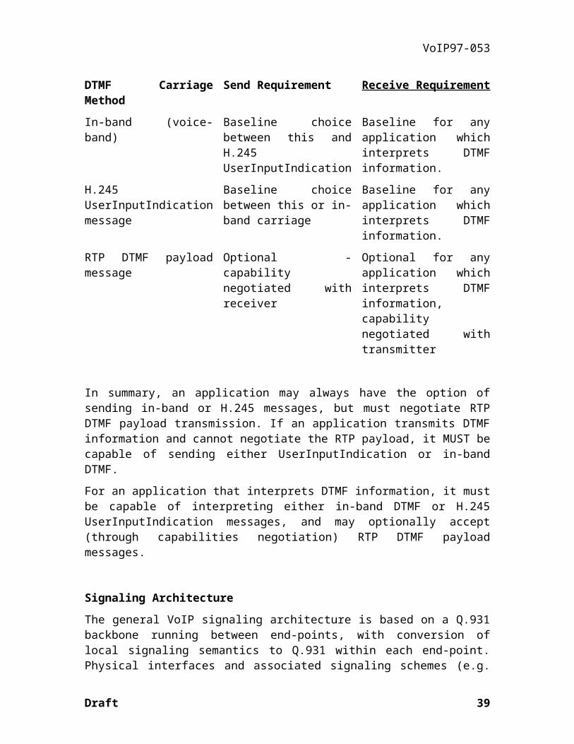
The following table defines the range of options and baseline requirements for VoIP DTMF carriage by defining what is required of both the sender and receiver of DTMF information for each of the options:
DTMF Carriage Method Send Requirement Receive Requirement
In-band (voice-band) Baseline choice between this and H.245 UserInputIndication
Baseline for any application which interprets DTMF information.
H.245 UserInputIndication message
Baseline choice between this or in-band carriage
Baseline for any application which interprets DTMF information.
RTP DTMF payload message
Optional - capability negotiated with receiver
Optional for any application which interprets DTMF information, capability negotiated with transmitter
In summary, an application may always have the option of sending in-band or H.245 messages, but must negotiate RTP DTMF payload transmission. If an application transmits DTMF information and cannot negotiate the RTP payload, it MUST be capable of sending either UserInputIndication or in-band DTMF.
For an application that interprets DTMF information, it must be capable of interpreting either in-band DTMF or H.245 UserInputIndication messages, and may optionally accept (through capabilities negotiation) RTP DTMF payload messages.
Draft 29
VoIP97-053
Signaling Architecture
The general VoIP signaling architecture is based on a Q.931 backbone running between end-points, with conversion of local signaling semantics to Q.931 within each end-point. Physical interfaces and associated signaling schemes (e.g. pulse dialing, PRI) have local significance only - this preserves the any-to-any connectivity nature of VoIP. This concept is illustrated by example in . Here, both the Internet telephone and gateway service elements provide termination of their local signaling format and semantic conversion to the Q.931 backbone. Providing any-to-any connectivity also precludes concepts such as channel associated signaling telemetry.
Similarly, once a connection is established via Q.931, in-band signaling events may occur that need to be handled in a similar any-to-any connectivity fashion.
Draft
Internet
VoIP Packet/StreamGateway
E&M
Local SignalingQ.931 Backbone
PBX
Internet Telephone S/W
Local Signaling
GUI Signaling I/F
TraditionalTelephone
Figure 9 VoIP Signaling Connectivity
30

VoIP97-053
Directory Services And Call Management Agent
This section examines the specification of directory and call management services as part of a VoIP service implementation. The VoIP Forum has had an ongoing discussion group related to the vision of implementing a broad Call Management Agent Service. Sections 5.2 to 5.4 describe how future implementations of CMA would fit into a general service along with elements such as directory services. The specification of CMA is still an ongoing activity, however - components of CMA will be gradually introduced into the IA as formal specifications as the CMA specification continues to evolve and mature.
This current version of the VoIP Implementation Agreement makes a recommendation on how to implement E.164 to dynamic IP address resolution only. This can be found in section 5.5.
5.2Logical Voice Service Modules
IP Cloud
SCN Network(POTS)
LDAPServer
VoIP Client
CMAServer
VOIP H.323Gatekeeper
POTS User
VOIP H.323TelephonyGateWay
CMAC
CMAC
CMAC
.
Figure 10 - Logical Voice Service Modules
5.3Directory Servers
Directory Servers provide the function to map user names to IP addresses on a Voice over IP network, as well as provide functions for users to negotiate for call services.
A Directory Service takes as input a name or names for someone, and returns a set of attributes which have been previously stored in the directory for that person. The directory only returns what has been stored; it does no significant computation on the stored information, nor does it make any guarantees that information returned is current. The primary purpose of the directory is to ascertain whether a particular person is registered, and whether the stored information represents the terminal or person with whom communications is desired.
Draft 31

VoIP97-053
A Rendezvous Service takes as input an unambiguous identifier for a correspondent (i.e. it refers to exactly one registered user - possibly returned previously by a directory lookup), and returns current information about the user's current address(es), preferences about how to be reached (I-Phone, PSTN, cell phone, voice mail, etc.), and possibly other dynamically changing information computed by the location service. Note: unlike a directory, a location service may be modeled as an agent which sits actively on the network and acts on a user's behalf even when the user is unavailable.
5.4The CMA System
5.4.1Overview
The call management agent system provides intelligent, communication terminal independent call management services. It is an essential link in providing the call setup information for Internet based telecom services including IP to IP, SCN to IP, IP to SCN, and SCN to SCN calls. This includes managing the various communication terminal addresses1 of a given person or organization, the ability to provide the various dynamic mappings between addresses to allow all combinations of calls, and the ability to intelligently route calls according to agent based logic. The following scenario with the accompanying diagram portrays the underlying concept.
Suppose Jack has three communication terminals - a home phone, a business phone and an IP phone. During working hours, he wants all calls to be routed to his business phone. When he’s at home, he wants all calls to be routed to his home phone, but calls from Joe to be routed to his laptop based IP phone. Alas, Jack has only a dialup account at an ISP. This means he doesn’t have a fixed IP and it might be the case that he isn’t online at a given time. In this case, he wants Joe’s calls to be routed to his home phone number. Jack would “inject” this logic (0), along with the list of communication terminals he supports into his CMA, so the CMA will be able to perform the call routing accordingly. Now, Jack can be accessed by these various communication through a single logical address, his CMAA.
Now suppose Joe, an IP phone user, wants to call Jack. Suppose Joe doesn’t have Jack’s CMAA. He would thus first consult a white pages directory service, to get the CMAA (1). Now his IP phone would contact his own CMA and request it to contact Jack (2). Joe’s CMA will now locate Jack’s CMA, and contact it, identifying itself as Joe’s CMA (3). Jack’s CMA will now perform the computation according to the logic previously injected into it. If Jack’s online, it will reply with the current IP address of Jack’s IP phone. Otherwise, it will provide Joe’s CMA with the E.164 telephone number which will be resolved to the appropriate IP address of the telephony gateway to call out from.
1 This includes the resolving dynamic IP addresses which are typically used by dialup Internet subscribers.
Draft 32
VoIP97-053
White PagesService
Call Mgmt Server
Joe’s Agent
Call Mgmt Server
Jack’s Agent Joe’s ClientJack’s Client
1 If needed, consult white pages toget Jack’s “Call ManagementAgent Address”
2 Ask own agent to setup the call,or directly access Jack’s agent
3 Ask Jack’s agent to get Jack’scurrent “location”. Jack’s agentconsults Jack’s set of rules,and decides (according to callerid, time of day, Jack’s currentlocation....) where to route Joe’scall to. Joe might be redirected toanother agent.
0 Initially, Define the agentprofile. Periodically notify theagent about dynamic informationsuch as current location orcurrentIP address.
Figure 11 - CMA System Sample Scenario
Given the needed call setup information, Joe’s IP phone can now call the remote terminal (Be it a telephony gateway which in turn will call Jack’s home telephone (e.g.,E.164) number, or Jack’s actual IP phone address) directly.
5.5E.164 to dynamic IP resolution
5.5.1Introduction
Consensus has developed that there is an immediate need to enable some dynamic address mappings in the short term, in addition to the longer term work which should continue. It is important to examine what Call Management features are already provided by H.323. This is especially true in light of the recent additions to the RAS protocol for version 2 of H.323. RASv2 was determined by Study Group 16 of the ITU-T in Geneva in February 1997.
Version 2 of the RAS protocol of H.323 contains messages to perform the basic dynamic address mappings that have been agreed upon as first requirements for Call Management in previous VoIP meetings. VoIP endpoints (terminals and gateways) that require these dynamic address mapping services should obtain them via these standard messages. For terminals that can not send the RAS v2 PDUs, we propose to determine some conventions for the terminal names so that some static address mappings can be supported in an interoperable way.
Version 2 of RAS enables all of the basic dynamic address mappings that were discussed as requirements in previous VoIP meetings. This includes dynamic mappings between
Draft 33

VoIP97-053
E.164 numbers and IP addresses. In fact it even improves upon them, since it allows for much richer mappings, for example using a simple naming scheme of H.323 terminals via “email-like names.” The RAS messages and information flows used to accomplish the mappings are reviewed. VoIP endpoints which require these address mappings should use these standard H.323 methods.
Terminals that do not support RASv2 PDUs cannot register themselves with names that can be automatically understood as IP addresses or Email names in an interoperable way. This is because the TerminalAlias field contains only an arbitrary string (called and “H323-ID”) or an E.164 number. They also cannot signal that the registration is valid only for a certain time period in an interoperable way. This is because the registration contains no “time to live” field. For terminals that do not support RASv2, we propose that the IA contain some conventions which allow terminals to use the H323-ID field to indicate if the name should be parsed as an Email name or as an IP address.
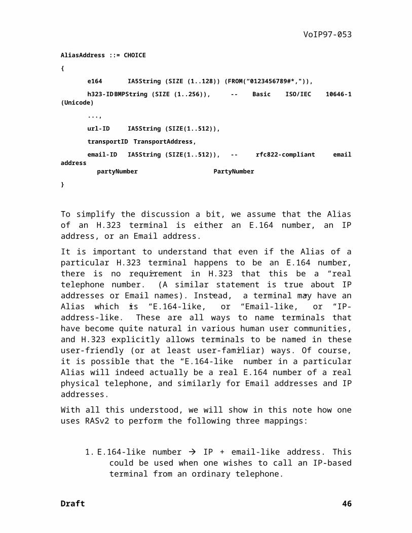
In order to see how RASv2 does these address mappings, we first recall how H.323 terminals are named. In addition to E.164 numbers and IP addresses, H.323 allows terminals to have other sorts of names. The name of an H.323 terminal is usually called a “Terminal Alias,” or just “Alias” for short. It can have various forms, defined by the AliasAddress structure:
AliasAddress ::= CHOICE
{
e164 IA5String (SIZE (1..128)) (FROM(“0123456789#*,")),
h323-IDBMPString (SIZE (1..256)), -- Basic ISO/IEC 10646-1 (Unicode)
...,
url-ID IA5String (SIZE(1..512)),
transportID TransportAddress,
email-ID IA5String (SIZE(1..512)), -- rfc822-compliant email address
partyNumber PartyNumber
}
To simplify the discussion a bit, we assume that the Alias of an H.323 terminal is either an E.164 number, an IP address, or an Email address.
It is important to understand that even if the Alias of a particular H.323 terminal happens to be an E.164 number, there is no requirement in H.323 that this be a “real telephone number.” (A similar statement is true about IP addresses or Email names). Instead, a terminal may have an Alias which is “E.164-like,” or “Email-like,” or “IP-address-like.” These are all ways to name terminals that have become quite natural in various human user communities, and H.323 explicitly allows terminals to be named in these user-friendly (or at least user-familiar) ways. Of course, it is possible that the “E.164-like”
Draft 34
VoIP97-053
number in a particular Alias will indeed actually be a real E.164 number of a real physical telephone, and similarly for Email addresses and IP addresses.
With all this understood, we will show in this note how one uses RASv2 to perform the following three mappings:
1. E.164-like number à IP + email-like address. This could be used when one wishes to call an IP-based terminal from an ordinary telephone.
2. Email-like address à IP + E.164-like number. This could be used when one wishes to call an ordinary telephone from an IP-based terminal.
3. E.164-like number à IP + E.164-like number. This could be used when one wishes to place a call between two telephones via a system of H.323 gateways.
Note that in these examples, the range of the mappings includes real IP addresses. That is, we are mapping from some Alias to a real IP address plus another Alias. These are the sort of mappings that were seen to be Call Management requirements in earlier VoIP sessions. Other translations are possible too; for example, one could use RASv2 to map IP-address-like Aliases to actual IP numbers. We shall see also that this mapping can be made dynamic, in the sense that the mapping can be installed for a limited duration and then changed.
This IA does not require that VoIP endpoints implement ALL of RASv2. The proposal here is that those endpoints which require the basic sort of Call Management given by Email-IP-E.164-like address mappings support the RASv2 messages needed to implement this service. Since RASv2 messages are backward compatible, this will interwork with terminals that support only version 1 messages. Such terminals won’t normally be able to get the dynamic address mapping service in a standard way, however.
For endpoints that can’t support version 2 messages, the IA can give conventions for H323-IDs which will allow them to obtain at least some of the mapping services in an interoperable way.
The messages which are required to support this basic service include the Registration messages, the Unregistration messages, and the Location Messages. The optional TimeToLive fields are required in the Registration messages to support a dynamic mappings.
It is very important to emphasise that neither H.323 nor RAS nor this IA propose any particular scheme for actually defining the mapping, nor even any system of actual names for any terminals. These are very important questions, but they are outside the scope of H.323 and this contribution. This problem is similar to the Domain Name Service of the IETF - it defines the allowed formats of names, and also defines the protocol and information flow needed to perform certain mappings. But what the actual names of the hosts are is outside the scope of the DNS specification.
Draft 35

VoIP97-053
In what follows, we shall use the term “telephone” to mean a PSTN/ISDN/Cell telephone terminal, and “IP-phone” to mean an IP-based H.323 terminal.
5.5.2Practical examples of dynamic Address Mappings in RAS
Scenario 1: E.164-like number à IP + email-like address
In this first example, let us first suppose that user Smith has a telephone, and user Jones has an IP-phone. Let’s suppose that Jones’s IP-phone is named “[email protected].” Jones would like to receive calls from ordinary phones. Clearly, the only thing that poor Smith can input is a string of numbers. Somehow, the string of numbers that Smith inputs must be translated into the Terminal Alias [email protected]. Here is the sequence of information units which must move between the terminal and a Gatekeeper in order to make this happen:
1. Jones’s terminal registers itself with the gatekeeper with two TerminalAliases, one [email protected] and one the “phone number” which Jones wishes people to dial to reach his IP-phone.
2. Smith picks up his phone and dials an H.323 gateway, and via an IVR prompt enters Jones’s “phone number.”
3. The Gateway sends a LocationRequest Message to its Gatekeeper and asks to resolve the phone number it receieved.
4. The Gatekeeper returns in the LocationConfirm Message to the Gateway the Terminal Alias [email protected] along with the IP transport address of Jones’s IP-phone application.
5. The gateway completes the call, connecting Smith’s phone with Jones’s IP-phone.
If the mapping is to be a dynamic one, then Jones’s IP-phone inserts a “TimeToLive” field in its Registration Request Message. The gatekeeper can return a different value, and this is the length of time for which the mapping will be valid.
Scenario 2: Email-like address à IP + E.164-like number
In this case Smith wishes to get calls from IP-phone users. There is presumably a gateway service which allows IP-phone users to call Smith. The information flow this time is as follows:
Draft 36
VoIP97-053
1. Smith’s gateway registers itself with the gatekeeper with two TerminalAliases, one [email protected] and one the actual E.164 number of his telephone.
2. Jones enters into the user interface of his IP-phone the callee’s name [email protected].
3. Jones’s IP-phone sends a LocationRequest Message to the Gatekeeper and asks to resolve the TerminalAlias [email protected].
4. The Gatekeeper returns in the LocationConfirm Message to the Jones’s terminal the Terminal Alias which is Smith’s E.164 number along with the IP transport address of Smith’s gateway.
5. Jones’s IP-phone then calls Smith’s gateway, giving as the TerminalAlias it wishes to call the E.164 number it received from the gatekeeper.
It is important to state that there are other information flows possible to complete this scenario. For example, it is possible that the gatekeeper would return to Jones’s terminal the IP transport address of Smith’s gateway, without adding Smith’s E.164 number. Jones’s terminal would then call the IP of Smith’s gateway and give as the TerminalAlias [email protected]. In this way, only Smith’s gateway would need to hold the association between the email-like name [email protected] and Smith’s actual E.164 number. This provides a certain level of privacy to Smith, who can give out his Alias [email protected] without fear that his actual phone number will be sent over an untrusted IP-network to an unknown user’s terminal.
Scenario 3: E.164-like number à IP + E.164-like number
The final example we give is how one can use RASv2 messages to implement a system for allowing telephones to call other telephones, using an IP-based H.323 network in the middle. We assume that Jones has an ordinary telephone in addition to his IP-phone for this example:
1. Smith picks up his telephone and dials his “Internet Telephone Service Provider” (ITSP). Presumably the number connects him to a PSTN-H.323 gateway server. Smith then punches the E.164(-like) number he wishes to reach (perhaps after suitable authentication).
2. The gateway sends a location request to its gatekeeper, including the E.164 (-like) number it was just given.
3. The gatekeeper returns in the Location Confirm message the IP address of a remote gateway along with a TerminalAlias which is an E.164 number. Note it is not necessarily the same E.164 number as Smith dialed in.
Draft 37
VoIP97-053
4. The gateway that Smith dialed then places an H.323 call to the remote gateway, giving the E.164 number that it got from its gatekeeper.
5. The remote gateway then places a call on the PSTN to the E.164 number, and Smith can now talk to Jones.
All of these examples are rather simplified to emphasize the information that flows in the RAS messages to support the dynamic address mappings. RASv2 provides many other Call Management Services, such as privacy of addresses. IA 1.0, however, has limited its scope to the dynamic address mappings as first steps in fulfilling the requirements for useful Call Management.
Draft 38
VoIP97-053
6Annexes (Normative)Annex A: RTP Payload TypesThe RTP protocol reserves 7 bits for the definition of payload. The following table gives the payload type mapping as proposed in the revised draft of the RTP Profile for Audio and Video Conferences with Minimal Control [38].
0 G.711 -law PCM audio 18 G.729 audio
1 1016 audio 19-22
unassigned audio
2 G.721 23 unassigned audio
3 GSM 6.10 audio 24 unassigned video
4 G.723.1 audio 25 CelB video
5 DVI4 audio (8 kHz) 26 JPEG video
6 DVI4 audio (16 kHz) 27 unassigned video
7 LPC audio 28 nv video
8 G.711 A-law PCM audio 29-30
unassigned video
9 G.722 audio (16 kHz) 31 H261 video
10 L16 audio (stereo) 32 MPV video
11 L16 audio (mono) 33 MP2T video
12 G.723 34 H.263 video
13 CN (comfort noise level) 35-71
unassigned
14 MPA audio 72-76
reserved
15 G.728 audio 77 RED audio
16 DVI4 audio (11.025 kHz) 78-95
unassigned
17 DVI4 audio (22.050 kHz) 96-127
dynamic
Draft 39

VoIP97-053
Annex B: Other Codec Transfer SyntaxPlaceholder for other codec transfer syntaxes (i.e. G.729, GSM 6.10), if not defined elsewhere in existing standards.
G.729:The following table indicates the bit packing for the G.729 codec. The RTP payload type for G.729 is 18.
Description of transmitted parameters indices – The bitstream ordering is reflected by the order in the table – For each parameter the Most Significant Bit (MSB) is
transmitted first2
GSM 6.10:
IntroductionThe GSM audio compression, utilizes a frame of 160 samples (each sample is a 16 bits signed word). And compresses it into a frame of 260 bits. Those 260 bits are made up of different variables, each variable takes up a different number of bits.
2 G.729 bit ordering table copied from ITU-T Recommendation G.729.
Draft
Symbol Description Bits
L0 Switched MA predictor of LSP quantizer 1
L1 First stage vector of quantizer 7
L2 Second stage lower vector of LSP quantizer 5
L3 Second stage higher vector of LSP quantizer 5
P1 Pitch delay first subframe 8
P0 Parity bit for pitch delay 1
C1 Fixed codebook first subframe 13
S1 Signs of fixed-codebook pulses 1st subframe 4
GA1 Gain codebook (stage 1) 1st subframe 3
GB1 Gain codebook (stage 2) 1st subframe 4
P2 Pitch delay second subframe 5
C2 Fixed codebook 2nd subframe 13
S2 Signs of fixed-codebook pulses 2nd subframe 4
GA2 Gain codebook (stage 1) 2nd subframe 3
GB2 Gain codebook (stage 2) 2nd subframe 4
40

VoIP97-053
The VoIP forum selected the use of the RTP basic packaging type which enables the packaging of even or odd number of GSM frames within a single packet of RTP.
The RTP payload type for GSM 6.10 is 3.
General Packaging IssuesThe GSM audio encoding used in the RTP protocol differs from that used by the ACM?? Codec supplied by Microsoft, not by the calculation of the different fields, and not by the order of the fields in the frame, but by the packing of those fields in every GSM frame buffer.
In the ACM Codec, every two frames (320 samples) are packed into a buffer of 65 bytes (520 bits). The packing begins from the least significant bit of every byte, and the least significant bits of the field are packed first. For instance, if the first field is F1 and contains 6 bits, and the second field is F2 which also contains 6 bits, they are packed in the following way: the first byte contains F1 in bits 0-5, and the lower two bits of F2 in bits 6-7. The second byte contains the high 4 bits of F2 in bits 0-3, and the 4 least significant bits of F3 in bits 4-7, and so on. The 33 rd byte contains the last 4 bits of the first GSM frame in its lower 4 bits (0-3) and the first 4 bits of the next frame (the lower 4 bits of F1) in bits 4-7.
In the GSM encoding used by RTP, the bits are packed beginning from the most significant bit. Every 160 sample GSM frame is coded into one 33 byte (264 bit) buffer. Every such buffer begins with a 4 bit signature (0xD), followed by the MSB encoding of the fields of the frame. The first byte thus contains 1101 in the 4 most significant bits (4-7) and the 4 most significant bits of F1 (2-5) in the 4 least significant bits (0-3). The second byte contains the 2 least bits of F1 in bits 6-7, and F2 in bits 0-5, and so on. The order of the fields in the frame is as follows:
GSM variable names & numbers# Field Name # of bits # Field Name # of bits
1 LARc[0] 6 22 xmc[9] 3
2 LARc[1] 6 23 xmc[10] 3
3 LARc[2] 5 24 xmc[11] 3
4 LARc[3] 5 25 xmc[12] 3
5 LARc[4] 4 26 Nc[1] 7
6 LARc[5] 4 27 bc[1] 2
7 LARc[6] 3 28 Mc[1] 2
8 LARc[7] 3 29 xmaxc[1] 6
9 Nc[0] 7 30 xmc[13] 3
10 bc[0] 2 31 xmc[14] 3
Draft 41
VoIP97-053
11 Mc[0] 2 32 xmc[15] 3
12 xmaxc[0] 6 33 xmc[16] 3
13 xmc[0] 3 34 xmc[17] 3
14 xmc[1] 3 35 xmc[18] 3
15 xmc[2] 3 36 xmc[19] 3
16 xmc[3] 3 37 xmc[20] 3
17 xmc[4] 3 38 xmc[21] 3
18 xmc[5] 3 39 xmc[22] 3
19 xmc[6] 3 40 xmc[23] 3
20 xmc[7] 3 41 xmc[24] 3
21 xmc[8] 3 42 xmc[25] 3
Draft 42

VoIP97-053
# Field Name # of bits # Field Name # of bits
43 Nc[2] 7 60 Nc[3] 7
44 bc[2] 2 61 bc[3] 2
45 Mc[2] 2 62 Mc[3] 2
46 xmaxc[2] 6 63 xmaxc[3] 6
47 xmc[26] 3 64 xmc[39] 3
48 xmc[27] 3 65 xmc[40] 3
49 xmc[28] 3 66 xmc[41] 3
50 xmc[29] 3 67 xmc[42] 3
51 xmc[30] 3 68 xmc[43] 3
52 xmc[31] 3 69 xmc[44] 3
53 xmc[32] 3 70 xmc[45] 3
54 xmc[33] 3 71 xmc[46] 3
55 xmc[34] 3 72 xmc[47] 3
56 xmc[35] 3 73 xmc[48] 3
57 xmc[36] 3 74 xmc[49] 3
58 xmc[37] 3 75 xmc[50] 3
59 xmc[38] 3 76 xmc[51] 3
Draft 43

VoIP97-053
The RTP PackagingSo if F.i signifies the ith bit of the field F, and bit 0 is the least significant bit, and the bits of every byte are numbered from 7 to 0 from left to right, then in the RTP encoding we have:
Byte # Bit 7 Bit 6 Bit 5 Bit 4 Bit 3 Bit 2 Bit 1 Bit 0
0 1 1 0 1 LARc[0].5 LARc[0].4 LARc[0].3 LARc[0].2
1 LARc[0].1 LARc[0].0 LARc[1].5 LARc[1].4 LARc[1].3 LARc[1].2 LARc[1].1 LARc[1].0
2 LARc[2].4 LARc[2].3 LARc[2].2 LARc[2].1 LARc[2].0 LARc[3].4 LARc[3].3 LARc[3].2
Packaging [n] GSM frames within one RTP package Payload.Basically the RTP payload used defines the way of marking the number of frames per RTP package. More detailed information can be found in the RTP spec (ref.??).
1101 GSM 6.1[n] 1101 GSM 6.1[n+1] 1101 GSM 6.1[n+2]
The MS PackagingAnd in the MS codec encoding we have:
Byte # Bit 7 Bit 6 Bit 5 Bit 4 Bit 3 Bit 2 Bit 1 Bit 0
0 LARc[1].1 LARc[1].0 LARc[0].5 LARc[0].4 LARc[0].3 LARc[0].2 LARc[0].1 LARc[0].0
1 LARc[2].3 LARc[2].2 LARc[2].1 LARc[2].0 LARc[1].5 LARc[1].4 LARc[1].3 LARc[1].2
2 LARc[4].1 LARc[4].0 LARc[3].4 LARc[3].3 LARc[3].2 LARc[3].1 LARc[3].0 LARc[2].4
The 33rd byte which is the connecting byte of two frames will be:
Byte # Bit 7 Bit 6 Bit 5 Bit 4 Bit 3 Bit 2 Bit 1 Bit 0
32 LARc[0].3 LARc[0].2 LARc[0].1 LARc[0].0 xmc[51].2 xmc[51].1 xmc[51].0 xmc[50].2
First Variable of second Frame Last Bits of First Frame
Transfer CharacteristicsUnit Frame Size Delay: 20 ms
Delay for N Packed Frames: N*20 ms
Draft 44

VoIP97-053
Annex C: Noise Level Transfer Syntax
Methods for noise level transfer / silence indication are still under investigation.
The VAD noise level packet contains a single byte message to the receiver to play comfort noise at the absolute dBmO level specified by the negative value of the least most significant 6 bits of the octet. This message would normally be sent once at the beginning of a silence period (which also indicates the transition from speech to silence), but rate of noise level updates is implementation specific.
MSbit LSbit
0* 0* - dBmO noise level
* - set to zero
Draft 45
VoIP97-053
7 Appendixes (Informative)
Annex D: Quality of Service (QoS)Given the nature of packet networks, establishing a given Quality of Service (QoS) is a key component of Voice over IP terminals. Maintaining QoS for both VoIP traffic and other traffic is a key consideration for IP networks serving VoIP terminals.
DelayOne of the key elements of end user perceived quality is end to end delay. Delay will be affected by:
· Framing delay: the amount of time represented in the voice packet.
· Coder Delay: voice coders have certain inherent delays.
· Packetization delay: a terminal or gateway will have delays passing the voice packet through its IP stack and injecting into the IP network.
· Transit Delay: voice packets transported through IP networks will experience delays related to the transmission time of the packet across each link and queuing and processing delays in routers inside the network.
Delay VariancePackets transmitted over IP networks will arrive with variable delays. The variance in inter packet arrival times is called jitter. Accommodation for this variable delay must be made at the terminating endpoint. Initially this can be achieved by the addition of a fixed delay FIFO on the receiver. Alternatively, a receiver may attempt to measure jitter and adaptively size the jitter buffer. The jitter buffer is sized such that for the distribution of arrival times, an acceptable number of packets are not played due to the fact that they have been delayed by an interval exceeding the jitter buffer size.
Delay sensitive packets can be adversely affected by the traffic mix when passing over slow links (typically the last link at the user’s access to a WAN. Over a 56K link, it takes over 200ms to transmit a 1500 byte frame (as for file transfer or e-mail). See Carsten Bormann3 for an excellent treatment for this problem. Voice packets that are queued behind this will be subjected to increases in jitter of up to the transit time of the largest frame size for the link. Terminals should require stacks and access routers that include procedures that give enhanced treatment for real-time traffic.
Packet LossPacket loss can be a result of CRC errors on voice packets or loss due to congestion. In addition, from the point of view of the coder, a packet delayed enough to exceed the jitter
3 draft-ietf-issll-isslow-02.txt
Draft 46
VoIP97-053
buffer size must be dealt with as a lost packet. In any case, the coder must deal with the lost packet by some method. These may include simply not playing a packet, repeating the last packet or some implementation-specific lost packet replacement technique.
Packets can also be lost due to congestion and congestion management techniques. In a best-effort delivery service, packets are queued in buffers of finite sizes in routers. When those buffers overflow, packets are generally discarded.
Congestion ManagementTraditionally, UDP traffic does not have a congestion management feedback mechanism such as Van Jacobson. Therefore, high-volume UDP traffic tends to displace TCP traffic, which will back off in the face of congestion. Without other congestion control mechanisms, UDP traffic will not even be aware of congestion, while the TCP traffic is starved.
A technique for managing congestion due to UDP traffic is called Random Early Drop, or RED4. RED operates by subjecting traffic contributing to congestion to random packet loss. The presumption is that the application will adapt to packet loss in a useful way, probably by reducing its offered load.
Admission ControlThe Resource ReSerVation Protocol (RSVP) is another technique for congestion management. Its function is to attempt to secure reserved bandwidths for particular flow specifications (Tspecs). In a properly operating network, flows operating within their Tspecs will not be subject to congestion, eliminating packet loss due to congestion. In addition, RSVP may cause the packet scheduler within a router to alter the delivery order of packets in such a way that the delay experienced by any given packet falls within the specification described by the Tspec, which will tend to contributed to lower jitter.
It is beyond the scope of this specification to define methods in which RSVP can be used to improve VoIP performance, although future revisions of the IA may address specific RSVP implementation details
Echo CancellationAll telephony voice services currently in use today reflect some level of echo back to a user. This echo can be caused in several ways - two to four-wire hybrid mismatches and acoustic coupling are two examples. The term echo is used broadly here as simply the return of a signal's reflection back to the originator. However, users typically associate echo with some time delay - this is because a user will only begin to differentiate the returned signal from the original if the delay between the two is greater than 20-30 ms. In fact, some low-delay echo is required for handsets to provide sound reinforcement of the original signal - this is typically called sidetone. Besides giving necessary reinforcement, sidetone also gives the user the feeling that their telephone set is 'working'.
4 Sally Floyd, TBD.
Draft 47
VoIP97-053
Packet voice networks, however, are much more likely to introduce sufficient latency to cause what a user would consider an audible echo. The echo path is round-trip, and thus any speech coding, packetization and buffering delays are accumulated in both directions of transmission, increasing the likelihood of audibility.
Echo suppressors and echo cancellers are devices which attempt to remove a user's reflected signal while preserving as much as possible the far-end talker's signal transmitted to the user. Echo suppressors are devices which use some sort of half-duplex switching technology to block.
Service Models and Requirements
Half-Duplex H/W
Client S/W built on a half-duplex hardware base (i.e. half-duplex PC sound card) is not required to provide an echo control device.
Full-Duplex H/W
Client or gateway S/W built on a full-duplex hardware base (i.e. full-duplex PC sound card) is required to provide some means of echo control. This can range from a push-to-talk mechanism to voice-activated switches to full-duplex echo cancellation systems. It is recommended that where possible, a full-duplex echo cancellation system be implemented, meeting either G.165 Network Echo Cancellation or G.167 Acoustic Echo Cancellation requirements where appropriate.
Hybrid
EchoCanceller
+
-
Echo
SpeechEncoding
SpeechDecoding
Pack
et T
rans
mis
sion
PacketBuffer
PacketBuffer
SpeechDecoding
SpeechEncoding
Echo
+
-
Hybrid
EchoCanceller
Draft 48
VoIP97-053
Annex E: Comparison Of Compressed/Uncompressed RTP bit rate (BPS) and frame size (frame sz), vs. Number of GSM, G.723.1, G.729 frames per packet.
Actual transmitted data over the modemframes per packets packet + Uncompressed Compressed
Processingpacket per sec delay (ms) frame sz actual bps frame sz actual bps
GSM-RTP Packaging 1 50.00 50 80 32000 43 172002 25.00 70 114 22800 76 15200
Coder params: 3 16.67 90 147 19600 110 14667Frames/sec: 50 4 12.50 110 180 18000 143 14300Bits/Sec 13200 5 10.00 130 214 17120 176 14080Delay(ms) 30 10 5.00 230 380 15200 343 13720
25 2.00 530 880 14080 843 13488(Bits/frame) 264 50 1.00 1030 1713 13704 1676 13408GSM - MS Packaging(Even frames per packet) 2 25.00 70 113 22600 75 15000Coder params:Frames/sec: 50 4 12.50 110 178 17800 141 14100Bits/Sec 13000Delay(ms) 30 10 5.00 230 375 15000 338 13520
(Bits/frame) 260 50 1.00 1030 1688 13504 1651 13208G.723 - 5.3 1 33.33 75 67 17867 30 8000
2 16.67 105 87 11600 50 6667Coder params: 3 11.11 135 107 9512 70 6223Frames/sec: 33.3333333 4 8.33 165 127 8467 90 6000Bits/Sec 5300 5 6.67 195 147 7840 110 5867Delay(ms) 45 10 3.33 345 248 6614 210 5600
25 1.33 795 549 5856 511 5451(Bits/frame) 159 50 0.67 1545 1051 5606 1013 5403G.723 - 6.3 1 33.33 75 71 18934 33 8800
2 16.67 105 95 12667 57 7600Coder params: 3 11.11 135 119 10578 81 7200Frames/sec: 33.3333333 4 8.33 165 142 9467 105 7000Bits/Sec 6300 5 6.67 195 166 8854 129 6880Delay(ms) 45 10 3.33 345 286 7627 248 6614
25 1.33 795 643 6859 606 6464(Bits/frame) 189 50 0.67 1545 1240 6614 1203 6416G.729 1 100.00 30 57 45600 20 16000
2 50.00 40 67 26800 30 12000Coder params: 3 33.33 50 77 20534 40 10667Frames/sec: 100 4 25.00 60 87 17400 50 10000Bits/Sec 8000 5 20.00 70 97 15520 60 9600Delay(ms) 20 10 10.00 120 148 11840 111 8880
25 4.00 270 299 9568 262 8384(Bits/frame) 80 50 2.00 520 552 8832 515 8240
PPP stuffing Packet Overhead: Uncompressed Compressedoverhead PPP 6 5
IP 201.01 UDP 8
RTP 12 2Header Refresh 0 2
Total 46 9
Draft 49