vodafone digital subscriber signalling system no. 1 dss1 ... · the implementation of the dss1...
TRANSCRIPT

Vodafone DSS1 Layer 2 ITU-T-L Interface Specification Date:28.07.2016 Page 1 of 31
Interface Specification
Vodafone Digital Subscriber Signalling System No. 1
DSS1 Layer 2: LAPD
Interface Specification
Version: 2.1 28.07.2016

Vodafone DSS1 Layer 2 ITU-T-L Interface Specification Date: 28.07.2016 Page 2 of 31
Interface Specification
Contents
Contents ...................................................................................................................................................................2
Conventions ..............................................................................................................................................................3 Contact......................................................................................................................................................................4
1 Scope ................................................................................................................................................................5
2 References ........................................................................................................................................................6
2.1 Normative References ...............................................................................................................................6 2.2 Reference Acquisition ................................................................................................................................6
3 Definitions and Abbreviations ............................................................................................................................7 3.1 Definitions ...................................................................................................................................................7 3.2 Abbreviations ..............................................................................................................................................7
4 Tables ................................................................................................................................................................7
Annex A Protocol Capabilities (PC) ................................................................................................................... 25
Annex B Frames – Protocol Data Units (FR) ..................................................................................................... 29
Annex C System parameters (SP) ..................................................................................................................... 30 History .................................................................................................................................................................... 31
Vodafone DSS1 Layer 2 ITU-T-L Interface Specification Date: 28.07.2016 Page 3 of 31
Interface Specification
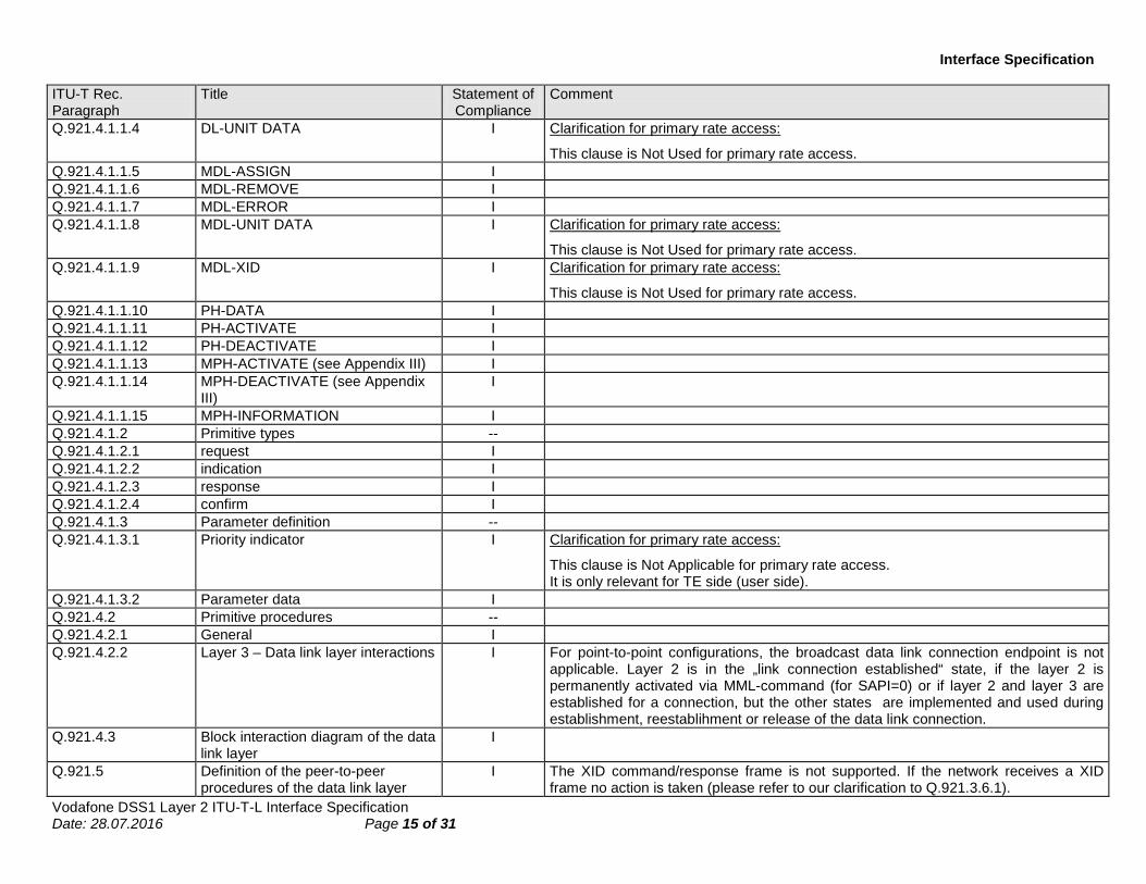
Conventions The statement of compliance is abbreviated as follows: I = Implemented, the function is implemented according to the relevant ITU-T Recommendation,
unless the "comment" field specifies a variation, NU = Not Used, the function is not implemented, NA = Not Applicable-- = Descriptive text or title in the recommendation, no comment necessary.

Vodafone DSS1 Layer 2 ITU-T-L Interface Specification Date: 28.07.2016 Page 4 of 31
Interface Specification
Contact Vodafone GmbH Ferdinand-Braun-Platz 1 40549 Düsseldorf Germany Telefon: +49 (0)800 172 1212 Website: www.vodafone.de

Vodafone DSS1 Layer 2 ITU-T-L Interface Specification Date: 28.07.2016 Page 5 of 31
Interface Specification
1 Scope The implementation of the DSS1 Layer 2 in EWSD is based on the specification produced by ETSI and ITU-T (previously CCITT) to support the services and Supplementary Services of the memorandum of understanding (MOU).
This interface specification may be changed at any time. The user of this interface specification has to check for the newest version available from Vodafone GmbH. This interface specification may be superseded in total or in part by the terms of a contract between the individual network user and Vodafone GmbH.

Vodafone DSS1 Layer 2 ITU-T-L Interface Specification Date: 28.07.2016 Page 6 of 31
Interface Specification
2 References In the case of a conflict between specific requirements in this document with requirements in any of the directly or indirectly referenced documents, the specific requirements of this document are applicable.
2.1 Normative References The publications listed hereafter form the basis for the DSS1 Layer 2 implementation in EWSD.
Q.920 ITU-T Rec. Q.920 (I.440) (03/93) DIGITAL SUBSCRIBER SIGNALLING SYSTEM No. 1 (DSS1) ISDN USER-NETWORK INTERFACE DATA LINK LAYER GENERAL ASPECTS.
Q.921 ITU-T Rec. Q.921 (I.440) (03/93) ISDN USER-NETWORK INTERFACE DATA LINK LAYER SPECIFICATION.
300 125-X ETSI Rec. prETS 300 125-X (09/1991) Integrated Services Digital Network (ISDN); User-network interface data link layer specification Application of CCITT Recommendations Q.920/I.440 and Q.921/I.441
2.2 Reference Acquisition • European Telecommunications Standards Institute: http://www.etsi.org
• ITU Recommendations: http://www.itu.int

Vodafone DSS1 Layer 2 ITU-T-L Interface Specification Date: 28.07.2016 Page 7 of 31
Interface Specification
3 Definitions and Abbreviations 3.1 Definitions The definitions in the referenced standards apply.
3.2 Abbreviations The definitions in the referenced standards apply.
4 Tables
In order to give information about the implemented messages, parameters and procedures, each relevant paragraph of the ITU-T Rec. Q.92X is listed thereafter in tabular form.

Vodafone DSS1 Layer 2 ITU-T-L Interface Specification Date: 28.07.2016 Page 8 of 31
Interface Specification
ITU-T Rec. Paragraph
Title Statement of Compliance
Comment
Q.920 DIGITAL SUBSCRIBER SIGNALLING SYSTEM No. 1 (DSS1) – ISDN USER-NETWORK INTERFACE DATA LINK LAYER – GENERAL ASPECTS
--
Q.920.1 General I The NOTE 1 is modified as follow: The physical layer is currently defined in Recommendations I.430 [8] and I.431 [9], and prETS 300 012 [14] and prETS 300 011 [15], respectively, and layer 3 is defined in Recommendations Q.930 (I.450) [10], Q.931 (I.451) [11] and ETS 300 102-1 [16], ETS 300 102-2 [17], and X.25 [4]. References should be made to these Recommendations for the complete definition of the protocols and procedures across the ISDN user-network interface. The NOTE 2 is modified as follow: The term "data link layer" is used in the main text of this Recommendation. However, mainly in figures and tables, the terms "layer 2" and "L2" are used as abbreviations. Furthermore, in accordance with Recommendations Q.930 (I.450) [10] and Q.931 (I.451) [11], and ETS 300 102-1 [16] and ETS 300 102-2 [17], the term "layer 3" is used to indicate the layer above the data link layer.
Q.920.2 Concepts and terminology I Clarification for basic access:
For point-to-point configurations, the layer 2 will support the data link (SAPI = 0 (signalling), TEI = 0) and (SAPI = 16, (p-data conforming to X.25), TEI = 0) and in addition one management link (SAPI = 63, TEI = 127 (broadcast)). The management link is only used in certain failure conditions. For point-to-multipoint configurations, the SAPI-values 0, 16, 63 are supported. Note: SAPI = 1 (P-data conforming to Q.931) is not supported, because only X.25-p-Data-Terminals can be connected via X.25-Terminal-adapters and the p-data are routed to the packet handler. Clarification for primary rate access:
The layer 2 will only support one link for SAPI = 0 and TEI = 0 is allocated for this purpose. Broadcast data link entities are not applicable.
Q.920.3 Overview description of LAPD functions and procedures
--
Q.920.3.1 General I For point-to-point configurations, only point-to-point data link connections and layer management connections are applicable.
Q.920.3.2 Unacknowledged operation I For point-to-point configurations, only point-to-point data link connections and layer management connections are applicable.
Q.920.3.3 Acknowledged operation I Q.920.3.4 Establishment of information transfer
modes --

Vodafone DSS1 Layer 2 ITU-T-L Interface Specification Date: 28.07.2016 Page 9 of 31
Interface Specification
ITU-T Rec. Paragraph
Title Statement of Compliance
Comment
Q.920.3.4.1 Data link connection identification I Clarification for basic access:
For point-to-point configurations, the layer 2 will support the data links (0, 0) and (16, 0) and in addition one management link (63, 127). Clarification for primary rate access:
The layer 2 will only support one link for SAP1 = 0, and TEI = 0 is allocated for this purpose.
Q.920.3.4.2 Data link states I Clarification for basic access:
For point-to-point configurations, the data link entities are never in the TEI-unassigned state, because the TEI-value=0 is reserved for this case. Clarification for primary rate access:
Please refer to our comments to Annex B.2. Q.920.3.4.3 TEI administration I Clarification for primary rate access:
This clause is Not Applicable for primary rate access. For point-to-point configurations, the TEI procedures are not supported.
Q.920.3.4.4 Establishment of multiple frame operation
I
Q.920.4 Service characteristics -- Q.920.4.1 General I Q.920.4.2 Services provided to layer 3 I Clarification for primary rate access:
This clause is Not Applicable for primary rate access. The network does not use UI-frames for transmission of messages. On receipt of an UI-frame, the network treats the frame according to § Q.921.5.2.3.
Q.920.4.2.1 Unacknowledged information transfer service
I Clarification for primary rate access:
This clause is Not Applicable for primary rate access. The network does not send UI-frames.
Q.920.4.2.2 Acknowledged information transfer service
I
Q.920.4.3 Services provided to layer management
I
Q.920.4.4 Administrative services I Data link connection parameter passing is not supported.
Clarification for primary rate access:
This clause is not used for primary rate access. Q.920.4.5 Model of the data link service - Q.920.4.5.1 General I Clarification for basic access:

Vodafone DSS1 Layer 2 ITU-T-L Interface Specification Date: 28.07.2016 Page 10 of 31
Interface Specification
ITU-T Rec. Paragraph
Title Statement of Compliance
Comment
For point-to-point configuration, a broadcast information (i.e. TEI=127) transfer mode is not applicable for data link connections.
Clarification for primary rate access:
A broadcast information (i.e. TEI = 127) transfer mode is not applicable. Table 1/Q.920: DL-UNIT DATA is not supported.
Q.920.4.5.2 Data link layer representation as seen by layer 3
-
Q.920.4.5.2.1 Data link connection endpoint states I Q.920.4.5.2.2 Broadcast data link layer connection
services I Clarification for basic access:
For point-to-point configurations, a broadcast data link layer connection is not applicable for data link connections.
Clarification for primary rate access:
This clause is Not Applicable for primary rate access.
Q.920.4.5.2.3 Point-to-point data link connection endpoint services
I Clarification for basic access:
For point-to-point configurations: − Layer 2 will support the data links (0, 0) and (16, 0) and in addition one
management link (63, 127) − Layer 2 in the „link connection established“ state, if the layer 2 is
permanently activated via MML-command (for SAAPI=0) or if layer 2 − layer 3 are established for a connection.
Clarification for primary rate access:
− The network does not use UI-frames for transmission of messages. − On receipt of an UI-frame, the network treats the frame according to
§Q.921.5.2.3 of this specification. − Layer 2 will only support one link for SAPI = 0 and TEI = 0 is allocated for
this purpose. − Layer 2 is under normal operation conditions in the „link connection
established“ state, but the other states are implemented and used when the data link connection is established, re-established or released.
Q.920.4.5.2.4 Sequences of primitives at one point-to-point data link connection endpoint
I
Q.920.4.6 Services required from the physical layer
I The last part of paragraph is modified as follow: The primitives between management entities and the physical layer are:

Vodafone DSS1 Layer 2 ITU-T-L Interface Specification Date: 28.07.2016 Page 11 of 31
Interface Specification
ITU-T Rec. Paragraph
Title Statement of Compliance
Comment
iv) activation: MPH-ACTIVATE-INDICATION This primitive is used to indicate that the physical layer connection has been activated.
v) deactivation: MPH-DEACTIVATE-REQUEST/INDICATION These primitives are used to request deactivation of the physical layer connection and to indicate that the physical layer connection has been deactivated. The REQUEST is used at the network side only.
vi) MPH-INFORMATION-INDICATION: This primitive is used to indicate to user management entities information regarding the physical layer condition. Two parameters are defined: connected and disconnected.
Q.920.5 Data link layer - Management structure
I Clarification for primary rate access:
For point-to-point configurations, the broadcast data link entity is not applicable. Parameter initialisation procedures are not supported.
Q.920.5.1 Data link procedure I Q.920.5.2 Multiplex procedure I Clarification for basic access:
For point-to-point configurations, layer 2 will support the data links (0, 0) and (16, 0) and in addition one management link (63, 127).
Clarification for primary rate access:
Layer 2 will only support one link for SAPI = 0, and TEI = 0 is allocated for this purpose.
Q.920.5.3 Structure of the data link procedure I For point-to-point configurations, the broadcast data link entity is not applicable. Q.920.5.4 Overall data link layer functional
diagram -
Q.920.5.4.1 General I Q.920.5.4.2 Enhanced functional block diagram
and block interaction diagram I Clarification for basic access:
For point-to-point configurations, layer 2 will support the data links (0, 0) and (16, 0) and in addition one management link (63, 127). Broadcast data link entities are not applicable.
Clarification for primary rate access:
Layer 2 will only support one link for SAPI = 0, and TEI = 0 is allocated for this purpose.
Q.921. ISDN USER-NETWORK INTERFACE-DATA LINK LAYER
--

Vodafone DSS1 Layer 2 ITU-T-L Interface Specification Date: 28.07.2016 Page 12 of 31
Interface Specification
ITU-T Rec. Paragraph
Title Statement of Compliance
Comment
SPECIFICATION Q.921.1 General I The third sentence of NOTE 1 is modified as follows:
Furthermore, in accordance with Recommendations Q.930 (I.450) [2] and Q.931 (I.451) [3], and ETS 300 102-1 [9] and ETS 300 102-2 [10], the term "layer 3" is used to indicate the layer above the data link layer.
Q.921.2 Frame structure for peer-to-peer communication
--
Q.921.2.1 General I Q.921.2.2 Flag sequence I The last sentence is modified as follows:
See ISDN User-Network Interfaces: Layer 1 Recommendations I.430 [4] and I.431 [5], and prETS 300 012 [7] and prETS 300 011 [8], respectively, for applicability.
Q.921.2.3 Address field I The LAPB data link connection is not supported, because the LAPB address field is not sufficient for ISDN (it cannot contain SAPI plus TEI). If the network receives a LAPB-frame, the frame is treated as an invalid frame as described in § Q.921.5.8.4.
Q.921.2.4 Control field I Q.921.2.5 Information field I Q.921.2.6 Transparency I Q.921.2.7 Frame check sequence (FCS) field I Q.921.2.8 Format convention I Q.921.2.8.1 Numbering convention I Q.921.2.8.2 Order of bit transmission I Q.921.2.8.3 Field mapping convention I Q.921.2.9 Invalid frames I Q.921.2.10 Frame abort I Q.921.3 Elements of procedures and formats
of fields for data link layer peer-to-peer communication
--
Q.921.3.1 General I Q.921.3.2 Address field format I Q.921.3.3 Address field variables -- Q.921.3.3.1 Address field extension bit (EA) I Q.921.3.3.2 Command/response field bit (C/R) I Q.921.3.3.3 Service access point identifier
(SAPI) I Clarification for basic access:
The network only accepts frames which have one of the following SAPI values: 0, 16, 63. Note: SAPI=1 (p-data conforming to Q.931) is not supported, because only X.25-p-

Vodafone DSS1 Layer 2 ITU-T-L Interface Specification Date: 28.07.2016 Page 13 of 31
Interface Specification
ITU-T Rec. Paragraph
Title Statement of Compliance
Comment
Data-Terminals can be connected via X.25-Terminal-adapters and the p-data are routed to the packet handler. In EWSD also the SAPI=32 is used for loop tests in the NT. The Terminal Equipment only use SAPI=0, 16, 63. Clarification for primary rate access:
Table 2/Q.921: Only SAPI = 0 is supported. Q.921.3.3.4 Terminal endpoint identifier (TEI) I Clarification for basic access:
For point-to-point configurations, layer 2 will support the data links (0, 0) and (16, 0) and in addition one management link (63, 127).
Clarification for primary rate access:
Layer 2 will only support one link for SAPI = 0, and TEI = 0 is allocated for this purpose.
Q.921.3.3.4.1 TEI for broadcast data link connection
I For point-to-point configurations, broadcast data link connection is not supported. Clarification for primary rate access:
This clause is Not Applicable for primary rate access.
Q.921.3.3.4.2 TEI for point-to-point data link connection
I For point-to-point configurations, only TEI=0 is used.
Q.921.3.4 Control field formats I Q.921.3.4.1 Information transfer (I) format I Q.921.3.4.2 Supervisory (S) format I Q.921.3.4.3 Unnumbered (U) format I Q.921.3.5 Control field parameters and
associated state variables I
Q.921.3.5.1 Poll/Final (P/F) bit I Q.921.3.5.2 Multiple frame operation – variables
and sequence numbers --
Q.921.3.5.2.1 Modulus I Q.921.3.5.2.2 Send state variable V(S) I Q.921.3.5.2.3 Acknowledge state variable V(A) I Q.921.3.5.2.4 Send sequence number N(S) I Q.921.3.5.2.5 Receive state variable V(R) I Q.921.3.5.2.6 Receive sequence number N(R) I Q.921.3.5.3 Unacknowledged operation –
variables and parameters I
Q.921.3.6 Frame types --

Vodafone DSS1 Layer 2 ITU-T-L Interface Specification Date: 28.07.2016 Page 14 of 31
Interface Specification
ITU-T Rec. Paragraph
Title Statement of Compliance
Comment
Q.921.3.6.1 Commands and responses I The XID command/response frame is not supported (according to Appendix IV.4). If the network receives a XID frame, no action is taken. Parameter negotiation procedures are not supported, the parameter values are fixed in the exchange and cannot be changed.
Q.921.3.6.2 Information (I) command I Q.921.3.6.3 Set asynchronous balanced mode
extended (SABME) command I
Q.921.3.6.4 Disconnect (DISC) command I For point-to-point configurations, the network does normally not initiate the termination of multiple frame operation. However, mechanisms for terminating the multiple frame operation are implemented for failure conditions.
Q.921.3.6.5 Unnumbered information (UI) command
I Clarification for primary rate access:
This clause is Not Used for primary rate access. The network does not support UI-frames for transmission of messages. On receipt of an UI-frame, the network treats the frame according to § Q.921.5.2.3.
Q.921.3.6.6 Receive ready (RR) command/response
I
Q.921.3.6.7 Reject (REJ) command/response I The optional procedure for the retransmission of an REJ response frame (see Appendix I) is not supported.
Q.921.3.6.8 Receive not ready (RNR) command/response
I
Q.921.3.6.9 Unnumbered acknowledgement (UA) response
I
Q.921.3.6.10 Disconnected mode (DM) response I Q.921.3.6.11 Frame reject (FRMR) response NA The network does never send the Frame reject (FRMR) response frame, because not
all terminals can handle FRMR. If the network receives a FRMR frame, actions according to § Q.921.5.8.6 of this specification, are taken. On receiving of an incorrect frame, the exchange resets layer 2 by SABME.
Q.921.3.6.12 Exchange identification (XID) command/response
NU Exchange identification is not supported (refer to Appendix IV).
Q.921.4 Elements for layer-to-layer communication
--
Q.921.4.1 General I Clarification for primary rate access:
Table 6/Q.921: DLU-UNIT DATA, MDL-UNIT DATA and MDL-XID are not supported. Q.921.4.1.1 Generic names -- Q.921.4.1.1.1 DL-ESTABLISH I Q.921.4.1.1.2 DL-RELEASE I Q.921.4.1.1.3 DL-DATA I
Vodafone DSS1 Layer 2 ITU-T-L Interface Specification Date: 28.07.2016 Page 15 of 31
Interface Specification
ITU-T Rec. Paragraph
Title Statement of Compliance
Comment
Q.921.4.1.1.4 DL-UNIT DATA I Clarification for primary rate access:
This clause is Not Used for primary rate access. Q.921.4.1.1.5 MDL-ASSIGN I Q.921.4.1.1.6 MDL-REMOVE I Q.921.4.1.1.7 MDL-ERROR I Q.921.4.1.1.8 MDL-UNIT DATA I Clarification for primary rate access:
This clause is Not Used for primary rate access. Q.921.4.1.1.9 MDL-XID I Clarification for primary rate access:
This clause is Not Used for primary rate access. Q.921.4.1.1.10 PH-DATA I Q.921.4.1.1.11 PH-ACTIVATE I Q.921.4.1.1.12 PH-DEACTIVATE I Q.921.4.1.1.13 MPH-ACTIVATE (see Appendix III) I Q.921.4.1.1.14 MPH-DEACTIVATE (see Appendix
III) I
Q.921.4.1.1.15 MPH-INFORMATION I Q.921.4.1.2 Primitive types -- Q.921.4.1.2.1 request I Q.921.4.1.2.2 indication I Q.921.4.1.2.3 response I Q.921.4.1.2.4 confirm I Q.921.4.1.3 Parameter definition -- Q.921.4.1.3.1 Priority indicator I Clarification for primary rate access:
This clause is Not Applicable for primary rate access. It is only relevant for TE side (user side).
Q.921.4.1.3.2 Parameter data I Q.921.4.2 Primitive procedures -- Q.921.4.2.1 General I Q.921.4.2.2 Layer 3 – Data link layer interactions I For point-to-point configurations, the broadcast data link connection endpoint is not
applicable. Layer 2 is in the „link connection established“ state, if the layer 2 is permanently activated via MML-command (for SAPI=0) or if layer 2 and layer 3 are established for a connection, but the other states are implemented and used during establishment, reestablihment or release of the data link connection.
Q.921.4.3 Block interaction diagram of the data link layer
I
Q.921.5 Definition of the peer-to-peer procedures of the data link layer
I The XID command/response frame is not supported. If the network receives a XID frame no action is taken (please refer to our clarification to Q.921.3.6.1).

Vodafone DSS1 Layer 2 ITU-T-L Interface Specification Date: 28.07.2016 Page 16 of 31
Interface Specification
ITU-T Rec. Paragraph
Title Statement of Compliance
Comment
Q.921.5.1 Procedure for the use of the P/F bit -- Q.921.5.1.1 Unacknowledged information
transfer I
Q.921.5.1.2 Acknowledged multiple frame information transfer
I Note is not supported, i.e. LAPB is not supported.
Q.921.5.2 Procedures for unacknowledged information transfer
--
Q.921.5.2.1 General I Clarification for primary rate access:
This clause is Not Applicable for primary rate access. The network does not support UI-frames for transmission of messages.
Q.921.5.2.2 Transmission of unacknowledged information
I Clarification for primary rate access:
At the network side, the system management entity provides that the PH-DEACTIVATE-INDICATION primitive will be issued only, if persistent deactivation has occurred. However, at the user side, the conditions to issue a PH-DEACTIVATE-INDICATION primitive depend on the implementation of the physical layer.
Clarification for primary rate access:
This clause is Not Applicable for primary rate access. The network does not support UI-frames for transmission of messages.
Q.921.5.2.3 Receipt of unacknowledged information
I Clarification for primary rate access:
This clause is Not Applicable for primary rate access. If an UI-frame is received, the frame will be discarded.
Q.921.5.3 Terminal endpoint identifier (TEI) management procedures
-- Clarification for primary rate access:
Layer Management: There will be no TEI management procedures (no TEI assignment procedures, TEI removal, TEI check, TEI Identify verify, because only the TEI value 0 is used (Refer to our clarification to Q.921/Annex A).
Q.921.5.3.1 General I Clarification for primary rate access:
This clause is Not Used for primary rate access. Q.921.5.3.2 TEI assignment procedure I Clarification for primary rate access:
The network selects a TEI value from a map of the full range of automatic TEI values (64 - 126), or, if some TEI values are currently in use, from an updated list of all automatic TEI values available for assignment.
Clarification for primary rate access:
This clause is Not Used for primary rate access.
Vodafone DSS1 Layer 2 ITU-T-L Interface Specification Date: 28.07.2016 Page 17 of 31
Interface Specification
ITU-T Rec. Paragraph
Title Statement of Compliance
Comment
Q.921.5.3.2.1 Expiry of timer T202 I Clarification for primary rate access:
This clause is Not Used for primary rate access. Q.921.5.3.3 TEI check procedure -- Q.921.5.3.3.1 Use of the TEI check procedure I Clarification for primary rate access:
This clause is Not Used for primary rate access. Q.921.5.3.3.2 Operation of the TEI check
procedure I Clarification for primary rate access:
This clause is Not Used for primary rate access. Q.921.5.3.4 TEI removal procedure I Clarification for primary rate access:
This clause is Not Used for primary rate access. Q.921.5.3.4.1 Action taken by the data link layer
entity receiving the MDL-REMOVE request primitive
I Clarification for primary rate access:
This clause is Not Used for primary rate access.
Q.921.5.3.4.2 Conditions for TEI removal I Clarification for primary rate access:
This clause is Not Used for primary rate access. Q.921.5.3.5 TEI identity verify procedure -- Q.921.5.3.5.1 General I Clarification for primary rate access:
This clause is Not Used for primary rate access. Q.921.5.3.5.2 Operation of the TEI identity verify
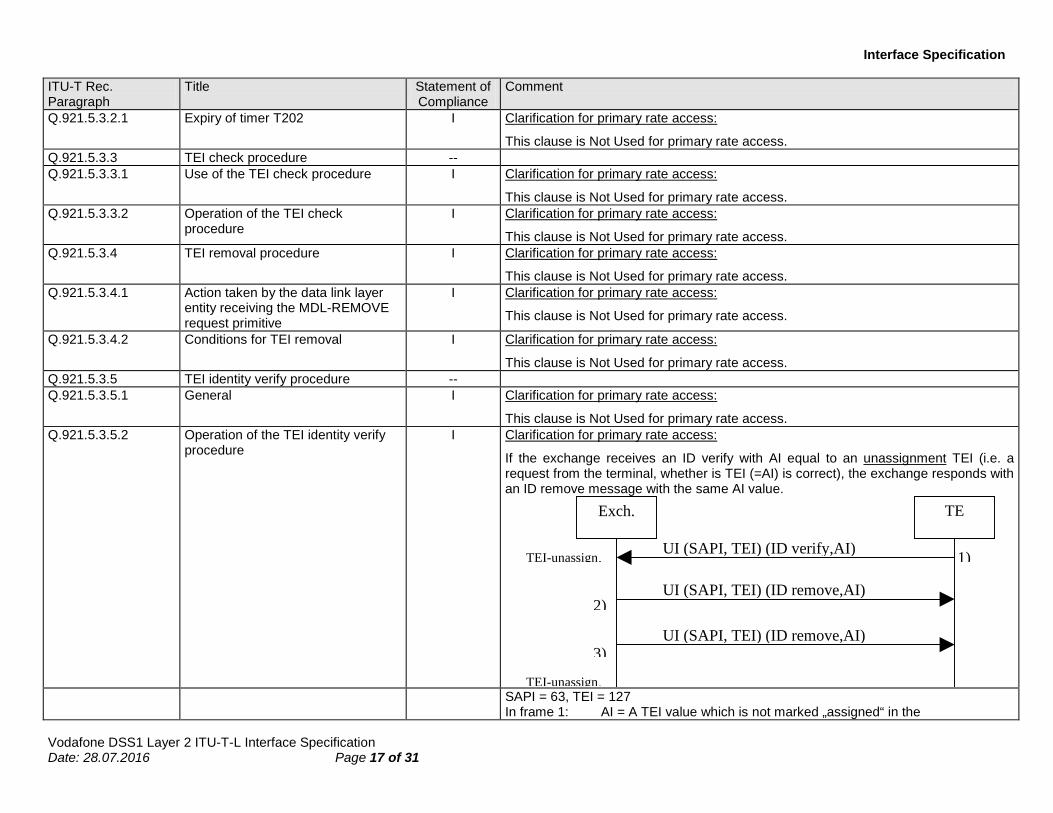
procedure I Clarification for primary rate access:
If the exchange receives an ID verify with AI equal to an unassignment TEI (i.e. a request from the terminal, whether is TEI (=AI) is correct), the exchange responds with an ID remove message with the same AI value.
TEExch.
UI (SAPI, TEI) (ID remove,AI)
UI (SAPI, TEI) (ID remove,AI)
UI (SAPI, TEI) (ID verify,AI)TEI-unassign.
TEI-unassign.
1)
2)
3)
SAPI = 63, TEI = 127
In frame 1: AI = A TEI value which is not marked „assigned“ in the
Vodafone DSS1 Layer 2 ITU-T-L Interface Specification Date: 28.07.2016 Page 18 of 31
Interface Specification
ITU-T Rec. Paragraph
Title Statement of Compliance
Comment
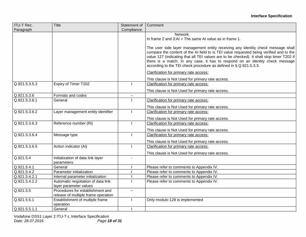
Network. In frame 2 and 3:AI = The same AI value as in frame 1. The user side layer management entity receiving any identity check message shall compare the content of the AI field to is TEI value requested being verified and to the value 127 (indicating that all TEI values are to be checked). It shall stop timer T202 if there is a match. In any case, it has to respond on an identity check message according to the TEI check procedure as defined in § Q.921.5.3.3.
Clarification for primary rate access:
This clause is Not Used for primary rate access. Q.921.5.3.5.3 Expiry of Timer T202 I Clarification for primary rate access:
This clause is Not Used for primary rate access. Q.921.5.3.6 Formats and codes -- Q.921.5.3.6.1 General I Clarification for primary rate access:
This clause is Not Used for primary rate access. Q.921.5.3.6.2 Layer management entity identifier I Clarification for primary rate access:
This clause is Not Used for primary rate access. Q.921.5.3.6.3 Reference number (Ri) I Clarification for primary rate access:
This clause is Not Used for primary rate access. Q.921.5.3.6.4 Message type I Clarification for primary rate access:
This clause is Not Used for primary rate access. Q.921.5.3.6.5 Action indicator (Ai) I Clarification for primary rate access:
This clause is Not Used for primary rate access. Q.921.5.4 Initialization of data link layer
parameters -
Q.921.5.4.1 General I Please refer to comments to Appendix IV. Q.921.5.4.2 Parameter initialization I Please refer to comments to Appendix IV. Q.921.5.4.2.1 Internal parameter initialization I Please refer to comments to Appendix IV. Q.921.5.4.2.2 Automatic negotiation of data link
layer parameter values I Please refer to comments to Appendix IV.
Q.921.5.5 Procedures for establishment and release of multiple frame operation
--
Q.921.5.5.1 Establishment of multiple frame operation
I Only modulo 128 is implemented
Q.921.5.5.1.1 General I

Vodafone DSS1 Layer 2 ITU-T-L Interface Specification Date: 28.07.2016 Page 19 of 31
Interface Specification
ITU-T Rec. Paragraph
Title Statement of Compliance
Comment
Q.921.5.5.1.2 Establishment procedures I Q.921.5.5.1.3 Procedure on expiry of timer T200 I Q.921.5.5.2 Information transfer I Q.921.5.5.3 Termination of multiple frame
operation -- For point-to-point configurations, the network does normally not initiate the termination
of multiple frame operation. However, mechanisims for terminating the multiple frame operation are implemented for failure conditions.
Q.921.5.5.3.1 General I Clarification for primary rate access:
The „persistent layer 1 deactivation“ is assumed to be a port, that is barred in layer 1; this means, that an awake-signal from the user is ignored. The state „persistent layer 1 deactivation“ does not exist. The primitive „PH-DEACTIVATE-INDICATION“ is used to acknowledge a layer 1 deactivation to layer 2.
Q.921.5.5.3.2 Release procedure I Q.921.5.5.3.3 Procedure on expiry of timer T200 I Q.921.5.5.4 TEI-assigned state I Clarification for basic access:
An unsolicited DM response with the F-bit set to 0 is ignored, because LAPB operation is not supported. This case is a relic from LAPB-procedures, to be able to request a layer 2-establishment from the slave in the unbalanced mode. The exchange/terminal requests a layer 2 establishment with SABME (i.e. balanced mode), so the establishment according to Table 9/Q.921 (DM response, F=0/TEI-assigned) is not applicable.
Q.921.5.5.5 Collision of unnumbered commands and responses
--
Q.921.5.5.5.1 Identical transmitted and received commands
I
Q.921.5.5.5.2 Different transmitted and received commands
I
Q.921.5.5.6 Unsolicited DM response and SABME or DISC command
NU A LAPB operation is not supported (please refer to our clarification to Q.921.2.3).
Q.921.5.6 Procedures for information transfer in multiple frame operation
I
Q.921.5.6.1 Transmitting I frames I Q.921.5.6.2 Receiving I frames I Q.921.5.6.2.1 P bit set to 1 I Q.921.5.6.2.2 P bit set to 0 I Q.921.5.6.3 Sending and receiving --

Vodafone DSS1 Layer 2 ITU-T-L Interface Specification Date: 28.07.2016 Page 20 of 31
Interface Specification
ITU-T Rec. Paragraph
Title Statement of Compliance
Comment
acknowledgements Q.921.5.6.3.1 Sending acknowledgements I Q.921.5.6.3.2 Receiving acknowledgements I Q.921.5.6.4 Receiving REJ frames I Q.921.5.6.5 Receiving RNR frames I If the peer layer 2 enters the Busy State, this condition will be scanned with the timer
T200 till N2X4 times. If no release of the peer busy state will be advised after the last inquiry, then the layer 2 connection will be reestablished.
Q.921.5.6.6 Data link layer own receiver busy condition
I
Q.921.5.6.7 Waiting acknowledgement I Q.921.5.7 Re-establishment of multiple frame
operation --
Q.921.5.7.1 Criteria for re-establishment I Clarification for basic access:
An unsolicited DM response with the F-bit set to 0 is ignored, because LAPB operation is not supported. This case is a relic from LAPB-procedures, to be able a layer 2-establishment from the slave in the unbalanced mode. The exchange/terminal requests a layer 2 establishment with SABME (i.e. balanced mode), so the establishment according to Table 9/Q.921 (DM response, F=0/TEI-assigned) is not applicable.
Q.921.5.7.2 Procedures I Q.921.5.8 Exception condition reporting and
recovery I
Q.921.5.8.1 N(S) sequence error I The optional procedures of Appendix I are not supported. Q.921.5.8.2 N(R) sequence error I The information field contained in an I frame which is correct in sequence and format
is delivered to layer 3 by means of the DL-DATA-INDICATION primitive. Q.921.5.8.3 Timer recovery condition I Q.921.5.8.4 Invalid frame condition I Q.921.5.8.5 Frame rejection condition I − „Incorrect length“ means more than 6 octets between the flags for supervisory
frames or more than 5 octets between the flags for unnumbered frames, or more than 265 octets between the flags for UI-frames.
− Frame rejection condition means: sending a REJ-frame. Q.921.5.8.6 Receipt of an FRMR response frame I Q.921.5.8.7 Unsolicited response frames I Replace „Establish“ by „Ignore“ in the matrix-field: „DM response, F=0“I“TEI assigned“.
LAPB is not supported by Siemens; therefore a layer 2-establishment with „DM“ from TE is not applicable in the state „TEI assigned“ (refer to 5.5.6). The data link layer will always be established with SABME.

Vodafone DSS1 Layer 2 ITU-T-L Interface Specification Date: 28.07.2016 Page 21 of 31
Interface Specification
ITU-T Rec. Paragraph
Title Statement of Compliance
Comment
Note: We assume an inconstancy in ETSI (Table 9/Q.921 Q.921.5.5.6). Q.921.5.8.8 Duplicate assignment of a TEI value I Q.921.5.9 List of system parameters I Parameter negotiation is not supported (please refer to Appendix IV.4). Q.921.5.9.1 Timer T200 I Default value T200 = 1 s is used. Q.921.5.9.2 Maximum number of
retransmissions (N200) I Default value N200 = 3 is used.
Q.921.5.9.3 Maximum number of octets in an information field (N201)
I Default value N201 = 260 octets is used.
Q.921.5.9.4 Maximum number of transmissions of the TEI Identity request message (N202)
NA Not applicable in the network side.
Q.921.5.9.5 Maximum number of outstanding I frames (k)
I The default values are used for the window size.
Q.921.5.9.6 Timer T201 I Default value T201 = 1s is used.
Clarification for primary rate access:
This clause is Not Used for primary rate access. Q.921.5.9.7 Timer T202 NA Not applicable in the network side. Q.921.5.9.8 Timer T203 I Default value T203 = 10s is used. Q.921.5.10 Data link layer monitor function -- Q.921.5.10.1 General I The paragraph is modified as follows:
The procedural elements defined in § 5 allow for the supervision of the data link layer resource. This section describes procedures which may be used to provide this supervision function. The use of this function is mandatory for network side data link layer entities in European networks but optional for a user side data link layer entity.
Q.921.5.10.2 Data link layer supervision in the multiple-frame-established state
I
Q.921.5.10.3 Connection verification procedures -- Q.921.5.10.3.1 Start timer T203 I Q.921.5.10.3.2 Stop timer T203 I Q.921.5.10.3.3 Expiry of timer T203 I Q.921.A Provision of point-to-point signalling
connections I The following paragraph is added:
In European networks, the TEI value 0 is reserved for NT2 in point-to-point configurations using a single data link connection (that is, only one point-to-point data link connection is supported within each SAP), in addition to this, the broadcast data link connection, (TEI = 127) between the NT2 and the network may be supported within each SAP.
Q.921.B SDL for point-to-point procedures - Q.921.B.1 General I

Vodafone DSS1 Layer 2 ITU-T-L Interface Specification Date: 28.07.2016 Page 22 of 31
Interface Specification
ITU-T Rec. Paragraph
Title Statement of Compliance
Comment
Q.921.B.2 An overview of the states of the point-to-point data link layer entity
I States 2 and 3 are not supported (user function)
Q.921.B.3 Cover notes I Q.921.B.4 The use of queues I Q.921.B.5 SDL representation I Clarification for primary rate access:
This clause is Not Used for primary rate access. I-frames are never used as supervisory commands. Only I-commands with P-0 are supported.
Q.921.C SDL representation of the broadcast procedures
I Not for point-to-point configurations
Clarification for primary rate access:
This clause is Not Used for primary rate access.
Q.921.D State transition table of the point-to-point procedures of the data link layer
- Refer to comments to Q.921.3.6.7.
Q.921.D.1 The state transition table presented in ...
Q.921.D.2 Key to the state transition table - Q.921.D.2.1 Definition of a cell of the state
transition table I
Q.921.D.2.2 Key to the contents of a cell I Q.921.E Protocol Implementation Conference
Statement (PICS) to Recommendation Q.921 for Basic Rate (User-side)
I
Q.921.E.1 General I For the answer please refer to Appendix A Q.921.E.2 Abbreviations and special symbols I Q.921.E.3 Instructions for completing for PICS
Proforma I
Q.921.E.4 Global statement of conformance I Q.921.E.5 Protocol Capabilities (PC) I Refer to Appendix A Q.921.E.6 Frames – Protocol Data Units (FR) I Refer to Appendix A Q.921.E.7 System parameters (SP) I Refer to Appendix A Q.921.I Retransmission of REJ response
frames -- Please refer to comments to Q.921.3.6.7
Q.921.I.1 Introduction NU Q.921.I.2 Procedure NU

Vodafone DSS1 Layer 2 ITU-T-L Interface Specification Date: 28.07.2016 Page 23 of 31
Interface Specification
ITU-T Rec. Paragraph
Title Statement of Compliance
Comment
Q.921.I.2.1 Recovery state variable V(M) NU Q.921.I.2.2 N(S) sequence error supplementary
procedure NU
Q.921.II Appendix II Occurrence of MDL-ERROR indication within the basic states and actions to be taken by the management entity
--
Q.921.II.1 Introduction I Q.921.II.2 Layout of Table II.1 I Clarification for basic access:
Q.921.II.3 Preferred management actions I The terms „remove TEI“ and „TEI removal“ are interpreted in the following way:
„Remove TEI“: cancel the TEI values in the DLCI table „TEI removal procedure“: Send an Identity Remove to the TE. In both cases the result will be a transition to the state „TEI unassigned“. Clarification for basic access:
a) Error log The specified error flags are implemented in the system. The evaluation, counting, storage of the error flags will be included in a further step. For Error code C and D, the TEI check procedure shall be used.
Clarification for primary rate access:
Items b), c) and d) are not supported for point-to-point configurations. Error log: Specific counters are implemented for error logging. The evaluation of data link errors will be included in a further step.
Q.921.III Appendix III Optional basic access deactivation procedures
--
Q.921.III.1 Introduction I Following text replaces the first section: This appendix provides an example of a deactivation of the user-network interface at reference point S or T. Figure III-1/Q.921 provides a conceptual model of the interactions which are required for this deactivation procedure. A function that initiates the deactivation of the user-network interface at the S-interface point is implemented. The functionality is similar to the procedure shown in Appendix III. However, the deactivation timer (TM01 in Appendix III) is set to 30 s.
Q.921.III.2 Description of the Conceptual Model I Q.921.III.3 Deactivation procedure with MPH-
DEACTIVATE indication I

Vodafone DSS1 Layer 2 ITU-T-L Interface Specification Date: 28.07.2016 Page 24 of 31
Interface Specification
ITU-T Rec. Paragraph
Title Statement of Compliance
Comment
Q.921.III.4 Deactivation procedure without MPH-DEACTIVATE indication
I
Q.921.IV Appendix IV Automatic negotiation of data link layer parameters
--
Q.921.IV.1 General I Q.921.IV.2 Automatic negotiation of data link
layer parameter values I

Vodafone DSS1 Layer 2 ITU-T-L Interface Specification Date: 28.07.2016 Page 25 of 31
Interface Specification
Annex A Protocol Capabilities (PC)
Index
Protocol Feature
Status Reference
(subclause,appendix)
Support
PC 1.1 Is the CPE of the non-automatic TEI assignment category?
O.1 3.3.4.2 Yes:X No:_ X:_
PC 1.2 Is the CPE of the automatic TEI assignment category?
O.1 3.3.4 Yes:X No: _ X:_
PC 2 Does the CPE support the broadcast data link? M 5.2 Yes:X No:_ X:_
PC 4 Does the CPE support data link nonitor function? O 5.10 Yes:X No:_ X:_
PC 5 Does the CPE support reject retransmission procedure
O 3.6.7 5.8.1 Appendix I
Yes:_ No:X X:_
PC 6.1 Does the DLE support automatic negotiation of data link layer parameters?
O.2 Appendix IV Yes:X No:_ X:_
PC 6.2 Does the DLE support internal parameter initialization?
O.2 5.4 Yes:X No:_ X:_
PC 7 Does the CPE permit concurrent LAPB data link connection within the D-channel
O 2.3 Yes:_ No:X X:_
Service Access Point Identifier (SAPI)
PC 8 If the CPE supports Layer 3 call control procedures, is SAPI = 0 supported?
M 3.3.3 Yes:X No:_ X:_
PC 9 If the CPE supports X.25 Layer 3 packet procedures on D-channel, is SAPI = 16 supported?
M 3.3.3 Yes:_ No:X X:_
PC 10 Is SAPI = 63 supported M 3.3.3 Yes:X No:_ X:_
PC 11.1 Does the implementation support the association of a given TEI with all SAPs which the CPE supports?
O 3.3.4, 5.3.1 3.4.3/Q.920
Yes:X No:_ X:_
PC 11.2 If the CPE is an X.31 type of packet mode terminal equipment, is a given TEI for point-to-point data link connection (<127) associated with all SAPs which the CPE supports?
M 3.3.4, 5.3.1 3.4.3/Q.920
Yes:X No:_ X:_
PC 12 Does the implementation support modulus 128 for frames numbering?
M 3.5.2.1, 5.5.1
Yes:X No:_ X:_
Peer-to-peer procedures
PC 13 PC 14
Unacknowledged Information Transfer Does the CPE support UI-command? Is the P/F bit set to 0?
M M
5.2.2 5.1.1
Yes:X No:_ X:_ Yes:X No:_ X:_
TEI Management
PC 15 Does the CPE transmit management entity messages in UI frames with DLCI = (63, 127)?
M 5.3.1 Yes:X No:_ X:_

Vodafone DSS1 Layer 2 ITU-T-L Interface Specification Date: 28.07.2016 Page 26 of 31
Interface Specification
Index
Protocol Feature
Status
Reference (subclause, appendix)
Support
TEI Assignment Procedures
PC 16.1 Does the CPE initiate TEI assignment upon power-up?
O.3 5.3.1 Yes:X No:_ X:_
PC 16.2 Does the CPE initiate TEI assignment at the time an incoming or an outgoing call is handled, if there is no TEI assigned?
O.3 5.3.1 Yes:X No:_ X:_
PC 17 If the CPE is of the non-automatic category, does the CPE side management entity assign a TEI value?
M 5.3.2 Yes:X No:_ X:_
If the CPE is of the automatic category:
PC 18 Does the CPE side management entity initiate TEI assignment?
M 5.3.2 Yes:X No:_ X:_
PC 19 Is the Ri randomly generated? M 5.3.2 Yes:X No:_ X:_
PC 20 Is the Ai value in an Identity Request message always equal to 127?
M 5.3.2 Yes:X No:_ X:_
PC 21 Does the CPE retransmit an Identity Request message upon timer T202 expiry?
M 5.3.2.1 Yes:X No:_ X:_
PC 22 Does the CPE use a new value of Ri in the above instance (PC 21)?
M 5.3.2.1 Yes:X No:_ X:_
TEI Check Response/Removal/Identity Verify
PC 23.1 Does the CPE send a single Identity Check Response message, if the Ai value in the received Identity Check Request message is equal to 127?
O.4 5.3.3.2 Yes:X No:_ X:_
PC 23.2 Does the CPE send an individual Identy Check Response message, for each TEI which is assigned to it, if the Ai value in the received Identity Check Request message is equal to 127?
O.4 5.3.3.2 Yes:X No:_ X:_
PC 23.3 Does the CPE send any combination of (multiple) “single” and “individual” Identity Check Response messages in order to report all the TEIs assigned to it, if the Ai value in the received Identity Check Request message is equal to 127?
O.4 5.3.3.2 Yes:X No:_ X:_
PC 24 Does the CPE support transmitting one Identity Check Response message in response to an Identity Check Request message with Ai 127, if the TEI value being checked is in use?
M 5.3.3.2 Yes:X No:_ X:_
PC 25 Does the DLE enter the TEI Unassigned state, upon removal of an automatic TEI?
M 5.3 Yes:X No:_ X:_
PC 26 Does the CPE send an Identity Request message upon removal of an automatic TEI?
M 5.3.4 Yes:X No:_ X:_
Index
Protocol Feature
Status
Reference (subclause, appendix)
Support

Vodafone DSS1 Layer 2 ITU-T-L Interface Specification Date: 28.07.2016 Page 27 of 31
Interface Specification
PC 27.1
If an Identity Request message is outstanding: Does the CPE remove the TEI from the DLE on receipt of an Identity Assigned message containing a TEI value which is already in use?
O.5
5.3.2 5.3.4.2
Yes:X No:_ X:_
PC 27.2 Does the CPE initiate TEI identity verify procedure on receipt of an Identity Assigned message containing a TEI value which is already in use?
O.5 5.3.2 Yes:X No:_ X:_
PC 28
If the CPE is of the non-automatic TEI category, Does the CPE notify to the equipment user the need for corrective action after non-automatic TEI removal?
M
5.3.4 5.3.4.2
Yes:X No:_ X:_
PC 29.1
If the CPE checks the TEI of all Identity Assign messages: Does the CPE remove TEI from the DLE on receipt of an Identity Assigned message containing a TEI value which is already in use?
O.6
5.3.2 5.3.4.2
Yes:X No:_ X:_
PC 29.2 Does the CPE initiate TEI identity verify procedure on receipt of an Identity Assigned message containing a TEI value which is already in use?
O.6 5.3.2 Yes:X No:_ X:_
PC 30 If the CPE initiates a TEI Identity Verify procedure, does the Ai contain the own TEI which has been assigned by ASP (automatic TEI) or entered (non-automatic TEI), respectively?
M 5.3.5.2 Yes:X No:_ X:_
PC 31
If the CPE initiates the TEI identity verify procedure, Does the CPE remove the TEI from the DLE, if no Identity Check Request message with an Ai 127 or an Ai value equal to Ai value in the Identity Verify Request message has been received when timer T202 (again) expired after retransmission of the Identity Verify Request message upon expiry of timer T202?
M
5.3.5.3
Yes:X No:_ X:_
Establishment and Release of Multiple Frame Operation
PC 32 Does the CPE support multiple frame operation? M 5.5 Yes:X No:_ X:_
Does the DLE initiate multi-frame establishment
PC 33.1 a) immediately after TEI assignment? O.7 5.5 Yes:X No:_ X:_
PC 33.2 b) when there is an incoming or an outgoing call?
O.7 5.5 Yes:X No:_ X:_
PC 34.1 c) Does the DLE remain in TEI Assigned state when the multiple frame operation is released?
O.8 5.5.3 Yes:X No:_ X:_
PC 34.2 d) Does the DLE initiate immediate re-establishment when the multiple frame operation is released?
O.8 5.5.3 Yes:X No:_ X:_
Index
Protocol Feature
Status
Reference (subclause, appendix)
Support
Unsolicited Commands and Responses

Vodafone DSS1 Layer 2 ITU-T-L Interface Specification Date: 28.07.2016 Page 28 of 31
Interface Specification
If the CPE is of the automatic TEI assignment category
PC 35.1 Does the CPE initiate TEI identity verify procedure on the receipt of an unsolicited UA response in the Multiple Frame Established State?
O.9 Appendix II 5.8.7
Yes:X No:_ X:_
PC 35.2 Does the CPE remove the TEI from the DLE on the receipt of an unsolicited UA response in the Multiple Frame Established State?
O.9 Appendix II 5.8.7
Yes:X No:_ X:_
PC 36.1 Does the CPE initiate TEI identity verify procedure on the receipt of an unsolicited UA response in the Timer Recovery State?
O.10 Appendix II 5.8.7
Yes:X No:_ X:_
PC 36.2 Does the CPE remove the TEI from the DLE on the receipt of an unsolicited UA response in the Timer Recovery State?
O.10 Appendix II 5.8.7
Yes:X No:_ X:_
PC 37.1 Does the CPE remove the TEI from the DLE, after N200 unsuccessful retransmissions of SABME?
O.11 Appendix II Yes:X No:_ X:_
PC 37.2 Does the CPE initiate the TEI identity verify procedure, after N200 unsuccessful retransmissions of SABME?
O.11 Appendix II Yes:X No:_ X:_
PC 38.1 Does the CPE remove the TEI from the DLE, after N200 unsuccessful retransmissions of DISC?
O.12 Appendix II Yes:X No:_ X:_
PC 38.2 Does the CPE initiate the TEI identity verify procedure, after N200 unsuccessful retransmissions of DISC?
O.12 Appendix II Yes:X No:_ X:_
O.1 = Support of at least one of these items is required. O.2 = Support of at least one of these items is required. O.3 = Support of at least one of these items is required. O.4 = Support of one, and only one, of these items is required. O.5 = Support of one, and only one, of these items is required. O.6 = Support of one, and only one, of these items is required. O.7 = Support of at least one of these items is required. O.8 = Support of at least one of these items is required. O.9 = Support of one, and only one, of these items is required. O.10 = Support of one, and only one, of these items is required. O.11 = Support of one, and only one, of these items is required. O.12 = Support of one, and only one, of these items is required.

Vodafone DSS1 Layer 2 ITU-T-L Interface Specification Date: 28.07.2016 Page 29 of 31
Interface Specification
Annex B Frames – Protocol Data Units (FR) Index Protocol Feature Status Reference Support
FR 1 Frame Format A M 2.1 Yes:X No:_ X:_
FR 2 Frame Format B M 2.1 Yes:X No:_ X:_
FR 3 Flag Sequence Opening flag M 2.2 Yes:X No:_ X:_
FR 4 Flag Sequence Closing flag M 2.2 Yes:X No:_ X:_
Address Field
FR 5 Two octets M 2.3 Yes:X No:_ X:_
FR 6 If the DLE permits concurrent LAPB data link connection within the D-channel, is the one octet address field recognized?
M 2.3 Yes:X No:_ X:_
Control Field
Unacknowledged operation
FR 7 Single octet M 2.4 Yes:X No:_ X:_
Multiple frame operation
FR 8 Two octets M 2.4 Yes:X No:_ X:_
FR 9 Single octet (unnumbered frame) M 2.4 Yes:X No:_ X:_
Order of Bit Transmission
FR 10 Ascending numerical order M 2.8.2 Yes:X No:_ X:_
Field Mapping Convention
FR 11 Lower bit number = Lowest order value M 2.8.3 Yes:X No:_ X:_
Do all transmitted frames contain the following fields?
FR 12.1 – Flag M 2.2 Yes:X No:_ X:_
FR 12.2 – Address M 2.3 Yes:X No:_ X:_
FR 12.3 – Control M 2.4 Yes:X No:_ X:_
FR 12.4 – FCS M 2.7 Yes:X No:_ X:_
FR 13 Is the CPE capable of accepting the closing flag as the opening flag of the next frame?
M 2.2 Yes:X No:_ X:_
FR 14 Does the CPE generate a single flag as above? O 2.2 Yes:X No:_ X:_
FR 15 Does the CPE ignore one flag, or two or more consecutive flags that do not delimit frames?
M 2.2 Yes:X No:_ X:_
FR 16 Are all invalid frames discarded and no action taken? M 2.9 Yes:X No:_ X:_
FR 17 Are seven or more contiguous 1 bits interpreted as an abort and the associated frames ignored?
M 2.10 Yes:X No:_ X:_
FR 18 If the CPE supports the automatic negotiation of data link layer parameters, does the CPE support XID frames?
M Appendix IV Yes:X No:_ X:_

Vodafone DSS1 Layer 2 ITU-T-L Interface Specification Date: 28.07.2016 Page 30 of 31
Interface Specification
Annex C System parameters (SP) Index System parameters Status Reference Support/Range
If the DLE supports multiple frame operation
SP 1 Retransmission time (T200) M 5.9.1 Yes:X No:_ Value:1
SP 2 Maximum number of retransmissions (N200) M 5.9.2 Yes:X No:_ Value:3
Maximum number of octets in information field (N201)
SP 3 for SAP supporting signalling M 5.9.3 Yes:X No:_ Value:260
SP 4 for SAP supporting packet on the D-channel M 5.9.3 Yes:X No:_ Value:260
Maximum number of outstanding I frames (K)
SP 5 for SAP supporting basic access signalling M 5.9.5 Yes:X No:_ Value:1
SP 6 for SAP supporting basic access packet on the D-channel
M 5.9.5 Yes:X No:_ Value:3
If the CPE is of the automatic TEI assignment category,
SP 7 Maximum number of transmissions of TEI Identity Request message (N202)
M 5.9.4 Yes:_ No:X X:_
SP 8 Minimum time between the transmission of TEI Identity Request message (T202)
M 5.9.7 Yes:_ No:X X:_
If the CPE supports the data link monitor function,
SP 9 Maximum time allowed without frames being exchanged (T203)
M 5.9.8 Yes:X No:_ Value:10
If the CPE supports the automatic negotiation of data link parameters,
SP 10 Retransmission time of XID frame (TM20) M Appendix IV.2 Yes:X No:_ Value:2.5
SP 11 Maximum number of retransmissions of XID frame (NM20)
M Appendix IV.2 Yes:X No:_ Value:3

Vodafone DSS1 Layer 2 ITU-T-L Interface Specification Date: 28.07.2016 Page 31 of 31
Interface Specification
History Document history
V 2.0 21st of July 1999 DL2 2.0-L-T
V 2.1 28th of July 2016 Update Layout, Contact Information, Small adjustments to Table in Appendix B to fit new Layout