vocational training
DESCRIPTION
its about training in BHILAI STEEL PLANTTRANSCRIPT

VOCATIONAL TRAINING
-BHILAI STEEL PLANT
-SHUBHAM KUMAR SINGH-LAXMI PRASAD PATLEY
Blast Furnace
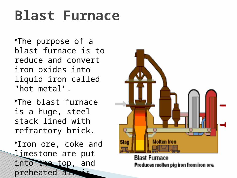
•The purpose of a blast furnace is to reduce and convert iron oxides into liquid iron called "hot metal".
•The blast furnace is a huge, steel stack lined with refractory brick.
•Iron ore, coke and limestone are put into the top, and preheated air is blown into the bottom.

Blast Furnace (Constructional features)
A blast furnace has a typical conical shape. The sections from top down are:
Throat, where the burden surface is. The shaft or stack, where the ores are heated and
reduction starts. The bosh parallel or belly and The bosh, where the reduction is completed and
the ores are melted down. The hearth, where the molten material is
collected and is cast via the taphole.


MaterialChemicl Analysis Specification Size Other Properties
Fe 64.0 % min. 10-40 mm
(Lumps) SiO2 2.5 ± 0.5 %
P 0.10 % max. Softening Melting range:
Al2O3 / SiO2 0.88 % max. 1175 - 1540 ˚C
Sinter Fe 50% 5-40 mm
FeO 10%
SiO2 6% RDI: 23 - 25
Al2O3 3%
CaO 14-15 % Softening Melting range:
MgO 4-5% 1330 – 1600 oC
Coke Ash 15-16 % 52 -55 mm CRI: 22 -24 max.
VM 0.3-0.4 % CSR: 60 min.
M 5 ± 0.5 % M40: 80 – 82 %
S 0.5-0.6 % M10: 7.8 – 8.4%
C 75-80 %
Limestone CaO 38% Min. 6-50 mm
SiO2 6.5 ± 0.25 %
MgO 8.5 ± 0.5 %
SPECIFICATIONS OF RAW MATERIALS

MAIN DIMENSIONS OF BLAST FURNACES

UPPER STACK ZONE Reduction of Oxides 3 Fe 2O3 + CO = 2 Fe3O4 + CO2
Fe3O4 + CO = 3FeO + CO2
FeO + CO = Fe + CO2
Decomposition of Hydrates Water - Gas Shift Reaction CO + H2O = CO2 + H2
Carbon Deposition Decomposition of Carbonates MIDDLE STACK ZONE Direct / Indirect Reduction
FeO + CO = Fe + CO 2 CO2 + C = 2CO FeO + C = Fe + CO Gas utilization
Reactions in the Blast Furnace:
< 600°C
600-900°C
900-1100°C
> 1100°C

LOWER STACK ZONE Calcination of Limestone Reduction of Various elements
Reduction of unreduced Iron Reduction of Silicon
Reduction of Mn, P, Zn etc. Formation / melting of slag, final reduction of
FeO
and melting of Fe.
COMBUSTION ZONE Burning and combustion of Coke C + O2 = CO2 + 94450 cal (direct
reduction) CO2 + C = 2CO - 41000 cal (solution loss
reaction) Complete reduction of Iron Oxide
RACEWAY Coke and Hydrocarbons are oxidized Large evolution of heat
HEARTH Saturation of Carbon with Iron Final Reduction of P, Mn,Si and Sulfur .
< 600°C
600-900°C
900-1100°C
> 1100°C

1. Raw Material section(Charging)2. Furnace Section3. Auxillary Section
Main Sections of Blast Furnace:

ORE YARD STOCK HOUSE COKE CHARGING SYSTEM HOIST HOUSE CHARGING OPERATORS CONTROL
ROOM (COCR)
RAW MATERAL SECTION (Charging):

The main responsibility of this section is to receive the raw materials required for the production of Hot Metal from various sources, storing and transporting them to the top of the furnace in time, for the smooth running of the furnace.
Raw material is arriving to the Blast Furnace department
Unloaded in the Ore Trench of Ore Yard. The materials from Ore Trench are transported to
Ore Yard with the help of Ore Bridge Cranes (OBCs) having a span of 76.2 meters.
Approx the following amount of materials can be stored in Ore Yard at a particular time. 1. Fine Ore : 85,000 tonnes2. Iron Ore (Lumps): 1,80,000 tonnes3. Limestone : 40,000 tonnes4. Mn. Ore : 11,000 tonnes5. Quartzite : 3,000 tonnes
ORE YARD
STOCK HOUSE: Feeding materials-> Bunkers Vibro-feeder Screens
Conveyor Belts Weighing hopper Skip Car
COKE CHARGING SYSTEM : Coke from coke bunkers falls on a vibratory screen. BF size coke from the screen collects in a weighing
hopper. The fines below 25 mm size collect in a bottom
bunker from where it is hoisted to top bunker by means of coke breeze skip (Volume 0.5 m3 to 0.75 m3 ).
Top bunker is emptied in every 4th hour into dump cars that carry coke breeze to sintering plants.
For taking charged materials to the Furnace top, two-way skip hoist with 2 skips of useful volume 6.5 m3 for BF# 1,2,3; 10 m3
for BF #4,5,6 and 13 m3 for BF # 7 are provided. The hoist house operates the skip that is driven by two motors
HOIST HOUSE
All the charging activities are monitored from the COCR round the clock. Thus raw materials are transported to the top of the furnace.
CHARGING OPERATORS CONTROL ROOM (COCR)

◦ Top Charging Equipment: ◦ Charging Sequence ◦ Hot Blast Stoves ◦ Auxiliary Fuel Injection ◦ The Cast house◦ Furnace Foreman Control Room
FURNACE SECTION
The hearth bottom, hearth, bosh, belly and the shaft are cooled by means of coolers of various designs.
Steel refractory lined plates protect the walls of the furnace top.
The bigger furnaces are lined with carbon blocks in the hearth and in the periphery of the hearth bottom.

The burden material which reaches to the top of the furnace by skip car is to be distributed into the furnace.
Double bell charging system ,Rotating Charging Unit (RCU) , Paul-Wurth Bell Less Top (BLT) charging system are used in different furnaces.
TOP CHARGING EQUIPMENT
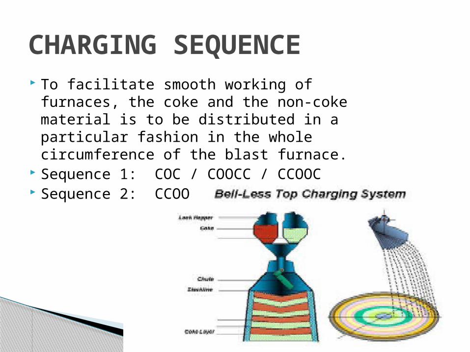
To facilitate smooth working of furnaces, the coke and the non-coke material is to be distributed in a particular fashion in the whole circumference of the blast furnace.
Sequence 1: COC / COOCC / CCOOC Sequence 2: CCOO
CHARGING SEQUENCE

Each stove consists of a combustion chamber and refractory checker brickwork.
There are two cycles in the stove operation. 1. ON GAS: Stove in the heating mode2. ON BLAST: Stove in the blast mode
HOT BLAST STOVES

The fuels used for this purpose are pulverized coal, and coal tar. Economic and operational benefits achieved by using Pulverized Coal Injection (PCI).
Lower consumption of expensive coking coals, extended coke oven life, higher BF productivity, reduced overall emissions, greater flexibility in BF operation are some of the advantages of using this method.
AUXILLARY FUEL INJECTION

The liquid iron and slag collect in the hearth of the furnace, from where they are tapped via the taphole into the cast house and to transport ladles.
The equipments available at the cast house are:1. Drill Machine used for opening the tapping 2. Mud gun used for closing the tapping3. Cast House Crane for material handling during cast house preparation4. Rocking Runner to divert the metal into a different metal ladle5. .Pusher Car used for local placement of the metal ladle
THE CAST HOUSE
FURNACE FOREMAN CONTROL ROOM•All the activities burden distribution, stoves, cast house,
auxiliary fuel injection etc. are controlled from FFCR located in the furnace. LEVEL-0 and LEVEL-1 automation facilities are there in all BF’s. All the details regarding the furnace are monitored using DDCs and mimic panels kept in the FFCR.

Ladle Repair Shop Pig Casting Machine Cold Pig Yard Tap-hole Mass Shop Slag Dump Post
AUXILIARY SECTION

Ladle Repair Shop: There are 3 ladle repair shops provided for relining, repairing and leaning of the iron ladles. Each shop contains an E.O.T. crane (75T) for speeding up the job.
Pig Casting Machine: There are 4 double strand Pig Casting Machines, each having a capacity of 1600 T/day. Each machine contains 308 moulds in one belt with lime coating arrangement underneath the machine. Moulds are filled with the hot metal from the ladle at the spout, cooled by water sprays on the bed while on movement and the pigs are separated from mould chain by knockout arrangement. Each pig weights about 45 kg.
Cold Pig Yard : Cold Pigs from PCM come here. These are stacked according to their quality, and loaded in box wagons for dispatch to stack yards of customers.
Tap Hole Mass Shop: Here, Refractory Mass required for Blast Furnace department is made e.g. Mudgun clay, Tap hole frame mass and Runner Mass etc..
Slag Dump Post: The slag ladles from BF 1,2 &3 and slag coming from BF 4,5 &6 in case of SGP failure is sent to the dump post for emptying the ladles. Provision exists at the dump post for tilting and hammering out the slag with the help of cranes.

FOUNDRY
Foundry is a manufacturing unit where castings
are produced by melting metal and pouring it
into the moulds of desired shape and size.
CASTING
It is a metal forming technique like Forging,
Stamping, Rolling , Pressing etc.
TYPES OF FOUNDRIES:
1. Jobbing Foundry
2. Production Foundry
3. Captive Foundry

FLOW SHEET( Sand Castings)
PATTERN MAKING ( Including core boxes)
SAND PREPARATION MOLDING & CORE MAKING
MELTING
CLEANING ( FETTLING)
INSPECTION AND
QUALITY CONTROL
POURING
FINISHED
CASTINGS

1. PATTERN MAKING
• Patterns are replica of the casting.
• Material :
Deodar wood, teak wood, Aluminum, M.S. plate,
Expanded foam polystyrene ( thermocol), wax
etc.• Types
a. Single or loose patterns
b. Gated patterns
c. Match plate patterns
d. Cope and drag patterns
e. Special patterns and devices

2. SAND PREPARATION
Sand is the principal material for moulding
because of the following qualities.
a. Quite cheap and is available in plenty.
b. It has refractoriness.
c. Can take any shape.
d. Can withstand the pressure of molten metal when mixed
with Bentonite or clay.
e. Does not chemically react with molten metal.
f. Can be reused.

TYPICAL SAND MIXTURE
SAND : 78 – 80%
BENTONITE : 10-12 %
MOLASSES : 2 %
SAW DUST : 1 %
WATER : 7%

NEW SANDSYSTEM
STORAGE
SAND MIXER MOULDERS HOPPERS
MOULD POURING
SHAKE OUT
FINES EXHAUSTER
LUMP BREAKER & SEPARATOR
MAGNETIC SEPARATOR
SCREENING
CASTING
CORE BUTTS DISCARD
METALLIC CHIPS & FINS
CORE LUMPS
SAND CIRCULATION

3. MOULDING & CORE MAKING
• Moulding requires the ramming of sand around
the pattern
• As the sand is packed , it develops strength and
becomes rigid within the flask

FOUNDRY & PATTERN SHOP (BSP)
STEEL NON-FERROUS
CASTINGS :
CAST IRON
RATED CAPACITY6500 TON / Year
RATED CAPACITY79000 TON / Year
RATED CAPACITY500 TON / Year

TYPICAL PRODUCTS
CAST IRON Ingot moulds
Bottom plates/stools, Trumpet,
Track plates, Thimble stand, Dumping bell, Gate carrier top, Inserts, Weight for SLI ,
Door body Door frame Break Blocks for locomotives, etc.
Charging Box,
Twin hearth beams,
Sill plates,
Ladle cover,
Tong
Ladle bush,
L1 &R1 guard,
Wobler coupling,
Coke crusher band,
wear plates
Reheating furnace parts
Sinter crusher guide,
mould bogie plate form
Thimble
STEEL
NON FERROUS
Aluminium shots/cubes, Various types of Bushes, Slide Blocks, Liners, Copper tuyeres, Copper coolersMonkeys,, Leading Nuts and Body covers Mud gun nut, Screw Down Nut, etc.
SMS-I
Steel Melting Sop - 1 (SMS-1) follows the conventional route of steel making in which steel is produced through Twin Hearth furnaces and cast into ingot moulds. The ingots are stripped off from the ingot moulds and are sent to BBM for further heating and rolling into blooms.

SMS-I comprises of various sections for melting, casting & stripping of 2.5 MT ingots annually. The main sections are:
1. Mixer2. Stock Yard3. Furnace4. Pit side5. Mould Yard6. Stripper Yard


FURNACE
There are at present 4 Twin hearth furnaces of 2 x 250 T capacity. Of these, The furnaces are fixed type with basic lining (magnesite) and basic roof (magnesite -chrome).The technological regime of a Twin Hearth. furnace is based on equal duration for both "Solid" and "Liquid" periods of a heat in both hearths.
The major operations during Solid period are : 1. Tapping and fettling2. Charging3. Heating and sill making4. Hot metal pouring.
The major operations during Liquid period are :1. Melting2. Refining 3.Holding.


PIT SIDE
It is an important area of multifarious activities. All the pit side activities can be divided into two groups i.e. major activities and supportive activities. Major Activities 1. Launder making and timely supply to furnace.2. Providing thimbles for flushing & tapping.3. Providing ladles for tapping.4. Teeming of steel into ingots as per steel grade.Supportive Activities1. Dismantling of ladles.2. Relining of ladles.3. Heating of ladles.4. Mech. repair of Ladles, Launders, thimbles etc.5. House keeping & cleaning6. Disaster Management.

There are two mould yards attached to SMS-I. Function-wise they are similar.
The main objective of mould yards are:i) Preparing & supplying mould train to pit side.ii) Receiving moulds on cooling plates after stripping.iii) Receiving bottom stool trains after charging of ingots in the soaking pits.
MOULD YARD

THANK YOU