vmirror sm8x4 user guide 1.31 - vicom systemsvicom.com/pdf/vmirror_sm8x4_user_guide.pdf · document...
TRANSCRIPT

Page 1 of 32
Vmirror SM8x4 Appliance User Guide

Page 2 of 32
Copyright © 2012, Vicom Systems, Inc. All rights reserved. Under the copyright laws, this manual may not be copied, in whole or in part, without the written consent of Vicom. Your rights to the software are governed by the accompanying software license agreement. Vicom Systems and the Vicom logo are trademarks of Vicom Systems, Inc. Other company and product names mentioned herein are trademarks of their respective companies. Mention of third-party products is for informational purposes only and constitutes neither an endorsement nor a recommendation. Vicom assumes no responsibility with regard to the performance or use of these products. Every effort has been made to ensure that the information in this manual is accurate. However, Vicom is not responsible for any printing or clerical errors. Specifications are subject to change without notice. Vmirror SM8x4 Appliance User Guide Version Number: 1.31 Document Number: 908-033012 Publication Date: 5/9/2012
Page 3 of 32
Table of Contents 1 Introducing Vicom Vmirror SM8x4 Appliance ................................................. 5
1.1 What it is ...................................................................................................... 5 1.2 What it does ................................................................................................. 5 1.3 Features & Benefits ..................................................................................... 5
2 Functional Description ...................................................................................... 6 2.1 Key Deployment Concepts ......................................................................... 6
2.1.1 Module Connections ........................................................................................................ 6 2.1.2 VME Cluster Data Synchronization ................................................................................. 6 2.1.3 Server Perception ............................................................................................................ 6
2.2 Read/Write I/O Flow ..................................................................................... 7 2.3 Rebuilding a Mirror ..................................................................................... 7 2.4 Product Scaling ........................................................................................... 8 2.5 Multi-site configuration ............................................................................... 9
3 Vmirror Hardware ............................................................................................ 11 3.1 Overview .................................................................................................... 11 3.2 Vmirror Appliance Components .............................................................. 11
4 Installing an Appliance in a Rack ................................................................... 12 4.1 Preparing to Install Your Appliance ........................................................ 12
4.1.1 Guidelines for Appliance Installation .............................................................................. 12 4.1.2 Choose the Appliance’s Position in the Rack ................................................................ 12 4.1.3 Electrical Power ............................................................................................................. 13 4.1.4 Operating Environment .................................................................................................. 13 4.1.5 Rack Stability ................................................................................................................. 13 4.1.6 Considerations for Cables ............................................................................................. 14
4.2 Installing the Vmirror Appliance .............................................................. 14 4.2.1 Get Ready to Install ....................................................................................................... 14 4.2.2 Install the Vmirror Appliance in the Rack ....................................................................... 14 4.2.3 Connect Cables to the Vmirror Appliance ...................................................................... 15
5 Configuring the ................................................................................................ 17 5.1 Installation Overview ................................................................................ 17
5.1.1 Installation plan .............................................................................................................. 17 5.1.2 VME Virtualization ......................................................................................................... 17 5.1.3 Using VME for Storage Migration .................................................................................. 17 5.1.4 Backup data before VME installation ............................................................................. 17 5.1.5 Storage Configuration .................................................................................................... 17
5.2 VME Configuration .................................................................................... 18 5.2.1 Setting up communication to the VME ........................................................................... 18 5.2.2 Setting the Engine IP Addresses ................................................................................... 18
Page 4 of 32
5.2.3 Storage side Cabling, Zoning, and Configuration .......................................................... 19 5.2.4 Host Side Cabling, Zoning, and Configuration ............................................................... 23
5.3 Host bring-up ............................................................................................. 25 5.4 Creation of Mirrors .................................................................................... 25
6 System Management ....................................................................................... 27 6.1 Firmware Upgrade ..................................................................................... 27
7 Specifications .................................................................................................. 28 8 Support ............................................................................................................. 30 9 Communications Regulation Information ..................................................... 31

Page 5 of 32
1 INTRODUCING VICOM VMIRROR SM8X4 APPLIANCE Congratulations on purchasing your Vmirror SM8x4 Appliance. This Fibre Channel, fabric-based appliance is intended to improve both performance and reliability in high-volume data storage and delivery systems.
1.1 What it is
Vmirror SM8x4 is a Fibre Channel appliance that transparently routes and mirrors data from host systems to Fibre Channel storage systems at Fibre Channel line speed. The architecture is highly scalable: the appliance operates in single-engine configurations for continuous data protection and in dual-engine clusters for high availability with no single point of failure. A single 1U appliance chassis can house either one or two engine modules.
It is available in two models:
• SM8x4-1: 8Gb/s single-engine appliance
• SM8x4-2: 8Gb/s dual-engine appliance
1.2 What it does
To provide both continuous data protection and access, the SM8x4 appliance mirrors pairs of physical storage volumes and presents each pair to connected host systems as a single, unbreakable LUN. Each volume making up the mirror holds an identical, block-for-block copy of the data in the other.
A Vicom Vmirror appliance improves both reliability and performance. Reliability is improved because the host systems’ data as well as data access is protected against the failure or unavailability of either physical volume. This protection is effectively instantaneous, and is completely transparent to the host systems. To maintain the absolute data synchronization, writes commands are safeguarded to complete the data writing onto both mirrored members. To improve the throughput performance, Read commands are allowed to select the data reading from either mirrored members.
All management is centralized on the appliance and other than the management software; there is no host software to install.
1.3 Features & Benefits
• Synchronous mirroring ensures full data integrity
• Clustering of up to 4 engines ensures continuous data access of engine failure
• Instantaneous and automatic failover of mirrors as well as engines
• Redundant dual power inputs and supplies
• No software agents or drivers on hosts
• No format or data changes on mirrored LUNs (no proprietary signatures)
• Modular implementation with single-point-of-control
• Scalable throughput increases linearly as more engines are added
• User data is moved at wire speed without host CPU assistance
Page 6 of 32
2 FUNCTIONAL DESCRIPTION
2.1 Key Deployment Concepts
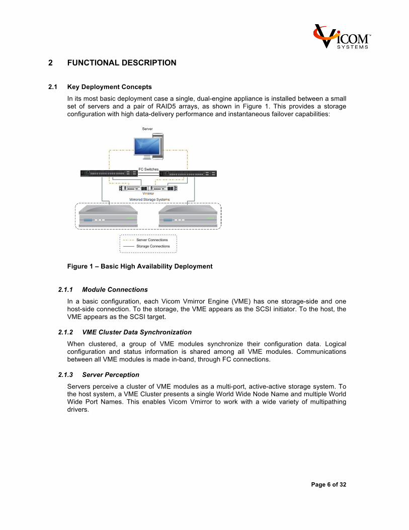
In its most basic deployment case a single, dual-engine appliance is installed between a small set of servers and a pair of RAID5 arrays, as shown in Figure 1. This provides a storage configuration with high data-delivery performance and instantaneous failover capabilities:
Figure 1 – Basic High Availability Deployment
2.1.1 Module Connections
In a basic configuration, each Vicom Vmirror Engine (VME) has one storage-side and one host-side connection. To the storage, the VME appears as the SCSI initiator. To the host, the VME appears as the SCSI target.
2.1.2 VME Cluster Data Synchronization
When clustered, a group of VME modules synchronize their configuration data. Logical configuration and status information is shared among all VME modules. Communications between all VME modules is made in-band, through FC connections.
2.1.3 Server Perception
Servers perceive a cluster of VME modules as a multi-port, active-active storage system. To the host system, a VME Cluster presents a single World Wide Node Name and multiple World Wide Port Names. This enables Vicom Vmirror to work with a wide variety of multipathing drivers.
Page 7 of 32
2.2 Read/Write I/O Flow
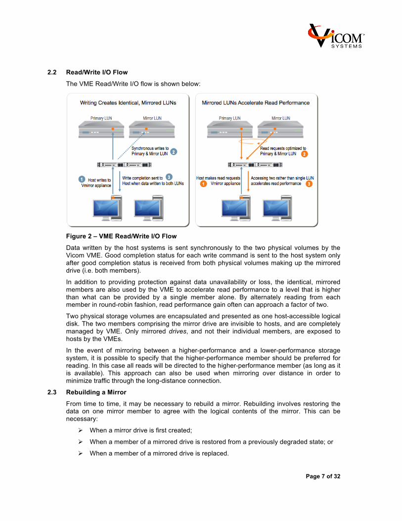
The VME Read/Write I/O flow is shown below:
Figure 2 – VME Read/Write I/O Flow
Data written by the host systems is sent synchronously to the two physical volumes by the Vicom VME. Good completion status for each write command is sent to the host system only after good completion status is received from both physical volumes making up the mirrored drive (i.e. both members).
In addition to providing protection against data unavailability or loss, the identical, mirrored members are also used by the VME to accelerate read performance to a level that is higher than what can be provided by a single member alone. By alternately reading from each member in round-robin fashion, read performance gain often can approach a factor of two.
Two physical storage volumes are encapsulated and presented as one host-accessible logical disk. The two members comprising the mirror drive are invisible to hosts, and are completely managed by VME. Only mirrored drives, and not their individual members, are exposed to hosts by the VMEs.
In the event of mirroring between a higher-performance and a lower-performance storage system, it is possible to specify that the higher-performance member should be preferred for reading. In this case all reads will be directed to the higher-performance member (as long as it is available). This approach can also be used when mirroring over distance in order to minimize traffic through the long-distance connection.
2.3 Rebuilding a Mirror
From time to time, it may be necessary to rebuild a mirror. Rebuilding involves restoring the data on one mirror member to agree with the logical contents of the mirror. This can be necessary:
Ø When a mirror drive is first created;
Ø When a member of a mirrored drive is restored from a previously degraded state; or
Ø When a member of a mirrored drive is replaced.
Page 8 of 32
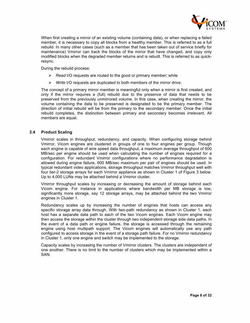
When first creating a mirror of an existing volume (containing data), or when replacing a failed member, it is necessary to copy all blocks from a healthy member. This is referred to as a full rebuild. In many other cases (such as a member that has been taken out of service briefly for maintenance) Vmirror can track the blocks of the mirror that have changed, and copy only modified blocks when the degraded member returns and is rebuilt. This is referred to as quick-resync.
During the rebuild process:
Ø Read I/O requests are routed to the good or primary member; while
Ø Write I/O requests are duplicated to both members of the mirror drive.
The concept of a primary mirror member is meaningful only when a mirror is first created, and only if the mirror requires a (full) rebuild due to the presence of data that needs to be preserved from the previously unmirrored volume. In this case, when creating the mirror, the volume containing the data to be preserved is designated to be the primary member. The direction of initial rebuild will be from the primary to the secondary member. Once the initial rebuild completes, the distinction between primary and secondary becomes irrelevant. All members are equal.
2.4 Product Scaling
Vmirror scales in throughput, redundancy, and capacity. When configuring storage behind Vmirror, Vicom engines are clustered in groups of one to four engines per group. Though each engine is capable of wire speed data throughput, a maximum average throughput of 600 MB/sec per engine should be used when calculating the number of engines required for a configuration. For redundant Vmirror configurations where no performance degradation is allowed during engine failure, 600 MB/sec maximum per pair of engines should be used. In typical redundant video applications, storage throughput matches Vmirror throughput well with four tier-2 storage arrays for each Vmirror appliance as shown in Cluster 1 of Figure 3 below. Up to 4,000 LUNs may be attached behind a Vmirror cluster.
Vmirror throughput scales by increasing or decreasing the amount of storage behind each Vicom engine. For instance in applications where bandwidth per MB storage is low, significantly more storage, say 12 storage arrays, may be attached behind the two Vmirror engines in Cluster 1.
Redundancy scales up by increasing the number of engines that hosts can access any specific storage array data through. With two-path redundancy as shown in Cluster 1, each host has a separate data path to each of the two Vicom engines. Each Vicom engine may then access the storage within the cluster through two independent storage side data paths. In the event of a data path or engine failure, the storage is accessed through the remaining engine using host multipath support. The Vicom engines will automatically use any path configured to access storage in the event of a storage path failure. For no Vmirror redundancy in Cluster 1, only one engine and switch may be implemented to the storage.
Capacity scales by increasing the number of Vmirror clusters. The clusters are independent of one another. There is no limit to the number of clusters which may be implemented within a SAN.

Page 9 of 32
Figure 3: Two-Cluster Diagram
2.5 Multi-site configuration
The module architechtue of Vmirror and industry standard switches provides the capability to expand the SAN and storage across multiple sites. This is useful for applications where operations must continue through single-site-failure events, such as power outage or fire.
The Figure 4 below shows an active-active multi-site configuration. Switch ISLs (Inter Switch Links) expand the SAN across two locations. The mirrored storage arrays are then located at the two sites. Due to the synchronous design of Vmirror, site-to-site communication latency should be low. Typical switch fibre ISL connections support up to 10KM distance with low latency. Refer to your switch manufacturer for details.
Figure 4: Multi-Site Configuration

Page 10 of 32
In this configuration, each host has access to at least two Vicom engines through two independent paths and each engine has access to storage though two independent paths. Due to the modular nature of Vmirror, multi-site configurations can vary depending on system requirements. Please contact your VAR or Vicom for additional configuration support.
Page 11 of 32
3 VMIRROR HARDWARE
3.1 Overview
The Vicom VME is designed for optimized data movement. The VMEs’ Fibre Channel controllers can simultaneously transmit and receive data at wire speed, without CPU assistance. High-speed processors, memory and bus architectures are used internally throughout to further reduce processing latency.
3.2 Vmirror Appliance Components
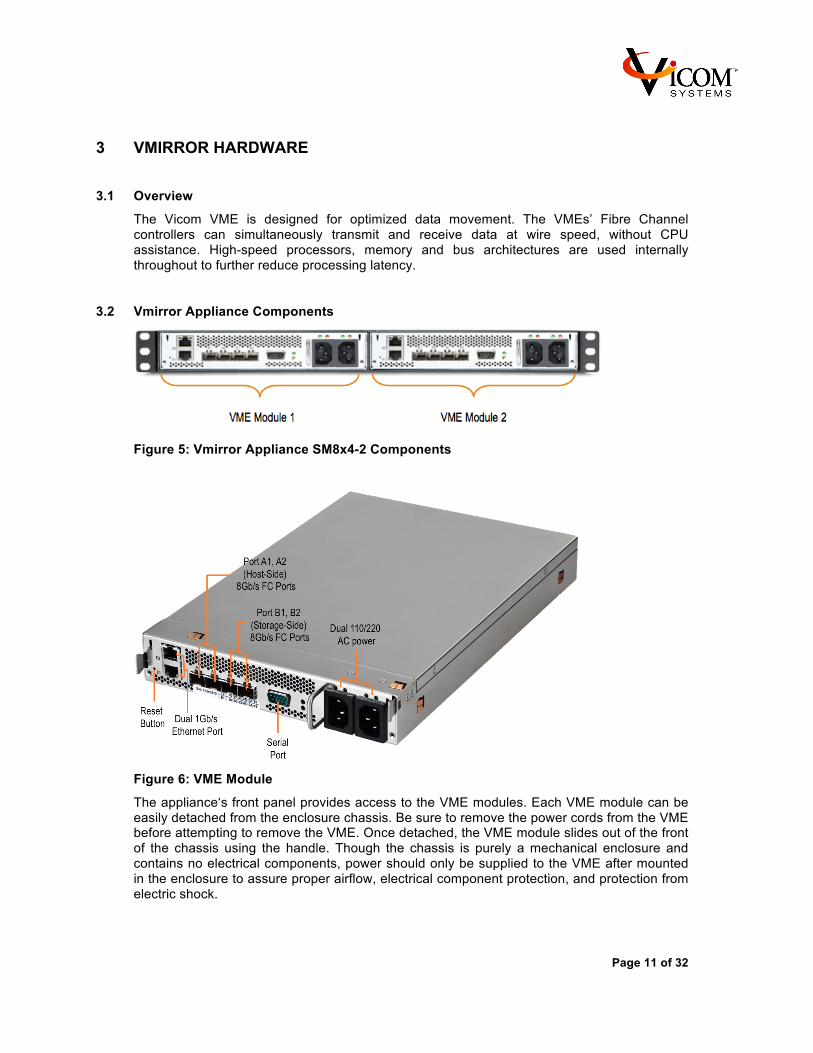
Figure 5: Vmirror Appliance SM8x4-2 Components
Figure 6: VME Module
The appliance‘s front panel provides access to the VME modules. Each VME module can be easily detached from the enclosure chassis. Be sure to remove the power cords from the VME before attempting to remove the VME. Once detached, the VME module slides out of the front of the chassis using the handle. Though the chassis is purely a mechanical enclosure and contains no electrical components, power should only be supplied to the VME after mounted in the enclosure to assure proper airflow, electrical component protection, and protection from electric shock.

Page 12 of 32
The VME contains sensitive electronics that can be damaged by static electricity. When handling the VME be sure to follow proper ESD preventative measures. To prevent any possibility of damage from static electricity, do not touch the electronics directly.
There are no user serviceable parts in the VME. A VME should only be handled on the off chance that it needs to be replaced with another VME.
To replace the VME module, simply slide it into the enclosure chassis. Make sure the VME is fully seated in the chassis.
4 INSTALLING AN APPLIANCE IN A RACK 4.1 Preparing to Install Your Appliance
4.1.1 Guidelines for Appliance Installation
To ensure the proper operation of your Vmirror Appliance, you should use the following guidelines:
Ø Decide on the proper location of the appliance in the rack.
Ø Make sure there is adequate power available for the appliance and all other components in the rack.
Ø Assure the operating environment for the rack meets the requirements given in Chapter 7 specifications.
Ø Be sure to consider each of the following requirements.
o Elevated Operating Ambient - If installed in a closed or multi-unit rack assembly, the operating ambient temperature of the rack environment may be greater than room ambient. Therefore, consideration should be given to installing the equipment in an environment compatible with the maximum ambient temperature (40°C) specified by the manufacturer.
o Reduced Air Flow - Installation of the equipment in a rack should be such that the amount of airflow required for safe operation of the equipment is not compromised.
o Mechanical Loading - Mounting of the equipment in the rack should be such that a hazardous condition is not achieved due to uneven mechanical loading.
o Circuit Overloading - Consideration should be given to the connection of the equipment to the supply circuit and the effect that overloading of the circuits might have on overcurrent protection and supply wiring. Appropriate consideration of equipment nameplate ratings should be used when addressing this concern.
o Reliable Earthing - Reliable earthing of rack-mounted equipment should be maintained. Particular attention should be given to supply connections other than direct connections to the branch circuit (e.g. use of power strips).
4.1.2 Choose the Appliance’s Position in the Rack
When determining the appliance‘s position in the rack, be sure to allow enough room for airflow and access.
The appliance‘s internal cooling fans pull air in through the front panel openings, and blow it out through the rear of the unit. Make sure you do not cover any of the chassis openings, or otherwise impede the airflow path through the unit.

Page 13 of 32
Leave a minimum of 36 inches clearance in front of the rack to permit adequate room to comfortably work when installing or removing entire appliances. If the rack itself will be moved before trying to install or remove an appliance, then the front clearance may be reduced to whatever is considered reasonable.
To avoid damaging the cables and connectors, do not attempt to remove VME modules from the chassis while cables are connected to them.
Unplug power cords before removing a VME module from the chassis.
4.1.3 Electrical Power
If you plan to install the Vmirror Appliance in a rack that contains other components, be sure that the available power connections are sufficient for the combined power needs of all components. To plan for safe and adequate power to the Vmirror Appliance, follow these guidelines:
Ø Check the documentation for all components in the rack to determine their power requirements.
Ø Make sure that the available power supply for the rack is sufficient for the planned components. It is important to make sure that you have more power available than the combined power requirements of all the components in the rack.
Ø Make sure the power load is distributed evenly among the circuits in the rack‘s location. Consult an electrician or other expert if you need assistance with planning for the power needs of your components.
Ø If you need assistance in determining the power needs of the components in the rack, consult an electrical expert who is familiar with your facility.
Ø Make sure that the power connections for the Vmirror Appliance and all other components are grounded (according to local and national standards). Consult an electrician if you need assistance with grounding.
4.1.4 Operating Environment
The operating environment for the Vmirror Appliance‘s rack must meet certain requirements:
Verify that the temperature range of the rack‘s location is within the limits established for the Vmirror Appliance and all other components.
Make certain that the rack‘s location has adequate ventilation to maintain the necessary temperature range. This is particularly important for a rack that is enclosed in a cabinet, or in a data center where there are multiple racks in close proximity.
If multiple components are installed in the rack, consider additional cooling to ensure efficient operation of the Vmirror Appliance and other equipment.
4.1.5 Rack Stability
The rack must be stable and strong enough to hold all the installed components.
Ø Check the documentation for the rack to make certain that it can carry the combined load of all the components.
Ø Make certain that all components are properly secured in the rack.
Ø When working with components in the rack, never slide out more than one unit at a time.
Page 14 of 32
4.1.6 Considerations for Cables
For optimal efficiency in server operation and maintenance, follow these guidelines for handling cables connected to the Vmirror Appliance and other components in a rack:
Ø Arrange all component cables so that they do not interfere with access to the rack. Ideally each component should have a cable-management option in place so that anyone servicing units in the rack can readily determine where each cable is connected.
Ø To ensure full signal strength for Ethernet, serial, and other connections, make sure cables do not exceed established length limits.
Ø Remember to unplug power cord and disconnect any affected cables from the Vmirror Appliance before removing a VME module from the chassis.
4.2 Installing the Vmirror Appliance
The Vmirror Appliance is designed for standard 19” rack mounting. It is not designed for use as a desktop unit.
The Vmirror Appliance is 1.75 inches (1U) high.
Note: Any rack used for the Vmirror Appliance should meet the specifications of the American National Standards Institute (ANSI)/Electronic Industries Association (EIA) standard ANSI/EIA-310-D-92, International Electrotechnical Commission (IEC) 297, and Deutsche Industrie Norm (DIN) 41494. See the rack’s documentation to determine whether it is compatible with these standards.
The brackets and screws necessary to attach the Vmirror Appliance to any of these racks are included with your unit. You need to supply medium-sized flat blade screwdriver for the installation.
4.2.1 Get Ready to Install
As noted above, you should install the Vmirror Appliance in a four-post rack. Mounting instructions are given below. Preparations for mounting are the same, regardless of which type of four-post rack (open-frame or cabinet-enclosed) you use.
Note: Check the rack’s documentation for any special instructions or guidelines you should follow.
Before beginning work with the Vmirror Appliance and rack, make the following preparations.
Ø If possible, arrange to work with another person as you prepare the appliance and install it in a rack.
Ø Gather the tools, brackets, and connectors you‘ll need for the installation. (Everything except the screwdriver is provided with the appliance.)
Ø A medium-sized flat blade screwdriver.
Ø To mount the appliance, you’ll use the two mounting brackets built in with the unit and four thumb style rack attachment screws.
Note: Check the documentation for your rack and use the appropriate set of screws. If screws are provided with your rack, you can use those as well.
4.2.2 Install the Vmirror Appliance in the Rack
Follow these steps to prepare the Vmirror Appliance for installation.
1. Unpack the contents of Vmirror Appliance package.

Page 15 of 32
2. Locate the Clip Style retainer nuts, Thumb Style rack screws and plastic washers. There are:
a. Four (4) pieces of size 10-32 Clip Style Retainer Nuts and
b. Four (4) sets of size 10-32 Thumb Style Rack Screws and plastic washers.
3. Position the appliance to the rack to determine the rack mounting holes to be used. Take note that the corner mounting holes of the appliance will be used in installing the appliance to the rack.
Figure 7 – Appliance Mounting Holes
4. If the mounting holes of the rack are not size 10-32, attach the four (4) pieces of Clip Style retainer nuts to the mounting holes of the rack.
Figure 8 – Attachment of Clip Style Retainer Nuts to the Rack.
5. Mount the appliance to the rack using the four (4) sets of Thumb Style Rack Screws and plastic washers.
Figure 9 – Mounted Vmirror Appliance
4.2.3 Connect Cables to the Vmirror Appliance
Once the Vmirror Appliance is secured in the rack, you can connect the cables and power cord directly to its front panel. Follow these steps to connect cables for host, storage, management and power directly to the appliance.
1. Gather the cables and devices you will connect to the appliance‘s front panel. Make certain that each cable has the proper connector and that it is designed for
Page 16 of 32
use in the storage network topology you are deploying the appliance to. (Check the documentation for each device or cable to determine that it can be used with the appliance and storage network.)
2. Label each cable so that you can locate a specific cable quickly and avoid errors when disconnecting cables.
3. Beginning at one side of the appliance’s front panel, connect each cable to the appropriate port.
4. When all cables are in place, connect each one to its intended device.
5. Connect the power cord(s) to the front panel power supply connectors.
6. If more than one type of power cord came with your appliance, use the cord appropriate for the electrical service available at your location.
7. After all connections are complete, plug the power cord(s) into a power source.
8. With the appliance in the rack and the cables in place, you can prepare to set up the VMEs.
Page 17 of 32
5 CONFIGURING THE VME 5.1 Installation Overview
5.1.1 Installation plan
Before configuring the VME into a storage environment, it is recommended to review the installation procedures and generate an installation document, which includes alias names for devices and ports, device IP address, FC port WWNNs, an installation plan, and a configuration diagram. Since configurations vary, this users guide attempts to cover only the most common installation scenarios. For installation with critical operational storage already on-line, the plan may require two passes through the procedure, first to configure all equipment that is not involved with current production, then to insert the VME and configure the remaining equipment. An installation document provides for more focus on product configuration during the configuration of the system, which speeds up the configuration process, reduces potential configuration mistakes and reduces system downtime.
As a service to you, at no charge, Vicom or a trained Vicom partner will discuss, review and comment on VME installation plans submitted to [email protected].
5.1.2 VME Virtualization
VME virtualization allows FC LUNs to be pooled together and carved into user specified LUN sizes. Unless VME virtualization is required, VME virtualization should not be used as it adds unnecessary complexity to the configuration. Since most modern storage arrays provide this capability, it is best to implement the LUN virtualization within the storage array and not within the Vmirror. When virtualization is not used, the VME presents the storage array data as is, bit for bit, to the host systems.
5.1.3 Using VME for Storage Migration
The VME may be used to migrate data between mirrored LUNs from old to new storage. After a Vmirror data migration, LUN sizes and data configuration will be identical across the source and target LUNs. VME cannot be used if the user plans to change LUN size or location of data on disks during a data migration. Such a migration should be performed by other means before implementing VME to reduce the complexity of installation. Once the data is migrated, configured and operates as desired, the VME and mirrored storage can be easily installed and synchronized.
5.1.4 Backup data before VME installation
Before installing VME, assure that all data is archived and can be restored in the event of a storage or configuration failure.
5.1.5 Storage Configuration
The VME works at the FC storage block level and is unaware of any host file system information. This allows for mirroring of any host FC data without the need for special VME configuration requirements.
When creating mirrored LUNs, the members should be of similar or same size. If members are of different sizes, the VME will create a mirror LUN with capacity equal to the smallest member. Assure that new mirror members are equal to or larger than the existing LUNs, when creating members for LUNs that already have data.
Mirrored LUN members should be located on different storage arrays so that if a storage array goes off-line, data will remain accessible from the remaining member. It is also important data that requires low latency access such as metadata, not be placed on storage arrays or
Page 18 of 32
volumes that contain long IO transfers or are heavily accessed. If possible, place metadata on separate storage arrays as application data.
For many storage arrays, access to a LUN through two different controllers within an array reduces performance. For LUNs mirrored by VME, assign access to a single LUN member through only one controller.
For any new storage array that will be mirrored to an existing array, create LUN members on the new storage array to match the existing storage array. LUNs that do not have mirrored members may still be accessed through VME as single member mirrors.
For mirrored members spanning multiple new storage arrays, create LUN members on both storage arrays.
5.2 VME Configuration
This section describes configuration between the VME and storage attached behind the VME.
5.2.1 Setting up communication to the VME
The VME command line interface, CLI, is used to configure the VME and is accessed through VME Ethernet port E1. Once VME access is established entering “help” will list available commands. For command specific information, for example to obtain details for the command mirror, enter “help mirror”.
NOTE: Ethernet port E2 is used only for manufacturing diagnostics. It is not used in normal operation mode.
5.2.2 Setting the Engine IP Addresses
For access to the VME CLI, the IP addresses of the engine must be changed from the factory default (10.10.10.1) to unique addresses supported on the network. All engines require access to the Ethernet network for configuration purpose, since commands such as Cluster-Engine requires Ethernet access to all engines in the cluster. Setting of engine IP addresses is provided below.
NOTE: Assure that you save the new Ethernet address information in a secure location, since access to the VME terminal window is difficult without knowledge of the address. If you have misplaced programmed Ethernet address, contact [email protected] for help to recover programmed address from the engines.
1. Connect a console terminal to the engine using a standard Cat-5 Ethernet cable. Refer to Figure 6 to locate the module‘s Ethernet port connector.
2. Assure that only one engine with default setting is attached to the Ethernet connection or network at a time since all new engines have the same Ethernet address and all Ethernet devices on a network must have unique address.
3. Open a Telnet session on the console terminal by connecting to the VMEs default IP address: 10.10.10.1 If the address is not supported on the network, connect the console terminal directly to the Ethernet port.
4. Upon successfully establishing a Telnet session, you will be prompted for a login password.
5. With a new VME, there is no password pre-loaded. Simply press Enter to continue.
6. The VME presents a menu of operational settings options. Select Option 6 – View/Change Interface Configuration.
7. At the resulting prompt, select E = Ethernet.
8. Follow the prompts to enter the following information:

Page 19 of 32
Ø The new IP Address for the engine.
Ø The Subnet Mask used on the network segment.
Ø The Gateway Address of the network switch.
9. Once the parameters have been entered, press Enter to accept the changes and exit the utility. The engine automatically reboots, updating its address information.
10. Repeat this procedure for all engines using unique addresses.
5.2.3 Storage side Cabling, Zoning, and Configuration
For configurations where existing storage used in production is configured with new storage, it may be best to perform the setup of VME and storage in two passes, once implementing only new equipment so that production is not disrupted, and a second time requiring a production shutdown to integrate remaining production equipment. One to four engines may be clustered together to provide storage data path redundancy. If any engine fails, host multi-path software will continue to access storage through remaining engines. Single-engine clusters provide storage mirroring with no multi-path redundancy. Dual-engine clusters provide the benefit of data access through two redundant VMEs. 4-engine clusters are used in dual site configurations so that host IOs are not required to traverse across locations twice. The VME B1 and B2 ports are used to connect to storage side switches. To maintain access between engines and storage, assure that redundant data paths and switches are provided between each engine and all storage within the cluster; see Figure 10. In the diagram, LUNs are assigned to multiple ports of only one storage array’s controller. The LUN may be accessed through either switch A or switch B. Each engine port accesses the mirrored LUN through one of the switches. In the event of a switch or VME failure, host multipath software will continue to access storage through the remaining VME/switch. The engines use the storage FC network to communicate amongst themselves through the B1 and B2 ports. In Figure 10 the ISL link is used to create the communication link between VME storage B ports and must be zoned together for this communication.

Page 20 of 32
Figure 10: Engine to Storage Connection
When both the B1 and B2 ports are used, one of two configurations may be implemented, the isolated fabric or the non-isolated fabric configuration. See figure Figure 11 for an isolated fabric configuration example and Figure 12 for a non-isolated fabric configuration example.
Figure 11: Isolated fabrics, No ISL required between switches, Recommended
Configuration
Figure 12: Non-isolated fabric spans switches: ISL required for VME communications
For an isolated fabric, switches are not shared between the two fabrics and do not require ISL connections. This is the recommended configuration as it reduces switch port count required and provides a more robust failure protection since removal of a switch will not affect the redundant switch in any way. In the non-isolated case, switches are shared between fabrics and require ISL connections. This configuration is easiest to upgrade from a configuration where only the B1 ports are used. In the example configuration, if only the B1 ports were used then only zones 1 would be implemented. Zones 2 is added when the B2 ports are included. In the case where the solution is implemented using a blade switch, switch 1 and 2 designate redundant blades.

Page 21 of 32
Figure 13: Isolated Fabric Storage Cluster Configuration
The following is a list of guidelines when cabling and configuring the VME, switch and storage. Please refer to Figure 13 below of an example isolated storage cluster configuration implementation of the guidelines.
1. Label cabling so that that cables are easily recognized
2. Always locate mirrored storage members on different storage arrays
(LUNs 1A and 1B are mirrored and located on different storage arrays)
3. Map any mirrored member to only one controller within the storage array (LUNs 2A and 3A are mapped to ports 1 and 2 of only controller 2, not controller 1)
4. Assure that any LUN is connected through two redundant switch hardware paths to two redundant VMEs. (All LUNs connect through both switch 1 and switch 2 to both VME 1 and VME 2. Switch 1 and switch 2 represent redundant switch hardware)
5. For isolated fabric create a zone such that storage controller port 1 and VME port B1 go to switch/fabric 1. All storage controller port 2 and VME port B2 go to switch/fabric 2: Zone 1 within switch 1 includes:

Page 22 of 32
• engine 1 port B1 • engine 2 port B1 • port 1 of all storage controllers Zone 2 within switch 2 includes: • engine 1 port B2 • engine 2 port B2 • port 2 of all storage controllers
The following is the procedure for configuring the VME engines:
1. Cable storage, VME, and switches as described in the guidelines provided above 2. Power on switches, then storage, then engines 3. Open switch GUI 4. Verify that all switch ports are attached to correct devices referencing FC addresses
displayed in the switch GUI 5. Disable I/O stream guard for all switch ports connected to storage or engine ports 6. Set switch port bandwidth for ports attached to storage and engines to match device.
For ports attached to SM8x4 set to 8 Gb/sec. 7. Create switch zone configurations as described in the guidelines provided above 8. Telnet to engine 1 and type 7 to go to the engine CLI.
Issue “explore B1” to verify that the engine sees devices expected from B1 port. (In the Figure 13 example, the port should see 8 storage controllers, all port 1’s, 10 LUNs and the other engine’s B1 port.)
9. Repeat for all storage side engine ports cabled
Note: If on-line production storage is used, for the first pass it is best to generate the storage integration plan and move to host side setup. This way any host side configuration not involving production hardware may be configured before issuing production shutdown.
10. Power off all secondary storage members so that only one copy of the mirrors is
active. For configurations where production data resides on the storage, the primary storage members are the existing storage LUNs containing all production data. Assure that these primary members are configured first and the secondary members containing no production data are powered off. At a later stage the secondary members will be powered on and Vmirror will automatically synchronize data from primary members to the secondary members. Assure that no secondary member has valuable data since it will be overwritten during the synchronization process. (In the example, storage arrays 2 and 4 would be powered off, 1 and 3 would remain on and defined as the primary members)
11. Issue “explore B1” to engine 1 and assure configuration is as expected. Issue “explore B2” and assure configuration is as expected. If the outputs are as expected, issue “conmgr auto” and then “conmgr write” to register both LUNs and partner engine ports into the engine. Issue “conmgr status” to check if all expected devices are registered in the engine database Repeat above steps for all engines in the cluster
Note: The next steps will create one-way mirrors form the primary members and assign them to all hosts.
Page 23 of 32
12. Only the master engine can create mirror drives. To identify which engine is the
master, telnet to any engine within the cluster and type 7 to go to engine CLI, and then type “dmeprop”
13. Within the master CLI, issue “mirror create 0” to create a single member mirror drive. 14. Issue “mirror” to view the mirror drive information. (Note: the target number for the first
mirror drive is specified on the left side as a 5 digit number) 15. Issue “mirror create 1” to create the second single member mirror drive 16. Continue to create single member mirrors for all drives 17. Issue “mirror” to view mirror drives and log target numbers into installation plan
document 18. From the master engine CLI issue “map auto on” to enable map 0 to all hosts. All
LUNs that are mapped to map 0 will be seen by all hosts attached to the engines. 19. Issue “map auto” to check the status of maps 20. Map single member mirrors to map 0 by issuing map 0 command, for example “map 0
33537 33538” where 33537 and 33538 are example target numbers for a single member drives. Use target numbers that where issued for LUNs you created.
21. Check to assure the correct number of drives were created by issuing “map 0”
5.2.4 Host Side Cabling, Zoning, and Configuration
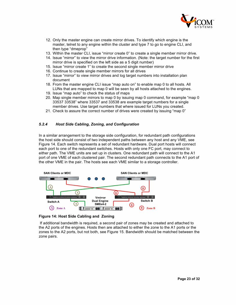
In a similar arrangement to the storage side configuration, for redundant path configurations the host side should consist of two independent paths between any host and any VME, see Figure 14. Each switch represents a set of redundant hardware. Dual port hosts will connect each port to one of the redundant switches. Hosts with only one FC port, may connect to either path. The VME units are set up in clusters. One redundant path will connect to the A1 port of one VME of each clustered pair. The second redundant path connects to the A1 port of the other VME in the pair. The hosts see each VME similar to a storage controller.
Figure 14: Host Side Cabling and Zoning
If additional bandwidth is required, a second pair of zones may be created and attached to the A2 ports of the engines. Hosts then are attached to either the zone to the A1 ports or the zones to the A2 ports, but not both, see Figure 15. Bandwidth should be matched between the zone pairs.
Page 24 of 32
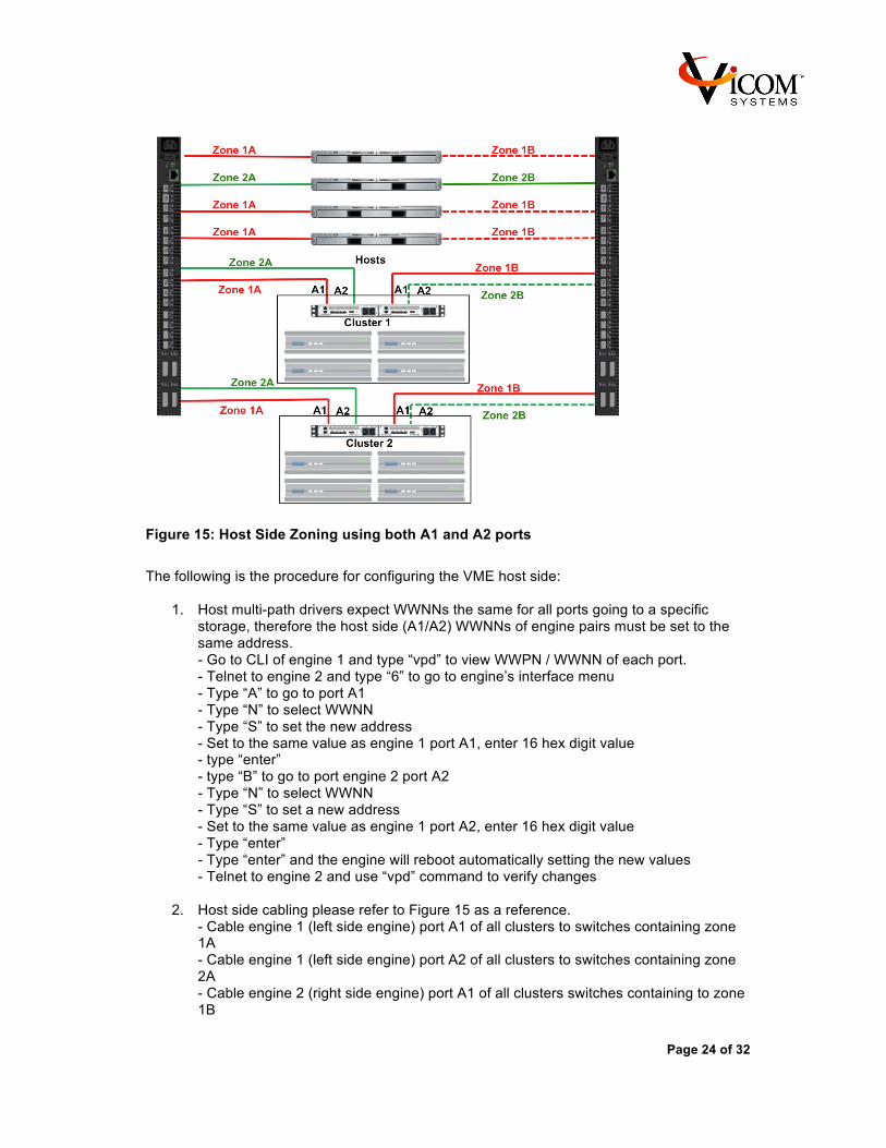
Figure 15: Host Side Zoning using both A1 and A2 ports
The following is the procedure for configuring the VME host side:
1. Host multi-path drivers expect WWNNs the same for all ports going to a specific storage, therefore the host side (A1/A2) WWNNs of engine pairs must be set to the same address. - Go to CLI of engine 1 and type “vpd” to view WWPN / WWNN of each port. - Telnet to engine 2 and type “6” to go to engine’s interface menu - Type “A” to go to port A1 - Type “N” to select WWNN - Type “S” to set the new address - Set to the same value as engine 1 port A1, enter 16 hex digit value - type “enter” - type “B” to go to port engine 2 port A2 - Type “N” to select WWNN - Type “S” to set a new address - Set to the same value as engine 1 port A2, enter 16 hex digit value - Type “enter” - Type “enter” and the engine will reboot automatically setting the new values - Telnet to engine 2 and use “vpd” command to verify changes
2. Host side cabling please refer to Figure 15 as a reference. - Cable engine 1 (left side engine) port A1 of all clusters to switches containing zone 1A - Cable engine 1 (left side engine) port A2 of all clusters to switches containing zone 2A - Cable engine 2 (right side engine) port A1 of all clusters switches containing to zone 1B

Page 25 of 32
- Cable engine 2 (right side engine) port A2 of all clusters switches containing to zone 2B - Open switch GUI and check connections by verifying FC addresses - Set all VME connections to I/O stream guard disabled - Set all connections to match device speed, 8Gb/sec for VM8x4 - Connect all first host ports to either switches containing zone 1A or 2A such that bandwidth is balanced between the two zones. - Connect all second host ports to either switches containing zone 1B or 2B such any specific host is connected to either zones 1A and 1B or zones 2A and 2B - Power on hosts - Open switch GUI and set I/O stream guard to enabled for all host connections - Verify that host connections are correct by verifying host FC addresses - Create zones 1A, 1B, 2A and 2B - telnet to engine 1 in a cluster and type 7 to go to the CLI, issue “explore A1” and verify all host ports mapped to zone 1A are available - repeat the previous step for engine 1 port A2, engine 2 port A1, engine 2 port A2 - Issue “conmgr auto initiator” followed by “conmgr write” to register all initiators into the engine database for engine 1 - Issue “conmgr status” to verify connected devices in the engine 1 - Issue “conmgr auto initiator” followed by “conmgr write” to register all initiators into the engine database for engine 2 - Issue “conmgr status” to verify connected devices in engine 2
5.3 Host bring-up
The LUNs will now be available with one copy for each FC path. Reboot host systems, verify the LUNs are available to the hosts as expected using host utilities and restart applications if application copies primary members included system data. Assure all systems operate as expected. At this point in the configuration, host systems no longer need to be shutdown. The systems may be put back into production though leaving the systems off-line for the remainder of the installation can reduce failures due to configuration errors and speed up the synchronization of mirrors.
5.4 Creation of Mirrors
This section describes the procedure of registering, mirroring and synchronizing the secondary storage members. - Power on secondary storage arrays - Telnet to engine 1 of one cluster - Type “explore B1” to check if the correct storage controller ports are visible from port B1. There should be one port per storage array controller mapped to the B1 zone. - Type “explore B2” to check if the correct storage controller ports are visible from port B2 - Issue “conmgr auto drive add” and then “conmgr write” to register the LUNs resident on the storage array - Issue “conmgr status” to view if LUNs are entered in the engine’s database and to log member target numbers into installation plan - Telnet to engine 2 within the same cluster and repeat above procedure Note: (The next steps of the installation will be adding the secondary member to the one-way mirrors. If the wrong mirror is mapped the mirror pairs will not be

Page 26 of 32
configured as you expect. Assure that you verify IDs carefully before implementing command) - Type “mirror add x y” where y is the target number of the LUN you will be adding and x is the target number (for example 33537) of the mirror will be adding the LUN x to. Repeat the command for all single mirror / LUN member pairs. - Synchronization will begin automatically.

Page 27 of 32
6 SYSTEM MANAGEMENT This section contains procedures used after the system is configured and in production. It is important to implement features such email notifications so that the appropriate individuals are notified in the event of an error condition.
6.1 Firmware Upgrade
The following procedure is used for firmware upgrades. For email notices when firmware updates are available, please send an email to [email protected] specifying “Please add me to Vmirror firmware/technical notices” to be included on the email notification list.
1. Download latest Firmware at ???. Place it in a directory that is easy to access and if compressed, uncompress before moving to the next step.
2. Updating firmware will cause the Vmirror engine to reboot which takes approximately 10-15 seconds. It is highly recommended that you stop all IO intensive applications during firmware upload.
3. ftp 172.16.16.68 (FTP to the engine IP address you wish to update) The system should return that connection is made and that FTP server is ready and request a user name
4. User Login name is: vicomftp 5. For new products there is no password, simply hit enter for password
The system will specify that the user is logged in 6. ftp> bin
Returns: TYPE Command okay 7. ftp> cd mbflash
Returns: CWD requested file action okay, completed. 8. ftp> put fcfc6-15.1.0.bin fwimage
(Assure that you are in the directory where the image resides or the path to the directory is placed before the filename such as: C:\vicom\fcfc6-15.1.0.bin. Filenames may change, assure that the filename that you have downloaded and uncompressed is the same as specified in the command. Returns: PORT command okay. File status okay, about to open data connection. Closing data connection, 1693244 bytes sent in 2.81 seconds, 601.72Kbytes/sec.
9. ftp> bye 10. You have downloaded the firmware, wait 2 minutes for the Vmirror to load firmware
into flash and reboot. 11. Check that the firmware has been uploaded using

Page 28 of 32
7 SPECIFICATIONS
Models SM8x4-1. Single-engine FC appliance SM8x4-2. Dual-engine clustered FC appliance
Fibre Connectivity
ANSI/IS Protocol/Topology Standards: ANSI Fibre Channel (FC-PH, FC-PH-2, FC-PH-3, FC-PLDA, FC-FLA) ANSI Fibre Channel Arbitrated Loop (FC-PLDA, FC-AL, FC-AL-2) ANSI Fibre Channel Fabric (FC-FLA, FC-GS-2) Classes of Service: Class 3
Data Transfer Rate: 2, 4 or 8 Gb/sec
Port Type: N(L)_Port Quad 8Gb Fibre Channel ports (SFP)
Serial Port Connectivity
Protocol: Serial Transmission
Speed: 115200 baud
Connector DB-9
Used Pin Signals 2: Received data (RD) 3: Transmitted data (TD)
Protocol: RS-232
Ethernet Port Connectivity
IEEE 802.3 compliant Protocol: Transmission Control Protocol – Internet Protocol (TCP-IP) Speed:
10/100/1000Base-T Connector
RJ-45 Maximum Cable length
100 meters (m) Compatible Storage Appliance Admin management package, Telnet, FTP
Page 29 of 32
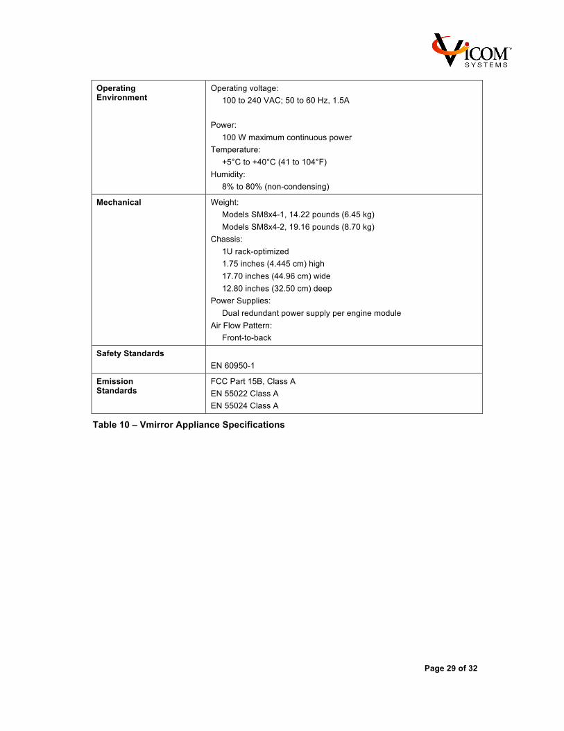
Operating Environment
Operating voltage: 100 to 240 VAC; 50 to 60 Hz, 1.5A
Power: 100 W maximum continuous power
Temperature: +5°C to +40°C (41 to 104°F)
Humidity: 8% to 80% (non-condensing)
Mechanical Weight: Models SM8x4-1, 14.22 pounds (6.45 kg) Models SM8x4-2, 19.16 pounds (8.70 kg)
Chassis: 1U rack-optimized 1.75 inches (4.445 cm) high 17.70 inches (44.96 cm) wide 12.80 inches (32.50 cm) deep
Power Supplies: Dual redundant power supply per engine module
Air Flow Pattern: Front-to-back
Safety Standards EN 60950-1
Emission Standards
FCC Part 15B, Class A EN 55022 Class A EN 55024 Class A
Table 10 – Vmirror Appliance Specifications
Page 30 of 32
8 SUPPORT Vicom Systems Support
You can reach Vicom Systems Support using any of the following methods:
Vicom Systems Support
4800 Great America Parkway, Santa Clara, CA 94054
Phone: (650) 539-4005
Fax: (650) 560-6441
Email: [email protected]
Internet: http://www.vicom.com/support/support_vicom.htm
Page 31 of 32
9 COMMUNICATIONS REGULATION INFORMATION Emission Standards
Ø FCC Part 15, Class A Ø EN 55022 Class A
FCC Part 15, Class A
FCC Compliance Statement
This equipment has been tested and found to comply with the limits for a class A digital device pursuant to Part 15 of the FCC Rules. These limits are designed to provide reasonable protection against harmful interference when the equipment is operated in a commercial environment. This equipment generates, uses, and can radiate radio frequency energy and, if not installed and used in accordance with the manufacturer's instruction manual, may cause harmful interference with radio communications. Operation of this equipment in a residential area is likely to cause harmful interference, in which case you will be required to correct the interference at your own expense. EN 55022 Class A
Warning: This is a Class A product. In a domestic environment this product may cause radio interference, in which case the user may be required to take adequate measures. High-Risk Activities Warning This computer system is not intended for use in the operation of nuclear facilities, aircraft navigation or communications systems, or air traffic control machines, or for any other uses where the failure of the computer system could lead to death, personal injury or severe environmental damage. Battery Disposal Information Dispose of batteries according to your local environmental laws and guidelines. Deutschland Das Gerät enthält Batterien. Diese gehören nicht in den Hausmüll. Sie können verbrauchte Batterien beim Handel oder bei den Kommunen unentgeltlich abgeben. Um Kurzschlüsse zu vermeiden, kleben Sie die Pole der Batterien vorsorglich mit einem Klebestreifen ab. Nederlands Gebruikte batterijen kunnen worden ingeleverd bij de chemokar of in een speciale batterijcontainer voor klein chemisch afval (kca) worden gedeponeerd.

Page 32 of 32