vm-7 monitoring system...turbine supervisory instrument (tsi), the vm-7 monitoring system, supports...
TRANSCRIPT
VM-7 MONITORING SYSTEM
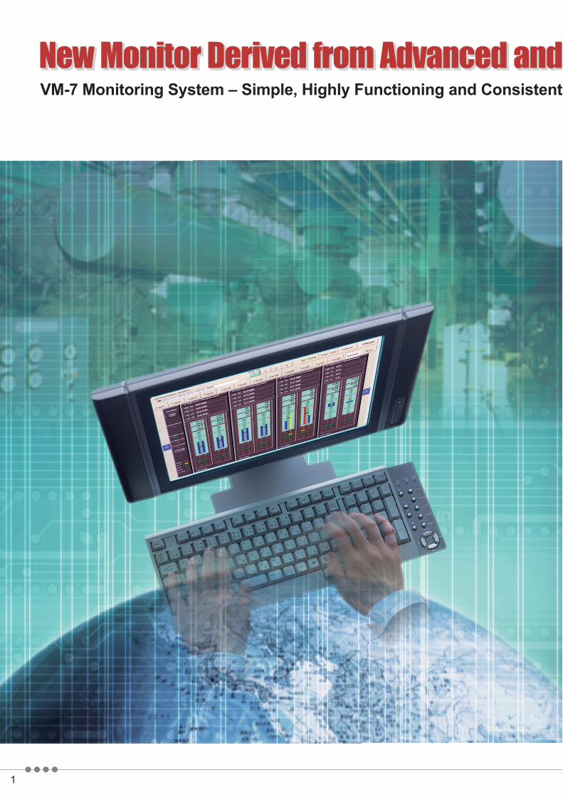
New Monitor Derived from Advanced andNew Monitor Derived from Advanced andNew Monitor Derived from Advanced and
Experienced Sensor TechnologyExperienced Sensor TechnologyExperienced Sensor TechnologyExperienced Sensor Technology
For details of specifications, outline drawings, or model code numbers, go to the Shinkawa Sensor Technology website (http://www.sst-shinkawa.co.jp).
Monitoring System forRotating Machinery
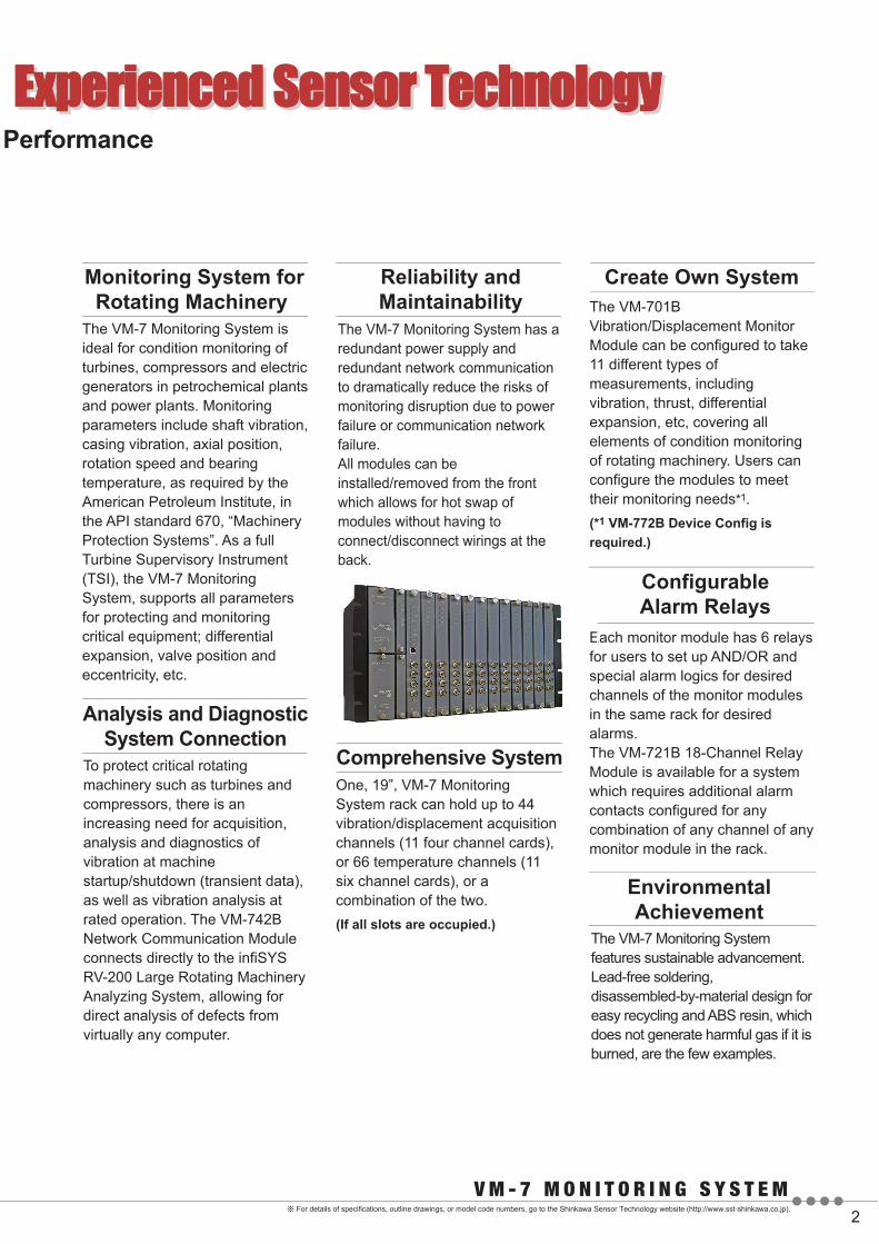
Reliability andMaintainability
The VM-7 Monitoring System is ideal for condition monitoring of turbines, compressors and electric generators in petrochemical plants and power plants. Monitoring parameters include shaft vibration, casing vibration, axial position, rotation speed and bearing temperature, as required by the American Petroleum Institute, in the API standard 670, “Machinery Protection Systems”. As a full Turbine Supervisory Instrument (TSI), the VM-7 Monitoring System, supports all parameters for protecting and monitoring critical equipment; differential expansion, valve position and eccentricity, etc.
Comprehensive SystemOne, 19”, VM-7 Monitoring System rack can hold up to 44 vibration/displacement acquisition channels (11 four channel cards), or 66 temperature channels (11 six channel cards), or a combination of the two. (If all slots are occupied.)
Create Own SystemThe VM-701B Vibration/Displacement Monitor Module can be configured to take 11 different types of measurements, including vibration, thrust, differential expansion, etc, covering all elements of condition monitoring of rotating machinery. Users can configure the modules to meet their monitoring needs*1.(*1 VM-772B Device Config is required.)
Configurable Alarm Relays
Each monitor module has 6 relays for users to set up AND/OR and special alarm logics for desired channels of the monitor modules in the same rack for desired alarms. The VM-721B 18-Channel Relay Module is available for a system which requires additional alarm contacts configured for any combination of any channel of any monitor module in the rack.
EnvironmentalAchievement
The VM-7 Monitoring System features sustainable advancement. Lead-free soldering, disassembled-by-material design for easy recycling and ABS resin, which does not generate harmful gas if it is burned, are the few examples.
Analysis and DiagnosticSystem Connection
To protect critical rotating machinery such as turbines and compressors, there is an increasing need for acquisition, analysis and diagnostics of vibration at machine startup/shutdown (transient data), as well as vibration analysis at rated operation. The VM-742B Network Communication Module connects directly to the infiSYS RV-200 Large Rotating Machinery Analyzing System, allowing for direct analysis of defects from virtually any computer.
The VM-7 Monitoring System has a redundant power supply and redundant network communication to dramatically reduce the risks of monitoring disruption due to power failure or communication network failure.All modules can be installed/removed from the front which allows for hot swap of modules without having to connect/disconnect wirings at the back.
Efoscin

VM-76 B Instrument Rack
VM-75□BPower Supply Module
VM-741BLocal Communication &Phase Marker Module
VM-742BNetworkCommunication Module
VM-701BVibration/DisplacementMonitor Module
VM-721B18-Channel RelayModule
VM-704BTemperature MonitorModule
VM-721B 18-Channel Relay Module
6U, 19 in. 482.6 (W) x 265.9 (H) x 350 (D) mmVM-761B – Features European I/O terminal type.VM-762B*1 – Features D-sub I/O connector type.(*1 Under development)
VM-741B Local Communication & Phase Marker ModuleTransmits data from back communication port to local display PC via dedicated Ethernet to display bar graphs of measured values and alarm status. (Requires VM-771B MCL View installed on display PC.)
Also, communicates with service PC via front USB port for configuration of monitor module.(Requires VM-772B Device Config installed on service PC.)
VM-742B Network Communication ModuleCommunicates data between the VM-7 Monitoring System and DCS, PLC or to most any control systems. It also provides communications direct with the infiSYS View Station for data analysis. For DCS, measured values,
analysis data (0.5X, 1X, 2X, Not-1X)*3 and alarm status are output via Ethernet using Modbus/TCP protocol or RS-485 using Modbus/RTU.For the infiSYS View Station, measured values, analysis data*3 and waveform data*3 are output via dedicated Ethernet.(*3 Available with the optional analysis boards installed on vibration monitor modules.)
VM-75 B Power Supply ModuleRated voltage types: 100-240 VAC, 24 VDC*2 or 110 VDCUp to two power supply modules can be mounted on a rack for redundant power supply.(*2 Under development)
VM-70□B Monitor ModuleReceives input signals from various transducers, including vibration/displacement transducers, acceleration/velocity transducers, thermocouples and RTD, processes them according to the monitoring parameters, and outputs the measured values and alarm contact.
Provides 18 alarm contacts that are independent from monitor modules. Users can program AND/OR or 2 out of 3 logics with any channels of any modules within the rack.
Six alarm relays are available for each monitor module. If the optional analysis board is installed on VM-701B or VM-702B, it performs analysis based on the received phase marker signals (max. 4 channels per rack) and vibration waveform signals (max. 44 channels per rack), and then transmits the analysis data to the infiSYS View Station via VM-742B.Note: For monitoring parameters and the number of channels of each
Monitor Module Monitoring Parameter Numberof Inputs
Numberof Outputs
Input Transducer
FK or VK
FK or VKFK or VKFK or VKFK or VKFK, VK & LS + VM-21
LS + VM-21LS + VM-21
FK or VK & CV (2 systems)
FK, RD or MS
Rotor Speed of CH1
FK or VK
TC or RTD
CVCACV or CA
Displacement VibrationVM-701B Vibration / Displacement Monitor Module
VM-702B Absolute Vibration Monitor Module
VM-704B Temperature Monitor Module
VM-703BTachometer &EccentricityMonitor Module
Thrust PositionDifferential Expansion (Single Input)Ramp Differential ExpansionComplementary Input Differential Expansion
Case Expansion/Complementary ExpansionCase ExpansionValve Position
Shaft Relative Vibration and Shaft AbsoluteVibration or Casing Vibration
Rotor SpeedCH1CH2CH2
CH3
Rotor Acceleration
Eccentricity
Temperature
Velocity VibrationAcceleration VibrationDual Path Vibration
4
4422
344
4*2
2
1
2
6
444
4
4444
344
4*1
2
0
FK, RD or MSCH1 & CH2 Reverse Rotation 221
6
442
FK or VK & RDVM-706B Rod Drop Monitor Module Rod Drop 441 (PM)
*1) 2 sets of 2 inputs for 2 measuring points.*2) 2 sets of 2 outputs for 2 measuring points.

For details of specifications, outline drawings, or model code numbers, go to the Shinkawa Sensor Technology website (http://www.sst-shinkawa.co.jp).
VM-771B MCL View
Bar graph screen(current value display)
Device Config screen
MCL View displays measurement values and other monitoring status of each module. (Software installation is required.)
VM-772B Device ConfigDevice Cofig allows users to configure the monitoring system in or out of the field. PC can be connected to the USB port of the rack.
VM-773B infiSYS Analysis ViewinfiSYS Analysis View displays measured values, analysis plots and diagnostic results.Note; optional analysis board must be specified when ordering to obtain analysis and diagnostic functions, i.e., VM-701B/ALY or VM-702B/ALY.
Local Comm.
USBLocal Comm.
Power Supply 1 to 2AC or DCPhase Marker 4 ch (RD, FK)
PC for Local Display
MCL View
infiSYS View Station
infiSYS Analysis View
Host PC
PC for Service
Ethernet
Dedicated Comm. Linefor infiSYS View StationEthernet
Monitor Output (Buffered Output) Front BNC & Rear Panel Connector
Alarm Relay Output Individual monitor modules DAN, ALT, CH-OK Rack as a system SYS-OK, PWR-OK
Transducer 44 ch(VK, FK, CV, CA, RD, MS)Power Supply for Transducer 44 ch
Recorder Output 4 to 20 mA or 1 to 5 V
Network Comm.Modbus/TCP and Modbus/RTU (Redundant Comm.)
Device Config
Contact InputAlarm ResetSequenceLow-cut Filter (10 pole)
infiSYS View Station Screen

Experienced Sensor TechnologyExperienced Sensor TechnologyModule Item Specifications
Instrument Rack Size 482.6 (W) 265.9 (H) 350.0 (D) mm
Max. number of Mountable Modules
Power Supply Module 2 Local Communication & Phase Marker Module 1Network Communication Module 2 Monitor Module 1118-Channel Relay Module 1
Power Supply Module
Local Communication & Phase Marker Module
Phase Marker Input RD-05A or FK-202F Transducer 4 channels
Front USB 1 (for PC for service and maintenance purpose) Rear Ethernet 100 Base-TX 1 (for PC for permanent display)
Communication Port
Software Screen ViewMeasured value (numeric and bar graph displays), GAP (bias) voltage indication, alarm setting value, alarm status, channel bypass status,danger bypass status, Power OK status, tag name, serial No., channel nameMachine train diagram, measured value, alarm setting valueCursor functionRelay status, relay logic
* MCL View installation on PC required.
Power (rating) 100-240 VAC / 110 VDC / 24 VDC (Module for 24 VDC is under development.)
[Bar graph screen](current value display)
[Train screen][Trend graph screen][Relay status screen]
Monitor Module
18-Channel Relay Module
NetworkCommunication Module
Digital Display Accuracy(on Display Software for PC)
Recorder Output (4 to 20 mA or 1 to 5 V)
Number of AlarmContact Outputs
Number of AlarmContact Output
Communication Protocol Modbus/TCP Ethernet 10 Base-T / 100 Base-TX (communication ports at rear side) Modbus/RTU RS-485
Communication Item
SPDT 6 points
SPST 18 points
Vibration/displacement/eccentricityRotation speedTemperature
1.0% of F.S. at 25 (0.003% of rdg. 1 digit) at 25 (1.0% of F.S. 1 ) at 25
2.0% of F.S. at 0 to 65 (0.03% of rdg. 1 digit) at 0 to 65 (2.0% of F.S. 1 ) at 0 to 65
2.0% of F.S. at 0 to 65 2.0% of F.S. at 0 to 65 (2.0% of F.S. 1 ) at 0 to 65
1.0% of F.S. at 25 1.0% of F.S. at 25 (1.0% of F.S. 1 ) at 25
Vibration/displacement/eccentricityRotation speedTemperature
Up to 44 points* (vibration channels of VM-701B)* When 11 modules are installed.Amplitude : 0.5X, 1X, 2X, nX1*, nX2*, nX3*, nX4*, Not-1X, Sp-p maxPhase : 0.5X, 1X, 2X, nX1*, nX2*, nX3*, nX4** nX amplitude and phase can be monitored on the infiSYS View Station.
Number of points of vibration analysis
Analysis item
Vibration Analysis Capability (Available with analysis board installed)
* For module and mountable slot number, refer to the chart on page 6, “MOUNTABLE MODULE SLOT NUMBER”.
VM-76 B Instrument Rack Frontpanel View
Dimension : mm
Panel Cutout
・Measured value ・Gap voltage ・Danger alarm status ・Alert alarm status ・OK alarm status・Danger Bypass status ・Danger & Alert Set value ・OK limits set value・Alarm set multiplier status ・Low-cut filter (10 pole) ON/OFF status ・Power-OK status・Analysis data (available with analysis board installed): amplitude and phase of 0.5X, 1X and 2X and amplitude of
Not-1X
ModuleP1 P2 0 1 2 3
Slot No.4 5 6 7 8 9 10
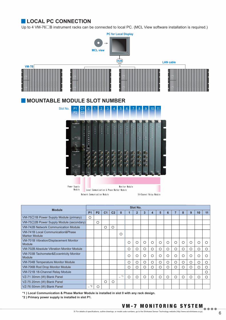
VM-75 1B Power Supply Module (primary)VM-75 2B Power Supply Module (secondary)VM-742B Network Communication ModuleVM-741B Local Communication&Phase Marker ModuleVM-701B Vibration/Displacement Monitor ModuleVM-702B Absolute Vibration Monitor ModuleVM-703B Tachometer&Eccentricity Monitor ModuleVM-704B Temperature Monitor ModuleVM-706B Rod Drop Monitor ModuleVM-721B 18-Channel Relay ModuleVZ-71 30mm (W) Blank Panel
VZ-76 50mm (W) Blank PanelVZ-75 20mm (W) Blank Panel
11C1 C2
Up to 4 VM-76□B instrument racks can be connected to local PC. (MCL View software installation is required.)
PC for Local Display
LAN cableVM-7B
HUB
MCL view
*1 ) Local Communication & Phase Marker Module is installed in slot 0 with any rack design.*2 ) Primary power supply is installed in slot P1.
*1
*2
For details of specifications, outline drawings, or model code numbers, go to the Shinkawa Sensor Technology website (http://www.sst-shinkawa.co.jp).
New Monitor Derived from Advanced and
AC
AC
AC
AC
AC
AC
AC
AC
P1P2
Slot No. C1C2
0 1 2 3 4 5 6 7 8 9 10 11

Printed in Japan 11009E1.2-11XXX
Contact to Published in Jul. 2011
3rd Fl. Shin-kojimachi Bldg.3-3 Kojimachi 4-chome, Chiyoda-kuTokyo 102-0083, JapanPhone : 81-3-3263-4417 Fax : 81-3-3262-2171 WEB : http://www.shinkawa.co.jp/
4355 Ferguson Drive Suite 215 Cincinnati, Ohio 45245, USAPhone : 1-877-586-5690 Fax : 1-513-297-9003e-mail : [email protected] : http://www.sec-america.com
4-22 Yoshikawa-kogyodanchi, Higashihiroshima 739-0153, JapanPhone : 81-82-429-1118 Fax : 81-82-429-0804WEB : http://www.sst-shinkawa.co.jp* Specifications, outline drawings and other written information can be changed without notice.
When exporting Shinkawa products, permission may be required for export or service transactions, pursuant to the provision of the Foreign Exchange and Foreign Trade Act.When re-exporting Shinkawa products, permission may be required from the US Department of Commerce, pursuant to the provision of the Export Administration Regulation (EAR).Please contact our service representative for further information.All company and product names in this brochure are trademarks or registered trademarks.