vloc series 2 user handbook (vlocpro2, vlocml2)
TRANSCRIPT

vLoc Series 2 User Handbook(vLocPro2, vLocML2)(English Edition)Version 1.5


Table of Content
General Safety & Care Information············································································································1
1.1 Who Can Use This Equipment····································································································1
1.2 Work-site Safety··························································································································1
1.3 Equipment Safety························································································································1
1.4 Batteries and Environmental Safety····························································································1
1.4.1 Alkaline Batteries (Non Rechargeable)·················································································1
1.4.2 Nickel Metal Hydride Batteries (Rechargeable)·····································································1
1.4.3 Lithium-Ion Batteries (Rechargeable)···················································································2
1.4.4 Lithium Metal Batteries (Non Rechargeable)·········································································2
1.4.5 General Rules Regarding Disposal of Batteries····································································2
1.4.6 Transportation of Lithium-ion and Lithium Metal Batteries····················································3
1.5 Care of Equipment·····················································································································3
1.6 Care When Interpreting the Information Provided by the Locator················································3
1.7 American & Canadian Safety Notices··························································································4
Service & Support·······································································································································5
2.1 Serial Number and Software Revision Number···········································································5
2.2 Distributors and Service Centers Closest to You·········································································6
vLocPro2 Receiver·····································································································································7
3.1 vLocPro2 Receiver······················································································································7
3.2 Charging the Receiver Batteries··································································································8
3.3 vLocPro2 Receiver Main Display·································································································9
3.4 vLocPro2 Receiver Screen Shots······························································································10
3.5 Locating Mode (Response)·······································································································11
3.5.1 Peak Response Mode·········································································································11
3.5.2 Broad Peak Mode···············································································································11
3.5.3 Null Mode····························································································································12
3.5.4 Peak with Arrows Response Mode······················································································12
3.5.5 Sonde Mode························································································································13
3.6 Audio·········································································································································14
3.7 Sensitivity Control·····················································································································14
3.8 Frequency Selection·················································································································14
3.9 Information Pushbutton (Depth & Current)················································································15
3.10 Information Pushbutton (Setup Menu)····················································································16
vLocML2 Receiver···································································································································17
4.1 Introduction·······························································································································17
4.2 Operating the vLocML2······································································································18
4.2.1 Switching Between Configuration·······················································································18
4.2.2 Standard···························································································································18
4.2.3 Dedicated····························································································································18

4.2.4 Marker Depth Estimation in Dedicated Mode·····································································20
4.2.5 Dual Configuration·············································································································21
Data Logging·······································································································································23
5.1 Bluetooth································································································································23
5.1.1 Fitting the Bluetooth Module·····························································································23
5.2 Holux GPS Device Overview··································································································24
5.2.1 Pairing with the vLocPro2/vLocML2 Receivers··································································25
5.2.2 Gathering Data in Active Modes························································································25
5.2.3 Gathering Data in Power and Radio (Passive) Modes························································25
5.2.4 Transferring Data from the Locator to a Computer······························································26
5.3 Trimble ProXT/XH··················································································································26
5.3.1 Trimble ProXT/XH Setting up Procedure···········································································26
5.3.2 Transferring Data from the vLoc2 to a Computer·································································28
5.4 MyLocator2···························································································································28
5.4.1 Launch the Application······································································································28
5.4.2 Splash Screen··················································································································30
5.4.3 Upload Data Files··············································································································30
5.4.4 Software Update·················································································································31
5.4.5 Advanced Configuration Tool······························································································32
5.4.6 Switch On/Off User Menu Settings······················································································32
5.4.7 Switching On/Off Frequency Selections··············································································33
5.4.8 Saving a Configuration·······································································································34
5.4.9 Configuration Lock Dongle··································································································34
5.4.10 Icon Summary····················································································································36
Loc-10Tx Transmitter······························································································································37
6.1 Loc-10Tx Transmitter Overview································································································37
6.2 Transmitter Battery····················································································································38
6.2.1 Removing the Battery Tray··································································································38
6.2.2 Replacing the Alkaline Battery·····························································································38
6.2.3 Rechargeable Batteries······································································································39
6.2.4 Re-fitting the Battery Tray···································································································39
6.2.5 Battery Charging and Disposal····························································································39
6.2.6 Battery Condition Indication································································································40
6.3 Transmitting Modes···················································································································40
6.3.1 Induction Mode···················································································································40
6.3.2 Direct Connection Mode·····································································································41
6.3.3 Clamp Mode························································································································41
6.3.4 Connection Block················································································································42
6.3.5 Frequencies and Power Output···························································································43
6.3.6 Most Used Frequencies (Frequency Selection) Feature·····················································44
6.3.7 "Dual frequency" Mode········································································································45
6.4 Information·······························································································································46

Loc-5Tx Transmitter································································································································47
7.1 Pushbutton································································································································47
7.2 External Connectors··················································································································47
7.3 Transmitter Battery····················································································································47
7.3.1 Removing the Battery Tray··································································································47
7.3.2 Replacing Alkaline Batteries································································································48
7.3.3 Rechargeable Batteries······································································································48
7.3.4 Re-fitting the Battery Tray···································································································48
7.3.5 Battery Charging and Disposal····························································································49
7.3.6 Battery Condition Indication································································································49
7.4 Display······································································································································49
7.5 Multi Frequencies······················································································································50
7.6 Most Used Frequencies (Frequency Selection) Feature···························································50
7.7 Induction Mode························································································································51
7.8 Direct Connection Mode···········································································································52
7.9 Clamp Mode······························································································································52
Loc-1Tx Transmitter·································································································································53
8.1 Pushbutton································································································································53
8.2 External Connectors··················································································································53
8.3 Replacing Alkaline Batteries······································································································53
8.4 Rechargeable Batteries············································································································54
8.5 Loc-1Tx Transmitter Operation·································································································54
Using the vLocPro2··································································································································55
9.1 Using the Receiver···················································································································55
9.1.1 Line Locating·······················································································································55
9.1.2 Depth & Current Measurement···························································································55
9.1.3 Sonde Location···················································································································56
9.1.4 Using the LDI Feature to Locate Sondes································································57
9.2 Passive or Active Location·······················································································58
9.2.1 Passive Locating······························································································58
9.2.2 Active Locating································································································59
9.3 Applying the Transmitter’s Signal··············································································59
9.3.1 Direct Connection·····························································································59
9.3.2 Clamp (Coupler)·······························································································60
9.3.3 Induction········································································································61
9.3.4 Searching (sweeping) an Area··········································································62
9.3.5 Tracing a Buried Line························································································62
9.3.6 Pinpointing & Confirming the Buried Line···························································63
9.3.7 Distorted Fields································································································63
9.3.8 Measuring Depth and Current···········································································64
9.3.9 Signal Direction Precision Identification·······························································65
9.4 Using the Accessories···························································································68

9.4.1 Using the LPC Separation Filter········································································68
9.4.2 Using the A-frame in Fault Finding····································································68
9.4.3 Using the Remote Antenna USB·····································································71
Accessories & Options····································································································74
10.1 A-frame (Optional)····························································································74
10.2 Remote Antenna (Optional)·····················································································74
10.3 Loc-10Tx Vehicle Power Lead (Optional)···································································74
10.4 Loc-10Tx Outdoor Power Supply (Optional)································································74
10.5 LPC Separation Filter (Optional)··············································································75
10.6 Receiver Vehicle Charging Lead (Optional)·································································75
10.7 Sonde (Optional)···································································································75
10.8 Clamp (Optional)································································································76
10.9 Lithium-ion Rechargeable Battery Pack (Standard)··················································76
10.10 Receiver Battery Charger (Standard)································································76
10.11 USB Cable (Standard)···························································································77
10.12 Alkaline Battery Holder (Standard)···········································································77
10.13 Ground Stake (Standard)·······················································································77
10.14 Direct Connection Lead (Standard)···········································································77
10.15 Loc-1Tx Alkaline Battery Tray (Standard)···································································77
10.16 Ground Spool (Optional)························································································77
10.17 Banana Plugs Adapter (Optional)··········································································77
10.18 Loc-5Tx Battery Pack (NiMH)···················································································78
10.19 Loc-5Tx Alkaline Battery Tray···················································································78
10.20 Loc-5Tx/10Tx Charger···························································································78
10.21 Loc-10Tx Rechargeable Battery Tray········································································78
10.22 Loc-10Tx Alkaline Battery Tray·················································································78
Glossary ·················································································································79

Page 1 of 80
1 General Safety & Care Information
1.1 Who Can Use This Equipment• This equipment must only be used by people suitably trained in the use of pipe and cable
locators.
1.2 Work-site Safety• Use your companies, or other applicable safety code and rules when using this equipment.
• Unless having the required authorization, license and appropriate training – do NOT make
connections to any pipe, cable or conductor.
• The equipment should not come in contact with corrosive or hazardous chemicals, or gases,
dust.
• Do NOT directly connect this equipment to cables or pipes that have a potential difference to
ground of greater than 35V AC.
1.3 Equipment Safety• Do NOT open the enclosures (housings) of either the transmitter or receiver.
• Place the ground stake firmly in the ground before connecting the cable from the transmitter.
• Do NOT hold any uninsulated portion of the connection leads & clips when the transmitter is
switched on.
1.4 Batteries and Environmental SafetyVivax-Metrotech products use four types of batteries:
• Alkaline batteries
• Ni-MH (Nickel Metal Hydride) batteries – rechargeable
• Lithium-ion batteries – rechargeable
• Lithium metal batteries – (small non rechargeable button cells for “clock” applications)
1.4.1 Alkaline Batteries (Non Rechargeable)• When replacing the alkaline batteries – use only the size and type specified – do NOT mix
battery types (rechargeable and alkaline).
• Do NOT mix partially discharged and fully charged cells in the same battery pack – do NOT
mix old with new.
• Never attempt to charge alkaline batteries.
1.4.2 Nickel Metal Hydride Batteries (Rechargeable)• When using rechargeable batteries, use only the correct charging device supplied or
specified by the manufacturer. The battery pack or the battery charger will contain circuitry
to manage the charging process – other chargers (even if they have the same connector,
General Safety & Care Information

Page 2 of 80
1 General Safety & Care Information
polarity, voltage & current rating will not have the same control circuitry and can cause
damage to the product, overheating, and in extreme cases fire or harm to the individual.
• Do NOT assume that if the plug fits it is the correct charger – a charger with the correct part
number MUST be used – just because it is a Vivax-Metrotech charger and the plug fits does
NOT mean it is the correct charger.
• Before using for the first time, charge rechargeable batteries for 6 hours. If at any time the
rechargeable batteries do NOT last as long as anticipated – discharge fully and then charge
for 6 hours.
• Care should be taken when charging batteries – NEVER repeatedly recharge batteries (or
turn power off & on) without using the instrument. If used with an inverter in a vehicle – charge
the product then unplug the charger and do NOT charge again until the rechargeable batteries
have been used for at least ten minutes. Failure to do this could result in the overcharging of
the battery which will shorten the life of the battery, and could in some circumstances cause
overheating or fire.
• If ever the product becomes hot during the charging process IMMEDIATELY unplug the
charger and use the rechargeable batteries for at least 10 minutes before recharging. If this
reoccurs the next time the unit is charged – return immediately to Vivax-Metrotech for repair.
• Do NOT charge batteries for prolonged periods of time without using the locator for at least 10
mins. Charging for prolonged period of time could overcharge the battery, reduce the battery
life and in extreme circumstances cause damage to the locator and fire.
1.4.3 Lithium-Ion Batteries (Rechargeable)• Lithium-ion Batteries – some products use Lithium-ion batteries – the requirements for
marking and transportation are still developing. Please contact Vivax-Metrotech before
shipping products containing Lithium-ion batteries or Lithium-ion battery packs on their own
for any “special instructions”.
1.4.4 Lithium Metal Batteries (Non Rechargeable)• Commonly known as “button cells” these are small – non rechargeable batteries used to
power internal “clocks” within some units (similar to computers). Generally they have a life of
3-5 years.
• Under no circumstances should any attempt be made to charge these batteries.
• Dispose of to your company’s work practice/environmental standards, the prevailing laws, or
recognized best practice. Always dispose of batteries responsibly.
1.4.5 General Rules Regarding Disposal of Batteries• NEVER disassemble a battery, or battery pack.
• Never dispose of in a fire or water.
• Dispose of batteries in accordance with your Company’s work practice/environmental
standards, the prevailing laws, or recognized best practice. Always dispose of batteries
responsibly.

Page 3 of 80
1.4.6 Transportation of Lithium-ion and Lithium Metal Batteries• The Lithium-ion and Lithium metal batteries used in Vivax-Metrotech products meet the
required safety standards and include the designated protection circuitry.
• Recent regulation changes require that when batteries with Lithium-ion and Lithium metal
batteries are transported the packaging MUST included specified warning labels. Please
contact Vivax-Metrotech Customer Service (USA 1-800-446-3392, International +1-408-
734-1400 (USA Pacific Time Zone)) for more details.• Regulations have also changed regarding the shipping of spare battery packs (battery packs
that are not inside a product). There are limitations on the weight of the package, and the
packaging must be marked with the appropriate warning labels. Please contact Vivax-
Metrotech Customer Service (USA 1-800-446-3392, International +1-408-734-1400 (USA
Pacific Time Zone)) for more details.• Vivax-Metrotech vLoc Series 2 products using Lithium-ion battery are classified as "not
restricted" they can be shipped normally by road/rail/sea & air (passenger & freight aircraft)
without restrictions.
IMPORTANT
Remember – Batteries contain dangerous chemicals – They can be affected
by many things such as water ingress or heat – In some circumstances
they can explode. They also can cause electric shocks!
1.5 Care of Equipment• Use equipment only as directed in this User Handbook.
• Do NOT immerse any part of this equipment in water.
• Store in a dry place.
• Keep equipment in the case provided when not in use.
• If left for prolonged period of time – remove alkaline batteries.
• Keep unit clean and free of dust and dirt.
• Protect against excessive heat.
1.6 Care When Interpreting the Information Provided by the Locator
• Like all locators – this instrument is locating, and providing depth and current readings based
on electromagnetic signals that radiate from the buried cable or pipe. In most cases these
signals will enable the locator to pinpoint both position depth and current correctly.
• BEWARE – in some cases other factors will distort electromagnetic fields radiating from cable or pipe being located, resulting in incorrect information.
• Always locate responsibly, and use information learned during your training to interpret the
information provided by the locator.
• Do NOT provide information regarding depth of cable or pipe to anyone unless authorized to
do so by your company.
• REMEMBER that depth measurements are to the center of the electromagnetic field or pipe – In the case of pipes this may be significantly deeper than the top of the pipe.
1 General Safety & Care Information

Page 4 of 80
1.7 American & Canadian Safety NoticesUSA
• This transmitter and receiver comply with the general conditions of operation, pursuant to part
15 of the FCC Rules.
○ CFR 47 Part 2
○ CFR 47 Part 15
• Changes or modifications not expressly approved by the manufacturer could void the user’s
authority to operate the products.
CANADA
• Equipment is for use by trained operators only, and not for general household or consumer
use.
• Operation is subject to the following two conditions: (1) this device may not cause
interference, and (2) this device must accept any interference that may cause undesired
operation of the device.
EUROPE
• Vivax-Metrotech confirms that the location system is compliant with relevant provision of
European directive 1999/5/EC.
○ EN 55011
○ EN 61000-4-2: A1 & A2
○ EN 61000-4-3
○ EN 61000-4-8: A1
○ ETSI EN 300 330-2
○ ETSI EN 301 489-1
○ ETSI EN 301 489-3
1 General Safety & Care Information

Page 5 of 80
2.1 Serial Number and Software Revision NumberAlways quote your receiver and transmitter model number, serial number and software revision
number when requesting product support. They can be found as follows: (for reference only)
NOTE
The transmitter Model & Serial Number can be found at the bottom of the
transmitter and also inside the transmitter between the battery tray and the
main module of transmitter.
Software Revision Number: On both receiver and transmitter the software
revision number is displayed on the LCD during the start up sequence or can
be found in the “About” section of the user menu.
2 Service & Support
Service & Support
1 Model & Serial Number

Page 6 of 80
2.2 Distributors and Service Centers Closest to You:
United Kingdom
Vivax-Metrotech Ltd.
14-15, Bishops Court Gardens,
Bishops Court Lane,
Clyst St. Mary, Exeter, Devon,
EX51DH, UK
Tel : +44(0)1392-368833
Website : www.vivax-metrotech.com
Email : [email protected]
Canada
Vivax Canada Inc.
41 Courtland Ave Unit 6,
Vaughan, ON L4K 3T3, Canada
Tel : +1-289-846-3010
Fax : +1-905-752-0214
Website : www.vivax-metrotech.com
Email : [email protected]
China
Leidi Utility Supply (Shanghai) Ltd.
No.780, Tianshan Rd,
Shanghai, China 200051
T/Free : 4008-206-719
Tel : +86-21-5235-3001
Fax : +86-21-5235-8365
Website : www.leidi.com
Email : [email protected]
United State of America
Vivax-Metrotech Corporation
3251 Olcott Street,
Santa Clara, CA 95054, USA
Website : www.vivax-metrotech.com
Sales & Sales Support:
T/Free : 800-446-3392
Tel : +1-408-734-1400
Fax : +1-408-734-1415
Email : [email protected]
Application Support:
T/Free : 800-624-6210
Tel : +1-408-454-7159
Fax : +1-408-743-5597
Email : [email protected]
Service & Repairs:
T/Free : 800-638-7682
Tel : +1-408-962-9990
Fax : +1-408-734-1799
Email : [email protected]
All Other Department:
T/Free : 877-330-1647
Tel : +1-408-734-3880
Fax : +1-408-962-9993
Australasia
Vivax-Metrotech AUS
Unit 1, 176 South Creek Road,
Cromer NSW 2009, Australia
Tel : +61-2-9972-9244
Fax : +61-2-9972-9433
Website : www.vivax-metrotechaus.com
Email : [email protected]
2 Service & Support
Page 7 of 80
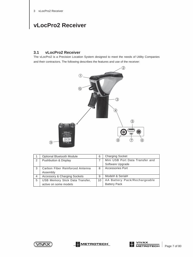
3.1 vLocPro2 ReceiverThe vLocPro2 is a Precision Location System designed to meet the needs of Utility Companies
and their contractors. The following describes the features and use of the receiver:
3 vLocPro2 Receiver
vLocPro2 Receiver
12
3
45
67
8
910
Optional Bluetooth ModulePushbutton & Display
Carbon Fiber Reinforced Antenna AssemblyAccessory & Charging SocketsUSB Memory Stick Data Transfer, active on some models
Charging SocketMini USB Port Data Transfer and Software UpgradeAccessories Port
Model# & Serial#AA Bat tery Pack/Rechargeable Battery Pack
Page 8 of 80
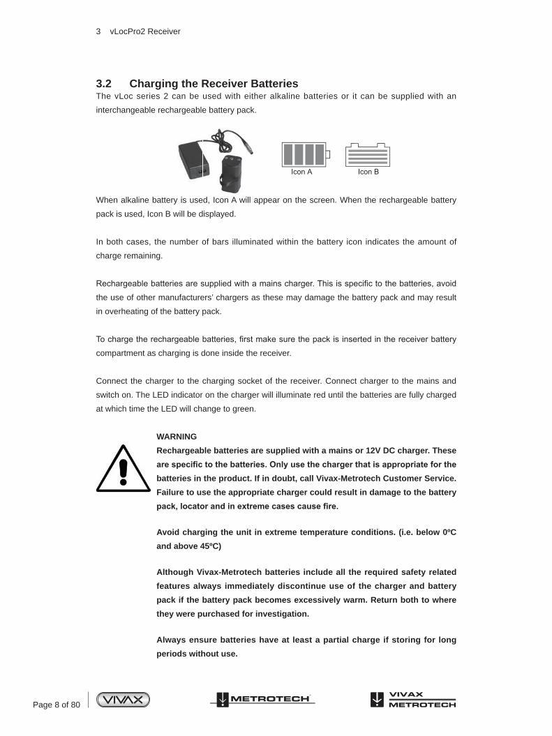
3.2 Charging the Receiver BatteriesThe vLoc series 2 can be used with either alkaline batteries or it can be supplied with an
interchangeable rechargeable battery pack.
When alkaline battery is used, Icon A will appear on the screen. When the rechargeable battery
pack is used, Icon B will be displayed.
In both cases, the number of bars illuminated within the battery icon indicates the amount of
charge remaining.
Rechargeable batteries are supplied with a mains charger. This is specific to the batteries, avoid
the use of other manufacturers’ chargers as these may damage the battery pack and may result
in overheating of the battery pack.
To charge the rechargeable batteries, first make sure the pack is inserted in the receiver battery
compartment as charging is done inside the receiver.
Connect the charger to the charging socket of the receiver. Connect charger to the mains and
switch on. The LED indicator on the charger will illuminate red until the batteries are fully charged
at which time the LED will change to green.
WARNING
Rechargeable batteries are supplied with a mains or 12V DC charger. These
are specific to the batteries. Only use the charger that is appropriate for the batteries in the product. If in doubt, call Vivax-Metrotech Customer Service.
Failure to use the appropriate charger could result in damage to the battery
pack, locator and in extreme cases cause fire.
Avoid charging the unit in extreme temperature conditions. (i.e. below 0ºC
and above 45ºC)
Although Vivax-Metrotech batteries include all the required safety related
features always immediately discontinue use of the charger and battery
pack if the battery pack becomes excessively warm. Return both to where
they were purchased for investigation.
Always ensure batteries have at least a partial charge if storing for long
periods without use.
3 vLocPro2 Receiver

Page 9 of 80
123456789
101112131415161718
Digital Display of Signal ResponseLoudspeaker StatusBluetooth and GPS Signal QualityAlkaline/Rechargeable Battery StatusPeak Signal IndicationFrequencyLocation Mode SelectGain Control (increase gain)Information Depth/Current Measurement
Frequency Select Gain Control (reduce gain)On/Off ControlLine Direction Indicator (LDI)Left vs Right Indicationdb Gain SettingAnalogue Display of Signal ResponseContinuous Depth/CurrentLocation Mode(Peak, Null, Sonde, Broad, Peak Arrows)
Dispose of all batteries in accordance with your company procedures and
Federal/State and local regulations.
Never dismantle batteries, put them in fire, or get wet.
3.3 vLocPro2 Receiver Main DisplayThe vLocPro2 has several display options – the display shown below is representative of the
types of display and icons used.
Note: Bluetooth function is available in vLoc receivers with Bluetooth module only.
3 vLocPro2 Receiver
Page 10 of 80
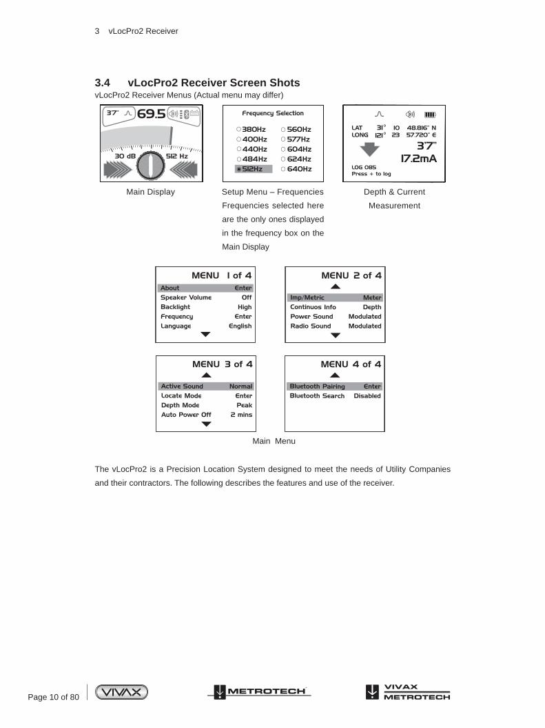
3.4 vLocPro2 Receiver Screen ShotsvLocPro2 Receiver Menus (Actual menu may differ)
The vLocPro2 is a Precision Location System designed to meet the needs of Utility Companies
and their contractors. The following describes the features and use of the receiver.
Main Display Setup Menu – Frequencies
Main Menu
Depth & Current
MeasurementFrequencies selected here
are the only ones displayed
in the frequency box on the
Main Display
3 vLocPro2 Receiver

Page 11 of 80
3.5 Locating Mode (Response)The vLocPro2 receiver has four antennas, and these can be toggled through different
configurations (modes) to provide different responses to the signals radiating from the buried
pipes and cables. The modes are:
3.5.1 Peak Response Mode
This uses the two horizontal antennas and provides a “Peak” or
maximum signal response over the center of the radiated signal
from the buried line. The line direction indicator (LDI) shows the
direction of the cable (available in Active modes). The color of the
LDI changed from clear to blue when the receiver is in line with the
buried line.
This is the most accurate of the locating modes as both antennas
are used to provide a clearly identifiable “Peak”. In the “Peak”
mode, a “Peak” signal indicator helps to clarify the position of the
“Peak”. This shows the last “Peak” located for a few seconds,
enabling the user to return to that position quickly.
3.5.2 Broad Peak Mode
This uses a single horizontal antenna and provides a “Peak” or
maximum signal response over the center of the radiated signal
from the buried line. The line direction indicator (LDI) shows the
direction of the cable (available in Active modes). The color of the
LDI changed from clear to blue when the receiver is in line with the
buried line.
This is less accurate than the twin horizontal antenna “Peak” mode
– but is useful if the buried line is particularly deep. For pinpointing
the line, the “Peak” mode should be used.
3 vLocPro2 Receiver

Page 12 of 80
3.5.3 Null Mode
This uses vertical antennas and provides a minimum or “Null”
response over the center of the radiated signal from the buried line.
The line direction indicator (LDI) shows the direction of the cable
(available in Active modes). The color of the LDI changed from
clear to blue when the receiver is in line with the buried line.
Some users prefer the null response; it works well in uncongested
areas, but is more prone to inaccuracies due to distortion of the
radiated signal in congested areas.
Left/right indication arrows are also displayed when in “Null” mode.
The arrows indicate the direction to move the receiver to locate the
position of the buried line.
3.5.4 Peak with Arrows Response Mode
This uses the two horizontal antennas and provides a “Peak” or
maximum signal response over the center of the radiated signal from
the buried line. The line direction indicator (LDI) shows the direction of
the cable (available in Active modes). The color of the LDI changed from
clear to blue when the receiver is in line with the buried line.
This is the most accurate of the locating modes as both antennas
are used to provide a clearly identifiable “Peak”. In the “Peak”
mode, a “Peak” signal indicator helps to clarify the position of the
“Peak”. This shows the last “Peak” located for a few seconds,
enabling the user to return to that position quickly.
Left/Right arrows also guide the user to the line. However, it
should be noted that the arrows use the Null antenna to resolve
which arrows are activated. The null antenna is not as accurate in
distorted fields as the peak antennas. Therefore, when pinpointing,
use the peak bargraph to determine the position of the line.
3 vLocPro2 Receiver
Page 13 of 80
Note
If the arrows indicated a different position for the cable than the
peak bargraph position, this indicates the possibility of a distorted
field. Check by taking a depth reading on the ground and then lift
the cable locator a known distance such as 1m (3ft). If the depth
does not increase by this amount it confirms a distorted field and
the data should be treated with caution.
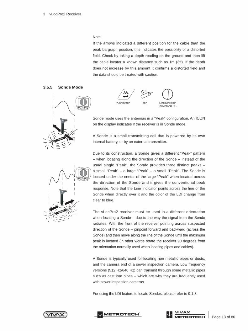
3.5.5 Sonde Mode
Sonde mode uses the antennas in a “Peak” configuration. An ICON on the display indicates if the receiver is in Sonde mode.
A Sonde is a small transmitting coil that is powered by its own
internal battery, or by an external transmitter.
Due to its construction, a Sonde gives a different “Peak” pattern
– when locating along the direction of the Sonde – instead of the
usual single “Peak”, the Sonde provides three distinct peaks –
a small “Peak” – a large “Peak” – a small “Peak”. The Sonde is
located under the center of the large “Peak” when located across
the direction of the Sonde and it gives the conventional peak
response. Note that the Line Indicator points across the line of the
Sonde when directly over it and the color of the LDI change from
clear to blue.
The vLocPro2 receiver must be used in a different orientation
when locating a Sonde – due to the way the signal from the Sonde
radiates. With the front of the receiver pointing across suspected
direction of the Sonde – pinpoint forward and backward (across the
Sonde) and then move along the line of the Sonde until the maximum
peak is located (in other words rotate the receiver 90 degrees from
the orientation normally used when locating pipes and cables).
A Sonde is typically used for locating non metallic pipes or ducts,
and the camera end of a sewer inspection camera. Low frequency
versions (512 Hz/640 Hz) can transmit through some metallic pipes
such as cast iron pipes – which are why they are frequently used
with sewer inspection cameras.
For using the LDI feature to locate Sondes, please refer to 9.1.3.
3 vLocPro2 Receiver

Page 14 of 80
3.6 Audio
The visual display is also accompanied by an audio response. The output level (volume) of
this response is set by entering the “Setup Menu”. Press and hold “i” pushbutton for 2 seconds
to enter setup menu. The setup display defaults to volume. Use the “M” pushbutton to toggle
through the available options (Off – Low – Med – High). Press the “i” pushbutton again to exit
the setup menu. As the loudspeaker uses a significant amount of power, using lower volume can
make the battery life of the receiver last longer.
3.7 Sensitivity Control
In manual modes, “+” and “-” pushbuttons are provided to increase or reduce the sensitivity of the
receiver. If the bar graph moves towards the minimum or maximum a single touch of the opposite
pushbutton returns it to approximately 50% deflection. Holding down or repeated pushing of the “+”
or “-” pushbuttons increments/decrements the gain.
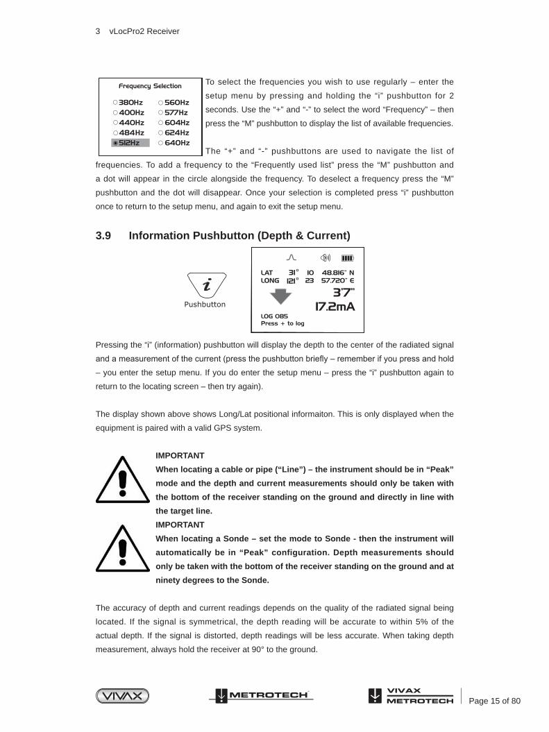
3.8 Frequency Selection
The vLocPro2 receiver is capable of locating a large number of frequencies or frequency
combinations. A list of these frequencies can be accessed using the setup menu. Most of these
frequencies listed – you will never use – the setup menu allows you to select the frequencies you
wish to use regularly. The frequency select pushbutton on the main receiver pad is used to toggle
through the frequencies defined using the setup menu. The operating frequency will be shown
at the lower right side of the display. You can change this selection at any time using the setup
menu.
The initial frequencies set at the time the unit is supplied are “Power”, “Radio” and the frequencies
used by the transmitter purchased. See the transmitter section for suggestions of which frequency
is best suited to specific applications.
3 vLocPro2 Receiver
Page 15 of 80
To select the frequencies you wish to use regularly – enter the
setup menu by pressing and holding the “i” pushbutton for 2
seconds. Use the “+” and “-” to select the word “Frequency” – then
press the “M” pushbutton to display the list of available frequencies.
The “+” and “-” pushbuttons are used to navigate the list of
frequencies. To add a frequency to the “Frequently used list” press the “M” pushbutton and
a dot will appear in the circle alongside the frequency. To deselect a frequency press the “M”
pushbutton and the dot will disappear. Once your selection is completed press “i” pushbutton
once to return to the setup menu, and again to exit the setup menu.
3.9 Information Pushbutton (Depth & Current)
Pressing the “i” (information) pushbutton will display the depth to the center of the radiated signal
and a measurement of the current (press the pushbutton briefly – remember if you press and hold
– you enter the setup menu. If you do enter the setup menu – press the “i” pushbutton again to
return to the locating screen – then try again).
The display shown above shows Long/Lat positional informaiton. This is only displayed when the
equipment is paired with a valid GPS system.
IMPORTANT
When locating a cable or pipe (“Line”) – the instrument should be in “Peak”
mode and the depth and current measurements should only be taken with
the bottom of the receiver standing on the ground and directly in line with
the target line.
IMPORTANT
When locating a Sonde – set the mode to Sonde - then the instrument will
automatically be in “Peak” configuration. Depth measurements should
only be taken with the bottom of the receiver standing on the ground and at
ninety degrees to the Sonde.
The accuracy of depth and current readings depends on the quality of the radiated signal being
located. If the signal is symmetrical, the depth reading will be accurate to within 5% of the
actual depth. If the signal is distorted, depth readings will be less accurate. When taking depth
measurement, always hold the receiver at 90° to the ground.
3 vLocPro2 Receiver

Page 16 of 80
3.10 Information Pushbutton (Setup Menu)
As described previously, a second function performed by the “i” is to access the SETUP menu.
Press and hold the “i” pushbutton for two seconds to display the SETUP menu. Use the “+”, “-”
to navigate through the various options and use the “M” pushbutton to select. To exit the setup
menu, press the “i” pushbutton.
The setup menu allows the user to configure their personal preference, this menu can be
accessed and changed at any time.
3 vLocPro2 Receiver
Page 17 of 80
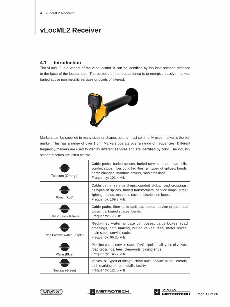
4.1 IntroductionThe vLocML2 is a variant of the vLoc locator. It can be identified by the loop antenna attached
to the base of the locator tube. The purpose of the loop antenna is to energize passive markers
buried above non metallic services or points of interest.
Markers can be supplied in many sizes or shapes but the most commonly used marker is the ball
marker. This has a range of over 1.5m. Markers operate over a range of frequencies. Different
frequency markers are used to identify different services and are identified by color. The industry
standard colors are listed below:
4 vLocML2 Receiver
vLocML2 Receiver
Cable paths, buried splices, buried service drops, load coils, conduit stubs, fiber optic facilities, all types of splices, bends, depth changes, manhole covers, road crossingsFrequency: 101.4 kHz
Cable paths, service drops, conduit stubs, road crossings, all types of splices, buried transformers, service loops, street lighting, bends, man hole covers, distribution loopsFrequency: 169.8 kHz
Reclaimed water, private campuses, valve boxes, road crossings, path making, buried valves, tees, meter boxes, main stubs, service stubsFrequency: 66.35 kHz
Cable paths, fiber optic facilities, buried service drops, road crossings, buried splices, bendsFrequency: 77 kHz
Pipeline paths, service stubs, PVC pipeline, all types of valves, road crossings, tees, clean-outs, casing endsFrequency: 145.7 kHz
Valves, all types of fittings, clean outs, service stubs, laterals, path marking of non-metallic facilityFrequency: 121.6 kHz

Page 18 of 80
Gas and Electric Installations (EDF only)Frequency: 40 kHz
Pipeline paths, main stubs, service stubs, tees, road crossings, all types of valves, meter boxes, stopping fittings, depth changes, transition fittings, squeeze points, pressure control fittings, electro fusion couplings, all types of fittings and jointsFrequency: 83 kHz
Cable paths, service drops, conduit stubs, road crossings, all types of splices, buried transformers, service loops, street lighting, bends, man hole covers, distribution loopsFrequency: 134 kHz
4.2 Operating the vLocML2The vLocML2 can be operated in three configurations:
• Standard cable locator
• Dedicated marker locator
• Dual cable locator and marker locator
4.2.1 Switching Between ConfigurationThere are two ways of switching between configurations:
• Using the user menu
• Using the “M” pushbutton
To use the user menu, press and hold the “i” pushbutton. Use the “+” pushbutton to scroll down
to “Marker Locator”. Press the enter key to scroll through the options. Exit the user menu by
pressing the “i” pushbutton.
It is possible to hop between configurations using the enter key. To do this press and hold the
enter key until the desired configuration is reached.
4.2.2 StandardIn this configuration the unit operates as a standard vLoc cable and pipe locator. For the operation
of this see the standard vLoc user handbook sections.
4.2.3 Dedicated
In this configuration the unit is dedicated to detecting markers. The screen of the vLocML2 will look similar to the picture below
Note that the ball icon is illuminated indicating that the dedicated configuration is selected. If the line icon is illuminated with the ball icon, this indicates that the Dual configuration is activated.
4 vLocML2 Receiver

Page 19 of 80
It is also possible to take depth to marker estimations in the dedicated mode. (Section 4.2.4)
Use the “f” pushbutton to select the marker type that is to be located.
Sweep the area of where the marker is to be located. Use a slow, deliberate arm sweeping
motion slowly moving forward making sure no area is missed.
69.53’7’’
512 Hz30 dB
2
1
24
53
Signal strength from Marker used for pinpointing positionMarker detection ball (Not adjustable)Marker icon indicating marker detection activeMarker type, numericMarker type, graphic
1
23
45
4 vLocML2 Receiver
Slowly walk forward
Sweepingaction
When the locator is within range of the marker there will be a sound from the speaker and also
the icon in the centre of the display (2) will start to fill up.
Move the locator forward and back, left and right, until the largest signal is detected. Note the bar
graph (1) will also respond. Use the “+” and “-” pushbuttons to keep the signal on scale. The bar
graph should be used to pinpoint the position of the marker.
Page 20 of 80
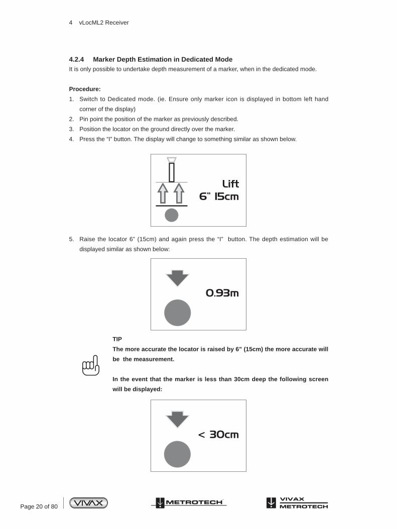
4.2.4 Marker Depth Estimation in Dedicated ModeIt is only possible to undertake depth measurement of a marker, when in the dedicated mode.
Procedure:
1. Switch to Dedicated mode. (ie. Ensure only marker icon is displayed in bottom left hand
corner of the display)
2. Pin point the position of the marker as previously described.
3. Position the locator on the ground directly over the marker.
4. Press the “I” button. The display will change to something similar as shown below.
5. Raise the locator 6” (15cm) and again press the “I” button. The depth estimation will be
displayed similar as shown below:
TIP
The more accurate the locator is raised by 6” (15cm) the more accurate will
be the measurement.
In the event that the marker is less than 30cm deep the following screen
will be displayed:
Lift6” 15cm
4 vLocML2 Receiver
Page 21 of 80
If the following display is shown, this indicates that the marker is either out of range or there is an
invalid signal.
X
4 vLocML2 Receiver
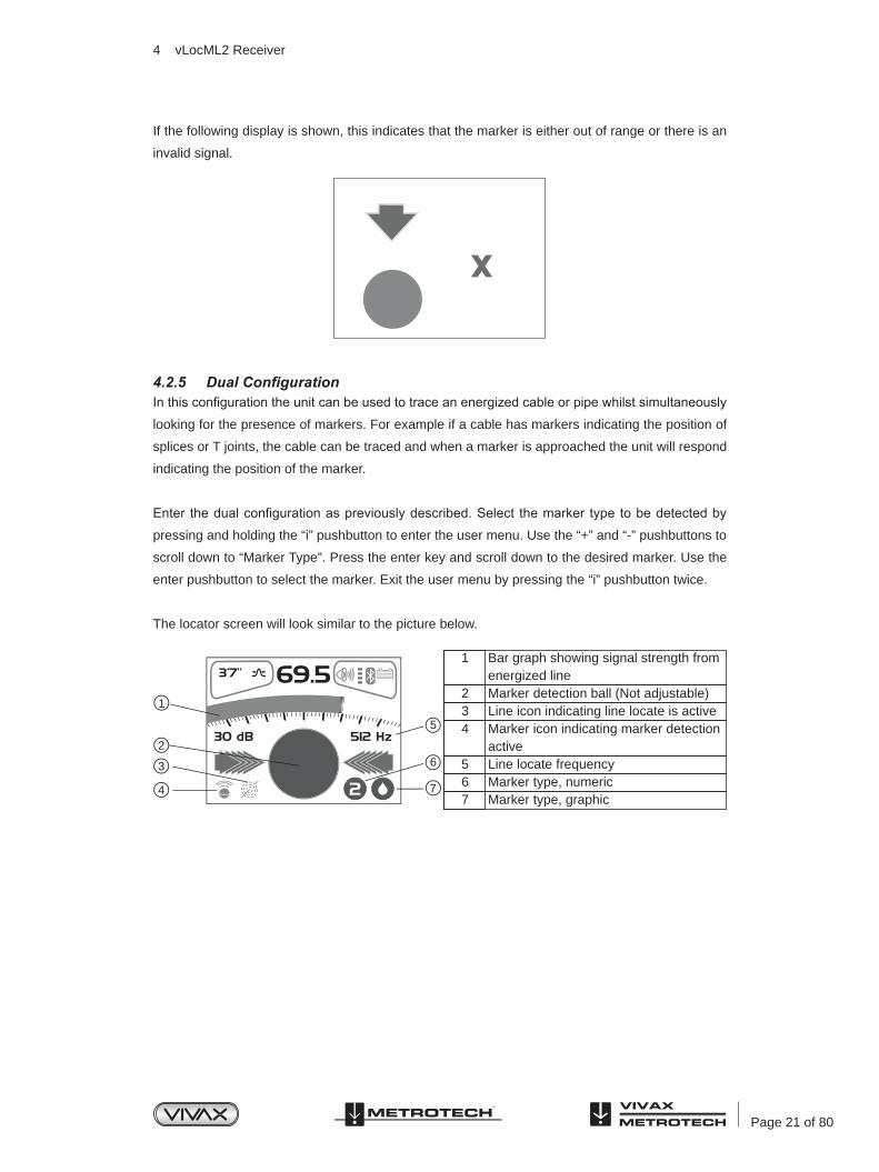
4.2.5 Dual ConfigurationIn this configuration the unit can be used to trace an energized cable or pipe whilst simultaneously
looking for the presence of markers. For example if a cable has markers indicating the position of
splices or T joints, the cable can be traced and when a marker is approached the unit will respond
indicating the position of the marker.
Enter the dual configuration as previously described. Select the marker type to be detected by
pressing and holding the “i” pushbutton to enter the user menu. Use the “+” and “-” pushbuttons to
scroll down to “Marker Type”. Press the enter key and scroll down to the desired marker. Use the
enter pushbutton to select the marker. Exit the user menu by pressing the “i” pushbutton twice.
The locator screen will look similar to the picture below.
Bar graph showing signal strength from energized lineMarker detection ball (Not adjustable)Line icon indicating line locate is activeMarker icon indicating marker detection activeLine locate frequencyMarker type, numericMarker type, graphic
1
234
567
69.53’7’’
512 Hz30 dB
2
1
26
5
7
3
4
Page 22 of 80
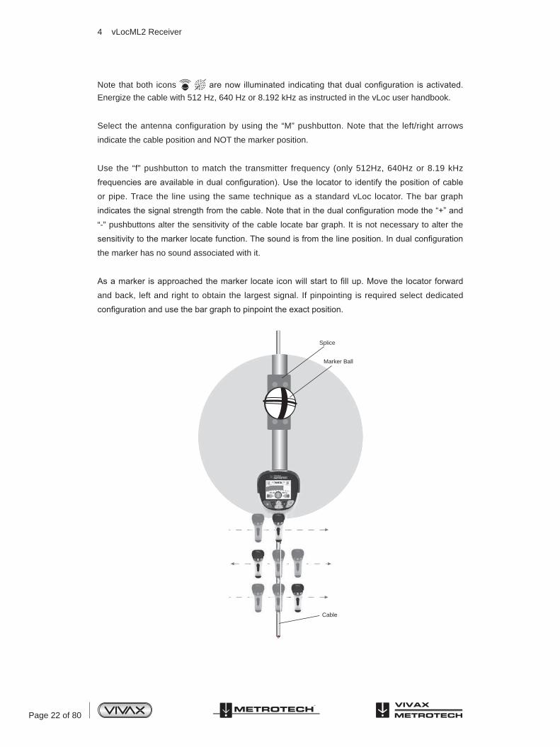
Note that both icons are now illuminated indicating that dual configuration is activated. Energize the cable with 512 Hz, 640 Hz or 8.192 kHz as instructed in the vLoc user handbook.
Select the antenna configuration by using the “M” pushbutton. Note that the left/right arrows
indicate the cable position and NOT the marker position.
Use the “f” pushbutton to match the transmitter frequency (only 512Hz, 640Hz or 8.19 kHz
frequencies are available in dual configuration). Use the locator to identify the position of cable
or pipe. Trace the line using the same technique as a standard vLoc locator. The bar graph
indicates the signal strength from the cable. Note that in the dual configuration mode the “+” and
“-” pushbuttons alter the sensitivity of the cable locate bar graph. It is not necessary to alter the
sensitivity to the marker locate function. The sound is from the line position. In dual configuration
the marker has no sound associated with it.
As a marker is approached the marker locate icon will start to fill up. Move the locator forward
and back, left and right to obtain the largest signal. If pinpointing is required select dedicated
configuration and use the bar graph to pinpoint the exact position.
Marker Ball
Splice
Cable
4 vLocML2 Receiver
Page 23 of 80
The vLoc2 has an internal memory that can be used to store location data. It can store in excess
of 1000 records.
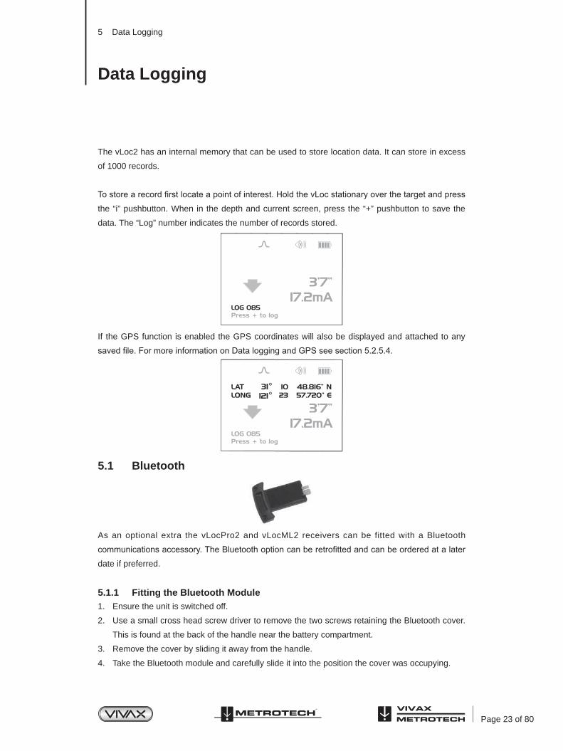
To store a record first locate a point of interest. Hold the vLoc stationary over the target and press
the “i” pushbutton. When in the depth and current screen, press the “+” pushbutton to save the
data. The “Log” number indicates the number of records stored.
If the GPS function is enabled the GPS coordinates will also be displayed and attached to any
saved file. For more information on Data logging and GPS see section 5.2.5.4.
5.1 Bluetooth
As an optional extra the vLocPro2 and vLocML2 receivers can be fitted with a Bluetooth
communications accessory. The Bluetooth option can be retrofitted and can be ordered at a later
date if preferred.
5.1.1 Fitting the Bluetooth Module1. Ensure the unit is switched off.
2. Use a small cross head screw driver to remove the two screws retaining the Bluetooth cover.
This is found at the back of the handle near the battery compartment.
3. Remove the cover by sliding it away from the handle.
4. Take the Bluetooth module and carefully slide it into the position the cover was occupying.
5 Data Logging
Data Logging

Page 24 of 80
5 Data Logging
5. Replace the two cross head screws.
6. Switch on the unit and after a few seconds a grey, Bluetooth icon should appear showing that
the module is fitted.
7. If a red line is shown through the icon, this indicates that the Bluetooth module is not enabled.
Bluetooth enable is located in the user menu which is accessed using a long press of the “i”
button.
8. The Bluetooth can communicate with external devices that are also Bluetooth enabled. There
are many Bluetooth enabled GPS devices but Vivax-Metrotech offer the Holux GPS as a
suitable solution for those requiring mapping to accuracies better than 5m. For those requiring
accuracies better than this, for instance submeter accuracy, the customer should contact a
GPS supplier of their choice. However, as a recommendation, one such device that delivers
submeter accuracy is the Trimble ProXT.
5.2 Holux GPS Device Overview
The Holux M-1200E is a simple GPS device with integral rechargeable batteries and Bluetooth
communications. It can either be mounted in the purpose designed holder from Vivax-Metrotech
or can be positioned anywhere within a few meters from the vLocPro2. For instance using “Velcro”
to attach it to the peak of a baseball cap ensures clear view of the sky and satellites.
The best accuracy that can be expected from this device is better than 2.2m. However, this
depends on satellite and DPGS satellite availability. It is compatible with EGNOS and WAAS
SBAS differential satellite correction systems.
Ensure the battery is charged by either using the cigarette charger lead supplied or attaching it to
a USB interface using a standard USB to mini USB lead.
To switch on the M-1200E position the slider switch, located on the side of the device, to the
on position. The Bluetooth icon will flash rapidly (approx every half second). This indicates that
it is searching for a device to pair with. When the Holux is paired with a device the flashing will
change to a slower rate.
The GPS icon will be continuously illuminated indicating that GPS lock is not achieved. When the
GPS icon starts to flash GPS lock is achieved.
TIP
For best results allow the GPS indicator to flash at least 15 minutes before commencing a survey.

Page 25 of 80
5.2.1 Pairing with the vLocPro2/vLocML2 Receivers1. Switch on the M1200 and ensure it is within a couple of meters of the receiver.
2. Pairing the M1200 with the receiver is achieved through the setup menu. To enter the setup
menu press and hold the “i” pushbutton.
3. Press the “+” button to scroll to “Bluetooth Pairing” and press the “M” pushbutton. The
vLocPro2 will begin to search for available devices. At the end of the search, a list will be
displayed which should include “HOLUX_M-1200” Use the “+” and “–” pushbuttons to
highlight this device and press the “M” pushbutton.
4. The vLocPro2 will automatically return to the locate screen. Within 10 seconds the Bluetooth
icon will change from grey to blue. This indicates that pairing is successful.
TIP
When not using the Bluetooth function switch off the Bluetooth search
function by entering the user menu and deselecting “Bluetooth Search”.
This will save battery life and prevent interference from the Bluetooth
search activity, in the Radio mode.
When the Bluetooth search function is deactivated a red line will appear
through the Bluetooth icon in the locate screen.
5. Next to the Bluetooth icon is the red GPS signal strength bar graph. This will not appear until
a valid GPS signal is detected.
6. The bar graph has 4 levels. For best results, allow a few minutes after the bar graph has
started before commencing the survey. The accuracy will improve with more bars illuminated.
5.2.2 Gathering Data in Active ModesSwitch on the Holux and ensure pairing as indicated above. (Bluetooth icon should be blue) Wait
for a valid GPS signal as indicated by the red bar graph next to the Bluetooth icon.
TIP
It is a good idea to ensure the datalog is clear before commencing. To do
this press the “i" button. Whilst the depth screen is displayed press and
hold the “-” button. The message:
“Are you sure you want to delete all this datalog. Press + key to Delete”
Pressing the “+” key will clear the datalog.
5.2.3 Gathering Data in Power and Radio (Passive) ModesThis is done in the same way as in the active modes except that it is not possible to enter the
measure mode unless a valid GPS signal is received from the Holux GPS.
Depth and current are not available in the passive modes but all other data can be saved to the
datalog.
5 Data Logging
Page 26 of 80
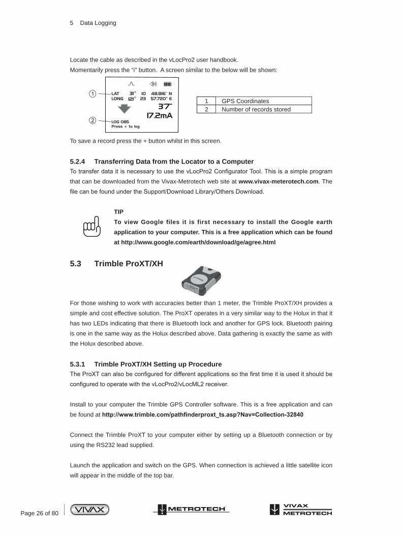
Locate the cable as described in the vLocPro2 user handbook.
Momentarily press the “i" button. A screen similar to the below will be shown:
To save a record press the + button whilst in this screen.
5.2.4 Transferring Data from the Locator to a ComputerTo transfer data it is necessary to use the vLocPro2 Configurator Tool. This is a simple program
that can be downloaded from the Vivax-Metrotech web site at www.vivax-meterotech.com. The
file can be found under the Support/Download Library/Others Download.
TIP
To view Google files it is first necessary to install the Google earth
application to your computer. This is a free application which can be found
at http://www.google.com/earth/download/ge/agree.html
5.3 Trimble ProXT/XH
For those wishing to work with accuracies better than 1 meter, the Trimble ProXT/XH provides a
simple and cost effective solution. The ProXT operates in a very similar way to the Holux in that it
has two LEDs indicating that there is Bluetooth lock and another for GPS lock. Bluetooth pairing
is one in the same way as the Holux described above. Data gathering is exactly the same as with
the Holux described above.
5.3.1 Trimble ProXT/XH Setting up ProcedureThe ProXT can also be configured for different applications so the first time it is used it should be
configured to operate with the vLocPro2/vLocML2 receiver.
Install to your computer the Trimble GPS Controller software. This is a free application and can
be found at http://www.trimble.com/pathfinderproxt_ts.asp?Nav=Collection-32840
Connect the Trimble ProXT to your computer either by setting up a Bluetooth connection or by
using the RS232 lead supplied.
Launch the application and switch on the GPS. When connection is achieved a little satellite icon
will appear in the middle of the top bar.
1 GPS Coordinates2 Number of records stored
5 Data Logging

Page 27 of 80
1. From “Skyplot” select “Setup”.
2. Now select “GPS Settings”.
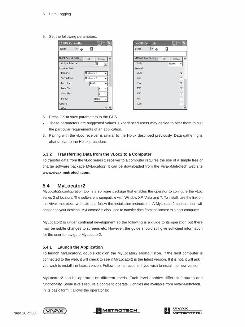
3. Select COM1 and set the parameters as below and then press OK.
4. Now select the spanner on the “NMEA Output” line.
5 Data Logging
Page 28 of 80
5. Set the following perameters:
6. Press OK to save parameters to the GPS.
7. These parameters are suggested values. Experienced users may decide to alter them to suit
the particular requirements of an application.
8. Pairing with the vLoc receiver is similar to the Holux described previously. Data gathering is
also similar to the Holux procedure.
5.3.2 Transferring Data from the vLoc2 to a ComputerTo transfer data from the vLoc series 2 receiver to a computer requires the use of a simple free of
charge software package MyLocator2. It can be downloaded from the Vivax-Metrotech web site
www.vivax-metrotech.com.
5.4 MyLocator2MyLocator2.configuration tool is a software package that enables the operator to configure the vLoc
series 2 of locators. The software is compatible with Window XP, Vista and 7. To install, use the link on
the Vivax-metrotech web site and follow the installation instructions. A MyLocator2 shortcut icon will
appear on your desktop. MyLocator2 is also used to transfer data from the locator to a host computer.
MyLocator2 is under continual development so the following is a guide to its operation but there
may be subtle changes to screens etc. However, the guide should still give sufficient information
for the user to navigate MyLocator2.
5.4.1 Launch the ApplicationTo launch MyLocator2, double click on the MyLocator2 shortcut icon. If the host computer is
connected to the web, it will check to see if MyLocator2 is the latest version. If it is not, it will ask if
you wish to install the latest version. Follow the instructions if you wish to install the new version.
MyLocator2 can be operated on different levels. Each level enables different features and
functionality. Some levels require a dongle to operate. Dongles are available from Vivax-Metrotech.
In its basic form it allows the operator to:
5 Data Logging
Page 29 of 80
• Check the software revision number and download the latest version. This feature is useful
where software changes have been made to enhance existing features and to install new free
of charge features as they become available.
• Upload data files. Files that have been saved in the equipment such as location/GPS data
can be transferred to a PC using MyLocator2.
• Adding flash screens: The user can add pictures or company Logo’s of his choice to the start up screen.
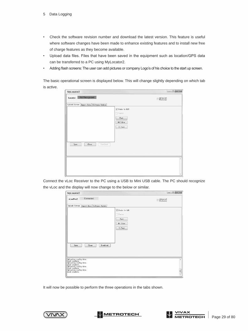
The basic operational screen is displayed below. This will change slightly depending on which tab
is active.
Connect the vLoc Receiver to the PC using a USB to Mini USB cable. The PC should recognize
the vLoc and the display will now change to the below or similar.
It will now be possible to perform the three operations in the tabs shown.
5 Data Logging
Page 30 of 80
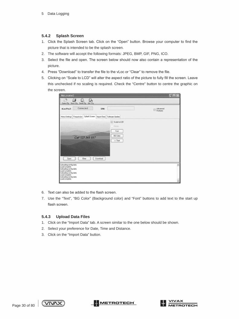
6. Text can also be added to the flash screen.
7. Use the “Text”, “BG Color” (Background color) and “Font” buttons to add text to the start up
flash screen.
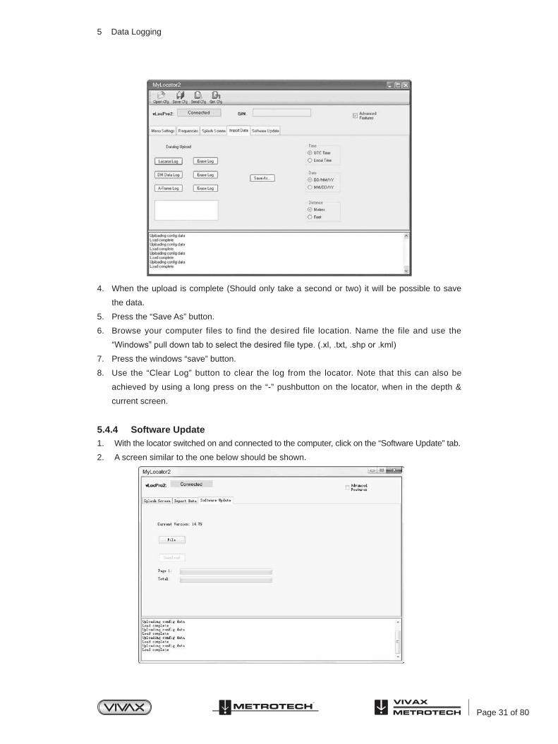
5.4.3 Upload Data Files1. Click on the “Import Data” tab. A screen similar to the one below should be shown.
2. Select your preference for Date, Time and Distance.
3. Click on the “Import Data” button.
5.4.2 Splash Screen1. Click the Splash Screen tab. Click on the “Open” button. Browse your computer to find the
picture that is intended to be the splash screen.
2. The software will accept the following formats: JPEG, BMP, GIF, PNG, ICO.
3. Select the file and open. The screen below should now also contain a representation of the
picture.
4. Press “Download” to transfer the file to the vLoc or “Clear” to remove the file.
5. Clicking on “Scale to LCD” will alter the aspect ratio of the picture to fully fill the screen. Leave
this unchecked if no scaling is required. Check the “Centre” button to centre the graphic on
the screen.
5 Data Logging
Page 31 of 80
4. When the upload is complete (Should only take a second or two) it will be possible to save
the data.
5. Press the “Save As” button.
6. Browse your computer files to find the desired file location. Name the file and use the
“Windows” pull down tab to select the desired file type. (.xl, .txt, .shp or .kml)
7. Press the windows “save” button.
8. Use the “Clear Log” button to clear the log from the locator. Note that this can also be
achieved by using a long press on the “-” pushbutton on the locator, when in the depth &
current screen.
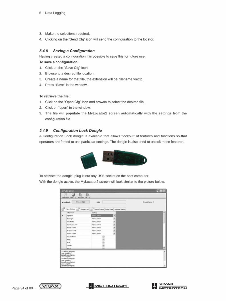
5.4.4 Software Update1. With the locator switched on and connected to the computer, click on the “Software Update” tab.
2. A screen similar to the one below should be shown.
5 Data Logging

Page 32 of 80
3. If connected to the Web, press the “Get latest sw rev” button. Alternatively, if the software
revision required is already saved, use the “File” button to browse to the relevant file.
4. Click on the “Download” button. The progress bars below will start to activate showing
the progress of the software installation. When it is complete a message “software upload
complete” will be shown both on the computer and locator screen.
5. Note that the new software will not be active until the unit has been switched off and on again.
5.4.5 Advanced Configuration ToolClicking the “Advanced” button allows the user to configure the instrument to specific
requirements.
The extra features available are:
• Switch on or off user menu settings
• Switch off frequency selections
By doing this the locator is simplified and tailored exactly to the customer requirements.
The configuration can be saved as a “configuration” file and used to configure other vLoc2
locators. This ensures consistency throughout the locator fleet.
5.4.6 Switch On/Off User Menu Settings1. With the locator switched on and connected to the host computer click on the “Menu Settings” tab.
2. A screen similar to the one below should be shown. If not, click on the “Get Cfg” icon on the
top bar. This will load the configuration of the connected locator to the host pc.
5 Data Logging

Page 33 of 80
3. Check the boxes that are required to be made available.
4. Click on the pull down menu and select the settings required.
5. Clicking on the “Send Cfg” icon will send the configuration to the locator.
5.4.7 Switching On/Off Frequency Selections1. Click on the “Frequencies” tab. A screen similar to the one below should be shown.
2. Each row is color coded:
a. Grey indicates that frequency is not selected for either the menu or the frequency key.
b. White indicates that the frequency will be active in the locator menu but has not
been selected to show on the frequency key. (Note that it is still possible to make this
frequency available on the locator by selecting it in the locator frequency menu.
c. Green indicates that the frequency will be available both in the locator menu and
frequency select key.
d. Blue shows active line.
5 Data Logging
Page 34 of 80
3. Make the selections required.
4. Clicking on the “Send Cfg” icon will send the configuration to the locator.
5.4.8 Saving a ConfigurationHaving created a configuration it is possible to save this for future use.
To save a configuration:1. Click on the “Save Cfg” icon.
2. Browse to a desired file location.
3. Create a name for that file, the extension will be: filename.vmcfg.
4. Press “Save” in the window.
To retrieve the file:1. Click on the “Open Cfg” icon and browse to select the desired file.
2. Click on “open” in the window.
3. The file will populate the MyLocator2 screen automatically with the settings from the
configuration file.
5.4.9 Configuration Lock DongleA Configuration Lock dongle is available that allows “lockout” of features and functions so that
operators are forced to use particular settings. The dongle is also used to unlock these features.
To activate the dongle, plug it into any USB socket on the host computer.
With the dongle active, the MyLocator2 screen will look similar to the picture below.
5 Data Logging
Page 35 of 80
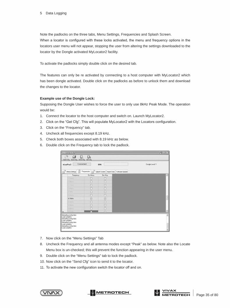
Note the padlocks on the three tabs, Menu Settings, Frequencies and Splash Screen.
When a locator is configured with these locks activated, the menu and frequency options in the
locators user menu will not appear, stopping the user from altering the settings downloaded to the
locator by the Dongle activated MyLocator2 facility.
To activate the padlocks simply double click on the desired tab.
The features can only be re activated by connecting to a host computer with MyLocator2 which
has been dongle activated. Double click on the padlocks as before to unlock them and download
the changes to the locator.
Example use of the Dongle Lock:
Supposing the Dongle User wishes to force the user to only use 8kHz Peak Mode. The operation
would be:
1. Connect the locator to the host computer and switch on. Launch MyLocator2.
2. Click on the “Get Cfg”. This will populate MyLocator2 with the Locators configuration.
3. Click on the “Frequency” tab.
4. Uncheck all frequencies except 8.19 kHz.
5. Check both boxes associated with 8.19 kHz as below.
6. Double click on the Frequency tab to lock the padlock.
7. Now click on the “Menu Settings” Tab
8. Uncheck the Frequency and all antenna modes except “Peak” as below. Note also the Locate
Menu box is un-checked; this will prevent the function appearing in the user menu.
9. Double click on the “Menu Settings” tab to lock the padlock.
10. Now click on the “Send Cfg” icon to send it to the locator.
11. To activate the new configuration switch the locator off and on.
5 Data Logging

Page 36 of 80
5 Data Logging
5.4.10 Icon Summary
Icon FunctionOpens a previously saved configuration.
Saves a configuration created by the operator to a file of your choice.
Either “Send” (saves) configuration to a locator or “Get” (copy) a configuration
from a locator.
“Clears” a configuration created on the configuration tool.

Page 37 of 80
6.1 Loc-10Tx Transmitter OverviewThe Loc-10Tx transmitter is a rugged portable transmitter powered by alkaline “D” cells or Ni-MH
(Nickel Metal Hydride) rechargeable batteries. The following describes the features and uses of
the transmitter.
Display
1 Frequency Being Transmitted (200 kHz available in some country)
6 Output Setting (Step) (filled box indicates current level has been reached, empty box indicates requested current level has not been achieved)
2 Digital Read Out (mA, volts, ohms) 7 Low Power Indicator (enabled automatically when battery becomes one bar)
3 Loudspeaker Level 8 Battery Status
4 Units (mA, volts, ohms) 9 High Voltage Warning* (output is enabled for high voltage)
5 Mode Indication
*High Voltage Warning – the transmitter checks the line when connected, if the line is carrying in excess of 35V, it will display “high voltage” warning icon and not allow the transmitter to operate. In addition the transmitter is protected by a 1.25A/250V fuse in the event of excessive voltage or voltage spikes on the line.
Pushbutton
6 Loc-10Tx Transmitter
Loc-10Tx Transmitter
83.1 kHz
LP
1 0 0 mA
1 2
3
4
5
67
8
9
1 On/Off Control2 Output Decrease3 Frequency Select4 Output Increase5 Information (Volume, mAmps, volts, ohms)

Page 38 of 80
1 Output Connection2 Output Protection (Fuse)3 Loudspeaker4 Battery Charging Socket & DC Input
Connections
6.2 Transmitter Battery
In most markets the transmitter is shipped with alkaline batteries (12 x D cells) unless
rechargeable batteries are specified. Batteries are fitted into quick release trays – the alkaline
is an open pack, to enable the batteries to be changed. The rechargeable pack is a sealed unit
containing Ni-MH (Nickel Metal Hydride) batteries. These packs can only be fitted in a manner to
ensure that the alkaline batteries cannot be inadvertently charged.
6.2.1 Removing the Battery Tray
6.2.2 Replacing the Alkaline Battery• To access batteries – undo stainless steel screws on each battery cover
• To remove batteries – turn tray upside down and give a short sharp tap of the battery tray on
your hand
• Replace batteries with new batteries of the same type, be sure not to mix old and new
batteries
• Do NOT use rechargeable batteries in the alkaline battery tray. Ensure that batteries are
inserted the correct way (see label and molded “+” and “-” in the bottom of the tray)
• Refit the battery cover – then refit the battery tray
WARNING
Alkaline Batteries – insert alkaline batteries (x12) as shown:
Push up button Pull out bottom of catch Lift up catch until it clears catch plate
6 Loc-10Tx Transmitter
Page 39 of 80
6.2.3 Rechargeable Batteries• Do NOT attempt to replace the rechargeable batteries or remove battery covers – return to
Vivax-Metrotech or a Vivax-Metrotech approved service centers for replacement.
WARNING
Use only Vivax-Metrotech recommended charger.
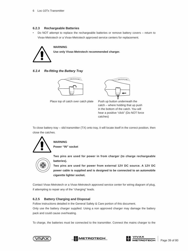
6.2.4 Re-fitting the Battery Tray
To close battery tray – slid transmitter (TX) onto tray, it will locate itself in the correct position, then
close the catches.
WARNING
Power “IN” socket
Two pins are used for power in from charger (to charge rechargeable
batteries).
Two pins are used for power from external 12V DC source. A 12V DC
power cable is supplied and is designed to be connected to an automobile
cigarette lighter socket.
Contact Vivax-Metrotech or a Vivax-Metrotech approved service center for wiring diagram of plug,
if attempting to repair any of the “charging” leads.
6.2.5 Battery Charging and DisposalFollow instructions detailed in the General Safety & Care portion of this document.
Only use the battery charger supplied. Using a non approved charger may damage the battery
pack and could cause overheating.
To charge, the batteries must be connected to the transmitter. Connect the mains charger to the
Place top of catch over catch plate Push up button underneath the catch – where holding that up push in the bottom of the catch. You will hear a positive “click” (Do NOT force catches)
6 Loc-10Tx Transmitter
Page 40 of 80
charging socket on the side of the transmitter and connect the charger to a suitable mains socket.
The LED will show a red light indicating that the charge cycle is in progress. When the batteries
are fully charged the LED will change to green.
NOTE
Rechargeable pack cannot be charged from a 12V DC source.
6.2.6 Battery Condition IndicationThe battery condition (charge) is displayed on the left side of the display, in the case of the
rechargeable batteries the condition is also indicated on the charger (red/green light).
6.3 Transmitting ModesThe transmitter has three transmitting modes, which are selected automatically.
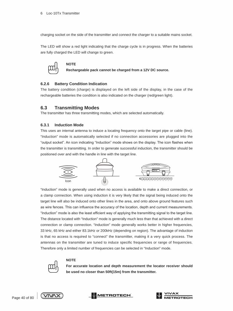
6.3.1 Induction ModeThis uses an internal antenna to induce a locating frequency onto the target pipe or cable (line).
“Induction” mode is automatically selected if no connection accessories are plugged into the
“output socket”. An icon indicating “Induction” mode shows on the display. The icon flashes when
the transmitter is transmitting. In order to generate successful induction, the transmitter should be
positioned over and with the handle in line with the target line.
“Induction” mode is generally used when no access is available to make a direct connection, or
a clamp connection. When using induction it is very likely that the signal being induced onto the
target line will also be induced onto other lines in the area, and onto above ground features such
as wire fences. This can influence the accuracy of the location, depth and current measurements.
“Induction” mode is also the least efficient way of applying the transmitting signal to the target line.
The distance located with “Induction” mode is generally much less than that achieved with a direct
connection or clamp connection. “Induction” mode generally works better in higher frequencies,
33 kHz, 65 kHz and either 83.1kHz or 200kHz (depending on region). The advantage of induction
is that no access is required to “connect” the transmitter, making it a very quick process. The
antennas on the transmitter are tuned to induce specific frequencies or range of frequencies.
Therefore only a limited number of frequencies can be selected in “Induction” mode.
NOTE
For accurate location and depth measurement the locator receiver should
be used no closer than 50ft(15m) from the transmitter.
FU
SE
6 Loc-10Tx Transmitter
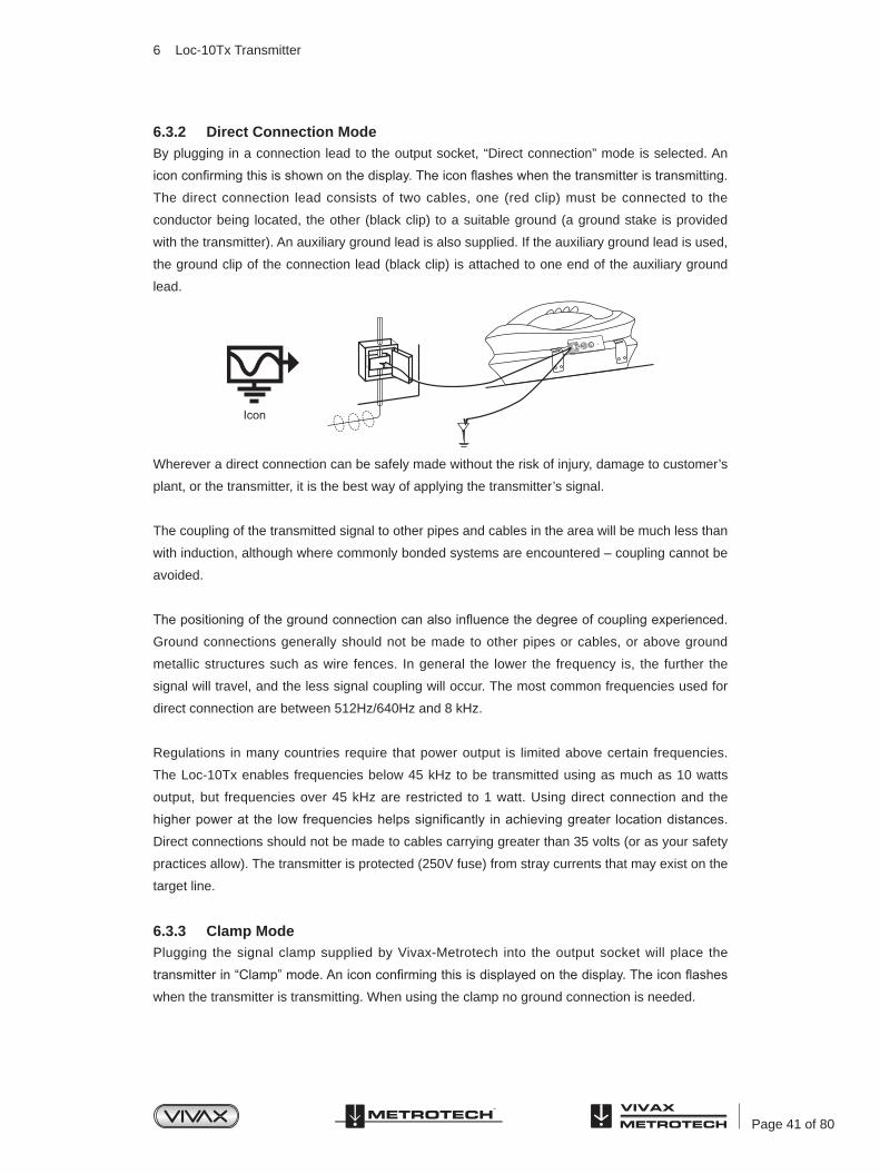
Page 41 of 80
6.3.2 Direct Connection ModeBy plugging in a connection lead to the output socket, “Direct connection” mode is selected. An
icon confirming this is shown on the display. The icon flashes when the transmitter is transmitting.
The direct connection lead consists of two cables, one (red clip) must be connected to the
conductor being located, the other (black clip) to a suitable ground (a ground stake is provided
with the transmitter). An auxiliary ground lead is also supplied. If the auxiliary ground lead is used,
the ground clip of the connection lead (black clip) is attached to one end of the auxiliary ground
lead.
Wherever a direct connection can be safely made without the risk of injury, damage to customer’s
plant, or the transmitter, it is the best way of applying the transmitter’s signal.
The coupling of the transmitted signal to other pipes and cables in the area will be much less than
with induction, although where commonly bonded systems are encountered – coupling cannot be
avoided.
The positioning of the ground connection can also influence the degree of coupling experienced.
Ground connections generally should not be made to other pipes or cables, or above ground
metallic structures such as wire fences. In general the lower the frequency is, the further the
signal will travel, and the less signal coupling will occur. The most common frequencies used for
direct connection are between 512Hz/640Hz and 8 kHz.
Regulations in many countries require that power output is limited above certain frequencies.
The Loc-10Tx enables frequencies below 45 kHz to be transmitted using as much as 10 watts
output, but frequencies over 45 kHz are restricted to 1 watt. Using direct connection and the
higher power at the low frequencies helps significantly in achieving greater location distances.
Direct connections should not be made to cables carrying greater than 35 volts (or as your safety
practices allow). The transmitter is protected (250V fuse) from stray currents that may exist on the
target line.
6.3.3 Clamp ModePlugging the signal clamp supplied by Vivax-Metrotech into the output socket will place the
transmitter in “Clamp” mode. An icon confirming this is displayed on the display. The icon flashes
when the transmitter is transmitting. When using the clamp no ground connection is needed.
FU
SE
6 Loc-10Tx Transmitter

Page 42 of 80
The clamp again is a precise way to apply the locating signal. It is generally used when access to
the conductor cannot be achieved to make a direct connection (but there is sufficient access to
place the clamp around the cable), or when it is not safe to make a direct connection because the
target cable is carrying electricity.
The clamp is a specialized inductive device (sometimes known as a toroidor coupler). All clamps
are optimized to work at specific frequencies. In most cases clamps are designed to be used at
up to three frequencies only, generally between 8 kHz and 85 kHz. The transmitter will only allow
the selection of a suitable frequency for your clamp.
WARNING
When applying the clamp to cables that carry electricity – be sure to follow
your company’s safety instructions and procedures. Beware that if applied
around a high voltage cable – that cable may induce a current in the clamp
causing it to snap shut or jump quite dramatically – always apply clamps
carefully.
6.3.4 Connection Block
All the connections made to the transmitter are made at the connection block except for a USB
socket which is mounted inside the battery compartment and is used for programming the
transmitter’s processor.
The connection block consists of:
• Output (XLR) socket – for the direct connection lead and clamp.
• Charger socket (to allow the retrofitting of a rechargeable battery pack – the charging socket is present even if re-chargeable batteries have not been purchased).
• Transmitter 12V DC power lead used to power the transmitter from a vehicle (NOT for
charging).
1 Output Connection2 Output Protection (Fuse)3 Loudspeaker4 Battery Charging Socket & DC Input
6 Loc-10Tx Transmitter

Page 43 of 80
• Fuse – this protects the transmitter circuitry in the event of the transmitter receiving up to
250V incoming on the output leads.
• A beeper is positioned behind the small hole.
6.3.5 Frequencies and Power OutputThe Loc-10Tx transmitter is supplied with a predefined set of transmit frequencies.
Standard frequencies are:
• 512Hz (where electrical systems are 60Hz) direct connection – 10 watts.
• 640Hz (where electrical systems are 50Hz) direct connection – 10 watts.
• 65 kHz direct connection – 1 watt.
• 83.1 kHz, 89kHz, 131kHz direct connection – 1 watt (depending on region).
• 200 kHz direct connection – 1 watt (depending on region).
• Induction frequencies are 8 kHz, 33 kHz and 65 kHz or alternatively 33 kHz, 65 kHz and 200
kHz(Note: 200 kHz is not permitted in some markets). Other combination between 8kHz,
33kHz, 65kHz, 78kHz and 200kHz also available. For detail please refer to Loc-10TxSIS data
sheet.
• Other frequencies with 10 Watt output:
○ Direction connection: 256Hz, 491Hz, 512Hz, 982Hz
○ Direct and clamp connection : 8.19kHz, 8.44kHz, 9.5kHz, 9.82kHz, 32.8kHz, 38kHz
As with most manufacturers the clamps and induction antennas are tuned to specific frequencies,
and do NOT work over the complete range.
Frequencies are selected by pressing the “f” pushbutton which toggles through the available
frequencies for the selection mode. The frequency is automatically selected if you don’t toggle
past it within 2 seconds. The frequency is shown on the display.
The output current is shown in large characters on the display – to increase or reduce the power
output press “+” or “-”. The vertical bar graph at the bottom of the display indicates which of the
four current output steps is being used. If the transmitter can supply the requested current, the
bar will turn black. If the bar does not turn black, improving the ground connections or wetting the
ground where the earth stake in positioned, may help. However, it may not be able to achieve
the current setting requested because the impedance of the line is too high for this setting. If this
happens it is best to select a setting that has a black bar, this will ensure a stable output.
6 Loc-10Tx Transmitter
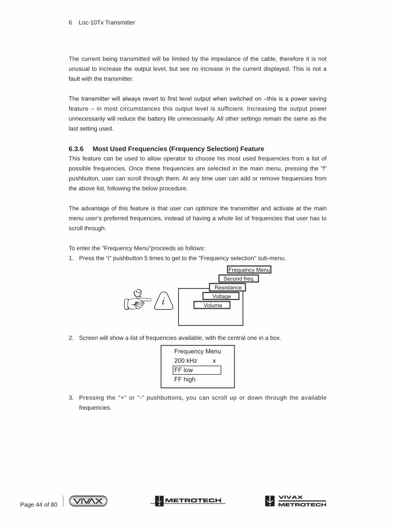
Page 44 of 80
The current being transmitted will be limited by the impedance of the cable, therefore it is not
unusual to increase the output level, but see no increase in the current displayed. This is not a
fault with the transmitter.
The transmitter will always revert to first level output when switched on –this is a power saving
feature – in most circumstances this output level is sufficient. Increasing the output power
unnecessarily will reduce the battery life unnecessarily. All other settings remain the same as the
last setting used.
6.3.6 Most Used Frequencies (Frequency Selection) FeatureThis feature can be used to allow operator to choose his most used frequencies from a list of
possible frequencies. Once these frequencies are selected in the main menu, pressing the "f"
pushbutton, user can scroll through them. At any time user can add or remove frequencies from
the above list, following the below procedure.
The advantage of this feature is that user can optimize the transmitter and activate at the main
menu user’s preferred frequencies, instead of having a whole list of frequencies that user has to
scroll through.
To enter the "Frequency Menu"proceeds as follows:
1. Press the “i" pushbutton 5 times to get to the "Frequency selection" sub-menu.
2. Screen will show a list of frequencies available, with the central one in a box.
3. Pressing the "+" or "-" pushbuttons, you can scroll up or down through the available
frequencies.
6 Loc-10Tx Transmitter

Page 45 of 80
4. Once the wanted frequency is inside the box, press “f” pushbutton to select or deselect the
frequency. An “x” will appear in the box for a selected frequency.
5. After selecting for the frequencies, press the "i" pushbutton again to exit the “Frequency
Menu” and the selected list of frequencies can be select from the main display screen.
6.3.7 "Dual frequency" ModeThis feature can be used when user wants to energize on user’s target two frequencies at the same time.
Mainly, it can be used when user is not sure which frequency can be impressed better into the target.
NOTE
• When using "dual frequency" mode, total power will be split between
the two activated frequencies.
• This mode of operation is available only for frequencies below 40 kHz.
• The two frequencies have to be available in the main menu.
To enter the "Choose Second Freq." menu, proceeds as follows:
1. Press "f" pushbutton to select the lowest frequency that user want to have in the dual
combination.
2. Press "i" pushbutton 4 times to get to the "Choose Second Freq." sub-menu. The above
frequency will be shown in a box.
3. By using the "+" and "-" pushbuttons, user can scroll through the available frequencies and
bring the wanted one in the box.
4. Press "f" pushbutton to select the second frequency and exit the submenu to return to the
main display.
5. In the main display screen, both frequencies are displayed.The frequency will toggle between
the two chosen frequencies.
6 Loc-10Tx Transmitter
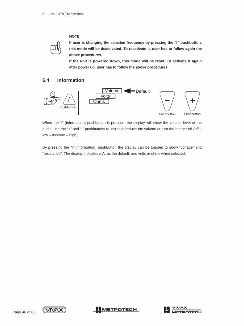
Page 46 of 80
NOTE
If user is changing the selected frequency by pressing the "f" pushbutton,
this mode will be deactivated. To reactivate it, user has to follow again the
above procedures.
If the unit is powered down, this mode will be reset. To activate it again
after power up, user has to follow the above procedures.
6.4 Information
When the “i” (information) pushbutton is pressed, the display will show the volume level of the
audio; use the “+” and “-” pushbuttons to increase/reduce the volume or turn the beeper off (off –
low – medium – high).
By pressing the “i” (information) pushbutton the display can be toggled to show “voltage” and
“resistance”. The display indicates mA, as the default, and volts or ohms when selected.
6 Loc-10Tx Transmitter

Page 47 of 80
7.1 Pushbutton
7.2 External Connectors
7.3 Transmitter BatteryIn most markets the transmitter is shipped with alkaline batteries (8 x D cells) unless rechargeable
batteries are specified. Batteries are fitted into quick release trays – the alkaline is an open pack,
to enable the batteries to be changed. The rechargeable pack is a sealed unit containing Ni-MH
(Nickel Metal Hydride) batteries. These packs can only be fitted in a manner to ensure that the
alkaline batteries cannot be inadvertently charged.
7.3.1 Removing the Battery Tray
To remove the tray, operate the three ¼ turn fasteners in an anti clockwise direction. This should
now release the tray which can then be slid out from the transmitter body. Be careful not to allow
the batteries to fall from the tray as it is removed from the body.
7 Loc-5Tx Transmitter
Loc-5Tx Transmitter
1 2 3 4 5
12345
On/Off ControlOutput DecreaseInformation (Volume, mA, Volts, Ohms)Frequency SelectOutput Increase
1234
Mini USB PortOutput FuseSpeakerOutput Connection
12
Battery Charging Socket & DC Input¼ turn fasteners
1 2 3 4
12

Page 48 of 80
7.3.2 Replacing Alkaline Batteries• Replace with new batteries of the same type, be sure not to mix old and new batteries
• Do NOT use rechargeable batteries in the alkaline battery tray. Ensure that batteries are
inserted the correct way (see label “+” and “-” on the side of the tray)
• Refit the battery tray and operate the three ¼ turn fasteners in a clock wise direction.
WARNING
Alkaline Batteries – insert alkaline batteries (x8) as shown
7.3.3 Rechargeable Batteries• Do NOT attempt to replace the rechargeable batteries or remove battery covers – return to
Vivax-Metrotech or a Vivax-Metrotech approved service centers for replacement.
WARNING
Use only Vivax-Metrotech recommended charger.
7.3.4 Re-fitting the Battery TrayRefit the battery tray and operate the three ¼ turn fasteners in a clock wise direction.
WARNING
Power “IN” socket
Two pins are used for power in from charger (to charge rechargeable
batteries).
Two pins are used for power from external 12V DC source. (e.g. 12V DC
cigarette lighter supply from automobile)
NOTE
Rechargeable pack cannot be charged from a 12V DC source.
Contact Vivax-Metrotech or a Vivax-Metrotech approved service center for wiring diagram of plug,
if attempting to repair any of the “charging” leads.
7 Loc-5Tx Transmitter

Page 49 of 80
7.3.5 Battery Charging and DisposalFollow instructions detailed in the General Safety & Care portion of this document.
Only use the charger supplied with the equipment. Using a non approved battery charger may
damage the batteries and cause overheating.
The charger is mains operated. Connect the charger to the battery pack at the rear of the
transmitter. Switch on the charger. The LED on the charger will show a red light indicating that the
charge process has started. When the LED changes to a green indicator the charge sequence is
complete and the batteries will be fully charged.
7.3.6 Battery Condition IndicationThe battery condition (charge) is displayed on the left side of the display, in the case of the
rechargeable batteries the condition is also indicated on the charger (red/green light).
7.4 Display• Startup screen, software configuration
• Main screen
• Clamp Mode
• Induction Mode
• DC Measurement
conf 011
VIVAX 100
9.82 kHzBat=Full
300mACONN
1
2
3
4
1234
Frequency Being TransmittedBattery StatusSignal Current Out (mA)Mode Indication
9.82 kHzBat=Full
25mACLAMP
9.82 kHzBat=FullI ND
V=3VR=50 ohm
7 Loc-5Tx Transmitter

Page 50 of 80
If a DC measurement is required, while in the voltage and resistance screen, press and hold the
“i” pushbutton. The unit will enter in to the DC measurement sequence and at the end of it will
display the DC resistance of the load.
Screen showing DC resistance of the load.
7.5 Multi FrequenciesTo transmit simultaneous up to 3 frequencies proceed as follows:
1. Place the transmitter in the first frequency using the “f” key in the main menu
2. Press the “i” key 3 times. The display will show the screen below with “Freq # 2” and “Freq # 3”
flashing. This mean they are not set yet.
3. At this point, with the “up” and “down” keys you can select the second frequency to be
transmitted. Once in the proper selection, press the “f” button to confirm. The “Freq # 2” row
will not flash any more confirming that it has been set. Repeat the above procedure for the
third selection or press “i” to exit this menu, if a third frequency is not needed.
4. Main display will show the “MULTI” as a mode of operation as shown below.
NOTE
The “MULTI” mode is only a one time mode. If the unit powered down the
MULTI mode has to be reactivated.
7.6 Most Used Frequencies (Frequency Selection) FeatureThis feature can be used to allow operator to activate the most used frequencies from a list of
possible frequencies. Once these frequencies are selected in the main menu, press the "f" key,
scrolls through them. At any time the user can add or remove frequencies from the above list,
following the below procedure.
2
R=50 ohm
Freq # 2Freq # 3
9.82 kHz982Hz
MultiBat=Full
25mACONN
7 Loc-5Tx Transmitter
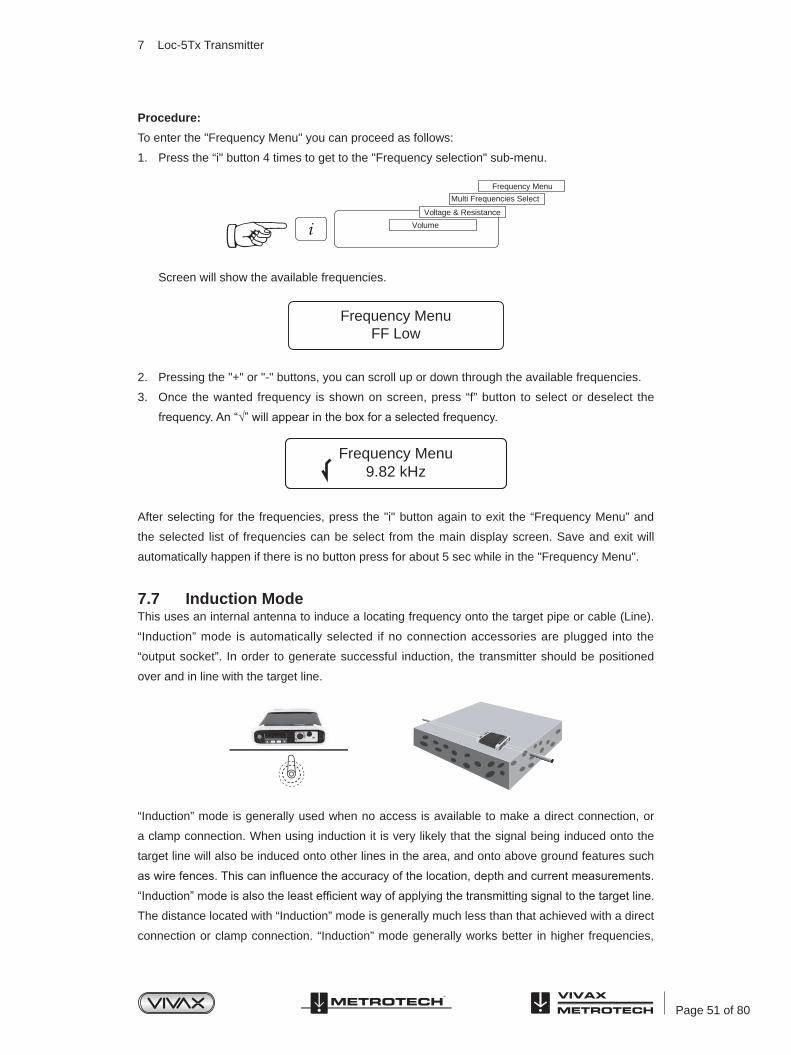
Page 51 of 80
Procedure:
To enter the "Frequency Menu" you can proceed as follows:
1. Press the “i" button 4 times to get to the "Frequency selection" sub-menu.
Screen will show the available frequencies.
2. Pressing the "+" or "-" buttons, you can scroll up or down through the available frequencies.
3. Once the wanted frequency is shown on screen, press “f” button to select or deselect the
frequency. An “√” will appear in the box for a selected frequency.
After selecting for the frequencies, press the "i" button again to exit the “Frequency Menu” and
the selected list of frequencies can be select from the main display screen. Save and exit will
automatically happen if there is no button press for about 5 sec while in the "Frequency Menu".
7.7 Induction ModeThis uses an internal antenna to induce a locating frequency onto the target pipe or cable (Line).
“Induction” mode is automatically selected if no connection accessories are plugged into the
“output socket”. In order to generate successful induction, the transmitter should be positioned
over and in line with the target line.
“Induction” mode is generally used when no access is available to make a direct connection, or
a clamp connection. When using induction it is very likely that the signal being induced onto the
target line will also be induced onto other lines in the area, and onto above ground features such
as wire fences. This can influence the accuracy of the location, depth and current measurements.
“Induction” mode is also the least efficient way of applying the transmitting signal to the target line.
The distance located with “Induction” mode is generally much less than that achieved with a direct
connection or clamp connection. “Induction” mode generally works better in higher frequencies,
Volume
Voltage & Resistance
Multi Frequencies Select
Frequency Menu
Frequency MenuFF Low
Frequency Menu9.82 kHz
7 Loc-5Tx Transmitter

Page 52 of 80
33 kHz, 65 kHz and either 83.1 kHz (depending on region). The advantage of induction is that no
access is required to “connect” the transmitter, making it a very quick process. The antennas on
the transmitter are tuned to induce specific frequencies or range of frequencies. Therefore only a
limited number of frequencies can be selected in “Induction” mode.
NOTE
For accurate location and depth measurement the locator receiver should
not be used within 50ft (15m) from the transmitter.
7.8 Direct Connection ModeA connection lead set is supplied with the Loc-5Tx transmitter. This lead set is used to make an
electrical connection to a cable or pipe that is to be traced. One of the leads is connected to the
line and the other to a ground point that is nearby or a by inserting the ground rod supplied with
the equipment and connecting to that.
A good connection is indicated by a change in tone from the speaker and a current reading on the
display.
More information can be found in section 6.3.2.
7.9 Clamp ModeThe signal clamp is an optional extra. There are three different sizes 2in (50mm), 4in (100mm),
5in (125mm).
The clamp is generally used to apply the signal tone to a live cable or telecom cable where an
electrical connection is not possible because of safety or access issues.
Please refer to section 6.3.3 for further information.
7 Loc-5Tx Transmitter

Page 53 of 80
8 Loc-1Tx Transmitter
8.1 Pushbutton
8.2 External Connectors
Loc-1Tx Transmitter
1234
On/Off ControlFrequency Select (the arrow points to the corresponding frequency printed on the label on top) Audio Beeper LevelOutput High/Low setting
1234
Mini USB PortOutput FuseSpeakerOutput Connection
12
DC Input (power supply only)¼ turn fasteners
8.3 Replacing Alkaline Batteries• Replace with new batteries of the same type, be sure not to mix old and new batteries.
• Do NOT use rechargeable batteries in the alkaline battery tray. Ensure that batteries are
inserted the correct way (see label “+” and “-” on the side of the tray).
• Refit the battery tray and operate the three ¼ turn fasteners in a clock wise direction.
WARNING
Alkaline Batteries – insert alkaline batteries (x4) as shown
1 2 3 4
12

Page 54 of 80
8.4 Rechargeable BatteriesRechargeable batteries are not available for the Loc-1Tx transmitter.
8.5 Loc-1Tx Transmitter OperationThe operation of the Loc-1Tx transmitter is very similar to the Loc-5Tx transmitter. This is covered
in section 7.7 to 7.9.
8 Loc-1Tx Transmitter

Page 55 of 80
9 Using the vLocPro2
9.1 Using the Receiver9.1.1 Line LocatingLine locating is when a pipe or cable is being located. When line locating, the receiver should be
held with the display forward, and then swept to the left and right across the suspected direction
of the buried line. Note the line direction indicator (LDI) always points in the direction of the line
(active in active modes). The LDI color change from clear to blue when the receiver is in line with
the buried line.
The receiver should be kept parallel to the ground – and should not be flipped up at the end of
each pass. See diagram (a).
To establish the direction of the cable – use whatever mode you prefer to locate the line; then
switch to “Peak” mode to confirm the direction. Pinpoint the line – by carefully establishing the
exact “Peak” position. Then (with the base of the receiver on the ground) rotate the receiver
through 90 degrees, as you do this the signal being received will reduce substantially (possibly
disappear). Then rotate the locator until you find the maximum “Peak”. The front of the locator is
again facing in the direction of the buried line. See diagram (b).
9.1.2 Depth & Current MeasurementPinpoint the exact position of the cables as follows:
• Locate lateral position of the cable.
• Rotate receiver to confirm the direction of the cable (you will see a null response when the
receiver is intersecting the direction of the cable at 90 degrees).
• Rotate the receiver back until it is exactly in line with the cable.
Using the vLocPro2
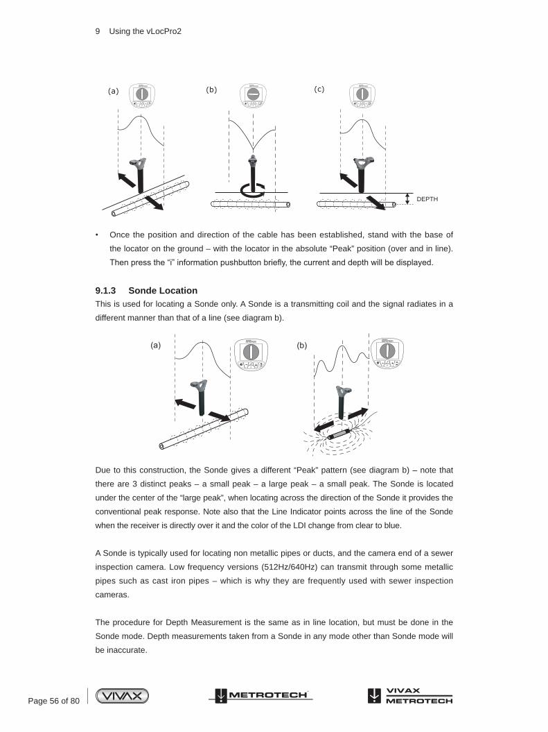
Page 56 of 80
• Once the position and direction of the cable has been established, stand with the base of
the locator on the ground – with the locator in the absolute “Peak” position (over and in line).
Then press the “i” information pushbutton briefly, the current and depth will be displayed.
9.1.3 Sonde LocationThis is used for locating a Sonde only. A Sonde is a transmitting coil and the signal radiates in a
different manner than that of a line (see diagram b).
Due to this construction, the Sonde gives a different “Peak” pattern (see diagram b) – note that
there are 3 distinct peaks – a small peak – a large peak – a small peak. The Sonde is located
under the center of the “large peak”, when locating across the direction of the Sonde it provides the
conventional peak response. Note also that the Line Indicator points across the line of the Sonde
when the receiver is directly over it and the color of the LDI change from clear to blue.
A Sonde is typically used for locating non metallic pipes or ducts, and the camera end of a sewer
inspection camera. Low frequency versions (512Hz/640Hz) can transmit through some metallic
pipes such as cast iron pipes – which is why they are frequently used with sewer inspection
cameras.
The procedure for Depth Measurement is the same as in line location, but must be done in the
Sonde mode. Depth measurements taken from a Sonde in any mode other than Sonde mode will
be inaccurate.
DEPTH
9 Using the vLocPro2
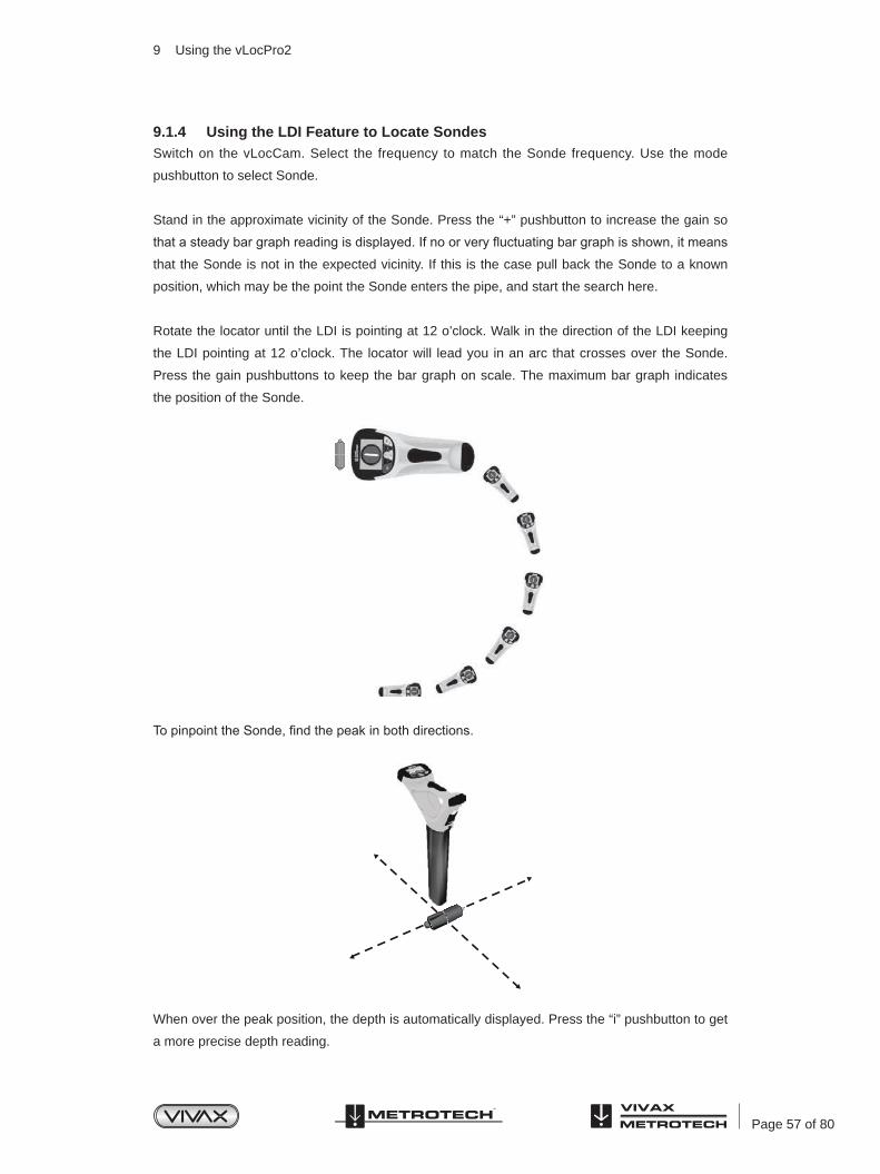
Page 57 of 80
9.1.4 Using the LDI Feature to Locate SondesSwitch on the vLocCam. Select the frequency to match the Sonde frequency. Use the mode
pushbutton to select Sonde.
Stand in the approximate vicinity of the Sonde. Press the “+” pushbutton to increase the gain so
that a steady bar graph reading is displayed. If no or very fluctuating bar graph is shown, it means
that the Sonde is not in the expected vicinity. If this is the case pull back the Sonde to a known
position, which may be the point the Sonde enters the pipe, and start the search here.
Rotate the locator until the LDI is pointing at 12 o’clock. Walk in the direction of the LDI keeping
the LDI pointing at 12 o’clock. The locator will lead you in an arc that crosses over the Sonde.
Press the gain pushbuttons to keep the bar graph on scale. The maximum bar graph indicates
the position of the Sonde.
To pinpoint the Sonde, find the peak in both directions.
When over the peak position, the depth is automatically displayed. Press the “i” pushbutton to get
a more precise depth reading.
9 Using the vLocPro2
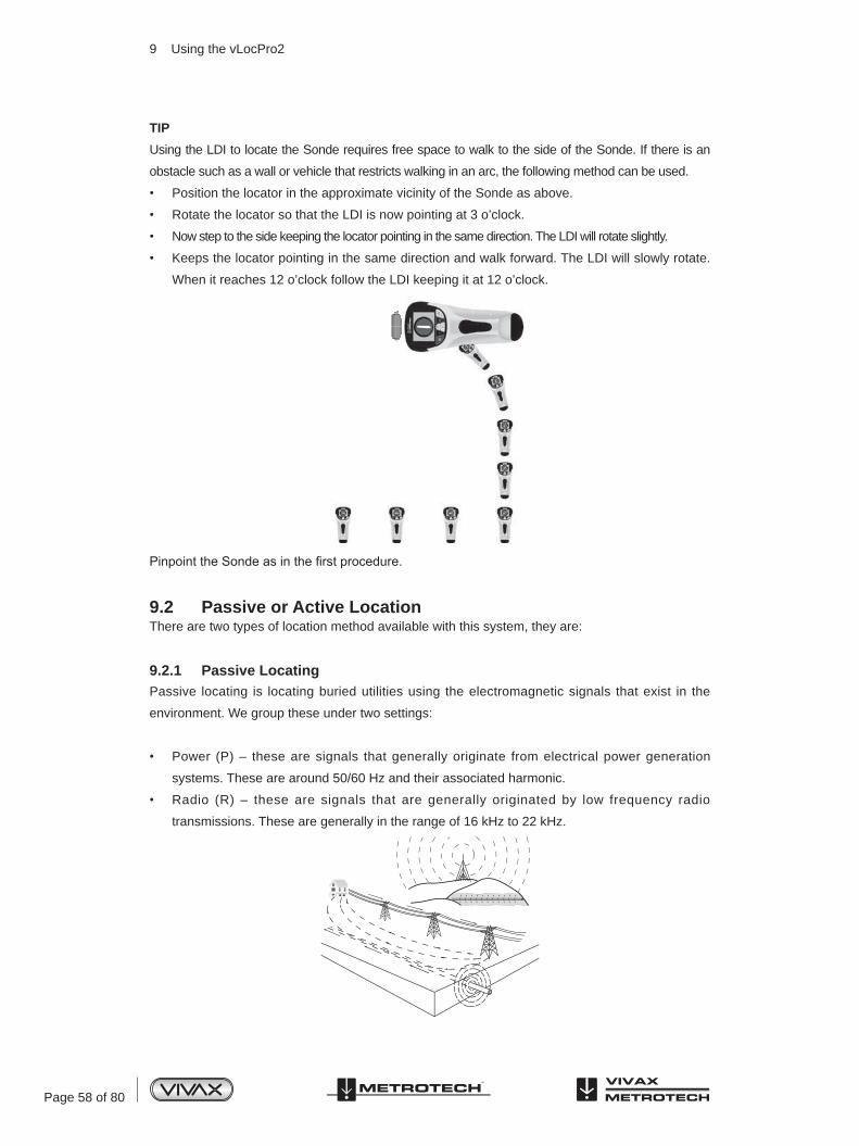
Page 58 of 80
TIP
Using the LDI to locate the Sonde requires free space to walk to the side of the Sonde. If there is an
obstacle such as a wall or vehicle that restricts walking in an arc, the following method can be used.
• Position the locator in the approximate vicinity of the Sonde as above.
• Rotate the locator so that the LDI is now pointing at 3 o’clock.
• Now step to the side keeping the locator pointing in the same direction. The LDI will rotate slightly.
• Keeps the locator pointing in the same direction and walk forward. The LDI will slowly rotate.
When it reaches 12 o’clock follow the LDI keeping it at 12 o’clock.
Pinpoint the Sonde as in the first procedure.
9.2 Passive or Active LocationThere are two types of location method available with this system, they are:
9.2.1 Passive LocatingPassive locating is locating buried utilities using the electromagnetic signals that exist in the
environment. We group these under two settings:
• Power (P) – these are signals that generally originate from electrical power generation
systems. These are around 50/60 Hz and their associated harmonic.
• Radio (R) – these are signals that are generally originated by low frequency radio
transmissions. These are generally in the range of 16 kHz to 22 kHz.
9 Using the vLocPro2

Page 59 of 80
Passive location is used to search an area to see if buried metallic lines are present (known as
locating to AVOID). It does not help to identify what buried pipe or cable is present, only to confirm
that there is a pipe or cable there. A typical application would be to check an area before installing
a fence post.
9.2.2 Active LocatingActive locating is using a transmitter to apply a very precise frequency to a pipe or cable, and
then using a receiver turned to find the signal being radiated at that precise frequency. Active
location frequencies can be applied by direct connection, clamp or induction.
This receiver provides a wide range of frequencies for active location. Some will be the same as
the frequencies provided by the Vivax-Metrotech’s transmitter, others will be frequencies used in
other manufacturers’ transmitter.
The choice of frequencies when using induction or the clamp is restricted due to the requirement
that these modes be tuned for specific frequencies (or range of frequencies). The full range of
frequencies is available in “Direct connection” mode.
For frequencies below 45 kHz, authorities such as the FCC allow higher power output to be used;
for frequencies of 45 kHz and above, power output for this type of equipment is restricted to 1
watt. Therefore more power is available when lower frequencies are used.
9.3 Applying the Transmitter’s SignalThe transmitter’s signal cable is applied in any one of the three ways:
9.3.1 Direct ConnectionThis is used on pipes or cables that are not live and do NOT carry hazardous voltages. The “Direct
connection” mode will be selected automatically when the connection leads are plugged into the
transmitter.
FU
SE
FU
SE
9 Using the vLocPro2

Page 60 of 80
WARNING
Never make a direct connection to live cables carrying hazardous voltages.
Do NOT plug the connection leads into the transmitter before connecting to the buried line and
fixing the ground stake.
Take the ground stake and push firmly into the ground and connect it to the black connection
lead.
To make the signal travel further along the buried line, ensure to place the ground stake as far
away as possible, and at 90 degrees to the line. Where practical avoid having other buried lines
between the ground stake and the target line, this will reduce the chances of the transmitter signal
coupling to another pipe or cable.
Do NOT connect the black lead to any other metallic items that may have an above or below
ground structure, or to any other pipes or cables; connecting to such items would cause signals to
radiate from these secondary structures, which in turn will increase the likelihood of an incorrect
locate.
Connect the red connection lead to the target line after removing any surface corrosion.
Plug the connection leads into the transmitter switch on and select the desired frequency.
WARNING
BE CAREFUL not to hit other buried lines when inserting the ground stake
into the ground. Check using passive location prior to inserting ground
stake. Stop if additional resistance is felt during insertion.
9.3.2 Clamp (Coupler)This is used when applying the transmitter signal to cables carrying hazardous voltages, or
cables where access to the metallic conductor is not possible, or desirable. The “Clamp” mode is
selected automatically when the clamp is plugged into the transmitter.
For a clamp to work the current induced by the clamp must flow along the buried line. This means
the buried line must have a ground connection at both ends.
FU
SE
9 Using the vLocPro2
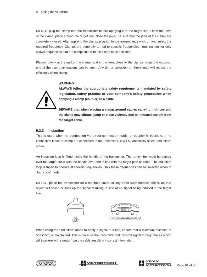
Page 61 of 80
Do NOT plug the clamp into the transmitter before applying it to the target line. Open the jaws
of the clamp, place around the target line, close the jaws. Be sure that the jaws of the clamp are
completely closed. After applying the clamp, plug it into the transmitter, switch on and select the
required frequency. Clamps are generally turned to specific frequencies. Your transmitter only
allows frequencies that are compatible with the clamp to be selected.
Please note – at the end of the clamp, and in the area close to the clamps hinge the exposed
end of the clamp laminations can be seen. Any dirt or corrosion on these ends will reduce the
efficiency of the clamp.
WARNING
ALWAYS follow the appropriate safety requirements mandated by safety
legislation, safety practice or your company’s safety procedures when
applying a clamp (coupler) to a cable.
BEWARE that when placing a clamp around cables carrying high current,
the clamp may vibrate, jump or close violently due to inducted current from
the target cable.
9.3.3 InductionThis is used when no connection via direct connection leads, or coupler is possible. If no
connection leads or clamp are connected to the transmitter, it will automatically select “Induction”
mode.
An induction loop is fitted inside the handle of the transmitter. The transmitter must be placed
over the target cable with the handle over and in line with the target pipe or cable. The induction
loop is tuned to operate at specific frequencies. Only these frequencies can be selected when in
“Induction” mode.
Do NOT place the transmitter on a manhole cover, or any other such metallic object, as that
object will shield or soak up the signal resulting in little of no signal being induced in the target
line.
When using the “Induction” mode to apply a signal to a line, ensure that a minimum distance of
50ft (15m) is maintained. This is because the transmitter will transmit signal through the air which
will interfere with signals from the cable, resulting incorrect information.
9 Using the vLocPro2

Page 62 of 80
9.3.4 Searching (sweeping) an AreaIn any given area, it is likely that buried pipes and cables are not parallel to each other, frequently
they will cross the area being searched at a variety of different angles and depths. As the response
of locator antennas is directional, it is important to search the area in the same or similar pattern as
below. This orients the antennas in a way that will locate any signals being radiate from the buried
line. Once a response is found, then trace and pinpoint the line and mark. Searching an area in
this way is generally (but not exclusively) done in the “Peak” mode using passive locating.
9.3.5 Tracing a Buried LineOnce a buried line is located it is generally necessary, and a good practice, to trace that line for
some distance in both directions. Whenever practical it should be traced to a point that provides
additional confirmation of what type of service is being located (a telephone pedestal, a manhole
cover etc). If tracing a line to which a transmitter signal has been applied, one should trace out
from the transmitter connection point. The receiver should be held level to the ground and rotated
in a small arc across the anticipated route of the buried line. A clear response should be visible on
the display and heard audibly.
9 Using the vLocPro2
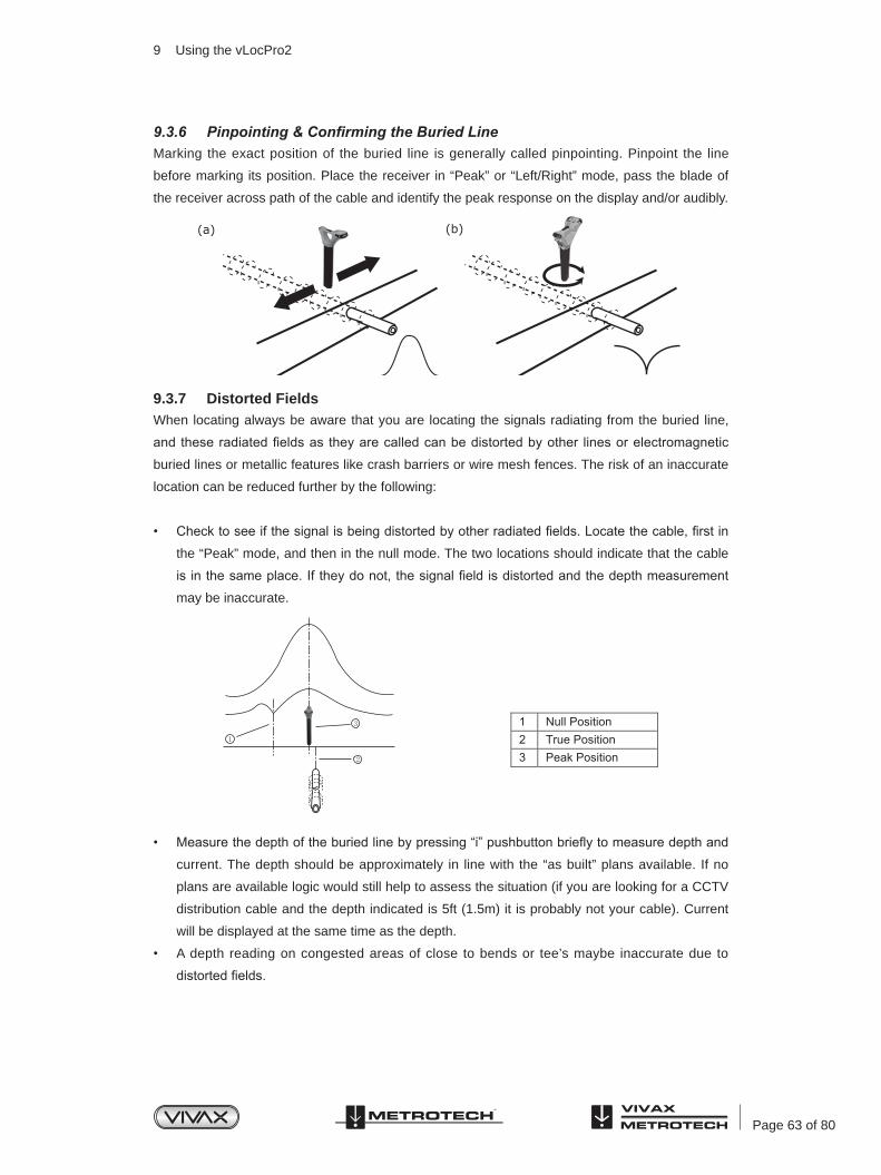
Page 63 of 80
9.3.6 Pinpointing & Confirming the Buried LineMarking the exact position of the buried line is generally called pinpointing. Pinpoint the line
before marking its position. Place the receiver in “Peak” or “Left/Right” mode, pass the blade of
the receiver across path of the cable and identify the peak response on the display and/or audibly.
9.3.7 Distorted FieldsWhen locating always be aware that you are locating the signals radiating from the buried line,
and these radiated fields as they are called can be distorted by other lines or electromagnetic
buried lines or metallic features like crash barriers or wire mesh fences. The risk of an inaccurate
location can be reduced further by the following:
• Check to see if the signal is being distorted by other radiated fields. Locate the cable, first in
the “Peak” mode, and then in the null mode. The two locations should indicate that the cable
is in the same place. If they do not, the signal field is distorted and the depth measurement
may be inaccurate.
• Measure the depth of the buried line by pressing “i” pushbutton briefly to measure depth and
current. The depth should be approximately in line with the “as built” plans available. If no
plans are available logic would still help to assess the situation (if you are looking for a CCTV
distribution cable and the depth indicated is 5ft (1.5m) it is probably not your cable). Current
will be displayed at the same time as the depth.
• A depth reading on congested areas of close to bends or tee’s maybe inaccurate due to
distorted fields.
9 Using the vLocPro2

Page 64 of 80
9.3.8 Measuring Depth and Current• Pinpoint the cable as described in “Pinpointing cable”, with the receiver in line with and
directly above the buried line – measure the depth (d) by pressing “i” pushbutton briefly.
Current will be displayed at the same time as the depth.
• Be careful when locating in congested areas or close to bends or tee’s, they may be
inaccurate due to distorted fields.
• An alternate method of verifying depth (D) is triangulation. There are two methods of
triangulation, 50% and 70% rules. If using the 50% rule Broad peak mode (single antenna)
should be used or peak mode if using the 70% rule. On some models there is an option that
instructs the user in taking triangulation measurements. In this case the antenna selection is
done automatically so the operator does not need to select the antenna configuration.
Semi Automatic Triangulation Mode
On some models a "triangulation mode" is available that assist in taking these types of
measurements.
To use the Triangulation mode the function must first be activated in the User Menu. The user
Menu will give the option of Peak Depth or Triangulation. If Triangulation is selected, either 50%
or 70% rules will be initiated. 50% or 70% rules are selected by connecting the unit to MyLocator2
and selecting “Menu Settings” and then the desired rule in the “Depth Mode” tab.
To use the function first locate the cable or pipe in the usual way.
Press the “i” pushbutton and a depth will be indicated. To confirm with triangulation, press the “i”
pushbutton again.
50ft
(20m)d d d dd d
d
Distance A to B = Depth (D) Distance (A’ to B’)/2 = Depth (D)
9 Using the vLocPro2
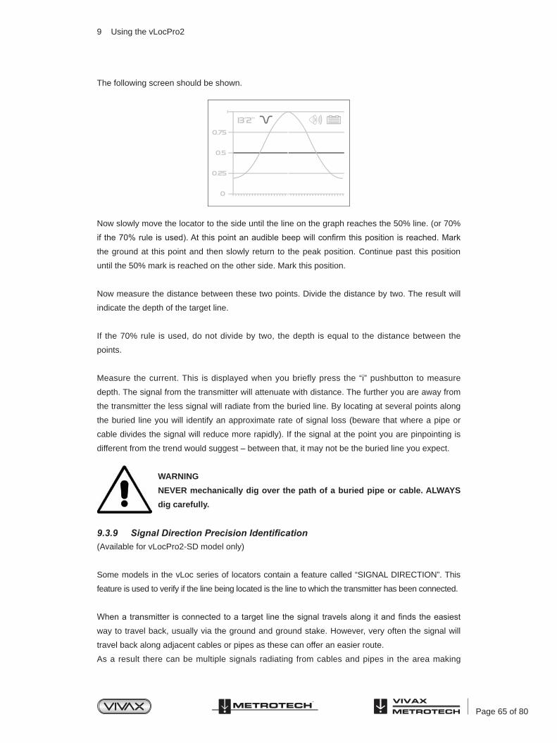
Page 65 of 80
The following screen should be shown.
Now slowly move the locator to the side until the line on the graph reaches the 50% line. (or 70%
if the 70% rule is used). At this point an audible beep will confirm this position is reached. Mark
the ground at this point and then slowly return to the peak position. Continue past this position
until the 50% mark is reached on the other side. Mark this position.
Now measure the distance between these two points. Divide the distance by two. The result will
indicate the depth of the target line.
If the 70% rule is used, do not divide by two, the depth is equal to the distance between the
points.
Measure the current. This is displayed when you briefly press the “i” pushbutton to measure
depth. The signal from the transmitter will attenuate with distance. The further you are away from
the transmitter the less signal will radiate from the buried line. By locating at several points along
the buried line you will identify an approximate rate of signal loss (beware that where a pipe or
cable divides the signal will reduce more rapidly). If the signal at the point you are pinpointing is
different from the trend would suggest – between that, it may not be the buried line you expect.
WARNING
NEVER mechanically dig over the path of a buried pipe or cable. ALWAYS
dig carefully.
9.3.9 Signal Direction Precision Identification(Available for vLocPro2-SD model only)
Some models in the vLoc series of locators contain a feature called “SIGNAL DIRECTION”. This
feature is used to verify if the line being located is the line to which the transmitter has been connected.
When a transmitter is connected to a target line the signal travels along it and finds the easiest
way to travel back, usually via the ground and ground stake. However, very often the signal will
travel back along adjacent cables or pipes as these can offer an easier route.
As a result there can be multiple signals radiating from cables and pipes in the area making
9 Using the vLocPro2

Page 66 of 80
it difficult to identify the target line. These return signals are typically traveling in the opposite
direction than the applied signal. The Signal Direction feature identifies which direction the signal
is flowing and hence the target line.
To use the signal direction system:
• Connect the transmitter to the target line using a direct connection only.
• Turn the transmitter and receiver on and set both to:
○ SD-USA – if in North America or any territory where the power system is 60Hz.
○ SD-EUR – if in Europe or any territory where the power system is 50Hz.
• The receiver may, or may not be flashing the “SD” icon and LDI bezel. "A flashing icon and
bezel indicates that the unit needs to be synchronized with the transmitter.” Even if the icon
is not flashing it is always good practice to synchronize the system at the beginning of a
survey to ensure reliable results and to maximize the distance to the next synchronization
point.
• To synchronize the receiver to the transmitter at the beginning of a survey, pinpoint the line
very close to the transmitter – be sure that it is the correct line. Then, standing facing away
from where the transmitter is attached and press the “i” pushbutton. The unit will now display
the information screen showing the depth of line, signal current and a hand with the “SD” icon
positioned over the return pushbutton. Pressing the return pushbutton will synchronize the
system and return the unit to the locate screen. The top portion of the bezel surrounding the
LDI will light and not be flashing indicating the receiver is locked onto the signal. The system
is now synchronized.
FU
SE
9 Using the vLocPro2

Page 67 of 80
• Proceed to locate, trace, pinpoint as required ensuring at all times the top portion of the LDI
bezel remains illuminated.
• If at any time top portion of the bezel ceases to be illuminated and the bottom portion of the
LDI bezel lights up – you are not locating the correct line, you are locating a line which is
carrying the return signal.
• At some point you may find that the top or bottom portion of the LDI bezel together with the
SD icon and start flashing – this is indicating that synchronization with the transmitter has
deteriorated and a reset is required.
• Re-trace your line back to a point where a solid signal direction is obtained. Precisely pinpoint
the line and stand with your back to the direction of the transmitter as you did when you
initiated the original sync and press the “i” pushbutton then the enter pushbutton to re-sync
with the transmitter signal.
• Continue to locate, pinpoint and trace.
9 Using the vLocPro2

Page 68 of 80
NOTE
If several lines are commonly bonded the Signal Direction will carry through
to the other lines. This is useful for locating multiple line installations.
However be aware that if a non target line is commonly bonded to the
target line that line will also appear as being “in Sync” with the target line.
When performing a reset, take care to ensure that you have not strayed
from the target line.
9.4 Using the Accessories9.4.1 Using the LPC Separation Filter
The LPC separation filter (LPC) is used to safely inject a trace tone to a live cable via a domestic
mains socket, so that the cable can be traced from the premises to the connection in the street. It
is suitable for connecting to voltages between 100V AC and 250V AC.
Method:
Plug the LPC into the output socket of the transmitter. Identify a suitable main socket. If a switch
is fitted to the socket, switch off. Plug in the LPC to the mains socket and then switch back on. Set
the LPC rotary switch to match the two indicator lights. Set the transmitter to the frequency to be
located.(8 kHz or 32 kHz are good frequencies for this application). Set the output to mid range.
9.4.2 Using the A-frame in Fault Finding
The A-frame accessory is used to detect ground faults on pipes and cables. In the case of pipes,
the faults consist of coating defects. In the case of cables, faults are usually caused by insulation
damage allowing the metallic sheath (or internal conductor) to become in contact with the ground.
To detect a damaged section, the line should be isolated and have all ground bonding removed.
This will ensure that the ground fault is not masked by deliberate bonding to ground. The A-frame
cannot distinguish between these two situations.
9 Using the vLocPro2
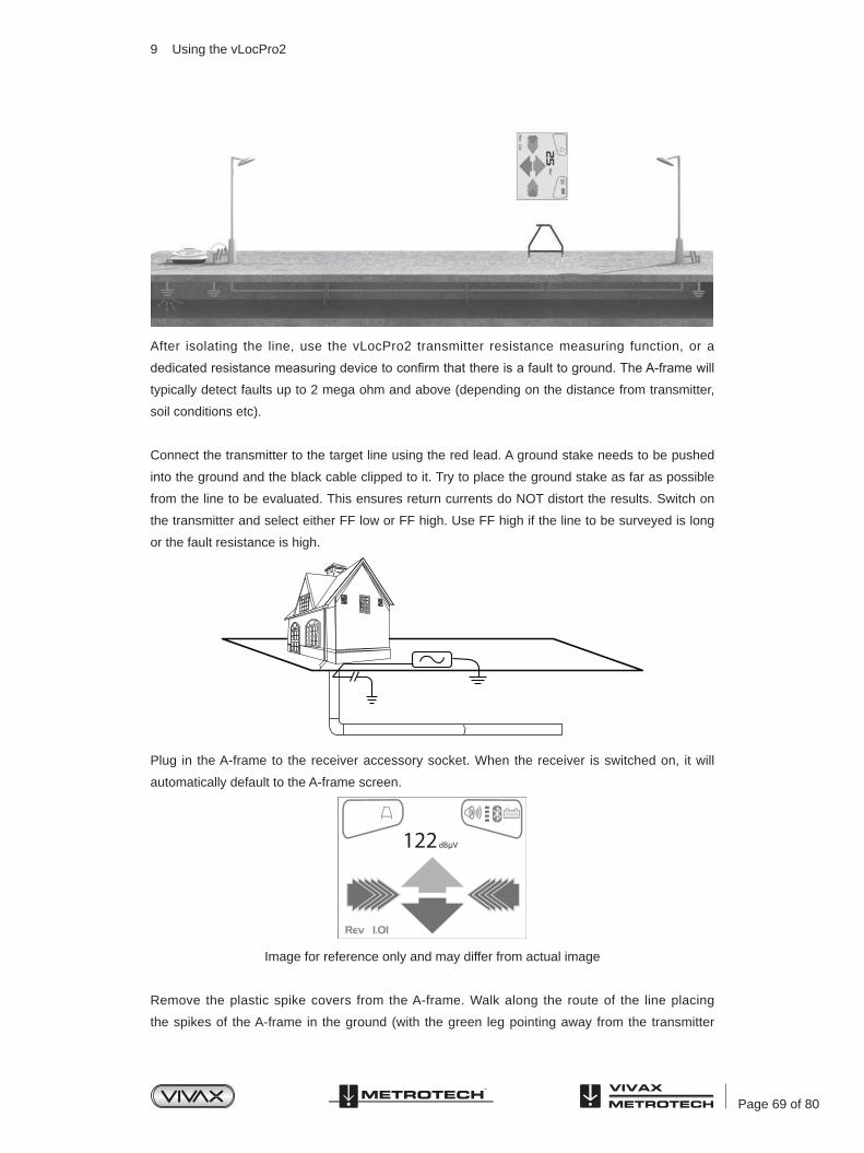
Page 69 of 80
After isolating the line, use the vLocPro2 transmitter resistance measuring function, or a
dedicated resistance measuring device to confirm that there is a fault to ground. The A-frame will
typically detect faults up to 2 mega ohm and above (depending on the distance from transmitter,
soil conditions etc).
Connect the transmitter to the target line using the red lead. A ground stake needs to be pushed
into the ground and the black cable clipped to it. Try to place the ground stake as far as possible
from the line to be evaluated. This ensures return currents do NOT distort the results. Switch on
the transmitter and select either FF low or FF high. Use FF high if the line to be surveyed is long
or the fault resistance is high.
Plug in the A-frame to the receiver accessory socket. When the receiver is switched on, it will
automatically default to the A-frame screen.
Image for reference only and may differ from actual image
Remove the plastic spike covers from the A-frame. Walk along the route of the line placing
the spikes of the A-frame in the ground (with the green leg pointing away from the transmitter
9 Using the vLocPro2

Page 70 of 80
connection point) every two or three paces. If starting near the transmitter, the Arrow on the
display will point away from the ground point. As the distance from the transmitter increases, the
dBuV reading will reduce and eventually the arrow will fluctuate or disappear all together. This is
because the fault location is further along the line. If the left/right arrows are activated, use them
to ensure the A-frame is positioned over the line and continue placing the A-frame in the ground
every two or three paces. If the left/right arrows are not activated use the “M” pushbutton to
enter the locate screen allowing the user to confirm the position of the target line. Press the “M”
pushbutton again to re enter the A-frame mode.
Eventually the A-frame will detect the fault signal and the “Fault Find” arrow will point forwards.
Continue moving forwards, it may be worth reducing the distance between measurements points
as the fault is neared. The dBuV reading will increase as the fault is neared. Maximum reading
will be just before and just after the fault. When over the fault, the dBuV reading will drop and
the arrow will flip backwards indicating that the position of the fault has been passed. Carefully
place the A-frame before and after the fault to pinpoint the position. Repeating this across the
line direction will pinpoint the fault laterally. The fault will be at the point where the lateral fault is
identified.
WARNING
Always disconnect or isolate cables before making connections to
conductors. Never attach the transmitter to live cables unless authorised.
Use the appropriate accessories.
TIP
If it is suspected that there is just one fault. Insert the A-frame approximately
one meter from the earth stake. Note the dBuV, this is approximately the
maximum dBuV reading that will be measured over the fault.
9 Using the vLocPro2
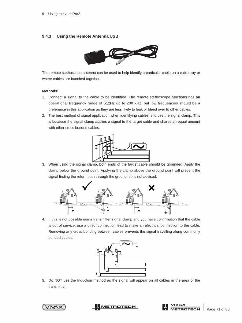
Page 71 of 80
9.4.3 Using the Remote Antenna USB
The remote stethoscope antenna can be used to help identify a particular cable on a cable tray or
where cables are bunched together.
Methods:
1. Connect a signal to the cable to be identified. The remote stethoscope functions has an
operational frequency range of 512Hz up to 200 kHz, but low frequencies should be a
preference in this application as they are less likely to leak or bleed over to other cables.
2. The best method of signal application when identifying cables is to use the signal clamp. This
is because the signal clamp applies a signal to the target cable and shares an equal amount
with other cross bonded cables.
3. When using the signal clamp, both ends of the target cable should be grounded. Apply the
clamp below the ground point. Applying the clamp above the ground point will prevent the
signal finding the return path through the ground, so is not advised.
4. If this is not possible use a transmitter signal clamp and you have confirmation that the cable
is out of service, use a direct connection lead to make an electrical connection to the cable.
Removing any cross bonding between cables prevents the signal travelling along commonly
bonded cables.
5. Do NOT use the Induction method as the signal will appear on all cables in the area of the
transmitter.
9 Using the vLocPro2

Page 72 of 80
6. Connect the remote stethoscope antenna to the accessory input of the Receiver. The correct
settings and user interface will be automatically selected.
7. Ensure the frequency selected on the vLoc is the same as selected on the transmitter.
8. Place the stethoscope on each of the suspected target cables with the flats of the antenna in
line with the route of the cable.
9. Note the large dBuV reading in the centre of the screen for each cable. The one with the
largest reading is likely to be the target cable.
10. If necessary adjust the sensitivity of the vLoc so that the signal is within the operating section
of the bar graph. This will help identify the cable if the signal levels are similar because of
cross coupling of the signal.
WARNING
The remote stethoscope antenna is a useful tool to help identify cables.
However, it should not be used as positive identification before an unused cable is cut. Always follow company procedures when cutting disused or
isolated cables.
TIP
The remote antenna USB stethoscope can be used to help identify disused
and isolated cables. This process can be further enhanced if the cable is
isolated and is of a twisted cable construction.
Method:
1. Connect the transmitter to two of the cores of the cable. At the far end short together these
two conductors making a loop.
2. Set the transmitter to a low frequency such as 640Hz and set the output to maximum.
9 Using the vLocPro2

Page 73 of 80
3. At the point of interest, run the remote stethoscope antenna along the suspected target cable.
If the correct cable is being assessed the signal will increase and decrease in sympathy with
the twist of the two conductors within the cable.
4. If the signal is a steady level and does not rise and fall, this is probably NOT the target cable.
WARNING
The remote stethoscope antenna is a useful tool to help identify cables.
However, it should not be used as positive identification before an unused cable is cut. Always follow company procedures when cutting disused or
isolated cables.
9 Using the vLocPro2

Page 74 of 80
10 Accessories & Options
10.1 A-frame (Optional)The A-frame accessory is used to detect ground faults on pipes
and cables. In the case of pipes, the faults consist of coating
defects. In the case of cables, faults are usually caused by
insulation damage allowing the metallic sheath (or internal
conductor) to become in contact with the ground.
10.2 Remote Antenna (Optional)The remote antenna can be used to help identify a particular
cable on a cable tray or where cables are bunched together.
10.3 Loc-10Tx Vehicle Power Lead (Optional)12V DC, 30ft (10m) lead to power the transmitter from a vehicle.
Note, this is NOT a charge lead.
If it is intended to apply the transmitter to a target line at high
output levels and long periods, it may be useful to power the
transmitter using the 12V DC vehicle power lead. To power
the transmitter from the 12V DC vehicle power lead, connect
the lead to the 12V DC input positioned on the side of the
transmitter. Plug the cigarette lighter plug into the vehicle
cigarette lighter socket (be sure that the socket is live. Some
vehicles only activate the cigarette lighter when the vehicle is
running).
It is not necessary to disconnect or remove the standard batteries
as the unit will automatically select the external 12V DC supply.
10.4 Loc-10Tx Outdoor Power Supply (Optional)12V DC, 30ft (10m) lead to power (NOT charge lead) the
transmitter from the mains supply.
Note, this is NOT a charge lead.
Accessories & Options
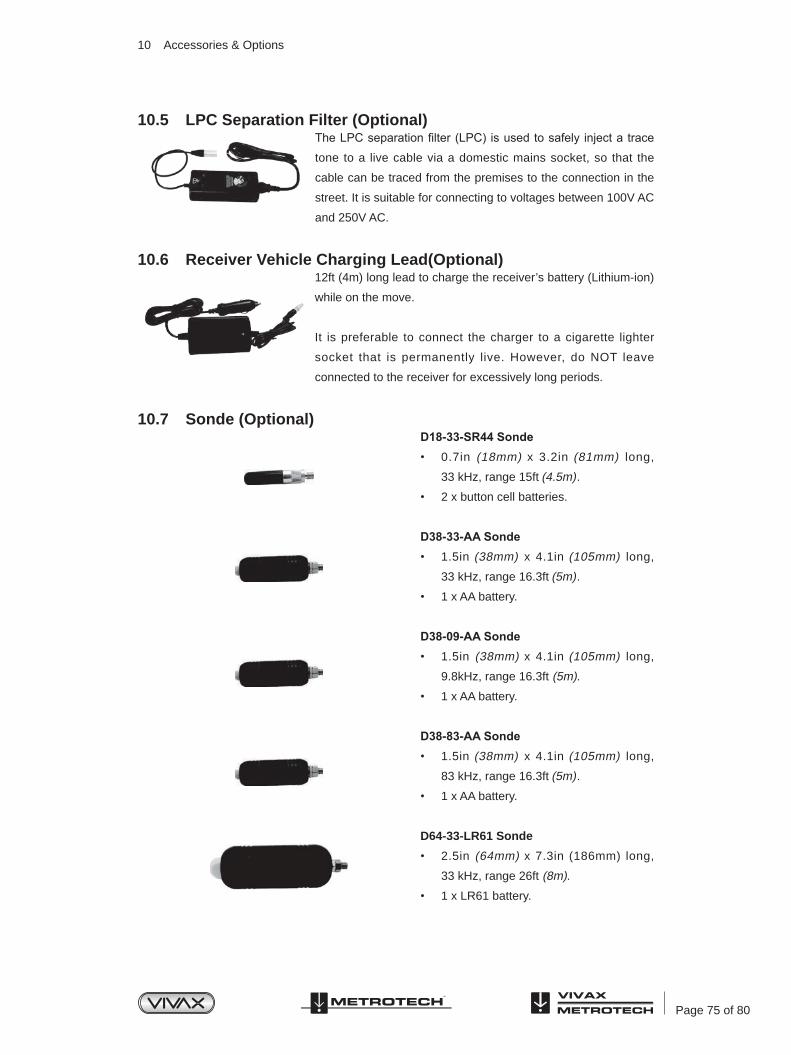
Page 75 of 80
10.5 LPC Separation Filter (Optional)The LPC separation filter (LPC) is used to safely inject a trace
tone to a live cable via a domestic mains socket, so that the
cable can be traced from the premises to the connection in the
street. It is suitable for connecting to voltages between 100V AC
and 250V AC.
10.6 Receiver Vehicle Charging Lead(Optional)12ft (4m) long lead to charge the receiver’s battery (Lithium-ion)
while on the move.
It is preferable to connect the charger to a cigarette lighter
socket that is permanently live. However, do NOT leave
connected to the receiver for excessively long periods.
10.7 Sonde (Optional)D18-33-SR44 Sonde• 0.7in (18mm) x 3.2in (81mm) long,
33 kHz, range 15ft (4.5m).
• 2 x button cell batteries.
D38-33-AA Sonde• 1.5in (38mm) x 4.1in (105mm) long,
33 kHz, range 16.3ft (5m).
• 1 x AA battery.
D38-09-AA Sonde• 1.5in (38mm) x 4.1in (105mm) long,
9.8kHz, range 16.3ft (5m).
• 1 x AA battery.
D38-83-AA Sonde• 1.5in (38mm) x 4.1in (105mm) long,
83 kHz, range 16.3ft (5m).
• 1 x AA battery.
D64-33-LR61 Sonde
• 2.5in (64mm) x 7.3in (186mm) long,
33 kHz, range 26ft (8m).
• 1 x LR61 battery.
10 Accessories & Options

Page 76 of 80
D64-09-LR61 Sonde• 2.5in (64mm) x 7.3in (186mm) long,
9.8 kHz, range 26ft (8m).
• 1 x LR61 battery.
D64-83-LR61 Sonde• 2.5in (64mm) x 7.3in (186mm) long,
83 kHz, range 26ft (8m).
• 1 x LR61 battery.
D23F-512-AA / D23F-640-AA Sonde
• 1in (23mm) x 18in (456mm) long,
range 20ft (7m).
• “Flexible (3 section) Sonde with optional
512Hz or 640Hz for use in cast iron pipes”.
• 1 x AA battery.
10.8 Clamp (Optional)
• VX2/50, VX4/100, VX5/125, VX18/450F
• Dia. 2in (50mm), Dia. 5in (125mm), Dia. 4in (100mm), 18in flexible (Circumference 450mm)
An accessory used to apply the transmitter signal to an insulated line, removing the need to
connect the transmitter signal directly to a conductor or cable sheath.
10.9 Lithium-ion Rechargeable Battery Pack (Standard)The Lithium-ion rechargeable battery pack is supplied as
standard. Use the battery charger listed below to charge the
battery pack. Charging is done with the battery inside the
receiver.
10.10 Receiver Battery Charger (Standard)The receiver Lithium-ion battery charger is supplied as a
standard item. It is powered from the mains supply (100-250V
AC)
10 Accessories & Options

Page 77 of 80
10.11 USB Cable(Standard)The USB cable is used to connect the receiver to a host
computer so that software updates can be implemented and
also for the transfer of data logs from the unit to a computer.
10.12 Alkaline Battery Holder(Standard)This battery pack is supplies as standard and is used in the
event the rechargeable battery pack has fully discharged. It
can be considered as a backup battery pack. It requires 6 x AA
alkaline batteries.
10.13 Ground Stake(Standard)Used to make an independent connection to the ground so as to
complete the circuit when the transmitter is connected to a line
using the direct connection method.
10.14 Direct Connection Lead(Standard)Used to connect the transmitter to a line using the direct
connection method.
10.15 Loc-1Tx Alkaline Battery Tray (Standard)Requires 4 x Alkaline D cells.
10.16 Ground Spool (Optional)Used to extend the ground connection to a suitable grounding
position.
10.17 Banana Plugs Adapter (Optional)Adapts the direct connection crocodile clip to banana plug
allowing the direct connection leads to be connected to a
banana socket.
10 Accessories & Options

Page 78 of 80
10.18 Loc-5Tx Battery Pack (NiMH)NiMH rechargeable battery pack. Only use the charger supplied
as below.
10.19 Loc-5Tx Alkaline Battery TrayRequires 8 x Alkaline D cells.
10.20 Loc-5Tx/10Tx ChargerMains charger (100-250V AC input) used to charge 5 Watt or
10 Watt rechargeable battery packs. Supplied as standard with
rechargeable battery option.
10.21 Loc-10Tx Rechargeable Battery TrayNiMH rechargeable battery pack. Only use the charger supplied.
10.22 Loc-10Tx Alkaline Battery TrayRequires 12 x Alkaline D cells.
10 Accessories & Options

Page 79 of 80
A locate where a transmitter is used to apply a signal to a buried
pipe or cable, the position of which is then located by a receiver
tuned to the same frequency.
A signal applied by the locator transmitter to a buried line. Typical
this is a very precise frequency.
The reduction of an electromagnetic signal from a pipe or cable.
An accessory used to apply the transmitter signal to an insulated
line, removing the need to connect the transmitter signal directly to
a conductor or cable sheath.
The act of signals transferring to lines to which they were not
originally applied. Coupling can be “direct” where the target line
has an electrical connection to another line, or “induced” where the
signal radiates from the target line to another line or lines.
The information visually available on the dot matrix display.
Line direction indicator (although visually like a compass, this is the
only relation to a compass.)
A generic term for any buried pipe or cable.
A minimum response to a buried line.
A locate where the receiver searches for a wide range of signals
that radiate from buried pipes or cables. These signals come from
a variety of sources in the environment and couple to the buried (&
overhead) lines. Typical examples 50/60Hz and LF/VLF radio.
A wide range of signals that radiate from buried pipes or cables.
These signals come from a variety of sources in the environment
and couple to the buried (& overhead) lines. Typical examples
50/60Hz and LF/VLF radio.
Active Locate
Active Signal
Attenuation
Clamp (or Coupler)
Coupling
Display
LDI
Line
Null
Passive Locate
Passive signals
11 Glossary
Glossary

Page 80 of 80
11 Glossary
A maximum response to a buried line.
Using a receiver to identify the exact position of a buried line.
The indication that the receiver gives which is caused by the
signals it is receiving. This can be visual, audio or both. Typically it
is displayed on the locators dot matrix display and audibly from a
loudspeaker in the receiver housing.
This describes the act of looking for a buried line within a given
area.
A small transmitting coil which may be built into a product such
as a sewer camera or packaged as a small self contained battery
powered transmitter. A receiver tuned to the same frequency can
locate the position of the Sonde and hence whatever it is attached
to or in. Frequently used for locating sewer cameras, and the non
metallic pipes.
The buried pipe or cable to be located.
Using a locator to following the path of a buried line.
Peak
Pinpoint
Response
Search (sweep)
Sonde
Target Line
Trace
Illustrations used in the preparation of this manual will inevitably show some resemblance
to similar illustrations from other Manufacturers-some manufacturers have given permission
for the use of their graphics (Vivax-Metrotech & Seba) is given credit for these use. This
statement is intended to attribute such credit.
Disclaimer: Product and accessory specification and availability information is subject to change
without prior notice.

Notes:
Vivax-Metrotech Corporation,
3251 Olcott St.,Santa Clara CA 95054, USA
Website: www.vivax-metrotech.com
