vl-epm-16 tomcat cmos setup reference - versalogic epm-16 cmos setup referenc… · vl-epm-16...
TRANSCRIPT
12100 SW Tualatin Rd Tualatin Oregon 97062 (503) 747-2261 [email protected] www.VersaLogic.com
VL-EPM-16 Tomcat CMOS Setup Reference
This article provides reference information and tips for setting CMOS Setup parameters on the VL-EPM-16 (Tomcat). Start CMOS Setup by pressing Delete during the early boot cycle. The Main menu appears first. You can scroll to other menus using the left and right arrow keys. The CMOS Setup menus are:
Main Menu Advanced Menu
o Board Configuration o CPU Configuration o IDE Configuration
IDE Master/Slave Configurations o Remote Access Configuration o USB Configuration
USB Mass Storage Device Configuration PCI/PnP Menu
o IRQ Trigger Type Settings Boot Menu
o Boot Settings Configuration Security Menu Chipset Menu
o NorthBridge Chipset Configuration o SouthBridge Chipset Configuration
ISA Configuration Serial/Parallel Port Configuration WatchDog Configuration
Exit Menu
The basic idea when using CMOS Setup is to navigate to the menus containing fields you want to review, and change those fields as desired. When your settings are complete, navigate to the Exit menu, and select “Save Changes and Exit.” This causes the settings to be stored in nonvolatile memory in the system, and the system will reboot so that POST can configure itself with the new settings. After rebooting it may be desirable to reenter the Setup system as necessary to adjust settings as necessary.
Once the system boots, CMOS Setup cannot be entered; this is because the memory used by the BIOS configuration manager is deallocated by the system BIOS, so that it can be used by the OS when it boots. To reenter CMOS Setup after boot, simply reset the system or power off and power back on.
Note: The configurations and factory defaults described here are for VL-EPM-16 BIOS version 1.00.
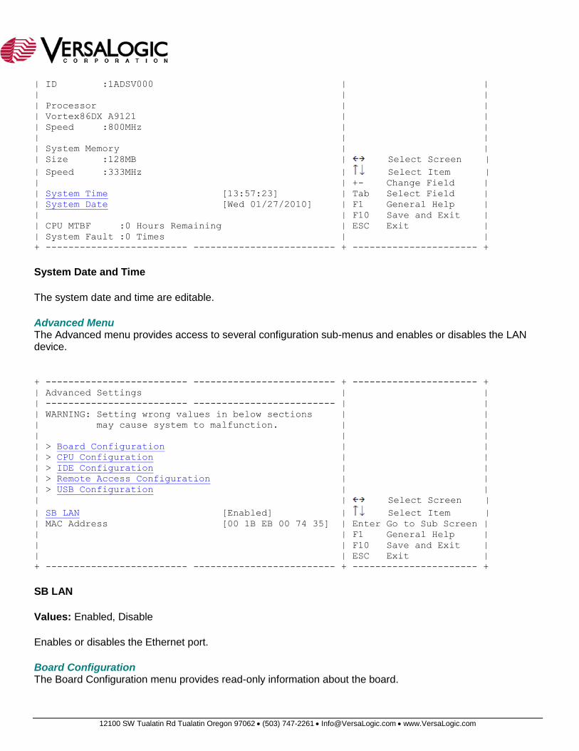
Main Menu The Main menu displays BIOS, processor, and memory information and edits the system date and time. A record of system faults and MTBF is also displayed.
+ ------------------------- ------------------------- + ---------------------- +
| System Overview | |
| ------------------------- ------------------------- | |
| AMIBIOS | |
| Version :08.00.14 | |
| Build Date:10/22/09 | |
12100 SW Tualatin Rd Tualatin Oregon 97062 (503) 747-2261 [email protected] www.VersaLogic.com
| ID :1ADSV000 | |
| | |
| Processor | |
| Vortex86DX A9121 | |
| Speed :800MHz | |
| | |
| System Memory | |
| Size :128MB | Select Screen |
| Speed :333MHz | Select Item |
| | +- Change Field |
| System Time [13:57:23] | Tab Select Field |
| System Date [Wed 01/27/2010] | F1 General Help |
| | F10 Save and Exit |
| CPU MTBF :0 Hours Remaining | ESC Exit |
| System Fault :0 Times | |
+ ------------------------- ------------------------- + ---------------------- +
System Date and Time
The system date and time are editable.
Advanced Menu The Advanced menu provides access to several configuration sub-menus and enables or disables the LAN device.
+ ------------------------- ------------------------- + ---------------------- +
| Advanced Settings | |
| ------------------------- ------------------------- | |
| WARNING: Setting wrong values in below sections | |
| may cause system to malfunction. | |
| | |
| > Board Configuration | |
| > CPU Configuration | |
| > IDE Configuration | |
| > Remote Access Configuration | |
| > USB Configuration | |
| | Select Screen |
| SB LAN [Enabled] | Select Item |
| MAC Address [00 1B EB 00 74 35] | Enter Go to Sub Screen |
| | F1 General Help |
| | F10 Save and Exit |
| | ESC Exit |
+ ------------------------- ------------------------- + ---------------------- +
SB LAN
Values: Enabled, Disable
Enables or disables the Ethernet port.
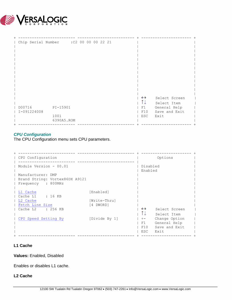
Board Configuration The Board Configuration menu provides read-only information about the board.
12100 SW Tualatin Rd Tualatin Oregon 97062 (503) 747-2261 [email protected] www.VersaLogic.com
+ ------------------------- ------------------------- + ---------------------- +
| Chip Serial Number :C2 00 00 00 22 21 | |
| | |
| | |
| | |
| | |
| | |
| | |
| | |
| | |
| | |
| | |
| | |
| | |
| | Select Screen |
| | Select Item |
| D00716 PI-15901 | F1 General Help |
| I-091224008 | F10 Save and Exit |
| 1001 | ESC Exit |
| 6390A5.ROM | |
+ ------------------------- ------------------------- + ---------------------- +
CPU Configuration The CPU Configuration menu sets CPU parameters.
+ ------------------------- ------------------------- + ---------------------- +
| CPU Configuration | Options |
| ------------------------- ------------------------- | |
| Module Version - 00.01 | Disabled |
| | Enabled |
| Manufacturer: DMP | |
| Brand String: Vortex86DX A9121 | |
| Frequency : 800MHz | |
| | |
| L1 Cache [Enabled] | |
| Cache L1 : 16 KB | |
| L2 Cache [Write-Thru] | |
| Fetch Line Size [4 DWORD] | |
| Cache L2 : 256 KB | Select Screen |
| | Select Item |
| CPU Speed Setting By [Divide By 1] | +- Change Option |
| | F1 General Help |
| | F10 Save and Exit |
| | ESC Exit |
+ ------------------------- ------------------------- + ---------------------- +
L1 Cache
Values: Enabled, Disabled
Enables or disables L1 cache.
L2 Cache
12100 SW Tualatin Rd Tualatin Oregon 97062 (503) 747-2261 [email protected] www.VersaLogic.com
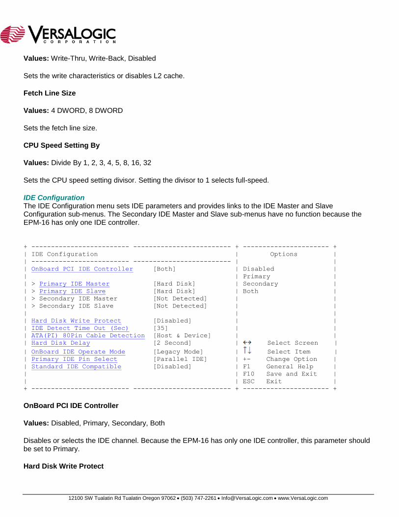
Values: Write-Thru, Write-Back, Disabled
Sets the write characteristics or disables L2 cache.
Fetch Line Size
Values: 4 DWORD, 8 DWORD
Sets the fetch line size.
CPU Speed Setting By
Values: Divide By 1, 2, 3, 4, 5, 8, 16, 32
Sets the CPU speed setting divisor. Setting the divisor to 1 selects full-speed.
IDE Configuration The IDE Configuration menu sets IDE parameters and provides links to the IDE Master and Slave Configuration sub-menus. The Secondary IDE Master and Slave sub-menus have no function because the EPM-16 has only one IDE controller.
+ ------------------------- ------------------------- + ---------------------- +
| IDE Configuration | Options |
| ------------------------- ------------------------- | |
| OnBoard PCI IDE Controller [Both] | Disabled |
| | Primary |
| > Primary IDE Master [Hard Disk] | Secondary |
| > Primary IDE Slave [Hard Disk] | Both |
| > Secondary IDE Master [Not Detected] | |
| > Secondary IDE Slave [Not Detected] | |
| | |
| Hard Disk Write Protect [Disabled] | |
| IDE Detect Time Out (Sec) [35] | |
| ATA(PI) 80Pin Cable Detection [Host & Device] | |
| Hard Disk Delay [2 Second] | Select Screen |
| OnBoard IDE Operate Mode [Legacy Mode] | Select Item |
| Primary IDE Pin Select [Parallel IDE] | +- Change Option |
| Standard IDE Compatible [Disabled] | F1 General Help |
| | F10 Save and Exit |
| | ESC Exit |
+ ------------------------- ------------------------- + ---------------------- +
OnBoard PCI IDE Controller
Values: Disabled, Primary, Secondary, Both
Disables or selects the IDE channel. Because the EPM-16 has only one IDE controller, this parameter should be set to Primary.
Hard Disk Write Protect
12100 SW Tualatin Rd Tualatin Oregon 97062 (503) 747-2261 [email protected] www.VersaLogic.com
Values: Enabled, Disabled
Setting this parameter to enabled prevents the IDE hard disk from being written to. To operate the hard disk normally, set this parameter to Enabled.
IDE Detect Time Out (Sec)
Values: 0, 5, 10, 15, 20, 25, 30, 35
Sets the maximum time in seconds that the BIOS will try to auto-detect the connection device. A value of 0 is best if the on-board IDE controller is attached to specific drives. Most IDE drives can be detected in 5 seconds or less.
ATA(PI) 80Pin Cable Detection
Values: Host & Device, Host, Device
Selects the method used to auto-detect the type of IDE cable attached. Host & Device uses both the IDE controller and IDE device, Host uses only the IDE controller, and Device uses only the IDE device.
Hard Disk Delay
Values: Disabled, 1 Second, 2 Second, 4 Second, 8 Second
Sets the amount of time the BIOS will wait for a device to become ready. In most cases, a delay of 2 seconds is adequate.
OnBoard IDE Operate Mode
Values: Legacy Mode, Native Mode
Sets the I/O and memory address of the IDE controller. Legacy Mode uses standard IDE controller addresses. Native Mode uses 8212 controller addresses.
Primary IDE Pin Select
Values: Parallel IDE, SD Card
This parameter should be set to Parallel IDE.
Standard IDE Compatible
Values: Enabled, Disabled
This function is reserved for Linux. Select Enabled when operating the EPM-16 under Linux. When operating under Windows, the parameter has no function and either setting is allowed.
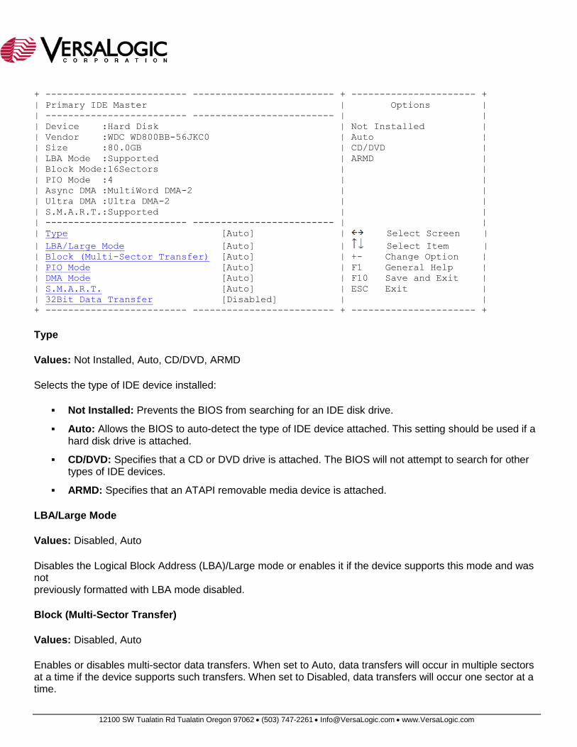
IDE Master/Slave Configurations The IDE Master/Slave menus configure IDE parameters.
12100 SW Tualatin Rd Tualatin Oregon 97062 (503) 747-2261 [email protected] www.VersaLogic.com
+ ------------------------- ------------------------- + ---------------------- +
| Primary IDE Master | Options |
| ------------------------- ------------------------- | |
| Device :Hard Disk | Not Installed |
| Vendor :WDC WD800BB-56JKC0 | Auto |
| Size :80.0GB | CD/DVD |
| LBA Mode :Supported | ARMD |
| Block Mode:16Sectors | |
| PIO Mode :4 | |
| Async DMA :MultiWord DMA-2 | |
| Ultra DMA :Ultra DMA-2 | |
| S.M.A.R.T.:Supported | |
| ------------------------- ------------------------- | |
| Type [Auto] | Select Screen |
| LBA/Large Mode [Auto] | Select Item |
| Block (Multi-Sector Transfer) [Auto] | +- Change Option |
| PIO Mode [Auto] | F1 General Help |
| DMA Mode [Auto] | F10 Save and Exit |
| S.M.A.R.T. [Auto] | ESC Exit |
| 32Bit Data Transfer [Disabled] | |
+ ------------------------- ------------------------- + ---------------------- +
Type
Values: Not Installed, Auto, CD/DVD, ARMD
Selects the type of IDE device installed:
Not Installed: Prevents the BIOS from searching for an IDE disk drive.
Auto: Allows the BIOS to auto-detect the type of IDE device attached. This setting should be used if a hard disk drive is attached.
CD/DVD: Specifies that a CD or DVD drive is attached. The BIOS will not attempt to search for other types of IDE devices.
ARMD: Specifies that an ATAPI removable media device is attached.
LBA/Large Mode
Values: Disabled, Auto
Disables the Logical Block Address (LBA)/Large mode or enables it if the device supports this mode and was not previously formatted with LBA mode disabled.
Block (Multi-Sector Transfer)
Values: Disabled, Auto
Enables or disables multi-sector data transfers. When set to Auto, data transfers will occur in multiple sectors at a time if the device supports such transfers. When set to Disabled, data transfers will occur one sector at a time.
12100 SW Tualatin Rd Tualatin Oregon 97062 (503) 747-2261 [email protected] www.VersaLogic.com
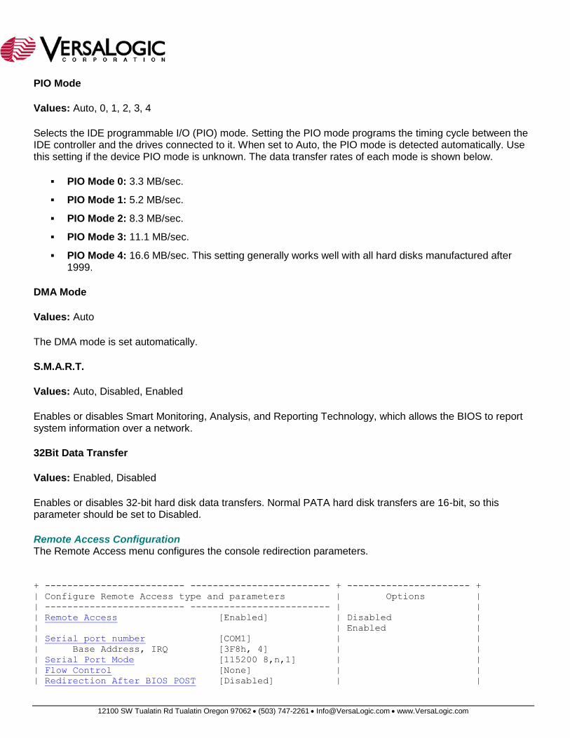
PIO Mode
Values: Auto, 0, 1, 2, 3, 4
Selects the IDE programmable I/O (PIO) mode. Setting the PIO mode programs the timing cycle between the IDE controller and the drives connected to it. When set to Auto, the PIO mode is detected automatically. Use this setting if the device PIO mode is unknown. The data transfer rates of each mode is shown below.
PIO Mode 0: 3.3 MB/sec.
PIO Mode 1: 5.2 MB/sec.
PIO Mode 2: 8.3 MB/sec.
PIO Mode 3: 11.1 MB/sec.
PIO Mode 4: 16.6 MB/sec. This setting generally works well with all hard disks manufactured after 1999.
DMA Mode
Values: Auto
The DMA mode is set automatically.
S.M.A.R.T.
Values: Auto, Disabled, Enabled
Enables or disables Smart Monitoring, Analysis, and Reporting Technology, which allows the BIOS to report system information over a network.
32Bit Data Transfer
Values: Enabled, Disabled
Enables or disables 32-bit hard disk data transfers. Normal PATA hard disk transfers are 16-bit, so this parameter should be set to Disabled.
Remote Access Configuration The Remote Access menu configures the console redirection parameters.
+ ------------------------- ------------------------- + ---------------------- +
| Configure Remote Access type and parameters | Options |
| ------------------------- ------------------------- | |
| Remote Access [Enabled] | Disabled |
| | Enabled |
| Serial port number [COM1] | |
| Base Address, IRQ [3F8h, 4] | |
| Serial Port Mode [115200 8,n,1] | |
| Flow Control [None] | |
| Redirection After BIOS POST [Disabled] | |
12100 SW Tualatin Rd Tualatin Oregon 97062 (503) 747-2261 [email protected] www.VersaLogic.com
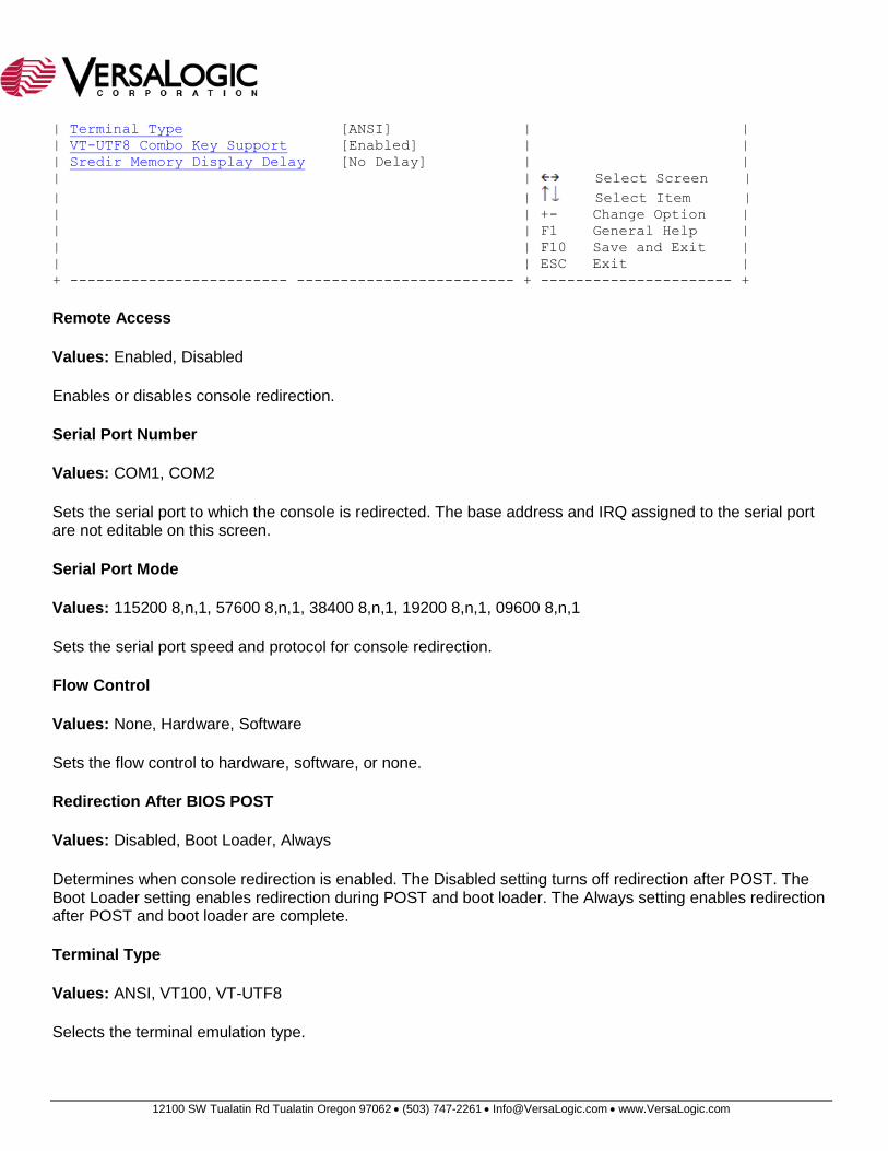
| Terminal Type [ANSI] | |
| VT-UTF8 Combo Key Support [Enabled] | |
| Sredir Memory Display Delay [No Delay] | |
| | Select Screen |
| | Select Item |
| | +- Change Option |
| | F1 General Help |
| | F10 Save and Exit |
| | ESC Exit |
+ ------------------------- ------------------------- + ---------------------- +
Remote Access
Values: Enabled, Disabled
Enables or disables console redirection.
Serial Port Number
Values: COM1, COM2
Sets the serial port to which the console is redirected. The base address and IRQ assigned to the serial port are not editable on this screen.
Serial Port Mode
Values: 115200 8,n,1, 57600 8,n,1, 38400 8,n,1, 19200 8,n,1, 09600 8,n,1
Sets the serial port speed and protocol for console redirection.
Flow Control
Values: None, Hardware, Software
Sets the flow control to hardware, software, or none.
Redirection After BIOS POST
Values: Disabled, Boot Loader, Always
Determines when console redirection is enabled. The Disabled setting turns off redirection after POST. The Boot Loader setting enables redirection during POST and boot loader. The Always setting enables redirection after POST and boot loader are complete.
Terminal Type
Values: ANSI, VT100, VT-UTF8
Selects the terminal emulation type.
12100 SW Tualatin Rd Tualatin Oregon 97062 (503) 747-2261 [email protected] www.VersaLogic.com
VT-UTF8 Combo Key Support
Values: Enabled, Disabled
Enables or disables the VT-UTF8 combo key to work in ANSI and VT100 emulation mode.
Sredir Memory Display Delay
Values: No Delay, Delay 1 Sec, Delay 2 Sec, Delay 4 Sec
Sets the delay between display memory and console redirection refresh.
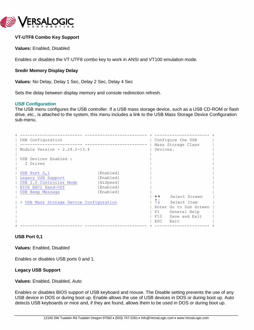
USB Configuration The USB menu configures the USB controller. If a USB mass storage device, such as a USB CD-ROM or flash drive, etc., is attached to the system, this menu includes a link to the USB Mass Storage Device Configuration sub-menu.
+ ------------------------- ------------------------- + ---------------------- +
| USB Configuration | Configure the USB |
| ------------------------- ------------------------- | Mass Storage Class |
| Module Version - 2.24.2-13.4 | Devices. |
| | |
| USB Devices Enabled : | |
| 2 Drives | |
| | |
| USB Port 0,1 [Enabled] | |
| Legacy USB Support [Enabled] | |
| USB 2.0 Controller Mode [HiSpeed] | |
| BIOS EHCI Hand-Off [Enabled] | |
| USB Beep Message [Enabled] | |
| | Select Screen |
| > USB Mass Storage Device Configuration | Select Item |
| | Enter Go to Sub Screen |
| | F1 General Help |
| | F10 Save and Exit |
| | ESC Exit |
+ ------------------------- ------------------------- + ---------------------- +
USB Port 0,1
Values: Enabled, Disabled
Enables or disables USB ports 0 and 1.
Legacy USB Support
Values: Enabled, Disabled, Auto
Enables or disables BIOS support of USB keyboard and mouse. The Disable setting prevents the use of any USB device in DOS or during boot up. Enable allows the use of USB devices in DOS or during boot up. Auto detects USB keyboards or mice and, if they are found, allows them to be used in DOS or during boot up.
12100 SW Tualatin Rd Tualatin Oregon 97062 (503) 747-2261 [email protected] www.VersaLogic.com
USB 2.0 Controller Mode
Values: FullSpeed, HiSpeed
Sets the USB controller to full speed or high speed mode.
BIOS EHCI Hand-Off
Values: Enabled, Disabled
Enables or disables support for operating system without an EHCI hand-off (USB "hot swap") feature. This parameter should be set to Enabled.
USB Beep Message
Values: Enabled, Disabled
Enables or disables the USB beep function. When Enabled a beep sounds for each USB device detected (for example, if a USB keyboard and mouse are connected, two beeps will sound). An external speaker must be connected to the board for the beeps to be audible.
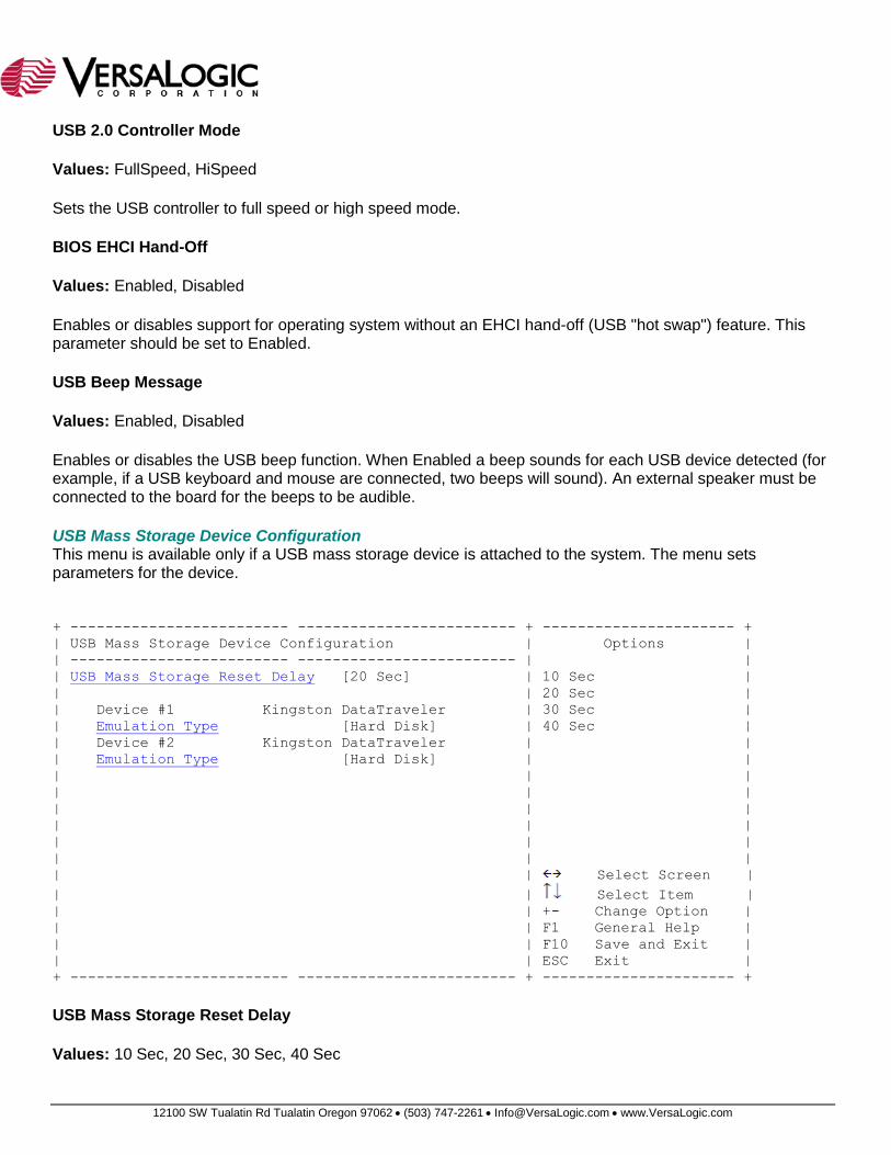
USB Mass Storage Device Configuration This menu is available only if a USB mass storage device is attached to the system. The menu sets parameters for the device.
+ ------------------------- ------------------------- + ---------------------- +
| USB Mass Storage Device Configuration | Options |
| ------------------------- ------------------------- | |
| USB Mass Storage Reset Delay [20 Sec] | 10 Sec |
| | 20 Sec |
| Device #1 Kingston DataTraveler | 30 Sec |
| Emulation Type [Hard Disk] | 40 Sec |
| Device #2 Kingston DataTraveler | |
| Emulation Type [Hard Disk] | |
| | |
| | |
| | |
| | |
| | |
| | |
| | Select Screen |
| | Select Item |
| | +- Change Option |
| | F1 General Help |
| | F10 Save and Exit |
| | ESC Exit |
+ ------------------------- ------------------------- + ---------------------- +
USB Mass Storage Reset Delay
Values: 10 Sec, 20 Sec, 30 Sec, 40 Sec
12100 SW Tualatin Rd Tualatin Oregon 97062 (503) 747-2261 [email protected] www.VersaLogic.com
Sets the USB mass storage device reset delay.
Emulation Type
Values: Auto, Floppy, Forced FDD, Hard Disk, CDROM
Sets the USB mass storage device emulation type.
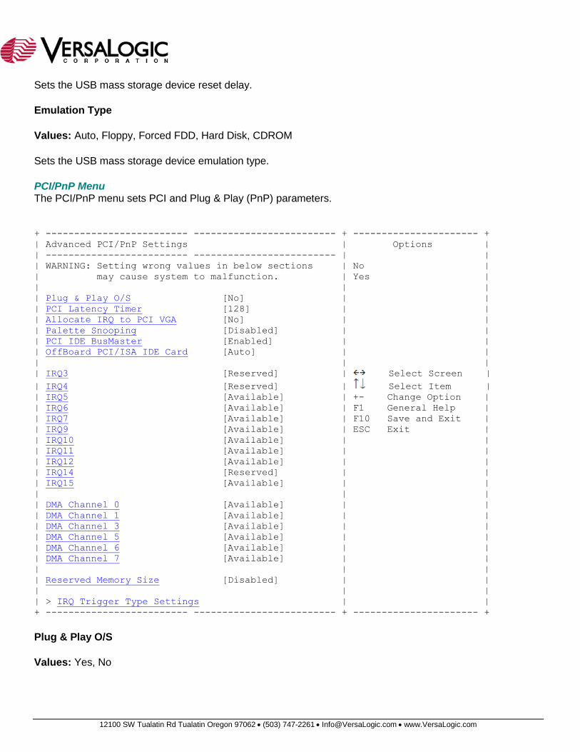
PCI/PnP Menu The PCI/PnP menu sets PCI and Plug & Play (PnP) parameters.
+ ------------------------- ------------------------- + ---------------------- +
| Advanced PCI/PnP Settings | Options |
| ------------------------- ------------------------- | |
| WARNING: Setting wrong values in below sections | No |
| may cause system to malfunction. | Yes |
| | |
| Plug & Play O/S [No] | |
| PCI Latency Timer [128] | |
| Allocate IRQ to PCI VGA [No] | |
| Palette Snooping [Disabled] | |
| PCI IDE BusMaster [Enabled] | |
| OffBoard PCI/ISA IDE Card [Auto] | |
| | |
| IRQ3 [Reserved] | Select Screen |
| IRQ4 [Reserved] | Select Item |
| IRQ5 [Available] | +- Change Option |
| IRQ6 [Available] | F1 General Help |
| IRQ7 [Available] | F10 Save and Exit |
| IRQ9 [Available] | ESC Exit |
| IRQ10 [Available] | |
| IRQ11 [Available] | |
| IRQ12 [Available] | |
| IRQ14 [Reserved] | |
| IRQ15 [Available] | |
| | |
| DMA Channel 0 [Available] | |
| DMA Channel 1 [Available] | |
| DMA Channel 3 [Available] | |
| DMA Channel 5 [Available] | |
| DMA Channel 6 [Available] | |
| DMA Channel 7 [Available] | |
| | |
| Reserved Memory Size [Disabled] | |
| | |
| > IRQ Trigger Type Settings | |
+ ------------------------- ------------------------- + ---------------------- +
Plug & Play O/S
Values: Yes, No
12100 SW Tualatin Rd Tualatin Oregon 97062 (503) 747-2261 [email protected] www.VersaLogic.com
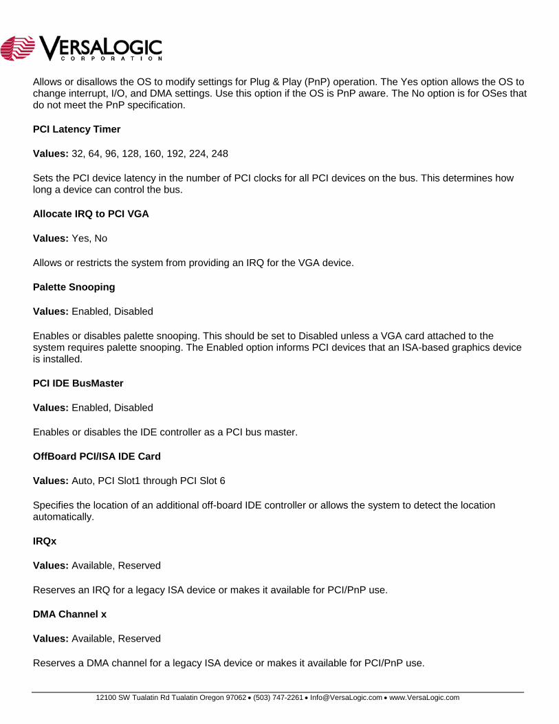
Allows or disallows the OS to modify settings for Plug & Play (PnP) operation. The Yes option allows the OS to change interrupt, I/O, and DMA settings. Use this option if the OS is PnP aware. The No option is for OSes that do not meet the PnP specification.
PCI Latency Timer
Values: 32, 64, 96, 128, 160, 192, 224, 248
Sets the PCI device latency in the number of PCI clocks for all PCI devices on the bus. This determines how long a device can control the bus.
Allocate IRQ to PCI VGA
Values: Yes, No
Allows or restricts the system from providing an IRQ for the VGA device.
Palette Snooping
Values: Enabled, Disabled
Enables or disables palette snooping. This should be set to Disabled unless a VGA card attached to the system requires palette snooping. The Enabled option informs PCI devices that an ISA-based graphics device is installed.
PCI IDE BusMaster
Values: Enabled, Disabled
Enables or disables the IDE controller as a PCI bus master.
OffBoard PCI/ISA IDE Card
Values: Auto, PCI Slot1 through PCI Slot 6
Specifies the location of an additional off-board IDE controller or allows the system to detect the location automatically.
IRQx
Values: Available, Reserved
Reserves an IRQ for a legacy ISA device or makes it available for PCI/PnP use.
DMA Channel x
Values: Available, Reserved
Reserves a DMA channel for a legacy ISA device or makes it available for PCI/PnP use.
12100 SW Tualatin Rd Tualatin Oregon 97062 (503) 747-2261 [email protected] www.VersaLogic.com
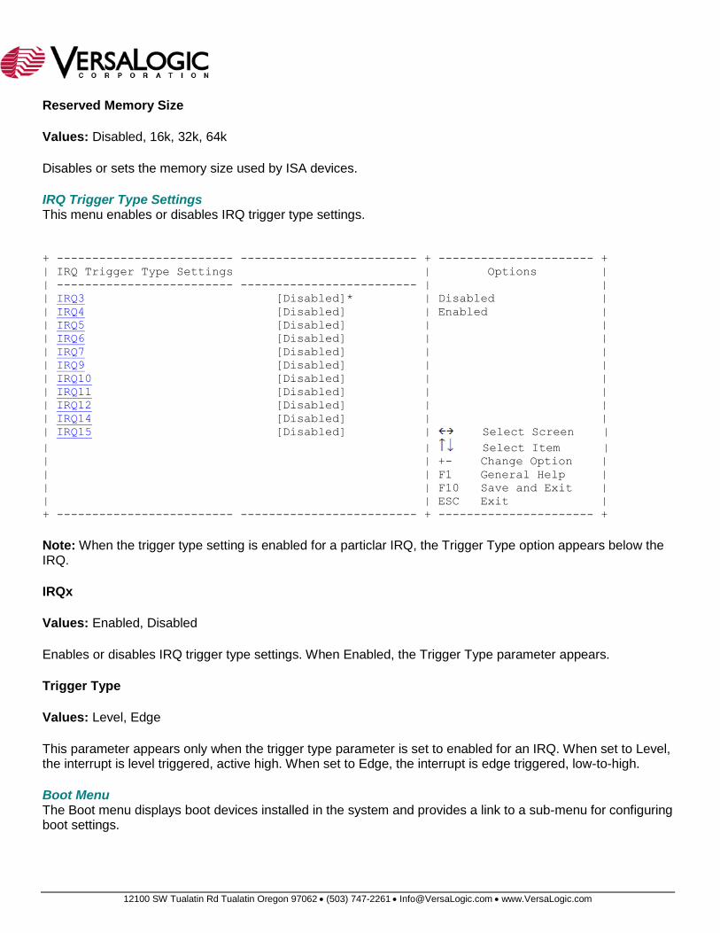
Reserved Memory Size
Values: Disabled, 16k, 32k, 64k
Disables or sets the memory size used by ISA devices.
IRQ Trigger Type Settings This menu enables or disables IRQ trigger type settings.
+ ------------------------- ------------------------- + ---------------------- +
| IRQ Trigger Type Settings | Options |
| ------------------------- ------------------------- | |
| IRQ3 [Disabled]* | Disabled |
| IRQ4 [Disabled] | Enabled |
| IRQ5 [Disabled] | |
| IRQ6 [Disabled] | |
| IRQ7 [Disabled] | |
| IRQ9 [Disabled] | |
| IRQ10 [Disabled] | |
| IRQ11 [Disabled] | |
| IRQ12 [Disabled] | |
| IRQ14 [Disabled] | |
| IRQ15 [Disabled] | Select Screen |
| | Select Item |
| | +- Change Option |
| | F1 General Help |
| | F10 Save and Exit |
| | ESC Exit |
+ ------------------------- ------------------------- + ---------------------- +
Note: When the trigger type setting is enabled for a particlar IRQ, the Trigger Type option appears below the IRQ.
IRQx
Values: Enabled, Disabled
Enables or disables IRQ trigger type settings. When Enabled, the Trigger Type parameter appears.
Trigger Type
Values: Level, Edge
This parameter appears only when the trigger type parameter is set to enabled for an IRQ. When set to Level, the interrupt is level triggered, active high. When set to Edge, the interrupt is edge triggered, low-to-high.
Boot Menu The Boot menu displays boot devices installed in the system and provides a link to a sub-menu for configuring boot settings.
12100 SW Tualatin Rd Tualatin Oregon 97062 (503) 747-2261 [email protected] www.VersaLogic.com
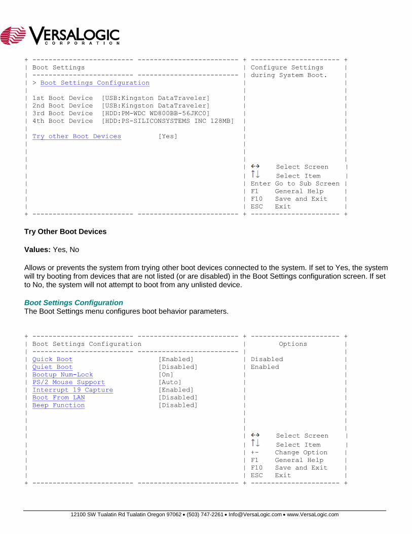
+ ------------------------- ------------------------- + ---------------------- +
| Boot Settings | Configure Settings |
| ------------------------- ------------------------- | during System Boot. |
| > Boot Settings Configuration | |
| | |
| 1st Boot Device [USB:Kingston DataTraveler] | |
| 2nd Boot Device [USB:Kingston DataTraveler] | |
| 3rd Boot Device [HDD:PM-WDC WD800BB-56JKC0] | |
| 4th Boot Device [HDD:PS-SILICONSYSTEMS INC 128MB] | |
| | |
| Try other Boot Devices [Yes] | |
| | |
| | |
| | |
| | Select Screen |
| | Select Item |
| | Enter Go to Sub Screen |
| | F1 General Help |
| | F10 Save and Exit |
| | ESC Exit |
+ ------------------------- ------------------------- + ---------------------- +
Try Other Boot Devices
Values: Yes, No
Allows or prevents the system from trying other boot devices connected to the system. If set to Yes, the system will try booting from devices that are not listed (or are disabled) in the Boot Settings configuration screen. If set to No, the system will not attempt to boot from any unlisted device.
Boot Settings Configuration The Boot Settings menu configures boot behavior parameters.
+ ------------------------- ------------------------- + ---------------------- +
| Boot Settings Configuration | Options |
| ------------------------- ------------------------- | |
| Quick Boot [Enabled] | Disabled |
| Quiet Boot [Disabled] | Enabled |
| Bootup Num-Lock [On] | |
| PS/2 Mouse Support [Auto] | |
| Interrupt 19 Capture [Enabled] | |
| Boot From LAN [Disabled] | |
| Beep Function [Disabled] | |
| | |
| | |
| | |
| | Select Screen |
| | Select Item |
| | +- Change Option |
| | F1 General Help |
| | F10 Save and Exit |
| | ESC Exit |
+ ------------------------- ------------------------- + ---------------------- +
12100 SW Tualatin Rd Tualatin Oregon 97062 (503) 747-2261 [email protected] www.VersaLogic.com
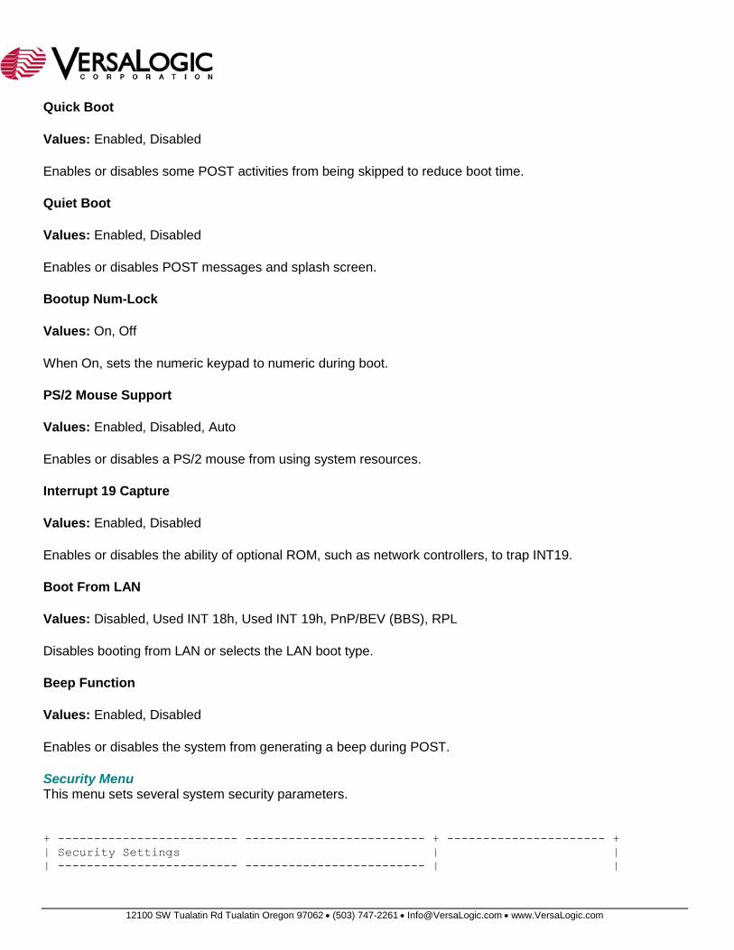
Quick Boot
Values: Enabled, Disabled
Enables or disables some POST activities from being skipped to reduce boot time.
Quiet Boot
Values: Enabled, Disabled
Enables or disables POST messages and splash screen.
Bootup Num-Lock
Values: On, Off
When On, sets the numeric keypad to numeric during boot.
PS/2 Mouse Support
Values: Enabled, Disabled, Auto
Enables or disables a PS/2 mouse from using system resources.
Interrupt 19 Capture
Values: Enabled, Disabled
Enables or disables the ability of optional ROM, such as network controllers, to trap INT19.
Boot From LAN
Values: Disabled, Used INT 18h, Used INT 19h, PnP/BEV (BBS), RPL
Disables booting from LAN or selects the LAN boot type.
Beep Function
Values: Enabled, Disabled
Enables or disables the system from generating a beep during POST.
Security Menu This menu sets several system security parameters.
+ ------------------------- ------------------------- + ---------------------- +
| Security Settings | |
| ------------------------- ------------------------- | |
12100 SW Tualatin Rd Tualatin Oregon 97062 (503) 747-2261 [email protected] www.VersaLogic.com
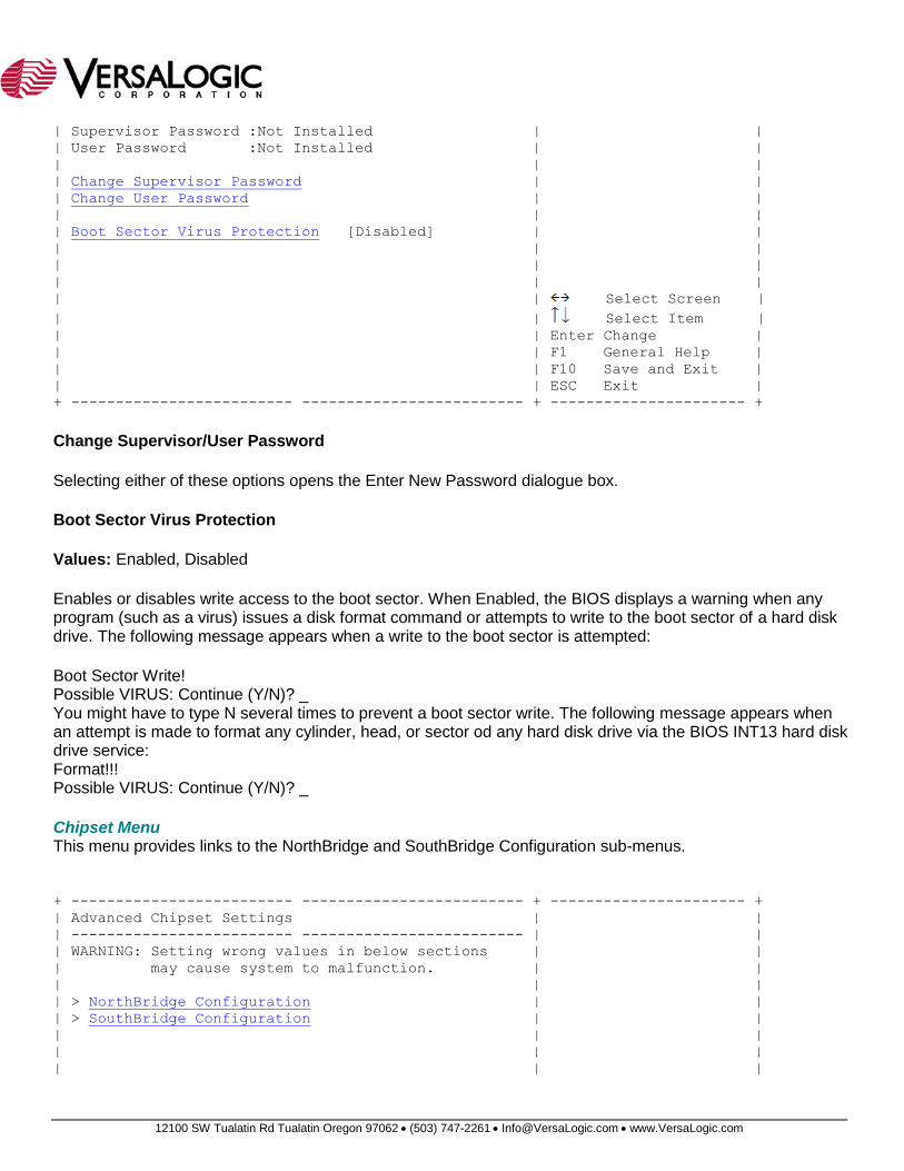
| Supervisor Password :Not Installed | |
| User Password :Not Installed | |
| | |
| Change Supervisor Password | |
| Change User Password | |
| | |
| Boot Sector Virus Protection [Disabled] | |
| | |
| | |
| | |
| | Select Screen |
| | Select Item |
| | Enter Change |
| | F1 General Help |
| | F10 Save and Exit |
| | ESC Exit |
+ ------------------------- ------------------------- + ---------------------- +
Change Supervisor/User Password
Selecting either of these options opens the Enter New Password dialogue box.
Boot Sector Virus Protection
Values: Enabled, Disabled
Enables or disables write access to the boot sector. When Enabled, the BIOS displays a warning when any program (such as a virus) issues a disk format command or attempts to write to the boot sector of a hard disk drive. The following message appears when a write to the boot sector is attempted:
Boot Sector Write! Possible VIRUS: Continue (Y/N)? _ You might have to type N several times to prevent a boot sector write. The following message appears when an attempt is made to format any cylinder, head, or sector od any hard disk drive via the BIOS INT13 hard disk drive service: Format!!! Possible VIRUS: Continue (Y/N)? _
Chipset Menu This menu provides links to the NorthBridge and SouthBridge Configuration sub-menus.
+ ------------------------- ------------------------- + ---------------------- +
| Advanced Chipset Settings | |
| ------------------------- ------------------------- | |
| WARNING: Setting wrong values in below sections | |
| may cause system to malfunction. | |
| | |
| > NorthBridge Configuration | |
| > SouthBridge Configuration | |
| | |
| | |
| | |
12100 SW Tualatin Rd Tualatin Oregon 97062 (503) 747-2261 [email protected] www.VersaLogic.com
| | |
| | |
| | Select Screen |
| | Select Item |
| | Enter Go to Sub Screen |
| | F1 General Help |
| | F10 Save and Exit |
| | ESC Exit |
+ ------------------------- ------------------------- + ---------------------- +
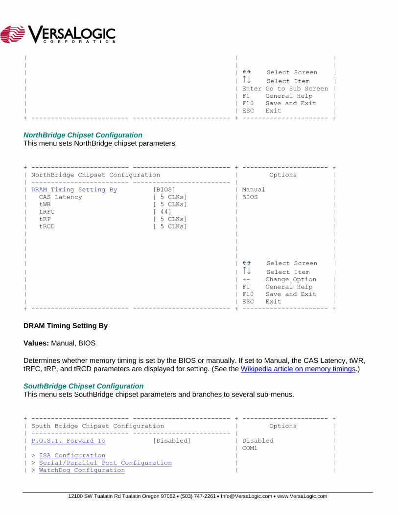
NorthBridge Chipset Configuration This menu sets NorthBridge chipset parameters.
+ ------------------------- ------------------------- + ---------------------- +
| NorthBridge Chipset Configuration | Options |
| ------------------------- ------------------------- | |
| DRAM Timing Setting By [BIOS] | Manual |
| CAS Latency [ 5 CLKs] | BIOS |
| tWR [ 5 CLKs] | |
| tRFC [ 44] | |
| tRP [ 5 CLKs] | |
| tRCD [ 5 CLKs] | |
| | |
| | |
| | |
| | |
| | Select Screen |
| | Select Item |
| | +- Change Option |
| | F1 General Help |
| | F10 Save and Exit |
| | ESC Exit |
+ ------------------------- ------------------------- + ---------------------- +
DRAM Timing Setting By
Values: Manual, BIOS
Determines whether memory timing is set by the BIOS or manually. If set to Manual, the CAS Latency, tWR, tRFC, tRP, and tRCD parameters are displayed for setting. (See the Wikipedia article on memory timings.)
SouthBridge Chipset Configuration This menu sets SouthBridge chipset parameters and branches to several sub-menus.
+ ------------------------- ------------------------- + ---------------------- +
| South Bridge Chipset Configuration | Options |
| ------------------------- ------------------------- | |
| P.O.S.T. Forward To [Disabled] | Disabled |
| | COM1 |
| > ISA Configuration | |
| > Serial/Parallel Port Configuration | |
| > WatchDog Configuration | |
12100 SW Tualatin Rd Tualatin Oregon 97062 (503) 747-2261 [email protected] www.VersaLogic.com
| | |
| | |
| | |
| | |
| | |
| | Select Screen |
| | Select Item |
| | +- Change Option |
| | F1 General Help |
| | F10 Save and Exit |
| | ESC Exit |
+ ------------------------- ------------------------- + ---------------------- +
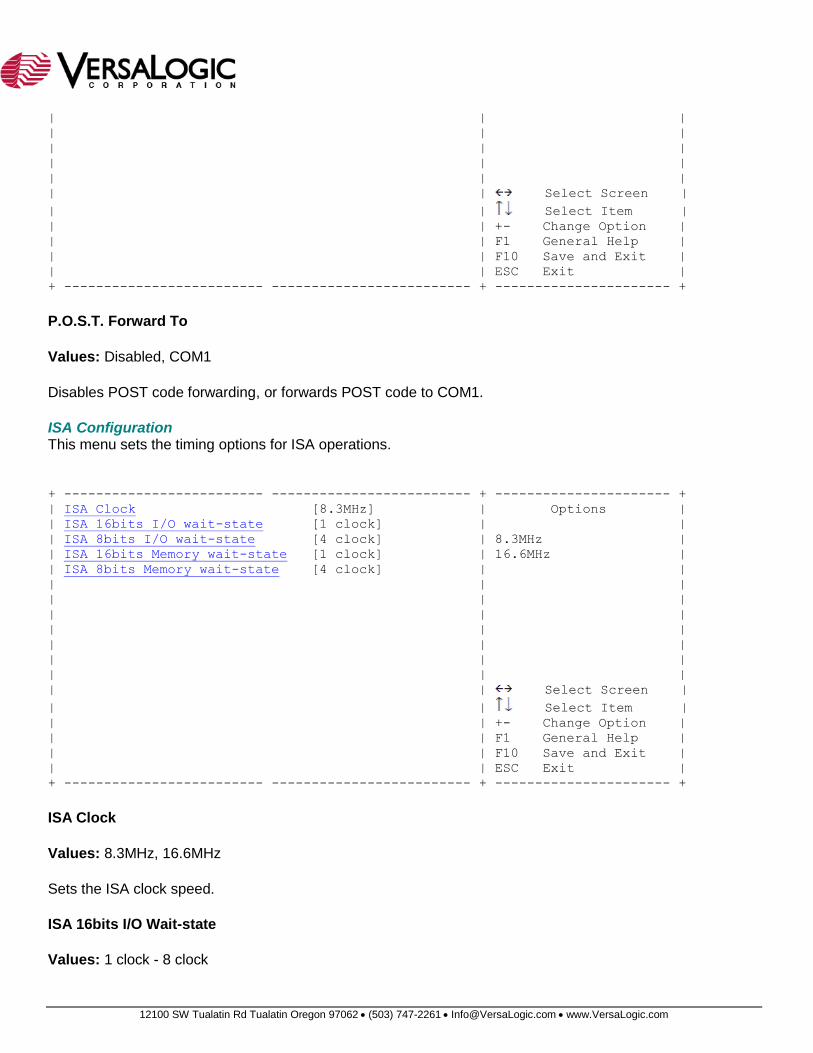
P.O.S.T. Forward To
Values: Disabled, COM1
Disables POST code forwarding, or forwards POST code to COM1.
ISA Configuration This menu sets the timing options for ISA operations.
+ ------------------------- ------------------------- + ---------------------- +
| ISA Clock [8.3MHz] | Options |
| ISA 16bits I/O wait-state [1 clock] | |
| ISA 8bits I/O wait-state [4 clock] | 8.3MHz |
| ISA 16bits Memory wait-state [1 clock] | 16.6MHz |
| ISA 8bits Memory wait-state [4 clock] | |
| | |
| | |
| | |
| | |
| | |
| | |
| | |
| | Select Screen |
| | Select Item |
| | +- Change Option |
| | F1 General Help |
| | F10 Save and Exit |
| | ESC Exit |
+ ------------------------- ------------------------- + ---------------------- +
ISA Clock
Values: 8.3MHz, 16.6MHz
Sets the ISA clock speed.
ISA 16bits I/O Wait-state
Values: 1 clock - 8 clock
12100 SW Tualatin Rd Tualatin Oregon 97062 (503) 747-2261 [email protected] www.VersaLogic.com
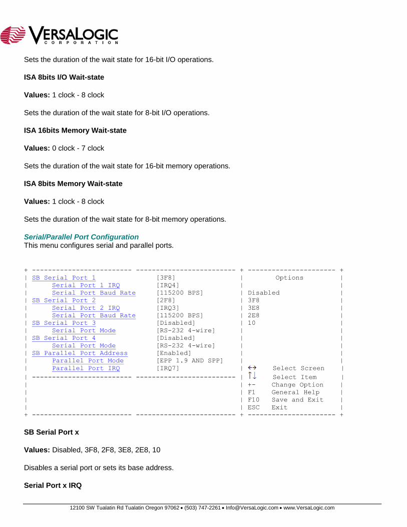
Sets the duration of the wait state for 16-bit I/O operations.
ISA 8bits I/O Wait-state
Values: 1 clock - 8 clock
Sets the duration of the wait state for 8-bit I/O operations.
ISA 16bits Memory Wait-state
Values: 0 clock - 7 clock
Sets the duration of the wait state for 16-bit memory operations.
ISA 8bits Memory Wait-state
Values: 1 clock - 8 clock
Sets the duration of the wait state for 8-bit memory operations.
Serial/Parallel Port Configuration This menu configures serial and parallel ports.
+ ------------------------- ------------------------- + ---------------------- +
| SB Serial Port 1 [3F8] | Options |
| Serial Port 1 IRQ [IRQ4] | |
| Serial Port Baud Rate [115200 BPS] | Disabled |
| SB Serial Port 2 [2F8] | 3F8 |
| Serial Port 2 IRQ [IRQ3] | 3E8 |
| Serial Port Baud Rate [115200 BPS] | 2E8 |
| SB Serial Port 3 [Disabled] | 10 |
| Serial Port Mode [RS-232 4-wire] | |
| SB Serial Port 4 [Disabled] | |
| Serial Port Mode [RS-232 4-wire] | |
| SB Parallel Port Address [Enabled] | |
| Parallel Port Mode [EPP 1.9 AND SPP] | |
| Parallel Port IRQ [IRQ7] | Select Screen |
| ------------------------- ------------------------- | Select Item |
| | +- Change Option |
| | F1 General Help |
| | F10 Save and Exit |
| | ESC Exit |
+ ------------------------- ------------------------- + ---------------------- +
SB Serial Port x
Values: Disabled, 3F8, 2F8, 3E8, 2E8, 10
Disables a serial port or sets its base address.
Serial Port x IRQ
12100 SW Tualatin Rd Tualatin Oregon 97062 (503) 747-2261 [email protected] www.VersaLogic.com
Values: IRQ3, IRQ4, IRQ5, IRQ6, IRQ7, IRQ9, IRQ10, IRQ11, IRQ12
Selects the interrupt for a serial port.
Serial Port Baud Rate
Values: 2400 BPS, 4800 BPS, 9600 BPS, 19200 BPS, 38400 BPS, 57600 BPS, 115200 BPS
Selects the initial baud rate for a serial port.
Serial Port Mode
Values: RS-232 4-wire, RS-422,485
Selects the mode for a serial port.
SB Parallel Port Address
Values: Disabled, 378, 278
Disables the parallel port or selects its base address.
Parallel Port Mode
Values: BPP, EPP 1.9 AND SPP, ECP, ECP AND EPP 1.9, SPP, EPP 1.7 AND SPP, ECP AND EPP 1.7
Sets the parallel port mode.
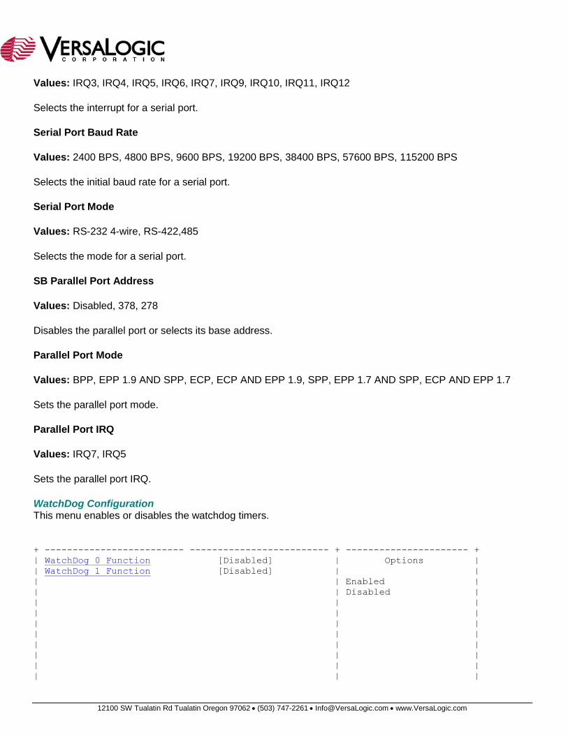
Parallel Port IRQ
Values: IRQ7, IRQ5
Sets the parallel port IRQ.
WatchDog Configuration This menu enables or disables the watchdog timers.
+ ------------------------- ------------------------- + ---------------------- +
| WatchDog 0 Function [Disabled] | Options |
| WatchDog 1 Function [Disabled] | |
| | Enabled |
| | Disabled |
| | |
| | |
| | |
| | |
| | |
| | |
| | |
| | |
12100 SW Tualatin Rd Tualatin Oregon 97062 (503) 747-2261 [email protected] www.VersaLogic.com
| | Select Screen |
| | Select Item |
| | +- Change Option |
| | F1 General Help |
| | F10 Save and Exit |
| | ESC Exit |
+ ------------------------- ------------------------- + ---------------------- +
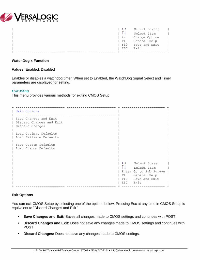
WatchDog x Function
Values: Enabled, Disabled
Enables or disables a watchdog timer. When set to Enabled, the WatchDog Signal Select and Timer parameters are displayed for setting.
Exit Menu This menu provides various methods for exiting CMOS Setup.
+ ------------------------- ------------------------- + ---------------------- +
| Exit Options | |
| ------------------------- ------------------------- | |
| Save Changes and Exit | |
| Discard Changes and Exit | |
| Discard Changes | |
| | |
| Load Optimal Defaults | |
| Load Failsafe Defaults | |
| | |
| Save Custom Defaults | |
| Load Custom Defaults | |
| | |
| | |
| | |
| | Select Screen |
| | Select Item |
| | Enter Go to Sub Screen |
| | F1 General Help |
| | F10 Save and Exit |
| | ESC Exit |
+ ------------------------- ------------------------- + ---------------------- +
Exit Options
You can exit CMOS Setup by selecting one of the options below. Pressing Esc at any time in CMOS Setup is equivalent to "Discard Changes and Exit."
Save Changes and Exit: Saves all changes made to CMOS settings and continues with POST.
Discard Changes and Exit: Does not save any changes made to CMOS settings and continues with POST.
Discard Changes: Does not save any changes made to CMOS settings.

12100 SW Tualatin Rd Tualatin Oregon 97062 (503) 747-2261 [email protected] www.VersaLogic.com
Load Optimal Defaults: Resets CMOS to factory defaults, even if there are custom defaults available. All changes made to CMOS settings during the current and previous CMOS Setup sessions will revert.
Load Failsafe Defaults: Resets CMOS to factory defaults.
Save Custom Defaults: Saves current CMOS settings to custom defaults.
Load Custom Defaults: Resets CMOS to custom defaults.
###