vj-1204 installation manual - signwarehouse · full-color inkjet printer vj-1204. this manual is...
TRANSCRIPT

1 VJ1204E-I-00
VJ-1204 INSTALLATION MANUALPlease read this manual be-fore usingThank you for purchasing a MUTOH product.
This manual explains the steps for unpacking, mount-ing and basic installation before using the MUTOH Full-color inkjet printer VJ-1204.
This manual is intended for owners, installers, and users of this product.
Understand the contents and instructions in this man-ual before installing this product.
Installation flow chartThe broad steps for installation are shown below.
There are instructions for each section beginning on the next page.
1 Unpacking boxes
1.1Unpacking the printer box
1.2 Unpacking the stand box
2 Confirming bundled items
2.1 Items in the printer box
2.2 Items in the attachment box
2.3 Items in the stand box
3 Assembling
3.1 The stand assembling procedure
3.2 Assembling the stand
3.3 Detaching protective materials
4 Installation
4.1 Installation environment
4.2 Installation procedure
5 Connecting the power cable
6 Turning the power ON/OFF
7 Installing the ink cartridge
8 Loading the roll media
9 Checking the printing condition
10Manual composition

VJ-1204 INSTALLATION MANUAL
VJ1204E-I-00 2
1
3
2
3
3
12
4
3
65
7 8
4
5
4
1 2
2
3
1
No. Name 4 Accessory bag 5 Installation Manual (this manual)
No. Name 1 Printer box 2 Scroller 3 Packing material
No. Name Q'ty 1 Printer main body 1 set 2 A0 Scroller 3 inch 1 3 Installation Manual (this manual) 1
No. Name Q'ty 1 Left support 1 2 Right support 1 3 Caster section (left, right) 2 4 Central beam 1 5 Book holder 1 6 Hexagon socket head cap screw 8 7 Butterfly bolt 2 8 Hexagonal wrench 1
No. Name Q'ty 1 Power cable 1 2 Poly-knit wiper 10 sheets 3 Operation Manual CD 1 4 Quick Reference 1
1 Unpacking boxesProcedures for unpacking boxes are explained.
This product is packaged separately, divided into the printer and the stand.
Make sure to unpack this product with three persons or more.
While taking out the printer from the box, make sure to remove the vinyl sheet and hold the handles on the print-er side. If the printer is lifted with the vi-nyl sheet attached, there is a possibili-ty that the printer might slip from your hands and be damaged.
1.1 Unpacking printer boxUnpack the printer box in accordance with the follow-ing steps.1.Carry the box to where you will unpack it. 2.Remove the bands.3.Open the box and take out the following compo-
nents. Installation Manual (this manual) Accessory bag Scroller
1.2 Unpacking stand boxUnpack the stand box in accordance with the follow-ing steps.
1.Carry the box to where you will unpack it.
2.Open the box and take out the components.
2 Confirming bundled itemsAfter unpacking, please confirm that the product has not damaged and no components are missing.
If any items are damaged or missing, contact MUTOH local dealer.
2.1 Items in the printer box
2.2 Items in the accessory bag
2.3 Items in the stand box
NOTE
CAUTION
VJ-1204 INSTALLATION MANUAL
3 VJ1204E-I-00
3
24
1
2
1
2
1
1
3
1
42
2
4
4
3
1
1
2
1
2
1
13
4
3
2
4
12
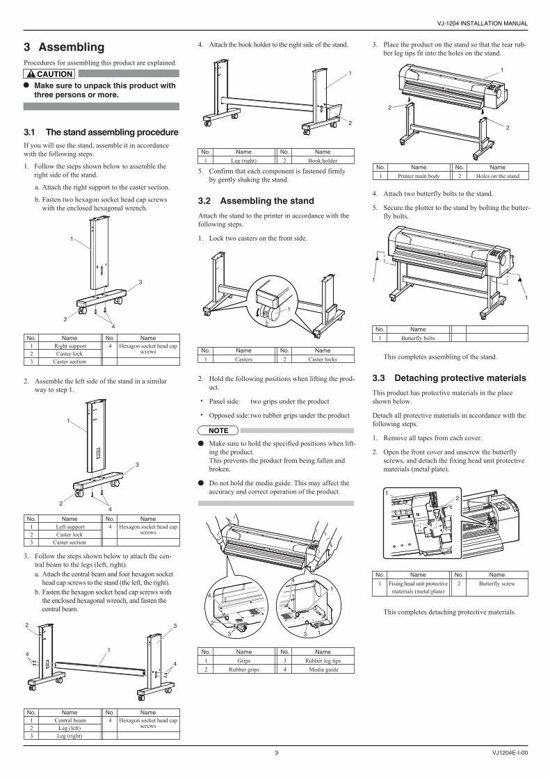
3 AssemblingProcedures for assembling this product are explained.
Make sure to unpack this product with three persons or more.
3.1 The stand assembling procedureIf you will use the stand, assemble it in accordance with the following steps.
1.Follow the steps shown below to assemble the right side of the stand.
a.Attach the right support to the caster section.
b.Fasten two hexagon socket head cap screws with the enclosed hexagonal wrench.
2.Assemble the left side of the stand in a similar way to step 1.
3.Follow the steps shown below to attach the cen-tral beam to the legs (left, right).a.Attach the central beam and four hexagon socket
head cap screws to the stand (the left, the right). b.Fasten the hexagon socket head cap screws with
the enclosed hexagonal wrench, and fasten the central beam.
4.Attach the book holder to the right side of the stand.
5.Confirm that each component is fastened firmly by gently shaking the stand.
3.2 Assembling the stand
Attach the stand to the printer in accordance with the following steps.
1.Lock two casters on the front side.
2. Hold the following positions when lifting the prod-uct.
Panel side: two grips under the product
Opposed side:two rubber grips under the product
Make sure to hold the specified positions when lift-ing the product.This prevents the product from being fallen and broken.
Do not hold the media guide. This may affect the accuracy and correct operation of the product.
3.Place the product on the stand so that the rear rub-ber leg tips fit into the holes on the stand.
4.Attach two butterfly bolts to the stand.
5.Secure the plotter to the stand by bolting the butter-fly bolts.
This completes assembling of the stand.
3.3 Detaching protective materials
This product has protective materials in the place shown below.
Detach all protective materials in accordance with the following steps.
1.Remove all tapes from each cover.
2.Open the front cover and unscrew the butterfly screws, and detach the fixing head unit protective materials (metal plate).
This completes detaching protective materials.
No. Name 4 Hexagon socket head cap screws
No. Name 1 Right support 2 Caster lock 3 Caster section
No. Name 4 Hexagon socket head cap screws
No. Name 1 Left support 2 Caster lock 3 Caster section
No. Name 4 Hexagon socket head cap screws
No. Name 1 Central beam 2 Leg (left) 3 Leg (right)
No. Name
1 Leg (right) No. Name
2 Book holder
No. Name
1 Butterfly bolts
No. Name
1 Casters No. Name
2 Caster locks
No. Name
1 Fixing head unit protective materials (metal plate)
No. Name
2 Butterfly screw
No. Name
1 Printer main body No. Name
2 Holes on the stand
No. Name
1 Grips 2 Rubber grips
No. Name
3 Rubber leg tips 4 Media guide
CAUTION
NOTE

VJ-1204 INSTALLATION MANUAL
VJ1204E-I-00 4
1
2
1
2
1
e
a
b
c
d
a=180mmb=450mmc=480mmd=300mme=1198mm
4 InstallationProcedures and environment for installing this product are explained.
4.1 Installation environment
Install this product to the appropriate place with refer-ence to the following.
Do not install the printer in the follow-ing places where there is a possibility that the printer may be damaged or might fall or be fallen by chance.
On a shaky stand Slanting location Places where vibration of other machines etc. is transmitted.
Do not stamp on the printer or do not place heavy things on top of it. The printer may be damaged or might fall or be fallen by chance.
Cover the printer with blanket and cloth like tablecloth and do not close the vent. If the vent is closed, the print-er could accumulate heat inside and may cause fire.
Do not install the printer in a location that has high humidity or is dusty. It could lead to electric shock and fire.
4.1.1 Installation environmental condition
Select an installation location in accordance with the table below.
For temperature and humidity, avoid locations such as the following. There is a possibility that the print quality will be affected.Places where temperature or humidity may rapidly change, even though within the required conditions.Places that receive direct sunlight, increased illumination or direct air, for example from an airconditioner.To keep the temperature and humidity constant, in-stall this product in a location where the air condi-tion is adjustable.
4.1.2 Installation space
Install on a level floor which meets the following con-dition.
It has enough strength to support the weight of the printer and the stand.
For the weight of the printer and the stand, refer to the Operation Manual.
4.1.3 Installation procedure
Install this product to the installation place in accord-ance with the list shown below.
Please check that the butterfly bolts are not loose before/after carrying this product.
When transferring or carrying outside, separate the printer and the stand.
1.Check that the two butterfly bolts attaching the stand and the printer are not loose.
2.Carry the plotter to the installation place.
3.Lock two casters on the front side.
4.Check that the two butterfly bolts attaching the stand and the printer are not loose.
5 Connecting the power cableThis section explains how to connect the power cable.
Make sure that the included power ca-ble is used.If other power cables are used, it may cause an electric shock or fire.
Do not use a damaged power cable. It may cause an electric shock or fire.
Follow the steps below to connect the power cable.
1.Confirm that the product is turned OFF.
If the [Power] key is pressed, the product is turned ON. Press the key again, and turn OFF the power.
2.Connect the power cable to the AC inlet on the back of the product.
3.Correctly insert the power cable plug into the pow-er socket.
More than 2940 Pa (300 kg/m2)
PowerSpecifica-tion
Environm-entalconditions
Floor strength of installation place
PowerSupply
FrequencyRange
AC90V - 132V/198V - 264V
50/60Hz ± 1Hz
Powercapacity
Change rate
Operativecondition
Archiving environment
Guaranteed range of printing accuracy
More than 10 A
Temperature:20 °C to 32 °CHumidity: 40 % to 60 %, No Condensation
Temperature:22 °C to 30°CHumidity: 40 % to 60 %
Temperature: within 2 °C per hourHumidity: within 5 % per hourTemperature:-20° C to 60 °CHumidity: 5 % to 85 % ,No Condensation (Ink unfilled)
No. Name
1 Casters No. Name
2 Caster locks
No. Name
1 AC inlet
No. Name
1 Power cable
NOTE
NOTE
NOTE
WARNING
WARNING
NOTE

VJ-1204 INSTALLATION MANUAL
5 VJ1204E-I-00
1
2
1
2 3 4 5
2
1
1
2
21
43
4
6Turning the power ON / OFFThis section explains how to turn ON/OFF the printer.
6.1 Turning the power ONFollow the procedure below to turn ON the printer.
1.Press the [Power] key on the operation panel to turn ON the printer.
The Power lamp on the operation panel lights up in green.
The printer starts initial operation.
When the initial operation is complete, the printer enters normal status.
6.2 Turning the power OFFFollow the procedure below to turn OFF the printer.
1.Regarding the operating condition of the printer, confirm the following.
Printing or other operations are not in progress.
The operation panel is in normal status.
2.Press the [Power] key on the operation panel to turn OFF the printer.
The Power lamp on the operation panel turns OFF.
If the operation panel is in the following status, the power is ON.The [Power] key is pressed in.The Power lamp lights up in green.Press the key once again and turn OFF the power.
3.The printer starts operating to turn the power OFF.
The operation panel displays "Power Off".
All the lamps on the operation panel and the LCD monitor are turned OFF.
The printer automatically turns the power OFF.
After turning OFF the printer, wait for 10 seconds or longer to turn it ON again.
When not using the printer for a long period, push the media loading lever to the back.
7 Installing ink cartridgesThis section explains how to install ink cartridges.
Follow the steps below to install ink cartridges.
1.Turn ON the product.
The operation panel displays "[KCMY] Discharged" and the product starts initial operation.
After the initial operation, the operation panel dis-plays "Insert CleaningCart.".
2.Take out the cleaning cartridge from the bag.
3.Install the cleaning cartridge into the ink cartridge slots.
Install the cleaning cartridge with mark facing to the product.
Insert the cartridge all the way into the product.
The product starts filling cleaning fluid.
4.After the cleaning fluid is filled, take out the clean-ing cartridge.
The operation panel displays "During washing" and the product starts head cleaning.
After the head cleaning, the operation panel dis-plays "Insert InkCartridges".
5.After the head cleaning, take out the ink cartridge from the bag and shake it gently two to three times before installing.
Slots for ink cartridges are specified depending on colors of the ink cartridges. Match the color marked in the front of the slots with the color of the ink cartridge.
Install the ink cartridges with mark facing to the product.
Insert the cartridge all the way into the product.
"Ink Refill **%" is displayed on the operation panel and ink replenishment starts.
The ink replenishment takes about four minutes. Ink filling operation and pause operation are re-peated during the ink replenishment.
When "100%" is displayed, the ink replenishment is complete.
6.After the ink replenishment is complete, "Media End" is displayed on the operation panel.
If the printer is used immediately after the ink re-plenishment is complete, the following results may occur.Printed line becomes blurred.White lines appear in the print.In such cases, follow the Operation Manual "6.2.3. Head cleaning" and charge a small amount of ink. Then, check the printing result.If there is no improvement in the printing result even after performing the head cleaning, leave the printer unused for an hour or more. Then, perform a head cleaning again and check the printing re-sult.If there is still no improvement, contact MUTOH local dealer.
8 Loading roll mediaThis section explains how to load roll media.
Follow the steps below to load roll media.
1. Set roll media in the scroller so that the roll media gets winded up in the direction of anti-clockwise when viewed from the fixed flange side.
2. Push the roll media until its core hits the right edge of the fixed flange.
3. Attach the movable flange so that it is firmly at-tached to the roll media core.
4.Set the scroller onto the scroll receiver with the fixed flange side facing the ink cartridge slots.
(Continue to next)
No. Name
1 Ink cartridge 2 Ink cartridge slot K 3 Ink cartridge slot C
No. Name
4 Ink cartridge slot M 5 Ink cartridge slot Y
No. Name
1 Fixed flange No. Name
2 Roll media
No. Name
1 Cleaning cartridge No. Name
2 Ink cartridge slots
No. Name
1 Movable flange No. Name
2 Roll media
No. Name
1 Scroller 2 Fixed flange
No. Name
3 Ink cartridge slot 4 Scroller receiver
NOTE
NOTE
NOTE

VJ-1204 INSTALLATION MANUAL
VJ1204E-I-00 6
1
21
2 21
2
1
(Cont'd)
5.Turn ON the product.
6.The product starts the initial operation.
The operation panel displays "Media End".
7.Push the media loading lever backward.
The operation panel displays "Lever Up".
8.Feed the roll media into the media feed slot.
9.Open the front cover, and pull out the roll media.
10.Press and hold the front edge of the roll media and wind it back with the scroller to remove a media bend or slant.
11.Return the media loading lever to the front and close the front cover.
The operation panel displays the media type setup menu.
12.Press the [+] or [-] key on the operation panel to select the type of the loaded media and press the [Enter] key.
This confirms the media type.
The operation panel displays "Media Initial", and media initial operation starts.
After the media initial operation is completed, the operation panel displays "Ready to Print", and the display enters normal status.
13.Wind back the roll media with the scroller to re-move a media bend.
The media loading is complete.
9 Checking printing conditionsCheck the condition of the print head after the ink re-plenishment.
1.Turn ON the printer and load equal to or bigger than A3 size of roll media.
8 Loading the roll media
2.Confirm that the printer functions normally.
3.Press the [<] key on the operation panel for two seconds or more.
Nozzle check printing starts.
4.Check the sample print for blurred or missing parts in the check pattern.
5.If the nozzle check result indicates that there is a problem such as mentioned above in the check pat-tern, clean the head.
Press and hold the [Cleaning] key on the operation panel for two seconds or more.
The operation panel displays "Cleaning **%".
6.Head cleaning starts.
If one time of head cleaning was not enough to re-move blurred or missing parts in the check pattern, perform powerful cleaning.If those problems above were not improved after a few times of head cleaning, refer to the Operation Manual "7 Troubleshooting" and perform required procedures.
7.Perform nozzle check again and check the condi-tion of the print head.
10Manual composition This product includes the following three manuals.
Installation Manual (this manual)
This manual explains the procedures of unpacking, in-stalling, and the basic set up.
Quick Reference
Quick Reference is excerpts of functions used daily.
Operation Manual (CD-ROM)
The Operation Manual explains the basic installation, daily use and applicable functions.
The Operation Manual of this product is created with the HTML format and can be viewed using browsers such as Internet Explorer.
Refer to Quick Reference "5.5 Using Operation Manual CD" for viewing the Operation Manual.
12
22 1
No. Name
1 Media loading lever
No. Name
1 Roll media No. Name
2 Media feed slot
No. Name
1 Front cover No. Name
2 Roll media
No. Name
1 Media loading lever No. Name
2 Front cover
No. Name
1 Roll media No. Name
2 Scroller
No. Name
1 Roll media No. Name
2 Scroller
NOTE
TIP

VJ-1204 INSTALLATION MANUAL
7 VJ1204E-I-00
< MEMO >

MUTOH INDUSTRIES LTD.Tel.:81-(0)3-5486-7145Fax:81-(0)3-5486-7163E-mail:[email protected]://www.mutoh.co.jp
MUTOH AMERICA INC.Tel.:1-480-968-7772Fax:1-480-968-7990E-mail:[email protected]://www.mutoh.com
MUTOH EUROPE N.V.Tel.:32-(0)59-561400Fax:32-(0)59-807117E-mail:[email protected]://www.mutoh.be
MUTOH DEUTSCHLAND GmbH.Tel.:49-(0)2159-913430Fax:49-(0)2159-913456E-mail:[email protected]