visualizing sound- a musical composition of aural architecture
DESCRIPTION
Visualizing Sound- A Musical Composition of Aural ArchitectureTRANSCRIPT

University of South FloridaScholar Commons
Graduate Theses and Dissertations Graduate School
2009
Visualizing sound: A musical composition of auralarchitectureJames PendleyUniversity of South Florida
Follow this and additional works at: http://scholarcommons.usf.edu/etdPart of the American Studies Commons
This Thesis is brought to you for free and open access by the Graduate School at Scholar Commons. It has been accepted for inclusion in GraduateTheses and Dissertations by an authorized administrator of Scholar Commons. For more information, please contact [email protected].
Scholar Commons CitationPendley, James, "Visualizing sound: A musical composition of aural architecture" (2009). Graduate Theses and Dissertations.http://scholarcommons.usf.edu/etd/2137
Visualizing Sound: A Musical Composition of Aural Architecture
by
James Pendley
A thesis submitted in partial fulfi llmentof the requirements for the degree of
Master of ArchitectureSchool of Architecture and Community Design
College of the ArtsUniversity of South Florida
Major Professor - Stanley Russell, M. Arch. Alex Bothos, M. Arch.
Paul Reller, M. M.
Date of ApprovalNovember 13, 2009
Keywords: performance spaces, acoustics, design, music, form
Copyright 2009, James Pendley©

Thank you to the faculty of the sa_cd for the devotion to education as well as the students.I would like to extend a special thanks to Stan Russell (Project Chair), Alex Bothos (Thesis Commit-tee), Paul Reller (Thesis Committee), Trent Green (Thesis I Professor)
Words could not express the gratitude to my family and friends for the endless support and standing by my side throughout this crazy endeavor called architecture school. Without you all none of this would have been possible.
To my wife, Thank you so much for the patience and understanding for so many years, and totally supporting me in whatever I do. Forever, I love youTo my daughter Jaymie Lynn Pendley for being so understanding and patient. You are such a beautiful person, I am so proud to be your dad. I love you baby girl.
Thank you to Donna Pendley for wonderful thoughts and ideas along the way.
Acknowledgements

List of Figures..........................................
Abstract..................................................
Thesis Project.......................................... Thesis Project Description
Acoustics / Music...................................... History of Music / Acoustics Sabine’s Equation
Sound / Acoustics - Research.................... Physical Acoustic Perception Psychoacoustics Room Acoustics Sound Mapping Acoustics / Space
Case Studies............................................ Theatre at Epidaurus Adrienne Arsht Center Tempe Center for The Arts Shanghai Oriental Arts Center Walt Disney Concert Hall
iii
vi 1 2 6 7 8
10111213141516
171820222426
Case Study Summary
Program Elements..................................... Performance / Musical Education
Program Analysis...................................... Program Exploration 3-D Program Layout Program Square Footage
Site Selection........................................... Sarasota, Florida Zoning District Proposed Sites Selected Site
Site Analysis............................................ Environmental Site Characteristics
Project Concepts...................................... Placement / Organization
Parti Exploration.......................................
28
2930
31323334
3536383942
434445
4954
55
i
Table of Contents
Conceptual Design..................................... Conceptual Schematic Design
Design Phase.......................................... Floorplans Sections Elevations Details Anechoic Concept Acoustical Testing - Ray Tracing Renderings Draft Model Section Model Final Model
Conclusion..............................................
Bibliography............................................
Internet References.................................
Image References...................................
5859
6263666870717274808182
84
85
87
88
ii
List of Figures
Fig. 1 - Sound PerceptionFig. 2 - Epidaurus TheatreFig. 3 - Sound WaveFig. 4 - Epidaurus TheaterFig. 5 - Human Auditory SystemFig. 6 - Breaking the Sound BarrierFig. 7 - Cause / EffectFig. 8 - Process of PerceptionFig. 9 - Brain ProcessFig. 10 - Diagram of BrainFig. 11 - Water AcousticsFig. 12 - Human Auditory SystemFig. 13 - Auditory System in BrainFig. 14 - Acoustic Scales Fig. 15 - RotundaFig. 16 - ParabolaFig. 17 - Acoustics / FormFig. 18 - Sound Through PopulationFig. 19 - 3-D Map of SoundFig. 20 - Room AcousticsFig. 21 - Sound ExplosionFig. 22 - Sound ReactionFig. 23 - Sound Wave (Guitar)Fig. 24 - Sound Refl ection
Fig. 25 - Room AcousticsFig. 26 - Theater at EpidaurusFig. 27 - Plan, EpidaurusFig. 28 - Wind ConceptFig. 29 - SeatingFig. 30 - Seating DiagramFig. 31 - Adrienne Arsht CenterFig. 32 - Main Performance HallFig. 33 - Ceiling AcousticsFig. 34 - MaestroFig. 35 - Steel Skin SystemFig. 36 - Isolation Wall / HallwayFig. 37 - Exterior AmphitheaterFig. 38 - Performance HallFig. 39 - Plan Fig. 40 - SectionFig. 41 - Render of ComplexFig. 42 - Plan of ContextFig. 43 - Entrance WDCHFig. 44 - AxonometricFig. 45 - Plan Entire ComplexFig. 46 - Section Performance HallFig. 47 - TeachingFig. 48 - Practicing
1 410111111111112121213131314141415151616161616
161818191919202121212121222223232425262727273030
iii

Fig. 49 - Parti of ThoughtFig. 50 - Program AnalysisFig. 51 - Program AnalysisFig. 52 - Site MapFig. 53 - Shore LineFig. 54 - Sunset at SiteFig. 55 - Future Land UseFig. 56 - Zone DistrictsFig. 57 - SiteFig. 58 - AerialFig. 59 - Site MapFig. 60 - AerialFig. 61 - SiteFig. 62 - AerialFig. 63 - Site MapFig. 64 - AerialFig. 65 - AerialFig. 66 - SiteFig. 67 - Site MapFig. 68 - AerialFig. 69 - Site PropertiesFig. 70 - The BayFig. 71 - Population - FloridaFig. 72 - Sun ChartFig. 73 - Site ClimateFig. 74 - Site Analysis Map
Fig. 75 - ViewsFig. 76 - Site MapFig. 77 - Figure / GroundFig. 78 - Green SpaceFig. 79 - Site StructureFig. 80 - Site MapFig. 81 - Vehicular PathFig. 82 - Pedestrian PathFig. 83 - Major StreetsFig. 84 - Site TransitionFig. 85 - Points of InterestFig. 86 - Site UtilizationFig. 87 - Diagram Fig. 88 - DiagramFig. 89 - Natural Sound at SiteFig. 90 - Man Made Sound at SiteFig. 91 - Spatial TransitionFig. 92 - Sound OverlayFig. 93 - 3-D SoundFig. 94 - Movement of SoundFig. 95 - Motion in SoundFig. 96 - Model ConceptFig. 97 - Model ConceptFig. 98 - Model ConceptFig. 99 - ConceptFig. 100 - Concept Model
3232333636363738393939394040404041414141424244444445
4546464646474747474848484850505050515151525252525353
iv

Fig. 101 - Concept ModelFig. 102 - Concept ModelFig. 103 - Schematic ConceptsFig. 104 - PartiFig. 105 - PartiFig. 106 - PartiFig. 107 - Parti ExplorationFig. 108 - Parti ExplorationFig. 109 - Parti ExplorationFig. 110 - Concept DrawingFig. 111 - Concept IdeaFig. 112 - AnalysisFig. 113 - Concept IdeaFig. 114 - Exploration of IdeaFig. 115 - Sound / WaterFig. 116 - Space LayoutFig. 117 - Conceptual SchematicFig. 118 - Schematic ConceptFig. 119 - Schematic ConceptFig. 120 - Initial SketchFig. 121 - Sound as an Element of DesignFig. 122 - Sound Rings at SiteFig. 123 - Site PlanFig. 124 - FloorplanFig. 125 - 2nd FloorplanFig. 126 - 3rd Floorplan
Fig. 127 - SectionsFig. 128 - PerspectivesFig. 129 - ElevationsFig. 130 - ElevationsFig. 131 - DetailsFig. 132 - Anechoic ConceptFig. 133 - Acoustical Ray TraceFig. 134 - Acoustical TestingFig. 135 - RenderFig. 136 - RenderFig. 137 - RenderFig. 138 - RenderFig. 139 - Render Fig. 140 - RenderFig. 141 - RenderFig. 142 - Draft ModelFig. 143 - Section ModelFig. 144 - Final ModelFig. 145 - Final ModelFig. 146 - Final ModelFig. 147 - Final ModelFig. 148 - Final ModelFig. 149 - Final Model
5353545656565757575959595959606060606060616162636465
6667686970717273747475767778798081828383838384
v

We depend on our collective senses in order to rationalize and negotiate space. Unfortunate-ly, sound and acoustics has become a secondary concern to that of the visual perception in archi-tecture. The initial design intent for many mod-ern performance spaces and music education space, for about the past one-hundred years, has not been driven by sound or acoustics, as a consequence the visual perception has become the major infl uence. Prior to modern acoustical applications, performance spaces have been designed for the essence of sound and the form and func-tion had no divisible lines, but with amplifi cation of sound and the technology to reproduce and manipulate sound, form over took acoustics as a design based idea.
vi
Visualizing Sound: A Musical Composition of Aural Architecture
James Pendley
ABSTRACT This thesis is a direct reaction to the way acoustics and sound, in performance spaces, has evolved over the past hundred years with the advent of modern acoustical technology. This thesis will ask the question of how can sound and acoustics be the main inspiration for the design intent and a formal determinate of space. By using sound and acoustics as a design based method of space making, architecture can achieve a visualization of space through the aural perception of sound. Reexamining how sound reacts to the geometric shapes and forms in architecture can unveil a solution to poor acoustics in many per-formance spaces, and result in a method of vi-sualizing sound and acoustics in space and not merely a visual experience of the built form. This document will analyze the principals and the application of acoustical design in per-formance and musical education spaces and re-establish the connection of music, acoustics and architecture. The outcome for this thesis will re-sult in the holistic approach to an acoustically designed performance center inter-connected with scholastic spaces for musical education.
Thesis Project
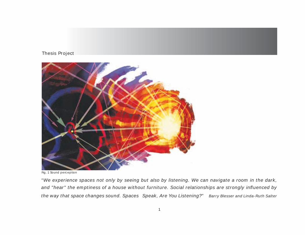
“We experience spaces not only by seeing but also by listening. We can navigate a room in the dark,
and "hear" the emptiness of a house without furniture. Social relationships are strongly infl uenced by
the way that space changes sound. Spaces Speak, Are You Listening?” Barry Blesser and Linda-Ruth Salter
Fig. 1 Sound perception
1
and tactile qualities of space without the use of typical barriers. The typical space for mu-sical education is a simple square room with an additive aspect for sound response. The original idea for the space was not sound or music, it is only a container for the program. Space for this purpose must be considered in the initial design and structure as a whole entity. Sound can not be physically seen, even though sound is matter and occupies space, the perception of sight cannot detect audible sound waves. One must envision the connec-tion of the senses, vision has connections to taste, smell and tactile qualities, if one sees and object one can perceive the essence of that object such as smell, taste, and touch while the audible sense activates only a visu-al perception, an audible perception responds to the “minds eye”. We as human beings have been programmed to link sounds with a cer-tain image of an object, therefore sound can be seen through a psychological aspect. This thesis began to develop from an exploration of the aural perception of space
Thesis Project Description
The built environment in which we dwell is interpreted through our inherent senses. We as human beings depend upon our sensorial percep-tions in order to rationalize and negotiate space. Without a visual or audible connection to the built environment the perception of architecture would not be so amazing. Aural perceptions of music and tonal effects augment every aspect of life. Through the phenomenon of music and sound our relation-ships with each other as well as the natural ele-ments coalesce to create a holistic entity of dwell-ing within the world of architecture. Music, acoustics and sound plays a quintes-sential role in our every day to day life and yet the facilities that teach these arts do not receive the same respect as others. The architecture for these programmatic issues is generic and lacks the edu-cational sources to produce the fi nal product, mu-sic, that is intertwined in every aspect of our lives. By examining the ways that sound reacts to space and how sound can create space is going to be the fi rst step in the direction to create a new type of aural architecture suited for an educational pur-pose. By using the natural elements and the built environment one can perceive the wind, water, light
2
in architecture. Space is perceived through an ac-cumulation of all the senses and yet the modern day architecture is mainly concerned with the icon-ic visual representation of the architecture. Today’s modern architecture has a strong in-fl uence to the visual component of perception and the audible component has diminished from the importance of the design phase in its infancy. This thesis consists of three main goals as well as the intent to improve the quality of the aural architec-tural environment in which we dwell:
1 To analyze and explore the possibilities of sound as a design inspiration and generator of space in performance spaces.2) To increase awareness and improve the quality of acoustics in the space utilized by performance halls and the musical education.3) To unite music and architecture in such a way that the design infl uences and inspires creativity and encour-ages an exploration of sound and music by the students and performers.
The intent is to heighten ones awareness of the essential role that sound plays in the built en-vironment and to revitalize the aspect of aural de-
sign in architecture. This thesis looks to pro-vide a framework for inhabitable spaces that consist of the perception of sound through the built environment. Rethinking how sound can evolve into inhabitable space and employing the princi-pals of sound in space this thesis will attempt to redefi ne how people occupy the built envi-ronment through sound and not only the typ-ical visual aspect. This thesis will prove that aural architecture can and will be a sustain-able characteristic of modern architecture. The conceptual and schematic phase of design will have to incorporate the ideas of sound as divisions of space and not sole-ly rely on walls and barriers to defi ne said space. Applying aural and acoustical systems to create a sensorial relationship with the built form will only enhance the architecture and hopefully start to reveal that the reality of sound as a generator of space is a facet that is missing in architectural design today.
3

“As opposed to acoustics in architecture, which focuses on the ways that space affects the physical properties of sound waves (spatial acous-tics), aural architecture focuses on the way that lis-teners experience the space”. (Blesser, p.5). Acous-tics manipulate the actual sound waves to enhance or diminish the perception of sound in itself, but aural architecture has a psychological impact on the perception of space through the way sound is understood as a medium of space. A visual connection of space is inhibited by barriers such as walls, structure and obstacles yet an aural connection is uninhibited by such physical obstructions. A space is therefore combined into one entity through the aural perception of space. The human body responds to space instinctively and directly through the receptors of vision, hear-ing, smell and touch, but through the passing of time technology has somehow overshadowed this connection of perception to emphasis the dominant sense of vision. Ancient architects could not afford to isolate the senses into separate entities and had to design using the holistic realm of perception. Examining the ancient amphitheaters and the architecture pri-or the introduction of modern technology one can fi nd that the acoustics of space were designed from
the initial inking of the pen. Acoustics and sound has played a major role in the forma-tion and spatial confi guration of architectural spaces of the past. (Bryant, p.9) This is evident in the ruins of ancient buildings especially the “perfect clarity of the Greek amphitheaters where a speaker, stand-ing at a focal point created by the surround-ing walls, is heard distinctly by all members of the audience.” (Bill Viola in Sheridan, p.3). The essence of sound and acoustics were the main focus and they achieved some of the purest quality of sound that still exists today. (Bomgardner, p.231)
4
Fig. 2 Epidarus Amphitheater

Some of the top rated performance centers today have extremely well designed acoustics. The problem is just that, engineered sound and not the pure quality of sound that is the being perceived. Architecture has given birth to quite a few specialized fi elds such as the acousticians and sound engineers. The element of sound has been written out of the architect’s equation as a design inspiration. This document will compare the modern and ancient performance venues and analyze the char-acteristics which improve or diminish the acousti-cal qualities of the space. Music is an expression of an idea and an idea is a generator of space. The historical technique of designing amphitheaters or acoustical space, especially without the modern technology, is quite amazing. These spaces consist of the pure essence of sound. The space resonates through natural qualities and is not muddied with additive aspects to enhance the acoustics of the space. The importance of looking back to what has been done can only improve what will be done. A series of acoustical studies will prove that acoustics can be a visual connection to an educational expe-rience of space. Our senses are combined into one entity, the
human body. Not all of our senses are equal though, vision seems to be the dominate overall factor as well as in architecture and the others senses seem passive to that of vi-sion. The way that architecture has evolved the audible aspect of perception has dimin-ished into the overlaying of materials and not the architecture in itself, therefore rethinking how sound is perceived and the psychologi-cal and physiological effects on the human psyche in relation to architecture will begin to evolve into a new method of visualizing sound in performance space.
This Document will employ the following methods research:- Case Studies and Combined Strategies - > Modern day theaters > Modern music schools > Performance halls- Interpretive Research - > Greek and Roman amphitheaters > Origins of acoustical planning
5
6
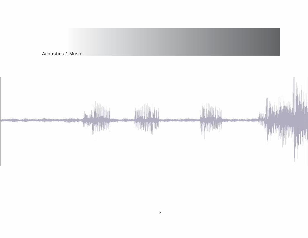
Acoustics / Music
History of Music / Acoustics
The evolution of technology for acoustics and music was basically unchanged for nearly 1800 years. Dating back to the era of the Greeks in 350 B.C. up until the 1500s performance settings were open air forums. The advent of performance halls required a selection of distinct materials to control the reverberation time of the sound. Prior to this, the material that were used had a major effect on acoustics. Dorian chants were created to either shorten or extend the reverberation time of sound and therefore a pioneer of acoustics in space. The same principal applies to instruments as well. The harp, piano and violin could project their sound for quite a distance, but with invention of electric amplifi ers the need for self-sustaining instruments diminished and this brought about a new era in sound and spaces for sound. In modern day writings about architecture there seems to be very little about acoustics and sound in the overall planning of design, but Sheri-dan states that Vitruvius, in The Ten Books on Ar-chitecture, emphasized an equal amount of text to “sound, music and acoustics as he did to site design, materials and color; a level of attention unheard of in current architectural writing.” (Sheridan, p.3) The aspect of sound in Vitruvius’ writings re-late
to “proportional” and “actual” modes. (Bry-ant, p.15) The “proportional” mode “relates the spatio-visual experience of width, height, and depth to the tonal experience of har-monic musical notes,” this provides a “basis for linking the two types of experience and a practical guide for sizing the various parts of building.” (Sheridan, p.3) “This concept is arguably the foundation for the concept of architecture as frozen music”. (Bryant, p.15) The “actual” mode of Vitruvian theory “relays specifi c advice, derived from expe-rience and experimentation, on how sound behaves under certain physical conditions”, including the topics of propagation, refl ection and sympathetic resonance: a clear forerun-ner for today’s modern acoustic engineering practices”. (Sheridan, p.8) The evolution of modern acoustics dates to the late 1800’s. Sabines are a mea-surement of acoustical values. The name was derived by its inventor Wallace Sabine, 1868-1919. The fi rst application of his re-search was Fogg Hall at Harvard University. “Sabine’s career is the story of the birth of the fi eld of modern architectural acoustics.
7

Sabine’s Equation
In 1895, acoustically improving the Fogg Lecture Hall, part of the recently constructed Fogg Art Mu-seum, was considered an impossible task by the senior staff of the physics department at Harvard. The assignment was passed down until it landed on the shoulders of a young physics professor, Sa-bine”. (AE)
“Sabine was able to determine, through these late night forays, that a defi nitive relationship ex-ists between the quality of the acoustics, the size of the chamber, and the amount of absorption surfac-es present. He formally defi ned the reverberation time, which is still the most important characteris-tic currently in use for gauging the acoustical qual-ity of a room, as number of seconds required for the intensity of the sound to drop from the starting level, by an amount of 60 dB (decibels).” (AE)
“The formula is RT60 = 0.049V \Sa Where RT60 is the reverberation time, V is the volume of the room in cubic meters, and Sa is the total ab-sorption, a is the average absorption coeffi cient of room surfaces and S is the surface area”. (Sabine) “Note that the reverberation equation formula is just that, a formula, not an actual equation. By
studying various rooms judged acoustically good for their intended uses, Sabine deter-mined that good concert halls had reverber-ation times of 2-2.15 seconds (“with short-er reverberation times, a music hall seems too “dry” to the listener”) (AE), the average known “good” reverberation time for this space was slightly under 1 second. Looking at Fogg Museum’s lecture room, Sabine fi gured out “that a spoken word remained audible for about 5.5 sec-onds, or about an additional 12-15 words if the speaker continued talking”. (Sabine) This would result with very high values and rang-es of echo and resonance. Utilizing his discoveries used for the Fogg Hall, “Sabine deployed sound absorbing materials throughout the Fogg Lecture Hall to cut its reverberation time down and re-duce the “echo effect.” This accomplishment cemented Wallace Sabine’s career, and led to his hiring as the acoustical consultant for Boston’s Symphony Hall, the fi rst concert hall to be designed using quantitative acoustics. His acoustic design was a great success and Symphony Hall is generally considered one
8

of the best symphony halls in the world.” (Thomp-son) The way sound defi nes space has a direct cor-relation to the spatial qualities of the space. Soci-ety and culture are key formal determinates of how space is defi ned and how people inhabit the built environment. Blesser refers to space making as” incidental consequences of sociocultural forces.” (Blesser, p. 5) which is to say that a certain culture will form space through the beliefs of their culture and the sounds that envelope their surroundings.
“Listeners react both to sound source and to spatial acoustics because each is an aural stimulus with social, cultural, and personal meaning depend-ing on the physical design and the cultural context, aural architecture can stimulate anxiety, tranquil-ity, socialization, isolation, frustration, fear, bore-dom, aesthetic please, and so on”. (Blesser, p. 11)
This thesis exploration will attempt to de-fi ne space as an aural perception. While occupying space there are psychological and physiological as-pects to inhabitation. The audible sense is the main focus of this exploration being used to determining
the spatial qualities. Sound is essential to the rationalization of our world and the realm of architecture. Through the built form this thesis will employ 3d modeling and simulation as well as the use of case studies and interpretive research methods employed in the present and past. The fi rst step in beginning the ar-duous task of reinterpreting how sound, as a determinate factor of space, is a plausible application that needs to, and must be, rein-troduced to the world of architecture.
9
10
Sound / Acoustics - Research
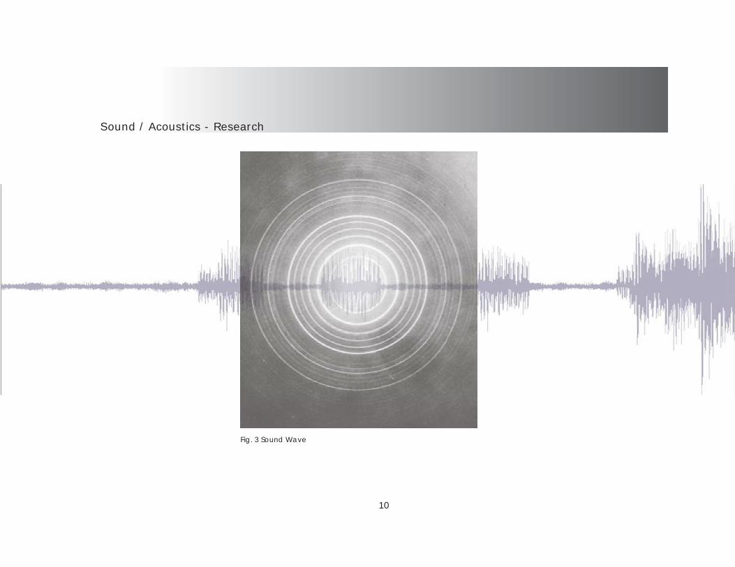
Fig. 3 Sound Wave

Physical Acoustics
“Sound is a travelling wave which is an os-cillation of pressure transmitted through a solid, liquid, or gas, composed of frequencies within the range of hearing and of a level suffi ciently strong to be heard, or the sensation stimulated in organs of hearing by such vibrations.”
“Acoustics is the interdisciplinary science that deals with the study of sound, ultrasound and infrasound (all mechanical waves in gases, liq-uids, and solids). A scientist who works in the fi eld of acoustics is an acoustician. The application of acoustics in technology is called acoustical engi-neering. There is often much overlap and inter-action between the interests of acousticians and acoustical engineers.”
11
Fig. 8 Process of PerceptionFig. 7 Cause / EffectFig. 6 Breaking the Sound Barrier
Fig. 4Sine Wave Fig. 5 Human Auditory System
Perception
12
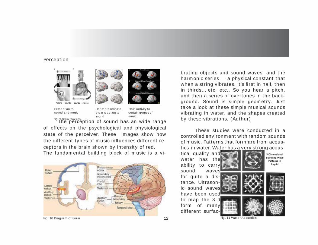
The perception of sound has an wide range of effects on the psychological and physiological state of the perceiver. These images show how the different types of music infl uences different re-ceptors in the brain shown by intensity of red. The fundamental building block of music is a vi-
brating objects and sound waves, and the harmonic series — a physical constant that when a string vibrates, it’s fi rst in half, then in thirds… etc. etc.. So you hear a pitch, and then a series of overtones in the back-ground. Sound is simple geometry. Just take a look at these simple musical sounds vibrating in water, and the shapes created by these vibrations. (Authur)
These studies were conducted in a controlled environment with random sounds of music. Patterns that form are from acous-tics in water. Water has a very strong acous-tical quality and water has the ability to carry sound waves for quite a dis-tance. Ultrason-ic sound waves have been used to map the 3-d form of many different surfac-
Fig. 10 Diagram of Brain
Hot spots indicate brain reaction to sound
Brain activity to certain genres of music.
Perception to sound and music
Fig. 9 Brain Process
Fig. 11 Water Acoustics
Psychoacoustics
13
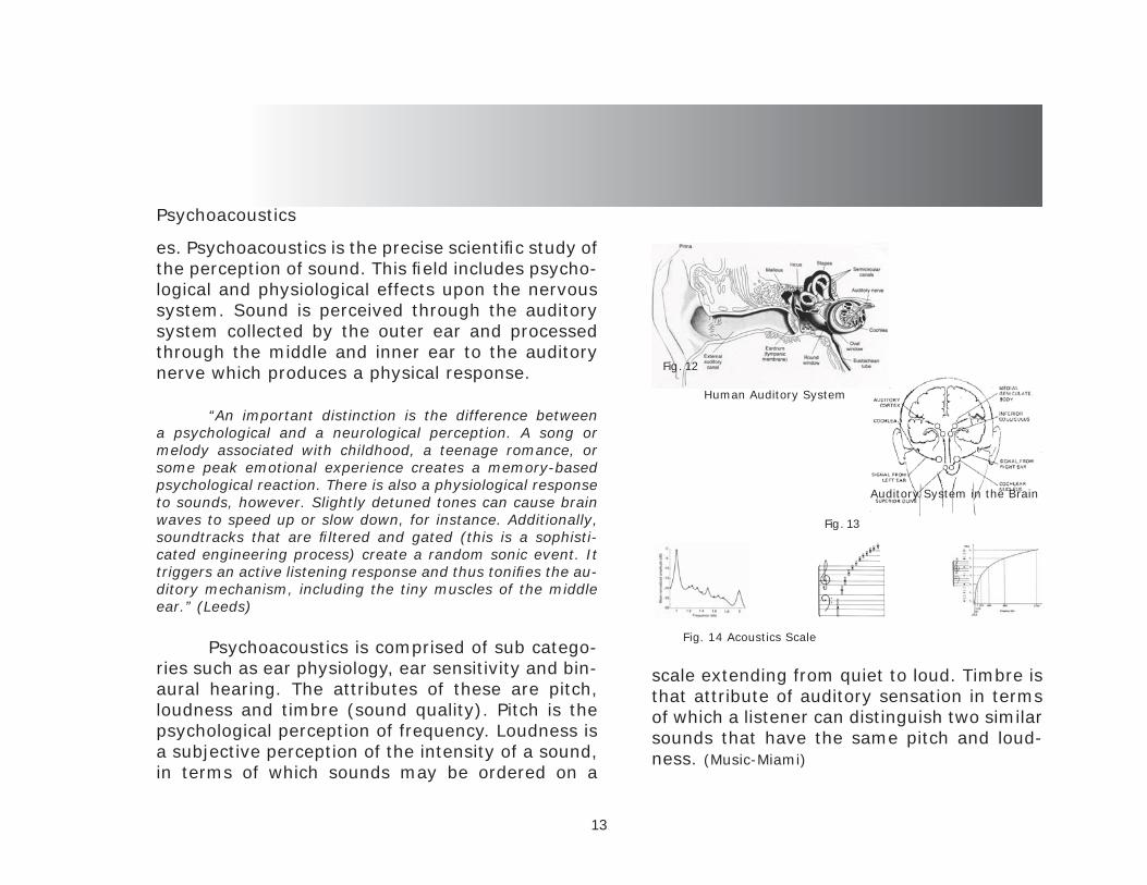
es. Psychoacoustics is the precise scientifi c study of the perception of sound. This fi eld includes psycho-logical and physiological effects upon the nervous system. Sound is perceived through the auditory system collected by the outer ear and processed through the middle and inner ear to the auditory nerve which produces a physical response.
“An important distinction is the difference between a psychological and a neurological perception. A song or melody associated with childhood, a teenage romance, or some peak emotional experience creates a memory-based psychological reaction. There is also a physiological response to sounds, however. Slightly detuned tones can cause brain waves to speed up or slow down, for instance. Additionally, soundtracks that are fi ltered and gated (this is a sophisti-cated engineering process) create a random sonic event. It triggers an active listening response and thus tonifi es the au-ditory mechanism, including the tiny muscles of the middle ear.” (Leeds)
Psychoacoustics is comprised of sub catego-ries such as ear physiology, ear sensitivity and bin-aural hearing. The attributes of these are pitch, loudness and timbre (sound quality). Pitch is the psychological perception of frequency. Loudness is a subjective perception of the intensity of a sound, in terms of which sounds may be ordered on a
scale extending from quiet to loud. Timbre is that attribute of auditory sensation in terms of which a listener can distinguish two similar sounds that have the same pitch and loud-ness. (Music-Miami)
Auditory System in the Brain
Human Auditory System
Fig. 12
Fig. 13
Fig. 14 Acoustics Scale

Room Acoustics
14
Room acoustics is the workings of sound in an enclosed or covered space and has a direct ef-fect on the sound perception of the space. Such considerations that have to be dealt with is size, volume, shape and materials of the space as well as many other indirect characteristics of sound. The properties of acoustics can be analyzed by their inherent attributes, such as reverberation time, refl ection, refraction, diffusion, this is only a few of the main principals of sound, but these play a huge role in the understanding how sound reacts to space. Acoustics can enhance or diminish the sound quality of space and turn a well designed space into a undesirable experience of music and space. The way that sound reacts to a room can be divided into four mainly unique frequency zones:“The fi rst zone is below the frequency that has a wavelength of twice the longest length of the room. In this zone sound behaves very much like chang-es in static air pressure. Above that zone, until the frequency is approximately 11,250(RT60/V)1/2, wavelengths are comparable to the dimensions of the room, and so room resonances dominate. The third region which extends approximately 2 oc-taves is a direct level transition to the fourth zone. In the fourth zone, sounds behave like rays of light
bouncing around the room. “(Leeds)
The zones and regions that are created by sound waves also create problems within enclosed space. Sound waves have refl ections from fl oors, ceilings and walls. Source waves and refl ected waves come into contact with each other and create standing waves or high pressure zones. In response to this Oscar Bo-nello, in 1981, utilized a modal density concept solution called “Bonello Criteria” which uses concepts from psychoacous-tics. “The method analyzes the fi rst 48 room modes and plots the number of modes in each one-third of an octave. The curve increases monotonically (each one-third of an octave must have more modes than the preceding one)”. (Bryant p.54) Fig. 17 Acoustics / Form
Fig. 15 Rotunda
Fig. 16 Parabola

Sound Mapping
15
Sound mapping has become a very useful tool in the realm of architecture. The urban sounds that occupy the exterior of buildings and the can-yons of the city dictate the layout of many public and private spaces. Noise is defi ned as “In com-mon use, the word noise means unwanted sound or noise pollution.” (Websters) As seen in Fig. 19 the massing of urban sound is directly related to population. The sound is a collection of all sounds and noises. The idea of mapping sound came about when residential areas started to sprawl away from the downtown zones. The ability to understand the
way sound can infl uence the habitation of space can achieve a sense of collaboration of the built form and sound. Sound has mass and depth but is unable to be seen by the human eye, but by using computer tech-nology one can visualize the form of sound and how sound can indeed be seen. Sound can be broken down into a mathematical equation of pressure / time and wavelength / amplitude. Frequency is the number of oc-currences of a repeating event per unit time. The basic building blocks of sound are a com-bination of all of these bundled into one unit of sound. The measurement of these charac-teristics enable the mapping of sound waves and sound occurrences along planes.
Fig. 18 Sound Map through population Fig. 19 3-D Map of Sound

Acoustics / Space
16
Sound in space is very distinctive to the prin-cipals of acoustics. The form of a given space can either enhance or diminish the quality of perception. Examining fi g. 26 one can see how sound waves re-act to a non-conforming space of fl at planes. Sound refl ects off of a given surface and impedes the fol-lowing transmission of the next wave. By utilizing acoustics sound can be tuned to the specifi c space, but by doing this the essence of the sound is com-promised. The Space must represent the sound and
not the sound representing the space. Sound is an explosion of energy spreading out in all directions. See fi g. 22 Refl ection, absorption and diffusion are major considerations of sound design be-cause of the way that sound reacts to a solid object. Diffusers will “soften” the sound and absorption will “nullify” the wave through the use of juxtaposition of the surface. The sound wave has a rise (compression) and a fall (rar-efraction) that comprises the amplitude and wavelength. This breaks down to a height and distance of sound, therefore acoustics can not only be measured in terms of mass, but can also demonstrate mass through vol-ume which is a defi ner of space.
Fig. 24 Sound Refl ection Fig. 25 Room Acoustics
Fig. 23 Sound Wave (Guitar) Fig. 22 Sound Refl ectionFig. 21 Sound Explosion
Fig. 20 Room Acoustics

Case Studies
17
Theatre at Epidaurus
18
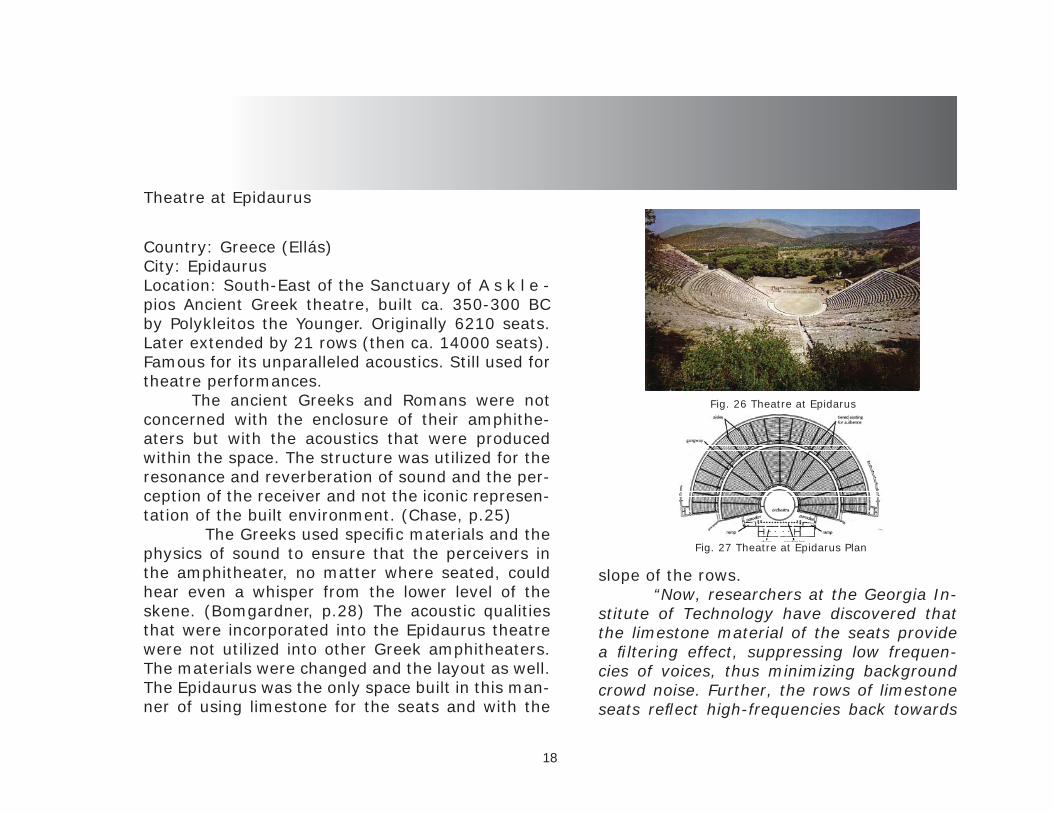
Country: Greece (Ellás) City: Epidaurus Location: South-East of the Sanctuary of A s k l e -pios Ancient Greek theatre, built ca. 350-300 BC by Polykleitos the Younger. Originally 6210 seats. Later extended by 21 rows (then ca. 14000 seats). Famous for its unparalleled acoustics. Still used for theatre performances. The ancient Greeks and Romans were not concerned with the enclosure of their amphithe-aters but with the acoustics that were produced within the space. The structure was utilized for the resonance and reverberation of sound and the per-ception of the receiver and not the iconic represen-tation of the built environment. (Chase, p.25) The Greeks used specifi c materials and the physics of sound to ensure that the perceivers in the amphitheater, no matter where seated, could hear even a whisper from the lower level of the skene. (Bomgardner, p.28) The acoustic qualities that were incorporated into the Epidaurus theatre were not utilized into other Greek amphitheaters. The materials were changed and the layout as well. The Epidaurus was the only space built in this man-ner of using limestone for the seats and with the
slope of the rows. “Now, researchers at the Georgia In-stitute of Technology have discovered that the limestone material of the seats provide a fi ltering effect, suppressing low frequen-cies of voices, thus minimizing background crowd noise. Further, the rows of limestone seats refl ect high-frequencies back towards
Fig. 26 Theatre at Epidarus
Fig. 27 Theatre at Epidarus Plan

19
the audience, enhancing the effect.” (Chao) The use of aural architecture is the subject matter of relevance of to this thesis. The Greeks utilized the sense of audible perception and did not rely on the visual aspect alone in the construction of this space. With the emphasis on the audible, the space transmits sound throughout the entire area through elements of architecture and nature. Sound is the main generator of space in this in-stance therefore the inhabitation of sound through a spatial composition is achieved. The Greeks used scups in the front of the seats to direct and channel sound and diffuse the frequencies that had undesirable results. Fig. 30The theatre was recessed in the ground to utilize the prevailing winds that helped transmit the sound waves. Fig. 28 Limestone used in the seating area was the secret to the perfection of the ancient acoustics. Fig. 29 The overall analysis was conducted through an exploratory and descriptive research. Interpre-tive research was employed in the case study of the theatre at Epidaurus, Greece. While looking at the main form of the performance halls one thing runs consistent with all of the cases is that they were all designed with acoustics in mind, but the only
Fig. 29 Seating
Fig. 28 Wind Concept
Fig. 30 Seating Diagram
one that was designed for pure essence was Epidaurus. The materials were the secret to the phenomenon. The limestone took the low frequencies out of the mix and intensifi ed the middle and high frequencies.

The Adrienne Arsht Center for the Performing Arts
20
The Adrienne Arsht Center for the Performing Arts of Miami-Dade County, Inc., 1300 Biscayne Blvd. Miami, Fl. 25490 Architect: Cesar Pelli _ 2001-2006
“The objectives of Adrienne Arsht Center for the Performing Arts of Miami-Dade County are to:• Offer state-of-the-art accommodations for artists, cultural organizations and their audiences;• Operate in an effi cient and cost-effective manner and attract governmental and foundation fund raising;• Provide a range of performing arts experi-ences beyond what is available regionally;• Act as a catalyst for area revitalization and enhance regional economic opportunities through the Center’s appeal to tourism.” The Adrienne Arsht Center, formally known as the Carnival center, was built to facilitate the grow-ing need for acoustical environments that acted as an “educational and cultural resource” for the ur-ban fabric of Miami-Dade County and the surround-ing areas. The acoustics were designed by Russell Johnson, master acoustician and theatre planner. While Pelli designed the space the actual acoustics
“make” the space, for without the utilization of acoustical interventions the space would not function as a performance venue. Acous-tics in the ballet performing area are inter-twined with the architecture and allow the sound to infi ltrate the whole existence of the space.” (Hall, p.18) The surrounding walls of the theater were designed not only to isolate the inte-rior but to insulate the acoustics. Fig. ## The dampening doors are built so that they may be adjusted to the particular type of perfor-mance. Johnson spent his entire professional life mastering the acoustical values of space and how to achieve the optimal level of ex-cellence in acoustics. The center has two main performance (acoustical) spaces as well as a black box theatre that functions on acoustical qualities. The building is constructed so that the per-
Fig. 31 Adrienne Arsht Center

21
formance spaces are encapsulated inside the en-velope in order to isolate the possible opportunities of the acoustics. The ceiling panels are adjustable in such a way as to maximize the refraction and refl ection of the sound waves. The center is not only for performances they provide an educational realm as well. The center encompasses the entire realm of the performing arts from ballet to musical composition, theater and education while utilizing the principals and theories of acoustics to create their spaces.
Fig. 33 Ceiling acoustics
Fig. 32 Main Performance Hall
Fig. 35 Steel Skin System
Fig. 36 Isolation Wall / HallwayFig. 34 Maestro

Tempe Center for the Arts
22
Designed by Tempe-based Architekton and Barton Myers Associates of Los Angeles, houses a state-of-the-art, 600-seat proscenium theater, a 200-seat studio theater and a 3,500 square-foot gallery.
The main characteristics of the room are: Volume: 18 900 m3, Seats number: 600, Volume / seat: 6.9 m3/st, Max width: 29 m - average width 21 m, Mean ceiling height: 15.9 m, Distance to the second balcony most distant seat: 39 m, Distance to the stage for the most distant VIP seats: 25 m, Distance to the stage for the stalls seat:29 m (low), 33 m (upper). The Tempe center of the arts was tuned to accommodate a wider range of performances. The hall is more adaptive to a varying range of genres. The architect designed the center with other func-tions as well. The educational program included in the design focuses on the journey from learning to showcasing ones talent in the hall. The diversity of the hall is part of its success. The universal space is an asset to the Tempe community. Tempe Center for the Arts stages innovative programming that enriches, enlightens, inspires and expands the artistic horizons of the Tempe Fig. 38 Performance Hall
Fig. 37 Exterior Amphitheater

23
Fig. 40 Section
Fig. 39 Plan
community. The TCA is a unique visual and per-forming arts experience built by the community for the community. It is a professional level venue in which local groups are expected to provide more than 75 percent of the overall programming. The center offers a unique blending of arts and culture at a distinctive destination that features what few cities can boast – Town Lake’s endless outdoor ac-tivities, the dining and nightlife of a vibrant down-town, a dynamic shopping venue and one of the nation’s top universities. The Facility: The 88,000 square-foot facility features a theater, studio, gallery, banquet/meet-ing room, donor lounge, an on-site, full-service box offi ce, theatrical and administrative support areas, two dedicated catering areas, arts retail space, a lounge and a 17-acre art park. Theater - At the heart of the TCA is a 600-seat performance hall able to accommodate dance, drama, small scale opera, musical theater, orches-tral performances and solo recitals. The auditorium incorporates four seating levels - an orchestra lev-el, parterre and two balconies. To the sides of the auditorium, boxes extend and nearly connect to the stage. Above the forestage, an overhead grid allows suspension of scenery, lighting and sound equipment. A state-of-the-art computerized control
system offers maximum fl exibility for theatri-cal lighting and the latest in audio-video and communication systems technology.

Shanghai Oriental Arts Center
24
Fig. 41 Render of Complex
Location: Century Avenue, ShanghaiTotal surface area: 39,694 sqmAuditorium capacities:Philharmonic Orchestra Hall: 1,979 seatsLyric Theatre: 1,054 seatsChamber Music Hall: 330 seats The main characteristics of the room are: Volume: 28 450 m3, Seats number: 1979, Volume / seat: 6.9 m3/st, Max width: 37 m - average width 38 m, Mean ceiling height: 28.9 m, Distance to the second balcony most distant seat: 46 m, Dis-tance to the stage for the most distant VIP seats: 36 m, Distance to the stage for the stalls seat: 28 m (low), 39 m (upper) Project description: The Oriental Arts Centre project is a fi rst rank public cultural building, en-compassing mainly three venues : a 1,979 seats Philharmonic Orchestra Hall, a 1,054 seats lyric Theatre, a 330 seats chamber Music Hall. With a 39,694 sq.m construction site area, the project will be built on 7 main levels. The project architectural intend is based on the following basic principles:- The building has a base on which the public spac-es will develop.
- The halls will emerge from the base as trees from the earth.- The building should be covered and en-closed by one unique cantilevered roof, linked by curved glass walls to the base.- Spaces inside the building are distributed around and from a central circulation and meeting point. This should apply to the public as well as to the performers and the VIP’s.- The public space should be open and adapt-able in order to increase the potential of use of the building.- The performers should be provided with an effi cient and agreeable working space.- The three performance halls should be dif-ferent in form and use different materials.- The outside walls of the three halls will use enamel ceramic as their main common mate-

Viewed from above, Shanghai Oriental Art Center is just like fi ve blossoming petals, which constitute respectively the entrance hall, Oriental Performance Hall, Oriental Con-cert Hall, Exhibition Hall and Oriental Opera Hall, forming a beautiful butterfl y orchid in full bloom.
25
rial.- The material of the façades will be a glass incor-porating a perforated metal sheet of variable den-sity.- The façades design itself will express innovation, modernity and enhance the public areas.- Although secondary in their functional impor-tance, the public spaces will defi ne the character of the building and its fi tting with the spirit of the time. Located in the administrative and cultural center of Pudong New Area, Shanghai Oriental Art Center is the east starting point of Shanghai cultur-al axis in the new round of cultural layout. With an investment of 1 billion RMB by Shanghai Municipal Government and Pudong New Area Administration, Shanghai Oriental Art Center is one of the most important symbolic cultural projects. It occupies a total area of nearly 40,000 square meters and is designed by Paul Andreu, the famous French archi-tect. The construction started on 26th March 2002 and was fi nished with the grand New Year Concert as its Opening Ceremony on 31st December 2004, which marked the beginning of its trial operation. And its offi cial operation is dated on 1st July 2005.
Fig. 42 Plan of Context
Walt Disney Concert Hall
26
Fig. 43 Entrance WDCH
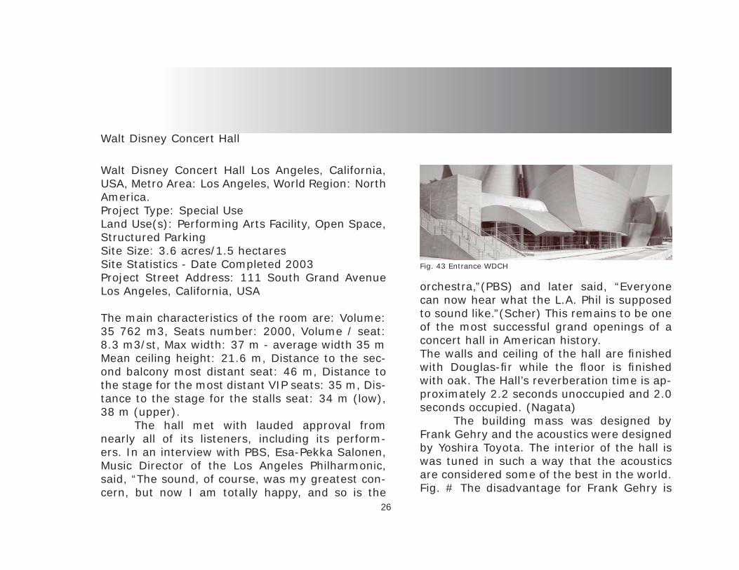
Walt Disney Concert Hall Los Angeles, California, USA, Metro Area: Los Angeles, World Region: North America. Project Type: Special Use Land Use(s): Performing Arts Facility, Open Space, Structured Parking Site Size: 3.6 acres/1.5 hectaresSite Statistics - Date Completed 2003 Project Street Address: 111 South Grand Avenue Los Angeles, California, USA
The main characteristics of the room are: Volume: 35 762 m3, Seats number: 2000, Volume / seat: 8.3 m3/st, Max width: 37 m - average width 35 mMean ceiling height: 21.6 m, Distance to the sec-ond balcony most distant seat: 46 m, Distance to the stage for the most distant VIP seats: 35 m, Dis-tance to the stage for the stalls seat: 34 m (low), 38 m (upper). The hall met with lauded approval from nearly all of its listeners, including its perform-ers. In an interview with PBS, Esa-Pekka Salonen, Music Director of the Los Angeles Philharmonic, said, “The sound, of course, was my greatest con-cern, but now I am totally happy, and so is the
orchestra,”(PBS) and later said, “Everyone can now hear what the L.A. Phil is supposed to sound like.”(Scher) This remains to be one of the most successful grand openings of a concert hall in American history.The walls and ceiling of the hall are fi nished with Douglas-fi r while the fl oor is fi nished with oak. The Hall’s reverberation time is ap-proximately 2.2 seconds unoccupied and 2.0 seconds occupied. (Nagata) The building mass was designed by Frank Gehry and the acoustics were designed by Yoshira Toyota. The interior of the hall is was tuned in such a way that the acoustics are considered some of the best in the world. Fig. # The disadvantage for Frank Gehry is

27
that the main design intent was that of the acous-tician and not the architect. The diminishing role of the architect is contributing to the diminishing aspect of sound as a design inspiration. This leads to a solely visual aspect for design intent.
Fig. 46 Section Performance Hall
Fig. 45 Plan - Entire Complex
Fig. 44 Axonometric

28
Case Study Summary
The overall analysis was conducted through an exploratory and descriptive research. Interpre-tive research was employed in the case study of the theatre at Epidaurus, Greece. While looking at the main form of the performance halls one thing runs consistent with all of the cases is that they were all designed with acoustics in mind, but the only one that was designed for pure essence was Epidaurus. The materials were the secret to the phenomenon. The limestone took the low frequencies out of the mix and intensifi ed the mids and highs. The performance halls of The Tempe center, Oriental arts center and Walt Disney concert hall were all designed by an acoustician and the archi-tect designed the “shell” in which it rest. TCA SOAC WDCH
Performance Hall # of seats 600 1979 2250 Reverberation time - 2.7 sec. 2.4 sec. 2.2 sec Distance Stage to furthest seat - 21 m 46m 44 m Materials - Mahogany/Cherry, Oak-Acoustical Panel, Doug-las Fir / Oak Form- Semi-Circle, Semi - In Round , Semi - In Round Direct sound perception - 195’ 360’ 360’Sound Absorption - Diffusers Yes Yes Yes
The analysis not only focused on the space as an inhabitable form, but mainly fo-cused on the relation of space to acoustics and sound within the space. The Walt Disney concert hall, designed by Frank Gehry has unparalleled acoustics designed by Yoshiuro Toyota. The hall was tuned for an orchestra setting to achieve the optimal aural percep-tion anywhere in the room. The hall is em-bedded in the overall plan of the complex and yet it is the main hub of the building . The Tempe center of the arts was tuned to accommodate a wider range of perfor-mances. The hall is more adaptive to a vary-ing range of genres. The architect designed the center with other functions as well. The educational program included in the design focuses on the journey from learning to showcasing ones talent in the hall. The Shanghai Oriental arts center, de-signed by French architect Paul Adreau in collaboration with Marko Vian (acoustician), was intended to unite all genres of music and performance arts.

29
Program Elements
30
Performance / Musical Education
The intent of the program is to integrate the aspect of musical education and the experience of musical performance. The main design intent is to improve the acoustical qualities of the performance space and explore the “lost” aspect of sound as a design driver. The main concept is the performance hall’s acoustics, but the aspect of learning is equally important. By using the actual sound of music as a generator for space the spaces will not evolve as a typical arts center, but will transform from a space that sound is engineered for into a space that is tuned for the sound.
The evolution of technology has put limita-tions on the way performance hall are designed ei-ther by form or budget. The sound has some major considerations that must be incorporated in the de-sign for a successful space to come to fruition and poses the qualities that the space deserves.
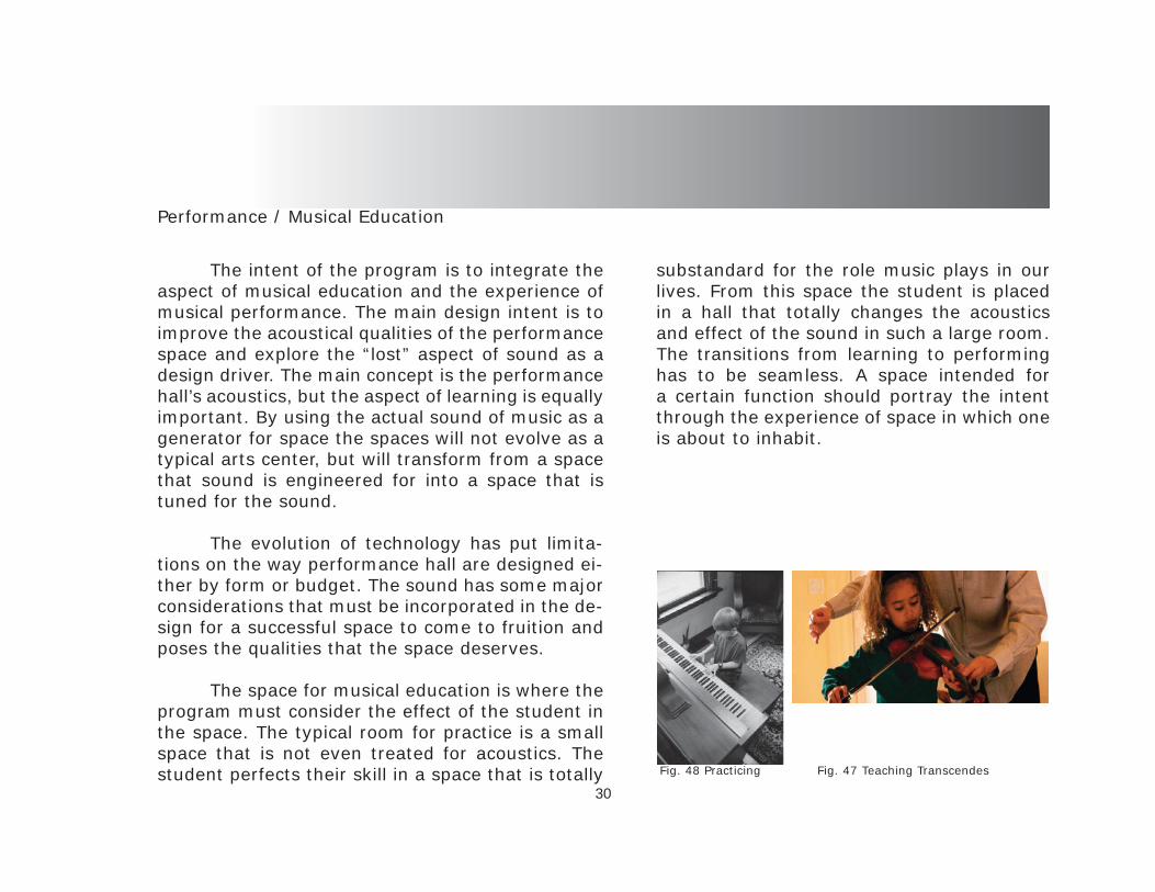
The space for musical education is where the program must consider the effect of the student in the space. The typical room for practice is a small space that is not even treated for acoustics. The student perfects their skill in a space that is totally
substandard for the role music plays in our lives. From this space the student is placed in a hall that totally changes the acoustics and effect of the sound in such a large room. The transitions from learning to performing has to be seamless. A space intended for a certain function should portray the intent through the experience of space in which one is about to inhabit.
Fig. 47 Teaching TranscendesFig. 48 Practicing

31
Program Analysis
32
Program Exploration
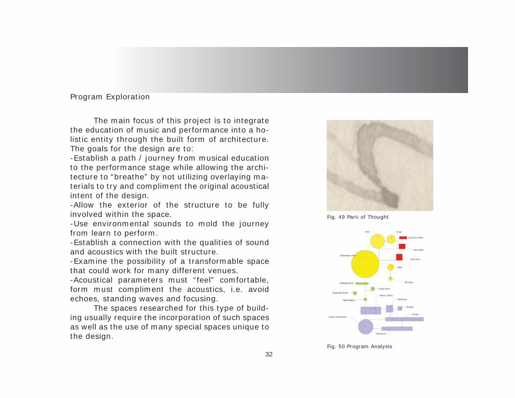
The main focus of this project is to integrate the education of music and performance into a ho-listic entity through the built form of architecture. The goals for the design are to:-Establish a path / journey from musical education to the performance stage while allowing the archi-tecture to “breathe” by not utilizing overlaying ma-terials to try and compliment the original acoustical intent of the design.-Allow the exterior of the structure to be fully involved within the space.-Use environmental sounds to mold the journey from learn to perform.-Establish a connection with the qualities of sound and acoustics with the built structure.-Examine the possibility of a transformable space that could work for many different venues.-Acoustical parameters must “feel” comfortable, form must compliment the acoustics, i.e. avoid echoes, standing waves and focusing. The spaces researched for this type of build-ing usually require the incorporation of such spaces as well as the use of many special spaces unique to the design.
Fig. 49 Parti of Thought
Fig. ##
Fig. 50 Program Analysis

33
3-D Program Layout
Fig. 51 Program Analysis

34
Program Square Footage
Spaces for performance hall program- Entrance / exterior space - ........................................................................---------- Lobby –...............................................................................................2,000 sq. ft. - Large performance hall - ..............................................................40 – 45,000 sq. ft.- Stage - left / right, back stage –.................................................................---------- Dressing rooms – ...........................................................................10 @ 100 sq. ft. ea.- Green room – ........................................................................................ 750 sq. ft.- Production offi ce – ............................................................................4 @ 200 sq. ft. ea.- Planners room – .............................................................................. 2 @ 100 sq. ft. ea.- Box offi ces – ...........................................................................................500 sq. ft.- Restrooms and vending - .........................................................................----------- Restaurant / Café –................................................................................2,000 sq. ft.- Gift Shop – .............................................................................................300 sq. ft.- Loading dock -...........................................................................................--------- Stage equipment room – ..........................................................................500 sq. ft. - Mechanical (tare spaces) / services –...........................................................---------- Studios / class – ......................................................................... 10 @ 1,500 sq. ft. ea.- Class rooms – ...............................................................................8 @ 1,000 sq. ft. ea.- Practice rooms -..................................................................................... 150 sq. ft. ea.- Practice hall – ....................................................................................10,000 sq. ft.- Admin. Offi ces –............................................................................. 10 @ 250 sq. ft. ea.- Gallery –..............................................................................................1,000 sq. ft.- Multi-purpose room – ............................................................................. 750 sq. ft. - Restrooms / mechanical (tare spaces) - ....................................................------------ Storage – ..............................................................................................500 sq. ft. Total sq. ft. 90,000 sq. ft.

35
Site Selection

36Fig. 52 Site Map
Fig. 53 Shore Line
Fig. 54 Sunset at Site
The sites were chosen for the surrounding context of Sarasota. The array of different types of urban, green space and residential areas is quite astonishing. The three sites all have their own characteristics and attributes, but the fi nal choice of site is one that has three very distinct areas that will compliment the program as well as the building. The Gulf coast has very calming proper-ties that will be emphasized in the design.
Sarasota, Florida

12TH ST
SIESTA DR
6TH ST
4TH ST
SO
SPR
EYA
VE
STA
MIA
MIT
RL
NO
RA
NG
EA
VE
MAIN ST
SSH
AD
EA
VE
BAHIA VISTA ST
TAM
IAM
I TRLN
STU
TTLE
AV
E
NE A
STA
VE
2ND ST
NTA
MIA
MIT
RL
HYDE PARK ST
CO
CO
AN
UT
AV
E
17TH ST
JOHN
RINGLIN
GBLVD
32ND ST
NW
ASH
ING
TON
BLV
D
SO
RA
NG
EA
VE
HILLVIEW ST
NLI
ME
AV
E
WALDEMERE ST
10TH ST
ARLINGTON ST
BAYSHORERD
BR
AD
E NTO
NR
D
SEA
STA
VE
WOOD ST
NTU
TTLE
AV
E
NB
E NEV
AR
D
21ST ST
40TH ST
BIRD
KEY
DR
CIRCUS BLV
D
SPA
LMA
VE
5TH ST
18TH ST
DATURA ST
FLOYD ST
24TH ST
FRUITVILLE RD
DR M L KING JR WAY
MECCA DR
SSC
HO
OL
AV
E
47TH ST
9TH ST
BENJAMIN
FRANKLINDR
LEON
AV
E
42ND ST
41ST ST
MOUND ST
LAUREL ST
SB
RIN
KA
VE
GROVE ST
DIX
IEA
VE
15TH ST
16TH ST
HIBISCUS ST
HIGHLAND ST
PROSPECT ST
RINGLING BLVD
38TH ST
CLEMATIS ST
BA
Y S
HO
RE
RD
N B
RIN
K A
VE
WEBBER STN
LO
CK
WO
OD
RID
GE
RD
MORRILL ST
FLO
RID
A A
VE
N L
E MO
N A
VE
SPOLK
DR
TAR
P ON
AV
E
7TH ST
BEE RIDGE RD
SB
ENEV
AR
D
39TH ST
RO
BIN
DR
TEMPLE ST
SOUTH DR
NEU
CLI
DA
VE
BAY ST
OSP
REY
AV
EN
STE V
E NS
DR
19TH ST
NPO
MP A
NO
AV
E
TAMI SOLA ST
HIG
ELA
VE
WESTW
AYDR
13TH ST
OAK ST
14TH ST
GIL
LESP
IEA
VE
ROSE ST
HATTON ST
PIN OAKS ST
8TH ST
GO
OD
RIC
HA
VE
NC
ON
RA
DA
VE
COURTLAND ST
PATTERSON DR
20TH ST
PELICAN DR
CALLIANDRA DR
UNIVERSITY PKWY
52ND ST
33RD ST
NORTH DR
HILLVIEW DR
OH
IOPL
JOHNRINGLING
PKWY
25TH ST
BELVOIR BLVD
22ND ST
RH
OD
E SA
VE
MID
WES
TPK
WY
SBLVD
OFPRESIDENTS
POM
ELO
AV
E
BA
ILEY
RD
BREEZEMONT DR
S SHORE DR
SEU
CLI
DA
VE
RA
WLS
AV
E
NLI
NK
SA
VE
EAST
CH
ESTE
RD
R
P ER
SHIN
GA
VE
NO
BLE
STFL
OW
ERD
R
WIN
CH
ESTE
RD
R
NOVUS ST
SEAGULL LN
PATT
ISO
NA
VE
N SHORE DR
DA
VID
AV
E
NJ E
FFER
S ON
AV
E
BAILEY ST
SPINEAPPLE
AVE
NOVUS CT
FREELING DR
BAYFRONTDR
58TH ST
LOUISE ST
PIN
EP L
KEN THOMPSON PKWY
NORSOTA WAY
BOYCE STCUNLIFF LN
OW
LW
AY
LOMA LINDA ST
NANCY ST
CORWOOD DR
LINCOLN DR
SYDELLE ST
1ST ST
BAY VIEW DR
IXO
RA
AV
E
10TH WAY
MEADOW
LARKDR
POPLAR ST
WISTERIA ST
NB
RIG
GS
AV
E
PAY
NE
PKW
Y SL I
ME
AV
E
GO
LDEN
SAN
DS
DR
MA
PLE
AV
E
CH
AR
LOTT
EA
VE
46TH ST
SAPPHIRE DR
BR
YW
ILL
CIR
OAKWOOD BLVD S
MARTIN ST
MORRIS ST
EAST
AV
E
FLAM
ING
OA
VE
CA
RU
SOPL
FLO
RES
AV
E
CH
APE
LD
R
DAVIS BLVD
3RD ST
CIT
RU
SA
VE
HAWTHORNE ST
WES
TPL
MADISON DR
SLO
CK
WO
OD
RI D
GE
RD
TYLER DR
LEMO
NA
VE
N
BR
I GG
SA
VE
DA
DE
AV
E
SW
ASH
ING
T ON
BLV
D
VIRGINIA DR
STATE ST
SA
LLEN
DA
LEA
VE
31ST ST
34TH ST
NPOLK
DR
ALLENWOOD ST
INDIAN BEACH DR
PRINCETON ST
CH
UR
CH
AV
E
CLEVELAND DR
APR
ICO
TA
VE
HANSEN ST
BAY POINT DR
WIS
TER
I AP L
NO
WL
DR
ORCHID ST
TANGIER WAY
MCKINLEY DR
35TH ST
TAN
GIE
RTE
R
IRO
QU
OIS
DR
CHERYLE LN
HARVARD ST
CEN
TER
PL
OGDEN ST
EC
OR
NE L
I US
CIR
MICHIGAN ST
ACACIA DR
36TH ST
HIC
KO
RY
AV
E
CORNELL ST
JOLSON DR
BROWNING ST
SUN
CIR
PANA
MA
DR
YA
LEA
VE
MIM
OSA
DR
SEQUOIA LN
WIN
TON
AV
E
SHORELAND DR
WC
OR
NEL
IUS
CI R
MA
NG
OA
VE
AL A
MED
AA
VE
NO
SPR
EYA
VE
MONROE DR
JACKSON DR
PAR
KLA
ND
AV
E
WISCONSIN LN
MO
URN
ING
DO
VE
DR
23RD ST
ALM
ERIA
AV
E
JEFFERSON CIR
GULF STREAMAVE
JASMINE DR
SC
ON
RA
DA
VE
11TH ST
COLORADO ST
OA
KW
OO
DB
LVD
W
28TH ST
EDEN MILLS DR
S OWL DR
ALDERMAN ST
CENTR
AL
AV
E
30TH ST
LAKE RIDGE DR
LAUREL OAK WAY
MA
CK
ERA
LA
VE
GREENBRIAR ST
53RD ST
ERIE
CT
GARY ST
OLEANDER ST
GARDEN LN
S LODGE DR
REM
ING
TON
DR
29TH ST
44TH ST
GOLF ST
NW
ASHINGTONDR
ASH TER
MAGNOLIA ST
BEVERLY DR
CO
HEN
WA
Y
PHEASANT DR
OAKWOOD BLVD N
43RD ST
TULIP DR
BLVD OF THE ARTS
SEMINOLE DR
SPRING CREEK DR
NSH
AD
EA
VE
SUNNYSIDE PL
GRANT DR
N RIVERSIDE DR
SUNNYSIDE LN
STR
ING
FIEL
DA
VE
BOB
WH
ITE
DR
PALM
AD
ELIA
AV
E
LYLE ST
RO
YA
LPA
LMA
VE
S AIN
TLU
CI E
AV
E
BOUGAINVILLEA ST
45TH ST
WH
ITE
OA
KW
AY
OVERCUP OAK TER
GOLDENROD ST
TENNESSEE LN
VA
UG
HN
AV
E
SPANISH OAK TER
LOWE DR
VERSAILLES ST
IRVING ST
AD
ELIA
AV
E
AU
DU
BO
NPL
BLU
EJA
YPL
BO
YD
AV
E
GO
L DE N
GA
TEPT
CALOOSA DR
BEA
RD
EDO
AK
SD
R
S MILMAR DR
NEBRASKA ST
MORNINGSID
E DR
SEED
SA
VE
WINDSOR DR
ASPINWALL ST
WOODLAND DR
MELO
DY
CIR
CAM
INO
REA
L
VIL
AS
AV
E
GU
AV
AC
T
CHEROKEE DR
BR
IGG
SC
T
OR
EGO
NC
T
SHINGLE OAK TER
LEW
ISA
VE
CO
LUM
BIA
CT
WA
LLA
CE
AV
E
CR
AFT
LN
CLE
MA
TIS
PL
MYRTLE ST
OA
KPA
RK
AV
E
F LE T
CH
E RA
VE
GULFMEADDR
SUN
SET
DR
RIL
MA
AV
E
SYLVAN DR
JAC
INTO
CT
SB
RI N
KS
AV
E
S NEA
DA
VE
N WARBLER LN
VISTADR
AN
GLI
ND
R
PALO
NIA
CT
OA
KW
OO
DB
LVD
LAU
REN
TPL
SSPOONBILL
DR
KIN
GS
AV
E
BEA
RD
EDO
AK
SC
IR
DES
OT O
PL
N PINEAPPLE AVE
IND
IAN
PL
SUN
TAN
AV
E
JULI
APL
N LODGE DR
CH
AR
LES
LN
GRO
VE
PL
MIRAMAR CT
EUC
LID
TER
GOPHER ST
SERENA ST
WA
TER
LOO
AV
E
CA
RD
INA
LPL
SUN
WA
YA
VE
INDIAN BEACH LN
ZAC
CH
INIA
VE
BR
ISTO
LC
T
GLENGARY ST
FILLMORE DR
LIB
ERTY
AV
E
GER
SHW
IND
R
ALTA VISTA ST
SJE
FFER
S ON
AV
E
SAR
ASO
TAA
VE
INDIANA LN
PALM
ETTOLN
CA
RO
LIN
AA
VE
OSBORNE DR
ELDERMAN
KU
MQ
UA
TC
T
S WARBLER LN
MARGARET ST
MAY LN
HO
RTO
NC
IR
MI M
OS A
CI R
HA
MIL
TON
AV
E
BONITA LN
GUILDFORD LN
BAY RD
CO
LTLN
MILFORD CIR
RO
WE
PL
CED
AR
POIN
TD
R
BUCKEYE CIR
PALM
ERW
OO
DC
T
WO
OD
LN
RA
VEN
NA
ST
4 5TH
CT
HARBOR PL
WH
ITE
LN
ROSELAWN ST
32ND ST
20TH ST
HATTON ST
4TH ST
NOVUS ST
SEU
CLI
DA
VE
47TH ST
NJE
FFER
SON
AV
E
25TH ST
18TH ST
44TH ST
24TH ST
ROSE ST
24TH ST
NPO
MP A
NO
AV
E
BAY ST
41ST ST
BAY ST
TEMPLE ST
31ST ST
SJE
FFER
S ON
AV
E
MAIN ST
33RD ST
12TH ST
COLORADO ST
13TH ST
HIBISCUS ST
7TH ST
23RD ST
BROWNING ST
BAYFRONT DR
16TH ST
21ST ST
5TH ST
GIL
LESP
IEA
VE
BAY ST
2ND ST
WOOD ST
SLI
ME
AV
E
18TH ST
FLOYD ST
6TH ST
2ND ST
6TH ST
23RD ST
40TH ST
34TH ST
18TH ST
DAVIS BLVD
NOVUS ST
25TH ST
RINGLING BLVD
10TH ST
5TH ST
MYRTLE ST
6TH ST
41ST ST
SSC
HO
OL
AV
E
4TH ST
35TH ST
BROWNING ST
15TH ST
NB
RIN
KA
VE
1ST ST
20TH ST
8TH ST
36TH ST
34TH ST
WISTERIA ST
SLI
ME
AV
E
5TH ST
BAY ST
NO
SPR
EYA
VE
PROSPECT ST
NOVUS ST
RO
YA
LPA
LMA
VE
29TH ST
GO
OD
RIC
HA
VE
17TH ST
GOLDENROD ST
43RD ST
FLOYD ST
PALM
AD
ELI A
AV
E
32ND ST
19TH ST
BAY ST
OAK ST
22ND ST
PROSPECT ST
11TH ST
46TH ST
42ND ST
22ND ST
DAVIS BLVD
8TH ST
GO
OD
RIC
HA
VE
NS H
AD
EA
VE
LOMA LINDA ST
23RD ST
15TH ST
9TH ST
45TH ST
CEN
TRA
LA
VE
FRUITVILLE RD
44TH ST
MAGNOLIA ST
39TH ST
1ST ST
21ST ST
WOOD STBAY ST
GIL
LESP
IEA
VE
7TH ST
19TH ST
BR
AD
ENTO
NR
D
9TH ST
TAR
PON
AV
E
NC
ON
RA
DA
VE
8TH ST
BROWNING ST
24TH ST
9TH ST
22ND ST
19TH ST
HAWTHORNE ST
WOOD ST
ORCHID ST
Gulf of Mexico
Sarasota Bay
BigPass
PansyLagoon
NewPass
3
22 1
5
4
6
8
9
7
Future Land Use2030
Illustration LU-6
Adopted by Ordinance No. 08-4792
This map cannot be interpreted independentof the Sarasota City Plan as thecomprehensive plan may be amended from time to time.
1
2
3
4
RailroadsCity Limits Parcels
Neighborhood Office
Community Office / Institutional
" " " " " " " "
" " " " " " " "
" " " " " " " "
" " " " " " " "
" " " " " " " "
" " " " " " " "
Neighborhood Commercial
Community Commercial
Production Intensive Commercial
Resort Residential
Metropolitan / Regional
Open Space-Recreational-Conservation (uplands)
Open Space-Recreational-Conservation (waterbodies)
(See Future Land Use Action Strategy 1.9 for policyregarding privately owned submerged lands)
Future Land Use Map Classifications
Multiple Family (Moderate Density)
Multiple Family (Medium Density)
Mixed Residential
Single Family (Low Density)
Single Family (Very Low Density)
Urban Neighborhood
Downtown Bayfront
Urban Edge
Downtown Core
Metropolitan Regional Land Uses
Regional shopping center9
Hospital activities, Professional/Medical Offices, Medical Laboratories8
Commercial tourist shopping center7
Fairground activities6
Recreation, Entertainment, Residential and Non-Residential Uses4
Recreation, Entertainment, Museum, and Cultural Facilities5
Retirement Center3
Institution of higher learning, Museum, Entertaining2
Airport activities, Car Rental Agencies, Hotels/Motels, and Development consisting of Office, Entertainment, Education, Commercial Retail, Service, and Church uses1
Sites Corresponding to Future Land Use Action Strategy 1.10Parcel ID 2027-09-0100, Application No. 07-PA-02
Parcel ID 0025-03-0031, Application No. 06-PA-05
Parcel ID 2025-15-0017, Application No. 06-PA-082
3Parcel IDs 2029-14-0002, 2029-11-0047 2029-06-0030, 2029-11-0045, 2029-14-0001, Application No. 05-PA-03
4
1
0 1 20.5Miles
37
Fig. 55 Future Land Use
Site
S a r a s o t aS a r a s o t aB a yB a y
JOHN RINGLING BLVD
FRUITVILLE RD
2ND ST
MAIN ST
RINGLING BLVD
4TH ST
6TH ST
7TH ST
8TH ST
9TH ST
10TH ST
MORRILL ST
DOLPHIN ST
LAUREL ST
SO
RANG
EAV
E
OAK ST
SPALM
AVE
SPINEAPPLE
AVE
TAMIAMI TRAIL
STATE ST
CROSS ST
MAINST
MCANSH SQ
MIRA MAR CT
COCO
ANUT
AVE
GULFSTREAM AVE
N PALM AVE
1ST ST
2ND ST
FRUITVILLE RD
NTA
MIA
MIT
RL
4TH ST
5TH ST
WAT
ERG
ATE
DR
SUN S
ETDR
E LV E
R NO
N AA V
E BLVD OF THE ARTS
MAY LN
7TH ST
FLO
RIDA
AVE
9TH ST
10TH ST
9TH ST
COHE
NW
A Y
COCO
ANUT
AVE
CENT
R AL
A VE
LEM
ON
AVE
KUM
QUA
T CT
OR A
NGE
AVE
GO
ODR
ICH
AVE
OSP
REY
AVE
GO
ODR
ICH
A VE
GIL
LESP
IEAV
E
NW
ASH I
NGT O
N BL
VD
GIL
LESP
IE A
VE
4TH ST
5TH ST
6TH ST
7TH ST
8TH ST
9TH ST
10TH ST
EAST AVE
AUDU
BON
PL
SEED
SAV
E
LIM
EAV
E
APRI
COT
AVE
MAN
GO
AVE 8TH ST
6TH ST
FRUITVILLE RD
2ND ST
SCHO
OL
AVE
AUDU
BON
PLHALT
ON
PL
1ST ST
EAST
AVE
WAL
LACE
AVE
FLET
CHER
AVE
MAIN ST
RINGLING BLVD
ADAMS LN
PAYNE PKWY
LAUREL ST
OAK ST
SW
ASH I
NGTO
NBL
VD
ALDERMAN ST
JULI
APL
ADAMS LN
GOLF ST
SLI
NKS
AVE
OSP
REY
AVEPINE
PL
INDI
ANPL
1ST ST
MOUND ST
C-CBD
G
CI
C-CBD
G
G
NT
CI
NT
RMF-3
OP
RMF-3
G
IILW
MCI
CRT
G
CI
RSF-1
RMF-4
RMF-4
ILWRSF-4CI
R
RM
RMF-3
OPB
RSF-CG
OPB OPB-1
RMF-4
CSC-N
CN
ILW
RSF-3GRSM-9
G
G
RMF-5
G
RMF-5
RMF-3OPB-1
CRT
CND
OPBRMF-3RM
F-1
RMF-1
RSF-2RMF-4
G CI
OPB
CGRMF-4
RMF-2
RMF-5 RSF-4
ORD
RMF-3
RMF -3
RMF -R
NS H
ADE
AVE
10TH ST
RMF-4
OCD
CG
CND
CGD OCD
RITZ CARLTON DRIVE
G
060105 Legend
ADOPTEDDowntown Zone Districts
09/07/2005
Downtown Neighborhood
Downtown Edge
Downtown Core
Downtown Bayfront
09/07/2005 slmNote: Map provided for informationalpurposes. Please see official zoningmap for exact zoning district boundaries.
®0 500 1,000250
Feet
DOWNTOWN ZONE DISTRICTS
38
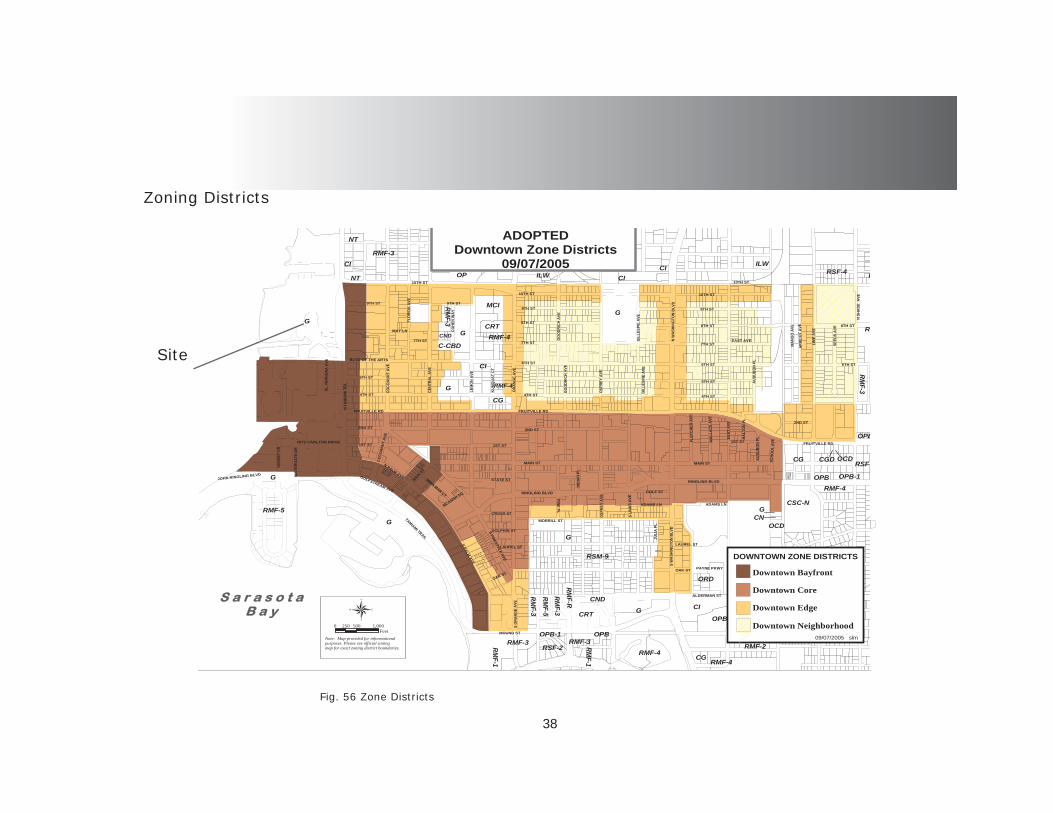
Zoning Districts
Fig. 56 Zone Districts
Site

39
Fig. 59 Site Map
Fig. 60 Aerial
Proposed Site
Location: Televast Rd. between 18th St. East and U.S. 301. The site stretches from Televast Rd. and University Parkway. The size of the site is .5 miles x .4 miles. The space is heavily spotted by trees and natural bush lines. The large lot of land would be suffi cient for this type of use but looking at the pros and cons of the site the choice would have to meet the main list of criteria. (See program analy-sis list).Advantages of site: Large site, non-residential zone, centrally located between Bradenton and Sarasota. The land is mainly unpopulated and the surrounding space is isolated by the interstate U.S. 301. The site is closely linked to many other minor destinations and some major transportation hubs.Disadvantages of site: The site is set back off of the bay and has no link to the south side of the city. The site is isolated by the airport and U.S. 301. The residual noise from the airport is the main reason
Fig. 57 Site Fig. 58 Aerial
40
Fig. 64 Aerial
Fig. 63 Site map
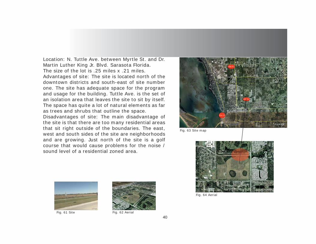
Location: N. Tuttle Ave. between Myrtle St. and Dr. Martin Luther King Jr. Blvd. Sarasota Florida.The size of the lot is .25 miles x .21 miles. Advantages of site: The site is located north of the downtown districts and south-east of site number one. The site has adequate space for the program and usage for the building. Tuttle Ave. is the set of an isolation area that leaves the site to sit by itself. The space has quite a lot of natural elements as far as trees and shrubs that outline the space.Disadvantages of site: The main disadvantage of the site is that there are too many residential areas that sit right outside of the boundaries. The east, west and south sides of the site are neighborhoods and are growing. Just north of the site is a golf course that would cause problems for the noise / sound level of a residential zoned area.
Fig. 61 Site Fig. 62 Aerial
41
Fig. 68 Aerial
Fig. 67 Site Map
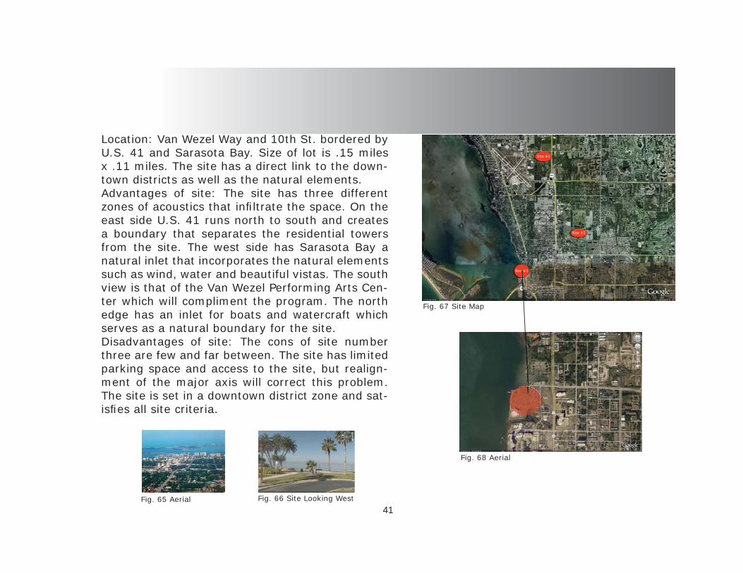
Location: Van Wezel Way and 10th St. bordered by U.S. 41 and Sarasota Bay. Size of lot is .15 miles x .11 miles. The site has a direct link to the down-town districts as well as the natural elements. Advantages of site: The site has three different zones of acoustics that infi ltrate the space. On the east side U.S. 41 runs north to south and creates a boundary that separates the residential towers from the site. The west side has Sarasota Bay a natural inlet that incorporates the natural elements such as wind, water and beautiful vistas. The south view is that of the Van Wezel Performing Arts Cen-ter which will compliment the program. The north edge has an inlet for boats and watercraft which serves as a natural boundary for the site.Disadvantages of site: The cons of site number three are few and far between. The site has limited parking space and access to the site, but realign-ment of the major axis will correct this problem. The site is set in a downtown district zone and sat-isfi es all site criteria.
Fig. 65 Aerial Fig. 66 Site Looking West

42
Selected Site
Fig. 69 Site Properties
The site is positioned on Sarasota Bay just north of the John Ringling Blvd., that leads to St. Armonds Circle, Lido Key and Longboat Key. The site peers out over the bay while being nestled on the edge of the urban fabric.
Fig. 70 The Bay
The downtown district sits to the south-east of the site on a grid layout that inter-sects with the coastline.
The Coastline is adorned by marinas and tourist activities up to 10th St. then the residential zone comes into play.
The interior streets from US 41 and Fruitville Rd. is mainly residential with con-dos and townhomes scattered with single family homes.
The Bridge crossing the bay has re-cently been replaced with an architectural arched bridge, adding to the beauty of the site and coastline.

43
Site Analysis

44
Fig. 72 Sun Path
Fig. 73 Site Climate
Fig. 71 Population - Florida
Environmental
~Florida receives some of the most intense sun-light in the southern re-gions therefore shading is a must in the design phase.
~Humidity is quite high in this region so the design must consider this aspect of construction.
~The wind speed on the coast has a constant fl ow over the site and the in-land areas.
~The average temp. of the region is the high 70s to low 80s but with the humidity it “feels” hotter.
~The amount of rainfall is very high in the summer and moderate through-out the rest of the year.
The population in Florida is somewhat sparse when one looks at Fig. # . The coast seems to be the popular areas and in the central zone around Orlando. The Tampa Bay area has quite a high population that stretches down to Sarasota and through to Naples.
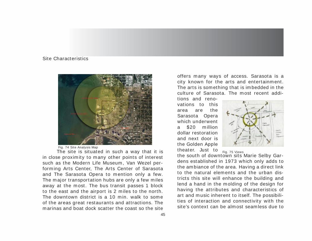
45
Site Characteristics
The site is situated in such a way that it is in close proximity to many other points of interest such as the Modern Life Museum, Van Wezel per-forming Arts Center, The Arts Center of Sarasota and The Sarasota Opera to mention only a few. The major transportation hubs are only a few miles away at the most. The bus transit passes 1 block to the east and the airport is 2 miles to the north. The downtown district is a 10 min. walk to some of the areas great restaurants and attractions. The marinas and boat dock scatter the coast so the site
offers many ways of access. Sarasota is a city known for the arts and entertainment. The arts is something that is imbedded in the culture of Sarasota. The most recent addi-tions and reno-vations to this area are the Sarasota Opera which underwent a $20 million dollar restoration and next door is the Golden Apple theater. Just to the south of downtown sits Marie Selby Gar-dens established in 1973 which only adds to the ambiance of the area. Having a direct link to the natural elements and the urban dis-tricts this site will enhance the building and lend a hand in the molding of the design for having the attributes and characteristics of art and music inherent to itself. The possibili-ties of interaction and connectivity with the site’s context can be almost seamless due to
Fig. 74 Site Analysis MapFig. 75 Views

46
Fig. 77 Figure / Ground Fig. 79 Exploded Site StructureFig. 78 Green Spaces
The downtown area of Sarasota has some very nice green spaces but there could defi nitely be more. Fortunately the west coast of Sarasota has some lush open green spaces and parks that dot the shoreline of the bay. The site has a thin line of green at the shore but there will be a full restoration of the site due to the parking lot on the space at the present.
Fig. 76 Site Map
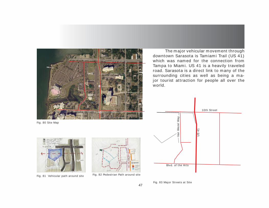
47
Fig. 82 Pedestrian Path around site
Fig. 83 Major Streets at Site
Fig. 81 Vehicular path around site
The major vehicular movement through downtown Sarasota is Tamiami Trail (US 41) which was named for the connection from Tampa to Miami. US 41 is a heavily traveled road. Sarasota is a direct link to many of the surrounding cities as well as being a ma-jor tourist attraction for people all over the world.
Fig. 80 Site Map
10th Street
US 4
1
Blvd. of the Arts
Van
Wez
el W
ay
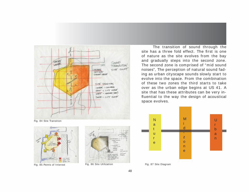
48
Fig. 87 Site Diagram
Fig. 84 Site Transition
Fig. 86 Site UtilizationFig. 85 Points of Interest
The transition of sound through the site has a three fold effect. The fi rst is one of nature as the site evolves from the bay and gradually steps into the second zone. The second zone is comprised of “mid sound noises”, The perception of natural sound fad-ing as urban cityscape sounds slowly start to evolve into the space. From the combination of these two zones the third starts to take over as the urban edge begins at US 41. A site that has these attributes can be very in-fl uential to the way the design of acoustical space evolves.
Nature
Urban
Mid-zone

49
Project Concepts

50
Project Concepts
The main concept for this thesis is acoustics so the fi rst conceptual analysis was for the sound of the site and how the transitions create zones and regions. Looking at how sounds move through the site leads to positioning points and points of spacial placement. All of the sound analysis had concen-trations of sound mixes in the mid zone. Utilizing the site lead to important issues such as thresholds and connections of program that are essential to the design.
Fig. 91 Spatial Transition
Fig. 90 Man Made Sound at Site
Fig. 89 Natural Sound at Site
Fig. 88 Site Diagram
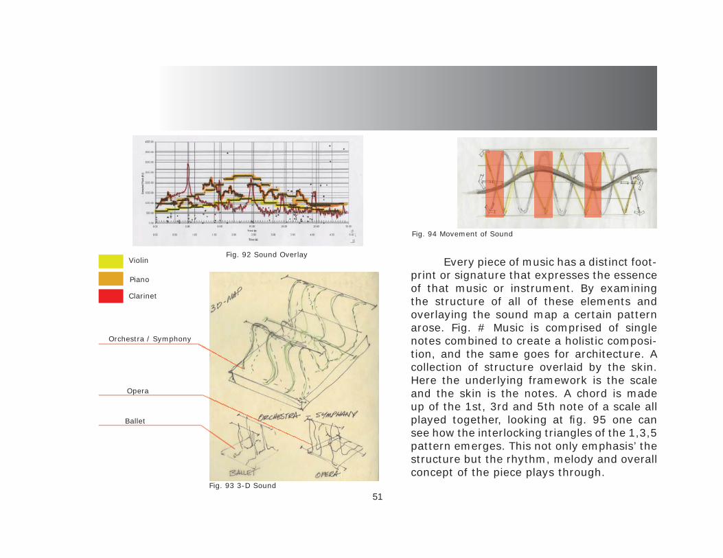
51
Every piece of music has a distinct foot-print or signature that expresses the essence of that music or instrument. By examining the structure of all of these elements and overlaying the sound map a certain pattern arose. Fig. # Music is comprised of single notes combined to create a holistic composi-tion, and the same goes for architecture. A collection of structure overlaid by the skin. Here the underlying framework is the scale and the skin is the notes. A chord is made up of the 1st, 3rd and 5th note of a scale all played together, looking at fi g. 95 one can see how the interlocking triangles of the 1,3,5 pattern emerges. This not only emphasis’ the structure but the rhythm, melody and overall concept of the piece plays through.
Violin
Clarinet
Piano
Fig. 92 Sound Overlay
Fig. 93 3-D Sound
Fig. 94 Movement of Sound
Ballet
Opera
Orchestra / Symphony

52
Fig. 98 Concept ModelFig. 96 Concept Model
Fig. 95 Motion in Sound
Fig. 97 Concept Model

53 Fig. 102 Concept ModelFig. 100 Concept Model Fig. 101 Concept Model
This concept model examines how sound as a formal determinate of space can express move-ment through pitch and frequency at concentration points on site. The movement of a sine wave tells of the amplitude and wavelength and at the same time expresses structure and form. The movement from the bay to the street edge is a composition all its own waiting to take shape.
Fig. 99 Concept Drawing

54
Placement / Organization
The fi rst Scheme focused on the connection of the bay and the urban districts. The exploration was to focus the performance hall to the community face and shoulder the bay. The education aspect was to be the connecting stitch of the fabric and the experience.
The second scheme was intended to be a stage for the community focusing on the face of the performance and to be the center of attention on the site. The layout set in the lower center of the site and looks at the urban set as a performer.
The third composition was a combination of the vi-sual aesthetic of the bay interconnected with the aural perception of the performance while the interplay with the community and the urban aspect. The educational concept is to evolve from the idea to the expression of the idea.
Fig. 103 Scheme Concepts

55
Parti Exploration

56
Fig. 105 Parti Exploration
Parti Exploration
Fig. 106 Parti Exploration
The parti exploration was based on the con-cept of including the community in the function of the center. The education of music is a universal language that all of mankind speaks. The coast-line enhances the appeal of the site and allows the design to include all of the aspects of sound from nature to urban sounds. The center of all the connection is the perfor-mance hall and to follow is the musical education school. The parti allows for the encompassing of the whole concept of music, from the aspect of in-spiration to the delivery of performance. The jour-ney of knowledge is one of ups and downs just like the compositions of music.
Fig. 104 Parti Exploration
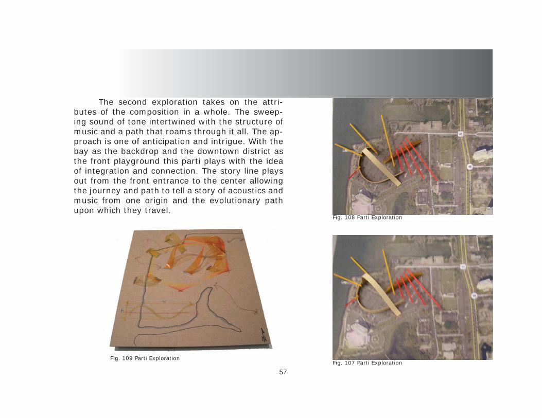
57Fig. 107 Parti Exploration
Fig. 108 Parti Exploration
The second exploration takes on the attri-butes of the composition in a whole. The sweep-ing sound of tone intertwined with the structure of music and a path that roams through it all. The ap-proach is one of anticipation and intrigue. With the bay as the backdrop and the downtown district as the front playground this parti plays with the idea of integration and connection. The story line plays out from the front entrance to the center allowing the journey and path to tell a story of acoustics and music from one origin and the evolutionary path upon which they travel.
Fig. 109 Parti Exploration

58
Conceptual Design

59
Conceptual Design
Fig. 110 Concept Drawing
Fig. 113 Concept Idea
Fig. Fig. 114 Time - SpaceFig. 112 Analysis
The concept of music is one of motion, there-fore the overlaying ideas of acoustics in motion and music in time directs the evolution of the design through movement of structure and form that fol-low the function. The idea of time and space allow fl exibility in the overall scheme. With the incorpo-ration of education the intensity of rise and fall will come into play and partner with sound as a formal determinate of space.
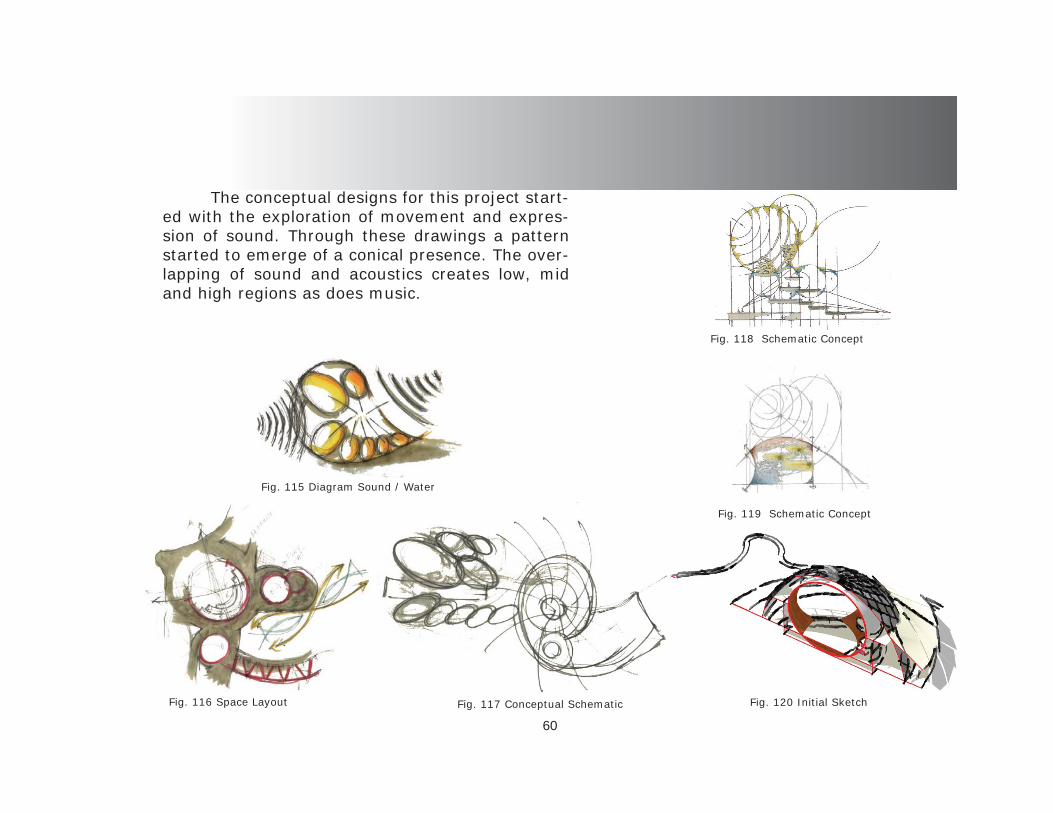
60
The conceptual designs for this project start-ed with the exploration of movement and expres-sion of sound. Through these drawings a pattern started to emerge of a conical presence. The over-lapping of sound and acoustics creates low, mid and high regions as does music.
Fig. 115 Diagram Sound / Water
Fig. 116 Space Layout Fig. 117 Conceptual Schematic Fig. 120 Initial Sketch
Fig. 118 Schematic Concept
Fig. 119 Schematic Concept

61
Sound explodes in three different phases. The fi rst phase is the direct perception, the second is a refl ected perception and fi nally the third is the echo phase. Many designers at-tempt to isolate or delete most of echo and yet sometimes the echo is needed to enhance the sound in itself. The time it takes sound to propagate is extremely quick. Sound travels at 1130 ft. per second and if the room is only
100’ in length the time it would take for a per-ception is going to be measured in hundredths of a second. Therefore the layout of the design must compliment this occurrence. By design-ing in concentric rings the sound is allowed to respond by using its own attributes. The sound is not corrected to the space but the space is designed for the sound. The site was allowing for the building to respond to the environment as well as the function for which it is intended, once the sound is manipulated the design is obscured and sound engineering takes over
Fig. 122 Rings at site
Fig. 121 Sound as element of design

62
Design Phase
The actual design grew from the infl uence of sound as a design element and a formal de-terminant of space making. The design includes the three distinct spaces for performance. The main performance hall, a mid size hall and the practice assembly space in the school are all focused on the journey that a musician must travel throughout their path to the large hall. The fl oorplans encompass the overall idea of sound propagation moments after the explo-sion. Sound travels in concentric rings as well as 360 degrees sphere. The idea of inhabiting the fringes of that explosion is where the inner space evolved from. If one is centered in the path then the three phases of sound will bright-en the perception at that moment in time. The distance of the performance space is 87’ therefore the time to design space is only seven hundredths of a second. By utilizing the vertical aspect of design the design was able to elevate the tiers and provide a direct line of sight and a direct line of audible perception. The con-nection of the ellipsoid to the outer shell is one of no connection. The outer dome is intended to
encompass the entire aspect of the function of the space. The conditioned space is all captured
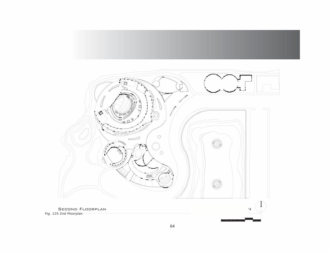
64
Fig. 125 2nd Floorplan
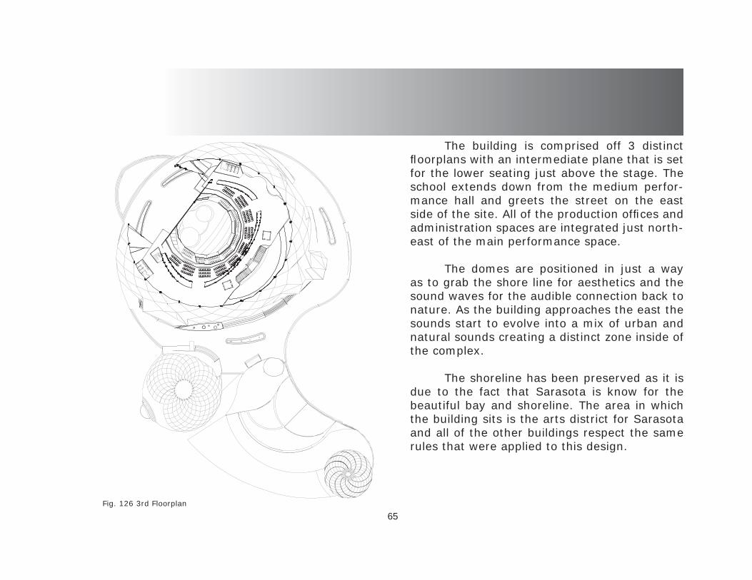
65
The building is comprised off 3 distinct fl oorplans with an intermediate plane that is set for the lower seating just above the stage. The school extends down from the medium perfor-mance hall and greets the street on the east side of the site. All of the production offi ces and administration spaces are integrated just north-east of the main performance space.
The domes are positioned in just a way as to grab the shore line for aesthetics and the sound waves for the audible connection back to nature. As the building approaches the east the sounds start to evolve into a mix of urban and natural sounds creating a distinct zone inside of the complex.
The shoreline has been preserved as it is due to the fact that Sarasota is know for the beautiful bay and shoreline. The area in which the building sits is the arts district for Sarasota and all of the other buildings respect the same rules that were applied to this design.
Fig. 126 3rd Floorplan
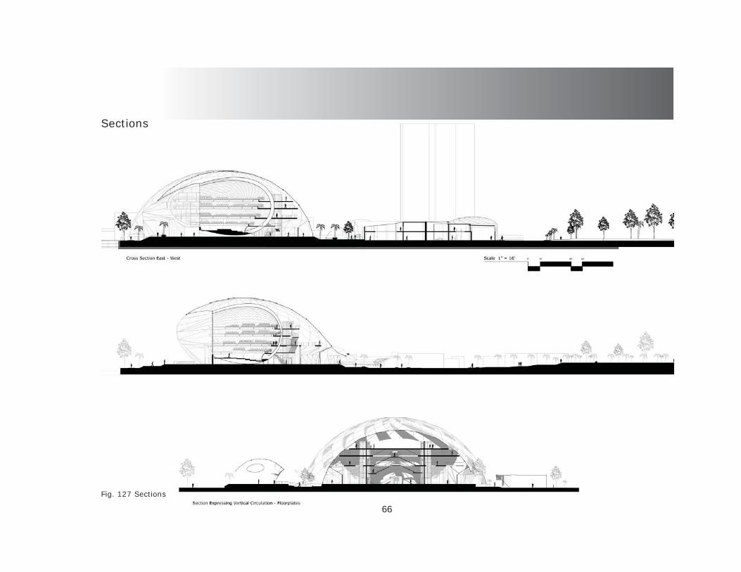
66
Sections
Fig. 127 Sections

67
The section perspective expresses the in-terior qualities of the performance hall and the connection of the fl oor plates and the interior ellipsoid. The coverage of the outer dome forms the circulation throughout the building.
Fig. 128 Section Perspective
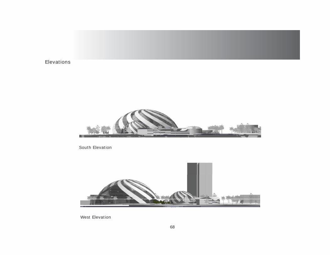
68
Elevations
South Elevation
West Elevation
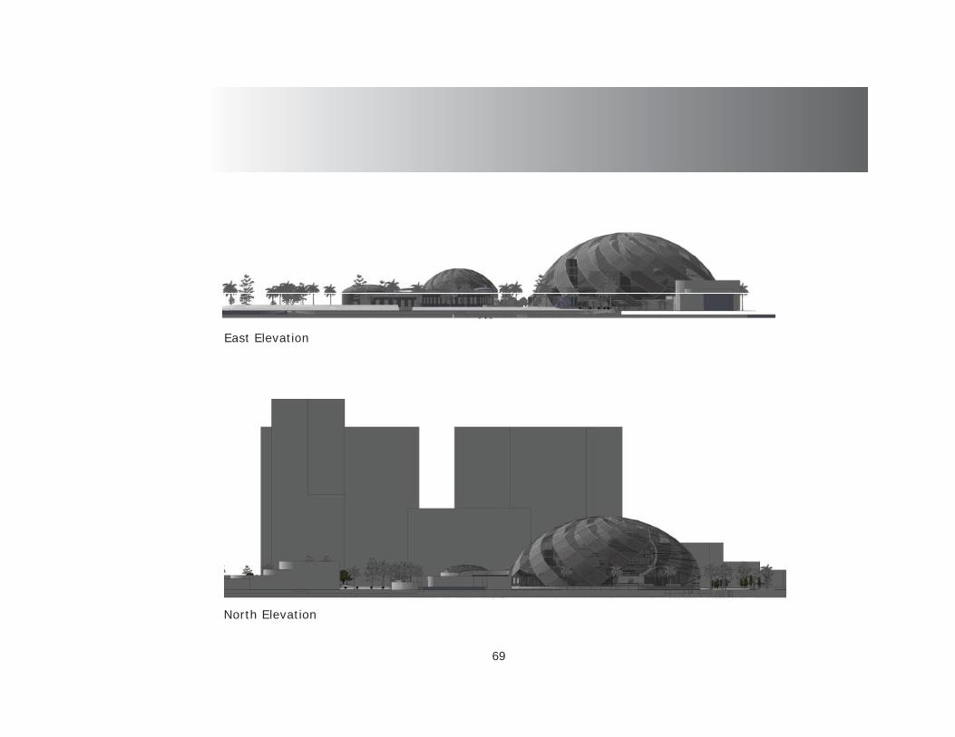
69
East Elevation
North Elevation

70
Details
Fig. 131 Details

71
Anechoic Concept
Fig. 132 Anechoic Concept
The anechoic concept was incorporated into the inner lining of the shells to cancel and absorb the unwanted sound waves and limit the refl ection and echo.

72
Acoustical Testing - Ray Tracing
Fig. 133 Acoustical Testing

73Fig. 134 Acoustical Testing
Acoustical Testing - Ray Tracing
Acoustical design is quite diffi cult due to there being so many un-knowns. The frequencies can cause trouble with a design. In order to solve for the unknown exacting dimensions and confi gu-rations should be used to organize and prioritize placement and position of design elements that will enhance the sound and not merely the visual aesthetic that so many other buildings employ in their design. Ray tracing was the major tool used in this design. Going back to basics and utilizing the old technique of design-ing acoustics performed perfectly in this space.
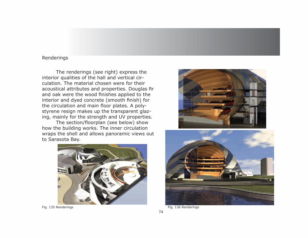
74
Renderings
Fig. 136 Renderings
The renderings (see right) express the interior qualities of the hall and vertical cir-culation. The material chosen were for their acoustical attributes and properties. Douglas fi r and oak were the wood fi nishes applied to the interior and dyed concrete (smooth fi nish) for the circulation and main fl oor plates. A poly-styrene resign makes up the transparent glaz-ing, mainly for the strength and UV properties. The section/fl oorplan (see below) show how the building works. The inner circulation wraps the shell and allows panoramic views out to Sarasota Bay.
Fig. 135 Renderings
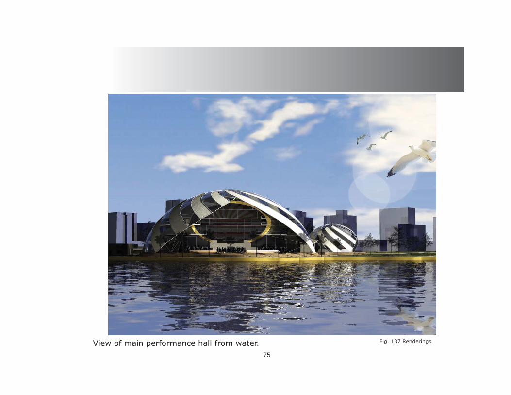
75
Fig. 137 RenderingsView of main performance hall from water.
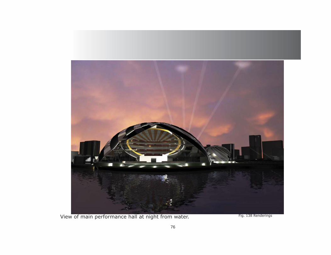
76
Fig. 138 RenderingsView of main performance hall at night from water.

77
Fig. 139 RenderingsInterior performance hall view out to the bay.

78
Fig. 140 RenderingsMain entrance view from listening sphere.
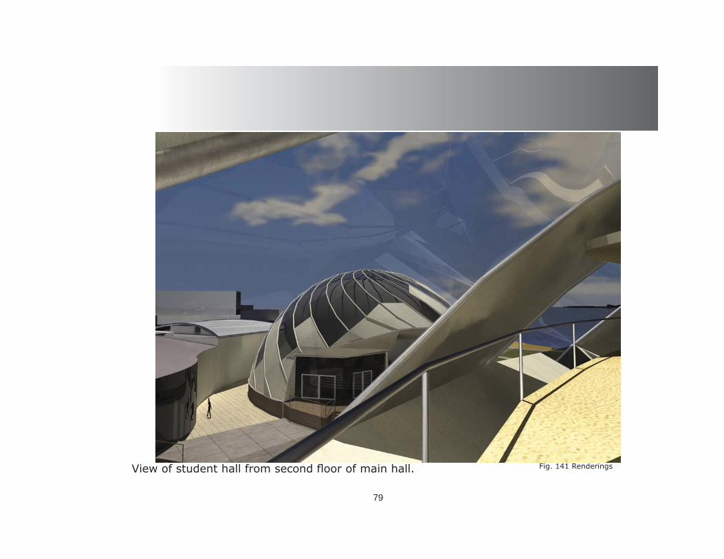
79
Fig. 141 RenderingsView of student hall from second fl oor of main hall.

Draft Model
80
The initial draft model took form and al-lowed the design to reveal its faults. Through the exploration of study models the design evolved into a holistic approach at acoustics in architecture. Acoustics, as a design infl uence, has long been abandoned by the architecture profession. This is possibly one way to reintro-duce the acoustical aspect of design back into the design phase as an element or an inspira-tion for the overall approach to the initial lining of the paper.
Fig. 142 Draft Model
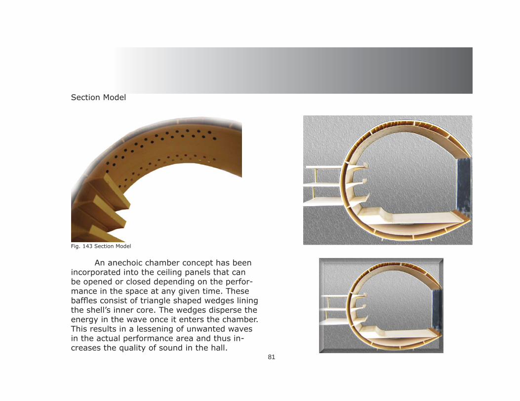
Section Model
An anechoic chamber concept has been incorporated into the ceiling panels that can be opened or closed depending on the perfor-mance in the space at any given time. These baffl es consist of triangle shaped wedges lining the shell’s inner core. The wedges disperse the energy in the wave once it enters the chamber. This results in a lessening of unwanted waves in the actual performance area and thus in-creases the quality of sound in the hall.
81
Fig. 143 Section Model
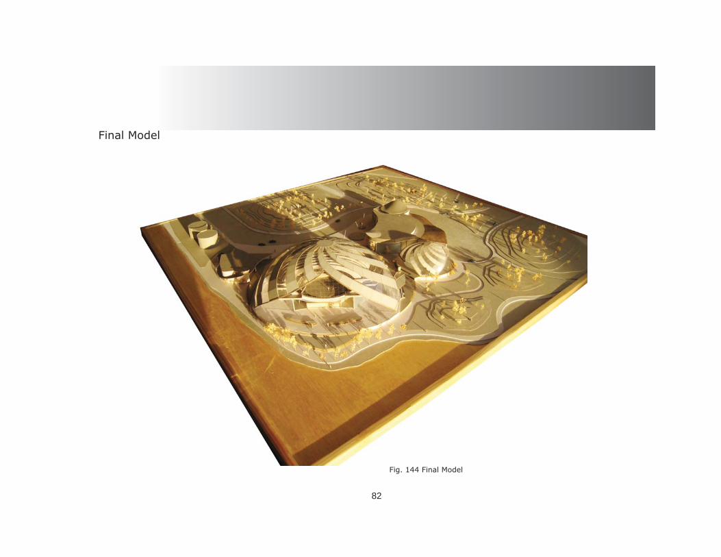
Final Model
82
Fig. 144 Final Model
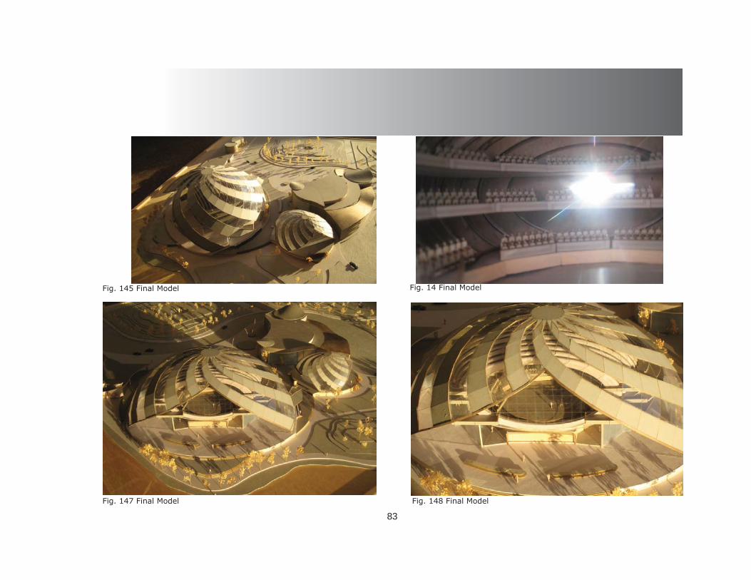
83
Fig. 145 Final Model Fig. 14 Final Model
Fig. 147 Final Model Fig. 148 Final Model

Conclusion
84
In conclusion; throughout all of the re-search and analysis the main idea of using sound and music as the main infl uence for the design remained constant through the design phase and ultimately answered the thesis ques-tion of how sound can be a design inspiration as well as a formal determinate in the design phase. The popular trend for today’s modern ar-chitecture is one of convenience. The architect has bypassed the obligation and the duty to de-sign all aspects of inhabitable space. Over the passage of time the profession of architecture has spawned many other professions and led the way to the demise of the “Master Builder” depiction that the architect once possessed. This thesis reinforces the fact that all as-pects of sound in space is able to be designed by the architect and does not have to be leased out to a consultant to do “our” job. Sound is some-thing that should not be designed. The space for the sound is the design in itself that compli-ments the music and therefore the music is free to play upon the structure of the architecture, both of these elements coalescing to create a holistic entity called musical architecture. Fig. 149 Final Model

85
Acoustical Engineering - “Ideas, Thoughts and Plans”<http://www.acoustics-engineering.com/sabin/wcsabine.htm>
Andō, Tadao, Michael Auping, and Modern Art Museum of Fort Worth. Seven Interviews with Tadao Ando. Fort Worth Tex.: Modern Art Museum of Fort Worth, 2002.
Blesser, Barry, and Linda Ruth Salter. Spaces Speak, are You Listening? : Experiencing Aural Architecture. Cambridge, Mass.: MIT Press, 2007.
Bomgardner, D. L., and Inc NetLibrary. The Story of the Roman Amphitheatre [Electronic Resource]. London ; New York: Routledge, 2000.
Bullivant, Lucy. “Tonkin Liu: Places of Sense.” A + U: architecture and urbanism, 2008 Jan., n.1(448) (2008).
Campbell, M. and Greated, C. “The Musician’s Guide to Acoustics. New York”: Shirmer Books, 1997.
Chase, Ramond G. Ancient Hellenistic and Roman Amphitheatres, Stadiums, and Theatres : The Way they Look Now. Portsmouth, N.H.: P.E. Randall, 2002.
Coarelli, Filippo, and Ada Gabucci. The Colosseum. Los Angeles: J. Paul Getty Museum, 2001. Connell, John, and Chris Gibson. Sound Tracks : Popular Music, Identity, and Place. London ; New York: Routledge, 2003.
Davey, Peter. “Light and Dark.” 215.1286 (2004 Apr): 46-47.
E. Togo Salmon Conference, E. Togo Salmon Conference, and William J. Slater. Roman Theater and Society : E. Togo Salmon Papers I. Ann Arbor: University of Michigan Press, 1996.
Encyclopaedia Britannica. “sound.” 2009. Encyclopaedia Britannica Online. 02 Jun. 2009 <http://www.britannica.com/EBchecked/topic/555255/sound>.
Hall, Peter. “Hear Color, See Sound: Architect Christopher Janney’s Playful Public Art Acts as an Aural and Light-Filled
Bibliography

86
Salve to the Alienating Effects of the Built Environment.” Metropolis, 2007 Sept., v.27, n.2 27.2 (2007):137,166-167.
Leeds, Joshua. “THE POWER OF SOUND: How to Manage Your Personal Soundscape for a Vital, Productive & Healthy Life”. Published March, 2001 by Healing Arts Press. 338 pages. 60 minute CD. ISBN 0-89281-768-2.Phillips, Dered. “Daylighting: Natural Light in Architecture.” (2004).
Macht, William P. “Sound Solutions.” Urban Land, Apr., v.64, n. 4, p. 42-45. 2005.
Rasmussen, Steen Eiler. Experiencing Architecture. The MIT Press,Cambridge, Massachusetts, 1959.
Rykwert, Joseph. On Adam’s House in Paradise. The Museum of Modern Art, New York, New York, 1972.
Sheridan, Ted and K. VanLengen. “Hearing Architecture: Exploring and Designing the Aural Environment.” The Journal of Architectural Education, Vol. 57 Issue 2, The MIT Press, Cambridge, Massachusetts, November 2003.
Sabine “Sabine.” The Oxford Pocket Dictionary of Current English. 2009. Encyclopedia.com. 30 Jun. 2009 <http://www.encyclopedia.com>.
Sabine, Wallace Clement. “Collected papers on acoustics” Edition 2 Publisher Harvard University Press, 1922 Original from the University of Michigan Digitized Oct 4, 2007 Length 279 pages Wallace C. Sabine: Collected Papers on Acoustics. 1993, Trade Cloth ISBN 0-932146-60-0 Peninsula Publishing, Los Altos, U. S.. LCCN: 93-085708, 1993.
Sabine, Wallace Clement. “Collected Papers on Acoustics” (New York: Dover Publications, 1964) [fi rst published by Har-vard University Press, 1922] 1993.
Thompson, Emily. “The soundscape of modernity : architectural acoustics and the culture of listening in America”, 1900 - 1933 (Cambridge, Mass.: MIT Press, 2002).
Woolman, Matt. Sonic Graphics : Seeing Sound. New York: Rizzoli, 2000.
Blesser, Barry and Linda Ruth Salter. Spaces Speak, are You Listening? : Experiencing Aural Architecture. Cambridge, Mass.: MIT Press, 2007.

87
Blesser, Barry R. Spaces Speak. Are you listening?<http://www.blesser.net/downloads/RDC%20Article.pdf
Bryant, John W. Sound, Awareness and Place: Architecture from an Aural Perspective, 2008 <https://drum.umd.edu/dspace/bitstream/1903/7835/1/umi-umd-5121421.pdf>
Chao, Tom. Live Science Staff Writer <http://www.livescience.com/history/070405_greeks_acoustics.html>
Musical Elements. 2003. Online. Internet. 13 Sept 2009. <http://www.digitalbrain.com/>
Musical Instruments. 1999. Online. Internet. 3 Oct. 2009. <http://www.naxos.com/intro.htm>
“The Los Angeles Philharmonic Inaugurates Walt Disney Concert Hall”. <http://www.pbs.org/wnet/gperf/dialogue/dialogue_disneyhall.html> accessdate=2009-07-10.
“sound.” Encyclopædia Britannica. 2009. Encyclopædia Britannica Online. 02 Jun. 2009 <http://www.britannica.com/EBchecked/topic/555255/sound>.
Sabine “Sabine.” The Oxford Pocket Dictionary of Current English. 2009. Encyclopedia.com. 30 Jun. 2009 <http://www.encyclopedia.com>.
“Wallace Clement Sabine.”. 18 May 2009, 00:30 UTC. 18 May 2009 <http://en. /w/index.php?title=Wallace_Clement_Sabine&oldid=290620385>.
www.city-data.com/city/Sarasota-Florida.html
Internet Reference
88
Images 30,49-51,74-113,115-149 are original works. J.P.
Epidaurus Amphitheater / Greek <http://www.wwnorton.com/.../ralph/ralimage/epidars.jpgs.>
Images Ref: Adrienne Arsht Center <http://www.static.fl ickr.com/119/264648314_2b4a8>
Tempe Art Center<http://www.worldarchitecturenews.com/news_images/123>
Sound Space - Michael-Dauzon<http://www.lorenzobrusci.com/blog/2008/03/13/michael-dauzon-decorporation-project- in-nancy-22nd-to-26th-sep-tember-2008/#>
Shrine of St. Werburgh in the Chester Cathedral -Spaces Speak, Are You Listening? Experiencing Aural Architecture Blesser and Salter <http://www.blesser.net/images/Shrine%20web.jpg> Bryant, John W. Sound, Awareness and Place: Architecture from an Aural Perspective, 2008 <https://drum.umd.edu/dspace/bitstream/1903/7835/1/umi-umd-5121421.pdf>
Diagrams refl ection<http://www.hyperphysics.phy-astr.gsu.edu/.../refl c.html diagrams refl ection>
Airplanehttp://www.news.navy.mil/view_single.asp?id=1445, Photo number: 9907076483G000<http://www.news.navy.mil/management/photodb/photos/990707-N-6483G-001.jpg>
Image Reference:

89
Nautilus <http://www.o-dub.com/images/nautilus.jpg>
Maps of temp and wind<http://www.city-data.com/city/Sarasota-Florida.html>
Suitable acoustics<http://www.nonoise.org/quietnet/qc/booklet.htm>
Composite of sound mapping <http://www.robeahrs.com/illustration.jpg/illustrations/>
Ear dynamics<http://www.cyprushearing.org/cyprus-hearing-how-the-ear works >
Teaching<i278.photobucket.com/albums/kk110/schryver196> Teaching Student
Brain Diagram<http://www.frontiersin.org/images/fi ns3_1/BrainTuning_logo.jpg>
Ear picwww.cyprushearing.org/cyprus-hearing-how-the-...
Scher, Valerie (2003-10-25). “Disney Hall opens with a bang”. The San Diego Union-Tribune. <http://www.signonsandiego.com/news/features/20031025-9999_1c25gala.html.> Retrieved on 2009-07-10.
Fact sheetNagata Acoustics, “Building Details and Acoustics Data”<http://www.nagata.co.jp/e_sakuhin/factsheets/wdch.pdf. Retrieved on 2009-07-16.>