visual programming languages - bridges to...
TRANSCRIPT

Bridges To Computing Brooklyn College
http://bridges.brooklyn.cuny.edu/ Page 1
VISUAL PROGRAMMING LANGUAGES
I. Introduction:
By now you have worked in several different programming languages and programming environments. As you have seen, programs can be created by typing text into a text editor (such as notepad) or an IDE (integrated development environment) application. Programs can also be created using Visual Programming Languages (VPL) such as SCRATCH. But SCRATCH is a rather limited VPL.
We can define a VPL as any programming language that lets users create programs by manipulating program components (objects, functions, variables) graphically rather than by specifying them with text. Many traditional text-based programming languages now support visual interfaces. These visually transformed languages are not the same as natural visual languages which have a visual expression for which there is no obvious text equivalence.
Many VPLs are based on the idea of "boxes and arrows," where boxes or other screen objects are treated as entities, connected by arrows, lines or arcs which represent relations (and program flow).
Figure 1: Quartz Composer (Apple)
Many VPLs are created and targeted towards beginner programmers who have only a basic understanding of concepts like variables and logic. However, VPLs are not limited to novices. VPLs may appeal to more advanced programmers for rapid prototyping or code development. VPLs are also often well suited to programming within a variety of concurrent or distributed processing scenarios. VPLs thus appeal to a wide audience of users from students to professional programmers.
Bridges To Computing Brooklyn College
http://bridges.brooklyn.cuny.edu/ Page 2
SOME WELL KNOWN AND FREE VPL PROGRAMS (IN NO PARTICULAR ORDER):
AgentSheets, easy to use game authoring and computational science authoring tool.
Quartz Composer, a language for processing and rendering graphical data (MaxOS X)
Scratch
Lily, browser based visual programming environment
PureData an open-source version of Max 5.0, visual programming environment for building interactive, real-time music and multimedia applications.
Microsoft Robotics Developer Studio 2008 R2 Express Edition (the free version of Microsoft Robotics Developer Studio 2008) has capabilities similar to Robolab and is free. It contains within it Microsoft VPL (Visual Programming Language).
II. Introduction to MicroSoft VPL
As part of your lab today you will create and run three programs in Microsoft VPL. Each of these programs is detailed in the following tutorials.
NOTE: The first tutorials come directly from the Microsoft MSDN site on VPL. The 3rd tutorial comes from the Microsoft MSDN site on VPL (hands on lab section). There are many more labs available at those two links, and VPL is a powerful language. In order to get VPL you will need to download and install the FREE version of Microsoft Robotics Developer Studio 2008 R2 Express Edition.
TUTORIAL # 1 – HELLO WORLD
To run VPL, from the Start menu choose All Programs and then click on Visual Programming Language under the Microsoft Robotics Developer Studio installation folder.
From the File menu click New to create a new project. Insert a Data activity, by double-clicking on the icon or dragging and dropping it from the Basic Activities toolbox. Choose string from the drop-down list. Click in the text box of the Data activity block and type Hello World.
Figure 1 - Data Activity Block
Insert a Simple Dialog activity block by dragging one from the Services toolbox and place it to the right of the Data activity block. (To save time looking for a service, you can type the name of the service you are looking for into the top of the Services toolbox. The toolbox will then display any matching activities.)

Bridges To Computing Brooklyn College
http://bridges.brooklyn.cuny.edu/ Page 3
Drag a link starting from the output connection pin of the Data activity block onto the Simple Dialog activity block. The Connections dialog box automatically opens. Choose DataValue in the first list and AlertDialog in the second list, then click OK.
Figure 2 - Connections Dialog Box
The Data Connections dialog box opens next. In the drop-down list, choose value.

Bridges To Computing Brooklyn College
http://bridges.brooklyn.cuny.edu/ Page 4
Figure 3 - Data Connections Dialog Box
The Data Connections dialog box tells VPL that you want to apply the value of the Data activity to the message text for the Alert form of this dialog.
Your diagram should now look like the following.
Figure 4 - Completed Diagram
Now choose the Run command from the Run menu (or press F5). If you have not saved your project yet, VPL opens the Save dialog. Enter a name for your project and click Save.
VPL should now run your application. If you get a message asking whether to unblock the application, choose Unblock.
A simple Alert dialog box should appear with the text Hello World in it.
Figure 5 - Alert Dialog
To stop the application, click the Stop button in the Run dialog.
TUTORIAL # 2 – VARIABLES & SERVICES
To begin, create a new project by choosing New from the File menu. Next, insert a Variable activity by dragging it into the tool box or double-clicking it.
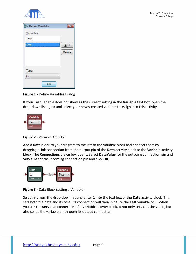
Click the Ellipsis Button (…) on the Variable activity block opening the Define Variables dialog. (You can also select "Variables..." from the Edit menu). In the dialog box, click on the Add button and type Test in the text box. In the Type drop-down list make sure int is selected as the variable type. Click OK.
Bridges To Computing Brooklyn College
http://bridges.brooklyn.cuny.edu/ Page 5
Figure 1 - Define Variables Dialog
If your Test variable does not show as the current setting in the Variable text box, open the drop-down list again and select your newly created variable to assign it to this activity.
Figure 2 - Variable Activity
Add a Data block to your diagram to the left of the Variable block and connect them by dragging a link connection from the output pin of the Data activity block to the Variable activity block. The Connections dialog box opens. Select DataValue for the outgoing connection pin and SetValue for the incoming connection pin and click OK.
Figure 3 - Data Block setting a Variable
Select int from the drop-down list and enter 1 into the text box of the Data activity block. This sets both the data and its type. Its connection will then initialize the Test variable to 1. When you use the SetValue connection of a Variable activity block, it not only sets 1 as the value, but also sends the variable on through its output connection.

Bridges To Computing Brooklyn College
http://bridges.brooklyn.cuny.edu/ Page 6
TEST THE VALUE OF A VARIABLE
Add a Merge activity block to the right of your Variable activity block and connect the Variable activity block to the Merge activity block. You will use this block to create a counting loop. A Merge activity block can have multiple inputs, each input is passed on as it is received.
Figure 4 - Merge Block
Add an If activity block to the diagram to right of the Merge activity block. Connect the Merge activity block outgoing connection to the If activity block. In the If activity block, enter Test == 10 in the test condition. (The syntax with a double equal sign is from C#. You can also use a single equal sign in VPL.) This causes the If activity block to check if the variable Test is equal to 10, and send a message via its normal output pin if it is, or send a message through the Else pin if it is not equal.
Figure 5 - If Block
INCREMENT A VARIABLE
Add a Calculate activity block. Right-click on the Calculate block and select "Flip Connections" from the pop-up context menu. This swaps the input and output pins so that the connections on the diagram flow in a more natural way. Connect it to the Else connection (the lower output pin) of the If activity block. This connection is used if the test condition is false, i.e. Test is not equal to 10. In the Calculate activity block, type Test + 1.
Figure 6 - Increment a Variable
Bridges To Computing Brooklyn College
http://bridges.brooklyn.cuny.edu/ Page 7
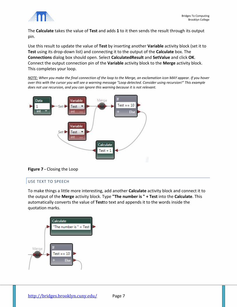
The Calculate takes the value of Test and adds 1 to it then sends the result through its output pin.
Use this result to update the value of Test by inserting another Variable activity block (set it to Test using its drop-down list) and connecting it to the output of the Calculate box. The Connections dialog box should open. Select CalculatedResult and SetValue and click OK. Connect the output connection pin of the Variable activity block to the Merge activity block. This completes your loop.
NOTE: When you make the final connection of the loop to the Merge, an exclamation icon MAY appear. If you hover over this with the cursor you will see a warning message "Loop detected. Consider using recursion!" This example does not use recursion, and you can ignore this warning because it is not relevant.
Figure 7 - Closing the Loop
USE TEXT TO SPEECH
To make things a little more interesting, add another Calculate activity block and connect it to the output of the Merge activity block. Type "The number is " + Test into the Calculate. This automatically converts the value of Testto text and appends it to the words inside the quotation marks.
Bridges To Computing Brooklyn College
http://bridges.brooklyn.cuny.edu/ Page 8
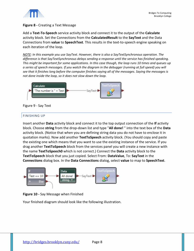
Figure 8 - Creating a Text Message
Add a Text-To-Speech service activity block and connect it to the output of the Calculate activity block. Set the Connections from the CalculatedResult to the SayText and the Data Connections from value to SpeechText. This results in the text-to-speech engine speaking on each iteration of the loop.
NOTE: In this example you use SayText. However, there is also a SayTextSynchronous operation. The difference is that SayTextSynchronous delays sending a response until the service has finished speaking. This might be important for some applications. In this case though, the loop runs 10 times and queues up a series of speech messages. If you watch the diagram in the debugger (running at full speed) you will see that it finishes long before the computer finishes saying all of the messages. Saying the messages is not done inside the loop, so it does not slow down the loop.
Figure 9 - Say Text
FINISHING UP
Insert another Data activity block and connect it to the top output connection of the If activity block. Choose string from the drop-down list and type "All done! " into the text box of the Data activity block. (Notice that when you are defining string data you do not have to enclose it in quotation marks). Now add another TextToSpeech activity block. (You should copy and paste the existing one which means that you want to use the existing instance of the service. If you drag another TextToSpeech block from the services panel you will create a new instance with the name TextToSpeech0 which is not correct.) Connect the Data activity block to the TextToSpeech block that you just copied. Select From: DataValue, To: SayText in the Connections dialog box. In the Data Connections dialog, select value to map to SpeechText.
Figure 10 - Say Message when Finished
Your finished diagram should look like the following illustration.

Bridges To Computing Brooklyn College
http://bridges.brooklyn.cuny.edu/ Page 9
Figure 11 - Completed Diagram
RUN THE PROGRAM
Now, if you connected everything up correctly, you should be able to Run the application (by selecting the Start command on the Run menu or pressing F5). You will hear your PC count to ten and then say "All done". If you don't hear anything, check your connections and the volume for your speakers. (If you don't have speakers you could use the Simple Dialog service used in VPL Tutorial 1 - Hello World in place of the TextToSpeech service.)
TUTORIAL #3: SIMULATION ENVIRONMENTS
Many robots use what is called a "Differential Drive" which has two wheels that can be driven independently. Although most Differential Drives have two driven wheels, there is often a third passive wheel, called a CASTOR or JOCKEY WHEEL, which is just for balance. The reason this configuration is popular is that it allows the robot to rotate on the spot. It can therefore drive in any direction after making a tight turn that takes a space no larger than the robot.
RDS defines a GENERIC CONTRACT for a Differential Drive that specifies the programming interface for controlling a drive regardless of the type of robot that you are using (which is why it is called GENERIC).
In this lab you will only use the SetDrivePower operation which simply sets the power to each of the drive's wheels. However, as you will see, this gives you complete control over where the robot goes.
To get started, open the Visual Programming Language application.
Bridges To Computing Brooklyn College
http://bridges.brooklyn.cuny.edu/ Page 10
STEP 1: ADD A DESKTOP JOYSTICK SERVICE
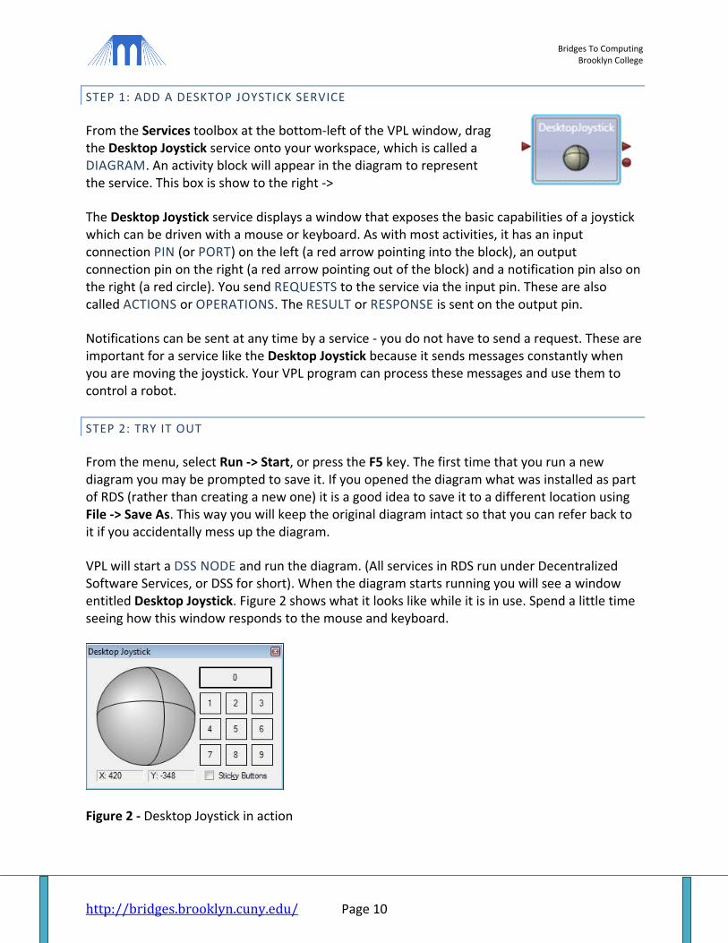
From the Services toolbox at the bottom-left of the VPL window, drag the Desktop Joystick service onto your workspace, which is called a DIAGRAM. An activity block will appear in the diagram to represent the service. This box is show to the right ->
The Desktop Joystick service displays a window that exposes the basic capabilities of a joystick which can be driven with a mouse or keyboard. As with most activities, it has an input connection PIN (or PORT) on the left (a red arrow pointing into the block), an output connection pin on the right (a red arrow pointing out of the block) and a notification pin also on the right (a red circle). You send REQUESTS to the service via the input pin. These are also called ACTIONS or OPERATIONS. The RESULT or RESPONSE is sent on the output pin.
Notifications can be sent at any time by a service - you do not have to send a request. These are important for a service like the Desktop Joystick because it sends messages constantly when you are moving the joystick. Your VPL program can process these messages and use them to control a robot.
STEP 2: TRY IT OUT
From the menu, select Run -> Start, or press the F5 key. The first time that you run a new diagram you may be prompted to save it. If you opened the diagram what was installed as part of RDS (rather than creating a new one) it is a good idea to save it to a different location using File -> Save As. This way you will keep the original diagram intact so that you can refer back to it if you accidentally mess up the diagram.
VPL will start a DSS NODE and run the diagram. (All services in RDS run under Decentralized Software Services, or DSS for short). When the diagram starts running you will see a window entitled Desktop Joystick. Figure 2 shows what it looks like while it is in use. Spend a little time seeing how this window responds to the mouse and keyboard.
Figure 2 - Desktop Joystick in action

Bridges To Computing Brooklyn College
http://bridges.brooklyn.cuny.edu/ Page 11
NOTE: You can click on the "trackball" with the left mouse button and hold the button down. As you drag, it will simulate moving a joystick. With the keyboard, the keys W, A, S, and D can also be used. If you play computer games you might be familiar with these keys from first-person shooter games. If not, look carefully at the layout of these keys on the keyboard because they correspond to the four directions: forward; left; back; and right. With a little practice you should be able to control the joystick quite easily.
STEP 3: ADD A GENERIC DIFFERENTIAL DRIVE & MANIFEST
In the same way as you added the Desktop Joystick service in Step 1, now add a Generic Differential Drive (GDD) service. It is called GENERIC because it supports common operations available on most differential drives, but it is not by default associated with a specific drive system. A generic drive can be associated with a real drive at runtime using a file called a MANIFEST. One of the benefits of RDS is that you can write general programs that will run on a variety of robots simply by changing the manifest.
To associate the generic drive with a specific robot drive system, so that you can interact with the robot's hardware, first click on the Generic Differential Drive block on the main diagram to make sure that it is selected. (The activity block will be highlighted with a blue border). Then, in the Properties toolbox on the bottom-right, under Configuration, select the Use a Manifest entry from the drop-down list. Now, under Manifest, click the Import button. Select the entry for IRobot.Create.Simulation.Manifest.xml. The Properties toolbox should look like Figure 3.
Figure 3 - Associate the Generic Differential Drive with a specific robot's manifest

Bridges To Computing Brooklyn College
http://bridges.brooklyn.cuny.edu/ Page 12
The manifest specifies, among other things, which service will be implementing the generic drive when you run the program. By selecting a manifest, the generic drive in the diagram has been associated with a particular robot drive service (in this case a simulated iRobot Create). If you wanted to use a real Create, or some other robot, you would just select a different manifest.
STEP 4: CONNECT THE COMPONENTS
Robotics Developer Studio supports a PUBLISH-SUBSCRIBE MODEL. A service, or in this case your diagram, can SUBSCRIBE to the NOTIFICATIONS that another service publishes. In this example, when the position of the joystick changes the Desktop Joystick service will issue a notification. The diagram can receive that notification by connecting to the notification pin on the Desktop Joystick service, which is the small red circle on the right side of the activity block. The small red arrow on the right is a RESULT output. These outputs are discussed in more detail in the Quick Introduction to VPL at the end of this lab. In this example the output pin is not used.
Connect the notification pin of the Desktop Joystick (the small red circle) to the input pin of the GDD (the small red arrow on the left side) as shown in Figure 4. To do this, click the left mouse button on the notification pin and hold it down, then drag the mouse over the GDD block. You do not have to place the mouse exactly over the input pin. A connection link will follow the mouse as you move the cursor. (Wave the mouse around. It's fun to watch VPL drawing bezier curves.) The GDD block will be highlighted when you have the mouse positioned correctly. Release the mouse button and the connection link will snap into place between the two blocks. Figure 4 shows what the completed connection looks like, but you have not finished yet.
Figure 4 - Connect the Desktop Joystick to the Generic Differential Drive
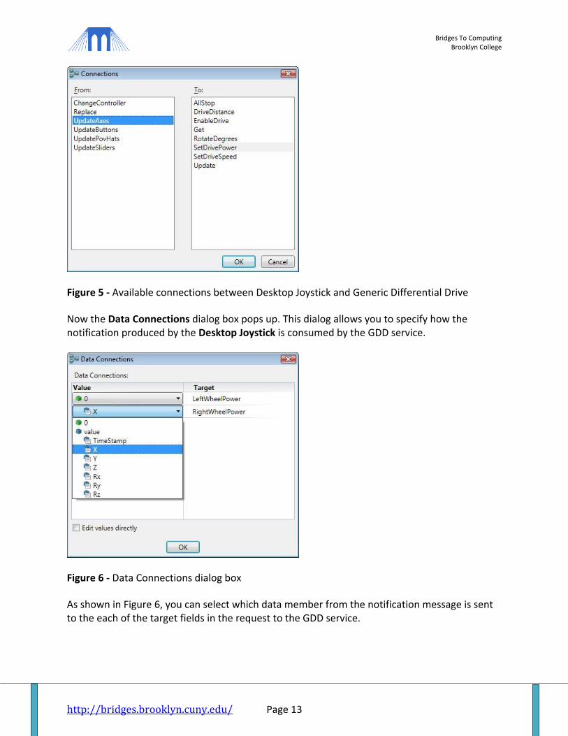
The Connections dialog box will pop up. This shows the available notifications that the Desktop Joystick service supports in the From column on the left, and the available request types that the GDD service supports in the To column on the right. The purpose of this VPL diagram is to drive a robot using the joystick, so select UpdateAxes from the left column and SetDrivePower in the right column then click OK.
Bridges To Computing Brooklyn College
http://bridges.brooklyn.cuny.edu/ Page 13
Figure 5 - Available connections between Desktop Joystick and Generic Differential Drive
Now the Data Connections dialog box pops up. This dialog allows you to specify how the notification produced by the Desktop Joystick is consumed by the GDD service.
Figure 6 - Data Connections dialog box
As shown in Figure 6, you can select which data member from the notification message is sent to the each of the target fields in the request to the GDD service.

Bridges To Computing Brooklyn College
http://bridges.brooklyn.cuny.edu/ Page 14
STEP 5: CONFIGURE THE DATA CONNECTION
The Desktop Joystick service sends notifications when the joystick axes change (the X and Y values change), as you may have noticed when trying out the diagram earlier. (While the joystick is not moving, notifications are not sent). These values vary between -1000 and 1000.
The GDD service expects LeftWheelPower and RightWheelPower values between -1.0 and 1.0, where these values indicate the amount of power to be fed to the Left and Right wheels respectively. If both are positive then the robot will move forward; if both are negative then the robot will move backwards; if the left and right values are different then the side of the robot with the higher value will move forward move than the side with the lower value, causing the robot to turn in an arc. If you exactly match the power settings, but they have opposite signs, then the robot will rotate on the spot.
You now need to create a data transformation that will convert the X and Y values from the Desktop Joystick into LeftWheelPower and RightWheelPower settings. Select the Edit values directly check box at the bottom of the DataConnections dialog. Then enter the following expressions into the Value boxes for the LeftWheelPower and RightWheelPower targets.
(-Y + X) / 1000.0 (-Y - X) / 1000.0 The DataConnections dialog will now look like Figure 7. Take a moment to understand how these expressions convert the X and Y values from the joystick into left and right values for a differential drive system. Notice that there is a scale factor of 1000. You could use more complicated formulas, but these ones work reasonably well.
Figure 7 - Data Connections dialog for SetDrivePower

Bridges To Computing Brooklyn College
http://bridges.brooklyn.cuny.edu/ Page 15
Note: Once a connection has been established, you can change the details later. If you right-click on the connection link, the pop-up context menu contains options to delete the link or open the Connections or Data Connections dialogs. If you select a link by clicking on it with the left mouse button, the Data Connections are shown in the Properties toolbox and you can change them there. This is similar to the Data Connections dialog. When a link is selected, small boxes appear over the pins at each end. Look carefully because it might not be obvious to you if you are a beginner.
STEP 6: TRY IT OUT
Select Run -> Start from the menu, or press F5. Have fun driving your simulated robot around, immersed in the realism of the simulation engine's physics model. If you click on the Simulation window so it has focus, and you can use the the mouse and also the keys W, A, S, D, Q, and E to change the camera location in the simulated environment.
Figure 8 - Simulated iRobot Created in simulated environment
Note that the Desktop Joystick automatically displays on top of other windows so it appears in Figure 8 over the top of the simulation. It is not part of the simulation window.