visual plus manual - scuba · pdf filevisual plus manual. ... linear single row graph ......
TRANSCRIPT

(c) 2006-08, Saryna Technologies LLC/Advanced Inspection Technology
Visual Plus Manual

IMPORTANTEddy Current Inspection
VisualPlus 3 is an eddy current inspection tool to be used inconjunction with visual cylinder inspection. Eddy current inspectionIS NOT A SUBSTITUTE for visual inspection by a properly trainedinspector. EACH CYLINDER MUST BE VISUALLY INSPECTED BYA PROPERLY TRAINED INSPECTOR AFTER EDDY CURRENTINSPECTION. We recommend our OpticalPlus product to assist invisual cylinder inspection.

All rights reserved. No parts of this work may be reproduced in any form or by any means - graphic, electronic, ormechanical, including photocopying, recording, taping, or information storage and retrieval systems - without thewritten permission of the publisher.
Products that are referred to in this document may be either trademarks and/or registered trademarks of therespective owners. The publisher and the author make no claim to these trademarks.
While every precaution has been taken in the preparation of this document, the publisher and the author assume noresponsibility for errors or omissions, or for damages resulting from the use of information contained in this documentor from the use of programs and source code that may accompany it. In no event shall the publisher and the author beliable for any loss of profit or any other commercial damage caused or alleged to have been caused directly orindirectly by this document.
Printed: October 2008
Visual Plus Manual
(c) 2006-08, Saryna Technologies LLC/Advanced Inspection Technology

The manufacturer, importer, and the dealer cannot be held responsible for accidental damage, including personalinjury or any other damage, due to inappropriate usage of the product.
Information in the user manual is written for the current specification of the product.
The manufacturer of Visual Plus 3 system continues to provide additional functions and apply new technology to it. Allspecifications may be changed without notice to individual users.
Limited Liability

5Contents
5
(c) 2006-08, Saryna Technologies LLC/Advanced Inspection Technology
Table of Contents
Part I Visual Plus Eddy Current Inspection 9
................................................................................................................................... 91 Safety Precautions
................................................................................................................................... 92 Introduction
.......................................................................................................................................................... 10Unpacking Your VisualPlus 3
.......................................................................................................................................................... 11A Few Suggestions
.......................................................................................................................................................... 11Getting to Know VisualPlus 3
.......................................................................................................................................................... 12VisualPlus 3 Probe
......................................................................................................................................................... 13Care & Maintenance
......................................................................................................................................................... 13Available Sizes
.......................................................................................................................................................... 13Installation
......................................................................................................................................................... 14Connecting Cables
......................................................................................................................................................... 14Installing Software
......................................................................................................................................................... 14Configuring Software
......................................................................................................................................... 14Setting COM Port
......................................................................................................................................... 16Setting Shop Information
......................................................................................................................................... 17Adding Inspector Names
................................................................................................................................... 173 Calibration
................................................................................................................................... 194 Inspection
................................................................................................................................... 195 Analysis
.......................................................................................................................................................... 20Understanding Results
.......................................................................................................................................................... 24Cylinders that sometimes pass and sometime fail
.......................................................................................................................................................... 24Alloy type may be incorrect for Luxfer cylinders manufactured between 1987 and 1989
................................................................................................................................... 256 Editing Customers, Inspectors, etc.
.......................................................................................................................................................... 26Editing Inspectors
......................................................................................................................................................... 26Adding a new inspector
......................................................................................................................................................... 26Editing inspector information
......................................................................................................................................................... 27Deleting inspector
.......................................................................................................................................................... 27Editing Customers
......................................................................................................................................................... 27Adding a new customer
......................................................................................................................................................... 28Editing customer information
......................................................................................................................................................... 28Deleting customer
.......................................................................................................................................................... 28Editing Selection (drop-down) Box Values
.......................................................................................................................................................... 29Editing Shop Information
......................................................................................................................................................... 30Adding a new location
......................................................................................................................................................... 30Editing existing location
......................................................................................................................................................... 31Deleting location
................................................................................................................................... 317 Viewing, Searching, and Printing Records
.......................................................................................................................................................... 31Working with inspection list
.......................................................................................................................................................... 31Searching records
.......................................................................................................................................................... 31Defining columns
.......................................................................................................................................................... 31Printing results
.......................................................................................................................................................... 31Saving and loading reports
................................................................................................................................... 318 Preferences
.......................................................................................................................................................... 31General
.......................................................................................................................................................... 33Data Management

Visual Plus Manual6
(c) 2006-08, Saryna Technologies LLC/Advanced Inspection Technology
.......................................................................................................................................................... 34Printing
.......................................................................................................................................................... 35Hydro
................................................................................................................................... 369 Main Menu
.......................................................................................................................................................... 36File Menu
......................................................................................................................................................... 36New command
......................................................................................................................................................... 36Open command
......................................................................................................................................................... 36Open From Database command
......................................................................................................................................................... 36Save command
......................................................................................................................................................... 36Save As command
......................................................................................................................................................... 37Save To Database command
......................................................................................................................................................... 37Print command
......................................................................................................................................................... 37Print Preview command
......................................................................................................................................................... 37Print Setup command
......................................................................................................................................................... 37Information command
......................................................................................................................................................... 38Preferences command
......................................................................................................................................................... 38Shop Information command
......................................................................................................................................................... 38Send command
......................................................................................................................................................... 38File 1, 2, 3, 4 command
......................................................................................................................................................... 38File Exit command
.......................................................................................................................................................... 38Edit Menu
......................................................................................................................................................... 38Cut command
......................................................................................................................................................... 38Copy command
......................................................................................................................................................... 39Paste command
......................................................................................................................................................... 39Inspector Editor command
......................................................................................................................................................... 39Customer Editor command
......................................................................................................................................................... 39Selection Box Values command
.......................................................................................................................................................... 39View Menu
......................................................................................................................................................... 39Toolbar command
......................................................................................................................................................... 39Status Bar Command
......................................................................................................................................................... 39Display Type
......................................................................................................................................... 39Switch To Next View
......................................................................................................................................... 39Overlay Threads
......................................................................................................................................... 39Individual Threads
......................................................................................................................................... 40Linear Graph
......................................................................................................................................... 40Linear Single Row Graph
......................................................................................................................................... 403D Spiral View
......................................................................................................................................... 40Hydro View
......................................................................................................................................... 40Calibration Frequency Sweep
......................................................................................................................................... 40Accelerometer Calibration
......................................................................................................................................................... 40Data Source
......................................................................................................................................... 40Calibration Standard
......................................................................................................................................... 40Recorded Data
......................................................................................................................................................... 40Zoom
......................................................................................................................................... 40In
......................................................................................................................................... 40Out
......................................................................................................................................................... 40Baseline Removal
......................................................................................................................................... 41Subtract More
......................................................................................................................................... 41Subtract Less
.......................................................................................................................................................... 41Inspection Menu
......................................................................................................................................................... 41Calibration Wizard command
......................................................................................................................................................... 41Start Recording command
......................................................................................................................................................... 41Stop Recording command
......................................................................................................................................................... 41Inspection Fill Out PSI Form command
......................................................................................................................................................... 42Inspection Pass command

7Contents
7
(c) 2006-08, Saryna Technologies LLC/Advanced Inspection Technology
......................................................................................................................................................... 42Inspection Fail command
......................................................................................................................................................... 42Analyze Inspection Results command
......................................................................................................................................................... 42Find Indications command
.......................................................................................................................................................... 42Database Menu
......................................................................................................................................................... 43Search
......................................................................................................................................................... 43Settings
.......................................................................................................................................................... 44Hydro Menu
......................................................................................................................................................... 44Data Entry Only
......................................................................................................................................................... 44Data Entry and Visual Inspection
......................................................................................................................................................... 44Visual Inspection Only
......................................................................................................................................................... 44Hydro Calibration Data Entry
......................................................................................................................................................... 45Hydro Testing
......................................................................................................................................................... 45Test Report
.......................................................................................................................................................... 45Help Menu
......................................................................................................................................................... 45Help Topics command
......................................................................................................................................................... 45What's This? Help command
......................................................................................................................................................... 45Enter License Key command
......................................................................................................................................................... 46Test Probe Accelerometer command
......................................................................................................................................................... 46About command
................................................................................................................................... 4610 Backing Up Data
................................................................................................................................... 4711 Troubleshooting
.......................................................................................................................................................... 47OBDC Driver Errors
.......................................................................................................................................................... 47Invalid attribute/option identifier error message
.......................................................................................................................................................... 48Error opening communications port
.......................................................................................................................................................... 49Crash when starting the program
.......................................................................................................................................................... 51Communication issues when using USB-Serial adapter
Part II Visual Plus Hydro Testing 51
................................................................................................................................... 521 Configuring Software
................................................................................................................................... 522 Entering Calibration Data
................................................................................................................................... 543 Hydro Test Result Codes
................................................................................................................................... 544 Manual Hydro Module
................................................................................................................................... 575 Single Jacket/Single Workstation Module
................................................................................................................................... 576 Multiple Jacket/Multiple Workstation Module
.......................................................................................................................................................... 58Entering Cylinder Data
.......................................................................................................................................................... 58Performing Visual Inspection
.......................................................................................................................................................... 58Performing Hydro Test
................................................................................................................................... 587 Hydro Test Report
................................................................................................................................... 588 Hardware Requirements and Setup
.......................................................................................................................................................... 58Required Hardware
.......................................................................................................................................................... 59Configuring Hardware
Part III Database 60
................................................................................................................................... 611 Schema
................................................................................................................................... 622 Upgrading VisualPlus in multi-user environment
................................................................................................................................... 633 Protecting Inspector and Shop Records
Part IV Automation Interface 64

Visual Plus Manual8
(c) 2006-08, Saryna Technologies LLC/Advanced Inspection Technology
................................................................................................................................... 661 Creating, showing and closing VisualPlus
................................................................................................................................... 672 Calibrating
................................................................................................................................... 673 Inspecting
................................................................................................................................... 684 Reference
.......................................................................................................................................................... 68Methods
.......................................................................................................................................................... 69Properties
.......................................................................................................................................................... 70Events
.......................................................................................................................................................... 71Constants
Part V OpticalPlus Manual 72
................................................................................................................................... 721 Inspection
................................................................................................................................... 732 Condeming Cylinders
................................................................................................................................... 733 Changing Batteries
................................................................................................................................... 744 Maintenance
Index 0

Visual Plus Eddy Current Inspection 9
(c) 2006-08, Saryna Technologies LLC/Advanced Inspection Technology
1 Visual Plus Eddy Current Inspection
IMPORTANTVisualPlus 3 is an eddy current inspection tool to be used in conjunction with visualcylinder inspection. Eddy current inspection IS NOT A SUBSTITUTE for visualinspection by a properly trained inspector EACH CYLINDER MUST BE VISUALLYINSPECTED BY A PROPERLY TRAINED INSPECTOR AFTER EDDY CURRENTINSPECTION. We recommend our OpticalPlus product to assist in visual cylinderinspection.
1.1 Safety Precautions
To ensure the safe and efficient operation of your VisualPlus 3 unit, there are a number ofimportant safety guidelines you should always follow:
The VisualPlus 3 unit is provided with a universal type power supply rated for 100-240V,50-60Hz. DO NOT USE WITH ANY OTHER POWER SOURCE.
Do not immerse or expose the unit or probe to water or other liquids.
Use only components and attachments with your unit designed specifically for thatpurpose. ANY ATTEMPT TO INSERT UNAUTHORIZED DEVICES INTO ANY OF THEPORTS WILL VOID THE LIMITED WARRANTY.
Do not attempt to service the unit yourself. Service should only be conducted by anauthorized service center. ANY ATTEMPT TO OPEN THE UNIT WILL VOID THELIMITED WARRANTY.
Read the set-up and operating instructions before attempting to operate the unit.
Keep this User Manual and other reference materials near the unit in a place where theycan be accessed for future reference.
Unplug the unit from the power outlet before cleaning. Do not use liquid or aerosolcleaners. Use a DAMP cloth and mild dish washing liquid for cleaning the unit and theprobe. A small toothbrush is recommended for cleaning the probe.
1.2 Introduction
VisualPlus 3 is an eddy current inspection device capable of recording crack indicationsignals along with angular position of a probe. This capability allows VisualPlus 3 toautomatically determine the size and position of all indications and fail cylinders that do notpass appropriate criteria.
VisualPlus 3 uses a dual axis accelerometer to determine probe angular position bymeasuring force of gravity acting on each of the two axis. In is therefore essential toobserve the following rule when performing calibration and inspecting cylinders:
THE PROBE MUST BE IN HORIZONTAL POSITION DURING CALIBRATION ANDINSPECTION. IT IS OK TO HAVE IT TILTED FROM HORIZONTAL PLANE BY UP TO +/-20 DEGREES.

Visual Plus Manual10
(c) 2006-08, Saryna Technologies LLC/Advanced Inspection Technology
Minimum System Requirements
Operating System
Windows 98 (*)
Windows 98 Second Edition
Windows Me
Windows 2000
Windows XP
Windows Vista
Hardware
Pentium II or better
64MB RAM
10MB Free drive space
Video card capable of supporting 1024x768 resolution
RS232 Serial Communications Port (9 pin) or SIIG USB-Serial Adapter (Part#JU-CB1S12-S3). All other USB-Serial Adapters are not supported.
(*) May require installation of Microsoft MDAC 2.5 supplied on the installation disk. Pleaserun mdac_typ.exe file from the installation disk after installing Visual Plus.
1.2.1 Unpacking Your VisualPlus 3
As you unpack your new VisualPlus 3 unit, please check to be sure that the following itemsare included:
VisualPlus 3 acquisition module
One or more probes
One or more calibration standards
RS232 Serial Cable
Power supply
User Manual

Visual Plus Eddy Current Inspection 11
(c) 2006-08, Saryna Technologies LLC/Advanced Inspection Technology
1.2.2 A Few Suggestions
Before you begin to use your VisualPlus unit, please take a few minutes to:
Store the box and packing materials in a safe dry place for future use.
Write down the VisualPlus 3 serial number (located on the bottom of VisualPlus 3acquisition module, the number should be in format Axxxxxx), probe serial number(located at the end of the probe), and calibration standard serial number (located on thebottom of the front of the calibration standard) on your sales receipt. File your sales receiptfor future reference.
1.2.3 Getting to Know VisualPlus 3
VisualPlus 3 consists of the following components:
1. VisualPlus 3 acquisition module.
2. VisualPlus 3 probe (there may be more than one probe depending on the packagepurchased).
3. Calibration Standard (there may be more than one calibration standard depending on thepackage purchased).
4. RS232 Serial Cable
5. Power Supply, Regulated, 5V DC
VisualPlus 3 requires an RS232 communications port on the computer that will be used forinspections. Most newer computers no longer have this port. If your computer does not havesuch a port you have to purchase a USB-Serial Adapter. WE ONLY RECOMMEND ANDSUPPORT SIIG PART# JU-CB1S12-S3 USB TO SERIAL ADAPTER.
Please note that other brands may not work at all or may work for a while and then causestrange readings or loss of connection. There are some adapters that WILL NOT WORK forsure with VisualPlus 3, they are: Radioshack USB-Serial adapter, IOGrear USB-Serial

Visual Plus Manual12
(c) 2006-08, Saryna Technologies LLC/Advanced Inspection Technology
adapter, etc.
Please note that some customers are reporting satisfactory results with Belkin USB-Serialadapter, although it's not officially supported it is a good second choice if SIIG adapter is notavailable.
1.2.4 VisualPlus 3 Probe
VisualPlus 3 probe consists of the following components:
1. Threaded probe body
2. Eddy current sensor
3. Slip ring
4. Cable assembly
5. Alignment notch (this notch indicates the location of the eddy current sensor 2 since it isnot visible when inside of a cylinder)
6. Tension adjustment hollow set screw.
7. Tension flap

Visual Plus Eddy Current Inspection 13
(c) 2006-08, Saryna Technologies LLC/Advanced Inspection Technology
1.2.4.1 Care & Maintenance
VisualPlus 3 probe is a sensitive electronic device and requires following care:
1. It is extremely important to prevent sharp bending and kinking at the transition betweenslip ring 3 and cable assembly 4. Frequent bending at this location will at some pointbreak a wire at the top of the slip ring which cannot be repaired without costly slip ringreplacement. If bending is prevented the probes can last for years. It is best to allow thecable to hang freely from the probe and to watch that you are not putting pressure on thecable during calibration and inspection.
2. The probe body 1 is made out of acetal plastic (metal cannot be used in an eddy currentprobe) which wears slightly each time it is threaded into a cylinder. Rough dirty thread ona cylinder will wear the probe more than nice clean threads. We recommend thoroughlycleaning cylinder threads before performing inspections.
3. As probe wears it will feel loose when it is threaded into cylinders. You may see sharpspikes on calibration and inspection graphs. The eddy current sensor 2 is sensitive todistance from the thread surface to the sensor, when the probe is loose the sensor is notheld firmly against the thread surface and the spikes result. To compensate for this pleaseuse a hex key to increase tension on the flap 7 by rotating tension adjustment hollow setscrew 6 clockwise. If the probe becomes too tight, loosen the tension by rotating screw 6counter clockwise.
1.2.4.2 Available Sizes
Probe Type Thread Size Description Tension Adjustment Screw Hex KeySize
#1 0.75-14NPSM Scuba 5/32"
#2 0.75-16UNF Medical/IndustrialGas
1/8"
#3 1.125-12UNF Beverage/Medical/Industrial Gas/FireExtinguisher
5/32"
#4 0.875-14UNF Life Support/Fire 5/32"
#5 0.625-18UNF Paintball/Spare Air 5/64"
#6 0.75-14NGT Industrial Gas 5/32"
M18 M18 x 1.5 1/8"
M25 M25 x 2.0 5/32"
M30
25E
1.2.5 Installation

Visual Plus Manual14
(c) 2006-08, Saryna Technologies LLC/Advanced Inspection Technology
1.2.5.1 Connecting Cables
1. Connect Serial Cable (4) to VisualPlus 3 acquisition module, plug the other end of thecable into a 9 pin RS232 serial port on the back of the computer. If computer does nothave an RS232 serial port please install a USB-Serial adapter and then plug the SerialCable (4) into the adapter.
2. Connect the Power Supply (5) to the VisualPlus 3 acquisition module and then plug thePower Supply (5) into an electrical outlet (use surge protector if power surges arecommon in your area). The power supply is designed to work on 110/220v, 50/60Hzpower. You may need an outlet adapter for countries outside of USA.
3. Connect the Probe (2) to VisualPlus 3 acquisition module.
4. Press the power button on the front of VisualPlus 3 acquisition module. A red light shouldturn on on the left of the power button.
1.2.5.2 Installing Software
1. Please note that you should install VisualPlus 3 using a user account with Administrativeprivileges.
2. To install VisualPlus 3 software place the software CD into your CD or DVD drive. Ifsoftware installation does not start automatically please click on Start->My Computer (ordouble-click My Computer or Computer icon on your desktop). Double-click on your CD orDVD driver and double-click on Setup application. The VisualPlus 3 software installationwizard should start.
3. On the first 'Welcome to the VisualPlus Setup Wizard' page click Next.
4. Please read the software license agreement on the next License Agreement page. If youagree to the terms of software license agreement please click on 'I Agree' radio buttonand click Next. If you do not agree please click on Cancel.
5. On the next 'Select Installation Folder' page click on 'Everyone' radio button if you wouldlike VisualPlus 3 software to be accessible to all users of this computer. Please do notchange the Folder unless there is a specific reason to do so. Click Next.
6. On the next 'Confirm Installation' page click Next to start installation.
7. Once installation has been completed you will be taken to the 'Installation Complete'page. Click Close on this page.
8. The VisualPlus 3 software is now installed.
1.2.5.3 Configuring Software
1.2.5.3.1 Setting COM Port
Visual Plus software connects to Visual Plus instrument via an RS232 link. In order toproperly communicate with Visual Plus you must specify a COM port that the unit isconnected to. Typically for laptops it will be COM1, if you use a USB-Serial adapter the COMport number is hard to predict. The best way to find out the COM port is to select

Visual Plus Eddy Current Inspection 15
(c) 2006-08, Saryna Technologies LLC/Advanced Inspection Technology
File->Preferences from the main menu. Click on the Find button in the Visual Plus COMPort Address group. If the unit is connected and USB-Serial adapter is installed properly theVisualPlus 3 will find the correct COM port.
If using Find fails to work try the following method:
1. Go to Start->Control Panel.
2. Double-click System icon.
3. Select Hardware tab.
4. Click on Device Manager.
5. Expand (double-click) the Ports (COM & LPT) item in the tree on the left side of thewindow.
6. The USB adapter or built in COM ports will be listed here. Write down available COMport numbers.
7. If USB Serial adapter has a yellow exclamation mark on it that means that the driverwas not installed properly. Please contact AIT for assistance with this problem.
8. Open Visual Plus software, go to File->Preferences, enter the first COM portnumber that you wrote down in 'Visual Plus COM Port Address' field. If you nowknow the COM port number please enter that number. Please enter the COM portincluding the 'COM' prefix with no space between COM and the number. Just thenumber is not enough. Click OK.
9. Hit F4 to enter Calibration Wizard, enter Inspector Name and Probe Type, hit Next. IfVisual Plus is still unable to connect to the unit please try steps 7-8 with the rest ofthe COM port numbers that you wrote down. If you are unable to connect on any ofthem please try installing software on another computer or use another USB adapterto see if the COM port might be defective. If you are unable to connect on twocomputers or you don't have another computer please contact AIT for assistance.

Visual Plus Manual16
(c) 2006-08, Saryna Technologies LLC/Advanced Inspection Technology
After the COM port has been set please click OK to save this setting. You may want toreview Preferences section of the manual before starting inspections.
1.2.5.3.2 Setting Shop Information
Before proceeding with the first calibration and inspection it is recommended to set shopdetails, otherwise the test report will be missing this information.
1. On the main menu select File->Shop Information.
2. Click on Edit.
3. Enter the information for this facility. The shop code is a field that can be used if there aremultiple locations that have a unique code assigned to them. If this is a hydro test facility
31

Visual Plus Eddy Current Inspection 17
(c) 2006-08, Saryna Technologies LLC/Advanced Inspection Technology
please enter the RIN number in the last field.
4. Click OK. The information that you entered should now be shown under Shop Info groupbox. Click Close.
5. The shop information is now set.
1.2.5.3.3 Adding Inspector Names
We also recommend that you go ahead and enter the names of inspectors that will beperforming eddy and hydro testing at this point. This allows you to select the inspector namefrom drop down boxes on the main screen, calibration wizard and the PSI form. In addition,the Hydro page of the PSI form only allows selection of an existing inspector name, youcannot add a new inspector by typing it into Tested By field.
Please refer to Editing Inspectors section for more information on adding inspectors.
1.3 Calibration
The Visual Plus instrument must be calibrated at the beginning of each testing session, eachtime a new/different probe is to be used and whenever the base unit loses communicationwith the host computer or the probe. When one of these situations occurs the software willprompt you to run the calibration wizard before testing can begin/resume.
Loading a file while Visual Plus is calibrated no longer invalidates the calibration. This wayyou can look are previously recorded data for a cylinder before running inspection withouthaving to recalibrate. As soon as you start inspection, the data for the current calibration willreplace whatever was loaded from the file.
1. BE SURE to hold the probe horizontally in right hand facing the left hand.
2. Place flat portion of the calibration standard ring on edge of table/bench.
3. Thread the PROBE into calibration standard ring (flat part flush on table/bench, heldwith left hand) clockwise with right hand. Turn PROBE, not the standard ring!
4. Stop when probe base is flush with end of standard and press F4.
5. Enter the inspector's name into the Inspected By field.
6. Enter probe type or part number into the Probe Type field.
7. Follow instructions by turning the PROBE (hold the calibration standard fixed, do notallow it to rotate) 2 turns counter clockwise into position B.
8. Click Next or hit enter.
9. Follow instructions by turning the PROBE AGAIN (hold the calibration standard fixed,do not allow it to rotate) two more turns counter clockwise. Turn the PROBE slowly
26

Visual Plus Manual18
(c) 2006-08, Saryna Technologies LLC/Advanced Inspection Technology
and avoid bumping it at this time. Bumping the probe may cause probe position toshow a 'step' in readings every 90 degrees.
10. Click Next or hit enter.
11. Turn the PROBE (not the calibration standard) clockwise into the calibration ring untilabout one full thread of the probe is showing on the other side of the calibration ringand the probe sensor indicator (bar on the graph) shows the highest measurementfor half a turn. The Next button will light up at this point.
12. Click Next or hit enter.
13. Turn the PROBE (not the calibration standard) counter clockwise until the probe ispulled out of the threads and Finish button lights up.
14. Press Finish or hit enter.
15. Unless an error message is shown the unit is now calibrated.
Successful calibration should look similar to this example:

Visual Plus Eddy Current Inspection 19
(c) 2006-08, Saryna Technologies LLC/Advanced Inspection Technology
1.4 Inspection
1. Perform calibration if it hasn't been done already. If data from another inspection iscurrently displayed in Visual Plus, please click on the New button on the toolbar orselect it from the main menu under File submenu (you can also press Ctrl-N ).
2. Place a cylinder to be inspected in HORIZONTAL POSITION (a tank holder makesinspection easier to perform, contact AIT to order). It helps if you position the cylinderwith the serial number on top, first letter of serial number at the 12 o'clock position.Please make sure that the cylinder does not move during recording.
3. Fill in all fields on the main screen.
4. Thread the PROBE into the cylinder (clockwise) until the signal on the bar graph(right side of inspection display screen) is at maximum position. This indicates thatthe probe sensor is all the way through the threaded cylinder neck. If the cylinderdoes not have threads that go all the way, stop when you encounter significantresistance turning the probe and make a note in comments section.
5. Continue threading the PROBE into the cylinder (clockwise) until the white indicatorline on the probe lines up with the first letter of the serial number stamped on thecylinder. All cylindrical graphs assume that inspection started with probe indicator linealigned on the first letter of serial number, in the 12 o'clock position. You will be ableto easily compare a printout with the actual cylinder to find detected cracks.
6. Press F6 to start recording data.
7. Thread the probe all the way out (counterclockwise) until the signal bar on the graphis at maximum position, watch the probe speed indicator on the right of thecomments section to make sure that you are not exceeding the maximum rotationalspeed indicated on the gauge (the maximum speed will vary depending on theVisualPlus 3 unit model and the type of probe, Probe Driver allows for higherspeeds).
8. Press F7 to stop recording data.
9. Perform analysis of the data, add comments and pass or fail the inspection usingF10 to pass inspection and F11 to fail inspection.
10. Click on the Save button on the toolbar or press Ctrl-S or F8 to save the data.
1.5 Analysis
Visual Plus can automatically attempt to detect cracks defined as two indications for 6351alloy and three indications for 6061 alloy in consecutive threads that are bigger than 30% for6061 alloy and 25% for 6351 alloy of the calibration standard indication height. If suchcracks were found, the position and size information will be added to comments section andstatus of inspection will be automatically changed to Failed. This functionality can beenabled in File->Preferences dialog box or it can be manually executed viaView->Filter->Analyze Inspection Results. Visual Plus will reject indications that are 10degrees wider than the calibration standard indications. Those indications are usually

Visual Plus Manual20
(c) 2006-08, Saryna Technologies LLC/Advanced Inspection Technology
caused by variation in material properties or corrosion and are not the same as SLC. Pleasevisually verify that no cracks where missed using Optical Plus visual inspection system. Ifdata looks fine use F10 to pass the inspection. Please remember to save and print theresults.
1.5.1 Understanding Results
VisualPlus 3 has several different views for visualizing inspection data. Each indication isdescribed by it's position (in degrees) from probe location when inspection started, height (%of calibration standard crack peak height, absolute value), and width (at half peak indegrees).
If the probe indicator line was aligned with the first letter of the serial number when recordingstarted (usually via F6 key) then the diagram below shows the locations for 0, 90, 180, and270 degrees. Position of 360 degrees is same as 0 degrees. The position is always countedfrom the probe starting position, counter clockwise.
On a graph example below two threads of an inspection trace are shown, there are twomajor cracks, one at position 17 degrees counter clockwise from the starting point andanother one at position 231 degrees counter clockwise from the starting point. Eachdetected peak is described using following abbreviations: Pos - position from the startingpoint in degrees, Hgt - height of the peak in percent of calibration standard and the absolutevalue in brackets, and Ang - half-peak width in degrees.

Visual Plus Eddy Current Inspection 21
(c) 2006-08, Saryna Technologies LLC/Advanced Inspection Technology
The diagram below shows the locations of the cracks as viewed looking at the cylindercrown with the probe starting location oriented in at the 12 o'clock position. A radial trace ofthe inspection has been overlayed over the cylinder crown to illustrate the point further.

Visual Plus Manual22
(c) 2006-08, Saryna Technologies LLC/Advanced Inspection Technology
The images of the cracks are shown below, image on the left is of the crack at position 17degrees, image on the right is of the crack at position 231 degrees.

Visual Plus Eddy Current Inspection 23
(c) 2006-08, Saryna Technologies LLC/Advanced Inspection Technology

Visual Plus Manual24
(c) 2006-08, Saryna Technologies LLC/Advanced Inspection Technology
1.5.2 Cylinders that sometimes pass and sometime fail
Please note that some tanks may have indications that are very close to the threshold set as30% of calibration crack for 6061 alloy and 25% of calibration crack for 6351 alloy. Sincepeak heights vary slightly from run to run it might be the case that for one inspection thistype of tank will pass and for another inspection it will fail. Those tanks are typically notcracked which should always be verified with OpticalPlus visual inspection system.
1.5.3 Alloy type may be incorrect for Luxfer cylinders manufactured between 1987and 1989
VisualPlus 3 determines the cylinder alloy based on the Manufacturer and ManufacturingDate fields. Luxfer made a gradual transition from 6351 to 6061 alloy between 1987 and1989. To error on the safe side the VisualPlus 3 will set the alloy type for any Luxfer cylindermanufactured before 8/1989 to 6351 which uses more stringent criteria for rejection. If acylinder fails eddy current test with no more than 2 consecutive threads and you can verifythat a cylinder is in fact manufactured using 6061 alloy you can pass the inspection aftercarefully checking the cylinder with OpticalPlus visual inspection system.
The following Luxfer technical bulletin may be of use in determining the alloy type:
November 12, 2003

Visual Plus Eddy Current Inspection 25
(c) 2006-08, Saryna Technologies LLC/Advanced Inspection Technology
Dates when Luxfer changed its aluminum alloy from 6351to 6061
Between 1987 and 1988, Luxfer Gas Cylinders discontinued use of 6351 aluminum alloy andbegan using a proprietary version of 6061 aluminum alloy for all its aluminum cylindermodels manufactured in the United States. Listed below are the dates by model number whenthe transitions to the new alloy occurred. Any current Luxfer models that do not appear onthis list were never made from 6351 alloy in the first place and have always been made fromLuxfer's proprietary 6061 alloy.
SCUBA Change Date CO2 Change Date
C1.2, C1.5 1-89
S30, S63 5-88 C2 11-88
S40 6-88 C10 8-88
S50, S92 4-88 C5 6-88
S72, S100 8-87 C15 11-87
S80 1-88 C20, C35 4-88
S808 5-87 C50 2-88
SCBA Change Date MEDICAL Change Date
L7, L8, L13 9-87 M9 1-88
L13 5-88 MD15, ME24 12-87
L15 1-89
INDUSTRIALGAS
Change Date
N22, N150 5-88
N33 11-88
L26 2-88 N60, N122 12-87
L45 11-87 N88 12-88
1.6 Editing Customers, Inspectors, etc.
VisualPlus 3 software allows various records such as customers, inspectors, and selectionbox values to be added, edited, or deleted. This information is stored in the VisualPlus 3database. When record is deleted it is not physically removed from the database, it isflagged as deleted so that reports depending on that record remain accessible.

Visual Plus Manual26
(c) 2006-08, Saryna Technologies LLC/Advanced Inspection Technology
1.6.1 Editing Inspectors
To add, edit or delete inspectors select Edit->Inspectors from the main menu. After allchanges have been completed click on Close button in the right upper corner to close theInspector Editor window.
If the PSI Inspector Number is entered for the inspector that is currently processing cylindersand the If PSI number is entered, automatically display PSI form option is checked inthe Preferences dialog box , the PSI form will be automatically shown when the inspectionis either passed or failed.
1.6.1.1 Adding a new inspector
To add a new inspector click on Add New button in the Inspector Editor window.
Enter the inspector First and Last name into the Name field. Enter the PSI inspector numberinto the following field if the inspector has a PSI number. Click Add New to add thisinspector. Please note that the inspector name cannot be changed after addition. Doublecheck the inspector name accuracy before clicking Add New. If you still make a mistake youwill have to delete the inspector and add a new record.
1.6.1.2 Editing inspector information
To change the PSI Inspector Number for a particular inspector, enter the new number in thefield to the right of the inspector name. Click Update button in the same row as the inspectorthat you are editing. Please note that you can only change the PSI Inspector Number one
31

Visual Plus Eddy Current Inspection 27
(c) 2006-08, Saryna Technologies LLC/Advanced Inspection Technology
inspector at a time. If the number has been changed for multiple inspectors the only numberthat will be stored is the number in the row where Update is clicked. All other numbers willrevert back to their original values.
1.6.1.3 Deleting inspector
To delete an inspector click Delete button in the same row as the inspector that you aredeleting. A dialog box will ask to confirm that you want to delete an inspector. Click Yes toconfirm deletion. The inspector name that was deleted will no longer show up in the'Inspected By' boxes and the Inspector Editor but it will still show on the inspection list andthe hydro test report for inspections performed by that inspector.
1.6.2 Editing Customers
To add, edit or delete customers select Edit->Customers from the main menu. After allchanges have been completed click on Close button in the right upper corner to close theCustomer Editor window. Customer information is stored in the database and is used toautomatically populate the address and phone number fields on the PSI form. It may also beused in the future to generate mailing labels for customer that are due for an inspection.
1.6.2.1 Adding a new customer
To add a new customer click on Add New button in the Customer Editor window.
Enter customer information information into the fields provided. The Certification # field isoptional and can be used for tracking additional customer information. Click Add New to addthis customer. Please note that the customer name cannot be changed after addition.Double check the customer name accuracy before clicking Add New. If you still make amistake you will have to delete the customer and add a new record.

Visual Plus Manual28
(c) 2006-08, Saryna Technologies LLC/Advanced Inspection Technology
1.6.2.2 Editing customer information
To change information for a particular customer, enter the new information into fields to theright of the customer name. Click Update button in the same row as the customer that youare editing. The length of each row is fairly long so it may be necessary to either make theCustomer Editor window larger or use the scroll bar on the bottom of the window to scroll tothe right in order to reveal the Update button. If information has been changed for multiplecustomers the only information that will be stored is the information in the row where Updateis clicked. All other information will revert back to their original values.
1.6.2.3 Deleting customer
To delete a customer click Delete button in the same row as the customer that you aredeleting. The length of each row is fairly long so it may be necessary to either make theCustomer Editor window larger or use the scroll bar on the bottom of the window to scroll tothe right in order to reveal the Delete button. A dialog box will ask to confirm that you wantto delete a customer. Click Yes to confirm deletion. The customer name that was deletedwill no longer show up in the 'Customer' boxes and the Customer Editor but it will still showon the inspection list and the hydro test report for inspections performed for that customer.
1.6.3 Editing Selection (drop-down) Box Values
VisualPlus 3 software allows editing of values that show up in drop-down boxes throughoutthe program. Please note that some items such as pre-defined manufacturer names cannotbe deleted. To add, edit or delete drop-down box values select Edit->Selection BoxValues from the main menu. After all changes have been completed click on OK button atthe bottom to close the window.

Visual Plus Eddy Current Inspection 29
(c) 2006-08, Saryna Technologies LLC/Advanced Inspection Technology
The name of the drop-down box for which the entries will be edited is first selected byclicking on one of the tabs at the top of the window.
To add a new entry click on Add New button. An edit box will appear in Additional Valuesgroup with value 'New Value'. Type the name that you want over the 'New Value' text andhit Enter key to save changes.
To modify an existing entry click on the entry that you would like to modify and then clickon Modify Selected. The old value will be highlighted in an edit box. Modify this value tothe desired text and hit Enter key to save changes.
To delete an existing entry click on the entry that you would like to delete and then clickon Delete Selected. Please note that you can select multiple items to be deleted usingnormal Windows multiple selection commands.
1.6.4 Editing Shop Information
VisualPlus 3 software allows entry of facility information for more than one location. This isto accommodate situations where there are multiple locations connected to a central server.Although the information can be entered for multiple location, only one can be selected ascurrent location. The information for this location will appear in files generated at thiscomputer. To edit or set the current shop information select File-Shop Information. Thecurrent shop information that will be used on all reports generated at this computer is shownin the Shop Info group box. When all editing has been completed and the desired shopinformation is shown in Shop Info group box click the Close button.
Visual Plus Manual30
(c) 2006-08, Saryna Technologies LLC/Advanced Inspection Technology
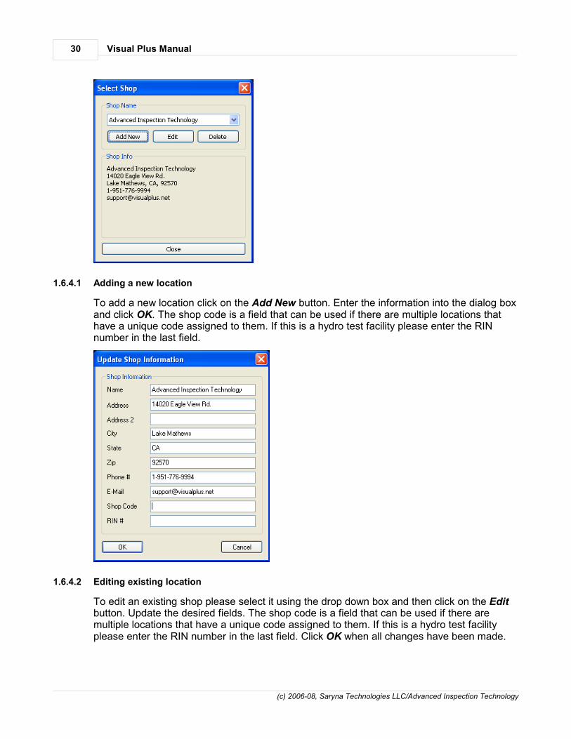
1.6.4.1 Adding a new location
To add a new location click on the Add New button. Enter the information into the dialog boxand click OK. The shop code is a field that can be used if there are multiple locations thathave a unique code assigned to them. If this is a hydro test facility please enter the RINnumber in the last field.
1.6.4.2 Editing existing location
To edit an existing shop please select it using the drop down box and then click on the Editbutton. Update the desired fields. The shop code is a field that can be used if there aremultiple locations that have a unique code assigned to them. If this is a hydro test facilityplease enter the RIN number in the last field. Click OK when all changes have been made.

Visual Plus Eddy Current Inspection 31
(c) 2006-08, Saryna Technologies LLC/Advanced Inspection Technology
1.6.4.3 Deleting location
To delete an existing shop please select it using the drop down box and then click on the Delete button. Click Yes on the following dialog box after verifying that the correct shop isbeing deleted. Click No if you want to cancel deletion.
Please note that it is possible to add password protection to the delete button. Please see page for more info.
1.7 Viewing, Searching, and Printing Records
Enter topic text here.
1.7.1 Working with inspection list
Enter topic text here.
1.7.2 Searching records
Enter topic text here.
1.7.3 Defining columns
Enter topic text here.
1.7.4 Printing results
Enter topic text here.
1.7.5 Saving and loading reports
Enter topic text here.
1.8 Preferences
The following sections describe preferences that can be set for VisualPlus 3software.
1.8.1 General
The General page of the Preferences property sheet is used to set VisualPlus/VisualDepthCOM port addresses as well as other generic settings.
63

Visual Plus Manual32
(c) 2006-08, Saryna Technologies LLC/Advanced Inspection Technology
Visual Plus COM Port Address - use the drop down menu to select the COM port towhich VisualPlus 3 acquisition module is connected. Click Find button to performautomatic search for VisualPlus 3 COM port.
Visual Depth COM Port Address - use the drop down menu to select the COM port towhich Visual Depth acquisition module is connected. If you do not have Visual Depth pitdepth measurement system this value does not matter.
If PSI number is entered, automatically display PSI form after passing or failinginspection - if this item is checked then whenever the eddy current inspection is passedor failed (F10/F11 keys) if the inspector has a PSI number assigned to him/her then a PSIform will be shown automatically. The PSI form can always be opened by pressing F3 key.
Perform automatic analysis at the end of recording - this item should normally bechecked. If checked, VisualPlus 3 software will perform analysis of recorded data afterStop Recoding button (F7 key) is pressed and the results of analysis are displayed in thecomments window below the graph. If software determines that inspection fails then theInspection Result will be set to Fail automatically.
Use VIP Detailed Cylinder Inspection Form instead of PSI form - if checked, analternative visual inspection form will be used when pressing F3 or selecting 'Inspection->Fill Out Inspection Form' from the main menu. This item is normally not checked and thePSI for is used.
Prefill Customer/Serial#/Manufacturer field with 'NOT ENTERED' text on NewDocument - if checked, then customer, serial#, and Manufacturer fields will be set to NOTENTERED whenever New Document is selected (F5 key or File->New). This can be usedif inspections are never saved unless they fail. In this scenario the inspections are doneuntil a tank fails, in this case all of the information gets entered and tank is inspectedagain. This option is normally not checked. WARNING! WE DO NOT RECOMMENDENABLING THIS OPTION. UNLESS MANUFACTURER AND ORIGINAL

Visual Plus Eddy Current Inspection 33
(c) 2006-08, Saryna Technologies LLC/Advanced Inspection Technology
MANUFACTURING DATE ARE ENTERED CORRECTLY THE VISUAL PLUSSOFTWARE CANNOT DETERMINE WHICH ALLOY WAS USED TO MANUFACTURE ACYLINDER.
Make DOT Spec/Exemption field mandatory - if checked, the DOT Spec must beentered on the main screen before starting an inspection. If this item is not checked theninspection can start with that field blank. This is mainly used for hydro test facilities thatneed to keep track of this data.
1.8.2 Data Management
The Data Management page of the Preferences property sheet is used to set parametersrelated to storage of files on disk.
The Automatically save files in this directory edit box specifies the location whereVisualPlus files will be stored by default. This means that when you press F8 or Save Asthis directory will be show in the Save As box. If Store files for each customer in aseparate directory is checked then a subdirectory with a customer's name will be createdunder this directory and all files for that particular customer will be stored in thissubdirectory.
If Add -Failed to file name of a cylinder that failed an inspection is checked then -Failed will be ended to the end of the file name for all files where the inspection was failed.
The Format file names as CustomerName-SerialNumber-Date option changes thedefault file name for each inspection to be in the following format: CustomerName-SerialNumber-Date. For example: AIT-P123456-04-30-2004.vis, AIT-P123456-04-30-2004-Failed.vis, etc.

Visual Plus Manual34
(c) 2006-08, Saryna Technologies LLC/Advanced Inspection Technology
1.8.3 Printing
The Printing page of the Preferences property sheet is used to set parameters related toprinting of inspection results and reports.
When Print file to default printer when saving file for the first time is checked thenwhenever an inspection is performed and it is saved via F8 key the inspection will beprinted on the default printer. This option is very handy if your company policy is to print ahardcopy of every inspection. The printing will only happen if the file was just created andit is being saved for the first time, it will not print when re-saving an existing file.
Do not use dark background on PSI form section headings to conserve printer ink/toner will use white backgrounds on the PSI form section titles if checked.
Print shop info (name, address,etc.) on the PSI form will add a Shop Info section to thePSI form.
Scale Inspection List output (%) option sets the scaling factor for printing the inspectionlist and the hydro test report log. If the inspection report or the hydro test log has too manycolumns you can set this value to a lower number (no less than 50%) to make the resultssmaller so that they will fit on a single page.
Print Province/Postal Code instead of State/Zip option allows customers in Canada tohave correct wording in address printouts on the PSI and inspection report forms. Checkthis option if you are in Canada, leave unchecked for US.
Print graph line thickness (pixels) - changes graph thickness to the specified valuewhen printing, normally it should be left at default value but if output on your printer is toothin or too thick you can adjust it with this value.
Print graph font size (pixels) - changes graph annotations font size to the specifiedvalue when printing, normally it should be left at default value but if output on your printer

Visual Plus Eddy Current Inspection 35
(c) 2006-08, Saryna Technologies LLC/Advanced Inspection Technology
is too small or large you can adjust it with this value.
1.8.4 Hydro
The Hydro page of the Preferences property sheet is used to set parameters related tohydro test equipment and testing. This tab is only visible if you have purchased and entereda correct license key for the hydro acquisition module (single jacket or multiple jackets).
Pressure Gauge field specifies the COM port for the digital pressure gauge used in thehydro acquisition system.
Jacket/Scale # field - specifies the COM port for a scale assigned for a particular jacketand whether that jacket is active. If a particular jacket is damaged or non-functional it canbe temporarily disabled from acquisition using the checkbox. Depending on the number oflicensed jacket more than a single Jacket/Scale # files may be enabled.
Enable Extended Permanent Expansion Measurement Mode by Default - for smallercylinders the default amount of time to measure the permanent expansion may be too low,causing good cylinders to be failed for permanent expansion that would pass givenadditional 10 - 20 seconds to contract to original volume. If this option is enabled then ifany jacket has a cylinder that will fail the inspection at the end of the permanent expansionmeasurement cycle then an extended permanent expansion measurement cycle isentered which allows more time for smaller cylinders to contract to original size. The lengthof this cycle is defined by the Extended Permanent Expansion Measurement Period(seconds) field.
Extended Permanent Expansion Measurement Period (seconds) - length of theExtended Permanent Expansion Measurement Period in seconds.

Visual Plus Manual36
(c) 2006-08, Saryna Technologies LLC/Advanced Inspection Technology
1.9 Main Menu
The following section contains information on each item in the main menu. Some informationhas been discussed in previous sections.
1.9.1 File Menu
1.9.1.1 New command
Use this command to create a new document in Visual Plus. You can also use F5 key toactivate this command. Typically this command is used before entering cylinder data andperforming an inspection to clear out all previous data.
You can open an existing document with the Open command .
1.9.1.2 Open command
Use this command to open an existing document stored on disk in the current window. Youcan also use Ctrl-O key combination to activate this command.
You can create new documents with the New command .
1.9.1.3 Open From Database command
Use this command to open a file from the database. All inspection records are stored in thedatabase even when the file is saved to a disk instead of directly into the database. Openinga file does not invalidate Visual Plus calibration. The current calibration data will be stored inmemory and will be retrieved again when the next inspection starts.
Please see page for more information.
1.9.1.4 Save command
Use this command to save the active document to its current name and directory. You canalso use Ctrl-S key combination to activate this command. When you save a document forthe first time, Visual Plus displays the Save As dialog box so you can name your document.If you want to change the name and directory of an existing document before you save it,choose the Save As command . If you would like to store the file in the database, choosethe Save To Database command .
1.9.1.5 Save As command
Use this command to save and name the active document. You can also use F8 key toactivate this command. Visual Plus displays the Save As dialog box so you can name yourdocument.
To save a document with its existing name and directory, use the Save command .
Please note that Store inspection results in database option of Database settings dialog swaps F8 and Alt-F8 (Save As and Save To Database) keys so that files can be stored
directly into the database by pressing F8 without asking for a file name or location.
36
36
31
36
37
36
43

Visual Plus Eddy Current Inspection 37
(c) 2006-08, Saryna Technologies LLC/Advanced Inspection Technology
1.9.1.6 Save To Database command
Use this command to save a file to the database. You can also use Alt-F8 key combinationto activate this command.
Please note that Store inspection results in database option of Database settings dialog swaps F8 and Alt-F8 (Save As and Save To Database) keys so that files can be stored
directly into the database by pressing F8 without asking for a file name or location.
1.9.1.7 Print command
Use this command to print a document. This command presents a Print dialog box, whereyou may specify the range of pages to be printed, the number of copies, the destinationprinter, and other printer setup options.
Please note that first page printed is always the eddy current inspection report. If the PSI orVIP forms have been activated then the corresponding form will be printed as the secondpage of the report. If you only want to print the PSI or VIP forms, select Print range on the Print dialog box as 'Pages from 2 to 2'.
1.9.1.8 Print Preview command
Use this command to display the active document as it would appear when printed. Whenyou choose this command, the main window will be replaced with a print preview window inwhich one or two pages will be displayed in their printed format. The print preview toolbaroffers you options to view either one or two pages at a time; move back and forth throughthe document; zoom in and out of pages; and initiate a print job.
1.9.1.9 Print Setup command
Use this command to select a printer and a printer connection. This command presents a Print Setup dialog box, where you specify the printer and its connection.
1.9.1.10 Information command
Use this command to display the file information dialog. You can also use Ctrl-I keycombination to activate this command. The software and firmware version shown here is theversion that was used to record inspection for the currently loaded file. The personperforming inspection and calibration is also listed here.
43

Visual Plus Manual38
(c) 2006-08, Saryna Technologies LLC/Advanced Inspection Technology
1.9.1.11 Preferences command
Use this command to specify preferences for Visual Plus. Please see page for moreinformation.
1.9.1.12 Shop Information command
Use this command to specify shop information such as name, address, etc. This commandwill bring up the Shop Information dialog box. This information is then displayed on theprintout of the inspection. Please see page for more information.
1.9.1.13 Send command
Use this command to send the active document through e-mail. This command presents amail window with the active document attached to it. You may then fill out the To field,Subject field, and so on, and add text to the body of the message. When you are finished,you can click the Send button to send the message.
1.9.1.14 File 1, 2, 3, 4 command
Use the numbers and filenames listed at the bottom of the File menu to open any of thelisted documents you closed. Choose the number that corresponds with the document youwant to open.
1.9.1.15 File Exit command
Use this command to end your Visual Plus session. You can also use the Close commandon the application Control menu. Visual Plus prompts you to save documents with unsavedchanges.
Please note that calibration will be lost when VisualPlus 3 software closes. You will have torun calibration again before performing any more inspections.
1.9.2 Edit Menu
1.9.2.1 Cut command
Use this command to remove the currently selected data from the document and put it onthe clipboard. This command is unavailable if there is no data currently selected.
Cutting data to the clipboard replaces the contents previously stored there.
1.9.2.2 Copy command
Use this command to copy selected data onto the clipboard. This command is unavailable ifthere is no data currently selected.
Copying data to the clipboard replaces the contents previously stored there.
31
29

Visual Plus Eddy Current Inspection 39
(c) 2006-08, Saryna Technologies LLC/Advanced Inspection Technology
1.9.2.3 Paste command
Use this command to insert a copy of the clipboard contents at the insertion point. Thiscommand is unavailable if the clipboard is empty.
1.9.2.4 Inspector Editor command
Use this command to display the inspector editor dialog. Please see page for moreinformation.
1.9.2.5 Customer Editor command
Use this command to display the customer editor dialog. Please see page for moreinformation.
1.9.2.6 Selection Box Values command
Use this command to display the selection (drop-down) box values dialog. Please see page for more information.
1.9.3 View Menu
1.9.3.1 Toolbar command
Use this command to display and hide the toolbar, which includes buttons for some of themost common commands in Visual Plus, such as File Open. A checkmark appears next tothe menu item when the toolbar is displayed.
1.9.3.2 Status Bar Command
Use this command to display and hide the status bar, which describes the action to beexecuted by the selected menu item or pressed toolbar button, and keyboard latch state. Acheckmark appears next to the menu item when the status bar is displayed.
1.9.3.3 Display Type
Enter topic text here.
1.9.3.3.1 Switch To Next View
Enter topic text here.
1.9.3.3.2 Overlay Threads
Enter topic text here.
1.9.3.3.3 Individual Threads
Enter topic text here.
26
27
28

Visual Plus Manual40
(c) 2006-08, Saryna Technologies LLC/Advanced Inspection Technology
1.9.3.3.4 Linear Graph
Enter topic text here.
1.9.3.3.5 Linear Single Row Graph
Enter topic text here.
1.9.3.3.6 3D Spiral View
Enter topic text here.
1.9.3.3.7 Hydro View
Enter topic text here.
1.9.3.3.8 Calibration Frequency Sweep
Enter topic text here.
1.9.3.3.9 Accelerometer Calibration
Enter topic text here.
1.9.3.4 Data Source
Enter topic text here.
1.9.3.4.1 Calibration Standard
Enter topic text here.
1.9.3.4.2 Recorded Data
Enter topic text here.
1.9.3.5 Zoom
Enter topic text here.
1.9.3.5.1 In
Enter topic text here.
1.9.3.5.2 Out
Enter topic text here.
1.9.3.6 Baseline Removal
Enter topic text here.

Visual Plus Eddy Current Inspection 41
(c) 2006-08, Saryna Technologies LLC/Advanced Inspection Technology
1.9.3.6.1 Subtract More
Enter topic text here.
1.9.3.6.2 Subtract Less
Enter topic text here.
1.9.4 Inspection Menu
1.9.4.1 Calibration Wizard command
Use this command to start probe calibration. This command will bring up the CalibrationWizard dialog box. For more information please see page .
1.9.4.2 Start Recording command
Use this command to start recording of data from the cylinder. Visual Plus will check tomake sure that all required fields are filled out before starting. An error message will bedisplayed and the focus will be switched to the mandatory field that needs to be filled out.For more information about inspection please see page .
Please make sure that the probe and cylinder are in horizontal position during recording.PLEASE MAKE SURE THAT THE CYLINDER DOES NOT MOVE DURING INSPECTION.
Please always start recording with the probe threaded all the way into the cylinder (checkthe signal bar to see if it's all the way to the top) and the white indicator line on the probealigned with the first letter of the cylinder's serial number. This will allow you to easilycompare recorded indications to the actual cylinder since the top position on the screen willbe aligned with the first letter of the serial number.
Most menu items (Open, Save, etc.) are disabled during recording to prevent datacorruption. Please stop recording before attempting to perform those operations.
1.9.4.3 Stop Recording command
Use this command to stop recording of data from the cylinder. Please note that you will notbe able to change fields such as customer name, serial number, inspector, etc. afterrecording has been completed. To start inspecting the next cylinder, first save the currentinspection using the Save command , then select New command to clear all data,enter information and start recording again.
1.9.4.4 Inspection Fill Out PSI Form command
Use this command to fill out information for the PSI or VIP form.VisualPlus 3 displays thePSI or VIP Form dialog box so you can enter form data. If this is the first time the form isopened for this document, information such as customer name, serial number, inspectorname, and etc. will be transferred to the form from the main screen.
It is possible to automatically open the form after passing or failing inspection. To enable thisfeature please enter the PSI Inspector Number for each inspector that has that number in
17
19
36 36
Visual Plus Manual42
(c) 2006-08, Saryna Technologies LLC/Advanced Inspection Technology
the Inspector Editor located under main menu Edit->Inspectors. Make sure that there is acheck mark on the If PSI number is entered, automatically display PSI form afterpassing or failing inspection option in General page of Preferences dialog box accessiblethrough File->Preferences.
1.9.4.5 Inspection Pass command
Use this command to indicate that this inspection was completed successfully and that thiscylinder can be put back in service. Please only do this after completing both the eddycurrent and visual inspection of the cylinder.
1.9.4.6 Inspection Fail command
Use this command to indicate that this inspection was not completed successfully and thatthis cylinder should be removed from service. The cylinder condition and threading conditionon the PSI form will be automatically set to Unacceptable.
1.9.4.7 Analyze Inspection Results command
Use this command to analyze inspection results. This command finds indications in recordeddata and then applies a set of rules to determine if there is a possibility that the thread areaof the cylinder could be cracked. The current rules for 6351 alloy, 1995 Catalina 6061, or anunknown alloy type are: two consecutive indications, higher than 25% of the calibrationstandard crack height and indication width not exceeding width of the calibration standardcrack by more than eight degrees. The current rules for 6061 alloy are: three consecutiveindications, higher than 30% of the calibration standard crack height and indication width notexceeding width of the calibration standard crack by more than five degrees. The results ofthe inspection will be added to the comment section of the main window and if any cracksare detected the inspection status will be changed to Failed. For more information aboutanalysis of data please see page .
Typically this function is activated automatically after recording is stopped (usually via F7key). If this does not happen automatically you can enable it by checking Performautomatic analysis at the end of recording checkbox in General page of Preferencesdialog box accessible through File->Preferences.
Please always check recorded data manually and perform visual inspection of eachcylinder using Optical Plus visual inspection system.
1.9.4.8 Find Indications command
Use this command to look for indications on recorded inspection results. Software willtypically find many small indications on dirty/noisy cylinders, they are not considered cracksunless there is a required number of consecutive indications depending on the cylinder alloy.Please use Analyze Inspection Results command to detect cracks using latest definitionof a crack. For more information about analysis of data please see page .
1.9.5 Database Menu
19
72
42
19

Visual Plus Eddy Current Inspection 43
(c) 2006-08, Saryna Technologies LLC/Advanced Inspection Technology
1.9.5.1 Search
Use this command to display the database search dialog box. Enter the search parameterssuch as manufacturer, customer, inspector, serial number, dates, etc. Please remember thatreturned records must satisfy all specified constraints. In effect, logically the AND operationis perform on all specified parameters. Click OK to search the database. The results will beshown in an Open From Database dialog.
Please note that it is possible to specify wildcards in the serial number field, use % wildcardto replace any number of unknown characters, use _ (underscore) to replace a singlecharacter. Any other standard Transact-SQL LIKE expression is acceptable.
1.9.5.2 Settings
Use this command to display the database settings dialog. Please select either the defaultMS Access database file in the Visual Plus program folder or an ODBC DSN name. TheODBC DSN name is an advanced option that allows you to place the database file anywhereon your computer or on a network. In addition to MS Access database format, MS SQLServer Express and MS SQL Server can be used. A MS SQL Server schema creation scripthas been provided in the Visual Plus program directory as well as instruction on how tosetup the database and Visual Plus (Install MS SQL Server 2005 Express.pdf).

Visual Plus Manual44
(c) 2006-08, Saryna Technologies LLC/Advanced Inspection Technology
Store inspection results in database... - this option swaps F8 and Alt-F8 (Save As andSave To Database) keys so that files can be stored directly into the database by justpressing F8. There is no file name to be set so if all data has been entered on the mainscreen the file is saved immediately. There is a confirmation box that shows up after thefile has been saved.
Show list of previous inspections if the current cylinder has been inspected already- this option brings up a list of previous inspection for the currently entered serial numberbefore inspection begins. This list will pop up right after you start recording data (typicallyvia F6 key). Take a look at the list and the previous results, print it if needed, then closethe window by clicking on the X in the right upper corner or just hit ESC. The VisualPlus 3software will begin acquisition and you can start unscrewing the probe from the cylinder.Please note that right after you close this window it may look like VisualPlus 3 is not doinganything but as you turn the probe you will see that is actually recording data.
1.9.6 Hydro Menu
Enter topic text here.
1.9.6.1 Data Entry Only
Enter topic text here.
1.9.6.2 Data Entry and Visual Inspection
Enter topic text here.
1.9.6.3 Visual Inspection Only
Enter topic text here.
1.9.6.4 Hydro Calibration Data Entry
Enter topic text here.

Visual Plus Eddy Current Inspection 45
(c) 2006-08, Saryna Technologies LLC/Advanced Inspection Technology
1.9.6.5 Hydro Testing
Enter topic text here.
1.9.6.6 Test Report
Enter topic text here.
1.9.7 Help Menu
1.9.7.1 Help Topics command
Use this command to display the opening screen of help. From the opening screen, you canjump to step-by-step instructions for using VisualPlus 3 and various types of referenceinformation.
Once you open help, you can click the Contents button whenever you want to return to theopening screen.
1.9.7.2 What's This? Help command
Use this command to obtain help on some portion of VisualPlus 3 software. When youchoose the toolbar's Context Help button, the mouse pointer will change to an arrow andquestion mark. Then click somewhere in the VisualPlus 3 window, such as another toolbarbutton. The help topic will be shown for the item you clicked.
1.9.7.3 Enter License Key command
Use this command to enter a license key purchased for one of the add-on modules forVisualPlus 3 software. A license key is required for optional modules such various hydro testmodules.
Enter the license key in to the edit box. Click OK to save the license key.
Verify that the correct module has been added in the following screen. If an error messageappears please make sure that the license key was typed in correctly.

Visual Plus Manual46
(c) 2006-08, Saryna Technologies LLC/Advanced Inspection Technology
1.9.7.4 Test Probe Accelerometer command
Use this command to display the probe accelerometer test dialog. You may be asked toopen this dialog by AIT to check probe position noise levels as well as probe function.Normally you don't need to use this dialog box. Please note that if probe is connected thenumbers in all group boxes will be constantly changing. This is an indication thatcommunications with VisualPlus 3 acqusition module have been established and thatposition resolving circuitry of the probe is functional. This does not diagnose probe sensorproblems.
To determine the probe accelerometer X/Y range press the Reset Range button, hold theprobe horizontally and make at least one full revolution. The X Range and Y Range valuesshould become stable, around 60 for newer probes and less for the older probes.
1.9.7.5 About command
Use this command to display the copyright notice and version number of your copy ofVisualPlus 3.
1.10 Backing Up Data
To prevent data loss in an event of a hard disk malfunction or other problem it isrecommended to regularly backup following data:

Visual Plus Eddy Current Inspection 47
(c) 2006-08, Saryna Technologies LLC/Advanced Inspection Technology
visplus4.mdb file in Visual Plus directory. This file contains information aboutinspectors, calibration and inspection records and may contain other information inthe future. The database may contain the actual recorded date or links to data filesfor each inspection record depending on settings specified under Database->Settings. Please don't move files after they have been saved into thedata directory, if you do, you will not be able to pull up recorded data for those filesfrom the database report view.
Directory containing all data files. You can find out the location of this directory byopening Visual Plus software and selecting File->Preferences from the main menu.It is typically a directory called Data under Visual Plus directory. Keep in mind that ifyou save files in directory other than this default directory you will need to back it upalso.
You may also back up HKEY_CURRENT_USER\Software\AIT\VISPlus registry key.Please don't modify any registry values directly. Preferences and shop informationare stored in the registry and since they can be recreated easily from Visual Plus inan event of a crash, backing up this registry key can be skipped.
1.11 Troubleshooting
This section describes common problems with VisualPlus 3 and software.
1.11.1 OBDC Driver Errors
You may get this error if you are trying to run VisualPlus 3 under Windows 98 First Editionsoftware. VisualPlus 3 requires Microsoft Data Access Components (MDAC) 2.6 or later tobe installed on your system for it to work properly. To fix this problem, download and installMDAC component from our website or directly from microsoft (go to www.microsoft.com andtype in MDAC in the search box, then select MDAC Downloads). This only applies toWindows 98 First Edition but if you are getting this error with later versions you may want totry installing the latest MDAC to make sure that you don't have a corrupted driver.
1.11.2 Invalid attribute/option identifier error message
Visual Plus stores information about inspectors, calibration and inspection records in adatabase file called visplus4.mdb located in Visual Plus directory. In Windows 2000/XP youmay get an error during calibration and inspection if the Administrator installed Visual Plussoftware and another user without administrative privileges attempts to run Visual Plus. Thishappens because other users do not have Full Access permission to the database file.
To solve this problem you need to give Full Access permission to the Users security group.In addition to Users you may need to give the same permission to the Domain Users groupif you log in on a specific domain. Depending on how a network is setup you may need togrant this permission to other groups. Please consult your system administrator for help.
To set permissions, log in as administrator and right mouse click on visplus4.mdb usuallylocated in C:\Programs Files\ Visual Plus directory. Select Properties menu item, selectSecurity tab. If the tab is not visible please read the next paragraph. Click on Add, select ortype in Users. Click on the added Users group and click on Full Access box below. Click

Visual Plus Manual48
(c) 2006-08, Saryna Technologies LLC/Advanced Inspection Technology
OK. Other users of this computer can now use Visual Plus. You can do the same forDomain Users if you log onto a domain.
In Windows XP, if a machine is not a part of a domain it will typically not display the Security tab when you right mouse click on a file and select Properties. To get that tab toshow up you need to go to Tools->Folder Options in Windows Explorer. Click on the Viewtab, scroll all the way down to Use simple file sharing and make sure that it IS NOTCHECKED.
1.11.3 Error opening communications port
Visual Plus software connects to Visual Plus instrument via an RS232 link. In order toproperly communicate with Visual Plus you must specify a COM port that the unit isconnected to. Typically for laptops it will be COM1, if you use a USB-Serial adapter the COMport number is hard to predict. The best way to find out the COM port is to select File->Preferences from the main menu. Click on the Find button in the Visual Plus COMPort Address group. If the unit is connected and USB-Serial adapter is installed properly theVisualPlus 3 will find the correct COM port.
If using Find fails to work try the following method:
1. Go to Start->Control Panel.
2. Double-click System icon.
3. Select Hardware tab.
4. Click on Device Manager.
5. Expand (double-click) the Ports (COM & LPT) item in the tree on the left side of thewindow.
6. The USB adapter or built in COM ports will be listed here. Write down available COMport numbers.

Visual Plus Eddy Current Inspection 49
(c) 2006-08, Saryna Technologies LLC/Advanced Inspection Technology
7. If USB Serial adapter has a yellow exclamation mark on it that means that the driverwas not installed properly. Please contact AIT for assistance with this problem.
8. Open Visual Plus software, go to File->Preferences, enter the first COM portnumber that you wrote down in 'Visual Plus COM Port Address' field. If you nowknow the COM port number please enter that number. Please enter the COM portincluding the 'COM' prefix with no space between COM and the number. Just thenumber is not enough. Click OK.
9. Hit F4 to enter Calibration Wizard, enter Inspector Name and Probe Type, hit Next. IfVisual Plus is still unable to connect to the unit please try steps 7-8 with the rest ofthe COM port numbers that you wrote down. If you are unable to connect on any ofthem please try installing software on another computer or use another USB adapterto see if the COM port might be defective. If you are unable to connect on twocomputers or you don't have another computer please contact AIT for assistance.
1.11.4 Crash when starting the program
In rare cases the Microsoft Data Access Components (MDAC) can get corrupted. In thiscase VisualPlus 3 software will crash before showing the main window. For operatingsystems before Windows XP we recommend installing the latest version of MDACcomponents from microsoft.com.
Unfortunately MDAC cannot be easily re-installed on Windows XP. We found that followinginstructions work well for repairing MDAC in this situation.
The following instructions have been reproduced with permission from macropool GmbH (www.macropool.com). Please note that if the following instructions do not help macropooloffers an MDAC repair tool. The original source can be found here: http://www.macropool.com/en/download/mdac_xp_sp2.html
How to Repair MDAC 2.8 Under WindowsXP with SP2 Installed General Information
Windows XP with Service Pack 2 contains MDAC version 2.81, which is currently notavailable for download at the Microsoft Web site as a standalone installation. If you try toinstall MDAC 2.8, which is the latest available standalone download of MDAC, you willreceive a message that you already have a newer version of MDAC installed. Therefore, underWindows XP SP2, you must manually repair MDAC 2.81 as outlined below.
How to Repair MDAC 2.81 under Windows XP with SP2
1. In Windows Explorer, open the c:\Windows\Inf folder.
Note If you cannot see the c:\Windows\Inf folder, follow these steps:

Visual Plus Manual50
(c) 2006-08, Saryna Technologies LLC/Advanced Inspection Technology
a. On the desktop, double-click My Computer, and then on the Tools menu, clickFolder Options.
b. Click the View tab.
c. Under Advanced settings, select the Show hidden files and folders check box.
d. Clear the Hide extensions for known file types check box.
e. Click OK.
2. In the C:\Windows\Inf folder, right-click the Mdac.inf file, and then click Install.
3. When you are prompted to insert the Windows XP SP2 CD, use one of the followingmethods:
I. If you have a Windows XP SP2 CD:
a. Insert the Windows XP Service Pack 2 CD in the CD or DVD drive. Note If a "Welcome to Microsoft Windows XP" message appears, click Exit.
b. Click Browse.
c. In the File name box, type CD or DVD drive that contains the Windows XPService Pack 2 CD drive letter:\i386. For example, type d:\i386 if the WindowsXP Service Pack 2 CD is in drive D.
d. Click Open.
II. If you do not have a Windows XP SP2 CD:
a. In the File name box, type %systemroot%\windows\servicepackfiles\i386, andthen click Open.
b. When prompted for adcjavas.inc, point to C:\Windows\servicepackfiles\i386Note: If you cannot find this folder put the Windows CD into your CD driveand browse for that file.
c. When prompted for the file handler.reg, either point to C:\ProgramFiles\Common Files\System\msadc, or put the Windows XP CD in yourCD-ROM drive.
d. When prompted for MDACRdMe.htm, point to C:\Program Files\CommonFiles\System\Ado. If this file is not present rename the fileMDACReadme.htm to MDACRdMe.htm.
e. When prompted for oledbjvs.inc, point to C:\Program Files\CommonFiles\System\Ole DB.

Visual Plus Eddy Current Inspection 51
(c) 2006-08, Saryna Technologies LLC/Advanced Inspection Technology
f. When prompted for mssoap1.dll, point to C:\Program Files\CommonFiles\MSSoap\Binaries.
g. When prompted for mssoapr.dll, point to C:\Program Files\Common
Files\MSSoap\Binaries (or below its subfolders).
4. You may also be prompted for the original Windows XP CD that was used to install theoperating system.
a. Insert the Windows XP Service Pack 2 CD in the CD or DVD drive. Note If a "Welcome to Microsoft Windows XP" message appears, click Exit.
b. Click Browse.
c. In the File name box, type CD or DVD drive that contains the Windows XP ServicePack 2 CD drive letter:\i386. For example, type d:\i386 if the Windows XP ServicePack 2 CD is in drive D.
d. Click Open.
Note: In the case you cannot find those files in the given folders search the whole hard diskfor them.
1.11.5 Communication issues when using USB-Serial adapter
VisualPlus 3 software is extremely sensitive to the type of USB-Serial adapter used.
WE ONLY RECOMMEND AND SUPPORT SIIG PART# JU-CB1S12-S3 USB TO SERIALADAPTER.
Please note that other brands may not work at all or may work for a while and then causestrange readings or loss of connection. There are some adapters that WILL NOT WORK forsure with VisualPlus 3, they are: Radioshack USB-Serial adapter, IOGrear USB-Serialadapter, etc.
Please note that some customers are reporting satisfactory results with Belkin USB-Serialadapter, although it's not officially supported it is a good second choice if SIIG adapter is notavailable.
2 Visual Plus Hydro Testing
VisualPlus 3 software is capable of tracking and recording hydro testing data. There areseveral options that are available depending on the type of license that you purchase.
Manual hydro data entry - in this case a page is added to the PSI form that allows you toenter the hydro test data manually. Cylinder information is entered into tabs on the PSIform. On the last Hydro tab the operator performs the hydro test and enters the results

Visual Plus Manual52
(c) 2006-08, Saryna Technologies LLC/Advanced Inspection Technology
(total and permanent expansion) into the dialog box. The results of the test can be viewedthrough the Hydro Test list (for multiple tests), by printing out the PSI form (a Hydrosection is added to the PSI form for files that contain this information), or the test resultscan be printed out in DOT compliant manner.
Single jacket/single workstation - in this configuration VisualPlus 3 will record the testresults utilizing a digital scale and a digital pressure gauge. The interface is similar to themanual configuration above with test initiated by clicking Measure with VisualPlus Hydrobutton on the Hydro tab of the PSI form. The results are automatically entered into thedialog box and can be viewed by any of the methods mentioned for the manualconfiguration. The digital pressure gauge and digital scale must be connected to thecomputer running VisualPlus 3. It is also possible to use special hydro data entry/visualinspection/hydro testing dialogs from the multiple workstation method below. Please notethat if you plan to use separate workstations for data entry/visual inspection and hydrotesting you should purchase the multiple jacket/multiple workstations license as describedbelow but mention that you only have a single jacket.
Multiple jacket/multiple workstations - this configuration is used for higher throughputfacilities that want to break up hydro test into two or three steps that can be done inparallel. For example, a single workstation with a label printer is setup for data entry. Thecylinder info is entered into a special form which produces a barcode label after saving theinfo into the database. The cylinder then passes on to visual inspection station. At thisstation the barcode is scanned and the cylinder is either passed, rejected or condemned.All passing cylinders are then moved to the hydro test station where each tank barcode isscanned and test is performed. All resulting data is stored in the database. The results foreach date can be printed out in a DOT compliant format. It is possible to have multipledata entry, multiple visual inspection, and multiple hydro test stations.
2.1 Configuring Software
To enable VisualPlus 3 software for any of the modules (manual, single jacket/workstation,and multiple jacket/workstation) a license key must be entered into the software.
1. Click on Help->Enter License Key, type of copy/paste the license key that you purchasedinto the dialog box and click OK.
2. It is highly recommended to switch VisualPlus 3 software to store raw data in thedatabase instead of Data folder. Should you decide to upgrade to a multiple jacket/workstation configuration later this option will preserve all raw data. To switch to this modeclick on Database->Settings from the main menu and make sure that Store inspectionresults in database option is checked. You MUST choose this setting if you are usingMultiple Jacket/Multiple Workstation Module.
3. Configure the COM ports used for the digital pressure gauge and the scales in File->Preferences->Hydro. See page for more info.
2.2 Entering Calibration Data
Before performing hydro testing the system should be checked with a calibrated cylinder foreach day. VisualPlus 3 software does not perform this function automatically but allows the
35

Visual Plus Hydro Testing 53
(c) 2006-08, Saryna Technologies LLC/Advanced Inspection Technology
results of calibration to be entered manually so that they show up on the Hydro Test Report.This is applicable to all hydro modules, including the manual data entry module.
1. To enter the calibration data, select Hydro->Hydro Calibration Data Entry from the mainmenu. Enter the hydro operator and supervisor names and click OK.
2. In the following dialog box, enter the calibration cylinder Serial #, Owner (typically yourbusiness name) and the test results. If there are any comments they can be entered intothe Remarks field. It is common to enter the jacket number in to the remarks field formulti-jacket systems. If calibration was performed on jacket #1, J1 is entered into theRemarks field in this case.
3. Click Store Record or press F2 to record the data. The calibration results fields will bereset and ready for entry of the next calibration data point. The previously entered recordwill be shown in the Log section until this dialog box is closed.
4. Click Close after all calibration data have been entered.
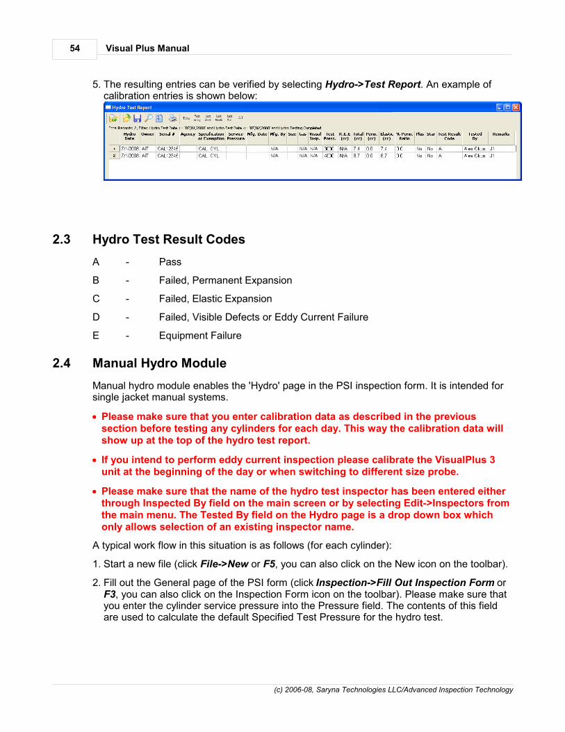
Visual Plus Manual54
(c) 2006-08, Saryna Technologies LLC/Advanced Inspection Technology
5. The resulting entries can be verified by selecting Hydro->Test Report. An example ofcalibration entries is shown below:
2.3 Hydro Test Result Codes
A - Pass
B - Failed, Permanent Expansion
C - Failed, Elastic Expansion
D - Failed, Visible Defects or Eddy Current Failure
E - Equipment Failure
2.4 Manual Hydro Module
Manual hydro module enables the 'Hydro' page in the PSI inspection form. It is intended forsingle jacket manual systems.
Please make sure that you enter calibration data as described in the previoussection before testing any cylinders for each day. This way the calibration data willshow up at the top of the hydro test report.
If you intend to perform eddy current inspection please calibrate the VisualPlus 3unit at the beginning of the day or when switching to different size probe.
Please make sure that the name of the hydro test inspector has been entered eitherthrough Inspected By field on the main screen or by selecting Edit->Inspectors fromthe main menu. The Tested By field on the Hydro page is a drop down box whichonly allows selection of an existing inspector name.
A typical work flow in this situation is as follows (for each cylinder):
1. Start a new file (click File->New or F5, you can also click on the New icon on the toolbar).
2. Fill out the General page of the PSI form (click Inspection->Fill Out Inspection Form orF3, you can also click on the Inspection Form icon on the toolbar). Please make sure thatyou enter the cylinder service pressure into the Pressure field. The contents of this fieldare used to calculate the default Specified Test Pressure for the hydro test.

Visual Plus Hydro Testing 55
(c) 2006-08, Saryna Technologies LLC/Advanced Inspection Technology
3. If eddy current inspection is required click OK to close the PSI form. Perform the eddycurrent inspection, if the tank passes inspection, press F10 to pass eddy current part ofinspection and return to the External page of the PSI form (press F3 and then click onExternal tab). If the tank fails, return straight to the Condition page of the PSI form andselect Unacceptable under Cylinder Condition, fill out the rest of this page and thenadvance to Hydro page. Please skip the following item in this situation, it is not necessaryto fill out External to Valve pages if the tank is going to fail anyway.
4. If tank has passed eddy current inspection then fill out External, Internal, Threading, andValve pages.
5. On the Condition page, if you select Marginal under Cylinder Condition and then selectinspector name under Tested By field of the Hydro page that would create a 'Reject' entryin the Hydro log when this file is saved. If Unacceptable is selected then a 'Condemn'entry is created. If Acceptable is select then the final test result will be determined by theHydro test.

Visual Plus Manual56
(c) 2006-08, Saryna Technologies LLC/Advanced Inspection Technology
6. Click on Hydro tab. Under Tested By field select the name of the person performing thehydro test. If this field is set to 'Not Tested' there will be no hydro record created andnothing will show up in the Hydro Test report. This field must be set to the inspector nameeven if the outcome of the test is 'Reject' or 'Condemn'.
7. Please double-check the Specified Pressure field. It is calculated as 5/3 of the servicepressure entered on the General page of the PSI form. Please note that if a cylinder isstamped with test pressure (TP) you need to change this field to reflect the specified testpressure. Also, if re-testing a cylinder that failed because of equipment failure thespecified pressure should be increased according to inspection guidelines.
8. Perform the hydro test on the cylinder and enter the information into the form. Based onthe entered Reject Elastic Expansion (REE) and Reject % Permanent Expansion fieldsthe software will calculate if the cylinder passes or fails the hydro test. If the Elasticexpansion is greater than REE then the Cylinder is failed with test code 'C - Fail,Excessive Elastic'. If the REE is zero then this comparison is not performed and will notaffect the outcome of the test. The REE column in the Hydro Test report will have N/A inthis case. If the % Permanent expansion is greater than Reject % Permanent Expansionthen the cylinder is failed with test code 'B - Fail, Permanent Expansion'. The Elastic and% Permanent fields are calculated automatically. The result of the test is shown in theTest Result Code field. If there was an equipment failure please check the 'EquipmentFailure' checkbox. This will create an entry in the Hydro Test report with the test code 'E'.Enter any remarks into the Remarks field. If this test is a re-test of a previous hydro testthen make sure to check the checkbox under 'If retest...' group and specify the date of theprevious test.
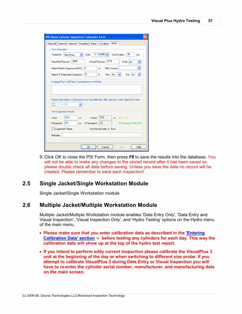
Visual Plus Hydro Testing 57
(c) 2006-08, Saryna Technologies LLC/Advanced Inspection Technology
9. Click OK to close the PSI Form, then press F8 to save the results into the database. Youwill not be able to make any changes to the stored record after it has been saved soplease double check all data before saving. Unless you save the data no record will becreated. Please remember to save each inspection!
2.5 Single Jacket/Single Workstation Module
Single Jacket/Single Workstation module
2.6 Multiple Jacket/Multiple Workstation Module
Multiple Jacket/Multiple Workstation module enables 'Data Entry Only', 'Data Entry andVisual Inspection', 'Visual Inspection Only', and 'Hydro Testing' options on the Hydro menuof the main menu.
Please make sure that you enter calibration data as described in the 'EnteringCalibration Data' section before testing any cylinders for each day. This way thecalibration data will show up at the top of the hydro test report.
If you intend to perform eddy current inspection please calibrate the VisualPlus 3unit at the beginning of the day or when switching to different size probe. If youattempt to calibrate VisualPlus 3 during Date Entry or Visual Inspection you willhave to re-enter the cylinder serial number, manufacturer, and manufacturing dateon the main screen.
52

Visual Plus Manual58
(c) 2006-08, Saryna Technologies LLC/Advanced Inspection Technology
2.6.1 Entering Cylinder Data
Enter topic text here.
2.6.2 Performing Visual Inspection
Enter topic text here.
2.6.3 Performing Hydro Test
Enter topic text here.
2.7 Hydro Test Report
Enter topic text here.
2.8 Hardware Requirements and Setup
Hardware list and configuration information is provided in this section.
2.8.1 Required Hardware
To use Visual Plus Hydro Testing module in Single Jacket/Workstation or Multiple Jacket/Workstation mode the following hardware is required:
Acculab VIC-5101 Scale with YADAP-RS serial interface (one for each jacket of yoursystem)
Red Lion Pressure Gauge Meter (Part# PAXP0000) with serial interface and Turck7500psi pressure sensor (Part# PT7500PSIG-13-LI3-H1131).
USB-Serial Adapter(s). If your computer does not have enough built-in serial (9 pin male)ports (many newer computers do not have them) you will need a USB to multiple serialport adapter or several single USB-Serial adapters. For multiple jacket configurations (4 ormore jackets) we recommend using an eight port USB to serial adapter (Part# USBG-8X-RS232) from CableMax. It can be ordered here: http://www.cablemax.com/serial-adapters/usb-to-8port_rs232_adapter.html. For one to three jacket configuration either the eightport module can be used or a less expensive four port (Part# USBG-4X-RS232) adaptercan be used. If using several single USB-Serial adapters we recommend SIIG USB-Serialadapter (Part# JU-CB1S12-S3).
The following additional hardware is recommended for the Multiple Jacket/Workstationmode:
Barcode scanners (2pcs). One for Visual Inspection workstation and one for Hydro Testworkstation. Symbol LS 2208 Scanner Multiple Interface Scanner (USB Kit, Cable, Standand Software) - Part# LS2208-SR20001R-UR at www.barcodespot.com
Brother QL-500 or QL-550 (this printer has automatic label cutter) label printer for eachdata entry station.

Visual Plus Hydro Testing 59
(c) 2006-08, Saryna Technologies LLC/Advanced Inspection Technology
Brother DK-1204 labels. Those are 2/3" x 2-1/8" multi-purpose labels.
If using a wireless connection between data entry, visual inspection, and hydro testworkstations we recommend following network hardware:
Linksys WRT110 RangePlus wireless router.
Linksys WUSB100 RangePlus wireless USB network adapter.
2.8.2 Configuring Hardware
It is necessary to modify Acculab scale configuration for all scales to allow the software topoll the current weight and change the baud rate to 19200bps with no flow control. Pleasemake sure that serial interface has been installed in each scale before starting thisprocedure.
1. Turn the scale off.
2. Turn the scale on and while all digits are displayed, press and hold Zero until '1' isdisplayed on the screen.
3. Press F button (usually twice) so that display is showing '6'.
4. Press Enter. The display should show '6. 1.'
5. Press Enter. The display should show '6. 1. 2 o'
6. Press F button (usually three times) so that display is showing '6. 1. 1'
7. Press Enter and hold until the display shows '6. 1. 1 o'
8. Press Zero twice. The display should show '6.'
9. Press F button (usually four times) so that display is showing '5.'
10. Press Enter. The display should show '5.1.'
11. Press Enter. The display should show '5.1.4 o'
12. Press F button (usually four times) so that display is showing '5.1.8'
13. Press Enter and hold until the display shows '5.1.8 o'
14. Press Zero once. The display should show '5.1.'
15. Press F button (usually three times) so that display is showing '5.4.'
16. Press Enter. The display should show '5.4.2 o'.
17. Press F button (usually once) so that display is showing '5.4.3'

Visual Plus Manual60
(c) 2006-08, Saryna Technologies LLC/Advanced Inspection Technology
18. Press Enter and hold until the display shows '5.4.3 o'
19.Press and hold Zero until the scale turns off, it will turn back on by itself.
The scale is now configured for acquisition. To verify this configuration you can follow steps1 through 5. At step 5 the scale should show '6. 1. 1 o'. Similarly check for None hardwarehandshake (5.4.3 o) and 19200 baud (5.1.8 o). that If this is correct you can turn the scaleoff and then back on.
Double check that the scale is configured to output data in grams:
1. Turn the scale off.
2. Turn the scale on and while all digits are displayed, press and hold Zero until '1' isdisplayed on the screen.
3. Press Enter. The display should show '1. 1.'
20.Press F button (usually five times) so that display is showing '1. 7.'
21. Press Enter. The display should show '1. 7. 2 o'.
22. If the display is correct then the scale is configured for gram output and you can turn thescale off and then back on. If it shows something else then follow instructions in the scaleuser manual to set units to grams.
The communication parameters should be set to the following (this is different from factorydefaults): 19200 baud, odd parity, 7 bits, 1 stop bit, no handshake.
3 Database
VisualPlus 3 database contains information about inspectors, calibration and inspectionrecords, etc.

Database 61
(c) 2006-08, Saryna Technologies LLC/Advanced Inspection Technology
3.1 Schema
VisualPlus 3 database schema:

Visual Plus Manual62
(c) 2006-08, Saryna Technologies LLC/Advanced Inspection Technology
3.2 Upgrading VisualPlus in multi-user environment
When VisualPlus 3 is opened it checks the database schema number and if it determinesthat the schema is older than the current schema for this version of VisualPlus 3 it willperform schema update. This update is performed automatically without prompt. It istherefore very important to follow procedure below to make sure that upgrade is donecorrectly. This procedure applies for MS SQL Server installations.
1. Notify all users about upcoming upgrade. Ideally the upgrade should be down after-hoursso that when database is put into RESTRICTED_USER state the users do not loose anydata. After the upgrade the users will have to download and install the latest clientsoftware before performing inspections.
2. It is important to make sure that in a multi-user environment all currently logged in usersare first logged off and the database is switched to RESTRICTED_USER access state. Inthis state only users with db_owner, dbcreator, or sysadmin roles can access thedatabase. Run MS SQL Server Management Studio Express. Switch to theRESTRICTED_USER state by right mouse clicking the vp database and selectingProperties. Select Options on the left upper panel and scroll down to Restrict Access item(last item). Change this item from MULTI_USER to RESTRICTED_USER. All users will belogged of the database and database will be put into Restricted state.
3. If database is configured for access via SQL Server Authentication it is important to verifythat there is a login available that has db_owner role for the VisualPlus 3 database set.Typically this user is 'sa', please verify that you know the password for this login (it can bereset by logging into database from the server with Windows Authentication method) andthat 'sa' login has a check in the Map column of the User Mapping page.

Database 63
(c) 2006-08, Saryna Technologies LLC/Advanced Inspection Technology
4. Install the latest VisualPlus 3 client on a computer that has been setup to access theproduction database.
5. Run VisualPlus 3 client. Login with 'sa' (or other login that has db_datareader ANDdb_datawriter AND db_ddladmin OR db_owner permission set). If no error messages aredisplayed and the main window opens that means that schema upgrade completedsuccessfully. To double-check, press Alt-O and you should see the list of latestinspections.
6. Switch the database to MULTI_USER as in step 1. Close VisualPlus 3 client, and run itagain. This time log in with normal login that is used to access the database routinely.This login should have db_datareader and db_datawriter permissions set for theproduction database.
7. Verify that no error messages are shown and that inspection records appear in responseto Alt-O.
8. Notify all users to download and install the latest VisualPlus 3 client before attempting toperform any inspections.
3.3 Protecting Inspector and Shop Records
In multi-user environments it is very easy for inspector records to become disorganized ifinspectors do not select correct names from drop down boxes. Multiple records could becreated for the same inspector. In addition, the shop information could be deleted by acareless inspector. To minimize chances of this happening you can set a simple password tolock out access to inspector editor and to block access to delete shop function. If thispassword is set then inspectors cannot be added through drop down boxes in CalibrationWizard and the main screen, they have to be added through the inspector editor.

Visual Plus Manual64
(c) 2006-08, Saryna Technologies LLC/Advanced Inspection Technology
To set a password run the following SQL statement against the database:
INSERT INTO Settings (Name, Val) VALUES ('DeleteButtonPassword', 'password')
Replace password with the password of choice. Please note that the password is stored inplain text is not meant as a security feature. It is there to prevent accidental changes.
4 Automation Interface
VisualPlus 3 software can be launched via OLE Automation interface from any programminglanguage. This allows integration of VisualPlus 3 into other applications, such as hydrotesting equipment software.
Multiple instances of VisualPlus 3 software can be started to allow multiple VisualPlus 3units connected to the same computer to run at the same time with different size probesconnected to each VisualPlus 3 unit.
Visual Basic examples provided in the following sections assume that a reference to VISPlusobject has been added to your project. Please run VisualPlus 3 application once to makesure that the registry is set correctly to allow the reference to show up in the Project->AddReference option in Visual Basic. It will be under COM tab. Double-click on the VISPluscomponent name to add it to the project.
Under Visual Basic 6 the creation of VisualPlus 3 object is slightly different, the objectshould be declared as follows:
Dim WithEvents vp1a As VISPlus.VisualPlusInterface
The object should be created as follows:
Set vp1a = New VISPlus.VisualPlusInterface
In order to prevent error messages related to database access from VisualPlus 3 thedatabase access has to be set up through ODBC. Go to Control Panel->Performance andMaintenance->Administrative Tools->Data Sources (ODBC). Click on System DSN tab andclick on Add on the right.

Automation Interface 65
(c) 2006-08, Saryna Technologies LLC/Advanced Inspection Technology
Select Microsoft Access Driver (*.mdb) and click Finish.
Enter the data source name that you will remember later, such as 'vp'. Description field isoptional, you can enter something like 'Visual Plus Database'. Click on Select and then findthe visplus4.mdb file typically located in C:\Program Files\Visual Plus folder. If you do not

Visual Plus Manual66
(c) 2006-08, Saryna Technologies LLC/Advanced Inspection Technology
have visplus4.mdb file in that folder please make sure that you run VisualPlus 3 applicationat least once to create it. Select the visuplus4.mdb file and click OK.
Click OK two more times to close the ODBC Data source Administrator window. RunVisualPlus 3 application and select Database->Settings. Click on the ODBC DSN radiobutton and type in the name of the data source name that you defined in the previous step.In this case you can type in 'vp'. Alternatively you can click on the Browse button and selectthe appropriate database source name. Set other database settings as desired and clickOK. VisualPlus 3 application will terminate and after you run it again it will connect to thedatabase through ODBC driver allowing multiple instances of the application to talk to thedatabase without errors.
4.1 Creating, showing and closing VisualPlus
Create VisualPlus 3 instance as follows:
Dim WithEvents VP1a As VISPlus.VisualPlusInterface' Create the objectVP1a = New VISPlus.VisualPlusInterfaceClass' Set com port for this instance of the application, no need if only running one instance' it will default to the com port specified in Preferences.VP1a.SetComPort(Val(ComPort1.Text))' Disable user's ability to close the application via Alt-F4/File->Exit/System Menu->Close/XVP1a.AllowUserCloseApplication = False
at this point a VisualPlus 3 instance will be running and the main window is hidden.
To show the window use ShowWindow() function, to hide the window again, useHideWindow() function:
VP1a.ShowWindow()VP1a.HideWindow()
To close the VisualPlus 3 instance call TerminateApplication() function as follows:
VP1a.TerminateApplication()

Automation Interface 67
(c) 2006-08, Saryna Technologies LLC/Advanced Inspection Technology
In your handler of OnApplicationTerminated() event set the object to Nothing:
Private Sub VP1a_OnApplicationTerminated() Handles VP1a.OnApplicationTerminated VP1a = Nothing End Sub
4.2 Calibrating
Each VisualPlus 3 instance has to be calibrated at the beginning of the day and if there is aloss of communication with VisualPlus 3 unit or the probe. Calibrate as follows:
Private Sub Calibrate1_Click(ByVal sender As System.Object, ByVal e AsSystem.EventArgs) Handles Calibrate1.Click
Dim nCalibrationRecordID
On Error GoTo ErrorHandler
VP1a.ShowWindow() VP1a.Calibrate(Inspector1.Text, Val(ProbeType1.Text), nCalibrationRecordID) VP1a.HideWindow() Exit Sub
ErrorHandler: MsgBox(CStr(Err.Number) & " - " & Err.Description)
End Sub
at this point the VisualPlus 3 instance will be calibrated and ready for inspection. If a loss ofcalibration occurs due to unplugged probe/loss of power to the unit or communication failurean OnCalibrationLost event will be sent. You can handle it as follows:
Private Sub VP1a_OnCalibrationLost() Handles VP1a.OnCalibrationLost MsgBox("Unit 1 lost calibration.") End Sub
4.3 Inspecting
Inspection can be started by calling StartInspection method as follows:
Private Sub Inspect1_Click(ByVal sender As System.Object, ByVal e As System.EventArgs) Handles Inspect1.Click On Error GoTo ErrorHandler Dim nResult As Integer Dim tMfg As Date tMfg = #5/31/1993# VP1a.ShowWindow() VP1a.StartInspection("B333", "Luxfer", "Etogen", "Alex Okun", tMfg, tMfg, tMfg) Exit Sub ErrorHandler: MsgBox("Unit 1 inspection failed to start.") End Sub
Please note that this function will return immediately even if acquisition has started. You canpoll InspectionResults property to find out if inspection is done. If the returned value isVPA_INSPECTION_RUNNING then inspection is not complete. All other values indicate thatinspection was either aborted or it has been finished. Alternatively you can implement OnInspectionDone handler which is called when user saves the inspection file through themain menu or by hitting F8:
Private Sub VP1a_OnInspectionDone(ByVal nInspectionResult As Byte, ByVal lInspectionRecordID As Integer, ByVal sSavedFilePathName As String, ByVal lDatabaseFileRecordID As Integer) Handles VP1a.OnInspectionDone VP1a.HideWindow() MsgBox("Unit 1 inspection done.") End Sub

Visual Plus Manual68
(c) 2006-08, Saryna Technologies LLC/Advanced Inspection Technology
4.4 Reference
VisualPlus 3 Automation interface methods, properties, and constants are described in thissection.
4.4.1 Methods
SetComPort(LONG nComPort) - set the com port of this VisualPlus 3 instance. This call isonly necessary if multiple instances of VisualPlus 3 will be created. If only a single instanceis used then the com port can be specified in VisualPlus 3 application. Normally S_OK isreturned. A return value of E_FAIL is possible if there are major issues with the application.
ShowWindow() - show VisualPlus 3 window maximized, the splitter bars are also reset totheir original state. Normally S_OK is returned. A return value of E_FAIL is possible if thereare major issues with the application.
HideWindow() - hide VisualPlus 3 window, the application is still running in the background.Normally S_OK is returned. A return value of E_FAIL is possible if there are major issueswith the application.
TerminateApplication() - terminate VisualPlus 3 application. Don't forget to destroy theinterface to the application inOnApplicationTerminated event handler. In Visual Basic youcan just set the interface variable = Nothing. Normally S_OK is returned. A return value ofE_FAIL is possible if there are major issues with the application.
Calibrate(BSTR sInspectorName, LONG nProbeType, LONG* nCalibrationRecordID) -calibrate this instance of VisualPlus 3 application. The probe type will be preselectedaccording to nProbeType variable (see Constants section for values) and the inspectorname will be set to sInspectorName. If calibration was aborted or did not succeed thenE_ABORT error will be returned, otherwise S_OK is returned, nCalibrationRecordID is set tothe ID of the calibration record created in VisualPlus 3 database in CalibrationRecords . Areturn value of E_FAIL is possible if there are major issues with the application. AnOnCalibrationLost event is sent if a previously calibrated unit looses it's calibration due tounplugged probe/loss of power to the unit or communication failure.
StartInspection(BSTR sSerialNumber, BSTR sManufacturer, BSTR sCustomer, BSTRsInspectorName, DATE tMfgDate, DATE tLastHydroDate, DATE tLastVisualPlusDate,BSTR sDOTSpecExempt) - start inspection on this instance of VisualPlus 3 application.The tank serial number, manufacturer, customer name, inspector name, tank manufacturingdate, tank last hydro date, tank last visual plus inspection date, and DOT Spec/Exemptionare passed on to the VisualPlus 3 application. The correct manufacturing date andmanufacturer must be supplied in order to properly classify the tank alloy type. Themanufacturer field is not case sensitive. Also, if DOT Spec/Exemption is a requiredfield, as set in Preferences dialog, then this field must not be empty. If inspection wasaborted or an error occurred (missing fields like serial number, hardware errors, etc.) thenE_ABORT error will be returned, otherwise S_OK is returned. A return value of E_FAIL ispossible if there are major issues with the application. An OnInspectionDone event is sentwhen inspection is completed. This happens when the user elects to save the file via themain menu or by pressing F8. Alternatively the status can be polled using InspectionResults property.
GetInspectionDataInfo(LONG* nStartIndex, LONG* nEndIndex, LONG*

Automation Interface 69
(c) 2006-08, Saryna Technologies LLC/Advanced Inspection Technology
nDataPointsPerTurn) - retrieve inspection raw data information. The amount of dataavailable is nEndIndex - nStartIndex + 1. This should be used to allocate an appropriatearray of Int32 type in VB.NET and Long in VB6 (Long type in VB.NET is 64bit and we need32bit elements in the array). The nDataPointsPerTurn specifies the number of points in eachrevolution, typically the VisualPlus 3 data has 0.25 degree resolution so there will be 360*4points per revolution.
GetInspectionData(SAFEARRAY **psaArray, LONG nStartIndex, LONG nEndIndex) -retrieve the raw data from the specified start index to the end index. The index variablesmust be in the bounds of nStartIndex/nEndIndex retrieved with GetInspectionDataInfo. Anarray with at least nEndIndex-nStartIndex+1 number of elements of type Int32 must bepassed to this function. If nStartIndex/nEndIndex is out of bounds or the array is too smallthe function will return E_FAIL, otherwise the array is populated with data and S_OK isreturned.
GetCrackInfo(LONG nCrackIndex, LONG* nCrackPosition, LONG* nCrackAvgHeight,LONG* nCrackAvgWidth, LONG* nFirstThread, LONG* nLastThread) - retrieveinformation about a crack specified by zero-based nCrackIndex variable. The valid range fornCrackIndex is: 0 <= nCrackIndex < NumberOfCracksDetected. This function returnsinformation on average crack angular position, average crack width, and the thread numberwhere crack begins and ends. This function will return E_FAIL if nCrackPosition is out ofbounds, otherwise S_OK is returned.
OpenFromFile(BSTR sPathName) - open VisualPlus 3 binary file from disk with the pathand name specified by sPathName. Returns S_OK if successfully loaded, E_ABORT if filewas not found and E_FAIL if other errors occurred.
OpenFromDatabase(LONG nInspectionRecordID) - open VisualPlus 3 binary file fromdatabase with the record ID specified by nInspectionRecordID. This is the same value as lInspectionRecordID which is returned in OnInspectionDone event handler . Returns S_OKif successfully loaded, E_ABORT if the record was not found or the file it references was notfound, E_FAIL in other cases.
SelectGraphView(LONG nGraphViewType) - Select the type of graph that will bedisplayed in VisualPlus 3 window. This function is typically called before callingSaveGraphImage to select which view will be stored in the bitmap. See Constants sectionfor values accepted by this function under Graph View Types. Returns S_OK if everythingis normal and E_FAIL in other cases.
SaveGraphImage(BSTR sPathName, LONG nWidth, LONG nHeight, BSTRsImageType, LONG nStyle) - Save a copy of the currently displayed graph in the specifiedfile. Set nWidth and nHeight to the needed resolution, image type should be one of "BMP","PNG", "JPEG", or "GIF". The nStyle specifies the style to apply to the bitmap. Currently theonly values are 0 (black background - not very good for printing) or 1 (white background -preferred for printing).Returns S_OK if everything is normal, E_ABORT if could not open theoutput file for writing and E_FAIL in other cases.
4.4.2 Properties
InspectionResults (get only) - get inspection status. Once inspection starts withStartInspection the returned value will be VPA_INSPECTION_RUNNING if the inspectionis still being recorded/analyzed. The value will change to eitherVPA_INSPECTION_UNKNOWN, VPA_INSPECTION_PASSED, or

Visual Plus Manual70
(c) 2006-08, Saryna Technologies LLC/Advanced Inspection Technology
VPA_INSPECTION_FAILED once the user selects F8 to save the results of the inspection.If inspection was aborted the return value will be VPA_INSPECTION_CANCELLED.
AllowUserCloseApplication (get/set) - enable/disable ability of user to close VisualPlus 3application via Alt-F4/System Menu/etc. Set to False to disable those options. This canprevent user from accidentally closing the application and loosing calibration.
NumberOfCracksDetected (get only) - returns the number of cracks that was detectedduring analysis. Typically this value should be retrieved after inspection has been completed(for example in the OnInspectionDone event handler). You can follow this call with calls toGetCrackInfo to obtain information on each crack that was found.
Following properties are all get only properties, they are typically used afterloading a VisualPlus 3 file using OpenFromFile or OpenFromDatabasemethods:
InspectionSerialNumber - returns the cylinder serial number.
InspectionCustomer - returns the customer name.
InspectionDate - returns the date and time of the inspection.
InspectionDOTSpec - returns DOT spec, such as: 3AL, etc.
InspectionManufacturer - returns the cylinder manufacturer.
InspectionAlloy - returns the tank alloy type.
InspectionInspectedBy - returns the name of the person that performed the inspection.
InspectionMfgDate - returns manufacturing date of the cylinder.
InspectionLastHydroDate - returns last hydro test date of the cylinder.
InspectionLastVPDate - returns last VisualPlus inspection of the cylinder.
ProbeSerialNumber - return probe serial number.
ProbeType - returns probe type.
VisualPlusSerialNumber - returns VisualPlus 3 serial number.
CalibrationStandardSerialNumber - returns calibration standard serial number.
CalibrationStandardCrackInfo - returns information on calibration crack as a string.
4.4.3 Events
OnApplicationTerminated - called when VisualPlus 3 application instance is terminating.Normally this occurs if TerminateApplication method is called or if user closes application.To prevent user from closing the application set AllowUserCloseApplication property toFalse.
OnCalibrationLost - called if a previously calibrated VisualPlus 3 unit looses it's calibrationdue to unplugged probe/loss of power to the unit or communication failure. Normally you canrecord this fact in the internal 'status' variable so that you can prompt the user to recalibrate

Automation Interface 71
(c) 2006-08, Saryna Technologies LLC/Advanced Inspection Technology
this unit before allowing next inspection.
OnInspectionDone(ByVal nInspectionResult As Byte, ByVal lInspectionRecordID AsInteger, ByVal sSavedFilePathName As String, ByVal lDatabaseFileRecordID AsInteger) - called when inspection is completed. This happens when the user elects to savecurrent inspection file via the main menu or by pressing F8. The nInspectionResult will beset to one of the possible VPA_INSPECTION_ constants. See InspectionResults propertyfor more info. lInspectionRecordID is the ID of the record in the database InspectionRecordstable. sSaveFilePathName is the full path and file name of the saved file (it will be blank iffile is saved directly into database). lDatabaseFileRecordID is the ID of the VisualPlus 3binary file stored in the database. If the file was stored directly on disk then this variable willbe 0.
4.4.4 Constants
Return Values
VPA_OK (0) - function call was successful.
VPA_ERROR (1) - function call failed.
Return Values for VPGetInspectionResults
VPA_INSPECTION_CANCELLED (0) - either inspection was never started orit failed to start because some required field was missing or there was aproblem with hardware.
VPA_INSPECTION_RUNNING (1) - inspection is currently running.
VPA_INSPECTION_UNKNOWN (2) - inspection was completed but theoperator did not pass or fail the tank.
VPA_INSPECTION_PASSED (3) - inspection was completed and theoperator passed the tank.
VPA_INSPECTION_FAILED (4) - inspection was completed and theoperator/software failed the tank.
Probe Types
VPA_PROBE_UNDEFINED 10000
VPA_PROBE_SCUBA1 10001
VPA_PROBE_SCBA2 10002
VPA_PROBE_SCBA3 10003
VPA_PROBE_SCBA4 10004
VPA_PROBE_M25 10005
VPA_PROBE_SPAREAIR 10006
VPA_PROBE_25E 10007
VPA_PROBE_M18 10008
VPA_PROBE_6 10009
Graph View Types
VIEW_TYPE_OVERLAY_THREADS 1
VIEW_TYPE_INDUVIDUAL_THREADS 2
VIEW_TYPE_LINEAR_GRAPH 3
VIEW_TYPE_3D_SPIRAL 4
VIEW_TYPE_LINEAR_SINGLE_ROW 5

Visual Plus Manual72
(c) 2006-08, Saryna Technologies LLC/Advanced Inspection Technology
5 OpticalPlus Manual
5.1 Inspection
Turn on the light by turning light switchclock-wise to maximum intensity. InsertOpticalPlus into a cylinder allowing thestep ring to rest on the cylinder neckshoulder. Loosen the step ring set screwand lower OpticalPlus to the start of thethread while observing through theeyepiece. Tighten the step ring set screw.Adjust focus by loosening focus set screwand rotating the eyepiece. Tighten the setscrew when thread is in focus. Examinethe lower set of threads by rotatingOpticalPlus 360 degrees. Loosen step ringset screw, raise OpticalPlus to view thenext set of threads. Repeat previous twosteps until all threads have beenexamined. Don’t forget to turn off the lightafter inspection.
Using with VisualPlus III
When used in combination with VisualPlusIII, OpticalPlus can be used to locate andexamine imperfections found during eddycurrent testing. Make sure that youperform VisualPlus inspection with probepointed at the first letter of cylinder serialnumber when starting data acquisition.Loosen step ring set screw, locate a tickmark on the step ring scale correspondingto the crack position angle reported byVisualPlus. Line up this mark with the firstletter of the cylinder serial number. Whileholding the ring in place with one hand,line up a vertical grove on the side ofOpticalPlus with 0 scale mark on the stepring and lower OpticalPlus in the cylinderwhile examining threads.

OpticalPlus Manual 73
(c) 2006-08, Saryna Technologies LLC/Advanced Inspection Technology
5.2 Condeming Cylinders
While using OpticalPlus, if you find a feature that appears to be a crack, perform a follow-upinspection with VisualPlus III to determine if what you are seeing is actually a crack. Look atthe recorded trace in the location where you identified a potential crack. Note if there is apeak at that location that was not identified because it is a superficial cut or if it is a validcrack that is obscured by thread damage or corrosion. Do not condemn a cylinder for a"crack" based solely on the use of OpticalPlus. Many common, harmless features found incylinder threads-for example, tooling stops, the attenuated tips of acceptable folds, andsuperficial cuts or gouges-can be mistaken for cracks, especially under magnification. (Thisrestriction does not apply to threads that are badly corroded or otherwise damaged to suchan extent that a VisualPlus probe cannot be screwed in; such cylinders should becondemned for reasons other than neck cracks.) Please use data from both OpticalPlus andVisualPlus III instruments to make decisions in borderline cases.
5.3 Changing Batteries
OpticalPlus uses three N size alkaline batteries. While not as common as AA batteries the Nsize battery can be obtained from Radio Shack, AIT, and most electronics stores.
Please play the battery change video on our website. Open www.visualplus.net, selectproducts and click on Battery Change Video in the Optical Plus section.
To change batteries unscrew and remove eyepiece tube, unscrew and remove three coverscrew, carefully lift the cover and remove battery holders by gently pulling on wires or usinga screwdriver. Please note the wire arrangement so that OpticalPlus can be re-assembled inthe same order. Replace batteries noting the polarity indicated inside each battery holder.Place both battery holders back into the instrument body in the same orientation as notedduring disassembly. Push wires with rubber tubes on them into channels to keep wires fromcoming loose while placing the cover on OpticalPlus. Replace cover and tighten three coverscrews. Thread the eyepiece tube back into the instrument body.OpticalPlus uses three Nsize alkaline batteries. While not as common as AA batteries the N size battery can beobtained from Radio Shack, AIT, and most electronics stores. To change batteries unscrewand remove eyepiece tube, unscrew and remove three cover screw, carefully lift the coverand remove battery holders using pliers or a screwdriver. DO NOT PULL ON THE WIRES.DO NOT BEND WIRES AT SOLDER JOINTS. THE WIRES ARE EASY TO BREAK. Pleasenote the wire arrangement so that OpticalPlus can be re-assembled in the same order.Replace batteries noting the polarity indicated inside each battery holder. Place both batteryholders back into the instrument body in the same orientation as noted during disassembly.Push wires with rubber tubes on them into channels to keep wires from coming loose whileplacing the cover on OpticalPlus. Replace cover and tighten three cover screws. Thread theeyepiece tube back into the instrument body.
If you break wires and would like to attempt to repair them yourself or if you are unsure onhow to put the battery holders back into the instrument body please see a document labelledWire Repair Instructions in the Products section of our website in the Optical Plus section. Ifyou do not feel comfortable attempting to repair the wires please send the OpticalPlus in forservice.

Visual Plus Manual74
(c) 2006-08, Saryna Technologies LLC/Advanced Inspection Technology
5.4 Maintenance
OpticalPlus uses acrylic lenses and first surface mirror. Please don’t use any solvents onthose surfaces. Cleaning is best done with clean compressed air. Dust accumulation shouldnot affect image quality while performing an inspection, even though it might be visible ifOpticalPlus is not focused on a surface.