visual and radio navigation - learn to fly with...
TRANSCRIPT
Ground School 2011 Created by Steve Reisser
VISUAL AND RADIO NAVIGATION
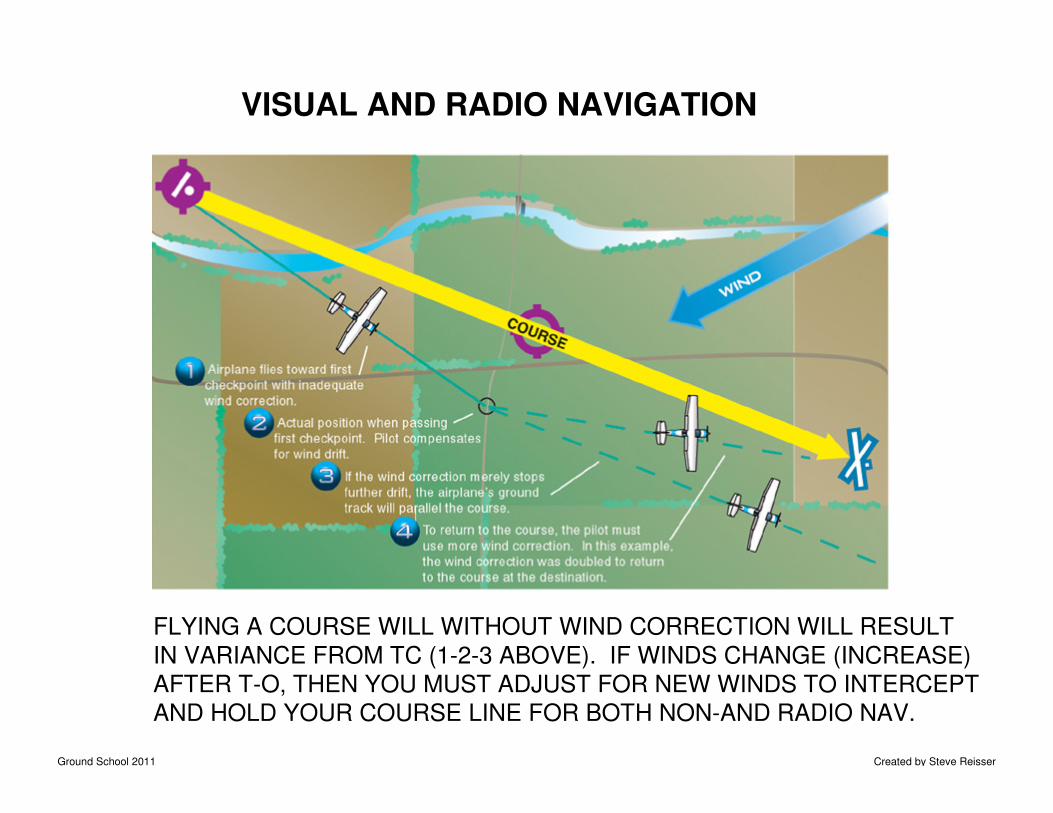
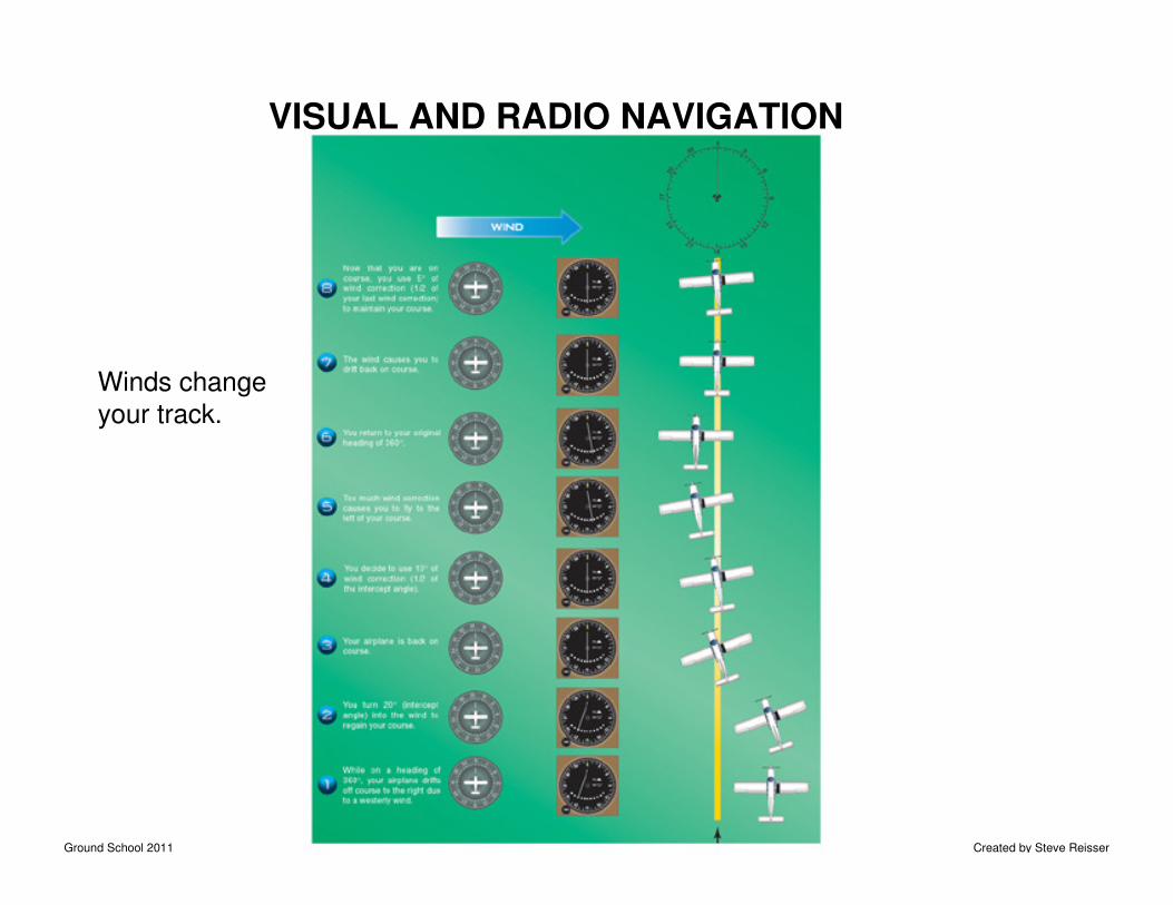
FLYING A COURSE WILL WITHOUT WIND CORRECTION WILL RESULT
IN VARIANCE FROM TC (1-2-3 ABOVE). IF WINDS CHANGE (INCREASE)
AFTER T-O, THEN YOU MUST ADJUST FOR NEW WINDS TO INTERCEPT
AND HOLD YOUR COURSE LINE FOR BOTH NON-AND RADIO NAV.
Ground School 2011 Created by Steve Reisser
VISUAL AND RADIO NAVIGATION
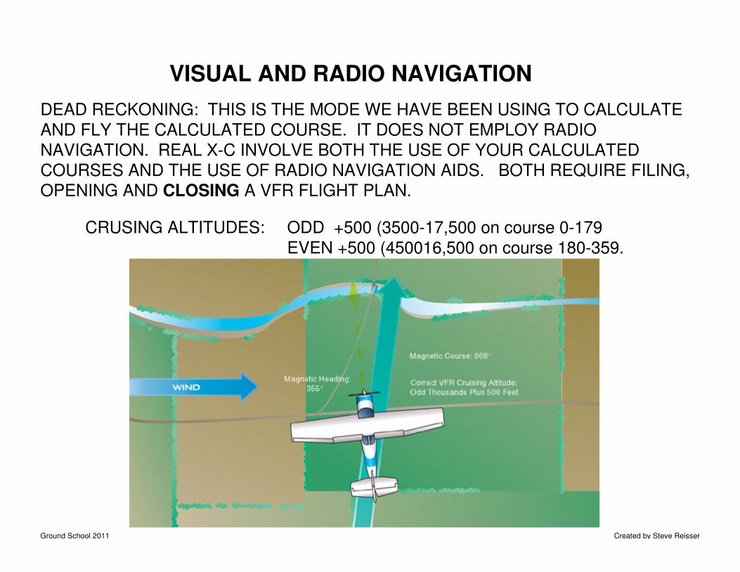
DEAD RECKONING: THIS IS THE MODE WE HAVE BEEN USING TO CALCULATE
AND FLY THE CALCULATED COURSE. IT DOES NOT EMPLOY RADIO
NAVIGATION. REAL X-C INVOLVE BOTH THE USE OF YOUR CALCULATED
COURSES AND THE USE OF RADIO NAVIGATION AIDS. BOTH REQUIRE FILING,
OPENING AND CLOSING A VFR FLIGHT PLAN.
CRUSING ALTITUDES: ODD +500 (3500-17,500 on course 0-179
EVEN +500 (450016,500 on course 180-359.
Ground School 2011 Created by Steve Reisser
VISUAL AND RADIO NAVIGATION
VOR NAVIGATION
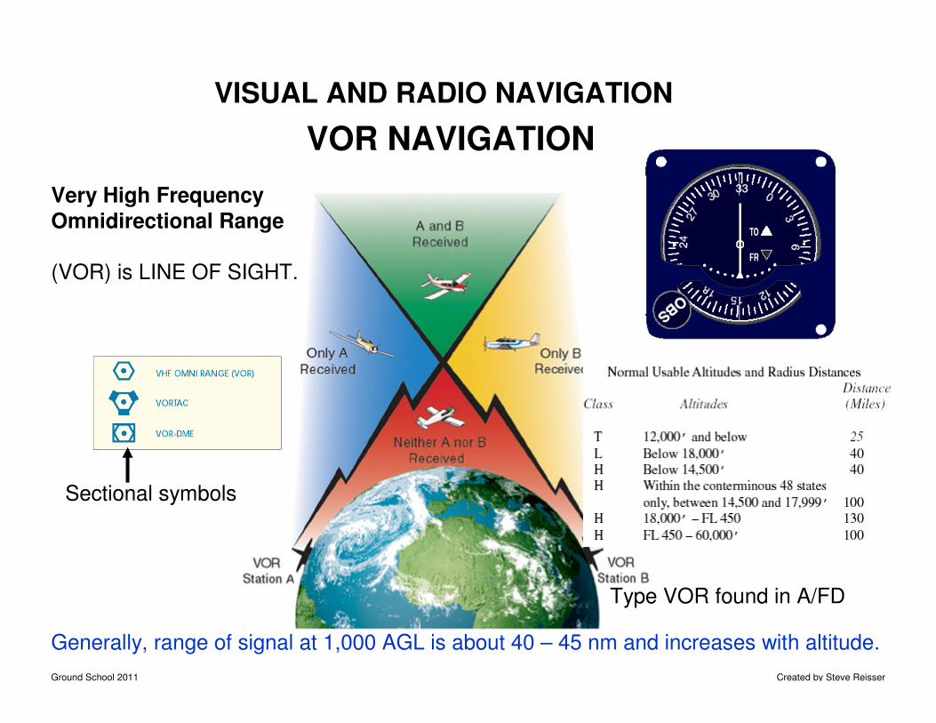
Very High Frequency
Omnidirectional Range
(VOR) is LINE OF SIGHT.
Type VOR found in A/FD
Sectional symbols
Generally, range of signal at 1,000 AGL is about 40 – 45 nm and increases with altitude.
Ground School 2011 Created by Steve Reisser
VISUAL AND RADIO NAVIGATION
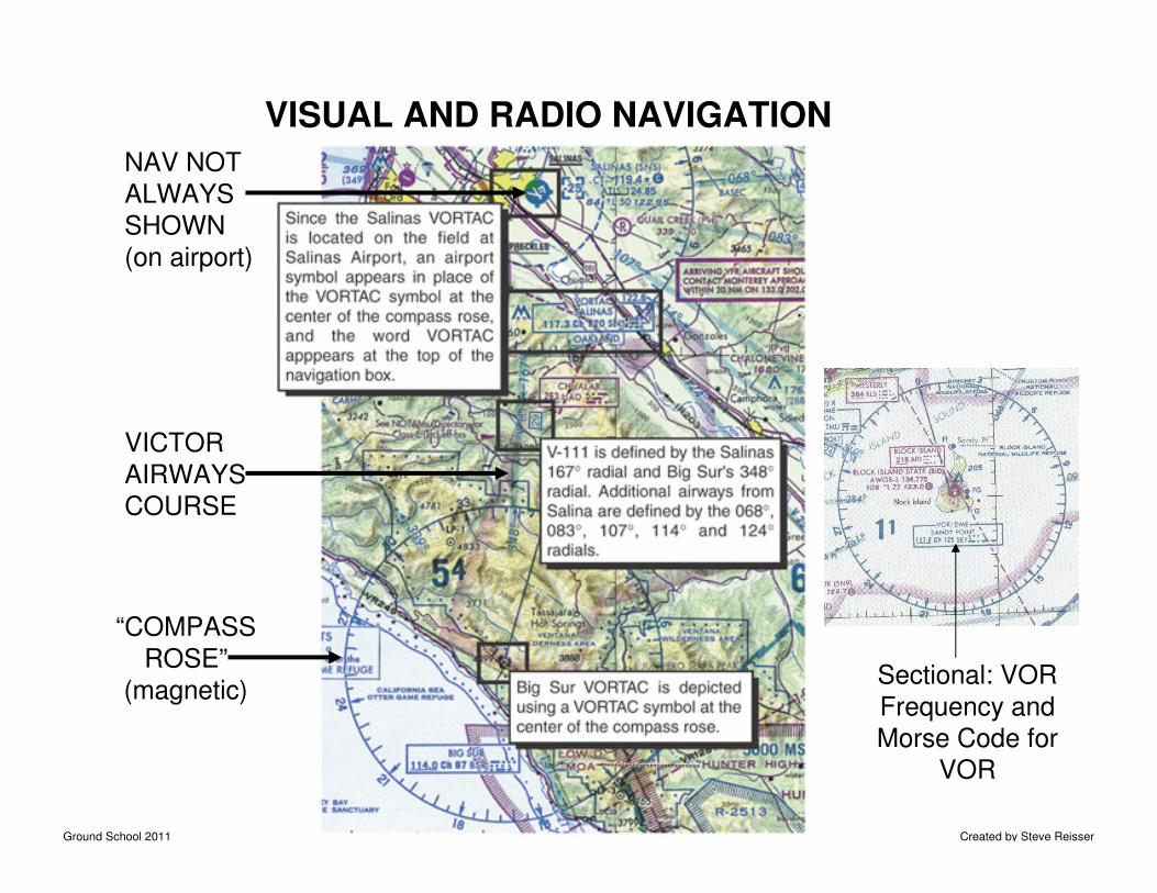
“COMPASS
ROSE”
(magnetic)
VICTOR
AIRWAYS
COURSE
NAV NOT
ALWAYS
SHOWN
(on airport)
Sectional: VOR
Frequency and
Morse Code for
VOR
Ground School 2011 Created by Steve Reisser
VISUAL AND RADIO NAVIGATION
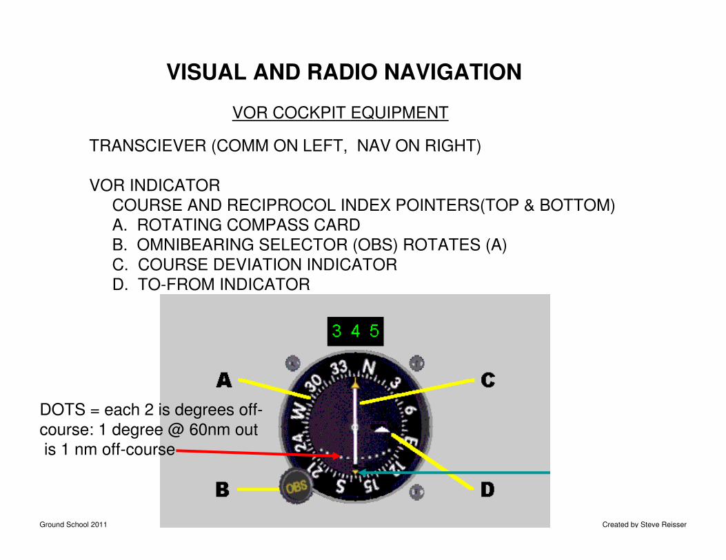
VOR COCKPIT EQUIPMENT
TRANSCIEVER (COMM ON LEFT, NAV ON RIGHT)
VOR INDICATOR
COURSE AND RECIPROCOL INDEX POINTERS(TOP & BOTTOM)
A. ROTATING COMPASS CARD
B. OMNIBEARING SELECTOR (OBS) ROTATES (A)
C. COURSE DEVIATION INDICATOR
D. TO-FROM INDICATOR
DOTS = each 2 is degrees off-
course: 1 degree @ 60nm out
is 1 nm off-course
Ground School 2011 Created by Steve Reisser
VISUAL AND RADIO NAVIGATION
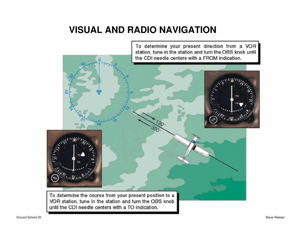
NAVIGATING USING THE VOR
IDENTIFY THE STATION
1. TUNE NAVIGATION RECIEVER TO THE FREQUENCY
2. LISTEN. MORSE CODE GIVEN FOR EACH STATIONVERIFY BY LOOKING AT SECTION TO INSURE THATYOU ARE REALLY ON THE CORRECT FREQUENCY
3. TURN THE OBS TO CHANGE THE ROTATING COMPASSCARD TO EITHER IDENTIFY WHERE YOU ARE OR TO SET THE COURSE YOU WANT TO FLY.
Ground School 2011 Created by Steve Reisser
VISUAL AND RADIO NAVIGATION
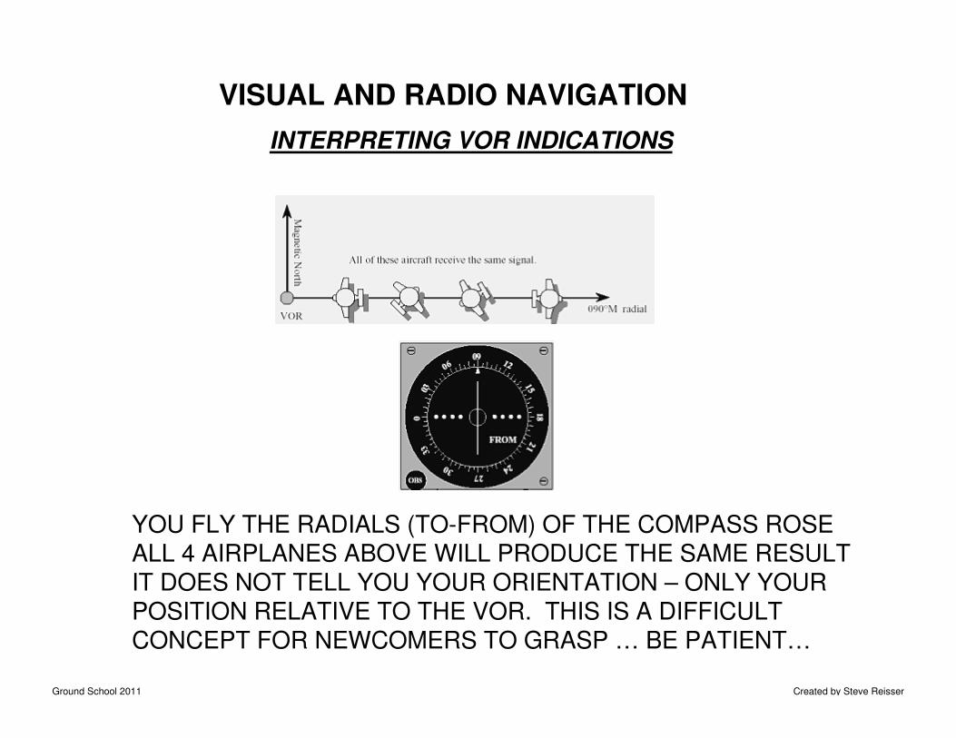
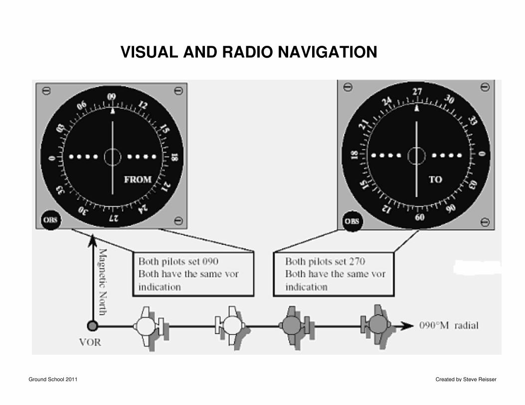
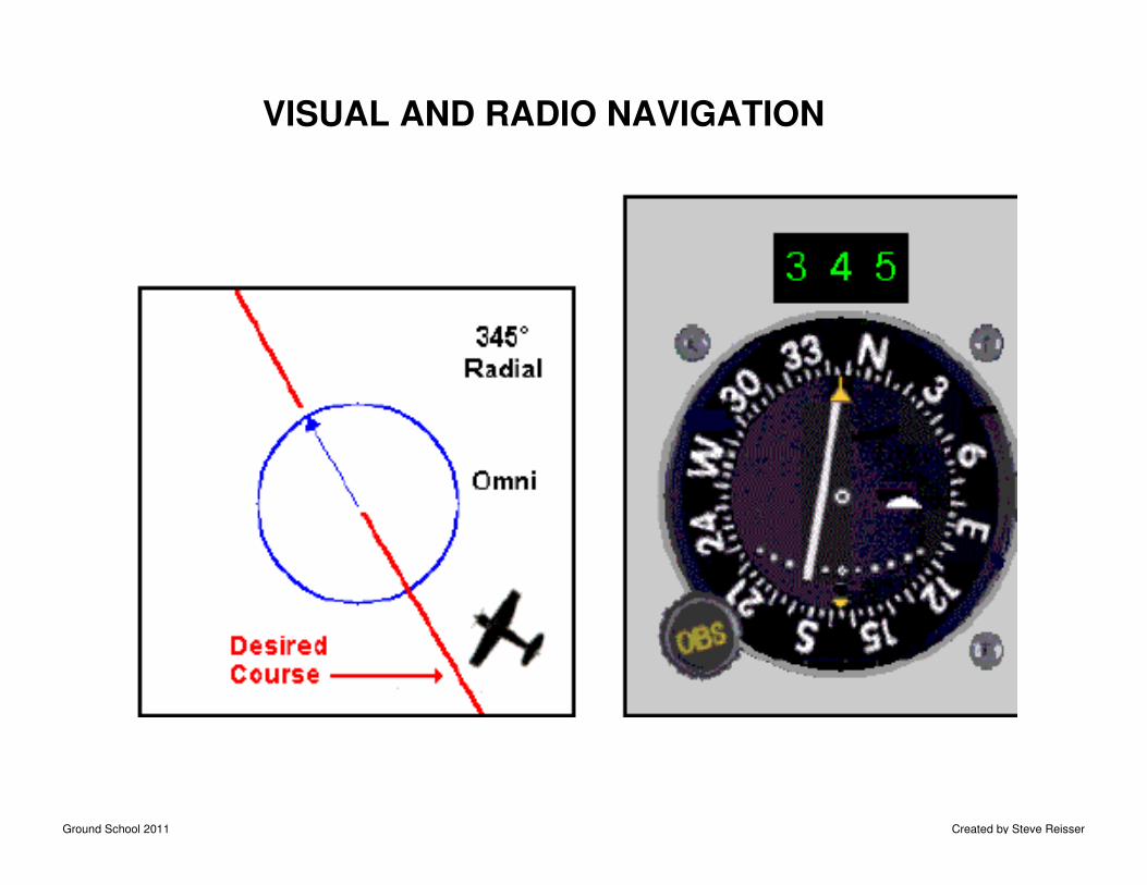
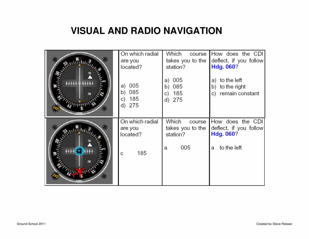
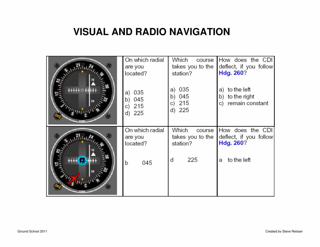
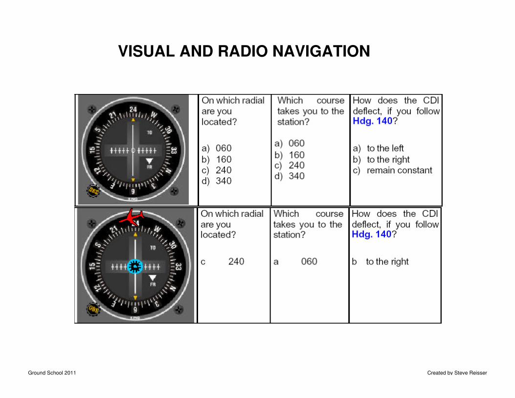
INTERPRETING VOR INDICATIONS
YOU FLY THE RADIALS (TO-FROM) OF THE COMPASS ROSEALL 4 AIRPLANES ABOVE WILL PRODUCE THE SAME RESULTIT DOES NOT TELL YOU YOUR ORIENTATION – ONLY YOURPOSITION RELATIVE TO THE VOR. THIS IS A DIFFICULTCONCEPT FOR NEWCOMERS TO GRASP … BE PATIENT…
Ground School 2011 Created by Steve Reisser
VISUAL AND RADIO NAVIGATION
Ground School 2011 Created by Steve Reisser
VISUAL AND RADIO NAVIGATION
Ground School 2011 Created by Steve Reisser
VISUAL AND RADIO NAVIGATION
Ground School 2011 Created by Steve Reisser
VISUAL AND RADIO NAVIGATION
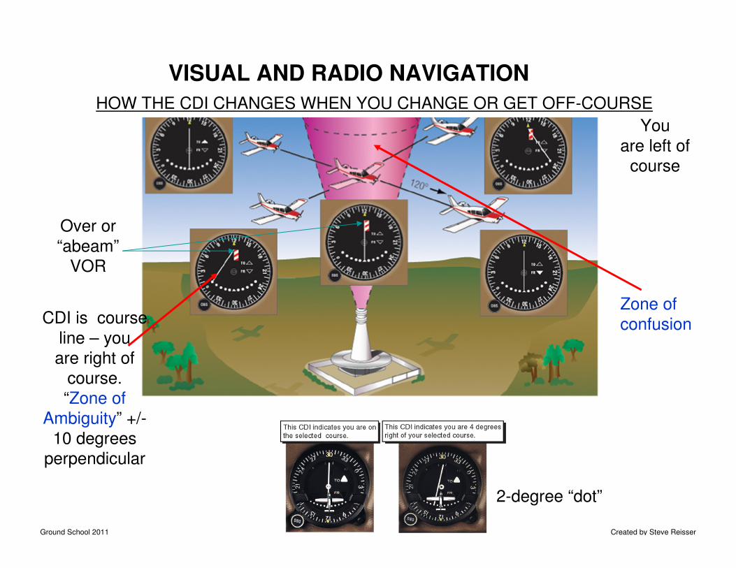
HOW THE CDI CHANGES WHEN YOU CHANGE OR GET OFF-COURSE
Over or
“abeam”
VOR
CDI is course
line – you
are right of
course.
“Zone of
Ambiguity” +/-
10 degrees
perpendicular
You
are left of
course
2-degree “dot”
Zone of
confusion
Ground School 2011 Created by Steve Reisser
VISUAL AND RADIO NAVIGATION
Winds change
your track.
Ground School 2011 Created by Steve Reisser
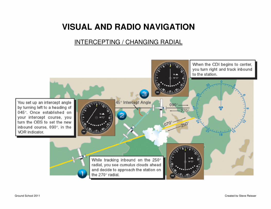
VISUAL AND RADIO NAVIGATION
INTERCEPTING / CHANGING RADIAL
Ground School 2011 Created by Steve Reisser
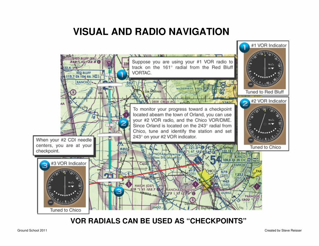
VISUAL AND RADIO NAVIGATION
VOR RADIALS CAN BE USED AS “CHECKPOINTS”
Ground School 2011 Created by Steve Reisser
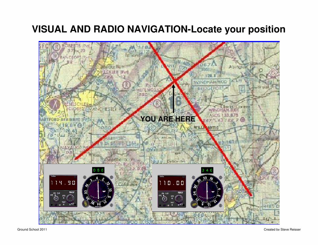
VISUAL AND RADIO NAVIGATION-Locate your position
YOU ARE HERE
Ground School 2011 Created by Steve Reisser
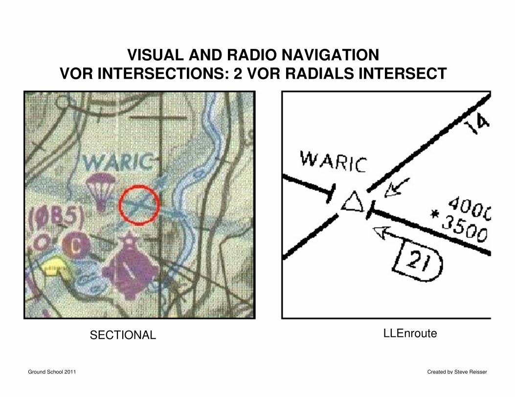
VISUAL AND RADIO NAVIGATIONVOR INTERSECTIONS: 2 VOR RADIALS INTERSECT
SECTIONAL LLEnroute
Ground School 2011 Created by Steve Reisser
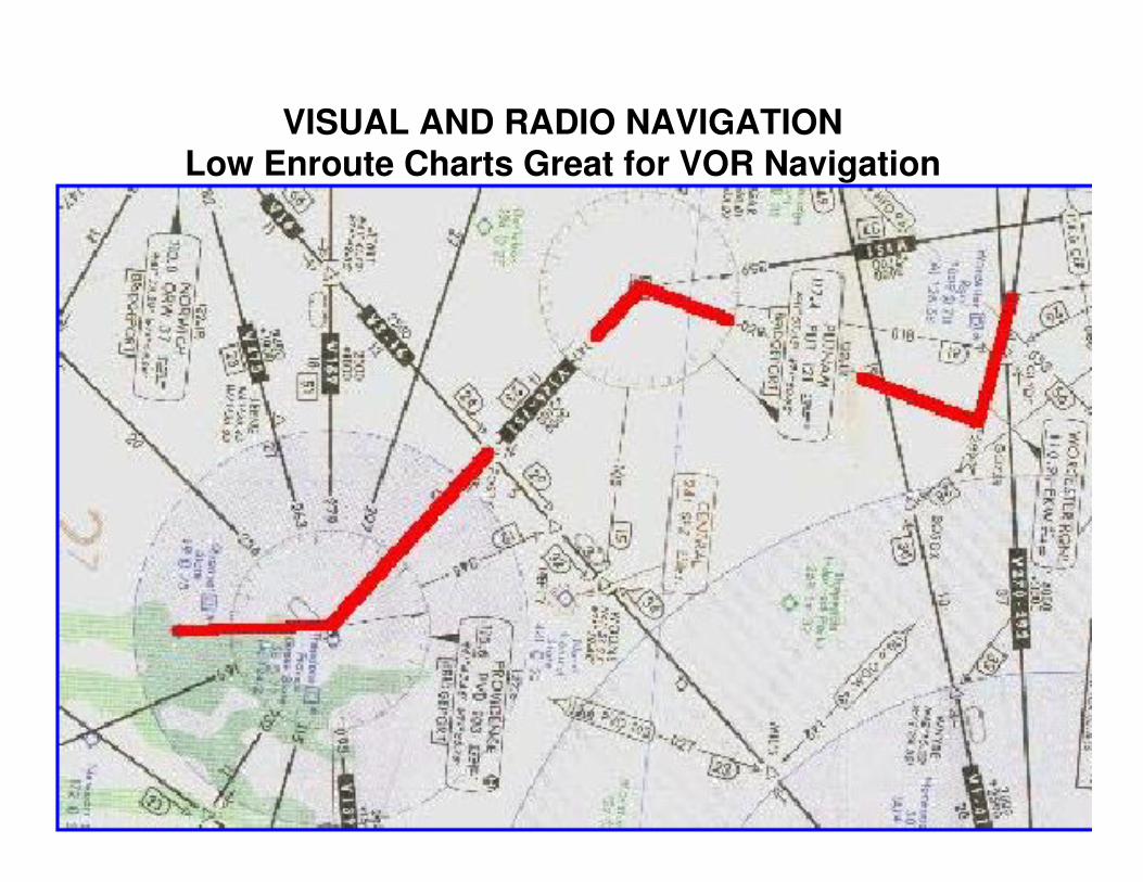
VISUAL AND RADIO NAVIGATIONLow Enroute Charts Great for VOR Navigation
Ground School 2011 Created by Steve Reisser
VISUAL AND RADIO NAVIGATION
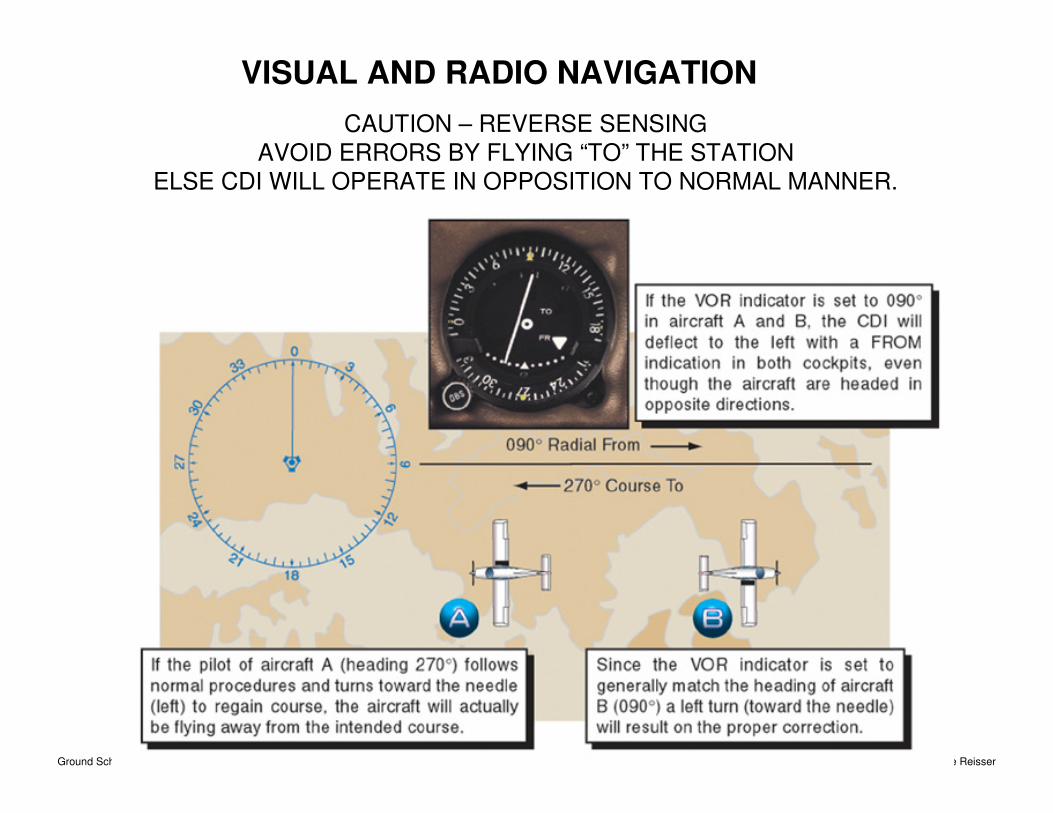
CAUTION – REVERSE SENSING
AVOID ERRORS BY FLYING “TO” THE STATION
ELSE CDI WILL OPERATE IN OPPOSITION TO NORMAL MANNER.
Ground School 2011 Created by Steve Reisser
VISUAL AND RADIO NAVIGATION
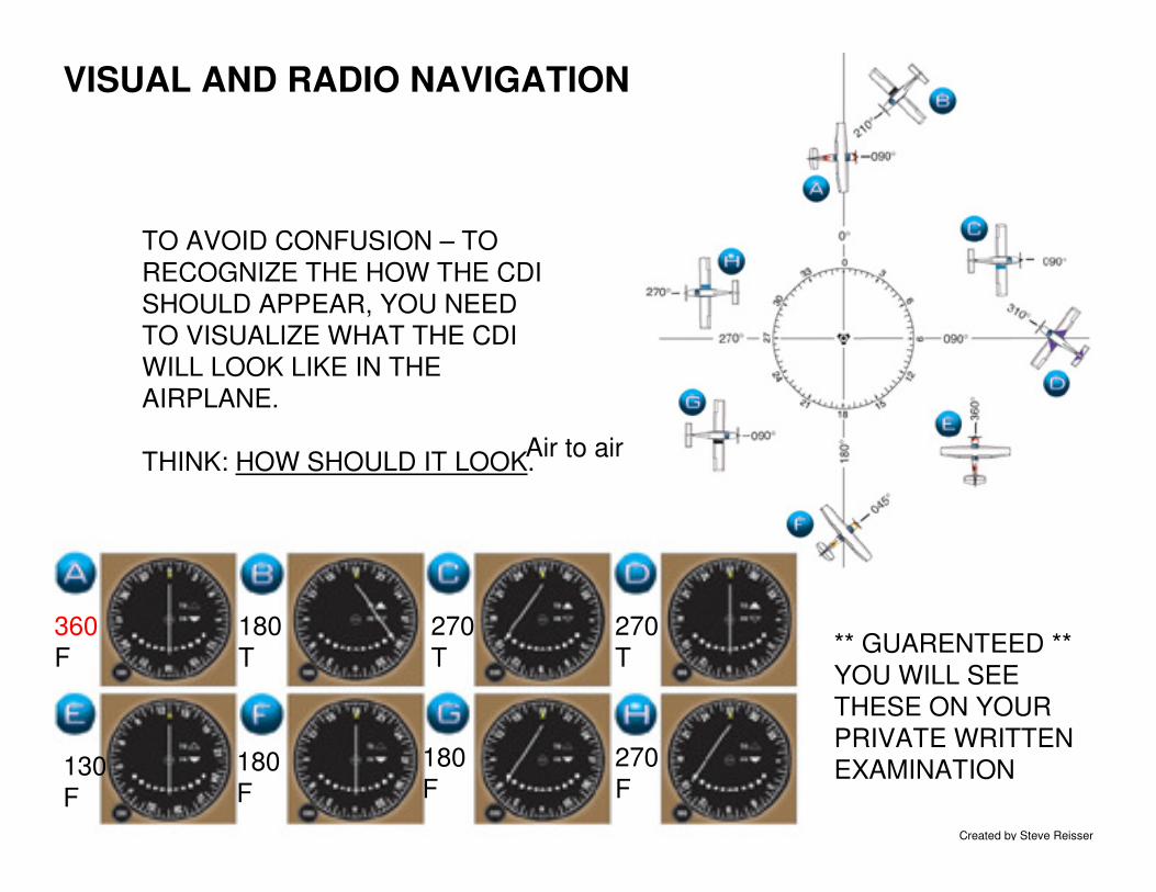
TO AVOID CONFUSION – TO
RECOGNIZE THE HOW THE CDI
SHOULD APPEAR, YOU NEED
TO VISUALIZE WHAT THE CDI
WILL LOOK LIKE IN THE
AIRPLANE.
THINK: HOW SHOULD IT LOOK.
** GUARENTEED **
YOU WILL SEE
THESE ON YOUR
PRIVATE WRITTEN
EXAMINATION
360
F
180
T
270
T
270
T
130
F
180
F
180
F
270
F
Air to air
Ground School 2011 Created by Steve Reisser
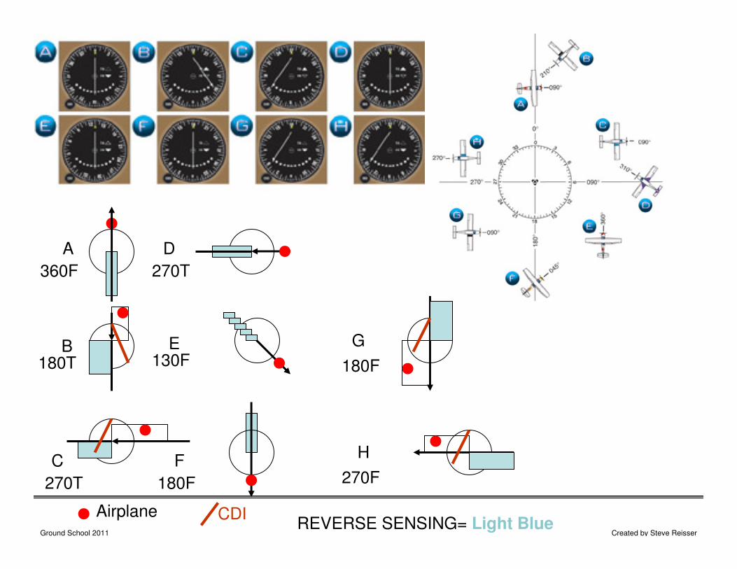
A
B
360F
180T
C
270T
D
270T
E130F
F
180F
G
180F
H
270F
REVERSE SENSING= Light BlueAirplane CDI
Ground School 2011 Created by Steve Reisser
VISUAL AND RADIO NAVIGATION
Ground School 2011 Created by Steve Reisser
VISUAL AND RADIO NAVIGATION
Ground School 2011 Created by Steve Reisser
VISUAL AND RADIO NAVIGATION
Ground School 2011 Created by Steve Reisser
VISUAL AND RADIO NAVIGATION
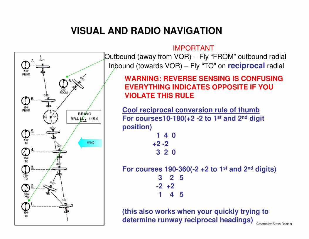
IMPORTANT
Outbound (away from VOR) – Fly “FROM” outbound radial
Inbound (towards VOR) – Fly “TO” on reciprocal radial
Cool reciprocal conversion rule of thumb
For courses10-180(+2 -2 to 1st and 2nd digit
position)
1 4 0
+2 -2
3 2 0
For courses 190-360(-2 +2 to 1st and 2nd digits)
3 2 5-2 +2
1 4 5
(this also works when your quickly trying to determine runway reciprocal headings)
WARNING: REVERSE SENSING IS CONFUSING
EVERYTHING INDICATES OPPOSITE IF YOUVIOLATE THIS RULE
Ground School 2011 Created by Steve Reisser
VISUAL AND RADIO NAVIGATION
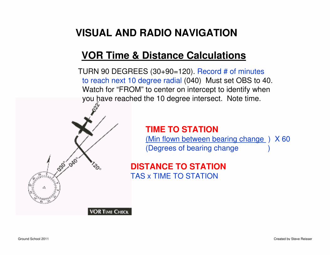
VOR Time & Distance Calculations
TIME TO STATION(Min flown between bearing change ) X 60
(Degrees of bearing change )
DISTANCE TO STATIONTAS x TIME TO STATION
TURN 90 DEGREES (30+90=120). Record # of minutes
to reach next 10 degree radial (040) Must set OBS to 40.
Watch for “FROM” to center on intercept to identify when
you have reached the 10 degree intersect. Note time.
Ground School 2011 Created by Steve Reisser
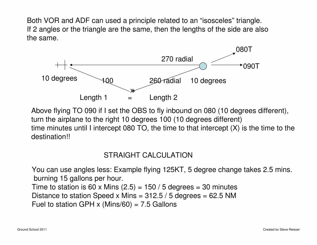
Both VOR and ADF can used a principle related to an “isosceles” triangle.
If 2 angles or the triangle are the same, then the lengths of the side are also
the same.
10 degrees10 degrees
Length 1 Length 2=
Above flying TO 090 if I set the OBS to fly inbound on 080 (10 degrees different),
turn the airplane to the right 10 degrees 100 (10 degrees different)
time minutes until I intercept 080 TO, the time to that intercept (X) is the time to the
destination!!
270 radial
260 radial
x
090T
080T
100
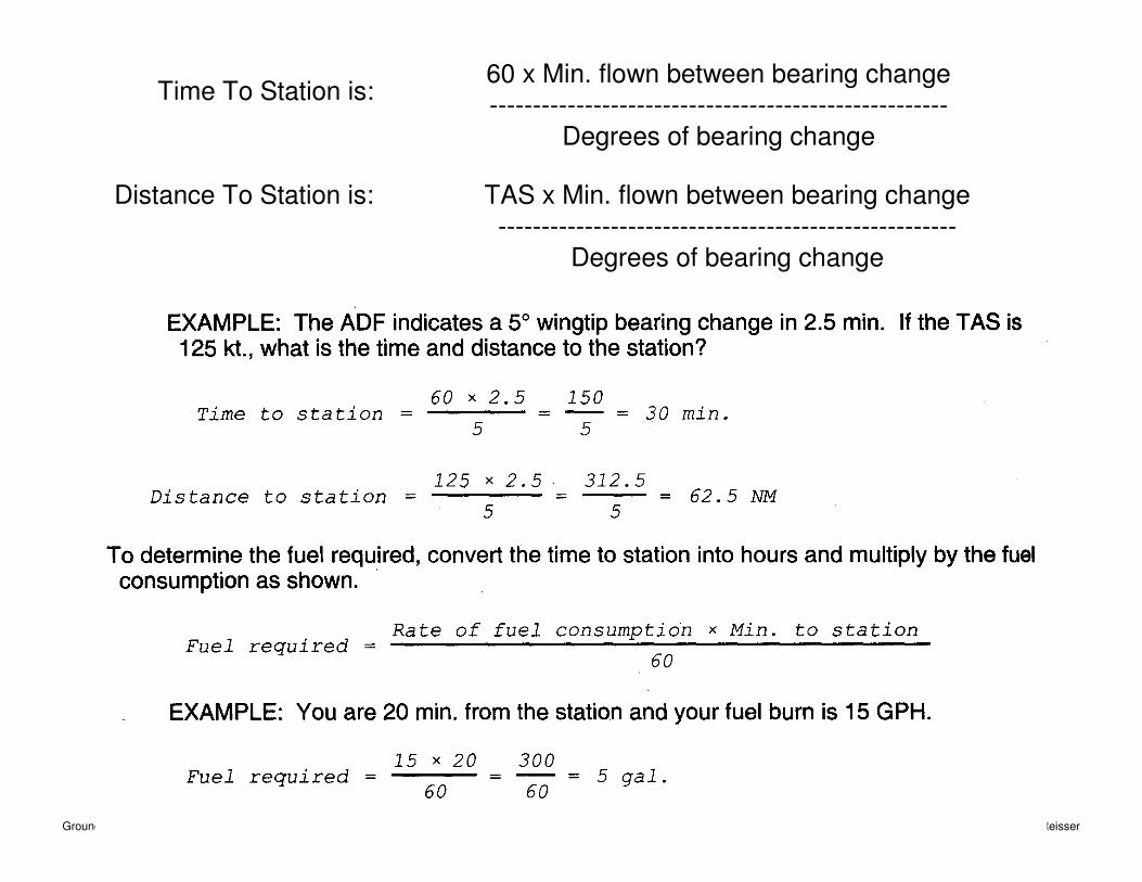
You can use angles less: Example flying 125KT, 5 degree change takes 2.5 mins.
burning 15 gallons per hour.
Time to station is 60 x Mins (2.5) = 150 / 5 degrees = 30 minutes
Distance to station Speed x Mins = 312.5 / 5 degrees = 62.5 NM
Fuel to station GPH x (Mins/60) = 7.5 Gallons
STRAIGHT CALCULATION
Ground School 2011 Created by Steve Reisser
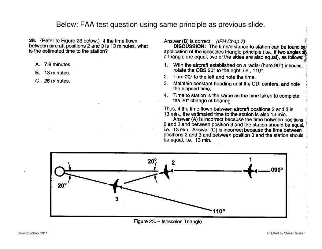
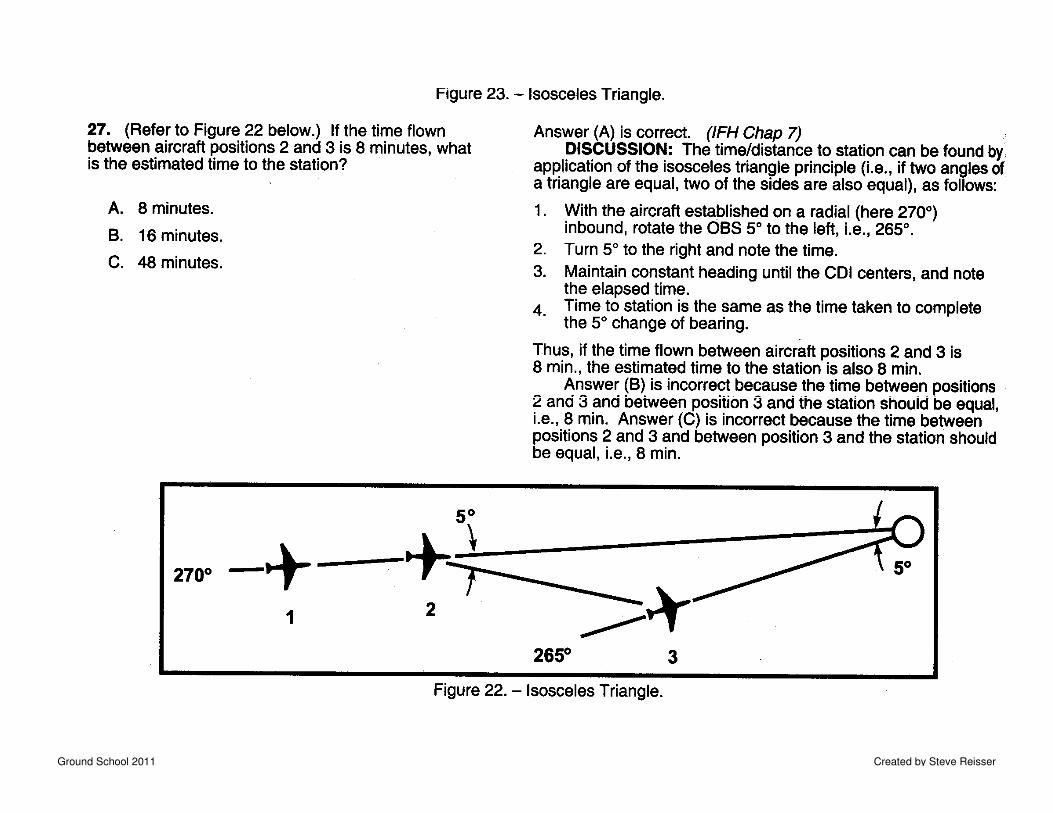
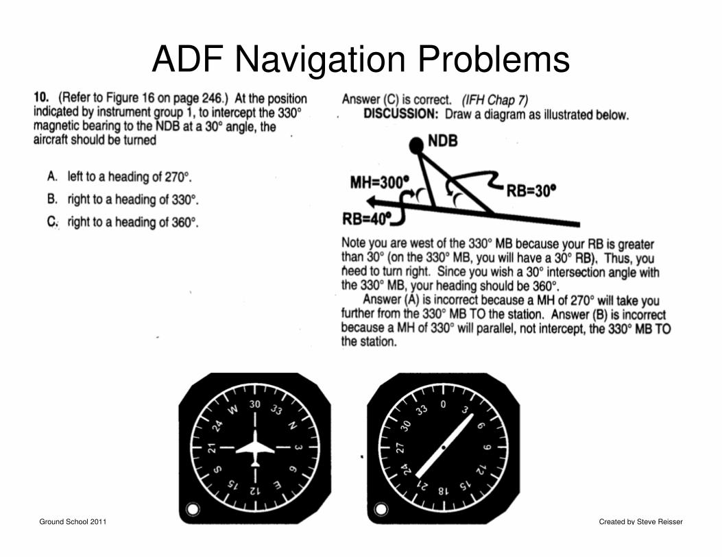
Below: FAA test question using same principle as previous slide.
Ground School 2011 Created by Steve Reisser
Ground School 2011 Created by Steve Reisser
Ground School 2011 Created by Steve Reisser
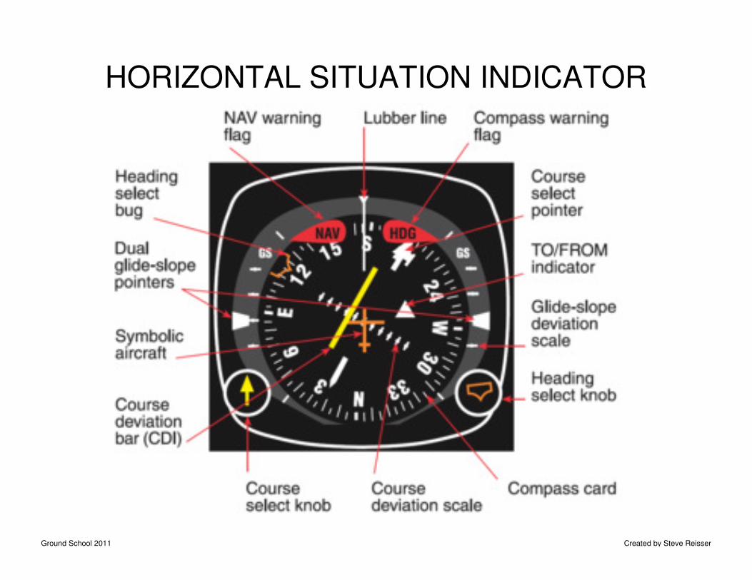
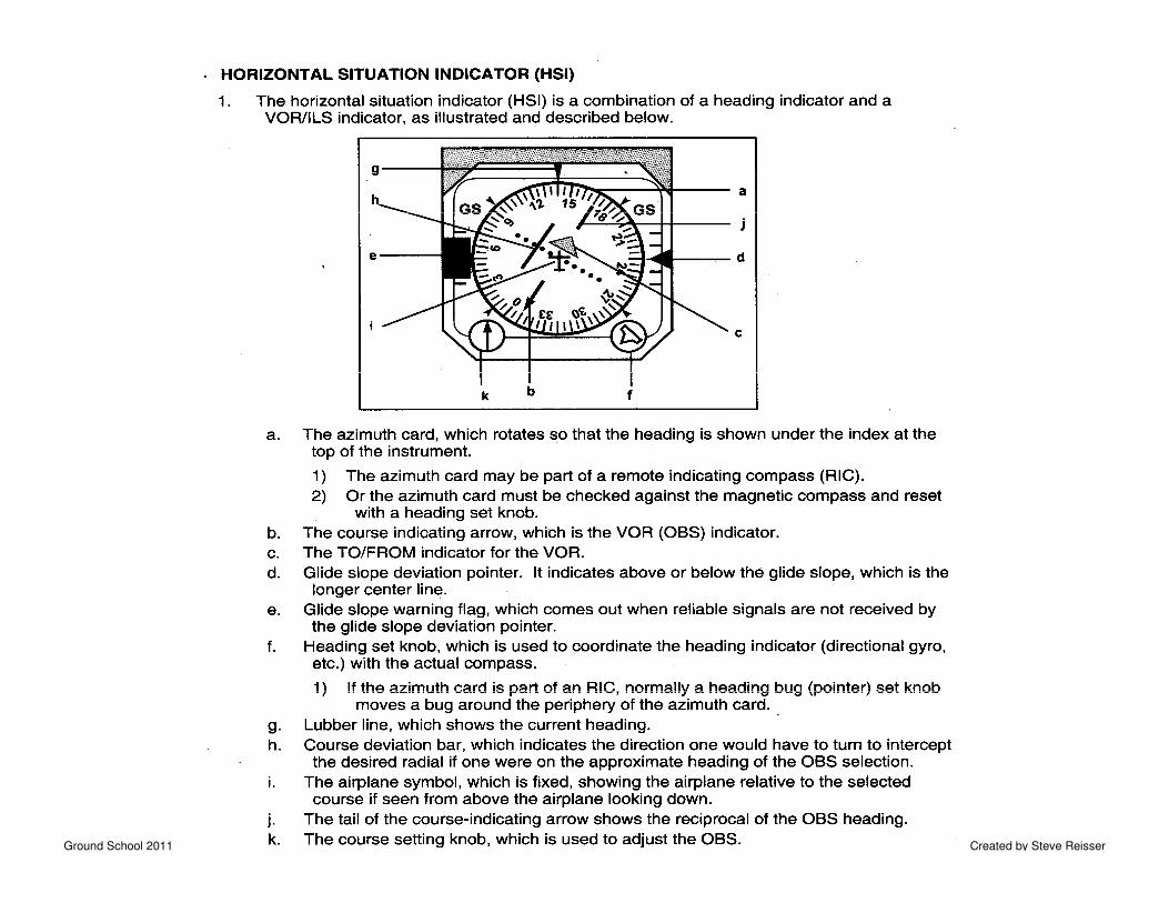
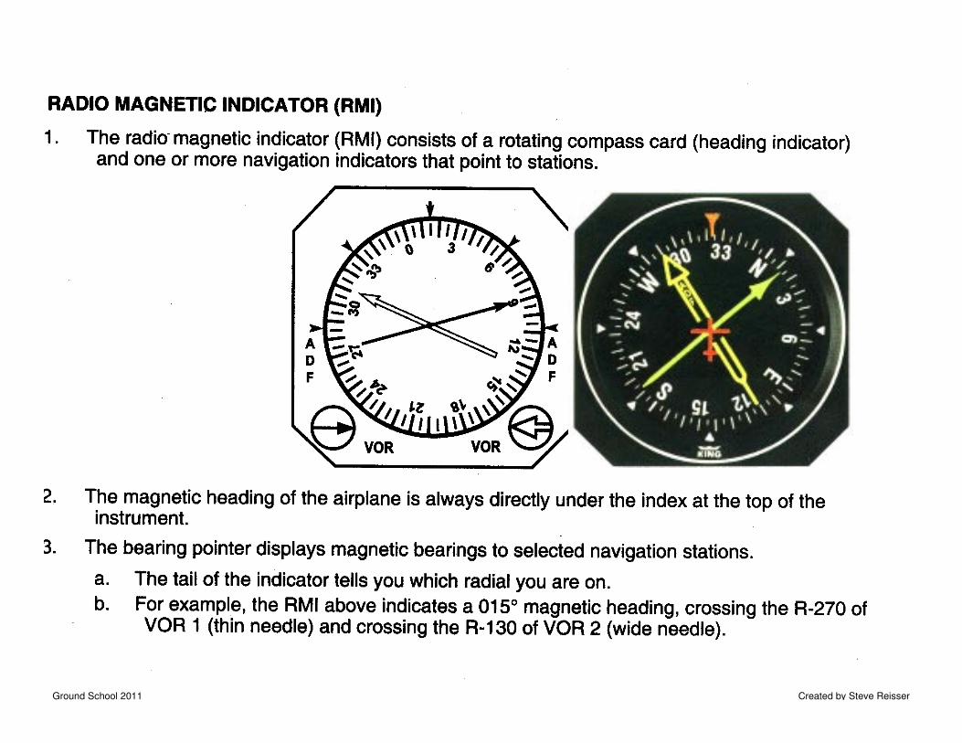
HORIZONTAL SITUATION INDICATOR
Ground School 2011 Created by Steve Reisser
Ground School 2011 Created by Steve Reisser
VISUAL AND RADIO NAVIGATION
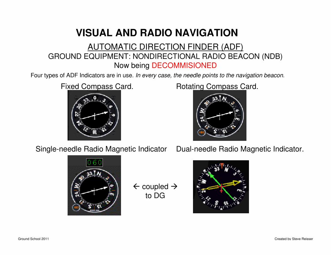
AUTOMATIC DIRECTION FINDER (ADF)GROUND EQUIPMENT: NONDIRECTIONAL RADIO BEACON (NDB)
Now being DECOMMISIONED
Four types of ADF Indicators are in use. In every case, the needle points to the navigation beacon.
Fixed Compass Card. Rotating Compass Card.
Single-needle Radio Magnetic Indicator Dual-needle Radio Magnetic Indicator.
� coupled �
to DG
Ground School 2011 Created by Steve Reisser
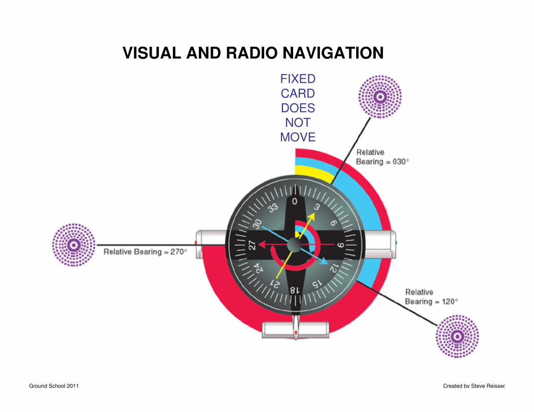
VISUAL AND RADIO NAVIGATION
FIXED
CARD
DOES
NOT
MOVE
Ground School 2011 Created by Steve Reisser
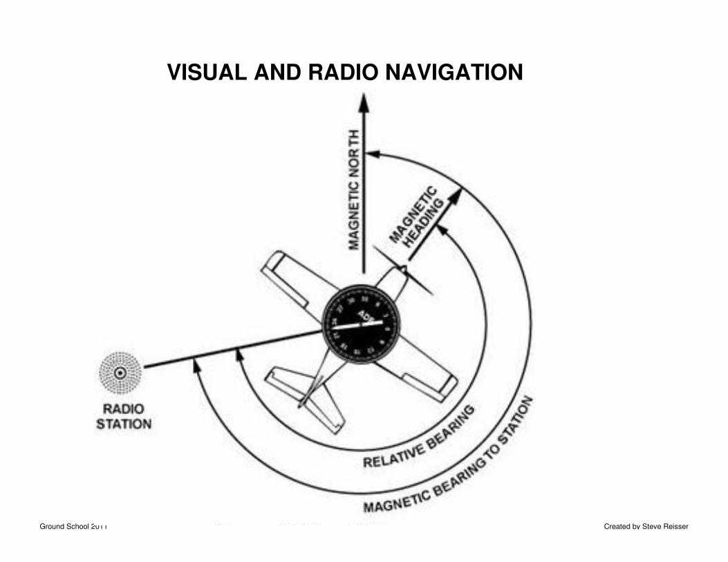
VISUAL AND RADIO NAVIGATION
Ground School 2011 Created by Steve Reisser
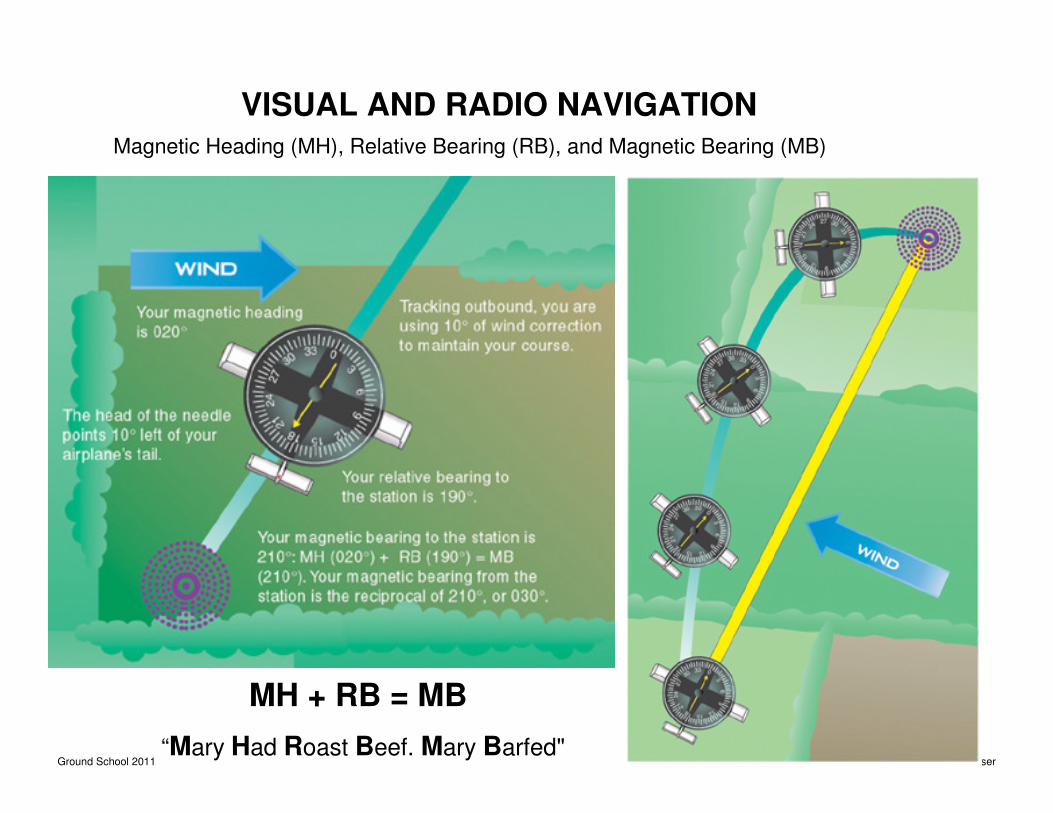
VISUAL AND RADIO NAVIGATIONMagnetic Heading (MH), Relative Bearing (RB), and Magnetic Bearing (MB)
MH + RB = MB
“Mary Had Roast Beef. Mary Barfed"
Ground School 2011 Created by Steve Reisser
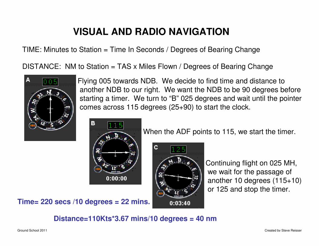
VISUAL AND RADIO NAVIGATION
DISTANCE: NM to Station = TAS x Miles Flown / Degrees of Bearing Change
TIME: Minutes to Station = Time In Seconds / Degrees of Bearing Change
Flying 005 towards NDB. We decide to find time and distance to
another NDB to our right. We want the NDB to be 90 degrees before
starting a timer. We turn to “B” 025 degrees and wait until the pointer
comes across 115 degrees (25+90) to start the clock.
When the ADF points to 115, we start the timer.
Continuing flight on 025 MH,
we wait for the passage of
another 10 degrees (115+10)
or 125 and stop the timer.
Time= 220 secs /10 degrees = 22 mins.
Distance=110Kts*3.67 mins/10 degrees = 40 nm
Ground School 2011 Created by Steve Reisser
Time To Station is:60 x Min. flown between bearing change
-----------------------------------------------------
Degrees of bearing change
Distance To Station is: TAS x Min. flown between bearing change
-----------------------------------------------------
Degrees of bearing change
Ground School 2011 Created by Steve Reisser
VISUAL AND RADIO NAVIGATION
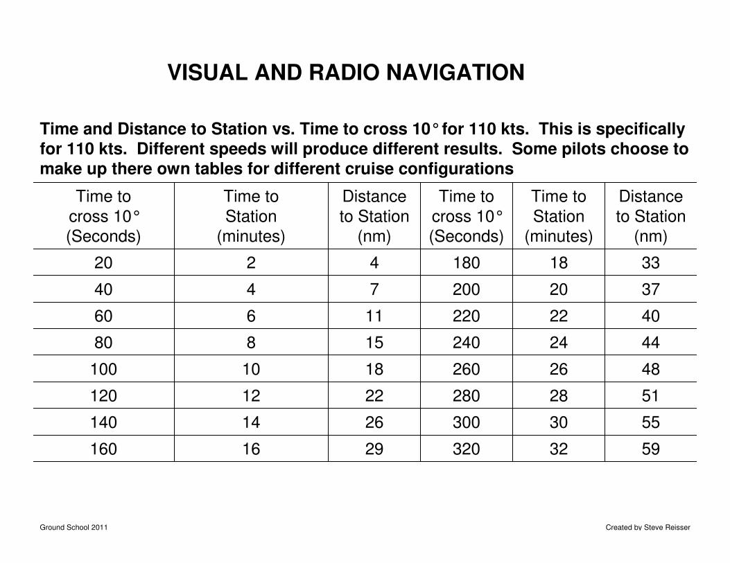
Time and Distance to Station vs. Time to cross 10°for 110 kts. This is specifically
for 110 kts. Different speeds will produce different results. Some pilots choose to
make up there own tables for different cruise configurations
59 32 320 29 16 160
55 30 300 26 14 140
51 28 280 22 12 120
48 26 260 18 10 100
44 24 240 15 8 80
40 22 220 11 6 60
37 20 200 7 4 40
33 18 180 4 2 20
Distance
to Station
(nm)
Time to
Station
(minutes)
Time to
cross 10°
(Seconds)
Distance
to Station
(nm)
Time to
Station
(minutes)
Time to
cross 10°
(Seconds)
Ground School 2011 Created by Steve Reisser
VISUAL AND RADIO NAVIGATION
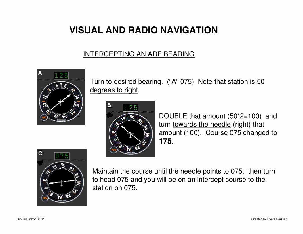
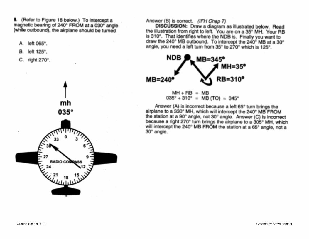
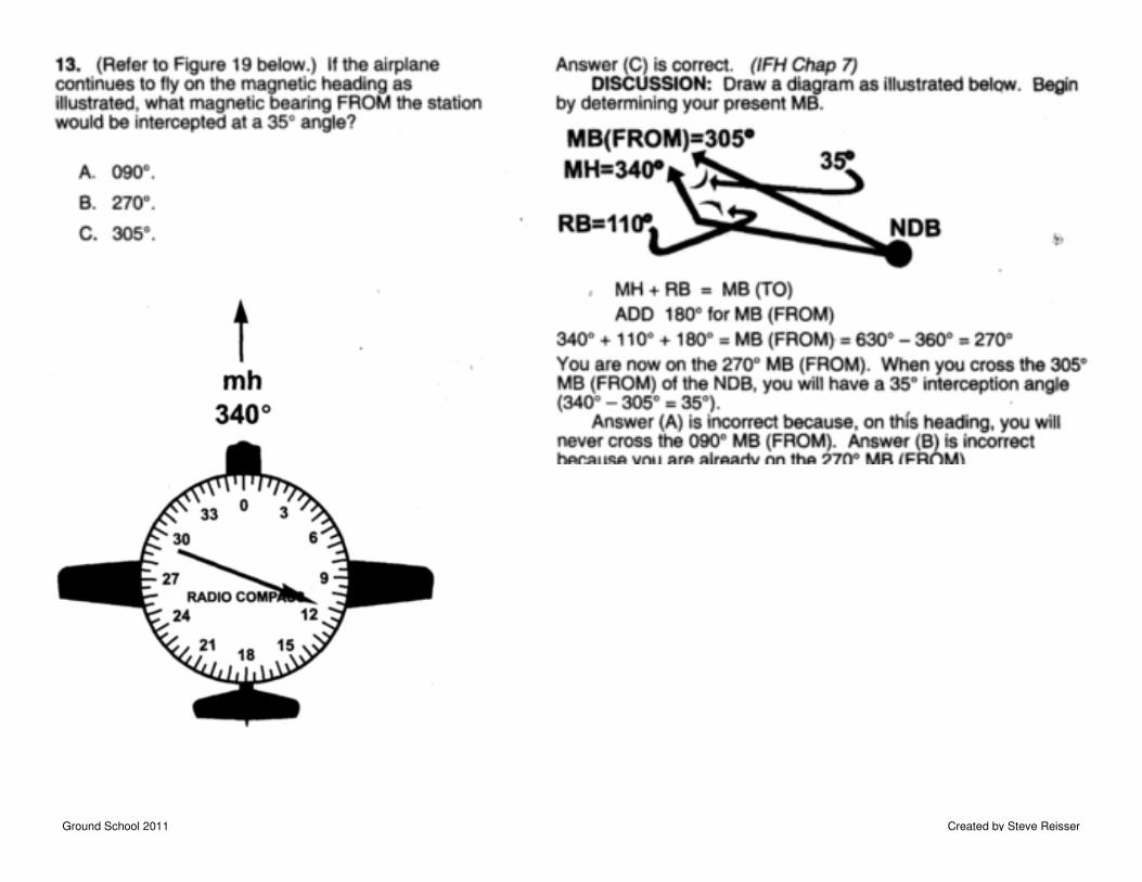
INTERCEPTING AN ADF BEARING
DOUBLE that amount (50*2=100) and
turn towards the needle (right) that
amount (100). Course 075 changed to
175.
Maintain the course until the needle points to 075, then turn
to head 075 and you will be on an intercept course to the
station on 075.
Turn to desired bearing. (“A” 075) Note that station is 50
degrees to right.
Ground School 2011 Created by Steve Reisser
ADF Navigation Problems
Ground School 2011 Created by Steve Reisser
Ground School 2011 Created by Steve Reisser
Ground School 2011 Created by Steve Reisser
VISUAL AND RADIO NAVIGATION
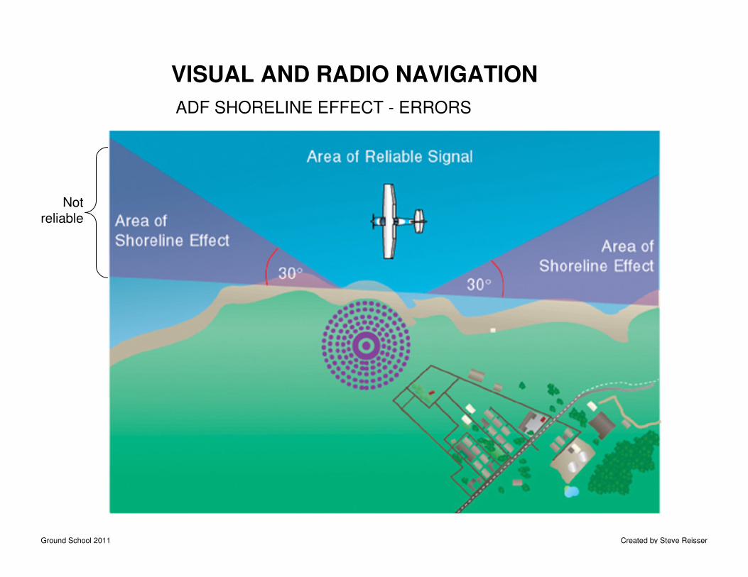
ADF SHORELINE EFFECT - ERRORS
Notreliable
Ground School 2011 Created by Steve Reisser
VISUAL AND RADIO NAVIGATION
NDB/ADF errors
Electrical interference. Radio waves are emitted by the aircraft alternator in the frequency band
of the ADF. An alternator suppressor is fitted to contain those emissions but this component
does not have a long life and it is wise to test the ADF for correct operation during pre-flight
checks. The test is made by selecting a transmitter – which must be a reasonable distance away,
say 30 nm – then watch the ADF needle during the engine run up. If the needle moves as rpm
increase there is electrical interference and probably the alternator suppressor should be
replaced. Magnetos may also interfere with the ADF.
Thunderstorms emit electrical energy in the NDB band and will deflect the ADF needle towards
the storm.
Twilight/night effect. Radio waves arriving at a receiver come both directly from the transmitter
– the ground wave – and indirectly as a wave reflected from the ionosphere – the sky wave. The
sky wave is affected by the daily changes in the ionosphere, read the ionization layers section in
the Aviation Meteorology Guide. Twilight effect is minimal on transmissions at frequencies below
350 kHz.
Terrain and coastal effects. In mountainous areas NDB signals may be reflected by the terrain
which can cause the bearing indications to fluctuate. Some NDBs located in conditions where
mountain effect is troublesome transmit at the higher frequency of 1655 kHz. Ground waves are
refracted when passing across coast lines at low angles and this will affect the indicated bearing
for an aircraft tracking to seaward and following the shore line.
Attitude effects. The indicated bearing will not be accurate whilst the aircraft is banked.
Ground School 2011 Created by Steve Reisser
Ground School 2011 Created by Steve Reisser
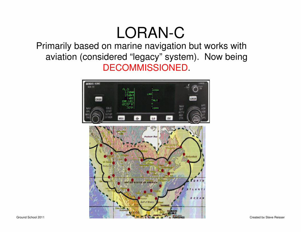
LORAN-CPrimarily based on marine navigation but works with
aviation (considered “legacy” system). Now being
DECOMMISSIONED.
Ground School 2011 Created by Steve Reisser
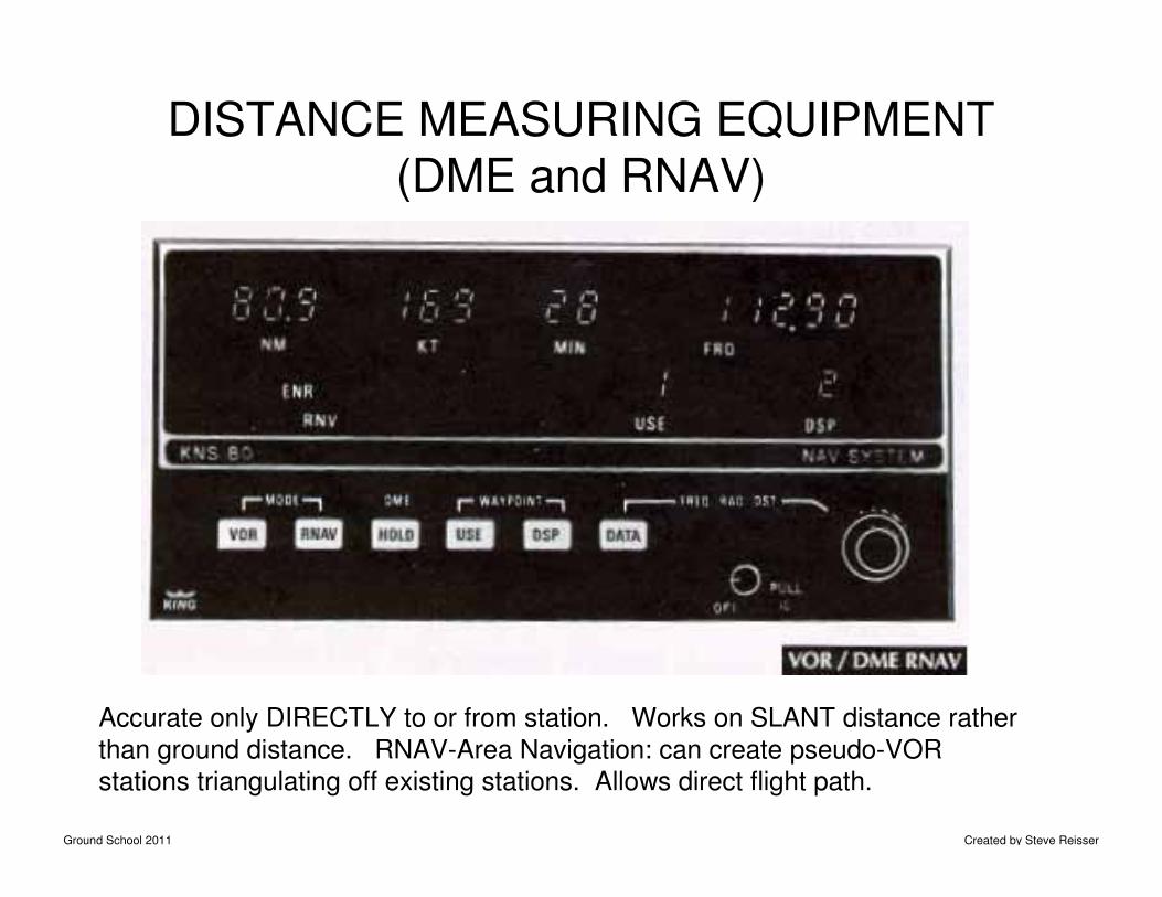
DISTANCE MEASURING EQUIPMENT (DME and RNAV)
Accurate only DIRECTLY to or from station. Works on SLANT distance rather
than ground distance. RNAV-Area Navigation: can create pseudo-VOR
stations triangulating off existing stations. Allows direct flight path.
Ground School 2011 Created by Steve Reisser
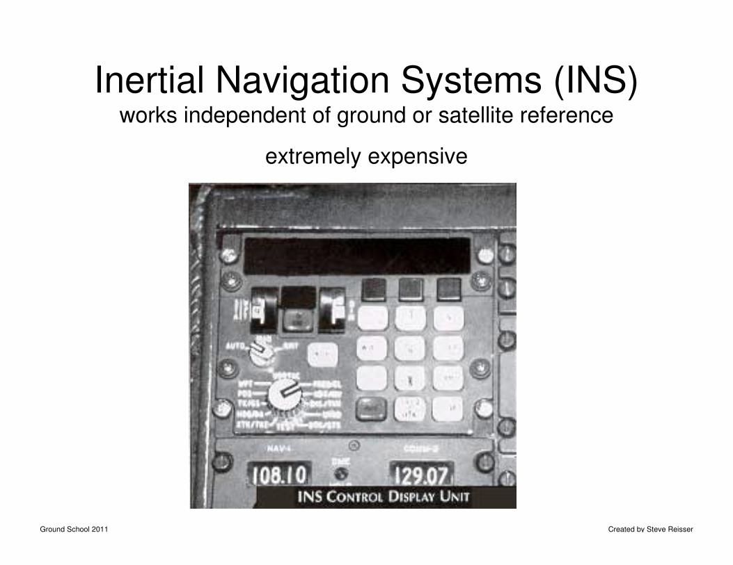
Inertial Navigation Systems (INS)works independent of ground or satellite reference
extremely expensive