vista 128 owners manual
TRANSCRIPT

8/8/2019 Vista 128 Owners Manual
http://slidepdf.com/reader/full/vista-128-owners-manual 1/80
K5895V3 6/04 Rev A
A AA A A AA ADDDDDDDDEEEEEEEEMMMMMMMMCCCCCCCCOOOOOOOO VVVVVVVVIIIIIIIISSSSSSSSTTTTTTTT A AA A A AA A SSSSSSSSEEEEEEEERRRRRRRRIIIIIIIIEEEEEEEESSSSSSSS
VVVVVVVVIIIIIIIISSSSSSSSTTTTTTTT A AA A A AA A--------111111112222222288888888BBBBBBBBPPPPPPPP / // / / // / VVVVVVVVIIIIIIIISSSSSSSSTTTTTTTT A AA A A AA A--------222222225555555500000000BBBBBBBBPPPPPPPP / // / / // /
VVVVVVVVIIIIIIIISSSSSSSSTTTTTTTT A AA A A AA A--------111111112222222288888888SSSSSSSSIIIIIIII A AA A A AA A Commercial BurglaryCommercial BurglaryCommercial BurglaryCommercial Burglary
Partitioned Security SystemPartitioned Security SystemPartitioned Security SystemPartitioned Security System
With Scheduling With Scheduling With Scheduling With Scheduling
User Guide

8/8/2019 Vista 128 Owners Manual
http://slidepdf.com/reader/full/vista-128-owners-manual 2/80
– 2 –
Your Honeywell security system is designed for use with devices manufactured or approved byHoneywell for use with your security system. Your Honeywell security system is not designed foruse with any device that may be attached to your security system's keypad or othercommunicating bus if Honeywell has not approved such device for use with your security system.Use of any such unauthorized device may cause damage or compromise the performance of yoursecurity system and affect the validity of your Honeywell limited warranty. When you purchasedevices that have been manufactured or approved by Honeywell, you acquire the assurance thatthese devices have been thoroughly tested to ensure optimum performance when used with yourHoneywell security system.

8/8/2019 Vista 128 Owners Manual
http://slidepdf.com/reader/full/vista-128-owners-manual 3/80
– 3 –
TABLE OF CONTENTS
SYSTEM OVERVIEW...................................5 General.....................................................5 A Partitioned System.................................5 Panel Linking ............................................6 Zones .......................................................6 Fire Protection ..........................................6 Burglary Protection....................................7 Alarms......................................................7 Memory of Alarm.......................................7 Speed Key (Macros) .................................8 Using Schedules.......................................8 Device Timers...........................................8
To Access Another Partition (GOTOCommand)................................................8 Master Keypad Operation ......................... 9 Self-Help Feature......................................9 Phone Access & Voice ResponseCapability..................................................9
ABOUT THE KEYPADS............................. 10 General...................................................10 The Alpha Keypad ..................................10
FUNCTIONS OF THE KEYPAD.................. 11 ENTRY/EXIT DELAYS ...............................14
General Information ................................14 SECURITY CODES & AUTHORITY
LEVELS..................................................15 General Information ................................15 Duress Code...........................................15 Quick Arming .......................................... 15 Authority Levels ...................................... 16 General Rules on Authority Levels andChanges ................................................. 17 To Exit User Edit Mode ........................... 17 To Add a User.........................................18 To Change a User's Code.......................20 To Delete a User.....................................21
ACCESSING OTHER PARTITIONS...........22 To Access Another Partition....................22
Global Arming......................................... 22 Master Keypad Operation ....................... 23 Common Lobby Operation ...................... 25
How User Codes Affect the CommonLobby......................................................26
ACCESSING OTHER PANELS...................27 Single-Partition Single-Panel Mode..........27 Multi-Partition Multi-Panel Mode ..............28 Multi-Panel View Mode............................29 Priority of Displays for Multi-Partitionand Multi-Panel Modes............................30
CHECKING FOR OPEN ZONES.................31 Using the ✳ READY Key .....................31
DISPLAYING ALL ZONE
DESCRIPTORS ......................................32 Using the ✳ READY Key .....................32
BYPASSING PROTECTION ZONES..........33
Using the 6 BYPASS Key ...................33
Quick Bypass..........................................34 Displaying Bypassed Zones.....................34 Group Bypass .........................................35
ARMING PERIMETER ONLY .....................36
Using the 3 STAY key.........................36
Auto-STAY Arming..................................37 ARMING PERIMETER ONLY .....................38
Using the 7 INSTANT Key ..................38 ARMING ALL PROTECTION......................39
Using the 2 AWAY Key.......................39
ARMING ALL PROTECTION......................40
Using the 4 MAXIMUM Key ................40
QUICK EXIT ...............................................41
Using the # + 9 Keys......................41
DISARMING AND SILENCING ALARMS....42
Using the 1 OFF Key ..........................42
Memory of Alarm.....................................42
USING THE KEYSWITCH..........................43 General ...................................................43 Arming ....................................................43

8/8/2019 Vista 128 Owners Manual
http://slidepdf.com/reader/full/vista-128-owners-manual 4/80
– 4 –
Disarming ............................................... 43 CHIME MODE............................................ 44
Using the 9 Key.................................. 44
VIEWING CENTRAL STATIONMESSAGES ........................................... 45 General Information ................................ 45
PANIC KEYS .............................................46 Using Panic Keys.................................... 46
SPEED KEY (MACROS) ............................ 47 General Information ................................ 47 Defining .................................................. 47 Executing................................................ 48
ACCESS DOOR CONTROL....................... 49
General Information ................................ 49 Executing................................................ 49 USING #70 RELAY MENU MODE.............. 50
General Information ................................ 50 USING SCHEDULES................................. 51
Delaying the Closing Time ...................... 51 Temporary Open/Close Schedules.......... 51 Programming Temporary Schedules....... 52
PROGRAMMING DEVICE TIMERS........... 54 General Information ................................ 54 Randomize Output Device Times............ 56
USING #77 INSTANT ACTIVATIONMODE....................................................57
EVENT LOG PROCEDURES..................... 60 General Information ................................ 60 To Display The Event Log....................... 60
SETTING THE TIME AND DATE ............61 TESTING THE SYSTEM.............................62
Using the 5 TEST Key........................62
Testing Your System...............................62 FIRE ALARM SYSTEM...............................63
In Case Of Fire Alarm..............................63 Silencing A Fire Alarm.............................63 Fire Display Lock.....................................63 Typical Trouble Displays .........................64 Power Failure..........................................65 Recommendations For Smoke AndHeat Detectors........................................66 Recommendations For Proper
Intrusion Protection .................................67 EMERGENCY EVACUATION.....................68 MAINTAINING YOUR SYSTEM..................69
Taking Care of Your System....................69 Replacing Batteries in WirelessSensors ..................................................69 Silencing Low Battery Warning Tonesat the Keypad..........................................70 Routine Care...........................................70
QUICK GUIDE TO SYSTEMFUNCTIONS...........................................71
QUICK GUIDE TO SYSTEMFUNCTIONS...........................................72
SUMMARY OF AUDIBLENOTIFICATION.......................................73
INDEX........................................................78

8/8/2019 Vista 128 Owners Manual
http://slidepdf.com/reader/full/vista-128-owners-manual 5/80
– 5 –
System Overview General
Your Honeywell security system consists of a main control panel, at least one
keypad, and various sensors strategically positioned throughout the
premises. The system offers you three forms of protection: burglary, fire andemergency. The keypad provides full control of system operation.
The system uses microcomputer technology to monitor all protection zones
and system status and provides appropriate information for display on thekeypad(s) used with the system, and initiates appropriate alarms. Your
system may also have been programmed to automatically transmit alarm or
status messages over the phone lines to a central alarm monitoring station.
This manual is designed to help you become comfortable operatingyour system. Each function is explained in step-by-step detail. We
recommend you read the SYSTEM OVERVIEW section to become
familiar with the terminology and the basic features of the system.
NOTE: If you have a Symphony (Advanced User Interface) and/or
TeleSmart connected to your system, refer to the Symphony and
TeleSmart User Guides for operating instructions for those units.
NOTE: All references in this manual for number of zones, number of
user codes, number of access cards, and the event log capacity, use
the VISTA-250BP’s features. The following table lists the differences
between the VISTA-128BP/128SIA and the VISTA-250BP control
panels. Additionally, only the VISTA-128BP/128SIA supports the
capability to have a device duplicate keypad sounds at a remote
location. All other features are identical for both panels.
Feature VISTA-128BP/128SIA VISTA-250BP
Number of Zones 128 250
Number of User Codes 150 250
Number of Access Cards 250 500
Event Log Capacity 512 1000
VistaKey Modules 8 15

8/8/2019 Vista 128 Owners Manual
http://slidepdf.com/reader/full/vista-128-owners-manual 6/80
– 6 –
System Overview (cont ’ d)
A Partitioned System
Simply stated, a partitioned system shares one physical alarm system among
different users, each with their own requirements. For the most part, you as
a user need not know about other users and their structure in the system,but from time to time, you may see display messages that indicate the system
is in use by another user. Do not be concerned, this is normal. Refer to the
ACCESSING OTHER PARTITIONS section for additional information.
Panel Linking
Panel Linking networks up to eight VISTA-128BP/VISTA-250BP control
panels, enabling a user to control the features of all control panels from asingle location. The Panel Linking is ideal for multi-building environments(e.g. a shopping mall, college campus, etc.).
The system provides the following three modes to access other “linked”
control panels:
• Single-Partition, Single-Panel − displays status of a partition on a remotecontrol panel and allows control of that remote control panel.
• Multi-Partition, Multi-Panel Mode − displays status and allows
arming/disarming of multiple partitions at once on a remote control
panel.
• Multi-Panel View Mode − displays status and allows arming/disarming of multiple remote control panels at a time.
Zones
Your system's sensing devices have been assigned to various "zones." Forexample, the sensing device on your Entry/Exit door may have been assigned
to zone 001, sensing devices on windows in the master bedroom to zone 002,and so on. These numbers will appear on the display, along with an alpha
descriptor for that zone (if programmed), when an alarm or trouble condition
occurs.
Fire Protection
The fire protection portion of your security system (if used) is always on and
will sound an alarm if a fire condition is detected. Refer to the FIRE ALARM
SYSTEM section for important information concerning fire protection, smokedetectors and planning emergency exit routes from your house.

8/8/2019 Vista 128 Owners Manual
http://slidepdf.com/reader/full/vista-128-owners-manual 7/80
– 7 –
System Overview (cont ’ d)
Burglary Protection
The burglary protection portion of your system must be turned on or "armed"
before it will sense burglary alarm conditions. Your system provides four
modes of burglary protection: STAY, AWAY, INSTANT and MAXIMUM, andeven allows you to BYPASS selected zones of protection while leaving the
rest of the system armed. The system also provides a CHIME mode, for
alerting users to the opening and closing of doors and windows while the
system is disarmed. Refer to the other sections of this manual for procedures
for using these features.
The following table lists the four different arming modes and the results of
each.
Features For Each Arming Mode ArmingMode
ExitDelay
EntryDelay
PerimeterArmed
AWAY Yes Yes Yes
STAY✳ Yes Yes Yes
INSTANT✳ Yes No Yes
MAXIMUM Yes No Yes✳ The system provides three different STAY and INSTANT arming modes. See
ARMING IN THE STAY MODES and ARMING IN THE INSTANT MODES
sections for details on these modes.
Alarms
When an alarm occurs, both the keypad and external sounders will sound,
and the keypad will display the zone(s) causing the alarm. If your system is
connected to a central monitoring station, an alarm message will also be sent.
To stop the alarm sounding, simply disarm the system.
Memory of Alarm
When an alarm condition occurs, the keypad displays the number(s) of the
zone(s) that caused the problem, and displays the type of alarm (ex. FIRE,
ALARM). It remains displayed until it is cleared by disarming the system
(see DISARMING THE SYSTEM section).
8/8/2019 Vista 128 Owners Manual
http://slidepdf.com/reader/full/vista-128-owners-manual 8/80
– 8 –
System Overview (cont ’ d)
Speed Key (Macros)
The system can store a string of up to 32 keystrokes, which can be activated
anytime by simply pressing the “A, B, C, or D” keys. This feature can be
used to make it easy to perform multiple functions at once (such as going to
another partition to bypass a zone), or it can be used to simplify an everyday,
repeated procedure. Refer to the SPEED KEY section for procedures forusing this feature.
Using Schedules
Your system may have been programmed with schedules for automatically
arming, disarming and activating various devices and/or performing othersystem functions at predetermined times. Users can modify some of theseschedules by manually delaying a closing time, using temporary schedules, or
by programming special user schedules. Refer to the USING SCHEDULES
section at the end of this manual for scheduling related procedures.
Device Timers
The system provides up to 20 "timers" that can be used to control variousdevices, such as lights or appliances. These timers are similar in concept to
the individual appliance timers that might be purchased at a department
store. The devices that can be controlled are programmed into the system by
the installer. Up to 96 of these devices can be programmed. Refer to the
PROGRAMMING DEVICE TIMERS section for procedures.To Access Another Partition (GOTO Command)
Each keypad is assigned a default partition for display purposes, and will
show only that partition's information. But, if the user is authorized, a
keypad in one partition can be used to perform system functions in another
partition, by using the GOTO command. Note that only those partitions
authorized and programmed by the installer can be accessed in this manner.
To GOTO another partition, enter your security code, then press [✳] followed
by the desired partition number (1-8).
The keypad will remain in the new partition until directed to go to another
partition, or until 120 seconds has elapsed with no keypad activity. Entering
your security code, pressing [✳] followed by [0] will return the keypad to its
original partition.
8/8/2019 Vista 128 Owners Manual
http://slidepdf.com/reader/full/vista-128-owners-manual 9/80
– 9 –
System Overview (cont ’ d)
Master Keypad Operation
A "Master" keypad is one on which the status of all 8 partitions is displayed
simultaneously. A user can get more information about a certain partition by
simply entering [✳] + the desired partition number (1-8). To log on to the
"Master" partition (9) using the GOTO command, and to perform any
functions at a Master keypad, a user must have access to all partitions.
Self-Help Feature
Abbreviated user's instructions are built into the system that can be easilyviewed on the alpha keypad's message display screen. This feature will prove
particularly useful if this manual is not conveniently accessible when youneed to perform a system procedure with which you are not familiar.
To view the abbreviated instructions:
Simply press and hold down the function key of interest until the description
starts to appear (about 5 seconds) and then release it. The system must be
“READY TO ARM” to perform this function.
Refer to the FUNCTIONS OF THE KEYPAD section for descriptions of each
key function.
Phone Access & Voice Response Capability
Your system may include a 4285 or 4286 VIP module that will permit you to
access the system via a Touch-tone phone, either on-premises or by call-inwhen away. The phone access feature will enable you to do the following:
• Receive synthesized voice messages over the telephone regarding the
status of the security system.
• Arm and disarm the system and perform most function commands via
the telephone, with voice confirmation provided after each command
entry.
• Control 4204/4204CF relays devices and lights and appliances throughthe #70 Manual Relay Activation mode.
Complete information regarding the use of this feature is provided in a
separate manual entitled PHONE ACCESS USER'S GUIDE, which
accompanies the 4285 or 4286 VIP module.
8/8/2019 Vista 128 Owners Manual
http://slidepdf.com/reader/full/vista-128-owners-manual 10/80

8/8/2019 Vista 128 Owners Manual
http://slidepdf.com/reader/full/vista-128-owners-manual 11/80
– 11 –
Functions Of The Keypad
1 OFF
4 MAX
7 INSTANT
READY
2 AWAY
5 TEST
8 CODE
0
3 STAY
6 BYPASS
#
ARMED
READY
6 1 6 0 - 0 0 - 0 0 2 - V 1
9 CHIME
A
B
C
D
SPEAKER
LCD
DISPLAY
FUNCTION
KEYS
LEDS
IMPORTANT!: When using the keypad to enter codes and commands,sequential key depressions must be made within 3 seconds of oneanother. If 3 seconds elapses without a key depression, the entry isaborted and must be repeated from its beginning.

8/8/2019 Vista 128 Owners Manual
http://slidepdf.com/reader/full/vista-128-owners-manual 12/80
– 12 –
Functions Of The Keypad (cont ’ d)
ALPHA DISPLAY WINDOW: A 2-line,
32-character Liquid Crystal Display (LCD).
Displays protection point identification and
system status, messages, and user
instructions.
1 OFF : Disarms the burglary portion of
the system, silences alarms and audible
trouble indicators, and clears visual alarmtrouble after the problem has been
corrected.
2 AWAY : Completely arms both
perimeter and interior burglary protection
by sensing an intruder's movementsthrough protected interior areas as well as
guarding protected doors, windows, etc.Late arrivals can enter through an entry
delay zone without causing an alarm if the
system is disarmed before the entry delaytime expires.
3 STAY : Arms the perimeter burglary
protection, guarding protected doors,
windows and other perimeter protectionpoints, and sounds an alarm if one is
opened. Allows automatic bypassing of
certain areas, which allows movementwithin your house without causing an
alarm. Late arrivals can enter through an
entry delay zone without causing an alarm
if the system is disarmed before the entry
delay time expires. See ARMING PERIMETER ONLY for a full explanation
of the STAY key.
4 MAXIMUM : Arms in manner similar
to AWAY mode, but eliminates the entrydelay period, thus providing maximum
protection. An alarm will occur
immediately upon opening any protectionpoint, including entry delay zones.
5 TEST : Tests the system and alarm
sounder if disarmed.
6 BYPASS : Removes individual
protection zones from being monitored by
the system. Displays previously bypassedprotection zones.
7 INSTANT : Arms in manner similar
to STAY mode, but turns off the entry
delay period, offering greater security
while inside and not expecting any late
arrivals. An alarm will occur immediately
upon opening any perimeter protectionpoint, including entry delay zones.
8 CODE : Allows the entry of additional
user codes that can be given to other users
of the system.

8/8/2019 Vista 128 Owners Manual
http://slidepdf.com/reader/full/vista-128-owners-manual 13/80
–13 –
Functions Of The Keypad (cont ’ d)
9 CHIME : Turns on & off the CHIME
mode. When on, any entry through aprotected delay or perimeter zone while the
system is disarmed will cause a tone to
sound at the Keypad(s).
✳ READY : When depressed prior to
arming the system, the keypad will display
all open protection zones within the
keypad's home partition. This key is also
used to display all zone descriptors thathave been programmed for your system, by
holding the key down for at least 5 seconds.
# : Permits ARMING of the system
without use of a security code ("Quick
Arm", if programmed).
KEYS 0-9: Used to enter your individual
security access code(s).
LED READY INDICATOR: (GREEN) Lit
indicates system is ready to be armed,
while unlit indicates system not ready.
LED ARMED INDICATOR: (RED) Lit
when the system has been armed (STAY,
AWAY, INSTANT or MAXIMUM).
SPEAKER: Source of audible internal
warning and confirmation sounds, as well
as alarms (see "Summary of AudibleNotifications").
FUNCTION KEYS: These keys can be
used for Speedkey (macros) functions or
panic keys. Refer to the SPEEDKEY(MACROS) and PANIC KEYS sections for
descriptions of these functions.

8/8/2019 Vista 128 Owners Manual
http://slidepdf.com/reader/full/vista-128-owners-manual 14/80
– 14 –
Entry/Exit Delays General Information
Your system has installer-programmed time delays, known as exit delay and
entry delay. Whenever you arm your system, exit delay gives you time to
leave through the designated exit door without setting off an alarm. Exit
delay begins immediately after entering any arming command, and applies to
all modes of arming protection. If programmed, a slow beeping will soundthroughout the exit delay period.
Entry Delay gives you time to disarm the system when you reenter through
the designated entrance door. But the system must be disarmed before the
entry delay period ends, or an alarm will occur. The keypad will beep during
the entry delay period, reminding you to disarm the system. You can alsoarm the system with no entry delay at all by using either INSTANT orMAXIMUM arming modes. These modes provide greater security while on
the premises or while away for extended periods of time. See your installer
for your delay times.
8/8/2019 Vista 128 Owners Manual
http://slidepdf.com/reader/full/vista-128-owners-manual 15/80

8/8/2019 Vista 128 Owners Manual
http://slidepdf.com/reader/full/vista-128-owners-manual 16/80
– 16 –
Security Codes & Authority Levels (cont ’ d)
Authority Levels
Authority levels define the system functions a particular user can perform.
Depending on the authority assigned to you, there are certain system
functions you may be prohibited from performing. In summary, there are sixauthority levels, each having certain system restrictions as shown below.
Level 1 Master: Can perform all system functions in assigned
partitions, and can add, delete or change Manager
and Operator level users. Master codes are added
by the Installer.
Level 2 Manager: Can perform system functions in assigned
partitions, and can add, delete or change Operatorlevel users.
Level 3 Operator A: Can perform system functions in assigned
partitions, but cannot add or delete other users.
Level 4 Operator B: Same as Operator A, except Operator B cannot
bypass zones of protection.
Level 5 Operator C: Can arm the system in assigned partitions, but
cannot disarm the system unless the system wasarmed with this code. This code is typically
assigned to someone who has a need to
arm/disarm the system only at certain times (suchas a baby-sitter).
Level 6 Duress: Can arm and disarm the system, but also sends a
silent panic alarm to the central station, if that
service is connected.
To view your authority level and system capabilities:
1. Enter your code + [✳] + [✳].
2. The keypad will display the partition(s) that you are authorized to
operate, and your user number and authority level in each partition.

8/8/2019 Vista 128 Owners Manual
http://slidepdf.com/reader/full/vista-128-owners-manual 17/80
– 17 –
Security Codes & Authority Levels (cont ’ d)
General Rules on Authority Levels and Changes
• A user may not delete or change the user code of the SAME or HIGHER
authority than which he is assigned.
• A user may only ADD users to a LOWER authority level.
• A user may assign access codes only to those partitions to which the user
adding the code has access. (ex. a user with access to only partition 1
cannot assign codes in partition 2.)
• The only way to assign a user's authority level is by using the "Add A
User" procedure. To change a user's authority level, that user must first
be deleted, then added again.
• A user can only be DELETED or CHANGED from within the partition heis assigned.
• User numbers must be entered as 3-digit entries. Single digit user
numbers must be preceded by a "00" (example, 003, 004, etc.). Security
codes are entered as 4-digit numbers.
• Before assigning a security code, be sure it does not conflict with anyDURESS code.
Note: When adding, changing or deleting users, all other alpha keypads in
that partition will display "User Edit Mode – Please Stand By", and key
depressions (except Panic) at those keypads will be ignored. Panic keydepressions will cause an alarm and terminate user entry.
To Exit User Edit Mode
You can exit any of the user edit modes described on the following pages at
any time by doing the following:
1. Press either ✳ or # , or don't press any key for 10 seconds.
2. System returns to normal mode.

8/8/2019 Vista 128 Owners Manual
http://slidepdf.com/reader/full/vista-128-owners-manual 18/80
– 18 –
Security Codes & Authority Levels (cont ’ d)
To Add a User
IMPORTANT: Temporary users should not be shown how to use any system
function they do not need to know (e.g. bypassing protection zones).
CODE
1. Enter Master or Manager code and press the 8 key.
2. Enter the new user's 3-digit User Number (002-250).
3. Enter 4-digit security code for that user. The following prompts willappear.
ADD NEW USER?
0 = NO , 1 = YES Enter 1 to add a new user code. Entering 0 will
change the existing user's code to the code enteredin step 3. See Changing A User's Code section.
USER NUMBER = 003
ENTER AUTH. LEVEL Enter the authority level, 1-6, for this user within
this partition.1=master 2=manager 3=operator A
4=operator B 5=operator C 6=duress code
GROUP BYPASSING?
0 = NO , 1 = YES
Enter 1 (YES) to allow this user to perform groupbypasses. Enter 0 (NO) this user will not be able to
perform group bypasses.
ACCESS GROUP?
ENTER 0-8
If access schedules have been programmed, this
prompt appears. Enter the user's access group
number (1-8) if this user should have limitedaccess to the system. Enter 0 if no access group
should be assigned.
RF BUTTON ?
0 = NO , 1 = YES This prompt will appear if a 5800 series buttontransmitter has been supplied and has not yet been
assigned to a user. Press 1 if a button transmitter
will be assigned to this user. Otherwise press 0.
ENTER BUTTON ZN #
(001-250) If assigning a button transmitter, this prompt will
appear. Enter the button's zone number (see your
installer for zone number).

8/8/2019 Vista 128 Owners Manual
http://slidepdf.com/reader/full/vista-128-owners-manual 19/80
– 19 –
Security Codes & Authority Levels (cont ’ d)
MULTI-ACCESS ?
0 = NO , 1 = YES If you as a user have access to other partitions, thekeypad will prompt for ability of this new user to
access (GOTO) those partitions. Press 0 (NO) or 1
(YES). If no, the system activates this user code and
exits “Add a User” mode. If yes, the keypad prompts
for the Global Arm option for this user.
GLOBAL ARM ?
0 = NO , 1 = YES Press 1 (YES) if this user will be allowed to try to
arm more than one partition at the same time.
Press 0 if this user will arm only his assigned
partition.
PART.2 - SHOP?
0 = NO , 1 = YES The keypad now prompts for the user’s access to thenext partition (see GOTO command). Again press 0
or 1. If yes, the system will automatically assign a
user number for use in that partition and will
prompt for authority level and global arm optionsfor this user within the partition (see previous
steps).
XMIT USER DATA?
0 = NO , 1 = YES If the user number is from 001-050 this prompt
appears. Answer YES (1) to have the system send
the user’s attributes to all the other control panelsthat are “linked” to this control. If you answer NO
(0), the system displays the following prompt on the
next page.
INDV USER PGM
1 = YES 0 = NO
Answer YES (1) to link to another control panel andmanually enter the user into partition(s) in that
control panel. If you answer NO (0), the system
scrolls through each partition displaying a
summary of the user’s attributes in each partition
(see next prompt).

8/8/2019 Vista 128 Owners Manual
http://slidepdf.com/reader/full/vista-128-owners-manual 20/80
– 20 –
Security Codes & Authority Levels (cont ’ d)
PART. 1 A0* WHSE
USER 003 AUTH=3G.
When all partitions have been displayed, the
keypad will scroll through the partition(s) to which
access has been assigned, and will display the usernumber, authority level and global arm option for
each. The “G” after the authority level indicates
that the global arm feature is active for this user in
the displayed partition. The "*" indicates the
partition from which this user can be changed or
deleted. The "." at the end of the second line
indicates that this user sends open/close reports.Open/close reporting is automatically active for anyusers added by you, if you have open/close reporting
active.
To Change a User's Code
CODE
1. Enter Master or Manager code and press the 8 key + user number
to be changed.
2. Enter the new code for that user.
ADD NEW USER?
0 = NO , 1 = YES The system will recognize that the user number is
already in use and will prompt whether or not this
is a new user. Enter 0 to change the existinguser's code to the code entered in step 3.
USER 002 CHANGED
SUCCESSFULLY
The system will confirm that the change is allowedbased on authorization level, and if so, will put the
new code into effect.
Note that if changing one’s own code, thesystem will prompt for the new code to be re-
entered. This prevents accidentally changing one's
own code.

8/8/2019 Vista 128 Owners Manual
http://slidepdf.com/reader/full/vista-128-owners-manual 21/80
– 21 –
Security Codes & Authority Levels (cont ’ d)
To Delete a User
CODE
1. Enter Master or Manager code and press the 8 key + user number
to be deleted.
2. Enter Master or Manager code first entered.
OK TO DELETE
0 = NO , 1 = YES The system will recognize that the User number
is already in use and will prompt to confirm that
it should be deleted. Press 0 (NO) or 1 (YES).
USER CODE
DELETED If yes, that user's code will be removed from all
partitions to which it was assigned, and allauthorization levels and other information aboutthat user will be deleted. Note that a user can
only be deleted from the partition in which it was
first assigned, and can only be deleted by a userwith a higher authority level. A User's security
code cannot be deleted by oneself.

8/8/2019 Vista 128 Owners Manual
http://slidepdf.com/reader/full/vista-128-owners-manual 22/80
– 22 –
Accessing Other Partitions To Access Another Partition
Each keypad is assigned a default partition for display purposes, and will
show only that partition's information. But, if the user is authorized, a
keypad in one partition can be used to perform system functions in other
partitions by using the GOTO command. Note that only those partitions
authorized and programmed by the installer can be accessed in this manner.
To GOTO another partition:READY
1. Enter your security code, then press T + partition number (0-8).
Entering partition number 0 will return the keypad to its originalpartition.
2. LOG-ON TO AAAAPART. X COMPLETE
The keypad will remain in the new partition
until directed to go to another partition, or
until 2 minutes has elapsed with no keypadactivity.
AAAA = alpha descriptor programmed by the
installer
X = partition number
Global Arming
The Global Arming option may be assigned for use by some users. If Global
Arming was enabled for use with your security code, a keypad prompt
(message) shown below appears after pressing one of the arming functionkeys (STAY, INSTANT, AWAY, MAXIMUM, OFF).
ARM P 1 2 3 4 5 6 7 8HIT 0-8 X X X - - X - -
The prompt displays all the partitions. The user
may only arm/disarm the partitions they are
assigned access to.
To select the partition(s) that are to be armed,
enter the desired number 1-8. An "X" will appear
under that partition. Entering a partition's
number again will delete the “X” and thatpartition will not arm when this prompt is exited.
Pressing 0 will turn all partitions the user is
assigned access to on/off.
When completed, press ✳ to exit. All the partitions
with the “X” will then arm/disarm.

8/8/2019 Vista 128 Owners Manual
http://slidepdf.com/reader/full/vista-128-owners-manual 23/80

8/8/2019 Vista 128 Owners Manual
http://slidepdf.com/reader/full/vista-128-owners-manual 24/80
– 24 –
Accessing Other Partitions (cont ’ d)
The following is an example of what would be displayed for a fault conditionon Zone 002 (Loading Dock Window) on Partition 1 (Warehouse) when
logging on from a keypad on Partition 9:
WHSE DISARMEDHIT ✴ FOR FAULTS
This is the normal display that appears at Partition 1's keypad(s). Pressing ✴
will display:
FAULT 002 LOADINGDOCK WINDOW
Additional zone faults will be displayed one at a time. To display a new
partition's status, press ✴ + [Partition No.]. This will display the status of
the new partition.
The "Armed" LED on a Master keypad will be lit only if all partitions have
been armed successfully. The "Ready" LED will be lit only if all partitions
are "ready to arm."
The sounder on a Master keypad will reflect the sound of the most critical
condition on all of the partitions. The priority of the sounds is as follows:
A. Pulsing fire alarm sounds
B. Steady burglar alarm sounds
C. Trouble soundsThe sounder may be silenced by pressing any key on the Master keypad.

8/8/2019 Vista 128 Owners Manual
http://slidepdf.com/reader/full/vista-128-owners-manual 25/80
– 25 –
Accessing Other Partitions (cont ’ d)
Common Lobby Operation
When an installation consists of a partition that is shared by users of other
partitions in a building, that shared partition may be assigned as a “common
lobby” partition for the system. An example of this might be in a medicalbuilding where there are two doctors and a common entrance area.
This option employs logic for automatic arming and disarming of the common
lobby. Partitions may be set to affect and/or attempt to arm the commonlobby. This will affect the way the lobby will react when arming or disarming
activity occurs in another partition.
Partitions that affect the lobby will cause the following to occur:
a. When the first partition that affects the lobby is disarmed, the lobby willalso be disarmed.
b. The common lobby cannot be armed unless every partition selected to
affects the lobby is armed.
c. Arming the last partition that affects the lobby will not automatically
attempt to arm the lobby.
Partitions set to arm the lobby will cause the following to occur:
a. When the first partition that affects the lobby is disarmed, the lobby will
also be disarmed.
b. The common lobby cannot be armed unless every partition selected to
affects the lobby is armed.
c. Arming the last partition programmed to arm the lobby willautomatically attempt to arm the lobby. If any faults exist in the lobbypartition, or another partition that affects the lobby is disarmed, the
lobby cannot be armed, and the message “UNABLE TO ARM LOBBY
PARTITION” will be displayed.
The following chart summarizes how the common lobby partition will
operate:
Partition AffectsLobby
Partition ArmsLobby
Disarms WhenPartition Disarms
Attempts to ArmWhen Partition
Arms
Can Be Armed ifOther Partitions
Disarmed
NO NO NO NO YES
YES NO YES NO NO
YES YES YES YES NO
NO YES ---ENTRY NOT ALLOWED---

8/8/2019 Vista 128 Owners Manual
http://slidepdf.com/reader/full/vista-128-owners-manual 26/80
– 26 –
Accessing Other Partitions (cont ’ d)
How User Codes Affect the Common Lobby
Codes with “Global” ArmingIf your code is given “global arming” when it is defined, the system displays a
prompt that allows you to pick and choose the partitions to be armed ordisarmed. This eliminates the “automatic” operation of the lobby. Keep in
mind, however, that if attempting to arm all the partitions you have access
to, and another affecting partition is disarmed, (one you do not have access
to) you will not be able to arm the lobby, and the message “UNABLE TO
ARM LOBBY PARTITON” will be displayed.
Codes with “Non-Global” ArmingIf arming with a non-global code, the lobby partition operation will beautomatic, as described in the previous table.
Other Methods of Arming/DisarmingWhen arming or disarming a partition that affects and/or arms the common
lobby in one of the following manners, lobby logic remains active:
• Quick-Arm
• Keyswitch
• Wireless Button
• Wireless Keypad

8/8/2019 Vista 128 Owners Manual
http://slidepdf.com/reader/full/vista-128-owners-manual 27/80
– 27 –
Accessing Other Panels If the user is authorized, a keypad in one panel can be used to performsystem functions in other panels by using one of the panel linking methods
described below. Note that only users 001 to 050 can be authorized to
access other panels.
The system provides three modes to access other “linked” control panels:
• Single-Partition, Single-Panel − displays status of a partition on a remote
control panel and allows control of that remote control panel.
• Multi-Partition, Multi-Panel Mode − displays status and allows
arming/disarming of multiple partitions at once on a remote controlpanel.
•
Multi-Panel View Mode−
displays status and allows arming/disarming of multiple remote control panels at a time.
NOTE: A user will not be able to access or view partitions or panels that
they have not been assigned to.
Single-Partition Single-Panel Mode
To access the single-partition single panel mode, perform the following steps:
1. Enter your security code + # + 8 + 6 .
2. Enter the panel ID# (01-08) of the panel you want to link to.
3. Enter the partition number of the panel.
4. The keypad displays “AWAITING PANEL LINK.” After a few seconds,
the keypad displays the status of the partition along with the panel IDnumber and partition number flashing in the upper right-hand corner.
The user now has full control of the remote control panel. All functions
can be performed except the following:
• Those limited by the user’s authority level.
• The user cannot enter Installer Program mode
• The user cannot execute another panel linking mode.
NOTE: To execute another panel linking mode or to access a different
remote panel, the user must first exit this mode (return to the originalcontrol panel).
5. To exit, enter your security code + # + 8 + 5 . After a few seconds,
the keypad displays the status of the original partition for the keypad. Also, this mode will end in approximately 120 seconds if no keys are
pressed.
8/8/2019 Vista 128 Owners Manual
http://slidepdf.com/reader/full/vista-128-owners-manual 28/80
– 28 –
Accessing Other Panels (cont ’ d)
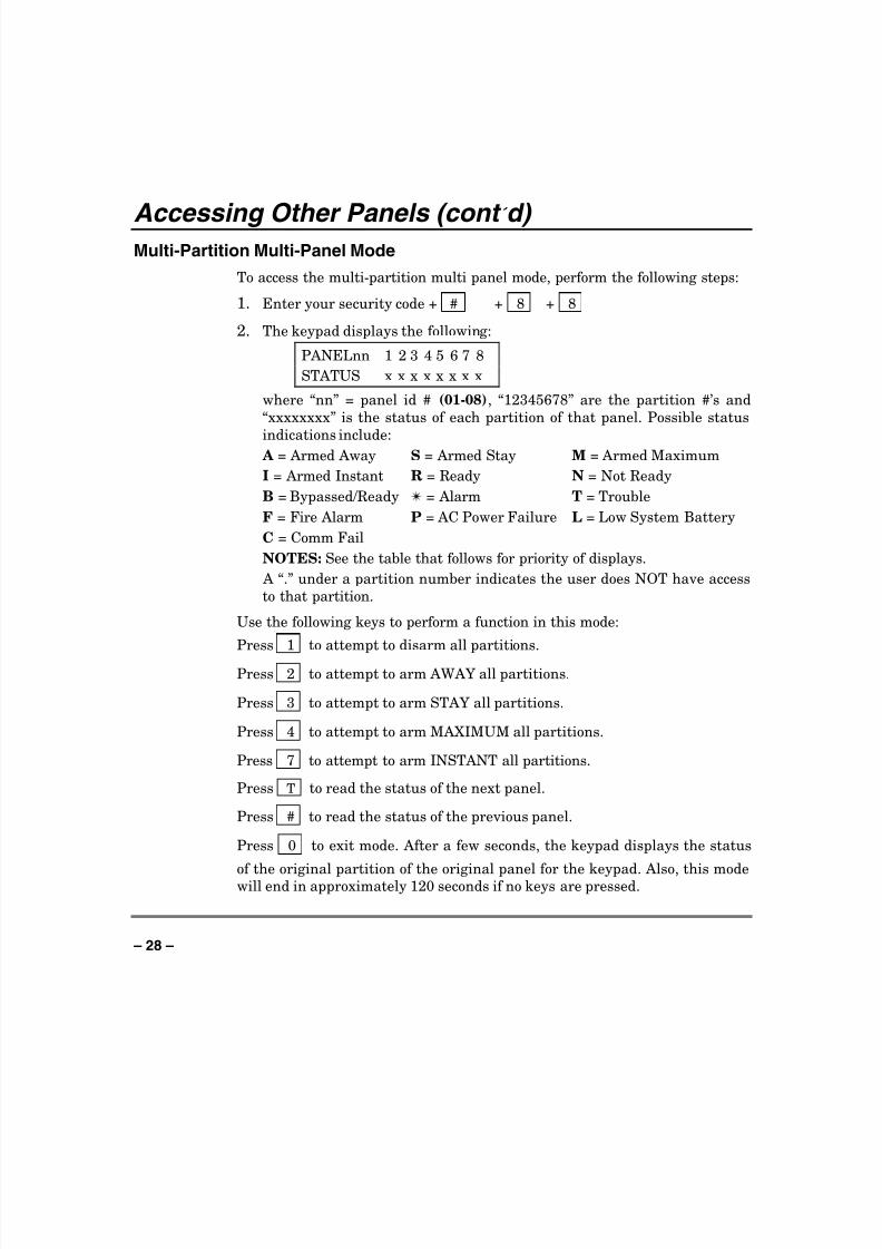
Multi-Partition Multi-Panel Mode
To access the multi-partition multi panel mode, perform the following steps:
1. Enter your security code + # + 8 + 8
2. The keypad displays the following:
PANELnn 1 2 3 4 5 6 7 8
STATUS x x x x x x x x
where “nn” = panel id # (01-08), “12345678” are the partition #’s and
“xxxxxxxx” is the status of each partition of that panel. Possible status
indications include: A = Armed Away S = Armed Stay M = Armed Maximum
I = Armed Instant R = Ready N = Not Ready
B = Bypassed/Ready ✴ = Alarm T = Trouble
F = Fire Alarm P = AC Power Failure L = Low System Battery
C = Comm Fail
NOTES: See the table that follows for priority of displays.
A “.” under a partition number indicates the user does NOT have access
to that partition.
Use the following keys to perform a function in this mode:
Press 1 to attempt to disarm all partitions.
Press 2 to attempt to arm AWAY all partitions.
Press 3 to attempt to arm STAY all partitions.
Press 4 to attempt to arm MAXIMUM all partitions.
Press 7 to attempt to arm INSTANT all partitions.
Press T to read the status of the next panel.
Press # to read the status of the previous panel.
Press 0 to exit mode. After a few seconds, the keypad displays the status
of the original partition of the original panel for the keypad. Also, this modewill end in approximately 120 seconds if no keys are pressed.
8/8/2019 Vista 128 Owners Manual
http://slidepdf.com/reader/full/vista-128-owners-manual 29/80
– 29 –
Accessing Other Panels (cont ’ d)
NOTES:
When performing any of the arming commands, if there are faults in any of the partitions, none of the partitions will arm. These faults must be corrected
or bypassed before attempting to arm.
When performing either a STAY or INSTANT arm command the system
always arm in mode 1 (see page 36 Arming Perimeter Only for a detailedexplanation of the STAY arming modes.
The user cannot execute another panel linking mode. To execute another
panel linking mode or to access a different remote panel, the user must firstexit this mode (return to the original control panel).
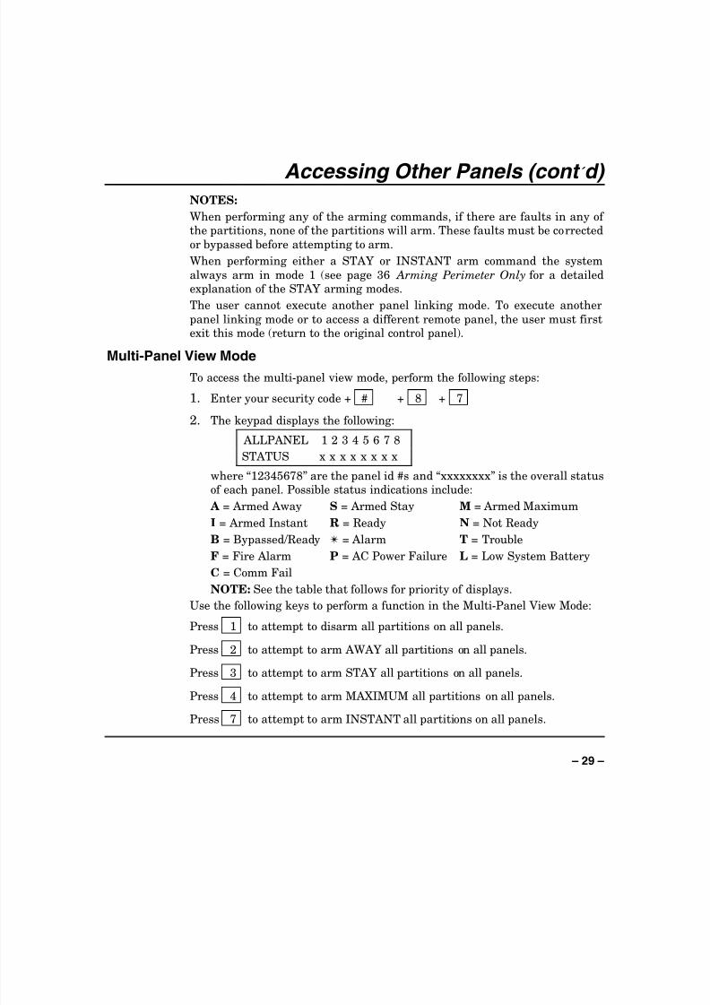
Multi-Panel View Mode
To access the multi-panel view mode, perform the following steps:
1. Enter your security code + # + 8 + 7
2. The keypad displays the following:
ALLPANEL 1 2 3 4 5 6 7 8
STATUS x x x x x x x x
where “12345678” are the panel id #s and “xxxxxxxx” is the overall statusof each panel. Possible status indications include:
A = Armed Away S = Armed Stay M = Armed Maximum
I = Armed Instant R = Ready N = Not ReadyB = Bypassed/Ready ✴ = Alarm T = Trouble
F = Fire Alarm P = AC Power Failure L = Low System Battery
C = Comm Fail
NOTE: See the table that follows for priority of displays.
Use the following keys to perform a function in the Multi-Panel View Mode:
Press 1 to attempt to disarm all partitions on all panels.
Press 2 to attempt to arm AWAY all partitions on all panels.
Press 3 to attempt to arm STAY all partitions on all panels.
Press 4 to attempt to arm MAXIMUM all partitions on all panels.
Press 7 to attempt to arm INSTANT all partitions on all panels.

8/8/2019 Vista 128 Owners Manual
http://slidepdf.com/reader/full/vista-128-owners-manual 30/80
– 30 –
Accessing Other Panels (cont ’ d)
Press 0 to exit mode. After a few seconds, the keypad displays the status
of the original partition of the original panel for the keypad. Also, this mode
will end in approximately 120 seconds if no keys are pressed.
NOTES:
When performing any of the arming commands, if there are faults in any of
the partitions of a panel, the system will not arm that panel, but will arm all
the other partitions of the other panels.
When performing either a STAY or INSTANT arm command the system
always arm in mode 1 (see page 36 Arming Perimeter Only for a detailed
explanation of the STAY arming modes.
The user cannot execute another panel linking mode. To execute anotherpanel linking mode or to access a different remote panel, the user must first
exit this mode (return to the original control panel).
Priority of Displays for Multi-Partition and Multi-Panel Modes
This table shows the priority of displays if more than one of the conditions
exists at the same time.
Priority Description Display
1 Fire Alarm F
2 All Other Alarms ✴
3 AC Loss P
4 Comm Fail C
5 System Low Battery L
6 Trouble T
7 Bypass B
8 Not Ready N
9 Ready R
10 Armed STAY S
11 Armed AWAY A
12 Armed INSTANT I
13 Armed MAXIMUM M

8/8/2019 Vista 128 Owners Manual
http://slidepdf.com/reader/full/vista-128-owners-manual 31/80
– 31 –
Checking For Open Zones Using the ✳✳✳✳ READY Key
Before arming your system, all protected doors, windows and other protection
zones must be closed or bypassed (see BYPASSING section). Otherwise the
keypad will display a "Not Ready" message. Using the READY key willdisplay all zones that are faulted, making it easier for you to secure any open
zones.
To show faulted zones:
DISARMED - PRESS✴ TO SHOW FAULTS
Note: Some keypads light a green LED when
the system is ready. If not lit, the system is not
ready to be armed.
READY
1. Do not enter security code, but simply press ✳ .
FAULT 005 FRONTUPSTAIRS BEDROOM Typical fault display
2. DISARMEDREADY TO ARM
Secure or bypass the zones displayed beforearming the system. The "Ready" message will
be displayed† when all protection zones have
been either closed or bypassed.
†NOTE: All or part of this message may bereplaced by a customized message programmed
by the installer. Bear this in mind whenever
the instructions indicate that the
"DISARMED" or "READY" message will be
displayed.

8/8/2019 Vista 128 Owners Manual
http://slidepdf.com/reader/full/vista-128-owners-manual 32/80
– 32 –
Displaying All Zone Descriptors Using the ✳✳✳✳ READY Key
The Alpha Keypads can also display all the zone descriptors that are
programmed in your system. The abbreviated instructions for the READY
key will appear first, followed by the zone descriptors. Displaying alldescriptors is useful when you need to know the zone number of a particular
zone, as when bypassing zones.
The "Disarmed-Ready to arm" message must be displayed before zone
descriptors can be displayed.
READY
Press the ✳ key and hold down for at least 5 seconds.

8/8/2019 Vista 128 Owners Manual
http://slidepdf.com/reader/full/vista-128-owners-manual 33/80
– 33 –
Bypassing Protection Zones Using the 6 BYPASS Key
This key is used when you want to arm your system with one or more zones
intentionally unprotected. Bypassed zones are unprotected and will not cause
an alarm when violated while your system is armed. All bypasses are
removed when an OFF sequence (security code plus OFF) is performed.
Bypasses are also removed if the arming procedure that follows the bypass
command is not successful.
Note: The system will not allow fire or emergency zones to be
bypassed.
To bypass zones, the system must be disarmed first.
BYPASS
1. Enter your security code and press 6 .
2. Enter zone number(s) for the zones to be bypassed (e.g., 001, 002, 003,etc.).
Important! All single-digit numbers must be preceded by “00” (for
example, enter 001 for zone 1).
3. BYPASS 007 FRONTUPSTAIRS BEDROOM
Typical bypass message
When finished, the keypad will display theword BYPASS along with each bypassed zone
number. Wait for these zones to be displayed
before arming. Arming the system beforebypassed zones are displayed eliminates all
bypasses.
4. DISARMED BYPASSREADY TO ARM
Arm the system as usual when the keypad
displays "ready" to arm message.
8/8/2019 Vista 128 Owners Manual
http://slidepdf.com/reader/full/vista-128-owners-manual 34/80
– 34 –
Bypassing Protection Zones (cont ’ d)
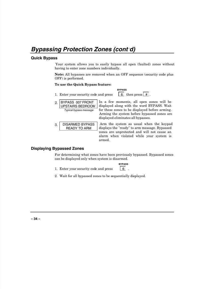
Quick Bypass
Your system allows you to easily bypass all open (faulted) zones without
having to enter zone numbers individually.
Note: All bypasses are removed when an OFF sequence (security code plusOFF) is performed.
To use the Quick Bypass feature:
BYPASS
1. Enter your security code and press 6 then press # .
2. BYPASS 007 FRONTUPSTAIRS BEDROOM
Typical bypass message
In a few moments, all open zones will bedisplayed along with the word BYPASS. Wait
for these zones to be displayed before arming. Arming the system before bypassed zones are
displayed eliminates all bypasses.
3. DISARMED BYPASSREADY TO ARM
Arm the system as usual when the keypaddisplays the "ready" to arm message. Bypassed
zones are unprotected and will not cause an
alarm when violated while your system is
armed.
Displaying Bypassed Zones
For determining what zones have been previously bypassed. Bypassed zones
can be displayed only when system is disarmed.
BYPASS
1. Enter your security code and press 6 .
2. Wait for all bypassed zones to be sequentially displayed.

8/8/2019 Vista 128 Owners Manual
http://slidepdf.com/reader/full/vista-128-owners-manual 35/80
– 35 –
Bypassing Protection Zones (cont ’ d)
Group Bypass
Your system allows you to easily bypass a group of zones without having to
enter zone numbers individually. The system provides up to 15 groups. There
is no limit to the number of zones that may be assigned to any one group.Check with your installer for a list of zones assigned to the group(s).
Notes:
All bypasses are removed when an OFF sequence (security code plus OFF) is
performed.
Users must be assigned the following attributes to perform the group bypassfunction:
• Enabled for group bypassing
• Access to the partition(s) containing the zones being bypassed
• Global arming capability.
To use the Group Bypass feature:BYPASS
1. Enter your security code and press 6 then press ✳ then enter the
group number (01-15).
2. BYPASS 007 FRONTUPSTAIRS BEDROOM
Typical bypass message
In a few moments, all the zones in the group
will be displayed along with the word BYPASS.
Wait for these zones to be displayed before
arming. Arming the system before bypassed
zones are displayed eliminates all bypasses.
3. DISARMED BYPASSREADY TO ARM
Arm the system as usual when the keypad
displays the "ready" to arm message. Bypassed
zones are unprotected and will not cause analarm when violated while your system is
armed.

8/8/2019 Vista 128 Owners Manual
http://slidepdf.com/reader/full/vista-128-owners-manual 36/80
– 36 –
Arming Perimeter Only (With Entry Delay ON)
Using the 3 STAY key
Use this key when you are staying home, but might expect someone to use
the entrance door later.
When armed in STAY mode, the system will sound an alarm if a protected
door or window is opened, but you may otherwise move freely throughout the
premises. Late arrivals can enter through the entrance door without causing
an alarm, but they must disarm the system within the entry delay period or
an alarm will occur.The system provides three STAY modes. STAY mode 1, 2, and 3. STAY
modes 1 and 2, when activated, automatically bypass specific zones assigned
by the your installer to each of the STAY modes. STAY mode 3, whenactivated, automatically bypasses all zones assigned to STAY modes 1 AND
2. Check with your installer for a list of the zones that are bypassed during
each STAY mode.
Close all perimeter windows and doors before arming (see
CHECKING FOR OPEN ZONES section)
STAY
1. Enter your security code and press 3 + 1 for STAY Mode 1.
Enter your security code and press 3 + 2 for STAY Mode 2.
Enter your security code and press 3 + 3 for STAY Mode 3.
NOTE: If none of the zones in a partition are assigned to Stay mode 2, then
when the user enters [User Code] + [3] (STAY), all zones assigned to Stay
mode 1 are automatically bypassed.
2. ARMED ***STAY 1*ZONE BYPASSED
The keypad beeps three times, displays the
armed message, and indicates which STAY
mode (1, 2 or 3).
Note: "ZONE BYPASSED" in this display
simply indicates that some zones of protectionare not armed when using STAY mode.

8/8/2019 Vista 128 Owners Manual
http://slidepdf.com/reader/full/vista-128-owners-manual 37/80
– 37 –
Arming Perimeter Only (With Entry Delay ON) (cont ’ d)
Auto-STAY Arming
Auto-stay allows the system to automatically bypass certain zones if uponarming none of the entry/exit zones are faulted during the exit delay time (no
one exits the premises). The system provides an option to set each burglary
zone for Auto-stay. All zones enabled for auto-stay except for perimeter and
day/night types of zones, has exit delay time when the partition is armed.
Check with your installer for the zones assigned for Auto-STAY.
NOTE:
• Auto-STAY applies to all four arming modes (AWAY, STAY, INSTANTand MAXIMUM).
• Arming the partition AWAY via an RF transmitter overrides the Auto-
stay feature (partition will not bypass zones programmed for auto-stay).

8/8/2019 Vista 128 Owners Manual
http://slidepdf.com/reader/full/vista-128-owners-manual 38/80
– 38 –
Arming Perimeter Only (With Entry Delay OFF)
Using the 7 INSTANT Key
Important: If you are using a Symphony (Advanced User Interface), NIGHT
mode is the same as INSTANT.
Use this key when you are staying home and do not expect anyone to use the
entrance door.
When armed in INSTANT mode, the system will sound an alarm if aprotected door or window is opened, but you may otherwise move freely
throughout the premises. The alarm will also sound immediately if anyoneopens the entrance door.
The system provides three INSTANT modes. INSTANT mode 1, 2, and 3.
INSTANT modes 1 and 2, when activated, automatically bypass specific
zones assigned by your installer to each of the INSTANT modes. INSTANTmode 3, when activated, automatically bypasses all zones assigned to
INSTANT modes 1 AND 2. Check with your installer for a list of the zones
that are bypassed during each INSTANT mode.
Close all perimeter windows and doors before arming (see
CHECKING FOR OPEN ZONES section)
INSTANT
1. Enter your security code and press 7 + 1 for INSTANT Mode 1.
Enter your security code and press 7 + 2 for INSTANT Mode 2.
Enter your security code and press 7 + 3 for INSTANT Mode 3.
NOTE: If none of the zones in a partition are assigned to INSTANT mode 2,
then when the user enters [User Code] + [7] (INSTANT), all zones assigned
to INSTANT mode 1 are automatically bypassed.
2. ARMED *INSTANT1ZONE BYPASSED The keypad beeps three times, displays the
armed message and indicates which INSTANT
mode (1, 2, or 3).
Note: "ZONE BYPASSED" in this display
simply indicates that some zones of protectionare not armed when using INSTANT mode.

8/8/2019 Vista 128 Owners Manual
http://slidepdf.com/reader/full/vista-128-owners-manual 39/80
– 39 –
Arming All Protection (With Entry Delay ON)
Using the 2 AWAY Key
Use this key when no one will be staying on the premises.
When armed in AWAY mode, the system will sound an alarm if a protected
door or window is opened, or if any movement is detected inside the premises.
You may leave through the entrance door during the exit delay period
without causing an alarm. You may also reenter through the entrance door,
but must disarm the system within the entry delay period or an alarm will
occur.Close all perimeter windows and doors before arming (see
CHECKING FOR OPEN ZONES section)
AWAY
1. Enter your security code and press 2 .
2. ARMED **AWAY**YOU MAY EXIT NOW The keypad will beep twice and will display the
armed message.
Note: The "YOU MAY EXIT NOW" portion of
the message disappears when exit delayexpires.

8/8/2019 Vista 128 Owners Manual
http://slidepdf.com/reader/full/vista-128-owners-manual 40/80
– 40 –
Arming All Protection (With Entry Delay OFF)
Using the 4 MAXIMUM Key
Use this key when the premises will be vacant for extended periods of time
such as vacations, etc., or when no one will be moving through protected
interior areas.
When armed in MAXIMUM mode, the system will sound an alarm if a
protected door or window is opened, or if any movement is detected inside the
premises. You may leave through the entrance door during the exit delay
period without causing an alarm, but an alarm will be sounded as soon assomeone reenters.
Close all perimeter windows and doors before arming (see
CHECKING FOR OPEN ZONES section).
MAXIMUM
1. Enter your security code and press 4 .
2. ARMED *MAXIMUM*YOU MAY EXIT NOW The keypad will beep twice and will display the
armed message.
Note: The "YOU MAY EXIT NOW" portion of the message disappears when exit delay
expires.

8/8/2019 Vista 128 Owners Manual
http://slidepdf.com/reader/full/vista-128-owners-manual 41/80
– 41 –
Quick Exit Using the # + 9 Keys
The Quick Exit feature allows you to exit the armed partition without having
to disarm and then rearm the partition.
To Quick Exit the premises:
1. Press the # key and then press the 9 key.
2. The system will sound the exit beeps, if enabled, and will give you the
programmed exit delay time to leave the premises.

8/8/2019 Vista 128 Owners Manual
http://slidepdf.com/reader/full/vista-128-owners-manual 42/80
– 42 –
Disarming And Silencing Alarms Using the 1 OFF Key
The OFF key is used to disarm the system and to silence alarm and trouble
sounds. See "SUMMARY OF AUDIBLE NOTIFICATION" section for
information which will help you to distinguish between FIRE andBURGLARY alarm sounds.
IMPORTANT: If you return and the main burglary sounder is on, DO NOT enterthe premises, but call the police from a nearby safe location. If you return after analarm has occurred and the main sounder has shut itself off, the keypad will beeprapidly upon entering, indicating that an alarm has occurred during your absence.
LEAVE IMMEDIATELY and CONTACT THE POLICE from a nearby safelocation.
To disarm the system and silence burglary or fire alarms: OFF
1. Enter your security code and press 1 .
DISARMEDREADY TO ARM
2. The Ready message will be displayed (if no alarms have occurred while
armed) and the keypad will beep once to confirm that the system is
disarmed.
IMPORTANT: If an invalid code is entered to silence an alarm condition,the keypad stops beeping for 10-15 seconds. If a valid code is not enteredduring the 10-15 seconds, the keypad resumes beeping.
Memory of Alarm
The keypad displays the zone number and type of alarm for any zone that
has an alarm condition. These messages will remain displayed until cleared
by a user. If an alarm has occurred, note the zone number displayed on thekeypad and repeat step 1 above to clear the "Memory of Alarm" and restore
the Ready message display. If the Ready message will not display, go to the
displayed zone and remedy the fault (close windows, etc.). If the fault cannot
be remedied, notify the alarm agency.
If the system was armed when the alarm occurred, repeat step 1 twice: onceto disarm the system, a second time to clear the display.

8/8/2019 Vista 128 Owners Manual
http://slidepdf.com/reader/full/vista-128-owners-manual 43/80
– 43 –
Using The Keyswitch General
Your system may be equipped with a keyswitch for use when arming and
disarming a partition. A red and green light on the keyswitch plate indicate
the status of your system as follows:
Green Light: Lights when the system is disarmed and ready to be
armed (no open zones). If the system is disarmed and the
green light is off, it indicates the system is not ready (one or
more zones are open).
Red Light: Lights when system is armed or memory of alarm exists.
Lit Steady: Partition is armed in AWAY mode.
Slow Flashing: Partition is armed in STAY mode.
Rapid Flashing: Memory of alarm, indicating an alarm has occurred .
Arming
To arm in the AWAY mode, turn the key to the right for 1 second andrelease. Keypads will beep twice and the
red light will stay on steady.
To arm in the STAY mode, turn thekey to the right and hold for longer than
10 seconds, then release. Keypads will
beep three times and the red light willflash slowly.
Disarming
To disarm the partition, turn the key
to the right and release. If an alarm hasoccurred, the red light will be flashing
rapidly (memory of alarm).
GREEN RED

8/8/2019 Vista 128 Owners Manual
http://slidepdf.com/reader/full/vista-128-owners-manual 44/80
– 44 –
Chime Mode Using the 9 Key
Your system can be set to alert you to the opening of a door or window while
it is disarmed by using CHIME mode. When activated, three tones will sound
at the Keypad whenever a protected perimeter door or window is opened, and
the Not Ready message will be displayed. Pressing the READY key willdisplay the open protection points.
Note that Chime mode can be activated only when the system is disarmed.
1. To turn Chime Mode on, enter the security code and press 9 .
CHIME MODE ON The CHIME MODE ON message will appearfor about two seconds then disappear. To
display this message again (to determine
whether chime mode is on or off), simply press
and hold down the CHIME key for 5 seconds.
2. To turn Chime Mode off, enter the security code and press 9 again.
CHIME MODE OFF The CHIME MODE OFF message will appear
for about two seconds then disappear. To
display this message again (to determine
whether chime mode is on or off), simply press
and hold down the CHIME key for 5 seconds.

8/8/2019 Vista 128 Owners Manual
http://slidepdf.com/reader/full/vista-128-owners-manual 45/80
– 45 –
Viewing Alarm Company Messages General Information
Users of the system may periodically receive messages on their display
screens from their monitoring agency or installer. When a message is waiting
to be viewed, the message shown below will appear.
MESSAGE. PRESS 0FOR 5 SECS.
1. Press and hold down 0 key for 5 seconds.
2. The message could take up to four screens to display all the information
available.
NOTE: Any message sent by the central station downloader may be viewedat any partition’s keypad.

8/8/2019 Vista 128 Owners Manual
http://slidepdf.com/reader/full/vista-128-owners-manual 46/80
– 46 –
Panic Keys (For Manually Activating Silent And/Or Audible Alarms)
Using Panic Keys
Your system may have been programmed to use special key combinations tomanually activate panic functions. The functions that might be programmed
are Silent Emergency, Audible Emergency, Personal Emergency, and Fire.
See your installer for the function(s) that may have been programmed for
your system.
Active Panic Functions
(Your installer should note whichfunction(s) is active in yoursystem.)
Keys Zone Function
1 and * 995
3 and # 996
* and # 999
A 995
B 999
C 996
To use a paired key panic function,
simply press both keys of the assignedpair at the same time.
If your keypad(s) have lettered keys forpanic functions, press the designatedkey and hold down for at least 2 secondsto activate the panic function.
A silent emergency sends a silent alarm signal to the central station, butthere will be no audible alarms or visual displays.
An audible emergency sends an emergency message to the central station
(if connected) and will sound a loud, steady alarm at your keypad and at any
external sounders that may be connected ( ALARM plus a zone number
would also be displayed).
A personal emergency alarm sends an emergency message to the centralstation (if connected) and will sound at Keypads, but not at external bells or
sirens. ( ALARM plus a zone number would also be displayed.)
A fire alarm sends a fire alarm message to the central station and will
uniquely sound external bells and sirens (FIRE plus a zone number would
also be displayed).

8/8/2019 Vista 128 Owners Manual
http://slidepdf.com/reader/full/vista-128-owners-manual 47/80
– 47 –
Speed Key (Macros) General Information
The “A”, “B”, “C”, and/or “D” keys can be used to activate a string of
commands up to 32 keystrokes each. These commands are known as a macro
and are stored in the system’s memory. Typical Speed Key functions include:
• Arming sequences that involve first bypassing certain zones before
arming.
• Seldom used but repeatable sequences.
• Relay activation sequences.
NOTE: If a speedkey function includes an arming sequence and the user
executing it has global arming, all partitions the user can global arm willarm.
Defining
To program a macro, enter your user code + [#] + [D]. The following appears:
ENTER SPEED KEY #
01-32 00=QUIT
Enter the 2-digit Speed Key number (01-32) being defined and press [*].
Enter up to 32 keystrokes. A Speed Key sequence can include different
commands. Press the "D" key to separate different commands. For example,you may want to perform the following sequence.
GOTO partition 2.....................Enter *2
Bypass zones 10 & 11...............Press bypass [6], then the zone numbers 010
& 011
Arm in maximum mode ...........Press maximum [4] key
Return to partition 1................Enter *1
To program that Speed Key sequence, type the following:
*2 D 6010011 D 4 D *1 D D
Note that the "D" key is pressed after each command. Press "D" twice to
complete the entry and exit.
NOTE: When defining Speed Key sequences, do not use the [#] key to
represent Quick Arming. The system uses the code entered in response to
the prompt to initiate commands in a Speed Key sequence, so the quick armkey is unnecessary. The system interprets the use of the [#] key in a Speed
Key sequence as its designated function only.

8/8/2019 Vista 128 Owners Manual
http://slidepdf.com/reader/full/vista-128-owners-manual 48/80
– 48 –
Speed Key (Macros) (cont ’ d)
Executing
To execute a Speed Key sequence, do the following:
If a lettered key, A-B-C, has been assigned as a Speed Key, press and hold
down the appropriate key (about 2 seconds). If a user code is required for any
part of the Speed Key sequence, the following prompt appears. Otherwise,the Speed Key sequence automatically begins.
ENTER USER CODE
✴✴✴✴
Enter your user code. The defined Speed Key sequence will begin
automatically.To activate a Speed Key not assigned to the A-B-C keys, press and hold down
the [D] key for 2 seconds until the following prompt appears:
ENTER SPEED KEY #
01-32 00=QUIT
Enter the desired Speed Key number.
If a user code is required for any part of the Speed Key sequence, thefollowing prompt appears. Otherwise, the Speed Key sequence automatically
begins.
ENTER USER CODE
✴✴✴✴
Enter your user code. The programmed Speed Key sequence will beginautomatically.

8/8/2019 Vista 128 Owners Manual
http://slidepdf.com/reader/full/vista-128-owners-manual 49/80
– 49 –
Access Door Control General Information
Your system may be set up such that a locked access door (such as in a lobby)
can be unlocked momentarily or for a specific period of time, using a keypad
command. Ask your installer if this has been done in our system.
Executing
There are several entries that can be entered at the keypad to activate thiscommand:
1. Enter your security code + [0]. The door will unlock for 2 seconds.
2. Enter your security code + [#] + 73, or security code + [#] + 74 + accesspoint. The door will unlock for a specific period of time.
3. Enter your security code + [#] + 75 + access point + function. Thefunctions available are Grant, Protect and Bypass. Grant will
temporarily unlock a door to allow an access. Protect will cause a door to
unlock only when a valid access is received. Bypass will cause a door to
be permanently unlocked to allow continuous access.
4. Access control functions may also be executed use your security code + [#]
+ 77. See Using #77 Instant Activation Mode later in this manual.
8/8/2019 Vista 128 Owners Manual
http://slidepdf.com/reader/full/vista-128-owners-manual 50/80
– 50 –
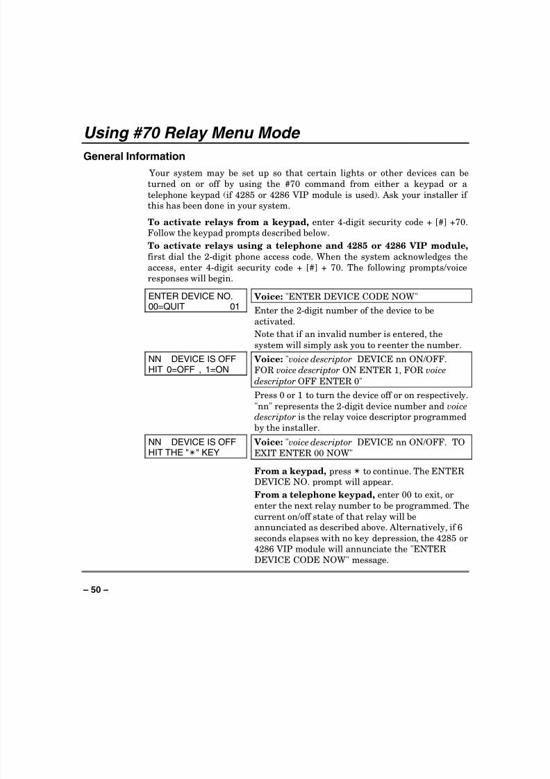
Using #70 Relay Menu Mode General Information
Your system may be set up so that certain lights or other devices can be
turned on or off by using the #70 command from either a keypad or a
telephone keypad (if 4285 or 4286 VIP module is used). Ask your installer if this has been done in your system.
To activate relays from a keypad, enter 4-digit security code + [#] +70.
Follow the keypad prompts described below.
To activate relays using a telephone and 4285 or 4286 VIP module,
first dial the 2-digit phone access code. When the system acknowledges the
access, enter 4-digit security code + [#] + 70. The following prompts/voice
responses will begin.
ENTER DEVICE NO.00=QUIT 01 Voice: "ENTER DEVICE CODE NOW"
Enter the 2-digit number of the device to be
activated.
Note that if an invalid number is entered, the
system will simply ask you to reenter the number.
NN DEVICE IS OFFHIT 0=OFF , 1=ON Voice: "voice descriptor DEVICE nn ON/OFF.
FOR voice descriptor ON ENTER 1, FOR voice
descriptor OFF ENTER 0"
Press 0 or 1 to turn the device off or on respectively.
"nn" represents the 2-digit device number and voicedescriptor is the relay voice descriptor programmed
by the installer.
NN DEVICE IS OFFHIT THE "✴" KEY Voice: "voice descriptor DEVICE nn ON/OFF. TO
EXIT ENTER 00 NOW"
From a keypad, press ✴ to continue. The ENTERDEVICE NO. prompt will appear.
From a telephone keypad, enter 00 to exit, or
enter the next relay number to be programmed. The
current on/off state of that relay will beannunciated as described above. Alternatively, if 6
seconds elapses with no key depression, the 4285 or
4286 VIP module will annunciate the "ENTERDEVICE CODE NOW" message.

8/8/2019 Vista 128 Owners Manual
http://slidepdf.com/reader/full/vista-128-owners-manual 51/80
– 51 –
Using Schedules Delaying the Closing Time
Your system's programmed schedules may automatically arm the system at a
predetermined time. In the event a user must stay on the premises later than
usual, users with master or manager authority levels can manually delay the
automatic arming (closing) time up to 2 hours. To delay the closing time:
1. Enter your security code (master or manager authority levels only).
2. Press the # key, followed by 82.
3. A menu prompt will be displayed, asking for the number of hours of delay.
CLOSING DELAY?KEY 0-2 HOURS
Enter the desired number of hours of delay, 1 or 2.
The system automatically exits this mode afterentry.
Note that the delay is from the scheduled closing time, not from the
time the command is entered.
IMPORTANT: The selected delay cannot be reduced once it is set. A 1
hour delay can be increased to 2 hours, though.
4. The system will automatically send a message to the central station
informing them that the programmed schedule has been changed.
Temporary Open/Close Schedules
Temporary schedules allow you to override the normal schedules
programmed by the installer. Temporary schedules can be in effect for up toone week, and take effect as soon as they are programmed.
They are comprised of an arming (closing) time window and a disarming
(opening) time window. A time window is simply a defined period of time, at
the end of which arming or disarming will occur.
Before programming, use a worksheet similar to the one below to plan your
schedule. This will make it easier when actually programming the schedule.
Arm/Disarm Mon Tue Wed Thu Fri Sat Sun
Windows
Disarm Window
Start Time HH:MM
Stop Time HH:MM
Arm Window
Start Time HH:MM
Stop Time HH:MM
8/8/2019 Vista 128 Owners Manual
http://slidepdf.com/reader/full/vista-128-owners-manual 52/80
– 52 –
Using Schedules (cont ’ d)
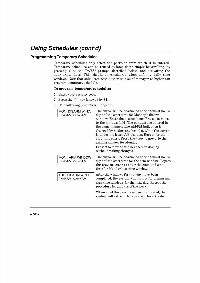
Programming Temporary Schedules
Temporary schedules only affect the partition from which it is entered.
Temporary schedules can be reused at later dates simply by scrolling (by
pressing #) to the DAYS? prompt (described below) and activating theappropriate days. This should be considered when defining daily time
windows. Note that only users with authority level of manager or higher can
program temporary schedules.
To program temporary schedules:
1. Enter your security code.
2. Press the # key followed by 81.
3. The following prompts will appear.
MON DISARM WIND.07:45AM 08:45AM The cursor will be positioned on the tens of hours
digit of the start time for Monday's disarm
window. Enter the desired hour. Press * to move
to the minutes field. The minutes are entered in
the same manner. The AM/PM indication is
changed by hitting any key, 0-9, while the cursor
is under the letter A/P position. Repeat for the
stop time entry. Press the * key to move to the
arming window for Monday.
Press # to move to the next screen display
without making changes.
MON ARM WINDOW07:45AM 08:45AM
The cursor will be positioned on the tens of hours
digit of the start time for the arm window. Repeat
the previous steps to enter the start and stop
time for Monday's arming window.
TUE DISARM WIND.07:45AM 08:45AM
After the windows for that day have been
completed, the system will prompt for disarm and
arm time windows for the next day. Repeat theprocedure for all days of the week.
When all of the days have been completed, the
system will ask which days are to be activated.

8/8/2019 Vista 128 Owners Manual
http://slidepdf.com/reader/full/vista-128-owners-manual 53/80

8/8/2019 Vista 128 Owners Manual
http://slidepdf.com/reader/full/vista-128-owners-manual 54/80
– 54 –
Programming Device Timers General Information
Device timers consist of an ON time & an OFF time, and selected days of the
week in which they are active. There are up to 20 timers that can be used to
control various devices, such as lights or appliances. Your installer will have
programmed the appropriate devices into the system (up to 96 devices can beprogrammed).
Each timer controls a single device (designated as an output number) thatyou select. For example, timer 1 might be set to turn the porch lights on at
7:00pm and turn them off at 11:00pm. Timer 2 might turn on the air
conditioner Monday-Friday at 4:30pm to cool the premises before you arrive
at 5:00pm, and turn it off at 10:00pm when you are retiring for the night. If desired, different timers can control the same device. For example, timer 2
could be used Monday-Friday as in the previous example, and timer 3 could
be set to turn the air conditioner on and off at different times Saturday and
Sunday.
To enter the device timer menu mode:
Enter your security code, then press the # key followed by 83.
OUTPUT TIMER # ?01-20,00=QUIT 01
Up to 20 timers can be programmed. Each timer
is identified by a number 1-20. Enter the desired
timer number to be programmed (1-20). Press *
to accept entry.
06 07:00P 11:45PPORCH LITE 04
If that timer number has already beenprogrammed, a summary screen will appear. In
this example:
06 = Timer #
04 = Output Device # affected by this timer
PORCH LITE = Output Descriptor for Device 4
07:00PM = Start Time;
11:45PM = Stop Time
Press * to continue.See your installer for device numbers.
00 ENTER OUTPUT#00
Enter the desired output device number (1-96). As the number is entered, the device's description
will appear.
To delete a previously programmed timer, enter00 as the output number.

8/8/2019 Vista 128 Owners Manual
http://slidepdf.com/reader/full/vista-128-owners-manual 55/80

8/8/2019 Vista 128 Owners Manual
http://slidepdf.com/reader/full/vista-128-owners-manual 56/80
– 56 –
Programming Device Timers (cont ’ d)
Randomize Output Device Times
Devices in your system may be set for a random schedule, whereby they will
turn on and off at different times each day. This is useful when going on
vacation and you desire the turning on and off of the lights to the give the
appearance of someone being home. Your installer sets these devices for arandom schedule. You can initiate a random schedule by either of the
following methods:
1. Enter your security code and press # followed by 41.
This will randomize, up to 30 minutes, the activation time of all devices,
programmed for randomization, assigned to the partition the sequence isentered in. Enter the sequence again to turn off the random schedule.
2. Enter your security code and press # followed by 42.
This is the same as the method above, except the randomization occurs
only on devices with activation times within 6 PM and 5 AM. Enter the
same sequence again to turn off the random schedule.
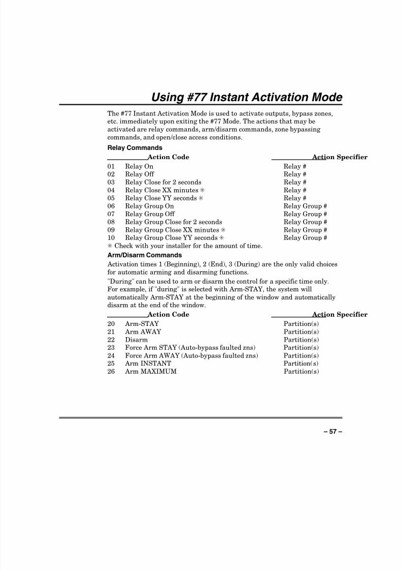
8/8/2019 Vista 128 Owners Manual
http://slidepdf.com/reader/full/vista-128-owners-manual 57/80
– 57 –
Using #77 Instant Activation Mode The #77 Instant Activation Mode is used to activate outputs, bypass zones,etc. immediately upon exiting the #77 Mode. The actions that may be
activated are relay commands, arm/disarm commands, zone bypassing
commands, and open/close access conditions.
Relay Commands
Action Code Action Specifier
01 Relay On Relay #02 Relay Off Relay #
03 Relay Close for 2 seconds Relay #
04 Relay Close XX minutes✳ Relay #
05 Relay Close YY seconds ✳ Relay #06 Relay Group On Relay Group #
07 Relay Group Off Relay Group #
08 Relay Group Close for 2 seconds Relay Group #
09 Relay Group Close XX minutes✳ Relay Group #10 Relay Group Close YY seconds✳ Relay Group #
✳ Check with your installer for the amount of time.
Arm/Disarm Commands
Activation times 1 (Beginning), 2 (End), 3 (During) are the only valid choices
for automatic arming and disarming functions.
"During" can be used to arm or disarm the control for a specific time only.For example, if "during" is selected with Arm-STAY, the system will
automatically Arm-STAY at the beginning of the window and automaticallydisarm at the end of the window.
Action Code Action Specifier
20 Arm-STAY Partition(s)
21 Arm AWAY Partition(s)
22 Disarm Partition(s)23 Force Arm STAY (Auto-bypass faulted zns) Partition(s)
24 Force Arm AWAY (Auto-bypass faulted zns) Partition(s)25 Arm INSTANT Partition(s)
26 Arm MAXIMUM Partition(s)

8/8/2019 Vista 128 Owners Manual
http://slidepdf.com/reader/full/vista-128-owners-manual 58/80
– 58 –
Using #77 Instant Activation Mode (cont ’ d)
Bypass Commands
Activation times 1 (Beginning), 2 (End), 3 (During) are the only valid choices
for bypass commands. If 3 (During) is selected for auto-bypassing, the
system bypasses the zone(s) specified on a particular zone list at the
beginning of the window and unbypasses them at the end of the window. If itis selected for auto unbypassing, the system removes the bypass at the
beginning of the window and restores the bypass at the end of the window.
Action Code Action Specifier
30 Auto bypass - Zone list Zone list #31 Auto unbypass - Zone list Zone list #
Open/Close Windows Activation time 3 (During) is the only valid choice for these commands.
Action Code Action Specifier
40 Enable Opening Window by partition Partition(s)
41 Enable Closing Window by partition Partition(s)
42 Enable Access Window for access group Access Group
Access Control Commands
Action Code Action Specifier
55 Access Point Grant Access Point #
56 Access Point Grant with Override Access Point #
57 Access Point Protect Access Point #
58 Access Point Bypass Access Point #
59 Access Point Lock Access Point #60 Access Point Exit Access Point #
61 Access Point Group Grant Group #62 Access Point Group Grant with Override Group #
63 Access Point Group Protect Group #
64 Access Point Group Bypass Group #
66 Access Point Group Exit Group #
67 Access Point Partition Grant Partition #
68 Access Point Partition Grant with Override Partition #
69 Access Point Protect by Partition Partition #
70 Access Point Bypass by Partition Partition #71 Access Point Lock by Partition Partition #
72 Access Point Exit by Partition Partition #73 Access Point Trigger On Trigger #74 Access Point Trigger Off Trigger #

8/8/2019 Vista 128 Owners Manual
http://slidepdf.com/reader/full/vista-128-owners-manual 59/80
– 59 –
Using #77 Instant Activation Mode (cont ’ d)
Additional Commands
Action Code Action Specifier
77 Access Point Group Enable Group #
78 Access Point Group Disable Group #
To enter the Instant Activation Mode:
Enter your security code, then press the [#] key followed by 77.
ACTION ? Enter the code for the desired action. The
action codes are the events that are to take place
when either the system exits the #77 Mode or the
scheduled time is reached, depending on the actionselected.
Press [✳] to continue.
Enter the action specifier. This defines what the
action will affect (relay, relay group, partition, zonelist, user group). The action specifier screen prompt
varies, depending on the type of action selected.
As an example, if you selected “Auto Bypass” as the
action, the action specifier prompt would be:
ZONE LIST ?
ARE YOU SURE ?1 = YES 0 = NO 0
Enter 1 (YES) or 0 (NO).Press [✳] to continue.
QUIT MENU MODE?
1 = YES 0 = NO
Enter 1 (YES) or 0 (NO).
Press [✳] to continue.

8/8/2019 Vista 128 Owners Manual
http://slidepdf.com/reader/full/vista-128-owners-manual 60/80
– 60 –
Event Log Procedures General Information
The system has the ability to record
various events in a history log wherein
each event is recorded in one of fivecategories (listed below), with the time and
date of its occurrence. The Event Log holds
up to 1000 events, with the oldest event
being replaced by the logging of any new
event after the log is full. Using an alphakeypad, the Event Log can be viewed one
category at a time, or can display allevents, regardless of category (ALLEVENT LOG). The system also allows
selection of displaying the COMPLETE log,or only those events occurring since the
last installer service (RECENT). In
addition, events in the other partitions can
be viewed by users authorized to access
those partitions. Note that events are
displayed in chronological order, from most
recent to oldest.
To Display The Event Log
1. Enter CODE + [#] + [6] + [0]
2. Select the display mode.
RECENT: Displays only those events
occurring since last Event Log Clear
command was executed.
COMPLETE: Displays complete event
log (up to 1000 events).
Press the desired key, 0 or 1.
ENTER 0 = RECENT1 = COMPLETE
3. Select the partition, 0-8.
Enter the partition number for thepartition whose events are to be
displayed.
Entering 0 (NO) will display all
partitions' events.
SCAN LOG BY PART0=NO 1-8=PART #
4. Use the [3] & [1] keys (for next and
previous categories respectively) todisplay the categories of events.
Press [8] to select a category anddisplay the first event. Press [8] again
for each subsequent event.
Shows burglary alarm occurred in zone
3 (C03) of partition 1 (P1), at 12:02AM
on January 1.
P1 01/01 12:02AMBURGLARY C003
Typical Event Log Display
After the last event has been
displayed, the END OF EVENT LOGmessage appears for a few seconds, then
the system automatically displays theRECENT/COMPLETE mode select
screen again (see step 2).
5. To EXIT the Event Log:
Press [✱] at any time.
ALARM EVENT LOGTYPE CCC UUU
Typical Category Select Screen

8/8/2019 Vista 128 Owners Manual
http://slidepdf.com/reader/full/vista-128-owners-manual 61/80
– 61 –
Event Logging Procedures (continued) ALARM EVENT LOG
Displays time and date for zones thathave either caused an alarm or have been
restored in the selected partition.
CHECK EVENT LOG
Displays time and date for zones thathave caused a trouble or supervisory
condition in the selected partition.
BYPASS EVENT LOG
Displays time and date for zones that
have been bypassed in the partition.
OPEN EVENT LOGDisplays time, date and user number or 6-
character descriptor for the user, if
programmed, for each arming and
disarming of the system for the partition
selected.
SYSTEM EVENT LOGDisplays time and date for system
problems, such as AC Loss, low battery,
etc., regardless of partition.
ALL EVENT LOGDisplays all categories of events in
chronological order.
See your Installer for additional
information concerning the event log.
Setting the Time and Date
1. Enter Installer or Master Code + [#] +
63. Typical display shows:
TIME/DATE –– THU12:01 AM 01/01/90
The day of the week is automatically
calculated based on the date entered.
Time and date entries are made by simply
entering the appropriate hour, minute,
month, day and year.
Press [✳] to move the cursor to the right of
the display, to the next position.
Press [#] to move the cursor to the left of
the display, to the previous position.
2. Enter the hour. Then press [✳] to
move to the “minutes” field.
3. Enter the minutes. Press [✳
] to moveto the AM/PM position.
4. Press any key 0-9 to change AM to
PM, or PM to AM. Press [✳] to move
cursor to the “month” field position.
5. Enter the month using a 2-digit entry.
Press [✳] to move cursor to the “day”field position.
6. Enter the day using a 2-digit entry.
Press [✳] to move cursor to the “year”field position.
7. Press [✳] to continue.
8. The following display appears:
Broadcast Time?1=YES 0=NO 0
If panel linking is being used, enter 1
(YES) to send this time and date setting to
all the other panels. Otherwise enter 0.
Press [✳] to exit the real-time clock editmode.
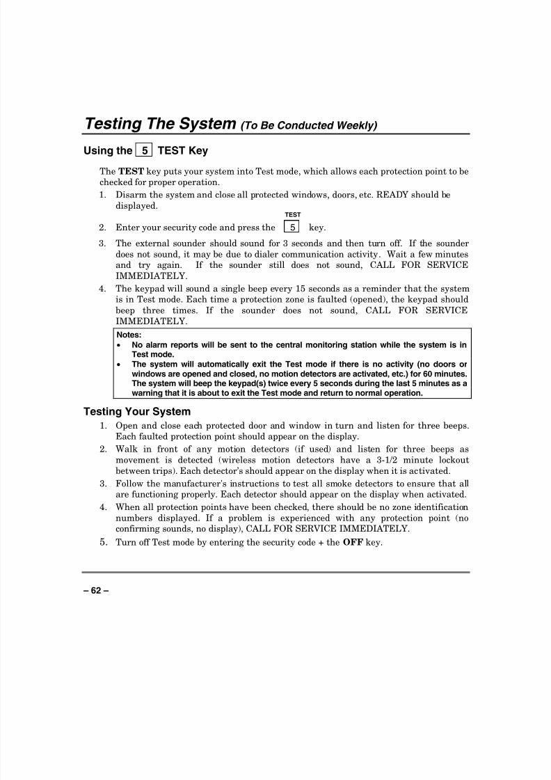
8/8/2019 Vista 128 Owners Manual
http://slidepdf.com/reader/full/vista-128-owners-manual 62/80
– 62 –
Testing The System (To Be Conducted Weekly)
Using the 5 TEST Key
The TEST key puts your system into Test mode, which allows each protection point to be
checked for proper operation.
1. Disarm the system and close all protected windows, doors, etc. READY should be
displayed.TEST
2. Enter your security code and press the 5 key.
3. The external sounder should sound for 3 seconds and then turn off. If the sounder
does not sound, it may be due to dialer communication activity. Wait a few minutesand try again. If the sounder still does not sound, CALL FOR SERVICE
IMMEDIATELY.
4. The keypad will sound a single beep every 15 seconds as a reminder that the systemis in Test mode. Each time a protection zone is faulted (opened), the keypad should
beep three times. If the sounder does not sound, CALL FOR SERVICE
IMMEDIATELY.
Notes:
• No alarm reports will be sent to the central monitoring station while the system is inTest mode.
• The system will automatically exit the Test mode if there is no activity (no doors orwindows are opened and closed, no motion detectors are activated, etc.) for 60 minutes.The system will beep the keypad(s) twice every 5 seconds during the last 5 minutes as awarning that it is about to exit the Test mode and return to normal operation.
Testing Your System1. Open and close each protected door and window in turn and listen for three beeps.
Each faulted protection point should appear on the display.
2. Walk in front of any motion detectors (if used) and listen for three beeps as
movement is detected (wireless motion detectors have a 3-1/2 minute lockout
between trips). Each detector’s should appear on the display when it is activated.
3. Follow the manufacturer's instructions to test all smoke detectors to ensure that allare functioning properly. Each detector should appear on the display when activated.
4. When all protection points have been checked, there should be no zone identification
numbers displayed. If a problem is experienced with any protection point (noconfirming sounds, no display), CALL FOR SERVICE IMMEDIATELY.
5. Turn off Test mode by entering the security code + the OFF key.

8/8/2019 Vista 128 Owners Manual
http://slidepdf.com/reader/full/vista-128-owners-manual 63/80
– 63 –
Fire Alarm System Your fire alarm system (if installed) is on 24 hours a day, providingcontinuous protection. In the event of an emergency, the smoke and heat
detectors automatically send signals to your Control, triggering a loud
interrupting sound from the keypad and the optional exterior sounders.
FIRE appears at your keypad and remains on until you silence the alarm.
In Case Of Fire Alarm
1. Should you become aware of a fire emergency before your detectors sense
the problem, go to your nearest keypad and manually initiate an alarm
by pressing the panic key assigned as FIRE emergency (if programmed
by the installer) and hold down for at least 2 seconds.
2. Evacuate all occupants from the premises.
3. If flames and/or smoke are present, leave the premises and notify your
local Fire Department immediately.
4. If no flames or smoke are apparent, investigate the cause of the alarm.The descriptor of the zone(s) in alarm appears at the keypad.
Silencing A Fire Alarm
1. Silence the alarm by entering your code and pressing the OFF key. To
clear the display, enter your code and press the OFF key again
2. If the keypad does not indicate a READY condition after the second OFF
sequence, press the READY key to display the zone(s) that are faulted.
Be sure to check that smoke detectors are not responding to smoke orheat producing objects in their vicinity. Should this be the case,eliminate the source of heat or smoke.
3. If this does not remedy the problem, there may still be smoke in thedetector. Clear it by fanning the detector for about 30 seconds.
4. You can clear the display by entering your code + the OFF key.
Fire Display Lock
If several zones produce an alarm before any are silenced, the system can be
programmed to lock the keypad display with the first zone that produced analarm. Ask your installer if your system has been activated with this feature.
To display the other zone(s), press the [*] key for each zone.

8/8/2019 Vista 128 Owners Manual
http://slidepdf.com/reader/full/vista-128-owners-manual 64/80
– 64 –
Trouble Conditions Typical Trouble Displays
The word CHECK or TRBL on the Keypad's display, accompanied by a rapid
"beeping" at the Keypad, indicates that there is a trouble condition in the
system.
To silence the beeping sound for trouble conditions, press any key.
• A display of “CHECK” or “TRBL” accompanied by a display of "CALL
SERVICE" indicates that a problem exists with the system that
eliminates some of the protection. CALL FOR SERVICE
IMMEDIATELY.
• A display of “CHECK” or “TRBL" accompanied by a display of one or
more zone descriptors indicates that a problem exists with those zone(s)*.
First, determine if the zone(s) displayed are intact and make them so if
they are not. If the problem has been corrected, the display of the zone
descriptor(s) and “CHECK” or “TRBL” should disappear. If not, key an
OFF sequence (Code plus OFF) to clear the display. If the displaypersists, CALL FOR SERVICE IMMEDIATELY.
• A display of “CHECK” or “TRBL” accompanied by a numeric display of
“6XX,” where XX = 01-32, indicates a trouble on a supervised relay
(corresponding relay number 01-32).
• A display of “CHECK” or “TRBL” accompanied by a numeric display of
“8XX,” where XX = 00-30, indicates a trouble on a peripheral device(connected to the panel’s keypad terminals) of a corresponding device
address (00-30).
• A display of “CHECK” or “TRBL” accompanied by a numeric display of “9XX,” where XX = 00-99, indicates a system trouble exists (dialers, bell
outputs, ground fault, etc.). These zones are as follows:
970: Bell Supervision
988: 2nd
RF Receiver – not receiving signals
990: 1st
RF Receiver – not receiving signals
997: Polling Loop Short
• A display of "COMM. FAILURE" at the Keypad indicates that a failure
has occurred in the telephone communication portion of your system.CALL FOR SERVICE IMMEDIATELY.
8/8/2019 Vista 128 Owners Manual
http://slidepdf.com/reader/full/vista-128-owners-manual 65/80

8/8/2019 Vista 128 Owners Manual
http://slidepdf.com/reader/full/vista-128-owners-manual 66/80
– 66 –
Recommendations For Proper Protection The following recommendations for the location of fire and burglary detection
devices help provide proper coverage for the protected premises.
Recommendations For Smoke And Heat DetectorsWith regard to the number and placement of smoke/heat detectors, we subscribe to the
recommendations contained in the National Fire Protection Association's (NFPA) Standard
#72 noted below.
Early warning fire detection is best achieved by the installation of fire detection
equipment in all rooms and areas of the household as follows: For minimum protection
a smoke detector should be installed outside of each separate sleeping area, and on eachadditional floor of a multi-floor family living unit, including basements. The installation
of smoke detectors in kitchens, attics (finished or unfinished), or in garages is notnormally recommended.
For additional protection the NFPA recommends that you install heat or smoke detectors in
the living room, dining room, bedroom(s), kitchen, hallway(s), attic, furnace room, utility and
storage rooms, basements and attached garages.
DINING
KITCHENBEDROOM
BEDROOM
BEDROOM
BEDROOM
LIVING ROOMBEDROOM
BDRM
BDRM
DINING
LIVING ROOM
TV ROOM KITCHEN
BEDROOM BEDROOMTO
BR
LVNG RM
BASEMENT
KTCHN
. CLOSED
DOOR
GARAGE
Smoke Detectors for Minimum Protection
Smoke Detectors for Additional Protection
Heat-Activated Detectors
f l o o r_ p l a n - 0 0 1 - V 0

8/8/2019 Vista 128 Owners Manual
http://slidepdf.com/reader/full/vista-128-owners-manual 67/80
– 67 –
Recommendations For Proper Protection (cont ’ d)
In addition, we recommend the following:
§ Install a smoke detector inside every bedroom where a smoker sleeps.
§ Install a smoke detector inside bedrooms where electrical appliances (such as portable
heaters, air conditioners or humidifiers) are used.
§ Install a smoke detector inside every bedroom where someone sleeps with the door partly
or completely closed. Smoke could be blocked by the closed door. Also, an alarm in the
hallway outside may not wake up the sleeper if the door is closed.
§ Install a smoke detector at both ends of a hallway if the hallway is more than 40 feet (12
meters) long.
§ Install smoke detectors in any room where an alarm control is located, or in any room
where alarm control connections to an AC source or phone lines are made. If detectors arenot so located, a fire within the room could prevent the control from reporting a fire or an
intrusion.
Recommendations For Proper Intrusion Protection
For proper intrusion coverage, sensors should be located at every possible point of entry to a
home or commercial premises. This would include any skylights that may be present, and
the upper windows in a multi-level building.
In addition, we recommend that radio backup be used in a security system so that alarm
signals can still be sent to the alarm monitoring station in the event that the telephone lines
are out of order (alarm signals are normally sent over the phone lines, if connected to analarm monitoring station).
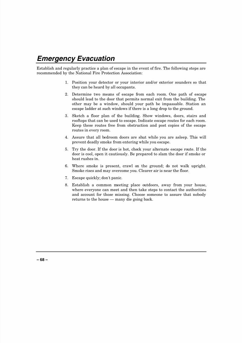
8/8/2019 Vista 128 Owners Manual
http://slidepdf.com/reader/full/vista-128-owners-manual 68/80
– 68 –
Emergency Evacuation Establish and regularly practice a plan of escape in the event of fire. The following steps arerecommended by the National Fire Protection Association:
1. Position your detector or your interior and/or exterior sounders so that
they can be heard by all occupants.
2. Determine two means of escape from each room. One path of escape
should lead to the door that permits normal exit from the building. The
other may be a window, should your path be impassable. Station an
escape ladder at such windows if there is a long drop to the ground.
3. Sketch a floor plan of the building. Show windows, doors, stairs and
rooftops that can be used to escape. Indicate escape routes for each room.Keep these routes free from obstruction and post copies of the escape
routes in every room.
4. Assure that all bedroom doors are shut while you are asleep. This will
prevent deadly smoke from entering while you escape.
5. Try the door. If the door is hot, check your alternate escape route. If the
door is cool, open it cautiously. Be prepared to slam the door if smoke or
heat rushes in.
6. Where smoke is present, crawl on the ground; do not walk upright.
Smoke rises and may overcome you. Clearer air is near the floor.
7. Escape quickly; don't panic.
8. Establish a common meeting place outdoors, away from your house,
where everyone can meet and then take steps to contact the authorities
and account for those missing. Choose someone to assure that nobody
returns to the house — many die going back.

8/8/2019 Vista 128 Owners Manual
http://slidepdf.com/reader/full/vista-128-owners-manual 69/80
– 69 –
Maintaining Your System Taking Care of Your System
The components of your security system are designed to be as free of
maintenance as possible. However, there are some things you can do to make
sure that your system is in reliable working condition.
1. Test your system weekly.
2. Test the system after any alarm occurs (see TESTING THE SYSTEM ).
Replacing Batteries in Wireless Sensors
Wireless sensors may not have
been used in your security system
Each wireless sensor in your system has a 9-volt or 3-volt battery. The system
detects a low battery in any wireless sensor, including smoke detectors, theoptional personal emergency transmitter, and the optional portable wirelesskeypad. (A low battery in a portable wireless keypad is detected as soon as
one of its keys is pressed, and the keypad will display 00.)
Alkaline batteries provide a minimum of 1 year of operation, and in most
units and applications, provide 2–4 years of service. Actual battery life will
depend on the environment in which the sensor is used, the number of signals
that the transmitter in the sensor has had to send, and the specific type of
sensor. Factors such as humidity, high or low temperatures or large swingsin temperature, may all lead to the reduction of actual battery life in an
installation.
If you have a low battery in a wireless sensor, a low battery message
is displayed on the keypad.
In addition, a battery-operated smoke detector with a low battery also emits
a single "chirp" sound once approximately every 20-30 seconds, identifyingitself as the smoke detector with the weak battery. If you do not replace a
smoke detector's low battery, the smoke detector may sound continuously, as
if there were a fire alarm.
Note: The low battery message comes on as a warning that battery
replacement in indicated sensor(s) is due within 30 days. In the meantime,
the sensor(s) causing the low battery indication is still fully operational.
Important: Use only batteries recommended by your installer as
replacement.
8/8/2019 Vista 128 Owners Manual
http://slidepdf.com/reader/full/vista-128-owners-manual 70/80
– 70 –
Maintaining Your System (cont ’ d)
Silencing Low Battery Warning Tones at the Keypad
The keypad’s warning tones can be silenced by performing an OFF sequence
(code plus OFF key), but the Keypad's low battery message display will
remain on as a reminder that you have a low battery condition in one or more
of your sensors. When you replace the weak battery with a fresh one, the
sensor will send a "good battery" signal to the control as soon as the sensor isactivated (opening/closing of door, window, etc.), causing the low battery
display to turn off. If the sensor is not activated, the display will
automatically clear within approximately 1 hour.
Routine Care
• Treat the components of your security system as you would any other
electrical equipment. Do not slam sensor-protected doors or windows.
• Keep dust from accumulating on the keypad and all protective sensors,particularly on motion sensors and smoke detectors.
• The keypad and sensors should be cleaned carefully with a dry soft cloth.
Do not spray water or any other fluid on the units.
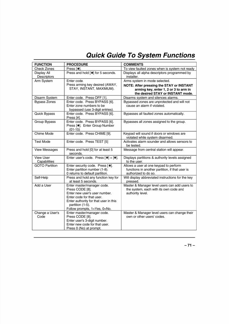
8/8/2019 Vista 128 Owners Manual
http://slidepdf.com/reader/full/vista-128-owners-manual 71/80
– 71 –
Quick Guide To System Functions FUNCTION PROCEDURE COMMENTS
Check Zones Press [✱]. To view faulted zones when is system not readyDisplay All
DescriptorsPress and hold [✱] for 5 seconds. Displays all alpha descriptors programmed by
installer.
Arm System Enter code.Press arming key desired (AWAY,
STAY, INSTANT, MAXIMUM).
Arms system in mode selected.
NOTE: After pressing the STAY or INSTANTarming key, enter 1, 2 or 3 to arm inthe desired STAY or INSTANT mode.
Disarm System Enter code. Press OFF [1]. Disarms system and silences alarms.
Bypass Zones Enter code. Press BYPASS [6].Enter zone numbers to be
bypassed (use 3-digit entries).
Bypassed zones are unprotected and will notcause an alarm if violated.
Quick Bypass Enter code. Press BYPASS [6].Press [#].
Bypasses all faulted zones automatically.
Group Bypass Enter code. Press BYPASS [6].Press [✱]. Enter Group Number
(01-15)
Bypasses all zones assigned to the group.
Chime Mode Enter code. Press CHIME [9]. Keypad will sound if doors or windows areviolated while system disarmed.
Test Mode Enter code. Press TEST [5] Activates alarm sounder and allows sensors tobe tested.
View Messages Press and hold [0] for at least 5seconds.
Message from central station will appear.
View UserCapabilities
Enter user's code. Press [✱] + [✱]. Displays partitions & authority levels assignedto the user.
GOTO Partition Enter security code. Press [✱].
Enter partition number (1-8).0 returns to default partition.
Allows a user at one keypad to perform
functions in another partition, if that user isauthorized to do so.
Self-Help Press and hold any function key forat least 5 seconds.
Will display abbreviated instructions for the keypressed.
Add a User Enter master/manager code.Press CODE [8].Enter new user's user number.Enter code for that user.Enter authority for that user in this
partition (1-5).Follow prompts, 1=Yes, 0=No.
Master & Manager level users can add users tothe system, each with its own code andauthority level.
Change a User'sCode
Enter master/manager code.Press CODE [8].Enter user's 3-digit number.Enter new code for that user.
Press 0 (No) at prompt.
Master & Manager level users can change theirown or other users' codes.

8/8/2019 Vista 128 Owners Manual
http://slidepdf.com/reader/full/vista-128-owners-manual 72/80
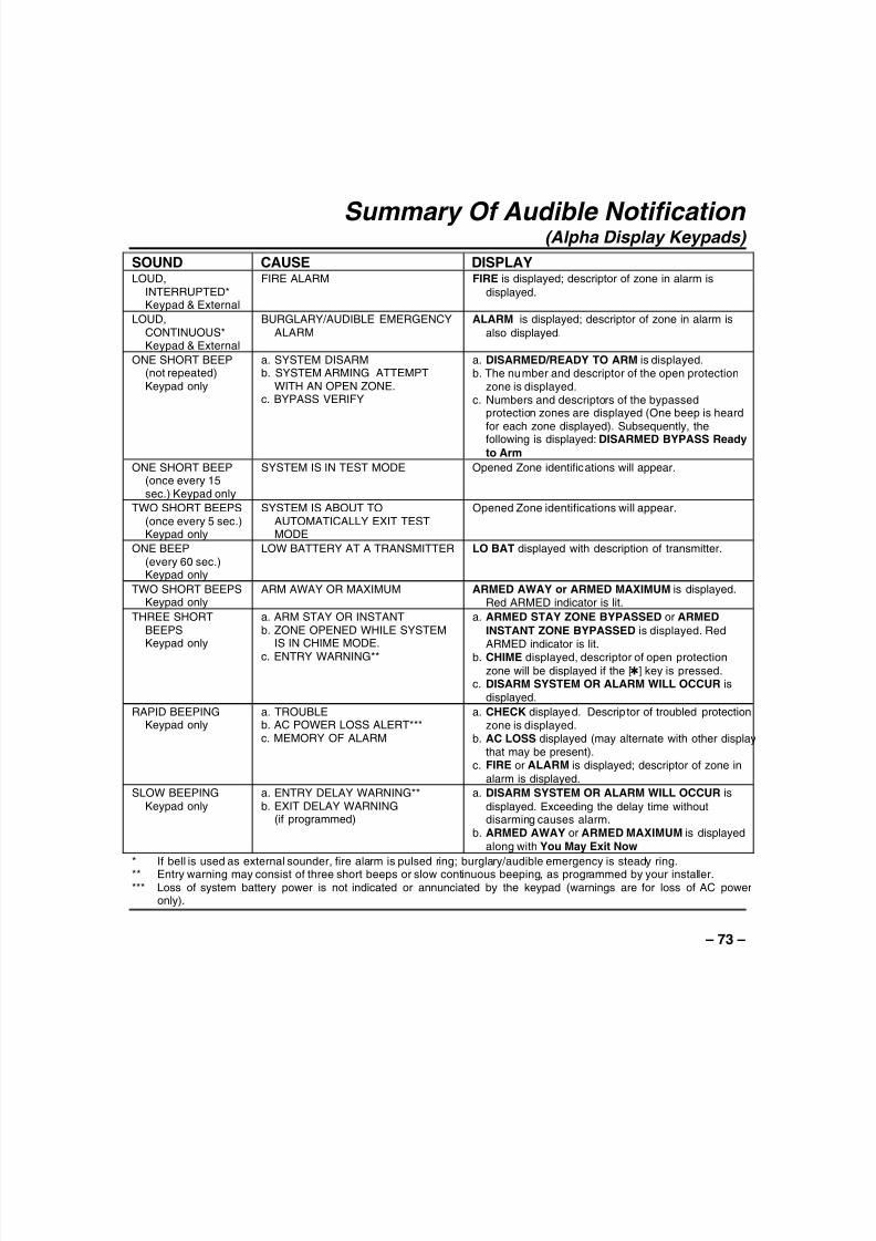
8/8/2019 Vista 128 Owners Manual
http://slidepdf.com/reader/full/vista-128-owners-manual 73/80
– 73 –
Summary Of Audible Notification (Alpha Display Keypads)
SOUND CAUSE DISPLAYLOUD,
INTERRUPTED*Keypad & External
FIRE ALARM FIRE is displayed; descriptor of zone in alarm is
displayed.
LOUD,CONTINUOUS*Keypad & External
BURGLARY/AUDIBLE EMERGENCYALARM
ALARM is displayed; descriptor of zone in alarm is
also displayed.
ONE SHORT BEEP(not repeated)Keypad only
a. SYSTEM DISARMb. SYSTEM ARMING ATTEMPT
WITH AN OPEN ZONE.c. BYPASS VERIFY
a. DISARMED/READY TO ARM is displayed.b. The number and descriptor of the open protection
zone is displayed.c. Numbers and descriptors of the bypassed
protection zones are displayed (One beep is heardfor each zone displayed). Subsequently, thefollowing is displayed: DISARMED BYPASS Ready
to Arm
ONE SHORT BEEP(once every 15sec.) Keypad only
SYSTEM IS IN TEST MODE Opened Zone identifications will appear.
TWO SHORT BEEPS(once every 5 sec.)Keypad only
SYSTEM IS ABOUT TOAUTOMATICALLY EXIT TESTMODE
Opened Zone identifications will appear.
ONE BEEP(every 60 sec.)Keypad only
LOW BATTERY AT A TRANSMITTER LO BAT displayed with description of transmitter.
TWO SHORT BEEPSKeypad only
ARM AWAY OR MAXIMUM ARMED AWAY or ARMED MAXIMUM is displayed.Red ARMED indicator is lit.
THREE SHORTBEEPSKeypad only
a. ARM STAY OR INSTANTb. ZONE OPENED WHILE SYSTEM
IS IN CHIME MODE.
c. ENTRY WARNING**
a. ARMED STAY ZONE BYPASSED or ARMED
INSTANT ZONE BYPASSED is displayed. RedARMED indicator is lit.
b. CHIME displayed, descriptor of open protection
zone will be displayed if the [✱] key is pressed.c. DISARM SYSTEM OR ALARM WILL OCCUR is
displayed.
RAPID BEEPINGKeypad only
a. TROUBLEb. AC POWER LOSS ALERT***c. MEMORY OF ALARM
a. CHECK displayed. Descriptor of troubled protectionzone is displayed.
b. AC LOSS displayed (may alternate with other displaythat may be present).
c. FIRE or ALARM is displayed; descriptor of zone in
alarm is displayed.
SLOW BEEPINGKeypad only
a. ENTRY DELAY WARNING**b. EXIT DELAY WARNING
(if programmed)
a. DISARM SYSTEM OR ALARM WILL OCCUR is
displayed. Exceeding the delay time withoutdisarming causes alarm.
b. ARMED AWAY or ARMED MAXIMUM is displayed
along with You May Exit Now
* If bell is used as external sounder, fire alarm is pulsed ring; burglary/audible emergency is steady ring.** Entry warning may consist of three short beeps or slow continuous beeping, as programmed by your installer.*** Loss of system battery power is not indicated or annunciated by the keypad (warnings are for loss of AC power
only).

8/8/2019 Vista 128 Owners Manual
http://slidepdf.com/reader/full/vista-128-owners-manual 74/80
– 74 –
UL NOTICE: This is a “GRADE A” system.“FEDERAL COMMUNICATIONS COMMISSION (FCC) Part 15 STATEMENT”
This equipment has been tested to FCC requirements and has been found acceptable for use. The FCCrequires the following statement for your information:
This equipment generates and uses radio frequency energy and if not installed and used properly, that is, instrict accordance with the manufacturer’s instructions, may cause interference to radio and televisionreception. It has been type tested and found to comply with the limits for a Class B computing device inaccordance with the specifications in Part 15 of FCC Rules, which are designed to provide reasonableprotection against such interference in a residential installation. However, there is no guarantee thatinterference will not occur in a particular installation. If this equipment does cause interference to radio ortelevision reception, which can be determined by turning the equipment off and on, the user is encouragedto try to correct the interference by one or more of the following measures:
• If using an indoor antenna, have a quality outdoor antenna installed.
• Reorient the receiving antenna until interference is reduced or eliminated.• Move the receiver away from the control/communicator.
• Move the antenna leads away from any wire runs to the control/communicator.
• Plug the control/communicator into a different outlet so that it and the receiver are on different branchcircuits.
If necessary, the user should consult the dealer or an experienced radio/television technician for additionalsuggestions.
The user or installer may find the following booklet prepared by the Federal Communications Commissionhelpful: “Interference Handbook”
This booklet is available from the U.S. Government Printing Office, Washington, DC 20402.
The user shall not make any changes or modifications to the equipment unless authorized by the InstallationInstructions or User’s Manual. Unauthorized changes or modifications could void the user’s authority tooperate the equipment.
IN THE EVENT OF TELEPHONE OPERATIONAL PROBLEMSIn the event of telephone operational problems, disconnect the control by removing the plug from the RJ31X(CA38A in Canada) telephone wall jack. We recommend that your certified installer demonstratedisconnecting the phones on installation of the system. Do not disconnect the phone connection inside thecontrol/communicator. Doing so will result in the loss of your phone lines. If the regular phone workscorrectly after the control/communicator has been disconnected from the phone lines, thecontrol/communicator has a problem and should be returned for repair. If upon disconnection of thecontrol/communicator, there is still a problem on the line, notify the telephone company that they have aproblem and request prompt repair service. The user may not under any circumstances (in or out ofwarranty) attempt any service or repairs to the system. It must be returned to the factory or an authorizedservice agency for all repairs.

8/8/2019 Vista 128 Owners Manual
http://slidepdf.com/reader/full/vista-128-owners-manual 75/80
– 75 –
“FEDERAL COMMUNICATIONS COMMISSION (FCC) Part 68 NOTICE
This equipment complies with Part 68 of the FCC rules. On the front cover of this equipment is alabel that contains, among other information, the FCC registration number and ringer equivalencenumber (REN) for this equipment. If requested, this information must be provided to thetelephone company.
This equipment uses the following jacks:
An RJ31X is used to connect this equipment to the telephone network.
The REN is used to determine the quantity of devices which may be connected to the telephoneline. Excessive RENs on the telephone line may result in the devices not ringing in response toan incoming call. In most, but not all areas, the sum of the RENs should not exceed five (5.0). Tobe certain of the number of devices that may be connected to the line, as determined by the totalRENs, contact the telephone company to determine the maximum REN for the calling area.
If this equipment causes harm to the telephone network, the telephone company will notify you inadvance that temporary discontinuance of service may be required. If advance notice is notpractical, the telephone company will notify the customer as soon as possible. Also, you will beadvised of your right to file a complaint with the FCC if you believe necessary.
The telephone company may make changes in its facilities, equipment, operations, or proceduresthat could affect the operation of the equipment. If this happens, the telephone company willprovide advance notice in order for you to make the necessary modifications in order to maintainuninterrupted service.
If trouble is experienced with this equipment, please contact the manufacturer for repair andwarranty information. If the trouble is causing harm to the telephone network, the telephonecompany may request you remove the equipment from the network until the problem is resolved.
There are no user serviceable components in this product, and all necessary repairs must be
made by the manufacturer. Other repair methods may invalidate the FCC registration on thisproduct.
This equipment cannot be used on telephone company-provided coin service. Connection toParty Line Service is subject to state tariffs.
This equipment is hearing-aid compatible.
When programming or making test calls to an emergency number, briefly explain to thedispatcher the reason for the call. Perform such activities in the off-peak hours; such as earlymorning or late evening.

8/8/2019 Vista 128 Owners Manual
http://slidepdf.com/reader/full/vista-128-owners-manual 76/80
– 76 –
CANADIAN DEPARTMENT OF COMMUNICATIONS
(DOC) STATEMENT
NOTICE
The Canadian Department of Communications labelidentifies certified equipment. This certification meansthat the equipment meets certain telecommunicationsnetwork protective, operational and safetyrequirements. The Department does not guarantee theequipment will operate to the user’s satisfaction.
Before installing this equipment, users should ensurethat it is permissible to be connected to the facilities ofthe local telecommunications company. The equipmentmust also be installed using an acceptable method ofconnection. In some cases, the company’s inside w iringassociated with a single line individual service may be
extended by means of certified connector assembly(telephone extension cord). The customer should beaware that compliance with the above conditions maynot prevent degradation of service in some situations.
Repairs to certified equipment should be made by anauthorized Canadian maintenance facility designatedby the supplier. Any repairs or alterations made by theuser to this equipment, or equipment malfunctions, maygive the telecommunications company cause to requestthe user to disconnect the equipment.
Users should ensure for their own protection that theelectrical ground connections of the power utility,telephone lines and internal metallic water pipe system,if present, are connected together. This precaution maybe particularly important in rural areas.
Caution: User should not attempt to make such
connections themselves, but should contact theappropriate electric inspection authority, or electrician,as appropriate.
The Load Number (LN) assigned to each terminaldevice denotes the percentage of the total load to beconnected to a telephone loop which is used by thedevice, to prevent overloading. The termination on aloop may consist of any combination of devices subjectonly to the requirement that the total of the Load
Numbers of all the devices does not exceed 100.
AVIS
L’étiquette du ministère des Communications du Canadaidentifie le matériel homologué. Cette étiquette certifie quele matériel est conforme à certaines normes de protection,d’exploitation et de sécurité des réseaux detélécommunications. Le ministère n’assure toutefois pasque le matériel fonctionnera à la satisfaction de l’utilisateur.
Avant d’installer ce matériel, l’utilisateur doit s’assurer qu’ilest permis de le raccorder aux installations de l’entrepriselocale de télécommunications. Le matériel doit égalementêtre installé en suivant une méthode acceptée deraccordement. Dans certains cas, les fils intérieurs del’entreprise utilisés pour un service individuel à la ligne
unique peuvent être prolongés au moyen d’un dispositifhomologué de raccordement (cordon prolongateurtéléphonique interne). L’abonné ne doit pas oublier qu’il estpossible que la conformité aux conditions énoncées ci-dessus n’empèchet pas la dégradation du service danscertaines situations. Actuellement, les entreprises detélécommunications ne permettent pas que l’on raccordeleur matériel aux prises d’abonnés, sauf dans les cas precisprévus par les tarifs particuliers de ces entreprises.
Les réparations du matériel homologué doivent êtreeffectuées pas un centre d’entretien canadien autorisédésigné par le fournisseur. La compagnie detélécommunications peut demander à l’utilisateur dedébrancher un appareil à la suite de réparations ou demodifications effectuées par l’utilisateur ou à cause demauvais fonctionnement.
Pour sa propre protection, l’utilisateur doit s’assurer quetous les fils de mise en terre de la source d’énergieélectrique, des lignes téléphoniques de réseau de conduitesd’eau s’il y en a, soient raccordés ensemble. Cetteprécaution est particulièrement importante dans les régionsrurales.
Avertissement: L’utilisateur ne doit pas tenter de faire cesraccordements lui-même; il doit avoir recours à un serviced’inspection des installations électriques, ou à un électricien,selon le cas.
L’indice de charge (IC) assigné à chaque dispositif terminalpour éviter toute surcharge indique le pourcentage de lacharge totale qui peut être raccordé à un circuittéléphonique bouclé utilisé par ce dispositif. La terminaisondu circuit bouclé peut être constituée de n’importe quellecombinaison de dispositifs, pourvu que la somme des
indices de charge de l’ensemble des dispositifs ne dépassepas 100.

8/8/2019 Vista 128 Owners Manual
http://slidepdf.com/reader/full/vista-128-owners-manual 77/80
– 77 –
WARNING!
THE LIMITATIONS OF THIS ALARM SYSTEMWhile this system is an advanced design security system, it does not offer guaranteed protection against burglary or fire orother emergency. Any alarm system, whether commercial or residential, is subject to compromise or failure to warn for avariety of reasons. For example:• Intruders may gain access through unprotected openings or have the technical sophistication to bypass an alarm sensor
or disconnect an alarm warning device.• Intrusion detectors (e.g. passive infrared detectors), smoke detectors, and many other sensing devices will not work
without power. Battery operated devices will not work without batteries, with dead batteries, or if the batteries are not putin properly. Devices powered solely by AC will not work if their AC power supply is cut off for any reason, however briefly.
• Signals sent by wireless transmitters may be blocked or reflected by metal before they reach the alarm receiver. Even ifthe signal path has been recently checked during a weekly test, blockage can occur if a metal object is moved into thepath.
• A user may not be able to reach a panic or emergency button quickly enough.• While smoke detectors have played a key role in reducing residential fire deaths in the United States, they may not
activate or provide early warning for a variety of reasons in as many as 35% of all fires, according to data published by theFederal Emergency Management Agency. Some of the reasons smoke detectors used in conjunction with this System
may not work are as follows. Smoke detectors may have been improperly installed and positioned. Smoke detectors maynot sense fires that start where smoke cannot reach the detectors, such as in chimneys, in walls, or roofs, or on the otherside of closed doors. Smoke detectors also may not sense a fire on another level of a residence or building. A secondfloor detector, for example, may not sense a first floor or basement fire. Moreover, smoke detectors have sensinglimitations. No smoke detector can sense every kind of fire every time. In general, detectors may not always warn aboutfires caused by carelessness and safety hazards like smoking in bed, violent explosions, escaping gas, improper storageof flammable materials, overloaded electrical circuits, children playing with matches, or arson. Depending upon the natureof the fire and/or the locations of the smoke detectors, the detector, even if it operates as anticipated, may not providesufficient warning to allow all occupants to escape in time to prevent injury or death.
• Passive Infrared Motion Detectors can only detect intrusion within the designed ranges as diagrammed in their installationmanual. Passive Infrared Detectors do not provide volumetric area protection. They do create multiple beams ofprotection, and intrusion can only be detected in unobstructed areas covered by those beams. They cannot detect motionor intrusion that takes place behind walls, ceilings, floors, closed doors, glass partitions, glass doors, or windows.Mechanical tampering, masking, painting or spraying of any material on the mirrors, windows or any part of the opticalsystem can reduce their detection ability. Passive Infrared Detectors sense changes in temperature; however, as theambient temperature of protected area approaches the temperature range of 90° to 105°F, the detection performance candecrease.
• Alarm warning devices such as sirens, bells or horns may not alert people or wake up sleepers if they are located on theother side of closed or partly open doors. If warning devices sound on a different level of the residence from thebedrooms, then they are less likely to waken or alert people inside the bedrooms. Even persons who are awake may nothear the warning if the alarm is muffled from a stereo, radio, air conditioner or other appliance, or by passing traffic.Finally, alarm warning devices, however loud, may not warn hearing-impaired people or waken deep sleepers.
• Telephone lines needed to transmit alarm signals from a premises to a central monitoring station may be out of service ortemporarily out of service. Telephone lines are also subject to compromise by sophisticated intruders.
• Even if the system responds to the emergency as intended, however, occupants may have insufficient time to protectthemselves from the emergency situation. In the case of a monitored alarm system, authorities may not respondappropriately.
• This equipment, like other electrical devices, is subject to component failure. Even though this equipment is designed tolast as long as 10 years, the electronic components could fail at any time.
The most common cause of an alarm system not functioning when an intrusion or fire occurs is inadequate maintenance.This alarm system should be tested weekly to make sure all sensors and transmitters are working properly.Installing an alarm system may make one eligible for lower insurance rates, but an alarm system is not a substitute forinsurance. Homeowners, property owners and renters should continue to act prudently in protecting themselves and
continue to insure their lives and property.We continue to develop new and improved protection devices. Users of alarm systems owe it to themselves and their lovedones to learn about these developments.

8/8/2019 Vista 128 Owners Manual
http://slidepdf.com/reader/full/vista-128-owners-manual 78/80
– 78 –
Index #70 command .............................................504285 or 4286 VIP module ............. ........... 9, 50AC Loss......................................................65Access Another Partition............. ............. ....22Access Control Commands........... .............. .58Access Door................................................49Action Code ................................................57Action Specifier ............. ............. ............. ....57Add a User..................................................18ADD NEW USER ........................................20Add User Code............................................17Ademco Dealer............................................65
Advanced User Interface ............ ............. 5, 10Alarm ............................................................7Alkaline batteries.........................................69Alpha Keypads............................................10Arm/Disarm Commands...............................57Armed...........................................................7ARMED INDICATOR...................................13Audible Emergency .............. ............. ..........46Audible Signals............................................73Authority Level ............ ............. ............. ......15Authority Levels................. .............. ...... 16, 17Auto-STAY Arming............ .............. ............ 37Away.......................................................7, 22AWAY.........................................................43
AWAY mode ...............................................39Battery Life..................................................69Burglary........................................................5Burglary Protection........................................7Bypass- Access Door ............. ............. ........49Bypass Commands .............. ............. ..........58Bypass Zones ............. ............. ............. ......33Bypassing ...................................................33Call Service.................................................64Change a User's Code.................................20Change User Code......................................17CHECK.......................................................64Chime .....................................................7, 44Clock ....................................................61, 72Closing Time...............................................51
Comm. Failure.............................................64Common Lobby...........................................25Delaying Closing Time.................................51
Delete a User.................. ............. ............. .. 21Delete User Code ....................................... 17Descriptors ................................................. 32Device Timers................. ............. ........... 8, 54Disarm........................................................ 42Displays for Multi-Partition and Multi-Panel
Modes .................................................... 30DOC........................................................... 76Duress........................................................ 16Duress Code..................... ............. ............. 15Emergency ...................................................5Entry Delay................................................. 14
Entry/Exit ......................................................6Event Log Procedures....... ............. ............. 60Exit Delay ................................................... 14Exit User Edit Mode .................................... 17FCC............................................................ 74Fire......................................................... 5, 46Fire Alarm................................................... 63Fire Display Lock ........................................ 63Fire Protection .............................................. 6GLOBAL ARM ............................................19Global Arming............................................. 22Goto........................................................... 19GOTO......................................................... 22GOTO Command........ ............. ............. ........ 8
Grant- Access Door........................ ............. 49Group Bypass............ ............. .............. ...... 35How to Use Panel Linking.................... ........ 27Instant .................................................... 7, 22INSTANT.................................................... 14INSTANT mode ..........................................38Keypad.........................................................5Keypad back lighting..... ............. ............. .... 10Keypads..................................................... 10Keyswitch ................................................... 43LO Bat........................................................65Low Battery............ ............. ............. ........... 69Low Battery Warning................ ............. ...... 70macro ......................................................... 47Macros ......................................................... 8
Manager ..................................................... 16Master ........................................................ 16Master Keypad............. .............. ............. 9, 23

8/8/2019 Vista 128 Owners Manual
http://slidepdf.com/reader/full/vista-128-owners-manual 79/80
– 79 –
Maximum.................................................7, 22
MAXIMUM.................................................. 14MAXIMUM mode ........................................ 40Memory of Alarm ............. ............. ...........7, 42Messages................................................... 45Modem Comm............................................ 65MULTI-ACCESS......................................... 19Multi-Panel View Mode ............................... 29Multi-Partition Multi-Panel Mode.... .............. 28NFPA ......................................................... 66NIGHT........................................................ 38Not Ready.................................................. 31Off.............................................................. 22OFF ........................................................... 42Open Zones............ .............. ............. ......... 31Open/Close Schedules ............................... 51Open/Close Windows.................. ............. ... 58Operator A.................................................. 16Operator B.................................................. 16Operator C ................................................. 16OUTPUT TIMER......................................... 54Panel Linking...........................................6, 27Panic Keys................................................. 46PANIC KEYS.............................................. 13Partitioned Security System ............ .............. 5Partitioned System........... .............. .............. . 5Personal Emergency................. ............. ..... 46Phone Access .............................................. 9Power......................................................... 65POWER/READY INDICATOR............ ......... 13
Protect- Access Door... ............. ............. ..... 49Quick Arm .................................................. 13Quick Arming.............................................. 15Quick Bypass ............................................. 34Quick Exit................................................... 41Quick Guide...........................................71, 72Randomize Output Devices....... ............. ..... 56Ready ........................................................ 31READY....................................................... 44Ready Key.................................................. 31Relay commands........................................ 57
Relay Menu Mode............... .............. .......... 50
Replacing Batteries .............. ............. .......... 69RF BUTTON ...............................................18Routine Care....................... ............. ........... 70Schedules...... ............. ............. ............. .. 8, 51Security Code ............................................. 15Security Codes............. .............. ............. .... 15Sensing Devices ...........................................6Silencing A Fire Alarm..... ............. ............. .. 63Silent Emergency.............. ............. ............. 46Single-Partition Single-Panel Mode............. . 27Smoke Detectors.................. ............. .......... 62Speed Key ..................................................47SPEED KEY .................................................8Stay........................................................ 7, 22STAY..........................................................43STAY mode ................................................36Symphony............ ............. ............. ......... 5, 10System LO Bat............ ............. ............. ...... 65System Overview ............ ............. ............. ....5TeleSmart ............................................... 5, 10Temporary Schedules ............ ............. .. 51, 52Temporary Users ........................................18Test Key .....................................................62Test mode..................... ............. ............. .... 62Testing Your System ............ ............. .......... 62Time, Setting the.... ............. ............. ..... 61, 72Time Window..............................................51TRBL..........................................................64Trouble Condition.......... ............. ............. .... 64
UNABLE TO ARM LOBBY............ .............. . 25User Edit Mode ........................................... 17User Numbers........... ............. .............. ....... 15User's Instructions.........................................9Using #77 Instant Activation Mode.............. . 57WARRANTY ...............................................81Wireless Sensor.............. ............. ............. .. 69Zone Bypassed............. ............. ............. .... 36Zone Descriptors............... ............. ............. 32Zones ...........................................................6

8/8/2019 Vista 128 Owners Manual
http://slidepdf.com/reader/full/vista-128-owners-manual 80/80