visit troubleshooting guidedms.hvacpartners.com/docs/1009/public/0e/58mvp-10sm.pdf · variable...
TRANSCRIPT

Variable Speed, Two-StageElectronic Condensing
Four-Way Multipoise Gas Furnace
Troubleshooting Guide
(This document is to be used for Series 170 58MVP furnaces. Use58MVP-8SM for all previous Series.)
NOTE: Read the entire instruction manual before starting theinstallation.
TABLE OF CONTENTS
Safety Considerations.....................................................................1
Instructions .....................................................................................1
General............................................................................................3
Sequence of Operation...................................................................3Single-Stage Thermostat and Two-Stage Heating(Adaptive Mode).......................................................................3Two-Stage Thermostat and Two-Stage Heating......................4Cooling Mode ...........................................................................5Thermidistat Mode....................................................................6Super-Dehumidify Mode ..........................................................6Continuous Blower Mode.........................................................6Heat Pump Defrost ...................................................................7Component Test ........................................................................7
Service/Status Code Instructions ...................................................8
Component Test .............................................................................9Start Here......................................................................................10Rapid Flashing Amber LED........................................................11Improper Cooling Airflow ...........................................................12High-Heat Temperature Rise Too Low.......................................13Status Code 11—No Previous Code ...........................................14Status Code 12—Blower On After Power Up............................14Status Code 13—Limit Circuit Lockout .....................................15Status Code 14—Ignition Lockout ..............................................16Status Code 15—Blower Motor Lockout....................................16Status Code 21—Gas Heating Lockout ......................................16Status Code 22—Abnormal Flame-Proving Signal ....................17Status Code 23—Pressure Switch Did Not Open.......................17Status Code 24—Secondary Voltage Fuse Is Open ...................18Status Code 25—Model Selection or Setup Error......................20Status Code 31—High-Heat Pressure Switch or Relay DidNot Close or Reopened................................................................21Status Code 32—Low-Heat Pressure Switch Did Not Closeor Reopened..................................................................................23Status Code 33—Limit Circuit Fault ..........................................24Status Code 34—Ignition Proving Fault .....................................27Status Code 41—Blower Motor Fault.........................................29Status Code 42—Inducer Motor Fault ........................................31Status Code 43—Low-Heat Pressure Switch Open WhileHigh-Heat Pressure Switch is Closed..........................................33Status Code 45—Control Circuitry Lockout...............................34Cleanup and Start-Up Instructions ..............................................34
Appendix ABoard Layout and Wiring Schematics ........................................35
Appendix BECM Blower Motor Description and Operation.........................37
Appendix CPressure Check Diagram..............................................................38
Appendix DStatic Pressure Reading Location Diagrams ...............................38
Appendix EQuick Reference Information ......................................................40
Flame Sensor Microamperage...........................................40Hot Surface Igniter Reading .............................................40Gas Valve Ohm Readings.................................................40Power choke (Inductor).....................................................40
Appendix FFurnace Staging Algorithm..........................................................40
SAFETY CONSIDERATIONSInstalling and servicing heating equipment can be hazardous due togas and electrical components. Only trained and qualified person-nel should install, repair, or service heating equipment.
Untrained personnel can perform basic maintenance functionssuch as cleaning and replacing air filters. All other operations mustbe performed by trained service personnel. When working onheating equipment, observe precautions in the literature, on tags,and on labels attached to or shipped with the unit and other safetyprecautions that may apply.
Follow all safety codes. In the United States, follow all safetycodes including the National Fuel Gas Code (NFGC) NFPA 542002/ANSI Z223.1-2002 and the Installation Standards, Warm AirHeating and Air Conditioning Systems (NFPA 90B) ANSI/NFPA90B. In Canada, refer to the CAN/CGA-B/49.1- and .2-M00National Standard of Canada, Natural Gas and Propane InstallationCodes (NSCNGPIC). Wear safety glasses and work gloves. Havea fire extinguisher available during start-up and adjustment proce-dures and service calls.
Recognize safety information. This is the safety-alert symbol.When you see this symbol on the unit and in instructions or
manuals, be alert to the potential for personal injury.
Understand the signal words DANGER, WARNING, CAUTION,and NOTE. These words are used with the safety-alert symbol.DANGER identifies the most serious hazards, which will result insevere personal injury or death. WARNING signifies hazardswhich could result in personal injury or death. CAUTION is usedto identify unsafe practices, which would result in minor personalinjury or product and property damage. NOTE is used to highlightsuggestions, which will result in enhanced installation, reliability,or operation.
INSTRUCTIONSThis guide uses your expertise and observations to lead you to thetrouble spot as efficiently as possible. This is only intended as aguide and should not be used blindly. Your experience andexpertise are of high value when troubleshooting this unit. Do notdisregard all of your instincts.
Visit www.carrier.com
Manufacturer reserves the right to discontinue, or change at any time, specifications or designs without notice and without incurring obligations.Book 1 4Tab 6a 8a
PC 101 Catalog No. 535–80083 Printed in U.S.A. Form 58MVP-10SM Pg 1 6-03 Replaces: New

The variable speed furnace control was designed with diagnosticcapabilities built in. An AMBER LED is used to flash a statuscode, which will lead you to one of the sections as listed in theIndex.
You should ALWAYS begin in the START HERE section (seeIndex for page number), which will guide you to the appropriatesection where a minimal number of steps will be used to correctthe problem. Once in a section, read the ACTION. An ACTIONmay have a number in the GO TO column. Do whatever theACTION says, then proceed to the step indicated in the GO TOcolumn.
2

If the ACTION is a question (a question will have a number in theYES or NO column), answer it YES or NO. If the answer is YES,go to the step indicated in the YES column. If the answer is NO,go to the step indicated in the NO column.
Let’s try our guide out using the EXAMPLE section below, andsee how it works. Suppose that the problem is a defective low heatpressure switch (for example the contacts will not open). This is aninternal problem and cannot simply be seen. We go to the STARTHERE section to Step 1.
GENERAL
The furnace must have a 115-vac power supply properly connectedand grounded. Correct polarity must be maintained to enable gasheating operation.
The gas service pressure must not exceed 0.5 psig (14-in.wc), andno less than 0.16 psig (4.5-in.wc).
Thermostat wire connections to the furnace at R and W/W1 are theminimum required for gas heating operation. W2 must be con-nected for 2-stage heating thermostats. Y/Y2 and G are required tobe connected to the furnace for single-stage cooling and heatpumps. Y1, Y/Y2, and G are required for two-stage cooling andheat pumps. G is required for continuous-fan. COM-24V is requiredfor some clock thermostats. These connections must be made at the24-vac terminal block on the furnace control (See Appendix A).
This furnace can be installed with either a single-stage heat/cool ora two-stage heat/cool thermostat.
This furnace is equipped with a manual reset limit switch inthe gas control area. The switch will open and shut off powerto the gas valve, if a flame rollout or overheating conditionoccurs in the gas control area. DO NOT bypass the switch.Correct inadequate combustion-air supply and/or componentfailure before resetting the switch. Failure to follow thiscaution could result in premature product failure.
Before operating the furnace, check each manual reset switch forcontinuity. If necessary, press and release the button to reset theswitch.
SEQUENCE OF OPERATIONUsing the schematic diagram in Appendix A, follow the sequenceof operation through the different modes. Read and follow thewiring diagram very carefully.
NOTE: If a power interruption occurs during a call for heat(W/W1 or W/W1-and-W2), the control will start a 90-secondblower-only ON period two seconds after power is restored, if thethermostat is still calling for gas heating. The amber LED light will
flash code 12 during the 90-second period, after which the LEDwill be ON continuous, as long as no faults are detected. After the90-second period, the furnace will respond to the thermostatnormally.
The blower access panel must be installed for power to beconducted through the blower door interlock switch ILK to thefurnace control CPU, transformer TRAN, inducer motor IDM,blower motor BLWM, hot-surface igniter HSI, and gas valve GV.
Step 1—Single-Stage Thermostat and Two-StageHeating (Adaptive Mode)NOTE: The low-heat only switch SW1-2 selects either thelow-heat only operation mode when ON, (see sequence 2. below)or the adaptive heating mode when OFF in response to a call forheat. (See Fig. 1.) When the W2 thermostat terminal is energizedit will always cause high-heat operation when the R to W circuit isclosed, regardless of the setting of the low-heat only switch.
This furnace can operate as a two-stage furnace with a single-stagethermostat because the furnace control CPU includes a pro-grammed adaptive sequence of controlled operation, which selectslow-heat or high-heat operation. This selection is based upon thestored history of the length of previous gas-heating periods of thesingle-stage thermostat.
The furnace will start up in either low- or high-heat. If the furnacestarts up in low-heat, the control CPU determines the low-heaton-time (from 0 to 16 minutes) which is permitted before switch-ing to high-heat.
If the power is interrupted, the stored history is erased and thecontrol CPU will select low-heat for up to 16 minutes and then
ExampleStart Here
STEP ACTION YES NO GO TO
1.
Step 1 tells us to remove main furnace door first and NOTTO REMOVE THE BLOWER ACCESS PANEL. It then asks
the question, ″Is AMBER LED status light on?″. If the lowheat pressure switch was defective, a pressure switch didnot open status code would be flashing, so the answer is
YES. We go to Step 2.
2 19
2.
Step 2 asks the question, ″Is the AMBER LED status lightblinking rapidly without a pause?″. If the low heat pressureswitch was defective, a pressure switch did not open status
code would be flashing, so the answer is NO. We go toStep 4.
3 4
4.
Step 4 asks the question, ″Is the AMBER LED status lightblinking ON/OFF slowly with a combination of short and
long flashes?″. If the low heat pressure switch was defec-tive, a pressure switch did not open status code would be
flashing, so the answer is YES. We go to Step 5.
5 7
5.
Step 5 tells us to determine the status code. The statuscode is a 2 digit number with the first digit determined bythe number of short flashes and the second digit by thenumber of long flashes. So we count the short and longflashes and see that status code 23 is flashing and go to
Step 6.
6
6. Step 6 tells us to go to status code 23 section. INDEX
3
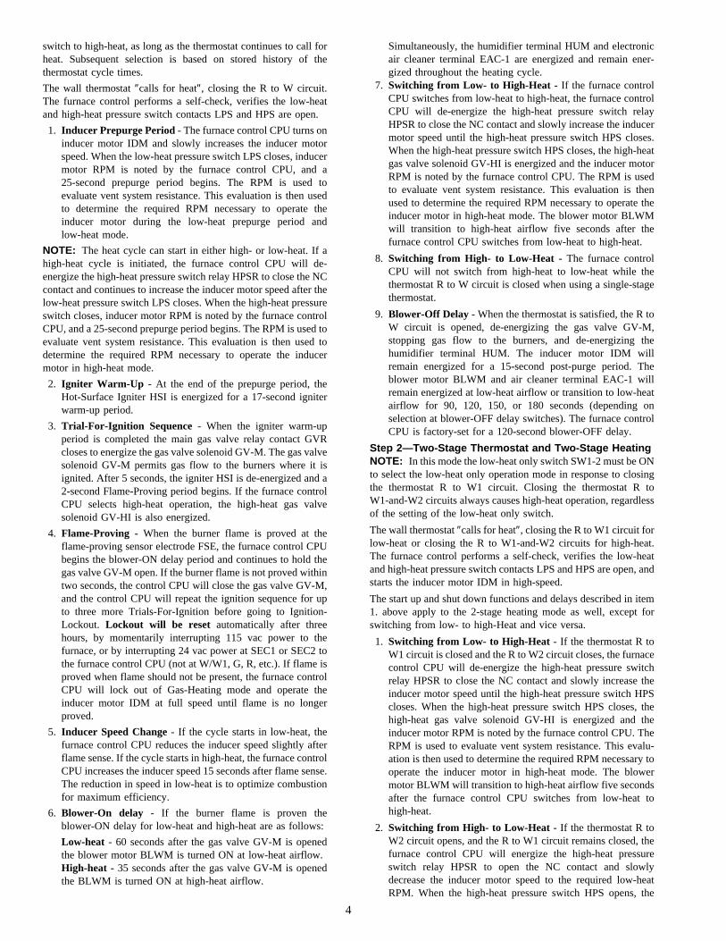
switch to high-heat, as long as the thermostat continues to call forheat. Subsequent selection is based on stored history of thethermostat cycle times.
The wall thermostat ″calls for heat″, closing the R to W circuit.The furnace control performs a self-check, verifies the low-heatand high-heat pressure switch contacts LPS and HPS are open.
1. Inducer Prepurge Period - The furnace control CPU turns oninducer motor IDM and slowly increases the inducer motorspeed. When the low-heat pressure switch LPS closes, inducermotor RPM is noted by the furnace control CPU, and a25-second prepurge period begins. The RPM is used toevaluate vent system resistance. This evaluation is then usedto determine the required RPM necessary to operate theinducer motor during the low-heat prepurge period andlow-heat mode.
NOTE: The heat cycle can start in either high- or low-heat. If ahigh-heat cycle is initiated, the furnace control CPU will de-energize the high-heat pressure switch relay HPSR to close the NCcontact and continues to increase the inducer motor speed after thelow-heat pressure switch LPS closes. When the high-heat pressureswitch closes, inducer motor RPM is noted by the furnace controlCPU, and a 25-second prepurge period begins. The RPM is used toevaluate vent system resistance. This evaluation is then used todetermine the required RPM necessary to operate the inducermotor in high-heat mode.
2. Igniter Warm-Up - At the end of the prepurge period, theHot-Surface Igniter HSI is energized for a 17-second igniterwarm-up period.
3. Trial-For-Ignition Sequence - When the igniter warm-upperiod is completed the main gas valve relay contact GVRcloses to energize the gas valve solenoid GV-M. The gas valvesolenoid GV-M permits gas flow to the burners where it isignited. After 5 seconds, the igniter HSI is de-energized and a2-second Flame-Proving period begins. If the furnace controlCPU selects high-heat operation, the high-heat gas valvesolenoid GV-HI is also energized.
4. Flame-Proving - When the burner flame is proved at theflame-proving sensor electrode FSE, the furnace control CPUbegins the blower-ON delay period and continues to hold thegas valve GV-M open. If the burner flame is not proved withintwo seconds, the control CPU will close the gas valve GV-M,and the control CPU will repeat the ignition sequence for upto three more Trials-For-Ignition before going to Ignition-Lockout. Lockout will be reset automatically after threehours, by momentarily interrupting 115 vac power to thefurnace, or by interrupting 24 vac power at SEC1 or SEC2 tothe furnace control CPU (not at W/W1, G, R, etc.). If flame isproved when flame should not be present, the furnace controlCPU will lock out of Gas-Heating mode and operate theinducer motor IDM at full speed until flame is no longerproved.
5. Inducer Speed Change - If the cycle starts in low-heat, thefurnace control CPU reduces the inducer speed slightly afterflame sense. If the cycle starts in high-heat, the furnace controlCPU increases the inducer speed 15 seconds after flame sense.The reduction in speed in low-heat is to optimize combustionfor maximum efficiency.
6. Blower-On delay - If the burner flame is proven theblower-ON delay for low-heat and high-heat are as follows:
Low-heat - 60 seconds after the gas valve GV-M is openedthe blower motor BLWM is turned ON at low-heat airflow.High-heat - 35 seconds after the gas valve GV-M is openedthe BLWM is turned ON at high-heat airflow.
Simultaneously, the humidifier terminal HUM and electronicair cleaner terminal EAC-1 are energized and remain ener-gized throughout the heating cycle.
7. Switching from Low- to High-Heat - If the furnace controlCPU switches from low-heat to high-heat, the furnace controlCPU will de-energize the high-heat pressure switch relayHPSR to close the NC contact and slowly increase the inducermotor speed until the high-heat pressure switch HPS closes.When the high-heat pressure switch HPS closes, the high-heatgas valve solenoid GV-HI is energized and the inducer motorRPM is noted by the furnace control CPU. The RPM is usedto evaluate vent system resistance. This evaluation is thenused to determine the required RPM necessary to operate theinducer motor in high-heat mode. The blower motor BLWMwill transition to high-heat airflow five seconds after thefurnace control CPU switches from low-heat to high-heat.
8. Switching from High- to Low-Heat - The furnace controlCPU will not switch from high-heat to low-heat while thethermostat R to W circuit is closed when using a single-stagethermostat.
9. Blower-Off Delay - When the thermostat is satisfied, the R toW circuit is opened, de-energizing the gas valve GV-M,stopping gas flow to the burners, and de-energizing thehumidifier terminal HUM. The inducer motor IDM willremain energized for a 15-second post-purge period. Theblower motor BLWM and air cleaner terminal EAC-1 willremain energized at low-heat airflow or transition to low-heatairflow for 90, 120, 150, or 180 seconds (depending onselection at blower-OFF delay switches). The furnace controlCPU is factory-set for a 120-second blower-OFF delay.
Step 2—Two-Stage Thermostat and Two-Stage HeatingNOTE: In this mode the low-heat only switch SW1-2 must be ONto select the low-heat only operation mode in response to closingthe thermostat R to W1 circuit. Closing the thermostat R toW1-and-W2 circuits always causes high-heat operation, regardlessof the setting of the low-heat only switch.
The wall thermostat ″calls for heat″, closing the R to W1 circuit forlow-heat or closing the R to W1-and-W2 circuits for high-heat.The furnace control performs a self-check, verifies the low-heatand high-heat pressure switch contacts LPS and HPS are open, andstarts the inducer motor IDM in high-speed.
The start up and shut down functions and delays described in item1. above apply to the 2-stage heating mode as well, except forswitching from low- to high-Heat and vice versa.
1. Switching from Low- to High-Heat - If the thermostat R toW1 circuit is closed and the R to W2 circuit closes, the furnacecontrol CPU will de-energize the high-heat pressure switchrelay HPSR to close the NC contact and slowly increase theinducer motor speed until the high-heat pressure switch HPScloses. When the high-heat pressure switch HPS closes, thehigh-heat gas valve solenoid GV-HI is energized and theinducer motor RPM is noted by the furnace control CPU. TheRPM is used to evaluate vent system resistance. This evalu-ation is then used to determine the required RPM necessary tooperate the inducer motor in high-heat mode. The blowermotor BLWM will transition to high-heat airflow five secondsafter the furnace control CPU switches from low-heat tohigh-heat.
2. Switching from High- to Low-Heat - If the thermostat R toW2 circuit opens, and the R to W1 circuit remains closed, thefurnace control CPU will energize the high-heat pressureswitch relay HPSR to open the NC contact and slowlydecrease the inducer motor speed to the required low-heatRPM. When the high-heat pressure switch HPS opens, the
4

high-heat gas valve solenoid GV-HI is de-energized. Whenthe inducer motor IDM reduces pressure sufficiently, thehigh-heat pressure switch HPS will open. The gas valvesolenoid GV-M will remain energized as long as the low-heatpressure switch LPS remains closed. The blower motorBLWM will transition to low-heat airflow five seconds afterthe R to W2 circuit opens.
Step 3—Cooling Mode
The thermostat ″calls for cooling″.
1. Single-Speed CoolingThe thermostat closes the R to G-and-Y circuits. The R to Ycircuit starts the outdoor unit, and the R to G-and-Y/Y2circuits start the furnace blower motor BLWM on coolingairflow. Cooling airflow is based on the A/C selection shownin Table 1 and 1a.The electronic air cleaner terminal EAC-1 is energized with115 vac when the blower motor BLWM is operating.When the thermostat is satisfied, the R to G-and-Y circuits areopened. The outdoor unit will stop, and the furnace blowermotor BLWM will continue operating at cooling airflow foran additional 90 seconds. Jumper Y/Y2 to DHUM to reducethe cooling off-delay to 5 seconds. (See Fig. 2 in Appendix.)
2. Single-Stage Thermostat and Two-Speed Cooling(Adaptive Mode)This furnace can operate a two-speed cooling unit with asingle-stage thermostat because the furnace control CPUincludes a programmed adaptive sequence of controlled op-eration, which selects low-cooling or high-cooling operation.This selection is based upon the stored history of the length ofprevious cooling period of the single-stage thermostat.
NOTE: The air conditioning relay disable jumper ACRDJ mustbe connected to enable the adaptive cooling mode in response to acall for cooling. (See Fig. 2 in Appendix.) When in place thefurnace control CPU can turn on the air conditioning relay ACR toenergize the Y/Y2 terminal and switch the outdoor unit tohigh-cooling.
The furnace control CPU can start up the cooling unit ineither low- or high-cooling. If starting up in low-cooling, thefurnace control CPU determines the low-cooling on-time(from 0 to 20 minutes) which is permitted before switchingto high-cooling.
If the power is interrupted, the stored history is erased andthe furnace control CPU will select low-cooling for up to 20minutes and then energize the air conditioning relay ACR toenergize the Y/Y2 terminal and switch the outdoor unit tohigh-cooling, as long as the thermostat continues to call forcooling. Subsequent selection is based on stored history ofthe thermostat cycle times.
The wall thermostat ″calls for cooling″, closing the R toG-and-Y circuits. The R to Y1 circuit starts the outdoor uniton low-cooling speed, and the R to G-and-Y1 circuits startsthe furnace blower motor BLWM at low-cooling airflowwhich is the true on-board CF selection as shown in Table 1and 1a.
If the furnace control CPU switches from low-cooling tohigh-cooling, the furnace control CPU will energize the airconditioning relay ACR. When the air conditioning relayACR is energized the R to Y1-and-Y2 circuits switch theoutdoor unit to high-cooling speed, and the R to G-and-Y1-and-Y/Y2 circuits transition the furnace blower motor
Table 1—Cooling Tonnage vs. Airflow (CFM)
AIR CONDITIONING TONS(12,000 BTU/HR)
AIRFLOW(CFM) 040, 060, AND 3T-080 MODEL 5T-080 AND 100 MODEL 120 MODEL
1-1/2 525 X2 700 X X X
2-1/2 875 X X X3 1050 X X X
3-1/2 1225 X X X4 1400 X X5 1750 X X6 2100 X
Table 1a—A/C or CF Airflow Selection ChartA03083
A/C OR CF AIRFLOW SELECTION CHARTBASED ON 350 CFM/TON
MODELSIZE
040,060, 3T-080
5T-080, 100
120
DEF. 5252 700 875 10501 1225 1225 1225
DEF. 7002 875 1050 1225 1400 17501 1750
DEF. 700 8752 1050 1225 1400 17501 2100
1. DEFAULT A/C AIRFLOW WHEN A/C SWITCHES ARE IN OFF POSITION2. DEFAULT CONT. FAN AIRFLOW WHEN CF SWITCHES ARE IN OFF POSITION
5
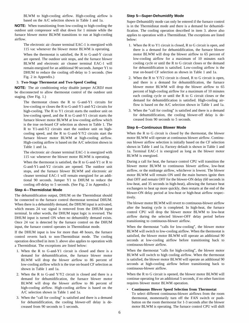
BLWM to high-cooling airflow. High-cooling airflow isbased on the A/C selection shown in Table 1 and 1a.
NOTE: When transitioning from low-cooling to high-cooling theoutdoor unit compressor will shut down for 1 minute while thefurnace blower motor BLWM transitions to run at high-coolingairflow.
The electronic air cleaner terminal EAC-1 is energized with115 vac whenever the blower motor BLWM is operating.
When the thermostat is satisfied, the R to G-and-Y circuitare opened. The outdoor unit stops, and the furnace blowerBLWM and electronic air cleaner terminal EAC-1 willremain energized for an additional 90 seconds. Jumper Y1 toDHUM to reduce the cooling off-delay to 5 seconds. (SeeFig. 2 in Appendix.)
3. Two-Stage Thermostat and Two-Speed Cooling
NOTE: The air conditioning relay disable jumper ACRDJ mustbe disconnected to allow thermostat control of the outdoor unitstaging. (See Fig. 1.)
The thermostat closes the R to G-and-Y1 circuits forlow-cooling or closes the R to G-and-Y1-and-Y2 circuits forhigh-cooling. The R to Y1 circuit starts the outdoor unit onlow-cooling speed, and the R to G-and-Y1 circuit starts thefurnace blower motor BLWM at low-cooling airflow whichis the true on-board CF selection as shown in Table 1. TheR to Y1-and-Y2 circuits start the outdoor unit on high-cooling speed, and the R to G-and-Y/Y2 circuits start thefurnace blower motor BLWM at high-cooling airflow.High-cooling airflow is based on the A/C selection shown inTable 1 and 1a.
The electronic air cleaner terminal EAC-1 is energized with115 vac whenever the blower motor BLWM is operating.
When the thermostat is satisfied, the R to G-and-Y1 or R toG-and-Y1-and-Y2 circuits are opened. The outdoor unitstops, and the furnace blower BLWM and electronic aircleaner terminal EAC-1 will remain energized for an addi-tional 90 seconds. Jumper Y1 to DHUM to reduce thecooling off-delay to 5 seconds. (See Fig. 2 in Appendix.)
Step 4—Thermidistat ModeThe dehumidification output, DHUM on the Thermidistat shouldbe connected to the furnace control thermostat terminal DHUM.When there is a dehumidify demand, the DHUM input is activated,which means 24 vac signal is removed from the DHUM inputterminal. In other words, the DHUM input logic is reversed. TheDHUM input is turned ON when no dehumidify demand exists.Once 24 vac is detected by the furnace control on the DHUMinput, the furnace control operates in Thermidistat mode.
If the DHUM input is low for more than 48 hours, the furnacecontrol reverts back to non-Thermidistat mode. The coolingoperation described in item 3. above also applies to operation witha Thermidistat. The exceptions are listed below:
1. When the R to G-and-Y1 circuit is closed and there is ademand for dehumidification, the furnace blower motorBLWM will drop the blower airflow to 86 percent oflow-cooling airflow which is the true on-board CF selection asshown in Table 1 and 1a.
2. When the R to G-and Y/Y2 circuit is closed and there is ademand for dehumidification, the furnace blower motorBLWM will drop the blower airflow to 86 percent ofhigh-cooling airflow. High-cooling airflow is based on theA/C selection shown in Table 1 and 1a.
3. When the ″call for cooling″ is satisfied and there is a demandfor dehumidification, the cooling blower-off delay is de-creased from 90 seconds to 5 seconds.
Step 5—Super-Dehumidify Mode
Super-Dehumidify mode can only be entered if the furnace controlis in the Thermidistat mode and there is a demand for dehumidi-fication. The cooling operation described in item 3. above alsoapplies to operation with a Thermidistat. The exceptions are listedbelow:
1. When the R to Y1 circuit is closed, R to G circuit is open, andthere is a demand for dehumidification, the furnace blowermotor BLWM will drop the blower airflow to 65 percent oflow-cooling airflow for a maximum of 10 minutes eachcooling cycle or until the R to G circuit closes or the demandfor dehumidification is satisfied. Low-cooling airflow is thetrue on-board CF selection as shown in Table 1 and 1a.
2. When the R to Y/Y2 circuit is closed, R to G circuit is open,and there is a demand for dehumidification, the furnaceblower motor BLWM will drop the blower airflow to 65percent of high-cooling airflow for a maximum of 10 minuteseach cooling cycle or until the R to G circuit closes or thedemand for dehumidification is satisfied. High-cooling air-flow is based on the A/C selection shown in Table 1 and 1a.
3. When the ″call for cooling″ is satisfied and there is a demandfor dehumidification, the cooling blower-off delay is de-creased from 90 seconds to 5 seconds.
Step 6—Continuous Blower Mode
When the R to G circuit is closed by the thermostat, the blowermotor BLWM will operate at continuous blower airflow. Continu-ous blower airflow selection is initially based on the CF selectionshown in Table 1 and 1a. Factory default is shown in Table 1 and1a. Terminal EAC-1 is energized as long as the blower motorBLWM is energized.
During a call for heat, the furnace control CPU will transition theblower motor BLWM to continuous blower airflow, low-heatairflow, or the midrange airflow, whichever is lowest. The blowermotor BLWM will remain ON until the main burners ignite thenshut OFF and remain OFF for the blower-ON delay (60 seconds inlow-heat, and 35 seconds in high-heat), allowing the furnace heatexchangers to heat up more quickly, then restarts at the end of theblower-ON delay period at low-heat or high-heat airflow respec-tively.
The blower motor BLWM will revert to continuous-blower airflowafter the heating cycle is completed. In high-heat, the furnacecontrol CPU will drop the blower motor BLWM to low-heatairflow during the selected blower-OFF delay period beforetransitioning to continuous-blower airflow.
When the thermostat ″calls for low-cooling″, the blower motorBLWM will switch to low-cooling airflow. When the thermostat issatisfied, the blower motor BLWM will operate an additional 90seconds at low-cooling airflow before transitioning back tocontinuous-blower airflow.
When the thermostat ″calls for high-cooling″, the blower motorBLWM will switch to high cooling airflow. When the thermostatis satisfied, the blower motor BLWM will operate an additional 90seconds at high-cooling airflow before transitioning back tocontinuous-blower airflow.
When the R to G circuit is opened, the blower motor BLWM willcontinue operating for an additional 5 seconds, if no other functionrequires blower motor BLWM operation.
• Continuous Blower Speed Selection from ThermostatTo select different continuous-blower airflows from the roomthermostat, momentarily turn off the FAN switch or push-button on the room thermostat for 1-3 seconds after the blowermotor BLWM is operating. The furnace control CPU will shift
6
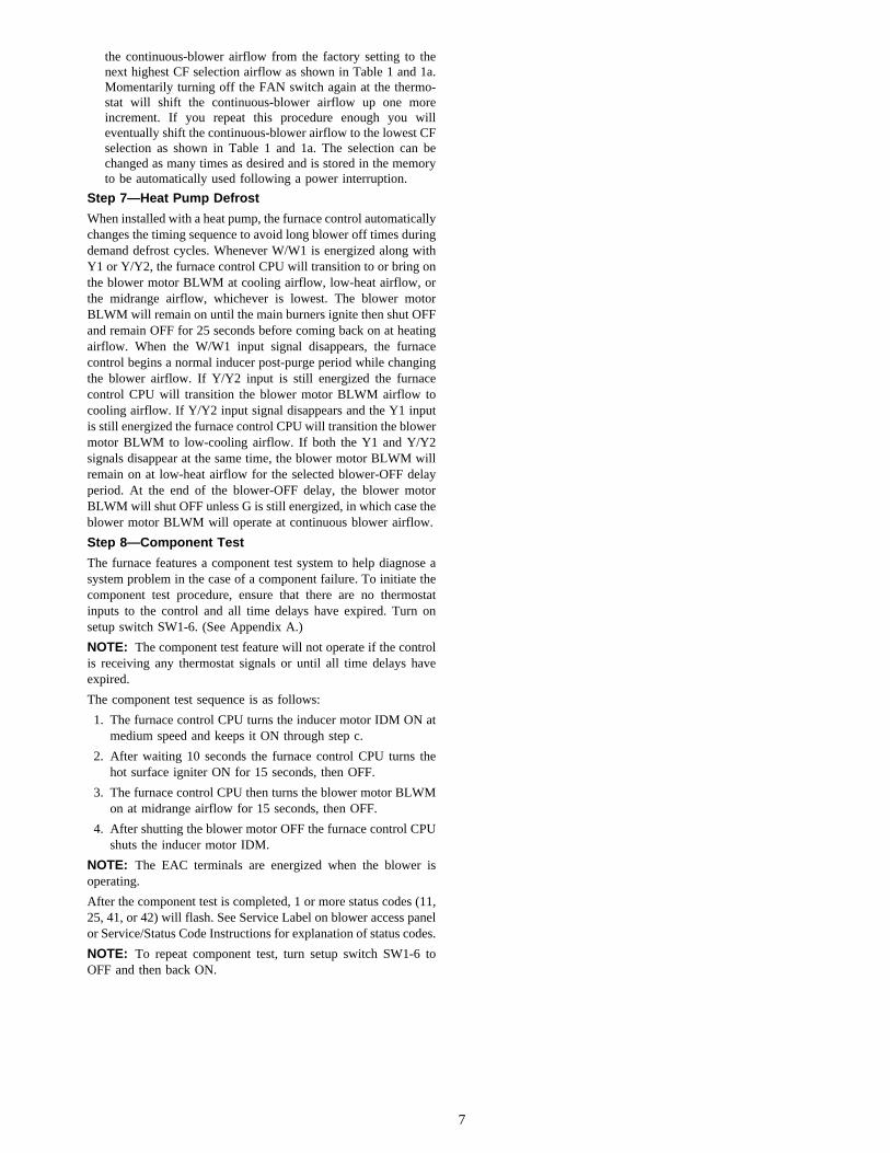
the continuous-blower airflow from the factory setting to thenext highest CF selection airflow as shown in Table 1 and 1a.Momentarily turning off the FAN switch again at the thermo-stat will shift the continuous-blower airflow up one moreincrement. If you repeat this procedure enough you willeventually shift the continuous-blower airflow to the lowest CFselection as shown in Table 1 and 1a. The selection can bechanged as many times as desired and is stored in the memoryto be automatically used following a power interruption.
Step 7—Heat Pump Defrost
When installed with a heat pump, the furnace control automaticallychanges the timing sequence to avoid long blower off times duringdemand defrost cycles. Whenever W/W1 is energized along withY1 or Y/Y2, the furnace control CPU will transition to or bring onthe blower motor BLWM at cooling airflow, low-heat airflow, orthe midrange airflow, whichever is lowest. The blower motorBLWM will remain on until the main burners ignite then shut OFFand remain OFF for 25 seconds before coming back on at heatingairflow. When the W/W1 input signal disappears, the furnacecontrol begins a normal inducer post-purge period while changingthe blower airflow. If Y/Y2 input is still energized the furnacecontrol CPU will transition the blower motor BLWM airflow tocooling airflow. If Y/Y2 input signal disappears and the Y1 inputis still energized the furnace control CPU will transition the blowermotor BLWM to low-cooling airflow. If both the Y1 and Y/Y2signals disappear at the same time, the blower motor BLWM willremain on at low-heat airflow for the selected blower-OFF delayperiod. At the end of the blower-OFF delay, the blower motorBLWM will shut OFF unless G is still energized, in which case theblower motor BLWM will operate at continuous blower airflow.
Step 8—Component Test
The furnace features a component test system to help diagnose asystem problem in the case of a component failure. To initiate thecomponent test procedure, ensure that there are no thermostatinputs to the control and all time delays have expired. Turn onsetup switch SW1-6. (See Appendix A.)
NOTE: The component test feature will not operate if the controlis receiving any thermostat signals or until all time delays haveexpired.
The component test sequence is as follows:
1. The furnace control CPU turns the inducer motor IDM ON atmedium speed and keeps it ON through step c.
2. After waiting 10 seconds the furnace control CPU turns thehot surface igniter ON for 15 seconds, then OFF.
3. The furnace control CPU then turns the blower motor BLWMon at midrange airflow for 15 seconds, then OFF.
4. After shutting the blower motor OFF the furnace control CPUshuts the inducer motor IDM.
NOTE: The EAC terminals are energized when the blower isoperating.
After the component test is completed, 1 or more status codes (11,25, 41, or 42) will flash. See Service Label on blower access panelor Service/Status Code Instructions for explanation of status codes.
NOTE: To repeat component test, turn setup switch SW1-6 toOFF and then back ON.
7
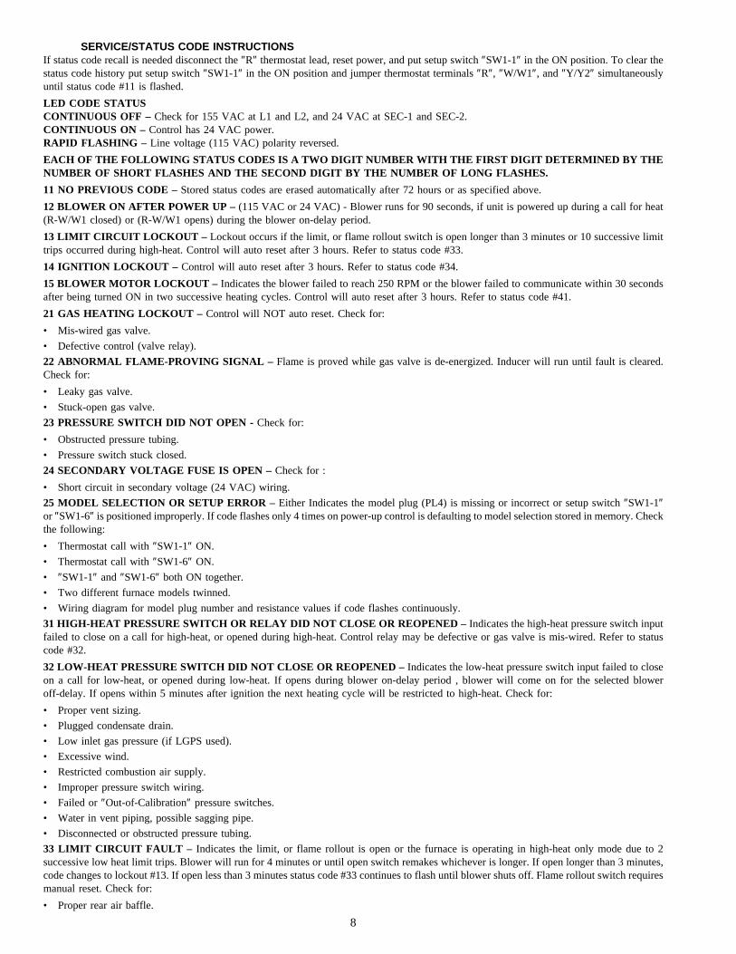
SERVICE/STATUS CODE INSTRUCTIONSIf status code recall is needed disconnect the ″R″ thermostat lead, reset power, and put setup switch ″SW1-1″ in the ON position. To clear thestatus code history put setup switch ″SW1-1″ in the ON position and jumper thermostat terminals ″R″, ″W/W1″, and ″Y/Y2″ simultaneouslyuntil status code #11 is flashed.
LED CODE STATUSCONTINUOUS OFF – Check for 155 VAC at L1 and L2, and 24 VAC at SEC-1 and SEC-2.CONTINUOUS ON – Control has 24 VAC power.RAPID FLASHING – Line voltage (115 VAC) polarity reversed.
EACH OF THE FOLLOWING STATUS CODES IS A TWO DIGIT NUMBER WITH THE FIRST DIGIT DETERMINED BY THENUMBER OF SHORT FLASHES AND THE SECOND DIGIT BY THE NUMBER OF LONG FLASHES.
11 NO PREVIOUS CODE – Stored status codes are erased automatically after 72 hours or as specified above.
12 BLOWER ON AFTER POWER UP – (115 VAC or 24 VAC) - Blower runs for 90 seconds, if unit is powered up during a call for heat(R-W/W1 closed) or (R-W/W1 opens) during the blower on-delay period.
13 LIMIT CIRCUIT LOCKOUT – Lockout occurs if the limit, or flame rollout switch is open longer than 3 minutes or 10 successive limittrips occurred during high-heat. Control will auto reset after 3 hours. Refer to status code #33.
14 IGNITION LOCKOUT – Control will auto reset after 3 hours. Refer to status code #34.
15 BLOWER MOTOR LOCKOUT – Indicates the blower failed to reach 250 RPM or the blower failed to communicate within 30 secondsafter being turned ON in two successive heating cycles. Control will auto reset after 3 hours. Refer to status code #41.
21 GAS HEATING LOCKOUT – Control will NOT auto reset. Check for:
• Mis-wired gas valve.
• Defective control (valve relay).
22 ABNORMAL FLAME-PROVING SIGNAL – Flame is proved while gas valve is de-energized. Inducer will run until fault is cleared.Check for:
• Leaky gas valve.
• Stuck-open gas valve.
23 PRESSURE SWITCH DID NOT OPEN - Check for:
• Obstructed pressure tubing.
• Pressure switch stuck closed.
24 SECONDARY VOLTAGE FUSE IS OPEN – Check for :
• Short circuit in secondary voltage (24 VAC) wiring.
25 MODEL SELECTION OR SETUP ERROR – Either Indicates the model plug (PL4) is missing or incorrect or setup switch ″SW1-1″or ″SW1-6″ is positioned improperly. If code flashes only 4 times on power-up control is defaulting to model selection stored in memory. Checkthe following:
• Thermostat call with ″SW1-1″ ON.
• Thermostat call with ″SW1-6″ ON.
• ″SW1-1″ and ″SW1-6″ both ON together.
• Two different furnace models twinned.
• Wiring diagram for model plug number and resistance values if code flashes continuously.
31 HIGH-HEAT PRESSURE SWITCH OR RELAY DID NOT CLOSE OR REOPENED – Indicates the high-heat pressure switch inputfailed to close on a call for high-heat, or opened during high-heat. Control relay may be defective or gas valve is mis-wired. Refer to statuscode #32.
32 LOW-HEAT PRESSURE SWITCH DID NOT CLOSE OR REOPENED – Indicates the low-heat pressure switch input failed to closeon a call for low-heat, or opened during low-heat. If opens during blower on-delay period , blower will come on for the selected bloweroff-delay. If opens within 5 minutes after ignition the next heating cycle will be restricted to high-heat. Check for:
• Proper vent sizing.
• Plugged condensate drain.
• Low inlet gas pressure (if LGPS used).
• Excessive wind.
• Restricted combustion air supply.
• Improper pressure switch wiring.
• Failed or ″Out-of-Calibration″ pressure switches.
• Water in vent piping, possible sagging pipe.
• Disconnected or obstructed pressure tubing.
33 LIMIT CIRCUIT FAULT – Indicates the limit, or flame rollout is open or the furnace is operating in high-heat only mode due to 2successive low heat limit trips. Blower will run for 4 minutes or until open switch remakes whichever is longer. If open longer than 3 minutes,code changes to lockout #13. If open less than 3 minutes status code #33 continues to flash until blower shuts off. Flame rollout switch requiresmanual reset. Check for:
• Proper rear air baffle.
8
• Loose blower wheel.
• Defective switch or connections.
• Improper low-heat gas input adjustment.
• Stuck high-heat solenoid in gas valve.
• Improper or misaligned limit and/or limit shield.
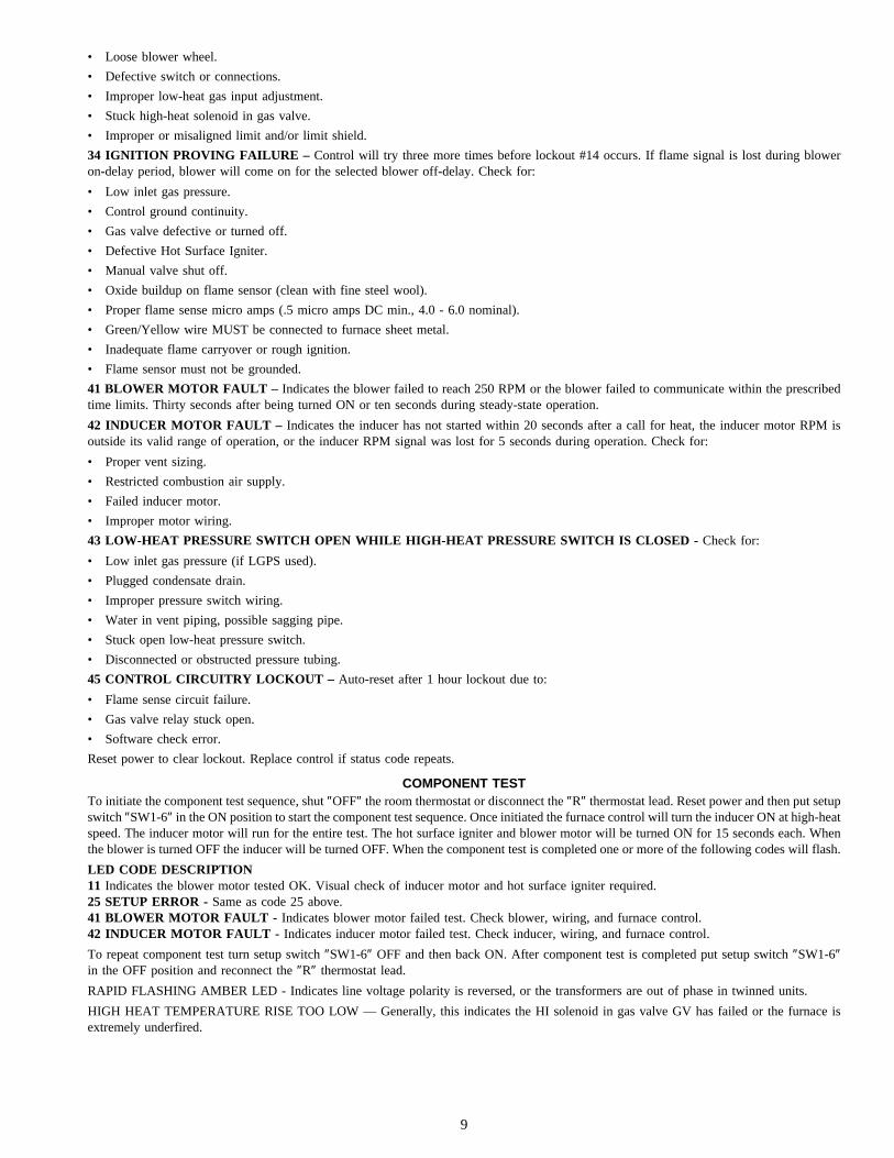
34 IGNITION PROVING FAILURE – Control will try three more times before lockout #14 occurs. If flame signal is lost during bloweron-delay period, blower will come on for the selected blower off-delay. Check for:
• Low inlet gas pressure.
• Control ground continuity.
• Gas valve defective or turned off.
• Defective Hot Surface Igniter.
• Manual valve shut off.
• Oxide buildup on flame sensor (clean with fine steel wool).
• Proper flame sense micro amps (.5 micro amps DC min., 4.0 - 6.0 nominal).
• Green/Yellow wire MUST be connected to furnace sheet metal.
• Inadequate flame carryover or rough ignition.
• Flame sensor must not be grounded.
41 BLOWER MOTOR FAULT – Indicates the blower failed to reach 250 RPM or the blower failed to communicate within the prescribedtime limits. Thirty seconds after being turned ON or ten seconds during steady-state operation.
42 INDUCER MOTOR FAULT – Indicates the inducer has not started within 20 seconds after a call for heat, the inducer motor RPM isoutside its valid range of operation, or the inducer RPM signal was lost for 5 seconds during operation. Check for:
• Proper vent sizing.
• Restricted combustion air supply.
• Failed inducer motor.
• Improper motor wiring.
43 LOW-HEAT PRESSURE SWITCH OPEN WHILE HIGH-HEAT PRESSURE SWITCH IS CLOSED - Check for:
• Low inlet gas pressure (if LGPS used).
• Plugged condensate drain.
• Improper pressure switch wiring.
• Water in vent piping, possible sagging pipe.
• Stuck open low-heat pressure switch.
• Disconnected or obstructed pressure tubing.
45 CONTROL CIRCUITRY LOCKOUT – Auto-reset after 1 hour lockout due to:
• Flame sense circuit failure.
• Gas valve relay stuck open.
• Software check error.
Reset power to clear lockout. Replace control if status code repeats.
COMPONENT TESTTo initiate the component test sequence, shut ″OFF″ the room thermostat or disconnect the ″R″ thermostat lead. Reset power and then put setupswitch ″SW1-6″ in the ON position to start the component test sequence. Once initiated the furnace control will turn the inducer ON at high-heatspeed. The inducer motor will run for the entire test. The hot surface igniter and blower motor will be turned ON for 15 seconds each. Whenthe blower is turned OFF the inducer will be turned OFF. When the component test is completed one or more of the following codes will flash.
LED CODE DESCRIPTION11 Indicates the blower motor tested OK. Visual check of inducer motor and hot surface igniter required.25 SETUP ERROR - Same as code 25 above.41 BLOWER MOTOR FAULT - Indicates blower motor failed test. Check blower, wiring, and furnace control.42 INDUCER MOTOR FAULT - Indicates inducer motor failed test. Check inducer, wiring, and furnace control.
To repeat component test turn setup switch ″SW1-6″ OFF and then back ON. After component test is completed put setup switch ″SW1-6″in the OFF position and reconnect the ″R″ thermostat lead.
RAPID FLASHING AMBER LED - Indicates line voltage polarity is reversed, or the transformers are out of phase in twinned units.
HIGH HEAT TEMPERATURE RISE TOO LOW — Generally, this indicates the HI solenoid in gas valve GV has failed or the furnace isextremely underfired.
9

START HERE-IF A PROBLEM EXISTS, THE SERVICE TECHNICIAN SHOULD ALWAYS BEGINTROUBLSHOOTING HERE
Special Note: All voltmeters are not the same - your readings will vary. This applies to the entire content of this troubleshootingmanual. They are not absolute values. Correct 115-VAC VOLTAGE, CURRENT, and power MEASUREMENTS CANNOT BETAKEN ON VARIABLE SPEED FURNACES UNLESS USING A TRUE rms METER.
STEP ACTION YES NO GO TO
1
Remove main furnace door first. DO NOT REMOVEBLOWER ACCESS PANEL! Record status of AMBER LED.
See Service/Status Code Instructions.Is AMBER LED status light on?
2 19
2 Is the AMBER LED status light blinking rapidly without apause? 3 4
3 Go to the page number indicated in the Index for RAPIDFLASHING LED. INDEX
4 Is the AMBER LED status light blinking ON/OFF slowly witha combination of short and long flashes? 5 7
5Determine status code. The status code is a 2 digit numberwith the first digit determined by the number of short flashes
and the second digit by the number of long flashes.6
6 Go to page number indicated in the Index for the sectioncovering the status code. INDEX
7
To retrieve previous codes, no thermostat inputs to the con-trol must be present and all time delays must have expired.Put setup switch SW1-1 in the ON position and record thestatus codes listed in the status code history. The statuscodes will flash in the order of occurrence. Read status
codes until an 11 code flashes. After the 11 code flashesthe status codes will repeat.
8
8
Was there a previous status code other than code 11?Note: Status codes are erased after 72 hours or can be
manually erased by putting setup switch SW1-1 in the ONposition and jumpering R, W/W1, and Y/Y2 simultaneously
until status code 11 is flashed.
9 10
9 Go to page number indicated in the Index for the sectioncovering the first previous status code. INDEX
10 Does the problem appear to be low cooling airflow? 11 12
11 Go to page number indicated in Index for the section cover-ing IMPROPER COOLING AIRFLOW. INDEX
12 Set thermostat to call for heat and set the thermostat fancontrol to AUTO position if equipped. 13
13 Does the furnace respond to the call for heat? 14 28
14 Observe operation of furnace for 20 minutes or until AM-BER LED status light starts blinking. 15
15 Does the AMBER LED status light blink ON/OFF slowlywith a combination of short and long flashes? 5 16
16
Is the temperature rise below the range specified on therating plate when the unit is operating in high heat?
Note: If the temperature rise is above the range specifiedon the rating plate refer to the Start-Up and Adjustment
section in the Installation, Start-Up, and Operating Instruc-tions.
17 18
17Go to page number indicated in Index for the section cover-ing HIGH HEAT TEMPERATURE RISE TOO LOW (COLD
BLOW).INDEX
18 Go to page number indicated in Index for CLEANUP ANDSTART-UP INSTRUCTIONS. INDEX
19 Make sure power is being supplied to the furnace. 20
20Check fuses, breakers, or manual disconnects to be surethey are correctly set. If not, reset them and go back to
step 1.21
21 Remove blower access panel and depress door switch. Usea piece of tape to hold switch closed. 22
22 Is 115-vac across L1 and L2? 24 23
23Turn power off. Check continuity of power leads and door
switch. If necessary repair power leads and/or replace doorswitch.
18
24 Is 24-vac across SEC-1 and SEC-2? 25 2625 Replace the variable speed furnace control. 18
10
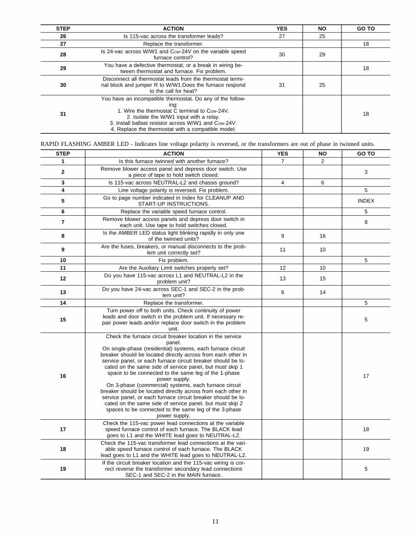
STEP ACTION YES NO GO TO26 Is 115-vac across the transformer leads? 27 2527 Replace the transformer. 18
28 Is 24-vac across W/W1 and COM-24V on the variable speedfurnace control? 30 29
29 You have a defective thermostat, or a break in wiring be-tween thermostat and furnace. Fix problem. 18
30Disconnect all thermostat leads from the thermostat termi-
nal block and jumper R to W/W1.Does the furnace respondto the call for heat?
31 25
31
You have an incompatible thermostat. Do any of the follow-ing:
1. Wire the thermostat C terminal to COM-24V.2. Isolate the W/W1 input with a relay.
3. Install ballast resistor across W/W1 and COM-24V.4. Replace the thermostat with a compatible model.
18
RAPID FLASHING AMBER LED - Indicates line voltage polarity is reversed, or the transformers are out of phase in twinned units.
STEP ACTION YES NO GO TO1 Is this furnace twinned with another furnace? 7 2
2 Remove blower access panel and depress door switch. Usea piece of tape to hold switch closed. 3
3 Is 115-vac across NEUTRAL-L2 and chassis ground? 4 64 Line voltage polarity is reversed. Fix problem. 5
5 Go to page number indicated in Index for CLEANUP ANDSTART-UP INSTRUCTIONS. INDEX
6 Replace the variable speed furnace control. 5
7 Remove blower access panels and depress door switch ineach unit. Use tape to hold switches closed. 8
8 Is the AMBER LED status light blinking rapidly in only oneof the twinned units? 9 16
9 Are the fuses, breakers, or manual disconnects to the prob-lem unit correctly set? 11 10
10 Fix problem. 511 Are the Auxiliary Limit switches properly set? 12 10
12 Do you have 115-vac across L1 and NEUTRAL-L2 in theproblem unit? 13 15
13 Do you have 24-vac across SEC-1 and SEC-2 in the prob-lem unit? 6 14
14 Replace the transformer. 5
15
Turn power off to both units. Check continuity of powerleads and door switch in the problem unit. If necessary re-pair power leads and/or replace door switch in the problem
unit.
5
16
Check the furnace circuit breaker location in the servicepanel.
On single-phase (residential) systems, each furnace circuitbreaker should be located directly across from each other inservice panel, or each furnace circuit breaker should be lo-cated on the same side of service panel, but must skip 1space to be connected to the same leg of the 1-phase
power supply.On 3-phase (commercial) systems, each furnace circuit
breaker should be located directly across from each other inservice panel, or each furnace circuit breaker should be lo-cated on the same side of service panel, but must skip 2spaces to be connected to the same leg of the 3-phase
power supply.
17
17Check the 115-vac power lead connections at the variablespeed furnace control of each furnace. The BLACK leadgoes to L1 and the WHITE lead goes to NEUTRAL-L2.
18
18Check the 115-vac transformer lead connections at the vari-
able speed furnace control of each furnace. The BLACKlead goes to L1 and the WHITE lead goes to NEUTRAL-L2.
19
19If the circuit breaker location and the 115-vac wiring is cor-rect reverse the transformer secondary lead connections
SEC-1 and SEC-2 in the MAIN furnace.5
11
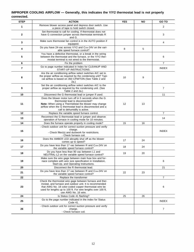
IMPROPER COOLING AIRFLOW — Generally, this indicates the Y/Y2 thermostat lead is not properlyconnected.
STEP ACTION YES NO GO TO
1 Remove blower access panel and depress door switch. Usea piece of tape to hold switch closed. 2
2Set thermostat to call for cooling. If thermostat does not
have G connection jumper across thermostat terminals Rand G.
3
3 Make sure thermostat fan control is in the AUTO position ifequipped. 4
4 Do you have 24-vac across Y/Y2 and COM-24V on the vari-able speed furnace control? 8 5
5You have a defective thermostat, or a break in the wiringbetween the thermostat and the furnace, or the Y/Y2 ther-
mostat terminal is not wired to the thermostat.6
6 Fix the problem 7
7 Go to page number indicated in Index for CLEANUP ANDSTART-UP INSTRUCTIONS. INDEX
8
Are the air conditioning airflow select switches A/C set tothe proper airflow as required by the condensing unit? Typi-
cal airflow is based on 350 CFM/TON (See Table 2 and2a.)
10 9
9Set the air conditioning airflow select switches A/C to theproper airflow as required by the condensing unit. (See
Table 2 and 2a.)7
10 Disconnect the G thermostat lead or jumper if used. 11
11
Does the blower motor turn off in 5 seconds when the Gthermostat lead is disconnected?
Note: When using a Thermidistat the blower may changeairflow when the G thermostat lead is disconnected and a
call to dehumidify is active.
12 13
12 Replace the variable speed furnace control. 7
13 Reconnect the G thermostat lead or jumper and observeoperation of furnace in cooling mode for 10 minutes. 14
14 Does the furnace operate properly in cooling mode? 15 16
15
- Check outdoor unit for correct suction pressure and verifycharge.
- Check filter(s) and ductwork for restrictions.- Check furnace coil.
INDEX
16 Does the AMBER LED abruptly shut off as the blowercomes up to speed? 17 24
17 Do you have less than 17 vac between R and COM-24V onthe variable speed furnace control? 18 24
18 Do you have less than 90 vac between L1 andNEUTRAL-L2 on the variable speed furnace control? 19 20
19Make sure the wire gage between main fuse box and fur-nace complies with wire size specification in Installation,
Start-Up, and Operating Instructions.6
20 Disconnect the R thermostat lead. 21
21 Do you have less than 17 vac between R and COM-24V onthe variable speed furnace control? 22 23
22 Replace the transformer 7
23
Check the thermostat wire gage between furnace and ther-mostat, and furnace and outdoor unit. It is recommendedthat AWG No. 18 color-coded copper thermostat wire be
used for lengths up to 100 ft. For wire lengths over 100 ft,use AWG No. 16 wire.
6
24 Is Status Code 41 flashing? 25 26
25 Go to the page number indicated in the Index for StatusCode 41. INDEX
26- Check outdoor unit for correct suction pressure and verify
charge.- Check furnace coil.
7
12
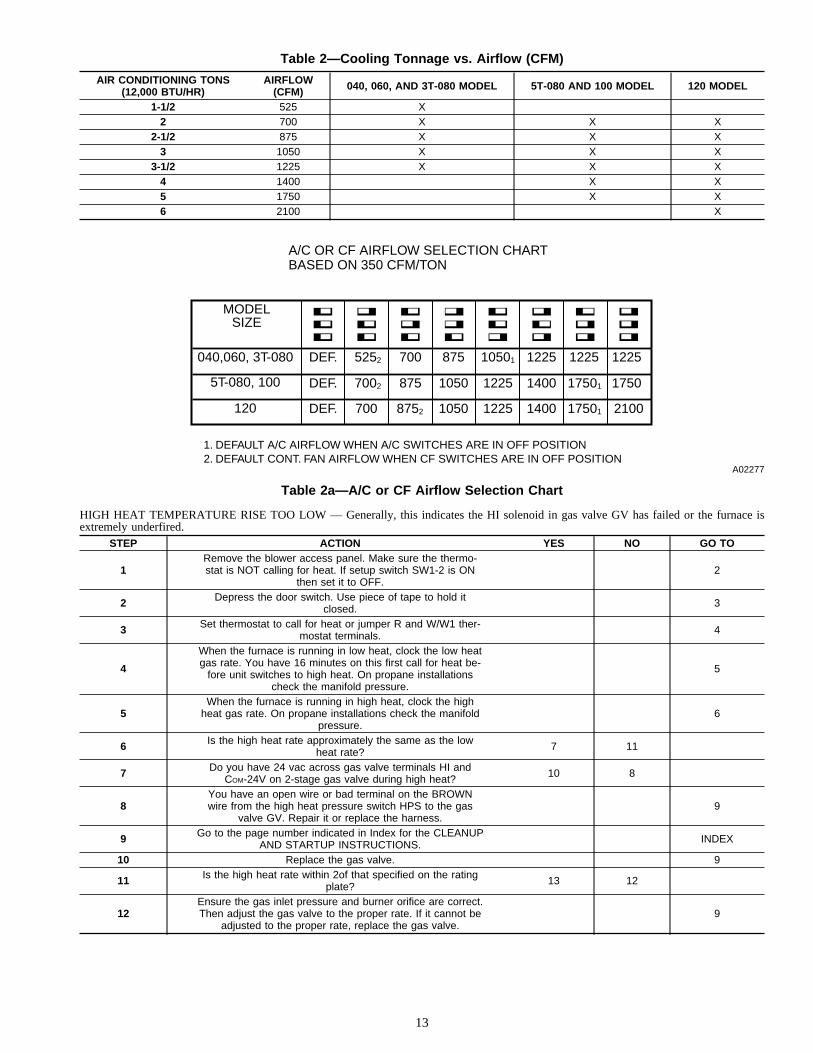
HIGH HEAT TEMPERATURE RISE TOO LOW — Generally, this indicates the HI solenoid in gas valve GV has failed or the furnace isextremely underfired.
STEP ACTION YES NO GO TO
1Remove the blower access panel. Make sure the thermo-stat is NOT calling for heat. If setup switch SW1-2 is ON
then set it to OFF.2
2 Depress the door switch. Use piece of tape to hold itclosed. 3
3 Set thermostat to call for heat or jumper R and W/W1 ther-mostat terminals. 4
4
When the furnace is running in low heat, clock the low heatgas rate. You have 16 minutes on this first call for heat be-
fore unit switches to high heat. On propane installationscheck the manifold pressure.
5
5When the furnace is running in high heat, clock the high
heat gas rate. On propane installations check the manifoldpressure.
6
6 Is the high heat rate approximately the same as the lowheat rate? 7 11
7 Do you have 24 vac across gas valve terminals HI andCOM-24V on 2-stage gas valve during high heat? 10 8
8You have an open wire or bad terminal on the BROWNwire from the high heat pressure switch HPS to the gas
valve GV. Repair it or replace the harness.9
9 Go to the page number indicated in Index for the CLEANUPAND STARTUP INSTRUCTIONS. INDEX
10 Replace the gas valve. 9
11 Is the high heat rate within 2of that specified on the ratingplate? 13 12
12Ensure the gas inlet pressure and burner orifice are correct.Then adjust the gas valve to the proper rate. If it cannot be
adjusted to the proper rate, replace the gas valve.9
Table 2—Cooling Tonnage vs. Airflow (CFM)
AIR CONDITIONING TONS(12,000 BTU/HR)
AIRFLOW(CFM) 040, 060, AND 3T-080 MODEL 5T-080 AND 100 MODEL 120 MODEL
1-1/2 525 X2 700 X X X
2-1/2 875 X X X3 1050 X X X
3-1/2 1225 X X X4 1400 X X5 1750 X X6 2100 X
Table 2a—A/C or CF Airflow Selection Chart
A02277
A/C OR CF AIRFLOW SELECTION CHARTBASED ON 350 CFM/TON
MODELSIZE
040,060, 3T-080
5T-080, 100
120
DEF. 5252 700 875 10501 1225 1225 1225
DEF. 7002 875 1050 1225 1400 17501 1750
DEF. 700 8752 1050 1225 1400 17501 2100
1. DEFAULT A/C AIRFLOW WHEN A/C SWITCHES ARE IN OFF POSITION2. DEFAULT CONT. FAN AIRFLOW WHEN CF SWITCHES ARE IN OFF POSITION
13
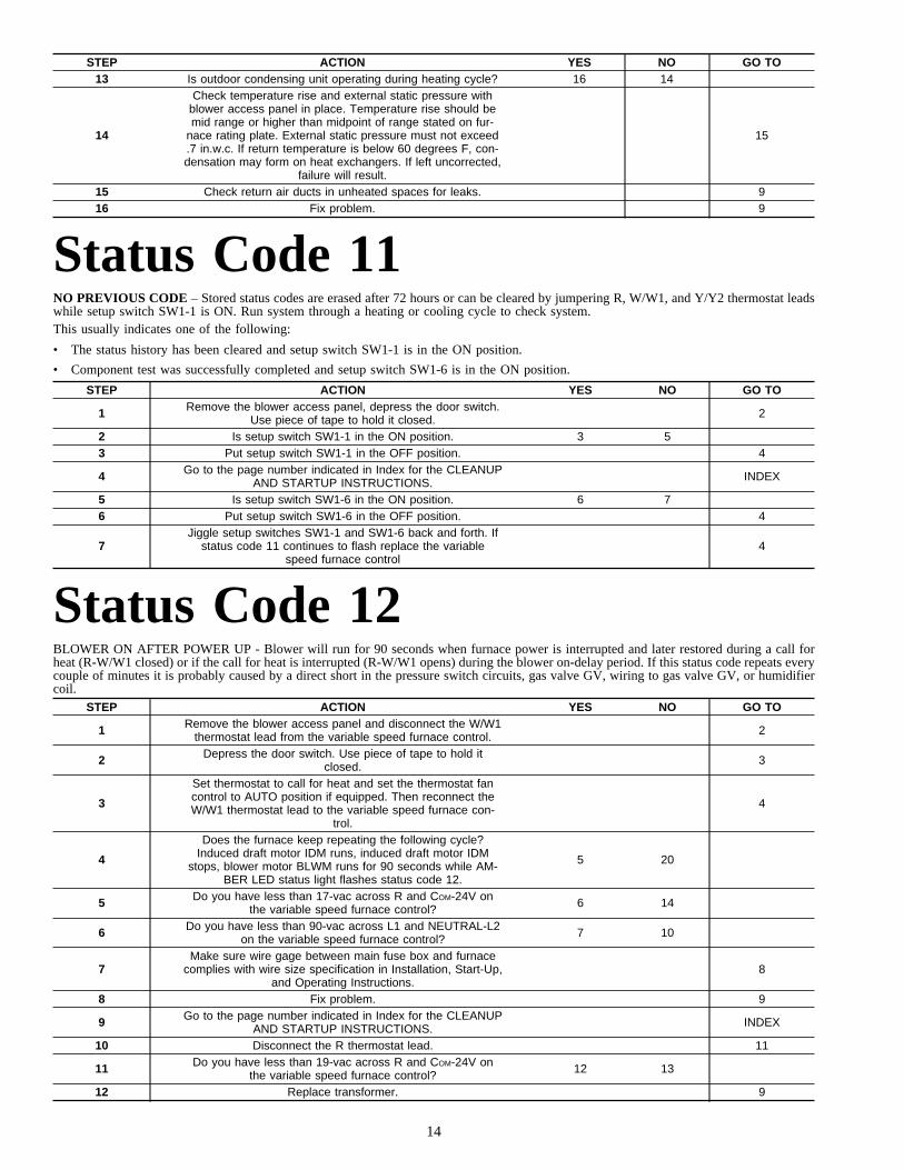
STEP ACTION YES NO GO TO13 Is outdoor condensing unit operating during heating cycle? 16 14
14
Check temperature rise and external static pressure withblower access panel in place. Temperature rise should bemid range or higher than midpoint of range stated on fur-
nace rating plate. External static pressure must not exceed.7 in.w.c. If return temperature is below 60 degrees F, con-densation may form on heat exchangers. If left uncorrected,
failure will result.
15
15 Check return air ducts in unheated spaces for leaks. 916 Fix problem. 9
Status Code 11NO PREVIOUS CODE – Stored status codes are erased after 72 hours or can be cleared by jumpering R, W/W1, and Y/Y2 thermostat leadswhile setup switch SW1-1 is ON. Run system through a heating or cooling cycle to check system.This usually indicates one of the following:
• The status history has been cleared and setup switch SW1-1 is in the ON position.
• Component test was successfully completed and setup switch SW1-6 is in the ON position.
STEP ACTION YES NO GO TO
1 Remove the blower access panel, depress the door switch.Use piece of tape to hold it closed. 2
2 Is setup switch SW1-1 in the ON position. 3 53 Put setup switch SW1-1 in the OFF position. 4
4 Go to the page number indicated in Index for the CLEANUPAND STARTUP INSTRUCTIONS. INDEX
5 Is setup switch SW1-6 in the ON position. 6 76 Put setup switch SW1-6 in the OFF position. 4
7Jiggle setup switches SW1-1 and SW1-6 back and forth. If
status code 11 continues to flash replace the variablespeed furnace control
4
Status Code 12BLOWER ON AFTER POWER UP - Blower will run for 90 seconds when furnace power is interrupted and later restored during a call forheat (R-W/W1 closed) or if the call for heat is interrupted (R-W/W1 opens) during the blower on-delay period. If this status code repeats everycouple of minutes it is probably caused by a direct short in the pressure switch circuits, gas valve GV, wiring to gas valve GV, or humidifiercoil.
STEP ACTION YES NO GO TO
1 Remove the blower access panel and disconnect the W/W1thermostat lead from the variable speed furnace control. 2
2 Depress the door switch. Use piece of tape to hold itclosed. 3
3
Set thermostat to call for heat and set the thermostat fancontrol to AUTO position if equipped. Then reconnect theW/W1 thermostat lead to the variable speed furnace con-
trol.
4
4
Does the furnace keep repeating the following cycle?Induced draft motor IDM runs, induced draft motor IDM
stops, blower motor BLWM runs for 90 seconds while AM-BER LED status light flashes status code 12.
5 20
5 Do you have less than 17-vac across R and COM-24V onthe variable speed furnace control? 6 14
6 Do you have less than 90-vac across L1 and NEUTRAL-L2on the variable speed furnace control? 7 10
7Make sure wire gage between main fuse box and furnace
complies with wire size specification in Installation, Start-Up,and Operating Instructions.
8
8 Fix problem. 9
9 Go to the page number indicated in Index for the CLEANUPAND STARTUP INSTRUCTIONS. INDEX
10 Disconnect the R thermostat lead. 11
11 Do you have less than 19-vac across R and COM-24V onthe variable speed furnace control? 12 13
12 Replace transformer. 9
14

STEP ACTION YES NO GO TO
13The thermostat and/or thermostat wires are loading downthe transformer. Replace the thermostat or repair thermo-
stat wires.9
14 Does the hot surface ignitor HSI come on during the cycle? 15 19
15 Disconnect the humidifier lead from HUM terminal on vari-able speed furnace control. 16
16 Does the furnace still alternately cycle induced draft motorIDM and blower motor BLWM as described in Step 4. 18 17
17 There is a direct short in wiring to humidifier solenoid coil,diode bridge(if used), or humidifier solenoid coil. 8
18 There is a short in the gas valve GV or wiring to gas valveGV. Refer to Appendix E to check gas valve GV. 8
19 There is a direct short in the ORANGE wire from the lowheat pressure switch LPS. 8
20 While the unit is operating in low heat jumper R and W2thermostat terminals. 21
21Does the furnace abruptly shut down with no inducer postpurge and then run blower motor BLWM for 90 secondswhile AMBER LED status light flashes status code 12.
22 26
22 Disconnect BROWN wire to gas valve GV. 23
23 Does the furnace still abruptly shut down as described inStep 21. 25 24
24 Replace gas valve. 9
25 There is a direct short to ground in the GRAY or BROWNwires connected to the high heat pressure switch HPS. 8
26
Power to the furnace was probably interrupted or line volt-age was too low during a call for heat. This is normal op-eration. Go to the page number indicated in Index for the
CLEANUP AND STARTUP INSTRUCTIONS.
INDEX
Status Code 13LIMIT CIRCUIT LOCKOUT - Lockout occurs if the limit or flame rollout switch is open longer than 3 minutes or 10 successive limit tripsoccurred during high-heat. The variable speed furnace control will auto-reset in 3 hours. Flame roll-out switch FRS requires manual-reset.
STEP ACTION YES NO GO TO
1 Remove the blower access panel. Make sure the thermo-stat is NOT calling for heat. 2
2 Depress the door switch. Use piece of tape to hold itclosed. 3
3 Does status code 33 flash? 11 44 Does a different status code flash? 5 6
5 Go to page number indicated in the Index for the sectioncovering the status code. INDEX
6 Set thermostat to call for heat or jumper R and W/W1 ther-mostat terminals. 7
7 Observe the furnace operation for 25 minutes or until statuscode starts flashing. 8
8 Does status code 33 flash? 26 99 Does a different status code flash? 5 10
10 Go to page number indicated in Index for CLEANUP ANDSTART-UP INSTRUCTIONS. INDEX
11 Is 24-vac across connector terminal PL1-6 and COM-24V onvariable speed furnace control? 13 12
12 Replace the variable speed furnace control. 10
13 Is 24-vac across connector terminal PL1-8 and COM-24V onvariable speed furnace control? 12 14
14 Turn power off. 1515 Do you have continuity across limit switch LS? 17 1616 Replace limit switch LS. 10
17 Do you have continuity across the flame rollout switchFRS? 25 18
18 Can flame rollout switch FRS be reset? 20 1919 Replace flame rollout switch FRS. 10
20 Reset flame rollout switch FRS, turn power on, and observefurnace operation for (2) 15 minute cycles. 21
21 Does the flame rollout switch FRS trip again? 23 22
15
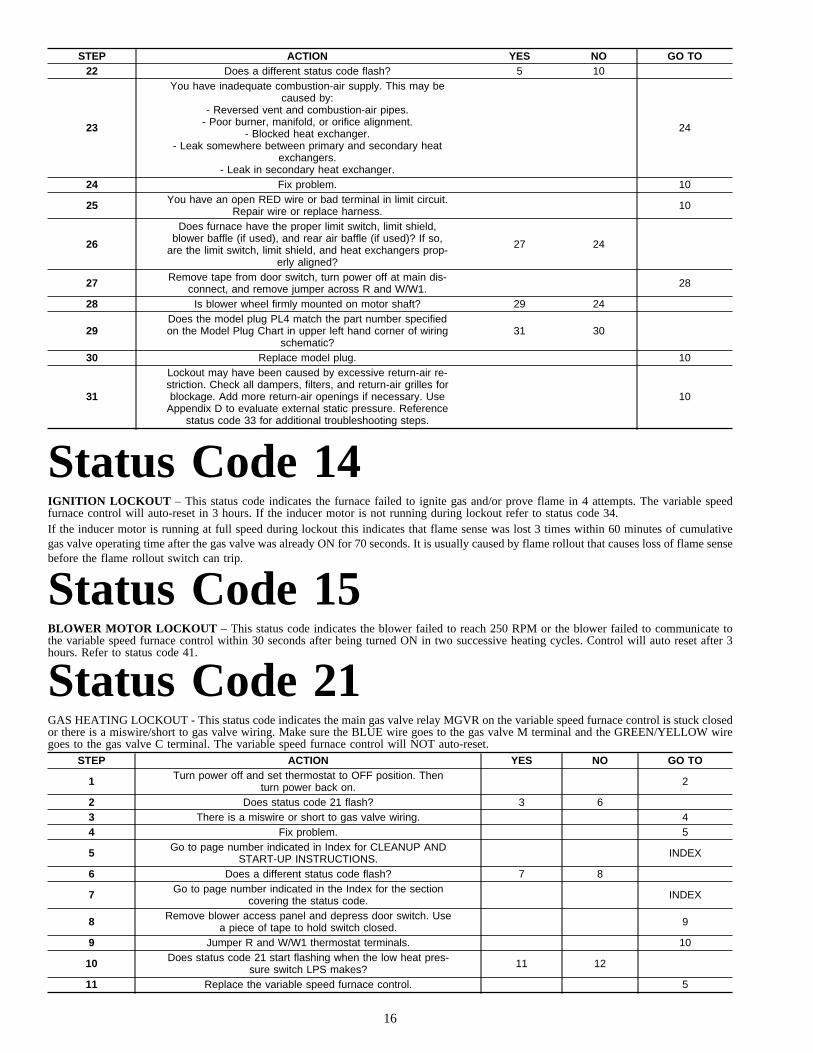
STEP ACTION YES NO GO TO22 Does a different status code flash? 5 10
23
You have inadequate combustion-air supply. This may becaused by:
- Reversed vent and combustion-air pipes.- Poor burner, manifold, or orifice alignment.
- Blocked heat exchanger.- Leak somewhere between primary and secondary heat
exchangers.- Leak in secondary heat exchanger.
24
24 Fix problem. 10
25 You have an open RED wire or bad terminal in limit circuit.Repair wire or replace harness. 10
26
Does furnace have the proper limit switch, limit shield,blower baffle (if used), and rear air baffle (if used)? If so,
are the limit switch, limit shield, and heat exchangers prop-erly aligned?
27 24
27 Remove tape from door switch, turn power off at main dis-connect, and remove jumper across R and W/W1. 28
28 Is blower wheel firmly mounted on motor shaft? 29 24
29Does the model plug PL4 match the part number specifiedon the Model Plug Chart in upper left hand corner of wiring
schematic?31 30
30 Replace model plug. 10
31
Lockout may have been caused by excessive return-air re-striction. Check all dampers, filters, and return-air grilles forblockage. Add more return-air openings if necessary. Use
Appendix D to evaluate external static pressure. Referencestatus code 33 for additional troubleshooting steps.
10
Status Code 14IGNITION LOCKOUT – This status code indicates the furnace failed to ignite gas and/or prove flame in 4 attempts. The variable speedfurnace control will auto-reset in 3 hours. If the inducer motor is not running during lockout refer to status code 34.If the inducer motor is running at full speed during lockout this indicates that flame sense was lost 3 times within 60 minutes of cumulativegas valve operating time after the gas valve was already ON for 70 seconds. It is usually caused by flame rollout that causes loss of flame sensebefore the flame rollout switch can trip.
Status Code 15BLOWER MOTOR LOCKOUT – This status code indicates the blower failed to reach 250 RPM or the blower failed to communicate tothe variable speed furnace control within 30 seconds after being turned ON in two successive heating cycles. Control will auto reset after 3hours. Refer to status code 41.
Status Code 21GAS HEATING LOCKOUT - This status code indicates the main gas valve relay MGVR on the variable speed furnace control is stuck closedor there is a miswire/short to gas valve wiring. Make sure the BLUE wire goes to the gas valve M terminal and the GREEN/YELLOW wiregoes to the gas valve C terminal. The variable speed furnace control will NOT auto-reset.
STEP ACTION YES NO GO TO
1 Turn power off and set thermostat to OFF position. Thenturn power back on. 2
2 Does status code 21 flash? 3 63 There is a miswire or short to gas valve wiring. 44 Fix problem. 5
5 Go to page number indicated in Index for CLEANUP ANDSTART-UP INSTRUCTIONS. INDEX
6 Does a different status code flash? 7 8
7 Go to page number indicated in the Index for the sectioncovering the status code. INDEX
8 Remove blower access panel and depress door switch. Usea piece of tape to hold switch closed. 9
9 Jumper R and W/W1 thermostat terminals. 10
10 Does status code 21 start flashing when the low heat pres-sure switch LPS makes? 11 12
11 Replace the variable speed furnace control. 5
16
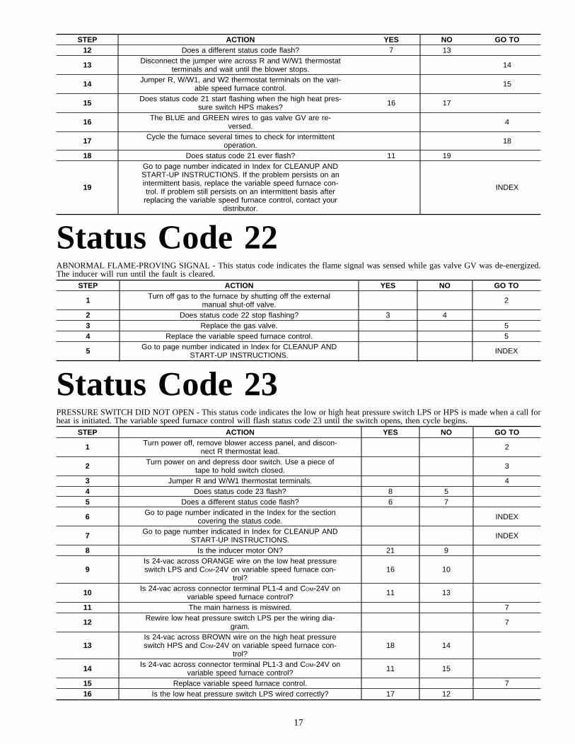
STEP ACTION YES NO GO TO12 Does a different status code flash? 7 13
13 Disconnect the jumper wire across R and W/W1 thermostatterminals and wait until the blower stops. 14
14 Jumper R, W/W1, and W2 thermostat terminals on the vari-able speed furnace control. 15
15 Does status code 21 start flashing when the high heat pres-sure switch HPS makes? 16 17
16 The BLUE and GREEN wires to gas valve GV are re-versed. 4
17 Cycle the furnace several times to check for intermittentoperation. 18
18 Does status code 21 ever flash? 11 19
19
Go to page number indicated in Index for CLEANUP ANDSTART-UP INSTRUCTIONS. If the problem persists on anintermittent basis, replace the variable speed furnace con-trol. If problem still persists on an intermittent basis after
replacing the variable speed furnace control, contact yourdistributor.
INDEX
Status Code 22ABNORMAL FLAME-PROVING SIGNAL - This status code indicates the flame signal was sensed while gas valve GV was de-energized.The inducer will run until the fault is cleared.
STEP ACTION YES NO GO TO
1 Turn off gas to the furnace by shutting off the externalmanual shut-off valve. 2
2 Does status code 22 stop flashing? 3 43 Replace the gas valve. 54 Replace the variable speed furnace control. 5
5 Go to page number indicated in Index for CLEANUP ANDSTART-UP INSTRUCTIONS. INDEX
Status Code 23PRESSURE SWITCH DID NOT OPEN - This status code indicates the low or high heat pressure switch LPS or HPS is made when a call forheat is initiated. The variable speed furnace control will flash status code 23 until the switch opens, then cycle begins.
STEP ACTION YES NO GO TO
1 Turn power off, remove blower access panel, and discon-nect R thermostat lead. 2
2 Turn power on and depress door switch. Use a piece oftape to hold switch closed. 3
3 Jumper R and W/W1 thermostat terminals. 44 Does status code 23 flash? 8 55 Does a different status code flash? 6 7
6 Go to page number indicated in the Index for the sectioncovering the status code. INDEX
7 Go to page number indicated in Index for CLEANUP ANDSTART-UP INSTRUCTIONS. INDEX
8 Is the inducer motor ON? 21 9
9Is 24-vac across ORANGE wire on the low heat pressureswitch LPS and COM-24V on variable speed furnace con-
trol?16 10
10 Is 24-vac across connector terminal PL1-4 and COM-24V onvariable speed furnace control? 11 13
11 The main harness is miswired. 7
12 Rewire low heat pressure switch LPS per the wiring dia-gram. 7
13Is 24-vac across BROWN wire on the high heat pressureswitch HPS and COM-24V on variable speed furnace con-
trol?18 14
14 Is 24-vac across connector terminal PL1-3 and COM-24V onvariable speed furnace control? 11 15
15 Replace variable speed furnace control. 716 Is the low heat pressure switch LPS wired correctly? 17 12
17
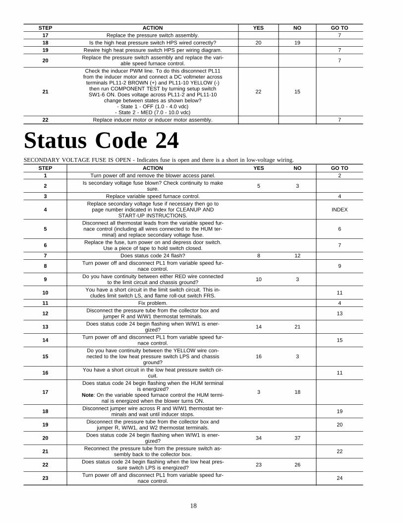
STEP ACTION YES NO GO TO17 Replace the pressure switch assembly. 718 Is the high heat pressure switch HPS wired correctly? 20 1919 Rewire high heat pressure switch HPS per wiring diagram. 7
20 Replace the pressure switch assembly and replace the vari-able speed furnace control. 7
21
Check the inducer PWM line. To do this disconnect PL11from the inducer motor and connect a DC voltmeter across
terminals PL11-2 BROWN (+) and PL11-10 YELLOW (-)then run COMPONENT TEST by turning setup switchSW1-6 ON. Does voltage across PL11-2 and PL11-10
change between states as shown below?- State 1 - OFF (1.0 - 4.0 vdc)
- State 2 - MED (7.0 - 10.0 vdc)
22 15
22 Replace inducer motor or inducer motor assembly. 7
Status Code 24SECONDARY VOLTAGE FUSE IS OPEN - Indicates fuse is open and there is a short in low-voltage wiring.
STEP ACTION YES NO GO TO1 Turn power off and remove the blower access panel. 2
2 Is secondary voltage fuse blown? Check continuity to makesure. 5 3
3 Replace variable speed furnace control. 4
4Replace secondary voltage fuse if necessary then go to
page number indicated in Index for CLEANUP ANDSTART-UP INSTRUCTIONS.
INDEX
5Disconnect all thermostat leads from the variable speed fur-nace control (including all wires connected to the HUM ter-
minal) and replace secondary voltage fuse.6
6 Replace the fuse, turn power on and depress door switch.Use a piece of tape to hold switch closed. 7
7 Does status code 24 flash? 8 12
8 Turn power off and disconnect PL1 from variable speed fur-nace control. 9
9 Do you have continuity between either RED wire connectedto the limit circuit and chassis ground? 10 3
10 You have a short circuit in the limit switch circuit. This in-cludes limit switch LS, and flame roll-out switch FRS. 11
11 Fix problem. 4
12 Disconnect the pressure tube from the collector box andjumper R and W/W1 thermostat terminals. 13
13 Does status code 24 begin flashing when W/W1 is ener-gized? 14 21
14 Turn power off and disconnect PL1 from variable speed fur-nace control. 15
15Do you have continuity between the YELLOW wire con-nected to the low heat pressure switch LPS and chassis
ground?16 3
16 You have a short circuit in the low heat pressure switch cir-cuit. 11
17
Does status code 24 begin flashing when the HUM terminalis energized?
Note: On the variable speed furnace control the HUM termi-nal is energized when the blower turns ON.
3 18
18 Disconnect jumper wire across R and W/W1 thermostat ter-minals and wait until inducer stops. 19
19 Disconnect the pressure tube from the collector box andjumper R, W/W1, and W2 thermostat terminals. 20
20 Does status code 24 begin flashing when W/W1 is ener-gized? 34 37
21 Reconnect the pressure tube from the pressure switch as-sembly back to the collector box. 22
22 Does status code 24 begin flashing when the low heat pres-sure switch LPS is energized? 23 26
23 Turn power off and disconnect PL1 from variable speed fur-nace control. 24
18

STEP ACTION YES NO GO TO
24Do you have continuity between the ORANGE wire con-nected to the low heat pressure switch LPS and chassis
ground?25 3
25 The ORANGE wire from low heat pressure switch LPS isshorting to ground. Replace or repair it. 11
26 Does status code 24 begin flashing when the gas valve GVis energized? 27 17
27 Disconnect jumper wire across R and W/W1 thermostat ter-minals and replace secondary voltage fuse. 28
28 Disconnect BLUE wire to gas valve GV and jumper R andW/W1 thermostat terminals. 29
29 Does status code 34 flash? If not, status code 24 shouldoccur when BLUE wire is energized. 33 30
30 Turn power off and disconnect PL1 from variable speed fur-nace control. 31
31 Do you have continuity between the BLUE wire and chassisground? 32 3
32 The BLUE wire to gas valve GV is shorting to ground. Re-place or repair it. 11
33 Replace gas valve GV. 4
34 Turn power off and disconnect PL1 from variable speed fur-nace control. 35
35 Do you have continuity between the GRAY wire connectedto the high heat pressure switch HPS and chassis ground? 36 3
36 You have a short circuit in the high heat pressure switchcircuit. 11
37 Reconnect the pressure tube from the pressure switch as-sembly back to the collector box. 38
38 Does status code 24 begin flashing when the high heatpressure switch HPS is energized? 39 56
39 Disconnect jumper wire across R, W/W1, and W2 thermo-stat terminals and replace secondary voltage fuse. 40
40 Disconnect BROWN wire to gas valve GV and jumper R,W/W1, and W2 thermostat terminals. 41
41 Does status code 24 begin flashing when the high heatpressure switch HPS is energized? 42 33
42 Turn power off and disconnect PL1 from variable speed fur-nace control. 43
43 Do you have continuity between the BROWN wire andchassis ground? 44 3
44 The BROWN wire to high heat pressure switch HPS andgas valve GV is shorting to ground. Replace or repair it. 11
45 Disconnect jumper wire across R, W/W1, and W2 thermo-stat terminals and wait until blower stops. 46
46 Jumper R, G, and Y/Y2 thermostat terminals. 47
47 Does status code 24 begin flashing when G and Y/Y2 areenergized? 3 48
48Reconnect all thermostat leads (except humidifier lead to
HUM terminal) to variable speed furnace control and oper-ate furnace in heating and cooling mode from thermostat.
49
49 Does status code 24 occur during heating cycle? 50 51
50
You have a defective thermostat or a short circuit in R,W/W1, or W2 wiring between thermostat, furnace, and out-door unit. If the furnace is twinned, also check the twinning
kit relay TKR.
11
51 Does status code 24 occur during cooling cycle? 52 53
52
You have a defective thermostat, short circuit in G, Y1,Y/Y2 or O wiring between thermostat and outdoor unit, or ashort circuit in the outdoor unit contactor or reversing valve-
(heat pump only).
11
53 Does problem usually occur in cooling mode? 54 55
54Check outdoor unit contactor. Failure to pull in can causeexcessive current draw on low-voltage circuit. This can be
an intermittent problem.11
55
Reconnect humidifier and check for excessive current drawwhen the blower turns ON. If current draw is excessive
check wiring to humidifier solenoid, diode bridge(if used),and humidifier solenoid.
11
19
STEP ACTION YES NO GO TO56 Continue to observe the furnace operation for 10 minutes. 5757 Does status code 24 flash after the blower comes on? 58 59
58 The insulation is loose and has shorted against the limitswitch(es). 11
59 Check for loose or torn insulation because it can cause in-termittent occurrences of status code 24. 45
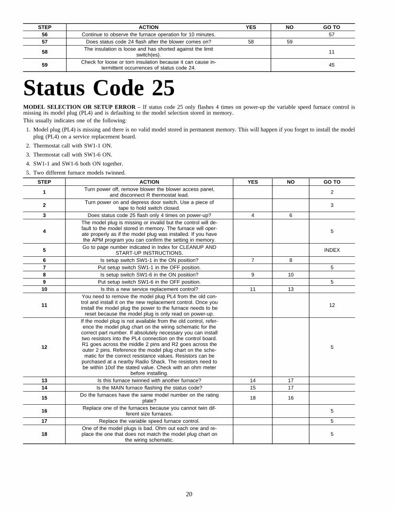
Status Code 25MODEL SELECTION OR SETUP ERROR – If status code 25 only flashes 4 times on power-up the variable speed furnace control ismissing its model plug (PL4) and is defaulting to the model selection stored in memory.This usually indicates one of the following:
1. Model plug (PL4) is missing and there is no valid model stored in permanent memory. This will happen if you forget to install the modelplug (PL4) on a service replacement board.
2. Thermostat call with SW1-1 ON.
3. Thermostat call with SW1-6 ON.
4. SW1-1 and SW1-6 both ON together.
5. Two different furnace models twinned.
STEP ACTION YES NO GO TO
1 Turn power off, remove blower the blower access panel,and disconnect R thermostat lead. 2
2 Turn power on and depress door switch. Use a piece oftape to hold switch closed. 3
3 Does status code 25 flash only 4 times on power-up? 4 6
4
The model plug is missing or invalid but the control will de-fault to the model stored in memory. The furnace will oper-ate properly as if the model plug was installed. If you havethe APM program you can confirm the setting in memory.
5
5 Go to page number indicated in Index for CLEANUP ANDSTART-UP INSTRUCTIONS. INDEX
6 Is setup switch SW1-1 in the ON position? 7 87 Put setup switch SW1-1 in the OFF position. 58 Is setup switch SW1-6 in the ON position? 9 109 Put setup switch SW1-6 in the OFF position. 510 Is this a new service replacement control? 11 13
11
You need to remove the model plug PL4 from the old con-trol and install it on the new replacement control. Once youinstall the model plug the power to the furnace needs to be
reset because the model plug is only read on power-up.
12
12
If the model plug is not available from the old control, refer-ence the model plug chart on the wiring schematic for the
correct part number. If absolutely necessary you can installtwo resistors into the PL4 connection on the control board.R1 goes across the middle 2 pins and R2 goes across theouter 2 pins. Reference the model plug chart on the sche-matic for the correct resistance values. Resistors can be
purchased at a nearby Radio Shack. The resistors need tobe within 10of the stated value. Check with an ohm meter
before installing.
5
13 Is this furnace twinned with another furnace? 14 1714 Is the MAIN furnace flashing the status code? 15 17
15 Do the furnaces have the same model number on the ratingplate? 18 16
16 Replace one of the furnaces because you cannot twin dif-ferent size furnaces. 5
17 Replace the variable speed furnace control. 5
18One of the model plugs is bad. Ohm out each one and re-place the one that does not match the model plug chart on
the wiring schematic.5
20
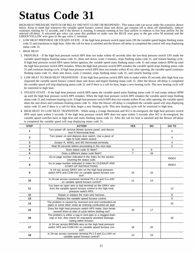
Status Code 31HIGH-HEAT PRESSURE SWITCH OR RELAY DID NOT CLOSE OR REOPENED - This status code can occur under the scenarios shownbelow. Keep in mind that whenever the variable speed furnace control shuts unit down, gas remains off or shuts off immediately, inducercontinues running for 15 seconds, and if the blower is running, it remains running at low heat airflow or reduces to low heat airflow for theselected off-delay. A miswired gas valve can cause this problem so make sure the BLUE wire goes to the gas valve M terminal and theGREEN/YELLOW wire goes to the gas valve C terminal.• LOW HEAT PREPURGE OR STEADY-STATE - If the high heat pressure switch input turns ON the variable speed begins flashing status
code 31 and transitions to high heat. After the call for heat is satisfied and the blower off-delay is completed the control will stop displayingstatus code 31.
• HIGH HEAT
1. PREPURGE - If the high heat pressure switch HPS does not make within 45 seconds after the low-heat pressure switch LPS made thevariable speed begins flashing status code 31, shuts unit down, waits 2 minutes, stops flashing status code 31, and restarts heating cycle.If high heat pressure switch HPS opens before ignition, the variable speed starts flashing status code 31 and ramps inducer RPM up untilthe high heat pressure switch HPS remakes. When the high heat pressure switch HPS remakes the variable speed stops flashing status code31 and continues heating cycle. If high heat pressure switch HPS does not remake within 45 sec after opening, the variable speed continuesflashing status code 31, shuts unit down, waits 2 minutes, stops flashing status code 31, and restarts heating cycle.
2. LOW HEAT TO HIGH HEAT TRANSITION - If the high heat pressure switch HPS fails to make within 45 seconds after high heat wasrequested the variable speed furnace control shuts unit down and begins flashing status code 31. After the blower off-delay is completedthe variable speed will stop displaying status code 31 and if there is a call for heat, begin a new heating cycle. This new heating cycle willbe restricted to high heat.
3. STEADY-STATE - If the high heat pressure switch HPS opens the variable speed starts flashing status code 31 and ramps inducer RPMup until the high heat pressure switch HPS remakes. When the high heat pressure switch HPS remakes the variable speed stops flashingstatus code 31 and continues heating cycle. If high heat pressure switch HPS does not remake within 45 sec after opening, the variable speedshuts the unit down and continues flashing status code 31. After the blower off-delay is completed the variable speed will stop displayingstatus code 31 and if there is a call for heat, begin a new heating cycle. This new heating cycle will be restricted to high heat.
4. HIGH HEAT TO LOW HEAT TRANSITION - When using a 2-stage thermostat and W2 is de-energized, the high heat pressure switchHPS must open within 5 seconds. If the high heat pressure switch HPS does not open within 5 seconds after W2 is de-energized, thevariable speed switches back to high heat and starts flashing status code 31. After the call for heat is satisfied and the blower off-delayis completed the variable speed will stop displaying status code 31.
STEP ACTION YES NO GO TO
1 Turn power off, remove blower access panel, and discon-nect R thermostat lead. 2
2 Turn power on and depress door switch. Use a piece oftape to hold switch closed. 3
3 Jumper R, W/W1, and W2 thermostat terminals. 44 Wait 90 seconds before proceeding to the next step. 55 Does status code 31 flash? 9 66 Does a different status code flash? 7 34
7 Go to page number indicated in the Index for the sectioncovering the status code. INDEX
8 Go to page number indicated in Index for CLEANUP ANDSTART-UP INSTRUCTIONS. INDEX
9Is 24-vac across GRAY wire on the high heat pressure
switch HPS and COM-24V on variable speed furnace con-trol?
15 10
10 Is 24-vac across connector terminal PL1-12 and COM-24Von variable speed furnace control? 11 13
11You have an open wire or bad terminal on the GRAY wirefrom the variable speed furnace control to the high heat
pressure switch HPS.12
12 Repair or replace the main wire harness. 813 Replace the variable speed furnace control. 8
14 The problem is caused by reversed vent and combustion-airpipes or some other moist air entering combustion-air pipe. 32
15 Does the high heat pressure switch HPS make, then breakseveral times at start of cycle before faulting out? 16 17
16The problem is either a sag in vent pipe or a clogged drain
trap or line. Also check for improperly plumbed drainagetubing within furnace.
32
17Is 24-vac across BROWN wire on the high heat pressure
switch HPS and COM-24V on variable speed furnace con-trol?
18 20
18 Is 24-vac across connector terminal PL1-3 and COM-24V onvariable speed furnace control? 13 19
21

STEP ACTION YES NO GO TO
19You have an open wire or bad terminal on the BROWN
wire from the high heat pressure switch HPS to the variablespeed furnace control.
12
20 Turn power off and disconnect jumper wire across R,W/W1, and W2 thermostat terminals. 21
21
Connect 1 side of slope manometer with a tee to collectorbox pressure tap. Connect other side with a tee to gas
valve pressure fitting. Refer to pressure check diagram inAppendix C.
22
22 Turn power on and jumper R, W/W1, and W2 thermostatterminals. 23
23 Do you have atleast 1.90 in. wc pressure drop across heatexchangers when status code 31 flashes? 24 25
24 Replace the pressure switch assembly. 8
25 Is inducer motor rotating in direction indicated on inducerhousing? 27 26
26 Replace inducer motor or inducer motor assembly. 827 Turn power off. 2828 Is inducer wheel okay? 30 29
29 If possible, replace inducer wheel. Otherwise, replace in-ducer motor assembly. 8
30 Is the inducer wheel properly mounted to the inducer motorshaft? 31 32
31 Is there any frost build-up on the combustion-air inlet? 14 3332 Fix problem. 8
33 You have excessive restriction in combustion-air or ventpipe. Also check for proper vent sizing for installation. 32
34 Continue to observe furnace operation for 20 minutes oruntil status code starts flashing. 35
35 Does status code 31 flash? 37 3636 Does a different status code flash? 7 43
37 Turn power off and disconnect jumper wire across R,W/W1, and W2 thermostat terminals. 38
38
Connect 1 side of slope manometer with a tee to collectorbox pressure tap. Connect other side with a tee to gas
valve pressure fitting. Refer to pressure check diagram inAppendix C.
39
39 Turn power on and jumper R, W/W1, and W2 thermostatterminals. 40
40 Monitor slope manometer. Does the pressure reading ap-pear to be stable when fault occurs? 41 42
41Replace pressure switch assembly. If problem persists,check wiring for an intermittent connection in high heat
pressure switch HPS circuit.8
42Check for a sag in vent pipe or partially clogged drain trapor line. Also check for improperly plumbed drainage tubing
within furnace.8
43 Disconnect jumper wire across R, W/W1, and W2 thermo-stat terminals and wait for the blower off-delay to finish. 44
44 Reset the power and jumper R and W/W1 thermostat termi-nals. 45
45 Does status code 31 flash? 47 4646 Does a different status code flash? 7 8
47 Turn power off and disconnect the GRAY wire to the highheat pressure switch HPS. 48
48 Turn power ON and jumper R and W/W1 thermostat termi-nals. 49
49 Does status code 31 flash? 50 13
50The BROWN wire is shorting to the ORANGE wire thatgoes the low heat pressure switch LPS. Reconnect the
GRAY wire to the high heat pressure switch HPS.12
22
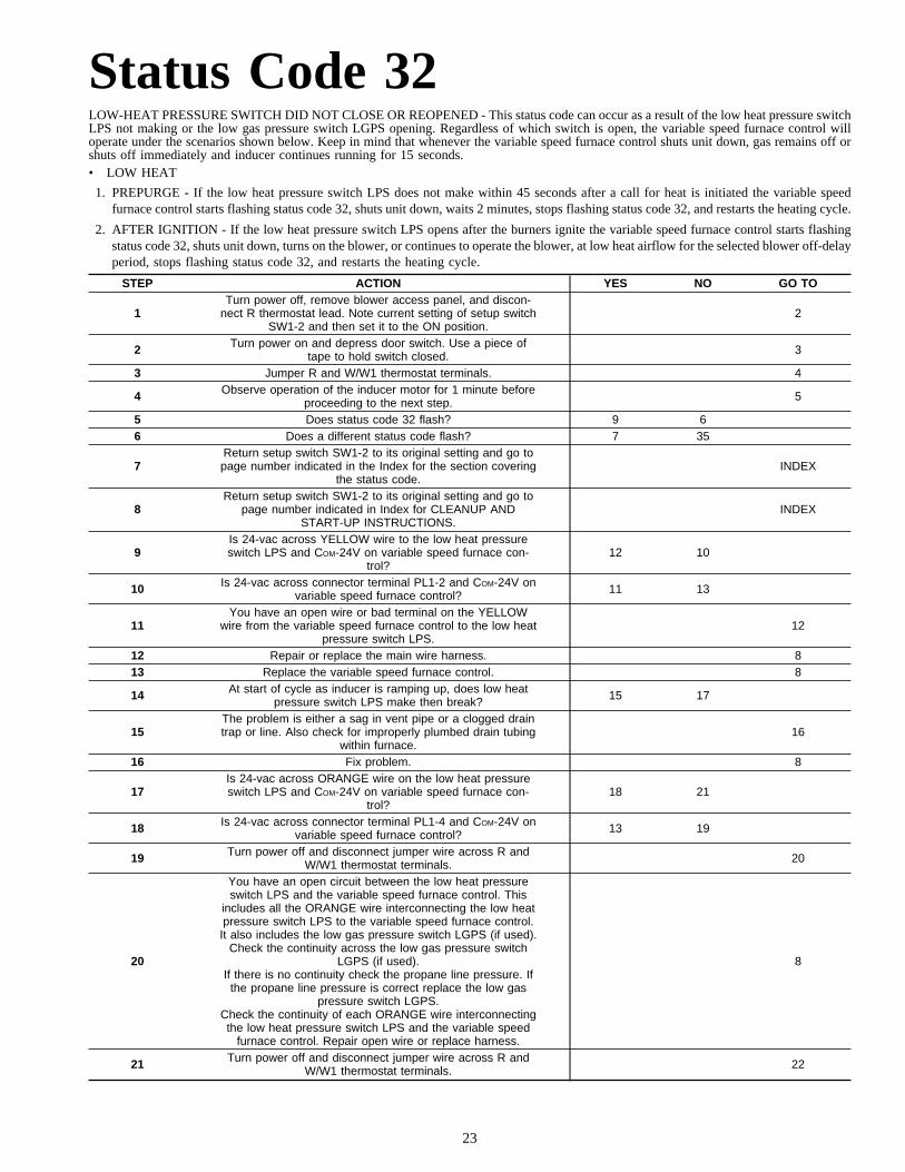
Status Code 32LOW-HEAT PRESSURE SWITCH DID NOT CLOSE OR REOPENED - This status code can occur as a result of the low heat pressure switchLPS not making or the low gas pressure switch LGPS opening. Regardless of which switch is open, the variable speed furnace control willoperate under the scenarios shown below. Keep in mind that whenever the variable speed furnace control shuts unit down, gas remains off orshuts off immediately and inducer continues running for 15 seconds.• LOW HEAT
1. PREPURGE - If the low heat pressure switch LPS does not make within 45 seconds after a call for heat is initiated the variable speedfurnace control starts flashing status code 32, shuts unit down, waits 2 minutes, stops flashing status code 32, and restarts the heating cycle.
2. AFTER IGNITION - If the low heat pressure switch LPS opens after the burners ignite the variable speed furnace control starts flashingstatus code 32, shuts unit down, turns on the blower, or continues to operate the blower, at low heat airflow for the selected blower off-delayperiod, stops flashing status code 32, and restarts the heating cycle.
STEP ACTION YES NO GO TO
1Turn power off, remove blower access panel, and discon-
nect R thermostat lead. Note current setting of setup switchSW1-2 and then set it to the ON position.
2
2 Turn power on and depress door switch. Use a piece oftape to hold switch closed. 3
3 Jumper R and W/W1 thermostat terminals. 4
4 Observe operation of the inducer motor for 1 minute beforeproceeding to the next step. 5
5 Does status code 32 flash? 9 66 Does a different status code flash? 7 35
7Return setup switch SW1-2 to its original setting and go topage number indicated in the Index for the section covering
the status code.INDEX
8Return setup switch SW1-2 to its original setting and go to
page number indicated in Index for CLEANUP ANDSTART-UP INSTRUCTIONS.
INDEX
9Is 24-vac across YELLOW wire to the low heat pressureswitch LPS and COM-24V on variable speed furnace con-
trol?12 10
10 Is 24-vac across connector terminal PL1-2 and COM-24V onvariable speed furnace control? 11 13
11You have an open wire or bad terminal on the YELLOW
wire from the variable speed furnace control to the low heatpressure switch LPS.
12
12 Repair or replace the main wire harness. 813 Replace the variable speed furnace control. 8
14 At start of cycle as inducer is ramping up, does low heatpressure switch LPS make then break? 15 17
15The problem is either a sag in vent pipe or a clogged draintrap or line. Also check for improperly plumbed drain tubing
within furnace.16
16 Fix problem. 8
17Is 24-vac across ORANGE wire on the low heat pressureswitch LPS and COM-24V on variable speed furnace con-
trol?18 21
18 Is 24-vac across connector terminal PL1-4 and COM-24V onvariable speed furnace control? 13 19
19 Turn power off and disconnect jumper wire across R andW/W1 thermostat terminals. 20
20
You have an open circuit between the low heat pressureswitch LPS and the variable speed furnace control. This
includes all the ORANGE wire interconnecting the low heatpressure switch LPS to the variable speed furnace control.It also includes the low gas pressure switch LGPS (if used).
Check the continuity across the low gas pressure switchLGPS (if used).
If there is no continuity check the propane line pressure. Ifthe propane line pressure is correct replace the low gas
pressure switch LGPS.Check the continuity of each ORANGE wire interconnectingthe low heat pressure switch LPS and the variable speed
furnace control. Repair open wire or replace harness.
8
21 Turn power off and disconnect jumper wire across R andW/W1 thermostat terminals. 22
23
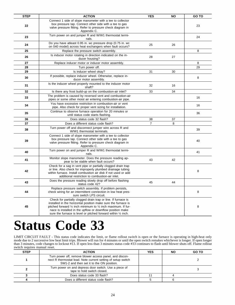
STEP ACTION YES NO GO TO
22
Connect 1 side of slope manometer with a tee to collectorbox pressure tap. Connect other side with a tee to gas
valve pressure fitting. Refer to pressure check diagram inAppendix C.
23
23 Turn power on and jumper R and W/W1 thermostat termi-nals. 24
24 Do you have atleast 0.95 in. wc pressure drop (0.75 in. wcon 040 model) across heat exchangers when fault occurs? 25 26
25 Replace the pressure switch assembly. 8
26 Is inducer motor rotating in direction indicated on the in-ducer housing? 28 27
27 Replace inducer motor or inducer motor assembly. 828 Turn power off. 2929 Is inducer wheel okay? 31 30
30 If possible, replace inducer wheel. Otherwise, replace in-ducer motor assembly. 8
31 Is the inducer wheel properly mounted to the inducer motorshaft? 32 16
32 Is there any frost build-up on the combustion-air inlet? 33 34
33 The problem is caused by reversed vent and combustion-airpipes or some other moist air entering combustion-air pipe. 16
34 You have excessive restriction in combustion-air or ventpipe. Also check for proper vent sizing for installation. 16
35 Continue to observe furnace operation for 20 minutes oruntil status code starts flashing. 36
36 Does status code 32 flash? 38 3737 Does a different status code flash? 7 8
38 Turn power off and disconnect jumper wire across R andW/W1 thermostat terminals. 39
39
Connect 1 side of slope manometer with a tee to collectorbox pressure tap. Connect other side with a tee to gas
valve pressure fitting. Refer to pressure check diagram inAppendix C.
40
40 Turn power on and jumper R and W/W1 thermostat termi-nals. 41
41 Monitor slope manometer. Does the pressure reading ap-pear to be stable when fault occurs? 43 42
42
Check for a sag in vent pipe or partially clogged drain trapor line. Also check for improperly plumbed drainage tubingwithin furnace. Install combustion air disk if not used or add
additional restriction to combustion-air inlet.
8
43 Does the pressure reading slowly drop off before flashingstatus code 42? 45 44
44Replace pressure switch assembly. If problem persists,
check wiring for an intermittent connection in low heat pres-sure switch LPS circuit.
8
45
Check for partially clogged drain trap or line. If furnace isinstalled in the horizontal position make sure the furnace ispitched forward ¼ inch minimum to ½ inch maximum. If fur-
nace is installed in the upflow or downflow position makesure the furnace is level or pitched forward within ½ inch.
8
Status Code 33LIMIT CIRCUIT FAULT - This status code indicates the limit, or flame rollout switch is open or the furnace is operating in high-heat onlymode due to 2 successive low heat limit trips. Blower will run for 4 minutes or until the open switch remakes whichever is longer. If open longerthan 3 minutes, code changes to lockout #13. If open less than 3 minutes status code #33 continues to flash until blower shuts off. Flame rolloutswitch requires manual reset.
STEP ACTION YES NO GO TO
1Turn power off, remove blower access panel, and discon-
nect R thermostat lead. Note current setting of setup switchSW1-2 and then set it to the ON position.
2
2 Turn power on and depress door switch. Use a piece oftape to hold switch closed. 3
3 Does status code 33 flash? 11 44 Does a different status code flash? 5 6
24

STEP ACTION YES NO GO TO
5Return setup switch SW1-2 to its original setting and go topage number indicated in the Index for the section covering
the status code.INDEX
6 Jumper R and W/W1 thermostat terminals. 7
7 Observe the furnace operation for 25 minutes or until statuscode starts flashing. 8
8 Does status code 33 flash? 40 99 Does a different status code flash? 5 27
10Return setup switch SW1-2 to its original setting and go to
page number indicated in Index for CLEANUP ANDSTART-UP INSTRUCTIONS.
INDEX
11 Is 24-vac across connector terminal PL1-6 and COM-24V onvariable speed furnace control? 13 12
12 Replace the variable speed furnace control. 10
13 Is 24-vac across connector terminal PL1-8 and COM-24V onvariable speed furnace control? 12 14
14 Turn power off. 1515 Do you have continuity across limit switch LS? 19 16
16 Wait for unit to cool then recheck for continuity across limitswitch LS. 17
17 Do you have continuity across limit switch LS? 19 1818 Replace limit switch. 10
19 Do you have continuity across the flame rollout switchFRS? 35 20
20 Can flame rollout switch FRS be reset? 22 2121 Replace flame rollout switch FRS. 10
22 Reset flame rollout switch FRS, turn power on, and observefurnace operation for (2) 15 minute cycles. 23
23 Does flame rollout switch FRS trip again? 25 2424 Does a different status code flash? 5 10
25
You have inadequate combustion-air supply. This may becaused by:
- Reversed vent and combustion-air pipes.- Poor burner, manifold, or orifice alignment.
- Blocked heat exchanger.- Leak in secondary heat exchanger.
- Leak somewhere between primary and secondary heatexchangers.
26
26 Fix problem. 1027 While the unit is operating in low heat jumper R and W2. 28
28 Observe furnace operation for another 10 minutes or untilstatus code 33 starts flashing. 29
29 Does status code 33 flash? 50 3030 Does a different status code flash? 5 3131 Is the furnace in the downflow or horizontal position? 32 10
32 Disconnect the R thermostat lead, wait for blower to stop,and continue to observe furnace for 5 minutes. 33
33 Does fault occur after blower stops? 34 10
34Increase the blower off-delay time to 180 seconds by put-ting both setup switches SW1-7 and SW1-8 into the ON
position.26
35 Turn power on. 3636 Does status code 33 flash? 38 3737 Does a different status code flash? 5 6
38 You have an open RED wire or bad terminal in limit circuit.Repair wire or replace harness. 10
39
Does furnace have the proper limit switch, limit shield,blower baffle (if used), and rear air baffle (if used)? If so,
are the limit switch, limit shield, and heat exchangers prop-erly aligned?
40 26
40 Remove tape from door switch, turn power off at main dis-connect, and remove jumper across R and W/W1. 41
41 Is the blower wheel firmly mounted on motor shaft? 42 26
42Does the model plug PL4 match the part number specifiedon the Model Plug Chart in the upper left hand corner of
wiring schematic?44 43
43 Replace model plug. 10
25

STEP ACTION YES NO GO TO
44 Turn power on and depress door switch. Use a piece oftape to hold switch closed. 45
45 Jumper R and W/W1 thermostat terminals. 4646 Does status code 33 occur during low heat? 47 57
47 Clean or replace filter if necessary, then recycle furnaceafter limit resets. 48
48 Observe furnace operation for 25 minutes or until statuscode 33 starts flashing. 49
49 Does status code 33 occur? 50 10
50Is furnace considerably overfired (10or more)? Clock inputrate. Do not use manifold pressure method unless using
propane.51 52
51
Ensure gas inlet pressure and burner orifices (natural orpropane) are correct. Then adjust gas valve to proper rateper Installation, Start-Up, and Operating Instructions. If it
cannot be adjusted to proper rate, replace gas valve.
10
52 Is temperature rise within rise range? 54 53
53 Does the installation have a bypass humidifier or zoningsystem bypass? 58 61
54 Turn power off and install a temperature probe in front oflimit switch button. 55
55
Turn power on and cycle unit. Does limit switch open at atemperature at least 10 deg. F below temperature setpointfor limit switch? (EXAMPLE: The setpoint is 220 deg F, but
the switch opens at a temperature below 210 deg F.)
18 56
56
The problem may be related to poor air distribution or ex-cessive pressure drop across filter. Check filter and return-
air grilles for blockage. Add turning vanes, more supplyopenings, or more return-air openings. Use Appendix D to
evaluate external static pressure.
26
57 While the unit is operating in low heat jumper R and W2. 47
58 With blower access panel in place record temperature riseacross return air duct before and after the bypass. 59
59 Is temperature rise from bypass greater than 15 deg. F? 60 61
60 The bypass is oversized. Adjust damper or replace withproperly sized bypass. 10
61 Does installation have modulating zone dampers? 62 66
62
Disable modulating zone damper system with all dampersin open position except bypass damper. If installation is
equipped with a bypass damper, it should be in the closedposition.
63
63
Turn power off and disconnect jumper from the R thermo-stat terminal. Turn power back on and reconnect jumper to
R thermostat terminal. Observe for 15 minutes with theblower access panel in place.
64
64 Does status code 33 flash? 66 65
65The problem is caused by the modulating zone damper sys-
tem. Check the zoning system manufacturer’s Installationand Troubleshooting guide for corrective action.
10
66 Turn power off and install a temperature probe in front oflimit switch button. 67
67
Turn power on and cycle unit. Does limit switch open at atemperature at least 10 deg. F below temperature setpointfor limit switch? (EXAMPLE: The setpoint is 220 deg F, but
the switch opens at a temperature below 210 deg F.)
18 68
68 Adjust the blower airflow using dip switch SW1-3 andSW1-4 to get the temperature rise within the rise range. 26
26
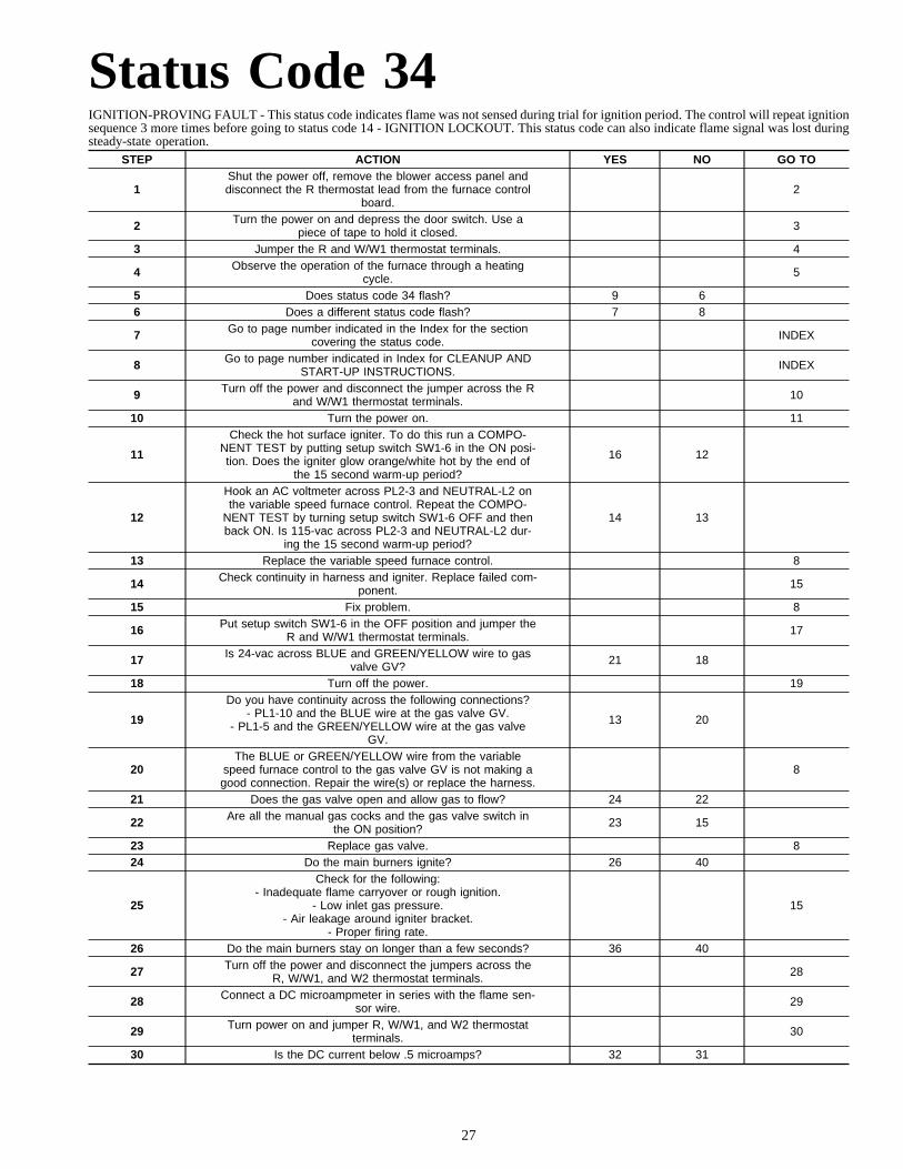
Status Code 34IGNITION-PROVING FAULT - This status code indicates flame was not sensed during trial for ignition period. The control will repeat ignitionsequence 3 more times before going to status code 14 - IGNITION LOCKOUT. This status code can also indicate flame signal was lost duringsteady-state operation.
STEP ACTION YES NO GO TO
1Shut the power off, remove the blower access panel anddisconnect the R thermostat lead from the furnace control
board.2
2 Turn the power on and depress the door switch. Use apiece of tape to hold it closed. 3
3 Jumper the R and W/W1 thermostat terminals. 4
4 Observe the operation of the furnace through a heatingcycle. 5
5 Does status code 34 flash? 9 66 Does a different status code flash? 7 8
7 Go to page number indicated in the Index for the sectioncovering the status code. INDEX
8 Go to page number indicated in Index for CLEANUP ANDSTART-UP INSTRUCTIONS. INDEX
9 Turn off the power and disconnect the jumper across the Rand W/W1 thermostat terminals. 10
10 Turn the power on. 11
11
Check the hot surface igniter. To do this run a COMPO-NENT TEST by putting setup switch SW1-6 in the ON posi-tion. Does the igniter glow orange/white hot by the end of
the 15 second warm-up period?
16 12
12
Hook an AC voltmeter across PL2-3 and NEUTRAL-L2 onthe variable speed furnace control. Repeat the COMPO-
NENT TEST by turning setup switch SW1-6 OFF and thenback ON. Is 115-vac across PL2-3 and NEUTRAL-L2 dur-
ing the 15 second warm-up period?
14 13
13 Replace the variable speed furnace control. 8
14 Check continuity in harness and igniter. Replace failed com-ponent. 15
15 Fix problem. 8
16 Put setup switch SW1-6 in the OFF position and jumper theR and W/W1 thermostat terminals. 17
17 Is 24-vac across BLUE and GREEN/YELLOW wire to gasvalve GV? 21 18
18 Turn off the power. 19
19
Do you have continuity across the following connections?- PL1-10 and the BLUE wire at the gas valve GV.
- PL1-5 and the GREEN/YELLOW wire at the gas valveGV.
13 20
20The BLUE or GREEN/YELLOW wire from the variable
speed furnace control to the gas valve GV is not making agood connection. Repair the wire(s) or replace the harness.
8
21 Does the gas valve open and allow gas to flow? 24 22
22 Are all the manual gas cocks and the gas valve switch inthe ON position? 23 15
23 Replace gas valve. 824 Do the main burners ignite? 26 40
25
Check for the following:- Inadequate flame carryover or rough ignition.
- Low inlet gas pressure.- Air leakage around igniter bracket.
- Proper firing rate.
15
26 Do the main burners stay on longer than a few seconds? 36 40
27 Turn off the power and disconnect the jumpers across theR, W/W1, and W2 thermostat terminals. 28
28 Connect a DC microampmeter in series with the flame sen-sor wire. 29
29 Turn power on and jumper R, W/W1, and W2 thermostatterminals. 30
30 Is the DC current below .5 microamps? 32 31
27
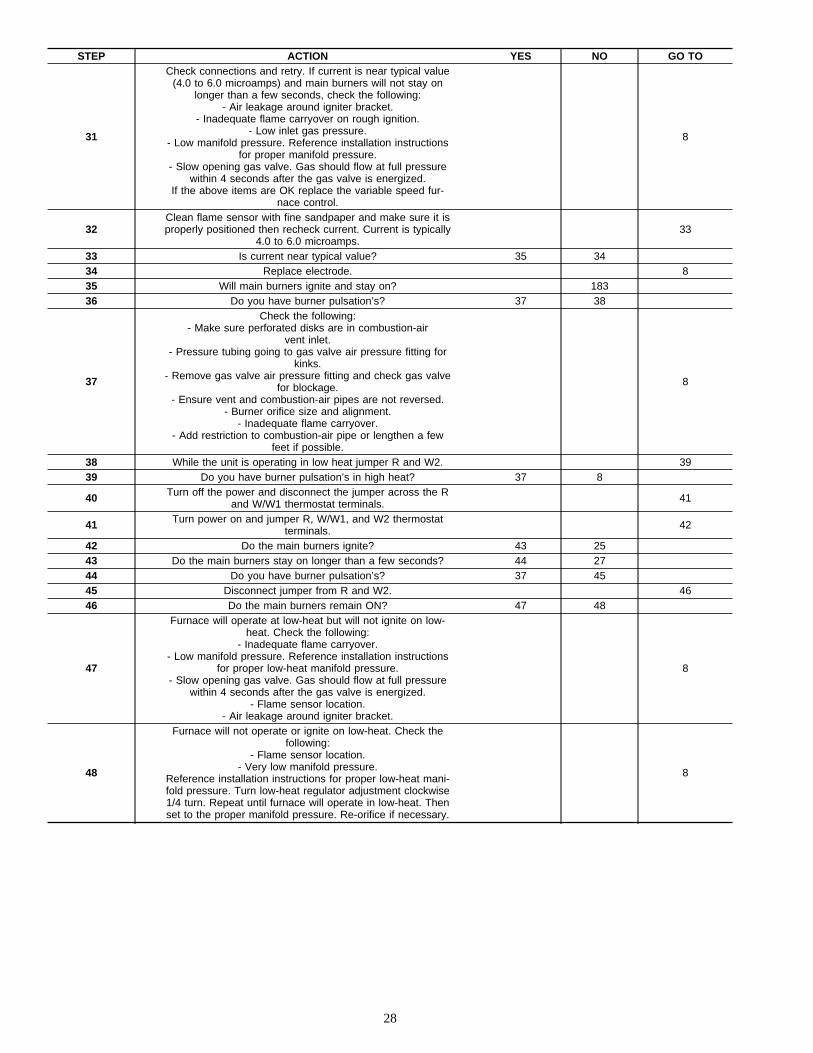
STEP ACTION YES NO GO TO
31
Check connections and retry. If current is near typical value(4.0 to 6.0 microamps) and main burners will not stay on
longer than a few seconds, check the following:- Air leakage around igniter bracket.
- Inadequate flame carryover on rough ignition.- Low inlet gas pressure.
- Low manifold pressure. Reference installation instructionsfor proper manifold pressure.
- Slow opening gas valve. Gas should flow at full pressurewithin 4 seconds after the gas valve is energized.
If the above items are OK replace the variable speed fur-nace control.
8
32Clean flame sensor with fine sandpaper and make sure it isproperly positioned then recheck current. Current is typically
4.0 to 6.0 microamps.33
33 Is current near typical value? 35 3434 Replace electrode. 835 Will main burners ignite and stay on? 18336 Do you have burner pulsation’s? 37 38
37
Check the following:- Make sure perforated disks are in combustion-air
vent inlet.- Pressure tubing going to gas valve air pressure fitting for
kinks.- Remove gas valve air pressure fitting and check gas valve
for blockage.- Ensure vent and combustion-air pipes are not reversed.
- Burner orifice size and alignment.- Inadequate flame carryover.
- Add restriction to combustion-air pipe or lengthen a fewfeet if possible.
8
38 While the unit is operating in low heat jumper R and W2. 3939 Do you have burner pulsation’s in high heat? 37 8
40 Turn off the power and disconnect the jumper across the Rand W/W1 thermostat terminals. 41
41 Turn power on and jumper R, W/W1, and W2 thermostatterminals. 42
42 Do the main burners ignite? 43 2543 Do the main burners stay on longer than a few seconds? 44 2744 Do you have burner pulsation’s? 37 4545 Disconnect jumper from R and W2. 4646 Do the main burners remain ON? 47 48
47
Furnace will operate at low-heat but will not ignite on low-heat. Check the following:
- Inadequate flame carryover.- Low manifold pressure. Reference installation instructions
for proper low-heat manifold pressure.- Slow opening gas valve. Gas should flow at full pressure
within 4 seconds after the gas valve is energized.- Flame sensor location.
- Air leakage around igniter bracket.
8
48
Furnace will not operate or ignite on low-heat. Check thefollowing:
- Flame sensor location.- Very low manifold pressure.
Reference installation instructions for proper low-heat mani-fold pressure. Turn low-heat regulator adjustment clockwise1/4 turn. Repeat until furnace will operate in low-heat. Thenset to the proper manifold pressure. Re-orifice if necessary.
8
28
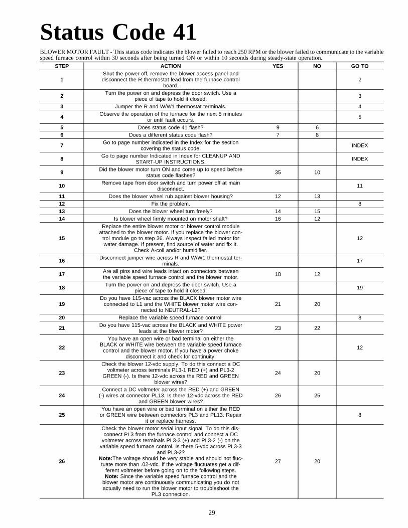
Status Code 41BLOWER MOTOR FAULT - This status code indicates the blower failed to reach 250 RPM or the blower failed to communicate to the variablespeed furnace control within 30 seconds after being turned ON or within 10 seconds during steady-state operation.
STEP ACTION YES NO GO TO
1Shut the power off, remove the blower access panel anddisconnect the R thermostat lead from the furnace control
board.2
2 Turn the power on and depress the door switch. Use apiece of tape to hold it closed. 3
3 Jumper the R and W/W1 thermostat terminals. 4
4 Observe the operation of the furnace for the next 5 minutesor until fault occurs. 5
5 Does status code 41 flash? 9 66 Does a different status code flash? 7 8
7 Go to page number indicated in the Index for the sectioncovering the status code. INDEX
8 Go to page number Indicated in Index for CLEANUP ANDSTART-UP INSTRUCTIONS. INDEX
9 Did the blower motor turn ON and come up to speed beforestatus code flashes? 35 10
10 Remove tape from door switch and turn power off at maindisconnect. 11
11 Does the blower wheel rub against blower housing? 12 1312 Fix the problem. 813 Does the blower wheel turn freely? 14 1514 Is blower wheel firmly mounted on motor shaft? 16 12
15
Replace the entire blower motor or blower control moduleattached to the blower motor. If you replace the blower con-
trol module go to step 36. Always inspect failed motor forwater damage. If present, find source of water and fix it.
Check A-coil and/or humidifier.
12
16 Disconnect jumper wire across R and W/W1 thermostat ter-minals. 17
17 Are all pins and wire leads intact on connectors betweenthe variable speed furnace control and the blower motor. 18 12
18 Turn the power on and depress the door switch. Use apiece of tape to hold it closed. 19
19Do you have 115-vac across the BLACK blower motor wire
connected to L1 and the WHITE blower motor wire con-nected to NEUTRAL-L2?
21 20
20 Replace the variable speed furnace control. 8
21 Do you have 115-vac across the BLACK and WHITE powerleads at the blower motor? 23 22
22
You have an open wire or bad terminal on either theBLACK or WHITE wire between the variable speed furnace
control and the blower motor. If you have a power chokedisconnect it and check for continuity.
12
23
Check the blower 12-vdc supply. To do this connect a DCvoltmeter across terminals PL3-1 RED (+) and PL3-2
GREEN (-). Is there 12-vdc across the RED and GREENblower wires?
24 20
24Connect a DC voltmeter across the RED (+) and GREEN
(-) wires at connector PL13. Is there 12-vdc across the REDand GREEN blower wires?
26 25
25You have an open wire or bad terminal on either the RED
or GREEN wire between connectors PL3 and PL13. Repairit or replace harness.
8
26
Check the blower motor serial input signal. To do this dis-connect PL3 from the furnace control and connect a DC
voltmeter across terminals PL3-3 (+) and PL3-2 (-) on thevariable speed furnace control. Is there 5-vdc across PL3-3
and PL3-2?Note:The voltage should be very stable and should not fluc-tuate more than .02-vdc. If the voltage fluctuates get a dif-
ferent voltmeter before going on to the following steps.Note: Since the variable speed furnace control and the
blower motor are continuously communicating you do notactually need to run the blower motor to troubleshoot the
PL3 connection.
27 20
29
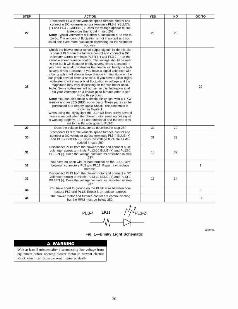
STEP ACTION YES NO GO TO
27
Reconnect PL3 to the variable speed furnace control andconnect a DC voltmeter across terminals PL3-3 YELLOW
(+) and PL3-2 GREEN (-). Does the voltage appear to fluc-tuate more than it did in step 26?
Note: Typical voltmeters will show a fluctuation of .2-vdc to1-vdc. The amount of fluctuation is not important and you
could see even more fluctuation depending on the voltmeteryou use.
20 28
28
Check the blower motor serial output signal. To do this dis-connect PL3 from the furnace control and connect a DC
voltmeter across terminals PL3-4 (+) and PL3-2 (-) on thevariable speed furnace control. The voltage should be near0-vdc but it will fluctuate briefly several times a second. If
you have an analog voltmeter the needle will briefly go highseveral times a second. If you have a digital voltmeter witha bar graph it will show a large change in magnitude on thebar graph several times a second. If you have a plain digital
voltmeter it will show a brief fluctuation in voltage and themagnitude may vary depending on the volt meter used.
Note: Some voltmeters will not sense this fluctuation at all.Test your voltmeter on a known good furnace prior to ser-
vicing this product.Note: You can also make a simple blinky light with a 1 KWresistor and an LED (RED works best). These parts can be
purchased at a nearby Radio Shack. The schematic isshown in Figure 1:
When using the blinky light the LED will flash briefly severaltimes a second when the blower motor serial output signalis working properly. LED’s are directional and the lead clos-
est to the flat side goes to PL3-2.
29
29 Does the voltage fluctuate as described in step 28? 30 20
30
Reconnect PL3 to the variable speed furnace control andconnect a DC voltmeter across terminals PL3-4 BLUE (+)and PL3-2 GREEN (-). Does the voltage fluctuate as de-
scribed in step 28?
31 33
31
Disconnect PL13 from the blower motor and connect a DCvoltmeter across terminals PL13-10 BLUE (+) and PL13-1
GREEN (-). Does the voltage fluctuate as described in step28?
15 32
32You have an open wire or bad terminal on the BLUE wirebetween connectors PL3 and PL13. Repair it or replace
harness.8
33
Disconnect PL13 from the blower motor and connect a DCvoltmeter across terminals PL13-10 BLUE (+) and PL13-1
GREEN (-). Does the voltage fluctuate as described in step28?
15 34
34 You have short to ground on the BLUE wire between con-nectors PL3 and PL13. Repair it or replace harness. 8
35 The blower motor and furnace control are communicatingbut the RPM must be below 250. 14
Wait at least 5 minutes after disconnecting line voltage fromequipment before opening blower motor to prevent electricshock which can cause personal injury or death.
Fig. 1—Blinky Light SchematicA03094
PL3-4 1KΩ PL3-2
30
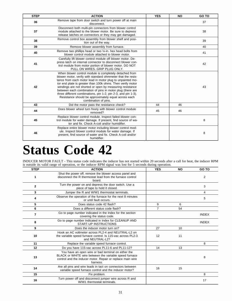
STEP ACTION YES NO GO TO
36 Remove tape from door switch and turn power off at maindisconnect. 37
37Disconnect both multi-pin connectors from blower controlmodule attached to the blower motor. Be sure to depressrelease latches on connectors or they may get damaged.
38
38 Remove control box assembly from blower shelf and posi-tion out of the way. 39
39 Remove blower assembly from furnace. 40
40 Remove two phillips head or two ¼-in. hex head bolts fromblower control module attached to blower motor. 41
41
Carefully lift blower control module off blower motor. De-press latch on internal connector to disconnect blower con-trol module from motor portion of blower motor. DO NOT
PULL ON WIRES. GRIP PLUG ONLY.
42
42
When blower control module is completely detached fromblower motor, verify with standard ohmmeter that the resis-tance from each motor lead in motor plug to unpainted mo-tor end plate is greater than 100k ohms. Then verify motorwindings are not shorted or open by measuring resistancebetween each combination of pins in motor plug (there arethree different combinations, pin 1-2, pin 2-3, and pin 1-3).
Resistance should be approximately equal across eachcombination of pins.
43
43 Did the motor pass the resistance check? 44 46
44 Does blower wheel turn freely with blower control moduleremoved? 45 46
45Replace blower control module. Inspect failed blower con-
trol module for water damage. If present, find source of wa-ter and fix. Check A-coil and/or humidifier.
8
46
Replace entire blower motor including blower control mod-ule. Inspect blower control module for water damage. If
present, find source of water and fix. Check A-coil and/orhumidifier.
8
Status Code 42INDUCER MOTOR FAULT - This status code indicates the inducer has not started within 20 seconds after a call for heat, the inducer RPMis outside its valid range of operation, or the inducer RPM signal was lost for 5 seconds during operation.
STEP ACTION YES NO GO TO
1Shut the power off, remove the blower access panel anddisconnect the R thermostat lead from the furnace control
board.2
2 Turn the power on and depress the door switch. Use apiece of tape to hold it closed. 3
3 Jumper the R and W/W1 thermostat terminals. 4
4 Observe the operation of the furnace for the next 8 minutesor until fault occurs. 5
5 Does status code 42 flash? 9 66 Does a different status code flash? 7 54
7 Go to page number indicated in the Index for the sectioncovering the status code. INDEX
8 Go to page number Indicated in Index for CLEANUP ANDSTART-UP INSTRUCTIONS INDEX
9 Does the inducer motor turn on? 27 10
10Hook an AC voltmeter across PL2-4 and NEUTRAL-L2 on
the variable speed furnace control. Is 115-vac across PL2-3and NEUTRAL-L2?
12 11
11 Replace the variable speed furnace control. 812 Do you have 115-vac across PL11-6 and PL11-12? 14 13
13
You have an open wire or bad terminal on either theBLACK or WHITE wire between the variable speed furnacecontrol and the inducer motor. Repair or replace main wire
harness.
8
14 Are all pins and wire leads in tact on connectors betweenvariable speed furnace control and the inducer motor? 16 15
15 Fix problem. 8
16 Turn power off and disconnect jumper wire across R andW/W1 thermostat terminals. 17
31
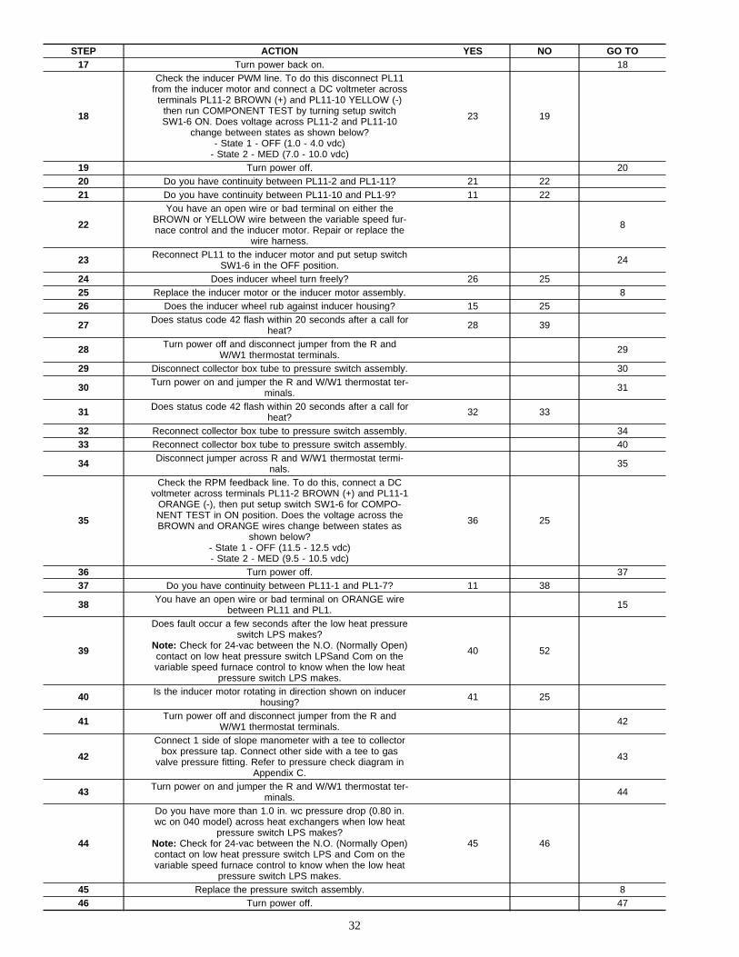
STEP ACTION YES NO GO TO17 Turn power back on. 18
18
Check the inducer PWM line. To do this disconnect PL11from the inducer motor and connect a DC voltmeter across
terminals PL11-2 BROWN (+) and PL11-10 YELLOW (-)then run COMPONENT TEST by turning setup switchSW1-6 ON. Does voltage across PL11-2 and PL11-10
change between states as shown below?- State 1 - OFF (1.0 - 4.0 vdc)
- State 2 - MED (7.0 - 10.0 vdc)
23 19
19 Turn power off. 2020 Do you have continuity between PL11-2 and PL1-11? 21 2221 Do you have continuity between PL11-10 and PL1-9? 11 22
22
You have an open wire or bad terminal on either theBROWN or YELLOW wire between the variable speed fur-nace control and the inducer motor. Repair or replace the
wire harness.
8
23 Reconnect PL11 to the inducer motor and put setup switchSW1-6 in the OFF position. 24
24 Does inducer wheel turn freely? 26 2525 Replace the inducer motor or the inducer motor assembly. 826 Does the inducer wheel rub against inducer housing? 15 25
27 Does status code 42 flash within 20 seconds after a call forheat? 28 39
28 Turn power off and disconnect jumper from the R andW/W1 thermostat terminals. 29
29 Disconnect collector box tube to pressure switch assembly. 30
30 Turn power on and jumper the R and W/W1 thermostat ter-minals. 31
31 Does status code 42 flash within 20 seconds after a call forheat? 32 33
32 Reconnect collector box tube to pressure switch assembly. 3433 Reconnect collector box tube to pressure switch assembly. 40
34 Disconnect jumper across R and W/W1 thermostat termi-nals. 35
35
Check the RPM feedback line. To do this, connect a DCvoltmeter across terminals PL11-2 BROWN (+) and PL11-1
ORANGE (-), then put setup switch SW1-6 for COMPO-NENT TEST in ON position. Does the voltage across theBROWN and ORANGE wires change between states as
shown below?- State 1 - OFF (11.5 - 12.5 vdc)- State 2 - MED (9.5 - 10.5 vdc)
36 25
36 Turn power off. 3737 Do you have continuity between PL11-1 and PL1-7? 11 38
38 You have an open wire or bad terminal on ORANGE wirebetween PL11 and PL1. 15
39
Does fault occur a few seconds after the low heat pressureswitch LPS makes?
Note: Check for 24-vac between the N.O. (Normally Open)contact on low heat pressure switch LPSand Com on thevariable speed furnace control to know when the low heat
pressure switch LPS makes.
40 52
40 Is the inducer motor rotating in direction shown on inducerhousing? 41 25
41 Turn power off and disconnect jumper from the R andW/W1 thermostat terminals. 42
42
Connect 1 side of slope manometer with a tee to collectorbox pressure tap. Connect other side with a tee to gas
valve pressure fitting. Refer to pressure check diagram inAppendix C.
43
43 Turn power on and jumper the R and W/W1 thermostat ter-minals. 44
44
Do you have more than 1.0 in. wc pressure drop (0.80 in.wc on 040 model) across heat exchangers when low heat
pressure switch LPS makes?Note: Check for 24-vac between the N.O. (Normally Open)contact on low heat pressure switch LPS and Com on thevariable speed furnace control to know when the low heat
pressure switch LPS makes.
45 46
45 Replace the pressure switch assembly. 846 Turn power off. 47
32

STEP ACTION YES NO GO TO47 Is inducer blower wheel okay? 49 48
48 If possible, replace inducer wheel. Otherwise replace in-ducer motor assembly. 8
49 Is there any frost build-up on combustion-air inlet? 50 51
50 The problem is caused by reversed vent and combustion-airpipes or some other moist air entering combustion-air pipe. 15
51 You have excessive restriction in combustion-air or ventpipe. 15
52Make sure all pins and wire leads are in tact on connectors
between variable speed furnace control and the inducermotor.
53
53Replace the inducer motor or the inducer motor assembly.If problem still persists after replacing the inducer motor,
contact your distributor.8
54 Turn power off and disconnect jumper from the R andW/W1 thermostat terminals. 55
55 Turn power on and jumper the R, W/W1, and W2 thermo-stat terminals. 56
56
Does fault occur a few seconds after the high heat pressureswitch HPS makes?
Note: Check for 24-vac between the N.O. (Normally Open)contact on high heat pressure switch HPS and Com on thevariable speed furnace control to know when the high heat
pressure switch HPS makes.
57 8
57 Turn power off and disconnect jumper from the R, W/W1,and W2 thermostat terminals. 58
58
Connect 1 side of slope manometer with a tee to collectorbox pressure tap. Connect other side with a tee to gas
valve pressure fitting. Refer to pressure check diagram inAppendix C.
59
59 Turn power on and jumper the R, W/W1, and W2 thermo-stat terminals. 60
60
Do you have more than 1.9 in. wc pressure drop acrossheat exchangers when high heat pressure switch HPS
makes?Note: Check for 24-vac between the N.O. (Normally Open)contact on high heat pressure switch HPS and Com on thevariable speed furnace control to know when the high heat
pressure switch HPS makes.
45 49
Status Code 43LOW-HEAT PRESSURE SWITCH OPEN WHILE HIGH-HEAT PRESSURE SWITCH IS CLOSED - This status codecan occur as a result of the low heat pressure switch LPS not making during a call for high heat. Keep in mind that whenever status code 43occurs the variable speed furnace control shuts unit down, turns the inducer off, and gas remains off.• LOW HEAT PREPURGE - If the high heat pressure switch HPS makes and the low heat pressure switch LPS is still open the variable speed
furnace control starts flashing status code 43, shuts unit down, and waits 2 minutes before restarting the heating cycle.
• HIGH HEAT PREPURGE - If the high heat pressure switch HPS makes and the low heat pressure switch LPS is still open the variable speedfurnace control starts flashing status code 43, shuts unit down, and waits 2 minutes before restarting the heating cycle.
STEP ACTION YES NO GO TO
1Turn power off, remove the blower access panel and dis-connect the R thermostat lead from the furnace control
board.2
2 Turn the power on and depress the door switch. Use apiece of tape to hold switch closed. 3
3 Jumper the R, W/W1, and W2 thermostat terminals. 44 Observe the operation of the furnace until ignition. 55 Does status code 43 flash? 9 66 Does a different status code flash? 7 8
7 Go to page number indicated in the Index for the sectioncovering the status code. INDEX
8 Go to page number Indicated in Index for CLEANUP ANDSTART-UP INSTRUCTIONS. INDEX
9 Are the pressure switches wired correctly? 11 1010 Fix problem. 8
33

STEP ACTION YES NO GO TO
11Is 24-vac across YELLOW wire to the low heat pressure
switch LPS and COM-24V on variable speed furnace con-trol?
14 12
12 Is 24-vac across connector terminal PL1-2 and COM-24V onvariable speed furnace control? 13 18
13You have an open wire or bad terminal on the YELLOW
wire from the variable speed furnace control to the low heatpressure switch LPS. Repair it or replace the harness.
8
14Is 24-vac across ORANGE wire on the low heat pressureswitch LPS and COM-24V on variable speed furnace con-
trol?15 19
15 Is 24-vac across connector terminal PL1-4 and COM-24V onvariable speed furnace control? 18 16
16 Turn power off and disconnect jumper wire across R andW/W1 thermostat terminals. 17
17
You have an open circuit between the low heat pressureswitch LPS and the variable speed furnace control. This
includes all the ORANGE wire interconnecting the low heatpressure switch LPS to the variable speed furnace control.It also includes the low gas pressure switch LGPS (if used).
Check the continuity across the low gas pressure switchLGPS (if used). If there is no continuity check the propane
line pressure. If the propane line pressure is correct replacethe low gas pressure switch LGPS.
Check the continuity of each ORANGE wire interconnectingthe low heat pressure switch LPS and the variable speed
furnace control. Repair open wire or replace harness.
8
18 Replace the variable speed furnace control. 8
19 Replace the low heat pressure switch or the pressureswitch assembly. 8
Status Code 45CONTROL CIRCUITRY LOCKOUT - This status code indicates the variable speed furnace control detectedone of the following:
1. Flame sense circuitry failure.
2. Software check error.
3. Gas valve relay stuck open.
Auto-reset after 1 hour. Replace variable speed furnace control if status code repeats.
CLEANUP AND START-UP INSTRUCTIONS1. Start furnace using procedure outlined on Lighting Instructions attached to furnace. Observe operation of furnace through at least 1
complete heating cycle controlled from the room thermostat. Observe cycle for 20 minutes or until a status code is flashed. If status codeflashes, refer to the Index.
2. Recycle as necessary and check thermostat heat anticipator setting, gas input rates, and temperature rises. These procedures are outlinedin Installation, Start-Up, and Operating Instructions.
3. Check operation of safety devices: limit switch and flame rollout switch.
4. Put all setup switches in their proper positions.
5. Remove tape from the door switch.
6. Replace thermostat leads (if necessary).
7. Set thermostat in AUTO position, calling for heat.
8. Set thermostat to desired temperature.
9. Replace the blower access panel and furnace door. Clean up.
34
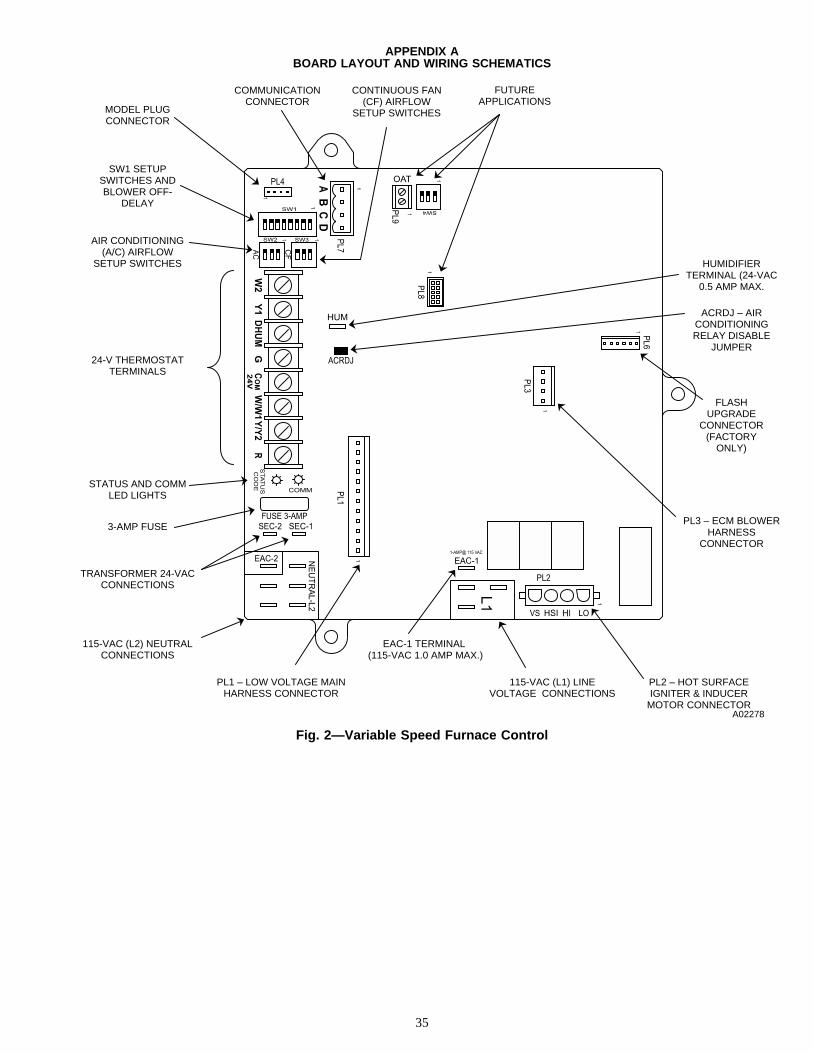
APPENDIX ABOARD LAYOUT AND WIRING SCHEMATICS
Fig. 2—Variable Speed Furnace Control
A02278
FLASH UPGRADE
CONNECTOR (FACTORY
ONLY)
ACRDJ – AIR CONDITIONING RELAY DISABLE
JUMPER
HUMIDIFIER TERMINAL (24-VAC
0.5 AMP MAX.
CONTINUOUS FAN (CF) AIRFLOW
SETUP SWITCHES
COMMUNICATION CONNECTOR
AIR CONDITIONING (A/C) AIRFLOW
SETUP SWITCHES
MODEL PLUG CONNECTOR
SW1 SETUP SWITCHES AND BLOWER OFF-
DELAY
STATUS AND COMM LED LIGHTS
3-AMP FUSE
TRANSFORMER 24-VAC CONNECTIONS
PL3 – ECM BLOWER HARNESS
CONNECTOR
PL1 – LOW VOLTAGE MAIN HARNESS CONNECTOR
EAC-1 TERMINAL (115-VAC 1.0 AMP MAX.)
115-VAC (L1) LINE VOLTAGE CONNECTIONS
115-VAC (L2) NEUTRAL CONNECTIONS
PL2 – HOT SURFACE IGNITER & INDUCER
MOTOR CONNECTOR
24-V THERMOSTAT TERMINALS
FUTURE APPLICATIONS
35
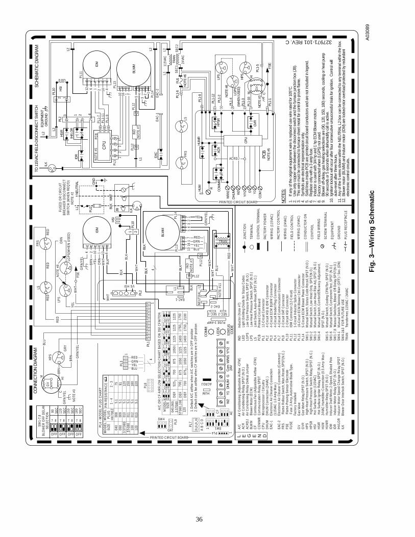
Fig
.3—
Wir
ing
Sch
emat
icA
0308
9
L E G E N D
JUN
CTI
ON
TER
MIN
AL
CO
NTR
OL
TER
MIN
AL
FAC
TORY
PO
WE
R
WIR
ING
(115
VAC
)
FAC
TORY
CO
NTR
OL
WIR
ING
(24V
AC)
FIE
LD C
ON
TRO
L
WIR
ING
(24V
AC)
CO
ND
UC
TOR
ON
CO
NTR
OL
FIE
LD W
IRIN
G
SCR
EW
TE
RM
INA
L
EQ
UIP
ME
NT
GR
OU
ND
PLU
G R
EC
EP
TAC
LE
NO
TES:
327971-101 REV. C
1.If
any
of th
e or
igin
al e
quip
men
t wire
is re
plac
ed u
se w
ire ra
ted
for 1
05°C
.2.
Use
onl
y co
pper
wire
bet
wee
n th
e di
scon
nect
sw
itch
and
the
furn
ace
junc
tion
box
(JB)
.3.
This
wire
mus
t be
conn
ecte
d to
furn
ace
shee
t met
al fo
r con
trol t
o pr
ove
flam
e.4.
Sym
bols
are
ele
ctric
al re
pres
enta
tion
only
.5.
Solid
line
s in
side
PC
B ar
e pr
inte
d ci
rcui
t boa
rd c
ondu
ctor
s an
d ar
e no
t inc
lude
d in
lege
nd.
6.R
epla
ce o
nly
with
a 3
am
p fu
se.
7.In
duct
or is
use
d w
ith 3
/4 h
p an
d 1
hp E
CM
Blo
wer
mot
ors.
8.Fa
ctor
y co
nnec
ted
whe
n (L
GPS
) not
use
d.9.
Blow
er o
ff-de
lay,
gas
hea
ting
sele
ctio
ns a
re (9
0, 1
20, 1
50, 1
80) s
econ
ds, c
oolin
g or
hea
t pum
p90
sec
onds
or 5
sec
onds
whe
n de
hum
idify
cal
l is
activ
e.10
.Ig
nitio
n lo
ckou
t will
occu
r afte
r fou
r con
secu
tive
unsu
cces
sful
tria
ls fo
r ign
ition
. C
ontro
l will
auto
-rese
t afte
r thr
ee h
ours
.11
.An
y of
the
5 w
ires
show
n w
ithin
the
NEU
TRAL
L2
box
can
be c
onne
cted
to a
ny te
rmin
al w
ithin
the
box.
12.
Blow
er m
otor
(BLW
M) a
nd In
duce
r mot
or (I
DM
) are
lock
ed-ro
tor o
verlo
ad p
rote
cted
by
redu
ndan
tel
ectro
nic
cont
rol c
ircui
ts.
A/C
A
ir C
ondi
tioni
ng (
Adj
usta
ble
Airf
low
-CFM
)AC
R
Air
Con
ditio
ning
Rel
ay, S
PS
T (N
.O.)
ACR
DJ
A
ir C
ondi
tioni
ng R
elay
Def
eat J
umpe
rBL
WM
B
low
er M
otor
(EC
M)
CF
C
ontin
uous
Fan
(A
djus
tabl
e A
irflo
w -
CFM
)C
OM
MR
Com
mun
icat
ion
Rel
ay, S
PD
TC
PU
M
icro
proc
esso
r / C
ircui
try
DH
UM
D
HU
M C
onne
ctio
n (2
4VAC
)E
AC-1
E
lect
roni
c A
ir C
lean
er C
onne
ctio
n
(115
VAC
1.0
Am
p M
ax.)
EAC
-2
Ele
ctro
nic
Air
Cle
aner
Con
nect
ion
(Com
mon
)FR
S
Fla
me
Rol
lout
Sw
itch,
Man
. Res
et, S
PST
(N.C
.)FS
E
Fla
me-
Pro
ving
Sen
sor E
lect
rode
FUSE
F
use,
3 A
mp,
Aut
omot
ive
Bla
de Ty
pe,
F
acto
ry In
stal
led
GV
G
as V
alve
GV
R
Gas
Val
ve R
elay
, DP
ST (N
.O.)
HP
S
Hig
h-H
eat P
ress
ure
Switc
h, S
PS
T (N
.O.)
HP
SR
Hig
h-H
eat P
ress
ure
Switc
h R
elay
, SP
ST (N
.C.)
HSI
H
ot S
urfa
ce Ig
nite
r (11
5VAC
)H
SIR
H
ot S
urfa
ce Ig
nite
r Rel
ay, S
PST
(N.O
.)H
UM
2
4VAC
Hum
idifi
er C
onne
ctio
n (0
.5 A
mp
Max
.)H
UM
R
Hum
idifi
er R
elay
, SP
ST (N
.O.)
IDM
In
duce
r Dra
ft M
otor
, 2-S
peed
, Sha
ded
Pole
IDR
In
duce
r Mot
or R
elay
, SP
ST (N
.O.)
IHI/L
OR
In
duce
r Mot
or S
peed
Cha
nge
Rel
ay, S
PD
TIL
K
Blo
wer
Doo
r Int
erlo
ck S
witc
h, S
PS
T (N
.O.)
IND
In
duct
or (N
ote
#7)
LED
Li
ght E
mitt
ing
Dio
de fo
r Sta
tus
Cod
esLG
PS
Lo
w G
as P
ress
ure
Switc
h, S
PST
(N.O
.)LP
S
Low
-Hea
t Pre
ssur
e Sw
itch,
SP
ST (N
.O.)
LS
Li
mit
Sw
itch,
Aut
o-R
eset
, SP
ST (N
.C.)
PC
B
Prin
ted
Circ
uit B
oard
PL1
12
-Circ
uit C
onne
ctor
PL2
4-
Circ
uit H
SI &
IDM
Con
nect
orP
L3
4-C
ircui
t EC
M B
LWM
Con
nect
orP
L4
4-C
ircui
t Mod
el P
lug
Con
nect
orP
L7
4-C
ircui
t Com
mun
icat
ion
Con
nect
orP
L9
2-C
ircui
t OAT
Con
nect
orP
L10
2-
Circ
uit H
SI C
onne
ctor
PL1
1
IDM
Con
nect
or (1
2-C
ircui
t)P
L12
1-
Circ
uit I
nduc
tor S
plic
e C
onne
ctor
PL1
3
16-C
ircui
t EC
M B
low
er C
trl. C
onne
ctor
PL1
4
5-C
ircui
t EC
M B
low
er P
ower
Con
nect
orSW
1-1
M
anua
l Sw
itch,
Sta
tus
Cod
e R
ecal
l, SP
ST
(N.O
.)SW
1-2
M
anua
l Sw
itch,
Low
-Hea
t Onl
y, S
PS
T(N
.O.)
SW1-
3
Man
ual S
witc
h, L
ow-H
eat R
ise
Adj
. SP
ST
(N.O
.)SW
1-4
M
anua
l Sw
itch,
Com
fort
/Effi
cien
cy A
djus
tmen
t,
SPST
(N.O
.)SW
1-5
M
anua
l Sw
itch,
Coo
ling
CFM
/Ton
, SP
ST
(N.O
.)SW
1-6
M
anua
l Sw
itch,
Com
pone
nt Te
st, S
PS
T (N
.O.)
SW1-
7,8
Man
ual S
witc
hes,
Blo
wer
Off-
Del
ay, S
PS
T(N
.O.)
SW4-
1
Man
ual S
witc
h, Tw
inni
ng M
ain
(OFF
) / S
ec. (
ON
)SW
4-2&
3 F
OR
FU
TUR
E U
SETR
AN
Tr
ansf
orm
er, 1
15VA
C /
24VA
C
GV
M
CH
I
NO
TE #
3
BLU
BRN
HP
S
GR
N/Y
EL
FRS
LS
NO
TE #
8
GR
Y
RE
DR
ED
RE
D
LPS
(WH
EN
USE
D)
LGP
SB
RN
FSE
WH
T
PL3
1
4
HSI
L1FUSE
D O
R C
IRC
UIT
BR
EA
KE
R D
ISC
ON
NE
CT
SWIT
CH
(WH
EN
RE
Q'D
)N
OTE
#2
GN
D
NEU
TRAL
FU2 BL
K
ILK
PL1
0
JB
1 2
BLK
WH
T
PL1
TRAN
BLW
M
L1
EAC-1
PL1
2
IND
NO
TE #
7
PL12
4
HSI
PL2
VS
BLK
WH
TW
HT BL
U
SEC-2
CO
DE
SEC-1
HUM
FUSE 3-AMP
W/W
1D
HU
MG
24Vom
CW
2Y
/Y2
RY
1S
TATU
S
LED
S
CO
MM
ACRDJ
PL8
PL9
OAT
SW 4
PL7
AB
CD
CF
AC
SW1PL4
GR
N/Y
EL
1. D
efau
lt A
/C a
irflo
w w
hen
A/C
sw
itche
s ar
e in
OFF
pos
ition
2. D
efau
lt co
nt. fa
n ai
rflow
whe
n C
F sw
itche
s ar
e in
OFF
pos
ition
A/C
OR
CF
AIR
FLO
W S
ELE
CTI
ON
CH
AR
T B
ASE
D O
N 35
0 C
FM/T
ON
1H
SI2
S
CH
EMAT
IC D
IAG
RAM
IDR
T
O 1
15VA
C F
IELD
-DIS
CO
NN
ECT
SWIT
CH
ILK
EQU
IPM
ENT
GR
OU
ND 1 23
HS
IR
IHI/L
OR
PL2
L2
L2
FU1
NO
TE #
6
PL1-
8
R
PL1-
6
L2
PL10
4
CP
U
NO
TE #
5P
CB
PL3
12
34
BLW
M
PL1
3
10 16 1 7
54
32 1
EAC
-1P
L14
PL1
2IN
DN
OTE
#7
PL1
2
L1
EAC
EAC
-2
TRAN
115V
ACL1
L2 SEC
2S
EC
1
24VA
C
PL1-
12
HPS
R
GV
LPS
NO
TE #
8
LGPS
(WH
EN U
SED
)H
PS
HI
PL1
-2
PL1-
4
PL1-
3
PL1
-10
PL1-
5
W/W
1
CP
U
GVR
DH
UM
W2
Y/Y
2 G Y1
CO
MN
OTE
#3
CM
PL1-
1FS
EN
OTE
#5
ACR
CO
MM
R
PCB
1
1
1
221
0017
5014
00
1225
1225
1225
1225
1050
1050
875
875
700
700
525
120
5T08
0,10
0D
EF.
DE
F.
DE
F.04
0,06
0,3.
5T08
0
SIZE
MO
DE
L
1 2 3
OFF1 2 3
OFF1 2 3
OFF1 2 3
OFF1 2 3
OFF1 2 3
OFF1 2 3
OFF1 2 3
OFF
OR
N
BLK
GR
N/Y
EL
516
17
10 BLUYELGRNRED
PL1
3P
L14
BLK
YE
L
CO
NN
ECTI
ON
DIA
GR
AM
BLK W
HT
YEL14
32
BLUYELGRNRED
SW
1-7,
8B
LOW
ER
OFF
DE
LAY
SELE
CTI
ON 9
0SE
C12
0SE
C15
0SE
C18
0SE
C
OFF OFF OFF OFF
7 8 7 8 7 8 7 8
11
2
1
1
ACRDJ
PRINTED CIRCIUT BOARD
PRINTED CIRCIUT BOARDH
UM
RH
UM
RE
D
MO
DE
LM
OD
EL
SIZE
PLU
GH
K70
EZ
PIN
RE
SIS
TAN
CE
K
1 - 4
2 - 3
040
060
3.5T
080
5T-0
8010
0
008
009
010
011
012
5.1
5.1
5.1
5.1
5.1
75 91 120
150
180
PL4
- M
OD
EL
PLU
G C
HA
RT
120
013
5.1
220 2
700
875
1050
1225
1400
117
5017
50
IDM
GR
N/Y
EL
BR
N
OR
NY
EL
WH
TB
LK
BLK
WH
T
FRS
LS
IDM
PL1
1
PL1
-9P
L1-1
1P
L1-7
L2
NO
TE #
11
NE
UTR
AL
- L2
EAC-2W
HT
RE
D4 2 10 1 12 642 10112 6
36
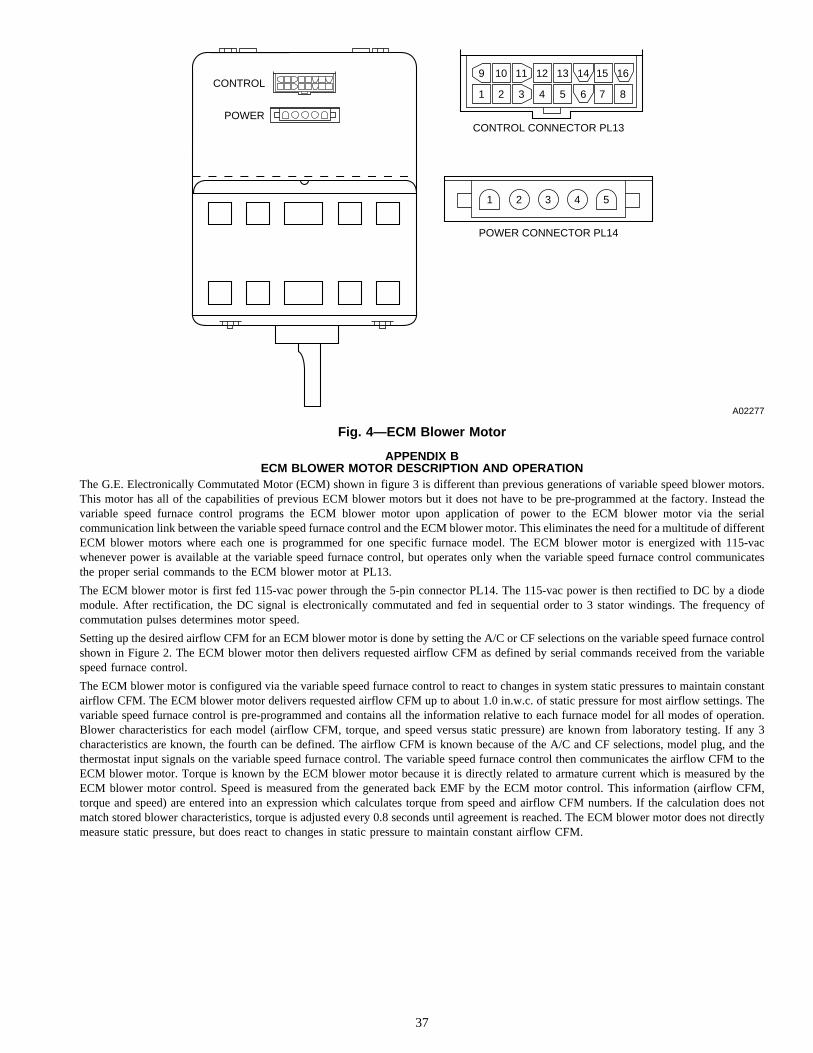
APPENDIX BECM BLOWER MOTOR DESCRIPTION AND OPERATION
The G.E. Electronically Commutated Motor (ECM) shown in figure 3 is different than previous generations of variable speed blower motors.This motor has all of the capabilities of previous ECM blower motors but it does not have to be pre-programmed at the factory. Instead thevariable speed furnace control programs the ECM blower motor upon application of power to the ECM blower motor via the serialcommunication link between the variable speed furnace control and the ECM blower motor. This eliminates the need for a multitude of differentECM blower motors where each one is programmed for one specific furnace model. The ECM blower motor is energized with 115-vacwhenever power is available at the variable speed furnace control, but operates only when the variable speed furnace control communicatesthe proper serial commands to the ECM blower motor at PL13.
The ECM blower motor is first fed 115-vac power through the 5-pin connector PL14. The 115-vac power is then rectified to DC by a diodemodule. After rectification, the DC signal is electronically commutated and fed in sequential order to 3 stator windings. The frequency ofcommutation pulses determines motor speed.
Setting up the desired airflow CFM for an ECM blower motor is done by setting the A/C or CF selections on the variable speed furnace controlshown in Figure 2. The ECM blower motor then delivers requested airflow CFM as defined by serial commands received from the variablespeed furnace control.
The ECM blower motor is configured via the variable speed furnace control to react to changes in system static pressures to maintain constantairflow CFM. The ECM blower motor delivers requested airflow CFM up to about 1.0 in.w.c. of static pressure for most airflow settings. Thevariable speed furnace control is pre-programmed and contains all the information relative to each furnace model for all modes of operation.Blower characteristics for each model (airflow CFM, torque, and speed versus static pressure) are known from laboratory testing. If any 3characteristics are known, the fourth can be defined. The airflow CFM is known because of the A/C and CF selections, model plug, and thethermostat input signals on the variable speed furnace control. The variable speed furnace control then communicates the airflow CFM to theECM blower motor. Torque is known by the ECM blower motor because it is directly related to armature current which is measured by theECM blower motor control. Speed is measured from the generated back EMF by the ECM motor control. This information (airflow CFM,torque and speed) are entered into an expression which calculates torque from speed and airflow CFM numbers. If the calculation does notmatch stored blower characteristics, torque is adjusted every 0.8 seconds until agreement is reached. The ECM blower motor does not directlymeasure static pressure, but does react to changes in static pressure to maintain constant airflow CFM.
Fig. 4—ECM Blower Motor
A02277
POWER CONNECTOR PL14
1
1 2 3 4 5 6 7 8
9 10 11 12 13 14 15 16
2 3 4 5
CONTROL CONNECTOR PL13
CONTROL
POWER
37
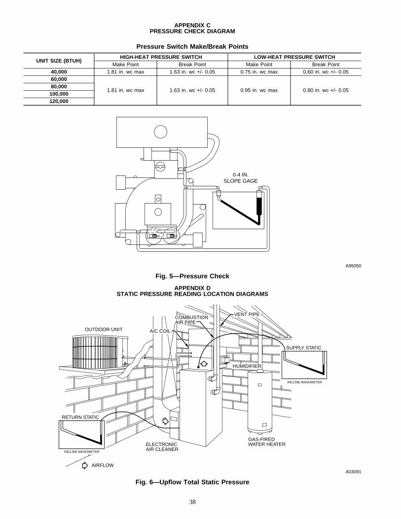
APPENDIX CPRESSURE CHECK DIAGRAM
APPENDIX DSTATIC PRESSURE READING LOCATION DIAGRAMS
Pressure Switch Make/Break Points
UNIT SIZE (BTUH)HIGH-HEAT PRESSURE SWITCH LOW-HEAT PRESSURE SWITCH
Make Point Break Point Make Point Break Point40,000 1.81 in. wc max 1.63 in. wc +/- 0.05 0.75 in. wc max 0.60 in. wc +/- 0.0560,000
1.81 in. wc max 1.63 in. wc +/- 0.05 0.95 in. wc max 0.80 in. wc +/- 0.0580,000
100,000120,000
Fig. 5—Pressure Check
A95050
0-4 IN.SLOPE GAGE
Fig. 6—Upflow Total Static Pressure
A03091
COMBUSTIONAIR PIPE
A/C COILOUTDOOR UNIT
VENT PIPE
HUMIDIFIER
GAS-FIREDWATER HEATERELECTRONIC
AIR CLEANER
AIRFLOW
SUPPLY STATIC
INCLINE MANOMETER
RETURN STATIC
INCLINE MANOMETER
38

Tools Needed:
1. Pilot Tube
2. Incline Manometer/Magnahelic
Example 1:Return ESP after Filter 0.20 in.w.c.Supply ESP before Coil 0.40 in.w.c.------------------------------------------------------Total ESP 0.60 in.w.c.
Fig. 7—Downflow Total Static Pressure
A03092
ELECTRONICAIR CLEANER
HUMIDIFIER
A/C COIL
VENT
COMBUSTIONAIR
OUTDOORUNIT
AIRFLOW
SUPPLY STATIC
INCLINE MANOMETER
RETURN STATIC
INCLINE MANOMETER
Fig. 8—Horizontal Total Static Pressure
A03093
SUPPLY STATIC
INCLINE MANOMETER
RETURN STATIC
INCLINE MANOMETER
VENT PIPE
ELECTRONICAIR CLEANER
FURNACECONDENSATE
DRAIN
REFRIGERATIONPIPING
AIR CONDITIONINGCOIL
AIRFLOW
COMBUSTION-AIR PIPE
39
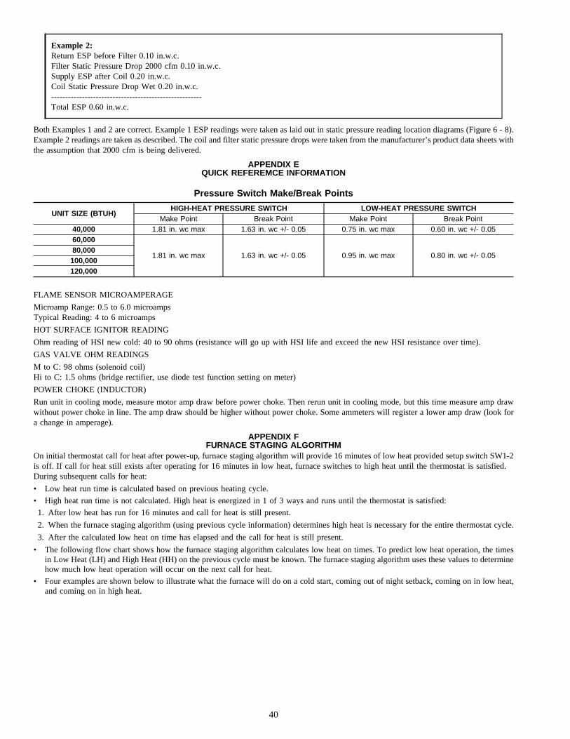
Example 2:Return ESP before Filter 0.10 in.w.c.Filter Static Pressure Drop 2000 cfm 0.10 in.w.c.Supply ESP after Coil 0.20 in.w.c.Coil Static Pressure Drop Wet 0.20 in.w.c.------------------------------------------------------Total ESP 0.60 in.w.c.
Both Examples 1 and 2 are correct. Example 1 ESP readings were taken as laid out in static pressure reading location diagrams (Figure 6 - 8).Example 2 readings are taken as described. The coil and filter static pressure drops were taken from the manufacturer’s product data sheets withthe assumption that 2000 cfm is being delivered.
APPENDIX EQUICK REFEREMCE INFORMATION
FLAME SENSOR MICROAMPERAGE
Microamp Range: 0.5 to 6.0 microampsTypical Reading: 4 to 6 microamps
HOT SURFACE IGNITOR READING
Ohm reading of HSI new cold: 40 to 90 ohms (resistance will go up with HSI life and exceed the new HSI resistance over time).
GAS VALVE OHM READINGS
M to C: 98 ohms (solenoid coil)Hi to C: 1.5 ohms (bridge rectifier, use diode test function setting on meter)
POWER CHOKE (INDUCTOR)
Run unit in cooling mode, measure motor amp draw before power choke. Then rerun unit in cooling mode, but this time measure amp drawwithout power choke in line. The amp draw should be higher without power choke. Some ammeters will register a lower amp draw (look fora change in amperage).
APPENDIX FFURNACE STAGING ALGORITHM
On initial thermostat call for heat after power-up, furnace staging algorithm will provide 16 minutes of low heat provided setup switch SW1-2is off. If call for heat still exists after operating for 16 minutes in low heat, furnace switches to high heat until the thermostat is satisfied.During subsequent calls for heat:
• Low heat run time is calculated based on previous heating cycle.
• High heat run time is not calculated. High heat is energized in 1 of 3 ways and runs until the thermostat is satisfied:
1. After low heat has run for 16 minutes and call for heat is still present.
2. When the furnace staging algorithm (using previous cycle information) determines high heat is necessary for the entire thermostat cycle.
3. After the calculated low heat on time has elapsed and the call for heat is still present.
• The following flow chart shows how the furnace staging algorithm calculates low heat on times. To predict low heat operation, the timesin Low Heat (LH) and High Heat (HH) on the previous cycle must be known. The furnace staging algorithm uses these values to determinehow much low heat operation will occur on the next call for heat.
• Four examples are shown below to illustrate what the furnace will do on a cold start, coming out of night setback, coming on in low heat,and coming on in high heat.
Pressure Switch Make/Break Points
UNIT SIZE (BTUH)HIGH-HEAT PRESSURE SWITCH LOW-HEAT PRESSURE SWITCH
Make Point Break Point Make Point Break Point40,000 1.81 in. wc max 1.63 in. wc +/- 0.05 0.75 in. wc max 0.60 in. wc +/- 0.0560,000
1.81 in. wc max 1.63 in. wc +/- 0.05 0.95 in. wc max 0.80 in. wc +/- 0.0580,000
100,000120,000
40
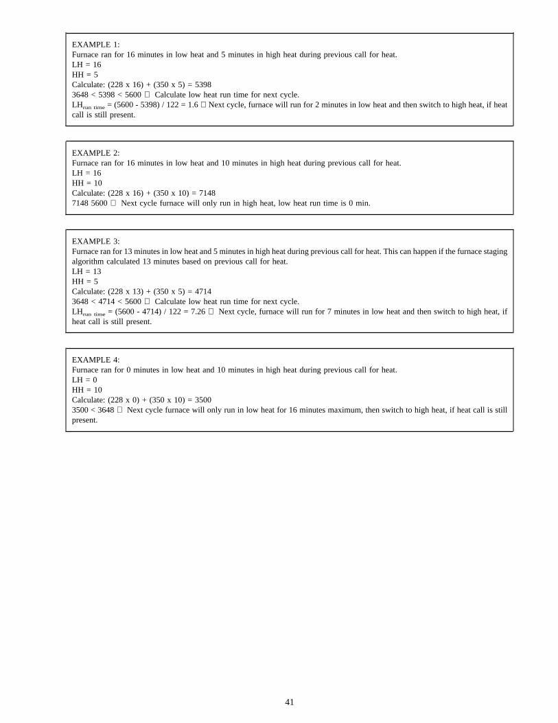
EXAMPLE 1:Furnace ran for 16 minutes in low heat and 5 minutes in high heat during previous call for heat.LH = 16HH = 5Calculate: (228 x 16) + (350 x 5) = 53983648 < 5398 < 5600 ⇒ Calculate low heat run time for next cycle.LHrun time = (5600 - 5398) / 122 = 1.6 ⇒ Next cycle, furnace will run for 2 minutes in low heat and then switch to high heat, if heatcall is still present.
EXAMPLE 2:Furnace ran for 16 minutes in low heat and 10 minutes in high heat during previous call for heat.LH = 16HH = 10Calculate: (228 x 16) + (350 x 10) = 71487148 5600 ⇒ Next cycle furnace will only run in high heat, low heat run time is 0 min.
EXAMPLE 3:Furnace ran for 13 minutes in low heat and 5 minutes in high heat during previous call for heat. This can happen if the furnace stagingalgorithm calculated 13 minutes based on previous call for heat.LH = 13HH = 5Calculate: (228 x 13) + (350 x 5) = 47143648 < 4714 < 5600 ⇒ Calculate low heat run time for next cycle.LHrun time = (5600 - 4714) / 122 = 7.26 ⇒ Next cycle, furnace will run for 7 minutes in low heat and then switch to high heat, ifheat call is still present.
EXAMPLE 4:Furnace ran for 0 minutes in low heat and 10 minutes in high heat during previous call for heat.LH = 0HH = 10Calculate: (228 x 0) + (350 x 10) = 35003500 < 3648 ⇒ Next cycle furnace will only run in low heat for 16 minutes maximum, then switch to high heat, if heat call is stillpresent.
41
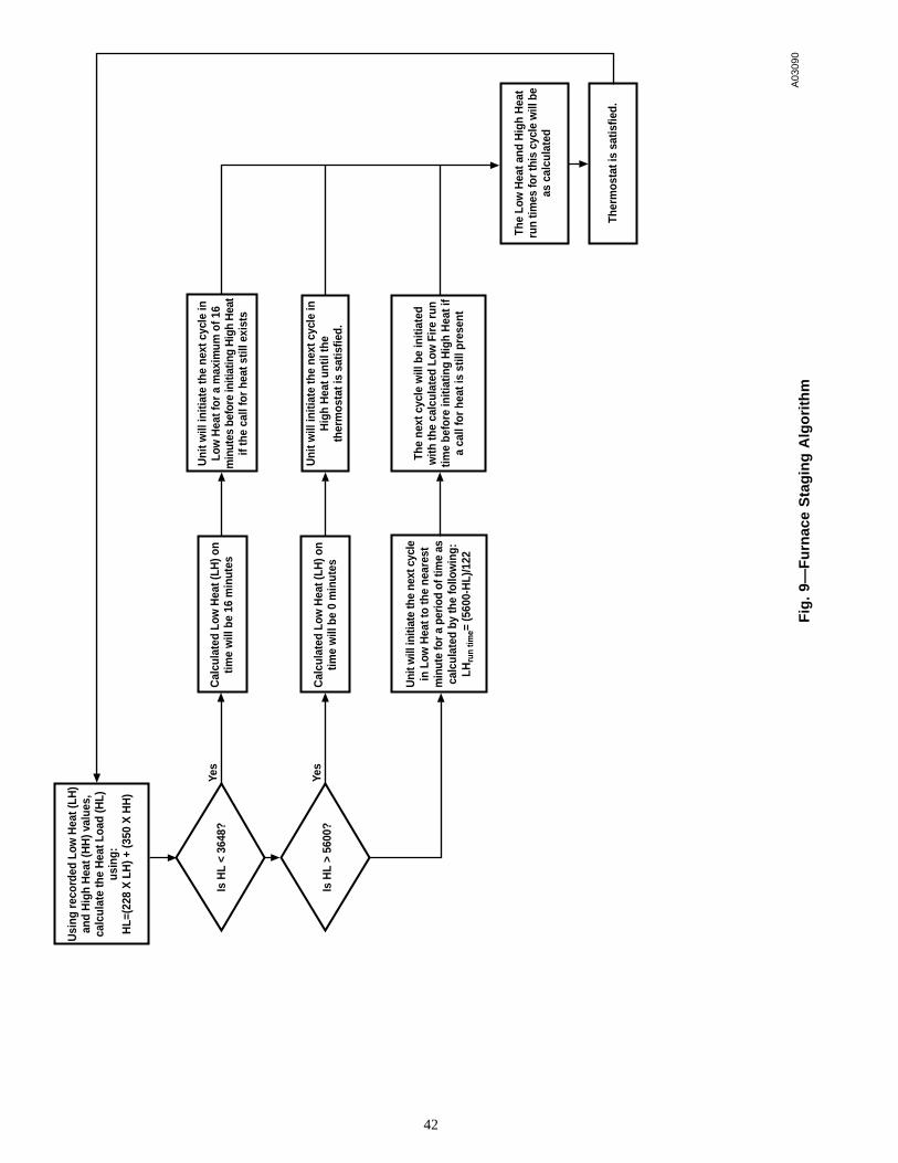
Fig
.9—
Fu
rnac
eS
tag
ing
Alg
ori
thm
A03
090
Usi
ng r
ecor
ded
Low
Hea
t (LH
)an
d H
igh
Hea
t (H
H) v
alue
s,ca
lcul
ate
the
Hea
t Loa
d (H
L)us
ing:
HL=
(228
X L
H) +
(350
X H
H)
Is H
L <
3648
?
Is H
L >
5600
?
Cal
cula
ted
Low
Hea
t (LH
) on
time
will
be
16 m
inut
es
Cal
cula
ted
Low
Hea
t (LH
) on
time
will
be
0 m
inut
es
Yes
Yes
Uni
t will
initi
ate
the
next
cyc
lein
Low
Hea
t to
the
near
est
min
ute
for a
per
iod
of ti
me
asca
lcul
ated
by
the
follo
win
g:LH
run
time=
(560
0-H
L)/1
22
Uni
t will
initi
ate
the
next
cyc
le in
Low
Hea
t for
a m
axim
um o
f 16
min
utes
bef
ore
initi
atin
g H
igh
Hea
tif
the
call
for
heat
stil
l exi
sts
Uni
t will
initi
ate
the
next
cyc
le in
Hig
h H
eat u
ntil
the
ther
mos
tat i
s sa
tisfie
d.
The
next
cyc
le w
ill b
e in
itiat
edw
ith th
e ca
lcul
ated
Low
Fir
e ru
ntim
e be
fore
initi
atin
g H
igh
Hea
t if
a ca
ll fo
r he
at is
stil
l pre
sent
The
Low
Hea
t and
Hig
h H
eat
run
times
for t
his
cycl
e w
ill b
eas
cal
cula
ted
Ther
mos
tat i
s sa
tisfie
d.
42
A94328
SERVICE TRAINING
Packaged Service Training programs are an excellent way to increase yourknowledge of the equipment discussed in this manual, including: • Unit Familiarization • Maintenance • Installation Overview • Operating SequenceA large selection of product, theory, and skills programs is available, using popularvideo-based formats and materials. All include video and/or slides, plus companionbook.
Classroom Service Training plus "hands-on" the products in our labs can meanincreased confidence that really pays dividends in faster troubleshooting, fewercallbacks. Course descriptions and schedules are in our catalog.
CALL FOR FREE CATALOG 1-800-644-5544
[ ] Packaged Service Training [ ] Classroom Service Training
43

Copyright 2003 CARRIER Corp. • 7310 W. Morris St. • Indianapolis, IN 46231 58mvp10sm
Manufacturer reserves the right to discontinue, or change at any time, specifications or designs without notice and without incurring obligations.Book 1 4Tab 6a 8a
PC 101 Catalog No. 535–80083 Printed in U.S.A. Form 58MVP-10SM Pg 44 6-03 Replaces: New