virtualized anr to manage resources for optimization of
TRANSCRIPT
Research ArticleVirtualized ANR to Manage Resources for Optimization ofNeighbour Cell Lists in 5G Mobile Wireless Networks
Yoonsu Shin and Songkuk Kim
School of Integrated Technology, Yonsei Institute of Convergence Technology, Yonsei University, Seoul, Republic of Korea
Correspondence should be addressed to Yoonsu Shin; [email protected]
Received 26 August 2016; Revised 11 December 2016; Accepted 29 December 2016; Published 8 February 2017
Academic Editor: Piotr Zwierzykowski
Copyright © 2017 Yoonsu Shin and Songkuk Kim. This is an open access article distributed under the Creative CommonsAttribution License, which permits unrestricted use, distribution, and reproduction in any medium, provided the original work isproperly cited.
In future, more devices such as wearable devices will be connected to the networks. This will increase simultaneous handovers.The coverage of a cell will be small because a superhigh frequency used in 5G wireless networks does not propagate very far. Thistrend will increase the number of neighbour cell lists and it will accelerate the change of neighbour cell lists since the coverageof cells can be altered by the environment. Meanwhile, the ANR technology will be essential in 5G networks. Since the networkenvironment in the future is not similar to the present, the strategy of ANR should also be different from the present. First, sincepractical neighbour cell lists in each cell are changed frequently and individually, it is necessary to optimize them frequently andindividually. Second, since the neighbour cell lists in each cell are not changed similarly, it is necessary to operate ANR flexibly. Torespond to these issues, we propose to use network function virtualization (NFV) for ANR. To evaluate the proposed strategies, wemeasured additional resource consumption and the latency of handover if neighbour cell lists are not optimized whenUEs performhandover simultaneously. These experiments are conducted using Amarisoft LTE-100 Platform.
1. Introduction
In the IoT era, the mass use of devices such as wearabledevices and wireless sensors in mobility (e.g., vehicle, per-sonal mobility, and watch) will be connected to the networksfor convenience. This will cause an increase of simultaneoushandover.Thus, the handover performancewill becomemoreimportant for ceaseless connection and QoS. In particular,if there will be an urgent situation to receive data fromnetworks, the handover performance will be critical. More-over, in the 5G era, the coverage area of cells will becomesmaller because a superhigh frequency will be used forhigh throughput. The superhigh frequency cannot propagatevery far. Hence, more cells are necessary to cover the samearea (i.e., massive small cells). These features will increasethe number of neighbour cell lists, and it will acceleratethe change of neighbour cell lists because the coverage ofcells can be altered by the environment, which includesreflection, diffraction, and shadowing effects. In addition,these small cells will also increase the simultaneous handoverbecause the boundary among cells will increase. Moreover,
nowadays, moving cells and small cells are usually used fordata traffic rushes and radio shadow areas [1], andmacrocellsand massive small cells will coexist in 5G networks. In thiscomplex network design, the configuration of neighbour cellsbecomes more difficult even though it is very important forhandover between two neighbour cells.
Meanwhile, it is necessary to inquire assumption thatan increase of neighbour cell lists will accelerate the changeof neighbour cell lists. First, practical neighbour cell lists,according to the strength of the signal from other cells, arenot fixed.Thismeans that a strong signal from far-off cells canbe received in the serving cell, and it propagates sufficientlyfar because radio signal strength is affected by environmentalfactors such as temperature and humidity [2–5]. This effectis also due to shadowing, fast fading, reflection, and so on[6, 7]. For example, authors in [6] emulated the propagationeffects by increasing the standard deviation of the lognormalshadowing in themacrocells. In this simulation, the small cellhad just one single neighbour macrocell as a neighbour celllist at the region with the no shadowing (i.e., a small cell wasin a macrocell), but four neighbour cells were detected in a
HindawiMobile Information SystemsVolume 2017, Article ID 9643401, 9 pageshttps://doi.org/10.1155/2017/9643401

2 Mobile Information Systems
small cell with the shadowing of 12 dB standard deviation.If the standard deviation would increase, the number ofneighbour cell lists would increase. On the contrary, if thestandard deviation would decrease, the number of neighbourcell lists would again decrease. In this simulation, the numberof neighbour cell lists in a macrocell was varied from six toabout 20, and the number of neighbour cell lists in a smallcell was varied from one to about 10 according to shadowingstandard deviation.Therefore, if there are many small cells ina macrocell, it is expected that the number of neighbour celllists in a cell increases more and the neighbour cell lists in acell change more frequently.
Due to massive small cells in 5G networks, automaticneighbour relation (ANR) technology, which automaticallydetects and configures neighbour cells, will be essential andbecome more important in 5G networks because manualconfiguration and optimization of neighbour cell lists in eachindividual small cell will become more costly and difficult.ANR detects a new cell’s information including physical cellID (PCI), E-UTRAN cell global identifier (ECGI), and the IPaddress from operations, administration, and maintenance(OAM) in order to execute handover to a new cell whena serving cell does not know the new cell and the servingcell receives the strong signal of the new cell. This handovermethod is called UE-Triggered ANR with OAM Support [8].In other handovermethods, ANR receives only the IP addressfrom OAM and the other information from mobile phones[9]. Basically, ANR makes it possible for enhanced NodeB(eNodeB) to detect the neighbour cells on the basis of UEmeasurements [10]. The UE eventually sends MeasurementReport messages, including PCI, to eNodeB when the UEgets a stranger signal than that from serving eNodeB, orperiodically transfers this message [11].
Finally, since the network environment in the future(i.e., an increase of simultaneous handovers and a frequentchange of neighbour cell lists) will not be the same as thepresent, the strategy of ANR should also be changed as weneeded a new strategy of self-organizing networks in the pastdue to enterprise femtocells [12], and the strategies to beconsidered are discussed as below. First, it is necessary tooptimize the neighbour cell lists frequently and individuallybecause practical neighbour cell lists for each cell are changedfrequently and individually due to the change of environmentand the redundant neighbour cell lists could be burdensometo perform handover quickly. Although traditional ANRfunction has neighbour removal function [13], it does notconsider this future condition (i.e., frequent change of prac-tical neighbour cell lists). Recently, ANR algorithm for thiscomplex network environment is researched [14], but it isonly for overreached scenario. To apply the change of a cell’scoverage according to a natural phenomenon, it is necessaryto check the signal frequently and individual for optimizingneighbour cell lists. Second, it needs to operate ANR flexiblybecause the neighbour cell lists in some cells are rarelymodified while those in other cells are frequently modified.For example, when a great number of people gather for afestival, game, or national holiday, it is necessary to operatenew small cells or moving cells for a while. Additionally, if atall building is built or if it is rainy or sunny, the cell coverage is
altered, and this can also change the neighbour cell lists. Sincethis trend continues and even accelerates, these strategies willbecome more essential in the future.
For these strategies, we propose using network functionvirtualization (NFV) [15] for operating ANR. That is, ANR-virtual network function (ANR-VNF), in which networkentry is virtualized and has ANR functionality, can bedeployed and extended frequently and flexibly. For instance,in the case where the deviation of a floating population islarge, such as that at a stadium, it is more efficient andinexpensive to operate moving cells than fixed cells for dataoffload. Also, in the case where the fluctuation of shadowingstandard deviation is large due to weather, more resourcesare needed for optimizing neighbour cell lists quickly. In anycase, in order to configure and optimize neighbour cell listsmore quickly, it is necessary to extend the capacity of ANRfunctionality.
The remainder of this paper is organized as follows.Section 2 provides background on self-organizing networks(SON), ANR, NFV, and so on. Section 3 adduces the exper-iments for necessity of these strategies and expected hazard.Section 4 explains the proposed methods such as ANR-VNFin detail. Finally, Section 5 gives the conclusions.
2. Background and Related Work
2.1. Self-Organizing Networks (SON). Operating radio net-works is a challenging task, especially in cellular mobilecommunication systems due to their latent complexity. Thiscomplexity arises from the number of network elementsand interconnections between their configurations. In aheterogeneous network, it is difficult to handle the variety oftechnologies and their precise operational paradigms. Today,planning and optimization tools are typically semiautomatedand management tasks need to be tightly supervised byhuman operators. This manual effort by the human operatoris time-consuming, expensive, and error-prone and requires ahigh degree of expertise. SONcan be used to reduce operatingcosts by reducing tasks at hand and to protect proceeds byminimising human error. The subsection below details SONtaxonomies.
2.1.1. Self-Configuration. Configuration of base stations(eNBs), relay stations (RS), and femtocells is required duringdeployment, extension, and upgrade of network terminals.Configurations may also be needed when there is a changein the system, such as the failure of a node or a drop innetwork performance. In future systems, the conventionalprocess of manual configuration needs to be replaced withself-configuration. It is predictable that nodes in futurecellular networks should be able to self-configure all of theirinitial parameters including IP addresses, neighbour list, andradio access parameters.
2.1.2. Self-Optimization. After the initial self-configurationphase, it is significant to continuously optimize systemparameters to ensure efficient performance of the system if allits optimization objectives are to be maintained. Optimiza-tion in legacy systems can be done through periodic drive

Mobile Information Systems 3
tests or analysis from log reports generated from networkoperating centers. Self-optimization includes load balancing,interference control, coverage extension, and capacity opti-mization.
2.1.3. Self-Healing. Wireless cellular systems are prone tofaults and failures because of component malfunctions ornatural disasters. In traditional systems, failures are mainlydetected by the centralized O&M (Operation and Mainte-nance) software. Events are recorded and necessary alarmsare set off. When alarms cannot be cleared remotely, radionetwork engineers are usually mobilized and sent to cell sites.This process could take days or even weeks before the systemreturns to normal operation. In future self-organized cellularsystems, this process needs to be improved by consolidatingthe self-healing functionality. Self-healing is a process thatrelates the remote detection, diagnosis, and triggering ofcompensation or recovery actions to blunt the effect of faultsin the network’s equipment.
2.2. Automatic Neighbour Relation (ANR) [7–9]. The cov-erage of cells is limited because the cell cannot emit radiofrequency with unlimited power, so there are many cellsfor covering a wide area. If one mobile phone moves fromthe coverage area of one cell to that of another, it wouldconnect to the new cell and disconnect from the old cell.Thisprocedure is called handover. In LTE radio access network,the cell consists only of eNodeB which communicates witheach other directly via theX2 interface.Over this X2 interface,neighbouring eNodeBs communicate with each other toprepare and execute handovers. In order to provide seamlessmobility in LTE, it is important to set up the X2 interfacewithout omission because there will be no handover betweenneighbouring eNodeBs unless the X2 interface is set up andfunctioning.
The X2 interface is set up by using the neighbour cell listsin the Neighbour Relation Tables (NRT) of each eNodeB, sothere is neither X2 interface nor handover between neighbourcells if one eNodeB omits the neighbour cell lists in its ownNRT, which is caused by a moving cell or a newly addedsmall cell. In this case, Automatic neighbour Relation (ANR)functionality can detect the new neighbour cell and add itslist to the NRT automatically.
2.3. Network Function Virtualization [15]. Service provisionwithin the telecommunications industry has traditionallybeen based on network operators providing physical propri-etary devices and equipment for each function. These ded-icated requirements for high quality, stability, and stringentprotocol adherence have led to long product cycles, verylow service agility, and heavy dependence on specializedhardware.
However, the requirements by users for more diverseand new (short-lived) services with high data rates continueto increase. Therefore, Telecommunication Service Providers(TSPs) must correspondingly and continuously purchase,store, and operate new physical equipment. All these factorslead to high CAPEX and OPEX for TSPs. Moreover, theresulting increase in capital and operational costs cannot
result in higher subscription fees, so TSPs have been forcedto find ways of building more dynamic and service-awarenetworks with the objective of reducing product cycles,operating, and capital expenses and improving service agility.
NFV [16, 17] has been proposed as a way to address thesechallenges by forcing virtualization technology to offer a newway to design, deploy, and manage networking services. Themain idea of NFV is the decoupling of physical networkequipment from the functions that run on them. The goal ofNFV is to transform the way that network operators designnetworks by evolving virtualization technology to reinforcemuch of the network equipment onto standard servers, whichcould be located in data centers, distributed network nodes,and at the end user premises. It involves the implementationof network functions in software—VNFs—that can run onone or more industry standard physical servers and that canbe moved to various locations in the networks as requiredwithout the need for installation of new equipment.
With this, NFV allows TSPs to get more flexibility tofurther open up their network capabilities and services tousers and other services and the ability to deploy or supportnew network services faster and cheaper so as to realizebetter service agility. To achieve these benefits, NFV paves theway for a number of differences in the way network serviceprovisioning is realized in comparison to current practice.
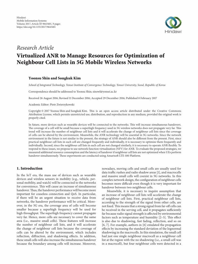
2.4. Virtualized Cellular Infrastructure. A basic architectureof LTEnetworkswithoutNFV shows that theUE is connectedto the Evolved Packet Core (EPC) over the LTE accessnetwork (E-UTRAN), inwhich the eNodeB is the base stationfor LTE radio.The EPC ismade up of the ServingGateway (S-GW), the Packet Data Network (PDN), the Gateway (P-GW),the Mobility Management Entity (MME), and the Policy andCharging Rules Function (PCRF). All these functions arebased on dedicated equipment.
In virtualized cellular infrastructure shown in Figure 1,however, the network entries of EPC get virtualized into adata center. Also, a logic part of eNodeB gets virtualizedinto data center and only the RF part of eNodeB remains.This division of eNodeB is called C-RAN (cloud radioaccess network). C-RAN features centralized processing,collaborative radio, real-time cloud computing, and powerefficient infrastructure [18]. C-RAN is composed of the BBU(baseband unit), OTN (optical transmission network), andthe RRU (remote radio unit). The BBUs implement thebase station functionality whereas the RRUs perform radiofunctions. Also, the BBUs and RRUs are applicable to typicalRAN, from macrocell to femtocell. Thus, these BBUs canbe centralized and this makes networks more efficient andoptimized in terms of cost, resources, and energy through theorchestration management system [18, 19].
2.5. Amarisoft LTE-100 Platform. The Amarisoft LTE-100platform is a software-based LTE station running on a PC.Like a virtualized cellular infrastructure, the Amarisoft LTE-100 platform provides LTE Enhanced Packet Core (EPC) andbase station (eNB) on each PC. The EPC includes MobilityManagement Entity (MME) with built-in Packet Gateway(P-GW), Serving Gateway (S-GW), and Home Subscriber
4 Mobile Information Systems
Homenetwork
Automobile
Mobile RRU
Data center(C-RAN)
Internet
VNFs P-GW
S-GW
MME
BBU
WireWirelessDeploy VNF
Figure 1: The architecture of virtualized cellular infrastructure.
Servers (HSS). The radio interface in the software-based LTEsolution was handled by Ettus Research USRP N210. Theantenna configuration used in the experiments was a Single-Input Single-Output (SISO) scheme.
The PHY layer complies with LTE release 13 and supportsclosed-loop power control, and the protocol layer also com-plies with LTE release 13 and implements the MAC, RLC,PDCP, and RRC layers. Also, it supports intra-eNodeB, S1,or X2 handovers. For network interface, it supports standardS1AP and GTP-U interfaces to the Core Network and theX2AP interface between eNodeBs.
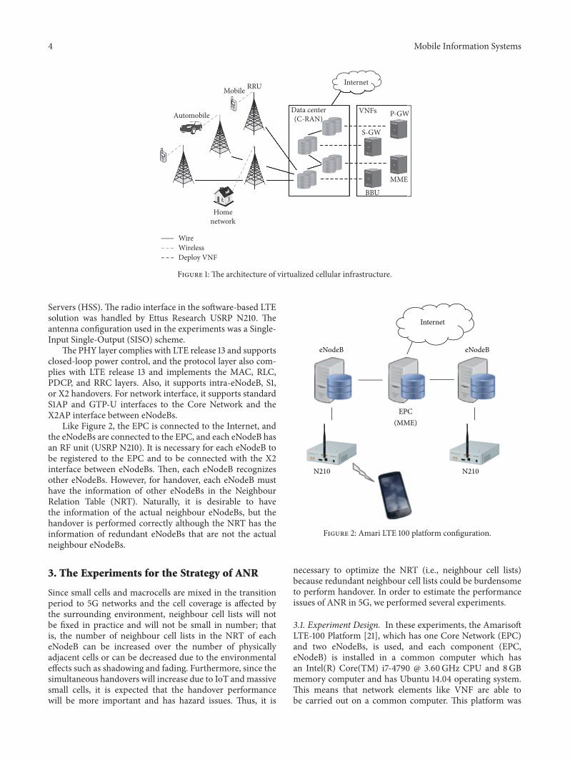
Like Figure 2, the EPC is connected to the Internet, andthe eNodeBs are connected to the EPC, and each eNodeB hasan RF unit (USRP N210). It is necessary for each eNodeB tobe registered to the EPC and to be connected with the X2interface between eNodeBs. Then, each eNodeB recognizesother eNodeBs. However, for handover, each eNodeB musthave the information of other eNodeBs in the NeighbourRelation Table (NRT). Naturally, it is desirable to havethe information of the actual neighbour eNodeBs, but thehandover is performed correctly although the NRT has theinformation of redundant eNodeBs that are not the actualneighbour eNodeBs.
3. The Experiments for the Strategy of ANR
Since small cells and macrocells are mixed in the transitionperiod to 5G networks and the cell coverage is affected bythe surrounding environment, neighbour cell lists will notbe fixed in practice and will not be small in number; thatis, the number of neighbour cell lists in the NRT of eacheNodeB can be increased over the number of physicallyadjacent cells or can be decreased due to the environmentaleffects such as shadowing and fading. Furthermore, since thesimultaneous handovers will increase due to IoT andmassivesmall cells, it is expected that the handover performancewill be more important and has hazard issues. Thus, it is
Internet
eNodeB eNodeB
N210 N210
EPC(MME)
Figure 2: Amari LTE 100 platform configuration.
necessary to optimize the NRT (i.e., neighbour cell lists)because redundant neighbour cell lists could be burdensometo perform handover. In order to estimate the performanceissues of ANR in 5G, we performed several experiments.
3.1. Experiment Design. In these experiments, the AmarisoftLTE-100 Platform [21], which has one Core Network (EPC)and two eNodeBs, is used, and each component (EPC,eNodeB) is installed in a common computer which hasan Intel(R) Core(TM) i7-4790 @ 3.60GHz CPU and 8GBmemory computer and has Ubuntu 14.04 operating system.This means that network elements like VNF are able tobe carried out on a common computer. This platform was

Mobile Information Systems 5
UE Source eNB Target eNB MME
(1) Measurement control
UL allocation
(2) Measurement reports
(3) HO decision(4) Handover request
(5) Admission control
(6) Handover request ack DL allocation
(7) RRC connection reconfiguration
Detach from old cell and synchronize to new cell
Deliver buffered and in transit packets to target eNB
(8) SN status transfer
Buffer packets from source eNB
(9) Synchronization
(11) RRC connection reconfiguration complete
(12) Path switch request
(13) Path switch request ack (14) UE context release
(15) Releaseresources
(10) UL allocation+ TA for UE
Figure 3: Handover procedure.
used in recent researches [22, 23]. Figure 2 shows the over-all network configuration for experiments. There are twoeNodeBs and one EPC, and it supports handover. Since thereare just two eNodeBs, the optimizedNRT of each eNodeB hasjust one neighbour cell, and the nonoptimizedNRT hasmoreneighbour cells. Also, two eNodeBs have the same handoverthreshold and different frequency, so the handover betweentwo eNodeBs is interfrequency mobility handover. Severaldevices including a Galaxy S7, iPhone 6s, iPhone 6 plus, andiPhone SE are used as UEs.
For executing handover, the UEs are at a similar distancefrom two cells and perform handover simultaneously bydecreasing the power of the serving cells with commandat the same time. In order words, UEs do not move fromserving cell to target cell; they are just fixed in the sameposition with light of sight (LOS). Other power adapta-tion is not considered. This forces the UEs to have thesame handover condition (e.g., the power of the servingcell is less than that of neighbour cell). We increase thenumber of UEs that perform handover simultaneously (e.g.,2, 3, and 4 UEs), and all these handover experimentsare executed over 10 times. During handover, to mea-sureCPUusage, the Linux “top” command is used tomeasurethe CPU usage of the eNodeB program during handover.This “top” command measures CPU usage per second which
makes it possible to evaluate the fluctuation of CPU usage forthe running the eNodeB program.
For evaluating handover latency, the log information isused. For that, the handover procedure is necessary. Authorsin [24] explained the intra-MME/S-GW handover procedurewhich means that only eNodeB (not MME and S-GW) ischanged when handover is executed, and Figure 3 showsthis intra-MME/S-GW handover procedure concretely. Thehandover time (latency) is the period from the MeasurementReports message (2) to the UE Context Release message(14). The handover is triggered by the UE that sends aMeasurement Report message (2) to the serving cell, and atthe handover completion, the target cell sends theUEContextRelease message (14) to the serving cell to inform successof handover via X2AP [25]. Thus, the handover time canbe measured by estimating the period from MeasurementReport message (2) to UE Context Release message (14).To measure exact handover latency using log information,three computers are synchronized using NTP (network timeprotocol).
With the handover procedure log, we measure each UE’shandover latency, which means the period of each UE’shandover when all UEs complete handover simultaneously.We also measure total handover latency, which means theperiod from the start time of the first UE’s handover to the
6 Mobile Information Systems
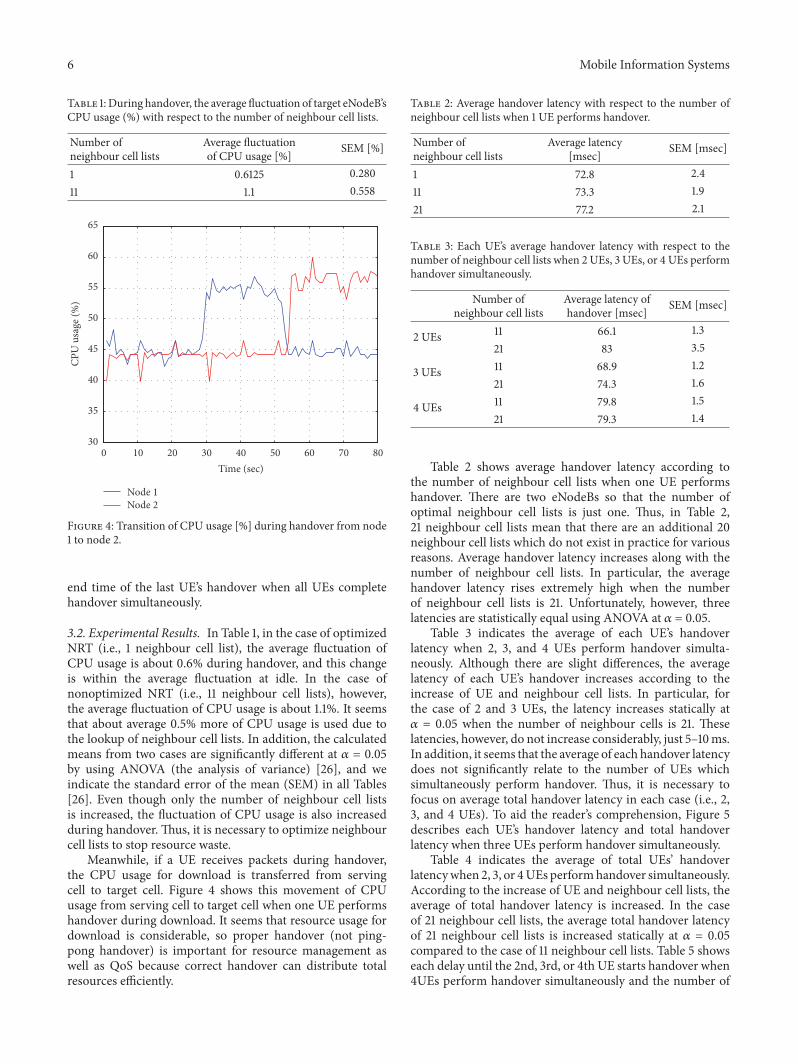
Table 1: During handover, the average fluctuation of target eNodeB’sCPU usage (%) with respect to the number of neighbour cell lists.
Number ofneighbour cell lists
Average fluctuationof CPU usage [%] SEM [%]
1 0.6125 0.28011 1.1 0.558
0 10 20 30 40 50 60 70 8030
35
40
45
50
55
60
65
Time (sec)
CPU
usa
ge (%
)
Node 1 Node 2
Figure 4: Transition of CPU usage [%] during handover from node1 to node 2.
end time of the last UE’s handover when all UEs completehandover simultaneously.
3.2. Experimental Results. In Table 1, in the case of optimizedNRT (i.e., 1 neighbour cell list), the average fluctuation ofCPU usage is about 0.6% during handover, and this changeis within the average fluctuation at idle. In the case ofnonoptimized NRT (i.e., 11 neighbour cell lists), however,the average fluctuation of CPU usage is about 1.1%. It seemsthat about average 0.5% more of CPU usage is used due tothe lookup of neighbour cell lists. In addition, the calculatedmeans from two cases are significantly different at 𝛼 = 0.05by using ANOVA (the analysis of variance) [26], and weindicate the standard error of the mean (SEM) in all Tables[26]. Even though only the number of neighbour cell listsis increased, the fluctuation of CPU usage is also increasedduring handover. Thus, it is necessary to optimize neighbourcell lists to stop resource waste.
Meanwhile, if a UE receives packets during handover,the CPU usage for download is transferred from servingcell to target cell. Figure 4 shows this movement of CPUusage from serving cell to target cell when one UE performshandover during download. It seems that resource usage fordownload is considerable, so proper handover (not ping-pong handover) is important for resource management aswell as QoS because correct handover can distribute totalresources efficiently.
Table 2: Average handover latency with respect to the number ofneighbour cell lists when 1 UE performs handover.
Number ofneighbour cell lists
Average latency[msec] SEM [msec]
1 72.8 2.411 73.3 1.921 77.2 2.1
Table 3: Each UE’s average handover latency with respect to thenumber of neighbour cell lists when 2 UEs, 3 UEs, or 4 UEs performhandover simultaneously.
Number ofneighbour cell lists
Average latency ofhandover [msec] SEM [msec]
2 UEs 11 66.1 1.321 83 3.5
3 UEs 11 68.9 1.221 74.3 1.6
4 UEs 11 79.8 1.521 79.3 1.4
Table 2 shows average handover latency according tothe number of neighbour cell lists when one UE performshandover. There are two eNodeBs so that the number ofoptimal neighbour cell lists is just one. Thus, in Table 2,21 neighbour cell lists mean that there are an additional 20neighbour cell lists which do not exist in practice for variousreasons. Average handover latency increases along with thenumber of neighbour cell lists. In particular, the averagehandover latency rises extremely high when the numberof neighbour cell lists is 21. Unfortunately, however, threelatencies are statistically equal using ANOVA at 𝛼 = 0.05.
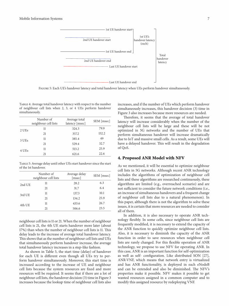
Table 3 indicates the average of each UE’s handoverlatency when 2, 3, and 4 UEs perform handover simulta-neously. Although there are slight differences, the averagelatency of each UE’s handover increases according to theincrease of UE and neighbour cell lists. In particular, forthe case of 2 and 3 UEs, the latency increases statically at𝛼 = 0.05 when the number of neighbour cells is 21. Theselatencies, however, do not increase considerably, just 5–10ms.In addition, it seems that the average of each handover latencydoes not significantly relate to the number of UEs whichsimultaneously perform handover. Thus, it is necessary tofocus on average total handover latency in each case (i.e., 2,3, and 4 UEs). To aid the reader’s comprehension, Figure 5describes each UE’s handover latency and total handoverlatency when three UEs perform handover simultaneously.
Table 4 indicates the average of total UEs’ handoverlatencywhen 2, 3, or 4UEs performhandover simultaneously.According to the increase of UE and neighbour cell lists, theaverage of total handover latency is increased. In the caseof 21 neighbour cell lists, the average total handover latencyof 21 neighbour cell lists is increased statically at 𝛼 = 0.05compared to the case of 11 neighbour cell lists. Table 5 showseach delay until the 2nd, 3rd, or 4th UE starts handover when4UEs perform handover simultaneously and the number of
Mobile Information Systems 7
2nd UE handover start
2nd UE handover end
Last UE handover start
Last UE handover end
1st UE handover start
1st UE handover end
1st UE’shandover latency
(each)
Totalhandover
latency
Figure 5: Each UE’s handover latency and total handover latency when UEs perform handover simultaneously.
Table 4: Average total handover latency with respect to the numberof neighbour cell lists when 2, 3, or 4 UEs perform handoversimultaneously.
Number ofneighbour cell lists
Average totallatency [msec] SEM [msec]
2 UEs 11 324.3 79.921 357.2 152.2
3 UEs 11 385.4 4921 529.4 32.7
4 UEs 11 513.2 25.921 621.6 22.6
Table 5: Average delay until other UEs start handover since the startof the 1st handover.
Number ofneighbour cell lists
Average delay[msec] SEM [msec]
2nd UE 11 28.2 6.321 31.7 6.4
3rd UE 11 137.3 10.121 134.2 25.9
4th UE 11 433.6 26.721 506.6 23.5
neighbour cell lists is 11 or 21.When the number of neighbourcell lists is 21, the 4th UE starts handover more later (about17%) than when the number of neighbour cell lists is 11. Thisdelay leads to the increase of average total handover latency.This shows that as the number of neighbour cell lists and UEsthat simultaneously perform handover increase, the averagetotal handover latency increases in a step-like fashion.
As shown in Table 5, the start time (delay) of handoverfor each UE is different even though all UEs try to per-form handover simultaneously. Moreover, this start time isincreased according to the increase of UE and neighbourcell lists because the system resources are fixed and moreresources will be required. It seems that if there are a lot ofneighbour cell lists, the handover decision (3) time in Figure 3increases because the lookup time of neighbour cell lists also
increases, and if the number of UEs which perform handoversimultaneously increases, this handover decision (3) time inFigure 3 also increases because more resources are needed.
Therefore, it seems that the average of total handoverlatency will increase considerably when the number of theneighbour cell lists will be large and these will be notoptimized in 5G networks and the number of UEs thatperform simultaneous handover will increase dramaticallydue to IoT and massive small cells. As a result, some UEs willhave a delayed handover. This will result in the degradationof QoS.
4. Proposed ANR Model with NFV
As we mentioned, it will be essential to optimize neighbourcell lists in 5G networks. Although recent ANR technologyincludes the algorithms of optimization of neighbour celllists and these algorithms are researched continuously, thesealgorithms are limited (e.g., overreached scenario) and arenot sufficient to consider the future network conditions (i.e.,an increase of simultaneous handovers and a frequent changeof neighbour cell lists due to a natural phenomenon). Inthis paper, although there is not the algorithm to solve theseissues, it is certain that more resources are needed to considerall of them.
In addition, it is also necessary to operate ANR tech-nology flexibly. In some cells, since neighbour cell lists arefrequently modified, it is necessary to extend the capacity ofthe ANR function to quickly optimize neighbour cell lists.Also, it is necessary to diminish the capacity of the ANRfunction in order to save resources when neighbour celllists are rarely changed. For this flexible operation of ANRtechnology, we propose to use NFV for operating ANR. Inthis case, ANR is an important function for self-optimizationas well as self- configuration. Like distributed SON [27],ANR-VNF, which means that network entry is virtualizedand has ANR functionality, is deployed in each eNodeBand can be extended and also be diminished. The NFV’sproperties make it possible. NFV makes it possible to getwanted resources assigned in a common computer and tomodify this assigned resource by redeploying VNF.
8 Mobile Information Systems
Stadium
ANR-VNF
ANR-VNF
Moving cell
RRURRU
BBU BBU C-RAN
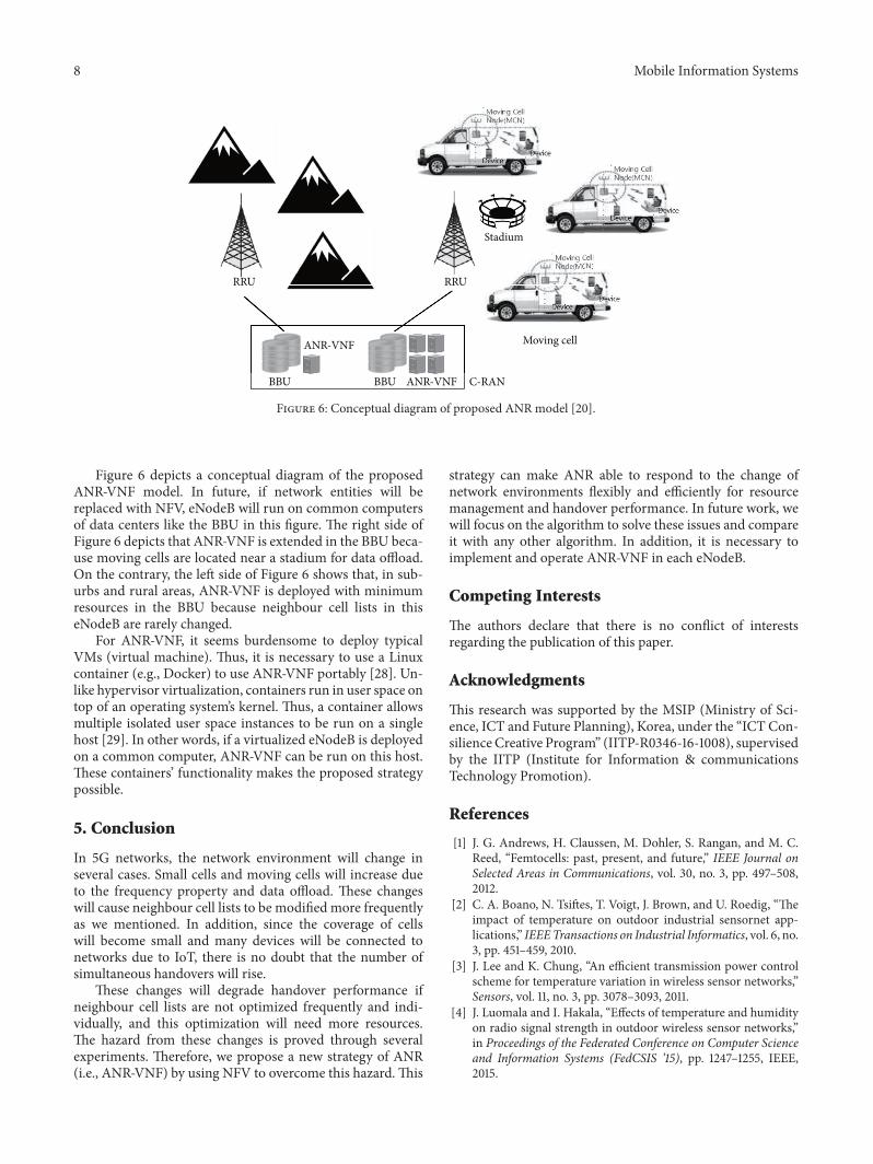
Figure 6: Conceptual diagram of proposed ANR model [20].
Figure 6 depicts a conceptual diagram of the proposedANR-VNF model. In future, if network entities will bereplaced with NFV, eNodeB will run on common computersof data centers like the BBU in this figure. The right side ofFigure 6 depicts that ANR-VNF is extended in the BBU beca-use moving cells are located near a stadium for data offload.On the contrary, the left side of Figure 6 shows that, in sub-urbs and rural areas, ANR-VNF is deployed with minimumresources in the BBU because neighbour cell lists in thiseNodeB are rarely changed.
For ANR-VNF, it seems burdensome to deploy typicalVMs (virtual machine). Thus, it is necessary to use a Linuxcontainer (e.g., Docker) to use ANR-VNF portably [28]. Un-like hypervisor virtualization, containers run in user space ontop of an operating system’s kernel. Thus, a container allowsmultiple isolated user space instances to be run on a singlehost [29]. In other words, if a virtualized eNodeB is deployedon a common computer, ANR-VNF can be run on this host.These containers’ functionality makes the proposed strategypossible.
5. Conclusion
In 5G networks, the network environment will change inseveral cases. Small cells and moving cells will increase dueto the frequency property and data offload. These changeswill cause neighbour cell lists to be modified more frequentlyas we mentioned. In addition, since the coverage of cellswill become small and many devices will be connected tonetworks due to IoT, there is no doubt that the number ofsimultaneous handovers will rise.
These changes will degrade handover performance ifneighbour cell lists are not optimized frequently and indi-vidually, and this optimization will need more resources.The hazard from these changes is proved through severalexperiments. Therefore, we propose a new strategy of ANR(i.e., ANR-VNF) by using NFV to overcome this hazard.This
strategy can make ANR able to respond to the change ofnetwork environments flexibly and efficiently for resourcemanagement and handover performance. In future work, wewill focus on the algorithm to solve these issues and compareit with any other algorithm. In addition, it is necessary toimplement and operate ANR-VNF in each eNodeB.
Competing Interests
The authors declare that there is no conflict of interestsregarding the publication of this paper.
Acknowledgments
This research was supported by the MSIP (Ministry of Sci-ence, ICT and Future Planning), Korea, under the “ICT Con-silienceCreative Program” (IITP-R0346-16-1008), supervisedby the IITP (Institute for Information & communicationsTechnology Promotion).
References
[1] J. G. Andrews, H. Claussen, M. Dohler, S. Rangan, and M. C.Reed, “Femtocells: past, present, and future,” IEEE Journal onSelected Areas in Communications, vol. 30, no. 3, pp. 497–508,2012.
[2] C. A. Boano, N. Tsiftes, T. Voigt, J. Brown, and U. Roedig, “Theimpact of temperature on outdoor industrial sensornet app-lications,” IEEETransactions on Industrial Informatics, vol. 6, no.3, pp. 451–459, 2010.
[3] J. Lee and K. Chung, “An efficient transmission power controlscheme for temperature variation in wireless sensor networks,”Sensors, vol. 11, no. 3, pp. 3078–3093, 2011.
[4] J. Luomala and I. Hakala, “Effects of temperature and humidityon radio signal strength in outdoor wireless sensor networks,”in Proceedings of the Federated Conference on Computer Scienceand Information Systems (FedCSIS ’15), pp. 1247–1255, IEEE,2015.
Mobile Information Systems 9
[5] C. Ortega-Corral, L. E. Palafox, J. A. Garcıa-Macıas, J. Sanchez-Garcıa, L. Aguilar, and J. I. Nieto-Hipolito, “Parameter opti-mization of a temperature and relative humidity based trans-mission power control scheme for wireless sensor networks,”International Journal of Distributed Sensor Networks, vol. 2015,article no. 20, Article ID 921319, 2015.
[6] A. J. Fehske, I. Viering, J. Voigt, C. Sartori, S. Redana, andG. P. Fettweis, “Small-cell self-organizing wireless networks,”Proceedings of the IEEE, vol. 102, no. 3, pp. 334–350, 2014.
[7] C. M. Mueller, H. Bakker, and L. Ewe, “Evaluation of the auto-matic neighbor relation function in a dense urban scenario,” inProceedings of the IEEE 73rd Vehicular Technology Conference,pp. 1–5, Yokohama, Japan, May 2011.
[8] S. Hamalainen, H. Sanneck, and C. Sartori, LTE Self-OrganizingNetworks (SON), JohnWiley & Sons, New York, NY, USA, 2012.
[9] J. T. Penttinen,The Telecommunications Handbook: EngineeringGuidelines for Fixed, Mobile and Satellite Systems, JohnWiley &Sons, Ltd, Chichester, UK, 2015.
[10] Y. Watanabe, Y. Matsunaga, K. Kobayashi, H. Sugahara, and K.Hamabe, “Dynamic neighbor cell listmanagement for handoveroptimization in LTE,” in Proceedings of the IEEE 73rd VehicularTechnology Conference (VTC ’11-Spring), Budapest, Hungary,May 2011.
[11] P.-C. Lin, “Minimization of drive tests using measurement rep-orts from user equipment,” in Proceedings of the IEEE 3rd GlobalConference on Consumer Electronics (GCCE ’14), pp. 84–85,IEEE, Tokyo, Japan, October 2014.
[12] L. S. Mohjazi, M. A. Al-Qutayri, H. R. Barada, K. F. Poon, andR. M. Shubair, “Self-optimization of pilot power in enterprisefemtocells using multi objective heuristic,” Journal of ComputerNetworks and Communications, vol. 2012, Article ID 303465, 14pages, 2012.
[13] TS ETSI. 136 300 v8. 12.0, Evolved Universal Terrestrial RadioAccess (E-UTRA) and Evolved Universal Terrestrial RadioAccess Network (E-UTRAN); Overall description; Stage 2(3GPP TS 36.300 version 8.12.0 Release 8).
[14] D. Ortega-Sicilia, F. Cabrera Almeida, A. Sedeno Noda, and A.Ayala-Alfonso, “Design and evaluation of ANR algorithm forLTE real scenario with high interference,” Electronics Letters,vol. 51, no. 24, pp. 2057–2058, 2015.
[15] R. Mijumbi, J. Serrat, J.-L. Gorricho, N. Bouten, F. De Turck,and R. Boutaba, “Network function virtualization: state-of-the-art and research challenges,” IEEE Communications Surveys andTutorials, vol. 18, no. 1, pp. 236–262, 2015.
[16] B. Han, V. Gopalakrishnan, L. Ji, and S. Lee, “Network functionvirtualization: challenges and opportunities for innovations,”IEEE Communications Magazine, vol. 53, no. 2, pp. 90–97, 2015.
[17] R. Guerzoni, “Network functions virtualisation: an introduc-tion, benefits, enablers, challenges and call for action,” inProceedings of the SDN and OpenFlow World Congress, 2012.
[18] J. Wu, Z. Zhang, Y. Hong, and Y. Wen, “Cloud radio accessnetwork (C-RAN): a primer,” IEEE Network, vol. 29, no. 1, pp.35–41, 2015.
[19] H. Hawilo, A. Shami, M. Mirahmadi, and R. Asal, “NFV: stateof the art, challenges, and implementation in next generationmobile networks (vEPC),” IEEE Network, vol. 28, no. 6, pp. 18–26, 2014.
[20] Y. Hwang and J. Shin, “A user centric moving cell managementmechanism in LTE-Advanced system,” in Proceedings of the 5thInternational Conference on Information and CommunicationTechnology Convergence (ICTC ’14), pp. 243–245, Busan, Korea,October 2014.
[21] “Software LTE base station on PC Amari LTE 100,” http://www.amarisoft.com/.
[22] R. Trestian, Q.-T. Vien, P. Shah, andG.Mapp, “Exploring energyconsumption issues for multimedia streaming in LTE HetNetsmall cells,” in Proceedings of the IEEE 40th Conference on LocalComputer Networks (LCN ’15), pp. 498–501, IEEE, ClearwaterBeach, Fla, USA, October 2015.
[23] X. Xiong, T. Wu, H. Long, and K. Zheng, “Implementation andperformance evaluation of LECIM for 5G M2M applicationswith SDR,” in Proceedings of the IEEE GlobecomWorkshops (GCWkshps ’14), pp. 612–617, December 2014.
[24] J. Han and B. Wu, “Handover in the 3GPP long term evolution(LTE) systems,” in Proceedings of the Global Mobile Congress(GMC ’10), IEEE, Shanghai, China, October 2010.
[25] A. Hans, A. Sharma, K. Kumar, and N. Singh, “An overviewof handoff procedure in LTE technology,” in Proceedings ofthe International Conference on Medical Imaging, m-Health andEmerging Communication Systems (MedCom ’14), pp. 391–394,Greater Noida, India, November 2014.
[26] R. J. Freund, D. Mohr, and W. J. Wilson, Statistical Methods,Elsevier, Amsterdam, The Netherlands, 3rd edition, 2010.
[27] S. Feng and E. Seidel, Self-Organizing Networks (son) in 3gppLong Term Evolution, Nomor Research GmbH, Munich, Ger-many, 2008.
[28] C. Boettiger, “An introduction to docker for reproducibleresearch,” ACM SIGOPS Operating Systems Review, vol. 49, no.1, pp. 71–79, 2015.
[29] J. Turnbull,TheDocker Book: Containerization is the new virtua-lization, James Turnbull, 2014.

Submit your manuscripts athttps://www.hindawi.com
Computer Games Technology
International Journal of
Hindawi Publishing Corporationhttp://www.hindawi.com Volume 2014
Hindawi Publishing Corporationhttp://www.hindawi.com Volume 2014
Distributed Sensor Networks
International Journal of
Advances in
FuzzySystems
Hindawi Publishing Corporationhttp://www.hindawi.com
Volume 2014
International Journal of
ReconfigurableComputing
Hindawi Publishing Corporation http://www.hindawi.com Volume 2014
Hindawi Publishing Corporationhttp://www.hindawi.com Volume 2014
Applied Computational Intelligence and Soft Computing
Advances in
Artificial Intelligence
Hindawi Publishing Corporationhttp://www.hindawi.com Volume 2014
Advances inSoftware EngineeringHindawi Publishing Corporationhttp://www.hindawi.com Volume 2014
Hindawi Publishing Corporationhttp://www.hindawi.com Volume 2014
Electrical and Computer Engineering
Journal of
Journal of
Computer Networks and Communications
Hindawi Publishing Corporationhttp://www.hindawi.com Volume 2014
Hindawi Publishing Corporation
http://www.hindawi.com Volume 2014
Advances in
Multimedia
International Journal of
Biomedical Imaging
Hindawi Publishing Corporationhttp://www.hindawi.com Volume 2014
ArtificialNeural Systems
Advances in
Hindawi Publishing Corporationhttp://www.hindawi.com Volume 2014
RoboticsJournal of
Hindawi Publishing Corporationhttp://www.hindawi.com Volume 2014
Hindawi Publishing Corporationhttp://www.hindawi.com Volume 2014
Computational Intelligence and Neuroscience
Industrial EngineeringJournal of
Hindawi Publishing Corporationhttp://www.hindawi.com Volume 2014
Modelling & Simulation in EngineeringHindawi Publishing Corporation http://www.hindawi.com Volume 2014
The Scientific World JournalHindawi Publishing Corporation http://www.hindawi.com Volume 2014
Hindawi Publishing Corporationhttp://www.hindawi.com Volume 2014
Human-ComputerInteraction
Advances in
Computer EngineeringAdvances in
Hindawi Publishing Corporationhttp://www.hindawi.com Volume 2014