virtualization architecture using the id/locator split ...pan/papers/6.ilswrl--computer...
TRANSCRIPT

Author's personal copy
Virtualization architecture using the ID/Locator split conceptfor Future Wireless Networks (FWNs)
Chakchai So-In b, Raj Jain a,⇑, Subharthi Paul a, Jianli Pan a
a Department of Computer Science & Engineering, Washington University in St. Louis, One Brookings Drive, Box 1045, St. Louis, MO 63130, USAb Department of Computer Science, Faculty of Science, Khon Kaen University, 123 Mitaparb Rd., Naimaung, Maung, Khon Kaen 40002, Thailand
a r t i c l e i n f o
Article history:Available online 22 September 2010
Keywords:ID/Locator splitFuture Wireless NetworksFWNsNext generation wireless networksNGWNsMobilityMultihomingPrivacySystem Architecture EvolutionSAEVirtual objectObjectVirtual object to virtual objectcommunicationVirtual channelChannelMulti-tierFuture wireless internetFuture internetNetwork architecture
a b s t r a c t
Future Wireless Networks (FWNs) will be a convergence of many fixed and mobile net-working technologies including cellular, wireless LANs, and traditional wired networks.This united ubiquitous network will consist of billions of networkable devices with differ-ent networking interfaces. A common networking protocol is required to communicateamong these devices and interfaces; System Architecture Evolution (SAE) documents statethat Internet Protocol (IP), world-widely used in the current Internet, is likely to becomethat common protocol. However, traditional IP architecture has faced several known chal-lenges, such as mobility, multihoming, privacy, path preference selection, etc., whichshould be resolved in FWNs. One of the difficulties in the current IP architecture is theoverloading of IP addresses used both as the identity and the location of IP devices. In thispaper, we propose a virtualization concept for networkable components, or (virtual)objects, which generalizes all abstract components to potentially be used in FWNs. In addi-tion, we have explicitly separated the functions of the virtual object identity from the vir-tual object location (using the ID/locator split concept). The end-to-end communication is aconcatenation of the involved components, called a channel. To help support the ownershipand policy enforcement for trusted vs. untrusted networks, a set of (virtual) networkablecomponents with the same interest, called a realm, is formed in a multi-tier structure.The individual policy can be enforced for each individual group of (virtual) objects and/or channels. This virtualization architecture concept, characterized by the ID/locator splitconcept, is well-suited for FWNs and helps eliminate problems in the current Internet.
� 2010 Elsevier B.V. All rights reserved.
1. Introduction
Future Wireless Networks (FWNs) offer a large-scaleinteroperability of diverse traditional wireless networkswith many types of wireless technologies: cellularnetworks, sensor networks, RFID (Radio-Frequency IDenti-fication) networks, and the conventional wired networks.FWNs are evolving into an ubiquitous network in whichcustomers or users will not need to be aware of the differ-
ent behaviours and/or characteristics of the networkingmedia underneath their applications [1]. Moreover, apolicy-based control would be necessary to make use ofmultiple interfaces [2–5] in an efficient way.
FWNs should also support peer-to-peer, point-to-multi-point, and ad hoc infrastructure modes. FWNs may providea guaranteed service with an agreement on the quality ofservice (QoS) control, as well as best-effort services. Inaddition, the emergence of billions of networkable mobilewireless devices, which may outnumber the wired PC’s asearly as 2010 [4], including Laptops, PDAs (Personal DigitalAssistants), cell phones, wireless sensors, etc., shall exacer-bate the problem of scalability in the current networks.
1389-1286/$ - see front matter � 2010 Elsevier B.V. All rights reserved.doi:10.1016/j.comnet.2010.08.013
⇑ Corresponding author.E-mail addresses: [email protected] (C. So-In), [email protected]
(R. Jain), [email protected] (S. Paul), [email protected] (J. Pan).
Computer Networks 55 (2011) 415–430
Contents lists available at ScienceDirect
Computer Networks
journal homepage: www.elsevier .com/ locate/comnet

Author's personal copy
Moreover, with the advances in networking technolo-gies, the concept of a single user-single host-single inter-face will no longer be common in FWNs. Users bearingseveral multi-interface wireless devices leveraging a vari-ety of networking interfaces, such as wireless local areanetworks (WLANs), 2G/3G, LTE (Long Term Evolution),(Mobile) WiMAX, and Ethernet shall call for an ubiqui-tous high-speed networking environment that can inher-ently support mobility: mobility over large geographictopologies and mobility of users (mobile users) overdevices, device multihoming and concurrent multi-inter-face sessions.
With various networking connections, service providersand mobile users should be able to choose the best connec-tion (path preference selection) based on cost and quality ofservice (QoS) requirements. Multiple interfaces shouldallow load sharing, load balancing, and higher availabilitywith recommended path information from the service pro-viders. Also, the mobile users should be able to maintaintheir privacy, while the networking environment shouldprovide inherent security. Apart from all these require-ments, FWNs’ designers also need to evaluate the transi-tion steps from the current networks to FWNs, e.g., howto incrementally deploy the FWN system into the currentnetwork [6–9].
The issues of interoperability, guaranteed service, sca-lability, mobility, multihoming, path preference selection,privacy, security, deployability, etc., discussed above, rep-resent some of the key requirements for the design ofFWNs. Given these different sets of requirements, it isquite difficult to predict which direction FWNs will beheaded, especially in terms of a common communicationprotocol among networking components. The 3rd Genera-tion Partnership Project (3GPP) has made a decision toadopt Internet Protocol, or IP [10,11], into cellularnetworks as well. System Architecture Evolution (SAE) isthe core networking architecture being developed by3GPP [12–14] for the next generation of cellular wirelessnetworks. SAE will be an all-IP based mobile wirelessnetwork.
Note that FWNs will face the same problems that havebeen identified for the current Internet. The Internet now isnot only being used academically, but also in industry witha non-trustworthy design for commercial applications. So,this design has brought difficulties into the relationshipamongst the organizations and the administrative hierar-chies. More importantly, one of the greatest issues of thecurrent IP architecture is the overloading of IP addresssemantics [15–19]. The IP address acts as a host or nodeidentifier as well as a locator in the routing space. This con-textual overloading implicitly binds a host to its point-of-attachment in the network, and there is no independentnamespace to represent the end host itself. Thus, everytime the end host moves to a new network or changes itsinterface; and consequently obtains a new IP address, allthe sessions bound to the previous IP address are broken.
Such an implicit overloading makes it difficult to sup-port full mobility, multihoming, traffic engineering, pri-vacy, security, etc. As a result, in this paper, we propose anew concept on how to apply the ID/locator split idea intothe IP-based FWNs. In addition, we extend this splitting
concept beyond hosts in order to be general enough tocover all feasible physical and logical components, or ob-jects, in FWNs. We call this the virtualization of objects.
Note that in this paper, we do not intend to limit thearchitecture to a specific solution, but rather provide thevirtualization architecture concept in general. Obviously,there are possible solutions available; some may meetthe requirements, and some may not. Nevertheless, we in-clude some probable techniques when we introduce thearchitecture requirements.
This paper is organized as follows. In Section 2, we dis-cuss common terminologies in the traditional networkarchitecture. In this section, we compare an illustrationof a wired/wireless and cellular network structure. Also,we briefly explain a cross-over function among theseterminologies. In Section 3, we discuss the proposal of anID/locator split concept that will apply to the virtualnetworkable components in FWNs. Using examples, weillustrate how to apply the FWN architecture concepts toour current network in Section 4. In Section 5, we showfeasibility by applying the ID/locator split concept intoour virtualization architecture. In Section 6, we briefly de-scribe related work focusing on the ID/locator split conceptproposed in the current IP networks. We also briefly pointout their pros and cons which leads to our proposal.Finally, our conclusions are drawn in Section 7.
2. Current networks: terminology and systemarchitecture
This section describes terminologies used in currentnetworks. We also discuss a conceptual definition for eachterm and notation with provided examples. In addition, wediscuss two main current network architectures illustratedby examples: wired/wireless data networks (Internet) andcellular networks.
2.1. Terminology
Name: a word or a combination of words, readable andrecognizable by humans, to identify a person, place, orthing, such as John Smith,Washington University in St. Louis,Intel, and Microsoft. Usually, name is also represented bythe organizational management, which tends to be hierar-chical; for example, john_smith.cec.eng.wustl.edu representsuser John Smith in the Department of Computer Scienceand Engineering, School of Engineering and AppliedScience, Washington University in St. Louis.
Address: a point of attachment or the name of the placewhere a person, something, or organization may normallybe reached; for example, One Brookings Drive, St. Louis, MO63130 USA is the address of Washington University inSt. Louis.
Locator: where something could be located currently,such as GPS (Global Positioning System) latitude and longi-tude positions. Note that the address and the locator arevery similar, and in some contexts they are the same. Forinstance, One Brookings Drive, St. Louis, MO 63130 andGPS positions at 38� 380 52.8200N and 90� 18016.2200W areconsidered as both the address and the locator. However,
416 C. So-In et al. / Computer Networks 55 (2011) 415–430
Author's personal copy
in a Mobile IP environment [20,21], a home IP address canbe represented as the address, and its Care of Address(CoA) is the locator.
Identifier (ID): a representation of a particular person ora thing. The identifier is usually unique within a particulardomain, called Local ID. That local ID may result in a globalunique ID with a combination of local ID and domain ID,called Global ID. For example, a student ID, 388812, is anunique ID within the Washington University in St. Louisdomain. A combination of University ID and student ID isglobally unique. Similarly, a telephone number, 233-7456, is unique within the city of St. Louis and the stateof Missouri. With the prefix 314, the identifier is uniquewithin the USA and globally unique with the additionalprefix of 1.
Name vs. Identifier: Name and identifier represent thesame object; however, a name is basically readable byhumans and easier to remember and recognize. Usually,there is a one-to-one mapping relationship between nameand ID. For example, the user name John Smith has a socialsecurity number or his identification number 498-21-3611. There are also optional alias names and/or nick-names. Note that this relationship implicitly representshis ownership and existence in the world. For this particu-lar example, this ID is unique within the USA, or we can sayJohn Smith is within the US domain.
Another example is an explicit hierarchical naming sys-tem which is related to his ownership and function, such [email protected] and [email protected]. With theseexamples, John Smith is tied to some domains and can usu-ally be provided with his unique ID within an organization.In the first example, the identifier (Social Security Number)is permanent for his life; however, in the second example,the mapping can be changed over the organizationalpolicy.
Hardware vs. Software: IDs can be used to representboth hardware and software. Hardware IDs represent theidentity of the physical device, such as MAC (Media AccessControl), used as the identifier of Ethernet networkinginterfaces; IMEI (International Mobile Equipment Identity),used as the identifier of GSM phones (Global System forMobile communications); and IMSI (International MobileSubscriber Identity), used as the identifier of SIM cards(Subscriber Identity Module).
For software IDs, considering a TCP/IP (TransmissionControl Protocol/Internet Protocol) stack, the IP addressmay represent the identifier at the network layer, andthe combination with TCP port number is the identifierat the transport layer. Note that in some contexts, theseIDs are used interchangeably. For example, the MAC ad-dress can also represent the identifier for the link layer inthe TCP/IP stack (also used as the networking interfaceID). So, this MAC address resents both hardware andsoftware IDs.
Tier Structure: A logical concept of an arrangement ofgrouped components within the same specific interests;for example, an user-tier means a representation of a groupof users, and a host-tier means a group of hosts. Note thatwe call a physical-tier for a group of hardware as in the pre-vious two examples, and a logical-tier for a group ofsoftware, such as network and transport layers.
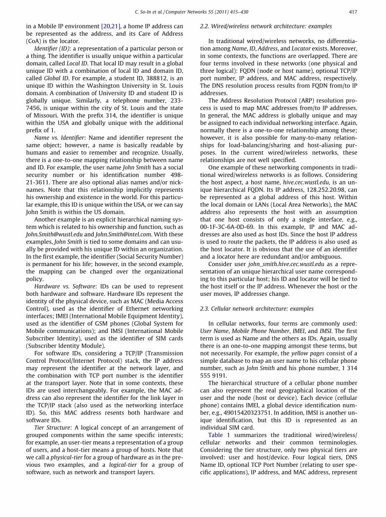
2.2. Wired/wireless network architecture: examples
In traditional wired/wireless networks, no differentia-tion among Name, ID, Address, and Locator exists. Moreover,in some contexts, the functions are overlapped. There arefour terms involved in these networks (one physical andthree logical): FQDN (node or host name), optional TCP/IPport number, IP address, and MAC address, respectively.The DNS resolution process results from FQDN from/to IPaddresses.
The Address Resolution Protocol (ARP) resolution pro-cess is used to map MAC addresses from/to IP addresses.In general, the MAC address is globally unique and maybe assigned to each individual networking interface. Again,normally there is a one-to-one relationship among these;however, it is also possible for many-to-many relation-ships for load-balancing/sharing and host-aliasing pur-poses. In the current wired/wireless networks, theserelationships are not well specified.
One example of these networking components in tradi-tional wired/wireless networks is as follows. Consideringthe host aspect, a host name, hive.cec.wustl.edu, is an un-ique hierarchical FQDN. Its IP address, 128.252.20.98, canbe represented as a global address of this host. Withinthe local domain or LANs (Local Area Networks), the MACaddress also represents the host with an assumptionthat one host consists of only a single interface, e.g.,00-1F-3C-6A-0D-69. In this example, IP and MAC ad-dresses are also used as host IDs. Since the host IP addressis used to route the packets, the IP address is also used asthe host locator. It is obvious that the use of an identifierand a locator here are redundant and/or ambiguous.
Consider user john_smith.hive.cec.wustl.edu as a repre-sentation of an unique hierarchical user name correspond-ing to this particular host; his ID and locator will be tied tothe host itself or the IP address. Whenever the host or theuser moves, IP addresses change.
2.3. Cellular network architecture: examples
In cellular networks, four terms are commonly used:User Name, Mobile Phone Number, IMEI, and IMSI. The firstterm is used as Name and the others as IDs. Again, usuallythere is an one-to-one mapping amongst these terms, butnot necessarily. For example, the yellow pages consist of asimple database to map an user name to his cellular phonenumber, such as John Smith and his phone number, 1 314555 9191.
The hierarchical structure of a cellular phone numbercan also represent the real geographical location of theuser and the node (host or device). Each device (cellularphone) contains IMEI, a global device identification num-ber, e.g., 49015420323751. In addition, IMSI is another un-ique identification, but this ID is represented as anindividual SIM card.
Table 1 summarizes the traditional wired/wireless/cellular networks and their common terminologies.Considering the tier structure, only two physical tiers areinvolved: user and host/device. Four logical tiers, DNSName ID, optional TCP Port Number (relating to user spe-cific applications), IP address, and MAC address, represent
C. So-In et al. / Computer Networks 55 (2011) 415–430 417

Author's personal copy
application, transport, Internet, and link layer abstractionsfor wired/wireless networks.
Note that we can consider the network infrastructure asone more tier [22]. The ambiguity and dependency of allrelated terms and functions make it difficult to achieve fullmobility, multihoming, location privacy, etc., required forFWNs. In FWNs, these traditional networks will merge intoone united ubiquitous network. Therefore, an unique rep-resentation and/or function are required. We will discussall concepts required for FWNs and provide examples inthe next section. We will again revisit some of these tradi-tional network terminologies and functions, especially asapplied to FWNs in Section 4.
3. FWNs: terminology and system architecture
This section discusses the concepts used for the FWNarchitecture. We revisit some of required terminologiesand relate them to their functions. We introduce a virtual-ization concept, virtual object, of the component, object, inFWNs. Then, we represent the communication betweenthe (virtual) objects/components represented as a (virtual)channel.
Since each virtual object is independent from others,mobility, multihoming, and location privacy can be directlyapplied to each individual virtual object. We provide a de-tailed description of these terms in the next section. Theseterms are required to ensure FWNs support all possiblerepresentations in the future. In addition, the policyenforcement can apply in a particular virtual object, agroup of virtual objects, and the layout of virtual objectswith quality of service (QoS) controls.
3.1. Terminology introduced in FWNs
Object: an addressable component that can be physicaland/or logical. Examples of physical objects are: PersonalComputer (PC), Router/Switch, Cellular Phone, NetworkingInterface, and Human. Examples of logical objects are:Application and Transport Layers. Each object has an iden-tifier (ID) and optional Locator (s) and Name (s).
Virtual Object: a virtual representation of objects; forexample, virtual machine (a logical machine that executeslike a real machine), virtual interface (a logical networkinginterface), and virtual network (a logical network that pro-vides a specific set of guaranteed resources shared from aphysical network), etc.
(Virtual) Tier: Logical concepts of an arrangement with-in the same specific interest (virtual) object group.
Multi-Tier: A hierarchically vertical communicationtiers.
(Virtual) Channel: (virtual) object to (virtual) objectcommunication; a concatenation of objects or virtualobjects. The channel allows the communication establish-ment of both inter-tier and intra-tier communication.
Virtual Identifier: Especially for privacy purposes, thevirtual identifier [4] is a representation of an identifierresulting from multiple levels of ID mapping or other map-pings from the identifier to its locator, primarily to hide theactual ID.
Realm: A hierarchical group of virtual components thatlogically belongs within the same organization. The organi-zation defines its own policy and provides a trustedrelationship.
In FWNs, we apply all required terminologies, such asan identifier, locator, address, tier, etc., from the currentnetwork. However, Address has the same function asLocator. The address is only used for location, not identifi-cation. Therefore, Address is no longer a notation in FWNs.Name functions as ID, except being readable and/or recog-nizable by humans. ID is usually independent from thelocators.
All components are represented as Objects. Each objecthas an identifier and optionally has names and locators.In addition, similar to hardware/software definitions (SeeSection 3.1), the object represents both physical and logicaldefinitions. The virtual representation of object (s) is calledVirtual Object. We consider (virtual) object to (virtual)object communication as a (Virtual) Channel. Notice thathost-to-host and user-to-user communications are justexamples. A group of the same interested objects is calledTier and Virtual Tier for a group of virtual objects.
3.2. Virtual object abstraction
In this section, we discuss in detail the virtual object(VO) abstraction and (virtual) channel or virtual object tovirtual object (VO-to-VO) communication used as an end-to-end communication.
3.2.1. (Virtual) object descriptionA virtual object (VO) represents both logical and
physical illustrations of an object. The virtual object hasan identifier, optional locators, and optional names. Fig. 1shows an example of a (virtual) object. In this example,
Table 1Networks (Wired/Wireless/Cellular) vs. Terminology: User and Host/Device.
Networks Terminology
Wired/WirelessNetworks
User (User Name) M Host (Host Name, IPaddress, and MAC address)
CellularNetworks
User (User Name) M Host/Device (TelephoneNumber ID, SIM ID, and Device ID)
Device
User
Interface
Networks
Application
Transport
Internet
Link
Virtual D
evice
Virtual Network
Virtual Interface
Virtual Application
Device
. . .
Virtual User
Fig. 1. (Virtual) Object Examples: virtual user, virtual device, virtualinterface, virtual network, and virtual application.
418 C. So-In et al. / Computer Networks 55 (2011) 415–430

Author's personal copy
user, device, interface, and network are physical objects.Application, transport, Internet, and link are logical objects.Each particular virtual object may consist of several ob-jects, such as virtual devices or virtual hosts, virtual inter-faces, virtual networks, and virtual applications.
The virtual objects may share the same resources. Forexample, many virtual host objects share the samephysical device or host object; however, there is a tightboundary of the guaranteed resources allocated to eachvirtual object for QoS control purposes. The mechanismsto achieve this tight boundary are out of the scope of thispaper. The dashed circle and oval shown in Fig. 1 representeach individual virtual object. Note that a virtual objectmay not be limited to a single physical object. It may spanmultiple objects; for example, a virtual application mayoperate over multiple devices (parallel/distribute comput-ing), and a virtual storage host may consist of manynetworking storage hosts.
3.2.2. (Virtual) Object to (Virtual) object communication or(Virtual) channel
In the virtual object model, the end-to-end communica-tion is established by the layout of a concatenation of many(virtual) objects, called (virtual) channel. The layout of thecommunication pattern is not limited to inter-tier commu-nication but also intra-tier communication (See Fig. 2). This(virtual) channel is again treated as an individual commu-nication of a shared resource in which the organizationalpolicy can be enforced with QoS controls.
Fig. 2 shows an example of (virtual) channel representa-tion. Fig. 3 shows the communication point of attachmentfor each inter-tier and intra-tier communication, calledObject Access Point (OAP). We define the input and outputof a virtual object as Input Object Unit (IOU) and OutputObject Unit (OOU). Consider a cross layer communication.These points of assessment, OAP, IOU, and OOU, allowcommunication amongst the virtual objects, such as tosend some useful information from bottom tier to uppertier. Link reliability information (e.g., for congestion andcollision indication separation; and wireless channel char-acteristics for modulation and coding optimization pur-poses) can be sent to change the transmission propertyor characteristic and/or choose a proper transmission
channel. Note that the IOU and OOU header overheadsare added for each tier communication.
3.2.3. (Virtual) object mobility and multihomingIn the virtual object model, each virtual object has a
built-in mobile characteristic (mobile object = object).Since each virtual object is independent and treated indi-vidually, mobility and multihoming can directly apply toeach individual virtual object. Consider the mobility as-pect. Each virtual object has a locally unique identifier(within a particular domain) and locator (s). In some con-texts, we can consider the identifier as IOU and the locatoras OOU for each virtual object. The locator, or OOU, is usu-ally independent from IOU so that when the virtual objectmoves, its ID remains the same, but its locator may change.
Applications in FWNs will be established with IDs, notlocators. Consider the multihoming aspect. Again, the vir-tual object abstraction allows one-to-one, one-to-many,many-to-one, and many-to-many relationships of the com-munication to form the (virtual) channel with individualpolicy enforcement and QoS controls.
3.2.4. (Virtual) object privacyIn FWNs, Privacy can be applied to each individual vir-
tual object: the location and ID privacy are just examples.In fact, the virtual concept to represent the real object isimplicitly used in terms of the object privacy. Considerthe user location privacy. Since the users no longer requirethe locators to reach the destination, this can facilitate theuser location privacy. Consider an individual ID. Similar tothe virtual ID concept in [4], in FWNs, a virtual ID is alsoused to represent one or more levels of privacy in orderto hide the real ID; and again for location privacy, the iden-tifier can be treated as a virtual location.
3.2.5. (Virtual) object path/ (Virtual) channel selectionIn a mobile wireless network environment with several
devices or interfaces attached to different service provid-ers, the virtual user object should be able to select hisown path based on the cost of service and QoS. To supportthis path or channel selection preference, an agreementamong the virtual objects along the path is required, nor-mally with the cooperation of a cloud of service providersto support load sharing/balancing systems so that the sys-tems can forward the transaction to the end point of thevirtual object with the preferred path.
Tier 3: Interface
Tier 4: Network
Tier 1: User
Tier 2: Device
. . .
Intra-Tier
Inter-Tier
Virtual Object
Fig. 2. (Virtual) Channel Examples: Four tiers (User, Device, Interface, andNetwork) with Intra-tier and Inter-tier communication.
Virtual Object Virtual Object
Virtual Object
Virtual Object
IOU
OOUIOU
OOU
OOUIOU
OAP
OAPIOU
OOU
Fig. 3. Object Access Point (OAP): Input Object Unit (IOU) versus OutputObject Unit (OOU).
C. So-In et al. / Computer Networks 55 (2011) 415–430 419

Author's personal copy
The virtual object may use different techniques andinformation acquired from the path information or fromthe service provider to select the channel. For example,in [4] a weighting mechanism is used to identify theingress path to the user. In [5], a policy-based mechanismachieved by applying a linear programming concept isused to select underlying multiple interfaces formultihoming purposes.
3.2.6. Policy enforcementAs described above, the policy management can be di-
rectly applied to individual (virtual) objects and channels.The policy is enforced through the concept of realm ordomain. A set of policy and QoS control parameters is re-quired for guaranteed services and the virtualization ofshared resources. We will describe this issue in detail inthe next section.
3.3. Realm managers and mapping system servers
In this section, we discuss the policy management en-forced by realm managers. We also describe the functionsof the realm servers as well as providing some possiblemechanisms existing in the current networks.
3.3.1. Hierarchical policy enforcementA realm manager mainly functions as a policy enforce-
ment manager for a group of (virtual) objects. The realmmanagers may be hierarchically distributed for delaylatency reduction purposes with an increase in the numberof realm servers. For example, in a mobile wirelessnetworking environment, mobile user objects frequentlychange their locations. This also requires cooperationamong realm managers to develop the communicationchannel and provide the guaranteed resources.
In general, the border router gateway and/or the basestation can function as a realm manager. Fig. 4 shows anexample of a realm hierarchy. In this example, there arethree tiers:L1,L2, andL3. Each realm manager Rx1x2
(x1 being an index of hierarchical tier structure and x2 rep-resenting the realm managers within the same tier) isresponsible for policy management in a particular realm.Note that the policy of the lower-tier realm managers can-not rewrite those of the higher-level realm managers.
3.3.2. Location services and decentralized managementA realm manager also functions as a mapping server to
resolve the identifier to/from the locators. Again, the realm
manager is managed in a distributed and hierarchical man-ner. A cloud of realm managers within the same realm canalso communicate with each other, which helps to mitigatethe scalability, load balancing/sharing, and fault-toleranceof the system architecture.
A mobile object tracking system is required in FWNs,and the realm manager should support this function. Therealm manager also cooperates with others to providethe location service. For example, mobile user objectsmay query as to where the nearest mall and coffee shopare. Note that this location service follows the mobileobject’s location privacy policy. Several location discoverymechanisms can be used in different contexts/networks,such as location discovery in sensor networks [23] andmobile ad hoc networks [24,25].
3.3.3. Service discoveryA realm manager also provides a discovery service for
mobile object users or other objects; for example, themobile object users can query on and list offered services.Several proposals on service discovery when applied in dif-ferent networks may be used, such as a multipath cross-layer service discovery in mobile ad hoc networks [26], acommunity-based service discovery [27], and a contextaware semantic service discovery [28].
3.3.4. Realm managers with proxy/relay functionA realm manager can also function as proxy and relay
servers. Especially in a mobile wireless environment,mobile objects tend to move frequently at high speeds. Inaddition, to save battery power, mobile objects are primar-ily in a sleep mode and wake up only when necessary. Be-cause of these characteristics, the realm manager shouldkeep track of mobile objects and should buffer, and thenrelay/forward the transactions from/to the mobile objectswhen they are awake [29]. The proxy can also operate onbehalf of legacy nodes unaware of the virtual object con-cept; this is similar to the use of a proxy in Mobile IPv6[30].
3.3.5. Realm managers with guaranteed resources and QoScontrols
Each virtual object and/or virtual channel established isconsidered a shared resource. Therefore, the realm man-ager should provide enough resources, according to thepromised QoS, to the virtual object. Consider the virtualchannel setup. This requires communication among therealm managers to provide the resources reserved for theentire (virtual) channel. Again, the mechanisms to achievethis tight boundary are out of the scope of this paper; fur-ther information can be found in [31–34].
Moreover, especially in a mobile wireless environment,when mobile objects move, the communication amongrealm managers is also required to guarantee the promisedQoS, say from one base station to another. The reservationfor the resources for each particular service is based on theagreed policy setup.
To communicate among realm managers, a (virtual)channel reservation control protocol may be used alongthe path. This reservation control protocol may be similarto Resource ReSerVation Protocol, or RSVP, [35]; however,
Realm (R11)L1
L2
L3 R32R31
R23R22R21
R33 R34
1 2 3
Fig. 4. Realm Hierarchy: three levels.
420 C. So-In et al. / Computer Networks 55 (2011) 415–430

Author's personal copy
this modified RSVP should be aware of the virtual objectmobility, multihoming, channel information, etc.
3.3.5.1. Leasing control management. FWNs should supportthe resource leasing as well. Since each virtual object/channel can be governed by an individual set of policies(each virtual channel with a shared guaranteed resourceor a virtual application object may be owned by differentservice providers), it is possible to manage and to developa pricing model between service providers and customers.Some of resource leasing concepts can be applied into thearchitecture, such as a mechanism for resource leasingmanagement for a smart space [36] and for suspending avirtual machine [37].
Another example is that of a virtual network when asmall service provider can lease a virtual channel consist-ing of a set of virtual hosts and virtual network objects inorder to provide access to its own application and/orInternet. Again, the small service provider can provideservices or sub-lease its set of shared resources. Virtualapplication leasing is also applicable in FWNs. The virtualapplication requires the cooperation among realm manag-ers to provide the guaranteed resources.
3.3.6. Multiple ID resolution and mapping databaseA realm manager is required to support multiple ID res-
olution functions. The realm manager stores a mappingdatabase of both inter-realm and intra-realm mappinginformation. In addition, for privacy purposes, a virtual IDmay be used, and the realm manager is supposed to alsostore the mapping of this virtual ID and the actual ID.
All mapping databases should be stored at realmmanagers. Within a single domain/realm, several realmmanagers may work as primary and secondary serversfor fault-tolerance. Furthermore, the database can also bestored in Distributed Hash Tables (DHTs) [38] for scalabil-ity purposes. Note that each DHT is managed within a par-ticular realm, and the database between different realms ismanaged in a hierarchical manner.
3.3.7. Realm managers assisted multihoming with multipleobjects
A realm manager can also provide the multihomingknowledge database for a virtual object. The realm man-ager acts as a knowledge-based system to recommendthe path (s) to the virtual object. The virtual object canuse this information as well as its own policies to make afinal path selection.
3.3.8. Other functions of realm managersA realm represents an administrative domain, or orga-
nization. Each organization has several functions that helpin the efficient operation of the organization. These func-tions can be performed by the realm managers. Severalsuch functions are listed below. All of these functions areoptional and can be performed by other objects in thesystem.
3.3.8.1. Dual-stack realm managers. For backward compati-bility to legacy nodes, a realm manager also functions in adual-stack mode so that legacy nodes that do not recognize
the virtual object concept and/or an ID/locator separationcan communicate with each other in FWNs. The realmmanager works as a convertor/encap-decapsulator to for-ward the transactions from/to FWNs. This concept is simi-lar to the use of Dual stack hosts and router (DSMIPv6) inMobile IPv6 [39].
3.3.8.2. Virtual realm managers. The realm manager is alsoan object. So, the virtual realm manager is a virtualizedrealm manager, e.g., many different virtual realm manag-ers can operate over a single realm manager server, orone virtual realm manager can be spread over multiplerealm manager servers.
3.3.8.3. Garbage collection realm manager. The realm man-ager may keep track of the mobile objects and their usagesof resources. It may be possible that the mobile objects ac-quire the resources, and then leave them unused. Therealm manager may periodically check/update the use ofresources of the mobile objects [40,41].
3.3.8.4. Channel state controller. To help support themigration of (virtual) objects and/or (virtual) channels,the realm manager may function as a channel state con-troller and store the channel state information requiredto re-establish the connection. Additionally, similar to therelaying and buffering functions described earlier, therealm manager may function as a caching server. When-ever there is a connectivity disruption for mobile users,the realm manager may cache the information until theoperation is back on track. To achieve the migration, simi-lar approaches to a process migration [42–44], servicemigration [45], and virtual machine migration [46] canbe applied.
3.3.8.5. Auto-reconfiguration manager. A realm managermay help in the establishment of a local network (if noneexists) so that mobile objects can form a network basedon the policies of the realm [47,48]. There may be a proto-col for communication amongst mobile objects as well asrealm managers (See also Generic ID, Section 5). The realmmanagers should keep track of the existence of eachmobile object. The mobile objects can leave or join thenetwork anytime.
As indicated earlier, the realm manager may be respon-sible for many functions. It is also possible that these func-tions are split into many small parts, and some servers cantake responsibility together with the communication pro-tocol among those servers, such as a location service man-ager and mapping manager servers.
3.3.9. Signaling and data separationIn IP-based wired/wireless networks, the data and con-
trol are in the same communication channel. This may notbe true for cellular networks. The separation of control anddata in cellular networks introduces many advantages,especially in terms of security. To allow high-speedmobility and optimize the latency, the control signalshould be sent over a reliable and fast communicationchannel.
C. So-In et al. / Computer Networks 55 (2011) 415–430 421

Author's personal copy
In addition, the separation of control and data paths canhelp eliminate the triangulation problem [19] such as in aMobile IP environment. As in circuit-switched networks,after setting up the data channel, the data can be trans-ferred with minimal overhead.
3.4. Identifier (ID)
In general, there are two types of Identifiers (IDs): a flatID or a hierarchical ID. Each has its pros and cons. A flat IDmay be secure (e.g., a 128-bit user public key), but lacksscalability, and hence may introduce high latency in largesystems. The behavior of hierarchical IDs is just theopposite. We recommend using a combination of both,i.e., the flat ID within the domain and hierarchical amongdomains or realms: Local ID+Domain ID=Global ID. Again,the identifier is unique within a domain, and in combina-tion with its domain ID, it is globally unique.
3.4.1. Group IDA representation of a group of (virtual) objects. This
group of objects normally lies within the same domain orrealm, but is not restricted to; for example, channel ID con-sists of the layout of many virtual objects. Group ID is alsoused in multicasting aspects when many (virtual) objectsrepresent the communication end point.
3.4.2. Generic IDThis ID is used for self-organizational purposes. This ID
can automatically be assigned to the unknown virtualobjects to make them function properly in order to com-municate with the rest of the network. Optionally therealm manager may periodically scan the local domainand, in case a new virtual object is present without anidentity, this generic ID is assigned.
However, in fact, whenever the virtual object joins thenetwork, the realm manager may announce the presenceof the virtual object. Then, based on the realm policies,the realm manager may allow the new virtual object tocommunicate within/among the domain (s).
3.4.3. Disposable IDThis ID is temporarily created for future applications,
and it has an expiration date. Note that the realm managermanages a collection of these IDs, and possibly reuses theunused IDs.
Note that these IDs are just examples. These IDs can ap-ply within a single administrative domain and/or amongdifferent domains. These IDs for different object realms/domains can be communicated through inter-realmcommunication.
3.5. Virtualization architecture challenges
In this section, we describe the impact of the virtualiza-tion architecture using ID/locator split concept within theexisting routing architecture and the overall systemperformance.
3.5.1. Routing scalability and architectureSince the ID/locator split concept is used to separate the
functionality of the identity and the locator for each(virtual) object, similar to other ID/locator split approaches[18] the routing scalability issue can be mitigated. Ingeneral, this issue is due to the exponential growth of thesize of the IP routing table. If a site uses provider aggregat-able (PA) addresses, it has to renumber all its hosts when itchanges the provider.
On the other hand, it if uses provider independent (PI)addresses, these addresses are not aggregatable, and thusresults in an increase of the size of routing tables. Withan ID-Locator overlay, it is possible to use PI addresses asIds and PA addresses as locators. With this approach, onlyPA addresses are used in the core network, and the scala-bility issue is resolved. This only occurs when PI is treatedas the identity, and PA as the locator. All existing routingmechanisms can function as if it is using the locator, notthe identity. However, in the future, since we treat eachnetworkable component as an object, i.e., each (virtual)object may consist of more than one locator, and each isused to establish the channel to form the communication,the future routing architecture may require a modificationto allow the virtualization architecture.
3.5.2. System performanceFirst due to the ID/locator split concept, the complexity
of the system ambiguity is reduced; however, this ap-proach increases the levels of mapping, e.g., from nameto ID and from ID to locator. Second, due to the virtualiza-tion concept, in fact, the system performance may be de-creased. For example, consider a virtual host case; onededicated server obviously performs much better thanshared servers; however, the total system performanceconsidering the waste and budget will be improvedsignificantly.
For example, several virtual hosts can operate over apowerful server with high utilization (many to one rela-tionship) rather than one-to-one mapping for each applica-tion to a single host. On the other hand, a virtual host canspan over multiple low performance servers (one-to-manyrelationship) as well as a many-to-many relationship. Byapplying the virtualization architecture, we also simplifythe management functionality. It is also possible to move,turn on and off, backup, etc., dynamically without aware-ness of any physical components. In addition, other keyvirtualization features, such as fault-tolerance, load bal-ancing/sharing, traffic engineering, etc., can be achieved.
It’s also possible that an application provider is not thesame as the resource provider (application service vs. host-ing service). For example, Microsoft may rent a set of virtualservers to provide an application leasing service to the enduser. However, again this requires the mechanisms to guar-antee the dedicated resource over the shared resources.
3.5.3. Implementation and deployabilityCurrently, there are some commercial products, e.g.,
VMware [49], and public domain products, e.g., Xen [50],User Mode Linux [51], and Kernel Based Virtual Machine[52], available which apply the virtualization concept tothe server farms, in terms of cloud computing. This is just
422 C. So-In et al. / Computer Networks 55 (2011) 415–430

Author's personal copy
one example relating to our architecture; however, ourperspective is to scale this example into a large scalenetwork for future Internet usage. Obviously, to achieveour architecture requirements, cooperation amongst theend users, service providers, and software developers,must co-exist. Notice that, in fact, the ID/locator split con-cept evokes the deployability issue; however, modifyingthe current Internet (e.g., including many extensions ofMobile IP in order to resolve the mobility problem) hasmade the Internet more complex and difficult to use, andresulted in additional complex issues.
4. Migrating toward Future Wireless Networks from thecurrent network: examples
In this section, we describe the current network; thenetworking components applied to those in FWNs, espe-cially how to incrementally migrate the current networkinto FWNs. Although we have briefly described the currentwired/wireless networks in the beginning of this paper, weagain revisit some problems and definitions, and then wewill focus on the detailed solutions.
4.1. Traditional wired/Wireless and cellular networks:examples
In IP-based wired/wireless networks, one issue is that ofrenumbering when the network changes its service pro-vider. It may also result in an increase in the number ofrouting records causing routing scalability problems[6–9]. A site may have multiple interfaces with multipleservice providers. One interface is basically used as anegress network. Usually, only one egress is used at a time;the other interfaces are used as backups. Therefore, most ofID/locator split proposals focus on how to achieve sitemultihoming. There is not much discussion on mobility,privacy, etc.
The ID/locator spilt concept is generally proposed sothat a provider aggregatable, or PA, address can be usedfor routing purposes. A provider independent, or PI, ad-dress is used as the identity (ID). In the current network,there are normally three configurations.
First, in general, users access the Internet through theircorresponding hosts. The hosts do not normally move orchange locations, but if moved, it is frequently with alow speed (within the same administrative domain). Hostmultihoming does not directly affect the performance be-cause the host will usually remain in a single domain. Asshown in Table 1, in terms of a TCP/IP reference model,the mapping terminology is as follows: User (User Name)M Host (Host Name, optional TCP/IP port (for TCP-basedapplications) number, IP address, and MAC address).
Second, in cellular networks, the main focus is on usersand mobile devices. In this case, users tend to move acrossthe administrative domain at a high speed. Also, users mayown several devices, and each device can consist of manynetworking interfaces, such as 2G/3G, (Mobile) WiMAX,LTE, Satellite, WLANs, etc. Therefore, the focus is on user/device mobility and user/device multihoming.
With the multihoming feature supported, a user or hostis required to maintain and/or utilize multiple interfacesover different networks. For example, a user may have atwo-interface device, such as a cellular phone with WiMAXfrom Clearwire and 3G from T-Mobile. In addition, it is pos-sible that she may also own another mobile device withWLANs and 3G both from T-Mobile. In the first case, theuser has two different egress networks, but not in thelatter.
The third scenario is when the whole network moves.This movement of the entire network can apply to bothwired/wireless and cellular networks. This scenario is sim-ilar to the site renumbering in wired/wireless networks,but with a high speed movement.
4.2. Potential virtualization architecture usage: examples
There are many possible applications with the virtual-ization architecture using the ID/locator split concept. Inthis section, we provide three examples.
First, currently, mobile devices are more powerful thansimply a device for emitting a voice communication but in-stead provide data-orientated applications. These devicesmay be compared to a small personal computer in whichmany applications can run simultaneously. They aremostly equipped with multiple networking interfaces,e.g., 3G, WLAN, WiMAX, and Bluetooth.
One example is to create a virtual mobile device with avirtual networking interface, and so each individual policycan be enforced. Suppose the mobile user wants to run anapplication requiring different security policies/profilesdepending on the domain. With the virtualization architec-ture using the ID/locator split concept, a single device and/or single or multiple networking interfaces can form the(virtual) channel, and then each individual security policycan be applied directly. There is also an optional interac-tion amongst these virtual devices. Due to the powerfulnature of the device, it can be shared among differentpeople with security and privacy enforcement.
Second, in FWNs, people are more likely to be work-at-home employees. They can basically work anywhere in theworld with the network connectivity provided. The travel-ling cost is substantially reduced, providing people any-where more opportunities, regardless of the location, andespecially people with disabilities. Suppose Google pro-vides its employees with this flexibility. One concern ison how to provide the reliable and substantial resource,i.e., bandwidth and delay guaranteed, for the mobile homeusers so that they can access the information (as if they areworking at headquarters). This can be achieved by havingthe user ID and cooperate ID, with policy enforcement.Suppose the user has two network connections: Charterand AT & T networks. Traditionally, these service providersdo not differentiate the users among other customers.However, Google can sign an agreement with both serviceproviders to treat the transaction generated/received by/to its employees with a higher priority.
In fact, this example is similar to when we allow the useof a group ID to access a paid database, e.g., ieeex-plore.ieee.org. Currently, to access the paid database,authentication is verified by the registered IP addresses,
C. So-In et al. / Computer Networks 55 (2011) 415–430 423

Author's personal copy
e.g., University IP addresses. Home users have to access thedatabase through the University proxy server, or over a vir-tual private network channel. However, with the group IDfeature, the home users can directly access the databasewith the authenticated group ID.
Similarly, suppose Google and Microsoft provide onlineapplication leasing services, such as the database, MS-office,etc. There are two considerations here. First, with the virtu-alization concept, these companies can place the actual serv-ers in different regions so as to reduce the access latency(this is similar to Akamai.) However, all servers are used asa server pool (aka a virtual server). It depends on the require-ments and quality of service needed to allocate the resourcesfrom this pool to each user/customer.
Note that to make the application leasing feasible, aguaranteed networking resource is also required, whichcannot be achieved in the traditional best effort networkarchitecture. In the future, the company may again makean agreement to the service provider to allocate the re-sources needed for its customer. It is also obvious whenInternet is distributed in such a manner (different owner-ships, e.g., Verizon and AT & T), a third party, or a servicebroker, may be required to allocate the resource guaran-teed for the entire (virtual) channel, the end-to-endcommunication.
Third, for our virtualization architecture using the ID/locator split concept, the communication occurs due to aconcatenation of (virtual) objects, unlike the end-to-endcommunication in the current network. In each pair of vir-tual object to virtual object communication point, a type ofmessages can be passed over. Compared to the current net-work, in the future network, we will allow the middle boxto be placed anywhere along the (virtual) channel withoutbreaking the end-to-end communication. An example isthe proxy. Especially in a mobile wireless environment,the virtualization architecture supports a message passing
mechanism; for example, the channel quality which indi-cates loss/congestion can be sent over to aid the transportprotocol to make a transmission decision accordingly.
Note that, similar to a system call and an applicationprogramming interface, the virtualization architecturegeneralizes enough to provide the interface between theuser and the virtualized networking architecture. Endusers can query and submit the requirement, and it is upto the architecture to determine whether it can fulfil therequirement, with corresponding costs. The network archi-tecture is open, and this allows the user to develop newservices using the provided interface or even a newinterface.
4.3. Preliminary steps toward FWNs
The united ubiquitous communication protocol is ex-pected to be IP-based in FWNs. A traditional TCP/IP proto-col stack potentially will be applied to FWNs. In currentnetworks using a virtual object concept, we can apply thevirtualization using the ID/locator split concept in thateach physical/logical component is treated as an individualobject. Each object has an identity (ID) and optional loca-tors and names.
For simplicity, initially there will be no virtual objects(no virtual devices or virtual interfaces). There are four tierabstractions-each physical and logical: user, device, inter-face, and network; and application, transport, Internet,and link as shown in Fig. 5. Tables 2 and 3 provide exam-ples of the mapping tier for wired/wireless and cellularnetworks used in FWNs.
4.4. Identification (ID) toward FWNs
Each object has an individual ID: user ID, device/node/host ID, interface ID, network ID (e.g., router/switch ID)as well as application ID, transport ID, internet ID, and linkID. The ID consists of flat and hierarchical portions. TheseIDs are unique within a particular domain, the local ID. Ahash of the public key can be used as a simple representa-tion of the unique ID for security.
Networks
Device
User
Interface
Application
Transport
Internet
Link
Fig. 5. Simplified Multi-tier Object Model: User, Device + Interface(Application, Transport, Internet, and Link), and Networks.
Table 2Physical Mapping-Tier (3-tiers): User, Device or Host, and Interface.
Tier Wired/Wireless Networks Cellular Networks
Name ID Locator Name ID Locator
User DNS User Name N/A IP or MAC address User Name User ID Telephone NumberDevice or Host DNS Host Name IP/MAC address IP or MAC address Device Name IMSI and/or IMEI Telephone NumberInterface N/A IP/MAC address IP or MAC address N/A N/A N/A
Table 3Logical mapping-tier: Application, Transport, Internet, and Link.
Protocol Stack Name ID Locator
Application DNS User Name Application ID N/ATransport N/A TCP Port Number N/AInternet N/A IP address N/ALink N/A MAC address N/A
424 C. So-In et al. / Computer Networks 55 (2011) 415–430

Author's personal copy
A combination of the local ID and its domain serves as aglobal ID. We recommend an identity representation of128 bits to allow backward-compatibility with legacynodes (in IPv6 systems). The division of the number of bitsfor local and global IDs is arbitrary. It may be better to usemultiples of 32 bits, particularly if there is a transaction orcomputation involving 32-bit IPv4 addresses.
Table 4 shows an example of a modification in the cur-rent mapping-tier. Note that to simply make a current TCP/IP model support mobility when the host moves, TCP/IP IDscan be used as an indirection level, so that the networkconnection is formed, and tied to this ID, not the IP addressor locator shown in Fig. 6.
4.5. Mapping systems
In wired/wireless networks, there are two levels ofmapping from a FQDN DNS name to an IP address (byDNS resolution) then to a MAC address (by ARP resolution).In cellular networks, usually only one level is required tomap from a user name to telephone number. Therefore,in FWNs, we reorganize the mapping explicitly and specifythe function for each term. Unlike in traditional networks,we consider both inter-tier and intra-tier resolution.
In addition, we consider a vertical and horizontal reso-lution. From Name to ID or from ID to locator, we call this
horizontal resolution, and between IDs, called vertical res-olution. For some static bindings, DNS-like systems may beused. For more dynamic bindings, such as ID to locatorsand vertical resolutions, extra mapping severs will berequired.
4.5.1. Mapping examplesTable 5 shows a configuration of a mapping example
from the current network to FWNs. In this scenario, forsimplicity, there is no organization or domain relationship(the identity is secure flat ID.) The flat ID makes it difficultto enforce policies, and it may also lead to scalabilityissues.
In this example, John Smith uses a service which implic-itly states that John Smith will be subscribed into a partic-ular domain. A simple example is that John Smith isworking at Washington University in St. Louis, and he reg-isters one of his locators, i.e., WLANs to the Universitynetwork. His ID may contain a hierarchical portion of hisdomain, such as country code (USA) and school (Washing-ton University in St. Louis).
Therefore, in order to reach John Smith, his ID will resultwithin the Washington University in St. Louis mapping ser-ver. Then, this organization can enforce its policies on theappropriate communication channel. John Smith may alsohave a global flat identifier stored at the US realm managerserver. Then, the US realm manager server will redirect alltransactions to the Washington University in St. Louisrealm server, if this is the mapping registered at the USserver.
4.5.1.1. Mobility. Whenever John Smith moves from oneplace to another; his ID remains the same, but not his loca-tors. Note that this movement within the same domainmay not require any extra procedures except an updateof IDs and locators. However, if John Smith moves to differ-ent domains, an agreement among service providers is re-quired to allow roaming by John Smith with policyenforcement.
4.5.1.2. Multihoming. Since John Smith owns many deviceswith different interfaces, he may probably register severallocators to the mapping servers. Suppose an IP address rep-resents a locator, the ID/locator split concept allows the
Table 4Physical Mapping-Tier for current networks applied for FWNs Example: User, Device or Host, and Interface.
Tier Name ID Locator
User User Name Hash (IMEI or user identification or public key) Based on Device/HostDevice or Host Device/Host Name Hash (IMSI or serial number. or public key) Based on InterfaceInterface Interface Name MAC address IP address or Telephone Number
Application
Transport
Internet
Link
IP addresses/MAC address
Indirection ID
Indirection Layer
Fig. 6. Logical Mapping-Tier for current networks applied in FWNsExample: Application, Transport, Indirection Layer, Internet, and Link.
Table 5Mapping example.
Case study User, John Smith, owns Iphone with (3G and WLAN) interfaces; and his laptop with Ethernet and WLAN interfaces.User: User name: John Smith and his ID, Hash (John Smith Public Key).Device: Device names are Iphone 3Gs and IBM laptop. Device IDs are Hash (IMSI of Iphone) and Hash (IBM serial number).Interface: No explicit interface name; however, WLANs, 3G, WiMAX can be used on interfaces names. Interfaces IDs are MAC addresses and 3G
identifications. At this level, IP addresses and/or telephone numbers can represent the locations of these interfaces.
C. So-In et al. / Computer Networks 55 (2011) 415–430 425

Author's personal copy
mapping from an identity to many different locators withdifferent/same (load sharing/load balancing) weights. Toachieve the desired load sharing/balancing, cooperationamongst his service providers and/or his organizationalpolicy, especially for the ingress transaction, is required.
4.5.1.3. User location privacy. Since John’s User ID is used toreach him, and not his exact location; the user location pri-vacy may be maintained. However, the hierarchical part ofhis ID may implicitly reveal his location in terms of hisorganization; in this case, there is a trade-off amongstthe management/scalability and privacy. Note that theborder router and/or proxy servers can also operate as asource address rewritten functionality in order for trulyhiding the domain ID from each user.
5. Experimental study
In this section, we demonstrate the feasibility and proofof concepts of our virtualization architecture using the ID/locator split concept. There are two setups.
First, we want to show the feasibility by applying the vir-tualization concept to segregate/constrain shared resourcesamong virtual objects (e.g., virtual hosts and virtual net-working interfaces), and second, to apply the ID/LocationSplit concepts to our virtualization architecture.
Note that in our testbed, we simplified several network-able components and made the best resource usage of ouravailable hardware and software. In our setup, the virtualobjects are limited to only the virtual hosts and virtual net-working interfaces. We also restricted the correspondingbandwidth to each virtual networking interface so thatthe virtual network can support the maximum bandwidthrequirement. We used a rendezvous server as our simpli-fied realm server. This server primarily does the mapping,resource management, and quality control functions.
In general, in our testbed (Table 6), there is one server(Dell Precision Workstation 690) with two CPUs (IntelXeon) 3 GHz each, two 1-gigabit Ethernet interfaces, 2 GBmemory, and a 150 GB SATA (Serial Advanced TechnologyAttachment) disk. This server provides virtual host func-tionality. There are four virtual hosts installed, each shar-ing only 1 CPU, 256 MB virtual memory, and 8 GB virtualdisk. We chose the virtualization software, VMware ESXIversion 4.0 [49], to implement the virtualization architec-
ture. Each virtual host has Linux Ubuntu 9.10 (kernel ver-sion 2.6-31-19) installed as the operating system.
We chose OpenHIP version 0.7 (running in a user mode)[53] as our representation of the ID/locator split conceptinstalling it into each virtual host.
Each networking interface attaches to an individualEthernet switch (to separate the broadcast network). Inaddition, there is another server providing the forwardingmechanism between two networks, using the basic LinuxIP forwarding mechanism. This server also provides DHCP(Dynamic Host Configuration Protocol) functionality. Thisserver is Intel Pentium 4 running at 2 GHz with 512 MBmemory, 80 GB IDE (Integrated Drive Electronics) disk,and two 100 Mbps Ethernet interfaces. The operating sys-tem is Linux Ubuntu 9.10 with Linux kernel version2.6.31-19. Note that in each setup, we conducted five trialsfor our experiment.
5.1. Experimental configurations
There are two configurations. Fig. 7 shows the first con-figuration in managing the virtualization architecture. Inthis figure, at the server machine, we installed two virtualhosts (acting as clients, called vid2 and vid3); each virtualhost attaches to the virtual networking interface at 1 Mbps.For server functionality, we setup another virtual host,called vid1, with 100 Mbps as a virtual networkinginterface.
Virtual channels are setup between the server and eachclient. There are also two 100 Mbps Ethernet switches toseparate the broadcast networks. We ran an iperf program(version 2.04) [54] to simulate the traffic using UDP (UserDatagram Protocol) for 10 Mbps bandwidth running over20 s. The traffic was generated from a server to two clientsin different UDP ports (different channels).
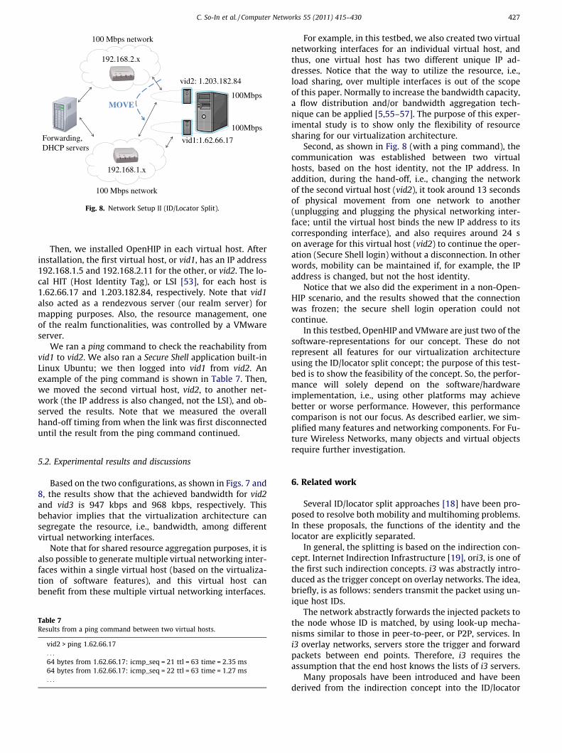
Fig. 8 shows the second configuration by applying theID/locator split concept into the virtualization architecture.In this setup, there are only two virtual hosts running onthe server. Each virtual host attaches to 100 Mbps virtualnetworking interfaces in different networks: 192.168.1.xand 192.168.2.x. The average delay between the two vir-tual hosts is in a range between 1 to 3 ms.
Table 6Hardware and software configurations.
VirtualizationServer
Dell Precision Workstation 690 (Intel Xeon3 GHz)2 GB memory2 � Intel Gigabit EthernetWestern Digital 150 GB SATA disk
Forwarding Intel Pentium 4 (2 GHz)DHCP Server 512 MB memory
Seagate 80 GB IDE disk2 � 100 Mbps Ethernet
Software VMware ESXI version 4.0OpenHIPLinux Ubuntu 9.10 (Kernel 2.6-31-19)
192.168.1.x
192.168.2.x
vid2
vid1
vid3
Forwarding,DHCP servers
1Mbps
1Mbps
100Mbps
100 Mbps network
100 Mbps network
Fig. 7. Network setup I (virtualization architecture).
426 C. So-In et al. / Computer Networks 55 (2011) 415–430
Author's personal copy
Then, we installed OpenHIP in each virtual host. Afterinstallation, the first virtual host, or vid1, has an IP address192.168.1.5 and 192.168.2.11 for the other, or vid2. The lo-cal HIT (Host Identity Tag), or LSI [53], for each host is1.62.66.17 and 1.203.182.84, respectively. Note that vid1also acted as a rendezvous server (our realm server) formapping purposes. Also, the resource management, oneof the realm functionalities, was controlled by a VMwareserver.
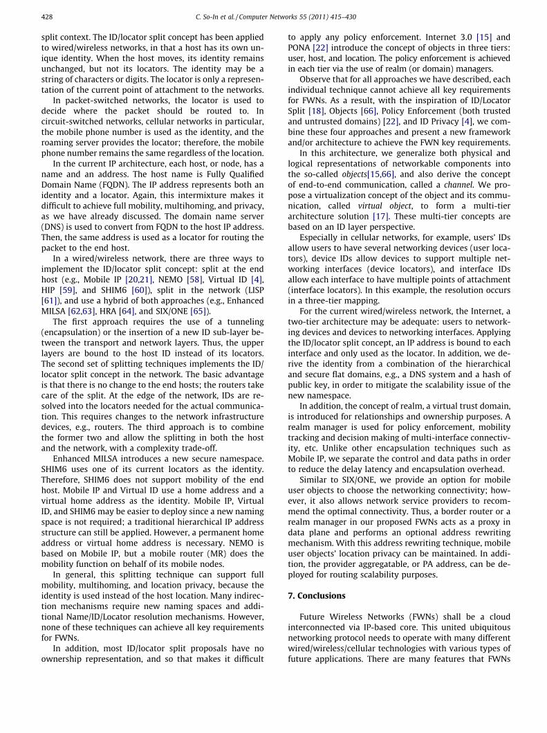
We ran a ping command to check the reachability fromvid1 to vid2. We also ran a Secure Shell application built-inLinux Ubuntu; we then logged into vid1 from vid2. Anexample of the ping command is shown in Table 7. Then,we moved the second virtual host, vid2, to another net-work (the IP address is also changed, not the LSI), and ob-served the results. Note that we measured the overallhand-off timing from when the link was first disconnecteduntil the result from the ping command continued.
5.2. Experimental results and discussions
Based on the two configurations, as shown in Figs. 7 and8, the results show that the achieved bandwidth for vid2and vid3 is 947 kbps and 968 kbps, respectively. Thisbehavior implies that the virtualization architecture cansegregate the resource, i.e., bandwidth, among differentvirtual networking interfaces.
Note that for shared resource aggregation purposes, it isalso possible to generate multiple virtual networking inter-faces within a single virtual host (based on the virtualiza-tion of software features), and this virtual host canbenefit from these multiple virtual networking interfaces.
For example, in this testbed, we also created two virtualnetworking interfaces for an individual virtual host, andthus, one virtual host has two different unique IP ad-dresses. Notice that the way to utilize the resource, i.e.,load sharing, over multiple interfaces is out of the scopeof this paper. Normally to increase the bandwidth capacity,a flow distribution and/or bandwidth aggregation tech-nique can be applied [5,55–57]. The purpose of this exper-imental study is to show only the flexibility of resourcesharing for our virtualization architecture.
Second, as shown in Fig. 8 (with a ping command), thecommunication was established between two virtualhosts, based on the host identity, not the IP address. Inaddition, during the hand-off, i.e., changing the networkof the second virtual host (vid2), it took around 13 secondsof physical movement from one network to another(unplugging and plugging the physical networking inter-face; until the virtual host binds the new IP address to itscorresponding interface), and also requires around 24 son average for this virtual host (vid2) to continue the oper-ation (Secure Shell login) without a disconnection. In otherwords, mobility can be maintained if, for example, the IPaddress is changed, but not the host identity.
Notice that we also did the experiment in a non-Open-HIP scenario, and the results showed that the connectionwas frozen; the secure shell login operation could notcontinue.
In this testbed, OpenHIP and VMware are just two of thesoftware-representations for our concept. These do notrepresent all features for our virtualization architectureusing the ID/locator split concept; the purpose of this test-bed is to show the feasibility of the concept. So, the perfor-mance will solely depend on the software/hardwareimplementation, i.e., using other platforms may achievebetter or worse performance. However, this performancecomparison is not our focus. As described earlier, we sim-plified many features and networking components. For Fu-ture Wireless Networks, many objects and virtual objectsrequire further investigation.
6. Related work
Several ID/locator split approaches [18] have been pro-posed to resolve both mobility and multihoming problems.In these proposals, the functions of the identity and thelocator are explicitly separated.
In general, the splitting is based on the indirection con-cept. Internet Indirection Infrastructure [19], ori3, is one ofthe first such indirection concepts. i3 was abstractly intro-duced as the trigger concept on overlay networks. The idea,briefly, is as follows: senders transmit the packet using un-ique host IDs.
The network abstractly forwards the injected packets tothe node whose ID is matched, by using look-up mecha-nisms similar to those in peer-to-peer, or P2P, services. Ini3 overlay networks, servers store the trigger and forwardpackets between end points. Therefore, i3 requires theassumption that the end host knows the lists of i3 servers.
Many proposals have been introduced and have beenderived from the indirection concept into the ID/locator
192.168.1.x
192.168.2.x
vid2
Forwarding,DHCP servers
100Mbps
100Mbps
100 Mbps network
100 Mbps network
vid1:1.62.66.17
vid2: 1.203.182.84
MOVE
Fig. 8. Network Setup II (ID/Locator Split).
Table 7Results from a ping command between two virtual hosts.
vid2 > ping 1.62.66.17. . .
64 bytes from 1.62.66.17: icmp_seq = 21 ttl = 63 time = 2.35 ms64 bytes from 1.62.66.17: icmp_seq = 22 ttl = 63 time = 1.27 ms. . .
C. So-In et al. / Computer Networks 55 (2011) 415–430 427
Author's personal copy
split context. The ID/locator split concept has been appliedto wired/wireless networks, in that a host has its own un-ique identity. When the host moves, its identity remainsunchanged, but not its locators. The identity may be astring of characters or digits. The locator is only a represen-tation of the current point of attachment to the networks.
In packet-switched networks, the locator is used todecide where the packet should be routed to. Incircuit-switched networks, cellular networks in particular,the mobile phone number is used as the identity, and theroaming server provides the locator; therefore, the mobilephone number remains the same regardless of the location.
In the current IP architecture, each host, or node, has aname and an address. The host name is Fully QualifiedDomain Name (FQDN). The IP address represents both anidentity and a locator. Again, this intermixture makes itdifficult to achieve full mobility, multihoming, and privacy,as we have already discussed. The domain name server(DNS) is used to convert from FQDN to the host IP address.Then, the same address is used as a locator for routing thepacket to the end host.
In a wired/wireless network, there are three ways toimplement the ID/locator split concept: split at the endhost (e.g., Mobile IP [20,21], NEMO [58], Virtual ID [4],HIP [59], and SHIM6 [60]), split in the network (LISP[61]), and use a hybrid of both approaches (e.g., EnhancedMILSA [62,63], HRA [64], and SIX/ONE [65]).
The first approach requires the use of a tunneling(encapsulation) or the insertion of a new ID sub-layer be-tween the transport and network layers. Thus, the upperlayers are bound to the host ID instead of its locators.The second set of splitting techniques implements the ID/locator split concept in the network. The basic advantageis that there is no change to the end hosts; the routers takecare of the split. At the edge of the network, IDs are re-solved into the locators needed for the actual communica-tion. This requires changes to the network infrastructuredevices, e.g., routers. The third approach is to combinethe former two and allow the splitting in both the hostand the network, with a complexity trade-off.
Enhanced MILSA introduces a new secure namespace.SHIM6 uses one of its current locators as the identity.Therefore, SHIM6 does not support mobility of the endhost. Mobile IP and Virtual ID use a home address and avirtual home address as the identity. Mobile IP, VirtualID, and SHIM6 may be easier to deploy since a new namingspace is not required; a traditional hierarchical IP addressstructure can still be applied. However, a permanent homeaddress or virtual home address is necessary. NEMO isbased on Mobile IP, but a mobile router (MR) does themobility function on behalf of its mobile nodes.
In general, this splitting technique can support fullmobility, multihoming, and location privacy, because theidentity is used instead of the host location. Many indirec-tion mechanisms require new naming spaces and addi-tional Name/ID/Locator resolution mechanisms. However,none of these techniques can achieve all key requirementsfor FWNs.
In addition, most ID/locator split proposals have noownership representation, and so that makes it difficult
to apply any policy enforcement. Internet 3.0 [15] andPONA [22] introduce the concept of objects in three tiers:user, host, and location. The policy enforcement is achievedin each tier via the use of realm (or domain) managers.
Observe that for all approaches we have described, eachindividual technique cannot achieve all key requirementsfor FWNs. As a result, with the inspiration of ID/LocatorSplit [18], Objects [66], Policy Enforcement (both trustedand untrusted domains) [22], and ID Privacy [4], we com-bine these four approaches and present a new frameworkand/or architecture to achieve the FWN key requirements.
In this architecture, we generalize both physical andlogical representations of networkable components intothe so-called objects[15,66], and also derive the conceptof end-to-end communication, called a channel. We pro-pose a virtualization concept of the object and its commu-nication, called virtual object, to form a multi-tierarchitecture solution [17]. These multi-tier concepts arebased on an ID layer perspective.
Especially in cellular networks, for example, users’ IDsallow users to have several networking devices (user loca-tors), device IDs allow devices to support multiple net-working interfaces (device locators), and interface IDsallow each interface to have multiple points of attachment(interface locators). In this example, the resolution occursin a three-tier mapping.
For the current wired/wireless network, the Internet, atwo-tier architecture may be adequate: users to network-ing devices and devices to networking interfaces. Applyingthe ID/locator split concept, an IP address is bound to eachinterface and only used as the locator. In addition, we de-rive the identity from a combination of the hierarchicaland secure flat domains, e.g., a DNS system and a hash ofpublic key, in order to mitigate the scalability issue of thenew namespace.
In addition, the concept of realm, a virtual trust domain,is introduced for relationships and ownership purposes. Arealm manager is used for policy enforcement, mobilitytracking and decision making of multi-interface connectiv-ity, etc. Unlike other encapsulation techniques such asMobile IP, we separate the control and data paths in orderto reduce the delay latency and encapsulation overhead.
Similar to SIX/ONE, we provide an option for mobileuser objects to choose the networking connectivity; how-ever, it also allows network service providers to recom-mend the optimal connectivity. Thus, a border router or arealm manager in our proposed FWNs acts as a proxy indata plane and performs an optional address rewritingmechanism. With this address rewriting technique, mobileuser objects’ location privacy can be maintained. In addi-tion, the provider aggregatable, or PA address, can be de-ployed for routing scalability purposes.
7. Conclusions
Future Wireless Networks (FWNs) shall be a cloudinterconnected via IP-based core. This united ubiquitousnetworking protocol needs to operate with many differentwired/wireless/cellular technologies with various types offuture applications. There are many features that FWNs
428 C. So-In et al. / Computer Networks 55 (2011) 415–430

Author's personal copy
should support and provide, such as interoperability, guar-anteed service, scalability, mobility, multihoming, pathpreference selection, privacy, security, deployability, etc.
With a traditional IP architecture, one of the greatestobstacles to achieve full mobility and multihoming is theoverloading of IP addresses used as both identity andlocator. As a result, in this paper, we focus on this particu-lar problem and propose the separation implied by thesetwo functions.
In this paper, aside from the ID/locator split proposals,compared to other existing proposals on this separation,the architecture we recommended here is limited to justthe current networking components, such as hosts, routers,and networking interfaces. We generalized the splittingconcept of networkable components as objects. We also ap-plied the virtualization concept into these components.Therefore, our architecture is generalized for FWNs.
In addition, we predict the future service as a virtualiza-tion of all components so that we again apply this concept toeach end-to-end communication, channel, with individualpolicy enforcement. Therefore, it is easy to support full vir-tual object mobility and multihoming. In addition, the poli-cies can be applied to each virtual object and channel (end-to-end communication). Our framework also allows theconcept of object ownership to achieve resource sharing/leasing.
Finally, we demonstrated the feasibility and proof ofconcepts for our virtualization architecture using the ID/locator split concept by showing a simplified model interms of resource sharing and mobility supports.
References
[1] IEEE, IEEE Standard for Local and Metropolitan Area Networks, Part21: Media Independent Handover Services, IEEE STD 802.21-2008,2009.
[2] M. Blanchet, Ed. P. Seite, Multiple Interfaces Problem Statement,Internet-Draft, draft-blanchet-mif-problem-statement-02.txt, 2010.
[3] M. Wasserman, Ed., Current Practices for Multiple Interface Hosts,Internet-Draft, draft-ietf-mif-current-practices-00, 2009.
[4] C. So-In, R. Jain, J. Pan, S. Paul, Virtual ID: A Technique for Mobility,Multihoming, and Location Privacy in Next Generation WirelessNetworks, in Proceedings of IEEE Consumer Communication andNetworking Conference, 2010, pp. 1–5.
[5] C. So-In, R. Jain, S. Paul, J. Pan, A Policy Oriented Multi-InterfaceSelection Framework for Mobile IPv6 Using the ID/Locator SplitConcepts in the Next Generation Wireless Networks, in the 2nd Int.Conf. on Computer and Automation Engineering (ICCAE), Feb. 2010.
[6] D. Raychaudhuri, M. Gerla, Ed., New Architectures and DisruptiveTechnologies for the Future Internet: The Wireless, Mobile andSensor Network Perspective, NSF Wireless Mobile Planning GroupWorkshop, Aug. 2005.
[7] L. Kleinrock, A vision for the Internet, ST J. for Research 2 (1) (2005)4–5.
[8] D. Clark, R. Braden, K. Sollins, J. Wroclawski, D. Katabi, New Arch:Future Generation Internet Architecture, Technical Report, Air ForceResearch Laboratory, 2003, 76 pp.
[9] A. Perrig, D. Clark, S. Bellovin, Ed., Secure Next Generation Internet,NSF Workshop Report, 2005.
[10] DARPA Internet Program, Internet Protocol, RFC 791, 1981.[11] S. Deering and R. Hinden, Internet Protocol Version 6 (IPv6)
Specification, RFC 2460, 1998.[12] The 3rd Generation Partnership Project, The 3GPP Technical
Specification Group Service and System Aspects; General PacketRadio Service (GPRS) enhancements for Evolved Universal TerrestrialRadio Access Network (E-UTRAN) access, 3GPP TS 23.401 V8.0.0,2007, 167 pp.
[13] The 3rd Generation Partnership Project, The 3GPP TechnicalSpecification Group Service and System Aspects; Architecture
enhancements for non-3GPP accesses, 3GPP TS 23.402 V8.0.0,2007, 131 pp.
[14] ITU-T, General requirements for ID/locator separation in NGN,Y.2015, 2007, 18 pp.
[15] R. Jain, Internet 3.0: Ten Problems with Current Internet Architectureand Solutions for the Next Generation, in: Proceedings of IEEE MilitaryCommunication Conference, 2006, pp. 1–9.
[16] D. Meyer, L. Zhang, K. Fall, Report from the IAB Workshop on Routingand Addressing, RFC 4984, 2007.
[17] S. Paul, J. Pan, R. Jain, A Survey of Naming Systems: Classification andAnalysis of the Current Schemes Using a New Naming ReferenceModel, WUSTL Technical Report, 2009. http://www.cse.wustl.edu/�jain/papers/naming.htm.
[18] C. So-In, R. Jain, S. Paul, Future Wireless Networks: Key Issues and aSurvey (ID/Locator Split Perspective), WUSTL Technical Report,2009. http://www.cse.wustl.edu/�jain/papers/fwns.htm.
[19] I. Stoica, D. Adkins, S. Zhuang, S. Shenker, S. Surana, InternetIndirection Infrastructure, IEEE/ACM Transaction on Networking 12(2) (2004) 205–218.
[20] C. Perkins, Ed., IP Mobility Support for IPv4, RFC 3220, 2002.[21] D. Johonson, C. Perkins, J. Arkko, Mobility Support in IPv6, RFC 3775,
2004.[22] S. Paul, R. Jain, J. Pan, M. Bowman, A Vision of the Next Generation
Internet: A Policy Oriented Perspective, in: Proceedings of BritishComputer Society International Conference on Visions of ComputerScience, 2008.
[23] L. Fang, W. Du, P. Ning, A beacon-less location discovery scheme forwireless sensor networks, in: Proceedings of IEEE Conference onComputer Communication, 2005, pp. 161–171.
[24] J. Kuo, W. Liao, Modeling the behavior of flooding on target locationdiscovery in mobile ad hoc networks, in: Proceedings of IEEEInternational Conference on Communication, 2005, pp. 3015–3019.
[25] S.S. Yau, W. Gao, D. Huang, A Location-based Directional RouteDiscovery (LDRD) Protocol in Mobile Ad-hoc Networks, in:Proceedings of Global Telecommuncaitons Conference, 2006, pp.1–6.
[26] X. Shao, L. Heng-Ngoh, T. Kiong-Lee, T. Yoong-Chai, L. Zhou, J.C.M.Teo, Multipath cross-layer service discovery (MCSD) for mobile adhoc networks, in: Proceedings of Services Computing Conference,2009, pp. 408–413.
[27] C.A. Perryea, S. Chung, Community-Based Service Discovery, in:Proceedings of International Conference on Web Services, 2006, pp.903–906.
[28] P. Patel, S. Chaudhary, Context Aware Semantic Service Discovery,in: Proceedings of World Conference on Serivces, 2009, pp. 1–8.
[29] D. Zhu, M.W. Mutka, C. Zhiwei, Using cooperative multiple paths toreduce file download latency in cellular data networks, in:Proceedings of Global Telecommuncaitons Conference, 2005, pp.2480–2484.
[30] S. Gundavelli, K. Leung, V. Devarapalli, K. Chowdhury, B. Patil, ProxyMobile IPv6, RFC 5213, 2008.
[31] K. Shiomoto, I. Inoue, E. Oki, Network virtualization in high-speed huge-bandwidth optical circuit switching network, in:Proceedings of IEEE Conference on Computer Communication,2008, pp. 1–6.
[32] P. Garbacki, V.K. Naik, Efficient Resource Virtualization and SharingStrategies for Heterogeneous Grid Environments, in: Proceedings ofIFIP/IEEE International Symposium on Integrated NetworkManagement, 2007, pp. 40–49.
[33] T. Hossfeld, K. Leibnitz, A. Nakao, Modeling of Modern RouterArchitectures Supporting Network Virtualization, in: Proceedings ofGlobal Telecommuncaitons Conference, 2009, pp. 1–6.
[34] Y. Wei, J. Wang, C. Wang, Bandwidth Guaranteed Multi-Path Routingas a Service over a Virtual Network, in: Proceedings of InternationalConference on Inteligent Networks and Intelligent Systems, 2008,pp. 221–224.
[35] D. Awduche, L. Berger, D. Gan, T. Li, V. Srinivasan, G. Swallow, RSVP-TE: Extensions to RSVP for LSP Tunnels, RFC 3209, 2001.
[36] J. Marko, P. Mikko, R. Jukka, Lease-Based Resource Management inSmart Spaces, in: Proceedings of Pervasive Computing andCommunication Workshops, 2007, pp. 622–626.
[37] B. Sotomayor, R.S. Montero, I.M. Llorente, I. Foster, Resource Leasingand the Art of Suspending Virtual Machines, in: Proceedings of HighPerformance Computing and Communication, 2009, pp. 59–68.
[38] G. Urdaneta, G. Pierre, M.V. Steen, A Survey of DHT SecurityTechniques, IEEE ACM Computing Surveys (2009).
[39] H. Soliman, Mobile IPv6 support for dual stack Hosts and Routers(DSMIPv6), Internet-Draft, draft-ietf-mip6-nemo-v4traversal-05.txt,2007.
C. So-In et al. / Computer Networks 55 (2011) 415–430 429

Author's personal copy
[40] T. Kalibera, F. Pizlo, A.L. Hosking, J. Vitek, Scheduling Hard Real-TimeGarbage Collection, in: Proceedings of Real-Time SystemsSymposium, 2009, pp. 81–92.
[41] V.V. Kapadia, D.G. Thakore, Distributed Garbage Collection UsingClient Server Approach in Train Algorithm, in: Proceedings ofAdvance Computing Conference, 2009, pp. 492–495.
[42] T. Liu, Z. Ma, Z. Ou, A Novel Process Migration Method for MPIApplications, in: Proceedings of the 15th IEEE Pacific RimInternational Symposium on Dependable Computing, 2009, pp.247–251.
[43] T. Maoz, A. Barak, L. Amar, Combining Virtual Machine migrationwith process migration for HPC on multi-clusters and Grids, in:Proceedings of IEEE International Conference on Cluster Computing,2008, pp. 89–98.
[44] Y. Akai, K. Wakao, T. Yokouchi, M. Kai, Development of the strongmigration mobile agent system AgentSphere for autonomicdistributed processing, in: Proceedings of IEEE Pacific RimConference on Communication, Computers and Signal Processing,2009, pp. 582–587.
[45] W. Kuang-Lai, C. Shieh, C. Hsu, Service migration–a new paradigmfor content distribution systems, in: Proceedings of the 3rdInternational Conference on Communication and Networking inChina, 2008, pp. 34–38.
[46] J. Park, J. Kim, H. Choi, Y. Woo, Virtual machine migration in self-managing virtualized server environments, in: Proceedings ofInternational Conference on Advanced Communication Technology,2009, pp. 2077–2083.
[47] N. Wakamiya, S. Arakawa, M. Murata, Self-Organization BasedNetwork Architecture for New Generation Networks, in:Proceedings of the 1st International Conference on EmergingNetwork Intelligence, 2009, pp. 61–68.
[48] M.O. Cherif, S.M. Senouci, B. Ducourthial, A new framework of self-organization of vehicular networks, in: Proceedings GlobalInformation Infrastructure Symposium, 2009, pp. 1–6.
[49] VMware ESXI v.4, 2010. http://www.vmware.com/products/esxi.[50] P. Barham, B. Dragovic, K. Fraser, S. Hand, T. Harris, A. Ho, R.
Neugebauery, I. Pratt, A. Warfield, Xen and the Art of Virtualization,in: Proceedings of the 22nd ACM Symposium on Operating SystemsPrinciples, 2003, pp. 164–177.
[51] The User-mode Linux Kernel. http://user-mode-linux.sourceforge.net/.
[52] Kernel Based Virtual Machine. http://www.linux-kvm.org/.[53] OpenHIP 2009. http://www.openhip.org.[54] Iperf. http://sourceforge.net/projects/iperf.[55] H. Hsieh, R. Sivakumar, A Transport Layer Approach for Achieving
Aggregate Bandwidths on Multi-Homed Mobile Hosts, in:Proceedings of International Conference on Mobile Computing andNetworking, 2002, pp. 83–94.
[56] H. Adiseshu, G. Parlkar, G. Varghese, A Reliable and Scalable StripingProtocol, ACM SIGCOMM Computer Communication Review 26 (4)(1996).
[57] J.C. Fernandez, T. Taleb, M. Guizani, N. Kato, Bandwidth aggregation-aware dynamic QoS negotiation for real-time video streaming innext-generation wireless networks, IEEE Transactions onMultimedia 11 (6) (2009) 1082–1093.
[58] K. Nagami, S. Uda, N. Ogashiwa, H. Esaki, U. Tokyo, R. Wakikawa, H.Ohnishi, Multihoming for Small-Scale Fixed Networks Using MobileIP and Network Mobility (NEMO), RFC 4908, 2007.
[59] R. Moskowitz, P. Nikander, P. Jokela, Host Identity Protocol (HIP)Architecture, RFC 4423, 2006.
[60] E. Nordmark, M. Bagnulo, Internet Draft: Shim6: level 3multihoming Shim protocol for IPv6, Internet-Draft, draft-ietf-shim6-proto-09, 2007.
[61] D. Meyer, The Locator Identifier Separaton Protocol (LISP), CiscoSystems: The Internet Protocol J. 11 (1) (2008).
[62] J. Pan, S. Paul, R. Jain, M. Bowman, MILSA: A Mobility andMultihoming Supporting Identifier Locator Split Architecture forNaming in the Next Generation Internet, in: Proceedings of IEEEGlobal Communication Conference, 2008, pp. 1–6.
[63] J. Pan, S. Paul, R. Jain, M. Bowman, S. Chen, Enhanced MILSAArchitecture for Naming, Addressing, Routing and Security Issues inthe Next Generation Internet, in: Proceedings of IEEE GlobalCommunication Conference, 2009, pp. 1–6.
[64] X. Xu, D. Guo, Hierarchical routing architecture, in: Proceedings of the4th Euro-NGI Conference on Next Generation Internetworks, 2008, pp. 7
[65] C. Vogt, Six/One: a solution for routing and addressing, in: IPv6,Internet-Draft, draft-vogt-rrg-six-one-01.txt, 2007.
[66] G. Booch, Object-Oriented Design with Applications, The BenjaminCummings Publishing Company, Inc., CA, 1991.
Chakchai So-In received his B.E. and M.E.degrees in Computer Engineering fromKasetsart University, Bangkok, Thailand in1999 and 2001, respectively. In 2003, He wasan internetworking trainee in a CNAP program(sponsored by Cisco Systems) at NanyangTechnological University (NTU), Singapore andalso obtained Cisco Career Certifications, e.g.,CCNP and CCDP. He also received M.S. and Ph.D.in Computer Engineering from the Departmentof Computer Science and Engineering, Wash-ington University in St. Louis (WUSTL), MO USAin 2006 and 2010, respectively. In summer
2006, He was a student intern at mobile IP division, Cisco Systems, CA USA.He was also a student intern at WiMAX Forum and Bell Labs during summer2008 and 2010. His research interests include architectures for FutureWireless Networks/Next Generation Wireless Networks and Future Inter-net; congestion control in high speed networks; protocols to support net-work and transport mobility, multihoming, and privacy; and quality ofservices (QoSs) in (broadband) wireless access networks, i.e., (Mobile)WiMAX and LTE (Advanced).
Raj Jain is a Fellow of IEEE, a Fellow of ACM, awinner of ACM SIGCOMM Test of Time awardand ranks among the top 50 in Citeseer’s listof Most Cited Authors in Computer Science.Dr. Jain is currently a Professor of ComputerScience and Engineering at Washington Uni-versity in St. Louis. Previously, he was one ofthe Co-founders of Nayna Networks, Inc-anext generation telecommunications systemscompany in San Jose, CA. He was a SeniorConsulting Engineer at Digital EquipmentCorporation in Littleton, Mass and then aprofessor of Computer and Information Sci-
ences at Ohio State University in Columbus, Ohio. He is the author of ‘‘Artof Computer Systems Performance Analysis,” which won the 1991 ‘‘Best-Advanced How-to Book, Systems” award from Computer Press Associa-tion. His fourth book entitled ‘‘High-Performance TCP/IP: Concepts,Issues, and Solutions,” was published by Prentice Hall in November 2003.
Subharthi Paul received his BS degree fromUniversity of Delhi, Delhi, India, and Master’sdegree in Software Engineering from JadavpurUniversity, Kolkata, India. He is presently adoctoral student in Computer Science andEngineering at Washington University in St.Louis, MO USA. His primary research interestsare in the area of Future Internet Architectures.
Jianli Pan received his B.E. in 2001 fromNanjing University in Posts and Telecommu-nications (NUPT), and M.S. in 2004 from theBeijing University of Posts and Telecommu-nications (BUPT), China. He is currently aPh.D. student in the Department of ComputerScience and Engineering in Washington Uni-versity in Saint Louis, MO USA. His currentresearch is on the next generation Internetarchitecture and related issues. He is cur-rently a student member of the IEEE.
430 C. So-In et al. / Computer Networks 55 (2011) 415–430