virtual testing and simulation - web.mscsoftware.comweb.mscsoftware.com/aero/pdf/se4vp.pdfmodel...
TRANSCRIPT
Global Sales and Distribution
© 2008 IBM Corporation
October 23rd, 2008
Virtual Testing and Simulation:A Systems Engineering Approach
October 2008
Francesco PedullàIndustry Solutions [email protected]
IBM Aerospace & Defence Industry
© Copyright IBM Corporation 20082
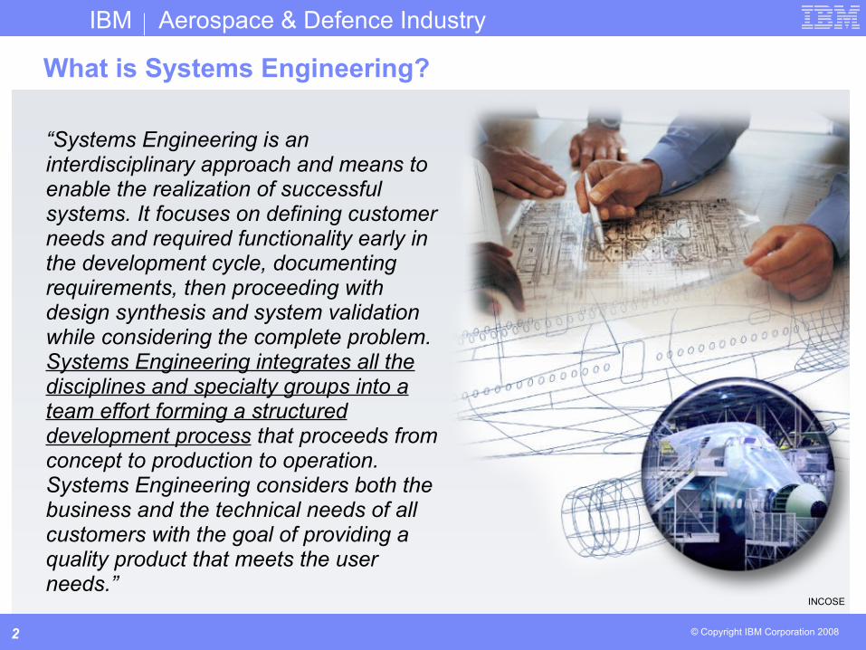
“Systems Engineering is an interdisciplinary approach and means to enable the realization of successful systems. It focuses on defining customer needs and required functionality early in the development cycle, documenting requirements, then proceeding with design synthesis and system validation while considering the complete problem. Systems Engineering integrates all the disciplines and specialty groups into a team effort forming a structured development process that proceeds from concept to production to operation. Systems Engineering considers both the business and the technical needs of all customers with the goal of providing a quality product that meets the user needs.”
What is Systems Engineering?
INCOSE
IBM Aerospace & Defence Industry
© Copyright IBM Corporation 20083
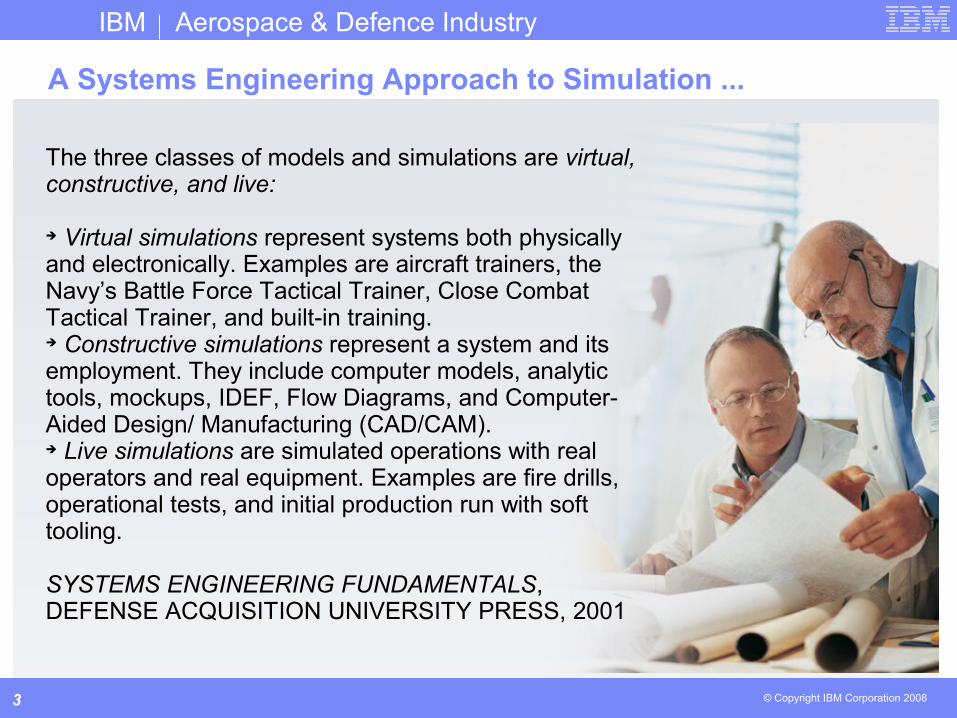
The three classes of models and simulations are virtual, constructive, and live:
Virtual simulations represent systems both physically and electronically. Examples are aircraft trainers, the Navy’s Battle Force Tactical Trainer, Close Combat Tactical Trainer, and built-in training. Constructive simulations represent a system and its employment. They include computer models, analytic tools, mockups, IDEF, Flow Diagrams, and Computer-Aided Design/ Manufacturing (CAD/CAM). Live simulations are simulated operations with real operators and real equipment. Examples are fire drills, operational tests, and initial production run with soft tooling.
SYSTEMS ENGINEERING FUNDAMENTALS,DEFENSE ACQUISITION UNIVERSITY PRESS, 2001
A Systems Engineering Approach to Simulation ...

IBM Aerospace & Defence Industry
© Copyright IBM Corporation 20084
... is based on Modelling: Model Driven Systems EngineeringB
usin
ess
Pro
cess
Man
agem
ent S
yste
m
Requirement Management System
Product Data Management System
Sim
ulation System
Model Analysis & Verification・ Model Structure Validation・ Constraint Verification・ Dynamic Analysis・ Trade-Off Analysis
Modeling Manager・ Requirement Analysis・Modeling & Update・ Model Retrieval
・ Differential Modeling
Method Manager・Method Management・ Template Management・ Process Definition・ Process Guidance
System-level Product Manager・ Product Data Integration・ Configuration Management・ Change Management・ Variation Management・ Security Management・ Traceability Management
MDSE focuses on creating models that capture the essential features of a design. A modelling paradigm for MDSE is considered effective if its models make sense from the point of view of the
user and can serve as a basis for implementing systems. The models are developed through extensive communication among product managers, designers, and members of the development team. As the models approach completion, they enable the development of software and systems.
IBM Aerospace & Defence Industry
© Copyright IBM Corporation 20085
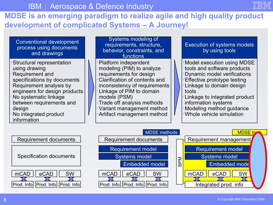
MDSE is an emerging paradigm to realize agile and high quality product development of complicated Systems – A Journey!
Conventional development process using documents
and drawingsExecution of systems models
by using tools
Systems modeling of requirements, structure,
behavior, constraints, and functions
Structural representation using drawingRequirement and specifications by documentsRequirement analysis by engineers for design productsNo systematic linkage between requirements and design No integrated product information
Platform independent modeling (PIM) to analyze requirements for designClarification of contents and inconsistency of requirementsLinkage of PIM to domain models (PSM)Trade off analysis methodsVariant management methodArtifact management method
Model execution using MDSE tools and software productsDynamic model verificationsEffective prototype testingLinkage to domain design toolsLinkage to integrated product information systemsModeling method guidanceWhole vehicle simulation
Requirement documents
Specification documents
mCAD eCAD SW
Prod. Info
Requirement documents
mCAD eCAD SW
Prod. Info Prod. Info
MDSE toolsMDSE methods
Prod. Info Prod. Info Prod. Info
Requirement modelSystems model
Embedded model
Requirement management
Requirement model
mCAD eCAD SW
Integrated prod. info
Systems modelEmbedded model
Ext
. Sim
ulat
ions
BP
M
IBM Aerospace & Defence Industry
© Copyright IBM Corporation 20086
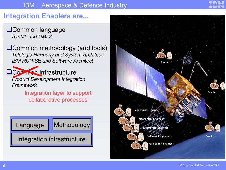
Common languageSysML and UML2
Common methodology (and tools)Telelogic Harmony and System ArchitectIBM RUP-SE and Software Architect
Common infrastructureProduct Development Integration Framework
Mechanical Engineer
Mechanical Engineer
Electronics Engineer
Software Engineer
Verification Engineer
Supplier
Supplier
Supplier
Integration layer to support collaborative processes
Language Methodology
Integration infrastructure
Integration Enablers are...

IBM Aerospace & Defence Industry
© Copyright IBM Corporation 20087
Common LanguageSysML and UML2

IBM Aerospace & Defence Industry
© Copyright IBM Corporation 20088
Key Features and Expected Benefits
Key Features:- Open standard- Widely adopted and recognized- Capable of supporting two different domains: software and systems development
Expected Benefits:- Well known to practitioners - No dependency from specific technology or provider- Evolving with the community needs- Excellent tool support
An example: SysML and UML2
IBM Aerospace & Defence Industry
© Copyright IBM Corporation 20089
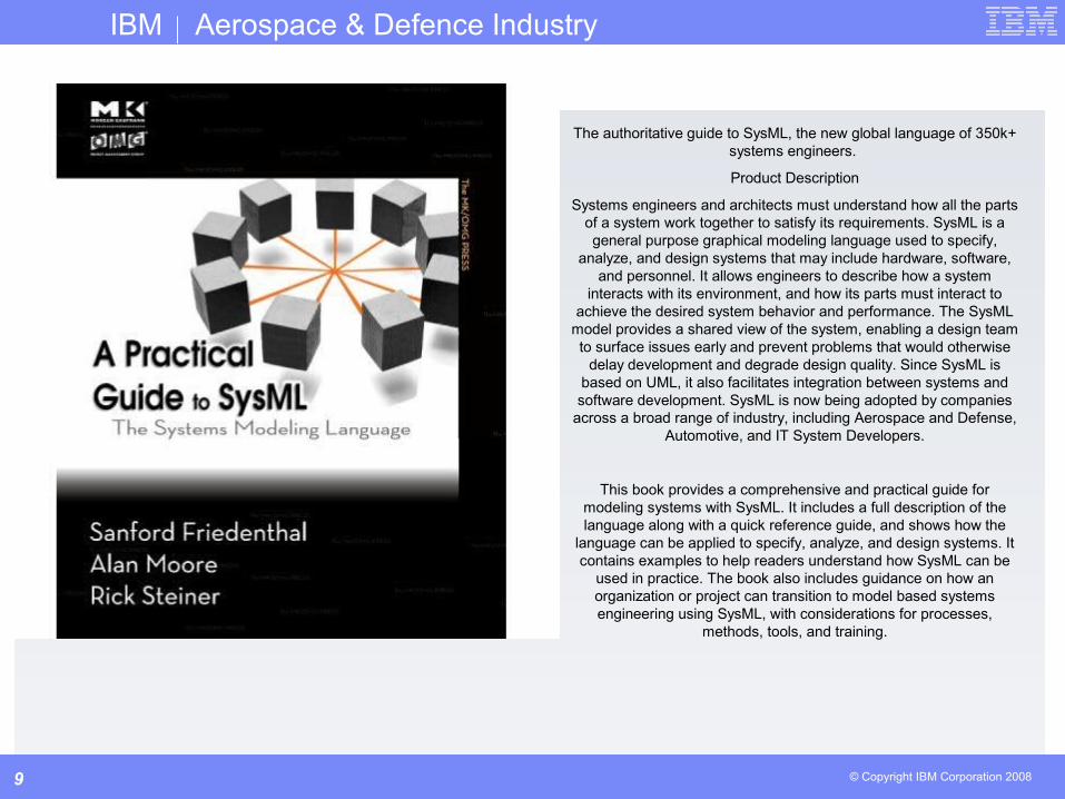
The authoritative guide to SysML, the new global language of 350k+ systems engineers.
Product Description
Systems engineers and architects must understand how all the parts of a system work together to satisfy its requirements. SysML is a general purpose graphical modeling language used to specify,
analyze, and design systems that may include hardware, software, and personnel. It allows engineers to describe how a system
interacts with its environment, and how its parts must interact to achieve the desired system behavior and performance. The SysML
model provides a shared view of the system, enabling a design team to surface issues early and prevent problems that would otherwise
delay development and degrade design quality. Since SysML is based on UML, it also facilitates integration between systems and software development. SysML is now being adopted by companies
across a broad range of industry, including Aerospace and Defense, Automotive, and IT System Developers.
This book provides a comprehensive and practical guide for modeling systems with SysML. It includes a full description of the language along with a quick reference guide, and shows how the
language can be applied to specify, analyze, and design systems. It contains examples to help readers understand how SysML can be
used in practice. The book also includes guidance on how an organization or project can transition to model based systems engineering using SysML, with considerations for processes,
methods, tools, and training.

IBM Aerospace & Defence Industry
© Copyright IBM Corporation 200810
The System Model as a framework for analysis and traceability (figure 17.1 Friedenthal = Lockheed Martin, Moore = MathLab, Steiner = Raytheon)
ibd Structure act Behavior
req Requirements par Parametrics
External Requirements
System Documentation and Specification
Analysis Models
System Model (SysML)
System framework for design
Mechanical Design Models Electrical Design Models Software Design Models Testing Methods and Models
TraceabilityRationale
Viewpoint
Analysis Needs
PerformanceEstimates

IBM Aerospace & Defence Industry
© Copyright IBM Corporation 200811
Interlocking disciplines in an integrated system development environment (figure 17.2 Friedenthal = Lockheed Martin, Moore = MathLab, Steiner = Raytheon)
Project Management
SoS/DoDAF/Business Process ModelingUPDM
Systems Modeling(SysML)
Software ModelingUML 2.0
Hardware ModelingVHDL, CAD,…
Document Generation
CM
/DM
Prod
uct D
ata
Man
agem
ent
Req
uire
men
ts M
anag
emen
t
Perf
orm
ance
Sim
ulat
ion
Val
idat
ion
and
Ver
ifica
tion
Engi
neer
ing
Ana
lysi
s

IBM Aerospace & Defence Industry
© Copyright IBM Corporation 200812
Common Methodology and ToolsTelelogic Harmony and Rhapsody
IBM RUP-SE and Software Architect

IBM Aerospace & Defence Industry
© Copyright IBM Corporation 200813
Key Features and Expected Benefits Leverage standards-based systems engineering processes- Customize systems engineering processes to meet organizational needs- Ensure communication and increase productivity across the systems engineering
lifecycle- Build system of systems architectures
Support for industry modeling standards and architecture frameworks including DoDAF, MoDAF, AusDAF, NATO C3, UPDM, UML, SysML- Comply with industry architecture standards, while ensuring traceability from
enterprise architecture to product/systems development- Reuse architectural components across the team ensuring consistency in developing
products Capability to manage product requirements across stakeholders- Improves ability to integrate products across multiple development environments - leveraging a common view of requirements- Facilitate trade-off decisions
Traceability of requirements to the rest of the development artifacts and design history- Improving communication across teams- Facilitating compliance and auditability
Propagate changes across multiple domains- Shorten delivery times and lower product cost- Continuous improvement and quality of products- Helping integrate PLM processes across domains (and suppliers) using PDIF/SOA
An example: IBM's Telelogic Harmony and RUP-SE
IBM Aerospace & Defence Industry
© Copyright IBM Corporation 200814
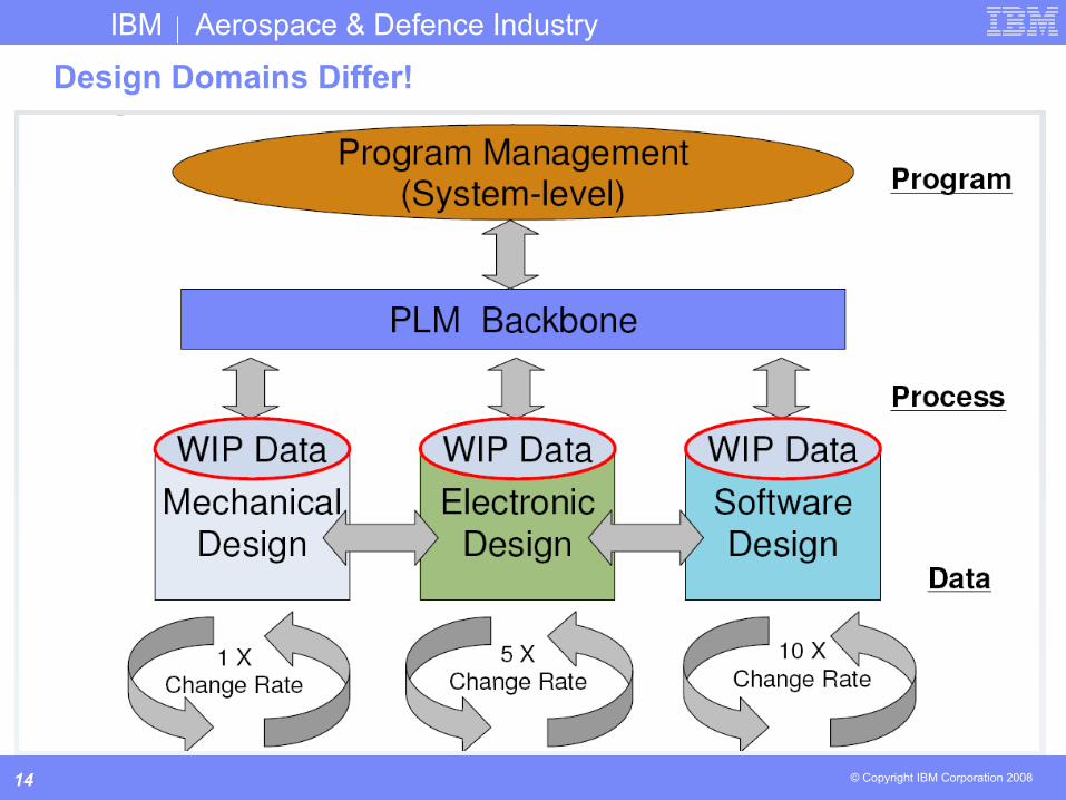
Design Domains Differ!

IBM Aerospace & Defence Industry
© Copyright IBM Corporation 200815
MDD: Component Sharing Roadmap
Strategic: Tau functionality migration to Rational
Modeling Platform (RMP) Move of RT functionality to RMP SDL Suite on RMP Support for Jazz
Thin-client (web) modeling components Modeling services
Tactical: RMP component reuse in Rhapsody Common integration with RM, Change
Management, CM, System Architect, etc.
Current
= shared technology
+2 years +4 years Strategic:
RMP technology leveraged by Rhapsody
Sharing of RMP rich client components across all offerings
RSA-RTE assimilation into Rhapsody product line
Sharing of Jazz modeling components
Potential for Statemate to use some Jazz technology
Strategic: Joint work on OMG Diagram RFP
for common diagram interchange Joint work on UPDM
Tactical: RTC integration UML action language work .Net support System Architect integration DOORS integration
Rhapsody
Tau
RSA4 WS
RSA-RTE
Rhapsody
RSA-Tau
RSA4 WS
RSA-RTE
Rhapsody
RSA- Tau
RSA4 WS
Rhap-RTE
RSM/RSA-SE
RSM/RSA-SE
RSM/RSA-SE
SDL Suite
SDL Suite
SDL Suite

IBM Aerospace & Defence Industry
© Copyright IBM Corporation 200816
Integration InfrastructureProduct Development Integration Framework

IBM Aerospace & Defence Industry
© Copyright IBM Corporation 200817
Key Features and Expected Benefits
Key Features:- Based on SOA principles- Based on COTS products- Based on one data model- Integration of the whole Engineering domain, from design to maintenance
Expected Benefits:- Enable effective collaboration- Provide greater flexibility - Enable BPM (from monitoring to optimization)- Specific to simulation:
Support and speedup simulation data management Mantain a coherent view of the product Support the whole process Enable optimization
An example: IBM's Product Development Integration Framework

IBM Aerospace & Defence Industry
© Copyright IBM Corporation 200818
Governance, not more computing power, is the key to higher productivity
The gap in benefits between the highest and lowest IT spenders for computing power was only 4% without a good management system.
With a good governance system – Productivity improvement is 25%– Capital improvement is 70%
Source: Stephen J. Dorgan and John J. Dowdy - The McKinsey Quarterly, 2004 Number 4
Present
Leading Practice
3%
Requirements Analysis/Design Development Deployment
27% 55% 15%
20% 13% 22% 5%30-50%
Time savingUniversity of West Virginia and The United States Air Force Academy 2001

IBM Aerospace & Defence Industry
© Copyright IBM Corporation 200819
Engineering Change Request (ECR)
1 2 3 4 5Identification Potential of Change
Development Alternative Solutions
Specification and Decision of Change
Realisation of Change
Roll-Out into Production
M1: Change Idea
M2: Change Potential Identified
M3: Potential Solution defined
M4: ECR decided
M5: ECO decided
M6: ECN released
M7:Change implemented
1 2 3 4 5Receipt of
ECR RequestCreation of
ECRTechnical
Analysis of ECRCommenting on ECR Approval of
ECR
M3: Potential Solution defined
M3.1: Decision of
ECR
M3.2: ECR created
M3.3: ECR detailed
M3.4: ECR commented
M4: ECR decided
Example: VDA Change Management Process
The PDIF Vision — BPM and application integration in ONE framework
IBM Aerospace & Defence Industry
© Copyright IBM Corporation 200820
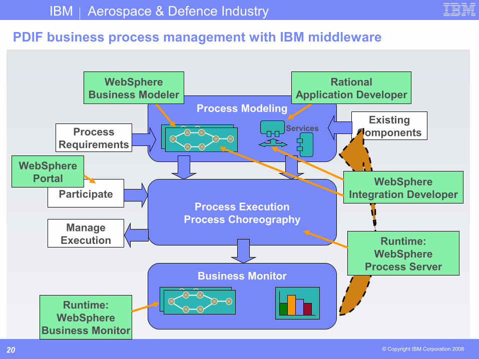
Process Modeling
Process ExecutionProcess Choreography
Participate
ManageExecution
ServicesExisting
ComponentsProcessRequirements
Business Monitor
Runtime:WebSphere
Business Monitor
WebSpherePortal
WebSphereBusiness Modeler
RationalApplication Developer
Runtime:WebSphere
Process Server
WebSphereIntegration Developer
PDIF business process management with IBM middleware

IBM Aerospace & Defence Industry
© Copyright IBM Corporation 200821
Product Data and Metadata
American Society ofMechanical Engineers
SOA and PLM Services
IBM PDIF: Integration Built on a Layer of Standards

IBM Aerospace & Defence Industry
© Copyright IBM Corporation 200822
Open Standards for transport, messaging, description, quality of service, and management and composition.
IBM SOA: Infrastructure Built on a Layer of Standards