vinyl window flange - ply gem...so as to not crack the mull strip. step 16) using color-matched...
TRANSCRIPT

Page 1 of 8170176000_New Construction Beveled and Brickmould Flange Tube Mull Instructions_RevB_July 2015_PMG
Step 1)Prepare Rough Opening (RO). The RO should be level, plumb and square. Opening dimension should be a maximum of 1/4” taller and 1/2” wider than the total installed dimensions, including the mull post width.
Locate and mark opening where mull post will be installed based on configuration and sizing of windows.
If a weather-resistant barrier is used, follow the barrier manufacturer’s recommendations for treatment of window openings.
If using pan flashing, install it at this time. Follow the pan flashing manufacturer’s recommendations (or ASTM 2112 standards), making sure that the product provides an adequate sill dam height to the interior.
Vinyl Window FlangeBeveled and Brickmould Tube Mull Instructions
Beveled: Pages 1 - 4 & Brickmould: Pages 5 - 8
IMPORTANT! READ ALL INSTRUCTIONS BEFORE BEGINNING INSTALLATION. Follow your local building codes, customs and building practices for additional installation requirements. The manufacturer will accept no responsibility for air or water leakage
above, under, or around the window unit. These instructions are general in nature; for specific questions, contact Ply Gem Windows at 1-888-9PLYGEM.
For Florida applications, consult product listing on Florida Building Code website for approved fastener specifications. FL# 16118
Beveled Frame Parts
WH I T E
W H I T E
NEW CONSTRUCTIONW I N D O W S
RECOMMENDED TOOLS & ACCESSORIES(Not supplied by Ply Gem)
• Hammer• Tape measure• Phillips head screwdriver• Flat head screwdriver• 1/2” drill bit• Utility knife• Putty knife or flat bar• Level• Framing square• Pliers• Snips• Sealant gun • Exterior-grade sealant• Shims• ITW or ELCO masonry/
concrete installation anchors per instructions on floridabuilding.org.
• Tape-covered wood block
(1) Exterior beveled tube mull cover
(1) Aluminum mill structural tube mull
(2) Galvanized steel tube mull anchors (end clips)
(22) #8-18 x 7/8” PHL, PH, SD, zinc screws
(14) 1/2” hole plugs
(1) Interior beveled tube mull cover
Step 2)Slide tube mull anchors into each end of mull post.
Step 3)Locate mull posts with anchors into RO, based on unit dimensions. External mull post face should be flush with the RO outer face. Remaining width of openings cannot exceed 1/4” (max) of unit to be installed.

Page 2 of 8170176000_New Construction Beveled and Brickmould Flange Tube Mull Instructions_RevB_July 2015_PMG
Step 4)Secure the top and bottom anchors utilizing approved fasteners in two exteriorz prepunched holes as shown.
NOTE: Application of the fasteners into the top anchor prior to the bottom anchor allows for ease in plumbing the mull post.
Using a level, plumb the mull post and secure the bottom anchor.
Step 5)This unit comes with a factory-installed flange. There is an integral nail fin on the sill only. Wood shipping material may be attached to the nail fin of the sill. Remove these items prior to installation. Do not remove the nail fin or wood shipping board from this unit until it is ready to be placed into the opening.
Step 6)NOTE: Any weld flash interfering with the unit being flush to the mull post or mull bridge installation needs to be removed prior to installing units.
Step 7)If the window unit is not predrilled, drill holes into the jamb using a 1/2” drill bit following the fastener schedule in Table 1 or Table 2 located at the end of these instructions.
Step 8)Apply a minimum of 3/8” bead of exterior-grade sealant to the back of the flange.
NOTE: If using pan flashing, apply a discontinuous bead (leaving 1” void approx. 6” from each end) to flange at sill so as to provide adequate drainage.
Step 9)With the window closed and locked, place it in the RO and center it from side to side. If the sill of the rough opening is not level and true, place shims as needed to prevent the sill from bowing or sagging, otherwise place the window unit directly onto the sill. If your window is a horizontal sliding window, make sure each meeting rail is supported.
NOTE: Shim as necessary to ensure that the sealant placed on the flange comes in contact with the RO. Over-shimming may cause bowing and prevent proper window operation.
Step 10)INTERIOR: Place a shim between the clip and buck/frame at the installation clip/through frame fastener point nearest the top center, and fasten the window with a single approved fastener.
NOTE: ITW or ELCO masonry/concrete installation anchors per instructions on floridabuilding.org.
Screw window unit to mull post using provided fastener (part # 440049000). Approved masonry fasteners are not included in this kit.
Step 11)After checking the operation of the window, proceed with fastening the window at the remainder of the fastening points.
Page 3 of 8170176000_New Construction Beveled and Brickmould Flange Tube Mull Instructions_RevB_July 2015_PMG
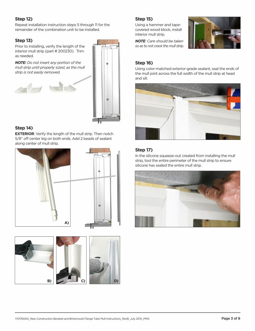
Step 12)Repeat installation instruction steps 5 through 11 for the remainder of the combination unit to be installed.
Step 13)Prior to installing, verify the length of the interior mull strip (part # 200230). Trim as needed.
NOTE: Do not insert any portion of the mull strip until properly sized, as the mull strip is not easily removed.
Step 14)EXTERIOR: Verify the length of the mull strip. Then notch 5/8” off center leg on both ends. Add 2 beads of sealant along center of mull strip.
Step 15)Using a hammer and tape-covered wood block, install interior mull strip.
NOTE: Care should be taken so as to not crack the mull strip.
Step 16)Using color-matched exterior-grade sealant, seal the ends of the mull joint across the full width of the mull strip at head and sill.
Step 17)In the silicone squeeze-out created from installing the mull strip, tool the entire perimeter of the mull strip to ensure silicone has sealed the entire mull strip.
A)
B) C) D)

Page 4 of 8170176000_New Construction Beveled and Brickmould Flange Tube Mull Instructions_RevB_July 2015_PMG
Figure 2
PRECAUTIONARY NOTES• For trim and siding, leave a 1/8”-1/4” gap all the way around the window frame to allow for expansion.
• Exterior wall systems like stucco and EIFS must be designed to manage moisture around the window opening.
• If present, do not block or seal weep holes.• Follow the siding manufacturer’s requirements for sealing between the siding and window frames.• Any low-expansion foam used should conform to AAMA 812-04 (see manufacturer’s requirements), but any binding or damage
of any type caused by the insulation will not be covered under warranty.
• Do not paint any vinyl part of this window for any reason. Painting vinyl will render null and void all warranties.
CAUTIONAcid solutions used to clean masonry can damage window and door items such as cladding, hardware, glass, sealants and
fasteners. The cleaning solution manufacturers recommend must be followed carefully; you must protect Ply Gem window units from contact with solution. If solution does come in contact with unit, immediately rinse all surfaces with clean water.
Figure 1
Through Frame Install Clip Install

Page 5 of 8170176000_New Construction Beveled and Brickmould Flange Tube Mull Instructions_RevB_July 2015_PMG
Step 1)Prepare Rough Opening (RO). The RO should be level, plumb and square. Opening dimension should be a maximum of 1/4” taller and 1/2” wider than the total installed dimensions, including the mull post width.
Locate and mark opening where mull post will be installed based on configuration and sizing of windows.
If a weather-resistant barrier is used, follow the barrier manufacturer’s recommendations for treatment of window openings.
If using pan flashing, install it at this time. Follow the pan flashing manufacturer’s recommendations (or ASTM 2112 standards), making sure that the product provides an adequate sill dam height to the interior.
Brickmould Tube Mull Instructions
Brickmould Parts
(1) Exterior brickmould tube mull cover(1) Aluminum mill structural tube mull
(2) Galvanized steel tube mull anchors (end clips)
(14) 1/2” hole plugs
(1) Interior brickmould tube mull cover
Step 2)Slide tube mull anchors into each end of mull post.
Step 3)Locate mull posts with anchors into RO, based on unit dimensions. External mull post face should be flush with the RO outer face. Remaining width of openings cannot exceed 1/4” (max) of unit to be installed.
(22) #8-18 x 7/8” PHL, PH, SD, zinc screws
For Florida applications, consult product listing on Florida Building Code website for approved fastener specifications. FL# 16118

Page 6 of 8170176000_New Construction Beveled and Brickmould Flange Tube Mull Instructions_RevB_July 2015_PMG
Step 4)Secure the top and bottom anchors utilizing approved fasteners in two exterior prepunched holes as shown.
NOTE: Application of the fasteners into the top anchor prior to the bottom anchor allows for ease in plumbing the mull post.
Using a level, plumb the mull post and secure the bottom anchor.
Step 5)This unit comes with a factory-installed flange. There is an integral nail fin on the sill only. Wood shipping material may be attached to the nail fin of the sill. Remove these items prior to installation. Do not remove the nail fin or wood shipping board (suggested shipping material) from this unit until it is ready to be placed into the opening.
Step 6)NOTE: Any weld flash interfering with the unit being flush to the mull post or mull bridge installation needs to be removed prior to installing units.
Step 7)If the window unit is not predrilled, drill holes into the jamb using a 1/2” drill bit following the fastener schedule in Table 1 or Table 2 located at the end of these instructions.
Step 8)Apply a minimum of 3/8” bead of exterior-grade sealant to the back of the flange.
NOTE: If using pan flashing, apply a discontinuous bead (leaving 1” void approx. 6” from each end) to flange at sill so as to provide adequate drainage.
Step 9)With the window closed and locked, place it in the RO and center it from side to side. If the sill of the rough opening is not level and true, place shims as needed to prevent the sill from bowing or sagging, otherwise place the window unit directly onto the sill. If your window is a horizontal sliding window, make sure each meeting rail is supported.
NOTE: Shim as necessary to ensure that the sealant placed on the flange comes in contact with the RO. Over-shimming may cause bowing and prevent proper window operation.
Step 10)INTERIOR: Place a shim between the clip and buck/frame at the installation clip/through frame fastener point nearest the top center, and fasten the window with a single approved fastener.
NOTE: ITW or ELCO masonry/concrete installation anchors per instructions on floridabuilding.org.
Screw window unit to mull post using provided fastener (part # 440049000). Approved masonry fasteners are not included in this kit.
Step 11)After checking the operation of the window, proceed with fastening the window at the remainder of the fastening points.

Page 7 of 8170176000_New Construction Beveled and Brickmould Flange Tube Mull Instructions_RevB_July 2015_PMG
Step 12)Repeat installation instruction steps 5 through 11 for the remainder of the combination unit to be installed.
Step 13)Prior to installing, verify the length of the interior mull strip (part # 200230). Trim as needed.
NOTE: Do not insert any portion of the mull strip until properly sized, as the mull strip is not easily removed.
Step 14)EXTERIOR: Verify the length of the mull strip. Then notch 5/8” off center leg on both ends. Add 2 beads of sealant along center of mull strip.
Step 15)Using a hammer and tape-covered wood block, install interior mull strip.
NOTE: Care should be taken so as to not crack the mull strip.
Step 16)Using color-matched exterior-grade sealant, seal the ends of the mull joint across the full width of the mull strip at head and sill.
Step 17)In the silicone squeeze-out created from installing the mull strip, tool the entire perimeter of the mull strip to ensure silicone has sealed the entire mull strip.
A)
B) C) D)

Page 8 of 8170176000_New Construction Beveled and Brickmould Flange Tube Mull Instructions_RevB_July 2015_PMG
Figure 1
Through Frame Install Clip Install
Figure 2
PRECAUTIONARY NOTES• For trim and siding, leave a 1/8”-1/4” gap all the way around the window frame to allow for expansion.
• Exterior wall systems like stucco and EIFS must be designed to manage moisture around the window opening.• If present, do not block or seal weep holes.• Follow the siding manufacturer’s requirements for sealing between the siding and window frames.• Any low-expansion foam used should conform to AAMA 812-04 (see manufacturer’s requirements), but any binding or damage
of any type caused by the insulation will not be covered under warranty.
• Do not paint any vinyl part of this window for any reason. Painting vinyl will render null and void all warranties.
CAUTIONAcid solutions used to clean masonry can damage window and door items such as cladding, hardware, glass, sealants and
fasteners. The cleaning solution manufacturers recommend must be followed carefully; you must protect Ply Gem window units from contact with solution. If solution does come in contact with unit, immediately rinse all surfaces with clean water.