vinay sridhara department of electrical and computer engineering cisc 861 - wireless networks and...
Post on 21-Dec-2015
216 views
TRANSCRIPT

Vinay SridharaDepartment of Electrical and Computer Engineering
CISC 861 - Wireless Networks and Mobile Computing
Connectivity Issues in Presence of UAVs in Mobile Ad Hoc Networks

UAV Why UAVs Related Issues Related problems Heuristics Flocking Algorithm Assumptions Flocking Rules Some implementation details Performance evaluation Simulation results UAV placement problem in Urban scenarios Simulated Annealing Analysis Result Performance Evaluation Conclusions
Overview

UAV – unmanned aerial vehicle Used for surveillance and reconnaissance Projected as an important component of
MANETs in warfare
UAV

Propagation loss The slow fading due to shadows caused
by obstacles is reduced or does not even exist
The propagation loss between UAVs and between UAV and ground node
Also the propagation of ground nodes as the distance increases
UAVs can act as reliable routers for multihop communications
Motion can be controlled using algorithms
2δ
1
1
Why UAVs ?

UAVs are costly Minimize the number of UAVs Optimal placement of UAVs Load balancing
Related Issues

Sensor network coverage problem Inventory coverage problem when using
sensors for identifying the RFID of equipment
Similar Problems
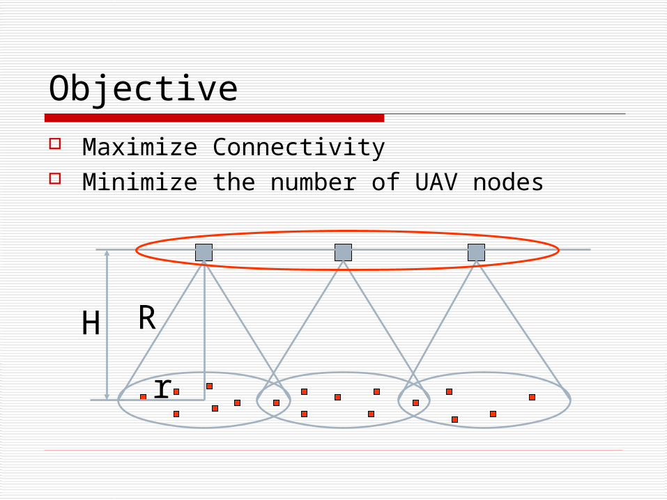
H
r
R
Maximize Connectivity Minimize the number of UAV nodes
Objective

Objective: Maximize connectivity Minimize the # of UAVs
Problem Formulation: Given a distribution of N nodes on the ground
plane and the free-space transmission ranges of UAVs (R) which are flying at an altitude H, what is the minimum number of UAVs necessary such that every ground node is connected to the UAV and the UAVs for a connected subgraph?
Optimal UAV Placement

Heuristics – I Static grid based approach
Divide the air plane into rectangular / hexagonal grid and place the UAV at the center of each grid
Very simple approach Costly Might not be very effective
Random movement approach Make the UAV take a random walk above the
ground with in a specified boundary Very ad hoc method and does not optimize
anything

Local flocking rule based approach Simultaneously track and cover the ground nodes
and keep connectivity with the aerial nodes Inspired by the flocking nature of birds
Cluster based approach
Heuristics – II

Based on the local flocking rules that birds and insects exhibit
Always fly in a group Do not crash into each other Overall motion is controlled purely by
the local motion of the individual birds
Flocking Algorithm
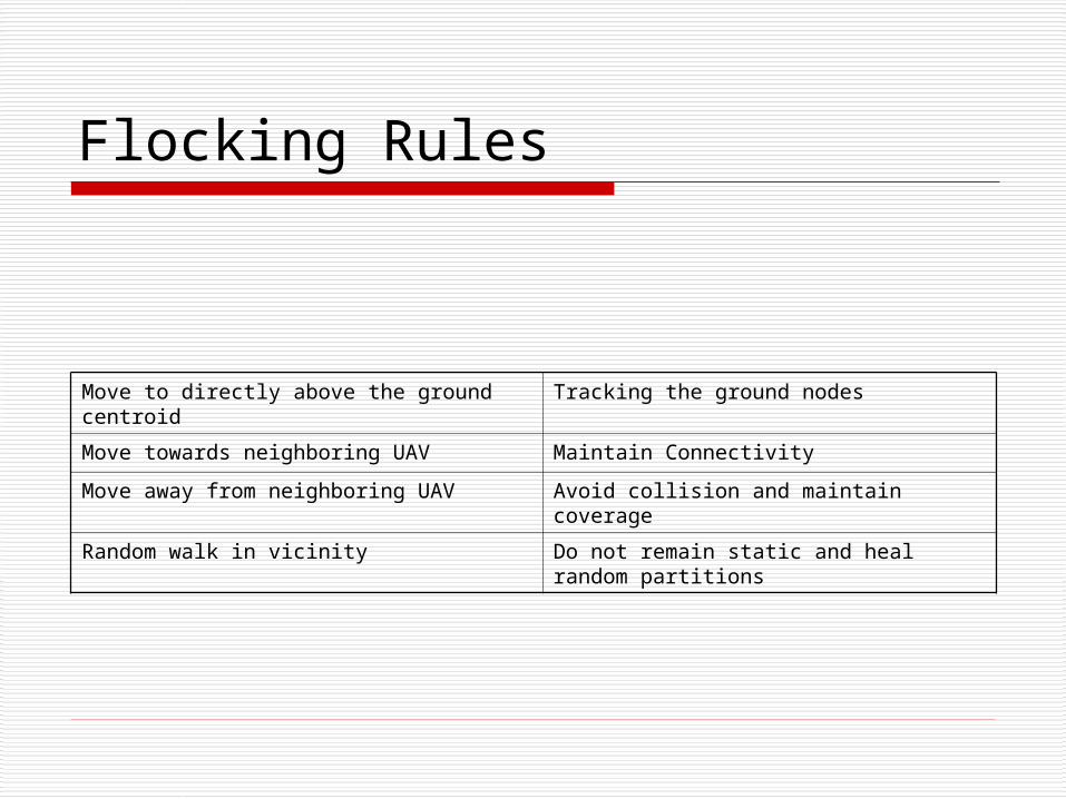
Move to directly above the ground centroid
Tracking the ground nodes
Move towards neighboring UAV Maintain Connectivity
Move away from neighboring UAV Avoid collision and maintain coverage
Random walk in vicinity Do not remain static and heal random partitions
Flocking Rules

Safe distance Limited rotation R2 propagation loss Cannot fly very close to the ground Poor or no connectivity between
ground nodes Complete connectivity of ground
nodes is not guaranteed
Assumptions – I

Assumptions – II UAVs cannot remain absolutely stationary UAV is not a point object Start with small number of fixed UAVs and
adjust their positions Only local information is available for each
UAV Neighbor discovery protocol is running on
all ground and airborne nodes

Obtained from the periodic heartbeat messages
UAV local Information UAVs Current location (GPS Information) Number of ground nodes connected to the
UAV Ground Node local Information
Ground nodes current location (GPS Information)
Local Information

New Neighbor
Recv Heartbeat
UpdateTable
Y
• Store Separation distance
• Store number of nodes connected to neighboring UAV U(j)
• Maintain a cumulative average of number of connected ground nodes
Working …
currentt
avg1t
avgt Nα1αNN

Threshold parameters
Dmax Max distance between two nodes without losing connectivity
Dmin Minimum distance between nodes to maintain good coverage (load balancing)
DcentrMax Maximum distance UAV allowed to remain from the ground centroid
Dsafe Minimum distance to be maintained to lower the risk of collision
Drwalk Maximum distance UAV allowed to loiter
θmax Maximum turning angle
α Averaging Bias

State Machine Representation
safeyoume Dd ,
avgtt NN 1
avgtt NN 1
Move tocentroid
Attract
Repel Random walk
centrMAXcentroid Dd
centrMAXcentroid Dd
min, Dd youme
max, Dd youme
min, Dd youme
min, Dd youme
)()( yourt
met NN
)()( yourt
met NN
safeyoume Dd ,

Arrival of a heartbeat from a neighbor may result in a state transition and a new destination waypoint may be set for the UAV
There is a state-specific order of testing the conditions before rule execution at each UAV E.g. in state attract 3 conditions can be active simultaneously
Currently the UAVs do not remember the neighbor updates that causes the state transition if this state is maintained then rule execution can be more
intelligent
avgtt NN 1 .3
centrMAXcentroid Dd .1
min, .2 Dd youme Order of execution is 3, 2 and 1Order of execution is 3, 2 and 1
Rule Execution
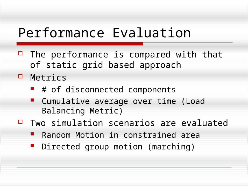
The performance is compared with that of static grid based approach
Metrics # of disconnected components Cumulative average over time (Load
Balancing Metric) Two simulation scenarios are evaluated
Random Motion in constrained area Directed group motion (marching)
Performance Evaluation

Simulation Parameters
4020 and 2020)( 2 KmArea
100N
%20/18],[ maxmin smVV
speriodHeartbeat 5
25.0
KmDrwalk 5.0
KmD 12max
kmD 10min
6max
KmHUAV 10 4#
WdbmPowerTx 233 dbGainAntenna 1

Simulation Results - No Marching

Simulation Results – Marching
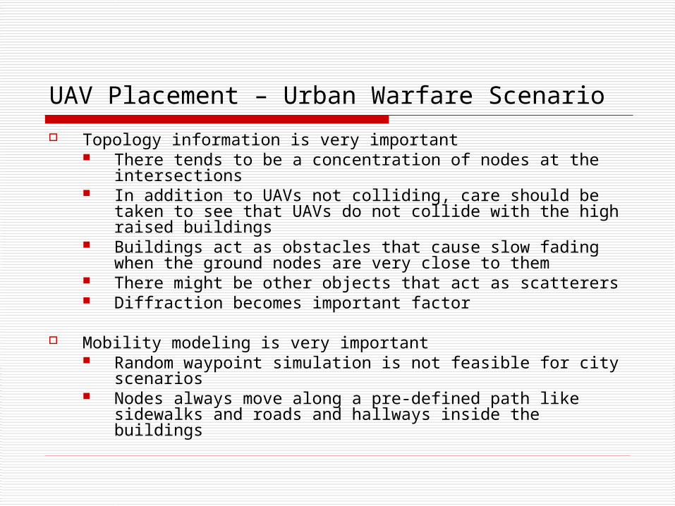
Topology information is very important There tends to be a concentration of nodes at the
intersections In addition to UAVs not colliding, care should be taken to
see that UAVs do not collide with the high raised buildings Buildings act as obstacles that cause slow fading when the
ground nodes are very close to them There might be other objects that act as scatterers Diffraction becomes important factor
Mobility modeling is very important Random waypoint simulation is not feasible for city
scenarios Nodes always move along a pre-defined path like sidewalks
and roads and hallways inside the buildings
UAV Placement – Urban Warfare Scenario

Simulated annealing A generalization of a Monte Carlo method
for examining the equations of state and frozen states of n-body systems [Metropolis et al. 1953]
The concept is based on the way the liquids freeze and the metals get into crystalline form as the temperature decreases
Simulated Annealing

Algorithm Objective
To find the global minimum In our case find a point where there is maximum
connectivity
do for number of iterationsfind (NewPos)if (NewPos better than oldPos)
acceptelse
accept with a probability given by end
Significance of temperature
T
dE
e

Scenario

Area ~ 500 X 500 m2
# of ground nodes = 30 Simulation time = 100s # of buildings = 10 # of floors = 3 and Height = 3.5m Buildings are assumed to be homogeneous Height of UAV plane = 30m Mobility – constrained mobility Pause time distribution – exponentially
distributed with mean 20
Simulation Parameters

Analysis – I

Analysis – II

Result

0 0.05 0.1 0.15 0.2 0.25 0.3-0.2
-0.1
0
0.1
0.2
0.3
0.4
0.5
0.6
0.7simulated annealing num iter=100 initial temp=4.00
relative error (BestMax-FoundMax)/BestMax
pro
b
0 0.005 0.01 0.015 0.02 0.025 0.03-0.1
0
0.1
0.2
0.3
0.4
0.5
0.6
0.7
0.8
0.9
simulated annealing num iter=1000 initial temp=2.00
relative error (BestMax-FoundMax)/BestMax
pro
b
Evaluation metric Optimal connectivity in presence of a single UAV
node
Performance

Need to incorporate different parameters like Velocity Rotational Angle Etc
Need to consider load balancing issues under the presence of more than one UAV node
Need to evaluate the algorithm with different topologies
Need to consider different mobility scenarios E.g. group mobility
Conclusions & Future Work

[1] K. Kar and S. Banerjee, ìNode Placement for Connected Coverage in Sensor Networks,î WiOpt 2003 Workshop, INRIA Sophia-Antipolis, France, March 2003.
[2] C. W. Reynolds, ìFlocks, Herds, and Schools: A Distributed Behavioral Model,î Computer Graphics, 21(4) (SIGGRAPH '87 Conference Proceedings), pp. 25-34, 1987.
[3] K. Xu, X. Hong, M. Gerla, H. Ly, and D. L. Gu, ìLandmark routing in large wireless battleeld networks using UAVs,î MILCOM 2001 - IEEE Military Communications Conference, no. 1, October 2001, pp. 230-234.
[4] Metropolis,N., A. Rosenbluth, M. Rosenbluth, A. Teller, E. Teller, "Equation of State Calculations by Fast Computing Machines", J. Chem. Phys.,21, 6, 1087-1092, 1953.
[5] “An Intelligent Approach to Coordinated Control of Multiple Unmanned Aerial Vehicles” George Vachtsevanos, Liang Tang, Johan Reimann [email protected] [email protected] [email protected] School of Electrical and Computer Engineering Georgia Institute of Technology, Atlanta, GA, 30332. U.S.A.
[6] UAV Placement for Enhanced Connectivity in wireless Adhoc Networks by Majid Raissi-Dehkordi, Karthikeyan Chandrashekar,John S. Baras
References

Thank you

How is load balancing achieved in flocking algorithm ?
In the flocking approach only local information is used. What is the main advantage of this ?
Questions