viking installation guide€¦ · viking range corporation 111 front street greenwood, mississippi...
TRANSCRIPT
Viking Range Corporation
111 Front Street
Greenwood, Mississippi 38930 USA
(662) 455-1200
For product information,
call 1-888-VIKING1 (845-4641)
or visit the Viking Web site at
vikingrange.com
F20456G EN (111609J)
Viking Installation Guide
Outdoor Gas Grills

IMPORTANT – Please Read and Follow!
3
Table of ContentsImportant Information________________________________________________________________________2T-Series ______________________________________________________________________________________4
Dimensions (30” and 41”) _______________________________________________________________4Specifications (30” and 41”) _____________________________________________________________5Dimensions (53”)_________________________________________________________________________6Specifications (53”)_______________________________________________________________________7
E-Series______________________________________________________________________________________8Dimensions (30” and 41”) _______________________________________________________________8Specifications (30” and 41”) _____________________________________________________________9Dimensions (53”) _______________________________________________________________________10Specifications (53”) _____________________________________________________________________11
General Information ________________________________________________________________________12Built-In information _________________________________________________________________________13
Clearance Dimensions (30”)_____________________________________________________________14Clearance Dimensions (41”)_____________________________________________________________15Clearance Dimensions (53”)_____________________________________________________________16Cutout Dimensions (30”)________________________________________________________________17Cutout Dimensions (41”) _______________________________________________________________18Cutout Dimensions (53”) _______________________________________________________________19
Ventilation for Built-In Installations ____________________________________________________20Gas and Electrical Connection ______________________________________________________________21Natural Fixed Piping Connection ___________________________________________________________22LP/Propane Fixed Piping Connection _______________________________________________________23LP/Propane Tank Requirements _____________________________________________________________24LP/Propane Tank Connection _______________________________________________________________25Leak Testing ________________________________________________________________________________26Burner Adjustment _________________________________________________________________________28Rotisserie System ___________________________________________________________________________30Performance Checklist ______________________________________________________________________31Final Preparation____________________________________________________________________________31Service & Registration ______________________________________________________________________32
WARNINGEXCESSIVE WEIGHT HAZARD
Use two or more people to move and install thisunit. Failure to follow this instruction can resultin back or other injury.
WARNINGFOR YOUR SAFETY
If not installed, operated and maintained inaccordance with the manufacturer’s instructions,this product could expose you to substances infuel or fuel combustion which can cause death orserious illness and which are known to causecancer, birth defects or other reproductive harm.
For example, benzene is a chemical which is partof the gas supplied to the cooking product. It isconsumed in the flame during combustion.However, exposure to a small amount of benzeneis possible if a gas leak occurs. Formaldehyde andsoot are by-products of incomplete combustion.Properly adjusted burners with a bluish rather thanyellow flame minimize incomplete combustion.
• Before beginning, please read theseinstructions completely and carefully.
• Do not remove permanently affixed labels,warnings, or plates from product. This mayvoid the warranty.
• Please observe all local and national codesand ordinances.
• The installer should leave these instructionswith the consumer who should retain forlocal inspector’s use and for futurereference.
• This outdoor cooking appliance shall be onlyused outdoors and shall not be used in abuilding, garage or any other enclosed area.
WARNINGThis outdoor gas grill is not intended to be installedinside a home or on recreational vehicles and/orboats.
WARNINGKeep electrical supply cord and the fuel supplyhose away from heated surfaces.
WARNINGThis appliance is not fused. Installer must install aground fault interrupt.
CAUTIONConversions should only be performed by anauthorized service technician.
WARNINGELECTRICAL SHOCK HAZARDThis appliance is equipped with a 3’ (91.4 cm) 3-prong power cord with a grounding plug foryour protection against shock hazard and shouldbe plugged directly into a properly groundedreceptacle. Do not cut or remove the groundingprong from this plug. This unit is not fused andinstaller must install a GFI. Unit must begrounded in accordance with local codes or withthe National Electrical Code ANSI/NFPA 70, orthe Canadian Electrical Code, CSA C22.1.
CAUTIONBefore placing into operation, always check forgas leaks with a soapy water solution. DO NOTUSE AN OPEN FLAME TO CHECK FOR LEAKS.
IMPORTANT – Please Read and Follow!Installation must conform with local codesor in the absence of codes, the National FuelGas Code, ANSI Z223.1/NFPA 54.
In Canada: Installation must be in accordancewith the current CSA-B149.1, Natural Gas andPropane Installation Code or CSA-B149.2,Propane Storage and Handling Code and/orlocal codes. For units with an external electricalsource, when installed, must be electricallygrounded in accordance with local codes orwith the National Electrical code ANSI/NFPA70, or Canadian Electrical code, CSA C22.1.
WARNINGDANGERFOR YOUR SAFETY
IIff yyoouu ssmmeellll ggaass:: 11.. SShhuutt ooffff ggaass ttoo tthhee aapppplliiaannccee.. 22.. EExxttiinngguuiisshh aannyy ooppeenn ffllaammee.. 33.. OOppeenn lliidd.. 44.. IIff ooddoorr ccoonnttiinnuueess,, kkeeeepp aawwaayy
ffrroomm tthhee aapppplliiaannccee,, iimmmmeeddiiaatteellyyccaallll yyoouurr ggaass ssuupppplliieerr oorr yyoouurr ffiirreeddeeppaarrttmmeenntt..
WARNINGFOR YOUR SAFETY
11.. DDoo nnoott ssttoorree oorr uussee ggaassoolliinnee oorrootthheerr ffllaammmmaabbllee vvaappoorrss aannddlliiqquuiiddss iinn tthhee vviicciinniittyy ooff tthhiiss oorraannyy ootthheerr aapppplliiaannccee..
22.. AAnnyy LLPP ccyylliinnddeerr nnoott ccoonnnneecctteeddffoorr uussee sshhaallll nnoott bbee ssttoorreedd iinn tthheevviicciinniittyy ooff tthhiiss oorr aannyy ootthheerraapppplliiaannccee..
2
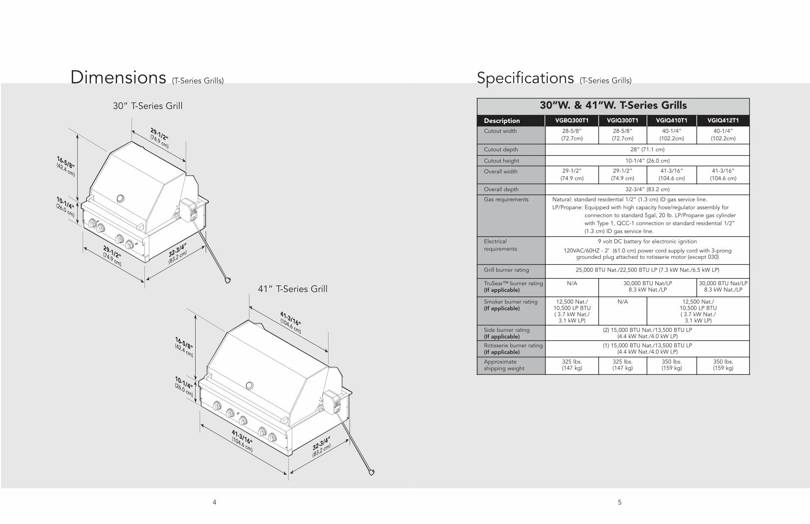
Specifications (T-Series Grills)
5
Dimensions (T-Series Grills)
4
41-3/16”(104.6 cm) 32-3/4”
(83.2 cm)
41-3/16”(104.6 cm)16-5/8”(42.4 cm)
10-1/4”(26.0 cm)
29-1/2”(74.9 cm)32-3/4”
(83.2 cm)
29-1/2”(74.9 cm)
16-5/8”(42.4 cm)
10-1/4”(26.0 cm)
30” T-Series Grill
41” T-Series Grill
30”W. & 41”W. T-Series Grills Description VGBQ300T1 VGIQ300T1 VGIQ410T1 VGIQ412T1
Cutout width 28-5/8” (72.7cm)
28-5/8” (72.7cm)
40-1/4” (102.2cm)
40-1/4”(102.2cm)
Cutout depth 28” (71.1 cm)
Cutout height 10-1/4” (26.0 cm)
Overall width 29-1/2” (74.9 cm)
29-1/2” (74.9 cm)
41-3/16” (104.6 cm)
41-3/16” (104.6 cm)
Overall depth 32-3/4” (83.2 cm)
Gas requirements Natural: standard residential 1/2” (1.3 cm) ID gas service line.LP/Propane: Equipped with high capacity hose/regulator assembly for
connection to standard 5gal, 20 lb. LP/Propane gas cylinder with Type 1, QCC-1 connection or standard residential 1/2” (1.3 cm) ID gas service line.
Electrical requirements
9 volt DC battery for electronic ignition
120VAC/60HZ - 2’ (61.0 cm) power cord supply cord with 3-pronggrounded plug attached to rotisserie motor (except 030)
Grill burner rating 25,000 BTU Nat./22,500 BTU LP (7.3 kW Nat./6.5 kW LP)
TruSear™ burner rating (If applicable)
N/A 30,000 BTU Nat/LP 8.3 kW Nat./LP
30,000 BTU Nat/LP 8.3 kW Nat./LP
Smoker burner rating (If applicable)
12,500 Nat./10,500 LP BTU( 3.7 kW Nat./
3.1 kW LP)
N/A 12,500 Nat./10,500 LP BTU( 3.7 kW Nat./
3.1 kW LP)
Side burner rating (If applicable)
(2) 15,000 BTU Nat./13,500 BTU LP(4.4 kW Nat./4.0 kW LP)
Rotisserie burner rating (If applicable)
(1) 15,000 BTU Nat./13,500 BTU LP (4.4 kW Nat./4.0 kW LP)
Approximate shipping weight
325 lbs. (147 kg)
325 lbs. (147 kg)
350 lbs. (159 kg)
350 lbs. (159 kg)

Specifications (T-Series Grills)
7
Dimensions (T-Series Grills)
6
53”W. T-Series Grills Description VGIQ530T1 VGIQ532T1
Cutout width 52-1/4” (132.7 cm)
Cutout depth 28” (71.1 cm)
Cutout height 10-1/4” (26.0 cm)
Overall width 53-3/16” (135.1 cm)
Overall depth 32-3/4” (83.2 cm)
Gas requirements Natural: standard residential 1/2” (1.3 cm) ID gas service line.
LP/Propane: equipped with high capacity hose/regulator assembly for connection to standard 5gal, 20 lb. LP/Propane gas cylinder with Type 1, QCC-1 connection or standard residential 1/2” (1.3 cm) ID gas service line.
Electrical requirements 9 volt DC battery for electronic ignition
120VAC/60HZ - 2’ (61.0 cm) power cord supply cord with 3-pronggrounded plug attached to rotisserie motor
Grill burner rating 25,000 BTU Nat./22,500 BTU LP (7.3 kW Nat./6.5 kW LP)
TruSear™ burner rating (If applicable)
30,000 BTU Nat/LP 8.3 kW Nat./LP
30,000 BTU Nat/LP 8.3 kW Nat./LP
Smoker burner rating (If applicable)
12,500 Nat./10,500 LP BTU( 3.7 kW Nat./3.1 kW LP)
Side burner rating (If applicable)
(2) 15,000 BTU Nat./13,500 BTU LP(4.4 kW Nat./4.0 kW LP)
Rotisserie burner rating (If applicable)
(2) 15,000 BTU Nat./13,500 BTU LP (4.4 kW Nat./4.0 kW LP)
15,000 BTU Nat./13,500 BTU LP (4.4 kW Nat./4.0 kW LP)
Approximate shipping weight
490 lbs. (222 kg)
460 lbs. (209 kg)
53-3/16”(135.1 cm)32-3/4”
(83.2 cm)
41-3/16”(104.6 cm)
16-5/8”(42.4 cm)
10-1/4”(26.0 cm)
53” T-Series Grill
98
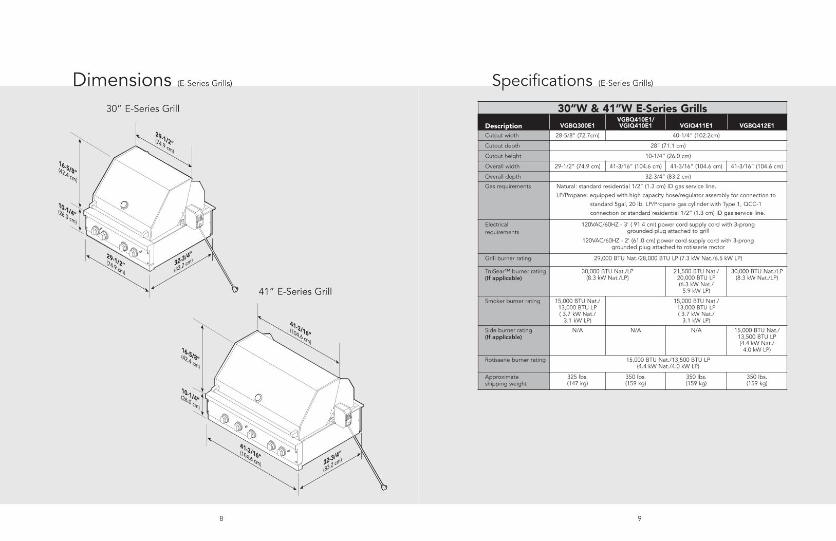
Specifications (E-Series Grills)
30”W & 41”W E-Series Grills Description VGBQ300E1
VGBQ410E1/VGIQ410E1 VGIQ411E1 VGBQ412E1
Cutout width 28-5/8” (72.7cm) 40-1/4” (102.2cm)
Cutout depth 28” (71.1 cm)
Cutout height 10-1/4” (26.0 cm)
Overall width 29-1/2” (74.9 cm) 41-3/16” (104.6 cm) 41-3/16” (104.6 cm) 41-3/16” (104.6 cm)
Overall depth 32-3/4” (83.2 cm)
Gas requirements Natural: standard residential 1/2” (1.3 cm) ID gas service line.
LP/Propane: equipped with high capacity hose/regulator assembly for connection to
standard 5gal, 20 lb. LP/Propane gas cylinder with Type 1, QCC-1
connection or standard residential 1/2” (1.3 cm) ID gas service line.
Electrical requirements
120VAC/60HZ - 3’ ( 91.4 cm) power cord supply cord with 3-prong grounded plug attached to grill
120VAC/60HZ - 2’ (61.0 cm) power cord supply cord with 3-pronggrounded plug attached to rotisserie motor
Grill burner rating 29,000 BTU Nat./28,000 BTU LP (7.3 kW Nat./6.5 kW LP)
TruSear™ burner rating (If applicable)
30,000 BTU Nat./LP(8.3 kW Nat./LP)
21,500 BTU Nat./20,000 BTU LP (6.3 kW Nat./
5.9 kW LP)
30,000 BTU Nat./LP(8.3 kW Nat./LP)
Smoker burner rating 15,000 BTU Nat./13,000 BTU LP( 3.7 kW Nat./
3.1 kW LP)
15,000 BTU Nat./13,000 BTU LP( 3.7 kW Nat./
3.1 kW LP)
Side burner rating (If applicable)
N/A N/A N/A 15,000 BTU Nat./13,500 BTU LP(4.4 kW Nat./
4.0 kW LP)
Rotisserie burner rating 15,000 BTU Nat./13,500 BTU LP (4.4 kW Nat./4.0 kW LP)
Approximate shipping weight
325 lbs. (147 kg)
350 lbs. (159 kg)
350 lbs. (159 kg)
350 lbs. (159 kg)
41-3/16”(104.6 cm) 32-3/4”
(83.2 cm)
41-3/16”(104.6 cm)16-5/8”(42.4 cm)
10-1/4”(26.0 cm)
29-1/2”(74.9 cm)32-3/4”
(83.2 cm)
29-1/2”(74.9 cm)
16-5/8”(42.4 cm)
10-1/4”(26.0 cm)
30” E-Series Grill
41” E-Series Grill
Dimensions (E-Series Grills)
1110
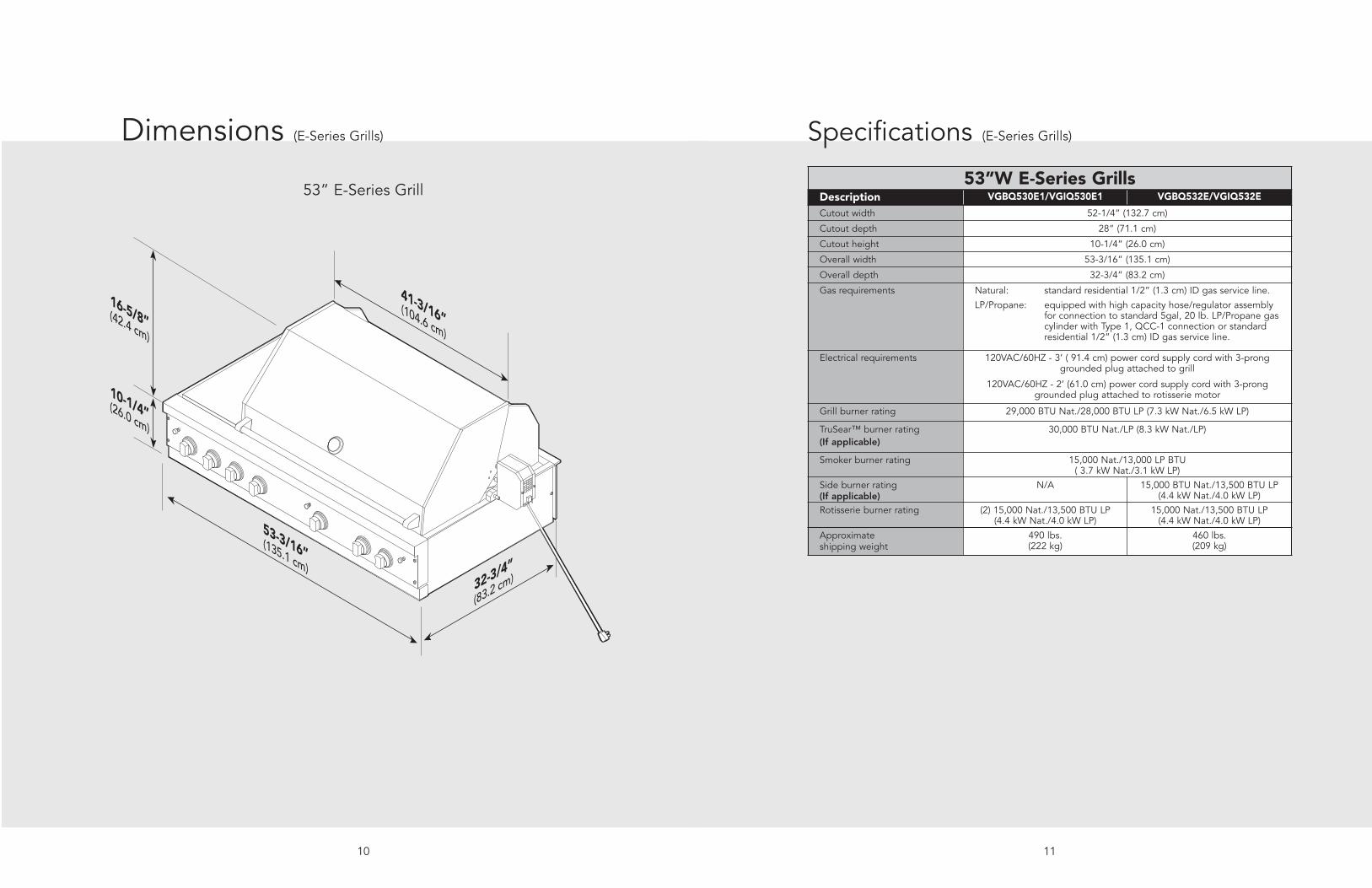
Specifications (E-Series Grills)Dimensions (E-Series Grills)
53”W E-Series GrillsDescription VGBQ530E1/VGIQ530E1 VGBQ532E/VGIQ532E
Cutout width 52-1/4” (132.7 cm)
Cutout depth 28” (71.1 cm)
Cutout height 10-1/4” (26.0 cm)
Overall width 53-3/16” (135.1 cm)
Overall depth 32-3/4” (83.2 cm)
Gas requirements Natural: standard residential 1/2” (1.3 cm) ID gas service line.
LP/Propane: equipped with high capacity hose/regulator assemblyfor connection to standard 5gal, 20 lb. LP/Propane gascylinder with Type 1, QCC-1 connection or standardresidential 1/2” (1.3 cm) ID gas service line.
Electrical requirements 120VAC/60HZ - 3’ ( 91.4 cm) power cord supply cord with 3-prong grounded plug attached to grill
120VAC/60HZ - 2’ (61.0 cm) power cord supply cord with 3-pronggrounded plug attached to rotisserie motor
Grill burner rating 29,000 BTU Nat./28,000 BTU LP (7.3 kW Nat./6.5 kW LP)
TruSear™ burner rating (If applicable)
30,000 BTU Nat./LP (8.3 kW Nat./LP)
Smoker burner rating 15,000 Nat./13,000 LP BTU( 3.7 kW Nat./3.1 kW LP)
Side burner rating (If applicable)
N/A 15,000 BTU Nat./13,500 BTU LP(4.4 kW Nat./4.0 kW LP)
Rotisserie burner rating (2) 15,000 Nat./13,500 BTU LP (4.4 kW Nat./4.0 kW LP)
15,000 Nat./13,500 BTU LP (4.4 kW Nat./4.0 kW LP)
Approximate shipping weight
490 lbs. (222 kg)
460 lbs. (209 kg)
53-3/16”(135.1 cm)32-3/4”
(83.2 cm)
41-3/16”(104.6 cm)
16-5/8”(42.4 cm)
10-1/4”(26.0 cm)
53” E-Series Grill
Built-In Information
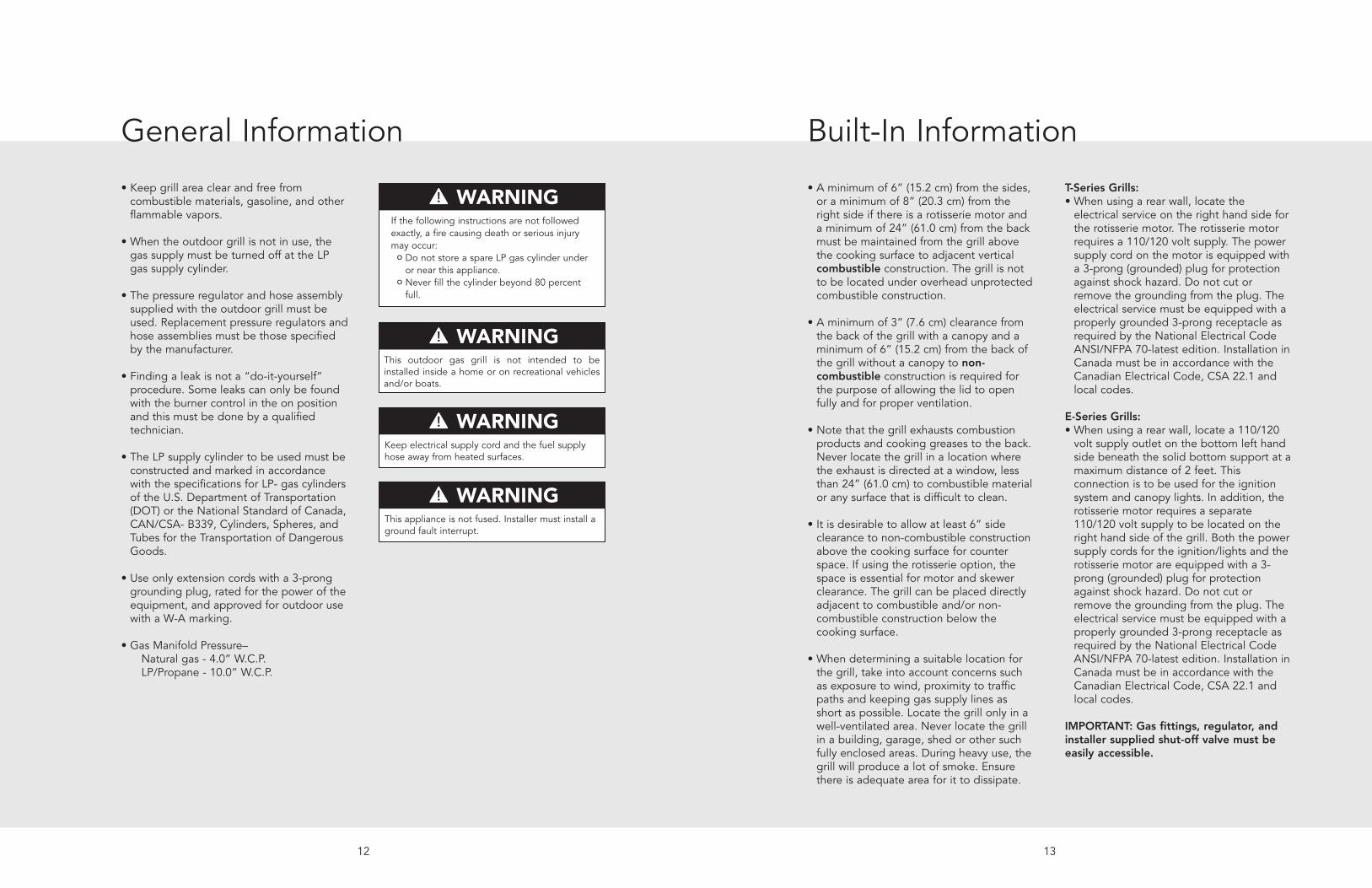
• A minimum of 6” (15.2 cm) from the sides,or a minimum of 8” (20.3 cm) from theright side if there is a rotisserie motor anda minimum of 24” (61.0 cm) from the backmust be maintained from the grill abovethe cooking surface to adjacent verticalcombustible construction. The grill is notto be located under overhead unprotectedcombustible construction.
• A minimum of 3” (7.6 cm) clearance fromthe back of the grill with a canopy and aminimum of 6” (15.2 cm) from the back ofthe grill without a canopy to non-combustible construction is required forthe purpose of allowing the lid to openfully and for proper ventilation.
• Note that the grill exhausts combustionproducts and cooking greases to the back.Never locate the grill in a location wherethe exhaust is directed at a window, lessthan 24” (61.0 cm) to combustible materialor any surface that is difficult to clean.
• It is desirable to allow at least 6” sideclearance to non-combustible constructionabove the cooking surface for counterspace. If using the rotisserie option, thespace is essential for motor and skewerclearance. The grill can be placed directlyadjacent to combustible and/or non-combustible construction below thecooking surface.
• When determining a suitable location forthe grill, take into account concerns suchas exposure to wind, proximity to trafficpaths and keeping gas supply lines asshort as possible. Locate the grill only in awell-ventilated area. Never locate the grillin a building, garage, shed or other suchfully enclosed areas. During heavy use, thegrill will produce a lot of smoke. Ensurethere is adequate area for it to dissipate.
T-Series Grills:• When using a rear wall, locate the
electrical service on the right hand side forthe rotisserie motor. The rotisserie motorrequires a 110/120 volt supply. The powersupply cord on the motor is equipped witha 3-prong (grounded) plug for protectionagainst shock hazard. Do not cut orremove the grounding from the plug. Theelectrical service must be equipped with aproperly grounded 3-prong receptacle asrequired by the National Electrical CodeANSI/NFPA 70-latest edition. Installation inCanada must be in accordance with theCanadian Electrical Code, CSA 22.1 andlocal codes.
E-Series Grills:• When using a rear wall, locate a 110/120
volt supply outlet on the bottom left handside beneath the solid bottom support at amaximum distance of 2 feet. Thisconnection is to be used for the ignitionsystem and canopy lights. In addition, therotisserie motor requires a separate110/120 volt supply to be located on theright hand side of the grill. Both the powersupply cords for the ignition/lights and therotisserie motor are equipped with a 3-prong (grounded) plug for protectionagainst shock hazard. Do not cut orremove the grounding from the plug. Theelectrical service must be equipped with aproperly grounded 3-prong receptacle asrequired by the National Electrical CodeANSI/NFPA 70-latest edition. Installation inCanada must be in accordance with theCanadian Electrical Code, CSA 22.1 andlocal codes.
IMPORTANT: Gas fittings, regulator, andinstaller supplied shut-off valve must beeasily accessible.
1312
General Information
• Keep grill area clear and free fromcombustible materials, gasoline, and otherflammable vapors.
• When the outdoor grill is not in use, thegas supply must be turned off at the LPgas supply cylinder.
• The pressure regulator and hose assemblysupplied with the outdoor grill must beused. Replacement pressure regulators andhose assemblies must be those specifiedby the manufacturer.
• Finding a leak is not a “do-it-yourself”procedure. Some leaks can only be foundwith the burner control in the on positionand this must be done by a qualifiedtechnician.
• The LP supply cylinder to be used must beconstructed and marked in accordancewith the specifications for LP- gas cylindersof the U.S. Department of Transportation(DOT) or the National Standard of Canada,CAN/CSA- B339, Cylinders, Spheres, andTubes for the Transportation of DangerousGoods.
• Use only extension cords with a 3-pronggrounding plug, rated for the power of theequipment, and approved for outdoor usewith a W-A marking.
• Gas Manifold Pressure–Natural gas - 4.0” W.C.P. LP/Propane - 10.0” W.C.P.
WARNING
DANGER
CAUTION
FOR YOUR SAFETY
This outdoor gas grill is not intended to beinstalled inside a home or on recreational vehiclesand/or boats.
WARNING
DANGER
CAUTION
FOR YOUR SAFETY
Keep electrical supply cord and the fuel supplyhose away from heated surfaces.
WARNING
DANGER
CAUTION
FOR YOUR SAFETY
This appliance is not fused. Installer must install aground fault interrupt.
WARNING
DANGER
CAUTION
FOR YOUR SAFETY
If the following instructions are not followedexactly, a fire causing death or serious injurymay occur:
o Do not store a spare LP gas cylinder underor near this appliance.
o Never fill the cylinder beyond 80 percentfull.
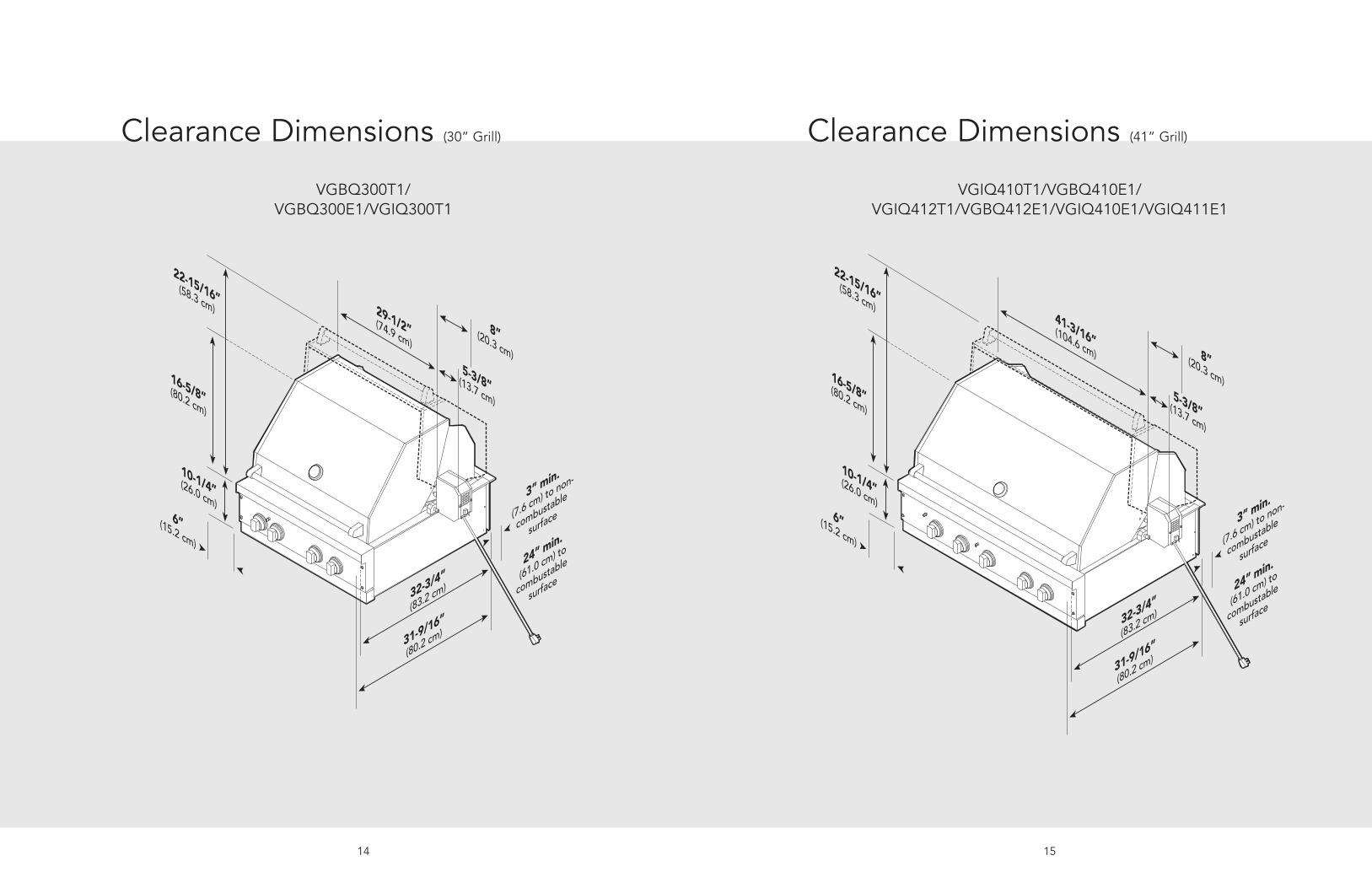
22-15/16”(58.3 cm)
16-5/8”(80.2 cm)
10-1/4”(26.0 cm)
29-1/2”(74.9 cm)8”(20.3 cm)
5-3/8”(13.7 cm)
32-3/4”
(83.2 cm)
31-9/16”
(80.2 cm)
3” min.
(7.6 cm) to non-
combustable
surface
24” min.
(61.0 cm) to
combustable
surface
6”(15.2 cm)
14
22-15/16”(58.3 cm)
16-5/8”(80.2 cm)
10-1/4”(26.0 cm)
41-3/16”(104.6 cm) 8”(20.3 cm)5-3/8”(13.7 cm)
32-3/4”
(83.2 cm)
31-9/16”
(80.2 cm)
3” min.
(7.6 cm) to non-
combustable
surface
24” min.
(61.0 cm) to
combustable
surface
6”(15.2 cm)
Clearance Dimensions (41” Grill)
15
Clearance Dimensions (30” Grill)
VGBQ300T1/VGBQ300E1/VGIQ300T1
VGIQ410T1/VGBQ410E1/VGIQ412T1/VGBQ412E1/VGIQ410E1/VGIQ411E1

10-1/4”(26.0 cm)
36”(91.4 cm)
**Access door opening
28”
(71.1 cm)28-5/8”(72.7 cm) 3”(7.6 cm) min.
Electrical connection for rotisserie motor(position unit so that the plug is always accessible)
Electrical connection for power supply cord onE-Series to be located onrear wall with a maximumdistance of 2’ (61.0 cm)beneath solid bottomsupport.
*Solid bottom
support
Countertop typically requires 1/2” wide by 1/2” deep notch cutout on each side of grill. This allows grill CP to sit back properly in the cutout.
Gas inlet and power cord location area
5”(12.7 cm)5”(12.7 cm)
1/2”(1.2 cm)
1/2”
(1.2 cm)
Cutout Dimensions (30” Grill)
17
22-15/16”(58.3 cm)
16-5/8”(80.2 cm)
10-1/4”(26.0 cm)6”(15.2 cm)
41-3/16”(104.6 cm) 8”(20.3 cm)5-3/8”(13.7 cm)
32-3/4”
(83.2 cm)
31-9/16”
(80.2 cm)
3” min.
(7.6 cm) to non-
combustable
surface
24” min.
(61.0 cm) to
combustable
surface
Clearance Dimensions (53” Grill)
16
VGBQ530T1/VGIQ530T1VGBQ530E1/VGIQ530E1/VGIQ532T1
VGBQ532E1/VGIQ532E1
**Access Doors sold separately - refer toaccess door installation instructions forcorrect dimensions.
*IMPORTANTCabinet cutout must have a solid bottom tosupport the full weight of the unit.
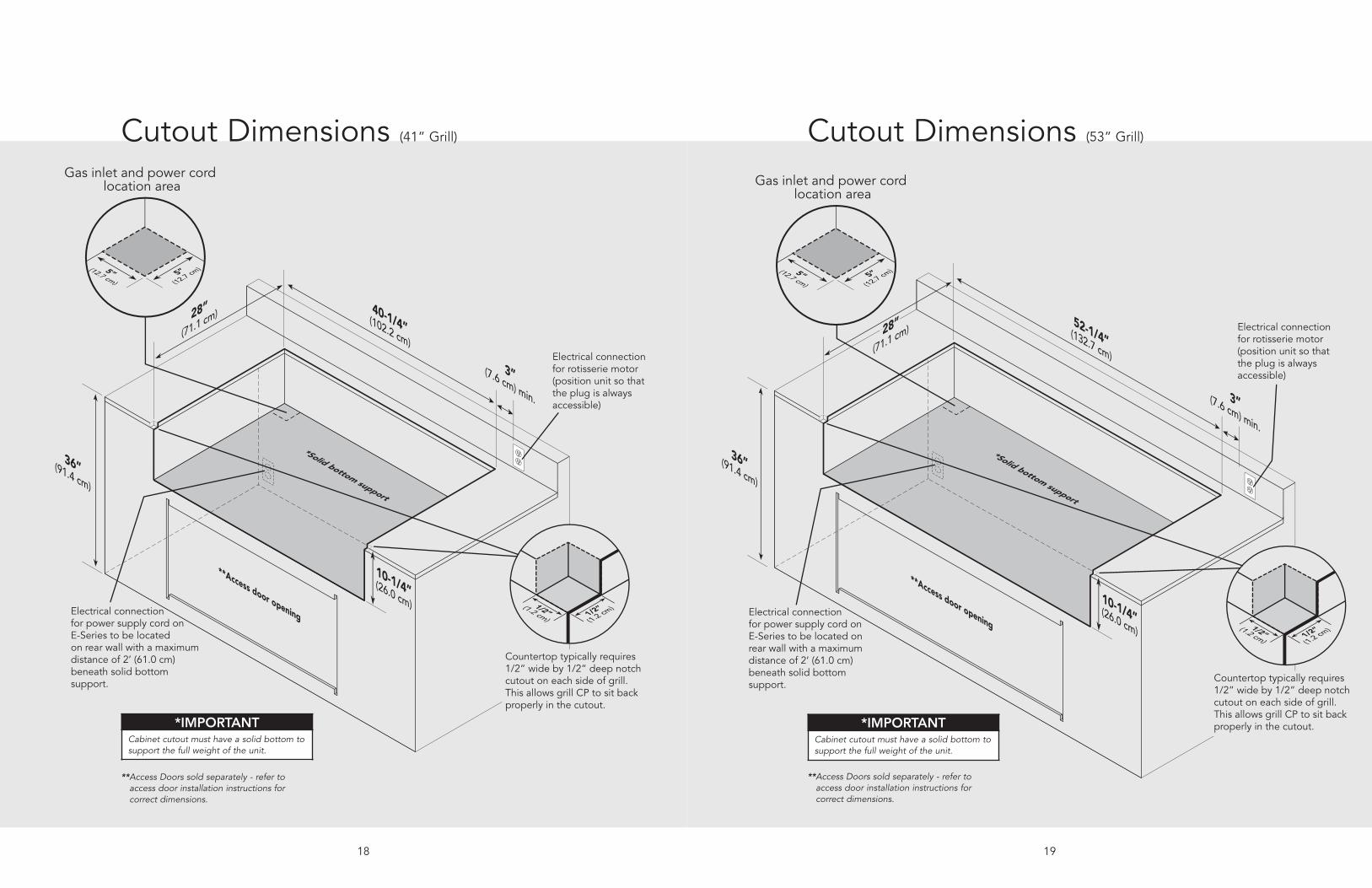
10-1/4”(26.0 cm)
36”(91.4 cm)
**Access door opening
28”
(71.1 cm)52-1/4”(132.7 cm)
3”(7.6 cm) min.
Electrical connection for rotisserie motor(position unit so that the plug is always accessible)
Electrical connection for power supply cord on E-Series to be located on rear wall with a maximumdistance of 2’ (61.0 cm)beneath solid bottomsupport.
*Solid bottom support
Gas inlet and power cord location area
5”(12.7 cm)5”(12.7 cm)
Countertop typically requires 1/2” wide by 1/2” deep notch cutout on each side of grill. This allows grill CP to sit back properly in the cutout.
1/2”(1.2 cm)
1/2”
(1.2 cm)
Cutout Dimensions (53” Grill)
19
10-1/4”(26.0 cm)
36”(91.4 cm)
**Access door opening
28”
(71.1 cm) 40-1/4”(102.2 cm)
3”(7.6 cm) min.
Electrical connection for rotisserie motor(position unit so that the plug is always accessible)
Electrical connection for power supply cord on E-Series to be located on rear wall with a maximumdistance of 2’ (61.0 cm)beneath solid bottomsupport.
*Solid bottom support
Gas inlet and power cord location area
5”(12.7 cm)5”(12.7 cm)
Countertop typically requires 1/2” wide by 1/2” deep notch cutout on each side of grill. This allows grill CP to sit back properly in the cutout.
1/2”(1.2 cm)
1/2”
(1.2 cm)
Cutout Dimensions (41” Grill)
18
**Access Doors sold separately - refer toaccess door installation instructions forcorrect dimensions.
**Access Doors sold separately - refer toaccess door installation instructions forcorrect dimensions.
*IMPORTANTCabinet cutout must have a solid bottom tosupport the full weight of the unit.
*IMPORTANTCabinet cutout must have a solid bottom tosupport the full weight of the unit.

Gas and Electrical Connection
GAS CONNECTIONVerify the type of gas supply to be used,either natural or LP, and make sure themarking on the grill rating plate agrees withthat of the supply. Never connect anunregulated gas line to the appliance. Aninstaller supplied gas shut-off valve must beinstalled in an easily accessible location. Allinstaller supplied parts must conform to localcodes, or in the absence of local codes, withthe National Electrical Code, ANSI/NFPA 70and the National Fuel Code, ANSIZ223.1/NFPA 54. In Canada: Installation must be inaccordance with the current CSA-B149.1,Natural Gas Installation Code or CSA-B149.2, Propane Installation Code and/orlocal codes. All pipe sealants must be anapproved type and resistant to the actions ofLP gas. Never use pipe sealant on flarefittings. All gas connections should be madeby a competent technician and inaccordance with local codes and orordinances. In the absence of codes, theinstallation must comply with the NationalFuel Gas Code ANSI Z223.1/NFPA 54. Thegas grill and its individual shut-off valve mustbe disconnected from the gas supply pipingsystem during any pressure testing of thatsystem at test pressures in excess of 1/2PSIG (3.5 kPa). The gas grill must be isolatedfrom the gas supply piping system byclosing its individual manual shut-off valveduring any pressure testing of that system attest pressures equal to or less than 1/2 psi(3.5 kPa). Built-in installations must beplumbed using a fixed/hard line if the unit isgoing to be operated at a distanceexceeding 3 feet (0.91 meters) from the fuelsupply per ANSI Z21.24 CSA.
GAS CONVERSION To convert a grill from natural toLP/Propane or LP/Propane to natural, youMUST use conversion kit sold seperately.
ELECTRICAL CONNECTION
21
WARNING
DANGER
CAUTION
FOR YOUR SAFETY
Conversions should only be performed by anauthorized service technician.
WARNINGELECTRICAL SHOCK HAZARD
This appliance is equipped with a 3’(91.4 cm) 3-prong power cord with agrounding plug for your protectionagainst shock hazard and should be
plugged directly into a properly groundedreceptacle. Do not cut or remove the groundingprong from this plug. This unit is not fused andinstaller must install a GFI. Unit must begrounded in accordance with local codes or withthe National Electrical Code ANSI/NFPA 70, orthe Canadian Electrical Code, CSA C22.1.
Ventilation for Built-In Installations WhenUsing an Enclosed LP-Gas Cylinder
20
Vents
1.00 inch maximum
5.00 inchmaximum
All vents no more than 5.00 inchesabove the floor of the installation.
5.00 inchmaximum
Not more than 5.00 inches from insidebottom of countertop.
Bottom Vent notmore than 1.00 inch from inside floor of installation.
An enclosure for an LP-gas cylinder shall be ventilated by openings at both the upper and lowerlevels of the enclosure. The effectiveness of the opening(s) for purposes of ventilation shall bedetermined with the LP-gas supply cylinder in place. This shall be accompanied by one of thefollowing:
a. One side of the enclosure shall be completely open; or
b. For an enclosure having four sides, a top and a bottom:1. At least two ventilation openings (See Part IV, Definitions) shall be provided in the side
walls of the enclosure, located within 5 in. (217 mm) of the top of the enclosure, equallysized, spaced at a minimum of 90 degrees (1.57 rad), and unobstructed. The opening(s)shall have a total free area of not less than 1 in2/lb (1.42 cm2/kg) of stored fuel capacity.
2. Ventilation opening(s) shall be provided at floor level at rear of the enclosure and shallhave a total free area of not less than 1/2 in2/lb (7.1 cm2/kg) of stored fuel capacity. Thebottom of the openings shall be 1 in. (25.4 mm) or less from the floor level and theupper edge no more than 5 in. (127 mm) above the floor level. The openings shall beequally sized, spaced at a minimum of 90 degrees (1.57 rad) and unobstructed.
3. Every opening shall have minimum dimensions so as to permit the entrance of a 1/8 inch(3.2 mm) diameter rod.
4. Ventilation openings in the side walls shall not communicate directly with otherenclosures of the outdoor cooking gas appliance.
Vents locatedon sidewall

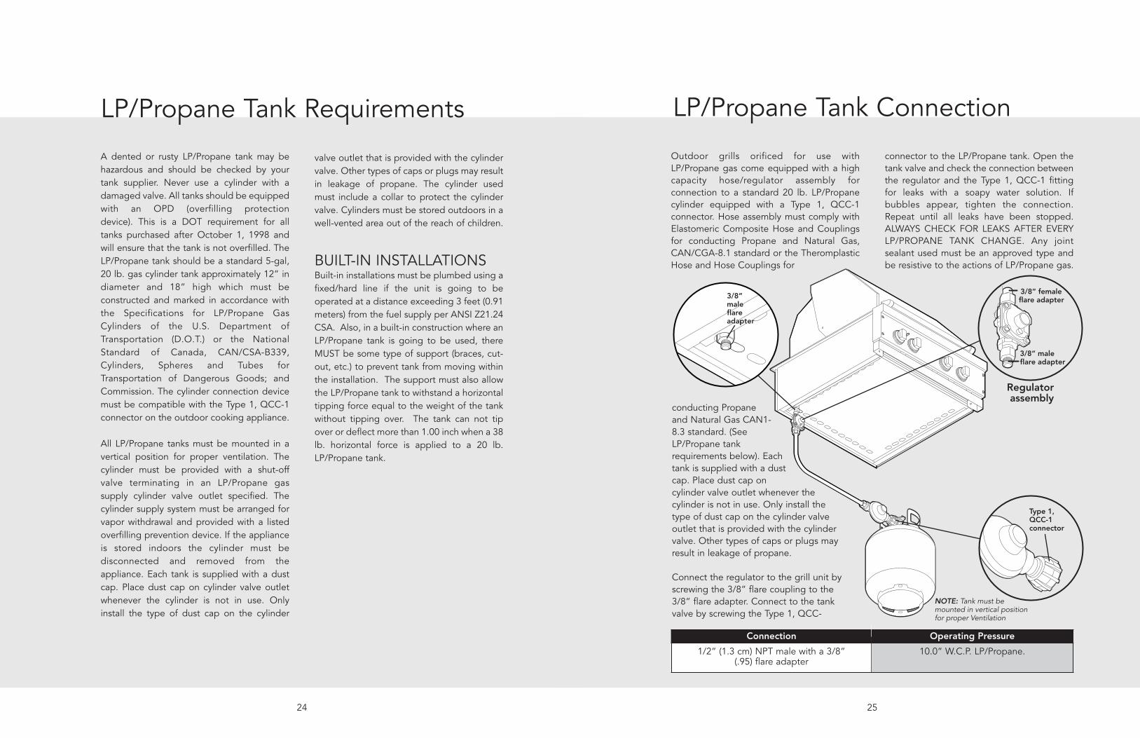
3/8” 3/8” male male flare flare dapterdapter
3/8” male flare adapter
Installer supplied flexible gas linewith 3/8” female adapter or Viking GHS12
Installer supplied shut-off valve must be easily accessible
3/8” female flare adapter
Regulator assembly
3/8” male flare adapter
23
LP/Propane Fixed Piping Connection
Check with your local gas utility company orwith local codes for instructions on installinggas supply lines. Be sure to check on typeand size of run and how deep to bury thelines. If the gas line is too small, the grill willnot function properly.
To connect the supplied regulator assemblyto the incoming flexible gas line, attach witha 3/8” female flare adapter to the 3/8” male
flare adapter to the regulator assembly.Ensure that the regulator arrow points in thedirection of the gas flow towards the unitand away from the supply. Attach theregulator assembly to the grill unit with the3/8” female flare adapter on the regulatorassembly to the 3/8” male flare adapter onthe grill. Do not forget to place theinstaller supplied gas valve in anaccessible location.
Connection Operating Pressure Supply Pressure
Standard Residential 1/2” IDgas service line - 1/2” NPT
male with 3/8” flare adapter.
10.0” W.C.P. LP/Propane. 11” to 14”W.C.P. Nat. If inexcess of 14” W.C.P., a step-down regulator is required.
Male Male couplercouplersleevesleeve
Male couplersleeve
Installer supplied flexible gas linewith 1/2” female adapter or Viking GHS12
Installer supplied shut-off valve must be easily accessible
3/8” female flare adapter
7/8” male flare adapter
Regulator assembly
Natural Fixed Piping Connection
22
Check with your local gas utility company orwith local codes for instructions on installinggas supply lines. Be sure to check on typeand size of run and how deep to bury thelines. If the gas line is too small, the grill willnot function properly.
To connect the supplied regulator assemblyto the incoming flexible gas line, attach witha 1/2” (1.3 cm) female flare adapter to the7/8” (2.2 cm) male flare adapter on theregulator assembly. Ensure that the regulatorarrow points in the direction of the gas flowtowards the unit and away from the supply.
Attach the regulator assembly to the grillunit by pulling back the female couplersleeve towards the regulator. Insert thecoupler into the male coupler fitting on thegrill until the sleeve snaps forward securingthe connection. Do not forget to place theinstaller supplied gas valve in anaccessible location.
NOTE: If using a Viking GSH12 flexiblehose, remove the 1/2” flare adapter andattach hose to the 7/8” (2.2 cm) male flareon the regulator assembly.
Connection Operating Pressure Supply Pressure
Standard Residential 1/2” IDgas service line - 1/2” NPT
male with 7/8” (2.2 cm)flare adapter.
4.0” W.C.P. Nat. 6” to 10”W.C.P. Nat. If inexcess of 10” W.C.P., a step-down regulator is
required.
25
3/8” 3/8” male male flare flare adapteradapter
3/8” male flare adapter
Type 1, QCC-1connector
3/8” female flare adapter
3/8” male flare adapter
Regulator assembly
NOTE: Tank must be mounted in vertical positionfor proper Ventilation
LP/Propane Tank Connection
conducting Propaneand Natural Gas CAN1-8.3 standard. (SeeLP/Propane tankrequirements below). Eachtank is supplied with a dustcap. Place dust cap oncylinder valve outlet whenever thecylinder is not in use. Only install thetype of dust cap on the cylinder valveoutlet that is provided with the cylindervalve. Other types of caps or plugs mayresult in leakage of propane.
Connect the regulator to the grill unit byscrewing the 3/8” flare coupling to the3/8” flare adapter. Connect to the tankvalve by screwing the Type 1, QCC-
Connection Operating Pressure
1/2” (1.3 cm) NPT male with a 3/8” (.95) flare adapter
10.0” W.C.P. LP/Propane.
Outdoor grills orificed for use withLP/Propane gas come equipped with a highcapacity hose/regulator assembly forconnection to a standard 20 lb. LP/Propanecylinder equipped with a Type 1, QCC-1connector. Hose assembly must comply withElastomeric Composite Hose and Couplingsfor conducting Propane and Natural Gas,CAN/CGA-8.1 standard or the TheromplasticHose and Hose Couplings for
connector to the LP/Propane tank. Open thetank valve and check the connection betweenthe regulator and the Type 1, QCC-1 fittingfor leaks with a soapy water solution. Ifbubbles appear, tighten the connection.Repeat until all leaks have been stopped.ALWAYS CHECK FOR LEAKS AFTER EVERYLP/PROPANE TANK CHANGE. Any jointsealant used must be an approved type andbe resistive to the actions of LP/Propane gas.
24
A dented or rusty LP/Propane tank may behazardous and should be checked by yourtank supplier. Never use a cylinder with adamaged valve. All tanks should be equippedwith an OPD (overfilling protectiondevice). This is a DOT requirement for alltanks purchased after October 1, 1998 andwill ensure that the tank is not overfilled. TheLP/Propane tank should be a standard 5-gal,20 lb. gas cylinder tank approximately 12” indiameter and 18” high which must beconstructed and marked in accordance withthe Specifications for LP/Propane GasCylinders of the U.S. Department ofTransportation (D.O.T.) or the NationalStandard of Canada, CAN/CSA-B339,Cylinders, Spheres and Tubes forTransportation of Dangerous Goods; andCommission. The cylinder connection devicemust be compatible with the Type 1, QCC-1connector on the outdoor cooking appliance.
All LP/Propane tanks must be mounted in avertical position for proper ventilation. Thecylinder must be provided with a shut-offvalve terminating in an LP/Propane gassupply cylinder valve outlet specified. Thecylinder supply system must be arranged forvapor withdrawal and provided with a listedoverfilling prevention device. If the applianceis stored indoors the cylinder must bedisconnected and removed from theappliance. Each tank is supplied with a dustcap. Place dust cap on cylinder valve outletwhenever the cylinder is not in use. Onlyinstall the type of dust cap on the cylinder
valve outlet that is provided with the cylindervalve. Other types of caps or plugs may resultin leakage of propane. The cylinder usedmust include a collar to protect the cylindervalve. Cylinders must be stored outdoors in awell-vented area out of the reach of children.
BUILT-IN INSTALLATIONSBuilt-in installations must be plumbed using afixed/hard line if the unit is going to beoperated at a distance exceeding 3 feet (0.91meters) from the fuel supply per ANSI Z21.24CSA. Also, in a built-in construction where anLP/Propane tank is going to be used, thereMUST be some type of support (braces, cut-out, etc.) to prevent tank from moving withinthe installation. The support must also allowthe LP/Propane tank to withstand a horizontaltipping force equal to the weight of the tankwithout tipping over. The tank can not tipover or deflect more than 1.00 inch when a 38lb. horizontal force is applied to a 20 lb.LP/Propane tank.
LP/Propane Tank Requirements

27
5 6
Do not attempt to repair the cylinder valve if it shouldbecome damaged. The cylinder must be replaced.
7
2
81
Call an authorized gas appliance service technician or LP/Propane gas dealer.
Do not use the grill until
the leak is corrected. OFF
1
2
9
Stop a leak by tightening the loose joint or byreplacing the faulty part with a replacement part
recommended by the manufacturer.
If you are unable to stop a leak, shut off the gas at the cylinder valve. Remove the cylinder
from the grill.
After checking for leaks, push in and turn any controlknob to release the pressure in the hose and manifold.
Turn off the control knob.
Bubbling bubbles in the soap solution indicates that aleak is present.
26
1
OFF
2
Check that all control knobs are in the “OFF” position.
3 4
Apply the soap solution to fittings. Turn cylinder valve knob counter clockwise one turn to open.
Leak Testing
Although all gas connections on the grill areleak tested at the factory prior to shipment,a complete gas tightness check must beperformed at the installation due to possiblemishandling in shipment or excessivepressure unknowingly being applied to theunit. Periodically check the whole system forleaks, or immediately check if the smell ofgas is detected.
• Do not smoke while leak testing.
• Extinguish all flames.
• Never leak test with an open flame
WARNING
DANGER
CAUTION
FOR YOUR SAFETY
Before placing into operation, always check forgas leaks with a soapy water solution. DO NOTUSE AN OPEN FLAME TO CHECK FOR LEAKS.
Make a soap solution of one part liquid detergent andone part water. You will need a spray bottle, brush or
towel to apply the solution to the fittings. Note: For LP/Propane units, check with a full cylinder.

29
21
HI/LITE
4
CORRECT
YELLOW
BLUE LIFTING
5
1/2"(1.3 cm)3/8"(.95 cm)
Push and turn the the valve to light the burner andadjust according to the directions following. NOTE: Byreplacing the knob, it may be easier to light the burner.
1
Off
6
2
3
7
Once adjusted, turn the burner off, tighten the setscrew on the air shutter. For grill and smoker burners,
replace the valve panel and knobs.
For grill and smoker burners, replace the drip tray.
3
3
1
Off 2
Once adjusted, turn the burner off, tighten the set screwon the air shutter. For side burners, replace the grate
support, burner bowls, and grates for the side burners.
If the flame is yellow, turn the air shutter counterclockwise to allow more air to the burner. If the flame is
noisy and lifting away from the burner, turn the air shutterclockwise to reduce the amount of air to the burner.
28
1 2
To access the air shutter on the grill burners andsmoker burner, remove the drip tray
Remove the knobs and valve panel. NOTE: Leave wiresconnected to switches on valve panel.
3
To access the air shutter on the side burners, removethe grates, burner bowls, and grate support.
With a screw driver, loosen the lock-screw on the faceof the air shutter.
Burner Adjustment
Each burner is tested and adjusted at thefactory prior to shipment; however, variationsin the local gas supply may make it necessaryto adjust the burners. The flames of theburners (except the rotisserie infrared burner)should be visually checked and comparedwith the following illustrations.
Flames should be blue and stable with noyellow tips, excessive noise or lifting. If any ofthese conditions exist, check if the air shutteror burner ports are blocked by dirt, debris,spider webs, etc. With a proper flame height,adjust the air shutter to obtain a blue flamewith no yellow tipping that sits on the burnerat the burner ports. The air shutter is lockedin place by a set screw which must beloosened prior to lighting the burner foradjustments.
CORRECT YELLOW BLUE LIFTING

3130
Rotisserie System
The rotisserie motor is attached to themounting bracket located on the right sideof the grill frame. The rotisserie motor mustbe electrically grounded in accordance withlocal codes. The skewer for the rotisserie isassembled into the gear box assembly byplacing the pointed end into the gear box,and resting the threaded end on the supportat the left side of the grill. With the skewerpushed as far in as possible, the groovedskewer bushing should rest on the left sidebracket. Do not remove the plastic coveron the rotisserie motor switch due tosafety consideration.
WARNINGELECTRICAL SHOCK HAZARDThis appliance is equipped with a groundingplug for your protection against shock hazardand should be plugged directly into a properlygrounded receptacle. Do not cut or remove thegrounding prong from this plug.
Groove skewersupport
Rotisseriemotor
Groundedplug
Mounting bracket
Gear boxassembly
Performance Checklist
A qualified installer should carry out thefollowing checks:
• All internal packaging removed.
• Specified clearances maintained tocombustible materials.
• Pressure regulator connected and set.
• Manual shut-off valve installed andaccessible.
• Check air shutter adjustment - sharp blueflame, no yellow tipping.
• Check for gas leaks (odors) at all gasconnections.
• Each burner lights satisfactorily, individuallyor with adjacent burners lit.
Any adjustments necessary that are theresult of the installer not followinginstructions will be responsibility of theinstaller, dealer or the end user of theproduct.
Final Preparation• Some stainless steel parts may have a
plastic protective wrap which must bepeeled off. The interior should be washedthoroughly with hot, soapy water toremove film residues and any dust ordebris before being used, then rinsed andwiped dry. Solutions stronger than soapand water are rarely needed.
• All stainless steel body parts should bewiped with hot, soapy water and with aliquid cleaner designed for this material. If buildup occurs, do not use steel wool,abrasive cloths, cleansers, or powders!
If it is necessary to scrape stainless steel toremove encrusted materials, soak with hot,wet cloths to loosen the material, then usea wool or nylon scraper. Do not use ametal knife, spatula, or any other materialtool to scrape stainless steel! Scratches arealmost impossible to remove.

32 33
Service & PartsOnly authorized replacement parts may be used in performing service on the appliance. Do notrepair or replace any part of the appliance unless specifically recommended in the manual. Allother servicing should be referred to a qualified technician.
Record the following information indicated below. You will need it if service is ever required. The serialnumber and model number for your appliance are located on the identification plate mounted on thebottom left side of the door opening.
Model number
_________________________________________
Serial number
_________________________________________
Date of purchase
_________________________________________
Date installed
_________________________________________
Dealer's name
_________________________________________
Address
_________________________________________
Service & Registration

3534