viii. 1 viii. overview of design guidelines see these resources: various city/county design manuals...
TRANSCRIPT

VIII. 1
VIII. Overview Of Design Guidelines
See these resources: Various City/County Design Manuals and CCDC-01 (5.4), CCDM-99 (1005), CTDM-89 (9.5), FITD Class CD
A.Bridge Design Tips: Use Computerized step-backwater model such as HEC-2,
HEC-RAS or WSPRO Take cross sections 1) far downstream 2) at the face of the
bridge 3) at the bridge opening 4) far upstream Utilize guidance (such as Hydraulics of Bridge Waterways)
produced by Federal Highway Administration and/or the U.S. Army Corps of Engineers
Utilize Scour Countermeasures: such as provision of deep toe-downs on bridge piers and abutments or construction of spur dikes and jetties
Meet minimum freeboard requirements listed in the literature

VIII. 2
Example Large Scale Bridge

VIII. 3
Example Small Scale Bridge
VIII. 4
See these resources: Various City/County Design Manuals and CCDC-01 (5.1 to 5.3),CCDM-99 (1001 to 1004), CTDM-89 (11), YCDM-98 (8.2 to 8.4), FITD Class CD
VIII. Overview Of Design Guidelines
B.Culvert Design Tips: Consider Step-by-Step Procedures for Sizing Culverts See Literature for Explanations/Equations of Culvert
Hydraulics Determine whether a culvert is under inlet or outlet control See Guidance for Culvert Inlet/Outlet Design and Protection Consider Countermeasures for Culvert Sedimentation and
Erosion See Nomographs to simplify equation solving See guidance equations to evaluate the appropriateness of
using a culvert in lieu of a bridge See guidance for culvert material selection

VIII. 5
Example Small Culverts

VIII. 6
Example Culvert Inlet and Outlet Protection

VIII. 7
Example Culvert Inlet and Outlet Control Diagrams

VIII. 8
Example Culvert Flow Types

VIII. 9
Example Culvert Nomograph
VIII. 10See these resources: Various City/County Design Manuals, CTDM-89, FITD Class CD
VIII. Overview Of Design Guidelines
C.Dip Crossing Design Tips:Definition: “Crossings of watercourses which are designed to allow drainage to flow across roadways at-grade are commonly referred to as either ‘at-grade’ or ‘dip’ crossings” (CTDM-89).
Design Dip Crossings to have a 4% minimum cross-slope to reduce roadway sedimentation
At a minimum, place a two-foot-deep cutoff wall along the upstream side of the dip crossing to protect against general scour
Place a minimum 3-foot-deep cutoff wall downstream of the dip crossing to protect against local scour and channel degradation

VIII. 11
Examples of Dip Crossings

VIII. 12
VIII. Overview Of Design Guidelines
D.Low-Flow Channel Crossing Design Tips:Definition: When “the bottom of the channel cross section is too wide to efficiently convey the low-flow discharges [which instead] creates an incised low-flow channel that may meander back and forth across the bed of the channel...” And, “the meandering process can cause frequent and unnecessary scouring at the toe of the primary banks…[which can] even destabilize totally lined channels.” (CTDM-89).
Possibly construct a low-flow channel within any larger channel in order to restrict the low flows to a designated area within the primary channel.
The designed low-flow channel should be designed such that the unit discharge associated with the 2-year storm event is the same as pre-construction conditions.
See these resources: Various City/County Design Manuals, CTDM-89, FITD Class CD

VIII. 13
Example Low Flow Channel

VIII. 14See this resources: FITD Class CD
VIII. Overview Of Design Guidelines
E. Other Design TopicsDesign Guidance are Similarly Available for the Following –
Levee Systems
VIII. 15
VIII. Overview Of Design Guidelines
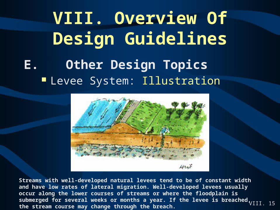
E. Other Design Topics Levee System: Illustration
Streams with well-developed natural levees tend to be of constant width and have low rates of lateral migration. Well-developed levees usually occur along the lower courses of streams or where the floodplain is submerged for several weeks or months a year. If the levee is breached, the stream course may change through the breach.
VIII. 16See this resources: FITD Class CD
VIII. Overview Of Design Guidelines
E. Other Design TopicsDesign Guidance are Similarly Available for the Following –
Levee SystemsFEMA Requirements

VIII. 17See this resources: FITD Class CD
VIII. Overview Of Design Guidelines
E. Other Design TopicsDesign Guidance are Similarly Available for the Following –
Levee SystemsFEMA Requirements
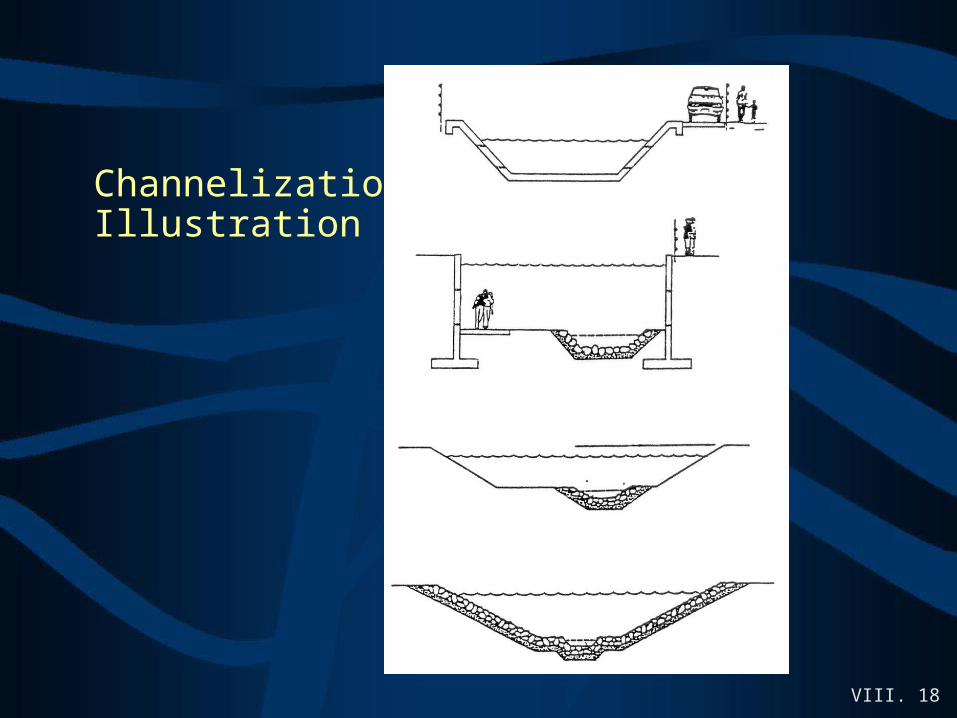
Channelization
VIII. 18
Channelization Illustration

VIII. 19See this resources: FITD Class CD
VIII. Overview Of Design Guidelines
E. Other Design TopicsDesign Guidance are Similarly Available for the Following –
Levee Systems Channelization Super-Elevation
VIII. 20
VIII. Overview Of Design Guidelines
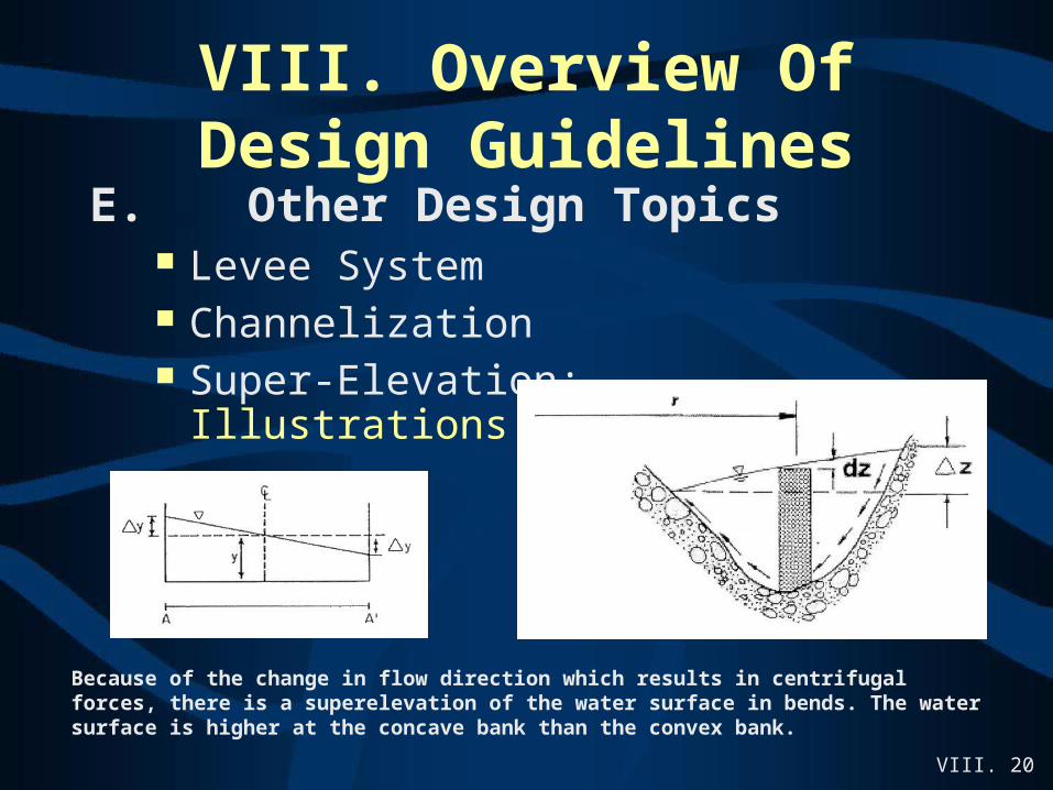
E. Other Design Topics Levee System Channelization Super-Elevation:
Illustrations
Because of the change in flow direction which results in centrifugal forces, there is a superelevation of the water surface in bends. The water surface is higher at the concave bank than the convex bank.