· web viewt he u.s. atlantic ocean and gulf of mexico coasts where the basic ultimate design...
TRANSCRIPT

Florida Supplement to the 2012 IRCICC EDIT VERSION
Note 1: Throughout the document, change International Building Code to Florida Building Code, Building; change the ICC Electrical Code to Chapter 27 of the Florida Building Code, Building; change the International Energy Conservation Code to the Florida Building Code, Energy Conservation; change the International Existing Building Code to Florida Building Code, Existing Building; change the International Fire code to Florida Fire Prevention Code; change International Fuel Gas Code to Florida Building Code, Fuel Gas; change the International Mechanical Code to Florida Building Code, Mechanical; change the International Plumbing Code to Florida Building Code, Plumbing; change the International Residential Code to Florida Building Code, Residential.
PREFACE
Introduction
Development
History
The State of Florida first mandated statewide building codes during the 1970s at the beginning of the modern construction boom. The first law required all municipalities and counties to adopt and enforce one of the four state-recognized model codes known as the “state minimum building codes.” During the early 1990s a series of natural disasters, together with the increasing complexity of building construction regulation in vastly changed markets, led to a comprehensive review of the state building code system. The study revealed that building code adoption and enforcement was inconsistent throughout the state and those local codes thought to be the strongest proved inadequate when tested by major hurricane events. The consequences of the building codes system failure were devastation to lives and economies and a statewide property insurance crisis. The response was a reform of the state building construction regulatory system that placed emphasis on uniformity and accountability.
The 1998 Florida Legislature amended Chapter 553, Florida Statutes (FS), Building Construction Standards, to create a single state building code that is enforced by local governments. As of March 1, 2002, the Florida Building Code , which is developed and maintained by the Florida Building Commission, supersedes all local building codes. The Florida Building Code is updated every three years and may be amended annually to incorporate interpretations and clarifications.
Scope
The Florida Building Code is based on national model building codes and national consensus standards which are amended where necessary for Florida’s specific needs. However, code requirements that address snow loads and earthquake protection are pervasive; they are left in place but should not be utilized or enforced because Florida has no snow load or earthquake threat. The code incorporates all building construction-related regulations for public and private
FLORIDA BUILDING CODE — RESIDENTIAL 7.1
buildings in the State of Florida other than those specifically exempted by Section 553.73, Florida Statutes . It has been harmonized with the Florida Fire Prevention Code , which is developed and maintained by the Department of Financial Services, Office of the State Fire Marshal, to establish unified and consistent standards.
The base codes for the Fifth edition (2014) of the Florida Building Code include: the International Building Code®, 2012 edition; the International Plumbing Code®, 2012 edition; the International Mechanical Code®, 2012 edition; the International Fuel Gas Code®, 2012 edition; the International Residential Code®, 2012 edition; the International Existing Building Code®, 2012 edition; the International Energy Conservation Code, 2012; the National Electrical Code, 2011 edition; substantive criteria from the American Society of Heating, Refrigerating and Air-conditioning Engineers’ (ASHRAE) Standard 90.1-2010. State and local codes adopted and incorporated into the code include the Florida Building Code, Accessibility, and special hurricane protection standards for the High-Velocity Hurricane Zone.
The code is composed of nine main volumes: the Florida Building Code, Building , which also includes state regulations for licensed facilities; the Florida Building Code, Plumbing ; the Florida Building Code, Mechanical; the Florida Building Code, Fuel Gas ; the Florida Building Code, Existing Building ; the Florida Building Code, Residential; the Florida Building Code, Energy Conservation ; the Florida Building Code, Accessibility and the Florida Building Code, Test Protocols for High-Velocity Hurricane Zones . Chapter 27 of the Florida Building Code, Building , adopts the National Electrical Code , NFPA 70, by reference.
Under certain strictly defined conditions, local governments may amend requirements to be more stringent than the code. All local amendments to the Florida Building Code must be adopted by local ordinance and reported to the Florida Building Commission then posted on www.floridabuilding.org in Legislative format for a month before being enforced. Local amendments to the Florida Building Code and the Florida Fire Prevention Code may be obtained from the Florida Building Commission web site, or from the Florida Department of Business and Professional Regulation or the Florida Department of Financial Services, Office of the State Fire Marshal, respectively.
Adoption and Maintenance
[Note to editor: Replace ICC “Adoption” and “Maintenance” with the following text:]
The Florida Building Code is adopted and updated with new editions triennially by the Florida Building Commission. It is amended annually to incorporate interpretations, clarifications and to update standards. Minimum requirements for permitting, plans review and inspections are established by the code, and local jurisdictions may adopt additional administrative requirements that are more stringent. Local technical amendments are subject to strict criteria established by Section 553.73, F.S. They are subject to Commission review and adoption into the code or repeal when the code is updated triennially and are subject to appeal to the Commission according to the procedures established by Section 553.73, F.S .
Eleven Technical Advisory Committees (TACs), which are constituted consistent with American National Standards Institute (ANSI) Guidelines, review proposed code changes and clarifications of the code and make recommendations to the Commission. These TACs whose membership is constituted consistent with American National Standards Institute (ANSI) Guidelines include:
FLORIDA BUILDING CODE — RESIDENTIAL 7.2

Accessibility; Joint Building Fire (a joint committee of the Commission and the State Fire Marshal); Building Structural; Code Administration/ Enforcement; Electrical; Energy; Mechanical; Plumbing and Fuel Gas; Roofing; Swimming Pool; and Special Occupancy (state agency construction and facility licensing regulations).
The Commission may only issue official code clarifications using procedures of Chapter 120, Florida Statutes . To obtain such a clarification, a request for a Declaratory Statement (DEC) must be made to the Florida Building Commission in a manner that establishes a clear set of facts and circumstances and identifies the section of the code in question. Requests are analyzed by staff, reviewed by the appropriate Technical Advisory Committee, and sent to the Florida Building Commission for action. These interpretations establish precedents for situations having similar facts and circumstances and are typically incorporated into the code in the next code amendment cycle. Non-binding opinions are available from the Building Officials Association of Florida’s web site (www.BOAF.net) and a Binding Opinion process is available online at www.floridabuilding.org.
Code Development Committee Responsibilities (Letter Designations in Front of Section Numbers)
[Note to editor: Use paragraphs 1 specific to this code through the code committee descriptors. Delete the remaining text in this section.]
Marginal Markings
Solid vertical lines in the margins within the body of the code indicate a technical change from the requirements of the 2009 edition. Deletion indicators in the form of an arrow (→) are provided in the margin where an entire section, paragraph, exception or table has been deleted or an item in a list of items or table has been deleted.
A single asterisk [*] placed in the margin indicates that text or a table has been relocated within the code. A double asterisk [**] placed in the margin indicates that the text or table immediately following it has been relocated there from elsewhere in the code. The following table indicates such relocations in the 2012 Edition of the International Residential Code. [Delete table]
Dotted vertical lines in the margins within the body of the code indicate a change from the requirements of the base codes to the Florida Building Code, 5 th Edition (2014) effective ??? .
Sections deleted from the base code are designated “Reserved” in order to maintain the structure of the base code.
Italicized Terms
[No change to I Code text.]
Acknowledgments
The Florida Building Code is produced through the efforts and contributions of building designers, contractors, product manufacturers, regulators and other interested parties who
FLORIDA BUILDING CODE — RESIDENTIAL 7.3

participate in the Florida Building Commission’s consensus processes, Commission staff and the participants in the national model code development processes.
[Note to Editor: Delete the following ICC text in its entirety:]
Effective Use of the …
Legislation
CHAPTER 1, SCOPE AND ADMINISTRATION
Section R101.2 Scope. Change to read as follows:
R101.2 Scope. The provisions of the International Residential Code for One- and Two-family Dwellings Florida Building Code, Residential , shall apply to the construction, alteration, movement, enlargement, replacement, repair, equipment, use and occupancy, location, removal and demolition of detached one– and two–family dwellings and townhouses not more than three stories above grade plane in height with a separate means of egress and their accessory structures.
Exceptions:
1.- 2. (No change)
3. Existing buildings undergoing repair, alteration, or additions, and or change of occupancy shall comply with the Florida Building Code , Existing Building . .
R101.2.1 The provisions of Chapter 1, Florida Building Code, Building, shall govern the administration and enforcement of the Florida Building Code, Residential.
Section R101.3 Intent. Change to read as follows:
R101.3 Intent. The purpose of this code is to establish minimum requirements to safeguard the public safety, health and general welfare through affordability, structural strength, means of egress facilities, stability, sanitation, light and ventilation, energy conservation and safety to life and property from fire and other hazards attributed to the built environment and to provide safety to fire fighters and emergency responders during emergency operations. Reserved.
Sections R102 through R114. Change to read as follows:
FLORIDA BUILDING CODE — RESIDENTIAL 7.4

SECTION R102 APPLICABILITY
RESERVED
R102.1 General. Where there is a conflict between a general requirement and a specific requirement, the specific requirement shall be applicable. Where, in any specific case, different sections of this code specify different materials, methods of construction or other requirements, the most restrictive shall govern.
R102.2 Other laws. The provisions of this code shall not be deemed to nullify any provisions of local, state or federal law.
R102.3 Application of references. References to chapter or section numbers, or to provisions not specifically identified by number, shall be construed to refer to such chapter, section or provision of this code.
R102.4 Referenced codes and standards. The codes and standards referenced in this code shall be considered part of the requirements of this code to the prescribed extent of each such reference and as further regulated in Sections R102.4.1 and R102.4.2. Exception: Where enforcement of a code provision would violate the conditions of the listing of the equipment or appliance, the conditions of the listing and manufacturer’s instructions shall apply.
R102.4.1 Differences. Where differences occur between provisions of this code and referenced codes and standards, the provisions of this code shall apply.
R102.4.2 Provisions in referenced codes and standards. Where the extent of the reference to a referenced code or standard includes subject matter that is within the scope of this code, the provisions of this code, as applicable, shall take precedence over the provisions in the referenced code or standard.
R102.5 Appendices. Provisions in the appendices shall not apply unless specifically referenced in the adopting ordinance.
R102.6 Partial invalidity. In the event any part or provision of this code is held to be illegal or void, this shall not have the effect of making void or illegal any of the other parts or provisions.
R102.7 Existing structures. The legal occupancy of any structure existing on the date of adoption of this code shall be permitted to continue without change, except as is specifically covered in this code, the International Property Maintenance Code or the International Fire Code, or as is deemed necessary by the building official for the general safety and welfare of the occupants and the public.
R102.7.1 Additions, alterations or repairs. Additions, alterations or repairs to any structure shall conform to the requirements for a new structure without requiring the existing structure to comply with all of the requirements of this code, unless otherwise
FLORIDA BUILDING CODE — RESIDENTIAL 7.5

stated. Additions, alterations or repairs shall not cause an existing structure to become unsafe or adversely affect the performance of the building.
SECTION R103DEPARTMENT OF BUILDING SAFETY
RESERVED
R103.1 Creation of enforcement agency. The department of building safety is hereby created and the official in charge thereof shall be known as the building official.
R103.2 Appointment. The building official shall be appointed by the chief appointing authority of the jurisdiction.
R103.3 Deputies. In accordance with the prescribed procedures of this jurisdiction and with the concurrence of the appointing authority, the building official shall have the authority to appoint a deputy building official, the related technical officers, inspectors, plan examiners and other employees. Such employees shall have powers as delegated by the building official.
SECTION R104DUTIES AND POWERS OF THE BUILDING OFFICIAL
RESERVED
R104.1 General. The building official is hereby authorized and directed to enforce the provisions of this code. The building official shall have the authority to render interpretations of this code and to adopt policies and procedures in order to clarify the application of its provisions. Such interpretations, policies and procedures shall be in conformance with the intent and purpose of this code. Such policies and procedures shall not have the effect of waiving requirements specifically provided for in this code.
R104.2 Applications and permits. The building official shall receive applications, review construction documents and issue permits for the erection and alteration of buildings and structures, inspect the premises for which such permits have been issued and enforce compliance with the provisions of this code.
R104.3 Notices and orders. The building official shall issue all necessary notices or orders to ensure compliance with this code.
R104.4 Inspections. The building official is authorized to make all of the required inspections, or the building official shall have the authority to accept reports of inspection by approved agencies or individuals. Reports of such inspections shall be in writing and be certified by a responsible officer of such approved agency or by the responsible individual. The building official is authorized to engage such expert opinion as deemed necessary to report upon unusual technical issues that arise, subject to the approval of the appointing authority.
FLORIDA BUILDING CODE — RESIDENTIAL 7.6

R104.5 Identification. The building official shall carry proper identification when inspecting structures or premises in the performance of duties under this code.
R104.6 Right of entry. Where it is necessary to make an inspection to enforce the provisions of this code, or where the building official has reasonable cause to believe that there exists in a structure or upon a premises a condition which is contrary to or in violation of this code which makes the structure or premises unsafe, dangerous or hazardous, the building official or designee is authorized to enter the structure or premises at reasonable times to inspect or to perform the duties imposed by this code, provided that if such structure or premises be occupied that credentials be presented to the occupant and entry requested. If such structure or premises be unoccupied, the building official shall first make a reasonable effort to locate the owner or other person having charge or control of the structure or premises and request entry. If entry is refused, the building official shall have recourse to the remedies provided by law to secure entry.
R104.7 Department records. The building official shall keep official records of applications received, permits and certificates issued, fees collected, reports of inspections, and notices and orders issued. Such records shall be retained in the official records for the period required for the retention of public records.
R104.8 Liability. The building official, member of the board of appeals or employee charged with the enforcement of this code, while acting for the jurisdiction in good faith and without malice in the discharge of the duties required by this code or other pertinent law or ordinance, shall not thereby be rendered liable personally and is hereby relieved from personal liability for any damage accruing to persons or property as a result of any act or by reason of an act or omission in the discharge of official duties. Any suit instituted against an officer or employee because of an act performed by that officer or employee in the lawful discharge of duties and under the provisions of this code shall be defended by legal representative of the jurisdiction until the final termination of the proceedings. The building official or any subordinate shall not be liable for cost in any action, suit or proceeding that is instituted in pursuance of the provisions of this code.
R104.9 Approved materials and equipment. Materials, equipment and devices approved by the building official shall be constructed and installed in accordance with such approval.
R104.9.1 Used materials and equipment. Used materials, equipment and devices shall not be reused unless approved by the building official.
R104.10 Modifications. Wherever there are practical difficulties involved in carrying out the provisions of this code, the building official shall have the authority to grant modifications for individual cases, provided the building official shall first find that special individual reason makes the strict letter of this code impractical and the modification is in compliance with the intent and purpose of this code and that such modification does not lessen health, life and fire safety or structural requirements. The details of action granting modifications shall be recorded and entered in the files of the department of building safety.
FLORIDA BUILDING CODE — RESIDENTIAL 7.7

R104.10.1 Flood hazard areas. The building official shall not grant modifications to any provision related to flood hazard areas as established by Table R301.2(1) without the granting of a variance to such provisions by the board of appeals.
R104.11 Alternative materials, design and methods of construction and equipment. The provisions of this code are not intended to prevent the installation of any material or to prohibit any design or method of construction not specifically prescribed by this code, provided that any such alternative has been approved. An alternative material, design or method of construction shall be approved where the building official finds that the proposed design is satisfactory and complies with the intent of the provisions of this code, and that the material, method or work offered is, for the purpose intended, at least the equivalent of that prescribed in this code. Compliance with the specific performance-based provisions of the International Codes in lieu of specific requirements of this code shall also be permitted as an alternate.
R104.11.1 Tests. Whenever there is insufficient evidence of compliance with the provisions of this code, or evidence that a material or method does not conform to the requirements of this code, or in order to substantiate claims for alternative materials or methods, the building official shall have the authority to require tests as evidence of compliance to be made at no expense to the jurisdiction. Test methods shall be as specified in this code or by other recognized test standards. In the absence of recognized and accepted test methods, the building official shall approve the testing procedures. Tests shall be performed by an approved agency. Reports of such tests shall be retained by the building official for the period required for retention of public records.
SECTION R105PERMITS
RESERVED
R105.1 Required. Any owner or authorized agent who intends to construct, enlarge, alter, repair, move, demolish or change the occupancy of a building or structure, or to erect, install, enlarge, alter, repair, remove, convert or replace any electrical, gas, mechanical or plumbing system, the installation of which is regulated by this code, or to cause any such work to be done, shall first make application to the building official and obtain the required permit.
R105.2 Work exempt from permit. Permits shall not be required for the following. Exemption from permit requirements of this code shall not be deemed to grant authorization for any work to be done in any manner in violation of the provisions of this code or any other laws or ordinances of this jurisdiction.
Building:
1. One-story detached accessory structures used as tool and storage sheds, playhouses and similar uses, provided the floor area does not exceed 200 square feet (18.58 m2).
FLORIDA BUILDING CODE — RESIDENTIAL 7.8

2. Fences not over 7 feet (2134 mm) high.
3. Retaining walls that are not over 4 feet (1219 mm) in height measured from the bottom of the footing to the top of the wall, unless supporting a surcharge.
4. Water tanks supported directly upon grade if the capacity does not exceed 5,000 gallons (18 927 L) and the ratio of height to diameter or width does not exceed 2 to 1.
5. Sidewalks and driveways.
6. Painting, papering, tiling, carpeting, cabinets, counter tops and similar finish work.
7. Prefabricated swimming pools that are less than 24 inches (610 mm) deep.
8. Swings and other playground equipment.
9. Window awnings supported by an exterior wall which do not project more than 54 inches (1372 mm) from the exterior wall and do not require additional support.
10. Decks not exceeding 200 square feet (18.58 m2) in area, that are not more than 30 inches (762 mm) above grade at any point, are not attached to a dwelling and do not serve the exit door required by Section R311.4.
Electrical:
1. Listed cord-and-plug connected temporary decorative lighting.
2. Reinstallation of attachment plug receptacles but not the outlets therefor.
3. Replacement of branch circuit overcurrent devices of the required capacity in the same location.
4. Electrical wiring, devices, appliances, apparatus or equipment operating at less than 25 volts and not capable of supplying more than 50 watts of energy.
5. Minor repair work, including the replacement of lamps or the connection of approved portable electrical equipment to approved permanently installed receptacles.
Gas:
1. Portable heating, cooking or clothes drying appliances.
2. Replacement of any minor part that does not alter approval of equipment or make such equipment unsafe.
FLORIDA BUILDING CODE — RESIDENTIAL 7.9

3. Portable-fuel-cell appliances that are not connected to a fixed piping system and are not interconnected to a power grid.
Mechanical:
1. Portable heating appliances.
2. Portable ventilation appliances.
3. Portable cooling units.
4. Steam, hot- or chilled-water piping within any heating or cooling equipment regulated by this code.
5. Replacement of any minor part that does not alter approval of equipment or make such equipment unsafe.
6. Portable evaporative coolers.
7. Self-contained refrigeration systems containing 10 pounds (4.54 kg) or less of refrigerant or that are actuated by motors of 1 horsepower (746 W) or less.
8. Portable-fuel-cell appliances that are not connected to a fixed piping system and are not interconnected to a power grid.
The stopping of leaks in drains, water, soil, waste or vent pipe; provided, however, that if any concealed trap, drainpipe, water, soil, waste or vent pipe becomes defective and it becomes necessary to remove and replace the same with new material, such work shall be considered as new work and a permit shall be obtained and inspection made as provided in this code.
The clearing of stoppages or the repairing of leaks in pipes, valves or fixtures, and the removal and reinstallation of water closets, provided such repairs do not involve or require the replacement or rearrangement of valves, pipes or fixtures.
R105.2.1 Emergency repairs. Where equipment replacements and repairs must be performed in an emergency situation, the permit application shall be submitted within the next working business day to the building official.
R105.2.2 Repairs. Application or notice to the building official is not required for ordinary repairs to structures, replacement of lamps or the connection of approved portable electrical equipment to approved permanently installed receptacles. Such repairs shall not include the cutting away of any wall, partition or portion thereof, the removal or cutting of any structural beam or load-bearing support, or the removal or change of any required means of egress, or rearrangement of parts of a structure affecting the egress requirements; nor shall ordinary repairs include addition to, alteration of, replacement or relocation of any water supply, sewer, drainage, drain leader, gas, soil, waste, vent or
FLORIDA BUILDING CODE — RESIDENTIAL 7.10

similar piping, electric wiring or mechanical or other work affecting public health or general safety.
R105.2.3 Public service agencies. A permit shall not be required for the installation, alteration or repair of generation, transmission, distribution, metering or other related equipment that is under the ownership and control of public service agencies by established right.
R105.3 Application for permit. To obtain a permit, the applicant shall first file an application therefor in writing on a form furnished by the department of building safety for that purpose. Such application shall:
1. Identify and describe the work to be covered by the permit for which application is made.
2. Describe the land on which the proposed work is to be done by legal description, street address or similar description that will readily identify and definitely locate the proposed building or work.
3. Indicate the use and occupancy for which the proposed work is intended.
4. Be accompanied by construction documents and other information as required in Section R106.1.
5. State the valuation of the proposed work.
6. Be signed by the applicant or the applicant’s authorized agent.
7. Give such other data and information as required by the building official.
R105.3.1 Action on application. The building official shall examine or cause to be examined applications for permits and amendments thereto within a reasonable time after filing. If the application or the construction documents do not conform to the requirements of pertinent laws, the building official shall reject such application in writing stating the reasons therefor. If the building official is satisfied that the proposed work conforms to the requirements of this code and laws and ordinances applicable thereto, the building official shall issue a permit therefor as soon as practicable.
R105.3.1.1 Determination of substantially improved or substantially damaged existing buildings in flood hazard areas. For applications for reconstruction, rehabilitation, addition or other improvement of existing buildings or structures located in a flood hazard area as established by Table R301.2(1), the building official shall examine or cause to be examined the construction documents and shall prepare a finding with regard to the value of the proposed work. For buildings that have sustained damage of any origin, the value of the proposed work shall include the cost to repair the building or structure to its predamaged condition. If the building official finds that the value of proposed
FLORIDA BUILDING CODE — RESIDENTIAL 7.11

work equals or exceeds 50 percent of the market value of the building or structure before the damage has occurred or the improvement is started, the finding shall be provided to the board of appeals for a determination of substantial improvement or substantial damage. Applications determined by the board of appeals to constitute substantial improvement or substantial damage shall require all existing portions of the entire building or structure to meet the requirements of Section R322.
R105.3.2 Time limitation of application. An application for a permit for any proposed work shall be deemed to have been abandoned 180 days after the date of filing unless such application has been pursued in good faith or a permit has been issued; except that the building official is authorized to grant one or more extensions of time for additional periods not exceeding 180 days each. The extension shall be requested in writing and justifiable cause demonstrated.
R105.4 Validity of permit. The issuance or granting of a permit shall not be construed to be a permit for, or an approval of, any violation of any of the provisions of this code or of any other ordinance of the jurisdiction. Permits presuming to give authority to violate or cancel the provisions of this code or other ordinances of the jurisdiction shall not be valid. The issuance of a permit based on construction documents and other data shall not prevent the building official from requiring the correction of errors in the construction documents and other data. The building official is also authorized to prevent occupancy or use of a structure where in violation of this code or of any other ordinances of this jurisdiction.
R105.5 Expiration. Every permit issued shall become invalid unless the work authorized by such permit is commenced within 180 days after its issuance, or if the work authorized by such permit is suspended or abandoned for a period of 180 days after the time the work is commenced. The building official is authorized to grant, in writing, one or more extensions of time, for periods not more than 180 days each. The extension shall be requested in writing and justifiable cause demonstrated.
R105.6 Suspension or revocation. The building official is authorized to suspend or revoke a permit issued under the provisions of this code wherever the permit is issued in error or on the basis of incorrect, inaccurate or incomplete information, or in violation of any ordinance or regulation or any of the provisions of this code.
R105.7 Placement of permit. The building permit or copy thereof shall be kept on the site of the work until the completion of the project.
R105.8 Responsibility. It shall be the duty of every person who performs work for the installation or repair of building, structure, electrical, gas, mechanical or plumbing systems, for which this code is applicable, to comply with this code.
R105.9 Preliminary inspection. Before issuing a permit, the building official is authorized to examine or cause to be examined buildings, structures and sites for which an application has been filed.
FLORIDA BUILDING CODE — RESIDENTIAL 7.12

SECTION R106CONSTRUCTION DOCUMENTS
RESERVED
R106.1 Submittal documents. Submittal documents consisting of construction documents, and other data shall be submitted in two or more sets with each application for a permit. The construction documents shall be prepared by a registered design professional where required by the statutes of the jurisdiction in which the project is to be constructed. Where special conditions exist, the building official is authorized to require additional construction documents to be prepared by a registered design professional.
Exception: The building official is authorized to waive the submission of construction documents and other data not required to be prepared by a registered design professional if it is found that the nature of the work applied for is such that reviewing of construction documents is not necessary to obtain compliance with this code.
R106.1.1 Information on construction documents. Construction documents shall be drawn upon suitable material. Electronic media documents are permitted to be submitted when approved by the building official. Construction documents shall be of sufficient clarity to indicate the location, nature and extent of the work proposed and show in detail that it will conform to the provisions of this code and relevant laws, ordinances, rules and regulations, as determined by the building official. Where required by the building official, all braced wall lines, shall be identified on the construction documents and all pertinent information including, but not limited to, bracing methods, location and length of braced wall panels, foundation requirements of braced wall panels at top and bottom shall be provided.
R106.1.2 Manufacturer’s installation instructions. Manufacturer’s installation instructions, as required by this code, shall be available on the job site at the time of inspection.
R106.1.3 Information for construction in flood hazard areas. For buildings and structures located in whole or in part in flood hazard areas as established by Table R301.2(1), construction documents shall include:
1. Delineation of flood hazard areas, floodway boundaries and flood zones and the design flood elevation, as appropriate;
2. The elevation of the proposed lowest floor, including basement; in areas of shallow flooding (AO Zones), the height of the proposed lowest floor, including basement, above the highest adjacent grade;
3. The elevation of the bottom of the lowest horizontal structural member in coastal high hazard areas (V Zone); and
FLORIDA BUILDING CODE — RESIDENTIAL 7.13

4. If design flood elevations are not included on the community’s Flood Insurance Rate Map (FIRM), the building official and the applicant shall obtain and reasonably utilize any design flood elevation and floodway data available from other sources.
R106.2 Site plan or plot plan. The construction documents submitted with the application for permit shall be accompanied by a site plan showing the size and location of new construction and existing structures on the site and distances from lot lines. In the case of demolition, the site plan shall show construction to be demolished and the location and size of existing structures and construction that are to remain on the site or plot. The building official is authorized to waive or modify the requirement for a site plan when the application for permit is for alteration or repair or when otherwise warranted.
R106.3 Examination of documents. The building official shall examine or cause to be examined construction documents for code compliance.
R106.3.1 Approval of construction documents. When the building official issues a permit, the construction documents shall be approved in writing or by a stamp which states "REVIEWED FOR CODE COMPLIANCE.” One set of construction documents so reviewed shall be retained by the building official. The other set shall be returned to the applicant, shall be kept at the site of work and shall be open to inspection by the building official or his or her authorized representative.
R106.3.2 Previous approvals. This code shall not require changes in the construction documents, construction or designated occupancy of a structure for which a lawful permit has been heretofore issued or otherwise lawfully authorized, and the construction of which has been pursued in good faith within 180 days after the effective date of this code and has not been abandoned.
R106.3.3 Phased approval. The building official is authorized to issue a permit for the construction of foundations or any other part of a building or structure before the construction documents for the whole building or structure have been submitted, provided that adequate information and detailed statements have been filed complying with pertinent requirements of this code. The holder of such permit for the foundation or other parts of a building or structure shall proceed at the holder’s own risk with the building operation and without assurance that a permit for the entire structure will be granted.
R106.4 Amended construction documents. Work shall be installed in accordance with the approved construction documents, and any changes made during construction that are not in compliance with the approved construction documents shall be resubmitted for approval as an amended set of construction documents.
R106.5 Retention of construction documents. One set of approved construction documents shall be retained by the building official for a period of not less than 180 days from date of completion of the permitted work, or as required by state or local laws.
FLORIDA BUILDING CODE — RESIDENTIAL 7.14

SECTION R107TEMPORARY STRUCTURES AND USES
RESERVED
R107.1 General. The building official is authorized to issue a permit for temporary structures and temporary uses. Such permits shall be limited as to time of service, but shall not be permitted for more than 180 days. The building official is authorized to grant extensions for demonstrated cause.
R107.2 Conformance. Temporary structures and uses shall conform to the structural strength, fire safety, means of egress, light, ventilation and sanitary requirements of this code as necessary to ensure the public health, safety and general welfare.
R107.3 Temporary power. The building official is authorized to give permission to temporarily supply and use power in part of an electric installation before such installation has been fully completed and the final certificate of completion has been issued. The part covered by the temporary certificate shall comply with the requirements specified for temporary lighting, heat or power in NFPA 70.
R107.4 Termination of approval. The building official is authorized to terminate such permit for a temporary structure or use and to order the temporary structure or use to be discontinued.
SECTION R108FEES
RESERVED
R108.1 Payment of fees. A permit shall not be valid until the fees prescribed by law have been paid. Nor shall an amendment to a permit be released until the additional fee, if any, has been paid.
R108.2 Schedule of permit fees. On buildings, structures, electrical, gas, mechanical and plumbing systems or alterations requiring a permit, a fee for each permit shall be paid as required, in accordance with the schedule as established by the applicable governing authority.
R108.3 Building permit valuations. Building permit valuation shall include total value of the work for which a permit is being issued, such as electrical, gas, mechanical, plumbing equipment and other permanent systems, including materials and labor.
R108.4 Related fees. The payment of the fee for the construction, alteration, removal or demolition for work done in connection with or concurrently with the work authorized by a building permit shall not relieve the applicant or holder of the permit from the payment of other fees that are prescribed by law.
R108.5 Refunds. The building official is authorized to establish a refund policy.
FLORIDA BUILDING CODE — RESIDENTIAL 7.15

R108.6 Work commencing before permit issuance. Any person who commences work requiring a permit on a building, structure, electrical, gas, mechanical or plumbing system before obtaining the necessary permits shall be subject to a fee established by the applicable governing authority that shall be in addition to the required permit fees.
SECTION R109 INSPECTIONS
RESERVED
R109.1 Types of inspections. For onsite construction, from time to time the building official, upon notification from the permit holder or his agent, shall make or cause to be made any necessary inspections and shall either approve that portion of the construction as completed or shall notify the permit holder or his or her agent wherein the same fails to comply with this code.
R109.1.1 Foundation inspection. Inspection of the foundation shall be made after poles or piers are set or trenches or basement areas are excavated and any required forms erected and any required reinforcing steel is in place and supported prior to the placing of concrete. The foundation inspection shall include excavations for thickened slabs intended for the support of bearing walls, partitions, structural supports, or equipment and special requirements for wood foundations.
R109.1.2 Plumbing, mechanical, gas and electrical systems inspection. Rough inspection of plumbing, mechanical, gas and electrical systems shall be made prior to covering or concealment, before fixtures or appliances are set or installed, and prior to framing inspection.
Exception: Backfilling of ground-source heat pump loop systems tested in accordance with Section M2105.1 prior to inspection shall be permitted.
R109.1.3 Floodplain inspections. For construction in flood hazard areas as established by Table R301.2(1), upon placement of the lowest floor, including basement, and prior to further vertical construction, the building official shall require submission of documentation, prepared and sealed by a registered design professional, of the elevation of the lowest floor, including basement, required in Section R322.
R109.1.4 Frame and masonry inspection. Inspection of framing and masonry construction shall be made after the roof, masonry, all framing, firestopping, draftstopping and bracing are in place and after the plumbing, mechanical and electrical rough inspections are approved.
R109.1.5 Other inspections. In addition to the called inspections above, the building official may make or require any other inspections to ascertain compliance with this code and other laws enforced by the building official.
FLORIDA BUILDING CODE — RESIDENTIAL 7.16

R109.1.5.1 Fire-resistance-rated construction inspection. Where fire-resistance-rated construction is required between dwelling units or due to location on property, the building official shall require an inspection of such construction after all lathing and/or wallboard is in place, but before any plaster is applied, or before wallboard joints and fasteners are taped and finished.
R109.1.6 Final inspection. Final inspection shall be made after the permitted work is complete and prior to occupancy.
R109.1.6.1 Elevation documentation. If located in a flood hazard area, the documentation of elevations required in Section R322.1.10 shall be submitted to the building official prior to the final inspection.
R109.2 Inspection agencies. The building official is authorized to accept reports of approved agencies, provided such agencies satisfy the requirements as to qualifications and reliability.
R109.3 Inspection requests. It shall be the duty of the permit holder or their agent to notify the building official that such work is ready for inspection. It shall be the duty of the person requesting any inspections required by this code to provide access to and means for inspection of such work.
R109.4 Approval required. Work shall not be done beyond the point indicated in each successive inspection without first obtaining the approval of the building official. The building official upon notification, shall make the requested inspections and shall either indicate the portion of the construction that is satisfactory as completed, or shall notify the permit holder or an agent of the permit holder wherein the same fails to comply with this code. Any portions that do not comply shall be corrected and such portion shall not be covered or concealed until authorized by the building official.
SECTION R110CERTIFICATE OF OCCUPANCY
RESERVED
R110.1 Use and occupancy. No building or structure shall be used or occupied, and no change in the existing occupancy classification of a building or structure or portion thereof shall be made until the building official has issued a certificate of occupancy therefor as provided herein. Issuance of a certificate of occupancy shall not be construed as an approval of a violation of the provisions of this code or of other ordinances of the jurisdiction. Certificates presuming to give authority to violate or cancel the provisions of this code or other ordinances of the jurisdiction shall not be valid.
Exceptions:
1. Certificates of occupancy are not required for work exempt from permits under Section R105.2.
FLORIDA BUILDING CODE — RESIDENTIAL 7.17

2. Accessory buildings or structures.
R110.2 Change in use. Changes in the character or use of an existing structure shall not be made except as specified in Sections 3408 and 3409 of the International Building Code.
R110.3 Certificate issued. After the building official inspects the building or structure and finds no violations of the provisions of this code or other laws that are enforced by the department of building safety, the building official shall issue a certificate of occupancy which shall contain the following:
1. The building permit number.
2. The address of the structure.
3. The name and address of the owner.
4. A description of that portion of the structure for which the certificate is issued.
5. A statement that the described portion of the structure has been inspected for compliance with the requirements of this code.
6. The name of the building official.
7. The edition of the code under which the permit was issued.
8. If an automatic sprinkler system is provided and whether the sprinkler system is required.
9. Any special stipulations and conditions of the building permit.
R110.4 Temporary occupancy. The building official is authorized to issue a temporary certificate of occupancy before the completion of the entire work covered by the permit, provided that such portion or portions shall be occupied safely. The building official shall set a time period during which the temporary certificate of occupancy is valid.
R110.5 Revocation. The building official shall, in writing, suspend or revoke a certificate of occupancy issued under the provisions of this code wherever the certificate is issued in error, or on the basis of incorrect information supplied, or where it is determined that the building or structure or portion thereof is in violation of any ordinance or regulation or any of the provisions of this code.
SECTION R111
SERVICE UTILITIES RESERVED
FLORIDA BUILDING CODE — RESIDENTIAL 7.18

R111.1 Connection of service utilities. No person shall make connections from a utility, source of energy, fuel or power to any building or system that is regulated by this code for which a permit is required, until approved by the building official.
R111.2 Temporary connection. The building official shall have the authority to authorize and approve the temporary connection of the building or system to the utility, source of energy, fuel or power.
R111.3 Authority to disconnect service utilities. The building official shall have the authority to authorize disconnection of utility service to the building, structure or system regulated by this code and the referenced codes and standards set forth in Section R102.4 in case of emergency where necessary to eliminate an immediate hazard to life or property or when such utility connection has been made without the approval required by Section R111.1 or R111.2. The building official shall notify the serving utility and whenever possible the owner and occupant of the building, structure or service system of the decision to disconnect prior to taking such action if not notified prior to disconnection. The owner or occupant of the building, structure or service system shall be notified in writing as soon as practical thereafter.
SECTION R112 BOARD OF APPEALS
RESERVED
R112.1 General. In order to hear and decide appeals of orders, decisions or determinations made by the building official relative to the application and interpretation of this code, there shall be and is hereby created a board of appeals. The building official shall be an ex officio member of said board but shall have no vote on any matter before the board. The board of appeals shall be appointed by the governing body and shall hold office at its pleasure. The board shall adopt rules of procedure for conducting its business, and shall render all decisions and findings in writing to the appellant with a duplicate copy to the building official.
R112.2 Limitations on authority. An application for appeal shall be based on a claim that the true intent of this code or the rules legally adopted thereunder have been incorrectly interpreted, the provisions of this code do not fully apply, or an equally good or better form of construction is proposed. The board shall have no authority to waive requirements of this code.
R112.2.1 Determination of substantial improvement in flood hazard areas. When the building official provides a finding required in Section R105.3.1.1, the board of appeals shall determine whether the value of the proposed work constitutes a substantial improvement. A substantial improvement means any repair, reconstruction, rehabilitation, addition or improvement of a building or structure, the cost of which equals or exceeds 50 percent of the market value of the building or structure before the improvement or repair is started. If the building or structure has sustained substantial damage, all repairs are considered substantial improvement regardless of the actual repair work performed. The term does not include:
FLORIDA BUILDING CODE — RESIDENTIAL 7.19

1. Improvements of a building or structure required to correct existing health, sanitary or safety code violations identified by the building official and which are the minimum necessary to assure safe living conditions; or
2. Any alteration of an historic building or structure, provided that the alteration will not preclude the continued designation as an historic building or structure. For the purpose of this exclusion, an historic building is:
2.1. Listed or preliminarily determined to be eligible for listing in the National Register of Historic Places; or
2.2. Determined by the Secretary of the U.S. Department of Interior as contributing to the historical significance of a registered historic district or a district preliminarily determined to qualify as an historic district; or
2.3. Designated as historic under a state or local historic preservation program that is approved by the Department of Interior.
R112.2.2 Criteria for issuance of a variance for flood hazard areas. A variance shall be issued only upon:
1. A showing of good and sufficient cause that the unique characteristics of the size, configuration or topography of the site render the elevation standards in Section R322 inappropriate.
2. A determination that failure to grant the variance would result in exceptional hardship by rendering the lot undevelopable.
3. A determination that the granting of a variance will not result in increased flood heights, additional threats to public safety, extraordinary public expense, cause fraud on or victimization of the public, or conflict with existing local laws or ordinances.
4. A determination that the variance is the minimum necessary to afford relief, considering the flood hazard.
5. Submission to the applicant of written notice specifying the difference between the design flood elevation and the elevation to which the building is to be built, stating that the cost of flood insurance will be commensurate with the increased risk resulting from the reduced floor elevation, and stating that construction below the design flood elevation increases risks to life and property.
R112.3 Qualifications. The board of appeals shall consist of members who are qualified by experience and training to pass on matters pertaining to building construction and are not employees of the jurisdiction.
FLORIDA BUILDING CODE — RESIDENTIAL 7.20

R112.4 Administration. The building official shall take immediate action in accordance with the decision of the board.
SECTION R113 VIOLATIONS RESERVED
R113.1 Unlawful acts. It shall be unlawful for any person, firm or corporation to erect, construct, alter, extend, repair, move, remove, demolish or occupy any building, structure or equipment regulated by this code, or cause same to be done, in conflict with or in violation of any of the provisions of this code.
R113.2 Notice of violation. The building official is authorized to serve a notice of violation or order on the person responsible for the erection, construction, alteration, extension, repair, moving, removal, demolition or occupancy of a building or structure in violation of the provisions of this code, or in violation of a detail statement or a plan approved thereunder, or in violation of a permit or certificate issued under the provisions of this code. Such order shall direct the discontinuance of the illegal action or condition and the abatement of the violation.
R113.3 Prosecution of violation. If the notice of violation is not complied with in the time prescribed by such notice, the building official is authorized to request the legal counsel of the jurisdiction to institute the appropriate proceeding at law or in equity to restrain, correct or abate such violation, or to require the removal or termination of the unlawful occupancy of the building or structure in violation of the provisions of this code or of the order or direction made pursuant thereto.
R113.4 Violation penalties. Any person who violates a provision of this code or fails to comply with any of the requirements thereof or who erects, constructs, alters or repairs a building or structure in violation of the approved construction documents or directive of the building official, or of a permit or certificate issued under the provisions of this code, shall be subject to penalties as prescribed by law.
SECTION R114 STOP WORK ORDER
RESERVED
R114.1 Notice to owner. Upon notice from the building official that work on any building or structure is being prosecuted contrary to the provisions of this code or in an unsafe and dangerous manner, such work shall be immediately stopped. The stop work order shall be in writing and shall be given to the owner of the property involved, or to the owner’s agent or to the person doing the work and shall state the conditions under which work will be permitted to resume.
FLORIDA BUILDING CODE — RESIDENTIAL 7.21

R114.2 Unlawful continuance. Any person who shall continue any work in or about the structure after having been served with a stop work order, except such work as that person is directed to perform to remove a violation or unsafe condition, shall be subject to penalties as prescribed by law.
CHAPTER 2, DEFINITIONSAdd or revise the following definitions as shown:
ADDITION. An extension or increase in floor area, number of stories or height of a building or structure.
AIR BARRIER. See Section R202 of the Florida Building Code, Energy Efficiency N1101.9 for definition applicable in Chapter 11.
APPLICABLE GOVERNING BODY. A city, county, state, state agency or other political government subdivision or entity authorized to administer and enforce the provisions of this code, as adopted or amended. Also applies to administrative authority.
ARCHITECT. A Florida-registered architect.
CARBON MONOXIDE ALARM. A device for the purpose of detecting carbon monoxide, that produces a distinct audible alarm, and is listed or labeled with the appropriate standard, either ANSI/UL 2034 - 96, Standard for Single and Multiple Station CO Alarms , or UL 2075 - 04, Gas and Vapor Detector Sensor , in accordance with its application.
COMMERCIAL, BUILDING. See Section R202 of the Florida Building Code, Energy Efficiency N1101.9 for definition applicable in Chapter 11.
COMMISSION . Means the Florida Building Commission created as per Section 553.74, Florida Statutes.
CURTAIN WALL. See Section R202 of the Florida Building Code, Energy Efficiency N1101.9 for definition applicable in Chapter 11.
DECORATIVE CEMENTITIOUS FINISH . A skim coat, as defined in ASTM C 926, of Portland cement-based plaster applied to concrete or masonry surfaces intended for cosmetic purposes.
DEMAND RECIRCULATION WATER SYSTEM. See Section R202 of the Florida Building Code, Energy Efficiency N1101.9 for definition applicable in Chapter 11.
DUCT SYSTEM. See Section R202 of the Florida Building Code, Energy Efficiency N1101.9 for definition applicable in Chapter 11.
ENFORCEMENT AGENCY.
Local enforcement agency. An agency of local government, a local school board, a community college board of trustees, or a university board of trustees in the State University System with jurisdiction to make inspections of buildings and to enforce the codes which
FLORIDA BUILDING CODE — RESIDENTIAL 7.22

establish standards for design, construction, erection, alteration, repair, modification, or demolition of public or private buildings, structures, or facilities.
State Enforcement Agency. Means the agency of state government with authority to make inspections of buildings and to enforce the codes, as required by Chapter 553, Florida Statutes which establish standards for design, construction, erection, alteration, repair, modification or demolition of public or private buildings, structures or facilities.
ENGINEER . A Florida-registered engineer.
FENESTRATION. Skylights, roof windows, vertical windows (whether fixed or moveable); opaque doors; glazed doors; glass block; and combination opaque/glazed doors. For definition applicable in Chapter 11, sS ee Section R202 of the Florida Building Code, Energy Efficiency .
FIRE SEPARATION DISTANCE. The distance measured from the building face to one of the following:
1. To the closest interior lot line; or
2. To the centerline of a street, an alley, easement or public way; or
3. To an imaginary line between two buildings on the lot.
The distance shall be measured at a right angle from the face of the wall.
FOSSIL FUEL. Coal, kerosene, oil, fuel gases, or other petroleum or hydrocarbon product that emits carbon monoxide as a by-product of combustion.
GARAGE DOOR MANUFACTURER: The party responsible for the completed assembly of the garage door components.
GRAY WATER. Waste discharged from lavatories, bathtubs, showers, clothes washers and laundry trays.
GRAY WATER. As defined by Sections 381.0065(2)(b) and (d) Florida Statutes , “Graywater” means that part of domestic sewage that is not blackwater, including waste from the bath, lavatory, laundry, and sink, except kitchen sink waste. “Blackwater” means that part of domestic sewage carried off by toilets, urinals, and kitchen drains.
HABITABLE SPACE.A space in a building for living, sleeping, eating or cooking. Bathrooms, toilet rooms, closets, halls, screen enclosures, sunroom Categories I, II and III as defined in the AAMA/NPEA/NSA 2100, storage or utility spaces and similar areas, are not considered habitable spaces.
HIGH-EFFICACY LAMPS. See Section R202 of the Florida Building Code, Energy Efficiency N1101.9 for definition applicable in Chapter 11.
HIGH VELOCITY HURRICANE ZONE (HVHZ) . This zone consists of Broward and Dade counties.
FLORIDA BUILDING CODE — RESIDENTIAL 7.23

HURRICANE-PRONE REGIONS. Areas vulnerable to hurricanes, defined as
the U.S. Atlantic Ocean and Gulf of Mexico coasts where the basic ultimate design wind speed, Vult, for Risk Category II buildings is greater than 90 115 miles per hour (51.9 m/s), and Hawaii, Puerto Rico, Guam, Virgin Islands, and America Samoa.
INSULATING SHEATHING. An insulating board having a minimum thermal resistance of R-2 of the core material. For definition applicable in Chapter 11, sSee Section R202 of the Florida Building Code, Energy Efficiency.
LANDSCAPE ARCHITECT. A Florida registered Landscape Architect.
LOCAL FLOODPLAIN MANAGEMENT ORDINANCE. An ordinance or regulation adopted pursuant to the authority granted to local governments by Title 44 Code of Federal Regulations, Sections 59 and 60 for participation in the National Flood Insurance Program.
MATERIAL CODE VIOLATION. A material code violation is a violation that exists within a completed building, structure or facility which may reasonably result, or has resulted, in physical harm to a person or significant damage to the performance of a building or its systems.
MATERIAL VIOLATION. As defined in Florida Statutes.
MEANS OF ESCAPE . A way out of a building or structure that does not conform to the strict definition of means of egress but does provide an alternate way out. A means of escape consists of a door, stairway, passage or hall providing a way of unobstructed travel to the outside at street or ground level. It may also consist of a passage through an adjacent nonlockable space, independent of and remotely located from the means of egress, to any approved exit.
MODULAR HOME. Any residential unit, constructed to standards promulgated by the Florida Building Commission, away from the installation site, and which bears a Department of Business and Professional Regulation Insignia.
REGISTERED TERMITICIDE . Product listed as registered for use as a preventative treatment for termites for new construction by the Florida Department of Agriculture and Consumer Services under authority of Chapter 487, Florida Statutes .
REPAIR. The reconstruction or renewal of any part of an existing building for the purpose of its maintenance. For definition applicable in Chapter 11, sSee Section R202 of the Florida Building Code, Energy Efficiency.
ROOF SECTION. A separation or division of a roof area by existing expansion joints, parapet walls, flashing (excluding valley), difference of elevation (excluding hips and ridges), roof type or legal description; not including the roof area required for a proper tie-off with an existing system.
SEPARATE ATMOSPHERE. The atmosphere that exists between rooms, spaces or areas that are separated by an approved smoke barrier.
SITE BUILT SINGLE-FAMILY RESIDENTIAL STRUCTURES. This term shall mean site built single family detached residential structures.
SCREEN ENCLOSURE. A building or part thereof, in whole or in part self-supporting, and having walls of insect screening with or without removable vinyl or acrylic wind break panels
FLORIDA BUILDING CODE — RESIDENTIAL 7.24

and a roof of insect screening, plastic, aluminum or similar lightweight material, or other materials and assemblies such as a patio, deck, or roof of a structure.
SKYLIGHT. See Section R202 of the Florida Building Code, Energy Efficiency N1101.9 for definition applicable in Chapter 11.
SLEEPING UNIT. See Section C202 of the Florida Building Code, Energy Efficiency N1101.9 for definition applicable in Chapter 11.
SUNROOM.
1. A one-story structure attached to a dwelling with a glazing area in excess of 40 percent of the gross area of the structure’s exterior walls and roof. For definition applicable in Chapter 11, see Section N1101.9.
2. A one-story structure added to a dwelling with solid roof panels without sloped glazing. The sunroom walls may have any configuration, provided the open areas with operable or fixed glass or windows or side hinged or sliding glass doors of the longer wall and one additional wall is equal to at least 65 percent of the area below 6 foot 8 inches (2032 mm) of each wall, measured from the floor. For the purposes of this code the term sunroom as used herein shall include conservatories, sunspaces, solariums, and porch or patio covers or enclosures.
THERMAL ISOLATION. Physical and space conditioning separation from conditioned space(s) consisting of existing or new walls, doors and/or windows. The conditioned space(s) shall be controlled as separate zones for heating and cooling or conditioned by separate equipment. For definition applicable in Chapter 11, sSee Section R202 of the Florida Building Code, Energy Efficiency N1101.
TOWNHOUSE. A single-family dwelling unit constructed in a group of three or more attached units with property lines separating each unit in which each unit extends from foundation to roof and with a yard or public way on at least two sides.
U-FACTOR, THERMAL TRANSMITTANCE. See Section R202 of the Florida Building Code, Energy Efficiency N1101.9 for definition applicable in Chapter 11.
VALUE . The estimated current replacement cost of the building in kind.
VENTILATION. The natural or mechanical process of supplying conditioned or unconditioned air to, or removing such air from any space. For definition applicable in Chapter 11, sSee Section R202 of the Florida Building Code, Energy Efficiency .
WHOLE-HOUSE MECHANICAL VENTILATION SYSTEM. An exhaust system, supply system, or combination thereof that is designed to mechanically exchange indoor air for outdoor air when operating continuously or through a programmed intermittent schedule to satisfy the whole-house ventilation rate. For definition applicable in Chapter 11, sSee Section R202 of the Florida Building Code, Energy Efficiency.
WIND-BORNE DEBRIS REGION. Areas within hurricane-prone regions as designated in accordance with Figure R302.1(4). located:
1. Within 1 mile (1.61 km) of the coastal mean high water line where the ultimate design wind speed Vult is 130 mph (58 m/s) or greater; or
FLORIDA BUILDING CODE — RESIDENTIAL 7.25

2. In areas where the ultimate design wind speed V ult is 140 mph (63 m/s) or greater.
WIND SPEED, Vult. Ultimate design wind speeds (3-sec gust), miles per hour (mph) (km/hr) determined from Figure R301.2(4).
WIND SPEED, Vasd. Nominal design wind speeds (3-sec gust), miles per hour (mph) (km/hr) where applicable.
CHAPTER 3, BUILDING PLANNING
Section R301.1 Application. Change to read as follows:
R301.1 Application. Buildings and structures, and all parts thereof, shall be constructed to safely support all loads, including dead loads, live loads, roof loads, flood loads, and wind loads as prescribed by this code. The construction of buildings and structures in accordance with the provisions of this code shall result in a system that provides a complete load path that meets all requirements for the transfer of all loads from their point of origin through the load-resisting elements to the foundation. Buildings and structures constructed as prescribed by this code are deemed to comply with the requirements of this section.
Exception : Buildings and structures located within the High Velocity Hurricane Zone shall comply with Sections R302 to R324, inclusive and the provisions of Chapter R44 and section R406. In addition, buildings and structures located in flood hazard areas established in Table R301.2(1) shall comply with Sections R301.2.4 and R322.
Table R301.2(1). Change to read as shown:
TABLE R301.2(1) CLIMATIC AND GEOGRAPHIC DESIGN CRITERIA
GROUND
SNOWLOAD
WIND DESIGNSEISMICDESIGN
CATEGORYf
SUBJECT TO DAMAGE FROM
WINTER
DESIGNTEMPe
ICE BARRIERUNDERLAYMEN
TREQUIREDh
FLOODHAZARD
Sg
AIRFREEZIN
GINDEXi
MEANANNUA
LTEMPj
Speedd
(mph)
Topographic
effectsk
(NA)Weatherin
ga
Frost line dept
hbTermit
ec
NA See Fig. R301.2(4) NA Negligible NA VeryHeavy NA NA NA
For SI: 1 pound per square foot = 0.0479 kN/m2, 1 mile per hour =1.609 km/h. a. Weathering is “negligible” for concrete as determined from the Weathering Probability Map [Figure 301.2(3)]. The grade of masonry units shall be determined from ASTM C 34, C 55, C 62, C 73, C 90, C 129, C 145, C 216 or C 652.b. The frost line depth may require deeper footings than indicated in Figure R403.1(1). The jurisdiction shall fill in the frost line depth column with the minimum depth of footing below finish grade. Reserved.c. Termite infestation per Figure R301.2(6) is “very heavy.”d. Wind speed shall be from the basic wind speed map [Figure R301.2(4). Wind exposure category shall be determined on a site-specific basis in accordance with Section R301.2.1.4.
FLORIDA BUILDING CODE — RESIDENTIAL 7.26

e. The outdoor design dry-bulb temperature shall be selected from the columns of 971/2-percent values for winter from Appendix D of the Florida Building Code, Plumbing. Deviations from the Appendix D temperatures shall be permitted to reflect local climates or local weather experience as determined by the building official.f. The jurisdiction shall fill in this part of the table with the seismic design category determined from Section R301.2.2.1. Reserved.g. The applicable governing body shall, by local floodplain management ordinance, specify jurisdiction shall fill in this part of the table with (a) the date of the jurisdiction’s entry into the National Flood Insurance Program (date of adoption of the first code or ordinance for management of flood hazard areas), (b) the date(s) of the Flood Insurance Study and (c) the panel numbers and dates of all currently effective FIRM and FBFM, or other flood hazard map adopted by the authority having jurisdiction, as amended. h. In accordance with Sections R905.2.7.1, R905.4.3.1, R905.5.3.1, R905.6.3.1, R905.7.3.1 and R905.8.3.1, where there has been a history of local damage from the effects of ice damming, the jurisdiction shall fill in this part of the table with “YES.” Otherwise, the jurisdiction shall fill in this part of the table with “NO.” Reserved.i. The jurisdiction shall fill in this part of the table with the 100-year return period air freezing index (BF-days) from Figure R403.3(2) or from the 100-year (99 percent) value on the National Climatic Data Center data table “Air Freezing Index-USA Method (Base 32°F)” at www.ncdc.noaa.gov/fpsf.html. Reserved.j. The jurisdiction shall fill in this part of the table with the mean annual temperature from the National Climatic Data Center data table “Air Freezing Index- USA Method (Base 32°F)” at www.ncdc.noaa.gov/fpsf.html. Reserved.k. In accordance with Section R301.2.1.5, where there is local historical data documenting structural damage to buildings due to topographic wind speed-up effects, the jurisdiction shall fill in this part of the table with “YES.” Otherwise, the jurisdiction shall indicate “NO” in this part of the table. Reserved.
Table R301.2(2). Delete and replace with the following:
TABLE R301.2(2)COMPONENT AND CLADDING LOADS FOR A BUILDING WITH A MEAN ROOF
HEIGHT OF 30 FEET LOCATED IN EXPOSURE B (psf) a,b,c,d,e,f ,g
ZONE
EFFECTIVE
WINDAREA(feet2)
Ultimate Design Wind Speed Vult (mph)
110 115 120 130 140 150 160 180 200Roof > 0 to
7 degre
es
1 10 8.9 -21.8 9.7 -23.8 10.5 -25.9 12.4 -30.4 14.3 -35.3 16.5 -40.5 18.7 -46.1 23.7 -58.3 29.3 -72.01 20 8.3 -21.2 9.1 -23.2 9.9 -25.2 11.6 -29.6 13.4 -34.4 15.4 -39.4 17.6 -44.9 22.2 -56.8 27.4 -70.11 50 7.6 -20.5 8.3 -22.4 9.0 -24.4 10.6 -28.6 12.3 -33.2 14.1 -38.1 16.0 -43.3 20.3 -54.8 25.0 -67.71 100 7.0 -19.9 7.7 -21.8 8.3 -23.7 9.8 -27.8 11.4 -32.3 13.0 -37.0 14.8 -42.1 18.8 -53.3 23.2 -65.9
2 10 8.9 -36.5 9.7 -39.9 10.5 -43.5 12.4 -51.0 14.3 -59.2 16.5 -67.9 18.7 -77.3 23.7 -97.8 29.3-
120.7
2 20 8.3 -32.6 9.1 -35.7 9.9 -38.8 11.6 -45.6 13.4 -52.9 15.4 -60.7 17.6 -69.0 22.2 -87.4 27.4-
107.92 50 7.6 -27.5 8.3 -30.1 9.0 -32.7 10.6 -38.4 12.3 -44.5 14.1 -51.1 16.0 -58.2 20.3 -73.6 25.0 -90.92 100 7.0 -23.6 7.7 -25.8 8.3 -28.1 9.8 -33.0 11.4 -38.2 13.0 -43.9 14.8 -50.0 18.8 -63.2 23.2 -78.1
3 10 8.9 -55.0 9.7 -21.8 10.5 -65.4 12.4 -76.8 14.3 -89.0 16.5-
102.2 18.7-
116.3 23.7-
147.2 29.3-
181.7
3 20 8.3 -45.5 9.1 -21.2 9.9 -54.2 11.6 -63.6 13.4 -73.8 15.4 -84.7 17.6 -96.3 222-
121.9 27.4-
150.53 50 7.6 -33.1 8.3 -20.4 9.0 -39.3 10.6 -46.2 12.3 -53.5 14.1 -61.5 16.0 -69.9 20.3 -88.5 25.0 -
109.3
FLORIDA BUILDING CODE — RESIDENTIAL 7.27

3 100 7.0 -23.6 7.7 -19.8 8.3 -28.1 9.8 -33.0 11.4 -38.2 13.0 -43.9 14.8 -50.0 18.8 -63.2 23.2 -78.1
Roof > 7 to
27 degre
es
1 10 12.5 -19.9 13.7 -37.9 14.9 -23.7 17.5 -27.8 20.3 -32.3 23.3 -37.0 28.5 -42.1 33.6 -53.3 41.5 -65.91 20 11.4 -19.4 12.5 -34.9 13.6 -23.0 16.0 -27.0 18.5 -31.4 21.3 -36.0 24.2 -41.0 30.6 -51.9 37.8 -64.01 50 10.0 -18.6 10.9 -30.9 11.9 -22.2 13.9 -26.0 16.1 -30.2 18.5 -34.6 21.1 -39.4 26.7 -49.9 32.9 -61.61 100 8.9 -18.1 9.7 -27.8 10.5 -21.5 12.4 -25.2 14.3 -29.3 16.5 -33.6 18.7 -38.2 23.7 -48.4 29.3 -59.8
2 10 12.5 -34.7 13.7 -56.0 14.9 -41.3 17.5 -48.4 20.3 -56.2 23.3 -64.5 26.5 -73.4 33.6 -92.9 41.5-
114.6
2 20 11.4 -31.9 12.5 -52.4 13.6 -38.0 16.0 -44.6 18.5 -51.7 21.3 -59.3 24.2 -67.5 30.6 -85.4 37.8-
105.52 50 10.0 -28.2 10.9 -47.6 11.9 -33.6 13.9 -39.4 16.1 -45.7 18.5 -52.5 21.1 -59.7 26.7 -75.6 32.9 -93.32 100 8.9 -25.5 9.7 -44.0 10.5 -30.3 12.4 -35.6 14.3 -41.2 16.5 -47.3 18.7 -53.9 23.7 -68.2 29.3 -84.2
3 10 12.5 -51.3 13.7 -23.8 14.9 -61.0 17.5 -71.6 20.3 -83.1 23.3 -95.4 26.5-
108.5 33.6-
137.3 41.5-
169.5
3 20 11.4 -47.9 12.5 -22.6 13.6 -57.1 16.0 -67.0 18.5 -77.7 21.3 -89.2 24.2-
101.4 30.6-
128.4 37.8-
158.5
3 50 10.0 -43.5 10.9 -21.0 11.9 -51.8 13.9 -60.8 16.1 -70.5 18.5 -81.0 21.1 -92.1 26.7-
116.6 32.9-
143.9
3 100 8.9 -40.2 9.7 -19.8 10.5 -47.9 12.4 -56.2 14.3 -65.1 16.5 -74.8 18.7 -85.1 23.7-
107.7 29.3-
132.9
Roof > 27 to 45 degre
es
1 10 19.9 -21.8 21.8 -27.6 23.7 -25.9 27.8 -30.4 32.3 -35.3 37.0 -40.5 42.1 -46.1 53.3 -58.3 65.9 -72.01 20 19.4 -20.7 21.2 -26.6 23.0 -24.6 27.0 -28.9 31.4 -33.5 36.0 -38.4 41.0 -43.7 51.9 -55.3 64.0 -68.31 50 18.6 -19.2 20.4 -25.0 22.2 -22.8 26.0 -26.8 30.2 -31.1 34.6 -35.7 39.4 -40.6 49.9 -51.4 61.6 -63.41 100 18.1 -18.1 19.8 -23.8 21.5 -21.5 25.2 -25.2 29.3 -29.3 33.6 -33.6 38.2 -38.2 48.4 -48.4 59.8 -59.82 10 19.9 -25.5 21.8 -27.8 23.7 -30.3 27.8 -35.6 32.3 -41.2 37.0 -47.3 42.1 -53.9 53.3 -68.2 65.9 -84.22 20 19.4 -24.3 21.2 -26.6 23.0 -29.0 27.0 -34.0 31.4 -39.4 36.0 -45.3 41.0 -51.5 51.9 -65.2 64.0 -80.52 50 18.6 -22.9 20.4 -25.0 22.2 -27.2 26.0 -32.0 30.2 -37.1 34.6 -42.5 39.4 -48.4 49.9 -61.3 61.6 -75.62 100 18.1 -21.8 19.8 -23.8 21.5 -25.9 25.2 -30.4 29.3 -35.3 33.6 -40.5 38.2 -46.1 48.4 -58.3 59.8 -72.03 10 19.9 -25.5 21.8 -27.8 23.7 -30.3 27.8 -35.6 32.3 -41.2 37.0 -47.3 42.1 -53.9 53.3 -68.2 65.9 -84.23 20 19.4 -24.3 21.2 -26.6 23.0 -29.0 27.0 -34.0 31.4 -39.4 36.0 -45.3 41.0 -51.5 51.9 -65.2 64.0 -80.53 50 18.6 -22.9 20.4 -25.0 22.2 -27.2 26.0 -32.0 30.2 -37.1 34.6 -42.5 39.4 -48.4 49.9 -61.3 61.6 -75.63 100 18.1 -21.8 19.8 -23.6 21.5 -25.9 25.2 -30.4 29.3 -35.3 33.6 -40.5 38.2 -46.1 48.4 -58.3 59.8 -72.0
Wall
4 10 21.8 -23.6 23.8 -25.8 25.9 -28.1 30.4 -33.0 35.3 -38.2 40.5 -43.9 46.1 -50.0 58.3 -63.2 72.0 -78.14 20 20.8 -22.6 22.7 -24.7 24.7 -26.9 29.0 -31.6 33.7 -36.7 38.7 -42.1 44.0 -47.9 55.7 -60.6 68.7 -74.84 50 19.5 -21.3 21.3 -23.3 23.2 -25.4 27.2 -29.8 31.6 -34.6 36.2 -39.7 41.2 -45.1 52.2 -57.1 64.4 -70.64 100 18.5 -20.4 20.2 -22.2 22.0 -24.2 25.9 -28.4 30.0 -33.0 34.4 -37.8 39.2 -43.1 49.6 -54.5 61.2 -67.34 500 16.2 -18.1 17.7 -19.8 19.3 -21.5 22.7 -25.2 26.3 -29.3 30.2 -33.6 34.3 -38.2 43.5 -48.4 53.7 -59.85 10 21.8 -29.1 23.8 -31.9 25.9 -34.7 30.4 -40.7 35.3 -47.2 40.5 -54.2 46.1 -61.7 58.3 -78.0 72.0 -96.35 20 20.8 -27.2 22.7 -29.7 24.7 -32.4 29.0 -38.0 33.7 -44.0 38.7 -50.5 44.0 -57.5 55.7 -72.8 68.7 -89.95 50 19.5 -24.6 21.3 -26.9 23.2 -29.3 27.2 -34.3 31.6 -39.8 36.2 -45.7 41.2 -52.0 52.2 -65.8 64.4 -81.35 100 18.5 -22.6 20.2 -24.7 22.0 -26.9 25.9 -31.6 30.0 -36.7 34.4 -42.1 39.2 -47.9 49.6 -60.6 61.2 -74.85 500 16.2 -18.1 17.7 -19.8 19.3 -21.5 22.7 -25.2 26.3 -29.3 30.2 -33.6 34.3 -38.2 43.5 -48.4 53.7 -59.8
FLORIDA BUILDING CODE — RESIDENTIAL 7.28

a. The effective wind area shall be equal to the span length multiplied by an effective width. This width shall be permitted to be not be less than one-third the span length. For cladding fasteners, the effective wind area shall not be greater than the area that is tributary to an individual fastener.b. For effective areas between those given above, the load may be interpolated; otherwise, use the load associated with the lower effective area.c. Table values shall be adjusted for height and exposure by multiplying by the adjustment coefficient in Table R301.2(3).d. See Figure R301.2(7) for location of zones.e. Plus and minus signs signify pressures acting toward and away from the building surfaces.f. Positive design wind pressures shall not be less than +16 psf and negative design wind pressures shall not be less than -16 psf. g. For allowable stress design and for testing as specified in Section R301.2.1.6, component and cladding loads are permitted to be multiplied by 0.6.
Section R301.2.1 Wind design criteria. Change to read as shown:
R301.2.1 Wind design criteria. Buildings and portions thereof shall be constructed in accordance with the wind provisions of this code using the basic wind speed in Table R301.2(1) as determined from Figure R301.2(4)A. The structural provisions of this code for wind loads are not permitted where wind design is required as specified in Section R301.2.1.1. Where different construction methods and structural materials are used for various portions of a building, the applicable requirements of this section for each portion shall apply. Where not otherwise specified, the wind loads listed in Table R301.2(2) adjusted for height and exposure using Table R301.2(3) shall be used to determine design load performance requirements for wall coverings, curtain walls, roof coverings, exterior windows, skylights, garage doors and exterior doors (other than garage doors). Where loads for garage doors are not otherwise specified, the loads listed in Table R301.2(4) adjusted for height and exposure using Table R301.2(3) shall be used to determine design load performance requirements. Asphalt shingles shall be designed for wind speeds in accordance with Section R905.2.4. A continuous load path shall be provided to transmit the applicable uplift forces in Section R802.11.1 from the roof assembly to the foundation.
Add the following table:
TABLE R301.2(4)NOMINAL (ASD) GARAGE DOOR LOADS FOR A BUILDING WITH A
MEAN ROOF HEIGHT OF 30 FEET LOCATED IN EXPOSURE B (PSF) 1,2,3,4,5
Roof Angle >10 degrees
Ultimate Design Wind Speed (Vult) Determined in Accordance with Section R301.2.1 (mph - 3 Second Gust)
Width(ft)
Height(ft)
100 mph 110 mph 120 mph 130 mph 140 mph 150 mph 160 mph 170 mph 180 mph 190 mph 200 mph
9 7 9.6 -10.9
11.4
-12.9
13.7
-15.5
16.1
-18.2
18.5
-20.9
21.3 -24.1
24.3
-27.5
27.6
-31.2
30.6
-34.6
34.2
-38.6
38.0 -43.0
16 7 9.2 -10.3
10.9
-12.2
13.1
-14.6
15.5
-17.2
17.7
-19.7
20.4 -22.7
23.3
-26.0
26.4
-29.4
29.3
-32.6
32.7
-36.5
36.4 -40.6
78 mph 85 mph 93 mph 101 mph 108 mph 116 mph 124 mph 132 mph 139 mph 147 mph 155 mphNominal Design Wind Speed (Vasd) converted from Vult per Section R301.2.1.3
For SI: 1 foot = 304.8 mm, 1 mile per hour = 1.609 km/h, 1 psf = 47.88 N/m 2 1. For effective areas or wind speeds between those given above the load may be interpolated, otherwise use the load associated with the lower effective area.
FLORIDA BUILDING CODE — RESIDENTIAL 7.29

2. Table values shall be adjusted for height and exposure by multiplying by the adjustment coefficient in Table R301.2(3)3. Plus and minus signs signify pressures acting toward and away from the building surfaces.4. Negative pressures assume door has 2 feet of width in building's end zone.5.Table values include the 0.6 load reduction factor.
R301.2.1.1 Wind limitations and wind design required. The wind provisions of this code shall not apply to the design of buildings where wind design is required in accordance with Figure R301.2(4)B or where the basic ultimate design wind speed, Vult, from Figure R301.2(4)A equals or exceeds 115 110 miles per hour (51 49 m/s).Exceptions:
1. For concrete construction, the wind provisions of this code shall apply in accordance with the limitations of Sections R404 and R611.2. For structural insulated panels, the wind provisions of this code shall apply in accordance with the limitations of Section R613.
In regions where wind design is required in accordance with Figure R301.2(4)B or where the basic ultimate design wind speed, Vult, shown on Figure R301.2(4)A equals or exceeds 115 110 miles per hour (51 49 m/s), the design of buildings for wind loads shall be in accordance with one or more of the following methods:
1. AF&PA Wood Frame Construction Manual (WFCM); or 2. ICC Standard for Residential Construction in High-Wind Regions (ICC 600); or3. ASCE Minimum Design Loads for Buildings and Other Structures (ASCE 7); or4. AISI Standard for Cold-Formed Steel Framing—Prescriptive Method For One- and Two-Family Dwellings (AISI S230); or5. International Florida Building Code.6. Concrete masonry construction shall be designed in accordance with the provisions of this code or in accordance with TMS 402/ACI 530/ASCE 5 and TMS 602/ACI 530.1/ASCE 6; or7. The MAF Guide to Concrete Masonry Residential Construction in High Wind Areas shall be permitted for applicable concrete masonry buildings for a basic wind speed of 130 mph (58 m/s) or less in Exposure B and 110 mph (49 m/s) or less in Exposure C in accordance with Figure R301.2(4) as converted in accordance with R301.2.1.3.
The wind speeds in Figure R301.2(4) shall be converted to nominal wind speeds, Vasd, in accordance with Section R301.2.1.3 when the provisions of the standards referenced in Items 2, 4 and 7 2 through 4 are used unless the wind provisions in the standards are based on Ultimate Wind Speeds as specified in Figure R301.2(4) or Chapter 26 of ASCE 7.
The elements of design not addressed by the methods in Items 1 through 5 7 shall be in accordance with the provisions of this code. When ASCE 7 or the International Florida Building Code is used for the design of the building, the wind speed map and exposure category requirements as specified in ASCE 7 and the International Florida Building Code shall be used.
Delete Figures R301.2(4)A, R301.2(4)B, and R301.2(4)C as shown:
FIGURE R301.2(4)A
FLORIDA BUILDING CODE — RESIDENTIAL 7.30

BASIC WIND SPEEDS
FIGURE R301.2(4)BREGIONS WHERE WIND DESIGN IS REQUIRED
FIGURE R301.2(4)CWIND-BORNE DEBRIS REGIONS
Insert Figure R301.2(4) as follows:
Modify Figure R301.2(4)A - add footnote 6 as follows:
6 5 . This map is accurate to the county. Local governments establish specific wind speed/wind- borne debris lines using physical landmarks such as major roads, canals, rivers, and shorelines.
Section R301.2.1.1.1 Add a new section as shown:
FLORIDA BUILDING CODE — RESIDENTIAL 7.31

R301.2.1.1.1 Aluminum structure design. The AAF Guide to Aluminum Construction in High-Wind Areas shall be permitted for the construction of the aluminum structures therein addressed. Screen enclosures shall be permitted to be designed in accordance with the Florida Building Code, Building, Section 2002 and shall be permitted to be designed in accordance with Figure 1609C. Vinyl and acrylic panels shall be permitted and shall be removable. Removable panels shall be identified as removable by a decal. The identification decal shall essentially state: “Removable panel SHALL be removed when wind speeds exceed 75 mph (34 m/s).” Decals shall be placed such that the decal is visible when the panel is installed.
R301.2.1.1.2 Add new section as shown:
R301.2.1.1.2 Sunroom design.
R301.2.1.1.2.1 Sunrooms shall comply with AAMA/NPEA/NSA 2100 as modified below.
AAMA 2100, Section 5.2.1 Wind Loads: Modify Section 5.2.1 as follows:
5.2.1 Wind Loads: Basic wind speed (Vasd) in miles per hour (mph) shall be determined in accordance with Section R301.2.1. Sunrooms including exposed structures, components, cladding, and roof covering shall be designed to resist the wind loads as established in Section R301.2.1.
R301.2.1.1.2.2 For the purpose of applying the criteria of the AAMA/NPEA/NSA 2100, sunrooms shall be categorized in one of the following categories by the permit applicant, design professional or the property owner where the sunroom is being constructed.
Category I: A Thermally Isolated Sunroom with walls that are either open or enclosed with insect screening or 0.5 mm (20 mil) maximum thickness plastic film. The space is defined as a non-habitable, non-conditioned sunroom.
Category II: A Thermally Isolated Sunroom with enclosed walls. The openings are permitted to be enclosed with translucent or transparent plastic or glass. The space is defined as a non-habitable, non-conditioned sunroom.
Category III: A Thermally Isolated Sunroom with enclosed walls. The openings are permitted to be enclosed with translucent or transparent plastic or glass. The sunroom fenestration complies with additional requirements for air infiltration resistance and water penetration resistance. The space is defined as a non-habitable, non-conditioned sunroom.
Category IV: A Thermally Isolated Sunroom with enclosed walls. The sunroom is designed to be heated and or cooled by a separate temperature control or system and is thermally isolated from the primary structure. The sunroom fenestration
FLORIDA BUILDING CODE — RESIDENTIAL 7.32

complies with additional requirements for air infiltration resistance, water penetration resistance, and thermal performance. The space is defined as a non-habitable and conditioned sunroom.
Category V: A Sunroom with enclosed walls. The sunroom is designed to be heated and or cooled and is open to the main structure. The sunroom fenestration complies with additional requirements for air infiltration resistance, water penetration resistance, and thermal performance. The space is defined as a habitable and conditioned sunroom.
Add Section R301.2.1.1.3 to read as follows:
R301.2.1.1.3 Alternative design method for screen enclosure.
(1) The purpose of this Section is to provide an alternate method for designing aluminum screen enclosures as defined by the Florida Building Code, permitting the loads of the structural frame to be based on portions of the screen in the screen walls removed, retracted, moved to the open position, or cut. The use of framing materials other than aluminum is allowed in accordance with Section 104.11 of the Florida Building Code, Building . The method applies only to walls and roofs with 100% screen. (a) Screen enclosure frames designed in accordance with the screen removal alternates of this Section, shall be designed using signed and sealed site-specific engineering and shall be designed in accordance with the wind load provisions of the Florida Building Code, Building , Section 1609.1.1 , (b) Designs that consider these screen alternates shall comply with Florida Building Code, Building, Section 2002.4 and Table 2002.4, using the 110 mph column as modified by Table 2002.4A with all screen panels in place.(c) Designs using strength design or load and resistance factor design in accordance with the Florida Building Code, Building , Section 1605.2 or allowable stress design methods of the Florida Building Code, Building , Section 1605.3.1 shall be permitted. (d) The design shall be by rational analysis or by 3D Finite Element Analysis. Either method will be acceptable. (2) Where screen enclosures are designed in accordance with the screen removal alternates of this Section, removable screen may consist of removable panels, retractable panels, or by designating specific screen panels in the design in which the screen is to be removed by cutting the screen. Removable panels shall be removed; retractable panels shall be placed in the retracted position without increasing the load on the affected area. Screen designated in the design to be cut shall be completely cut when wind speeds are forecast to exceed 75 mph.(3) Where screen enclosures designed in accordance with the screen removal alternates of this Section serve as the barrier required by R4501.17.1, the required minimum height of the barrier shall be maintained when screen panels are retracted, removed, moved to the open position, or cut.(4) Where screen enclosures are designed in accordance with the screen removal alternates of this Section, retractable screen panels, removable screen panels, and
FLORIDA BUILDING CODE — RESIDENTIAL 7.33

screen panels identified to be cut shall be clearly identified on adjacent structural members with highly visible permanent labels, at each panel, or by other means approved by the local building department.(5) Where screen enclosures are designed in accordance with the screen removal alternates of this Section, the retraction of screen panels, removal of screen panels, or cutting of screen panels shall not require the use of ladders or scaffolding.(6) Engineering documents submitted with building permit applications shall identify the panels to be removed, retracted, opened, or cut.(7) Where screen enclosures are designed in accordance with the screen removal alternates of this Section based on removing screen panels by cutting the screen, the contractor shall provide replacement screen for a one-time replacement of all screen and spline designated by the design to be cut.(8) Where screen enclosures are designed in accordance with the screen removal alternates of this Section, the contractor shall provide written notice to the owner and the local building code enforcement department that the owner must retract, remove, or cut a panel or panels of the screen enclosure in accordance with the project engineering design or the manufacturer’s instructions when wind speeds are expected to exceed 75 mph.
Section R301.2.1.2 Protection of openings. Change to read as follows:
R301.2.1.2 Protection of openings. Exterior glazing Glazed openings in buildings located in windborne debris regions shall be protected from windborne debris. Glazed opening protection for windborne debris shall meet the requirements of the Large Missile Test of ASTM E 1996 and ASTM E 1886 referenced therein, SSTD 12, TAS 201,202, and 203 or AAMA 506, as applicable. The applicable wind zones for establishing missile types in ASTM E 1996 are shown in Section R301.2.1.2.1 on Figure R301.2 (4) . Garage door glazed opening protection for windborne debris shall meet the requirements of an approved impact-resisting standard or ANSI/DASMA 115
1. Opening in sunrooms, balconies or enclosed porches constructed under existing roofs or decks are not required to be protected provided the spaces are separated from the building interior by a wall and all openings in the separating wall are protected in accordance with this section. Such space shall be permitted to be designed as either partially enclosed or enclosed structures.
2. Storage sheds that are not designed for human habitation and that have a floor area of 720 square feet (67 m2) or less are not required to comply with the mandatory wind-borne debris impact standard of this code.
Exception: Wood structural panels with a minimum thickness of 7/16 inch (11 mm) and a maximum span of 8 feet (2438 mm) shall be permitted for opening protection in one- and two-story buildings. Panels shall be precut and attached to the framing surrounding the opening containing the product with the glazed opening. Panels shall be predrilled as required for the anchorage method and shall be secured with the
FLORIDA BUILDING CODE — RESIDENTIAL 7.34

attachment hardware provided. Attachments shall be designed to resist the component and cladding loads determined in accordance with either Table R301.2(2) or ASCE 7, with the permanent corrosion-resistant attachment hardware provided and anchors permanently installed on the building. Attachment in accordance with Table R301.2.1.2 is permitted for buildings with a mean roof height of 33 feet (10 058 mm) or less where Vasd determined in accordance with Section R301.2.3, does not exceed 130 miles per hour (58 m/s) located in Wind Zones 1 and 2 in accordance with Figure R301.2(4)C.
R301.2.1.2.1 Modifications to ASTM E 1996. Section 6.2.2 of ASTM E 1996 shall be modified as follows:
6.2.2 Unless otherwise specified, select the wind zone based on the basic wind speed as follows:
6.2.2.1WindZone 1 - 130 mph <= basic wind speed < 140 mph, and Hawaii.
6.2.2.2 Wind Zone 2 - 140 mph <= basic wind speed < 150 mph at greater than 1.6 km (one mile) from the coastline. The coastline shall be measured from the mean high water mark.
6.2.2.3 Wind Zone 3 - 150 mph (58 m/s) <= basic wind speed <= 170 mph (63 m/s), or 140 mph (54 m/s) < basic wind speed <= 170 mph (63 m/s) and within 1.6 km (one mile) of the coastline. The coastline shall be measured from the mean high water mark.
6.2.2.4 Wind Zone 4- basic wind speed > 170 mph (63 m/s).
R301.2.1.2.1.1 Modifications to ASTM E 1886 and ASTM E 1996.
Table 1 of ASTM E 1886 and ASTM E 1996 – add column and notes to read as follows:
Air Pressure Cycles0.2 to 0.5 Ppos
1
0.0 to 0.6 Ppos
0.5 to 0.8 Ppos
0.3 to 1.0 Ppos
0.3 to 1.0 Pneg2
0.5 to 0.8 Pneg
0.0 to 0.6 Pneg
0.2 to 0.5 Pneg Notes:1. Ppos = 0.6 x positive ultimate design load in accordance with ASCE 7. 2. P neg = 0.6 x negative ultimate design load in accordance with ASCE 7.
FLORIDA BUILDING CODE — RESIDENTIAL 7.35

Section R301.2.1.3 Wind speed conversion. Change to read as follows:
R301.2.1.3 Wind speed conversion. When required referenced documents are based on fastest mile wind speeds, the three-second gust basic ultimate design wind speeds, Vult, wind speeds, V3s, of Figure R301.2(4) shall be converted to fastest mile nominal design wind speeds, Vasd Vfm, using Table R301.2.1.3.
Delete existing Table R301.2.1.3 and replace with the following:
TABLE R301.2.1.3WIND SPEED CONVERSIONS abc
Vult 100 110 120 130 140 150 160 170 180 190 200Vasd 78 85 93 101 108 116 124 132 139 147 155a. Linear interpolation is permitted b. V asd = nominal design wind speed c. V ult = ultimate design wind speed determined from Figure R301.2(4).
Section R301.2.1.4. Exposure category. Change to read as follows:
R301.2.1.4 Exposure category. For each wind direction considered, an exposure category that adequately reflects the characteristics of ground surface irregularities shall be determined for the site at which the building or structure is to be constructed. For a site located in the transition zone between categories, the category resulting in the largest wind forces shall apply. Account shall be taken of variations in ground surface roughness that arise from natural topography and vegetation as well as from constructed features. For any given wind direction, the exposure in which a specific building or other structure is sited shall be assessed as being one of the following categories. . For a site where multiple detached one- and two-family dwellings, townhouses or other structures are to be constructed as part of a subdivision, master-planned community, or otherwise designated as a developed area by the authority having jurisdiction, the exposure category for an individual structure shall be based upon the site conditions that will exist at the time when all adjacent structures on the site have been constructed, provided their construction is expected to begin within one year of the start of construction for the structure for which the exposure category is determined. For any given wind direction, the exposure in which a specific building or other structure is sited shall be assessed as being one of the following categories:
1. Exposure A. Large city centers with at least 50 percent of the buildings having a height in excess of 70 feet (21 336 mm). Use of this exposure category shall be limited to those areas for which terrain representative of Exposure A prevails in the upwind
FLORIDA BUILDING CODE — RESIDENTIAL 7.36

direction for a distance of at least 0.5 mile (0.8 km) or 10 times the height of the building or other structure, whichever is greater. Possible channeling effects or increased velocity pressures due to the building or structure being located in the wake of adjacent buildings shall be taken into account.2. Exposure B. Urban and suburban areas, wooded areas, or other terrain with numerous closely spaced obstructions having the size of single family dwellings or larger. Exposure B shall be assumed unless the site meets the definition of another type exposure.3. Exposure C. Open terrain with scattered obstructions, including surface undulations or other irregularities, having heights generally less than 30 feet (9144 mm) extending more than 1,500 feet (457 m) from the building site in any quadrant. This exposure shall also apply to any building located within Exposure B type terrain where the building is directly adjacent to open areas of Exposure C type terrain in any quadrant for a distance of more than 600 feet (183 m). This category includes flat, open country and grasslands.4. Exposure D. Flat, unobstructed areas exposed to wind flowing over open water for a distance of at least 1 mile (1.61 km). Shorelines in Exposure D include inland waterways, the Great Lakes, and coastal areas of California, Oregon, Washington and Alaska. This exposure shall apply only to those buildings and other structures exposed to the wind coming from over the water. Exposure D extends inland from the shoreline a distance of 1500 feet (457 m) or 10 times the height of the building or structure, whichever is greater.
Exception : An intermediate exposure between the exposure categories defined is permitted in a transition zone provided that it is determined by a rational analysis method.
R301.2.1.4.1 Wind directions and sectors. For each selected wind direction at which the wind loads are to be evaluated, the exposure of the building or structure shall be determined for the two upwind sectors extending 45 degrees (0.79 rad) either side of the selected wind direction. The exposures in these two sectors shall be determined in accordance with Sections R301.2.1.4.2 and R301.2.1.4.3 and the exposure resulting in the highest wind loads shall be used to represent winds from that direction.
R301.2.1.4.2 Surface roughness categories. A ground surface roughness within each 45-degree 4(0.79 rad) sector shall be determined for a distance upwind of the site as defined in Section R301.2.1.4.3 from the categories defined below, for the purpose of assigning an exposure category as defined in Section R301.2.1.4.3.
Surface Roughness B. Urban and suburban areas, wooded areas or other terrain with numerous closely spaced obstructions having the size of single-family dwellings or larger.
Surface Roughness C. Open terrain with scattered obstructions having heights generally less than 30 feet (9144 mm). This category includes flat open country and grasslands. This surface roughness shall also apply to any building located within surface roughness B-type terrain where the building is within 100 feet horizontally in
FLORIDA BUILDING CODE — RESIDENTIAL 7.37

any direction of open areas of surface roughness C or D-type terrain that extends more than 600 feet (182.9 m) and width greater than 150 ft. in the upwind direction. Short-term (less than two year) changes in the pre-existing terrain exposure, for the purposes of development, shall not be considered surface roughness C. Where development buildout will occur within three years and the resultant condition will meet the definition of surface roughness B, surface roughness B shall be regulating for the purpose of permitting. This category includes flat open country and grasslands and shall extend downwind for a distance of 1500 feet.
Surface Roughness D. Flat, unobstructed areas and water surfaces. This category includes smooth mud flats, salt flats and unbroken ice.
R301.2.1.4.3 Exposure categories. An exposure category shall be determined in accordance with the following:
Exposure B. For buildings with a mean roof height of less than or equal to 30 feet, Exposure B shall apply where the ground surface roughness, as defined by Surface Roughness B, prevails in the upwind direction for a distance of at least 1,500 ft (457 m). For buildings with a mean roof height greater than 30 ft, Exposure B shall apply where Surface Roughness B prevails in the upwind direction for a distance of at least 2,600 feet (792 m) or 20 times the height of the building, whichever is greater.
Exposure C. Exposure C shall apply for all cases where Exposures B or D do not apply.
Exposure D. Exposure D shall apply where the ground surface roughness, as defined by Surface Roughness D, prevails in the upwind direction for a distance of at least 5,000 feet (1524 m) or 20 times the height of the building, whichever is greater. Exposure D shall also apply where the ground surface roughness immediately upwind of the site is B or C, and the site is within a distance of 600ft (183 m) or 20 times the building height, whichever is greater, from an exposure D condition as defined in the previous sentence.
Section R301.2.1.6. Add the following section to read as follows:
R301.2.1.6 Testing to allowable or nominal loads. Where testing for wind load resistance is based on allowable or nominal wind loads, the design wind loads determined in accordance with ASCE 7 or Section 1609 of the Florida Building Code, Building are permitted to be multiplied by 0.6 for the purposes of the wind load resistance testing.
R301.2.1.7 Basic wind speed. The ultimate design wind speed, V ult, in miles per hour, for the development of windloads, shall be determined from Figure R301.2(4). The exact location of wind speed lines shall be established by local ordinance using recognized physical landmarks such as major roads, canals, rivers and lake shores whenever possible.
Section R301.2.2.3.1 Height limitations. Change to read as follows:
FLORIDA BUILDING CODE — RESIDENTIAL 7.38
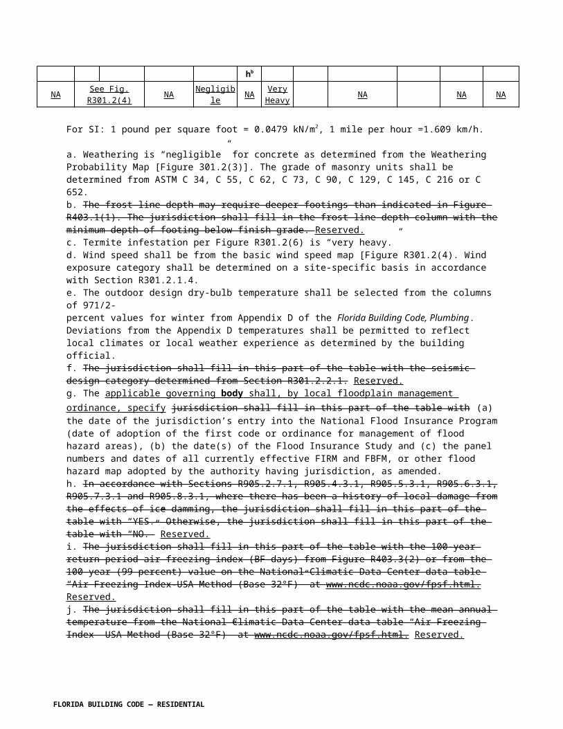
R301.2.2.3.1 Height limitations. Wood-framed buildings shall be limited to three stories above grade plane or the limits given in Table R602.10.3(3). Cold-formed, steel-framed buildings shall be limited to less than or equal to three stories above grade plane in accordance with AISI S230. Mezzanines as defined in Section R202 shall not be considered as stories. Structural insulated panel buildings shall be limited to two stories above grade plane.
Section R301.2.4.1. Change to read as follows:
R301.2.4.1 Alternative provisions. As an alternative to the requirements in Section R322, R322.3 for buildings and structures located in whole or in part in coastal high-hazard areas (V Zones) and Coastal A Zones, if delineated, ASCE 24 is permitted subject to the limitations of this code and the limitations therein.
R301.2.5 Add to read as follows:
R301.2.5 Structures seaward of a coastal control construction line. Structures located seaward of the coastal construction control line shall be designed to resist the predicted forces of a 100-year storm event in accordance with Section 3109 of the Florida Building Code, Building .
Section R301.3 Story height. Change to read as follows:
R301.3 Story height. The wind and seismic provisions of this code shall apply to buildings with story heights not exceeding the following:
1. For wood wall framing, the laterally unsupported bearing wall stud height permitted by Section R602 Table R602.3(5) plus a height of floor framing not to exceed 16 inches (406mm).
Exception: For wood-framed wall buildings with bracing in accordance with Tables R602.10.3(1) and R602.10.3(3), the wall stud clear height used to determine the maximum permitted story height may be increased to 12 feet (3658 mm) without requiring an engineered design for the building wind and seismic force-resisting systems provided that the length of bracing required by Table R602.10.3(1) is increased by multiplying by a factor of 1.10 and the length of bracing required by Table R602.10.3(3) is increased by multiplying by a factor of 1.20. Wall studs are still subject to the requirements of this section.
(no change to remainder of text)
Section R301.9. Add to read as follows:
R301.9 All exterior wall coverings and soffits shall be capable of resisting the design pressures specified for walls for components and cladding loads in accordance with Table R301.2(2) as
FLORIDA BUILDING CODE — RESIDENTIAL 7.39

modified by Table R301.2(3), Manufactured soffits shall be tested at 1.5 times the design pressure.
Section R302.1 Exterior walls. Change to read as follows:
R302.1 Exterior walls. Construction, projections, openings and penetrations of exterior walls of dwellings and accessory buildings shall comply with Table R302.1(1); or dwellings equipped throughout with an automatic sprinkler system installed in accordance with Section P2904 shall comply with Table R302.1(2).
Exceptions:1.-5. [No change]6. Screen enclosure walls of insect screening with a maximum of 25% solid flexible finishes.
Section R302.2. Townhouses. Change to read as shown:
R302.2 Townhouses. Each townhouse shall be considered a separate building and shall be separated by fire-resistance- rated wall assemblies meeting the requirements of Section R302.1 for exterior walls.
Exception: A common 1-hour 2-hour fire-resistance-rated wall assembly tested in accordance with ASTME 119 or UL 263 is permitted for townhouses if such walls do not contain plumbing or mechanical equipment, ducts or vents in the cavity of the common wall, unless such materials and methods of penetration comply with Section R302.4. The wall shall be rated for fire exposure from both sides and shall extend to and be tight against exterior walls and the underside of the roof sheathing. Electrical installations shall be installed in accordance with Chapters 34 through 43. Penetrations of electrical outlet boxes shall be in accordance with Section R302.4.
Section R302.3. Revise to read as shown:
R302.3 Two-family dwellings. Dwelling units in two-family dwellings shall be separated from each other by wall and/or floor assemblies having not less than a 1-hour fire-resistance rating when tested in accordance with ASTM E 119 or UL 263. Fire-resistance-rated floor/ceiling and wall assemblies shall extend to and be tight against the exterior wall, and wall assemblies shall extend from the foundation to the underside of the roof sheathing.
Exceptions:1. – 2. [No change] 3. Screen enclosure walls of insect screening with a maximum of 25 percent solid flexible finishes.
R302.5.2 Duct penetration. Change to read as shown:
R302.5.2 Duct penetration. Ducts in the garage and ducts penetrating the walls or ceilings separating the dwelling from the garage shall be constructed of a minimum No. 26 gage (0.48 mm) sheet steel, 1 inch minimum rigid nonmetallic Class 0 or Class 1 duct board, or other approved material and shall have no openings into the garage,
FLORIDA BUILDING CODE — RESIDENTIAL 7.40

Section R302.13Combustible insulation clearance. Change to read as shown:
R302.13 Combustible insulation clearance. Combustible insulation shall be separated a minimum of 3 inches (76 mm) from recessed luminaires, fan motors and other heat-producing devices.
Exception: Where heat-producing devices are listed for lesser clearances, combustible insulation complying with the listing requirements shall be separated in accordance with the conditions stipulated in the listing.
Recessed luminaires installed in the building thermal envelope shall meet the requirements of Section R402.4.4 of the Florida Building Code, Energy Conservation N1102.4.4 of this code.
Section R303.4 Mechanical ventilation. Change to read as shown:
R303.4 Mechanical ventilation. Where the air infiltration rate of a dwelling unit is less than 5 air changes per hour when tested with a blower door at a pressure of 0.2 inch w.c. (50 Pa) in accordance with Section R402.4.1.2 of the Florida Building Code, Energy Efficiency N1102.4.1.2, the dwelling unit shall be provided with whole-house mechanical ventilation in accordance with Section M1507.3.
Section R306.3 Sewage disposal. Change to read as shown:
R306.3 Sewage disposal. All plumbing fixtures shall be connected to a sanitary sewer or to an approved private sewage disposal system in accordance with Chapter 64E-6, Florida Administrative Code, Standards for Onsite Sewage Treatment and Disposal Systems.
Section R308.1 Identification. Change to read as shown:
R308.1 Identification. Each pane shall bear the manufacturer's label designating the type and thickness of glass or glazing material. Except as indicated in Section R308.1.1 each pane of glazing installed in hazardous locations as defined in Section R308.4 shall be provided with a manufacturer’s or installer's label, designation specifying who applied the designation, designating the type of glass and the safety glazing standard with which it complies, which is visible in the final installation. The designation safety glazing label shall be acid etched, sandblasted, ceramic-fired, laser etched, embossed, or be of a type which once applied cannot be removed without being destroyed. A label shall be permitted in lieu of the manufacturer’s designation. Laminated glass, other than used for safety glazing, shall be permanently identified as per this section, designating laminator, overall glass thickness and trade name of interlayer.
Exceptions:
1. For other than tempered glass, manufacturer’s designations are not required provided the building official approves the use of a certificate, affidavit or other evidence furnished by the gazing contractor certifying that each light id glazed in accordance with approved construction documents that comply with the provisions of this chapter confirming compliance with this code.
FLORIDA BUILDING CODE — RESIDENTIAL 7.41

2. Tempered spandrel glass is permitted to be identified by the manufacturer with a removable paper designation label
R310.1 Emergency escape and rescue required. Change to read as follows:
R310.1 Emergency escape and rescue required. [No change to text; exceptions only]Exceptions: 71. Basements used only to house mechanical equipment and not exceeding total floor area of 200 square feet (18.58 m2).2. The emergency escape and rescue opening shall be permitted to open into a screen enclosure, open to the atmosphere, where a screen door is provided leading away from the residence.
R310.4 Bars, grills, covers and screens. Change to read as shown:
R310.4 Bars, grills, covers and screens. Bars, grills, covers, screens or similar devices are permitted to be placed over emergency escape and rescue openings, bulkhead enclosures, or window wells that serve such openings, provided the minimum net clear opening size complies with Sections R310.1.1 to R310.1.3, and such devices shall be releasable or removable from the inside without the use of a key, tool, special knowledge or force greater than that which is required for normal operation of the escape and rescue opening. The temporary installation or closure of storm shutters, panels, and other approved hurricane protection devices shall be permitted on emergency escape and rescue openings during the threat of a storm. Such devices shall not be required to comply with the operational constraints of Section R310.1.4. While such protection is provided, at least one means of escape from the dwelling or dwelling unit shall be provided. The means of escape shall be within the first floor of the dwelling or dwelling unit and shall not be located within a garage without a side-hinged door leading directly to the exterior.
Occupants in any part of the dwelling or dwelling unit shall be able to access the means of escape without passing through a lockable door not under their control.
Section R311.2 Egress door. Add exception to read as follows:
R311.2 Egress door. At least one egress door shall be provided for each dwelling unit. The egress door shall be side-hinged, and shall provide a minimum clear width of 32 inches (813 mm) when measured between the face of the door and the stop, with the door open 90 degrees (1.57 rad). The minimum clear height of the door opening shall not be less than 78 inches (1981 mm) in height measured from the top of the threshold to the bottom of the stop. Other doors shall not be required to comply with these minimum dimensions. Egress doors shall be readily openable from inside the dwelling without the use of a key or special knowledge or effort.
Exception: Buildings that are 400 square feet or less and that are intended for use in conjunction with one- and two-family residences are not subject to the door height and width requirements of this code.
Section R311.3 Floors and landings at exterior doors. Change to read as shown:
FLORIDA BUILDING CODE — RESIDENTIAL 7.42

R311.3 Floors and landings at exterior doors. There shall be a landing or floor on each side of each exterior door. The width of each landing shall not be less than the door served. Every landing shall have a minimum dimension of 36 inches (914 mm) measured in the direction of travel. Exterior landings shall be permitted to have a slope not to exceed 1/4 unit vertical in 12 units horizontal (2-percent).
Exception: Exterior balconies less than 60 square feet (5.6m2) and only accessible from a door are permitted to have a landing less than 36 inches (914 mm) measured in the direction of travel.
R311.3.1 Floor elevations at the required egress doors. Landings or finished floors at the required egress door shall not be more than l ½ inches (38 mm) lower than the top of the threshold.
Exception: The landing or floor on the exterior side shall not be more than 7-3/4 inches (196 mm) below the top of the threshold provided the door does not swing over the landing or floor.
Where exterior landings of floors serving the required egress door are not at grade, they shall be provided with access to grade by means of a ramp in accordance with Section R311.8 or a stairway in accordance with Section R311.7.
R311.3.2 Floor elevations for other exterior doors. Doors other than the required egress door shall be provided with landings or floors not more than 7-3/4, inches (196 mm) below the top of the threshold.
Exception: A landing is not required where a stairway of two or fewer risers is located on the exterior side of the door. , provided the door does not swing over the stairway.
Section R311.7.6, Landings for stairways. Add exception 2 as shown:
R311.7.6 Landings for stairways. There shall be a floor or landing at the top and bottom of each stairway. The minimum width perpendicular to the direction of travel shall be no less than the width of the flight served. Landings of shapes other than square or rectangular shall be permitted provided the depth at the walk line and the total area is not less than that of a quarter circle with a radius equal to the required landing width. Where the stairway has a straight run, the minimum depth in the direction of travel shall be not less than 36 inches (914 mm).
Exceptions: 1. A floor or landing is not required at the top of an interior flight of stairs, including stairs in an enclosed garage, provided a door does not swing over the stairs.2. See Section R311.3 from exterior doors where a step down is provided.
Section R313 Automatic Fire Sprinkler. Change to read as follows:
SECTION R313AUTOMATIC FIRE SPRINKLER
RESERVED
FLORIDA BUILDING CODE — RESIDENTIAL 7.43

R313.1 Townhouse automatic fire sprinkler systems. An automatic residential fire sprinkler system shall be installed in townhouses.
Exception: An automatic residential fire sprinkler system shall not be required when additions or alterations are made to existing townhouses that do not have an automatic residential fire sprinkler system installed.
R313.1.1 Design and installation. Automatic residential fire sprinkler systems for townhouses shall be designed and installed in accordance with Section P2904.
R313.2 One- and two-family dwellings automatic fire systems. An automatic residential fire sprinkler system shall be installed in one- and two-family dwellings.
Exception: An automatic residential fire sprinkler system shall not be required for additions or alterations to existing buildings that are not already provided with an automatic residential sprinkler system.
R313.2.1 Design and installation. Automatic residential fire sprinkler systems shall be designed and installed in accordance with Section P2904 or NFPA 13D.
Section R314 Smoke Alarms
Add Exception 3 to Section R314.4
One-family and two-family dwellings and townhomes undergoing a repair, or a level 1 alteration as defined in the Florida Building Code, may use smoke alarms powered by 10-year nonremovable, nonreplaceable batteries in lieu of retrofitting such dwelling with smoke alarms powered by the dwelling's electrical system.
R315.1. Carbon monoxide alarms. Replace Section R315.1 to read as shown:
SECTION R315CARBON MONOXIDE ALARMS
R315.1 Carbon monoxide protection alarms . Every separate building or an addition to an existing building for which a permit for new construction is issued and having a fossil-fuel-burning heater or appliance, a fireplace, an attached garage, or other feature, fixture, or element that emits carbon monoxide as byproduct of combustion shall have an operational carbon monoxide alarm installed within 10 feet of each room used for sleeping purposes. For new construction, an approved carbon monoxide alarm shall be installed outside of each separate sleeping area in the immediate vicinity of the bedrooms in dwelling units within which fuel-fired appliances are installed and in dwelling units that have attached garages.
FLORIDA BUILDING CODE — RESIDENTIAL 7.44

Exception: This section shall not apply to existing buildings that are undergoing alterations or repair unless the alteration is an addition as defined in Section R315.1.3.
R315.1.1 Carbon monoxide alarm. The requirements of Section R315.1 shall be satisfied by providing for one of the following alarm installations:
(1) A hard-wired carbon monoxide alarm.(2) A battery-powered carbon monoxide alarm.(3) A hard-wired combination carbon monoxide and smoke alarm.(4) A battery-powered combination carbon monoxide and smoke alarm.
R315.1.2 Combination alarms. Combination smoke/carbon monoxide alarms shall be listed and labeled by a Nationally Recognized Testing Laboratory.
R315.1.3 Addition shall mean : An extension or increase in floor area, number of stories or height of a building or structure.
315.2 Carbon monoxide detection systems. Reserved. Carbon monoxide detection systems that include carbon monoxide detectors and audible notification appliances, installed and maintained in accordance with this section for carbon monoxide alarms and NFPA 720, shall be permitted. The carbon monoxide detectors shall be listed as complying with UL 2075. Where a household carbon monoxide detection system is installed, it shall become a permanent fixture of the occupancy, owned by the homeowner and shall be monitored by an approved supervising station.
Exception: Where carbon monoxide alarms are installed meeting the requirements of Section R315.1, compliance with Section 315.2 is not required.
R315.3 Where required in existing dwellings. Reserved . Where required in existing dwellings. Where work requiring a permit occurs in existing dwellings that have attached garages or in existing dwellings within which fuel-fired appliances exist, carbon monoxide alarms shall be provided in accordance with Section R315.1.
R315.4 Alarm requirements. Reserved. Single-station carbon monoxide alarms shall be listed as complying with UL 2034 and shall be installed in accordance with this code and the manufacturer’s installation instructions.
Section R318 Protection against subterrannean termites . Replace with Florida specific criteria to read as shown:
SECTION R318PROTECTION AGAINST TERMITES
R318.1 Termite Protection. Termite protection shall be provided by registered termiticides, including soil applied pesticides, baiting systems, and pesticides applied to wood, or other approved methods of termite protection labeled for use as a preventative treatment to new construction. See §202, REGISTERED TERMITICIDE. Upon completion of the application of
FLORIDA BUILDING CODE — RESIDENTIAL 7.45

the termite protective treatment, a Certificate of Compliance shall be issued to the building department by the licensed pest control company that contains the following statement: "The building has received a complete treatment for the prevention of subterranean termites. Treatment is in accordance with rules and laws established by the Florida Department of Agriculture and Consumer Services."
R318.1.1 If soil treatment used for subterranean termite prevention, the initial chemical soil treatment inside the foundation perimeter shall be done after all excavation, backfilling and compaction is complete.R318.1.2 If soil treatment is used for subterranean termite prevention, soil area disturbed after initial chemical soil treatment shall be retreated with a chemical soil treatment, including spaces boxed or formed.R318.1.3 If soil treatment is used for subterranean termite prevention, space in concrete floors boxed out or formed for the subsequent installation of plumbing traps, drains or any other purpose shall be created by using plastic or metal permanently placed forms of sufficient depth to eliminate any planned soil disturbance after initial chemical soil treatment.R318.1.4 If soil treatment is used for subterranean termite prevention, chemically treated soil shall be protected with a minimum 6 mil vapor retarder to protect against rainfall dilution. If rainfall occurs before vapor retarder placement, retreatment is required. Any work, including placement of reinforcing steel, done after chemical treatment until the concrete floor is poured, shall be done in such manner as to avoid penetrating or disturbing treated soil.R318.1.5 If soil treatment is used for subterranean termite prevention, concrete overpour or mortar accumulated along the exterior foundation perimeter shall be removed prior to exterior chemical soil treatment, to enhance vertical penetration of the chemicals.R318.1.6 If soil treatment is used for subterranean termite prevention, chemical soil treatments shall also be applied under all exterior concrete or grade within 1 foot (305 mm) of the primary structure sidewalls. Also, a vertical chemical barrier shall be applied promptly after construction is completed, including initial landscaping and irrigation/sprinkler installation. Any soil disturbed after the chemical vertical barrier is applied shall be promptly retreated.R318.1.7 If a registered termiticide formulated and registered as a bait system is used for subterranean termite prevention, §R318.1.1 through §R318.1.6 do not apply; however, a signed contract assuring the installation, maintenance and monitoring of the baiting system that is in compliance with the requirements of Chapter 482, F.S. for a minimum of five years from the issue of the Certificate of Occupancy shall be provided to the building official prior to the pouring of the slab, and the system must be installed prior to final building approval. If the baiting system directions for use require a monitoring phase prior to installation of the pesticide active ingredient, the installation of the monitoring phase components shall be deemed to constitute installation of the system.
R318.1.8 If a registered termiticide formulated and registered as a wood treatment is used for subterranean termite prevention, Sections R318.1.1 through R318.1.6 do not apply. Application of the wood treatment termiticide shall be as required by label directions for use, and must be completed prior to final building approval.
R318.2 Penetration. Protective sleeves around piping penetrating concrete slab-on-grade floors shall not be of cellulose-containing materials. If soil treatment is used for subterranean termite
FLORIDA BUILDING CODE — RESIDENTIAL 7.46

protection, the sleeve shall have a maximum wall thickness of 0.010 inch (0.25 mm), and be sealed within the slab using a non-corrosive clamping device to eliminate the annular space between the pipe and the sleeve. No termiticides shall be applied inside the sleeve.
R318 . 3 Cleaning. Cells and cavities in masonry units and air gaps between brick, stone or masonry veneers and the structure shall be cleaned of all non-preservative treated or non-naturally durable wood, or other cellulose-containing material prior to concrete placement.
Exception: Inorganic material manufactured for closing cells in foundation concrete masonry unit construction or clean earth fill placed in concrete masonry unit voids below slab level before termite treatment is performed.
R318.4 Concrete bearing ledge. Brick, stone or other veneer shall be supported by a concrete bearing ledge at least equal to the total thickness of the brick, stone or other veneer which is poured integrally with the concrete foundation. No supplemental concrete foundation pours which will create a hidden cold joint shall be used without supplemental treatment in the foundation unless there is an approved physical barrier. An approved physical barrier shall also be installed from below the wall sill plate or first block course horizontally to embed in a mortar joint. If masonry veneer extends below grade, a termite protective treatment must be applied to the cavity created between the veneer and the foundation, in lieu of a physical barrier.
Exception: Veneer supported by a structural member secured to the foundation sidewall in accordance with ACI 530/ASCE 5/TMS 402, provided at least a 6 inch (152 mm) clear inspection space of the foundation sidewall exterior exist between the veneer and the top of any soil, sod, mulch or other organic landscaping component, deck, apron, porch, walk or any other work immediately adjacent to or adjoining the structure.
R318.5 Protection against decay and termites. Condensate Lines, irrigation/sprinkler system risers for spray heads, and roof downspouts shall discharge at least 1 foot (305 mm) away from the structure sidewall, whether by underground piping, tail extensions or splash blocks. Gutters with downspouts are required on all buildings with eaves of less than 6 inches (152 mm) horizontal projection except for gable end rakes or on a roof above another roof.
R318.6 Preparation of building site and removal of debris.R318.6.1 All building sites shall be graded to provide drainage under all portions of the building not occupied by basements.R318.6.2 The foundation and the area encompassed within 1 foot (305 mm) therein shall have all vegetation, stumps, dead roots, cardboard, trash and foreign material removed and the fill material shall be free of vegetation and foreign material. The fill shall be compacted to assure adequate support of the foundation.R318.6.3 After all work is completed, loose wood and debris shall be completely removed from under the building and within 1 foot (305 mm) thereof. All wood forms and supports shall be completely removed. This includes, but is not limited to: wooden grade stakes, forms, contraction spacers, tub trap boxes, plumbing supports, bracing, shoring, forms or other cellulose-containing material placed in any location where such materials are not clearly visible and readily removable prior to completion of the work. Wood shall not be stored in contact with the ground under any building.
FLORIDA BUILDING CODE — RESIDENTIAL 7.47

[Florida specific]
Add new Section R318.7 as shown:
R318.7 Inspection for termites. In order to provide for inspection for termite infestation, clearance between exterior wall coverings and final earth grade on the exterior of a building shall not be less than 6 inches (152 mm).
Exceptions:l. Paint or decorative cementitious finish less than 5/8 inch (17.1 mm) thick adhered directly to the masonry foundation sidewall.2. Access or vehicle ramps which rise to the interior finish floor elevation for the width of such ramps only.3. A 4-inch (102 mm) inspection space above patio and garage slabs and entry areas.4. If the patio has been soil treated for termites, the finish elevation may match the building interior finish floor elevations on masonry construction only.5. Masonry veneers constructed in accordance with Section R318.4.
Section R318.8. Add section to read as shown:
R318.8 Foam plastic protection. In areas where the probability of termite infestation is "very heavy” as indicated in Figure R301.2(6), extruded and expanded polystyrene, polyisocyanurate and other foam plastics shall not be installed on the exterior face or under interior or exterior foundation walls or slab foundations located below grade. The clearance between foam plastics installed above grade and exposed earth shall be at least 6 inches (152 mm).
Exceptions:1. Buildings where the structural members of walls, floors, ceilings and roofs are entirely of noncombustible materials or pressure-preservative-treated wood. 2. When in addition to the requirements of Section R318.1, an approved method of protecting the foam plastic and structure from subterranean termite damage is used. 3. On the interior side of basement walls.
SECTION R320
ACCESSIBILITY
Section R320.1 Scope. Revise to read as shown:
R320.1 Scope. Shall be in accordance with the provisions of the Florida Building Code, Accessibility. Where there are four or more dwelling units or sleeping units in a single structure, the provisions of Chapter 11 of the International Building Code for Group R-3 shall apply.
R320.1.1 All new single-family houses, duplexes, triplexes, condominiums and townhouses shall provide at least one bathroom, located with maximum possible privacy, where bathrooms are provided on habitable grade levels, with a door that has a 29-inch (737 mm)
FLORIDA BUILDING CODE — RESIDENTIAL 7.48

clear opening. However, if only a toilet room is provided at grade level, such toilet rooms shall have a clear opening of not less than 29 inches (737 mm).
Section R321.3 Accessibility. Revise to read as shown:
R321.3 Accessibility. Reserved. Elevators or platform lifts that are part of an accessible route required by Chapter 11 of the International Building Code, shall comply with ICC A117.1.
R322.1.1 Alternative provisions. Revise to read as shown:
R322.1.1 Alternative provisions. As an alternative to the requirements in Section R322, R322.3 for buildings and structures located in whole or in part in coastal high-hazard areas (V Zones) and Coastal A Zones, if delineated, ASCE 24 is permitted subject to the limitations of this code and the limitations therein.
Section R322.1.7 Protection of water supply and sanitary sewage systems. Revise to read as shown:
R322.1.7 Protection of water supply and sanitary sewage systems. New and replacement water supply systems shall be designed to minimize or eliminate infiltration of flood waters into the systems in accordance with the plumbing provisions of this code. New and replacement sanitary sewage systems shall be designed to minimize or eliminate infiltration of floodwaters into systems and discharges from systems into floodwaters in accordance with the plumbing provisions of this code and in accordance with Chapter 64E-6, Florida Administrative Code, Standards for Onsite Sewage Treatment and Disposal Systems. and Chapter 3 of the International Private Sewage Disposal Code.
Section R322.1.9 Manufactures homes. Revise to read as shown:
R322.1.9 Manufactured homes. In addition to the applicable requirements of the state agency with jurisdiction over installation of manufactured homes, installation of manufactured homes in flood hazard areas is subject to the applicable provisions of the local floodplain management ordinance.
Section R322.1.11 Structural seaward of a coastal construction line. Add section to read as shown:
R322.1.11 Structures seaward of a coastal construction line. In addition to the requirements of this section, structures located in flood hazard areas and seaward of the coastal construction line shall be designed to resist the predicted forces of a 100-year storm event in accordance with Section R3109 of the Florida Building Code, Building, and the more restrictive provisions shall govern.
FLORIDA BUILDING CODE — RESIDENTIAL 7.49

Section R322.2.4 Pools in flood hazard areas. Add to read as shown:
R322.2.4 Pools in flood hazard areas. Pools that are located in flood hazard areas established by Table R301.2(1), including above-ground pools, on-ground pools, and in-ground pools that involve placement of fill, shall comply with Sections R322.2.4.1 or RB322.2.4.2.
Exception: Pools located in riverine flood hazard areas which are outside of designated floodways.
R322.2.4.1 Pools located in designated floodways. Where pools are located in designated floodways, documentation shall be submitted to the building official, which demonstrates that the construction of the pool will not increase the design flood elevation at any point within the jurisdiction.
R322.2.4.2 Pools located where floodways have not been designated. Where pools are located in riverine flood hazard areas where design flood elevations are specified but floodways have not been designated, the applicant shall provide a floodway analysis that demonstrates that the proposed pool will not increase the design flood elevation more than 1 foot (305 mm) at any point within the jurisdiction.
Section R322.3.2 Elevation requirements. Revise to read as shown:
R322.3.2 Elevation requirements.
1. All buildings and structures erected within coastal high-hazard areas shall be elevated so that the lowest portion of all structural members supporting the lowest floor, with the exception of piling, pile caps, columns, grade beams and bracing, is elevated to or above the design flood elevation. :
1.1. Located at or above the design flood elevation, if the lowest horizontal structural member is oriented parallel to the direction of wave approach, where parallel shall mean less than or equal to 20 degrees (0.35 rad) from the direction of approach, or
1.2. Located at the base flood elevation plus 1 foot (305 mm), or the design flood elevation, whichever is higher, if the lowest horizontal structural member is oriented perpendicular to the direction of wave approach, where perpendicular shall mean greater than 20 degrees (0.35 rad) from the direction of approach.
2. – 4. [No change]
Section R322.3.3.1 Pools. Add new section to read as shown:
R322.3.3.1 Pools. Pools in coastal high-hazard areas shall be designed and constructed in conformance with ASCE 24.
FLORIDA BUILDING CODE — RESIDENTIAL 7.50
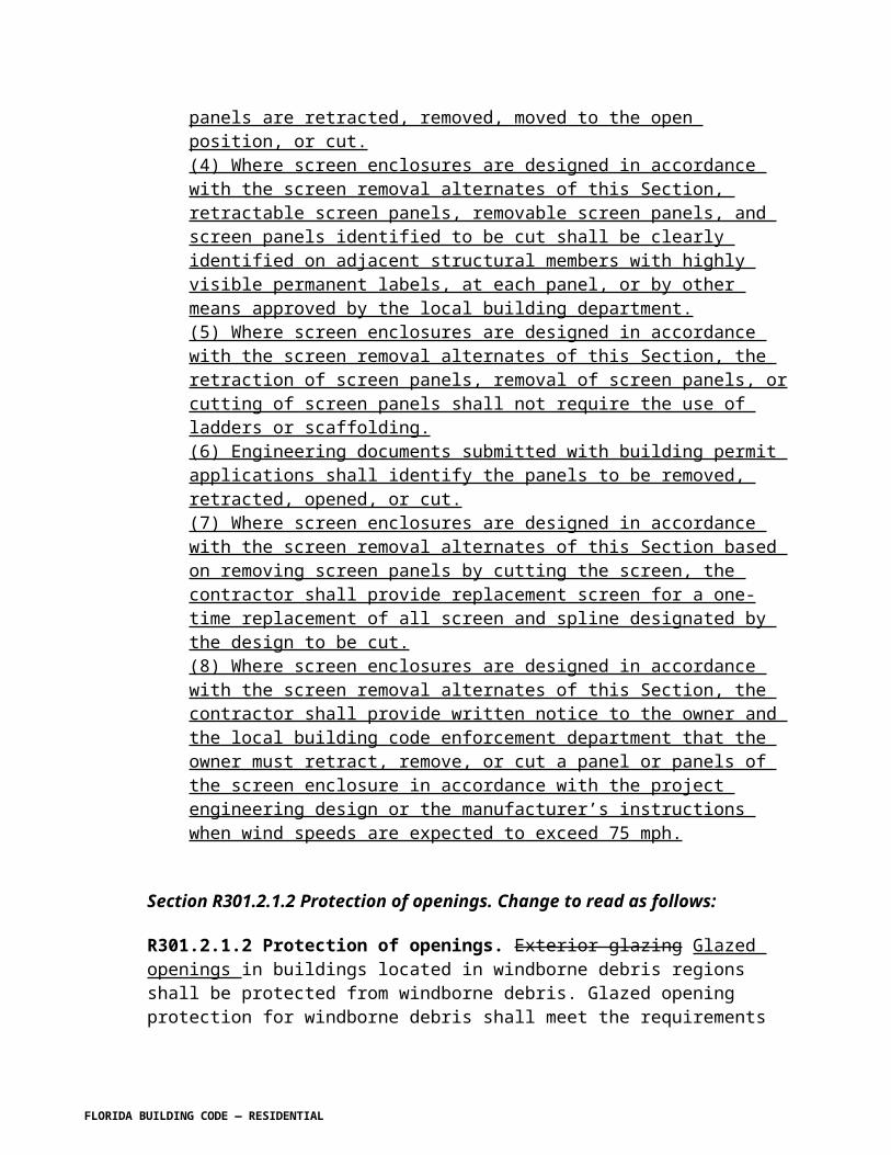
Section R322.3.4 Walls below design flood elevation. Revise to read as shown:
R322.3.4 Walls below design flood elevation. Walls and partitions are permitted below the elevated floor, provided that such walls and partitions are not part of the structural support of the building or structure and:
1. Electrical, mechanical, and plumbing system components are not to be mounted on or penetrate through walls that are designed to break away under flood loads; and2. Are constructed with insect screening or open lattice; or
3. Are designed to break away or collapse without causing collapse, displacement or other structural damage to the elevated portion of the building or supporting foundation system. Such walls, framing and connections shall have a design safe loading resistance of not less than 10 (479 Pa) and no more than 20 pounds per square foot (958 Pa) determined using allowable stress design; or
4. Where wind loading values of this code exceed 20 pounds per square foot (958 Pa) determined using allowable stress design, the construction documents shall include documentation prepared and sealed by a registered design professional that:
4.1 – 4.2 [No change]
Section R324. Add a new section to read as shown:
SECTION R324AIRPORT NOISE
R324.1 Airport noise study guidelines . The Aviation Safety and Noise Abatement Act of 1979 14 CFR Part 150 (US Department of Transportation) including revisions through January 2005 and hereby adopted as a guideline for establishing airport noise control. When required by a local government by local ordinance to provide noise attenuation in a new structure or addition to an existing structure near an airport in the area of the local government, the applicant must provide either:
1. A testing certificate from an accredited noise testing lab that a new structure or addition to existing structure built to the submitted engineering plans will achieve an average minimum dBA reduction equal to or greater than the reduction required,2. An engineering judgment signed and sealed by an engineer licensed in the State of Florida that the structure or addition built to the submitted engineering plans will achieve an average minimum dBA reduction equal to or greater than the reduction required, or 3. Plans using the standards contained in "Guidelines for Sound Insulation of Residences Exposed to Aircraft Operations" prepared for the Department of the Navy by Wyle Research and Consulting, Arlington, Virginia, April 2005 on file with the Florida Building Commission.
FLORIDA BUILDING CODE — RESIDENTIAL 7.51

CHAPTER 4, FOUNDATIONS
Section R401.1 Application. Revise text to add exception 3 to read as shown:
R401.1 Application. The provisions of this chapter shall control the design and construction of the foundation and foundation spaces for all buildings. In addition to the provisions of this chapter, the design and construction of foundations in flood hazard areas as established by Table R301.2(1) shall meet the provisions of Section R322. Wood foundations shall be designed and installed in accordance with AF&PA PWF.
Exception: The provisions of this chapter shall be permitted to be used for wood foundations only in the following situations: 1. – 2. [No change]3. Buildings and structures located within the High-Velocity Hurricane Zone shall comply with the provisions of Chapter 44 and, as applicable, Section R322 in flood hazard areas.
Section R401.2 Requirements. Revise to read as shown:
R401.2 Requirements. Foundations shall be capable of resisting all loads from roof uplift and building overturn. Foundation uplift for light-frame wood or steel buildings shall be calculated or determined from Table R401.1. Masonry buildings within the dimensional scope of Table R401.1 shall be assumed to be of adequate weight so as not to require uplift resistance greater than that provided by the structure and any normal foundation. Foundation construction shall also be capable of accommodating all gravity loads according to Section R301 and of transmitting the resulting loads to the supporting soil. Fill soils that support footings and foundations shall be designed, installed and tested in accordance with accepted engineering practice. Gravel fill used as footings for wood and precast concrete foundations shall comply with Section R403.
TABLE R401.1FOUNDATION UPLIFT LIGHT STEEL & WOOD FRAME BUILDINGS IN
EXPOSURE B (plf) 5, 6
Roof Angle
Bldg Width
Minimum Building Length
Vasd as determined in accordance with Section R301.2.1.3 / Velocity Pressure
100 110 120 130 140 15015 18 22 26 30 34
45
3 Stories 3
20 12 173 276 389 512 644 78725 14 73 165 265 374 492 61830 19 0 81 174 275 384 50235 25 17 48 104 200 305 41740 35 33 69 109 152 240 349
2 Stories 2
20 12 64 126 195 270 350 43725 15 17 66 129 198 272 35230 22 38 62 90 146 217 294
FLORIDA BUILDING CODE — RESIDENTIAL 7.52

35 35 56 86 118 154 192 25240 40 74 108 146 186 230 277
1 Story 1
20 12 33 46 61 94 132 17325 22 57 75 96 118 142 16730 18 79 103 129 157 187 21935 16 100 128 159 192 229 26740 16 120 152 188 226 268 312
30
3 Stories 3
20 12 92 177 271 373 483 60125 17 0 63 143 230 324 42530 25 0 23 52 125 209 30035 35 13 44 78 115 154 20640 40 28 64 102 145 190 239
2 Stories 2
20 13 1 50 103 162 224 29225 23 16 35 57 84 139 19930 30 36 60 87 116 148 18135 35 54 83 115 150 187 22740 36 71 104 141 181 224 27020 20 32 46 60 76 93 11225 15 56 74 95 117 140 16630 13 78 102 127 155 185 21735 14 99 127 157 190 226 264
1Story 1 40 16 118 150 185 223 264 308
20 12 113 203 301 408 523 64725 14 45 130 222 322 431 54730 17 4 85 177 277 385 50135 19 20 58 154 257 369 489
3Story 1 40 21 35 72 141 249 367 49320 12 43 100 163 231 304 38425 13 22 79 143 214 289 37130 15 42 72 141 217 298 38635 15 61 92 150 232 321 417
2Story 1 40 16 78 114 164 254 352 45720 12 38 57 94 135 179 22625 12 62 82 122 171 223 28030 12 85 110 154 212 275 34235 14 107 136 190 257 330 409
1Story 1 40 16 126 160 227 304 388 478
TABLE R401.1FOUNDATION UPLIFT LIGHT STEEL & WOOD FRAME BUILDINGS IN
EXPOSURE C (plf) 5, 6
Roof Angle
Bldg Width
Minimum Building Vasd as determined in accordance with Section
R301.2.1.3 / Velocity Pressure
FLORIDA BUILDING CODE — RESIDENTIAL 7.53

Length 4 100 110 120 130 140 15021 26 31 36 42 48
45
3 Stories 3
20 12 370 515 673 845 1031 123125 13 249 377 518 670 836 101330 17 159 278 408 550 703 86735 21 89 203 328 463 610 76740 26 102 153 262 394 537 691
2 Stories 2
20 12 184 271 368 472 585 70625 13 119 200 288 385 489 60130 18 85 147 233 326 426 53335 24 113 155 200 284 383 48940 36 139 187 240 297 358 457
1 Story 1
20 12 58 95 140 189 243 30025 16 92 118 147 178 224 28130 19 124 157 193 233 275 32135 17 154 193 236 283 334 38840 16 182 227 277 331 389 452
30
3 Stories 3
20 12 256 376 507 650 804 97025 15 130 232 344 466 598 74030 21 47 127 228 337 455 58235 31 72 116 163 241 351 469
40 40 96 146 200 259 323
392
2 Stories 2
20 12 95 163 238 320 408 50225 18 53 85 151 223 301 38530 30 83 117 154 195 239 30435 35 110 150 195 244 296 35340 37 135 182 233 289 350 415
1 Story 1
20 20 58 76 97 119 143 16925 16 91 117 145 176 210 24530 13 123 156 191 230 272 31735 14 152 191 234 280 330 38440 16 179 224 273 327 384 446
20
3 Stories 3
20 12 285 411 549 698 860 103425 13 207 325 455 595 748 91130 15 162 280 409 549 701 86335 17 138 260 393 538 695 86340 18 124 252 392 545 709 886
2 Stories 2
20 12 152 233 320 416 519 63025 12 133 215 306 404 511 625
FLORIDA BUILDING CODE — RESIDENTIAL 7.54

30 13 130 219 316 422 536 65835 14 138 235 341 456 581 71540 16 150 257 373 500 636 783
1 Story 1
20 12 88 136 188 245 307 37325 12 114 172 235 303 377 45730 12 146 214 288 370 457 55235 14 180 259 346 441 543 65340 16 215 306 406 515 632 758
Notes:
1. Based on 1 st floor height = 10 ft. or 11 ft. floor to floor in multi-story. 2. Based on 2 nd floor height = 8 ft. or 9 ft. floor to floor in multi-story. 3. Based on 3 rd floor height = 8 ft. 4. Building length shall be equal to or greater than that shown in tables. 5. Roof and floor framing shall span in the same direction. 6. Includes provision for 2 foot roof overhang
Section R403.1 General. Revise to read as shown:
R403.1 General. [No change to text]
R403.1.1 Minimum size. Minimum sizes for concrete and masonry footings shall be as set forth in Table R403.1 and Figure R403.1(1). Minimum sizes for concrete and masonry footings shall also be as required to provide adequate resistance to uplift and overturn of the building as determined from Table 401.1 or as calculated using engineered design in accordance with the Florida Building Code, Building . The footing width, W, shall be based on the load-bearing value of the soil in accordance with Table R401.4.1. Spread footings shall be at least 8 inches (203 mm) in thickness T. Footing projections, P, shall be at least 2 inches (51 mm) and shall not exceed the thickness of the footing. The size of footings supporting piers and columns shall be based on the tributary load and allowable soil pressure in accordance with Table R401.4.1. Footings for wood foundations shall be in accordance with the details set forth in Section R403.2, and Figures R403.1(2) and R403.1(3).
R403.1.2 Resistance to uplift. Uplift resistance of common foundations are given in Table R403.1.2. Uplift resistance of these foundations may be increased by increasing the size of the concrete footing. When determining the modified uplift resistance the added weight shall be reduced by multiplying by a factor of 0.6. Other foundation systems shall be engineered in accordance with the Florida Building Code, Building .
TABLE R403.1.2FOUNDATION UPLIFT DESIGN DETAILS
FOOTING TYPE T W SLAB/WALL 1 RESISTANCE NOTESA Mono 20 12 6 502 3
Mono 20 16 6 585 3B Mono Interior 20 12 13 796 3
FLORIDA BUILDING CODE — RESIDENTIAL 7.55

Mono Interior 20 16 13 879 3C 12” Stem/Joist 10 20 228 436 1,2,3D Mono 20 12 6 502 --
Mono 20 16 6 585 --E Mono Interior 20 12 13 796 --
Mono Interior 20 16 13 879 --F Stem/Joist 10 20 -- 208 2,3G Stem/Slab 10 20 6 460 3H Stem/Slab 10 12 6 377 3
Stem/Slab 10 20 6 460 3For SI: 1 inch = 25.4 mm.1. Tributary width of 3½" slab or weight of stemwall and bond beam2. 1st floor dead load multiplied by 0.6 may also be included.3. All footing dowel bars shall be same size as wall steel, shall have a standard 90-degree hook, and shall be embedded a minimum of 6 inches. Dowel bars shall lap vertical wall reinforcement a minimum of 25 inches.
Delete Figure R403.1(1) and replace with the following:
FOOTING A MONOLITHIC SLAB-ON-GRADE EXTERIOR WALL
FLORIDA BUILDING CODE — RESIDENTIAL 7.56

FOOTING B MONOLITHIC SLAB-ON-GRADE INTERIOR WALL FIGURE 403.1(1) CONCRETE AND MASONRY FOUNDATION DETAILS
FLORIDA BUILDING CODE — RESIDENTIAL 7.57

FOOTING C STEM WALL WOOD JOIST FLOOR FIGURE R403.1(1)—continued
FOOTING D MONOLITHIC EXTERIOR FOOTING
FOOTING E MONOLITHIC INTERIOR FOOTING
FIGURE R403.1(1)—continued
FLORIDA BUILDING CODE — RESIDENTIAL 7.58

FOOTING F WOOD FLOOR TO CONCRETE OR MASONRY STEMWALL
FIGURE R403.1(1)—continued
FLORIDA BUILDING CODE — RESIDENTIAL 7.59

FOOTING G STEMWALL FOUNDATION WITH SLAB ON GRADE
FIGURE R403.1(1)—continued
FLORIDA BUILDING CODE — RESIDENTIAL 7.60

FOOTING H FIGURE R403.1(1)—continued
FLORIDA BUILDING CODE — RESIDENTIAL 7.61

Section R403.1.6 Foundation anchorage. Change to read as follows:
R403.1.6 Foundation anchorage. (no change).Exceptions: 1. [No change]2. Walls 24 inches (610 mm) total length or shorter connecting offset braced wall panels shall be anchored to the foundation with a minimum of one anchor bolt located in the center third of the plate section and shall be attached to adjacent braced wall panels at corners as required in Section R602 shown in item 8 of Table R602.3(1).3. Connection of walls 12 inches (305 mm) total length or shorter connecting offset braced wall panels to the foundation without anchor bolts shall be permitted. The wall shall be attached to adjacent braced wall panels at corners as required in Section R602 shown in item 8 of Table R602.3(1).
Section R404.2.6 Fastening. Change to read as follows:
R404.2.6 Fastening. Wood structural panel foundation wall sheathing shall be attached to framing in accordance with Section R602 Table R602.3(1) and Section R402.1.1.
Section R404.3 Wood sill plates. Change to read as follows:
R404.3 Wood sill plates. Wood sill plates shall be a minimum of 2-inch by 4-inch (51 mm by 102 mm) nominal lumber. Sill plate anchorage shall be in accordance with Sections R403.1.6 and R602 R602.11.
Section R404.5.1 Design. Change to read as follows:
R404.5.1 Design. Precast concrete foundation walls shall be designed in accordance with accepted engineering practice. The design and manufacture of precast concrete foundation wall panels shall comply with the materials requirements of Section R402.3 or ACI 318. The panel design drawings shall be prepared by a registered design professional where required by the statutes of the jurisdiction in which the project is to be constructed in accordance with Section R106.1 107 of the Florida Building Code, Building .
Section R404.5.2 Precast concrete foundation design drawings. Change to read as follows:
R404.5.2 Precast concrete foundation design drawings. (no change)1-6. (No change)7. BasicUltimate design wind speed, Vult , from Figure R301.2(4).
Section R408.3Unvented crawl space. Change to read as follows:
R408.3 Unvented crawl space. Ventilation openings in under-floor spaces specified in Sections R408.1and R408.2 shall not be required where:
FLORIDA BUILDING CODE — RESIDENTIAL 7.62

1. [No change]2. One of the following is provided for the under-floor space:
2.1 Continuously operated mechanical exhaust ventilation at a rate equal to 1 cubic foot per minute (0.47 L/s) for each 50 square feet (4.7 m2) of crawl space floor area, including an air pathway to the common area (such as a duct or transfer grille), and perimeter walls insulated in accordance with Section R402.2.10 of the Florida Building Code, Energy Conservation N1103.2.1 of this code;
2.2 -2.3 [No change]
CHAPTER 5, FLOORS
R501.1 Application. Change to read as follows:
R501.1 Application. The provisions of this chapter shall control the design and construction of the floors for all buildings including the floors of attic spaces used to house mechanical and/or plumbing fixtures and equipment.
Exception: Buildings and structures located within the High-Velocity Hurricane Zone shall comply with the provisions of Chapter 44.
Section 502.1. Add the following sections R502.1.8 through R502.1.11 as shown using IRC sections identified in brackets:
R502.1.8 [IRC502.12] Draftstopping required. Draftstopping shall be provided in accordance with Section R302.12.
R502.1.9 [IRC502.13] Fireblocking required. Fireblocking shall be provided in accordance with Section R302.11.
R502.1.10 [IRC502.11] Wood trusses
R502.1.10.1 [IRC502.11.1] Design. Wood trusses shall be designed in accordance with approved engineering practice. The design and manufacture of metal plate connected wood trusses shall comply with ANSI/TPI 1. The truss design drawings shall be prepared by a registered professional where required by Florida Statutes. the statutes of the jurisdiction in which the project is to be constructed in accordance with Section R106.1.
R502.1.10.2 [IRC502.11.2] Bracing. Trusses shall be braced to prevent rotation and provide lateral stability in accordance with the requirements specified in the construction documents for the building and on the individual truss design drawings. In the absence of specific bracing requirements, trusses shall be braced in accordance with TPI/WTCA BCSI accepted industry practices , such as the Building Component Safety Information (BCSI) Guide to Good Practice for Handling, Installing & Bracing of Metal Plate Connected Wood Trusses.
FLORIDA BUILDING CODE — RESIDENTIAL 7.63

R502.1.10.3 [IRC502.11.3] Alterations to trusses. [No change to text].
R502.1.10.4 [IRC502.11.4] Truss design drawings. Truss design drawings, prepared in compliance with Section R502.1.10.1, shall be provided to the building official and approved prior to installation. Truss design drawing shall be provided with the shipment of trusses delivered to the job site. Truss design drawings shall include, at a minimum, the information specified below: [No change to remainder of text]
R502.1.11 [IRC502.8] Cutting, drilling and notching. Structural floor members shall not be cut, bored or notched in excess of the limitations specified in this section. See Figure R502.1.11 R502.8.
FIGURE R502.1.11 [IRC502.8]CUTTING, NOTCHING and DRILLING.
[No other change to IRC Figure R502.8]
R502.1.11.1 [IRC502.8.1] Sawn lumber. [No change to IRC R502.8.1 text]
R502.1.11.2 [IRC502.8.2] Engineered wood products. [No change to IRC R502.8.2 text]
Section R502.2 Design and construction. Revise to read as shown:
R502.2 Design and construction. Floor framing of light-frame wood construction shall be designed and constructed in accordance with the provisions of Section R301.2.1.1 or in accordance with the AF&PA NDS. Floor framing of light-frame wood construction shall also comply with Sections R317, R318 R319, R320, and R502.1. Floors shall be designed and constructed in accordance with the provisions of this Chapter, Figure R502.2 and Sections R317 and R318 or in accordance with AF&PA/ NDS.
[The remainder of Section R502.2 is to be deleted and "Reserved."]
Section R505 Steel Floor Framing. Reserve as shown:
SECTION R505STEEL FLOOR FRAMING
RESERVED
CHAPTER 6, WALL CONSTRUCTION
Section R601.1 Application. Revise to read as shown:
FLORIDA BUILDING CODE — RESIDENTIAL 7.64

R601.1 Application. The provisions of this chapter shall control the design and construction of all walls and partitions for all buildings.
Exception: Buildings and structures located within the High-Velocity Hurricane Zone shall comply with the provisions of Chapter 44.
Section 602.2. Revise Section R602.2 and add the following sections R602.2.2.1 through R602.2.3.1 as shown using IRC sections identified in brackets:
R602.2 General requirements Grade. Studs shall be a minimum No. 3, standard or stud grade lumber. Exception: Bearing studs not supporting floors and nonbearing studs may be utility grade lumber, provided the studs are spaced in accordance with Table R602.3(5).
R602.2.1 [IRC602.8] Fireblocking required. Fireblocking shall be provided in accordance with Section R302.11.
R602.2.2 [IRC602.7.3] Nonbearing walls. Load-bearing headers are not required in interior or exterior nonbearing walls. A single flat 2-inch-by-4-inch (51 mm by 102 mm) member may be used as a header in interior or exterior nonbearing walls for openings up to 8 feet (2438 mm) in width if the vertical distance to the parallel nailing surface above is not more than 24 inches (610 mm). For such nonbearing headers, no cripples or blocking are required above the header.
R602.2.2.1 [IRC602.5] Interior nonbearing walls. Interior nonbearing walls shall be permitted to be constructed with 2-inch-by-3-inch (51 mm by 76 mm) studs spaced 24 inches (610 mm) on center or, when not part of a braced wall line, 2-inch-by-4-inch (51 mm by 102 mm) flat studs spaced at 16 inches (406 mm) on center. Interior nonbearing walls shall be capped with at least a single top plate. Interior nonbearing walls shall be fireblocked in accordance with Section R302.11 R602.8.
R602.2.3 [IRC602.6] Drilling and notching--studs. Drilling and notching of studs shall be in accordance with the following:
1. Notching. Any stud in an exterior wall or bearing partition may be cut or notched to a depth not exceeding 25 percent of its width. Studs in nonbearing partitions may be notched to a depth not to exceed 40 percent of a single stud width.
2. Drilling. Any stud may be bored or drilled, provided that the diameter of the resulting hole is no more than 60 percent of the stud width, the edge of the hole is no more than 5/8 inch (16 mm) to the edge of the stud, and the hole is not located in the same section as a cut or notch. Studs located in exterior walls or bearing partitions drilled over 40 percent and up to 60 percent shall also be doubled with no more than two successive doubled studs bored. See Figures R602.2.3(1) and R602.2.3(2) [IRC Figures R602.6(1) and R602.6(2)].
Exception: Use of approved stud shoes is permitted when they are installed in accordance with the manufacturer’s recommendations.
R602.2.3.1 [IRC602.6.1] Drilling and notching of top plate. When piping or ductwork is placed in or partly in an exterior wall or interior load-bearing wall, necessitating cutting,
FLORIDA BUILDING CODE — RESIDENTIAL 7.65

drilling or notching of the top plate by more than 50 percent of its width, a galvanized metal tie not less than 0.054 inch thick (1.37 mm) (16 ga) and 11/2 inches (38 mm) wide shall be fastened across and to the plate at each side of the opening with not less than eight 10d (0.148 inch diameter) having a minimum length of 1½ inches (38 mm) at each side or equivalent. The metal tie must extend a minimum of 6 inches past the opening. See Figure R602.2.3.1 [IRC Figure R602.6.1].
Exception: When the entire side of the wall with the notch or cut is covered by wood structural panel sheathing.
Section R602.3 Design and construction. Revise to read as shown:
R602.3 Design and construction. Exterior walls of light-frame wood construction shall be designed and constructed in accordance with the provisions of Section R301.2.1.1 or in accordance with the AF&PA NDS. Exterior walls of light-frame wood construction shall also comply with Section R602.1. and R602.2 . this chapter and Figures R602.3(1) and R602.3(2) or in accordance with AF&PA’s NDS. Components of exterior walls shall be fastened in accordance……..purposes shall comply with Section R703.
The remainder of Section R602.3 and sections R602.4 through R602.12 are to be deleted and "Reserved."
Section R603 STEEL WALL FRAMING. Delete text and reserve as shown:
SECTION R603STEEL WALL FRAMING
RESERVED
SECTION R606GENERAL MASONRY CONSTRUCTION
Section R606.2 Thickness of masonry. Change to read as shown:
R606.2 Thickness of masonry. The minimum nominal thickness of exterior concrete masonry walls shall be 8 inches or shall be designed in accordance with Section R606.1. The nominal thickness of masonry walls shall conform to the requirements of Sections R606.2.1 through R606.2.4.
R606.2.1 Minimum thickness. Reserved. The minimum thickness of masonry bearing walls more than one story high shall be 8 inches (203 mm). Solid masonry walls of one-story dwellings and garages shall not be less than 6 inches (152 mm) in thickness when not greater than 9 feet (2743 mm) in height, provided that when gable construction is used, an additional 6 feet (1829mm) is permitted to the peak of the gable. Masonry walls shall be laterally supported in either the horizontal or vertical direction at intervals as required by Section R606.8.
FLORIDA BUILDING CODE — RESIDENTIAL 7.66

R606.2.2 Rubble stone masonry wall. Reserved. The minimum thickness of rough, random or coursed rubble stone masonry walls shall be 16 inches (406 mm).
R606.2.3 Change in thickness. [No change to IRC text].
R606.2.4 Parapet walls. Unreinforced solid masonry parapet walls shall not be less than 8 inches (203 mm) in thickness and their height shall not exceed four times their thickness. Unreinforced hollow unit masonry parapet walls shall be not less than 8 inches (203 mm) in thickness, and their height shall not exceed three times their thickness. Masonry parapets in areas subject to wind loads of 30 pounds per square foot (1.44 kN/m2) shall be reinforced in accor dance with ACI 530/ASCE 5/TMS 402. Masonry parapets , located in Seismic Design Category D0, D1 or D2, or on townhouses in Seismic Design Category C shall be reinforced in accordance with Section R606.12.
Section R606.5 Allowable stresses. Change to read as follows:
R606.5 Allowable stresses Allowable compressive stresses in masonry shall not exceed the values prescribed in Table R606.5. Concrete masonry units shall be hollow or solid unit masonry in accordance with ASTM C 90 and shall have a minimum net area compressive strength of 1900 psi in compliance with ASTM C 90. Mortar shall comply with Section R607.1. In determining the stresses in masonry, the effects of all loads and conditions of loading and the influence of all forces affecting the design and strength of the several parts shall be taken into account.
R606.5.1 Combined units. [no change is proposed to IRC text]
TABLE R606.5ALLOWABLE COMPRESSIVE STRESSES FOR
EMPIRICAL DESIGN OF MASONRYReserved
ALLOWABLECOMPRESSIVE STRESSESa
GROSS CROSS-SECTIONALAREAb
CONSTRUCTION; COMPRESSIVESTRENGTH OF UNIT, GROSS AREA
Type M or SMortar
Type N mortar
Solid masonry of brick and other solid unitsof clay or shale; sand-lime or concrete brick:8,000 + psi 350 3004,500 psi 225 2002,500 psi 160 140
1,500 psi 115 100Groutedc masonry, of clay or shale;sand-lime or concrete:4,500+ psi
225 200
FLORIDA BUILDING CODE — RESIDENTIAL 7.67

2,500 psi 160 140 1,500 psi 115 100Solid masonry of solid concrete masonryunits:3,000+ psi
225 200
2,000 psi 160 140
1,200 psi 115 100
Masonry of hollow load-bearing units:2,000+ psi
140 120
1,500 psi 115 100
1,000 psi 75 70
700 psi 60 55
Hollow walls (cavity or masonry bondedd)solid units:2,500+ psi
160 140
1,500 psi 115 100
Hollow units 75 70
Stone ashlar masonry:Granite 720 640Limestone or marble 450 400Sandstone or cast stone 360 320
Rubble stone masonry:Coarse, rough or random
120 100
For SI: 1 pound per square inch = 6.895 kPa.a. Linear interpolation shall be used for determining allowable stresses for masonry units having
compressive strengths that are intermediate between those given in the table.b. Gross cross-sectional area shall be calculated on the actual rather than nominal dimensions.c. See Section R607.d. Where floor and roof loads are carried upon one wythe, the gross cross-sectional area is that of
the wythe under load; if both wythes are loaded, the gross cross-sectional area is that of the wall minus the area of the cavity between the wythes. Walls bonded with metal ties shall be considered as cavity walls unless the collar joints are filled with mortar or grout.
FLORIDA BUILDING CODE — RESIDENTIAL 7.68

Section R606.6 Piers. Change to read as follows:
R606.6 Piers. Reserved. The unsupported height of masonry piers shall not exceed ten times their least dimension. When structural clay tile or hollow concrete masonry units are used for isolated piers to support beams and girders, the cellular spaces shall be filled solidly with concrete or Type M or S mortar, except that unfilled hollow piers may be used if their unsupported height is not more than four times their least dimension. Where hollow masonry units are solidly filled with concrete or Type M, S or N mortar, the allowable compressive stress shall be permitted to be increased as provided in Table R606.4.
R606.6.1 Pier cap. Hollow piers shall be capped with 4 inches (102 mm) of solid masonry or concrete, a masonry cap block, or shall have cavities of the top course filled with concrete or grout or other approved methods.
Section R606.8 Stack bond. Change to read as follows:
R606.8 Stack b Bond. Masonry walls shall be running bond or stack bond construction. In unreinforced masonry where masonry units are laid in stack bond, longitudinal reinforcement consisting of not less than two continuous wires each with a minimum aggregate cross-sectional area of 0.017 square inch (11 mm2) shall be provided in horizontal bed joints spaced not more than 16 inches (406 mm) on center vertically.
R606.8.1 Joint reinforcement stack bond. When masonry units are laid in stack bond, horizontal joint reinforcement shall be placed in bed joints at not more than 16 inches on center. Horizontal joint reinforcement shall be a minimum of 9-gage and shall be in addition to required vertical reinforcement, Joint reinforcement shall be embedded in accordance with R606.13.6.
Section R606.9 Lateral support. Change to read as follows:
R606.9 Lateral support. Reserved. Masonry walls shall be laterally supported in either the horizontal or the vertical direction. The maximum spacing between lateral supports shall not exceed the distances in Table R606.9. Lateral support shall be provided by cross walls, pilasters, buttresses or structural frame members when the limiting distance is taken horizontally, or by floors or roofs when the limiting distance is taken vertically.
R606.9.1 Horizontal lateral support. Reserved. Lateral support in the horizontal direction provided by intersecting masonry walls shall be provided by one of the methods in Section R606.9.1.1 or Section R606.9.1.2.
R606.9.1.1 Bonding pattern. Reserved. Fifty percent of the units at the intersection shall be laid in an overlapping masonry bonding pattern, with alternate units having a bearing of not less than 3 inches (76mm) on the unit below.
FLORIDA BUILDING CODE — RESIDENTIAL 7.69

R606.9.1.2 Metal reinforcement. Reserved. Interior nonload-bearing walls shall be anchored at their intersections, at vertical intervals of not more than 16 inches (406 mm) with joint reinforcement of at least 9 gage, or 1/4 inch (6.4 mm) galvanized mesh hardware cloth. Intersecting masonry walls, other than interior nonload-bearing walls, shall be anchored at vertical intervals of not more than 8 inches (203 mm) with joint reinforcement of at least 9 gage and shall extend at least 30 inches (762mm) in each direction at the intersection. Other metal ties, joint reinforcement or anchors, if used, shall be spaced to provide equivalent area of anchorage to that required by this section.
R606.9.2 Vertical lateral support. Reserved. Vertical lateral support of masonry walls shall be provided in accordance with one of the methods in Section R606.9.2. 1 or Section R606.9.2.2.
R606.9.2.1 Roof structures. Reserved. Masonry walls shall be anchored to roof structures with metal strap anchors spaced in accordance with the manufacturer’s instructions, ½ inch (13 mm) bolts spaced not more than 6 feet (1829 mm) on center, or other approved anchors. Anchors shall be embedded at least 16 inches (406 mm) into the masonry, or b3e hooked or welded to bond beam reinforcement placed not less than 6 inches (152 mm) from the top of the wall..
R606.9.2.2 Floor diaphragms. Reserved. Masonry walls shall be anchored to floor diaphragm framing by metal strap anchors spaced in accordance with the manufacturer’s instructions, ½ inch diameter (13 mm) bolts spaced at intervals not to exceed 6 feet (1829 mm) and installed as shown in Figure R606.11(1), or by other approved methods.
Table R606.9 Spacing of Lateral Support for Masonry Walls. Delete table to read as follows:
TABLE R606.9SPACING OF LATERAL SUPPORT FOR MASONRY WALLS
Reserved
For SI: 1 foot = 304.8 mm.
a. Except for cavity walls and cantilevered walls, the thickness of a wall shall be its nominal thickness measured perpendicular to the face of the wall. For cavity walls, the thickness shall be determined as the sum of the nominal thicknesses of the individual
FLORIDA BUILDING CODE — RESIDENTIAL 7.70
CONSTRUCTIONMAXIMUM WALL LENGTH TO
THICKNESSOR WALL HEIGHT TO THICKNESSa,b
Bearing walls:
Solid or solid grouted
20
18Nonbearing walls:
Exterior
18
36

wythes. For cantilever walls, except for parapets, the ratio of height to nominal thickness shall not exceed 6 for solid masonry, or 4 for hollow masonry. For parapets, see Section R606.2.4.
b. An additional unsupported height of6feet is permitted for gable end walls.
Section R606.10 Lintels. Change to read as follows:
R606.10 Lintels. Reserved. Masonry over openings shall be supported by steel lintels, reinforced concrete or masonry lintels or masonry arches, designed to support load imposed.
Section R606.11 Anchorage. Change to read as follows:
R606.11 Anchorage. Reserved. Masonry walls shall be anchored to floor and roof systems in accordance with the details shown in Figure R606. 11(1), R606.11(2), or R606.11(3). Footings may be considered as points of lateral support.
Figure R606.11(1)Anchorage Requirements for Masonry Walls Located in Seismic Design Category A, B or
C and Where Wind Loads are Less than 30 psf.Reserved.
Section R606.12.1.1 Floor and roof diaphragm construction. Change to read as follows:
R606.12.1.1 Floor and roof diaphragm construction. Floor and roof diaphragms shall be constructed of wood structural panels attached to wood framing in accordance with Section R602 Table R602.3(1) or to cold-formed steel floor framing in accordance with AISI S230 Table R505.3(1) or to cold-formed steel roof framing in accordance with AISI S230 Table R804.3. [No change to remainder of section]
Section R606.13 Protection for reinforcement. Completely change to read as follows:
R606.13 Protection for rReinforcement. Reinforcing steel shall be a minimum of Grade 60 No. 5 or No. 4 bars and shall be identified in an approved manner. Bars shall be completely embedded in mortar or grout. Joint reinforcement embedded in horizontal mortar joints shall not have less than 5/8-inch (15.9 mm) mortar coverage from the exposed face. All other reinforcement shall have a minimum coverage of one bar diameter over all bars, but not less than ¾ inch (19.1 mm), except where exposed to weather or soil, in which case the mini-mum coverage shall be 2 inches (51 mm).
R606.13.1 Bundling. Bundling shall be permitted when two bars are required at the same location in a wall or in a bond beam.
R606.13.2 Splicing. Splices shall be lap splices. Non-contact lap splices shall be permitted provided reinforcing bars are not spaced farther apart than 5 inches. Splice lengths shall be in
FLORIDA BUILDING CODE — RESIDENTIAL 7.71

accordance with Table R606.13.2. and shall be a minimum of 25 inches for No. 5 bars and 20 inches for No. 4 bars.
R606.13.3 Bending. Reinforcement shall be bent in the shop or in the field. All reinforcement shall be bent cold. The diameter of the bend, measured on the inside of the bar, shall not be less than six-bar diameters. Reinforcement partially embedded in concrete shall not be field bent.
Exception: Where bending is necessary to align dowel bars with a vertical cell, bars partially embedded in concrete shall be permitted to be bent at a slope of not more than 1 inch of horizontal displacement to 6 inches of vertical bar length.
R606.13.4 Clearance from masonry. Reinforcing bars embedded in grouted masonry cells shall have a minimum clear distance between reinforcing bars and any face of a cell of ¼-inch for fine grout or ½-inch for coarse grout.
R606.13.5 Cover for reinforcing steel. Reinforcing bars used in masonry walls shall have a masonry cover, including grout, of not less than 2 inches for masonry units with face exposed to earth or weather and 1½-inch for masonry units not exposed to earth or weather.
R606.13.6 Joint reinforcement embedment. Longitudinal wires of joint reinforcement shall be fully embedded in mortar or grout with a minimum cover of ⅝- inch when exposed to earth or weather and ½-inch when not exposed to earth or weather.
R606.13.7 Cleanout openings. Cleanout openings shall be provided for cells containing spliced reinforcement when the grout pour exceeds 5 feet in height. Where cleanout openings
FLORIDA BUILDING CODE — RESIDENTIAL 7.72
TABLE 606.13.2LAP SPLICE LENGTHS
Bar Size (No.) Lap Length (in.)
3 15
4 20
5 25
6 42
7 59

are required, an opening shall be provided in the bottom course of the masonry cell to be filled. Cleanout openings shall have a minimum opening dimension of 3 inches.
R606.13.8 Termination. All vertical wall reinforcement shall be terminated by hooking into a bond beam or footing with a standard hook. Standard hooks shall be formed by bending the vertical wall reinforcement in accordance with Section R606.13.3 or shall be a prefabricated standard hook. Splices to standard hooks shall be lap splices with the minimum extension length beyond the bend for standard hooks of 10 inches for No. 5 bars and 8 inches for No. 4 bars. Hooks at bond beams shall extend to the uppermost horizontal reinforcement of the bond beam and shall be embedded a minimum of 6 inches into the bond beam as detailed in Figure R606.13A and Figure R606.13B. Where multiple bars are required, a single standard hook shall terminate into the bond beam or footing. In narrow footings where the width is insufficient to accommodate a standard 90-degree hook and provide the concrete cover required by Section 1901.2 of the Florida Building Code, Building , the hook shall be rotated in the horizontal direction until the required concrete cover is achieved.
R606.13.9 Continuity multi-story construction. Vertical wall reinforcement in multi-story construction shall extend through bond beams and shall be continuous with the vertical wall reinforcement of the wall above or be offset in accordance with Section R606.13.1 and Figure R606.13.9B.
Exception: Where more than one bar in the same cell is required for vertical wall reinforcement, only one bar shall be required to be continuous between stories.
R606.13.9.1 Offset reinforcement. Vertical reinforcement shall be permitted to be offset between floor levels. Reinforcement for the lower story shall be anchored into the upper floor level bond beam and reinforcement for the upper story shall be anchored into the bond beams above and below in accordance with Section R606.13.8 and Figures R606.13.9A and R606.13.9B.
Section R606.14.1 Joist bearing. Change to read as shown:
R606.14.1 Joist bearing. Except where supported on a 1 inch by 4inch (25.4 mm by 102 mm) ribbon strip and nailed to the adjoining stud and as provided in Section R606.11, the ends of each joist shall not have less than 1 ½ inches (33 mm) of bearing on wood or metal, or less than 3 inches (76 mm) on masonry. Joists shall have a bearing of not less than 1½ inches (38 mm), except as provided in Section R606.14, and shall be supported in accordance with Figure R606.11(1).
FLORIDA BUILDING CODE — RESIDENTIAL 7.73

Termination per 606.10.8
Error: Reference source not found
FIGURE R606.13.9ACONTINUITY OF REINFORCEMENT
ONE STORY MASONRY WALL
FLORIDA BUILDING CODE — RESIDENTIAL 7.74

FIGURE R606.13.9BCONTINUITY OF FIRST AND SECOND FLOOR
VERTICAL WALL REINFORCEMENT
Section R606.16. Add a new section to read as shown:
R606.16 Masonry Opening Tolerances. Masonry rough openings may vary in the cross section dimension or elevation dimension specified on the approved plans from - 1/4 inches (6.4 mm) to + 1/2 inches (12.7 mm). For exterior window and door installation provisions see Sections R612.3 and R612.10.
Section R607, Unit Masonry. Change to read as shown:
SECTION R607 UNIT MASONRY
R607.1 Mortar. Mortar for use in masonry construction shall be either Type M or S with a f’m of 1500- psi in accordance with comply with ASTM C 270. The type of mortar shall be in ac-cordance with Sections R607. 1.1, and R607. 1.2 and shall meet the proportion specifications of Table R607.1 or the property specifications of ASTM C 270.
R607.1.1 – R607.1.3 [No change to text]
FLORIDA BUILDING CODE — RESIDENTIAL 7.75
OFFSET METHOD CONTINUOUS METHOD

Table R607.1 Mortar Proportions. Delete type N and O mortar in the table to read as shown:
TABLE R607.1MORTAR PROPORTIONSa, b
PROPORTIONS BY VOLUME (cementitious materials)Mortar Type Portland
cement or blended cement
Mortar cement Masonry cement Hydrated limec or lime putty
Aggregate ratio(measured in damp,
loose conditions)M S N M S N
Cement-lime
MSNO
1111
--------
--------
--------
--------
--------
--------
¼over ¼ to ½
over ½ to 1 ¼over 1 ¼ to 2 ½
Not less than 2 ¼ and not more than 3 times the sum
of separate volumes of lime, if used, and cement
Mortar cement
MMSSNO
1--½------
--1--------
------1----
1--1--11
------------
------------
------------
---
Masonry cement
MMSSNO
1--½------
--1--------
------1----
1--1--11
---
For SI: 1 cubic foot = 0.0283 m3, 1 pound = 0.454 kg.a. For the purpose of these specifications, the weight of 1 cubic foot of the respective materials shall be
considered to be as follows:Portland Cement 94 pounds Masonry Cement Weight printed on bagMortar Cement Weight printed on bag Hydrated Lime 40 poundsLime Putty (Quicklime) 80 pounds Sand, damp and loose 80 pounds of dry sand
b. Two air-entraining materials shall not be combined in mortar.c. Hydrated lime conforming to the requirements of ASTM C 207.
SECTION R609GROUTED MASONRY
Section R609.1.2 Grouting requirements. Change to read as follows:
R609.1.2 Grout lift height. Grouting requirements. Maximum pour heights and the minimum dimensions of spaces provided for grout placement shall conform to Table R609. 1.2. Where the following conditions are met, place grout in lifts not exceeding 12.67 ft (3.86 m).
1. The masonry has cured for at least 4 hours. 2. The grout slump is maintained between 10 and 11 in. (254 and 279 mm). 3. No intermediate reinforced bond beams are placed between the top and the bottom of the pour height.
Otherwise, place grout in lifts not exceeding 5 ft (1.52 m). If the work grouting is stopped for one hour or longer, the horizontal construction joints shall be formed by stopping all tiers at the same elevation and with the grout 1 inch (25.4 mm) below the top.
FLORIDA BUILDING CODE — RESIDENTIAL 7.76

Table R609.1.2 Grout Space Dimensions and Pour Heights. Delete table to read as shown:
TABLE R609.1.2GROUT SPACE DIMENSIONS AND POUR HEIGHTS
Reserved
R609.1.4 Grout placement. All cells containing reinforcement or anchor bolts shall be grouted solid. Grout shall be a plastic mix suitable for pumping without segregation of the constituents and shall be mixed thoroughly. Grout shall have a maximum coarse aggregate size of ⅜-inch, shall be placed at an 8 to 11-inch slump, and shall have a minimum specified compressive strength of 2000 psi at 28 days in accordance with ASTM C 476, or when tested in an approved manner. Grout shall be placed by pumping or by an approved alternate method and shall be placed before any initial set occurs and in no case more than 1½ hours after water has been added. Grouting shall be done in a continuous pour, in lifts not exceeding 5 feet (1524 mm). It shall be consolidated by puddling or mechanical vibrating during placing and reconsolidated after excess moisture has been absorbed but before plasticity is lost. in accordance with Section 609.1.2. Grout shall be consolidated at the time of placement in accordance with the following:
1. Consolidate grout pours 12 in. (305 mm) or less in height by mechanical vibration or by puddling. 2. Consolidate pours exceeding 12 in. (305 mm) in height by mechanical vibration, and reconsolidate by mechanical vibration after initial water loss and settlement has occurred.
R609.1.5 Cleanouts. Where required by the building official, cleanouts shall be provided as specified in this section. Cleanouts shall be provided at the bottom course at each pour of grout where such pour exceeds 5 feet (1524 mm) in height and where required by the building official. Cleanouts shall be provided with an opening of sufficient size to permit removal of debris. The minimum opening dimension shall be 3 in. (76.2 mm). The cleanouts shall be sealed before grouting and after inspection.
R609.1.5.1 Grouted multiple-wythe masonry. [No change proposed]
R609.1.5.2 Grouted hollow unit masonry. Reserved. Cleanouts shall be provided at the bottom course of each cell to be grouted at each pour of grout, where such pour exceeds 4 5 feet (1219 mm) in height.
DELETE SECTIONS R609.2, 609.3, AND R609.4 IN THEIR ENTIRETY AND ADD NEW SECTIONS R609.2 THROUGH R609.6 AS FOLLOWS:
R609.2 Bond beams. A reinforced bond beam shall be provided in masonry walls at the top of the wall and at each floor level of each exterior wall. Masonry walls not extending to the roof line shall have a bond beam at the top of the wall.
Exceptions: 1. A bond beam is not required at the floor level for slab-on-ground floors. 2. Gable endwalls shall be in conformance with Section R609.4.
FLORIDA BUILDING CODE — RESIDENTIAL 7.77

STD. HOOKLAPPED W/WALL REINF.
R609.2.1 Bond beam types. Bond beams shall be one of the following: 1. 8" thick x 8" high masonry.
8" thick x 12" high masonry. 8" thick x 16" high masonry.8” thick x 24” high masonry.8” thick x 32” high masonry.
2. Precast units certified by the manufacturer for the uplift loads as set forth in the standard used for design of the building as specified in Section R301.2.1.1. Precast units shall be installed in accordance with the manufacturer’s specifications, and approved by the building official.
R609.2.2 Bond beam reinforcement. The minimum reinforcement for bond beam roof diaphragm chord tension reinforcement steel shall be as set forth in Table R609.2.2A1 through Table R609.2.2A-4 for the appropriate grade of steel and exposure category. The minimum reinforcement for bond beam uplift resisting reinforcement steel shall be as set forth in Tables R609.2.2B-1 through R609.2.2B-8 for the loads set forth in the standard used for design of the building as specified in Section R301.2.1.1 . The total minimum area of bond beam reinforcement shall be the sum of the required area of the diaphragm chord tension steel and the required area of bond beam uplift steel. Bond beam area shall be converted to bar size in accordance with Table R609.2.2C.
R609.2.3 Location of reinforcement . Reinforcement shall be located in the top of bond beams and in the top and bottom of bond beams also serving as lintels.
R609.2.4 Corner continuity. Corner continuity. Reinforcement in bond beams shall be continuous around corners as detailed in Figure R609.2.4.
Exception: In bond beams requiring two reinforcing bars, one bar shall be continuous around corners.
R609.2.5 Change in height. Changes in bond beam height shall be permitted as detailed in Figure R609.2.5.
FLORIDA BUILDING CODE — RESIDENTIAL 7.78

FIGURE R609.2.4CORNER CONTINUITY OF BOND BEAM AND WALL REINFORCEMENT
FIGURE R609.2.5CHANGES IN BOND BEAM HEIGHT
R609.2.6 Precast units reinforcement. Precast bond beams shall properly receive and retain all vertical wall reinforcement. Precast bond beams shall contain the minimum amount of continuous reinforcement set forth in Sections R609.2.2 and R609.6 as applicable and shall be reinforced at joints o act as drag struts and diaphragm chords.
TABLE R609.2.2A-1 GRADE 60 EXPOSURE BROOF DIAPHRAGM CHORD TENSION BOND BEAM STEEL AREA, IN 2
Vasd asdetermined in
accordance with
SectionR301.2.1.3
BUILDING WIDTH
WALL HEIGHT
BUILDING LENGTH
40 50 60 70 80
100
24 10 0.037 0.052 0.069 0.088 0.11024 8 0.030 0.042 0.055 0.071 0.08832 10 0.029 0.040 0.053 0.067 0.08432 8 0.023 0.032 0.042 0.054 0.06740 10 0.026 0.036 0.047 0.059 0.07340 8 0.021 0.029 0.037 0.047 0.058
110 24 10 0,045 0.063 0.084 0.107 0.133
FLORIDA BUILDING CODE — RESIDENTIAL 7.79

24 8 0.036 0.050 0.067 0.086 0.10732 10 0.035 0.048 0.064 0.082 0.10132 8 0.028 0.039 0.051 0.065 0.08140 10 0.032 0.043 0.057 0.072 0.08840 8 0.025 0.035 0.045 0.057 0.070
120
24 10 0.054 0.075 0.099 0.127 0.15824 8 0.043 0.060 0.080 0.102 0.12732 10 0.041 0.058 0.076 0.097 0.12132 8 0.033 0.046 0.061 0.078 0.09740 10 0.038 0.052 0.067 0.085 0.10540 8 0.030 0.041 0.054 0.068 0.084
130
24 10 0.063 0.088 0.117 0.149 0.18624 8 0.050 0.070 0.093 0.120 0.14932 10 0.049 0.068 0.089 0.114 0.14232 8 0.039 0.054 0.071 0.091 0.11340 10 0.044 0.061 0.079 0.100 0.12340 8 0.035 0.048 0.063 0.080 0.098
140
24 10 0.073 0.102 0.135 0.173 0.21624 8 0.058 0.082 0.108 0.139 0.17332 10 0.056 0.078 0.104 0.132 0.16432 8 0.045 0.063 0.083 0.106 0.13140 10 0.051 0.070 0.092 0.116 0.14340 8 0.041 0.056 0.073 0.093 0.114
150
24 10 0.084 0.117 0.155 0.199 0.24824 8 0.067 0.094 0.124 0.159 0.19832 10 0.065 0.090 0.119 0.152 0.18932 8 0.052 0.072 0.095 0.121 0.15140 10 0.059 0.081 0.105 0.133 0.16440 8 0.047 0.064 0.084 0.106 0.131
Notes:
1. Diaphragm chord tension steel area shall be added to bond beam uplift steel area for total required bond beam area of steel. Select appropriate bar size and number of bars from Table R609.2.2C.2. The tabular value for diaphragm chord tension steel area shall be permitted to be multiplied by a factor of 0.65 for bond beam spans located in the end zone.
FLORIDA BUILDING CODE — RESIDENTIAL 7.80

TABLE R609.2.2A-2 GRADE 60 ROOF EXPOSURE CROOF DIAPHRAGM CHORD TENSION BOND BEAM STEEL AREA, IN 2
Vasd asdetermined in
accordance with
SectionR301.2.1.3
BUILDING WIDTH
WALL HEIGHT
BUILDING LENGTH
40 50 60 70 80
100
24 10 0.052 0.073 0.097 0.124 0.15424 8 0.042 0.058 0.077 0.099 0.12332 10 0.040 0.056 0.074 0.095 0.11832 8 0.032 0.045 0.059 0.076 0.09440 10 0.037 0.050 0.066 0.083 0.10240 8 0.029 0.040 0.052 0.066 0.082
110
24 10 0.063 0.088 0.117 0.150 0.18724 8 0.051 0.071 0.094 0.120 0.14932 10 0.049 0.068 0.090 0.114 0.14232 8 0.039 0.054 0.072 0.092 0.11440 10 0.044 0.061 0.079 0.100 0.12440 8 0.035 0.049 0.063 0.080 0.099
120
24 10 0.075 0.105 0.139 0.178 0.22224 8 0.060 0.084 0.112 0.143 0.17832 10 0.058 0.081 0.107 0.136 0.16932 8 0.046 0.065 0.085 0.109 0.13540 10 0.053 0.072 0.094 0.119 0.14740 8 0.042 0.058 0.076 0.095 0.118
130
24 10 0.088 0.123 0.164 0.209 0.26124 8 0.071 0.099 0.131 0.168 0.20932 10 0.068 0.095 0.125 0.160 0.19932 8 0.055 0.076 0.100 0.128 0.15940 10 0.062 0.085 0.111 0.140 0.17340 8 0.050 0.068 0.089 0.112 0.138
140 24 10 0.102 0.143 0.190 0.243 0.30224 8 0.082 0.114 0.152 0.194 0.24232 10 0.079 0.110 0.145 0.185 0.23032 8 0.063 0.088 0.116 0.148 0.184
FLORIDA BUILDING CODE — RESIDENTIAL 7.81
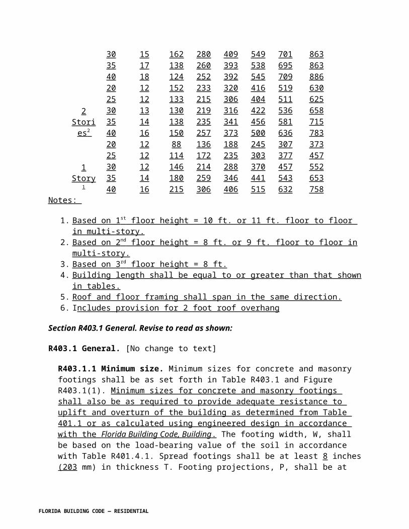
40 10 0.072 0.098 0.129 0.162 0.20040 8 0.057 0.079 0.103 0.130 0.160
150
24 10 0.118 0.164 0.218 0.279 0.34724 8 0.094 0.131 0.174 0.223 0.27832 10 0.091 0.126 0.167 0.213 0.26432 8 0.073 0.101 0.133 0.170 0.21240 10 0.082 0.113 0.148 0.187 0.23040 8 0.066 0.090 0.118 0.149 0.184
Notes:
1. Diaphragm chord tension steel area shall be added to bond beam uplift steel area for total required bond beam area of steel. Select appropriate bar size and number of bars from Table R609.2.2C.2. The tabular value for diaphragm chord tension steel area shall be permitted to be multiplied by a factor of 0.65 for bond beam spans located in the end zone.
FLORIDA BUILDING CODE — RESIDENTIAL 7.82

TABLE R609.2.2A-3 GRADE 40 EXPOSURE BROOF DIAPHRAGM CHORD TENSION BOND BEAM STEEL AREA, IN 2
Vasd asdetermined in
accordance withSection
R301.2.1.3BUILDING
WIDTHWALL
HEIGHT
BUILDING LENGTH
40 50 60 70 80
100
24 10 0.056 0.078 0.104 0.133 0.16524 8 0.045 0.062 0.083 0.106 0.13232 10 0.043 0.060 0.079 0.101 0.12632 8 0.035 0.048 0.063 0.081 0.10140 10 0.039 0.054 0.070 0.089 0.10940 8 0.031 0.043 0.056 0.071 0.087
110
24 10 0.068 0.094 0.125 0.160 0.20024 8 0.054 0.076 0.100 0.128 0.16032 10 0.052 0.073 0.096 0.122 0.15232 8 0.042 0.058 0.077 0.098 0.12240 10 0.047 0.065 0.085 0.107 0.13240 8 0.038 0.052 0.068 0.086 0.106
120
24 10 0.081 0.112 0.149 0.191 0.23824 8 0.064 0.090 0.119 0.153 0.19032 10 0.062 0.086 0.114 0.146 0.18132 8 0.050 0.069 0.091 0.117 0.14540 10 0.056 0.077 0.101 0.128 0.15740 8 0.045 0.062 0.081 0.102 0.126
130
24 10 0.095 0.132 0.175 0.224 0.27924 8 0.076 0.106 0.140 0.179 0.22332 10 0.073 0.101 0.134 0.171 0.21232 8 0.058 0.081 0.107 0.137 0.17040 10 0.066 0.091 0.119 0.150 0.18540 8 0.053 0.073 0.095 0.120 0.148
140
24 10 0.110 0.153 0.203 0.260 0.32424 8 0.088 0.122 0.162 0.208 0.25932 10 0.085 0.117 0.155 0.198 0.24632 8 0.068 0.094 0.124 0.159 0.19740 10 0.077 0.105 0.138 0.174 0.21440 8 0.062 0.084 0.110 0.139 0.171
FLORIDA BUILDING CODE — RESIDENTIAL 7.83

150
24 10 0.126 0.176 0.233 0.298 0.37124 8 0.101 0.140 0.186 0.239 0.29732 10 0.097 0.135 0.178 0.228 0.28332 8 0.078 0.108 0.143 0.182 0.22640 10 0.088 0.121 0.158 0.200 0.24640 8 0.071 0.097 0.126 0.160 0.197
Notes:1. Diaphragm chord tension steel area shall be added to bond beam uplift steel area for total required bond beam area of steel. Select appropriate bar size and number of bars from Table R609.2.2C2. The tabular value for diaphragm chord tension steel area shall be permitted to be multiplied by a factor of 0.65 for bond beam spans located in the end zone.
FLORIDA BUILDING CODE — RESIDENTIAL 7.84

TABLE R609.2.2A-4 GRADE 40 EXPOSURE CROOF DIAPHRAGM CHORD TENSION BOND BEAM STEEL AREA, IN 2
Vasd asdetermined in
accordance with
SectionR301.2.1.3
BUILDING WIDTH
WALL HEIGHT
BUILDING LENGTH
40 50 60 70 80
100
24 10 0.078 0.109 0.145 0.186 0.23124 8 0.063 0.088 0.116 0.149 0.18532 10 0.060 0.084 0.111 0.142 0.17632 8 0.048 0.067 0.089 0.114 0.14140 10 0.055 0.075 0.098 0.124 0.15340 8 0.044 0.060 0.079 0.099 0.123
110
24 10 0.095 0.132 0.176 0.225 0.28024 8 0.076 0.106 0.141 0.180 0.22432 10 0.073 0.102 0.135 0.172 0.21332 8 0.059 0.081 0.108 0.137 0.17140 10 0.067 0.091 0.119 0.150 0.18540 8 0.053 0.073 0.095 0.120 0.148
120
24 10 0.113 0.158 0.209 0.268 0.33324 8 0.090 0.126 0.167 0.214 0.26732 10 0.087 0.121 0.160 0.204 0.25432 8 0.070 0.097 0.128 0.163 0.20340 10 0.079 0.108 0.142 0.179 0.22140 8 0.063 0.087 0.113 0.143 0.176
130
24 10 0.133 0.185 0.245 0.314 0.39124 8 0.1066 0.148 0.196 0.251 0.31332 10 0.102 0.142 0.188 0.240 0.29832 8 0.082 0.114 0.150 0.192 0.23840 10 0.093 0.127 0.166 0.210 0.25940 8 0.074 0.102 0.133 0.168 0.207
140
24 10 0.154 0.214 0.285 0.364 0.45424 8 0.123 0.172 0.288 0.291 0.36332 10 0.119 0.165 0.218 0.278 0.34532 8 0.095 0.132 0.174 0.223 0.27640 10 0.108 0.148 0.193 0.244 0.30040 8 0.086 0.118 0.154 0.195 0.240
FLORIDA BUILDING CODE — RESIDENTIAL 7.85

150
24 10 0.176 0.246 0.327 0.418 0.52124 8 0.141 0.197 0.261 0.335 0.41732 10 0.136 0.189 0.250 0.319 0.39732 8 0.109 0.151 0.200 0.255 0.31740 10 0.124 0.169 0.221 0.280 0.34540 8 0.099 0.136 0.177 0.224 0.276
Notes:
1. Diaphragm chord tension steel area shall be added to bond beam uplift steel area for total required bond beam area of steel. Select appropriate bar size and number of bars from Table R609.2.2C.2. The tabular value for diaphragm chord tension steel area shall be permitted to be multiplied by a factor of 0.65 for bond beam spans located in the end zone.
FLORIDA BUILDING CODE — RESIDENTIAL 7.86

TABLE R609.2.2B-1 GRADE 60AREA OF STEEL REQUIRED IN BOND BEAM FOR UPLIFT BENDING, IN 2
UPLIFT, plf (ALLOWABLE
STRESS DESIGN)
8 IN. BOND BEAM/LINTEL SPAN, FT.
4 6 8 10 12 14 16 1850 0.000 0.000 0.000 0.000 0.000 0.000 0.000 0.000100 0.009 0.021 0.038 0.060 0.088 0.123 NP NP150 0.016 0.037 0.067 0.107 0.159 NP NP NP200 0.023 0.053 0.096 0.157 NP NP NP NP250 0.030 0.069 0.127 0.211 NP NP NP NP300 0.037 0.086 0.160 0.270 NP NP NP NP350 0.044 0.103 0.194 NP NP NP NP NP400 0.051 0.120 0.230 NP NP NP NP NP450 0.058 0.138 0.269 NP NP NP NP NP500 0.065 0.156 NP NP NP NP NP NP550 0.073 0.175 NP NP NP NP NP NP600 0.080 0.195 NP NP NP NP NP NP650 0.088 0.215 NP NP NP NP NP NP700 0.095 0.235 NP NP NP NP NP NP750 0.103 0.257 NP NP NP NP NP NP800 0.110 0.280 NP NP NP NP NP NP850 0.118 NP NP NP NP NP NP NP900 0.126 NP NP NP NP NP NP NP950 0.134 NP NP NP NP NP NP NP1000 0.142 NP NP NP NP NP NP NP1050 0.150 NP NP NP NP NP NP NP1100 0.158 NP NP NP NP NP NP NP
Notes:
1. When reinforcement required is 0.00, only diaphragm chord tension reinforcement is required.2. Diaphragm chord tension steel area shall be added to bond beam uplift steel area for total required bond beam area of steel. Select appropriate bar size and number of bars from Table R609.2.2C.
FLORIDA BUILDING CODE — RESIDENTIAL 7.87

TABLE R609.2.2B-2 GRADE 60AREA OF STEEL REQUIRED IN BOND BEAM FOR UPLIFT BENDING, IN 2
UPLIFT, plf (ALLOWABLE
STRESSDESIGN)
16 IN. BOND BEAM/LINTEL SPAN, FT.
4 6 8 10 12 14 16 1850 0.000 0.000 0.000 0.000 0.000 0.000 0.000 0.000100 0.000 0.000 0.000 0.000 0.000 0.000 0.000 0.000150 0.005 0.010 0.019 0.029 0.042 0.58 0.076 0.097200 0.007 0.017 0.030 0.046 0.067 0.092 0.121 0.154250 0.010 0.023 0.040 0.063 0.092 0.126 0.167 0.214300 0.013 0.029 0.051 0.081 0.117 0.162 0.214 0.275350 0.015 0.035 0.062 0.098 0.143 0.197 0.262 NP400 0.018 0.041 0.073 0.116 0.169 0.234 0.312 NP450 0.021 0.047 0.084 0.134 0.195 0.271 NP NP500 0.023 0.053 0.096 0.152 0.222 0.309 NP NP550 0.026 0.059 0.107 0.170 0.249 0.348 NP NP600 0.029 0.066 0.118 0.188 0.277 0.388 NP NP650 0.032 0.072 0.130 0.206 0.305 0.429 NP NP700 0.034 0.078 0.141 0.225 0.334 NP NP NP750 0.037 0.084 0.152 0.244 0.363 NP NP NP800 0.040 0.091 0.164 0.263 0.392 NP NP NP850 0.042 0.097 0.176 0.282 0.422 NP NP NP900 0.045 0.103 0.187 0.302 0.453 NP NP NP950 0.048 0.110 0.199 0.321 NP NP NP NP1000 0.051 0.116 0.211 0.341 NP NP NP NP1050 0.053 0.122 0.223 0.362 NP NP NP NP1100 0.056 0.129 0.235 0.382 NP NP NP NP
Notes:
1. When reinforcement required is 0.00, only diaphragm chord tension reinforcement is required.2. Diaphragm chord tension steel area shall be added to bond beam uplift steel area for total required bond beam area of steel. Select appropriate bar size and number of bars from Table R609.2.2C.
FLORIDA BUILDING CODE — RESIDENTIAL 7.88

TABLE R609.2.2B-3 GRADE 60AREA OF STEEL REQUIRED IN BOND BEAM FOR UPLIFT BENDING, IN 2
UPLIFT, plf(ALLOWABLE
STRESSDESIGN)
24 IN. BOND BEAM/LINTEL SPAN, FT.
4 6 8 10 12 14 16 1850 0.000 0.000 0.000 0.000 0.000 0.000 0.000 0.000100 0.000 0.000 0.000 0.000 0.000 0.000 0.000 0.000150 0.000 0.000 0.000 0.000 0.000 0.000 0.000 0.000200 0.004 0.008 0.014 0.022 0.032 0.043 0.057 0.072250 0.005 0.012 0.021 0.032 0.047 0.064 0.084 0.106300 0.007 0.015 0.027 0.043 0.062 0.085 0.1111 0.142350 0.009 0.019 0.034 0.054 0.077 0.106 0.139 0.177400 0.010 0.023 0.041 0.064 0.093 0.127 0.167 0.213450 0.012 0.027 0.048 0.075 0.108 0.148 0.195 0.249500 0.014 0.031 0.054 0.086 0.124 0.170 0.224 0.286550 0.015 0.034 0.061 0.096 0.140 0.192 0.253 0.323600 0.017 0.038 0.068 0.107 0.155 0.213 0.282 0.361650 0.019 0.042 0.075 0.118 0.171 0.235 0.311 0.399700 0.020 0.046 0.082 0.129 0.187 0.257 0.341 0.438750 0.022 0.050 0.089 0.140 0.203 0.280 0.371 0.477800 0.024 0.053 0.095 0.150 0.219 0.302 0.401 0.517850 0.025 0.057 0.102 0.161 0.235 0.325 0.423 0.558900 0.027 0.061 0.109 0.172 0.251 0.347 0.462 NP950 0.029 0.065 0.116 0.183 0.268 0.370 0.494 NP1000 0.030 0.069 0.123 0.194 0.284 0.394 0.525 NP1050 0.032 0.072 0.130 0.206 0.301 0.417 0.557 NP1100 0.034 0.076 0.137 0.217 0.317 0.440 NP NP
Notes:
1. When reinforcement required is 0.00, only diaphragm chord tension reinforcement is required.2. Diaphragm chord tension steel area shall be added to bond beam uplift steel area for total required bond beam area of steel. Select appropriate bar size and number of bars from Table R609.2.2C.
FLORIDA BUILDING CODE — RESIDENTIAL 7.89

TABLE R609.2.2B-4 GRADE 60AREA OF STEEL REQUIRED IN BOND BEAM FOR UPLIFT BENDING, IN 2
UPLIFT, plf(ALLOWABLE
STRESS DESIGN)
32 IN. BOND BEAM/LINTEL SPAN, FT.
4 6 8 10 12 14 16 1850 0.000 0.000 0.000 0.000 0.000 0.000 0.000 0.000100 0.000 0.000 0.000 0.000 0.000 0.000 0.000 0.000150 0.000 0.000 0.000 0.000 0.000 0.000 0.000 0.000200 0.000 0.000 0.000 0.000 0.000 0.000 0.000 0.000250 0.003 0.007 0.012 0.019 0.027 0.037 0.048 0.061300 0.004 0.009 0.017 0.026 0.038 0.052 0.068 0.086350 0.005 0.012 0.022 0.034 0.049 0.067 0.087 0.111400 0.007 0.015 0.027 0.042 0.060 0.082 0.107 0.136450 0.008 0.018 0.031 0.049 0.071 0.097 0.127 0.161500 0.009 0.020 0.036 0.057 0.082 0.112 0.147 0.187550 0.010 0.023 0.041 0.065 0.093 0.127 0.167 0.213600 0.011 0.026 0.046 0.072 0.104 0.143 0.187 0.239650 0.013 0.029 0.051 0.080 0.116 0.158 0.208 0.265700 0.014 0.031 0.056 0.088 0.127 0.174 0.288 0.291750 0.015 0.034 0.061 0.095 0.138 0.189 0.249 0.317800 0.016 0.037 0.066 0.103 0.149 0.205 0.269 0.344850 0.018 0.040 0.071 0.111 0.161 0.220 0.290 0.370900 0.019 0.042 0.076 0.119 0.172 0.236 0.311 0.397950 0.020 0.045 0.081 0.127 0.183 0.252 0.332 0.4241000 0.021 0.048 0.085 0.134 0.195 0.267 0.353 0.4511050 0.022 0.051 0.090 0.142 0.206 0.283 0.374 0.4791100 0.024 0.053 0.095 0.150 0.218 0.299 0.395 0.506
Notes:
1. When reinforcement required is 0.00, only diaphragm chord tension reinforcement is required.2. Diaphragm chord tension steel area shall be added to bond beam uplift steel area for total required bond beam area of steel. Select appropriate bar size and number of bars from Table R609.2.2C.
FLORIDA BUILDING CODE — RESIDENTIAL 7.90

TABLE R609.2.2B-5 GRADE 40AREA BOND BEAM/LINTEL UPLIFT STEEL DESIGN
UPLIFT, plf (ALLOWABLE
STRESSDESIGN)
8 IN. BOND BEAM/LINTEL SPAN, FT.
4 6 8 10 12 14 16 1850 0.000 0.000 0.000 0.000 0.000 0.000 0.000 0.000100 0.014 0.032 0.057 0.090 0.132 0.184 NP NP150 0.024 0.055 0.100 0.160 0.239 NP NP NP200 0.034 0.079 0.144 0.235 NP NP NP NP250 0.045 0.103 0.191 NP NP NP NP NP300 0.055 0.128 0.240 NP NP NP NP NP350 0.066 0.154 NP NP NP NP NP NP400 0.076 0.180 NP NP NP NP NP NP450 0.087 0.207 NP NP NP NP NP NP500 0.098 0.234 NP NP NP NP NP NP550 0.109 0.263 NP NP NP NP NP NP600 0.120 NP NP NP NP NP NP NP650 0.131 NP NP NP NP NP NP NP700 0.143 NP NP NP NP NP NP NP750 0.154 NP NP NP NP NP NP NP800 0.166 NP NP NP NP NP NP NP850 0.177 NP NP NP NP NP NP NP900 0.189 NP NP NP NP NP NP NP950 0.201 NP NP NP NP NP NP NP1000 0.213 NP NP NP NP NP NP NP1050 0.225 NP NP NP NP NP NP NP1100 0.238 NP NP NP NP NP NP NP
Notes:
1. When reinforcement required is 0.00, only diaphragm chord tension reinforcement is required.2. Diaphragm chord tension steel area shall be added to bond beam uplift steel area for total required bond beam area of steel. Select appropriate bar size and number of bars from Table R609.2.2C.
FLORIDA BUILDING CODE — RESIDENTIAL 7.91

TABLE R609.2.2B-6 GRADE 40AREA BOND BEAM/LINTEL UPLIFT STEEL DESIGN
UPLIFT, plf(ALLOWABLE
STRESSDESIGN)
16 IN. BOND BEAM/LINTEL SPAN, FT.
4 6 8 10 12 14 16 1850 0.000 0.000 0.000 0.000 0.000 0.000 0.000 0.000100 0.000 0.000 0.000 0.000 0.000 0.000 0.000 0.000150 0.007 0.016 0.028 0.044 0.063 0.087 0.114 0.145200 0.011 0.025 0.044 0.069 0.101 0.138 0.181 0.231250 0.015 0.034 0.061 0.095 0.138 0.190 0.250 0.320300 0.019 0.043 0.077 0.121 0.176 0.242 0.321 0.413350 0.023 0.052 0.093 0.147 0.215 0.296 0.393 NP400 0.027 0.061 0.110 0.174 0.254 0.351 0.468 NP450 0.031 0.071 0.127 0.200 0.293 0.407 NP NP500 0.035 0.080 0.143 0.227 0.333 0.464 NP NP550 0.039 0.089 0.160 0.254 0.374 0.523 NP NP600 0.043 0.098 0.177 0.282 0.415 0.583 NP NP650 0.047 0.108 0.194 0.310 0.458 0.644 NP NP700 0.051 0.117 0.211 0.338 0.500 NP NP NP750 0.056 0.126 0.229 0.366 0.544 NP NP NP800 0.060 0.136 0.246 0.394 0.588 NP NP NP850 0.064 0.145 0.264 0.423 0.633 NP NP NP900 0.068 0.155 0.281 0.453 0.679 NP NP NP950 0.072 0.164 0.299 0.482 NP NP NP NP1000 0.076 0.174 0.317 0.512 NP NP NP NP1050 0.080 0.183 0.335 0.542 NP NP NP NP1100 0.084 0.193 0.353 0.573 NP NP NP NP
Notes:
1. When reinforcement required is 0.00, only diaphragm chord tension reinforcement is required.2. Diaphragm chord tension steel area shall be added to bond beam uplift steel area for total required bond beam area of steel. Select appropriate bar size and number of bars from Table R609.2.2C.
FLORIDA BUILDING CODE — RESIDENTIAL 7.92

TABLE R609.2.2B-7 GRADE 40AREA BOND BEAM/LINTEL UPLIFT STEEL DESIGN
UPLIFT, plf(ALLOWABLE
STRESS DESIGN)
24 IN. BOND BEAM/LINTEL SPAN, FT.
4 6 8 10 12 14 16 1850 0.000 0.000 0.000 0.000 0.000 0.000 0.000 0.000100 0.000 0.000 0.000 0.000 0.000 0.000 0.000 0.000150 0.000 0.000 0.000 0.000 0.000 0.000 0.000 0.000200 0.005 0.012 0.021 0.033 0.048 0.065 0.085 0.108250 0.008 0.017 0.031 0.049 0.070 0.096 0.126 0.160300 0.010 0.023 0.041 0.065 0.093 0.127 0.167 0.212350 0.013 0.029 0.051 0.080 0.116 0.159 0.209 0.266400 0.015 0.034 0.061 0.096 0.139 0.191 0.251 0.319450 0.018 0.040 0.072 0.112 0.163 0.223 0.293 0.374500 0.020 0.046 0.082 0.128 0.186 0.255 0.336 0.429550 0.023 0.051 0.092 0.144 0.209 0.287 0.379 0.485600 0.025 0.057 0.102 0.161 0.233 0.320 0.423 0.542650 0.028 0.063 0.112 0.177 0.257 0.353 0.467 0.599700 0.030 0.069 0.123 0.193 0.280 0.386 0.511 0.657750 0.033 0.074 0.133 0.209 0.304 0.419 0.556 0.716800 0.035 0.080 0.143 0.226 0.329 0.453 0.601 0.776850 0.038 0.086 0.154 0.242 0.353 0.487 0.647 0.837900 0.040 0.091 0.164 0.259 0.377 0.521 0.694 NP950 0.043 0.097 0.174 0.275 0.402 0.556 0.741 NP1000 0.045 0.103 0.185 0.292 0.426 0.590 0.788 NP1050 0.048 0.109 0.195 0.308 0.451 0.625 0.836 NP1100 0.051 0.114 0.205 0.325 0.476 0.661 NP NP
Notes:
1. When reinforcement required is 0.00, only diaphragm chord tension reinforcement is required.2. Diaphragm chord tension steel area shall be added to bond beam uplift steel area for total required bond beam area of steel. Select appropriate bar size and number of bars from Table R609.2.2C.
FLORIDA BUILDING CODE — RESIDENTIAL 7.93

TABLE R609.2.2B-8 GRADE 40AREA BOND BEAM/LINTEL UPLIFT STEEL DESIGN
UPLIFT, plf(ALLOWABLE
STRESS DESIGN)
32 IN. BOND BEAM/LINTEL SPAN, FT.
4 6 8 10 12 14 16 1850 0.000 0.000 0.000 0.000 0.000 0.000 0.000 0.000100 0.000 0.000 0.000 0.000 0.000 0.000 0.000 0.000150 0.000 0.000 0.000 0.000 0.000 0.000 0.000 0.000200 0.000 0.000 0.000 0.000 0.000 0.000 0.000 0.000250 0.004 0.010 0.018 0.028 0.040 0.055 0.072 0.091300 0.006 0.014 0.025 0.039 0.057 0.077 0.101 0.129350 0.008 0.018 0.033 0.051 0.073 0.100 0.131 0.166400 0.010 0.022 0.040 0.062 0.090 0.123 0.161 0.204450 0.012 0.026 0.047 0.074 0.107 0.145 0.191 0.242500 0.014 0.031 0.054 0.085 0.123 0.168 0.221 0.281550 0.015 0.035 0.062 0.097 0.140 0.191 0.251 0.319600 0.017 0.039 0.069 0.108 0.157 0.214 0.281 0.358650 0.019 0.043 0.077 0.120 0.173 0.237 0.312 0.397700 0.021 0.047 0.084 0.132 0.190 0.260 0.342 0.436750 0.023 0.051 0.091 0.143 0.207 0.284 0.373 0.476800 0.025 0.055 0.099 0.155 0.224 0.307 0.404 0.515850 0.026 0.059 0.106 0.166 0.241 0.330 0.435 0.556900 0.028 0.064 0.113 0.178 0.258 0.354 0.466 0.596950 0.030 0.068 0.121 0.190 0.275 0.377 0.497 0.6361000 0.032 0.072 0.128 0.201 0.292 0.401 0.529 0.6771050 0.034 0.076 0.136 0.213 0.309 0.425 0.561 0.7181100 0.035 0.080 0.143 0.225 0.326 0.449 0.592 0.760
Notes:
1. When reinforcement required is 0.00, only diaphragm chord tension reinforcement is required.2. Diaphragm chord tension steel area shall be added to bond beam uplift steel area for total required bond beam area of steel. Select appropriate bar size and number of bars from Table R609.2.2C.
FLORIDA BUILDING CODE — RESIDENTIAL 7.94

TABLE R609.2.2CBOND BEAM AREA OF STEEL PROVIDED IN 2 /FT
NUMBER OF BARS BAR SIZENo. 4 No. 5 No. 6
1 0.20 0.31 0.442 0.40 0.62 0.88
Figure R609.2.4Corner Continuity of Bond Beam and Wall Reinforcement
FLORIDA BUILDING CODE — RESIDENTIAL 7.95

Figure R609.2.5Changes in Bond Beam Height
R609.3 Vertical Reinforcement . Vertical reinforcement shall be provided in conformance with Sections R609.3.1 through R609.3.6.
R609.3.1 One reinforcement bar shall be provided in each corner, including interior corners and corners created by changes in wall direction or offsetting of walls.
R609.3.2 Openings. A minimum of one bar of the size used for vertical wall reinforcement shall be provided on each side of openings wider than 6 feet. If more vertical reinforcement is interrupted by an opening than is provided beside the opening (total in the first and second cells adjacent to the opening), one-half of the equivalent area of reinforcement interrupted by the opening shall be placed on each side of the opening. This reinforcement shall be placed within the first and/or second cells beside the opening.
R609.3.2 .1 Girders. At least one reinforcement bar shall be provided where girders or girder trusses bear on masonry walls.
R609.3.3 Spacing. Vertical reinforcement shall be provided as set forth in Tables R609.3.3.A-1 through Table R609.3.3A-4 and R609.3.3.B-1, through R609.3.3B-4 as applicable.
R609.3.4 Precast bond beams. Vertical reinforcement used in conjunction with precast bond beams shall be spaced the same as for masonry bond beams. Reinforcement shall terminate in the precast beam as set forth in Section R606.13.8.
FLORIDA BUILDING CODE — RESIDENTIAL 7.96

R609.3.5 Duplication. Reinforcing steel requirements shall not be additive. A single bar shall be permitted to satisfy multiple requirements.
R609.3.6 Termination. Vertical reinforcement shall terminate in footings and bond beams as set forth in Section R606.16.8.
TABLE R609.3.3A-1 GRADE 60SINGLE STORY AND TOP STORY WALLS PARALLEL TO RIDGE
VERTICAL REINFORCEMENT SPACING NO. 5 BARS ( 5 / 8 IN.)EXPOSURE B B B C C C
Vasd asdetermined in
accordance with
SectionR301.2.1.3
WALL HEIGHT
7BUILDING WIDTH
24 32 40 24 32 40
100
8.00 9.87 9.87 9.87 8.34 8.34 8.348.67 9.97 9.97 9.97 8.42 8.42 8.429.33 10.06 10.06 10.06 8.49 8.49 8.4910.00 10.14 10.14 10.14 8.57 8.57 8.54
EXPOSURE B B B C C CVasd as
determined inaccordance
withSection
R301.2.1.3WALL
HEIGHT
BUILDING WIDTH
24 32 40 24 32 40
110
8.00 8.97 8.7 8.97 7.58 7.58 7.588.67 9.06 9.06 9.06 7.65 7.56 7.659.33 9.14 9.14 9.14 7.72 7.72 7.7210.00 9.22 9.22 9.22 7.79 7.79 7.79
EXPOSURE B B B C C CVasd as
determined inaccordance
withSection
R301.2.1.3WALL
HEIGHT
BUILDING WIDTH
24 32 40 24 32 40
120
8.00 8.23 8.23 8.23 6.95 6.95 6.958.67 8.30 8.30 8.30 7.01 7.01 7.019.33 8.38 8.38 8.38 7.08 7.08 7.0810.00 8.45 8.45 8.45 6.87 6.87 6.87
FLORIDA BUILDING CODE — RESIDENTIAL 7.97

EXPOSURE B B B C C CVasd as
determined in accordance
withSection
R301.2.1.3WALL
HEIGHT
BUILDING WIDTH
24 32 40 24 32 40
130
8.00 7.59 7.59 7.59 6.41 6.41 6.218.67 7.67 7.67 7.67 6.47 6.14 5.679.33 7.73 7.73 7.57 6.03 5.58 5.1910.00 7.80 7.36 6.90 5.44 5.07 4.74
EXPOSURE B B B C C CVasd as
determined inaccordance
withSection
R301.2.1.3WALL
HEIGHT
BUILDING WIDTH
24 32 40 24 32 40
140
8.00 7.05 7.05 7.05 5.95 5.76 5.278.67 7.12 7.12 7.01 5.70 5.22 4.829.33 7.18 6.88 6.40 5.14 4.75 4.4110.00 6.70 6.24 5.85 4.64 4.32 4.04
EXPOSURE B B B C C CVasd as
determined inaccordance
withSection
R301.2.1.3WALL
HEIGHT
BUILDING WIDTH
24 32 40 24 32 40
150
8.00 6.58 6.58 6.58 5.46 4.96 4.548.67 6.64 6.50 6.01 4.91 4.50 4.159.33 6.39 5.91 5.49 4.43 4.09 3.8010.00 5.76 5.37 5.02 4.00 3.72 3.48
FLORIDA BUILDING CODE — RESIDENTIAL 7.98

TABLE R609.3.3A-2 GRADE 60SINGLE STORY AND TOP STORY WALLS PARALLEL TO RIDGE
VERTICAL REINFORCEMENT SPACING NO. 4 BARS ( 1 / 2 IN.)EXPOSURE B B B C C C
Vasd asdetermined in
accordance withSection
R301.2.1.3WALL
HEIGHT
BUILDING WIDTH
24 32 40 24 32 40
100
8.00 9.87 9.87 9.87 8.34 7.97 7.328.67 9.97 9.97 9.97 7.79 7.17 6.659.33 10.06 9.69 9.08 6.98 6.48 6.0510.00 9.06 8.72 8.22 6.27 5.87 5.51
EXPOSURE B B B C C CVasd as
determined inaccordance with
SectionR301.2.1.3
WALL HEIGHT
BUILDING WIDTH
24 32 40 24 32 40
110
8.00 8.97 8.97 8.76 7.01 6.38 5.858.67 9.06 9.06 9.06 6.83 6.83 6.839.33 8.45 8.45 8.45 5.99 5.99 5.9910.00 7.47 7.47 7.47 5.30 5.30 5.30
EXPOSURE B B B C C CVasd as
determined in accordance with
SectionR301.2.1.3
WALL HEIGHT
BUILDING WIDTH
24 32 40 24 32 40
120
8.00 8.23 7.72 7.09 5.75 5.23 4.808.67 8.07 8.07 8.07 5.72 5.72 5.729.33 7.08 7.08 7.08 5.02 5.02 5.0210.00 6.26 6.26 6.26 4.43 4.43 4.43
EXPOSURE B B B C C CVasd as
determined in accordance with
SectionR301.2.1.3
WALL HEIGHT
BUILDING WIDTH
24 32 40 24 32 40130 8.00 7.04 6.41 5.88 4.82 4.38 4.01
FLORIDA BUILDING CODE — RESIDENTIAL 7.99

8.67 6.29 5.78 5.35 4.32 3.96 3.669.33 5.65 5.24 4.88 3.89 3.60 3.3510.00 5.09 4.75 4.45 3.51 3.27 3.06
EXPOSURE B B B C C CVasd as
determined inaccordance with
SectionR301.2.1.3
WALL HEIGHT
BUILDING WIDTH
24 32 40 24 32 40
140
8.00 5.95 5.41 4.08 4.09 3.72 3.408.67 5.33 4.89 4.52 3.68 3.37 3.119.33 4.79 4.44 4.13 3.31 3.08 2.8510.00 4.32 4.00 3.77 2.99 2.78 2.60
EXPOSURE B B B C C CVasd as
determined inaccordance with
SectionR301.2.1.3
WALL HEIGHT
BUILDING WIDTH
24 32 40 24 32 40
150
8.00 5.10 4.63 4.25 3.53 3.20 2.938.67 4.57 4.20 3.87 3.17 2.90 2.689.33 4.12 3.81 3.54 2.86 2.64 2.4510.00 3.71 3.46 3.24 2.58 2.40 2.24
FLORIDA BUILDING CODE — RESIDENTIAL

TABLE R609.3.3A-3 GRADE 40SINGLE STORY AND TOP STORY WALLS PARALLEL TO RIDGE
VERTICAL REINFORCEMENT SPACING NO. 5 BARS ( 5 / 8 IN.)EXPOSURE B B B C C C
Vasd as determined in
accordance withSection
R301.2.1.3WALL
HEIGHT
BUILDING WIDTH
24 32 40 24 32 40
100
8.00 9.87 9.87 9.87 8.34 8.23 7.578.67 9.97 9.97 9.97 8.05 7.41 6.879.33 10.06 10.01 9.38 7.22 6.70 6.2510.00 9.36 9.01 8.49 6.48 6.06 5.69
EXPOSURE B B B C C CVasd as
determined in accordance with
SectionR301.2.1.3
WALL HEIGHT
BUILDING WIDTH
24 32 40 24 32 40
110
8.00 8.97 8.97 8.97 7.24 6.59 6.058.67 9.06 9.06 9.06 7.06 7.06 7.069.33 8.73 8.73 8.73 6.19 6.19 6.1910.00 7.72 7.72 7.72 5.47 5.47 5.47
EXPOSURE B B B C C CVasd as
determined inaccordance with
SectionR301.2.1.3
WALL HEIGHT
BUILDING WIDTH
24 32 40 24 32 40
120
8.00 8.23 7.98 7.33 5.95 5.41 4.968.67 8.30 8.30 8.30 5.92 5.92 5.929.33 7.32 7.32 7.32 5.19 5.19 5.1910.00 6.47 6.47 6.47 4.58 4.58 4.58
EXPOSURE B B B C C CVasd as
determined inaccordance with
SectionR301.2.1.3
WALL HEIGHT
BUILDING WIDTH
24 32 40 24 32 40130 8.00 7.27 6.62 6.07 4.98 4.52 4.14
FLORIDA BUILDING CODE — RESIDENTIAL

8.67 6.50 5.98 5.53 4.47 4.10 3.789.33 5.84 5.41 5.04 4.02 3.72 3.4610.00 5.26 4.91 4.60 3.63 3.38 3.16
EXPOSURE B B B C C CVasd as
determined inaccordance with
SectionR301.2.1.3
WALL HEIGHT
BUILDING WIDTH
24 32 40 24 32 40
140
8.00 6.15 5.59 5.13 4.23 3.84 3.528.67 5.51 5.06 4.67 3.80 3.48 3.219.33 4.95 4.59 4.27 3.43 3.17 2.9410.00 4.46 4.16 3.90 3.09 2.88 2.69
EXPOSURE B B B C C CVasd as
determined inaccordance with
SectionR301.2.1.3
WALL HEIGHT
BUILDING WIDTH
24 32 40 24 32 40
150
8.00 5.27 4.79 4.39 3.64 3.31 3.028.67 4.73 4.34 4.00 3.27 3.00 2.769.33 4.26 3.94 3.66 2.95 2.73 2.5310.00 3.84 3.58 3.35 2.66 2.48 2.32
FLORIDA BUILDING CODE — RESIDENTIAL

TABLE R609.3.3A-4 GRADE 40SINGLE STORY AND TOP STORY WALLS PARALLEL TO RIDGE
VERTICAL REINFORCEMENT SPACING NO. 4 BARS ( 1 / 2 IN.)
EXPOSURE B B B C C CVasd as
determined inaccordance with
SectionR301.2.1.3
WALL HEIGHT
BUILDING WIDTH
24 32 40 24 32 40
100
8.00 8.78 8.04 7.42 5.82 5.31 4.888.67 7.77 7.19 6.69 5.19 4.78 4.439.33 6.83 6.46 6.05 4.66 4.32 4.0310.00 6.04 5.81 5.48 4.18 3.91 3.67
EXPOSURE B B B C C CVasd as
determined inaccordance with
SectionR301.2.1.3
WALL HEIGHT
BUILDING WIDTH
24 32 40 24 32 40
110
8.00 6.94 6.34 5.84 4.67 4.25 3.908.67 6.42 6.42 6.42 4.56 4.56 4.569.33 5.63 5.63 5.63 4.00 4.00 4.0010.00 4.98 4.98 4.98 3.53 3.53 3.53
EXPOSURE B B B C C CVasd as
determined in accordance with
SectionR301.2.1.3
WALL HEIGHT
BUILDING WIDTH
24 32 40 24 32 40
120
8.00 5.64 5.15 4.73 3.84 3.49 3.208.67 5.38 5.38 5.38 3.82 3.82 3.829.33 4.72 4.72 4.72 3.35 3.35 3.3510.00 4.17 4.17 4.17 2.95 2.95 2.95
EXPOSURE B B B C C CVasd as
determined inaccordance with
SectionR301.2.1.3
WALL HEIGHT
BUILDING WIDTH
24 32 40 24 32 40130 8.00 4.69 4.27 3.92 3.21 2.92 2.67
FLORIDA BUILDING CODE — RESIDENTIAL

8.67 4.19 3.86 3.57 2.88 2.64 2.449.33 3.77 3.49 3.25 2.60 2.40 2.2310.00 3.39 3.17 2.97 2.34 2.18 2.04
EXPOSURE B B B C C CVasd as
determined inaccordance with
SectionR301.2.1.3
WALL HEIGHT
BUILDING WIDTH
24 32 40 24 32 40
140
8.00 3.97 3.61 3.31 2.73 2.46 2.278.67 3.55 3.26 3.01 2.45 2.25 2.079.33 3.20 2.96 2.75 2.21 2.04 1.9010.00 2.88 2.69 2.52 1.99 1.86 1.74
EXPOSURE B B B C C CVasd as
determined in accordance with
SectionR301.2.1.3
WALL HEIGHT
BUILDING WIDTH
24 32 40 24 32 40
150
8.00 3.40 3.09 2.83 2.35 2.13 1.958.67 3.05 2.80 2.58 2.11 1.93 1.789.33 2.75 2.54 2.36 1.90 1.76 1.6310.00 2.48 2.31 2.16 1.72 1.60 1.50
FLORIDA BUILDING CODE — RESIDENTIAL

TABLE R609.3.3B-1 GRADE 60MAXIMUM SPACING OF NO. 5 ( 5 / 8 IN.) VERTICAL REINFORCEMENT AT
CONTINUOUS CONCRETE MASONRY LOWER STORIES OF MULTISTORY AND GABLE ENDS SINGLE STORY OR TOP STORY OF MULTISTORY, FEET
Vasd as determined
inaccordance
withSection
R301.2.1.3 100 110 120 130 140 150
EXP
WALL HT
END ZON
E
INT ZON
E
END ZON
E
INT ZON
E
END ZON
E
INT ZON
E
END ZON
E
INT ZON
E
END ZON
E
INT ZON
E
END ZON
E
INT ZON
E
B
8 9.87 10.53 8.97 9.57 8.23 8.78 7.59 8.10 7.05 7.52 6.58 7.028.67 9.97 10.59 9.06 9.63 8.30 8.82 7.67 8.15 7.12 7.56 6.64 7.069.33 10.06 10.64 9.14 9.68 8.38 8.87 7.73 8.19 7.18 7.60 6.70 7.1010 10.14 10.69 9.22 9.72 8.45 8.91 7.80 8.23 7.08 7.64 6.14 6.8512 10.17 10.83 8.38 9.14 7.01 7.65 5.95 6.49 5.10 5.57 4.42 4.8314 7.75 8.29 6.37 6.82 5.33 5.70 4.51 4.83 3.86 4.14 3.34 3.5816 6.12 6.43 5.03 5.29 4.19 4.41 3.55 3.73 3.03 3.19 2.62 2.7618 4.97 5.14 4.07 4.21 3.39 3.51 2.86 2.96 2.44 2.53 2.10 2.1820 4.12 4.20 3.38 3.44 2.81 2.86 2.36 2.41 2.01 2.05 1.72 1.7622 3.48 3.49 2.84 2.85 2.36 2.36 1.98 1.99 1.68 1.68 1.43 1.44
C
8 8.34 8.89 7.58 8.09 6.95 7.41 6.41 6.84 5.95 6.35 5.56 5.938.67 8.42 8.94 7.65 8.13 7.01 7.45 6.47 6.88 6.01 6.39 5.24 5.969.33 8.49 8.99 7.72 8.17 7.08 7.49 6.52 6.91 5.53 6.37 4.75 5.5310 8.57 9.03 7.79 8.21 6.87 7.53 5.83 6.50 5.00 5.58 4.31 4.8412 7.21 7.86 5.92 6.47 4.95 5.40 4.19 4.58 3.59 3.92 3.10 3.3914 5.47 5.86 4.49 4.81 3.75 4.01 3.16 3.39 2.70 2.90 2.33 2.5016 4.31 4.54 3.53 3.72 2.94 3.09 2.47 2.61 2.11 2.22 1.81 1.9118 3.49 3.61 2.85 2.95 2.37 2.45 1.99 2.06 1.68 1.75 1.44 1.4920 2.89 2.94 2.35 2.40 1.94 1.98 1.63 1.66 1.37 1.40 1.16 1.1922 2.43 2.43 1.97 1.98 1.62 1.63 1.35 1.35 1.13 1.14 1.03 1.26
FLORIDA BUILDING CODE — RESIDENTIAL

TABLE R609.3.3B-2 GRADE60 MAXIMUM SPACING OF NO. 4 ( 1 / 2 IN.) VERTICAL REINFORCEMENT AT
CONTINUOUS MASONRY LOWER STORIES OF MULTISTORY AND GABLE ENDS SINGLE STORY OR TOP STORY OF MULTISTORY, FEET
Vasd as determine
d inaccordanc
e withSection
R301.2.1.3 100 110 120 130 140 150
EXP
WALL HT
END ZON
E
INT ZON
E
END ZON
E
INT ZON
E
END ZON
E
INT ZON
E
END ZON
E
INT ZON
E
END ZON
E
INT ZON
E
END ZON
E
INT ZON
E
B
8 9.87 10.53 8.97 9.57 8.23 8.78 7.59 8.10 6.42 7.52 5.47 6.688.67 9.97 10.59 9.06 9.63 8.07 8.82 6.86 7.76 5.77 6.68 4.93 5.809.33 10.06 10.64 8.45 9.48 7.08 7.95 6.02 6.76 5.17 5.81 4.46 5.0510 9.06 10.09 7.47 8.32 6.26 6.97 5.32 5.92 4.57 5.09 3.96 4.4212 6.56 7.16 5.40 5.89 4.52 4.93 3.84 4.19 3.29 3.59 2.85 3.1214 5.00 5.35 4.11 4.40 3.44 3.68 2.91 3.12 2.49 2.67 2.16 2.3116 3.95 4.15 3.24 3.41 2.71 2.85 2.29 2.41 1.96 2.06 1.69 1.7818 3.21 3.31 2.63 2.72 2.19 2.27 1.85 1.91 1.58 1.63 1.36 1.4120 2.66 2.71 2.18 2.22 1.81 1.84 1.52 1.55 1.30 1.32 1.11 1.1322 2.25 2.25 1.83 1.84 1.52 1.53 1.28 1.28 1.08 1.09 0.93 0.93
C
8 8.34 8.89 7.58 8.09 6.20 7.41 5.15 6.29 4.36 5.30 3.73 4.538.67 8.29 8.94 6.83 7.73 5.58 6.48 4.65 5.50 3.94 4.73 3.38 4.099.33 7.28 8.17 5.99 6.73 5.02 5.64 4.21 4.79 3.57 4.11 3.06 3.5710 6.43 7.16 5.30 5.90 4.43 4.94 3.76 4.19 3.22 3.60 2.78 3.1212 4.65 5.07 3.82 4.17 3.19 3.49 2.70 2.95 2.31 2.53 2.00 2.1914 3.53 3.78 2.90 3.10 2.42 2.59 2.04 2.19 1.74 1.87 1.50 1.6116 2.78 2.93 2.28 2.40 1.90 2.00 1.60 1.68 1.36 1.43 1.17 1.2318 2.25 2.33 1.84 1.90 1.53 1.58 1.28 1.33 1.09 1.13 0.93 0.9620 1.86 1.90 1.52 1.55 1.25 1.28 1.05 1.07 0.88 0.90 0.75 0.7722 1.57 1.57 1.27 1.28 1.05 1.05 0.87 0.87 0.73 0.73 0.67 0.81
FLORIDA BUILDING CODE — RESIDENTIAL

TABLE R609.3.3B-3 GRADE 40MAXIMUM SPACING OF NO. 5 ( 5 / 8 IN.) VERTICAL REINFORCEMENT AT
CONTINUOUS CONCRETE MASONRY LOWER STORIES OF MULTISTORY AND GABLE ENDS SINGLE STORY OR TOP STORY OF MULTISTORY, FEET
Vasd as determined
inaccordance
with Section
R301.2.1.3 100 110 120 130 140 150
EXP
WALL HT
END ZON
E
INT ZON
E
END ZON
E
INT ZON
E
END ZON
E
INT ZON
E
END ZON
E
INT ZON
E
END ZON
E
INT ZON
E
END ZON
E
INT ZON
E
B
8 9.87 10.53 8.97 9.57 8.23 8.78 7.59 8.10 6.63 7.52 5.65 6.918.67 9.97 10.59 9.06 9.63 8.30 8.82 7.09 8.02 5.97 6.90 5.09 5.999.33 10.06 10.64 8.73 9.68 7.32 8.21 6.22 6.98 5.35 6.00 4.61 5.2110 9.36 10.42 7.72 8.60 6.47 7.20 5.49 6.12 4.72 5.26 4.10 4.5712 6.78 7.39 5.58 6.09 4.67 5.10 3.96 4.33 3.40 3.71 2.95 3.2214 5.16 5.53 4.25 4.55 3.55 3.80 3.01 3.22 2.58 2.76 2.23 2.3916 4.08 4.29 3.35 3.52 2.80 2.94 2.36 2.49 2.02 2.13 1.74 1.8418 3.31 3.43 2.72 2.81 2.26 2.34 1.91 1.98 1.63 1.69 1.40 1.4520 2.75 2.80 2.25 2.29 1.87 1.90 1.57 1.60 1.34 1.36 1.15 1.1722 2.32 2.33 1.90 1.90 1.57 1.58 1.32 1.32 1.12 1.12 0.00 0.00
C
8 8.34 8.89 7.58 8.09 6.40 7.41 5.32 6.50 4.50 5.47 3.86 4.688.67 8.42 8.94 7.06 7.99 5.77 6.69 4.80 5.69 4.07 4.89 3.49 4.229.33 7.52 8.44 6.19 6.95 5.19 5.82 4.35 4.95 3.69 4.25 3.17 3.6810 6.65 7.40 5.47 6.10 4.58 5.10 3.88 4.33 3.33 3.72 2.87 3.2212 4.80 5.24 3.95 4.31 3.30 3.60 2.79 3.05 2.39 2.61 2.07 2.2614 3.65 3.91 3.00 3.21 2.50 2.68 2.11 2.26 1.80 1.93 1.55 1.6716 2.88 3.02 2.35 2.48 1.96 2.06 1.65 1.74 1.40 1.48 1.21 1.2718 2.33 2.41 1.90 1.97 1.58 1.63 1.32 1.37 1.12 1.16 0.00 0.0020 1.92 1.96 1.57 1.60 1.30 1.32 1.08 1.10 0.00 0.00 0.00 0.0022 1.62 1.62 1.31 1.32 1.08 1.09 0.00 0.00 0.00 0.00 0.00 0.00
FLORIDA BUILDING CODE — RESIDENTIAL

TABLE R609.3.3B-4 GRADE 40MAXIMUM SPACING OF NO. 4 ( 1 / 2 IN.) VERTICAL REINFORCEMENT AT
CONTINUOUS CONCRETE OR MASONRY LOWER STORIES OF MULTISTORY AND GABLE ENDS SINGLE STORY OR TOP STORY OF MULTISTORY, FEET
Vasd as determined in
accordance with
Section R301.2.1.3 100 110 120 130 140 150
EXP
WALL HT
END ZONE
INT ZONE
END ZONE
INT ZONE
END ZONE
INT ZONE
END ZONE
INT ZONE
END ZONE
INT ZONE
END ZONE
INT ZONE
B
8 8.89 10.23 7.41 8.44 6.21 7.08 5.10 6.02 4.28 5.18 3.64 4.468.67 7.78 8.80 6.42 7.26 5.38 6.09 4.57 5.17 3.85 4.45 3.29 3.879.33 6.83 7.66 5.63 6.32 4.72 5.30 4.01 4.50 3.45 3.87 2.97 3.3610 6.04 6.73 4.98 5.55 4.17 4.65 3.54 3.95 3.05 3.39 2.64 2.9512 4.38 4.77 3.60 3.93 3.02 3.29 2.56 2.79 2.19 2.40 1.90 2.0814 3.33 3.56 2.74 2.93 2.29 2.45 1.94 2.08 1.66 1.78 1.44 1.5416 2.63 2.77 2.16 2.27 1.80 1.90 1.53 1.61 1.30 1.37 1.13 1.1918 2.14 2.21 1.75 1.81 1.46 1.51 1.23 1.27 1.05 1.09 0.90 0.9420 1.77 1.81 1.45 1.48 1.21 1.23 1.02 1.03 0.86 0.88 0.74 0.7622 1.50 1.50 1.22 1.23 1.01 1.02 0.85 0.85 0.72 0.72 0.00 0.00
C
8 6.38 7.28 5.08 6.00 4.13 5.03 3.43 4.19 2.90 3.53 2.49 3.028.67 5.53 6.25 4.56 5.15 3.72 4.32 3.10 3.67 2.62 3.15 2.25 2.729.33 4.85 5.44 4.00 4.49 3.35 3.76 2.80 3.19 2.38 2.74 2.04 2.3810 4.29 4.78 3.53 3.93 2.95 3.29 2.51 2.79 2.15 2.40 1.85 2.0812 3.10 3.38 2.55 2.78 2.13 2.32 1.80 1.97 1.54 1.69 1.33 1.4614 2.35 2.52 1.93 2.07 1.61 1.73 1.36 1.46 1.16 1.25 1.00 1.0816 1.85 1.95 1.52 1.60 1.26 1.33 1.06 1.12 0.91 0.96 0.78 0.8218 1.50 1.55 1.23 1.27 1.02 1.05 0.85 0.89 0.72 0.75 0.00 0.0020 1.24 1.26 1.01 1.03 0.84 0.85 0.70 0.71 0.00 0.00 0.00 0.0022 1.04 1.05 0.85 0.85 0.70 0.70 0.00 0.00 0.00 0.00 0.00 0.00
R609.3.4 Precast bond beams. Vertical reinforcement used in conjunction with precast bond beams shall be spaced the same as for masonry bond beams. Reinforcement shall terminate in the precast beam as set forth in Section R606.9.8.
R609.3.5 Duplication. Reinforcing steel requirements shall not be additive. A single bar shall be permitted to satisfy multiple requirements.
R609.3.6 Termination. Vertical reinforcement shall terminate in footings and bond beams as set forth in Section R606.9.8.
FLORIDA BUILDING CODE — RESIDENTIAL

R609.4 Masonry gables . Gable end walls of concrete or masonry shall be constructed full height to the roof line.
Exception: Gable end trusses or wood framed gable end walls in conformance with Tables R609.4A and R609.4B and Figure R609.4. Wood gable stud wall connectors shall be capable of resisting the vertical and horizontal loads of Table R609.4B as well as the uplift load stipulated at Figure R609.4. Where masonry gable end walls do not go to the roof, a bond beam complying with Section R609.2 shall be provided at the top of the masonry.
TABLE R609.4AWOOD GABLE BRACE NAILING
Vasd asdetermined inaccordance with SectionR301.2.1.3
NAIL SIZE
RAKE HEIGHT
12 14 16 18 20 22
EXPOSURE B
10010d 4 4 5 5 6 68d 6 7 8 8 9 10
11010d 4 5 6 6 7 78d 7 8 9 10 11 11
12010d 5 6 7 7 8 88d 9 10 11 12 13 13
13010d 6 7 8 9 10 108d 10 11 13 14 15 15
14010d 7 8 9 10 11 118d 12 13 15 16 18 18
15010d 8 9 11 12 13 138d 13 15 17 19 20 20
EXPOSURE C
10010d 5 6 7 7 8 88d 8 9 11 12 13 13
11010d 6 7 8 9 10 108d 10 11 13 14 15 15
12010d 7 8 9 10 11 118d 12 14 15 17 18 18
13010d 9 10 11 12 13 138d 14 16 18 20 22 22
14010d 10 12 13 14 15 158d 16 19 21 23 25 25
15010d 12 13 15 16 18 188d 19 21 24 26 29 29
FLORIDA BUILDING CODE — RESIDENTIAL

TABLE R609.4BWOOD GABLE STUD CONNECTOR LOADS
Vasd as determine
d in accordance
with Section
R301.2.1.3ROOF ZONE
CONNECTOR LOADS(Allowable
Stress Design)
WALLZONEVERT HORIZ 1
EXPOSURE B
1002E 43 16 1E2E 43 11 1
1102E 53 20 1E2E 53 13 1
1202E 62 23 1E2E 62 15 1
1302E 73 27 1E2E 73 18 1
1402E 85 32 1E2E 85 21 1
1502E 98 36 1E2E 98 24 1
EXPOSURE C
1002E 61 23 1E2E 61 15 1
1102E 74 28 1E2E 74 18 1
1202E 88 33 1E2E 88 22 1
1302E 103 38 1E2E 103 25 1
1402E 119 45 1E2E 119 30 1
1502E 137 51 1E2E 137 34 1
1. Unit load on stud. Multiply by 1 / 2 stud length plus 1 / 2 wall height for total connector load.
FLORIDA BUILDING CODE — RESIDENTIAL

FLORIDA BUILDING CODE — RESIDENTIAL

FIGURE R609.4 GABLE END BRACING FOR MASONRY WALLS NOT CONTINUOUS TO THE
ROOF DIAPHRAGM
R609.4.1 Rake beam. Where concrete or masonry is carried full height to the roof line, a cast-in-place rake beam as detailed in Figure R609.4.1 shall be provided. The minimum thickness of the rake beam from top of masonry shall be 4 inches (102 mm). One No. 5 continuous reinforcing bar shall be placed in the rake beam along the roof line.
FLORIDA BUILDING CODE — RESIDENTIAL

FIGURE R609.4.1CONTINUOUS GABLE ENDWALL REINFORCEMENT ONE AND MULTISTORY
R609.4.2 Vertical reinforcement. Vertical reinforcement shall be provided at the maximum spacing as set forth in Tables R609.3.3B-1 through R609.3.3.B-4 as applicable.
R609.4.3 Termination. Required vertical reinforcement shall terminate at the rake beam in accordance with Section R606.13.8.
R609.4.4 Nailer . A minimum 2 feet 4 inch nailer for connecting roof sheathing shall be bolted to the top of the wall with a minimum of 1 / 2 inch (12.7 mm) anchor bolts spaced as set forth in Table R609.4.4. The nailer shall be permitted to be bolted to the inside or outside of the wall.
R609.4 .5 Gable overhang. Gable overhangs up to 2 feet (610 mm) in width complying with Figure R609.4.5 shall be permitted.
FLORIDA BUILDING CODE — RESIDENTIAL

TABLE R609.4.4ANCHOR BOLT SPACING FOR ATTACHING 2 × 4 MINIMUM WOOD NAILER
TO RAKE BEAMREQUIRED ROOF
DIAPHRAGM CAPACITY(ALLOWABLE STRESS DESIGN)
1/2-INCH ANCHOR BOLT MAXIMUM SPACING
≤105 6′ - 0″145 5′ - 0″195 4′ - 0″230 3′ - 6″270 3′ - 0″325 2′ - 6″415 2′ - 0″565 1′ - 6″700 1′ - 2″845 1′ - 0″
R609.4.5 Ga
FIGURE R609.4.5 GABLE OVERHANGR609.5 Exterior shearwalls. Each exterior wall shall have the required length of effective shearwall to resist horizontal movement or forces at the ends of diaphragms in conformance with this section.
FLORIDA BUILDING CODE — RESIDENTIAL

R609.5.1 Shearwall lengths. The required shearwall segment length shall be as set forth in Tables R609.5.1A through R609.5.1R as applicable.
R609.5.2 Multistory shearwalls. Shearwall segments in an upper story shall be located directly over and within the length of shearwall segments in the story below. Reinforcement at the ends of shearwall segments shall be continuous from the bond beam of the upper story through the story below.
Exception: Offsetting of vertical reinforcement as set forth in Section R606.13.9.1 shall be permitted.
R609.5.3 The connector load for total shear at the top story wall shall be determined in accordance with Table R609.5.3A and Figure R609.5.3. Transverse connector loads shall be in accordance with Table R609.5.3B and Figure R609.5.3.
R609.5.4 Endwall roof shear loads shall be in accordance with Table R609.5.4.
FLORIDA BUILDING CODE — RESIDENTIAL

TABLE R609.5.1A GRADE 60REQUIRED SHEARWALL LENGTH PARALLEL TO RIDGE NO. 4
REINFORCEMENT 1,2,3,5 ROOF ANGLE ≤ 23°
EXP
Vasd asdetermined
inaccordance with SectionR301.2.1.3
TOP STORY
1ST STORY OF 2 STORY OR
2ND STORY OF 3 STORY
1ST STORY OF 3 STORY
BUILDING WIDTH BUILDING WIDTH BUILDING WIDTH
24 32 40 24 32 40 24 32 40
B
100 1.62 2.31 3.14 3.68 4.98 6.49 5.41 7.28 9.43110 1.96 2.79 3.80 4.45 6.03 7.85 6.55 8.81 11.42120 2.33 3.32 4.52 5.30 7.17 9.34 7.79 10.48 13.58130 2.73 3.90 5.31 6.22 8.42 10.96 9.14 12.30 15.94140 3.17 4.52 6.16 7.22 9.376 12.71 10.60 14.27 18.49150 3.64 5.19 7.07 8.28 11.21 14.59 12.17 16.38 21.23
C
100 1.92 2.77 3.82 4.86 6.63 8.69 7.56 10.15 13.13110 2.32 3.35 4.62 5.88 8.02 10.52 9.14 12.28 15.88120 2.76 3.99 5.50 7.00 9.54 12.52 10.88 14.61 18.90130 3.24 4.68 6.46 8.21 11.20 14.69 12.77 17.15 22.18140 3.76 5.43 7.49 9.53 12.99 17.04 14.81 19.89 25.73150 4.32 6.23 8.59 10.94 14.91 19.56 17.00 22.83 29.53
REQUIRED SHEARWALL LENGTH PARALLEL TO RIDGE NO. 5 REINFORCEMENT 1,2,3,6 ROOF ANGLE ≤ 23°
EXP
Vasd asdetermined
in accordance with Section
R301.2.1.3
TOP STORY
1ST STORY OF 2 STORY OR
2ND STORY OF 3 STORY
1ST STORY OF 3 STORY
BUILDING WIDTH
BUILDING WIDTH BUILDING WIDTH
24 32 40 24 32 40 24 32 40
B
100 1.09 1.55 2.12 2.48 3.35 4.37 3.64 4.90 6.35110 1.32 1.88 2.56 3.00 4.06 5.28 4.41 5.93 7.68120 1.57 2.23 3.05 3.57 4.83 6.29 5.24 7.06 9.14130 1.84 2.62 3.57 4.19 5.67 7.38 6.16 8.28 10.73140 2.13 3.04 4.15 4.86 6.57 8.56 7.14 9.60 12.45150 2.45 3.49 4.76 5.58 7.54 9.82 8.19 11.02 14.29
C 100 1.29 1.86 2.57 3.27 4.46 5.85 5.09 6.83 8.84
FLORIDA BUILDING CODE — RESIDENTIAL

110 1.56 2.26 3.11 3.96 5.40 7.08 6.16 8.26 10.69120 1.86 2.68 3.70 4.71 6.42 8.43 7.33 9.84 12.72130 2.18 3.15 4.35 5.53 7.54 9.89 8.60 11.54 14.93140 2.53 3.65 5.04 6.41 8.74 11.47 9.97 13.39 17.32150 2.91 4.19 5.79 7.36 10.04 13.17 11.45 15.37 19.88
Notes:1. The cumulative shear wall segment length for each side of the building shall be equal to or greater than the tabular shear wall length required. If the required shear wall segment length provided is not one continuous shear wall segment, the total shear wall length required shall be increased by 0.67 feet (8 inches) for each additional shear wall segment making up the total shear wall length on a side.2. The minimum shear wall segment length shall be 2 feet-0 inches. Values less than 2 feet-0 inches are shown only for summation of shear wall segments and for interpolation purposes. A grouted cell with vertical reinforcement of the size indicated is required at each end of every shear wall segment.3. Other than incidental utility penetrations, shearwall piers and shearwall segments shall not contain openings with a maximum horizontal or vertical dimension of 5 inches for piers and 12 inches for portions of shearwall segments above and below piers. The total area of openings in any one segment of shearwall shall not exceed 144 square inches.4. Required shearwall lengths normal (perpendicular) to the ridge are per lineal foot of building length. Multiply tabular values by building length distance between adjacent shear walls perpendicular to the ridge if interior shear walls are used for total shear wall length required.5. Shear wall lengths are based on shear wall segment heights of 80 inches (height from the floor to the top of the highest opening adjacent to the shear segment—corners and openings as permitted by Note 3 of this table are not considered for the purpose of this measurement). For shear segment heights other than 80 inches, multiply tabular length values as follows:
Segment Height (inches) Length Multiplier
88 1.09
96 1.19
104 1.28
112 1.37
FLORIDA BUILDING CODE — RESIDENTIAL

TABLE R609.5.1B GRADE 60REQUIRED SHEARWALL LENGTH PARALLEL TO RIDGE NO. 4
REINFORCEMENT 1,2,3,5 ROOF ANGLE 30°
EXP
Vasd as determined
in accordance
with Section
R301.2.1.3
TOP STORY
1ST STORY OF 2 STORY OR
2ND STORY OF 3 STORY
1ST STORY OF 3 STORY
BUILDING WIDTH BUILDING WIDTH BUILDING WIDTH
24 32 40 24 32 40 24 32 40
B
100 1.66 2.45 3.40 3.55 4.92 6.49 5.18 7.13 9.36110 2.01 2.96 4.11 4.30 5.96 7.86 6.27 8.63 11.32120 2.39 3.52 4.89 5.12 7.09 9.35 7.46 10.27 13.47130 2.81 4.13 5.74 6.00 8.32 10.97 8.76 12.05 15.81140 3.26 4.79 6.66 6.96 9.65 12.73 10.15 13.98 18.34150 3.74 5.50 7.64 7.99 11.08 14.61 11.66 16.05 21.05
C
100 2.00 2.99 4.21 4.73 6.62 8.82 7.22 9.92 12.97110 2.42 3.62 5.10 5.72 8.01 10.67 8.74 12.00 15.70120 2.88 4.30 6.07 6.81 9.53 12.70 10.40 14.28 18.68130 3.37 5.05 7.12 7.99 11.19 14.90 12.20 16.76 21.92140 3.91 5.86 8.26 9.27 12.98 17.28 14.15 19.43 25.43150 4.49 6.73 9.48 10.64 14.90 19.84 16.25 22.31 29.19
REQUIRED SHEARWALL LENGTH PARALLEL TO RIDGE NO. 5 REINFORCEMENT 1,2,3,5 ROOF ANGLE 30°
EXP
Vasd as determined
inaccordance
with Section R301.2.1.3
TOP STORY
1ST STORY OF 2 STORY
OR2ND STORY OF 3 STORY
1ST STORY OF 3 STORY
BUILDING WIDTH
BUILDING WIDTH
BUILDING WIDTH
24 32 40 24 32 40 24 32 40
B
100 1.12 1.65 2.29 2.39 3.31 4.37 3.49 4.80 6.30110 1.35 1.99 2.77 2.89 4.01 5.29 4.22 5.81 7.62120 1.61 2.37 3.29 3.44 4.77 6.29 5.02 6.91 9.07130 1.89 2.78 3.86 4.04 5.60 7.39 5.89 8.11 10.64140 2.19 3.23 4.48 4.69 6.50 8.57 6.84 9.41 12.34150 2.52 3.71 5.14 5.38 7.46 9.83 7.85 10.80 14.17
C 100 1.34 2.01 2.84 3.18 4.46 5.93 4.86 6.67 8.73
FLORIDA BUILDING CODE — RESIDENTIAL

110 1.63 2.44 3.43 3.85 5.39 7.18 5.88 8.08 10.57120 1.94 2.90 4.08 4.58 6.42 8.55 7.00 9.61 12.57
130 2.27 3.40 4.79 5.38 7.53 10.03 8.21 11.28 14.76
140 2.63 3.94 5.56 6.24 8.74 11.63 9.53 13.08 17.12
150 3.02 4.53 6.38 7.16 10.03 13.35 10.94 15.02 19.65
Notes:1. The cumulative shear wall segment length for each side of the building shall be equal to or greater than the tabular shear wall length required. If the required shear wall segment length provided is not one continuous shear wall segment, the total shear wall length required shall be increased by 0.67 feet (8 inches) for each additional shear wall segment making up the total shear wall length on a side.2. The minimum shear wall segment length shall be 2 feet-0 inches. Values less than 2 feet-0 inches are shown only for summation of shear wall segments and for interpolation purposes. A grouted cell with vertical reinforcement of the size indicated is required at each end of every shear wall segment.3. Other than incidental utility penetrations, shearwall piers and shearwall segments shall not contain openings with a maximum horizontal or vertical dimension of 5 inches for piers and 12 inches for portions of shearwall segments above and below piers. The total area of openings in any one segment of shearwall shall not exceed 144 square inches.4. Required shearwall lengths normal (perpendicular) to the ridge are per lineal foot of building length. Multiply tabular values by building length distance between adjacent shear walls perpendicular to the ridge if interior shear walls are used for total shear wall length required.5. Shear wall lengths are based on shear wall segment heights of 80 inches (height from the floor to the top of the highest opening adjacent to the shear segmentâ€"corners and openings as permitted by Note 3 of this table are not considered for the purpose of this measurement). For shear segment heights other than 80 inches, multiply tabular length values as follows:
Segment Height (inches) Length Multiplier88 1.096 1.19104 1.2
1121.7
FLORIDA BUILDING CODE — RESIDENTIAL

TABLE R609.5.1C GRADE 60REQUIRED SHEARWALL LENGTH PARALLEL TO RIDGE NO. 4
REINFORCEMENT 1,2,3,5 ROOF ANGLE 45°
EXP
Vasd as determined
inaccordance with Section
R301.2.1.3
TOP STORY
1ST STORY OF 2 STORY OR
2ND STORY OF 3 STORY
1ST STORY OF 3 STORY
BUILDING WIDTH BUILDING WIDTH BUILDING WIDTH
24 32 40 24 32 40 24 32 40
B
100 2.11 3.24 4.64 2.11 5.72 7.73 5.77 8.17 11.00110 2.56 3.92 5.61 4.85 6.92 9.36 6.98 9.89 13.31120 3.05 4.67 6.68 5.77 8.23 11.13 8.31 11.77 15.85130 3.57 5.48 7.84 6.77 9.66 13.07 9.75 13.81 18.60140 4.15 6.35 9.09 7.85 11.20 15.16 11.31 16.02 21.57150 4.76 7.29 10.43 9.01 12.86 17.40 12.98 18.39 24.76
C
100 2.63 4.13 6.03 5.45 7.90 10.84 7.22 9.92 12.97110 3.18 4.99 7.30 6.60 9.56 13.12 8.74 12.00 15.70120 3.79 5.94 8.68 7.85 11.38 15.61 10.40 14.28 18.68130 4.45 6.97 10.19 9.21 13.35 18.32 12.20 16.76 21.92140 5.16 8.09 11.82 10.68 15.48 21.25 14.15 19.43 25.43150 5.92 9.28 13.57 12.26 17.77 24.39 16.25 22.31 29.19
REQUIRED SHEARWALL LENGTH PARALLEL TO RIDGE NO. 5 REINFORCEMENT1,2,3,6 ROOF ANGLE 45°
EXP
Vasd as determined
inaccordance with SectionR301.2.1.3
TOP STORY
1ST STORY OF 2 STORY OR
2ND STORY OF 3 STORY
1ST STORY OF 3 STORY
BUILDING WIDTH BUILDING WIDTH BUILDING WIDTH
24 32 40 24 32 40 24 32 40
B
100 1.42 2.18 3.12 2.70 3.85 5.21 3.88 5.50 7.41110 1.72 2.64 3.78 3.26 4.66 6.30 4.70 6.66 8.96120 2.05 3.14 4.49 3.88 5.54 7.50 5.59 7.92 10.67130 2.41 3.69 5.27 4.56 6.50 8.80 6.56 9.30 12.52140 2.79 4.27 6.12 5.29 7.54 10.20 7.61 10.78 14.52150 3.20 4.91 7.02 6.07 8.66 11.71 8.74 12.38 16.67
C 100 1.77 2.78 4.06 3.67 5.32 7.30 5.38 7.59 10.18
FLORIDA BUILDING CODE — RESIDENTIAL

110 2.14 3.36 4.91 4.44 6.43 8.83 6.51 9.19 12.32120 2.55 4.00 5.85 5.28 7.66 10.51 7.75 10.93 14.66130 2.99 4.69 6.86 6.20 8.99 12.33 9.09 12.83 17.21140 3.47 5.44 7.96 7.19 10.42 14.30 10.55 14.88 19.96150 3.98 6.25 9.13 8.26 11.96 16.42 12.11 17.09 22.91
Notes:1. The cumulative shear wall segment length for each side of the building shall be equal to or greater than the tabular shear wall length required. If the required shear wall segment length provided is not one continuous shear wall segment, the total shear wall length required shall be increased by 0.67 feet (8 inches) for each additional shear wall segment making up the total shear wall length on a side.2. The minimum shear wall segment length shall be 2 feet-0 inches. Values less than 2 feet-0 inches are shown only for summation of shear wall segments and for interpolation purposes. A grouted cell with vertical reinforcement of the size indicated is required at each end of every shear wall segment.3. Other than incidental utility penetrations, shearwall piers and shearwall segments shall not contain openings with a maximum horizontal or vertical dimension of 5 inches for piers and 12 inches for portions of shearwall segments above and below piers. The total area of openings in any one segment of shearwall shall not exceed 144 square inches.4. Required shearwall lengths normal (perpendicular) to the ridge are per lineal foot of building length. Multiply tabular values by building length distance between adjacent shear walls perpendicular to the ridge if interior shear walls are used for total shear wall length required.5. Shear wall lengths are based on shear wall segment heights of 80 inches (height from the floor to the top of the highest opening adjacent to the shear segmentâ€"corners and openings as permitted by Note 3 of this table are not considered for the purpose of this measurement). For shear segment heights other than 80 inches, multiply tabular length values as follows:
Segment Height (inches) Length Multiplier88 1.0996 1.19104 1.28112 1.37
FLORIDA BUILDING CODE — RESIDENTIAL

TABLE R609.5.1D GRADE 60REQUIRED SHEARWALL LENGTH PERPENDICULAR TO RIDGE NO. 4
REINFORCEMENT PER FOOT OF BUILDING LENGTH 1,2,3,4,5 ROOF ANGLE 23°
EXP
Vasd asdetermined
in accordance
with Section
R301.2.1.3
TOP STORY
1ST STORY OF 2 STORY OR
2ND STORY OF 3 STORY
1ST STORY OF 3 STORY
BUILDING WIDTH BUILDING WIDTH BUILDING WIDTH
24 32 40 24 32 40 24 32 40
B
100 0.054 0.053 0.053 0.142 0.142 0.141 0.231 0.231 0.230110 0.065 0.065 0.064 0.172 0.172 0.171 0.279 0.279 0.278120 0.077 0.077 0.076 0.205 0.204 0.204 0.333 0.332 0.331130 0.091 0.090 0.089 0.240 0.240 0.239 0.390 0.390 0.389140 0.105 0.104 0.103 0.279 0.278 0.277 0.453 0.452 0.451150 0.121 0.120 0.119 0.320 0.319 0.318 0.520 0.519 0.518
C
100 0.075 0.075 0.074 0.199 0.199 0.198 0.324 0.323 0.322110 0.091 0.090 0.089 0.241 0.241 0.240 0.392 0.391 0.390120 0.108 0.108 0.106 0.287 0.287 0.285 0.466 0.466 0.464130 0.127 0.126 0.125 0.337 0.336 0.335 0.547 0.546 0.545140 0.147 0.147 0.145 0.391 0.390 0.388 0.635 0.634 0.632150 0.169 0.168 0.166 0.449 0.448 0.446 0.729 0.728 0.726
REQUIRED SHEARWALL LENGTH PERPENDICULAR TO RIDGE NO. 5 REINFORCEMENT PER FOOT OF BUILDING LENGTH 1,2,3,4,5 ROOF ANGLE 23°
EXP
Vasd asdetermined
inaccordance with Section
R301.2.1.3
TOP STORY
1ST STORY PF 2 STORY OR
2ND STORY OF 3 STORY
1ST STORY OF 3 STORY
BUILDING WIDTH BUILDING WIDTH BUILDING WIDTH
24 32 40 24 32 40 24 32 40
B
100 0.036 0.036 0.035 0.096 0.096 0.095 0.155 0.155 0.155110 0.044 0.043 0.043 0.116 0.116 0.115 0.188 0.188 0.187120 0.052 0.052 0.051 0.138 0.138 0.137 0.224 0.224 0.223130 0.061 0.061 0.060 0.162 0.162 0.161 0.263 0.262 0.262140 0.071 0.070 0.070 0.188 0.187 0.186 0.305 0.304 0.303150 0.081 0.081 0.080 0.215 0.215 0.214 0.350 0.349 0.348
FLORIDA BUILDING CODE — RESIDENTIAL
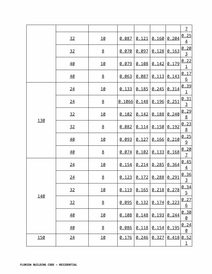
C
100 0.051 0.050 0.050 0.134 0.134 0.133 0.218 0.218 0.217110 0.061 0.061 0.060 0.162 0.162 0.161 0.264 0.263 0.263120 0.073 0.072 0.072 0.193 0.193 0.192 0.314 0.313 0.313130 0.086 0.085 0.084 0.227 0.226 0.225 0.368 0.368 0.367140 0.099 0.099 0.097 0.263 0.263 0.261 0.427 0.427 0.425150 0.114 0.113 0.112 0.302 0.301 0.300 0.490 0.490 0.488
Notes:1. The cumulative shear wall segment length for each side of the building shall be equal to or greater than the tabular shear wall length required. If the required shear wall segment length provided is not one continuous shear wall segment, the total shear wall length required shall be increased by 0.67 feet (8 inches) for each additional shear wall segment making up the total shear wall length on a side.2. The minimum shear wall segment length shall be 2 feet-0 inches. Values less than 2 feet-0 inches are shown only for summation of shear wall segments and for interpolation purposes. A grouted cell with vertical reinforcement of the size indicated is required at each end of every shear wall segment.3. Other than incidental utility penetrations, shearwall piers and shearwall segments shall not contain openings with a maximum horizontal or vertical dimension of 5 inches for piers and 12 inches for portions of shearwall segments above and below piers. The total area of openings in any one segment of shearwall shall not exceed 144 square inches.4. Required shearwall lengths normal (perpendicular) to the ridge are per lineal foot of building length. Multiply tabular values by building length distance between adjacent shear walls perpendicular to the ridge if interior shear walls are used for total shear wall length required.5. Shear wall lengths are based on shear wall segment heights of 80 inches (height from the floor to the top of the highest opening adjacent to the shear segmentâ€"corners and openings as permitted by Note 3 of this table are not considered for the purpose of this measurement). For shear segment heights other than 80 inches, multiply tabular length values as follows:
Segment Height (inches) Length Multiplier88 1.0996 1.19104 1.28112 1.37
FLORIDA BUILDING CODE — RESIDENTIAL

TABLE R609.5.1E GRADE 60REQUIRED SHEARWALL LENGTH PERPENDICULAR TO RIDGE NO. 4
REINFORCEMENT PER FOOT OF BUILDING LENGTH 1,2,3,4,5 ROOF ANGLE 30°
EXP
Vasd asdetermined
inaccordance
with Section
R301.2.1.3
TOP STORY
1ST STORY OF 2 STORY OR
2ND STORY OF 3 STORY
1ST STORY OF 3 STORY
BUILDING WIDTH BUILDING WIDTH BUILDING WIDTH
24 32 40 24 32 40 24 32 40
B
100 0.088 0.102 0.117 0.166 0.180 0.195 0.243 0.257 0.272110 0.107 0.124 0.142 0.201 0.217 0.236 0.294 0.311 0.329120 0.127 0.147 0.169 0.239 0.259 0.280 0.350 0.371 0.392130 0.149 0.173 0.198 0.280 0.304 0.329 0.411 0.435 0.460140 0.173 0.200 0.230 0.325 0.352 0.382 0.477 0.504 0.534150 0.199 0.230 0.264 0.373 0.404 0.438 0.548 0.579 0.613
C
100 0.124 0.143 0.164 0.232 0.252 0.273 0.341 0.361 0.382110 0.150 0.173 0.199 0.281 0.305 0.330 0.413 0.437 0.462120 0.178 0.206 0.237 0.335 0.363 0.393 0.491 0.519 0.550130 0.209 0.242 0.278 0.393 0.426 0.461 0.577 0.610 0.645140 0.242 0.281 0.322 0.456 0.494 0.535 0.669 0.707 0.748150 0.278 0.322 0.370 0.523 0.567 0.614 0.768 0.812 0.859
REQUIRED SHEARWALL LENGTH PERPENDICULAR TO RIDGE NO. 5 REINFORCEMENT PER FOOT OF BUILDING LENGTH 1,2,3,4,5 ROOF ANGLE 30°
EXP
Vasd asdetermined
inaccordancewith SectionR301.2.1.3
TOP STORY
1ST STORY OF 2 STORY OR
2ND STORY OF 3 STORY
1ST STORY OF 3 STORY
BUILDING WIDTH BUILDING WIDTH BUILDING WIDTH
24 32 40 24 32 40 24 32 40
B
100 0.059 0.069 0.079 0.112 0.121 0.131 0.164 0.173 0.183110 0.072 0.083 0.095 0.135 0.146 0.159 0.198 0.210 0.222120 0.086 0.099 0.114 0.161 0.174 0.189 0.236 0.249 0.264130 0.100 0.116 0.133 0.189 0.204 0.222 0.277 0.293 0.310140 0.116 0.135 0.155 0.219 0.237 0.257 0.321 0.339 0.359150 0.134 0.155 0.177 0.251 0.272 0.295 0.369 0.390 0.412
C 100 0.083 0.096 0.111 0.156 0.170 0.184 0.230 0.243 0.257
FLORIDA BUILDING CODE — RESIDENTIAL

110 0.101 0.117 0.134 0.189 0.205 0.222 0.278 0.294 0.311120 0.120 0.139 0.159 0.225 0.244 0.265 0.331 0.350 0.370130 0.141 0.163 0.187 0.264 0.287 0.311 0.388 0.410 0.434140 0.163 0.189 0.217 0.307 0.333 0.360 0.450 0.476 0.504150 0.187 0.217 0.249 0.352 0.382 0.413 0.517 0.546 0.578
Notes:1. The cumulative shear wall segment length for each side of the building shall be equal to or greater than the tabular shear wall length required. If the required shear wall segment length provided is not one continuous shear wall segment, the total shear wall length required shall be increased by 0.67 feet (8 inches) for each additional shear wall segment making up the total shear wall length on a side.2. The minimum shear wall segment length shall be 2 feet-0 inches. Values less than 2 feet-0 inches are shown only for summation of shear wall segments and for interpolation purposes. A grouted cell with vertical reinforcement of the size indicated is required at each end of every shear wall segment.3. Other than incidental utility penetrations, shearwall piers and shearwall segments shall not contain openings with a maximum horizontal or vertical dimension of 5 inches for piers and 12 inches for portions of shearwall segments above and below piers. The total area of openings in any one segment of shearwall shall not exceed 144 square inches.4. Required shearwall lengths normal (perpendicular) to the ridge are per lineal foot of building length. Multiply tabular values by building length distance between adjacent shear walls perpendicular to the ridge if interior shear walls are used for total shear wall length required.5. Shear wall lengths are based on shear wall segment heights of 80 inches (height from the floor to the top of the highest opening adjacent to the shear segmentâ€"corners and openings as permitted by Note 3 of this table are not considered for the purpose of this measurement). For shear segment heights other than 80 inches, multiply tabular length values as follows:
Segment Height (inches) Length Multiplier88 1.0996 1.19104 1.28112 1.37
FLORIDA BUILDING CODE — RESIDENTIAL

TABLE R609.5.1F GRADE 60REQUIRED SHEARWALL LENGTH PERPENDICULAR TO RIDGE NO.4
REINFORCEMENT PER FOOT OF BUILDING LENGTH 1,2,3,4,5 ROOF ANGLE 45°
EXP
Vasd as determined
inaccordance
with Section
R301.2.1.3
TOP STORY
1ST STORY OF 2 STORY OR
2ND STORY OF 3 STORY
1ST STORY OF 3 STORY
BUILDING WIDTH BUILDING WIDTH BUILDING WIDTH
24 32 40 24 32 40 24 32 40
B
100 0.118 0.142 0.168 0.196 0.220 0.246 0.273 0.297 0.323110 0.143 0.172 0.204 0.237 0.266 0.297 0.331 0.360 0.391120 0.170 0.205 0.242 0.282 0.317 0.354 0.393 0.428 0.466130 0.200 0.241 0.284 0.331 0.372 0.415 0.462 0.503 0.546140 0.232 0.279 0.330 0.384 0.431 0.482 0.536 0.583 0.634150 0.266 0.320 0.378 0.440 0.495 0.553 0.615 0.669 0.727
C
100 0.166 0.200 0.236 0.274 0.308 0.345 0.383 0.417 0.453110 0.200 0.241 0.285 0.332 0.373 0.417 0.464 0.505 0.549120 0.239 0.287 0.340 0.395 0.444 0.496 0.552 0.600 0.653130 0.280 0.337 0.399 0.464 0.521 0.582 0.647 0.705 0.766140 0.325 0.391 0.462 0.538 0.604 0.675 0.751 0.817 0.888150 0.373 0.449 0.531 0.617 0.694 0.775 0.862 0.938 1.020
REQUIRED SHEARWALL LENGTH PERPENDICULAR TO RIDGE NO.5 REINFORCEMENT PER FOOT OF BUILDING LENGTH 1,2,3,4,5 ROOF ANGLE 45°
EXP
Vasd asdetermined
inaccordance with Section
R301.2.1.3
TOP STORY
1ST STORY OF 2 STORY OR
2ND STORY OF 3 STORY
1ST STORY OF 3 STORY
BUILDING WIDTH BUILDING WIDTH BUILDING WIDTH
24 32 40 24 32 40 24 32 40
B
100 0.080 0.096 0.113 0.132 0.148 0.165 0.184 0.200 0.218110 0.096 0.116 0.137 0.159 0.179 0.200 0.223 0.242 0.263120 0.115 0.138 0.163 0.190 0.213 0.238 0.265 0.288 0.313130 0.134 0.162 0.191 0.223 0.250 0.280 0.311 0.338 0.368140 0.156 0.188 0.222 0.258 0.290 0.324 0.361 0.392 0.427150 0.179 0.216 0.255 0.296 0.333 0.372 0.414 0.450 0.490
C 100 0.111 0.134 0.159 0.185 0.208 0.232 0.258 0.281 0.305
FLORIDA BUILDING CODE — RESIDENTIAL

110 0.135 0.163 0.192 0.223 0.251 0.281 0.312 0.340 0.369120 0.161 0.193 0.229 0.266 0.299 0.334 0.371 0.404 0.439130 0.188 0.227 0.268 0.312 0.351 0.392 0.436 0.474 0.516140 0.219 0.263 0.311 0.362 0.407 0.455 0.505 0.550 0.598150 0.251 0.302 0.357 0.416 0.467 0.522 0.580 0.632 0.687
Notes:1. The cumulative shear wall segment length for each side of the building shall be equal to or greater than the tabular shear wall length required. If the required shear wall segment length provided is not one continuous shear wall segment, the total shear wall length required shall be increased by 0.67 feet (8 inches) for each additional shear wall segment making up the total shear wall length on a side.2. The minimum shear wall segment length shall be 2 feet-0 inches. Values less than 2 feet-0 inches are shown only for summation of shear wall segments and for interpolation purposes. A grouted cell with vertical reinforcement of the size indicated is required at each end of every shear wall segment.3. Other than incidental utility penetrations, shear wall piers and shear wall segments shall not contain openings with a maximum horizontal or vertical dimension of 5 inches for piers and 12 inches for portions of shear wall segments above and below piers. The total area of openings in any one segment of shear wall shall not exceed 144 square inches.4. Required shear wall lengths normal (perpendicular) to the ridge are per lineal foot of building length. Multiply tabular values by building length distance between adjacent shear walls perpendicular to the ridge if interior shear walls are used for total shear wall length required.5. Shear wall lengths are based on shear wall segment heights of 80 inches (height from the floor to the top of the highest opening adjacent to the shear segment—corners and openings as permitted by Note 3 of this table are not considered for the purpose of this measurement). For shear segment heights other than 80 inches, multiply tabular length values as follows:
Segment Height (inches) Length Multiplier88 1.0996 1.19104 1.28112 1.37
FLORIDA BUILDING CODE — RESIDENTIAL

TABLE R609.5.1G GRADE 40REQUIRED SHEARWALL LENGTH PARALLEL TO RIDGE NO.4
REINFORCEMENT 1,2,3,5 ROOF ANGLE ≤ 23°
EXP
Vasd as determined
inaccordancewith SectionR301.2.1.3
TOP STORY
1ST STORY OF 2 STORY OR
2ND STORY OF 3 STORY
1ST STORY OF 3 STORY
BUILDING WIDTH BUILDING WIDTH BUILDING WIDTH
24 32 40 24 32 40 24 32 40
B
100 2.32 3.31 4.51 5.29 7.15 9.31 7.77 10.45 13.55110 2.81 4.01 5.46 6.40 8.65 11.27 9.40 12.65 16.39120 3.35 4.77 6.50 7.61 10.30 13.41 11.19 15.05 19.51130 3.93 5.59 7.63 8.94 12.09 15.74 13.13 17.67 22.90140 4.55 6.49 8.84 10.36 14.02 18.26 15.23 20.49 26.56150 5.23 7.45 10.15 11.90 16.09 20.96 17.48 23.52 30.48
C
100 2.75 3.98 5.49 6.98 9.52 12.49 10.85 14.57 18.85110 3.33 4.81 6.64 8.45 11.52 15.11 13.13 17.63 22.81120 3.97 5.73 7.90 10.05 13.70 17.98 15.63 20.98 27.14130 4.66 6.72 9.27 11.80 16.08 21.10 18.34 24.63 31.86140 5.40 7.79 10.75 13.68 18.65 24.47 21.27 28.56 36.95150 6.20 8.95 12.34 15.71 21.41 28.10 24.42 32.79 42.41
Notes:1. The cumulative shear wall segment length for each side of the building shall be equal to or greater than the tabular shear wall length required. If the required shear wall segment length provided is not continuous the total shear wall length required shall be increased by 8" for each additional shear wall segment on a side.2. Minimum shear wall segment length shall be 2′-0". A grouted cell with reinforcing steel shall be provided at each end of every shear wall segment. A minimum length of 24 inches (610 mm) of solid wall segment, extending the full height of each wall, shall be provided at exterior corners of exterior walls. A fully grouted cell with reinforcing steel shall be provided at each end of every shear wall segment.3. Portions of walls with openings shall not be considered part of the shear wall length.4. Required shearwall lengths perpendicular to the ridge are per lineal foot of building length. Multiply tabular values by building length for total shear wall length required.5. Shearwall lengths for no. 4 reinforcement are based on shearwall segment height of 80 inches and shearwall segment length of 24 inches.6. Shearwall lengths for no. 5 reinforcement are based on shearwall segment height of 96 inches and shearwall segment length of 24 inches.
FLORIDA BUILDING CODE — RESIDENTIAL

TABLE R609.5.1H GRADE 40REQUIRED SHEARWALL LENGTH PARALLEL TO RIDGE NO.5
REINFORCEMENT 1,2,3,6 ROOF ANGLE ≤ 23°
EXP
Vasd asdetermined
inaccordancewith SectionR301.2.1.3
TOP STORY
1ST STORY OF 2 STORY OR
2ND STORY OF 3 STORY
1ST STORY OF 3 STORY
BUILDING WIDTH BUILDING WIDTH BUILDING WIDTH
24 32 40 24 32 40 24 32 40
B
100 1.59 2.26 3.08 3.61 4.88 6.36 5.30 7.14 9.25110 1.92 2.73 3.73 4.37 5.91 7.69 6.42 8.63 11.19120 2.28 3.25 4.44 5.20 7.03 9.16 7.64 10.28 13.32130 2.68 3.82 5.21 6.10 8.25 10.75 8.96 12.06 15.63140 3.11 4.43 6.04 7.07 9.57 12.46 10.40 13.99 18.13150 3.57 5.08 6.93 8.12 10.99 14.31 11.93 16.06 20.81
C
100 1.88 2.71 3.75 4.77 6.50 8.52 7.41 9.95 12.87110 2.28 3.28 4.53 5.77 7.86 10.31 8.96 12.04 15.57120 2.71 3.91 5.39 6.86 9.36 12.28 10.67 14.32 18.53130 3.18 4.59 6.33 8.05 10.98 14.41 12.52 16.81 21.75140 3.69 5.32 7.34 9.34 12.73 16.71 14.52 19.50 25.22150 4.23 6.11 8.43 10.72 14.62 19.18 16.67 22.38 28.95
Notes:1. The cumulative shear wall segment length for each side of the building shall be equal to or greater than the tabular shear wall length required. If the required shear wall segment length provided is not continuous the total shear wall length required shall be increased by 8" for each additional shear wall segment on a side.2. Minimum shear wall segment length shall be 2′-0". A grouted cell with reinforcing steel shall be provided at each end of every shear wall segment. A minimum length of 24 inches (610 mm) of solid wall segment, extending the full height of each wall, shall be provided at exterior corners of exterior walls. A fully grouted cell with reinforcing steel shall be provided at each end of every shear wall segment.3. Portions of walls with openings shall not be considered part of the shear wall length.4. Required shearwall lengths perpendicular to the ridge are per lineal foot of building length. Multiply tabular values by building length for total shear wall length required.5. Shearwall lengths for no. 4 reinforcement are based on shearwall segment height of 80 inches and shearwall segment length of 24 inches.6. Shearwall lengths for no. 5 reinforcement are based on shearwall segment height of 96 inches and shearwall segment length of 24 inches.
FLORIDA BUILDING CODE — RESIDENTIAL

TABLE R609.5.1I GRADE 40REQUIRED SHEARWALL LENGTH PARALLEL TO RIDGE NO.4
REINFORCEMENT 1,2,3,5 ROOF ANGLE 30°
EXP
Vasd as determined
inaccordance
with Section R301.2.1.3
TOP STORY
1ST STORY OF 2 STORY OR
2ND STORY OF 3 STORY
1ST STORY OF 3 STORY
BUILDING WIDTH BUILDING WIDTH BUILDING WIDTH
24 32 40 24 32 40 24 32 40
B
100 2.39 3.51 4.88 5.10 7.07 9.32 7.44 10.24 13.44110 2.89 4.25 5.90 6.17 8.55 11.28 9.00 12.39 16.26120 3.43 5.06 7.02 7.35 10.18 13.43 10.71 14.75 19.35130 4.03 5.94 8.24 8.62 11.95 15.76 12.57 17.31 22.71140 4.67 6.89 9.56 10.00 13.86 18.28 14.58 20.08 26.34150 5.37 7.90 10.98 11.48 15.91 20.98 16.74 23.05 30.23
C
100 2.87 4.29 6.05 6.79 9.51 12.66 10.37 14.24 18.63110 3.47 5.19 7.32 8.22 11.51 15.32 12.55 17.23 22.54120 4.13 6.18 8.71 9.78 13.69 18.23 14.93 20.51 26.83130 4.85 7.26 10.23 11.48 16.07 21.40 17.53 24.06 31.49140 5.62 8.41 11.86 13.31 18.64 24.82 20.33 27.91 36.52150 6.45 9.66 13.62 15.28 21.39 28.49 23.33 32.04 41.92
Notes:1. The cumulative shear wall segment length for each side of the building shall be equal to or greater than the tabular shear wall length required. If the required shear wall segment length provided is not continuous the total shear wall length required shall be increased by 8" for each additional shear wall segment on a side.2. Minimum shear wall segment length shall be 2′-0". A grouted cell with reinforcing steel shall be provided at each end of every shear wall segment. A minimum length of 24 inches (610 mm) of solid wall segment, extending the full height of each wall, shall be provided at exterior corners of exterior walls. A fully grouted cell with reinforcing steel shall be provided at each end of every shear wall segment.3. Portions of walls with openings shall not be considered part of the shear wall length.4. Required shearwall lengths perpendicular to the ridge are per lineal foot of building length. Multiply tabular values by building length for total shear wall length required.5. Shearwall lengths for no. 4 reinforcement are based on shearwall segment height of 80 inches (2032 mm) and shearwall segment length of 24 inches (610 mm).6. Shearwall lengths for no. 5 reinforcement are based on shearwall segment height of 96 inches (2438 mm) and shearwall segment length of 24 inches (610 mm).
FLORIDA BUILDING CODE — RESIDENTIAL

TABLE R609.5.1J GRADE 40REQUIRED SHEARWALL LENGTH PARALLEL TO RIDGE NO.5
REINFORCEMENT 1,2,3,6 ROOF ANGLE 30°
EXP
Vasd as determined
inaccordancewith SectionR301.2.1.3
TOP STORY
1ST STORY OF 2 STORY OR
2ND STORY OF 3 STORY
1ST STORY OF 3 STORY
BUILDING WIDTH BUILDING WIDTH BUILDING WIDTH
24 32 40 24 32 40 24 32 40
B
100 1.63 2.40 3.33 3.48 4.83 6.37 5.08 6.99 9.17110 1.97 2.90 4.03 4.21 5.84 7.70 6.15 8.46 11.10120 2.34 3.45 4.80 5.02 6.95 9.17 7.31 10.07 13.21130 2.75 4.05 5.63 5.89 8.16 10.76 8.58 11.82 15.50140 3.19 4.70 6.53 6.83 9.46 12.48 9.96 13.71 17.98150 3.66 5.40 7.49 7.84 10.86 14.32 11.43 15.73 20.64
C
100 1.96 2.93 4.13 4.64 6.49 8.64 7.08 9.72 12.72110 2.37 3.55 5.00 5.61 7.85 10.46 8.57 11.76 15.39120 2.82 4.22 5.95 6.68 9.35 12.45 10.19 14.00 18.31130 3.31 4.95 6.98 7.84 10.97 14.61 11.96 16.43 21.49140 3.84 5.74 8.10 9.09 12.72 16.94 13.88 19.05 24.93150 4.41 6.59 9.29 10.43 14.61 19.45 15.93 21.87 28.62
Notes:1. The cumulative shear wall segment length for each side of the building shall be equal to or greater than the tabular shear wall length required. If the required shear wall segment length provided is not continuous the total shear wall length required shall be increased by 8" for each additional shear wall segment on a side.2. Minimum shear wall segment length shall be 2′-0". A grouted cell with reinforcing steel shall be provided at each end of every shear wall segment. A minimum length of 24 inches (610 mm) of solid wall segment, extending the full height of each wall, shall be provided at exterior corners of exterior walls. A fully grouted cell with reinforcing steel shall be provided at each end of every shear wall segment.3. Portions of walls with openings shall not be considered part of the shear wall length.4. Required shearwall lengths perpendicular to the ridge are per lineal foot of building length. Multiply tabular values by building length for total shear wall length required.5. Shearwall lengths for no. 4 reinforcement are based on shearwall segment height of 80 inches (2032 mm) and shearwall segment length of 24 inches (610 mm).6. Shearwall lengths for no. 5 reinforcement are based on shearwall segment height of 96 inches (2438 mm) and shearwall segment length of 24 inches (610 mm).
FLORIDA BUILDING CODE — RESIDENTIAL

TABLE R609.5.1K GRADE 40REQUIRED SHEARWALL LENGTH PARALLEL TO RIDGE NO.4
REINFORCEMENT 1,2,3,5 ROOF ANGLE 45°
EXP
Vasd asdetermined
inaccordancewith SectionR301.2.1.3
TOP STORY
1ST STORY OF 2 STORY OR
2ND STORY OF 3 STORY
1ST STORY OF 3 STORY
BUILDING WIDTH BUILDING WIDTH BUILDING WIDTH
24 32 40 24 32 40 24 32 40
B
100 3.04 4.65 6.66 3.04 8.21 11.11 8.28 11.74 15.80110 3.68 5.63 8.06 6.96 9.93 13.44 10.02 14.20 19.12120 4.37 6.70 9.59 8.29 11.82 15.99 11.93 16.90 22.76130 5.13 7.86 11.25 9.72 13.87 18.77 14.00 19.84 26.71140 5.95 9.12 13.05 11.28 16.09 21.77 16.24 23.01 30.97150 6.83 10.47 14.98 12.95 18.47 24.99 18.64 26.41 35.56
C
100 3.78 5.93 8.66 7.83 11.34 15.57 10.37 14.24 18.63110 4.57 7.17 10.48 9.47 13.73 18.84 12.55 17.23 22.54120 5.44 8.53 12.47 11.27 16.34 22.42 14.93 20.51 26.83130 6.39 10.01 14.64 13.23 19.17 26.31 17.53 24.06 31.49140 7.41 11.61 16.98 15.34 22.24 30.52 20.33 27.91 36.52150 8.50 13.33 19.49 17.61 25.53 35.03 23.33 32.04 41.92
Notes:1. The cumulative shear wall segment length for each side of the building shall be equal to or greater than the tabular shear wall length required. If the required shear wall segment length provided is not continuous the total shear wall length required shall be increased by 8" for each additional shear wall segment on a side.2. Minimum shear wall segment length shall be 2′-0". A grouted cell with reinforcing steel shall be provided at each end of every shear wall segment. A minimum length of 24 inches (610 mm) of solid wall segment, extending the full height of each wall, shall be provided at exterior corners of exterior walls. A fully grouted cell with reinforcing steel shall be provided at each end of every shear wall segment.3. Portions of walls with openings shall not be considered part of the shear wall length.4. Required shearwall lengths perpendicular to the ridge are per lineal foot of building length. Multiply tabular values by building length for total shear wall required.5. Shearwall lengths for no. 4 reinforcement are based on shearwall segment height of 80 inches (2032 mm) and shearwall segment length of 24 inches (610 mm).6. Shearwall lengths for no. 5 reinforcement are based on shearwall segment height of 96 inches (2438 mm) and shearwall segment length of 24 inches (610 mm).
FLORIDA BUILDING CODE — RESIDENTIAL

FLORIDA BUILDING CODE — RESIDENTIAL

TABLE R609.5.1L GRADE 40REQUIRED SHEARWALL LENGTH PARALLEL TO RIDGE NO.5
REINFORCEMENT 1,2,3,6 ROOF ANGLE 45°
EXP
Vasd asdetermined
inaccordance
with Section R301.2.1.3
TOP STORY
1ST STORY OF 2 STORY OR
2ND STORY OF 3 STORY
1ST STORY OF 3 STORY
BUILDING WIDTH BUILDING WIDTH BUILDING WIDTH
24 32 40 24 32 40 24 32 40
B
100 2.07 3.18 4.55 3.93 5.60 7.58 5.66 8.01 10.79110 2.51 3.84 5.50 4.75 6.78 9.17 6.84 9.70 13.05120 2.99 4.57 6.55 5.66 8.07 10.92 8.14 11.54 15.54130 3.50 5.37 7.68 6.64 9.47 12.81 9.56 13.54 18.23140 4.06 6.23 8.91 7.70 10.99 14.86 11.08 15.71 21.15150 4.67 7.15 10.23 8.84 12.61 17.06 12.72 18.03 24.27
C
100 2.58 4.05 5.91 5.34 7.74 10.63 7.84 11.06 14.83110 3.12 4.89 7.15 6.47 9.37 12.86 9.48 13.38 17.94120 3.71 5.83 8.51 7.69 11.15 15.31 11.29 15.93 21.36130 4.36 6.84 9.99 9.03 13.09 17.96 13.25 18.69 25.06140 5.06 7.93 11.59 10.47 15.18 20.83 15.36 21.68 29.07150 5.80 9.10 13.30 12.02 17.43 23.92 17.63 24.88 33.37
Notes:1. The cumulative shear wall segment length for each side of the building shall be equal to or greater than the tabular shear wall length required. If the required shear wall segment length provided is not continuous the total shear wall length required shall be increased by 8" for each additional shear wall segment on a side.2. Minimum shear wall segment length shall be 2′-0". A grouted cell with reinforcing steel shall be provided at each end of every shear wall segment. A minimum length of 24 inches (610 mm) of solid wall segment, extending the full height of each wall, shall be provided at exterior corners of exterior walls. A fully grouted cell with reinforcing steel shall be provided at each end of every shear wall segment.3. Portions of walls with openings shall not be considered part of the shear wall length.4. Required shearwall lengths perpendicular to the ridge are per lineal foot of building length. Multiply tabular values by building length for total shear wall length.5. Shearwall lengths for no. 4 reinforcement are based on shearwall segment height of 80 inches (2032 mm) and shearwall segment length of 24 inches (610 mm).6. Shearwall lengths for no. 5 reinforcement are based on shearwall segment height of 96 inches (2438 mm) and shearwall segment length of 24 inches (610 mm).
FLORIDA BUILDING CODE — RESIDENTIAL

TABLE R609.5.1M GRADE 40REQUIRED SHEARWALL LENGTH PERPENDICULAR TO RIDGE NO.4
REINFORCEMENT PER FOOT OF BUILDING LENGTH 1,2,3,4,5 ROOF ANGLE ≤ 23°
EXP
Vasd as determined
inaccordancewith SectionR301.2.1.3
TOP STORY
1ST STORY OF 2 STORY OR
2ND STORY OF 3 STORY
1ST STORY OF 3 STORY
BUILDING WIDTH BUILDING WIDTH BUILDING WIDTH
24 32 40 24 32 40 24 32 40
B
100 0.077 0.077 0.076 0.204 0.204 0.203 0.332 0.331 0.330110 0.093 0.093 0.092 0.247 0.247 0.246 0.401 0.401 0.400120 0.111 0.110 0.109 0.294 0.294 0.292 0.478 0.477 0.476130 0.130 0.129 0.128 0.345 0.345 0.343 0.561 0.560 0.558140 0.151 0.150 0.148 0.400 0.400 0.398 0.650 0.649 0.647150 0.173 0.172 0.170 0.460 0.459 0.457 0.746 0.745 0.743
C
100 0.108 0.107 0.106 0.286 0.286 0.285 0.465 0.464 0.463110 0.131 0.130 0.128 0.347 0.346 0.344 0.563 0.562 0.560120 0.155 0.155 0.153 0.413 0.412 0.410 0.670 0.669 0.667130 0.182 0.181 0.179 0.484 0.483 0.481 0.786 0.785 0.783140 0.212 0.210 0.208 0.562 0.560 0.558 0.911 0.910 0.908150 0.243 0.242 0.239 0.645 0.643 0.640 1.046 1.045 1.042
Notes:1. The cumulative shear wall segment length for each side of the building shall be equal to or greater than the tabular shear wall length required. If the required shear wall segment length provided is not continuous the total shear wall length required shall be increased by 8" for each additional shear wall segment on a side.2. Minimum shear wall segment length shall be 2′-0". A grouted cell with reinforcing steel shall be provided at each end of every shear wall segment. A minimum length of 24 inches (610 mm) of solid wall segment, extending the full height of each wall, shall be provided at exterior corners of exterior walls. A fully grouted cell with reinforcing steel shall be provided at each end of every shear wall segment.3. Portions of walls with openings shall not be considered part of the shear wall length.4. Required shearwall lengths perpendicular to the ridge are per lineal foot of building length. Multiply tabular values by building length for total shear wall length.5. Shearwall lengths for no. 4 reinforcement are based on shearwall segment height of 80 inches (2032 mm) and shearwall segment length of 24 inches (610 mm).6. Shearwall lengths for no. 5 reinforcement are based on shearwall segment height of 96 inches (2438 mm) and shearwall segment length of 24 inches (610 mm).
FLORIDA BUILDING CODE — RESIDENTIAL

TABLE R609.5.1N GRADE 40REQUIRED SHEARWALL LENGTH PERPENDICULAR TO RIDGE NO.5
REINFORCEMENT PER FOOT OF BUILDING LENGTH 1,2,3,4,6 ROOF ANGLE ≤ 23°
EXP
Vasd asdetermined
inaccordancewith SectionR301.2.1.3
TOP STORY
1ST STORY OF 2 STORY OR
2ND STORY OF 3 STORY
1ST STORY OF 3 STORY
BUILDING WIDTH BUILDING WIDTH BUILDING WIDTH
24 32 40 24 32 40 24 32 40
B
100 0.053 0.052 0.052 0.139 0.139 0.139 0.226 0.226 0.226110 0.064 0.063 0.063 0.169 0.168 0.168 0.274 0.274 0.273120 0.076 0.075 0.074 0.201 0.200 0.200 0.326 0.326 0.325130 0.089 0.088 0.087 0.236 0.235 0.234 0.383 0.382 0.381140 0.103 0.102 0.101 0.273 0.273 0.272 0.444 0.443 0.442150 0.118 0.118 0.116 0.314 0.313 0.312 0.509 0.509 0.507
C
100 0.074 0.073 0.072 0.196 0.195 0.194 0.317 0.317 0.316110 0.089 0.089 0.088 0.237 0.236 0.235 0.384 0.384 0.383120 0.106 0.106 0.104 0.282 0.281 0.280 0.457 0.457 0.455130 0.125 0.124 0.122 0.331 0.330 0.328 0.536 0.536 0.534140 0.144 0.144 0.142 0.383 0.383 0.381 0.622 0.621 0.620150 0.166 0.165 0.163 0.440 0.439 0.437 0.714 0.713 0.711
Notes:1. The cumulative shear wall segment length for each side of the building shall be equal to or greater than the tabular shear wall length required. If the required shear wall segment length provided is not continuous the total shear wall length required shall be increased by 8" for each additional shear wall segment on a side.2. Minimum shear wall segment length shall be 2′-0". A grouted cell with reinforcing steel shall be provided at each end of every shear wall segment. A minimum length of 24 inches (610 mm) of solid wall segment, extending the full height of each wall, shall be provided at exterior corners of exterior walls. A fully grouted cell with reinforcing steel shall be provided at each end of every shear wall segment.3. Portions of walls with openings shall not be considered part of the shear wall length.4. Required shearwall lengths perpendicular to the ridge are per lineal foot of building length. Multiply tabular values by building length for total shear wall length.5. Shearwall lengths for no. 4 reinforcement are based on shearwall segment height of 80 inches (2032 mm) and shearwall segment length of 24 inches (610 mm).6. Shearwall lengths for no. 5 reinforcement are based on shearwall segment height of 96 inches (2438 mm) and shearwall segment length of 24 inches (610 mm).
FLORIDA BUILDING CODE — RESIDENTIAL

TABLE R609.5.1O GRADE 40REQUIRED SHEARWALL LENGTH PERPENDICULAR TO RIDGE NO.4
REINFORCEMENT PER FOOT OF BUILDING LENGTH 1,2,3,4,5 ROOF ANGLE 30°
EXP
Vasd asdetermined
inaccordance with SectionR301.2.1.3
TOP STORY
1ST STORY OF 2 STORY OR
2ND STORY OF 3 STORY
1ST STORY OF 3 STORY
BUILDING WIDTH BUILDING WIDTH BUILDING WIDTH
24 32 40 24 32 40 24 32 40
B
100 0.127 0.147 0.168 0.238 0.258 0.280 0.349 0.370 0.391110 0.153 0.178 0.204 0.288 0.312 0.338 0.423 0.447 0.473120 0.182 0.211 0.242 0.343 0.372 0.403 0.503 0.532 0.563130 0.214 0.248 0.284 0.402 0.436 0.473 0.591 0.624 0.661140 0.248 0.288 0.330 0.467 0.506 0.548 0.685 0.724 0.766150 0.285 0.330 0.379 0.536 0.581 0.629 0.786 0.831 0.880
C
100 0.178 0.206 0.236 0.334 0.362 0.392 0.490 0.518 0.548110 0.215 0.249 0.285 0.404 0.438 0.474 0.593 0.627 0.663120 0.256 0.296 0.340 0.481 0.521 0.565 0.706 0.746 0.789130 0.300 0.348 0.399 0.564 0.612 0.663 0.828 0.876 0.926140 0.348 0.403 0.462 0.654 0.709 0.768 0.960 1.015 1.074150 0.400 0.463 0.531 0.751 0.814 0.882 1.102 1.166 1.233
Notes:1. The cumulative shear wall segment length for each side of the building shall be equal to or greater than the tabular shear wall length required. If the required shear wall segment length provided is not continuous the total shear wall length required shall be increased by 8" for each additional shear wall segment on a side.2. Minimum shear wall segment length shall be 2′-0". A grouted cell with reinforcing steel shall be provided at each end of every shear wall segment. A minimum length of 24 inches (610 mm) of solid wall segment, extending the full height of each wall, shall be provided at exterior corners of exterior walls. A fully grouted cell with reinforcing steel shall be provided at each end of every shear wall segment.3. Portions of walls with openings shall not be considered part of the shear wall length.4. Required shearwall lengths perpendicular to the ridge are per lineal foot of building length. Multiply tabular values by building length for total shear wall length.5. Shearwall lengths for no. 4 reinforcement are based on shearwall segment height of 80 inches (2032 mm) and shearwall segment length of 24 inches (610 mm).6. Shearwall lengths for no. 5 reinforcement are based on shearwall segment height of 96 inches (2438 mm) and shearwall segment length of 24 inches (610 mm).
FLORIDA BUILDING CODE — RESIDENTIAL

TABLE R609.5.1P GRADE 40REQUIRED SHEARWALL LENGTH PERPENDICULAR TO RIDGE NO.5
REINFORCEMENT PER FOOT OF BUILDING LENGTH 1,2,3,4,6 ROOF ANGLE 30°
EXP
Vasd asdetermined
inaccordancewith SectionR301.2.1.3
TOP STORY
1ST STORY OF 2 STORY OR
2ND STORY OF 3 STORY
1ST STORY OF 3 STORY
BUILDING WIDTH BUILDING WIDTH BUILDING WIDTH
24 32 40 24 32 40 24 32 40
B
100 0.087 0.100 0.115 0.163 0.176 0.191 0.239 0.252 0.267110 0.105 0.121 0.139 0.197 0.213 0.231 0.289 0.305 0.323120 0.125 0.144 0.165 0.234 0.254 0.275 0.344 0.363 0.384130 0.146 0.169 0.194 0.275 0.298 0.323 0.403 0.426 0.451140 0.170 0.196 0.225 0.319 0.345 0.374 0.468 0.494 0.523150 0.195 0.225 0.258 0.366 0.397 0.430 0.537 0.568 0.601
C
100 0.121 0.140 0.161 0.228 0.247 0.268 0.334 0.354 0.374110 0.147 0.170 0.195 0.276 0.299 0.324 0.405 0.428 0.453120 0.175 0.202 0.232 0.328 0.356 0.385 0.482 0.509 0.539130 0.205 0.237 0.272 0.385 0.418 0.452 0.565 0.598 0.632140 0.238 0.275 0.316 0.447 0.484 0.525 0.656 0.693 0.734150 0.273 0.316 0.362 0.513 0.556 0.602 0.753 0.796 0.842
Notes:1. The cumulative shear wall segment length for each side of the building shall be equal to or greater than the tabular shear wall length required. If the required shear wall segment length provided is not continuous the total shear wall length required shall be increased by 8" for each additional shear wall segment on a side.2. Minimum shear wall segment length shall be 2′-0". A grouted cell with reinforcing steel shall be provided at each end of every shear wall segment. A minimum length of 24 inches (610 mm) of solid wall segment, extending the full height of each wall, shall be provided at exterior corners of exterior walls. A fully grouted cell with reinforcing steel shall be provided at each end of every shear wall segment.3. Portions of walls with openings shall not be considered part of the shear wall length.4. Required shearwall lengths perpendicular to the ridge are per lineal foot of building length. Multiply tabular values by building length for total shear wall length.5. Shearwall lengths for no. 4 reinforcement are based on shearwall segment height of 80 inches (2032 mm) and shearwall segment length of 24 inches (610 mm).6. Shearwall lengths for no. 5 reinforcement are based on shearwall segment height of 96 inches (2438 mm) and shearwall segment length of 24 inches (610 mm).
FLORIDA BUILDING CODE — RESIDENTIAL

TABLE R609.5.1Q GRADE 40REQUIRED SHEARWALL LENGTH PERPENDICULAR TO RIDGE NO.4
REINFORCEMENT PER FOOT OF BUILDING LENGTH 1,2,3,4,5 ROOF ANGLE 45°
EXP
Vasd asdetermined
inaccordance with Section
R301.2.1.3
TOP STORY
1ST STORY OF 2 STORY OR
2ND STORY OF 3 STORY
1ST STORY OF 3 STORY
BUILDING WIDTH BUILDING WIDTH BUILDING WIDTH
24 32 40 24 32 40 24 32 40
B
100 0.170 0.204 0.242 0.281 0.316 0.353 0.392 0.427 0.464110 0.205 0.247 0.292 0.340 0.382 0.427 0.475 0.517 0.562120 0.244 0.294 0.348 0.405 0.455 0.508 0.565 0.615 0.669130 0.287 0.345 0.408 0.475 0.534 0.597 0.663 0.722 0.785140 0.333 0.401 0.474 0.551 0.619 0.692 0.769 0.837 0.910150 0.382 0.460 0.544 0.632 0.710 0.794 0.883 0.961 1.045
C
100 0.238 0.287 0.339 0.394 0.443 0.495 0.550 0.599 0.651110 0.288 0.347 0.410 0.477 0.536 0.599 0.666 0.725 0.788120 0.343 0.413 0.488 0.567 0.637 0.713 0.792 0.862 0.937130 0.402 0.484 0.572 0.666 0.748 0.836 0.930 1.012 1.100140 0.466 0.562 0.664 0.772 0.868 0.970 1.078 1.174 1.276150 0.535 0.645 0.762 0.887 0.996 1.113 1.238 1.347 1.465
Notes:1. The cumulative shear wall segment length for each side of the building shall be equal to or greater than the tabular shear wall length required. If the required shear wall segment length provided is not continuous the total shear wall length required shall be increased by 8" for each additional shear wall segment on a side.2. Minimum shear wall segment length shall be 2′-0". A grouted cell with reinforcing steel shall be provided at each end of every shear wall segment. A minimum length of 24 inches (610 mm) of solid wall segment, extending the full height of each wall, shall be provided at exterior corners of exterior walls. A fully grouted cell with reinforcing steel shall be provided at each end of every shear wall segment.3. Portions of walls with openings shall not be considered part of the shear wall length.4. Required shearwall lengths perpendicular to the ridge are per lineal foot of building length. Multiply tabular values by building length for total shear wall length.5. Shearwall lengths for no. 4 reinforcement are based on shearwall segment height of 80 inches (2032 mm) and shearwall segment length of 24 inches (610 mm).6. Shearwall lengths for no. 5 reinforcement are based on shearwall segment height of 96 inches (2438 mm) and shearwall segment length of 24 inches (610 mm).
FLORIDA BUILDING CODE — RESIDENTIAL

TABLE R609.5.1R GRADE 40REQUIRED SHEARWALL LENGTH PERPENDICULAR TO RIDGE NO.5
REINFORCEMENT PER FOOT OF BUILDING LENGTH 1,2,3,4,6 ROOF ANGLE 45°
EXP
Vasd as determined
inaccordancewith SectionR301.2.1.3
TOP STORY
1ST STORY OF 2 STORY OR
2ND STORY OF 3 STORY
1ST STORY OF 3 STORY
BUILDING WIDTH BUILDING WIDTH BUILDING WIDTH
24 32 40 24 32 40 24 32 40
B
100 0.116 0.140 0.165 0.192 0.216 0.241 0.268 0.292 0.317110 0.140 0.169 0.200 0.232 0.261 0.292 0.324 0.353 0.384120 0.167 0.201 0.237 0.276 0.310 0.347 0.386 0.420 0.456130 0.196 0.236 0.279 0.324 0.364 0.407 0.453 0.493 0.536140 0.227 0.273 0.323 0.376 0.422 0.472 0.525 0.572 0.621150 0.261 0.314 0.371 0.432 0.485 0.542 0.603 0.656 0.713
C
100 0.162 0.196 0.231 0.269 0.302 0.338 0.376 0.409 0.444110 0.196 0.237 0.280 0.325 0.366 0.409 0.454 0.495 0.538120 0.234 0.282 0.333 0.387 0.435 0.486 0.541 0.589 0.640130 0.274 0.331 0.391 0.455 0.511 0.571 0.635 0.691 0.751140 0.318 0.383 0.453 0.527 0.592 0.662 0.736 0.801 0.871150 0.365 0.440 0.520 0.605 0.680 0.760 0.845 0.920 1.000
Notes:1. The cumulative shear wall segment length for each side of the building shall be equal to or greater than the tabular shear wall length required. If the required shear wall segment length provided is not continuous the total shear wall length required shall be increased by 8" for each additional shear wall segment on a side.2. Minimum shear wall segment length shall be 2′-0". A grouted cell with reinforcing steel shall be provided at each end of every shear wall segment. A minimum length of 24 inches (610 mm) of solid wall segment, extending the full height of each wall, shall be provided at exterior corners of exterior walls. A fully grouted cell with reinforcing steel shall be provided at each end of every shear wall segment.3. Portions of walls with openings shall not be considered part of the shear wall length.4. Required shearwall lengths perpendicular to the ridge are per lineal foot of building length. Multiply tabular values by building length for total shear wall length.5. Shearwall lengths for no. 4 reinforcement are based on shearwall segment height of 80 inches (2032 mm) and shearwall segment length of 24 inches (610 mm).6. Shearwall lengths for no. 5 reinforcement are based on shearwall segment height of 96 inches (2438 mm) and shearwall segment length of 24 inches (610 mm).
FLORIDA BUILDING CODE — RESIDENTIAL

TABLE R609.5.3ATOTAL SHEAR AT TOP OF TOP STORY WALL 1,2
EXP
Vasd asdetermined
inaccordance
with Section
R301.2.1.3VEL
PRESSURE
ROOF ANGLE UP TO 45°
ROOF ANGLE UP TO 30°
BUILDING WIDTH BUILDING WIDTH
24 32 40 24 32 40
B
100 15.2 2022 3113 4456 1568 2319 3215110 18.4 2447 3767 5392 1897 2806 3890120 22.0 2912 4483 6417 2258 3339 4630130 25.8 3418 5262 7531 2649 3919 5433140 29.9 3964 6102 8734 3073 4545 6301150 34.3 4550 7005 10,027 3527 5218 7234
C
100 21.4 2835 4365 6248 2198 3251 4507110 25.9 3431 5282 7560 2660 3934 5454120 30.8 4083 6286 8997 3165 4682 6491130 36.1 4792 7377 10,559 3715 5495 7618140 41.9 5557 8555 12,246 4308 6372 8835150 48.1 6380 9821 14,058 4946 7315 10,142
1. Loads are based on 10' wall height. Multiply by 0.9 for 8-foot (2438 mm) wall heights.2. To determine individual connector load parallel to the wall, divide shear value by the number of connectors (Load F1 from Figure R609.5.3).
FLORIDA BUILDING CODE — RESIDENTIAL

TABLE R609.5.3BTRANSVERSE CONNECTOR LOAD (F2) 1,2
EXP
Vasd as determined
inaccordancewith SectionR301.2.1.3 VEL PRESSURE
ROOF ANGLE <23°
ROOF ANGLE >23°
EDGE ZONE
INT ZONE
B
100 15.2 394 319 289110 18.4 477 386 349120 22.0 568 460 416130 25.8 667 539 488140 29.9 773 626 566150 34.3 887 718 650
C
100 21.4 553 448 405110 25.9 669 541 490120 30.8 796 644 583130 36.1 935 756 684140 41.9 1084 877 793150 48.1 1244 1007 911
1. Loads are based on 10-foot wall height. Multiply by 0.8 for 8-foot (2438 mm)wall height.
2. F2 load in accordance with Figure R609.5.3.
FLORIDA BUILDING CODE — RESIDENTIAL

Fig. R609.5.3 Typical Roof to Wall Connections
TABLE R609.5.4END WALL ROOF SHEAR PER FOOT OF BUILDING LENGTH
EXP
Vasd as determined
inaccordance
with Section
R301.2.1.3
POUNDS PER FT OFBLDGLENGTH
FOR 23° ROOF SLOPE
POUNDS PER FT OFBLDGLENGTH
FOR 30° ROOF SLOPE
POUNDS PER FT OFBLDGLENGTH
FOR 45° ROOF SLOPE
BUILDING WIDTH BUILDING WIDTH BUILDING WIDTH
24 32 40 24 32 40 24 32 40
B
100 43.6 42.8 43.1 76.9 87.8 100.1 104.4 123.8 145.1110 52.7 51.8 52.2 93.1 106.3 121.1 126.3 149.8 175.5120 62.8 61.7 62.1 110.8 126.5 144.2 150.3 178.3 208.9130 73.7 72.4 72.8 130.0 148.5 169.2 176.4 209.2 245.1140 85.4 84.0 84.5 150.8 172.2 196.2 204.6 242.6 284.3150 98.1 96.4 97.0 173.1 197.7 225.3 234.8 278.5 326.4
C 100 61.1 60.1 60.4 107.9 123.2 140.4 146.3 173.6 203.4
FLORIDA BUILDING CODE — RESIDENTIAL

110 73.9 72.7 73.1 130.5 149.0 169.9 177.1 210.0 246.1120 88.0 86.5 87.0 155.3 177.4 202.1 210.7 249.9 292.9130 103.3 101.5 102.1 182.3 208.1 237.2 247.3 293.3 343.7140 119.8 117.7 118.4 211.4 241.4 275.1 286.8 340.2 398.6150 137.5 135.2 136.0 242.7 277.1 315.8 329.2 390.5 457.6
Notes:1. Tabular values between 23° and 30° and between 30° and 45° are permitted to be interpolated.2. Multiply by total building length for total end wall shear. Divide total shear by building width for required shear capacity of roof diaphragm and connections.
R609.6 Assemblies and beams spanning openings.
R609.6.1 Preengineered assemblies for masonry walls.
R609.6.1.1 Unreinforced masonry units above an opening and 8-inch (203 mm) high bond beams above an opening shall be supported by an assembly.
R609.6.1.2 Preengineered assemblies shall be selected from a manufacturer’s approved schedule or other approved tables for the load capacities based on the appropriate minimum gravity load carrying capacities established in Tables R609.6.1.2(1), R609.6.1.2(2), and R609.6.1.2(3).
TABLE R609.6.1.2(1)SUPERIMPOSED LOADS MINIMUM RATED LOAD CAPACITY OF 6-INCHOR 8-INCH-THICK PRE-ENGINEERED ASSEMBLIES SPANNING OPENINGS OF
ONE STORY AND TOP STORY OF MULTI-STORY BUILDINGS 1,3,4
ROOF SPAN (FT)
UPLIFT (plf)
GRAVITY (plf)
Vasd as determined in accordance with Section R301.2.1.3
100 mph 120 mph 140 mph4 2 150 85 112 16512 330 152 204 30524 600 262 351 52536 870 374 502 74544 1,050 451 605 90052 1,230 530 710 1,05560 1,410 609 816 1,215
Notes:
FLORIDA BUILDING CODE — RESIDENTIAL

1. All loads are superimposed at the top of the wall and do not include dead loads of the bond beam or masonry above the assembly. Add 100% of additional dead loads to the gravity loads and subtract 85% of these loads from the uplift loads.2. Use 4-foot roof span for assemblies in endwalls.3. For total roof dead loads over 10 psf, increase gravity loads by the following amount: (Roof Dead Load - 10 psf) × (Roof Span + 2 ft)/2
FLORIDA BUILDING CODE — RESIDENTIAL

TABLE R609.6.1.2(2)SUPERIMPOSED LOADS MINIMUM RATED LOAD CAPACITY 8-INCH-
THICK PREENGINEERED ASSEMBLIES SPANNING OPENINGS OF BOTTOM STORY OF TWO-STORY UILDINGS, SECOND AND BOTTOM STORIES OF THREE-STORY BUILDINGS—WOOD FLOOR SYSTEM 3,4,5
FLOOR SPAN 1
(FT)
MINIMUM RATED GRAVITY LOAD ASSEMBLY (plf)ASSEMBLY CLEAR SPAN (FT)
4 6 8 12 16 204 2 210 260 310 410 510 61012 430 480 530 630 730 83024 760 810 860 960 1,060 1,16036 1,090 1,140 1,190 1,290 1,390 1,49044 1,310 1,360 1,410 1,510 1,610 1,71052 1,530 1,580 1,630 1,730 1,830 1,93060 1,750 1,800 1,850 1,950 2,050 2,150
Notes:1. For a wall supporting floors on both sides, enter table with the sum of the 2 full spans.NOTE: Tabular values are for 1 / 2 the load of the full span shown.2. Use 4 ft building width for assemblies in walls not supporting floors (normally endwalls and interior masonry walls and shearwalls).3. The values in this table may be interpolated.4. These loads take into account the dead load of any masonry in the wall above the assembly
FLORIDA BUILDING CODE — RESIDENTIAL

and live and dead loads of the roof and floor supported. Dead load of the assembly is not included in the table and if not included in the preengineered concrete design must be added to the loads in the table.5. This table is applicable for all roof dead loads.
FLORIDA BUILDING CODE — RESIDENTIAL

TABLE R609.6.1.2(3)SUPERIMPOSED LOADS MINIMUM RATED LOAD CAPACITY 8-INCH-THICK PREENGINEERED ASSEMBLIES SPANNING OPENINGS OF BOTTOM STORY OF TWO-STORY BUILDINGS, SECOND AND BOTTOM STORIES OF THREE-
STORY BUILDINGS—HOLLOWCORE FLOOR SYSTEM 3,4,5
FLOOR SPAN 1 (FT)
MINIMUM RATED GRAVITY LOAD ASSEMBLY (plf)ASSEMBLY CLEAR SPAN (FT)
4 6 8 12 16 204 2 290 340 390 490 590 69012 670 720 770 870 970 1,07024 1,240 1,290 1,340 1,440 1,540 1,64036 1,810 1,860 1,910 2,010 2,110 2,21044 2,190 2,240 2,290 2,390 2,490 2,59052 2,570 2,620 2,670 2,770 2,870 2,97060 2,950 3,000 3,050 3,150 3,250 3,350
Notes:1. For a wall supporting floors on both sides, enter table with the sum of the 2 full spans.NOTE: Tabular values are for 1 / 2 the load of the full span shown.2. Use 4 ft building width for assemblies in nonfloor bearing walls (normally endwalls and interior masonry walls and shearwalls).3. The values in this table may be interpolated.4. These loads take into account the dead load of any masonry in the wall above the assembly and live and dead loads of the roof and floor supported. Dead load of the assembly is not included in the table and if not included in the preengineered concrete assembly design must be added to the loads in the table.5. This table is applicable for all roof dead loads.
FLORIDA BUILDING CODE — RESIDENTIAL

R609.6.1.3 Preengineered assemblies may function as a bond beam over an opening provided that:
1. The bond beam reinforcement is continuous through the assembly.2. The assembly has an uplift rating that equals or exceeds the appropriate value stipulated in Table R609.6.1.2(1) if the lintel directly supports a roof. Exception: If the reinforcement in the top of the assembly is equal to or greater than the reinforcement required in the bottom of the assembly by the manufacturer, uplift need not be considered.
R609.6.1.4 Preengineered assemblies spanning openings shall extend a minimum of 4 inches (102 mm) nominal past each side of the opening.
R609.6.2 Continuous bond beams spanning openings.
R609.6.2.1 Under the provisions of this section, bond beams shall: 1. Be 16 inches (406 mm) high nominal over openings, except cast-in-place concrete bond beams, which may be 12 inches (305 mm) high nominal.2. Have top reinforcement continuous over the wall and opening.3. Have bottom reinforcement extending past each side of the opening a minimum of 24 inches (610 mm) for concrete walls and 4 inches (102 mm) for masonry walls.4. Meet the provisions of Tables R609.6.2.1(1), R609.6.2.1(2) and R609.6.2.1(3) as appropriate.
FLORIDA BUILDING CODE — RESIDENTIAL

TABLE R609.6.2.1(1)MAXIMUM CLEAR SPAN CAPACITY OF CONTINUOUS BOND BEAMS ACTING
AS LINTELS ONE STORY AND TOP STORY OF MULTISTORY BUILDINGS
ROOFSPAN (FT)
MAXIMUM ALLOWABLE CLEAR SPAN (FT-IN)5
BOND BEAM 6” THICK WALL1, 2, 4 BOND BEAM 8” THICK WALL1, 2, 4
16-1 16-2 C12-1 C12-2C16-
1 C16-2 16-1 16-2 C12-1 C12-2 C16-1 C16-243 16-0 17-4 16-0 20-8 18-0 24-8 16-0 18-8 15-4 20-8 17-4 23-412 12-0 13-4 12-0 15-4 14-0 18-8 12-8 14-0 11-4 16-0 13-4 18-024 8-8 8-8 9-4 10-8 10-8 14-8 10-0 11-4 8-8 12-8 10-8 14-836 6-8 6-8 8-0 8-0 9-4 11-4 8-8 8-8 7-4 10-0 8-8 12-044 6-0 6-0 7-4 7-4 8-0 10-0 7-4 7-4 6-8 8-8 8-0 11-452 5-4 5-4 6-0 6-0 8-0 8-8 6-8 6-8 6-8 8-0 7-4 10-860 4-8 4-8 6-0 6-0 7-4 8-0 6-0 6-0 6-0 7-4 7-4 10-0
Notes:1. Designation of bond beam types over openings:
a. Letter C designates a concrete bond beam. All other bond beams are masonry.b. The first number denotes the nominal height of the bond beam in inches.c. The second number denotes the number of No.5 reinforcing bars in the top and the bottom of the beam. A single (1) No.7 bar may be used in lieu of two No.5 bars. The bottom reinforcing steel shall be located no more than 2 3/4 inches clear distance from the bottom of masonry bond beams and 11/2 inches for concrete bond beams.
2. All bond beams have reinforcement in the top as required by Tables R609.2.2A-1 through 609.2.2A-4 and Tables R609.2.2B-1 through R609.2.2B-8 as appropriate. If two No.5 are required in this table and only one No.5 is required by Tables R609.2.2A-1 through R609.2.2A-4 and Tables R609.2.2B-1 through R609.2.2B-8 as appropriate, the additional bar shall be placed in the top of the bond beam over the opening and shall extend past the opening a minimum of 24 inches.3. Use 4 foot roof span for lintels in endwalls.4. The bottom reinforcement in precast lintels may be used to satisfy the continuous bond beam bottom reinforcement requirement.5. For roof dead loads more than 10 psf:
a. For 20 psf roof dead load, multiply allowable clear spans by 0.85.b. For 30 psf roof dead load, multiply allowable clear spans by 0.75.c. Values for other roof dead loads may be interpolated.
FLORIDA BUILDING CODE — RESIDENTIAL

FLORIDA BUILDING CODE — RESIDENTIAL

TABLE R609.6.2.1(2)MAXIMUM CLEAR SPAN OF CONTINUOUS BOND BEAMS ACTING AS LINTELS
BOTTOM STORY OF TWO-STORY BUILDINGS, SECOND AND BOTTOM STORIESOF THREE-STORY BUILDINGS—WOOD FLOOR SYSTEM
BUILDING WIDTH (FT)
BOND BEAM 8” THICK WALL1, 2, 4
16-1 16-2 C12-1 C12-2 C16-1 C16-2 C16-3MAXIMUM ALLOWABLE CLEAR SPAN (FT-IN)5
43 11-4 13-4 10-8 14-0 12-0 15-4 18-012 10-0 11-4 9-4 12-0 10-8 14-0 16-024 8-8 8-8 8-0 10-0 8-8 12-0 12-836 6-8 6-8 6-8 8-0 8-0 10-8 10-844 6-0 6-0 6-0 7-4 7-4 9-4 9-452 5-4 5-4 6-0 6-8 6-8 8-8 8-860 4-8 4-8 5-4 6-0 6-8 8-0 8-0
Notes:1. Designation of bond beam over openings:a. Letter C designates a concrete bond beam. All other bond beams are masonry.b. The first number denotes the nominal height of the bond beam in inches.c. The second number denotes the number of No.5 reinforcing bars in the top and the bottom of the beam. One No.7 may be used in lieu of two No.5. The bottom reinforcing steel shall be located no more than 2 3/4 inches clear distance from the bottom of masonry bond beams and 11/2 inches for concrete bond beams.2. All bond beams shall have reinforcement in the top in accordance with Section R609.6.2.3. Use 4-foot floor span for lintels in walls parallel to hollowcore.4. The bottom reinforcement in precast lintels may be used to satisfy the continuous bond beam bottom reinforcement requirement.5. This table is applicable for all roof dead loads.
FLORIDA BUILDING CODE — RESIDENTIAL

FLORIDA BUILDING CODE — RESIDENTIAL

TABLE R609.6.2.1(3)MAXIMUM CLEAR SPAN OF CONTINUOUS BOND BEAMS ACTING
LINTELS BOTTOM STORY OF TWO-STORY BUILDINGS,SECOND AND BOTTOM STORIES OF THREE-STORY BUILDINGS—
HOLLOWCORE SECOND FLOOR
BUILDING WIDTH (FT)
BOND BEAM 8” THICK WALL1, 2, 4
16-1 16-2 C12-1 C12-2 C16-1 C16-2 C16-3MAXIMUM ALLOWABLE CLEAR SPAN (FT-IN)5
43 10-8 12-0 10-0 13-4 11-4 14-8 17-412 8-8 9-4 8-0 10-8 9-4 12-0 13-424 6-0 6-0 6-0 7-4 7-4 10-0 10-036 4-8 4-8 5-4 6-0 6-0 8-0 8-044 4-0 4-0 4-8 5-4 6-0 7-4 7-452 4-0 4-0 4-8 4-8 5-4 6-8 6-860 3-4 3-4 4-0 4-0 5-4 6-0 6-0
Notes:1. Designation of bond beam over openings:d Letter C designates a concrete bond beam. All other bond beams are masonry.e. The first number denotes the nominal height of the bond beam in inches.f. The second number denotes the number of No.5 reinforcing bars in the top and the bottom of the beam. One No.7 may be used in lieu of two No.5. The bottom reinforcing steel shall be located no more than 2 3/4 inches clear distance from the bottom of masonry bond beams and 11/2 inches for concrete bond beams.2. All bond beams shall have reinforcement in the top in accordance with Section R609.6.2.3. Use 4-foot floor span for lintels in walls parallel to hollowcore.4. The bottom reinforcement in precast lintels may be used to satisfy the continuous bond beam bottom reinforcement requirement.5. This table is applicable for all roof dead loads.
FLORIDA BUILDING CODE — RESIDENTIAL

R609.6.2.2 Top reinforcement required over the opening which is in addition to that required over the wall shall extend past the opening a minimum of 24 inches (610 mm).
R609.6.2.3 When pre-engineered assemblies are utilized to form the bottom portion of the bond beam over the opening in masonry walls, the bottom reinforcement of the pre-engineered assemblies shall be counted toward the additional bottom reinforcement required over the opening.
R609.6.3 Bond beams combined with lintels.
R609.6.3.1 The provisions of this section shall apply when the lintel, the wall area between the lintel and the bond beam, and the bond beam itself are solid grouted masonry units or cast together as one unit.
R609.6.3.2 Combined bond beams/lintels shall meet the requirements of the appropriate Table R609.6.3.2(1), R609.6.3.2(2) or R609.6.3.2(3).
FLORIDA BUILDING CODE — RESIDENTIAL
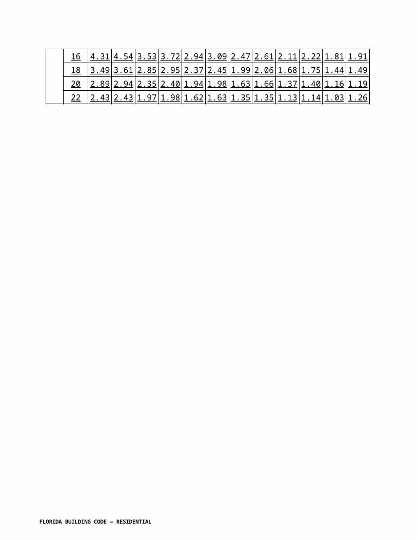
TABLE R609.6.3.2(1)COMBINED BOND BEAM/LINTELS ONE STORY AND TOP STORY OF
MULTISTORY BUILDINGS
BONDBEAM
HEIGHT
ROOFSPAN (FT)
MAXIMUM ALLOWABLE CLEAR SPAN (FT-IN)COMBINED BOND BEAM/LINTEL 8" THICK WALL1, 2
12-1 12-2 16-1 16-2 24-1 24-2 24-3 32-2 32-3 32-4 40-2 40-3 40-4 48-3 48-4 48-5
6"
4 11-4 12-0 14-8 16-0 18-8 22-8 23-4 27-4 29-4 30-0 29-4 34-0 35-4 38-0 39-4 40-812 8-0 8-8 11-4 12-0 14-8 17-4 17-4 18-8 22-9 23-3 24-8 24-8 28-9 29-4 31-4 33-424 6-0 6-9 8-8 8-8 11-4 14-0 14-0 18-0 18-0 18-0 20-0 22-0 20-0 26-0 26-0 26-036 4-8 4-8 6-8 6-8 10-0 10-8 10-8 14-0 14-0 14-0 17-4 17-4 17-4 20-8 20-8 20-844 4-0 4-0 6-0 6-0 9-4 9-4 9-4 12-8 12-8 12-8 15-4 15-4 15-4 18-0 18-0 18-052 3-4 3-4 5-4 5-4 8-0 8-0 8-0 11-4 11-4 11-4 14-0 14-0 14-0 16-8 16-8 16-860 3-4 3-4 4-8 4-8 7-4 7-4 7-4 10-0 10-0 10-0 12-8 12-8 12-8 15-4 15-4 15-4
8"
4 12-0 12-8 14-8 16-8 17-4 23-4 24-8 25-4 30-0 30-8 26-8 32-8 35-4 34-0 39-4 40-812 8-8 9-4 11-4 13-4 14-0 18-8 20-8 21-4 24-8 26-0 22-8 28-0 30-0 29-4 34-0 35-424 6-8 7-4 9-4 10-0 11-4 15-4 16-0 17-4 20-8 21-4 19-4 23-4 25-4 25-4 28-8 30-036 6-0 6-0 8-0 8-8 9-4 13-4 13-4 15-4 17-4 17-4 16-8 20-8 21-4 22-0 24-8 24-844 5-4 5-4 7-4 7-4 8-8 11-4 11-4 14-0 15-4 15-4 16-0 18-8 18-8 20-8 22-0 22-052 4-8 4-8 6-8 6-8 8-0 10-0 10-0 13-4 14-0 14-0 14-8 17-4 17-4 19-4 20-0 20-060 4-0 4-0 6-0 6-0 8-0 9-4 9-4 12-8 12-8 12-8 14-0 15-4 15-4 18-8 18-8 18-8
Notes:1. Designation of combined bond beam/lintels:a. The first number denotes the nominal height of the bond beam/lintel in inches.b. The second number denotes the number of No.5 reinforcing bars in the bottom of the bond beam/lintel. The equivalent or greater area of reinforcement may be obtained by using reinforcement other than No.5. For example, when three No.5 are required, one No.9 may be used. Also, one No.7 may be used to replace two No.5 or two No.7 to replace four No.5. The bottom reinforcing steel is to be located not more than 23/4 inches clear distance from the bottom of the lintel.2. All bond beams shall have reinforcement in the top in accordance with Tables R609.2.2A-1 through R609.2.2A-4 and Tables R609.2.2B-1 through R609.2.2B-8, as appropriate.
FLORIDA BUILDING CODE — RESIDENTIAL

TABLE R609.6.3.2(2)COMBINED BOND BEAM/LINTELS BOTTOM STORY OF TWO-STORY
BUILDINGS, SECOND AND BOTTOM STORIES OF THREE-STORY BUILDINGS—WOOD FLOOR SYSTEM
FLOOR SPAN SUPPORTED
(FT)
COMBINED BOND BEAM/LINTEL 8" THICK WALL1, 2, 4
12-2 16-2 24-2 24-3 32-2 32-3 40-3 40-4 48-3 48-4MAXIMUM ALLOWABLE CLEAR SPAN (FT-IN)5
43 9-4 12-0 16-0 16-8 18-0 20-0 22-8 24-0 24-0 26-812 8-0 10-8 14-0 15-4 16-0 18-8 20-8 22-0 22-0 24-024 6-0 8-8 12-0 12-0 14-0 15-4 18-0 18-0 20-0 20-836 4-8 6-8 10-0 10-0 12-8 13-4 16-0 16-0 18-0 18-044 4-0 6-0 9-4 9-4 12-0 12-0 14-8 14-8 16-8 16-852 4-0 5-4 8-8 8-8 10-8 10-8 13-4 13-4 16-0 16-060 3-4 4-8 8-0 8-0 10-0 10-0 12-8 12-8 14-8 14-8
Notes:1. Designation of combined bond beam/lintels:
a. The first number denotes the nominal height of the bond beam/lintel in inches.b. The second number denotes the number of No.5 reinforcing bars in the bottom of
FLORIDA BUILDING CODE — RESIDENTIAL

the bond beam/lintel. The equivalent or greater area of reinforcement may be obtained by using reinforcement other than No.5 bars. For example, when three No.5 are required, one No.9 may be used. Also, one No.7 may be used to replace two No.5 or two No.7 may be used to replace four No.5. The bottom reinforcing steel is to be located not more than 23/4 inches clear distance from the bottom of the lintel.
2. All bond beams shall have reinforcement in the top in accordance with Section R609.6.2.3. Use 4 foot floor span for walls parallel to hollowcore (nonloadbearing).4. All The bottom reinforcement in precast lintels may be used to satisfy the continuous bond beam bottom reinforcement requirement.5. This table is applicable for all roof dead loads.
FLORIDA BUILDING CODE — RESIDENTIAL

TABLE R609.6.3.2(3)COMBINED BOND BEAM/LINTELS BOTTOM STORY OF TWO-STORY
BUILDINGS, SECOND AND BOTTOM STORIES OF THREE-STORY BUILDINGS—HOLLOWCORE FLOOR SYSTEM
FLOOR SPANSUPPORTED
(FT)
COMBINED BOND BEAM/LINTEL 8" THICK WALL1, 2, 4
12-2 16-2 24-2 24-3 32-2 32-340-3
40-4
48-3
48-4
MAXIMUM ALLOWABLE CLEAR SPAN (FT-IN)5
43 8-8 11-4 15-4 16-0 17-4 19-422-0
23-4
23-4
25-4
12 6-8 9-4 12-8 12-8 14-8 16-018-8
18-8
20-8
21-4
24 4-8 6-0 9-4 9-4 12-0 12-014-8
14-8
17-4
17-4
36 3-4 4-8 7-4 7-4 10-0 10-012-0
12-0
14-8
14-8
44 2-8 4-0 6-8 6-8 8-8 8-811-4
11-4
13-4
13-4
52 2-8 4-0 6-0 6-0 8-0 8-010-0
10-0
12-0
12-0
60 2-8 3-4 5-4 5-4 7-4 7-4 9-4 9-411-4
11-4
Notes:1. Designation of combined bond beam/lintels:a. The first number denotes the nominal height of the bond beam/lintel in inches.b. The second number denotes the number of No.5 reinforcing bars in the bottom of the bond beam/lintel. The equivalent or greater area of reinforcement may be obtained by using reinforcement other than No.5 bars. For example, when three No.5 are required, one No.9 may be used. Also, one No.7 may be used to replace two No.5 or two No.7 may be used to replace four No.5. The bottom reinforcing steel is to be located not more than 23/4 inches clear distance from the bottom of the lintel.2. All bond beams shall have reinforcement in the top in accordance with Section R609.6.2.3. Use 4-foot floor span for walls parallel to hollowcore (non-loadbearing).4. All the bottom reinforcement in precast lintels may be used to satisfy the continuous bond beam bottom reinforcement requirement.5. This table is applicable for all roof dead loads.
FLORIDA BUILDING CODE — RESIDENTIAL

R609.6.3.3 Top reinforcement which is in addition to that required in the bond beam over the wall shall extend a minimum of 24 inches (610 mm) past each side of the opening. Top bond beam reinforcement shall be continuous over wall and opening.
R609.6.3.4 Bottom reinforcing shall extend past each side of the opening a minimum of 24 inches (610 mm) for concrete walls and 4 inches (102 mm) for masonry walls. When using a precast lintel, the reinforcing in the precast lintel shall be included when determining the total amount of bottom reinforcement furnished.
R609.6.3.5 For masonry walls, a cleanout shall be provided in the cells directly above the ends of the lintel when the reinforcing steel in the bottom of the lintel is more than 22 inches (559 mm) below the top of the bond beam.
Section R611.2 Applicability limits. Change to read as shown:
R611.2 Applicability limits. The provisions of this section shall apply to the construction of exterior concrete walls for buildings not greater than 60 feet (18 288 mm) in plan dimensions, floors with clear spans not greater than 32 feet (9754 mm) and roofs with clear spans not greater than 40 feet (12 192 mm). Buildings shall not exceed 35 feet (10 668 mm) in mean roof height or two stories in height above-grade. Floor/ceiling dead loads shall not exceed 10 pounds per square foot (479 Pa), roof/ceiling dead loads shall not exceed 15 pounds per square foot (718 Pa) and attic live loads shall not exceed 20 pounds per square foot (958 Pa). Roof overhangs shall not exceed 2 feet (610 mm) of horizontal projection beyond the exterior wall and the dead load of the overhangs shall not exceed 8 pounds per square foot (383 Pa).
FLORIDA BUILDING CODE — RESIDENTIAL

Walls constructed in accordance with the provisions of this section shall be limited to buildings subjected to a maximum Vasd, determined in accordance with Section R301.2.1.3, design wind speed of 130 miles per hour (58 m/s) Exposure B, 110 miles per hour (49 m/s) Exposure C and 100 miles per hour (45 m/s) Exposure D. Walls constructed in accordance with the provisions of this section shall be limited to detached one- and two-family dwellings and townhouses.
Buildings that are not within the scope of this section shall be designed in accordance with PCA 100 or ACI 318.
Tables R611.6(1) – R611.6(4). Change to read as follows:
TABLE R611.6(1) MINIMUM VERTICAL REINFORCEMENT FOR FLAT ABOVE-GRADE WALLSa,b,c,d,e
MAXIMUM Vasd
(mph) determined in
accordance with Section R301.2.1.3
WIND SPEED
MAXIMUM UNSUPPORTED
WALL HEIGHT PER
STORY (feet)
MINIMUM VERTICAL REINFORCEMENT—BAR SIZE AND SPACING (inches)f, g
Nominalh wall thickness (inches)Exposure Category 4 6 8 10
B C D Topi Sidei Topi Sidei Topi Sidei Topi Sidei
[no change to rest of table]
TABLE R611.6(2) MINIMUM VERTICAL REINFORCEMENT FOR WAFFLE-GRID ABOVE-GRADE WALLSa,b,c,d,e
MAXIMUM Vasd (mph) determined in
accordance with Section R301.2.1.3 WIND
SPEED
MAXIMUM UNSUPPORTED
WALL HEIGHT PER
STORY (feet)
MINIMUM VERTICAL REINFORCEMENT—BAR SIZE AND
SPACING (inches)f, g
Nominalh wall thickness (inches)Exposure Category 6 8B C D Topi Sidei Topi Sidei
[no change to rest of table]
FLORIDA BUILDING CODE — RESIDENTIAL

TABLE R611.6(3) MINIMUM VERTICAL REINFORCEMENT FOR 6-INCH SCREEN-GRID ABOVE-GRADE WALLSa,b,c,d,e
MAXIMUM Vasd (mph) determined in
accordance with Section R301.2.1.3 WIND
SPEED
MAXIMUM UNSUPPORTED
WALL HEIGHT PER
STORY(feet)
MINIMUM VERTICAL REINFORCEMENT—BAR SIZE AND
SPACING (inches)f, g
Nominalh wall thickness (inches)Exposure Category 6B C D Topi Sidei
[no change to rest of table]
TABLE R611.6(4) MINIMUM VERTICAL REINFORCEMENT FOR FLAT, WAFFLEAND SCREEN-GRID ABOVE-GRADE WALLS DESIGNED CONTINUOUS
WITH FOUNDATION STEM WALLSa,b,c,d, e,k,l
MAXIMUM Vasd (mph)
determined in accordance with Section R301.2.1.3
WIND SPEED HEIGHT OF
STEM WALLh, i
(feet)
MAXIMUMDESIGN
LATERAL SOIL LOAD
(psf/ft)
MAXIMUM UNSUPPORTED
HEIGHT OF ABOVE-
GRADE WALL(feet)
MINIMUM VERTICAL REINFORCEMENT—BAR
SIZE AND SPACING(inches)f, g
Wall type and nominal thicknessj(inches)
Exposure Category Flat Waffle Screen
B C D 4 6 8 10 6 8 6[no change to rest of table]
Tables R611.7(1A), (1B) and (1C). Change to read as shown:
TABLE R611.7(1A) UNREDUCED LENGTH, UR, OF SOLID WALL REQUIRED IN EACH EXTERIOR ENDWALL FOR WIND PERPENDICULAR TO RIDGE ONE
STORY OR TOP STORY OF TWO-STORYa,c,d,e,f,g
SIDEWALL
LENGTH (feet)
ENDWALL
LENGTH (feet)
ROOF SLOPE
UNREDUCED LENGTH,UR, OF SOLID WALL REQUIRED IN ENDWALLS FOR WIND
PERPENDICULAR TO RIDGE (feet)Maximum Vasd determined in accordance with Section
R301.2.1.3 Basic Wind Speed (mph) Exposure85B 90B 100B 110B 120B 130B
Minimumb
[no change to rest of table]
FLORIDA BUILDING CODE — RESIDENTIAL

a. [No change]b. Tabulated lengths in the "minimum” column are based on the requirements of Section 6.1.4.1 of ASCE 7 that the main wind-force resisting system be designed for a minimum service level force of 10 psf multiplied by the area of the building projected onto a vertical plane normal to the assumed wind direction. Tabulated lengths in shaded cells are less than the "minimum” value. Where the minimum controls, it is permitted to be reduced in accordance with Notes c, d and e. See Section R611.7.1.1.b. – g. [No change]
TABLE R611.7(1B) UNREDUCED LENGTH, UR,OF SOLID WALL REQUIRED IN EACH EXTERIOR ENDWALL FOR WIND PERPENDICULAR TO RIDGE FIRST
STORY OF TWO-STORYa,c,d,e,f,g
SIDEWALL
LENGTH(feet)
ENDWALL
LENGTH (feet)
ROOFSLOPE
UNREDUCED LENGTH,UR, OF SOLID WALL REQUIRED IN ENDWALLS FOR WIND
PERPENDICULAR TO RIDGE (feet)Maximum Vasd determined in accordance with Section
R301.2.1.3 Basic Wind Speed (mph) Exposure85B 90B 100B 110B 120B 130B
Minimumb
[No change to rest of table]a. [No change]b. Tabulated lengths in the "minimum” column are based on the requirements of Section 6.1.4.1 of
ASCE 7 that the main wind-force resisting system be designed for a minimum service level force of 10 psf multiplied by the area of the building projected onto a vertical plane normal to the assumed wind direction. Tabulated lengths in shaded cells are less than the "minimum” value. Where the minimum controls, it is permitted to be reduced in accordance with Notes c, d and e. See Section R611.7.1.1.
c. – g. [No change]
TABLE R611.7(1C) UNREDUCED LENGTH, UR, OF SOLID WALL REQUIRED IN EACH EXTERIOR SIDEWALL FOR WIND PARALLEL TO RIDGEa,c,d,e,f,g
SIDEWALL
LENGTH(feet)
ENDWALLLENGTH
(feet)ROOF SLOPE
UNREDUCED LENGTH,UR, OF SOLID WALL REQUIRED IN ENDWALLS FOR WIND
PERPENDICULAR TO RIDGE (feet)Maximum Vasd determined in accordance with Section
R301.2.1.3 Basic Wind Speed (mph) Exposure85B 90B 100B 110B 120B 130B
Minimumb
[No change to rest of table]a. [No change]b. Tabulated lengths in the "minimum” column are based on the requirements of Section
6.1.4.1 of ASCE 7 that the main wind-force resisting system be designed for a minimum
FLORIDA BUILDING CODE — RESIDENTIAL

service level force of 10 psf multiplied by the area of the building projected onto a vertical plane normal to the assumed wind direction. Tabulated lengths in shaded cells are less than the "minimum” value. Where the minimum controls, it is permitted to be reduced in accordance with Notes c, d and e. See Section R611.7.1.1.
c. – g. [No change]
Section R612.1. Change to read as follows: R612.1 General. This section prescribes performance and construction requirements for exterior windows and doors installed in walls. Windows and doors shall be installed and flashed in accordance with the fenestration manufacturer’s written installation instructions. Window and door openings shall be flashed in accordance with Section R703.8. Written installation instructions shall be provided by the fenestration manufacturer for each window or door.
Section R612.2 Performance. Revise to read as shown:
R612.2 Performance. Exterior windows and doors shall be designed to resist the design wind loads specified in Table R301.2(2) adjusted for height and exposure per Table R301.2(3). For testing required in Sections R612.3 and R612.5, design pressures determined from Table R301.2(2) or ASCE 7 are permitted to be multiplied by 0.6.
R612.2.1. Custom doors. Custom (one-of-a-kind) exterior door assemblies shall be tested by an approved testing laboratory or be engineered in accordance with accepted engineering practices .
Section R612.3 Testing and labeling. Revise to read as shown:
R612.3 Testing and labeling. Exterior windows and doors shall be tested by an approved independent testing laboratory, and shall be labeled to indicate compliance with AAMA/WDMA/CSA 101/I.S.2/A440 or TAS 202 (HVHZ shall comply with TAS 202). Exterior side-hinged doors shall be tested and labeled as conforming to AAMA/WDMA/CSA 101/I.S.2/A440 or comply with Section R612.5. Exterior windows and doors shall be labeled with a permanent label, marking, or etching providing traceability to the manufacturer and product. The following shall also be required either on a permanent label or on a temporary supplemental label applied by the manufacturer: information identifying the manufacturer, the product model/series number, positive and negative design pressure rating, product maximum size, glazing thickness, impact-resistance rating if applicable, Florida Product Approval number or Miami-Dade Product Approval number, applicable test standard(s), and approved product certification agency, testing laboratory, evaluation entity or Miami-Dade Product Approval.
The labels are limited to one design pressure rating per reference standard. The temporary supplemental label shall remain on the window or door until final approval by the building official.
FLORIDA BUILDING CODE — RESIDENTIAL

Exceptions:1. Door assemblies installed in nonhabitable areas where the door assembly and area are designed to accept water infiltration need not be tested for water infiltration.2. Door assemblies installed where the overhang (OH) ratio is equal to or more than 1 need not be tested for water infiltration. The overhang ratio shall be calculated by the following equation:
OH ratio = OH Length/OH Height
Where:
OH length = The horizontal measure of how far an overhang over a door projects out from door surface.
OH height = The vertical measure of the distance from the door sill to the bottom of the overhang over a door.
3. Pass-through windows for serving from a single-family kitchen, where protected by a roof overhang of 5 feet (1.5 m) or more shall be exempted from the requirements of the water infiltration test. 4.Decorative glazed openings.
Glass Strength: Products tested and labeled as conforming to ANSI/AAMA/NWWDA 101/ I.S.2 or ANSI/AAMA/WDMA/101/ I.S.2/NAFS or AAMA/WDMA/CSA 101/I.S.2/A440 or TAS 202 shall not be subject to the requirements of the Florida Building Code. Determination of load resistance of glass for specific loads of products not tested and certified in accordance with Section R 612.3 shall be designed to comply with ASTM E 1300.
R612.3.1 Comparative analysis. Structural wind load design pressures for window and door units smaller other than the size tested in accordance with Section R612.3 shall be permitted to be higher different than the design value of the tested unit provided such higher different pressures are determined by accepted engineering analysis or validated by an additional test of the window or door unit to the different design pressure in accordance with section R612.3. All components of the small alternative size unit shall be the same as the tested or labeled unit. Where such calculated design pressures are used, they shall be validated by an additional test of the window unit having the highest allowable design pressure.
Exceptions: i Operable windows and doors rated in this manner shall comply with the following:
1. The frame area of the alternate size unit shall not exceed the frame area of the tested approved unit.2. Shall vary from the tested approved unit only in width, height or load requirements.3. Shall not exceed 100 percent of the proportional deflection for fiber stress of the intermediate members of the approved unit.4. Shall not exceed 100 percent of the concentrated load at the juncture of the intermediate members and the frame of the approved unit.5. Shall not exceed the air and water infiltration resistance of the tested approved unit.6. Shall not exceed the maximum cyclic pressure of the tested approved unit when tested per TAS 201 and TAS 203 or ASTM E 1886 and ASTM E 1996 where applicable.
FLORIDA BUILDING CODE — RESIDENTIAL

ii. Non-operable windows and doors rated in this manner shall comply with the following:1. The frame area of the alternate size unit shall not exceed the frame area of the tested approved unit.2. Shall vary from the tested approved unit only in width, height or load requirements.3. The maximum uniform load distribution (ULD) of any side shall be equal to the uniform load carried by the side divided by the length of the side.4. The ULD of any member shall not exceed the ULD of the corresponding member of the tested approved unit.5. The ULD of each member shall be calculated in accordance with standard engineering analysis.6. Shall not exceed the air and water infiltration resistance of the tested approved unit.7. Shall not exceed the maximum cyclic pressure of the tested approved unit when tested per TAS 201 and TAS 203 or ASTM E 1886 and ASTM E 1996 where applicable.
Section R612.4 Garage doors. Revise R612.4 to read as shown:
R612.4 Garage doors. Garage doors shall be tested for determination of structural performance under uniform static air pressure difference in accordance with ANSI/DASMA 108, ASTM E330 Procedure A, or TAS 202. For garage doors tested in accordance with ASTM E330, acceptance criteria shall be in accordance with ANSI/DASMA 108. (HVHZ shall comply with TAS 202.) Design pressures shall be determined from Table R301.2(4) or ASCE 7. The design pressures, as determined from ASCE 7, are permitted to be multiplied by 0.6. Garage doors shall be tested in accordance with either ASTM E 330 or ANSI/ DASMA 108, and shall meet the acceptance criteria of ANSI/DASMA 108.
R612.4.1 Garage door labeling. Garage doors shall be labeled with a permanent label provided by the garage door manufacturer. The label shall identify the garage door manufacturer, the garage door model/series number, the positive and negative design pressure rating, indicate impact rated if applicable, the installation instruction drawing reference number, the Florida Product Approval or Miami-Dade Product Approval number if applicable, and the applicable test standards. The required garage door components for an approved garage door assembly may be indicated using a checklist form on the label. If a checklist format is used on the label, the door installer or the garage door manufacturer shall mark the selected components on the checklist that are required to assemble an approved garage door system. The installation instructions shall be provided and available on the job site.
Section R612.6.1 Fenestration testing and labeling. Change to read as shown:
R612.6.1 Fenestration testing and labeling. Reserved. Fenestration shall be tested by an approved independent laboratory, listed by an approved entity, and bear a label identifying manufacturer, performance characteristics, and approved inspection agency to indicate compliance with the requirements of the following specification:
1. ASTM E 1886 and ASTM E 1996; or2. AAMA 506.
FLORIDA BUILDING CODE — RESIDENTIAL
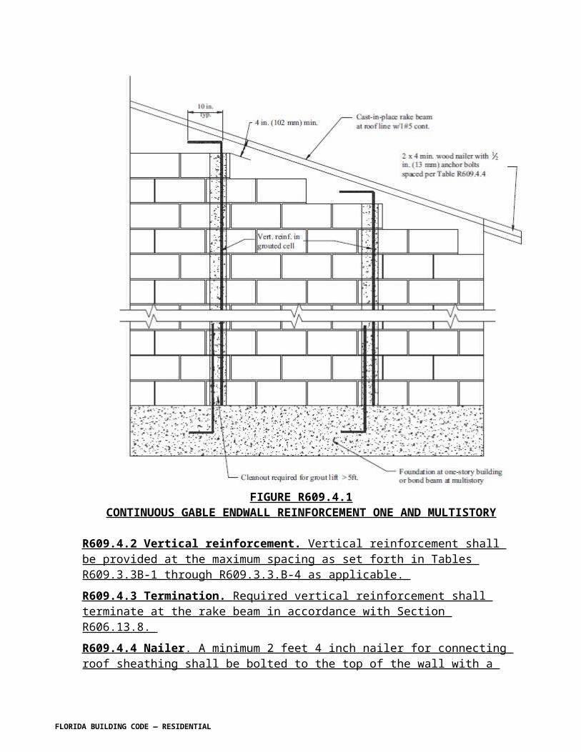
Section R612.8.Mullions. Add new section to read as shown:
R612 .8.4 Masonry Rough Openings. Masonry rough opening dimensions shall be within the tolerances specified at Section R606.16 and in addition shall provide for a window perimeter sealant joint a maximum of ¼ inches in width.
Section R612.9. Add a new section to read as shown:
R612.9 Door components. Door components evaluated by an approved product evaluation entity, certification agency, testing laboratory or engineer may be interchangeable in exterior door assemblies provided that the door component(s) provide equal or greater structural performance as demonstrated by accepted engineering practices.
R612.9.1 Optional exterior door component testing . With the exception of HVHZ, exterior side-hinged door assemblies not covered by Section R612.6 shall be permitted to have the option to have the components of the assembly tested and rated for structural integrity in accordance with the following ANSI A250.13
Following the structural testing of exterior door components, there shall be no permanent deformation of any perimeter frame or panel member in excess of 0.4 percent of its span after the load is removed. After each specified loading, there shall be no glass breakage, permanent damage to fasteners, hardware parts, or any other damage that causes the door to be inoperable, as applicable.
Section R612.10. Add a new section to read as shown:
R612. 10 Flashing, sealants and weatherstripping. Flashing and sealants for exterior windows and doors shall comply with Section R703.8
Section R613.2 Applicability limits. Change to read as follows:
R613.2 Applicability limits. The provisions of this section shall control the construction of exterior structural insulated panel walls and interior load-bearing structural insulated panel walls for buildings not greater than 60 feet (18 288 mm) in length perpendicular to the joist or truss span, not greater than 40 feet (12 192 mm) in width parallel to the joist or truss span and not greater than two stories in height with each wall not greater than 10 feet (3048 mm) high. All exterior walls installed in accordance with the provisions of this section shall be considered as load-bearing walls. Structural insulated panel walls constructed in accordance with the provisions of this section shall be limited to sites subjected to a maximum Vasd, determined in accordance with Section R301.2.1.3, design wind speed of 120 miles per hour (54 m/s),
FLORIDA BUILDING CODE — RESIDENTIAL

Exposure A or B or 110 mph (49 m/s) Exposure C, and a maximum ground snow load of 70 pounds per foot (3.35 kPa), and Seismic Design Categories A, B, and C.
Section R613.5 Wall construction. Change to read as follows:
R613.5 Wall construction. Exterior walls of SIP construction shall be designed and constructed in accordance with the provisions of this section and Tables R613.5(1) andR613.5(2) and Figures R613.5(1) through R613.5(5). SIP walls shall be fastened to other wood building components in accordance with Section R602Tables R602.3(1) through R602.3(4).
Framing shall be attached in accordance with Section R602TableR602.3(1) unless otherwise provided for in Section R613.
Tables R613.5(1) and R613.5(2). Change header only to read as shown:
TABLE R613.5(1)MINIMUM THICKNESS FOR SIP WALL
SUPPORTING SIP LIGHT-FRAME ROOF ONLY (inches)MAXIMUM V asd
DETERMINED IN ACCORDANCE WITH
SECTION R301.2.1.3WIND SPEED (3-second gust)
BUILDING WIDTH (feet)
24 28 32 36 40
(remainder of table unchanged)
TABLE R613.5(2)MINIMUM THICKNESS FOR SIP WALLS SUPPORTING SIP
OR LIGHT-FRAME ONE STORY AND ROOF (inches)MAXIMUM V asd
DETERMINED INACCORDANCE WITH
SECTION R301.2.3WIND SPEED (3-second gust)
BUILDING WIDTH (feet)
24 28 32 36 40
(remainder of table unchanged)
Figures R613.5(3), R613.5(4), R613.5(5) and R613.5.1. Replace in their entirety with the following:
FLORIDA BUILDING CODE — RESIDENTIAL

For SI: 1 inch = 25.4 mm.
FIGURE R613.5(3) TRUSSED ROOF TO TOP PLATE CONNECTION
FLORIDA BUILDING CODE — RESIDENTIAL

For SI: 1 inch = 25.4 mm.Note: Figures illustrate SIP-specific attachment requirements. Other connections shall be made in accordance with Section R602 as appropriate.
FIGURE R613.5(4) SIP WALL TO WALL PLATFORM FRAME CONNECTION
FLORIDA BUILDING CODE — RESIDENTIAL

For SI: 1 inch = 25.4 mm.Note: Figures illustrate SIP-specific attachment requirements. Other connections shall be made in accordance with Section R602 as appropriate.
FIGURE R613.5(5) SIP WALL TO WALL BALLOON FRAME CONNECTION (I-Joist floor shown for Illustration only)
FLORIDA BUILDING CODE — RESIDENTIAL

For SI: 1 inch = 25.4 mm.Notes:1. Top plates shall be continuous over header.2. Lower 2x top plate shall have a width equal to the SIP core width and shall be recessed into the top edge of the panel. Cap plate shall be placed over the recessed top plate and shall have a width equal to the SIPs width.3. SIP facing surfaces shall be nailed to framing and cripples with 8d common or galvanized box nails spaced 6 inches on center.4. Galvanized nails shall be hot-dipped or tumbled. Framing shall be attached in accordance to Section R602 unless otherwise provide for in Section R613.
FIGURE R613.5.1 SIP WALL FRAMING CONFIGURATION
FLORIDA BUILDING CODE — RESIDENTIAL

Section R613.5.3 Wall bracing. Change to read as follows:
R613.5.3 Wall bracing. SIP walls used for wall bracing shall be designed for wind loads in accordance with Section R301.1 or Section R602.SIP walls shall be braced in accordance with Section R602.10. SIP walls shall be considered continuous wood structural panel sheathing for purposes of computing required bracing. SIP walls shall meet the requirements of Section R602.10.4 except that SIPs corners shall be fabricated as shown in Figure R613.9. When SIP walls are used for wall bracing, the SIP bottom plate shall be attached to wood framing below in accordance with Section R602.3Table R602.3(1).
Section R613.10 Headers. Change to read as follows:
R613.10 Headers. SIP headers shall be designed and constructed in accordance with Table R613.10 and FigureR613.5.1. SIPs headers shall be continuous sections without splines. Headers shall be at least 11 7/8 inches (302 mm) deep. Headers longer than 4 feet (1219 mm) shall be constructed in accordance with Section R602 R602.7.
R613.10.1 Wood structural panel box headers. Wood structural panel box headers shall be allowed where SIP headers are not applicable. Wood structural panel box headers shall be constructed in accordance with Section R602 Figure R602.7.2 and Table R602.7.2.
Section R614. Add a new section on Combined Concrete, Masonry, or ICF and Wood Exterior Wall Construction to read as follows:
SECTION R614COMBNED CONCRETE, MASONRY, OR ICF AND
WOOD EXTERIOR WALL CONSTRUCTION
R614.1 General. This section prescribes construction requirements for individual building elements where one or more exterior walls above the foundation contain multiple construction types. Where specific construction requirements are not specifically prescribed in this section, the requirements in the applicable sections of each material shall govern.
R614.2 Concrete, masonry, or ICF first story wood frame second and third story. R614.2.1 Foundation. The foundation system shall be designed in accordance with Chapter 4. R614.2.2 First-story construction. The concrete, masonry or ICF first-story shall be in accordance with Chapter 6 for the applicable first-story construction method . R614.2.3 Floor systems. The second- and third-story floor system shall be in accordance with Chapter 5. R614.2.4 Second- and third-story construction. The second-and third-story walls, ceilings and roof shall be in accordance with the appropriate sections in Chapters 6, 8, and 9. R614.2.5 Shear wall connections. Second-story shearwalls shall be connected to first-story walls in accordance with Tables 3.2A, 3.2B, 3.2C, A-3.24, 4 3.28 or A-3.2C of the AF&PA Wood Frame Construction Manual for One- and Two-Family Dwellings as applicable.
FLORIDA BUILDING CODE — RESIDENTIAL

R614.3 Wood frame gable endwalls above concrete, masonry, or ICF walls. This condition is not permitted unless there is a ceiling diaphragm in accordance with Figures 3.7a and 3.15 of the AF&PA Wood Frame Construction Manual for One- and Two-Family Dwellings.
R614.3.1 Gable construction. Gable construction shall be in accordance with the AF&PA Wood Frame Construction Manual for One- and Two-Family Dwellings. R614.3.2 Wall construction. Concrete, masonry or ICF wall construction shall be in accordance with Chapter 6. R614.3.3 Gable connection. The connection of the wood frame gable endwall to the concrete, masonry or ICF wall shall be in accordance with Figures R614.3(1) and R614.3(2), or Figure R609.4.
Tables R614.3(1) and R614.3(2). Add to read as shown:
Note: For Table 207B, Section 207.3.1 and Section 208.6.4(1), see IBHS Guidelines for Hurricane Resistant Residential Construction. Ceiling diaphragms where provided shall comply with IBHS Section 207.2.
FIGURE R614.3(1) DIRECT TRUSS TO CONCRETE, MASONRY OR ICF WALL CONNECTION FOR GYPSUM BOARD CEILING DIAPHRAGM
FLORIDA BUILDING CODE — RESIDENTIAL

Note: For Table 207B and Section 207.3.1, see IBHS Guidelines for Hurricane Resistant Residential Construction. Ceiling diaphragms where provided shall comply with IBHS Section 207.2.
FIGURE R614.3(2) DIRECT TRUSS TO CONCRETE, MASONRY OR ICF WALL FOR GYPSUM BOARD CEILING DIAPHRAGM
Section R615. Add a new major section on Impact-Resistant Coverings to read as shown:
SECTION R615IMPACT-RESISTANT COVERINGS
R615.1 Impact resistant coverings shall be tested at 1.5 times the design pressure (positive or negative) expressed in pounds per square feet as determined by the Florida Building Code, Building Section 1609 for which the specimen is to be tested. The design pressures, as determined from Section 1609 of the Florida Building Code, Building or ASCE 7, are permitted to be multiplied by 0.6.
R615.1.1 Impact resistant coverings shall be labeled in accordance with the provisions of Section R615.
R615.2. Labels. A permanent label shall be provided by the product approval holder on all impact resistant coverings.
R615.2.1 The following information shall be included on the labels on impact resistant coverings:
FLORIDA BUILDING CODE — RESIDENTIAL

1. Product approval holder name and address. 2. All applicable methods of approval. Methods of approval include, but, are not limited to Miami-Dade NOA; Florida Building Commission, TDI Product Evaluation; ICC-ES.3. The test standard or standards specified at Section R301.2.1.2, including standards referenced within the test standards specified at Section R301.2.1.2 used to demonstrate code compliance.4. For products with a Florida Product Approval Number or a Miami-Dade County Building and Neighborhood Compliance Department Notice of Acceptance Number (NOA), such numbers shall be included on the label.
R615.3 Location of label. The location of the label on the impact resistant covering shall be as follows:
1. Accordions: Bottom of the locking bar or center mate facing the exterior or outside. 2. Rollup: On the bottom of the hood facing the exterior or outside or on the bottom slat facing the exterior or outside.3. Bahama Awning or Colonial Hinged: On the bottom, placed on the back of the shutter. 4. Panels: For metal and plastic panels the label may be embossed or printed spaced not more than every three (3) lineal feet on each panel. The label shall be applied by the holder of the product approval and shall face the exterior or outside.5. Framed products: The label shall be on the side or bottom facing the exterior or outside. 6. Labels on all other products shall face the exterior or outside.
R615.4 Installation. All impact resistant coverings shall be installed in accordance with the manufacturer’s installation instructions and in accordance with the product approval. Installation instructions shall be provided and shall be available to inspection personnel on the job site. Opening protection components, fasteners, and other parts evaluated by an approved product evaluation entity, certification agency, testing laboratory, architect, or engineer and approved by the holder of the product approval may be interchangeable in opening protection assemblies provided that the opening protection component(s) provide equal or greater structural performance and durability as demonstrated by testing in accordance with approved test standards.
CHAPTER 7WALL COVERINGS
Section R701.1 Application. Revise to add exception as shown:
R701.1 Application. The provisions of this chapter shall control the design and construction of the interior and exterior wall covering for all buildings.
Exception: Buildings and structures located within the High-Velocity Hurricane Zone shall comply with the provisions of Chapter 44.
FLORIDA BUILDING CODE — RESIDENTIAL

Section R702.3.5Application . Change to read as shown:
R702.3.5 Application. Maximum spacing of supports and the size and spacing of fasteners used to attach gypsum board shall comply with Table R702.3.5. Gypsum sheathing shall be attached to exterior walls in accordance with Section R602Table R602.3(1). Gypsum board shall be applied at right angles or parallel to framing members. All edges and ends of gypsum board shall occur on the framing members, except those edges and ends that are perpendicular to the framing members. Interior gypsum board shall not be installed where it is directly exposed to the weather or to water.
Section R703.1.3. Add a new section to read as shown:
R703.1.3 Load resistance. All exterior walls, wall coverings and soffits shall be capable of resisting the design pressures specified in Table R301.2(2) for walls.
Section R703.3. Add a new section to read as shown:
R703.3.3 Attachment. Wood, hardboard and wood structural panel siding shall be attached in accordance with the AF&PA WFCM .
R703.3.4 Minimum thickness. Wood, hardboard and wood structural panel siding shall be of the minimum thickness specified in the AF&PA WFCM .
Section R703.4 Attachments. Revise to read as shown:
R703.4 Attachments. Unless specified otherwise, all wall coverings shall be securely fastened in accordance with Table R703.4 or with other approved aluminum, stainless steel, zinc-coated or other approved corrosion-resistive fasteners. Where wind pressures determined in accordance with Table R301.2(2) the basic wind speed in accordance with Figure R301.2(4)A is 110 miles per hour (49 m/s) or higher, the attachment of wall coverings shall be designed to resist the component and cladding loads specified in Table R301.2(2), adjusted for height and exposure in accordance with Table R301.2(3) do not exceed 30 psf, wall coverings are permitted to be installed in accordance with Table R703.4.
Table R703.4 Weather-Resistant Siding Attachment and Minimum Thickness. Revise to read as shown:
FLORIDA BUILDING CODE — RESIDENTIAL
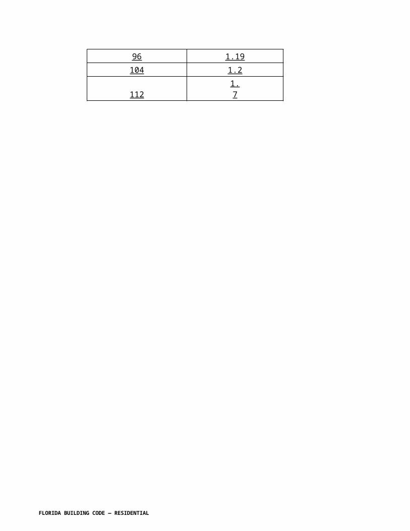
TABLE R703.4WEATHER-RESISTANT SIDING ATTACHMENT AND MINIMUM THICKNESS
SIDING MATERIAL
NOMINAL THICKNESSa (inches)
JOINT TREAT-MENT
WATER-RESISTIVE BARRIER REQUIRED
Type of Supports for the Siding Material and Fastenersb,c,d
Wood or wood structural panel sheathing into stud
Fiber- board sheathing into stud
Gypsum sheathing into stud
Foam plastic sheathing into stud
Direct to studs
Number or spacing of fasteners
Horizontal aluminum
[No change to IRC table]
Anchored veneer: brick, concrete, masonry or stone
[No change to IRC table]
Adhered veneer: concrete, stone or masonry
[No change to IRC table]
Hardboardk
Panel siding-vertical
See Section R703.3.3 7/16
-- Yes Note m Note m Note m Note m Note m 6” panel edges12” inter.sup.n
See Section R703.3.4Hardboardk Lap-siding-horizontal
See Section R703.3.3 7/16
Note q p
Yes Note o Note o Note o Note o Note o Same as stud spacing 2 per bearing
See Section R703.3.4Steelh 29 ga. Lap Yes 0.113 nail
1 ¾”Staple 1 ¾”
0.113 nail2 ¾”Staple 2 ½”
0.113 nail2 ½ ”Staple 2¼”
0.113 nail1 ¾”Staplev
Not allowed
Same as stud spacing
Particleboard panels
3/8-1/2 – Yes 6d box nail (2” x 0.099”)
6d box nail (2” x 0.099”)
6d box nail (2” x 0.099”)
box nail 6d box nail (2” x 0.099”)3/8 not allowed
6” panel edges12” inter. Sup.o
5/8 – Yes 6d box nail (2” x 0.099”)
8d box nail (2 1/2” x 0.113”)
8d box nail (2 1/2” x 0.113”)
box nail 6d box nail (2” x 0.099”)
Wood structural panel ANSI/APA-PRP 210 sidingi (exterior grade)
[No change] [No change]
[No change]
[No change]
[No change]
[No change]
[No change]
[No change]
[No change]
Wood structural panel lapsiding
[No change] [No change]
[No change]
[No change]
[No change]
[No change]
[No change]
[No change]
[No change]
Vinyl sidingm 0.035 Lap Yes See Section R703.3.4 R703.11. 0.120 nail (shank) with a .313 head or 16-
0.120 nail (shank) with a .313
0.120 nail (shank) with
0.120 nail (shank) with a .313
Not allowed
16” on center.....oor test report
FLORIDA BUILDING CODE — RESIDENTIAL

gage staple with 3/8 to ½–inch crowny,z
head or 16-gage staple with 3/8 to ½–inch crowny,z
a .313 head or 16-gage staple with 3/8 to ½–inch crowny,z
head or 16-gage staple with 3/8 to ½–inch crowny,z
Woodj rustic, drop
3/8 Min
Lap Yes Fastener penetration into stud-1”
0.113 nail 2 ½” Staple-2”
Face nailing up to 6” widths, 1 nail per bearing; 8” widths and over, 2 nails per bearing
Shiplap 19/32 Average
Bevel 7/16Butt tip 3/16
Fiber cement panel sidingr
[No change] [No change]
[No change]
[No change]
[No change]
[No change]
[No change]
[No change]
[No change]
Fiber cement lap sidingr
[No change] [No change]
[No change]
[No change]
[No change]
[No change]
[No change]
6d corrosion-resistant nailw or…nailr
Note wt
For SI: 1 inch = 25.4 mm.a-b No change c. Reserved . d-i No change.m. Reserved . n. No changeo. Reserved . P – z No change .
Section R703.5.3 Attachment. Revise to read as shown:
R703.5.3 Attachment. Wood shakes and shingles, and attachment and supports shall be capable of resisting the wind pressures determined in accordance with Table R310.2(2).Where wind pressures determined in accordance with Table R301.2(2) do not exceed 30 psf, E each shake or shingle shall be held in place by two hot-dipped zinc-coated, stainless steel, or aluminum nails or staples. The fasteners shall be long enough to penetrate the sheathing or furring strips by a minimum of 1/2 inch (13 mm) and shall not be overdriven. Where pressures determined in accordance with Table R301.2(2) exceed 30 psf, the attachment shall be designed to resist the prescribed wind pressures.
R703.5.3.1 Staple attachment. Reserved Staples shall not be less than 16 gage and shall have a crown width of not less than 7/16 inch (11 mm), and the crown of the staples shall be parallel with the butt of the shake or shingle. In single-course application, the fasteners shall be concealed by the course above and shall be driven approximately 1 inch (25 mm) above the butt line of the succeeding course and 3/4 inch (19 mm) from the edge. In double-course applications, the exposed shake or shingle shall be face-nailed with two casing nails, driven approximately 2 inches (51 mm) above the butt line and 3/4 inch (19 mm) from each edge. In all applications, staples shall be concealed by the course above. With shingles wider than 8
FLORIDA BUILDING CODE — RESIDENTIAL

inches (203 mm) two additional nails shall be required and shall be nailed approximately 1 inch (25 mm) apart near the center of the shingle.
Section R703.7 Stone and masonry veneer, general. Revise to read as shown:
R703.7 Stone and masonry veneer, general. Stone and masonry veneer shall be installed in accordance with this chapter, Table R703.4 and Figure R703.7. These veneers installed over a backing of wood or cold-formed steel shall be limited to the first story above-grade plane and shall not exceed 5 inches (127 mm) in thickness. See Section R602.3 R602.10 for wall bracing requirements for masonry veneer for wood-framed construction and Section R301.2.1 R603.9.5 for wall bracing requirements for masonry veneer for cold-formed steel construction. The provisions of this section are limited to areas where the Vasd as determined in accordance with Section R301.2.1.3, is equal to or less than 130 mph.
Section R703.7.4.1 Size and spacing. Revise to read as shown:
R703.7.4.1 Size and spacing. Veneer ties, if strand wire, shall not be less in thickness than No. 9 U.S. gage [(0.148 inch) (4 mm)] wire and shall have a hook embedded in the mortar joint, or if sheet metal, shall be not less than No. 22 U.S. gage by [(0.0299 inch) (0.76 mm)] 7/8 inch (22 mm) corrugated. Each tie shall support not more than 2.67 square feet (0.25 m2) of wall area and shall be spaced not more than 32 inches (813 mm) on center horizontally and 24 inches (635 mm) on center vertically.
Exception: 1. In Seismic Design Category D0, D1 or D2 or townhouses in Seismic Design Category C or in wind areas of more than 30 pounds per square foot pressure (1.44 kPa), each tie shall support not more than 2 square feet (0.2 m2) of wall area.2. Where the V asd as determined in accordance with Section R301.2.1.3 exceeds 110 mph (176.99 km/h) or is less than or equal to 130 mph (208 km/h), each tie shall support not more than 1.8 square feet (0.167 m 2 ) of wall area and anchors shall be spaced at a maximum 18 inches (457 mm) horizontally and vertically.
Section R703.8 Flashing. Revise to read as shown:
R703.8 Flashing. Approved corrosion-resistant flashing shall be applied shingle-fashion in a manner to prevent entry of water into the wall cavity or penetration of water to the building structural framing components. Self-adhered membranes used as flashing shall comply with AAMA 711. All exterior fenestration products shall be sealed at the juncture with the building wall with a sealant complying with AAMA 800 or ASTM C 920 Class 25 Grade NS or greater for proper joint expansion and contraction, ASTM C 1281 , AAMA 812 , or other approved standard as appropriate for the type of sealant. The flashing shall extend to the surface of the exterior wall finish. Approved corrosion-resistant flashings shall be installed at all of the following locations:
1. Exterior window and door openings. Flashing at exterior window and door openings shall extend to the surface of the exterior wall finish or to the water-resistive barrier for subsequent
FLORIDA BUILDING CODE — RESIDENTIAL

drainage. Flashing at exterior window and door openings shall be installed in accordance with one or more of the following:
1.1. The fenestration manufacturer’s installation and flashing instructions, or for applications not addressed in the fenestration manufacturer’s instructions, in accordance with the flashing manufacturer’s instructions. Where flashing instructions or details are not provided, pan flashing shall be installed at the sill of exterior window and door openings. Pan flashing shall be sealed or sloped in such a manner as to direct water to the surface of the exterior wall finish or to the water-resistive barrier for subsequent drainage. Openings using pan flashing shall also incorporate flashing or protection at the head and sides.1.2. In accordance with the flashing design or method of a registered design professional.1.3. In accordance with other approved methods.1.4. In accordance with FMA/AAMA 100, FMA/AAMA 200, FMA/WDMA 250, or FMA/AAMA/WDMA 300.
2. At the intersection of chimneys or other masonry construction with frame or stucco walls, with projecting lips on both sides under stucco copings.
3. Under and at the ends of masonry, wood or metal copings and sills.
4. Continuously above all projecting wood trim.
5. Where exterior porches, decks or stairs attach to a wall or floor assembly of wood-frame construction.
6. At wall and roof intersections.
7. At built-in gutters.
Change R703.9 as shown:
R703.9 Exterior insulation and finish system (EIFS)/EIFS with drainage. Exterior Insulation and Finish System (EIFS) shall be designed or tested to meet the wind pressures specified in Table R301.2(2) and shall comply with this chapter and Sections R703.9.1 and R703.9.3. EIFS with drainage shall comply with this chapter and Sections R703.9.2, R703.9.3 and R703.9.4.
Section R703.11.2 Foam plastic sheathing. Revise to read as shown:
R703.11.2 Foam plastic sheathing. Vinyl siding used with foam plastic sheathing shall be installed in accordance with Section R703.11.2.1, or R703.11.2.2, or R703.11.2.3.
Exception: Where the foam plastic sheathing is applied directly over wood structural panels, 1fiberboard, gypsum sheathing or other approved backing capable of independently resisting the design wind pressure, the vinyl siding shall be installed in accordance with Section R703.11.1.
R703.11.2.1 Basic wind speed not exceeding 90 miles per hour and Exposure Category B. Reserved. Where the basic wind speed does not exceed 90 miles per hour (40 m/s), the Exposure Category is B and gypsum wall board or equivalent is installed on the side of the
FLORIDA BUILDING CODE — RESIDENTIAL

wall opposite the foam plastic sheathing, the minimum siding fastener penetration into wood framing shall be 11/4 inches (32 mm) using minimum 0.120-inch diameter nail (shank) with a minimum 0.313-inch diameter head, 16 inches on center. The foam plastic sheathing shall be minimum 1/2-inch-thick (12.7 mm) (nominal) extruded polystyrene per ASTM C 578, 1/2-inch-thick (12.7 mm) (nominal) polyisocyanurate per ASTM C 1289, or 1- inch-thick (25 mm) (nominal) expanded polystyrene per ASTM C 578.
R703.11.2.2 Design wind pressure rating. Basic wind speed exceeding 90 miles per hour or Exposure Categories C and D. Where the basic wind speed exceeds 90 miles per hour (40 m/s) or the Exposure Category is C or D, or all conditions of Section R703.11.2.1 are not met, the adjusted design pressure rating for the assembly shall meet or exceed the loads listed in Tables R301.2(2) adjusted for height and exposure using Table R301.2(3). Where the Vult wind speed does not exceed 140 mph, The design wind pressure rating of the vinyl siding for installation over solid sheathing as provided in the vinyl siding manufacturer’s product specifications shall be adjusted for installation over foam plastic sheathing for the following wall assembly conditions:
1. Ultimate wind speeds, V ult, greater than 115 mph and less than 130 mph:
1 a. For wall assemblies with foam plastic sheathing on the exterior side and gypsum wall board or equivalent on the interior side of the wall, the vinyl siding’s design wind pressure rating shall be multiplied by 0.39.
2 b. For wall assemblies with foam plastic sheathing on the exterior side and no gypsum wall board or equivalent on the interior side of wall, the vinyl siding’s design wind pressure rating shall be multiplied by 0.27.
The adjusted design pressure rating for the assembly shall meet or exceed the loads listed in Tables R301.2(2) adjusted for height and exposure using Table R301.2(3). Design pressures in Table R301.2(2) are permitted to be multiplied by 0.6.
2. Ultimate wind speeds, Vult, greater than 130 mph and less than 140 mph:
a. The vinyl siding’s design wind pressure rating shall be multiplied by 0.27.
The adjusted design pressure rating for the assembly shall meet or exceed the loads listed in Tables R301.2(2) adjusted for height and exposure using Table R301.2(3). Design pressures in Table R301.2(2) are permitted to be multiplied by 0.6.
3 Ultimate wind speeds, Vult, equal to or greater than 140 mph:
Foam sheathing shall be installed over a sheathing material designed and attached to separately resist 100% of the wind load.
R703.11.2.3 Manufacturer specification. [No change to text]
CHAPTER 8ROOF-CEILING CONSTRUCTION
FLORIDA BUILDING CODE — RESIDENTIAL

Add an exception to R801.1 as shown:
R801.1 Application. The provisions of this chapter shall control the design and construction of the roof-ceiling system for all buildings (see Section R301.2.1.1).
Exception: Buildings and structures located within the High-Velocity Hurricane Zone shall comply with the provisions of Chapter 44.
Section R802.1 Identification. Revise to read as shown:
R802.1 General Requirements. Roof and ceiling framing of wood construction shall be designed and constructed in accordance with the provisions of this Section.
R802.1.1 [IRC802.1] Identification. [No change to text]
R802.1.1.1 [IRC802.1.1] Blocking. [No change to text]
R802.1.7 [IRC802.10] Wood trusses.
R802.1.7.1 [IRC802.10.1] Truss design drawings. Truss design drawings, prepared in conformance with Section R802.1.7.1, R802.10.1 shall be provided to the building official and approved prior to installation. Truss design drawings shall include, at a minimum, the information specified below. Truss design drawing shall be provided with the shipment of trusses delivered to the jobsite.
1. Ultimate design wind speed, Vult, and exposure category.2. Slope or depth, span and spacing.3. Location of all joints.4. Required bearing widths.5. Design loads as applicable.
5.1 Top chord live load (as determined from Section R301.6). 5.2 Top chord dead load. 5.3 Bottom chord live load. 5.4 Bottom chord dead load. 5.5 Concentrated loads and their points of application. 5.6 Controlling wind and earthquake loads.
6. Adjustments to lumber and joint connector design values for conditions of use.7. Each reaction force and direction.8. Joint connector type and description (e.g., size, thickness or gauge) and the dimensioned location of each joint connector except where symmetrically located relative to the joint interface.9. Lumber size, species and grade for each member.10. Connection requirements for: 10.1 Truss to truss girder. 10.2 Truss ply to ply. 10.3 Field splices.
FLORIDA BUILDING CODE — RESIDENTIAL

11. Calculated deflection ratio and/or maximum description for live and total load.12. Maximum axial compression forces in the truss members to enable the building designer to design the size, connections and anchorage of the permanent continuous lateral bracing. Forces shall be shown on the truss design drawing or on supplemental documents.13. Required permanent truss member bracing location.
R802.1.7.2 R802.10.2 Design. Wood trusses shall be designed in accordance with accepted engineering practice. The design and manufacture of metal-plate-connected wood trusses shall comply with ANSI/TPI 1. The truss design drawings shall be prepared by a registered professional where required by Florida Statutes the statutes of the jurisdiction in which the project is to be constructed in accordance with Section R106.1.
R802.1.7.2.1 R802.10.2. Applicability limits. Reserved.
R802.1.7.3 R802.10.3 Bracing. [No other change to IRC text]
R802.1.7.4 R802.10.4 Alterations to trusses. [No other change to IRC text]
R802.1.7.5 R802.10.5 Truss to wall connection. Trusses shall be connected to wall plates by the use of approved connectors having a resistance to design uplift, lateral and shear forces. Trusses shall be installed in accordance with the manufacturer’s design and specifications. For roof assemblies subject to wind uplift pressures of 20 pounds per square foot (0.958 kN/m2) or greater, as established in Table R301.2(2), adjusted for height and exposure per Table R301.2(3), see Section R802.2.9.
R802.1.8 R802.7 Cutting and notching. [No other change to IRC text]
R802.1.8.1 R802.7.1 Sawn lumber. [No other change to IRC text]
R802.1.8.1.1 R802.7.1.1 Cantilevered portions of rafters. [No other change to IRC text]
R802.1.8.1.2 R802.7.1.2 Ceiling joist taper cut. [No other change to IRC text]
R802.1.8.2 R802.7.2Engineered wood products. [No other change to IRC text].
R802.2 Design and construction. Roof-ceilings of light-frame wood construction shall be designed and constructed in accordance with the provisions of Section R301.2.1.1 and Section R802.1.
Exceptions:
1. For rafter connections to the top plate, straps and/or clips shall extend such that the top nail is within 1 inch of the top of the rafter with one or more nails installed on the opposite
FLORIDA BUILDING CODE — RESIDENTIAL

side of the rafter.
2. Roof sheathing shall be at a minimum attached in accordance with Section R803.2.3.
The framing details required in Section R802 apply to roofs having a minimum slope of three units vertical in 12 units horizontal (25-percent slope) or greater. Roof-ceilings shall be designed and constructed in accordance with the provisions of this chapter and Figures R606.11(1), R606.11(2) and R606.11(3) or in accordance with AFPA/NDS. Components of roof-ceilings shall be fastened in accordance with Table R602.3(1).
Delete the remainder of Section R802 and show as "Reserved."
Section R803.2.3 Installation. Change to read as shown:
R803.2.3 Installation. Wood structural panel used as roof sheathing shall be installed with joints staggered in accordance with Section R803 .2.3.1 or not staggered in accordance with Table R602.3(1), or APA E30 for wood roof framing or in accordance with AISI 230 with Table R804.3 for steel roof framing.
R803.2.3.1 Sheathing fastenings. Wood structural panel sheathing shall be fastened to roof framing with 8d annular ring-shank nails at 6 inches on center at edges and 6 inches on center at intermediate framing. Ring-shank nails shall have the following minimum dimensions:
1. 0.113 inch nominal root shank diameter 2. Ring diameter of 0.010 0.012 over shank diameter 3. 16 to 20 rings per inch4. 0.280 inch full round head diameter5. 2-3/8 inch nail length
Where roof framing with a specific gravity, 0.42 =< G < 0.49 is used, spacing of ring-shank fasteners shall be 4 inches on center in nailing zone 3 in accordance with Figure R803.2.3.1 where Vult is 165 160 mph or greater.
Exceptions:
1. Where roof framing with a specific gravity, 0.42 = <G < 0.49 is used, spacing of ring-shank fasteners shall be permitted at 12 inches on center at intermediate framing in nailing zone 1 for any Vult and in nailing zone 2 for Vult less than or equal to 140 mph in accordance with Figure R803.2.3.1 2304.7.2.1.1 .
2. Where roof framing with a specific gravity, G = 0.49 is used, spacing of ring-shank fasteners shall be permitted at 12 inches on center at intermediate framing in nailing zone 1 for any Vult and in nailing zone 2 for Vult less than or equal to 150 mph in
FLORIDA BUILDING CODE — RESIDENTIAL

accordance with Figure R803.2.3.1 2304.7.2.1.1 .
3. Where roof framing with a specific gravity, G = 0.49 is used, 8d common or 8d hot dipped galvanized box nails at 6 inches on center at edges and 6 inches on center at intermediate framing shall be permitted for Vult less than or equal to 130 mph in accordance with Figure R803.2.3.1 2304.7.2.1.1 .
4. Where roof diaphragm requirements necessitate a closer fastener spacing.
FIGURE R803.2.3.1 ROOF SHEATHING NAILING ZONES
Section R804 Steel Roof Framing. Revise to read as shown:
SECTION R804STEEL ROOF FRAMING
RESERVED
Section R806.5 Unvented attic and unvented enclosed rafter assemblies. Change to read as shown:
R806.5 Unvented attic and unvented enclosed rafter assemblies. Unvented attic assemblies (spaces between the ceiling joists of the top story and the roof rafters) and unvented enclosed rafter assemblies (spaces between ceilings that are applied directly to the underside of roof framing members/rafters and the structural roof sheathing at the top of the roof framing members/rafters shall be permitted if all the following conditions are met:
1. [No change]2. [No change]
FLORIDA BUILDING CODE — RESIDENTIAL

3. [No change]4. In Climate Zones 5,6,7 and 8 of Table R301.1 of the Florida Building Code, Energy
Conservation , any air-impermeable insulation shall be a Class II vapor retarder, or shall have a Class III vapor retarder coating or covering in direct contact with the underside of the insulation.
5. [No change]
Table R806.5 Insulation for Condensation Control. Change to read as shown:
Table R806.5 Insulation for Condensation Control[No change to table]
a. Contributes to but does not supersede the requirements in Section R403.2.1 of the Florida Building Code, Energy Conservation N1103.2.1.
CHAPTER 9ROOF ASSEMBLIES
R901.1 Scope. Add exception as shown:
R901.1 Scope. The provisions of this chapter shall govern the design, materials, construction and quality of roof assemblies.
Exception: Buildings and structures located within the High-Velocity Hurricane Zone shall comply with the provisions of Chapter 44 .
SECTION 903WEATHER PROTECTION
Section R903.2.1 Locations. Change to read as shown:
R903.2.1 Locations. Flashings shall be installed at wall and roof intersections, wherever there is a change in roof slope or direction and around roof openings. A flashing shall be installed to divert the water away from where the eave of a sloped roof intersects a vertical sidewall. Where flashing is of metal, the metal shall be corrosion resistant with a thickness of not less than 0.019 inch (0.5 mm) (No. 26 galvanized sheet) provided in Table R903.2.1.
Exception: Flashing is not required at hip and ridge junctions .
TABLE R903.2.1METAL FLASHING MATERIAL
FLORIDA BUILDING CODE — RESIDENTIAL

MATERIAL
GAGE MINIMUMTHICKNESS
(INCHES) GAGE
WEIGHT(lbs per sq
ft)Copper 0.024 1 (16 oz)Aluminum 0.024Stainless steel 28
Galvanizedsteel 0.0179 26
(zinc coated G90)
26(zinc coated
G90)Aluminumzinc coatedsteel
0.017926
(AZ50 alumzinc)
26(AZ50
alum zinc)Zinc alloy 0.027Lead 2.5 (40 oz)Painted terne 1.25 (20 oz)
Section R903.2.3. Add a section to read as shown:
R903.2.3 Membrane flashings. All membrane flashing shall be installed according to the roof assembly manufacturer’s published literature.
Section R903.4 Roof drainage. Change to read as shown:
R903.4 Roof drainage. Unless roofs are sloped to drain over roof edges, roof drains shall be installed at each low point of the roof. Where required for roof drainage, scuppers shall be placed level with the roof surface in a wall or parapet. The scupper shall be located as determined by the roof slope and contributing roof area.
Section R903.4.1 Secondary (emergency overflow) drains or scuppers. Change to read as follows:
R903.4.1 Secondary (emergency overflow) drains or scuppers. Overflow drains and scuppers. When other means of drainage of overflow water is not provided, overflow scuppers shall be placed in walls or parapets not less than 2 inches (51 mm) nor more than 4 inches (102 mm) above the finished roof covering and shall be located as close as practical to required vertical leaders or downspouts or wall and parapet scuppers. An overflow scupper shall be sized in accordance with the Florida Building Code, Plumbing.
Where roof drains are required, secondary emergency overflow roof drains or scuppers shall be provided where the roof perimeter construction extends above the roof in such a manner that water will be entrapped if the primary drains allow buildup for any reason. Overflow drains having the same size as the roof drains shall be installed with the inlet flow line located 2 inches (51 mm) above the low point of the roof, or overflow scuppers having three times the size of the roof drains and having a minimum opening height of 4 inches (102 mm) shall be
FLORIDA BUILDING CODE — RESIDENTIAL

installed in the adjacent parapet walls with the inlet flow located 2 inches (51 mm) above the low point of the roof served. The installation and sizing of overflow drains, leaders and conductors shall comply with Sections 1106 and 1108 as applicable of the International Plumbing Code.
Overflow drains shall discharge to an approved location and shall not be connected to roof drain lines.
Section R903.4.2. Add a new section to read as follows:
R903.4.2 One and two family dwellings, and private garages. When gutters and leaders are placed on the outside of buildings, the gutters and leaders shall be constructed of metal or approved plastic for outdoor exposure with lapped, soldered or caulked joints and shall be securely fastened to the building with a corrosion resistant fastening device of similar or compatible material to the gutters and downspouts.
SECTION R904MATERIALS
Section R904. Change to read as follows:
R904.1 Scope. The requirements set forth in this section shall apply to the application of roof covering materials specified herein. Roof assemblies shall be applied in accordance with this chapter and the manufacturer’s installation instructions. Installation of roof assemblies shall comply with the applicable provisions of Section R905.
R904.2 Compatibility of materials. Roof assemblies shall be of materials that are compatible with each other and with the building or structure to which the materials are applied.
R904.3 Material specifications and physical characteristics. Roof covering materials shall conform to the applicable standards listed in this chapter. In the absence of applicable standards or where materials are of questionable suitability, testing by an approved testing agency shall be required by the building official to determine the character, quality and limitations of application of the materials.
Section R904.4 Product identification. Change to read as shown. Renumber Product identification to R904.5 as shown below.
R904.4 Fasteners.
R904.4.1 Nails. Nails shall be corrosion resistant nails conforming to ASTM F 1667. The corrosion resistance shall meet ASTM A 641, Class I or an equal corrosion resistance by coating, electro galvanization, mechanical galvanization, hot dipped galvanization, stainless steel, nonferrous metal and alloys or other suitable corrosion-resistant material. Metal or plastic cap nails shall have a head diameter of not less than 1 inch (25.4 mm) with a thickness
FLORIDA BUILDING CODE — RESIDENTIAL

of at least 32-gauge sheet metal, Metal tin-tabs shall be not less than 1 5 / 8 inches (41 mm) and not more than 2 inches (51 mm) in diameter and of not less than 32 gage (0.010 inch) sheet metal in compliance with the corrosion resistance requirements.
R904.4.2 Screws. Wood screws shall conform to ANSI/ASME B 18.6.1. Screws shall be corrosion resistant by coating, galvanization, stainless steel, nonferrous metal or other suitable corrosion resistant material. The corrosion resistance shall be demonstrated through one of the following methods:
1. Corrosion resistance equivalent to ASTM A 641, Class 1; 2. Corrosion resistance in accordance with TAS 114, Appendix E; 3. Corrosion resistant coating exhibiting not more than 5 percent red rust after 1000 hours exposure in accordance with ASTM B 117.
R904.4.3 Clips. Clips shall be corrosion resistant clips. The corrosion resistance shall meet 0.90 ounce per square foot (0.458 kg/m 2 ) measured according ASTM A 90/A 90M, TAS 114 Appendix E or an equal corrosion resistance coating, electro galvanization, mechanical galvanization, hot dipped galvanization, stainless steel, nonferrous metals and alloys or other suitable corrosion resistant material. Stainless steel clips shall conform to ASTM A167, Type 304.
R904.4 R904.5 Product identification. Roof covering materials shall be delivered in packages bearing the manufacturer’s identifying marks and approved testing agency labels when required. Bulk shipments of materials shall be accompanied by the same information issued in the form of a certificate or on a bill of lading by the manufacturer.
SECTION R905REQUIREMENTS FOR ROOF COVERINGS
Section R905.2.2 Slope. Change to read as shown:
R905.2.2 Slope. Asphalt shingles shall be used only on roof slopes of two units vertical in 12 units horizontal (2:12) or greater. For roof slopes from two units vertical in 12 units horizontal (2:12) up to and less than four units vertical in 12 units horizontal (4:12), double underlayment application is required in accordance with Section R905.2.7.
Section R905.2.3 Underlayment. Change to read as shown:
R905.2.3 Underlayment. Unless otherwise noted, required underlayment shall conform to with ASTM D 226 Type I or Type II, ASTM D 4869, Type I II or Type IV, or ASTM D 6757.
Self-adhering polymer modified bitumen sheet shall comply with ASTM D 1970.
R905.2.4.1 Wind resistance of asphalt shingles. Change to read as shown:
FLORIDA BUILDING CODE — RESIDENTIAL

R905.2.4.1 Wind resistance of asphalt shingles. Asphalt shingles shall be tested in accordance with ASTM D 7158. Asphalt shingles shall meet the classification requirements of Table R905.2.4.1(1) for the appropriate maximum basic wind speed. Asphalt shingle packaging shall bear a label to indicate compliance with ASTM D 7158 and the required classification in Table R905.2.4.1(1) installed in accordance with Section R905.2.6. and R905.2.6.1.
Exception: Asphalt shingles not included in the scope of ASTM D 7158 shall be tested and labeled to indicate compliance with ASTM D 3161 and the required classification in Table R905.2.4.1(2).
TABLE R905.2.4.1(1)CLASSIFICATION OF ASPHALT ROOF SHINGLES PER ASTM D 7158
Reserved.
MAXIMUM BASIC WIND SPEED FROM FIGURE 301.2(4)A (mph) CLASSIFICATION REQUIREMENT
85 D, G or H90 D, G or H100 G or H110 G or H120 G or H130 H140 H150 H
For SI: 1 mile per hour = 0.447 m/s.
TABLE R905.2.4.1(2)CLASSIFICATION OF ASPHALT SHINGLES PER ASTM D 3161
Reserved.
MAXIMUM BASIC WIND SPEED FROM FIGURE 301.2(4)A (mph) CLASSIFICATION REQUIREMENT
85 A, D or F90 A, D or F100 A, D or F110 F120 F130 F140 F150 F
FLORIDA BUILDING CODE — RESIDENTIAL

For SI: 1 mile per hour = 0.447 m/s.
Section R905.2.6.1. Add a new section to read as follows:
R905.2.6.1 Wind resistance of asphalt shingles. Asphalt Shingles shall be classified in accordance with ASTM D 3161, TAS 107 or ASTM D 7158 to resist the basic wind speed per Figure R301.2(4). Shingles classified as ASTM D 3161 Class D or classified as ASTM D 7158 Class G are acceptable for use in the 100-mph wind zone. Shingles classified as ASTM D 3161 Class F, TAS107 or ASTM D 7158 Class H are acceptable for use in all wind zones. Asphalt shingle wrappers shall indicate compliance with one of the required classifications as shown in Table R905.2.6.1.
TABLE R905.2.6.1WIND RESISTANCE OF ASPHALT SHINGLES
Classification of Asphalt Shingles
Maximum Basic Wind Speed, V ult,
From Figure R301.2(4)
Vasd as determined in
accordance with Section
R301.2.1.3 ASTM D 7158 ASTM D 3161110 85 D, G or H A, D or F116 90 D, G or H A, D or F129 100 G or H A, D or F142 110 G or H F155 120 G or H F168 130 H F181 140 H F194 150 H F
Section R905.2.7 Underlayment application. Change to read as shown:
R905.2.7 Underlayment application. Underlayment shall be installed using one of the following methods:For roof slopes from two units vertical in 12 units horizontal (17-percent slope), up to four units vertical in 12 units horizontal (33-percent slope), underlayment shall be two layers applied in the following manner. Apply a 19-inch (483 mm) strip of underlayment felt parallel to with and starting at the eaves, fastened sufficiently to hold in place. Starting at the eave,
FLORIDA BUILDING CODE — RESIDENTIAL

apply 36-inch-wide (914 mm) sheets of underlayment, overlapping successive sheets 19 inches (483 mm), and fastened sufficiently to hold in place. Distortions in the underlayment shall not interfere with the ability of the shingles to seal. End laps shall be offset by 6 feet (1829 mm). For roof slopes of four units vertical in 12 units horizontal (33-percent slope) or greater, underlayment shall be one layer applied in the following manner. Underlayment shall be applied shingle fashion, parallel to and starting from the eave and lapped 2 inches (51 mm) fastened sufficiently to hold in place. Distortions in the underlayment shall not interfere with the ability of the shingles to seal. End laps shall be offset by 6 feet (1829 mm).
1. For roof slopes from two units vertical in 12 units horizontal (17-percent slope), and less than four units vertical in 12 units horizontal (33-percent slope). Underlayment shall comply with ASTM D 226, Type I or Type II or ASTM D 4869, Type II or Type IV or ASTM D 6757 and shall be two layers applied in the following manner. Apply a 19-inch (483 mm) strip of underlayment felt parallel to and starting at the eaves, fastened sufficiently to hold in place. Starting at the eave, apply 36-inch-wide (914 mm) sheets of underlayment, overlapping successive sheets 19 inches (483 mm), and fastened with 1 inch (25 mm) round plastic cap, metal cap nails or nails and tin-tabs attached to a nailable deck with one row in the field of the sheet with a maximum fastener spacing of 12 in. o.c. (305 mm), and one row at the overlaps fastened 6 in. o.c. (152 mm). Synthetic underlayment shall be fastened in accordance with this section and the manufacturer’s recommendations. 2. For roof slopes of four units vertical in 12 units horizontal (33-percent slope) or greater. Underlayment shall comply with ASTM D 226, Type II or ASTM D 4869, Type IV or ASTM D 6757 and shall be one layer applied in the following manner. Underlayment shall be applied shingle fashion, parallel to and starting from the eave and lapped 2 inches (51 mm), fastened with 1 inch (25 mm) round plastic cap, metal cap nails or nails and tin-tabs attached to a nailable deck with two staggered rows in the field of the sheet with a maximum fastener spacing of 12 in. o.c. (305 mm), and one row at the overlaps fastened 6 in. o.c. (152 mm). Synthetic underlayment shall be fastened in accordance with this section and the manufacturer’s recommendations End laps shall be offset by 6 feet (1829 mm). 3. As an alternative, the entire roof deck shall be covered with an approved self- adhering polymer modified bitumen sheet meeting ASTM D 1970 or an approved self- adhering synthetic underlayment installed in accordance with the manufacturer’s installation instructions.
R905.2.7.1 Ice barrier. Reserved. In areas where there has been a history of ice forming along the eaves causing a backup of water as designated in Table R301.2(1), an ice barrier that consists of a least two layers of underlayment cemented together or of a self-adhering polymer modified bitumen sheet, shall be used in lieu of normal underlayment and extend from the lowest edges of all roof surfaces to a point at least 24 inches (610 mm) inside the exterior wall line of the building. Exception: Detached accessory structures that contain no conditioned floor area.
FLORIDA BUILDING CODE — RESIDENTIAL

R905.2.7.2 Underlayment and high winds. Reserved.Underlayment applied in areas subject to high winds [above 110 mph (49 m/s) in accordance with Figure R301.2(4)A] shall be applied with corrosion-resistant fasteners in accordance with manufacturer’s installation instructions. Fasteners are to be applied along the overlap not farther apart than 36 inches (914 mm) on center. Underlayment installed where the basic wind speed equals or exceeds 120 mph (54 m/s) shall comply with ASTM D 226 Type II, ASTM D 4869 Type IV, or ASTM D 6757. The underlayment shall be attached in a grid pattern of 12 inches (305 mm) between side laps with a 6-inch (152 mm) spacing at the side laps. Underlayment shall be applied in accordance with Section R905.2.7 except all laps shall be a minimum of 4 inches (102 mm). Underlayment shall be attached using metal or plastic cap nails with a head diameter of not less than 1 inch (25.4 mm) with a thickness of at least 32-gauge sheet metal. The cap-nail shank shall be a minimum of 12 gauge (0.105 inches) with a length to penetrate through the roof sheathing or a minimum of 3/4 inch (19 mm) into the roof sheathing. Exception: As an alternative, adhered underlayment complying with ASTM D 1970 shall be permitted.
Section R905.2.8 Flashing. Change to read as shown:
R905.2.8.1 Base and cap counter flashing. Base and cap counter flashing shall be installed in accordance with manufacturer’s installation instructions. Base flashing shall be of either corrosion-resistant metal of minimum nominal 0.019-inch (0.5 mm) thickness or mineral surface roll roofing weighing a minimum of 77 pounds per 100 square feet (4 kg/m2). Cap flashing shall be corrosion-resistant metal of minimum nominal 0.019-inch (0.5 mm) thickness as follows:
1. In accordance with manufacturer’s installation instructions, or
2. A continuous metal minimum 4 inch by 4 inch "L” flashing shall be set in approved flashing cement and set flush to base of wall and over the underlayment. Both horizontal and vertical metal flanges shall be fastened 6 inches (152 mm) on center with approved fasteners. All laps shall be a minimum of 4 inches (102 mm) fully sealed in approved flashing cement. Flashing shall start at the lower portion of roof to ensure water-shedding capabilities of all metal laps. The entire edge of the horizontal flange shall be sealed covering all nail penetrations with approved flashing cement and membrane. Shingles shall overlap the horizontal flange and shall be set in approved flashing cement.
Base flashing shall be of either corrosion-resistant metal provided in Section R905.2.8.1 or mineral surface roll roofing weighing a minimum of 77 pounds per 100 square feet (3.76 kg/m 2 ). Counter flashing shall be corrosion-resistant metal with a minimum thickness provided in Table R903.2.1.
FLORIDA BUILDING CODE — RESIDENTIAL

R905.2.8.2 Valleys. Valley linings shall be installed in accordance with the manufacturer’s installation instructions before applying shingles. Valley linings of the following types shall be permitted:
1. For open valleys (valley lining exposed) lined with metal, the valley lining shall be at least 24 16 inches (610 406 mm) wide and of any of the corrosion-resistant metals in Table R905.2.8.2 R903.2.1 .
2. For open valleys, valley lining of two plies of mineral surfaced roll roofing, complying with ASTM D 3909 or ASTM D 6380 Class M, shall be permitted. The bottom layer shall be 18 inches (457 mm) and the top layer a minimum of 36 inches (914 mm) wide.
3. For closed valleys (valley covered with shingles), valley lining of one ply of smooth roll roofing complying with ASTM D 6380 Class S and at least 36 inches wide (914 mm) or valley lining as described in Item 1 or 2 above shall be permitted. Self-adhering polymer modified bitumen underlayment complying with ASTM D 1970 shall be permitted in lieu of the lining material
TABLE R905.2.8.2VALLEY LINING MATERIAL
Reserved.
MATERIALMINIMUM
THICKNESS (inches)
GAGE WEIGHT (pounds)
Cold-rolled copper 0.0216 nominal — ASTM B 370, 16 oz. per square foot
Lead-coated copper 0.0216 nominal — ASTM B 101, 16 oz. per square foot
High-yield copper 0.0162 nominal — ASTM B 370, 12 oz. per square foot
Lead-coated high-yield copper 0.0162 nominal — ASTM B 101, 12 oz. per
square footAluminum 0.024 — —Stainless steel — 28 —
Galvanized steel 0.0179 26 (zinc coated G90) —
Zinc alloy 0.027 — —Lead — — 21/2
Painted terne — — 20 For SI: 1 inch = 25.4 mm, 1 pound = 0.454 kg.
FLORIDA BUILDING CODE — RESIDENTIAL

905.2.8.3 Sidewall flashing. Base f Flashing against a vertical sidewall shall be by the step-flashing method or continuous "L” flashing method. continuous or step flashing and shall be a minimum of 4 inches (102 mm) in height and 4 inches (102 mm) in width and shall direct water away from the vertical sidewall onto the roof and/or into the gutter. Where siding is provided on the vertical sidewall, the vertical leg of the flashing shall be continuous under the siding. Where anchored masonry veneer is provided on the vertical sidewall, the base flashing shall be provided in accordance with this section and counterflashing shall be provided in accordance with Section R703.7.2.2. Where exterior plaster or adhered masonry veneer is provided on the vertical sidewall, the base flashing shall be provided in accordance with this section and Section R703.6.3.
R905.2.8.5 Drip edge. Provide drip edge at eaves and gables of shingle roofs. Overlap to be a minimum of 3 inches (76 mm). Eave drip edges shall extend 1 / 2 inch (13 mm) below sheathing and extend back on the roof a minimum of 2 inches (51 mm). Drip edge at eaves shall be permitted to be installed either over or under the underlayment. If installed over the underlayment, there shall be a minimum 4 inch (51 mm) width of roof cement installed over the drip edge flange. Drip edge shall be mechanically fastened a maximum of 12 inches (305 mm) on center. Where the V asd as determined in accordance with Section R301.2.1.3 is 110 mph (177 km/h) or greater or the mean roof height exceeds 33 feet (10 058 mm), drip edges shall be mechanically fastened a maximum of 4 inches (102 mm) on center.
A drip edge shall be provided at eaves and gables of shingle roofs. Adjacent pieces of drip edge shall be overlapped a minimum of 2 i0nches (51 mm). Drip edges shall extend a minimum of 0.25 inch (6.4 mm) below the roof sheathing and extend up the roof deck a minimum of 2 inches (51 mm). Drip edges shall be mechanically fastened to the roof deck at a maximum of 12 inches (305 mm) o.c. with fasteners as specified in Section R905.2.5. Underlayment shall be installed over the drip edge along eaves and under the underlayment on gables. Unless specified differently by the shingle manufacturer, shingles are permitted to be flush with the drip edge.
Section R905.3 Clay and concrete tile. Change to read as follows:
R905.3 Clay and concrete tile. The installation of clay and concrete shall comply with the provisions of this section be in accordance with the manufacturer’s installation instructions, or recommendations of FRSA/TRI Florida High Wind Concrete and Clay Roof Tile Installation Manual, Fifth Edition where the Vasd is determined in accordance with Section R301.2.1.3 or the recommendations of RAS 118, 119 or 120.
R905.3.1 Deck requirements. Concrete and clay tile shall be installed only over solid sheathing or, except where the roof covering is specifically designed and tested in accordance with Chapter 16, Florida Building Code, Building to be applied over spaced structural sheathing boards.
R905.3.2 Deck slope. Clay and concrete roof tile shall be installed on roof slopes of two and one-half units vertical in 12 units horizontal (21/2:12) or greater. For roof slopes from two and
FLORIDA BUILDING CODE — RESIDENTIAL

one-half units vertical in 12 units horizontal (21/2:12) to four units vertical in 12 units horizontal (4:12), double underlayment application is required in accordance with Section R905.3.3. in accordance with the recommendations of FRSA/TRI Florida High Wind Concrete and Clay Roof Tile Installation Manual, Fifth Edition where the Vasd is determined in accordance with Section R301.2.1.3 or the recommendations of RAS 118, 119 or 120.
R905.3.3 Underlayment. Unless otherwise noted, r Required underlayment shall conform to with ASTM D 226, Type II; ASTM D 2626, Type I II; ASTM D 1970 or ASTM D 6380, Class M mineral surfaced roll roofing and shall be installed in accordance with FRSA/TRI Florida High Wind Concrete and Clay Roof Tile Installation Manual, Fifth Edition where the Vasd is determined in accordance with Section R301.2.1.3 or the recommendations of RAS 118, 119 or 120.
R905.3.3.1 Low s Slope and underlayment requirements roofs. Refer to FRSA/TRI Florida High Wind Concrete and Clay Roof Tile Installation Manual, Fifth Edition where the Vasd is determined in accordance with Section R301.2.1.3 or RAS 118, 119 or 120 for underlayment and slope requirements for specific roof tile systems.For roof slopes from two and one-half units vertical in 12 units horizontal (21/2:12), up to four units vertical in 12 units horizontal (4:12), underlayment shall be a minimum of two layers underlayment applied as follows:
1. Starting at the eave, a 19-inch (483 mm) strip of underlayment shall be applied parallel with the eave and fastened sufficiently in place.2. Starting at the eave, 36-inch-wide (914 mm) strips of underlayment felt shall be applied, overlapping successive sheets 19 inches (483 mm), and fastened sufficiently in place.
R905.3.3.2 High slope roofs. Reserved.For roof slopes of four units vertical in 12 units horizontal (4:12) or greater, underlayment shall be a minimum of one layer of underlayment felt applied shingle fashion, parallel to and starting from the eaves and lapped 2 inches (51 mm), fastened sufficiently in place.
R905.3.3.3 Underlayment and high winds. Reserved.Underlayment applied in areas subject to high wind [above 110 miles per hour (49 m/s) in accordance with Figure R301.2(4)A] shall be applied with corrosion-resistant fasteners in accordance with manufacturer’s installation instructions. Fasteners are to be applied along the overlap not farther apart than 36 inches (914 mm) on center. Underlayment installed where the basic wind speed equals or exceeds 120 mph (54 m/s) shall be attached in a grid pattern of 12 inches (305 mm) between side laps with a 6-inch (152 mm) spacing at the side laps. Underlayment shall be applied in accordance with Section R905.2.7 except all laps shall be a minimum of 4 inches (102 mm). Underlayment shall be attached using metal or plastic cap nails with a head diameter of not less than 1 inch (25.4 mm) with a thickness of at least 32-gauge sheet metal. The cap-nail shank shall be a minimum of 12 gauge (0.105 inches) with a length to penetrate through the roof sheathing or a minimum of 3/4-inch (19 mm) into the roof sheathing. Exception: As an alternative, adhered underlayment complying with ASTM D 1970 shall be permitted.
FLORIDA BUILDING CODE — RESIDENTIAL

R905.3.4 Clay tile. Clay roof tile shall comply with ASTM C 1167.
R905.3.5 Concrete tile. Concrete roof tile shall comply with ASTM C 1492.
R905.3.6 Fasteners. Nails shall be corrosion-resistant and not less than 11 gage, 5/16-inch (7.95 mm) head, and of sufficient length to penetrate the deck a minimum of 3/4 inch (19.1 mm) or through the thickness of the deck, whichever is less, or in accordance with the FRSA/TRI Florida High Wind Concrete and Clay Roof Tile Installation Manual, Fifth Edition where the Vasd is determined in accordance with Section R301.2.1.3 or in accordance with the recommendations of RAS 118, 119 or 120. Attaching wire for clay or concrete tile shall not be smaller than 0.083 inch (2.1 mm). Perimeter fastening areas include three tile courses but not less than 36 inches (914 mm) from either side of hips or ridges and edges of eaves and gable rakes.
R905.3.7 Application. Tile shall be applied in accordance with this chapter and the manufacturer’s installation instructions, or recommendations of the FRSA/TRI Florida High Wind Concrete and Clay Roof Tile Installation Manual, Fifth Edition based on the following:
Attachment. Clay and concrete roof tiles shall be fastened in accordance with FRSA/TRI Florida High Wind Concrete and Clay Roof Tile Installation Manual, Fifth Edition where the Vasd is determined in accordance with Section R301.2.1.3. 1. Climatic conditions.2. Roof slope.3. Underlayment system.4. Type of tile being installed.
Clay and concrete roof tiles shall be fastened in accordance with this section and the manufacturer’s installation instructions. Perimeter tiles shall be fastened with a minimum of one fastener per tile. Tiles with installed weight less than 9 pounds per square foot (0.4 kg/m2) require a minimum of one fastener per tile regardless of roof slope. Clay and concrete roof tile attachment shall be in accordance with the manufacturer’s installation instructions where applied in areas where the wind speed exceeds 100 miles per hour (45 m/s) and on buildings where the roof is located more than 40 feet (12 192 mm) above grade. In areas subject to snow, a minimum of two fasteners per tile is required. In all other areas, clay and concrete roof tiles shall be attached in accordance with Table R905.3.7.
R905.3.7.1 Hip and ridge tiles. Hip and ridge tiles shall be installed in accordance with FRSA/TRI Florida High Wind Concrete and Clay Roof Tile Installation Manual, Fifth Edition where the Vasd is determined in accordance with Section R301.2.1.3.
TABLE R905.3.7CLAY AND CONCRETE TILE ATTACHMENT
Reserved.
HEATHING ROOF SLOPE NUMBER OF FASTENERSSolid without battens All One per tileSpaced or solid with battens Fasteners not —
FLORIDA BUILDING CODE — RESIDENTIAL

and slope < 5:12 requiredSpaced sheathing without battens
5:12 = slope < 12:12 One per tile/every other row12:12 = slope < 24:12 One per tile
R905.3.8 Flashing. At the juncture of roof vertical surfaces, flashing and counterflashing shall be provided in accordance with this chapter and the manufacturer’s installation instructions or recommendations of the FRSA/TRI Florida High Wind Concrete and Clay Roof Tile Installation Manual, Fifth Edition where the Vasd is determined in accordance with Section R301.2.1.3 or the recommendations of RAS 118, 119 or 120. and, where of metal, shall not be less than 0.019 inch (0.5 mm) (No. 26 galvanized sheet gage) corrosion-resistant metal. The valley flashing shall extend at least 11 inches (279 mm) from the centerline each way and have a splash diverter rib not less than 1 inch (25 mm) high at the flow line formed as part of the flashing. Sections of flashing shall have an end lap of not less than 4 inches (102 mm). For roof slopes of three units vertical in 12 units horizontal (25-percent slope) and greater, valley flashing shall have a 36-inch-wide (914 mm) underlayment of one layer of Type I underlayment running the full length of the valley, in addition to other required underlayment. In areas where the average daily temperature in January is 25°F (-4°C) or less, metal valley flashing underlayment shall be solid-cemented to the roofing underlayment for slopes less than seven units vertical in 12 units horizontal (58-percent slope) or be of self-adhering polymer modified bitumen sheet.
Section R905.4 Metal roof shingles. Change to read as follows:
R905.4 Metal roof shingles. The installation of metal roof shingles shall comply with the provisions of this section.
R905.4.1 Deck requirements. Metal roof shingles shall be applied to a solid or closely fitted deck, except where the roof covering is specifically designed to be applied to spaced sheathing.
R905.4.2 Deck slope. Metal roof shingles shall not be installed on roof slopes below three units vertical in 12 units horizontal (25-percent slope).
R905.4.3 Underlayment. Underlayment shall comply with ASTM D 226, Type I or Type II or ASTM D 4869, Type I II or Type II IV or ASTM D 1970 or ASTM D 6757. Underlayment shall be installed in accordance with the manufacturer’s installation instructions.
R905.4.3.1 Ice barrier. Reserved.In areas where there has been a history of ice forming along the eaves causing a backup of water as designated in Table R301.2(1), an ice barrier that consists of at least two layers of underlayment cemented together or a self-adhering polymer modified bitumen sheet shall be used in place of normal underlayment and extend from the lowest edges of all roof surfaces to a point at least 24 inches (610 mm) inside the exterior wall line of the building. Exception: Detached accessory structures that contain no conditioned floor area.
R905.4.3.2 Underlayment and high winds. Reserved.
FLORIDA BUILDING CODE — RESIDENTIAL

Underlayment applied in areas subject to high winds [above 110 mph (49 m/s) in accordance with Figure R301.2(4)A] shall be applied with corrosion-resistant fasteners in accordance with manufacturer’s installation instructions. Fasteners are to be applied along the overlap not farther apart than 36 inches (914 mm) on center. Underlayment installed where the basic wind speed equals or exceeds 120 mph (54 m/s) shall comply with ASTM D 226 Type II. The underlayment shall be attached in a grid pattern of 12 inches (305 mm) between side laps with a 6-inch (152 mm) spacing at the side laps. Underlayment shall be applied in accordance with Section R905.2.7except all laps shall be a minimum of 4 inches (102 mm). Underlayment shall be attached using metal or plastic cap nails with a head diameter of not less than 1 inch (25.4 mm) with a thickness of at least 32-gauge sheet metal. The cap-nail shank shall be a minimum of 12 gauge (0.105 inches) with a length to penetrate through the roof sheathing or a minimum of 3/4 inch (19 mm) into the roof sheathing. Exception: As an alternative, adhered underlayment complying with ASTM D 1970 shall be permitted.
R905.4.3.3 Underlayment Application . Underlayment shall be installed using one of the following methods:
1. Two layer underlayment shall comply with ASTM D 226, Type I or Type II or ASTM D 4869, Type II or Type IV or ASTM D 6757: Apply a 19-inch (483 mm) strip of underlayment felt parallel to and starting at the eaves, fastened sufficiently to hold in place. Starting at the eave, apply 36-inch-wide (914 mm) sheets of underlayment, overlapping successive sheets 19 inches (483 mm), and fastened with 1 inch (25 mm) round plastic cap, metal cap nails or nails and tin-tabs attached to a nailable deck with one row in the field of the sheet with a maximum fastener spacing of 12 in. o.c. (305 mm), and one row at the overlaps fastened 6 in. o.c. (152 mm). Synthetic underlayment shall be fastened in accordance with this section and the manufacturer’s recommendations. 2. One layer underlayment shall comply with ASTM D 226, Type II or ASTM D 4869, Type IV or ASTM D 6757: Underlayment shall be applied shingle fashion, parallel to and starting from the eave and lapped 2 inches (51 mm), fastened with 1 inch (25 mm) round plastic cap, metal cap nails or nails and tin-tabs attached to a nailable deck with two staggered rows in the field of the sheet with a maximum fastener spacing of 12 in. o.c. (305 mm), and one row at the overlaps fastened 6 in. o.c. (152 mm). Synthetic underlayment shall be fastened in accordance with this section and the manufacturer’s recommendations End laps shall be offset by 6 feet (1829 mm). 3. As an alternative, the entire roof deck shall be covered with an approved self- adhering polymer modified bitumen sheet meeting ASTM D 1970 or an approved self- adhering synthetic underlayment installed in accordance with the manufacturer’s installation instructions.
R905.4.4 Material standards. Metal roof shingle roof coverings shall comply with Table R905.10.3(1) R905.4.4. The materials used for metal roof shingle roof coverings shall be naturally corrosion resistant or be made provided with corrosion resistant resistance in accordance with the standards and minimum thicknesses specified in the standards listed in Table R905.10.3(2) R905.4.4.
FLORIDA BUILDING CODE — RESIDENTIAL

TABLE 905.4.4METAL ROOF COVERINGS
ROOF COVERING TYPE STANDARD
STANDARD APPLICATION RATE/THICKNESS
Aluminum ASTM B 209
0.024-inch minimum thickness for roll-formed panels and 0.019-inch minimum thicknessfor press-formed shingles
Aluminum-zinc coatedsteel ASTM A 792 0.013-inch minimum thickness,
AZ 50 (coated minimum application rate)
Cold-rolled copper ASTM B 370
Minimum 16 oz./sq. ft. and 12 oz./sq. ft. high yield copper for metal-sheet roof coveringsystems: 12 oz./sq. ft. for preformed metal shingle systems
Copper ASTM B 37016 oz./sq. ft. for metal-sheet roof-covering systems; 12 oz./sq. ft. for preformed metalshingle systems.
Galvanized steel ASTM A 653 0.013-inch minimum thickness, G-90 zinc-coated a
Hard lead - 2 lbs./sq. ft.Lead-coated copper ASTM B 101 -Prepainted steel ASTM A 755 0.0142 inch minimum thicknessSoft lead - 3 lbs./sq. ft.Stainless steel ASTM A 240 300 Series alloys
Steel ASTM A 924/ASTM A 924M -
Terne and terne-coatedstainless -
Terne coating of 40 lbs. per double base box, field painted where applicable in accordancewith manufacturer’s installation instructions
Zinc -
0.027 inch minimum thickness; 99.995% electrolytic high grade zinc with alloy additives ofcopper (0.08% - 0.20%), titanium (0.07% - 0.12%) and aluminum (0.015%)
For SI: 1 ounce per square foot = 0.0026 kg/m 2 , 1 pound per square foot = 4.882 kg/m 2 , 1 inch = 25.4 mm, 1 pound = 0.454 kg.
a. For Group U buildings, the minimum coating thickness for ASTM A 653 galvanized steel roofing shall be G.
FLORIDA BUILDING CODE — RESIDENTIAL

R905.4.5 Application. Metal roof shingles shall be secured to the roof in accordance with this chapter and the approved manufacturer’s installation instructions installed in accordance with the approved manufacturer’s installation instructions. The product approval shall state the allowable uplift resistance for the attachment system. The installation of metal roof shingles shall be limited to roofs where the allowable uplift resistance is equal to or greater than the design uplift pressure for the roof listed in Table R301.2(2).
R905.4.6 Flashing. Roof valley flashing shall be of corrosion-resistant metal of the same material as the roof covering or shall comply with the standards in Table R905.10.3(1) R905.4.4.. The Vvalley flashing shall extend at least 8 inches (203 mm) from the centerline each way and shall have a splash diverter rib not less than 3/4 inch (19 mm) high at the flow line formed as part of the flashing. Sections of flashing shall have an end lap of not less than 4 inches (102 mm). The metal valley flashing shall have a 36-inch-wide (914 mm) underlayment directly under it consisting of one layer of underlayment running the full length of the valley, in addition to underlayment required for metal roof shingles. In areas where the average daily temperature in January is 25°F (-4°C) or less, the metal valley flashing underlayment shall be solid cemented to the roofing underlayment for roof slopes under seven units vertical in 12 units horizontal (58-percent slope) or self-adhering polymer modified bitumen sheet.
Section R905.5 Mineral-surfaced roll roofing. Change to read as shown:
R905.5 Mineral-surfaced roll roofing. The installation of mineral-surfaced roll roofing shall comply with this section.
R905.5.1 Deck requirements. Mineral-surfaced roll roofing shall be fastened to solidly sheathed roofs.
R905.5.2 Deck slope. Mineral-surfaced roll roofing shall not be applied on roof slopes below one unit vertical in 12 units horizontal (8-percent slope).
R905.5.3 Underlayment. Underlayment shall comply with ASTM D 226, Type I or Type II or ASTM D 4869, Type II or Type IV or ASTM D 1970 or ASTM D 6757.
R905.5.3.1 Ice barrier. Reserved.In areas where there has been a history of ice forming along the eaves causing a backup of water as designated in Table R301.2(1), an ice barrier that consists of at least two layers of underlayment cemented together or a self-adhering polymer modified bitumen sheet shall be used in place of normal underlayment and extend from the lowest edges of all roof surfaces to a point at least 24 inches (610 mm) inside the exterior wall line of the building. Exception: Detached accessory structures that contain no conditioned floor area.
R905.5.3.2 Underlayment and high winds. Reserved.Underlayment applied in areas subject to high winds [above 110 mph (49 m/s) in
FLORIDA BUILDING CODE — RESIDENTIAL

accordance with Figure R301.2(4)A] shall be applied with corrosion-resistant fasteners in accordance with manufacturer’s installation instructions. Fasteners are to be applied along the overlap not farther apart than 36 inches (914 mm) on center. Underlayment installed where the basic wind speed equals or exceeds 120 mph (54 m/s) shall comply with ASTM D 226 Type II. The underlayment shall be attached in a grid pattern of 12 inches (305 mm) between side laps with a 6-inch (152 mm) spacing at the side laps. Underlayment shall be applied in accordance with Section R905.2.7except all laps shall be a minimum of 4 inches (102 mm). Underlayment shall be attached using metal or plastic cap nails with a head diameter of not less than 1 inch (25.4 mm) with a thickness of at least 32-gauge sheet metal. The cap-nail shank shall be a minimum of 12 gauge (0.105 inches) with a length to penetrate through the roof sheathing or a minimum of 3/4 inch (19 mm) into the roof sheathing. Exception: As an alternative, adhered underlayment complying with ASTM D 1970 shall be permitted.
R905.5.3.3 Underlayment Application. Underlayment shall be installed using one of the following methods:
1. Two layer underlayment shall comply with ASTM D 226, Type I or Type II or ASTM D 4869, Type II or Type IV or ASTM D 6757: Apply a 19-inch (483 mm) strip of underlayment felt parallel to and starting at the eaves, fastened sufficiently to hold in place. Starting at the eave, apply 36-inch-wide (914 mm) sheets of underlayment, overlapping successive sheets 19 inches (483 mm), and fastened with 1 inch (25 mm) round plastic cap, metal cap nails or nails and tin-tabs attached to a nailable deck with one row in the field of the sheet with a maximum fastener spacing of 12 in. o.c. (305 mm), and one row at the overlaps fastened 6 in. o.c. (152 mm). Synthetic underlayment shall be fastened in accordance with this section and the manufacturer’s recommendations.
2. One layer underlayment shall comply with ASTM D 226, Type II or ASTM D 4869, Type IV or ASTM D 6757: Underlayment shall be applied shingle fashion, parallel to and starting from the eave and lapped 2 inches (51 mm), fastened with 1 inch (25 mm) round plastic cap, metal cap nails or nails and tin-tabs attached to a nailable deck with two staggered rows in the field of the sheet with a maximum fastener spacing of 12 in. o.c. (305 mm), and one row at the overlaps fastened 6 in. o.c. (152 mm). Synthetic underlayment shall be fastened in accordance with this section and the manufacturer’s recommendations End laps shall be offset by 6 feet (1829 mm).
3. As an alternative, the entire roof deck shall be covered with an approved self-adhering polymer modified bitumen sheet meeting ASTM D 1970 or an approved self-adhering synthetic underlayment installed in accordance with the manufacturer’s installation instructions.
R905.5.4 Material standards. Mineral-surfaced roll roofing shall conform to ASTM
FLORIDA BUILDING CODE — RESIDENTIAL

D 3909 or ASTM D 6380, Class M or Class WS.
R905.5.5 Application. Mineral-surfaced roll roofing shall be installed in accordance with this chapter and the manufacturer’s installation instructions.
Section 905.6 Slate and slate-type shingles. Change to read as shown:
R905.6 Slate and slate-type shingles. The installation of slate and slate-type shingles shall comply with the provisions of this section.
R905.6.1 Deck requirements. Slate shingles shall be fastened to solidly sheathed roofs.
R905.6.2 Deck slope. Slate shingles shall be used only on slopes of four units vertical in 12 units horizontal (33-percent slope) or greater.
R905.6.3 Underlayment. Underlayment shall comply with ASTM D 226, Type I or Type II or ASTM D 4869,Type I II or Type II IV or ASTM D 1970 or ASTM D 6757. Underlayment shall be installed in accordance with the manufacturer’s installation instructions.
R905.6.3.1 Ice barrier. Reserved. In areas where there has been a history of ice forming along the eaves causing a backup of water as designated in Table R301.2(1), an ice barrier that consists of at least two layers of underlayment cemented together or a self-adhering polymer modified bitumen sheet shall be used in place of normal underlayment and extend from the lowest edges of all roof surfaces to a point at least 24 inches (610 mm) inside the exterior wall line of the building. Exception: Detached accessory structures that contain no conditioned floor area.
R905.6.3.2 Underlayment and high winds. Reserved. Underlayment applied in areas subject to high winds [above 110 mph (49 m/s) in accordance with Figure R301.2(4)A] shall be applied with corrosion-resistant fasteners in accordance with manufacturer’s installation instructions. Fasteners are to be applied along the overlap not farther apart than 36 inches (914 mm) on center. Underlayment installed where the basic wind speed equals or exceeds 120 mph (54 m/s) shall comply with ASTM D 226 Type II. The underlayment shall be attached in a grid pattern of 12 inches (305 mm) between side laps with a 6-inch (152 mm) spacing at the side laps. Underlayment shall be applied in accordance with Section R905.2.7except all laps shall be a minimum of 4 inches (102 mm). Underlayment shall be attached using metal or plastic cap nails with a head diameter of not less than 1 inch (25.4 mm) with a thickness of at least 32-gauge sheet metal. The cap-nail shank shall be a minimum of 12 gauge (0.105 inches) with a length to penetrate through the roof sheathing or a minimum of 3/4 inch (19 mm) into the roof sheathing. Exception: As an alternative, adhered underlayment complying with ASTM D 1970 shall be permitted.
FLORIDA BUILDING CODE — RESIDENTIAL
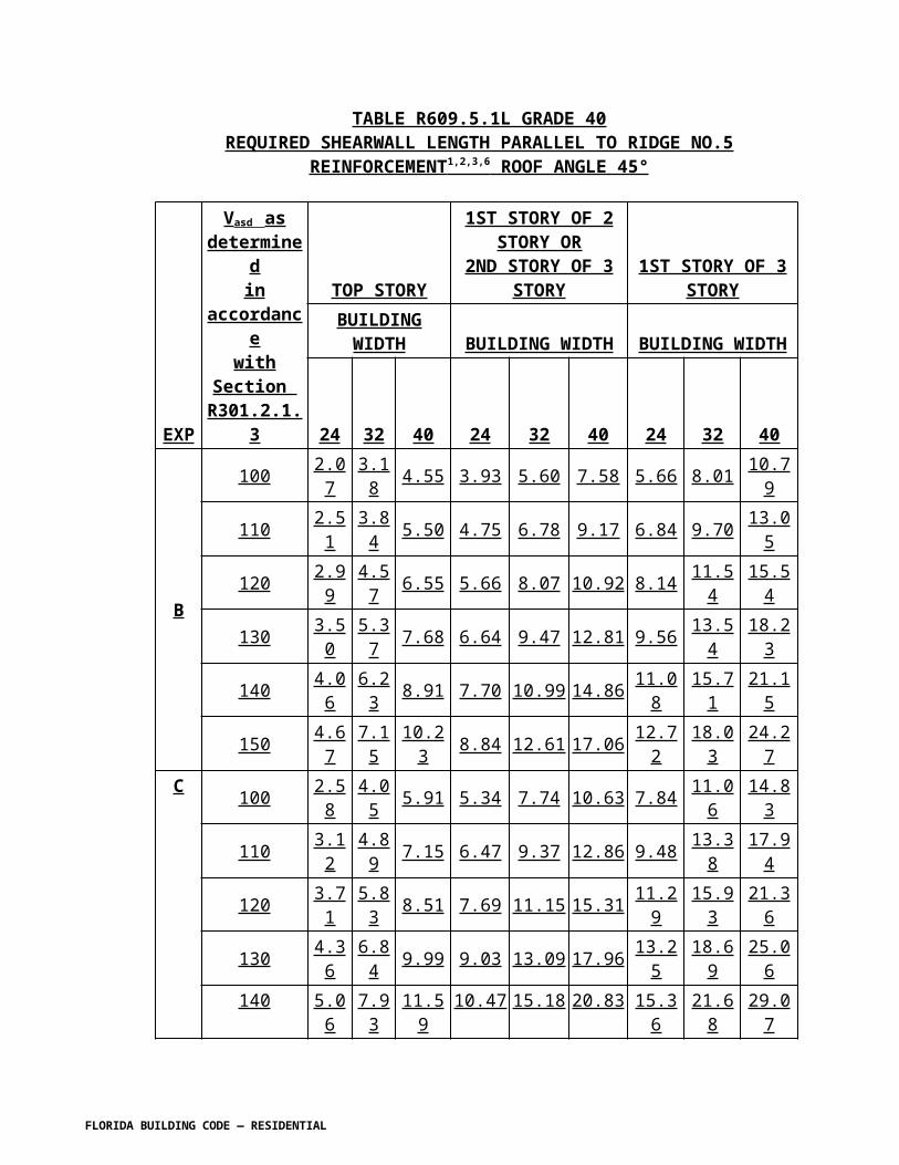
R905.6.3.3 Underlayment Application . Underlayment shall be installed using one of the following methods:
1. Two layer underlayment shall comply with ASTM D 226, Type I or Type II or ASTM D 4869, Type II or Type IV or ASTM D 6757: Apply a 19-inch (483 mm) strip of underlayment felt parallel to and starting at the eaves, fastened sufficiently to hold in place. Starting at the eave, apply 36-inch-wide (914 mm) sheets of underlayment, overlapping successive sheets 19 inches (483 mm), and fastened with 1 inch (25 mm) round plastic cap, metal cap nails or nails and tin-tabs attached to a nailable deck with one row in the field of the sheet with a maximum fastener spacing of 12 in. o.c. (305 mm), and one row at the overlaps fastened 6 in. o.c. (152 mm). Synthetic underlayment shall be fastened in accordance with this section and the manufacturer’s recommendations.
2. One layer underlayment shall comply with ASTM D 226, Type II or ASTM D 4869, Type IV or ASTM D 6757: Underlayment shall be applied shingle fashion, parallel to and starting from the eave and lapped 2 inches (51 mm), fastened with 1 inch (25 mm) round plastic cap, metal cap nails or nails and tin-tabs attached to a nailable deck with two staggered rows in the field of the sheet with a maximum fastener spacing of 12 in. o.c. (305 mm), and one row at the overlaps fastened 6 in. o.c. (152 mm). Synthetic underlayment shall be fastened in accordance with this section and the manufacturer’s recommendations End laps shall be offset by 6 feet (1829 mm).
3. As an alternative, the entire roof deck shall be covered with an approved self-adhering polymer modified bitumen sheet meeting ASTM D 1970 or an approved self-adhering synthetic underlayment installed in accordance with the manufacturer’s installation instructions.
R905.6.4 Material standards. Slate shingles shall comply with ASTM C 406.
R905.6.5 Application. Minimum headlap for slate shingles shall be in accordance with Table R905.6.5. Slate shingles shall be secured to the roof with two fasteners per slate. Slate shingles shall be installed in accordance with this chapter and the manufacturer’s installation instructions.
TABLE R905.6.5SLATE SHINGLE HEADLAP
SLOPE HEADLAP (inches)
4:12 ≤ slope < 8:12 48:12 ≤ slope < 20:12 3
Slope ≤ 20:12 2For SI:1inch = 25.4 m.
R905.6.6 Flashing. Flashing and counter flashing shall be made with sheet metal. Valley flashing shall be a minimum of 15 16 inches (381 406 mm) wide. Valley and flashing metal shall be a minimum uncoated thickness of 0.0179-inch (0.5 mm) zinc
FLORIDA BUILDING CODE — RESIDENTIAL

coated G90 as provided in Table R903.2.1 for nonferrous metal or stainless steel. Chimneys, stucco or brick walls shall have a minimum of two plies of felt for a cap flashing consisting of a 4-inch-wide (102 mm) strip of felt set in plastic cement and extending 1 inch (25 mm) above the first felt and a top coating of plastic cement. The felt shall extend over the base flashing 2 inches (51 mm).
R905.6.7 Slate and slate-type shingles shall be installed in accordance with this chapter and the manufacturer’s installation instructions. The product approval shall state the allowable uplift resistance for the attachment system. The installation of slate and slate-type shingles shall be limited to roofs where the allowable uplift resistance is equal to or greater than the design uplift pressure for the roof listed in Table R301.2(2).
Section R905.7 Wood shingles. Change to read as shown:
R905.7 Wood shingles. The installation of wood shingles shall comply with the provisions of this section.
R905.7.1 Deck requirements. Wood shingles shall be installed on solid or spaced sheathing. Where spaced sheathing is used, sheathing boards shall not be less than 1-inch by 4-inch (25.4 mm by 102 mm) nominal dimensions and shall be spaced on centers equal to the weather exposure to coincide with the placement of fasteners.
R905.7.1.1 Solid sheathing required. Reserved. In areas where the average daily temperature in January is 25°F (-4°C) or less, solid sheathing is required on that portion of the roof requiring the application of an ice barrier.
R905.7.2 Deck slope. Wood shingles shall be installed on slopes of three units vertical in 12 units horizontal (25-percent slope) or greater.
R905.7.3 Underlayment. Underlayment shall comply with ASTM D 226, Type I or ASTM D 4869, Type I or II.
R905.7.3.1 Ice barrier. Reserved. In areas where there has been a history of ice forming along the eaves causing a backup of water as designated in Table R301.2(1), an ice barrier that consists of at least two layers of underlayment cemented together or a self-adhering polymer modified bitumen sheet shall be used in lieu of normal underlayment and extend from the lowest edges of all roof surfaces to a point at least 24 inches (610 mm) inside the exterior wall line of the building.
Exception: Detached accessory structures that contain no conditioned floor area.
R905.7.3.2 Underlayment and high winds. Reserved. Underlayment applied in areas subject to high winds [above 110 mph (49 m/s) in accordance with Figure R301.2(4)A] shall be applied with corrosion-resistant fasteners in accordance with manufacturer’s installation instructions. Fasteners are to be applied along the overlap not farther apart than 36 inches (914mm) on center.
FLORIDA BUILDING CODE — RESIDENTIAL

Underlayment installed where the basic wind speed equals or exceeds 120 mph (54 m/s) shall comply with ASTM D 226 Type II or ASTM D 4869 Type IV. The underlayment shall be attached in a grid pattern of 12 inches (305 mm) between side laps with a 6-inch (152 mm) spacing at the side laps. Underlayment shall be applied in accordance with Section R905.2.7 except all Head laps shall be a minimum of 4 inches (102 mm). Underlayment shall be attached using metal or plastic cap nails with a head diameter of not less than 1 inch (25.4 mm) with a thickness of at least 32-gauge sheet metal. The cap-nail shank shall be a minimum of 12 gauge (0.105 inches) with a length to penetrate through the roof sheathing or a minimum of 3/4 inch (19 mm) into the roof sheathing.
Exception: As an alternative, adhered underlayment complying with ASTM D 1970 shall be permitted.
R905.7.3.3 Underlayment Application. Underlayment shall be installed using one of the following methods:
1. Two layer underlayment shall comply with ASTM D 226, Type I or Type II or ASTM D 4869, Type II or Type IV: Apply a 19-inch (483 mm) strip of underlayment felt parallel to and starting at the eaves, fastened sufficiently to hold in place. Starting at the eave, apply 36-inch-wide (914 mm) sheets of underlayment, overlapping successive sheets 19 inches (483 mm), and fastened with 1 inch (25 mm) round plastic cap, metal cap nails or nails and tin-tabs attached to a nailable deck with one row in the field of the sheet with a maximum fastener spacing of 12 in. o.c. (305 mm), and one row at the overlaps fastened 6 in. o.c. (152 mm).
2. One layer underlayment shall comply with ASTM D 226, Type II or ASTM D 4869, Type IV: Underlayment shall be applied shingle fashion, parallel to and starting from the eave and lapped 2 inches (51 mm), fastened with 1 inch (25 mm) round plastic cap, metal cap nails or nails and tin-tabs attached to a nailable deck with two staggered rows in the field of the sheet with a maximum fastener spacing of 12 in. o.c. (305 mm), and one row at the overlaps fastened 6 in. o.c. (152 mm). End laps shall be offset by 6 feet (1829 mm).
Section R905.7 Wood shingles. Change to read as shown:
R905.7.4 Material standards. Wood shingles shall be of naturally durable wood and comply with the requirements of Table R905.7.4.
TABLE R905.7.4WOOD SHINGLE MATERIAL REQUIREMENTS
FLORIDA BUILDING CODE — RESIDENTIAL

MATERIAL MINIMUM GRADES APPLICABLE GRADING RULES
Wood shingles of naturally durable wood 1, 2 or 3 Cedar Shake and Shingle Bureau
R905.7.5 Application Attachment. Wood shingles shall be installed according to this chapter and the manufacturer’s installation instructions. Wood shingles shall be laid with a side lap not less than 11/2 inches (38 mm) between joints in courses, and no two joints in any three adjacent courses shall be in direct alignment. Spacing between shingles shall not be less than 1/4 inch to 3/8 inch (6 mm to 10 mm). Weather exposure for wood shingles shall not exceed those set in Table R905.7.5. Fasteners for wood shingles shall be corrosion resistant with a minimum penetration of 1/2 inch (13 mm) into the sheathing. For sheathing less than 1/2 inch (13 mm) in thickness, the fasteners shall extend through the sheathing. Wood shingles shall be attached to the roof with two fasteners per shingle, positioned no more than 3/4 inch (19 mm) from each edge and no more than 1 inch (25 mm) above the exposure line. Attachment in accordance with Table R905.7.5 shall be used for roofs with a mean roof height of 40 feet or less and in regions with a V asd as determined in accordance with Section R301.2.1.3 to be 100 mph or less
TABLE R905.7.5WOOD SHINGLE WEATHER EXPOSURE AND ROOF SLOPE AND SHAKE
INSTALLATION
ROOFING MATERIAL
LENGTH (inches) GRADE
EXPOSURE (inches)
3:12 pitch to 4:12 pitch or steeper
Shingles of naturally durable
wood
16No. 1 33/4 5No. 2 31/2 4No. 3 3 31/2
18No. 1 41/4 51/2
No. 2 4 41/2
No. 3 31/2 4
24No. 1 53/4 71/2
No. 2 51/2 61/2
No. 3 5 51/2
ROOF ITEM WOOD SHINGLES WOOD SHAKES1. DeckRequirements
Shingles shall be applied to roofs with solid or spaced sheathing. Where spaced
Shakes shall be applied to roofs with solid or spaced sheathing. Where spaced sheathing is used,
FLORIDA BUILDING CODE — RESIDENTIAL

sheathing is used,sheathing boards shall not be 4 less than 1”× 4” nominal dimensions and shall be spaced on centerequal to the weather exposure to coincide with the placement of fasteners.
sheathing boards shall not be less than 1” × 4” nominal dimensions and shall be spaced on center equal to the weather exposure to coincide with the placement of fasteners. When 1” × 4” spaced sheathing is installed at 10 inches, boards must be installed between the sheathing boards.
2. Interlayment No requirements. Interlayment shall comply with ASTM D 226, Type 1.
3. Underlayment Underlayment shall comply with ASTM D 226,Type 1.
No requirements.
4. Application --- ---Attachment Fasteners for wood shingles
shall be corrosion resistant with a minimum penetration of 3 / 4 inch into the sheathing. For sheathing less than 1 / 2 inch thick, the fasteners shall extend through the sheathing a minimum of 3 / 8 inch.
Fasteners for wood shakes shall be corrosion resistant with a minimum penetration of 3 / 4 inch into the sheathing. For sheathing less than 1 / 2 inch thick, the fasteners shall extend through the sheathing a minimum of 3 / 8 inch.
No. of fasteners Wood shingles shall be attached to the roof with two fasteners per shingle, positioned no more than 3 / 4
inch (19.1 mm) from each edge and no more than 1 1 / 2 inch (38.1 mm) above the exposure line.
Wood shakes shall be attached to the roof with two fasteners per shake, positioned no more than 1 inch (25.4 mm) from each edge and no more than 1 1 / 2 inches(38.1 mm) above the exposure line
For SI: 1 inch = 25.4 mm
R905.7.6 Valley flashing Attachment for V asd as determined in accordance with Section R301.2.1.3 greater than 100 mph. Roof flashing shall be not less than No. 26 gage [0.019 inches (0.5 mm)] corrosion-resistant sheet metal and shall extend 10 inches (254 mm) from the centerline each way for roofs having slopes less than 12 units vertical in 12 units horizontal (100-percent slope), and 7 inches (178 mm) from the centerline each way for slopes of 12 units vertical in 12 units horizontal and greater. Sections of flashing shall have an end lap of not less than 4 inches (102 mm). Wood shingles installed in accordance with Table R905.7.5 and the requirements of R905.7.6 have an allowable uplift resistance of 45 psf. The installation of wood shingles shall be limited to roofs where the allowable uplift resistance is equal to or greater than the design uplift pressure for the roof listed in Table R301.2(2).
R905.7.6.1 Fasteners.
FLORIDA BUILDING CODE — RESIDENTIAL

R905.7.6.1.1 Nails. N ails to attach the wood shakes shall be 3d stainless-steel ring-shank nails. The nails shall have sufficient length to penetrate through the wood shakes and shall penetrate through the sheathing.
R905.7.6.1.2 Screws. Screws to attach the battens to the framing shall be No. 8 by 2 1 / 2 inches (64 mm) long corrosion resistant wood screws. Wood screws shall be corrosion resistant screw s conforming to ANSI/ASME B 18.6.1. The corrosion resistance shall meet ASTM A 641, Class 1 or an equal corrosion resistance by coating, electro galvanization, mechanical galvanization, stainless steel, nonferrous metal or other suitable corrosion resistant material.
R905.7.6.1.3 Wood battens. 1 × 4 wood battens shall be attached to the wood joists with 2 screws per joist. The first batten shall be located 6 inches (152 mm) from the outer edge of the wood joist. Second batten shall be spaced 1- 1 / 4 inches (32 mm) from the first batten. The remaining battens shall be spaced a maximum 2 inches (51 mm) apart, except the last one which shall be spaced no greater than 3 / 4 inches (19 mm) from the previous batten.
R905.7.6.1.4 Shingles. Shingles shall be attached to the battens with 2 nails for each shingle placed 1 1 / 2 inch (38 mm) above the exposure line. The nails shall be 3 / 4 to 1 inch (19 to 25 mm) from the shingle edges.
R905.7.7 Label required Application. Each bundle of shingles shall be identified by a label of an approved grading or inspection bureau or agency. Wood shingles shall be installed according to this chapter and the manufacturer’s installation instructions. Weather exposure for wood shingles shall not exceed those set in Table R905.7.7.
TABLE R905.7.7WOOD SHINGLE WEATHER EXPOSURE AND ROOF SLOPE
ROOFINGMATERIAL
LENGTH(inches) GRADE
EXPOSURE (inches)3:12 pitch
to< 4:12
4:12 pitch orsteeper
Shingles ofnaturally durablewood
16No. 1 3 3 / 4 5No. 2 3 1 / 2 4No. 3 3 3 1 / 2
18No. 1 4 1 / 4 5 1 / 2
No. 2 4 4 1 / 2
No. 3 3 1 / 2 4
24No. 1 5 3 / 4 7 1 / 2
No. 2 5 1 / 2 6 1 / 2
No. 3 5 5 1 / 2
For SI: 1 inch = 25.4 mm.
FLORIDA BUILDING CODE — RESIDENTIAL

R905.7.8 Flashing. At the juncture of the roof and vertical surfaces, flashing and counter flashing shall be provided in accordance with the manufacturer’s installation instructions, and where of metal, shall not be less than 0.017-inch (0.48 mm) (No. 26 galvanized sheet gage) corrosion-resistant metal.
R905.7.8.1 Valley flashing. Roof flashing shall be not less than No. 26 gage [0.017 inches (0.48 mm)] corrosion-resistant sheet metal and shall extend 10 inches (254 mm) from the centerline each way for roofs having slopes less than 12 units vertical in 12 units horizontal (100-percent slope), and 7 inches (178 mm) from the centerline each way for slopes of 12 units vertical in 12 units horizontal and greater. Sections of flashing shall have an end lap of not less than 4 inches (102 mm).
R905.7.9 Label required. Each bundle of shingles shall be identified by a label of an approved grading or inspection bureau or agency.
Section R905.8 Wood shakes. Change to read as shown:
R905.8 Wood shakes. The installation of wood shakes shall comply with the provisions of this section.
R905.8.1 Deck requirements. Wood shakes shall be used only on solid or spaced sheathing. Where spaced sheathing is used, sheathing boards shall not be less than 1-inch by 4-inch (25 mm by 102 mm) nominal dimensions and shall be spaced on centers equal to the weather exposure to coincide with the placement of fasteners. Where 1-inch by 4-inch (25 mm by 102 mm) spaced sheathing is installed at 10 inches (254 mm) on center, additional 1-inch by 4-inch (25 mm by 102 mm) boards shall be installed between the sheathing boards.
R905.8.1.1 Solid sheathing required. Reserved.In areas where the average daily temperature in January is 25°F (-4°C) or less, solid sheathing is required on that portion of the roof requiring an ice barrier
R905.8.2 Deck slope. Wood shakes shall only be used on slopes of three four (4) units vertical in twelve (12) units horizontal (25 33-percent slope) or greater.
R905.8.3 Underlayment. Underlayment shall comply with ASTM D 226, Type I or Type II or ASTM D 4869, Type I or II or Type IV.
R905.8.3.1 Ice barrier. Reserved.In areas where there has been a history of ice forming along the eaves causing a backup of water as designated in Table R301.2(1), an ice barrier that consists of at least two layers of underlayment cemented together or a self-adhering polymer modified bitumen sheet shall be used in place of normal underlayment and extend from the lowest edges of all roof surfaces to a point at least 24 inches (610 mm) inside the exterior wall line of the building.
FLORIDA BUILDING CODE — RESIDENTIAL

Exception: Detached accessory structures that contain no conditioned floor area.
R905.8.3.2 Underlayment and high winds. Reserved.Underlayment applied in areas subject to high winds [above 110 mph (49 m/s) in accordance with Figure R301.2(4)A] shall be applied with corrosion-resistant fasteners in accordance with manufacturer’s installation instructions. Fasteners are to be applied along the overlap not farther apart than 36 inches (914 mm) on center. Underlayment installed where the basic wind speed equals or exceeds 120 mph (54 m/s) shall comply with ASTM D 226 Type II. The underlayment shall be attached in a grid pattern of 12 inches (305 mm) between side laps with a 6-inch (152 mm) spacing at the side laps. Underlayment shall be applied in accordance with Section R905.2.7except all laps shall be a minimum of 4 inches (102 mm). Underlayment shall be attached using metal or plastic cap nails with a head diameter of not less than 1 inch (25.4 mm) with a thickness of at least 32-gauge sheet metal. The cap-nail shank shall be a minimum of 12 gauge (0.105 inches) with a length to penetrate through the roof sheathing or a minimum of 3/4 inch (19 mm) into the roof sheathing.
Exception: As an alternative, adhered underlayment complying with ASTM D 1970 shall be permitted.
R905.8.3.3 Underlayment Application. Underlayment shall be installed using one of the following methods:
1. Two layer underlayment shall comply with ASTM D 226, Type I or Type II or ASTM D 4869, Type II or Type IV: Apply a 19-inch (483 mm) strip of underlayment felt parallel to and starting at the eaves, fastened sufficiently to hold in place. Starting at the eave, apply 36-inch-wide (914 mm) sheets of underlayment, overlapping successive sheets 19 inches (483 mm), and fastened with 1 inch (25 mm) round plastic cap, metal cap nails or nails and tin-tabs attached to a nailable deck with one row in the field of the sheet with a maximum fastener spacing of 12 in. o.c. (305 mm), and one row at the overlaps fastened 6 in. o.c. (152 mm).
2. One layer underlayment shall comply with ASTM D 226, Type II or ASTM D 4869, Type IV: Underlayment shall be applied shingle fashion, parallel to and starting from the eave and lapped 2 inches (51 mm), fastened with 1 inch (25 mm) round plastic cap, metal cap nails or nails and tin-tabs attached to a nailable deck with two staggered rows in the field of the sheet with a maximum fastener spacing of 12 in. o.c. (305 mm), and one row at the overlaps fastened 6 in. o.c. (152 mm). End laps shall be offset by 6 feet (1829 mm).
R905.8.3.4 Interlayment. Interlayment shall comply with ASTM D 226, Type I.
R905.8.4 Interlayment Attachment. Attachment in accordance with Table R905.7.5 shall be used for roofs with a mean roof height of 40 feet or less and in regions with a as determined in accordance with Section R301.2.1.3, of 100 mph or less.
FLORIDA BUILDING CODE — RESIDENTIAL

Interlayment shall comply with ASTM D 226, Type I.
R905.8.5 Material standards. Wood shakes shall comply with the requirements of Table R905.8.5.
TABLE R905.8.5WOOD SHAKE MATERIAL REQUIREMENTS
MATERIALMINIMUM GRADES
APPLICABLE GRADING RULES
Wood shakes of naturally durable wood 1 Cedar Shake and Shingle Bureau
Taper sawn shakes of naturally durable wood 1 or 2 Cedar Shake and Shingle Bureau
Preservative-treated shakes and shingles of naturally durable wood 1 Cedar Shake and Shingle Bureau
Fire-retardant-treated shakes and shingles of naturally durable wood 1 Cedar Shake and Shingle Bureau
Preservative-treated taper sawn shakes of Southern pine treated in accordance with AWPA Standard U1 (Commodity Specification A, Use Category 3B and Section 5.6)
1 or 2 Forest Products Laboratory of theTexas Forest Services
R905.8.6 Application. Reserved.Wood shakes shall be installed ac4cording to this chapter and the manufacturer’s installation instructions. Wood shakes shall be laid with a side lap not less than 11/2
inches (38 mm) between joints in adjacent courses. Spacing between shakes in the same course shall be 3/8 inch to 5/8 inch (9.5 mm to 15.9 mm) for shakes and tapersawn shakes of naturally durable wood and shall be 3/8 inch to 5/8 inch (9.5 mm to 15.9 mm) for preservative-treated taper sawn shakes. Weather exposure for wood shakes shall not exceed those set forth in Table R905.8.6. Fasteners for wood shakes shall be corrosion-resistant, with a minimum penetration of 1/2 inch (12.7 mm) into the sheathing. For sheathing less than 1/2 inch (12.7 mm) thick, the fasteners shall extend through the sheathing. Wood shakes shall be attached to the roof with two fasteners per shake, positioned no more than 1 inch (25 mm) from each edge and no more than 2 inches (51 mm) above the exposure line.
TABLE R905.8.6WOOD SHAKE WEATHER EXPOSURE AND ROOF SLOPE
Reserved.
FLORIDA BUILDING CODE — RESIDENTIAL

ROOFING MATERIAL
LENGTH (inches) GRADE
EXPOSURE (inches)
4:12 pitch or steeperShakes of naturally durable wood
18 No. 1 71/2
24 No. 1 10a
Preservative-treated taper sawn shakes of Southern Yellow Pine
18 No. 1 71/2
24 No. 1 1018 No. 2 51/2
24 No. 2 71/2
Taper-sawn shakes of naturally durable wood
18 No. 1 71/2
24 No. 1 1018 No. 2 51/2
24 No. 2 71/2
For SI: 1 inch = 25.4 mm.a. For 24-inch by 3/8-inch handsplit shakes, the maximum exposure is 71/2 inches.
R905.8.7 Shake placement Attachment for V asd as determined in accordance with Section R301.2.1.3 greater than 100 mph. Wood shakes installed in accordance with Table R905.7.5 and the requirements of R905.8.7 have an allowable uplift resistance of 90 psf. The installation of wood shakes shall be limited to roofs where the allowable uplift resistance is equal to or greater than the design uplift pressure for the roof listed in Table R301.2(2). The starter course at the eaves shall be doubled and the bottom layer shall be either 15-inch (381 mm), 18-inch (457 mm) or 24-inch (610 mm) wood shakes or wood shingles. Fifteen-inch (381 mm) or 18-inch (457 mm) wood shakes may be used for the final course at the ridge. Shakes shall be interlaid with 18-inch-wide (457 mm) strips of not less than No. 30 felt shingled between each course in such a manner that no felt is exposed to the weather by positioning the lower edge of each felt strip above the butt end of the shake it covers a distance equal to twice the weather exposure.
R905.8.7.1 Fasteners.
R905.8.7.1.1 Nails . Nails to attach the wood shakes shall be 6d stainless-steel ring-shank nails. The nails shall have sufficient length to penetrate through the wood shakes and shall penetrate through the sheathing.
R905.8.7.1.2 Screws. Screws to attach the battens to the framing shall be No. 8 by 2 1 / 2 inches long corrosion resistant wood screws. Wood screws shall be corrosion resistant screws conforming to ANSI/ASME B 18.6.1. The corrosion resistance shall meet ASTM A 641, Class 1 or an equal corrosion resistance by coating, electro galvanization, mechanical galvanization, stainless steel, nonferrous metal or other suitable corrosion resistant material.
R905.8.7.1.3 Wood battens. 1 × 6 wood battens shall be attached to the wood joists with 2 screws per joist. The first batten shall be located 6 inches from the
FLORIDA BUILDING CODE — RESIDENTIAL

outer edge of the wood joist. The second batten shall be spaced 1- 1 / 4 inches from the first batten. The remaining battens shall be spaced a maximum 2 inches apart, except the last one, which shall be spaced no greater than 3 / 4 inches from the previous batten.
R905.8.7.1.4 Shakes. Shakes shall be attached to the battens with 2 nails for each shake placed 1 1 / 2 inch above the exposure line. The nails shall be 3 / 4 to 1 inch from the shake edges.
R905.8.8 Valley flashing Application. Wood shakes shall be laid with a side lap not less than 1 1 / 2 inches (38 mm) between joints in adjacent courses. Spacing between shakes in the same course shall be 3 / 8 to 5 / 8 inches (9.5 to 15.9 mm) for shakes and taper sawn shakes of naturally durable wood and shall be 1 / 4 to 3 / 8 inch (6.4 to 9.5 mm) for preservative taper sawn shakes. Weather exposure for wood shakes shall not exceed those set in Table R905.8.8.Roof valley flashing shall not be less than No. 26 gage [0.019 inch (0.5 mm)] corrosion-resistant sheet metal and shall extend at least 11 inches (279 mm) from the centerline each way. Sections of flashing shall have an end lap of not less than 4 inches (102 mm).
TABLE R905.8.8WOOD SHAKE WEATHER EXPOSURE AND ROOF SLOPE
ROOFING MATERIALLENGTH
(inches) GRADEEXPOSURE (inches)4:12 pitch or steeper
Shakes of naturally durablewood
18 No. 1 7 1 / 2
24 No. 1 10 a
Preservative-treated tapersawn shakes of SouthernYellow Pine
18 No. 1 7 1 / 2
24 No. 1 1018 No. 2 5 1 / 2
24 No. 2 7 1 / 2
Taper-sawn shakes ofnaturally durable wood
18 No. 1 7 1 / 2
24 No. 1 1018 No. 2 5 1 / 2
24 No. 2 7 1 / 2
For SI: 1 inch = 25.4 mm.a. For 24-inch by 3 / 8-inch handsplit shakes, the maximum exposure is 7 1 / 2 inches.
FLORIDA BUILDING CODE — RESIDENTIAL

R905.8.9 Label required. Each bundle of shakes shall be identified by a label of an approved grading or inspection bureau or agency.
R905.8.10 Flashing. At the juncture of the roof and vertical surfaces, flashing and counter flashing shall be provided in accordance with the manufacturer’s installation instructions, and where of metal, shall not be less than 0.017-inch (0.48 mm) (No. 26 galvanized sheet gage) corrosion-resistant metal.
R905.8.10.1 Valley flashing. Valley flashing shall extend at least 11 inches (279 mm) from the centerline each way and have a splash diverter rib not less than 1 inch (25 mm) high at the flow line formed as part of the flashing. Sections of flashing shall have an end lap of not less than 4 inches (102 mm). For roof slopes of four (4) units vertical in twelve (12) units horizontal (33-percent slope) and over, the valley flashing shall have a 36-inch-wide (914 mm) underlayment of one layer of ASTM D 226 Type I underlayment running the full length of the valley, in addition to other required underlayment per Table R903.2.1 Valley flashing and flashing metal shall be a minimum thickness as provided in Table R903.2.1 for nonferrous metal or stainless steel.
Section R905.9 Built-up roofs. Change to read as shown:
R905.9 Built-up roofs. The installation of built-up roofs shall comply with the provisions of this section.
R905.9.1 Slope. Built-up roofs shall have a design slope of a minimum of one-fourth unit vertical in 12 units horizontal (2-percent slope) for drainage, except for coal-tar built-up roofs, which shall have a design slope of a minimum one-eighth unit vertical in 12 units horizontal (1-percent slope).
R905.9.2 Material standards. Built-up roof covering materials shall comply with the standards in Table R905.9.2 or UL 55A.
R905.9.2.1 Red rosin paper shall be used when the membrane is applied directly to a wood deck or cementitious fiber decks.
TABLE R905.9.2BUILT-UP ROOFING MATERIAL STANDARDS
MATERIAL STANDARD STANDARD
Acrylic coatings used in roofing ASTM D 6083Aggregate surfacing ASTM D 1863Asphalt adhesive used in roofing ASTM D 3747Asphalt cements used in roofing ASTM D 2822; D 3019; D 4586Asphalt-coated glass fiber base sheet ASTM D 4601
FLORIDA BUILDING CODE — RESIDENTIAL

Asphalt coatings used in roofing ASTM D 1227; D 2823; D 2824; D 4479
Asphalt glass felt ASTM D 2178Asphalt primer used in roofing ASTM D 41Asphalt-saturated and asphalt-coated organic felt base sheet ASTM D 2626
Asphalt-saturated organic felt (perforated) ASTM D 226Asphalt used in roofing ASTM D 312Coal-tar cements used in roofing ASTM D 4022; D 5643Coal-tar primer used in roofing, dampproofing and waterproofing ASTM D 43
Coal-tar saturated organic felt ASTM D 227Coal-tar used in roofing ASTM D 450, Type I or IIGlass mat, coal tar ASTM D 4990Glass mat, venting type ASTM D 4897Mineral-surfaced inorganic cap sheet ASTM D 3909Thermoplastic fabrics used in roofing ASTM D 5665; D 5726R905.9.3 Application. [No change to IRC text]
Section 905.10 Metal roof panels. Change to read as shown:
R905.10 Metal roof panels. The installation of metal roof panels shall comply with the provisions of this section.
R905.10.1 Deck requirements. Metal roof panel roof coverings shall be applied to solid or spaced sheathing, except where the roof covering is specifically designed to be applied to spaced supports.
R905.10.2 Slope. Minimum slopes for metal roof panels shall comply with the following:
1. The minimum slope for lapped, nonsoldered-seam metal roofs without applied lap sealant shall be three units vertical in 12 units horizontal (25-percent slope).
2. The minimum slope for lapped, nonsoldered-seam metal roofs with applied lap sealant shall be one-half vertical unit in 12 units horizontal (4-percent slope). Lap sealants shall be applied in accordance with the approved manufacturer’s installation instructions.
3. The minimum slope for standing-seam roof systems shall be one-quarter unit vertical in 12 units horizontal (2-percent slope).
R905.10.3 Material standards. Metal-sheet roof covering systems that incorporate supporting structural members shall be designed in accordance with the International Building Code Florida Building Code, Building . Metal-sheet roof coverings installed over structural decking shall comply with Table R905.10.3(1) 4.4. The materials used
FLORIDA BUILDING CODE — RESIDENTIAL

for metal-sheet roof coverings shall be naturally corrosion resistant or provided with corrosion resistance in accordance with the standards and minimum thicknesses shown in Table R905.10.3(2) 4.4.
TABLE R905.10.3(1)METAL ROOF COVERING STANDARDS
Reserved.
ROOF COVERING TYPE STANDARD APPLICATION RATE/THICKNESS
Galvanized steel ASTM A 653 G90 Zinc coatedStainless steel ASTM A 240, 300 Series alloysSteel ASTM A 924Lead-coated copper ASTM B 101
Cold-rolled copperASTM B 370 minimum 16 oz/sq ft and 12 oz/sq ft high-yield copper for metal-sheet roof-covering systems; 12 oz/sq ft for preformed metal shingle systems.
Hard lead 2 lb/sq ftSoft lead 3 lb/sq ft
AluminumASTM B 209, 0.024 minimum thickness for roll-formed panels and 0.019-inch minimum thickness for pressformed shingles.
Terne (tin) and terne-coated stainless
Terne coating of 40 lb per double base box, field painted where applicable in accordance with manufacturer’s installation instructions.
Zinc0.027 inch minimum thickness: 99.995% electrolytic high-grade zinc with alloy additives of copper (0.08 - 0.20%), titanium (0.07% - 0.12%) and aluminum (0.015%).
For SI: 1 ounce per square foot = 0.305 kg/m2, 1 pound per square foot = 4.214 kg/m2, 1 inch = 25.4 mm, 1 pound = 0.454 kg.
TABLE R905.10.3(2)MINIMUM CORROSION RESISTANCE
Reserved.
55% aluminum-zinc alloy coated steel ASTM A 792 AZ 50
5% aluminum alloy-coated steel ASTM A 875 GF60Aluminum-coated steel ASTM A 463 T2 65Galvanized steel ASTM A 653 G-90Prepainted steel ASTM A 755a
a. Paint systems in accordance with ASTM A 755 shall be applied over steel products with corrosion-resistant coatings complying with ASTM A 792, ASTM A 875, ASTM A 463, or ASTM A 653.
FLORIDA BUILDING CODE — RESIDENTIAL

R905.10.4 Attachment. Metal roof panels shall be secured to the supports in accordance with this chapter and the manufacturer’s installation instructions. Metal roofing fastened directly to steel framing shall be attached by approved fasteners. In the absence of manufacturer’s installation instructions, t The following fasteners shall be used:
1. Galvanized fasteners shall be used for galvanized roofs.2. Hard C copper ,brass, bronze, or copper alloy or 300 series stainless steel fasteners shall be used for copper roofs.3. Stainless steel fasteners are acceptable for all types of metal roofs.4. Aluminum-zinc coated fasteners are acceptable for aluminum-zinc coated roofs.
R905.10.5 Underlayment. Underlayment shall comply with ASTM D 226, Type I or Type II or ASTM D 4869, Type II or Type IV or ASTM D 1970 or ASTM D 6757.
R905.10.5.1 Underlayment and high winds. Reserved . Underlayment applied in areas subject to high winds [above 110 mph (49 m/s) in accordance with Figure R301.2(4)A] shall be applied with corrosion-resistant fasteners in accordance with manufacturer’s installation instructions. Fasteners are to be applied along the overlap not farther apart than 36 inches (914 mm) on center.
Underlayment installed where the basic wind speed equals or exceeds 120 mph (54 m/s) shall comply with ASTM D 226 Type II. The underlayment shall be attached in a grid pattern of 12 inches (305 mm) between side laps with a 6-inch (152 mm) spacing at the side laps. Underlayment shall be applied in accordance with Section R905.2.7except all laps shall be a minimum of 4 inches (102 mm). Underlayment shall be attached using metal or plastic cap nails with a head diameter of not less than 1 inch (25.4 mm) with a thickness of at least 32-gauge sheet metal. The cap-nail shank shall be a minimum of 12 gauge (0.105 inches) with a length to penetrate through the roof sheathing or a minimum of 3/4 inch (19 mm) into the roof sheathing.
Exception: As an alternative, adhered underlayment complying with ASTM D 1970 shall be permitted.
R905.10.5.2 Underlayment Application. Underlayment shall be installed using one of the following methods:
1. Two layer underlayment shall comply with ASTM D 226, Type I or Type II or ASTM D 4869, Type II or Type IV or ASTM D 6757: Apply a 19-inch (483 mm) strip of underlayment felt parallel to and starting at the eaves, fastened sufficiently to hold in place. Starting at the eave, apply 36-inch-wide (914 mm) sheets of underlayment, overlapping successive sheets 19 inches (483 mm), and fastened with 1 inch (25 mm) round plastic cap, metal cap nails or nails and tin-tabs attached to a nailable deck with one row in the field of the sheet with a maximum fastener spacing of 12 in. o.c. (305 mm), and one row at the overlaps fastened 6 in. o.c. (152 mm). Synthetic underlayment shall be fastened in accordance with this section and the manufacturer’s recommendations.
FLORIDA BUILDING CODE — RESIDENTIAL

2. One layer underlayment shall comply with ASTM D 226, Type II or ASTM D 4869, Type IV or ASTM D 6757: Underlayment shall be applied shingle fashion, parallel to and starting from the eave and lapped 2 inches (51 mm), fastened with 1 inch (25 mm) round plastic cap, metal cap nails or nails and tin-tabs attached to a nailable deck with two staggered rows in the field of the sheet with a maximum fastener spacing of 12 in. o.c. (305 mm), and one row at the overlaps fastened 6 in. o.c. (152 mm). Synthetic underlayment shall be fastened in accordance with this section and the manufacturer’s recommendations End laps shall be offset by 6 feet (1829 mm).
3. As an alternative, the entire roof deck shall be covered with an approved self-adhering polymer modified bitumen sheet meeting ASTM D 1970 or an approved self-adhering synthetic underlayment installed in accordance with the manufacturer’s installation instructions.
Section R905.11 Modified bitumen roofing. Change to read as shown:
R905.11 Modified bitumen roofing. The installation of modified bitumen roofing shall comply with the provisions of this section.
R905.11.1 Slope. Modified bitumen membrane roofs shall have a design slope of a minimum of one-fourth unit vertical in 12 units horizontal (2-percent slope) for drainage.
R905.11.2 Material standards. Modified bitumen roof coverings shall comply with the standards in Table R905.11.2.
TABLE R905.11.2MODIFIED BITUMEN ROOFING MATERIAL STANDARDS
MATERIAL STANDARD
Acrylic coating ASTM D 6083Asphalt adhesive ASTM D 3747Asphalt cement ASTM D 3019Asphalt coating ASTM D 1227; D 2824Asphalt primer ASTM D 41
Modified bitumen roofmembrane
ASTM D 6162; D 6163; D 6164;D 6222; D 6223; D 6298; D 6509CGSB 37-GP-56M
R905.11.3 Application. Modified bitumen roofs shall be installed according to this chapter and the manufacturer’s installation instructions. The approved allowable uplift resistance for the modified bitumen roof shall be equal to or greater than the uplift resistance for the roof based on Table R301.2(2).
FLORIDA BUILDING CODE — RESIDENTIAL

Section R905.12 Thermoset single-ply roofing. Change to read as shown:
R905.12 Thermoset single-ply roofing. The installation of thermoset single-ply roofing shall comply with the provisions of this section.
R905.12.1 Slope. Thermoset single-ply membrane roofs shall have a design slope of a minimum of one-fourth unit vertical in 12 units horizontal (2-percent slope) for drainage.
R905.12.2 Material standards. Thermoset single-ply roof coverings shall comply with ASTM D 4637, ASTM D 5019 or CGSB 37-GP-52M.
R905.12.3 Application. Thermoset single-ply roofs shall be installed according to this chapter and the manufacturer’s installation instructions. The approved allowable uplift resistance for the thermoset single-ply membrane roof shall be equal to or greater than the uplift resistance for the roof based on Table R301.2(2).
Section R905.13 Thermoplastic sing-ply roofing. Change to read as shown:
R905.13 Thermoplastic single-ply roofing. The installation of thermoplastic single-ply roofing shall comply with the provisions of this section.
R905.13.1 Slope. Thermoplastic single-ply membrane roofs shall have a design slope of a minimum of one-fourth unit vertical in 12 units horizontal (2-percent slope).
R905.13.2 Material standards. Thermoplastic single-ply roof coverings shall comply with ASTM D 4434, ASTM D 6754, ASTM D 6878 or CGSB CAN/CGSB 37.54.
R905.13.3 Application. Thermoplastic single-ply roofs shall be installed according to this chapter and the manufacturer’s installation instructions. The approved allowable uplift resistance for the thermoplastic single-ply roof shall be equal to or greater than the uplift resistance for the roof based on Table R301.2(2).
Section R905.14 Sprayed polyurethane foam roofing. Change to read as shown:
R905.14 Sprayed polyurethane foam roofing. The installation of sprayed polyurethane foam roofing shall comply with the provisions of this section.
R905.14.1 Slope. Sprayed polyurethane foam roofs shall have a design slope of a minimum of one-fourth unit vertical in 12 units horizontal (2-percent slope) for drainage.
R905.14.2 Material standards. Spray-applied polyurethane foam insulation shall comply with ASTM C 1029, Type III or IV.
R905.14.3 Application. Foamed-in-place roof insulation shall be installed in accordance with this chapter and the manufacturer’s installation instructions. A liquid-applied protective coating that complies with Table R905.14.3 Section
FLORIDA BUILDING CODE — RESIDENTIAL

R905.15 shall be applied no less than 2 hours nor more than 72 hours following the application of the foam. The approved allowable uplift resistance for the sprayed polyurethane foam roofing shall be equal to or greater than the uplift resistance for the roof based on Table R301.2(2).
TABLE R905.14.3PROTECTIVE COATING MATERIAL STANDARDS
Reserved.
MATERIAL STANDARD
Acrylic coating ASTM D 6083Silicone coating ASTM D 6694Moisture-cured polyurethane coating ASTM D 6947
R905.14.4 Foam plastics. Foam plastic materials and installation shall comply with Section R316.
Section R905.15 Liquid-applied roofing. Change to read as shown:
R905.15 Liquid-applied roofing. The installation of liquid-applied roofing shall comply with the provisions of this section.
R905.15.1 Slope. Liquid-applied roofing shall have a design slope of a minimum of one-fourth unit vertical in 12 units horizontal (2-percent slope).
R905.15.2 Material standards. Liquid-applied roofing shall comply with ASTM C 836, C 957, D 1227, D 3468, D 6083, D 6694 or D 6947.
R905.15.3 Application. Liquid-applied roof coatings shall be installed according to this chapter and the manufacturer’s installation instructions. The approved allowable uplift resistance for the liquid-applied coatings shall be equal to or greater than the uplift resistance for the roof based on Table R301.2(2).
Section R905.16 Photovoltaic modules/shingles. Change to read as shown:
R905.16 Building integrated P photovoltaic roofing modules/shingles. The installation of building integrated photovoltaic roofing modules/shingles shall comply with the provisions of this section.
R905.16.1 Material standards. Building integrated P photovoltaic roofing modules/shingles shall be listed and labeled in accordance with UL 1703.
R905.16.2 Attachment. Building integrated P photovoltaic roofing modules/shingles
FLORIDA BUILDING CODE — RESIDENTIAL

shall be attached in accordance with the manufacturer’s installation instructions.
R905.16.3 Wind resistance. Building integrated P photovoltaic roofing modules/shingles shall be tested in accordance with procedures and acceptance criteria in ASTM D 3161 or TAS 107. Building integrated P photovoltaic roofing modules/shingles shall comply with the classification requirements of Table R905.2 4.1(2) .6.1 for the appropriate maximum basic wind speed. Building integrated P photovoltaic roofing modules/shingle packaging shall bear a label to indicate compliance with the procedures in ASTM D 3161 or TAS 107 and the required classification from Table R905.2 4.1(2) .6.1.
Section R905.17. Add a section to read as shown:
R905.17 Photovoltaic systems. Rooftop mounted photovoltaic systems shall be designed in accordance with this section.
R905.17.1 Wind resistance. Rooftop mounted photovoltaic systems shall be designed for wind loads for component and cladding in accordance with Chapter 16 of the Florida Building Code, Building using an effective wind area based on the dimensions of a single unit frame.
R905.17.2 Fire classification. Rooftop mounted photovoltaic systems shall have the same fire classification as the roof assembly required by Section R902.
R905.17.3 Installation. Rooftop mounted photovoltaic systems shall be installed in accordance with the manufacturer's installation instructions.
R905.17.4 Photovoltaic panels and modules. Photovoltaic panels and modules mounted on top of a roof shall be listed and labeled in accordance with UL 1703 and shall be installed in accordance with the manufacturer's installation instructions.
SECTION R907REROOFING
Section R907 Reroofing. Change to read as shown:
FLORIDA BUILDING CODE — RESIDENTIAL

R907.1 General. Materials and methods of application used for re-covering or replacing an existing roof covering shall comply with the requirements of Chapter 9 of the Florida Building Code, Residential.
Exception: Reroofing shall not be required to meet the minimum design slope requirement of one-quarter unit vertical in 12 units horizontal (2-percent slope) in Section R905 for roofs that provide positive roof drainage.
R907.2 Structural and construction loads. The structural roof components shall be capable of supporting the roof covering system and the material and equipment loads that will be encountered during installation of the roof covering system.
R907.3 Recovering versus replacement. New roof coverings shall not be installed without first removing all existing layers of roof coverings where any of the following conditions exist occur:
1. Where the existing roof or roof covering is water-soaked or has deteriorated to the point that the existing roof or roof covering is not adequate as a base for additional roofing.
2. Where the existing roof covering is wood shingle or shake, slate, clay, cement or asbestos-cement tile.
3. Where the existing roof has two or more applications of any type of roof covering.
4. When blisters exist in any roofing, unless blisters are cut or scraped open and remaining materials secured down before applying additional roofing.
5. Where the existing roof is to be used for attachment for a new roof system and compliance with the securement provisions of Section R905 cannot be met.
Exceptions:
1. Complete and separate roofing systems, such as standing-seam metal roof systems, that are designed to transmit the roof loads directly to the building’s structural system and that do not rely on existing roofs and roof coverings for support, shall not require the removal of existing roof coverings.2. Reserved. Installation of metal panel, metal shingle and concrete and clay tile roof coverings over existing wood shake roofs shall be permitted when the application is in accordance with Section R907.4. 3. The application of new protective coating over existing spray polyurethane foam roofing systems shall be permitted without tear-off of existing roof coverings.4. Reserved. Where the existing roof assembly includes an ice barrier membrane that is adhered to the roof deck, the existing ice barrier membrane shall be permitted to remain in place and covered with an additional layer of ice barrier membrane in accordance with Section R905. 5. Roof Coating. Application of elastomeric and or maintenance coating systems over existing asphalt shingles shall be in accordance with the shingle manufacturer’s approved installation instructions.
R907.4 Roof recovering. Reserved. Where the application of a new roof covering over wood shingle or shake roofs creates a combustible concealed space, the entire existing surface shall be
FLORIDA BUILDING CODE — RESIDENTIAL

covered with gypsum board, mineral fiber, glass fiber or other approved materials securely fastened in place.
R907.5 Reinstallation of materials. Existing slate, clay or cement tile shall be permitted for reinstallation, except that damaged, cracked or broken slate or tile shall not be reinstalled. Any existing flashings, edgings, outlets, vents or similar devices that are a part of the assembly shall be replaced when rusted, damaged or deteriorated. Aggregate surfacing materials shall not be reinstalled.
R907.6 Flashings. Flashings shall be reconstructed in accordance with approved manufacturer’s installation instructions. Metal flashing to which bituminous materials are to be adhered shall be primed prior to installation.
R907.7 When a roof covering on an existing site-built single-family residential structure is removed and replaced, the following procedures shall be permitted to be performed by the roofing contractor:
(a) Roof-decking attachment shall be as required by Section R907.7.1.(b) A secondary water barrier shall be provided as required by Section R907.7.2.
Exception : Single family residential structures permitted subject to the Florida Building Code are not required to comply with this section.R907.7.1 Roof decking attachment for site-built single-family residential structures. For site-built single-family residential structures the fastening shall be in accordance with Section R907.7.1.1 or R907.7.1.2 as appropriate for the existing construction. 8d nails shall be a minimum of 0.113 inch (2.9 mm) in diameter and shall be a minimum of 2 1 / 4 inch (57 mm) long to qualify for the provisions of this section for existing nails regardless of head shape or head diameter.
R907.7.1.1 Roof decking consisting of sawn lumber or wood planks up to 12” wide and secured with at least two nails (minimum size 8d) to each roof framing member it crosses shall be deemed to be sufficiently connected. Sawn lumber or wood plank decking secured with smaller fasteners than 8d nails or with fewer than two nails (minimum size 8d) to each framing member it crosses shall be deemed sufficiently connected if fasteners are added such that two clipped head, round head, or ring shank nails (minimum size 8d) are in place on each framing member it crosses.
R907.7.1.2 For roof decking consisting of wood structural panels, fasteners and spacing required in columns 3 and 4 of Table R907.7.1.2 are deemed to comply with the indicated design wind speed range. Wood structural panel connections retrofitted with a two part urethane based closed cell adhesive sprayed onto the joint between the sheathing and framing members are deemed to comply provided testing using the manufacturer’s recommended application on panels connected with 6d smooth shank nails at no more than a 6-inch edge and 12-inch field spacing demonstrate an uplift resistance of a minimum of 200 psf.
Supplemental fasteners as required by Table R907.7.1.2 shall be 8d ring shank nails with round heads and the following minimum dimensions:
FLORIDA BUILDING CODE — RESIDENTIAL

1. 0.113-inch nominal shank diameter.2. Difference between root and ring diameter a minimum of 5% of root nail diameter . Ring diameter a minimum of 0.010-inch over shank diameter.3. 16 to 20 rings per inch.4. A minimum 0.280-inch full round head diameter.5. Ring shank to extend a minimum of 1 1 / 2 inches from the tip of the nail.6. Minimum 2 3/8 - 1 / 4 inch nail length.
TABLE R907.7.1.2SUPPLEMENT FASTENERS AT PANEL EDGES AND INTERMEDIATE FRAMING
EXISTING FASTENERS
EXISTING SPACING
Vasd 110 MPH OR LESS SUPPLEMENTAL
FASTENERSPACING SHALLBE NO GREATER
THAN
Vasd GREATER THAN 110 MPH
SUPPLEMENTALFASTENER SPACING
SHALL BE NOGREATER THAN
Staples or 6d Any 6”o.c. b 6”o.c. b 8d clippedhead, roundhead, smooth orring shank
6”o.c. orless None necessary None necessary
8d clippedhead, roundhead, smooth orring shank
Greaterthan
6”o.c.6”o.c. a 6”o.c. a
For SI: 1 inch = 25.4 mm.a. Maximum spacing determined based on existing fasteners and supplemental fasteners.b. Maximum spacing determined based on supplemental fasteners only.c. Vasd shall be determined in accordance with Section 1609.3.1 of the Florida Building Code, Building or Section R301.2.1.3 of the Florida Building Code, Residential.
R907.7.2 Roof secondary water barrier for site-built single family residential structures. A secondary water barrier shall be installed using one of the following methods when roof covering is removed and replaced:
1. In either HVHZ or Non-HVHZ regions:
a) All joints in structural panel roof sheathing or decking shall be covered with a minimum 4 inch (102 mm) wide strip of self-adhering polymer modified bitumen tape applied directly to the sheathing or decking. The deck and self-adhering polymer modified bitumen tape shall be covered with one of the underlayment systems approved for the particular roof covering to be applied to the roof.
b) The entire roof deck shall be covered with an approved asphalt impregnated 30# felt underlayment or approved synthetic underlayment installed with nails and tin-tabs in accordance with Sections 1518.2.2, 1518.2.3, or 1518.2.4 R4402.7.2, R4402.7.3, or
FLORIDA BUILDING CODE — RESIDENTIAL

R4402.7.4 of the Florida Building Code, Building Residential. (No additional underlayment shall be required over the top of this sheet.) The synthetic underlayment shall be fastened in accordance with the manufacturer’s recommendations.
2. Outside the High Velocity Hurricane Zone:
a) The entire roof deck shall be covered with an approved self-adhering polymer modified bitumen sheet meeting ASTM D 1970 or an approved self-adhering synthetic underlayment installed in accordance with the manufacturer’s installation instructions. No additional underlayment shall be required on top of this sheet for new installations.
b) An underlayment system approved for the particular roof covering shall be applied with the following modification:
(1) For roof slopes that require one layer of underlayment, a layer of approved asphalt impregnated ASTM D 226 Type I or Type II, ASTM D 4869, Type II or Type IV underlayment or approved synthetic underlayment shall be installed. The felt is to be fastened with 1 inch (25 mm) round plastic cap, metal cap nails or nails and tin-tabs attached to a nailable deck with two staggered rows in the field of the sheet with a maximum fastener spacing of 12 in. o.c. (305 mm), and one row at the overlaps fastened 6 in. o.c. (152 mm). Synthetic underlayment shall be fastened in accordance with this section and the manufacturer’s recommendations.
(2) For roof slopes that require two layers of underlayment, an approved asphalt impregnated ASTM D 226 Type I or Type II, ASTM D 4869, Type II or Type IV underlayment shall be installed in a shingle–fashion and lapped 19 inch (483 mm) and fastened with 1 inch (25 mm) round plastic cap, metal cap nails or nails and tin- tabs, attached to a nailable deck with one row in the field of the sheet with a maximum fastener spacing of 12 in. o.c. (305 mm), and one row at the overlaps fastened 6 in. o.c. (152 mm). An approved synthetic underlayment shall be installed in accordance with this section and the manufacturer’s installation instruction. (No additional underlayment shall be required over the top of this sheet.)
Exceptions:
1. Roof slopes < 2:12 having a continuous roof system shall be deemed to comply with Section R907.7.2 requirements for a secondary water barrier.
2. Clay and concrete tile roof systems installed as required by the Florida Building Code, Residential are deemed to comply with the requirements of Section R907.7.2 for Secondary Water Barriers.
R907.8 When a roof covering on an existing site-built-single-family residential structure is removed and replaced on a building that is located in the wind-borne debris region as defined in the Florida Building Code, Building and that has an insured value of $300,000 or more or, if the building is uninsured or for which documentation of insured value is not presented, has a just valuation for the structure for purposes of ad valorem taxation of $300,000 or more:
(a) Roof to wall connections shall be improved as required by Section R907.8.1(b) Mandated retrofits of the roof-to-wall connection shall not be required beyond a 15 percent increase in the cost of re-roofing.
FLORIDA BUILDING CODE — RESIDENTIAL

Exception: Single-family residential structures permitted subject to the Florida Building Code are not required to comply with this section.
R907.8.1 Roof-to-wall connections for site-built single-family residential structures. W here required by Section R907.8, the intersection of roof framing with the wall below shall provide sufficient resistance to meet the uplift loads specified in Table R907.8.1 either because of existing conditions or through retrofit measures. As an alternative to an engineered design, the prescriptive retrofit solutions provided in Sections R907.8.1.1 through R907.8.1.7 shall be accepted as meeting the mandated roof-to-wall retrofit requirements.
Exceptions:
1. Where it can be demonstrated (by code adoption date documentation and permit issuance date) that roof-to-wall connections and/or roof-to-foundation continuous load path requirements were required at the time of original construction.
2. Roof-to-wall connections shall not be required unless evaluation and installation of connections at gable ends or all corners can be completed for 15 percent of the cost of roof replacement.
TABLE R907.8.1REQUIRED UPLIFT CAPACITIES FOR ROOF-TO-WALL CONNECTIONS a, b
(POUNDS PER LINEAR FOOT)
Ultimate Design Wind Speed,
Vult
Roof Span (feet)
Overhangs12 20 24 28 32 36 40
Within 6 feet of building corner
85 -69.85 -116.42 -139.70 -162.99 -186.27 -209.55 -232.84 -2790 -82.67 -137.78 -165.34 -192.90 -220.45 -248.01 -275.57 -30.3100 -110.51 -184.18 -221.01 -257.85 -294.68 -331.52 -368.36 -37.4110 -141.27 -235.45 -282.55 -329.64 -376.73 -423.82 -470.91 -45.3120 -174.97 -291.62 -349.94 -408.26 -466.59 -524.91 -583.23 -53.9130 -211.60 -352.66 -423.19 -493.72 -564.26 -634.79 -705.32 -63.2140 -251.15 -418.59 -502.31 -586.02 -669.74 -753.46 -837.18 -73.3150 -293.64 -489.40 -587.28 -685.16 -783.04 -880.92 -978.80 -84.2170 -387.40 -645.67 -774.81 -903.94 -1033.08 -1162.21 -1291.35 -108
Greater than 6 feet from building corner
85 -39.10 -65.17 -78.20 -91.24 -104.27 -117.30 -130.34 -2790 -48.20 -80.33 -96.39 -112.46 -128.52 -144.59 -160.66 -30.3100 -67.95 -113.24 -135.89 -158.54 -181.19 -203.84 -226.49 -37.4110 -89.78 -149.63 -179.55 -209.48 -239.40 -269.33 -299.25 -45.3120 -113.68 -189.47 -227.37 -265.26 -303.16 -341.05 -378.94 -53.9130 -139.67 -232.78 -279.34 -325.90 -372.45 -419.01 -465.57 -63.2140 -167.74 -279.56 -335.47 -391.38 -447.29 -503.21 -559.12 -73.3150 -197.88 -329.80 -395.76 -461.72 -527.68 -593.64 -659.60 -84.2170 -264.41 -440.68 -528.81 -616.95 -705.08 -793.22 -881.35 -108
ULTIMATE ROOF SPAN (feet) OVERHANGS
FLORIDA BUILDING CODE — RESIDENTIAL

DESIGN WINDSPEED, Vult 12 20 24 28 32 36 40
Within 6 feet of building corner
85 -69.85 -116.42 -139.70 -162.99 -186.27 -209.55 -232.8490 -82.67 -137.78 -165.34 -192.90 -220.45 -248.01 -275.57100 -110.51 -184.18 -221.01 -257.85 -294.68 -331.52 -368.36110 -141.27 -235.45 -282.55 -329.64 -376.73 -423.82 -470.91120 -174.97 -291.62 -349.94 -408.26 -466.59 -524.91 -583.23130 -211.60 -352.66 -423.19 -493.72 -564.26 -634.79 -705.32140 -251.15 -418.59 -502.31 -586.02 -669.74 -753.46 -837.18150 -293.64 -489.40 -587.28 -685.16 -783.04 -880.92 -978.80170 -387.40 -645.67 -774.81 -903.94 -1033.08 -1162.21 -1291.35
Greater than 6 feet from building corner
85 -39.10 -65.17 -78.20 -91.24 -104.27 -117.30 -130.3490 -48.20 -80.33 -96.39 -112.46 -128.52 -144.59 -160.66100 -67.95 -113.24 -135.89 -158.54 -181.19 -203.84 -226.49110 -89.78 -149.63 -179.55 -209.48 -239.40 -269.33 -299.25120 -113.68 -189.47 -227.37 -265.26 -303.16 -341.05 -378.94130 -139.67 -232.78 -279.34 -325.90 -372.45 -419.01 -465.57140 -167.74 -279.56 -335.47 -391.38 -447.29 -503.21 -559.12150 -197.88 -329.80 -395.76 -461.72 -527.68 -593.64 -659.60170 -264.41 -440.68 -528.81 -616.95 -705.08 -793.22 -881.35
For SI: 1 foot=304.8mm; 1 pound per linear foot=1.488 kg/m; 1 mile per hour=0.305 m/sa. The uplift loads are pounds per lineal foot of building length. For roof uplift connections multiply by 1.33
for framing spaced 16 inches on center and multiply by 2 for framing spaced 24 inches on center.b. The uplift loads do not account for the effects of overhangs. The magnitude of the above loads shall be
increased by adding the overhang loads found in the table. The overhang loads are also based on framing spaced 12 inches on center. The overhang loads given shall be multiplied by the overhang projection and added to the roof uplift value in the table.
c. For Ultimate design wind speeds, V ult, greater than 170 mph, wind uplift forces shall be determined in accordance with Section R802.3 or ASCE 7.
d. Ultimate Design Wind Speeds determined from Figure R301.2(4).
R907.8.1.1 Access for Retrofitting Roof to Wall Connections. These provisions are not intended to limit the means for gaining access to the structural elements of the roof and wall for the purposes of retrofitting the connection. The retrofit of roof to wall connections can be made by access through the area under the eave, from above through the roof, or from the interior of the house. Methods for above access include removal of roof panels or sections thereof or removal of portions of roof paneling at selected locations large enough for access, viewing, and installing the retrofit connectors and fasteners.
Where panels or sections are removed, the removed portions shall not be reused. New paneling shall be used and fastened as in new construction.
Holes shall be deemed adequately repaired if a patch of paneling is installed with no gap greater than ½ inch (13 mm) between the patch and the existing sheathing and if the patch is supported using one of the following methods.
a) Solid 1 1 / 2 inch lumber shall fully support the patch and shall be secured to the existing sheathing with #8 by 1 1 / 4 inch screws spaced a minimum of 3 inches (76 mm) around the perimeter with screws a minimum of 3 / 4 inch from the near edge of the hole.
FLORIDA BUILDING CODE — RESIDENTIAL

The patch shall be secured to the lumber with #8 × 1- 1 / 4 inch screws spaced on a grid no greater than 6 inches by 6 inches (152 mm × 152 mm) with no fewer than 2 screws.
b) Holes that extend horizontally from roof framing member to adjacent roofing framing member that are less than or equal to 7 inches (178 mm) wide along the slope of the roof shall be supported by minimum of 2 × 4 lumber whose face is attached to each roofing framing members using a minimum of 2 each 3-inch (76 mm) long fasteners (#8 screws or 10d common nails) connecting the two. The patch shall have attached to its bottom, running horizontally, a minimum 2 × 4 either flat wise or on edge secured with #8 × 1 1 / 4 inch screws a maximum of 4 inches (102 mm) on center and no more distant from the end of the added lumber than 3 inches (76 mm). The patch shall be secured with two #8 × 1-1 1 / 4 inch screws to each support member.
R907.8.1.2 Partially inaccessible straps. Where part of a strap is inaccessible, if the portion of the strap that is observed is fastened in compliance with these requirements, the inaccessible portion of the strap shall be presumed to comply with these requirements.
R907.8.1.3 Prescriptive method for gable roofs on a wood frame wall. The anchorage of each of the exposed rafters or truss within 6 feet (1829 mm) of the corner along the exterior wall on each side of each gable end shall be inspected. Wherever a strap is missing or an existing strap has fewer than four fasteners on each end, approved straps, ties or right angle brackets with a minimum uplift capacity of 500 lbs (740 kg) shall be installed that connect each rafter or truss to the top plate below. Adding fasteners to existing straps shall be allowed in lieu of adding a new strap provided the strap is manufactured to accommodate at least 4 fasteners at each end. Wherever access makes it possible (without damage of the wall or soffit finishes), both top plate members shall be connected to the stud below using a stud to plate connector with a minimum uplift capacity of 500 lbs (740 kg). Use of straps that connect directly from the rafter or truss to the wall stud below shall be allowed as an alternate provided the two members align with no more than 1 1 / 2 inches (38 mm) offset.
R907.8.1.4 Prescriptive method for gable roofs on a masonry wall. The anchorage of each of the exposed rafters or truss within 6 feet (1829 mm) of the corner along the exterior wall on each side of each gable end shall be inspected. Wherever a strap is missing or an existing strap has fewer than four fasteners on each end, approved straps, ties or right angle gusset brackets with a minimum uplift capacity of 500 lbs (740 kg) shall be installed that connect each rafter or truss to the top plate below or directly to the masonry wall using approved masonry screws of a length and diameter recommended by the manufacturer. In the absence of manufacturer’s recommendations, screws shall provide at least a 2 1 / 2 inch (64 mm) embedment into the concrete or masonry. When the straps or right angle gusset brackets are attached to a wood sill plate, the sill plate shall be anchored to the concrete masonry wall below. This anchorage shall be accomplished by installing 1 / 4-inch diameter masonry screws, each with supplementary 1 / 4-inch washer, having sufficient length to develop a 2 1 / 2 inch (64 mm) embedment into the concrete and masonry. These screws shall be installed within 4 inches (102 mm) of the truss or rafter on both sides of each interior rafter or truss and on the accessible wall side of the gable end truss or rafter.
R907.8.1.5 Prescriptive method for hip roofs on a wood frame wall. Unless it is possible to verify through non-destructive inspection or from plans prepared by a design
FLORIDA BUILDING CODE — RESIDENTIAL

professional that the roof structure is anchored at least as well as outlined below, access shall be provided at a minimum to the hip rafter (commonly known as a "king jack”), to the hip girder and at each corner of the hip roof. The hip rafter (commonly known as a "king jack”), the hip girder and the rafters/trusses adjacent to the hip girder that are not anchored with a strap having at least four fasteners on each end, shall be connected to the top plate below using a strap or a right angle gusset bracket having a minimum uplift capacity of 500 lbs (740 kg). Adding fasteners to existing straps shall be allowed in lieu of adding a new strap provided the strap is manufactured to accommodate at least 4 fasteners at each end. Wherever access makes it possible (without damage of the wall or soffit finishes), both top plate members shall be connected to the stud below using a stud to plate connector with a minimum uplift capacity of 500 lbs (740 kg). Use of straps that connect directly from the hip rafter, hip girder or adjacent rafters/trusses to the wall stud below shall be allowed as an alternate provided the two members align with no more than 1 1 / 2 inch (38 mm) offset.
R907.8.1.6 Prescriptive method for hip roofs on a masonry wall. Unless it is possible to verify through non-destructive inspection or from plans prepared by a design professional that the roof structure is anchored at least as well as outlined below, access shall be provided at a minimum to the hip rafter (commonly known as a "king jack”), to the hip girder and at each corner of the hip roof. The hip rafter (commonly known as a "king jack”), the hip girder and the rafters/trusses adjacent to the hip girder that are not anchored with a strap having at least four fasteners on each end, shall be connected to the concrete masonry wall below using approved straps or right angle gusset brackets with a minimum uplift capacity of 500 lbs (740 kg). Adding fasteners to existing straps shall be allowed in lieu of adding a new strap provided the strap is manufactured to accommodate at least 4 fasteners at each end. The straps or right angle gusset brackets shall be installed such that they connect each rafter or truss to the top plate below or directly to the masonry wall using approved masonry screws of a length and diameter recommended by the manufacturer. In the absence of manufacturer’s recommendations, screws shall provide at least 2 1 / 2 inches (64 mm) embedment into the concrete or masonry. When the straps or right angle gusset brackets are attached to a wood sill plate, the sill plate shall be anchored to the concrete masonry wall below. This anchorage shall be accomplished by installing 1 / 4-inch (6 mm) diameter masonry screws, each with supplementary 1 / 4-inch (6 mm) washer, with sufficient length to develop a 2 1 / 2 inch (64 mm) embedment into the concrete and masonry. These screws shall be installed within 4 inches (102 mm) of the truss or rafter on both sides of each interior rafter or truss and on the accessible wall side of the gable end truss or rafter.
R907.8.1.7 Priorities for mandated roof-to-wall retrofit expenditures. Priority shall be given to connecting the exterior corners of roofs to walls where the spans of the roofing members are greatest. For houses with both hip and gable roof ends, the priority shall be to retrofit the gable end roof-to-wall connections unless the width of the hip end is more than 1.5 times greater than the width of the gable end. When considering priorities for houses with both hip and gable roof ends, and the fifteen percent of the cost of roof replacement is sufficient to complete all of the prioritized elements pursuant to this section, but is not sufficient to complete all of the non-prioritized elements, then no portion of complete retrofit of the non-prioritized element is required.
FLORIDA BUILDING CODE — RESIDENTIAL

CHAPTER 10. CHIMNEYS AND FIREPLACES.
Section R1001.12 Fireplace fireblocking. Change to read as shown:
R1001.12 Fireplace fireblocking. Fireplace fireblocking shall comply with the provisions of Section R602.2.1R602.8.
CHAPTER 11 ENERGY EFFICIENCY
Section N101 Energy efficiency. Revise to read as shown:
N1101 Energy efficiency. The provisions of the Florida Building Code, Energy Conservation, shall govern the energy efficiency of residential construction.
[The remaining text of this Chapter is deleted and reserved]
CHAPTER 12 MECHANICAL ADMINISTRATION. [No change]
CHAPTER 13 GENERAL MECHANICAL SYSTEM REQUIREMENTS
Section M1308.1 Drilling and notching. Change to read as follows:
M1308.1 Drilling and notching. Wood-framed structural members shall be drilled, notched or altered in accordance with the provisions of Sections R502.1.11, R602.2.3, R602.2.3.1, and R802.1.8 R502.8, R602.6, R602.6.1 and R802.7. Holes in load-bearing members of cold-formed steel light-frame construction shall be permitted only in accordance with AISI S230 Sections R505.2.5, R603.2.5 and R804.2.5. In accordance with the provisions of AISI S230 Sections R505.3.5, R603.3.4 and R804.3.4, cutting and notching of flanges and lips of load-bearing members of cold-formed steel light frame construction shall not be permitted. Structural insulated panels (SIPs) shall be drilled and notched or altered in accordance with the provisions of Section R613.7.
FLORIDA BUILDING CODE — RESIDENTIAL

CHAPTER 14, HEATING AND COOLING EQUIPMENT AND APPLIANCES
Section 1411.5 Insulation of refrigerant piping. Change to read as follows:
M1411.5 Insulation of refrigerant piping. Piping and fittings for refrigerant vapor (suction) lines shall be insulated with insulation having a thermal resistivity of at least R-3 R-4 and having external surface permeance not exceeding 0.05 perm [2.87 ng/(s . m2 . Pa)] when tested in accordance with ASTM E 96.
CHAPTER 15, EXHAUST SYSTEMS.
Revise M1503.4 to add “Exception” as follows:
M1503.4 Makeup air required.Exhaust hood systems capable of exhausting in excess of 400 cubic feet per minute (0.19 m3/s) shall be provided with makeup air at a rate approximately equal to the exhaust air rate. Such makeup air systems shall be equipped with a means of closure and shall be automatically controlled to start and operate simultaneously with the exhaust system.
Exception:
In a single-family dwelling, make-up air is not required for range hood exhaust systems capable of exhausting: (a) Four hundred cubic feet per minute or less; or (b) More than 400 cubic feet per minute but no more than 800 cubic feet per minute if there are no gravity vent appliances within the conditioned living space of the structure.
CHAPTER 16, DUCT SYSTEMS
Section M1601.1.1 Above-ground duct systems. Change to read as shown:
M1601.1.1 Above-ground duct systems. Above-ground duct systems shall conform to the following:
1. – 6. [No change]
7. Stud wall cavities and the spaces between solid floor joists to be used as air plenums shall comply with the following conditions:
FLORIDA BUILDING CODE — RESIDENTIAL

7.1 – 7.3 [No change]
7.4 Stud wall cavities and joist-space plenums shall be isolated from adjacent concealed spaces by tight-fitting fireblocking in accordance with Section R602.2.1R602.8.
7.5 [No change]
Section M1601.4.4 Fireblocking. Change to read as shown:
M1601.4.4 Fireblocking. Duct installations shall be fireblocked in accordance with Section R602.2.1R602.8.
Section M1602.4 Add a section to read as follows:
M1602.4 Balanced Return Air. Restricted return air occurs in buildings when returns are located in central zones and closed interior doors impede air flow to the return grill or when ceiling spaces are used as return plenums and fire walls restrict air movement from one portion of the return plenum to another. Provisions shall be made in both residential and commercial buildings to avoid unbalanced air flows and pressure differentials caused by restricted return air. Pressure differentials across closed doors where returns are centrally located shall be limited to 0.01 inch WC (2.5 pascals) or less. Pressure differentials across fire walls in ceiling space plenums shall be limited to 0.01 inch WC (2.5 pascals) by providing air duct pathways or air transfer pathways from the high pressure zone to the low zone.
Exceptions:
1. Transfer ducts may achieve this by increasing the return transfer 11/2 times the cross sectional area (square inches) of the supply duct entering the room or space it is serving and the door having at least an unrestricted 1 inch undercut to achieve proper return air balance.
2. Transfer grilles shall use 50 square inches (of grille area) to 100 cfm (of supply air) for sizing through-the-wall transfer grilles and using an unrestricted 1 inch undercutting of doors to achieve proper return air balance.
3. Habitable rooms only shall be required to meet these requirements for proper balanced return air excluding bathrooms, closets, storage rooms and laundry rooms, except that all supply air into the master suite shall be included.
CHAPTER 17, COMBUSTION AIR [No change]
CHAPTER 18, CHIMNEYS AND VENTS
Section M1801.9 Fireblocking. Change to read as shown:
FLORIDA BUILDING CODE — RESIDENTIAL

M1801.9 Fireblocking. Vent and chimney installations shall be fireblocked in accordance with Section R602.2.1R602.8.
CHAPTER 19, SPECIAL APPLIANCES, EQUIPMENT AND SYSTEMS [No change]
CHAPTE 20, BOILERS AND WATER HEATERS [No change]
CHAPTER 21, HYDRONIC PIPING
Section M2101.6 Drilling and notching. Change to read as shown:
M2101.6 Drilling and notching. Wood-framed structural members shall be drilled, notched or altered in accordance with the provisions of Sections R502.1.11, R602.2.3, R602.2.3.1, and R802.1.8 R502.8, R602.6, R602.6.1 and R802.7. Holes in load bearing members of cold-formed steel light-frame construction shall be permitted only in accordance with AISI S230 Sections R505.2.5, R603.2.5 and R804.2.5.In accordance with the provisions of AISI S230 Sections R505.3.5, R603.3.4 and R804.3.4, cutting and notching of flanges and lips of load-bearing members of cold-formed steel light frame construction shall not be permitted. Structural insulated panels (SIPs) shall be drilled and notched or altered in accordance with the provisions of Section R613.
CHAPTER 22, SPECIAL PIPING AND STORAGE SYSTEMS [No change]
CHAPTER 23, SOLAR ENERGY SYSTEMS
Section M2301.2.2 Roof mounted collectors. Revise section to read as shown:
M2301.2.2 Roof-mounted collectors. The roof shall be constructed to support the loads imposed by roof-mounted solar collectors. Roof-mounted solar collectors that serve as a roof covering shall conform to the requirements for roof coverings in Chapter 9 ( the HVHZ shall comply with Chapter 44) of this code. Where mounted on or above the roof coverings, the collectors and supporting structure shall be constructed of noncombustible materials or fire-retardant-treated wood equivalent to that required for the roof construction.
FLORIDA BUILDING CODE — RESIDENTIAL

Section M2301.2.7 Roof and wall penetrations. Revise section to read as shown:
M2301.2.7 Roof and wall penetrations. Roof and wall penetrations shall be flashed and sealed in accordance with Chapter 9 (the HVHZ shall comply with Chapter 44) of this code to prevent entry of water, rodents and insects.
Section M2302.2.1 Roof-mounted panels and modules. Revise to read as shown:
M2302.2.1 Roof-mounted panels and modules. Where photovoltaic panels and modules are installed on roofs, the roof shall be constructed to support the loads imposed by such modules. Roof-mounted photovoltaic panels and modules that serve as roof covering shall conform to the requirements for roof coverings in Chapter 9 ( the HVHZ shall comply with Chapter 44) . Where mounted on or above the roof coverings, the photovoltaic panels and modules and supporting structure shall be constructed of noncombustible materials or fire-retardant treated wood equivalent to that required for the roof construction.
Section M2302.2.2 Roof and wall penetrations. Revise to read as shown:
M2302.2.2 Roof and wall penetrations. Roof and wall penetrations shall be flashed and sealed in accordance with Chapter 9 (the HVHZ shall comply with Chapter 44 ) to prevent entry of water, rodents, and insects.
CHAPTER 24, FUEL GASSection G2412.9 Identification. Revise to read as shown:
G2412.9 (401.9) Identification. Each length of pipe and tubing and each pipe fitting, utilized in a fuel gas system, shall bear the identification of the manufacturer.
Exception : The manufacturer identification for fittings and pipe nipples shall be on each piece or shall be printed on the fitting or nipple packaging or provided documentation.
Section G2412.10 Third-party testing and certification. Revise to read as shown:
G2412.10· (401.10) Third-party testing and certification. Reserved. All piping, tubing and fittings shall comply with the applicable referenced standards, specifications and performance criteria of this code and shall be identified in accordance with Section 401.9. Piping, tubing and fittings shall either be tested by an approved third-party testing agency or certified by an approved third-party certification agency.
CHAPTER 25, PLUMBING ADMINISTRATION
FLORIDA BUILDING CODE — RESIDENTIAL

Section P2503.8.2 Testing. Change to read as shown:
P2503.8.2 Testing. Reduced pressure principle, double check, double check detector and pressure vacuum breaker backflow preventer assemblies shall be tested at the time of installation, and immediately after repairs or relocation and at least annually.
CHAPTER 26, GENERAL PLUMBING REQUIREMENTS
Section P2603.2Drilling and notching. Change to read as shown:
P2603.2 Drilling and notching. Wood-framed structural members shall not be drilled, notched or altered in any manner except as provided in Sections R502.1.11, R602.2.3, R602.2.3.1, and R802.1.8 R502.8, R602.6, R802.7 and R802.7.1. Holes in load-bearing members of cold-formed steel light-frame construction shall be permitted only in accordance with AISI S230 Sections R505.2.5, R603.2.5 and R804.2.5.In accordance with the provisions in AISI S230 Sections R505.3.5, R603.3.4 and R804.3.4, cutting and notching of flanges and lips of load-bearing members of cold-formed steel light frame construction shall not be permitted. Structural insulated panels (SIPs) shall be drilled and notched or altered in accordance with the provisions of Section R613.7.
Section P2603.3 Breakage and corrosion. Revise to read as shown:
P2603.3 Breakage and corrosion. Pipes passing through concrete or cinder walls and floors, cold-formed steel framing or other corrosive material shall be protected against external corrosion by a protective sheathing or wrapping or other means that will withstand any reaction from lime and acid of concrete, cinder or other corrosive material. Sheathing or wrapping shall allow for movement including expansion and contraction of piping. Minimum wall thickness of material shall be 0.025 inch (0.64 mm) 0.010 inch (0.254 mm) .
Exception: Sleeving is not required for installation of CPVC into concrete or similar material .
P2603.3.1 Penetration. Add text to read as shown:
P2603.3.1 Penetration. Protective sleeves around piping penetrating concrete slab-on-grade floors shall not be of cellulose-containing materials. If soil treatment is used for subterranean termite protection, the sleeve shall have a maximum wall thickness of 0.010 inch, and be sealed within the slab using a non-corrosive clamping device to eliminate the annular space between the pipe and the sleeve. No termiticides shall be applied inside the sleeve.
CHAPTER 27, PLUMBING FIXTURES. [No change]
FLORIDA BUILDING CODE — RESIDENTIAL

CHAPTER 28, WATER HEATERS [No change]
CHAPTER 29, WATER SUPPLY AND DISTRIBUTION
Section P2905.2.1 Lead content of drinking water pipe and fittings. Add to read as shown:
P2905.2.1 Lead content of drinking water pipe and fittings. Pipe, pipe fittings, joints, valves, faucets, and fixture fittings utilized to supply water for drinking or cooking purposes shall comply with NSF 372 and shall have a weighted average lead content of 0.25 percent lead or less.
CHAPTER 30, SANITARY DRAINAGE
Section P3003.19 Joints between drainage piping and water closets. Change to read as shown:
P3003.19 Joints between drainage piping and water closets. Joints between drainage piping and water closets or similar fixtures shall be made by means of a closet flange or a waste connector and sealing gasket compatible with the drainage system material, securely fastened to a structurally firm base. The inside diameter of the drainage pipe shall not be used as a socket fitting for a 4-inch by 3-inch (102 mm by 76 mm) closet flange. The joint shall be bolted, with an approved gasket flange to fixture connection complying with ASME A112.4.3 or setting compound between the fixture and the closet flange or waste connector and sealing gasket. The waste connector and sealing gasket joint shall comply with the joint-tightness test of ASME A112.4.3 and shall be installed in accordance with the manufacturer’s installation instructions.
Section P3009.1 Scope. Revise to read as shown:
P3009.1 Scope. The provisions of shall govern the materials, design, construction and installation of gray water systems for flushing of water closets and urinals and for subsurface landscape irrigation. See Figures P3009.1(1) and P3009.1(2).
FIGURE P3009.1(1)GRAY WATER RECYCLING SYSTEM FOR FLUSHING WATER CLOSETS AND URINALS
[No change to figure]
FLORIDA BUILDING CODE — RESIDENTIAL

Figure P3009.1(2). Delete table and reserve as shown:
FIGURE P3009.1(2)GRAY WATER RECYCLING SYSTEM FOR SUBSURFACE LANDSCAPE IRRIGATION.
Reserved.
Section P3009.2 Installation. Revise to read as shown:
P3009.2 Installation. In addition to the provisions of Section P3009, systems for flushing of water closets and urinals shall comply with Section P3009.13 and systems for subsurface landscape irrigation shall comply with Section P3009.14. Except as provided for in Section P3009, all systems shall comply with the provisions of the other sections of this code.
P3009.3-P3009.13 [Text is unchanged]
Section P3009.14 Landscape irrigation systems. Revise to read as shown. Delete the remainder of Section P3009.14 and show as "Reserved."
P3009.14 Landscape irrigation systems. Reserved. Subsurface landscape irrigation systems shall comply with Sections P3009.14.1 through P3009.14.11
P3009.14.1 Collection reservoir. Reserved. Reservoirs shall be sized to limit the retention time of gray water to a maximum of 24 hours.
P3009.14.1.1 Identification. Reserved. The reservoir shall be identified as containing nonpotable water.
P3009.14.2 Valves required. Reserved. A check valve and a full-open valve located on the discharge side of the check valve shall be installed on the effluent pipe of the collection reservoir.
P3009.14.3 Makeup water. Reserved. Makeup water shall not be required for subsurface landscape irrigation systems. Where makeup water is provided, the installation shall be in accordance with Section 3009.13.3.
P3009.14.4 Disinfection. Reserved. Disinfection shall not be required for gray water used or subsurface landscape irrigation systems.
P3009.14.5 Coloring. Reserved. Gray water used for subsurface landscape irrigation systems shall not be required to be dyed.
FLORIDA BUILDING CODE — RESIDENTIAL

P3009.14.6 Estimating gray water discharge. Reserved. The system shall be sized in accordance with the gallons-per-day-per-occupant number based on the type of fixtures connected to the gray water system. The discharge shall be calculated by the following equation:
C = A × B (Equation 30-1)
where:
A = Number of occupants:
Number of occupants shall be determined by the actual number of occupants, but not less than two occupants for one bedroom and one occupant for each additional bedroom.
B =Estimated flow demands for each occupant:
Residential—25 gallons per day (94.6 lpd) per occupant for showers, bathtubs and lavatories and 15 gallons per day (56.7 lpd) per occupant for clothes washers or laundry trays.
C= Estimated gray water discharge based on the total
number of occupants.
P3009.14.7 Percolation tests. Reserved. The permeability of the soil in the proposed absorption system shall be determined by percolation tests or permeability evaluation.
P3009.14.7.1 Percolation tests and procedures. Reserved. At least three percolation tests in each system area shall be conducted. The holes shall be spaced uniformly in relation to the bottom depth of the proposed absorption system. More percolation tests shall be made where necessary, depending on system design.
P3009.14.7.1.1 Percolation test hole. Reserved. The test hole shall be dug or bored. The test hole shall have vertical sides and a horizontal dimension of 4 inches to 8 inches (102 mm to 203 mm). The bottom and sides of the hole shall be scratched with a sharp-pointed instrument to expose the natural soil. All loose material shall be removed from the hole and the bottom shall be covered with 2 inches (51 mm) of gravel or coarse sand.
P3009.14.7.1.2 Test procedure, sandy soils. Reserved. The hole shall be filled with clear water to a minimum of 12 inches (305 mm) above the bottom of the hole for tests in sandy soils. The time for this amount of water to seep away shall be determined, and this procedure shall be repeated if the water from the second filling of the hole seeps away in 10 minutes or less. The test shall proceed as follows: Water shall be added to a point not more than 6 inches (152 mm) above the gravel or coarse sand. Thereupon,
FLORIDA BUILDING CODE — RESIDENTIAL

from a fixed reference point, water levels shall be measured at 10-minute intervals for a period of 1 hour. Where 6 inches (152 mm) of water seeps away in less than 10 minutes, a shorter interval between measurements shall be used, but in no case shall the water depth exceed 6 inches (152 mm). Where 6 inches (152 mm) of water seeps away in less than 2 minutes, the test shall be stopped and a rate of less than 3 minutes per inch (7.2 s/mm) shall be reported. The final water level drop shall be used to calculate the percolation rate. Soils not meeting the above requirements shall be tested in accordance with Section 3009.14.7.1.3.
P3009.14.7.1.3 Test procedure, other soils. Reserved. The hole shall be filled with clear water, and a minimum water depth of 12 inches (305 mm) shall be maintained above the bottom of the hole for a 4-hour period by refilling whenever necessary or by use of an automatic siphon. Water remaining in the hole after 4 hours shall not be removed. Thereafter, the soil shall be allowed to swell not less than 16 hours or more than 30 hours. Immediately after the soil swelling period, the measurements for determining the percolation rate shall be made as follows: Any soil sloughed into the hole shall be removed and the water level shall be adjusted to 6 inches (152 mm) above the gravel or coarse sand. Thereupon, from a fixed reference point, the water level shall be measured at 30-minute intervals for a period of 4 hours, unless two successive water level drops do not vary by more than 1/16 inch (1.59 mm). At least three water level drops shall be observed and recorded. The hole shall be filled with clear water to a point not more than 6 inches (152 mm) above the gravel or coarse sand whenever it becomes nearly empty. Adjustments of the water level shall not be made during the three measurement periods except to the limits of the last measured water level drop. When the first 6 inches (152 mm) of water seeps away in less than 30 minutes, the time interval between measurements shall be 10 minutes and the test run for 1 hour. The water depth shall not exceed 5 inches (127 mm) at any time during the measurement period. The drop that occurs during the final measurement period shall be used in calculating the percolation rate.
P3009.14.7.1.4 Mechanical test equipment. Reserved. Mechanical percolation test equipment shall be of an approved type.
P3009.14.7.2 Permeability evaluation. Reserved. Soil shall be evaluated for estimated percolation based on structure and texture in accordance with accepted soil evaluation practices. Borings shall be made in accordance with Section P3009.14.7.1 for evaluating the soil.
P3009.14.8 Subsurface landscape irrigation site location. Reserved. The surface grade of all soil absorption systems shall be located at a point lower than the surface grade of any water well or reservoir on the same or adjoining lot. Where this is not possible, the site shall be located so that surface water drainage from the site is not directed toward a well or reservoir. The soil absorption system shall be located with a minimum horizontal distance between various elements as indicated in Table P3009.14.8. Private sewage disposal systems in compacted areas, such as parking lots and driveways, are prohibited. Surface water shall be diverted away from any soil absorption site on the same or neighboring lots.
TABLE P3009.14.8LOCATION OF GRAY WATER SYSTEM
FLORIDA BUILDING CODE — RESIDENTIAL

Reserved.
ELEMENT
MINIMUM HORIZONTAL DISTANCE
HOLDING TANK
(feet)
IRRIGATION DISPOSAL FIELD
(feet)Buildings 5 2
Property line adjoining private property 5 5
Public water main 10 10
Seepage pits 5 5
Septic tanks 0 5
Streams and lakes 50 50
Water service 5 5
Water wells 50 100For SI: 1 foot = 304.8 mm.
P3009.14.9 Installation. Reserved. Absorption systems shall be installed in accordance with Sections P3009.14.9.1 through P3009.14.9.5 to provide landscape irrigation without surfacing of gray water.
P3009.14.9.1 Absorption area. Reserved. The total absorption area required shall be computed from the estimated daily gray water discharge and the design-loading rate based on the percolation rate for the site. The required absorption area equals the estimated gray water discharge divided by the design-loading rate from Table P3009.14.9.1.
Table P3009.14.9.1 Design Loading Rate. Delete and reserve as shown:
TABLE P3009.14.9.1DESIGN LOADING RATE
Reserved ERCOLATION RATE
(minutes per inch)DESIGN LOADING FACTOR (gallons per square foot per day)
FLORIDA BUILDING CODE — RESIDENTIAL

0 to less than 10 1.210 to less than 30 0.830 to less than 45 0.72
45 to 60 0.4
For SI: 1 minute per inch = min/25.4 mm,
1 gallon per square foot = 40.7 L/m2.
P3009.14.9.2 Seepage trench excavations. Reserved. Seepage trench excavations shall be a minimum of 1 foot (304 mm) to a maximum of 5 feet (1524 mm) wide. Trench excavations shall be spaced a minimum of 2 feet (610 mm) apart. The soil absorption area of a seepage trench shall be computed by using the bottom of the trench area (width) multiplied by the length of pipe. Individual seepage trenches shall be a maximum of 100 feet (30 480 mm) in developed length.
P3009.14.9.3 Seepage bed excavations. Reserved. Seepage bed excavations shall be a minimum of 5 feet (1524 mm) wide and have more than one distribution pipe. The absorption area of a seepage bed shall be computed by using the bottom of the trench area. Distribution piping in a seepage bed shall be uniformly spaced a maximum of 5 feet (1524 mm) and a minimum of 3 feet (914 mm) apart, and a maximum of 3 feet (914 mm) and a minimum of 1 foot (305 mm) from the sidewall or headwall.
P3009.14.9.4 Excavation and construction. Reserved. The bottom of a trench or bed excavation shall be level. Seepage trenches or beds shall not be excavated where the soil is so wet that such material rolled between the hands forms a soil wire. All smeared or compacted soil surfaces in the sidewalls or bottom of seepage trench or bed excavations shall be scarified to the depth of smearing or compaction and the loose material removed. Where rain falls on an open excavation, the soil shall be left until sufficiently dry so a soil wire will not form when soil from the excavation bottom is rolled between the hands. The bottom area shall then be scarified and loose material removed.
P3009.14.9.5 Aggregate and backfill. Reserved. A minimum of 6 inches (152 mm) of aggregate ranging in size from 1/2 inch to 21/2 inches (12.7 mm to 64 mm) shall be laid into the trench below the distribution piping elevation. The aggregate shall be evenly distributed a minimum of 2 inches (51 mm) over the top of the distribution pipe. The aggregate shall be covered with approved synthetic materials or 9 inches (229 mm) of uncompacted marsh hay or straw. Building paper shall not be used to cover the aggregate. A minimum of 9 inches (229 mm) of soil backfill shall be provided above the covering.
P3009.14.10 Distribution piping. Reserved. Distribution piping shall be not less than 3 inches (76 mm) in diameter. Materials shall comply with Table P3009.14.10. The top of the distribution pipe shall be not less than 8 inches (203 mm) below the original surface. The slope of the distribution pipes shall be a minimum of 2 inches (51 mm) and a maximum of 4 inches (102 mm) per 100 feet (30 480 mm).
FLORIDA BUILDING CODE — RESIDENTIAL

TABLE P3009.14.10DISTRIBUTION PIPE
Reserved.MATERIAL STANDARD
Polyethylene (PE) plastic pipe ASTM F 405
Polyvinyl chloride (PVC) plastic pipe ASTM D 2729
Polyvinyl chloride (PVC) plastic pipe with a 3.5-inch O.D. and solid cellular core or composite wall
ASTM F 1488
P3009.14.11 Joints. Reserved. Joints in distribution pipe shall be made in accordance with Section P3003.
CHAPTER 31, VENTS [No change]
CHAPTER 32, TRAPS [No change]
CHAPTER 33, STORAGE DRAINAGE [No change]
CHAPTER 34, GENERAL REQUIREMENTS [No change]
CHAPTER 35, ELECTRICAL DEFINITIONS [No change]
CHAPTER 36, SERVICES [No change]
FLORIDA BUILDING CODE — RESIDENTIAL

CHAPTER 37, BRANCH CIRCUIT AND FEEDER REQUIREMENTS [No change]
CHAPTER 38, WIRING METHODS [No change]
CHAPTER 39, POWER AND LIGHTING DISTRIBUTION [No change]
CHAPTER 40, DEVICES AND LUMINAIRES [No change]
CHAPTER 41, APPLIANCE INSTALLATION [No change]
CHAPTER 42, SWIMMING POOLS [Electrical Provisions]
CHAPTER 43 CLASS 2 REMOTE-CONTROL, SIGNALING AND POWER-LIMITED CIRCUITS [No change]
CHAPTER 44 HIGH-VELOCITY HURRICANE ZONES REFERENCED STANDARDS
Section R4401. Change to read as follows:
SECTION R4401HIGH-VELOCITY HURRICANE ZONES —
EXTERIOR WALL COVERING R4401.1 Refer to Chapter 14 of the Florida Building Code, Building.
FLORIDA BUILDING CODE — RESIDENTIAL

Section R4402. Change to read as follows:
SECTION R4402HIGH-VELOCITY HURRICANE ZONES —
ROOF ASSEMBLIES AND ROOFTOP STRUCTURES R4402.1. Refer to Chapter 15 of the Florida Building Code, Building .
[U
Section R4403. Change to read as follows:
SECTION R4403HIGH-VELOCITY HURRICANE ZONES—
GENERAL R4403.1 Refer to Chapter 16 of the Florida Building Code, Building .
Section R4404. Change to read as follows:
SECTION R4404HIGH-VELOCITY HURRICANE ZONES —FOUNDATIONS AND RETAINING WALLS
R4404.1 Refer to Chapter 18 of the Florida Building Code, Building .
Section R4405. Change to read as follows:
SECTION R4405HIGH-VELOCITY HURRICANE ZONES —
CONCRETE R4405.1 Refer to Chapter 19 of the Florida Building Code, Building .
Section R4406. Change to read as follows:
SECTION 4406HIGH-VELOCITY HURRICANE ZONES —
LIGHT METAL ALLOYS
R4406.1 Aluminum. Refer to Chapter 20 of the Florida Building Code, Building .
FLORIDA BUILDING CODE — RESIDENTIAL

Section R4407. Change to read as follows:
SECTION 4407HIGH-VELOCITY HURRICANE ZONES — MASONRY
R4407.1 Refer to Chapter 21 of the Florida Building Code, Building .
Section R4408. Change to read as follows:
SECTION 4408HIGH-VELOCITY HURRICANE ZONES — STEEL
R4408.1 Refer to Chapter 22 of the Florida Building Code, Building .
Section R4409. Change to read as follows:
SECTION 4409HIGH-VELOCITY HURRICANE ZONES — WOOD
R4409.1 Refer to Chapter 23 of the Florida Building Code, Building .
Section R4410. Change to read as follows:
SECTION R4410HIGH-VELOCITY HURRICANE ZONES —
GLASS AND GLAZING
R4410.1 Refer to Chapter 24 of the Florida Building Code, Building .
Section R4411. Change to read as follows:
SECTION R4411HIGH-VELOCITY HURRICANE ZONES —
GYPSUM BOARD AND PLASTER
R4411.1 Refer to Chapter 25 of the Florida Building Code, Building.
FLORIDA BUILDING CODE — RESIDENTIAL

Section R4412. Change to read as follows:
SECTION R4412HIGH-VELOCITY HURRICANE ZONES —
PLASTICS
R4412.1 Refer to Chapter 26 of the Florida Building Code, Building .
Add Chapter 45 to read as follows:
CHAPTER 45, PRIVATE SWIMMING POOLS
R4501.1 Definitions, general.
R4501.1.1 Tense, gender and number. For the purpose of this code, certain abbreviations, terms, phrases, words, and their derivatives shall be construed as set forth in this section. Words used in the present tense include the future. Words in the masculine gender include the feminine and neuter. Words in the feminine and neuter gender include the masculine. The singular number includes the plural and the plural number includes the singular.
R4501.1.2 Words not defined. Words not defined herein shall have the meanings stated in the Florida Building Code, Building; Florida Building Code, Mechanical; Florida Building Code, Plumbing; Florida Building Code, Fuel Gas ; or Florida Fire Prevention Code . Words not defined in the Florida Building Code shall have the meanings stated in the W ebster's Third New International Dictionary of the English Language Unabridged .
R4501.2 Definitions.
ABOVEGROUND/ONGROUND POOL. See "Swimming Pool."
ADMINISTRATIVE AUTHORITY. The individual official, board, department or agency established and authorized by a state, county, city or other political subdivision created by law to administer and enforce the provisions of the swimming pool code as adopted or amended.
APPROVED. Accepted or acceptable under an applicable specification stated or cited in this code, or accepted as suitable for the proposed use under procedures and power of the administrative authority.
APPROVED SAFETY COVER. A manually or power-applied safety pool cover that meets all of the performance standards of the ASTM International in compliance with ASTM F
FLORIDA BUILDING CODE — RESIDENTIAL

1346.
APPROVED TESTING AGENCY. An organization primarily established for the purpose of testing to approved standards and approved by the administrative authority.
BACKWASH PIPING. See "Filter waste discharge piping."
BARRIER. A fence, dwelling wall or nondwelling wall or any combination thereof which completely surrounds the swimming pool and obstructs access to the swimming pool, especially access from the residence or from the yard outside the barrier.
BODY FEED. Filter aid fed into a diatomite-type filter throughout the filtering cycle.
CARTRIDGE FILTER. A filter using cartridge type filter elements.
CHEMICAL PIPING. Piping which conveys concentrated chemical solutions from a feeding apparatus to the circulation piping.
CIRCULATION PIPING SYSTEM. Piping between the pool structure and the mechanical equipment. Usually includes suction piping, face piping and return piping.
COMBINATION VALVE. A multipart valve intended to perform more than one function.
DESIGN HEAD. Total head requirement of the circulation system at the design rate of flow.
DIATOMITE (DIATOMACEOUS EARTH). A type of filter aid.
DIATOMITE TYPE FILTER. A filter designed to be used with filter aid.
DIRECT ACCESS FROM THE HOME. Means any opening which discharges into the "perimeter" of the pool or any opening in an exterior dwelling wall, or interior wall (for indoor pools) which faces the pool.
EXIT ALARM. A device that makes audible, continuous alarm sounds when any door or window which permits access from the residence to any pool that is without an intervening enclosure is opened or left ajar.
FACE PIPING. Piping, with all valves and fittings, which is used to connect the filter system together as a unit. FILTER. Any apparatus by which water is clarified.
FILTER AID. A nonpermanent type of filter medium or aid such as diatomite, alum, etc.
FILTER CARTRIDGE. A disposable or renewable filter element which generally employs no filter aid.
FILTER ELEMENT. That part of a filter which retains the filter medium.
FLORIDA BUILDING CODE — RESIDENTIAL

FILTER MEDIUM. Fine material which entraps the suspended particles and removes them from the water.
FILTER RATE. Average rate of flow per square foot of filter area.
FILTER ROCK. Specially graded rock and gravel used to support filter sand.
FILTER SAND. A specially graded type of permanent filter medium.
FILTER SEPTUM. That part of the filter element in a diatomite type filter upon which a cake of diatomite or other nonpermanent filter aid may be deposited.
FILTER WASTE DISCHARGE PIPING. Piping that conducts waste water from a filter to a drainage system. Connection to drainage system is made through an air gap or other approved methods.
FRESH WATER. Those waters having a specific conductivity less than a solution containing 6,000 ppm of sodium chloride.
HIGH RATE SAND FILTER. A sand filter designed for flows in excess of 5 gpm per square feet.
HOT TUB. See "Swimming pool."
INGROUND POOL. See "Swimming pool."
INLET FITTING. Fitting or fixture through which circulated water enters the pool.
MAIN SUCTION OUTLET. Outlet at the deep portion of the pool through which the main flow of water leaves the pool when being drained or circulated.
MEDICALLY FRAIL ELDERLY PERSON. Means any person who is at least 65 years of age and has a medical problem that affects balance, vision, or judgment, including but not limited to a heart condition, diabetes, or Alzheimer's disease or any related disorder.
MESH SAFETY BARRIER. A combination of materials, including fabric, posts, and other hardware to form a barrier around a swimming pool.
POOL. See "Swimming pool."
POOL DEPTHS. The distance between the floor of pool and the maximum operating water level.
POOL PERIMETER. A pool perimeter is defined by the limits of the pool deck, its surrounding area including yard area on same property, and any dwelling or nondwelling wall or any combination thereof which completely surrounds the pool.
FLORIDA BUILDING CODE — RESIDENTIAL

POOL PLUMBING. All chemical, circulation, filter waste discharge piping, deck drainage and water filling system.
PORTABLE POOL. A prefabricated pool which may be erected at the point of intended use and which may be subsequently disassembled and reerected at a new location. Generally installed on the surface of the ground and without excavation.
PRECOAT. In a diatomite-type filter, the initial coating or filter aid placed on the filter septum at the start of the filter cycle.
RAPID SAND FILTER. A filter designed to be used with sand as the filter medium and for flows not to exceed 5 gpm per square feet.
RECEPTOR. An approved plumbing fixture or device of such material, shape and capacity as to adequately receive the discharge from indirect waste piping, so constructed and located as to be readily cleaned.
RESIDENTIAL. Means situated on the premises of a detached one-family or two-family dwelling or a one-family townhouse not more than three stories high.
RETURN PIPING. That portion of the circulation piping which extends from the outlet side of the filters to the pool.
SALINE WATER. Those waters having a specific conductivity in excess of a solution containing 6,000 ppm of sodium chloride.
SEPARATION TANK. A device used to clarify filter rinse or waste water. Sometimes called a reclamation tank.
SKIM FILTER. A surface skimmer combined with a vacuum diatomite filter.
SPA, NONPORTABLE. See "Swimming pool."
SPA, PORTABLE. Nonpermanent structure intended for recreational bathing, in which all controls and water heating and water circulating equipment are an integral part of the product and which is cord-connected and not permanently electrically wired.
SUCTION PIPING. That portion of the circulation piping located between the pool structure and the inlet side of the pump and usually includes main outlet piping, skimmer piping, vacuum piping and surge tank piping.
SURFACE SKIMMER. A device generally located in the pool wall which skims the pool surface by drawing pool water over a self adjusting weir.
SWIMMING POOL, PRIVATE. Any structure, located in a residential area, that is intended for swimming or recreational bathing and contains water over 24 inches (610 mm)
FLORIDA BUILDING CODE — RESIDENTIAL

deep including but not limited to inground, aboveground, and onground swimming pools, hot tubs, and nonportable spas.
SWIMMING POOL, INDOOR. A swimming pool which is totally contained within a structure and surrounded on all four sides by walls of said structure.
SWIMMING POOL, OUTDOOR. Any swimming pool which is not an indoor pool.
SWIMMING POOL, PUBLIC. A water-tight structure of concrete, masonry, fiberglass, stainless steel or plastic which is located either indoors or outdoors, used for bathing or swimming by humans, and filled with a filtered and disinfected water supply, together with buildings, appurtenances and equipment used in connection therewith. A public swimming pool or public pool shall mean a conventional pool, spa-type pool, wading pool, special purpose pool or water recreation attraction, to which admission may be gained with or without payment of a fee and includes, pools operated by or serving camps, churches, cities, counties, day care centers, group home facilities for eight or more clients, health spas, institutions, parks, state agencies, schools, subdivisions; or the cooperative living-type projects of five or more living units, such as apartments, boarding houses, hotels, mobile home parks, motels, recreational vehicle parks and townhouses.
SWIMMING POOL, RESIDENTIAL. See "Swimming pool, private."
TURNOVER TIME. The time in hours required for the circulation system to filter and recirculate a volume of water equal to the pool volume.
VACUUM FITTING. A fitting in the pool which is used as a convenient outlet for connecting the underwater suction cleaning equipment.
VACUUM PIPING. The piping from the suction side of a pump connected to a vacuum fitting located at the pool and below the water level.
WASTE PIPING. See "Filter waste discharge piping."
WIDTH AND/OR LENGTH. Actual water dimension taken from wall to wall at the maximum operating water level.
YOUNG CHILD. Means any person under the age of six years.
R4501.3 Mechanical requirements. Unless otherwise specified in this code, all piping, equipment and materials used in the process piping system of swimming pools that are built in place shall conform to the Florida Building Code, Plumbing .
R4501.4 Approvals.
R4501.4.1 Compliance. All materials, piping, valves, equipment or appliances entering into the construction of swimming pools or portions thereof shall be of a type complying with this code or of a type recommended and approved by a nationally recognized testing agency or
FLORIDA BUILDING CODE — RESIDENTIAL

conforming to other recognized standards acceptable to the administrative authority.
R4501.4.2 Items not covered. For any items not specifically covered in these requirements, the administrative authority is hereby authorized to require that all equipment, materials, methods of construction and design features shall be proven to function adequately, effectively and without excessive maintenance and operational difficulties.
R4501.4.2.1. Flood hazard areas. Pools installed in flood hazard areas established in Section R322 shall comply with Section R322.2.4 (A Zones) or R322.3.3.1 in coastal high-hazard areas (V Zones).
R4501.4.3 Applicant responsibility. It shall be the responsibility of the applicant to provide such data, tests or other adequate proof that the device, material or product will satisfactorily perform the function for which it is intended, before such item shall be approved or accepted for tests.
R4501.5 Alternate materials and methods of construction.
R4501.5.1 Approval and authorization. The provisions of this code are not intended to prevent the use of any alternate material, method of construction, appliance or equipment, provided any such alternate has been first approved and its use authorized by the administrative authority.
R4501.5.2 Required tests. When there is insufficient evidence to substantiate claims for alternates, the administrative authority may require tests, as proof of compliance, to be made by an approved agency at the expense of the applicant.
R4501.6 Engineering design.
Section R4501.6.1 Conformance standard. Change to read as shown:
R4501.6.1 Conformance standard. Design, construction and workmanship shall be in conformity with the requirements of ANSI/NSPI 3; ANSI/APSP/ICCNSPI 4; ANSI/ APSP/ICCNSPA 5; ANSI/ APSP/ICCNSPI 6; and ANSI/APSP 7.
R4501.6.2 Required equipment. Every swimming pool shall be equipped complete with approved mechanical equipment consisting of filter, pump, piping valves and component parts.
Exception: Pools with a supply of fresh water equivalent to the volume of the pool in the specified turnover time will be allowed.
R4501.6.3 Water velocity. Pool piping shall be designed so the water velocity will not exceed 10 feet per second (3048 mm/s) for pressure piping and 8 feet per second (2438 mm/s) for suction piping, except that the water velocity shall not exceed 8 feet per second (2438 mm/s) in copper tubing. Main suction outlet velocity must comply with ANSI/APSP
FLORIDA BUILDING CODE — RESIDENTIAL

7.
Exception: Jet inlet fittings shall not be deemed subject to this requirement.
R4501.6.4 Piping to heater. Water flow through the heater, any bypass plumbing installed, any back-siphoning protection, and the use of heat sinks shall be done in accordance with the manufacturer's recommendations.
R4501.6.5 Piping installation . All piping materials shall be installed in strict accordance with the manufacturer's installation standards.
Exception: Primer and glue on exposed aboveground piping not required to be colored.
R4501.6.6 Entrapment protection. Entrapment protection for suction outlets shall be installed in accordance with requirements of ANSI/APSP 7.
R4501.7 Pumps.
R4501.7.1 Strainer. Pool circulating pumps shall be equipped on the inlet side with an approved type hair and lint strainer when used with a pressure filter.
R4501.7.2 Installation. Pumps shall be installed in accordance with manufacturer recommendations.
R4501.7.3 Capacity. Pumps shall have design capacity at the following heads: 1. Pressure Diatomaceous Earth-At least 60 feet (18 288 mm). 2. Vacuum Diatomaceous Earth-20-inch (508 mm) vacuum on the suction side and 40-foot (12 192 mm) total head.3. Rapid Sand-At least 45 feet (13 716 mm).4. High Rate Sand-At least 60-feet (18 288 mm).
R4501.7.4 Materials. Pump impellers, shafts, wear rings and other working parts shall be of corrosion-resistant materials.
R4501.8 Valves.
R4501.8.1 General. Valves shall be made of materials that are approved in the Florida Building Code, Plumbing . Valves located under concrete slabs shall be set in a pit having a least dimension of five pipe diameters with a minimum of at least 10 inches (254 mm) and fitted with a suitable cover. All valves shall be located where they will be readily accessible for maintenance and removal.
R4501.8.2 Full-way (gate) valves. Full-way valves shall be installed to insure proper functioning of the filtration and piping system. When the pump is located below the overflow rim of the pool, a valve shall be installed on the discharge outlet and the suction line.
FLORIDA BUILDING CODE — RESIDENTIAL

R4501.8.3 Check valves. Where check valves are installed they shall be of the swing, spring or vertical check patterns.
R4501.8.4 Combination valves. Combination valves shall be installed per manufacturer's installation instructions.
R4501.9 Water supply. Unless an approved type of filling system is installed, any water supply which in the judgment of the administrative authority may be used to fill the pool, shall be equipped with backflow protection. No over the rim fill spout shall be accepted unless located under a diving board, or properly guarded.
R4501.10 Waste water disposal.
R4501.10.1 Connection limitations. Direct or indirect connections shall not be made between any storm drain, sewer, drainage system, seepage pit underground leaching pit, or subsoil drainage line, and any line connected to a swimming pool unless approved by the administrative authority.
R4501.10.2 Disposal through public sewer. When the waste water from a swimming pool is to be disposed of through a public sewer, a 3-inch (76 mm) P-trap shall be installed on the lower terminus of the building drain and the tall piece from the trap shall extend a minimum of 3-inches (76 mm) above finished grade and below finished floor grade. This trap need not be vented. The connection between the filter waste discharge piping and the P-trap shall be made by means of an indirect connection.
R4501.10.3 Deviations. Plans and specifications for any deviation from the above manner of installation shall first be approved by the administrative authority before any portion of any such system is installed. When waste water disposal is to seepage pit installation, it shall be installed in accordance with the approval granted by the administrative authority.
R4501.11 Separation tank. A separation tank of an approved type may be used in lieu of the aforementioned means of waste water disposal when connected as a reclamation system.
R4501.12 Tests.
R4501.12.1 Pressure test. All pool piping shall be tested and proved tight to the satisfaction of the administrative authority, under a static water or air pressure test of not less than 35 pounds per square inch (psi) (241 kPa) for 15 minutes.
Exception: Circulating pumps need not be tested as required in this section.
R4501.12.2 Drain and waste piping. All drain and waste piping shall be tested by filling with water to the point of overflow and all joints shall be tight.
R4501.13 Drain piping.
R4501.13.1 Slope to discharge. Drain piping serving gravity overflow gutter drains and deck drains shall be installed to provide continuous grade to point of discharge.
FLORIDA BUILDING CODE — RESIDENTIAL

R4501.13.2 Joints and connections. Joints and connections shall be made as required by the Florida Building Code, Plumbing .
R4501.14 Water heating equipment.
R4501.14.1 Labels. Swimming pool water heating equipment shall conform to the design, construction and installation requirements in accordance with accepted engineering practices and shall bear the label of a recognized testing agency, and shall include a consideration of combustion air, venting and gas supply requirements for water heaters.
R4501.14.2 Water retention. If a heater is not equipped or designed for an approved permanent bypass or antisiphon device, an approved permanent bypass or antisiphon device shall be installed to provide a positive means of retaining water in the heater when the pump is not in operation.
R4501.14.3 Pit drainage. When the heater is installed in a pit, the pit shall be provided with approved drainage facilities.
R4501.14.4 Connections. All water heating equipment shall be installed with flanges or union connection adjacent to the heater.
R4501.14.5 Relief valve. When water heating equipment which is installed in a closed system has a valve between the appliance and the pool, a pressure relief valve shall be installed on the discharge side of the water heating equipment. For units up to and including 200,000 Btu/hour input, the relief valve shall be rated by the American Gas Association.
R4501.15 Gas piping. Gas piping shall comply with the Florida Building Code, Fuel Gas .
R4501.16 Electrical. Electrical wiring and equipment shall comply with Chapter 27 of the Florida Building Code .
R4501.17 Residential swimming barrier requirement. Residential swimming pools shall comply with Sections R4501.17.1 through R4501.17.3.
Exception: A swimming pool with an approved safety pool cover complying with ASTM F 1346.
R4502.17.1 Outdoor swimming pools. Outdoor swimming pools shall be provided with a barrier complying with R4501.17.1.1 through R4501.17.1.14.
R4501.17.1.1 The top of the barrier shall be at least 48 inches (1219 mm) above grade measured on the side of the barrier which faces away from the swimming pool. The maximum vertical clearance between grade and the bottom of the barrier shall be 2 inches (51 mm) measured on the side of the barrier which faces away from the swimming pool. Where the top of the pool structure is above grade the barrier may be at ground level or mounted on top of the pool structure. Where the barrier is mounted on
FLORIDA BUILDING CODE — RESIDENTIAL

top of the pool structure, the maximum vertical clearance between the top of the pool structure and the bottom of the barrier shall be 4 inches (102 mm).
R4501.17.1.2 The barrier may not have any gaps, openings, indentations, protrusions, or structural components that could allow a young child to crawl under, squeeze through, or climb over the barrier as herein described below. One end of a removable child barrier shall not be removable without the aid of tools. Openings in any barrier shall not allow passage of a 4-inch-diameter (102 mm) sphere.
R4501.17.1.3 Solid barriers which do not have openings shall not contain indentations or protrusions except for normal construction tolerances and tooled masonry joints.
R4501.17.1.4 Where the barrier is composed of horizontal and vertical members and the distance between the tops of the horizontal members is less than 45 inches (1143 mm), the horizontal members shall be located on the swimming pool side of the fence. Spacing between vertical members shall not exceed 1 ¾ inches (44 mm) in width. Where there are decorative cutouts within vertical members, spacing within the cutouts shall not exceed 1 ¾ inches (44 mm) in width.
R4501.17.1.5 Where the barrier is composed of horizontal and vertical members and the distance between the tops of the horizontal members is 45 inches (1143 mm) or more, spacing between vertical members shall not exceed 4 inches (102 mm). Where there are decorative cutouts within vertical members, spacing within the cutouts shall not exceed 1¾ inches (44 mm) in width.
R4501.17.1.6 Maximum mesh size for chain link fences shall be a 2 ¼ inch square (57 mm) unless the fence is provided with slats fastened at the top or bottom which reduce the openings to no more than 1¾inches (44 mm).
R4501.17.1.7 Where the barrier is composed of diagonal members, the maximum opening formed by the diagonal members shall be no more than 1¾inches (44 mm).
R4501.17.1.8 Access gates, when provided, shall be self-closing and shall comply with the requirements of Sections R4501.17.1.1 through R4501.17.1.7 and shall be equipped with a self-latching locking device located on the pool side of the gate. Where the device release is located no less than 54 inches (1372 mm) from the bottom of the gate, the device release mechanism may be located on either side of the gate and so placed that it cannot be reached by a young child over the top or through any opening or gap from the outside. Gates that provide access to the swimming pool must open outward away from the pool. The gates and barrier shall have no opening greater than ½ inch (12.7 mm) within 18 inches (457 mm) of the release mechanism.
R4501.17.1.9 Where a wall of a dwelling serves as part of the barrier, one of the following shall apply:
1. All doors and windows providing direct access from the home to the pool shall
FLORIDA BUILDING CODE — RESIDENTIAL

be equipped with an exit alarm complying with UL 2017 that has a minimum sound pressure rating of 85 dB A at 10 feet (3048 mm). Any deactivation switch shall be located at least 54 inches (1372 mm) above the threshold of the access. Separate alarms are not required for each door or window if sensors wired to a central alarm sound when contact is broken at any opening .
Exceptions:
a. Screened or protected windows having a bottom sill height of 48 inches (1219 mm) or more measured from the interior finished floor at the pool access level.
b. Windows facing the pool on floor above the first story.
c. Screened or protected pass-through kitchen windows 42 inches (1067 mm) or higher with a counter beneath.
2. All doors providing direct access from the home to the pool must be equipped with a self-closing, self-latching device with positive mechanical latching/locking installed a minimum of 54 inches (1372 mm) above the threshold, which is approved by the authority having jurisdiction.
R4501.17.1.10 Where an aboveground pool structure is used as a barrier or where the barrier is mounted on top of the pool structure, and the means of access is a ladder or steps, the ladder or steps either shall be capable of being secured, locked or removed to prevent access, or the ladder or steps shall be surrounded by a barrier which meets the requirements of Sections R4501.17.1.1 through R4501.17.1.9 and Sections R4501.17.1.12 through R4501.17.1.14. When the ladder or steps are secured, locked or removed, any opening created shall not allow the passage of a 4-inch-diameter (102 mm) sphere.
R4501.17.1.11 Standard screen enclosures which meet the requirements of Section R4501.17 may be utilized as part of or all of the "barrier" and shall be considered a "nondwelling" wall. Removable child barriers shall have one end of the barrier nonremovable without the aid of tools.
R4501.17.1.12 The barrier must be placed around the perimeter of the pool and must be separate from any fence, wall, or other enclosure surrounding the yard unless the fence, wall, or other enclosure or portion thereof is situated on the perimeter of the pool, is being used as part of the barrier, and meets the barrier requirements of this section.
R4501.17.1.13 Removable child barriers must be placed sufficiently away from the water's edge to prevent a young child or medically frail elderly person who may manage to penetrate the barrier from immediately falling into the water. Sufficiently away from the water's edge shall mean no less than 20 inches (508 mm) from the barrier to the water's edge. Dwelling or nondwelling walls including screen enclosures, when used as
FLORIDA BUILDING CODE — RESIDENTIAL

part or all of the "barrier" and meeting the other barrier requirements, may be as close to the water's edge as permitted by this code.
R4501.17.1.14 A wall of a dwelling may serve as part of the barrier if it does not contain any door or window that opens to provide direct access from the home to the swimming pool.
R4501.17.1.14.1 Adjacent waterways. Permanent natural or permanent man-made features such as bulkheads, canals, lakes, navigable waterways, etc., adjacent to a public or private swimming pool or spa may be permitted as a barrier when approved by the authority having jurisdiction. When evaluating such barrier features, the authority may perform on-site inspections and review evidence such as surveys, aerial photographs, water management agency standards and specifications, and any other similar documentation to verify, at a minimum, the following:
1. The barrier feature is not subject to natural changes, deviations, or alterations and is capable of providing an equivalent level of protection as that provided by the code.
2. The barrier feature clearly impedes, prohibits or restricts access to the swimming pool or spa.
R4501.17.1.15 A mesh safety barrier meeting the requirements of Section R4501.17 and the following minimum requirements shall be considered a barrier as defined in this section:
1. Individual component vertical support posts shall be capable of resisting a minimum of 52 pounds (229 N) of horizontal force prior to breakage when measured at a 36-inch (914 mm) height above grade. Vertical posts of the child mesh safety barrier shall extend a minimum of 3 inches (76 mm) below deck level and shall be spaced no greater than 36 inches (914 mm) apart.
2. The mesh utilized in the barrier shall have a minimum tensile strength according to ASTM D 5034 of 100 lbf., and a minimum ball burst strength according to ASTM D 3787 of 150 lbf. The mesh shall not be capable of deformation such that a ¼ -inch (6.4 mm) round object could pass through the mesh.
The mesh shall receive a descriptive performance rating of no less than "trace discoloration" or "slight discoloration" when tested according to ASTM G 53 (Weatherability, 1,200 hours).
3. When using a molding strip to attach the mesh to the vertical posts, this strip shall contain, at a minimum, #8 by ½-inch (12.7 mm) screws with a minimum of two screws at the top and two at the bottom with the
FLORIDA BUILDING CODE — RESIDENTIAL

remaining screws spaced a maximum of 6 inches (152 mm) apart on center.
4. Patio deck sleeves (vertical post receptacles) placed inside the patio surface shall be of a nonconductive material.
5. A latching device shall attach each barrier section at a height no lower than 45 inches (11 613 mm) above grade. Common latching devices that include, but are not limited to, devices that provide the security equal to or greater than that of a hook and eye type latch incorporating a spring actuated retaining lever (commonly referred to as a safety gate hook).
6. The bottom of the child mesh safety barrier shall not be more than 1 inch (25 mm) above the deck or installed surface (grade).
R4501.17.2 Indoor swimming pools. All walls surrounding indoor swimming pools shall comply with Section R4501.17.1.9.
R4501.17.3 Prohibited locations. A barrier may not be located in a way that allows any permanent structure, equipment, or window that opens to provide access from the home to the swimming pool.
R4501.18 Ladders and steps. All pools whether public or private shall be provided with a ladder or steps in the shallow end where water depth exceeds 24 inches (610 mm). In private pools where water depth exceeds 5 feet (1524 mm), there shall be ladders, stairs or underwater benches/swimouts in the deep end. Where manufactured diving equipment is to be used, benches or swimouts shall be recessed or located in a corner.
Exception: In private pools having more than one shallow end, only one set of steps are required. A bench, swim-out or ladder may be used at all additional shallow ends in lieu of an additional set of steps.
R4501.19 Final inspection. Final electrical, and barrier code, inspection shall be completed prior to filling the pool with water.
Exception: Vinyl liner and fiberglass pools are required to be filled with water upon installation.
R4501.20 Filters. Components shall have sufficient capacity to provide a complete turnover of pool water in 12 hours or less.
R4501.20.1 Sand filters.
R4501.20.1.1 Approved types. Rapid sand filters (flow up to 5 gpm per square foot) shall be constructed in accordance with approved standards. Where high rate sand filters (flow in excess of 5 gpm per square foot) are used, they shall be of an approved type. The circulation system and backwash piping shall be adequate for proper backwashing
FLORIDA BUILDING CODE — RESIDENTIAL

of said filter and shall provide backwash flow rates of at least 12 gpm per square foot or rapid sand filters or 15 gpm per square foot or high rate sand filters.
R4501.20.1.2 Instructions. Every filter system shall be provided with written operating instructions.
R4501.20.1.3 Filter system equipment. On pressure type filters, a means shall be provided to permit the release of internal pressure. A filter incorporating an automatic internal air release as its principal means of air release shall have lids which provide a slow and safe release of pressure as part of its design. A separation tank used in conjunction with a filter tank shall have as part of its design a manual means of air release or a lid which provides a slow and safe release of pressure as it is opened.
R4501.20.2 Diatomite type filters.
R4501.20.2.1 Design. Diatomite-type filters shall be designed for operation under either pressure or vacuum. The design capacity for both pressure and vacuum filters shall not exceed 2 gpm per square foot of effective filter area.
R4501.20.2.2 Filter aid. Provision shall be made to introduce filter aid into the filter in such a way as to evenly precoat the filter septum.
R4501.21 Pool fittings.
R4501.21.1 Approved type. Pool fittings shall be of an approved type and design as to be appropriate for the specific application.
R4501.21.2 Skimmers. Approved surface skimmers are required and shall be installed in strict accordance with the manufacturer's installation instructions. Skimmers shall be installed on the basis of one per 800 square feet (74 m 2 ) of surface area or fraction thereof, and shall be designed for a flow rate of at least 25 gallons per minute (gpm) (1.6 L/s) per skimmer.
R4501.21.3 Main outlet. An approved main outlet, when provided, shall be located on a wall or floor at or near the deepest point in the pool for emptying or circulation, or both, of the water in the pool.
R4501.21.4 Hydrostatic relief device. In areas of anticipated water table an approved hydrostatic relief device shall be installed.
Exception: Plastic liner pools (where there is no structural bottom to the pool).
R4501.21.5 Inlet fittings. Approved manufactured inlet fittings for the return of recirculated pool water shall be provided on the basis of at least one per 300 square feet (28 m 2 ) of surface area. Such inlet fittings shall be designed and constructed to insure an adequate seal to the pool structure and shall incorporate a convenient means of sealing for pressure testing
FLORIDA BUILDING CODE — RESIDENTIAL

of the pool circulation piping. Where more than one inlet is required, the shortest distance between any two required inlets shall be at least 10 feet (3048 mm).
R4501.22 Equipment foundations and enclosures. All pool motors and equipment shall be installed in compliance with the manufacturer’s recommendations. All heating and electrical equipment, unless approved for outdoor installation, shall be adequately protected against the weather or installed within a building.
R4501.23 Accessibility and clearances. Equipment shall be so installed as to provide ready accessibility for cleaning, operating, maintenance and servicing.
CHAPTER 46. Change Chapter 44, Referenced Standards, to Chapter 46 as follows:
Chapter 46 44, REFERENCED STANDARDS
Add or update the following standards:
AAF – 2010 Guide to Aluminum Construction in High Wind Areas 2010
AAMA American Architectural Manufacturers Association 1827 Walden Office Square, Suite 550 Schaumburg, IL 60173-4268
Standard Referenced in codereference number Title section number
101/I.S.2-97
101/I.S.2/NAFS-02
AAMA/WDMA/CSA 101/I.S.2/A440—05 or 08 or 11
Voluntary Specifications for Aluminum, Vinyl (PVC) and WoodWindows and Glass Doors
Voluntary Performance Specifications for Windows, SkylightsAnd Glass Doors
North American Fenestration Standards/Specifications for Windows, Doors and Skylights
R308.6.9, R612.3
R308.6.9, R612.3
R308.6.9, R612.3,N1102.4.3
506—06 or 08 or 11 Voluntary Specifications for Hurricane Impact and Cycle Testing of Fenestration Products
R301.2.1.2R612.6.1
AAMA/NPEA/NSA2100-11
Voluntary Specifications for Sunrooms R202, R301.2.1.1.2.1
FMA/AAMA 100-12 Standard Practice for the Installation of Windows with Flanges or Mounting R703.8
FLORIDA BUILDING CODE — RESIDENTIAL

FMA/AAMA 200-12 09 Standard Practice for the Installation of Windows with Frontal Flanges for Surface Barrier Masonry R703.8
FMA/WDMA 250-10 Standard Practice for the Installation of Non-Frontal Flange Windows with R703.8 Mounting Flanges for Surface Barrier Masonry for Extreme Wind/Water Conditions
FMA/AAMA/WDMA300-12 Standard Practice for the Installation of Exterior Doors in Wood FrameConstruction for Extreme Wind/Water Exposure R703.8
AAMA 800-05 Voluntary Specifications and Test Methods for Sealants R703.8 AAMA 812-04 Voluntary Practice for Assessment of Single Component Aerosol Expanding
Polyurethane Foams for Sealing Rough Openings of Fenestration Installations R703.8
ACCA
Standard Referenced in codereference number Title section number
Manual J-11 Residential Load Calculation- Eighth Edition N1103.6, M1401.3Manual S-10 Residential Equipment Selection N1103.6, M1401.3
ACIStandard Referenced in codereference number Title section number
530-11 Building Code Requirements for Masonry Structures R301.2.1.1, R318.4, R606.2.4
AFPA American Forest and Paper Association (American Wood Council Division) 111 19th Street, NW, #800 Washington, DC 20036
Standard Referenced in codereference number Title section number
NDS—12 National Design Specification (NDS) for Wood Construction with R404.2.2, R502.2, Table R503.1, 2005 Supplement R602.3, Table R602.3.1, R611.9.2, R611.9.3, R802.2 AFPA—2012 Span Tables for Joists and Rafters Reserved R502.2.2, R802.2.2, R802.2.3 WFCM—2012 Wood Frame Construction Manual for One- and Two-family Dwellings R301.2.1.1, R614.2.5, R614.3.1 , 703.3.3, 703.3.4, R802.2
AISI
S230-07 Standard for Cold-formed steel Framing—Prescriptive Method forOne- and Two-family Dwellings, with Supplement 2, dated 2008 [No change], R803.2.3, P2603.2
APSP Association of Pool and Spa Professionals2111 Eisenhower AvenueAlexandria, VA 22314
FLORIDA BUILDING CODE — RESIDENTIAL

Standard Referenced in codereference number Title section number ANSI/NSPI 3—99 American National Standard for Permanently Installed
Residential Spas ………………………………………..…..AG104 R4501.6.1ANSI/APSP/ICCNSPI 4—1299 American National Standard for Aboveground/On ground AG103.2 Residential Swimming Pools. . . . ............................................................R4501.6.1ANSI/APSP/ICC NSPI 5-0311 American National Standard for Residential In ground Swimming AG103.1
Pools…………………………………………………………………. R4501.6.1ANSI/APSP/ICCNSPI 6—1399 American National Standard for Portable Spas. . . . . . .. . . . AG104.2, R4501.6.1 ANSI/APSP 7—06 American National Standard for Suction Entrapment Avoidance In Swimming Pools, Wading Pools, Spas, Hot Tubs, and Catch AG106.1 Basins…………….………………………… R4501.6.1, R4501.6.3, R4501.6.6
ASCE American Society of Civil Engineers 1801 Alexander Bell Drive Reston, VA 20191-4400Standard Referenced in codereference number Title section number 7— 10 Minimum Design Loads for Buildings and Other Structures R301.2.1.1, R301.2.1.2.1.1, R301.2.1.6,
Table R611.7.4, R612.2, R612.4, R615.1, Table R907.8.1
24—05 Flood-resistant Design and Construction R301.2.4, R301.2.4.1, R322.1, R322.1.1, R322.1.6, R322.1.9, R322.2.2,
R322.3.3.1, AG103.3ASHRAE
Standard Referenced in codereference number Title section number
ASHRAE – 2009 ASHRAE Handbook of Fundamentals N1102.1.4, Table N105.5.2(1), P3001.2, P3101.4, P3103.2
ASHRAE 193-2010 Method of Test for Determining Air Tightness of HVAC Equipment N1103.2.2.1
ASME
B 18.6.1-97 Wood Screws (Inch Series) R905.7.6.1.2, R905.8.7.1
ASTM ASTM International 100 Barr Harbor Drive West Conshohocken, PA 19428Standard Referenced in codereference number Title section number A 653/A 653M-08 Specification for Steel Sheet, Zinc Coated (Galvanized) or Zinc Iron
Alloy Coated (Galvanized) by the Hot Dip Process R317.3.1, R505.2.1, R505.2.3, R603.2.1,
R603.2.3, Table R606.15.1, R611.5.2.3, R804.2.1, R804.2.3,
FLORIDA BUILDING CODE — RESIDENTIAL

Table R905.4.4, Table R905.10.3(1), Table R905.10.3(2), M1601.1.1A 167-99(2009) Specification for Stainless and Heat-resisting Chromium-nickel
Steel Plate, Sheet and Strip R606.15, TableR606.15.1, R904.4.3A 240/A 240M-09a Standard Specification for Chromium and Chromium-nickel Stainless Table R905.10.3(1)
Steel Plate, Sheet and Strip for Pressure Vessels and for General Applications Table R905.4.4A 641/A 641 M-09a Specification for Zinc-coated (Galvanized) Carbon Steel Wire R317.3.1, R505.2.1,
R904.4.1, R904.4.2, R905.7.6.1.2, R905.8.7.1 A 755/A 755M Specification for Steel Sheet, Metallic Coated by the Hot-dip Process and Table R905.10.3(2)-03 (2008) Prepainted by the Coil-coating Process for Exterior Exposed Building Products Table R905.4.4A 792/A 792 M-08 Specification for Steel Sheet, 55% Aluminum-zinc Alloy-coated
by the Hot-dip Process [No change except:], Table R905.4.4 R905.10.3(2) A 924/A 924 M-08a Standard Specification for General Requirements for Steel Sheet,
Metallic-coated by the Hot-Dip Process Table R905.4.4 R905.10.3(1)B 101-07 Specification for Lead-coated Copper Sheet and Strip for
Building Construction Table R905.2.8.2, Table R905.4.4 R905.10.3(1)B209-07Specification for Aluminum and Aluminum-alloy Sheet and Plate Table R905.4.4 R905.10.3(1) B 370—09 Specification for Copper Sheet and Strip for Building Construction Table R905.2.8.2, Table R905.4.4 , Table R905.10.3(1), Table P2701.1 C 90—11b08 Specification for Load Bearing Concrete Masonry Units Table R301.2(1), R606.5C 920 - 08 Specification for Elastomeric Joint Sealants …………………. R406.4.1, R703.8C 926-11a06 Specification for Application of Portland Cement Based Plaster R202,…[No change] C 1063-12a08 Specification for Installation of Lathing and Furring to Receive Interior and Exterior Portland Cement-based Plaster [No change]C 1281- 03 Standard Specification for Preformed Tape Sealants for Glazing Applications .… R703.8 D 226-06 Specification for Asphalt saturated (Organic Felt) Used in Roofing and Waterproofing
R703.2, R905.2.3, R905.2.7 , R905.3.3, R905.4.3.32, R905.5.3, R905.5.3.32, R905.6.3, R905.6.3.2, R905.6.3.3, R905.7.3.3,
Table R905.7.5, R905.8.3, R905.8.3.2, R905.8.3.3, R905.8.3.4, R905.8.4, R905.8.10.1, Table R905.9.2, R905.10.5, R905.10.5.1 R905.10.5.2,
R907.7.2D1970-09 Specification for Self-adhering Polymer Modified Bitumen Sheet Materials
Used as Steep Roofing Underlayment for Ice Dam Protection R905.2.3, R905.2.7.2, R905.2.8.2, R905.3.3.3, R905.4.3, R905.4.3.32, R905.5.3.2, R905.6.3, R905.6.3.32, R905.7.3.2, R905.8.3.2, R905.10.5.1, R905.10.5.2, R907.7.2
D2729-04e01 Specification for Poly (Vinyl Chloride)(PVC) Sewer Pipe and Fittings D3161-09 Test Method for Wind Resistance of Asphalt Shingles (Fan Induced Method)
[No change plus] R905.2.6.1, R905.16.3D4869-05e01 Specification for Asphalt-saturated (Organic Felt) Underlayment R905.2.3, R905.2.7.2,
Used in Steep Slope Roofing R905.4.3, R905.4.3.32, R905.5.3, R905.5.3.32, R905.6.3,R905.6.3.32, R905.7.3, R905.7.3.32, R905.8.3, R905.8.3.32, R905.10.5, R907.7.2
D 5034—95 Test Method for Breaking Strength and Elongation of Textile Fabrics (Grab Test) Specifications for Adhesives for Field Gluing Plywood to Lumber Framing for Floor Systems R4501.17.1.15D 6509-00 Specification for Atactic Polypropylene (APP) Modified Bituminous
Base Sheet Materials Using Glass Fiber Reinforcements ………… ……….Table R905.11.2D6757- 07 Standard Specification for Underlayment Felt Containing Inorganic Fibers
Used in Steep-Slope Roofing R905.2.3, R905.2.7.2, R905.4.3, R905.4.3.3, R905.5.3, R905.5.3.3, R905.6.3, R905.6.3.3, R905.10.5, R905.10.5.2
D7158- 07 Standard Test Method for Wind Resistance of Sealed Asphalt Shingles (Uplift Force/Uplift Resistance Method) R905.2.4.1, Table R905.2.4.1(1),
R905.2.6.1, Table R905.2.6.1
FLORIDA BUILDING CODE — RESIDENTIAL

E 283-04 Test Method for Determining the Rate of Air Leakage Through Exterior Windows, Curtain Walls and Doors Under Specified Pressure Differences Across the Specimen N1102.4.4
E 1300—04e01, Practice for Determining Load Resistance of Glass in Buildings R612.307e01 or 09a98 E 1886-02 or 05 Test Method for Performance of Exterior Windows, Curtain Walls, Doors and R301.2.1.2, R301.2.1.2.1.1
Storm Shutters Impacted by Missiles and Exposed to Cyclic Pressure Differentials R612.3.1, R612.6.1 1996-02, 05 Standard Specification for Performance of Exterior Windows, Curtain Walls, Doors 06, 09, or 12 and Impact Protective Systems Impacted by Windborne Debris in Hurricanes R301.2.1.2,
R301.2.1.2.1, R612.3.1, R612.6.1 F 405-05 Specification for Corrugated Polyethylene (PU) Tubing and Fittings Table P3302.1 F 1346-91(2003) Performance Specification for Safety Covers and Labeling Requirements for AG105.2, AG105.5,
All Covers for Swimming Pools , Spas and Hot Tubs R4501.2, R4501.17F 1488-03 Specification for Coextruded Composite Pipe Table P3009.14.10 F1667-05 Specification for Driven Fasteners, Nails, Spikes and Staples [no change], R904.4.1
CSA
Standard Referenced in codereference number Title section number
AAMA/WDMA/CSA 101/ North American Fenestration Standard/Specification forI.S.2/A 440 – 11 Windows, Doors and Unit Skylights N1102.4.3
Florida Codes Florida Building Commission Building Codes and StandardsDepartment of Business and Professional Regulation1940 N. Monroe Street, Suite 90ATallahassee, Fl. 32399-0772
Standard Referenced in codereference number Title section number
FBC-A-Fifth Edition (2014)Florida Building Code, Accessibility R320.1 FBC-B- Fifth Edition (2014) Florida Building Code, Building R101.2.1, R301.2.1.1, R301.2.1.1.3, R301.2.1.6,
R301.2.5, R322.1.11, R403.1.1, R403.1.2, R404.5.1, R606.13.8, R615.1, R802.1.3.4, R905.3.1, R905.10.3, Table R907.7.1.2, R907.7.2, R907.8, M1904.1, R4201.1.2, R4201.16, R4401.1, R4402.1, R4403.1, R4404.1, R4405.1, R4406.1, R4407.1, R4408.1, R4409.1, R4410.1, R4411.1, R4412.1
FBC-EC- Fifth Edition (2014) Florida Building Code, Energy Conservation R302.13, R408.3, R806.5, N1101.2, FBC-EB- Fifth Edition (2014) Florida Building Code, Existing Building R101.2, R907.1, M1202.1, P2502, Table E3403FFPC- Fifth Edition (2014) Florida Fire Prevention Code M1904.1, M2201.7, G2412.2 FBC-FG- Fifth Edition (2014) Florida Building Code, Fuel Gas M1301.1, M1904.1, G2401.1, G2423.1,
R4501.1.2, R4501.15FBC-M- Fifth Edition (2014) Florida Building Code, Mechanical M1301.1, M1304.7.2, G2402.3, Table E3403,
FLORIDA BUILDING CODE — RESIDENTIAL

R4501.1.2, R4501.15FBC-P- Fifth Edition (2014) Florida Building Code, Plumbing Table R301.2(1), R903.4.1,G2402.3, P2601.1, P2902.5.5, R4501.1.2, R4501.3, R4501.8.1, R4501.13.2 64E Rule 64E, Florida Administrative Code (Sewage Disposal) R306.3, R322.1.7 FS Florida Statutes R202, R318.1.7, R502.1.10.1, R802.1.7.2 FBC-TPHVHZ- Fifth Edition (2014) Florida Building Code, Test Protocols for High Velocity Hurricane Zones
RAS 118 R905.3, R905.3.2, R905.3.3, R905.3.3.1, R905.3.6, R905.3.8 RAS 119 R905.3, R905.3.2, R905.3.3, R905.3.3.1, R905.3.6, R905.3.8 RAS120 R905.3, R905.3.2, R905.3.3, R905.3.3.1, R905.3.6, R905.3.8 TAS 107 R905.2.6.1, R905.16.3 TAS 114 R904.4.2, R904.4.3 TAS 201 R301.2.1.2, R612.3.1 TAS 202 R301.2.1.2, R612.3, R612.4 TAS 203 R301.2.1.2, R612.3.1
FRSA Florida Roofing, Sheet Metal and Air Conditioning Contractors Association4111 Metric DriveWinter Park, Florida 32792
Standard Referenced in codereference number Title section number
FRSA/TRI Florida High Wind Concrete and Clay Roof Tile Installation Manual, Fifth Edition Revised, April 2012 R905.3, R905 .3.2, R905.3.3,
R905.3.3.1,R905.3.6, R905.3.7, R905.3.7.1, R905.3.8
ICC International Code Council, Inc.500 New Jersey Avenue, NW, 6th FloorWashington, DC 20001
[Replace all references to IBC, IRC, IFGC, IMC, IPC, etc. with references to Florida Codes]Standard Referenced in codereference number Title section number
IBHS-2005 Guidelines for Hurricane Resistant Residential Construction (with Errata) Figure R614.3(1), Figure R614.3(2)
ICC 400-12 Standard on the Design and Construction of Log Structures R301.1.1ICC 600-08 Standard for Residential Construction in High -wind Regions R301.2.1.1SSTD 12-99 Standard for Determining the Wind Resistance from Wind-Bourne Debris R301.2.1.2
MAF Masonry Association of Florida398 Camino Gardens Blvd, Suite 108Boca Raton, FL 33432
MAF-97 Guide to Concrete Masonry Residential Construction in High Wind Areas R301.2.1.1
FLORIDA BUILDING CODE — RESIDENTIAL

NSF
372-2010 Drinking Water System Components - Lead Content P2905.2.1
UL
1703-02 Flat-plate Photovoltaic Modules and Panels—with revisions through April 2005 R905.16.1, R905.17.4, M2302.3
2034-08 Standard for Single- and Multiple-station Carbon Monoxide Alarms R202, RR315.42075-04 Standard for Gas and Vapor Detectors and Sensors—with revisions
Through September 28, 2007 R202, R315.2
WDMA
AAMA/WDMA/CSA Specifications for Windows, Doors and Skylights R308.6.9, R612.3, N1102.4.3101/I.S.2/A440-08
Appendix E: Manufactured housing used as dwellings. Replace to read as follows:
APPENDIX E:FLORIDA STANDARD FOR MITIGATION OF RADON
IN EXISTING BUILDINGS
FLORIDA BUILDING CODE — RESIDENTIAL

Effective: June 1, 1994
INTRODUCTION
Radon is a radioactive gas which occurs naturally in soils. It has been found in high concentrations in some areas of many states including Florida. Radon can enter buildings through floor cracks and openings driven by pressure differences which result from space conditioning and ventilation systems, temperatures and wind. Its radioactive decay products can cause lung cancer when breathed.
The following building standards have been developed in accordance with Section 553.98 , Florida Statues to protect the public by setting standards for mitigation of radon concentrations in existing buildings.
PRINCIPAL APPROACHES FOR RADON MITIGATION IN EXISTING BUILDINGS
This building standard addresses five principal approaches to mitigating radon accumulation in buildings:
1. Radon control using the building structure as a gas barrier. This is a passive approach which requires no fans (see Chapter 4 ).
2. Radon control by lowering the air pressure in the soil beneath the building relative to the indoor air pressure of the building. This is an active approach which requires one or more electrically driven fans (see Chapter 6 ).
3. Radon control by raising the indoor air pressure in the building relative to the air pressure in the soil beneath the building. This is an active approach which may either use an existing heating and air-conditioning system blower or an additional electrically driven fan. This approach may have significant negative impact on the annual energy consumption of the building due to heating and cooling of additional outdoor air in addition to fan power consumption (see Chapter 5 ).
4. Radon control by ventilating the building with outdoor air. This is an active approach which may either use an existing heating and air-conditioning system blower or an additional electrically driven fan. This approach may have significant negative impact on the annual energy consumption of the building due to heating and cooling of additional outdoor air and to increased fan power consumption (see Chapter 5 ).
FLORIDA BUILDING CODE — RESIDENTIAL

5. Radon control by separating the building and source with a ventilated region of outside air. This approach is generally applicable to buildings with a crawl space, and may be either active or passive (see Chapter 6 ).
FLORIDA BUILDING CODE — RESIDENTIAL

The standard does not mandate the implementation of any of the principal approaches listed above. It establishes minimum standard practices for each of the principal approaches. Implementation of these minimum standard practices does not guarantee successful mitigation. A post-mitigation indoor radon concentration test must be conducted to demonstrate successful mitigation in compliance with the rules of the Department of Health and Chapter 3 of this standard.
FOREWORD
The practices incorporated in the standard are based on experience, testing and in certain cases expectations founded on interpretation of fundamental physical principles. The demonstration at successful mitigation utilizing the different approaches incorporated in this standard varies.
Subslab depressurization, crawlspace ventilation, and submembrane depressurization have the highest demonstrated success rates. Success with these approaches has in many cases required modification and enhancement of systems based on post mitigation indoor radon tests.
Effective sealing of accessible entry points has been demonstrated to make a significant impact on indoor radon concentrations. However, mitigation by sealing entry points alone has not had a demonstrated level of success equivalent to the aforementioned active mitigation systems. This is understood to be principally because of the difficulty in locating and treating enough entry points to resist the driving forces which cause radon laden soil gas and crawlspace air entry. The significance of entry points and their treatment can be ranked based on their size, location and the degree of depressurization of the building space surrounding them. Design and construction of successful sub-slab depressurization systems also depends on entry point size, location and the magnitude of coincident building depressurization. Attention to limiting entry at points of high depressurization such as space conditioning system return plenums, mechanical closets, etc., is critical to the success of both passive mitigation and minimally designed active mitigation systems.
Building pressurization is expected, based on fundamental principles, to provide a potentially effective mitigation strategy. The effectiveness for individual cases may rely on occupant behavior as well as building leakage characteristics. Pressurization systems also have potentially major impacts on occupant comfort, humidity control and energy use.
Building ventilation has potential application where low indoor radon concentrations exist initially. This approach can have significant impacts on the ability of a building’s climate control systems to perform adequately in the hot and humid climate and on energy consumption for comfort conditioning.
FLORIDA BUILDING CODE — RESIDENTIAL

None of the techniques in this standard are guaranteed to provide adequate mitigation. The complexities of existing buildings and the inherent limitations in the ability to determine the building’s construction characteristics result in conditions too diverse for a standard to anticipate. Successful mitigation depends on the experience of the mitigator to make an effective selection of mitigation options. A post mitigation indoor radon test is essential for determining if initial mitigation has been successful. Proper maintenance and operation of mechanical systems implemented as part of active mitigation approaches are critical to the long term effectiveness of mitigation where such systems are used. Periodic retests of indoor radon concentrations at least every two years, and when the building undergoes significant structural alterations, are advised for all mitigation approaches to provide continued assurance of safe indoor radon levels.
FLORIDA BUILDING CODE — RESIDENTIAL

CHAPTER E1 ADMINISTRATION
E101 General.
E101.1 Title. Provisions in the following chapters and sections shall constitute and be known as, and may be cited as, the Florida Standard For Mitigation of Radon in Existing Buildings , hereinafter referred to as "this standard.”
E101.2 Intent .
E101.2.1 General. This standard applies to those alterations to existing buildings that are implemented to reduce indoor radon concentrations, in order to enable control of human exposure to indoor radon and its progeny.
E101.2.2 Limits. This standard is intended to improve indoor air quality with respect to radon. These standards are based on the principle of limiting radon concentrations to levels as low as reasonably achievable, within the limitations at current technology and economic feasibility. Use of this standard does not guarantee radon will be limited to any specific concentrations in a building; however, experience indicates a reduction in radon and its progeny can be realized by using the mitigation strategies described in this standard.
E101.2.3 Durability . Experience with the radon-resistant construction details contained herein has been limited to a fraction of the average life of a building. Implementation of radon mitigation measures described herein does not guarantee that mitigation effects will be permanent. Periodic inspection and maintenance of the radon mitigation measures and retesting of indoor radon levels is the responsibility of the building owner.
E101.3 Scope.
E101.3.1 Applicability. The provisions of this standard shall apply to the construction or alteration associated with the mitigation of indoor radon in every building or structure not specifically exempted. Exempted occupancies shall include structures not intended for human occupancy.
E102 Alternate materials and methods . The provisions of this standard are not intended to prevent the use of any material or method of construction not specifically prescribed by this standard, provided any such alternate is demonstrated according to the provisions of Chapter E3 of this standard, to be effective at the control of radon.
FLORIDA BUILDING CODE — RESIDENTIAL

E103 Compliance. All mitigation shall be deemed to be in compliance with this standard when: (a) the techniques utilized in mitigation meet the minimum standard practices established herein; and (b) the building is determined to meet the "not to exceed” exposure standard established by the Department of Health (DOH) or the level specified in any warranty or guarantee provided to the client. The Department of Health (DOH) has set an exposure standard for radon decay products in buildings at an annual average of 0.02 working levels. Under conditions often encountered in homes, this is equivalent to an annual average radon level of 4.0 picocuries per liter. Radon levels in most buildings can be reduced to 4.0 picocuries per liter or below.
Testing must be conducted in accordance with all applicable sections of the DOH Florida Administrative Code Chapter 64E- 5 and in accordance with Chapter E3 of this standard.
FLORIDA BUILDING CODE — RESIDENTIAL

CHAPTER E2 DEFINITIONS
E201 General. For the purposes of this standard, certain abbreviations, terms, phrases, words and their derivatives shall be set forth in this chapter. Where terms are not defined therein, they shall have the meaning as noted in the applicable locally adopted code. Words not defined in any locally adopted code shall have the meanings in Webster’s Ninth New Collegiate Dictionary, as revised.
E202 Definitions .
AUTOMATIC. Self-acting, operating by its own mechanism when activated by some personal influence, as for example, a change in current, pressure, temperature or mechanical configuration.
CAULKS AND SEALANTS. Those materials which will significantly reduce the flow of gases through small openings in the building shell. Among those used are:
CONDITIONED SPACE . All spaces which are provided with heated and/or cooled air or which are maintained at temperatures over 50°F (10°C) during the heating season, including adjacent connected spaces separated by an uninsulated component (e.g. basements, utility rooms, garages, corridors).
CONTRACTOR. A building trades professional licensed by the state, including certified mitigation business.
CRAWLSPACE. An area beneath the living space in some houses, where the floor of the lowest living area is elevated above grade level. This space (which generally provides only enough head room for a person to crawl in), is not living space, but often contains utilities.
DEPRESSURIZATION. A condition that exists when the measured air pressure is lower than the reference air pressure.
ELASTOMERIC. That property of macromolecular material of returning rapidly to approximately the initial dimensions and shape, after substantial deformation by a weak stress and release of stress.
MIL. 1 mil = 1/1000 of an inch
MITIGATION. The act of making less severe, reducing or relieving. For the purposes of this
FLORIDA BUILDING CODE — RESIDENTIAL

standard, a building shall not be considered as mitigated until it has been demonstrated to meet the standards of compliance specified in Section 103 .
OUTSIDE AIR. Air taken from the outdoors and, therefore, not previously circulated through the system.
PICOCURIE (pCi). A unit of measurement of radioactivity. A curie is the amount of any radionuclide that undergoes exactly 3.7 x 10¹⁰ radioactive disintegrations per second. A picocurie is one trillionth (10-12) of a curie, or 0.037 disintegrations per second.
PICOCURIES PER LITER (pCi/l). A common unit of measurement of the concentration of radioactivity in a gas. A picocurie per liter corresponds to 0.037 radioactive disintegrations per second in every liter of air.
RADIUM (Ra). A naturally occurring radioactive element resulting from the decay of uranium. It is the parent of radon.
RADON (Rn). A naturally occurring, chemically inert, radioactive gas. It is part of the uranium- 238 decay series, it is the direct decay product of radium-226.
SOIL DEPRESSURIZATION SYSTEM. A system designed to withdraw air below the slab through means of a vent pipe and fan arrangement (active).
SOIL GAS. Gas which is always present underground, in the small spaces between particles of the soil or in crevices in rock. Major constituents of soil gas include nitrogen, water vapor, carbon dioxide, and (near the surface) oxygen. Since radium-226 is essentially always present in the soil or rock, varying levels of radon-222 will exist in the soil gas.
SOIL GAS RETARDER. A concrete slab; polyvinylchloride (PVC) ethylenepropylene dieneterpolymer (EPDM), neoprene or other flexible sheet material; or other system of materials placed between the soil and the building for the purpose of reducing the flow of soil gas into the building.
URETHANE. A crystalline ester-amide used as a gelatinizing agent for cellulose acetate or cellulose nitrate. A component of polyurethane used in making flexible and rigid foams, elastomers, and resins for coatings and adhesives.
VENTILATION. The process of supplying or removing air, by natural or mechanical means, to or from any space. Such air may or may not have been conditioned.
FLORIDA BUILDING CODE — RESIDENTIAL

CHAPTER E3 TESTING
E301 General. Where mitigation projects are performed by commercial mitigation contractors, all tests performed to demonstrate compliance with this standard must be performed by a certified radon measurement business certified by the Florida Department of Health and Rehabilitative Services. Compliance tests must be performed by a measurement business independent of the mitigation contractor.
E301.1 Test procedures. Testing shall be conducted according to the procedures in the appropriate sections of EPA 402-R-92-004, Indoor Radon and Radon Decay Product Measurement Device Protocols (US EPA, July, 1992) and EPA 402-R-92-003, Protocols for Radon and Radon Decay Product Measurements in Homes (US EPA, June 1993).
E301.2 Acceptable devices and test periods. Selection of devices, operational devices, and test periods shall be in accordance with EPA 402-R-92-004.
E301.2.1 Acceptance criteria. The building will be deemed to comply with the standard if post mitigation test results performed in accordance with this chapter and all applicable sections of Chapter 64E- 5 , Florida Administrative Code , Part XII, Subpart A, meet the "not to exceed” exposure standard established by the DOH or the level specified in any warranty or guarantee to the client.
CHAPTER E4 STRUCTURAL SEALING AND HVAC SYSTEM BALANCING
E401 General. When accessible cracks, penetrations, and joints in floors and walls in contact with the soil, or separating conditioned space from a crawl space, are sealed to reduce radon entry, they shall as a minimum be sealed in accordance with the provisions of this chapter. In addition, when acceptable indoor radon concentrations are attained by the sealing of ducts and plenums, they shall be done in accordance with the provisions of this chapter.
E402 Sealing cracks and joints in concrete floors and walls.
E402.1 Small cracks and joints. Cracks and joints with widths less than 1 / 16 inch (1.6 mm) shall be repaired by the application of an elastomeric material capable of withstanding at least 25 percent extension and extending at least 4 inches (102 mm) beyond the length and width of the crack, or by the method described in Section E402.2.
FLORIDA BUILDING CODE — RESIDENTIAL

E402.2 Large cracks and joints . Cracks with widths larger than 1 / 16 inch (1.6 mm) shall be enlarged to a recess with minimum dimensions of 1 / 4 inch by 1 / 4 inch (6 mm by 6 mm) and sealed with an approved caulk or sealant applied over a sealant backer in accordance with the manufacturer’s recommendations. Cracks and joints with widths less than 1 / 16 inch (1.6 mm) may also be sealed in this manner if traffic, floor covering material or other conditions are inconsistent with the provisions of Section E402.1.
E402.3 Utility penetrations, work spaces and large slab openings. Where large openings through the slab exist, such as at a bath tub drain or a toilet flange, an acceptable method for sealing the exposed soil shall include fully covering the exposed soil with a solvent based plastic roof cement or other approved material as per Section E405.1 to a minimum depth of 1 inch (25 mm). Where voids between masonry foundation walls and the slab edge are accessible, and are sealed in order to reduce radon entry, nonshrinking cementitious material may be used.
E402.4 Utility penetrations in crawlspace walls. Utility penetrations or other openings through hollow cavity walls that separate conditioned space from soil, or conditioned space from a crawl space, shall be sealed with an approved material on both the interior and exterior faces of the wall. Penetrations and openings through solid concrete floors or walls may be sealed on only the interior face.
E402.5 Hollow masonry walls. All openings for electrical boxes or plumbing or other wall penetrations in hollow masonry walls, that are sealed in order to reduce radon entry, shall be sealed with an approved caulk and/or gasket on the interior face of the wall.
E402.6 Sumps. Any sump located in a conditioned portion of a building, or in an enclosed space directly attached to a conditioned portion of a building, shall be covered by a lid. An air tight seal shall be formed between the sump and lid and at any wire or pipe penetrations.
E403 Floors over crawlspace.
FLORIDA BUILDING CODE — RESIDENTIAL

E403.1 Reinforced concrete floors . Cracks and penetrations through concrete floors constructed over crawlspaces, and that are sealed in order to reduce radon entry, shall be sealed in conformance with all applicable provisions of Section E402.
E403.2 Wood-framed floors . All penetrations through the subfloor, including but not limited to plumbing pipes, wiring and ductwork, that are sealed in order to reduce radon entry, shall be sealed with an approved caulk in accordance with the manufacturer’s recommendations. Where large openings are created by plumbing, such as at bath tub drains, sheet metal or other rigid and durable materials shall be used in conjunction with sealants to close and seal the opening.
E404 Combined construction types.
E404.1 Structural chases. Openings which connect a crawlspace and the space between floor or ceiling joists, wall studs, or any other hollow chase adjoining conditioned space, that are sealed in order to reduce radon entry concentrations, shall be closed and sealed in accordance with the appropriate portions of this chapter.
E404.2 Wall penetrations. Openings for electrical or plumbing connections in a wall between a crawlspace and a conditioned space, that are sealed in order to reduce radon entry, shall be closed and sealed with an approved caulk and/or gasket.
E404.3 Doors. When a door is located in a wall between a crawlspace and the conditioned space, it shall be fully weatherstripped or gasketed.
E405 Approved sealant materials.
E405.1 Sealants. Acceptable caulks and sealants shall conform with ASTM C 920 , Standard Specifications for Elastomeric Joint Sealants, and ASTM C 962 , Standard Guide for Use of Elastomeric Joint Sealants . All sealant materials and methods of application shall be compatible with the location, function and material of the surface or surfaces being sealed.
E406 Space conditioning and ventilation systems.
E406.1 Mechanical system connections. Condensate drains and pipe chases for freon lines that provide a direct connection between the indoor air and the soil shall be sealed in accordance with the provisions of this section.
FLORIDA BUILDING CODE — RESIDENTIAL

E406.1.1 Condensate drains. Condensate drains shall connect to air outside the building perimeter at a height of at least 6 inches (172 mm) above the finished grade ground level. Chases through which the condensate and refrigerant lines run shall not terminate in the air return plenum or duct. If a portion of the condensate pipe does not drop below the height of the condensate outlet, then a trap should be installed to prevent suction of outdoor air into the air handler.
E406.1.2 Freon chases. Freon chases that terminate within the house or garage shall be sealed with closed cell expanding foam material. Pipe insulation shall be removed from the freon lines at the point of the seal to provide for complete bond between the freon line and the foam.
E406.2 Air distribution systems.
E406.2.1 Sealing. All ducts and plenums that are modified or sealed in order to achieve acceptable indoor radon concentrations, shall be made airtight in accordance with the current edition Chapter 13 of the Florida Building Code, Building . If ductboard is used, the seal must be on the foil side of the ductboard. Mastic sealing systems designed specifically for the conditions of use shall be used in accordance with the manufacturer’s recommendations to close and seal leaks in ducts or plenums. Modifications to ducts located in crawlspaces or service areas of attics shall incorporate support, cover or other protection from accidental damage.
E406.2.2 Return plenums. If acceptable indoor radon concentrations are achieved in part by construction or modification of a return plenum, it shall be constructed with materials and closures which produce a continuous air barrier for the life of the building. Construction of the return plenum shall be done such that a continuous air barrier completely separates the plenum from adjacent building structures. If duct board is the primary air barrier, then the joints shall be sealed by fabric and mastic on the foil side of the board.
FLORIDA BUILDING CODE — RESIDENTIAL

CHAPTER E5 ENGINEERED SYSTEMS
E501 General . Design of radon mitigation systems must be signed by a certified radon mitigation specialist. Additionally, for radon mitigation systems that rely upon ventilation or pressurization of the conditioned space for radon control, the plans and specifications for the ventilation or pressurization system shall be signed and where appropriate sealed according to the provisions of Section 471.003, Florida Statutes and Section 553.79, Florida Statutes . Such systems may include, but are not limited to, one of the following:
E501.1 Air pressure control. Indoor pressure may be elevated relative to subslab levels.
E501.2 Ventilation. An indoor air exchange rate may be maintained in a sufficient quantity to satisfy Section E502.1.
E502 Design criteria.
E502.1 Compliance. Any engineered radon mitigation system in compliance with this standard must maintain an indoor radon concentration equal to or less than the "not to exceed” radon exposure standard established by the Florida DOH during the primary hours of occupancy. The interior surfaces of buildings pressurized as the primary means of radon control, must be sealed to Section 606 , Air infiltration, Chapter 13, Energy Efficiency, of the Florida Building Code, Building . The design values for total ventilation and air exchange rates for each space occupancy shall not exceed the minimums provided for each space occupancy classification in Chapter M4, Ventilation, of the Florida Building Code, Mechanical or the ASHRAE 62 Alternative. When these air quantities are not sufficient to maintain indoor concentrations below the acceptable level, other mitigation options shall be used.
E502.2 Tests. The indoor radon concentration must be measured in accordance with Chapter 3 and certified as acceptable according to current Florida DOH rules.
E502.3 System monitoring device. Any engineered system must have a mechanism installed to automatically indicate failure of the system to building occupants, which shall be either a visual device conveniently visible to building occupants, or a device that produces a minimum 60 db audible signal.
FLORIDA BUILDING CODE — RESIDENTIAL

CHAPTER E6 SOIL DEPRESSURIZATION SYSTEMS
E601 General. This chapter provides minimum design and construction criteria for active soil depressurization systems. The operating soil depressurization system shall maintain under the building a pressure less than the indoor air pressure. Systems for buildings with slab on grade floors shall as a minimum comply with Section E603.1. Systems for buildings with off grade floors shall as minimum comply with Section E603.2 or E604.
E602 Soil depressurization system installation criteria.
E602.1 Suction fans.
E602.1.1 Fan . Suction shall be provided by a fan, rated for continuous operation and having thermal overload with automatic reset features.
E602.1.2 Seal. The suction fan shall be designed and manufactured to provide an air-tight seal between the inlet and outlet ducts and the fan housing. The fan housing must remain air-tight at air pressure equal to the rated maximum operating pressure.
E602.1.3 Rating. The rating specific to system type shall apply (see Sections E603.1 and E603.2).
E602.1.4 Location. The suction fan shall be located where any leakage of air from the exhaust portion of the fan or vent system shall be into outside air. No pressurized portion of the vent system shall pass through conditioned space.
E602.1.5 Power supply. Electrical power shall be supplied to the fan in compliance with the provisions of Chapter 27 of the Florida Building Code, Building and any additional local regulations.
E602.2 System monitoring device. The soil depressurization system shall include a system monitoring device which shall be either a visual device, conveniently visible to building occupants, or a device that produces a minimum 60 db audible signal, activated by the loss of pressure or flow in the vent pipe.
E602.3 Vents.
E602.3.1 Material. Piping material shall be of any type approved by locally adopted codes for plumbing vents.
E602.3.2 Slope. The vent piping shall have a minimum slope of 1 / 8 inch (3.2 mm) per foot in order to drain any condensation back to soil beneath the soil gas retarder. The system shall be designed and installed so that no portion will allow the excess accumulation of condensation.
FLORIDA BUILDING CODE — RESIDENTIAL

E602.3.3 Terminals. Vent pipes shall be terminated in locations that will minimize human exposure to their exhaust air. Locations shall be above the eave of the roof. To prevent reentrainment of radon, the point of discharge from vents of fan-powered soil depressurization shall meet all of the following requirements:
(1) be 10 feet (3048 mm) or more above ground level,
(2) be 10 feet (3048 mm) or more from any window, door, or other opening (e.g., operable skylight, or air intake) into conditioned spaces of the structure, and
(3) be 10 feet (3048 mm) or more from any opening into an adjacent building. The total required distance [10 feet (3048 mm)] from the point of discharge to openings in the structure shall be measured either directly between the two points or be the sum of measurements made around intervening obstacles. If the point of discharge is at or below any window, door, or other opening into conditioned spaces of the structure the total required distance [10 feet (3048 mm)] shall be measured horizontally between the two points.
E602.3.4 Labeling . All exposed components of the soil depressurization system shall be labeled "Soil Gas System” to prevent accidental damage or misuse. Labels shall be on a yellow band, 2 inches (51 mm) wide and spaced three feet apart on all components.
E602.3.5 Clearance. All vent piping shall be located in compliance with existing and applicable codes, with regards to clearances from mechanical equipment and flues and notching of structural members. No vent shall penetrate a fire wall or party wall.
E603 Soil depressurization system design criteria.
E603.1 Subslab depressurization systems. Depressurization systems in sands or other granular soils shall as a minimum and within the practical limits posed by the building, meet the following requirements:
E603.1.1 Arrangement. Within the practical limits posed by the building, suction points shall be distributed as nearly equally as possible, and as follows:
(1) A maximum of 1,300 square feet (121 m 2 ) per suction point, and
(2) Each required suction point shall be located not less than 6 feet (1829 mm) nor more than 18 feet (5486 mm) from the perimeter; and
(3) Multiple suction points shall be located within 36 feet (10 973 mm) of each other.
FLORIDA BUILDING CODE — RESIDENTIAL

E603.1.2 Pipe size. Suction pipe should be of a size appropriate to the air-flows of the system, a minimum of 1 / 2 inches (38 mm) in diameter at the fan, and shall not be reduced between the fan outlet and the final termination point.
E603.1.3 Pits. Suction point pits excavated below the slab shall be sized to provide adequate pressure distribution beneath the slab. Dimensions of 22 inches (559 mm) in diameter and 11 inches (279 mm) deep, or excavation of 1 cubic foot (.02832 m 3 ) of soil, shall be presumed to meet this requirement. Further the pit shall be filled with 1 inch (25 mm) size gravel.
E603.1.4 Rating. Suction fans must be capable of developing minimum flows appropriate to the system at 1 inch water column pressure. Fans producing 100 cubic foot per minute (cfm) (.047 m 3 /s) at 1 inch water column pressure are presumed to meet this requirement.
E603.2 Submembrane depressurization systems.
E603.2.1 General. Submembrane soil depressurization systems are essentially the same as subslab depressurization systems, but without the cover of a concrete slab. The membrane shall be protected from wind uplift in accordance with locally adopted codes. Systems may be of suction pit or continuous ventilation mat design.
E603.2.2 Membrane soil-gas retarder . A membrane soil-gas retarder shall consist of a 8 mil or thicker single ply polyethylene sheet or other sheeting material of equal or lower permeability and equal or greater strength. Place sheeting to minimize seams and to cover all of the soil below the building floor. Retarders must provide excellent environmental stress crack resistance, impact strength and high tensile strength including additives to retard polymer oxidation and UV degradation. Where pipes, columns or other objects penetrate the soil-gas retarder, it shall be cut and sealed to the pipe, column or penetration. All seams of the membrane shall be lapped at least 12 inches (305 mm). Punctures or tears in the membrane shall be repaired with the same or compatible material.
E603.2.3 Depressurization systems in sands or granular soils with suction pit design. Submembrane soil depressurization systems covering sand or other granular soils shall meet the requirements of Section E602.1, with the suction pits filled with 1 inch (25 mm) size gravel which shall be covered by 1 / 8 inch (3.2 mm) thick steel plate, 16 gage corrugated sheet metal, or equivalent sheets of other termite resistant structural materials, in compliance with existing and applicable codes.
FLORIDA BUILDING CODE — RESIDENTIAL

E603.2.4 Depressurization systems in sands or granular soils with continuous ventilation mat(s) design. Depressurization systems in sands or other granular soils and utilizing a continuous ventilation mat shall have at least 216 square inches (.14 m 2 ) of suction area per lineal foot and shall meet the following requirements:
E603.2.4.1 Arrangement. Suction points shall be equally distributed as follows:
(1) The suction point should be centrally located along the length of each unconnected strip of mat; and
(2) Mat strips should be oriented along the central axis of the longest dimension of the crawlspace; and
(3) A minimum of one strip shall be used for crawlspaces having widths up to 50 feet (15 240 mm) [additional strips should be added for each additional crawlspace width of up to 50 feet (15 240 mm) width]; and
(4) The mat strip shall extend to not closer than 6 feet (1828 mm) of the inner stemwall at both ends of the building; and
(5) A separate suction point and fan shall be installed for each 100 feet (30 480 mm) linear length of ventilation mat.
E603.2.4.2 Pipe size. Suction pipe shall be a minimum 3 inch (76 mm) diameter and shall be carried full size to the final termination point.
E603.2.4.3 Rating. Suction fans must be capable of developing minimum flows of at least 100 cfm (.047 m 3 /s), at 1-inch water column (.2488 kPa) pressure.
E604 Crawlspace ventilation.
E604.1 Active ventilation of the crawlspace . Structures that rely upon active (fan-driven) ventilation of the crawlspace for radon control, shall utilize fans rated for continuous operation, and shall be equipped with a fan failure warning device as specified in Section 603.2 , and shall have a thermal overload with automatic reset feature.
E604.1.1 Vents. Vents connecting the crawlspace with outside air shall be sized and located as required to provide mitigation of the indoor radon concentration as demonstrated by post-mitigation test, and shall not be equipped with operable louvers or other means for adjustment by building occupants. Where adjustable vents are used, they shall be permanently fixed in the proper adjustment by the mitigation contractor.
FLORIDA BUILDING CODE — RESIDENTIAL

E604.1.2 Plumbing. Plumbing located in the crawlspace shall be adequately protected from freezing by insulation or means other than restriction of ventilation air.
Appendix F: Radon control methods. Replace to read as follows:
Appendix F:Florida Standard for Passive Radon-Resistant
New Residential Building Construction.
CHAPTER F1 GENERAL
F101 General. Provisions in the following chapters and sections shall constitute and be known as and may be cited as the Florida Standard For Passive Radon-Resistant New Residential Building Construction , hereinafter referred to as "this standard.”
F102 Intent.
F102.1 General. This standard shall apply to the design and construction of new residential buildings as determined in Section F103, Scope, to enable control of human exposure to indoor radon and its progeny.
F102.2 Compliance. This passive standard wll provide radon protection beyond that provided by standard building code provisions. Compliance with existing local building codes and with the Energy Efficiency, Chapter 13 of the Florida Building Code, Building, current edition, is assumed.
F103 Scope.
F103.1 Applicability. The provisions of this standard shall apply to the construction of new residential buildings and additions to existing residential buildings. Residential buildings are defined for the purposes of this standard as one- or two-family detached houses and town house apartments with no more than three stories (distinguished from condominiums, apartments and commercial buildings that employ different construction practices).
F103.2 Additions. When the cost of an addition exceeds a cumulative total of 50 percent of the assessed value of the existing building, only the addition to the building must meet the requirements for new buildings in Section F104.1.
F104 Compliance.
F104.1 New buildings and additions. All new residential buildings and additions to existing residential buildings shall use passive radon protection measures, as determined in Chapter F3 of this standard.
FLORIDA BUILDING CODE — RESIDENTIAL

F104.2 Exemptions. Exempt buildings are as follows:
(1) Buildings of classifications not listed in Section F103.1, Applicability, and
(2) Residential buildings built on piers or pilings that elevate the bottom of the floor joists a minimum of 18 inches (457 mm) above grade, which do not have skirting or stem walls that restrict air ventilation, and which comply with the following additional provisions:
(a) The perimeter of the building from the ground plane to the lower surface of the floor shall be totally open for ventilation, except for the occurrence of enclosures complying with item (c) below.
(b) All pilings, posts or other supports shall be solid, or if hollow, shall be capped by an 8-inch (203 mm) solid masonry unit or sealed by a permanent barrier that is impermeable to air flow.
(c) Enclosures of any kind, including chases, storage rooms, elevator shafts and stairwells, etc., that connect between the soil and the structure shall be sealed at the surface of the soil to comply with the sealing provisions of Chapter F3 and shall have a soil contact area of less than 5 percent of the total building floor area.
CHAPTER F2 DEFINITIONS
F201 General. For the purposes of this standard, certain abbreviations, terms, phrases, words and their derivatives shall be set forth in this chapter. Words not defined herein shall have the meanings stated in the Standard Building Code, Standard Mechanical Code , Standard Plumbing Code, Standard Gas Code, or the Standard Fire Prevention Code or the current Florida Building Code, Building . Words not defined in these codes shall have the meanings in Webster’s Ninth Collegiate Dictionary , as revised.
F202 Definitions.
ADDITION. A building extension or increase in floor area that can be occupied or that exchanges air with the conditioned space of the building.
AIR DISTRIBUTION SYSTEM. For the purposes of this standard, the air distribution system components which include ducts, plenums, air handlers, furnaces, single-package air conditioners, etc.
CAULKS AND SEALANTS. Those materials which will significantly reduce the flow of gases through small openings in the building shell. Among those used are:
Urethane. A crystalline ester-amide used as a gelatinizing agent for cellulose acetate or cellulose nitrate. A component of polyurethane used in making flexible and rigid foams, elastomers, and resins for coatings and adhesives.
Epoxy. A thermosetting resin characterized by adhesiveness, flexibility and resistance to chemicals and used chiefly as a coating or adhesive.
Polysulfide rubber. A synthetic rubber characterized by impermeability to gases and used in adhesives, binders and sealing compositions and in coatings.
CONDITIONED FLOOR AREA. The horizontal projection (outside measurements) of that portion of space which is conditioned directly or indirectly by an energy-using system.
FLORIDA BUILDING CODE — RESIDENTIAL

CONDITIONED SPACE. All spaces which are provided with heated and/or cooled air or which are maintained at temperatures over 50°F (10°C) during the heating season, including adjacent connected spaces separated by an uninsulated component (e.g., basements, utility rooms, garages, corridors).
CONTRACTION JOINT. A formed, sawed, or tooled groove in a concrete slab to create a weakened plane and control the location of cracking resulting from drying and thermal shrinkage (also sometimes called control joint).
CRAWL SPACE. The unconditioned space between the lowest structural member of the floor and the earth. The crawl space is created when the floor spans between structural supports rather than being directly supported by the earth beneath the floor.
ELASTOMERIC. That property of macromolecular material of returning rapidly to approximately the initial dimensions and shape, after substantial deformation by a weak stress and release of stress.
HIGH RANGE WATER REDUCER. A chemical admixture added to the concrete capable of reducing the water content at least 12 percent. This admixture shall conform to ASTM C 494 Type F or G.
HVAC. Heating, ventilating and air conditioning.
INFILTRATION BARRIER. A product or system designed to limit the free passage of air through a building envelope component (wall, ceiling or floor). Such products and systems may be continuous or noncontinuous discrete elements which are sealed together to form a continuous barrier against air infiltration.
MANUFACTURED SANDS. Sands resulting from the crushing of rock, gravel or slag.
MASTIC. A sealant with putty-like properties.
MIDRANGE WATER REDUCER. A water reducing admixture capable of reducing water content from 6 to 15 percent. This admixture shall conform to ASTM C 494 Type A and or F.
MITIGATE. Make less severe, reduce, relieve.
NATURAL SANDS. Sands resulting from the natural disintegration and abrasion of rock.
OCCUPANCY. The purpose for which a building or part thereof is used or intended to be used. For the purposes of determining changes of occupancy for this code, the occupancy shall be considered the major occupancy group designations established by the locally adopted building code.
OUTSIDE AIR. Air taken from the outdoors and, therefore, not previously circulated through the system.
PASSIVE RADON PROTECTION SYSTEM. Indoor radon reducing building design, material, or construction features that increase the barriers to radon entry and require no mechanical operation, operating costs, or user attention beyond normal home maintenance (such as recaulking floor cracks, etc.)
PERM. Unit of measurement of the water vapor permeance of materials. Value of one perm is equal to one grain of water vapor per square foot hour per inch of mercury vapor pressure difference.
FLORIDA BUILDING CODE — RESIDENTIAL

PICOCURIE (pCi). A unit of measurement of radioactivity. A curie is the amount of any radionuclide that undergoes exactly 3.7 x 10¹⁰ radioactive disintegrations per second. A picocurie is one trillionth (10 - 12 ) of a curie, or 0.037 disintegrations per second.
PlCOCURIE PER LITER (pCi/L). A common unit of measurement of the concentration of radioactivity in a gas. A picocurie per liter corresponds to 0.037 radioactive disintegrations per second in every liter of air.
RADIUM (Ra). A naturally occurring radioactive element resulting from the decay of uranium. For the purposes of this standard, radium applies to radium-226. It is the parent of radon gas.
RADON. A naturally occurring, chemically inert, radioactive gas. It is part of the uranium-238 decay series. For the purposes of this standard, radon applies to radon-222; thus, it is the direct decay product of radium-226.
REMOTE SPACE. A space isolated from the main conditioned area of a building by intermediate nonconditioned spaces.
RESIDENTIAL BUILDING. Residential occupancies which include single- and multiple-family buildings that are three or fewer stories above grade. Hotels, motels and other transient occupancies are considered nonresidential buildings for the purpose of this standard.
SLUMP. A measure of the relative consistency or stiffness of fresh concrete mix, as defined by ASTM C 143 .
SOIL GAS. Gas which is always present underground, in the small spaces between particles of the soil or in crevices of rock. Major constituents of soil gas include air and water vapor. Since radium-226 is essentially always present in the soil or rock, trace levels of radon-222 also will exist in the soil gas.
SUBSTRUCTURE MEMBRANE. Flexible, nondegrading material sheet placed between the soil and the building for the purpose of reducing the flow of soil gas and moisture into the building. Examples are: polyethylene, ethylenepropylene diene terpolymer (EPDM), neoprene, and cross laminated HDPE.
VENTILATION. The process of supplying or removing air, by natural or mechanical means, to or from any space. Such air may or may not have been conditioned.
WATER-REDUCING ADMIXTURE. A chemical additive to concrete capable of increasing its flow ability without increased mixing water, without set retardation, and without increased air entrainment.
CHAPTER F3 CONSTRUCTION REQUIREMENTS FOR PASSIVE RADON CONTROL
F301 General. This chapter provides minimum design and construction criteria for passive control of radon entry into residential buildings. Construction to these standards will limit radon entry points through building floors and foundations and will limit mechanical depressurization of buildings which can enhance radon entry.
FLORIDA BUILDING CODE — RESIDENTIAL

F302 Sub-slab and soil cover membranes.
F302.1 Membrane material. A sub-slab or soil-cover membrane shall consist of a minimum 0.006 inch (0.152 mm) (6 mil) thick single layer of polyethylene. Polyvinylchloride (PVC), ethylene propylene diene terpolymer (EPDM), neoprene or other nondeteriorating nonporous material may be used instead of polyethylene, provided the installed thickness has greater or equal resistance to air flow, puncturing, cutting and tearing, and a permeance of less than 0.3 perm as determined in accordance with ASTM E 96 . The membrane shall be placed to minimize seams and to cover all of the soil below the building floor.
F302.2 Tape. Tape used to install the membrane shall have a minimum width of 2 inches (51 mm) and shall be pressure sensitive vinyl or other nondeteriorating pressure sensitive tape compatible with the surfaces being joined. Paper tape and/or cloth shall not be used for these purposes.
F302.3 Mastic. Mastic used to install the membrane shall be compatible with the surfaces being joined, and shall be installed in accordance with the manufacturer’s recommendations for the materials, surface conditions and temperatures involved. Mastic may be used to join sections of membrane to one another or to elements of the building foundation, or to seal penetrations in the membrane.
F302.4 Installation. The membrane shall be placed under the entire soil-contact area of the floor in a manner that minimizes the required number of joints and seams. Care shall be taken to prevent damage to the membrane during the construction process.
F302.5 Seams. Seams between portions of the membrane shall be lapped a minimum of 12 inches (305 mm) and shall be secured in place with a continuous band of tape or mastic centered over the edge of the top membrane.
F302.6 Slab edges and joints. The membrane shall fully cover the soil beneath the building floor. Where the slab edge is cast against a foundation wall or grade beam, the membrane shall contact the foundation element, and shall not extend vertically into the slab more than one inch.
F302.7 Penetrations, punctures, cuts and tears. At all points where pipes, conduits, stakes, reinforcing bars or other objects pass through the membrane, the membrane shall be fitted to within 1 / 2 inch (12.7 mm) of the penetration and sealed to the penetration. Penetrations may be sealed with either mastic or tape. When necessary to meet this requirement, a second layer of the
FLORIDA BUILDING CODE — RESIDENTIAL

membrane, cut so as to provide a minimum 12 inches (305 mm) lap on all sides, shall be placed over the object and shall be sealed to the membrane with a continuous band of tape.
F302.8 Repairs. Where portions of an existing slab have been removed and are about to be replaced, a membrane shall be carefully fined to the opening and all openings between the membrane and the soil closed with tape or mastic.
F303 Floor slab-on-grade buildings.
F303.1 General. All concrete slabs supported on soil and used as floors for conditioned space or enclosed spaces connected or adjacent to a conditioned space shall be constructed in accordance with the provisions of Section F302 and Section F303.
F303.2 Slab edge detail. Slabs and foundations shall be constructed using a slab edge detail that eliminates cracks that could connect the house interior to sub-slab soil and is consistent with other construction constraints such as terrain. Monolithic slab construction should be used where possible. Only the following slab edge detail options may be used:
(1) Thickened edge monolithic — the sub-slab membrane shall extend beyond the outside face of the slab edge.
(2) Slab poured into stem wall — where concrete blocks are used as slab forms, the sub-slab membrane shall extend horizontally at least 1 inch (25.4 mm) into the stem wall, but shall not extend upward along any vertical faces of the stem wall. The concrete slab shall be poured into the stem wall to completely fill its open volume to form a continuous and solid stem wall cap of minimum 8 inch (203 mm) thickness. Framed exterior walls shall be sealed or gasket to the slab.
(3) Slab capping stem wall — where the floor slab is formed and placed to completely cover the stem wall, the sub-slab membrane shall extend horizontally beneath the slab to its outer edge. The supporting stem wall shall be capped with a solid masonry unit of at least 4 inch (102 mm) thickness beneath the membrane and the slab.
F303.3 Sealing of joints, penetrations and cracks in slabs.
F303.3.1 Contraction joints. All contraction joints shall be cleaned and sealed against soil- gas entry by use of an approved sealant (see Section F303.6) applied according to the manufacturer’s instructions. (Note: most sealants require the concrete to be cured and dried.) For bottom-induced joints, inverted T-split ribbed waterstops at least 6 inches (152 mm) wide made of impermeable material may be formed into the slab and shall not require top-surface sealing for radon control.
FLORIDA BUILDING CODE — RESIDENTIAL

F303.3.2 Horizontal joints. Horizontal joints between two slabs of different elevations that are poured at different times shall provide horizontal contact between the two slabs that is at least 8 inches (203 mm) wide, or shall be sealed by an approved sealant (Section F303.6).
F303.3.3 Vertical joints through slabs. Vertical joints through slabs shall be formed with a recess of not less than 1 / 4 inch by 1 / 4 inch (6.4 by 6.4 mm) and sealed with an approved sealant.
Exception: Slab-edge vertical joints occurring in slab poured into stem wall construction [see Section F303.2(2)]. The sealant (see Section F303.6) shall be applied according to the manufacturer’s instructions.
(Note: most sealants require the concrete to be cured and dried.)
F303.3.4 Penetrations.
F303.3.4.1 Stake penetrations. Any stake that extends through more than one-fourth the thickness of the slab shall be of a nonporous material resistant to decay, corrosion and rust, and shall be cast tightly against the slab, or sealed to the slab in accordance with Section F303.6. All stakes shall either be solid, or shall have the upper end tightly sealed by installation of an end cap designed to provide a gas-tight seal.
F303.3.4.2 Work spaces. Work spaces formed into a slab, such as beneath a shower or bath tub drain, shall be sealed gas tight. The exposed soil shall be compacted and then shall be fully covered with a solvent-based plastic roof cement or a foamed-in-place polyurethane sealant or other approved elastomeric material to a minimum depth of 1 inch (25.4 mm).
F303.3.4.3 Pipe penetrations. Plastic pipes shall be in contact with the slab along the slab’s depth by casting the concrete tightly against the pipe. Where pipes are jacketed by sleeves they shall be sealed by one of the following methods:
(1) Formation of a slot in the slab around the pipe and casting with asphalt or an approved sealant from the slab to a point above the sleeve, or
(2) Seal the space between the sleeve and the pipe with an appropriate joint sealant (see Section F303.6).
(3) Pipes and wiring penetrating the slab through chases or conduit shall be sealed by placing an approved sealant between the pipe or wiring and chase or conduit. Plastic sheath, foam or insulation material shall not be used alone around pipes or conduit for sealing purposes.
(4) Where multiple pipes are ganged, block out a work space around the multiple pipes and seal as in Section F303.3.4.2.
FLORIDA BUILDING CODE — RESIDENTIAL

F303.3.5 Cracks. All slab cracks greater than 1 / 32 inch (0.8 mm) wide; all cracks that exhibit vertical displacement; all cracks that connect weakened zones in the slab such as vertical penetrations or reentrant corners; and, all cracks that cross changes in materials or planes in the structure, shall be cleaned and sealed against radon entry, prior to applying floor covering, with a flexible field-molded elastomeric sealant installed in accordance with Section F303.6. Cracks less than 1 / 32 inch (0.8 mm) in width that do not meet any of the above criteria may be left unsealed.
F303.4 Concrete for slabs.
F303.4.1 Mix design. Mix designs for all concrete used in the construction of slab-on-grade floors shall specify a minimum design strength of 3,000 psi (20.7 MPa) at 28 days and a design slump not to exceed 4 inches (102 mm). On-site slumps shall not exceed 5 inches (127 mm), provided total water added to the mix including plant, transit and site added water does not exceed the following parameters:
(1) For mixes using natural sands — 275 pounds per cubic yard [33 gallons (125 L)].
(2) For mixes using manufactured sands — 292 pounds per cubic yard [35 gallons (132.5 L)].
F303.4.2 Concrete placement. For improved workability of concrete used in the construction of slab-on-grade floors, additional water and/or water-reducing admixtures shall be wed within the following constraints:
(1) Slumps in excess of 5 inches (127 mm) shall be achieved through the use of mid-range or high-range water reducing admixtures. Water shall not be used in excess of the limitations.
(2) Slumps of concrete containing mid-range or high range water reducing admixtures shall not exceed 8 inches (203 mm).
F303.4.3 Curing. Concrete slabs shall be cured continuously after pouring according to one of the following procedures:
(1) Moist curing by means of ponding, fog spray or wet burlap for at least 7 days.
(2) Moist curing using impermeable cover sheet materials conforming with ASTM C l71 for at least 7 days.
(3) Curing with liquid membrane forming compound according to manufacturer’s specifications and conforming with ASTM C 309 .
Curing compounds shall be compatible with materials specified in Section F303.6.
FLORIDA BUILDING CODE — RESIDENTIAL

F303.4.4 Loading. Loading or use of the slab shall be delayed for a minimum of 48 hours after concrete placement. When the slab is used for material storage after the minimum 48-hour period, caution should be used to prevent impact loading.
F303.4.5 Slab reinforcement. Floor slabs shall be reinforced by steel reinforcing bars at reentrant corners such as inside comers of an L-shaped slab. Reentrant corners shall have two pieces of #4 reinforcing bar 36 inches (914 mm) long placed diagonally to the comer, 12 inches (305 mm) apart, with the first bar placed 2 inches (51 mm) from the comer. All reinforcement shall be appropriately positioned in the upper third of the slab.
F303.5 Sealing walls. Penetrations for electrical receptacles and switches, wiring, plumbing, etc. in the interior surface of the concrete block walls shall be sealed.
F303.6 Approved sealant material. Acceptable polyurethane, polysulfide and epoxy caulks and sealants shall conform with ASTM C 920-87 , Standard Specifications for Elastomeric Joint Sealants , and ASTM C 1193-91 , Standard Guide for Use of Joint Sealants . Sealant material and the method of application shall be compatible with curing compounds, admixtures and floor finishing materials; withstand light traffic; be impermeable to soil gas; and have an allowable extension and compression of at least 25 percent with 100 percent recovery. Sealants shall be applied to dried and cured concrete in accordance with manufacturers’ instructions. Backer rods may be used to support sealants in cracks and joints.
F304 Slab-below-grade construction.
F304.1 General. For the purposes of this standard, slab-below-grade construction is defined as any conditioned space with the finished floor below finished grade at any point.
F304.2 Slab construction. Slabs shall have a sub-slab membrane, conforming with Section F302 that extends to the slab perimeter, but does not vertically separate the slab from the foundation wall. The slab and membrane shall be placed in accordance with Section F303, or may use a floating slab design with all of the following conditions:
(1) The stem wall is solid poured concrete. (2) The slab-wall joint is tooled and sealed with flowable polyurethane (according to Section F303.6). (3) All other provisions of Section F303 are satisfied.
F304.3 Sealing walls.
FLORIDA BUILDING CODE — RESIDENTIAL
F304.3.1 Walls. Walls surrounding slab-below-grade space shall be constructed from solid poured concrete, at least 8 inches (203 mm) thick, and shall be sealed with a continuous waterproofing coating applied to their outside surface from the top of the footing to finished grade. This coating shall completely seal any joint between the footing and the wall.
F304.3.2 Utility penetrations. All utility penetrations through walls in partial or full contact with the soil shall be closed and sealed with an approved sealant material (see Section F303.6) on the interior and exterior faces of the wall.
F304.4 Sumps. Any sump located in a habitable portion of a building, or in an enclosed space directly attached to a portion of a building, shall be covered by a lid. An air tight seal shall be formed between the sump and lid and at any wire or pipe penetrations.
F305 Buildings with crawl spaces.
F305.1 General. For the purposes of this standard, buildings with crawl spaces include all buildings with floor supported above grade which do not meet the requirements of Section F306.
F305.2 Floor systems. Reinforced concrete floors constructed over crawl spaces shall conform to all applicable provisions of Section F303. Wood-framed floors constructed over crawl spaces shall include an air infiltration barrier in compliance with Chapter 13 of the Florida Building Code, Building , current edition. All joints and penetrations through the floor, including plumbing pipes, conduits, chases, wiring, ductwork and floor-wall joints, shall be fully sealed with an approved caulk. Where large openings are created (such as at bathtub drains), sheet metal or other rigid materials shall be used in conjunction with sealants to close and seal the openings.
F305.3 Crawl space ventilation. Screened vents without closures shall be installed around the perimeter of the house to connect the crawl space with outdoor air.
F305.3.1 Vent area. The crawl space vents shall have a total area equal to either:
(1) at least 1 / 150 of the area enclosed by the crawl space if the crawl space is exposed to bare soil; or
(2) at least 1 / 300 of the area enclosed by the crawl space if the crawl space is completely covered by a sub-structure membrane.
F305.3.2 Ventilation obstructions. The crawl space shall not contain structures that restrict ventilation in the crawl space. If freeze protection is provided for plumbing in the crawl space, the protection shall not restrict air ventilation in the crawl space.
F305.4 Sealing walls and doors. Penetrations from the crawl space into wall cavities shall be fully sealed with an approved caulk or sealant. When a door is located between the crawl space and the conditioned space, it shall be fully weatherstripped or gasketed.
FLORIDA BUILDING CODE — RESIDENTIAL

F305.5 Closing and sealing other paths. Any openings that connect a crawl space and the closed space between floor or ceiling joists, wall studs, or any other cavity adjoining conditioned space shall be closed and sealed.
F305.6 Soil connection. Foundation walls and piers or other intermediate supports that intersect the floor plane shall be solid across the entire horizontal section at a point above the ground plane.
F306 Buildings with combination floor systems.
F306.1 Floor system construction. Where slab-on-grade, slab below-grade, crawl space or elevated building construction are combined in one structure, the provisions for each construction type shall be met.
F306.2 Walls. A wall located between a crawl space and conditioned space shall be designed and constructed in compliance with Chapter 13 of the Florida Building Code, Building , current, and the provisions of the applicable Sections F303 through F305 of this standard.
F307 Space conditioning systems.
F307.1 Equipment enclosures.
F307.1.1 Crawl spaces. Return ducts, return plenums and air handlers shall not be located in crawl spaces. Crawl spaces shall not be used as supply or return plenums.
F307.1.2 Condensate drains, piping and wiring chases. Condensate drain pipe joints shall be sealed (chemical weld, soldered, etc.) gas tight and shall terminate outside the building perimeter at a height of at least 6 inches (152 mm) above the finished grade ground level. Chases through which the condensate and refrigerant lines run shall not terminate in the return sections of the air distribution system. Where chase lines terminate within the house or garage, they shall be sealed.
F307.2 Air distribution systems.
F307.2.1 Sealing. All ducts and plenums shall be made air tight, constructed and installed in accordance with the current edition Chapter 13 of the Florida Building Code, Building . Where rigid fibrous glass ductboard is used, the seal must be on the foil air barrier side of the ductboard.
F307.2.2 Return plenums and ducts. Return air shall be separated from any floor that is in contact with the soil or a crawl space, by a plenum or duct fabricated in compliance with Section F307.2.1 and all local codes. Construction of the return plenum or duct shall provide a continuous air barrier that completely separates the depressurized plenum or duct from adjacent building components including but not limited to floors, walls, chases, enclosures, etc. The support platform shall not be used as a return plenum. Where the support platform
FLORIDA BUILDING CODE — RESIDENTIAL

provides a protective enclosure for a duct, one side shall have a removable panel or door to provide access for inspection and/or repair of the duct and duct-to-air handler connection. Ducts shall carry the return air from the return grills or return plenums to the air handler and shall have a positive air-tight seal to the air handler. A closet shall not be used as a return plenum.
F307.2.3 Return grille connection. The return pathway from the return grille shall be a part of the return duct or plenum and shall have a continuous air barrier along its boundary. Where the return pathway passes through a wall cavity, the cavity shall be sealed around the duct in all directions to prevent the leakage of air into the return air stream.
F307.2.4 Location of ducts and plenums. Supply and return ducts shall not be located below concrete slab-on-grade floors, and return ducts and plenums shall not be located in crawl spaces.
F307.3 Exhaust fans.
F307.3.1 Bathroom fans. Bathroom exhaust fans shall be controlled by an independent separate switch. Manually operated timers should be used as applicable.
F307.3.2 Attic fans. If used, attic exhaust fans shall be installed with unobstructed vent and intake areas in accordance with the minimum areas prescribed by their manufacturer. In no case shall effective open vent area be less than the minimum areas prescribed by the manufacturer.
Appendix G Swimming Pools, Spas and Hot Tubs. Delete and change to read as shown.
APPENDIX GSWIMMING POOLS, SPAS AND HOT TUBS
RESERVED.
FLORIDA BUILDING CODE — RESIDENTIAL