· web viewfracture mechanics is a field of mechanics that focuses on what causes cracks to...
TRANSCRIPT

Sean CraigGeneral Manager, Maxcess-Tidland2305 SE 8th AveCamas, WA 98607+1.360.834.2345 ext 397 (office)+1.360.607.4651 (mobile)[email protected]
Improving Edge Quality in Film Applications with Tangent Shear Slitting
Slitting is really just a controlled crack. When we study how things break or why they break we are in an area of science known as fracture mechanics. Fracture mechanics is a field of mechanics that focuses on what causes cracks to propagate in different materials or, more simply, the forces that separate things. However, while most analysis concentrates on how to prevent fractures, in slitting our emphasis is on how to control and focus the fracture. For this paper our focus is on how best to control that fracture when slitting films.
While it is important to understand the properties of all materials in order to achieve good slit quality, plastic film has some unique characteristics. Plastic films begin in a liquid state that is cooled to become the final product, whether that is polyethylene terephthalate (PET), oriented or bi-oriented polypropylene (OPP/BOPP), polylactic acid (PLA), polyethylene (PE), or some other form. Due to the “plastic flow” characteristic it exhibits, plastic film reacts to obstacles in its path depending on velocity, density, rigidity, temperature, crystalline structure and shear characteristics. Needless to say, the act of slitting film involves placing a significant obstacle in its path.
Edge defects such as curled or deformed edges can often wreak havoc on downstream processes. The culprit here is often the slitting process used—razor slitting. Razor slitting produces an inferior result primarily due to the fact that it induces lateral tensile stress forces across the web (cross-machine “Y” mode – Figure 1).
Figure 1

When engaging the web, the razor creates a “controlled crack” ahead of the blade edge. The physical properties of the material and the shape of the blade edge determine how and where this crack will form. The farther away from the tip of the razor the crack forms, the less stable the process. Edge flaws may develop, and uncontrolled tearing or splitting may occur. Additionally, the properties of the material yield different crack characteristics. Low elongation or thick materials “crack” farther ahead of the blade edge while high elongation or thin materials “crack” closer to the blade edge (Figure 2).
Furthermore, the ratio of web tension to the material’s yield stress must be considered. Since the blade is dragging against the web, this frictional resistance must be factored in with the tension force. A general guideline is that the web tension in the slitting zone should not exceed 10% of the material’s elastic limit. (Ref: Wm Hawkins Plastic, Film, & Foil Web Handling Guide). Otherwise, as the film passes the blade shoulders, the additional drag from the blade, combined with web tension, could exceed the film's elastic limit. Fragmented, stretched, thickened, and deformed edges are the result.
Another option exists that should be carefully considered for the benefits it provides to slitting films: Tangent Shear Slitting.
In a tangent shear slitting system, a round upper blade and lower anvil contact each other at a specific, synchronized point—called the nip—in order to concentrate the forces on a given material to create a controlled fracture that separates one piece from another piece in such a way that a nice, clean edge remains. Different from razor slitting, tangent shear slitting leverages shear stresses in the vertical (“Z” mode) to avoid lateral cross-web conflict (Figure 3). With shear slitting, the forces are perpendicular to the crack, the crack is sheared out-of-plane and crack propagation is concentrated in a precise and focused location.
We are going to talk about the specific factors that need to be controlled at the crack in tangent shear slitting, but first let’s address the overall set-up. Tangent shear slitting begins with a properly set up shear slitter table—an infeed and outfeed idler on either side of the slitter anvils (Figure 4). Regardless of the material, this table should have the idlers spaced as close to the anvils as possible in order to suppress web flutter. Also, the optimal ratio for the lower anvil to the upper blade is 1.5:1.0; that is, a lower blade diameter 1.5 times the diameter of the upper blade. A typical size is a 90mm upper blade with a 150mm lower anvil. At the slitter table the web must not be disturbed by any outside force as it passes over the slitter
Figure 4
Figure 3
Figure 2

table. Maintaining uniform tension, speed, flatness, and guiding across the entire length of the slitter table are imperatives for a quality slitting result.
From the general setup of the tangent shear slitting system we move to the specific factors that must be controlled in order to successfully slit films, specifically blade profile and anvil position.
Blade profile relates to the shape of the blade at the cutting point. For slitting shrink sleeve films, this factor is very important. The profile of the blade influences how the material passes through the nip point and around the upper blade. Incorrect blade profile for a given material may result in distortion of the material as it passes around the blade. Too narrow of a blade may result in reduced blade life and diminished slit quality.
In Figure 5, you see typical blade profiles for tangent shear slitting. They range from nearly square to very acute angles and because the blade projects through the web while slitting, it has a significant impact on the slit web edge. As the material passes around the blade, the stress on the material at the nip point changes from a vertical shear stress with a square blade to lateral tensile stress with an acute blade.
Since film is sometimes slit with razors, a natural conclusion is to use a very narrow blade for tangent shear slitting. In fact, the opposite is true. To better maintain the vertical shear stress we need for film, using a lower angle blade with a high finish tolerance on both the blade and the lower anvil actually produces better results for shrink film.
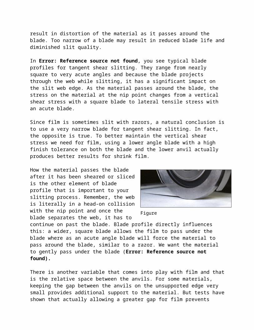
How the material passes the blade after it has been sheared or sliced is the other element of blade profile that is important to your slitting process. Remember, the web is literally in a head-on collision with the nip point and once the blade separates the web, it has to continue on past the blade. Blade profile directly influences this: a wider, square blade allows the film to pass under the blade where as an acute angle blade will force the material to pass around the blade, similar to a razor. We want the material to gently pass under the blade (Figure 6).
There is another variable that comes into play with film and that is the relative space between the anvils. For some materials, keeping the gap between the anvils on the unsupported edge very small provides additional support to the material. But tests have shown that actually allowing a greater gap for film prevents lateral crowding of the slit edge and therefore less damage to the unsupported edge.
Testing demonstrates that using a more acute blade with only a 1mm gap
Figure 5
Figure 6
produced more edge “curl” than when using a less acute or more “square” blade with a 3mm gap between the anvils. This is because the low angle blade allows the material to deflect under the blade, maintaining vertical stresses; the additional gap allows the material to deflect without crowding (Figure 7).
We see that for slitting films, “razor sharp” may not be good enough. If the converter is plagued by slit edge quality issues, then properly implemented tangent shear slitting may help reduce slit edge defects that wreak havoc on down stream processes. In summary, for optimal results in slitting films, insure the following items are in place in your process:
Use a tangent shear slitting systemPermits slitter nip synchronizationEliminates poor slit quality caused by lateral stresses induced by razor slitting
Run with large lower slitters>1.5:1.0 lower anvil diameter ratio
Manage the tension at the nip pointDo not exceed 10% of the material yield strengthIsolate the tension at the slitter table when possible if material tension varies
Permits varying tension to match the film's thickness and yield characteristics
Run microfinished, single bevel upper slittersRms 2-4 finish – Blades and anvils
Insure adequate slitter gapTangent system, unsupported side
Insure slitter has adequate overspeedAccomodates blade re-grind diameter