contentsedge.rit.edu/.../p13372/public/workingdocuments/manual.docx · web viewcontents setup...
TRANSCRIPT

ContentsSetup
Manual for Assembly
Manual for Parts
Manual for Tools
Manual for Program
This manual is intended for the next group that takes on the task of improving this project. May they succeed where this group has failed.

SetupIf New Scale Technologies software is not installed on computer, insert New Scale Pathway Software from CD marked v2.7.4 for USB Microcontroller is a MC3300 RV.
Attach Power cable to jack on device then attach the USB cable to the computer (Order is important).
Run executable on flash drive that appears or New Scale Technologies Pathway. Click setup connection to verify that two microcontrollers are available on USB ports. If not, check USB connections to hub and hub connections to computer. If this is successful, manipulator will be operable through New Scale Technologies Pathway and the program.
Manual for AssemblyRefer to CAD model for orientations
1) Finish parts. Because making such small parts fit together requires that parts hold tight tolerances, chances are these parts need to be filed to fit, especially when 3-D printed. This likely involves opening holes and C'bores with the dremel & drill bits for printed parts and filing sharp edges for machined.Tools: needle files, regular files, Teflon tape, 10 thick PETE, Swiss army knife, screw drivers, dremel, drill bitsComponents: Delrin/ABS-printed parts, stopper, M-1, M1.4 screws, tracker sensorsSignificant points:a) Sensors should lie flat when screwed on. File printed/Delrin parts to allow for this where sensor electronics may hit the Delrin/ABS. The screws should be forced in so that they leave a tapped hole when removed. Sensors may be left on if desired.b) M-1 screws and M-1.4 screws should protrude 1.5 mm and 1 mm respectively where they are to attach to rails and carriages (except through stopper). Drill counterbores, shim the contact between rail/carriage and part with at most 1 layer of PETE, and/or wrap Teflon tape on screw just below screw head to act as a washer.c) Motor slots may need to be scraped deeper. Flathead screw driver or Swiss army knife can be used for this.
2) Insert & glue magnets into Delrin/ABS parts, glue motor contact surfaces on, then file down motor contact surfaces until magnets satisfactorily attract metal on the surface.Tools: needle files, Krazy GlueComponents: Delrin/ABS-printed parts, Delrin contact surface, neodymium magnetsSignificant points:a) Magnets should go into their slots without sticking out. If they do not, their slots need to be filed deeper and/or wider.

b) Quick/aggressive filing and heat can degrade the magnets.
3) Glue motor mounts and shave/file one end to allow rails to mount.Tools: Krazy glue, needle files, Swiss army knife (or any other sharp but sturdy knife)Components: motor mounts, Delrin/abs printed partsSignificant points:a) Motor slots in motor mounts should line up with slots in Delrin/abs printed partsb) Tabs on motor mounts should be free of glue; however glue should be spread evenly and thinly onto the other portions of the contact surface.c) At least 1 mm should remain intact and glued down on the edge of the motor mount slot. Beyond this, motor mount should be shaved for an interference fit with rail.
4) Tape tracker magnets onto carriages as in the CAD model.Tools: double sided tape, Swiss army knifeComponents: rails with carriages, tracker magnets
5) Attach rails to parts. Also attach stopper with M-1 screw to the Y-axis. Perform steps 1 & 4 again if required.Tools: screw driversComponents: rails with carriages, stopper, Delrin/abs parts, M-1 & M1.4 screwsSignificant points:a) Only remove the O-ring on the side that the components attach to so rails do not fall out.
6) Attach 2 tracker sensors to Links if not already attached from step 1. Check spacing between magnets and sensor by aligning corresponding parts and shim up tracker sensors with double sided tape and/or PETE if required.Tools: screw drivers, double sided tape, PETE, Swiss army knifeComponents: Delrin/ABS printed parts (now with rails and carriages attached)Significant points:a) Rail on link-X may have to be detached and reattached several times.
7) Attach carriages to combine parts. Perform steps 1 & 4 again if required. Tracker sensor screws on Link-Z may have to be loosened depending on the screw driver used. Loosen screws and slip copper tape under to connect all rails to the carriages attached to the same Link, and retighten screws.Tools: screw driversComponents: rails with carriages, Delrin/abs parts, M-1 & M1.4 screws, Copper TapeSignificant points:a) All carriages and rails should be electrically connected to serve as a common ground for limit switches. The motors however should be insulated from this ground connection.
8) Attach holder. Link-Holder may be removed for ease if required.

Tools: Allen keys, Krazy glue, pliersComponents: holder, Delrin/abs parts (now all together with rails).
9) Attach limit switchesTools: Krazy glue, screw driverComponents: Delrin/abs parts (now all together with rails and holder), limit switches, M-1 screws
10) Attach motors. The tabs will need to be bent away from the part. A plastic deformation is acceptable, but a second deformation will need to be placed to bend them back and secure the motors in place.Tools: flathead screw driver.Components: Delrin/abs parts (now all together with rails and holder), motors
11) Attach tracker sensor and parts to bottom housing. Shim up tracker sensor as with the previous two if required.Tools: Screw drivers, shimsComponents: Tracker sensor, M-1 screws (2X), Delrin/abs parts (now all together with rails and holder), M-1.4 screws (2X), bottom housing
12) Attach electronics, then attach top housing. For more details on microcontroller connections, view the MC-3300 RV Controller Details document by New Scale Technology. USB hub connections should be obvious. USB Hub can be glued or taped in place.Tools: Screw drivers, double sided tape, Krazy glueComponents: Bottom housing (with previously attached components), MC-3300 RV Controllers (2X), USB hub, M2.5 screws (6X) for MC-3300, M-2 Countersunk screws for Top Housing, Top Housing
Manual for PartsThis section contains BOM relevant data as well as basic manufacturing info particularly useful for parts without drawings. Note that stock refers to this project’s items, NBIL the room 17-2120, and the machine shop the second floor machine shop next to the Brinkman lab.
USB HubIOGear USB Hub, GUH285 hub from Amazon. This hub gets disassembled, has its housing cut to fit in dimensions and then is reassembled before it becomes a part for the manipulator.Comments: Recommend investing time to improve on mounting this to the Bottom Housing.
New Scale Technologies HardwareMC-3300 Motor controllers, NSE 5310 Tracker sensors & corresponding magnets, SQL-RV-1-8 motors provided by New Scale Technologies. Note the USB cables have been trimmed and 2 power adapter jacks have been merged.Comments: See New Scale Tech documentation for info. Additional documentation can be found in the CDs provided by New Scale Technologies.
Carriage and Rail (3X)2mm x 40 mm rail carriages can be obtained from McMaster(8381K1).Comments: There are 3 spares currently in stock in the lab. If the carriage falls off the rail, DO NOT PANIC. The balls can be poked back in with something nonmetal.
M1.4x5 Screw (8X)M1.4, 5 mm long screws are used in mounting Links and can be obtained from McMaster(91800A034).Comments: There are only 2 spares in stock in the lab.

M1x3 Screw (15X)M1, 3 mm long screws are used in mounting sensors, stoppers/limit switches (or in place of stoppers to prevent carriages from falling off the rails). They can be obtained from McMaster(91800A052), but getting them overseas (through eBay) will provide easier to handle Phillips head screws. Comments: Several spares of both varieties are in stock at the lab.
Phillips and flathead M1x3 screws
M3x12 mm Screw (2X)M3, 12 mm long screw can be obtained from McMaster(92290A117) and used on PHolder. Inch equivalents can be used as an alternative.Comments: plenty in stock at the lab. Though these are metric, only an Inch key among those of the NBIL will fit.
M2.5x4 mm Screw (6X)M2.5, 4 mm long screw can be obtained from McMaster(94017A150) and used to mount MC-3300 to Bottom Housing. Inch equivalents can be used as an alternative.Comments: plenty in stock at the lab.
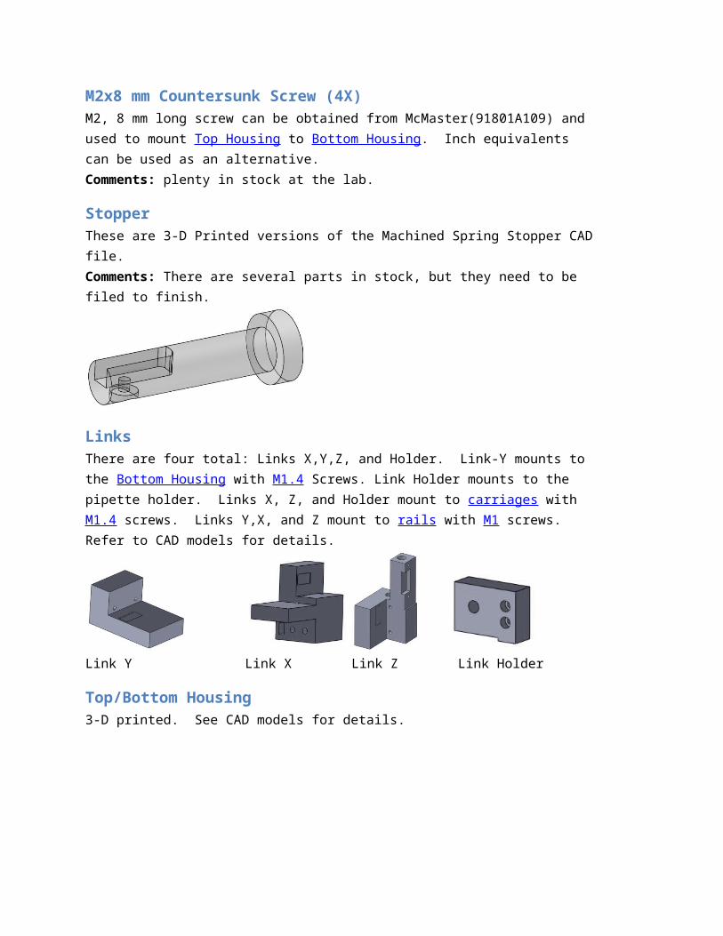
M2x8 mm Countersunk Screw (4X)M2, 8 mm long screw can be obtained from McMaster(91801A109) and used to mount Top Housing to Bottom Housing. Inch equivalents can be used as an alternative.Comments: plenty in stock at the lab.
StopperThese are 3-D Printed versions of the Machined Spring Stopper CAD file.Comments: There are several parts in stock, but they need to be filed to finish.
LinksThere are four total: Links X,Y,Z, and Holder. Link-Y mounts to the Bottom Housing with M1.4 Screws. Link Holder mounts to the pipette holder. Links X, Z, and Holder mount to carriages

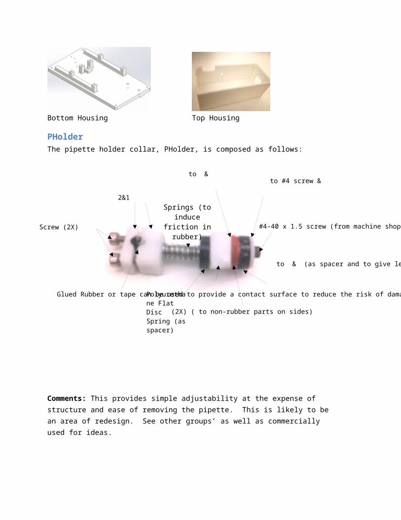
Polyurethane Flat Disc Spring (as spacer)
Springs (to induce friction in rubber)
to & (as spacer and to give leverage to friction in rubber)
Glued Rubber or tape can be used to provide a contact surface to reduce the risk of damaging the pipette
(2X) ( to non-rubber parts on sides)
#4-40 x 1.5 screw (from machine shop)
to #4 screw &
2&1
Screw (2X)
to &
with M1.4 screws. Links Y,X, and Z mount to rails with M1 screws. Refer to CAD models for details.
Link Y Link X Link Z Link Holder
Top/Bottom Housing3-D printed. See CAD models for details.
Bottom Housing Top Housing
PHolderThe pipette holder collar, PHolder, is composed as follows:
Comments: This provides simple adjustability at the expense of structure and ease of removing the pipette. This is likely to be an area of redesign. See other groups’ as well as commercially used for ideas.
CustColThese 2 parts are similar to the Links in material to save money. They can be machined Delrin, printed ABS, or almost anything that is rigid and light enough. They are used in PHolder. See CAD models for dimensions.
CustCol 2 CustCol 1
Polyurethane Flat Disc SpringThese are from McMaster(94045K116) and used in PHolder.
Plastic WasherThese are 3-D printed, with the same Outer Diameter Polyurethane Flat Disc Spring, Inner Diameter to glue to the #4 screw, and 1.5 mm thickness. They are used in PHolder.
Plastic Washer glued to screw
Rubber WasherThese are low-precision cut with a XActo knife from sheet rubber with the Polyurethane Flat Disc Spring as a template.
Motor MountsOne is used for each motor. They are glued to the Links. They are cut from .010 thick PETE with an XActo knife as a high precision part.Comments: Several are in stock in the lab. These are not designed for repeated removal and reattachment of the motors and so those currently on the prototype are fairly worn out, though barely still usable.
Limit SwitchesThese are PETE cut with a Swiss army knife with Copper Tape to provide electrical conductivity and Electrical tape to provide insulation. They are screwed onto rails or Krazy glued to Links.
SpringsSteel compression springs from McMaster. Those of the lowest spring rate (1986K52) are used to deliver a force to push the carriage against the motor’s screw. Springs to apply a greater force are used in the PHolder.
Spring on carriage and rail setup.
Copper Tape contact connected to grounded railCopper Tape contact
connected to MC3300 port

Neodymium MagnetsA return force spring alternative. Gluing a Magnet into a Link allows it to attract the motor’s screw. A thin Delrin surface between the screw and the magnet is required to reduce friction. The thinner the Delrin, the stronger the attraction will be.Comments: These 1/8 in diameter, 1/16 in thick cylindrical magnets can be obtained from Amazon, but several are in stock.
Delrin Contact SurfaceThis surface contacts the motor's screw. It is of great importance that this surface be smooth, flat and have a low coefficient of friction. Currently this is a filed down part, but purchasing very thin Delrin from McMaster is recommended.Comments: Our intent was to machine the Links from Delrin, removing the need for a separate part, however due to time constraints, the parts were 3-D printed. Gluing a separate surface can work, however for use of the Neodymium Magnets, any surface between the magnets and motor’s screw must be very thin. Recommend purchasing .010 thick Delrin from McMaster.

Manual for ToolsThese tools need to be restocked at various rates (glues and tapes for example need to be replaced considerably quicker than files).
FilesNeeded for:Finishing parts to tolerancesComments: What the NBIL has (needle file set & 3 files with handles) should suffice.
Screw DriversNeeded for:Attaching various screws, pushing them out, and sometimes scraping surfaces on soft materialsComments: The NBIL has all drivers required.
Pliers, Vice Grips & ClampsNeeded for:Grabbing various things and holding them in place.Comments: The NBIL has all these that are required.
Allen KeysNeeded for:Attaching various socket head cap screwsComments: The NBIL has all keys required among its Inch set.
Drill BitsNeeded for:Drilling holes, C’boresComments: The Machine shop and NBIL have some of the larger drill bits. In addition to these, .8 mm and 1mm (1/32 in) drill bits are required and can be obtained from various sources. Two of each are in stock and require the Dremel and Chuck to use.
Extremely Tiny EndmillNeeded for:Milling small features such as the motor slot. Note that though the cutting diameter is small, the 1/8 shank diameter allows this to be used in the machine shop millsComments: 1/32 is recommended, but can be expensive. Anything less than 1/16 should suffice depending on how the fillets are handled and whether it is finished by a needle file. The prices (on Amazon) fluctuate from below $5 to above $20 with each restock/purchase made. Consider a wider range of diameters to find something very cheap. Two of these are in stock.

Dremel & workstationNeeded for:Drilling small holes (1mm/.8mm). Note that the chuck is also required.Comments: the machine shop has these, but not the chuck.
Dremel chuckNeeded for:Drilling small holes. The machine shop simply does not have the tools to effectively use extremely tiny drill bits (.8 mm/ 1/32 in) so this chuck along with a dremel and workstation are required.Comments: The machine shop has a dremel with a workstation, but no chuck. The Dremel 4486 MultiPro Keyless Chuck can be purchased from Amazon.
Sheet Rubber1/16 in thick rubber can be obtained from McMaster.Comments: a small amount is in stock.
XActo KnifeNeeded for:Cutting several 2-D parts.Comments: Low precision parts can be traced from plastic or metal templates placed on top of the material. For high precision parts, such as motor mounts, first tape the clear material to a 1:1 printout of the part, with double sided tape. Then cut out atop a soft mat such as the XActo self healing cutting mat or an expendable sheet of rubber. The NBIL has a knife and spare blades but no mat.
Classic Swiss Army KnifeNeeded for:Nothing in particular that cannot be done in a more difficult way, however it is very useful cutting and trimming small things via the small scissors. The tweezers and toothpick are also useful.Comments: Fairly cheap for all that it provides. An alternative would be to obtain some durable yet tiny scissors.
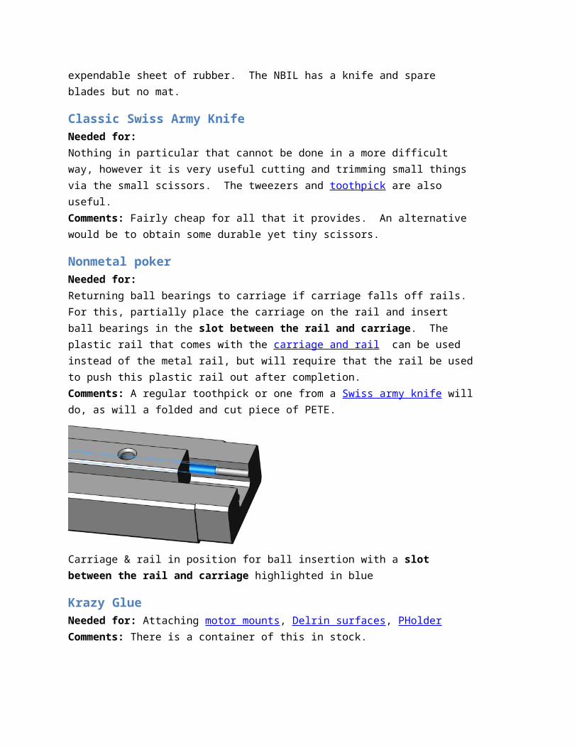
Nonmetal pokerNeeded for:Returning ball bearings to carriage if carriage falls off rails. For this, partially place the carriage on the rail and insert ball bearings in the slot between the rail and carriage. The plastic rail that comes with the carriage and rail can be used instead of the metal rail, but will require that the rail be used to push this plastic rail out after completion.Comments: A regular toothpick or one from a Swiss army knife will do, as will a folded and cut piece of PETE.

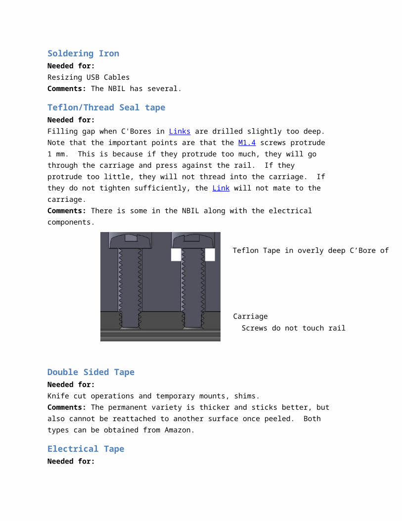
Teflon Tape in overly deep C’Bore of
Screws do not touch rail
Carriage
Carriage & rail in position for ball insertion with a slot between the rail and carriage highlighted in blue
Krazy GlueNeeded for: Attaching motor mounts, Delrin surfaces, PHolderComments: There is a container of this in stock.
Soldering IronNeeded for:Resizing USB CablesComments: The NBIL has several.
Teflon/Thread Seal tapeNeeded for:Filling gap when C'Bores in Links are drilled slightly too deep. Note that the important points are that the M1.4 screws protrude 1 mm. This is because if they protrude too much, they will go through the carriage and press against the rail. If they protrude too little, they will not thread into the carriage. If they do not tighten sufficiently, the Link will not mate to the carriage.Comments: There is some in the NBIL along with the electrical components.
Double Sided TapeNeeded for:
Knife cut operations and temporary mounts, shims.Comments: The permanent variety is thicker and sticks better, but also cannot be reattached to another surface once peeled. Both types can be obtained from Amazon.
Electrical TapeNeeded for:Resizing USB Cables. General insulating purposes.Comments: The NBIL has some.
Copper TapeNeeded for:Limit switch grounding, shielding for USB Cables once resized.Comments: Can be obtained from Amazon. Also recommend attempting an alternative such as Flexible Printed Circuit, or very thin wire for limit switches.
Shrink TubingNeeded for:Limit switch board connectors, resizing USB Cables.Comments: A variety pack can be obtained from Amazon.
Clear PETENeeded for:.010 thick (Clear) for Motor Mounts. Shims. Also serves as a great cut & fold rapid prototyping tool.Comments: A large sheet can be purchased from McMaster. Almost any thin sheet plastic can be used as an alternative. For a cheap solution, cut up recycled packaging.
ShimsNeeded for:Spacing parts to tolerances requiredComments: Almost any thin material such as double sided tape and Clear PETE can be used as shims.
AcetoneNeeded for:Cleaning motor screwsComments: NBIL has some. Do not use it with NBIL Petri dishes since this will dissolve the dish and deposit dish crud on the screw rather than cleaning it.
Program Structure
JSExtends CNstsquigglectrlctrl1. This does everything CNstsquigglectrlctrl1 did and also has added functions for the joystick use.
Joystick
GUI ComponentsThis block represents the many buttons and other Graphical User Interface classes for user interaction.
NstSquiggleCtrlDemoCppExtends CWinApp. This is the main application, started when the executable is run. It has a CNstSquiggleCtrlDemoCppDlg that it creates when started.
NstSquiggleCtrlDemoCppDlgHolds all CDialogs that are called up for the main GUI, the joystick configuration GUI, and the About dialog.
User
Microcontrollers
Mouse and Keyboard Monitor
Data cable
Manual for ProgramThe program has been written in visual C++ and is an extension of the demo C++ program provided by New Scale Technologies.
Structure Starting the program starts the CWinApp, NstSquiggleCtrlDemoCpp, which creates the CDialog NstSquiggleCtrlDemoCppDlg. From here the buttons that are common with the basic New Scale Tech program call up ActiveX commands in the CNstsquigglectrlctrl1. For more info on these, review their documentation from NST. The additional parts of this program are an additional timer, the DirectShow window, and a dialog for configuring the joystick. The timer calls the JS command chkstick() which then performs what it deems necessary from the change in the joystick. The DirectShow part simply displays the selected filter. For more info on the joystick configuration dialog see Configuring the Joystick.
FilesResource.h & NstSquiggleCtrlDemoCpp.rc- the resource files that holds all dialogs and data on their components
DSFilterWnd.h &.cpp- the file containing the DirectShow filter code for the camera image display
Joysticks.h & .cpp- the JS class and related functions that extend the CNSTsquigglectrlctrl1
nstsquigglectrlctrl1.h- essentially the wrapper for the ActiveX control provided by New Scale Technologies
Configure JoystickBrings up Dialog
Camera selectionselect camera to display on Connect
Camera Displayshows the DirectShow filter of the selected camera upon connection. Note for Point Grey use see
Connect/Disconnect Connects/Disconnects Joystick and Camera in addition to NST functionality
NstSquiggleCtrlDemoCpp.h &.cpp – the CWinApp. It just creates a dialog, NstSquiggleCtrlDemoCppDlg, and exits when the dialog is closed.
NstSquiggleCtrlDemoCppDlg.h &.cpp – All the Dialogs. Their components are read in by DDX and all their functions, listeners and etc are in these files.
stdafx.h & .cpp – the precompiled headers, important things here are the specifications of the windows version through WINVER and _WIN32_WINNT
OwnerBtns.h & .cpp – some other GUI stuff that came with the New Scale Tech code.
Main DialogThis is the dialog that comes up when running the executable. All commands except those noted behave as in the New Scale Technologies software. View separate NST documentation for those buttons.
Add/Modify/DeleteCommands to alter the Mapping List based on the values above and the current selection on the list.
Deadzone and gain for the command. For more info see
CommandValues correspond to Name of the .
Button or Axis for mapping. Note that compass directions in buttons correspond to the POV/Hat
Mapping ListThis is a list of all the mapped commands. The CMD field corresponds to the ID:Abbrev. of the . This serves to select a command to view and modify.
Joystick SelectionSelects which of the connected joysticks is to be used and mapped for.
Note that a stick must be connected and selected in order to properly create a mapping for it.
Config File Filename/path of config file for saving and loading. Note that CURRENT.CFG is loaded on start
Configuring the JoystickTo open this dialog, click Configure Joystick in the Main Dialog.
Command ListThis is a list of commands for button and axis assignment that have been implemented. An Axis command is activated when the value read on that Axis is changed and no Ignore All is issued by a button press.
ID: Abbrev. Name Description
00:igna Ignore All Button command that when pressed ignores all changes in the joystick.
01:fwd0 Fwd 0 Button command that when pressed, orders motor 0 to run forward and stop when released
02:rev0 Rev 0 Button command that when pressed, orders motor 0 to run in reverse and stop when released
03:fwd1 Fwd 1 Same as 01:fwd0 but for motor 104:rev1 Rev 1 Same as 02:rev0 but for motor 1

05:fwd2 Fwd 2 Same as 01:fwd0 but for motor 206:rev2 Rev 2 Same as 02:rev0 but for motor 207:spu0 SpdUp0 Button command that when pressed increments the
speed of motor 0 by a hard coded value.08:spd0 SpdDn0 Button command that when pressed decrements the
speed of motor 0 by a hard coded value.09:spu1 SpdUp1 Same as 07:spu0 but for motor 110:spd1 SpdDn1 Same as 08:spd0 but for motor 111:spu2 SpdUp2 Same as 07:spu0 but for motor 212:spd2 SpdDn2 Same as 08:spd0 but for motor 213:ssp0 SetSp0 Axis command that when activated sets the speed of
motor 0 to the fraction of the Axis value. Deadzone is ignored and positive and negative positioning of the axis is not considered.
14:ssp1 SetSp1 Same as 13:ssp0 but for motor 115:ssp2 SetSp2 Same as 13:ssp0 but for motor 216:mts0 MtrSt0 Axis command that when the stick change and position
are in the same direction, issues to motor 0 the axis change of steps in the direction the axis is pushed (for a hard coded duty cycle) to execute before next joystick check.
17:mts1 MtrSt1 Same as 16:mts0 but for motor 118:mts2 MtrSt2 Same as 16:mts0 but for motor 219:rsp0 RunSp0 Axis command that when activated sets the speed and
orders the motor to move in the corresponding direction.20:rsp1 RunSp1 Same as 19:rsp0 but for motor 121:rsp2 RunSp2 Same as 19:rsp0 but for motor 222:rcl0 RunCL0 Axis command that when activated orders a closed loop
move on motor 0 equal to the change of the axis. This is not only untested but a bit buggy due to the need to enable and disable closed loop operation
23:rcl1 RunCL1 Same as 22:rcl0 but for motor 124:rcl2 RunCL2 Same as 22:rcl0 but for motor 2
Joystick ValuesThe Axis values the joystick reads for this program is not the raw data but that which has already been processed by the operating system to the range of 0-65535. To view these values, run the Simple Joystick program’s JS.exe. This allows it to support a variety of joysticks without altering the configuration significantly. For normal sticks, subtracting 32767 will give a directional value (-32767 to 32768).
The deadzone can be thought of as the following mapping. 1 above this deadzone value is mapped to 1, 2 above to 2 and so forth. 1 below the negative of the deadzone value is mapped

to -1, 2 below to -2 and so forth. Any values between the negative deadzone and deadzone values are mapped to 0. This deadzone allows for an easy way to bias movements to be along the axes since slight, unintentional motions in an axis will be mapped to 0.
After the deadzone is applied, the value is multiplied by the Gain divided by the remaining maximum. A negative gain will invert an axis.
Point GreyTo use Point Grey camera displaying proper grayscale, FlyCap should be started before connecting, and one of the 640x480 resolution settings should be selected as shown below.