video surveillance system design -...
TRANSCRIPT

UNIVERSITY OF NAIROBI
VIDEO SURVEILLANCE SYSTEM DESIGN
PRJ 107
BY:
MWONGEERA MURUNGI
REG. NO. F17/9351/2002
SUPERVISOR: DR. MANGOLI
EXAMINER: DR. ABUNGU
MAY, 2009
DEPARTMENT OF ELECTRICAL AND INFORMATION ENGINEERING
PROJECT REPORT SUBMITTED IN PARTIAL FULFILLMENT OF THE
REQUIREMENT FOR THE AWARD OF BACHELOR OF SCIENCE
DEGREE IN ELECTRICAL AND ELECTRONIC ENGINEERING,
UNIVERSITY OF NAIROBI.

ii
I dedicate this project to my parents who never lost faith in me.

iii
ACKNOWLEDGEMENT
The completion of this work would not have been possible without the assistance of many
people who devoted their time, energy and knowledge. Very special thanks to Dr Maurice K.
Mangoli, lecturer, School of Engineering, University of Nairobi and supervisor of my
project, for discussions, counsel and guiding me from the beginning to end of this study. I am
also very grateful to Web Engineering LTD for their insight pertaining certain aspects of the
project and my colleagues for their contributions.
My appreciation also goes to my parents and entire family their constant support throughout
the tumultuous pursuit of my academic goals. Special thanks to Eden Karimi and the entire
Team Apex members for their assistance in compiling this documentation.
I thank God for all things possible.

iv
Table of Contents
DEDICATION...................................................................................................................ii
ACKNOWLEDGEMENT.................................................................................................iii
TABLE OF ABBREVIATIONS......................................................................................vii
ABSTRACT......................................................................................................................ix
CHAPTER ONE: INTRODUCTION ....................................................................................1
1.1 General Background ....................................................................................................1
1.2 Objective of the project ................................................................................................2
1.3 Problem Statement .......................................................................................................2
1.4 Evaluating needs and expectations of a CCTV system .................................................3
1.5 Outline of the report organisation .................................................................................3
CHAPTER TWO: TECHNOLOGICAL BACKGROUND ...................................................4
2.1 Background .................................................................................................................4
2.2 Overview of video surveillance systems.......................................................................5
2.3 The video’s role and its applications ............................................................................6
2.4 Hardware components of a video surveillance system ..................................................7
2.5 Types of CCTV Systems..............................................................................................8
2.5.1 Wireless CCTV systems........................................................................................9
2.5.2 Wired CCTV Systems ...........................................................................................9
2.6 Choosing a CCTV camera ......................................................................................... 10
2.7 Overview of cameras ................................................................................................. 11
2.7.1 Camera specifications ......................................................................................... 11
2.7.2 IP cameras .......................................................................................................... 13
2.7.3 System Block Diagram of an IP based Camera .................................................... 16
2.8 Data transmission over IP .......................................................................................... 17
2.9 Cabling ...................................................................................................................... 18
2.10 Data storage for Surveillance Systems ..................................................................... 19
2.10.1 DVR ................................................................................................................. 19
2.10.2 NVRs ................................................................................................................ 19
2.11 Other components of Video Surveillance Systems ................................................... 20

v
2.11.1 Switchers .......................................................................................................... 20
2.12.2 Monitors ........................................................................................................... 21
2.12.3 Video Motion detector (VMD) .......................................................................... 21
2.13 Assesment of IP based video Surveillance Systems for security applications ............ 22
2.13.1 IP Video Architectures ...................................................................................... 22
2.13.2 Camera Sensitivity ............................................................................................ 24
2.13.3 Digital Compression and Decompression .......................................................... 24
2.13.4 Servers and Workstations .................................................................................. 24
2.13.5 The Network ..................................................................................................... 25
2.13.6 Integration with Sensor Alarms ......................................................................... 26
2.14 Video Surveillance System Design using VideoCAD® software.............................. 27
CHAPTER THREE: METHODOLOGY ........................................................................... 29
3.1 Site Study and Analysis ............................................................................................. 29
3.1.1 Field of View ...................................................................................................... 29
3.1.2 Prevailing light conditions................................................................................... 31
3.2 Choice of camera and data transmission modes .......................................................... 32
3.2.1 Choice of Camera ............................................................................................... 32
3.2.2 Choosing a Video System ................................................................................... 34
3.2.3 Choice of data transmission mode ....................................................................... 34
3.3 Operational and equipment specifications .................................................................. 34
3.3.1 Equipment .......................................................................................................... 34
3.4 The Installation of the system .................................................................................... 35
3.5 Design using VideoCAD® ........................................................................................ 36
3.5.1 Identification of the area under surveillance. ....................................................... 37
3.5.2 3D Mapping of the area. ...................................................................................... 37
3.7.3 Introduction of cameras to the areas under surveillance ....................................... 39
3.7.4 Calculations of illuminance to ascertain that night-time surveillance is possible
using the same camera setup. ....................................................................................... 41
CHAPTER FOUR: RESULTS AND OBSERVATIONS ................................................... 45
4.1 Calculation of minimum scene illumination ............................................................... 45
4.1.1 Data from Field survey........................................................................................ 45
4.1.2 Camera Data ....................................................................................................... 45
4.1.3 Available illumination at the camera lens ............................................................ 45
4.1.4 Theoretical illumination ...................................................................................... 46
4.1.5 Camera scene illumination level .......................................................................... 46

vi
4.1.6 Camera distances and faceplate illuminations ...................................................... 47
4.2 Viewing the surveyed area on a monitor .................................................................... 48
4.3 Night-time surveillance .............................................................................................. 49
4.4 Effectiveness of the system ........................................................................................ 51
CHAPTER FIVE: CONCLUSION ...................................................................................... 52
5.1 Conclusion................................................................................................................. 52
5.2 Challenges faced ........................................................................................................ 52
5.3 Recommendations for future work ............................................................................. 52
REFERENCES.................................................................................................................... 54
APPENDIX A: THE VIDEO SIGNAL ............................................................................... 55
APPENDIX B: ILLUMINATION AND CAMERA SENSITIVITY IN CCTV................... 59

vii
Table of Abbreviations
AGC Automatic Gain Control
API Application-Program Interface
ASCII American Standard Code for Information Interchange
AVC Advanced Video Coding
AWG American wire gauge
BLC Black Light Compensation
BNC Bayonet Neill Concelman (connector used to terminate RG
cables)
CAT5e Category 5e (Ethernet Cable)
CCD Charge Coupled Device
CCTV Closed Circuit Television(TV)
CD CanDela
CIF Common Intermediate Format
DVR Digital Video Recorder
IP Internet Protocol
IRE Unit used in the measurement of composite video signals. The
name is derived from the initials of the Institute of Radio
Engineers.
JPEG Joint Pictures Experts Group
LAN/WAN Local Area Network/Wide Area Network
LCD Liquid Crystal Display
LEF Luminaire Efficiency Factor
LIDC Light Intensity Distribution Curves

viii
LUX Luminous flUX
Mbps Megabit Per Second
MOS/CMOS Metal-Oxide Semiconductor
MPEG/M-JPEG Motion Pictures Experts Group/ Motion-JPEG
NTSC National Television System Committee
NVR Network Video Recorder
PAL Phase Alternating Line
PC Personal Computer
PoE Power over Ethernet
PTZ Pan-Tilt-Zoom
RG-59 Coaxial cable with 75 ohm impedance
RMS Root Mean Square
SECAM Séquentiel couleur à mémoire, French for "Sequential Color with
Memory
SNR Signal to Noise Ratio
STP Shielded Twisted Pair
TL VCR Time-Lapse VCR
UTP Unshielded Twisted Pair
VCR Video Cassette Recorder
VMD Video Motion Detectors
VSS Video Surveillance system
XML eXtensible Mark-up Language

ix
Abstract
This project describes the steps involved in designing of a video surveillance system. It
discusses the theory of video surveillance types, components involved, selection of the best
equipment then a detailed virtual design. An introduction of the concept of video surveillance
systems is followed by detailed discussion of design considerations and design verification.
The system is designed to monitor a bank floor and the monitor displays the desired output
from a simulated implementation of the system. Upgrading possibilities are discussed.

1
CHAPTER ONE: INTRODUCTION
1.1 General Background
There are many different types of CCTV systems available—analogue and digital, wired and
wireless and their modes of operation vary; however, the basic components are more or less
the same: a camera, a lens, a monitor, and (for wired systems) cables that carry the signal
from one place to another. Many systems also use video recorders to record the video
footage.
The camera picks up the signal from the area being monitored via the lens (which determines
how far and how much the camera can see, and which is often bought separately) and can be
either wired or wireless. In a wired system, the camera sends the signals through a cable to
the monitor; in wireless systems, no cable is needed, and the camera broadcasts the signal
straight to the monitor.
The monitor can be either a simple television set (without tuning capacity) or a PC or laptop.
Most wired analogue systems use television monitors, while digital and wireless systems
tend to use computers as monitors for which remote viewing is possible, often via the
internet.
For recording purposes, the monitor is accompanied by a video recorder—a VCR for
analogue systems, or a DVR (digital video recorder), or NVR (Network Video Recorder) for
digital systems. A DVR can actually replace the monitor as the receiving device, since many
DVRs are stand-alone units that do everything a computer would do: receive, record, and
store the information for later viewing.
CCTV (Closed Circuit Television) refers to a system of surveillance cameras that sends
signals to a specific location—a monitor, or PC. CCTV systems are commonly used to
monitor banks, shopping malls, and government facilities—and these days, as CCTV
technology becomes more affordable and easier to use, more and more people are installing
CCTV cameras in their homes and businesses.
2
1.2 Objective of the project
The aim of the project was to design a video surveillance system to be used in an institution
to serve as a security measure, and assessment of the effectiveness of such a system as a
means monitoring an area to ascertain its security.
The specific objectives of installing a Video Surveillance System in an institution are
a) To detect intruders around the perimeter of the main building and alert the security
guards.
b) To provide a permanent record of activity from all cameras.
c) To provide a deterrent to crime and vandalism.
d) To enable 24 hour monitoring of designated areas.
e) To enable clear identification of miscreants within the range of the cameras.
f) To provide independent viewing of any camera at the control centre.
g) To enable live, real time recording of selected cameras.
1.3 Problem Statement
A closed circuit television (CCTV) system is an integral component of the security measures
that may need to be adopted by an institution. The institution’s premises may need to be
monitored on a regular basis to ensure safety. The need and extent of safety required helps
decide the investment required for the CCTV system; for example, deciding whether
procuring a single camera and monitor will suffice or a complex video surveillance system
with multiple cameras, multiple operators and digital recorders is required.
The investment in a simple or hi-tech system is justified on the basis of the following benefits
of a CCTV system that:
a) Helps surveillance of areas that require security round the clock
b) Helps observe and control traffic (human)
c) Prevents theft/ shoplifting, robbery and other crimes
d) Helps identify and initiate legal procedures against offenders with visual evidence from
the CCTV footage
e) Raise alarms on approaching dangers or avoidable circumstances

3
1.4 Evaluating needs and expectations of a CCTV system
An appropriate CCTV system justifies the expense and meets adequate security
requirements, identification of the needs and expectations that a CCTV system must fulfil
helps ensure security concerns are taken care of by the CCTV system to be installed as well
as budget considerations.
The following might be reasons why a video surveillance system may be needed by the
institution of concern.
a) Curbing Vandalism and thefts
b) The target for the intruder, is it material goods or information? I.e. industrial espionage.
c) Danger to individuals from attack.
d) Health and safety of individuals on the premises or site.
e) To replace or reduce manned guarding.
f) To supplement manned guarding, making them more efficient.
g) To monitor persons entering and leaving the premises.
h) To provide visual confirmation of intruders activating an alarm.
i) To monitor a remote, unattended site.
The list is obviously endless in general terms, but for a particular site, there must be finite
reasons for considering CCTV. If they cannot be listed, then it probably is not needed.
1.5 Outline of the report organisation
The report goes into theory of surveillance system components and their working. It further
looks at assessment of Video Surveillance systems with a view of determining its
effectiveness as a security tool. The later chapters delve into simulation of such a system
highlighting some of the technical challenges involved. At the end a conclusion is drawn
from the inference of the design carried out.

4
CHAPTER TWO: TECHNOLOGICAL
BACKGROUND
2.1 Background
Throughout history humans have valued their own life and the lives of their loved ones above
all else. Next in value has been their property. Over the centuries many techniques have been
developed to protect property against invaders or aggressors threatening to take or destroy it.
In the past as in the present, manufacturing, industrial and government organizations have
hired ‘watchmen’ to protect their facilities.
As electric technology advanced however, alarm systems and video were introduced, the
most advancement coming with the introduction of the Solid State Video Camera in the
1980s. By the early 90s, the solid-state camera using a Charge Coupled Device (CCD) image
sensor was the product of choice for new security installations. The solid-state CCD sensor
and the newer metal-oxide semiconductor (MOS) and Complimentary Metal-oxide
semiconductor (CMOS) sensors have longer life and are stable over all operating conditions.
Another factor in the explosive use of video in security systems has seen the rapid
improvement in equipment capability at affordable prices.
The 1990s saw the integration of computer technology with video security technology. All
the components were solid state. Digital video technology needed large-scale digital
memories to manipulate and store video images and the computer industry had them. To
achieve satisfactory video image transmission and storage, the video signal had to be
compressed to transmit it over the existing narrow band phone-line networks. The video-
computer industry already had compression for broadcast, industrial and government
requirements. The video industry needed a fast and low cost means to transmit the video
images to remote location and the US government’s Defence Advanced Research Projects
Agency (DARPA) had already developed the internet (and intranet), the predecessor of the
World Wide Web (WWW). The internet (and intranet) communication channels and the
WWW now provide the ability to transmit and receive video and audio and communicate and
control the data from anywhere. [2]

5
2.2 Overview of video surveillance systems
Video surveillance is a crucial component for the protection of important infrastructures. As
digital and networking technologies have been expanding worldwide and penetrating into
many traditional industrial areas during the past years, the video surveillance industry has
rapidly adopted these technologies. Leveraging the readily available Internet infrastructures
makes the video surveillance deployment much easier and more cost-efficient than traditional
hardwired closed-circuit television (CCTV) systems. Generally digital video surveillance
systems are composed of three modules: video capture units, network transmission, and
central control module. The video capture units are usually a set of digital cameras or some
analogue cameras supported by a video encoder device (switcher), which is able to perform
analogue-digital transition. This module captures the video, compresses raw data and
encodes it into a popular standard format (MPEG, Motion JPEG, H261, H263 or H264.). The
network transmission module delivers the encoded video stream over an IP based network.
This network could be a Local Area Network (LAN) or even the Internet. The central control
module can display and record each video channel. It also controls the cameras actions by
sending out control commands. Two types of data are flowing between those modules.
The first is the control data. The control command transmitter can be a PC, a control
keyboard or a matrix switcher relaying control to another switcher. The recipient can be an IP
PTZ (pan-tilt-zoom) dome camera, a matrix switcher, or a DVR/NVR (Digital Video
Recorder / Network Video Recorder). The control data exhibit the following characteristics:
• Small packet. Normally, the control command is only several ASCII characters and the
resulting network packet is very small.
• Burst operation. The control command transmitters send packets only when the user
operates the system or some new events occur. The commands will be sent intermittently
depending on users’ operations or specified system responses upon alarm-driven events.
• High correlation. Most commands are related to the context of other commands. For
example, a PAN LEFT dome control command will be meaningful when the previous
CAMERA SELECTION command is captured.
• Significant importance. The control packets may contain confidential data, such as user
name and password, system administration configuration and key distribution information.

6
The disclosure of these data may result in severe breach of security. For example, recorded
data may be tampered and deleted, or the system control may be totally lost.
The second type of data is the video stream. IP cameras, IP video servers and DVRs are the
source of digital video data.
The recipients of digital video can be a PC or a digital video decoder. In contrast with control
data, the video data features the following properties:
• Huge volume of data. The digital video requires up to 4 Mbps network bandwidth. Video
surveillance systems demand real-time display of the target site information, which results in
a stringent requirement for network throughput and processing capability.
• Time-sensitivity. The video data on the network is real-time and thus, grabbing the content
afterwards is of limited importance for ongoing attacks. There are potential security threats to
the IP based video surveillance systems. Adversaries can capture the video frames by simply
listening on the network transmission channel. Security is a must in order to make the IP-
based video surveillance systems practical and usable. [3]
Fig2.1 Video Surveillance System
2.3 The video’s role and its applications
In its broadest sense, the purpose of CCTV in any security plan is to provide remote eyes for
a security operator in order to create live-action displays from a distance. The video system
should have recording means- a VCR, a DVR, or other storage media – to maintain
permanent records for training or evidence. The following are some applications for which
video provide an effective solution:
a) When overt visual observation of a scene or activity is required from a remote
location.
7
b) Covert observation of a scene. It is easier to hide a small camera and lens in a target
location than to station a person in the area.
c) There is little action to watch in the area, as in an intrusion-detection location or a
storage room, but significant events must be recorded in the area when they occur.
Integration of video with alarm sensors and a time-lapse/real-time VCR or DVR
provides an extremely powerful solution.
d) Many locations must be observed simultaneously by one person from a central
security location
e) Tracing a person or a vehicle from an entrance into a facility to a final destination.
The security force can then predict where the person or vehicle can be interdicted.
f) Often a guard or security officer must only review a scene for activity periodically.
The use of video eliminates the need for a guard to make rounds to remote locations,
which is wasteful of a guard’s time.
g) When the crime has been committed, capturing the scene using the video camera and
recorder to have a permanent record and a hard copy printout of the activity and
event.
2.4 Hardware components of a video surveillance system
1) Lens: light from the illumination scene reflects off the scene. The lens collects the light
from the scene and forms an image of the scene on the light-sensitive camera sensor.
2) Camera: the camera sensor converts the visible scene formed by the lens into an electrical
signal suitable for transmission to the remote monitor
3) Transmission Link: the transmission media carries the electric video signal from the
camera to the remote monitor. Hard-wired media choices include: - Coaxial, 2-wire
unshielded twisted-pair (UTP), Fibre-optic cable, LAN, WAN, Intranet and Internet
network.
Wireless choices include: -Radio frequency (RF), Microwave and Optical infrared (IR)
Signals can be analogue or digital.
4) Monitor: The video monitor or computer screens display(CRT,LCD or plasma) the
camera image by converting the electrical video signal back into a visible image on the
monitor screens

8
5) Recorder: Camera scene is permanently recorded by a real-time or TL VCR onto
magnetic tape cassette or by a DVR using a magnetic disk hard drive.
6) Hard-copy Printer. The video printer produces a hard copy paper printout of any live or
recorded video image, using thermal, inkjet, laser or other printing technology.
7) Camera Switcher, quad Multiplexers. When CCTV security system has multiple cameras,
an electronic switcher, quad, or multiplexer is used to select different cameras
automatically or manually to display the images on a single or multiple monitors, as
individual or multiple scenes. The quad can digitally combine four cameras. The
multiplexer can digitally combine 4,9,16, and even 32 separate cameras.
8) Housings fall under the categories of indoor, outdoor and integral camera/housing
assemblies.
a) Dome Housing: the dome camera housing uses a hemispherical clear or tinted
plastic dome enclosing a fixed camera with pan-tilt-zoom lens capability.
b) Plug and play/ housing combinations: to simplify surveillance camera installations
many manufacturers now package the camera-lens housing as a complete assembly.
These plus and play cameras are ready to mount in a wall or ceiling and to connect
the power in and the video out.
9) Pan/Tilt Mechanism: When the camera must view a large area a pan and tilt mount is
used to rotate it horizontally (panning) and to tilt it. Providing a large angular coverage
10) Splitter/combiner: an optical or electronic image combiner or splitter is used to display
more than one camera scene on a single monitor.
11) Annotator: Time and date generator annotates the video scene with chronological
information. A camera identifier puts a camera number (or name) on the monitor screen
to identify the scene displayed on the camera.
2.5 Types of CCTV Systems
The key components of every Closed Circuit Television (CCTV) system are: single or
multiple cameras, recording device and a monitor. CCTV systems are broadly divided into
two known types, namely: wired CCTV systems and wireless CCTV systems. Wired systems
bind all three key components of a CCTV system with cables while a wireless system
comprises of a wireless camera that need not be connected to the recording device and
monitor.

9
Both of these systems have distinct advantages and disadvantages associated as different
types of technology are employed to provide security and reliable monitoring.
2.5.1 Wireless CCTV systems
Wireless CCTV systems are increasingly becoming a popular choice on account of the ease
of installing such a system, lack of cabling requirements and assured mobility. The key
advantages are:
a) A wireless camera can be moved to other locations requiring observation while it is
difficult to move a wired camera.
b) Best suited for locations requiring temporary observation or in a temporary location.
c) Wireless camera can be hidden to detect theft or pilferage
d) Wireless recording and monitoring device need not be in the same line of sight allowing
observation of any place from another remote location.
e) Wireless systems are cost effective, re-deployable and portable.
At the same time, there are some disadvantages of wireless CCTV systems,
a) Wireless systems require a dedicated frequency to transmit signals from the camera to the
receiving and recording station.
b) Frequencies may be subject to various interruptions by use of electric motored products,
air conditioning, fluorescent lighting or cordless telephones which affect the picture
quality.
c) Wireless camera may not provide the best picture quality as such systems are susceptible
to picture distortion while wired cameras provide relatively better picture quality.
d) Wireless CCTV cameras may need electric power which implies a wire runs through to
the camera though the video connection is wireless.
e) Wireless systems require wireless technology-specific expertise to diagnose and fix break
downs in the system.
2.5.2 Wired CCTV Systems
Wired CCTV systems connect the camera to the recording device and monitor with the help
of standard coaxial cables or Unshielded Twisted Pair (UTP) cables or fibre optic cables. The
key advantages of wired CCTV systems are:
a) Provides the best picture quality with zero interference
10
b) The camera can be located hundreds of meters away from the recording or monitoring
equipment.
c) All sensors can be run from a single power supply
The key disadvantages are:
a) Cabling and installing can be a tedious task, requiring help from experts
b) Observation is fixed to a specific area and the camera cannot be easily moved to another
location.
Overall, wireless cameras are relatively more expensive than traditional wired cameras.
Wireless CCTV systems are a preferred choice in specific locations devoid of easy cabling
facilities and for individuals requiring an easy-to-install solution.
The wired CCTV system is a preferred choice when good picture quality and economy
considerations gain precedence.
2.6 Choosing a CCTV camera
The type of camera impacts the quality of pictures received for monitoring or recording-
therefore, the CCTV camera along with the lens is an important component of the CCTV
system that helps capture images and convert those to electrical signals which are observed
or recorded.
To ensure the camera effectively converts light into a video signal; all cameras require an
optical lens to focus the light onto an image sensor located directly behind the lens inside the
camera.
There is a wide variety of cameras and lens available for CCTV systems which make the task
of choosing a system a little difficult. Here are some considerations that need to be assessed
when choosing a camera:
a) Lighting conditions: Image capture during day and night. The level of light has a direct
impact on the quality of images.
b) Position of camera: Indoor or Outdoor. Outdoor camera may require protective
enclosures to resist weather and criminals apart from aluminium housing and sealed cable
entry.
c) Field of View: Wide angle or narrow angle- the distance within which objects are in
focus.
d) Focal Length: The distance between the camera and the objects to be recorded.

11
e) Sensitivity and resolution: Sensitivity means a camera's response to lighting levels while
resolution implies the picture quality or details in image produced by the camera.
f) Colour or monochrome: Certain cameras can also switch between colour and
monochrome depending on lighting conditions. Monochrome cameras are best suitable
for low light conditions.
g) Price: The price of the camera as compared to the features, benefits and after-sales
service.
2.7 Overview of cameras
Cameras are the starting point of the video signal and are therefore a critical component of a
CCTV system. The word camera comes from the Latin "camara obscura" and means "dark
chamber".
Artists in the middle ages used a dark box to trace images. Since then the camera has come a
long way. Today there are three types of cameras most commonly used.
• Film cameras
• Photographic cameras
• Video cameras
The construction and type of Charge Coupled Device (CCD) chip used in a camera is
important. Some of the better quality cameras have superior chip design incorporating many
innovative features like On Chip Lens (OCL), Back Light Compensation (BLC), excess
charge drainage technology.
2.7.1 Camera specifications
Any camera data sheet has a number of specifications shown like resolution, sensitivity,
signal to noise ratio, camera voltage, chip type, and operating temperature. Some data sheets
are detailed, while others are quite sketchy and cover the bare minimum. To classify a
camera, the resolution and sensitivity in the data sheet are normally used. These two
specifications are the most important.
2.7.1.1 Resolution
Resolution is the quality of definition and clarity of a picture and is defined in lines
More lines = higher resolution = better picture quality.

12
Resolution depends upon the number of pixels (picture elements) in the CCD chip. If a
camera manufacturer can put in more number of pixels in the same size CCD chip, that
camera will have more resolution. In other words the resolution is directly proportional to the
number of pixels in the CCD chip.
In some data sheets, two type of resolution, vertical and horizontal are indicated.
Vertical resolution
Vertical resolution = no. of horizontal lines
Vertical Resolution is limited by the number of horizontal scanning lines.
In PAL it is 625 lines and in NTSC it is 525 lines.
Using the Kell or aspect ratio factor the maximum vertical resolution is .7 of the number of
horizontal scanning lines.
Using this, the maximum vertical resolution is:
• For PAL 625 * .7 = 470 lines
• For NTSC 525 * .7 = 393 lines
Vertical resolution is not critical as most camera manufacturers achieve this figure.
Horizontal resolution
Horizontal resolution = no. of vertical lines
Theoretically horizontal resolution can be increased infinitely, however, it may not be
technological possible to increase the number of pixels in a chip. As the number of pixels
increase in the chip, the pixel size reduces which affects the sensitivity. There is a trade-off
between resolution and sensitivity. If only one resolution is shown in the data sheet, it usually
is the horizontal resolution.
Although traditional analog cameras are often used in security systems, the trend today is
towards digital cameras in video surveillance -in part because they are better able to operate

13
in diverse lighting conditions, and produce high-quality images requiring less storage space
than video tapes. Additionally, digital camera users typically have more control setting
options, plus DVRs (Digital Video Recorders) enable users of video surveillance systems to
quickly sort through the recorded images in search of a particular incident or time period.
2.7.2 IP cameras
IP (Internet Protocol) cameras are CCTV cameras that utilize Internet Protocol to transmit
image data and control signals over a Fast Ethernet link. As such, IP cameras are also
commonly referred to as network cameras. IP cameras are primarily used for surveillance in
the same manner as analogue CCTV. A number of IP cameras are normally deployed
together with a digital video recorder (DVR) or a network video recorder (NVR) to form a
video surveillance system. [10]
Analogue CCTV uses established CCTV and broadcast television formats (e.g. CIF, NTSC,
PAL, and SECAM). Since analog video standards are mature, concerns over incompatibility
between analog surveillance cameras and recording systems are uncommon.
IP surveillance cameras, on the other hand, do not benefit from the same level of
standardization. Generally speaking, each make of IP camera will differ in terms of its
specific features and functions, video encoding (compression) schemes, supported network
protocols, and the API (Application-Program Interface) to be used by video management
software.
Setting up IP Camera to be viewed remotely involves setting up port forwarding which
means logging in to the router and changing settings.
Fig2.1: Outdoor megapixel IP camera
14
Power over Ethernet (PoE) technology, which cannot be applied in an analogue video
system, can be used in a network video system. PoE enables networked devices to receive
power from a PoE-enabled switch through the same Ethernet cable that transports data
(video). PoE provides substantial savings in installation costs and can increase the reliability
of the system.
2.7.2.1 Advantages of IP cameras
1. COST
a) Reduced system cost and added functionality due to general-purpose IP networking
equipment infrastructure.
b) Lower cost of cabling in large installations (CAT5e instead of RG-59 coaxial cable).
c) Reduced space requirements in large (many camera) CCTV setups because video
switching and routing is done via computer and does not need physically large and
expensive video matrix switchers.
2. IMAGE FORMAT
a) Support for a variety of image resolutions including both standard analog CCTV
resolutions (CIF, NTSC, PAL, and SECAM) and megapixel resolutions.
b) Capability for digital zoom of high-resolution megapixel images.
c) Progressive scan (versus interlaced scanning). Note that not all IP cameras operate in
progressive scan mode. Progressive scan allows still images to be removed in better
quality from a video feed. This is particularly true for a fast moving target, in which
case interlaced scanning will introduce shutter-blind artifacts.
d) Ability to select specific frame rates and resolution for each camera in a system.
e) No additional video encoder hardware is required to convert analog video signals into
digital data for recording onto hard drives.
3. NETWORK INFRASTRUCTURE
a) Convergence onto new or existing IP cabling infrastructure, including sites with
multiple buildings.
b) Ability to use Power over Ethernet allowing for one cable to handle power and data.
c) Capability for deploying with a wireless bridge.

15
d) Ability to use legacy coaxial cables with appropriate converters.
e) Ability to use fiber optic links with appropriate twisted-pair to fiber converters.
f) Transmission of commands for PTZ (pan, tilt, zoom) cameras via a single network
cable.
g) Simple to add one camera at a time to the system.
4. FUNCTIONALITY
a) Wireless allows the camera to be placed just about anywhere.
b) No limit on resolution inherent in standard analog video formats. Megapixel cameras
can far exceed image detail from conventional CCTV cameras.
c) On-camera automated alerting via email or file transfer in response to video motion
detection or dry-contact alarms.
d) Password lockout of unauthorized personnel to prevent viewing images or altering the
camera configuration.
e) Support for different streaming media and compression formats to relieve
transmission bandwidth and data storage requirements.
f) Encryption of camera control data and audio/video data.
g) Support for new embedded intelligent video motion detection (video analytics) with
shape recognition and counting applied to objects, people, and vehicles.
h) Integration of video surveillance with other systems and functions such as access
control, alarm systems, building management and traffic management.
i) Remote configuration, diagnostics, and maintenance.
j) Future-proof installations with field-upgradeable products due to the ability to
upgrade camera firmware over the network.
2.7.2.2 Disadvantages of IP cameras
The following are some of the potential weaknesses of IP cameras in comparison to analog
CCTV cameras.
a) Higher initial cost per camera.
b) Less choice of manufacturers.
16
c) Lack of standards. Different IP cameras may encode video differently or use a different
programming interface. This means a particular camera model should be deployed only
with compatible IP video recording solutions.
d) High network bandwidth requirements: a typical CCTV camera with resolution of
640x480 pixels and 10 frames per second (10 frame/s) in MJPEG (Motion JPEG) mode
requires about 3 Mbit/s.
e) Technical barrier. Installation for IP Camera requires a series of complicated network
setting including IP address, DDNS, router setting and port forwarding. This is very
difficult for most users to do alone without help from an IT technician. [10]
2.7.3 System Block Diagram of an IP based Camera
Camera: Surveillance Networked
A VSS includes a central control station and a plurality of video cameras each mounted
inside a dome housing unit. A video data buffer memory, storing compressed video data
generated by the camera is mounted with each camera in the respective dome unit. Data
buffered at the dome unit may be selectively protected from over-writing in response to
alarm signals and then retrieved for display or recording by the central control station. Both
live and buffered video signals are transmitted in compressed format over a data network that
is also used for command, alarm and status messaging. [5]

17
Fig2.2: System block diagram of an IP based camera
As part of a larger Video Surveillance System, a Surveillance Networked Camera captures
video via a CCD or CMOS sensor. The processing engine encodes the video stream in digital
formats such as H.264, Motion JPEG, MPEG4 or using proprietary codecs. This video
stream is sent back as IP packets to the larger security network.
2.8 Data transmission over IP
The compression used with modern IP camera based CCTV video surveillance systems is
usually either MPEG-4 or H.264 modes
The type of codec used as the video signal for an IP camera is usually indicated on the data
sheet whereas most modern DVRs and NVRs are capable of decoding these formats.
18
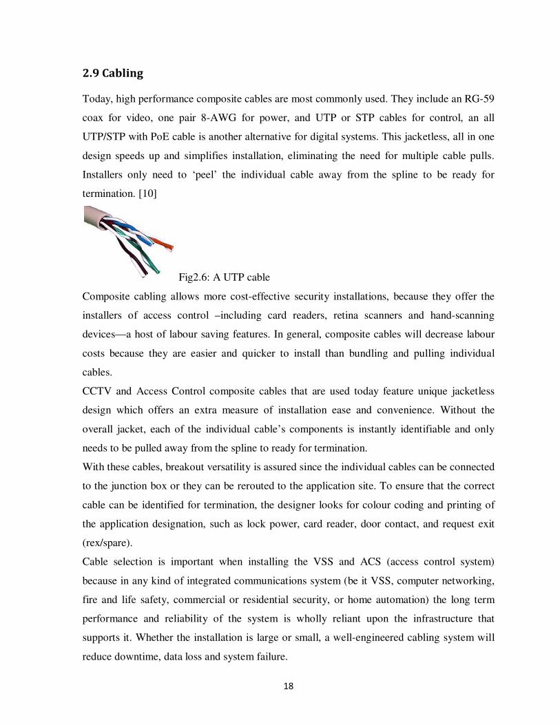
2.9 Cabling
Today, high performance composite cables are most commonly used. They include an RG-59
coax for video, one pair 8-AWG for power, and UTP or STP cables for control, an all
UTP/STP with PoE cable is another alternative for digital systems. This jacketless, all in one
design speeds up and simplifies installation, eliminating the need for multiple cable pulls.
Installers only need to ‘peel’ the individual cable away from the spline to be ready for
termination. [10]
Fig2.6: A UTP cable
Composite cabling allows more cost-effective security installations, because they offer the
installers of access control –including card readers, retina scanners and hand-scanning
devices—a host of labour saving features. In general, composite cables will decrease labour
costs because they are easier and quicker to install than bundling and pulling individual
cables.
CCTV and Access Control composite cables that are used today feature unique jacketless
design which offers an extra measure of installation ease and convenience. Without the
overall jacket, each of the individual cable’s components is instantly identifiable and only
needs to be pulled away from the spline to ready for termination.
With these cables, breakout versatility is assured since the individual cables can be connected
to the junction box or they can be rerouted to the application site. To ensure that the correct
cable can be identified for termination, the designer looks for colour coding and printing of
the application designation, such as lock power, card reader, door contact, and request exit
(rex/spare).
Cable selection is important when installing the VSS and ACS (access control system)
because in any kind of integrated communications system (be it VSS, computer networking,
fire and life safety, commercial or residential security, or home automation) the long term
performance and reliability of the system is wholly reliant upon the infrastructure that
supports it. Whether the installation is large or small, a well-engineered cabling system will
reduce downtime, data loss and system failure.

19
2.10 Data storage for Surveillance Systems
2.10.1 DVR
A Digital Video Recorder (DVR) is a digital video recorder that records motion video in a
digital format to a hard disk. This can include various models such as stand-alone, PC,
television, cable or satellite. Sizes include small, portable, desktop, industrial and
commercial. Software enables personal computers to extract segments of video for playback
from the hard disk. Closed circuit television (CCTV) has long replaced Video Cassette
Recorders (VCRs) with Digital recorders. These analogue devices initially stored images on
magnetic videotapes for playback. [11]
DVRs are superior to VCRs in that they offer: - better images, superior search capability,
simultaneous recording, live viewing and playback, remote access, easier integration with
security systems.
Advances
Heavy DVR competition means heavy innovation. The DVR is moving from a recording box
to a sophisticated system with video management features for example multiplexing, motion
detection, neural network processing (the DVR system automatically looks for a specific
object that was detected during playback by analysing the colour shape and size of object
then scours the footage for this object.), automatic frame rate adjustment, integration with
other data sources apart from cameras (e.g. POS), and firmware upgrading capabilities
2.10.2 NVRs
A Network Video Recorder or NVR is an Internet Protocol (IP) based device that sits on a
network. Because they are IP based NVRs can be managed remotely via a LAN or over the
internet giving greater flexibility. The basic function of an NVR is the simultaneous
recording and remote access of live video streams from an IP camera. [11]
Most NVRs feature flexible recording and playback capabilities, an optional intuitive remote
control unit, a user-friendly GUI, intelligent motion detection, and PTZ camera control.
20
As regards recording and playback, an NVR is similar to a DVR, an NVR is a true digital
system that receives digital images/ video streams over the network and records them to a
hard disk in a digital format.
A DVR on the other hand is a hybrid system that can accommodate analogue cameras and
store the video on a hard disk in a digital format. Some DVRs may have a rudimentary
interface to the network that offers remote viewing capabilities. An NVR does not have a
dedicated keyboard and monitor. All viewing and management of NVR takes place remotely
over the network via a PC.
An NVR is designed to offer optimal performance for up to a set number of IP cameras
which makes it less scalable than a PC server platform system. This makes the unit suitable
for smaller system configurations where the number of cameras stays within the limits of the
NVR design capacity. An advantage is that an NVR is less complex to install in comparison
to a PC server platform.
New generation NVRs hardware are open platform systems that allow the user to run any IP
recording software on the market. They usually support a Windows or Linux environment.
These open platform NVRs allow for flexibility and scalability when deploying an enterprise
level camera system. [9]
DVRs and NVRs biggest problem lies in video database management, for example many
DVRs can now ‘strip away’ frames from stored video as the video ages. So video originally
recorded at 30 frames per second can be stripped down to perhaps 1.75frames per second
after say 12 months of storage. Although stripping away of data saves up on storage space it
is not enough. Elimination of irrelevant footage would be a better way of managing the
problem, If only 2 out of 16 cameras that are programmed to run round the clock capture
relevant activity, the system should be able to purge the remaining 14 inactive cameras as
well as irrelevant material on the other two cameras.
2.11 Other components of Video Surveillance Systems
2.11.1 Switchers
The switcher accepts video signals from many different camera types and connects them to
one or more monitors or recorders. Using manual or automatic activation or an alarming
21
signal input, the switcher selects one or more of the cameras and diverts their video signal to
a specified monitor, recorder, or some other device or location. There are 4 basic switcher
types
1. Manual switcher: connects one camera at a time to the monitor, recorder or printer.
2. Sequential switcher : automatically switches the cameras in sequence to the output
device
3. Homing switcher: the operator can override the automatic sequence in the sequential
switcher.
4. Alarming switcher: connects the alarmed camera to the output automatically, when
the alarm is received.
Although switchers are analogue video Surveillance components, they are also implemented
in DVRs and NVRs therefore the feature is available in digital systems as well.
2.12.2 Monitors
Video monitors can be divided into: - Monochrome, Colour, CRT, LCD, Plasma or
Computer display.
Large video monitors do not necessarily have better picture resolutions or the ability to
increase the amount of intelligence available in the picture. This is dependent on the TV
standard. [1]
2.12.3 Video Motion detector (VMD)
This is a component that produces an alarm signal based on a change in the video scene. The
VMD can be built into the camera or be a separate component inserted between the camera
and the monitor software in a computer.
The VMD electronics either analogue or digital, store the video frames, compare subsequent
frames to the stored frames, then determine whether the scene has changed. In operation the
VMD ‘decides’ whether a change is significant and whether to flag it as an alarm in order to
alert the guard or some equipment or declare it a false alarm.

22
2.13 Assessment of IP based video Surveillance Systems for security
applications
The following was looked at with a view of assessing the effectiveness of an installed Video
Surveillance system.
Camera sensitivity, digital compression and decompression, servers and workstations, the
network and integration with sensor alarms
2.13.1 IP Video Architectures
Three different options currently exist in the commercial market for IP-based Video
Surveillance Architectures. For those systems using analogue cameras, network-based DVR's
(Digital Video Recorders) and analogue encoders make it possible to digitally encode an
analogue video feed and incorporate it into an IP network. These systems are typically
limited to lower-resolution IP video feeds (a maximum of 4CIF, or 704x480). Higher
resolution offerings are impractical due to the inherent resolution limitations of analogue
video. Native IP cameras allow creation of an entirely IP-based video platform and offer
more flexibility in terms of 4CIF and higher pixel resolution video streams. However, these
native IP systems are significantly different in terms of infrastructure when compared to
DVR's or encoders and may require additional network infrastructure in the field if upgrading
an existing, analogue system. Systems with analogue encoders or native IP cameras both use
NVR's (Network Video Recorders) to store video footage. Fig: 2.7 shows a simplified block
diagram of the typical IP based video surveillance architectures

23
A
A
A
A
A
A
IP
IP
IP
A = analogue Cameras
IP = IP based/Megapixel cameras
Fig2.7: Video surveillance system architectures
Digital Video
Recorder (DVR)
IP Network
Backbone Operator
Console
Encoder
Encoder
Encoder
IP Network
Backbone
Network
Video
recorder
(NVR)
Operator
Console
IP Network
Backbone
Network
Video
recorder
(NVR)
Operator
Console

24
2.13.2 Camera Sensitivity
On average, native IP-based cameras are less sensitive under low-light than high-end
analogue security cameras, and any architecture using native IP cameras must take this into
account. Interior applications where a well-lit scene can be guaranteed may not need to
consider this, but exterior security applications may need to factor this into the camera
selection.
2.13.3 Digital Compression and Decompression
With analogue systems, the video streaming to an operators console could be expected to be
of a similar quality to the video directly from a camera. With digital systems, however,
compression and decompression of the video stream can cause wide variations in video
quality at the operator’s console.
Megapixel cameras have an inherent advantage in effective line resolution with their higher
pixel resolution mitigating the effects of the digital compression. Video decompression must
be taken into account on the operator’s console. In time-critical and high-availability
systems, having an efficient video codec (compression/decompression algorithm) is essential.
The Windows Media codec may not be optimized for a particular encoding scheme. With
MJPEG, for example, CPU utilization could be decreased by 30-50% using an optimized
codec versus the Windows Media codec. These savings in CPU usage can allow for smoother
operation by eliminating jerky mouse movements or keyboard lag for the operator.
2.13.4 Servers and Workstations
Network-based systems that use analogue encoders and IP cameras have introduced a
completely new aspect to video assessment and surveillance, since the products are typically
software products running on commercial servers. Video system designers must now become
familiar with server hardware and software, both to implement a system and to maintain it.
Computer security techniques now also come into play-system designers must be able to
allow the appropriate people access to what they need and at the same time keep out
unauthorized personnel. Theoretically, since these are network-based video systems, anyone
with computer access to the security system could also access every camera or encoder on
the system unless cyber security is established correctly.
25
Servers must also maintain physical access controls to prevent tampering. Server and
workstation stability are also important issues. More stable server platforms such as Linux-
based products are available on the market, but workstations are usually limited to the
standard PC box. Locking these operator workstations down to the point where minimal
services are running and operators are only interacting with the video platform is highly
recommended. This prevents workstation resources from being given over to non-security
related processes. Frequent blue screens and constant rebooting are unacceptable in any
security system application.
2.13.5 The Network
Effective video assessment and surveillance must be able to provide quality video to an
operator in a timely manner. This means several things:
• Video cannot be too compressed in order to save network bandwidth; high levels of
compression make objects harder to identify by an operator
• An operator cannot experience excessive latency, especially with PTZ
(Pan/Tilt/Zoom) surveillance cameras; video and PTZ motion must seem to occur in
real-time to an operator.
With certain IP camera implementations of VSS it is not unusual to see network bandwidths
at 12-15 Mbps depending on camera settings.
Existing networks may have problems handling this bandwidth, especially if they're not
dedicated to physical security. Tradeoffs can be made with lower resolution cameras, higher
compression, or lower frame rates, but the effectiveness of the system needs to be taken into
consideration. It is recommended that a dedicated security network be installed to control
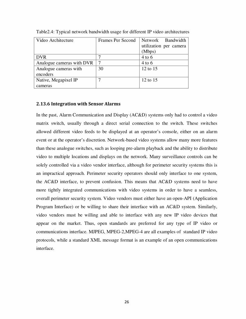
system security and for system effectiveness. Table2.4 shows equilibrium ranges for network
bandwidth utilization that are typical for each of the three architectures discussed. These
bandwidths are not constant, and spikes can be observed as high as 20 Mbps for the
megapixel cameras. These numbers are determined using similar image quality for each
camera or encoder. Image resolutions being the maximum possible for each device.
26
Table2.4: Typical network bandwidth usage for different IP video architectures
Video Architecture Frames Per Second Network Bandwidth
utilization per camera
(Mbps)
DVR 7 4 to 6
Analogue cameras with DVR 7 4 to 6
Analogue cameras with
encoders
30 12 to 15
Native, Megapixel IP
cameras
7 12 to 15
2.13.6 Integration with Sensor Alarms
In the past, Alarm Communication and Display (AC&D) systems only had to control a video
matrix switch, usually through a direct serial connection to the switch. These switches
allowed different video feeds to be displayed at an operator’s console, either on an alarm
event or at the operator’s discretion. Network-based video systems allow many more features
than these analogue switches, such as looping pre-alarm playback and the ability to distribute
video to multiple locations and displays on the network. Many surveillance controls can be
solely controlled via a video vendor interface, although for perimeter security systems this is
an impractical approach. Perimeter security operators should only interface to one system,
the AC&D interface, to prevent confusion. This means that AC&D systems need to have
more tightly integrated communications with video systems in order to have a seamless,
overall perimeter security system. Video vendors must either have an open-API (Application
Program Interface) or be willing to share their interface with an AC&D system. Similarly,
video vendors must be willing and able to interface with any new IP video devices that
appear on the market. Thus, open standards are preferred for any type of IP video or
communications interface. MJPEG, MPEG-2,MPEG-4 are all examples of standard IP video
protocols, while a standard XML message format is an example of an open communications
interface.

27
2.14 Video Surveillance System Design using VideoCAD® software
The Video surveillance design project contains the information about what and how detailed
each video camera will cover and which areas it will control. VideoCAD software facilitates
the process of professional CCTV system design. The software allows creation of the system
at a level that is both accessible without its actual application, and within a shorter period of
time. In VideoCAD both horizontal and vertical projections of a view area can be displayed.
However in design process the horizontal projection, i.e. projection on location plan, is
more often used.
Fig2.8: horizontal projection of view area
As a rule, the whole view area is not important but its part in the certain range of heights. If
area of concern is in the specified range of heights on a horizontal plane, it is a horizontal
projection of the view area. [9]
Horizontal projection of a view area in VideoCAD is determined by the key parameters:-
Height of view area upper bound; Height of view area lower bound and View area upper
bound distance.By changing these values, different sizes of projection are obtained.
Generally, any object, which is at the height between these bounds, and on a horizontal plane
within the limits of horizontal projection of the view area, will be visible on the screen. [9]

28
Thus, in order to get the sizes and position of a view area projection in relation to a camera, it
is necessary to set the following parameters (Fig.2.8):- Image sensor format and a lens focal
length, Height of the camera installation, Heights of the upper and the lower bounds of view
area and View area upper bound distance.
VideoCAD calculates all other parameters of the view area projection and displays the
projection graphically. It is enough to set these initial parameters, to place a camera with a
projection of view area, within which the objects will be visible on the monitor screen, as can
be seen in Fig2.10
Fig. 2.10: Layout of view area projections on the location plan.
Fig. 2.9: Definition of the camera
position in VideoCAD
29
CHAPTER THREE: METHODOLOGY Before any installation of video surveillance system(s) an in-depth study of the site must be
carried out with the following aims:
1. Identifying need of the system.
2. Identification of the objective of the security concern, whether it is outside or inside, near
or far.
3. Identification of area needing surveillance
4. Where the cameras will be installed
5. Identification of the prevailing light conditions
6. How the images will be captured, viewed, recorded and stored for observation and
reference
7. The system design
8. Purchasing the right products and making installation decisions that help save time, effort
and money
3.1 Site Study and Analysis
3.1.1 Field of View
It is important to work with the end user to understand what field of view is required to be
seen on the monitor. The field of view is the width and height of the scene as viewed by the
lens. It depends upon the focal length and distance of the object.
Any field of view has some critical area which is the target area. For example when the
camera is viewing a gate, the space the car is coming through is the critical viewing area or if
one is watching the door, the space occupied by a person walking through the door is a
critical a viewing area. In the same way every scene has a critical viewing area. This critical
viewing area is usually ignored while selecting a lens for an application. After the installation
is complete it is not uncommon to hear comments that the end user wanted to positively
identify the person, but is not able to do so with the lens installed. The following steps
outline the procedure for performing the site analysis:-

30
Step 1
Identification of the scene area which needs to be covered by the lens and estimation of the
width or vertical height of the scene is done.
Step 2
Estimation of the distance from the camera to the scene.
Step 3
To calculate the focal length of the lens. The following methods can be used:
1. Standard formula
The focal length can be calculated using either the scene width or height formulas
= ×
Or
= × ℎ
Where, c = width of the CCD chip
v = height of CCD chip
d = distance from camera
w = width of field of view
h = height of field of view
f = Focal length of lens
2. Lens wheel calculator
Many lens manufacturers provide this lens calculator. It is quite simple to use and the
focal length of the lens can easily be calculated depending upon the object distance
and scene dimensions. The limitation is that it does not tell how large the critical
viewing area will be on the monitor.
Step 4
In any scene there are areas or moving objects, which are critical. It is important to
understand what is required, for a detection or positive identification.
1. Detection view - The critical viewing area should cover 5% of the monitor
2. Action view - The critical viewing area should cover about 10% of the monitor
3. Identification view - The critical viewing area should cover about 25% of the monitor.
Estimate of the horizontal and vertical dimensions of the critical viewing area

31
Step 5
Calculate the viewing area of the scene and also of the critical viewing area by multiplying
the horizontal and vertical dimensions. Divide the critical viewing area with the total viewing
area to get the size of the critical viewing area in the monitor.
× × × 100 = %
Step 6
If the proportion of the critical viewing area is as expected, use the calculated focal length;
If not, then change the
• Focal length till the correct proportion is found or
• Change the distance of the camera until the correct proportion is found
If this fails, one may have to choose a lens which is the nearest to the requirement.
3.1.2 Prevailing light conditions
As mentioned, (in appendix D), several measurements need to be undertaken to ensure that
the correct camera is chosen for the prevailing lighting conditions on the scene. Finally, a
comparison of the actual light at the scene (L) with the minimum scene illumination is made.
If the light available is more than the minimum scene illumination indicated, then the current
camera can be used. If the actual light at the scene is lower than the adjusted minimum scene
illumination of the camera, then the camera setting may require adjustment or an alternative
solution is necessary. The following steps will help resolve the issue.
Step 1
• Check if camera variables can be changed
• If AGC is switched off, then switch AGC on
• Reduce shutter speed, if possible
• Use a lens with a lower F-stop
• If no success go step 2
Step 2
• Find a more sensitive camera
• Down grade from colour to B/W camera
• Add Infrared light if B/W camera is being used
• Add more lighting at the scene

32
3.2 Choice of camera and data transmission modes
3.2.1 Choice of Camera
There are many different camera and data relaying modes to choose from however an
informed choice should be derived from the best value for money, robustness, future
proofing, ease of installation and maintenance and fast deplorability,
For these reasons, fixed wired cameras were chosen over wireless ones because although
wireless cameras can be moved to other locations requiring observation, they require
dedicated frequencies ,for data transmission to and from cameras, that are prone to
interruptions and which may end up distorting the picture. The picture quality is also
seriously compromised which means that if the signal were to be retransmitted (over the
internet for remote viewing for example) any further degradation of the picture quality would
result in an unusable image.
3.2.1.1 Calculations of minimum scene illumination
Various losses dramatically reduce the level of illumination reaching the faceplate. Hence, in
general CCTV rules of thumb are often used to approximate a calculation. For example if the
faceplate illumination is quoted as 1 lux the actual average illumination falling onto the
horizontal should be 200 × 1 or more to receive good pictures (e.g. 0.1 lux at faceplate =
20 lux average horizontal requirement). [1]
If the camera illumination level is quoted then it will need 10 ×lux average horizontal for a
good picture and 50 × lux, for full video recording quality pictures

33
Table3.1: Light reflectivity for common building materials
Percentage of scene illumination reflected toward camera(for white light colour
temperature 3500k)
Average (%) Minimum (likely) (%)
Asphalt/ tarmac 5 3
Parkland,trees,grass 20 15
Red brick, blue brick, dark
mortar
20 15
Yellow brick 25 15
Dark stone 30 25
Red brick, light mortar 35 30
Middle-coloured stone 35 30
Plain concrete (White) 40 30
Cars parked 40 30
Painted woods, light colours 50 35
Ceiling tiles (white), floors of
light colours
55 37
Portland stone, bath stone, or
other smooth white/cream
stone
60 40
Stone or profiled aluminium
cladding
60 40
Curtain glazing/windows 70 60
Large areas of snow 85 70
N.B
1. For any of the above horizontal surfaces with a vertical chain-link fence in the field:
• Green-covered PVC, subtract 1%
• Black-covered PVC, subtract 3%
2. If minimum levels of light reflected are required, use the second column
3. Source: Data courtesy of the Electricity Council Great Britain [1]
4. A good specification should say at least “camera sensitivity 10 lux of horizontal scene
illumination atf1.4 maximum aperture with 60% reflectance.”
3.2.2 Choosing a Video System
There was also the choice between using analogue or digital data transmission. As was
discussed earlier in the literature review, DVRs have the advantages of superior search
capabilities, remote access and easier integration with other security systems over traditional
analogue and VCR systems. This informed the choice of digital video over the analogue type.
34
3.2.3 Choice of data transmission mode
Here the choice of using an IP based wiring system was already dictated by the decision to
use DVRs instead of VCRs for storage and retrieval of the surveillance data. The use of
fibre-optics was not considered because the cost was too expensive to the end user.
3.3 Operational and equipment specifications
3.3.1 Equipment
a) Stand-alone DVR(Model NVR1004+)
b) Cameras (There are many choices from CMOS to CCD and even IR-cameras which take
images in the dark. CCD cameras are recommended over CMOS ones, as for IR-cameras,
they are only good for close distances)
c) Cables (point-to-point Unshielded Twisted Pair wire, 24-16 AWG (0, 5-1,5mm), stranded
or solid, Category 2 or better.)
d) Router(s)
e) Power Supply cables
f) Electrical sockets
g) Mounting brackets (for mounting the cameras)
The video signal may co-exist in the same wire bundle as other video, telephone, data,
control signals, or low-voltage power. Shielded Twisted Pair wire is not recommended;
however multi-pair wire (6 pair or more) with an overall shield is okay. Un-Twisted wire
should also not be used. For safety, video signals should never be placed in same conduit as
high voltage wiring.
After the equipment has been acquired, some other specifications that may to be identified
are:
Operation of system: Where system will be operated from and who will operate it.
System to be installed or connected: Indication as to whether there are other systems that will
be or possibly be connected to this system.
Future expansion: Statement of whether the system is likely to be extended in the future and
the possible extent of this.
35
3.4 The Installation of the system
1. After identifying the sites where the cameras are to be installed, cables are laid down
from the cameras to the DVR. After the DVR is configured it can be set to record only
when there is movement in the area. This will reduce the hard disk requirements
tremendously.
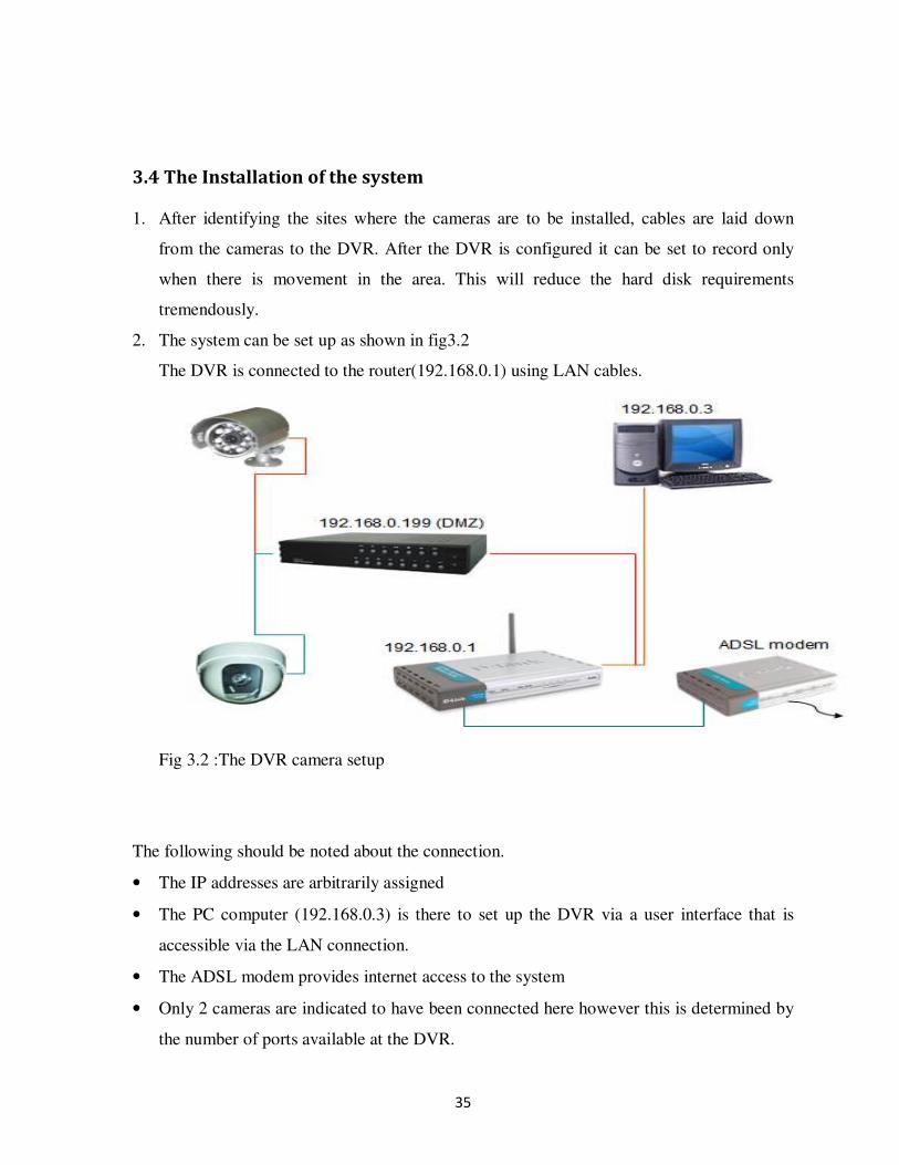
2. The system can be set up as shown in fig3.2
The DVR is connected to the router(192.168.0.1) using LAN cables.
Fig 3.2 :The DVR camera setup
The following should be noted about the connection.
• The IP addresses are arbitrarily assigned
• The PC computer (192.168.0.3) is there to set up the DVR via a user interface that is
accessible via the LAN connection.
• The ADSL modem provides internet access to the system
• Only 2 cameras are indicated to have been connected here however this is determined by
the number of ports available at the DVR.

36
3.5 Design using VideoCAD®
Due to various constraints pertaining physical design of the system, a more computer based
approach was favoured since such modelling would not only make the eventual installation
more manageable but also practical results could be simulated with an aim of perfecting the
proposed system way before implementation. Additionally no one company approached was
willing to share their architectural plans with this designer citing various reasons including
fear of industrial espionage and the risk that such non contractual disclosure could lead to
security breaches within their premises. For these reasons this designer was inclined to model
a system using CCTV system simulation software known as videoCAD which is freely
available on the internet (as a Demo version) and which was adequate to accomplish the
objectives of this particular project. Future projects would obviously have to consider the
importance of purchasing this sophisticated software as the demo version only offers limited
capability as a far as the design tools are concerned.
The following steps were carried out in order to implement the system as a computer
simulated Video Surveillance System
a) Identification of the area under surveillance
b) 3D mapping of the area
c) Introduction of different camera types into the area under surveillance
d) Placement of ‘objects’ that may be construed as intrusions or otherwise, at strategic
locations with a view of testing the relevance of camera placement areas.
e) Viewing of the surveyed area on a simulated monitor
f) Calculations of illuminance to ascertain that night-time surveillance is possible using the
same cameras with luminaries’ where necessary
g) Conclusion as to the success or failures of the system and what it would take to make it a
reality
3.5.1 Identification of the area under surveillance.
For the purposes of this particular project a Bank floor area was chosen as a good example to
demonstrate the proposed system
The Bank floor plan includes two floors, an upper ground floor and a lower ground floor both
of which would be equipped with cameras to survey activities in the Key area in an around
them.

37
Two exterior areas were also identified; the ATM area and the car park area which also
needed dedicated cameras capable of night-time surveillance
The following areas were identified as key areas requiring constant camera monitoring
Lower Ground floor level:- Front Door and Desk, ATM lobby and entrance, Banking Hall,
Teller Booths, Back Office, Back office- Banking hall adjoining doorway and room and
Counting room
Upper Ground floor level: - Open work plan area, Parking area
All cameras with the exception of the ATM entrance and front entrance cameras were PTZ
(Pan-Tilt-Zoom) cameras. The use of fixed cameras was to avoid tampering with the person
identification setting on those cameras surveying very key areas.
All cameras installed were dome type overhead at a height of 3m (approximately) from
normal floor level.
3.5.2 3D Mapping of the area.
Construction of the area in need of surveillance was done using AUTOCAD©
and VideoCAD
computer software both running on a Windows Vista operating system.

38
Fig3.3: A snapshot of the modelled bank lower ground floor
Teller
Booths
ATM Loading
Area
Adjoining
Doorway
Banking
Hall
Exterior
ATM Main
Entrance

39
Fig3.4: The model of the upper ground floor of the Bank showing the car park area
3.7.3 Introduction of cameras to the areas under surveillance
Cameras were placed at strategic positions in the identified areas. Care was taken not to
unnecessarily place too many cameras surveying one scene leading to redundancy and
unnecessary expense. For example one camera with a pan feature was installed to survey the
back office and washrooms area, however the ATM area being a critical security area had
dedicated cameras monitoring the entrance (to ATM booths) and another to view the ATMs.
PV porch
Store
Filing
Room
Kitchen
Gate
Open
Work plan
Surveillance
room
Generator
Room
Car Park

40
Fig3.5: Camera mounting (Cameras in the back office are not visible from this projection and
hence are not indicated)
Camera 7
Camera 5
Camera 12
Camera 4
Camera 8
Camera 2
Camera 6
Camera 3

41
Fig3.6: image as seen from camera 8
3.7.4 Calculations of illuminance to ascertain that night-time surveillance is
possible using the same camera setup.
At this stage some assumptions had to be made.
1. Specification of camera sensitivity would be supplied by the manufacturer
2. A luminaire would be used also whose specifications would also be known.
3.7.4.1 Camera specifications
Camera Type: PECLO MC3710H-1
Sensitivity: 0.07 lx at 40IRE
Lens F1.2
SNR- Not indicated
Max exposure time: 1/50s
Accordingly a SNR of 17dB was taken at 38IRE
3.7.4.2 Luminaire specifications
Type: OSRAM LUM HALOSTAR® 1000
Vertical angle of radiation: αv = 41°
Horizontal angle of radiation αh = 73°

42
Average angle αav (73+41)/2=57°.
NB The values of the angles can be obtained from a LIDC (Light intensity distribution
Curves usually included in the luminaire data sheet)
Axial Light Intensity with 1000lm light flux lamp = 750cd (from LIDC)
The halogen lamp OSRAM HALOLINE®
1000 Watt is installed in the luminaire.
Full light flux of the lamp is 22000 lm. (From Datasheet)
Thus, axial light intensity of this luminaire with the lamp OSRAM HALOLINE®
1000 Watt
will make
1000lm = 750cd
22000lm = x cd
= ∗"# $ = 16500 cd.
• The measurements were used to model the camera and the luminaire to simulate the
actual conditions.
• For an angle of radiation of 57° the Luminaire Efficiency Factor is about 0.5 ( i.e. LEF is
approximately proportional to the angle of radiation)
• Night time illumination from a moonlit night sky is about 0.2lx which would look
something like Fig3.8.
Fig3.7: Daytime view of a surveyed parking area
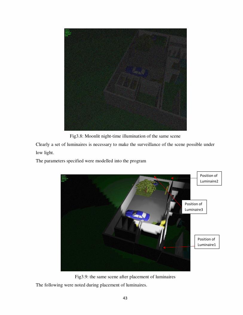
43
Fig3.8: Moonlit night-time illumination of the same scene
Clearly a set of luminaires is necessary to make the surveillance of the scene possible under
low light.
The parameters specified were modelled into the program
Fig3.9: the same scene after placement of luminaires
The following were noted during placement of luminaires.
Position of
Luminaire1
Position of
Luminaire3
Position of
Luminaire2

44
It was imperative that the lumianire be positioned behind the camera at a distance determined
by
% = &'
Where E = direct illumination (1lx)
I = light intensity(cd)
L = distance from luminaire to camera
However owing to constraints posed by construction of the building, the luminaire positions
were obtained by a trial and error method.
45
CHAPTER FOUR: RESULTS AND
OBSERVATIONS
4.1 Calculation of minimum scene illumination
A typical CCTV calculation for minimum scene illumination
4.1.1 Data from Field survey
• Area to be viewed: Building wall
• Distance from subject to camera: 10m
• Average horizontal illumination: 100 lux average (50% minimum)
• Plane of subject to be viewed: vertical
• Reflectivity of subject: wall, average 30%(minimum)
• Intensity of lighting off wall: 312.5 candelas
• Reflectivity of ground in front of the wall: average 37%(minimum)
• Assume f-stop value lens and iris : f1.4
4.1.2 Camera Data
• Minimum faceplate illumination of the chosen camera: 0.1 lux for good pictures
• Minimum scene illumination of chosen camera: 0.6 lux
• F1.4
• 50% reflection
4.1.3 Available illumination at the camera lens
• Light falling in front of the wall: 100 lux average
• Minimum light falling in front of the wall: 50% of average = 50 lux
• Minimum light reflected from ground onto the wall: 37% of minimum at ground =
18.5 lux. ( Refer to Table 3.1)
• Minimum light from the wall toward the camera: 30% of that arriving on wall from
ground = 18.5 × 0.3= 5.55 lux. Intensity at this point is 312.5 candelas(given)
• Loss of light due to distance to camera (assuming light reflected directly towards
camera):
46
% = &
Where E = lux level at the camera,
I = intensity in candelas at the wall
d = distance from wall to camera.
% = ($$ ) =3.125 lux
4.1.4 Theoretical illumination
At the faceplate of camera with an f1.4 f-stop value is given by
* = 14
Where c = illumination level at faceplate with 100% transmittance and
f = f-stop value used on iris.
* = $,×$.,) =
$".., = 0.127
(Or 12.7% of that arriving at the camera.)
Thus, faceplate illumination available = 3.125 lux × 0.127 = 0.39 lux.
Camera minimum faceplate illumination = 0.1 lux
Rule of thumb: required faceplate illumination × 200 = average horizontal illumination
required at scene [1]
0.1 × 200 = 20 lux. Actual horizontal average (100 lux) and minimum (50 lux) are both well
above 20 lux required by the rule of thumb calculation.
4.1.5 Camera scene illumination level
Rule of thumb: 10 × camera illumination level required for good picture: [1]
0.6 × 10 = 6 lux. , (Both 100 lux average and 50lux minimum are well over this)

47
4.1.6 Camera distances and faceplate illuminations
% × * = / 0121
Table 4.1: faceplate illumination at different distances
Distance from scene
to camera (m)
10 8 6 4 2 1
Faceplate
illumination (lux)
0.39 0.619 1.102 2.48 9.92 39.68
Graph4.1: Faceplate illuminations at different distances
From the table, the selected camera is suitable for use within the distances shown since the
calculated faceplate illumination exceeds the minimum value indicated on the camera
(0.1lux). At very large distances (Graph4.1) however the illumination approaches 0.1 and the
camera becomes unusable.
Hence the selected camera is capable of effectively being used in the CCTV system.
(Data for reflectivity are shown in Table 3.1)
0
5
10
15
20
25
30
35
40
45
1 2 4 6 8 10
Distance from scene to camera (m)
Fa
cep
late
illu
min
ati
on
(lu
x)

48
N.B Lighting level calculations are required to be provided by the system designer to show
how a chosen camera would be suitable: many manufacturers make it difficult for the true
camera needs or performance to be established by publishing either partial information,
introducing unseen assumptions, which enhance apparent performance, or deliberately
inflating the claims. [2]
4.2 Viewing the surveyed area on a monitor
A total of 15 cameras in total were used to survey both the lower and upper ground floors.
Fig4.1: View of the area under monitor
It was possible to select a particular camera and pan to a desired angle, indicating that the
user could effectively alter the view angle to a point of particular interest.

49
The ATM camera 3 was installed such that it could only be used for person detection. This
was done as a security measure to prevent misuse of the system to read confidential data
from the ATM while a customer is using the ATM machine.
4.3 Night-time surveillance
As outlined in chapter 3 in the section on Night-time surveillance the results were obtained
which proved that the system could be used (together with the appropriate luminaires) to
survey a specific area at night as can be seen in figure 4.4.
Fig4.2: camera 13 during the day

50
Fig4.3: camera 13 at night without illuminators
Fig4.4: the parking area under night time surveillance with illuminators
Satisfactory scene surveillance was obtained after incorporating illuminators into the system.

51
It possible that the luminaire(s) could double as security lamps and in so doing deter potential
security threats.
A disadvantage here would be that the system would largely remain insecure if the
illuminators were to be switched off during night-time surveillance hours. A possible counter
to this would be to incorporate an alarm system which would be triggered by a switch off of
the lighting
4.4 Effectiveness of the system
The effectiveness of the system would be determined by reaction time and usability under
low light conditions.
The reaction time of the CCTV system can be seen to be the time it takes from the
occurrence of the intrusion to the appearance of the same on the monitor. Proper and strategic
placement of cameras in the area ensures that blind spots are not created by the camera
system with conflicting or unnecessary repetition of information relayed to the monitor. The
other aspect which would affect the responsiveness would be the redraw time. This is the
time it takes for the monitoring system to redraw or to refresh the images on the screens from
the monitor. This is mostly determined by the camera type and the transmission system used
for the particular installation, however many modern surveillance systems have an automatic
redraw which coincides with the either the monitor refresh rate or the actual frame per
second setting of the camera type meaning that the redraw rate is almost real-time. With
digital transmission mode the redraw rate may be further constrained by bandwidth
limitations if transmission over IP is utilized. Again this is impossible to model without
carrying out extensive tests on the cabling before installing the system.
As was seen by the model of the CCTV system, low light or night time surveillance is
possible with the right selection of luminaire setup. Additionally camera specifications of F-
stop (Lens aperture setting), AGC (Noise reduction), and sensitivity were carefully chosen in
order to have an all round camera that could be used in both adequate and low light
conditions.

52
CHAPTER FIVE: CONCLUSION
5.1 Conclusion
As demonstrated in the discussion, the system design parameters were used to model a Video
Surveillance System using VideoCAD software, which was able to produce a useful security
monitoring tool. The importance of such a model was also demonstrated by the fact that
tedious camera mounting and removal exercises to ascertain optimum camera placement
positions would be eliminated. This would be beneficial to fast deployment of such a system
by cutting down on design time and cost of implementation. Further the design also looked at
night-time surveillance and demonstrated that this could be accomplished using the software.
5.2 Challenges faced
Although the project was successfully designed in a simulated environment several factors
would likely constrain an actual implementation of any such system
• The result of identification, detection and reading depends on many factors; it is
impossible to model all of them, and even if it were possible, then the labour-
intensiveness and the probability of error of such modelling would be very high;
• By video system it is implied a video camera with the lens, video signal transmission
channel, recorder and display device. Each component can cause specific distortion;
• From one and the same video system, images of different quality can be obtained
depending on its settings and scene features;
• Detection and identification depends on personal qualities of the operator, on the degree
of acquaintance with the identifiable person;
Despite these factors it is possible to model a working surveillance system and test it before
actual implementation which was successfully demonstrated by this designer
5.3 Recommendations for future work
• Incorporation of an alarm system to warn of switch off of light during night-time
surveillance
• Incorporation of access control system into the surveillance monitoring one.
• Fire detection capabilities

53
• Introduction of motion detection capabilities into the system by use of Video Motion
Detectors (VMDs)
• Fence Detection.
• Addition of Audio capability
These would greatly augment the system while improving the overall security of the area
under surveillance.

54
REFERENCES
[1] Neil Cummins, Security: A guide to se3curity systems design and equipment selection
and installation, 2nd edition (revised), published by: Butterworth-Heinemann, 1994
[2] Hernian Kreugle, CCTV Surveillance: Video practices and technology, Edition 2,
Butterworth-Heinemann, 2005.
[3] Zhaoyu Liu; Dichao Peng; Yuliang Zheng; Liu, J. Communication Protection in IP-
based Video Surveillance Systems, Proceedings of the Seventh IEEE International
Symposium on Multimedia (ISM’05) ,2005, 0-7695-2489-3/05,p1-2.
[4] Ely, Reuel Andrew (Plantation, FL) 1999 Distributed video data storage in video
surveillance system United States Sensormatic Electronics Corporation (Boca Raton,
FL) 5982418 http://www.freepatentsonline.com/5982418.html
[5] Peter Danielson, Video Surveillance for the rest of us: Proliferation, Privacy, and Ethics
Education, 2002, 0-7803-7824-0/02.
[6] Jayant Kapatker, Understanding CCTV series, Camera Specifications,
www.stamweb.com
[7] Jayant Kapatker, Understanding CCTV series, Lenses, www.stamweb.com
[8] Jayant Kapatker, Understanding CCTV series, The video Signal, www.stamweb.com
[9] The Principles of cctv design in VideoCAD, (parts 1-6), 2003-2008,
http://www.cctvcad.com
[10] http://en.wikipedia.org/wiki/IP_camera
[11] http://en.wikipedia.org/wiki/Digital_video_recorder and
http://en.wikipedia.org/wiki/Network_Video_Recorder

55
APPENDIX A: THE VIDEO SIGNAL The video signal is the basic electrical signal that starts at the camera and goes to the control
room via a transmission system. In CCTV this signal is called Composite Video. It has
maximum amplitude of one volt peak to peak. The composite video is made up of the
following parts: -Video signal, Horizontal sync pulse, Vertical sync pulse
Fig: A.1: The video signal
Video signal
When light falls on a CCD chip, it generates a charge in the pixels, which is directly
proportional to the light falling on them. More light means a greater charge. This charge is
then ‘read out’ from the CCD chip and is converted into a video signal. The methodology of
reading this charge from the chip depends upon the type of CCD chip. The greater the
amount of light on the pixel, the larger the amplitude of the video signal. As can be seen in
Fig: A.1, in a composite video, the maximum amplitude of the video signal is 0.7 volts. In
other words, the white or the bright part of the picture will have signal strength of 0.7 volts,
while the black or dark parts will have a signal of 0 volts. [8]
Vertical sync pulses A video picture is made up of video frames. In NTSC there are 30 frames per second, while
PAL has 25 frames per second. To avoid picture flickering in CCTV, this video frame is
divided into 2 fields i.e. odd and even fields. These two fields are separated out at the camera
point and then combined once again at the monitor end. This is also called interlacing of
fields.
At the end of each frame or field, a vertical sync pulse is added. This sync pulse tells the
electronic devices in the camera and other CCTV component that the field has come to an
end and gets them ready to receive the next frame or field. The duration of the pulse depends
upon the time the electronic devices take to receive the next field. The amplitude of this pulse
is a 0.3 volts. This when added to the video signal, gives total amplitude of 1 volt peak to
peak.

56
Fig A.2: odd and even fields making up the frame
Horizontal sync pulse
A video frame is made of lines. In NTSC there are 525 lines per frame, while PAL has 625
lines per frame. Each point in the line reflects the intensity of the video signal. At the end of
each line, a horizontal sync pulse is added. This sync pulse tells the electronic devices in the
CCTV system that a line has come to an end and to get ready for the start of the next line.
This also has amplitude of 0.3 volts.
Horizontal and vertical scanning frequencies TableA.1 details the different scanning frequencies under the PAL and NTSC system
Table A.1: different frequencies under PAL and NTSC systems
NTSC PAL
Frame Frequency 30 per sec 25 per sec
Duration of each frame 1/30 sec 1/25 sec
No. of fields per frame 2 2
Field frequency 60 per sec 50 per sec
No of lines per frame 525 625
No of lines per field 262.5 312.5
No of lines per sec 525 X 30 = 15750 625 X 25 = 15625
Duration of each line 1/15750 sec or 63.5 us 1/15625 sec or 64 us
Horizontal and vertical blanking Retrace or fly back is the time required to move from the end of one line to the start of the
next line or from the end of one field to the start of the next field. No picture information is
scanned during the retrace and therefore must be blanked out. (In television blanking means
“going to black level").
The retrace must be very rapid, since it is wasted time in terms of picture information. The
time needed for horizontal blanking is approximately 16% of each horizontal line. The time
for the vertical blanking is approximately 8% of the vertical field. [8]

57
TableA.2: Other parameters differentiating the PAL and NTSC systems
NTSC PAL
Field duration 1/60 sec 1/50 sec
Vertical blanking 1/60 * .08 = 1333 us 1/50* .08 = 1600 us
Line loss due to vertical
blanking
1333/63.5 = 21 lines 1600/64 = 25 lines
Line duration 63.5 us 64 us
Horizontal blanking 63.5 * .16=10.2 us 64 * .16=10.25 us
Visible trace time 53.3 us 53.75 us
Horizontal and vertical synchronization The blanking pulse puts the video signal at the black level; the synchronization pulse starts
the actual retrace in scanning. Each horizontal sync pulse is inserted in the video signal
within the time of the horizontal blanking pulse and each vertical sync pulse is inserted in the
video signal within the time of the vertical blanking time. TableA.3 shows the frequency of
each synchronization pulse.
TableA.3: frequencies of the various synchronization pulses
NTSC PAL
Vertical 60 Hz 50 Hz
Horizontal 15750 Hz 15625 Hz
The colour signal
A colour video signal is the same as monochrome except that the colour information in the
scene is also included, which is transmitted separately. The following two signals are
transmitted separately:
1. Luminance signal: known as the Y signal, it contains the variations in the picture
information as in a monochrome signal and is used to reproduce the picture in black
and white.
2. Chrominance signal: known as the C signal, it contains the colour information. It is
transmitted as the modulation on a sub carrier. The sub carrier frequency is 3.58 MHz
for NTSC and 4.43 MHz for PAL.
In a colour receiver, the chrominance signal is recovered and combined with the luminance
signal to give a colour picture. In a monochrome receiver, the chrominance signal is not used
and the picture is reproduced in black and white.
Construction of the composite video signal
The composite video has the following parts: -Camera signal output corresponding to the
variation of light in the scene; The sync pulses to synchronize the scanning ; The blanking
pulses to make the retrace invisible; For colour signals, the chrominance signal and colour
sync burst are added.

58
Image scanning techniques
Interlaced scanning and progressive scanning are the two techniques available today for
reading and displaying information produced by image sensors. Interlaced scanning is used
mainly in CCDs. Progressive scanning is used in either CCD or CMOS sensors. Cameras can
make use of either scanning technique. (Analogue cameras, however, can only make use of
the interlaced scanning technique for transferring images over a coaxial cable and for
displaying them on analog monitors.)
Interlaced scanning
When an interlaced image from a CCD is produced, two fields of lines are generated: a field
displaying the odd lines, and a second field displaying the even lines. However, to create the
odd field, information from both the odd and even lines on a CCD sensor is combined. The
same goes for the even field, where information from both the even and odd lines is
combined to form an image on every other line.
When transmitting an interlaced image, only half the number of lines (alternating between
odd and even lines) of an image is sent at a time, which reduces the use of bandwidth by half.
The monitor, for example, a traditional TV, must also use the interlaced technique. First the
odd lines and then the even lines of an image are displayed and then refreshed alternately at
25 (PAL) or 30 (NTSC) frames per second so that the human visual system interprets them as
complete images. All analogue video formats and some modern HDTV formats are
interlaced. Although the interlacing technique creates artifacts or distortions as a result of
‘missing’ data, they are not very noticeable on an interlaced monitor.
However, when interlaced video is shown on progressive scan monitors such as computer
monitors, which scan lines of an image consecutively, the artifacts become noticeable. The
artifacts, which can be seen as “tearing”, are caused by the slight delay between odd and even
line refreshes as only half the lines keep up with a moving image while the other half waits to
be refreshed. It is especially noticeable when the video is stopped and a freeze frame of the
video is analyzed.
Progressive scanning
With a progressive scan image sensor, values are obtained for each pixel on the sensor and
each line of image data is scanned sequentially, producing a full frame image. In other words,
captured images are not split into separate fields as with interlaced scanning. With
progressive scan, an entire image frame is sent over a network and when displayed on a
progressive scan computer monitor, each line of an image is put on the screen one at a time
in perfect order. Moving objects are, therefore, better presented on computer screens using
the progressive scan technique. In a video surveillance application, it can be critical in
viewing details of a moving subject (for example, a person running away).
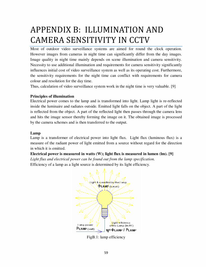
59
APPENDIX B: ILLUMINATION AND
CAMERA SENSITIVITY IN CCTV Most of outdoor video surveillance systems are aimed for round the clock operation.
However images from cameras in night time can significantly differ from the day images.
Image quality in night time mainly depends on scene illumination and camera sensitivity.
Necessity to use additional illumination and requirements for camera sensitivity significantly
influences initial cost of video surveillance system as well as its operating cost. Furthermore,
the sensitivity requirements for the night time can conflict with requirements for camera
colour and resolution for the day time.
Thus, calculation of video surveillance system work in the night time is very valuable. [9]
Principles of illumination
Electrical power comes to the lamp and is transformed into light. Lamp light is re-reflected
inside the luminaire and radiates outside. Emitted light falls on the object. A part of the light
is reflected from the object. A part of the reflected light then passes through the camera lens
and hits the image sensor thereby forming the image on it. The obtained image is processed
by the camera schemes and is then transferred to the output.
Lamp Lamp is a transformer of electrical power into light flux. Light flux (luminous flux) is a
measure of the radiant power of light emitted from a source without regard for the direction
in which it is emitted.
Electrical power is measured in watts (W); light flux is measured in lumen (lm). [9]
Light flux and electrical power can be found out from the lamp specification.
Efficiency of a lamp as a light source is determined by its light efficiency.
FigB.1: lamp efficiency

60
Light efficiency (luminous efficiency) is the ratio of the light flux emitted by the lamp to the
electrical power used to generate this flux. [9]
ŋ = ΦLAMPPLAMP
; ŋ is the light efficiency of lamp (lumen/watt);
ΦLAMP is light flux (lumen);
PLAMP is the consumed electrical power (watt).
However when choosing lamp, the designer should not consider only the light efficiency.
Cost of lamp, cost of control gear, colour-rendering index, life time, parameters of luminaire,
which allow installation of the lamp, are important.
For CCTV it is necessary to take into account spectral efficiency of radiation for different
types of image sensors.
Taking into account spectral efficiency is necessary for black-white and day-night cameras,
as the image sensor spectral sensitivity of such cameras differs significantly from the spectral
sensitivity of a human eye and illuminance meter. As a rule, discharge lamps with higher
light efficiency have smaller spectral efficiency, than incandescent lamps.
Luminaire Typical luminaire consists of lamp (or several lamps) and light armature including reflectors
and special glasses.
FigB.2: Luminaire showing angle of radiation, axial light Intensity and other parameters
Light flux emitted by the lamp re-reflects inside the luminaire and radiates outside. Major
part of light flux in many luminaries is radiated within a limited angle. This angle is named
Angle of radiation.

61
Angle of radiation is defined usually according to light intensity drop 50% relative to the
light intensity on axis of radiation.
Part of the light flux is absorbed inside the luminaire, another part is radiated out of the angle
of radiation.
Luminaire efficiency factor is the ratio between the light flux emitted by the luminaire and
the light flux of the lamp (or lamps) installed in the luminaire [9]
'%: = ΦLUMΦLAMP × 100
;LEF = luminaire efficiency factor;
ΦLUM = light flux emitted by the luminaire (lumen);
ΦLAMP = light flux of the lamps (lumen).
Light intensity
Distribution of the light flux of real luminaires in different directions is uneven. Density of
the light flux in certain direction is called light intensity.
Light intensity (luminous intensity) is the ratio of light flux of a light source, beamed within
the limits of an infinitesimal solid angle, to the value of this solid angle. [9]
Light intensity is measured in candelas (cd). One candela corresponds to the light flux of one
lumen, radiated within the limits of solid angle of one steradian.
< = =>
; I . light intensity (candel);
Φ . light flux (lumen) within the limits of solid angle Ω ;
Ω . solid angle (steradian).
Steradian = unit of measurement of solid angle
Solid angle of one steradian subtends surface on a sphere, the area of which is equal to the
squared radius of this sphere
Solid angle Ω (steradian), limited by a cone, is related to the full plane angle β (degrees) at
vertex of this cone by the following formula: [9]
Ω = 2π × 1 − cos β2
Full plane angle at the vertex of the cone, making 1 steradian, is equal to 65°32’.
Full sphere occupies 4*π steradian. [9]
π=3.14.
Light intensity distribution curves (LIDC)
Real luminaires have complicated spatial light intensity distribution, which cannot be
characterized only by the angle of radiation and the axial light intensity. In luminaire
specifications there are light intensity distribution curves (LID, LIDC), showing light
intensity distribution’s dependence on the angle in one or several planes.

62
GraphB.1: light intensity variation with beam angle
LIDC of some luminaires has rather complex form, but in practical modelling simplifications
are allowable. Many luminaires allow installing lamps of different type. That is why LIDC
is given for a reference lamp, radiating full light flux of 1000 lumen. For multi-lamp
luminaires 1000 lm is total light flux of lamps.
In order to get real light intensity in a certain direction, it is needed to divide light intensity in
this direction, got from LIDC by 1000, and multiply by the full light flux of the lamps
installed in the luminaire.
If for example, total light flux of the lamps in luminaire is 3000 lm, the value of light
intensity, got from LIDC (with the lamp of 1000 lm) should be multiply by 3.
With knowledge of lamp type, it is possible to obtain light flux of the lamp and take into
account spectral efficiency of radiation for different image sensors. Having LIDC of
luminaire, one can find out with what light intensity and in what direction this luminaire will
radiate. It is also possible to calculate illumination, produced by the luminaire at any
distance, from the light intensity.
Type and light flux of lamp, as well as LIDC of luminaire are important things that have to
be known about luminaire.
Illumination (illuminance) Camera sensitivity is defined through the minimum scene illumination. In order to connect
the luminaire parameters with the camera sensitivity it is needed to determine, which
illumination is produced by the luminaire on the scene. [9]
Illumination is the density of the light flux, falling on a surface. Illumination is measured in
lux (lx).
Average illumination of an area, created by light flux Φ falling on it, is determined by the
formula:
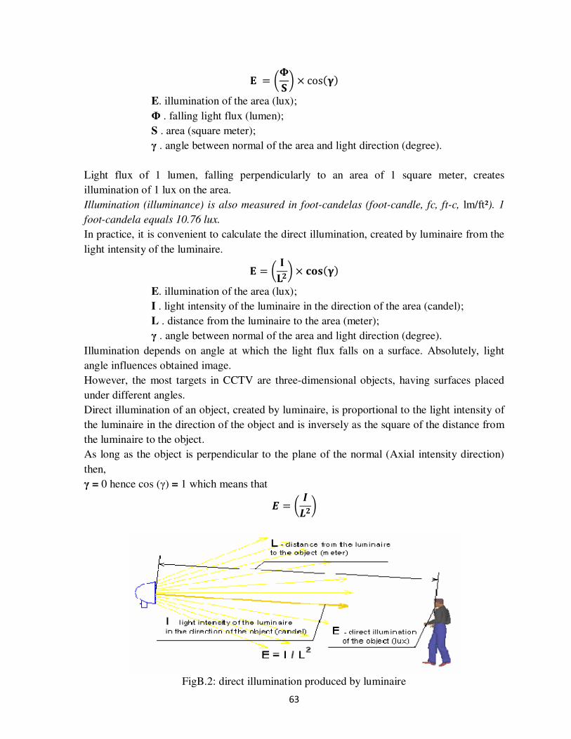
63
F = =G × cosHIJ
E. illumination of the area (lux);
Φ . falling light flux (lumen);
S . area (square meter);
γ . angle between normal of the area and light direction (degree).
Light flux of 1 lumen, falling perpendicularly to an area of 1 square meter, creates
illumination of 1 lux on the area.
Illumination (illuminance) is also measured in foot-candelas (foot-candle, fc, ft-c, lm/ft²). 1
foot-candela equals 10.76 lux.
In practice, it is convenient to calculate the direct illumination, created by luminaire from the
light intensity of the luminaire.
F = KLM × NOPHIJ
E. illumination of the area (lux);
I . light intensity of the luminaire in the direction of the area (candel);
L . distance from the luminaire to the area (meter);
γ . angle between normal of the area and light direction (degree).
Illumination depends on angle at which the light flux falls on a surface. Absolutely, light
angle influences obtained image.
However, the most targets in CCTV are three-dimensional objects, having surfaces placed
under different angles.
Direct illumination of an object, created by luminaire, is proportional to the light intensity of
the luminaire in the direction of the object and is inversely as the square of the distance from
the luminaire to the object.
As long as the object is perpendicular to the plane of the normal (Axial intensity direction)
then,
γ = 0 hence cos (γ) = 1 which means that
Q = <RM
FigB.2: direct illumination produced by luminaire

64
Light intensity of 1 candela (one lumen per one steradian) creates at distance of 1 meter from
the luminaire a direct illumination of 1 lux.
The formula is applicable, if the distance up to luminaire is bigger than the size of emitting
surface of the luminaire more than in 10 times.
Direct illumination, created by luminaire, is inversely as the square of the distance up to the
luminaire. Thus, light intensity of 1 candela created at distance of 10 m from the luminaire
illumination, which is equal to 0.01 lux. This is known inverse square law.
If the scene is illuminated by several luminaires, the result illumination, created by all
luminaires, equals to sum of illuminations, created by each luminaire.
In reality scene illumination, created by luminaire, can exceed calculated value of the direct
illumination, as the part of light flux re-reflects many times, creating diffused illumination.
Diffusion part of light depends on environment, reflection of objects on the scene, their
positions and so forth. Indoor diffusion part of light is large, in outdoor installations diffusion
part of light is less and depends on the season and weather.
Calculation of diffusion component of illumination is an intricate problem and demands big
amount of precise source data, which are often unknown at design stage.
Real scenes have also some background (ambient) illumination, which is created by sky,
street light and other light sources with unknown parameters. We do not know the parameters
of these sources, which is why we cannot calculate this illumination. We can only measure it
using illuminance meter (luxmeter), and then to take it into account at calculations and in
modelling.
Background illumination is summed up with illumination created by known luminaires.
In indoor installations the background illumination also depends on the season and weather.
Resulted scene illumination, as a rule, is distributed unevenly. On a scene there are both
highlighted and dusky areas.
Camera automatics adjust to the average level of illumination. If the contrast between
different areas on a scene approaches dynamic range of camera, the highlighted and (or)
dusky areas will be clipped.
Reflection
Part of light flux, falling on some object, is absorbed or transmitted through the object, and
another part is reflected.
Ratio of reflected light flux to the falling light flux is called object reflection factor.
S = TUVWXUX Y
K . reflection factor;
Φref . reflected light flux (lumen);
Φf . falling light flux (lumen).
Different objects have different reflection factors, therefore some objects seem to be darker,
and others, lighter. Object contrast relative to the background at equal illumination depends

65
on difference of object and background reflection factors. However in reality object
background illumination can differ.
Reflection factor depends on wave length (colour) of the falling radiation. Therefore objects
look coloured, and in infra-red illumination dark and light objects can be swapped.
More often reflection coming from matt surface or diffusion reflection, exists in nature. As a
result of diffusion reflection, the falling light is reflected with equal intensity in all directions.
There is also specular reflection from smooth surfaces. Because of the specular reflection on
the smooth surfaces there are flares from the light sources.
Lens
Part of the light reflected from the scene hits the camera lens. The amount of the light, going
through the lens, is determined by lens aperture. The aperture is indicated as F-number. For
example: F1.2, F1.4, F2.0.
The larger the F-number is, the less light going through the lens.
As a rule, the bigger the entrance pupil of the lens is, the more light it transmits. Pin-hole
lens have the narrowest aperture (larger value of F-number).
The aperture of auto iris lenses increases maximally (F-number value decreases) in low light
conditions. For such lens instead of aperture, the maximum and minimum apertures are
indicated, for example F1.2- F360.
Lens optical transmission changes inversely as the square of F-number.
For example, the lens F1.0 transmits in 4 times more light, than F2.0.
Camera sensitivity Camera sensitivity (minimum scene illumination) is a value of the scene illumination (lux)
with known reflection factor, at which we can get image with specified acceptable quality.
When defining sensitivity for cameras with removable lens, the aperture (F-number) of the
lens, with which the indicated sensitivity is assured, should be indicated. Usually these are
F1.2, F1.4 or F2.0.
If camera is used with other lens, its sensitivity will be changed inversely as the square of the
ratio of the F-number of the lens, installed on the camera, to the F-number of the lens, for
which the sensitivity is indicated.
For example, camera sensitivity is equal to 0.1 lx with the lens F1.2. Sensitivity of the same
camera with the lens F2.0 will make 0.1*(2/1.2)2=0.28 lx.
Sensitivity depends on exposure time. For standard cameras the maximal exposure time is
1/50 sec (PAL) or 1/60 sec (NTSC). For cameras allowing more exposure time, the exposure
time, at which indicated sensitivity is obtained, should be obligatory indicated.
With practically acceptable accuracy it is possible to consider that sensitivity is inversely to
the exposure time.
For example, if camera sensitivity is equal to 0.1 lx at exposure time of 1/5 sec, at exposure
time of 1/50 sec the sensitivity of this camera will be 0.1*(1/5)/(1/50)=1 lx.
Increased exposure time leads to resolution loss of moving objects.

66
For proper comparison of modern cameras it is necessary to recount sensitivity to the equal
exposure time. 1/50 (1/60) sec.
Minimum scene illumination calculations in design considerations
Light is a form of energy and cameras use this source of energy to excite phosphors on the
photosensitive layer of the faceplate.
The amount of light received on the faceplate of a camera is crucial since camera is designed
for a specific range of ambient lighting levels, with the minimum level being the threshold of
good picture production, cameras will give pictures below this level but not good pictures.
The CCTV designer must therefore calculate whether
a) Minimum illumination hitting the viewed scene, under all reasonable scenarios will
result in the minimum faceplate illumination to produce a good picture.
b) The automatic iris and lens combination will be able to regulate the level of
illumination entering the camera in such a way that optimum faceplate illumination is
always present while still giving a wide and high enough viewed scene area.
It is useful to look at the problem globally before going into calculations, ambient light
falling from the subject will go through a series of contortions, reflections, travel distances
and transmission through lenses before reaching the faceplate. Each interaction represents a
loss of light available. These losses are considered, in sequence, to arrive at the final
remaining figure in order to compare that figure to the actual needs of the faceplate or in the
reverse direction, to arrive at the average illumination of the scene required for a particular
camera selection.
Scene reflection factor Scene reflection factor at determining sensitivity, as a rule, is supposed to be 0.75, as
sensitivity measuring is carried out using the test chart printed on white sheet of paper,
having approximately the same reflection factor. [9]
Spectral sensitivity of image sensors of black/white and day/night cameras differs from the
spectral sensitivity of a human eye and illuminance meter. For such cameras the spectral
efficiency of the light source has an importance.
Spectral sensitivity of colour image sensors is close to the spectral sensitivity of a human eye,
therefore influence of spectral efficiency for colour cameras is not big.
Parameters, limiting image quality at defining sensitivity
Parameters, limiting image quality in low light conditions, for the most cameras are IRE and
Signal/noise ratio.

67
Camera’s work in low light conditions At low illumination electronic shutter set maximum exposure time, aperture is completely
opened, therefore electronic shutter and aperture could be not considered. The scheme
becomes quite simple.
FigB.3: the scheme of camera’s work in low light conditions
Signal from the image sensor, proportional to its illumination, comes to Automatic Gain
Control (AGC).
AGC Adjustment
AGC gain is automatically adjusted in order to get optimal image contrast in output.
An Image sensor always has some noise in output. If there is enough illumination, the signal
strength significantly exceeds noise level, the AGC gain is low and noise on the image is not
visible
When illumination decreases the signal level from the image sensor decreases too and
approaches to the noise level. AGC amplifies desired signal together with noises, seeking to
keep optimal image contrast
Thus, as illumination decreases, AGC gain increases. As a result, image contrast is not
changed, although noise increases. However, AGC gain has a limit. At further illumination
decrease AGC gain reaches maximum, after that, the image contrast begins to decrease and
the image becomes darker. At even further illumination decrease, noise level practically is
not changed. But signal/noise ratio continues diminishing, as image of the desired signal
decreases.
Maximum AGC gain of different models of cameras is different.
In some cameras image contrast diminishes even before the moment, when noise becomes
visible
In other cameras AGC keeps the contrast of very noisy signal
For the most of CCTV tasks, the contrast images are more preferable, in spite of disturbing
noise. However noisy images have many times bigger size after compression, what decreases
the archive depth and the transmission speed across digital communications channels. One
more problem is frequent false response of video motion detectors on noise.
Some models of cameras have switches, allowing changing the Maximum AGC gain in
dependence on application.

68
Signal/Noise ratio
Signal/noise ratio is the ratio of the maximum contrast on image to the root mean square
(RMS) value of noise.
With practically acceptable accuracy it is possible to consider that AGC operation does not
change signal/noise ratio of image. Signal/noise ratio depends only on illumination on the
image sensor and its features.
Responsible manufacturers usually indicate camera sensitivity as illumination, at which the
image has signal/noise ratio equal to 17dB (7 times), 20 dB (10 times) or 24 dB (16 times).
Unfortunately, many manufacturers of cameras do not indicate values of signal/noise ratio,
which the image will have at indicated minimum scene illumination. Very often as a result of
practical measuring camera parameters it becomes evident that at indicated in specification
illumination, the image has signal/noise ratio equal to 0dB and less.[9]
IRE
The parameter IRE came from analogue TV, but at present is applied for digital images as
well.
IRE determines what part of maximum possible brightness range the image occupies.
Whole possible brightness range of image is defined as 100IRE. Half of the brightness range
corresponds to 50IRE, quarter of the brightness range, 25IRE. Camera sensitivity is usually
defined as illumination, at which an output image has 40-50IRE, but there are some
exceptions.
The bigger IRE value (at the same signal/noise ratio) is indicated in camera sensitivity data,
the bigger maximum AGC gain of this camera is, the more contrast (but noisy) image is
displayed by the camera at low illumination.
Use of sensitivity in calculations It is possible to use values of camera sensitivity (lux) in design calculations, if it is known:
• Camera parameters, at which specified sensitivity is obtained:
o lens aperture (F number);
o Exposure time (sec).
• Parameters of obtained image:
o signal/noise ratio (dB);
o IRE
A Knowledge of sensitivity and other parameters, makes it possible to model images of
different scenes with different illuminations with the help of parametric camera model
existing in VideoCAD. This model includes the image formation laws in dependence on
illumination. The model takes into account the dynamic range, basic components of noise
and spectral sensitivity of image sensor, quantum noise, AGC, brightness, contrast, electronic
shutter control, gamma correction, back light compensation (BLC), lens aperture, auto-iris
operation.
The model is practically tested with many real cameras and shown very good accuracy for
practice.

69
Image processing inside camera
In modern cameras, the obtained image goes through special image processing. As a result of
the image processing at low illumination other parameters of the output image are worsened.
More often the resolution decreases, as a result of digital noise reduction or combining
signals from neighbouring pixels.
Often a manufacturer of cameras with noise reduction indicates high sensitivity in
specification, but writes nothing about the resolution drop.
Noise reduction is useful, as it decreases size of noisy images after compression and false
response of video motion detectors, but true value of sensitivity should be indicated at
switched-off noise reduction.