video compression and communications: from basics to h.261
TRANSCRIPT

Video Compression and Communications:From Basics to H.261, H.263, H.264, MPEG2,MPEG4 for DVB and HSDPA-Style Adaptive
Turbo-Transceivers
by
c©L. Hanzo, P.J. Cherriman, J. StreitDepartment of Electronics and Computer Science,
University of Southampton, UK

About the AuthorsLajos Hanzo(http://www-mobile.ecs.soton.ac.uk) FREng, FIEEE, FIET,DSc received his degree in electronics in 1976 and his doctorate in 1983.During his 30-year career in telecommunications he has heldvariousresearch and academic posts in Hungary, Germany and the UK. Since1986 he has been with the School of Electronics and Computer Science,University of Southampton, UK, where he holds the chair in telecom-munications. He has co-authored 15 books on mobile radio communica-tions totalling in excess of 10 000, published about 700 research papers,acted as TPC Chair of IEEE conferences, presented keynote lectures and
been awarded a number of distinctions. Currently he is directing an academic research team,working on a range of research projects in the field of wireless multimedia communicationssponsored by industry, the Engineering and Physical Sciences Research Council (EPSRC)UK, the European IST Programme and the Mobile Virtual Centreof Excellence (VCE), UK.He is an enthusiastic supporter of industrial and academic liaison and he offers a range ofindustrial courses. He is also an IEEE Distinguished Lecturer of both the CommunicationsSociety and the Vehicular Technology Society (VTS). Since 2005 he has been a Governer ofthe VTS. For further information on research in progress andassociated publications pleaserefer to http://www-mobile.ecs.soton.ac.uk
Peter J. Cherriman graduated in 1994 with an M.Eng. degree in In-formation Engineering from the University of Southampton,UK. Since1994 he has been with the Department of Electronics and Computer Sci-ence at the University of Southampton, UK, working towards aPh.D. inmobile video networking which was completed in 1999. Currently heis working on projects for the Mobile Virtual Centre of Excellence, UK.His current areas of research include robust video coding, microcellularradio systems, power control, dynamic channel allocation and multipleaccess protocols. He has published about two dozen conference and
journal papers, and holds several patents.
Jurgen Streit received his Dipl.-Ing. Degree in electronic engineeringfrom the Aachen University of Technology in 1993 and his Ph.D. inimage coding from the Department of Electronics and Computer Sci-ence, University of Southampton, UK, in 1995. From 1992 to 1996 Dr.Streit had been with the Department of Electronics and Computer Sci-ence working in the Communications Research Group. His workled tonumerous publications. Since then he has joined a management consul-tancy working as an information technology consultant.
i

ii

Other Wiley and IEEE PressBooks on Related Topics1
• R. Steele, L. Hanzo (Ed):Mobile Radio Communications: Second and Third Gener-ation Cellular and WATM Systems, John Wiley and IEEE Press, 2nd edition, 1999,ISBN 07 273-1406-8, 1064 pages
• L. Hanzo, F.C.A. Somerville, J.P. Woodard:Voice Compression and Communications:Principles and Applications for Fixed and Wireless Channels; IEEE Press and JohnWiley, 2001, 642 pages
• L. Hanzo, P. Cherriman, J. Streit:Wireless Video Communications: Second to ThirdGeneration and Beyond, IEEE Press and John Wiley, 2001, 1093 pages
• L. Hanzo, T.H. Liew, B.L. Yeap:Turbo Coding, Turbo Equalisation and Space-TimeCoding, John Wiley and IEEE Press, 2002, 751 pages
• J.S. Blogh, L. Hanzo:Third-Generation Systems and Intelligent Wireless Networking:Smart Antennas and Adaptive Modulation, John Wiley and IEEE Press, 2002, 408pages
• L. Hanzo, C.H. Wong, M.S. Yee:Adaptive Wireless Transceivers: Turbo-Coded, Turbo-Equalised and Space-Time Coded TDMA, CDMA and OFDM Systems, John Wiley andIEEE Press, 2002, 737 pages
• L. Hanzo, L-L. Yang, E-L. Kuan, K. Yen:Single- and Multi-Carrier CDMA: Multi-User Detection, Space-Time Spreading, Synchronisation, Networking and Standards,John Wiley and IEEE Press, June 2003, 1060 pages
• L. Hanzo, M. Munster, T. Keller, B-J. Choi,OFDM and MC-CDMA for BroadbandMulti-User Communications, WLANs and Broadcasting, John-Wiley and IEEE Press,2003, 978 pages
• L. Hanzo, S-X. Ng, T. Keller and W.T. Webb,Quadrature Amplitude Modulation:From Basics to Adaptive Trellis-Coded, Turbo-Equalised and Space-Time Coded OFDM,CDMA and MC-CDMA Systems, John Wiley and IEEE Press, 2004, 1105 pages
1For detailed contents and sample chapters please refer to http://www-mobile.ecs.soton.ac.uk
iii

iv
• L. Hanzo, T. Keller:An OFDM and MC-CDMA Primer, John Wiley and IEEE Press,2006, 430 pages
• L. Hanzo, F.C.A. Somerville, J.P. Woodard:Voice and Audio Compression for WirelessCommunications, John Wiley and IEEE Press, 2007, 858 pages
• L. Hanzo, P.J. Cherriman, J. Streit:Video Compression and Communications:H.261, H.263, H.264, MPEG4 and HSDPA-Style Adaptive Turbo-TransceiversJohnWiley and IEEE Press, 2007, 680 pages
• L. Hanzo, J. Blogh and S. Ni:HSDPA-Style FDD Versus TDD Networking:Smart Antennas and Adaptive ModulationJohn Wiley and IEEE Press, 2007, 650pages

viii

Contents
About the Authors i
Other Wiley and IEEE Press Books on Related Topics i
Preface v
Acknowledgments vii
I Video Codecs for HSDPA-Style Adaptive Videophones 1
2 Fractal Image Codecs 232.1 Fractal Principles . . . . . . . . . . . . . . . . . . . . . . . . . . . . . . .. 232.2 One-Dimensional Fractal Coding . . . . . . . . . . . . . . . . . . . .. . . . 26
2.2.1 Fractal Codec Design . . . . . . . . . . . . . . . . . . . . . . . . . . 292.2.2 Fractal Codec Performance . . . . . . . . . . . . . . . . . . . . . . .31
2.3 Error Sensitivity and Complexity . . . . . . . . . . . . . . . . . . .. . . . . 352.4 Summary and Conclusions . . . . . . . . . . . . . . . . . . . . . . . . . . .36
3 Low Bit-Rate DCT Codecs and HSDPA-Style Videophones 393.1 Video Codec Outline . . . . . . . . . . . . . . . . . . . . . . . . . . . . . . 393.2 The Principle of Motion Compensation . . . . . . . . . . . . . . . .. . . . 41
3.2.1 Distance Measures . . . . . . . . . . . . . . . . . . . . . . . . . . . 443.2.2 Motion Search Algorithms . . . . . . . . . . . . . . . . . . . . . . . 46
3.2.2.1 Full or Exhaustive Motion Search . . . . . . . . . . . . . . 463.2.2.2 Gradient-Based Motion Estimation . . . . . . . . . . . . . 473.2.2.3 Hierarchical or Tree Search . . . . . . . . . . . . . . . . . 483.2.2.4 Subsampling Search . . . . . . . . . . . . . . . . . . . . . 493.2.2.5 Post-Processing of Motion Vectors . . . . . . . . . . . . . 503.2.2.6 Gain-Cost-Controlled Motion Compensation . . . . . .. . 51
3.2.3 Other Motion Estimation Techniques . . . . . . . . . . . . . . .. . 523.2.3.1 Pel-Recursive Displacement Estimation . . . . . . . . .. 52
ix

x CONTENTS
3.2.3.2 Grid Interpolation Techniques . . . . . . . . . . . . . . . . 533.2.3.3 MC Using Higher Order Transformations . . . . . . . . . . 543.2.3.4 MC in the Transform Domain . . . . . . . . . . . . . . . . 54
3.2.4 Conclusion . . . . . . . . . . . . . . . . . . . . . . . . . . . . . . . 553.3 Transform Coding . . . . . . . . . . . . . . . . . . . . . . . . . . . . . . . . 55
3.3.1 One-Dimensional Transform Coding . . . . . . . . . . . . . . . .. . 553.3.2 Two-Dimensional Transform Coding . . . . . . . . . . . . . . . .. 563.3.3 Quantizer Training for Single-Class DCT . . . . . . . . . . .. . . . 603.3.4 Quantizer Training for Multiclass DCT . . . . . . . . . . . . .. . . 61
3.4 The Codec Outline . . . . . . . . . . . . . . . . . . . . . . . . . . . . . . . 643.5 Initial Intra-Frame Coding . . . . . . . . . . . . . . . . . . . . . . . .. . . 643.6 Gain-Controlled Motion Compensation . . . . . . . . . . . . . . .. . . . . 643.7 The MCER Active/Passive Concept . . . . . . . . . . . . . . . . . . . .. . 663.8 Partial Forced Update of the Reconstructed Frame Buffers . . . . . . . . . . 673.9 The Gain/Cost-Controlled Inter-Frame Codec . . . . . . . . .. . . . . . . . 69
3.9.1 Complexity Considerations and Reduction Techniques. . . . . . . . 703.10 The Bit-Allocation Strategy . . . . . . . . . . . . . . . . . . . . . .. . . . . 713.11 Results . . . . . . . . . . . . . . . . . . . . . . . . . . . . . . . . . . . . . . 733.12 DCT Codec Performance under Erroneous Conditions . . . .. . . . . . . . . 74
3.12.1 Bit Sensitivity . . . . . . . . . . . . . . . . . . . . . . . . . . . . . . 753.12.2 Bit Sensitivity of Codec I and II . . . . . . . . . . . . . . . . . .. . 78
3.13 DCT-Based Low-Rate Video Transceivers . . . . . . . . . . . . .. . . . . . 793.13.1 Choice of Modem . . . . . . . . . . . . . . . . . . . . . . . . . . . 793.13.2 Source-Matched Transceiver . . . . . . . . . . . . . . . . . . . .. 79
3.13.2.1 System 1 . . . . . . . . . . . . . . . . . . . . . . . . . . . 793.13.2.1.1 System Concept . . . . . . . . . . . . . . . . . . 793.13.2.1.2 Sensitivity-Matched Modulation . . . . . . . . . 803.13.2.1.3 Source Sensitivity . . . . . . . . . . . . . . . . . 803.13.2.1.4 Forward Error Correction . . . . . . . . . . . . . 813.13.2.1.5 Transmission Format . . . . . . . . . . . . . . . 82
3.13.2.2 System 2 . . . . . . . . . . . . . . . . . . . . . . . . . . . 843.13.2.2.1 Automatic Repeat Request . . . . . . . . . . . . 84
3.13.2.3 Systems 3–5 . . . . . . . . . . . . . . . . . . . . . . . . . 853.14 System Performance . . . . . . . . . . . . . . . . . . . . . . . . . . . . . .86
3.14.1 Performance of System 1 . . . . . . . . . . . . . . . . . . . . . . . . 863.14.2 Performance of System 2 . . . . . . . . . . . . . . . . . . . . . . . . 89
3.14.2.1 FER Performance . . . . . . . . . . . . . . . . . . . . . . 893.14.2.2 Slot Occupancy Performance . . . . . . . . . . . . . . . . 903.14.2.3 PSNR Performance . . . . . . . . . . . . . . . . . . . . . 92
3.14.3 Performance of Systems 3–5 . . . . . . . . . . . . . . . . . . . . . .933.15 Summary and Conclusions . . . . . . . . . . . . . . . . . . . . . . . . . .. 97

CONTENTS xi
4 Low Bit-Rate VQ Codecs and HSDPA-Style Videophones 994.1 Introduction . . . . . . . . . . . . . . . . . . . . . . . . . . . . . . . . . . . 994.2 The Codebook Design . . . . . . . . . . . . . . . . . . . . . . . . . . . . . 994.3 The Vector Quantizer Design . . . . . . . . . . . . . . . . . . . . . . . .. . 101
4.3.1 Mean and Shape Gain Vector Quantization . . . . . . . . . . . .. . 1064.3.2 Adaptive Vector Quantization . . . . . . . . . . . . . . . . . . . .. 1074.3.3 Classified Vector Quantization . . . . . . . . . . . . . . . . . . .. . 1094.3.4 Algorithmic Complexity . . . . . . . . . . . . . . . . . . . . . . . . 110
4.4 Performance under Erroneous Conditions . . . . . . . . . . . . .. . . . . . 1124.4.1 Bit-Allocation Strategy . . . . . . . . . . . . . . . . . . . . . . . .. 1124.4.2 Bit Sensitivity . . . . . . . . . . . . . . . . . . . . . . . . . . . . . . 113
4.5 VQ-Based Low-Rate Video Transceivers . . . . . . . . . . . . . . .. . . . . 1154.5.1 Choice of Modulation . . . . . . . . . . . . . . . . . . . . . . . . . 1154.5.2 Forward Error Correction . . . . . . . . . . . . . . . . . . . . . . . 1164.5.3 Architecture of System 1 . . . . . . . . . . . . . . . . . . . . . . . . 1184.5.4 Architecture of System 2 . . . . . . . . . . . . . . . . . . . . . . . . 1194.5.5 Architecture of Systems 3–6 . . . . . . . . . . . . . . . . . . . . . .120
4.6 System Performance . . . . . . . . . . . . . . . . . . . . . . . . . . . . . . 1204.6.1 Simulation Environment . . . . . . . . . . . . . . . . . . . . . . . . 1204.6.2 Performance of Systems 1 and 3 . . . . . . . . . . . . . . . . . . . . 1214.6.3 Performance of Systems 4 and 5 . . . . . . . . . . . . . . . . . . . . 1234.6.4 Performance of Systems 2 and 6 . . . . . . . . . . . . . . . . . . . . 125
4.7 Joint Iterative Decoding of Trellis-Based VQ-Video andTCM . . . . . . . . 1264.7.1 Introduction . . . . . . . . . . . . . . . . . . . . . . . . . . . . . . . 1264.7.2 System Overview . . . . . . . . . . . . . . . . . . . . . . . . . . . . 1274.7.3 Compression . . . . . . . . . . . . . . . . . . . . . . . . . . . . . . 1274.7.4 Vector quantization decomposition . . . . . . . . . . . . . . .. . . . 1284.7.5 Serial concatenation and iterative decoding . . . . . . .. . . . . . . 1284.7.6 Transmission Frame Structure . . . . . . . . . . . . . . . . . . . .. 1304.7.7 Frame difference decomposition . . . . . . . . . . . . . . . . . .. . 1304.7.8 VQ codebook . . . . . . . . . . . . . . . . . . . . . . . . . . . . . . 1324.7.9 VQ-induced code constraints . . . . . . . . . . . . . . . . . . . . .. 1334.7.10 VQ trellis structure . . . . . . . . . . . . . . . . . . . . . . . . . . .1344.7.11 VQ Encoding . . . . . . . . . . . . . . . . . . . . . . . . . . . . . . 1374.7.12 VQ Decoding . . . . . . . . . . . . . . . . . . . . . . . . . . . . . . 1384.7.13 Results . . . . . . . . . . . . . . . . . . . . . . . . . . . . . . . . . 140
4.8 Summary and Conclusions . . . . . . . . . . . . . . . . . . . . . . . . . . .143
5 Low Bit-Rate Quad-Tree-Based Codecs and HSDPA-Style Videophones 1475.1 Introduction . . . . . . . . . . . . . . . . . . . . . . . . . . . . . . . . . . . 1475.2 Quad-Tree Decomposition . . . . . . . . . . . . . . . . . . . . . . . . . .. 1475.3 Quad-Tree Intensity Match . . . . . . . . . . . . . . . . . . . . . . . . .. . 150
5.3.1 Zero-Order Intensity Match . . . . . . . . . . . . . . . . . . . . . .1505.3.2 First-Order Intensity Match . . . . . . . . . . . . . . . . . . . . .. 1525.3.3 Decomposition Algorithmic Issues . . . . . . . . . . . . . . . .. . . 153
5.4 Model-Based Parametric Enhancement . . . . . . . . . . . . . . . .. . . . . 156

xii CONTENTS
5.4.1 Eye and Mouth Detection . . . . . . . . . . . . . . . . . . . . . . . 1575.4.2 Parametric Codebook Training . . . . . . . . . . . . . . . . . . . .. 1595.4.3 Parametric Encoding . . . . . . . . . . . . . . . . . . . . . . . . . . 159
5.5 The Enhanced QT Codec . . . . . . . . . . . . . . . . . . . . . . . . . . . . 1615.6 Performance under Erroneous Conditions . . . . . . . . . . . . .. . . . . . 162
5.6.1 Bit Allocation . . . . . . . . . . . . . . . . . . . . . . . . . . . . . . 1635.6.2 Bit Sensitivity . . . . . . . . . . . . . . . . . . . . . . . . . . . . . . 165
5.7 QT-Codec-Based Video Transceivers . . . . . . . . . . . . . . . . .. . . . . 1655.7.1 Channel Coding and Modulation . . . . . . . . . . . . . . . . . . . .1655.7.2 QT-Based Transceiver Architectures . . . . . . . . . . . . . .. . . . 167
5.8 QT-Based Video-Transceiver Performance . . . . . . . . . . . .. . . . . . . 1705.9 Summary of QT-Based Video Transceivers . . . . . . . . . . . . . .. . . . . 1735.10 Summary of Low-Rate Codecs/Transceivers . . . . . . . . . . .. . . . . . . 174
II High-Resolution Video Coding 179
6 Low-Complexity Techniques 1816.1 Differential Pulse Code Modulation . . . . . . . . . . . . . . . . .. . . . . 181
6.1.1 Basic Differential Pulse Code Modulation . . . . . . . . . .. . . . . 1816.1.2 Intra/Inter-Frame Differential Pulse Code Modulation . . . . . . . . 1836.1.3 Adaptive Differential Pulse Code Modulation . . . . . . .. . . . . . 185
6.2 Block Truncation Coding . . . . . . . . . . . . . . . . . . . . . . . . . . .. 1856.2.1 The Block Truncation Algorithm . . . . . . . . . . . . . . . . . . .. 1856.2.2 Block Truncation Codec Implementations . . . . . . . . . . .. . . . 1886.2.3 Intra-Frame Block Truncation Coding . . . . . . . . . . . . . .. . . 1886.2.4 Inter-Frame Block Truncation Coding . . . . . . . . . . . . . .. . . 189
6.3 Subband Coding . . . . . . . . . . . . . . . . . . . . . . . . . . . . . . . . . 1916.3.1 Perfect Reconstruction Quadrature Mirror Filtering. . . . . . . . . . 193
6.3.1.1 Analysis Filtering . . . . . . . . . . . . . . . . . . . . . . 1936.3.1.2 Synthesis Filtering . . . . . . . . . . . . . . . . . . . . . . 1966.3.1.3 Practical QMF Design Constraints . . . . . . . . . . . . . 197
6.3.2 Practical Quadrature Mirror Filters . . . . . . . . . . . . . .. . . . . 2006.3.3 Run-Length-Based Intra-Frame Subband Coding . . . . . .. . . . . 2036.3.4 Max-Lloyd-Based Subband Coding . . . . . . . . . . . . . . . . . .206
6.4 Summary and Conclusions . . . . . . . . . . . . . . . . . . . . . . . . . . .209
7 High-Resolution DCT Coding 2117.1 Introduction . . . . . . . . . . . . . . . . . . . . . . . . . . . . . . . . . . . 2117.2 Intra-Frame Quantizer Training . . . . . . . . . . . . . . . . . . . .. . . . . 2117.3 Motion Compensation for High-Quality Images . . . . . . . . .. . . . . . . 2167.4 Inter-Frame DCT Coding . . . . . . . . . . . . . . . . . . . . . . . . . . . .222
7.4.1 Properties of the DCT transformed MCER . . . . . . . . . . . . .. 2227.4.2 Joint Motion Compensation and Residual Encoding . . . .. . . . . . 228
7.5 The Proposed Codec . . . . . . . . . . . . . . . . . . . . . . . . . . . . . . 2307.5.1 Motion Compensation . . . . . . . . . . . . . . . . . . . . . . . . . 231

CONTENTS xiii
7.5.2 The Inter/Intra-DCT Codec . . . . . . . . . . . . . . . . . . . . . . .2337.5.3 Frame Alignment . . . . . . . . . . . . . . . . . . . . . . . . . . . . 2337.5.4 Bit-Allocation . . . . . . . . . . . . . . . . . . . . . . . . . . . . . 2367.5.5 The Codec Performance . . . . . . . . . . . . . . . . . . . . . . . . 2377.5.6 Error Sensitivity and Complexity . . . . . . . . . . . . . . . . .. . 238
7.6 Summary and Conclusions . . . . . . . . . . . . . . . . . . . . . . . . . . .241
III H.261, H.263, H.264, MPEG2 and MPEG 4 forHSDPA-Style Wireless Video Telephony and DVB 243
8 H.261 for HSDPA-Style Wireless Video Telephony 2458.1 Introduction . . . . . . . . . . . . . . . . . . . . . . . . . . . . . . . . . . . 2458.2 The H.261 Video Coding Standard . . . . . . . . . . . . . . . . . . . . .. . 245
8.2.1 Overview . . . . . . . . . . . . . . . . . . . . . . . . . . . . . . . . 2458.2.2 Source Encoder . . . . . . . . . . . . . . . . . . . . . . . . . . . . . 2468.2.3 Coding Control . . . . . . . . . . . . . . . . . . . . . . . . . . . . . 2488.2.4 Video Multiplex Coder . . . . . . . . . . . . . . . . . . . . . . . . . 249
8.2.4.1 Picture Layer . . . . . . . . . . . . . . . . . . . . . . . . 2508.2.4.2 Group of Blocks Layer . . . . . . . . . . . . . . . . . . . 2518.2.4.3 Macroblock Layer . . . . . . . . . . . . . . . . . . . . . . 2538.2.4.4 Block Layer . . . . . . . . . . . . . . . . . . . . . . . . . 254
8.2.5 Simulated Coding Statistics . . . . . . . . . . . . . . . . . . . . .. 2568.2.5.1 Fixed-Quantizer Coding . . . . . . . . . . . . . . . . . . . 2578.2.5.2 Variable Quantizer Coding . . . . . . . . . . . . . . . . . 258
8.3 Effect of Transmission Errors on the H.261 Codec . . . . . . .. . . . . . . . 2598.3.1 Error Mechanisms . . . . . . . . . . . . . . . . . . . . . . . . . . . 2598.3.2 Error Control Mechanisms . . . . . . . . . . . . . . . . . . . . . . . 262
8.3.2.1 Background . . . . . . . . . . . . . . . . . . . . . . . . . 2628.3.2.2 Intra-Frame Coding . . . . . . . . . . . . . . . . . . . . . 2628.3.2.3 Automatic Repeat Request . . . . . . . . . . . . . . . . . 2638.3.2.4 Reconfigurable Modulations Schemes . . . . . . . . . . . 2638.3.2.5 Combined Source/Channel Coding . . . . . . . . . . . . . 263
8.3.3 Error Recovery . . . . . . . . . . . . . . . . . . . . . . . . . . . . . 2648.3.4 Effects of Errors . . . . . . . . . . . . . . . . . . . . . . . . . . . . 265
8.3.4.1 Qualitative Effect of Errors on H.261 Parameters . .. . . . 2658.3.4.2 Quantitative Effect of Errors on a H.261 Data Stream. . . 268
8.3.4.2.1 Errors in an Intra-Coded Frame . . . . . . . . . . 2688.3.4.2.2 Errors in an Inter-Coded Frame . . . . . . . . . . 2708.3.4.2.3 Errors in Quantizer Indices . . . . . . . . . . . . 2738.3.4.2.4 Errors in an Inter-Coded Frame with Motion Vec-
tors . . . . . . . . . . . . . . . . . . . . . . . . 2758.3.4.2.5 Errors in an Inter-Coded Frame at Low Rate . . . 277
8.4 A Reconfigurable Wireless Videophone System . . . . . . . . . .. . . . . . 2798.4.1 Introduction . . . . . . . . . . . . . . . . . . . . . . . . . . . . . . . 2798.4.2 Objectives . . . . . . . . . . . . . . . . . . . . . . . . . . . . . . . . 279

xiv CONTENTS
8.4.3 Bit-Rate Reduction of the H.261 Codec . . . . . . . . . . . . . .. . 2808.4.4 Investigation of Macroblock Size . . . . . . . . . . . . . . . . .. . 2808.4.5 Error Correction Coding . . . . . . . . . . . . . . . . . . . . . . . . 2838.4.6 Packetization Algorithm . . . . . . . . . . . . . . . . . . . . . . . .284
8.4.6.1 Encoding History List . . . . . . . . . . . . . . . . . . . . 2858.4.6.2 Macroblock Compounding . . . . . . . . . . . . . . . . . 2858.4.6.3 End of Frame Effect . . . . . . . . . . . . . . . . . . . . . 2888.4.6.4 Packet Transmission Feedback . . . . . . . . . . . . . . . 2888.4.6.5 Packet Truncation and Compounding Algorithms . . . .. 289
8.5 H.261-Based Wireless Videophone System Performance . .. . . . . . . . . 2908.5.1 System Architecture . . . . . . . . . . . . . . . . . . . . . . . . . . 2908.5.2 System Performance . . . . . . . . . . . . . . . . . . . . . . . . . . 293
8.6 Summary and Conclusions . . . . . . . . . . . . . . . . . . . . . . . . . . .299
9 Comparison of the H.261 and H.263 Codecs 3019.1 Introduction . . . . . . . . . . . . . . . . . . . . . . . . . . . . . . . . . . . 3019.2 The H.263 Coding Algorithms . . . . . . . . . . . . . . . . . . . . . . . .. 303
9.2.1 Source Encoder . . . . . . . . . . . . . . . . . . . . . . . . . . . . . 3039.2.1.1 Prediction . . . . . . . . . . . . . . . . . . . . . . . . . . 3039.2.1.2 Motion Compensation and Transform Coding . . . . . . . 3039.2.1.3 Quantization . . . . . . . . . . . . . . . . . . . . . . . . . 304
9.2.2 Video Multiplex Coder . . . . . . . . . . . . . . . . . . . . . . . . . 3049.2.2.1 Picture Layer . . . . . . . . . . . . . . . . . . . . . . . . 3059.2.2.2 Group of Blocks Layer . . . . . . . . . . . . . . . . . . . 3069.2.2.3 H.261 Macroblock Layer . . . . . . . . . . . . . . . . . . 3079.2.2.4 H.263 Macroblock Layer . . . . . . . . . . . . . . . . . . 3089.2.2.5 Block Layer . . . . . . . . . . . . . . . . . . . . . . . . . 312
9.2.3 Motion Compensation . . . . . . . . . . . . . . . . . . . . . . . . . 3129.2.3.1 H.263 Motion Vector Predictor . . . . . . . . . . . . . . . 3139.2.3.2 H.263 Subpixel Interpolation . . . . . . . . . . . . . . . . 314
9.2.4 H.263 Negotiable Options . . . . . . . . . . . . . . . . . . . . . . . 3149.2.4.1 Unrestricted Motion Vector Mode . . . . . . . . . . . . . . 3159.2.4.2 Syntax-Based Arithmetic Coding Mode . . . . . . . . . . 317
9.2.4.2.1 Arithmetic coding [326] . . . . . . . . . . . . . . 3179.2.4.3 Advanced Prediction Mode . . . . . . . . . . . . . . . . . 319
9.2.4.3.1 Four Motion Vectors per Macroblock . . . . . . . 3199.2.4.3.2 Overlapped Motion Compensation for
Luminance . . . . . . . . . . . . . . . . . . . . . 3209.2.4.4 P-B Frames Mode . . . . . . . . . . . . . . . . . . . . . . 322
9.3 Performance Results . . . . . . . . . . . . . . . . . . . . . . . . . . . . . .3259.3.1 Introduction . . . . . . . . . . . . . . . . . . . . . . . . . . . . . . . 3259.3.2 H.261 Performance . . . . . . . . . . . . . . . . . . . . . . . . . . . 3259.3.3 H.261/H.263 Performance Comparison . . . . . . . . . . . . . .. . 3289.3.4 H.263 Codec Performance . . . . . . . . . . . . . . . . . . . . . . . 331
9.3.4.1 Gray-Scale versus Color Comparison . . . . . . . . . . . . 3319.3.4.2 Comparison of QCIF Resolution Color Video . . . . . . . 334

CONTENTS xv
9.3.4.3 Coding Performance at Various Resolutions . . . . . . .. 3349.4 Summary and Conclusions . . . . . . . . . . . . . . . . . . . . . . . . . . .343
10 H.263 for HSDPA-Style Wireless Video Telephony 34510.1 Introduction . . . . . . . . . . . . . . . . . . . . . . . . . . . . . . . . . . .34510.2 H.263 in a Mobile Environment . . . . . . . . . . . . . . . . . . . . . .. . 345
10.2.1 Problems of Using H.263 in a Mobile Environment . . . . .. . . . . 34510.2.2 Possible Solutions for Using H.263 in a Mobile Environment . . . . . 346
10.2.2.1 Coding Video Sequences Using Exclusively Intra-CodedFrames . . . . . . . . . . . . . . . . . . . . . . . . . . . . 347
10.2.2.2 Automatic Repeat Requests . . . . . . . . . . . . . . . . . 34710.2.2.3 Multimode Modulation Schemes . . . . . . . . . . . . . . 34710.2.2.4 Combined Source/Channel Coding . . . . . . . . . . . . . 348
10.3 Design of an Error-Resilient Reconfigurable Videophone System . . . . . . . 34910.3.1 Introduction . . . . . . . . . . . . . . . . . . . . . . . . . . . . . . . 34910.3.2 Controling the Bit Rate . . . . . . . . . . . . . . . . . . . . . . . . .34910.3.3 Employing FEC Codes in the Videophone System . . . . . . .. . . 35110.3.4 Transmission Packet Structure . . . . . . . . . . . . . . . . . .. . . 35210.3.5 Coding Parameter History List . . . . . . . . . . . . . . . . . . .. . 35310.3.6 The Packetization Algorithm . . . . . . . . . . . . . . . . . . . .. . 355
10.3.6.1 Operational Scenarios of the Packetizing Algorithm . . . . 35510.4 H.263-Based Video System Performance . . . . . . . . . . . . . .. . . . . . 358
10.4.1 System Environment . . . . . . . . . . . . . . . . . . . . . . . . . . 35810.4.2 Performance Results . . . . . . . . . . . . . . . . . . . . . . . . . . 360
10.4.2.1 Error-Free Transmission Results . . . . . . . . . . . . . .36010.4.2.2 Effect of Packet Dropping on Image Quality . . . . . . .. 36010.4.2.3 Image Quality versus Channel Quality without ARQ .. . . 36110.4.2.4 Image Quality versus Channel Quality with ARQ . . . .. 362
10.4.3 Comparison of H.263 and H.261-Based Systems . . . . . . .. . . . 36310.4.3.1 Performance with Antenna Diversity . . . . . . . . . . . .36410.4.3.2 Performance over DECT Channels . . . . . . . . . . . . . 370
10.5 Transmission Feedback . . . . . . . . . . . . . . . . . . . . . . . . . . .. . 37210.5.1 ARQ Issues . . . . . . . . . . . . . . . . . . . . . . . . . . . . . . . 37610.5.2 Implementation of Transmission Feedback . . . . . . . . .. . . . . 378
10.5.2.1 Majority Logic Coding . . . . . . . . . . . . . . . . . . . 37910.6 Summary and Conclusions . . . . . . . . . . . . . . . . . . . . . . . . . .. 383
11 MPEG-4 Video Compression 38511.1 Introduction . . . . . . . . . . . . . . . . . . . . . . . . . . . . . . . . . . .38511.2 Overview of MPEG-4 . . . . . . . . . . . . . . . . . . . . . . . . . . . . . . 386
11.2.1 MPEG-4 Profiles . . . . . . . . . . . . . . . . . . . . . . . . . . . . 38611.2.2 MPEG-4 Features . . . . . . . . . . . . . . . . . . . . . . . . . . . . 38811.2.3 MPEG-4 Object Based Orientation . . . . . . . . . . . . . . . . .. 390
11.3 MPEG-4 : Content-Based Interactivity . . . . . . . . . . . . . .. . . . . . . 39311.3.1 Video Object Plane Based Encoding . . . . . . . . . . . . . . . .. . 39511.3.2 Motion and Texture Encoding . . . . . . . . . . . . . . . . . . . . .396

xvi CONTENTS
11.3.3 Shape Coding . . . . . . . . . . . . . . . . . . . . . . . . . . . . . . 40011.3.3.1 VOP Shape Encoding . . . . . . . . . . . . . . . . . . . . 40011.3.3.2 Gray Scale Shape Coding . . . . . . . . . . . . . . . . . . 402
11.4 Scalability of Video Objects . . . . . . . . . . . . . . . . . . . . . .. . . . 40211.5 Video Quality Measures . . . . . . . . . . . . . . . . . . . . . . . . . . .. 404
11.5.1 Subjective Video Quality Evaluation . . . . . . . . . . . . .. . . . . 40411.5.2 Objective Video Quality . . . . . . . . . . . . . . . . . . . . . . . .406
11.6 Effect of Coding Parameters . . . . . . . . . . . . . . . . . . . . . . .. . . 40611.7 Summary and Conclusion . . . . . . . . . . . . . . . . . . . . . . . . . . .. 410
12 HSDPA-Like and Turbo-Style Adaptive Single- and Multi-CarrierVideo Systems 41512.1 Turbo-equalised H.263-based videophony for GSM/GPRS. . . . . . . . . . 415
12.1.1 Motivation and Background . . . . . . . . . . . . . . . . . . . . . .41512.1.2 System Parameters . . . . . . . . . . . . . . . . . . . . . . . . . . . 41612.1.3 Turbo Equalization . . . . . . . . . . . . . . . . . . . . . . . . . . . 41812.1.4 Turbo-equalization Performance . . . . . . . . . . . . . . . .. . . . 422
12.1.4.1 Video Performance . . . . . . . . . . . . . . . . . . . . . 42312.1.4.2 Bit Error Statistics . . . . . . . . . . . . . . . . . . . . . . 426
12.1.5 Summary and Conclusions . . . . . . . . . . . . . . . . . . . . . . . 42712.2 HSDPA-Style Burst-by-burst Adaptive CDMA Videophony. . . . . . . . . . 428
12.2.1 Motivation and Video Transceiver Overview . . . . . . . .. . . . . 42812.2.2 Multimode Video System Performance . . . . . . . . . . . . . .. . 43212.2.3 Burst-by-Burst Adaptive Videophone System . . . . . . .. . . . . . 43612.2.4 Summary and Conclusions . . . . . . . . . . . . . . . . . . . . . . . 442
12.3 Adaptive Turbo-Coded OFDM-Based Videotelephony . . . .. . . . . . . . . 44212.3.1 Motivation and Background . . . . . . . . . . . . . . . . . . . . . .44212.3.2 AOFDM Modem Mode Adaptation and Signaling . . . . . . . . .. . 44412.3.3 AOFDM Subband BER Estimation . . . . . . . . . . . . . . . . . . 44412.3.4 Video Compression and Transmission Aspects . . . . . . .. . . . . 44412.3.5 Comparison of Subband-Adaptive OFDM and Fixed Mode
OFDM Transceivers . . . . . . . . . . . . . . . . . . . . . . . . . . 44512.3.6 Subband-Adaptive OFDM Transceivers Having Different
Target Bit Rates . . . . . . . . . . . . . . . . . . . . . . . . . . . . . 45012.3.7 Time-Variant Target Bit Rate OFDM Transceivers . . . .. . . . . . 45412.3.8 Summary and Conclusions . . . . . . . . . . . . . . . . . . . . . . . 464
12.4 HSDPA-Style Adaptive TCM, TTCM and BICM for H.263 VideoTelephony 46412.4.1 Introduction . . . . . . . . . . . . . . . . . . . . . . . . . . . . . . . 46412.4.2 System Overview . . . . . . . . . . . . . . . . . . . . . . . . . . . . 466
12.4.2.1 System Parameters and Channel Model . . . . . . . . . . . 46712.4.3 Employing Fixed Modulation Modes . . . . . . . . . . . . . . . .. 47012.4.4 Employing Adaptive Modulation . . . . . . . . . . . . . . . . . .. . 471
12.4.4.1 Performance of TTCM AQAM . . . . . . . . . . . . . . . 47312.4.4.2 Performance of AQAM Using TTCM, TCC, TCM and BICM47612.4.4.3 The Effect of Various AQAM Thresholds . . . . . . . . . . 477
12.4.5 TTCM AQAM in CDMA system . . . . . . . . . . . . . . . . . . . 480

CONTENTS xvii
12.4.5.1 Performance of TTCM AQAM in CDMA system . . . . . 48412.4.6 Conclusions . . . . . . . . . . . . . . . . . . . . . . . . . . . . . . . 485
12.5 Turbo-Detected MPEG-4 Video Using Multi-Level Coding, TCM and STTC 48612.5.1 Motivation and Background . . . . . . . . . . . . . . . . . . . . . .48612.5.2 The Turbo Transceiver . . . . . . . . . . . . . . . . . . . . . . . . . 487
12.5.2.1 Turbo Decoding . . . . . . . . . . . . . . . . . . . . . . . 48812.5.2.2 Turbo Benchmark Scheme . . . . . . . . . . . . . . . . . 490
12.5.3 MIMO Channel Capacity . . . . . . . . . . . . . . . . . . . . . . . . 49112.5.4 Convergence Analysis . . . . . . . . . . . . . . . . . . . . . . . . . 49412.5.5 Simulation results . . . . . . . . . . . . . . . . . . . . . . . . . . . 49812.5.6 Conclusions . . . . . . . . . . . . . . . . . . . . . . . . . . . . . . . 500
12.6 Near-Capacity Irregular Variable Length Codes . . . . . .. . . . . . . . . . 50112.6.1 Introduction . . . . . . . . . . . . . . . . . . . . . . . . . . . . . . . 50112.6.2 Overview of Proposed Schemes . . . . . . . . . . . . . . . . . . . .504
12.6.2.1 Joint source and channel coding . . . . . . . . . . . . . . . 50512.6.2.2 Iterative decoding . . . . . . . . . . . . . . . . . . . . . . 507
12.6.3 Parameter Design for the Proposed Schemes . . . . . . . . .. . . . 50912.6.3.1 Scheme hypothesis and parameters . . . . . . . . . . . . . 50912.6.3.2 EXIT chart analysis and optimization . . . . . . . . . . .. 510
12.6.4 Results . . . . . . . . . . . . . . . . . . . . . . . . . . . . . . . . . 51212.6.4.1 Asymptotic performance following iterative decoding con-
vergence . . . . . . . . . . . . . . . . . . . . . . . . . . . 51212.6.4.2 Performance during iterative decoding . . . . . . . . .. . 51412.6.4.3 Complexity analysis . . . . . . . . . . . . . . . . . . . . . 515
12.6.5 Conclusions . . . . . . . . . . . . . . . . . . . . . . . . . . . . . . . 51712.7 Digital Terrestrial Video Broadcasting for Mobile Receivers . . . . . . . . . 518
12.7.1 Background and Motivation . . . . . . . . . . . . . . . . . . . . . .51812.7.2 MPEG-2 Bit Error Sensitivity . . . . . . . . . . . . . . . . . . . .. 51912.7.3 DVB Terrestrial Scheme . . . . . . . . . . . . . . . . . . . . . . . . 53012.7.4 Terrestrial Broadcast Channel Model . . . . . . . . . . . . .. . . . 53312.7.5 Data Partitioning Scheme . . . . . . . . . . . . . . . . . . . . . . .53412.7.6 Performance of the Data Partitioning Scheme . . . . . . .. . . . . . 54012.7.7 Nonhierarchical OFDM DVBP Performance . . . . . . . . . . .. . 55112.7.8 Hierarchical OFDM DVB Performance . . . . . . . . . . . . . . .. 55612.7.9 Summary and Conclusions . . . . . . . . . . . . . . . . . . . . . . . 559
12.8 Satellite-Based Video Broadcasting . . . . . . . . . . . . . . .. . . . . . . 56312.8.1 Background and Motivation . . . . . . . . . . . . . . . . . . . . . .56312.8.2 DVB Satellite Scheme . . . . . . . . . . . . . . . . . . . . . . . . . 56312.8.3 Satellite Channel Model . . . . . . . . . . . . . . . . . . . . . . . .56612.8.4 The Blind Equalizers . . . . . . . . . . . . . . . . . . . . . . . . . . 56712.8.5 Performance of the DVB Satellite Scheme . . . . . . . . . . .. . . . 570
12.8.5.1 Transmission over the Symbol-Spaced Two-PathChannel . . . . . . . . . . . . . . . . . . . . . . . . . . . 570
12.8.5.2 Transmission over the Two-Symbol Delay Two-Path Channel57412.8.5.3 Performance Summary of the DVB-S System . . . . . . . 580
12.8.6 Summary and Conclusions . . . . . . . . . . . . . . . . . . . . . . . 583

xviii CONTENTS
12.9 Summary and Conclusions . . . . . . . . . . . . . . . . . . . . . . . . . .. 58512.10Wireless Video System Design Principles . . . . . . . . . . .. . . . . . . . 586
Glossary 589
Bibliography 599
Subject Index 623
Author Index 623

Part I
Video Codecs for HSDPA-StyleAdaptive Videophones


Part II
High-Resolution Video Coding


Part III
H.261, H.263, H.264, MPEG2 andMPEG 4 for
HSDPA-Style Wireless VideoTelephony and DVB


Chapter 11MPEG-4 Video CompressionJ-Y. Chung and L. Hanzo
11.1 Introduction
The“Moving Picture Experts Group” (MPEG) was established in 1988 [339], within the In-ternational Standard Organisation’s (ISO) Steering Group(SG) 29, which was responsiblefor the encoding of moving pictures and audio. The MPEG groupcommenced the devel-opment of the MPEG-1 standard in 1988, released the MPEG-1 standard in 1993 and em-barked on the standardisation of the MPEG-2 scheme in 1990 [340]. The MPEG-1 standardwas mainly targeted at CD-ROM applications dedicated to recording video at bit rates ofup to 1.5Mbit/s [340, 341]. By contrast, the MPEG-2 standardwas designed for substan-tially higher quality, namely for audiovisual applications such as today’s home entertain-ment systems and digital broadcasting systems requiring video bit rates between 2Mbit/s and30Mbit/s [342,343].
The MPEG-4 standardisation process was initiated in 1994 - with the mandate of stan-dardising algorithms for audio-visual coding in multimedia applications, while allowing forinteractivity, and supporting high compression as well as universal accessibility and portabil-ity of both the audio and video content [344].
The MPEG-4 Visual standard was developed by the ISO/IEC 14496-2 1, and its Version1 was released in 1998, which additional tools and profiles were added in two amendmentsof the standard, culminating in Version 2 during late 2001. The operating bit rates targetedby the MPEG-4 video standard are between 5 and 64kbit/s in thecontext of mobile or PublicSwitched Telephone Network (PSTN) based video applications, spanning up to 4 Mbit/s fordigital TV broadcast applications, and even to rates in excess of 100Mbit/s in High DefinitionTV (HDTV) studio applications [345].
The MPEG-4 video coding standard is capable of supporting all functionalities alreadyprovided by MPEG-1 and MPEG-2. The MPEG-4 Visual standard improves the popularMPEG-2 standard both in terms of the achievable compressionefficiency, at a given visual
1This is the project’s profile name for the International Organisation for Standardization/International Elec-trotechnical Commission (ISO/IEC). For example, the profile index 15444 for JPEG, 11172 for MPEG-1, 13818for MPEG-2, 14496 for MPEG-4, etc.
385

386 CHAPTER 11. MPEG-4 VIDEO COMPRESSION
quality, as well as in terms of the attainable flexibility that facilitates its employment in awide range of applications. It achieves these substantial advances by making use of moreadvanced compression algorithms and by providing an extensive set of ’tools’ for codingand manipulating digital media. The MPEG-4 Visual standardconsists of a ‘core’ videoencoder/decoder model that invoke a number of additional coding tools. The core model isbased on the well-established hybrid DPCM/DCT coding algorithm and the basic function ofthe core is extended by ‘tools’ supporting an enhanced compression efficiency and reliabletransmission. Furthermore, MPEG-4 facilitates an efficient and novel coded representationof the audio and video data that can be “content based”, whichis a concept to be highlightedin Section 11.3.
To elaborate a little further, the MPEG-4 video standard compresses the video signal withthe aid of a compression tool box constituted by a set of encoding tools supporting severalclasses of functionalities. In short, the most important features supported by the MPEG-4standard area high compression efficiency, content-based interactivity, and universal access,which are summarised below [340,346]:
• Achieving high compression efficiencyhas been a core feature of both MPEG-1 andMPEG-2. The storage and transmission of audio visual data requires a high compres-sion efficiency, while reproducing a high-quality video sequence, hence enabling ap-plications such as High Definition Television (HDTV) and Digital Video Disc (DVD)storage.
• Content-based interactivityrepresents video on an ‘object-basis’, rather than on a video‘frame-basis’, which is one of the novel features offered byMPEG-4. The concept ofcontent-based functionality will be elaborated on in more depth in Section 11.3.
• Universal accessallows audiovisual information to be transmitted and accessed in vari-ous network environments such as mobile networks as well as wire line-based systems.
This chapter provides a rudimentary overview of the MPEG-4 video standard. Followingthe overview of the standard – its approach and features, in Section 11.3, the philosophy ofthe object oriented coding scheme will be discussed. This isfollowed by a discussion onthe so-called profiles defined for coding of arbitrary-shaped objects and rectangular videoframes in Subsection 11.3.3. Then the profiles defined for scalable coding of video objectsare highlighted in Section 11.4 and subjective video quality measurement methods as well asour experimental results are discussed in Sections 11.5 and11.6.
11.2 Overview of MPEG-4
11.2.1 MPEG-4 Profiles
The MPEG-4 standard aims for satisfying the requirements ofvarious visual communica-tions applications using a toolkit-based approach for encoding and decoding of visual infor-mation [24, 346]. Below we will describe some of the key features of the MPEG-4 videostandard, which are superior in comparison to the previous video coding standards:
• The core compression tools are based on those of the ITU-T H.263 standard, whichare more efficient than those of the MPEG-1 [347] and MPEG-2 [348] video compres-sion schemes. Efficient compression of progressive and interlaced video sequences as

11.2. OVERVIEW OF MPEG-4 387
well as optional additional tools were introduced for the sake of further improving theattainable compression efficiency.
• Coding of video objects, having both rectangular shapes andirregular-shapes object.This is a new concept in the context of standard-based video coding and enables theindependent encoding of both foreground and background objects in a video scene.
• Support for error-resilient transmission over hostile networks. A range of error re-silience tools were included in the MPEG-4 codec for the sakeof assisting the decoderin recovering from transmission errors and for maintaininga successful video connec-tion in an error-prone network. Furthermore, the scalable coding tools are capable ofsupporting flexible transmission at a range of desired codedbitrates.
• Coding of still image within the same framework as full-motion video sequences.
• Coding of animated visual objects, such as 2D and 3D computer-generated polygonalmeshes, animated objects, etc.
• Coding for specialist applications, such as very high ’studio’ quality video. In thisapplication maintaining a high visual quality is more important than attaining a highcompression.
Table 11.1 lists the MPEG-4 visual profiles invoked for coding video scenes. These pro-files range from the so-called Simple Profile derived for the encoding of rectangular videoframes through profiles designed for arbitrary-shaped and scalable object coding to profilescontrived for the encoding of studio-quality video.
MPEG-4 Visual profile Main features2 Simple Low-complexity coding of rectangular video frames2 Advanced Simple Coding rectangular frames with improved efficiency and support for interlaces
video2 Advanced Real-Time Simple Coding rectangular frames for real-time streaming2 Core Basic coding of arbitrary-shaped video objects2 Main Feature-rich coding of video objects2 Advanced Coding Efficiency Highly efficient coding of video objects2 N-Bit Coding of video objects with sample resolutions other than 8 bits2 Simple Scalable Scalable coding of rectangular video frames2 Fine Granular Scalability Advanced scalable coding of rectangular frames2 Core Scalable Scalable coding of video objects2 Scalable Texture Scalable still texture with improved efficiency and object-based features2 Advanced Scalable Texture Scalable still texture with improved efficiency and object-based featured2 Advanced Core Combines features of Simple, Core and Advanced Scalable Texture Profiles2 Simple Studio Object-based coding of high quality video sequences2 Core Studio Object-based coding of high quality video with improved compression effi-
ciency
Table 11.1:MPEG-4 Visual profiles for coding natural video [24,346]
388 CHAPTER 11. MPEG-4 VIDEO COMPRESSION
11.2.2 MPEG-4 Features
display
Voice Codec
ProcessingPost−
ProcessingPre−
Tra
nspo
rt L
ayer
bitsream in
bitstream out
camerainput
output
microphone input
outputspeaker
Video Encoder
Video Decoder
Audio Decoder
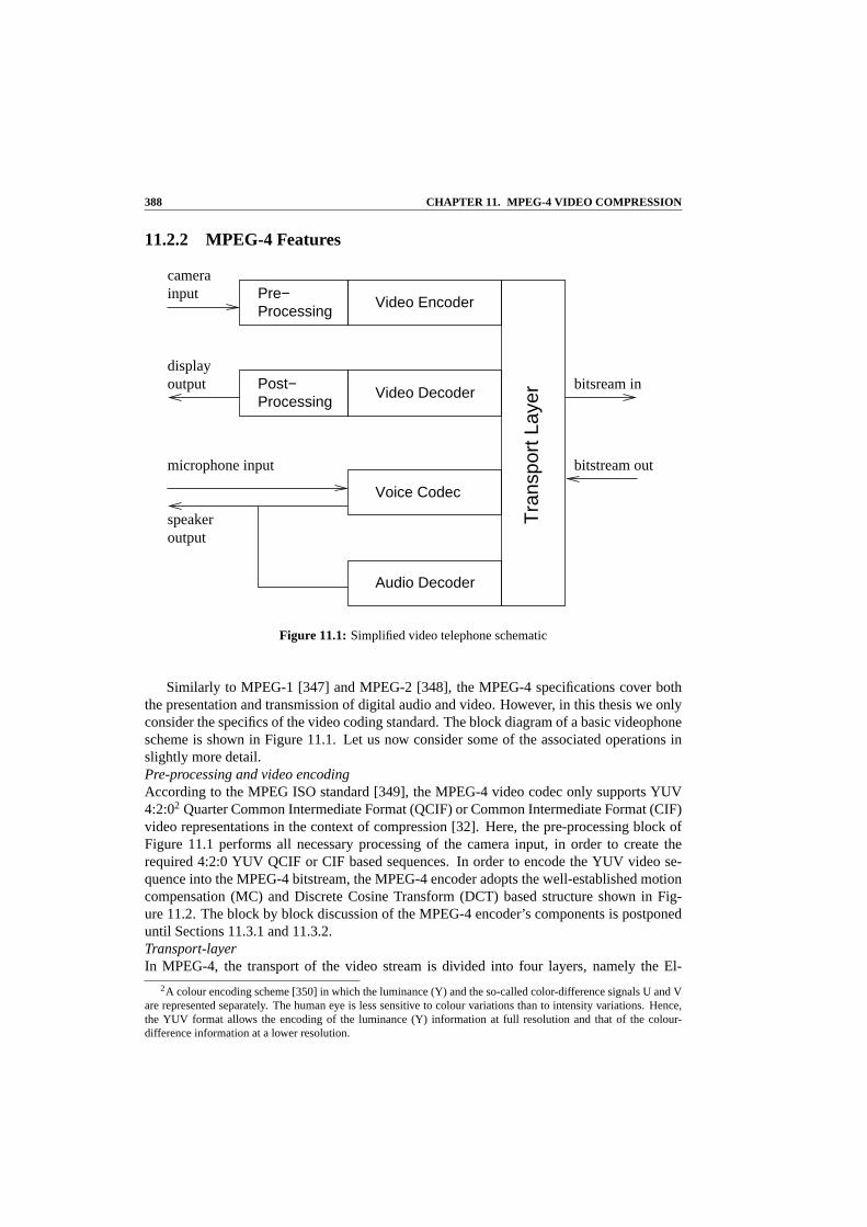
Figure 11.1: Simplified video telephone schematic
Similarly to MPEG-1 [347] and MPEG-2 [348], the MPEG-4 specifications cover boththe presentation and transmission of digital audio and video. However, in this thesis we onlyconsider the specifics of the video coding standard. The block diagram of a basic videophonescheme is shown in Figure 11.1. Let us now consider some of theassociated operations inslightly more detail.Pre-processing and video encodingAccording to the MPEG ISO standard [349], the MPEG-4 video codec only supports YUV4:2:02 Quarter Common Intermediate Format (QCIF) or Common Intermediate Format (CIF)video representations in the context of compression [32]. Here, the pre-processing block ofFigure 11.1 performs all necessary processing of the camerainput, in order to create therequired 4:2:0 YUV QCIF or CIF based sequences. In order to encode the YUV video se-quence into the MPEG-4 bitstream, the MPEG-4 encoder adoptsthe well-established motioncompensation (MC) and Discrete Cosine Transform (DCT) based structure shown in Fig-ure 11.2. The block by block discussion of the MPEG-4 encoder’s components is postponeduntil Sections 11.3.1 and 11.3.2.Transport-layerIn MPEG-4, the transport of the video stream is divided into four layers, namely the El-
2A colour encoding scheme [350] in which the luminance (Y) and the so-called color-difference signals U and Vare represented separately. The human eye is less sensitive to colour variations than to intensity variations. Hence,the YUV format allows the encoding of the luminance (Y) information at full resolution and that of the colour-difference information at a lower resolution.

11.2. OVERVIEW OF MPEG-4 389
DCT Q
iQ
iDCT
FBMC
Entropy
iQ
iDCT
FB MC
ME
x"(n)
MV
x’(n−1)
MV
x(n) x’(n−1) or x(n−1)
x(n) D(n)
x"(n)
X’(n−1)x’(n) x’(n)
D’(n) D’(n)
Decoded Video Sequence
x(n):Current frame
D(n):Residue, x(n) −x"(n)
MC :Motion Compensation
FB :Frame Buffer
x"n:Prediction for x(n)
D’(n):Decoded residue
ME :Motion Estimation
IDCT: Inverse DCT
x’(n):Reconstructed Frame
DCT : Discrete Cosine Transform
Q :Quantizer
IQ : Inverse Quantizer
EntropyEncoder Decoder
Figure 11.2: Block diagram of the MPEG-4 encoder and decoder.
ementary Stream [351], the Synchronisation Layer, the ’Flexmuxed’ [352] stream and the’Transmux’ [353] Stream. The MPEG-4 system’s architectureand transport layer have beennicely documented in the literature, for example in [351,354]. Below we briefly outline thesetransport layer characteristics:
• The termElementary Streams[351] refers to data that fully or partially contain theencoded representation of a single audio or video object, scene description informationor control information.
• TheSynchronisation Layer (SL)[355] adds the identification of the information sources,such as for example audio or video sources, as well as time stamps.
• Flexmuxed Streams[352] convey groups of elementary streams according to a specificset of common attributes, such as for example quality requirements.
• Transmux Streams[353] are constituted by streams transmitted over the network usingtransport protocols, such as the Real-Time Protocol (RTP) [356] used for transmissionover the Internet.
Video Decoder and Post ProcessingFigure 11.2 portrays the simplified block diagram of the MPEG-4 video decoder. Observethat the structure of the decoding process is identical to that of the encoder’s local decoder.Motion compensation, which has been comparatively studiedfor example in [4], is the most

390 CHAPTER 11. MPEG-4 VIDEO COMPRESSION
important process both in the video encoder and decoder in terms of achieving a high videocompression. Motion Compensation (MC) generates the Motion Vectors (MV) on the basis ofidentifying the most likely position within the previous video frame, where the current 8x8-pixel video block has originated from, as it moved along a certain motion trajectory in theconsecutive video frames. This motion-compensation process involves allocating a certainsearch area in the previous frame and then sliding the current block over this search area inan effort to find the position of highest correlation. Once this position has been identified, themotion compensated prediction residual (MCPR) [4] is formed by subtracting the two blocksfrom each other.
11.2.3 MPEG-4 Object Based Orientation
One of the functionalities defined by the MPEG-4 standard is the audio-visual ‘object’ basedprocessing, which forms the ‘object-based’ representation of the audio or video signal [342].A video object can be exemplified by a person walking against the backdrop of mountains.Both the object and the background can be substituted by another object or by another back-drop and as expected certain encoding techniques perform better for certain objects. Thisrepresentation supports‘content-based interactivity’, which will be discussed in more detailin section 11.3.
VO1
VO2VO3
VO4
Figure 11.3: Original decoded video scene.
Figure 11.3 shows an example of a video frame extracted from avideo scene, whichconsists of several objects namely text, an antenna, a mobile phone and the background scene.Again, in MPEG-4 based coding [349] these objects are referred to as ‘Video Objects’ (VO). The syntax of this representation may be written as (VO1) - text, VO2 - the antenna, VO3 -mobile phone and VO4 - background.
An MPEG-4 video scene may consist of one or more Video Objects(VO) . A videoobject (VO) is an area of the video scene that may occupy an arbitrarily-shaped region and

11.2. OVERVIEW OF MPEG-4 391
Time
VOP1 VOP2 VOP3
Video Object
Figure 11.4: VOPs and VO (rectangular)
may be present for an arbitrary length of time. An instance ofa VO at a particular point intime is a video object plane (VOP). This definition encompasses the traditional approach ofcoding complete frames, in which each VOP is a single frame ofvideo and a sequence offrames forms a VO. For example, Figure 11.4 shows a VO consisting of three rectangularVOPs, however in the MPEG-4 video standard, the introduction of the arbitrarily shaped VOconcept allows for more flexibility. Figure 11.5 shows a VO that consists of three irregular-shaped VOPs, each one present within a frame and each encodedseparately, hence leading tothe concept of object-based coding, which will be discussedin more detail in Section 11.3.The VO can be in binary shapes as VO1, VO2, VO3 in Figure 11.6 orin rectangular shapeas VO4 in Figure 11.6, which is equivalent to the dimension ofthe entire video frame’s size.For example, if a QCIF video format is used, the dimension would be 176×144 pixels.
In Table 11.2 we summarised some of the important nomenclature, which will be oftenused, when referring to the MPEG-4 video coding syntax. Let us now consider content-basedinteractivity in the context of MPEG-4 based coding in more detail.

392 CHAPTER 11. MPEG-4 VIDEO COMPRESSION
Time
VOP1 VOP3VOP2
Video Object
Figure 11.5: VOPs and VO (arbitrary shape)
Name Description
2 Visual Object Sequence (VS) The complete MPEG-4 scene, which may contain 2-D or 3-D natural as well ascomputer generated objects.
2 Video Object (VO) A 2D video object. In the simplest case this may be a rectangular frame, oran arbitrarily shaped element of the video frame corresponding to an object orbackground of the scene.
2 Video Object Layer (VOL) Every video object can be encoded in a scalable fashion i.e. at different bitrates,using a multi-layer representation constituted by the so-called base-layer andenhancement layer. Alternatively, it may be encoded in a non-scalable, i.e.fixed-bitrate form using a base-layer, but no enhancement layer, depending onthe application. These layers are referred to as Video Object Layers (VOL). TheVOL facilitates scalable coding, where the video object can be encoded usingboth spatial and/or temporal scalability.
2 Video Object Plane (VOP) A VOP is a time-domain sample of a video object. The VOPs can be encodedindependently of each other, i.e. using intra-frame coding or inter-frame as wellas bidirectional coding techniques employing motion compensation.
Table 11.2:Different MPEG-4 object-oriented representations of various video scenes

11.3. MPEG-4 : CONTENT-BASED INTERACTIVITY 393
VO1
VO2
VO3
VO4
Figure 11.6: Object oriented coding functionality in MPEG-4.
11.3 MPEG-4 : Content-Based Interactivity
‘Content-Based Interactivity’ attempts to encode an imagescene in a way that it will allowthe separate decoding and reconstruction of the various objects as well as facilitating themanipulation of the original scene with the aid of simple operations carried out in the formof its bitstream representation [342, 357]. As mentioned inTable 11.2, the MPEG-4 videocoding standard provides an “object-layered” bitstream referred to as Video Object Layer(VOL) for supporting this function. Hence, at the encoder the bitstream will be object-layeredand the shape, the grade of transparency of each object as well as the spatial coordinates andadditional parameters describing object scaling, rotation, etc. are described by the bitstreamof each video object layer (VOL) [342]. The received bitstream including all the informationbits is decoded and reconstructed by displaying the objectsin their original size and at theoriginal location, as depicted in Figure 11.7. Alternatively, it is possible to manipulate the

394 CHAPTER 11. MPEG-4 VIDEO COMPRESSION
image sequence according to the user’s preference, allowing the scaling shifting and othertransformations of the objects, as seen in Figure 11.8.
Figure 11.7: Original decoded video scene.
Figure 11.8: Decoded video scene according to the user’s preference. The content-based approachadopted by the MPEG-4 video coding standard allows flexible decoding, representationand manipulation of the video objects in a scene, where for example different-resolutionvideo decoding is facilitated.
As illustrated in Figure 11.8, the mobile phone video objectwas not decoded, the satelliteground station was decoded and displayed using scaling or rotation. Additionally, a newmobile videophone object defined by the user was included, which did not belong to theoriginal scene. Since the bitstream of the sequence is organised in an “Object Layered”form, the object manipulation is performed at the bitstreamlevel, by adding or deleting theappropriate object bitstreams [358,359].

11.3. MPEG-4 : CONTENT-BASED INTERACTIVITY 395
VO1
VO2
VO3
VO4
Decoding
Decoding
Decoding
Decoding
Video ObjectFormation
Video Information
M
U
X
D
M
U
X
Bitstream
User Interaction
DecompositionObjectVideo
Video Output
VO1
VO2
VO3
VO4
Encoding
Encoding
Encoding
Encoding
User Interaction
Figure 11.9: The content-based approach adopted by the MPEG-4 video coding standard allows flexi-ble decoding, representation and manipulation of video objects in a scene.
11.3.1 Video Object Plane Based Encoding
Before we may commence the encoding of an object, it must be sampled. Most objects aresampled at regular time intervals corresponding to the frame-scanning rate, and each samplecorresponding to the object’s spatial representation at aninstant in time is known as a VideoObject Plane (VOP). Hence each object in the scene is represented by a series of VOPs. Inmore familiar terms, a camera views a scene and captures the information by sampling thescene (by either canning, or shuttering and scanning). The camera provides its output as asequence of frames or, in MPEG-4 terminology, the texture part of a sequence of VOPs. AVOP contains texture data and either rectangular shape information or more complex shapedata associated with the object. VOPs, like frames in earlier versions of the MPEG codecfamily [29,30], may be encoded using intra-frame coding or by using motion compensation.
The MPEG-4 standard introduces the concept of Video Object Planes (VOPs) for sup-porting the employment of content-based interactive functionalities [340]. The associatedconcept is illustrated in Figure 11.9. The content of each video input frame is segmented intoa number of arbitrarily shaped image regions - i.e. into Video Objects (VO) and each VOis sampled in the time domain by extracting the corresponding area of the consecutive videoframes. Each time domain sample of a VO which corresponds to its image in consecutivevideo frame constitutes a VOP. The shape and location of eachVO may vary from frame toframe, which can be visualised by considering the example shown in Figure 11.10. More ex-plicitly, Figure 11.10 shows five consecutive frames of a particular video object, namely thatof the paraboloid antenna, which is rotating from the left tothe right during the time intervalspecified by the five consecutive frames spanning the interval of Frame 1 to Frame 5. Hence,

396 CHAPTER 11. MPEG-4 VIDEO COMPRESSION
in this case the paraboloid antenna constitutes a VO, while the successive frames portrayingthe VO constitute VOPs.
VOP1 VOP2 VOP3 VOP4 VOP5
(Frame1) (Frame 2) (Frame 3) (Frame4) (Frame 5)
Figure 11.10:The encoding of image sequences using MPEG-4 VOPs enables the employment ofcontent-based functionalities, where the VOP contains five consecutive time domainsamples of a VO extracted from five consecutive frames representinga video scene.
In contrast to the MPEG-1 [347] and MPEG-2 [348] standards, the VOP used in MPEG-4 is thus no longer considered to be a rectangular region. Again, the VOP extracted froma video scene contains motion parameters, shape information and texture data. These areencoded using an arrangement similar to a macroblock codingscheme that is reminiscent ofthe corresponding schemes used the MPEG-1 and MPEG-2 standards, as well as in the ITUH.263 coding standard [31].
11.3.2 Motion and Texture Encoding
I P P P
2 3 4
MB
1
1 2 3 4 Coding Order
Figure 11.11: I-frames (I-VOP) and P-frame (P-VOP) in a video sequence. The Pframes are encodedby using motion compensated prediction based on the nearest previous VOP.
As mentioned earlier, the MPEG-4 video encoding algorithm has a similar structure tothat of the well-established MPEG-1/2 and H.263 coding algorithms. Sikora and Schafer

11.3. MPEG-4 : CONTENT-BASED INTERACTIVITY 397
argued in [340] that the MPEG-4 coding algorithm encodes thefirst VOP in the intra-frameVOP coding mode (I-VOP), while each subsequent frame is encoded using inter-frame codedor predicted VOPs (P-VOP) and only data which accrues from the previous coded VOP frameis used for prediction. As can be seen from Figure 11.11, in this particular case the VideoObject is treated in a rectangular form. The first frame is coded as an I-VOP frame, whilethe second frame-which is the first P-VOP frame-is encoded using the previous I-VOP frameas a reference for temporal coding. Each subsequent P-VOP frame uses the previous P-VOPframe as its reference. Let us now consider how motion and texture encoding is carried out inMPEG-4 [340]. Both the motion and texture encoding of a VOP sequence is block-based. Ablock in video coding is typically defined as a rectangular array of8 × 8 pixels [344]. Sincethe chrominance of the video signal components is typicallysampled at a spatial frequency,which is a factor of two lower, than the spatial sampling frequency of the luminance (Y),each chrominance (C) block carries the colour-difference related information correspondingto four luminance (Y) blocks. The set of these six8 × 8-pixel blocks (4Y and 2C) is re-ferred to as a macroblock (MB), as shown in Figures 11.12 and 11.13. A MB is treated asa single encoded unit during the encoding process [360]. Additionally, the MPEG-4 schemeuses Y,U,V coding and a 4:2:0 structure of colour information [350]. This means that theluminance is encoded for every pixel, but the colour difference information is filtered anddecimated to half the luminance resolution, both horizontally and vertically. Thus an imagearea represented by a block of16 × 16 luminance pixels requires only8 × 8 values for Uand8 × 8 values for V. Since the standard uses8 × 8-pixel blocks for the DCT [349], themacroblock consists of four blocks of luminance samples (Y)and one block U as well as Vsamples. Figure 11.13 shows the macroblock encoding order for four luminance (Y) and twochronimance (U, V) blocks whereas Figure 11.12 shows the spatial relationship between theluminance and colour difference samples in YUV format.
The block diagram of an idealised video encoder and decoder has been shown earlier inFigure 11.2 of Section 11.2. In this section, we will discusseach individual block of theMPEG-4 video codec in more depth. The MPEG-4 video encoder and decoder are shown inFigure 11.14 and 11.15, respectively. The first frame in a video sequence is encoded in theintra-frame coded mode (I-VOP) without reference to any past or future frames. As seen inFigure 11.2, at the encoder the DCT is applied to each8×8-pixel luminance and chrominanceblock. Then each of the 64 DCT coefficients is quantised (Q) inthe block. After quantisa-tion, the lowest-frequency DCT coefficient, namely the DC coefficient is treated differentlyfrom the remaining coefficients, which are also often referred to as the ’alternating current’(AC) coefficients. The DC coefficient corresponds to the average luminance intensity of theblock considered and it is encoded by using a differential DCcomponent encoding method,employing the DC value of the previous frame as reference, when predicting and encodingthe current one. The nonzero quantised values of the remaining DCT coefficients and theirlocations are ’zig-zag’-scanned and run-length or entropy-coded by means of variable-lengthcode (VLC) tables similarly to the techniques shown from theMPEG-1 [29], MPEG-2 [30]and H.263 [27] codecs. More DCT algorithm will be discussed in Subsection??. Readersinterested in the details of zig-zag scanning are referred to [4], for example.
When considering P-VOP coding, the previous I- or P-VOP frame, namely framen − 1is stored in the reconstructed Frame Buffer (FB) of both the encoder and decoder for framereference. Motion Compensation (MC) is performed on a macroblock basis. Hence onlyone Motion Vector (MV) is estimated for the frame VOP-n for a particular macroblock to

398 CHAPTER 11. MPEG-4 VIDEO COMPRESSION
Luminance sampleChrominance sampleBlock edge
Figure 11.12:Positioning of luminance and chrominance samples in a macroblock containing four8 × 8-pixel luminance blocks having a total area of16 × 16 pixels in a video frame.Both colour-difference signals separating the chrominance samples are processed at halfthe spatial resolution.
Y1 Y2
Y3 Y4U V
8−pixels
8−pixels
8−pixels
8−pixels 8−pixels
8−pixels
Encoding Order : Y1 , Y2, Y3, Y4, U, V
Figure 11.13:Encoding order of blocks in a macroblock.

11.3. MPEG-4 : CONTENT-BASED INTERACTIVITY 399
Variable−lengthcoder
Prediction
Bufferfullness
Scalefector
IN Framereorder
predictor
Motion
Motion vectors
Inverse
DCT
De−quantizer
QuantizerDCT
Ratecontroller
Predictionencoder
buffer
Transmit OUT
X D
X’’
X’X’ D’
n n
n
n−1n n
bufferFrame
Figure 11.14:Block diagram of the MPEG-4 encoder.
IN
DC coefficients
Motion vectors
reorder
OUTFrame
predictorMotion
DCT
Inverse
quantizerDe−
decoder
Prediction
decodelength
Variable−D X’nn
X’’ n
X’n−1
bufferFrame
Figure 11.15:Block diagram of the MPEG-4 decoder.

400 CHAPTER 11. MPEG-4 VIDEO COMPRESSION
be encoded. These motion vectors are encoded and transmitted to the receiver. The motion-compensated prediction error or block residueD(n) seen in Figure 11.14 is calculated by sub-tracting each pixel in a macroblock from its motion-shiftedcounterpart in the previous VOPframe, namely in VOP-(n−1). Then an8×8-dimensional DCT is applied to each of the8×8blocks contained in the macroblock, followed first by quantisation of the DCT coefficientsand then by run-length coding and entropy coding, both of which constitute variable-lengthcoding (VLC) techniques.
The decoder of Figure 11.15 uses the ’inverse’ routine of theencoder for reproducing amacroblock of the Nth VOP frame at the receiver. After decoding the variable-length wordscontained in the video decoder’s buffer, the pixel values ofthe motion prediction error orblock residueD(n) are reconstructed with the aid of the inverse quantizer (iQ)and inverseDCT blocks of Figure 11.15. The motion-compensated pixels of the previous VOP frame,namely those of VOP-(n − 1) are contained in the VOP frame buffer of the decoder, whichare added to the motion prediction errorD(n) after appropriately positioning them accordingto the MVs, as seen in Figure 11.15 in order to recover the particular macroblock of VOP-n.
11.3.3 Shape Coding
A VO can be rectangular or of arbitrary shape. For a rectangular VOP, the encoding processis similar to that of the MPEG-1 [347] and MPEG-2 [348] standard. However, if a VO is ofarbitrary shape, a further coding step is necessitated prior to motion and texture coding, asillustrated in Figure 11.16 [361]. Specifically, in the MPEG-4 visual standard two types ofshape information are considered as inherent characteristics of a VO, binary and gray scaleshape information [362].
Motion
(MV)
Texture
(DCT)
Motion(MV)
Texture(DCT)
ShapeBitstream
Bitstream
Similar to H.263/MPEG-1/2
Similar to H.263/MPEG-1/2
Arbitrary VOP shape
Rectangular VOP Shape
Figure 11.16:MPEG-4 shape coding structures.
11.3.3.1 VOP Shape Encoding
In the MPEG-4 video compression algorithm, the shape of every VOP is coded along with itsother parameters, such as its texture and motion vectors. A binary alpha plane defines whichpixels within the boundary box belong to the VO at a given instant of time [363]. The VOP

11.3. MPEG-4 : CONTENT-BASED INTERACTIVITY 401
shape information or in this case the binary alpha plane is most commonly represented by amatrix having the same size as the VOP, where each element of the matrix may assume oneof two possible values, namely255 or 0, depending on whether the pixel is inside or outsidethe video object [362]. If the corresponding pixel belongs to the object, then the element isset to255, otherwise it is set to0. This matrix is referred to as abinary maskor as abitmap.Figure 11.17 shows the binary alpha plane of the “Miss America” and “Akiyo” VOP.
Figure 11.17:MPEG-4 binary plane of the “Miss America” and “Akiyo” frame.
Before encoding, the binary alpha plane is then partitionedinto binary alpha blocks (BAB)of size16 × 16-pixels. Each BAB is encoded separately. It is not surprising that a BAB maycontain identical values, which are either all 0, in which case the BAB is referred to as atransparent block or 255, when the BAB is said to be an opaque block. The main MPEG-4tools used for encoding BABs are the Context based Arithmetic Encoding (CAE) algorithmand the motion compensation scheme3 [362]. Inter-frame CAE (InterCAE) and intra-frameCAE (Intra CAE) are the two variants of the CAE algorithm usedin conjunction with P-or I-VOPs, respectively. The InterCAE scenario involves motion vectors, which are basedon finding and encoding the best-matching position of the previous VOP frame, whereas theother one is used without motion compensation and is referred to as IntraCAE. A BAB of thecurrent VOP may be encoded in one of the seven possible modes [364]:
3Any video sequence can be viewed as a set of consecutive snapshots of still images of a scene. Therefore,the consecutive snapshots are correlated. It is this form ofpredictability or redundancy that the motion predictionmechanism is exploiting. In a basic form, we can simply use the previous frame for predicting the current frame.

402 CHAPTER 11. MPEG-4 VIDEO COMPRESSION
1. If the entire BAB is flagged transparent, no shape encodingis necessary at all and hencetexture information is not encoded for this BAB.
2. If the entire BAB is flagged opaque, no shape encoding is necessary at all, but thetexture information is encoded for the VOP.
3. The BAB is encoded using IntraCAE without any reference toprevious frames andmotion compensation.
4. The block is not updated with respect to the same block of the previous frame, if wehave zero Motion Vector Difference (MVD) for the block concerned between the pre-vious and current frame.
5. Even if the MVD is zero, the content of the block may be updated. In this case, Inter-CAE is used for encoding the block update.
6. The MVD is non-zero and no update is necessary, thus neither the texture nor the shapeof the block is encoded.
7. The MVD is non-zero and the block has to be updated. In this case, InterCAE is usedfor encoding both the texture and the shape of the block.
Modes 1 and 2 require no shape coding. For mode 3, shape is encoded using IntraCAE.For modes 4-7, motion estimation and compensation are employed. The motion vector dif-ference (MVD) is the difference between the shape motion vector (MV) and its predictedvalue (MVP). This predicted value is estimated from either the neighbouring shape motionvectors or from the co-located texture motion vectors. When the mode indicates that noupdate is required, then the MV is simply used to copy an appropriately displaced16 × 16-pixel block from the reference binary alpha plane to the current BAB. If, however, the modeindicates that an update is required, then the update is coded using InterCAE.
11.3.3.2 Gray Scale Shape Coding
Instead of having only 0 and 255 as possible values for the shape encoding matrix, the shapeencoding may assume a range of values spanning from 0 to 255, which represent the degreeof transparency for each pixel, where 0 corresponds to a transparent pixel and 255 representsan opaque pixel. As regards to the values between 0 and 255, the smaller the value, the moretransparent the pixel. Similarly, the larger the value, themore opaque the pixel [363]. Thisscenario is referred to as gray-scale shape encoding, rather than binary shape encoding. Thesevalues may also be stored in a matrix form for representing the shape of VOP. The Gray-scale shape information is also encoded using a block based DCT similar to the conventionalapproach used in texture coding.
11.4 Scalability of Video Objects
In terms of scalability of the text, images and video to be encoded, the MPEG-4 standardprovides a procedure for the supporting complexity-based,spatial, temporal and quality scal-ability [364] which is the most frequently used parlance forindicating that the MPEG-4 codec
11.4. SCALABILITY OF VIDEO OBJECTS 403
may be configured in a plethora of different coding modes for the sake of striking differenttrade-offs in terms of the achievable implementation complexity, spatial and temporal reso-lution, video quality, etc. More specifically:
• Complexity-based scalability of the encoder and decoder facilitates the encoding ofimages or video at different levels of algorithmic complexity, where the complexityaffects the quality of the reconstructed object.
• Spatial scalability makes it possible for the bitstream to be decoded in subsets so thatthe spatial resolution of the objects would be improved upondecoding each consecutivesubset. A maximum of three specific scalability levels are supported for video objectsand 11 different levels for still images as well as for text.
• The philosophy of Temporal scalability is similar to that ofspatial scalability, exceptthat the video is displayed at a reduced temporal resolution, rather than reduced spatialresolution, for example at lower frame-rate.
• Quality-motivated scalability implies that a bitstream could be separated into severallayers, corresponding to different bitrates. When the layers are decoded, the quality isdetermined by the number of layers that was used.
Important considerations for video coding schemes to be used within future wireless net-works are the achievable compression efficiency, the attainable robustness against packet loss,the ability to adapt, to different available bandwidths, different amounts of memory and com-putational power for different mobile clients, etc. Scalable video coding schemes have beenproposed in the literature [72,108,118–120,124], which are capable of producing bit-streamsdecodable at different bit-rates, requiring different computational power and channel bit-rate.
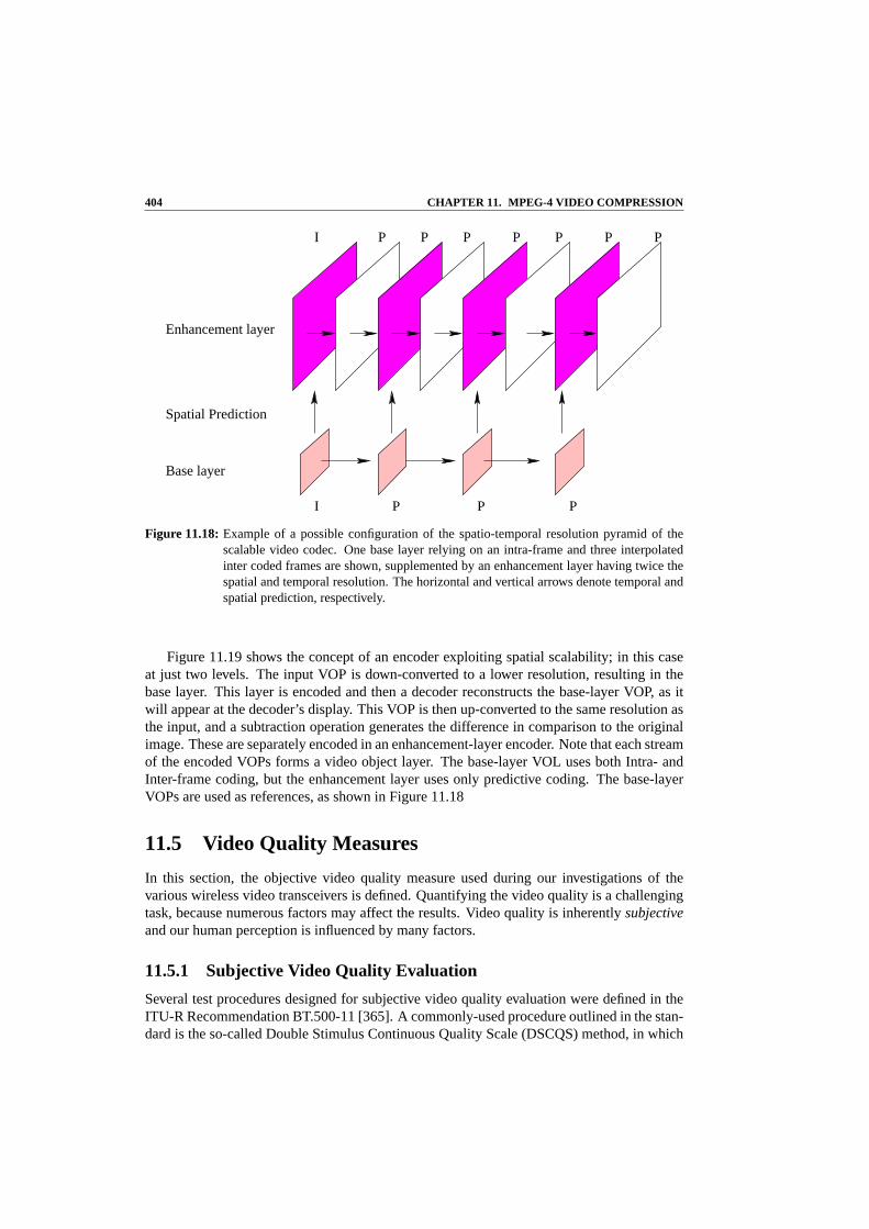
An example associated with two layers of scalability codingis shown in Figure 11.18. Theenhancement layers are encoded by a motion-compensated hybrid codec, where the DCT hasbeen replaced by lattice vector quantisation of the MCER. This approach leads to a codingefficiency attained by the layered coding scheme, which is comparable to that of single-layercodecs [344]. Since the ability to decode an enhancement layer depends on the reception ofthe base layer and lower enhancement layers, an efficient transmission scheme is expected toensure that these layers are transmitted such that the associated packet loss is kept as low aspossible even for high overall packet loss rates. In addition to the ability to adapt to differentclients we can also ensure a sufficiently graceful degradation of the associated video qualityin case of packet loss in this scenario.
As mentioned earlier, MPEG-4 provides both spatial and temporal scalability at the objectlevel [24,364]. In both of these scenarios this technique isinvoked for the sake of generating abase layer, representing the lowest quality to be supported by the bitstream, and one or moreenhancement layers. These layers may all be produced in a single encoding step. The scalingcan be implemented in two different ways. When there are knownbandwidth limitations, thedifferent-rate versions of the bitstream may be used that include only the base layer, or thebase layer plus lower-order enhancement layers. Alternatively, all layers may be transmittedand the scaling decision may be left for the decoder’s discission. If the display device at thereceiver side has a low resolution, or if the available computational resources are insufficientcapability, the enhancement layers may be ignored.
404 CHAPTER 11. MPEG-4 VIDEO COMPRESSION
I P P P P P P P
PI P P
Enhancement layer
Spatial Prediction
Base layer
Figure 11.18:Example of a possible configuration of the spatio-temporal resolution pyramid of thescalable video codec. One base layer relying on an intra-frame and three interpolatedinter coded frames are shown, supplemented by an enhancement layer having twice thespatial and temporal resolution. The horizontal and vertical arrows denote temporal andspatial prediction, respectively.
Figure 11.19 shows the concept of an encoder exploiting spatial scalability; in this caseat just two levels. The input VOP is down-converted to a lowerresolution, resulting in thebase layer. This layer is encoded and then a decoder reconstructs the base-layer VOP, as itwill appear at the decoder’s display. This VOP is then up-converted to the same resolution asthe input, and a subtraction operation generates the difference in comparison to the originalimage. These are separately encoded in an enhancement-layer encoder. Note that each streamof the encoded VOPs forms a video object layer. The base-layer VOL uses both Intra- andInter-frame coding, but the enhancement layer uses only predictive coding. The base-layerVOPs are used as references, as shown in Figure 11.18
11.5 Video Quality Measures
In this section, the objective video quality measure used during our investigations of thevarious wireless video transceivers is defined. Quantifying the video quality is a challengingtask, because numerous factors may affect the results. Video quality is inherentlysubjectiveand our human perception is influenced by many factors.
11.5.1 Subjective Video Quality Evaluation
Several test procedures designed for subjective video quality evaluation were defined in theITU-R Recommendation BT.500-11 [365]. A commonly-used procedure outlined in the stan-dard is the so-called Double Stimulus Continuous Quality Scale (DSCQS) method, in which

11.5. VIDEO QUALITY MEASURES 405
EnhancementLayer
Encoder
Multiplexer
VOLEnhancementUp−
Converter
Subtract
Down Converter
Base
EncoderLayer
BaseLayer
Decoder
Base Layer VOL
MultiplexedOutput
VOPsIn
Figure 11.19:Spatially scalable encoder for a single enhancement layer.
A or B
A or B
Source videosequence
Videoencoder
Videodecoder
Display
Figure 11.20:DSCQS testing system
406 CHAPTER 11. MPEG-4 VIDEO COMPRESSION
an assessor is presented with a pair of images or short video sequences A and B, one after theother, and is asked to assign both A and B a quality score on a continuous scale having fiveintervals ranging from ‘Excellent’ to ‘Bad’. In a typical test session, the assessor is shown aseries of pairs of sequences and is asked to grade each pair. Within each pair of sequences,one sequence is an unimpaired ‘reference’ sequence and the other is the same sequence, mod-ified by a system or process under test. Figure 11.20 shows an experimental set up for thetesting of a video codec, where the original sequence is compared to the same sequence afterencoding and decoding. Additionally, the order in which thesequence ’A’ and ’B’ are pre-sented randomly. The evaluation of subjective measures, such as the DSCQS measure is timeconsuming and expensive. Hence, contriving an objective video quality measure, which iscapable of reliably predicting the subjective quality is desirable.
11.5.2 Objective Video Quality
The designers and developers of video compression and processing systems rely heavily onobjective quality measures. The most widely used measure isthe Peak Signal to Noise Ra-tio (PSNR). The PSNR is measured on a logarithmic scale and depends on the normalisedmean squared error (MSE) between the original and the reconstructed as well as potentiallychannel-impaired image or video frame, relative to(2n − 1)2, namely normalised by thesquare of the highest possible pixel value in the image, where n is the number of bits perimage sample, yielding:
PSNR = 10log10(2n − 1)2
MSE. (11.1)
The PSNR may be conveniently calculated. However, its evaluation requires the avail-ability of the unimpaired original image or video signal forcomparison, which may not beavailable.
Unfortunately the PSNR defined above does not always constitute a reliable image qual-ity measure. For example, if the received image is shifted byone pixel compared to theoriginal image, the human eye would hardly notice any difference, while the PSNR objectivemeasures would indicate a more substantial degradation in quality.
Nonetheless, owing to its appealing implicity, in this thesis, the PSNR will be used as thepredominant image quality measure.
11.6 Effect of Coding Parameters
The previous sections described the MPEG-4 encoding and decoding process with the aidof block diagrams shown in Figures 11.14 and 11.15. In video compression, some of theencoding parameters seen in the context of Figures 11.14 and11.15 may directly affect theresultant reconstructed video quality. Therefore in this section, we will briefly demonstratehow these parameters may affect the encoded/decoded video quality.
The MPEG-4 source code used in our simulations was a modified version of the softwareimplementation provided by the Mobile Multimedia Systems (MoMuSys) Pan-European project.Simulations were carried out for the sake of characterisingthe achievable performance of theMPEG-4 codec. Most of our simulations used the popular “Akiyo”, “Miss America”, “Suzi”

11.6. EFFECT OF CODING PARAMETERS 407
or “Foreman” (144 × 176)-pixel resolution QCIF video sequence at a transmission framescanning rate of 10 or 30 frames/s. Additionally, the lengthof the video sequence used in oursimulations was 100 frames and apart from the first frame, no Intra-Frame coded update wasused, unless otherwise stated. Our results will be shown in graphical form in Figure 11.25 toFigure 11.28.
0 5 10 15 20 25 30Quantizer step size
30
32
34
36
38
40
42
44
46
48
50
Ave
rage
PS
NR
(dB
)
Figure 11.21:MPEG-4 average video quality (PSNR) versus quantiser step size ranging from 1 to 31using the (144 × 176)-pixel QCIF “Miss America” sequence.
Our investigations commenced by demonstrating the effect of the quantiser index em-ployed in the MPEG-4 encoder. In video compression, the quantisation operation is typicallyconstituted by a ‘forward quantiser’ in the encoder and an ‘inverse quantiser’ in the decoder.A critical parameter is the quantiser step size. If the step size is large, typically a highlycompressed bit stream is generated. However, the reconstructed values provide a crude ap-proximation of the original signal. If the step size is small, the reconstructed values matchthe original signal more closely at the cost of a reduced compression efficiency. The effectof different quantiser step sizes is demonstrated in Figure11.21 in terms of the video PSNR,while the associated subjective video quality is illustrated in Figure 11.22.
Let us now consider the effect of different bit-rates, although the effects of the video bit-rate and quantiser step size are highly correlated. In orderto achieve a given target bit-rate,the encoded video frame buffer is used for adjusting the quantiser step size. More explicitly,the encoder produces a variable-rate stream and the buffer may be emptied at a near-constanttransmission rate. If the encoder produces bits at a low rate, the buffer may become empty.

408 CHAPTER 11. MPEG-4 VIDEO COMPRESSION
Quantizer step size 1 Quantizer step size 5 Quantizer step size 15
Quantizer step size 20 Quantizer step size 25 Quantizer step size 31
Fine
Coarse
Figure 11.22:The effect of quantisation step size on the MPEG-4 encoder in the 2nd frame of the144x176 pixel QCIF “Miss America” sequence.
Variable−
BufferScale
factor fullnessRate
controller
Transmitbuffer
lengthcode
QuantizerDCT
Figure 11.23:Rate control in MPEG-4.
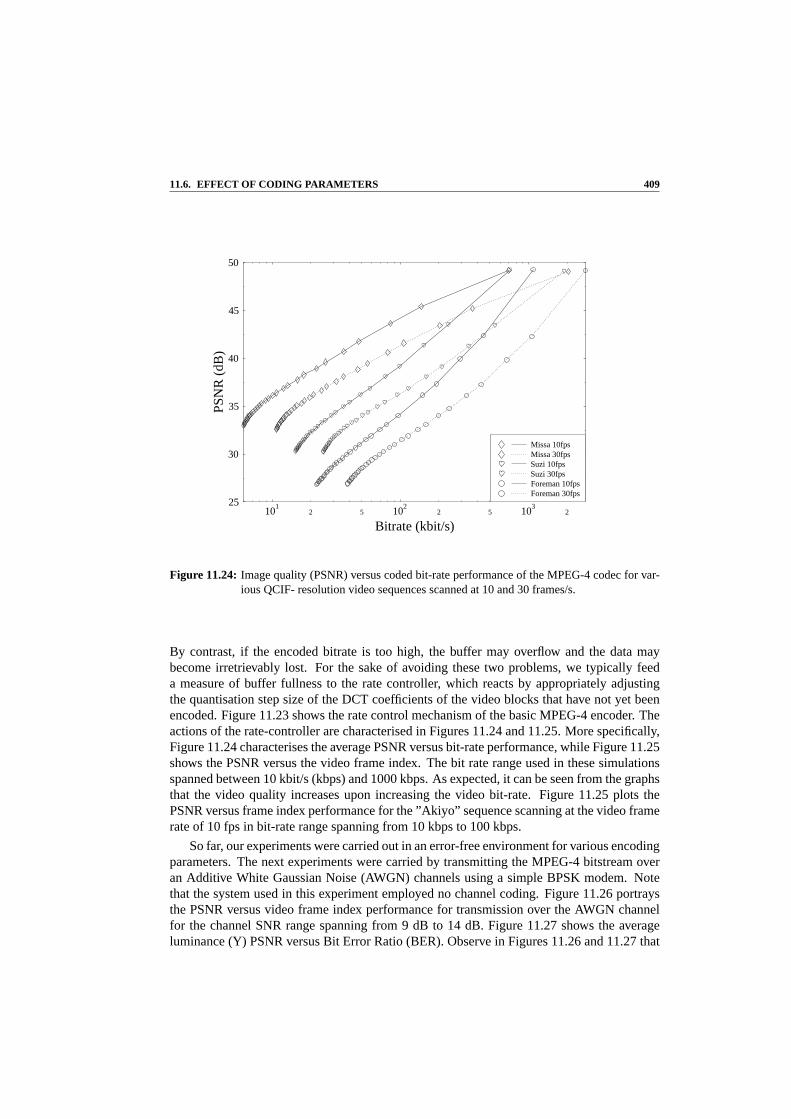
11.6. EFFECT OF CODING PARAMETERS 409
101
2 5 102
2 5 103
2
Bitrate (kbit/s)
25
30
35
40
45
50
PS
NR
(dB
)
Foreman 30fpsForeman 10fpsSuzi 30fpsSuzi 10fpsMissa 30fpsMissa 10fps
Figure 11.24: Image quality (PSNR) versus coded bit-rate performance of the MPEG-4 codec for var-ious QCIF- resolution video sequences scanned at 10 and 30 frames/s.
By contrast, if the encoded bitrate is too high, the buffer may overflow and the data maybecome irretrievably lost. For the sake of avoiding these two problems, we typically feeda measure of buffer fullness to the rate controller, which reacts by appropriately adjustingthe quantisation step size of the DCT coefficients of the video blocks that have not yet beenencoded. Figure 11.23 shows the rate control mechanism of the basic MPEG-4 encoder. Theactions of the rate-controller are characterised in Figures 11.24 and 11.25. More specifically,Figure 11.24 characterises the average PSNR versus bit-rate performance, while Figure 11.25shows the PSNR versus the video frame index. The bit rate range used in these simulationsspanned between 10 kbit/s (kbps) and 1000 kbps. As expected,it can be seen from the graphsthat the video quality increases upon increasing the video bit-rate. Figure 11.25 plots thePSNR versus frame index performance for the ”Akiyo” sequence scanning at the video framerate of 10 fps in bit-rate range spanning from 10 kbps to 100 kbps.
So far, our experiments were carried out in an error-free environment for various encodingparameters. The next experiments were carried by transmitting the MPEG-4 bitstream overan Additive White Gaussian Noise (AWGN) channels using a simple BPSK modem. Notethat the system used in this experiment employed no channel coding. Figure 11.26 portraysthe PSNR versus video frame index performance for transmission over the AWGN channelfor the channel SNR range spanning from 9 dB to 14 dB. Figure 11.27 shows the averageluminance (Y) PSNR versus Bit Error Ratio (BER). Observe in Figures 11.26 and 11.27 that

410 CHAPTER 11. MPEG-4 VIDEO COMPRESSION
0 10 20 30 40 50 60 70 80 90 100Frame Index
20
25
30
35
40
45
PS
NR
(dB
)
MP4 AKIYO: PSNR vs. Frame Index
40kbps30kbps20kbps10kbps
100kbps90kbps70kbps50kbps
Figure 11.25:MPEG-4 video quality (PSNR) versus frame index performance for thebit rate rangespanning from 10kbps to 100kbps using the (144x176)-pixel QCIF “Akiyo” sequence.
as expected, the decoded picture quality increases as the channel SNR increases. At lowchannel SNRs, the channel inflicts a high BER, hence the decoded video frame sequence willbe highly degraded. This is demonstrated in Figure 11.29. Viewing the codec’s performancefrom a different perspective, Figure 11.28 shows the average PSNR degradation versus BER.
11.7 Summary and Conclusion
In Section 11.1, we commenced our discourse by a brief historical perspective on the de-velopment of the MPEG-4 visual standard, the MPEG-4 visual profiles and features. Theseinclude the diverse set of coding tools described in the standard that are capable of supportinga wide range of applications, such as efficient coding of video frames, video coding for error-prone transmission networks, object-based coding and manipulation, as well as the interactivevisual applications.
In Section 11.3, we introduced the MPEG-4 visual encoding standard that supports anobject-based representation of the video sequence. This allows convenient access to andmanipulation of arbitrarily shaped regions in the frames ofthe video sequence.
Scalable coding is another of the feature supported by the MPEG-4 codec. Scalability issupported in terms of generating several layers of information. In addition to the base layer,enhancement layers may be decoded, which will improve the resultant image quality either

11.7. SUMMARY AND CONCLUSION 411
0 10 20 30 40 50 60 70 80 90 100Frame Index
0
5
10
15
20
25
30
35
40
45
PS
NR
(dB
)MP4 AKIYO: PSNR vs. Frame Index
Error freeSNR=14SNR=13SNR=12SNR=11SNR=10SNR=9
Figure 11.26:Decoded video quality (PSNR) versus frame index when transmitting overan AWGNchannel using a BPSK modem. These results were recorded for the ’Akiyo’ video se-quence at a resolution of (144x176)-pixels and 100kbps video bitrate.The 81st decodedvideo frame was shown in Figure 11.29
in terms of the achievable temporal or spatial resolution.In Section 11.5 the PSNR objective measure was introduced for quantifying the video
quality. Finally, the effect of certain important video encoding parameters were discussed inSection 11.6, commencing with an emphasis on thequantiser step sizeparameter, which alsoaffects the resultant videotarget bitrate.
The specifications of MPEG-4 standard continue to evolve with the addition of new tools,such as the recently introduced profile supporting video streaming [24]. However, amongstdevelopers and manufacturers, the most popular elements ofthe MPEG-4 Visual standard todate have been the simple and the advanced simple profile tools, which were summarised inTable 11.1. Having studied the MPEG-4 codec, let us know focus our attention on one itrelative, namely on the H.264 [26] codec in the next Chapter.

412 CHAPTER 11. MPEG-4 VIDEO COMPRESSION
10-7
10-6
10-5
10-4
10-3
10-2
BER
15
20
25
30
35
40
45
50
Ave
rage
PS
NR
(dB
)
MP4 AKIYO: Average PSNR vs. BER
Luminance (Y)
Figure 11.27:Average video quality (PSNR) versus BER for transmission over an AWGN channelusing BPSK modulation and the (144x176)-pixel QCIF ’Akiyo’ sequence.

11.7. SUMMARY AND CONCLUSION 413
10-6
2 5 10-5
2 5 10-4
2 5 10-3
2 5 10-2
BER
0
5
10
15
20
25
PS
NR
degr
adat
ion(
dB)
MP4 AKIYO: PSNR degradation vs. BER
Figure 11.28:Decoded video quality degradation in terms of PSNR versus Bit Error Rate(BER) fortransmission over an AWGN channel using BPSK modulation due to corruption of theMPEG-4 bit stream during transmission. The results were recorded forthe QCIF reso-lution “Akiyo” video sequence.

414 CHAPTER 11. MPEG-4 VIDEO COMPRESSION
SNR = 9dB SNR = 10dB SNR = 11dB
SNR = 12dB SNR = 13dB SNR = 14dB
Figure 11.29: Image degradation due to corruption of the MPEG-4 bitstream over AWGN channelsusing a BPSK modem in the 81st frame of the (144x176)-pixel QCIF “Akiyo” sequence.The BER within this frame at the above SNRs were between10−7 to 10−3 respectively,while the PSNR ranged from 41.74dB to 19.27dB.

Chapter 12HSDPA-Like and Turbo-StyleAdaptive Single- andMulti-Carrier Video Systems
P.J. Cherriman, J-Y. Chung, L. Hanzo, T. Keller, E-L. Kuan,C.S. Lee, R. Maunder, S.X. Ng, S. Vlahoyiannatos, J. Wang,B.L. Yeap
12.1 Turbo-Equalized H.263-BasedVideophony for GSM/GPRS1 2
12.1.1 Motivation and Background
The operational second-generation (2G) wireless systems [389] constitute a mature technol-ogy. In the context of 2G systems, and, with the advent of videotelephony, attractive value-added services can be offered to a plethora of existing users. Although the 2G systems havenot been designed with video communications in mind, with the aid of the specially designederror-resilient, fixed-rate video codecs proposed in Chapters 3–5 it is nonetheless realistic toprovide videophone services over these low-rate schemes. Specifically, in this chapter wedesigned a suite of fixed-rate, proprietary video codecs capable of operating at a video scan-ning or refreshment rate of 10 frames/s over an additional speech channel of the 2G systems.These video codecs were capable of maintaining sufficientlylow bit rates for the provision ofvideophony over an additional speech channel in the contextof the operational 2G wirelesssystems [389] provided that low-dynamic head-and-shoulders video sequences of the 176×
1This section is based onP. Cherriman, B. L. Yeap, and L. Hanzo: Turbo-Equalised H.263-based video tele-phony for GSM/GPRS; submitted to IEEE Tr. on CSVT, 2000.
2 c©2000 IEEE. Personal use of this material is permitted. However, permission to reprint/republish this materialfor advertising or promotional purposes or for creating new collective works for resale or redistribution to servers orlists, or to reuse any copyrighted component of this work in other works, must be obtained from IEEE.
415

416 CHAPTER 12. TURBO-STYLE AND HSDPA-LIKE ADAPTIVE VIDEO SYSTE MS
Simulation Parameters
Channel model COST-207 hilly terrainCarrier frequency 900 MHzVehicular speed 30 mphDoppler frequency 40.3 HzModulation GMSK, Bn = 0.3Channel coding Convol.(n,k,K) = (2,1,5)Octal generator polynomials 23, 33Channel interleavers Random (232, 928)Turbo-coding interleavers Random (116, 464)Max turbo-equalizer iterations 10No. of TDMA frame per packet 2No. of slots per TDMA frame 1, 4Convolutional decoder algorithm LOG-MAPEqualizer algorithm LOG-MAP
Table 12.1:System parameters
144-pixel Quarter Common Intermediate Format (QCIF) or 128× 96-pixel sub-QCIF videoresolution are employed. We note, however, that for high-dynamic sequences the 32 kbpstypical speech bit rate of the cordless telephone systems [389], such as the Japanese PHS, theDigital European Cordless Telephone (DECT), or the BritishCT2 system, is more adequatein terms of video quality. Furthermore, the proposed programmable video codecs are capa-ble of multirate operation in the third generation (3G) Universal Mobile TelecommunicationsSystem (UMTS) or in the IMT2000 and cdma2000 systems, which were summarized in [82].
Chapters 3–5 used constant video rate proprietary video codecs and reconfigureable Quadra-ture Amplitude Modulation (QAM)-based [390] transceivers. In this chapter we advocateconstant-envelope Gaussian Minimum Shift Keying (GMSK) [389]. Specifically, we inves-tigated the feasibility of H.263-based videotelephony in the context of an enhanced turbo-equalized GSM-like system, which can rely on power-efficient class-C amplification. The as-sociated speech compression and transmission aspects are beyond the scope of this book [391].
The outline of this section is as follows. Section 12.1.2 summarizes the associated systemparameters and system’s schematic, while Section 12.1.3 provides a brief overview of turboequalization. Section 12.1.4 characterizes the system both in terms of turbo equalizationperformance and video performance. Lastly, Section 12.1.5provides our conclusions. Let usnow consider the outline of the system.
12.1.2 System Parameters
The associated video system parameters for the GSM system are summarized in Table 12.1,and the system’s schematic is portrayed in Figure 12.1. An advanced feature of the systemis its employment of joint channel decoding and channel equalization, which is referred to asturbo equalization. The fundamental principles and motivation for using turbo equalizationare described in Section 12.1.3.
The system uses the GSM frame structure of Chapter 8 in [389] and the COST-207 HillyTerrain (HT) channel model, whose impulse response is shownin Figure 12.2. Each trans-
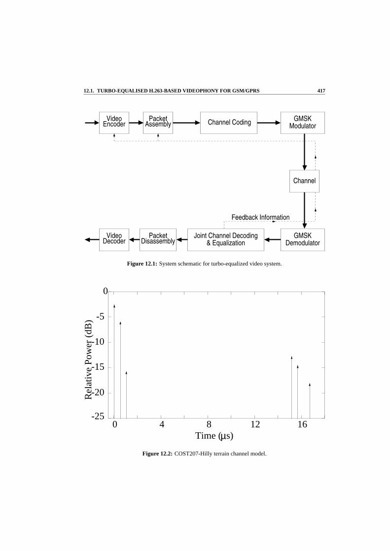
12.1. TURBO-EQUALISED H.263-BASED VIDEOPHONY FOR GSM/GPRS 417
VideoEncoder Assembly
Packet
DisassemblyPacketVideo
DecoderGMSK
Demodulator
GMSKModulator
Channel
Channel Coding
Feedback Information
Joint Channel Decoding& Equalization
Figure 12.1: System schematic for turbo-equalized video system.
0
Rel
ativ
e P
ower
(dB
) -5
-15
-10
-20
-250 4 8 12 16
Time ( s)µ
Figure 12.2: COST207-Hilly terrain channel model.

418 CHAPTER 12. TURBO-STYLE AND HSDPA-LIKE ADAPTIVE VIDEO SYSTE MS
Bit rates, etc.Slots/TDMA frame 1 4
Coded bits/TDMA slot 116 116Data bits/TDMA slot 58 58Data bits/TDMA frame 58 232TDMA frame/packet 2 2Data bits/packet 116 464Packet header (bits) 8 10CRC (bits) 16 16Video bits/packet 92 438TDMA frame length 4.615 ms 4.615 msTDMA frames/s 216.68 216.68Video packets per sec 108.34 108.34Video bit rate (kbps) 10.0 47.5Video frame rate (fps) 10 10
Table 12.2:Summary of System-Specific Bit Rates
mitted packet is interleaved over two GSM TDMA frames in order to disperse bursty errors.The GPRS system allows the employment of multiple time-slots per user. We studied
both a GSM-like system using 1 slot per TDMA frame and a GPRS-like arrangement withfour slots per TDMA frame. In this scenario, the user is assigned half the maximum capacityof an eight-slot GPRS/GSM carrier. The bit rates associatedwith one and four slots perTDMA frame are shown in Table 12.2.
The effective video bit rates that can be obtained in conjunction with half-rate convolu-tional coding are 10 and 47.5 Kbit/s for the one and four slotsper TDMA frame scenario,respectively. Again, the system’s schematic is shown in Figure 12.1. The basic prerequisitefor the duplex video system’s operation (as seen in Figure 12.1) is use of the channel de-coder’s output is used for assessing whether the received packet contains any transmissionerrors. If it does, the remote transmitter is instructed (bysuperimposing a strongly protectedpacket acknowledgment flag on the reverse-direction message) to drop the correspondingvideo packet following the philosophy of [392]. This prevents the local and remote videoreconstructed frame buffers from being contaminated by channel errors.
12.1.3 Turbo Equalization
Turbo equalization [393] was proposed by Douillard, Picart, Jezequel, Didier, Berrou, andGlavieux in 1995 for a serially concatenated rateR = 1
2 , convolutional-coded Binary PhaseShift Keying (BPSK) system. Specifically, Douillardet al. demonstrated that the turbo equal-izer could mitigate the effects of intersymbol interference (ISI), provided that the channel im-pulse response (CIR) is known. Instead of performing the equalization and error correctiondecoding independently, better performance can be achieved by considering the channel’smemory, when performing joint equalization and decoding iteratively. Gertsman and Lod-ge [394] then showed that the iterative process of turbo equalizers can compensate for thedegradations caused by imperfect channel estimation. In the context of noncoherent detec-tion, Marslandet al. [395] demonstrated that turbo equalization offered betterperformance

12.1. TURBO-EQUALISED H.263-BASED VIDEOPHONY FOR GSM/GPRS 419
InterleaverChannel
Channel
DeinterleaverChannelOutput
SISO Equaliser SISO Conv Decoder
Figure 12.3: Structure of original turbo equalizer introduced by Douillardet al. [393].
than Dai’s and Shwedyk’s noncoherent, hard-decision-based receiver using a bank of Kalmanfilters [396]. Different iteration termination criteria [397], such as cross-entropy [398], werealso investigated in order to minimize the number of iteration steps for the turbo equalizer.A turbo-equalization scheme for the Global System of MobileCommunications (GSM) wasalso proposed by Bauch and Franz [399], who investigated different approaches for overcom-ing the dispersion of thea priori information due to the interburst interleaving scheme usedin GSM. Further research into combined turbo coding using convolutional constituent codesand turbo equalization has been conducted by Raphaeli and Zarai [400].
The basic philosophy of the original turbo-equalization technique derives from the iter-ative turbo-decoding algorithm consisting of two Soft-In/Soft-Out (SISO) decoders. Thisstructure was proposed by Berrouet al. [401,402]. Before proceeding with our in-depth dis-cussion, let us briefly define the termsa priori, a posteriori, and extrinsic information, whichwe employ throughout this section.
A priori Thea priori information associated with a bitvm is the information known beforeequalization or decoding commences, from a source other than the received sequenceor the code constraints.A priori information is also often referred to as intrinsic infor-mation to contrast it with extrinsic information.
Extrinsic The extrinsic information associated with a bitvm is the information provided bythe equalizer or decoder based on the received sequence and on thea priori informationof all bits with the exception of the received anda priori information explicitly relatedto that particular bitvm.
A posteriori The a posteriori information associated with a bit is the information that theSISO algorithm provides taking into account all available sources of information aboutthe bituk.
The turbo equalizer of Figure 12.3 consists of a SISO equalizer and a SISO decoder. TheSISO equalizer in the figure generates thea posterioriprobability upon receiving the cor-rupted transmitted signal sequence and thea priori probability provided by the SISO decoder.However, at the initial iteration stages (i.e., at the first turbo-equalization iteration) noa prioriinformation is supplied by the channel decoder. Therefore,thea priori probability is set to12 , since the transmitted bits are assumed to be equiprobable.Before passing thea posteriori

420 CHAPTER 12. TURBO-STYLE AND HSDPA-LIKE ADAPTIVE VIDEO SYSTE MS
information generated by the SISO equalizer to the SISO decoder of Figure 12.3, the contri-bution of the decoder in the form of —a priori information — accruing from the previousiteration must be removed in order to yield the combined channel and extrinsic information.This also minimizes the correlation between thea priori information supplied by the decoderand thea posteriori information generated by the equalizer. The term “combinedchanneland extrinsic information” indicates that they are inherently linked. In fact, they are typicallyinduced by mechanisms, which exhibit memory. Hence, they cannot be separated. The re-moval of thea priori information is necessary, to prevent the decoder from “reprocessing” itsown information, which would result in the positive feedback phenomenon, overwhelmingthe decoder’s current reliability-estimation of the codedbits, that is, the extrinsic information.
The combined channel and extrinsic information is channel-deinterleaved and directedto the SISO decoder, as depicted in Figure 12.3. Subsequently, the SISO decoder computesthe a posterioriprobability of the coded bits. Note that the latter steps aredifferent fromthose in turbo decoding, which only produces thea posterioriprobability of the source bitsrather than those of all channel-coded bits. The combined deinterleaved channel and extrinsicinformation are then removed from thea posteriori information provided by the decoder inFigure 12.3 before channel interleaving in order to yield the extrinsic information. This ap-proach prevents the channel equalizer from receiving information based on its own decisions,which was generated in the previous turbo-equalization iteration. The extrinsic informationcomputed is then employed as thea priori input information of the equalizer in the next chan-nel equalization process. This constitutes the first turbo-equalization iteration. The iterativeprocess is repeated until the required termination criteria are met [397]. At this stage, theaposterioriinformation of the source bits, which has been generated by the decoder, is utilizedto estimate the transmitted bits.
Recent work by Narayanan and Stuber [403] demonstrates the advantage of employingturbo equalization in the context of coded systems invokingrecursive modulators, such asDifferential Phase Shift Keying (DPSK). Narayanan and Stuber emphasized the importanceof a recursive modulator and show that high-iteration gainscan be achieved, even when thereis no ISI in the channel (i.e., for transmission over the nondispersive Gaussian channel). Theadvantages of turbo equalization as well as the importance of a recursive modulator moti-vated our research on turbo equalization of coded partial response GMSK systems [389],since GMSK is also recursive in its nature. In our investigations, we have employed con-volutional coding for the proposed turbo-equalized GSM-like video system as it has beenshown in reference [404] that convolutional-coded GMSK systems are capable of providinglarge iteration gains — that is, gains in SNR performance with respect to the first iteration —with successive turbo-equalization iterations. We also observed that the convolutional-codedGMSK system employing turbo equalization outperformed theconvolutional-coding basedturbo-coded GMSK scheme, as demonstrated by Figure 12.4. Specifically, over a nondisper-sive Gaussian channel the convolutional-coded GMSK systemhad an approximately 0.8 dBbetterEb/No performance than the corresponding convolutional-codingbased turbo-codedGMSK scheme atBER = 10−4. Although not explicitly shown here, similar findings werevalid for dispersive Rayleigh-fading channels, where the advantage of the convolutional-coded system over the convolutional-coding-based turbo-coded scheme was approximately1.0 dB.
These results were surprising since the more complex turbo-coded system was expectedto form a more powerful encoded system compared to the convolutional-coded scheme. Be-

12.1. TURBO-EQUALISED H.263-BASED VIDEOPHONY FOR GSM/GPRS 421
0 1 2 3 4 5 6 7 8 9Eb/No(dB)
10-1
10-2
10-3
10-4
10-5
BE
R ConvTurbo-convItr=8Itr=4Itr=2Itr=1
Figure 12.4: Comparison of theR = 0.5 convolutional-coded GMSK system withR = 0.5convolutional-coding-based turbo-coded GMSK scheme, transmitting over the nondis-persive Gaussian channel employing convolutional and turbo-coding-based turbo equal-ization, which performs eight turbo equalization iterations at the receiver.
low, we offer an interpretation of this phenomenon by considering the performance of bothcodes after the first turbo-equalization iteration. Specifically, over the nondispersive Gaus-sian channel in Figure 12.4, the convolutional-coded scheme yielded a lower BER than thatof the turbo-coded system atEb/No values below 4.5 dB, indicating that thea posterioriLLRs of the bits produced by the convolutional decoder had a higher reliability than that ofthe corresponding turbo-coded scheme. Consequently, uponreceiving the higher-confidenceLLR values from the decoder, the equalizer in the convolutional-coded scheme was capableof producing significantly more reliable LLR values in the subsequent turbo-equalization it-eration, when compared to the turbo-coded system. After receiving these more reliable LLRvalues, the decoder of the convolutional-coded system willgenerate even more reliable LLRvalues. Hence, the convolutional-coded system outperformed the turbo-coded scheme af-ter performing eight turbo-equalization iterations. Motivated by these trends — which werealso confirmed in the context of dispersive Rayleigh-fadingchannels [404] — we opted for aconvolutional-coded rather than turbo-coded GSM-like videophone system, which employsturbo equalization in order to enhance the video performance of the system.

422 CHAPTER 12. TURBO-STYLE AND HSDPA-LIKE ADAPTIVE VIDEO SYSTE MS
$RCSfile: logber-vs-csnr-withbe-1+4slot-1+2+10iter-coded.gle,v $ $Date: 1999/12/20 14:33:25 $
0 2 4 6 8 10 12 14Channel SNR (dB)
10-6
10-5
10-4
10-3
10-2
10-1
100
Bit
Err
orR
atio
1 Iteration2 Iterations10 Iterations
coded 1-slot = 10.0 kbpscoded 4-slot = 47.5 kbpsTurbo-Equalized GSM-like
Figure 12.5: BER versus channel SNR for one and four slots per TDMA frame, andfor 1, 2, and 10turbo-equalizer iterations, over the channel of Figure 12.2.
12.1.4 Turbo-equalization Performance
Let us now characterize the performance of our video system.Figure 12.5 shows the biterror ratio (BER) versus channel SNR for the one- and four-slot scenarios, after one, two andten iterations of the turbo equalizer. The figure shows the BER performance improvementupon each iteration of the turbo equalizer, although there is only a limited extra performanceimprovement after five iterations. The figure also shows thatthe four-slot scenario has a lowerbit error ratio than the one-slot scenario. This is because the four-slot scenario has a longerinterleaver, which renders the turbo-equalization process more effective due to its increasedtime diversity.
Let us now consider the associated packet-loss ratio (PLR) versus channel SNR perfor-mance in Figure 12.6. The PLR is a more pertinent measure of the expected video perfor-mance, since — based on the philosophy of [392] and on the previous two chapters — ourvideo scheme discards all video packets, which are not error-free. Hence, our goal is to main-tain as low a PLR as possible. Observe in Figure 12.6 that the associated iteration gains aremore pronounced in terms of the packet-loss ratio than in biterror ratio.
It should also be noted that for low SNRs the packet-loss performance of the four-slotsystem is inferior to that of the one-slot system, while the bit error ratio is similar or betterat the same SNRs. This is because the probability of having a single-bit error in the four-slotvideo packet is higher due to its quadruple length. This phenomenon is further detailed inSection 12.1.4.2.

12.1. TURBO-EQUALISED H.263-BASED VIDEOPHONY FOR GSM/GPRS 423
$RCSfile: logplr-vs-csnr-withbe-1+4slot-1+2+10iter-coded.gle,v $ $Date: 2000/09/29 15:10:53 $
0 2 4 6 8 10 12 14 16 18 20Channel SNR (dB)
5
10-3
2
5
10-2
2
5
10-1
2
5
100
Pac
ket-
loss
Rat
io
1 Iteration2 Iterations10 Iterations
coded 1-slot = 10.0 kbpscoded 4-slot = 47.5 kbpsTurbo-Equalized GSM-like
Figure 12.6: Video packet-loss ratio versus channel SNR for one and four slots perTDMA frame,and for 1, 2, and 10 turbo-equalizer iterations, over the channel of Figure 12.2 usingconvolutional coding.
12.1.4.1 Video Performance
The PLR performance is directly related to the video qualityof our video system. Figure 12.7shows the associated average PSNR versus channel SNR performance, demonstrating thatan improved video quality can be maintained at lower SNRs as the number of iterationsincreases. In addition, the higher bit rate of the four-slotsystem corresponds to a higheroverall video quality. Up to 6 dB SNR-gain can be achieved after 10 turbo-equalizationiterations, as seen in Figure 12.7.
Figure 12.7 characterizes the performance of the highly motion-active “Carphone” se-quence. However, the performance improvements are similarfor the low-activity “MissAmerica” video sequence, as seen in Figure 12.8. Observe that the lower-activity “MissAmerica” video sequence is represented at a higher video quality at the same video bit rate.A deeper insight into the achievable video-quality improvement in conjunction with turboequalization can be provided by plotting the video quality measured in PSNR (dB) versustime, as seen in Figure 12.9 for the “Miss America” video sequence using the four-slot sys-tem at a channel SNR of 6 dB for one, two, and ten iterations of the turbo equalizer.
Specifically, the bottom-trace of the figure shows how the video quality varies in the one-iteration scenario, which is equivalent to conventional equalization. The sudden reductions

424 CHAPTER 12. TURBO-STYLE AND HSDPA-LIKE ADAPTIVE VIDEO SYSTE MS
$RCSfile: psnr-vs-csnr-carphone-1+4slot-1+2+10iter-coded.gle,v $ $Date: 2000/09/29 16:01:02 $
0 2 4 6 8 10 12 14 16 18 20Channel SNR (dB)
20
22
24
26
28
30
32
Ave
rage
PS
NR
(dB
)
1 Iteration2 Iterations10 Iterations
coded 1-slot = 10.0 kbpscoded 4-slot = 47.5 kbpsQCIF CarphoneTurbo-Equalized GSM-like
Figure 12.7: Video quality in PSNR (dB) versus channel SNR for one and four slots per TDMA frame,and for 1, 2, and 10 iterations of the turbo-equalizer upon using the highlymotion active“Carphone” video sequence over the channel of Figure 12.2 using convolutional coding.
in video quality are caused by packet-loss events, which result in parts of the picture being“frozen” for one or possibly several consecutive video frames. The sudden increases in videoquality are achieved when the system updates the “frozen” part of the video picture in subse-quent video frames. The packet-loss ratio for this scenariowas 10% at the stipulated SNR of6dB.
The video quality improved significantly with the aid of two turbo-equalizer iterations,while the packet-loss ratio was reduced from 10% to 0.7%. In the time interval shown inFigure 12.9, there are eight lost video packets, six of whichcan be seen as sudden reductionsin video quality. However, in each case the video quality recovered with the update of the“frozen” picture areas in the next video frame.
We have found that the maximum acceptable PSNR video-quality degradation with re-spect to the perfect-channel scenario was about 1 dB, which was associated with nearly unim-paired video quality. In Table 12.3 we tabulated the corresponding minimum required channelSNRs that the system can operate at for a variety of scenarios, extracted from Figure 12.7.As the table shows, the minimum operating channel SNR for theone- and four-slot systemusing one iteration is 9 dB and 7.5 dB, respectively. This corresponds to a system usingconventional equalization. A system using two turbo-equalization iterations can reduce theseoperating SNRs to 7.2 dB and 5.2 dB, respectively. The minimum operating SNRs can be

12.1. TURBO-EQUALISED H.263-BASED VIDEOPHONY FOR GSM/GPRS 425
$RCSfile: psnr-vs-csnr-missa-1+4slot-1+2+10iter-coded.gle,v $ $Date: 2000/09/29 16:03:44 $
0 2 4 6 8 10 12 14 16 18 20Channel SNR (dB)
28
30
32
34
36
38
40
42A
vera
geP
SN
R(d
B)
1 Iteration2 Iterations10 Iterations
coded 1-slot = 10.0 kbpscoded 4-slot = 47.5 kbpsQCIF Miss AmericaTurbo-Equalized GSM-like
Figure 12.8: Video quality in PSNR (dB) versus channel SNR for one and four slots per TDMA frame,and for 1, 2, and 10 turbo-equalizer iterations, using the low-activity “Miss America”video sequence over the channel of Figure 12.2 using convolutional coding.
$RCSfile: psnr-vs-time-car-4slot-teq-1+2+10itercod.gle,v $ $Date: 2000/09/29 16:07:21 $
0 2 4 6 8 10Time (s)
26
28
30
32
34
36
38
40
42
PS
NR
(dB
)
1 Iteration2 Iterations10 IterationsTurbo-Equalized GSM-like, 6dB SNRQCIF Miss America, coded 4-slot = 47.5 kbps
Figure 12.9: Video quality in PSNR (dB) versus time using four slots per TDMA frame, and for 1,2, and 10 iterations of the turbo-equalizer for the low-activity “Miss America” video se-quence using convolutional coding.

426 CHAPTER 12. TURBO-STYLE AND HSDPA-LIKE ADAPTIVE VIDEO SYSTE MS
Channel SNR for 1 dB Loss of PSNRSlots/TDMA Frame 1 4
1 Iteration 9.0 dB 7.5 dB2 Iterations 7.2 dB 5.2 dB3 Iterations 6.44 dB 3.9 dB4 Iterations 6.37 dB 3.7 dB10 Iterations 5.8 dB 3.4 dB
Table 12.3:Minimum Required Operating Channel SNR for the QCIF “Carphone” Sequence over theChannel of Figure 12.2
reduced to as low as 5.8 dB and 3.4 dB for the one- and four-slotsystems, respectively, wheninvoking ten iterations.
12.1.4.2 Bit Error Statistics
In order to demonstrate the benefits of turbo equalization more explicitly, we investigated themechanism of how turbo equalization reduces the bit error and packet-loss ratios. We foundthat the distribution of the bit errors in video packets after each iteration provided interestinginsights. Hence, the CDF of the number of bit errors per videopacket was evaluated. In orderto allow a fair comparison between the one- and four-slot system, we normalized the numberof bit errors per packet to the video packet size, thereby producing the CDF of “in-packet”BER.
Figure 12.10 shows the CDF of the “in-packet” BER for a channel SNR of 2 dB and forone, two, five, and ten iterations for both the one- and four-slot systems. The value of theCDF for an “in-packet” BER of zero is the probability that a packet is error-free and so canbe interpreted as the packet success ratio (PSR). The packet-loss ratio is equal to 1 minus thePSR. For example, the four-slot system in Figure 12.10 at oneiteration has a packet successratio of 0.22, which corresponds to a packet-loss ratio of 78%.
Both the one- and four-slot systems increase the PSR as the number of iterations in-creases. For example, the four-slot system increases the PSR from 22% to 92% as the numberof iterations is increased from one to ten. This correspondsto a reduction in the packet-lossratio from 78% to 8%. However, the CDF of “in-packet” BER can provide further insightinto the system’s operation. It can be seen in Figure 12.10 that the turbo-equalizer itera-tions reduce the number of packets having “in-packet” BERs of less than 30%. However, theprobability of a packet having an “in-packet” BER higher than 35% is hardly affected by thenumber of iterations, since the number of bit errors is excessive, hence overwhelming eventhe powerful turbo equalization.
Figures 12.5 and 12.6, show that the four-slot system alwayshas a lower BER than theone-slot system, although at low SNRs the PLR is higher for the four-slot system. The CDFin Figure 12.10 can assist in interpreting this further. TheCDF shows that the PSR improvesmore significantly for the four-slot system than for the one-slot system as the number ofiterations increases. This is because the four-slot systemallows the employment of a longerinterleaver, thereby improving the efficiency of the turbo equalizer. However, the CDF alsounderlines a reason for the lower BER of the four-slot systemacross the whole range of SNRs,demonstrating that the probability of packets having a high“in-packet” bit error rate is lower

12.1. TURBO-EQUALISED H.263-BASED VIDEOPHONY FOR GSM/GPRS 427
$RCSfile: teq-coded-1vs4slot-2db-for-iter-cdf.gle,v $ $Date: 2001/01/11 16:05:30 $
0.0 0.1 0.2 0.3 0.4 0.5 0.6 0.7In-packet Bit Error Ratio
0.2
0.3
0.4
0.5
0.6
0.7
0.8
0.9
1.0
Pro
babi
lity
that
In-p
acke
tB
ER
<=
absc
issa
(CD
F)
4-slot @ 47.5kbps1-slot @ 10kbps1 Iteration2 Iterations5 Iterations10 Iterations
SNR=2dBTurbo-Equalized GSM-like
Figure 12.10:CDF of the “in-packet” BER at a channel SNR of 2 dB over the channel of Figure 12.2,and for various numbers of iterations for the turbo-equalized one- andfour-slot systemsusing convolutional coding.
for the four-slot system. Since packets having a high “in-packet” BER have a more graveeffect on the overall BER than those packets having a low “in-packet” BER, this explains theinferior overall BER performance of the one-slot system.
Figure 12.11 shows the CDF of “in-packet” BER for conventional equalization and withthe aid of ten turbo-equalizer iterations for 0 dB, 2 dB, and 4dB channel SNRs. Figure 12.11(a)represents a one-slot system, and Figure 12.11(b) a four-slot system. The figures also showthe packet-loss ratio performance improvement with the aidof turbo equalization.
12.1.5 Summary and Conclusions
In this section the performance of turbo-equalized GSM/GPRS-like videophone transceiverswas studied over dispersive fading channels as a function ofthe number of turbo-equalizationiterations. Iteration gains in excess of 4 dB were attained,although the highest per itera-tion gain was achieved for iteration indices below 5. As expected, the longer the associatedinterleaver, the better the BER and PLR performance. In contrast to our expectations, theturbo-coded, turbo-equalized system was outperformed by the less complex convolutionalcoded turbo-equalized system. In conclusion, GPRS/GSM areamenable to videotelephony,and turbo equalization is a powerful means of improving the system’s performance. Our fu-

428 CHAPTER 12. TURBO-STYLE AND HSDPA-LIKE ADAPTIVE VIDEO SYSTE MS
$RCSfile: teq-coded-norm-1slot-for-iter+snr.gle,v $ $Date: 2000/09/29 17:09:43 $
0.0 0.1 0.2 0.3 0.4 0.5 0.6 0.7In-packet bit error ratio
0.0
0.1
0.2
0.3
0.4
0.5
0.6
0.7
0.8
0.9
1.0
Pro
babi
lity
that
In-p
acke
tB
ER
<=
absc
issa
(CD
F)
SNR=0dBSNR=2BSNR=4dB1 Iteration10 Iterations
coded 1-slot, 10.0 kbpsTurbo-Equalized GSM-like
(a) 1-slot
$RCSfile: teq-coded-norm-4slot-for-iter+snr.gle,v $ $Date: 2000/09/29 17:09:43 $
0.0 0.1 0.2 0.3 0.4 0.5 0.6 0.7In-packet bit error ratio
0.0
0.1
0.2
0.3
0.4
0.5
0.6
0.7
0.8
0.9
1.0
Pro
babi
lity
that
In-p
acke
tB
ER
<=
absc
issa
(CD
F)
SNR=0dBSNR=2BSNR=4dB1 Iteration10 Iterations
coded 4-slot, 47.5 kbpsTurbo-Equalized GSM-like
(b) 4-slot
Figure 12.11:CDF of “in-packet” BER performance over the channel of Figure 12.2 for the turbo-equalized one- and four-slot system for channel SNRs of 0 dB, 2 dB,and 4 dB and 1 and10 iterations using convolutional coding.
ture work will improve the system’s performance invoking the forthcoming MPEG4 videocodec, using space-time coding and burst-by-burst adaptive turbo equalization.
12.2 HSDPA-Style Burst-by-burst Adaptive CDMA Videophony:Turbo-Coded Burst-by-Burst AdaptiveJoint Detection CDMA and H.263-BasedVideophony3 4
12.2.1 Motivation and Video Transceiver Overview
While the third-generation wireless communications standards are still evolving, they havebecome sufficiently mature for the equipment designers and manufacturers to complete thedesign of prototype equipment. One of the most important services tested in the field trials ofvirtually all dominant players in the field is interactive videotelephony at various bit rates andvideo qualities. Motivated by these events, the goal of thissection is to quantify the expectedvideo performance of a UMTS-like videophone scheme, while also providing an outlook onthe more powerful burst-by-burst adaptive transceivers ofthe near future.
In this study, we transmitted 176× 144 pixel Quarter Common Intermediate Format(QCIF) and 128× 96 pixel Sub-QCIF (SQCIF) video sequences at 10 frames/s using a recon-figurable Time Division Multiple Access/Code Division Multiple Access (TDMA/CDMA)transceiver, which can be configured as a 1-, 2-, or 4-bit/symbol scheme. The H.263 video
3This section is based on P. Cherriman, E.L. Kuan, and L. Hanzo:Burst-by-burst Adaptive Joint-detectionCDMA/H.263 Based Video Telephony, submitted to IEEE Transactions on Cicuits and Systems for Video Tech-nology, 1999.
4 c©1999 IEEE. Personal use of this material is permitted. However, permission to reprint/republish this materialfor advertising or promotional purposes or for creating new collective works for resale or redistribution to servers orlists, or to reuse any copyrighted component of this work in other works, must be obtained from IEEE.

12.2. HSDPA-STYLE BURST-BY-BURST ADAPTIVE CDMA VIDEOPHONY 429
Parameter
Multiple access TDMA/CDMAChannel type C0ST 207 Bad UrbanNumber of paths in channel 7Normalized Doppler frequency 3.7 × 10⁻⁵
CDMA spreading factor 16Spreading sequence RandomFrame duration 4.615 msBurst duration 577µsJoint-detection CDMA receiver Whitening matched filter (WMF) or min-
imum mean square error block decisionfeedback equalizer (MMSE-BDFE)
No. of slots/frame 8TDMA frame length 4.615msTDMA slot length 577µsTDMA slots/video packet 3Chip periods/TDMA slot 1250Data symbols/TDMA slot 68User data symbol rate (kBd) 14.7System data symbol rate (kBd) 117.9
Table 12.4:Generic System Parameters Using the Frames Spread Speech/Data Mode2 Proposal [405]
codec [258] exhibits an impressive compression ratio, although this is achieved at the cost ofa high vulnerability to transmission errors, since a run-length coded stream is rendered unde-codable by a single-bit error. In order to mitigate this problem, when the channel codec pro-tecting the video stream is overwhelmed by the transmissionerrors, we refrain from decodingthe corrupted video packet in order to prevent error propagation through the reconstructedvideo frame buffer [392]. We found that it was more beneficialin video-quality terms, ifthese corrupted video packets were dropped and the reconstructed frame buffer was not up-dated, until the next video packet replenishing the specificvideo frame area was received.The associated video performance degradation was found to be perceptually unobjectionablefor packet-dropping or transmission frame error rates (FER) below about 5%. These packetdropping events were signaled to the remote decoder by superimposing a strongly protected1-bit packet acknowledgment flag on the reverse-direction packet, as outlined in [392]. Bose-Chaudhuri-Hocquenghem (BCH) [321] and turbo error correction codes [401] were used, andagain, the CDMA transceiver was capable of transmitting 1, 2, and 4 bits per symbol, whereeach symbol was spread using a low spreading factor (SF) of 16, as seen in Table 12.4. Theassociated parameters will be addressed in more depth during our later discourse. Employ-ing a low spreading factor of 16 allowed us to improve the system’s multi-user performancewith the aid of joint-detection techniques [406]. We also note that the implementation of thejoint-detection receivers is independent of the number of bits per symbol associated with themodulation mode used, since the receiver simply inverts theassociated system matrix andinvokes a decision concerning the received symbol, regardless of how many bits per symbolwere used.Therefore, joint-detection receivers are amenable to amalgamation with the

430 CHAPTER 12. TURBO-STYLE AND HSDPA-LIKE ADAPTIVE VIDEO SYSTE MS
TrainingSequence
Data Data
577 microseconds
34 symbols = 34 symbols =544 chips 544 chips
107 chips
Guard
55CP
Spread Speech/Data Burst 2
Figure 12.12:Transmission burst structure of the FMA1 spread speech/data mode 2 of the FRAMESproposal [405].
Features BCH coding Turbo Coding
Modulation 4QAMTransmission bit rate (kbit/s) 29.5Video rate (kbit/s) 13.7 11.1Video frame rate (Hz) 10
Table 12.5:FEC-protected and Unprotected BCH and Turbo-Coded Bit Rates for the4QAM Trans-ceiver Mode
above 1-, 2-, and 4-bit/symbol modem, since they do not have to be reconfigured eachtime the modulation mode is switched.
In this performance study, we used the Pan-European FRAMES proposal [405] as thebasis for our CDMA system. The associated transmission frame structure is shown in Fig-ure 12.12, while a range of generic system parameters is summarized in Table 12.4. In ourperformance studies, we used the COST207 [407] seven-path bad urban (BU) channel model,whose impulse response is portrayed in Figure 12.13.
Our initial experiments compared the performance of a whitening matched filter (WMF)for single-user detection and the minimum mean square errorblock decision feedback equal-izer (MMSE-BDFE) for joint multi-user detection. These simulations were performed usingfour-level Quadrature Amplitude Modulation (4QAM), invoking both binary BCH [321] andturbo-coded [401] video packets. The associated bit rates are summarized in Table 12.5.The transmission bit rate of the 4QAM modem mode was 29.5 Kbps, which was reduceddue to the approximately half-rate BCH or turbo coding, plusthe associated video packetacknowledgment feedback flag error control [160] and video packetization overhead to pro-duce effective video bit rates of 13.7 Kbps and 11.1 Kbps, respectively. A more detaileddiscussion on the video packet acknowledgment feedback error control and video packetiza-tion overhead will be provided in Section 12.2.2 with reference to the convolutionally coded

12.2. HSDPA-STYLE BURST-BY-BURST ADAPTIVE CDMA VIDEOPHONY 431
0 1 2 3 4 5 6 7 8Path Delay ( s)
0.0
0.1
0.2
0.3
0.4
0.5
0.6
0.7
0.8
Nor
mal
ized
Mag
nitu
de
Figure 12.13:Normalized channel impulse response for the COST 207 [407] seven-path Bad Urbanchannel.
multimode investigations.Figure 12.14 portrays the bit error ratio (BER) performanceof the BCH coded video
transceiver using both matched filtering and joint detection for two to eight users. The biterror ratio is shown to increase as the number of users increases, even upon employing theMMSE-BDFE multi-user detector (MUD). However, while the matched filtering receiverexhibits an unacceptably high BER for supporting perceptually unimpaired video communi-cations, the MUD exhibits a far superior BER performance.
When the BCH codec was replaced by the turbo-codec, the bit error ratio performance ofboth matched filtering and the MUD receiver improved, as shown in Figure 12.15. However,as expected, matched filtering was still outperformed by thejoint-detection scheme for thesame number of users. Furthermore, the matched filtering performance degraded rapidly formore than two users.
Figure 12.16 shows the video packet-loss ratio (PLR) for theturbo-coded video streamusing matched filtering and joint detection for two to eight users. The figure clearly showsthat the matched filter was only capable of meeting the targetpacket-loss ratio of 5% for upto four users, when the channel SNR was in excess of 11 dB. However, the joint detectionalgorithm guaranteed the required video packet loss ratio performance for two to eight usersin the entire range of channel SNRs shown. Furthermore, the two-user matched-filtered PLRperformance was close to the eight-user MUD PLR.

432 CHAPTER 12. TURBO-STYLE AND HSDPA-LIKE ADAPTIVE VIDEO SYSTE MS
$RCSfile: ber-vs-csnr-bch-mf-vs-jd.gle,v $
8 10 12 14 16 18 20Channel SNR (dB)
5
10-4
2
5
10-3
2
5
10-2
2
5
10-1
2
5
100
Bit
Err
orR
atio
Joint DetectionMatched FilteringBCH coded 4QAM CDMA
2 Users4 Users6 Users8 Users
Figure 12.14:BER versus channel SNR 4QAM performance using BCH-coded, 13.7 Kbps video, com-paring the performance of matched filtering and joint detection for two to eight users.
12.2.2 Multimode Video System Performance
Having shown that joint detection can substantially improve our system’s performance, weinvestigated the performance of a multimode convolutionally coded video system employingjoint detection, while supporting two users. The associated convolutional codec parametersare summarized in Table 12.6.
We now detail the video packetization method employed. The reader is reminded thatthe number of symbols per TDMA frame was 68 according to Table12.4. In the 4QAMmode this would give 136 bits per TDMA frame. However, if we transmitted one videopacket per TDMA frame, then the packetization overhead would absorb a large percentageof the available bit rate. Hence we assembled larger video packets, thereby reducing thepacketization overhead and arranged for transmitting the contents of a video packet overthree consecutive TDMA frames, as indicated in Table 12.4. Therefore, each protected videopacket consists of68 × 3 = 204 modulation symbols, yielding a transmission bit rate ofbetween 14.7 and 38.9 Kbps for BPSK and 16QAM, respectively.However, in order toprotect the video data, we employed half-rate, constraint-length nine convolutional coding,using octal generator polynomials of 561 and 753. The usefulvideo bit rate was furtherreduced due to the 16-bit Cyclic Redundancy Checking (CRC) used for error detection andthe 9-bit repetition-coded feedback error flag for the reverse link. This results in video packet

12.2. HSDPA-STYLE BURST-BY-BURST ADAPTIVE CDMA VIDEOPHONY 433
$RCSfile: ber-vs-csnr-turbo-mf-vs-jd.gle,v $
8 10 12 14 16 18 20Channel SNR (dB)
5
10-4
2
5
10-3
2
5
10-2
2
5
10-1
2
5
100
Bit
Err
orR
atio
Joint DetectionMatched FilteringTurbo coded 4QAM CDMA
2 Users4 Users6 Users8 Users
Figure 12.15:BER versus channel SNR 4QAM performance using turbo-coded 11.1 Kbps video, com-paring the performance of matched filtering and joint detection for two to eight users.
Features Multirate System
Mode BPSK 4QAM 16QAMBits/symbol 1 2 4FEC Convolutional CodingTransmitted bits/packet 204 408 816Total bit rate (kbit/s) 14.7 29.5 58.9FEC-coded bits/packet 102 204 408Assigned to FEC-coding (kbit/s) 7.4 14.7 29.5Error detection per packet 16 bit CRCFeedback bits/packet 9Video packet size 77 179 383Packet header bits 8 9 10Video bits/packet 69 170 373Unprotected video rate (kbit/s) 5.0 12.3 26.9Video frame rate (Hz) 10
Table 12.6:Operational-Mode Specific Transceiver Parameters for the Proposed Multimode System

434 CHAPTER 12. TURBO-STYLE AND HSDPA-LIKE ADAPTIVE VIDEO SYSTE MS
$RCSfile: fer-vs-csnr-turbo-mf-vs-jd.gle,v $
8 10 12 14 16 18 20Channel SNR (dB)
5
10-3
2
5
10-2
2
5
10-1
2
5
100
Vid
eoP
acke
t-lo
ssR
atio
Joint DetectionMatched FilteringTurbo coded 4QAM CDMA
2 Users4 Users6 Users8 Users
5% PLR target
8 user JD
2 user MF
2 user JD
Figure 12.16:Video packet-loss ratio versus channel SNR for the turbo-coded 11.1Kbps video stream,comparing the performance of matched filtering and joint detection for twoto eight users.
sizes of 77, 179, and 383 bits for each of the three modulationmodes. The useful videocapacity was reduced further by the video packet header of between 8 and 10 bits, resultingin useful or effective video bit rates ranging from 5 to 26.9 Kbps in the BPSK and 16QAMmodes, respectively.
The proposed multimode system can switch among the 1-, 2-, and 4-bit/symbol modula-tion schemes under network control, based on the prevailingchannel conditions. As seen inTable 12.6, when the channel is benign, the unprotected video bit rate will be approximately26.9 Kbps in the 16QAM mode. However, as the channel quality degrades, the modem willswitch to the BPSK mode of operation, where the video bit ratedrops to 5 Kbps, and formaintaining a reasonable video quality, the video resolution has to be reduced to SQCIF (128x 96 pels).
Figure 12.17 portrays the packet loss ratio for the multimode system in each of its mod-ulation modes for a range of channel SNRs. The figure shows that above a channel SNR of14 dB the 16QAM mode offers an acceptable packet-loss ratio of less than 5%, while pro-viding an unprotected video rate of about 26.9 Kbps. If the channel SNR drops below 14 dB,the multimode system is switched to 4QAM and eventually to BPSK, when the channel SNRis below 9 dB, in order to maintain the required quality of service, which is dictated by thepacket-loss ratio. The figure also shows the acknowledgmentfeedback error ratio (FBER)

12.2. HSDPA-STYLE BURST-BY-BURST ADAPTIVE CDMA VIDEOPHONY 435
$RCSfile: fer+fber-vs-csnr-fixed-conv.gle,v $ $Date: 1999/04/08 15:04:27 $
0 2 4 6 8 10 12 14 16 18 20Channel SNR (dB)
5
10-3
2
5
10-2
2
5
10-1
2
5
PLR
/FB
ER
16QAM 26.9Kbps4QAM 12.3KbpsBPSK 5Kbps
FBERPLR
10% PLR
5% PLR
Figure 12.17:Video packet-loss ratio (PLR) and feedback error ratio (FBER) versus channel SNR forthe three modulation schemes of the two-user multimode system using joint detection.
for a range of channel SNRs, which has to be substantially lower than the video PLR itself.This requirement is satisfied in the figure, since the feedback errors only occur at extremelylow-channel SNRs, where the packet-loss ratio is approximately 50%. It is therefore assumedthat the multimode system would have switched to a more robust modulation mode, beforethe feedback acknowledgment flag can become corrupted.
The video quality is commonly measured in terms of the peak signal-to-noise-ratio (PSNR).Figure 12.18 shows the video quality in terms of the PSNR versus the channel SNRs for eachof the modulation modes. As expected, the higher throughputbit rate of the 16QAM modeprovides a better video quality. However, as the channel quality degrades, the video qualityof the 16QAM mode is reduced. Hence, it becomes beneficial to switch from the 16QAMmode to 4QAM at an SNR of about 14 dB, as suggested by the packet-loss ratio performanceof Figure 12.17. Although the video quality expressed in terms of PSNR is superior for the16QAM mode in comparison to the 4QAM mode at channel SNRs in excess of 12 dB, be-cause of the excessive PLR the perceived video quality appears inferior to that of the 4QAMmode, even though the 16QAM PSNR is higher for channel SNRs inthe range of 12–14 dB.More specifically, we found that it was beneficial to switch toa more robust modulationscheme when the PSNR was reduced by about 1 dB with respect to its unimpaired PSNRvalue. This ensured that the packet losses did not become subjectively obvious, resulting in a

436 CHAPTER 12. TURBO-STYLE AND HSDPA-LIKE ADAPTIVE VIDEO SYSTE MS
$RCSfile: psnr-vs-csnr-missa-sqcif-fixed.gle,v $
0 5 10 15 20 25Channel SNR (dB)
30
32
34
36
38
40
42
Ave
rage
PS
NR
(dB
)
BPSK 5Kbps SQCIF Miss-America4QAM 12.3Kbps SQCIF Miss-America16QAM 26.9Kbps SQCIF Miss-America
Figure 12.18:Decoded video quality (PSNR) versus channel SNR for the modulation modes of BPSK,4QAM, and 16QAM supporting two users with the aid of joint detection. Theseresultswere recorded for the “Miss America” video sequence at SQCIF resolution (128× 96pels).
higher perceived video quality and smoother degradation, as the channel quality deteriorated.The effect of packet losses on the video quality quantified interms of PSNR is portrayed
in Figure 12.19. The figure shows that the video quality degrades as the PLR increases. Inorder to ensure a seamless degradation of video quality as the channel SNR is reduced, itis best to switch to a more robust modulation scheme when the PLR exceeded 5%. Thefigure shows that a 5% packet-loss ratio results in a loss of PSNR when switching to a morerobust modulation scheme. However, if the system did not switch until the PSNR of themore robust modulation mode was similar, the perceived video quality associated with theoriginally higher rate, but channel-impaired, stream became inferior.
12.2.3 Burst-by-Burst Adaptive Videophone System
A burst-by-burst adaptive modem maximizes the system’s throughput by using the most ap-propriate modulation mode for the current instantaneous channel conditions. Figure 12.20exemplifies how a burst-by-burst adaptive modem changes itsmodulation modes based onthe fluctuating channel conditions. The adaptive modem usesthe SINR estimate at the out-put of the joint detector to estimate the instantaneous channel quality and therefore to set the

12.2. HSDPA-STYLE BURST-BY-BURST ADAPTIVE CDMA VIDEOPHONY 437
$RCSfile: psnr-vs-fer-missa-sqcif-fixed.gle,v $
0.0 0.05 0.1 0.15 0.2 0.25 0.3 0.35 0.4Video Packet-Loss Ratio
30
32
34
36
38
40
42A
vera
geP
SN
R(d
B)
BPSK 5Kbps SQCIF Miss-America4QAM 12.3Kbps SQCIF Miss-America16QAM 26.9Kbps SQCIF Miss-America
Figure 12.19:Decoded video quality (PSNR) versus video packet-loss ratio for the modulation modesof BPSK, 4QAM, and 16QAM, supporting two users with the aid of joint detection. Theresults were recorded for the “Miss America” video sequence at SQCIF resolution (128× 96 pels).
$RCSfile: adaptive-qam.gle,v $
0.0 0.1 0.2 0.3 0.4 0.5 0.6Time
6
8
10
12
14
Join
t-D
etec
tor
SIN
RE
stim
ate
(dB
)
1
2
4
Bits
/Sym
bol
Modulation Mode (bits/symbol)Joint-Detector SINR estimate (dB)
BPSK
4QAM
16QAM
4.615ms
Figure 12.20:Example of modem mode switching in a dynamically reconfigured burst-by-burst mo-dem in operation, where the modulation mode switching is based on the SINR estimateat the output of the joint detector.

438 CHAPTER 12. TURBO-STYLE AND HSDPA-LIKE ADAPTIVE VIDEO SYSTE MS
$RCSfile: aqam-mode-pdf.gle,v $
2 4 6 8 10 12 14 16 18 20Channel SNR
0.0
0.1
0.2
0.3
0.4
0.5
0.6
0.7
0.8
0.9
1.0
PD
F
16QAM4QAMBPSK
BPSK
4QAM
16QAM
16QAM
Figure 12.21:PDF of the various adaptive modem modes versus channel SNR.
modulation mode.The probability of the adaptive modem using each modulationmode for a particular chan-
nel SNRs is portrayed in Figure 12.21. At high-channel SNRs,the modem mainly uses the16QAM modulation mode, while at low-channel SNRs the BPSK mode is most prevalent.
The advantage of dynamically reconfigured burst-by-burst adaptive modem over the stat-ically switched multimode system previously described is that the video quality is smoothlydegraded as the channel conditions deteriorate. The switched multimode system results inmore sudden reductions in video quality, when the modem switches to a more robust mod-ulation mode. Figure 12.22 shows the throughput bit rate of the dynamically reconfiguredburst-by-burst adaptive modem, compared to the three modesof the statically switched mul-timode system. The reduction of the fixed modem modes’ effective throughput at low SNRsis due to the fact that under such channel conditions an increased fraction of the transmittedpackets have to be dropped, reducing the effective throughput. The figure shows the smoothreduction of the throughput bit rate, as the channel qualitydeteriorates. The burst-by-burstmodem matches the BPSK mode’s bit rate at low-channel SNRs and the 16QAM mode’s bitrate at high SNRs. The dynamically reconfigured HSDPA-styleburst-by-burst adaptive mo-dem characterized in the figure perfectly estimates the prevalent channel conditions, althoughin practice the estimate of channel quality is imperfect andit is inherently delayed, which re-sults in a slightly reduced performance when compared to perfect channel estimation [82,84].

12.2. HSDPA-STYLE BURST-BY-BURST ADAPTIVE CDMA VIDEOPHONY 439
$RCSfile: bitrate-vs-csnr-missa-sqcif-fixed-vs-aqam-tpbr.gle,v $
0 5 10 15 20 25 30Channel SNR (dB)
0
5
10
15
20
25
30
Thr
ough
putB
itR
ate
(Kbi
t/s)
All: SQCIF Miss-AmericaAQAM 5-26.9KbpsBPSK 5Kbps4QAM 12.3Kbps16QAM 26.9Kbps
Figure 12.22:Throughput bit rate versus channel SNR comparison of the three fixed modulation modes(BPSK, 4QAM, 16QAM) and the adaptive burst-by-burst modem (AQAM), both sup-porting two users with the aid of joint detection.
The smoothly varying throughput bit rate of the burst-by-burst adaptive modem translatesinto a smoothly varying video quality as the channel conditions change. The video qualitymeasured in terms of the average peak signal-to-noise ratio(PSNR) is shown versus thechannel SNR in Figure 12.23 in contrast to that of the individual modem modes. The figuredemonstrates that the burst-by-burst adaptive modem provides equal or better video qualityover a large proportion of the SNR range shown than the individual modes. However, even atchannel SNRs, where the adaptive modem has a slightly reduced PSNR, the perceived videoquality of the adaptive modem is better since the video packet-loss rate is far lower than thatof the fixed modem modes.
Figure 12.24 shows the video packet-loss ratio versus channel SNR for the three fixedmodulation modes and the burst-by-burst adaptive modem with perfect channel estimation.Again, the figure demonstrates that the video packet-loss ratio of the adaptive modem is sim-ilar to that of the fixed BPSK modem mode. However, the adaptive modem has a far higherbit-rate throughput, as the channel SNR increases. The burst-by-burst adaptive modem givesan error performance similar to that of the BPSK mode, but with the flexibity to increasethe bit-rate throughput of the modem, when the channel conditions improve. If imperfectchannel estimation is used, the bit rate throughput of the adaptive modem is reduced slightly.Furthermore, the video packet-loss ratio seen in Figure 12.24 is slightly higher for the AQAM

440 CHAPTER 12. TURBO-STYLE AND HSDPA-LIKE ADAPTIVE VIDEO SYSTE MS
$RCSfile: psnr-vs-csnr-missa-sqcif-fixed-vs-aqam.gle,v $
0 5 10 15 20 25Channel SNR (dB)
30
32
34
36
38
40
42
Ave
rage
PS
NR
(dB
)
AQAM 5-26.9Kbps SQCIF Miss-AmericaBPSK 5Kbps SQCIF Miss-America4QAM 12.3Kbps SQCIF Miss-America16QAM 26.9Kbps SQCIF Miss-America
Figure 12.23:Average decoded video quality (PSNR) versus channel SNR comparision of the fixedmodulation modes of BPSK, 4QAM and 16QAM, and the burst-by-burst adaptive mo-dem — both supporting two users with the aid of joint detection. These results wererecorded for the “Miss America” video sequence at SQCIF resolution (128× 96 pels).
$RCSfile: vplr-vs-csnr-fixed-vs-aqam.gle,v $ $Date: 2000/10/03 13:15:06 $
0 2 4 6 8 10 12 14 16 18 20Channel SNR (dB)
5
10-3
2
5
10-2
2
5
10-1
2
5
Vid
eoP
acke
t-Lo
ssR
atio
AQAM 5-26.9KbpsBPSK 5Kbps4QAM 12.3Kbps16QAM 26.9Kbps
10% PLR
5% PLR
16QAM
4QAM
AQAM
BPSK
Figure 12.24:Video packet-loss ratio (PLR) versus channel SNR for the three modulation schemes ofthe multimode system, compared to the burst-by-burst adaptive modem.Both systemssubstain two users using joint detection.

12.2. HSDPA-STYLE BURST-BY-BURST ADAPTIVE CDMA VIDEOPHONY 441
$RCSfile: psnr-vs-fer-missa-sqcif-fixed-vs-aqam.gle,v $
0.0 0.05 0.1 0.15 0.2 0.25 0.3 0.35 0.4Video Packet-Loss Ratio
30
32
34
36
38
40
42
Ave
rage
PS
NR
(dB
)
AQAM 5-26.9Kbps SQCIF Miss-AmericaBPSK 5Kbps SQCIF Miss-America4QAM 12.3Kbps SQCIF Miss-America16QAM 26.9Kbps SQCIF Miss-America
Figure 12.25:Decoded video quality (PSNR) versus video packet-loss ratio comparison of the fixedmodulation modes of BPSK, 4QAM, and 16QAM, and the burst-by-burstadaptive mo-dem. Both supporting two users with the aid of joint detection. These results wererecorded for the “Miss America” video sequence at SQCIF resolution (128× 96 pels).
scheme due to invoking higher-order modem modes, as the channel quality increases. How-ever, we have shown in the context of wideband video transmission [160] that it is possibleto maintain the video packet-loss ratio within tolerable limits for the range of channel SNRsconsidered.
The interaction between the video quality measured in termsof PSNR and the videopacket loss ratio can be seen more clearly in Figure 12.25. The figure shows that the adaptivemodem slowly degrades the decoded video quality from that ofthe error-free 16QAM fixedmodulation mode, as the channel conditions deteriorate. The video quality degrades fromthe error-free 41 dB PSNR, while maintaining a near-zero video packet-loss ratio, until thePSNR drops below about 36 dB PSNR. At this point, the further reduced channel qualityinflicts an increased video packet-loss rate, and the video quality degrades more slowly. ThePSNR versus packet-loss ratio performance then tends toward that achieved by the fixedBPSK modulation mode. However, the adaptive modem achievedbetter video quality thanthe fixed BPSK modem even at high packet-loss rates.

442 CHAPTER 12. TURBO-STYLE AND HSDPA-LIKE ADAPTIVE VIDEO SYSTE MS
12.2.4 Summary and Conclusions
In conclusion, the proposed joint-detection assisted burst-by-burst adaptive CDMA-basedvideo transceiver substantially outperformed the matched-filtering based transceiver. Thetransceiver guaranteed a near-unimpaired video quality for channel SNRs in excess of about5 dB over the COST207 dispersive Rayleigh-faded channel. The benefits of the multimodevideo transceiver clearly manifest themselves in terms of supporting unimpaired video qual-ity under time-variant channel conditions, where a single-mode transceiver’s quality wouldbecome severely degraded by channel effects. The dynamically reconfigured burst-by-burstadaptive modem gave better perceived video quality due to its more graceful reduction invideo quality, as the channel conditions degraded, than a statically switched multimode sys-tem.
Following our discussions on joint-detection assisted CDMA-based burst-by-burst adap-tive interactive videotelephony, in the next two sections we concentrate on a range of multi-carrier modems. The last section of the chapter considers distributive broadcast video trans-mission, based also on multicarrier modems.
12.3 Subband-Adaptive Turbo-Coded OFDM-BasedInteractive Videotelephony5 6 7
12.3.1 Motivation and Background
In Section 12.2 a CDMA-based video system was proposed, while the previous section con-sidered the transmission of interactive video using OFDM transceivers in various propagationenvironments. In this section, burst-by-burst adaptive OFDM is proposed and investigated inthe context of interactive videotelephony.
As mentioned earlier, burst-by-burst adaptive quadratureamplitude modulation [221](AQAM) was devised by Steele and Webb [221, 320] in order to enable the transceiver tocope with the time-variant channel quality of narrowband fading channels. Further relatedresearch was conducted at the University of Osaka by Sampei and his colleagues, investi-gating variable coding rate concatenated coded schemes [408]; at the University of Stanfordby Goldsmith and her team, studying the effects of variable-rate, variable-power arrange-ments [409]; and at the University of Southampton in the United Kingdom, investigating avariety of practical aspects of AQAM [410, 411]. The channel’s quality is estimated on aburst-by-burst basis, and the most appropriate modulationmode is selected in order to main-tain the required target bit error rate (BER) performance, while maximizing the system’sBit Per Symbol (BPS) throughput. Though use of this reconfiguration regime, the distribu-tion of channel errors becomes typically less bursty, than in conjunction with nonadaptive
5This section is based on P.J. Cherriman, T. Keller, and L. Hanzo: Subband-adaptive Turbo-coded OFDM-basedInteractive Video Telephony, submitted to IEEE Transactions on Circuits and Systems for Video Technology, July1999.
6Acknowledgment: The financial support of the Mobile VCE, EPSRC, UK and that of the European Commissionis gratefully acknowledged.
7 c©1999 IEEE. Personal use of this material is permitted. However, permission to reprint/republish this materialfor advertising or promotional purposes or for creating new collective works for resale or redistribution to servers orlists, or to reuse any copyrighted component of this work in other works must be obtained from IEEE.

12.3. ADAPTIVE TURBO-CODED OFDM-BASED VIDEOTELEPHONY 443
modems, which potentially increases the channel coding gains [412]. Furthermore, the soft-decision channel codec metrics can also be invoked in estimating the instantaneous channelquality [412], regardless of the type of channel impairments.
A range of coded AQAM schemes was analyzed by Matsuokaet al.[408], Lauet al.[413]and Goldsmithet al.[414]. For data transmission systems, which do not necessarily require alow transmission delay, variable-throughput adaptive schemes can be devised, which operateefficiently in conjunction with powerful error correction codecs, such as long block lengthturbo codes [401]. However, the acceptable turbo interleaving delay is rather low in thecontext of low-delay interactive speech. Video communications systems typically require ahigher bit rate than speech systems, and hence they can afford a higher interleaving delay.
The above principles — which were typically investigated inthe context of narrow-band modems — were further advanced in conjunction with wideband modems, employingpowerful block turbo-coded, wideband Decision Feedback Equalizer (DFE) assisted AQAMtransceivers [412, 415]. A neural-network Radial Basis Function (RBF) DFE-based AQAMmodem design was proposed in [416], where the RBF DFE provided the channel-quality es-timates for the modem mode switching regime. This modem was capable of removing theresidual BER of conventional DFEs, when linearly nonseparable received phasor constella-tions were encountered.
These burst-by-burst adaptive principles can also be extended to Adaptive OrthogonalFrequency Division Multiplexing (AOFDM) schemes [417] andto adaptive joint-detection-based Code Division Multiple Access (JD-ACDMA) arrangements [418]. The associatedAQAM principles were invoked in the context of parallel AOFDM modems by Czylwiketal. [419], Fischer [420], and Chowet al. [421]. Adaptive subcarrier selection has also beenadvocated by Rohlinget al. [422] in order to achieve BER performance improvements. Dueto lack of space without completeness, further significant advances over benign, slowly vary-ing dispersive Gaussian fixed links — rather than over hostile wireless links — are due toChow, Cioffi, and Bingham [421] from the United States, rendering OFDM the dominantsolution for asymmetric digital subscriber loop (ADSL) applications, potentially up to bitrates of 54 Mbps. In Europe OFDM has been favored for both Digital Audio Broadcasting(DAB) and Digital Video Broadcasting [423, 424] (DVB) as well as for high-rate WirelessAsynchronous Transfer Mode (WATM) systems due to its ability to combat the effects ofhighly dispersive channels [425]. The idea of “water-filling” — as allocating different mo-dem modes to different subcarriers was referred to — was proposed for OFDM by Kalet [426]and later further advanced by Chowet al. [421]. This approach was adapted later in thecontext of time-variant mobile channels for duplex wireless links, for example, in [417]. Fi-nally, various OFDM-based speech and video systems were proposed in [427, 428], whilethe co-channel interference sensitivity of OFDM can be mitigated with the aid of adaptivebeam-forming [429,430] in multi-user scenarios.
The remainder of this section is structured as follows. Section 12.3.1 outlines the architec-ture of the proposed video transceiver, while Section 12.3.5 quantifies the performance bene-fits of AOFDM transceivers in comparison to conventional fixed transceivers. Section 12.3.6endeavors to highlight the effects of more “aggressive” loading of the subcarriers in both BERand video quality terms, while Section 12.3.7 proposed time-variant rather than constant rateAOFDM as a means of more accurately matching the transceiverto the time-variant channelquality fluctuations, before concluding in Section 12.3.8.

444 CHAPTER 12. TURBO-STYLE AND HSDPA-LIKE ADAPTIVE VIDEO SYSTE MS
12.3.2 AOFDM Modem Mode Adaptation and Signaling
The proposed duplex AOFDM scheme operates on the following basis:
• Channel quality estimationis invoked upon receiving an AOFDM symbol in order toselect the modem mode allocation of the next AOFDM symbol.
• The decision concerning the modem modes for the next AOFDM symbol is based onthe prediction of the expected channel conditions. Then thetransmitter has to select theappropriate modem modes for the groups or subbands of OFDM subcarriers, where thesubcarriers were grouped into subbands of identical modem modes in order to reducethe required number of signaling bits.
• Explicit signaling or blind detection of the modem modesis used to inform the receiveras to what type of demodulation to invoke.
If the channel quality of the up-link and down-link can be considered similar, then thechannel-quality estimate for the up-link can be extracted from the down-link and vice versa.We refer to this regime as open-loop adaptation. In this case, the transmitter has to convey themodem modes to the receiver, or the receiver can attempt blind detection of the transmissionparameters employed. By contrast, if the channel cannot be considered reciprocal, then thechannel-quality estimation has to be performed at the receiver, and the receiver has to instructthe transmitter as to what modem modes have to be used at the transmitter, in order to satisfythe target integrity requirements of the receiver. We referto this mode as closed-loop adap-tation. Blind modem mode recognition was invoked, for example, in [417] — a techniquethat results in bit rate savings due to refraining from dedicating bits to explicit modem modesignaling at the cost of increased complexity. Let us address the issues of channel qualityestimation on a subband-by-subband basis in the next subsection.
12.3.3 AOFDM Subband BER Estimation
A reliable channel-quality metric can be devised by calculating the expected overall bit errorprobability for all available modulation schemesMn in each subband, which is denoted bype(n) = 1/Ns
∑
j pe(γj ,Mn). For each AOFDM subband, the modem mode having thehighest throughput, while exhibiting an estimated BER below the target value is then cho-sen. Although the adaptation granularity is limited to the subband width, the channel-qualityestimation is quite reliable, even in interference-impaired environments.
Against this background in our forthcoming discussions, the design tradeoffs of turbo-coded Adaptive Orthogonal Frequency Division Multiplex (AOFDM) wideband video transceiversare presented. We will demonstrate that AOFDM provides a convenient framework for adjust-ing the required target integrity and throughput both with and without turbo channel codingand lends itself to attractive video system construction, provided that a near-instantaneouslyprogrammable rate video codec — such as the H.263 scheme highlighted in the next section— can be invoked.
12.3.4 Video Compression and Transmission Aspects
In this study we investigate the transmission of 704 x 576 pixel Four-times Common Interme-diate Format (4CIF) high-resolution video sequences at 30 frames/s using subband-adaptive

12.3. ADAPTIVE TURBO-CODED OFDM-BASED VIDEOTELEPHONY 445
turbo-coded Orthogonal Frequency Division Multiplex (AOFDM) transceivers. The trans-ceiver can modulate 1, 2, or 4 bits onto each AOFDM subcarrier, or simply disable trans-missions for subcarriers that exhibit a high attenuation orphase distortion due to channeleffects.
The H.263 video codec [160] exhibits an impressive compression ratio, although this isachieved at the cost of a high vulnerability to transmissionerrors, since a run-length coded bitstream is rendered undecodable by a single bit error. In order to mitigate this problem, whenthe channel codec protecting the video stream is overwhelmed by the transmission errors,we refrain from decoding the corrupted video packet in orderto prevent error propagationthrough the reconstructed video frame buffer [392]. We found that it was more beneficialin video-quality terms if these corrupted video packets were dropped and the reconstructedframe buffer was not updated, until the next video packet replenishing the specific videoframe area was received. The associated video performance degradation was found percep-tually unobjectionable for packet dropping- or transmission frame error rates (FER) belowabout 5%. These packet dropping events were signaled to the remote video decoder by super-imposing a strongly protected one-bit packet acknowledgment flag on the reverse-directionpacket, as outlined in [392]. Turbo error correction codes [401] were used.
12.3.5 Comparison of Subband-Adaptive OFDMand Fixed Mode OFDM Transceivers
In order to show the benefits of the proposed subband-adaptive OFDM transceiver, we com-pare its performance to that of a fixed modulation mode transceiver under identical propaga-tion conditions, while having the same transmission bit rate. The subband-adaptive modem iscapable of achieving a low bit error ratio (BER), since it candisable transmissions over low-quality subcarriers and compensate for the lost throughputby invoking a higher modulationmode than that of the fixed-mode transceiver over the high-quality subcarriers.
Table 12.7 shows the system parameters for the fixed BPSK and QPSK transceivers, aswell as for the corresponding subband-adaptive OFDM (AOFDM) transceivers. The systememploys constraint length three, half-rate turbo coding, using octal generator polynomials of5 and 7 as well as random turbo interleavers. Therefore, the unprotected bit rate is approxi-mately half the channel-coded bit rate. The protected to unprotected video bit rate ratio is notexactly half, since two tailing bits are required to reset the convolutional encoders’ memoryto their default state in each transmission burst. In both modes, a 16-bit Cyclic RedundancyChecking (CRC) is used for error detection, and 9 bits are used to encode the reverse linkfeedback acknowledgment information by simple repetitioncoding. The feedback flag de-coding ensues using majority logic decisions. The packetization requires a small amountof header information added to each transmitted packet, which is 11 and 12 bits per packetfor BPSK and QPSK, respectively. The effective or useful video bit rates for the BPSK andQPSK modes are then 3.4 and 7.0 Mbps.
The fixed-mode BPSK and QPSK transceivers are limited to 1 and2 bits per symbol,respectively. By contrast, the proposed AOFDM transceivers operate at the same bit rate, astheir corresponding fixed modem mode counterparts, although they can vary their modulationmode on a subcarrier- by-subcarrier basis between 0, 1, 2, and 4 bits per symbol. Zero bitsper symbol implies that transmissions are disabled for the subcarrier concerned.
The “micro-adaptive” nature of the subband-adaptive modemis characterized by Fig-

446 CHAPTER 12. TURBO-STYLE AND HSDPA-LIKE ADAPTIVE VIDEO SYSTE MS
BPSK mode QPSK modePacket rate 4687.5 packets/sFFT length 512OFDM symbols/packet 3OFDM symbol duration 2.6667µsOFDM time frame 80 timeslots= 213µsNormalized Doppler frequency,f ′
d 1.235 × 10⁻⁴
OFDM symbol normalised Doppler frequency,FD 7.41 × 10⁻²
FEC coded bits/packet 1536 3072FEC-coded video bit rate 7.2 Mbps 14.4 MbpsUnprotected bits/packet 766 1534Unprotected bit rate 3.6 Mbps 7.2 MbpsError detection CRC (bits) 16 16Feedback error flag bits 9 9Packet header bits/packet 11 12Effective video bits/packet 730 1497Effective video bit rate 3.4 Mbps 7.0 Mbps
Table 12.7:System Parameters for the Fixed QPSK and BPSK Transceivers, as well as for the Corre-sponding Subband-adaptive OFDM (AOFDM) Transceivers for Wireless Local Area Net-works (WLANs)
ure 12.26, portraying at the top a contour plot of the channelsignal-to-noise ratio (SNR) foreach subcarrier versus time. At the center and bottom of the figure, the modulation modechosen for each 32-subcarrier subband is shown versus time for the 3.4 and 7.0 Mbps target-rate subband-adaptive modems, respectively. The channel SNR variation versus both timeand frequency is also shown in three-dimensional form in Figure 12.27, which may be moreconvenient to visualize. This was recorded for the channel impulse response of Figure 12.28.It can be seen that when the channel is of high quality — as for example, at about frame 1080— the subband-adaptive modem used the same modulation mode,as the equivalent fixed-ratemodem in all subcarriers. When the channel is hostile — for example, around frame 1060 —the subband-adaptive modem used a lower-order modulation mode in some subbands than theequivalent fixed-mode scheme, or in extreme cases disabled transmission for that subband.In order to compensate for the loss of throughput in this subband, a higher-order modulationmode was used in the higher quality subbands.
One video packet is transmitted per OFDM symbol; therefore,the video packet-lossratio is the same as the OFDM symbol error ratio. The video packet-loss ratio is plottedagainst the channel SNR in Figure 12.29. It is shown in the graph that the subband-adaptivetransceivers — or synonymously termed as microscopic-adaptive (µAOFDM), in contrast toOFDM symbol-by-symbol adaptive transceivers — have a lowerpacket-loss ratio (PLR) atthe same SNR compared to the fixed modulation mode transceiver. Note in Figure 12.29that the subband-adaptive transceivers can operate at lower channel SNRs than the fixed mo-dem mode transceivers, while maintaining the same requiredvideo packet-loss ratio. Again,the figure labels the subband-adaptive OFDM transceivers asµAOFDM, implying that theadaption is not noticeable from the upper layers of the system. A macro-adaption could

12.3. ADAPTIVE TURBO-CODED OFDM-BASED VIDEOTELEPHONY 447
0
4
8
12
16
Sub
band
inde
x
1050 1060 1070 1080 1090 1100
Transmission Frame (time)
No TXBPSKQPSK16QAM
0
4
8
12
16
Sub
band
inde
x
1050 1060 1070 1080 1090 1100
Transmission Frame (time)
No TXBPSKQPSK16QAM
Figure 12.26:The micro-adaptive nature of the subband-adaptive OFDM modem. The top graph isa contour plot of the channel SNR for all 512 subcarriers versus time.The bottomtwo graphs show the modulation modes chosen for all 16 32-subcarriersubbands forthe same period of time. The middle graph shows the performance of the 3.4 Mbpssubband-adaptive modem, which operates at the same bit rate as a fixed BPSK modem.The bottom graph represents the 7.0 Mbps subband-adaptive modem,which operated atthe same bit rate as a fixed QPSK modem. The average channel SNR was16 dB.

448 CHAPTER 12. TURBO-STYLE AND HSDPA-LIKE ADAPTIVE VIDEO SYSTE MS
Figure 12.27: Instantaneous channel SNR for all 512 subcarriers versus time, foran average channelSNR of 16 dB over the channel characterized by the channel impulse response (CIR) ofFigure 12.28.
GMT May 21 16:13 575
0.0
0.1
0.2
0.3
0.4
0.5
0.6
0.7
0.8
0.9
1.0
Am
plitu
de
0 25 50 75 100 125 150 175 200 225 250 275 300Time Delay [ns]
0 10 20 30 40 50 60 70 80 90
Path-Length Difference [m]
Figure 12.28: Indoor three-path WATM channel impulse response.

12.3. ADAPTIVE TURBO-CODED OFDM-BASED VIDEOTELEPHONY 449
$RCSfile: fer-vs-csnr-fixed-vs-identaqam-proper-crc.gle,v $ $Date: 1999/06/10 08:04:51 $
0 5 10 15 20 25 30Channel SNR (dB)
10-4
2
5
10-3
2
5
10-2
2
5
10-1
2
5
100F
ER
orP
acke
tLos
sR
atio
(PLR
)
AOFDM 3.4MbpsBPSK 3.4Mbps
AOFDM 7.0MbpsQPSK 7.0Mbps
10% PLR
5% PLR
Figure 12.29:Frame Error Rate (FER) or video packet-loss ratio (PLR) versus channel SNR for theBPSK and QPSK fixed modulation mode OFDM transceivers and for the correspondingsubband-adaptiveµAOFDM transceiver, operating at identical effective video bit rates,namely, at 3.4 and 7.0 Mbps, over the channel model of Figure 12.28 at a normalizedDoppler frequency ofFD = 7.41 × 10⁻².
be applied in addition to the microscopic adaption by switching between different target bitrates, as the longer-term channel quality improves and degrades. This issue is the subject ofSection 12.3.7.
Having shown that the subband-adaptive OFDM transceiver achieved a reduced videopacket loss in comparison to fixed modulation mode transceivers under identical channelconditions, we now compare the effective throughput bit rate of the fixed and adaptive OFDMtransceivers in Figure 12.30. The figure shows that when the channel quality is high, thethroughput bit rates of the fixed and adaptive transceivers are identical. However, as thechannel degrades, the loss of packets results in a lower throughput bit rate. The lower packet-loss ratio of the subband-adaptive transceiver results in ahigher throughput bit rate than thatof the fixed modulation mode transceiver.
The throughput bit rate performance results translate to the decoded video-quality perfor-mance results evaluated in terms of PSNR in Figure 12.31. Again, for high-channel SNRsthe performance of the fixed and adaptive OFDM transceivers is identical. However, as thechannel quality degrades, the video quality of the subband-adaptive transceiver degrades lessdramatically than that of the corresponding fixed modulation mode transceiver.

450 CHAPTER 12. TURBO-STYLE AND HSDPA-LIKE ADAPTIVE VIDEO SYSTE MS
$RCSfile: bitrate-vs-csnr-fixed-vs-identaqam-proper-crc.gle,v $ $Date: 2000/10/06 10:25:18 $
5 10 15 20 25 30Channel SNR (dB)
1000
2000
3000
4000
5000
6000
7000
8000
Bit
Rat
e(K
bit/s
)
BPSK 3.4MbpsAOFDM 3.4Mbps
QPSK 7.0MbpsAOFDM 7.0Mbps
Figure 12.30:Effective throughput bit rate versus channel SNR for the BPSK and QPSK fixed mod-ulation mode OFDM transceivers and that of the corresponding subband-adaptive orµAOFDM transceiver operating at identical effective video bit rates of 3.4 and 7.0Mbps, over the channel of Figure 12.28 at a normalized Doppler frequency ofFD =7.41 × 10⁻².
12.3.6 Subband-Adaptive OFDM Transceivers HavingDifferent Target Bit Rates
As mentioned earlier, the subband-adaptive modems employ different modulation modes fordifferent subcarriers in order to meet the target bit rate requirement at the lowest possiblechannel SNR. This is achieved by using a more robust modulation mode or eventually bydisabling transmissions over subcarriers having a low channel quality. By contrast, the adap-tive system can invoke less robust, but higher throughput, modulation modes over subcarriersexhibiting a high-channel quality. In the examples we have previously considered, we chosethe AOFDM target bit rate to be identical to that of a fixed modulation mode transceiver. Inthis section, we comparatively study the performance of variousµAOFDM systems havingdifferent target bit rates.
The previously describedµAOFDM transceiver of Table 12.7 exhibited a FEC-coded bitrate of 7.2 Mbps, which provided an effective video bit rate of 3.4 Mbps. If the video targetbit rate is lower than 3.4 Mbps, then the system can disable transmission in more of thesubcarriers, where the channel quality is low. Such a transceiver would have a lower bit error

12.3. ADAPTIVE TURBO-CODED OFDM-BASED VIDEOTELEPHONY 451
$RCSfile: psnr-vs-csnr-usfb-fx-vs-idaqam-proper-crc.gle,v $ $Date: 1999/06/10 08:04:51 $
10 15 20 25 30 35Channel SNR (dB)
24
26
28
30
32
34
36
Ave
rage
PS
NR
(dB
)
BPSK 3.4MbpsAOFDM 3.4Mbps
QPSK 7.0MbpsAOFDM 7.0Mbps
American Football - CIF4
Figure 12.31:Average video quality expressed in PSNR versus channel SNR for the BPSK and QPSKfixed modulation mode OFDM transceivers and for the correspondingµAOFDM trans-ceiver operating at identical channel SNRs over the channel model of Figure 12.28 at anormalized Doppler frequency ofFD = 7.41 × 10⁻².
rate than the previous BPSK-equivalentµAOFDM transceiver and therefore could be used atlower average channel SNRs, while maintaining the same bit error ratio target. By contrast,as the target bit rate is increased, the system has to employ higher-order modulation modesin more subcarriers at the cost of an increased bit error ratio. Therefore, high target bit-rateµAOFDM transceivers can only perform within the required biterror ratio constraints athigh-channel SNRs, while low target bit-rateµAOFDM systems can operate at low-channelSNRs without causing excessive BERs. Therefore, a system that can adjust its target bit rateas the channel SNR changes would operate over a wide range of channel SNRs, providingthe maximum possible average throughput bit rate, while maintaining the required bit errorratio.
Hence, below we provide a performance comparison of variousµAOFDM transceiversthat have four different target bit rates, of which two are equivalent to that of the BPSK andQPSK fixed modulation mode transceivers of Table 12.7. The system parameters for all fourdifferent bit-rate modes are summarized in Table 12.8. The modes having effective video bitrates of 3.4 and 7.0 Mbps are equivalent to the bit rates of a fixed BPSK and QPSK modetransceiver, respectively.
Figure 12.32 shows the Frame Error Rate (FER) or video packet-loss ratio (PLR) perfor-

452 CHAPTER 12. TURBO-STYLE AND HSDPA-LIKE ADAPTIVE VIDEO SYSTE MS
Packet rate 4687.5 Packets/sFFT length 512OFDM symbols/packet 3OFDM symbol duration 2.6667µsOFDM time frame 80 time-slots= 213µsNormalized Doppler frequency,f ′
d1.235 × 10
−4
OFDM symbol normalized Doppler fre-quency,FD
7.41 × 10⁻²
FEC-coded bits/packet 858 1536 3072 4272FEC-coded video bit rate 4.0 Mbps 7.2 Mbps 14.4 Mbps 20.0 MbpsNo. of unprotected bits/packet 427 766 1534 2134Unprotected bit rate 2.0 Mbps 3.6 Mbps 7.2 Mbps 10.0 MbpsNo. of CRC bits 16 16 16 16No. of feedback error flag bits 9 9 9 9No. of packet header bits/packet 10 11 12 13Effective video bits/packet 392 730 1497 2096Effective video bit rate 1.8 Mbps 3.4 Mbps 7.0 Mbps 9.8 MbpsEquivalent modulation mode BPSK QPSKMinimum channel SNR for 5% PLR (dB) 8.8 11.0 16.1 19.2Minimum channel SNR for 10% PLR (dB) 7.1 9.2 14.1 17.3
Table 12.8:System Parameters for the Four Different Target Bit Rates of the Various Subband-adaptiveOFDM (µAOFDM) Transceivers
mance versus channel SNR for the four different target bit rates of Table 12.8, demonstrating,as expected, that the higher target bit-rate modes require higher channel SNRs in order to op-erate within given PLR constraints. For example, the mode having an effective video bit rateof 9.8 Mbps can only operate for channel SNRs in excess of 19 dBunder the constraint of amaximum PLR of 5%. However, the mode that has an effective video bit rate of 3.4 Mbps canoperate at channel SNRs of 11 dB and above, while maintainingthe same 5% PLR constraint,albeit at about half the throughput bit rate and so at a lower video quality.
The trade-offs between video quality and channel SNR for thevarious target bit rates canbe judged from Figure 12.33, suggesting, as expected, that the higher target bit rates result in ahigher video quality, provided that channel conditions arefavorable. However, as the channelquality degrades, the video packet-loss ratio increases, thereby reducing the throughput bitrate and hence the associated video quality. The lower target bit-rate transceivers operate at aninherently lower video quality, but they are more robust to the prevailing channel conditionsand so can operate at lower channel SNRs, while guaranteeinga video quality, which isessentially unaffected by channel errors. It was found thatthe perceived video quality becameimpaired for packet-loss ratios in excess of about 5%.
The trade-offs between video quality, packet-loss ratio, and target bit rate are furtheraugmented with reference to Figure 12.34. The figure shows the video quality measuredin PSNR versus video frame index at a channel SNR of 16 dB as well as for an error-freesituation. At the bottom of each graph, the packet-loss ratio per video frame is shown. Thethree figures indicate the trade-offs to be made in choosing the target bit rate for the specificchannel conditions experienced — in this specific example for a channel SNR of 16dB. Notethat under error-free conditions the video quality improved upon increasing the bit rate.
Specifically, video PSNRs of about 40, 41.5, and 43 dB were observed for the effectivevideo bit rates of 1.8, 3.4, and 7.0 Mbps. The figure shows thatfor the target bit rate of

12.3. ADAPTIVE TURBO-CODED OFDM-BASED VIDEOTELEPHONY 453
$RCSfile: fer-vs-csnr-all-aqam-proper-crc.gle,v $ $Date: 2000/10/06 10:27:56 $
0 5 10 15 20 25 30Channel SNR (dB)
5
10-3
2
5
10-2
2
5
10-1
2
5
100
FE
Ror
Pac
ket-
Loss
Rat
io(P
LR)
AOFDM 1.8MbpsAOFDM 3.4Mbps (=BPSK)AOFDM 7.0Mbps (=QPSK)AOFDM 9.8Mbps
10% PLR
5% PLR
Figure 12.32:FER or video packet-loss ratio (PLR) versus channel SNR for the subband adaptiveOFDM transceivers of Table 12.8 operating at four different targetbit rates, over thechannel model of Figure 12.28 at a normalized Doppler frequency of FD = 7.41×10⁻².
1.8 Mbps, the system has a high grade of freedom in choosing which subcarriers to invoke.Therefore, it is capable of reducing the number of packets that are lost. The packet-lossratio remains low, and the video quality remains similar to that of the error-free situation.The two instances where the PSNR is significantly different from the error-free performancecorrespond to video frames in which video packets were lost.However, in both instances thesystem recovers in the following video frame.
As the target bit rate of the subband-adaptive OFDM transceiver is increased to 3.4 Mbps,the subband modulation mode selection process has to be more“aggressive,” resulting inincreased video packet loss. Observe in the figure that the transceiver having an effectivevideo bit rate of 3.4 Mbps exhibits increased packet loss. Inone frame as much as 5% ofthe packets transmitted for that video frame were lost, although the average PLR was only0.4%. Because of the increased packet loss, the video PSNR curve diverges from the error-free performance curve more often. However, in almost all cases the effects of the packetlosses are masked in the next video frame, indicated by the re-merging PSNR curves in thefigure, maintaining a close to error-free PSNR. The subjective effect of this level of packetloss is almost imperceivable.
When the target bit rate is further increased to 7.0 Mbps, the average PLR is about 5%under the same channel conditions, and the effects of this packet-loss ratio are becoming ob-

454 CHAPTER 12. TURBO-STYLE AND HSDPA-LIKE ADAPTIVE VIDEO SYSTE MS
$RCSfile: psnr-vs-csnr-usfootball-all-aqam-proper-crc.gle,v $ $Date: 1999/06/09 15:04:52 $
10 15 20 25 30 35Channel SNR (dB)
24
26
28
30
32
34
36
Ave
rage
PS
NR
(dB
)
AOFDM 1.8MbpsAOFDM 3.4Mbps (=BPSK)AOFDM 7.0Mbps (=QPSK)AOFDM 9.8Mbps
American Football - CIF4
Figure 12.33:Average video quality expressed in PSNR versus channel SNR for the subband-adaptiveOFDM transceivers of Table 12.8, operating at four different target bit rates, over thechannel model of Figure 12.28 at a normalized Doppler frequency of FD = 7.41×10⁻².
jectionable in perceived video-quality terms. At this target bit rate, there are several videoframes where at least 10% of the video packets have been lost.The video quality measured inPSNR terms rarely reaches its error-free level, because every video frame contains at least onelost packet. The perceived video quality remains virtuallyunimpaired until the head move-ment in the “Suzie” video sequence around frames 40–50, where the effect of lost packetsbecomes obvious, and the PSNR drops to about 30 dB.
12.3.7 Time-Variant Target Bit Rate OFDM Transceivers
By using a high target bit rate, when the channel quality is high, and employing a reducedtarget bit rate, when the channel quality is poor, an adaptive system is capable of maximizingthe average throughput bit rate over a wide range of channel SNRs, while satisfying a givenquality constraint. This quality constraint for our video system could be a maximum packet-loss ratio.
Because a substantial processing delay is associated with evaluating the packet-loss in-formation, modem mode switching based on this metric is lessefficient due to this latency.Therefore, we decided to invoke an estimate of the bit error ratio (BER) for mode switch-ing, as follows. Since the noise energy in each subcarrier isindependent of the channel’s

12.3. ADAPTIVE TURBO-CODED OFDM-BASED VIDEOTELEPHONY 455
$RCSfile: psnr+plr-per-vf-vs-vfidx-1.9Mbps-16dB-SNR.gle,v $ $Date: 2000/10/06 10:33:20 $
0 10 20 30 40 50 60Video Frame Index (30fps)
25
30
35
40
45
PS
NR
(dB
)
0.0
0.1
0.2
0.3
0.4
0.5
PLR
per
vide
ofr
ame
Suzie - CIF4 - AOFDM 1.9MbpsError-free16dB SNR
Packet Loss ratio per video frame
"Error-Free" PSNR
PSNR due to packet loss at 16dB SNR
$RCSfile: psnr+plr-per-vf-vs-vfidx-3.5Mbps-16dB-SNR.gle,v $ $Date: 2000/10/06 10:33:20 $
0 10 20 30 40 50 60Video Frame Index (30fps)
25
30
35
40
45
PS
NR
(dB
)
0.0
0.1
0.2
0.3
0.4
0.5
PLR
per
vide
ofr
ame
Suzie - CIF4 - AOFDM 3.5MbpsError-free16dB SNR
Packet Loss ratio per video frame
"Error-Free" PSNR
PSNR due to packet loss at 16dB SNR
$RCSfile: psnr+plr-per-vf-vs-vfidx-7.1Mbps-16dB-SNR.gle,v $ $Date: 2000/10/06 10:33:20 $
0 10 20 30 40 50 60Video Frame Index (30fps)
25
30
35
40
45
PS
NR
(dB
)
0.0
0.1
0.2
0.3
0.4
0.5
PLR
per
vide
ofr
ame
Suzie - CIF4 - AOFDM 7.1MbpsError-free16dB SNR
Packet Loss ratio per video frame
"Error-Free" PSNR
PSNR due to packet loss at 16dB SNR
Figure 12.34:Video-quality and packet-loss ratio (PLR) performance versus video-frame index (time)comparison of subband-adaptive OFDM transceivers having targetbit rates of 1.8, 3.4,and 7.0 Mbps, under the same channel conditions, at 16 dB SNR over the channel ofFigure 12.28 at a normalized Doppler frequency ofFD = 7.41 × 10⁻².

456 CHAPTER 12. TURBO-STYLE AND HSDPA-LIKE ADAPTIVE VIDEO SYSTE MS
frequency domain transfer functionHn, the local signal-to-noise ratio(SNR) in subcarriern can be expressed as
γn = |Hn|2· γ, (12.1)
whereγ is the overall SNR. If no signal degradation due to Inter–Subcarrier Interference(ISI) or interference from other sources appears, then the value ofγn determines the bit errorprobability for the transmission of data symbols over the subcarriern. Givenγj across theNs
subcarriers in thejth subband, the expected overall BER for all available modulation schemesMn in each subband can be estimated, which is denoted bype(n) = 1/Ns
∑
j pe(γj ,Mn).For each subband, the scheme with the highest throughput, whose estimated BER is lowerthan a given threshold, is then chosen.
We decided to use a quadruple-mode switched subband-adaptive modem using the fourtarget bit rates of Table 12.8. The channel estimator can then estimate the expected bit errorratio of the four possible modem modes. Our switching schemeopted for the modem mode,whose estimated BER was below the required threshold. This threshold could be variedin order to tune the behavior of the switched subband-adaptive modem for a high or a lowthroughput. The advantage of a higher throughput was a higher error-free video quality at theexpense of increased video packet losses, which could reduce the perceived video quality.
Figure 12.35 demonstrates how the switching algorithm operates for a 1% estimated BERthreshold. Specifically, the figure portrays the estimate ofthe bit error ratio for the fourpossible modem modes versus time. The large square and the dotted line indicate the modechosen for each time interval by the mode switching algorithm. The algorithm attempts to usethe highest bit-rate mode, whose BER estimate is less than the target threshold, namely, 1%in this case. However, if all the four modes’ estimate of the BER is above the 1% threshold,then the lowest bit-rate mode is chosen, since this will be the most robust to channel errors.An example of this is shown around frames 1035–1040. At the bottom of the graph a barchart specifies the bit rate of the switched subband adaptivemodem versus time in order toemphasize when the switching occurs.
An example of the algorithm, when switching among the targetbit rates of 1.8, 3.4, 7,and 9.8 Mbps, is shown in Figure 12.36. The upper part of the figure portrays the contourplot of the channel SNR for each subcarrier versus time. The lower part of the figure displaysthe modulation mode chosen for each 32-subcarrier subband versus time for the time-varianttarget bit-rate (TVTBR) subband adaptive modem. It can be seen at frames 1051–1055 thatall the subbands employ QPSK modulation. Therefore, the TVTBR-AOFDM modem hasan instantaneous target bit rate of 7 Mbps. As the channel degrades around frame 1060, themodem has switched to the more robust 1.8 Mbps mode. When the channel quality is higharound frames 1074–1081, the highest bit-rate 9.8 Mbps modeis used. This demonstrates thatthe TVTBR-AOFDM modem can reduce the number of lost video packets by using reducedbit-rate but more robust modulation modes, when the channelquality is poor. However, this isat the expense of a slightly reduced average throughput bit rate. Usually, a higher throughputbit rate results in a higher video quality. However, a high bit rate is also associated with ahigh packet-loss ratio, which is usually less attractive interms of perceived video quality thana lower bit-rate, lower packet-loss ratio mode.
Having highlighted how the time-domain mode switching algorithm operates, we willnow characterize its performance for a range of different BER switching thresholds. A lowBER switching threshold implies that the switching algorithm is cautious about switching tothe higher bit-rate modes. Therefore the system performance is characterized by a low video

12.3. ADAPTIVE TURBO-CODED OFDM-BASED VIDEOTELEPHONY 457
$RCSfile: estber-vs-pktnum-with-without-switching-mode.gle,v $ $Date: 1999/06/10 15:48:46 $
1025 1030 1035 1040 1045 1050Video Packet index (time)
100
10-1
10-2
10-3
10-4
10-5
10-6
Est
imat
eof
BE
R
AOFDM 1.8MbpsAOFDM 3.4Mbps (=BPSK)AOFDM 7.0Mbps (=QPSK)AOFDM 9.8Mbps
1.8Mbps
3.4Mbps
7.0Mbps
9.8Mbps
Switched AOFDM (threshold=0.01)
Sw
itche
dM
ode
Figure 12.35: Illustration of mode switching for the switched subband adaptive modem. The figureshows the estimate of the bit error ratio for the four possible modes. The large squareand the dotted line indicate the modem mode chosen for each time interval by the modeswitching algorithm. At the bottom of the graph, the bar chart specifies the bit rate ofthe switched subband adaptive modem on the right-hand axis versus time when using thechannel model of Figure 12.28 at a normalized Doppler frequency of FD = 7.41×10⁻².
packet-loss ratio and a low throughput bit rate. A high BER switching threshold results in theswitching algorithm attempting to use the highest bit-ratemodes in all but the worst channelconditions. This results in a higher video packet-loss ratio. However, if the packet-loss ratiois not excessively high, a higher video throughput is achieved.
Figure 12.37 portrays the video packet-loss ratio or FER performance of the TVTBR-AOFDM modem for a variety of BER thresholds, compared to the minimum and maximumrate unswitched modes. For a conservative BER switching threshold of 0.1%, the time-varianttarget bit-rate subband adaptive (TVTBR-AOFDM) modem has asimilar packet-loss ratioperformance to that of the 1.8 Mbps nonswitched or constant target bit-rate (CTBR) subbandadaptive modem. However, as we will show, the throughput of the switched modem is alwaysbetter than or equal to that of the unswitched modem and becomes far superior, as the channelquality improves. Observe in the figure that the “aggressive” switching threshold of 10% hasa similar packet-loss ratio performance to that of the 9.8 Mbps CTBR-AOFDM modem. Wefound that in order to maintain a packet-loss ratio of below 5%, the BER switching thresholdsof 2 and 3% offered the best overall performance, since the packet-loss ratio was fairly low,

458 CHAPTER 12. TURBO-STYLE AND HSDPA-LIKE ADAPTIVE VIDEO SYSTE MS
0
4
8
12
16
Sub
band
inde
x
1050 1060 1070 1080 1090 1100
Transmission Frame (time)
No TXBPSKQPSK16QAM
Figure 12.36:The micro-adaptive nature of the time-variant target bit-rate subband adaptive (TVTBR-AOFDM) modem. The top graph is a contour plot of the channel SNR for all 512 sub-carriers versus time. The bottom graph shows the modulation mode chosen for all 16subbands for the same period of time. Each subband is composed of 32subcarriers. TheTVTBR AOFDM modem switches between target bit rates of 2, 3.4, 7, and9.8 Mbps,while attempting to maintain an estimated BER of 0.1% before channel coding.Aver-age Channel SNR is 16 dB over the channel of Figure 12.28 at a normalized Dopplerfrequency ofFD = 7.41 × 10⁻².

12.3. ADAPTIVE TURBO-CODED OFDM-BASED VIDEOTELEPHONY 459
$RCSfile: fer-vs-csnr-aqam-nosw-sw-pcrc.gle,v $ $Date: 2000/10/06 10:42:10 $
0 5 10 15 20 25 30 35Channel SNR (dB)
5
10-3
2
5
10-2
2
5
10-1
2
5
100
FE
Ror
Pac
ket-
Loss
Rat
io(P
LR)
AOFDM 1.8MbpsAOFDM 9.8Mbps
Switched AOFDM, thres=0.1%Switched AOFDM, thres=1%Switched AOFDM, thres=2%Switched AOFDM, thres=3%Switched AOFDM, thres=5%Switched AOFDM, thres=10%Un-switched 9.8Mbps
Switched 2%
Switched 1%
Un-switched 1.8Mbps
Switched 5%
Switched 10%
Switched 3%
Switched 0.1%
10% PLR
5% PLR
Figure 12.37:FER or video packet-loss ratio versus channel SNR for the TVTBR-AOFDM modemfor a variety of BER switching thresholds. The switched modem uses fourmodes, withtarget bit rates of 1.8, 3.4, 7, and 9.8 Mbps. The unswitched 1.8 and9.8 Mbps resultsare also shown in the graph as solid markers using the channel model ofFigure 12.28 ata normalized Doppler frequency ofFD = 7.41 × 10⁻².
while the throughput bit rate was higher than that of an unswitched CTBR-AOFDM modem.A high BER switching threshold results in the switched subband adaptive modem trans-
mitting at a high average bit rate. However, we have shown in Figure 12.37 how the packet-loss ratio increases as the BER switching threshold increases. Therefore, the overall usefulor effective throughput bit rate — that is, the bit rate excluding lost packets — may in factbe reduced in conjunction with high BER switching thresholds. Figure 12.38 demonstrateshow the transmitted bit rate of the switched TVTBR-AOFDM modem increases with higherBER switching thresholds. However, when this is compared tothe effective throughput bitrate, where the effects of packet loss are taken into account, the tradeoff between the BERswitching threshold and the effective bit rate is less obvious. Figure 12.39 portrays the cor-responding effective throughput bit rate versus channel SNR for a range of BER switchingthresholds. The figure demonstrates that for a BER switchingthreshold of 10% the effec-tive throughput bit-rate performance was reduced in comparison to some of the lower BERswitching threshold scenarios. Therefore, the BER = 10% switching threshold is obviouslytoo aggressive, resulting in a high packet-loss ratio and a reduced effective throughput bitrate. For the switching thresholds considered, the BER = 5% threshold achieved the highesteffective throughput bit rate. However, even though the BER= 5% switching threshold pro-duces the highest effective throughput bit rate, this is at the expense of a relatively high videopacket-loss ratio, which, as we will show, has a detrimentaleffect on the perceived videoquality.
We will now demonstrate the effects associated with different BER switching thresh-olds on the video quality represented by the peak-signal-to-noise ratio (PSNR). Figure 12.40

460 CHAPTER 12. TURBO-STYLE AND HSDPA-LIKE ADAPTIVE VIDEO SYSTE MS
$RCSfile: txbitrate-vs-csnr-aqam-sw-pcrc.gle,v $ $Date: 2000/10/06 10:44:12 $
0 5 10 15 20 25 30 35 40Channel SNR (dB)
2000
3000
4000
5000
6000
7000
8000
9000
10000
Tran
smitt
edB
itR
ate
(Kbi
t/s)
Switched AOFDM, thres=0.1%Switched AOFDM, thres=1%Switched AOFDM, thres=2%Switched AOFDM, thres=3%Switched AOFDM, thres=5%Switched AOFDM, thres=10%
Figure 12.38:Transmitted bit rate of the switched TVTBR-AOFDM modem for a variety of BERswitching thresholds. The switched modem uses four modes, having target bit ratesof 1.8, 3.4, 7, and 9.8 Mbps, over the channel model of Figure 12.28 at a normalizedDoppler frequency ofFD = 7.41 × 10⁻².
portrays the PSNR and packet-loss performance versus time for a range of BER switchingthresholds. The top graph in the figure indicates that for a BER switching threshold of 1%the PSNR performance is very similar to the corresponding error-free video quality. How-ever, the PSNR performance diverges from the error-free curve when video packets are lost,although the highest PSNR degradation is limited to 2 dB. Furthermore, the PSNR curve typ-ically reverts to the error-free PSNR performance curve in the next frame. In this example,about 80% of the video frames have no video packet loss. When the BER switching thresholdis increased to 2%, as shown in the center graph of Figure 12.40, the video-packet loss ratiohas increased, such that now only 41% of video frames have no packet loss. The result of theincreased packet loss is a PSNR curve, which diverges from the error-free PSNR performancecurve more regularly, with PSNR degradations of up to 7 dB. When there are video frameswith no packet losses, the PSNR typically recovers, achieving a similar PSNR performanceto the error-free case. When the BER switching threshold was further increased to 3% —which is not shown in the figure — the maximum PSNR degradationincreased to 10.5 dB,and the number of video frames without packet losses was reduced to 6%.
The bottom graph of Figure 12.40 depicts the PSNR and packet loss performance fora BER switching threshold of 5%. The PSNR degradation in thiscase ranges from 1.8 to13 dB and all video frames contain at least one lost video packet. Even though the BER = 5%switching threshold provides the highest effective throughput bit rate, the associated videoquality is poor. The PSNR degradation in most video frames isabout 10 dB. Clearly, thehighest effective throughput bit rate does not guarantee the best video quality. We will nowdemonstrate that the switching threshold of BER = 1% provides the best video quality, whenusing the average PSNR as our performance metric.

12.3. ADAPTIVE TURBO-CODED OFDM-BASED VIDEOTELEPHONY 461
$RCSfile: bitrate-vs-csnr-aqam-sw-pcrc.gle,v $ $Date: 2000/10/06 10:46:16 $
0 5 10 15 20 25 30 35 40Channel SNR (dB)
1000
2000
3000
4000
5000
6000
7000
8000
9000
10000
Thr
ough
putB
itR
ate
(Kbi
t/s)
Switched AOFDM, thres=0.1%Switched AOFDM, thres=1%Switched AOFDM, thres=2%Switched AOFDM, thres=3%Switched AOFDM, thres=5%Switched AOFDM, thres=10%
thres=0.1%
thres=1%
thres=10%thres=2%
thres=3%
thres=5%
Figure 12.39:Effective throughput bit rate of the switched TVTBR-AOFDM modem fora variety ofBER switching thresholds. The switched modem uses four modes, with target bit ratesof 1.8, 3.4, 7, and 9.8 Mbps. The channel model of Figure 12.28 isused at a normalizedDoppler frequency ofFD = 7.41 × 10⁻².
Figure 12.41(a) compares the average PSNR versus channel SNR performance for a rangeof switched (TVTBR) and unswitched (CTBR) AOFDM modems. Thefigure compares thefour unswitched (i.e., CTBR subband adaptive modems) with switching (i.e., TVTBR sub-band adaptive modems), which switch between the four fixed-rate modes, depending on theBER switching threshold. The figure indicates that the switched TVTBR subband adaptivemodem having a switching threshold of BER = 10% results in similar PSNR performanceto the unswitched CTBR 9.8 Mbps subband adaptive modem. When the switching thresh-old is reduced to BER = 3%, the switched TVTBR AOFDM modem outperforms all of theunswitched CTBR AOFDM modems. A switching threshold of BER =5% achieves a PSNRperformance, which is better than the unswitched 9.8 Mbps CTBR AOFDM modem, butworse than that of the unswitched 7.0 Mbps modem, at low- and medium-channel SNRs.
A comparison of the switched TVTBR AOFDM modem employing allsix switchingthresholds that we have used previously is shown in Figure 12.41(b). This figure suggeststhat switching thresholds of BER = 0.1, 1, and 2% perform better than the BER = 3% thresh-old, which outperformed all of the unswitched CTBR subband adaptive modems. The bestaverage PSNR performance was achieved by a switching threshold of BER = 1%. The moreconservative BER = 0.1% switching threshold results in a lower PSNR performance, since its

462 CHAPTER 12. TURBO-STYLE AND HSDPA-LIKE ADAPTIVE VIDEO SYSTE MS
$RCSfile: psnr+plrpervf-vs-vfidx-crc-swth0.01-16dBSNR.gle,v $ $Date: 1999/06/23 14:25:21 $
0 10 20 30 40 50 60Video frame index (30fps)
0
5
10
15
20
25
30
35
40P
SN
R(d
B)
0.0
0.1
0.2
0.3
0.4
0.5
PLR
per
vide
ofr
ame
US Football - CIF4 - Switched AOFDM thres=1%Error-free16dB SNR
Packet Loss ratio per video frame
"Error-Free" PSNR
PSNR due to packet loss at 16dB SNR
$RCSfile: psnr+plrpervf-vs-vfidx-crc-swth0.02-16dBSNR.gle,v $ $Date: 1999/06/23 14:25:21 $
0 10 20 30 40 50 60Video frame index (30fps)
0
5
10
15
20
25
30
35
40
PS
NR
(dB
)
0.0
0.1
0.2
0.3
0.4
0.5
PLR
per
vide
ofr
ame
US Football - CIF4 - Switched AOFDM thres=2%Error-free16dB SNR
Packet Loss ratio per video frame
"Error-Free" PSNR
PSNR due to packet loss at 16dB SNR
$RCSfile: psnr+plrpervf-vs-vfidx-crc-swth0.05-16dBSNR.gle,v $ $Date: 1999/06/23 14:25:21 $
0 10 20 30 40 50 60Video frame index (30fps)
0
5
10
15
20
25
30
35
40
PS
NR
(dB
)
0.0
0.1
0.2
0.3
0.4
0.5
PLR
per
vide
ofr
ame
US Football - CIF4 - Switched AOFDM thres=5%Error-free16dB SNR
Packet Loss ratio per video frame
"Error-Free" PSNR
PSNR due to packet loss at 16dB SNR
Figure 12.40:Video-quality and packet-loss ratio performance versus video-frameindex (time) com-parison between switched TVTBR-AOFDM transceivers with different BER switchingthresholds, at an average of 16dB SNR, using the channel model of Figure 12.28 at anormalized Doppler frequency ofFD = 7.41 × 10⁻².

12.3. ADAPTIVE TURBO-CODED OFDM-BASED VIDEOTELEPHONY 463
$RCSfile: psnr-vs-csnr-usfb-aqam-nosw-sw-pcrc.gle,v $ $Date: 1999/07/02 15:31:43 $
10 15 20 25 30 35Channel SNR (dB)
24
26
28
30
32
34
36
Ave
rage
PS
NR
(dB
)
AOFDM 1.8MbpsAOFDM 3.4Mbps (=BPSK)AOFDM 7.0Mbps (=QPSK)AOFDM 9.8Mbps
American Football - CIF4
Switched AOFDM, thres=10%Switched AOFDM, thres=5%Switched AOFDM, thres=3%
Un-switched 9.8Mbps &Switched thres=3, 5%,10%
Un-switched 9.8Mbps &Switched thres=5%,10%
Un-switched 9.8Mbps & Switched thres=10%
Un-switched 1.8MbpsSwitched thres=5%
Un-switched 3.4Mbps
Un-switched 7.0Mbps
Switched thres=3%
(a)
$RCSfile: psnr-vs-csnr-usfb-aqam-sw-pcrc.gle,v $ $Date: 1999/06/23 16:44:03 $
10 15 20 25 30 35Channel SNR (dB)
24
26
28
30
32
34
36
Ave
rage
PS
NR
(dB
)
Switched AOFDM, thres=10%Switched AOFDM, thres=5%Switched AOFDM, thres=3%Switched AOFDM, thres=2%Switched AOFDM, thres=1%Switched AOFDM, thres=0.1%
American Football - CIF4 thres=1%
thres=3%
thres=10%
thres=2%
thres=0.1%
thres=5%
(b)
Figure 12.41:Average PSNR versus channel SNR performance for switched and unswitched subbandadaptive modems. Figure (a) compares the four unswitched CTBR subband adaptivemodems with switched TVTBR subband adaptive modems (using the same four modemmodes) for switching thresholds of BER = 3, 5, and 10%. Figure (b) compares theswitched TVTBR subband adaptive modems for switching thresholds of BER = 0.1, 1,2, 3, 5, and 10%.

464 CHAPTER 12. TURBO-STYLE AND HSDPA-LIKE ADAPTIVE VIDEO SYSTE MS
throughput bit rate was significantly reduced. Therefore, the best trade-off in terms of PSNR,throughput bit rate, and video packet-loss ratio was achieved with a switching threshold ofabout BER = 1%.
12.3.8 Summary and Conclusions
A range of AOFDM video transceivers has been proposed for robust, flexible, and low-delayinteractive videotelephony. In order to minimize the amount of signaling required, we dividedthe OFDM subcarriers into subbands and controlled the modulation modes on a subband-by-subband basis. The proposed constant target bit-rate AOFDMmodems provided a lower BERthan the corresponding conventional OFDM modems. The slightly more complex switchedTVTBR-AOFDM modems can provide a balanced video-quality performance, across a widerrange of channel SNRs than the other schemes investigated.
12.4 Burst-by-Burst Adaptive Decision Feedback EqualisedTCM, TTCM and BICM for H.263-Assisted WirelessVideo Telephony8
12.4.1 Introduction
M-ary Coded Modulation (CM) schemes such as Trellis Coded Modulation (TCM) [431]and Bit-Interleaved Coded Modulation (BICM) [432,433] constitute powerful and bandwidthefficient forward error correction schemes, which combine the functions of coding and mod-ulation. It was found in [432, 433] that BICM is superior to TCM when communicatingover narrowband Rayleigh fading channels, but inferior to TCM in Gaussian channels. In1993, power efficient binary Turbo Convolutional Codes (TCCs) were introduced in [401],which are capable of achieving a low bit error rate at low Signal-to-Noise Ratios (SNR).However, TCCs typically operate at a fixed coding rate of 1/2 and they were originally de-signed for Binary-Phase-Shift-Keying (BPSK) modulation,hence they require doubling thebandwidth. In order to lend TCCs a higher spectral efficiency, BICM using TCCs was firstproposed in [434], where it was also referred to as Turbo Coded Modulation (TuCM). Asanother design alternative, Turbo Trellis Coded Modulation (TTCM) was proposed in [435],which has a structure similar to that of the family of TCCs, but employs TCM codes as com-ponent codes. It was shown in [435] that TTCM performs betterthan TCM and TuCM at acomparable complexity. Many other bandwidth efficient schemes using turbo codes, such asmultilevel coding employing turbo codes [436], have been proposed in the literature [437],but here we focus our study on the family of TCM, BICM and TTCM schemes in the contextof a wireless video telephony system.
In general, fixed-mode transceivers fail to adequately accommodate and counteract thetime varying nature of the mobile radio channel. Hence theirerror distribution becomesbursty and this would degrade the performance of most channel coding schemes, unless long-delay channel interleavers are invoked. However, the disadvantage of long-delay interleaversis that owing to their increased latency they impair ‘lip-synchronisation’ between the voice
8Ng, Chung, Cherriman and Hanzo: CSVT

12.4. HSDPA-STYLE ADAPTIVE TCM, TTCM AND BICM FOR H.263 VIDEO TEL EPHONY 465
and video signals. By contrast, in Burst-by-Burst (BbB) Adaptive Quadrature Amplitude (orPhase Shift Keying) Modulation (AQAM) schemes [410, 411, 414, 438–447] a higher-ordermodulation mode is employed, when the instantaneous estimated channel quality is highfor the sake of increasing the number of Bits Per Symbol (BPS)transmitted. Conversely, amore robust but lower-throughput modulation mode is used, when the instantaneous chan-nel quality is low, in order to improve the mean Bit Error Ratio (BER) performance. Un-coded AQAM schemes [410, 411, 414, 439] and channel coded AQAM schemes [440–446]have been lavishly investigated in the context of narrowband fading channels. In particu-lar, adaptive trellis-codedM-ary PSK was considered in [440] and coset codes were appliedto adaptive trellis-codedM-ary QAM in [442]. However, these contributions were basedon a number of ideal assumptions, such as perfect channel estimation and zero modulationmode feedback delay.Hence, in [443], adaptive TCM using more realistic outdatedfadingestimates was investigated. Recently, the performance of adaptive TCM based on realisticpractical considerations such as imperfect channel estimation, modem mode signalling errorsand modem mode feedback delay was evaluated in [444], where the adaptive TCM schemewas found to be robust in most practical situations, when communicating over narrowbandfading channels. In an effort to increasing the so-called time-diversity order of the TCMcodes, adaptive BICM schemes have been proposed in [445], although their employment wasstill limited to communications over narrowband fading channels.
On the other hand, for communications over wideband fading channels, a BbB adap-tive transceiver employing separate channel coding and modulation schemes was proposedin [448]. The main advantage of this wideband BbB adaptive scheme is that regardless ofthe prevailing channel conditions, the transceiver achieves always the best possible source-signal representation quality such as video, speech, or audio quality by automatically adjust-ing the achievable bitrate and the associated multimedia source-signal representation qualityin order to match the channel quality experienced. Specifically, this wideband BbB adap-tive scheme employs the adaptive video rate control and packetisation algorithm of [392],which generates exactly the required number of video bits for the channel-quality-controlledburst-by-burst adaptive transceiver, depending on the instantaneous modem-mode-dependentpayload of the current packet, as determined by the current modem mode. Hence, a channel-quality-dependent variable-sized video packet is transmitted in each Time Division MultipleAccess (TDMA) frame constituted by a fixed number of AQAM symbols and hence the bestpossible source-signal representation quality is achieved on a near-instantaneous basis undergiven propagation conditions in order to cater for the effects of path-loss, fast-fading, slow-fading, dispersion, co-channel interference, etc. More explicitly, a half-rate BCH block codeand a half-rate TCC were employed and the modulation modes were adapted according tothe channel conditions. However, due to the fixed coding rateof the system the range of theeffective video bitrates was limited.Hence in this section our objective is to further de-velop the wireless video telephone system of [448] by increasing its bandwidth efficiencyup to a factor of two upon rendering not only the modulation-mode selection, but alsothe choice of the channel coding rate near instantaneously adaptive with the advent ofthe aforementioned bandwidth efficient coded modulation schemes. As a second objec-tive, we extend this adaptive coded modulation philosophy to multiuser scenarios in thecontext of a UMTS Terrestrial Radio Access (UTRA) [160,449] system.
This section is organised as follows. In Section 12.4.2 the system’s architecture is out-lined. In Section 12.4.3, the performance of various fixed-mode coded modulation schemes is

466 CHAPTER 12. TURBO-STYLE AND HSDPA-LIKE ADAPTIVE VIDEO SYSTE MS
Modulator
Data Decoder
Data Encoder
Mode Switching
WidebandFadingChannel
DFEDemodulator
Output SNR
Figure 12.42:The block diagram of the BbB adaptive coded modulation scheme.
characterised, while in Section 12.4.4 the performance of adaptive coded modulation schemesis evaluated. In Section 12.4.5 the performance of the adaptive TTCM based video system isstudied in the UTRA CDMA environment. Finally, we will conclude in Section 12.4.6.
12.4.2 System Overview
The simplified block diagram of the BbB adaptive coded modulation scheme is shown inFigure 12.42, where channel interleaving spanning one transmission burst is used. The lengthof the CM codeword is one transmission burst.
We invoke four CM encoders for our quadruple-mode adaptive coded modulation scheme,each attaching one parity bit to each information symbol generated by the video encoder,yielding a channel coding rate of1/2 in conjunction with the modulation modes of 4QAM,a rate of2/3 for 8PSK,3/4 for 16QAM and5/6 for 64QAM. The complexity of the CMschemes is compared in terms of the number of decoding statesand the number of decod-ing iterations. For a TCM or BICM code of memoryM , the corresponding complexity isproportional to the number of decoding statesS = 2M . Since TTCM schemes invoke twocomponent TCM codes, a TTCM code employingt iterations and using anS-state componentcode exhibits a complexity proportional to2.t.S or t.2M+1.
Over wideband fading channels, the employed Minimum Mean Squared Error (MMSE)based Decision Feedback Equaliser (DFE) eliminates most ofthe channel-induced InterSym-bol Interference (ISI). Consequently, the mean-squared error at the output of the DFE canbe calculated and used as the channel quality metric invokedfor switching the modulationmodes. More explicitly, the residual signal deviation fromthe error-free transmitted phasorsat the DFE’s output reflects the instantaneous channel quality of the time varying widebandfading channel. Hence, given a certain instantaneous channel quality, the most appropriatemodulation mode can be chosen according to this residual signal deviation from the error-freetransmitted phasors at the DFE’s output. Specifically, the SNR at the output of the DFE,γdfe,

12.4. HSDPA-STYLE ADAPTIVE TCM, TTCM AND BICM FOR H.263 VIDEO TEL EPHONY 467
can be computed as [439]:
γdfe =Wanted Signal Power
Residual ISI Power + Effective Noise Power.
=E[
|sk
∑Nf
m=0Cmhm|2]
∑−1q=−(Nf−1) E
[
|∑Nf−1
m=0 Cmhm+qsk−q|2]
+ N0
∑Nf
m=0 |Cm|2, (12.2)
whereCm andhm denotes the DFE’s feed-forward coefficients and the ChannelImpulseResponse (CIR), respectively. The transmitted signal is represented bysk andN0 denotesthe noise spectral density. Finally, the number of DFE feed-forward coefficients is denotedby Nf . The equaliser’s output SNR,γdfe, in Equation 12.2, is then compared against a set ofadaptive modem mode switching thresholdsfn, and subsequently the appropriate modulationmode is selected [439].
In the adaptive transmission schemes the outdated channel quality estimates arriving aftera feedback delay inevitably inflict performance degradations, which can be mitigated usingpowerful channel quality prediction techniques [450,451]. However, in our proposed adaptivevideo system we adopted the practical approach of employingoutdated, rather than perfectchannel quality estimates. Specifically, a practical modemmode switching regime adaptedto the specific requirements of wireless video telephony is employed, where a suitable mod-ulation mode is chosen at the receiver on a BbB basis and it is then communicated to thetransmitter by superimposing the requested modulation mode identifier code onto the termi-nal’s reverse-direction transmission burst. Hence, the actual channel condition is outdated byone TDMA/TDD frame duration.
At the receiver, the DFE’s symbol estimatesk is passed to the channel decoder and thelog-domain branch metric is computed for the sake of maximum-likelihood decoding at timeinstantk as:
mk(si) = −|sk − si|
2
2σ2, i = 0, . . . ,M− 1, (12.3)
wheresi is theith legitimate symbol of theM-ary modulation scheme andσ2 is the vari-ance of the Additive White Gaussian Noise (AWGN). Note that theequaliser outputsk isnear-Gaussian, since the channel has been equalised [439].In other words, the DFE has‘converted’ the dispersive Rayleigh fading channels into an ‘AWGN-like’ channel. Hence,the TCM and TTCM codes that have been designed for AWGN channels will outperform theBICM scheme, as we will demonstrate in Figure 12.44.
The following assumptions are stipulated. Firstly, we assume that the equaliser is capableof estimating the CIR perfectly with the aid of the equalisertraining sequence hosted by thetransmission burst of Figure 12.43. Secondly, the CIR is time-invariant for the duration of atransmission burst, but varies from burst to burst according to the Doppler frequency, whichcorresponds to assuming that the CIR is slowly varying.
12.4.2.1 System Parameters and Channel Model
For the sake of direct comparisons we used the same H.263 video codec, as in [448]. Hencewe refer the interested readers to [160] for a detailed description of the H.263 video codec.

468 CHAPTER 12. TURBO-STYLE AND HSDPA-LIKE ADAPTIVE VIDEO SYSTE MS
Trainingsequence
bitsTailing
bitsTailing
342 data symbols 49 symbols 342 data symbols
288 microseconds
Nonspread data burst
Data Data
3 3 11
Guard
Figure 12.43:Transmission burst structure of the FMA1 non-spread data as specified in the FRAMESproposal [405].
Features Multi-rate System
Mode 4QAM 8PSK 16QAM 64QAMTransmission Symbols/TDMA slot 684Bits/Symbol 2 3 4 6Transmission bits/TDMA slot 1368 2052 2736 4104Packet Rate 216.7/sTransmission bitrate (kbit/s) 296.4 444.6 592.8 889.3Code Termination Symbols 6Data Symbols/TDMA slot 678Coding Rate 1/2 2/3 3/4 5/6Information Bits/Symbol 1 2 3 5Unprotected bits/TDMA slot 678 1356 2034 3390Unprotected bitrate (kbit/s) 146.9 293.8 440.7 734.6Video packet CRC (bits) 16Feedback protection (bits) 9Video packet header (bits) 11 12 12 13Video bits/packet 642 1319 1997 3352Effective Video-rate (kbit/s) 139.1 285.8 432.7 726.3Video framerate (Hz) 30
Table 12.9:Operational-mode specific transceiver parameters for TTCM.
The transmitted bitrate of all four modes of operation is shown in Table 12.9 for the TTCMcoding scheme. The associated bitrates are similar for the other coded modulation schemes.The slight difference is caused by using different numbers of code termination symbols. Theunprotected bitrate before channel coding is also shown in the table. The actual useful bitrateavailable for video encoding is slightly lower, than the unprotected bitrate due to the usefulbitrate reduction required by the transmission of the strongly protected packet acknowledge-ment information and packetisation overhead information.The effective video bitrate is alsoshown in the table, which varies from 139 to 726 kbit/s. We have investigated the videosystem concerned using a wide range of video sequences having different resolutions. How-ever for conciseness we will only show results for the CommonIntermediate Format (CIF)

12.4. HSDPA-STYLE ADAPTIVE TCM, TTCM AND BICM FOR H.263 VIDEO TEL EPHONY 469
Parameter Value
Carrier Frequency 1.9GHzVehicular Speed 30mphDoppler frequency 85HzNormalised Doppler frequency 3.3 × 10⁻⁵
Channel type C0ST 207 Typical Urban [407]Number of paths in channel 4Data modulation Adaptive Coded Modulation
(4-QAM, 8-PSK, 16-QAM, 64-QAM)Decision Feedback Equaliser
Receiver type Number of Forward Filter Taps = 35Number of Backward Filter Taps = 7
Table 12.10:Modulation and channel parameters.
Features Value
Multiple access TDMANo. of Slots/Frame 16TDMA frame length 4.615msTDMA slot length 288µsData Symbols/TDMA slot 684User Data Symbol Rate (kBd) 148.2System Data Symbol Rate (MBd) 2.37Symbols/TDMA slot 750User Symbol Rate (kBd) 162.5System Symbol Rate (MBd) 2.6System Bandwidth (MHz) 3.9Eff. User Bandwidth (kHz) 244
Table 12.11:Generic system features of the reconfigurable multi-mode video transceiver, using thenon-spread data burst mode of the FRAMES proposal [405] shown inFigure 12.43.
resolution (352x288 pixels) ‘Salesman’ sequence at 30 frames per second.Table 12.10 shows the modulation and channel parameters employed. Again, similar
to [448], the COST 207 [407] channel models, which are widelyused in the community,were employed. Specifically, a 4-path Typical Urban COST 207channel [407] was used.The multi-path channel model is characterised by its discretized symbol-spaced CIR, whereeach path is faded independently according to a Rayleigh distribution. The non-spread datatransmission burst structure FMA1 specified in the FRAMES proposal [405] was used, whichis shown in Figure 12.43. Nyquist signalling was employed and the remaining system param-eters are shown in Table 12.11.
A component TCM having a code memory ofM = 3 was used for the TTCM scheme.The number of iterations for TTCM was fixed tot = 4 and hence the iterative schemeexhibited a similar decoding complexity to that of the TCM having a code memoryM = 6in terms of the number of coding states. The fixed-mode CM schemes that we invoked inour BbB AQAM schemes are Ungerbock’s TCM [85, 431], Robertson’s TTCM [85, 435]and Zehavi’s BICM [85, 432]. Soft decision trellis decodingutilising the Log-Maximum A

470 CHAPTER 12. TURBO-STYLE AND HSDPA-LIKE ADAPTIVE VIDEO SYSTE MS
Posteriori algorithm [452] was invoked for decoding.Note that the parameters of the DFE employed, which are the same as that of [448], as
well as that of the Joint Detection (JD) receiver in Section 12.4.5 were adjusted such that theyachieve their best attainable performance in terms of removing the effect of channel inducedmultipath interference as well as the multiuser interference, respectively. Hence, opting fora more complex DFE or JD design would not improve the overall achievable performance.Furthermore, since the video quality expressed in terms of the luminance Peak Signal toNoise Ratio (PSNR) is a direct function of the system’s effective throughput, we will usethe PSNR value as the ultimate evaluation metric of the system’s performance. Since thesame video system and channel model are employed, the complexity difference between thevarious CM-assisted video schemes is directly dependent onthe decoding complexity of theCM schemes. Hence, the complexity of the proposed video system is estimated in terms ofthe number of trellis states of the CM decoders.
12.4.3 Employing Fixed Modulation Modes
Initial simulations of the videophone transceiver were performed with the transceiver config-ured in one of the four fixed modulation modes of Table 12.9. Wecommence by comparingthe performance of TTCM in conjunction with a code memory ofM = 3 and usingt = 4iterations, to that of non-iterative TCM along with a code memory of M = 6, since theassociated computational complexity is similar. We then also compare these results to thatof TCM using a code memory ofM = 3 and to BICM employing a code memoryM = 3.Again, one video packet is transmitted in each TDMA frame andthe receiver checks, whetherthe received packet has any bit-errors using the associatedCyclic Redundancy Check (CRC).If the received packet has been corrupted, a negative acknowledgement flag is transmitted tothe video encoder in order to prevent it from using the packetjust transmitted for updating theencoder’s reconstruction frame buffer. This allows the video encoder’s and decoder’s recon-struction frame buffer to use the same contents for motion compensation. This acknowledge-ment message is strongly protected using repetition codes and superimposed on the reverselink transmission. In these investigations a transmissionframe error resulted in a video packeterror. We shall characterise the relative frequency of these packet corruption events by thePacket Loss Ratio (PLR). The PLR of the CM schemes is shown in Figure 12.44. We empha-sise again that the video packets are either error-free or discarded. Hence the PLR is a moremeaningful modem performance metric in this scenario, thanthe BER.
From Figure 12.44, it is found that the BICM scheme has the worst PLR performance andthe TCM6 scheme using a code memoryM = 6 has a significant PLR performance advan-tage over the TCM3 scheme employing a code memory ofM = 3. Furthermore, the TTCMscheme provides the best PLR performance, requiring an approximately 2.5 dBs lower chan-nel SNR than the BICM scheme. This is because turbo decoding of the TTCM scheme is veryeffective in reducing the number of bit errors to zero in all the received packets exhibiting amoderate or low number of bit errors before channel decoding. By contrast, the gravely error-infected received packets are simply dropped and the corresponding video frame segment isreplaced by the same segment of the previous frame. The performance of BICM is worse,than that of TCM due to the associated limited channel interleaving depth [432, 433] of theBICM scheme in our slow-fading wideband channels.
Figure 12.45 shows the error-free decoded video quality, measured in terms of the PSNR

12.4. HSDPA-STYLE ADAPTIVE TCM, TTCM AND BICM FOR H.263 VIDEO TEL EPHONY 471
plr-vs-csnr-bicm-tcm36-ttcm-fixed.gle
0 5 10 15 20 25 30Channel SNR (dB)
10-3
2
5
10-2
2
5
10-1
2
5
100P
acke
tLos
sR
atio
4QAM8PSK16QAM64QAM
TTCM (M=3, t=4)TCM6 (M=6)TCM3 (M=3)BICM (M=3)Frames (non-spread)
1% PLR
5% PLR
Figure 12.44:Packet loss ratio versus channel SNR for the four fixed modem modes, using the fourjoint coding/modulation schemes considered, namely BICM, TCM3, TCM6and TTCMwhen communicating over the COST 207 channel [407].
versus time for the CIF-resolution “Salesman” sequence foreach of the four fixed mod-ulation modes using the TTCM scheme. The figure demonstratesthat the higher order mod-ulation modes, which have a higher associated bitrate provide a better video quality. How-ever, in an error-impaired situation a high error-free PSNRdoes not always guarantee achiev-ing a better subjective video quality. In order to reduce thedetrimental effects of channel-induced errors on the video quality, we refrain from decoding the error-infested video packetsand hence avoid error propagation through the reconstructed video frame buffer [392, 448].Instead, these originally high-bitrate and high-quality but error-infested video packets aredropped and hence the reconstructed video frame buffer willnot be updated, until the nextpacket replenishing the specific video frame area arrives. As a result, the associated videoperformance degradation becomes fairly minor for PLR values below 5% [448], which issignificantly lower than in case of replenishing the corresponding video frame area with theerror-infested video packet.
12.4.4 Employing Adaptive Modulation
The BbB AQAM mode switching mechanism is characterised by a set of switching thresh-olds, by the corresponding random TTCM symbol-interleavers and the component codes, as

472 CHAPTER 12. TURBO-STYLE AND HSDPA-LIKE ADAPTIVE VIDEO SYSTE MS
psnr-vs-time-sm-4fm-errorfree2.gle
0 5 10 15 20Time (s)
28
29
30
31
32
33
34
35
36
37
38
PS
NR
(dB
)
4QAM8PSK16QAM64QAM
TTCM (M=3, t=4)CIF Salesman (ErrorFree)
Figure 12.45:PSNR (video quality) versus time for the four fixed modulation modes, under error-freechannel conditions using the CIF resolution “Salesman” video sequenceat 30 frame/s.TTCM scheme using a code memory ofM = 3 andt = 4 iterations was employed.
follows:
Modulation Mode=
4QAM, I0 = Is, R0 =1/2 if γDFE ≤ f1
8PSK, I1 = 2Is, R1 =2/3 if f1 < γDFE ≤ f2
16QAM, I2 = 3Is, R2 =3/4 if f2 < γDFE ≤ f3
64QAM, I3 = 5Is, R3 =5/6 if γDFE > f3,
(12.4)
wherefn, n = 1...3 are the AQAM switching thresholds, which were set accordingto thetarget PLR requirements, whileIs = 684 is the number of data symbols in a transmissionburst andIn represents the random TTCM symbol-interleaver size expressed in terms of thenumber of bits, which is not used for the TCM and BICM schemes.
The video encoder/decoder pair discards all corrupted video packets in an effort to avoiderror propagation effects in the video decoder. Therefore in this section the AQAM switchingthresholdsfn were chosen using an experimental procedure in order to maintain the requiredtarget PLR, rather than the BER. More specifically, we defineda set of “normal” thresholdsfor each adaptive coded modulation scheme depending on their fixed modem mode’s perfor-mance in terms of PLR versus average equaliser SNR. Explicitly, the “normal” threshold wasset to maintain a PLR around 3%. We also defined a “conservative” threshold, for a PLRaround 0.5%, and an “aggressive” threshold, for a PLR around20% for the adaptive TTCMscheme. These modem mode switching thresholds are listed inTable 12.12.
The probability of each of the modulation modes versus channel SNR is shown in Fig-

12.4. HSDPA-STYLE ADAPTIVE TCM, TTCM AND BICM FOR H.263 VIDEO TEL EPHONY 473
Thresholds (dB)No. Scheme M Type f1 f2 f3
1. TTCM 3 N 13.07 17.48 24.772. TTCM 3 C 16.00 20.00 27.253. TTCM 3 A 10.05 12.92 20.674. TCM 3 N 14.48 18.86 26.245. TCM 6 N 13.98 17.59 25.376. BICM 3 N 15.29 18.88 26.49
Table 12.12:Switching thresholds according to Equation 12.4 at the output of the equaliser required foreach modulation mode of the BbB adaptive modem. The threshold types are Normal (N),Conservative (C) and Aggressive (A).M denotes the code memory of the encoder.
ure 12.46 for the BbB adaptive TTCM scheme using the “normal”switching thresholds. Thegraph shows that the 4QAM mode is the most probable one at low channel SNRs, and the64QAM mode is predominant at high channel SNRs. In addition,for example at 20 dB, the4QAM mode is being used about 8% of the time and 64QAM only 1% ofthe time, since mostof the time the AQAM modem is operating in its 8PSK or 16QAM mode with an associatedprobability of 40% and 51%, respectively.
12.4.4.1 Performance of TTCM AQAM
In this section we compare the performance of the four fixed modulation modes with thatof the quadruple-mode TTCM AQAM scheme using the “normal” switching thresholds ofTable 12.12. The code memory isM = 3 and the number of turbo iterations ist = 4.
Specifically, in Figure 12.47 we compare the PLR performanceof the four fixed modula-tion modes with that of the quadruple-mode TTCM AQAM arrangement using the “normal”switching thresholds. The figure shows that the performanceat low channel SNRs is similarto that of the fixed TTCM 4QAM mode, while at high channel SNRs the performance issimilar to that of the fixed 64QAM mode. At medium SNR values the PLR performance isnear-constant, ranging from1% to 5%. More explicitly, the TTCM AQAM modem maintainsthis near-constant PLR, which is higher than that of the fixed4QAM modem, while achiev-ing a higher throughput bitrate, than the 2 bit/symbol rate of 4QAM. Since our BbB AQAMvideophone system’s video performance is closely related to the PLR, the TTCM AQAMscheme provides a near-constant video performance across awide range of channel SNRs.Additionally, the BbB TTCM AQAM modem allows the throughputbitrate to increase, as thechannel SNR increases, thereby supporting an improved video quality, as the channel SNRimproves, which is explicitly shown in Figure 12.48.
The effective throughput bitrate of the fixed-mode modems drops rapidly due to the in-creased PLR, which is a consequence of discarding the ‘payload’ of the corrupted videopackets, as the channel SNR reduces. The TTCM AQAM throughput bitrate matches thatachieved by the fixed modem modes at both low and high channel SNRs. At a channel SNRof 25 dB the fixed-mode 64QAM modem achieves an approximately700kbps throughput,while the TTCM AQAM modem transmits at approximately 500kbps. However, by referringto Figure 6 it can be seen that the 700kbps video throughput bitrate is achieved by 64QAMat a concomitant PLR of slightly over 5%, while the AQAM modemexperiences a reduced

474 CHAPTER 12. TURBO-STYLE AND HSDPA-LIKE ADAPTIVE VIDEO SYSTE MS
modepdf-ttcm-aqam-3pcet2.gle
0 5 10 15 20 25 30 35 40Channel SNR
0.0
0.1
0.2
0.3
0.4
0.5
0.6
0.7
0.8
0.9
1.0
PD
F
64QAM16QAM8PSK4QAM
Figure 12.46:PDF of the various active mode versus channel SNR for the quadruple-mode BbB adap-tive TTCM scheme using the “normal” thresholds employing a code memory of M = 3andt = 4 iterations when communicating over the COST 207 channel [407].
PLR of 2%. As mentioned earlier, the associated video performance degradation becomesnoticeable at a PLR in excess of 5%. Hence, the fixed-mode 64QAM modem results in asubjectively inferior video quality in comparison to the TTCM AQAM scheme at a channelSNR of 25 dB. The video quality expressed in terms of the average PSNR is closely relatedto the effective video throughput bitrate. Hence the trendsobserved in terms of PSNR inFigure 12.49 are similar to those seen in Figure 12.48.
Note that the channel-quality related AQAM mode feedback isoutdated by one TDMAtransmission burst of 4.615 ms for the sake of providing realistic results. As shown in [448],in the idealistic zero-delay-feedback AQAM scheme, the resultant PSNR curve follows theenvelope of the fixed-mode schemes. However, a suboptimum modulation modes may bechosen due to the one-frame-feedback delay, which may inflict an increased video packet loss.Since the effective throughput is quantified in terms of the average bitrate provided by all thesuccessful transmitted video packets but excluding the erroneous and hence dropped packets,the throughput and hence the PSNR of the realistic AQAM scheme using outdated channelquality estimates is lower than that of the ideal AQAM scheme. Furthermore, the AQAMsystem’s effective throughput is slightly reduced by allocating some of the useful payloadto the AQAM mode signalling information, which is protectedby strong repetition coding.Therefore, the throughput or PSNR curve of the AQAM scheme plotted in Figure 12.48 orFigure 12.49 does not strictly follow the throughput or PSNRenvelope of the fixed-modeschemes. However, at lower vehicular speeds the switching latency is less crucial and the

12.4. HSDPA-STYLE ADAPTIVE TCM, TTCM AND BICM FOR H.263 VIDEO TEL EPHONY 475
plr-vs-csnr-car-ttcm-aqam-3pcet-vs-fixed.gle
0 5 10 15 20 25 30Channel SNR (dB)
10-3
2
5
10-2
2
5
10-1
2
5
100P
acke
tLos
sR
atio
AQAM4QAM8PSK16QAM64QAM
Frames non-spreadTTCM (M=3, t=4)
1% PLR
5% PLR
Figure 12.47:Packet loss ratio versus channel SNR for the four fixed TTCM modes and for thequadruple-mode AQAM scheme using the “normal” thresholds of Table 12.12, employ-ing a code memory ofM = 3 andt = 4 iterations when communicating over the COST207 channel [407].
practical one-frame delay AQAM can achieve a performance that is closer to that of the idealzero-delay AQAM.
Figure 12.49 portrays that the AQAM modem’s video performance degrades gracefully,as the channel SNR degrades, while the fixed-mode modems’ video performance degradesmore rapidly, when the channel SNR becomes insufficient for the reliable operation of thespecific modem mode concerned. As we have shown in Figure 12.45, the higher-order mod-ulation modes, which have a higher associated bitrate provide a higher PSNR in an error-freescenario. However, in the presence of channel errors, the channel-induced PSNR drops andthe associated perceptual video quality degradations imposed by transmission errors are moredramatic when higher-order modulation modes are employed.Therefore, annoying videoartefacts and a low subjective video perception will be observed when employing higher-order modulation modes such as 64QAM during instances of lowchannel quality.However,these subjective video quality degradations and the associated artefacts are eliminated bythe advocated AQAM/TTCM regime, because it operates as a ‘safety-net’ mechanism, whichdrops the instantaneous AQAM/TTCM throughput in an effort to avoid the dramatic PSNRdegradations of the fixed modes during instances of low channel quality, instead of droppingthe entire received packet.

476 CHAPTER 12. TURBO-STYLE AND HSDPA-LIKE ADAPTIVE VIDEO SYSTE MS
tput-br-vs-csnr-car-ttcm-aqam-3pcet-vs-fixed.gle
0 5 10 15 20 25 30 35 40Channel SNR (dB)
0
100
200
300
400
500
600
700
800
Thr
ough
putV
ideo
Bitr
ate
(kbi
t/s)
AQAM4QAM8PSK16QAM64QAM
Frames non-spreadTTCM (M=3, t=4)
Figure 12.48:Throughput video bitrate versus channel SNR for the four fixed-modes and for thequadruple-mode TTCM AQAM scheme using the “normal” thresholds of Table 12.12,employing a code memory ofM = 3 andt = 4 iterations when communicating overthe COST 207 channel [407].
12.4.4.2 Performance of AQAM Using TTCM, TCC, TCM and BICM
Let us now compare the video performance of the TTCM-aided AQAM video system to thatof the TCC-assisted AQAM video system of [448]. The lowest information throughput of theTTCM AQAM scheme was 1 BPS in the 4QAM mode here, while that of the TCC AQAMscheme of [448] was 0.5 BPS in the BPSK mode. Furthermore, thehighest informationthroughput of the TTCM AQAM scheme was 5 BPS in the 64QAM mode here, while that ofthe TCC AQAM scheme of [448] was 3 BPS on the 64QAM mode. Hence we can see fromFigure 12.48 that TTCM has a video bitrate of about 100 kbit/sat SNR = 5 dB and 726 kbit/sat SNR = 35 dB. By contrast, the TCC in Figure 12 of [448] has only a video throughputof 50 kbit/s at SNR = 5 dB and 409 kbit/s at SNR = 35 dB. Hence we may conclude thatat the symbol-rate considered the TTCM scheme has substantially increased the achievableeffective video bitrate of the TCC scheme having an identical symbol-rate and characterisedin [448]. This increased effective video bitrate allows theTTCM scheme to transmit CIFvideo frames which are four times larger than the QCIF video frames transmitted by the TCCscheme of [448].
Let us now compare the video performance of the TTCM-aided AQAM video system tothat of the TCM- and BICM-assisted AQAM video system. As it was shown in Figure 12.44,the TTCM scheme achieved the best PLR performance in a fixed modulation scenario. There-

12.4. HSDPA-STYLE ADAPTIVE TCM, TTCM AND BICM FOR H.263 VIDEO TEL EPHONY 477
psnr-vs-csnr-sm-ttcm-aqam-3pcet-vs-fixed.gle
0 5 10 15 20 25 30 35 40Channel SNR (dB)
32
33
34
35
36
37
38A
vera
geP
SN
R(d
B)
AQAM4QAM8PSK16QAM64QAM
Frames non-spreadCIF SalesmanTTCM (M=3, t=4)
Figure 12.49:Average PSNR versus channel SNR for the four fixed TTCM modes and for thequadruple-mode TTCM AQAM scheme, using the “normal” thresholds ofTable 12.12,and the CIF “Salesman” video sequence at 30 frame/s. A code memoryof M = 3 andt = 4 iterations were invoked when communicating over the COST 207 channel [407].
fore – according to Table 12.12 – the AQAM switching thresholds of the TTCM scheme canthen be set lower, while still achieving the required PLR performance. The lower thresholdsimply that higher-order modulation modes can be used at lower channel SNRs, and hence ahigher video transmission bitrate is achieved with respectto the other joint coding and mod-ulation schemes. The PSNR video quality is closely related to the video bitrate. As shownin Figure 12.50, the TTCM-based AQAM modem exhibits the highest PSNR video qualityfollowed by the TCM6 scheme having a code memory ofM = 6, the TCM3 scheme havinga code memory ofM = 3, and finally, the BICM scheme having a code memory ofM = 3.
As seen in Figure 12.50, the PSNR video performance difference of the BICM schemecompared to that of the TTCM scheme is only about 2 dBs, since the video quality im-provement of TTCM is limited by the moderate turbo interleaver length of our BbB AQAMscheme. Therefore, the low complexity TCM3 scheme providesthe best compromise interms of the PSNR video performance and decoding complexity, since the BICM and TCM3schemes are of similar complexity, but the TCM3 scheme exhibits a better video performance.
12.4.4.3 The Effect of Various AQAM Thresholds
In the previous sections we have studied the performance of AQAM using the switchingthresholds of the “normal” scenario. By contrast, in this section we will study the perfor-

478 CHAPTER 12. TURBO-STYLE AND HSDPA-LIKE ADAPTIVE VIDEO SYSTE MS
psnr-vs-csnr-sm-aqam-bicm-tcm36-ttcm-3pcet.gle
0 5 10 15 20 25 30 35 40Channel SNR (dB)
32
33
34
35
36
37
38
Ave
rage
PS
NR
(dB
) BICM (M=3)TCM3 (M=3)TCM6 (M=6)TTCM (M=3, t=4)AQAM - Frames non-spreadCIF Salesman
Figure 12.50:Average PSNR versus channel SNR for the quadruple-mode AQAM modems using thefour joint coding/modulation schemes considered, namely BICM, TCM3,TCM6, TTCMwhen communicating over the COST 207 channel [407].
mance of the TTCM-aided AQAM scheme using the switching thresholds of the “conserva-tive”, “normal” and “aggressive” scenarios, which were characterised earlier in Table 12.12.Again, the “conservative”, “normal” and “aggressive” thresholds sets result in a target PLRof 0.5%, 3% and 20%, respectively.
The three sets of thresholds allowed us to demonstrate, how the performance of theAQAM modem was affected, when the modem used the radio channel more ‘aggressively’ ormore ‘conservatively’. This translated in a more and less frequent employment of the higher-throughput, but more error-prone AQAM modes, respectively. Explicitly, the more aggres-sive switching thresholds provide a higher effective throughput at a cost of a higher PLR. ThePSNR versus channel SNR performance of the three AQAM modem switching thresholds isdepicted in Figure 12.51, where it is shown that the average PSNR of the AQAM modememploying “aggressive” and “normal” switching thresholdsis about 4 and 2 dBs better thanthat employing “conservative” switching thresholds, respectively, for channel SNRs rangingfrom 12 to 30 dB. However, in perceptual video quality terms the best compromise was as-sociated with the “normal” switching threshold set. This was, because the excessive PLRof the “aggressive” set inflicted noticeable channel-induced video degradations, despite thefavourable video quality of the unimpaired high-throughput video packets.

12.4. HSDPA-STYLE ADAPTIVE TCM, TTCM AND BICM FOR H.263 VIDEO TEL EPHONY 479
$RCSfile: psnr-vs-csnr-sm-aqam-diffet.gle,v $ $Date: 2000/07/11 16:23:45 $
0 5 10 15 20 25 30 35 40Channel SNR (dB)
31
32
33
34
35
36
37
38
Ave
rage
PS
NR
(dB
)
ConservativeNormalAggressiveAQAM - Frames non-spreadCIF Salesman
Figure 12.51:Average PSNR video quality versus channel SNR for the quadruple-mode TTCMAQAM scheme using the three different sets of switching thresholds fromTable 12.12.TTCM scheme using a code ofM = 3 andt = 4 iterations was used when communi-cating over the COST 207 channel [407].
2/3 ms, 2560 chips, 240 data symbols
Midamble
544 chips
120 data symbols
960 chips 960 chips
120 data symbols Guard
96 chips
Figure 12.52:A modified UTRA Burst 1 [160] with a spreading factor of 8. The originalUTRA bursthas 244 data symbols.

480 CHAPTER 12. TURBO-STYLE AND HSDPA-LIKE ADAPTIVE VIDEO SYSTE MS
acm-cdma-thres-xdelay-plr.gle
5 10 15 20 25 30Channel SNR (dB)
10-3
2
5
10-2
2
5
10-1
2
5
100
Pac
ketL
oss
Rat
io
10 s delay, 4 users : tn(dB)=15.0, 19.0, 25.410 s delay, 2 users : tn(dB)=15.0, 19.0, 25.4Zero delay, 2 users : tn(dB)=12.4, 16.4, 23.6
4QAM 8PSK 16QAM 64QAM
5 % PLR
20
40
60
80
100
120
Vid
eoB
itrat
e(k
bit/s
)
Video BitratePLR
Figure 12.53:PLR and video bitrate versus channel SNR for the four fixed TTCM modes and for thequadruple-mode TTCM AQAM CDMA scheme supporting two and four users trans-mitting the QCIF video sequence at 30 frame/s, when communicating over the UTRAvehicular channel A [449].
12.4.5 TTCM AQAM in CDMA system
We have demonstrated that the adaptive video system aided byTTCM performs better thanthat aided by TCC [448], TCM and BICM in a single user scenario. We will now studythe performance of the most promising TTCM AQAM scheme in thecontext of Direct Se-quence Code Division Multiple Access (DS-CDMA), when communicating over the UTRAwideband vehicular Rayleigh fading channels [449] and supporting multiple users9.
In order to mitigate the effects of Multiple Access Interference (MAI) and ISI, while atthe same time improving the system’s performance by benefiting from the multipath diversityeffects of the channels, we employ the MMSE-based Block Decision Feedback Equaliser(MMSE-BDFE) for Joint Detection (JD) [202] in our system. The multiuser JD-MMSE-BDFE receivers are derivatives of the single-user MMSE-DFE[202,438], where the MAI isequalised as if it was another source of ISI. The interested readers are referred to [202, 438]for a detailed description of the JD-MMSE-BDFE scheme.
In joint detection systems the Signal to Interference plus Noise Ratio (SINR) of eachuser recorded at the output of the JD-MMSE-BDFE can be calculated by using the channel
9The significance of this research is that although independent adaptive coding and modulation was stan-dardised for employment in the 3G High Speed Data Packet Access mode, this was only proposed for high-latency data transmission. By contrast, here we employ joint adaptive CM in a low-latency, real-time videocontext.

12.4. HSDPA-STYLE ADAPTIVE TCM, TTCM AND BICM FOR H.263 VIDEO TEL EPHONY 481
psnr-vs-csnr-missa-fixed.gle
5 10 15 20 25 30Channel SNR (dB)
34
35
36
37
38
39
40
41
42A
vera
geP
SN
R(d
B)
64QAM16QAM8PSK4QAM2 users
AQAM: 10 s delay, 4 usersAQAM: 10 s delay, 2 users
Figure 12.54:Average PSNR versus channel SNR for the four fixed TTCM modes and for thequadruple-mode TTCM AQAM CDMA scheme supporting two and four users trans-mitting the QCIF video sequence at 30 frame/s, when communicating over the UTRAvehicular channel A [449].
estimates and the spreading sequences of all the users. By assuming that the transmitted datasymbols and the noise samples are uncorrelated, the expression used for calculating the SINRγo of then-th symbol transmitted by thek-th user was given by Kleinet al. [453] as:
γo(j) =Wanted Signal Power
Res. MAI and ISI Power + Eff. Noise Power
= g2j [D]2j,j − 1, for j = n + N(k − 1), (12.5)
where SINR is the ratio of the wanted signal power to the residual MAI and ISI power plusthe effective noise power. The number of users in the system isK and each user transmitsNsymbols per transmission burst. The matrixD is a diagonal matrix that is obtained with theaid of the Cholesky decomposition [454] of the matrix used for linear MMSE equalisationof the CDMA system [202, 453]. The notation[D]2j,j represents the element in thej-th rowandj-th column of the matrixD and the valuegj is the amplitude of thej-th symbol. TheAQAM mode switching mechanism used for the JD-MMSE-BDFE of userk is the same asthat of Equation 12.4, whereγDFE of userk was used as the modulation switching metric,

482 CHAPTER 12. TURBO-STYLE AND HSDPA-LIKE ADAPTIVE VIDEO SYSTE MS
which can be computed from:
γDFE(k) =1
N
N∑
n=1
γo(j), j = n + N(k − 1). (12.6)
Again, the log-domain branch metric is computed for the CM trellis decoding scheme usingthe MMSE-BDFE’s symbol estimate by invoking Equation 12.3.
The UTRA channel model and system parameters of the AQAM CDMAscheme areoutlined as follows. Table 12.13 shows the modulation and channel parameters employed.The multi-path channel model is characterised by its discretized chip-spaced UTRA vehicularchannel A [449]. The transmission burst structure of the modified UTRA Burst 1 [160] usinga spreading factor of eight is shown in Figure 12.52. The number of data symbols per JDblock is 20, hence the original UTRA Burst 1 was modified to host a burst of 240 datasymbols, which is a multiple of 20.
The remaining system parameters are shown in Table 12.14, where there are 15 time slotsin one UTRA frame and we assign one slot for one group of CDMA users. More specifically,each CDMA user group employed a similar system configuration, but communicated withthe base station employing another one of the 15 different time slots.
Parameter Value
Carrier Frequency 1.9GHzVehicular Speed 30mphDoppler frequency 85HzSystem Baud rate 3.84 MBdNormalised Doppler frequency 85/(3.84 × 106)=2.21 × 10⁻⁵
Channel type UMTS Vehicular Channel A [449]Number of paths in channel 6Data modulation Adaptive Coded Modulation
(4QAM, 8PSK, 16QAM, 64QAM)Receiver type JD-MMSE-BDFENo. of symbols per JD block 20
Table 12.13:Modulation and channel parameters for CDMA system.
In general, the total number of users supportable by the uplink CDMA system can beincreased by using a higher spreading factor at the cost of a reduced throughput, since thesystem’s chip rate was fixed at 3.84×10⁶ chip/s, as shown in Table 12.13. Another optionfor increasing the number of users supported is by assigningmore uplink time slots for newgroups of users. In our study, we investigate the proposed system using one time slot only.Hence the data symbol rate per slot per user is 24 kBd for a spreading factor of eight. Finally,Table 12.15 shows the operational-mode specific video transceiver parameters for the TTCMAQAM video system, where the effective video bitrate of eachuser is ranging from 19.8 kbit/sto 113.8 kbit/s. Since the video bitrate is relatively low asa consequence of CDMA spreading,we transmitted 176x144-pixel QCIF resolution video sequences at 30 frames/s based on theH.263 video codec [160].

12.4. HSDPA-STYLE ADAPTIVE TCM, TTCM AND BICM FOR H.263 VIDEO TEL EPHONY 483
Features Value
Multiple access CDMA, TDDNo. of Slots/Frame 15Spreading factor,Q 8Frame length 10msSlot length 2/3msData Symbols/Slot/User 240No. of Slot/User group 1User Data Symbol Rate (kBd) 240/10 = 24System Data Symbol Rate (kBd) 24x15 = 360Chips/Slot 2560Chips/Frame 2560x15=38400User Chip Rate (kBd) 2560/10 = 256System Chip Rate (MBd) 38.4/10 = 3.84System Bandwidth (MHz) 3.84 x 3/2 = 5.76Eff. User Bandwidth (kHz) 5760/15 = 384
Table 12.14:Generic system features of the reconfigurable multi-mode video transceiver, using thespread data burst 1 of UTRA [160,449] shown in Figure 12.52.
Features Multi-rate System
Mode 4QAM 8PSK 16QAM 64QAMTransmission Symbols 240Bits/Symbol 2 3 4 6Transmission bits 480 720 960 1440Packet Rate 100/sTransmission bitrate (kbit/s) 48 72 96 144Code Termination Symbols 6Data Symbols 234Coding Rate 1/2 2/3 3/4 5/6Information Bits/Symbol 1 2 3 5Unprotected bits 234 468 708 1170Unprotected bitrate (kbit/s) 23.4 46.8 70.8 117.0Video packet CRC (bits) 16Feedback protection (bits) 9Video packet header (bits) 11 12 12 13Video bits/packet 198 431 671 1138Effective Video-rate (kbit/s) 19.8 43.1 67.1 113.8Video framerate (Hz) 30
Table 12.15:Operational-mode specific transceiver parameters for TTCM in CDMA system.

484 CHAPTER 12. TURBO-STYLE AND HSDPA-LIKE ADAPTIVE VIDEO SYSTE MS
12.4.5.1 Performance of TTCM AQAM in CDMA system
The PLR and video bitrate performance of the TTCM AQAM CDMA scheme designed fora target PLR of5% and for supportingK = 2 and4 users is shown in Figure 12.53. ThePLR was below the target value of5% and the video bitrate improved, as the channel SNRincreased. Since we employed switching thresholds which are constant over the SNR range,in the region of SNR=10 dB the PLR followed the trend of 4QAM. Similarly, for SNRsbetween17 and 20 dB the PLR-trend of 16QAM was predominantly obeyed. Inboth of theseSNR regions a significantly lower PLR was achieved than the target value. We note, howeverthat it is possible to increase the PLR to the value of the target PLR, in this SNR region for thesake of attaining extra throughput gains by employing a set of switching thresholds, wherethe thresholds are varied as a function of the SNR [455], but this design option was set asidefor further research.
From Figure 12.53 we also notice that the performance difference between theK = 2 and4 user scenarios is only marginal with the advent of the powerful JD-MMSE-BDFE scheme.Specifically, there was only about one dB SNR penalty, when the number of users increasedfrom two to four for the 4QAM and 64QAM modes at both low and high SNRs, respectively.The PLR of the system supportingK = 4 users was still below the target PLR, when theswitching thresholds derived forK = 2 users were employed. In terms of the video bitrateperformance, the SNR penalty is less than one dB, when the number of users supported isincreased fromK = 2 to 4 users. Note that the delay spread of the chip-spaced UTRAvehicular channel A [449] is2.51 µs corresponding to2.51 × 3.84 ≈ 10 chip duration forthe 3.84 MBd Baud rate of our system, as seen in Table 12.13. Hence the delay spread islonger than the spreading code length (Q = 8 chips) used in our system and therefore theresultant ISI in the system is significantly higher, than that of the system employing a higherspreading factor, such asQ > 10 chips. These findings illustrated the efficiency of the JD-MMSE-BDFE scheme in combating the high ISI and MAI of the system. More importantly,the employment of the JD-MMSE-BDFE scheme in our system allowed us to generalise ourresults recorded for theK = 2 users scenario to that of a higher number of users, since theperformance penalty associated with supporting more userswas found marginal.
Let us also investigate the effect of mode signalling delay on the performance of theTTCM AQAM CDMA scheme in Figure 12.53. The performance of theideal scheme, wherethe channel quality estimation is perfect without any signalling delay is compared to that ofthe proposed practical scheme, where the channel quality estimation is imperfect and out-dated by the delay of one frame duration of10µs. For a target PLR of5%, the ideal schemeexhibited a higher video bitrate than the practical scheme.More specifically, at a target PLRof 5%, about 2.5 dB SNR gain is achieved by the ideal scheme in the SNR region span-ning from 8 dB to 27 dB. A channel quality signalling delay of one frame duration certainlyrepresents the worst case scenario. In general, the shorterthe signalling delay the betterthe performance of the adaptive system. Hence the performance of the zero-delay and one-frame delay schemes represent the lower-bound and upper-bound performance, respectively,for practical adaptive systems, although employing the channel-quality prediction schemesof [450,451] would allow us to approximate the perfect channel estimation scenario.
Let us now evaluate the PSNR performance of the proposed practical TTCM AQAMCDMA scheme. For maintaining a target PLR of 5% in conjunction with an adaptive modesignalling delay of one UTRA frame length of 10ms, the average PSNR versus channel SNR

12.4. HSDPA-STYLE ADAPTIVE TCM, TTCM AND BICM FOR H.263 VIDEO TEL EPHONY 485
performance of the quadruple-mode TTCM AQAM CDMA scheme is shown in Figure 12.54together with that of the four fixed TTCM modes. As shown in Figure 12.54, the video per-formance of the TTCM AQAM CDMA scheme supportingK = 4 users degrades gracefullyfrom the average PSNR of 41.5 dB to 34.2 dB, as the channel SNR degrades from 30 dB to5 dB. Hence, an attractive subjective video performance canbe obtained in the UTRA en-vironment. Again, the PSNR performance difference betweentheK = 2 and4 scenario isonly marginal with the advent of the powerful JD-MMSE-BDFE scheme invoked [202].
12.4.6 Conclusions
In this section various BbB AQAM TCM, TTCM and BICM based video transceivers havebeen studied. The near-instantaneously adaptive transceiver is capable of operating in fourdifferent modulation modes, namely 4QAM, 8PSK, 16QAM and 64QAM.
The advantage of using CM schemes in our near-instantaneously adaptive transceivers isthat when invoking higher-order modulation modes in case ofencountering a higher channelquality, the coding rate approaches unity. This allows us tomaintain as high a throughput aspossible. We found that the TTCM scheme provided the best overall video performance dueto its superior PLR performance. However, the lower complexity TCM3 assisted scheme pro-vides the best compromise in terms of the PSNR performance and complexity in comparisonto the TTCM, TCM6 and BICM assisted schemes.
The BbB AQAM modem guaranteed the same video performance as the lowest- andhighest-order fixed-mode modulation schemes at extremely low and high channel SNRs witha minimal latency. Furthermore, in between these extreme SNRs the effective video bitratesmoothly increased, as the channel SNR increased, whilst maintaining a near-constant PLR.By controlling the AQAM switching thresholds a near-constant PLR can be maintained. Wehave also compared the performance of the proposed TTCM AQAMscheme to that of theTCC AQAM arrangement characterised in [448] under similar conditions and the TTCMscheme was found to be more advantageous than the TCC scheme of [448] in the context ofthe adaptive H.263 video system. The best TTCM AQAM arrangement was also studied inthe context of a DS-CDMA system by utilising a JD-MMSE-BDFE scheme and promisingresults were obtained when communicating in the UTRA environment. It was also appar-ent from this study that, as long as the DFE or the JD-MMSE-BDFE scheme is capable oftransforming the wideband Rayleigh fading channel’s errorstatistics into ‘AWGN-like’ er-ror statistics, the performance trends of the CM schemes observed in AWGN channels willbe preserved in the wideband Rayleigh fading channels. Specifically, the TTCM assistedscheme, which is the best performer when communicating overAWGN channels, is alsothe best performer when communicating over the wideband Rayleigh fading channels, whencompared to the schemes assisted by TCC, TCM and BICM. Hence it is shown that by adapt-ing the video rate, channel coding rate and the modulation mode together according to thechannel quality, the best possible source-signal representation quality is achieved efficientlyin terms of bandwidth and power, on a near-instantaneous basis.
Our future research is focused on employing a similar BbB AQAM philosophy in thecontext of CDMA systems in conjunction with low density parity check coded modulationand the MPEG4 video codec.

486 CHAPTER 12. TURBO-STYLE AND HSDPA-LIKE ADAPTIVE VIDEO SYSTE MS
12.5 Turbo-Detected MPEG-4 Video UsingMulti-Level Coding, TCM and STTC 10
12.5.1 Motivation and Background
Trellis Coded Modulation (TCM) [85, 431] constitutes a bandwidth-efficient joint channelcoding and modulation scheme, which was originally designed for transmission over Addi-tive White Gaussian Noise (AWGN) channels. By contrast, Bit-Interleaved Coded Modula-tion (BICM) [432] employing parallel bit-based interleavers was designed for communicat-ing over uncorrelated Rayleigh fading channels. Therefore, TCM outperforms BICM, whencommunicating over AWGN channels since TCM exhibits a higherEuclidean distance. Bycontrast, the opposite is true, when communicating over uncorrelated Rayleigh fading chan-nels, since BICM exhibits a higher Hamming distance. Space-Time Trellis Coding (STTC)schemes [456,457], which employ multiple transmit and receive antennas are capable of pro-viding both spatial diversity gain and coding gain. Note that when the spatial diversity orderis sufficiently high, the channel’s Rayleigh fading envelope is transformed to a Gaussian-likenear-constant envelope. Hence, the benefits of a TCM scheme designed for AWGN chan-nels will be efficiently exploited, when TCM is concatenatedwith STTC in comparison toBICM [458].
Multi-Level Coding (MLC) schemes [459] have been widely designed for providing un-equal error protection capabilities [460]. In this section, we design a twin-class unequalprotection MLC scheme by employing two different code-ratemaximal minimum distanceNon-Systematic Convolutional codes (NSCs) [316, p. 331] orRecursive Systematic Con-volutional codes (RSCs) [85, 431] as the constituent codes.More specifically, a strongerNSC/RSC is used for protecting the more sensitive video bits, while a weaker NSC/RSC isemployed for protecting the less sensitive video bits. Notethat TCM employs a Set Parti-tioning (SP) based bit mapper [431], where the signal set is split into a number of subsets,such that the minimum Euclidean distance of the signal points in the new subset is increasedat every partitioning step. Hence, the NSC/RSC encoded bitswhich are based on the moresensitive video bits are also mapped to the constellation subsets having the highest minimumEuclidean distance for the sake of further enhanced protection. The TCM and STTC encodersmay be viewed as a ‘coded mapper’ for the unequal protected MLC scheme.
The MPEG-4 standard [24,461] offers a framework for a whole range of multimedia ap-plications, such as tele-shopping, interactive TV, Internet games or iterative mobile video tele-phony.The novel contribution of this section is that the state-of-the-art MPEG-4 video codecwas amalgamated with a systematically designed sophisticated turbo transceiver using MLCfor providing unequal error protection, TCM for maintaining bandwidth efficiency and STTCfor attaining spatial diversity. Extrinsic information was exchanged across three seriallyconcatenated decoder stages and the decoding convergence was studied using novel three-dimensional (3D) non-binary Extrinsic Information Transfer (EXIT) charts [462]. We willrefer to this unequal-protection joint MPEG-4 source-coding, channel-coding, modulationand spatial diversity aided turbo-transceiver as the STTC-TCM-2NSC or STTC-TCM-2RSCscheme. We will also investigate the STTC-BICM-2RSC scheme, where BICM is employed asthe inner code for the sake of studying the performance difference between BICM and TCM
10Ng, Chung and Hanzo,c©IEE 2005

12.5. TURBO-DETECTED MPEG-4 VIDEO USING MULTI-LEVEL CODING, TCM A ND STTC 487
TCM/
Encoder
BICM
STTC
Encoder
Fading
Channels
Iterative
Decoder
Encoder
NSC/RSC
EncoderNSC/RSC
Encoder
MLC
Υ
yNr
y1
.
xNt
x1
.
. .
. .b1
b2
c
b1
b2
u
Figure 12.55:Block diagram of the serially concatenated STTC-TCM/BICM-2NSC/2RSC scheme.
The notationsbi, bi, u, c, xj andyk denote the vectors of the class-i video bits, theestimates of the class-i video bits, the MLC coded symbols, the TCM coded symbols (orBICM coded bits), the STTC coded symbols for transmitterj and the received symbolsat receiverk, respectively. Furthermore,Υ is a bit-to-symbol converter, whileNt andNr denote the number of transmitters and receivers, respectively. The symbol-based (orbit-based) channel interleaver between the STTC and TCM (or BICM) schemes as wellas the two bit-based interleavers at the output of NSC/RSC encoders are not shown forsimplicity. The iterative decoder seen at the right is detailed in Figure 12.56.
as the inner code in the STTC-based unequal-protection turbo transceiver. it is shown thatsignificant iteration gains are attained with the aid of an efficient iterative decoding mecha-nism.
The rest of the section is structured as follows. In Section 12.5.2 we describe the proposedsystem’s architecture and highlight the interactions of its constituent elements. The achiev-able channel capacity of the scheme is studied in Section 12.5.3, while the convergence of theiterative receiver is investigated in Section 12.5.4. We elaborate further by characterising theachievable system performance in Section 12.5.5 and conclude with a range of system designguideline in Section 12.5.6.
12.5.2 The Turbo Transceiver
The schematic of the serially concatenated STTC-TCM/BICM-2NSC/2RSC turbo schemeusing a STTC, a TCM/BICM and two NSCs/RSCs as its constituentcodes is depicted in Fig-ure 12.55. The MPEG-4 codec operated atRf =30 frames per second using the (176 × 144)-pixel Quarter Common Intermediate Format (QCIF) Miss America video sequence, encodedat a near-constant bitrate ofRb=69 kbps. Hence, we haveRb/Rf = 2300 bits per videoframe. We partition the video bits into two unequal-protection classes. Specifically, class-1and class-2 consist of 25% (which is 575 bits) and 75% (which is 1725 bits) of the total num-ber of video bits. The more sensitive video bits constitutedmainly by the MPEG-4 framingand synchronisation bits are in class-1 and they are protected by a stronger binary NSC/RSChaving a coding rate ofR1 = k1/n1 = 1/2 and a code memory ofL1 = 3. The less sensitivevideo bits – predominantly signalling the MPEG-4 Discrete Cosine Transform (DCT) coef-ficients and motion vectors – are in class-2 and they are protected by a weaker non-binaryNSC/RSC having a coding rate ofR2 = k2/n2 = 3/4 and a code memory ofL2 = 3.Hence, the effective code rate for the MLC scheme employing theR1 = 1/2 andR2 = 3/4NSCs/RSCs is given byRMLC = (k1 + k2)/(n1 + n2) = 2/3. Note that the number ofMPEG-4 framing and synchronisation bits is only about 10% ofthe total number of videobits. Hence, about 25%-10%=15% of the class-1 bits are constituted by the video bits sig-

488 CHAPTER 12. TURBO-STYLE AND HSDPA-LIKE ADAPTIVE VIDEO SYSTE MS
nalling the most sensitive MPEG-4 DCT coefficients. We invoke code termination bits inboth NSCs/RSCs and hence the number of coded bits emerging from theR1 = 1/2 binaryNSC/RSC encoder is(575 + k1L1)/R1 = 1156 bits, while that generated by theR2 = 3/4non-binary NSC/RSC encoder is(1725 + k2L2)/R1 = 2312 bits.
The class-1 and class-2 NSC/RSC coded bit sequences seen in Figure 12.55 are inter-leaved by two separate bit interleavers of length 1156 and 2312 bits, respectively. The twointerleaved bit sequences are then concatenated to form a bit sequence of1156 + 2312 =3468 bits. This bit sequence is then fed to the TCM/BICM encoder ofFigure 12.55 having acoding rate ofR3 = k3/n3 = 3/4 and a code memory ofL4 = 3. When the SP-based TCMis employed, the Most Significant Bit (MSB) of the three-bit input symbol in the rate-3/4TCM encoder has a higher protection. Therefore, we map the interleaved bit sequence of theclass-1 NSC/RSC encoder to the MSB of the TCM scheme’s three-bit input symbol for thesake of further protecting the class-1 video bits. Hence theMLC encoder of Figure 12.55,which consists of two NSC/RSC encoders, can be viewed as a non-binary outer encoderproviding 3-bit MLC symbols, denoted asu in Figure 12.55, for the rate-3/4 TCM/BICMencoder. We employ code termination also in the TCM/BICM scheme and hence at theTCM/BICM encoder’s output we have(3468 + k3L3)/R3 = 4636 bits or 4636/4=1159symbols. The TCM symbol sequence (or BICM bit sequence) is then symbol-interleaved(or bit-interleaved) in Figure 12.55 and fed to the STTC encoder. We invoke a 16-stateSTTC scheme having a code memory ofL4 = 4 andNt = 2 transmit antennas, employingM = 16-level Quadrature Amplitude Modulation (16QAM). We terminate the STTC codeby a 4-bit 16QAM symbol, since we haveNt = 2. Therefore, at each transmit antenna wehave1159 + 1 = 1160 16QAM symbols or4 × 1160 = 4640 bits in a transmission frame.The overall coding rate is given byR = 2300/4640 = 0.496 and the effective throughputof the system islog2(M)R = 1.98 Bits Per Symbol (BPS). The STTC decoder employedNr = 2 receive antennas and the received signals are fed to the iterative decoders for the sakeof estimating the video bit sequences in both class-1 and class-2, as seen in Figure 12.55.
12.5.2.1 Turbo Decoding
The STTC-TCM-2RSC scheme’s turbo decoder structure is illustrated in Figure 12.56, wherethere are four constituent decoders, each labelled with a round-bracketed index. Symbol-based and bit-based MAP algorithms [85] operating in the logarithmic-domain are employedby the TCM as well as the rateR2 = 3/4 RSC decoders and by theR1 = 1/2 RSC decoder,respectively. The notationsP (.) andL(.) in Figure 12.56 denote the logarithmic-domainsymbol probabilities and the Logarithmic-Likelihood Ratio (LLR) of the bit probabilities,respectively. The notationsc, u and bi in the round brackets(.) in Figure 12.56 denoteTCM coded symbols, TCM information symbols and the class-i video bits, respectively. Thespecific nature of the probabilities and LLRs is representedby the subscriptsa, p, e andi,which denote in Figure 12.56a priori, a posteriori, extrinsic andintrinsic information,respectively. The probabilities and LLRs associated with one of the four constituent decodershaving a label of1, 2, 3a, 3b are differentiated by the identical superscripts of1, 2, 3a, 3b.Note that the superscript3 is used for representing the MLC decoder of Figure 12.56 whichinvokes the RSC decoders of3a and3b.
As we can observe from Figure 12.56, the STTC decoder of block(1) benefits from thea priori information provided by the TCM decoder of block (2), namelyfrom P 1
a (c) =

12.5. TURBO-DETECTED MPEG-4 VIDEO USING MULTI-LEVEL CODING, TCM A ND STTC 489
(3)
MLC
Dec
oder
(1)
TC
M
MA
P
Dec
oder
(2)
MA
P
Dec
oder
ST
TC
===(3
a)
(3b)D
ecod
erM
AP
RS
C
RS
CM
AP
Dec
oder
π−
1b 1
πb 2
Ω
Ψ
πs
π−
1s
P1 a(c
)=
P2 i(c
)
y
P1 p(c
)=
P1 e(c
)+
P2 i(c
)P2 a(c
)=
P1 e(c
)P
2 p(c
)=
P2 i(c
)+
P1 e(c
)
P2 p(u
)=
P2 i(u
)+
P3 e(u
)
Ψ−
1π−
1b 2
πb 1
L3 a(u
)=
L2 i(u
)
L3a
a(u
)
L3b
a(u
)
L3a
p(u
)=
L3a
e(u
)+
L3a
a(u
)
L3a
p(u
)
L3b
p(u
)
L3a
p(b
1)
L3b
p(b
2)
L3b
p(u
)=
L3b
e(u
)+
L3b
a(u
)
Ω−
1
L2 p(u
)=
L2 i(u
)+
L3 e(u
)
P2 a(u
)=
P3 e(u
)L
3 e(u
)
2m+
1
2m
Bit
LLR
Figure 12.56:Block diagram of the STTC-TCM-2RSC turbo detection scheme. The notationsπ(s,bi)
andπ−1(s,bi)
denote the interleaver and deinterleaver, while the subscripts denotes thesymbol-based interleaver of TCM and the subscriptbi denotes the bit-based interleaverfor class-i RSC. Furthermore,Ψ andΨ−1 denote LLR-to-symbol probability and sym-bol probability-to-LLR conversion, whileΩ andΩ−1 denote the parallel-to-serial andserial-to-parallel converter, respectively. The notationm denotes the number of infor-mation bits per TCM coded symbol. The thickness of the connecting lines indicates thenumber of non-binary symbol probabilities spanning from a single LLR per bit to 2m
and2m+1 probabilities.

490 CHAPTER 12. TURBO-STYLE AND HSDPA-LIKE ADAPTIVE VIDEO SYSTE MS
P 2i (c) regarding the2m+1-ary TCM coded symbols, wherem is the number of information
bits per TCM coded symbol. More specifically,P 2i (c) is referred to here as the intrinsic prob-
ability of the 2m+1-ary TCM coded symbols, because it contains the inseparableextrinsicinformation provided by the TCM decoder itself as well as thea priori information regard-ing the uncoded2m-ary TCM input information symbols emerging from the RSC decodersof block (3), namelyP 2
a (u) = P 3e (u). Hence, the STTC decoder indirectly also benefits
from thea priori informationP 2a (u) = P 3
e (u) provided by the RSC decoders of block (3),potentially enhanced by the TCM decoder of block (2). Similarly, the intrinsic probability ofP 2
i (u) provided by the TCM decoder for the sake of the RSC decoders’ benefit consists ofthe inseparable extrinsic information generated by the TCMdecoder itself as well as of thesystematic information of the STTC decoder, namelyP 2
a (c) = P 1e (c). Note that after the
symbol probability-to-LLR conversion,P 2i (u) becomesL2
i (u). Therefore, the RSC decodersof block (3) benefit directly from thea priori information provided by the TCM decoder ofblock (2), namely fromL3
a(u) = L2i (u) as well as indirectly from thea priori information
provided by the STTC decoder of block (1), namely fromP 2a (c) = P 1
e (c). On the other hand,the TCM decoder benefits directly from the STTC and RSC decoders through thea prioriinformation ofP 2
a (c) = P 1e (c) andP 2
a (u) = P 3e (u), respectively, as shown in Figure 12.56.
12.5.2.2 Turbo Benchmark Scheme
For the sake of benchmarking the scheme advocated, we created a powerful benchmarkscheme by replacing the TCM/BICM and NSC/RSC encoders of Figure 12.55 by a singleNSC codec having a coding rate ofR0 = k0/n0 = 1/2 and a code memory ofL0 = 6.We will refer to this benchmark scheme as the STTC-NSC arrangement. All video bits areequally protected in the benchmark scheme by a single NSC encoder and a STTC encoder. Abit-based channel interleaver is inserted between the NSC encoder and STTC encoder. Tak-ing into account the bits required for code termination, thenumber of output bits of the NSCencoder is(2300 + k0L0)/R0 = 4612, which corresponds to 1153 16QAM symbols. Again,a 16-state STTC scheme havingNt = 2 transmit antennas is employed. After code termina-tion, we have1153 + 1 = 1154 16QAM symbols or4(1154) = 4616 bits in a transmissionframe at each transmit antenna. Similar to the STTC-TCM/BICM-2NSC/2RSC scheme, theoverall coding rate is given byR = 2300/4616 = 0.498 and the effective throughput islog2(16)R = 1.99 BPS, both of which are close to the corresponding values of the proposedscheme.
Let us define a single decoding iteration for the proposed STTC-TCM/BICM-2NSC/2RSCscheme as a combination of a STTC decoding, a TCM/BICM decoding, a class-1 NSC/RSCdecoding and a class-2 NSC/RSC decoding step. Similarly, a decoding iteration of the STTC-NSC benchmark scheme is comprised of a STTC decoding and a NSCdecoding step. We willquantify the decoding complexity of the proposed STTC-TCM/BICM-2NSC/2RSC schemeand that of the benchmark scheme using the number of decodingtrellis states. The total num-ber of decoding trellis states per iteration of the proposedscheme employing 2 NSC/RSCdecoders having a code memory ofL1 = L2 = 3, TCM/BICM havingL3 = 3 and STTChavingL4 = 4, is S = 2L1 + 2L2 + 2L3 + 2L4 = 40. By contrast, the total number of de-coding trellis states per iteration for the benchmark scheme having a code memory ofL0 = 6and STTC havingL4 = 4, is given byS = 2L0 + 2L4 = 80. Therefore, the complex-ity of the STTC-TCM-2NSC/2RSC scheme having two iterationsis equivalent to that of the

12.5. TURBO-DETECTED MPEG-4 VIDEO USING MULTI-LEVEL CODING, TCM A ND STTC 491
benchmark scheme having a single iteration, which corresponds to 80 decoding states.
12.5.3 MIMO Channel Capacity
Let us consider a Multi-Input Multi-Output (MIMO) system employingNt transmit antennasandNr transmit antennas. When two-dimensionalL-ary PSK/QAM is employed at eachtransmit antenna, the received signal vector of the MIMO system is given by:
~y = H~x + ~n , (12.7)
where~y = (y1, . . . ,yNr)T is anNr-element vector of the received signals,H is an (Nr ×
Nt)-dimensional channel matrix,~x = (x1, . . . ,xNt)T is anNt-element vector of the trans-
mitted signals and~n = (n1, . . . ,nNr)T is anNr-element noise vector, where each elements
in ~n is an AWGN process having a zero mean and a variance ofN0/2 per dimension. Notethat in a MIMO system there areM = LNt number of possibleL-ary PSK/QAM phasor com-binations in the transmitted signal vector~x. The STTC scheme of [456] designed for attainingtransmit diversity may in fact be viewed as a rate-1/Nt channel code, where there are onlyL1
legitimate space-time codewords out of theLNt possible phasor combinations during eachtransmission period. By contrast, Bell Lab’s Layered Space-Time (BLAST) scheme [463]designed for attaining multiplexing gain may be viewed as a rate-1 channel code, where allLNt phasor combinations are legitimate during each transmission period. Despite havingdifferent code rates, both the STTC and BLAST schemes have the same channel capacity.
The conditional probability of receiving a signal vector~y given that anM = LNt -arysignal vector~xm, m ∈ 1, . . . ,M, was transmitted over Rayleigh fading channels is deter-mined by the Probability Density Function (PDF) of the noise, yielding:
p(~y|~xm) =1
πN0exp
(
−||~y − H~xm||2
N0
)
. (12.8)
In the context of discrete-amplitude QAM [195] and PSK [464]signals, we encounter aDiscrete-Input Continuous-Output Memoryless Channel (DCMC) [464]. We derived thechannel capacity for a MIMO system, which uses two-dimensional M -ary signalling overthe DCMC, from that of the Discrete Memoryless Channel (DMC)[465] as:
CDCMC = maxp(~x1)...p(~xM )
M∑
m=1
∞∫
−∞
p(~y|~xm)p(~xm) log2
(
p(~y|~xm)∑M
n=1 p(~y|~xn)p(~xn)
)
d~y [bit/sym],(12.9)
wherep(xm) is the probability of occurrence for the transmitted signalxm. It was shownin [465, p. 94] that for a symmetric DMC, the full capacity mayonly be achieved by us-ing equiprobable inputs. Hence, the right hand side of Equation (12.9), which representsthe mutual information between~x and~y, is maximised, when the transmitted symbols areequiprobably distributed, i.e. when we havep(~xm) = 1/M for m ∈ 1, . . . ,M. Hence, byusingp(~xm) = 1/M and after a range of mathematical manipulations, Equation (12.9) canbe simplified to:
CDCMC =log2(M) −1
M
M∑
m=1
E
[
log2
M∑
n=1
exp(Φm,n)
∣
∣
∣
∣
~xm
]
[bit/sym], (12.10)

492 CHAPTER 12. TURBO-STYLE AND HSDPA-LIKE ADAPTIVE VIDEO SYSTE MS
whereE[f(~y|~xm)|~xm] =∞∫
−∞
f(~y|~xm)p(~y|~xm)d~y is the expectation of the functionf(~y|~xm)
conditioned on~xm. The expectation in Equation (12.10) is taken overH and~n, while Φm,n
is given by:
Φm,n =− ||H(~xm − ~xn) + ~n||
2+ ||~n||
2
N0,
=
Nr∑
i=1
−∣
∣
∣
~hi(~xm − ~xn) + ni
∣
∣
∣
2
+ |ni|2
N0, (12.11)
where~hi is theith row ofH andni is the AWGN at theith receiver.When the channel input is a continuous-amplitude, discrete-time Gaussian-distributed
signal, we encounter a Continuous-Input Continuous-Output Memoryless Channel (CCMC) [464],where the capacity is only restricted either by the signalling energy or by the bandwidth. Itwas shown in [466,467] that the MIMO capacity of the CCMC can be expressed as:
CCCMC = E
[
WT
r∑
i=1
log2
(
1 + λi
SNR
Nt
)
]
, (12.12)
whereW is the bandwidth andT is the signalling period of the finite-energy signalling wave-form andr is the rank ofQ, which is defined asQ = HHH for Nr ≥ Nt or Q = HHH forNr < Nt. Furthermore,λi is theith eigenvalue of the matrixQ.
However, for the special case of an orthogonal MIMO transmission system, such as theorthogonal Space Time Block Coding (STBC) scheme of [468, 469], the received signal inEquation 12.7 can be transformed into [470]:
yi =
Nt∑
j=1
|hi,j |2x + Ωi = χ2
2Nt,ix + Ωi , i = 1, . . . , Nr , (12.13)
whereyi is the received signal at receiveri in the received signal vector~y andx is thecomplex-valued (two-dimensional) transmitted signal,hi,j is the complex-valued Rayleighfading coefficient between transmitterj and receiveri, χ2
2Nt,i=∑Nt
j=1 |hi,j |2 represents a
chi-squared distributed random variable having2Nt degree of freedom at receiveri andΩi istheith receiver’s complex-valued AWGN after transformation, which has a zero mean and avariance ofχ2
2Nt,iN0/2 per dimension. Due to orthogonal transmissions, the MIMO channel
was transformed into a Single-Input Multi-Output (SIMO) channel, where the equivalentRayleigh fading coefficient between the transmitter and theith receiver is given byχ2
2Nt,i
and the equivalent noise at theith receiver is given byΩi. Since the MIMO channel has nowbeen transformed into a SIMO channel, we haveM = L1 = L, since there is only a singletransmit antenna in a SIMO scheme. The channel capacity of STBC can be shown to be:
CSTBCDCMC =log2(M) −
1
M
M∑
m=1
E
[
log2
M∑
n=1
exp(ΦSTBCm,n )
∣
∣
∣
∣
xm
]
[bit/sym], (12.14)

12.5. TURBO-DETECTED MPEG-4 VIDEO USING MULTI-LEVEL CODING, TCM A ND STTC 493
where the expectation in Equation (12.14) is taken overχ22Nt,i
andΩi, while ΦSTBCm,n is given
by:
ΦSTBCm,n =
Nr∑
i=1
−|χ22Nt,i
(xm − xn) + Ωi|2 + |Ωi|
2
χ22Nt,i
N0. (12.15)
Furthermore, the CCMC capacity for STBC can be shown to be:
CSTBCCCMC = E
[
WT log2(1 +
Nr∑
i=1
χ22Nt,i
SNR
Nt
)
]
[bit/sym]. (12.16)
Figure 12.57 shows the MIMO channel capacity limit of STTC and STBC schemes em-ploying 16QAM andNt = Nr = 2.
16qam-2x2-div.gle
-6 -4 -2 0 2 4 6 8 10Eb/N0 (dB)
0
1
2
3
4
5
6
7
8
C(B
PS
)
DCMCCCMC
Nt = Nr = 2
Y = -0.49 dBX = -1.80 dB
C = 1.98 BPS
YX
STBC
STTC
Figure 12.57:The MIMO channel capacity limit for STTC and STBC schemes employing 16QAMandNt = Nr = 2.
As we can see from Figure 12.57, the channel capacity of STBC is lower than that ofSTTC due to employing orthogonal transmissions. Note that STBC achieves only diversitygain but no coding gain. However, the coding gain of STTC is achieved at the cost of a highertrellis-based decoding complexity. The MIMO channel capacity limit of STTC determinedfrom Equation 12.10 at a throughput of 1.98 BPS and 1.99 BPS isEb/N0=−1.80 dB and−1.79 dB, respectively. The corresponding channel capacity limit of STBC evaluated fromEquation 12.14 isEb/N0=−0.49 dB and−0.47 dB, respectively.

494 CHAPTER 12. TURBO-STYLE AND HSDPA-LIKE ADAPTIVE VIDEO SYSTE MS
12.5.4 Convergence Analysis
EXIT charts [471] have been widely used for analysing the convergence behaviour of iterativedecoding aided concatenated coding schemes. A specific novelty of this section is that wewill employ the technique proposed in [462] for computing the non-binary EXIT functions,where the multidimensional histogram computation of [472,473] is replaced by the lower-complexity averaging of the extrinsic symbol probabilities of the MAP decoders. Let usstudy the convergence of the proposed three-component STTC-TCM-2RSC scheme using3D EXIT charts [474], when communicating over MIMO Rayleighfading channels. As wecan see from Figure 12.56, the TCM decoder receives inputs from and provides outputs forboth the STTC and the MLC decoders of Figure 12.56. Hence we have to compute twoEXIT planes, the first one corresponding to the TCM decoder’sintrinsic probabilitiesP 2
i (c)provided for the STTC decoder and the second one corresponding to P 2
i (u) supplied forthe MLC decoders, as shown in Figure 12.56. By contrast, the STTC decoder has a singleEXIT plane characterising its extrinsic probabilityP 1
e (c) forwarded to the TCM decoder inFigure 12.56. Similarly, the MLC decoder has one EXIT plane characterising its extrinsicprobabilityP 3
e (u) forwarded to the TCM decoder in Figure 12.56.
Let us denote the averagea priori information and the average extrinsic (or intrinsic forTCM) information asIA andIE , respectively. TheIA (probabilities or LLRs) andIE (prob-abilities or LLRs) quantities of TCM corresponding to the links with the STTC and MLCschemes are differentiated by the subscripts1 and2, respectively. Similar to computing theconventional EXIT curve in a 2D EXIT chart, we have to model/provide thea priori in-formationIA for each of the inputs of a constituent decoder in order to compute the EXITplane of that constituent decoder in a 3D EXIT chart. When a long bit interleaver is usedbetween two non-binary constituent decoders,IA can indeed be sufficiently accurately mod-elled based on the assumption of having independent bits within the non-binary symbol [471].More explicitly, for the bit-interleaved decoder,IA can be computed based on the averagemutual information obtained, when Binary Phase Shift Keying (BPSK) modulated signalsare transmitted across AWGN channels. To expound further, since the MLC coded bits arebit-interleaved before feeding them to the TCM encoder, we model both the averagea prioriinformation provided for the TCM decoder, namelyIA2(TCM)= f(P 2
a (u)) correspondingto the non-binary TCM input symbol, as well as the averagea priori information generatedfor the MLC decoder, namelyIA(MLC)= f(P 2
i (c)) corresponding to the non-binary MLCcoded symbol, wheref(.) represents the EXIT function, by assuming that the MLC codedbits in a non-binary MLC coded symbol are independent of eachother.
By contrast, the bits in a non-binary coded symbol of a symbol-interleaved concatenatedcoding scheme are not independent. Hence, for the symbol-interleaved links between the16QAM-based TCM and STTC scheme, the distribution of the bits in a non-binary codedsymbol cannot be sufficiently accurately modelled using independent BPSK modulation. Inthis scenario, we found that when the averagea priori information generated for these 4-bitTCM coded symbols is modelled based on the average mutual information obtained when16QAM modulated signals are transmitted across AWGN channels, a good EXIT plane ap-proximation can be obtained. Note that the average mutual information of 16QAM in AWGNchannels is given by the AWGN channel’s capacity computed for16QAM (i.e. the DCMCcapacity [195]) provided that all the 16QAM symbols are equiprobable. Therefore, the av-eragea priori information provided for the TCM decoder, namelyIA1(TCM)= f(P 2
a (c)),

12.5. TURBO-DETECTED MPEG-4 VIDEO USING MULTI-LEVEL CODING, TCM A ND STTC 495
and the averagea priori information for STTC decoder, namelyIA(STTC)= f(P 1a (c)), are
generated based on the AWGN channel’s capacity determined for 16QAM.Figures 12.58 and 12.59 illustrate the 3D EXIT charts as wellas the iteration trajectories
for the proposed STTC-TCM-2RSC scheme atEb/N0 = −0.5 dB, when an interleaver blocklength of 10000 16QAM symbols is employed, whereEb/N0 is the Signal to Noise Ratio(SNR) per information bit.
0
1
2
3
4
IE1(TCM), IA(STTC)
0
1
2
3
IE(MLC), IA2(TCM)
0
1
2
3
4
IE(STTC), IA1(TCM)
Figure 12.58:The 3D EXIT chart and the iteration trajectory between the STTC and TCM decoders atEb/N0 = −0.5dB, when a block length of 10000 16QAM symbols is used. The EXITplane marked with triangles was computed based on the STTC decoder’s outputP 1
e (c)and the EXIT plane drawn using lines was computed based on the TCM decoder’s outputP 2
i (c).
Specifically, the EXIT plane marked with triangles in Figure12.58 was computed basedon the STTC decoder’s outputP 1
e (c) at the givenIE(MLC) andIA(STTC) abscissa values,while the EXIT plane drawn using lines in Figure 12.58 was computed based on the TCM de-coder’s outputP 2
i (c) at the givenIA1(TCM) andIA2(TCM) value. Similarly, the EXIT planeof Figure 12.59 spanning from the vertical line [IE(MLC)= 0, IA(MLC)= 0, IE(STTC)=0 → 4] to the vertical line [IE(MLC)= 3, IA(MLC)= 3, IE(STTC)= 0 → 4] was com-puted based on the MLC decoder’s outputP 3
e (c) at the givenIE(STTC) andIA(MLC). Theother EXIT plane of Figure 12.59 spanning from the horizontal line [IA2(TCM)= 0 → 3,IE2(TCM)= 0, IA1(TCM)= 0] to the horizontal line [IA2(TCM)= 0 → 3, IE2(TCM)= 3,IA1(TCM)= 4] was computed based on the TCM decoder’s outputP 2
i (u) at the givenIA1(TCM) andIA2(TCM) values.

496 CHAPTER 12. TURBO-STYLE AND HSDPA-LIKE ADAPTIVE VIDEO SYSTE MS
01
23
IE2(TCM), IA(MLC)0
1
2
3
IE(MLC), IA2(TCM)
0
1
2
3
4
IE(STTC), IA1(TCM)
Figure 12.59:The 3D EXIT chart and the iteration trajectory between the TCM and MLC decodersat Eb/N0 = −0.5dB, when a block length of 10000 16QAM symbols is used. TheEXIT plane spanning from the vertical line [IE(MLC)= 0, IA(MLC)= 0, IE(STTC)=0 → 4] to the vertical line [IE(MLC)= 3, IA(MLC)= 3, IE(STTC)= 0 → 4]was computed based on the MLC decoder’s outputP 3
e (c) and the other EXIT plane wascomputed based on the TCM decoder’s outputP 2
i (u).
As we can see from Figure 12.58, the iteration trajectory computed based on the averageintrinsic information of the TCM decoder’s output, namelyIE1(TCM)=f(P 2
i (c)), is underthe STTC-EXIT plane marked with triangles and above the TCM-EXIT plane drawn usinglines. Note that the approximated EXIT-planes in Figure 12.58 failed to mimic the exact dis-tribution of the TCM coded symbols, and hence resulted in some overshooting mismatchesbetween the EXIT-planes and the trajectory. However, as seen from Figure 12.59, the mis-match between the EXIT-planes and the trajectory computed based on the average intrinsicinformation of the TCM decoder’s output, namelyIE2(TCM)=f(P 2
i (u)), is minimal. Ex-plicitly, the trajectory seen in Figure 12.59 is located on the right of the MLC-EXIT planespanning two vertical lines and on the left of the TCM-EXIT plane spanning two horizontallines. Note from Figure 12.59 thatIE2(TCM) is not strictly monotonically increasing withIE(STTC), which is in contrast to the bit-interleaved system of [474]. Hence, we cannotcombine Figures 12.58 and 12.59 into a single 3D EXIT chart, as it is in [474].
As we can see from Figure 12.58, the STTC-based EXIT plane spans from the hori-zontal line [IE(MLC)= 0 → 3, IE1(TCM)=0, IE(STTC)=2.0148] to the horizontal line[IE(MLC)= 0 → 3, IE1(TCM)=4, IE(STTC)=2.3493]. Since the STTC decoder was

12.5. TURBO-DETECTED MPEG-4 VIDEO USING MULTI-LEVEL CODING, TCM A ND STTC 497
01
23
IE2(TCM), IA(MLC)0
1
2
3
IE(MLC), IA2(TCM)
0
1
2
3
4
IE(STTC), IA1(TCM)
-0.77dB
0.5dB
Figure 12.60:The 3D EXIT chart and the iteration trajectory between the TCM and MLC decodersat Eb/N0 = −0.77dB, when a block length of 100000 16QAM symbols is used, aswell as atEb/N0 = 0.5dB, when a block length of 1160 16QAM symbols is used. TheEXIT plane spanning from the vertical line [IE(MLC)= 0, IA(MLC)= 0, IE(STTC)=0 → 4] to the vertical line [IE(MLC)= 3, IA(MLC)= 3, IE(STTC)= 0 → 4]was computed based on the MLC decoder’s outputP 3
e (c) and the other EXIT plane wascomputed based on the TCM decoder’s outputP 2
i (u).
unable to converge to theIE(STTC)=4 position, a two-stage concatenated scheme basedon STTC, such as for example the STTC-NSC benchmark scheme, would fail to reach anerror free performance atEb/N0 = −0.5 dB. However, as we can see from Figures 12.58and 12.59, the TCM decoder’s output trajectories convergedto the [IE(MLC)=3, IE1(TCM)=4]and [IE(MLC)=3, IE2(TCM)=3] positions, respectively. This indicates that an error-freeperformance can be attained by the three-stage concatenated STTC-TCM-2RSC schemeat Eb/N0 = −0.5 dB , despite employing a poorly converging STTC scheme. As wecan observe from Figure 12.59, the intersection of the EXIT planes includes the verticalline at [IE(MLC)=3, IE2(TCM)=3, IE(STTC)=1.9 → 4], hence the recursive TCM de-coder has in fact aided the non-recursive STTC decoder in achieving an early convergenceat IE(STTC)=1.9, rather than only atIE(STTC)=4, when the STTC-TCM scheme is itera-tively exchanging extrinsic information with the MLC decoder. This indicates that when anon-recursive STTC is employed, a three-stage concatenated coding scheme is necessary forapproaching the MIMO channel’s capacity. Better constituent codes may be designed for thethree-stage concatenated coding scheme based on the 3D EXITchart of Figure 12.59. More

498 CHAPTER 12. TURBO-STYLE AND HSDPA-LIKE ADAPTIVE VIDEO SYSTE MS
explicitly, good constituent codes would result in two EXITplanes that intersect at as low anIE(STTC) value in Figure 12.59, as possible. It should be notedhowever that such schemesmay require a high number of iterations, because they may operate between the cut-off-rateand the capacity, which typically imposes a high delay and high complexity.
Figure 12.60 shows that convergence can be achieved at a low SNR value ofEb/N0 =−0.77 dB, when a longer interleaver block length of 100000 16QAM symbols is employed.By contrast, convergence is only achieved at a higher SNR value of Eb/N0 = 0.5 dB,when a shorter interleaver block length of 1160 16QAM symbols is used. Hence, the lower-delay STTC-TCM-2RSC scheme of Section 12.5.2 employing an interleaver length of 116016QAM symbols is approximately2.3 dB away from the STTC channel capacity of−1.80 dBand0.99 dB from the STBC channel capacity of−0.49 dB at a throughput of 1.98 BPS, ac-cording to Figure 12.57. When a longer interleaver delay of 100000 16QAM symbols canbe tolerated, the effective throughput becomes approximately 2.00 BPS, since the code rateloss due to termination symbols/bits has been slightly reduced. In this case, the STTC-TCM-2RSC scheme which converged atEb/N0 = −0.77 dB is only about1 dB away from theSTTC channel capacity of−1.77 dB and it performs0.32 dB better than the STBC channelcapacity of−0.45 dB at a throughput of 2.00 BPS.
12.5.5 Simulation results
We continue our discourse by characterising the attainableperformance of the proposedMPEG-4 based video telephone schemes using both the Bit Error Ratio (BER) and the aver-age video Peak Signal to Noise Ratio (PSNR) [4].
Figures 12.61 and 12.62 depict the class-1 and class-2 BER versusEb/N0 performance ofthe 16QAM-based STTC-TCM-2NSC and STTC-TCM-2RSC schemes,respectively, whencommunicating over uncorrelated Rayleigh fading channels.
Specifically, the class-1 bits benefit from more than an orderof magnitude lower BER ata given SNR, than the class-2 bits. Figure 12.63 compares theoverall BER performance ofthe STTC-TCM-2NSC and STTC-TCM-2RSC schemes. More explicitly, the STTC-TCM-2RSC scheme is outperformed by the STTC-TCM-2NSC arrangement, when the number ofiterations is lower than eight. At BER=10−4 an approximately 4 dB and 6 dB iteration gainwas attained by the STTC-TCM-2NSC and STTC-TCM-2RSC schemes, respectively, whenthe number of iterations was increased from one to eight. Note in Figures 12.62 and 12.63that the STTC-TCM-2RSC scheme suffers from an error floor, despite having a high iterationgain, which is due to the employment of RSC outer codes instead of the NSC outer codes.
The BER performance curves of STTC-BICM-2RSC and STTC-NSC are shown in Fig-ure 12.64. Note that if we reduce the code memory of the NSC constituent code of the STTC-NSC benchmark scheme fromL0=6 to 3, the best possible performance becomes poorer. Ifwe increasedL0 from 6 to 7 (or higher), the decoding complexity would be significantly in-creased, while the attainable best possible performance isonly marginally improved. Hence,the STTC-NSC scheme havingL0=6 constitutes a powerful benchmark scheme in terms ofits performance versus complexity tradeoffs. As observed in Figure 12.64, the performanceof the STTC-BICM-2RSC scheme is even worse than that of the STTC-NSC benchmarkscheme. More explicitly, STTC-BICM-2RSC employing eight iterations cannot outperformthe STTC-NSC arrangement employing two iterations. By changing the outer code to NSC,i.e. using the STTC-BICM-2NSC scheme, the attainable performance cannot be further im-

12.5. TURBO-DETECTED MPEG-4 VIDEO USING MULTI-LEVEL CODING, TCM A ND STTC 499
16qam-conv2-cm-st-v-2.gle
0 1 2 3 4 5 6Eb/N0 (dB)
10-5
10-4
10-3
10-2
10-1
100
BE
R 8 iter4 iter2 iter1 iter
class 2class 1STTC-TCM-2NSC
0 1 2 3 4 5 6Eb/N0 (dB)
10-5
10-4
10-3
10-2
10-1
100
BE
R
Figure 12.61:BER versusEb/N0 performance of the 16QAM-based STTC-TCM-2NSC assistedMPEG-4 scheme, when communicating over uncorrelated Rayleigh fading channels.The effective throughput was1.98 BPS.
proved. The complexity of the STTC-TCM-2NSC/2RSC arrangement having four (or eight)iterations corresponds to 160 (or 320) trellis states, which is similar to that of the STTC-NSC scheme having two (or four) iterations. Hence at a complexity of 160 (or 320) trellisstates, theEb/N0 performance of the STTC-TCM-2NSC (or STTC-TCM-2RSC) scheme isapproximately 2 dB (or 2.8 dB) better than that of the STTC-NSC benchmark scheme atBER=10−4.
Let us now consider the PSNR versusEb/N0 performance of the systems characterisedin Figures 12.65 and 12.66. The PSNR performance trends are similar to our observationsmade in the context of the achievable BER results. The maximum attainable PSNR is 39.7 dB.Observe in Figure 12.65 that the BER floor of the STTC-TCM-2RSC scheme resulted in aslightly lower maximum attainable PSNR value, when we hadEb/N0 < 6 dB. Furthermore,when employing eight iterations atEb/N0 = 0.5 dB, the PSNR of STTC-TCM-2RSC wasfound to be slightly lower than that of the STTC-TCM-2NSC arrangement, although the BERof STTC-TCM-2RSC is significantly lower than that of the STTC-TCM-2NSC scheme, asit is evidenced in Figure 12.63. This is because STTC-TCM-2RSC suffers from a highertransmission frame error ratio, despite having a lower BER,in comparison to the STTC-TCM-2NSC scheme atEb/N0 = 0.5 dB.

500 CHAPTER 12. TURBO-STYLE AND HSDPA-LIKE ADAPTIVE VIDEO SYSTE MS
16qam-conv2-cm-st-v-2b.gle
0 1 2 3 4 5 6Eb/N0 (dB)
10-5
10-4
10-3
10-2
10-1
100
BE
R 8 iter4 iter2 iter1 iter
class 2class 1STTC-TCM-2RSC
0 1 2 3 4 5 6Eb/N0 (dB)
10-5
10-4
10-3
10-2
10-1
100
BE
R
Figure 12.62:BER versusEb/N0 performance of the 16QAM-based STTC-TCM-2RSC assistedMPEG-4 scheme, when communicating over uncorrelated Rayleigh fading channels.The effective throughput was1.98 BPS.
12.5.6 Conclusions
In conclusion, a jointly optimised source-coding, outer channel-coding, inner coded modu-lation and spatial diversity aided turbo transceiver was studied and proposed for MPEG-4wireless video telephony. With the aid of an MLC scheme that consists of two different-rateNSCs/RSCs the video bits were unequally protected according to their sensitivity. The em-ployment of TCM improved the bandwidth efficiency of the system and by utilising STTCspatial diversity was attained. The performance of the proposed STTC-TCM-2NSC/STTC-TCM-2RSC scheme was enhanced with the advent of an efficient iterative decoding structureexchanging extrinsic information across three consecutive blocks. Explicitly, it was shown inSection 12.5.4 that when a non-recursive STTC decoder is employed, a three-stage concate-nated iterative decoding scheme is required for approaching the MIMO channel’s capacity. Itwas shown in Figures 12.63 and 12.65 that the STTC-TCM-2RSC scheme requiredEb/N0 =0.5 dB in order to attain BER=10−4 and PSNR> 37 dB, which is 2.3 dB away from the cor-responding MIMO channel’s capacity. However, if the proposed STTC-TCM-2RSC schemeis used for broadcasting MPEG-4 encoded video, where a longer delay can be tolerated, therequiredEb/N0 value is only1 dB away from the MIMO channel’s capacity, as evidencedby comparing Figures 12.57 and 12.60.

12.6. NEAR-CAPACITY IRREGULAR VARIABLE LENGTH CODES 501
16qam-conv2-cm-st-v-ber-2.gle
0 1 2 3 4 5 6Eb/N0 (dB)
10-5
10-4
10-3
10-2
10-1
100
BE
R
8 iter4 iter2 iter1 iter
STTC-TCM-2RSCSTTC-TCM-2NSC
0 1 2 3 4 5 6Eb/N0 (dB)
10-5
10-4
10-3
10-2
10-1
100
BE
R
Figure 12.63:BER versusEb/N0 performance of the 16QAM-based STTC-TCM-2NSC and STTC-TCM-2RSC assisted MPEG-4 schemes, when communicating over uncorrelatedRayleigh fading channels. The effective throughput was1.98 BPS.
12.6 Near-Capacity Irregular Variable Length Codes11
12.6.1 Introduction
Irregular Convolutional Coding (IrCC) [475] has been proposed for employment as an outerchannel codec in iteratively decoded schemes. This amalgamates a number of componentConvolutional Codes (CC) having different coding rates, each of which encodes an appropri-ately selected fraction of the input bit stream. More specifically, the appropriate fractions maybe selected with the aid of EXtrinsic Information Transfer (EXIT) chart analysis [476], in or-der to shape the inverted EXIT curve of the composite IrCC forensuring that it does not crossthe EXIT curve of the inner codec. In this way, an open EXIT chart tunnel may be createdat low Eb/N0 values, which implies approaching the channel’s capacity bound [477]. Thiswas demonstrated for the serial concatenation of IrCCs combined with precoded equalisationin [478], for example.
Similarly to binary Bose-Chaudhuri-Hocquenghem (BCH) codecs [479], the constituentbinary CCs [479] of an IrCC codec are unable to exploit the unequal source symbol oc-currence probabilities that are typically associated withaudio, speech, image and video
11R. G. Maunder, J. Wang, S. X. Ng, L-L. Yang and L. Hanzo: On the Performance and Complexity of IrregularVariable Length Codes for Near-Capacity Joint Source and Channel Coding, submitted to IEEE Transactions onWireless Communications

502 CHAPTER 12. TURBO-STYLE AND HSDPA-LIKE ADAPTIVE VIDEO SYSTE MS
16qam-conv2-bicm-st-v-ber-2.gle
0 1 2 3 4 5 6Eb/N0 (dB)
10-5
10-4
10-3
10-2
10-1
100
BE
R
8 iter4 iter2 iter1 iter
STTC-NSCSTTC-BICM-2RSC
0 1 2 3 4 5 6Eb/N0 (dB)
10-5
10-4
10-3
10-2
10-1
100
BE
R
Figure 12.64:BER versusEb/N0 performance of the 16QAM-based STTC-BICM-2RSC and STTC-NSC assisted MPEG-4 schemes, when communicating over uncorrelatedRayleigh fad-ing channels. The effective throughput of STTC-BICM-2RSC and STTC-NSC was1.98BPSand1.99 BPS, respectively.
sources [391] [160]. Since the exploitation of all available redundancy is required for near-capacity operation [480], typically a Huffman source encoder [481] is employed for removingthis redundancy, before channel encoding commences. However, Huffman decoding is verysensitive to bit errors, requiring the low Bit Error Ratio (BER) reconstruction of the Huffmanencoded bits in order that a low Symbol Error Ratio (SER) may be achieved [482].
This motivates the application of the Variable Length ErrorCorrection (VLEC) class ofVariable Length Codes (VLCs) [482] as an alternative to the Huffman and BCH or CC codingof sequences of source symbols having values with unequal probabilities of occurrence. InVLEC coding, the source symbols are represented by binary codewords of varying lengths.Typically, the more frequently that a particular source symbol value occurs, the shorter itsVLEC codeword is, resulting in a reduced average codeword length L. In order that eachvalid VLEC codeword sequence may be uniquely decoded, a lower bound equal to the sourceentropyE is imposed upon the average codeword lengthL. Any discrepancy betweenLandE is quantified by the coding rateR = E/L ∈ [0, 1] and may be attributed to the in-tentional introduction of redundancy into the VLEC codewords. Naturally, this intentionallyintroduced redundancy imposes code constraints that limitthe set of legitimate sequences ofVLEC-encoded bits. Like the code constraints of CC and BCH coding [479], the VLC codeconstraints may be exploited for providing an additional error correcting capability during

12.6. NEAR-CAPACITY IRREGULAR VARIABLE LENGTH CODES 503
16qam-conv2-cm-st-v-psnr-2.gle
0 1 2 3 4 5 6Eb/N0 (dB)
15
20
25
30
35
40
Ave
rage
PS
NR
8 iter4 iter2 iter1 iter
STTC-TCM-2RSCSTTC-TCM-2NSC
0 1 2 3 4 5 6Eb/N0 (dB)
15
20
25
30
35
40
Ave
rage
PS
NR
Figure 12.65:Average PSNR versusEb/N0 performance of the proposed 16QAM-based STTC-TCM-2NSC and STTC-TCM-2RSC assisted MPEG-4 schemes, when communicating overuncorrelated Rayleigh fading channels. The effective throughput was 1.98 BPS.
VLEC decoding [482]. Furthermore,unlikein CC and BCH decoding [479], any redundancyowing to the unequal occurrence probabilities of the sourcesymbol values may be addition-ally exploited during VLEC decoding [482].
Depending on the VLEC coding rate, the associated code constraints render VLEC de-coding substantially less sensitive to bit errors than Huffman decoding is. Hence, a codinggain of 1 dB at an SER of10−5 has been observed by employing VLEC coding having aparticular coding rate instead of a concatenated Huffman and BCH coding scheme having thesame coding rate [482].
This motivates the application of the irregular coding concept to VLEC coding for em-ployment in the near-capacity joint source and channel coding of sequences of source sym-bols having values with unequal occurrence probabilities.More specifically, we employ anovel Irregular Variable Length Coding (IrVLC) scheme as our outer source codec, whichwe serially concatenate [483] [484] with an inner channel codec for the sake of exchangingextrinsic information. In analogy to IrCC, the proposed IrVLC scheme employs a numberof component VLEC codebooks having different coding rates,which are used for encodingappropriately selected fractions of the input source symbol stream. In this way, the resultantcomposite inverted EXIT curve may be shaped for ensuring that it does not cross the EXITcurve of the inner channel codec.
The rest of this section is outlined as follows. In Section 12.6.2, we propose iteratively de-

504 CHAPTER 12. TURBO-STYLE AND HSDPA-LIKE ADAPTIVE VIDEO SYSTE MS
16qam-conv1c-st-v-psnr-2.gle
0 1 2 3 4 5 6Eb/N0 (dB)
15
20
25
30
35
40
Ave
rage
PS
NR
8 iter4 iter2 iter1 iter
STTC-NSCSTTC-BICM-2RSC
0 1 2 3 4 5 6Eb/N0 (dB)
15
20
25
30
35
40
Ave
rage
PS
NR
Figure 12.66:Average PSNR versusEb/N0 performance of the 16QAM-based STTC-BICM-2RSCand STTC-NSC assisted MPEG-4 benchmark schemes, when communicating over un-correlated Rayleigh fading channels. The effective throughput of STTC-BICM-2RSCand STTC-NSC was1.98 BPSand1.99 BPS, respectively.
coded schemes, in which we opt for serially concatenating IrVLC with Trellis Coded Modu-lation (TCM). Furthermore, Section 12.6.2 additionally introduces our bench-mark schemes,where IrVLC is replaced by regular VLCs having the same coding rate. The design and EXITchart aided characterisation of these schemes is detailed in Section 12.6.3. In Section 12.6.4,we quantify the attainable performance improvements offered by the proposed IrVLC ar-rangements compared to the regular VLC bench-marker schemes, as provided in [485]. Fur-thermore in Section 12.6.4 of this contribution, we additionally consider a Huffman codingand IrCC based bench-marker, as well as presenting significant new results pertaining to thecomputational complexity of the considered schemes. More specifically, we quantify thecomputational complexity required for achieving a range ofsource sample reconstructionqualities at a range of Rayleigh fading channelEb/N0 values. Finally, we offer our conclu-sions in Section 12.6.5.
12.6.2 Overview of Proposed Schemes
In this section we provide an overview of a number of seriallyconcatenated and iteratively de-coded joint source and channel coding schemes. Whilst the novel IrVLC scheme introducedin this section may be tailored for operating in conjunctionwith any inner channel codec,we opt for employing TCM [486] in each of our considered schemes. This provides error

12.6. NEAR-CAPACITY IRREGULAR VARIABLE LENGTH CODES 505
protection without any bandwidth expansion or effective bit-rate reduction by accommodat-ing the additional redundancy by transmitting more bits perchannel symbol. The choice ofTCM is further justified, sinceA PosterioriProbability (APP) TCM Soft-In Soft-Out (SISO)decoding, similarly to APP SISO IrVLC decoding, operates onthe basis of Add-Compare-Select (ACS) operations within a trellis structure. Hence,the APP SISO IrVLC and TCMdecoders can share resources in systolic-array based chips, facilitating a cost effective imple-mentation. Furthermore, we will show that TCM exhibits attractive EXIT characteristics inthe proposed IrVLC context even without requiring TTCM- or BICM-style internal iterativedecoding [479].
Our considered schemes differ in their choice of the outer source codec. Specifically,we consider a novel IrVLC codec and an equivalent regular VLC-based bench-marker inthis role. In both cases we employ both Symbol-Based (SB) [487] [488] and Bit-Based(BB) [489] VLC decoding, resulting in a total of four different configurations. We refer tothese four schemes as the SBIrVLC-, BBIrVLC-, SBVLC- and BBVLC-TCM arrangements,as appropriate. A schematic that is common to each of these four considered schemes isprovided in Figure 12.67.
π
π
Lop(s
1)
Q−1e
Lop(s
M)
Lop(s)
decoders
BB/SBVLC
M SISO
s1
Q−1
sM
e s
estimators
sequence
M MAP VLC
+ Loe(u)Lo
p(u)−
Loa(u)
π−1
+
Lia(u)
y
−
Lie(u) Li
p(u)
y
Qe
encoder
TCMM VLC
encoders
xss1
sM
u1
uM
u
Rayleigh
fading
channel
decoder
TCM
SISO
Lop(u
1) Lo
p(uM
)
Loa(u
1) Lo
a(uM
)
For SBVLC decoding
For BBVLC decoding
Figure 12.67:Schematic of the SBIrVLC-, BBIrVLC-, SBVLC- and BBVLC-TCM schemes. In theIrVLC schemes, theM number of VLC encoders, APP SISO decoders and MAP se-quence estimators are each based upon one ofN number of VLC codebooks. By con-trast, in the VLC bench-markers, all of theM number of VLC encoders, decoders andsequence estimators are based upon the same VLC codebook.
12.6.2.1 Joint source and channel coding
The schemes considered are designed for facilitating the near-capacity detection of sourcesamples received over an uncorrelated narrowband Rayleighfading channel. We consider thecase of independent identically distributed (i.i.d.) source samples, which may represent theprediction residual error that remains following the predictive coding of audio, speech, image

506 CHAPTER 12. TURBO-STYLE AND HSDPA-LIKE ADAPTIVE VIDEO SYSTE MS
or video information [391] [160], for example. A Gaussian source sample distribution isassumed, since this has widespread applications owing to the wide applicability of the centrallimit theorem. Note however that with the aid of suitable adaptation, the techniques proposedin this treatise may be just as readily applied to arbitrary source sample distributions.
In the transmitter of Figure 12.67, the real-valued source samples are quantized toKnumber of quantization levels in the blockQ. The resultant frame of quantized source sam-ples is synonymously referred to as the frame of source symbols s here. Each source symbolin this frame indexes the particular quantization levelek, k ∈ [1 . . . K], that represents thecorresponding source sample in the framee with the minimum squared error. Owing tothe lossy nature of quantization, distortion is imposed upon the reconstructed source sam-ple framee that is obtained by the receiver of Figure 12.67, following inverse quantizationin the blockQ−1. The total distortion expected depends on both the originalsource sam-ple distribution as well as on the number of quantization levels K. This distortion may beminimised by employing Lloyd-Max quantization [490] [491]. Here, aK = 16-level Lloyd-Max quantization scheme is employed, which achieves an expected Signal to QuantizationNoise Ratio (SQNR) of about 20 dB for a Gaussian source [490].Note however that withsuitable adaptation, the techniques advocated in this treatise may be just as readily appliedto arbitrary quantisers. Also note that Lloyd-Max quantization results in a large variation inthe occurrence probabilities of the resultant source symbol values. These occurrence proba-bilities are given by integrating the source Probability Density Function (PDF) between eachpair of adjacent decision boundaries. In the case of ourK = 16-level quantizer, the sourcesymbol values’ occurrence probabilities vary by more than an order of magnitude between0.0082 and 0.1019. These probabilities correspond to symbol informations spanning between3.29 and 6.93 bits/symbol, motivating the application of VLC and giving a source entropy ofE = 3.77 bits/symbol.
In the transmitter of the proposed scheme, the Lloyd-Max quantized source symbol frames is decomposed intoM = 300 sub-framessmM
m=1, as shown in Figure 12.67. In the caseof the SBIrVLC- and SBVLC-TCM schemes, this decomposition is necessary for the sakeof limiting the computational complexity of VLC decoding, since the number of transitionsin the symbol-based VLC trellis is inversely proportional to the number of sub-frames in thiscase [487]. We opt for employing the same decomposition of the source symbol frames intosub-frames in the case of the BBIrVLC- and BBVLC-TCM schemesfor the sake of ensur-ing that we make a fair comparison with the SBIrVLC- and SBVLC-TCM schemes. This isjustified, since the decomposition considered benefits the performance of the BBIrVLC- andBBVLC-TCM schemes, as will be detailed below. Each source symbol sub-framesm com-prisesJ = 100 source symbols. Hence, the total number of source symbols ina source sym-bol frame becomesM · J = 30, 000. As described above, each Lloyd-Max quantized sourcesymbol in the sub-framesm has aK-ary valuesm
j ∈ [1 . . . K], where we havej ∈ [1 . . . J ].As described in Section 12.6.1, we employN number of VLC codebooks to encode the
source symbols, where we opted forN = 15 for the SBIrVLC and BBIrVLC schemes andN = 1 for the regular SBVLC and BBVLC schemes. Each Lloyd-Max quantized sourcesymbol sub-framesm is VLC-encoded using a single VLC codebookVLCn, where we haven ∈ [1 . . . N ]. In the case of the SBIrVLC and BBIrVLC schemes, the particular fractionCn of the set of source symbol sub-frames that is encoded by the specific VLC codebookVLCn is fixed and will be derived in Section 12.6.3. The specific Lloyd-Max quantizedsource symbols having the value ofk ∈ [1 . . . K] and encoded by the specific VLC codebook

12.6. NEAR-CAPACITY IRREGULAR VARIABLE LENGTH CODES 507
VLCn are represented by the codewordVLCn,k, which has a length ofIn,k bits. TheJ = 100 VLC codewords that represent theJ = 100 Lloyd-Max quantized source symbolsin each source symbol sub-framesm are concatenated to provide the transmission sub-frameum = VLCn,sm
j Jj=1.
Owing to the variable lengths of the VLC codewords, each of theM = 300 transmissionsub-frames typically comprises a different number of bits.In order to facilitate the VLCdecoding of each transmission sub-frameum, it is necessary to explicitly convey its lengthIm =
∑Jj=1 In,sm
j to the receiver. Furthermore, this highly error sensitive side informationmust be reliably protected against transmission errors. This may be achieved using a lowrate block code, for example. For the sake of avoiding obfuscation, this is not shown inFigure 12.67. Note that the choice of the specific number of sub-framesM in each frameconstitutes a trade-off between the computational complexity of SBVLC decoding or theperformance of BBVLC decoding and the amount of side information that must be conveyed.In Section 12.6.3, we shall comment on the amount of side information that is required forreliably conveying the specific number of bits in each transmission sub-frame to the decoder.
In the scheme’s transmitter, theM = 300 number of transmission sub-framesumMm=1
are concatenated. As shown in Figure 12.67, the resultant transmission frameu has a lengthof∑M
m=1 Im bits.In the proposed scheme, the VLC codec is protected by a serially concatenated TCM
codec. Following VLC encoding, the bits of the transmissionframeu are interleaved in theblockπ of Figure 12.67 and TCM encoded in order to obtain the channel’s input symbolsx,as shown in Figure 12.67. These are transmitted over an uncorrelated narrowband Rayleighfading channel and are received as the channel’s output symbolsy, as seen in Figure 12.67.
12.6.2.2 Iterative decoding
In the receiver, APP SISO TCM- and VLC-decoding are performed iteratively, as shown inFigure 12.67. Both of these decoders invoke the Bahl-Cocke-Jelinek-Raviv (BCJR) algo-rithm [492] on the basis of their trellises. Symbol-based trellises are employed in the caseof TCM [486], SBIrVLC and SBVLC [487] [488] decoding, whilstBBIrVLC and BBVLCdecoding rely on bit-based trellises [489]. All BCJR calculations are performed in the loga-rithmic probability domain and using an eight-entry lookuptable for correcting the Jacobianapproximation in the Log-MAP algorithm [479]. The proposedapproach requires only Add,Compare and Select (ACS) computational operations during iterative decoding, which willbe used as our complexity measure, since it is characteristic of the complexity/area/speedtrade-offs in systolic-array based chips.
As usual, extrinsic soft information, represented in the form of Logarithmic LikelihoodRatios (LLRs) [493], is iteratively exchanged between the TCM and VLC decoding stages forthe sake of assisting each other’s operation, as detailed in[483] and [484]. In Figure 12.67,L(·) denotes the LLRs of the bits concerned (or the log-APPs of thespecific symbols asappropriate), where the superscripti indicates inner TCM decoding, whileo correspondsto outer VLC decoding. Additionally, a subscript denotes the dedicated role of the LLRs(or log-APPs), witha, p ande indicatinga priori, a posterioriand extrinsic information,respectively.
Just asM = 300 separate VLC encoding processes are employed in the proposed scheme’stransmitter,M = 300 separate VLC decoding processes are employed in its receiver. In

508 CHAPTER 12. TURBO-STYLE AND HSDPA-LIKE ADAPTIVE VIDEO SYSTE MS
parallel to the composition of the bit-based transmission frameu from its M = 300 sub-frames, thea priori LLRs Lo
a(u) are decomposed intoM = 300 sub-frames, as shown inFigure 12.67. This is achieved with the aid of the explicit side information that conveys thenumber of bitsIm in each transmission sub-frameum. Each of theM = 300 VLC de-coding processes is provided with thea priori LLR sub-frameLo
a(um) and in response itgenerates thea posterioriLLR sub-frameLo
p(um), m ∈ [1 . . . M ]. Thesea posterioriLLR
sub-frames are concatenated in order to provide thea posterioriLLR frameLop(u), as shown
in Figure 12.67.In the case of SBIrVLC and SBVLC decoding, each of theM = 300 VLC decoding pro-
cesses additionally provides log-APPs pertaining to the corresponding source symbol sub-frameLo
p(sm). This comprises a set ofK number of log-APPs for each source symbolsm
j
in the sub-framesm, wherej ∈ [1 . . . J ]. Each of these log-APPs provides the logarithmicprobability that the corresponding source symbolsm
j has the particular valuek ∈ [1 . . . K].In the receiver of Figure 12.67, the source symbols’ log-APPsub-frames are concatenatedto provide the source symbol log-APP frameLo
p(s). By inverse-quantising this soft infor-mation in the blockQ−1, a frame of Minimum Mean Squared Error (MMSE) source sampleestimatese can be obtained. More specifically, each reconstructed source sample is obtainedby using the corresponding set ofK source symbol value probabilities to find the weightedaverage of theK number of quantization levelsekK
k=1.Conversely, in the case of BBIrVLC and BBVLC decoding, no symbol-baseda poste-
riori output is available. In this case, each source symbol sub-framesm is estimated fromthe correspondinga priori LLR sub-frameLo
a(um). This may be achieved by employingMaximumA Posteriori(MAP) sequence estimation operating on a bit-based trellisstructure,as shown in Figure 12.67. Unlike in APP SISO SBIrVLC and SBVLCdecoding, bit-basedMAP sequence estimation cannot exploit the knowledge that each sub-framesm comprisesJ = 100 source symbols. For this reason, the resultant hard decision estimatesm of eachsource symbol sub-framesm may or may not containJ = 100 source symbols. In order thatwe may prevent the loss of synchronisation that this would imply, source symbol estimatesare removed from, or appended to the end of each source symbolsub-frame estimatesm forensuring that they each comprise exactlyJ = 100 source symbol estimates. Note that it is thedecomposition of the source symbol frames into sub-frames that provides this opportunityto mitigate the loss of synchronisation that is associated with bit-based MAP VLC sequenceestimation. Hence the decomposition of the source symbol frames into sub-frames benefitsthe performance of the BBIrVLC- and BBVLC-TCM schemes, as mentioned above.
Following MAP sequence estimation, the adjusted source symbol sub-frame estimatessm are concatenated for the sake of obtaining the source symbolframe estimates. This maybe inverse-quantised in order to obtain the source sample frame estimatee. Note that for thereconstruction of a source sample frame estimatee from a givena priori LLR frameLo
a(u),a higher level of source distortion may be expected in the BBIrVLC- and BBVLC-TCMschemes than in the corresponding SBIrVLC- and SBVLC-TCM schemes. This is due tothe BBIrVLC- and BBVLC-TCM schemes’ reliance on hard decisions as opposed to the softdecisions of the SBIrVLC- and SBVLC-TCM schemes. However, this reduced performancesubstantially benefits us in terms of a reduced complexity, since the bit-based VLC decodingtrellis employed during APP SISO BBIrVLC and BBVLC decodingand MAP sequence esti-mation contains significantly less transitions than the symbol-based VLC decoding trellis ofAPP SISO SBIrVLC and SBVLC decoding.

12.6. NEAR-CAPACITY IRREGULAR VARIABLE LENGTH CODES 509
In the next section we detail the design of our IrVLC scheme and characterise each ofthe SBIrVLC-, BBIrVLC-, SBVLC- and BBVLC-TCM schemes with the aid of EXIT chartanalysis.
12.6.3 Parameter Design for the Proposed Schemes
12.6.3.1 Scheme hypothesis and parameters
As described in Section 12.6.1, the SBIrVLC and BBIrVLC schemes may be constructedby employing a number of VLC codebooks having different coding rates, each of whichencodes an appropriately chosen fraction of the input source symbols. We opted for usingN = 15 VLC codebooksVLCn, n ∈ [1 . . . N ], that were specifically designed for en-codingK = 16-level Lloyd-Max quantized Gaussian i.i.d. source samples. These 15 VLCcodebooks were selected from a large number of candidate codebooks in order to provide asuite of similarly-spaced EXIT curves. More specifically, theN = 15 VLC codebooks com-prised 13 Variable Length Error Correcting (VLEC) designs having various so-called mini-mum block-, convergence- and divergence-distances as defined in [494], complemented by asymmetric- and an asymmetric- Reversible Variable Length Coding (RVLC) design [494]. Inall codebooks, a free distance of at leastdf = 2 was employed, since this supports conver-gence to an infinitesimally low BER [495]. The resultant average VLC codeword lengths ofLn =
∑Kk=1 P (k) · In,k, n ∈ [1 . . . N ], were found to range from 3.94 to 12.18 bits/symbol.
When compared to the source symbol entropy ofE = −∑K
k=1 P (k) · log2(P (k)) = 3.77bits/symbol, these correspond to coding rates ofRn = E/Ln spanning the range of 0.31 to0.96.
As will be detailed below, our SBIrVLC and BBIrVLC schemes were designed underthe constraint that they have an overall coding rate ofR = 0.52. This value was chosen,since it is the coding rate of the VLC codebookVLC10, which we employ in our SBVLCand BBVLC bench-markers usingN = 1 codebook. This coding rate results in an averageinterleaver length ofM · J · E/R = 217, 500 bits for all the schemes considered.
In-phase Quadrature-phase (IQ)-interleaved TCM having eight trellis-states per symbolalong with 3/4-rate coded 16-Level Quadrature Amplitude Modulation (16QAM) is em-ployed, since this is appropriate for transmission over uncorrelated narrowband Rayleigh fad-ing channels. Ignoring the modest bitrate contribution of conveying the side information, thebandwidth efficiency of the schemes considered is thereforeη = 0.52 ·0.75 · log2(16) = 1.56bit/s/Hz, assuming ideal Nyquist filtering having a zero excess bandwidth. This value corre-sponds to the channel capacity of the uncorrelated narrowband Rayleigh fading channel at anEb/N0 value of 2.6 dB [496]. Given this point on the corresponding channel capacity curve,we will be able to quantify, how closely the proposed schemesmay approach this ultimatelimit.
Recall from Section 12.6.2 that it is necessary to convey thelength of each transmissionsub-frameum to the receiver in order to facilitate its VLC decoding. It was found for allconsidered schemes that a single 10-bit fixed-length codeword of side information is suffi-cient for conveying the length of each of theM = 150 transmission sub-framesum in eachtransmission frameu. As suggested in Section 12.6.2, this error sensitive side informationmay be protected by a low-rate block code in order to ensure its reliable transmission. Notethat since even a repetition code having a rate as low as1/7 encodes the side information

510 CHAPTER 12. TURBO-STYLE AND HSDPA-LIKE ADAPTIVE VIDEO SYSTE MS
with only about 1% of the expected transmission frame length, we consider the overhead ofconveying side information to be acceptable.
12.6.3.2 EXIT chart analysis and optimization
We now consider the EXIT characteristics of the various components of our various schemes.In all cases, EXIT curves were generated using uncorrelatedGaussian distributeda prioriLLRs with the assumption that the transmission frame’s bitshave equiprobable values. This isjustified, because we employ a long interleaver and because the entropy of the VLC encodedbits was found to be at least 0.99 for all considered VLC codebooks. All mutual informationmeasurements were made using the histogram-based approximation of the LLR PDFs [476].
In Figure 12.68, we provide the EXIT curvesIie(I
ia, Eb/N0) of the TCM scheme for a
number ofEb/N0 values above the channel capacity bound of 2.6 dB. The inverted EXITcurvesIo,n
a (Ioe ) plotted for theN = 15 VLC codebooks, together with their coding ratesRn,
are also given in Figure 12.68. Note that these curves were obtained using bit-based VLCdecoding, but very similar curves may be obtained for symbol-based decoding.
The inverted EXIT curve of an IrVLC schemeIoa(Io
e ) can be obtained as the appropriatelyweighted superposition of theN = 15 component VLC codebooks’ EXIT curves,
Ioa(Io
e ) =N∑
n=1
αnIo,na (Io
e ), (12.17)
whereαn is the fraction of the transmission frameu that is generated by the specific compo-nent codebookVLCn. Note that the values ofαn are subject to the constraints
N∑
n=1
αn = 1, αn ≥ 0 ∀ n ∈ [1 . . . N ]. (12.18)
The specific fraction of source symbol sub-framessm that should be encoded by the specificcomponent codebookVLCn in order that it generates a fractionαn of the transmission frameu, is given by
Cn = αn · Rn/R, (12.19)
whereR = 0.52 is the desired overall coding rate. Again, the specific values of Cn aresubject to the constraints
N∑
n=1
Cn =N∑
n=1
αn · Rn/R = 1, Cn ≥ 0 ∀ n ∈ [1 . . . N ]. (12.20)
Beneficial values ofCn may be chosen by ensuring that there is an open EXIT tunnelbetween the inverted IrVLC EXIT curve and the EXIT curve of TCM at anEb/N0 value thatis close to the channel capacity bound. This may be achieved using the iterative EXIT-chartmatching process of [475] to adjust the values ofCnN
n=1 under the constraints of (12.18)and (12.20) for the sake of minimising the error function
CnNn=1 = argmin
CnNn=1
(∫ 1
0
e(I)2dI
)
, (12.21)

12.6. NEAR-CAPACITY IRREGULAR VARIABLE LENGTH CODES 511
0
0.1
0.2
0.3
0.4
0.5
0.6
0.7
0.8
0.9
1
0 0.1 0.2 0.3 0.4 0.5 0.6 0.7 0.8 0.9 1
I ei , I
ao
Iai, Ie
o
VLC1 R1=0.96 C1SB=0.00 C1
BB=0.00
VLC2 R2=0.91 C2SB=0.00 C2
BB=0.00
VLC3 R3=0.86 C3SB=0.00 C3
BB=0.00
VLC4 R4=0.81 C4SB=0.00 C4
BB=0.00
VLC5 R5=0.75 C5SB=0.29 C5
BB=0.32
VLC6 R6=0.70 C6SB=0.00 C6
BB=0.00
VLC7 R7=0.64 C7SB=0.00 C7
BB=0.00
VLC8 R8=0.60 C8SB=0.00 C8
BB=0.00
VLC9 R9=0.57 C9SB=0.00 C9
BB=0.00
VLC10 R10=0.52 C10SB=0.00 C10
BB=0.00
VLC11 R11=0.47 C11SB=0.65 C11
BB=0.63
VLC12 R12=0.43 C12SB=0.00 C12
BB=0.00
VLC13 R13=0.39 C13SB=0.06 C13
BB=0.00
VLC14 R14=0.35 C14SB=0.00 C14
BB=0.00
VLC15 R15=0.31 C15SB=0.00 C15
BB=0.05
IrVLC R=0.52
TCM Eb/N0=3.7dB
TCM Eb/N0=3.2dB
Figure 12.68: Inverted VLC EXIT curves and TCM EXIT curves.

512 CHAPTER 12. TURBO-STYLE AND HSDPA-LIKE ADAPTIVE VIDEO SYSTE MS
wheree(I) = Ii
e(I, Eb/N0) − Ioa(I) (12.22)
is the difference between the inverted IrVLC EXIT curve and the EXIT curve of TCM at aparticular targetEb/N0 value. Note that in order to ensure that the design results inan openEXIT tunnel, we must impose the additional constraint of
e(I) > 0 ∀ I ∈ [0, 1]. (12.23)
Open EXIT tunnels were found to be achievable for both the SBIrVLC- and the BBIrVLC-TCM schemes at anEb/N0 of 3.2 dB, which is just 0.6 dB from the channel capacity boundof 2.6 dB. The inverted BBIrVLC EXIT curve is shown in Figure 12.68, which is similar tothe SBIrVLC EXIT curve not shown here for reasons of space-economy. The correspond-ing values ofCn are provided for both the SBIrVLC- and the BBIrVLC-TCM schemes inFigure 12.68.
By contrast, the corresponding EXIT-tunnel only becomes open for the SBVLC- andBBVLC-TCM bench-markers forEb/N0 values in excess of 3.7 dB, which is 1.1 dB fromthe channel capacity bound of 2.6 dB. We can therefore expectour SBIrVLC- and BBIrVLC-TCM schemes to be capable of operating at nearly half the distance from the channel capacitybound in comparison to our bench-markers, achieving a gain of about 0.5 dB.
12.6.4 Results
In this section, we discuss our findings when communicating over an uncorrelated narrow-band Rayleigh fading channel having a range ofEb/N0 values above the channel capacitybound of 2.6 dB.
In addition to the proposed SBIrVLC-, BBIrVLC-, SBVLC- and BBVLC-TCM schemes,in this section we also consider the operation of an additional bench-marker which we referto as the Huffman-IrCC-TCM scheme. In contrast to the SBIrVLC-, BBIrVLC-, SBVLC-and BBVLC-TCM schemes, in the Huffman-IrCC-TCM scheme the transmission frameuof Figure 12.67 is generated by both Huffman and concatenated IrCC encoding the sourcesymbol frames, rather than by invoking VLC encoding. More specifically, Huffman codingis employed on a sub-frame by sub-frame basis, as described in Section 12.6.2. The resultantframe of Huffman encoded bitsv is protected by the memory-4 17-component IrCC schemeof [497]. This was tailored to have an overall coding rate of 0.52 and an inverted EXIT curvethat does not cross the TCM EXIT curve at anEb/N0 of 3.2 dB, just like the SBIrVLC andBBIrVLC designs detailed in Section 12.6.3. In the Huffman-IrCC-TCM receiver, iterativeAPP SISO IrCC and TCM decoding proceeds, as described in Section 12.6.2. Note that inaddition to thea posterioriLLR frameLo
p(u) pertaining to the transmission frameu, the APPSISO IrCC decoder can additionally provide thea posterioriLLR frameLo
p(v) pertaining tothe frame of Huffman encoded bitsv. It is on the basis of this that bit-based MAP Huffmansequence estimation may be invoked on a sub-frame by sub-frame basis in order to obtain thesource symbol frame estimates.
12.6.4.1 Asymptotic performance following iterative decoding convergence
For each of our schemes and for each value ofEb/N0, we consider the reconstructed sourcesample framee and evaluate the Signal to Noise Ratio (SNR) associated withthe ratio of

12.6. NEAR-CAPACITY IRREGULAR VARIABLE LENGTH CODES 513
the source signal’s energy and the reconstruction error energy that may be achieved follow-ing iterative decoding convergence. This relationship is plotted for each of the SBIrVLC-,BBIrVLC-, SBVLC- and BBVLC-TCM schemes, as well as for the Huffman-IrCC-TCMscheme, in Figure 12.69.
-5
0
5
10
15
20
25
2.5 3 3.5 4 4.5 5
Rec
onst
ruct
ion
SN
R [d
B]
Eb/N0 [dB]
SBIrVLC-TCM
SBVLC-TCM
BBIrVLC-TCM
BBVLC-TCM
Huffman-IrCC-TCM
0.6 dB0.8 dB
1.1 dB
Figure 12.69:Reconstruction SNR versusEb/N0 for a Gaussian source usingK = 16-level Lloyd-Max quantization for the SBIrVLC-, BBIrVLC-, SBVLC- and BBVLC-TCM schemes,as well as for the Huffman-IrCC-TCM scheme, communicating over anuncorrelatednarrowband Rayleigh fading channel following iterative decoding convergence.
At sufficiently highEb/N0 values, all considered schemes are capable of achieving sourcesample reconstruction SNRs of up to 20 dB, which represents the error-free case, where onlyquantization noise is present, while all channel-induced errors are absent. As shown in Figure12.69, this may be achieved by the SBIrVLC- and BBIrVLC-TCM schemes atEb/N0 valuesabove 3.2 dB, which is just 0.6 dB from the channel capacity bound of 2.6 dB. This representsa 0.5 dB gain over the SBVLC- and BBVLC-TCM schemes, which requireEb/N0 values inexcess of 3.7 dB, a value that is 1.1 dB from the channel capacity bound. Additionally, theSBIrVLC- and BBIrVLC-TCM schemes can be seen to offer a 0.2 dBgain over the Huffman-IrCC-TCM scheme, which is incapable of operating within 0.8dB of the channel capacitybound.
Note that our findings recorded in Figure 12.69 for the SBIrVLC-, BBIrVLC-, SBVLC-and BBVLC-TCM schemes confirm the EXIT chart predictions of Section 12.6.3. Fig-ure 12.68 provides decoding trajectories for the BBIrVLC-TCM and BBVLC-TCM schemesat Eb/N0 values of 3.2 dB and 3.7 dB, respectively. Note that owing to the sufficiently longinterleaver length ofM ·J ·E/R = 217, 500 bits, correlation within thea priori LLR framesLi
a(u) andLoa(u) is mitigated and the recorded trajectories exhibit a close match with the cor-
responding TCM and inverted IrVLC/VLC EXIT curves. In both cases, the correspondingtrajectory can be seen to converge to the (1,1) mutual information point of the EXIT chart af-

514 CHAPTER 12. TURBO-STYLE AND HSDPA-LIKE ADAPTIVE VIDEO SYSTE MS
ter a number of decoding iterations. Note that with each decoding iteration, a greater extrinsicmutual information is achieved, which corresponds to a greater source sample reconstructionSNR.
At low Eb/N0 values, the corresponding TCM EXIT curves cross the inverted IrVLCor VLC EXIT curves and the open EXIT chart tunnel disappears.In these cases, iterativedecoding convergence to unity mutual information cannot beachieved, resulting in the poorreconstruction quality that may be observed at low values ofEb/N0 in Figure 12.69.
In the case of the Huffman-IrCC-TCM scheme however, poor reconstruction qualitieswere obtained despite the presence of an open EXIT chart tunnel for Eb/N0 values between3.2 dB and 3.4 dB in Figure 12.69. This surprising result may be attributed to the APPSISO IrCC decoder’s relatively high sensitivity to any residual correlation within thea prioriLLR frameLo
a(u) that could not be mitigated by the interleaver having an average length of217,500 bits. As a result of this, the Huffman-IrCC-TCM EXITtrajectory does not approachthe inverted IrCC EXIT curve very closely and a wide EXIT chart tunnel is required foriterative decoding convergence to the(1, 1) mutual information point of the EXIT chart.
The relatively high sensitivity of APP SISO CC decoding to any correlation within theapriori LLR frameLo
a(u) as compared to VLC decoding may be explained as follows. DuringAPP SISO CC decoding using the BCJR algorithm, it is assumed that alla priori LLRs thatcorrespond to bits within each set ofL consecutive codewords are uncorrelated, whereL isthe constraint length of the CC [479]. By contrast, during APP SISO VLC decoding usingthe BCJR algorithm, it is assumed that alla priori LLRs that correspond to bits within eachsinglecodeword are uncorrelated [489]. Hence, the BCJR-based APPSISO decoding of aCC scheme can be expected to be more sensitive to correlationwithin thea priori LLR frameLo
a(u) than that of a VLC scheme having similar codeword lengths. Asa result, a longerinterleaver and hence a higher latency would be required forfacilitating near-capacity CCoperation.
12.6.4.2 Performance during iterative decoding
The achievement of iterative decoding convergence requires the completion of a sufficientlyhigh number of decoding iterations. Clearly, each decodingiteration undertaken is associatedwith a particular computational complexity, the sum of which represents the total computa-tional complexity of the iterative decoding process. Hence, the completion of a sufficientlyhigh number of decoding iterations in order to achieve iterative decoding convergence maybe associated with a high computational complexity. In order to quantify how this computa-tional complexity scales as iterative decoding proceeds, we recorded the total number of ACSoperations performed per source sample during APP SISO decoding and MAP sequence es-timation.
Furthermore, the performance of the considered schemes wasalso assessedduring theiterative decoding process, not only after its completion once convergence has been achieved.This was achieved by evaluating the source sample reconstruction SNR following the com-pletion ofeachdecoding iteration. The total computational complexity associated with thisSNR was calculated as the sum of the computational complexities associated with all decod-ing iterations completed so far during the iterative decoding process. Clearly, as more andmore decoding iterations are completed, the resultant source sample reconstruction SNR canbe expected to increase until iterative decoding convergence is achieved. However, the asso-

12.6. NEAR-CAPACITY IRREGULAR VARIABLE LENGTH CODES 515
ciated total computational complexity will also increase as more and more decoding iterationsare completed. Hence, this approach allows the characterisation of the tradeoff between re-construction quality and computational complexity.
For each considered Rayleigh channelEb/N0 value, a set of source sample reconstructionSNRs and their corresponding computational complexities was obtained, as described above.Note that the size of these sets was equal to the number of decoding iterations required toachieve iterative decoding convergence at the particularEb/N0 value. It would therefore bepossible to display the source sample reconstruction SNR versus both theEb/N0 and thecomputational complexity in a three-dimensional surface plot, for each of the SBIrVLC-,BBIrVLC-, SBVLC- and BBVLC-TCM schemes. For clarity however, these surfaces areprojected in the direction of the source sample reconstruction SNR axis into two dimensionsin Figure 12.70. We employ contours of constant source sample reconstruction SNR, namely15 dB and 20 dB, to parameterise the relationship between theRayleigh fading channel’sEb/N0 value and the associated computational complexity. Note that the plot of Figure 12.69may be thought of as a cross-section through the surfaces represented by Figure 12.70, per-pedicular to the computational complexity axis at1 · 107 ACS operations per source sample.Note that this particular value of computational complexity is sufficiently high to achieveiterative decoding convergence at all values ofEb/N0, in each of the considered schemes.
Note that the SBIrVLC and SBVLC decoders have a computational complexity per sourcesample that depends on the number of symbols in each source symbol sub-framesm, namelyJ . This is because the number of transitions in their symbol-based trellises is proportional toJ2 [487]. Hence the results provided in Figure 12.70 for the SBIrVLC- and SBVLC-TCMschemes are specific to theJ = 100 scenario. By contrast, the TCM, BBIrVLC, BBVLCand IrCC decoders have a computational complexity per source sample that is independentof the number of symbols in each source symbol sub-framesm, namelyJ . This is becausethe number of transitions in their trellises is proportional to J [486] [498] [479]. Hence theresults for the BBIrVLC- and BBVLC-TCM schemes, as well as for the Huffman-IrCC-TCMscheme, provided in Figure 12.70 arenot specific for theJ = 100 case.
As shown in Figure 12.70, source sample reconstruction SNRsof up to 20 dB can beachieved within 0.6 dB of the channel’s capacity bound of 2.6dB for the SBIrVLC- andBBIrVLC-TCM schemes, within 1.1 dB for the SBVLC- and BBVLC-TCM schemes andwithin 0.8 dB for the Huffman-IrCC-TCM scheme. Note that these findings agree with thoseof the EXIT chart analysis and the asymptotic performance analysis.
12.6.4.3 Complexity analysis
We now comment on the computational complexities of the considered schemes and selectour preferred arrangement.
In all considered schemes and at all values ofEb/N0, a source sample reconstruction SNRof 15 dB can be achieved at a lower computational complexity than an SNR of 20 dB can, asshown in Figure 12.70. This is because a reduced number of decoding iterations is requiredfor achieving the extrinsic mutual information value associated with a lower reconstructionquality, as stated above. However, for all considered schemes operating at high values ofEb/N0, this significant 5 dB reduction in source sample reconstruction SNR facilitates onlya relatively modest reduction of the associated computational complexity, which was between9% in the case of the Huffman-IrCC-TCM scheme and 36% for the BBIrVLC-TCM scheme.

516 CHAPTER 12. TURBO-STYLE AND HSDPA-LIKE ADAPTIVE VIDEO SYSTE MS
1⋅104
1⋅105
1⋅106
1⋅107
2.5 3 3.5 4 4.5 5
AC
S o
pera
tions
per
sou
rce
sam
ple
Eb/N0 [dB]
SBIrVLC-TCM 20dB
SBIrVLC-TCM 15dB
SBVLC-TCM 20dB
SBVLC-TCM 15dB
BBIrVLC-TCM 20dB
BBIrVLC-TCM 15dB
BBVLC-TCM 20dB
BBVLC-TCM 15dB
Huffman-IrCC-TCM 20dB
Huffman-IrCC-TCM 15dB
1.1 dB
0.6 dB
1.1 dB
0.6 dB
0.8 dB
Figure 12.70:Computational complexity versusEb/N0 for a Gaussian source usingK = 16-levelLloyd-Max quantization for the SBIrVLC-, BBIrVLC-, SBVLC- and BBVLC-TCMschemes, as well as for the Huffman-IrCC-TCM scheme, communicating over an un-correlated narrowband Rayleigh fading channel, parameterised with thesource samplereconstruction SNR.

12.6. NEAR-CAPACITY IRREGULAR VARIABLE LENGTH CODES 517
Hence we may conclude that the continuation of iterative decoding until near-perfect conver-gence is achieved can be justified at all values ofEb/N0.
Additionally, it may be seen that a given source sample reconstruction SNR may beachieved at a reduced computational complexity for all considered schemes as theEb/N0
value increases. This may be explained by the widening of theEXIT chart tunnel, as theEb/N0 value increases. As a result, less decoding iterations are required for reaching theextrinsic mutual information that is associated with a specific source sample reconstructionSNR considered.
In each of the considered schemes it was found that VLC and CC decoding is associ-ated with a higher contribution to the total computational complexity than TCM decoding.Indeed, in the case of the SBIrVLC- and SBVLC-TCM schemes, itwas found that VLC de-coding accounts for about 97% of the numbers of ACS operations per source sample, havinga complexity of about 32.3 times higher than that of TCM decoding. By contrast, in theBBIrVLC- and BBVLC-TCM schemes, VLC decoding accounts for only 70% of the opera-tions, having a complexity of about 2.3 times that of TCM decoding. Similarly, CC decodingaccounts for only 60% of the ACS operations in the Huffman-IrCC-TCM scheme, having acomplexity of about 1.4 times that of TCM decoding.
The high complexity of the SBIrVLC and SBVLC decoders may be attributed to thespecific structure of their trellises, which contain significantly more transitions than those ofthe BBIrVLC, BBVLC and IrCC decoders [487]. As a result, the SBIrVLC- and SBVLC-TCM schemes have a complexity that is about an order of magnitude higher than that ofthe BBIrVLC- and BBVLC-TCM schemes, as well as the Huffman-IrCC-TCM scheme, asshown in Figure 12.70. In the light of this, the employment ofthe SBIrVLC- and SBVLC-TCM schemes cannot be readily justified.
Observe in Figure 12.70 that at highEb/N0 values, the SBIrVLC- and BBIrVLC-TCMschemes have a higher computational complexity than the corresponding SBVLC- or BBVLC-TCM scheme. This is due to the influence of their low rate VLC codebook components.These codebooks comprise codewords with many different lengths, which introduce manytransitions, when represented in a trellis structure. The observed computational complexitydiscrepancy is particularly high in the case of the schemes that employ the symbol-basedVLC trellis, owing to its particular nature. For this reason, the SBIrVLC-TCM scheme has acomputational complexity that is 240% higher than that of the SBVLC-TCM scheme.
By contrast, we note that at high values ofEb/N0 the BBIrVLC-TCM scheme has onlyabout a 60% higher computational complexity than the BBVLC-TCM scheme. Similarly, theBBIrVLC-TCM scheme has only twice the computational complexity of the Huffman-IrCC-TCM scheme. Coupled with the BBIrVLC-TCM scheme’s ability to operate within 0.6 dBof the Rayleigh fading channel’s capacity bound, we are ableto identify this as our preferredarrangement.
12.6.5 Conclusions
In this section we have introduced a novel IrVLC design for near-capacity joint source andchannel coding. In analogy to IrCC, IrVLC employs a number ofcomponent VLC codebookshaving different coding rates in appropriate proportions.More specifically, with the aid ofEXIT chart analysis, the appropriate fractions of the inputsource symbols may be chosen fordirectly ensuring that the EXIT curve of the IrVLC codec may be matched to that of a serially

518 CHAPTER 12. TURBO-STYLE AND HSDPA-LIKE ADAPTIVE VIDEO SYSTE MS
concatenated channel codec. In this way, an open EXIT chart tunnel facilitating near-capacityhigh quality source sample reconstruction may be achieved.
We have detailed the construction of an IrVLC scheme that is suitable for the encoding of16-level Lloyd-Max quantized Gaussian i.i.d. source samples and for use with IQ-interleavedTCM and 16QAM over uncorrelated narrowband Rayleigh fadingchannels. For the pur-poses of comparison, we also selected a regular VLC bench-marker, having a coding rateequal to that of our IrVLC scheme. Serially-concatenated and iteratively decoded SBIrVLC-,BBIrVLC-, SBVLC- and BBVLC-TCM schemes were characterisedwith the aid of EXITchart analysis. These schemes have a bandwidth efficiency of1.56 bits per channel symbol,which corresponds to a Rayleigh fading channel capacity bound of 2.6 dB. Using an averageinterleaver length of 217,500 bits, the SBIrVLC- and BBIrVLC-TCM schemes were found tooffer high-quality source sample reconstruction at anEb/N0 value of 3.2 dB, which is just 0.6dB from the capacity bound. This compares favourably with the SBVLC- and BBVLC-TCMbench-markers, which require anEb/N0 value of 3.7 dB. This also compares favourably witha Huffman-IrCC-TCM bench-marker, which requires anEb/N0 value of 3.4 dB owing to itsslightly eroded performance when operating with the considered interleaver length. Owingto the higher computational complexity of the SBIrVLC-TCM scheme, the BBIrVLC-TCMarrangement was identified as our preferred scheme.
12.7 Digital Terrestrial Video Broadcastingfor Mobile Receivers12
12.7.1 Background and Motivation
Following the standardization of the pan-European digitalvideo broadcasting (DVB) sys-tems, we have begun to witness the arrival of digital television services to the home. How-ever, for a high proportion of business and leisure travelers, it is desirable to have access toDVB services while on the move. Although it is feasible to access these services with the aidof dedicated DVB receivers, these receivers may also find their way into the laptop computersof the near future. These intelligent laptops may also become the portable DVB receivers ofwireless in-home networks.
In recent years three DVB standards have emerged in Europe for terrestrial [499], cable-based [500], and satellite-oriented [501] delivery of DVB signals. The more hostile propaga-tion environment of the terrestrial system requires concatenated Reed–Solomon (RS) [389,502] and rate-compatible punctured convolutional coding (RCPCC) [389, 502] combinedwith orthogonal frequency division multiplexing (OFDM)-based modulation [221]. By con-trast, the more benign cable and satellite-based media facilitate the employment of multi-level modems using up to 256-level quadrature amplitude modulation (QAM) [221]. Theseschemes are capable of delivering high-definition video at bit rates of up to 20 Mbit/s instationary broadcast-mode distributive wireless scenarios.
12This section is based on C. S. Lee, T. Keller, and L. Hanzo, OFDM-based turbo-coded hierarchical and non-hierarchical terrestrial mobile digital video broadcasting, IEEE Transactions on Broadcasting, March 2000, pp. 1-22,c©2000 IEEE. Personal use of this material is permitted. However, permission to reprint/republish this material for
advertising or promotional purposes or for creating new collective works for resale or redistribution to servers orlists, or to reuse any copyrighted component of this work in other works must, be obtained from the IEEE.

12.7. DVB-T FOR MOBILE RECEIVERS 519
Recently, a range of DVB system performance studies has beenpresented in the litera-ture [503–506]. Against this background, in this contribution we have proposed turbo-codingimprovements to the terrestrial DVB system [499] and investigated its performance underhostile mobile channel conditions. We have also studied various video bit-stream partitioningand channel coding schemes both in the hierarchical and nonhierarchical transceiver modesand compared their performance.
The rest of this section is divided as follows. In Section 12.7.2 the bit error sensitivityof the MPEG-2 coding parameters [507] is characterized. A brief overview of the enhancedturbo-coded and standard DVB terrestrial scheme is presented in Section 12.7.3, while thechannel model is described in Section 12.7.4. Following this, in Section 12.7.5 the readeris introduced to the MPEG-2 data partitioning scheme [508] used to split the input MPEG-2video bit-stream into two error protection classes, which can then be protected either equallyor unequally. These two video bit protection classes can then be broadcast to the receivers us-ing the DVB terrestrial hierarchical transmission format [499]. The performance of the datapartitioning scheme is investigated by corrupting either the high- or low-sensitivity videobits using randomly distributed errors for a range of systemconfigurations in Section 12.7.6,and their effects on the overall reconstructed video quality are evaluated. Following this, theperformance of the improved DVB terrestrial system employing the nonhierarchical and hi-erarchical format [499] is examined in a mobile environmentin Sections 12.7.7 and 12.7.8,before our conclusions and future work areas are presented in Section 12.7.9. We note fur-thermore that readers interested mainly in the overall system performance may opt to proceeddirectly to Section 12.7.3. Let us commence our discourse inthe next section by describingan objective method of quantifying the sensitivity of the MPEG-2 video parameters.
12.7.2 MPEG-2 Bit Error Sensitivity
At this stage we again note that a number of different techniques can be used to quantify thebit error sensitivity of the MPEG-2 bits. The outcome of these investigations will dependto a degree on the video material used, the output bit rate of the video codec, the objectivevideo-quality measures used, and the averaging algorithm employed. Perceptually motivated,subjective quality-based sensitivity testing becomes infeasible due to the large number ofassociated test scenarios. Hence, in this section we propose a simplified objective video-quality measure based bit-sensitivity evaluation procedure, which attempts to examine all themajor factors influencing the sensitivity of MPEG-2 bits. Specifically, the proposed proceduretakes into account the position and the relative frequency of the MPEG-2 parameters in thebit-stream, the number of the associated coding bits for each MPEG-2 parameter, the videobit rate, and the effect of loss of synchronization or error propagation due to corrupted bits.Nonetheless, we note that a range of similar bit-sensitivity estimation techniques exhibitingdifferent strengths and weaknesses can be devised. No doubtfuture research will produce avariety of similarly motivated techniques.
In this section, we assume familiarity with the MPEG-2 standard [507, 508]. The aim ofour MPEG-2 error-resilience study was to quantify the average PSNR degradation caused byeach erroneously decoded video codec parameter in the bit-stream, so that appropriate pro-tection can be assigned to each parameter. First, we define three measures, namely, the peaksignal-to-noise ratio (PSNR), the PSNR degradation, and the average PSNR degradation,

520 CHAPTER 12. TURBO-STYLE AND HSDPA-LIKE ADAPTIVE VIDEO SYSTE MS
which are to be used in our subsequent discussions. The PSNR is defined as follows:
PSNR= 10 log10
∑Nn=0
∑Mm=0 2552
∑Nn=0
∑Mm=0 ∆2
, (12.24)
where∆ is the difference between the uncoded pixel value and the reconstructed pixel value,while the variablesM andN refer to the dimension of the image. The maximum possible 8-bit pixel luminance value of 255 was used in Equation 12.24 inorder to mitigate the PSNR’sdependence on the video material used. The PSNR degradationis the difference between thePSNR of the decoder’s reconstructed image in the event of erroneous decoding and successfuldecoding. The average PSNR degradation is then the mean of the PSNR degradation valuescomputed for all the image frames of the video test sequence.
Most MPEG-2 parameters are encoded by several bits, and theymay occur in differentpositions in the video sequence. In these different positions, they typically affect the videoquality differently, since corrupting a specific parameterof a frame close to the commence-ment of a new picture start code results in a lesser degradation than corrupting an equivalentparameter further from the resynchronization point. Hencethe sensitivity of the MPEG-2parameters is position-dependent. Furthermore, different encoded bits of the same specificMPEG-2 parameter may exhibit different sensitivity to channel errors. Figure 12.71 showssuch an example for the parameter known as intradc precision [507], which is coded un-der the picture coding extension [508]. In this example, thePSNR degradation profiles dueto bit errors being inflicted on the parameter intradc precision of frame 28 showed that thedegradation is dependent on the significance of the bit considered. Specifically, errors in themost significant bit (MSB) caused an approximately 3 dB higher PSNR degradation than theleast significant bit (LSB) errors. Furthermore, the PSNR degradation due to an MSB errorof the intradc precision parameter in frame 73 is similar to the PSNR degradation profilefor the MSB of the intradc precision parameter of frame 28. Due to the variation of thePSNR degradation profile for the bits of different significance of a particular parameter, aswell as for the same parameter at its different occurrences in the bit-stream, it is necessary todetermine theaveragePSNR degradation for each parameter in the MPEG-2 bit-stream.
Our approach in obtaining the average PSNR degradation was similar to that suggestedin the literature [194, 509]. Specifically, the average measure used here takes into accountthe significance of the bits corresponding to the MPEG-2 parameter concerned, as well asthe occurrence of the same parameter at different locationsin the encoded video bit-stream.In order to find the average PSNR degradation for each MPEG-2 bit-stream parameter, thedifferent bits encoding a specific parameter, as well as the bits of the same parameter butoccurring at different locations in the MPEG-2 bit-stream,were corrupted and the associatedPSNR degradation profile versus frame index was registered.The observed PSNR degrada-tion profile generated for different locations of a specific parameter was then used to computethe average PSNR degradation. As an example, we will use the PSNR degradation profileshown in Figure 12.71. This figure presents three degradation profiles. The average PSNRdegradation for each profile is first computed in order to produce three average PSNR degra-dation values corresponding to the three respective profiles. The mean of these three PSNRaverages will then form the final average PSNR degradation for the intradc precision param-eter. The same process is repeated for all MPEG-2 parametersfrom the picture layer up tothe block layer. The difference with respect to the approachadopted in [194, 509] was thatwhile in [194, 509] the average PSNR degradation was acquired for each bit of the output

12.7. DVB-T FOR MOBILE RECEIVERS 521
0 10 20 30 40 50 60 70 80 90 100Frame Index
0
5
10
15
20
25
30
35
PS
NR
degr
adat
ion
(dB
)
MSB of intra_dc_precision (Frame 73)LSB of intra_dc_precision (Frame 28)MSB of intra_dc_precision (Frame 28)
Figure 12.71:PSNR degradation profile for the different bits used to encode the intradc precisionparameter [507] in different corrupted video frames for the “Miss America” QCIF videosequence encoded at 30 frame/s and 1.15 Mbit/s.
bit-stream, we have adopted a simpler approach in this contribution due to the large num-ber of different parameters within the MPEG-2 bit-stream. Figures 12.72 to 12.74 show thetypical average PSNR degradations of the various MPEG-2 parameters of the picture headerinformation, picture coding extension, slice layer macroblock layer and block layer [508],which were obtained using the176×144 quarter common intermediate format (QCIF) “MissAmerica” (MA) video sequence at 30 frames/s and a high average bit rate of 1.15 Mbit/s.
The different MPEG-2 parameters or code words occur with different probabilities, andthey are allocated different numbers of bits. Therefore, the average PSNR degradation reg-istered in Figures 12.72 to 12.74 for each MPEG-2 parameter was multiplied, with the long-term probability of this MPEG-2 parameter occurring in the MPEG-2 bit-stream and withthe relative probability of bits being allocated to that MPEG-2 parameter. Figures 12.75 and12.76 show the occurrence probability of the various MPEG-2parameters characterized inFigures 12.72 to 12.74 and the probability of bits allocatedto the parameters in the pictureheader information, picture coding extension, as well as inthe slice, macroblock, and blocklayers [508], respectively, for the QCIF MA video sequence encoded at 1.15 Mbit/s.
We will concentrate first on Figure 12.75(a). It is observed that all parameters — exceptfor the full pel forward vector, forwardf code, full pel backwardvector, and backwardf -code — have the same probability of occurrence, since they appear once for every codedvideo frame. The parameters fullpel forward vector and forwardf code have a higher pro-bability of occurrence than fullpel backwardvector and backwardf code, since the former

522 CHAPTER 12. TURBO-STYLE AND HSDPA-LIKE ADAPTIVE VIDEO SYSTE MS
0
5
10
15
20
25
Ave
rage
PS
NR
Deg
rada
tion
(dB
)
pict
ure
star
tcod
e
alig
nmen
t_bi
ts
back
war
d_f_
code
extr
a_bi
t_pi
ctur
e
forw
ard_
f_co
de
full_
pel_
for-
war
d_ve
ctor
full_
pel_
for-
war
d_ve
ctor
pict
ure_
co-
ding
_typ
e
tem
pora
l_-
refe
renc
e
vbv_
dela
y
Figure 12.72:Average PSNR degradation for the various MPEG-2 parameters in picture header infor-mation for the “Miss America” QCIF video sequence encoded at 30 frame/s and 1.15Mbit/s.
0
5
10
15
20
25
30
Ave
rage
PS
NR
Deg
rada
tion
(dB
)
exte
nsio
n_st
art_
code
pict
ure_
codi
ng_-
exte
nsio
n_id
entifi
erfo
rwar
d_ho
r_f_
code
forw
ard_
vert
_f_c
ode
back
war
d_ho
r_f_
code
back
war
d_ve
rt_f
_cod
e
intr
a_dc
_pre
cisi
on
pict
ure_
stru
ctur
e
top_
field
_firs
t
fram
e_pr
ed_f
ram
e_dc
tco
ncea
lmen
t_m
otio
n_ve
ctor
q_sc
ale_
type
intr
a_vl
c_fo
rmat
alte
rnat
e_sc
an
repe
at_fi
rst_
field
chro
ma_
420_
type
prog
ress
ive_
fram
eco
mpo
site
_dis
play
_fla
gal
ignm
entb
its
Figure 12.73:Average PSNR degradation for the various MPEG-2 parameters in picture coding ex-tension for the “Miss America” QCIF video sequence encoded at 30 frame/s and 1.15Mbit/s.

12.7. DVB-T FOR MOBILE RECEIVERS 523
0
5
10
15
20
25
Ave
rage
PS
NR
Deg
rada
tion
(dB
)
slic
e_st
art_
code
slic
e_ve
rtic
al_p
ositi
onqu
antiz
er_s
cale
_cod
e(s
lice
laye
r)ex
tra_
bit_
slic
em
acro
bloc
k_ad
dres
s_i
ncre
men
tm
acro
bloc
k_ty
pe
mot
ion_
code
mot
ion_
resi
dual
quan
tizer
_sca
le_c
ode
(mac
robl
ock
laye
r)co
ded_
bloc
k_pa
ttern
DC
_DC
T_S
ize
DC
_DC
T_D
iffer
entia
l
AC
Coe
ffici
ents
esca
pe_c
ode
run
leve
l
end-
of-b
lock
Figure 12.74:Average PSNR degradation for the various MPEG-2 parameters in slice,macroblock,and block layers for the “Miss America” QCIF video sequence encodedat 30 frame/sand 1.15 Mbit/s.
two appear in both P frames and B frames, while the latter two only occur in B frames. Forour experiments, the MPEG-2 encoder was configured so that for every encoded P frame,there were two encoded B frames. However, when compared withthe parameters from theslice layer, macroblock layer, and block layer, which are characterized by the bar chart of Fig-ure 12.75(b), the parameters of the picture header information and picture coding extensionappeared significantly less frequently.
If we compare the occurrence frequency of the parameters in the slice layer with those inthe macroblock and block layers, the former appeared less often, since there were 11 mac-roblocks and 44 blocks per video frame slice for the QCIF “Miss America” video sequencewere considered in our experiments. The AC discrete cosine transform (DCT) [177] coeffi-cient parameter had the highest probability of occurrence,exceeding 80%.
Figure 12.76 shows the probability of bits being allocated to the various MPEG-2 pa-rameters in the picture header information, picture codingextension, slice, macroblock andblock layers [508]. Figure 12.77 was included to more explicitly illustrate the probabilityof bit allocation seen in Figure 12.76(b), with the probability of allocation of bits to the ACDCT coefficients being omitted from the bar chart. Considering Figure 12.76(a), the twodominant parameters, with the highest number of encoding bits requirement are the picturestart code (PSC) and the picture coding extension start code(PCESC). However, comparingthese probabilities with the probability of bits being allocated to the various parameters in theslice, macroblock, and block layers, we see that the percentage of bits allocated can still beconsidered minimal due to their infrequent occurrence. In the block layer, the AC DCT coef-ficients require in excess of 85% of the bits available for thewhole video sequence. However,

524 CHAPTER 12. TURBO-STYLE AND HSDPA-LIKE ADAPTIVE VIDEO SYSTE MS
probability_of_occurence_of_parameter_in_bitstream.gle
0.0
0.002
0.004
0.006
0.008
0.01
0.012
0.014
Cod
ing
Par
amet
erO
ccur
ence
(in%
)
pict
ure
star
tcod
ete
mpo
ral_
refe
renc
epi
ctur
e_co
ding
_typ
evb
v_de
lay
full_
pel_
for-
war
d_ve
ctor
forw
ard_
f_co
defu
ll_pe
l_ba
ck-
war
d_ve
ctor
back
war
d_f_
code
extr
a_bi
t_pi
ctur
eal
ignm
entb
itsex
tens
ion
star
tcod
epi
ctur
eco
ding
ex-
tens
ion
iden
tifier
forw
ard_
hor_
f_co
defo
rwar
d_ve
r_f_
code
back
war
d_ho
r_f_
code
back
war
d_ve
r_f_
code
intr
a_dc
_pre
cisi
onpi
ctur
e_st
ruct
ure
top_
field
_firs
tfr
ame_
pred
_fra
me_
dct
conc
ealm
ent_
mo-
tion_
vect
orq_
scal
e_ty
pein
tra_
vlc_
form
atal
tern
ate_
scan
repe
at_fi
rst_
field
chro
ma_
420_
type
prog
ress
ive_
fram
eco
mpo
site
_dis
-pl
ay_fl
agal
ignm
entb
its
(a) Picture Header Information and Picture Coding Extensionprobability_of_occurence_of_parameter_in_bitstream2.gle
0
10
20
30
40
50
60
70
80
Cod
ing
Par
amet
erO
ccur
ence
(in%
)
star
tcod
epr
efix
slic
eve
rtic
alpo
sitio
nqu
antiz
er_-
scal
e_co
deex
tra_
bit_
slic
em
acro
bloc
k_ad
-dr
ess_
incr
emen
tm
acro
bloc
k_ty
pequ
antiz
er_-
scal
e_co
dem
otio
n_co
de
mot
ion_
resi
dual
code
d_bl
o-ck
_pat
tern
dct_
dc_s
ize
dc_d
ct_d
iffer
entia
l
AC
coef
ficie
nts
esca
peco
de run
sign
edle
vel
end-
of-b
lock
alig
nmen
tbits
(b) Slice, Macroblock, and Block LayersFigure 12.75:Occurrence probability for the various MPEG-2 parameters characterized in Fig-
ure 12.72 to Figure 12.74. (a) Picture header information and picture coding extension.(b) Slice, macroblock, and block layers for the “Miss America” QCIF video sequenceencoded at 30 frame/s and 1.15 Mbit/s.

12.7. DVB-T FOR MOBILE RECEIVERS 525
probability_of_bits_being_allocated_to_a_particular_parameter1.gle
0.0
0.01
0.02
0.03
0.04
0.05
0.06
0.07
0.08
0.09
0.1
Bits
allo
catio
npe
rco
dew
ord
(in%
)
pict
ure
star
tcod
ete
mpo
ral_
refe
renc
epi
ctur
e_co
ding
_typ
evb
v_de
lay
full_
pel_
forw
ard_
vect
orfo
rwar
d_f_
code
full_
pel_
back
war
d_ve
ctor
back
war
d_f_
code
extr
a_bi
t_pi
ctur
eal
ignm
entb
itsex
tens
ion
star
tcod
epi
ctur
eco
ding
ex-
tens
ion
iden
tifier
forw
ard_
hor_
f_co
defo
rwar
d_ve
r_f_
code
back
war
d_ho
r_f_
code
back
war
d_ve
r_f_
code
intr
a_dc
_pre
cisi
onpi
ctur
e_st
ruct
ure
top_
field
_firs
tfr
ame_
pred
_fra
me_
dct
conc
ealm
ent_
mo-
tion_
vect
orq_
scal
e_ty
pein
tra_
vlc_
form
atal
tern
ate_
scan
repe
at_fi
rst_
field
chro
ma_
420_
type
prog
ress
ive_
fram
eco
mpo
site
_dis
play
_flag
alig
nmen
tbits
(a) Picture Header Information and Picture Coding Extensionprobability_of_bits_being_allocated_to_a_particular_parameter2.gle
0
10
20
30
40
50
60
70
80
90
Bits
allo
catio
npe
rco
dew
ord
(in%
)
slic
est
artc
ode
prefi
x
slic
eve
rtic
alpo
sitio
nqu
antiz
er_-
scal
e_co
deex
tra_
bit_
slic
e
mac
robl
ock_
ad-
dres
s_in
crem
ent
mac
robl
ock_
type
quan
tizer
_-sc
ale_
code
mot
ion_
code
mot
ion_
resi
dual
code
d_bl
o-ck
_pat
tern
dct_
dc_s
ize
dc_d
ct_d
iffer
entia
l
AC
coef
ficie
nts
esca
peco
de run
sign
edle
vel
end-
of-b
lock
alig
nmen
tbits
(b) Slice, Macroblock, and Block Layers
Figure 12.76:Probability of bits being allocated to parameters in (a) picture header information andpicture coding extension; and (b) Slice, macroblock, and block layers for the “MissAmerica” QCIF video sequence encoded at 30 frame/s and 1.15 Mbit/s.

526 CHAPTER 12. TURBO-STYLE AND HSDPA-LIKE ADAPTIVE VIDEO SYSTE MS
probability_of_bits_being_allocated_to_a_particular_parameter2-no-ac-coeff.gle
0.0
0.5
1.0
1.5
2.0
2.5
3.0
3.5
Bits
allo
catio
npe
rco
dew
ord
(in%
)
star
tcod
epr
efix
slic
eve
rtic
alpo
sitio
nqu
antiz
er_-
scal
e_co
deex
tra_
bit_
slic
em
acro
bloc
k_ad
-dr
ess_
incr
emen
tm
acro
bloc
k_ty
pequ
antiz
er_-
scal
e_co
dem
otio
n_co
de
mot
ion_
resi
dual
code
d_bl
o-ck
_pat
tern
dct_
dc_s
ize
dc_d
ct_d
iffer
entia
l
esca
peco
de run
sign
edle
vel
end-
of-b
lock
alig
nmen
tbits
Figure 12.77:Probability of bits being allocated to the various MPEG-2 slice, macroblock, and blocklayer parameters, as seen in Figure 12.76(b), where the probability ofbits allocated tothe AC DCT coefficients was omitted in order to show the allocation of bits to the otherparameters more clearly. This probability of bits allocation to the various MPEG-2 pa-rameters is associated with the “Miss America” QCIF video sequence encoded at 30frame/s and 1.15 Mbit/s.
at bit rates lower than 1.15 Mbit/s the proportion of AC coefficient encoding bits was signifi-cantly reduced, as illustrated by Figure 12.78. Specifically, at 30 frame/s and 1.15 Mbit/s, theaverage number of bits per video frame is about 38,000 and a given proportion of these bitsis allocated to the MPEG-2 control header information, motion information, and the DCTcoefficients. Upon reducing the total bit rate budget — sincethe number of control headerbits is more or less independent of the target bit rate — the proportion of bits allocated to theDCT coefficients is substantially reduced. This is explicitly demonstrated in Figure 12.78 forbit rates of 1.15 Mbit/s and 240 kbit/s for the “Miss America”QCIF video sequence.
The next process, as discussed earlier, was to normalize themeasured average PSNRdegradation according to the occurrence probability of therespective MPEG-2 parametersin the bit-stream and the probability of bits being allocated to this parameter. The normal-ized average PSNR degradation caused by corrupting the parameters of the picture headerinformation and picture coding extension [508] is portrayed in Figure 12.79(a). Similarly,the normalized average PSNR degradation for the parametersof the slice, macroblock, andblock layers is shown in Figure 12.79(b). In order to visually enhance Figure 12.79(b), thenormalized average PSNR degradation for the AC DCT coefficients was omitted in the barchart shown in Figure 12.80.

12.7. DVB-T FOR MOBILE RECEIVERS 527
dct_coeff_bitcount.gle
0 20 40 60 80 100 120 140Frame Index
0
10000
20000
30000
40000
50000
60000
Num
ber
ofB
its
dct_coeff_bitcount_240kbit_per_second.gle
0 20 40 60 80 100 120 140Frame Index
0
5000
10000
15000
20000
25000
Num
ber
ofB
its
Figure 12.78:Profile of bits allocated to the DCT coefficients, when the 30 frame/s QCIF “Miss Amer-ica” video sequence is coded at (a) 1.15 Mbit/s (top) and (b) 240 kbit/s (bottom). Thesequence of frames is in the order I B B, P B B, P B B, P B B, and so on.

528 CHAPTER 12. TURBO-STYLE AND HSDPA-LIKE ADAPTIVE VIDEO SYSTE MS
normalised_psnr_degradation_with_prob_parame_occur+bits_allocated1.gle
0.0
5.e-07
1.e-06
1.5e-06
2.e-06
2.5e-06
3.e-06
Nor
mal
ised
Ave
rage
PS
NR
Deg
rad.
(indB
)
pict
ure
star
tcod
ete
mpo
ral_
refe
renc
epi
ctur
e_co
ding
_typ
evb
v_de
lay
full_
pel_
forw
ard_
vect
orfo
rwar
d_f_
code
full_
pel_
back
war
d_ve
ctor
back
war
d_f_
code
extr
a_bi
t_pi
ctur
eal
ignm
entb
itsex
tens
ion
star
tcod
epi
ctur
eco
ding
ex-
tens
ion
iden
tifier
forw
ard_
hor_
f_co
defo
rwar
d_ve
r_f_
code
back
war
d_ho
r_f_
code
back
war
d_ve
r_f_
code
intr
a_dc
_pre
cisi
onpi
ctur
e_st
ruct
ure
top_
field
_firs
tfr
ame_
pred
_fra
me_
dct
conc
ealm
ent_
mo-
tion_
vect
orq_
scal
e_ty
pein
tra_
vlc_
form
atal
tern
ate_
scan
repe
at_fi
rst_
field
chro
ma_
420_
type
prog
ress
ive_
fram
eco
mpo
site
_dis
play
_flag
alig
nmen
tbits
(a) Picture Header Information and Picture Coding Extensionnormalised_psnr_degradation_with_prob_parame_occur+bits_allocated2.gle
0
2
4
6
8
10
Nor
mal
ised
Ave
rage
PS
NR
Deg
rad.
(indB
)
star
tcod
epr
efix
slic
eve
rtic
alpo
sitio
nqu
antiz
er_-
scal
e_co
deex
tra_
bit_
slic
em
acro
bloc
k_ad
-dr
ess_
incr
emen
tm
acro
bloc
k_ty
pequ
antiz
er_-
scal
e_co
dem
otio
n_co
de
mot
ion_
resi
dual
code
d_bl
o-ck
_pat
tern
dct_
dc_s
ize
dc_d
ct_d
iffer
entia
l
AC
coef
ficie
nts
esca
peco
de run
sign
edle
vel
end-
of-b
lock
alig
nmen
tbits
(b) Slice, Macroblock, and Block LayersFigure 12.79:Normalized average PSNR degradation for the various parameters in (a) picture header
information and picture coding extension (b) slice, macroblock, and block layers, nor-malized to the occurrence probability of the respective parameters in the bit-stream andthe probability of bits being allocated to the parameter for the “Miss America” QCIFvideo sequence encoded at 30 frame/s and 1.15 Mbit/s.

12.7. DVB-T FOR MOBILE RECEIVERS 529
normalised_psnr_degradation_with_prob_parame_occur+bits_allocated2-no-ac-coeff.gle
0.0
0.005
0.01
0.015
0.02
0.025N
orm
aliz
edA
vera
geP
SN
RD
egra
d.(d
B)
star
tcod
epr
efix
slic
eve
rtic
alpo
sitio
nqu
antiz
er_-
scal
e_co
deex
tra_
bit_
slic
em
acro
bloc
k_ad
-dr
ess_
incr
emen
tm
acro
bloc
k_ty
pequ
antiz
er_-
scal
e_co
dem
otio
n_co
de
mot
ion_
resi
dual
code
d_bl
o-ck
_pat
tern
dct_
dc_s
ize
dc_d
ct_d
iffer
entia
l
esca
peco
de run
sign
edle
vel
end-
of-b
lock
alig
nmen
tbits
Figure 12.80:This bar chart is the same as Figure 12.79(b), although the normalized average PSNRdegradation for the AC DCT coefficients was omitted in order to show the average PSNRdegradation of the other parameters. This bar chart is presented for the “Miss America”QCIF video sequence encoded at 30 frame/s and 1.15 Mbit/s case.
The highest PSNR degradation was inflicted by the AC DCT coefficients, since these pa-rameters occur most frequently and hence are allocated the highest number of bits. When abit error occurs in the bit-stream, the AC DCT coefficients have a high probability of beingcorrupted. The other parameters, such as DCDCT size and DCDCT differential, exhib-ited high average PSNR degradations when corrupted, but registered low normalized averagePSNR degradations since their occurrence in the bit-streamis confined to the infrequent intra-coded frames.
The end-of-block MPEG-2 parameter exhibited the second highest normalized averagePSNR degradation in this study. Although the average numberof bits used for the end-of-block is only approximately 2.17 bits, the probability of occurrence and the probabilityof bits being allocated to it are higher than for other parameters, with the exception of theAC DCT coefficients. Furthermore, in general, the parameters of the slice, macroblock, andblock layers exhibit higher average normalized PSNR degradations due to their more frequent

530 CHAPTER 12. TURBO-STYLE AND HSDPA-LIKE ADAPTIVE VIDEO SYSTE MS
MPEG-2sourcecoder
MPEG-2sourcecoder
Scrambler
Scrambler
Mapper OFDMInnerInterleaver
block 4/16/64 QAM 2K mode
channel
RS(204,188)
Outer
conv.Interleaver
Inner CoderOuterCoder conv. / turbo
1/2 rate
RS(204,188)
Outer
conv.Interleaver
Inner CoderOuterCoder conv. / turbo
1/2 rate
Variable
Puncturer
Puncturer
Variable
Figure 12.81:Schematic of the DVB terrestrial transmitter functions.
occurrence in the bit-stream compared to the parameters that belong to the picture headerinformation and to the picture coding extension. This also implies that the percentage of bitsallocated to these parameters is higher.
Comparing the normalized average PSNR degradations of the parameters in the pictureheader information and picture coding extension, we observe that the picture start code (PSC)exhibits the highest normalized average PSNR degradation.Although most of the parametershere occur with equal probability as seen in Figure 12.75(a), the picture start code requires ahigher portion of the bits compared to the other parameters,with the exception of the exten-sion start code. Despite having the same probability of occurrence and the same allocation ofbits, the extension start code exhibits a lower normalized PSNR degradation than the picturestart code, since its average unnormalized degradation is lower, as shown in Figure 12.72 toFigure 12.74.
In Figures 12.79 and 12.80, we observed that the video PSNR degradation was domi-nated by the erroneous decoding of the AC DCT coefficients, which appeared in the MPEG-2video bit-stream in the form of variable-length codewords.This suggests that unequal errorprotection techniques be used to protect the MPEG-2 parameters during transmission. In alow-complexity implementation, two protection classes may be envisaged. The higher prior-ity class would contain all the important header information and some of the more importantlow-frequency variable-length coded DCT coefficients. Thelower priority class would thencontain the remaining less important, higher frequency variable-length coded DCT coeffi-cients. This partitioning process will be detailed in Section 12.7.5 together with its associ-ated performance in the context of the hierarchical DVB [499] transmission scheme in Sec-tion 12.7.8. Let us, however, first consider the architecture of the investigated DVB systemin the next section.
12.7.3 DVB Terrestrial Scheme
The block diagram of the DVB terrestrial (DVB-T) transmitter [499] is shown in Figure 12.81,which consists of an MPEG-2 video encoder, channel-coding modules, and an orthogonalfrequency division multiplex (OFDM) modem [221, 510]. The bitstream generated by theMPEG-2 encoder is packetized into frames 188 bytes long. Thevideo data in each packetis then randomized by the scrambler of Figure 12.81. The specific details concerning thescrambler have not been included in this chapter since they may be obtained from the DVB-Tstandard [499].
Because of the poor error resilience of the MPEG-2 video codec, powerful concatenated

12.7. DVB-T FOR MOBILE RECEIVERS 531
Convolutional Coder ParametersCode rate 1/2Constraint length 7n 2k 1Generator polynomials (octal format)171, 133
Table 12.16:Parameters of theCC(n, k, K) Convolutional Inner Encoder of the DVB-T Modem
channel coding is employed. The concatenated channel codecof Figure 12.81 comprises ashortened Reed–Solomon (RS) outer code and an inner convolutional encoder. The 188-byteMPEG-2 video packet is extended by the Reed–Solomon encoder[389, 502], with parity in-formation to facilitate error recovery in order to form a 204-byte packet. The Reed–Solomondecoder can then correct up to 8 erroneous bytes for each 204-byte packet. Following this,the RS-coded packet is interleaved by a convolutional interleaver and further protected by ahalf-rate inner convolutional encoder using a constraint length of 7 [389,502].
Furthermore, the overall code rate of the concatenated coding scheme can be adapted byvariable puncturing that supports code rates of1/2 (no puncturing) as well as2/3, 3/4, 5/6,and7/8. The parameters of the convolutional encoder are summarized in Table 12.16.
If only one of the two branches of the transmitter in Figure 12.81 is utilized, the DVB-Tmodem is said to be operating in its nonhierarchical mode. Inthis mode, the modem can havea choice of QPSK, 16QAM, or 64QAM modulation constellations[221].
A second video bit-stream can also be multiplexed with the first one by the inner in-terleaver, when the DVB modem is in its hierarchical mode [499]. The choice of modula-tion constellations in this mode is between 16QAM and 64QAM.We employ this transmis-sion mode when the data partitioning scheme of Section 12.7.5 is used to split the incom-ing MPEG-2 video bit-stream into two video bit-protection classes, with one class having ahigher grade of protection or priority than the other one. The higher priority video bits willbe mapped to the MSBs of the modulation constellation pointsand the lower priority videobits to the LSBs of the QAM-constellation [221]. For 16QAM and 64QAM, the two MSBsof each 4-bit or 6-bit QAM symbol will contain the more important video data. The lowerpriority video bits will then be mapped to the lower significance 2 bits and 4 bits of 16QAMand 64QAM, respectively [221].
These QPSK, 16QAM, or 64QAM symbols are then distributed over the OFDM carriers[221]. The parameters of the OFDM system are presented in Table 12.17.
Besides implementing the standard DVB-T system as a benchmark, we have improved thesystem by replacing the convolutional coder with a turbo codec [401,402]. The turbo codec’sparameters used in our investigations are displayed in Table 12.18. The block diagram of theturbo encoder is shown in Figure 12.82. The turbo encoder is constructed of two componentencoders. Each component encoder is a half-rate convolutional encoder whose parameters arelisted in Table 12.18. The two-component encoders are used to encode the same input bits,although the input bits of the second component encoder are interleaved before encoding.The output bits of the two-component codes are punctured andmultiplexed in order to form asingle-output bit-stream. The component encoder used hereis known as a half-rate recursivesystematic convolutional encoder (RSC) [511]. It generates one parity bit and one systematic

532 CHAPTER 12. TURBO-STYLE AND HSDPA-LIKE ADAPTIVE VIDEO SYSTE MS
OFDM ParametersTotal number of subcarriers 2048 (2 K mode)Number of effective subcarriers 1705OFDM symbol durationTs 224µsGuard interval Ts/4 = 56µsTotal symbol duration 280µs(inc. guard interval)Consecutive subcarrier spacing1/Ts 4464 HzDVB channel spacing 7.61 MHzQPSK and QAM symbol period 7/64µs
Table 12.17:Parameters of the OFDM Module Used in the DVB-T Modem [499]
Turbo Coder ParametersTurbo code rate 1/2Input block length 17, 952 bitsInterleaver type RandomNumber of turbo-decoder iterations 8
Turbo Encoder Component Code ParametersComponent code encoder type Recursive
SystematicConvolutional
(RSC)Component code decoder type log-MAP [452]Constraint length 3n 2k 1Generator polynomials (octal format) 7, 5
Table 12.18:Parameters of the Inner Turbo Encoder Used to Replace the DVB-T System’s K = 7Convolutional Encoder of Table 12.16 (RSC: recursive systematic code)
output bit for every input bit. In order to provide an overallcoding rate ofR = 1/2, half theoutput bits from the two encoders must be punctured. The puncturing arrangement used inour work is to transmit all the systematic bits from the first encoder and every other paritybit from both encoders [512]. We note here that one iterationof the turbo decoder involvestwo Logarithmic Maximum A-Posteriori (log-MAP) [452] decoding operations, which werepeated for the eight iterations. Hence, the total turbo decoding complexity is about 16times higher than a constraint lengthK = 3 constituent convolutional decoding. Therefore,the turbo decoder exhibits a similar complexity to theK = 7 convolutional decoder.
In this section, we have given an overview of the standard andenhanced DVB-T sys-tem, which we have used in our experiments. Readers interested in further details of theDVB-T system are referred to the DVB-T standard [499]. The performance of the standardDVB-T system and the turbo-coded system is characterized inSections 12.7.7 and 12.7.8 fornonhierarchical and hierarchical transmissions, respectively. Let us now briefly consider the

12.7. DVB-T FOR MOBILE RECEIVERS 533
ConvolutionalEncoder
ConvolutionalEncoder
InterleaverTurbo
Puncturer
Input bits
Output Bits
Figure 12.82:Block diagram of turbo encoder
multipath channel model used in our investigations.
12.7.4 Terrestrial Broadcast Channel Model
The channel model employed in this study was the 12-path COST207 [513] hilly terrain(HT) type impulse response, with a maximal relative path delay of 19.9µs. This channelwas selected in order to provide a worst-case propagation scenario for the DVB-T systememployed in our study.
In the system described here, we have used a carrier frequency of 500 MHz and a sam-pling rate of 7/64µs. Each of the channel paths was faded independently obeyinga Rayleigh-fading distribution, according to a normalized Doppler frequency of10−5 [389]. This corre-sponds to a worst-case vehicular velocity of about 200 km/h.The unfaded impulse responseis depicted in Figure 12.83. For the sake of completeness we note that the standard COST 207channel model was defined in order to facilitate the comparison of different GSM implemen-tations [389] under identical conditions. The associated bit rate was 271 kbit/s, while in ourinvestigations the bit rate of DVB-quality transmissions can be as high as 20 Mbit/s, wherea higher number of resolvable multipath components within the dispersion-range is consid-ered. However, the performance of various wireless tranceivers is well understood by theresearch community over this standard COST 207 channel. Hence, its employment is ben-eficial in benchmarking terms. Furthermore, since the OFDM modem has 2048 subcarriers,the subcarrier signaling rate is effectively 2000-times lower than our maximum DVB-rate of20 Mbit/s, corresponding to 10 kbit/s. At this subchannel rate, the individual subchannel canbe considered nearly frequency-flat. In summary, in conjunction with the 200 km/h vehicularspeed the investigated channel conditions constitute a pessimistic scenario.
In order to facilitate unequal error protection, the data partitioning procedure of theMPEG-2 video bit-stream is considered next.

534 CHAPTER 12. TURBO-STYLE AND HSDPA-LIKE ADAPTIVE VIDEO SYSTE MS
0 5 10 15 20 25 30 35 40 45Eb / N0 (dB)
10-5
10-4
10-3
10-2
10-1
100
BE
R
TU channel with m = 2, n = 1,= 1HT channel with m = 3, n = 2,= 2frame-invariant burst :
TU channel with m = 2, n = 1,= 1HT channel with m = 3, n = 2,= 2symbol-invariant burst :
Figure 12.83:COST 207 hilly terrain (HT) type impulse response.
12.7.5 Data Partitioning Scheme
Efficient bit-stream partitioning schemes for H.263-codedvideo were proposed, for example,by Gharavi and Alamouti [514], and were evaluated in the context of the third-generationmobile radio standard proposal known as IMT-2000 [389]. As portrayed in Figures 12.79and 12.80, the corrupted variable-length coded DCT coefficients produce a high video PSNRdegradation. Assuming that all MPEG-2 header information is received correctly, the fidelityof the reconstructed images at the receiver is dependent on the number of correctly decodedDCT coefficients. However, the subjective effects of losinghigher spatial frequency DCTcoefficients are less dramatic compared to those of the lowerspatial frequency DCT coeffi-cients. The splitting of the MPEG-2 video bit-stream into two different integrity bit-streamsis termed data partitioning [508]. Recall from Section 12.7.3 that the hierarchical 16-QAMand 64-QAM DVB-T transmission scheme enables us to multiplex two unequally protectedMPEG-2 video bit-streams for transmission. This section describes the details of the MPEG-2 data partitioning scheme [508].
Figure 12.84 shows the block diagram of the data partitioning scheme, which splits anMPEG-2 video bit-stream into two resultant bit-streams. The position at which the MPEG-2bit-stream is split is based on a variable referred to as the priority breakpoint (PBP) [508]. ThePBP can be adjusted at the beginning of the encoding of every MPEG-2 image slice, based onthe buffer occupancy or fullness of the two output buffers. For example, if the high-prioritybuffer is 80% full and the low-priority buffer is only 40% full, the rate-control module will

12.7. DVB-T FOR MOBILE RECEIVERS 535
Data
Partitioner
Buffer
Buffer
Buffer RateControl
Video
Input
Low-PriorityPartition
High-PriorityPartition
Figure 12.84:Block diagram of the data partitioner and rate controller.
PBP Syntax Elements in High-Priority Partition
0 Low-priority partition always has its PBP set to 0.1 Sequence, GOP, picture and slice layer information up to extra bit slice.2 Same as above and up to macroblock address increment.3 Same as above plus including macroblock syntax elements but excluding
coded block pattern.4 – 63 Reserved for future use.64 Same as above plus including DC DCT coefficient and the first run-length
coded DCT coefficient.65 Same as above and up to the second run-length coded DCT coefficient.64 +x Same as above and up tox run-length coded DCT coefficient.127 Same as above and up to 64 run-length coded DCT coefficient.
Table 12.19:Priority breakpoint values and the associated MPEG-2 parameters that will be directedto the high-priority partition [508]. A higher PBP directs more parameters tothe high-priority partition. By contrast, for the low-priority partition a higher PBP impliesobtain-ing less data
have to adjust the PBP so that more data is directed to the low-priority partition. This measureis taken to avoid high-priority buffer overflow and low-priority buffer underflow events. Thevalues for the MPEG-2 PBP are summarized in Table 12.19 [508].
There are two main stages in updating the PBP. The first stage involves the rate-controlmodule of Figure 12.84 in order to decide on the preferred newPBP value for each partitionbased on its individual buffer occupancy and on the current value of the PBP. The secondstage then combines the two desired PBPs based on the buffer occupancy of both buffers in

536 CHAPTER 12. TURBO-STYLE AND HSDPA-LIKE ADAPTIVE VIDEO SYSTE MS
order to produce a new PBP.The updating of the PBP in the first stage of the rate control module is based on a heuristic
approach, similar to that suggested by Aravindet al. [515]. The update procedure is detailedin Algorithm 1, which is discussed below and augmented by a numerical example at the endof this section.
The variable “sign” is used in Algorithm 1, in order to indicate how the PBP has to beadjusted in the high- and low-priority MPEG-2 partitions, so as to arrive at the required targetbuffer occupancy. More explicitly, the variable “sign” in Algorithm 1 is necessary becausethe MPEG-2 PBP values [508] shown in Table 12.19 indicate theamount of informationthat should be directed to the high-priority partition. Therefore, if the low-priority partitionrequires more data, then the new PBP must be lower than the current PBP. By contrast, forthe high-priority partition a higher PBP implies obtainingmore data.
Once the desired PBPs for both partitions have been acquiredwith the aid of Algorithm 1,Algorithm 2 is used to compute the final PBP for the current MPEG-2 image slice. Theinner workings of these algorithms are augmented by a numerical example at the end ofthis section. There are two main cases to consider in Algorithm 2. The first one occurswhen both partitions have a buffer occupancy of less than 50%. By using the reciprocal ofthe buffer occupancy in Algorithm 2 as a weighting factor during the computation of thePBP adjustment value “delta,” the algorithm will favor the new PBP decision of the lessoccupied buffer in order to fill the buffer with more data in the current image slice. Thisis simply because the buffer is closer to underflow; hence, increasing the PBP accordingto its instructions will assist in preventing the particular buffer from underflowing. On theother hand, when both buffers experience a buffer occupancyof more than 50%, the bufferoccupancy itself is used as a weighting factor instead. Now the algorithm will instruct thebuffer having a higher occupancy to adjust its desired PBP sothat less data is inserted into itin the current MPEG-2 image slice. Hence, buffer overflow problems are alleviated with theaid of Algorithm 1 and Algorithm 2.
The new PBP value is then compared to its legitimate range tabulated in Table 12.19. Fur-thermore, we restricted the minimum PBP value so that I-, P-,and B-pictures have minimumPBP values of 64, 3, and 2, respectively. Since B-pictures are not used for future predictions,it was decided that their data need not be protected as strongly as the data for I- and P-pictures.As for P-pictures, Ghanbari and Seferidis [323] showed thatcorrectly decoded motion vectorsalone can still provide a subjectively pleasing reconstruction of the image, even if the DCTcoefficients were discarded. Hence, the minimum MPEG-2 bit-stream splitting point or PBPfor P-pictures has been set to be just before the coded block pattern parameter, which wouldthen ensure that the motion vectors would be mapped to the high-priority partition. Uponreceiving corrupted DCT coefficients, they would be set to zero, which corresponds to settingthe motion-compensated error residual of the macroblock concerned to zero. For I-pictures,the fidelity of the reconstructed image is dependent on the number of DCT coefficients thatcan be decoded successfully. Therefore, the minimum MPEG-2bit-stream splitting point orPBP was set to include at least the first run-length-coded DCTcoefficient.
Below we demonstrate the operation of Algorithm 1 and Algorithm 2 with the aid ofa simple numerical example. We will assume that the PBP priorto the update is 75 andthat the buffer occupancy for the high- and low-priority partition buffers is 40% and 10%,respectively. Considering the high-priority partition, according to the buffer occupancy of40% Algorithm 1 will set the desired PBP update difference denoted by “diff” for the PBP

12.7. DVB-T FOR MOBILE RECEIVERS 537
Algorithm 1 Computes the desired PBP update for the high- and low-priority partitions whi h isthen passed to Algorithm 2, in order to determine the PBP to be set for the urrent image sli e.Step 1: Initialize parametersif High Priority Partition thensign := +1elsesign := 1end ifStep 2:if buer o upan y 80% thendi := 64 PBPend ifif buer o upan y 70% and buer o upan y < 80% thenif PBP 100 thendi := 9end ifif PBP 80 and PBP < 100 thendi := 5end ifif PBP 64 and PBP < 80 thendi := 2end ifend ifif buer o upan y 50% and buer o upan y < 70% thendi := +1end ifif buer o upan y < 50% thenif PBP 80 thendi := +1end ifif PBP 70 and PBP < 80 thendi := +2end ifif PBP 2 and PBP < 70 thendi := +3end ifend ifStep 3:di := sign diReturn di

538 CHAPTER 12. TURBO-STYLE AND HSDPA-LIKE ADAPTIVE VIDEO SYSTE MSAlgorithm 2 Computes the new PBP for the urrent image sli e based on the urrent buero upan y of both partitionsStep 1:if O upan yHighPriority < 50% and O upan yLowPriority < 50%or O upan yHighPriority = 50% and O upan yLowPriority < 50%or O upan yHighPriority < 50% and O upan yLowPriority = 50%or O upan yHighPriority < 25% and 50% < O upan yLowPriority < 70%or 50% < O upan yHighPriority < 70% and O upan yLowPriority < 25%thendelta := O upan y1HighPriority diHighPriority +O upan y1LowPriority diLowPriorityO upan y1HighPriority +O upan y1LowPriorityelsedelta := O upan yHighPriority diHighPriority +O upan yLowPriority diLowPriorityO upan yHighPriority +O upan yLowPriorityend ifStep 2:New PBP := Previous PBP + ddeltae where de means rounding up to the nearest integerReturn New PBPto +2. This desired update is referred to as diffHighPriority in Algorithm 2. For the low-priority partition, according to the buffer occupancy of 10%, Algorithm 1 will set the desiredupdate for the PBP to−2, since the sign of diff is changed by Algorithm 1. The desiredPBPupdate for the low-priority partition is referred to as diffLowPriority in Algorithm 2. Sincethe occupancy of both partition buffers’ is less than 50%, Algorithm 2 will use the reciprocalof the buffer occupancy as the weighting factor, which will then favor the desired update ofthe low-priority partition due to its 10% occupancy. The final update value, which is denotedby delta in Algorithm 2, is equal to−2 (after being rounded up). Hence, according to Step2 of Algorithm 2, the new PBP is 73. This means that for the current MPEG-2 image slicemore data will be directed into the low-priority partition in order to prevent buffer underflowsince PBP was reduced from 75 to 73 according to Table 12.19.
Apart from adjusting the PBP values from one MPEG-2 image slice to another to avoidbuffer underflow or overflow, the output bit rate of each partition buffer must be adjustedso that the input bit rate of the inner interleaver and modulator in Figure 12.81 is properlymatched between the two partitions. Specifically, in the 16QAM mode the two modem sub-channels have an identical throughput of 2 bits per 4-bit symbol. By contrast, in the 64QAMmode there are three 2-bit subchannels per 6-bit 64QAM symbol, although the standard [499]recommends using a higher-priority 2-bit and a lower-priority 4-bit subchannels. Hence, itis imperative to take into account the redundancy added by forward error correction (FEC),especially when the two partitions’ FECs operate at different code rates. Figure 12.85 showsa block diagram of the DVB-T system operating in the hierarchical mode and receiving itsinput from the video partitioner. The FEC module representsthe concatenated coding system,

12.7. DVB-T FOR MOBILE RECEIVERS 539
Video
PartitionerFEC
FEC
Modulator
B
B
B
B
1
2
3
4
Input
VideoOutput
High Priority Branch
Low Priority Branch
Figure 12.85:Video partitioning for the DVB-T system operating in hierarchical mode
Modulation Conv. Code Rate Conv. Code Rate Ratio(High Priority) (Low Priority) (High - B1 : Low - B2)
16QAM 1/2 1/2 1 : 11/2 2/3 3 : 41/2 3/4 2 : 31/2 5/6 3 : 51/2 7/8 4 : 72/3 1/2 4 : 3
64QAM 1/2 1/2 1 : 21/2 2/3 3 : 81/2 3/4 1 : 31/2 5/6 3 : 101/2 7/8 2 : 72/3 1/2 2 : 3
Table 12.20:The Bit Rate Partitioning Ratios Based on the Modulation Mode and Code Rates Selectedfor the DVB-T Hierarchical Mode. The Line in Bold Corresponds to our Worked Example
consisting of a Reed–Solomon codec [389] and a convolutional codec [389]. The modulatorcan invoke both 16QAM and 64QAM [221]. We shall now use an example to illustrate thechoice of the various partitioning ratios summarized in Table 12.20.
We shall assume that 64QAM is selected and the high-and low-priority video partitionsemploy 1
2 and 34 convolutional codes, respectively. This scenario is portrayed in the third line
of the 64QAM section of Table 12.20. We do not have to take the Reed–Solomon code rateinto account, since both partitions invoke the same Reed–Solomon codec. Based on thesefacts and on reference to Figure 12.85, the input bit ratesB3 andB4 of the modulator mustbe in the ratio 1:2, since the two MSBs of the 64-QAM constellation are assigned to thehigh-priority video partition and the remaining four bits to the low-priority video partition.
At the same time, the ratio ofB3 to B4 is related to the ratio ofB1 to B2 with the FEC

540 CHAPTER 12. TURBO-STYLE AND HSDPA-LIKE ADAPTIVE VIDEO SYSTE MS
Modulation Conv. Code Conv. Code RatioRate Rate (High : Low)
(High Prior. – B1) (Low Prior. – B2) (B1 : B2)
Scheme 1 16QAM 1/2 1/2 1 : 1Scheme 2 16QAM 1/3 2/3 1 : 2Scheme 3 16QAM 2/3 1/3 2 : 1
Table 12.21:Summary of the Three Schemes Employed in our Investigations into the Performance ofthe Data Partitioning Scheme. The FEC-coded High-priority Video Bit-StreamB3, asShown in Figure 12.85, was Mapped to the High-priority 16QAM Subchannel, while theLow-priority B4-stream to the Low Priority 16QAM Subchannel.
redundancy taken into account, requiring
B3
B4
= 2×B1
4
3×B2
64−QAM= 1
2
= 32 · B1
B2
64−QAM= 1
2
B1
B2
= 12 × 2
3
= 13 .
(12.25)
If, for example, the input video bit rate of the data partitioner module is 1 Mbit/s, the outputbit rate of the high- and low-priority partition would beB1 = 250 kbit/s andB2 = 750 kbit/s,respectively, according to the ratio indicated by Equation12.25.
In this section, we have outlined the operation of the data partitioning scheme whichwe used in the DVB-T hierarchical transmission scheme. Its performance in the context ofthe overall system will be characterized in Section 12.7.8.Let us, however, first evaluate theBER sensitivity of the partitioned MPEG-2 bit-stream to randomly distributed bit errors usingvarious partitioning ratios.
12.7.6 Performance of the Data Partitioning Scheme
Let us consider the 16QAM modem and refer to the equally splitrate 12 convolutional coded
high- and low-priority scenario as Scheme 1. Furthermore, the 16QAM rate13 convolutional
coded high priority data and rate23 convolutional coded low-priority data-based scenario isreferred to here as Scheme 2. Lastly, the 16QAM rate2
3 convolutional coded high-prioritydata and rate13 coded low-priority databased partitioning scheme is termed Scheme 3. Wethen programmed the partitioning scheme of Figure 12.85 formaintaining the required split-ting ratioB1/B2, as seen in Table 12.21. This was achieved by continuously adjusting thePBP using Algorithms 1 and 2. The704 × 576-pixel “Football” high-definition television(HDTV) video sequence was used in these investigations.
Figures 12.86 to 12.88 show the relative frequency at which aparticular PBP value occursfor each image of the “Football” video sequence for the threedifferent schemes of Table 12.21mentioned earlier. The reader may recall from Table 12.19 that the PBP values indicatethe proportion of encoded video parameters, which are to be directed into the high-prioritypartition. As the PBP value increases, the proportion of video data mapped to the high-priority partition increases and vice versa. Comparing Figures 12.86 to 12.88, we observe

12.7. DVB-T FOR MOBILE RECEIVERS 541
GMT Jun 1 11:48
0
20
40
60
80
100
Frame Index 2
4
PBP
0.2
0.4
0.6
0.8
1.0
Pro
babi
lity
of O
ccur
ence
0.2
0.4
0.6
0.8
1.0
Pro
babi
lity
of O
ccur
ence
(a)
GMT Jun 1 11:47
0
20
40
60
80
100
Frame Index
6466
6870
7274
7678
80
PBP
0.2
0.4
0.6
0.8
1.0
Pro
babi
lity
of O
ccur
ence
0.2
0.4
0.6
0.8
1.0
Pro
babi
lity
of O
ccur
ence
(b)Figure 12.86:Evolution of the probability of occurrence of PBP values from one pictureto another of
the704 × 576-pixel “Football” video sequence for Scheme 1 of Table 12.21.

542 CHAPTER 12. TURBO-STYLE AND HSDPA-LIKE ADAPTIVE VIDEO SYSTE MS
GMT Jun 1 11:49
0
20
40
60
80
100
Frame Index 2
4
PBP
0.2
0.4
0.6
0.8
1.0
Pro
babi
lity
of O
ccur
ence
0.2
0.4
0.6
0.8
1.0
Pro
babi
lity
of O
ccur
ence
(a)
GMT Jun 1 11:49
0
20
40
60
80
100
Frame Index
6466
6870
7274
7678
80
PBP
0.2
0.4
0.6
0.8
1.0
Pro
babi
lity
of O
ccur
ence
0.2
0.4
0.6
0.8
1.0
Pro
babi
lity
of O
ccur
ence
(b)Figure 12.87:Evolution of the probability of occurrence of PBP values from one pictureto another of
the704 × 576-pixel “Football” video sequence for Scheme 2 of Table 12.21.

12.7. DVB-T FOR MOBILE RECEIVERS 543
GMT Jun 1 11:50
0
20
40
60
80
100
Frame Index 2
4
PBP
0.2
0.4
0.6
0.8
1.0
Pro
babi
lity
of O
ccur
ence
0.2
0.4
0.6
0.8
1.0
Pro
babi
lity
of O
ccur
ence
(a)
GMT Jun 1 11:50
0
20
40
60
80
100
Frame Index
6466
6870
7274
7678
80
PBP
0.2
0.4
0.6
0.8
1.0
Pro
babi
lity
of O
ccur
ence
0.2
0.4
0.6
0.8
1.0
Pro
babi
lity
of O
ccur
ence
(b)Figure 12.88:Evolution of the probability of occurrence of PBP values from one pictureto another of
the704 × 576-pixel “Football” video sequence for Scheme 3 of Table 12.21.

544 CHAPTER 12. TURBO-STYLE AND HSDPA-LIKE ADAPTIVE VIDEO SYSTE MS
that Scheme 3 has the most data in the high-priority partition associated with the high PBPsof Table 12.19, followed by Scheme 1 and Scheme 2. This observation can be explainedas follows. We shall consider Scheme 3 first. In this scheme, the high-priority video bitsare protected by a rate23 convolutional code and mapped to the higher integrity 16QAMsubchannel. By contrast, the low-priority video bits are encoded by a rate13 convolutionalcode and mapped to the lower integrity 16QAM subchannel. Again, assuming that 16QAM isused in our experiment according to line 3 of Table 12.21,2
3 of the video bits will be placed inthe high-priority 16QAM partition and the remaining video bits in the low-priority 16QAMpartition, following the approach of Equation 12.25. The BER difference of the 16QAMsubchannels depend on the channel error statistics, but theassociated BERs are about a factorof 2–3 different [221]. In contrast to Scheme 3, Scheme 2 willhave1
3 of the video bits placedin the high-priority 16QAM partition, and the remaining23 of the video bits mapped to thelow-priority 16QAM partition, according to line 2 of Table 12.21. Lastly, Scheme 1 will havehalf of the video bits in the high- and low-priority 16QAM partitions, according to line 1of Table 12.21. This explains our observation in the contextof Scheme 3 in Figure 12.88,where a PBP value as high as 80 is achieved in some image frames. However, each PBPvalue encountered has a lower probability of being selected, since the total number of 3600occurrences associated with investigated 3600 MPEG-2 video slices per 100 image framesis spread over a higher variety of PBPs. Hence, Scheme 3 directs about23 of the originalvideo bits after23 rate coding to the high-priority 16QAM subchannel. This observation is incontrast to Scheme 2 of Figure 12.87, where the majority of the PBPs selected are only upto the value of 65. This indicates that about2
3 of the video bits are concentrated in the lowerpriority partition, as indicated in line 2 of Table 12.21.
Figures 12.89(a) to 12.91(a) show the average probability at which a particular PBP valueis selected by the rate control scheme, as discussed in Section 12.7.5, during the encoding ofthe video sequence. Again, we observe that Scheme 3 encounters the widest range of PBPvalues, followed by Scheme 1 and Scheme 2, respectively. According to Table 12.21, theseschemes map a decreasing number of bits to the high-prioritypartition in this order.
We then quantified the error sensitivity of the partitioningSchemes 1 to 3 characterized inTable 12.21, when each partition was subjected to randomly distributed bit errors, although inpractice the error distribution will depend on the fading channel’s characteristics. Specifically,the previously defined average PSNR degradation was evaluated for given error probabilitiesinflicting random errors imposed on one of the partitions, while keeping the other partitionerror-free. These results are portrayed in Figures 12.89(b), 12.90(b) and 12.91(b) for Schemes1 to 3, respectively.
Comparing Figures 12.89(b) to 12.91(b), we observe that theaverage PSNR degradationexhibited by the three schemes of Table 12.21, when only their high-priority partitions arecorrupted, is similar. The variations in the average PSNR degradation in these cases arecaused by the different quantity of sensitive video bits, which resides in the high prioritypartition. If we compare the performance of the schemes summarized in Table 12.21 at a BERof 2× 10⁻³, Scheme 3 experienced approximately 8.8 dB average video PSNR degradation,while Schemes 1 and 2 exhibited approximately 5 dB degradation. This trend was expected,since Scheme 3 had the highest portion of the video bits, namely, 2
3 residing in the high-priority partition, followed by Scheme 1 hosting12 and Scheme 2 having13 of the bits in thispartition.
On the other hand, we can observe a significant difference in the average PSNR degrada-

12.7. DVB-T FOR MOBILE RECEIVERS 545
histogramR12_R12.gle
2 3 64 65 66 67 68 69 70 71 72 73 74 75 76 77 78 79 80 81 82 83 84Priority Breakpoint
0.0
0.05
0.1
0.15
0.2
0.25
0.3
0.35
0.4
Occ
uren
ceF
requ
ency
(%)
(a)
partition_error_R12_R12.gle
10-52 5 10-4
2 5 10-32 5 10-2
2
BER
0
5
10
15
20
25
30
Ave
rage
PS
NR
degr
adat
ion
(dB
)
Only low priority partition in errorOnly high priority partition in errorRate1/2 - Rate1/2 pair
(b)
Figure 12.89: (a) Histogram of the probability of occurrence for various priority breakpoints and (b)average PSNR degradation versus BER for rate 1/2 convolutional coded high- and low-priority data in Scheme 1 of Table 12.21.

546 CHAPTER 12. TURBO-STYLE AND HSDPA-LIKE ADAPTIVE VIDEO SYSTE MS
histogramR13_R23.gle
2 3 64 65 66 67 68 69 70 71 72 73 74 75 76 77 78 79 80 81 82 83 84Priority Breakpoint
0.0
0.05
0.1
0.15
0.2
0.25
0.3
0.35
0.4
Occ
uren
ceF
requ
ency
(%)
(a)
partition_error_R13_R23.gle
10-52 5 10-4
2 5 10-32 5 10-2
2
BER
0
5
10
15
20
25
30
Ave
rage
PS
NR
degr
adat
ion
(dB
)
Only low priority partition in errorOnly high priority partition in errorRate1/3 - Rate2/3 pair
(b)Figure 12.90: (a) Histogram of the probability of occurrence for various priority breakpoints and (b)
average PSNR degradation versus BER for the rate 1/3 convolutional coded high-prioritydata and rate 2/3 convolutional coded low-priority data in Scheme 2 of Table12.21.

12.7. DVB-T FOR MOBILE RECEIVERS 547
histogramR23_R13.gle
2 3 64 65 66 67 68 69 70 71 72 73 74 75 76 77 78 79 80 81 82 83 84Priority Breakpoint
0.0
0.05
0.1
0.15
0.2
0.25
0.3
0.35
0.4
Occ
uren
ceF
requ
ency
(%)
(a)
partition_error_R23_R13.gle
10-52 5 10-4
2 5 10-32 5 10-2
2
BER
0
5
10
15
20
25
30
Ave
rage
PS
NR
degr
adat
ion
(dB
)
Only low priority partition in errorOnly high priority partition in errorRate2/3 - Rate1/3 pair
(b)
Figure 12.91: (a) Histogram of the probability of occurrence for various priority breakpoints and (b)average PSNR degradation versus BER for the rate 2/3 convolutional coded high-prioritydata and rate 1/3 convolutional coded low-priority data in Scheme 3 of Table12.21.

548 CHAPTER 12. TURBO-STYLE AND HSDPA-LIKE ADAPTIVE VIDEO SYSTE MS
tion measured for Schemes 1 to 3 of Table 12.21, when only the low priority partitions are cor-rupted by comparing the curves shown as broken lines in Figures 12.89(b) to 12.91(b). Underthis condition, Scheme 2 experienced approximately 16 dB average video PSNR degradationat a BER of2×10−3. By contrast, Scheme 1 exhibited an approximately 4 dB average videoPSNR degradation, while Scheme 3 experienced about 7.5 dB degradation at this BER. Thescheme with the highest portion of video bits in the lower priority partition (i.e., Scheme 2)experienced the highest average video PSNR degradation. This observation correlates wellwith our earlier findings in the context of the high-prioritypartition scenario, where the parti-tion holding the highest portion of the video bits in the error-impaired partition exhibited thehighest average PSNR degradation.
Having discussed our observations for the three schemes of Table 12.21 from the per-spective of the relative amount of video bits in one partition compared to the other, we nowexamine the data partitioning process further in order to relate them to our observations. Fig-ure 12.92 shows a typical example of an MPEG-2 video bit-stream both prior to and afterdata partitioning. There are two scenarios to be consideredhere, namely, intra-frame andinter-frame coded macroblock partitioning. We have selected the PBP value of 64 from Table12.19 for the intra-frame coded macroblock scenario and thePBP value of 3 for the inter-frame coded macroblock scenario, since these values have been selected frequently by therate-control arrangement for Schemes 1 and 2. This is evident from Figures 12.86 and 12.87as well as from Figures 12.89(a) and 12.90(a). With the aid ofTable 12.19 and Figure 12.92,this implies that only the macroblock (MB) header information and a few low-frequencyDCT coefficients will reside in the high-priority partition, while the rest of the DCT coef-ficients will be stored in the low-priority partition. Thesecan be termed as base layer andenhancement layer, as seen in Figure 12.92. In the worst-case scenario, where the entire en-hancement layer or low-priority partition data are lost dueto a transmission error near thebeginning of the associated low-priority bit stream, the MPEG-2 video decoder will onlyhave the bits of the high-priority partition in order to reconstruct the encoded video sequence.Hence, the MPEG-2 decoder cannot reconstruct good-qualityimages. Although the resultsreported by Ghanbari and Seferidis [323] suggest that adequate video reconstruction is pos-sible, provided that the motion vectors are correctly decoded, this observation is only true ifthe previous intra-coded frame is correctly reconstructed. If the previous intra-coded framecontains artifacts, these artifacts will be further propagated to forthcoming video frames bythe motion vectors. By attempting to provide higher protection for the high-priority partitionor base layer, we have indirectly forced the rate-control scheme of Section 12.7.5 to reducethe proportion of video bits directed into the high-priority partition under the constraint of agiven fixed bit rate, which is imposed by the 16QAM subchannels.
In order to elaborate a little further, at a BER of2 × 10−3, Scheme 1 in Figure 12.89(a)exhibited a near-identical PSNR degradation for the high- and low-priority video bits. Whenassigning more bits to the low-priority partition, in orderto accommodate a stronger FECcode in the high-priority partition, an increased proportion of error-impaired bits is inflictedin the low-priority partition. This is the reason for the associated higher error sensitivity seenin Figure 12.90(b). As such, there is a trade-off between theamount of video data protectedand the code rate of the channel codec. As a comparison to the above scenarios in the contextof Schemes 1 and 2, we shall now examine Scheme 3. In this scheme, more video data —namely, half the bits — can be directed into the high-priority partition, as demonstrated byFigure 12.88 due to encountering higher PBPs. This can also be confirmed with reference

12.7. DVB-T FOR MOBILE RECEIVERS 549
Coeff.DC
EOBCoeff.DC
EOB
EOBMotionVectors
MotionVectors EOB
MB Addr
Intra-frame Coded Macroblocks
1 2MB Addr
Macroblock Information 1 Macroblock Information 2
Inter-frame Coded Macroblocks
MB Addr1 1
MB Addr2 2
Macroblock Information 1 Macroblock Information 2
Code 1
Run Run
Code 2 Code 1
Run
Code 1
Run Run
Code 2Code 1
Run
Length Length Length
Length LengthLength
(a) Before Partitioning
DCCoeff
DCCoeff
MB Addr1
MB Addr2
MB Addr1
MotionVectors
MotionVectors
Intra-frame Coded Macroblocks
EOB EOB
Base Layer
Enhancement Layer
Inter-frame Coded Macroblocks
Enhancement Layer
Base Layer
EOB
21 2MB Addr
EOB
Code 1
Run
Code 1
Run
Run
Code 2
Code 1
Run Run
Code 2Code 1
Run
Length Length
Length
Length Length Length
(b) After Partitioning
Figure 12.92:Example of video bit stream (a) before data partitioning and (b) after datapartitioning forintra-frame coded macroblocks (MB) assuming a PBP of 64 and for inter-frame codedmacroblocks assuming a PBP of 3.

550 CHAPTER 12. TURBO-STYLE AND HSDPA-LIKE ADAPTIVE VIDEO SYSTE MS
PictureHeader
1HeaderSlice
1
MBData
HeaderSlice
2
MBData
PictureHeader
2
Slice Header
1MBData
Base Layer (High Priority Partition)
One Image Frame Information
Enhancement Layer (Low Priority Partition)
1
PictureHeader
Slice Header
1
MBData
Slice Header
2
MBData 2
PictureHeader
1HeaderSlice
One Image Frame Information
Figure 12.93:Example of high-level bit-stream syntax structure of a data partitioned MPEG-2 videobit stream. The “MB data” shown in the diagram refers to the macroblock header infor-mation and to the variable-length coded DCT coefficients, which have beenpartitionedas shown in Figure 12.92.
to Figures 12.90(b) and 12.91(b) by observing the PSNR degradations associated with thecurves plotted in broken lines. If the low-priority partition is lost in Scheme 3, its effecton the quality of the reconstructed images is less detrimental than that of Scheme 2, sinceScheme 3 loses only half the bits rather than 2/3. Hence, it isinteresting to note that Scheme3 experiences slightly higher average PSNR degradation than Scheme 1 at a BER of2×10−3,when only the low-priority partition is lost in both cases, despite directing only13 rather than12 of the bits to the low-priority partition. This observationcan be explained as follows.
Apart from partitioning the macroblock header informationand the variable-length codedDCT coefficients into the high- and low-priority partitions, synchronization information suchas the picture header information [508] is replicated in theenhancement layer, as suggestedby Gharaviet al. [514] as well as the MPEG-2 standard [508]. The purpose is to enable theMPEG-2 decoder to keep the base and enhancement layers synchronized during decoding.An example of this arrangement is shown in Figure 12.93. Thisresynchronization measureis only effective when the picture start code of both the high- and low-priority partitionsis received correctly. If the picture start code in the low-priority partition is corrupted, forexample, the MPEG-2 decoder may not detect this PSC, and all the data corresponding tothe current image frame in the low-priority partition will be lost. The MPEG-2 decoder willthen interpret the bits received for the low-priority partition of the next frame as the low-priority data expected for the current frame. As expected, because of this synchronizationproblem, the decoded video would have a higher average PSNR degradation than for the casewhere picture start codes are unimpaired. This explains ourobservation of a higher averagePSNR degradation for Scheme 3 when only its lower priority partition was corrupted bythe transmission channel. On the other hand, in this specificexperiment, Scheme 1 did notexperience the loss of synchronization due to corruption ofits picture start code. Viewingevents from another perspective, by opting for allocating less useful video bits to the low-priority partition, the probability of transmission errors affecting the fixed-length PSC withinthe reduced-sized low priority partition becomes higher.
These findings will assist us in explaining our observationsin the context of the hierar-

12.7. DVB-T FOR MOBILE RECEIVERS 551
chical transmission scheme of Section 12.7.8, suggesting that the data partitioning schemedid not provide overall gain in terms of error resilience over the nonpartitioned case. Let us,however, consider first the performance of the nonhierarchical DVB-T scheme in the nextsection.
12.7.7 Nonhierarchical OFDM DVBP Performance
In this section, we elaborate on our findings when the convolutional code used in the standardnonhierarchical DVB scheme [499] is replaced by a turbo code. We will invoke a range ofstandard-compliant schemes as benchmarks. The704 × 576-pixel HDTV-resolution “Foot-ball” video sequence was used in our experiments. The MPEG-2decoder employs a simpleerror concealment algorithm to fill in missing portions of the reconstructed image in the eventof decoding errors. The concealment algorithm will select the specific portion of the previousreconstructed image, which corresponds to the missing portion of the current image in orderto conceal the errors.
In Figure 12.94(a) and (b), the bit error rate (BER) performance of the various modemmodes in conjunction with our diverse channel-coding schemes are portrayed over station-ary, narrowband additive white Gaussian noise channels (AWGN), where the turbo codecexhibits a significantly steeper BER reduction in comparison to the convolutionally codedarrangements.
Specifically, comparing the performance of the various turbo and convolutional codesfor QPSK and 64QAM at a BER of10−4, we see that the turbo code exhibited an addi-tional coding gain of about 2.24 dB and 3.7 dB, respectively,when using half-rate codes inFigure 12.94(a) and (b). Hence, the peak signal-to-noise ratio (PSNR) versus channel signal-to-noise ratio (SNR) graphs in Figure 12.95 demonstrate that approximately 2 dB and 3.5 dBlower channel SNRs are required in conjunction with the rate1
2 turbo codec for QPSK and64QAM, respectively, than for convolutional coding, in order to maintain high reconstructedvideo quality. The termunimpairedas used in Figure 12.95 and Figure 12.96 refers to thecondition where the PSNR of the MPEG-2 decoder’s reconstructed image at the receiver isthe same as the PSNR of the same image generated by the local decoder of the MPEG-2 videoencoder, corresponding to the absence of channel — but not MPEG-2 coding — impairments.
Comparing the BER performance of the12 rate convolutional decoder in Figure 12.97(a)
and the log-MAP [452] turbo decoder using eight iterations in Figure 12.97(b) for QPSKmodulation over the worst-case fading mobile channel of Figure 12.83, we observe that at aBER of about10−4 the turbo code provided an additional coding gain of 6 dB in comparisonto the convolutional code. By contrast, for 64QAM using similar codes, a 5 dB coding gainwas observed at this BER.
Similar observations were also made with respect to the average peak signal-to-noiseratio (PSNR) versus channel signal-to-noise ratio (SNR) plots of Figure 12.96. For the QPSKmodulation mode and a12 coding rate, the turbo code required an approximately 5.5 dBlowerchannel SNR for maintaining near-unimpaired video qualitythan the convolutional code.
Comparing Figure 12.97(a) and Figure 12.98(a), we note thatthe Reed–Solomon decoderbecomes effective in lowering the bit error probability of the transmitted data further belowthe BER threshold of10−4. From these figures we also observe that the rate3
4 convolutionalcode is unsuitable for transmission over the highly dispersive hilly terrain channel used in thisexperiment, when 64QAM is employed. When the rate7
8 convolutional code is used, both

552 CHAPTER 12. TURBO-STYLE AND HSDPA-LIKE ADAPTIVE VIDEO SYSTE MS
awgn_nonhier_conv_code_BER_vs_Eb_over_No.gle
-4 -2 0 2 4 6 8 10 12 14Eb/No (dB)
10-7
10-6
10-5
10-4
10-3
10-2
10-1
100
BE
R
64QAM Guard 1/416QAM Guard 1/4QPSK Guard 1/4Conv R7/8Conv R3/4Conv R1/2
(a) Convolutional Code
awgn_nonhier_turbo_code_BER_vs_Eb_over_No.gle
-4 -2 0 2 4 6 8 10 12 14Eb/No (dB)
10-7
10-6
10-5
10-4
10-3
10-2
10-1
100
BE
R
64QAM Guard 1/416QAM Guard 1/4QPSK Guard 1/4TURBO R1/2
(b) Turbo Code
Figure 12.94:BER after (a) convolutional decoding and (b) turbo decoding for the DVB-T schemeover stationary nondispersiveAWGN channels fornonhierarchical transmission.

12.7. DVB-T FOR MOBILE RECEIVERS 553
0 5 10 15 20 25Channel SNR (dB)
10
15
20
25
30
Ave
rage
PS
NR
(dB
)
64QAM Guard 1/4QPSK Guard 1/4CONV R7/8CONV R1/2TURBO R1/2
unimpaired
2dB degra-dation
Figure 12.95:Average PSNR versus channel SNR of the DVB scheme [499] over nondispersiveAWGN channels fornonhierarchical transmission.
0 5 10 15 20 25 30 35 40 45Channel SNR (dB)
10
15
20
25
30
Ave
rage
PS
NR
(dB
)
64QAM Guard 1/416QAM Guard 1/4QPSK Guard 1/4CONV R7/8CONV R1/2TURBO R1/2
unimpaired
2dB degradation
Figure 12.96:Average PSNR versus channel SNR of the DVB scheme [499] over thewideband fadingchannelof Figure 12.83 fornonhierarchical transmission.

554 CHAPTER 12. TURBO-STYLE AND HSDPA-LIKE ADAPTIVE VIDEO SYSTE MS
wideband_nonhier_conv_code_BER_vs_Eb_over_No.gle
-5 0 5 10 15 20 25 30 35Eb/No (dB)
10-7
10-6
10-5
10-4
10-3
10-2
10-1
100
BE
R
64QAM Guard 1/416QAM Guard 1/4QPSK Guard 1/4Conv R7/8Conv R3/4Conv R1/2
(a) Convolutional Code
wideband_nonhier_turbo_code_BER_vs_Eb_over_No.gle
-5 0 5 10 15 20 25 30 35Eb/No (dB)
10-7
10-6
10-5
10-4
10-3
10-2
10-1
100
BE
R
64QAM Guard 1/4QPSK Guard 1/4TURBO R1/2
(b) Turbo Code
Figure 12.97:BER after (a) convolutional decoding and (b) turbo decoding for the DVB-T schemeover thewideband fading channelof Figure 12.83 fornonhierarchical transmission.

12.7. DVB-T FOR MOBILE RECEIVERS 555
wideband_nonhier_RS_conv_code_BER_vs_Eb_over_No.gle
-5 0 5 10 15 20 25 30 35Eb/No (dB)
10-7
10-6
10-5
10-4
10-3
10-2
10-1
100
BE
R
64QAM Guard 1/416QAM Guard 1/4QPSK Guard 1/4Conv R7/8Conv R3/4Conv R1/2
(a) RS and Convolutional Code
wideband_nonhier_RS_turbo_code_BER_vs_Eb_over_No.gle
-5 0 5 10 15 20 25 30 35Eb/No (in dB)
10-7
10-6
10-5
10-4
10-3
10-2
10-1
100
BE
R
64QAM Guard 1/4QPSK Guard 1/4TURBO R1/2
(b) RS and Turbo Code
Figure 12.98:BER after (a) RS and convolutional decoding and (b) RS and turbo decoding for theDVB-T scheme over thewideband fading channelof Figure 12.83 fornonhierarchicaltransmission.

556 CHAPTER 12. TURBO-STYLE AND HSDPA-LIKE ADAPTIVE VIDEO SYSTE MS
Mod. Code CSNR (dB) Eb/N0 BERQPSK Turbo (1/2) 1.02 1.02 6×10⁻⁶
64QAM Turbo (1/2) 9.94 5.17 2×10⁻³
QPSK Conv (1/2) 2.16 2.16 1.1×10⁻³
64QAM Conv (1/2) 12.84 8.07 6×10⁻⁴
QPSK Conv (7/8) 6.99 4.56 2×10⁻⁴
64QAM Conv (7/8) 19.43 12.23 3×10⁻⁴
Table 12.22:Summary of theNonhierarchicalPerformance Results over NondispersiveAWGNChan-nels Tolerating a PSNR Degradation of 2 dB. The BER Measure Refers to BER afterViterbi or Turbo Decoding
Mod. Code CSNR (dB) Eb/N0 BERQPSK Turbo (1/2) 6.63 6.63 2.5×10⁻⁴
64QAM Turbo (1/2) 15.82 11.05 2×10⁻³
QPSK Conv (1/2) 10.82 10.82 6×10⁻⁴
64QAM Conv (1/2) 20.92 16.15 7×10⁻⁴
QPSK Conv (7/8) 20.92 18.49 3×10⁻⁴
Table 12.23:Summary of theNonhierarchicalPerformance Results overWideband Fading ChannelsTolerating a PSNR Degradation of 2 dB. The BER Measure Refers to BER after Viterbior Turbo Decoding
the 16QAM and 64QAM schemes perform poorly. As for the QPSK modulation scheme, aconvolutional code rate as high as7
8 can still provide a satisfactory performance after Reed–Solomon decoding.
In conclusion, Tables 12.22 and 12.23 summarize the system performance in terms of thechannel SNR (CSNR) required for maintaining less than 2 dB PSNR video degradation. Atthis PSNR degradation, decoding errors were still perceptually unnoticeable to the viewer dueto the 30 frame/s refresh rate, although the typical still frame shown in Figure 12.99 in thisscenario exhibits some degradation. It is important to underline once again that theK = 3turbo code and theK = 7 convolutional code exhibited comparable complexities. The higherperformance of the turbo codec facilitates, for example, the employment of turbo-coded 16-QAM at a similar channel SNR, where convolutional-coded QPSK can be invoked. This inturn allows us to double the bit rate within the same bandwidth and thereby to improve thevideo quality. In the next section, we present the results ofour investigations employing theDVB-T system [499] in a hierarchical transmission scenario.
12.7.8 Hierarchical OFDM DVB Performance
The philosophy of the hierarchical transmission mode is that the natural BER difference ofa factor 2 to 3 of the 16QAM modem is exploited for providing unequal error protection forthe FEC-coded video streams B3 and B4 of Figure 12.85 [221]. If the sensitivity of the videobits requires a different BER ratio between the B3 and B4 streams, the choice of the FECcodes protecting the video streams B1 and B2 of Figure 12.85 can be appropriately adjustedto equal out or to augment these differences.

12.7. DVB-T FOR MOBILE RECEIVERS 557
Figure 12.99:Frame 79 of the “Football” sequence, which illustrates the visual effects of minor de-coding errors at a BER of2.10−4 after convolutional decoding. The PSNR degradationobserved is approximately 2 dB. The sequence was coded using a rate 7/8 convolutionalcode and transmitted employing QPSK modulation.
Below we invoke the DVB-T hierarchical scheme in a mobile broadcasting scenario. Wealso demonstrate the improvements that turbo codes offer when replacing the convolutionalcode in the standard scheme. Hence, the convolutional codecin both the high- and low-priority partitions was replaced by the turbo codec. We havealso investigated replacing onlythe high-priority convolutional codec with the turbo codec, pairing the1
2 rate turbo codec inthe high-priority partition with the convolutional codec in the low-priority partition. Again,the “Football” sequence was used in these experiments. Partitioning was carried out usingthe schematic of Figure 12.85 as well as Algorithms 1 and 2. The FEC-coded high-priorityvideo partition B3 of Figure 12.85 was mapped to the higher integrity 16QAM or 64QAMsubchannel. By contrast, the low-priority partition B4 of Figure 12.85 was directed to thelower integrity 16QAM or 64QAM subchannel. Lastly, no specific mapping was requiredfor QPSK, since it exhibits no subchannels. We note, however, that further design trade-offsbecome feasible when reversing the above mapping rules. This is necessary, for example,in conjunction with Scheme 2 of Table 12.21, since the high number of bits in the low-priority portion render it more sensitive than the high-priority partition. Again, the 16QAMsubchannels exhibit a factor of 2 to 3 BER difference under various channel conditions, whichimproves the robustness of the reverse-mapped Scheme 2 of Table 12.21.
Referring to Figure 12.100 and comparing the performance ofthe 1/2 rate convolutionalcode and turbo code at a BER of10−4 for the low-priority partition, we find that the turbocode, employing eight iterations, exhibited a coding gain of about 6.6 dB and 5.97 dB for16QAM and 64QAM, respectively. When the number of turbo-decoding iterations was re-duced to 4, the coding gains offered by the turbo code over that of the convolutional codewere 6.23 dB and 5.7 dB for 16QAM and 64QAM, respectively. We observed that by re-

558 CHAPTER 12. TURBO-STYLE AND HSDPA-LIKE ADAPTIVE VIDEO SYSTE MS
wideband_hier_conv_code_BER_vs_Eb_over_No.gle
0 5 10 15 20 25 30 35Eb/No (dB)
10-6
10-5
10-4
10-3
10-2
10-1
100
BE
R
64QAM Guard 1/416QAM Guard 1/4Conv R7/8 (Low Priority)Conv R3/4 (Low Priority)Conv R1/2 (Low Priority)Conv R2/3 (High Priority)Conv R1/2 (High Priority)
(a) Convolutional Code
wideband_hier_turbo_turbo_code_BER_vs_Eb_over_No.gle
0 5 10 15 20 25 30 35Eb/No (dB)
10-6
10-5
10-4
10-3
10-2
10-1
100
BE
R
64QAM Guard 1/416QAM Guard 1/4Turbo R1/2 (Low Priority - 2 iterations)Turbo R1/2 (Low Priority - 4 iterations)Turbo R1/2 (Low Priority - 8 iterations)
(b) Turbo Code
Figure 12.100:BER after (a) convolutional decoding and (b) turbo decoding for theDVB-T hierar-chical schemeover thewideband fading channelof Figure 12.83 using the schematicof Figure 12.85 as well as Algorithms 1 and 2. In (b), the BER of the turbo- orconvolutional-coded high-priority partition is not shown.

12.7. DVB-T FOR MOBILE RECEIVERS 559
ducing the number of iterations to four halved the associated complexity, but the turbo codeexhibited a coding loss of only about 0.37 dB and 0.27 dB in comparison to the eight-iterationscenario for 16QAM and 64QAM, respectively. Hence, the computational complexity of theturbo codec can be halved by sacrificing only a small amount ofcoding gain. The sub-stantial coding gain provided by turbo coding is also reflected in the PSNR versus channelSNR graphs of Figure 12.101. In order to achieve transmission with very low probability oferror, Figure 12.101 demonstrated that approximately 5.72dB and 4.56 dB higher channelSNRs are required by the standard scheme compared to the scheme employing turbo coding,when using four iterations in both partitions. We have only shown the performance of turbocoding for the low-priority partition in Figures 12.100(b)and 12.102(b), since the turbo orconvolutional-coded high-priority partition was received with very low probability of errorafter Reed–Solomon decoding for the range of SNRs used.
We also observed that the rate 3/4 and rate 7/8 convolutionalcodes in the low-prioritypartition were unable to provide sufficient protection to the transmitted video bits, as becomesevident from Figures 12.100(a) and 12.102(a). In these highcoding rate scenarios, due tothe presence of residual errors even after the Reed–Solomondecoder, the decoded videoexhibited some decoding errors, which is evidenced by the flattening of the PSNR versuschannel SNR curves in Figure 12.101(a), before reaching theerror-free PSNR.
A specific problem when using the data partitioning scheme inconjunction with the high-priority partition being protected by the rate12 code and the low-priority partition protectedby the rate3
4 and rate78 codes was that when the low-priority partition data was corrupted, the
error-free high priority data available was insufficient for concealing the errors, as discussedin Section 12.7.6. We have also experimented with the combination of rate2
3 convolutionalcoding and rate12 convolutional coding, in order to protect the high- and low-priority data,respectively. From Figure 12.101(a) we observed that the performance of this2
3 rate and12
rate combination approached that of the rate12 convolutional code in both partitions. This
was expected, since now more data can be inserted into the high-priority partition. Hence,in the event of decoding errors in the low-priority data, we had more error-free high-prioritydata that could be used to reconstruct the received image.
Our last combination investigated involved using rate12 turbo coding and convolutional
coding for the high- and low-priority partitions, respectively. Comparing Figures 12.103and 12.101(a), the channel SNRs required for achieving unimpaired video transmission weresimilar in both cases. This was expected, since the turbo-convolutional combination’s videoperformance is dependent on the convolutional code’s performance in the low-priority parti-tion.
Lastly, comparing Figures 12.101 and 12.96, we found that the unimpaired PSNR condi-tion was achieved at similar channel SNRs for the hierarchical and nonhierarchical schemes,suggesting that the data partitioning scheme had not provided sufficient performance im-provements in the context of the mobile DVB scheme to justifyits added complexity. Again,this was a consequence of relegating a high proportion of video bits to the low integrity par-tition.
12.7.9 Summary and Conclusions
In this chapter, we have investigated the performance of a turbo-coded DVB system in a mo-bile environment. A range of system performance results waspresented based on the stan-

560 CHAPTER 12. TURBO-STYLE AND HSDPA-LIKE ADAPTIVE VIDEO SYSTE MS
psnr_vs_Eb_over_No_wideband_hier_RS_conv.gle
10 15 20 25 30 35 40Channel SNR (dB)
5
10
15
20
25
30
Ave
rage
PS
NR
(dB
)
64QAM Guard 1/416QAM Guard 1/4CONV R2/3 (High Priority) CONV R1/2 (Low Priority)CONV R1/2 (High Priority) CONV R7/8 (Low Priority)CONV R1/2 (High Priority) CONV R3/4 (Low Priority)CONV R1/2 (High Priority) CONV R1/2 (Low Priority)
unimpaired
(a) Standard Schemepsnr_vs_Eb_over_No_wideband_hier_RS_turbo_turbo.gle
10 15 20 25 30 35 40Channel SNR (dB)
5
10
15
20
25
30
Ave
rage
PS
NR
(dB
)
64QAM Guard 1/416QAM Guard 1/4Turbo R1/2 (High and Low Priority - 4 iterations)Turbo R1/2 (High and Low Priority - 8 iterations)
unimpaired
(b) Turbo Code in Both Partitions
Figure 12.101:Average PSNR versus channel SNR for (a) standard DVB scheme [499] and (b) systemwith turbo coding employed in both partitions, for transmission over thewidebandfading channelof Figure 12.83 forhierarchical transmission using the schematic ofFigure 12.85 as well as Algorithms 1 and 2.

12.7. DVB-T FOR MOBILE RECEIVERS 561
wideband_hier_RS_conv_code_BER_vs_Eb_over_No.gle
0 5 10 15 20 25 30 35Eb/No (dB)
10-6
10-5
10-4
10-3
10-2
10-1
100
BE
R
64QAM Guard 1/416QAM Guard 1/4Conv R7/8 (Low Priority)Conv R3/4 (Low Priority)Conv R1/2 (Low Priority)Conv R2/3 (High Priority)Conv R1/2 (High Priority)
(a) RS and Convolutional Code
wideband_hier_RS_turbo_code_BER_vs_Eb_over_No.gle
0 5 10 15 20 25 30 35Eb/No (dB)
10-6
10-5
10-4
10-3
10-2
10-1
100
BE
R
64QAM Guard 1/416QAM Guard 1/4Turbo R1/2 (Low Priority - 2 iterations)Turbo R1/2 (Low Priority - 4 iterations)Turbo R1/2 (Low Priority - 8 iterations)
(b) RS and Turbo Code
Figure 12.102:BER after (a) RS and convolutional decoding and (b) RS and turbo decoding for theDVB-T hierarchical schemeover thewideband fading channelof Figure 12.83 usingthe schematic of Figure 12.85 as well as Algorithms 1 and 2. In (b), the BER of theturbo- or convolutional-coded high-priority partition is not shown.

562 CHAPTER 12. TURBO-STYLE AND HSDPA-LIKE ADAPTIVE VIDEO SYSTE MS
10 15 20 25 30 35 40Channel SNR (dB)
5
10
15
20
25
30
Ave
rage
PS
NR
(dB
)
64QAM Guard 1/416QAM Guard 1/4Turbo R1/2 (High Priority) CONV R1/2 (Low Priority)
unimpaired
Figure 12.103:Average PSNR versus channel SNR of the DVB scheme, employing turbo coding inthe high-priority partition and convolutional coding in the low-priority partition,overthewideband fading channelof Figure 12.83 forhierarchical transmissionusing theschematic of Figure 12.85 as well as Algorithms 1 and 2.
dard DVB-T scheme as well as on an improved turbo-coded scheme. The convolutional codespecified in the standard system was replaced by turbo coding, which resulted in a substantialcoding gain of around 5 dB. It is important to underline once again that theK = 3 turbo codeand theK = 7 convolutional code exhibited comparable complexities. The higher perfor-mance of the turbo codec facilitates, for example, the employment of turbo-coded 16QAM ata similar SNR, where convolutional-coded QPSK can be invoked. This in turn allows us todouble the video bit rate within the same bandwidth and henceto improve the video quality.We have also applied data partitioning to the MPEG-2 video stream to gauge its efficiencyin increasing the error resilience of the video codec. However, from these experiments wefound that the data partitioning scheme did not provide substantial improvements comparedto the nonpartitioned video transmitted over the nonhierarchical DVB-T system. Our futurework will focus on extending this DVB-T system study to incorporate various types of chan-nel models, as well as on investigating the effects of different Doppler frequencies on thesystem. Further work will also be dedicated to trellis-coded modulation (TCM) and turbotrellis-coded modulation (TTCM) based OFDM. The impact of employing various types ofturbo interleavers on the system performance is also of interest. A range of further wirelessvideo communications issues are addressed in [160, 516]. Let us now consider a variety ofsatellite-based turbo-coded blind-equalized multilevelmodulation-assisted video broadcast-ing schemes.

12.8. SATELLITE-BASED VIDEO BROADCASTING 563
12.8 Satellite-Based Video Broadcasting13
12.8.1 Background and Motivation
In recent years, three harmonized digital video broadcasting (DVB) standards have emergedin Europe for terrestrial [499], cable-based [500], and satellite-oriented [501] delivery ofDVB signals. The dispersive wireless propagation environment of the terrestrial systemrequires concatenated Reed–Solomon (RS) [389, 502] and rate-compatible punctured con-volutional coding (RCPCC) [389, 502] combined with orthogonal frequency division mul-tiplexing (OFDM)-based modulation [221]. The satellite-based system employs the sameconcatenated channel coding arrangement as the terrestrial scheme, while the cable-basedsystem refrains from using concatenated channel coding, opting for RS coding only. Theperformance of both of the latter schemes can be improved upon invoking blind-equalizedmultilevel modems [221], although the associated mild dispersion or linear distortion doesnot necessarily require channel equalization. However, since we propose invoking turbo-coded 4-bit/symbol 16-level quadrature amplitude modulation (16QAM) in order to improvethe system’s performance at the cost of increased complexity, in this section we also invokedblind channel equalizers. This is further justified by the associated high video transmissionrates, where the dispersion may become a more dominant performance limitation.
Lastly, the video codec used in all three systems is the Motion Pictures Expert Group’sMPEG-2 codec. These standardization activities were followed by a variety of system per-formance studies in the open literature [517–520]. Againstthis background, we suggestturbo-coding improvements to the satellite-based DVB system [501] and present performancestudies of the proposed system under dispersive channel conditions in conjunction with a va-riety of blind channel equalization algorithms. The transmitted power requirements of thestandard system employing convolutional codecs can be reduced upon invoking more com-plex, but more powerful, turbo codecs. Alternatively, the standard quaternary or 2-bit/symbolsystem’s bit error rate (BER) versus signal-to-noise ratio(SNR) performance can almost bematched by a turbo-coded 4-bit/symbol 16QAM scheme, while doubling the achievable bitrate within the same bandwidth and hence improving the associated video quality. This isachieved at the cost of an increased system complexity.
The remainder of this section is organized as follows. A succinct overview of the turbo-coded and standard DVB satellite scheme is presented in Section 12.8.2, while our channelmodel is described in Section 12.8.3. A brief summary of the blind equalizer algorithmsemployed is presented in Section 12.8.4. Following this, the performance of the improvedDVB satellite system is examined for transmission over a dispersive two-path channel inSection 12.8.5, before our conclusions and future work areas are presented in Section 12.8.6.
12.8.2 DVB Satellite Scheme
The block diagram of the DVB satellite (DVB-S) system [501] is shown in Figure 12.104,which is composed of a MPEG-2 video encoder (not shown in the diagram), channel-coding
13This section is based on C. S. Lee, S. Vlahoyiannatos, and L. Hanzo, “Satellite based turbo-coded, blind-equalized 4QAM and 16QAM digital video broadcasting,”IEEE Transactions on Broadcasting, March 2000, pp.22–34, c©2000 IEEE. Personal use of this material is permitted. However, permission to reprint/republish thismaterial for advertising or promotional purposes or for creating new collective works for resale or redistribution toservers or lists, or to reuse any copyrighted component of this work in other works must be obtained from the IEEE.

564 CHAPTER 12. TURBO-STYLE AND HSDPA-LIKE ADAPTIVE VIDEO SYSTE MS
ReedScrambler Solomon
Encoder
Convolutio-nal
Interleaver
Convolutio-nal
Encoder
BasebandShaping
&Modulator
Channel
Descrambler SolomonDecoder
Convolutio-nal Dein-terleaver
Convolutio-
Decodernal
Equali-zer
torDemodula-
&Reed-
Figure 12.104:Schematic of the DVB satellite system.
Convolutional Coder ParametersCode rate 1/2Constraint length 7n 2k 1Generator polynomials (octal format)171, 133
Table 12.24:Parameters of theCC(n, k, K) Convolutional Inner Encoder of the DVB-S Modem
modules, and a quadrature phase shift keying (QPSK) modem [221]. The bit-stream gener-ated by the MPEG-2 encoder is packetized into frames 188 bytes long. The video data in eachpacket is then randomized by the scrambler. The details concerning the scrambler have notbeen included in this chapter, since these may be obtained from the DVB-S standard [501].
Because of the poor error resilience of the MPEG-2 video codec, powerful concatenatedchannel coding is employed. The concatenated channel codeccomprises a shortened Reed–Solomon (RS) outer code and an inner convolutional encoder.The 188-byte MPEG-2 videopacket is extended by the Reed–Solomon encoder [389,502], with parity information to facil-itate error recovery to form a 204-byte packet. The Reed–Solomon decoder can then correctup to 8 erroneous bytes for each 204-byte packet. Following this, the RS-coded packet isinterleaved by a convolutional interleaver and is further protected by a half-rate inner convo-lutional encoder with a constraint length of 7 [389,502].
Furthermore, the overall code rate of the concatenated coding scheme can be adapted byvariable puncturing, not shown in the figure, which supportscode rates of12 (no puncturing)as well as2
3 , 34 , 5
6 , and 78 . The parameters of the convolutional encoder are summarized in
Table 12.24.In addition to implementing the standard DVB-S system as a benchmark, we have im-
proved the system’s performance with the aid of a turbo codec[401,402]. The block diagramof the turbo encoder is shown in Figure 12.105. The turbo encoder is constructed of twocomponent encoders. Each component encoder is a half-rate convolutional encoder whose

12.8. SATELLITE-BASED VIDEO BROADCASTING 565
ConvolutionalEncoder
ConvolutionalEncoder
InterleaverTurbo
Puncturer
Input bits
Output Bits
Figure 12.105:Block diagram of turbo encoder.
Turbo Coder ParametersTurbo code rate 1/2Input block length 17 952 bitsInterleaver type RandomNumber of turbo decoder iterations 8
Turbo Encoder Component Code ParametersComponent code encoder type Convolutional Encoder (RSC)Component code decoder type log-MAP [452]Constraint length 3n 2k 1Generator polynomials (octal format) 7, 5
Table 12.25:Parameters of the Inner Turbo Encoder Used to Replace the DVB-S System’s Convolu-tional Coder (RSC: Recursive Systematic Code)
parameters are listed in Table 12.25. The two component encoders are used to encode thesame input bits, although the input bits of the second component encoder are interleaved be-fore encoding. The output bits of the two component codes arepunctured and multiplexedin order to form a single-output bit stream. The component encoder used here is known as ahalf-rate recursive systematic convolutional encoder (RSC) [511]. It generates one parity bitand one systematic output bit for every input bit. In order toprovide an overall coding rateof one-half, half the output bits from the two encoders must be punctured. The puncturingarrangement used in our work is to transmit all the systematic bits from the first encoder andevery other parity bit from both encoders.
Readers interested in further details of the DVB-S system are referred to the DVB-Sstandard [501]. The performance of the standard DVB-S system and the performance ofthe turbo-coded system are characterized in Section 12.8.5. Let us now briefly consider themultipath channel model used in our investigations.

566 CHAPTER 12. TURBO-STYLE AND HSDPA-LIKE ADAPTIVE VIDEO SYSTE MS
GMT Jan 22 16:02 1301
0.0
0.2
0.4
0.6
0.8
1.0A
mpl
itude
0 5 10 15 20Time delay [µs]
Figure 12.106:Two-path satellite channel model with either a one-symbol or two-symboldelay.
12.8.3 Satellite Channel Model
The DVB-S system was designed to operate in the 12 GHz frequency band (K-band). Withinthis frequency band, tropospheric effects such as the transformation of electromagnetic en-ergy into thermal energy due to induction of currents in rainand ice crystals lead to sig-nal attenuations [521, 522]. In the past 20 years, various researchers have concentrated onattempting to model the satellite channel, typically within a land mobile satellite channelscenario. However, the majority of the work conducted, for example, by Vogel and hiscolleagues [523–526] concentrated on modelling the statistical properties of a narrowbandsatellite channel in lower frequency bands, such as the 870 MHz UHF band and the 1.5 GHzL-band.
Our high bit-rate DVB satellite system requires a high bandwidth, however. Hence, thevideo bit-stream is exposed to dispersive wideband propagation conditions. Recently, Saun-derset al. [527, 528] have proposed the employment of multipath channel models to studythe satellite channel, although their study concentrated on the L-band and S-band only.
Due to the dearth of reported work on wideband satellite channel modeling in the K-band, we have adopted a simpler approach. The channel model employed in this study wasthe two-path(nT )-symbol spaced impulse response, whereT is the symbol duration. In ourstudies we usedn = 1 andn = 2 (Figure 12.106). This corresponds to a stationary dispersivetransmission channel. Our channel model assumed that the receiver had a direct line-of-sightwith the satellite as well as a second path caused by a single reflector probably from a nearbybuilding or due to ground reflection. The ground reflection may be strong if the satellitereceiver dish is only tilted at a low angle.
Based on these channel models, we studied the ability of a range of blind equalizer al-gorithms to converge under various path-delay conditions.In the next section, we provide abrief overview of the various blind equalizers employed in our experiments. Readers inter-

12.8. SATELLITE-BASED VIDEO BROADCASTING 567
ested mainly in the system’s performance may proceed directly to our performance analysissection, Section 12.8.5.
12.8.4 The Blind Equalizers
This section presents the blind equalizers used in the system. The following blind equalizershave been studied:
1. The modified constant modulus algorithm (MCMA) [529].
2. The Benveniste-Goursat algorithm (B-G) [530].
3. The stop-and-go algorithm (S-a-G) [531].
4. The per-survivor processing (PSP) algorithm [532].
We will now briefly introduce these algorithms.First, we define the variables that we will use:
y(n) = [y(n + N1), . . . , y(0), . . . , y(n − N2)]T (12.26)
c(n) = [c−N1, . . . , co, . . . , cN2
]T (12.27)
z(n) =(
c(n))T
y(n) = yT (n)c(n) (12.28)
wherey(n) is the received symbol vector at timen, containing theN1 + N2 + 1 most recentreceived symbols, whileN1, N2 are the number of equalizer feedback and feedforward taps,respectively. Furthermore,c(n) is the equalizer tap vector, consisting of the equalizer tapvalues, andz(n) is the equalized symbol at timen, given by the convolution of the receivedsignal with the equalizer’s impulse response, while()T stands for matrix transpose. Note thatthe variables of Equations 12.26–12.28 assume complex values, when multilevel modulationis employed.
Themodified CMA (MCMA) is an improved version of Godard’s well-knownconstantmodulus algorithm (CMA)[533]. The philosophy of the CMA is based on forcing the mag-nitude of the equalized signal to a constant value. In mathematical terms, the CMA is basedon minimising the cost function:
J (CMA) = E
[
(
|z(n)|2− R2
)2]
, (12.29)
whereR2 is a suitably chosen constant andE[] stands for the expectation. Similarly to theCMA, the MCMA, which was proposed by Wesolowsky [529], forces the real and imaginaryparts of the complex signal to the constant values ofR2,R andR2,I , respectively, accordingto the equalizer tap update equation of [529]:
c(n+1) = c(n) − λ · y∗(n) · Re[z(n)] ·(
(Re[z(n)])2 − R2,R
)
+jIm[z(n)] ·(
(Im[z(n)])2 − R2,I
)
,
(12.30)

568 CHAPTER 12. TURBO-STYLE AND HSDPA-LIKE ADAPTIVE VIDEO SYSTE MS
whereλ is the step-size parameter and theR2,R, R2,I constant parameters of the algorithmare defined as:
R2,R =E[
(Re[a(n)])4]
E [(Re[a(n)])2](12.31)
R2,I =E[
(Im[a(n)])4]
E [(Im[a(n)])2], (12.32)
wherea(n) is the transmitted signal at time instantn.The BenvenisteGoursat(B-G) algorithm [530] is an amalgam of the Sato’s algorithm
[534] and the decision-directed (DD) algorithm [221]. Strictly speaking, the decision-directedalgorithm is not a blind equalization technique, since its convergence is highly dependent onthe channel.
This algorithm estimates the error between the equalized signal and the detected signalas:
ǫDD(n) = z(n) − z(n), (12.33)
wherez(n) is the receiver’s estimate of the transmitted signal at timeinstantn. Similarly tothe DD algorithm’s error term, the Sato error [534] is definedas:
ǫSato(n) = z(n) − γ · csgn(z(n)), (12.34)
whereγ is a constant parameter of the Sato algorithm, defined as:
γ =E[
(Re [a(n)])2]
E [|Re [a(n)]|]=
E[
(Im [a(n)])2]
E [|Im [a(n)]|](12.35)
and csgn(x) = sign(Rex) + jsign(Imx) is the complex sign function. The B-Galgorithm combines the above two error terms into one:
ǫG(n) = k1 · ǫDD(n) + k2 · |ǫ
DD(n)| · ǫSato(n), (12.36)
where the two error terms are suitably weighted by the constant parametersk1 andk2 inEquation 12.36. Using this error term, the B–G equalizer updates the equalizer coefficientsaccording to the following equalizer tap update equations [530]:
c(n+1) = c(n) − λ · y∗(n) · ǫG(n). (12.37)
In our investigations, the weights were chosen ask1 = 1, k2 = 5, so that the Sato error wasweighted more heavily than the DD error.
Thestop-and-go(S-a-G) algorithm [531] is a variant of the decision-directed algorithm[221], where at each equalizer coefficient adjustment iteration, the update is enabled or dis-abled depending on whether or not the update is likely to be correct. The update equations ofthis algorithm are given by [531]
c(n+1) = c(n) − λ · y∗(n) · [fn,R · ReǫDD(n) + jfn,I · ImǫDD(n)], (12.38)
where∗ stands for the complex conjugate,ǫDD(n) is the decision directed error as in Equa-tion 12.33 and the binary functionsfn,R, fn,I enable or disable the update of the equalizer

12.8. SATELLITE-BASED VIDEO BROADCASTING 569
Step Size No. of Initialλ Equalizer Tap
Taps VectorBenveniste–Goursat 5x10⁻⁴ 10 (1.2, 0, · · · , 0)Modified CMA 5x10⁻⁴ 10 (1.2, 0, · · · , 0)Stop-and-go 5x10⁻⁴ 10 (1.2, 0, · · · , 0)PSP (1 sym delay) 10−2 2 (1.2, 0)PSP (2 sym delay) 10−2 3 (1.2, 0, 0)
Table 12.26:Summary of the Equalizer Parameters Used in the Simulations. The Tap Vector(1.2, 0, · · · , 0) Indicates that the First Equalizer Coefficient is Initialized to the Value1.2, While the Others are Initialized to0.
according to the following rule. If the sign of the Sato error(the real or the imaginary partindependently) is the same as the sign of the decision-directed error, then the update takesplace; otherwise it does not.
In mathematical terms, this is equivalent to [531]:
fn,R =
1 if sgn(Re[ǫDD(n)]) = sgn(Re[ǫSato(n)])0 if sgn(Re[ǫDD(n)] 6= sgn(Re[ǫSato(n)])
(12.39)
fn,I =
1 if sgn(ImǫDD(n)) = sgn(ImǫSato(n))0 if sgn(ImǫDD(n)) 6= sgn(ImǫSato(n)).
(12.40)
For a blind equalizer, this condition provides us with a measure of the probability of thecoefficient update being correct.
The PSP algorithm [532] is based on employing convolutional coding. Hence, itis atrellis-based sequence estimation technique in which the channel is not knowna priori. Aniterative channel estimation technique is employed in order to estimate the channel jointlywith the modulation symbol. In this sense, an initial channel is used, and the estimate isupdated at each new symbol’s arrival.
In our case, the update was based on theleast means squares (LMS)estimates, accordingto the following channel-tap update equations [532]:
h(n+1) = h(n) + λ · a∗(n) ·(
y(n) − aT (n)h(n))
, (12.41)
whereh(n) = (h(n)−L1
, . . . , h(n)o , . . . , h
(n)L2
)T is the estimated (for one surviving path) channeltap vector at time instantn, a(n) = (a(n+L1), . . . , a(0), . . . , a(n−L2))
T is the associatedestimated transmitted symbol vector, andy(n) is the actually received symbol at time instantn.
Each of the surviving paths in the trellis carries not only its own signal estimation, butalso its own channel estimation. Moreover, convolutional decoding can take place jointlywith this channel and data estimation procedure, leading toimproved bit error rate (BER)performance. The various equalizers’ parameters are summarized in Table 12.26.
Having described the components of our enhanced DVB-S system, let us now considerthe overall system’s performance.

570 CHAPTER 12. TURBO-STYLE AND HSDPA-LIKE ADAPTIVE VIDEO SYSTE MS
12.8.5 Performance of the DVB Satellite Scheme
In this section, the performance of the DVB-S system was evaluated by means of simulations.Two modulation types were used, namely, the standard QPSK and the enhanced 16QAMschemes [221]. The channel model of Figure 12.106 was employed. The first channel modelhad a one-symbol second-path delay, while in the second one the path-delay correspondedto the period of two symbols. The average BER versus SNR per bit performance was evalu-ated after the equalization and demodulation process, as well as after Viterbi [389] or turbodecoding [402]. The SNR per bit orEb/No is defined as follows:
SNR per bit= 10 log10S
N+ δ, (12.42)
whereS is the average received signal power,N is the average received noise power, andδ, which is dependent on the type of modulation scheme used andchannel code rate (R), isdefined as:
δ = 10 log101
R× bits per modulation symbol. (12.43)
Our results are further divided into two subsections for ease of discussion. First, we presentthe system performance over the one-symbol delay two-path channel in Section 12.8.5.1.Next, the system performance over the two-symbol delay two-path channel is presented inSection 12.8.5.2. Lastly, a summary of the system performance is provided in Section 12.8.5.3.
12.8.5.1 Transmission over the Symbol-Spaced Two-Path Channel
The linear equalizers’ performance was quantified and compared using QPSK modulationover the one-symbol delay two-path channel model of Figure 12.107. Since all the equalizershave similar BER performance, only the modified CMA results are shown in the figure.
The equalized performance over the one symbol-spaced channel was inferior to thatover the nondispersive AWGN channel. However, as expected, it was better than withoutany equalization. Another observation for Figure 12.107 was that the different puncturedchannel-coding rates appeared to give slightly different bit error rates after equalization. Thiswas because the linear blind equalizers required uncorrelated input bits in order to converge.However, the input bits were not entirely random when convolutional coding was used. Theconsequences of violating the zero-correlation constraint are not generally known. Neverthe-less, two potential problems were apparent. First, the equalizer may diverge from the desiredequalizer equilibrium [535]. Second, the performance of the equalizer is expected to degrade,owing to the violation of the randomness requirement, whichis imposed on the input bits inorder to ensure that the blind equalizers will converge.
Since the channel used in our investigations was static, thefirst problem was not encoun-tered. Instead, the second problem was what we actually observed. Figure 12.108 quantifiesthe equalizers’ performance degradation due to convolutional coding. We can observe a0.1dB SNR degradation when the convolutional codec creates correlation among the bits for thisspecific case.
The average BER versus SNR curves after Viterbi or turbo decoding are shown in Fig-ure 12.109(a). In this figure, the average BER over the nondispersive AWGN channel afterturbo decoding constitutes the best-case performance, while the average BER of the one-symbol delay two-path MCMA-equalized rate 7/8 convolutionally coded scenario exhibits the

12.8. SATELLITE-BASED VIDEO BROADCASTING 571
0 2 4 6 8 10 12 14 16 18 20SNR per bit (dB)
10-42
510-3
2
510-2
2
510-1
2
5
BE
R
R7/8R3/4R1/2NEAWGNMCMA
(a) After equalization and demodulation
4 5 6 7 8 9 10SNR per bit (dB)
10-3
2
5
10-2
2
5
10-1
BE
R
R7/8R3/4R1/2MCMA
(b) Same as (a) but enlarged in order to show performance difference of the blind equalizer, whendifferent convolutional code rates are used
Figure 12.107:Average BER versus SNR per bit performance after equalization and demodulationemployingQPSK modulation andone-symbol delay channel(NE = nonequalized;MCMA = modified constant modulus algorithm).

572 CHAPTER 12. TURBO-STYLE AND HSDPA-LIKE ADAPTIVE VIDEO SYSTE MS
7.0 7.2 7.4 7.6 7.8 8.0 8.2 8.4 8.6 8.8 9.0
SNR per bit (dB)
2
3
BE
R(x
1e-2
)
B-G No CONVB-G CONV R7/8
Figure 12.108:Average BER versus SNR per bit performance after equalization and demodulationemployingQPSK modulation and theone-symbol delay two-path channelof Fig-ure 12.106, for the Benveniste–Goursat algorithm, where the input bitsare random (NoCONV) or correlated (CONV 7/8) as a result of convolutional coding having a codingrate of 7/8.
worst-case performance. Again, in this figure only the modified CMA was featured for sim-plicity. The performance of the remaining equalizers was characterized in Figure 12.109(b).Clearly, the performance of all the linear equalizers investigated was similar.
As seen in Figure 12.109(a), the combination of the modified CMA blind equalizer withturbo decoding exhibited the best SNR performance over the one-symbol delay two-pathchannel. The only comparable alternative was the PSP algorithm. Although the performanceof the PSP algorithm was better at low SNRs, the associated curves cross over and the PSPalgorithm’s performance became inferior below the averageBER of 10−3. Although notshown in Figure 12.109, the Reed–Solomon decoder, which wasconcatenated to either theconvolutional or the turbo decoder, became effective, whenthe average BER of its input wasbelow approximately10−4. In this case, the PSP algorithm performed by at least 1 dB worsein the area of interest, which is at an average BER of10−4.
A final observation in the context of Figure 12.109(a) is thatwhen convolutional decodingwas used, the associatedEb/No performance of the rate 1/2 convolutional coded scheme ap-peared slightly inferior to that of the rate 3/4 and the rate 7/8 scenarios beyond certainEb/No
values. This was deemed to be a consequence of the fact that the 1/2 rate encoder introducedmore correlation into the bitstream than its higher rate counterparts, and this degraded theperformance of the blind channel equalizers which performed best when fed with random

12.8. SATELLITE-BASED VIDEO BROADCASTING 573
0 2 4 6 8 10 12 14SNR per bit (dB)
10-6
10-5
10-4
10-3
10-2
10-1
BE
R
R7/8R3/4R1/2MCMA TURBONE TURBOAWGN TURBOMCMA CONVPSP
(a) PSP and linear equalizers
0 2 4 6 8 10 12 14SNR per bit (dB)
10-6
10-5
10-4
10-3
10-2
10-1
BE
R
TURBO R1/2CONV R7/8CONV R3/4CONV R1/2MCMAS-a-GB-G
(b) Linear equalizers only
Figure 12.109:Average BER versus SNR per bit performance after convolutional orturbo decodingfor QPSK modulation andone-symbol delay channel(NE = nonequalized;B-G =Benveniste–Goursat;S-a-G = stop-and-go;MCMA = modified constant modulus al-gorithm;PSP= per-survivor processing).

574 CHAPTER 12. TURBO-STYLE AND HSDPA-LIKE ADAPTIVE VIDEO SYSTE MS
bits.Having considered the QPSK case, we shall now concentrate onthe enhanced system
which employed 16QAM under the same channel and equalizer conditions. Figures 12.110and 12.111 present the performance of the DVB system employing 16QAM. Again, forsimplicity, only the modified CMA results are given. In this case, the ranking order of thedifferent coding rates followed our expectations more closely in the sense that the lowestcoding rate of 1/2 was the best performer, followed by rate 3/4 codec, in turn followed by theleast powerful rate 7/8 codec.
The stop-and-go algorithm has been excluded from these results, because it does not con-verge for high SNR values. This happens because the equalization procedure is activated onlywhen there is a high probability of correct decision-directed equalizer update. In our case, theequalizer is initialized far from its convergence point, and hence the decision directed updatesare unlikely to be correct. In the absence of noise, this leads to the update algorithm beingpermanently deactivated. If noise is present, however, then some random perturbations fromthe point of the equalizer’s initialization activate the stop-and-go algorithm and can lead toconvergence. We made this observation at medium SNR values in our simulation study. Forhigh SNR values, the algorithm did not converge.
It is also interesting to compare the performance of the system for the QPSK and 16QAMschemes. When the one-symbol delay two-path channel model ofFigure 12.106 was con-sidered, the system was capable of supporting the use of 16QAM with the provision of anadditional SNR per bit of approximately 4–5 dB. This observation was made by comparingthe performance of the DVB system when employing the modifiedCMA and the half-rateconvolutional or turbo code in Figures 12.109 and 12.111 at aBER of 10−4. Although theoriginal DVB satellite system only employs QPSK modulation, our simulations had shownthat 16QAM can be employed equally well for the range of blindequalizers that we haveused in our work. This allowed us to double the video bit rate and hence to substantially im-prove the video quality. The comparison of Figures 12.109 and 12.111 also reveals that theextra SNR requirement of approximately 4–5 dB of 16QAM over QPSK can be eliminatedby employing turbo coding at the cost of a higher implementational complexity. This allowedus to accommodate a doubled bit rate within a given bandwidth, which improved the videoquality.
12.8.5.2 Transmission over the Two-Symbol Delay Two-Path Channel
In Figure 12.112 (only for the Benveniste-Goursat algorithm for simplicity) and Figure 12.113,the corresponding BER results for the two-symbol delay two-path channel of Figure 12.106are given for QPSK. The associated trends are similar to those in Figures 12.107 and 12.109,although some differences can be observed, as listed below:
• The “crossover point” is where the performance of the PSP algorithm becomes in-ferior to the performance of the modified CMA in conjunction with turbo decoding.This point is now at10−4, which is in the range where the RS decoder guarantees anextremely low probability of error.
• The rate 1/2 convolutional decoding is now the best performer, when convolutionaldecoding is concerned, while the rate 3/4 scheme exhibits the worst performance.
Finally, in Figure 12.114, the associated 16QAM results arepresented. Notice that the

12.8. SATELLITE-BASED VIDEO BROADCASTING 575
2 4 6 8 10 12 14 16 18 20SNR per bit (dB)
10-42
510-3
2
510-2
2
510-1
2
5
BE
R
R7/8R3/4R1/2AWGNMCMA
(a) After equalization and demodulation
7 8 9 10 11 12 13 14SNR per bit (dB)
10-3
2
5
10-2
2
5
10-1
2
BE
R
R7/8R3/4R1/2AWGNMCMA
(b) Same as (a) but enlarged in order to show performance difference of the blind equalizer, whendifferent convolutional code rates are used
Figure 12.110:Average BER versus SNR per bit after equalization and demodulation for16QAMover theone-symbol delay two-path channelof Figure 12.106 (MCMA = modifiedconstant modulus algorithm).

576 CHAPTER 12. TURBO-STYLE AND HSDPA-LIKE ADAPTIVE VIDEO SYSTE MS
4 6 8 10 12 14 16 18 20SNR per bit (dB)
10-6
10-5
10-4
10-3
10-2
10-1
BE
R
R7/8R3/4R1/2MCMA TURBOB-G TURBOAWGN TURBOMCMA CONVB-G CONV
Figure 12.111:Average BER versus SNR per bit after Viterbi or turbo decoding for16QAM over theone-symbol delay two-path channelof Figure 12.106 (B-G = Benveniste–Goursat;S-a-G = stop-and-go;MCMA = modified constant modulus algorithm;PSP = per-survivor processing).
stop-and-go algorithm was again excluded from the results.Furthermore, we observe a high-performance difference between the Benveniste-Goursat algorithm and the modified CMA.In the previous cases we did not observe such a significant difference. The difference in thiscase is that the channel exhibits an increased delay spread.This illustrated the capability ofthe equalizers to cope with more widespread multipaths, while keeping the equalizer orderconstant at 10. The Benveniste-Goursat equalizer was more efficient than the modified CMAin this case.
It is interesting to note that in this case the performance ofthe different coding rates wasagain in the expected order: the rate1
2 scheme is the best, followed by the rate34 scheme and
then the rate78 scheme.If we compare the performance of the system employing QPSK and 16QAM over the
two-symbol delay two-path channel of Figure 12.106, we again observe that 16QAM can be

12.8. SATELLITE-BASED VIDEO BROADCASTING 577
0 2 4 6 8 10 12 14 16 18 20SNR per bit (dB)
10-3
2
5
10-2
2
5
10-1
2
5
BE
R
R7/8R3/4R1/2NEAWGNB-G
(a) After equalization and demodulation
4 5 6 7 8 9 10SNR per bit (dB)
2
5
10-2
2
5
10-1
BE
R
R7/8R3/4R1/2B-G
(b) Same as (a) but enlarged in order to show performance difference of the blind equalizer, whendifferent convolutional code rates are used
Figure 12.112:Average BER versus SNR per-bit performance after equalization anddemodulation forQPSK modulation over thetwo-symbol delay two-path channelof Figure 12.106(B-G = Benveniste-Goursat).

578 CHAPTER 12. TURBO-STYLE AND HSDPA-LIKE ADAPTIVE VIDEO SYSTE MS
0 2 4 6 8 10 12 14SNR per bit (dB)
10-6
10-5
10-4
10-3
10-2
10-1
BE
R
R7/8R3/4R1/2MCMA TURBONE TURBOAWGN TURBOMMAPSP
(a) PSP and linear equalizers
0 2 4 6 8 10 12 14SNR per bit (dB)
10-6
10-5
10-4
10-3
10-2
10-1
BE
R
TURBO R1/2CONV R7/8CONV R3/4CONV R1/2MCMAS-a-GB-G
(b) Linear equalizers onlyFigure 12.113:Average BER versus SNR per-bit performance after convolutional or turbo decoding for
QPSK modulation over thetwo-symbol delay two-path channelof Figure 12.106 (B-G = Benveniste-Goursat;S-a-G= stop-and-go;MCMA = modified constant modulusalgorithm;PSP= per-survivor processing).

12.8. SATELLITE-BASED VIDEO BROADCASTING 579
0 5 10 15 20SNR per bit (dB)
10-42
510-3
2
510-2
2
510-1
2
5
BE
R
R7/8R3/4R1/2AWGNMCMAB-G
(a) After equalization and demodulation
4 6 8 10 12 14 16 18 20 22SNR per bit (dB)
10-6
10-5
10-4
10-3
10-2
10-1
BE
R
R7/8R3/4R1/2MCMA TURBOS-a-G TURBOB-G TURBOAWGN TURBOMCMA CONVB-G CONV
(b) After viterbi or turbo decoding
Figure 12.114:Average BER versus SNR per-bit performance (a) after equalizationand demodulationand (b) after Viterbi or turbo decoding for16QAM over thetwo-symbol delay two-path channel of Figure 12.106 (B–G = Benveniste-Goursat;S-a-G = stop-and-go;MCMA = modified constant modulus algorithm;PSP= per-survivor processing).

580 CHAPTER 12. TURBO-STYLE AND HSDPA-LIKE ADAPTIVE VIDEO SYSTE MS
B-G MCMA S-a-G PSPQPSK 1 sym 73 161 143 0.139QPSK 2 sym 73 143 77 0.13916QAM 1 sym 411 645 139316QAM 2 sym 359 411 1320
Table 12.27:Equalizer Convergence Speed (in miliseconds) Measured in the Simulations, Given as anEstimate of Time Required for Convergence When 1/2 Rate Puncturing Is Used (x sym =x-Symbol Delay Two-path Channel andx Can Take Either the Value 1 or 2)
incorporated into the DVB system if an extra 5 dB of SNR per bitis affordable in power bud-get terms. Here, only the B-G algorithm is worth consideringout of the three linear equalizersof Table 12.26. This observation was made by comparing the performance of the DVB sys-tem when employing the Benveniste-Goursat equalizer and the half-rate convolutional coderin Figures 12.113 and 12.114.
12.8.5.3 Performance Summary of the DVB-S System
Table 12.27 provides an approximation of the convergence speed of each blind equalizationalgorithm of Table 12.26. PSP exhibited the fastest convergence, followed by the Benveniste-Goursat algorithm. In our simulations the convergence was quantified by observing the slopeof the BER curve and finding when this curve was reaching the associated residual BER,implying that the BER has reached its steady-state value. Figure 12.115 gives an illustrativeexample of the equalizer’s convergence for 16QAM. The stop-and-go algorithm convergessignificantly slower than the other algorithms, which can also be seen from Table 12.27. Thishappens because during start-up the algorithm is deactivated most of the time. The effectbecomes more severe with increasing QAM order.
Figure 12.116 portrays the corresponding reconstructed video quality in terms of the aver-age peak signal-to-noise ratio (PSNR) versus channel SNR (CSNR) for the one-symbol delayand two-symbol delay two-path channel models of Figure 12.106. The PSNR is defined asfollows:
PSNR= 10 log10
∑Nn=0
∑Mm=0 2552
∑Nn=0
∑Mm=0 ∆2
, (12.44)
where∆ is the difference between the uncoded pixel value and the reconstructed pixel value.The variablesM andN refer to the dimension of the image. The maximum possible 8-bitrepresented pixel luminance value of 255 was used in Equation 12.44 in order to mitigate thePSNR’s dependence on the video material used. The average PSNR is then the mean of thePSNR values computed for all the images constituting the video sequence.
Tables 12.28 and 12.29 provide a summary of the DVB satellitesystem’s performancetolerating a PSNR degradation of 2 dB, which was deemed to be nearly imperceptible interms of subjective video degradations. The average BER values quoted in the tables referto the average BER achieved after Viterbi or turbo decoding.The channel SNR is quotedin association with the 2 dB average video PSNR degradation,since the viewer will beginto perceive video degradations due to erroneous decoding ofthe received video around thisthreshold.

12.8. SATELLITE-BASED VIDEO BROADCASTING 581
0 250 500 750 1000 1250Time (msec)
5
10-1
2
BE
R
0 250 500 750 1000 1250 1500Bit Index (x1000)
S-a-GMCMAB-G
Figure 12.115:Learning curves for 16QAM, one-symbol delay two-path channel atSNR = 18 dB.
Mod. Equalizer Code CSNR Eb/N0
(dB)
QPSK PSP R=1/2 5.3 5.3QPSK MCMA Turbo (1/2) 5.2 5.216QAM MCMA Turbo (1/2) 13.6 10.6QPSK MCMA Conv (1/2) 9.1 9.116QAM MCMA Conv (1/2) 17.2 14.2QPSK MCMA Conv (3/4) 11.5 9.716QAM MCMA Conv (3/4) 20.2 15.4QPSK B-G Conv (7/8) 13.2 10.816QAM B-G Conv (7/8) 21.6 16.2
Table 12.28:Summary of Performance Results over the Dispersive One-symbol Delay Two-PathAWGN Channel of Figure 12.106 Tolerating a PSNR Degradation of 2 dB

582 CHAPTER 12. TURBO-STYLE AND HSDPA-LIKE ADAPTIVE VIDEO SYSTE MS
av_psnr_vs_channelSNR_for_dvbS_one_symbol_delay_2-path_channel_model.gle
0 5 10 15 20 25 30Channel SNR (dB)
10
15
20
25
30
Ave
rage
PS
NR
(dB
)
16QAMQPSKCONV R7/8 (Benveniste-Goursat)CONV R3/4 (Modified Constant Modulus)CONV R1/2 (Modified Constant Modulus)CONV R1/2 (PSP)TURBO R1/2 (Modified Constant Modulus)
error free
2dB degradation
QPSK
16-QAM
.
(a) One-symbol delay two-path channel modelav_psnr_vs_channelSNR_for_dvbS_two_symbol_delay_2-path_channel_model.gle
0 5 10 15 20 25 30Channel SNR (dB)
10
15
20
25
30
Ave
rage
PS
NR
(dB
)
16QAMQPSKCONV R7/8 (Modified CMA)CONV R7/8 (Benveniste-Goursat)CONV R3/4 (Benveniste-Goursat)CONV R1/2 (Benveniste-Goursat)CONV R1/2 (PSP)TURBO R1/2 (Benveniste-Goursat)
error free
2dB degradation
QPSK
16-QAM
.
(b) Two-symbol delay two-path channel model
Figure 12.116:Average PSNR versus channel SNR for (a) the one-symbol delay two-path channelmodel and (b) the two-symbol delay two-path channel model of Figure12.106 at avideo bit rate of 2.5 Mbit/s using the “Football” video sequence.

12.8. SATELLITE-BASED VIDEO BROADCASTING 583
Mod. Equalizer Code CSNR Eb/N0
(dB)
QPSK PSP R=1/2 4.7 4.7QPSK B-G Turbo (1/2) 5.9 5.916QAM B-G Turbo (1/2) 13.7 10.7QPSK B-G Conv (1/2) 8.0 8.016QAM B-G Conv (1/2) 17.0 14.0QPSK B-G Conv (3/4) 12.1 10.316QAM B-G Conv (3/4) 21.1 16.3QPSK B-G Conv (7/8) 13.4 11.016QAM MCMA Conv (7/8) 29.2 23.8
Table 12.29:Summary of Performance Results over the Dispersive Two-symbol Delay Two-pathAWGN Channel of Figure 12.106 Tolerating a PSNR Degradation of 2 dB
Mod. Equalizer Code Eb/N0
QPSK PSP R=1/2 6.1QPSK MCMA Turbo (1/2) 5.216QAM MCMA Turbo (1/2) 10.7QPSK MCMA Conv (1/2) 11.616QAM MCMA Conv (1/2) 15.3QPSK MCMA Conv (3/4) 10.516QAM MCMA Conv (3/4) 16.4QPSK B-G Conv (7/8) 11.816QAM B-G Conv (7/8) 17.2
Table 12.30:Summary of System Performance Results over the Dispersive One-symbol Delay Two-path AWGN Channel of Figure 12.106 Tolerating an Average BER of10−4, which wasEvaluated after Viterbi or Turbo Decoding but before RS Decoding
Tables 12.30 and 12.31 provide a summary of the SNR per bit required for the varioussystem configurations. The BER threshold of10−4 was selected here, because of this averageBER after Viterbi or turbo decoding, the RS decoder becomes effective, guaranteeing nearerror-free performance. This also translates into near unimpaired reconstructed video quality.
Finally, in Table 12.32 the QAM symbol rate or baud rate is given for different puncturingrates and for different modulation schemes, based on the requirement of supporting a videobit rate of2.5 Mbit/sec. We observe that the baud rate is between0.779 and2.73 MBd,depending on the coding rate and the number of bits per modulation symbol.
12.8.6 Summary and Conclusions
In this chapter, we have investigated the performance of a turbo-coded DVB system in asatellite broadcast environment. A range of system performance results was presented based

584 CHAPTER 12. TURBO-STYLE AND HSDPA-LIKE ADAPTIVE VIDEO SYSTE MS
Mod. Equalizer Code Eb/N0
QPSK PSP R=1/2 5.6QPSK B-G Turbo (1/2) 5.716QAM B-G Turbo (1/2) 10.7QPSK B-G Conv (1/2) 9.216QAM B-G Conv (1/2) 15.0QPSK B-G Conv (3/4) 12.016QAM B-G Conv (3/4) 16.8QPSK B-G Conv (7/8) 11.716QAM MCMA Conv (7/8) 26.0
Table 12.31:Summary of System Performance Results over the Dispersive Two-symbol Delay Two-path AWGN Channel of Figure 12.106 Tolerating an Average BER of10−4, which WasEvaluated after Viterbi or Turbo Decoding but before RS Decoding
Punctured Rate 4QAM 16QAMBaud Rate Baud Rate
(MBd) (MBd)1/2 2.73 1.373/4 1.82 0.9097/8 1.56 0.779
Table 12.32:The Channel Bit Rate for the Three Different Punctured Coding Rates and for the TwoModulations
on the standard DVB-S scheme, as well as on a turbo-coded scheme in conjunction withblind-equalized QPSK/16QAM. The convolutional code specified in the standard system wassubstituted with turbo coding, which resulted in a substantial coding gain of approximately4–5 dB. We have also shown that 16QAM can be utilized instead of QPSK if an extra 5 dBSNR per bit gain is added to the link budget. This extra transmitted power requirement can beeliminated upon invoking the more complex turbo codec, which requires lower transmittedpower for attaining the same performance as the standard convolutional codecs.
Our future work will focus on extending the DVB satellite system to support mobile usersfor the reception of satellite broadcast signals. The use ofblind turbo equalizers will also beinvestigated in comparison to conventional blind equalizers. Further work will also be dedi-cated to trellis-coded modulation (TCM) and turbo trellis-coded modulation (TTCM)-basedorthogonal frequency division multiplexed (OFDM) and single-carrier equalized modems.The impact on the system performance by employing various types of turbo interleavers andturbo codes is also of interest. A range of further wireless video communications issues areaddressed in [160].

12.9. SUMMARY AND CONCLUSIONS 585
12.9 Summary and Conclusions
In this concluding chapter, we attempted to provide the reader with a system-oriented overviewin the context of various adaptive and/or iterative transceivers. In all the systems investigatedwe have employed the H.263 video codec, but the channel coding and transmission schemeswere different. The channel codecs spanned from conventional low-complexity binary BCHand nonbinary RS codes to complex iteratively decoded turbocodecs.
In Section 12.1, we investigated the feasibility of real-time wireless videotelephony overGSM/GPRS links and quantified the achievable performance advantages with the advent ofturbo equalization invoking joint channel decoding and channel equalization. Interactivevideotelephony is feasible over GSM/GPRS even without turbo equalization and — as ex-pected — the attainable video performance improves when thenumber of GPRS time-slotsis increased. Apart from the higher associated bit rate the length of the interleaver can beincreased, which is also beneficial in overall error resilience terms.
HSDPA-style [197] burst-by-burst adaptive AQAM systems were also employed in con-junction with direct-sequence spreading, as it was demonstrated in Section 12.2. Explicitly,in Section 12.2 multi-user detection assisted burst-by-burst adaptive AQAM/CDMA systemswere studied, which attained a near-single-user performance.
In recent years OFDM has received a tremendous attention andhas been standardised foremployment in a whole host of applications. Specifically, the IEEE 802.11 and the High-Performance Local Area Network standard known as HIPERLAN II employ OFDM in pre-dominantly indoor LAN environments. Similarly, both the Pan-European terrestrial DigitalVideo Broadcast (DVB) system and the Digital Audio Broadcast (DAB) systems opted foradvocating OFDM. Motivated by these trends, we quantified the expected video performanceof a LAN-type and a cellular-type high-rate, high-quality interactive OFDM video system fortransmission over strongly dispersive channels.
The concept of symbol-by-symbol adaptive OFDM systems was introduced in Section 12.3,which converted the lessons of the single-carrier burst-by-burst adaptive modems to OFDMmodems. It was found that in indoor scenarios — where low vehicular/pedestrian speedsprevail and hence the channel quality does not change dramatically between the instant ofchannel quality estimation and the instant of invoking thisknowledge at the remote trans-mitter — symbol-by-symbol adaptive OFDM outperforms fixed-mode OFDM. More specif-ically, a high-quality group of subcarriers is capable of conveying a higher number of bitsper subcarrier at a given target transmission frame error ratio than the low-quality subcarriergroups. Furthermore, it was found beneficial to control the number of video bits per OFDMsymbol as a function of time, since in drastically faded instances the video bit rate could bereduced and hence a less heavily loaded OFDM symbol yielded fewer transmission errors.An interesting trade-off was, however, that upon loading the OFDM symbols with more bitsallowed us to use a higher turbo coding interleaver and channel interleaver, which improvedthe system’s robustness up to a limit, resulting in an optimum OFDM symbol loading.
The last two sections of this chapter considered turbo-coded terrestrial and satellite basedDVB broadcast systems, respectively. Specifically, Section 12.7 employed an OFDM-basedsystem, while Section 12.8 used blind-equalized single-carrier modems. An interesting con-clusion of our investigations was that upon invoking convolutional turbo coding — rather thanthe standard convolutional codecs — the system’s robustness improves quite dramatically.Hence the required SNR is reduced sufficiently, in order to beable to support, for example, 4

586 CHAPTER 12. TURBO-STYLE AND HSDPA-LIKE ADAPTIVE VIDEO SYSTE MS
bit/symbol transmissions, instead of 2 bit/symbol signalling. This then potentially allows usto double the associated video bit-rate within a given bandwidth at the cost of an acceptableimplementational complexity increase when replacing the standard convolutional codecs byturbo channel codecs.
12.10 Wireless Video System Design Principles
We conclude that 2G and 3G interactive cordless as well as cellular wireless videophonyusing the H.263 ITU codec is realistic in a packet acknowledgment assisted TDMA/TDD,CDMA/TDD, or OFDM/TDD system both with and without power control following thesystem design guidelines summarised below:
• In time-variant wireless environments adaptive multimodetransceivers are beneficial,in particular, if the geographic distribution of the wireless channel capacity — i.e., theinstantaneous channel quality — varies across the cell due to path loss, slow-fading,fast-fading, dispersion, co-channel interference, etc.
• In order to support the operation of intelligent multimode transceivers a video sourcecodec is required that is capable of conveniently exploiting the variable-rate, time-variant capacity of the wireless channel by generating always the required number ofbits that can be conveyed in the current modem mode by the transmission burst. Thisissue was discussed throughout this chapter.
• The H.263 video codec’s local and remote video reconstruction frame buffers have tobe always identically updated, which requires a reliable, strongly protected acknowl-edgment feedback flag. The delay of this flag has to be kept as low as possible, anda convenient mechanism for its transmission is constitutedby its superposition on thereverse-direction packets in TDD systems. Alternatively,the system’s control channelcan be used for conveying both the video packet acknowledgment flag and the trans-mission mode requested by the receiver. The emerging 3G CDMAsystems providea sufficiently high bitrate to convey the necessary side information. The associatedtiming issues were summarized in Figure 10.21.
• The acknowledgment feedback flag can be conveniently error protected by simple ma-jority logic decoded repetition codes, which typically provide more reliable protectionthan more complex similar-length error correction codes.
• For multimode operation an appropriate adaptive packetization algorithm is requiredthat controls the transmission, storage, discarding, and updating of video packets.
• For multimode operation in cellular systems an appropriatefixed FER power-controlalgorithm is required, that is capable of maintaining a constant transmission burst errorrate, irrespective of the modulation mode used, since it is the FER, rather than the biterror rate, which determines the associated video quality.
• We emphasize again that wireless videotelephony over 2G systems is realistic usingboth proprietary and standard video codecs, and the same design principles can also beapplied in the context of the emerging 3G CDMA systems, as it was demonstrated inthe context of our JD-ACDMA design example.

12.10. WIRELESS VIDEO SYSTEM DESIGN PRINCIPLES 587
• The feasibility of using similar design principles has beenshown also for high-rateWATM OFDM modems in this closing chapter.
Future video transceiver performance improvements are possible, while retaining the ba-sic system design principles itemized above. The image compression community completedthe MPEG4 video standard [536–538], while the wireless communications community hascommenced research toward the fourth generation of mobile radio standards. All in all, this isan exciting era for wireless video communications researchers, bringing about new standardsto serve a forthcoming wireless multimedia age.


Glossary
16CIF Sixteen Common Intermediate Format Frames are sixteen times as bigas CIFframes and contain 1408 pixels vertically and 1152 pixels horizontally
2G Second generation
3G Third generation
3GPP Third Generation Partnership Project
4CIF Four Common Intermediate Format Frames are four times as big as CIF framesand contain 704 pixels vertically and 576 pixels horizontally
AB Access burst
ACCH Associated control channel
ACELP Algebraic Code Excited Linear Predictive (ACELP) Speech Codec
ACF autocorrelation function
ACL Autocorrelation
ACO Augmented Channel Occupancy matrix, which contains the channel occupancyfor the local and surrounding base stations. Often used by locally distributedDCA algorithms to aid allocation decisions.
ACTS Advanced Communications Technologies and Services. The fourth frameworkfor European research (1994–98). A series of consortia consisting of universitiesand industrialists considering future communications systems.
ADC Analog–to–Digital Converter
ADPCM Adaptive Differential Pulse Coded Modulation
AGCH Access grant control channel
AI Acquisition Indicator
AICH Acquisition Indicator CHannel
ANSI American National Standards Institute
ARIB Association of Radio Industries and Businesses
ARQ Automatic Repeat Request, Automatic request for retransmission of corrupteddata
ATDMA Advanced Time Division Multiple Access
ATM Asynchronous Transfer Mode
589

590 GLOSSARY
AUC Authentication center
AV.26M A draft recommendation for transmitting compressed video over error-pronechannels, based on the H.263 [258] video codec
AWGN Additive White Gaussian Noise
B-ISDN Broadband ISDN
BbB Burst-by-Burst
BCCH Broadcast control channel
BCH Bose-Chaudhuri-Hocquenghem, a class of forward error correcting codes (FEC)
BCH Codes Bose-Chaudhuri-Hocquenghem (BCH) Codes
BER Bit error rate, the fraction of the bits received incorrectly
BN Bit number
BPSK Binary Phase Shift Keying
BS A common abbreviation for base station
BSIC Base station identifier code
BTC Block Truncation Coding
CBER Channel bit error rate, the bit error rate before FEC correction
CBP Coded block pattern, a H.261 video codec symbol that indicates which of theblocks in the macroblock are active
CBPB A fixed-length codeword used by the H.263 video codec to convey the codedblock pattern for bidirectionally predicted (B) blocks
CBPY A variable-length codeword used by the H.263 video codec to indicate the codedblock pattern for luminance blocks
CC Convolutional Code
CCCH Commom control channel
CCITT Now ITU, standardization group
CCL Cross-correlation
CD Code Division, a multiplexing technique whereby signals arecoded and thencombined in such a way that they can be separated using the assigned user sig-nature codes at a later stage
CDF Cumulative density function, the integral of the probability density function(PDF)
CDMA Code Division Multiple Access
CELL BAR ACCESS Boolean flag to indicate whether the MS is permitted
CIF Common Intermediate Format Frames containing 352 pixels vertically and 288pixels horizontally
CIR Carrier to Interference Ratio, same as SIR
COD A one-bit codeword used by the H.263 video codec that indicates whether thecurrent macroblock is empty or nonempty
CPICH Common PIlot CHannel
CT2 British Second Generation Cordless Phone Standard
CWTS China Wireless Telecommunication Standard
DAB Digital Audio Broadcasting
DAC Digital-to-Analog Convertor

GLOSSARY 591
DAMPS Pan-American Digital Advanced Phone System, IS-54
DB Dummy burst
DC Direct Current, normally used in electronic circuits to describe a power sourcethat has a constant voltage, as opposed to AC power in which the voltage is asine wave. It is also used to describe things that are constant, and hence have nofrequency component.
DCA Dynamic Channel Allocation
DCH Dedicated transport CHannel
DCS1800 A digital mobile radio system standard, based on GSM but operating at 1.8 GHzat a lower power
DCT A discrete cosine transform that transforms data into the frequency domain.Commonly used for video compression by removing high-frequencycompo-nents of the video frames
DECT A Pan-European digital cordless telephone standard
DL Down-link
DPCCH Dedicated Physical Control CHannel
DPCH Dedicated Physical CHannel
DPCM Differential Pulse Coded Modulation
DPDCH Dedicated Physical Data CHannel
DQUANT A fixed-length coding parameter used to differential change the current quantizerused by the H.263 video codec
DS–CDMA Direct Sequence Code Division Multiple Access
DSMA-CD Digital Sense Multiple Access-Collision Detection
DTTB Digital Terrestrial Television Broadcast
DVB-T Terrestrial Pan-European Digital Video Broadcast Standard
EIR Equipment identity register
EMC Electromagnetic Compatibility
EOB An end-of-block variable-length symbol used to indicate theend of the currentblock in the H.261 video codec
EREC Error-Resilient Entropy Coding. A coding technique that improves the robust-ness of variable-length coding by allowing easier resynchronization after errors
ERPC Error-Resilient Position Coding, a relative of the coding scheme known as Error-Resilient Entropy Coding (EREC)
ETSI European Telecommunications Standards Institute
EU European Union
FA First Available, a simple centralized DCA scheme that allocates the first channelfound that is not reused within a given preset reuse distance
FACCH Fast associated control channel
FACH Forward Access CHannel
FAW Frame Alignment Word
FBER Feedback error ratio, the ratio of feedback acknowledgment messages that arereceived in error
FCA Fixed Channel Allocation

592 GLOSSARY
FCB Frequency correction burst
FCCH Frequency Correction Channel
FD Frequency Division, a multiplexing technique whereby different frequencies areused for each communications link
FDD Frequency-Division Duplex, a multiplexing technique whereby the forward andreverse links use a different carrier frequency
FDM Frequency Division Multiplexing
FDMA Frequency Division multiple access, a multiple access technique whereby fre-quency division (FD) is used to provide a set of access channels
FEC Forward Error Correction
FEF Frame Error Flag
FER Frame error rate
FH Frequency hopping
FIFO First-In First-Out, a queuing strategy in which elements that have been in thequeue longest are served first
FN TDMA frame number
FPLMTS Future Public Land Mobile Telecommunication System
fps Frames per second
FRAMES Future Radio Wideband Multiple Access System
GBSC Group of blocks (GOB) start code, used by the H.261 and H.263 video codecsto regain synchronization, playing a similar role to PSC
GEI Functions similar to PEI but in the GOB layer of the H.261 videocodec
GFID A fixed-length codeword used by H.263 video codec to aid correct resynchro-nization after an error
GMSK Gaussian Mean Shift Keying, a modulation scheme used by the Pan-EuropeanGSM standard by virtue of its spectral compactness
GN Group of blocks number, an index number for a GOB used by the H.261 andH.263 video codecs
GOB Group of blocks, a term used by the H.261 and H.263 video codecs, consistingof a number of macroblocks
GOS Grade of Service, a performance metric to describe the qualityof a mobile radionetwork
GP Guard Period
GPS Global Positioning System
GQUANT Group of blocks quantizer, a symbol used by the H.261 and H.263video codecsto modify the quantizer used for the GOB
GSM A Pan-European digital mobile radio standard, operating at 900MHz
GSPARE Functions similar to PSPARE but in the GOB layer of the H.261 video codec
H.261 A video coding standard [257], published by the ITU in 1990
H.263 A video coding standard [258], published by the ITU in 1996
HC Huffman Coding
HCA Hybrid Channel Allocation, a hybrid of FCA and DCA
HCS Hierarchical Cell Structure

GLOSSARY 593
HDTV High-Definition Television
HLR Home location register
HO Handover
HTA Highest interference below Threshold Algorithm, a distributed DCA algorithmalso known as MTA. The algorithm allocates the most interfered channel, whoseinterference is below the maximum tolerable interference threshold.
IF Intermediate Frequency
IMSI International mobile subscriber identity
IMT-2000 International Mobile Telecommunications-2000
IMT2000 Intelligent Mobile Telecommunications in the Year 2000, Japanese Initiative for3rd Generation Cellular Systems
IS-54 Pan-American Digital Advanced Phone System, IS-54
IS-95 North American mobile radio standard, that uses CDMA technology
ISDN Integrated Services Digital Network, digital replacement of the analogue tele-phone network
ISI Intersymbol Interference, Inter-Subcarrier Interference
ITU International Telecommunications Union, formerly the CCITT,standardizationgroup
ITU-R International Mobile Telecommunication Union – Radiocommunication Sector
JDC Japanese Digital Cellular Standard
JPEG “Lossy” DCT-based Still Picture Coding Standard
LFA Lowest Frequency below threshold Algorithm, a distributed DCA algorithm thatis a derivative of the LTA algorithm, the difference being that the algorithmattempts to reduce the number of carrier frequencies being used concurrently
LIA Least Interference Algorithm, a distributed DCA algorithm that assigns the chan-nel with the lowest measured interference that is available.
LODA Locally Optimized Dynamic Assignment, a centralized DCA scheme, whichbases its allocation decisions on the future blocking probability in the vicinity ofthe cell
LOLIA Locally Optimized Least Interference Algorithm, a locally distributed DCA al-gorithm that allocates channels using a hybrid of the LIA andan ACO matrix
LOMIA Locally Optimized Most Interference Algorithm, a locally distributed DCA al-gorithm that allocates channels using a hybrid of the MTA andan ACO matrix
LP filtering Low-pass filtering
LP-DDCA Local Packing Dynamic Distributed Channel Assignment, a locally distributedDCA algorithm that assigns the first channel available that is not used by thesurrounding base stations, whose information is contained in an ACO matrix
LPF Low-pass filter
LSB Least significant bit
LSR Linear Shift Register
LTA Least interference below Threshold Algorithm, a distributed DCA algorithm thatallocates the least interfered channel, whose interference is below a preset max-imum tolerable interference level
LTI Linear Time-invariant

594 GLOSSARY
MA Abbreviation for Miss America, a commonly used head and shoulders videosequence referred to as Miss America
Macroblock A grouping of 8 by 8 pixel blocks used by the H.261 and H.263 video codecs.Consists of four luminance blocks and two chrominance blocks
MAI Multiple Access Interference
MAP Maximum–A–Posteriori
MB Macroblock
MBA Macroblock address symbol used by the H.261 video codec, indicating the po-sition of the macroblock in the current GOB
MBS Mobile Broadband System
MC Motion Compensation
MCBPC A variable-length codeword used by the H.263 video codec to convey the mac-roblock type and the coded block pattern for the chrominance blocks
MCER Motion Compensated Error Residual
MDM Modulation Division Multiplexing
MF-PRMA Multi-Frame Packet Reservation Multiple Access
MFlop Mega Flop, 1 million floating point operations per second
MODB A variable-length coding parameter used by the H.263 video codec to indicatethe macroblock mode for bidirectionally predicted (B) blocks
MPEG Motion Picture Expert Group, also a video coding standard designed by thisgroup that is widely used
MPG Multiple Processing Gain
MQUANT A H.261 video codec symbol that changes the quantizer used by current andfuture macroblocks in the current GOB
MS A common abbreviation for Mobile Station
MSC Mobile switching center
MSE Mean Square Error
MSQ Mean Square centralized DCA algorithm that attempts to minimize the meansquare distance between cells using the same channel
MTA Most interference below Threshold Algorithm, a distributedDCA algorithm alsoknown as HTA. The algorithm allocates the most interfered channel, whose in-terference is below the maximum tolerable interference level.
MTYPE H.261 video codec symbol that contains information about the macroblock, suchas coding mode, and flags to indicate whether optional modes areused, likemotion vectors, and loop filtering
MV Motion vector, a vector to estimate the motion in a frame
MVD Motion vector data symbol used by H.261 and H.263 video codecs
MVDB A variable-length codeword used by the H.263 video codec to convey the motionvector data for bidirectionally predicted (B) blocks
NB Normal burst
NCC Normalized Channel Capacity
NLF Nonlinear filtering
NMC Network management center

GLOSSARY 595
NN Nearest-Neighbor centralized DCA algorithm; allocates a channel used by thenearest cell, which is at least the reuse distance away
NN+1 Nearest-Neighbor-plus-one centralized DCA algorithm; allocates a channel usedby the nearest cell, which is at least the reuse distance plusone cell radius away
OFDM Orthogonal Frequency Division Multiplexing
OMC Operation and maintenance center
OVSF Orthogonal Variable Spreading Factor
P-CCPCH Primary Common Control Physical CHannel
PCH Paging CHannel
PCM Pulse code modulation
PCN Personal Communications Network
PCPCH Physical Common Packet CHannel
PCS Personal Communications System, a term used to describe third-generation mo-bile radio systems in North America
PDF Probability Density Function
PDSCH Physical Down-link Shared CHannel
PEI Picture layer extra insertion bit, used by the H.261 video codec, indicating thatextra information is to be expected
PFU Partial Forced Update
PGZ Peterson-Gorenstein-Zierler (PGZ) Decoder
PHP Japanese Personal Handyphone Phone System
PI Page Indicator
PICH Page Indicator CHannel
PLMN Public land mobile network
PLMN PERMITTED Boolean flag to indicate, whether the MS is permitted
PLMR Public Land Mobile Radio
PLR Packet-Loss Ratio
PP Partnership Project
PQUANT A fixed-length codeword used by the H.263 video codec to indicate the quantizerto use for the next frame
PRACH Physical Random Access CHannel
PRMA Packet Reservation Multiple Access, a statistical multiplexing arrangement con-trived to improve the efficiency of conventional TDMA systems,by detectinginactive speech segments using a voice activity detector, surrendering them andallocating them to subscribers contending to transmit an active speech packet
PRMA++ PRMA System allowing contention only in the so-called contention slots, whichprotect the information slots from contention and collisions
PSAM Pilot symbol-assisted modulation, a technique whereby knownsymbols (pilots)are transmitted regularly. The effect of channel fading on all symbols can thenbe estimated by interpolating between the pilots.
PSC Picture start code, a preset sequence used by the H.261 and H.263 video codecs,that can be searched for to regain synchronization after an error
PSD Power Spectral Density

596 GLOSSARY
PSNR Peak Signal to Noise Ratio, noise energy compared to the maximumpossiblesignal energy. Commonly used to measure video image quality
PSPARE Picture layer extra information bits, indicated by a PEI symbol in H.261 videocodec
PSTN Public switched telephone network
PTYPE Picture layer information, used by H.261 and H.263 video codecs to transmitinformation about the picture, e.g. Resolution, etc.
QAM Quadrature Amplitude Modulation
QCIF Quarter Common Intermediate Format Frames containing 176 pixelsverticallyand 144 pixels horizontally
QMF Quadrature Mirror Filtering
QN Quater bit number
QoS Quality of Service
QT Quad-Tree
RACE Research in Advanced Communications Equipment Programme in Europe, fromJune 1987 to December 1995
RACH Random Access CHannel
RC filtering Raised-cosine filtering
RF Radio frequency
RFCH Radio frequency channel
RFN Reduced TDMA frame number in GSM
RING A centralized DCA algorithm that attempts to allocate channels in one of thecells, which is at least the reuse distance away that forms a “ring” of cells
RLC Run-Length Coding
RPE Regular pulse excited
RS Codes Reed-Solomon (RS) codes
RSSI Received Signal Strength Indicator, commonly used as an indicator of channelquality in a mobile radio network
RTT Radio Transmission Technology
RXLEV Received signal level: parameter used in hangovers
RXQUAL Received signal quality: parameter used in hangovers
S-CCPCH Secondary Common Control Physical CHannel
SAC Syntax-based arithmetic coding, an alternative to variable-length coding, and avariant of arithmetic coding
SACCH Slow associated control channel
SB Synchronization burst
SCH Synchronization CHannel
SCS Sequential Channel Search distributed DCA algorithm that searches the avail-able channels in a predetermined order, picking the first channel found, whichmeets the interference constraints
SDCCH Stand-alone dedicated control channel
SF Spreading Factor

GLOSSARY 597
SINR Signal-to-Interference plus Noise ratio, same as signal-to-noise ratio (SNR) whenthere is no interference.
SIR Signal-to-Interference ratio
SNR Signal-to-Noise Ratio, noise energy compared to the signal energy
SPAMA Statistical Packet Assignment Multiple Access
SQCIF Sub-Quarter Common Intermediate Format Frames containing 128 pixels verti-cally and 96 pixels horizontally
SSC Secondary Synchronization Codes
TA Timing advance
TB Tailing bits
TC Trellis Coded
TCH Traffic channel
TCH/F Full-rate traffic channel
TCH/F2.4 Full-rate 2.4 kbps data traffic channel
TCH/F4.8 Full-rate 4.8 kbps data traffic channel
TCH/F9.6 Full-rate 9.6 kbps data traffic channel
TCH/FS Full-rate speech traffic channel
TCH/H Half-rate traffic channel
TCH/H2.4 Half-rate 2.4 kbps data traffic channel
TCH/H4.8 Half-rate 4.8 kbps data traffic channel
TCM Trellis code modulation
TCOEFF An H.261 and H.263 video codec symbol that contains the transform coefficientsfor the current block
TD Time Division, a multiplexing technique whereby several communications linksare multiplexed onto a single carrier by dividing the channelinto time periods,and assigning a time period to each communications link
TDD Time-Division Duplex, a technique whereby the forward and reverse links aremultiplexed in time.
TDMA Time Division Multiple Access
TFCI Transport-Format Combination Indicator
TIA Telecommunications Industry Association
TN Time slot number
TPC Transmit Power Control
TR Temporal reference, a symbol used by H.261 and H.263 video codecs to indicatethe real-time difference between transmitted frames
TS Technical Specifications
TTA Telecommunications Technology Association
TTC Telecommunication Technology Committee
TTIB Transparent tone in band
UHF Ultra high frequency
UL Up-link

598 GLOSSARY
UMTS Universal Mobile Telecommunications System, a future Pan-European third-generation mobile radio standard
UTRA Universal Mobile Telecommunications System Terrestrial Radio Access
VA Viterbi Algorithm
VAD Voice activity detection
VAF Voice activity factor, the fraction of time the voice activity detector of a speechcodec is active
VE Viterbi equalizer
VL Variable length
VLC Variable-length coding/codes
VLR Visiting location register
VQ Vector Quantization
W-CDMA Wideband Code Division Multiple Access
WARC World Administrative Radio Conference
WATM Wireless Asynchronous Transfer Mode (ATM)
WLAN Wireless Local Area Network
WN White noise
WWW World Wide Web, the name given to computers that can be accessedvia theInternet using the HTTP protocol. These computers can provide information ina easy-to-digest multimedia format using hyperlinks.

Bibliography
[1] R. M. Fano, “Transmission of Information,” inM.I.T. Press, (Cambridge, Mass), 1949.
[2] J. B. Connell, “A Huffman-Shannon-Fano code,”Proceedings of the IEEE, vol. 61, pp. 1046–1047, 1973.
[3] D. A. Huffman, “A method for the construction of minimum-redundancy codes,”Proceedings of IRE, vol. 20,9, pp. 1098–1101, September 1952.
[4] L. Hanzo, P. J. Cherriman and J. Street,Wireless Video Communications: Second to Third GenerationSystemsand Beyond. NJ, USA : IEEE Press., 2001.
[5] V. Baskaran and K. Konstantinides,Image and Video Compression Standards. Boston: Kluwer AcademicPublishers, 1995.
[6] J. L. Mitchell, W. B. Pennebaker, C. E. Fogg and D. J. LeGall, MPEG Video Compression Standard. NewYork: Chapman & Hall, 1997.
[7] B. G. Haskell, A. Puri and A. N. Netravali,Digital Video: An Introduction to MPEG-2. New York: Chapman& Hall, 1997.
[8] J. R. Jain,Fundamentals of Digital Image Processing. Englewood Cliffs, NJ: Prentice-Hall, 1989.
[9] A. Jain,Fundamentals of Digital Image Processing. Englewood Cliffs, NJ: Prentice-Hall, 1989.
[10] R. W. Burns,A History of Television Broadcasting. IEE History of Technology Series, Number 7, 1986.
[11] P. Symes,Video Compression Demystified. McGraw-Hill, 2001.
[12] A. Habibi, “An adaptive strategy for hybrid image coding,” IEEE Transactions on Communications, pp. 1736–1753, December 1981.
[13] K. R. Rao and P. Yip, “Discrete cosine transform - algorithms, advantages, applications,” inAcademic Press,(San Diego, CA), 1990.
[14] B. Ramamurthi and A. Gersho, “Classified vector quantization of images,”IEEE Transactions on communi-cations, vol. COM-34, pp. 1105–1115, November 1986.
[15] C. W. Rutledge, “Vector DPCM: vector predictive codingof color images,”Proceedings of the IEEE GlobalTelecommunications Conference, pp. 1158–1164, September 1986.
[16] M. Yuen, H. R. Wu, “A survey of hybrid MC/DPCM/DCT video coding distortions,”Signal Processing,vol. 70, pp. 247–278, July 1998.
[17] J. Zhang, M. O. Ahmad and M. N. S. Swamy, “Bidirectional variable size block motion compensation,”Electronics Letters, vol. 34, pp. 54–53, January 1998.
[18] S.-T. Hsiang and J. W. Woods, “Invertible three-dimensional analysis/synthesis system for video coding withhalf-pixel-accurate motion compensation,”Proceedomgs of SPIE 3653, Visual Communications and ImageProcessing’99, January 1999.
[19] G. J. Sullivan, T. Wiegand and T. Stockhammer, “Draft H.26L video coding standard for mobile applica-tions,” inProceedings of IEEE International Conference on Image Processing, vol. 3, (Thessaloniki, Greece),pp. 573–576, October 2001.
599

600 BIBLIOGRAPHY
[20] A. Alatan, L. Onural, M. Wollborn, R. Mech, E. Tuncel, and T. Sikora, “Image sequence analysis for emerginginteractive multimedia servicesłThe European COST211 framework,” IEEE Communications Letters, vol. 8,pp. 802–813, November 1998.
[21] CCITT/SG XV, “Codecs for videoconferencing using primary digital group transmission,” inRecommenda-tion H.120, CCITT (currently ITU-T), (Geneva), 1989.
[22] G. K. Wallace, “The JPEG still picture compression standard,” Communications of the Association for Com-puting Machinery, vol. 34, no. 4, pp. 30–44, 1991.
[23] ITU-T/SG16/Q15, “Video coding for low bitrate communication,” in ITU-T Recommendation H.263, Version2 (H.263+), ITU-T, (Geneva), 1998.
[24] ISO/IEC JTC1/SC29/WG11, “Information technology - Generic coding of audio-visual objects.,” inPart 2:Visual. Draft ISO/IEC 14496-2 (MPEG-4), version 1, ISO/IEC, (Geneva), 1998.
[25] ITU-T/SG16/Q15, “Draft for ”H.263++” annexes U, V, andW to recommendation H.263,” inDraft, ITU-T,(Geneva), 2000.
[26] Joint Video Team (JVT) of ISO/IEC MPEG and ITU-T VCEG, “Joint Final Committee Draft (JFCD) of jointvideo specification (ITU-T Rec. H.264 ł ISO/IEC 14496-10 AVC),” August 2002.
[27] ITU-T/SG15, “Video coding for low bitrate communication,” in ITU-T Recommendation H.263, Version 1,ITU-T, (Geneva), 1996.
[28] CCITT H.261, “Video Codec for audiovisual services at px64 kbit/s,” 1990.
[29] ISO/IEC JTC1/SC29/WG11, “Information technology - coding of moving pictures and associated audio fordigital storage media at up to about 1.5 Mbits/s. ,” inPart 2: Video. Draft ISO/IEC 11172-2 (MPEG-1),ISO/IEC, (Geneva), 1991.
[30] ISO/IEC JTC1/SC29/WG11, “Information technology - Generic coding of moving pictures and associatedaudio.,” in Part 2: Video. Draft ISO/IEC 13818-2 (MPEG-2) and ITU-T Recommendation H.262, ISO/IECamd ITU-T, (Geneva), 1994.
[31] ITU-T Experts Group on very low Bitrate Visual Telephony, “ITU-T Recommendation H.263:Video codingfor low bitrate communication,” December 1995.
[32] MPEG Video Group, “Report of ad-hoc group on the evaluation of tools for nontested functionalities of videosubmissions to MPEG-4,”Munich meeting, document ISO/IEC/JTC1/SC29/WG11 N0679, Jan. 1996.
[33] D. E. Pearson, “Developments in model-based video coding,” Proceedings of the IEEE, vol. 83, pp. 892–906,5–9 December 1995.
[34] B. Liu and A. Zaccarin, “New fast algorithms for the estimation of block motion vectors,”IEEE Transactionson Circuits and Systems for Video Technology, vol. 3, pp. 148–157, April 1993.
[35] ITU-R Recommendation BT.601-5 (10/95), “Studio encoding parameters of digital television for standard 4:3and wide-screen 16:9 aspect tatios,” .
[36] AT&T, “History of AT&T: Milestone in AT&T history. Online document available atURL:http://www.att.com/history/milestones.html.”
[37] D. Cohen, “Specifications for the Network Voice Protocol (NVP),” Internet Engineering Task Force, RFC741, November 1977.
[38] R. Cole, “PVP - A Packet Video Protocol,”Internal Document, USC/ISI, July 1981.
[39] E. M. Schooler, “A distributed architecture for multimedia conference control,”ISI research report ISI/RR-91-289, November 1991.
[40] ITU-T Recommendation H.320, “Narrowband ISDN Visual telephone systems and terminal equipment,”1995.
[41] V. JACOBSON, “DARTNET planning and review meeting,” December 1991.
[42] T. Dorcey, “CU-SeeMe Desktop VideoConferencing Software,”Connexions, vol. 9, March 1995.
[43] T. Turletti, “H.261 software codec for videoconferencing over the Internet,” inRapports de Recherche 1834,Institut National de Recherche en Informatique et en Automatique (INRIA), (Sophia-Antipolis, France), Jan-uary 1993.
[44] T. Dorcey, “CU-SeeMe Desktop Videoconferencing Software,”CONNEXIONS, pp. 42–45, March 1995.
BIBLIOGRAPHY 601
[45] H. Schulzrinne, “RTP: The real-time transport protocol,” in MCNC 2nd Packet Video Workshop, vol. 2, (Re-search Triangle Park, NC), December 1992.
[46] Cornell University, “The CU-SeeMe home page, URL: http://cu-seeme.cornell.edu/.”
[47] G. Venditto, “Internet phones - the future is calling,”Internet World, pp. 40–52, 1996.
[48] Vocaltec Communications Ltd., “The Vocaltec Telephony Gateway. Online document available atURL:http://www.vocaltec.com/products/products.htm.”
[49] ITU-T Recommendation H.324, “Terminal for Low Bitrate multimedia communication,” 1995.
[50] ITU-T Recommendation T.120, “Data protocols for multimedia conferencing,” July 1996.
[51] ITU-T Recommendation H.323, “Visual telephone systems and equipment for LAN which provide a non-guaranteed quality of service,” November 1996.
[52] CERN, “Caltech and HP open scientific datacenter,” November 1997.
[53] R. Braden et al., “Resource Reservation Protocol (RSVP),” September 1997.
[54] ITU-T Recommendation H.323 Version 2, “Packet-based multimedia communication systems,” January1998.
[55] J. Lennox, J. Rosenberg, H. Schulzrinne, “Common gatewayinterface for SIP,” June 2000.
[56] ITU-T Recommendation H.450.4, “Call hold supplementary service for H.323, Series H: Audiovisual andMultimedia Sytems,” May 1999.
[57] ITU-T Recommendation H.323 Version 4, “Packet-based multimedia communication systems,” November2000.
[58] S. Emani and S. Miller, “DPCM picture transmission over noisy channels with the aid of a markov model,”IEEE Transactions on Image Processing, vol. 4, pp. 1473–1481, November 1995.
[59] M. Chan, “The performance of DPCM operating on lossy channels with memory,”IEEE Transactions onCommunications, vol. 43, pp. 1686–1696, April 1995.
[60] CCITT/SG XV, “Video codec for audiovisual services atp × 64 kbit/s,” in Recommendation H.120, CCITT(currently ITU-T), (Geneva), 1993.
[61] ISO/IEC JTC1, “Coding of audio-visual objects - Part2:Visual,” April 1999.
[62] ITU-T Recommendation H.263, Version 2., “Video coding for low bitrate communication. InternationalTelecommunications Union, Geneva,” January 1998.
[63] M. R. Civanlar, A. Luthra, S. Wenger and W. Zhu, “Specialissue on streaming video,”IEEE Transactions onCircuits and Systems for Video Technology, vol. 11, March 2001.
[64] C.W. Chen, P. Cosman, N. Kingsbury, J. Liang and J.W. Modestino, “Special issue on error resilient imageand video transmission,”IEEE Journal on Selected Area in Communications, vol. 18, June 2001.
[65] P. List, A. Joch, J. Lainema, G. Bjontegaard and M. Karczewicz, “Adaptive deblocking filter,”IEEE Transac-tion on Circuits and Systems for Video Technology, vol. 13, pp. 614–619, July 2003.
[66] Y. Wang and Q.-F. Zhu, “Error control and concealment forvideo communications: A review,”Proceedingsof the IEEE, vol. 86, pp. 974–997, May 1998.
[67] S. Aign and K. Fazel, “Temporal and spatial error concealment techniques for hierarchical MPEG-2 videocodec,” in in Proceedings IEEE International Conference on Communications ICC 95, (Seattle, WA),pp. 1778–1783, June 1995.
[68] Y. Wang, Q.-F. Zhu and L. Shaw, “Maximally smooth image recovery in transform coding,”IEEE Transac-tions on Communications, vol. 41, pp. 1544–1551, October 1993.
[69] S. S. Hemami and T. H.-Y. Meng, “Transform coded image reconstruction exploiting interblock correlation,”IEEE Transactions on Image Processing, vol. 4, pp. 1023–1027, July 1995.
[70] W.-M. Lam and A.R. Reibman, “An error concealment algorithm for images subject to channel errors,”IEEETransactions on Image Processing, vol. 4, pp. 533–542, May 1995.
[71] H. Sun, K. Challapali and J. Zdepski, “Error concealmentin digital simulcast AD-HDTV decoder,”IEEETransactions on Consumer Electronics, vol. 38, pp. 108–118, August 1992.

602 BIBLIOGRAPHY
[72] R. Aravind, M.R. Civanlar and A.R. Reibman, “Packet lossresilience of MPEG-2 scalable video codingalgorithms,”IEEE Transactions on Circuits and Systems for Video Technology, vol. 6, pp. 426–435, October1996.
[73] W.-J. Chu and J.-J. Leou, “Detection and concealment of transmission errors in H.261 images,”IEEE Trans-actions on Circuits and Systems for Video Technology, vol. 8, pp. 78–84, February 1998.
[74] J. Apostolopoulos, “Error-resilient video compression via multiple state streams,”IProceedings IEEE Inter-national Workshop on Very Low Bit Rate Video Coding, pp. 168–171, October 1999.
[75] Q.-F. Zhu, Y. Wang and L. Shaw, “Coding and cell-loss recovery in DCT based packet video,”IEEE Trans-actions on Circuits and Systems for Video Technology, vol. 3, pp. 248–258, June 1993.
[76] B. Haskell and D. Messerschmitt, “Resynchronization ofmotion compensated video affected by ATM cellloss,”Proceedings IEEE International Conference on Acoustics, Speech and Signal Processing, ICASSP 93,pp. 545–548, March 1992.
[77] A. Narula and J.S. Lim, “Error concealment techniques foran all-digital highdefinition television system,”Proceedings of the SPIE, vol. 2094, pp. 304–318, November 1993.
[78] W. M. Lam, A. R. Reibman and B. Liu, “Recovery of lost or erroneously received motion vectors,”Pro-ceedings IEEE International Conference on Acoustics, Speech and Signal Processing, ICASSP 93, vol. 5,pp. 417–420, April 1993.
[79] J. Lu, M. L. Lieu, K. B. Letaief and J. C.-I. Chuang, “Error resilient transmission of H.263 coded video overmobile networks,”Proceedings IEEE International Symposium on Circuits and Systems, vol. 4, pp. 502–505,June 1998.
[80] M. Ghanbari and V. Seferidis, “Cell-loss concealment inATM video codecs,”IEEE Transactions on Circuitsand Systems for Video Technology, vol. 3, pp. 238–247, June 1993.
[81] L. H. Kieu and K. N. Ngan, “Cell-loss concealment techniques for layered video codecs in an ATM network,”IEEE Transactions on Image Processing, vol. 3, pp. 666–677, September 1994.
[82] L. Hanzo, L. L. Yang, E. L. Kuan and K. Yen,Single- and Multi-Carrier CDMA. Chichester, UK: JohnWiley-IEEE Press, 2003.
[83] L. Hanzo, W. Webb and T. Keller,Single- and Multi-Carrier Quadrature Amplitude Modulation: Principlesand Applications for Personal Communications, WLANs and Broadcasting. Piscataway, NJ, USA: IEEEPress, 2000.
[84] L. Hanzo, C. H. Wong, and M. S. Yee,Adaptive Wireless Tranceivers. Chichester, UK: John Wiley-IEEEPress, 2002.
[85] L. Hanzo, T. H. Liew and B. L. Yeap,Turbo Coding, Turbo Equalisation and Space Time Coding for Trans-mission over Wireless channels. New York, USA: John Wiley-IEEE Press, 2002.
[86] P. Jung and J. Blanz, “Joint detection with coherent receiver antenna diversity in CDMA mobile radio sys-tems,”IEEE Transactions on Vehicular Technology, vol. 44, pp. 76–88, February 1995.
[87] L. Hanzo, Muenster ,Choi and Keller,OFDM and MC-CDMA. Chichester, UK: John Wiley and IEEE Press.,2003.
[88] E. Steinbach, N. Farber and B. Girod, “Adaptive playout for low-latency videostreaming,” inIEEE Interna-tional Conference on Image Processsing ICIP-01, (Thessaloniki, Greece), pp. 962–965, October 2001.
[89] M. Kalman, E. Steinbach and B. Girod, “Adaptive playout for real-time media streaming,” inIEEE Interna-tional Symposium on Circuits and Systems, vol. 1, (Scottsdale, AZ), pp. 45–48, May 2002.
[90] S. Wenger, G. D. Knorr, J. Ott and F. Kossentini, “Error resilience support in H.263+,”IEEE Transactions onCircuits and Systems for Video Technology, vol. 8, pp. 867–877, November 1998.
[91] R. Talluri, “Error-resilient video coding in the ISO MPEG-4 standard,”IEEE Communications Magazine,vol. 2, pp. 112–119, June 1998.
[92] N. Farber, B. Girod and J. Villasenor, “Extension of ITU-T Recommendation H.324 for error-resilient videotransmission,”IEEE Communications Magazine, vol. 2, pp. 120–128, June 1998.
[93] E. Steinbach, N. Farber and B. Girod, “Standard compatible extension of H.263 for robust video transmissionin mobile environments,”IEEE Transactions on Circuits and Systems for Video Technology, vol. 7, pp. 872–881, December 1997.

BIBLIOGRAPHY 603
[94] B. Girod and N. Farber, “Feedback-based error control for mobile video transmission,” Proceedings of theIEEE, vol. 87, pp. 1707–1723, October 1999.
[95] G. J. Sullivan and T. Wiegand, “Rate-distortion optimization for video compression,”IEEE Signal ProcessingMagazine, vol. 15, pp. 74–90, November 1998.
[96] A. Ortega and K. Ramchandran, “From rate-distortion theory to commercial image and video compressiontechnology,”IEEE Signal Processing Magazine, vol. 15, pp. 20–22, November 1998.
[97] T. Wiegand, X. Zhang and B. Girod, “Long-term memory motion-compensated prediction,”IEEE Transac-tions on Circuits and Systems for Video Technology, vol. 9, pp. 70–84, February 1999.
[98] T. Wiegand, N. Farber and B. Girod, “Error-resilient video transmission using long-term memory motion-compensated prediction,”IEEE Journal on Selected Areas in Communications, vol. 18, pp. 1050–1062, June2000.
[99] P. A. Chou, A. E. Mohr, A. Wang and S. Mehrotra, “Error control for receiver-driven layered multicast ofaudio and video,”IEEE Transactions on Multimedia, vol. 3, pp. 108–122, March 2001.
[100] G. Cote and F. Kossentini, “Optimal intra coding of blocks for robust video communication over the Internet,”Signal Processing: Image Communication, vol. 15, pp. 25–34, September 1999.
[101] R. Zhang, S. L. Regunathan and K. Rose, “Video coding with optimal inter/intra-mode switching for packetloss resilience,”IEEE Journal on Selected Areas in Communications, vol. 18, pp. 966–976, June 2000.
[102] R. Zhang, S. L. Regunathan and K. Rose, “Optimal estimation for error concealment in scalable video cod-ing,” in Proceedings of Thirty-Fourth Asilomar Conference on Signals, Systems and Computers, vol. 2, (Pa-cific Grove, CA), pp. 1974–1978, 2000.
[103] R. Zhang, S.L. Regunathan and K. Rose, “Robust video coding for packet networks with feedback,” inProceedings of Thirty-Fourth Asilomar Conference on Signals, Systems and Computers, (Snowbird, UT),pp. 450–459, 2000.
[104] W. Tan and A. Zakhor, “Video multicast using layered FECand scalable compression,”IEEE Transactionson Circuits and Systems for Video Technology, vol. 11, pp. 373–387, March 2001.
[105] P. C. Cosman, J. K. Rogers, P.G. Sherwood and K. Zeger, “Image transmission over channels with bit er-rors and packet erasures,” inProceedings of Thirty-Fourth Asilomar Conference on Signals, Systems andComputers, (Pacific Grove, CA), pp. 1621–1625, 1998.
[106] S. Lee and P. Lee, “Cell loss and error recovery in variable rate video,”Journal of Visual Communication andImage Representation, vol. 4, pp. 39–45, March 1993.
[107] B. Girod, K. Stuhlmuller, M. Link and U. Horn, “Packet loss resilient Internet video streaming,” inPro-ceedings of Visual Communications and Image Processing VCIP-99, (San Jose, CA), pp. 833–844, January1999.
[108] M. Khansari and M. Vetterli, “Layered transmission of signals over powerconstrained wireless channels,” inProc. of the IEEE International Conference on Image Processing (ICIP), vol. 3, (Washington, DC), pp. 380–383, October 1995.
[109] R. Puri and K. Ramchandran, “Multiple description source coding using forward error correction codes,” inProc. Asilomar Conference on Signals, Systems and Computers, (Pacific Grove, CA,), pp. 342–346, Novem-ber 1999.
[110] R. Puri, K. Ramchandran, K. W. Lee and V. Bharghavan, “Forward error correction (FEC) codes basedmultiple description coding for Internet video streaming andmulticast,”Signal Processing: Image Commu-nicationn, vol. 16, pp. 745–762, May 2001.
[111] P. A. Chou and K. Ramchandran, “Clustering source/channel rate allocations for receiver-driven multicastunder a limited number of streams,” inProceedings of the IEEE International Conference on Multimedia andExpo (ICME), vol. 3, (New York, NY), pp. 1221–1224, July 2000.
[112] K. Stuhlmuller, N. Farber, M. Link and B. Girod, “Analysis of video transmission over lossy channels,”IEEEJournal on Selected Areas in Communications, vol. 18, pp. 1012–1032, June 2000.
[113] Y. J. Liang, J. G. Apostolopoulos and B. Girod, “Model-based delay-distortion optimization for video stream-ing using packet interleaving,” inProceedings of the 36th Asilomar Conference on Signals, Systems andComputers, (Pacific Grove, CA), November 2002.
604 BIBLIOGRAPHY
[114] S. Wicker,Error Control Systems for Digital Communication and Storage. Prentice-Hall, 1995.
[115] B. Dempsey, J. Liebeherr and A. Weaver, “On retransmission-based error control for continuous media trafficin packet-switching networks,”Computer Networks and ISDN Systems Journal, vol. 28, pp. 719–736, March1996.
[116] H. Liu and M. E. Zarki, “Performance of H.263 video transmission over wireless channels using hybridARQ,” IEEE Journal on Selected Areas in Communications, vol. 15, pp. 1775–1786, December 1999.
[117] C. Papadopoulos and G. M. Parulkar, “Retransmission-based error control for continuous media applications,”in Proc. Networkand Operating System Support for Digital Audio and Video (NOSSDAV), (Zushi, Japan),pp. 5–12, April 1996.
[118] G. J. Conklin, G. S. Greenbaum, K. O. Lillevold, A. F. Lippman and Y. A. Reznik, “Video coding for stream-ing media delivery on the Internet,”IEEE Transactions on Circuits and Systems for Video Technology, vol. 11,pp. 269–281, March 2001.
[119] Y.-Q. Zhang, Y.-J. Liu and R. L. Pickholtz, “Layered image transmission over cellular radio channels,”IEEETransactions on Vehicular Technology, vol. 43, pp. 786–794, August 1994.
[120] B. Girod, N. Farber and U. Horn, “Scalable codec architectures for Internet video-on-demand,” inPro-ceedings of the Thirty-First Asilomar Conference on Signals, Systems and Computers, (Pacific Grove, CA),pp. 357–361, November 1997.
[121] A. Puri, L. Yan and B. G. Haskell, “Temporal resolution scalable video coding,” inProc. of the IEEE Inter-national Conference on Image Processing (ICIP), vol. 2, (Austin, TX), pp. 947–951, November 1994.
[122] K. M. Uz, M. Vetterli, and D. J. LeGall, “Interpolativemultiresolution coding of advance television withcompatible subchannels,”IEEE Transactions on Circuits and Systems for Video Technology, vol. 1, pp. 88–99, March 1991.
[123] S. Zafar, Y.-Q. Zhang and B. Jabbari, “Multiscale video representation using multiresolution motion compen-sation and wavelet decomposition,”IEEE Journal on Selected Areas in Communications, vol. 11, pp. 24–35,January 1993.
[124] U. Horn, K. Stuhlmuller, M. Link and B. Girod, “Robust Internet video transmission based on scalable codingand unequal error protection,”Signal Processing: Image Communication, vol. 15, pp. 77–94, September1999.
[125] B. Girod and U. Horn, “Scalable codec for Internet video streaming,” inProceedings of the InternationalConference on Digital Signal Processing, (Piscataway, NJ), pp. 221–224, July 1997.
[126] M. Khansari, A. Zakauddin, W.-Y. Chan, E. Dubois and P.Mermelstein, “Approaches to layered coding fordual-rate wireless video transmission,”Proceedings of the IEEE International Conference on Image Process-ing (ICIP), pp. 285–262, November 1994.
[127] G. Karlsson and M. Vetterli, “Subband coding of video for packet networks,”Optical Engineering, vol. 27,pp. 574–586, July 1998.
[128] D. Quaglia and J. C. De Martin, “Delivery of MPEG video streams with constant perceptual quality of ser-vice,” Proceedings of the IEEE International Conference on Multimedia and Expo (ICME), vol. 2, pp. 85–88,August 2002.
[129] E. Masala, D. Quaglia and J. C. De Martin, “Adaptive picture slicing for distortion-based classification ofvideo packets,”Proceedings of the IEEE Fourth Workshop on Multimedia Signal Processing, pp. 111–116,October 2001.
[130] J. Shin, J. W. Kim and C. C. J. Kuo, “Quality-of-servicemapping mechanism for packet video in differentiatedservices network,”IEEE Transactions on Multimedia, vol. 3, pp. 219–231, June 2001.
[131] J. Shin, J. Kim and C. C. J. Kuo, “Relative priority based QoS interaction between video applications anddifferentiated service networks,” inProceedings of the IEEE International Conference on Image Processing,(Vancouver, BC, Canada), pp. 536–539, September 2000.
[132] S. Regunathan, R. Zhang and K. Rose, “Scalable video coding with robust mode selection,”Signal Process-ing: Image Communication, vol. 16, pp. 725–732, May 2001.
[133] H. Yang, R. Zhang and K. Rose, “Drift management and adaptive bit rate allocation in scalable video coding,”in Proceedings of the IEEE International Conference on Image Processing (ICIP), vol. 2, (Rochester, NY),pp. 49–52, September 2002.

BIBLIOGRAPHY 605
[134] S. Dogan, A. Cellatoglu, M. Uyguroglu, A. H. Sadka and A. M. Kondoz, “Error-resilient video transcod-ing for robust Internetwork communications using GPRS,”IEEE Transactions on Circuits and Systems forVideoTechnology - Special Issue on Wireless Video, vol. 12, pp. 453–464, July 2002.
[135] H. G. Musmann, P. Pirsch and H. J. Grallert, “Advances inpicture coding,”Proceedings of the IEEE, vol. 73,pp. 523–548, April 1985.
[136] M. Flierl and B. Girod, “Generalized B pictures and thedraft H.264/AVC video-compression standard,”IEEETransaction on Circuits and Systems for Video Technology, vol. 13, pp. 587–597, July 2003.
[137] T. Shanableh and M. Ghanbari, “Loss Concealment Using B-Pictures Motion Information,”IEEE Transactionon Multimedia, vol. 5, pp. 257–266, June 2003.
[138] M. Al-Mualla, N. Canagarajah and D. Bull, “Simplex minimization for single- and multiple reference mo-tion estimation,”IEEE Transactions on Circuits and Systems for Video Technology, vol. 11, pp. 1029–1220,December 2001.
[139] A. Luthra, G. J. Sullivan and T. Wiegand, “Special issue on the H.264/AVC video coding standard,”IEEETransactions on Circuits and Systems for Video Technology, vol. 13, July 2003.
[140] S. Wenger, “H.264/AVC Over IP,”IEEE Transactions on Circuits and Systems for Video Technology, vol. 13,pp. 587–597, July 2003.
[141] T. Stockhammer, M. M. Hannuksela and T. Wiegand, “H.264/AVC in wireless environments,”IEEE Trans-actions on Circuits and Systems for Video Technology, vol. 13, pp. 587–597, July 2003.
[142] A. Arumugam, A. Doufexi, A. Nix and P. Fletcher, “An investigation of the coexistence of 802.11g WLANand high data rate Bluetooth enabled consumer electronic devices in indoor home and office environments,”IEEE Transactions on Consumer Electronics, vol. 49, pp. 587–596, August 2003.
[143] R. Thobaben and J. Kliewer, “Robust decoding of variable-length encoded Markov sources using a three-dimensional trellis,”IEEE communications letters, vol. 7, pp. 320–322, July 2003.
[144] A. Murad and T. Fuja, “Joint source-channel decoding of variable-length encoded sources,” inIEEE Infor-mation Theory Workshop, (Killarney, Ireland), pp. 94–95, June 1998.
[145] M. Barnsley, “A better way to compress images,”BYTE, pp. 215–222, January 1988.
[146] J. Beaumont, “Image data compression using fractal techniques,”BT Technology, vol. 9, pp. 93–109, October1991.
[147] A. Jacquin, “Image coding based on a fractal theory of iterated contractive image transformations,”IEEETransactions on Image Processing, vol. 1, pp. 18–30, January 1992.
[148] D. Monro and F. Dudbridge, “Fractal block coding of images,” Electronic Letters, vol. 28, pp. 1053–1055,May 1992.
[149] D. Monro, D. Wilson, and J. Nicholls, “High speed image coding with the bath fractal transform,” in Damperet al. [544], pp. 23–30.
[150] J. Streit and L. Hanzo, “A fractal video communicator,” in Proceedings of IEEE VTC ’94[549], pp. 1030–1034.
[151] W. Welsh, “Model based coding of videophone images,”Electronic and Communication Engineering Journal,pp. 29–36, February 1991.
[152] J. Ostermann, “Object-based analysis-synthesis coding based on the source model of moving rigid 3D ob-jects,”Signal Processing: Image Communication, vol. 6, pp. 143–161, 1994.
[153] M. Chowdhury, “A switched model-based coder for video signals,” IEEE Transactions on Circuits and Sys-tems, vol. 4, pp. 216–227, June 1994.
[154] G. Bozdagi, A. Tekalp, and L. Onural, “3-D motion estimation and wireframe adaptation including photo-metric effects for model-based coding of facial image sequences,” IEEE Transactions on circuits and Systemsfor Video Technology, vol. 4, pp. 246–256, June 1994.
[155] Q. Wang and R. Clarke, “Motion estimation and compensation for image sequence coding,”Signal Process-ing: Image Communications, vol. 4, pp. 161–174, 1992.
[156] H. Gharavi and M. Mills, “Blockmatching motion estimation algorithms — new results,”IEEE Transactionson Circuits and Systems, vol. 37, pp. 649–651, May 1990.

606 BIBLIOGRAPHY
[157] J. Jain and A. Jain, “Displacement measurement and its applications in inter frame image coding,”IEEETransactions on Communications, vol. 29, December 1981.
[158] B. Wang, J. Yen, and S. Chang, “Zero waiting-cycle hierarchical block matching algorithm and its arrayarchitectures,”IEEE Transactions on Circuits and Systems for Video Technology, vol. 4, pp. 18–27, February1994.
[159] P. Strobach, “Tree-structured scene adaptive coder,” IEEE Transactions on Communications, vol. 38, pp. 477–486, April 1990.
[160] L. Hanzo and P. Cherriman and J. Streit,Video Compression and Communications over Wireless Channels:From Second to Third Generation Systems, WLANs and Beyond. IEEE Press, 2001. IEEE Press, 2001 (Fordetailed contents please refer to http://www-mobile.ecs.soton.ac.uk.).
[161] B. Liu and A. Zaccarin, “New fast algorithms for the estimation of block motion vectors,”IEEE Transactionson Circuits and Systems, vol. 3, pp. 148–157, April 1993.
[162] R. Li, B. Zeng, and N. Liou, “A new three step search algorithm for motion estimation,”IEEE Transactionson Circuits and Systems, vol. 4, pp. 439–442, August 1994.
[163] L. Lee, J. Wang, J. Lee, and J. Shie, “Dynamic search-window adjustment and interlaced search for block-matching algorithm,”IEEE Transactions on Circuits and Systems for Video Technology, vol. 3, pp. 85–87,February 1993.
[164] B. Girod, “Motion-compensating prediction with fractional-pel accuracy,”IEEE Transactions on Communi-cations, vol. 41, pp. 604–611, April 1993.
[165] J. Huang et al, “A multi-frame pel-recursive algorithm for varying frame-to-frame displacement estimation,”in Proceedings of International Conference on Acoustics, Speech, and Signal Processing, ICASSP’92[548],pp. 241–244.
[166] N. Efstratiadis and A. Katsaggelos, “Adaptive multiple-input pel-recursive displacement estimation,” inProceedings of International Conference on Acoustics, Speech, and Signal Processing, ICASSP’92[548],pp. 245–248.
[167] C. Huang and C. Hsu, “A new motion compensation method for image sequence coding using hierarchicalgrid interpolation,” IEEE Transactions on Circuits and Systems for Video Technology, vol. 4, pp. 42–51,February 1994.
[168] J. Nieweglowski, T. Moisala, and P. Haavisto, “Motioncompensated video sequence iinterpolation usingdigital image warping,” inProceedings of the IEEE International Conference on Acoustics, Speech and SignalProcessing (ICASSP’94)[546], pp. 205–208.
[169] C. Papadopoulos and T. Clarkson, “Motion compensationusing second-order geometric transformations,”IEEE Transactions on Circuits and Systems for Video Technology, vol. 5, pp. 319–331, August 1995.
[170] C. Papadopoulos,The use of geometric transformations for motion compensation in video data compression.PhD thesis, University of London, 1994.
[171] M. Hoetter, “Differential estimation based on object oriented mapping parameter estimation,”Signal Process-ing, vol. 16, pp. 249–265, March 1989.
[172] S. Karunaserker and N. Kingsbury, “A distortion measure for blocking artifacts in images based on humanvisual sensitivity,”IEEE Transactions on Image Processing, vol. 6, pp. 713–724, June 1995.
[173] D. Pearson and M. Whybray, “Transform coding of images using interleaved blocks,”IEE Proceedings,vol. 131, pp. 466–472, August 1984.
[174] J. Magarey and N. Kingsbury, “Motion estimation using complex wavelets,” inProceedings of the IEEEInternational Conference on Acoustics, Speech and Signal Processing (ICASSP’96)[547], pp. 2371–2374.
[175] R. Young and N. Kingsbury, “Frequency-domain motion estimation using a complex lapped transform,”IEEETransactions on Image Processing, vol. 2, pp. 2–17, January 1993.
[176] R. Young and N. Kingsbury, “Video compression using lapped transforms for motion estima-tion/compensation and coding,” inProceedings of the SPIE Communication and Image ProcessingCon-ference, (Boston, MA), pp. 1451–1463, SPIE, November 1992.
[177] K. Rao and P. Yip,Discrete Cosine Transform: Algorithms, Advantages and Applications. New York: Aca-demic Press Ltd., 1990.

BIBLIOGRAPHY 607
[178] A. Sharaf,Video coding at very low bit rates using spatial transformations. PhD thesis, Department ofElectronic and Electrical Engineering, Kings College, London, 1997.
[179] R. Clarke,Transform Coding of Images. New York: Academic Press, 1985.
[180] A. Palau and G. Mirchandani, “Image coding with discrete cosine transforms using efficient energy-basedadaptive zonal filtering,” inProceedings of the IEEE International Conference on Acoustics, Speech andSignal Processing (ICASSP’94)[546], pp. 337–340.
[181] H. Yamaguchi, “Adaptive DCT coding of video signals,”IEEE Transactions on Communications, vol. 41,pp. 1534–1543, October 1993.
[182] K. Ngan, “Adaptive transform coding of video signals,” IEE Proceedings, vol. 129, pp. 28–40, February 1982.
[183] R. Clarke, “Hybrid intra-frame transform coding of image data,”IEE Proceedings, vol. 131, pp. 2–6, February1984.
[184] F.-M. Wang and S. Liu, “Hybrid video coding for low bit-rate applications,” inProceedings of the IEEEInternational Conference on Acoustics, Speech and Signal Processing (ICASSP’94)[546], pp. 481–484.
[185] M. Ghanbari and J. Azari, “Effect of bit rate variationof the base layer on the performance of two-layer videocodecs,”IEEE Transactions on Communications for Video Technology, vol. 4, pp. 8–17, February 1994.
[186] N. Jayant and P. Noll,Digital Coding of Waveforms, Principles and Applications to Speech and Video. En-glewood Cliffs, NJ: Prentice-Hall, 1984.
[187] N. Cheng and N. Kingsbury, “The ERPC: an efficient error-resilient technique for encoding positional infor-mation of sparse data,”IEEE Transactions on Communications, vol. 40, pp. 140–148, January 1992.
[188] M. Narasimha and A. Peterson, “On the computation of the discrete cosine transform,”IEEE Transactions onCommunications, vol. 26, pp. 934–936, June 1978.
[189] L. Hanzo, F. Somerville, and J. Woodard, “Voice and audio compression for wireless communications: Princi-ples and applications for fixed and wireless channels.” 2007(For detailed contents, please refer to http://www-mobile.ecs.soton.ac.uk.).
[190] R. M. Pelz, “An un-equal error protected px8 kbit/s video transmission for DECT,” inProceedings of IEEEVTC ’94[549], pp. 1020–1024.
[191] L. Hanzo, R. Stedman, R. Steele, and J. Cheung, “A portable multimedia communicator scheme,” in Damperet al. [544], pp. 31–54.
[192] R. Stedman, H. Gharavi, L. Hanzo, and R. Steele, “Transmission of subband-coded images via mobile chan-nels,” IEEE Transactions on Circuits and Systems for Video Technology, vol. 3, pp. 15–27, February 1993.
[193] L. Hanzo and J. Woodard, “An intelligent multimode voicecommunications system for indoor communica-tions,” IEEE Transactions on Vehicular Technology, vol. 44, pp. 735–748, November 1995.
[194] L. Hanzo and J. Streit, “Adaptive low-rate wireless videophone systems,”IEEE Transactions on Circuits andSystems for Video Technology, vol. 5, pp. 305–319, August 1995.
[195] L. Hanzo, S. X. Ng, W. Webb and T.Keller,Quadrature Amplitude Modulation: From Basics to AdaptiveTrellis-Coded, Turbo-Equalised and Space-Time Coded OFDM, CDMA and MC-CDMA Systems. NewYork, USA : John Wiley and Sons, 2000.
[196] ETSI,GSM Recommendation 05.05, Annex 3, November 1988.
[197] Harri Holma and Anti Toskala,HSDPA/HSUPA for UMTS. Chichester, UK : John Wiley and Sons, 2006.
[198] G. Djuknic and D. Schilling, “Performance analysis of an ARQ transmission scheme for meteor burst com-munications,”IEEE Transactions on Communications, vol. 42, pp. 268–271, February/March/April 1994.
[199] L. de Alfaro and A. Meo, “Codes for second and third order GH-ARQ schemes,”IEEE Transactions onCommunications, vol. 42, pp. 899–910, February–April 1994.
[200] T.-H. Lee, “Throughput performance of a class of continuous ARQ strategies for burst-error channels,”IEEETransactions on Vehicular Technology, vol. 41, pp. 380–386, November 1992.
[201] S. Lin, D. Constello Jr., and M. Miller, “Automatic-repeat-request error-control schemes,”IEEE Communi-cations Magazine, vol. 22, pp. 5–17, December 1984.
[202] L. Hanzo and L-L. Yang, E. L. Kuan and K. Yen,Single- and Multi-Carrier CDMA. New York, USA: JohnWiley, IEEE Press, 2003.

608 BIBLIOGRAPHY
[203] A. Gersho and R. Gray,Vector Quantization and Signal Compression. Dordrecht: Kluwer Academic Pub-lishers, 1992.
[204] L. Torres, J. Casas, and S. deDiego, “Segmetation basedcoding of textures using stochastic vector quanti-zation,” in Proceedings of the IEEE International Conference on Acoustics, Speech and Signal Processing(ICASSP’94)[546], pp. 597–600.
[205] M. Jaisimha, J. Goldschneider, A. Mohr, E. Riskin, and R. Haralick, “On vector quantization for fast facetedge detection,” inProceedings of the IEEE International Conference on Acoustics, Speech and Signal Pro-cessing (ICASSP’94)[546], pp. 37–40.
[206] P. Yu and A. Venetsanopoulos, “Hierarchical finite-state vector quantisation for image coding,”IEEE Trans-actions on Communications, vol. 42, pp. 3020–3026, November 1994.
[207] C.-H. Hsieh, K.-C. Chuang, and J.-S. Shue, “Image compression using finite-state vector quantization withderailment compensation,”IEEE Transactions on Circuits and systems for Video Technology, vol. 3, pp. 341–349, October 1993.
[208] N. Nasrabadi, C. Choo, and Y. Feng, “Dynamic finite-state vector quantisation of digital images,”IEEETransactions on Communications, vol. 42, pp. 2145–2154, May 1994.
[209] V. Sitaram, C. Huang, and P. Israelsen, “Efficient codebooks for vector quantisation image compressionwith an adaptive tree search algorithm,”IEEE Transactions on Communications, vol. 42, pp. 3027–3033,November 1994.
[210] W. Yip, S. Gupta, and A. Gersho, “Enhanced multistage vector quantisation by joint codebook design,”IEEETransactions on Communications, vol. 40, pp. 1693–1697, November 1992.
[211] L. Po and C. Chan, “Adaptive dimensionality reduction techniques for tree-structured vector quantisation,”IEEE Transactions on Communications, vol. 42, pp. 2246–2257, June 1994.
[212] L. Lu and W. Pearlman, “Multi-rate video coding using pruned tree-structured vector quantization,” inPro-ceedings of the IEEE International Conference on Acoustics, Speech and Signal Processing (ICASSP’93),vol. 5, (Minneapolis, MN), pp. 253–256, IEEE, 27–30 April 1993.
[213] F. Bellifemine and R. Picco, “Video signal coding with DCT and vector quantisation,”IEEE Transactions onCommunications, vol. 42, pp. 200–207, February 1994.
[214] K. Ngan and K. Sin, “HDTV coding using hybrid MRVQ/DCT,” IEEE Transactions on Circuits and Systemsfor Video Technology, vol. 3, pp. 320–323, August 1993.
[215] D. Kim and S. Lee, “Image vector quantiser based on a classification in the DCT domain,”IEEE Transactionson Communications, pp. 549–556, April 1991.
[216] L. Torres and J. Huguet, “An improvement on codebook search for vector quantisation,”IEEE Transactionson Communications, vol. 42, pp. 208–210, February 1994.
[217] W. Press, S. Teukolsky, W. Vetterling, and B. Flannery, Numerical Recipes in C. Cambridge: CambridgeUniversity Press, 1992.
[218] J. Streit and L. Hanzo, “Dual-mode vector-quantised low-rate cordless videophone systems for indoors andoutdoors applications,”IEEE Transactions on Vehicular Technology, vol. 46, pp. 340–357, May 1997.
[219] Telcomm. Industry Association (TIA), Washington, DC,Dual-mode subscriber equipment — Network equip-ment compatibility specification, Interim Standard IS-54, 1989.
[220] Research and Development Centre for Radio Systems, Japan, Public Digital Cellular (PDC) Standard, RCRSTD-27.
[221] L. Hanzo, W. Webb, and T. Keller,Single- and Multi-Carrier Quadrature Amplitude Modulation: Principlesand Applications for Personal Communications, WLANs and Broadcasting. IEEE Press, 2000.
[222] C. E. Shannon, “A Mathematical Theory of Communication,”The Bell system Technical Journal, vol. 27,pp. 379–656, July 1948.
[223] L. Hanzo, P. J. Cherriman and J. Street,Wireless Video Communications: Second to Third GenerationSystemsand Beyond. New York, USA: IEEE Press, 2001.
[224] S. X. Ng, R. G. Maunder, J. Wang, L-L. Yang and L. Hanzo, “Joint Iterative-Detection of Reversible Variable-Length Coded Constant Bit Rate Vector-Quantized Video and Coded Modulation,” inEuropean Signal Pro-cessing Conference (EUSIPCO), (Vienna, Austria), pp. 2231–2234, September 2004.

BIBLIOGRAPHY 609
[225] ISO/IEC 14496-2:2004,Information Technology – Coding of Audio-Visual Objects – Part 2: Visual.
[226] S. X. Ng, J. Y. Chung, F. Guo and L. Hanzo, “A Turbo-Detection Aided Serially Concatenated MPEG-4/TCMVideophone Transceiver,” inIEEE Vehicular Technology Conference (VTC), (Los Angeles, USA), September2004.
[227] Q. Chen and K. P. Subbalakshmi, “Joint source-channel decoding for MPEG-4 video transmission over wire-less channels,”IEEE Journal on Selected Areas in Communications, vol. 21, no. 10, pp. 1780–1789, 2003.
[228] S. Benedetto, D. Divsalar, G. Montorsi and F. Pollara,“Serial Concatenation of Interleaved Codes: Per-formance Analysis, Design and Iterative Decoding,”IEEE Transactions on Information Theory, vol. 44,pp. 909–926, May 1998.
[229] J. Hagenauer and N. Gortz, “The Turbo Principal in Joint Source-Channel Coding,” in Proceedings of theIEEE Information Theory Workshop, (Paris, France), pp. 275–278, March 2003.
[230] S. X. Ng and L. Hanzo, “Space-Time IQ-Interleaved TCM and TTCM for AWGN and Rayleigh FadingChannels,”IEE Electronics Letters, vol. 38, pp. 1553–1555, November 2002.
[231] R. Bauer and J. Hagenauer, “Symbol-by-Symbol MAP Decoding of Variable Length Codes,” inITG Confer-ence on Source and Channel Coding, (Munich, Germany), pp. 111–116, January 2000.
[232] M. W. Marcellin and T. R. Fischer, “Trellis Coded Quantization of Memoryless and Gauss-Markov Sources,”IEEE Transactions on Communications, vol. 38, pp. 82–93, January 1990.
[233] L. R. Bahl, J. Cocke, F. Jelinek and J. Raviv, “Optimal decoding of linear codes for minimizing symbol errorrate,” IEEE Transactions on Information Theory, vol. 20, pp. 284–287, March 1974.
[234] J. Kliewer and R. Thobaben, “Iterative Joint Source-Channel Decoding of Variable-Length Codes UsingResidual Source Redundancy,”IEEE Transactions on Wireless Communications, vol. 4, May 2005.
[235] Joachim Hagenauer, Elke Offer and Lutz Papke, “Iterative Decoding of Binary Block and ConvolutionalCodes,”IEEE Transactions on Information Theory, vol. 42, pp. 429–445, March 1996.
[236] L. Hanzo, T. H. Liew and B. L. Yeap,Turbo Coding, Turbo Equalisation and Space Time Coding for Trans-mission over Wireless Channels. Chichester, UK: Wiley, 2002.
[237] Y. Takishima, M. Wada and H. Murakami, “Reversible Variable Length Codes,”IEEE Transactions on Com-munications, vol. 43, pp. 158–162, Feb/Mar/Apr 1995.
[238] D. A. Huffman, “A Method for the Construction of Minimum-Redundancy Codes,”Proceedings of the IRE,vol. 40, no. 9, pp. 1098–1101, 1951.
[239] Y. Linde, A. Buzo and R. Gray, “An Algorithm for Vector Quantizer Design,”IEEE Transactions on Com-munications, vol. 28, pp. 84–95, January 1980.
[240] P. Robertson, E. Villebrun and P. Hoher, “A comparison of optimal and sub-optimal MAP decoding al-gorithms operating in Log domain,” inProceedings of the International Conference on Communications,pp. 1009–1013, June 1995.
[241] V. Franz and J. B. Anderson, “Concatenated Decoding with a Reduced-Search BCJR Algorithm,”IEEE Jour-nal on Selected Areas in Communications, vol. 16, pp. 186–195, February 1998.
[242] L. Hanzo, S. X. Ng, T. Keller and W. Webb,Quadrature Amplitude Modulation. Chichester, UK: Wiley,2004.
[243] S. ten Brink, “Convergence Behaviour of Iteratively Decoded Parallel Concatenated Codes,”IEEE Transac-tions on Communications, vol. 49, pp. 1727–1737, October 2001.
[244] “Feature topic: Software radios,”IEEE Communications Magazine, vol. 33, pp. 24–68, May 1995.
[245] X. Zhang, M. Cavenor, and J. Arnold, “Adaptive quadtree coding of motion -compensated image sequencesfor use on the broadband ISDN,”IEEE Transactions on Circuits and Systems for Video Technology, vol. 3,pp. 222–229, June 1993.
[246] J. Vaisey and A. Gersho, “Image compression with variable block size segmentation,”IEEE Transactions onSignal Processing, vol. 40, pp. 2040–2060, August 1992.
[247] M. Lee and G. Crebbin, “Classified vector quantisationwith variable block-size DCT models,”IEE Proceed-ings, Vision, Image and Signal Processing, pp. 39–48, February 1994.

610 BIBLIOGRAPHY
[248] E. Shustermann and M. Feder, “Image compression via improved quadtree decomposition algorithms,”IEEETransactions on Image Processing, vol. 3, pp. 207–215, March 1994.
[249] F. DeNatale, G. Desoli, and D. Giusto, “A novel tree-structured video codec,” inProceedings of the IEEEInternational Conference on Acoustics, Speech and Signal Processing (ICASSP’94)[546], pp. 485–488.
[250] M. Hennecke, K. Prasad, and D. Stork, “Using deformabletemplates to infer visual speech dynamics,” inProceedings of the 28th Asilomar Conference on Signals, Systems and Computers, vol. 1, (Pacific Grove,CA), pp. 578–582, 30 October – 2 November 1994.
[251] G. Wolf et al., “Lipreading by neural networks: Visualpreprocessing, learning and sensory integration,”Proceedings of the neural information processing systems, vol. 6, pp. 1027–1034, 1994.
[252] J. Streit and L. Hanzo, “Quad-tree based parametric wireless videophone systems,”IEEE Transactions VideoTechnology, vol. 6, pp. 225–237, April 1996.
[253] E. Biglieri and M. Luise, “Coded modulation and bandwidth-efficient transmission,” inProceedings of theFifth Tirrenia Internatioanal Workshop, (Netherlands), 8–12 September 1991.
[254] L.-F. Wei, “Trellis-coded modulation with multidimensional constellations,”IEEE Transactions on Informa-tion Theory, vol. IT-33, pp. 483–501, July 1987.
[255] L. Hanzo and J. Stefanov, “The Pan-European Digital Cellular Mobile Radio System — known as GSM,” inSteele and Hanzo [321], ch. 8, pp. 677–765.
[256] ITU-T, ISO/IEC-CD-11172 — Coding of moving pictures and associated audio for digital storage.
[257] ITU-T, Recommendation H.261: Video codec for audiovisual services at px64 Kbit/s, March 1993.
[258] ITU-T, “Recommendation H.263: Video Coding for Low Bitrate communication,” March 1998.
[259] D. Redmill and N. Kingsbury, “Improving the error resilience of entropy encoded video signals,” inPro-ceedings of the Conference on Image Processing: Theory and Applications (IPTA), (Netherlands), pp. 67–70,Elsevier, 1993.
[260] N. Jayant, “Adaptive quantization with a one-word memory,” Bell System Technical Journal, vol. 52,pp. 1119–1144, September 1973.
[261] L. Zetterberg, A. Ericsson, and C. Couturier, “DPCM picture coding with two-dimensional control of adaptivequantisation,”IEEE Transactions on Communications, vol. 32, no. 4, pp. 457–642, 1984.
[262] C. Hsieh, P. Lu, and W. Liou, “Adaptive predictive imagecoding using local characteristics,”IEE Proceed-ings, vol. 136, pp. 385–389, December 1989.
[263] P. Wellstead, G. Wagner, and J. Caldas-Pinto, “Two-dimensional adaptive prediction, smoothing and filter-ing,” Proceedings of the IEE, vol. 134, pp. 253–266, June 1987.
[264] O. Mitchell, E. Delp, and S. Carlton, “Block truncation coding: A new approach to image compression,” inIEEE International Conference on Communications (ICC), pp. 12B.1.1–12B.1.4, 1978.
[265] E. Delp and O. Mitchell, “Image compression using block truncation coding,”IEEE Transactions on Com-munications, vol. 27, pp. 1335–1342, September 1979.
[266] D. Halverson, N. Griswold, and G. Wiese, “A generalized block truncation coding algorithm for image com-pression,”IEEE Transactions Acoustics, Speech and Signal Processing, vol. 32, pp. 664–668, June 1984.
[267] G. Arce and N. Gallanger, “BTC image coding using median filter roots,” IEEE Transactions on Communi-cations, vol. 31, pp. 784–793, June 1983.
[268] M. Noah, “Optimal Lloyd-Max quantization of LPC speechparameters,” inProceedings of InternationalConference on Acoustics, Speech, and Signal Processing, ICASSP’84, (San Diego, CA), pp. 1.8.1–1.8.4,IEEE, 19–21 March 1984.
[269] R. Crochiere, S. Webber, and J. Flangan, “Digital coding of speech in sub-bands,”Bell System TechnologyJournal, vol. 52, pp. 1105–1118, 1973.
[270] R. Crochiere, “On the design of sub-band coders for lowbit rate speech communication,”Bell System Tech-nology Journal, vol. 56, pp. 747–770, 1977.
[271] J. Woods and S. O’Neil, “Subband coding of images,”IEEE Transactions on Accoustic, Sound and SignalProcessing, vol. 34, pp. 1278–1288, October 1986.
[272] J. Woods, ed.,Subband Image Coding. Dordrecht: Kluwer Academic Publishers, March 1991.

BIBLIOGRAPHY 611
[273] H. Gharavi and A. Tabatabai, “Subband coding of digital images using two-dimensional quadrature mirrorfiltering,” in Proceedings of SPIE, 1986.
[274] H. Gharavi and A. Tabatabai, “Subband coding of monochrome and color images,”IEEE Transactions onCircuits and Systems, vol. 35, pp. 207–214, February 1988.
[275] H. Gharavi, “Subband coding algorithms for video applications: Videophone to HDTV-conferencing,”IEEETransactions on Circuits and Systems for Video Technology, vol. 1, pp. 174–183, February 1991.
[276] A. Alasmari, “An adaptive hybrid coding scheme for HDTV and digital video sequences,”IEEE Transactionson consumer electronics, vol. 41, no. 3, pp. 926–936, 1995.
[277] K. Irie et al., “High-quality subband coded for HDTV transmission,”IEEE Transactions on Circuits andSystems for Video Technology, vol. 4, pp. 195–199, April 1994.
[278] E. Simoncelli and E. Adelson, “Subband transforms,” in Woods [272], pp. 143–192.
[279] K. Irie and R. Kishimoto, “A study on perfect reconstructive subband coding,”IEEE Transactions on Circuitsand Systems for Video Technology, vol. 1, pp. 42–48, January 1991.
[280] J. Woods and T. Naveen, “A filter based bit allocation scheme for subband compression of HDTV,”IEEETransactions on Image Processing, vol. 1, pp. 436–440, July 1992.
[281] D. Esteban and C. Galand, “Application of quadrature mirror filters to split band voice coding scheme,” inProceedings of International Conference on Acoustics, Speech, and Signal Processing, ICASSP’77, (Hartford,CT), pp. 191–195, IEEE, 9–11 May 1977.
[282] J. Johnston, “A filter family designed for use in quadrature mirror filter banks,” inProceedings of InternationalConference on Acoustics, Speech, and Signal Processing, ICASSP’80, (Denver, CO), pp. 291–294, IEEE, 9–11 April 1980.
[283] H. Nussbaumer, “Complex quadrature mirror filters,” inProceedings of International Conference on Acous-tics, Speech, and Signal Processing, ICASSP’83, (Boston, MA), pp. 221–223, IEEE, 14–16 April 1983.
[284] C. Galand and H. Nussbaumer, “New quadrature mirror filter structures,”IEEE Transactions on AcousticSpeech Signal Processing, vol. ASSP-32, pp. 522–531, June 1984.
[285] R. Crochiere and L. Rabiner,Multirate Digital Processing. Englewood Cliffs, NJ: Prentice-Hall, 1993.
[286] S. Aase and T. Ramstad, “On the optimality of nonunitary filter banks in subband coders,”IEEE Transactionson Image Processing, vol. 4, pp. 1585–1591, December 1995.
[287] V. Nuri and R. Bamberger, “Size limited filter banks for subband image compression,”IEEE Transactions onImage Processing, vol. 4, pp. 1317–1323, September 1995.
[288] H. Gharavi, “Subband coding of video signals,” in Woods [272], pp. 229–271.
[289] O. Egger, W. Li, and M. Kunt, “High compression image coding using an adaptive morphological subbanddecomposition,”Proceedings of the IEEE, vol. 83, pp. 272–287, February 1995.
[290] P. Westerink and D. Boekee, “Subband coding of color images,” in Woods [272], pp. 193–228.
[291] Q. Nguyen, “Near-perfect-reconstruction pseudo-QMF banks,” IEEE Transactions on signal processing,vol. 42, pp. 65–76, January 1994.
[292] S.-M. Phoong, C. Kim, P. Vaidyanathan, and R. Ansari, “Anew class of two-channel biorthogonal filter banksand wavelet bases,”IEEE Transactions on Signal Processing, vol. 43, pp. 649–665, March 1995.
[293] E. Jang and N. Nasrabadi, “Subband coding with multistage VQ for wireless image communication,”IEEETransactions in Circuit and Systems for Video Technology, vol. 5, pp. 347–253, June 1995.
[294] P. Cosman, R. Gray, and M. Vetterli, “Vector quantisation of image subbands: A survey,”IEEE Transactionson Image Processing, vol. 5, pp. 202–225, February 1996.
[295] ITU, Joint Photographic Experts Group ISO/IEC, JTC/SC/WG8, CCITT SGVIII. JPEG technical specifica-tions, revision 5. Report JPEG-8-R5, January 1990.
[296] P. Franti and O. Nevalainen, “Block truncation codingwith entropy coding,”IEEE Transcations on Commu-nications, vol. 43, no. 4, pp. 1677–1685, 1995.
[297] V. Udpikar and J. Raina, “BTC image coding using vector quantisation,”IEEE Transactions on Communica-tions, vol. 35, pp. 353–359, March 1987.

612 BIBLIOGRAPHY
[298] International Standards Organization,ISO/IEC 11172 MPEG 1 International Standard, ’Coding of movingpictures and associated audio for digital storage media up to about 1.5 Mbit/s, Parts 1–3.
[299] International Standards Organization,ISO/IEC CD 13818 MPEG 2 International Standard, Information Tech-nology, Generic Coding of Moving Video and Associated AudioInformation, Parts 1–3.
[300] Telenor Research and Development, P.O.Box 83, N-2007 Kjeller, Norway,Video Codec Test Model ’TMN 5’,ITU Study Group 15, Working Party 15/1.
[301] D. Choi, “Frame alignment in a digital carrier system — a tutorial,” IEEE Communications Magazin, vol. 28,pp. 46–54, February 1990.
[302] ITU (formerly CCITT),ITU Recommendation X25, 1993.
[303] M. Al-Subbagh and E. Jones, “Optimum patterns for frame alignment,” IEE Proceedings, vol. 135, pp. 594–603, December 1988.
[304] T. Turletti, “A H.261 software codec for videoconferencing over the internet,” Tech. Rep. 1834, INRIA, 06902Sophia-Antipolis, France, January 1993.
[305] N. Kenyon and C. Nightingale, eds.,Audiovisual Telecommunications. London: Chapman and Hall, 1992.
[306] N. MacDonald, “Transmission of compressed video over radio links,” BT technology Journal, vol. 11,pp. 182–185, April 1993.
[307] M. Khansari, A. Jalali, E. Dubois, and P. Mermelstein, “Robust low bit-rate video transmission over wirelessaccess systems,” inProceedings of International Communications Conference (ICC), pp. 571–575, 1994.
[308] M. Khansari, A. Jalali, E. Dubois, and P. Mermelstein, “Low bit-rate video transmission over fading channelsfor wireless microcellular systems,”IEEE Transactions on Circuits and Systems for Video Technology, vol. 6,pp. 1–11, February 1996.
[309] N. Cheng,Error resilient video coding for Noisy Channels. PhD thesis, Department of Engineering, Univer-sity of Cambridge, 1991.
[310] D. Redmill,Image and Video Coding for Noisy Channels. PhD thesis, Signal Processing and CommunicationLaboratory, Department of Engineering, University of Cambridge, November 1994.
[311] Y. Matsumura, S. Nakagawa, and T. Nakai, “Very low bit rate video coding with error resilience,” in VLBV’95[550], pp. L–1.
[312] K. Ngan and D. Chai, “Enhancement of image quality in VLBRcoding,” in VLBV’95 [550], pp. L–3.
[313] K. Ngan and D. Chai, “Very low bit rate video coding using H.263 coder,”IEEE Transactions on Circuits andSystems for Video Technology, vol. 6, pp. 308–312, June 1996.
[314] W. Webb and L. Hanzo, “Square QAM,” inModern Quadrature Amplitude Modulation: Principles andApplications for Wireless Communications[221], ch. 5, pp. 156–169.
[315] IBM Corp., White Plains, NY,General Information: Binary Synchronous Communication, IBM PublicationGA27-3004, 1969.
[316] S. Lin and D. Constello Jr.,Error Control Coding: Fundamentals and Applications. Englewood Cliffs, NJ:Prentice-Hall, October 1982.
[317] S. Sampei, S. Komaki, and N. Morinaga, “Adaptive modulation/TDMA scheme for large capacity per-sonal multi-media communication systems,”IEICE Transactions on Communications (Japan), vol. E77-B,pp. 1096–1103, September 1994.
[318] J. Torrance and L. Hanzo, “Upper bound performance of adaptive modulation in a slow Rayleigh fadingchannel,”Electronics Letters, vol. 32, pp. 718–719, 11 April 1996.
[319] W. Webb and L. Hanzo, “Variable rate QAM,” inModern Quadrature Amplitude Modulation: Principles andApplications for Wireless Communications[221], ch. 13, pp. 384–406.
[320] R. Steele and W. Webb, “Variable rate QAM for data transmission over Rayleigh fading channels,” inPro-ceeedings of Wireless ’91, (Calgary, Alberta), pp. 1–14, IEEE, 1991.
[321] R. Steele and L. Hanzo, eds.,Mobile Radio Communications. Piscataway, NJ: IEEE Press, 1999.
[322] P. Skelly, M. Schwartz, and S. Dixit, “A histogram-based model for video traffic behavior in a ATM multi-plexer,” IEEE/ACM Transactions Networking, vol. 1, pp. 446–459, August 1993.

BIBLIOGRAPHY 613
[323] M. Ghanbari and V. Seferidis, “Cell-loss concealment in ATM video codecs,”IEEE Transactions on Circuitsand Systems for Video Technology, vol. 3, pp. 238–247, June 1993.
[324] W. Chung, F. Kossentini, and M. Smith, “An efficient motion estimation technique based on a rate-distortioncriterion,” in Proceedings of the IEEE International Conference on Acoustics, Speech and Signal Processing(ICASSP’96)[547], pp. 1977–1980.
[325] M. Whybray and W. Ellis, “H.263 - video coding recommendation for PSTN videophone and multimedia,”in IEE Colloquium (Digest), pp. 6/1–6/9, IEE, June 1995.
[326] P. Howard and J. Vitter, “Arithmetic coding for data compression,”Proceedings of the IEEE, vol. 82, pp. 857–865, June 1994.
[327] Telenor Research and Development, P.O.Box 83, N-2007 Kjeller, Norway, H.263 Software Codec.http://www.nta.no/brukere/DVC.
[328] N. Farber, E. Steinbach, and B. Girod, “Robust H.263 video transmission over wireless channels,” inPro-ceedings of International Picture Coding Symposium (PCS), (Melbourne, Australia), pp. 575–578, March1996.
[329] W. Ding and B. Liu, “Rate control of MPEG video coding and recording by rate-quantization modeling,”IEEE Transactions on Circuits and Systems for Video Technology, vol. 6, pp. 12–20, February 1996.
[330] G. Schuster and A. Katsaggelos, “A video compression scheme with optimal bit allocation between displace-ment vector field and displaced frame difference,” inProceedings of the IEEE International Conference onAcoustics, Speech and Signal Processing (ICASSP’96)[547], pp. 1967–1970.
[331] F. Martins, W. Ding, and E. Feig, “Joint control of spatial quantization and temporal sampling for verylow bitrate video,” inProceedings of the IEEE International Conference on Acoustics, Speech and SignalProcessing (ICASSP’96)[547], pp. 2074–2077.
[332] T. Wiegand, M. Lightstone, and D. Mukherjee, “Rate-distortion optimized mode selection for very low bitrate video coding and the emerging H.263 standard,”IEEE Transactions on Circuits and Systems for VideoTechnology, vol. 6, pp. 182–190, April 1996.
[333] K. Wong and L. Hanzo, “Channel coding,” in Steele and Hanzo [321], ch. 4, pp. 347–488.
[334] A. Paulraj, “Diversity techniques,” in Gibson [551],ch. 12, pp. 166–176.
[335] A. Mammela, Diversity receivers in a fast fading multipath channel. PhD thesis, Department of ElectricalEngineering, University of Oulu, Finland, 1995.
[336] R. Steele, “Digital European Cordless Telecommunications (DECT) systems,” in Steele and Hanzo [321],ch. 1.7.2, pp. 79–83.
[337] P. Crespo, R. M. Pelz, and J. Cosmas, “Channel error profile for DECT,” IEE Proceedings on Communica-tions, vol. 141, pp. 413–420, December 1994.
[338] S. Asghar, “Digital European Cordless Telephone,” inGibson [551], ch. 30, pp. 478–499.
[339] L. Chiariglione, “The development of an integrated audiovisual coding standard: MPEG,”Proceedings of theIEEE, vol. 83, pp. 151–157, February 1995.
[340] R. Schafer and T. Sikora, “Digital video coding standards and their role in video communications,”Proced-ings of the IEEE, vol. 83(10), pp. 907–924, June 1995.
[341] D. J. Le Gall, “The MPEG video compression algorithm,”Signal Processing: Image Communication, vol. 4,pp. 129–140, 1992.
[342] T. Sikora, “MPEG-4 very low bit rate video,”Proceedings of IEEE ISCAS Conference, Hong Kong, pp. 1440–1443, February 1997.
[343] T. Sikora, “The MPEG-4 video standard verification model,” IEEE Transactions on Circuit and Systems forVideo Technology, vol. 7, pp. 19–31, February 1997.
[344] ISO/IEC JTC1/SC29/WG11 N0702 Rev., “Information technology - Generic coding of moving pictures andassociated audio, Recommendation H.262. Draft International Standard,” vol. 83, March 1994.
[345] ISO/IEC 11172-2 Information technology, “Coding of moving pictures and associated audio for digital stor-age media at up to about 1.5Mbit/s - Video. Standards Organization/International Electrotechnical (in Ger-man). International Commission,” 1993.

614 BIBLIOGRAPHY
[346] MPEG AOE Group, “Proposal package description (PPD)-Revision 3,” July 1995.
[347] ISO/IEC JTC1/SC29/WG11, “Information technology - Coding of moving pictures and associated audio fordigital storage media at up to1.5Mbits/s. Part 2: Video. Draft ISO/IEC 11172-2 (MPEG-1),”ISO/IEC, 1991.
[348] ISO/IEC JTC1/SC29/WG11, “Information technology - Generic coding of moving pictures and associatedaudio. Part 2: Video. Draft ISO/IEC 13818-2 (MPEG-2) and ITU-T Recommendation H.262, ISO/IEC andITU-T,” ISO/IEC, 1994.
[349] ISO/IEC JTC1/SC29/WG11, “Information technology - Generic coding of audio-visual objects. Part 2: Vi-sual. Draft ISO/IEC 14496-2 (MPEG-4), version 1,” 1998.
[350] A. Jain,Fundamentals of Digital Image Processing. Wnglewood Cliffs, NJ: Prentice-Hall, 1989.
[351] O. Avaro, A. Eleftheriadis, C. Herpel, G. Rajan, L. Ward, “MPEG-4 systems: overview,”Signal Processing:Image Communication, vol. 15, pp. 281–298, 2000.
[352] G. Franceschini, “The delivery layer in MPEG-4,” inSignal Processing: Image Communication, vol. 15,pp. 347–363, 2000.
[353] C. Herpel, “Architectural considerations for carriage of MPEG-4 over IP network,” ISO/IECJTC1/SC29/WG11 N2615, December 1998.
[354] C. Herpel, A. Eleftheriadis, “MPEG-4 systems: elementary stream management,”Signal Processing: ImageCommunication, vol. 15, pp. 299–320, 2000.
[355] R. Talluri, “Error-resilient video coding in the ISO MEPG-4 standard,”IEEE Communications Magazine,pp. 112–119, June 1998.
[356] H. Schulzrinne, S. Casner, R. Frederick, V. Jacobson,“RTP: A transport protocol for real-time applications,”RFC 1889, January 1996.
[357] L. Chiariglione, “MPEG and multimedia communications,”IEEE Transactions on Circuits and Systems forVideo Technology, vol. 7, pp. 5–18, February 1997.
[358] K. N. Ngan, T. Sikora, M.-T. Sun and S. Pamchanathan, “Segmentation, description and retrival of videocontent,”IEEE Transactions on Circuits and Systems for Video Technology, special issue, vol. 8(5), pp. 521–524, September 1998.
[359] K. N. Ngan, T. Sikora, M.-T. Sun and S. Pamchanathan, “Representation and coding of images and video,”IEEE Transactions on Circuits and Systems for Video Technology, special issue, vol. 8, pp. 797–801, Novem-ber 1998.
[360] ISO/IEC 13818-2 MPEG-2 Video Coding Standard, “Information technology - Generic coding of movingpictures and associated audio information: Video,” March 1995.
[361] T. Sikora and L. Chiariglione, “MPEG-4 Video and its potential for future multimedia services,”Proceedingsof IEEE ISCAS Conference, Hong Kong, vol. 2, pp. 1468–1471, June 1997.
[362] F. Bossen, T. Ebrahimi, “A simple and efficient binary shape coding technique based on bitmap representa-tion,” Proceedings of the International Conference on Acoustics,Speech and Signal Processing (ICASSP’97),Munich, Germany, vol. 4, pp. 3129–3132, April 1997.
[363] T. Ebrahimi, C. Horne, “MPEG-4 natural video coding - Anoverview,” Signal Proceesing: Image Commu-nication, vol. 15, no. 4, pp. 365–385, 2000.
[364] ISO/IEC JTC1/SC29/WG11 N1902, “Information technology - coding of audio visual objects: visual,” Oc-tober 1997.
[365] Recommendation ITU-T BT.500-11, “Methodology for the subjective assessment of the quality of televisionpictures,” inITU-T, 2002.
[366] ITU-T/SG 16/VCEG(formerly Q.15 now Q.6), “H.26L test model long term number 7 (TML-7), Doc. VCEG-M81,” April 2001.
[367] Y. Zeng, L. Cheng, G. Bi and A. Kot, “Integer dcts and fast algorithms,”IEEE Transactions on Signal Pro-cessing, vol. 49, pp. 2774–2782, November 2001.
[368] W. Choi and B. Jeon, “Dynamic UVLC codeword remapping with fixed re-association table for H.26L,” inPicture Coding Symposium(PCS), (Seoul, Korea), pp. 167–170, April 2001.

BIBLIOGRAPHY 615
[369] D. Marpe, G. Blattermann, G. Heising, and T. Wiegand, “Further results for CABAC entropy coding scheme,”Document VCEG-M59, ITU-T Video Coding Experts Group, Apr. 2001, http:// standards.pictel.com/ ftp/video-site/ 0104 Aus/ VCEG-M59.doc.”
[370] R. J. Clarke, “Transform coding of images,” inMicroelectronics and Signal Processing. Academic Press,(London), 1985.
[371] T. N. N. Ahmed and K. Rao, “Discrete Cosine Transform,”IEEE Transactions on Computers, pp. 90–93,January 1974.
[372] ITU-T Rec. H.26L/ISO/IEC 11496-10, “Advanced video coding,” Final Committee Draft, Document JVT-E022, September 2002.
[373] D. Marpe, G. Blattermann, G. Heising, and T. Wiegand, “Adaptive codes for H.26L,” ITU-T SG16/Q.6 VCEG-L-13, January 2001.
[374] ITU-T, “Video coding for low bitrate communication,”ITU-T Recommendation H.263; version 1, November1995.
[375] J. Signes, Y. Fisher, and A. Eleftheriadis, “MPEG-4’sbinary format for scene description,” inSignal Process-ing: Image Communication, Special issue on MPEG-4, vol. 15, pp. 312–345, Jannuary 2000.
[376] A.M. Tekalp and J. Ostermann, “Face and 2-D mesh animationin MPEG-4,” in Signal Processing: ImageCommunication, Special issue on MPEG-4, vol. 15, pp. 387–421, Jannuary 2000.
[377] ISO/IEC JTC1/SC29/WG11 N1902, “Information technology - coding of audio visual objects: visual,”November 1998.
[378] ISO/IEC JTC1/SC29/WG11, “Adhoc group on core experiments on error resilience aspects of MPEG-4 video,description of error resilience aspects of MPEG-4 video,”Description of Error Resilience Core Experiments,November 1996.
[379] J.G. Proakis,Digital Communication. 3rd ed.McGraw-Hill, New York, 1995.
[380] S. B. Wicker,Error Control Systems for Digital Communication and Storage. Englewood Cliffs, NJ: PrenticeHall, 1994.
[381] A. Andreadis, G. Benelli, A. Garzelli, S. Susini, “FECcoding for H.263 compatible video transmission,”Proceesings of International Conference on Image Processing, Santa Barbara, CA, pp. 579–581, October1997.
[382] J. Wen, J. D. Villasenor, “A class of reversible variable length codes for robust image and video coding,”Proceedings 1997 IEEE International Conference on Image Processing, vol. 2, pp. 65–68, October 1997.
[383] H. Sun, J. W. Zdepski, W. Kwok, and D. Raychaudhuri, “Error concealment for robust decoding of MPEGcompressed video,” inSignal Processing: Image Communication, vol. 10(4), pp. 249–268, September 1997.
[384] A. Li, S. Kittitornkun, Y. H. Hu, D. S. Park, and J. Villasenor, “Data partitioning and reversible variable lengthcodes for robust video communications,” inIEEE Data Compression Conference Preceeding, (Snowbird,Utah), pp. 460–469, March 2000.
[385] B. L. Montgomery, J. Abrahams, “Synchronization of binary source codes,” inIEEE Transactions on Infor-mation Theory, vol. 32, pp. 849–854, November 1996.
[386] Y. Takishima, M. Wada, H. Murakami, “Reversible variable length codes,”IEEE Transections on Communi-cations, vol. 43, pp. 158–162, February 1995.
[387] R. Talluri, I. Moccagatta, Y. Nag, G. Cheung, “Error concelment by data partitioning,”Signal ProcessingMagazine, vol. 14, pp. 505–518, May 1999.
[388] C. Bormann, L. Cline, G. Deisher, T. Gardos, C. Maciocco, D. Newell, J. Ott, G. Sullimendation, S. Wenger,C. Zhu, “RTP Payload format for the 1998 version of ITU-T recommendation H.263 video (H.263+); Requestfor Comments 2429l,” , May 1998.
[389] R. Steele and L. Hanzo, eds.,Mobile Radio Communications. New York: IEEE Press-John Wiley, 2nd ed.,1999.
[390] L. Hanzo, W. Webb, and T. Keller,Single- and Multi-carrier Quadrature Amplitude Modulation. New York:John Wiley-IEEE Press, April 2000.

616 BIBLIOGRAPHY
[391] L. Hanzo, F. Somerville, and J. Woodard, “Voice compression and communications: Principles andapplications for fixed and wireless channels.” 2001 (For detailed contents, please refer to http://www-mobile.ecs.soton.ac.uk.).
[392] P. Cherriman and L. Hanzo, “Programmable H.263-based wireless video transceivers for interference-limitedenvironments,”IEEE Transactions on Circuits and Systems for Video Technology, vol. 8, pp. 275–286, June1998.
[393] C. Douillard, A. Picart, M. Jezequel, P. Didier, C. Berrou, and A. Glavieux, “Iterative correction of inter-symbol interference: Turbo-equalization,”European Transactions on Communications, vol. 6, pp. 507–511,1995.
[394] M. Gertsman and J. Lodge, “Symbol-by-symbol MAP demodulation of CPM and PSK signals on Rayleighflat-fading channels,”IEEE Transactions on Communications, vol. 45, pp. 788–799, July 1997.
[395] I. Marsland, P. Mathiopoulos, and S. Kallel, “Non-coherent turbo equalization for frequency selectiveRayleigh fast fading channels,” inProceedings of the International Symposium on Turbo Codes &RelatedTopics, (Brest, France), pp. 196–199, 3–5 September 1997.
[396] Q. Dai and E. Shwedyk, “Detection of bandlimited signals over frequency selective Rayleigh fading chan-nels,” IEEE Transactions on Communications, pp. 941–950, February/March/April 1994.
[397] G. Bauch, H. Khorram, and J. Hagenauer, “Iterative equalization and decoding in mobile communicationssystems,” inEuropean Personal Mobile Communications Conference, pp. 301–312, 1997.
[398] M. Moher, “Decoding via cross-entropy minimization,” in Proceedings of the IEEE Global Telecommunica-tions Conference 1993, (Houston, TX), pp. 809–813, 29 November – 2 December 1993.
[399] G. Bauch and V. Franz, “Iterative equalisation and decoding for the GSM-system,” inProceedings of IEEEVehicular Technology Conference (VTC’98)[539], pp. 2262–2266.
[400] D. Raphaeli and Y. Zarai, “Combined turbo equalizationand turbo decoding,”IEEE Communications Letters,vol. 2, pp. 107–109, April 1998.
[401] C. Berrou, A. Glavieux and P. Thitimajshima, “Near Shannon Limit Error-Correcting Coding and Decoding:Turbo Codes,” inProceedings of the International Conference on Communications, (Geneva, Switzerland),pp. 1064–1070, May 1993.
[402] C. Berrou and A. Glavieux, “Near optimum error correcting coding and decoding: turbo codes,”IEEE Trans-actions on Communications, vol. 44, pp. 1261–1271, October 1996.
[403] K. Narayanan and G. Stuber, “A serial concatenation approach to iterative demodulation and decoding,”IEEETransactions on Communications, vol. 47, pp. 956–961, July 1999.
[404] B. Yeap, T. Liew, J. Hamorsky, and L. Hanzo, “Comparativestudy of turbo equalisers using convolutionalcodes and block-based turbo-codes for GMSK modulation,” inProceeding of VTC’99 (Fall), (Amsterdam,Netherlands), pp. 2974–2978, IEEE, 19–22 September 1999.
[405] A. Klein, R. Pirhonen, J. Skoeld, and R. Suoranta, “FRAMES multiple access mode 1 — wideband TDMAwith and without spreading,” inProceedings of IEEE International Symposium on Personal, Indoor andMobile Radio Communications, PIMRC’97, vol. 1, (Marina Congress Centre, Helsinki, Finland), pp. 37–41,IEEE, 1–4 September 1997.
[406] E. Kuan and L. Hanzo, “Joint detection CDMA techniquesfor third-generation transceivers,” inProceedingof ACTS Mobile Communication Summit ’98[540], pp. 727–732.
[407] “COST 207: Digital land mobile radio communications, final report.” Office for Official Publications of theEuropean Communities, 1989. Luxembourg.
[408] H. Matsuoka, S. Sampei, N. Morinaga, and Y. Kamio, “Adaptive modulation system with variable coding rateconcatenated code for high quality multi-media communicationssystems,” inProceedings of IEEE VTC’96[545], pp. 487–491.
[409] S.-G. Chua and A. Goldsmith, “Variable-rate variable-power mQAM for fading channels,” inProceedings ofIEEE VTC’96[545], pp. 815–819.
[410] J. Torrance and L. Hanzo, “Latency and networking aspects of adaptive modems over slow indoors rayleighfading channels,”IEEE Transactions on Vehicular Technology, vol. 48, no. 4, pp. 1237–1251, 1998.
[411] J. Torrance, L. Hanzo, and T. Keller, “Interference aspects of adaptive modems over slow rayleigh fadingchannels,”IEEE Transactions on Vehicular Technology, vol. 48, pp. 1527–1545, September 1999.

BIBLIOGRAPHY 617
[412] T. Liew, C. Wong, and L. Hanzo, “Block turbo coded burst-by-burst adaptive modems,” inProceedings ofMicrocoll’99, Budapest, Hungary, pp. 59–62, 21–24 March 1999.
[413] V. Lau and M. Macleod, “Variable rate adaptive trelliscoded QAM for high bandwidth efficiency applicationsin rayleigh fading channels,” inProceedings of IEEE Vehicular Technology Conference (VTC’98) [539],pp. 348–352.
[414] A. Goldsmith and S. Chua, “Variable-rate variable-power MQAM for fading channels,”IEEE Transactionson Communications, vol. 45, pp. 1218–1230, October 1997.
[415] C. Wong, T. Liew, and L. Hanzo, “Turbo coded burst by burst adaptive wideband modulation with blind mo-dem mode detection,” inProceeding of ACTS Mobile Communication Summit ’99, (Sorrento, Italy), pp. 303–308, ACTS, 8–11 June 1999.
[416] M. Yee and L. Hanzo, “Upper-bound performance of radialbasis function decision feedback equalised burst-by-burst adaptive modulation,” inProceedings of ECMCS’99, (Krakow, Poland), 24–26 June 1999.
[417] T. Keller and L. Hanzo, “Adaptive orthogonal frequency division multiplexing schemes,” inProceeding ofACTS Mobile Communication Summit ’98[540], pp. 794–799.
[418] E. Kuan, C. Wong, and L. Hanzo, “Burst-by-burst adaptive joint detection CDMA,” inProceeding of VTC’99(Spring), (Houston, TX), IEEE, 16–20 May 1999.
[419] A. Czylwik, “Adaptive OFDM for wideband radio channels,” in Proceeding of IEEE Global Telecommunica-tions Conference, Globecom 96[543], pp. 713–718.
[420] R. Fischer and J. Huber, “A new loading algorithm for discrete multitone transmission,” inProceeding ofIEEE Global Telecommunications Conference, Globecom 96[543], pp. 713–718.
[421] P. Chow, J. Cioffi, and J. Bingham, “A practical discretemultitone transceiver loading algorithm for datatransmission over spectrally shaped channels,”IEEE Transactions on Communications, vol. 48, pp. 772–775,1995.
[422] H. Rohling and R. Grunheid, “Peformance of an OFDM-TDMA mobile communication system,” in Proceed-ing of IEEE Global Telecommunications Conference, Globecom 96[543], pp. 1589–1593.
[423] K. Fazel, S. Kaiser, P. Robertson, and M. Ruf, “A concept of digital terrestrial television broadcasting,”Wireless Personal Communications, vol. 2, pp. 9–27, 1995.
[424] H. Sari, G. Karam, and I. Jeanclaude, “Transmission techniques for digital terrestrial TV broadcasting,”IEEECommunications Magazine, pp. 100–109, February 1995.
[425] J. Borowski, S. Zeisberg, J. Hubner, K. Koora, E. Bogenfeld, and B. Kull, “Performance of OFDM andcomparable single carrier system in MEDIAN demonstrator 60GHz channel,” inProceeding of ACTS MobileCommunication Summit ’97[542], pp. 653–658.
[426] I. Kalet, “The multitone channel,”IEEE Transactions on Communications, vol. 37, pp. 119–124, February1989.
[427] P. Cherriman, T. Keller, and L. Hanzo, “Constant-rate turbo-coded and block-coded orthogonal frequencydivision multiplex videophony over UMTS,” inProceeding of Globecom’98[541], pp. 2848–2852.
[428] J. Woodard, T. Keller, and L. Hanzo, “Turbo-coded orthogonal frequency division multiplex transmission of8 kbps encoded speech,” inProceeding of ACTS Mobile Communication Summit ’97[542], pp. 894–899.
[429] Y. Li and N. Sollenberger, “Interference suppressionin OFDM systems using adaptive antenna arrays,” inProceeding of Globecom’98[541], pp. 213–218.
[430] F. Vook and K. Baum, “Adaptive antennas for OFDM,” inProceedings of IEEE Vehicular Technology Con-ference (VTC’98)[539], pp. 608–610.
[431] G. Ungerboeck, “Channel coding with multilevel/phasesignals,”IEEE Transactions on Information Theory,vol. IT-28, pp. 55–67, January 1982.
[432] E. Zehavi, “8-PSK trellis codes for a Rayleigh fading channel,” IEEE Transactions on Communications,vol. 40, pp. 873–883, May 1992.
[433] G. Caire, G. Taricco and E. Biglieri, “Bit-Interleaved Coded Modulation,”IEEE Transactions on InformationTheory, vol. IT-44, pp. 927–946, May 1998.
[434] S. L. Goff, A. Glavieux, and C. Berrou, “Turbo-codes and high spectral efficiency modulation,” inProceed-ings of IEEE International Conference on Communications, pp. 645–649, 1994.

618 BIBLIOGRAPHY
[435] P. Robertson and T. Worz, “Bandwidth-Efficient Turbo Trellis-Coded Modulation Using Punctured Compo-nent Codes,”IEEE Journal on Selected Areas in Communications, vol. 16, pp. 206–218, Feb 1998.
[436] U. Wachsmann and J. Huber, “Power and bandwidth efficient digital communications using turbo codes inmultilevel codes,”European Transactions on Telecommunications, vol. 6, pp. 557–567, September–October1995.
[437] D. J. Costello, A. Banerjee, T. E. Fuja and P. C. Massey,“Some Reflections on the Design of BandwidthEfficient Turbo Codes,” inProceedings of 4th ITG Conference on Source and Channel Coding, no. 170 inITG Fachbericht, (Berlin), pp. 357–363, VDE–Verlag, 28–30January 2002.
[438] L. Hanzo and C. H. Wong and M. S. Yee,Adaptive Wireless Transceivers: Turbo-Coded, Turbo-Equalizedand Space-Time Coded TDMA, CDMA and OFDM Systems. New York, USA: John Wiley, IEEE Press, 2002.
[439] C. Wong and L. Hanzo, “Upper-bound performance of a wideband burst-by-burst adaptive modem,”IEEETransactions on Communications, vol. 48, pp. 367–369, March 2000.
[440] S. M. Alamouti and S. Kallel, “Adaptive Trellis-Coded Multiple-Phased-Shift Keying Rayleigh fading chan-nels,” IEEE Transactions on Communications, vol. 42, pp. 2305–2341, June 1994.
[441] K. J. Hole, H. Holm, and G. E. Oien, “Adaptive multidimensional coded modulation over flat fading chan-nels,” IEEE Journal on Selected Areas in Communications, vol. 18, pp. 1153–1158, July 2000.
[442] A. Goldsmith and S. Chua, “Adaptive coded modulation forfading channels,”IEEE Transactions on Com-munications, vol. 46, pp. 595–602, May 1998.
[443] D. Goeckel, “Adaptive coding for fading channels using outdated fading estimates,”IEEE Transactions onCommunications, vol. 47, pp. 844–855, June 1999.
[444] V.K.N. Lau and M.D. Macleod, “Variable-Rate AdaptiveTrellis Coded QAM for Flat-Fading Channels,”IEEE Transactions on Communications, vol. 49, pp. 1550–1560, September 2001.
[445] P. Ormeci, X. Liu, D. Goeckel and R. Wesel, “Adaptive bit-interleaved coded modulation,”IEEE Transactionson Communications, vol. 49, pp. 1572–1581, September 2001.
[446] V.K.N. Lau, “Performance analysis of variable rate: symbol-by-symbol adaptive bit interleaved coded modu-lation for Rayleigh fading channels,”IEEE Transactions on Vehicular Technology, vol. 51, pp. 537–550, May2002.
[447] S. X. Ng, C. H. Wong and L. Hanzo, “Burst-by-Burst Adaptive Decision Feedback Equalized TCM, TTCM,BICM and BICM-ID,” International Conference on Communications (ICC), p. check!, June 2001.
[448] P. Cherriman, C. Wong, and L. Hanzo, “Turbo- and BCH-coded wide-band burst-by-burst adaptive H.263-assisted wireless video telephony,”IEEE Transactions on Circuits and Systems for Video Technology, vol. 10,pp. 1355–1363, December 2000.
[449] Special Mobile Group of ETSI, “UMTS: Selection procedures for the choice of radio transmission technolo-gies of the UMTS,” tech. rep., European Telecommunications Standard Institute (ETSI), France, 1998.
[450] A. Duel-Hallen, S. Hu, and H. Hallen, “Long range prediction of fading signals,”IEEE Signal ProcessingMagazine, vol. 17, pp. 62–75, May 2000.
[451] L. Hanzo, M. Munster, B. J. Choi and T. Keller,OFDM and MC-CDMA for Broadcasting Multi-User Com-munications, WLANs and Broadcasting. New York, USA: John Wiley, IEEE Press, 2003.
[452] P. Robertson, E. Villebrun, and P. Hoeher, “A comparison of optimal and sub-optimal MAP decoding algo-rithms operating in the log domain,” inProceedings of the International Conference on Communications,pp. 1009–1013, June 1995.
[453] A. Klein, G. Kaleh, and P. Baier, “Zero forcing and minimum mean square error equalization for multiuserdetection in code division multiple access channels,”IEEE Transactions on Vehicular Technology, vol. 45,pp. 276–287, May 1996.
[454] G. Golub and C. van Loan,Matrix Computations. North Oxford Academic, 1983.
[455] B. J. Choi and L. Hanzo, “Optimum Mode-Switching-Assisted Constant-Power Single- and MulticarrierAdaptive Modulation,”IEEE Transactions on Vehicular Technology, vol. 52, pp. 536–560, May 2003.
[456] V. Tarokh, N. Seshadri and A. R. Calderbank, “Space-time codes for high rate wireless communication:Performance analysis and code construction,”IEEE Transactions on Information Theory, vol. 44, pp. 744–765, March 1998.

BIBLIOGRAPHY 619
[457] M. Tao and R. S. Cheng, “Diagonal Block Space-time Code Design for Diversity and Coding Advantage overFlat Rayleigh Fading Channels,”IEEE Transactions on Signal Processing, to appear in April 2004.
[458] S. X. Ng, F. Guo and L. Hanzo, “Iterative Detection of Diagonal Block Space Time Trellis Codes, TCMand Reversible Variable Length Codes for Transmission over Rayleigh Fading Channels,” inIEEE VehicularTechnology Conference, (Los Angeles, USA), 26-29 September 2004.
[459] U. Wachsmann, R. F. H. Fischer, J. B. Huber, “MultilevelCodes: Theoretical Concepts and Practical DesignRules,”IEEE Transactions on Information Theory, vol. 45, pp. 1361–1391, July 1999.
[460] R. H. Morelos-Zaragoza, M. P. C. Fossorier, L. Shu, H. Imai, “Multilevel Coded Modulation for UnequalError Protection and Multistage Decoding – Part I: Symmetric Constellations,”IEEE Transactions on Com-munications, vol. 48, pp. 204–213, February 2000.
[461] ISO/IEC JTC1/SC29/WG11 W2502, “ISO/IEC 14496-2.,” inFinal Draft International Standard. Part 2:Visual, (Atlantic City), 1998.
[462] J. Kliewer, S. X. Ng, and L. Hanzo, “Efficient Computation of EXIT Functions for Non-Binary IterativeDecoding,”To appera in IEEE Transactions on Communications, 2005.
[463] G. J. Foschini, Jr., “Layered Space-time architecturefor wireless communication in a fading environmentwhen using multi-element antennas,”Bell Labs Tech. J., pp. 41–59, 1996.
[464] J. Proakis,Digital Communications. New York: McGraw-Hill, 1987.
[465] R. Gallager,Information Theory and Reliable Communication. John Wiley and Sons, 1968.
[466] E. Telatar, “Capacity of multi-antenna Gaussian channels,” European Transactions on Telecommunication,vol. 10, pp. 585–595, Nov–Dec 1999.
[467] B. Vucetic and J. Yuan,Space-Time Coding. New York: John Wiley-IEEE Press, May 2003.
[468] S. M. Alamouti, “A simple transmit diversity technique for wireless communications,”IEEE Journal onSelected Areas in Communications, vol. 16, pp. 1451–1458, October 1998.
[469] V. Tarokh, H. Jafarkhani, and A. Calderbank, “Space-time block codes from orthogonal designs,”IEEE Trans-actions on Information Theory, vol. 45, pp. 1456–1467, May 1999.
[470] S. X. Ng and L. Hanzo, “Space-Time IQ-interleaved TCM and TTCM for AWGN and Rayleigh FadingChannels,”IEE Electronics Letters, vol. 38, pp. 1553–1555, November 2002.
[471] S. ten Brink, “Convergence behaviour of iteratively decoded parallel concatenated codes,”IEEE Transactionson Communications, vol. 49, pp. 1727–1737, October 2001.
[472] H. Chen and A. Haimovich, “EXIT charts for turbo trellis-coded modulation,”IEEE Communications Letters,vol. 8, pp. 668–670, November 2004.
[473] A. Grant, “Convergence of non-binary iterative decoding,” in Proceedings of the IEEE Global Telecommuni-cations Conference (GLOBECOM), (San Antonio TX, USA), pp. 1058–1062, November 2001.
[474] M. Tuchler, “Convergence prediction for iterative decoding ofthreefold concatenated systems,” inProceed-ings of Global Telecommunications Conference — Globecom’02, vol. 2, (Taipei, Taiwan), pp. 1358 – 1362,IEEE, 17–21 November 2002.
[475] M. Tuchler and J. Hagenauer, “EXIT charts of irregular codes,” in Conference on Information Sciences andSystems, (Princeton, NJ), pp. 748–753, March 2002.
[476] ten Brink, S., “Convergence of iterative decoding,”Electronics Letters, vol. 35, no. 10, pp. 806–808, 1999.
[477] A. Ashikhmin and G. Kramer and S. ten Brink, “Extrinsic information transfer functions: model and erasurechannel properties,”IEEE Transactions on Information Theory, vol. 50, pp. 2657–2673, November 2004.
[478] J. Wang and S. X. Ng and A. Wolfgang and L-L. Yang and S. Chen and L. Hanzo, “Near-capacity three-stageMMSE turbo equalization using irregular convolutional codes,” in International Symposium on Turbo Codes,(Munich, Germany), April 2006. Electronic publication.
[479] L. Hanzo, T. H. Liew, and B. L. Yeap,Turbo Coding, Turbo Equalisation and Space-Time Coding forTrans-mission over Fading Channels. John Wiley-IEEE Press, 2002.
[480] C. Shannon,Mathematical Theory of Communication. University of Illinois Press, 1963.
[481] Huffman, D. A., “A method for the construction of minimum-redundancy codes,”Proceedings of the IRE,vol. 40, pp. 1098–1101, September 1952.

620 BIBLIOGRAPHY
[482] V. Buttigieg and P. G. Farrell, “Variable-length error-correcting codes,”IEE Proceedings on Communications,vol. 147, pp. 211–215, August 2000.
[483] Benedetto, S. and Montorsi, G., “Serial concatenation of block and convolutional codes,”Electronics Letters,vol. 32, no. 10, pp. 887–888, 1996.
[484] Benedetto, S. and Montorsi, G., “Iterative decoding of serially concatenated convolutional codes,”ElectronicsLetters, vol. 32, no. 13, pp. 1186–1188, 1996.
[485] R. G. Maunder and J. Wang and S. X. Ng and L-L. Yang and L. Hanzo, “Irregular Variable Length Codingfor Near-Capacity Joint Source and Channel coding.” Submitted to IEEE Workshop on Signal ProcessingSystems, Shanghai, China, October 2007.
[486] Ungerboeck, G., “Channel coding with multilevel/phase signals,”IEEE Transactions on Information Theory,vol. 28, no. 1, pp. 55–67, 1982.
[487] Bauer, R. and Hagenauer, J., “Symbol by symbol MAP decoding of variable length codes,” in3rd ITGConference on Source and Channel Coding, (Munich, Germany), pp. 111–116, January 2000.
[488] Kliewer, J. and Thobaben, R., “Iterative joint source-channel decoding of variable-length codes using residualsource redundancy,”IEEE Transactions on Wireless Communications, vol. 4, no. 3, pp. 919–929, 2005.
[489] V. B. Balakirsky, “Joint source-channel coding with variable length codes,” inIEEE International Symposiumon Information Theory, (Ulm, Germany), p. 419, June 1997.
[490] S. Lloyd, “Least squares quantization in PCM,”IEEE Transactions on Information Theory, vol. 28, no. 2,pp. 129–137, 1982.
[491] J. Max, “Quantizing for minimum distortion,” vol. 6, pp.7–12, March 1960.
[492] Bahl, L. and Cocke, J. and Jelinek, F. and Raviv, J., “Optimal decoding of linear codes for minimizing symbolerror rate (Corresp.),”IEEE Transactions on Information Theory, vol. 20, no. 2, pp. 284–287, 1974.
[493] Hagenauer, J. and Offer, E. and Papke, L., “Iterative decoding of binary block and convolutional codes,”IEEETransactions on Information Theory, vol. 42, no. 2, pp. 429–445, 1996.
[494] J. Wang and L-L. Yang and L. Hanzo, “Iterative construction of reversible variable-length codes and variable-length error-correcting codes,”IEEE Communications Letters, vol. 8, pp. 671–673, November 2004.
[495] R. Thobaben and J. Kliewer, “Low-complexity iterativejoint source-channel decoding for variable-lengthencoded Markov sources,”IEEE Transactions on Communications, vol. 53, pp. 2054–2064, December 2005.
[496] Hanzo, L. and Ng, S. X. and Keller, T. and Webb, W.,Quadrature Amplitude Modulation. Chichester, UK:Wiley, 2004.
[497] M. Tuchler, “Design of serially concatenated systems dependingon the block length,”IEEE Transactions onCommunications, vol. 52, pp. 209–218, February 2004.
[498] Bauer, R. and Hagenauer, J., “On variable length codesfor iterative source/channel decoding,” inData Com-pression Conference, (Snowbird, UT), pp. 273–282, March 2001.
[499] ETSI, Digital Video Broadcasting (DVB); Framing structure, channel coding and modulation for digitalterrestrial television, August 1997. EN 300 744 V1.1.2.
[500] ETSI,Digital Video Broadcasting (DVB); Framing structure, channel coding and modulation for cable sys-tems, December 1997. EN 300 429 V1.2.1.
[501] ETSI,Digital Video Broadcasting (DVB); Framing structure, channel coding and modulation for 11/12 GHzSatellite Services, August 1997. EN 300 421 V1.1.2.
[502] A. Michelson and A. Levesque,Error Control Techniques for Digital Communication. New York: Wiley-Interscience, 1985.
[503] S. O’Leary and D. Priestly, “Mobile broadcasting of DVB-T signals,”IEEE Transactions on Broadcasting,vol. 44, pp. 346–352, September 1998.
[504] W.-C. Lee, H.-M. Park, K.-J. Kang, and K.-B. Kim, “Performance analysis of viterbi decoder using channelstate information in COFDM system,”IEEE Transactions on Broadcasting, vol. 44, pp. 488–496, December1998.
[505] S. O’Leary, “Hierarchical transmission and COFDM systems,”IEEE Transactions on Broadcasting, vol. 43,pp. 166–174, June 1997.

BIBLIOGRAPHY 621
[506] L. Thibault and M. Le, “Performance evaluation of COFDMfor digital audoo broadcasting Part I: parametricstudy,” IEEE Transactions on Broadcasting, vol. 43, pp. 64–75, March 1997.
[507] B. Haskell, A. Puri, and A. Netravali,Digital Video: An Introduction To MPEG-2. Digital MultimediaStandards Series, London: Chapman and Hall, 1997.
[508] ISO/IEC 13818-2: Information Technology — Generic Coding of Moving Pictures and Associated AudioInformation — Part 2: Video, March 1995.
[509] L. Hanzo and J. Woodard, “An intelligent voice communications system for indoors communications,” inProceedings of IEEE Vehicular Technology Conference (VTC’95), vol. 4, (Chicago), pp. 735–749, IEEE,15–28 July 1995.
[510] P. Shelswell, “The COFDM modulation system: the heart ofdigital audio broadcasting,”Electronics & Com-munication Engineering Journal, vol. 7, pp. 127–136, June 1995.
[511] S. Wicker,Error Control Systems for Digital Communication and Storage. Englewood Cliffs, NJ: Prentice-Hall, 1994.
[512] A. Barbulescu and S. Pietrobon, “Interleaver design for turbo codes,”IEE Electronic Letters, pp. 2107–2108,December 1994.
[513] M. Failli, “Digital land mobile radio communications COST 207,” tech. rep., European Commission, 1989.
[514] H. Gharavi and S. Alamouti, “Multipriority video transmission for third-generation wireless communicationsystem,” in Gharavi and Hanzo [516], pp. 1751–1763.
[515] A. Aravind, M. Civanlar, and A. Reibman, “Packet loss resilience of MPEG-2 scalable video coding algo-rithms,” IEEE Transaction on Circuits And Systems For Video Technology, vol. 6, pp. 426–435, October1996.
[516] H. Gharavi and L. Hanzo, eds.,Proceedings of the IEEE, vol. 87, October 1999.
[517] G. Reali, G. Baruffa, S. Cacopardi, and F. Frescura, “Enhancing satellite broadcasting services using mul-tiresolution modulations,”IEEE Transactions on Broadcasting, vol. 44, pp. 497–506, December 1998.
[518] Y. Hsu, Y. Chen, C. Huang, and M. Sun, “MPEG-2 spatial scalable coding and transport stream error conceal-ment for satellite TV broadcasting using Ka-band,”IEEE Transactions on Broadcasting, vol. 44, pp. 77–86,March 1998.
[519] L. Atzori, F. D. Natale, M. D. Gregario, and D. Giusto, “Multimedia information broadcasting using digitalTV channels,”IEEE Transactions on Broadcasting, vol. 43, pp. 383–392, December 1997.
[520] W. Sohn, O. Kwon, and J. Chae, “Digital DBS system design and implementation for TV and data broadcast-ing using Koreasat,”IEEE Transactions on Broadcasting, vol. 44, pp. 316–323, September 1998.
[521] J. Griffiths,Radio Wave Propagation and Antennas — An Introduction. Englewood Cliffs, NJ: Prentice-Hall,1987.
[522] M. Karaliopoulos and F.-N. Pavlidou, “Modelling the land mobile satellite channel: a review,”Electronicsand Communication Engineering Journal, vol. 11, pp. 235–248, October 1999.
[523] J. Goldhirsh and W. Vogel, “Mobile satellite system fade statistics for shadowing and multipath from roadsidetrees at UHF and L-band,”IEEE Transactions on Antennas and Propagation, vol. 37, pp. 489–498, April1989.
[524] W. Vogel and J. Goldhirsh, “Multipath fading at L band for low elevation angle, land mobile satellite scenar-ios,” IEEE Journal on Selected Areas in Communications, vol. 13, pp. 197–204, February 1995.
[525] W. Vogel and G. Torrence, “Propagation measurements forsatellite radio reception inside buildings,”IEEETransactions on Antennas and Propagation, vol. 41, pp. 954–961, July 1993.
[526] W. Vogel and U. Hong, “Measurement and modelling of land mobile satellite propagation at UHF and L-band,”IEEE Transactions on Antennas and Propagation, vol. 36, pp. 707–719, May 1988.
[527] S. Saunders, C. Tzaras, and B. Evans, “Physical statistical propagation model for mobile satellite channel,”tech. rep., European Commission, 1998.
[528] S. Saunders,Antennas and Propagation for Wireless Communication Systems Concept and Design. NewYork: John Wiley and Sons, 1999.

622 BIBLIOGRAPHY
[529] K. Wesolowsky, “Analysis and properties of the modifiedconstant modulus algorithm for blind equalization,”European Transactions on Telecommunication, vol. 3, pp. 225–230, May–June 1992.
[530] M. Goursat and A. Benveniste, “Blind equalizers,”IEEE Transactions on Communications, vol. COM–28,pp. 871–883, August 1984.
[531] G. Picchi and G. Prati, “Blind equalization and carrier recovery using a “stop–and–go” decision–directedalgorithm,” IEEE Transactions on Communications, vol. COM–35, pp. 877–887, September 1987.
[532] A. Polydoros, R. Raheli, and C. Tzou, “Per–survivor processing: a general approach to MLSE in uncertainenvironments,”IEEE Transactions on Communications, vol. COM–43, pp. 354–364, February–April 1995.
[533] D. Godard, “Self–recovering equalization and carrier tracking in two–dimensional data communication sys-tems,”IEEE Transactions on Communications, vol. COM–28, pp. 1867–1875, November 1980.
[534] Y. Sato, “A method of self–recovering equalization formultilevel amplitude–modulation systems,”IEEETransactions on Communications, vol. COM–23, pp. 679–682, June 1975.
[535] Z. Ding, R. Kennedy, B. Anderson, and R. Johnson, “Ill-convergence of Godard blind equalizers in datacommunications systems,”IEEE Transactions on Communications, vol. COM-39, pp. 1313–1327, September1991.
[536] Y.-Q. Zhang, F. Pereira, T. Sikora, and C. Reader (Guest Editors), “Special issue on MPEG-4,”IEEE Trans-actions on Circuits and Systems for Video Technology, vol. 7, February 1997.
[537] L. Chiariglione, “MPEG and multimedia communication,”IEEE Transaction On Circuits And Systems ForVideo Technology, vol. 7, pp. 5–18, February 1997.
[538] T. Sikora, “The MPEG-4 video standard verification model,” IEEE Transaction On Circuits And Systems ForVideo Technology, vol. 7, pp. 19–31, February 1997.
[539] IEEE,Proceedings of IEEE Vehicular Technology Conference (VTC’98), (Ottawa, Canada), 18–21 May 1998.
[540] ACTS,Proceeding of ACTS Mobile Communication Summit ’98, (Rhodes, Greece), 8–11 June 1998.
[541] IEEE,Proceeding of Globecom’98, (Sydney, Australia), 8–12 November 1998.
[542] ACTS,Proceeding of ACTS Mobile Communication Summit ’97, (Aalborg, Denmark), 7–10 October 1997.
[543] IEEE,Proceeding of IEEE Global Telecommunications Conference,Globecom 96, (London), 18–22 Novem-ber 1996.
[544] R. Damper, W. Hall, and J. Richards, eds.,Proceedings of IEEE International Symposium of MultimediaTechnologies and Future Applications, (London), Pentech Press, April 1993.
[545] IEEE,Proceedings of IEEE VTC’96, (Atlanta, GA), 28 April–1 May 1996.
[546] IEEE, Proceedings of the IEEE International Conference on Acoustics, Speech and Signal Processing(ICASSP’94), (Adelaide, Australia), 19–22 April 1994.
[547] IEEE, Proceedings of the IEEE International Conference on Acoustics, Speech and Signal Processing(ICASSP’96), (Atlanta, GA), 7–10 May 1996.
[548] IEEE, Proceedings of International Conference on Acoustics, Speech, and Signal Processing, ICASSP’92,March 1992.
[549] IEEE,Proceedings of IEEE VTC ’94, (Stockholm, Sweden), 8–10 June 1994.
[550] Proceedings of International Workshop on Coding Techniques for Very Low Bit-rate Video (VLBV’95), (Shi-nagawa, Tokyo, Japan), 8–10 November 1995.
[551] J. Gibson, ed.,The Mobile Communications Handbook. Boca Raton FL: CRC Press and IEEE Press, 1996.

Author Index
Symbols, Jr [463] . . . . . . . . . . . . . . . . . . . . . . . . . . . . . . . . . . . 545, D.A. [481] . . . . . . . . . . . . . . . . . . . . . . . . . . . . . . . . .556, E. [493] . . . . . . . . . . . . . . . . . . . . . . . . . . . . . . . . . . . 561, F. [492] . . . . . . . . . . . . . . . . . . . . . . . . . . . . . . . . . . . 561, G. [483] . . . . . . . . . . . . . . . . . . . . . . . . . . . . . . 557, 561, G. [484] . . . . . . . . . . . . . . . . . . . . . . . . . . . . . . 557, 561, G. [486] . . . . . . . . . . . . . . . . . . . . . . . . . . 558, 561, 569, J. [493] . . . . . . . . . . . . . . . . . . . . . . . . . . . . . . . . . . . .561, J. [492] . . . . . . . . . . . . . . . . . . . . . . . . . . . . . . . . . . . .561, J. [498] . . . . . . . . . . . . . . . . . . . . . . . . . . . . . . . . . . . .569, J. [487] . . . . . . . . . . . . . . . . . . . . . . 559–561, 569, 571, J. [488] . . . . . . . . . . . . . . . . . . . . . . . . . . . . . . . 559, 561, L. [493] . . . . . . . . . . . . . . . . . . . . . . . . . . . . . . . . . . . 561, L. [492] . . . . . . . . . . . . . . . . . . . . . . . . . . . . . . . . . . . 561, L. [496] . . . . . . . . . . . . . . . . . . . . . . . . . . . . . . . . . . . 563, R. [498] . . . . . . . . . . . . . . . . . . . . . . . . . . . . . . . . . . . 569, R. [487] . . . . . . . . . . . . . . . . . . . . . 559–561, 569, 571, R. [488] . . . . . . . . . . . . . . . . . . . . . . . . . . . . . . 559, 561, S. [476] . . . . . . . . . . . . . . . . . . . . . . . . . . . . . . . 555, 564, S. [490] . . . . . . . . . . . . . . . . . . . . . . . . . . . . . . . . . . . 560, S. [483] . . . . . . . . . . . . . . . . . . . . . . . . . . . . . . . 557, 561, S. [484] . . . . . . . . . . . . . . . . . . . . . . . . . . . . . . . 557, 561, S.X. [496] . . . . . . . . . . . . . . . . . . . . . . . . . . . . . . . . . 563, T. [496] . . . . . . . . . . . . . . . . . . . . . . . . . . . . . . . . . . . 563, W. [496]. . . . . . . . . . . . . . . . . . . . . . . . . . . . . . . . . . .563261, CCITTH. [28] . . . . . . . . . . . . . . . . . 8, 11, 12, 416
AAase, S.O. [286] . . . . . . . . . . . . . . . . . . . . . . . . 200, 209Abrahams, J. [385] . . . . . . . . . . . . . . . . . . . . . . . . . . 453Adelson, E.H. [278] . . . . . . . . . . . . . . . . . . . . . . . . . 192Ahmad, M.O. [17] . . . . . . . . . . . . . . . . . . . . . . . . . . . . . 7Ahmed, N. [371] . . . . . . . . . . . . . . . . . . . . . . . . . . . . 424Aign, S. [67] . . . . . . . . . . . . . . . . . . . . . . . . . . . . . . . . . 15Al-Mualla, M. [138] . . . . . . . . . . . . . . . . . . . . . . . . . . 17Al-Subbagh, M. [303] . . . . . . . . . . . . . . . . . . . . . . . 235Alamouti, S.M. [514] . . . . . . . . . . . . . . . . . . . 588, 604Alamouti, S.M. [468] . . . . . . . . . . . . . . . . . . . . . . . . 546Alasmari, A.K. [276] . . . . . . . . . . . . . . . . . . . . . . . . 191Anderson, B.D.O. [535] . . . . . . . . . . . . . . . . . . . . . . 624
Anderson, J.B. [241] . . . . . . . . . . . . . . . . . . . . . . . . . 140Andreadis, A. [381] . . . . . . . . . . . . . . . . . . . . . . . . . 451Ansari, R. [292] . . . . . . . . . . . . . . . . . . . . . . . . . . . . . 202Anti Toskala, [197] 82, 98, 115, 166, 167, 169, 173,
374, 639Apostolopoulos, J.G. [113] . . . . . . . . . . . . . . . . . . . . 16Aravind, A. [515] . . . . . . . . . . . . . . . . . . . . . . . . . . . 590Aravind, R. [72] . . . . . . . . . . . . . . . . . . . . . . 15, 17, 403Arce, G.R. [267] . . . . . . . . . . . . . . . . . . . . . . . . . . . . 187Arnold, J.F. [245] . . . . . . . . . . . . . . . . . . 147, 153, 204Arumugam, A. [142] . . . . . . . . . . . . . . . . . . . . . . . . . .18Asghar, S. [338] . . . . . . . . . . . . . . . . . . . . . . . . . . . . . 370Ashikhmin, A. [477] . . . . . . . . . . . . . . . . . . . . . . . . . 555Atzori, L. [519] . . . . . . . . . . . . . . . . . . . . . . . . . . . . . 617Avaro, O. [351] . . . . . . . . . . . . . . . . . . . . . . . . . . . . . 389Azari, J. [185] . . . . . . . . . . . . . . . . . . . . . . . . . . . . . . . . 59
BBahl, [492] . . . . . . . . . . . . . . . . . . . . . . . . . . . . . . . . . 561Bahl, L.R. [233] . . . . . . . . . . . . . . . . . . . .127, 129, 138Balakirsky, V.B. [489] . . . . . . . . . . . . . . 559, 561, 568Bamberger, R.H. [287] . . . . . . . . . . . . . . . . . . . . . . . 200Barbulescu, A.S [512] . . . . . . . . . . . . . . . . . . . . . . . 586Barnsley, M.F. [145] . . . . . . . . . . . . . . . . 23–25, 29–31Baruffa, G. [517] . . . . . . . . . . . . . . . . . . . . . . . . . . . . 617Baskaran, V. [5] . . . . . . . . . . . . . . . . . . . . . . . . . . . . . . . 1Bauch, G. [399] . . . . . . . . . . . . . . . . . . . . . . . . . . . . . 473Bauch, G. [397] . . . . . . . . . . . . . . . . . . . . . . . . 473, 474Bauer, [498] . . . . . . . . . . . . . . . . . . . . . . . . . . . . . . . . 569Bauer, [487] . . . . . . . . . . . . . . . . . . .559–561, 569, 571Bauer, R. [231] . . . . . . . . . . . . . . . . . . . . . . . . . 126, 135Baum, K.L. [430] . . . . . . . . . . . . . . . . . . . . . . . . . . . 497Beaumont, J.M. [146] . . . . . . . . . . . . . . .23, 26, 29, 31Bellifemine, F. [213] . . . . . . . . . . . . . . . . . . . . . . . . . . 99Benedetto, [483] . . . . . . . . . . . . . . . . . . . . . . . . 557, 561Benedetto, [484] . . . . . . . . . . . . . . . . . . . . . . . . 557, 561Benedetto, S. [228] . . . . . . . . . . . . . . . . . . . . . . . . . . 126Benelli, G. [381] . . . . . . . . . . . . . . . . . . . . . . . . . . . . 451Benveniste, A. [530] . . . . . . . . . . . . . . . . . . . . 621, 622Berrou, C. [401] . 473, 483, 484, 497, 499, 585, 618Berrou, C. [393] . . . . . . . . . . . . . . . . . . . . . . . . 472, 473
623

624 AUTHOR INDEX
Berrou, C. [402] . . . . . . . . . . . . . . . 473, 585, 618, 624Bharghavan, V. [110] . . . . . . . . . . . . . . . . . . . . . . . . . 16Bi, G. [367] . . . . . . . . . . . . . . . . . . . . . . . . . . . . . . . . . 418Biglieri, E. [253] . . . . . . . . . . . . . . . . . . . . . . . . . . . . 165Bingham, J.A.C. [421] . . . . . . . . . . . . . . . . . . . . . . . 497Bjontegaard, G. [65] . . . . . . . . . . . . . . . . . . . . . 15, 418Blanz, J. [86] . . . . . . . . . . . . . . . . . . . . . . . . . . . . . . . . .16Blattermann, G. [373] . . . . . . . . . . . . . . 432, 435, 438Blattermann, G. [369] . . . . . . . . . . . . . . . . . . . . . . . .418Boekee, D.E. [290] . . . . . . . . . . . . . . . . . . . . . . . . . . 201Bogenfeld, E. [425] . . . . . . . . . . . . . . . . . . . . . . . . . .497Bormann, C. [388] . . . . . . . . . . . . . . . . . . . . . . . . . . 458Borowski, J. [425] . . . . . . . . . . . . . . . . . . . . . . . . . . . 497Bossen, F. [362] . . . . . . . . . . . . . . . . . . . . . . . . 400, 401Bozdagi, G. [154] . . . . . . . . . . . . . . . . . . . . . . . . . . . . 42Braden., R. [53] . . . . . . . . . . . . . . . . . . . . . . . . . . . . . . . 9Bull, D. [138] . . . . . . . . . . . . . . . . . . . . . . . . . . . . . . . . 17Burns, R.W. [10] . . . . . . . . . . . . . . . . . . . . . . . . . . . . . . 7Buttigieg, V. [482] . . . . . . . . . . . . . . . . . . . . . . 556, 557Buzo, A. [239] . . . . . . . . . . . . . . . . . . . . . . . . . . . . . . 133
CCacopardi, S. [517] . . . . . . . . . . . . . . . . . . . . . . . . . . 617Caldas-Pinto, J.R. [263] . . . . . . . . . . . . . . . . . . . . . . 185Calderbank, A.R. [456] . . . . . . . . . . . . . . . . . . 540, 545Calderbank, A.R. [469] . . . . . . . . . . . . . . . . . . . . . . 546Canagarajah, N. [138] . . . . . . . . . . . . . . . . . . . . . . . . .17Carlton, S.G. [264] . . . . . . . . . . . . . . . . . . . . . . . . . . 185Casas, J.R. [204] . . . . . . . . . . . . . . . . . . . . . . . . . . . . . 99Casner, S. [356] . . . . . . . . . . . . . . . . . . . . . . . . 389, 458Cavenor, M.C. [245] . . . . . . . . . . . . . . . . 147, 153, 204CCITT/SG, XV [21] . . . . . . . . . . . . . . . . . . . . . . . . . 6, 8CCITT/SG, XV [60] . . . . . . . . . . . . . . . . . . . . . . . . 8, 11Cellatoglu, A. [134] . . . . . . . . . . . . . . . . . . . . . . . . . . 17CERN, [52] . . . . . . . . . . . . . . . . . . . . . . . . . . . . . . . . . . . 9Chae, J.S. [520] . . . . . . . . . . . . . . . . . . . . . . . . . . . . . 617Chai, D. [313] . . . . . . . . . . . . . . . . . . . . . . . . . . 280, 319Chai, D. [312] . . . . . . . . . . . . . . . . . . . . . . . . . . 280, 319Challapali, K. [71] . . . . . . . . . . . . . . . . . . . . . . . . 15, 16Chan, C. [211] . . . . . . . . . . . . . . . . . . . . . . . . . . . . . . . 99Chan, M. [59]. . . . . . . . . . . . . . . . . . . . . . . . . . . . .8, 181Chan, W.-Y. [126] . . . . . . . . . . . . . . . . . . . . . . . . . . . . 17Chang, S. [158] . . . . . . . . . . . . . . . . . . . . . . . . . . . . . . 48Chen, C.W. [64] . . . . . . . . . . . . . . . . . . . . . . . . . . . . . . 15Chen, Q. [227] . . . . . . . . . . . . . . . . . . . . . . . . . . . . . . 126Chen, S. [478] . . . . . . . . . . . . . . . . . . . . . . . . . . . . . . 555Chen, Y.C. [518] . . . . . . . . . . . . . . . . . . . . . . . . . . . . 617Cheng, L. [367] . . . . . . . . . . . . . . . . . . . . . . . . . . . . . 418Cheng, N.T. [187] . . . . . . . . . . . 67, 78, 177, 279, 346Cheng, N.T. [309] . . . . . . . . . . . . . . . . . . . . . . .279, 346Cheng, R.S. [457] . . . . . . . . . . . . . . . . . . . . . . . . . . . 540Cherriman, P. [392] . . . . . . . . . . . . 472, 476, 483, 499Cherriman, P. [160] . 51, 67, 75, 115, 118, 119, 206,
484, 495, 499, 556, 560, 616, 638Cherriman, P. [427] . . . . . . . . . . . . . . . . . . . . . . . . . . 497Cherriman, P.J. [223] . . . . . . . . . . . 126, 127, 140, 142Cherriman, P.J. [4] . 1, 12, 13, 15–17, 389, 390, 397,
416, 435, 552
Cheung, G. [387] . . . . . . . . . . . . . . . . . . . . . . . . . . . . 457Cheung, J. [191] . . . . . . . . . . . . . . . . . . . . . . . . . . . . . . 74Chiariglione, L. [339] . . . . . . . . . . . . . . . . . . . . . . . . 385Chiariglione, L. [357] . . . . . . . . . . . . . . . . . . . . . . . . 393Chiariglione, L. [537] . . . . . . . . . . . . . . . . . . . . . . . . 641Chiariglione, L. [361] . . . . . . . . . . . . . . . . . . . . . . . . 400Choi, [87] . . . . . . . . . . . . . . . . . . . . . . . . . . . . . . . . . . . 16Choi, D.W. [301] . . . . . . . . . . . . . . . . . . . . . . . . . . . . 233Choi, W.I. [368] . . . . . . . . . . . . . . . . . . . . 418, 432, 435Choo, C. [208] . . . . . . . . . . . . . . . . . . . . . . . . . . . . . . . 99Chou, P.A. [99] . . . . . . . . . . . . . . . . . . . . . . . . . . . . . . .16Chou, P.A. [111] . . . . . . . . . . . . . . . . . . . . . . . . . . . . . 16Chow, P.S. [421] . . . . . . . . . . . . . . . . . . . . . . . . . . . . 497Chowdhury, M.F. [153] . . . . . . . . . . . . . . . . . . . . . . . 42Chu, W.-J. [73] . . . . . . . . . . . . . . . . . . . . . . . . . . . . . . . 15Chua, S-G. [409] . . . . . . . . . . . . . . . . . . . . . . . . . . . . 496Chua, S. [414] . . . . . . . . . . . . . . . . . . . . . . . . . . . . . . 497Chuang, J.C.-I. [79] . . . . . . . . . . . . . . . . . . . . . . . . . . .16Chuang, K-C. [207] . . . . . . . . . . . . . . . . . . . . . . . . . . .99Chung, J.Y. [226]. . . . . . . . . . . . . . . . . . .126, 127, 142Chung, W.C. [324] . . . . . . . . . . . . . . . . . . . . . . . . . . 313Cioffi, J.M. [421] . . . . . . . . . . . . . . . . . . . . . . . . . . . . 497Civanlar, M.R. [515] . . . . . . . . . . . . . . . . . . . . . . . . . 590Civanlar, M.R. [72] . . . . . . . . . . . . . . . . . . . 15, 17, 403Civanlar, M.R. [63] . . . . . . . . . . . . . . . . . . . . . . . . . . . 15Clarke, R.J. [179] . . . . . . . . . . . . . . . . . . . . . . . . 59, 191Clarke, R.J. [183] . . . . . . . . . . . . . . . . . . . . . . . . . . . . .59Clarke, R.J. [370] . . . . . . . . . . . . . . . . . . . . . . . . . . . 423Clarke, R.J. [155] . . . . . . . . . . . . . . . . . . . . . . . . . 42, 50Clarkson, T.G. [169] . . . . . . . . . . . . . . . . . . . . . . . . . . 54Cline, L. [388] . . . . . . . . . . . . . . . . . . . . . . . . . . . . . . 458Cocke, [492] . . . . . . . . . . . . . . . . . . . . . . . . . . . . . . . . 561Cocke, J. [233] . . . . . . . . . . . . . . . . . . . . . 127, 129, 138Cole, R. [38] . . . . . . . . . . . . . . . . . . . . . . . . . . . . . . . . . . 8Conklin, G.J. [118] . . . . . . . . . . . . . . . . . . . . . . . 17, 403Connell, J.B. [2] . . . . . . . . . . . . . . . . . . . . . . . . . . . . . . . 1Constello, D.J. Jr [201] . 84, 119, 169, 288, 347, 378Constello, D.J. Jr [316] . . . . . . . . . . . . . . . . . . 288, 378Cornell University, [46] . . . . . . . . . . . . . . . . . . . . . 9, 10Cosman, P. [64] . . . . . . . . . . . . . . . . . . . . . . . . . . . . . . 15Cosman, P.C. [105] . . . . . . . . . . . . . . . . . . . . . . . . . . . 16Cosman, P.C. [294] . . . . . . . . . . . . . . . . . . . . . . . . . . 204Cosmas, J. [337] . . . . . . . . . . . . . . . . . . . . . . . . . . . . 370Couturier, C. [261] . . . . . . . . . . . . . . . . . . . . . . . . . . 185Crebbin, G. [247]. . . . . . . . . . . . . . . . . . . . . . . . . . . .147Crespo, P. [337] . . . . . . . . . . . . . . . . . . . . . . . . . . . . . 370Crochiere, R.E. [269] . . . . . . . . . . . . . . . . . . . . . . . . 191Crochiere, R.E. [270] . . . . . . . . . . . . . . . . . . . . . . . . 191Crochiere, R.E. [285] . . . . . . . . . . . . . . . . . . . . . . . . 200Czylwik, A. [419] . . . . . . . . . . . . . . . . . . . . . . . . . . . 497
DDai, Q. [396] . . . . . . . . . . . . . . . . . . . . . . . . . . . . . . . .473Danny Cohen, [37] . . . . . . . . . . . . . . . . . . . . . . . . . . . . 8de Alfaro, L. [199] . . . . . . . . . . . . . . . . . . 84, 119, 169De Martin, J.C. [129] . . . . . . . . . . . . . . . . . . . . . . . . . 17De Martin, J.C. [128] . . . . . . . . . . . . . . . . . . . . . . . . . 17De Natale, F.G.B. [519] . . . . . . . . . . . . . . . . . . . . . . 617

AUTHOR INDEX 625
deDiego, S. [204] . . . . . . . . . . . . . . . . . . . . . . . . . . . . . 99Deisher, G. [388] . . . . . . . . . . . . . . . . . . . . . . . . . . . . 458Delp, E.J. [264] . . . . . . . . . . . . . . . . . . . . . . . . . . . . . 185Delp, E.J. [265] . . . . . . . . . . . . . . . . . . . . . . . . . 187–189Dempsey, B. [115] . . . . . . . . . . . . . . . . . . . . . . . . . . . . 17DeNatale, F.G.B. [249]. . . . . . . . . . . . . . . . . . . . . . .147Desoli, G.S. [249] . . . . . . . . . . . . . . . . . . . . . . . . . . . 147Di Gregario, M. [519] . . . . . . . . . . . . . . . . . . . . . . . .617Didier, P. [393] . . . . . . . . . . . . . . . . . . . . . . . . . 472, 473Ding, W. [329] . . . . . . . . . . . . . . . . . . . . . . . . . . . . . . 350Ding, W. [331] . . . . . . . . . . . . . . . . . . . . . . . . . . . . . . 351Ding, Z. [535]. . . . . . . . . . . . . . . . . . . . . . . . . . . . . . .624Divsalar, D. [228] . . . . . . . . . . . . . . . . . . . . . . . . . . . 126Dixit, S. [322]. . . . . . . . . . . . . . . . . . . . . . . . . . . . . . .292Djuknic, G.M. [198] . . . . . . . . . . . . . . . . . 84, 119, 169Dogan, S. [134] . . . . . . . . . . . . . . . . . . . . . . . . . . . . . . 17Dorcey, T. [44] . . . . . . . . . . . . . . . . . . . . . . . . . . . . . . . . 9Doufexi, A. [142] . . . . . . . . . . . . . . . . . . . . . . . . . . . . .18Douillard, C. [393] . . . . . . . . . . . . . . . . . . . . . . 472, 473Dubois, E. [308] . . . . . . . . . . . . . . . . . . . . . . . . 279, 346Dubois, E. [126] . . . . . . . . . . . . . . . . . . . . . . . . . . . . . . 17Dubois, E. [307] . . . . . . . . . . . . . . . . . . . . . . . . 279, 346Dudbridge, F. [148] . . . . . . . . . . . . . . . . . . . . 23, 29–31
EEbrahimi, T. [362] . . . . . . . . . . . . . . . . . . . . . . 400, 401Ebrahimi, T. [363] . . . . . . . . . . . . . . . . . . . . . . 400, 402Efstratiadis, N. [166] . . . . . . . . . . . . . . . . . . . . . . . . . .52Egger, O. [289] . . . . . . . . . . . . . . . . . . . . . . . . . . . . . 201Eleftheriadis, A. [351] . . . . . . . . . . . . . . . . . . . . . . . 389Eleftheriadis, A. [354] . . . . . . . . . . . . . . . . . . . . . . . 389Eleftheriadis, A. [375] . . . . . . . . . . . . . . . . . . . . . . . 448Elke Offer, [235] . . . . . . . . . . 127–129, 138, 140, 142Ellis, W. [325] . . . . . . . . . . . . . . . . . 316, 317, 319, 324Emani, S. [58] . . . . . . . . . . . . . . . . . . . . . . . . . . . . 8, 181Ericsson, A. [261] . . . . . . . . . . . . . . . . . . . . . . . . . . . 185Esteban, D. [281] . . . . . . . . . . . . . . 193, 194, 196, 197Evans, B.G. [527] . . . . . . . . . . . . . . . . . . . . . . . . . . . 620Experts Group on very low Bitrate Visual Telephony,
ITU-T [31] . . . . . . . . . . . . . . . . . . . . 7, 396
FFailli, M. [513] . . . . . . . . . . . . . . . . . . . . . . . . . . . . . . 587Fano, R.M. [1] . . . . . . . . . . . . . . . . . . . . . . . . . . . . . . . . 1Farber, N. [328] . . . . . . . . . . . . . . . . . . . . . . . . . . . . . 346Farber, N. [94] . . . . . . . . . . . . . . . . . . . . . . . . . . . . . . . 16Farrell, P.G. [482] . . . . . . . . . . . . . . . . . . . . . . . 556, 557Fazel, K. [67] . . . . . . . . . . . . . . . . . . . . . . . . . . . . . . . . 15Fazel, K. [423] . . . . . . . . . . . . . . . . . . . . . . . . . . . . . . 497Feder, M. [248] . . . . . . . . . . . . . . . . . . . . . . . . . 147, 153Feig, E. [331] . . . . . . . . . . . . . . . . . . . . . . . . . . . . . . . 351Feng, Y. [208] . . . . . . . . . . . . . . . . . . . . . . . . . . . . . . . . 99Fischer, R.F.H. [420] . . . . . . . . . . . . . . . . . . . . . . . . 497Fischer, R.F.H. [459] . . . . . . . . . . . . . . . . . . . . . . . . 540Fischer, T.R. [232] . . . . . . . . . . . . . . . . . . . . . . 126, 137Fisher, Y. [375]. . . . . . . . . . . . . . . . . . . . . . . . . . . . . .448Flangan, J.L. [269] . . . . . . . . . . . . . . . . . . . . . . . . . . 191Flannery, B.P. [217] . . . . . . . . . . . . . . . . . . . . . . . . . 113
Fletcher, P. [142] . . . . . . . . . . . . . . . . . . . . . . . . . . . . . 18Flierl, M. [136] . . . . . . . . . . . . . . . . . . . . . . . . . . . . . . . 17Fogg, C.E. [6] . . . . . . . . . . . . . . . . . . . . . . . . . . . . . . . . . 1Foschini, G.J. [463] . . . . . . . . . . . . . . . . . . . . . . . . . .545Fossorier, M.P.C. [460] . . . . . . . . . . . . . . . . . . . . . . 540Franceschini, G. [352] . . . . . . . . . . . . . . . . . . . . . . . 389Franti, P. [296] . . . . . . . . . . . . . . . . . . . . . . . . . . . . . . 210Franz, V. [399] . . . . . . . . . . . . . . . . . . . . . . . . . . . . . . 473Franz, V. [241] . . . . . . . . . . . . . . . . . . . . . . . . . . . . . . 140Frederick, R. [356] . . . . . . . . . . . . . . . . . . . . . . 389, 458Frescura, F. [517] . . . . . . . . . . . . . . . . . . . . . . . . . . . .617Fuja, T. [144] . . . . . . . . . . . . . . . . . . . . . . . . . . . . . . . . 18Farber, N. [112] . . . . . . . . . . . . . . . . . . . . . . . . . . . . . . 16
GGaland, C. [281] . . . . . . . . . . . . . . . 193, 194, 196, 197Galand, C.R. [284] . . . . . . . . . . . . . . . . . . . . . . . . . . 199Gallanger, N. [267] . . . . . . . . . . . . . . . . . . . . . . . . . . 187Gardos, T. [388] . . . . . . . . . . . . . . . . . . . . . . . . . . . . . 458Garzelli, A. [381]. . . . . . . . . . . . . . . . . . . . . . . . . . . .451Gersho, A. [246] . . . . . . . . . . . . . . . . . . . . . . . . . . . . 147Gersho, A. [203] . . . . . . . . . . . . . . . . . . . . 99–101, 110Gersho, A. [14] . . . . 7, 11, 29, 31, 33, 105, 109, 110Gersho, A. [210] . . . . . . . . . . . . . . . . . . . . . . . . . . . . . 99Gertsman, M.J. [394] . . . . . . . . . . . . . . . . . . . . . . . . 472Ghanbari, M. [80] . . . . . . . . . . . . . . . . . . . . . . . . . . . . 16Ghanbari, M. [137] . . . . . . . . . . . . . . . . . . . . . . . . . . . 17Ghanbari, M. [323] . . . . . . . . . . . . 295, 356, 590, 602Ghanbari, M. [185] . . . . . . . . . . . . . . . . . . . . . . . . . . . 59Gharavi, H. [192] . . . . . . . . . . . . . . . . . . . .76, 165, 201Gharavi, H. [514] . . . . . . . . . . . . . . . . . . . . . . . 588, 604Gharavi, H. [156] . . . . . . . . . . . . . . . . . . . . . . . . . . . . . 45Gharavi, H. [516] . . . . . . . . . . . . . . . . . . . . . . . . . . . .616Gharavi, H. [273] . . . . . . . . . . . . . . . . . . . . . . . . . . . .191Gharavi, H. [274] . . . . . . . . . . . . . . 191, 203, 204, 206Gharavi, H. [288] . . . . . . . . . . . . . . . . . . . . . . . 200, 226Gharavi, H. [275] . . . . . . . . . . . . . . . . . . . . . . . . . . . .191Girod, B. [136] . . . . . . . . . . . . . . . . . . . . . . . . . . . . . . . 17Girod, B. [92] . . . . . . . . . . . . . . . . . . . . . . . . . . . . . . . . 16Girod, B. [94] . . . . . . . . . . . . . . . . . . . . . . . . . . . . . . . . 16Girod, B. [97] . . . . . . . . . . . . . . . . . . . . . . . . . . . 16, 418Girod, B. [89] . . . . . . . . . . . . . . . . . . . . . . . . . . . . . . . . 16Girod, B. [113] . . . . . . . . . . . . . . . . . . . . . . . . . . . . . . . 16Girod, B. [107] . . . . . . . . . . . . . . . . . . . . . . . . . . . . . . . 16Girod, B. [120] . . . . . . . . . . . . . . . . . . . . . . . . . . 17, 403Girod, B. [125] . . . . . . . . . . . . . . . . . . . . . . . . . . . . . . . 17Girod, B. [164] . . . . . . . . . . . . . . . . . . . . . . . . . . 52, 301Girod, B. [328] . . . . . . . . . . . . . . . . . . . . . . . . . . . . . . 346Giusto, D.D. [249] . . . . . . . . . . . . . . . . . . . . . . . . . . .147Giusto, D.D. [519] . . . . . . . . . . . . . . . . . . . . . . . . . . .617Glavieux, A. [401]473, 483, 484, 497, 499, 585, 618Glavieux, A. [393] . . . . . . . . . . . . . . . . . . . . . . 472, 473Glavieux, A. [402] . . . . . . . . . . . . . 473, 585, 618, 624Godard, D.N. [533] . . . . . . . . . . . . . . . . . . . . . . . . . . 621Goldhirsh, J. [523] . . . . . . . . . . . . . . . . . . . . . . . . . . 620Goldhirsh, J. [524] . . . . . . . . . . . . . . . . . . . . . . . . . . 620Goldschneider, J.R. [205] . . . . . . . . . . . . . . . . . . . . . 99Goldsmith, A.J. [414] . . . . . . . . . . . . . . . . . . . . . . . . 497

626 AUTHOR INDEX
Goldsmith, A.J. [409] . . . . . . . . . . . . . . . . . . . . . . . . 496Gortz, N. [229] . . . . . . . . . . . . . . . . . . . . . . . . . . . . . . 126Goursat, M. [530] . . . . . . . . . . . . . . . . . . . . . . . 621, 622Grallert, H.J. [135] . . . . . . . . . . . . . . . . . . . . . . . . . . . 17Gray, R. [239] . . . . . . . . . . . . . . . . . . . . . . . . . . . . . . .133Gray, R.M. [294] . . . . . . . . . . . . . . . . . . . . . . . . . . . . 204Gray, R.M. [203] . . . . . . . . . . . . . . . . . . . . 99–101, 110Greenbaum, G.S. [118] . . . . . . . . . . . . . . . . . . . 17, 403Griffiths, J. [521] . . . . . . . . . . . . . . . . . . . . . . . . . . . . 620Griswold, N.C. [266] . . . . . . . . . . . . . . . . . . . . . . . . 187Group, MPEGAOE [346] . . . . . . . . . . . . . . . . 386, 387Grunheid, R. [422] . . . . . . . . . . . . . . . . . . . . . . . . . . 497Guo, F. [458] . . . . . . . . . . . . . . . . . . . . . . . . . . . . . . . 540Guo, F. [226] . . . . . . . . . . . . . . . . . . . . . . 126, 127, 142Gupta, S. [210] . . . . . . . . . . . . . . . . . . . . . . . . . . . . . . . 99
HHaavisto, P. [168] . . . . . . . . . . . . . . . . . . . . . . . . . . . . .54Habibi, A. [12] . . . . . . . . . . . . . . . . . . . . . . . . . . . . . . . . 7Hagenauer, [493] . . . . . . . . . . . . . . . . . . . . . . . . . . . . 561Hagenauer, [498] . . . . . . . . . . . . . . . . . . . . . . . . . . . . 569Hagenauer, [487] . . . . . . . . . . . . . . 559–561, 569, 571Hagenauer, J. [397] . . . . . . . . . . . . . . . . . . . . . 473, 474Hagenauer, J. [231] . . . . . . . . . . . . . . . . . . . . . 126, 135Hagenauer, J. [229] . . . . . . . . . . . . . . . . . . . . . . . . . . 126Hagenauer, J. [475] . . . . . . . . . . . . . . . . . . . . . 555, 564Halverson, D.R. [266] . . . . . . . . . . . . . . . . . . . . . . . 187Hamorsky, J. [404] . . . . . . . . . . . . . . . . . . . . . . 474, 475Hannuksela, M.M. [141] . . . . . . . . . . . . . . . . . . . . . . 17Hanzo, [496] . . . . . . . . . . . . . . . . . . . . . . . . . . . . . . . . 563Hanzo, L. [406] . . . . . . . . . . . . . . . . . . . . . . . . . . . . . 483Hanzo, L. [428] . . . . . . . . . . . . . . . . . . . . . . . . . . . . . 497Hanzo, L. [417] . . . . . . . . . . . . . . . . . . . . . . . . .497, 498Hanzo, L. [415] . . . . . . . . . . . . . . . . . . . . . . . . . . . . . 497Hanzo, L. [84] . . . . . . . . . . . . . . . . . . . . . . . . . . . 16, 492Hanzo, L. [392]. . . . . . . . . . . . . . . .472, 476, 483, 499Hanzo, L. [194] . . 78, 79, 83, 87–97, 174, 263, 279,
346, 347, 574Hanzo, L. [192] . . . . . . . . . . . . . . . . . . . . . 76, 165, 201Hanzo, L. [389] . 469, 470, 474, 572, 585, 587, 588,
593, 617, 618, 624Hanzo, L. [321] . . . . . . . . . . . . . . . . . . . . 291, 483, 484Hanzo, L. [87] . . . . . . . . . . . . . . . . . . . . . . . . . . . . . . . 16Hanzo, L. [221] . 121, 165, 347, 349, 358, 496, 572,
584, 585, 593, 598, 610, 617, 618, 622,624
Hanzo, L. [160] 51, 67, 75, 115, 118, 119, 206, 484,495, 499, 556, 560, 616, 638
Hanzo, L. [189]. . . . . . . . . . . . . . . .71, 75, 97, 98, 144Hanzo, L. [391] . . . . . . . . . . . . . . . . . . . . 470, 556, 560Hanzo, L. [191] . . . . . . . . . . . . . . . . . . . . . . . . . . . . . . 74Hanzo, L. [416] . . . . . . . . . . . . . . . . . . . . . . . . . . . . . 497Hanzo, L. [418] . . . . . . . . . . . . . . . . . . . . . . . . . . . . . 497Hanzo, L. [242] . . . . . . . . . . . . . . . . . . . . . . . . . . . . . 141Hanzo, L. [236] . . . . . . . . . . . . . . . . . . . . 129, 137, 140Hanzo, L. [223]. . . . . . . . . . . . . . . .126, 127, 140, 142Hanzo, L. [509] . . . . . . . . . . . . . . . . . . . . . . . . . . . . . 574Hanzo, L. [193] . . . . . . . . . . . . . . . . . . . . . . . . . . . . . . 76
Hanzo, L. [202] . . . . . . . . . . . . . . . . . . . . . . . . . . 97, 169Hanzo, L. [255] . . . . . . . . . . . . . . . . . . . . . . . . .167, 370Hanzo, L. [314] . . . . . . . . . . . . . . . . . . . . . . . . .283, 351Hanzo, L. [319] . . . . . . . . . . . . . . . . . . . . . . . . .291, 347Hanzo, L. [333] . . . . . . . . . . . . . . . . . . . . . . . . . . . . . 358Hanzo, L. [478] . . . . . . . . . . . . . . . . . . . . . . . . . . . . . 555Hanzo, L. [485] . . . . . . . . . . . . . . . . . . . . . . . . . . . . . 558Hanzo, L. [410] . . . . . . . . . . . . . . . . . . . . . . . . . . . . . 496Hanzo, L. [462] . . . . . . . . . . . . . . . . . . . . . . . . .540, 548Hanzo, L. [390] . . . . . . . . . . . . . . . . . . . . . . . . . . . . . 470Hanzo, L. [318] . . . . . . . . . . . . . . . . . . . . . . . . .291, 347Hanzo, L. [412] . . . . . . . . . . . . . . . . . . . . . . . . . . . . . 497Hanzo, L. [252] . . . . . . . . . . . 165, 168, 170–172, 174Hanzo, L. [470] . . . . . . . . . . . . . . . . . . . . . . . . . . . . . 546Hanzo, L. [458] . . . . . . . . . . . . . . . . . . . . . . . . . . . . . 540Hanzo, L. [224] . . . . . . . . . . . . . . . . . . . . 126, 127, 142Hanzo, L. [230] . . . . . . . . . . . . . . . . . . . . 126–129, 140Hanzo, L. [226] . . . . . . . . . . . . . . . . . . . . 126, 127, 142Hanzo, L. [150] . . . . . . . . . . . . . . . . . . . . . . . . . . 35, 174Hanzo, L. [427] . . . . . . . . . . . . . . . . . . . . . . . . . . . . . 497Hanzo, L. [516] . . . . . . . . . . . . . . . . . . . . . . . . . . . . . 616Hanzo, L. [195] 79–82, 85, 115, 119, 165, 166, 283,
545, 548Hanzo, L. [83] . . . . . . . . . . . . . . . . . . . . . . . . . . . . . . . 16Hanzo, L. [82] . . . .16, 71, 75, 82, 84, 116, 118, 119,
145, 173, 470, 492Hanzo, L. [85] . . . . . . . . . . 16, 81, 116, 166, 540, 542Hanzo, L. [411] . . . . . . . . . . . . . . . . . . . . . . . . . . . . . 496Hanzo, L. [218] . . . . . . . . . . . 114, 117, 122–125, 174Hanzo, L. [494] . . . . . . . . . . . . . . . . . . . . . . . . . . . . . 563Hanzo, L. [4] . 1, 12, 13, 15–17, 389, 390, 397, 416,
435, 552Hanzo, L. [404] . . . . . . . . . . . . . . . . . . . . . . . . .474, 475Haralick, R.M. [205] . . . . . . . . . . . . . . . . . . . . . . . . . . 99Harri Holma, [197] 82, 98, 115, 166, 167, 169, 173,
374, 639Haskell, B. [76] . . . . . . . . . . . . . . . . . . . . . . . . . . . . . . 16Haskell, B.G. [507] . . . . . . . . . . . . . . . . . . . . . 573–575Haskell, B.G. [7] . . . . . . . . . . . . . . . . . . . . . . . . . . . 1, 12Haskell, B.G. [121] . . . . . . . . . . . . . . . . . . . . . . . . . . . 17Heising, G. [373] . . . . . . . . . . . . . . . . . . . 432, 435, 438Heising, G. [369] . . . . . . . . . . . . . . . . . . . . . . . . . . . . 418Hemami, S.S. [69] . . . . . . . . . . . . . . . . . . . . . . . . . . . . 15Hennecke, M.E. [250] . . . . . . . . . . . . . . . . . . . . . . . 157Herpel, C. [351] . . . . . . . . . . . . . . . . . . . . . . . . . . . . . 389Herpel, C. [354] . . . . . . . . . . . . . . . . . . . . . . . . . . . . . 389Herpel, C. [353] . . . . . . . . . . . . . . . . . . . . . . . . . . . . . 389Hoeher, P. [452] . . . . . . . . . . . . . . . . . . . . 586, 605, 619Hoetter, M. [171] . . . . . . . . . . . . . . . . . . . . . . . . . . . . . 54Hoher, P. [240] . . . . . . . . . . . . . . . . . . . . . . . . . . . . . . 139Hong, U.S. [526] . . . . . . . . . . . . . . . . . . . . . . . . . . . . 620Horn, U. [125] . . . . . . . . . . . . . . . . . . . . . . . . . . . . . . . 17Horn, U. [124] . . . . . . . . . . . . . . . . . . . . . . . . . . . 17, 403Horne, C. [363] . . . . . . . . . . . . . . . . . . . . . . . . . 400, 402Howard, P.G. [326] . . . . . . . . . . . . . . . . . . . . . 317, 319Hsieh, C-H. [207] . . . . . . . . . . . . . . . . . . . . . . . . . . . . 99Hsieh, C. [262] . . . . . . . . . . . . . . . . . . . . . . . . . . . . . . 185Hsu, C. [167] . . . . . . . . . . . . . . . . . . . . . . . . . . . . . . . . 54

AUTHOR INDEX 627
Hsu, Y.F. [518] . . . . . . . . . . . . . . . . . . . . . . . . . . . . . . 617Hu, Y.H. [384] . . . . . . . . . . . . . . . . . . . . . . . . . . . . . . 453Huang, C. [167] . . . . . . . . . . . . . . . . . . . . . . . . . . . . . . 54Huang, C. [209] . . . . . . . . . . . . . . . . . . . . . . . . . . . . . . 99Huang, C.J. [518] . . . . . . . . . . . . . . . . . . . . . . . . . . . 617Huang, J. [165] . . . . . . . . . . . . . . . . . . . . . . . . . . . . . . . 52Huber, J.B. [420] . . . . . . . . . . . . . . . . . . . . . . . . . . . . 497Huber, J.B. [459] . . . . . . . . . . . . . . . . . . . . . . . . . . . . 540Hubner, J. [425] . . . . . . . . . . . . . . . . . . . . . . . . . . . . . 497Huffman, [481] . . . . . . . . . . . . . . . . . . . . . . . . . . . . . 556Huffman, D.A. [238] . . . . . . . . . . . . . . . . . . . . . . . . 133Huffman, D.A. [3] . . . . . . . . . . . . . . . . . . . . . . . . . . . . . 1Huguet, J. [216] . . . . . . . . . . . . . . . . . . . . . . . . . . . . . 111
IImai, H. [460] . . . . . . . . . . . . . . . . . . . . . . . . . . . . . . . 540Irie, K. [279] . . . . . . . . . . . . . . . . . . . . . . . . . . . . . . . . 192Irie., K. [277] . . . . . . . . . . . . . . . . . . . . . . . . . . . . . . . 191ISO/IEC 11172-2 Information technology, [345]385ISO/IEC 13818-2 MPEG-2 Video Coding Standard,
[360] . . . . . . . . . . . . . . . . . . . . . . . . . . . 397ISO/IEC JTC1, [61] . . . . . . . . . . . . . . . . . . . . . . 14, 433ISO/IEC JTC1/SC29/WG11 N0702 Rev., [344] 385,
397, 403ISO/IEC JTC1/SC29/WG11 N1902, [364] 401–403,
447, 448, 450, 451ISO/IEC JTC1/SC29/WG11 N1902, [377] . . . . . 451ISO/IEC JTC1/SC29/WG11 W2502, [461]. . . . .540ISO/IEC JTC1/SC29/WG11, [29] . 12, 17, 395, 397,
416ISO/IEC JTC1/SC29/WG11, [30] . 12, 17, 395, 397,
416ISO/IEC JTC1/SC29/WG11, [24] . . . 10, 13, 15, 17,
386, 387, 403, 411, 416, 540ISO/IEC JTC1/SC29/WG11, [378] . . . . . . . . . . . . 451ISO/IEC JTC1/SC29/WG11, [347] . . 386, 388, 396,
400ISO/IEC JTC1/SC29/WG11, [348] . . 386, 388, 396,
400ISO/IEC JTC1/SC29/WG11, [349] . . 388, 390, 397,
432, 449, 455, 464Israelsen, P. [209]. . . . . . . . . . . . . . . . . . . . . . . . . . . . .99ITU-T, [374] . . . . . . . . . . . . . . . . . . . . . . . . . . . 432, 433ITU-T, [258]174, 211, 213, 220, 226, 227, 301, 310,
343, 345, 483ITU-T/SG 16/VCEG(formerly Q.15 now Q.6), [366]
416, 420, 421, 424–426, 433–436ITU-T/SG15, [27] . . . . . . . . . . . . . . . . . 9, 12, 397, 416ITU-T/SG16/Q15, [23] . . . . . . . . . . . . . . . . . . 9, 13, 17ITU-T/SG16/Q15, [25] . . . . . . . . . . . . . . . . . . . . . . . .13
JJabbari, B. [123]. . . . . . . . . . . . . . . . . . . . . . . . . . . . . .17JACOBSON, V. [41] . . . . . . . . . . . . . . . . . . . . . . . . . . . 8Jacobson, V. [356] . . . . . . . . . . . . . . . . . . . . . . 389, 458Jacquin, A.E. [147] . . . . . . . . . . . . . . . . . . . . 23, 29–33Jafarkhani, H. [469] . . . . . . . . . . . . . . . . . . . . . . . . . 546Jain, A. [350] . . . . . . . . . . . . . . . . . . . . . . 388, 397, 424
Jain, A.K. [9] . . 4, 55–57, 59, 60, 70, 147, 174, 183,191, 212, 301
Jain, A.K. [157] . . . . . . . . . . . . . . . . . . . . . . . . . . . 47, 48Jain, J.R. [8] . . . . . . . . . . . . . . . . . . . . . . . . . . . . . . . . . . 1Jain, J.R. [157] . . . . . . . . . . . . . . . . . . . . . . . . . . . .47, 48Jaisimha, M.Y. [205] . . . . . . . . . . . . . . . . . . . . . . . . . . 99Jalali, A. [308] . . . . . . . . . . . . . . . . . . . . . . . . . 279, 346Jalali, A. [307] . . . . . . . . . . . . . . . . . . . . . . . . . 279, 346Jang, E. [293] . . . . . . . . . . . . . . . . . . . . . . . . . . 204, 206Jayant, N.S. [260] . . . . . . . . . . . . . . . . . . . . . . . . . . . 185Jayant, N.S. [186] . .60, 67, 106, 151, 153, 200, 215,
301Jeanclaude, I. [424] . . . . . . . . . . . . . . . . . . . . . . . . . . 497Jelinek, [492] . . . . . . . . . . . . . . . . . . . . . . . . . . . . . . . 561Jelinek, F. [233] . . . . . . . . . . . . . . . . . . . . 127, 129, 138Jeon, B.W. [368] . . . . . . . . . . . . . . . . . . . 418, 432, 435Jezequel, M. [393] . . . . . . . . . . . . . . . . . . . . . . 472, 473Joachim Hagenauer, [235]. .127–129, 138, 140, 142Joch, A. [65] . . . . . . . . . . . . . . . . . . . . . . . . . . . . 15, 418Johnson, R.C. [535] . . . . . . . . . . . . . . . . . . . . . . . . . 624Johnston, J.D. [282] . . . . . . . . . . . . 193, 199, 200, 202Joint Video Team (JVT) of ISO/IEC MPEG, [26] .7,
10, 15, 17, 411Jones, E.V. [303] . . . . . . . . . . . . . . . . . . . . . . . . . . . . 235Jung, P. [86] . . . . . . . . . . . . . . . . . . . . . . . . . . . . . . . . . 16
KKaiser, S. [423] . . . . . . . . . . . . . . . . . . . . . . . . . . . . . 497Kalet, I. [426] . . . . . . . . . . . . . . . . . . . . . . . . . . . . . . . 497Kallel, S. [395] . . . . . . . . . . . . . . . . . . . . . . . . . . . . . . 472Kalman, M. [89]. . . . . . . . . . . . . . . . . . . . . . . . . . . . . .16Kamio, Y. [408] . . . . . . . . . . . . . . . . . . . . . . . . 496, 497Kang, K-J. [504] . . . . . . . . . . . . . . . . . . . . . . . . . . . . 573Karaliopoulos, M.S. [522] . . . . . . . . . . . . . . . . . . . . 620Karam, G. [424] . . . . . . . . . . . . . . . . . . . . . . . . . . . . . 497Karczewicz, M. [65]. . . . . . . . . . . . . . . . . . . . . .15, 418Karlsson, G. [127] . . . . . . . . . . . . . . . . . . . . . . . . . . . . 17Karunaserker, S.A. [172] . . . . . . . . . . . . . . . . . . . . . . 54Katsaggelos, A. [166] . . . . . . . . . . . . . . . . . . . . . . . . . 52Katsaggelos, A.K. [330]. . . . . . . . . . . . . . . . . . . . . .351Keller, [87] . . . . . . . . . . . . . . . . . . . . . . . . . . . . . . . . . . 16Keller, [496] . . . . . . . . . . . . . . . . . . . . . . . . . . . . . . . . 563Keller, T. [428] . . . . . . . . . . . . . . . . . . . . . . . . . . . . . . 497Keller, T. [417] . . . . . . . . . . . . . . . . . . . . . . . . . 497, 498Keller, T. [221] . . 121, 165, 347, 349, 358, 496, 572,
584, 585, 593, 598, 610, 617, 618, 622,624
Keller, T. [242] . . . . . . . . . . . . . . . . . . . . . . . . . . . . . . 141Keller, T. [390] . . . . . . . . . . . . . . . . . . . . . . . . . . . . . . 470Keller, T. [427] . . . . . . . . . . . . . . . . . . . . . . . . . . . . . . 497Keller, T. [195] . 79–82, 85, 115, 119, 165, 166, 283,
545, 548Keller, T. [83] . . . . . . . . . . . . . . . . . . . . . . . . . . . . . . . . 16Keller, T. [411] . . . . . . . . . . . . . . . . . . . . . . . . . . . . . . 496Kennedy, R.A. [535] . . . . . . . . . . . . . . . . . . . . . . . . . 624Kenyon, N.D. [305]. . . . . . . . . . . . . . . . . . . . . . . . . .246Khansari, M. [308] . . . . . . . . . . . . . . . . . . . . . . 279, 346Khansari, M. [126] . . . . . . . . . . . . . . . . . . . . . . . . . . . 17

628 AUTHOR INDEX
Khansari, M. [108] . . . . . . . . . . . . . . . . . . . 16, 17, 403Khansari, M. [307] . . . . . . . . . . . . . . . . . . . . . . 279, 346Khorram, H. [397] . . . . . . . . . . . . . . . . . . . . . . 473, 474Kieu, L.H. [81] . . . . . . . . . . . . . . . . . . . . . . . . . . . . . . . 16Kim, C.W. [292] . . . . . . . . . . . . . . . . . . . . . . . . . . . . 202Kim, D.S. [215] . . . . . . . . . . . . . . . . . . . . . . . . . . . . . . 99Kim, J. [131] . . . . . . . . . . . . . . . . . . . . . . . . . . . . . . . . . 17Kim, J.W. [130] . . . . . . . . . . . . . . . . . . . . . . . . . . . . . . 17Kim, K-B. [504]. . . . . . . . . . . . . . . . . . . . . . . . . . . . .573Kingsbury, N. [64] . . . . . . . . . . . . . . . . . . . . . . . . . . . . 15Kingsbury, N.G. [187] . . . . . . . 67, 78, 177, 279, 346Kingsbury, N.G. [259] . . . . . . . . . . . . . . . . . . . 177, 211Kingsbury, N.G. [172] . . . . . . . . . . . . . . . . . . . . . . . . 54Kingsbury, N.G. [175] . . . . . . . . . . . . . . . . . . . . . . . . 55Kingsbury, N.G. [176] . . . . . . . . . . . . . . . . . . . . . . . . 55Kingsbury, N.G. [174] . . . . . . . . . . . . . . . . . . . . . . . . 55Kishimoto, R. [279] . . . . . . . . . . . . . . . . . . . . . . . . . 192Kittitornkun, S. [384] . . . . . . . . . . . . . . . . . . . . . . . . 453Klein, A. [405] . . . . . . . . . . . . . . . . . . . . . . . . . 483, 484Kliewer, [488] . . . . . . . . . . . . . . . . . . . . . . . . . . 559, 561Kliewer, J. [143] . . . . . . . . . . . . . . . . . . . . . . . . . . . . . .18Kliewer, J. [495] . . . . . . . . . . . . . . . . . . . . . . . . . . . . 563Kliewer, J. [462] . . . . . . . . . . . . . . . . . . . . . . . . 540, 548Kliewer, J. [234] . . . . . . . . . . . . . . . . . . . 127, 138, 139Knorr, G.D. [90] . . . . . . . . . . . . . . . . . . . . . . . . . . . . . .16Komaki, S. [317] . . . . . . . . . . . . . . . . . . . . . . . . . . . . 290Kondoz, A.M. [134] . . . . . . . . . . . . . . . . . . . . . . . . . . 17Konstantinides, K. [5] . . . . . . . . . . . . . . . . . . . . . . . . . . 1Koora, K. [425] . . . . . . . . . . . . . . . . . . . . . . . . . . . . . 497Kossentini, F. [90] . . . . . . . . . . . . . . . . . . . . . . . . . . . . 16Kossentini, F. [324] . . . . . . . . . . . . . . . . . . . . . . . . . . 313Kot, A. [367] . . . . . . . . . . . . . . . . . . . . . . . . . . . . . . . 418Kramer, G. [477] . . . . . . . . . . . . . . . . . . . . . . . . . . . . 555Kuan, E.L. [406] . . . . . . . . . . . . . . . . . . . . . . . . . . . . 483Kuan, E.L. [418] . . . . . . . . . . . . . . . . . . . . . . . . . . . . 497Kuan, E.L. [202] . . . . . . . . . . . . . . . . . . . . . . . . . 97, 169Kuan, E.L. [82] . . . 16, 71, 75, 82, 84, 116, 118, 119,
145, 173, 470, 492Kull, B. [425] . . . . . . . . . . . . . . . . . . . . . . . . . . . . . . . 497Kunt, M. [289] . . . . . . . . . . . . . . . . . . . . . . . . . . . . . . 201Kuo, C.C.J. [131] . . . . . . . . . . . . . . . . . . . . . . . . . . . . . 17Kuo, C.C.J. [130] . . . . . . . . . . . . . . . . . . . . . . . . . . . . . 17Kwok, W. [383] . . . . . . . . . . . . . . . . . . . . . . . . . . . . . 452Kwon, O.H. [520] . . . . . . . . . . . . . . . . . . . . . . . . . . . 617
LLainema, J. [65] . . . . . . . . . . . . . . . . . . . . . . . . . 15, 418Lam, W.-M. [70] . . . . . . . . . . . . . . . . . . . . . . . . . . . . . 15Lam, W.M. [78] . . . . . . . . . . . . . . . . . . . . . . . . . . . . . . 16Lau, V.K.N. [413] . . . . . . . . . . . . . . . . . . . . . . . . . . . 497Le Gall, D.J. [341] . . . . . . . . . . . . . . . . . . . . . . . . . . 385Le, M.T. [506] . . . . . . . . . . . . . . . . . . . . . . . . . . . . . . 573Lee, J. [163] . . . . . . . . . . . . . . . . . . . . . . . . . . . . . . . . . 52Lee, K.W. [110] . . . . . . . . . . . . . . . . . . . . . . . . . . . . . . 16Lee, L. [163] . . . . . . . . . . . . . . . . . . . . . . . . . . . . . . . . . 52Lee, M.H. [247] . . . . . . . . . . . . . . . . . . . . . . . . . . . . . 147Lee, S.U. [215] . . . . . . . . . . . . . . . . . . . . . . . . . . . . . . . 99Lee, T-H. [200]. . . . . . . . . . . . . . . . . . . . . .84, 119, 169
Lee, W-C. [504] . . . . . . . . . . . . . . . . . . . . . . . . . . . . . 573LeGall, D.J. [6] . . . . . . . . . . . . . . . . . . . . . . . . . . . . . . . .1LeGall, D.J. [122] . . . . . . . . . . . . . . . . . . . . . . . . . . . . 17Lennox, J. [55] . . . . . . . . . . . . . . . . . . . . . . . . . . . . . . . 10Leou, J.-J. [73] . . . . . . . . . . . . . . . . . . . . . . . . . . . . . . . 15Letaief, K.B. [79] . . . . . . . . . . . . . . . . . . . . . . . . . . . . .16Levesque, A.H. [502] . . . . . . . . . . 572, 585, 617, 618Li, A. [384] . . . . . . . . . . . . . . . . . . . . . . . . . . . . . . . . . 453Li, R. [162] . . . . . . . . . . . . . . . . . . . . . . . . . . . . . . . . . . 52Li, W. [289]. . . . . . . . . . . . . . . . . . . . . . . . . . . . . . . . .201Li, Y. [429] . . . . . . . . . . . . . . . . . . . . . . . . . . . . . . . . . 497Liang, J. [64] . . . . . . . . . . . . . . . . . . . . . . . . . . . . . . . . .15Liang, Y.J. [113] . . . . . . . . . . . . . . . . . . . . . . . . . . . . . 16Liebeherr, J. [115] . . . . . . . . . . . . . . . . . . . . . . . . . . . . 17Lieu, M.L. [79] . . . . . . . . . . . . . . . . . . . . . . . . . . . . . . .16Liew, T.H. [415] . . . . . . . . . . . . . . . . . . . . . . . . . . . . .497Liew, T.H. [236] . . . . . . . . . . . . . . . . . . . 129, 137, 140Liew, T.H. [412] . . . . . . . . . . . . . . . . . . . . . . . . . . . . .497Liew, T.H. [85] . . . . . . . . . 16, 81, 116, 166, 540, 542Liew, T.H. [404] . . . . . . . . . . . . . . . . . . . . . . . . 474, 475Lightstone, M. [332] . . . . . . . . . . . . . . . . . . . . . . . . . 351Lillevold, K.O. [118] . . . . . . . . . . . . . . . . . . . . . 17, 403Lim, J.S. [77] . . . . . . . . . . . . . . . . . . . . . . . . . . . . . . . . 16Lin, S. [201] . . . . . . . . . . 84, 119, 169, 288, 347, 378Lin, S. [316] . . . . . . . . . . . . . . . . . . . . . . . . . . . 288, 378Linde, Y. [239] . . . . . . . . . . . . . . . . . . . . . . . . . . . . . . 133Link, M. [112] . . . . . . . . . . . . . . . . . . . . . . . . . . . . . . . 16Link, M. [107] . . . . . . . . . . . . . . . . . . . . . . . . . . . . . . . 16Link, M. [124] . . . . . . . . . . . . . . . . . . . . . . . . . . . 17, 403Liou, N. [162] . . . . . . . . . . . . . . . . . . . . . . . . . . . . . . . . 52Liou, W. [262] . . . . . . . . . . . . . . . . . . . . . . . . . . . . . . 185Lippman, A.F. [118] . . . . . . . . . . . . . . . . . . . . . .17, 403List, P. [65] . . . . . . . . . . . . . . . . . . . . . . . . . . . . . . 15, 418Liu, B. [78] . . . . . . . . . . . . . . . . . . . . . . . . . . . . . . . . . . 16Liu, B. [34] . . . . . . . . . . . . . . . . . . . . . . . . . . . . . . . . . . . 7Liu, B. [329] . . . . . . . . . . . . . . . . . . . . . . . . . . . . . . . . 350Liu, B. [161] . . . . . . . . . . . . . . . . . . . . . . . . . . . . . . . . . 52Liu, S. [184] . . . . . . . . . . . . . . . . . . . . . . . . . . . . .59, 150Liu, Y.-J. [119] . . . . . . . . . . . . . . . . . . . . . . . . . . 17, 403Lloyd, [490] . . . . . . . . . . . . . . . . . . . . . . . . . . . . . . . . 560Lodge, J.L. [394] . . . . . . . . . . . . . . . . . . . . . . . . . . . . 472Lu, J. [79] . . . . . . . . . . . . . . . . . . . . . . . . . . . . . . . . . . . 16Lu, L. [212] . . . . . . . . . . . . . . . . . . . . . . . . . . . . . . . . . . 99Lu, P. [262] . . . . . . . . . . . . . . . . . . . . . . . . . . . . . . . . . 185Luise, M. [253] . . . . . . . . . . . . . . . . . . . . . . . . . . . . . 165Luthra, A. [139] . . . . . . . . . . . . . . . . . . . . . . . . . . . . . . 17Luthra, A. [63] . . . . . . . . . . . . . . . . . . . . . . . . . . . . . . . 15Lutz Papke, [235] . . . . . . . . . 127–129, 138, 140, 142
MMacDonald, N. [306] . . . . . . . . . . 263, 279, 346, 347Maciocco, C. [388] . . . . . . . . . . . . . . . . . . . . . . . . . . 458Macleod, M.D. [413] . . . . . . . . . . . . . . . . . . . . . . . . 497Magarey, J. [174] . . . . . . . . . . . . . . . . . . . . . . . . . . . . . 55Mammela, A. [335] . . . . . . . . . . . . . . . . . . . . . . . . . .366Mann Pelz, R. [337] . . . . . . . . . . . . . . . . . . . . . . . . . 370Mann Pelz, R. [190] . . . . . . . . . . . . . 74, 279, 346, 352Marcellin, M.W. [232] . . . . . . . . . . . . . . . . . . .126, 137
AUTHOR INDEX 629
Marpe, D. [373] . . . . . . . . . . . . . . . . . . . . 432, 435, 438Marpe, D. [369] . . . . . . . . . . . . . . . . . . . . . . . . . . . . . 418Marsland, I.D. [395] . . . . . . . . . . . . . . . . . . . . . . . . . 472Martins, F.C.M. [331] . . . . . . . . . . . . . . . . . . . . . . . . 351Masala, E. [129] . . . . . . . . . . . . . . . . . . . . . . . . . . . . . . 17Mathiopoulos, P.T. [395] . . . . . . . . . . . . . . . . . . . . . 472Matsumura, Y. [311] . . . . . . . . . . . . . . . . . . . . 279, 346Matsuoka, H. [408] . . . . . . . . . . . . . . . . . . . . . 496, 497Maunder, R.G. [485] . . . . . . . . . . . . . . . . . . . . . . . . .558Maunder, R.G. [224] . . . . . . . . . . . . . . . .126, 127, 142Max, J. [491] . . . . . . . . . . . . . . . . . . . . . . . . . . . . . . . 560Mehrotra, S. [99] . . . . . . . . . . . . . . . . . . . . . . . . . . . . . 16Meng, T.H.-Y. [69] . . . . . . . . . . . . . . . . . . . . . . . . . . . 15Meo, A.R. [199] . . . . . . . . . . . . . . . . . . . . .84, 119, 169Mermelstein, P. [308] . . . . . . . . . . . . . . . . . . . 279, 346Mermelstein, P. [126] . . . . . . . . . . . . . . . . . . . . . . . . . 17Mermelstein, P. [307] . . . . . . . . . . . . . . . . . . . 279, 346Messerschmitt, D. [76] . . . . . . . . . . . . . . . . . . . . . . . . 16Michelson, A.M. [502] . . . . . . . . . 572, 585, 617, 618Miller, M.J. [201] . . . . . . 84, 119, 169, 288, 347, 378Miller, S. [58] . . . . . . . . . . . . . . . . . . . . . . . . . . . . 8, 181Mills, M. [156] . . . . . . . . . . . . . . . . . . . . . . . . . . . . . . . 45Mirchandani, G. [180] . . . . . . . . . . . . . . . . . . . . . . . . 59Mitchell, J.L. [6] . . . . . . . . . . . . . . . . . . . . . . . . . . . . . . 1Mitchell, O.R. [264] . . . . . . . . . . . . . . . . . . . . . . . . . 185Mitchell, O.R. [265] . . . . . . . . . . . . . . . . . . . . 187–189Moccagatta, I. [387] . . . . . . . . . . . . . . . . . . . . . . . . . 457Modestino, J.W. [64] . . . . . . . . . . . . . . . . . . . . . . . . . .15Moher, M. [398] . . . . . . . . . . . . . . . . . . . . . . . . . . . . 473Mohr, A.E. [99] . . . . . . . . . . . . . . . . . . . . . . . . . . . . . . 16Mohr, A.E. [205] . . . . . . . . . . . . . . . . . . . . . . . . . . . . . 99Moisala, T. [168] . . . . . . . . . . . . . . . . . . . . . . . . . . . . . 54Monro, D.M. [148] . . . . . . . . . . . . . . . . . . . . 23, 29–31Monro, D.M. [149] . . . . . . . . . . . . . . . . . . . . 23, 29, 31Montgomery, B.L. [385] . . . . . . . . . . . . . . . . . . . . . 453Montorsi, [483] . . . . . . . . . . . . . . . . . . . . . . . . . 557, 561Montorsi, [484] . . . . . . . . . . . . . . . . . . . . . . . . . 557, 561Montorsi, G. [228] . . . . . . . . . . . . . . . . . . . . . . . . . . 126Morelos-Zaragoza, R.H. [460] . . . . . . . . . . . . . . . . 540Morinaga, N. [317] . . . . . . . . . . . . . . . . . . . . . . . . . . 290Morinaga, N. [408] . . . . . . . . . . . . . . . . . . . . . 496, 497Muenster, [87] . . . . . . . . . . . . . . . . . . . . . . . . . . . . . . . 16Mukherjee, D. [332] . . . . . . . . . . . . . . . . . . . . . . . . . 351Murad, A. [144] . . . . . . . . . . . . . . . . . . . . . . . . . . . . . . 18Murakami, H. [386] . . . . . . . . . . . . . . . . . . . . . 453, 457Murakami, H. [237] . . . . . . . . . . . . . . . . 132, 133, 140Musmann, H.G. [135] . . . . . . . . . . . . . . . . . . . . . . . . . 17
NNag, Y. [387] . . . . . . . . . . . . . . . . . . . . . . . . . . . . . . . 457Nakagawa, S. [311] . . . . . . . . . . . . . . . . . . . . . 279, 346Nakai, T. [311] . . . . . . . . . . . . . . . . . . . . . . . . . 279, 346Narasimha, M. [188] . . . . . . . . . . . . . . . . . . . . . . . . . . 71Narayanan, K.R. [403] . . . . . . . . . . . . . . . . . . . . . . . 474Narula, A. [77] . . . . . . . . . . . . . . . . . . . . . . . . . . . . . . . 16Nasrabadi, N. [293] . . . . . . . . . . . . . . . . . . . . . 204, 206Nasrabadi, N. [208] . . . . . . . . . . . . . . . . . . . . . . . . . . . 99Natarajan, T. [371] . . . . . . . . . . . . . . . . . . . . . . . . . . 424
Naveen, T. [280] . . . . . . . . . . . . . . . . . . . . . . . . . . . . 192Netravali, A.N. [507] . . . . . . . . . . . . . . . . . . . . 573–575Netravali, A.N. [7] . . . . . . . . . . . . . . . . . . . . . . . . . 1, 12Nevalainen, O. [296] . . . . . . . . . . . . . . . . . . . . . . . . .210Newell, D. [388] . . . . . . . . . . . . . . . . . . . . . . . . . . . . 458Ng, [496] . . . . . . . . . . . . . . . . . . . . . . . . . . . . . . . . . . . 563Ng, S.X. [242] . . . . . . . . . . . . . . . . . . . . . . . . . . . . . . 141Ng, S.X. [478] . . . . . . . . . . . . . . . . . . . . . . . . . . . . . . 555Ng, S.X. [485] . . . . . . . . . . . . . . . . . . . . . . . . . . . . . . 558Ng, S.X. [462] . . . . . . . . . . . . . . . . . . . . . . . . . . 540, 548Ng, S.X. [470] . . . . . . . . . . . . . . . . . . . . . . . . . . . . . . 546Ng, S.X. [458] . . . . . . . . . . . . . . . . . . . . . . . . . . . . . . 540Ng, S.X. [224] . . . . . . . . . . . . . . . . . . . . . 126, 127, 142Ng, S.X. [230] . . . . . . . . . . . . . . . . . . . . . 126–129, 140Ng, S.X. [226] . . . . . . . . . . . . . . . . . . . . . 126, 127, 142Ng, S.X. [195] . 79–82, 85, 115, 119, 165, 166, 283,
545, 548Ngan, K.N. [81] . . . . . . . . . . . . . . . . . . . . . . . . . . . . . . 16Ngan, K.N. [313] . . . . . . . . . . . . . . . . . . . . . . . 280, 319Ngan, K.N. [359] . . . . . . . . . . . . . . . . . . . . . . . . . . . . 394Ngan, K.N. [358] . . . . . . . . . . . . . . . . . . . . . . . . . . . . 394Ngan, K.N. [312] . . . . . . . . . . . . . . . . . . . . . . . 280, 319Ngan, K.N. [182] . . . . . . . . . . . . . . . . . . . . . . . . . . . . . 59Ngan, K.N. [214] . . . . . . . . . . . . . . . . . . . . . . . . . . . . . 99Nguyen, Q.T. [291] . . . . . . . . . . . . . . . . . . . . . . . . . . 202Nicholls, J.A. [149] . . . . . . . . . . . . . . . . . . . . 23, 29, 31Nieweglowski, J. [168] . . . . . . . . . . . . . . . . . . . . . . . . 54Nightingale, C. [305] . . . . . . . . . . . . . . . . . . . . . . . . 246Nix, A. [142] . . . . . . . . . . . . . . . . . . . . . . . . . . . . . . . . .18Noah, M.J. [268]. . . . . . . . . . . . . . . . . . . . . . . .188, 214Noll, P. [186] . . 60, 67, 106, 151, 153, 200, 215, 301Nuri, V. [287] . . . . . . . . . . . . . . . . . . . . . . . . . . . . . . . 200Nussbaumer, H.J. [284] . . . . . . . . . . . . . . . . . . . . . . 199Nussbaumer, H.J. [283] . . . . . . . . . . . . . . . . . . . . . . 199
OO’Leary, S. [503] . . . . . . . . . . . . . . . . . . . . . . . . . . . . 573O’Leary, S. [505] . . . . . . . . . . . . . . . . . . . . . . . . . . . . 573O’Neil, S.D. [271] . . . . . . . . . . . . . . . . . . . . . . . . . . . 191Offer, [493] . . . . . . . . . . . . . . . . . . . . . . . . . . . . . . . . . 561Onural, L. [154] . . . . . . . . . . . . . . . . . . . . . . . . . . . . . . 42Ortega, A. [96] . . . . . . . . . . . . . . . . . . . . . . . . . . . . . . . 16Ostermann, J. [152] . . . . . . . . . . . . . . . . . . . . . . . . . . . 42Ostermann, J. [376] . . . . . . . . . . . . . . . . . . . . . . . . . .449Ott, J. [90] . . . . . . . . . . . . . . . . . . . . . . . . . . . . . . . . . . . 16Ott, J. [388] . . . . . . . . . . . . . . . . . . . . . . . . . . . . . . . . . 458
PPalau, A. [180] . . . . . . . . . . . . . . . . . . . . . . . . . . . . . . . 59Pamchanathan, S. [359] . . . . . . . . . . . . . . . . . . . . . . 394Pamchanathan, S. [358] . . . . . . . . . . . . . . . . . . . . . . 394Papadopoulos, C. [117] . . . . . . . . . . . . . . . . . . . . . . . 17Papadopoulos, C.A. [169] . . . . . . . . . . . . . . . . . . . . . 54Papadopoulos, C.A. [170] . . . . . . . . . . . . . . . . . . . . . 54Papke, [493] . . . . . . . . . . . . . . . . . . . . . . . . . . . . . . . . 561Park, D.S. [384] . . . . . . . . . . . . . . . . . . . . . . . . . . . . . 453Park, H-M. [504] . . . . . . . . . . . . . . . . . . . . . . . . . . . . 573Parulkar, G.M. [117] . . . . . . . . . . . . . . . . . . . . . . . . . . 17

630 AUTHOR INDEX
Paulraj, A. [334] . . . . . . . . . . . . . . . . . . . . . . . . . . . . 364Pavlidou, F-N. [522] . . . . . . . . . . . . . . . . . . . . . . . . . 620Pearlman, W.A. [212] . . . . . . . . . . . . . . . . . . . . . . . . . 99Pearson, D.E. [33] . . . . . . . . . . . . . . . . . . . . . . . . . . . . . 6Pearson, D.E. [173] . . . . . . . . . . . . . . . . . . . . . . . . . . . 55Pennebaker, W.B. [6]. . . . . . . . . . . . . . . . . . . . . . . . . . .1Pereira, F. [536] . . . . . . . . . . . . . . . . . . . . . . . . . . . . . 641Peterson, A. [188] . . . . . . . . . . . . . . . . . . . . . . . . . . . . 71Phoong, S-M. [292] . . . . . . . . . . . . . . . . . . . . . . . . . 202Picart, A. [393] . . . . . . . . . . . . . . . . . . . . . . . . . 472, 473Picchi, G. [531] . . . . . . . . . . . . . . . . . . . . . . . . .621–623Picco, R. [213] . . . . . . . . . . . . . . . . . . . . . . . . . . . . . . . 99Pickholtz, R.L. [119] . . . . . . . . . . . . . . . . . . . . . 17, 403Pietrobon, S.S. [512]. . . . . . . . . . . . . . . . . . . . . . . . .586Pirhonen, R. [405] . . . . . . . . . . . . . . . . . . . . . . 483, 484Pirsch, P. [135] . . . . . . . . . . . . . . . . . . . . . . . . . . . . . . . 17Po, L. [211] . . . . . . . . . . . . . . . . . . . . . . . . . . . . . . . . . . 99Pollara, F. [228] . . . . . . . . . . . . . . . . . . . . . . . . . . . . . 126Polydoros, A. [532] . . . . . . . . . . . . . . . . . . . . . 621, 623Prasad, K.V. [250] . . . . . . . . . . . . . . . . . . . . . . . . . . . 157Prati, G. [531] . . . . . . . . . . . . . . . . . . . . . . . . . . 621–623Press, W.H. [217]. . . . . . . . . . . . . . . . . . . . . . . . . . . .113Priestly, D. [503] . . . . . . . . . . . . . . . . . . . . . . . . . . . . 573Proakis, J.G. [464] . . . . . . . . . . . . . . . . . . . . . . 545, 546Proakis, J.G. [379] . . . . . . . . . . . . . . . . . . . . . . . . . . .451Puri, A. [507] . . . . . . . . . . . . . . . . . . . . . . . . . . 573–575Puri, A. [7] . . . . . . . . . . . . . . . . . . . . . . . . . . . . . . . . 1, 12Puri, A. [121] . . . . . . . . . . . . . . . . . . . . . . . . . . . . . . . . 17Puri, R. [110] . . . . . . . . . . . . . . . . . . . . . . . . . . . . . . . . 16Puri, R. [109] . . . . . . . . . . . . . . . . . . . . . . . . . . . . . . . . 16
QQuaglia, D. [129] . . . . . . . . . . . . . . . . . . . . . . . . . . . . . 17Quaglia, D. [128] . . . . . . . . . . . . . . . . . . . . . . . . . . . . . 17
RRabiner, L.R. [285] . . . . . . . . . . . . . . . . . . . . . . . . . . 200Raheli, R. [532] . . . . . . . . . . . . . . . . . . . . . . . . 621, 623Raina, J. [297] . . . . . . . . . . . . . . . . . . . . . . . . . . . . . . 210Rajan, G. [351]. . . . . . . . . . . . . . . . . . . . . . . . . . . . . .389Ramamurthi, B. [14]7, 11, 29, 31, 33, 105, 109, 110Ramchandran, K. [96] . . . . . . . . . . . . . . . . . . . . . . . . 16Ramchandran, K. [111] . . . . . . . . . . . . . . . . . . . . . . . 16Ramchandran, K. [110] . . . . . . . . . . . . . . . . . . . . . . . 16Ramchandran, K. [109] . . . . . . . . . . . . . . . . . . . . . . . 16Ramstad, T.A. [286] . . . . . . . . . . . . . . . . . . . . .200, 209Rao, K.R. [371] . . . . . . . . . . . . . . . . . . . . . . . . . . . . . 424Rao, K.R. [13] . . . . . . . . . . . . . . . . . . . . . . 11, 423, 424Rao, K.R. [177] . . . . . . . . . . . . . . . . . . . 57, 59, 71, 577Raphaeli, D. [400] . . . . . . . . . . . . . . . . . . . . . . . . . . . 473Raviv, [492] . . . . . . . . . . . . . . . . . . . . . . . . . . . . . . . . 561Raviv, J. [233] . . . . . . . . . . . . . . . . . . . . . 127, 129, 138Raychaudhuri, D. [383] . . . . . . . . . . . . . . . . . . . . . . 452Reader (Guest Editors), C. [536] . . . . . . . . . . . . . . 641Reali, G. [517] . . . . . . . . . . . . . . . . . . . . . . . . . . . . . . 617Rec. H.26L/ISO/IEC 11496-10, ITU-T [372] . 426–
428Recommendation BT.601-5 (10/95), ITU-R [35] . . 8
Recommendation H.263, ITU-T [62] . . . . . . .15, 453Recommendation H.320, ITU-T [40] . . . . . . . . . . . . 8Recommendation H.323 Version 2, ITU-T [54]9, 12Recommendation H.323 Version 4, ITU-T [57] . . 10Recommendation H.323, ITU-T [51] . . . . . . . . . . . . 9Recommendation H.324, ITU-T [49] . . . . . . . . . . . . 9Recommendation H.450.4, ITU-T [56] . . . . . . . . . 10Recommendation ITU-T BT.500-11, [365] . . . . . 404Recommendation T.120, ITU-T [50] . . . . . . . . . . . . . 9Redmill, D.W. [259] . . . . . . . . . . . . . . . . . . . . 177, 211Redmill, D.W. [310] . . . . . . . . . . . . . . . . . . . . 279, 346Regunathan, S. [132]. . . . . . . . . . . . . . . . . . . . . . . . . .17Regunathan, S.L. [101] . . . . . . . . . . . . . . . . . . . . . . . .16Regunathan, S.L. [102] . . . . . . . . . . . . . . . . . . . . . . . .16Regunathan, S.L. [103] . . . . . . . . . . . . . . . . . . . . . . . .16Reibman, A.R. [515]. . . . . . . . . . . . . . . . . . . . . . . . .590Reibman, A.R. [72] . . . . . . . . . . . . . . . . . . . 15, 17, 403Reibman, A.R. [70] . . . . . . . . . . . . . . . . . . . . . . . . . . . 15Reibman, A.R. [78] . . . . . . . . . . . . . . . . . . . . . . . . . . . 16Reznik, Y.A. [118] . . . . . . . . . . . . . . . . . . . . . . . 17, 403Riskin, E.A. [205] . . . . . . . . . . . . . . . . . . . . . . . . . . . . 99Robertson, P. [423] . . . . . . . . . . . . . . . . . . . . . . . . . . 497Robertson, P. [452] . . . . . . . . . . . . . . . . . 586, 605, 619Robertson, P. [240] . . . . . . . . . . . . . . . . . . . . . . . . . . 139Rogers, J.K. [105] . . . . . . . . . . . . . . . . . . . . . . . . . . . . 16Rohling, H. [422] . . . . . . . . . . . . . . . . . . . . . . . . . . . 497Rose, K. [101] . . . . . . . . . . . . . . . . . . . . . . . . . . . . . . . 16Rose, K. [132] . . . . . . . . . . . . . . . . . . . . . . . . . . . . . . . 17Rose, K. [133] . . . . . . . . . . . . . . . . . . . . . . . . . . . . . . . 17Rose, K. [102] . . . . . . . . . . . . . . . . . . . . . . . . . . . . . . . 16Rose, K. [103] . . . . . . . . . . . . . . . . . . . . . . . . . . . . . . . 16Rosenberg, J. [55] . . . . . . . . . . . . . . . . . . . . . . . . . . . . 10Ruf, M.J. [423] . . . . . . . . . . . . . . . . . . . . . . . . . . . . . .497
SSadka, A.H. [134] . . . . . . . . . . . . . . . . . . . . . . . . . . . . 17Sampei, S. [317] . . . . . . . . . . . . . . . . . . . . . . . . . . . . 290Sampei, S. [408] . . . . . . . . . . . . . . . . . . . . . . . . 496, 497Sari, H. [424] . . . . . . . . . . . . . . . . . . . . . . . . . . . . . . . 497Sato, Y. [534] . . . . . . . . . . . . . . . . . . . . . . . . . . . . . . . 622Saunders, S. [528] . . . . . . . . . . . . . . . . . . . . . . . . . . . 620Saunders, S.R. [527] . . . . . . . . . . . . . . . . . . . . . . . . . 620Schafer, R. [340] . . . . . . . . . . . . . . 385, 386, 395, 397Schilling, D.L. [198] . . . . . . . . . . . . . . . . . 84, 119, 169Schooler, E.M. [39] . . . . . . . . . . . . . . . . . . . . . . . . . . . . 8Schulzrinne, H. [55] . . . . . . . . . . . . . . . . . . . . . . . . . . 10Schulzrinne, H. [45] . . . . . . . . . . . . . . . . . . . . . . . . . . . 9Schulzrinne, H. [356] . . . . . . . . . . . . . . . . . . . 389, 458Schuster, G.M. [330] . . . . . . . . . . . . . . . . . . . . . . . . 351Schwartz, M. [322] . . . . . . . . . . . . . . . . . . . . . . . . . . 292Seferidis, V. [80] . . . . . . . . . . . . . . . . . . . . . . . . . . . . . 16Seferidis, V. [323] . . . . . . . . . . . . . 295, 356, 590, 602Seshadri, N. [456] . . . . . . . . . . . . . . . . . . . . . . 540, 545Shanableh, T. [137] . . . . . . . . . . . . . . . . . . . . . . . . . . . 17Shannon, C.E. [222] . . . . . . . . . . . . . . . . 126, 142, 145Shannon, C.E. [480] . . . . . . . . . . . . . . . . . . . . . . . . . 556Sharaf, A. [178] . . . . . . . . . . . . . . . . . . . . . . . . . . . . . . 58Shaw, L. [68] . . . . . . . . . . . . . . . . . . . . . . . . . . . . . . . . 15

AUTHOR INDEX 631
Shaw, L. [75] . . . . . . . . . . . . . . . . . . . . . . . . . . . . . . . . 16Shelswell, P. [510] . . . . . . . . . . . . . . . . . . . . . . . . . . .584Sherwood, P.G. [105] . . . . . . . . . . . . . . . . . . . . . . . . . 16Shie, J. [163] . . . . . . . . . . . . . . . . . . . . . . . . . . . . . . . . . 52Shin, J. [131] . . . . . . . . . . . . . . . . . . . . . . . . . . . . . . . . .17Shin, J. [130] . . . . . . . . . . . . . . . . . . . . . . . . . . . . . . . . .17Shu, L. [460] . . . . . . . . . . . . . . . . . . . . . . . . . . . . . . . .540Shue, J-S. [207] . . . . . . . . . . . . . . . . . . . . . . . . . . . . . . 99Shustermann, E. [248] . . . . . . . . . . . . . . . . . . . 147, 153Shwedyk, E. [396] . . . . . . . . . . . . . . . . . . . . . . . . . . .473Signes, J. [375]. . . . . . . . . . . . . . . . . . . . . . . . . . . . . .448Sikora, T. [538] . . . . . . . . . . . . . . . . . . . . . . . . . . . . . 641Sikora, T. [359] . . . . . . . . . . . . . . . . . . . . . . . . . . . . . 394Sikora, T. [358] . . . . . . . . . . . . . . . . . . . . . . . . . . . . . 394Sikora, T. [536] . . . . . . . . . . . . . . . . . . . . . . . . . . . . . 641Sikora, T. [340] . . . . . . . . . . . . . . . . 385, 386, 395, 397Sikora, T. [342] . . . . . . . . . . . . . . . . . . . . 385, 390, 393Sikora, T. [343] . . . . . . . . . . . . . . . . . . . . . . . . . 385, 464Sikora, T. [361] . . . . . . . . . . . . . . . . . . . . . . . . . . . . . 400Simoncelli, E.P. [278] . . . . . . . . . . . . . . . . . . . . . . . . 192Sin, K.K. [214] . . . . . . . . . . . . . . . . . . . . . . . . . . . . . . . 99Sitaram, V. [209] . . . . . . . . . . . . . . . . . . . . . . . . . . . . . 99Skelly, P. [322] . . . . . . . . . . . . . . . . . . . . . . . . . . . . . . 292Skoeld, J. [405] . . . . . . . . . . . . . . . . . . . . . . . . . 483, 484Smith, M.J.T. [324] . . . . . . . . . . . . . . . . . . . . . . . . . . 313Sohn, W. [520] . . . . . . . . . . . . . . . . . . . . . . . . . . . . . . 617Sollenberger, N.R. [429] . . . . . . . . . . . . . . . . . . . . . 497Somerville, F.C.A. [189] . . . . . . . 71, 75, 97, 98, 144Somerville, F.C.A. [391] . . . . . . . . . . . . 470, 556, 560Stedman, R. [192] . . . . . . . . . . . . . . . . . . . 76, 165, 201Stedman, R. [191] . . . . . . . . . . . . . . . . . . . . . . . . . . . . 74Steele, R. [192] . . . . . . . . . . . . . . . . . . . . . 76, 165, 201Steele, R. [389] . .469, 470, 474, 572, 585, 587, 588,
593, 617, 618, 624Steele, R. [321] . . . . . . . . . . . . . . . . . . . . 291, 483, 484Steele, R. [191]. . . . . . . . . . . . . . . . . . . . . . . . . . . . . . .74Steele, R. [336] . . . . . . . . . . . . . . . . . . . . . . . . . 370, 371Steele, R. [320] . . . . . . . . . . . . . . . . . . . . 291, 347, 496Stefanov, J. [255] . . . . . . . . . . . . . . . . . . . . . . . 167, 370Steinbach, E. [93] . . . . . . . . . . . . . . . . . . . . . . . . . . . . 16Steinbach, E. [89] . . . . . . . . . . . . . . . . . . . . . . . . . . . . 16Steinbach, E. [88] . . . . . . . . . . . . . . . . . . . . . . . . . . . . 16Steinbach, E. [328] . . . . . . . . . . . . . . . . . . . . . . . . . . 346Stockhammer, T. [141] . . . . . . . . . . . . . . . . . . . . . . . . 17Stockhammer, T. [19] . . . . . . . . . . . 10, 415, 416, 432Stork, D.G. [250] . . . . . . . . . . . . . . . . . . . . . . . . . . . . 157Street, J. [223] . . . . . . . . . . . . . . . . . 126, 127, 140, 142Street, J. [4] . . 1, 12, 13, 15–17, 389, 390, 397, 416,
435, 552Streit, J. [194]78, 79, 83, 87–97, 174, 263, 279, 346,
347, 574Streit, J. [160] . . 51, 67, 75, 115, 118, 119, 206, 484,
495, 499, 556, 560, 616, 638Streit, J. [252] . . . . . . . . . . . . 165, 168, 170–172, 174Streit, J. [150] . . . . . . . . . . . . . . . . . . . . . . . . . . . 35, 174Streit, J. [218] . . . . . . . . . . . . 114, 117, 122–125, 174Strobach, P. [159]. . . .49, 50, 61, 147, 148, 153, 222Stuber, G.L. [403] . . . . . . . . . . . . . . . . . . . . . . . . . . . 474
Subbalakshmi, K.P. [227] . . . . . . . . . . . . . . . . . . . . 126Sullimendation, G. [388] . . . . . . . . . . . . . . . . . . . . . 458Sullivan, G.J. [139] . . . . . . . . . . . . . . . . . . . . . . . . . . . 17Sullivan, G.J. [95] . . . . . . . . . . . . . . . . . . . . . . . . . . . . 16Sullivan, G.J. [19] . . . . . . . . . . . . . . .10, 415, 416, 432Sun, H. [71] . . . . . . . . . . . . . . . . . . . . . . . . . . . . . . 15, 16Sun, H. [383] . . . . . . . . . . . . . . . . . . . . . . . . . . . . . . . 452Sun, M.-T. [359] . . . . . . . . . . . . . . . . . . . . . . . . . . . . 394Sun, M.-T. [358] . . . . . . . . . . . . . . . . . . . . . . . . . . . . 394Sun, M.J. [518] . . . . . . . . . . . . . . . . . . . . . . . . . . . . . 617Suoranta, R. [405] . . . . . . . . . . . . . . . . . . . . . . 483, 484Susini, S. [381]. . . . . . . . . . . . . . . . . . . . . . . . . . . . . .451Swamy, M.N.S. [17] . . . . . . . . . . . . . . . . . . . . . . . . . . . 7Symes, P. [11] . . . . . . . . . . . . . . . . . . . . . . . . . . . . . . . . . 7
TTabatabai, A. [273] . . . . . . . . . . . . . . . . . . . . . . . . . . 191Tabatabai, A. [274] . . . . . . . . . . . . 191, 203, 204, 206Takishima, Y. [386] . . . . . . . . . . . . . . . . . . . . . 453, 457Takishima, Y. [237] . . . . . . . . . . . . . . . . .132, 133, 140Talluri, R. [387] . . . . . . . . . . . . . . . . . . . . . . . . . . . . . 457Talluri, R. [355] . . . . . . . . . . . . . . . . . . . . . . . . 389, 453Tan, W. [104] . . . . . . . . . . . . . . . . . . . . . . . . . . . . . . . . 16Tao, M. [457] . . . . . . . . . . . . . . . . . . . . . . . . . . . . . . . 540Tarokh, V. [456] . . . . . . . . . . . . . . . . . . . . . . . . 540, 545Tarokh, V. [469] . . . . . . . . . . . . . . . . . . . . . . . . . . . . . 546Tekalp, A.M. [154] . . . . . . . . . . . . . . . . . . . . . . . . . . . 42Tekalp, A.M. [376] . . . . . . . . . . . . . . . . . . . . . . . . . . 449Telatar, E. [466] . . . . . . . . . . . . . . . . . . . . . . . . . . . . . 546ten Brink, [476]. . . . . . . . . . . . . . . . . . . . . . . . .555, 564ten Brink, S. [471] . . . . . . . . . . . . . . . . . . . . . . . . . . . 548ten Brink, S. [243] . . . . . . . . . . . . . . . . . . . . . . . . . . . 141ten Brink, S. [477] . . . . . . . . . . . . . . . . . . . . . . . . . . . 555Teukolsky, S.A. [217] . . . . . . . . . . . . . . . . . . . . . . . . 113Thibault, L. [506] . . . . . . . . . . . . . . . . . . . . . . . . . . . 573Thitimajshima, P. [401] . . . 473, 483, 484, 497, 499,
585, 618Thobaben, [488] . . . . . . . . . . . . . . . . . . . . . . . . 559, 561Thobaben, R. [143] . . . . . . . . . . . . . . . . . . . . . . . . . . . 18Thobaben, R. [495] . . . . . . . . . . . . . . . . . . . . . . . . . . 563Thobaben, R. [234] . . . . . . . . . . . . . . . . . 127, 138, 139Tim Dorcey, [42] . . . . . . . . . . . . . . . . . . . . . . . . . . . . . . 8Torrance, J.M. [410] . . . . . . . . . . . . . . . . . . . . . . . . . 496Torrance, J.M. [318] . . . . . . . . . . . . . . . . . . . . 291, 347Torrance, J.M. [411] . . . . . . . . . . . . . . . . . . . . . . . . . 496Torrence, G.W. [525] . . . . . . . . . . . . . . . . . . . . . . . . 620Torres, L. [204] . . . . . . . . . . . . . . . . . . . . . . . . . . . . . . 99Torres, L. [216] . . . . . . . . . . . . . . . . . . . . . . . . . . . . . 111Tuchler, M. [497] . . . . . . . . . . . . . . . . . . . . . . . . . . . 566Tuchler, M. [475] . . . . . . . . . . . . . . . . . . . . . . . 555, 564Tuchler, M. [474] . . . . . . . . . . . . . . . . . . . . . . . 548, 550Turletti, T. [304]. . . . . . . . . . . . . . . . . . . . . . . . . . . . .246Turletti, T. [43] . . . . . . . . . . . . . . . . . . . . . . . . . . . . . . . . 9Tzaras, C. [527] . . . . . . . . . . . . . . . . . . . . . . . . . . . . . 620Tzou, C. [532] . . . . . . . . . . . . . . . . . . . . . . . . . . 621, 623
UUdpikar, V. [297] . . . . . . . . . . . . . . . . . . . . . . . . . . . . 210

632 AUTHOR INDEX
Ungerboeck, [486] . . . . . . . . . . . . . . . . . 558, 561, 569Ungerboeck, G. [431] . . . . . . . . . . . . . . . . . . . . . . . . 540Uyguroglu, M. [134] . . . . . . . . . . . . . . . . . . . . . . . . . . 17Uz, K.M. [122] . . . . . . . . . . . . . . . . . . . . . . . . . . . . . . . 17
VVaidyanathan, P.P. [292]. . . . . . . . . . . . . . . . . . . . . .202Vaisey, J. [246] . . . . . . . . . . . . . . . . . . . . . . . . . . . . . . 147VCEG, ITU-T [26] . . . . . . . . . . . . . .7, 10, 15, 17, 411Venditto, G. [47] . . . . . . . . . . . . . . . . . . . . . . . . . . . . . . .9Venetsanopoulos, A. [206] . . . . . . . . . . . . . . . . . . . . .99Version 2., [62] . . . . . . . . . . . . . . . . . . . . . . . . . . 15, 453Vetterli, M. [127] . . . . . . . . . . . . . . . . . . . . . . . . . . . . . 17Vetterli, M. [108] . . . . . . . . . . . . . . . . . . . . . 16, 17, 403Vetterli, M. [294] . . . . . . . . . . . . . . . . . . . . . . . . . . . . 204Vetterli, M. [122] . . . . . . . . . . . . . . . . . . . . . . . . . . . . . 17Vetterling, W.T. [217] . . . . . . . . . . . . . . . . . . . . . . . . 113Video Group, MPEG [32] . . . . . . . . . . . . . . . . . . 7, 388Villasenor, J. [384] . . . . . . . . . . . . . . . . . . . . . . . . . . 453Villasenor, J.D. [382] . . . . . . . . . . . . . . . 452, 453, 457Villebrun, E. [452] . . . . . . . . . . . . . . . . . 586, 605, 619Villebrun, E. [240]. . . . . . . . . . . . . . . . . . . . . . . . . . .139Vitter, J.S. [326] . . . . . . . . . . . . . . . . . . . . . . . . 317, 319Vocaltec Communications Ltd., [48] . . . . . . . . . . . . . 9Vogel, W.J. [523] . . . . . . . . . . . . . . . . . . . . . . . . . . . . 620Vogel, W.J. [524] . . . . . . . . . . . . . . . . . . . . . . . . . . . . 620Vogel, W.J. [526] . . . . . . . . . . . . . . . . . . . . . . . . . . . . 620Vogel, W.J. [525] . . . . . . . . . . . . . . . . . . . . . . . . . . . . 620Vook, F.W. [430] . . . . . . . . . . . . . . . . . . . . . . . . . . . . 497Vucetic, B. [467] . . . . . . . . . . . . . . . . . . . . . . . . . . . . 546
WWachsmann, U. [459] . . . . . . . . . . . . . . . . . . . . . . . . 540Wada, M. [386] . . . . . . . . . . . . . . . . . . . . . . . . . 453, 457Wada, M. [237] . . . . . . . . . . . . . . . . . . . . 132, 133, 140Wagner, G.R. [263] . . . . . . . . . . . . . . . . . . . . . . . . . . 185Wallace, G.K. [22] . . . . . . . . . . . . . . . . . . . . . . . . 10, 11Wang, A. [99] . . . . . . . . . . . . . . . . . . . . . . . . . . . . . . . . 16Wang, B.M. [158] . . . . . . . . . . . . . . . . . . . . . . . . . . . . 48Wang, F-M. [184] . . . . . . . . . . . . . . . . . . . . . . . . 59, 150Wang, J. [478] . . . . . . . . . . . . . . . . . . . . . . . . . . . . . . 555Wang, J. [485] . . . . . . . . . . . . . . . . . . . . . . . . . . . . . . 558Wang, J. [163] . . . . . . . . . . . . . . . . . . . . . . . . . . . . . . . 52Wang, J. [224] . . . . . . . . . . . . . . . . . . . . . 126, 127, 142Wang, J. [494] . . . . . . . . . . . . . . . . . . . . . . . . . . . . . . 563Wang, Q. [155] . . . . . . . . . . . . . . . . . . . . . . . . . . . 42, 50Wang, Y. [66] . . . . . . . . . . . . . . . . . . . . . . . . . . . . . . . . 15Wang, Y. [68] . . . . . . . . . . . . . . . . . . . . . . . . . . . . . . . . 15Wang, Y. [75] . . . . . . . . . . . . . . . . . . . . . . . . . . . . . . . . 16Ward, L. [351] . . . . . . . . . . . . . . . . . . . . . . . . . . . . . . 389Weaver, A. [115] . . . . . . . . . . . . . . . . . . . . . . . . . . . . . 17Webb, [496] . . . . . . . . . . . . . . . . . . . . . . . . . . . . . . . . 563Webb, W. [242] . . . . . . . . . . . . . . . . . . . . . . . . . . . . . 141Webb, W. [195] 79–82, 85, 115, 119, 165, 166, 283,
545, 548Webb, W. [83] . . . . . . . . . . . . . . . . . . . . . . . . . . . . . . . .16
Webb, W.T. [221]121, 165, 347, 349, 358, 496, 572,584, 585, 593, 598, 610, 617, 618, 622,624
Webb, W.T. [314] . . . . . . . . . . . . . . . . . . . . . . . 283, 351Webb, W.T. [319] . . . . . . . . . . . . . . . . . . . . . . . 291, 347Webb, W.T. [390] . . . . . . . . . . . . . . . . . . . . . . . . . . . 470Webb, W.T. [320] . . . . . . . . . . . . . . . . . . 291, 347, 496Webber, S.A. [269] . . . . . . . . . . . . . . . . . . . . . . . . . . 191Wei, L-F. [254] . . . . . . . . . . . . . . . . . . . . . . . . . . . . . .165Wellstead, P.E. [263] . . . . . . . . . . . . . . . . . . . . . . . . .185Welsh, W.J. [151] . . . . . . . . . . . . . . . . . . . . . . . . . . . . .42Wen, J. [382] . . . . . . . . . . . . . . . . . . . . . . 452, 453, 457Wenger, S. [140] . . . . . . . . . . . . . . . . . . . . . . . . . . . . . 17Wenger, S. [90] . . . . . . . . . . . . . . . . . . . . . . . . . . . . . . .16Wenger, S. [388] . . . . . . . . . . . . . . . . . . . . . . . . . . . . 458Wenger, S. [63] . . . . . . . . . . . . . . . . . . . . . . . . . . . . . . .15Wesolowsky, K. [529]. . . . . . . . . . . . . . . . . . . . . . . .621Westerink, P.H. [290] . . . . . . . . . . . . . . . . . . . . . . . . 201Whybray, M.W. [325] . . . . . . . . . . 316, 317, 319, 324Whybray, M.W. [173] . . . . . . . . . . . . . . . . . . . . . . . . . 55Wicker, S.B. [114] . . . . . . . . . . . . . . . . . . . . . . . . . . . . 17Wicker, S.B. [511] . . . . . . . . . . . . . . . . . . . . . . 585, 619Wicker, S.B. [380] . . . . . . . . . . . . . . . . . . . . . . . . . . .451Wiegand, T. [139] . . . . . . . . . . . . . . . . . . . . . . . . . . . . 17Wiegand, T. [141] . . . . . . . . . . . . . . . . . . . . . . . . . . . . 17Wiegand, T. [95] . . . . . . . . . . . . . . . . . . . . . . . . . . . . . 16Wiegand, T. [98] . . . . . . . . . . . . . . . . . . . . . . . . . . . . . 16Wiegand, T. [97] . . . . . . . . . . . . . . . . . . . . . . . . . 16, 418Wiegand, T. [332] . . . . . . . . . . . . . . . . . . . . . . . . . . . 351Wiegand, T. [373] . . . . . . . . . . . . . . . . . . 432, 435, 438Wiegand, T. [19] . . . . . . . . . . . . . . . . 10, 415, 416, 432Wiegand, T. [369] . . . . . . . . . . . . . . . . . . . . . . . . . . . 418Wiese, G.L. [266] . . . . . . . . . . . . . . . . . . . . . . . . . . . 187Wilson, D.L. [149] . . . . . . . . . . . . . . . . . . . . . 23, 29, 31Wolf., G.J. [251] . . . . . . . . . . . . . . . . . . . . . . . . . . . . 157Wolfgang, A. [478] . . . . . . . . . . . . . . . . . . . . . . . . . . 555Wong, C.H. [415] . . . . . . . . . . . . . . . . . . . . . . . . . . . 497Wong, C.H. [84] . . . . . . . . . . . . . . . . . . . . . . . . . 16, 492Wong, C.H. [418] . . . . . . . . . . . . . . . . . . . . . . . . . . . 497Wong, C.H. [412] . . . . . . . . . . . . . . . . . . . . . . . . . . . 497Wong, K.H.H. [333] . . . . . . . . . . . . . . . . . . . . . . . . . 358Woodard, J.P [428] . . . . . . . . . . . . . . . . . . . . . . . . . . 497Woodard, J.P. [189] . . . . . . . . . . . . 71, 75, 97, 98, 144Woodard, J.P. [391] . . . . . . . . . . . . . . . . .470, 556, 560Woodard, J.P. [509] . . . . . . . . . . . . . . . . . . . . . . . . . . 574Woodard, J.P. [193] . . . . . . . . . . . . . . . . . . . . . . . . . . . 76Woods, J.W. [272] . . . . . . . . . . . . . . . . . . . . . . . . . . . 191Woods, J.W. [280] . . . . . . . . . . . . . . . . . . . . . . . . . . . 192Woods, J.W. [271] . . . . . . . . . . . . . . . . . . . . . . . . . . . 191
YYamaguchi, H. [181] . . . . . . . . . . . . . . . . . . . . . . . . . . 59Yan, L. [121] . . . . . . . . . . . . . . . . . . . . . . . . . . . . . . . . . 17Yang, H. [133] . . . . . . . . . . . . . . . . . . . . . . . . . . . . . . . 17Yang, L-L. [202] . . . . . . . . . . . . . . . . . . . . . . . . . 97, 169Yang, L-L. [478] . . . . . . . . . . . . . . . . . . . . . . . . . . . . 555Yang, L-L. [485] . . . . . . . . . . . . . . . . . . . . . . . . . . . . 558Yang, L-L. [224] . . . . . . . . . . . . . . . . . . . 126, 127, 142

AUTHOR INDEX 633
Yang, L-L. [494] . . . . . . . . . . . . . . . . . . . . . . . . . . . . 563Yang, L.L. [82] . . . 16, 71, 75, 82, 84, 116, 118, 119,
145, 173, 470, 492Yeap, B.L. [236] . . . . . . . . . . . . . . . . . . . 129, 137, 140Yeap, B.L. [85] . . . . . . . . . 16, 81, 116, 166, 540, 542Yeap, B.L. [404] . . . . . . . . . . . . . . . . . . . . . . . . 474, 475Yee, M.S. [84] . . . . . . . . . . . . . . . . . . . . . . . . . . . 16, 492Yee, M.S. [416] . . . . . . . . . . . . . . . . . . . . . . . . . . . . . 497Yen, J.C. [158] . . . . . . . . . . . . . . . . . . . . . . . . . . . . . . . 48Yen, K. [202] . . . . . . . . . . . . . . . . . . . . . . . . . . . . 97, 169Yen, K. [82] . 16, 71, 75, 82, 84, 116, 118, 119, 145,
173, 470, 492Yip, P. [13] . . . . . . . . . . . . . . . . . . . . . . . . . 11, 423, 424Yip, P. [177] . . . . . . . . . . . . . . . . . . . . . . 57, 59, 71, 577Yip, W. [210] . . . . . . . . . . . . . . . . . . . . . . . . . . . . . . . . 99Young, R.W. [175] . . . . . . . . . . . . . . . . . . . . . . . . . . . . 55Young, R.W. [176] . . . . . . . . . . . . . . . . . . . . . . . . . . . . 55Yu, P. [206] . . . . . . . . . . . . . . . . . . . . . . . . . . . . . . . . . . 99Yuan, J. [467] . . . . . . . . . . . . . . . . . . . . . . . . . . . . . . . 546
ZZaccarin, A. [34] . . . . . . . . . . . . . . . . . . . . . . . . . . . . . . 7Zaccarin, A. [161] . . . . . . . . . . . . . . . . . . . . . . . . . . . . 52Zafar, S. [123]. . . . . . . . . . . . . . . . . . . . . . . . . . . . . . . .17Zakauddin, A. [126] . . . . . . . . . . . . . . . . . . . . . . . . . . 17Zakhor, A. [104] . . . . . . . . . . . . . . . . . . . . . . . . . . . . . 16Zarai, Y. [400] . . . . . . . . . . . . . . . . . . . . . . . . . . . . . . 473Zdepski, J. [71] . . . . . . . . . . . . . . . . . . . . . . . . . . . 15, 16Zdepski, J.W. [383] . . . . . . . . . . . . . . . . . . . . . . . . . . 452Zeger, K. [105] . . . . . . . . . . . . . . . . . . . . . . . . . . . . . . . 16Zehavi, E. [432] . . . . . . . . . . . . . . . . . . . . . . . . . . . . . 540Zeisberg, S. [425] . . . . . . . . . . . . . . . . . . . . . . . . . . . 497Zeng, B. [162] . . . . . . . . . . . . . . . . . . . . . . . . . . . . . . . 52Zeng, Y. [367] . . . . . . . . . . . . . . . . . . . . . . . . . . . . . . 418Zetterberg, L. [261] . . . . . . . . . . . . . . . . . . . . . . . . . . 185Zhang, J. [17] . . . . . . . . . . . . . . . . . . . . . . . . . . . . . . . . . 7Zhang, R. [101] . . . . . . . . . . . . . . . . . . . . . . . . . . . . . . 16Zhang, R. [132] . . . . . . . . . . . . . . . . . . . . . . . . . . . . . . 17Zhang, R. [133] . . . . . . . . . . . . . . . . . . . . . . . . . . . . . . 17Zhang, R. [102] . . . . . . . . . . . . . . . . . . . . . . . . . . . . . . 16Zhang, R. [103] . . . . . . . . . . . . . . . . . . . . . . . . . . . . . . 16Zhang, X. [97] . . . . . . . . . . . . . . . . . . . . . . . . . . . 16, 418Zhang, X. [245] . . . . . . . . . . . . . . . . . . . . 147, 153, 204Zhang, Y.-Q. [536] . . . . . . . . . . . . . . . . . . . . . . . . . . 641Zhang, Y.-Q. [123] . . . . . . . . . . . . . . . . . . . . . . . . . . . 17Zhang, Y.-Q. [119] . . . . . . . . . . . . . . . . . . . . . . . 17, 403Zhu, C. [388] . . . . . . . . . . . . . . . . . . . . . . . . . . . . . . . 458Zhu, Q.-F. [66] . . . . . . . . . . . . . . . . . . . . . . . . . . . . . . . 15Zhu, Q.-F. [68] . . . . . . . . . . . . . . . . . . . . . . . . . . . . . . . 15Zhu, Q.-F. [75] . . . . . . . . . . . . . . . . . . . . . . . . . . . . . . . 16Zhu, W. [63] . . . . . . . . . . . . . . . . . . . . . . . . . . . . . . . . . 15