vibtransmitter vt1000 - ec systems - home page - user manual.pdf · user manual _en_ – 7 – ec...
TRANSCRIPT

_EN_
VIBTRANSMITTER
VT1000
USER MANUAL
VIBTRANSMITTER VT1000
EC SYSTEMS – 2 –
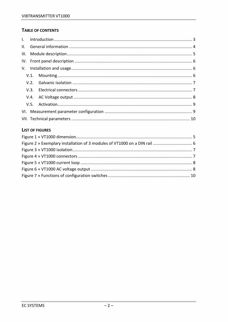
TABLE OF CONTENTS
I. Introduction ........................................................................................................................ 3
II. General information ........................................................................................................... 4
III. Module description ............................................................................................................. 5
IV. Front panel description ...................................................................................................... 6
V. Installation and usage ......................................................................................................... 6
V.1. Mounting ..................................................................................................................... 6
V.2. Galvanic isolation ........................................................................................................ 7
V.3. Electrical connectors ................................................................................................... 7
V.4. AC Voltage output ....................................................................................................... 8
V.5. Activation..................................................................................................................... 9
VI. Measurement parameter configuration ............................................................................ 9
VII. Technical parameters ....................................................................................................... 10
LIST OF FIGURES
Figure 1 » VT1000 dimension..................................................................................................... 5
Figure 2 » Exemplary installation of 3 modules of VT1000 on a DIN rail .................................. 6
Figure 3 » VT1000 isolation ........................................................................................................ 7
Figure 4 » VT1000 connectors ................................................................................................... 7
Figure 5 » VT1000 current loop ................................................................................................. 8
Figure 6 » VT1000 AC voltage output ........................................................................................ 8
Figure 7 » Functions of configuration switches ....................................................................... 10

USER MANUAL _EN_
– 3 – EC SYSTEMS
I . INTRODUCTION
The following paragraph does not apply to countries where legal provisions do not comply to
the conditions and terms described herein.
EC SYSTEMS DOES NOT TAKE ANY LIABILITY CONCERNING THIS MANUAL, WHETHER EXPLICIT
NOR IMPLIED (BUT NOT LIMITED TO); NOR CONCERNING A TYPICAL AVERAGE MARKET
QUALITY OR THE FITNESS FOR ANY SPECIAL PURPOSE.
In some countries and parts of some countries the exclusion and/or limitation of the
duration of explicit or implied warranties concerning certain transactions are not allowed.
Therefore the declaration above may be not effective in certain areas. This publication may
contain erroneous information and/or typographic errors. The contained information is
revised in an on-going process. So later editions can contain changes. Products/software
described herein may be changed and improved at any time without any obligation to a
prior announcement. Any product and company names mentioned herein may be protected
trademarks.
© COPYRIGHT
The following document is the property of EC Systems, which reserves all the copyrights,
patent-pending law and templates included.
Copying or other abuse of this document or its parts, or sharing with third parties requires
the written permission of EC Systems.

VIBTRANSMITTER VT1000
EC SYSTEMS – 4 –
I I . GENERAL INFORMATION
VIBTransmitter VT1000 is a universal module for condition monitoring of rotating machinery
with constant and variable rotational speed.
The features of VT1000 are as follow:
ICP® (IEPE) standard accelerometer input,
4..20 mA output proportional to signal estimate,
vibration velocity or acceleration measurement,
calculation of RMS or PEAK values,
built-in connector for the AC voltage signal from the vibration sensor (10 Vpp),
DIN rail mounting.
The system is a perfect solution for automated protection systems of rotating machines. The
device can be integrated with the controller via the 4..20 mA current output. The 10 Vpp AC
voltage output allows to control the vibration level using a portable vibration analyzer.
USER MANUAL _EN_
– 5 – EC SYSTEMS
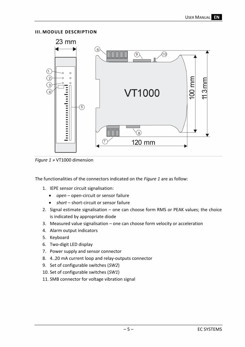
I I I . MODULE DESCRIPTION
Figure 1 » VT1000 dimension
The functionalities of the connectors indicated on the Figure 1 are as follow:
1. IEPE sensor circuit signalisation:
open – open-circuit or sensor failure
short – short-circuit or sensor failure
2. Signal estimate signalisation – one can choose form RMS or PEAK values; the choice
is indicated by appropriate diode
3. Measured value signalisation – one can choose form velocity or acceleration
4. Alarm output indicators
5. Keyboard
6. Two-digit LED display
7. Power supply and sensor connector
8. 4..20 mA current loop and relay-outputs connector
9. Set of configurable switches (SW2)
10. Set of configurable switches (SW1)
11. SMB connector for voltage vibration signal
VIBTRANSMITTER VT1000
EC SYSTEMS – 6 –
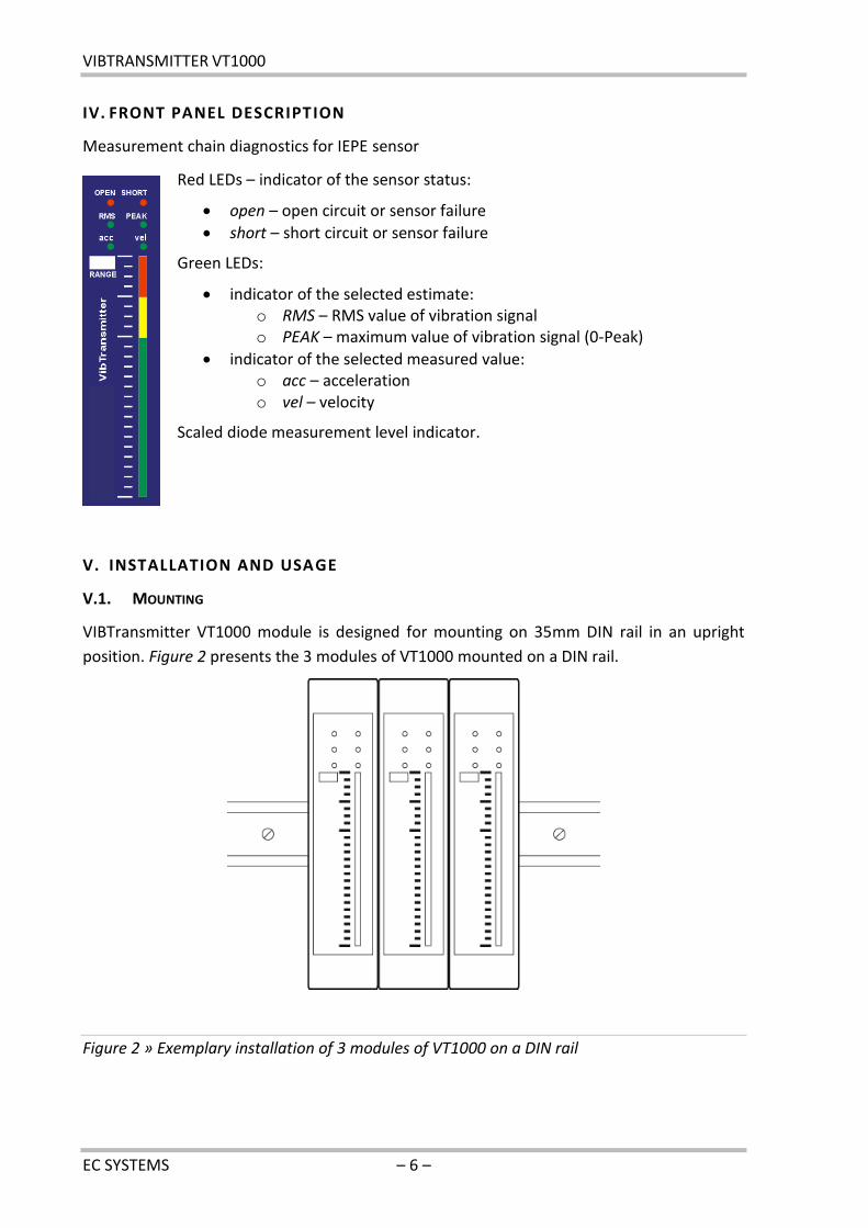
IV. FRONT PANEL DESCRIPTION
Measurement chain diagnostics for IEPE sensor
Red LEDs – indicator of the sensor status:
open – open circuit or sensor failure
short – short circuit or sensor failure
Green LEDs:
indicator of the selected estimate: o RMS – RMS value of vibration signal o PEAK – maximum value of vibration signal (0-Peak)
indicator of the selected measured value: o acc – acceleration o vel – velocity
Scaled diode measurement level indicator.
V. INSTALLATION AND USAGE
V.1. MOUNTING
VIBTransmitter VT1000 module is designed for mounting on 35mm DIN rail in an upright
position. Figure 2 presents the 3 modules of VT1000 mounted on a DIN rail.
Figure 2 » Exemplary installation of 3 modules of VT1000 on a DIN rail
USER MANUAL _EN_
– 7 – EC SYSTEMS
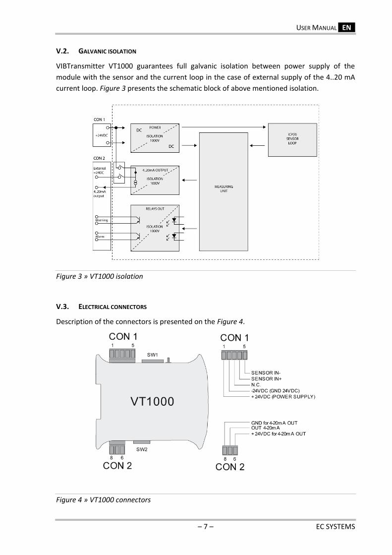
V.2. GALVANIC ISOLATION
VIBTransmitter VT1000 guarantees full galvanic isolation between power supply of the
module with the sensor and the current loop in the case of external supply of the 4..20 mA
current loop. Figure 3 presents the schematic block of above mentioned isolation.
Figure 3 » VT1000 isolation
V.3. ELECTRICAL CONNECTORS
Description of the connectors is presented on the Figure 4.
Figure 4 » VT1000 connectors
VIBTRANSMITTER VT1000
EC SYSTEMS – 8 –
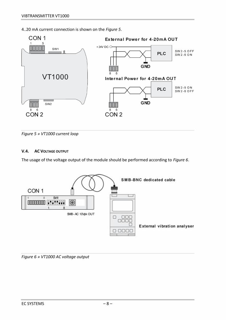
4..20 mA current connection is shown on the Figure 5.
Figure 5 » VT1000 current loop
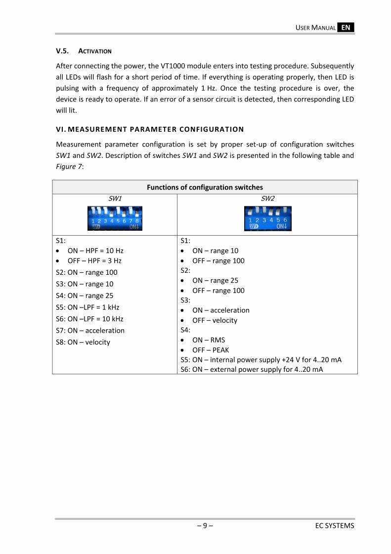
V.4. AC VOLTAGE OUTPUT
The usage of the voltage output of the module should be performed according to Figure 6.
Figure 6 » VT1000 AC voltage output
USER MANUAL _EN_
– 9 – EC SYSTEMS
V.5. ACTIVATION
After connecting the power, the VT1000 module enters into testing procedure. Subsequently
all LEDs will flash for a short period of time. If everything is operating properly, then LED is
pulsing with a frequency of approximately 1 Hz. Once the testing procedure is over, the
device is ready to operate. If an error of a sensor circuit is detected, then corresponding LED
will lit.
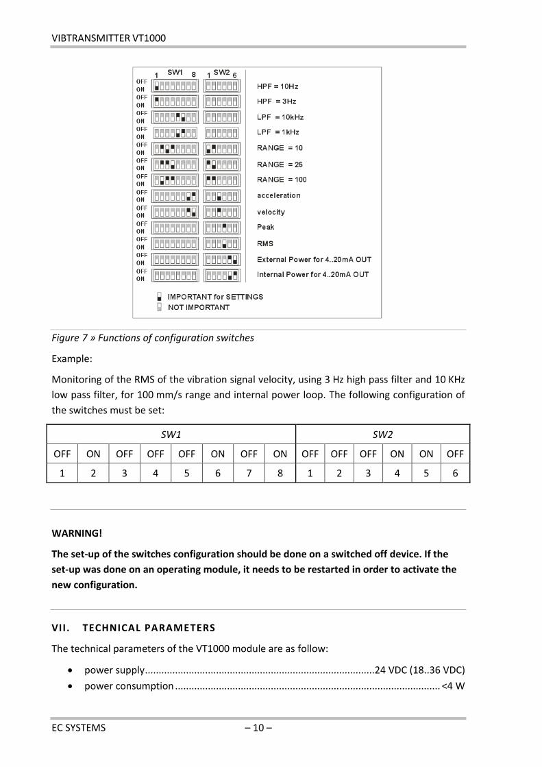
VI. MEASUREMENT PARAMETER CONFIGURATION
Measurement parameter configuration is set by proper set-up of configuration switches
SW1 and SW2. Description of switches SW1 and SW2 is presented in the following table and
Figure 7:
Functions of configuration switches
SW1
SW2
S1:
ON – HPF = 10 Hz
OFF – HPF = 3 Hz
S2: ON – range 100
S3: ON – range 10
S4: ON – range 25
S5: ON –LPF = 1 kHz
S6: ON –LPF = 10 kHz
S7: ON – acceleration
S8: ON – velocity
S1:
ON – range 10
OFF – range 100 S2:
ON – range 25
OFF – range 100 S3:
ON – acceleration
OFF – velocity S4:
ON – RMS
OFF – PEAK S5: ON – internal power supply +24 V for 4..20 mA S6: ON – external power supply for 4..20 mA
VIBTRANSMITTER VT1000
EC SYSTEMS – 10 –
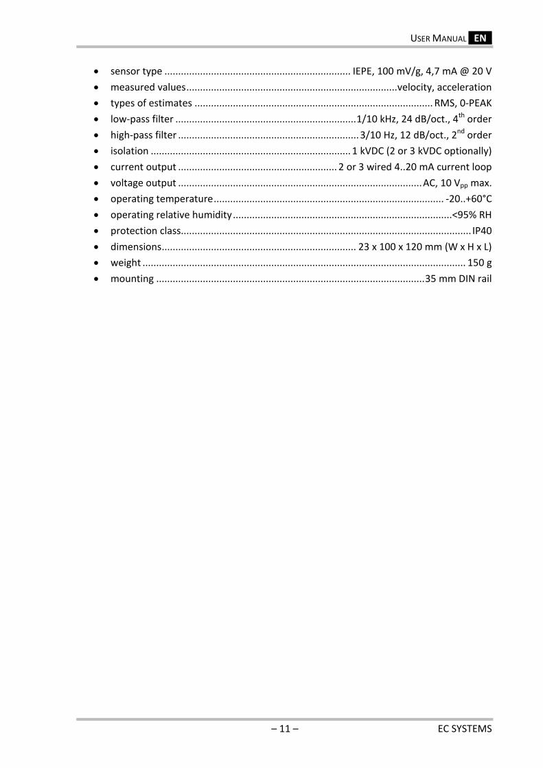
Figure 7 » Functions of configuration switches
Example:
Monitoring of the RMS of the vibration signal velocity, using 3 Hz high pass filter and 10 KHz
low pass filter, for 100 mm/s range and internal power loop. The following configuration of
the switches must be set:
SW1 SW2
OFF ON OFF OFF OFF ON OFF ON OFF OFF OFF ON ON OFF
1 2 3 4 5 6 7 8 1 2 3 4 5 6
WARNING!
The set-up of the switches configuration should be done on a switched off device. If the
set-up was done on an operating module, it needs to be restarted in order to activate the
new configuration.
VII. TECHNICAL PARAMETERS
The technical parameters of the VT1000 module are as follow:
power supply ....................................................................................24 VDC (18..36 VDC)
power consumption ................................................................................................. <4 W
USER MANUAL _EN_
– 11 – EC SYSTEMS
sensor type .................................................................... IEPE, 100 mV/g, 4,7 mA @ 20 V
measured values ............................................................................. velocity, acceleration
types of estimates ....................................................................................... RMS, 0-PEAK
low-pass filter .................................................................. 1/10 kHz, 24 dB/oct., 4th order
high-pass filter .................................................................. 3/10 Hz, 12 dB/oct., 2nd order
isolation ......................................................................... 1 kVDC (2 or 3 kVDC optionally)
current output .......................................................... 2 or 3 wired 4..20 mA current loop
voltage output ......................................................................................... AC, 10 Vpp max.
operating temperature .................................................................................... -20..+60°C
operating relative humidity ................................................................................ <95% RH
protection class.......................................................................................................... IP40
dimensions ....................................................................... 23 x 100 x 120 mm (W x H x L)
weight ...................................................................................................................... 150 g
mounting .................................................................................................. 35 mm DIN rail
VIBTRANSMITTER VT1000
EC SYSTEMS – 12 –
EC Systems Sp. z o.o. Lublańska 34
31-476 Krakow POLAND
Phone: +48 12 627 77 40 Sales: +48 12 627 77 23 Fax: +48 12 627 77 11
e-mail: [email protected]