vibration technical report (rev. 1) - b&p tunnel · vibration technical report . final, august...
TRANSCRIPT
August 2015
Federal Railroad AdministrationU.S. Department of Transportation Maryland Department
of Transportation
B&P Tunnel ProjectBaltimore, Maryland
VIBRATIONTECHNICAL REPORT
Federal Railroad AdministrationU.S. Department of Transportation Maryland Department
of Transportation

This page intentionally left blank.
Vibration Technical Report
FINAL, August 2015 E-1
EXECUTIVE SUMMARY
As part of the Maryland Department of Transportation’s (MDOT) proposed Baltimore and Potomac (B&P) Tunnel project in Baltimore, MD, a general vibration assessment was conducted to assess the potential for impacts at sensitive receptors along the various Build Alternatives. The vibration analysis is intended to estimate vibration levels expected from construction and operation of the future B&P Tunnel.
The operational impacts were evaluated using the guidelines set forth by the Federal Transit Administration’s (FTA) Transit Noise and Vibration Impact Assessment1. In addition, temporary construction vibration levels were also evaluated using both the FTA guidelines as well as standard industry practices for evaluating vibration due to tunnel boring and other tunnel excavation activities. This analysis was conducted using currently available information absent of vibration monitoring data that describes the ground-propagation characteristics or the building coupling losses. The results are, therefore, limited to the quality and accuracy of the available data much of which is based on default assumptions from the FTA guidelines.
Ambient vibration measurements were not conducted during this preliminary phase of the project. Once a preferred alternative is selected, a more detailed vibration assessment is recommended, including baseline vibration measurements, to document more accurately the potential for vibration impacts from train operations.
The proposed depth of the B&P Tunnel ranges from at-grade to 350 feet. Soil borings and geotechnical logs from other studies conducted in Baltimore (e.g., the Baltimore Red Line) indicate the tunnel would be bored through mixed-face bedrock. In addition to distance propagation, other adjustments applied to the default FTA ground-surface vibration curves include speed changes only. Other adjustments related to building coupling transmissibility or geologic conditions were not considered during the preliminary phase of the project.
As a result, operational levels under Alternative 1: No-Build due to ground-borne vibration from train passbys are predicted to exceed the FTA frequent impact criteria at 23 residences (FTA Category 2 land-uses) and one FTA Category 3 land-use (Eutaw-Marshburn Elementary School). Similarly, impacts due to ground-borne noise from train passbys are also predicted at 126 residences and one FTA Category 3 land-use (Eutaw-Marshburn Elementary School). No other exceedances of the FTA Category 3 land-uses (institutions) are predicted under Alternative 1: No-Build. However, no vibration impacts are expected under Alternative 1 because no project elements would be constructed. However, an impact assessment was conducted for NEPA disclosure and consistency with the approach applied to Alternatives 2, 3, and 11.
Operational impacts under Alternative 2 due to ground-borne vibration from train passbys are not predicted to exceed the FTA frequent impact criteria at any residences and other FTA Category 2 land-uses. Similarly, no impacts due to ground-borne noise from train passbys are predicted anywhere under Alternative 2.
Operational levels under Alternative 3A due to ground-borne vibration from train passbys are predicted to exceed the FTA frequent impact criteria at 69 residences and other FTA Category 2 land-uses. Similarly, 1 Federal Transit Administration, “Transit Noise and Vibration Impact Assessment”, Washington, DC, May 2006

Vibration Technical Report
FINAL, August 2015 E-2
impacts due to ground-borne noise from train passbys are also predicted at 215 residences and other FTA Category 2 land-uses. No exceedances of the FTA Category 1 or 3 land-uses (highly-sensitive equipment and institutions. respectively) are predicted under Alternative 3A.
Operational levels under Alternative 3B due to ground-borne vibration from train passbys are predicted to exceed the FTA frequent impact criteria at 138 residences and other FTA Category 2 land-uses. Similarly, impacts due to ground-borne noise from train passbys are also predicted at 303 residences and other FTA Category 2 land-uses. No exceedances of the FTA Category 1 or 3 land-uses (highly-sensitive equipment and institutions. respectively) are predicted under Alternative 3B.
Operational levels under Alternative 3C due to ground-borne vibration from train passbys are predicted to exceed the FTA frequent impact criteria at 92 residences and other FTA Category 2 land-uses. Similarly, impacts due to ground-borne noise from train passbys are also predicted at 265 residences and other FTA Category 2 land-uses. No exceedances of the FTA Category 1 or 3 land-uses (highly-sensitive equipment and institutions. respectively) are predicted under Alternative 3C.
Operational levels under Alternative 11A due to ground-borne vibration from train passbys are predicted to exceed the FTA frequent impact criteria at 476 residences and other FTA Category 2 land-uses. Similarly, impacts due to ground-borne noise from train passbys are also predicted at 672 residences and other FTA Category 2 land-uses. No exceedances of the FTA Category 1 or 3 land-uses (highly-sensitive equipment and institutions. respectively) are predicted under Alternative 11A.
Operational levels under Alternative 11B due to ground-borne vibration from train passbys are predicted to exceed the FTA frequent impact criteria at 320 residences and other FTA Category 2 land-uses. Similarly, impacts due to ground-borne noise from train passbys are also predicted at 543 residences and other FTA Category 2 land-uses. No exceedances of the FTA Category 1 or 3 land-uses (highly-sensitive equipment and institutions. respectively) are predicted under Alternative 11B.
Potential impacts during tunnel excavation are expected to be temporary as the advance rate for the tunnel boring machines (TBM), for example, is 30-40 feet per day. However, due to the absence of credible source data for vibration from TBM particularly applicable to the B&P Tunnel Corridor, the determination of impacts at nearby sensitive receptors is not possible without significant uncertainty. Although vibration levels from TBM are available in literature, the wide range of variability in source levels even for similar geotechnical conditions prohibit determining any credible levels at the closest residences. For example, estimated vibration levels from TBM through bedrock range from 30 to 61 VdB at a typical residence along the B&P Tunnel Corridor. These estimated levels are well below the threshold of impact using the FTA default prediction methodology.
Mitigation measures to eliminate or reduce the severity of impact during operations include resilient track fasteners, ballast mats or other vibration control measure that would decouple or break the path of propagation. Any viable mitigation measure would be investigated in more detail during final design when details of the track alignment are finalized.

Vibration Technical Report
FINAL, August 2015 i
TABLE OF CONTENTS
Executive Summary .................................................................................................................................... E-1
I. INTRODUCTION ..................................................................................................................................... 1
II. PROJECT BACKGROUND ........................................................................................................................ 1
III. PROJECT PURPOSE AND NEED .............................................................................................................. 1
A. Purpose of the Project ...................................................................................................................... 1
B. Need for the Project.......................................................................................................................... 3
IV. PROJECT ALTERNATIVES........................................................................................................................ 3
A. Alternative 1: No Build ...................................................................................................................... 3
B. Alternative 2 ...................................................................................................................................... 4
C. Alternative 3 ...................................................................................................................................... 4
D. Alternative 11 .................................................................................................................................... 5
V. HUMAN PERCEPTION OF VIBRATION ................................................................................................... 5
VI. REGULATORY FRAMEWORK .................................................................................................................. 8
A. Operational Vibration Criteria .......................................................................................................... 8
B. Construction Vibration Criteria ......................................................................................................... 8
VII. METHODOLOGY .................................................................................................................................... 9
A. Modeling Assumptions ..................................................................................................................... 9
VIII. AFFECTED ENVIRONMENT .................................................................................................................. 11
IX. ENVIRONMENTAL CONSEQUENCES .................................................................................................... 11
A. Alternative 1: No Build ................................................................................................................... 12
B. Alternative 2 .................................................................................................................................... 13
C. Alternative 3 .................................................................................................................................... 13
1. Alternative 3 Option A ................................................................................................................ 13
2. Alternative 3 Option B ................................................................................................................ 14
3. Alternative 3 Option C ................................................................................................................ 14
D. Alternative 11 .................................................................................................................................. 15
1. Alternative 11 Option A .............................................................................................................. 15
2. Alternative 11 Option B .............................................................................................................. 15
X. CONSTRUCTION AND MITIGATION ..................................................................................................... 16
A. Construction .................................................................................................................................... 16
B. Mitigation ........................................................................................................................................ 16

Vibration Technical Report
FINAL, August 2015 ii
XI. REFERENCES ........................................................................................................................................ 17
XII. APPENDIX ............................................................................................................................................ 17
TABLES
Table 1: Ground-Borne RMS Vibration Impact Criteria for Annoyance during Operations and Construction .................................................................................................................................................. 9 Table 2: B&P Tunnel Train Volumes and Speeds Proposed for the Noise Analysis .................................... 10 Table 3: Inventory of Ground-Borne Vibration Impacts Predicted during Operations for the Alts ........... 11 Table 4: Inventory of Ground-Borne Noise Impacts Predicted during Operations for the Alternatives .... 12 Table 5: Inventory of Ground-Borne Vibration Impacts Predicted during Operations for Alternative 1 ... 12 Table 6: Inventory of Ground-Borne Noise Impacts Predicted during Operations for Alternative 1 ......... 13 Table 7: Inventory of Ground-Borne Vibration Impacts Predicted during Operations for Alternative 2 ... 13 Table 8: Inventory of Ground-Borne Noise Impacts Predicted during Operations for Alternative 2 ......... 13 Table 9: Inventory of Ground-Borne Vibration Impacts Predicted during Operations for Alternative 3 ... 14 Table 10: Inventory of Ground-Borne Noise Impacts Predicted during Operations for Alternative 3 ....... 14 Table 11: Inventory of Ground-Borne Vibration Impacts Predicted during Operations for Alt 11 ............ 15 Table 12: Inventory of Ground-Borne Noise Impacts Predicted during Operations for Alternative 11 ..... 15
FIGURES
Figure 1. B&P Tunnel Project Vicinity ........................................................................................................... 2 Figure 2. B&P Tunnel Project Alternatives .................................................................................................... 6 Figure 3: Typical Ground-Borne Vibration Levels ......................................................................................... 7

Vibration Technical Report
FINAL, August 2015 1
I. INTRODUCTION This technical report presents a detailed analysis of the vibration impacts potentially generated by the alternatives being studied for the Baltimore and Potomac (B&P) Tunnel Project. This technical report has been prepared in support of the Environmental Impact Statement (EIS)2 being prepared by the Federal Railroad Administration (FRA)3, in coordination with the Maryland Department of Transportation (MDOT)4.
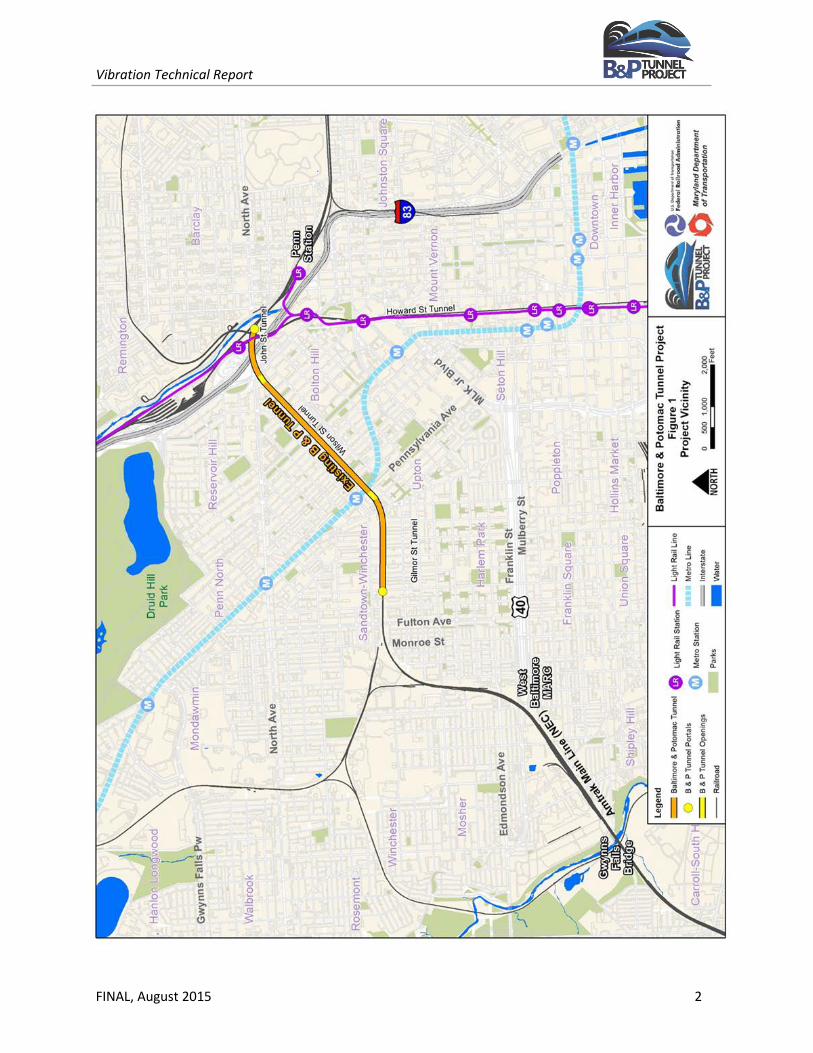
The project Study Area surrounds the existing 1.4-mile B&P Tunnel in the west-central portion of Baltimore City and includes Amtrak’s Northeast Corridor (NEC) between Penn Station to the north and the Gwynns Falls Bridge to the south, as illustrated in Figure 1.
Please note that all environmental evaluation in this technical report is current through August 2015.
II. PROJECT BACKGROUND
As shown in Figure 1, the B&P Tunnel is located beneath several West Baltimore neighborhoods, including Bolton Hill, Madison Park, and Upton. The tunnel is currently used by Amtrak5, MARC6, and Norfolk Southern Railway (NS) 6, and is owned by Amtrak. Built in 1873, the tunnel is one of the oldest structures on the NEC. It is approximately 7,500 feet (1.4 miles) long and is comprised of three shorter tunnels: the John Street Tunnel, the Wilson Street Tunnel, and the Gilmor Street Tunnel. The B&P Tunnel is a centerpiece of the Baltimore rail network that contributes to the economic vitality of the Northeast region. The B&P Tunnel is important not only for Baltimore, but also the NEC (NEC MPWG, 2010). The NEC is the nation’s most congested rail corridor and one of the highest volume corridors in the world (Amtrak, 2010).
III. PROJECT PURPOSE AND NEED
A. Purpose of the Project The primary purpose of the project is to address the structural and operational deficiencies of the B&P Tunnel. In addition, the project would: improve travel time, accommodate existing and projected travel demand for passenger services (regional and commuter), eliminate impediments to existing and projected
2 The EIS and associated technical reports are being conducted in compliance with the National Environmental Policy Act of 1969 (42 United States Code [USC] 4321 et seq.), the Council of Environmental Quality NEPA Regulations (40 CFR 1500-1508), the FRA Procedures for Considering Environmental Impacts (64 FR 28545, May 26, 1999), and FRA’s Update to NEPA Implementing Procedures (78 FR 2713, January 14, 2013). 3 FRA is serving as the lead Federal agency for the B&P Tunnel Project. 4 MDOT is the funding grantee for the B&P Tunnel Project. MDOT oversees six modal state agencies, including the Maryland Transit Administration (MTA). 5 Amtrak is the nation’s high-speed rail operator and owns the existing B&P Tunnel. 6 MARC (Maryland Area Regional Commuter) is administered by MTA. MARC is a commuter rail system comprised of three rail lines of service. One of the lines (the MARC Penn Line) operates along the NEC and through the B&P Tunnel, providing service between Washington, D.C. and Perryville, Maryland. 6 NS is a freight transportation provider that manages a nearly 20,000-mile rail network across the United States, including freight service through the existing B&P Tunnel (NS, 2014a).

This page is intentionally blank.
Vibration Technical Report
FINAL, August 2015 2
Figure 1. B&P Tunnel Project Vicinity

This page intentionally left blank.
Vibration Technical Report
FINAL, August 2015 3
operations along the NEC, provide operational reliability, and take into account the value of the existing tunnel as an important element of Baltimore's rail infrastructure.
B. Need for the Project
The purpose of the project was derived from the following needs:
• The existing B&P Tunnel is more than 140 years old and is approaching the end of its useful life with regard to its physical condition. While the tunnel currently remains safe for rail transportation, it requires substantial maintenance and repairs, and it does not meet current design standards. The tunnel is considered to be structurally deficient due to the horizontal radius of the original design, its age, and wear and tear.
• The tunnel is also functionally obsolete, meaning that it is not able to meet current and future rail demands due to its vertical and horizontal track alignment. The low-speed tunnel creates a bottleneck at a critical point in the NEC, affecting operations of the most heavily-traveled rail line in the United States.
• The existing double-track tunnel does not provide enough capacity to support existing and projected demands for regional and commuter passenger service.
• The existing tunnel is not suited for modern high-speed usage due to the current horizontal and vertical track alignment, which limits passenger train speeds through the tunnel to 30 MPH.
• The existing tunnel is a valuable resource. The disposition of the existing tunnel needs to be considered in the project.
IV. PROJECT ALTERNATIVES
Sixteen preliminary alternatives were identified, evaluated using a two-level progressive screening approach, and narrowed to four alternatives in the B&P Tunnel Project – Preliminary Alternatives Screening Report (FRA/MDOT, December 2014). The four preliminary alternatives retained for further design development and environmental study include Alternative 1: No-Build, Alternative 2: Restore/Rehabilitate Existing B&P Tunnel, Alternative 3: Great Circle Passenger Tunnel, and Alternative 11: Robert Street South.
These conceptual alternatives have evolved as the preliminary designs advanced. It was determined upon more detailed study of Alternatives 3 and 11 that several options could be accommodated within the general corridors of each, and that each of the options should be considered as part of the Project. This technical report considers Alternative 3 Options A, B, and C as well as Alternative 11 Options A and B (Figure 2). Alternative 2 is hereafter referred to as “Reconstruction and Modernization of the Existing Tunnel” to more accurately reflect the components of the alternative.
A. Alternative 1: No Build
Alternative 1 would entail continued use with no significant improvements to the existing B&P Tunnel. Routine maintenance of the tunnel would continue. The tunnel’s basic geometry and structure would not be improved; the existing tunnel and tracks would be left in place. This alternative would not modernize the tunnel or bring it into a “state of good repair,” but would rather maintain the existing service and ongoing maintenance as currently practiced with minimal disruption.

Vibration Technical Report
FINAL, August 2015 4
Necessary maintenance required to continue using the existing tunnel may include replacing damaged track slabs, repairing leaking utility lines above the tunnel, rebuilding deteriorated manholes, repairing brick and mortar, replacing catenary supports, and repairing the Gilmor Street portal.
B. Alternative 2
Alternative 2 includes the complete reconstruction of the existing B&P Tunnel in its current location. This alternative would address the existing B&P Tunnel’s deteriorating conditions and eliminate restrictions on the size of railcar traffic over the NEC through Baltimore. This alternative would completely replace the existing tunnel liner, lower the tunnel invert for greater vertical clearance, and widen the tunnel for greater horizontal clearance. The geometry of the existing tunnel, such as curves and grades, would not be altered. The resulting tunnel would accommodate a two-track alignment through the Study Area.
C. Alternative 3
Alternative 3 consists of three options (A, B, and C), all of which would extend in a wide arc north of the existing B&P Tunnel. Each option would include a north portal located in the vicinity of the MTA North Avenue Light Rail station, north of where I-83 crosses North Avenue. The south portal for each option would be constructed at one of two sites located south of Presstman Street, between Bentalou and Payson Streets. Each option would result in a four-track alignment through the Study Area, and would involve construction of four separate tunnel bores. Each option would require three ventilation plants – one at each portal and one mid-tunnel plant. All of the alternatives have similar north portal locations but differ in their south portal locations and underground alignment.
Alternative 3 Option A would include a south portal located at the existing P. Flanigan Asphalt plant, just south of the athletic fields at Carver Vocational-Technical High School, roughly a third of a mile west of the existing B&P Tunnel south portal. The alignment would rejoin the existing NEC corridor at the curve located south of the asphalt plant. Option A would result in a total travel distance of approximately 3.7 miles between Penn Station and the Amtrak Gwynns Falls Bridge. The tunnel segment of the alignment comprises 1.9 miles of this total length.
Alternative 3 Option B would include a south portal located southeast of the P. Flanigan Asphalt plant, adjacent to the existing NEC between Mosher Street and Riggs Avenue, roughly a third of a mile southwest of the existing B&P Tunnel south portal. Much of the underground portion of the alignment is identical to Option A. However, the alignment south of the south portal would be located east of the existing NEC. Alternative 3 Option B would result in a total travel distance of approximately 3.7 miles between Penn Station and the Amtrak Gwynns Falls Bridge. The tunnel segment of the alignment comprises 2.0 miles of this total length.
Alternative 3 Option C would include a south portal located at the P. Flanigan Asphalt plant, just south of the athletic fields at Carver Vocational-Technical High School, roughly a third of a mile west of the existing B&P Tunnel south portal. The underground portion of the tunnel would parallel the alignments identified under Options A and B; however, the alignment would be shifted further north. The alignment south of the south portal would be located west of the existing NEC. Option C would result in a total travel distance of approximately 3.8 miles between Penn Station and the Amtrak Gwynns Falls Bridge. The tunnel segment of the alignment comprises 2.2 miles of this total length.
Vibration Technical Report
FINAL, August 2015 5
D. Alternative 11
Alternative 11 includes two options (A and B) that provide for relatively straight alignments between Penn Station and the West Baltimore MARC Station, crossing diagonally underneath the existing B&P Tunnel. Each option would include a north portal in the vicinity of the MTA North Avenue Light Rail station, north of where I-83 crosses North Avenue. The south portal for each option would be located in the general vicinity of the West Baltimore MARC Station in the Midtown-Edmondson neighborhood. Each option would result in a four-track alignment through the Study Area, and would involve construction of four separate tunnel bores. Each option would require three ventilation plants – one at each portal and one mid-tunnel plant. Options A and B differ primarily in the south portal location and underground alignments.
Alternative 11 Option A would include a south portal located just west of the intersection of Harlem Avenue and Appleton Street, northeast of the West Baltimore MARC Station. The alignment would cross over Franklin and Mulberry Streets. Option A would result in a total travel distance of approximately 3.3 miles between Penn Station and the Amtrak Gwynns Falls Bridge. The tunnel segment of the alignment comprises 1.9 miles of this total length.
Alternative 11 Option B would exit the bored tunnel portion at a south portal located just southwest of the intersection of Edmondson Avenue and Pulaski Street, adjacent to the existing West Baltimore MARC Station. The underground portion of the alignment would run parallel to Option A, but would be shifted slightly north for the length of the tunnel alignment. The alignment would cross under Franklin and Mulberry Streets. Alternative 11 Option B would result in a total travel distance of approximately 3.3 miles between Penn Station and the Amtrak Gwynns Falls Bridge. The tunnel segment of the alignment comprises 2.2 miles of this total length.
V. HUMAN PERCEPTION OF VIBRATION
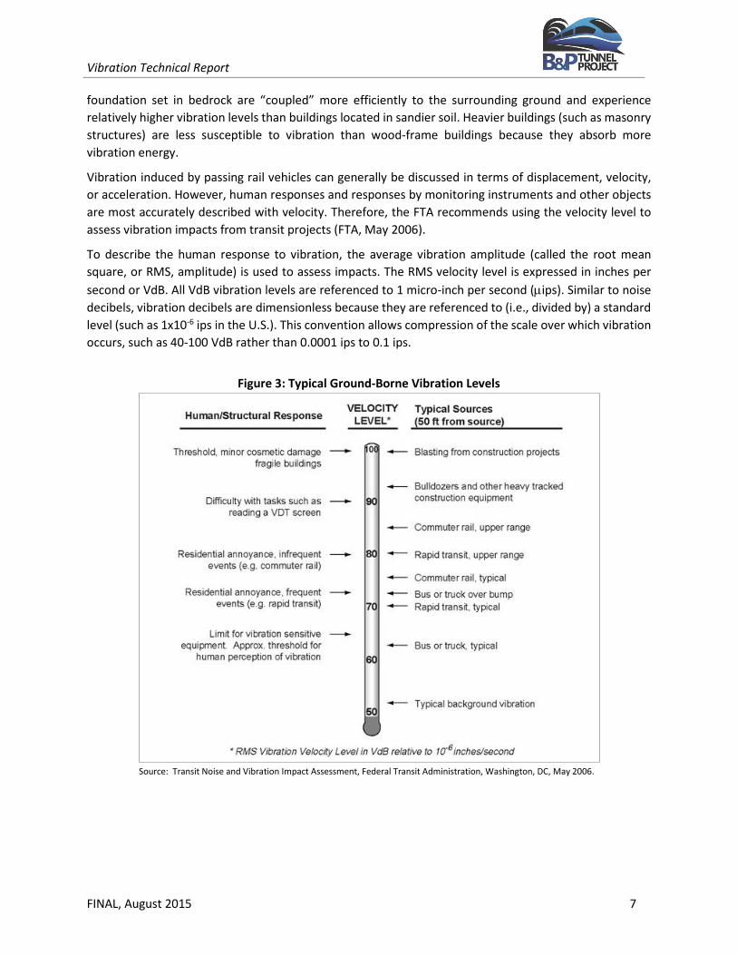
Ground-borne vibration associated with vehicle movements is usually the result of uneven interactions between wheels and the road or rail surfaces. Examples of such interactions (and subsequent vibrations) include train wheels over a jointed rail, an untrue rail car wheel with “flats,” and a motor vehicle wheel hitting a pothole, a manhole cover, or any other uneven surface. Typical ground-borne vibration levels from transit and other common sources are summarized in Figure 3. For example, typical ground-borne vibration levels at a receptor 50 feet from different transportation sources traveling at 50 miles per hour range from 61 VdB for trucks and buses, to 73 VdB for LRT vehicles, to 85 VdB for diesel locomotives. Similarly, a typical background vibration velocity level in residential areas is usually 50 VdB or lower, well below the threshold of perception for humans, which is around 65 VdB (FTA 2006). The typical background levels refer to ambient ground vibrations not related to any specific transportation source (e.g., naturally occurring ground vibration). This background vibration level is assumed to be fairly constant from site to site, except in the vicinity of active fault lines.
Unlike noise, which travels in air, transit vibration typically travels along the surface of the ground. Depending on the geological properties of the surrounding terrain and the type of building structure exposed to transit vibration, vibration propagation can be more or less efficient. Buildings with a solid

This page intentionally left blank

Vibration Technical Report
FINAL, August 2015 6
Figure 2. B&P Tunnel Project Alternatives

This page intentionally left blank.
Vibration Technical Report
FINAL, August 2015 7
foundation set in bedrock are “coupled” more efficiently to the surrounding ground and experience relatively higher vibration levels than buildings located in sandier soil. Heavier buildings (such as masonry structures) are less susceptible to vibration than wood-frame buildings because they absorb more vibration energy.
Vibration induced by passing rail vehicles can generally be discussed in terms of displacement, velocity, or acceleration. However, human responses and responses by monitoring instruments and other objects are most accurately described with velocity. Therefore, the FTA recommends using the velocity level to assess vibration impacts from transit projects (FTA, May 2006).
To describe the human response to vibration, the average vibration amplitude (called the root mean square, or RMS, amplitude) is used to assess impacts. The RMS velocity level is expressed in inches per second or VdB. All VdB vibration levels are referenced to 1 micro-inch per second (µips). Similar to noise decibels, vibration decibels are dimensionless because they are referenced to (i.e., divided by) a standard level (such as 1x10⁻⁶ ips in the U.S.). This convention allows compression of the scale over which vibration occurs, such as 40-100 VdB rather than 0.0001 ips to 0.1 ips.
Figure 3: Typical Ground-Borne Vibration Levels
Source: Transit Noise and Vibration Impact Assessment, Federal Transit Administration, Washington, DC, May 2006.

Vibration Technical Report
FINAL, August 2015 8
VI. REGULATORY FRAMEWORK
The vibration assessment was prepared in accordance with NEPA and the guidelines set forth by FTA’s Transit Noise and Vibration Impact Assessment [May 2006]. The future predicted vibration levels from the project were evaluated using the FTA guidelines. The FTA criteria are used to evaluate instantaneous levels from single events (such as a single train passby).
A. Operational Vibration Criteria
The FTA vibration criteria for evaluating ground-borne vibration impacts from train passbys at nearby sensitive receptors are shown in Table 1. These vibration criteria are related to ground-borne vibration levels that are expected to result in human annoyance, and are based on RMS velocity levels expressed in VdB referenced to one micro inch per second (µips). FTA's experience with community response to ground-borne vibration indicates that when there are only a few train events per day, it would take higher vibration levels to evoke the same community response that would be expected from more frequent events. This experience is taken into account in the FTA criteria by distinguishing between projects with frequent, occasional, or infrequent events. The frequent events category is defined as more than 70 events per day, the occasional events category is defined as between 30 and 70 events per day, and the infrequent events category is defined as less than 30 events per day. To be conservative, the FTA frequent criteria were used to assess ground-borne vibration impacts in the Study Area.
However, because the FTA criteria do not incorporate existing vibration, additional impacts from future vibration sources along the existing tunnel were evaluated based on a significant increase in vibration of 3 VdB or more above the Baseline Condition. For the project (which is proposing several new alignment options), an impact would occur if the future train vibration exceeds the impact criteria shown in Table 1. For Alternative 2 only, additional impact (or exceedance of the criteria) would also occur if the project significantly increases the resultant vibration 3 VdB or more than the existing vibration under the Baseline Condition (predicted vibration levels under Alternative 1). The additional impact criteria were applied to Alternative 2 because it is an existing active alignment whereas Alternatives 3 and 11 are proposed.
The vibration criteria levels shown in Table 1 are defined in terms of human annoyance for different land use categories such as high sensitivity (Category 1), residential (Category 2), and institutional (Category 3). In general, the vibration threshold of human perceptibility is approximately 65 VdB.
B. Construction Vibration Criteria
The same vibration criteria used to evaluate operational impacts may also be used to evaluate vibration impacts during temporary construction activities. Other criteria used to evaluate the potential for structural damage are also available. However, during the preliminary stage of the project when details of the actual construction scenarios and equipment are not yet know, a qualitative evaluation is typically utilized to identify potential problem areas. As a result, a quantitative assessment of impact during construction is recommended during the Final EIS or during Final Design when more details of the proposed construction equipment and construction scenarios are determined.

Vibration Technical Report
FINAL, August 2015 9
Table 1: Ground-Borne RMS Vibration Impact Criteria for Annoyance during Operations and Construction
Receptor Land Use RMS Vibration Levels (VdB) Ground-borne Noise Levels (dBA)
Category Description Frequent Occasional Infrequent Frequent Occasional Infrequent
Events Events Events Events Events Events
1
Buildings where low vibration is essential for interior operations
65 65 65 N/A N/A N/A
2
Residences and buildings where people normally sleep
72 75 80 35 38 43
3 Daytime institutional and office use
75 78 83 40 43 48
Specific Buildings
TV/Recording Studios/Concert Halls
65 65 65 25 25 25
Auditoriums 72 80 80 30 38 38
Theaters 72 80 80 35 43 43
Source: “Transit Noise and Vibration Impact Assessment”, Federal Transit Administration, Washington, DC, May 2006.
VII. METHODOLOGY
Noise and vibration impacts were evaluated using the FTA’s “General Assessment” guidelines to reflect the type of input data available. The following assumptions were applied for the prediction modeling analysis:
A. Modeling Assumptions
The modeling assumptions and input data used to predict existing and future vibration levels from rail service in the B&P Tunnel are summarized as follows:
• A screening assessment identified 6,858 land-uses within the FTA screening distance of 300 feet: o 6287 Residential including three mixed-use parcels o 101 Institutional properties o 2 Parks (Maple Leaf Park and Arnold Sumpter Park) o 179 Commercial parcels o 9 Industrial parcels o 280 Unknown or undeveloped parcels
• To determine the appropriate FTA evaluation criteria, rail operations along the Northeast Corridor (NEC) were evaluated using the following data (shown in Table 2) to determine the frequency of activity;

Vibration Technical Report
FINAL, August 2015 10
Table 2: B&P Tunnel Train Volumes and Speeds Proposed for the Noise Analysis
Condition Train Service AKA Total Bi-directional Train Frequencies Consist Data Speed
(mph) Daily Peak Hr. # of Locos # of Coaches
Alternative 1
MARC Regional 55 4 1 8 30
Acela Intercity Express 39 2 n/a 14 30
NE Regional/ Carolinian/ Vermonter
Intercity Corridor 49 3 1 8 30
Freight -- 2 0 1 8 30 Metropolitan -- n/a n/a n/a n/a 30
Alternatives 2, 3, and 11
MARC Regional 164 15 1 8 30/70
Acela Intercity Express 82 8 n/a 14 30/70
NE Regional/ Carolinian/ Vermonter
Intercity Corridor 48 4 1 8 30/70
Freight -- 2 0 1 8 30/70 Metropolitan -- 92 8 n/a 14 30/70
Source: KB Environmental Sciences, May 15, 2015.
• The FTA vibration thresholds selected for the evaluation criteria are based on the total number of daily operations the community would be exposed to. Based on the average daily operations for the No-Build Condition (Alternative 1) and the future Build Alternatives (Alternatives 2, 3A, 3B, and 3C, 11A, and 11B) as summarized in Table 2, the FTA “frequent” criteria (which correlate to more than 70 events per day) were selected to evaluate the potential for impacts from the project alternatives;
• Train speeds were also applied in accordance with the noise assessment, which include 30 miles per hour (mph) under Alternative 1 and a range of speeds from 30 mph at the east or north portal to 70 mph at the west or south portal for Alternatives 2, 3, and 11;
• Adjustments for continuously-welded track were also applied using the FTA guidelines for Alternatives 2, 3, and 11;
• To account for improvements to the existing corridor as well as the proposed tunnels, an adjustment of 5 VdB was applied to Alternative 1 to reflect adverse track and tunnel conditions similar to jointed-rail track;
• The FTA default ground-surface vibration curves for diesel-electric locomotives (which are heavier than the railcars) were utilized to reflect typical ground propagation characteristics; and,
• Adjustments for ground-borne noise reflect typical ground conditions with peak frequencies between 30-60 Hz.

Vibration Technical Report
FINAL, August 2015 11
VIII. AFFECTED ENVIRONMENT
Baseline vibration measurements were not conducted as part of this project because the focus of this preliminary phase is intended to compare the potential impacts between different alternatives and options. However, background vibration levels in the vicinity of the proposed tunnel alternatives are dominated by local traffic. Background vibration levels in the vicinity of the existing tunnel are dominated by current rail operations due to Amtrak, MARC and freight train passbys along the Northeast Corridor.
In order to compare the future impacts of Alternative 2, however, the impacts associated with Alternative 1 were modeled to determine a baseline condition. Therefore, as shown in Table 3, impacts under Alternative 1 due to ground-borne vibration from train passbys are predicted to exceed the FTA frequent impact criterion of 72 VdB at 23 residences and other FTA Category 2 land-uses. Similarly, exceedances of the FTA impact criterion of 75 VdB are predicted at one FTA Category 3 receptor (Eutaw-Marshburn Elementary School). No exceedances of the FTA ground-borne vibration impact criteria are predicted at any Category 1 land-uses (highly sensitive equipment) under Alternative 1.
Table 3: Inventory of Ground-Borne Vibration Impacts Predicted during Operations for the Alternatives Alt. Number of Impacts ID Total Residential (Cat. 2) Parks (Cat. 3) Institutional (Cat. 3) 1 24 23 0 1 2 0 0 0 0
3A 69 69 0 0 3B 138 138 0 0 3C 92 92 0 0
11A 476 476 0 0 11B 320 320 0 0
NB: 6858 receptor set used for all alternative analyses.
Vibration from train passbys in tunnels could contribute to ground-borne noise inside residences due to vibrating surfaces. The number of potential ground-borne noise impacts for each alternative is summarized in Table 4. Impacts under Alternative 1 due to ground-borne noise from train passbys are predicted to exceed the FTA frequent impact criterion of 35 dBA at 126 residences and other FTA Category 2 land-uses. Additionally, exceedances of the FTA impact criterion of 40 dBA are predicted at one FTA Category 3 receptor (Eutaw-Marshburn Elementary School). FTA Category 1 land-uses (highly sensitive equipment) are generally not sensitive to ground-borne noise.
IX. ENVIRONMENTAL CONSEQUENCES
To assess impacts along an existing, heavily-used rail corridor, Alternatives 2, 3, and 11 were modeled and compared to the FTA impact criteria to evaluate the change in ground-borne vibration as a result of the project. Along the existing tunnel alignment, future predicted vibration levels under Alternative 1 and

Vibration Technical Report
FINAL, August 2015 12
Table 4: Inventory of Ground-Borne Noise Impacts Predicted during Operations for the Alternatives Alt. Number of Impacts ID Total Residential (Cat. 2) Parks (Cat. 3) Institutional (Cat. 3) 1 127 126 0 1 2 0 0 0 0
3A 215 215 0 0 3B 303 303 0 0 3C 265 265 0 0
11A 672 672 0 0 11B 543 543 0 0
NB: 6858 receptor set used for all alternative analyses.
Alternative 2 were compared against the levels predicted for the Existing Condition to determine the relative change in impact. Along Alternatives 3A, 3B, and 3C, and 11A and 11B, future predicted vibration levels were compared against the FTA absolute criteria threshold limits to determine the onset and magnitude of impact.
A. Alternative 1: No Build
No vibration impacts are expected under Alternative 1 because no project elements would be constructed. However, an impact assessment was conducted for NEPA disclosure and consistency with the approach applied to Alternatives 2, 3, and 11.
Unlike noise, which is assessed using cumulative noise levels over one-hour and 24-hour periods, transit vibration impacts are assessed based on individual events, such as a train passby. Future vibration levels under Alternative 1 are expected to be similar to those currently experienced under existing conditions. Since existing vibration is dominated by existing rail traffic along the Northeast Corridor, these levels are expected to remain the same under Alternative 1. Since no project components or design elements are proposed under Alternative 1, the alternative would not cause any new vibration impacts.
Therefore, as shown in Table 5, levels under Alternative 1 due to ground-borne vibration from train passbys are predicted to exceed the FTA frequent impact criteria at 23 residences and other FTA Category 2 land-uses. Similarly, exceedances of the FTA impact criterion of 75 VdB are predicted at one FTA Category 3 receptor (Eutaw-Marshburn Elementary School). No exceedances of the FTA ground-borne vibration impact criteria are predicted at any Category 1 land-uses (highly sensitive equipment) under Alternative 1.
Table 5: Inventory of Ground-Borne Vibration Impacts Predicted during Operations for Alternative 1 Alt. Number of Impacts ID Total Residential (Cat. 2) Parks (Cat. 3) Institutional (Cat. 3) 1 24 23 0 1
NB: 6858 receptor set used for all alternative analyses. Similarly, as shown in Table 6, levels under Alternative 1 due to ground-borne noise from train passbys are predicted to exceed the FTA frequent impact criteria at 126 residences and other FTA Category 2 land-

Vibration Technical Report
FINAL, August 2015 13
uses. Additionally, exceedances of the FTA impact criterion of 40 dBA are also predicted at one FTA Category 3 receptor (Eutaw-Marshburn Elementary School).
Table 6: Inventory of Ground-Borne Noise Impacts Predicted during Operations for Alternative 1 Alt. Number of Impacts ID Total Residential (Cat. 2) Parks (Cat. 3) Institutional (Cat. 3) 1 127 126 0 1
NB: 6858 receptor set used for all alternative analyses.
B. Alternative 2
Future vibration levels under Alternative 2 are expected to be similar to those currently experienced under existing conditions. Since existing vibration is dominated by existing rail traffic along the Northeast Corridor, these levels are expected to decrease slightly due to structural improvements proposed as part of Alternative 2. As shown in Table 7, levels under Alternative 2 due to ground-borne vibration from train passbys are not predicted to exceed the FTA frequent impact criterion of 72 VdB at any residences or other FTA Category 2 land-uses. Additionally, exceedances of the FTA impact criterion of 75 VdB are also not predicted at any FTA Category 1 or 3 land-uses for institutional receptors and highly-sensitive equipment, respectively.
Table 7: Inventory of Ground-Borne Vibration Impacts Predicted during Operations for Alternative 2 Alt. Number of Impacts ID Total Residential (Cat. 2) Parks (Cat. 3) Institutional (Cat. 3) 2 0 0 0 0
NB: 6858 receptor set used for all alternative analyses.
Similarly, as shown in Table 8, levels under Alternative 2 due to ground-borne noise from train passbys are not predicted to exceed the FTA frequent impact criterion of 35 dBA at any residences or other FTA Category 2 land-uses. Additionally, exceedances of the FTA impact criterion of 40 dBA are also not predicted at any FTA Category 3 land-uses.
Table 8: Inventory of Ground-Borne Noise Impacts Predicted during Operations for Alternative 2 Alt. Number of Impacts ID Total Residential (Cat. 2) Parks (Cat. 3) Institutional (Cat. 3) 2 0 0 0 0
NB: 6858 receptor set used for all alternative analyses.
C. Alternative 3
Vibration impacts from Amtrak and freight trains due to steel wheel on steel rail interactions were evaluated using maximum corridor speeds that range from 30-70 miles per hour (mph). Therefore, exceedances of the FTA vibration “annoyance” impact criteria for frequent events were predicted at over 6800 residences and institutional land uses along Alternative 3, Options A and B.
1. Alternative 3 Option A
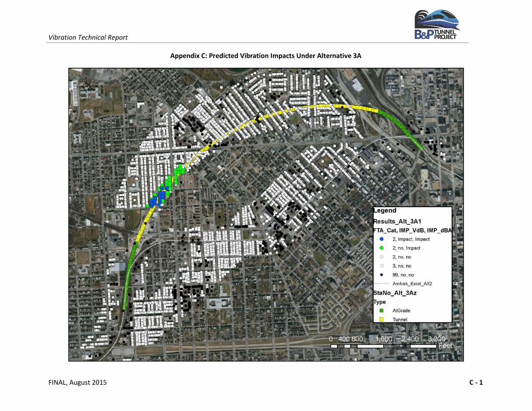
As shown in Table 9, levels under Alternative 3A due to ground-borne vibration from train passbys are predicted to exceed the FTA frequent impact criterion of 72 VdB at 69 residences and other FTA Category
Vibration Technical Report
FINAL, August 2015 14
2 land-uses. No exceedances of the FTA ground-borne vibration impact criteria are predicted at any Category 1 or 3 land-uses (institutions) under Alternative 3A.
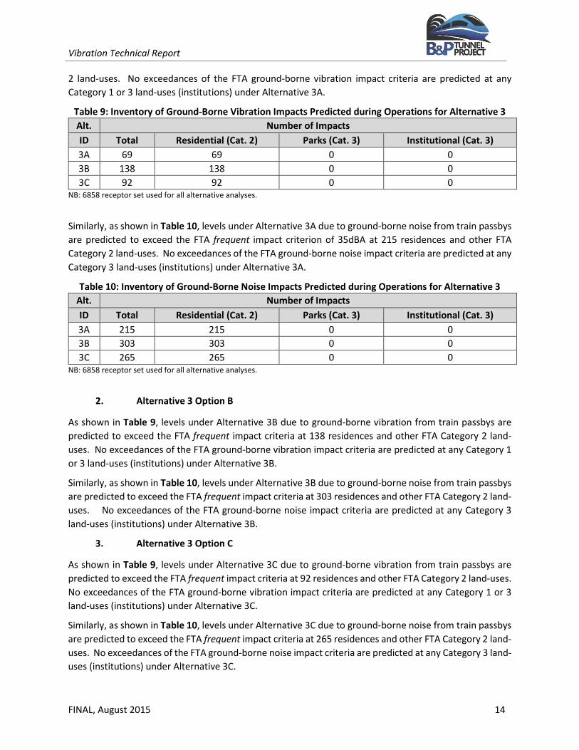
Table 9: Inventory of Ground-Borne Vibration Impacts Predicted during Operations for Alternative 3 Alt. Number of Impacts ID Total Residential (Cat. 2) Parks (Cat. 3) Institutional (Cat. 3) 3A 69 69 0 0 3B 138 138 0 0 3C 92 92 0 0
NB: 6858 receptor set used for all alternative analyses.
Similarly, as shown in Table 10, levels under Alternative 3A due to ground-borne noise from train passbys are predicted to exceed the FTA frequent impact criterion of 35dBA at 215 residences and other FTA Category 2 land-uses. No exceedances of the FTA ground-borne noise impact criteria are predicted at any Category 3 land-uses (institutions) under Alternative 3A.
Table 10: Inventory of Ground-Borne Noise Impacts Predicted during Operations for Alternative 3 Alt. Number of Impacts ID Total Residential (Cat. 2) Parks (Cat. 3) Institutional (Cat. 3) 3A 215 215 0 0 3B 303 303 0 0 3C 265 265 0 0
NB: 6858 receptor set used for all alternative analyses.
2. Alternative 3 Option B
As shown in Table 9, levels under Alternative 3B due to ground-borne vibration from train passbys are predicted to exceed the FTA frequent impact criteria at 138 residences and other FTA Category 2 land-uses. No exceedances of the FTA ground-borne vibration impact criteria are predicted at any Category 1 or 3 land-uses (institutions) under Alternative 3B.
Similarly, as shown in Table 10, levels under Alternative 3B due to ground-borne noise from train passbys are predicted to exceed the FTA frequent impact criteria at 303 residences and other FTA Category 2 land-uses. No exceedances of the FTA ground-borne noise impact criteria are predicted at any Category 3 land-uses (institutions) under Alternative 3B.
3. Alternative 3 Option C
As shown in Table 9, levels under Alternative 3C due to ground-borne vibration from train passbys are predicted to exceed the FTA frequent impact criteria at 92 residences and other FTA Category 2 land-uses. No exceedances of the FTA ground-borne vibration impact criteria are predicted at any Category 1 or 3 land-uses (institutions) under Alternative 3C.
Similarly, as shown in Table 10, levels under Alternative 3C due to ground-borne noise from train passbys are predicted to exceed the FTA frequent impact criteria at 265 residences and other FTA Category 2 land-uses. No exceedances of the FTA ground-borne noise impact criteria are predicted at any Category 3 land-uses (institutions) under Alternative 3C.

Vibration Technical Report
FINAL, August 2015 15
D. Alternative 11
Vibration impacts from Amtrak and freight trains due to steel wheel on steel rail interactions were evaluated using maximum corridor speeds that range from 30-70 miles per hour (mph). Therefore, exceedances of the FTA vibration “annoyance” impact criteria for frequent events were predicted at over 6800 residences and institutional land uses along Alternative 11.
1. Alternative 11 Option A
As shown in Table 11, levels under Alternative 11A due to ground-borne vibration from train passbys are predicted to exceed the FTA frequent impact criteria at 476 residences and other FTA Category 2 land-uses. No exceedances of the FTA ground-borne vibration impact criteria are predicted at any Category 1 or 3 land-uses (institutions) under Alternative 11A.
Table 11: Inventory of Ground-Borne Vibration Impacts Predicted during Operations for Alternative 11 Alt. Number of Impacts ID Total Residential (Cat. 2) Parks (Cat. 3) Institutional (Cat. 3)
11A 476 476 0 0 11B 320 320 0 0
NB: 6858 receptor set used for all alternative analyses.
Similarly, as shown in Table 12, levels under Alternative 11A due to ground-borne noise from train passbys are predicted to exceed the FTA frequent impact criteria at 672 residences and other FTA Category 2 land-uses. No exceedances of the FTA ground-borne noise impact criteria are predicted at any Category 3 land-uses (institutions) under Alternative 11A.
Table 12: Inventory of Ground-Borne Noise Impacts Predicted during Operations for Alternative 11
Alt. Number of Impacts ID Total Residential (Cat. 2) Parks (Cat. 3) Institutional (Cat. 3)
11A 672 672 0 0 11B 543 543 0 0
NB: 6858 receptor set used for all alternative analyses.
2. Alternative 11 Option B
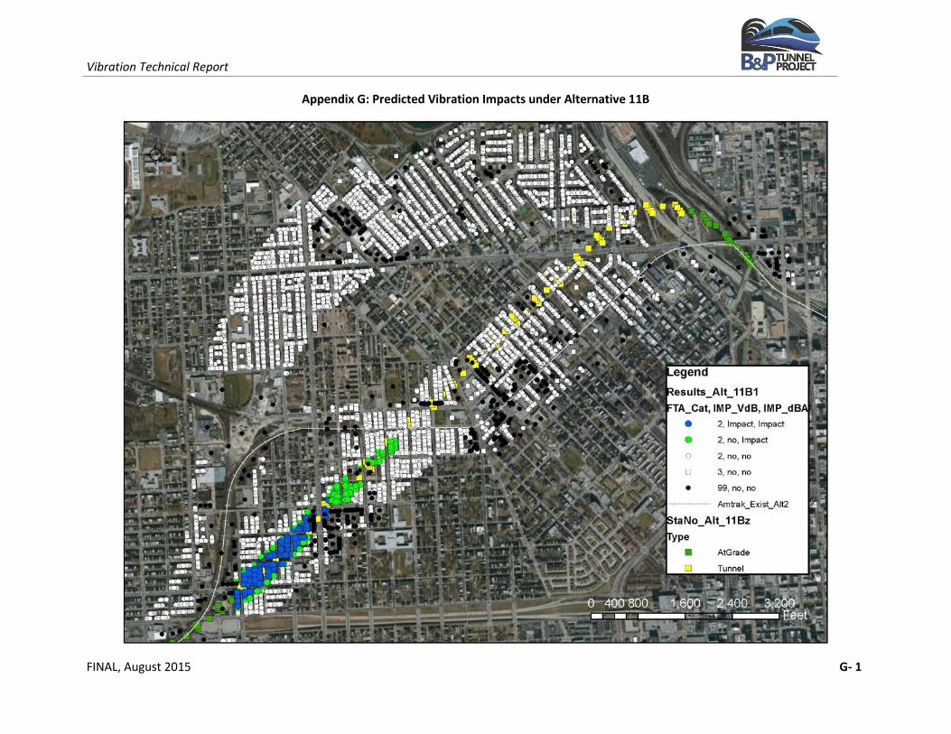
As shown in Table 11, levels under Alternative 11B due to ground-borne vibration from train passbys are predicted to exceed the FTA frequent impact criteria at 320 residences and other FTA Category 2 land-uses. No exceedances of the FTA ground-borne vibration impact criteria are predicted at any Category 1 or 3 land-uses (institutions) under Alternative 11B.
Similarly, as shown in Table 12, levels under Alternative 11B due to ground-borne noise from train passbys are predicted to exceed the FTA frequent impact criteria at 543 residences and other FTA Category 2 land-uses. No exceedances of the FTA ground-borne noise impact criteria are predicted at any Category 3 land-uses (institutions) under Alternative 11B.

Vibration Technical Report
FINAL, August 2015 16
X. CONSTRUCTION AND MITIGATION
Temporary impacts due to construction were evaluated qualitatively. Where impacts are predicted during operations or during construction, candidate control measures were identified and evaluated qualitatively to mitigate these potential impacts.
A. Construction
Vibration levels from construction activities as part of the B&P Tunnel Project, although temporary, could be a nuisance at nearby sensitive receptors. Vibration levels during construction are difficult to predict and vary depending on the types of construction activity and the types of equipment used for each stage of work. Heavy machinery, the major source of vibration in construction, is constantly moving in unpredictable patterns and is not usually at one location very long. Project construction activities could include tunnel excavation, relocating utilities and track laying. These excavation activities typically include tunnel boring machines (TBM), earth-moving equipment, and heavy-duty impulsive equipment, such as pile drivers, that may be utilized by the selected contractor. All construction activities would need to comply with the limits and guidelines included in the FTA guidelines so as to minimize vibration in the community.
Potential impacts during tunnel excavation are expected to be temporary as the advance rate for the TBM, for example, is typically 30-40 feet per day. However, due to the absence of credible source data for vibration from TBM particularly applicable to the B&P Tunnel corridor, the determination of impacts in the community during construction is not possible without significant uncertainty. Although vibration levels from TBM are available in literature, the wide range of variability in source levels even for similar geotechnical conditions prohibit determining any credible levels along the project alignments. For example, estimated vibration levels from TBM through bedrock range from 30 to 61 VdB at a typical building along the project alignments. These estimated levels range from well below background to barely noticeable at a typical residence. This range of levels from the TBM is also predicted to be well below the FTA impact criterion of 72 VdB for residences and other FTA Category 2 land-uses.
Therefore, MDOT and Amtrak are committed to minimizing impacts in the community by requiring its construction contractors to implement appropriate vibration control measures that would eliminate impacts and minimize extended disruption of normal activities.
B. Mitigation
Since exceedances of the FTA impact criteria are predicted for the proposed project alternatives, candidate mitigation measures were identified. Viable control measures include resilient track fasteners, resilient tie pads or ballast mats to decouple the rail from the support structure thereby reducing the magnitude of the vibration energy emitted into the surrounding ground. All vibration control measures would need to be evaluated in more detail during final design when the track alignments are finalized. Additionally, ground propagation characteristics determined through field measurements would also be required to accurately evaluate the various control measures considered.
Vibration Technical Report
FINAL, August 2015 17
XI. REFERENCES
U.S. Department of Transportation, Federal Transit Administration (FTA). 2006. FTA-VA-90-1003-06. Transit Noise and Vibration Impact Assessment. Office of Planning and Environment. Washington, DC.
U.S. Department of Transportation, Federal Railroad Administration (FRA) and the Maryland Department of Transportation (MDOT). December 2014. Preliminary Alternatives Screening Report (PASR). B&P Tunnel Project. Baltimore, MD.
XII. APPENDIX
Predicted Vibration Impacts Mapping
Appendix Figures A to G include colors and symbols identified in the legend as follows:
• "blue circle" - FTA Cat. 2 with both a vibration impact and a ground-borne noise impact; • "green circle" - FTA Cat. 2 with no vibration impact but with a ground-borne noise impact; • "red circle" - FTA Cat. 2 with a vibration impact but no ground-borne noise impact; • "white circle" - FTA Cat. 2 with neither a vibration impact nor a ground-borne noise impact; • "black circle" - non-sensitive land-use.
The receptor screening area is shown graphically with the range of colored circles.

(This page intentionally left blank)

Vibration Technical Report
FINAL, August 2015 A-1
Appendix A: Predicted Vibration Impacts under Alternative 1

This page intentionally left blank.

Vibration Technical Report
FINAL, August 2015 B - 1
Appendix B: Predicted Vibration Impacts under Alternative 2

This page intentionally left blank.
Vibration Technical Report
FINAL, August 2015 C - 1
Appendix C: Predicted Vibration Impacts Under Alternative 3A

This page intentionally left blank.

Vibration Technical Report
FINAL, August 2015 D - 1
Appendix D: Predicted Vibration Impacts under Alternative 3B

This page intentionally left blank.

Vibration Technical Report
FINAL, August 2015 E - 1
Appendix E: Predicted Vibration Impacts under Alternative 3C

This page intentionally left blank

Vibration Technical Report
FINAL, August 2015 F - 1
Appendix F: Predicted Vibration Impacts under Alternative 11A

This page intentionally left blank
Vibration Technical Report
FINAL, August 2015 G- 1
Appendix G: Predicted Vibration Impacts under Alternative 11B