vibration reduction methods for superconducting maglev ... · pdf filevibration reduction...
TRANSCRIPT

Vibration Reduction Methods for Superconducting Maglev Vehicles
1E. Suzuki, 2J. Shirasaki, 1K. Watanabe, 1H. Hoshino, and 2M. Nagai Railway Technical Research Institute, Tokyo, Japan1;
Tokyo University of Agriculture and Technology, Tokyo, Japan2
Abstract
The superconducting magnetically levitated transport (Maglev) system is a focus of interest as a future mode of transport at high speeds of over 500 km/h. Using a computational model of the vertical and pitching motions of a Maglev train, a study is conducted on the effectiveness of a maximum force control of the primary suspension using electromagnetic forces output by a bogie-integrated linear generator device, combined with a frequency-shaped optimal preview control of the secondary suspension using mechanical actuators and external disturbance information fed from the front to the rear of the train.
1. Introduction
In the continuing efforts toward the commercial operation of the superconducting Maglev system, in which vehicles travel at high speeds of over 500 km/h, methods of reducing vehicle vibrations are being examined with respect to suitability for a public mode of transportation. In order to reduce operating costs such as of the propulsion energy consumption and guideway maintenance of ground coil alignment, reducing the weight of Maglev vehicles is very important. However, the reduction in car body weight tends to increase vehicle vibrations, and is disadvantageous in terms of ride comfort. In comparison to wheel-on-rail vehicles, Maglev vehicles are composed of more lightweight car bodies and relatively heavier bogies which are mounted with devices such as superconducting magnets (SCMs) and an on-board refrigerating system. The secondary suspension in both Maglev and wheel-on-rail vehicles consist of springs and dampers between the car body and bogie. The primary suspension in wheel-on-rail vehicles consist of mechanical springs and dampers between the bogie frame and wheel axle, while the primary suspension of Maglev vehicles are characterized by electromagnetic interactions between the bogie and guideway that function as springs. The passive electromagnetic damping in the primary suspension of the Maglev vehicles is small. Therefore, it is effective to implement a control system that varies the electromagnetic forces to increase damping. In initial vehicle running tests, Maglev vehicle vibrations were controlled mainly focusing on the secondary suspension, and the control methods have been effective only for vibrations of relatively low frequencies at around 1 to 2 Hz corresponding to the natural car body vibration mode. The lightweight structure of the car bodies result in vibrations at around 4 to 5 Hz corresponding to the natural bogie vibration mode, and at other relatively higher frequencies that influence the ride comfort. A device called a linear generator that was developed and integrated into an existing bogie of the Maglev system generates on-board power and can also produce additional electromagnetic forces that can be used in the control of the primary suspension. This device has previously been demonstrated in full-scale vehicle experiments to effectively apply electromagnetic damping directly to the primary suspension, and reduce vibrations of relatively higher frequencies that are otherwise difficult to reduce by controlling only the secondary suspension. Studies on this primary suspension control device in conjunction with secondary suspension control and the effects on reducing vehicle vibrations are discussed in this report. The Maglev train set has an articulated bogie arrangement to provide a low center of gravity and improved magnetic shielding performance. The bogies are evenly spaced along the train set. In
addition, because of the interactions of electromagnetic forces in the primary suspension, each bogie of the Maglev train set is subjected to nearly the same external disturbance, with practically equal time differences between consecutive bogies. Utilizing these properties, techniques for preview control of the secondary suspension are examined that measure external disturbances at the front of the Maglev train set and feed the data to the rear of the train, to enhance the vehicle ability to efficiently minimize the impact of deviations in the guideway ground coil alignment. Results are presented on the methods for reducing vehicle vibrations of the superconducting Maglev train, examining the vibration control of the primary suspension using electromagnetic forces output by a bogie-integrated linear generator, combined with the preview control of the secondary suspension. Effective implementation of these vibration reduction methods on Maglev vehicles are expected to improve ride comfort, and eventually lead to the reduction of construction costs by enabling the relaxation of the limits of tolerated irregularities in the guideway alignment, and the reduction of management costs by minimizing guideway maintenance. Such cost reductions are expected to outweigh the increase in vehicle costs due to installation of vibration control systems.
2. Overview of the superconducting Maglev system and the mechanism of levitation[4]
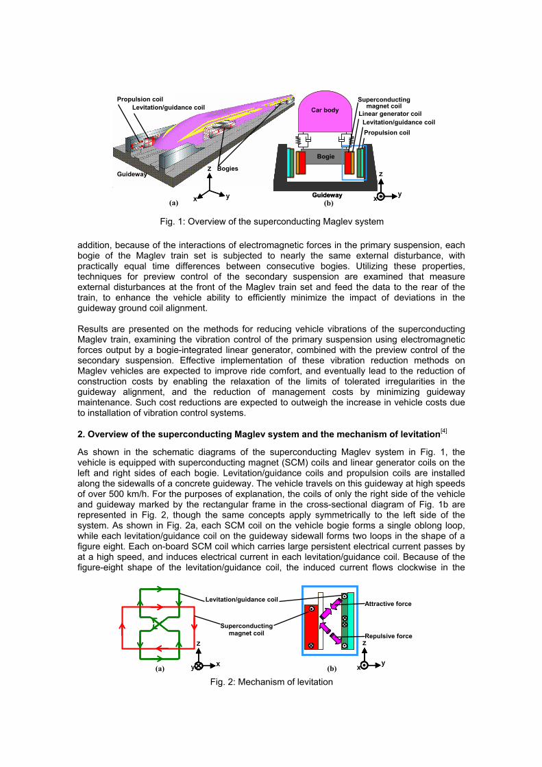
As shown in the schematic diagrams of the superconducting Maglev system in Fig. 1, the vehicle is equipped with superconducting magnet (SCM) coils and linear generator coils on the left and right sides of each bogie. Levitation/guidance coils and propulsion coils are installed along the sidewalls of a concrete guideway. The vehicle travels on this guideway at high speeds of over 500 km/h. For the purposes of explanation, the coils of only the right side of the vehicle and guideway marked by the rectangular frame in the cross-sectional diagram of Fig. 1b are represented in Fig. 2, though the same concepts apply symmetrically to the left side of the system. As shown in Fig. 2a, each SCM coil on the vehicle bogie forms a single oblong loop, while each levitation/guidance coil on the guideway sidewall forms two loops in the shape of a figure eight. Each on-board SCM coil which carries large persistent electrical current passes by at a high speed, and induces electrical current in each levitation/guidance coil. Because of the figure-eight shape of the levitation/guidance coil, the induced current flows clockwise in the
Fig. 1: Overview of the superconducting Maglev system
Guideway
Propulsion coil Levitation/guidance coil
Bogies
Bogie
Car body
Guideway
Bogie
Car body
Bogie
Car body
Guideway
Propulsion coil Levitation/guidance coil
Linear generator coil
Superconducting magnet coil
x
z
yx
z
y
z
yx
z
yx(a) (b)
Fig. 2: Mechanism of levitation
Levitation/guidance coil
Superconductingmagnet coil
Attractive force
Repulsive force z
y x
z
y x x
z
yx
z
y(a) (b)

upper loop and counter-clockwise in the lower loop. The resulting electromagnetic interactions between the coils are shown in Fig. 2b, characterized by attractive force in the upper half and repulsive force in the lower half. Recalling that this principle also applies symmetrically to the left side of the vehicle, the resulting forces maintain the levitation of the vehicle. The guidance function of null-flux cables (not shown in the figures) under the guideway, connecting each pair of levitation/guidance coils on the left and right sidewalls, ensure lateral centering of the vehicle.
3. Mechanism of generating additional electromagnetic forces using a bogie-integrated linear generator device to control vibrations of the primary suspension[4]
In the Maglev bogie-integrated linear generator device, linear generator coils are attached to the outer vessel surface of the SCM, and generate power in the traveling vehicle using the harmonic magnetic fields in the levitation/guidance coils. This device can also be used to generate additional electromagnetic forces in the primary suspension to be used as control forces in reducing vehicle vibrations. The principles of additional electromagnetic forces output by the linear generator are shown in Fig. 3. The equivalent configuration of the linear generator coil for the function of generating additional forces is expressed in Fig. 3a. Electrical current of amplitudes much smaller than that in the SCM coil is run through the linear generator coils. The resulting change in magnetic flux causes the already existing current in the levitation/guidance coil to increase slightly, indicated by the wide circular arrows in Figs. 3a and 3b. These additional currents generate additional forces indicated by the smaller additional arrows in Fig. 3c, resulting in an additional upward force acting on the bogie. Likewise, additional downward force acting on the bogie can be generated by reversing the direction of the current flowing in the linear generator coil. By varying the amplitude and direction of the current in the linear generator coils according to the vertical motion of the vehicle bogie, this device can be used to control vertical vehicle vibrations. This method has the advantage of requiring no additional systems solely for the purpose of generating electromagnetic forces. Furthermore, because the magnetic force is generated electrically, this method has minimal delay in response for high frequency ranges of vibration, in comparison to conventional methods using hydraulic or pneumatic systems.[5] Full-scale vehicle running tests on the Yamanashi Maglev Test Line confirmed the principles of magnetic forces output by the bogie-integrated linear generator device in the Japanese fiscal year 2001.[1] Vehicle running tests then confirmed the ability of the linear generator device to control vibrations using the generated forces in the fiscal year 2004.[2]
4. Analyses of vehicle dynamics
4.1 Vehicle model used in the computations
A vehicle model of a three-car train set for vertical and pitching motions with a total of 14 degrees of freedom was used, as shown in Fig. 4. The primary suspension between the bogie and guideway surface consists of electromagnetic spring characteristics resulting from
Fig. 3: Mechanism of additional upward force acting on the bogie, generated by linear generator coils and used for vibration control
Superconducting magnet coil
Levitation/guidance coil
Equivalent linear generator coil
Additional attractive force
Additional repulsive force
Additional induced current
x
z
yx
z
yx
z
yx
z
y
z
y x
z
y x
(c) (b) (a)

interactions between the superconducting magnets and ground coils. The spring characteristics of the vertical and pitching motions are coupled with each other. The magnetic spring acts in equal distribution along the length of the bogie from front to rear. However, for purposes of optimizing computations, equivalent spring characteristics were approximated by concentrating the springs at two positions, one on the front and the other on the rear of the bogie. The secondary suspension between the car body and bogie consists of air springs that were approximated using a damper and a spring connected in parallel. Actuators for vibration control were added to the secondary suspension of the middle and rear cars and were assumed to have ideal operating properties with no time delay. In the primary suspension control model, the forces output by the bogie-integrated linear generator were used in all four bogies as damping forces in the vibration control. The aforementioned magnetic forces output by the linear generator were assumed to be ideal, and delays in response were not considered. Furthermore, these magnetic forces of the linear generator are assumed to be equally distributed along the length of the bogie surface, such that the force at any longitudinal position on the bogie surface is of the same magnitude and same direction at any given time. For example, if an upward control force acts on the front end of a bogie at a given instance in time, an upward force of equal magnitude simultaneously acts on the rear end. Therefore, this force is assumed to have no influence on the bogie pitching motion. In the computation model, an equivalent vertical control force was concentrated on one point at the center of mass of each of the four bogies. Although the force only controls the vertical motion, the pitching vibrations are expected to be much smaller than the vertical vibrations in the passive case, making vertical control a priority. The vehicle traveling speed was set to a constant 500 km/h.
4.2 Vehicle model parameters
The vehicle model parameters used in the computations are shown in Table 1. The values are based on those used in Reference [7].
Parameter Value
mc (kg) 14.0×10³ mb (kg) 6.0×10³
Ic (kg·m2) 82.0×10⁴ Ib (kg·m2) 13.2×10³ kz (N/m) 0.4×10⁶ kmz (N/m) 4.7×10⁶
kmθ (N·m/rad) 1.0×10⁷ cz (N·s/m) 1.0×10⁴
lac (m) 8.8 lab (m) 2.03
Table 1: Vehicle model parameters
Primary suspension(Electromagnetic spring)
Secondary suspension(Air spring, Damper)
Fig. 4: Vehicle model used in the computations
z01f z01r z02f z02r z03f z03r z04f z04r
zc2 zc1 zc3
2·lab lac
θc1 θc2 θc3
θb1 zb1
mc Ic
mb Ib
θb2 zb2 θb3 zb3 θb4 zb4
Car body No. 2 Car body No. 3
kz cz
Traveling direction
Actuator
Bogieskmz
Car bodyNo. 1
Electromagnetic damping
kmθ

5. Control system
5.1 Frequency-shaped optimal preview control of the secondary suspension[3]
When the objective is to improve vehicle ride comfort, optimal control laws usually include a evaluation function based on the car body acceleration. Because human perception of vibrations differs according to the frequency, vibrations can be efficiently reduced by evaluating acceleration data modified by frequency shaping techniques, resulting in a control method that takes ride comfort factors into consideration. In this study, a frequency shaping function Q
―
(s) was derived as shown in Equation (1), with gain characteristics based on ride comfort level curve shown in Fig. 5, used by the former Japanese National Railways to define frequency-dependant human sensitivity to vibrations.
2221
2
221
1
1
2)(
nn
n
n
n
wswswK
wwssQ
++⋅
+=
ζ (1)
Here, K1 = 0.55, wn1 = 5.2π, wn2 = 12π, and ζ1 = 0.61. In order to suppress the actuator output at high frequencies, a frequency shaping function R
―
(s) was also applied to the control input.
22332
244
22443
2432
)2()2()(
nnn
nnn
wswswwswswKsR
++++
=ζζ
(2)
Here, K2 = 0.01, wn3 = 62π, wn4 = 20π, and ζ2 = ζ3 = 0.6. The shaping factor gain increases from around 10 Hz to 30 Hz, where the ride comfort level curve drops, and levels off at around 30 Hz, in effect a high pass filter. Next, inverse Laplace transforms of Equations (1) and (2) were derived to express the equations in state-space form. The state equation for Q
―
(s) can be expressed using the input Y, state Xq, and coefficient matrices Aq, Bq, Cq, and Dq:
YDXCYYBXAX
qqqq
qqqq
+=
+=& (3)
In the same manner, the state equation for R―
(s) can be expressed as:
uDXCYuBXAX
rrrr
rrrr
+=+=&
(4)
The state equations for the vehicle model shown in Fig. 4 can be expressed as:
0
0
xZDuCXYxWuBXAX&
&&
++=++=
(5)
Here, X represents the state variables, Y the output used in Equation (3), u the control input, 0x& the rate of change of the external disturbance x0 with respect to time, and A, B, C, D, and Z
the coefficient matrices. By substituting Y in Equation (3) with the output of Equation (5), frequency shaping factors are applied to the output. Combining Equations (3), (4), and (5) results in the form:
Gai
n [-]
Ride comfort filterQ―
(jω) R―
(jω)
Frequency [Hz] Fig. 5: Ride comfort filter and frequency shaping functions Q
―(jω), R
―
(jω)

0
000000
xZBW
u
B
DBB
X
XX
AACB
A
X
X
X
q
r
q
r
q
r
r
q &
&
&
&
⎥⎥⎥
⎦
⎤
⎢⎢⎢
⎣
⎡
+⎥⎥⎥
⎦
⎤
⎢⎢⎢
⎣
⎡
+⎪⎭
⎪⎬
⎫
⎪⎩
⎪⎨
⎧
⎥⎥⎥
⎦
⎤
⎢⎢⎢
⎣
⎡=
⎪⎪⎭
⎪⎪⎬
⎫
⎪⎪⎩
⎪⎪⎨
⎧
(6)
This state equation is discretized to construct an optimal preview control system.[3] Finally, an evaluation function J is used to derive feedback and feed-forward coefficients. This function evaluates values resulting from frequency shaping factors added to the output Y and the input u, and is expressed as:
[ ]∑
∑ ∑∑∞
+−=
∞
+−=
−
=
−
=
+=
⎪⎭
⎪⎬⎫
⎪⎩
⎪⎨⎧
⎥⎦
⎤⎢⎣
⎡−+⎥
⎦
⎤⎢⎣
⎡−=
1
22
1
21
0
21
0
)()(
)()()()(
R
R
Mkrq
Mk
k
n
k
n
krYkqY
nkunRrnkYnQqJ (7)
Here, q and r are coefficient weighting matrices, and MR is the number of preview steps. The optimal control input can be derived by solving the Riccati equation resulting from substituting the outputs of Equations (3) and (4) into Equation (7). Considering real-time performance and redundancy in this study, the frequency-shaped optimal preview control system was implemented using decentralized controllers. The vehicle model for computations is divided up as shown in Fig. 6, such that a reduced-order sub-model unit exists now for each actuator, with two vertical degrees of freedom in each sub-model unit consisting of one car body component and one bogie component. A controller is designed independently for each sub-model unit. For example, the state variables of Controller No. 1 in Fig. 6 are the vertical velocities and relative displacements of the car body and bogie:
[ ]Trbbcbccontroller zzzzzzx )()()()( 02222221 −−= && (8) Decentralizing the control system results in four state variables as shown in Equation (8), and greatly simplifies the computations in comparison to designing the controller using the full order of the entire model. For this decentralized controller model, the control system is designed by the methods described earlier in this section. Here, the evaluation function of this control model is based on Equation (7) and expressed as follows:
( ) ( )[( ) ( ) ]
⎪⎭
⎪⎬⎫
⎟⎠
⎞⎜⎝
⎛−
+−+−
+−+−
⎪⎩
⎪⎨⎧
+⎥⎥⎦
⎤
⎢⎢⎣
⎡⎟⎠
⎞⎜⎝
⎛−+⎟
⎠
⎞⎜⎝
⎛−=
∑ ∑
∑ ∑∑
=
−
=
∞
+−=
−
=
−
=
5
1
21
0
243
233
232
2222
1
21
03
21
021
)()(
)()()()(
)()()()(
)()()()(
i
k
ni
bcbc
bcbc
Mk
k
nc
k
nc
nkunRr
kzkzkzkz
kzkzkzkzq
nkznQnkznQqJR
&&&&
(9)
Equation (9) includes frequency shaping of vertical accelerations of the middle and rear cars and control inputs, and coefficient weighting of relative displacements. Coefficient weighting of the relative displacements can prevent vertical physical limit stoppers from colliding between the car body and bogie when the vertical displacement becomes very large. In this study, in order to achieve the maximum effect of vibration control, a limit was set for the maximum root-mean-squared (RMS) value of the forces generated by each actuator, r was set to a constant value, and q1 and q2 were varied to determine a combination of values that result in maximum improvement of ride comfort, within the defined limits of the actuator output. The weighting
Fig. 6: Model of decentralized controllers
ControllerNo. 1
Controllers No. 2 No. 3
Controllers No. 4 No. 5zc2 zc2 zc3 zc3
zb3 zb4 zb2 zb3
mcf mcr mcf mcr
mbr mbf mbr mbf
z01f z01r z02f z02r z03f z03r z04f z04r
u1 u2 u3 u4 u5
zc3
mcr
zb4 mbr

coefficients used in this study are shown in Table 2. This control method was compared with the case of optimal preview control without frequency shaping, in which the weighting coefficients were derived in a similar manner. Each car body and bogie was assumed to be symmetric in the longitudinal direction, such that the effective masses on which each controller acts consists of the front and rear halves of the bogie mass mbf = mbr and middle car body mass mcf = mcr. The rear car body mass is evenly distributed, such that mcf = mcr = mc /3.
Coefficient q1 q2 R
Value 107 1010 1 Table 2: Weighting coefficients used in frequency-shaped optimal preview control
5.2 Maximum force control of the primary suspension using the linear generator device
As discussed in Section 3, the bogie-integrated linear generator device can generate additional electromagnetic forces that can be applied to the vibration control of the primary suspension. Reference [5] mentions that the forces output by this linear generator device is relatively small for the requirements vibration control of the primary suspension. In order to fully utilize the forces generated by the bogie-integrated linear generator device, the maximum possible force output by the linear generator device is used at all times, with the polarity of the force switched according to the polarity of the bogie vertical velocity as expressed in Equation (10).[5]
( )mz b mzF sign z f= − ⋅& (10) Here, Fmz represents the control force and fmz the maximum possible vertical force output by the linear generator device. The computations assume that the bogie vertical velocity bz& which is the control feedback variable is derived by using accelerometers to measure the acceleration of the vertical vibration of the bogie, then integrating this acceleration once to derive the absolute velocity. Equation (10) was added to the dynamic equations of the vertical motions of all four bogies in Equation (5). The computations assume that the control force of each bogie can be applied independently of each other.
6. Model guideway irregularities for external disturbance input and ride comfort levels
To assess the effectiveness of the vibration control method, irregularities in the vertical alignment of ground coils along the sidewalls of the guideway (vertical irregularities) were generated, and used as external disturbance input in time domain simulations. A transfer function was formed based on Reference [7], and a uniformly random number was used to compute the vertical irregularities. This transfer function has the characteristic of flattening out at low frequencies in order to reduce the amplitude of vibrations in low frequency ranges. The power spectral density (PSD) of the vertical irregularities is shown in Fig. 7.
Wave number [1/m]
Fig. 7: Power spectral density of guideway irregularities
Gui
dew
ay ir
regu
larit
y P
SD
[(m
m2 )/(
1/m
)]
The ride comfort level, a quantitative index for passenger comfort based on the car body acceleration response to vertical irregularities, was used to confirm the performance of the vibration control in this study. This ride comfort level (denoted LT) is based on ISO 2631 and was devised by the former Japanese National Railways. To derive the LT value, ride comfort filters based on frequency shaping curves are applied to the vehicle response in the form of the car body vibration acceleration, to account for human perception of vibrations. Next, the resulting value is divided by a reference vibration acceleration value aref. Finally, the logarithm of the RMS of this value is derived, and expressed in decibels (dB). The following equation was used in this study to compute the ride comfort levels.[6]
][)(log20 10 dBaL refwT α= (11) where
]sec/[10
)(25
0
22
ma
dfPfW
ref
xxw
−
∞
=
⋅⋅= ∫α (12)
Here, W(f) represents the ride comfort filter, and Pxx(f) the car body vibration acceleration PSD. Since there are no regulations defining this filter for frequencies below 0.5 Hz, the weighting factor for 0.5 Hz was also used for the frequency range below 0.5 Hz.
7. Results
The following cases were studied as described in this chapter in the sections to follow: Case 1: Optimal preview control of secondary suspension without frequency shaping Case 2: Frequency-shaped optimal preview control of secondary suspension Case 3: Maximum force control of primary suspension Case 4: Cases 2 and 3 combined
7.1 Time domain computation results of the secondary suspension control
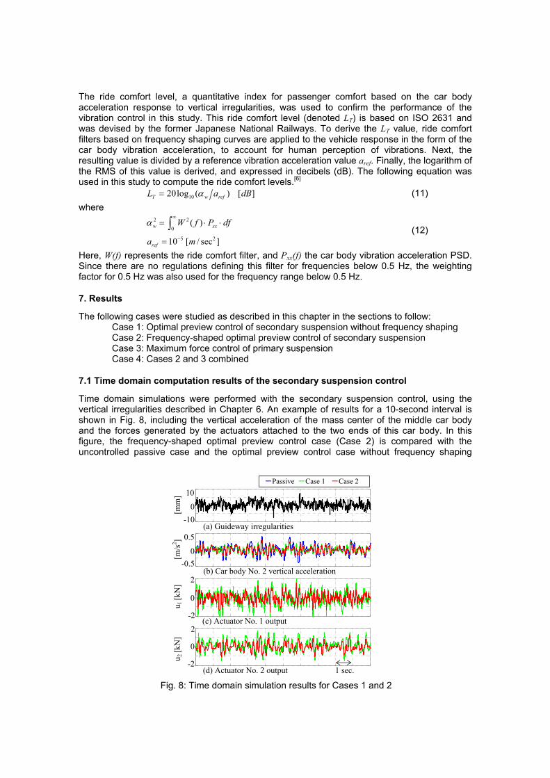
Time domain simulations were performed with the secondary suspension control, using the vertical irregularities described in Chapter 6. An example of results for a 10-second interval is shown in Fig. 8, including the vertical acceleration of the mass center of the middle car body and the forces generated by the actuators attached to the two ends of this car body. In this figure, the frequency-shaped optimal preview control case (Case 2) is compared with the uncontrolled passive case and the optimal preview control case without frequency shaping
Fig. 8: Time domain simulation results for Cases 1 and 2
-10
0.5
-0.5
-2
2
0
-2
2
0
0
0
(a) Guideway irregularities
(b) Car body No. 2 vertical acceleration
(c) Actuator No. 1 output
(d) Actuator No. 2 output
10 -Passive -Case 1 -Case 2
1 sec.u 2 [k
N]
u 1
[kN
]
[m/s2 ]
[m
m]
1 sec.

(Case 1). Figure 8b indicates that both of the two controlled cases have acceleration amplitudes smaller than that of the passive case, but it is difficult to see any significant differences between the two controlled cases. In contrast, Figs. 8c and 8d show that the actuator forces have smaller amplitudes in Case 2. In particular, actuator forces in Case 2 are within 1.5 kN, while those of Case 1 reach a maximum of 2.3 kN. Thus, for the same quantity of reduction in the car body acceleration, the frequency-shaped optimal preview control of Case 2 has a higher efficiency, allowing for the design of smaller actuators with smaller maximum forces.
7.2 Frequency domain computation results of the secondary suspension control
Next, in the examination of results in the frequency domain, vertical acceleration PSD plots of the middle and rear car bodies were derived from the time domain response described in the previous section, and are shown in Fig. 9. The quantity of reduction of the average ride comfort level relative to the reference passive case is displayed in the legends of this figure. The middle car body PSD peak at around 1 to 2 Hz corresponding to the vertical motions of the car body is larger in Case 2 than in Case 1. However, the frequency shaping factor of the vertical ride comfort level curve is small in this frequency range, such that there is no large difference in effect on the ride comfort level. At higher frequencies beyond 10 Hz, the frequency shaping factor reduces the effects of the actuator output force, as can be observed by comparing the acceleration output of Cases 1 and 2, resulting in the same order of ride comfort as that of the passive case at these higher frequencies. The ride comfort level in both controlled cases is over 3 dB lower than in the passive case. In the rear car body, the ride comfort level in Case 2 is almost 4 dB lower than in the passive case. However, the characteristic peak at around 1 to 2 Hz is not reduced and the effect of the vibration control is small compared with Case 1.
7.3 Comparison of forces generated by actuators in the secondary suspension control
To compare the effectiveness of the two vibration control methods, the RMS values of the force output for each actuator for Cases 1 and 2 are shown in Fig. 10. For the purpose of comparing the relative effectiveness of the control methods with and without frequency shaping, the RMS value of the actuator output force in the case without frequency shaping (Case 1) was defined as 100%. The force output of all five actuators in the frequency-shaped Case 2 is about 70 to 80%. In particular, actuators No. 1 and 2, installed at the positions of the air springs on the front and rear ends of the middle car body, have a force output of about 70%, while maintaining the same order of ride comfort level as shown in Fig. 9a.
(b) Car body No. 3 center of mass
Fig. 9: Car body vertical acceleration power spectral densities for Cases 1 and 2
(a) Car body No. 2 center of mass
1.0E-06
1.0E-04
1.0E-02
1.0E+00
0.1 1 10 100Frequency (Hz)
Acce
lera
tion
PSD
((m
/s2 )/H
z)
PassiveCase 1: -3.2 dBCase 2: -3.3 dB
1.0E-06
1.0E-04
1.0E-02
1.0E+00
0.1 1 10 100Frequency (Hz)
Acce
lera
tion
PSD
((m
/s2 )/H
z)
PassiveCase 1: -4.4 dBCase 2: -3.8 dB

7.4 Frequency domain computation results of the primary suspension control
Vertical acceleration PSD plots of the middle and rear car bodies were derived from the time domain response for the maximum force control of the primary suspension, and are shown in Fig. 11. The vertical generated force fmz in Equation (10) was set to 2 kN, and applied to each of the four bogies. As defined at the beginning of this chapter, Case 3 represents the maximum force control of the primary suspension control alone, and Case 2 is the frequency-shaped optimal preview control of the secondary suspension alone. Again, the quantity of reduction of the average ride comfort level relative to the reference passive case is displayed in the legends of this figure. The middle car body PSD peak at around 1 to 2 Hz corresponding to the vertical motions of the car body has been reduced in Case 2 to about one-seventh of the passive case, while this peak was hardly reduced in Case 3. The peak at around 4 to 5 Hz corresponding to the vertical motions of the bogie is slightly reduced in Case 2, while notably reduced in Case 3, to about one-sixth of the passive case. Although the effect of the control methods are at different frequency ranges, the resulting effect on the ride comfort level is of the same order for both cases, over 3 dB lower than in the passive case. In the rear car body, the ride comfort level in Case 2 is nearly 4 dB lower than in the passive case, while Case 3 is just about 3 dB lower.
Fig. 10: Comparison of RMS values for each actuator output Actuator No. 1 No. 2 No. 3 No. 4 No. 5
Nor
mal
ized
act
uato
r out
put
RM
S va
lues
[%]
Car body No. 2 Car body No. 3Case 1
Case 2
50
60
70
80
90
100
(b) Car body No. 3 center of mass
Fig. 11: Car body vertical acceleration power spectral densities for Cases 2 and 3
(a) Car body No. 2 center of mass
1.0E-06
1.0E-04
1.0E-02
1.0E+00
0.1 1 10 100Frequency (Hz)
Acce
lera
tion
PSD
((m
/s2 )/H
z)
PassiveCase 2: -3.3 dBCase 3: -3.5 dB
1.0E-06
1.0E-04
1.0E-02
1.0E+00
0.1 1 10 100Frequency (Hz)
Acce
lera
tion
PSD
((m
/s2 )/H
z)
PassiveCase 2: -3.8 dBCase 3: -3.0 dB

7.5 Combined primary and secondary suspension control
As defined at the beginning of this chapter, Case 4 combines Case 3, the maximum force control of the primary suspension, with Case 2, the frequency-shaped optimal preview control of the secondary suspension. Vertical acceleration PSD plots of the middle and rear car bodies for Cases 2 and 4 are shown in Fig. 12. The middle car body PSD peak at around 1 to 2 Hz has been reduced in Case 4 to about one-seventh of the passive case, the same as that of Case 2. The peak at around 4 to 5 Hz is slightly reduced in Case 2, while significantly reduced in Case 4, to about one-fifteenth of the passive case. With respect to the passive case, the reduction of ride comfort level in Case 4 is slightly larger than the sums of the reductions of ride comfort levels in Cases 2 and 3. Similar results are observed in the rear car body.
8. Conclusions
A study was conducted on the effectiveness of applying vibration control to the primary and secondary suspension components in a model of the vertical and pitching motions of the superconducting Maglev vehicle. Results confirmed that a frequency-shaped optimal preview control of the secondary suspension can maintain the same order of ride comfort levels in the middle car body, using 30% less actuator output force than in the case without frequency shaping. The vibration peaks at 1 to 2 Hz and at 4 to 5 Hz were considerably reduced by combining the primary and secondary suspension control methods, and the reduction of the ride comfort level with respect to the passive case is larger than the sums of the reductions of ride comfort levels of each control method applied alone.
Acknowledgment
This research is financially supported in part by the Ministry of Land, Infrastructure, Transport and Tourism, of the government of Japan.
References
[1] H. Hasegawa, T. Murai, T. Yamamoto. “Running tests of a combined SC type linear generator”, Transactions on Industry Applications, Institute of Electrical Engineers of Japan, Volume 123-D(2), pp. 156-163 (2003).
[2] Y. Sakamoto, T. Murai, T. Kashiwagi, M. Tanaka, E. Suzuki, K. Yamamoto. “The development of linear generator system combined with magnetic damping function”, Transactions on Industry Applications, Institute of Electrical Engineers of Japan, Volume 126-D(2), pp. 192-198 (2006).
(b) Car body No. 3 center of mass
Fig. 12: Car body vertical acceleration power spectral densities for Cases 2 and 4
(a) Car body No. 2 center of mass
1.0E-06
1.0E-04
1.0E-02
1.0E+00
0.1 1 10 100Frequency (Hz)
Acce
lera
tion
PSD
((m
/s2 )/H
z)
PassiveCase 2: -3.3 dBCase 4: -8.0 dB
1.0E-06
1.0E-04
1.0E-02
1.0E+00
0.1 1 10 100Frequency (Hz)
Acce
lera
tion
PSD
((m
/s2 )/H
z)
PassiveCase 2: -3.8 dBCase 4: -7.3 dB

[3] J. Shirasaki, E. Suzuki, K. Watanabe, H. Hoshino, M. Nagai. “Improvement of vibration reduction performance of superconducting Maglev vehicles using optimal preview control”, Proceedings of the Dynamics and Design Conference, Japan Society of Mechanical Engineers, CD-ROM, Paper OS11-410 (2007).
[4] E. Suzuki, J. Shirasaki, K. Watanabe, H. Hoshino, M. Nagai. “Comparison of methods to reduce vibrations in superconducting Maglev vehicles by primary suspension control”, Journal of Mechanical Systems for Transportation and Logistics, Japan Society of Mechanical Engineers, Volume 1, Number 1, pp. 3-13 (2008).
[5] E. Suzuki, K. Watanabe. “Results of vibration control of a Maglev vehicle utilizing a linear generator”, Proceedings of the International Design Engineering Technical Conferences, American Society of Mechanical Engineers, CD-ROM, DETC2005-84980 (2005).
[6] K. Tanifuji, H. Yoshioka, T. Miyashita. “A prediction of riding comfort with an artificial generation of track irregularity”, Transactions of the Japan Society of Mechanical Engineers, Edition C, Volume 56, Number 523, pp. 573-577 (1990).
[7] K. Watanabe, H. Yoshioka, E. Suzuki, T. Tohtake, M. Nagai. “A study of vibration control systems for superconducting Maglev vehicles”, Journal of System Design and Dynamics, Japan Society of Mechanical Engineers, Volume 1, Number 4, pp. 703-713 (2007).