vibration control buildings in japan - facultatea de ...civile.utcb.ro/pdf/seki5.pdf · vibration...
TRANSCRIPT
Vibration Control
Buildings in Japan
May 2017
Building Research Institute,
Japan
Matsutaro SEKI
Seki M., UTCB Lecture note, May 2017, BRI, Japan

Contents
1. Achievement state in Japan
2. Basic concept of vibration control
3. Vibration control devices
4. Vibration control design
5. Examples of vibration control buildings
Seki M., UTCB Lecture note, May 2017, BRI, Japan

Vibration Control buildings in Japan
Seki M., UTCB Lecture note, May 2017, BRI, Japan
Accum
ula
tive
num
ber

Principle of Vibration ControlReduction of Response by dampers
which absorb input energy
Seismic Isolation and Vibration Control
Traditional Building Vibration Control Building
Damper
Energy Absorption by Structural Members
Energy Absorption by Dampers
Cracks
Seki M., UTCB Lecture note, May 2017, BRI, Japan

Basic Concept of Vibration Control
Seismic isolationVibration control
Earthquake
resistant
Seismic Isolation Top floor vibration control Inner frame vibration control
T : long
Acc.: small
T : short
Acc.: big
T : long
Acc.: big
T :long
Disp.: small
Isolator
Vibration Control
devices
Dampers
Seki M., UTCB Lecture note, May 2017, BRI, Japan

Recommended height and period of buildings
Vibration
control
structure
Earthquake
resistant
structure
Seismic
isolation
building
Period (sec)
Heig
ht
(m)
Basic Concept of Vibration Control
Seki M., UTCB Lecture note, May 2017, BRI, Japan

Short Period Long Period
Period
Dis
p.
Damping
Big
Vibration
Control
Seismic Isolation
Short Period Long Period
Period
AC
C.
Damping
Big
Seismic
Isolation
Vibration
Control
Response Acceleration Response Displacement
Principle of Seismic Isolation
and Vibration Control
Seki M., UTCB Lecture note, May 2017, BRI, Japan
AIJ ,2007
力学機構 制振部材
①鋼材ダンパー
②鉛ダンパー 変位依存型ダンパー
(履歴減衰部材) ③摩擦ダンパー
④オイルダンパー
⑤粘性ダンパー 速度依存型ダンパー
(粘性減衰部材)
⑥粘弾性ダンパー
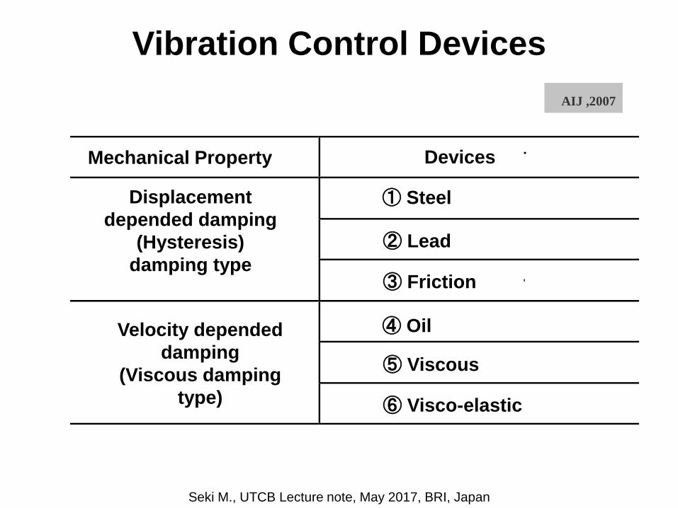
Vibration Control Devices
Mechanical Property
⑥ Visco-elastic
⑤ Viscous
④ Oil
③ Friction
② Lead
① Steel
Devices
Displacement
depended damping
(Hysteresis)
damping type
Velocity depended
damping
(Viscous damping
type)
Seki M., UTCB Lecture note, May 2017, BRI, Japan
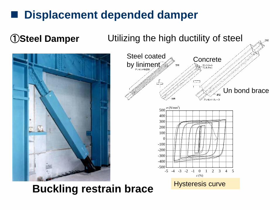
Displacement depended damper
①Steel Damper
Buckling restrain brace
Utilizing the high ductility of steel
-500
-400
-300
-200
-100
0
100
200
300
400
500
-5 -4 -3 -2 -1 0 1 2 3 4 5
(N/mm2)
(%)
Hysteresis curve
Steel coated
by linimentConcrete
Un bond brace

① Steel Damper
Column type shear panel
Displacement depended damper
Low
yielding
strength
steel
panel
Hysteresis curve
Seki M., UTCB Lecture note, May 2017, BRI, Japan

②鉛ダンパー
Lead Damper
(Cylinder type)
Utilizing the high ductility of leadUtilizing the plastic fluid resistant of lead
Displacement depended damper
Hysteresis curve
Seki M., UTCB Lecture note, May 2017, BRI, Japan

③Friction
damper
Friction damper (Bolt system)
Transforming vibration energy into thermal
energy
皿ばね
皿ばねボルトセット
ブレーキ材
ステンレス板外板(スプライスプレートなど)
中板(ブレース材など)長孔
座金
座金
摩擦面・摺動面
並列枚数5枚の例
外板(スプライスプレートなど)
主架構へ
ブレースなどへ
板座金
-1.5
-1.0
-0.5
0.0
0.5
1.0
1.5
-60 -40 -20 0 20 40 60
u d (mm)無次元化荷重
(Fd /F d
y )
Displacement depended damper
Hysteresis curve
Plate spring +bolt system
Sliding
plate

③Friction Damper
Friction Damper
(Ring system)
内筒 外筒
RingCenter bar-450
-300
-150
0
150
300
450
-30 -20 -10 0 10 20 30
ud [mm]
Fd
[kN
]
Displacement depended damper
Transforming vibration energy into
thermal energy
Hysteresis curve
Internal
pipe
External
pipe
Seki M., UTCB Lecture note, May 2017, BRI, Japan

① Oil Damper
Oil Damper
Utilizing the fluid resistance of oil
-300
-200
-100
0
100
200
300
-10 -5 0 5 10
変位 [mm]減
衰力
[kN
]
Velocity depended damper
Hysteresis curve

② Viscous Damper Utilizing the shear resistance of
polymer material
① データ : sheet"データ"に入力
② グラフのサイズ : (行1~19)×(列A~G)
③ グラフ中のフォント : MS Pゴシックでサイズ12
④ グラフ中のマーカー : サイズ7
⑤ グラフの輪郭 : なし⑥ 単位 : SI単位
⑦ ”減衰力”、”抵抗力”等 : 全て”減衰抵抗力”とする
-1000
-500
0
500
1000
-40 -20 0 20 40
変位 (mm)減
衰抵
抗力
(kN
)
Velocity depended damper
Viscous Damper(wall type)
Hysteresis curve
Viscous material
Seki M., UTCB Lecture note, May 2017, BRI, Japan

日本建築学会関東支部:免震・制振構造の設計2007年、4章
③ Visco-Elastic damper
Visco-elastic damper
Utilizing the shear resistance of visco-elastic material
仕切板中間板
外部鋼板
粘弾性材料
Velocity depended damper
Hysteresis curve
Visco-elastic
material
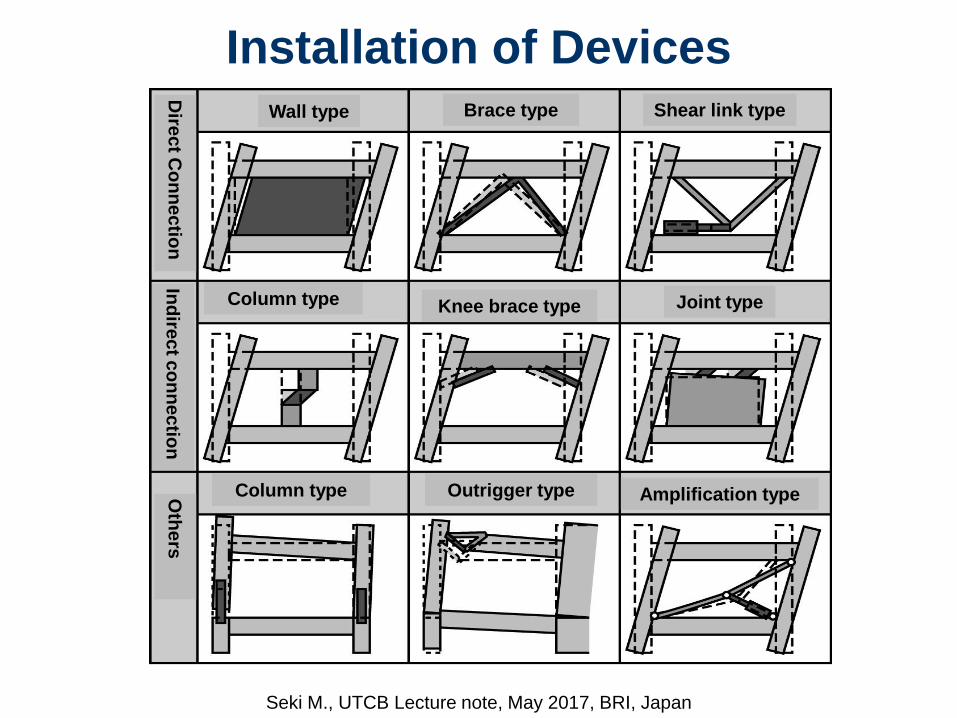
Installation of Devices
Amplification typeOutrigger typeColumn type
Joint typeKnee brace typeColumn type
Shear link typeBrace typeWall type
Dire
ct C
on
ne
ctio
nIn
dire
ct c
on
ne
ctio
nO
the
rs
Seki M., UTCB Lecture note, May 2017, BRI, Japan

Buckling restrain
brace
Friction damper brace Oil damper brace
Wall type Brace type Shear link type
Dire
ct c
on
ne
ctio
n
typ
e
Installation of Devices
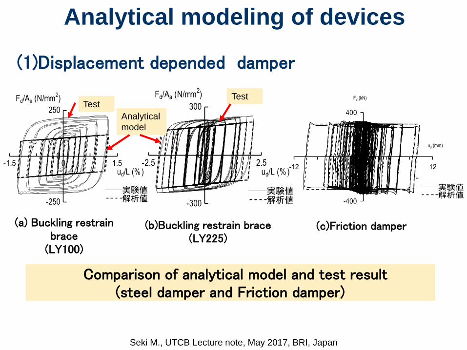
Analytical modeling of devices
(1)Displacement depended damper
-2.5 0 2.5
-300
0
300
Fd/Aa (N/mm2)
ud/L (%)
実験値解析値
-1.5 0 1.5
-250
0
250
Fd/Aa (N/mm2)
ud/L (%)
実験値解析値
-12 0 12
-400
-200
0
200
400
-12 0 12
-400
-200
0
200
400
-12 0 12
-400
-200
0
200
400
Fd (kN)
ud (mm)
-2.5 0 2.5
-300
0
300
Fd/Aa (N/mm2)
ud/L (%)
実験値解析値
(a) Buckling restrain brace
(LY100)
(b)Buckling restrain brace(LY225)
(c)Friction damper
Comparison of analytical model and test result(steel damper and Friction damper)
Test
Analytical
model
Test
Seki M., UTCB Lecture note, May 2017, BRI, Japan

(2) Velocity depended damper
-1 1 2
-500
500
0um
(cm)
Fd(kN)
実験 解析
-3 3
-1500
1500
0
ud(cm)
Fd(kN)
実験 解析
(a)Oil damper (with relief valve) (b) Viscous damper ( wall type)
Analytical modeling of devices
Comparison of analytical model and test result(Oil damper and Viscous damper)
Test
Test
Analytical
modelAnalytical
model
Seki M., UTCB Lecture note, May 2017, BRI, Japan
Structural Design of
Vibration Control
Buildings in Japan
Seki M., UTCB Lecture note, May 2017, BRI, Japan

Comparison of Earthquake resistant
design and vibration control design
Concentration to specific story
Unrepairable afterstrong earthquake
Usable after replacing the vibration control member
Takeuch T. , Titec
Structural
member
Vibration
control
member
Plastic
hinge at
beam
Vibration control designEarthquake resistant Design
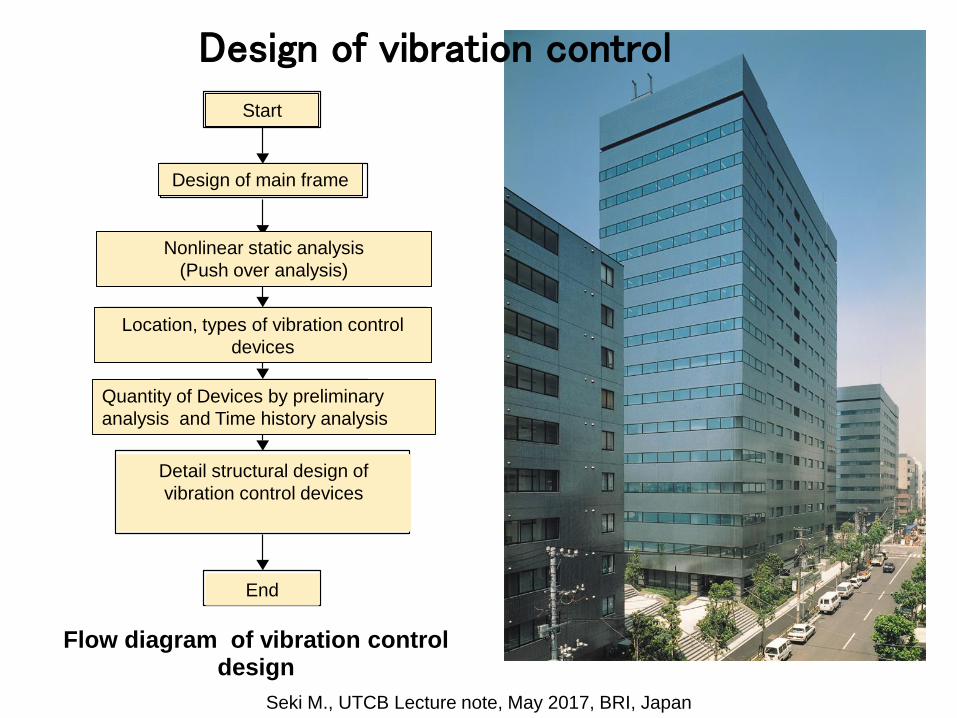
Flow diagram of vibration control design
スタート
主架構の設計
主架構の固有値解析・静的増分解析
制振部材の検討
制振部材の選択・配置・投入量の設定
時刻歴応答解析による評価
または
告示エネルギー法による評価
エンド
Start
Design of main frame
Nonlinear static analysis
(Push over analysis)
Location, types of vibration control
devices
Quantity of Devices by preliminary
analysis and Time history analysis
Detail structural design of
vibration control devices
End
Design of vibration control
Seki M., UTCB Lecture note, May 2017, BRI, Japan

Outline of the analyzed building
(a) Plan (b) Elevation (Y1,Y3)
・Steel Structure, 10F, Office building
・Moment resisting frame
・Height of building: 41m
・Analyzed direction: X direction
■■■■■00
00
■■■■0000
5000
41000
41000
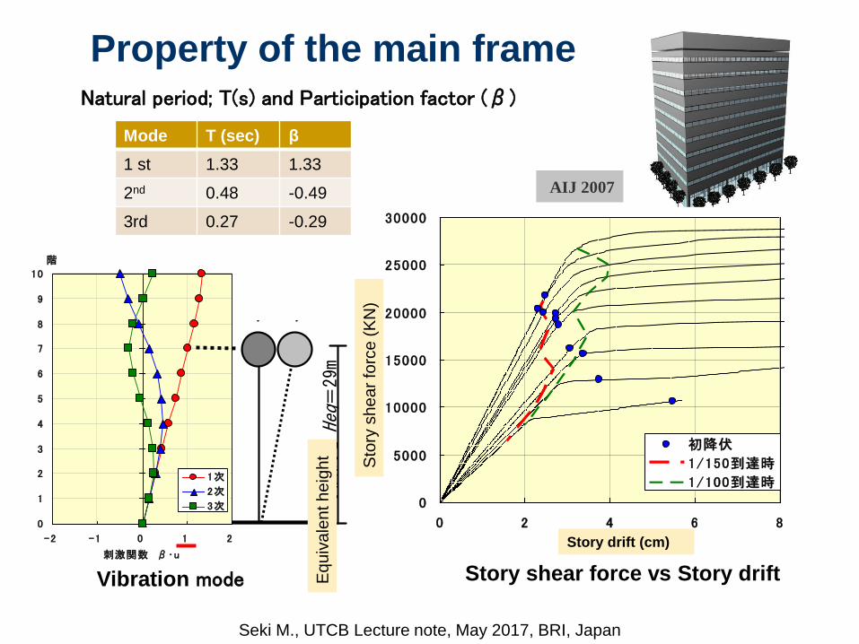
AIJ 2007
Property of the main frame
Story shear force vs Story drift
Natural period; T(s) and Participation factor (β)
0
1
2
3
4
5
6
7
8
9
10
-2 -1 0 1 2
刺激関数 β・u
階
1次
2次
3次 0
5000
10000
15000
20000
25000
30000
0 2 4 6 8
層間変形[cm]
層せ
ん断
力[k
N]
初降伏
1/150到達時
1/100到達時
Vibration mode
JSSIテーマストラクチャー 在来タイプ
COLLAPSE MECHANISM
500.0
400.0
400.0
400.0
400.0
400.0
400.0
400.0
400.0
400.0
640.0 640.0 640.0 640.0 640.0 640.0 640.0 640.0 640.0 640.0 640.0 640.0 640.0 640.0 640.0 640.0 640.0 640.0 640.0 640.0
Z 1
Z 2
Z 3
Z 4
Z 5
Z 6
Z 7
Z 8
Z 9
Z10
Z11
X 1 X 2 X 3 X 4 X 5 X 6 X 7 X 8 X 9 X10 X11 X12 X13 X14 X15 X16 X17 X18 X19 X20 X21
等価高さ
Heq=
29m
応答変位
図 4.2.8 等価 1 質点系の概念図
Mode T (sec) β
1 st 1.33 1.33
2nd 0.48 -0.49
3rd 0.27 -0.29
Story drift (cm)
Sto
ry s
he
ar
forc
e (
KN
)
Eq
uiv
ale
nt h
eig
ht
Seki M., UTCB Lecture note, May 2017, BRI, Japan

(1)Location of Dampers
(b) Y2 Elevation(a) Plan
Type of damper : Steel damper (Buckling retrain brace type)
Type of installation : Brace type
Location for plan : Symmetry
Location for elevation : Continuous from ground to top floor
Seki M., UTCB Lecture note, May 2017, BRI, Japan

0
10
20
30
40
50
60
0.1 1.0 10.0
固有周期[sec]
応答
変位
[cm
](2)Calculation of quantity of damper
Target Capacity:
Input Ground motions: three kinds of code based strong artificial motions.
Maximum response story drift: 1/150rad
h=2%
20%
10%
30%
1.33
40.0
19.3 (=2900/150)
Maximum response spectrum for design ground motions
Damping2%⇒18%
(Additional
damping16%)
JSSIテーマストラクチャー 在来タイプ
COLLAPSE MECHANISM
500.0
400.0
400.0
400.0
400.0
400.0
400.0
400.0
400.0
400.0
640.0 640.0 640.0 640.0 640.0 640.0 640.0 640.0 640.0 640.0 640.0 640.0 640.0 640.0 640.0 640.0 640.0 640.0 640.0 640.0
Z 1
Z 2
Z 3
Z 4
Z 5
Z 6
Z 7
Z 8
Z 9
Z10
Z11
X 1 X 2 X 3 X 4 X 5 X 6 X 7 X 8 X 9 X10 X11 X12 X13 X14 X15 X16 X17 X18 X19 X20 X21
等価1質点系の概念図
等価高さ
Heq=
29m
応答変位
-60000
-40000
-20000
0
20000
40000
60000
-60 -40 -20 0 20 40 60
応答変位[cm}応
答せ
ん断
力[k
N]
Hysteresis curve
h=2%
h=18%
Response disp.(cm)R
esp
on
se
sh
ea
r fo
rce
(K
N)
Natural period (sec)
Response d
isp. (c
m)
Seki M., UTCB Lecture note, May 2017, BRI, Japan

-60000
-40000
-20000
0
20000
40000
60000
-60 -40 -20 0 20 40 60
応答変位[cm}
応答
せん
断力
[kN
]
Hysteresis curve
h=2%
h=18%
Damping2%⇒18%
(Additional
Damping: 16%)
f
dy
df
d
eqQ
Q
W
Wh
11
28.0
4
18.0
f
d
eq
dy Qh
Q
11
28.0
(1.3.6)
より、
(1.3.7)
Damper strength to get the required additional damping
Required additional damping16(%)
Ductility factor of damper=5.0
Ground floor shear force=29,303 (kN)
507,11303,29
0.5
11
28.0
16.0
11
28.0
f
d
eq
dy Qh
Q (kN)
・Strength of dampers at ground floor
(2)Calculation of quantity of damper
Seki M., UTCB Lecture note, May 2017, BRI, Japan

Quantity of dampers at each story
・Ductility factor of dampers are assumed as constant; μdi =5.0
・Distribution of story shear coefficient is Ai which is defined by Japanese seismic
code
階目標ui(mm)
Kfi(kN/mm)
Qfi(kN)
Qdyi(kN)
Ci /Ai Kdi(kN/mm)
μdi
10 26.7 413 11,023 1,456 0.578 273 5.09 26.7 447 11,907 6,240 0.578 1,170 5.08 26.7 486 12,953 9,990 0.578 1,873 5.07 26.7 529 14,093 12,960 0.578 2,430 5.06 26.7 679 18,112 12,512 0.578 2,346 5.05 26.7 708 18,881 14,777 0.578 2,771 5.04 26.7 733 19,540 16,649 0.578 3,122 5.03 26.7 819 21,837 16,378 0.578 3,071 5.02 26.7 878 23,412 16,336 0.578 3,063 5.01 33.3 879 29,303 11,507 0.578 1,726 5.0
Property of Damper (strength and stiffness at each story)
(2)Calculation of quantity of damper
F
Seki M., UTCB Lecture note, May 2017, BRI, Japan

Reconfirmation of designed result by time history analysis)
Result of time history analysis
1
2
3
4
5
6
7
8
9
10
0 1/200 1/100 3/200 1/50
最大応答層間変形角(rad)
KOBE
HACH
TOHK
非制振構造応答推定値
目標層間変形角 1/150rad
1
2
3
4
5
6
7
8
9
10
0 20 40 60 80
最大応答変位(cm)
KOBE
HACH
TOHK
Response maximum displacement(cm)
Response maximum story drift angle (rad))
Without vibration controlVibration control
Vibration controlWithout vibration control
Target; 1/150
Without
vibration
control
Seki M., UTCB Lecture note, May 2017, BRI, Japan

Flow of vibration control design
Strength and stiffness of each story total
dampers
・Angle of installation
・Number of dampers at each story
Property of damper at each story(Strength and axial stiffness of one damper)
階 階高hi(m)
スパンS(m)
cosφ設置本数
nQdyi(kN)
Nd'(kN)
kdi(kN/mm)
kd'(kN/mm)
10 4.0 6.4 0.848 2 1,456 859 273 1909 4.0 6.4 0.848 4 6,240 1,840 1,170 4078 4.0 6.4 0.848 6 9,990 1,963 1,873 4347 4.0 6.4 0.848 8 12,960 1,910 2,430 4226 4.0 6.4 0.848 8 12,512 1,844 2,346 4085 4.0 6.4 0.848 10 14,777 1,743 2,771 3854 4.0 6.4 0.848 10 16,649 1,963 3,122 4343 4.0 6.4 0.848 10 16,378 1,931 3,071 4272 4.0 6.4 0.848 10 16,336 1,926 3,063 4261 5.0 6.4 0.788 8 11,507 1,825 1,726 347
スタート
主架構の設計
主架構の固有値解析・静的増分解析
制振部材の検討
制振部材の選択・配置・投入量の設定
時刻歴応答解析による評価
または
告示エネルギー法による評価
エンド
Start
Design of main frame
Nonlinear static analysis
(Push over analysis)
Location, types of vibration control
devices
Quantity of Devices by preliminary
analysis and Time history analysis
Detail structural design of
vibration control devices
End
Detail structural design of devices
Strength and stiffness of one piece of
damper
Seki M., UTCB Lecture note, May 2017, BRI, Japan

(a) Buckling retrain brace
Construction of Brace
(弾性部)
断面積:AE
(弾性部)
断面積:AE
LP 0.5LE 0.5LE
L
柱梁芯 柱梁芯
(塑性部)
断面積:AP
LaaaLP 1' 1"1 dPdP KK
・Length of plastic length
a :Area ratio of plastic and elastic
zone(=0.4)
a’:Area ration of plastic and
equivalent section
L :Length of brace
・Ductility factor of plastic zone
μd :Ductility factor of damper
KP :Axial stiffness at plastic zone
Kd” :Axial stiffness of brace
Plastic portionElastic portion Elastic portion
Seki M., UTCB Lecture note, May 2017, BRI, Japan
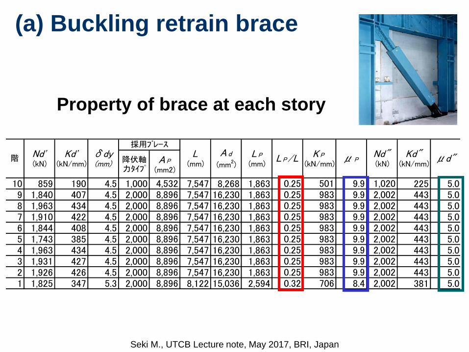
Property of brace at each story
降伏軸力タイプ
A P
(mm2)
10 859 190 4.5 1,000 4,532 7,547 8,268 1,863 0.25 501 9.9 1,020 225 5.09 1,840 407 4.5 2,000 8,896 7,547 16,230 1,863 0.25 983 9.9 2,002 443 5.08 1,963 434 4.5 2,000 8,896 7,547 16,230 1,863 0.25 983 9.9 2,002 443 5.07 1,910 422 4.5 2,000 8,896 7,547 16,230 1,863 0.25 983 9.9 2,002 443 5.06 1,844 408 4.5 2,000 8,896 7,547 16,230 1,863 0.25 983 9.9 2,002 443 5.05 1,743 385 4.5 2,000 8,896 7,547 16,230 1,863 0.25 983 9.9 2,002 443 5.04 1,963 434 4.5 2,000 8,896 7,547 16,230 1,863 0.25 983 9.9 2,002 443 5.03 1,931 427 4.5 2,000 8,896 7,547 16,230 1,863 0.25 983 9.9 2,002 443 5.02 1,926 426 4.5 2,000 8,896 7,547 16,230 1,863 0.25 983 9.9 2,002 443 5.01 1,825 347 5.3 2,000 8,896 8,122 15,036 2,594 0.32 706 8.4 2,002 381 5.0
μ PK P
(kN/mm)L P
(mm)L P/L Kd"
(kN/mm)μd"Nd"
(kN)階 Nd'
(kN)Kd'
(kN/mm)
採用ブレースδdy(mm)
L(mm)
A d
(mm2)
(a) Buckling retrain brace
Seki M., UTCB Lecture note, May 2017, BRI, Japan

Detail structural drawing of the brace
(a) Buckling retrain brace
Seki M., UTCB Lecture note, May 2017, BRI, Japan
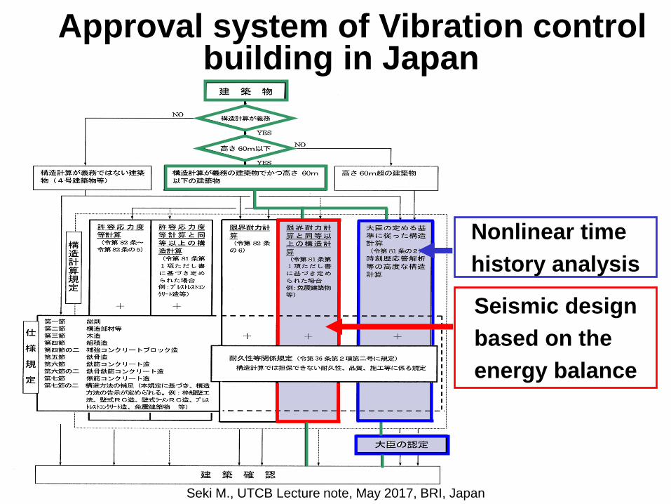
Approval system of Vibration control building in Japan
Nonlinear time
history analysis
Seismic design
based on the
energy balance
Seki M., UTCB Lecture note, May 2017, BRI, Japan

Consideration on vibration control designDesign : Nonlinear time history analysis
Appropriate modeling
Investigation on effective conditions on the response by the main frame and damper.
Modeling of main frame and damper are most important issues for analysis.
(Stiffness of main frame,/effect of flexural behavior/Stiffness of joint portion and
surrounding frame
軸剛性の高いダンパー
軸剛性の低い柱
連層ダンパー構面の曲げ変形
接合部ダンパー
ダンパー
リンクブレース
ダンパー接合部の変形Flexural deformation of main frame
Takeuchi, T. ,Titec
High stiffness of damper
Low stiffness of
frame
Damper Joint portion
Link brace
Damper
Deformation at joint portion
Seki M., UTCB Lecture note, May 2017, BRI, Japan
Examples of Vibration
Control Buildings in
Japan
Seki M., UTCB Lecture note, May 2017, BRI, Japan

Vibration Control Building
Seki M., UTCB Lecture note, May 2017, BRI, Japan

High Rise office Building (Steel St.)
Takeuchi (Tokyo Institute of Tech.)
Low Yielding Strength Steel Damper
Vibration Control Building
Seki M., UTCB Lecture note, May 2017, BRI, Japan

Installation of Oil Damper
Outside View
Medium Rise office Building( Steel. St)Takeuchi (Tokyo Institute of Tech.)
Vibration Control Building
Seki M., UTCB Lecture note, May 2017, BRI, Japan

30F office Building(Steel St.) 31F Office Building(steel St.)
Vibration Control Building
Seki M., UTCB Lecture note, May 2017, BRI, Japan

Friction Damper: Brace type
Vibration Control Building
Seki M., UTCB Lecture note, May 2017, BRI, Japan
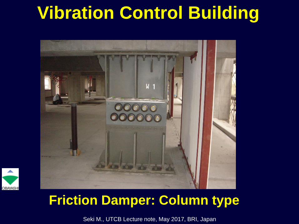
Friction Damper: Column type
Vibration Control Building
Seki M., UTCB Lecture note, May 2017, BRI, Japan

High rise residential
building
45F, B1FH=155.5 mResidential BuildingPassive Control System
Vibration Control Building
Seki M., UTCB Lecture note, May 2017, BRI, Japan

Parking tower (Shear wall) :33F
Residential Part (Frame Structure):45F
Area: 72,744 m2
45F, B1F
H=155.5 m
Oil dampers: 25KN s/cm; 80 Pieces
Outline of Structure
Seki M., UTCB Lecture note, May 2017, BRI, Japan
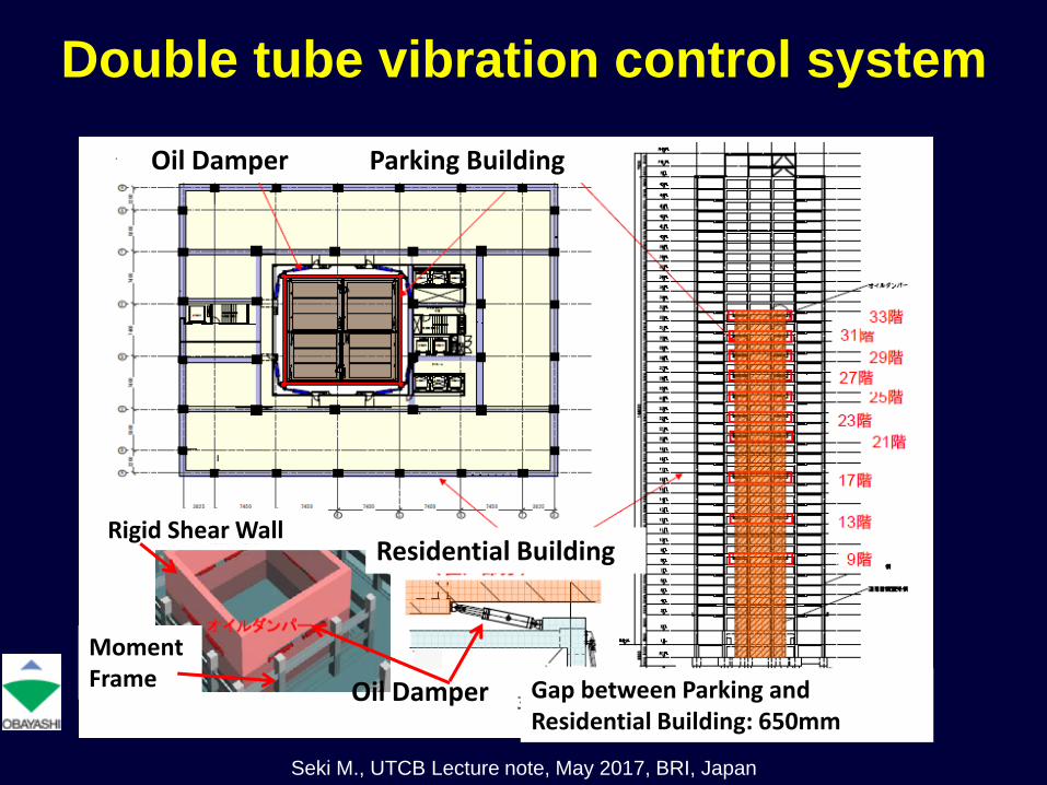
Double tube vibration control system
Oil Damper Parking Building
Residential Building
Oil Damper Gap between Parking and Residential Building: 650mm
Rigid Shear Wall
Moment Frame
Seki M., UTCB Lecture note, May 2017, BRI, Japan

Oil Dampers
Shear wall
structure
Moment
resisting
frame
Moment
resisting
frame
Shear wall
structure
Oil Damper between moment resisting frame and shear wall structure
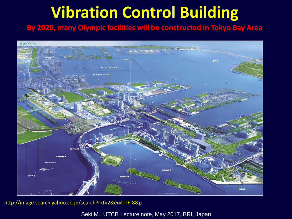
http://image.search.yahoo.co.jp/search?rkf=2&ei=UTF-8&p
By 2020, many Olympic facilities will be constructed in Tokyo Bay Area
Vibration Control Building
Seki M., UTCB Lecture note, May 2017, BRI, Japan

http://kenplatz.nikkeibp.co.jp/article/buildi
ng/news/20130911/631735/?P=1
Tokyo Bay AreaHigh Rise Residential
Building (2014. August)
Vibration Control Building
Seki M., UTCB Lecture note, May 2017, BRI, Japan

http://kenplatz.nikkeibp.co.jp/article/buildin
g/news/20130911/631735/?P=1
B2F, 44F H=250m
Isolators: 84
Natural Rubber Bearings: 21
Lead Plug Rubber
Bearings: 63
Dampers: 204
Low strength Steel Damper
(LY225)
Installed between Boundary
Beams
Isolation Story: B2F
Vibration Control Building
Seki M., UTCB Lecture note, May 2017, BRI, Japan

Steel Damper
Low Strength Steel Damper between Boundary Beams
Boundary Beam
Vibration Control Building
Seki M., UTCB Lecture note, May 2017, BRI, Japan
Retrofitting of residential building
by friction damper in Japan
From JBDPA “Seismic retrofitting examples of existing
reinforced buildings in Japan, 2009”

M8 Tokai Earthquake was predicted in 1976
Tokyo
Nagoya
Shizuoka
http://www.data.jma.go.jp/svd/eqev/data/tokai/tok
ai_eq1.html
Seki M., UTCB Lecture note, May 2017, BRI, Japan

Outline of Building
Name : A-Building
Use : Residential Building
Story : 5 stories
Total Area : 640 m2
Original Construction : 1968
Retrofitting Construction: 2006
Location : Shizuoka City, Japan
Retrofitting Project:
Design and construction work: Obayashi corporation
Structural test: Toyohashi University of Technology (TUT) and Obayashi corporation
Fund: Shizuoka prefecture
Seki M., UTCB Lecture note, May 2017, BRI, Japan

Before retrofitting After retrofitting
Seki M., UTCB Lecture note, May 2017, BRI, Japan
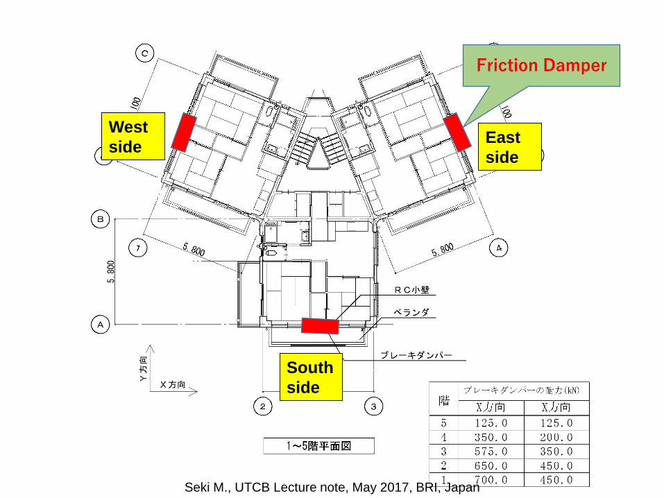
Friction Damper
East
side
West
side
South
side
Seki M., UTCB Lecture note, May 2017, BRI, Japan

East elevation
Aditional steel beam
Friction damper column
South elevation
Seki M., UTCB Lecture note, May 2017, BRI, Japan
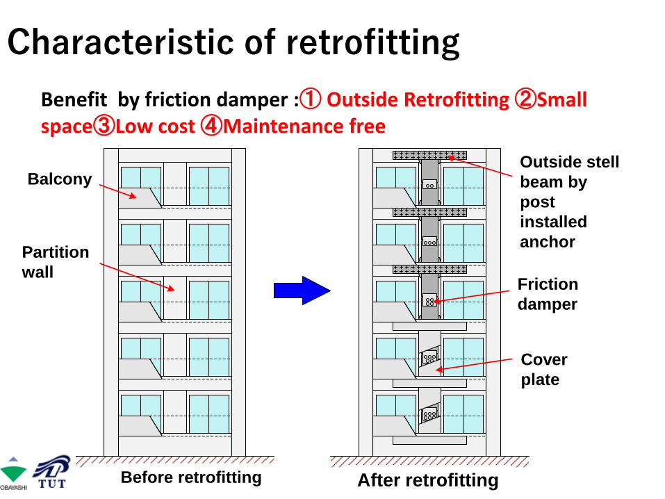
Characteristic of retrofitting
Benefit by friction damper :① Outside Retrofitting ②Small space③Low cost ④Maintenance free
バルコニー
方立壁
アンカーで外側鉄骨梁を固定
摩擦ダンパー
補強前 補強後
カバー
Outside stell
beam by
post
installed
anchor
Balcony
Partition
wallFriction
damper
Cover
plate
Before retrofitting After retrofitting

ET=0.90
Dirction Story Modelig SD T IS IS/ET CTSD
X
5ALL 1.00 0.96 1.57 1.75 1.64
Zone A 1.00 0.96 1.10 1.22 1.14
4ALL 1.00 0.96 0.97 1.07 1.01
Zone A 1.00 0.96 0.60 0.66 0.62
3ALL 1.00 0.96 0.79 0.87 0.82
Zone A 1.00 0.96 0.51 0.57 0.53
2ALL 1.00 0.96 0.74 0.83 0.77
Zone A 1.00 0.96 0.56 0.62 0.58
1ALL 1.00 0.96 0.79 0.88 0.82
Zone A 1.00 0.96 0.57 0.63 0.59
Y
5ALL 1.00 0.96 1.58 1.75 1.65
Zone 1 1.00 0.96 1.30 1.44 1.35
4ALL 1.00 0.96 1.00 1.11 1.04
Zone 1 1.00 0.96 0.81 0.90 0.84
3ALL 1.00 0.96 0.89 0.98 0.92
Zone 1 1.00 0.96 0.70 0.78 0.73
2ALL 1.00 0.96 0.79 0.87 0.82
Zone 1 1.00 0.96 0.70 0.78 0.73
1ALL 1.00 0.96 0.84 0.93 0.87
Zone 1 1.00 0.96 0.72 0.79 0.75
Is Index of Existing Building
Seki M., UTCB Lecture note, May 2017, BRI, Japan
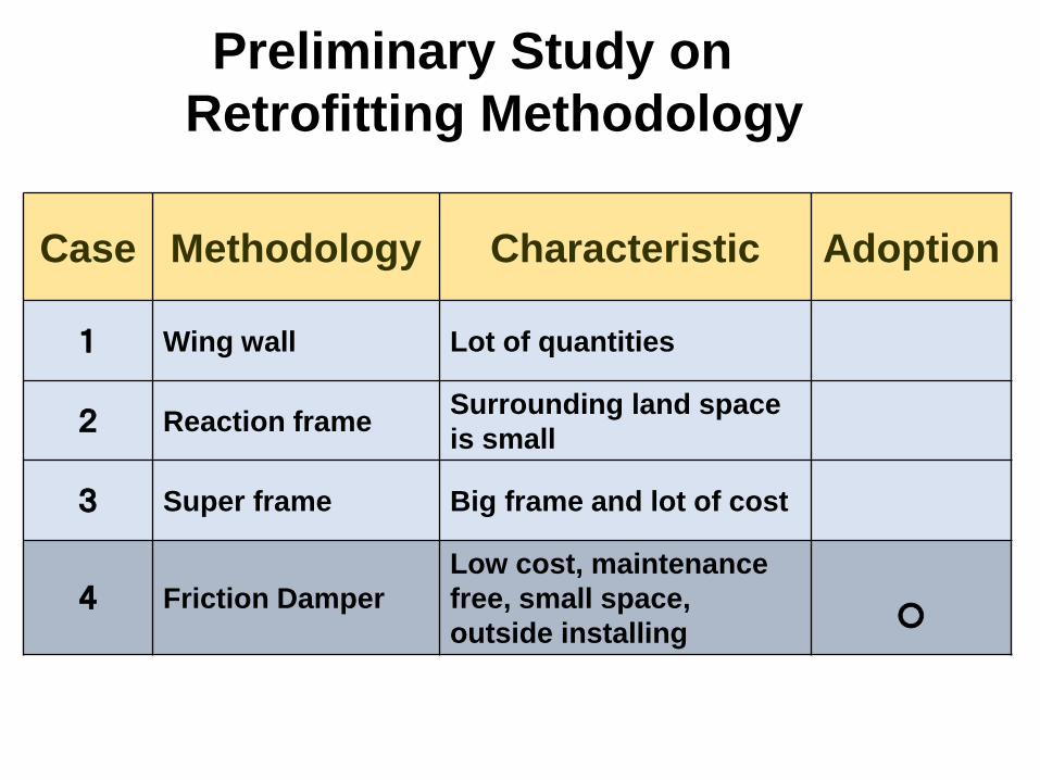
Case Methodology Characteristic Adoption
1 Wing wall Lot of quantities
2 Reaction frameSurrounding land space
is small
3 Super frame Big frame and lot of cost
4 Friction Damper
Low cost, maintenance
free, small space,
outside installing○
Preliminary Study on
Retrofitting Methodology

皿ばね
皿ばねボルトセット
ブレーキ材
ステンレス板外板(スプライスプレートなど)
中板(ブレース材など)長孔
座金
座金
摩擦面・摺動面
並列枚数5枚の例
外板(スプライスプレートなど)
主架構へ
ブレースなどへ
板座金
Structure of Friction Damper
Restoring Force Characteristics of Friction Damper
Plate Spring
Stainless Steel
Plate
Friction Plate
Seki M., UTCB Lecture note, May 2017, BRI, Japan

Structural test
Seki M., UTCB Lecture note, May 2017, BRI, Japan
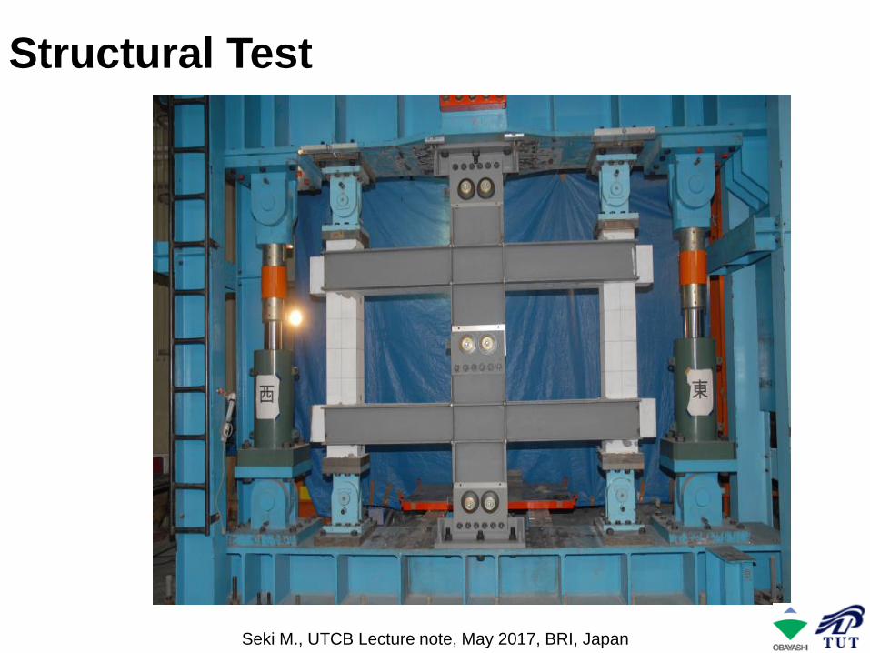
Structural Test
Seki M., UTCB Lecture note, May 2017, BRI, Japan
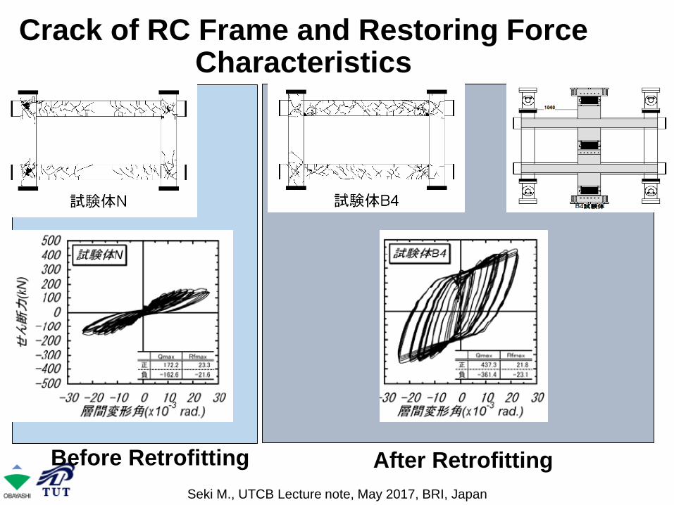
Crack of RC Frame and Restoring Force Characteristics
Before Retrofitting After Retrofitting
Seki M., UTCB Lecture note, May 2017, BRI, Japan

Detail Drawing of Retrofitting
あと施工アンカー
無収縮モルタル充填
ブレーキダンパー
無収縮モルタル充填
Non shrinkage
mortar
Non
shrinkage
mortar
Friction
Damper
Post
installed
anchor
Seki M., UTCB Lecture note, May 2017, BRI, Japan

Story
X Direction(Zone A) Y Direction(Zone 1)
Before Retrofitting
After RetrofittingBefore
RetrofittingAfter Retrofitting
IS CTSD IS CTSD IS CTSD IS CTSD
5 1.10 1.14 1.05 1.10 1.30 1.35 1.47 1.54
4 0.60 0.62 0.90 0.94 0.81 0.84 1.03 1.08
3 0.51 0.53 0.94 0.98 0.70 0.73 0.96 1.00
2 0.56 0.58 0.92 0.96 0.70 0.73 0.99 1.03
1 0.57 0.59 0.93 0.97 0.72 0.75 0.94 0.97
Is Index after Retrofitting
ET=0.90
Seki M., UTCB Lecture note, May 2017, BRI, Japan

1) Analytical model
■Structure:Five lamped mass shear model
■Parallel coupling of existing structure
and friction damper
■Damping Factor:3% proportional to secant stiffness
Existing
Structure
Friction
Damper
Nonlinear time history analysis
Analytical Model
Seki M., UTCB Lecture note, May 2017, BRI, Japan

2) Restoring force
characteristics of existing
building
■Skelton curve is obtained by
pushover analysis
■Hysteresis rule is after the TAKEDA
Model.
Shear force and disp. of each story
δ1 δ2 δ3
Qu
Q1
Q2
Skelton Curve of
Structure
Seki M., UTCB Lecture note, May 2017, BRI, Japan
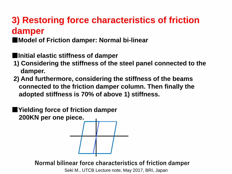
3) Restoring force characteristics of friction
damper■Model of Friction damper: Normal bi-linear
■Initial elastic stiffness of damper
1) Considering the stiffness of the steel panel connected to the
damper.
2) And furthermore, considering the stiffness of the beams
connected to the friction damper column. Then finally the
adopted stiffness is 70% of above 1) stiffness.
■Yielding force of friction damper
200KN per one piece.
Normal bilinear force characteristics of friction damperSeki M., UTCB Lecture note, May 2017, BRI, Japan
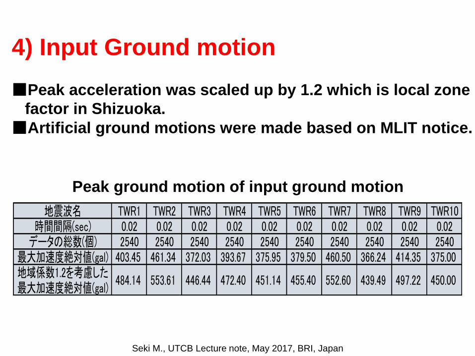
4) Input Ground motion
■Peak acceleration was scaled up by 1.2 which is local zone
factor in Shizuoka.
■Artificial ground motions were made based on MLIT notice.
地震波名 TWR1 TWR2 TWR3 TWR4 TWR5 TWR6 TWR7 TWR8 TWR9 TWR10時間間隔(sec) 0.02 0.02 0.02 0.02 0.02 0.02 0.02 0.02 0.02 0.02
データの総数(個) 2540 2540 2540 2540 2540 2540 2540 2540 2540 2540最大加速度絶対値(gal) 403.45 461.34 372.03 393.67 375.95 379.50 460.50 366.24 414.35 375.00地域係数1.2を考慮した最大加速度絶対値(gal)
484.14 553.61 446.44 472.40 451.14 455.40 552.60 439.49 497.22 450.00
Peak ground motion of input ground motion
Seki M., UTCB Lecture note, May 2017, BRI, Japan
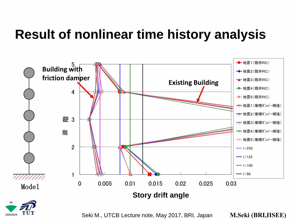
Result of nonlinear time history analysis
Model
1
2
3
4
5
0 0.005 0.01 0.015 0.02 0.025 0.03
層間変形角
階地震1(既存RC)
地震2(既存RC)
地震3(既存RC)
地震4(既存RC)
地震5(既存RC)
地震1(摩擦ダンパー補強)
地震2(摩擦ダンパー補強)
地震3(摩擦ダンパー補強)
地震4(摩擦ダンパー補強)
地震5(摩擦ダンパー補強)
1/250
1/125
1/100
1/80
Existing Building
Building with friction damper
階
Story drift angle
M.Seki (BRI,IISEE)Seki M., UTCB Lecture note, May 2017, BRI, Japan

2006 Oct.第3週 第4週 第1週 第2週 第3週 第4週 第3週 第4週 第1週 第4週
2006 Nov. 2006 Dec. 2007 Jan. 2007 Feb.
梁受け金
1階間柱足元本締め
グラウト養生
1階間柱足
中部電力高圧線盛替工事
竣工
仕上げ工事
準備工事
着工
梁鉄骨取付、グラウト
アンカー打
間柱取付
アンカー打
梁受け金
梁鉄骨取付、グラウト
間柱取付
グラウト養生
各階間柱足
各階間柱足元本締め
アンカー打 アンカー打
梁鉄骨取付、グラウト
間柱取付
1階間柱足
1階間柱足元本締め
西面
南面
東面
Construction Schedule (5 months)
Seki M., UTCB Lecture note, May 2017, BRI, Japan
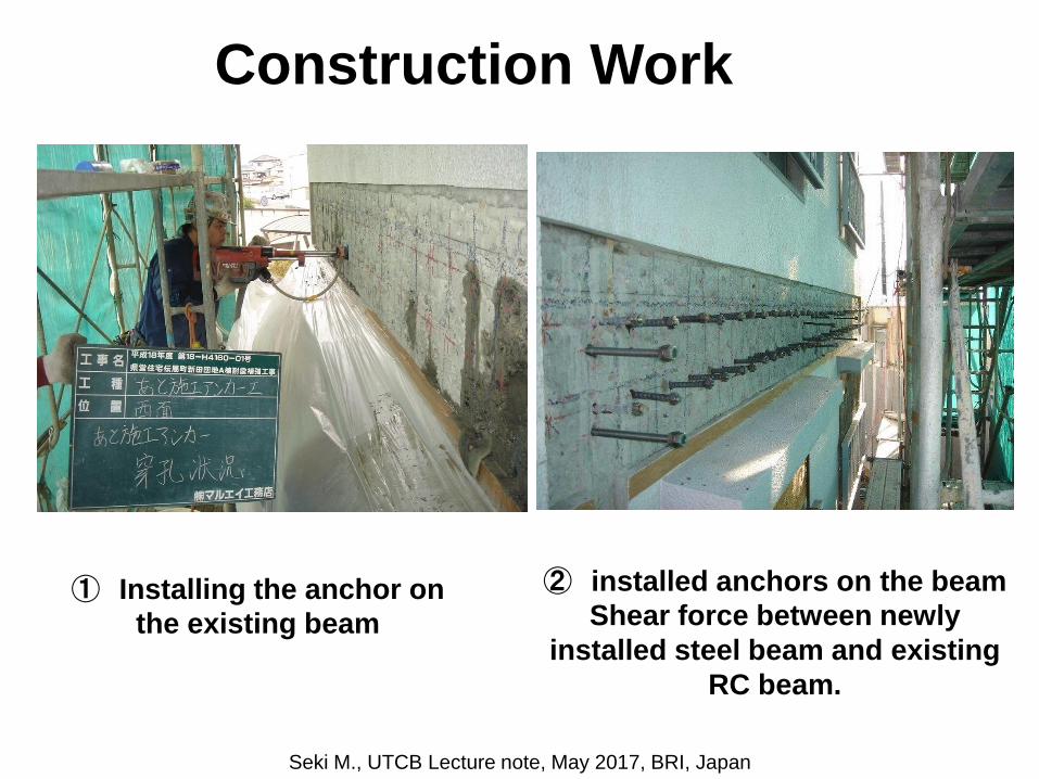
① Installing the anchor on
the existing beam
② installed anchors on the beam
Shear force between newly
installed steel beam and existing
RC beam.
Construction Work
Seki M., UTCB Lecture note, May 2017, BRI, Japan

③ Newly installed steel beam is lifted.
Seki M., UTCB Lecture note, May 2017, BRI, Japan

④ Installing the new
beam on the part of
post installed anchor.
⑤ After installing the new steel
beam
Seki M., UTCB Lecture note, May 2017, BRI, Japan

⑥ Grouting the mortar
behind the steel beam
⑦ Friction damper column
Seki M., UTCB Lecture note, May 2017, BRI, Japan
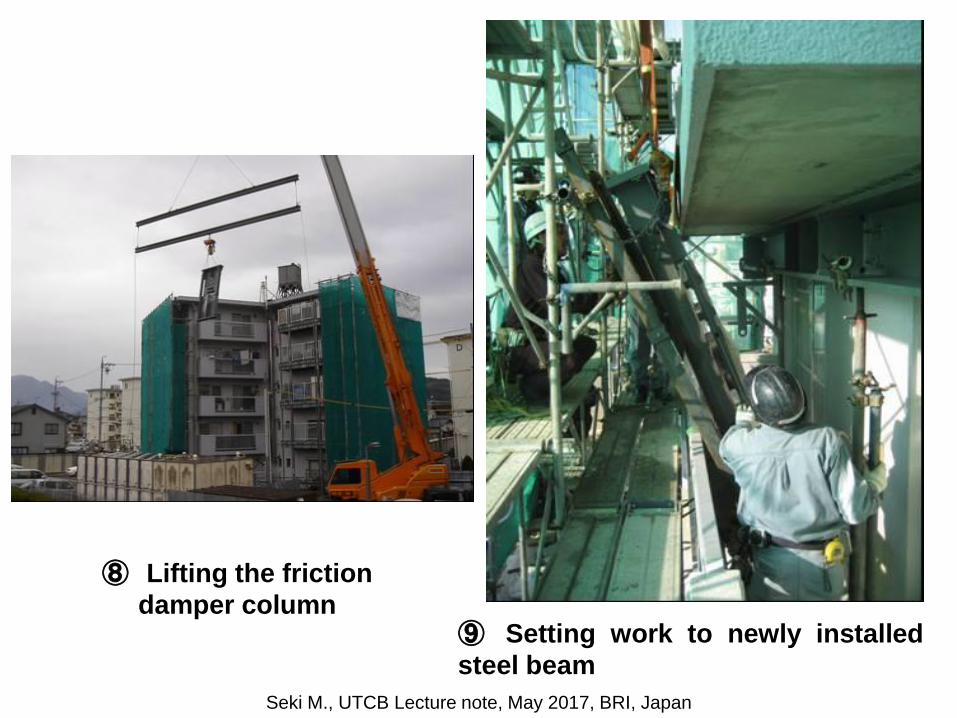
⑧ Lifting the friction
damper column⑨ Setting work to newly installed
steel beam
Seki M., UTCB Lecture note, May 2017, BRI, Japan

⑩ Completion of setting work
of friction damper column⑪ Completion of retrofitting
work
Seki M., UTCB Lecture note, May 2017, BRI, Japan

⑬ Friction damper can be seen from outside as
appealing and visual checking after earthquakes.
Seki M., UTCB Lecture note, May 2017, BRI, Japan
High rise buildings retrofitted
by the vibration control
methodology
Seki M., UTCB Lecture note, May 2017, BRI, Japan

Tokyo
Seismic Intensity (JMA)
Seismic Intensity: Tohoku Earthquake,11th, March, 2011
Osaka
Seki M., UTCB Lecture note, May 2017, BRI, Japan

High rise building in Shinjuku, Japan
Oil damper
2009 January completed by
retofitting
82
After Kimura Y., Taisei co.
Original construction: 1979, 55F, H=223m,Steel structure
Seki M., UTCB Lecture note, May 2017, BRI, Japan

Necessity of Vibration Control
・Lack of capacity against the unexpected strong ground motions
・Columns at lower stories exceed the allowable stress
Earthquake force
Tension for
column
Compression
for column
Compression
Compression
compression
Tension
Tension
Tension
Shear force
Background
83
After Kimura Y., Taisei co.
Seki M., UTCB Lecture note, May 2017, BRI, Japan

Oil damper (T-RESPO)
・Additional stress doesn’t occur against the beams and columns
Damping force
decreases beyond the
designed displacement
Characteristics
Mechanism of the controlled axial force
Oil damper with the
controlled axial force
After Kimura Y., Taisei co.
Seki M., UTCB Lecture note, May 2017, BRI, Japan

Effect of Vibration Control
・Peak displacement decreases
・Long term vibration decreases after terminating earthquake
Decreasing of peak disp.
後揺れ低減
before installing dampers
after installing dampers (T-RESPO)
Nonlinear time history analysis
Decreasing of response displacement
Decreasing of long
term vibration
After Kimura Y., Taisei co.

Passive Control of High Rise Building
Big Earthquakes having Long Period Components(3.11,2011 Earthquake)
Osaka Fusakishima City Office55F,B2F H=256m800km from epicenterFundamental Period (T): 7.0 sec
Seki M., UTCB Lecture note, May 2017, BRI, Japan
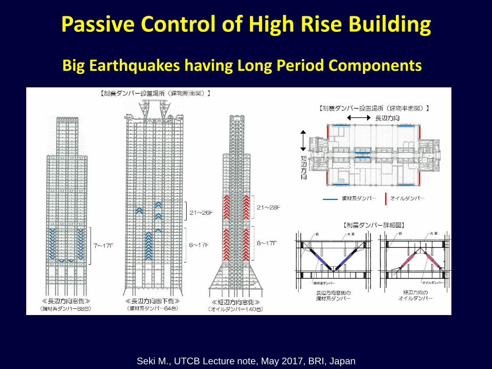
Big Earthquakes having Long Period Components
Passive Control of High Rise Building
Seki M., UTCB Lecture note, May 2017, BRI, Japan
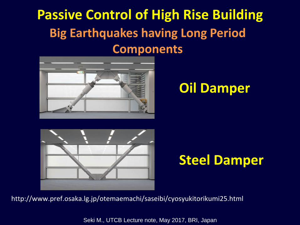
Big Earthquakes having Long Period Components
http://www.pref.osaka.lg.jp/otemaemachi/saseibi/cyosyukitorikumi25.html
Oil Damper
Steel Damper
Passive Control of High Rise Building
Seki M., UTCB Lecture note, May 2017, BRI, Japan

Big Earthquakes having Long Period Components
http://www.pref.osaka.lg.jp/attach/13203/00078593/230624file3-2.pdf
52F Displacement by Earthquake Response AnalysisBefore Strengthening; 259 cm → After; 207 cm
Before Strengthening
After Strengthening
sec
cm
Passive Control of High Rise Building
Seki M., UTCB Lecture note, May 2017, BRI, Japan

Passive
Damper
Tuned mass
Passive
Damper
Super Active Base
Isolation
Three Types of Vibration Control
Seki M., UTCB Lecture note, May 2017, BRI, Japan

www.mitsuifudosan.co.jp/corporate/news/2015/0514/st
Shinjuku Mitsui Building, Japan
Passive Vibration Control System: The
biggest TMD (Tuned Mass Damper) in Japan
Seki M., UTCB Lecture note, May 2017, BRI, Japan

Passive Vibration Control System: The
biggest TMD (Tuned Mass Damper) in Japan
www.mitsuifudosan.co.jp/corporate/news/2015/0514/st
Outline of the Building1. Original Building• Completion: Sept. 1974• Story: 55F, B3F• Height: 210m• Structure: S (Upper Structure), RC/SRC
(Basement)
2. Retrofitted Building• Completion: April 2015• Vibration control devices: TMD, Oil dampers
Seki M., UTCB Lecture note, May 2017, BRI, Japan

Passive Vibration Control System:
TMD (Tuned Mass Damper)
www.mitsuifudosan.co.jp/corporate/news/2015/0514/st
TMD Damper
Oil Damper Oil Damper
TMD Damper
Cover
Cable
Oil damper
Wight (3000KN)
Seki M., UTCB Lecture note, May 2017, BRI, Japan

Passive Vibration Control System:
TMD (Tuned Mass Damper)
www.mitsuifudosan.co.jp/corporate/news/2015/0514/st
Detail of TMD
Cable
Weight
Damper
Seki M., UTCB Lecture note, May 2017, BRI, Japan

Conclusions
1. More than 3000 buildings were completed in Japan and will increase more.
2. Vibration control can make the more flexible design easier than conventional structural design.
3. Effect against wind and earthquake was obtained and found to be effective for high quality buildings.
Seki M., UTCB Lecture note, May 2017, BRI, Japan

Thank you for your attention
Seki M., UTCB Lecture note, May 2017, BRI, Japan