vibration and balance problems in wood machining
TRANSCRIPT

Vibration and Balance Problems in Wood Machining
John S. StewartWood Machining & Tooling Research Program
North Carolina State University
Presented at the 5th Industrial Symposium on Tooling and Machining
for the Wood IndustryNovember 1-2, 2000
Raleigh, NC

Higher Speeds Cause More Vibration Problems
High Speed Planers10 years ago: 12,000 ipm (1000 feet per minute)Today: 24,000 ipm (2000 feet per minute)
CNC Routers10 years ago: 15,000 rpm, 500 ipmToday: 30,000 rpm, 2500 ipm

Typical Machine Vibration Spectrum
Force ~ mr(RPM)2; m = unbalance mass, r = mass radius
• Unbalance (mr) is constant for rigid rotors• Force due to unbalance increases with the square of RPM
FREQUENCY (RPM Order)
0 2 4 6 8 10
REL
ATI
VE V
IBR
ATI
ON
(AC
C.)
0
2
4
6
8
10
unba
lance
misalig
nmen
tbla
de pa
ssag
e
beari
ngs

Types of Unbalance
Static Unbalance Dynamic Unbalance(statically balanced)
Case Studies of Wood Machining Problems Caused by Vibration
• CNC Router Spindle Bearing Failures
• Moulder Surface Quality Problems
• Circular Sawing Quality Problems
• Tool Wear / Breakage Problems
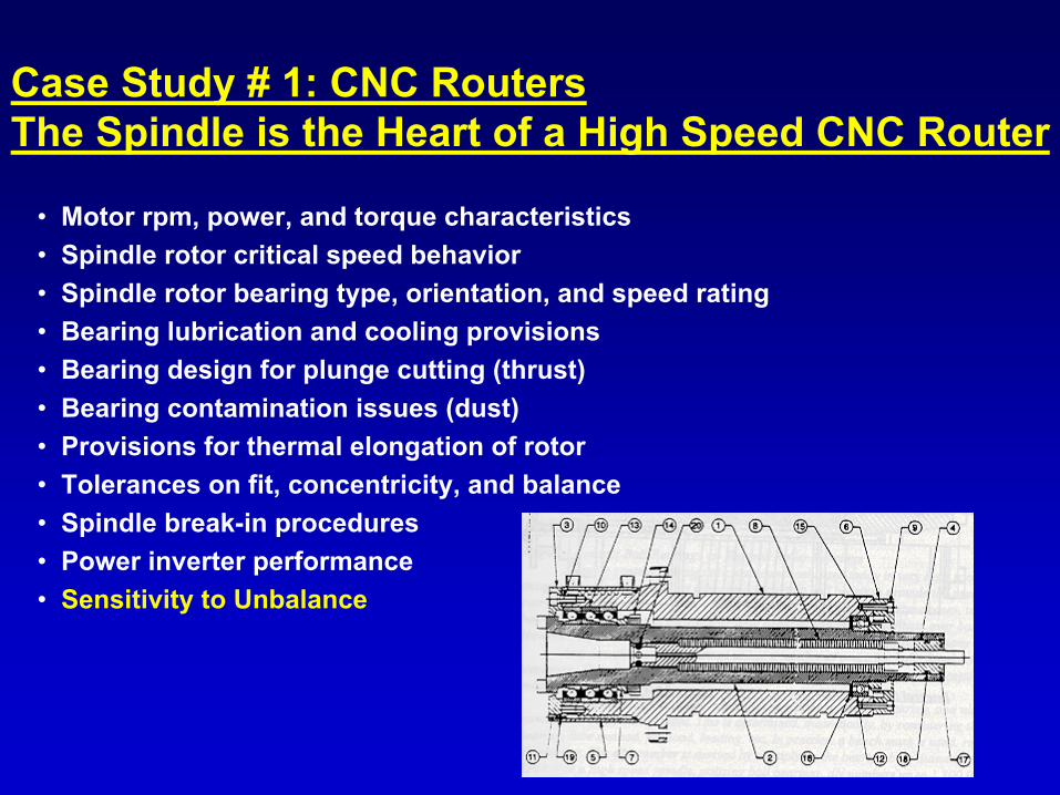
Case Study # 1: CNC RoutersThe Spindle is the Heart of a High Speed CNC Router
• Motor rpm, power, and torque characteristics• Spindle rotor critical speed behavior• Spindle rotor bearing type, orientation, and speed rating• Bearing lubrication and cooling provisions• Bearing design for plunge cutting (thrust)• Bearing contamination issues (dust)• Provisions for thermal elongation of rotor• Tolerances on fit, concentricity, and balance• Spindle break-in procedures• Power inverter performance• Sensitivity to Unbalance

Vibration Severity Chart
1.0 in/sec (very bad)0.5 in/sec (bad)0.2 in/sec (fair)0.1 in/sec (good)0.05 in/sec (excellent)
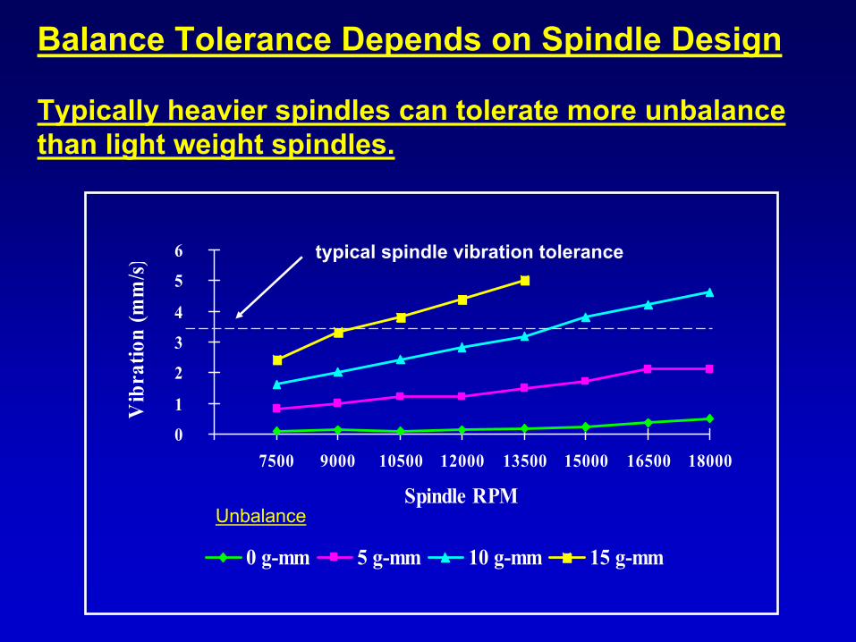
Balance Tolerance Depends on Spindle Design
Typically heavier spindles can tolerate more unbalance than light weight spindles.
0
1
2
3
4
5
6
7500 9000 10500 12000 13500 15000 16500 18000
Spindle RPM
Vib
ratio
n (m
m/s)
0 g-mm 5 g-mm 10 g-mm 15 g-mm
typical spindle vibration tolerance
Unbalance

Tool Chuck Considerations
Rigidity
• Type of Chuck Connection to the Spindle Shaft• Type of Tool Connection to Chuck
• The Torque Associated With High Speed / High Power Machining Far ExceedsConventional Machining.
Torque Transmission
• The Nature of the Connection of the Tool to the Chuck Influences the System Damping,Tool Chatter, Tool Deflection, and Dynamic Balance.
System Damping
• Chucks for High Speed Applications Should Be Balanced to ISO Grade G-1.0.(This is Not a Standard Balance Specification)
Balance Considerations

Balance Grade Considerations
• Typical unbalance for brazed tools exceeds 15 gram-mm.• Typical unbalance for solid carbide tools is less than 5 gram-mm.• Tool chucks may have 25 gram-mm or more unbalance and still be
labeled as balanced for high speed.
As Spindle Speeds Increase, Achieving a Suitable Balance Will Become Increasingly Difficult and May Necessitate the Use of In-Place Balancing Devices.
ISO G 1.0 Balance Grade Corresponds to Less than 10 gram-mmfor Spindle rpm of 20,000 and Less than 5 gram-mm for 30,000 rpm.
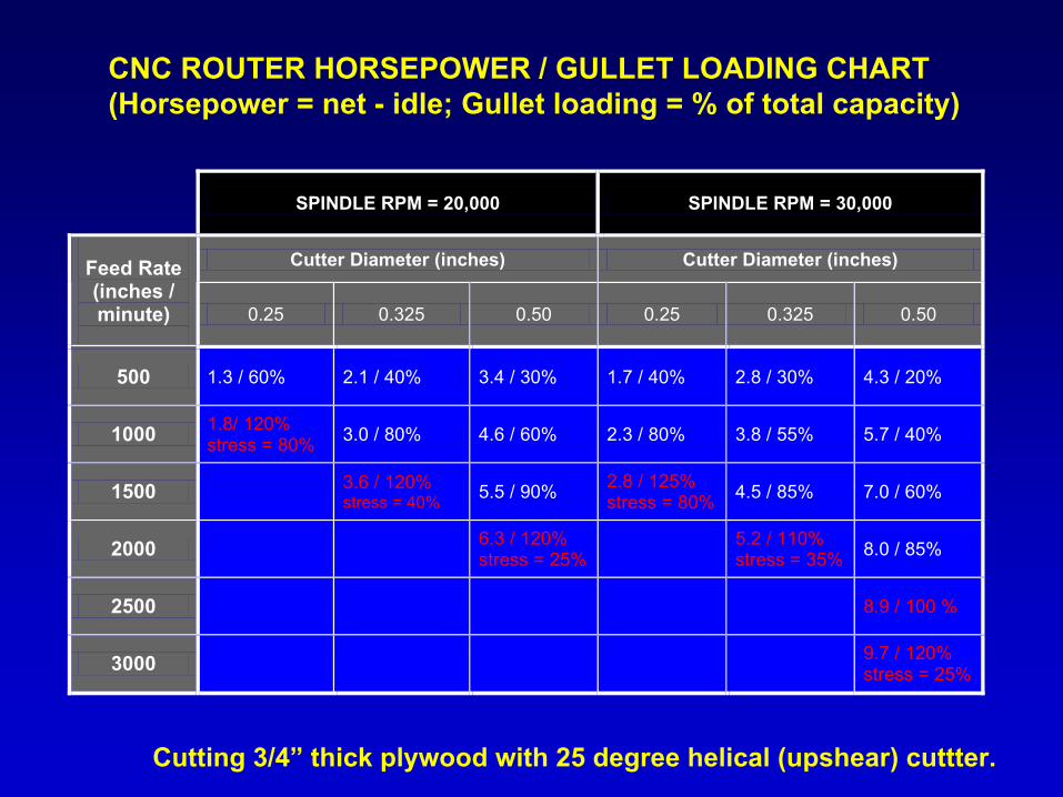
CNC ROUTER HORSEPOWER / GULLET LOADING CHART(Horsepower = net - idle; Gullet loading = % of total capacity)
Cutting 3/4” thick plywood with 25 degree helical (upshear) cuttter.
SPINDLE RPM = 20,000 SPINDLE RPM = 30,000
Cutter Diameter (inches) Cutter Diameter (inches) Feed Rate (inches / minute)
0.25 0.325 0.50 0.25 0.325 0.50
500 1.3 / 60% 2.1 / 40% 3.4 / 30% 1.7 / 40% 2.8 / 30% 4.3 / 20%
1000 1.8/ 120% stress = 80% 3.0 / 80% 4.6 / 60% 2.3 / 80% 3.8 / 55% 5.7 / 40%
1500 3.6 / 120%
stress = 40% 5.5 / 90% 2.8 / 125% stress = 80% 4.5 / 85% 7.0 / 60%
2000 6.3 / 120%
stress = 25% 5.2 / 110%
stress = 35% 8.0 / 85%
2500
8.9 / 100 %
3000 9.7 / 120%
stress = 25%

Forces for Straight Cutting Edge
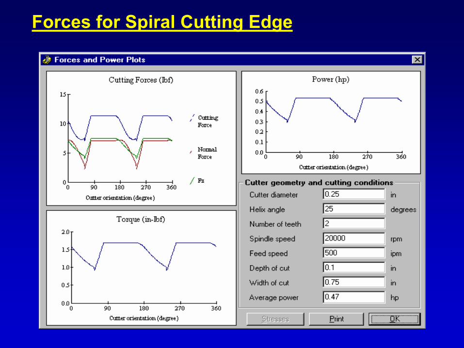
Forces for Spiral Cutting Edge

Case Study # 2: MouldersLaser Profilometer on Moulder

Optimizing Moulder Tooling Performance
• Precision Cutterhead Arbor
• Precision Cutterhead Centering
• Precision Cutterhead Grinding
• Precision Cutterhead Balancing

Effect of Unbalance on Tip Path

Balance Tolerance Nomogram

Surface Quality for Different Balance GradesISO G16 Tool UnbalanceISO G1 Tool Unbalance
Frequency(Knife Marks per 25 mm)
0 5 10 15 20 25
Surf
ace
Hei
ght (µm
)
02468
10121416
Frequency(Knife Marks per 25 mm)
0 5 10 15 20 25
Surf
ace
Hei
ght (µm
)
02468
10121416
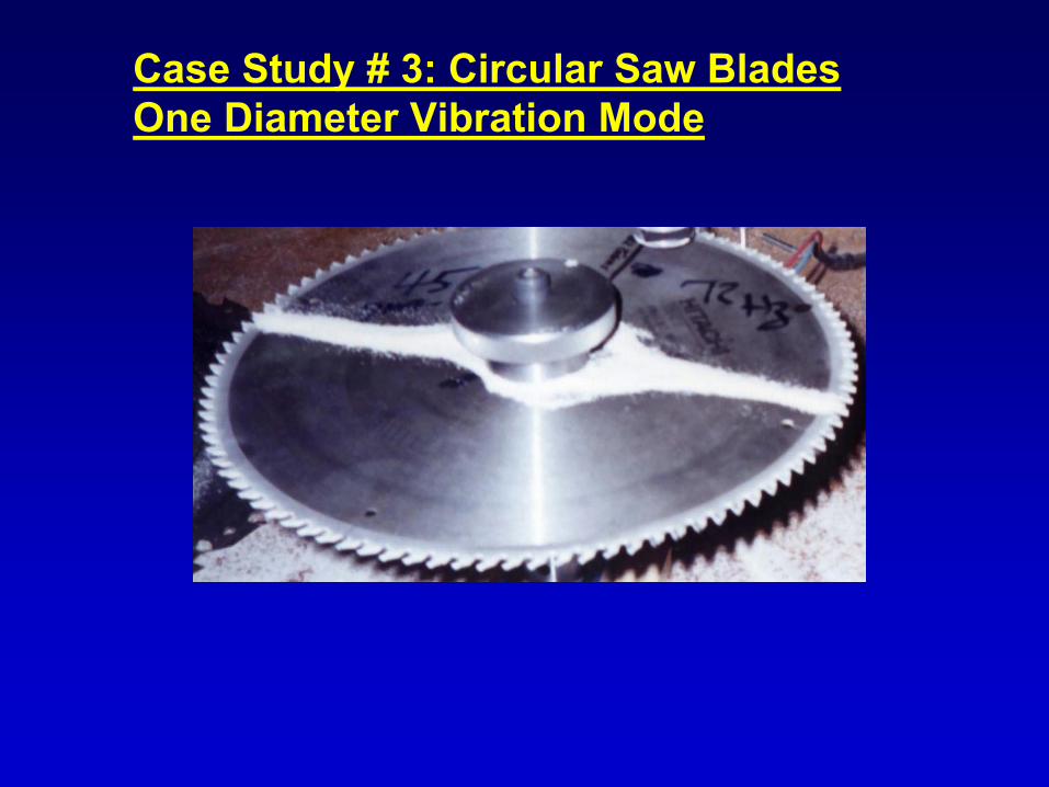
Case Study # 3: Circular Saw BladesOne Diameter Vibration Mode


Case Study # 4: Tool WearStudy of the Effect of Selected Machining Parameters on Carbide Tool Wear
• Tool Material• Tool Edge Quality• Workpiece Material• Material Processed (total)• Material Processed • Number of Tooth Impacts• Tool / Workpiece Vibration
UnbalanceWorkpiece Hold Down
• Cutterhead Diameter• Cutting Angles• Depth of Cut• Feed per Tooth• Peripheral Speed• Climb / Conventional Cut
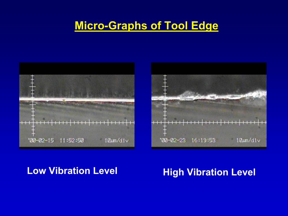
Micro-Graphs of Tool Edge
Low Vibration Level High Vibration Level

ACKNOWLEDGMENTS
This work was supported by the NC State University Wood Machining & Tooling Research Program through a grant from the US Department of Agriculture.