via caboto 19/3 m501mea monitor module 34147 … · the operator and local authority that the...
TRANSCRIPT

M501MEA Monitor Module
INSTALLATION AND MAINTENANCE INSTRUCTIONS
Pittway Tecnologica S.r.l.Via Caboto 19/3
34147 Trieste, Italy
BEFORE INSTALLINGThis information is included as a quick reference installation guide. Refer to the control panel installation manual for detailed system information. If the modules will be installed in an existing operational system, inform the operator and local authority that the system will be temporarily out of service. Disconnect power to the control panel before installing the modules.
NOTICE: This manual should be left with the owner/user of this equipment.
GENERAL DESCRIPTIONThe M501MEA monitor module can be installed in a single gang junction box directly behind the monitored unit. Its small size and light weight allow it to be installed without rigid mounting (see Figure 1). The M501MEA is intended for use in intelligent, two-wire systems where the individual address of each module is selected using rotary decade switches. It provides a two-wire initiating circuit for normally open contact fire alarm and security devices.
Note: The M501MEA serves only to relay information linked to a fire signal to the control panel - it does not monitor the secondary line for short circuit faults.
COMPATIBILITY REQUIREMENTSTo ensure proper operation, this module should only be connected to a compatible control panel.
FIGURE 1:
C01063-00
MOUNTING AND WIRINGNOTE: This module is intended to be wired and mounted without rigid connections inside a standard electrical box. If rigid mounting is required, then it may be affixed within the enclosure using cable ties and where necessary suitable adhesive or screw type cable tie bases. The testing and the approval was carried out with the rigid installation. The module should be mounted flat ensuring that it does not foul any other equipment in the enclosure and care must be taken to ensure wires are not damaged during the installation.
1. Connect the red (+) and black ( – ) wires to the positive and negative leads of the communication loop.
2. Connect the violet (+) and yellow ( – ) wires to a two-wire, normally open monitoring line.
3. Install the specified EOL resistor value to terminate the monitoring line. The EOL resistor for standard use is 47K Ohms – the other resistors are for special use only.
4. Set the address on the module per job drawings.
5. Install the module in the desired mounting location.
FIGURE 2. TYPICAL CIRCUIT CONFIGURATION:
(+)(–)
TONEXTDEVICE
BLA
CK
RE
D
(+)(–)(+) (–)
VIOLET
YELLOW
FIRE DETECTION AND ALARM SYSTEM LOOP
47k EOLINCLUDED(ELR-47k)
COMPATIBLE CONTROL
PANEL
ALL WIRING SHOWN IS
SUPERVISED AND POWER LIMITED
0
7 865432
1
910111213
1415 012345 6 7 8 9
C0614-05
SPECIFICATIONSCommunications LoopNominal Operating Voltage: 15-32 VDCAverage Operating Current: 400 µA, 1 comm. every 5 seconds, (Standard 47K EOL)Maximum Alarm Current 600 µA
Monitoring LineEOL Resistance: 47K Ohms StandardMaximum Wiring Resistance: 1.5K OhmsMaximum Voltage to EOL: 11 VoltsMaximum Short Circuit Current: 217 µA
I56-3924-002
GeneralTemperature Range: -10°C to 55°CHumidity: 10% to 93% Non-condensingDimensions: 33mm H x 71mm W x 15mm DWire Length: 150mm minimum
COMMUNICATION LOOP
MONITORING LINE
035913
EN 54-18: 2005Input Output Device
M501MEA
DoP Ref:0359-CPD-0176
System Sensor, 3825 Ohio Ave. St. Charles, IL 60174 USA
ENGLISH
EOLR E S I S T O R I N C L U D E D (47K OHMS STANDARD - ELR-47K)
SS-460-014 I56-3924-0021

Modulo di controllo M501MEA
ISTRUZIONI DI INSTALLAZIONE E MANUTENZIONE
Pittway Tecnologica S.r.l.Via Caboto 19/3,
34147 Trieste, Italia
PRIMA DELL'INSTALLAZIONELe seguenti informazioni intendono fornire una breve guida all'installazione. Fare riferimento al manuale di installazione del pannello di controllo per maggiori dettagli sul sistema. Se i moduli saranno installati in un sistema operativo già esistente, comunicare all'operatore e all'autorità locale che il sistema sarà temporaneamente fuori servizio. Disconnettere l'alimentazione al pannello di controllo prima di installare i moduli.
AVVISO: il presente manuale deve essere lasciato a disposizione del proprietario/utilizzatore dell'apparecchiatura.DESCRIZIONE GENERALEIl modulo di controllo M501MEA può essere installato in una scatola di connessione singola direttamente dietro l'unità monitorata. Le dimensioni contenute e il peso ridotto ne consentono l'installazione senza supporto rigido (cfr. figura 1). Il modulo M501MEA è destinato all'utilizzo in sistemi intelligenti a due fili in cui il singolo indirizzo di ogni modulo viene selezionato utilizzando selettori rotanti. Fornisce un circuito di attivazione a due fili per dispositivi di sicurezza e di allarme antincendio con un contatto normalmente aperto.
Nota: L’M501MEA ha il compito di ritrasmettere al pannello di controllo informazioni collegate a un segnale di allarme – non controlla eventuali guasti di corto circuito sulla linea secondaria.
REQUISITI DI COMPATIBILITÀPer assicurare il corretto funzionamento, questo modulo deve essere collegato unicamente a un pannello di controllo compatibile.
FIGURA 1:
C01063-00
MONTAGGIO E CABLAGGIONOTA: questo modulo è stato progettato per essere cablato e montato senza connessioni rigide all’interno di un contenitore standard di dispositivi elettrici. Qualora sia richiesto un montaggio rigido, si può fissare al contenitore mediante fascette serracavo e, se necessario, supporti per fascette adesivi o a vite. Il modulo andrebbe montato orizzontale, assicurandosi che non interferisca con altri dispositivi nel contenitore, e facendo attenzione a non danneggiare i cavi durante l’installazione.1. Collegare i fili rosso (+) e nero ( – ) ai fili di alimentazione del
positivo e negativo del loop.
2. Collegare il filo viola (+) e giallo (-) alla linea monitorata.
3. Installare il valore della resistenza di fine linea specificato per terminare la linea monitorata. La resistenza di fine linea standard è da 47 k ohm. Le altre resistenze sono solo per utilizzi speciali.
4. Impostare l'indirizzo sul modulo secondo i disegni.
5. Installare il modulo nella posizione di montaggio desiderata.
FIGURA 2. CONFIGURAZIONE TIPICA DEL CIRCUITO:
(+)(–)
AL DISPOSITIVO SUCCESSIVO
NER
O
RO
SSO
(+)(–)(+) (–)
VIOLA
GIALLO
CIRCUITO DEL SISTEMA DI RILEVAZIONE ED ALLARME ANTINCENDIO
47k FINE LINEA INCLUSO(RESISTENZA FINE LINEA-47k)
PANNELLO DI CONTROLLO COMPATIBILE
L'INTERO CABLAGGIO
ILLUSTRATO È MONITORATO E A
POTENZA LIMITATA
0
7 865432
1
910111213
1415 012345 6 7 8 9
C0614-06
SPECIFICHELoop indirizzabileTensione nominale di esercizio: 15-32 VCCCorrente media di esercizio: 400 µA, 1 comunicazione ogni 5 secondi, fine linea da 47 kCorrente massima di allarme: 600 µA max.
Linea monitorataResistenza di fine linea: 47 K ohm (Standard)Resistenza massima cablaggio: 1,5 K ohmTensione massima di fine linea: 11 voltCorrente massima di corto circuito: 217 µA
I56-3924-002
Caratteristiche generaliIntervallo di temperatura: da -10°C a 55°CUmidità: dal 10% al 93% (senza condensa)Dimensioni: 33 mm (altezza) x 71 mm (larghezza) x 15 mm (profondità)Lunghezza cavo: 150 mm minimo
LINEA MONITORATA
LOOP INDIRIZZABILE
FINE LINEA INCLUSO (47K OHM
STANDARD - ELR-47K)
ITALIANO
035913
EN 54-18: 2005Dispositivo di
ingresso/uscitaM501MEA
DoP Ref:0359-CPD-0176
System Sensor, 3825 Ohio Ave. St. Charles, IL 60174, USA
SS-460-014 I56-3924-0022

Módulo de supervisión M501MEA
INSTRUCCIONES DE INSTALACIÓN Y MANTENIMIENTO
Pittway Tecnologica S.r.l.Via Caboto 19/3
34147 Trieste, Italia
ANTES DE LA INSTALACIÓNEsta información se incluye como una guía de instalación de referencia rápida. Consulte el manual de instalación del panel de control para obtener información detallada del sistema. Si los módulos van a instalarse en un sistema operativo existente, comunique al operador y a las autoridades locales que el sistema estará temporalmente inactivo. Desconecte la alimentación del panel de control antes de instalar los módulos.
AVISO: El usuario o propietario del equipo debe contar con este manual.
DESCRIPCIÓN GENERALEl módulo de supervisión M501MEA puede instalarse en una caja de conexiones de salida única directamente tras la unidad supervisada. Su pequeño tamaño y ligereza hacen posible su instalación sin un montaje rígido (véase la Figura 1). El M501MEA está diseñado para su uso en sistemas de dos cables inteligentes en los que la dirección individual de cada módulo se selecciona mediante selectores giratorios por decenas. Proporciona un circuito de iniciación de dos cables para dispositivos de seguridad y alarma de incendios de contacto abierto.
Nota: EL M501MEA solo transmite información relacionada con la señal de alarma a la central de incendios - no supervisa la línea secundaria para averías de cortocircuito.
REQUISITOS DE COMPATIBILIDADA fin de garantizar un correcto funcionamiento, este módulo solo debe conectarse a un panel de control compatible.
FIGURA 1:
C01063-00
INSTALACIÓN Y CONEXIONADOEste módulo debe instalarse sin conexiones rígidas en el interior de una caja eléctrica estándar. Si requiere instalación rígida, se puede montar dentro de una caja mediante bridas y, si fuera necesario, con adhesivo adecuado o mediante algún otro elemento de fijación con tornillos. El módulo debe montarse de forma plana, de manera que no quede atrapado entre ningún otro dispositivo instalado en la misma caja. Igualmente, asegúrese de que los cables no se dañan durante la instalación.
1. Conecte el cable rojo (+) y negro (-) a los cables positivo y negativo de lazo direccionable.
2. Conecte el cable morado (+) y el amarillo (-) al circuito de entrada supervisado.
3. Instale el valor de resistencia de fin de línea especificado para finalizar el bucle de iniciación. La resistencia EOL (final de línea) para uso estándar es de 47K Ohmios –otras resistencias son para uso especial.
4. Defina la dirección del módulo por dibujo del trabajo.5. Instale el módulo en la ubicación de montaje que desee.
FIGURA 2. CONFIGURACIÓN HABITUAL DEL CIRCUITO:
(+)(–)
SIGUIENTE DISPOSITIVO
NEG
RO
RO
JO
(+)(–)(+) (–)
MORADO
AMARILLO
BUCLE DEL SISTEMA DE ALARMA Y DETECCIÓN DE INCENDIOS
INCLUYE FIN DE LÍNEA DE 47 kΩ(resistencia de fin de línea: 47 kΩ)
PANEL DE CONTROL
COMPATIBLE
TODO EL CABLEADO QUE
SE MUESTRA ESTÁ SUPERVISADO Y
CUENTA CON UNA LIMITACIÓN DE
POTENCIA
0
7 865432
1
910111213
1415 012345 6 7 8 9
C0614-07
ESPECIFICACIONESLazo direccionableTensión operativa nominal: de 15 a 32 VCCCorriente media de funcionamiento: 400 µA, 1 comunicación cada 5 segundos, fin de línea de 47 kΩCorriente máxima en alarma: 600 µA
Circuito de entrada supervisadoResistencia de fin de línea: 47 kΩ (estándar)Resistencia máxima de cableado: 1.5 kΩTensión máxima de fin de línea: 11 voltiosMáxima corriente en cortocircuito: 217 microamperios
I56-3924-002
GeneralIntervalo de temperatura: de -10 °C a 55 °CHumedad: de 10 % a 93 % (sin condensación)Dimensiones: 33 mm de altura x 71 mm de anchura x 15 mm de profundidadLongitud del cable: 150 mm como mínimo
CIRCUITO DEENTRADASUPERVISADO
LAZO DIRECCIONABLE
RESISTENCIA EOL INCLUIDA
(ESTÁNDAR DE 47K OHMIOS -
ELR-47K)
ESPAÑOL
035913
EN 54-18: 2005Dispositivo de entrada
y salidaM501MEA
DoP Ref:0359-CPD-0176
System Sensor, 3825 Ohio Ave. St. Charles, IL 60174, EE. UU.
SS-460-014 I56-3924-0023
M501MEA Monitormodul
INSTALLATIONS- UND WARTUNGSANWEISUNGEN
Pittway Tecnologica S.r.l.Via Caboto 19/3,
34147 Triest, Italien
VOR DER INSTALLATIONDie nachfolgenden Informationen werden als Kurzanleitung zur Installation bereitgestellt. Ausführliche Systeminformationen erhalten Sie im Installationshandbuch der Brandmelderzentrale. Bei Installation der Module in einem bereits vorhandenen, im Betrieb befindlichen System sind Bediener und örtliche Behörden davon in Kenntnis zu setzen, dass das System vorübergehend außer Betrieb gesetzt sein wird. Trennen Sie die Brandmelderzentrale vom Stromnetz, bevor Sie mit der Installation der Module beginnen.
HINWEIS: Diese Anleitung muss vom Eigentümer/Bediener des Geräts verwahrt werden.ALLGEMEINE BESCHREIBUNGDas M501MEA Monitormodul kann in einer Einfach-Verteilerdose direkt hinter der zu überwachenden Einheit installiert werden. Dank der kompakten Abmessungen und des geringen Gewichts kann die Installation des Moduls ohne starre Verbindungen erfolgen (siehe Abbildung 1). Das M501MEA Modul ist für den Einsatz in intelligenten Zweileitungssystemen vorgesehen, in denen die individuelle Adresse jedes Moduls über Dekaden-Drehschalter gewählt wird. Es bietet eine Zweileiterauslöseschaltung für Brandmeldesysteme und Sicherheitsapparaturen mit Schließerkontakt.
Anm.: Das Modul M501MEA dient nur dazu, die Information eines Feueralarms zur Brandmelderzentrale weiter zu leiten – es überwacht die Sekundärleitung nicht auf Kurzschluss.
KOMPATIBILITÄTSANFORDERUNGENUm einen einwandfreien Betrieb zu gewährleisten, darf das Modul nur an eine kompatible Brandmelderzentrale angeschlossen werden.
ABBILDUNG 1:
C01063-00
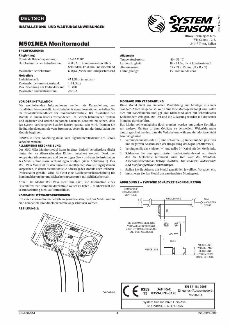
MONTAGE UND VERDRAHTUNGDiese Modul dient zur einfachen Verdrahtung und Montage in einem Standard-Anschlussgehäuse. Wenn eine feste Montage benötigt wird, sollte dies mit Kabelbindern und ggf. mit Klebeband oder mit schraubbaren Kabelbindern erfolgen. Die Test und die Zulassung wurden mit der festen Montage durchgeführt.Das Modul sollte möglichst flach moniert werden um andere Konflikte mit anderen Geräten in dem Gehäuse zu vermeiden. Weiterhin muss darauf geachtet werden, dass die Verkabelung während der Montage nicht beschädigt wird.1. Verbinden Sie das rote (+) und schwarze (–) Kabel mit den positiven
und negativen Anschlüssen der Ringleitung des Signalschaltkreises.
2. Verbinden Sie das violette (+) und gelbe (–) Kabel mit der Meldelinie.
3. Schliessen Sie den spezifizierten Endwiderstandswert an, durch den die Meldelinie terminiert wird. Der Wert des Standard-Abschlusswiderstands beträgt 47kOhm. Die anderen Widerstände sind nur für spezielle Anwendungen.
4. Stellen Sie die Adresse am Modul gemäß den jeweiligen Vorgaben ein.5. Installieren Sie das Modul am gewünschten Montageort.
ABBILDUNG 2 – TYPISCHE SCHALTKREISKONFIGURATION
SPEZIFIKATIONENRingleitungNominale Betriebsspannung: 15–32 V DCDurchschnittlicher Betriebsstrom: 400 µA, 1 Kommunikation alle 5 Sekunden, 47 kOhm EndwiderstandMaximaler Betriebsstrom 600 µA (Meldelinie kurzgeschlossen)
Meldelinie Endwiderstand: 47 kOhm (standard)Maximaler Leitungswiderstand: 1.5 kOhmMax. Spannung am Endwiderstand: 11 VoltMaximaler Kurzschlussstrom: 217 µA
I56-3924-002
(+)(–)
ZUM NÄCHSTEN GERÄT
SC
HW
AR
Z
RO
T
(+)(–)(+) (–)
VIOLETT
GELB
RINGLEITUNG
MIT 47 KOHM ENDWIDERSTAND
(ELR: 47.000)
KOMPATIBLE BRANDMELDER-
ZENTRALE
DIE GESAMTE GEZEIGTE VERKABELUNG VERFÜGT
ÜBER STROMBEGRENZUNG UND ÜBERWACHUNG
0
7 865432
1
910111213
1415 012345 6 7 8 9
AllgemeinTemperaturbereich: -10 - 55 °CLuftfeuchtigkeit: 10 – 93 %, nicht kondensierendAbmessungen: 33 x 71 x 15 mm (H x B x T)Leitungslänge: 150 mm mindestens
MELDELINIE
ABSCHLUSS-WIDERSTAND
BEIGELEGT (47KOHM STAN-DARD - ELR-47K)
DEUTSCH
035913
EN 54-18: 2005Eingangs-/Ausgangsgerät
M501MEA
DoP Ref:0359-CPD-0176
System Sensor, 3825 Ohio Ave. St. Charles, IL 60174 USA
SS-460-014 I56-3924-0024

Module moniteur M501MEA
INSTRUCTIONS D'INSTALLATION ET D'ENTRETIEN
Pittway Tecnologica S.r.l.Via Caboto 19/3,
34147 Trieste, Italie
AVANT DE COMMENCER L'INSTALLATIONLes renseignements qui suivent constituent un guide succinct d'installation. Pour obtenir des renseignements détaillés sur le système, consulter le manuel d'installation du panneau de commande. S'il est prévu d'installer les modules dans un système existant, informer la personne responsable du système et les autorités locales que le système sera temporairement hors service. Mettre le panneau de commande hors tension avant d'installer les modules.
AVIS : remettre ce manuel au propriétaire ou à l'utilisateur de cet appareil.
DESCRIPTION GÉNÉRALELe module moniteur M501MEA peut être installé dans une boîte de jonction simple, directement derrière l'unité surveillée. Petit et léger, il peut être installé sans connexion rigide (voir la Figure 1). Le M501MEA est prévu pour les systèmes intelligents à 2 fils dans lesquels l'adresse de chaque module est sélectionnée au moyen des commutateurs rotatifs intégrés. Il fournit un circuit de dispositifs de déclenchement (IDC) à 2 fils pour les dispositifs d'alarme incendie ou de sécurité à contact normalement ouvert.
Le M501MEA ne sert qu’à relayer l’information liée à un signal d’incendie sur l’ECS. Il ne surveille pas la ligne secondaire pour les défauts de court circuit.
COMPATIBILITÉPour qu'il fonctionne correctement, ce module doit être raccordé à un panneau de commande compatible.
FIGURE 1 :
C01063-00
MONTAGE ET CÂBLAGEREMARQUE : Ce module est destiné à être branché et monté sans des montages rigides à l’intérieur d’une boîte électrique standard. Si un montage rigide est nécessaire, il peut être fixé dans le boîtier à l’aide des colliers de serrage et si nécessaire les bases d’attaches de câble appropriés adhésif ou du type vis. Le module doit être monté à plat en s’assurant qu’il n’embrouillez pas d’autres équipements dans l’enceinte et les soins doivent être prises pour assurer les fils ne soient pas endommagés lors de l’installation.1. Raccorder le fil rouge (+) et le fil noir (-) pour le bus.
2. Raccorder le fil violet (+) et le fil jaune (-) pour le circuit d’entrée surveillé.
3. Installer une résistance de fin de ligne de la valeur spécifiée en fin de boucle. Le résistance de fin de ligne normale est de 47Kohms. Autres résistances sont réservées aux usages specifiques.
4. Régler l'adresse sur le module selon les dessins du projet.5. Installer le module à l'endroit de votre choix.
FIGURE 2. CONFIGURATION TYPE D'UN CIRCUIT :
(+)(–)
VERS DISPOSITIF SUIVANT
NO
IR
RO
UG
E
(+)(–)(+) (–)
VIOLET
JAUNE
BOUCLE DES DISPOSITIFS D'ALARME ET DE DÉTECTION D'INCENDIE
FDL de 47 k fournie(ELR-47k)
PANNEAU DE COMMANDE COMPATIBLE
TOUT LE CÂBLAGE ILLUSTRÉ EST
SURVEILLÉ ET À COURANT LIMITÉ
0
7 865432
1
910111213
1415 012345 6 7 8 9
C0614-08
CARACTÉRISTIQUES TECHNIQUESSur le busTension nominale de fonctionnement : 15-32 Vc.c.Courant moyen de fonctionnement : 400 µA, 1 communication toutes les 5 secondes, FDL de 47 Kohms Courant d’alarme maximum: 600 µA
Sur le circuit d’entrée surveilléRésistance FDL : 47 Kohms (Standard)Résistance maximum: 1.5 KohmsTension maximum FDL : 11 VoltsCourant max. de court circuit : 217 µA
I56-3924-002
GénéraleTempérature ambiante : -10 °C à 55 °CHumidité ambiante : 10 % à 93 % sans condensationDimensions : 33 mm H x 71 mm L x 15 mm PLongueur des fils de raccordement : 150 mm minimum
LE BUS
LE CIRCUITD’ENTRÉESURVEILLÉ
FDL INCLUS (ELR-47K
STANDARD)
FRANÇAIS
035913
EN 54-18: 2005Dispositif d’entrée/
sortie des systèmes de détection et d’alarme
incendie pour les batimentsM501MEA
DoP Ref:0359-CPD-0176
System Sensor, 3825 Ohio Ave. St. Charles, IL 60174, États-Unis
SS-460-014 I56-3924-0025