vhtr methods r&d plan: overall perspective richard r. schultz, program manager very high...
Post on 22-Dec-2015
216 views
TRANSCRIPT

VHTR Methods R&D Plan:
Overall Perspective
Richard R. Schultz, Program Manager
Very High Temperature Reactor Design Methods Development & Validation
Workshop: VHTR R&D Plan
Hosted by: Academic Center of Excellence for Thermal Fluids and Reactor Safety, Oregon State University
September 19-20, 2005

2VHTR R&D Plan Workshop Corvallis, OR September 19-20, 2005
Outline
• Background• Goals for VHTR• Needs: CFD and systems analysis software
development & validation• The Role of CFD & systems analysis software• Approach for achieving goals• Summary of experimental R&D• Summary of PIRT

3VHTR R&D Plan Workshop Corvallis, OR September 19-20, 2005
Energy Bill
• Was recently passed by Congress & signed by President
• Calls for locating a prototype Very High Temperature Reactor (VHTR) at the INL.
• Specifies that a consortium of appropriate industrial partners will be organized that will carry out cost-shared research, development, design, and construction activities, and operate research facilities on behalf of Project (see Energy Bill—Section 643—Subtitle C: Next Generation Nuclear Plant Project).

4VHTR R&D Plan Workshop Corvallis, OR September 19-20, 2005
Why at the Idaho National Laboratory?
• 52 nuclear test reactors
• First nuclear electricity to power a town
• 890 sq miles
• Lead Lab for Nuclear R&D

5VHTR R&D Plan Workshop Corvallis, OR September 19-20, 2005
Energy Act…
• I’m not going to interpret anything in the Energy Act.• It is important to remember that although millions of dollars are
mentioned in Energy Act—we won’t have dollars unless they are appropriated.
• For your reference regarding “…enabling research, development, and demonstration activities on technologies and components for reactor and balance-of-plant design, engineering, safety analysis, and qualification” see Sec 643 pages 622 through 627.
• R&D will be done for both pebble-bed and prismatic reference designs [Phase II, in which a design competition between concepts will be held, will not begin until NERAC determines that the objectives of Phase I have been achieved (see Sec 643 item (c)(3)(D), page 627)].
• Appropriations—see pages 902 through 915.

6VHTR R&D Plan Workshop Corvallis, OR September 19-20, 2005
The High Temperature Gas Reactor is Reference Design
• Utilize inherent characteristics– Helium coolant - inert, single phase– Refractory coated fuel - high temp
capability, low fission product release
– Graphite moderator - high temp stability, long response times
• Simple modular design:–Small unit rating per module–Low power density–Silo installation
• Passively safe design:–Annular core –Large negative temperature
coefficient–Passive decay heat removal –No powered reactor safety
systems
Reactor
Core Barrel Conditioning
SystemMaintenance Isolation/Shutdown Valve
Generator
Power Turbine
Recuperator
High Pressure Compressor
Low Pressure Compressor
Gearbox
Inter-Cooler
Core Conditioning System
Pre-Cooler
ReactorReactor
Core Barrel Conditioning
System
Core Barrel Conditioning
SystemMaintenance Isolation/Shutdown ValveMaintenance Isolation/Shutdown Valve
GeneratorGenerator
Power TurbinePower Turbine
RecuperatorRecuperator
High Pressure Compressor
High Pressure Compressor
Low Pressure Compressor
Low Pressure Compressor
GearboxGearbox
Inter-CoolerInter-Cooler
Core Conditioning System
Core Conditioning System
Pre-Cooler
Prismatic
Pebble-bed

7VHTR R&D Plan Workshop Corvallis, OR September 19-20, 2005
Strengths & Weaknesses of Prismatic DesignRelative to Pebble-Bed—INL Perception
Strengths:• Larger fabrication, operating, & licensing experience base in US.• Flow paths are well known and relatively controllable due to fixed core
design; peak fuel temperature may be more predictable.• Placement of control rods in fuel region is easier.Weaknesses:• Larger excess reactivity, higher control worth, and relatively high
packing fractions required to get desired operating cycle length.• Must be shut down periodically for refueling and refueling is relatively
complicated.• Fuel at hot spots remains at same location relatively long time.• Relatively strong reactivity increase upon significant water ingress.
_______________Items in red font require methods R&D to demonstrate capability of tools.

8VHTR R&D Plan Workshop Corvallis, OR September 19-20, 2005
Strengths & Weaknesses of Pebble-bed DesignRelative to Prismatic Design—INL Perception
Strengths:• Very little excess reactivity is needed—thus (a) reactivity insertion accident essentially
eliminated from consideration, (b) proliferation attempts easy to detect, and (c) significant reduction in reactivity insertion due to water ingress.
• Very effective fuel utilization.• Few reactor shutdowns required (no refueling outages).• Fuel enrichment is lower, easier to fabricate fuel pebbles, thus probably lower fuel costs.• Peak fuel temperatures will probably be lower.• Pebbles pass through high power region relatively rapidly—so fuel duty is milder and shared
among many more elements.
Weaknesses:• Likely to be more difficult to calculate flow and temperature variations.• More pebble withdraw tubes are needed for annular core than for a solid core; bridging and
stuck pebbles are a possibility.• Larger pressure drops across core (for 10 m high core). However, cross-flow design may
eliminate this issue.• Production of dust. AVR generated approximately 3 kg/year from control rod insertions, rubbing
of fuel pebbles, and drag of fuel pebbles on vessel.• Potentially may be more difficult to license.
_______________Items in red font require methods R&D to demonstrate capability of tools.

9VHTR R&D Plan Workshop Corvallis, OR September 19-20, 2005
Region of System Operational Conditions Depressurized Conduction Cooldown
Pressurized Conduction Cooldown
Inlet Plenum IP1: Validation of CFD mixing calculation during transient.
Core CO1: Nuclear data measurements to reduce calculational uncertainty.CO2: Modification of cross-section generation code to treat low-energy resonances with upscattering.CO3: Development of improved method for computing Dancoff factors.CO4: Characterization of hot channel temperatures and fluid behavior at operational conditions.CO5: Validation using integral experimental data.
CD1: Validation of systems analysis codes to demonstrate capability to predict thermal behavior.CD2: Validation of models that calculate fission product release from fuel.CD3: Validation and calculation of air ingress and potential water ingress behavior into reactor vessel and core region.
CP1: Validation of systems analysis codes to demonstrate capability to predict thermal and hydraulic behavior.
Outlet Plenum PO1: Validation of CFD mixing using mixed index refraction (MIR) facility data & data available in literature. Perform calculation of fluid behavior with validated code.
PD1: Validation of CFD mixing during operational transients and effect on turbine operational characteristics. Perform calculation of fluid behavior.
PP1: Validation of CFD mixing during operational transients and effect on turbine operational characteristics. Perform calculation of fluid behavior.
RCCS RO1: Validation of natural convection characteristics in cavity at operational conditions.RO2: Characterization of natural convection characteristics in cavity at operational conditions.
RD1: Validation of heat transfer & convection cooling phenomena present in reactor cavity and via RCCS.
RP1: Validation of heat transfer & convection cooling phenomena present in reactor cavity and via RCCS.
Portion of R&D Need Matrix…

10VHTR R&D Plan Workshop Corvallis, OR September 19-20, 2005
VHTR Objectives
• Demonstrate a full-scale prototype VHTR that is commercially licensed by the U.S. Nuclear Regulatory Commission
• Demonstrate safe and economical nuclear production of hydrogen and electricity

11VHTR R&D Plan Workshop Corvallis, OR September 19-20, 2005
Goal: Design Methods Development & Validation
• Ensure the software tools are available to enable the VHTR to be designed and licensed to achieve Generation IV Program standards & objectives.
12VHTR R&D Plan Workshop Corvallis, OR September 19-20, 2005
Effect of Goals on VHTR Software…• Because VHTR design goals are ambitious:
– High efficiencies
– High operating temperatures
– Exceptional safety margins
• And licensing the VHTR will be a challenge,
• Software tools for VHTR must have demonstrated capability and low calculational uncertainty

13VHTR R&D Plan Workshop Corvallis, OR September 19-20, 2005
VHTR Design Methods Development & Validation
• For each plant, the R&D Process is based on…– Identifying the most
demanding scenarios for candidate plant design
– Isolating key phenomena in scenarios
– Determining whether analysis tools can be used to confidently analyze plant behavior scenarios (Validation)
– Performing R&D to upgrade analysis tools where needed
Scenario Identification: Operational and accident scenarios that require analysis are identified
PIRT: Important phenomena are identified for each scenario (Phenomena Identification & Ranking Tables)
Validation: Analysis tools are evaluated to determine whether important phenomena can be calculated
Development: If important phenomena
cannot be calculated by analysis tools, then further development is undertaken
Analysis: The operational and accident scenarios that require study are analyzed
No Yes Yes

14VHTR R&D Plan Workshop Corvallis, OR September 19-20, 2005
The Calculation Process…
• Requires the analysis tools to have reasonable† agreement with data for key phenomena.
† Reasonable agreement: calculated value sometimes lies within data uncertainty band and shows same trends as data.
• Consists of seven steps • It’s assumed to be equally likely that the VHTR will be either
pebble-bed or block-type reactor
a. Material Cross Section Compilation and Evaluation
b. Preparation of Homogenized Cross Sections
c. Whole-Core Analysis (Diffusion or Transport), Detailed Heating Calculation, and Safety Parameter Determination
d. Thermal-Hydraulic and Thermal-Mechanical Evaluation of System Behavior
f. Fuel Behavior: Fission Gas Release Evaluation
g. Fission Gas Transport
e. Models for Balance of Plant Electrical Generation System and Hydrogen Production Plant
15VHTR R&D Plan Workshop Corvallis, OR September 19-20, 2005
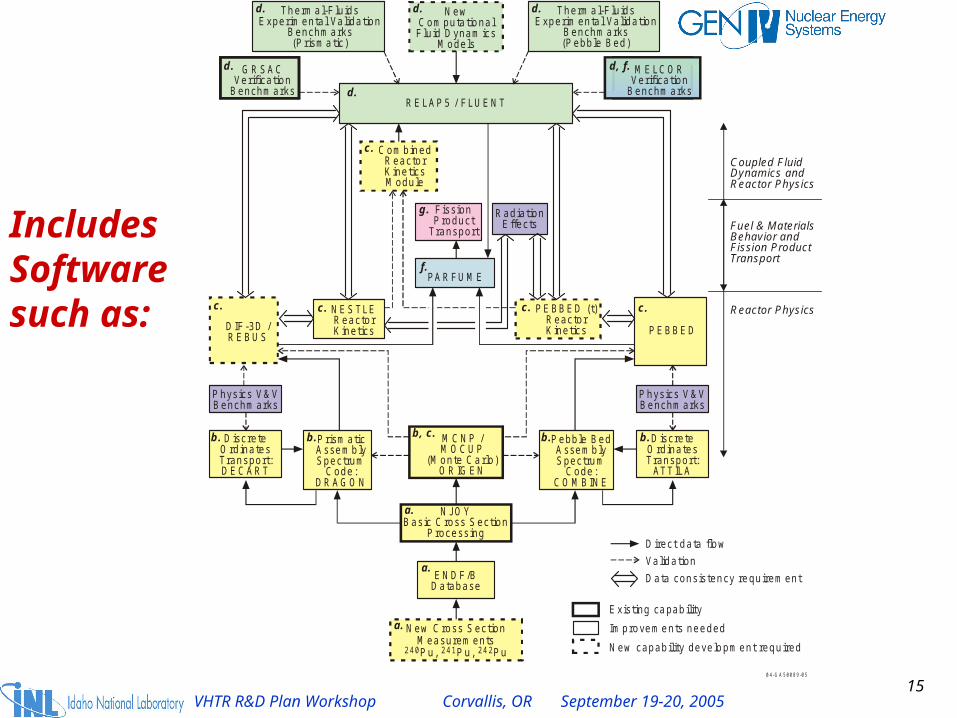
Includes Software such as:
Thermal-Fluids Experim ental Validation
Benchm arks(Prismatic)
NewComputational Fluid Dynam ics
Models
Thermal-Fluids Experim ental Validation
Benchm arks(Pebble Bed)
RELAP5 / FLUENT
CombinedReactorKineticsModule
NESTLEReactorKinetics
PEBBED (t)ReactorKinetics
PrismaticAssembly Spectrum
Code:DRAGO N
MCNP / MOCUP
(M onte Carlo)ORIGEN
NJOYBasic Cross Section
Processing
ENDF/BDatabase
New Cross Section Measurem entsPu, Pu, Pu240 241 242
DIF-3D /REBUS
PEBBED
Physics V&VBenchm arks
Physics V&VBenchm arks
Direct data flow
Validation
Data consistency requirement
0 4-G A 5 00 8 9-0 5
Coupled Fluid Dynam ics and Reactor Physics
Reactor Physics
Existing capability
Improvements needed
New capability developm ent required
DiscreteOrdinatesTransport:DECART
DiscreteOrdinatesTransport:
ATTILA
PARFUME
Fission Product
Transport Fuel & M aterialsBehavior and Fission Product Transport
a.
a.
b.b. b.
c. c.
f.
c. c.
g.
d. d, f.
d.
GRSACVerification
Benchm arks
MELCORVerification
Benchm arks
Pebble BedAssembly Spectrum
Code:COMBINE
b.
a.
b, c.
d. d. d.
c.
RadiationEffects

16VHTR R&D Plan Workshop Corvallis, OR September 19-20, 2005
What exists: Thermal-Fluid Analysis…
– Partially validated systems analysis codes that cannot predict localized hot spots.
– Unvalidated computational fluid dynamics codes that will calculate the presence of hot spots—but the results cannot be trusted.
– Identification of only some of the important phenomena.
– Large incomplete validation data base.

17VHTR R&D Plan Workshop Corvallis, OR September 19-20, 2005
Many of the Phenomena that Must Be Quantified & Analyzed Require CFD
• Forced convection: turbulent behavior and mixing• Mixed convection & free convection• Analysis of flow behavior in plena and chambers• Isolation of local hot spots a special need• Coupled calculations required: that is, calculations
that require coupled CFD codes and systems analysis codes (such as RELAP5) are quite important.
18VHTR R&D Plan Workshop Corvallis, OR September 19-20, 2005
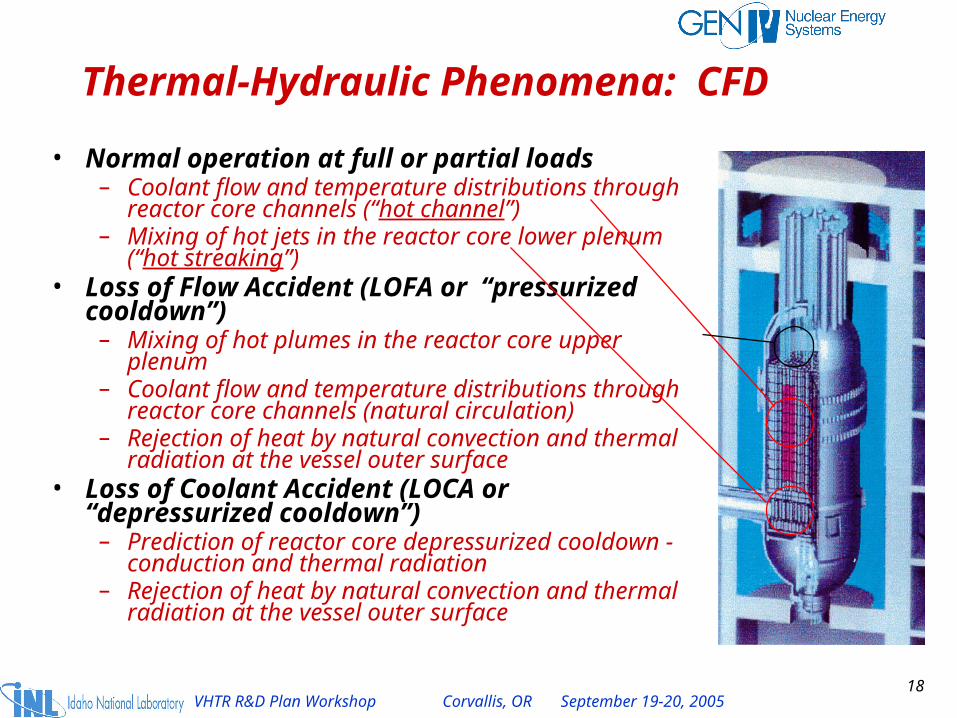
Thermal-Hydraulic Phenomena: CFD
• Normal operation at full or partial loads– Coolant flow and temperature distributions through
reactor core channels (“hot channel”)– Mixing of hot jets in the reactor core lower plenum
(“hot streaking”)• Loss of Flow Accident (LOFA or “pressurized
cooldown”)– Mixing of hot plumes in the reactor core upper plenum– Coolant flow and temperature distributions through
reactor core channels (natural circulation)– Rejection of heat by natural convection and thermal
radiation at the vessel outer surface• Loss of Coolant Accident (LOCA or
“depressurized cooldown”)– Prediction of reactor core depressurized cooldown -
conduction and thermal radiation– Rejection of heat by natural convection and thermal
radiation at the vessel outer surface

19VHTR R&D Plan Workshop Corvallis, OR September 19-20, 2005
Role of CFD & Systems Analysis Codes
Relevance:• Key phenomena will greatly influence the material temperatures
at operational conditions and accident conditions.• Some validation data are available and are being used to
validate CFD & one-dimensional systems analysis codes.• Present focus is on maximum channel coolant exit temperature
at operational conditions and turbulent mixing in lower plenum.
Importance: The software must be shown capable of calculating the maximum material temperatures to enable the VHTR to be licensed. The calculational uncertainty must be acceptably low to demonstrate the VHTR achieves its design claims and is licensable.

20VHTR R&D Plan Workshop Corvallis, OR September 19-20, 2005
CFD: Commercial vs. Non-Commercial…
• There are ongoing studies to evaluate non-commercial CFD codes.
• Commercial CFD codes are user-friendly and have an extensive V&V matrix. They can be used to analyze a wide variety of problems.
• Quite often, the opposite is true for non-commercial CFD codes since their development is often aimed at specific problems.
• However, non-commercial CFD codes are frequently state-of-the art and unexcelled in selected areas.

21VHTR R&D Plan Workshop Corvallis, OR September 19-20, 2005
Approach for Achieving CFD Validation Objectives…
• The process begins by using what is available in commercial CFD codes and by using RANS.
• As deficiencies are identified in commercial CFD codes, the R&D path is chosen based on magnitude of deficiency.
• Use LES and DES as necessary
• Define development, including need for non-commercial codes, as required.

22VHTR R&D Plan Workshop Corvallis, OR September 19-20, 2005
Example*: To Quantify Capabilities of Selected Commercial CFD Codes…
Standard Problem Committee—Committee formed by VHTR Program Group, consultants, and GIF Methods Project Board Members. Standard problems defined in accordance with phenomena identified in PIRT for design of interest.
Standard Problem Oversight Committee: Defines process for performing standard problem by exercise participants, evaluates results, and publishes results. Committee consists of CFD industry experts (some non-nuclear). Practices followed stem from CFD Committees of ASME Fluids Engineering Division and Nuclear Engineering Division best practice guidelines and used in ASME Journal of Fluids Engineering.
Standard Problem Participants: Participants perform standard problems using practices and procedures defined by Standard Problem Oversight Committee. Once completed, the results of the exercise are submitted to the Oversight Committee for evaluation.
Publish results of standard problems in ASME Journal of Fluids Engineering
Completed Standard Problem submitted to Oversight Committee
Standard Problem submitted to participants.
Set of Standard Problems defined by Committee submitted to Oversight Committee for distribution.
__________* Similar approach
proposed for systems analysis software

23VHTR R&D Plan Workshop Corvallis, OR September 19-20, 2005
CFD Tool Certification: for Use in Gen IV
• Industrial quality standards recommended, e.g., ISO 9001:2000 standards or equivalent (for software quality, construction, and certification)—particularly for design calculations
• CFD certification should be based on V&V matrix that contains dominant phenomena for key Gen IV system scenarios
• CFD software V&V required for key phenomena identified in matrix. Acceptance based on degree of agreement with qualified data
• Extent of commercial and non-commercial CFD capabilities & need for further development/R&D can be demonstrated by specifying a series of International Standard Problems—with results published in journals.
24VHTR R&D Plan Workshop Corvallis, OR September 19-20, 2005
Proposal: To Quantify Capabilities of Selected Commercial CFD Codes & Systems Analysis Codes…
1. Form PMB-sponsored committees with charter to define CFD code V&V matrix and systems analysis code V&V matrix based on Gen IV needs (the Standard Problem Committee).
2. Sponsor forums, similar to those hosted by Coordinating Group for Computational Fluid Dynamics (1993-4) or the Stanford Olympics (1968), to define International Standard Problems for CFD.
3. Publish results in journals.4. Use validation results as basis for achieving validation
objectives.5. In summary, base approach on that used by US Nuclear
Regulatory Commission when certifying their software tools to be used for reviewing the AP600 design for LWRs.

25VHTR R&D Plan Workshop Corvallis, OR September 19-20, 2005
Analysis Practices Should be Well-Defined
For CFD software:• Suggest following policy defined by Journal of Fluids
Engineering (Vol 115, 1993)
• Benchmark study requirements: suggest following lead of: C. J. Freitas, “Perspective: Selected Benchmarks from Commercial CFD Codes,” Journal of Fluid Mechanics, 117, 1995, pp. 208 to 218.
For systems analysis software—use directly practices and procedures implemented by USNRC.

26VHTR R&D Plan Workshop Corvallis, OR September 19-20, 2005
Summary: CFD Code Certification
• The CFD V&V matrix must be defined. • Proposed that:
– a series of CFD International Standard Problems be specified,
– commercial and non-commercial CFD organizations be solicited to participate in an ISP Forum
– the analyses be performed using rigorous standards
– the analyses be published in the literature.

27VHTR R&D Plan Workshop Corvallis, OR September 19-20, 2005
The Punch Line
• Current software and methods are not ready to perform design and analysis to the standard that will be required by the VHTR–considerable validation, and probably development, are required.
• The above conclusion also applies to present software capabilities to perform VHTR licensing calculations.
• Practices and procedures acceptable to community must be defined and implemented.
This effort is critical to mission success.

28VHTR R&D Plan Workshop Corvallis, OR September 19-20, 2005
For Validation Purposes: Some Data Sets Already Exist & Others Are Already Planned
Examples:
1. IAEA benchmark problems.
2. Integral facilities: HTTR, HTR-10
3. Various other experimental data recorded in GIF member experimental facilities
4. US DOE sponsored data: matched-index-of-refraction (INL) and NSTF (ANL)

29VHTR R&D Plan Workshop Corvallis, OR September 19-20, 2005
Summary of INL Experimental R&D
• Ongoing R&D
• Plans

30VHTR R&D Plan Workshop Corvallis, OR September 19-20, 2005
Objectives: Provide benchmark data for assessment and improvement of codes proposed for NGNP designs and safety studies andObtain better understanding of related phenomena, behavior and needs
Two emphases: Spatial variations in local fission rate and material behavior will cause "hot channels" which may cause "hot streaking" in lower plenum – and possible structural problemsStarted in August 2004
Thermal hydraulic benchmark experiments
A n n u la r sh ap ed A c tiv e C o re
O u te r S id e R e flec to r G rap h ite
C o re E x it H o t G as P len u m
G rap h ite C o re S u p p o rt C o lu m n s
S h u td o w n C o o lin g S y s tem M o d u le H o t D u c t
In su la tio n M o d u le
C ro ss Vesse l N ip p le
H o t D u c t S tru c tu ra l E lem en t
M e ta llic C o re S u p p o rt S tru c tu re
C o re In le t F lo w
C o re O u tle t F lo w
In su la tio n L ay e r fo r M e ta ll ic C o re S u p p o rt P la te
A d eq u a te?
M o d ify ?
Tu rb in e In le t"P a tte rn F a c to r"
Plan view of lower plenum forprismatic NGNP concept
0 4-G A 5 00 0 7-0 8
CL

31VHTR R&D Plan Workshop Corvallis, OR September 19-20, 2005
Overview of INL experimental tasksScaling
Needs
Heated experimentconcepts
Isothermal lower plenum flow experiment concepts
• Design• Fabrication• Measurements• Documentation
• Design• Fabrication• Measurements• Documentation
Coolant channels Lower plenum
Selection of first heated experiment
Pebble bed
exits?
Other important geometriesSecond heated experiment

32VHTR R&D Plan Workshop Corvallis, OR September 19-20, 2005
inTm,
D50
D30 wq
CFD predictions of Richards, Spall and McEligot [2004]Experiment of Shehata
and McEligot [1998]
Twall (K)
Effect of turbulence model in CFD codes ("hot channel")
Shehata
v f
Selection of an adequate turbulence model is critical for CFD predictions
Turbulencemodels
Run 618, turbulent, moderate q
w

33VHTR R&D Plan Workshop Corvallis, OR September 19-20, 2005
“Hot channel” experiment
Vacuum vessel
Multi-sensorhot-wire probe
Thermocouples
Gas circulator
Flow meter
Traversing table
Powersupply
Pressuretransducer
Heat exchanger
Upflow ordownflow
Potential concept to obtain benchmarkdata for turbulence modeling –
low pressure to reduce buoyancy effects
Example of operating conditions for which code predictions are needed: non-dimensional heat flux
Tabulated benchmark data are available for these conditions
For normal operation• Coolant channels have dominant forced convection with slight property variation• Parameters for buoyancy, streamwise acceleration and heat flux are low relative to thresholds for importance• Benchmark data are available to assess correlations in systems codes
0 .0001
0 .001
0 .01
102
103
104
105
Re
q+
Fu llpow er
R educed
pow er
S ign ifican t
N eglig ib le
0 .0001
0 .001
0 .01
102
103
104
105
Re
q+
Neg
ligib
le

34VHTR R&D Plan Workshop Corvallis, OR September 19-20, 2005
20c
c
DL
4j
s
DL
10jD
s
4.1jr
r
7pD
H jV
One typical conceptDesired: T (or C), V, v as fns{x,y,z}, Nu for surfaces, f or L, StrParameters: Geometry, Rep, Rej, Vj/Vp, Ri or a buoyancy parameter and Tj/Tp for heated jetsConditions: Normal, reduced power, transients
Dp
Dj/Dp 0.7
p/Dp 1.7
Preliminary scaling studies -- lower plenum ("hot streaking")
pV
35VHTR R&D Plan Workshop Corvallis, OR September 19-20, 2005
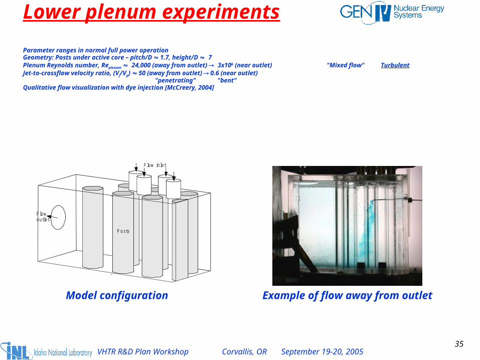
Parameter ranges in normal full power operationGeometry: Posts under active core – pitch/D 1.7, height/D 7Plenum Reynolds number, Replenum 24,000 (away from outlet) 3x10⁶ (near outlet) "Mixed flow" TurbulentJet-to-crossflow velocity ratio, (Vj/Vp) 50 (away from outlet) 0.6 (near outlet)
"penetrating" "bent"Qualitative flow visualization with dye injection [McCreery, 2004]
Lower plenum experiments
Model configuration Example of flow away from outlet
F low inlet
F lowoutlet
Posts
36VHTR R&D Plan Workshop Corvallis, OR September 19-20, 2005
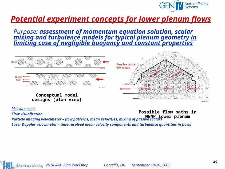
Potential experiment concepts for lower plenum flows
Purpose: assessment of momentum equation solution, scalar mixing and turbulence models for typical plenum geometry in limiting case of negligible buoyancy and constant properties
Measurements
Flow visualization
Particle imaging velocimeter – flow patterns, mean velocities, mixing of passive scalars
Laser Doppler velocimeter – time-resolved mean velocity components and turbulence quantities in flows
Possible flow paths in NGNP lower plenum
Conceptual model designs (plan view)

37VHTR R&D Plan Workshop Corvallis, OR September 19-20, 2005
How does refractive-index-matching help?• Optical techniques avoid disturbing the flow to be measured• Typical approaches are LDV, PIV, PTV, flow visualization, PLIF, etc.
Laser Doppler Velocimetry Particle Image Velocimetry Snell’s Law
• Unless the refractive indices are matched, the view may be distorted or impossible even with "transparent" materials and position measurements may be incorrect
(Rod is resting on the bottom of the beaker)
(Marking is on back of beaker)
Not matched
Matched
Example of application of refractive-index-matching
Refractive index not matched
Plexiglas model
Fluid
Laser beam
Laser beam
Lasertransmissionoptics
Signalcollectionoptics
Internalplexiglasrods
Optical techniques will be used with models in our large Matched-Index of Refraction (MIR) flow system

38VHTR R&D Plan Workshop Corvallis, OR September 19-20, 2005
Advantages– Versatile - basic/applied research, internal / external / coupled flows
– Non-intrusive, undistorted measurements of flow and transport
– -scale to building scale experience
– Good spatial and temporal resolution
– Benchmark measurements
Apparatus to study fluid physics phenomena in idealized SNF canister for EM Science project
(Rod is resting on the bottom of the beaker)
(Marking is on back of beaker)
Not matched
Matched
Example of application of refractive-index-matching
Benefits of INL MIR flow system• Refractive index-matching and optical measuring techniques allow flow measurements when
flow geometries are complicated• Most previous MIR experiments have been cm-scale; INL test section is about 0.6 m x 0.6 m x
2.5 m

39VHTR R&D Plan Workshop Corvallis, OR September 19-20, 2005
Initial INL MIR experiment on lower plenum flow for assessment of CFD toolsSome desired features
• Represent generic features of flows near LP outlet (crossflow) and away from outlet (no crossflow)
• Well-defined geometry; ratios as in NGNP point design
• Turbulent flow in jet entry ducts
• Crossflow in "mixed flow" or "turbulent" regime [Zukauskas, 1972]
• Jet velocity ratio: ½ < (Vjet/Vplenum) < "large"
• Limited domain to ease initial CFD modeling
• Measurements concentrating in important regions– U, V, W, u, v , w , uv, etc. as function of x, y, z
– Flow visualization
– Mixing of passive scalars
– Inlet flow quantities for boundary conditions

40VHTR R&D Plan Workshop Corvallis, OR September 19-20, 2005
Fabrication sketch of model
Dimensions:Dpost = 31.8 mm (1.25 in.), p/Dp = 1.7
Djet/Dp = 0.7, Hplenum/Dp = 6.85
Milestones/deliverables• Fabrication sketches
(for code developers)• Initial measurements
Proposed for later years*• Measurements and comparisons• Documented databases• Technical papers and reports
*Depending on funding from FY-06-07 US Gen IV program
Jet inlet ducts
Support posts
Sep 2005
Sep 2005
H
Flow

41VHTR R&D Plan Workshop Corvallis, OR September 19-20, 2005
Example of comparable PIV data from INL MIR flow system(idealized SCWR coolant channels in US/Korea I-NERI project [2005])
Flow
Streamwise velocity field

42VHTR R&D Plan Workshop Corvallis, OR September 19-20, 2005
Supporting PIV measurements by Prof. B.L. Smith at Utah State U.
x
y
1 5432Dp
LasersheetProfile location
Seeded
air flow
9.6/ ,
7.1)/(
in. 0.2 cm 08.5
DHlengthPost
Dp
DPIVDandp 2
000,56240 max
DVReZu
Geometry Measurements
Purpose = determine the minimum flow rate (Reynolds number) to achieve "mixed flow" in the crossflow of the INL lower plenum modelExperimental configuration
43VHTR R&D Plan Workshop Corvallis, OR September 19-20, 2005
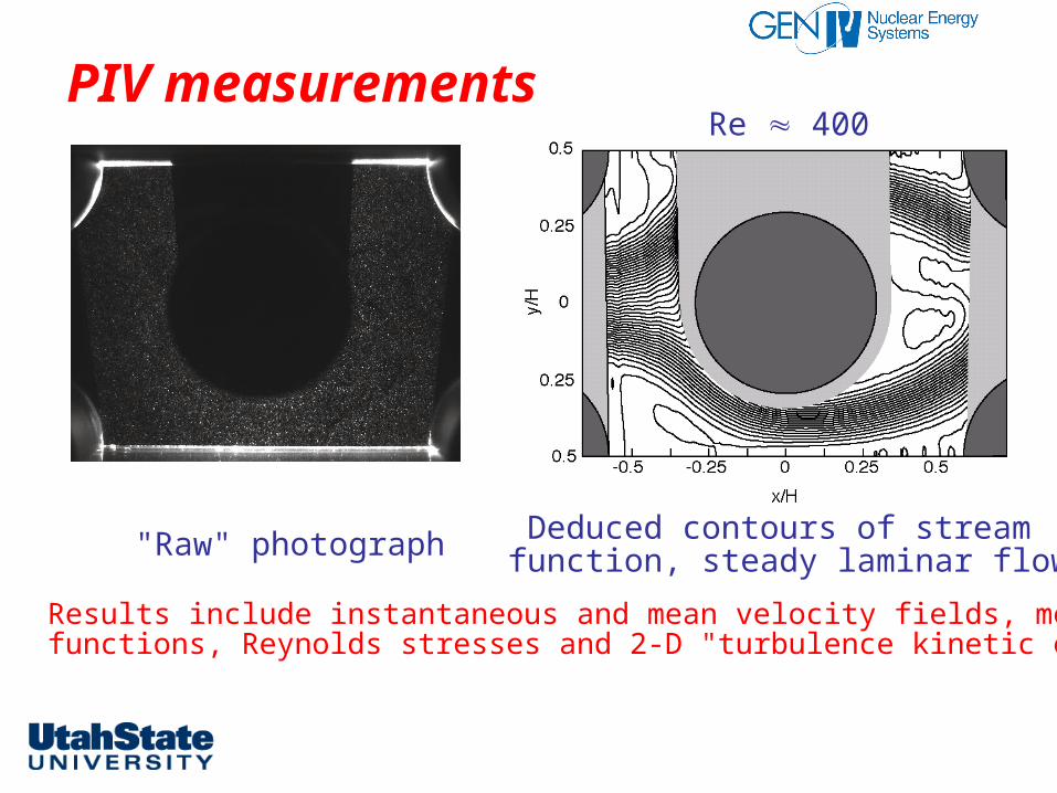
PIV measurements
"Raw" photograph Deduced contours of stream function, steady laminar flow
Re 400
Results include instantaneous and mean velocity fields, mean stream functions, Reynolds stresses and 2-D "turbulence kinetic energy"

44VHTR R&D Plan Workshop Corvallis, OR September 19-20, 2005
Preliminary classification
• Steady laminar flow• Unsteady laminar flow• Mixed partially-turbulent flow• Mixed turbulent flow• Turbulent flow
Visualizations and tabulations on web site(www.mae.usu.edu/faculty/bsmith/EFDL/array/Array.html)
Re < 400
400 < Re < 510
600 < Re < 1,900
1,900 < Re < 56,000
Re > 2 x 10⁵ [Zukauskas, 1972]

45VHTR R&D Plan Workshop Corvallis, OR September 19-20, 2005
Potential experiment concept for heated flows in lower plenumObjective: assessment of codes predicting thermal mixing under influence of buoyancy for typical plenum geometry
Fluid: heated air or water with salt solution for density variation
Measure temperature field with miniature multi-sensor probes of Vukoslavcevic and Wallace [U. Maryland, NERI project] and possibly velocity and turbulence fields
O u tle tf lo w
C o ldg a s
C o ldg a s
C o ldg a s
H o tg a s
H o llo wce ra m ic o rP yre x cylin d e rs
S a p p h ire o rca lc iu m flu o rid ew in d o wT ra ve rsin g
h o t-w irep ro b e(ve lo c ity ,te m p e ra tu re )
T h e rm a l im a g in g ca m e ra(e x is tin g F lir ca m e ra )
Z
X
Possiblemodel

46VHTR R&D Plan Workshop Corvallis, OR September 19-20, 2005
INL thermal-hydraulic experiments - plansFY-05• Complete fabrication sketches for MIR LP experiment• Complete fabrication and installation for first MIR LP experiment = jet inflow
without imposed crossflow (i.e., away from LP outlet)• Continue evaluation of experiment concepts for heated flows• Submit deliverable (fabrication sketches)• Initiate measurements with MIR LP experiments (milestone)
FY-06• Complete measurements for MIR LP experiment without crossflow; document• Design and cost system to provide crossflow in MIR LP model• Fabricate and install system to provide crossflow in MIR LP experiment• Initiate measurements with imposed crossflows• Complete fabrication sketches for second MIR LP experiment• Continue design and selection of experiments for
– Turbulence and stability data for vertical cooling channels– Heated flows in lower plenums
• Initiate design of MIR experiments on exit flows in pebble beds (if funding permits)

47VHTR R&D Plan Workshop Corvallis, OR September 19-20, 2005
Other recommended INL experiments for code validation
1. Core heat transfer experiments
a. Turbulence and stability data from vertical cooling channels
b. Bypass flow studies
c. Exit flows in pebble beds
2. Upper and lower plenum fluid behavior experiments
a. Fluid dynamics of lower plenums
b. Heated flows in lower plenums
c. Interactions between hot plumes in an upper plenum and parallel flow instabilities
3. Air ingress experiments: heat transfer and pressure drop of mixtures of air and helium
4. Larger scale vessel experiments: to examine the behavior in the core, in the plenums and the interactions between them

48VHTR R&D Plan Workshop Corvallis, OR September 19-20, 2005
VHTR - Scalability of the ANL Natural Convection Shutdown Heat Removal Test Facility (NSTF)
• Constructed CFD models of available RCCS designs and NSTF and performed accident condition analyses which showed strong 3-D effects and heat transfer differences with
existing 1-D correlations
• Identified major scaling parameters & phenomena and constructed a semi-analytical scaling model for air cooled RCCS
• Evaluated available RCCS designs, reviewed archival NSTF data, and identified needs for additional sets

49VHTR R&D Plan Workshop Corvallis, OR September 19-20, 2005
R&D Plans are Based on a Preliminary Phenomena Identification & Ranking (PIRT)
• Based on prioritization of scenarios and phenomena :– Identified by experienced gas-cooled system designers– Engineering judgment
• Aimed at requirements for performing reasonable calculations of plant behavior for:– Operational conditions (rated power): neutronics and
working fluid behavior– Pressurized conduction cooldown transient scenario (PCCS)– Depressurized conduction cooldown transient scenario
(DCCS) including possible air/water ingress• Focus is on maintaining integrity of fuel, core, and reactor vessel.

50VHTR R&D Plan Workshop Corvallis, OR September 19-20, 2005
PIRT: Components
• PIRT based on following components:
System Component Inlet Plenum Riser Upper Plenum and Components (e.g., Control Rod Assembly Surface Inside Vessel) Reflectors (Includes Bypass External to Core) Core(Includes Core Bypass Component) Fuel (Fuel Integrity)
Reactor Vessel*
Outlet Plenum and Components Hot Duct Annular Outlet (Hot) & Inlet (Cold) Pipe
Turbine Recuperator Precooler Low & High Pressure Compressor Intercooler
Power Conversion System (Direct Cycle)
Intermediate Heat Exchanger (IHX) Reactor Cavity Downcomers, Piping and Headers Air Cooler Chimney
Reactor Cavity Cooling System
Air Duct Shutdown Cooling System** Coolers

51VHTR R&D Plan Workshop Corvallis, OR September 19-20, 2005
Example: Depressurized Conduction Cooldown Scenario has 3 Phases
1. Blow down (depressurization),
2. Molecular diffusion: following blowdown, there is not sufficient helium left in reactor vessel to have natural circulation—however, air from confinement moves into reactor vessel via diffusion. Heat removal dominated by radiation and conduction heat transfer.
3. Natural convection: Sufficient air has moved into reactor vessel via diffusion that natural circulation is initiated and convective cooling becomes an important ingredient.

52VHTR R&D Plan Workshop Corvallis, OR September 19-20, 2005
Blowdown—Sample of Phase Description…
– Event initiated by rupture of largest system pipes– System depressurizes
– Helium working fluid discharged into volume that surrounds reactor
– “Rapid” heat-up of core occurs by the loss of forced convection
– Graphite dust from reactor core is transported to volume (the reactor confinement building) that contains reactor
– The confinement relief valves lift and gas is discharged to environment. Filters minimize distribution of dust to environment. Relief valves close when pressure has been reduced sufficiently.

53VHTR R&D Plan Workshop Corvallis, OR September 19-20, 2005
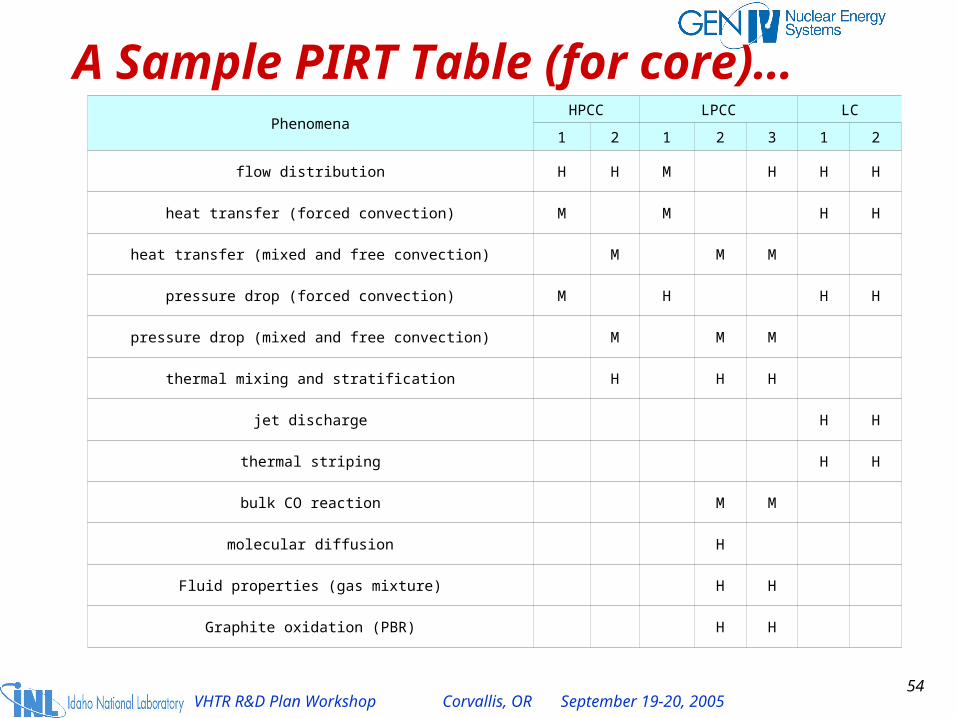
Phenomena are ranked…
• High if important.
• Medium if phenomena may have supporting role in system behavior or may be important and thus should be carefully evaluated.
• Low if can be neglected.
54VHTR R&D Plan Workshop Corvallis, OR September 19-20, 2005
A Sample PIRT Table (for core)…Phenomena
HPCC LPCC LC
1 2 1 2 3 1 2
flow distribution H H M H H H
heat transfer (forced convection) M M H H
heat transfer (mixed and free convection) M M M
pressure drop (forced convection) M H H H
pressure drop (mixed and free convection) M M M
thermal mixing and stratification H H H
jet discharge H H
thermal striping H H
bulk CO reaction M M
molecular diffusion H
Fluid properties (gas mixture) H H
Graphite oxidation (PBR) H H

55VHTR R&D Plan Workshop Corvallis, OR September 19-20, 2005
Region of System
Operational Conditions Depressurized Conduction Cooldown
Pressurized Conduction Cooldown
Inlet Plenum IP1: Validation of CFD mixing calculation during transient & action of plumes on pressure heat boundary..
Core CO4: Characterization of hot channel temp and fluid behavior at operational conditions.
CD3: Validation and calculation of air ingress and potential water ingress behavior into reactor vessel and core region.
CP1: Validation of systems analysis codes to demonstrate capability to predict thermal and hydraulic behavior.
Outlet Plenum PO1: Validation of CFD mixing using mixed index refraction (MIR) facility data & data available in literature. Perform calculation of fluid behavior with validated code.
PD1: Validation of CFD mixing during operational transients and effect on turbine operational characteristics. Perform calculation of fluid behavior.
PP1: Validation of CFD mixing during operational transients and effect on turbine operational characteristics. Perform calculation of fluid behavior.
Reactor Cavity Cooling System
RO1: Validation of natural convection characteristics in cavity at operational conditions.RO2: Characterization of natural convection characteristics in cavity at operational conditions.
RD1: Validation of heat transfer & convection cooling phenomena present in reactor cavity and via RCCS.
RP1: Validation of heat transfer & convection cooling phenomena present in reactor cavity and via RCCS.
CFD Validations Required Based on PIRT…

56VHTR R&D Plan Workshop Corvallis, OR September 19-20, 2005
Preliminary PIRT Being Used to Define CFD Related NGNP R&D…
• Most applications are at low Mach numbers—thus CFD techniques used for incompressible flows will be most used.
• A few applications for compressible, high-velocity CFD software are foreseen:– Perhaps blowdown– Pressure pulse propagation during turbomachinery
transients, e.g. compressor surges.
57VHTR R&D Plan Workshop Corvallis, OR September 19-20, 2005
Conclusions—Methods R&D• Passage of Energy Bill has authorized the project for siting the
VHTR at INL, execution requires appropriations.
• Candidate VHTRs are both prismatic & pebble-bed designs.
• The VHTR will:
– Make possible the efficient and cost effective production of either or both electricity and hydrogen
– Excel in safety and reliability
– Discharge waste that is suitable for long term disposal
– Provide a bridge to a low-emissions economy based on water as our primary transportation fuel
• The current Generation IV/VHTR methods R&D is centered on ensuring the software tools are available to enable the VHTR to be designed and licensed to achieve Generation IV Program standards & objectives.