vgn - assembly & disassembly the manifold onto the nozzles using the dowels to locate the...
TRANSCRIPT
VGN - ASSEMBLY & DISASSEMBLY
OSCO° inc.RUNNERLESS MOLDING SYSTEMS
THERMOCOUPLE
MINI-COIL HEATER
SEAL RING
PIN BUSHING
RETAINER
PIN BUSHING
MANIFOLD
VALVE PIN
RETAINER
CYLINDER
ASSEMBLY
PIN GUIDE
MOUNTING
PLATE
UPPER
SUPPORTS
VALVE
PIN
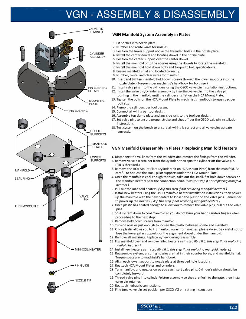
VGN Manifold System Assembly in Plates.
1. Fit nozzles into nozzle plate.
2. Number and route wires for nozzles.
3. Position the lower support above the threaded holes in the nozzle plate.
4. Install the center dowel and locating dowel in the nozzle plate.
5. Position the center support over the center dowel.
6. Install the manifold onto the nozzles using the dowels to locate the manifold.
7. Install the manifold hold down bolts and torque to bolt specifications.
8. Ensure manifold is flat and located correctly.
9. Number, route, and clear wires for manifold.
10. Insert and tighten manifold hold down screws through the lower supports into the
nozzle plate. (Torque is per machinist's handbook for bolt size.)
11. Install valve pins into the cylinders using the OSCO valve pin installation instructions.
12. Install the valve pin/cylinder assembly by inserting valve pin into the valve pin
bushing in the manifold until the cylinder sits flat on the HCA Mount Plate.
13. Tighten the bolts on the HCA Mount Plate to machinist's handbook torque spec per
bolt size.
14. Plumb the cylinders per tool design.
15. Connect all wiring per tool design.
16. Assemble top clamp plate and any side rails to the tool per design.
17. Set valve pins to ensure proper stroke and shut off per the OSCO vale pin installation
instructions.
18. Test system on the bench to ensure all wiring is correct and all valve pins actuate
correctly.
NOZZLE TIP
VGN Manifold Disassembly in Plates / Replacing Manifold Heaters
1. Disconnect the VG lines from the cylinders and remove the fittings from the cylinder.
2. Remove valve pin retainer from the cylinder, then spin the cylinder off the valve pin.
(Pin is threaded.)
3. Remove the HCA Mount Plate (cylinders sit on HCA Mount Plate) from the manifold. Be
careful to not lose the small pillar supports under the HCA Mount Plate.
4. Once the manifold is cool enough to touch, take out the small, flat hold down screws on
the manifold heaters near the connection point. (Skip this step if not replacing manifold
heaters.)
5. Pull out the manifold heaters. (Skip this step if not replacing manifold heaters.)
6. Install new heaters using the OSCO manifold heater installation instructions, then power
up the manifold with the new heaters to loosen the plastic on the valve pins. Remember
to power up the nozzles. (Skip this step if not replacing manifold heaters.)
7. Once plastic has heated enough to allow you to remove the valve pins, pull out the valve
pins.
8. Shut system down to cool manifold so you do not burn your hands and/or fingers when
proceeding to the next step.
9. Remove hold down screws from manifold.
10. Turn on nozzles just enough to loosen the plastic between nozzle and manifold.
11. Once plastic allows you to lift manifold away from nozzles, please do so. Be careful not to
lose the lower pillar supports, or the alignment dowel under the manifold.
12. Remove all seal rings. Replace w/new during reassembly.
13. Flip manifold over and remove failed heaters as in step #5. (Skip this step if not replacing
manifold heaters.)
14. Install new heaters as in step #6. (Skip this step if not replacing manifold heaters.)
15. Reassemble system, ensuring nozzles are flat in their counter bores, and manifold is flat.
Torque specs are to machinist's handbook.
16. Align each lower support to nozzle plate at threaded hole locations.
17. Reattach HCA Mount Plates and cylinders.
18. Turn manifold and nozzles on so you can insert valve pins. Cylinder's piston should be
completely forward.
19. Thread valve pins into cylinder/piston assembly so they are flush to the gate, then install
valve pin retainer.
20. Reattach hydraulic connections.
21. Fine tune valve pin set position per OSCO VG pin setting instructions.
LOWER
SUPPORTS
MANIFOLD
DOWEL
12.0

FREQUENTLY ASKED QUESTIONS
OSCO° inc.RUNNERLESS MOLDING SYSTEMS
HOW DO I.....
Question: How do I remove a previously installed Nozzle Tip?
Answer: Over time, the Nozzle Tips can become seized into the Nozzle body. The best way to
remove them is to use heat. Using an external heat source, gradually heat the lower part of the
Nozzle body, particularly where the threads are located. Once the area is heated, use correct socket
and wrench to loosen the tip.
**Note: In some applications, you will be able to remove the body heater. If you are able to slide the
heater(s) over the tip, it is recommended that you do so.
EXTERNAL
HEAT SOURCE
**NOTE: THIS VIEW SHOWS A NOZZLE ASSEMBLY WHERE THE HEATER IS UNABLE TO SLIDE OVER THE NOZZLE TIP.
SOCKET WRENCH
NOZZLE TIP
NOZZLE BODY
MINI-COIL
HEATER
19.0

OSCO° inc.RUNNERLESS MOLDING SYSTEMS
FREQUENTLY ASKED QUESTIONSHOW DO I.....
Question: How do I remove a previously installed flexible manifold heaters?
Answer: Occasionally there may be reason for you to replace your existing Flexible Heaters. To
do this, simply disconnect the heater lead wires and remove the hold-down screws. Starting at one
end, pry up on the Flexible Heater with a soft metal instrument continuing to follow the heater path
as you pry upward. Repeat these steps for each heater.
**Note: This procedure is only applicable to Flexible Heaters.
FLEXIBLE HEATER
RETAINER SCREWS
FLEXIBLE HEATER
OSCO
MANIFOLD
20.0

OSCO° inc.RUNNERLESS MOLDING SYSTEMS
FREQUENTLY ASKED QUESTIONSHOW DO I.....
Question: How do I replace a nozzle T/C (Thermocouple)?
Answer: There are (2) two types of thermocouples used in Osco Nozzle Assemblies. The ATC
thermocouple is used with "MC" Mini-Coil Heaters and the NTC thermocouple is used with "MBH"
Mineral Band Heaters. To remove an ATC thermocouple, you will need to remove the "MC" Heater
entirely to be able to gain access to the contact point of the thermocouple. If your Nozzle Assembly
contains an "MBH" Heater, you will need a 1/4" open-end wrench to remove the NTC thermocouple.
You may access the NTC thermocouples without the need to remove the "MBH" Heaters.
**Note: This procedure may not be applicable to a 'customer-specific' nozzle assembly.
NTC - THERMOCOUPLE
NTC - THERMOCOUPLE
ATC - THERMOCOUPLE
MINI-COIL HEATER
MINERAL BAND HEATER
MINERAL BAND HEATER
21.0

OSCO Torque Specifications
Miscellaneous
Component Thread Size Suggested Torque
300 Series Tips 1-3/16” – 18 90 – 100 ft. lbs.
MGN Probes 9/16” – 18 40 ft. lbs.
SCV-200 Tips 1” – 16 90 – 100 ft. lbs.
SCV-400 Tips 1-1/4” – 16 100 – 110 ft. lbs.
DSV-500 Tips 1-3/8” – 18 120 – 130 ft. lbs.
20 Series HSN/CVT
Component Thread Size Suggested Torque
Tip 3/8” – 24 15 ft. lbs.
Manifold Hold
Down Screws
5/16” – 18 or
3/8” – 16 32 ft. lbs.
MNS/MEN 5/8” – 18 55 ft. lbs.
Manifold Plug
Retainers 5/8” – 18 55 ft. lbs.
Thermocouple #8 – 32 20 inch lbs.
Thermocouple ¼” – 28 60 inch lbs.
50 Series HSN/CVT
Component Thread Size Suggested Torque
Tip ½” – 24 30 ft. lbs.
Manifold Hold Down Screws
3/8” – 16 32 ft. lbs.
MNS/MEN ¾” – 16 100 ft. lbs.
Manifold Plug
Retainers ¾” – 16 100 ft. lbs.
Thermocouple #8 – 32 20 inch lbs.
Thermocouple ¼” – 28 60 inch lbs.
100 Series HSN/CVT
Component Thread Size Suggested Torque
Tip 5/8” – 24 55 – 60 ft. lbs.
Manifold Hold Down Screws
3/8” – 16 32 ft. lbs.
MNS/MEN ¾” – 16 100 ft. lbs.
Manifold Plug Retainers
7/8” – 14 100 ft. lbs.
Thermocouple #8 – 32 20 inch lbs.
Thermocouple ¼” – 28 60 inch lbs.
200 Series HSN/CVT
Component Thread Size Suggested Torque
Tip 1” – 16 90 – 100 ft. lbs.
Manifold Hold Down Screws
3/8” – 16 32 ft. lbs.
MNS/MEN 1” – 12 120 ft. lbs.
Manifold Plug Retainers
1” – 14 120 ft. lbs.
Thermocouple #8 – 32 20 inch lbs.
Thermocouple ¼” – 28 60 inch lbs.
50 Series VGN
Component Thread Size Suggested Torque
Tip ½” – 24 30 ft. lbs.
Manifold Hold
Down Screws 3/8” – 16 32 ft. lbs.
MNS/MEN ¾” – 16 100 ft. lbs.
Manifold Plug
Retainers ¾” – 16 100 ft. lbs.
Pin Bushing Retainer
5/8” – 11 55 – 60 ft. lbs.
Thermocouple #8 – 32 20 inch lbs.
Thermocouple ¼” – 28 60 inch lbs.
100 Series VGN
Component Thread Size Suggested Torque
Tip 11/16” – 20 55 – 60 ft. lbs.
Manifold Hold Down Screws
3/8” – 16 32 ft. lbs.
MNS/MEN ¾” – 16 100 ft. lbs.
Manifold Plug Retainers
7/8” – 14 100 ft. lbs.
Pin Bushing Retainer
¾” – 16 100 ft. lbs.
Thermocouple #8 – 32 20 inch lbs.
Thermocouple ¼” – 28 60 inch lbs.
200 Series VGN
Component Thread Size Suggested Torque
Tip 1” – 16 90 – 100 ft. lbs.
Manifold Hold
Down Screws 3/8” – 16 32 ft. lbs.
MNS/MEN 1” – 12 120 ft. lbs.
Manifold Plug
Retainers 1” – 14 120 ft. lbs.
Pin Bushing Retainer
1” – 14 120 ft. lbs.
Thermocouple #8 – 32 20 inch lbs.
Thermocouple ¼” – 28 60 inch lbs.
OSCO® inc. RUNNERLESS MOLDING SYSTEMS
22.0