vfd66 drives installation guide (trane)
TRANSCRIPT

www.johnsoncontrols.com
Installation Guide
VFD66JCB-1 andVFD66KCB-1 Drives
Part Number: 24-10511-104Issue Number: 2

2 Installation Guide www.johnsoncontrols.com Issue Number: 2
Contents1 Safety information .................................................................... 4
1.1 Electrical safety - general warning .................................................................. 41.2 System design and safety of personnel .......................................................... 41.3 Environmental limits ....................................................................................... 41.4 Access ............................................................................................................ 41.5 Compliance and regulations ........................................................................... 41.6 Motor .............................................................................................................. 51.7 Electrical installation ....................................................................................... 51.8 Stored charge ................................................................................................. 51.9 Ground leakage current .................................................................................. 5
2 Rating data ................................................................................ 72.1 Supply types ................................................................................................... 72.2 Supply imbalance ........................................................................................... 8
3 Mechanical installation ............................................................ 94 Electrical installation ............................................................. 11
4.1 Drive details .................................................................................................. 114.2 Ground leakage ............................................................................................ 124.3 EMC .............................................................................................................. 134.4 Control terminals I/O specification ................................................................ 18
5 Operation ................................................................................ 195.1 Drive configuration ........................................................................................ 195.2 Line starting capabilities: .............................................................................. 195.3 Repairs and replacements ............................................................................ 19
6 Technical specifications ........................................................ 207 UL listing information ............................................................ 21
7.1 UL information .............................................................................................. 21

Installation Guide 3Issue Number: 2 www.johnsoncontrols.com
EC Declaration of Conformity
Certify and declare under our sole responsibility that the following:
conforms with the essential requirements of the following directives:
The following harmonised standards have been applied:
EN 61000-3-2:2006: Applicable where input current <16A. No limits apply for professional equipment where input power >1kW.
Therefore this product complies with the essential requirements and provisions of the Directives.The Technical documentation can be requested by the surveillance Authorities at the following address:
Name and position of person authorised by the manufacturer:
PDM Name: EU-DOC-VFD66-Variable Frequency Drive.docManufacturer: Johnson Controls Inc.
Address: 4620 Olympic BlvdErlanger KY 41018-0000
Country: USAPhone number: 859-283-1384
Description: Variable Frequency Drive for 3 phase induction motorsProduct name: VFD66Brand: Johnson Controls / Penn
Identification VFD66 followed by A,B,C,D,E,F,J or K followed by two letters. All can be followed by up to three additional numbers followed by up to two additional letters.
EMC Directive 2004/108/ECLow Voltage Directive 2006/95/EC
EN 61800-5-1:2007EN 61800-3:2004
EN 61000-6-2:2005EN 61000-6-4:2007EN 61000-3-2:2006EN 61000-3-3:2008
Company: Johnson Controls Inc.Att: Environment & Legislation
Address, City: Christian X’s Vej 201, 8270 HoejbjergCountry: DenmarkPhone number: + 45 8736 7000
Date: 1/21/2011
George RudichEngineering ManagerJohnson Controls Inc

1 Safety information
1.1 Electrical safety - general warningThe voltages used in the drive can cause severe electrical shock and/or burns, and could be lethal. Extreme care is necessary at all times when working with or adjacent to the drive. Specific warnings are given at the relevant places in this guide.
1.2 System design and safety of personnelThe drive is intended as a component for professional incorporation into a complete system or other equipment. If installed incorrectly, the drive may present a safety hazard.The drive uses high voltages and currents, carries a high level of stored electrical energy, and is used to control equipment, which can cause injury.System design, installation, commissioning and maintenance must be carried out by personnel who have the necessary training and experience. They must read this safety information and this guide carefully.The STOP and START controls or electrical inputs of the drive must not be relied upon to ensure safety of personnel. They do not isolate dangerous voltages from the output of the drive. The supply must be disconnected by an approved electrical isolation device before gaining access to the electrical connections.The drive is not intended to be used for safety-related functions.Careful consideration must be given to the function of the drive, which might result in a hazard, either through its intended behavior or through incorrect operation due to a fault. In any application where a malfunction of the drive or its control system could lead to or allow damage, loss or injury, a risk analysis must be carried out, and where necessary, further measures taken to reduce the risk.
1.3 Environmental limitsInstructions within the supplied data regarding transport, storage, installation and the use of the drive must be complied with, including the specified environmental limits.
1.4 AccessAccess must be restricted to authorized personnel only. Safety regulations which apply at the place of use must be complied with. The IP (Ingress Protection) rating of the drive is installation dependant.
1.5 Compliance and regulationsThe installer is responsible for complying with all relevant regulations, such as national wiring regulations, accident prevention regulations and electromagnetic compatibility (EMC) regulations. Particular attention must be given to the size of conductors, the selection of fuses and other protection, and protective ground (earth) connections.
4 Installation Guidewww.johnsoncontrols.com Issue Number: 2
Safety information
Rating data
Mechanical installation
Electrical installationO
perationTechnical specifications
UL listing inform
ation
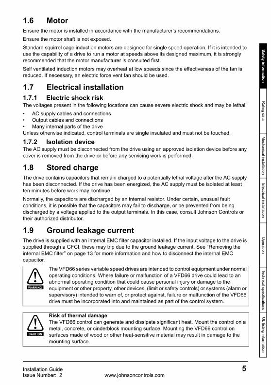
1.6 MotorEnsure the motor is installed in accordance with the manufacturer's recommendations.Ensure the motor shaft is not exposed.Standard squirrel cage induction motors are designed for single speed operation. If it is intended to use the capability of a drive to run a motor at speeds above its designed maximum, it is strongly recommended that the motor manufacturer is consulted first.Self ventilated induction motors may overheat at low speeds since the effectiveness of the fan is reduced. If necessary, an electric force vent fan should be used.
1.7 Electrical installation1.7.1 Electric shock riskThe voltages present in the following locations can cause severe electric shock and may be lethal:• AC supply cables and connections• Output cables and connections• Many internal parts of the driveUnless otherwise indicated, control terminals are single insulated and must not be touched.
1.7.2 Isolation deviceThe AC supply must be disconnected from the drive using an approved isolation device before any cover is removed from the drive or before any servicing work is performed.
1.8 Stored chargeThe drive contains capacitors that remain charged to a potentially lethal voltage after the AC supply has been disconnected. If the drive has been energized, the AC supply must be isolated at least ten minutes before work may continue.Normally, the capacitors are discharged by an internal resistor. Under certain, unusual fault conditions, it is possible that the capacitors may fail to discharge, or be prevented from being discharged by a voltage applied to the output terminals. In this case, consult Johnson Controls or their authorized distributor.
1.9 Ground leakage currentThe drive is supplied with an internal EMC filter capacitor installed. If the input voltage to the drive is supplied through a GFCI, these may trip due to the ground leakage current. See “Removing the internal EMC filter” on page 13 for more information and how to disconnect the internal EMC capacitor.
The VFD66 series variable speed drives are intended to control equipment under normal operating conditions. Where failure or malfunction of a VFD66 drive could lead to an abnormal operating condition that could cause personal injury or damage to the equipment or other property, other devices, (limit or safety controls) or systems (alarm or supervisory) intended to warn of, or protect against, failure or malfunction of the VFD66 drive must be incorporated into and maintained as part of the control system.
Risk of thermal damageThe VFD66 control can generate and dissipate significant heat. Mount the control on a metal, concrete, or cinderblock mounting surface. Mounting the VFD66 control on surfaces made of wood or other heat-sensitive material may result in damage to the mounting surface.
WARNING
CAUTION
Installation Guide 5Issue Number: 2 www.johnsoncontrols.com
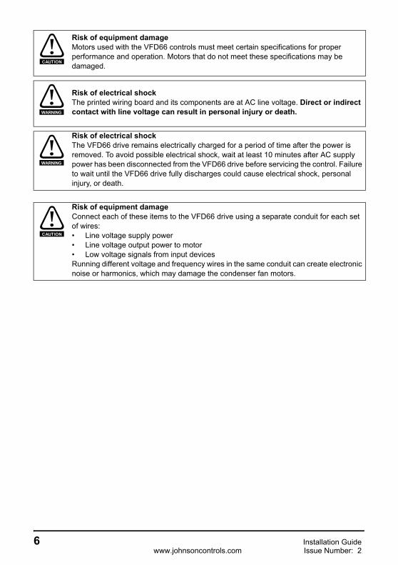
Risk of equipment damageMotors used with the VFD66 controls must meet certain specifications for proper performance and operation. Motors that do not meet these specifications may be damaged.
Risk of electrical shockThe printed wiring board and its components are at AC line voltage. Direct or indirect contact with line voltage can result in personal injury or death.
Risk of electrical shockThe VFD66 drive remains electrically charged for a period of time after the power is removed. To avoid possible electrical shock, wait at least 10 minutes after AC supply power has been disconnected from the VFD66 drive before servicing the control. Failure to wait until the VFD66 drive fully discharges could cause electrical shock, personal injury, or death.
Risk of equipment damageConnect each of these items to the VFD66 drive using a separate conduit for each set of wires:• Line voltage supply power• Line voltage output power to motor• Low voltage signals from input devicesRunning different voltage and frequency wires in the same conduit can create electronic noise or harmonics, which may damage the condenser fan motors.
CAUTION
WARNING
WARNING
CAUTION
6 Installation Guidewww.johnsoncontrols.com Issue Number: 2

Safety information
Rating data
Mechanical installation
Electrical installationO
perationTechnical specifications
UL listing inform
ation
2 Rating dataTable 2-1 Model numbers and ratings
Table 2-2 Cables
Overload capacity110% of output current for 1 minute.
Output frequency 0 to 60Hz
Output voltage3 phase, 0 to drive rating (230 or 460Vac)
The output frequency can be increased by 20% during deceleration to avoid tripping the drive.
2.1 Supply typesThe drive is suitable for use on:Star and Delta connected suppliesThree phase supplies with a grounded star point neutral configuration.Three phase supplies with a line grounded delta configuration.Ground suppliesSupplies with ground configurations TN, TN-C and TN-S.
Modelnumber
Motorpower Supply voltage
and frequencyOutput voltageand frequency
Input fuse
rating
Typical RMS input
current
Rated RMS output current
(A)
hp A A 50°C 60°C
VFD66JCB-1 1.53 phase 200 to
240Vac ±10%48 to 65Hz
Three phase0 to 240Vac0 to 60Hz
10 7.7 6.0 N/A
VFD66KCB-1 1.53 phase 380 to
480Vac ±10%48 to 65Hz
Three phase0 to 480Vac0 to 60Hz
6 4.4 3.0 N/A
Model VFD66JCB-1 VFD66KCB-1
Control cables mm 2 ≥0.5 ≥0.5AWG 20 20
Minimum recommended input wire mm 2 1.5 1.5AWG 14 14
Minimum recommended motor wire mm 2 1.5 1.5AWG 14 14
NOTE
Installation Guide 7Issue Number: 2 www.johnsoncontrols.com

Floating suppliesUngrounded supply configurationsThe drive is suitable for use in a circuit capable of delivering not more than 10,000 RMS symmetrical Amperes at 264Vac RMS maximum (200V drive) or 528Vac RMS maximum (400V drive).
2.2 Supply imbalanceThe maximum supply imbalance: 2% negative phase sequence as per IEC 60146-1-1.
8 Installation Guidewww.johnsoncontrols.com Issue Number: 2
Safety information
Rating data
Mechanical installation
Electrical installationO
perationTechnical specifications
UL listing inform
ation
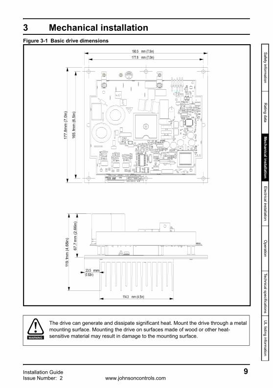
3 Mechanical installationFigure 3-1 Basic drive dimensions
The drive can generate and dissipate significant heat. Mount the drive through a metal mounting surface. Mounting the drive on surfaces made of wood or other heat-sensitive material may result in damage to the mounting surface.
mm
(7.0
in)
177.
8 mm
(6.5
in)
165.
1
mm
(4.6
8in)
119.
1
mm
(2.6
6in)
67.7
WARNING
Installation Guide 9Issue Number: 2 www.johnsoncontrols.com
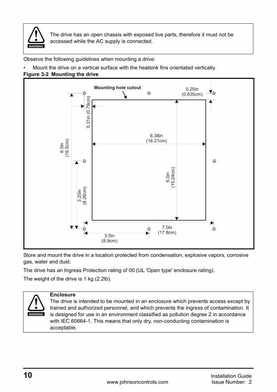
Observe the following guidelines when mounting a drive:• Mount the drive on a vertical surface with the heatsink fins orientated vertically.Figure 3-2 Mounting the drive
Store and mount the drive in a location protected from condensation, explosive vapors, corrosive gas, water and dust.The drive has an Ingress Protection rating of 00 (UL 'Open type' enclosure rating).The weight of the drive is 1 kg (2.2lb).
The drive has an open chassis with exposed live parts, therefore it must not be accessed while the AC supply is connected.
EnclosureThe drive is intended to be mounted in an enclosure which prevents access except by trained and authorized personnel, and which prevents the ingress of contamination. It is designed for use in an environment classified as pollution degree 2 in accordance with IEC 60664-1. This means that only dry, non-conducting contamination is acceptable.
WARNING
6.0i
n(1
5.24
cm)
6.38in(16.21cm)
0.31
in (0
.79c
m)
3.25
in(8
.26c
m)
6.5i
n(1
6.5c
m)
3.5in(8.9cm)
7.0in(17.8cm)
0.25in(0.635cm)
Mounting hole cutout
WARNING
10 Installation Guidewww.johnsoncontrols.com Issue Number: 2

Safety information
Rating data
Mechanical installation
Electrical installationO
perationTechnical specifications
UL listing inform
ation
4 Electrical installation
4.1 Drive detailsFigure 4-1 Power connection detail
*Ground connection must be made using UL listed 4mm (0.157 in) ring lugT1/U terminal (Red wire)T2/V terminal (Blue wire)T3/W Terminal (Black wire)
Optionalground
connection
Fuses
Mains supply
L3/T
L2/SL1/R
T1/UT2/V
T3/W Groundconnection*
Metalenclosure
Supplyground
Supplyground
Ground bar or similar
Installation Guide 11Issue Number: 2 www.johnsoncontrols.com

Figure 4-2 Control connections
4.2 Ground leakageThe ground leakage current depends upon the internal EMC filter being installed. The drive is supplied with the filter installed. Instructions for removal of the internal EMC filter are given in section 4.3.2With internal EMC filter installed:3 phase 200V drive: 7.8mA ac maximum at 220V, 50Hz (proportional to supply voltage and
frequency)3 phase 400V drive: 10.4mA ac maximum at 400V, 50Hz (proportional to supply voltage and
frequency)
With internal EMC filter removed <1mA
Fuses/MCBThe AC supply to the drive must be installed with suitable protection against overload and short circuits. Failure to observe this requirement will cause risk of fire.
The drive must be grounded by a conductor sufficient to carry the prospective fault current in the event of a fault. See also the warning in section 4.2 Ground leakage relating to ground leakage current.
The above leakage currents are just the leakage currents of the drive with the internal EMC filter connected and do not take into account any leakage currents of the motor or motor cable.
There is an internal voltage surge suppression device connected to ground. Under normal circumstances, this carries negligible current.
When the internal EMC filter is installed, the leakage current is high. In this case, a permanent fixed ground connection must be provided.
T1 PWM control input (C)(no connection)
T3 Fault output (F)T4 Fault return (FR)T5 PWM control return (CR)
WARNING
WARNING
NOTE
NOTE
WARNING
12 Installation Guidewww.johnsoncontrols.com Issue Number: 2

Safety information
Rating data
Mechanical installation
Electrical installationO
perationTechnical specifications
UL listing inform
ation
4.2.1 Use of ground fault circuit interrupter (GFCI)There are three common types of GFCI:
Type AC detects AC fault currentsType A detects AC and pulsating DC fault currents (provided the DC current reaches zero at
least once every half cycle)Type B detects AC, pulsating DC and smooth DC fault currents
• Type AC should never be used with drives• Type A can only be used with single phase drives• Type B must be used with three phase drives
4.3 EMC4.3.1 Internal EMC filterIt is recommended that the internal EMC filter is kept in place unless there is a specific reason for removing it.It is recommended that the filter be used in all applications unless the ground leakage current is unacceptable.
4.3.2 Removing the internal EMC filterRemoval of the internal EMC filterFigure 4-3 Removal of the internal EMC filter
To disconnect the internal EMC filter:1. Loosen the plate M3 nut2. Loosen the PCB screw3. Swivel the link to the position shown4. Re-tighten M3 nut to 1Nm (8.9 lb in)5. Re-tighten PCB screw to 1Nm (8.9 lb in)
Removal of the MOV varistorA MOV (varistor) is installed between the power circuit and ground in order to protect the drive from high voltage impulses caused by lightning etc. In some applications it may be necessary to disconnect this device, depending upon the applicable regulations - for example if there is no fixed ground connection.
3Plate M3nut
PCB screw2 5
1 4
Installation Guide 13Issue Number: 2 www.johnsoncontrols.com

Figure 4-4 Removal of the internal MOV
To disconnect the internal MOV:1. Loosen the plate M3 nut2. Loosen PCB screw3. Swivel the link to the position shown4. Re-tighten M3 nut to 1Nm (8.9 lb in)5. Re-tighten PCB screw to 1Nm (8.9 lb in)
4.3.3 Emissions complianceAn internal factory installed EMC filter is provided with all ratings, it is recommended that it is kept in place unless there is a specific reason for removing it. (3) This internal filter reduces radio-frequency emissions into the line power supply. When the motor cable is short, it permits the requirements of EN61800-3:2004 to be met for the second environment with restricted distribution. For longer motor cables, the filter continues to provide a useful reduction in emission level. When used with any length shielded motor cable (up to the limit for the drive), it is unlikely that nearby industrial equipment will be disturbed.
Installation of an additional external EMC filter as stated in Table 4-1 provides higher levels of emissions compliance. If the application requires these levels of compliance then the external filter must be installed in order to ensure compliance with EMC regulations such as the EC EMC Directive, and to ensure the validity of the CE mark.
Table 4-1 Emissions compliance for VFD66 based on EMC filter configuration
*The typical leakage current of the low leakage filter is 3mA compared to the standard filter which has a typical leakage current of 40mA.
Motor Cable Length m (ft)
Filter and Switching Frequency
Internal filter Only
Standard filter Low Leakage filterSchaffner P/N: FS6514-14-07 Schaffner P/N: FS6514-14-07-LL*
3kHz 3kHz 3kHz1 (3) C4 C2 C25 (16) C4 C2 C2
10 (33) C4 C2 C315 (50) C4 C2 C325 (82) C4 C2 C350 (164) C4 C2 C3
3Plate M3
nutPCBscrew2 5 1 4
14 Installation Guidewww.johnsoncontrols.com Issue Number: 2

Safety information
Rating data
Mechanical installation
Electrical installationO
perationTechnical specifications
UL listing inform
ation
Table 4-2 Key to conformity
Notes:
1. The first environment is one where the low voltage supply network also supplies residential premises.
2. When distribution is restricted, drives are available only to installer with EMC competence.3. Operation without an external filter is a practical cost-effective possibility in an industrial
installation where existing levels of electrical noise are likely to be high, and any electronic equipment in operation has been designed for such an environment. This is in accordance with EN 61800-3:2004 in the second environment, with restricted distribution. There is some risk of disturbance to other equipment, and in this case the user and supplier of the drive system must jointly take responsibility for correcting any problem which occurs.
Compliance Level Standard Description Frequency
Range Limits Application
C2
EN 61000-6-4:2007
Generic emission standard for the
Industrial Environment
0.15 – 0.50 MHz 79dBuV quasi peak 66dBuV average AC Supply
Lines0.50 – 30 MHz 73dBuV quasi peak
60dBuV average
EN 61800-3:2004IEC 61800-3
Product standard for adjustable power drive
systems.
Requirements for the first environment (1) with restricted distribution (2).
C3EN 61800-3:2004
IEC 61800-3
Product standard for adjustable power drive
systems.
Requirements for the second environment with unrestricted distribution.
C4 Requirements for the second environment with restricted distribution (2).
Installation Guide 15Issue Number: 2 www.johnsoncontrols.com

Figure 4-5 External EMC filter wiring
Notes:
• The M3 nut is provided to connect the shield to ground (earth).• Physically separate the input and output cables.• All input and output cables should be fully shielded, with the shield directly fixed to ground i.e.
not using pigtail. The motor cable shield should be connected to the ground connection nut/tab.• Do not run input cables alongside output cables. Do not bundle input and output cables
together.• The input ground wire should be connected to the enclosure box. The ground connection
between the enclosure and the base plate is made via the mounting screws.• Ideally, the motor cable shield should be clamped directly to the back plate.• The EMC filter body needs to be fixed to the same grounded metal part (e.g. the back plate) as
the motor cable shield.
Optionalground
connection
L2/S T1/UT2/V
T3/W Groundconnection
Alarmdevice
Inputdevice
EMC filter
L3/T L1/RL2/S
Gnd
L2/S T1/U T3/W Ground
Ground bar or similar
Supplyground
L3/T L1/R T2/V
Supplyground
16 Installation Guidewww.johnsoncontrols.com Issue Number: 2

Safety information
Rating data
Mechanical installation
Electrical installationO
perationTechnical specifications
UL listing inform
ation
4.3.4 Immunity complianceThe level of the drives immunity from conducted and radiated emissions from external sources is summarised below in Table 4-3.
Table 4-3 Immunity complianceStandard Type of immunity Test specification Application Level
IEC 61000-4-2EN 61000-4-2
Electrostaticdischarge
6kV contact discharge8kV air discharge Module enclosure Level 3
(industrial)
IEC 61000-4-3EN 61000-4-3
Radio frequency radiated field
10V/m prior to modulation
80 – 1000MHz80% AM (1kHz)
modulation
Module enclosure Level 3(industrial)
IEC 61000-4-4EN 61000-4-4
Fast transient burst
5/50ns 2kV transient at 5kHz repetition
frequency via coupling clamp
Control lines Level 4(industrial harsh)
5/50ns 2kV transient at 5kHz repetition
frequency by direct injection
Power lines Level 3(industrial)
IEC 61000-4-5EN 61000-4-5 Surges
Common mode 4kV1.2/50µs waveshape
AC supply lines:Line to ground Level 4
Differential mode 2kV1.2/50µs waveshape
AC supply lines:Line to line Level 3
Lines to ground Signal ports to ground Level 2
IEC 61000-4-6EN 61000-4-6
Conducted radio frequency
10V prior to modulation
0.15 – 80MHz80% AM (1kHz)
modulation
Control and power lines
Level 3(industrial)
IEC 61000-4-11EN 61000-4-11
Voltage dips and interruptions
-30% 10ms+60% 100ms
-60% 1s<-95% 5s
AC power ports
IEC 61000-6-1EN 61000-6-1:2007
Generic immunity standard for the residential, commercial and light – industrial
environmentComplies
IEC 61000-6-2EN 61000-6-2:2005
Generic immunity standard for the industrial environment Complies
IEC 61800-3EN 61800-3:2004
Product standard for adjustable speed power drive systems (immunity
requirements)
Meets immunity requirements for first and second environments
Installation Guide 17Issue Number: 2 www.johnsoncontrols.com

4.4 Control terminals I/O specification
4.4.1 Control connections
The control circuits are isolated from the power circuits in the drive by basic insulation (single insulation) only. The installer must ensure that the external control circuits are insulated from human contact by at least one layer of insulation (supplementary insulation) rated for use at the AC supply voltage.
If the control circuits are to be connected to other circuits classified as Safety Extra Low Voltage (SELV) (e.g. to personal computer), an additional isolating barrier must be included in order to maintain the SELV classification.
T1 PWM control input (C)Range 0-10VResolution 0.1%Accuracy ±3%Logic positive logic onlyNominal threshold voltage 5VInput impedance 660ΩSample time 6msFrequency 10Hz
T2 Not connected
T3 Fault output (F) (normally closed)On state current 500μA minimum at 2.5VOff state leakage current 50μA maximum at 5V
T4 Fault return (FR)
T5 PWM control return (CR) Range 0-10VResolution 0.1%Accuracy ±3%Digital input positive logic onlyNominal threshold voltage 5VInput impedance 660ΩSample time 6msFrequency 10Hz
The drive will perform a single automatic restart, 25 seconds after the trip condition.
A flywheel diode should be installed across inductive dc loads connected to the fault output e.g. relay coil.
WARNING
WARNING
WARNING
WARNING
18 Installation Guidewww.johnsoncontrols.com Issue Number: 2

Installation Guide 19Issue Number: 2 www.johnsoncontrols.com
Safety information
Operation
Mechanical installation
Electrical installationO
perationTechnical specifications
UL listing inform
ation
5 Operation
5.1 Drive configurationInput signal: The drive has only one digital input, which is a 10Hz, PWM speed reference. The duty cycle of this signal determines the speed of the motor.
Duty cycle high time from 0 to 7% will cause the inverter output to be off. Output (3Hz minimum frequency) will begin between 7% and 13% duty cycle and reaching 60 Hz output with 87% to 93% duty cycle; maintain 60Hz output from 93% to 100% duty cycle.
Figure 5-1 Output frequency Vs. input duty cycle
5.2 Line starting capabilities: The drive will start automatically when line power is applied, even if the motor is already rotating.
5.3 Repairs and replacementsField repairs of the VFD66 Control should not be made. In case of a defective or improperly functioning control, contact your nearest Authorized Johnson Controls/PENN® Distributor or Sales Representative. When contacting your Johnson Controls/PENN distributor, have the model number of the control available. This number can be found on the label on the side of the control.
0 20 40 60 80 100
0
20
40
60
10
30
50
Out
put f
requ
ency
(Hz)
Duty cycle (%)

20 Installation Guidewww.johnsoncontrols.com Issue Number: 2
6 Technical specifications
Building Efficiency507 East Michigan StreetMilwaukeeWI 53202
Model VFD66Drive voltage rating 230Vac, 460Vac @ 60Hz (230Vac, 400Vac @ 50Hz)Output Voltage/Output frequency 230Vac, 460Vac @ 60Hz Switching frequency 3kHzDuty NormalOverload limit 110% overload current for 60sAcceleration/Deceleration 5 s/100HzStart/Stop Terminal controlMotor cable lengths ≤50m
Ambient temperature -40°C to 50°C (-40°F to 122°F)
Storage temperature -40°C to 50°C (-40°F to 122°F)
AltitudeRated altitude: 1000m (3300 ft)Reduce the normal full load current by 1% for every 100m (330ft) above 1000m (3300ft) up to a maximum of 3000m (9842ft)
Humidity Maximum relative humidity 90% non-condensing at 40°C (104°F)
Storage humidity Maximum relative humidity 93%, 40°C, 4 daysVibration Meets EN61800-5-1 and ETS300019-2-2Enclosure IP00 (UL Open Type)
Approvals RoHS compliant, CE Approval, UL/cUL Approval (JCI file number E244421), C tick approval
Dimensions See Figure 3-1 on page 9Weight 2.2 lb (1kg)
The performance specifications are nominal and conform to acceptable industry standards. For application at conditions beyond these specifications, consult Johnson Controls/PENN Refrigeration Application Engineering at 1-800-275-5676. Johnson Controls, Inc. shall not be liable for damages resulting from misapplication or misuse of its products.
NOTE

Installation Guide 21Issue Number: 2 www.johnsoncontrols.com
Safety information
Operation
Mechanical installation
Electrical installationO
perationTechnical specifications
UL listing inform
ation
7 UL listing information
7.1 UL information (For VFD66JCB-1, VFD66KCB-1)
The Johnson Control UL file number is E244421. Confirmation of UL listing can be found on the UL website: www.ul.com.
7.1.1 ConformityThe drive conforms to UL listing requirements only when the following are observed:
• Class 1 60/75°C (140/167°C) copper wire only is used in the installation.• The ambient temperature does not exceed 50°C (122°F) when the drive is operating.• The grounding connection shall be made with a UL listed ring lug.• The drive is installed into a separate electrical type 1 enclosure or better, as defined by UL50.• UL listed class CC acting fuses e.g. Bussman Limitron KTK series, Gould AmpTrap ATM series
or equivalent are used in the AC supply.• Ensure that the field wiring leads are securely installed to the input and output power tabs.• Power circuit wiring leads need to be a minimum of 14 AWG wire.
7.1.2 AC supply specificationThe drive is suitable for use on available circuits of 5,000A RMS maximum, 480V/240V maximum, when protected by fuses only, sized 250% FLA maximum.
7.1.3 Motor overload protectionThe drive provides motor overload protection. The overload protection level is 110% of the full load current. For individual motor drive current rating, please refer relevant section of the User guide.
7.1.4 Over-speed protectionThe drive provides over-speed protection. However, it does not provide the level of protection afforded by an independent high integrity over-speed protection device.

24-10511-104